

Nikon N-STORM Operation Manual

M605E 12.6.Nx.1
Super-resolution Microscope
N-STORM
Simple Operation Manual


Introduction
Introduction
Thank you for purchasing a Nikon product.
This instruction manual is written for users of the Nikon Super-resolution Microscope N-STORM. To ensure correct usage,
read this manual carefully before operating this product.
• No part of this manual may be reproduced or transmitted in any form without prior written permission from Nikon.
• The contents of this manual are subject to change without notice.
• The equipment described in this manual may differ from the actual product in its appearance.
• Although every effort has been made to ensure the accuracy of this manual, errors or inconsistencies may remain. If you
note any points that are unclear or incorrect, please contact your nearest Nikon representative.
• Some of the equipment described in this manual may not be included in the set you have purchased.
• If you intend to use any other equipment with this product, read the manual for that equipment too.
• If this equipment is used in a manner not specified by the manufacturer, the protection provided by the equipment may be
impaired.
Symbols used in this operation manual
This operation manual uses the following symbols.
Indicates information that should be kept in mind when using this product, or which provides useful hints.
Registered trademark
• Product names and company names used in this document are trademarks or registered trademarks of their respective
companies.
• Trademarks and registered trademarks of their respective companies, as used in this document, are not marked with TM
and ®.
i

Contents
Contents
Introduction ................................................................................................................................................ i
Chapter
Terminology Used in This Document........................................................................................... 1
1
Chapter
STORM Microscopy Operation .....................................................................................................4
2
2.1 Preparation of the N-STORM System...................................................................................................... 5
2.2 Acquiring 3D-STORM (2D-STORM) Images.......................................................................................... 11
2.2.1 Acquiring Images in Normal Mode ...........................................................................................11
2.2.2 Acquiring Images in Continuous Mode..................................................................................... 16
2.3 N-STORM Analysis ................................................................................................................................22
2.4 Terminating the N-STORM System ........................................................................................................ 28
2.5 Calibration for 3D-STORM ..................................................................................................................... 29
Chapter
The Screens of the N-STORM Software..................................................................................... 34
3
3.1 N-STORM Control Window .................................................................................................................... 34
3.2 N-STORM Settings Window................................................................................................................... 36
3.3 N-STORM Analysis Window ..................................................................................................................37
3.3.1 Tool Bar .................................................................................................................................... 37
3.3.2 Slider ........................................................................................................................................40
3.3.3 Channel Tab ............................................................................................................................. 41
3.3.4 Status Bar.................................................................................................................................42
ii

Chapter
Terminology Used in This Document
1
1
Terminology Used in This Document
N-STORM
System that allows STochastic Optical Reconstruction Microscopy (STORM) with Nikon’s inverted research microscope
Ti-E.
During STORM, some fluorescent probe molecules are randomly stimulated (activated) with relatively weak light to become
activated, after which their images are acquired through an EM-CCD camera (imaging). The series of images that is acquired
through frequent repetition of this process is analyzed and synthesized by software, and formed into a super-resolution
image.
Conventional image
Image of 256 x 256 pixels acquired using an EM-CCD camera. In STORM analysis, a set of sequentially acquired
conventional images is used as material.
STORM image (2D-STORM/3D-STORM image)
Super-resolution image generated as a result of analyzing a dataset of conventional images. It includes information such as
the position, size, and intensity of each individual fluorescent probe molecule.
A STORM image that only has information on the positions in the X- and Y-axis directions is referred to as “2D-STORM
image,” while one that also has information on the positions in the Z-axis direction is referred to as “3D-STORM image.”
Dye pair
Composite dye used for STORM observation, such as the following:
Examples: Alexa405-Alexa647
Cy2-Alexa647
Cy3-Alexa647
Probe
Fluorescent molecule (dye pair or monomolecular dye) used for STORM observation.
Dataset
Set of consecutive frames (conventional images) acquired through an EM-CCD camera. A dataset is saved in ND2 file format
for NIS-Elements.
Frame
Individual conventional image that is acquired through an EM-CCD camera as material to be used to generate a STORM
image.
Activation frame
Frame (image) that is acquired when relatively weak laser light for activation is emitted. This activation causes some
fluorescent probe molecules to become activated. Activation frames are not used for STORM analysis. Note that if images
are to be acquired in continuous mode, there is no difference between the activation and imaging frames because activation
and imaging are performed simultaneously.
1

Chapter 1 Terminology Used in This Document
A
A
Imaging frame
Frame (image) that is acquired when laser light for imaging is emitted. In this frame, fluorescent probe molecules fluoresce
only when activation has caused them to become activated. Note that if images are to be acquired in continuous mode, there
is no difference between the activation and imaging frames because activation and imaging are performed simultaneously.
Cycle
Set of frames that consist of an activation frame (normally one frame) and the subsequent imaging frames (normally three
frames) on one channel during image acquisition in normal mode.
Channel
For a multistaining procedure, the cycle in which each dye is observed is called a channel.
Period
Set of cycles that are made up of one cycle of each of the multiple channels on which images are acquired in normal mode.
For example, if images are acquired on two channels, one period consists of two cycles. If images are acquired on only one
channel, a period is the same as a cycle.
Dataset structure in normal mode (example)
Number of image acquisition channels: 2
Number of activation frames per period (per cycle) on one channel: 1
Number of imaging frames per period (per cycle) on one channel: 3
ctivation laser
Channel 1 (405 nm)
ON
ON
ctivation laser
Channel 2 (561 nm)
Imaging
laser (647 nm)
A1 I1 I1 I1 A2 I2 I2 I2 A1 I1 I1
Frame
A1: Activation frame on channel 1
I1: Imaging frame on channel 1
A2: Activation frame on channel 2
I2: Imaging frame on channel 2
ON ON ON
Cycle
Period
ON
ON ON ON
Cycle
ON ON
(Repeat the same
operation.)
Dataset
2

Chapter 1 Terminology Used in This Document
A
Continuous mode
Method of acquiring STORM images using a monomolecular dye that can itself become bright or dark, instead of requiring a
dye pair for activation. Since the activation and imaging laser light are emitted simultaneously to acquire images, acquisition
takes less time than in normal mode. In this case, the definitions of cycle and period are not applied.
Dataset structure in continuous mode (example)
ctivation
laser (405 nm)
ON ON ON ON ON ON ON ON
Imaging
laser (647 nm)
ON ON ON ON ON ON ON ON
Frame
(Repeat the same
operation.)
Dataset
Non-specific activation (NSA)
During image acquisition in normal mode, only those molecules that are detected in the first imaging frame after activation
are classified as being of the relevant channel. Also, those molecules that are not detected in the first imaging frame but in
the second or subsequent frames are classified as being those of a non-specific activation (NSA) channel. Information on
non-specific activation channels is used for crosstalk subtraction. (For details, see step 6 in “2.3 N-STORM Analysis,” in
Chapter 2.)
3

(
)
Chapter
STORM Microscopy Operation
2
STORM Microscopy Operation
The overall operational steps and their corresponding descriptions in this chapter are as follows:
The screenshots in this document are presented as an example.
Steps from Image Acquisition to Analysis
2.1 Preparation of the N-STORM System
2.5 Calibration for 3D-STORM
(only for acquiring new 3D-STORM images)
2.2.1 Acquiring Images in Normal
Mode
2.3 N-STORM Analysis
2.4 Terminating the N-STORM System
2
2.2.2 Acquiring Images in
Continuous Mode
4

Chapter 2 STORM Microscopy Operation
r
2.1
Prepare the microscope, the laser, and other peripheral devices, and then start NIS-Elements AR.
The controller for the piezo Z stage must be connected to the PC with a USB cable. Remove the analog cable that
directly connects the controller to the microscope. Also, select [Manage devices...] from the [Devices] menu, and
turn off [Ti PiezoZ] under [Nikon Ti].
1 Perform safety checks.
(-> Chapter 3, “Detailed Microscopy Procedure” of the use
manual of the TIRF illuminator)
Preparation of the N-STORM System
Connecting the piezo Z stage
2-(1)
POWER
2 Turn the power on.
(1) Turn on the motorized stage and the illumination
light source.
(2) Turn on the piezo Z stage.
(3) Turn on the microscope.
(4) Turn on each laser head. (See the user manuals for
the TIRF illuminator and each laser head.)
(5) Turn on the LU4A laser unit.
(6) Turn on the PC.
Motorized stage power supply
2-(1)
Diascopic illumination power supply
2-(1)
HG precentered fiber illuminator
REVO
2-(3)
INTERLOCK
OFFSET
PFS
PIEZO
UNIT1 UNIT2 UNIT3
POWER
ONOFF
ERGO/JOY
MADE IN JAPAN
DSC1 DSC2 SHUTTER1
DC24V IN
USB
MODEL TI-HUBC/A
5 5 0 3 0 1
SHUTTER2
TI-PS
REMOTE HGFIE
STAGE
This device complies with Part 15 of the FCC Rules. Operation is subject to the following two conditions:
(1) this device may not cause harmful interference, and (2) this device must accept any interference
received including interference that may cause undesired operation.
This Class A digital apparatus complies with Canadian ICES-003.
Cet appareil numØrique de la classe A est conforme la norme NMB-003 du Canada.
Microscope
2-(5)
LU4A
5

Chapter 2 STORM Microscopy Operation
When MPB Communications Inc.’s 647-nm laser is
used
(1) Start the laser control software GUI-VFL.
(2) Click the [On] button in the window to turn on
the 647-nm laser.
The value of [SHG temp.] is displayed.
(3) Follow the procedure below to gradually
increase the output of the 647-nm laser through
GUI-VFL (procedure recommended by the
laser maker).
Set the power to 50 mW, click [Activate], and
then wait until the value of [Power, mW]
becomes about 50 mW.
Then, set the power to 200 mW, click [Activate],
and wait until the value of [Power, mW] reaches
about 200 mW. The value of [Power, mW] may
change by a few percent, but this does not
affect the acquisition of STORM images.
After the completion of this procedure, use
NIS-Elements to adjust the laser power. It is not
necessary to use GUI-VFL for adjustment.
(For details on the procedure for turning off this laser,
see step 1 in “2.4 Terminating the N-STORM
System.”)
3 Start NIS-Elements AR.
(1) Start NIS-Elements AR by double-clicking the
corresponding icon.
(2) When the camera driver selection dialog is
displayed, select [ANDOR with N-STORM]. (To
change the camera driver after NIS-Elements is
started, select [Select Driver…] from the [Acquire]
menu.)
(1)
(2)
(3)
(3)
3-(1)
3-(2)
(3) Display the [N-STORM] control window and the
[DU-897 Settings] (camera) control window. (Select
[Acquisition Controls] from the [View] menu and then
select the control windows.)
6

Chapter 2 STORM Microscopy Operation
4 Place the imaging target in the visual field.
Set a specimen, direct the light path to the binocular part to
perform epi-fluorescence microscopy, and then put the
STORM imaging target into the visual field.
(For details on the procedure for epi-fluorescence
microscopy, see the user manual for the microscope.)
5 Configure camera settings.
In the [DU-897 Settings] control window (EM-CCD camera
settings), configure the settings as follows.
[Format For Live]: No Binning
[Format For Capture]: No Binning
5
Exposure time: Any setting (50 msec or 1
frame recommended)
[Readout Mode]: EM Gain 10 MHz 14-bit
[EM Gain Multiplier]: 30
[Conversion Gain]: Maximum available value
[Desired Temperature]
(Commands -> Advanced
6 Wait until the temperature of the camera stabilizes at
Camera Settings): -70°C
about -70°C and [Desired temp. differs!] disappears.
It takes a few minutes for the temperature of the camera to
stabilize.
7 Put the objectives for STORM into the light path.
Objectives: CFI Apo TIRF 100x oil (NA1.49) or
CFI Plan Apo VC 100x oil (NA1.40)
Use Nikon immersion oil Type B or Type NF for oil
immersion of the objectives.
When using CFI Apo TIRF 100x oil, adjust the correction
ring to suit the cover glass. If a cover glass No. 1-S
(No.1.5) is used, it is recommended that the position of the
correction ring be 0.165 mm.
7

Chapter 2 STORM Microscopy Operation
8 Perform an observation with TIRF illumination.
(1) Direct the light path to the EM-CCD camera.
Note: Set the cylindrical lens for 3D-STORM to OUT
(where it is not in the light path).
(2) Set the episcopic illumination to [TIRF].
(3) Put the N-STORM filter cube into the light path.
(4) Click [Interlock] on the N-STORM control window to
disable the laser interlock.
If the interlock cannot be disabled
If clicking [Interlock] does not disable the interlock, the
light path may not be set to the side port, or the laser
safety cover of the stage may not be secured properly.
Make sure that the light path is set to the side port (the
EM-CCD camera for STORM), and that the laser safety
cover is secured. Then, click the [Interlock] button again.
(5) Click [Live] of NIS-Elements to display the live
image on the screen.
(6) Select the checkbox for the 647-nm laser and set
the power to about 5% to 10%. (If the power is too
strong, photo-bleaching further occurs.) Deselect
the checkboxes for the other lasers.
(7) Set the shutter of the laser to OPEN in the
N-STORM control window.
(8) Set the laser position to the TIRF position (about
4200). (For details on how to adjust the TIRF, see
the user manual for the TIRF illuminator.)
(9) After TIRF observation is completed, temporarily
deselect the checkbox for the 647-nm laser on the
N-STORM control window.
8-(1)
8-(2)
8-(8)
8-(4)
8-(7)
8-(6), (9)
8
Chapter 2 STORM Microscopy Operation
9 Configure camera ROI settings.
Select [Camera ROI] -> [Define ROI] from the [Acquire]
menu of NIS-Elements, and then configure the settings as
follows.
[Left] 128 pixels
[Top] 128 pixels
[Width] 256 pixels
[Height] 256 pixels
Available range
The range available for STORM is 256 x 256 pixels only.
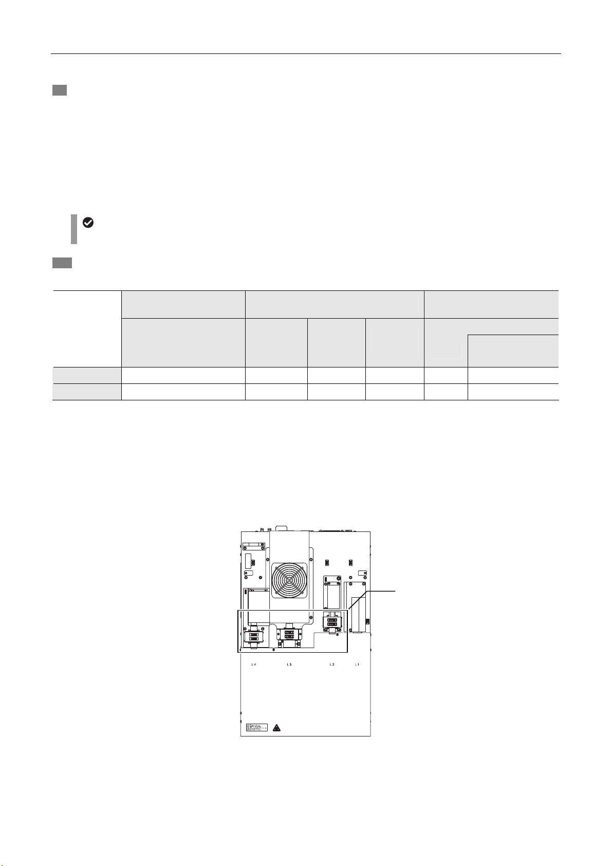
10 Configure the settings for the other optical systems
for N-STORM.
2D-STORM IN
3D-STORM IN
LU4A 4-laser unit Electric TIRF illuminator TI-TIRF-E
ND filter slider
1
*
IN IN OUT OUT 1x
1
*
IN IN OUT IN
STORM
slider
λ-plate
slider
ND
filter slider
3D-STORM port
(Ti-E side port)
Cylindrical lens
N-SIM/N-STORM
switching port is
2
*
STORM
used
2
*
IN: Included in the light path, OUT: Not included in the light path
*
1 ND filter slider of the LU4A 4-laser unit
L2 position: Two ND32s are put into the light path.
L3 position: Both ND2 and ND4 are put into the light path.
L4 position: Two ND32s are put into the light path.
*
2 Cylindrical lens
When the cylindrical lens is put into the light path, the image will be slightly blurred.
transportation.
Fix the laser unit with
four blocks during
ND filter sliders of the LU4A
4-laser unit
9
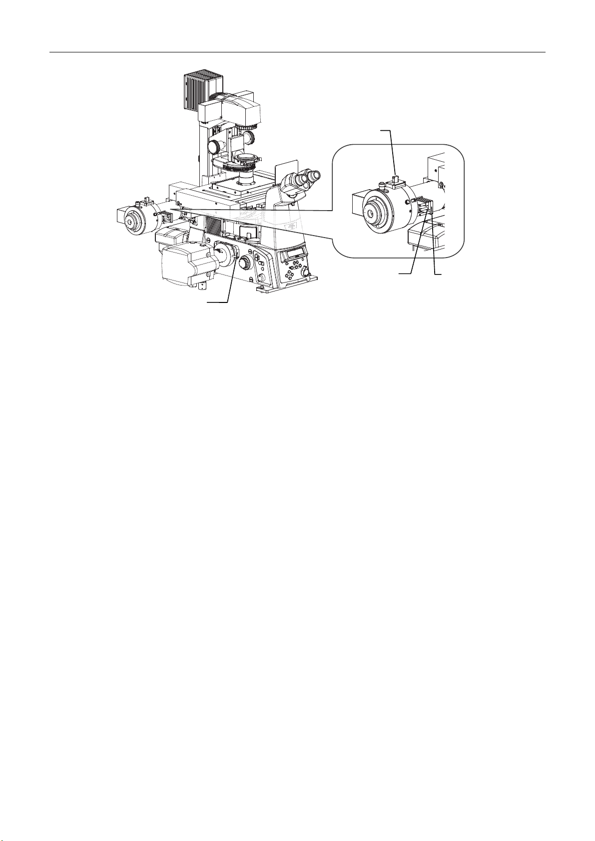
Chapter 2 STORM Microscopy Operation
r
STORM slide
Cylindrical lens
for center and left)
ND filter sliders
(the two of
the three sliders
λ-plate slider
(The right slider among the three)
10
Chapter 2 STORM Microscopy Operation
2.2
To perform STORM analysis, automatically repeat light stimulation and image acquisition with the appropriate laser power to
create a dataset. There are two types of mode for acquiring images: normal mode and continuous mode. In normal mode,
activation and imaging are performed in separate frames. In continuous mode, they are performed simultaneously.
The following basically describes the procedure for acquiring 3D-STORM images. Any differences from the procedure for
acquiring 2D-STORM images are noted together with the symbol “”.
2.2.1
In the example below, the following two types of probe are used.
• Channel 1: Alexa405-Alexa647 dye (Alexa647 activated by Alexa405)
• Channel 2: Cy3-Alexa647 dye (Alexa647 activated by Cy3)
Before the first 3D-STORM image is acquired, it is necessary to perform calibration. See “2.5 Calibration for
3D-STORM.”
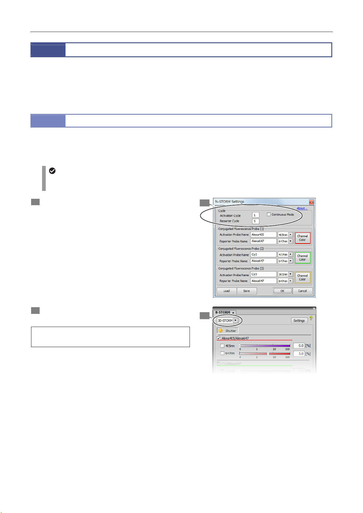
1 Click [Settings] in the [N-STORM] control window and
then specify the number of frames for each cycle.
[Continuous Mode]: Off
[Activation Cycle] (number of activation frames): 1
[Reporter Cycle] (number of reporter frames): 3
After making this setting, click [OK].
Acquiring 3D-STORM (2D-STORM) Images
Acquiring Images in Normal Mode
Calibration for 3D-STORM
1
2 Select [3D-STORM] from the list at the top left of the
[N-STORM] control window.
To acquire a 2D-STORM image, select
[2D-STORM].
2
11
 Loading...