

Page 1

N
Modulite Remote Control Set
MMLL--33
INSTRUCTION MANUAL
En
Page 2

CONTENTS
FOREWORD ..................................................... 3
NOMENCLATURE ............................................ 4–6
PREPARATION................................................. 7–18
Transmitter
Installing batteries and checking battery power.... 7–9
Receiver
Connecting the receiver to a camera................... 10–11
Attaching receiver to bracket (optional) ............... 11–12
Battery check.................................................... 13–14
Positioning the transmitter and receiver ........... 15–16
Distance range .................................................. 17
Channel selector setting ................................... 17
Camera settings ................................................ 18
2
OPERATION ..................................................... 18–29
Single frame shooting (S) .................................. 19–20
Continuous frame shooting (C) ......................... 21–22
Delay triggering ................................................. 23–24
Auto triggering ................................................. 25–28
Test mode ........................................................ 25–26
Auto triggering operation ................................... 26–28
Transmitter, receiver and camera indications... 29
WIRELESS FLASH OPERATION...................... 30–31
TIPS ON CARE ................................................. 32–33
ABOUT BATTERIES ......................................... 33
SPECIFICATIONS............................................. 34–35
Page 3

FOREWORD
Thank you for purchasing the Nikon Modulite Remote
Control Set ML-3. The Nikon ML-3 combines a
transmitter and receiver for the remote control of D3Series, D2-Series, D1-Series, D700, D300, D200,
D100 + MB-D100, F6, F5, F100, F90X/N90s or F90Series/N90 camera by infrared ray. Its maximum
effective range is 8m (26.2 ft.).
The ML-3 is designed so the transmission button
operates the same way as the shutter release button
on the camera. For example, lightly pressing the
transmission button turns on the camera’s exposure
meter and starts autofocus detection. Changeover
from single to continuous shutter release can be
accomplished directly from the transmitter and, when
set, continuous release is activated by pressing the
transmission button. The ML-3 also offers a delay
mode that releases the shutter release approximately
three seconds after you press the transmission
button. Since two channels can be selected for signal
transmission using the above-mentioned functions,
two ML-3 units can be used in the same location, at
the same time. Also, the shutter is released without
pressing the transmission button when the subject
crosses the point between the transmitter and the
receiver which manually focuses in advance using
the auto trigger function. This is especially convenient
when you want to take a picture, for example, of a
small animal that is sensitive to human presence.
When the transmitter of the ML-2 is used with the
receiver of the ML-3, the maximum operating distance
is extended to 100m away from the receiver, and a
number of D3-Series, D2-Series, D1-Series, D700,
D300, D200, D100 + MB-D100, F6, F5, F100, F90X/
N90s or F90-Series/N90 cameras can be operated
simultaneously by using the ML-2’s ALL mode.
For optimum results, read this manual and the
instruction manual of your camera thoroughly.
Infrared rays from the transmission head can
cause eye damage. Do not look into the
transmission head during transmission.
Notice for customers in the State of
California
WARNING: Handling the cord on this product
will expose you to lead, a chemical known to the
State of California to cause birth defects or other
reproductive harm. Wash hands after handling.
3
Page 4
NOMENCLATURE
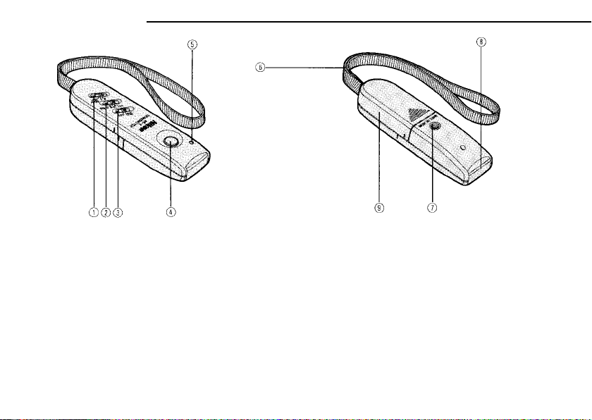
TRANSMITTER
1. Shooting mode selector: S for single-frame
shooting, C for continuous shooting, D/T for
delaying shutter release or checking transmitting
conditions (with channel selector set to A. TRIG)
2. Channel selector (see page 17)
3. Power switch
4. Transmission button: Lightly press to transmit the
signal that activates the camera’s exposure meter
and autofocus functions; fully depress to transmit
the signal that releases the shutter
4
5. Monitor light (battery check/transmission indicator
LED): Lights up for a moment when power switch
is set to ON or transmission button is lightly/fully
pressed; blinks during A.TRIG operation or when
battery power becomes weak
6. Wrist strap
7. Tripod socket
8. Transmission head: Do not cover or obstruct
during transmission
9. Battery chamber: Accepts two AAA-type batteries
(alkaline-manganese or manganese)
Page 5
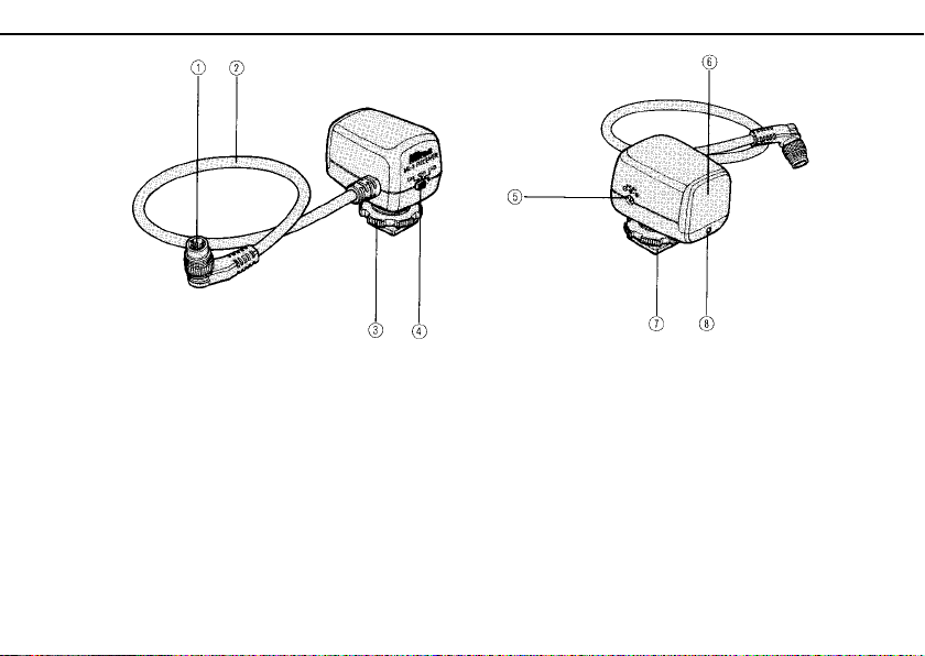
RECEIVER
1. Camera plug
2. Remote cord
3. Mounting foot lock screw: Be sure to tighten firmly
when attaching receiver to the camera or bracket
4. Power/channel selector switch: OFF — power is
off; for A. TRIG, CH1 and CH2, see page 14
5. External power socket for 6V power source (EIAJ
RC-5320)
6. Reception sensor
7. Rotatable shoe foot: Rotates a full 360°
8. Reception indicator LED
5
Page 6
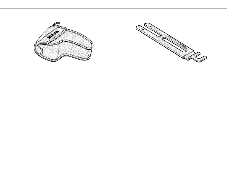
ACCESSORIES
Soft case (provided) Bracket (optional): For use when receiver cannot be
6
mounted on the camera.
Page 7
PREPARATION
Transmitter
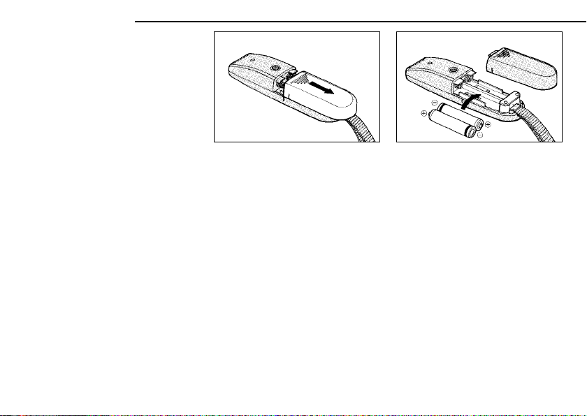
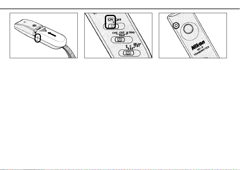
Installing batteries and
checking battery power
Open the battery chamber by
sliding the battery chamber
1.
lid.
• Be sure the transmitter’s
power switch is set to OFF
position.
7
Page 8
Close the battery lid by
sliding it back into place.
3.
8
Set power switch to ON.
If the monitor light comes on for a moment, batteries have
4.
sufficient power.
Page 9
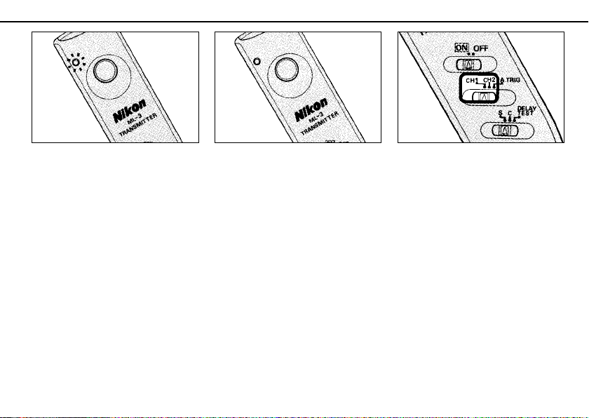
If it blinks, batteries may be
weak.*
* Only with the channel selector
set to CH1 or CH2.
If it does not come on, check
battery installation or replace
batteries with a fresh set.
Set the channel selector to
CH1 or CH2.
5.
9
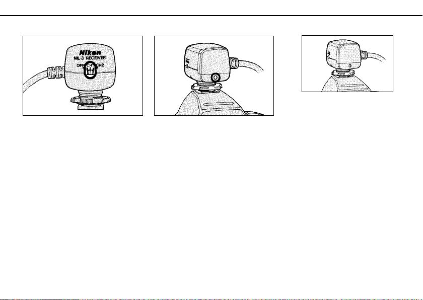
Page 10
Receiver
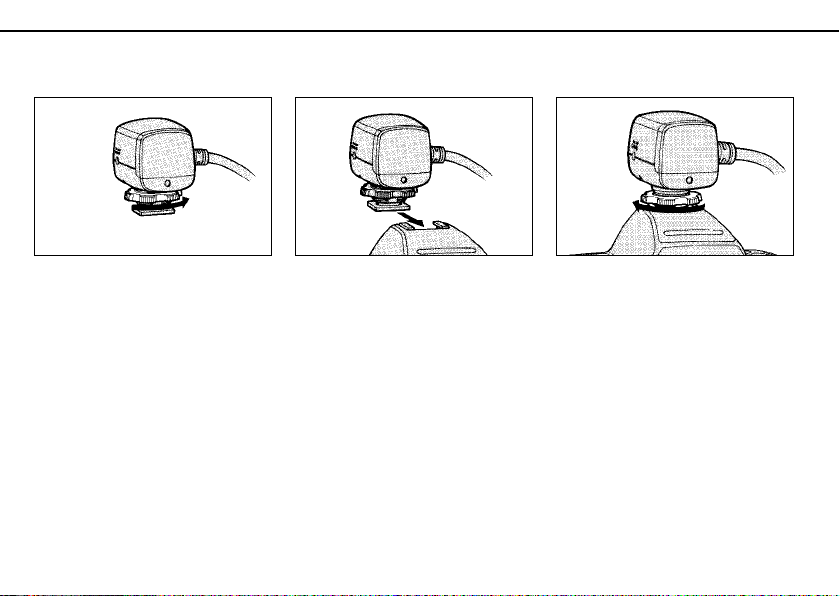
Connecting the receiver to a camera
Using gentle finger pressure,
1.
loosen the mounting foot
lock screw (turn counterclockwise) as far as it goes
without applying force.
10
While firmly holding the
2.
receiver, position the shoe
foot to the camera’s
accessory shoe and slide it
in as far as it goes.
Using finger pressure only,
3.
gently but firmly tighten the
lock screw
Page 11
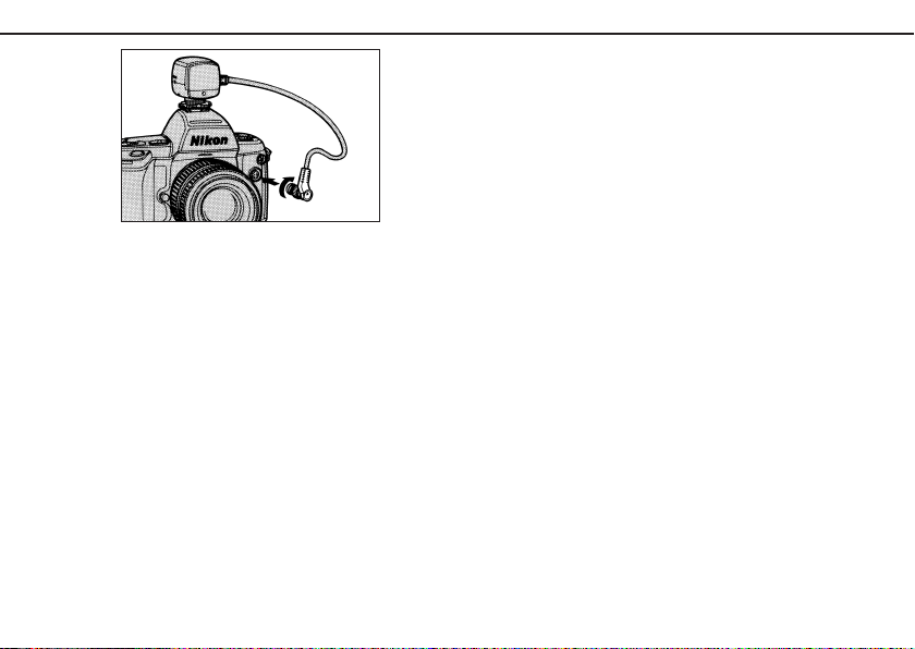
Insert the camera plug into the remote terminal
of the camera with the D symbol on the plug
4.
aligning with the index mark on the camera.
Then screw the threaded ring into the terminal.
Attaching receiver to
bracket (optional)
When shooting with a Speedlight
attached to the camera’s
accessory shoe, attach the
receiver by using the bracket.
11
Page 12

Insert the bracket between
the tripod head and the
1.
camera. Then, screw the
tripod’s lock nut firmly to
secure the assembly.
12
Insert the receiver into the
bracket and tighten the lock
2.
screw.
• Make sure the receiver
and/or bracket is not visible
in the viewfinder.
Insert the camera plug into
the remote terminal of the
3.
camera with the D symbol on
the plug aligning with the
index mark on the camera.
Then screw the threaded ring
into the terminal.
Page 13
Battery check
Set the power/channel selector switch to CH1 or CH2 according
to the channel selector setting on the transmitter. (Receiver
1.
operates with either CH1 or CH2 setting when the channel
selector setting on the transmitter is at A. TRIG.)
If the reception indicator LED lights up for a moment, the
camera’s batteries have sufficient power.
If it does not come on, check
camera’s battery installation or
replace camera’s batteries with a
fresh set.
13
Page 14

You should also replace
batteries if the LED starts
blinking after it lights up.
14
Notes:
• Power/channel selector switch setting on the
receiver must coincide with the channel
selector setting on the transmitter. Otherwise,
power does not turn on. (The receiver
operates in either CH1 or CH2 setting when
the channel selector setting on the transmitter
is at A. TRIG.)
• As both transmitter and receiver are
controlled by microprocessors, sometimes
they may fail to operate even with fresh,
correctly installed batteries. In this case, turn
the power switch OFF for a few seconds, then
ON again.
Page 15

Positioning the transmitter
and receiver
When positioning the transmitter
and receiver, check the following
to ensure effective transmission.
• There are no obstacles that
interfere with transmission.
• The receiver’s reception sensor
directly faces the transmitter
head.
15
Page 16

• The receiver’s reception sensor
faces away from the sun.
16
• When using the ML-3 at the
same time as video recording
equipment, do not point the
video’s remote commander in
the direction of the ML-3
reception sensor; it could cause
a malfunction.
• Harsh conditions, such as bad
weather, obstructions, etc., may
shorten the effective distance
range.
Page 17

Distance range Channel selector setting
Set each corresponding
transmitter/receiver pair to the
same channel. Up to two ML-3
sets can be used in the same area
without interference.
• If the transmitter is not pointed directly at the
receiver (if the angle is askew), the range changes
as follows:
0° — approx. 8m (26.2 ft.)
0-10° — approx. 6m (19.7 ft.)
17
Page 18

Camera settings
Be sure to adjust the camera settings before
operation.
Recommended camera settings are:
Focus modes: C or M
Film advance modes/release modes: CL or CH
Exposure modes: Programmed auto (q/t),
Aperture-Priority Auto or ShutterPriority Auto (see camera’s
instruction manual) exposure
mode.
Note:
When exposure is set to auto mode, use the
eyepiece shutter to prevent incorrect
exposure caused by light leaking through
the finder.
18
OPERATION
The ML-3 offers a choice of shooting modes:
• S: Single release mode
• C: Continuous release mode
• DELAY/TEST: Delay mode
• DELAY/TEST (in A.TRIG operation): Test mode
Page 19

Single frame shooting (S)
Set shooting mode selector
on the transmitter to S.
1.
• If the camera’s focus mode
is set to S, the camera may
not focus correctly when
the transmission button is
pressed lightly.
Be sure to set the camera’s
focus mode to C.
• Depending on the shooting
situation, set the camera’s
focus mode to M. In this
case, be sure to adjust
manually before
focus
shooting.
Point the transmitter in the direction of the reception sensor and
lightly press the transmission button. The monitor light on the
2.
transmitter will light up for a moment. Then, the reception indicator
LED also lights up for a moment and the camera’s exposure meter
turns on. In the autofocus mode, focus detection starts
immediately.
If a connected Speedlight is set at STBY (standby), it also turns on.
19
Page 20

Fully depress the transmission button.
The reception indicator LED will light up for a moment and one
3.
picture will be taken. Avoid changing the direction of the
transmitter while shooting.
20
Page 21

Continuous frame shooting (C)
Set the transmitter’s
shooting mode selector to C.
1.
• If the camera’s focus mode
is set to S, the camera may
not focus correctly when
the transmission button is
pressed lightly.
Be sure to set the camera’s
focus mode to C.
• Depending on the shooting
situation, set the camera’s
focus mode to M. In this
case, be sure to adjust
manually before
focus
shooting.
Point the transmitter in the direction of the reception sensor and
lightly press the transmission button. The monitor light on the
2.
transmitter will light up for a moment. Then, the reception indicator
LED also lights up for a moment and the camera’s exposure meter
turns on. In the autofocus mode, focus detection starts
immediately.
If a connected Speedlight is set at STBY (standby), it also turns on.
21
Page 22

Fully depress the transmission button. Pictures are taken
continuously as long as the transmission button is fully depressed.
3.
The reception indicator LED also lights up continuously to indicate
that pictures are being taken. Avoid changing the direction of the
transmitter while shooting.
22
To stop taking pictures,
remove your finger from the
4.
transmission button.
Page 23

Delay triggering
In this mode, shutter release occurs approx. 3
seconds after you fully depress the transmission
button so you can include yourself in the picture or
change positions, or recompose the picture.
Set the shooting mode selector to
DELAY/TEST.
1.
• If the camera’s focus mode is set to S, the
camera may not focus correctly when the
transmission button is pressed lightly.
Be sure to set the camera’s focus mode to C.
• Depending on the shooting situation, set the
camera’s focus mode to M. In this case, be
sure to adjust focus
manually before shooting.
23
Page 24

Point the transmitter in the direction of the
reception sensor and lightly press the
2.
transmission button. The monitor light will light
up for a moment.
The reception indicator LED lights up for a
moment and the camera’s exposure meter turns
on. If the camera’s focus mode is set to C,
focus detection starts immediately.
24
Fully depress the transmission button. It takes
approx. 3 seconds to take a picture.
3.
The reception indicator LED starts blinking
rapidly and continues blinking until a picture is
taken.
• To cancel operation during a delayedshooting interval, set the receiver’s
power/channel selector switch to OFF.
Pre-shooting focus detection: A focus
detection signal is not sent during the delayedshooting interval. Be sure to lightly press the
transmission button to secure focus before
actual shooting.
Page 25

Auto triggering
In this mode, the shutter is
released when the subject enters
the area directly between the
transmitter and the receiver,
without the transmission button
being pressed. This mode is
useful when you want to take a
picture, for example, of a wild
animal that is sensitive to human
presence.
Test mode
Before Auto Triggering operation,
shooting in the Test mode, which
verifies transmitter-to-receiver
communication, is recommended.
Set the transmitter’s channel
1.
selector to A. TRIG.
• In the Test mode, always
mount the receiver on the
camera or a tripod.
25
Page 26

Auto triggering operation
Set the shooting mode
2.
selector to DELAY/TEST.
26
Point the transmitter toward
3.
the receiver and block
infrared ray with your hand.
If the reception indicator LED
lights up for a moment, the
units are working correctly.
• If the reception indicator
LED blinks after lighting up,
battery power is exhausted.
Replace camera batteries.
Set the camera’s focus mode
to M and the film advance
1.
mode/release mode to CL or
CH.
Page 27

Set the transmitter’s
shooting mode to S or C.
2.
Set the receiver’s
3.
power/channel selector
switch to CH 1 or CH2.
Set camera, transmitter and
receiver on tripods as
4.
illustrated.
• Use optional Extension
Cord MC-21 (3m or 9.8 ft.)
to extend the connection
between the camera and
ML-3. Up to three MC-21
cords can be joined
together.
27
Page 28

Adjust focus manually
according to estimated
5.
subject position between the
transmitter and receiver.
• To ensure clearly focused
picture(s): (1) adjust focus
(and depth of field if
possible), to cover the area
where subject will cross the
infrared ray, (2) choose an
appropriate shutter speed
to freeze subject motion, (3)
consider the subject’s
shape and movement when
positioning the camera and
ML-3 units.
28
Set the transmitter’s channel
selector to A. TRIG.
6.
The monitor light starts
blinking and the shutter is
released automatically when
the subject enters the preset
focused point.
• To cancel operation at any
time, set the transmitter’s
channel selector to CH2 or
the receiver’s
power/channel selector
switch to OFF.
• Unclear pictures may result
from one or more factors
related to subject movement, such as crossing the
infrared ray too fast, crossing at an unfocused area or
from an unexpected direction, etc.
• With the transmitter’s
shooting mode selector set
to C, 2-second-continuous
shooting is possible.
• With the MF-26’s AutoSequence Shooting
function, 2-secondcontinuous shooting is
possible.
Page 29

Transmitter, receiver and camera indications
Transmitter Receiver
Channel selector Shooting mode
S focus detection on
CH1 or CH2
A. TRIG C
C focus detection on
DELAY
S
TEST
Transmission button
selector/Monitor light
Lightly pressed Lights up for a moment
Fully depressed Lights up for a moment Single release
Lightly pressed Lights up for a moment
Fully depressed Lights up continuously Continuous shooting
Lightly pressed Lights up for a moment
Fully depressed
Monitor light
continuously blinks enters prefocused position
Monitor light
continuously blinks enters prefocused position
Monitor light
continuously blinks
LED
Blinks for 3 sec. and lights up Single release after
for 0.4 sec. after shutter releases approx. 3 sec.
Lights up for a moment
Lights up for 2 sec
Lights up for a moment None
. Continuous release when subject
Camera
Exposure meter on;
Exposure meter on;
Exposure meter on;
focus detection on
Single release when subject
29
Page 30

WIRELESS FLASH OPERATION
When preparing for shooting, turn
Speedlight power on by lightly
pressing the transmission button.
For extended operation,
speedlights with standby
positions are recommended.
30
Attach the Speedlight to the
camera. Then, attach camera
1.
to the tripod with the bracket
in between.
Attach the receiver to the
bracket.
2.
Page 31

Connect the receiver’s
camera plug to camera’s
3.
remote terminal.
Set the Speedlight’s power
switch to STBY.
4.
Start shooting. For details on
flash shooting, see
Speedlight instruction
manual.
• Be sure to lightly press the
transmission button a few
seconds before triggering
to allow for Speedlight
power recharge.
• In continuous shooting,
make sure the
Speedlight’s firing intervals
are brief.
31
Page 32

TIPS ON CARE
• Avoid external shock.
• Avoid leaving in a hot or humid
place.
32
• Avoid water. • Do not disassemble.
• Avoid using where strong
magnetic or electric waves are
discharged (e.g., near TV tower).
Malfunction may result.
Page 33

Cleaning:
• Clean with a soft, clean cloth or blower
brush.
• After use near the sea, wipe equipment
first with a water-moistened soft cloth. Do
not use benzine or thinner.
Storage:
• When the transmitter is not in use, turn it
off. If you do not plan to use it soon,
remove the batteries.
• Protect from rust and mold by storing
equipment in a cool, dry place. Also, do
not store in direct sunlight, and keep it
away from naphthalene or camphor.
In a humid environment, store equipment
in a vinyl bag with a desiccant to keep out
dust, moisture and salt.
• Keep equipment away from other
electrical equipment such as radios or TV
sets.
ABOUT BATTERIES
New batteries
Puchase the freshest batteries possible.
Battery brand
Do not mix battery brands or use batteries with
different model numbers. Avoid mixing new and old
batteries.
Temperature
Battery life ratings are based on operation at around
20°C (68°F). At other temperatures battery life and
shooting range will be shortened. Have spare batteries
on hand if you anticipate using the equipment at low
temperatures.
Continuous frame shooting
For optimum results in continuous frame shooting,
always use fresh batteries. Alkaline-manganese
batteries are recommended.
Storage
To minimize power drainage, store batteries in a cool,
dry place with a temperature below 20°C (68°F).
Keep batteries out of children’s reach. If someone
accidentally swallows batteries, call a doctor
immediately.
Disposal
Do not dispose of batteries by burning, and never
disassemble them.
33
Page 34

SPECIFICATIONS
Transmitter and receiver
Modulation system Infrared communication
Range (Single- Approx. 8m (26.2 ft.)along the
frame shooting) optical axis
Number of control
output channels
Shooting modes S for single-frame shooting
Operating temperature
34
Approx. 6m (19.7 ft.) with a
light reception angle of 10°
Two channels available —
CH1, CH2
C for continuous shooting
DELAY for 3 sec. delayed
shooting
TEST for operation check in
A. TRIG mode
–20°C ~ 60°C (–4°F ~ 140°F)
Transmitter
Continuous Approx. 72 hours with in
standby time A.TRIG mode (alkaline-
Transmission Infrared rays
Number of output Three channels (CH1, CH2 and
channels A. TRIG)
Shooting modes S, C, DELAY/TEST
Transmission button Lightly pressing the button
Battery power check With sufficient battery power,
Power source Two AAA-type alkaline-
Others Tripod mounting socket (1/4
Dimensions 117(W) x 22(H) x 30(D)mm
Weight (excluding
batteries)
manganese battery)
activates the camera’s
exposure meter and autofocus
operation; fully depressing the
button releases the shutter
monitor light comes on for a
moment
With weak battery power and
channel selector set to CH1 or
CH2, monitor light blinks
manganese or high-rate
manganese batteries
in.), wriststrap
4.6(W) x 0.9(H) x1.2(D)in.
40g (1.4oz.)
Page 35

Receiver
Power/channel
switch CH1 or CH2 and OFF
Number of input
channels Two channels (CH1 and CH2)
Power source Supplied from D3-Series, D2-Series,
D1-Series, D700, D300, D200, D100 +
MB-D100, F6, F5, F100, F90X/N90s or
F90-Series/N90 camera body; 6V
external power source socket provided
(for EIAJ RC-5320)
Remote cord Approx. 28cm (11in.)
Shoe foot Rotates 360°
Battery power check With sufficient battery power, reception
indicator LED lights up for a moment
With weak battery power, reception
indicator LED blinks
Compatibility with Accepts ML-2’s CH1, CH2, ALL, TEST
ML-2 and DELAY mode signals
Dimensions 50(W) x 36(H) x 47(D)mm
2.0(W) x 1.4(H) x 1.9(D)in.
Weight 51g (1.8oz.)
All specifications apply when fresh alkaline batteries are
used, at normal temperature (20°C or 68°F).
Specifications and designs are subject to change without
notice.
35
Page 36

No reproduction in any form of this manual, in whole
or in part (except for brief quotation in critical articles
or reviews), may be made without written
authorization from NIKON CORPORATION.
N
NIKON CORPORATION
FUJI BLDG., 2-3, MARUNOUCHI 3-CHOME, CHIYODA-KU, TOKYO 100-8331 JAPAN
Printed in Japan KL9D16 (11)
8MEFRW29-16
 Loading...