

Page 1
VBA24001-R.3783.A
M
サービス
計画課
INC
作成承認印 配布許可印
VBA24001
REPAIR MANUAL
Printed in Japan APRIL.2009
Copyrightc2009 by Nikon Corporation.
All Rights Reserved.
無断転載を禁ず
!!
Page 2

VBA24001-R.3783 .A
INC
CONTENTS
Points to notice for Disassembly and Assembly ......................................................................................................................D1
Disassembly ................................................................................................................................................................................D2
1. External section ...............................................................................................................................................................D2
Bottom cover ..................................................................................................................................................................D2
Removal of back cover ..................................................................................................................................................D4
2. Back cover ........................................................................................................................................................................D6
Sponge/Button/FPC/Speaker ....................................................................................................................................... D8
SD cover unit ............................................................................................................................................................... D10
SD cover ........................................................................................................................................................................ D11
TFT monitor unit .......................................................................................................................................................D12
3. Front cover .....................................................................................................................................................................D18
Pop-up of Flash unit (SB) ...........................................................................................................................................D18
Front cover ................................................................................................................................................................... D18
4. Top cover ........................................................................................................................................................................ D19
TOGO PCB unit ..........................................................................................................................................................D19
Removal of top cover ................................................................................................................................................... D20
SB upper cover ............................................................................................................................................................D21
lower control unit..................................................................................................................................................D22
SB
SB release base unit .................................................................................................................................................... D24
AF-assist lamp unit ...................................................................................................................................................... D24
Power SW FPC unit .................................................................................................................................................... D25
Release button unit
C/D unit ....................................................................................................................................................................... D26
Top cover FPC unit .....................................................................................................................................................D26
Mode dial unit / AF/AE-L button / Delete button / AF-assist lamp window .........................................................D27
Hot shoe ........................................................................................................................................................................D27
5. Image sensor ...................................................................................................................................................................D28
SZ-DC/DC PCB unit .................................................................................................................................................. D28
Image sensor unit .........................................................................................................................................................D28
6. Separation of Front body from Rear Body .................................................................................................................D29
Bottom base unit .......................................................................................................................................................... D29
/ each button, etc ....................................................................................................................... D25
7. Rear body ....................................................................................................................................................................... D32
Microphone .................................................................................................................................................................D32
Main condenser ...........................................................................................................................................................D32
SB PCB unit ................................................................................................................................................................. D33
DC/DC PCB unit ........................................................................................................................................................D34
Battery box .................................................................................................................................................................. D35
Eyelet unit, etc ............................................................................................................................................................D36
8. Front body ...................................................................................................................................................................... D37
Shutter ........................................................................................................................................................................D37
- D5000 -
Page 3

Meterring FPC unit .................................................................................................................................................... D38
INC
VBA24001-R.3783 .A
Eyepiece barrel unit ...................................................................................................................................................D38
Penta unit ....................................................................................................................................................................D39
SI unit ..........................................................................................................................................................................D40
Relay PCB unit ...........................................................................................................................................................D42
Removal of bayonet .....................................................................................................................................................D43
Lens contact unit .........................................................................................................................................................D43
SQ base unit ................................................................................................................................................................. D45
AF sensor unit ............................................................................................................................................................. D46
Inside finder LCD unit ............................................................................................................................................... D46
plate ..............................................................................................................................................................................D47
Release button unit ..................................................................................................................................................... D47
F-min SW section .........................................................................................................................................................D48
Mirror unit/Aperture lever section ............................................................................................................................D48
Assembly/Adjustment ...............................................................................................................................................................A1
1. Front body ....................................................................................................................................................................... A1
Mirror unit .................................................................................................................................................................... A1
Aperture lever section ...................................................................................................................................................A2
Spring hooking position ................................................................................................................................................A2
F-min SW section ...........................................................................................................................................................A3
Release button unit ....................................................................................................................................................... A3
plate ...............................................................................................................................................................................A4
Inside finder LCD unit ................................................................................................................................................. A4
AF sensor unit ............................................................................................................................................................... A5
SQ PCB unit .................................................................................................................................................................. A5
Lens contact unit ..........................................................................................................................................................A7
Mounting of bayonet .................................................................................................................................................... A8
Height adjustment of Aperture lever
Relay-PCB unit .........................................................................................................................................................A10
SI unit ..........................................................................................................................................................................A11
Attachment position for Finder field frame ............................................................................................................A12
Penta unit ....................................................................................................................................................................A14
.......................................................................................................................... A9
Eyepiece barrel unit ...................................................................................................................................................A15
AE FPC unit ................................................................................................................................................................ A15
adjustment of Main mirror and Sub-mirror ........................................................................................................... A16
Shutter .........................................................................................................................................................................A25
2. Rear body ....................................................................................................................................................................... A26
Eyelet unit, etc ............................................................................................................................................................A26
Battery box .................................................................................................................................................................. A27
DC/DC PCB unit ........................................................................................................................................................A29
SB PCB unit ................................................................................................................................................................. A30
Main condenser ...........................................................................................................................................................A31
- D5000 -
Page 4

Microphone .................................................................................................................................................................A31
INC
VBA24001-R.3783 .A
3. Assembly of front body into rear body ........................................................................................................................A32
Bottom base unit .......................................................................................................................................................... A33
Inspection and Adjustment of Body back ................................................................................................................A34
4. Image sensor ...................................................................................................................................................................A38
Sponge ..........................................................................................................................................................................A38
Image sensor unit ........................................................................................................................................................A38
SZ-DC/DC PCB unit .................................................................................................................................................. A39
5. Top cover ........................................................................................................................................................................ A40
Hot shoe ........................................................................................................................................................................A40
AF-assist lamp unit & AF/AE lock button ................................................................................................................ A40
Mode dial unit & Delete-button-rubber SW ............................................................................................................. A41
Top cover FPC unit .....................................................................................................................................................A41
C/D unit ....................................................................................................................................................................... A42
Release button unit
Power SW FPC unit .................................................................................................................................................... A43
AF-assist lamp unit ...................................................................................................................................................... A44
SB release base unit .................................................................................................................................................... A44
lower control unit..................................................................................................................................................A45
SB
SB upper cover ............................................................................................................................................................A48
Top cover .....................................................................................................................................................................A49
TOGO PCB unit ..........................................................................................................................................................A50
Inspection and adjustment of AE CCD positioning ................................................................................................A51
Discharge of main condenser .....................................................................................................................................A52
6. Front cover .....................................................................................................................................................................A53
Gap adjustment of SB (ash unit) section ..................................................................................................................A53
7. Back cover .....................................................................................................................................................................A54
TFT monitor unit .......................................................................................................................................................A54
Back cover ...................................................................................................................................................................A61
Sponge/button/FPC/Speaker ......................................................................................................................................A62
SD cover .......................................................................................................................................................................A65
/ each button, etc ....................................................................................................................... A43
SD cover unit ............................................................................................................................................................... A66
8. External appearance .....................................................................................................................................................A68
Accuracy inspection and adjustment (Camera body excl. imaging) ....................................................................A69
D5000 Inspection and Adjustment Software (J65135) ............................................................................................. A70
Procedure for installation ...........................................................................................................................................A71
Procedure for installing USB driver .......................................................................................................................... A74
Necessary adjustments when parts are replaced ...................................................................................................... A76
Firmware update .........................................................................................................................................................A77
AE inspection and adjustment ...................................................................................................................................A84
AF inspection and adjustment ....................................................................................................................................A86
Bottom cover ................................................................................................................................................................A90
Shooting-image Adjustment .......................................................................................................................................A91
- D5000 -
Page 5

Shooting image adjustment software and Software updates ...................................................................................A92
INC
VBA24001-R.3783 .A
Image adjustment ........................................................................................................................................................A93
∞ Infinity focus inspection & adjustment ............................................................................................................... A97
Measurement of Consumption current value ...........................................................................................................A98
Cleaning between Penta unit and SI-LCD ................................................................................................................A99
Operation check of cleaning image sensor ..............................................................................................................A100
Hinge SW inspection ................................................................................................................................................. A103
Main/sub mirror angle inspection tool - use chart .................................................................................................A104
Wiring ......................................................................................................................................................................................... E1
Mounting Drawing .................................................................................................................................................................... E2
Inspection standards .................................................................................................................................................................. R1
Tools ............................................................................................................................................................................................T1
Screw sheet ..................................................................................................................................................................................S1
- D5000 -
Page 6

Points to notice for Disassembly and Assembly
WARNING
There are high voltege parts inside. Be careful of this electric shock,
when you remove the cover.
You must discharge the main condenser according to the instruction
of this repair manual after you remove the cover.
!
INC
Caution:
① In disassembly/(re)assembly, be sure to use conductive mat (J5033) and wrist strap (J5033-5), in
order to protect electric parts from static electricity.
VBA24001-R.3783.A
② Before disassembling, be sure to remove batteries or AC power cord.
③ In disassembling, be sure to memorize the processing state of wires and FPC, screws to be fixed and
their types, etc.
④ The low-pass filter of the image PCB/base plate is easily damaged. Handle it very carefully.
Points to notice for Lead-free solder products
・ Lead-free solder is used for this product.
・ For soldering work, the special solder and soldering iron are required.
・ Do NOT mix up lead-free solder with traditional solder.
Caution:
When "Separation of Front body from Rear body", "Disassembly of Image sensor unit"
and "Disassembly of Bayonet" are performed, be sure to carry out "RESET AF-DEFOCUS
COMPENSATION" of the D5000 adjustment software after assembly.
- D1 ・ D5000 -
Page 7
Disassembly
INC
1. External section
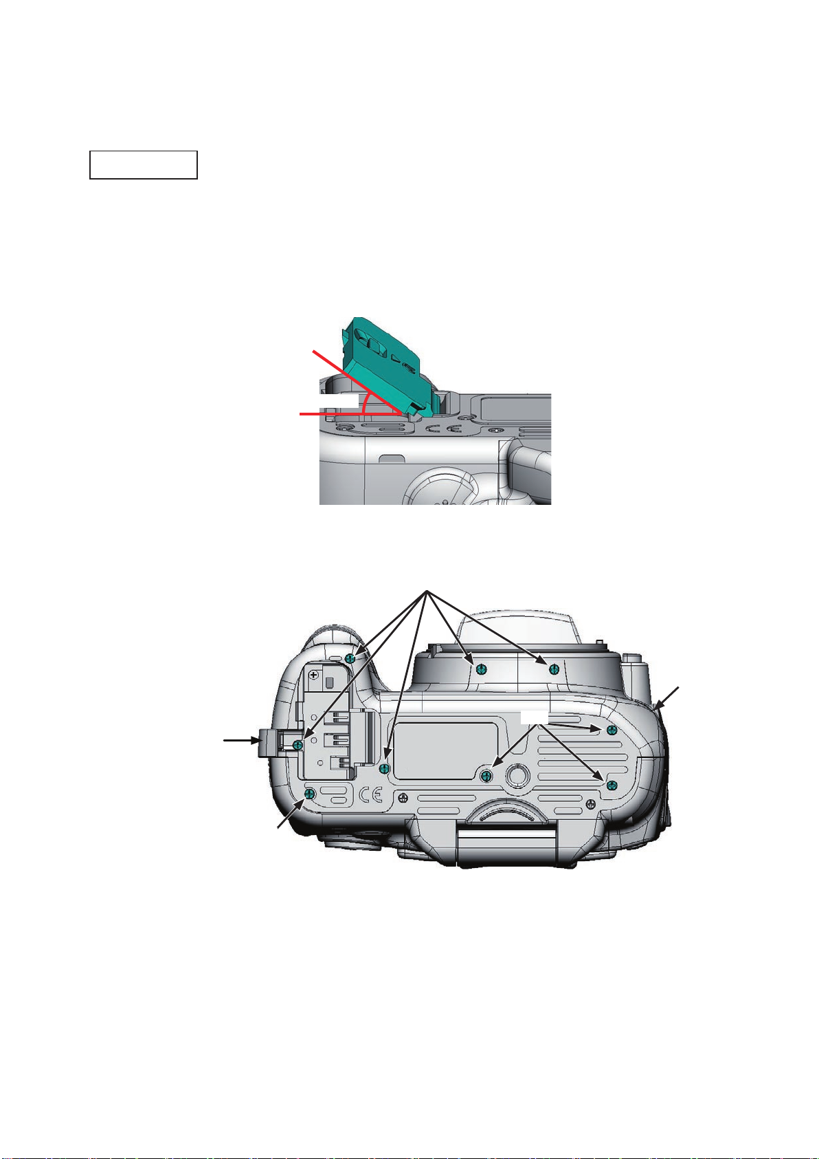
Bottom cover
・ Open and tilt the battery cover unit (#B151) at approx. 35° angle, then pull it out at the angle.
・ Open the power cable cover.
・ Take out the four screws (#735) and five screws (#671).
・ Remove the bottom cover (#25).
Approx. 35°
VBA24001-R.3783.A
Power cable cover
#671
#25
#735
#735
- D2 ・ D5000 -
Page 8
VBA24001-R.3783.A
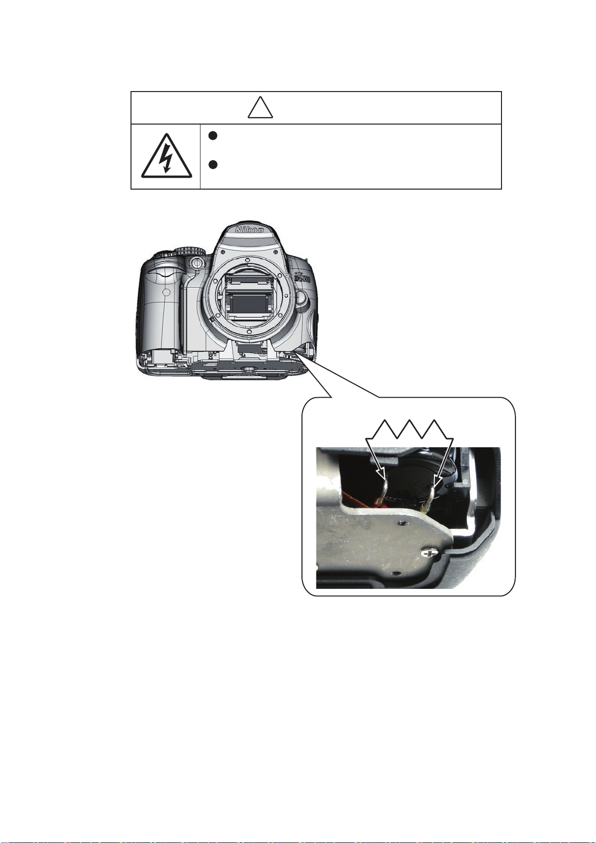
WARNING
There are high voltege parts inside. Be careful of this electric shock,
when you remove the cover.
You must discharge the main condenser according to the instruction
of this repair manual after you remove the cover.
!
INC
2K Ω /5W
- D3 ・ D5000 -
Page 9
VBA24001-R.3783.A
INC
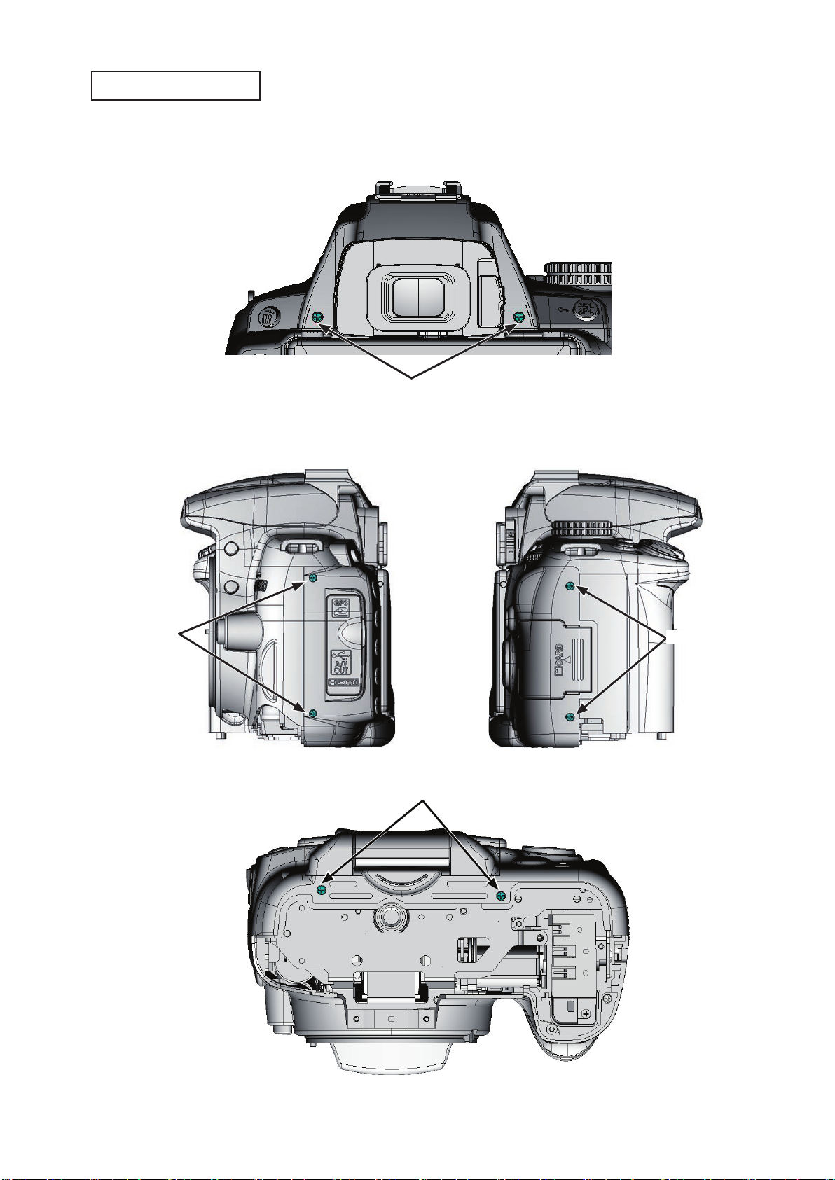
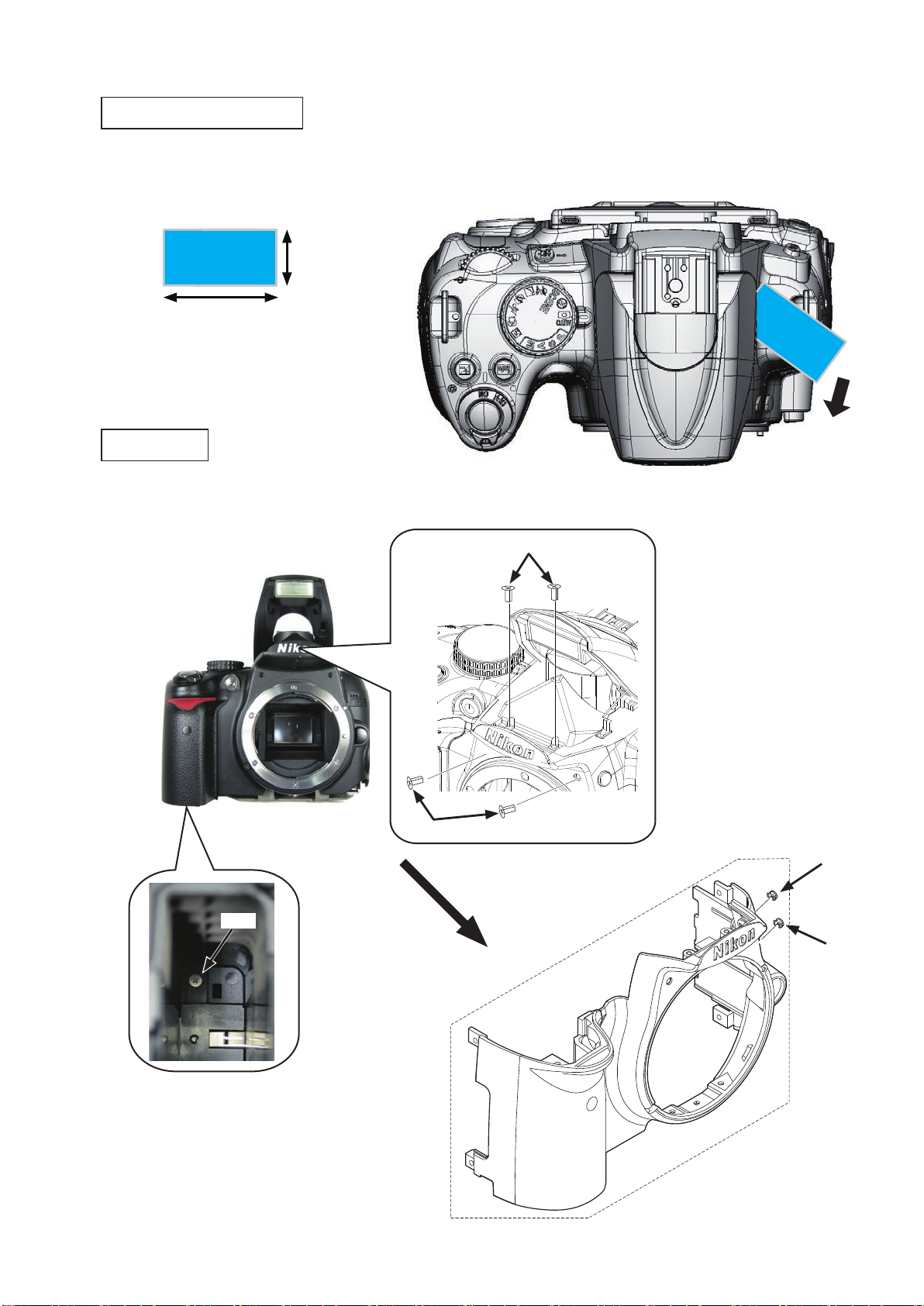
Removal of back cover
・ Take out the two screws (#618), the two screws (#690), the two screws (#697) and two screws (#740).
#618
#697
#690
#740
- D4 ・ D5000 -
Page 10
VBA24001-R.3783.A
INC
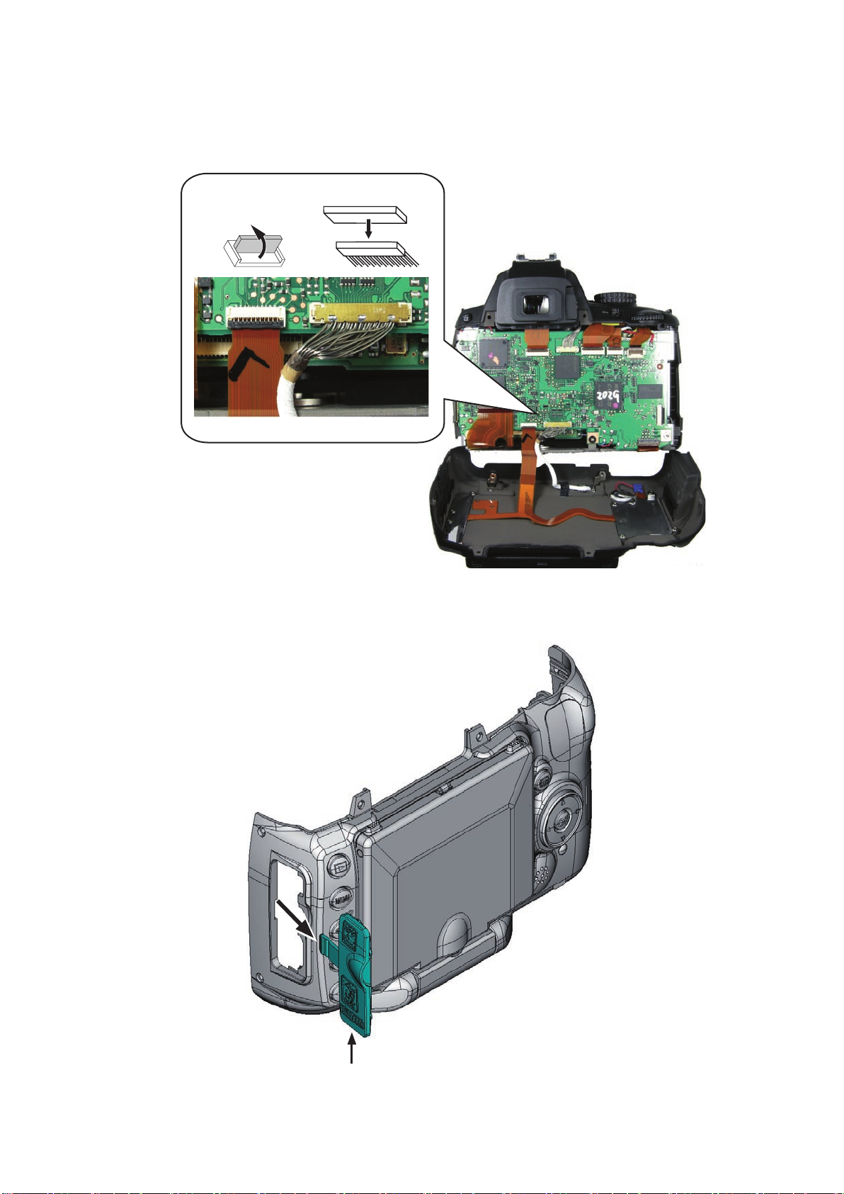
・ Remove the cover by lifting it at the grip side first, and then the whole.
・ Disconnect the FPC and harness (of the rear cover) from the connectors of the TOGO PCB UNIT(#B2001).
Remove the IF cover (#71).
・
#71
- D5 ・ D5000 -
Page 11
2. Back cover
INC
・ Peel off the tape (#705).
#705
・ Take out the two screws (#741).
・ Remove the hinge rear cover A (#445) and hinge rear cover B (#446).
#741
VBA24001-R.3783.A
#446
#445
- D6 ・ D5000 -
Page 12
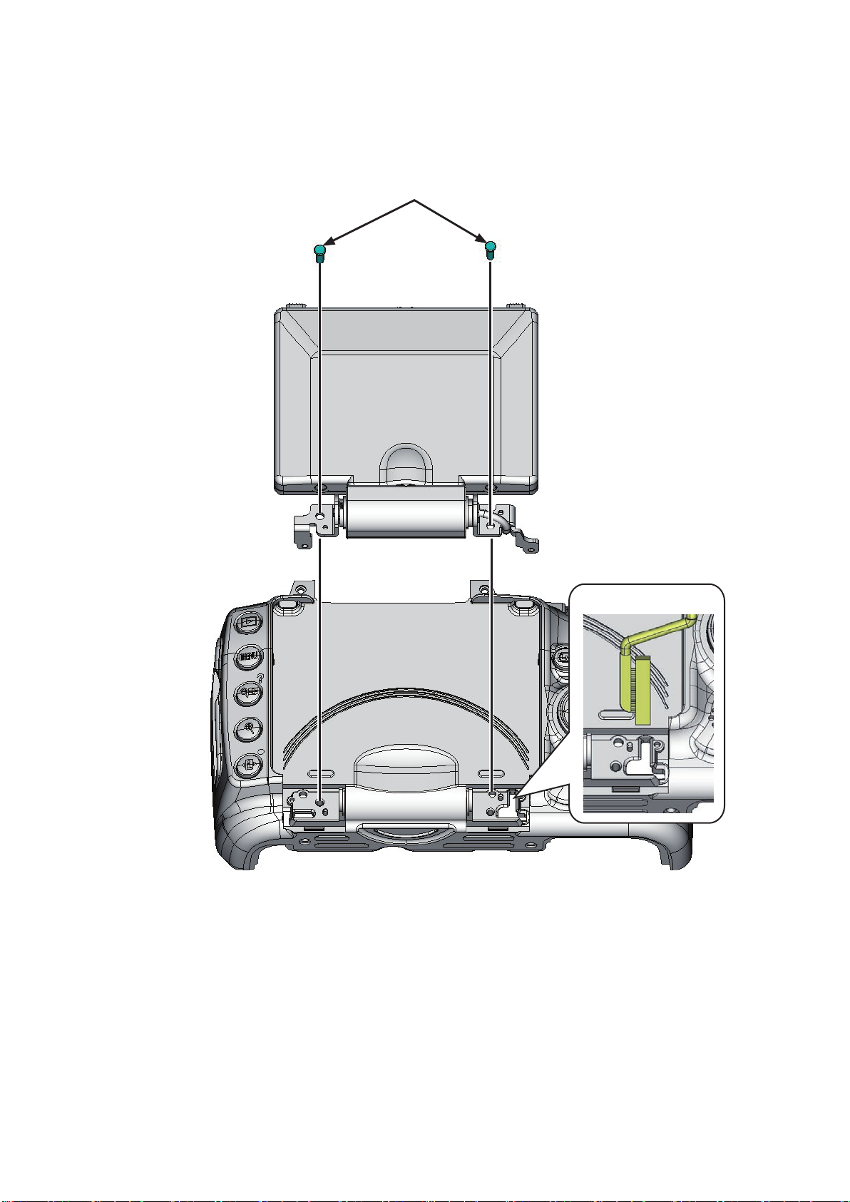
・ Take out the two screws (#682).
INC
・ Remove the TFT monitor unit from the back cover.
(When removing this, be careful not to catch the harness.)
#682
VBA24001-R.3783.A
Be careful NOT to catch.
- D7 ・ D5000 -
Page 13
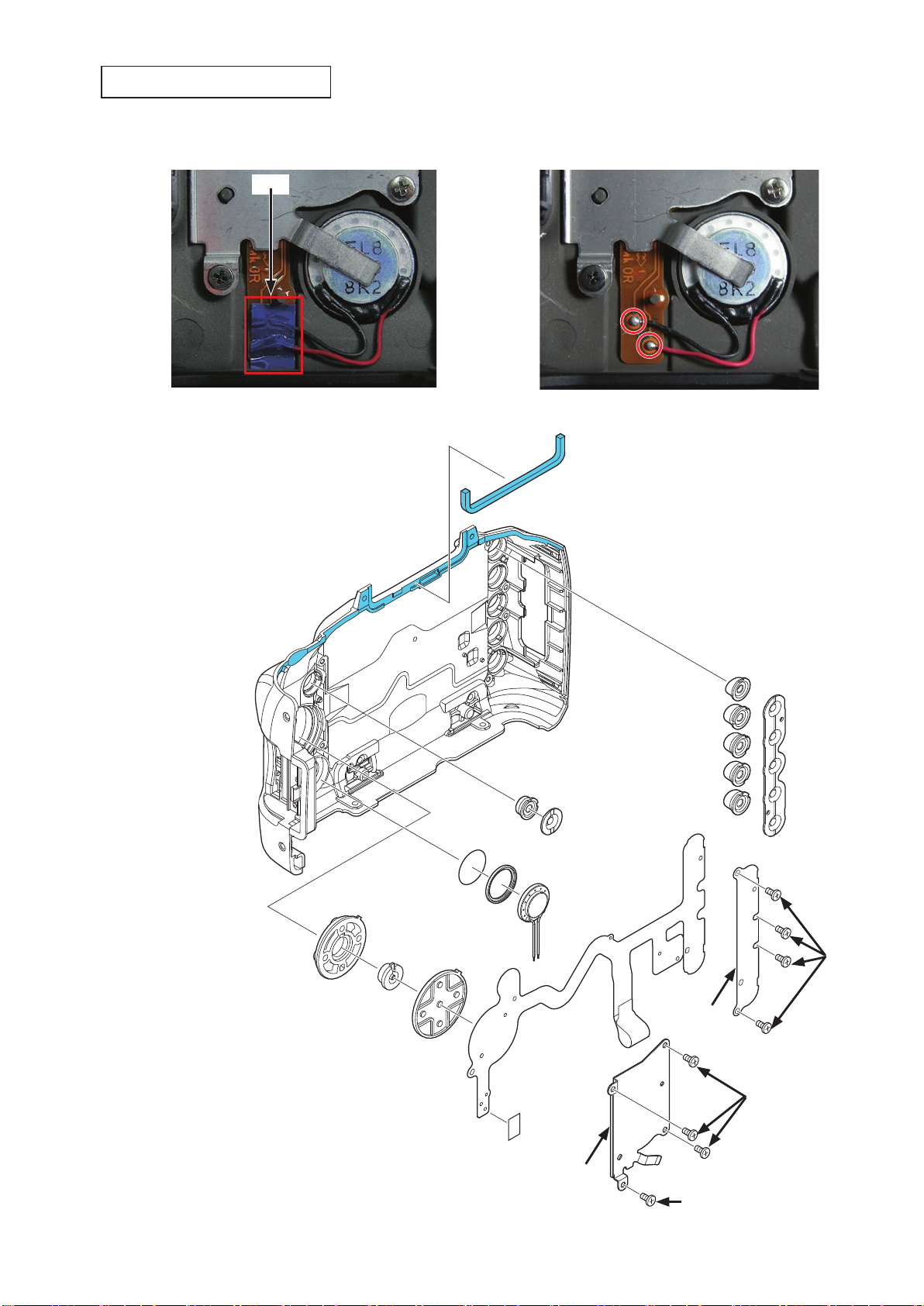
Sponge/Button/FPC/Speaker
INC
・ Peel off the tape (#707).
・ Unsolder the speaker (#1047).
#707
VBA24001-R.3783.A
#478
#412
#418
#413
#475
#474
#471
#472
#1047
#B1019
#424
#425
#426
#427
#422
#419
#421
#683
#683
#707
#415
#729
- D8 ・ D5000 -
Page 14
・ Peel off the tape (#477).
INC
・ Peel off the tape (#706).
・ Remove the superglue from the SD access lamp window (#408), and remove [#408].
#408
Adhesive: Superglue
VBA24001-R.3783.A
#706
#477
・ Remove the two rubbers (#473).
・ Remove the rubber (#469).
・ Peel off the double-stick tapes (#470 and #476).
#473
#469
#470
#476
- D9 ・ D5000 -
Page 15
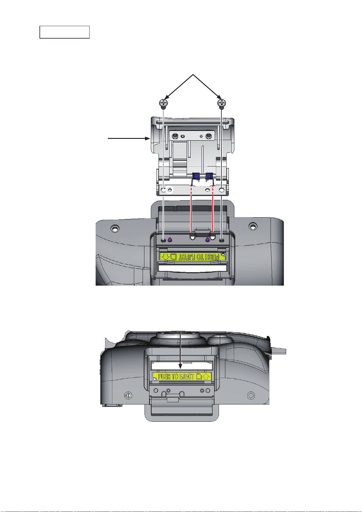
SD cover unit
INC
・ Take out the two screws (#684).
・ Remove the SD cover unit (#B443).
#B443
VBA24001-R.3783.A
#684
・ Peel off the label (#448).
#448
- D10 ・ D5000 -
Page 16
VBA24001-R.3783.A
INC
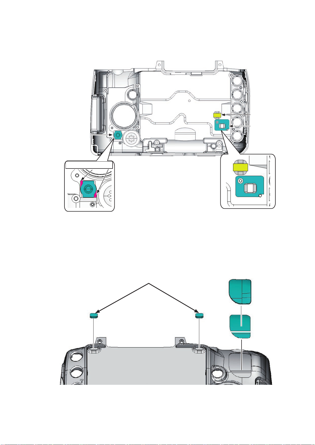
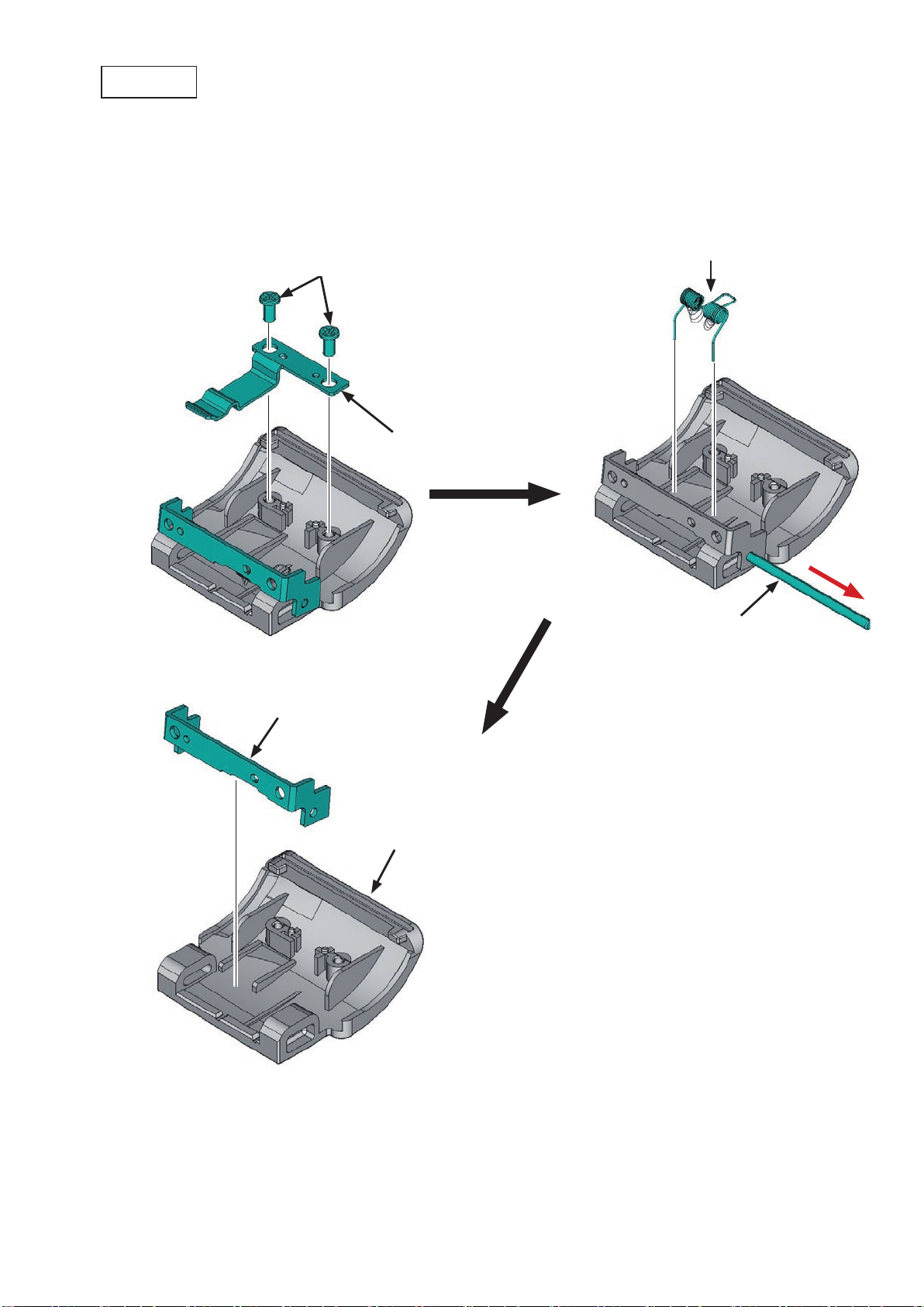
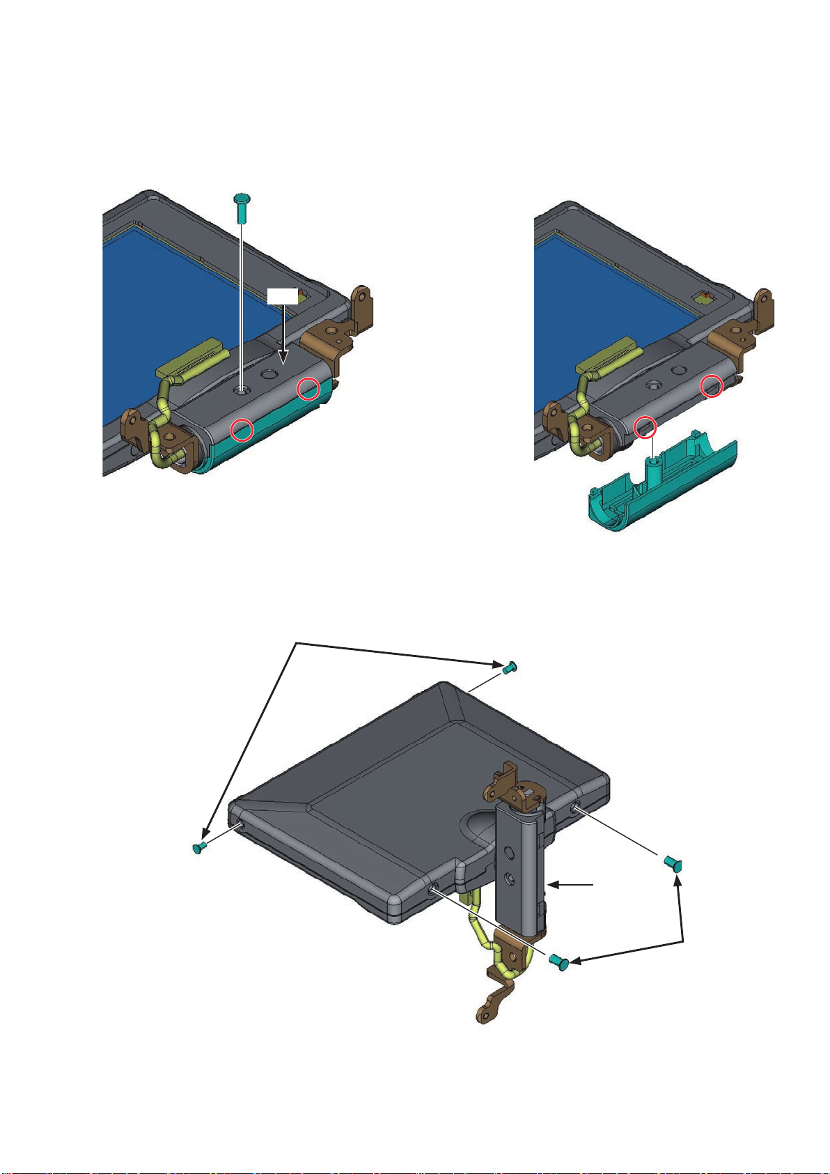
SD cover
・ Take out the two screws, and remove the SD-cover click spring.
・ Pull out the shaft, and remove the SD-cover torsion spring. (Be careful NOT to lose the spring.)
・ Remove the plate from the SD cover (#443).
SD-cover torsion spring
Screw
SD-cover click spring
Plate
Shaft
#443
- D11 ・ D5000 -
Page 17
VBA24001-R.3783.A
INC
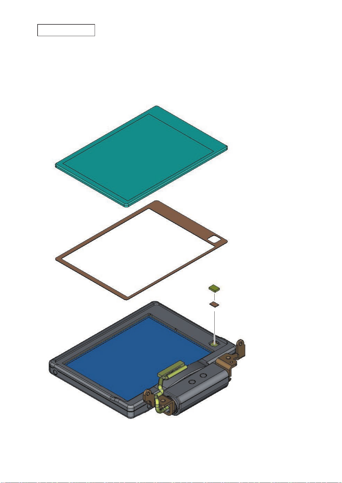
TFT monitor unit
・ Remove the TFT window (#402), and peel off the TFT window double-sticking tape (#403).
・ Remove the sensor magnet (#490) from the TFT monitor unit (#B2049).
・ Remove the magnet spacer (#494) from the sensor magnet (#490).
#402
#403
#B2049
#490
#494
- D12 ・ D5000 -
Page 18
VBA24001-R.3783.A
INC
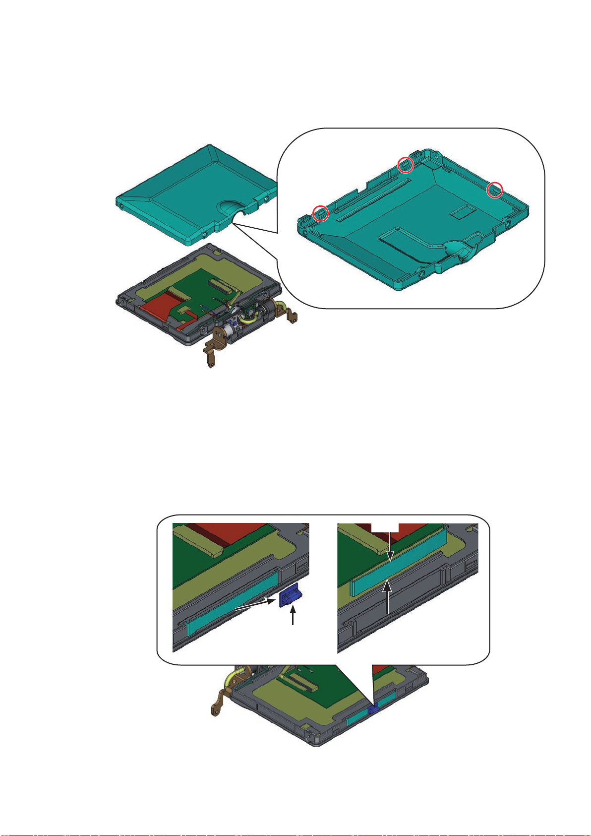
・ Take out the screw (#671).
・ Release the two inside hooks of the hinge bottom cover (#438), and remove the hinge top cover (#437).
(Caution : must be exercised that each part do not get scratched or dented. If it does, use a new one.)
#671
#438
Unhook here
#437
・ Position [#B454] as below, and take out the two screws (#673) and two screws (#674).
#673
Unhook here
#B454
#674
- D13 ・ D5000 -
Page 19
VBA24001-R.3783.A
INC
・ Release the three hooks, and remove the TFT top cover (#434).
[When removing this, be careful NOT to lose the lock-plate spring (#432) and lock knob (#431).]
(Caution : must be exercised that each part does not get scratched or dented. If it does, use a new one.)
Back
#434
・ Remove the lock knob (#431).
・ Remove the lock-plate spring (#432).
#432
#431
- D14 ・ D5000 -
Page 20
VBA24001-R.3783.A
INC
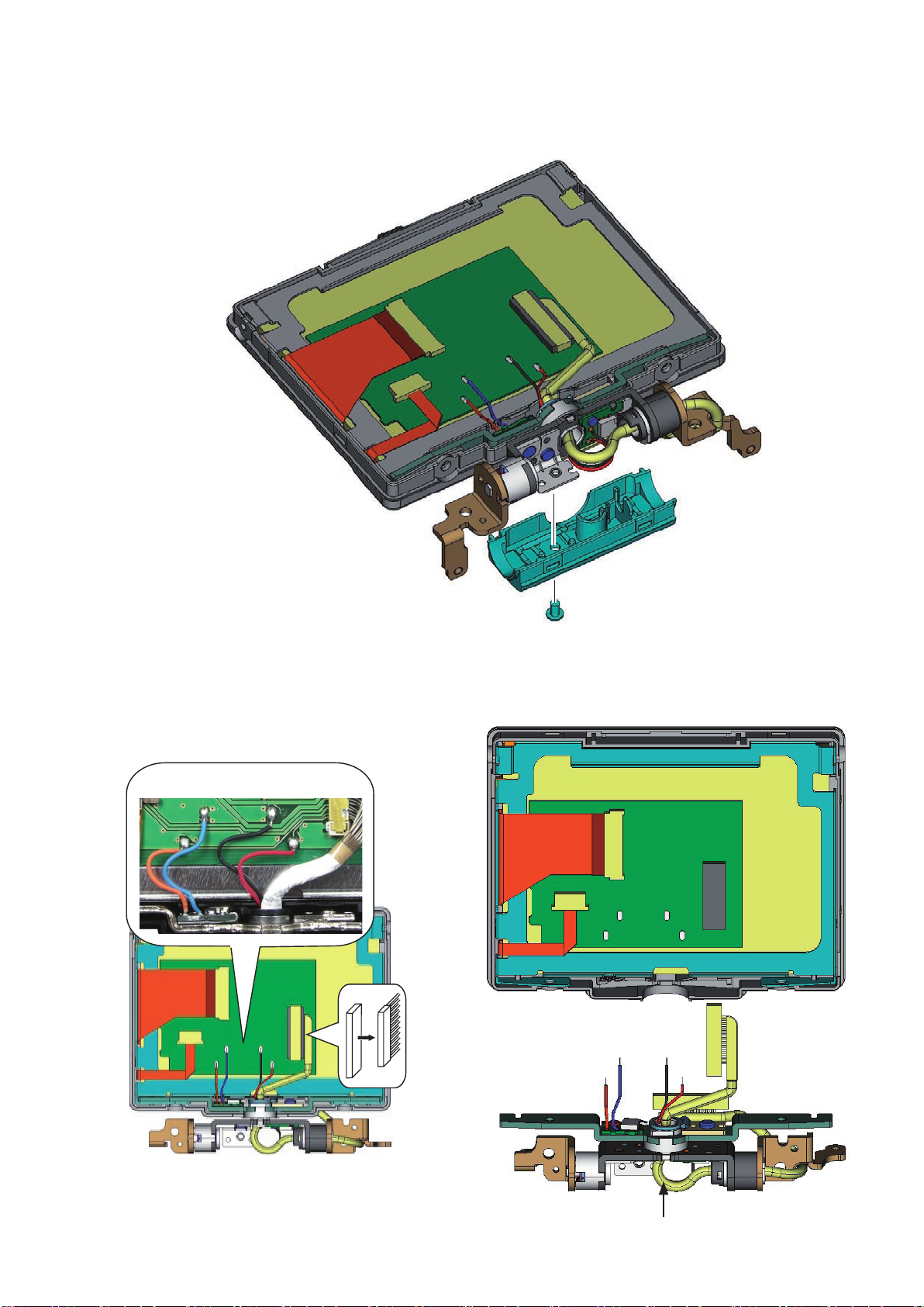
・ Take out the screw (#677).
・ Remove the hinge bottom cover (#438).
(Caution must be exercised that the part does not get scratched or dented. If it does, use a new one.)
・ Unsolder the wires [Orange/Blue/Black/Red].
・ Disconnect the harness from the connector.
・ Remove the hinge unit (#B454).
[Orange/Blue/Black/Red]
#438
#677
#B454
- D15 ・ D5000 -
Page 21
・ Remove the harness (#1058) from the hinge unit (#B454)
INC
#B454
VBA24001-R.3783.A
#1058
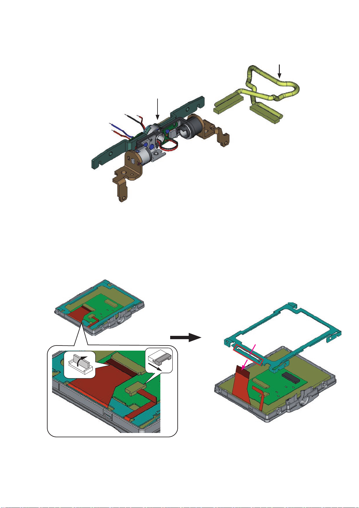
・ Disconnect the FPC.
・ While passing the FPC through, remove the retaining plate (#406).
#406
- D16 ・ D5000 -
Page 22

・ Remove the TFT monitor unit (#B1049).
INC
VBA24001-R.3783.A
#B1049
・ Remove the two sponges (#404) and two sponges (#405).
#404
#405#405
- D17 ・ D5000 -
Page 23
VBA24001-R.3783.A
INC
3. Front cover
Pop-up of Flash unit (SB)
・ Cut the lumirror sheet, etc, into the below size, and inset it in the clearance of the top cover pop-up
section. Then, slide it in the direction of the arrow and raise (pop-up) the flash unit.
Approx. 2cm
Approx. 4cm
Front cover
・ Take out the four screws (#610) and the one screw (#626).
・ Remove the front cover unit (#B24).
#626
#610
#610
#B24
#466
#465
- D18 ・ D5000 -
Page 24
VBA24001-R.3783.A
INC
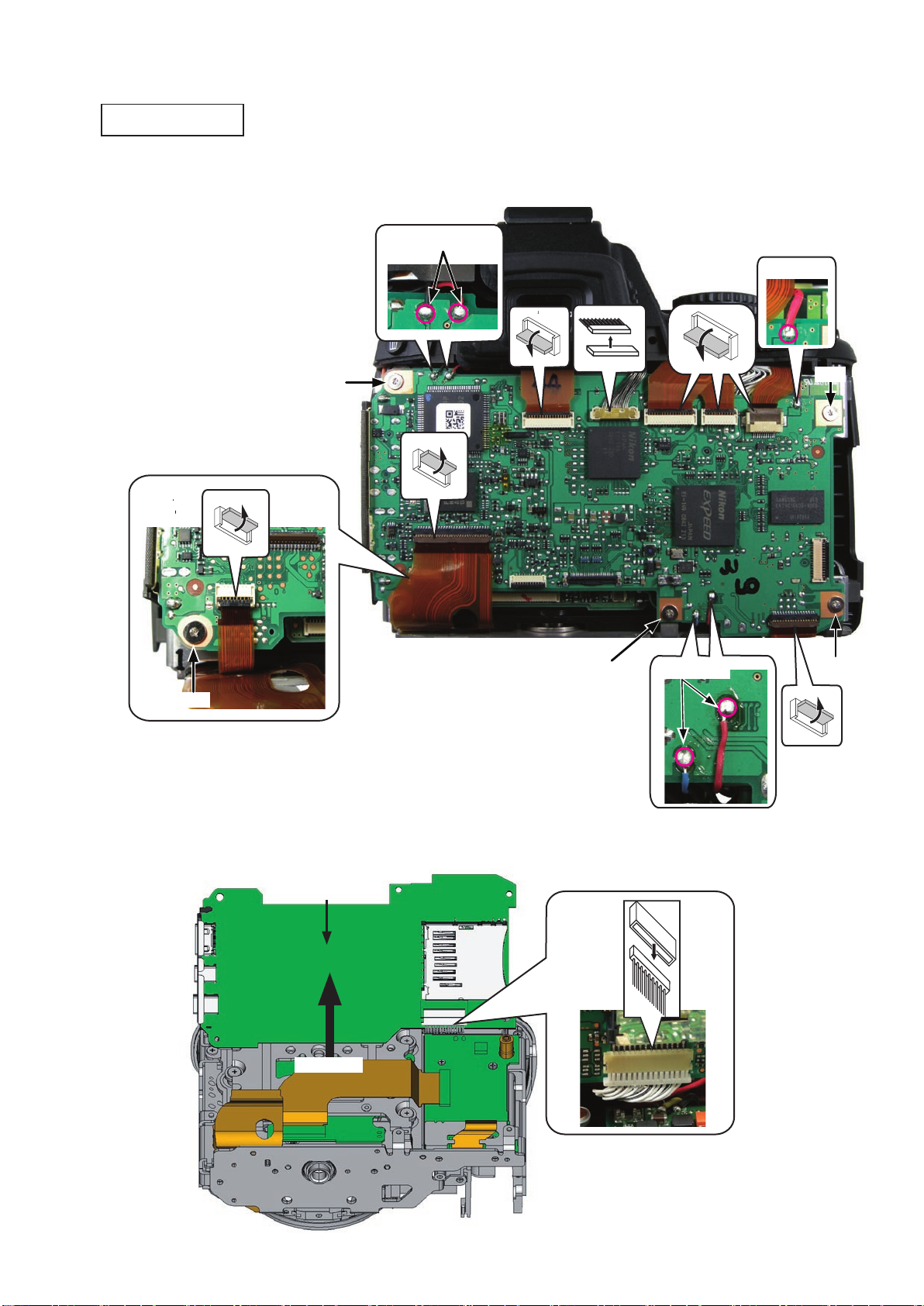
4. Top cover
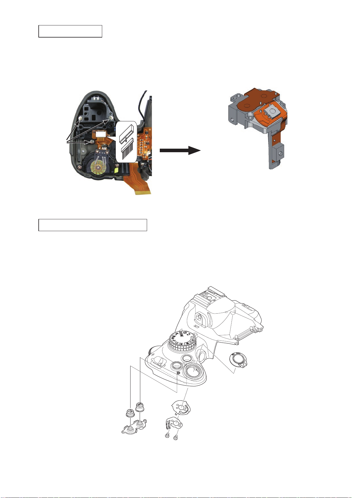
TOGO PCB unit
・ Disconnect the seven FPCs, and remove the harness from the connector.
・ Unsolder the wires in the upper right [Red], upper left [Black/Red] and lower right [Blue/Red] corner of
the PCB.
・ Take out the five screws (#663).
#663
[Black/Red]
#663
[Blue/Red]
[Red]
#663
#663
#663
・ Lift the one side of the PCB as below, and disconnect the connector of the back.
・ Remove the TOGO PCB unit (#B2001).
#B2001
Turn up
- D19 ・ D5000 -
Page 25
VBA24001-R.3783.A
INC
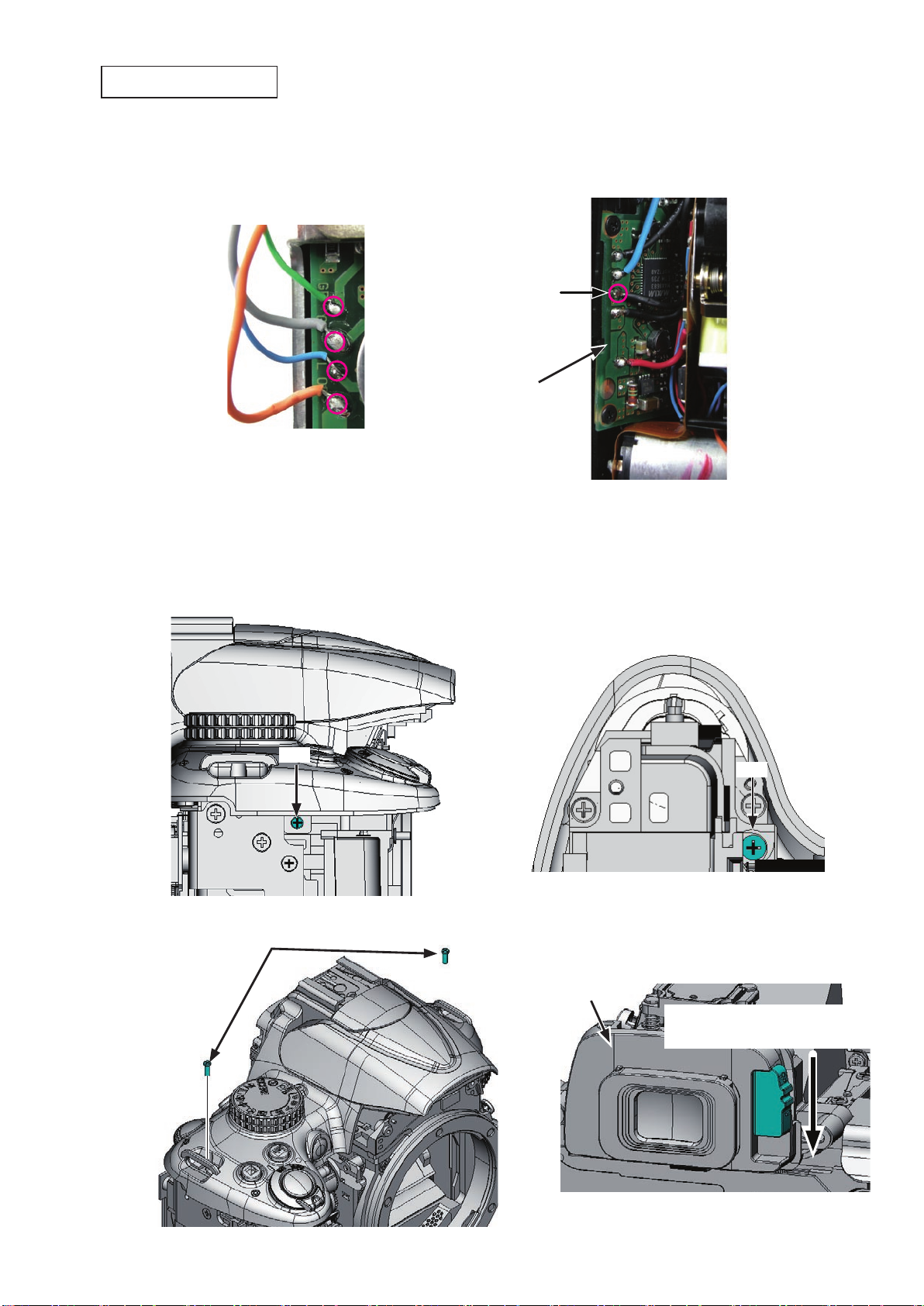
Removal of top cover
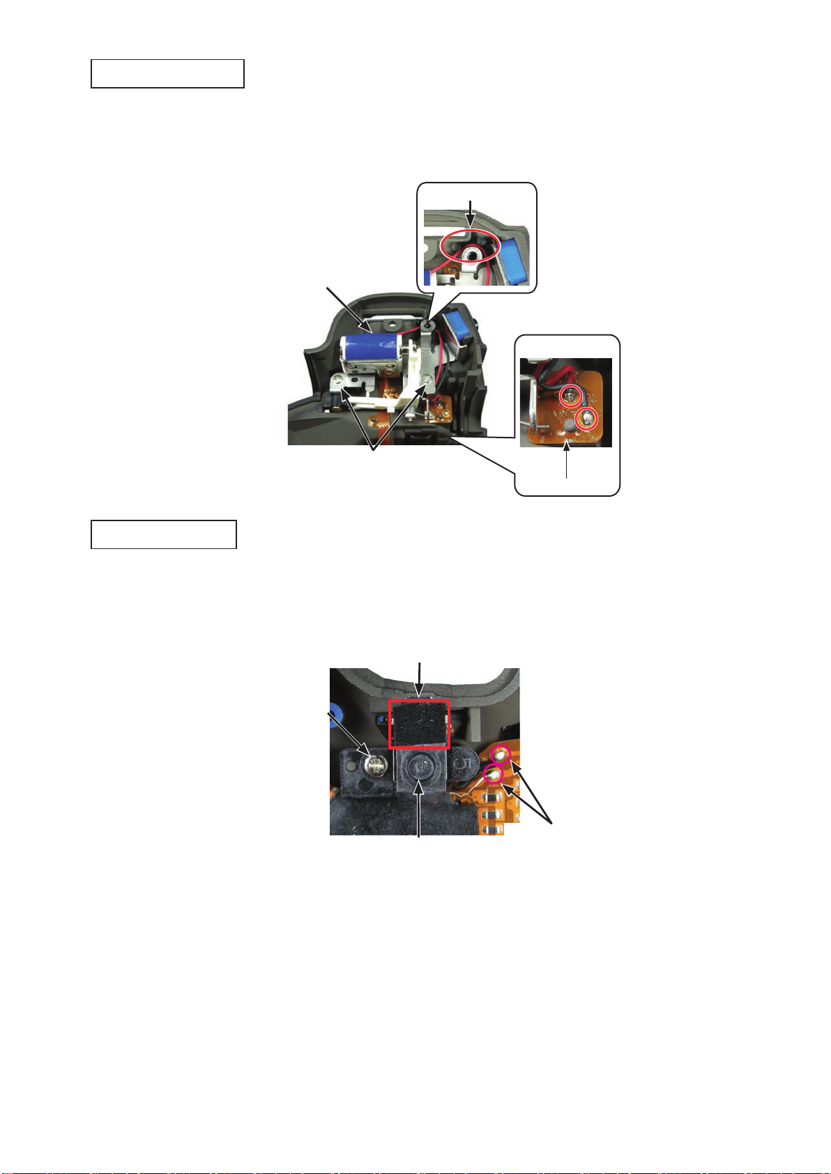
・ Remove the solders of the wires [Green/Gray/Blue/Orange] from the SB PCB unit (#B2006).
・ Remove the solder of the wire [Black] from the DC/DC PCB (#B2002).
[Green/Gray/Blue/Orange]
[Black]
#B2002
・ Take out the screw (#638).
・ Take out the screw (#607).
・ Take out the two screws (#737).
・ Remove the top cover and the eyepiece mold unit (#B271).
#607
#737 × 2
#638
#B271
Lowering this lever will facilitate
the removal of [#B271].
- D20 ・ D5000 -
Page 26

VBA24001-R.3783.A
INC
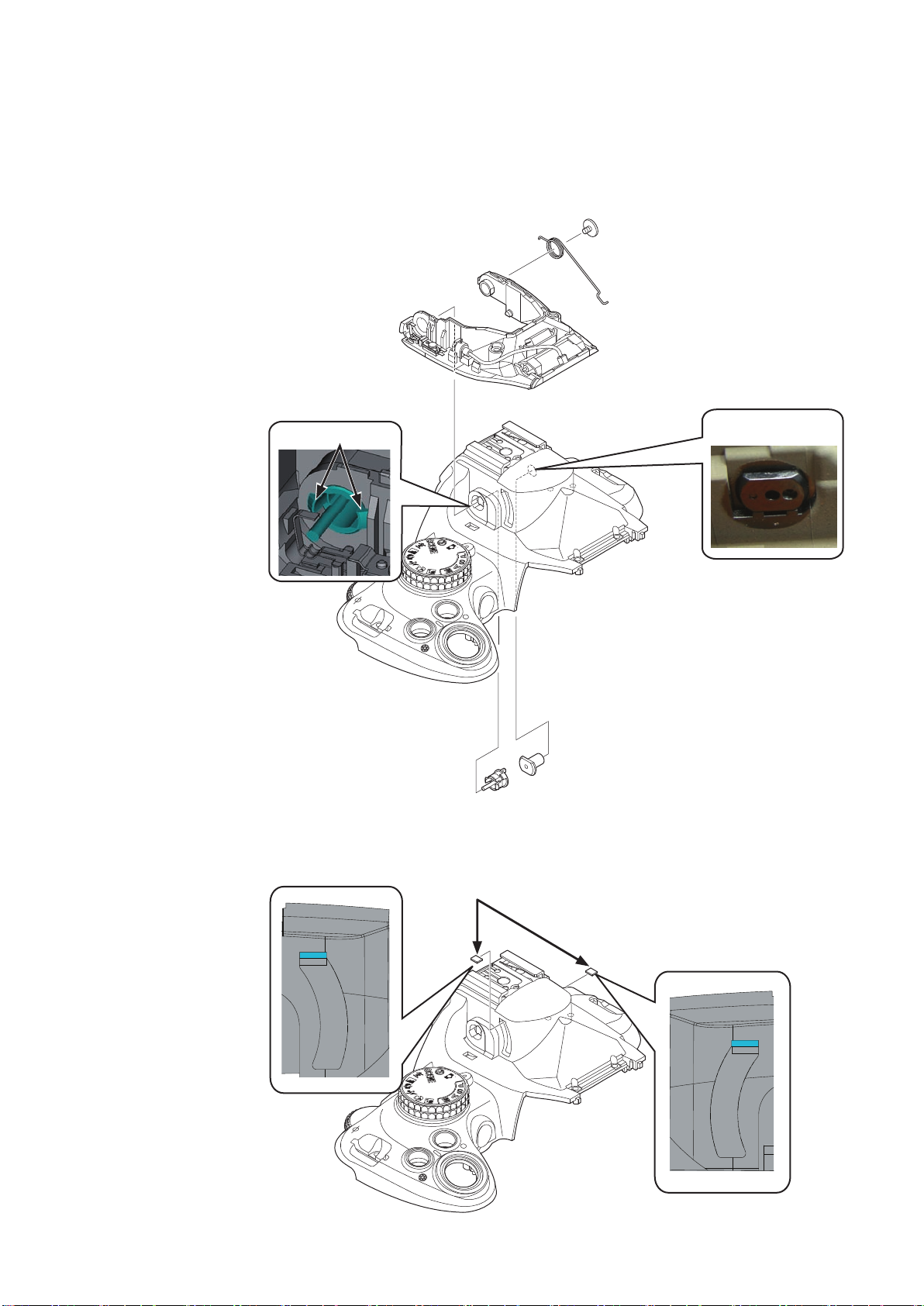
SB upper cover
・ Push the SB lock lever in the direction of the arrow, and raise (pop-up) the built-in SB (flash unit).
SB lock lever
・ Take out the two screws (#632).
#632
・ House the SB lower control unit (#B302), and remove the SB upper cover (#301).
#301
- D21 ・ D5000 -
Page 27

lower control unit
INC
SB
・ Take out the screw (#650), and release the wires from the bosses.
・ Unsolder the wires [Red/Blue/Green/Black] of the top cover FPC unit (#B1012).
[Red/Blue/Green/Black]
#B1012
VBA24001-R.3783.A
#650
・ Pull out the eight wires.
Boss
Boss
- D22 ・ D5000 -
Page 28
VBA24001-R.3783.A
AU
T
O
AU
T
O
INC
・ While pushing the rotate shaft (#306), take out the screw (#733) and remove the spring (#305).
・ Remove [#306].
・ Remove the SB rotating collar (#308), while releasing its two hooks.
・ Remove the SB lower control unit (#B302).
#733
#305
#B302
Remove this while
Unhook here.
pushing.
・ Remove the two rubbers (#311).
#306
#308
#311
- D23 ・ D5000 -
Page 29
SB release base unit
INC
・ Remove the solders of the wires [Red/Black] from the top cover FPC unit (#B1012).
・ Release the wires [Red/Black] from the guides.
・ Take out the two screws (#609), and remove the SB release base unit (#B2455).
Guide
#B2455
[Red/Black]
VBA24001-R.3783.A
#609
AF-assist lamp unit
・ Unsolder the wire [uncoated/Black].
・ Peel off the flocked sheet (#327).
・ Take out the screw (#608), and remove the AF-assist lamp unit (#B325).
#327
#608
[uncoated/Black]
#B325
#B1012
- D24 ・ D5000 -
Page 30
AU
T
O
Power SW FPC unit
INC
・ Remove the FPC.
・ Take out the three screws (#635).
・ Remove the power SW FPC unit (#B1011).
#635
VBA24001-R.3783.A
#B1011
Release button unit
/ each button, etc
・ Remove the rubber SW (#382), the + - /aperture button (#381) and the info button (#384).
・ Take out the two screws (#605).
・ Remove the on-off SW brush (#348), on-off click spring (#347), and on-off dial (#B345).
#B345
#381
#382
#384
- D25 ・ D5000 -
#347
#348
#605 × 2
Page 31

C/D unit
INC
・ Remove the three solder bridges.
・ Take out the two screws (#635), and remove the C/D unit (#B367).
#B367
#635
Top cover FPC unit
・ Remove the five solder bridges.
VBA24001-R.3783.A
・ Unsolder the wire [Black] that is connected to the DC/DC PCB.
・ Take out the two screws (#635), and remove the top cover FPC unit (#B1012).
[Black]
#635
#B1012
- D26 ・ D5000 -
Page 32

AU
T
O
Mode dial unit / AF/AE-L button / Delete button / AF-assist lamp window
INC
・ Take out the screw (#640).
・ Remove the contact brush (#372), click spring (#373), and mode dial unit (#B371).
・ Remove the retainer ring (#387), and remove the AF/AE-L button (#386).
・ Remove the delete button rubber SW (#423), and delete button (#428).
・ Remove the super X, and detach the AF-assist lamp window (#326).
#B371
#386
#428
#423
VBA24001-R.3783.A
#387
#373
#326
Adhesive: Super X
Hot shoe
#372
#640
・ Take out the four screws (#654).
・ Remove the backing plate (#322), shoe spring (#318), hot shoe (#316), and hot shoe mold unit (#B317).
#318
#316
#B317
#322
#654 × 4
- D27 ・ D5000 -
Page 33

5. Image sensor
INC
SZ-DC/DC PCB unit
VBA24001-R.3783.A
・ Disconnect the connection-FPC (#1026) from the
connector.
・ Unsolder the wires [Yellow/Black].
・ Take out the two screws (#670) and the one ne
screw (#687).
・ Remove the SZ-DC/DC PCB unit (#B2003).
#1026
[Yellow/Black]
#B2003
#687
#670
Image sensor unit
・ Unsolder the wires [Green/Purple].
・ Take out the three screws (#631), and remove the image sensor unit (#B2051).
Caution: Some bodies have already the washer put on the surface where the image sensor unit is mounted
or already the lumirror sheet attached on the side.
In the latter case (lumirror sheet attached), remove the super X, which is applied to the side (see below
" ■ " area), and then remove the image sensor unit.
#631
#B2051
[Green/Purple]
- D28 ・ D5000 -
Page 34

6. Separation of Front body from Rear Body
INC
Bottom base unit
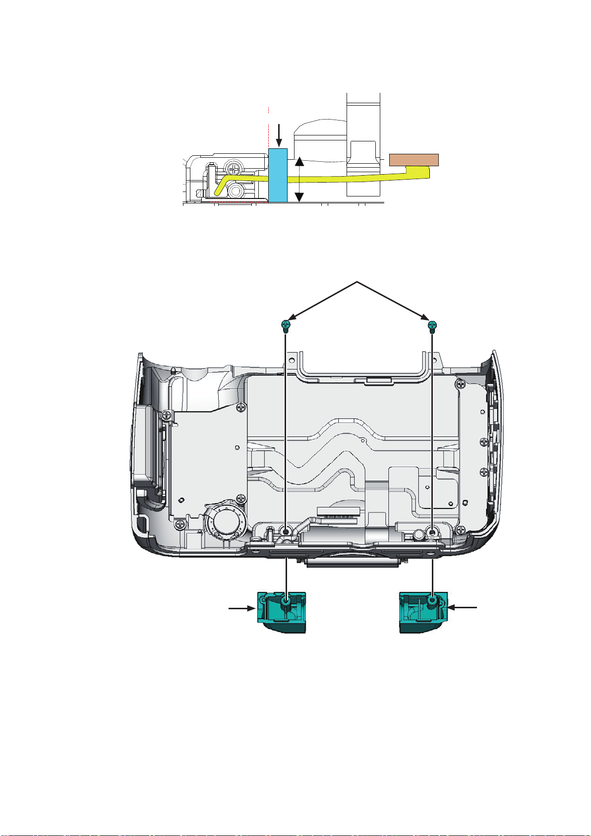
・ Take out the five screws (#616).
・ Take out the three screws (#691).
#616
VBA24001-R.3783.A
#691
#691
・ Remove the bottom base unit (#B66) by kind of scooping up as below.
#B66
- D29 ・ D5000 -
Page 35

・ Unsolder the wires [Black/Blue], which are connected from the penta unit.
INC
・ Unsolder the wires [Black/Red], which are connected from the SQ PCB unit.
[Black/Blue]
[Black/Red]
VBA24001-R.3783.A
・ Take out the four screws (#624).
#624
- D30 ・ D5000 -
Page 36

・ Separate the front body from the rear body.
INC
(Be careful of wires and FPCs.)
VBA24001-R.3783.A
- D31 ・ D5000 -
Page 37

7. Rear body
INC
Microphone
・ Remove the microphone (#1046).
Main condenser
VBA24001-R.3783.A
#1046
・ Unsolder the wires [Red/Black].
・ Take out the two screws (#615).
・ Remove the SB condenser unit (#B1048).
・ Remove the condenser (#1048) and two pieces of the double-stick tape (#141) from the condenser holder.
[Red/Black]
Condensor holder
#1048
#B1048
#615
#141
- D32 ・ D5000 -
Page 38

VBA24001-R.3783.A
INC
SB PCB unit
・ Unsolder the wires [Red/Black].
・ Remove the FPC (#1029) (being careful of the boss).
・ Take out the screw (#687).
・ Remove the SB PCB unit (#B2006) from between the SB PCB plate unit (#B82) and rear body unit.
・ Remove [#B82].
#B2006
Boss
#B82
#687
[Red/Black]
#B82
Rear body unit
- D33 ・ D5000 -
Page 39

DC/DC PCB unit
INC
・ Unsolder the battery-contact wires [Black/Red/Blue].
・ Take out the two screws (#665).
・ Disconnect the FPC.
・ Remove the DC/DC PCB unit (#B2002).
[Black/Red/Blue]
VBA24001-R.3783.A
#665
- D34 ・ D5000 -
Page 40

Battery box
INC
・ Take out the four screws (#615).
・ The battery BOX unit (#B156) will come off.
・ The lug plate (#159) will come off.
#615
VBA24001-R.3783.A
#B156
#159
・ Take out the screw (#607).
・ Remove the spring (#160).
・ Take out the three screws (#607).
・ Remove the three springs (#157).
・ Remove the backup battery (#B1044).
・ Peel off the double-stick tape (#141).
#607
#160
#607
#157
- D35 ・ D5000 -
#141
#B1044
Page 41

Eyelet unit, etc
INC
VBA24001-R.3783.A
#694
#957
#147
#735
#145
#147
#65
#143
#145
#694
#143
TA-0026(6x11)
TA-0026(6x11)
#143
#139
#904
#906
- D36 ・ D5000 -
Page 42

8. Front body
INC
Shutter
・ Remove the sponge (#757).
VBA24001-R.3783.A
#757
・ Remove the sponge (#149).
・ Turn the red gear in the direction of the arrow, and raise the mirror.
・ Remove the solder bridge.
・ Take out the two screws (#635).
・ Remove the shutter (#31).
#635
#149
- D37 ・ D5000 -
Page 43

VBA24001-R.3783.A
INC
Meterring FPC unit
・ Take out the screw (#607), and remove the retainer plate (#293).
・ Disconnect the FPC from the connector.
・ Take out the three screws (#607), and remove the metering FPC unit 1 (#B11013).
(Caution: Do NOT touch the red-marked screws during disassembly, because they are for adjustments.)
#293
#607
Do NOT touch here.
#607
#B11013
Eyepiece barrel unit
・ Take out the two screws (#638), and remove the eyepiece barrel unit (#B261).
#638
#B261
- D38 ・ D5000 -
Page 44

Penta unit
INC
・ Remove the super X (at red-marked " " two areas)
・ Take out the two screws (#635), and remove the springs (#201 and #202).
・ Remove the pent unit (#B4).
#635
#201
#202
VBA24001-R.3783.A
- D39 ・ D5000 -
Page 45

SI unit
INC
・ Turn the gear in the direction of the arrow, and lower the mirror.
・ Take out the two screws (#610), and remove the mirror setting unit (#B120).
#610
VBA24001-R.3783.A
#B120
・ Peel off the tape (#709), and remove the FPC.
#709
・ Release the hook as below.
・ Remove the SI unit (#B2050).
#B2050
- D40 ・ D5000 -
Page 46

・ Take out the two screws (#635).
INC
・ Remove SI retainer unit (#B277).
#635
・ Remove the two SI light guides (#335).
・ Disconnect the FPC from the connector.
・ Take out the two screws (#606).
・ Peel off the tape (#709).
・ Remove the SI LED FPC unit (#1017).
VBA24001-R.3783.A
#B277
#709
#335
#606
#1017
- D41 ・ D5000 -
Page 47

Relay PCB unit
INC
・ Take out the screw (#670).
・ Disconnect the three FPCs from the connectors.
・ Unsolder the wires [Yellow/Black].
VBA24001-R.3783.A
#670
[Yellow/Black]
・ With the FPC of the lens contact unit (#B2113) being turned up, take out the screw (#670).
・ Remove the Relay PCB unit (#1007).
Turn up the FPC of [#B2113]
#670
#1007
Boss
- D42 ・ D5000 -
Page 48

Removal of bayonet
INC
・ Take out the five screws (#648) and the one screw (#660).
・ Remove the bayonet (#111).
・ Remove the lug plate (#137).
・ Remove the three bayonet springs (#112).
VBA24001-R.3783.A
#137
#648
#660
Lens contact unit
・ Take out the two screws (#607).
・ Remove the plate (#339).
#607
・ Take out the two screws (#642).
#112
#339
#642
- D43 ・ D5000 -
Page 49

・ Peel off the synchro-mode/SB pop-up SW area, and turn up the FPC.
INC
・ Remove the lens contact unit (#B2113).
VBA24001-R.3783.A
- D44 ・ D5000 -
Page 50

SQ base unit
INC
・ Unsolder the wires [Orange/Black].
VBA24001-R.3783.A
[Orange/Black]
・ Take out the three screws (#638).
・ Pull the head of the aperture lever of the SQ PCB unit (#B242) from the gap of the front body unit
(#B22RP), and remove [#B242].
#638
#B242
- D45 ・ D5000 -
Page 51

B2
2
INC
AF sensor unit
・ Take out the three screws (#162) with hex key ( φ 1.5mm).
・ The AF sensor unit (#B2163) and three springs (#161) will come off.
#162 × 3
#161 × 3
VBA24001-R.3783.A
#B2163
Inside finder LCD unit
・ Take out the two screws (#683).
・ Remove the inside finder LCD unit (#B1021).
#683 × 2
#B1021
#332
#758
#276
#37
#38
- D46 ・ D5000 -
Page 52

plate
INC
Release button unit
VBA24001-R.3783.A
#299
#621 × 3
#B115
#119
#B116
- D47 ・ D5000 -
Page 53

F-min SW section
INC
VBA24001-R.3783.A
#607
#131
Mirror unit/Aperture lever section
・ Remove the super X.
#135
Orange:SQ FPC
Black:SQ FPC
#645
#134
#136
#133
#236
Adhesive: Super X
Adhesive: Super X
- D48 ・ D5000 -
Page 54

・ Remove each part/component.
INC
#238
VBA24001-R.3783.A
#B2231
#240
#239
#205
#206
#643
#199 × 2
#236
#190
#191
#203
- D49 ・ D5000 -
Page 55

VBA24001-R.3783.A
INC
Assembly/Adjustment
1. Front body
Mirror unit
#B2231
#238
Caution: For the tapes or sponges which are not described in
"Assembly" section, refer to the repair parts list.
#240
#239
Be careful NOT to bend this.
#199 × 2
#236
・ With the mirror being raised, insert the pins and apply the adhesive (Super X) to each pin.
#236
Adhesive: Super X
Apply to only one-fourth of the mount-side surrounding area.
Adhesive: Super X
- A1 ・ D5000 -
Page 56

Aperture lever section
INC
VBA24001-R.3783.A
#190
#205
Spring hooking position
・ Hook the spring (#206).
#206
#643
#191
#203
Grease:LEN317A
・ Hook the spring (#205).
Grease:LEN317A
#206
#205
- A2 ・ D5000 -
Page 57

F-min SW section
INC
#645
#134
VBA24001-R.3783.A
#607
#135
Orange:SQ FPC
Black:SQ FPC
Release button unit
#136
#133
#131
#621 × 3
Grease:LEN317A
#B115
#119
#B116
Boss hole
- A3 ・ D5000 -
Page 58

plate
INC
・ Mount the screen-case retaining plate (#299).
#299
Inside finder LCD unit
・ Attach the tape (#38) to the air plate (#37), ant mount it on the front body unit (#B22RP).
・ Attach the dust-proof sponge (#276) and the sponge (#332).
・ Mount the inside finder LCD unit (#B1021).
VBA24001-R.3783.A
・ Tighten the two screws (#683).
・ Attach the sponge (#758).
[#B1021] positioning direction
[#276/#332] attaching position
[#276 and #332] attaching position
#683 × 2
#B1021
#332
[#758] attaching position
#758
#276
#B22RP
[#332] must be attached to the mold.
#758
- A4 ・ D5000 -
#38
Attaching position
#37
Page 59

VBA24001-R.3783.A
B2
2
INC
AF sensor unit
・ Attach the three springs (#161).
・ Place the AF sensor unit (#B2163)
・ Turn the three screws (#162) lightly all the way with hex key ( φ 1.5mm), and then give each 1.5-turn
counterclockwise.
#B2163
#162 × 3
#161 × 3
SQ PCB unit
・ Move the aperture lever of the SQ PCB unit (#B242) in the direction of the arrow, and check that it is
movable freely.
(If not, turn the red-indicated gear in "Fig. 1" in the direction of the arrow, and make it movable.)
・ Move the (red-circled) roller section all the way to the end.
Aperture drive lever
#B242
Roller section
Fig. 1
- A5 ・ D5000 -
Page 60

VBA24001-R.3783.A
INC
・ Operate the mirror-up lever (#203), which is assembled in [#B22RP] in the direction of the arrow, and set
to be "mirror-down" as below.
・ While inserting the head of the aperture lever of the SQ PCB unit (#B242) into the gap of [#B22RP], mount
by fitting with the boss.
#B22RP
#203
#B242
・ Tighten the three screws (#638).
・ After mounting the SQ PCB unit (#B242), check whether the aperture lever can operate smoothly.
Pass the wires [Orange/Black] through inside the lug plate (#135) and behind the FPC of the SQ PCB unit
・
#B242), and then solder them.
(
[Orange/Black]
#638
Pass through inside #135
Pass through
behind FPC
- A6 ・ D5000 -
Page 61

INC
Lens contact unit
・ While turning up the FPC, mount the lens contact unit (#B2113).
#B2113
VBA24001-R.3783.A
・ Attach the FPC by fitting with the bosses.
・ Tighten the two screws (#642).
= Boss
#642
- A7 ・ D5000 -
Page 62

VBA24001-R.3783.A
INC
・ Mount the plate (#339).
・ Tighten the two screws (#607).
#339
#607
Mounting of bayonet
・ Mount the lug plate (#137).
・ Attach the three bayonet springs (#112).
・ Mount the bayonet mount (#111).
・ Tighten the five screws (#648) and the one screw (#660) in the below numeric order from ① to ⑥ .
#137
#112
②
④
⑤
③
#648
#660
⑥
①
Grease:LEN317A
Grease:LEN317A
- A8 ・ D5000 -
Page 63

VBA24001-R.3783.A
INC
Height adjustment of Aperture lever
Measure the height of the aperture lever with the tool (J18004).
・
Standard: 3.3 - 3.6mm
In case the result does not meet the standard, bend the aperture
lever section for adjustment.
Be careful NOT to bend the inside of the lever.
Height of aperture lever
3.3 - 3.6 mm
Aperture lever
- A9 ・ D5000 -
Page 64

VBA24001-R.3783.A
INC
Relay-PCB unit
・ With the FPC of the lens contact unit (#B2113) being turned up, mount the relay-PCB (#1007) by fitting
with the bosses.
・ Tighten the screw (#670).
Turn up the FPC of [#B2113].
Boss
#670
#1007
Boss
・ Solder the wires [Yellow/Black].
・ Connect the three FPCs to the connectors.
・ Tighten the screw (#670).
#670
[Yellow/Black]
(#1030 back)
[#905/#750] attaching position
#905
#750
Attach to the back.
- A10 ・ D5000 -
Page 65

SI unit
INC
・ Mount the SI LED FPC unit (#1017).
・ Attach the tape (#709).
・ Tighten the two screws (#606).
・ Connect the FPC to the connector.
VBA24001-R.3783.A
・ Mount the two SI light guides (#335).
#335
#1017
#709
#606
- A11 ・ D5000 -
Page 66

VBA24001-R.3783.A
INC
Attachment position for Finder field frame
・ Attach the tape (#295) to the SI retainer unit (#B277).
・ Attach the two sponges (#793) to the finder field frame 2 (#283), and then mount on the SI retainer unit
(#B277).
#295
#B277
NOT squeeze into the inside.
= Boss
#283
#793
Boss hole
Align the lateral locations with the boss holes.
NOT to be squeezed from [#283] lengthwise.
・ Mount the SI retainer unit (#B277).
・ Tighten the two screws (#635).
Boss hole
Direction for positioning
#B277
#635
- A12 ・ D5000 -
Page 67

VBA24001-R.3783.A
INC
・ Pass the FPC of the SI unit (#B2050) through □ -framed area of the retainer plate (#339), and mount it.
・ Engage the hook.
#B2050
#339
□ -framed area
・ Connect the FPC to the connector, and attach the tape (#709).
・ Mount the mirror setting unit (#B120), and tighten the two screws (#610).
#B120
#709
#610
- A13 ・ D5000 -
Page 68

Penta unit
INC
・ Mount the penta unit (#B4).
・ Attach the springs (#201 and #202), and tighten the two screws (#635).
・ Apply "Super X" to the below " " red-colored two places.
#B4
VBA24001-R.3783.A
#201
Direction for positioning
#635
#202
- A14 ・ D5000 -
Page 69

VBA24001-R.3783.A
INC
Eyepiece barrel unit
・ Mount the eyepiece barrel unit (#B261) by fitting with the boss, and tighten the two screws (#638).
#638
AE FPC unit
・ Mount the AE FPC unit (#B11013) by fitting with the boss, and tighten the three screws (#607).
・ Connect the FPC to the connector.
・ Mount the plate (#293) by fitting with the boss, and tighten the screw (#607).
(Caution: Do NOT touch the red-marked screws during assembly, because they are for adjustments.)
#B261
Do NOT touch here.
#607
#B11013
#293
#607
- A15 ・ D5000 -
Page 70

adjustment of Main mirror and Sub-mirror
WARNING
NEVER look directly at the laser beam which is reflected
by the mirror of cameras/inspection tools.
!
INC
VBA24001-R.3783.A
・
Position of operator and where the laser beam must not be looked directly.
Operator
Chart area
Chart
Laser beam path Laser beam path
Laser beam path
- A16 ・ D5000 -
Page 71

1. Positioning of Main mirror (reference 45° angle)
J19132H
MAIN/SUB MIRROR ANGLE INSPECTION TOOL-USE CHART
45°
47.75°
49°
47.75°
54°
51°
59°
Flat mirror
Tilted mirror
Tilted mirror
Tilted mirror
Tilted mirror
Tilted mirror
Flat mirror
Reference Line
INC
Positioning to become 45° angle
①
・Push the laser-beam axis-check mirror toward the
mount-face by hand.
・Radiate the laser beam, and check the position of
the reected image of the laser beam (without
looking directly at the laser beam.)
・Conrm that the position of the reected image
VBA24001-R.3783.A
Laser-beam axis-check mirror
coincides with that of the projecting point of the
laser. (i.e. The incident angle coincides with the
●
reection angle.)
・The positioning of reference 45° angle is
completed.
Remove the nder screen. Replace it with the D5000.45 deg. angle main-mirror tool (J15436).
②
Measurement of 45° degree angle of Main mirror
③
・Attach the camera body to the mount-face, and operate
the mirror a few times.
Position the camera in the direction of the arrow.
・
・Radiate the laser beam, and check the position of the
reected image of the laser beam.
- A17 ・ D5000 -
Camera: D300
Page 72

Check whether the results meet the standard. If not, make the adjustment.
INC
・
Standard value
<
>
Left-right deviation
Up-down deviation
Main mirror
0 ±2’
±4’
Device
HEX. KEY WRENCH (φ1.5mm)
VBA24001-R.3783.A
Press the lock/release button to detach the body from the mount-face.
・
Eccentric pin for
the main mirror
- A18 ・ D5000 -
Page 73

2. Positioning of Sub-mirror
MAIN/SUB MIRROR ANGLE
INSPECTION TOOL-USE CHART
45°
47.75°
49°
47.75°
54°
51°
59°
Flat mirror
Tilted mirror
Tilted mirror
Tilted mirror
Tilted mirror
Tilted mirror
Flat mirror
Reference Line
INC
The sub-mirror angle of this model is 51 degree angle. However, because the mirror tool for this angle is
not set as RP, regard the position which is 105.2 mm lower than the 54 degree-angle index position as the
51 degree-angle one, and make a necessary check.
VBA24001-R.3783.A
70mm
3mm
3mm
Regard this index position as a reference,
and make a measurement.
230mm
105.2 mm
Print out and use the chart of
Page A104.
- A19 ・ D5000 -
June. 22. 2009Changed page (Overall revision)
Page 74

VBA24001-R.3783.A
INC
・Set the 54°-angle measurement-use mirror, which is prepared as single part (J19132D), by placing it
horizontally, as if sandwiched in between the two adjustment boards.
・Slide the height display (of the measurement-use mirror) forward, and turn the screw to secure it.
Screw
Slide forward.
Sandwich in
Measurement-use mirror
Position slid forward.
Height display (of measurement-use mirror)
・Turn the mirror height adjusting micrometer, and set the measurement-use mirror visually to 54°-angle
position of the height display as below.
・After completing the positioning, be sure to return the height display to the standard position and x it with
the screw.
Mirror height adjusting micrometer
Standard position
Rough indication: Height of
※
measurement-use mirror of D5000
・Attach the mirror-angle reference tool to the mount.
・Loosen the below screw, and adjust the tool to the measurement position (54°).
・Tighten the screw and position it in the direction of the arrow.
Changed page △×1
Screw
Positioning
- A20 ・ D5000 - △ (Addition)
June. 22. 2009
Page 75

VBA24001-R.3783.A
J19132H
49°
47.75°
54°
59°
Tilted mirror
Tilted mirror
Tilted mirror
Flat mirror
INC
・Move the (measurement-use) mirror stage to the stop position.
・Conrm that the camera-release guard is kept raised horizontally at the stop position.
Move to stop position.
Camera release guard
・Radiate the laser beam. Conrm that the laser reected image is positioned at the scale of the set angle.
If the reected image is out of alignment, adjust it by turning the adjustable screw X (
・
(vertically) with the laser beam being radiated.
horizontally) or Y
Adjustable screw: X
Adjustable screw: Y
●
・Return the mirror stage to the standard position.
・Conrm that the camera-release guard is kept lowered, and detach the mirror angle reference tool from the
mount-face.
Standard position
Camera-release guard
- A21 ・ D5000 -
Page 76

VBA24001-R.3783.A
J19132H
45°
47.75°
49°
47.75°
54°
51°
59°
Flat mirror
Tilted mirror
Tilted mirror
Tilted mirror
Tilted mirror
Tilted mirror
Flat mirror
INC
Angle measurement of Sub-mirror
Attach the camera body to the mount-face, and operate the mirror a few times.
・
Position the camera in the direction of the arrow.
・
Camera: D300
・With the mirror being raised, move the (measurement-use) mirror stage to the stop position.
・Conrm that the camera-release guard is kept raised horizontally at the stop position, then lower the mirror.
Turn the (mirror height) adjusting micrometer and get the position where the laser reected image does not
・
move. At this position, check the angle of the sub-mirror.(The 51 degree-angle index position is 105.2 mm
Camera-release guard
lower than the 54 degree-angle index position.)
Mirror height adjust-
ing micrometer
Camera: D300
- A22 ・ D5000 -
●
Measure at the position where the
laser reected image does not move.
Page 77

VBA24001-R.3783.A
ミラーボックス底面
ミラーボックス底面
ミラーボックス底面
INC
Caution for measuring the angle of sub-mirror:
Make measurements by keeping the measurement-use mirror from coming in contact with the camera's
main mirror and the bottom section of the mirror box.
Main mirror
Sub-mirror
Measurement-use mirror
Avoid contact
Bottom section of mirror box
Position of laser reected image Cause Measure
Reference position
Laser reected image here
Laser reected image here
Measurement-use mirror contacts
the main mirror.
Bottom section of mirror box
Measurement-use mirror contacts the
Turn the (mirror height)
adjusting micrometer counter-
clockwise.
Turn the (mirror height) ad-
justing micrometer clockwise.
bottom section of the mirror box.
Reference position
Bottom section of mirror box
- A23 ・ D5000 -
Page 78

Check whether the results meet the standard. If not, make the adjustment.
INC
・
Standard value
<
>
Left-right deviation
Sub mirror
-
VBA24001-R.3783.A
Up-down deviation
Device
0 ± 7’
Eccentric pin for
the sub-mirror
HEX. KEY WRENCH (φ1.5mm)
・After completing the inspection and adjustment, with the mirror being raised, return the mirror stage to the
standard position.
・Conrm that the camera-release guard is kept lowered, and lower the mirror.
・Detach the camera body from the mount-face.
Standard position Camera-release guard
- A24 ・ D5000 -
Camera: D300
Page 79

Shutter
INC
・ Turn the red gear in the direction of the arrow, and raise the mirror.
・ Mount the shutter (#31).
・ Tighten the two screws (#635).
・ Make the solder bridges.
・ Attach the sponge (#149).
#31
#635
VBA24001-R.3783.A
#149
・ Attach the sponge (#757) to the gap between the shutter (#31) and the front body unit (#B22RP).
No gap from the sponge (#758)
#757
#758
The edge of the sponge must protrude
from edge face of the shutter.
- A25 ・ D5000 -
Page 80

2. Rear body
INC
VBA24001-R.3783.A
Eyelet unit, etc
[#147] attaching position
Joint line
Oil barrier:OS-30MEL
#147
#957
#694
#735
#145
#65
#143
#147
#143
#145
TA-0026 (6x11)
[#147] attaching position
Joint line
Oil barrier:OS-30MEL
#694
#143
TA-0026 (6x11)
#139
The holes must
be hidden.
#904
Attaching position
The holes must be
unseen.
Align with the
mold edge.
The hole must be unseen.
#906
Position in
center.
Back
- A26 ・ D5000 -
Page 81

Battery box
INC
・ Attach the double-stick tape (#141) to the battery box (#156).
・ Insert the backup battery (#B1044).
・ Attach the three springs (#157).
・ Tighten the three screws (#607).
・ Attach the spring (#160) by inserting its head into the hole.
・ Tighten the screw (#607).
#607
VBA24001-R.3783.A
#156
#157
#141
#B1044
#607
#160
Dipping
Grease: CFD-409Z
Insert the
head into the
hole.
- A27 ・ D5000 -
Page 82

・ Mount the lug plate (#159) by fitting with the bosses.
INC
・ Mount the battery box (#156) on the rear body.
・ Tighten the four screws (#615).
VBA24001-R.3783.A
#159
#615
- A28 ・ D5000 -
Page 83

DC/DC PCB unit
INC
・ Mount the DC/DC PCB unit (#B2002) and tighten the two screws (#665).
・ Connect the FPC.
・ Solder the battery-contact wires [Black/Red/Blue].
[Black/Red/Blue]
VBA24001-R.3783.A
#665
#B2002
- A29 ・ D5000 -
Page 84

VBA24001-R.3783.A
INC
SB PCB unit
・ Mount the SB PCB shield plate unit (#B82).
・ Put the SB PCB unit (#B2006) in between [#B82] and the rear body unit. (Put the wires inside the shield.)
・ Tighten the screw (#687).
・ Attach the connection-FPC (#1029) by fitting with the boss.
・ Arrange the wires [Red/Black], which are connected from the DC/DC PCB unit (#B2002), as below, and
solder them.
#B82
#B2006
#B2002
#B82
Rear body unit
Place inside the shield.
#687
- A30 ・ D5000 -
Boss
[Red/Black]
#1029
Page 85

VBA24001-R.3783.A
INC
Main condenser
・ Attach the two pieces of the double-stick tape (#141) to the condenser holder, and adhere the condenser.
・ Mount the SB condenser unit (#B1048) by fitting with the boss.
・ Tighten the two screws (#615).
・ Solder the wires [Red/Black], which are connected from the SB PCB unit (#B2006).
Condenser holder
#1048
[#1048] attaching area
#141
Direction for positioning
Attaching position:
The corner must come to the center of the rib.
#B1048
Microphone
・ Attach the microphone (#1046).
[Red/Black]
#615
#1046
- A31 ・ D5000 -
Page 86

VBA24001-R.3783.A
INC
3. Assembly of front body into rear body
・ Put mirror down, and assemble the front body into the rear body (being careful of wires and FPCs).
・ Tighten the four screws (#624) in the numeric order from ① to ④ .
①
#624
③
②
④
- A32 ・ D5000 -
Page 87

VBA24001-R.3783.A
INC
Bottom base unit
・ Mount the bottom base unit (#B66) (being careful NEITHER to be caught by the PCB NOR to pinch the
wires as below).
・ Tighten the five screws (#616) and three screws (#691) in the numeric order from ① to ⑧ .
#B66
③
⑥
⑤
#691
Do NOT pinch the wires.
#616
⑧
① ②
⑦
④
#691
- A33 ・ D5000 -
Page 88

ZERO/ABS
PRESET
TOL.
ON/OFF
0.00
mm
定盤
ZERO/ABS
PRESET
TOL.
ON/OFF
mm
定盤
2.12
10
20
30
40
50
40
30
20
10
0
10
20
30
40
50
40
30
20
10
0
定盤
定盤 定盤
20
10
0
10
20
30
40
50
40
30
20
10
0
Inspection and Adjustment of Body back
INC
・
"0" positioning of the dial gauge
(1)
J18001-1
(2)
Turn clockwise to 12 (0.12mm) position
Index circle
(3)
VBA24001-R.3783.A
△ (Revision)
0 ± 0.015 mm
Standard: 0±0.05 mm
Parallelism: 0.015mm or less
Surface plate
Surface plate
Surface plate
(1) Mount the tool (J18001-1) on the surface plate as above, then set the dial gauge to "0".
(2) From "0" position of (1), turn the index circle in the direction of the arrow so that the needle is on 12 (0.12mm)
position.
(3) Measure the body back based on "0" position of the index circle.
0 ± 0.015 mm
△ (Revision)
If the value is "0±0.05 mm / Parallelism: 0.015mm or less", it is within standard.
・
"0" positioning of the digital gauge
e.g.
2.12-2.12=0
So this is within
standard.
J18001-1
Surface plate
ABS] button so that the value becomes "0".
(2) Measure the body back based on "0" position
(3) Subtract "2.12mm" from the measured value. If the value is "Subtract "2.12mm" from the measured value. If the value is "2.12mm" from the measured value. If the value is "" from the measured value. If the value is "0±0.05 mm / Parallelism: 0.015mm or less",
(1) Mount the tool (J18001-1) on the surface plate as above, then turn the digital gauge ON and press [ZERO/
0 ± 0.015 mm
it is within standard.
Surface plate
△ (Revision)
※ "2.12mm" is a difference, resulting from subtracting [the height (46.67mm) of the body back tool
(J18001-1)] from [D5000 standard value (48.79mm)].
Changed page △× 3
- A34 ・ D5000 -
June. 22. 2009
Page 89

VBA24001-R.3783.A
INC
Measure six places from the bayonet face to the image PCB attaching face.
・
Measure the six places from the bayonet face to the image
・
PCB attaching face.
○ mark: to be measured
Standard: 48.79±0.05mm / Parallelism: 0.015mm or less
48.79 ± 0.015mm
・ In case the result is out of standard, loosen the screws
that attach the front and rear bodies, and make necessary
adjustments by changing the status of the attachments or
by using washers which are put on the mounting face of
the front and rear bodies.
・ Note: For some bodies, the washer(s) is/are already put on the attaching face of the image sensor, or
already the lumirror sheet attached on the side. The details are as follows:
Location ① Purpose: To adjust the height of the camera body
△ (Revision)
There are mark indications on the image-sensor-unit attaching face of the camera body where the washers
are necessary.
Blue = 0.02mm (#85); red = 0.1mm (#86); green = 0.06mm (#87)
* By adding the thickness of the washer to the measured value, check whether the result is within standard By adding the thickness of the washer to the measured value, check whether the result is within standard
48.79 ± 0.015mm
(48.79 ± 0.05mm) or not.
Location ② Purpose: To adjust the height of the image-sensor
There are mark indications on the image-sensor attaching face.
One marking = Three washers (#86: 0.1mm) are put on the face
Two markings = Three washers (#85: 0.02mm) are put on the face
No marking = The three lumirror sheets (#84) are attached on the side
* When the image sensor unit is replaced, remove the washers and lumirror sheet.When the image sensor unit is replaced, remove the washers and lumirror sheet.
Mark indication
Location
①
△ (Revision)
Marking where the washer is necessary.
Changed page △× 2
- A35 ・ D5000 -
June. 22. 2009
Page 90

VBA24001-R.3783.A
INC
Location
②
Marking
When the lumirror sheet is attached to
the side face, apply the suepr X after
tightening the screw.
Marking
Marking
Attaching position
- A36 ・ D5000 -
Page 91

・ Solder the wire [Black] which is connected from the ground.
INC
・ Solder the wire [Blue] which is connected from the lens contact.
・ Solder the wires [Black/Red] which are connected from the SQ PCB unit.
[Black]
[Blue]
[Black/Red]
VBA24001-R.3783.A
- A37 ・ D5000 -
Page 92

4. Image sensor
INC
Sponge
・ Attach the sponge (#144).
VBA24001-R.3783.A
Align with the
mold edge.
Image sensor unit
・ Mount the image sensor unit (#B2051), and tighten the three screws (#631).
・ Solder the wires [Green/Purple].
Caution: Some bodies have already the washer put on the surface where the image sensor unit is mounted
or already the lumirror sheet attached on the side.
In the latter case (lumirror sheet attached), remove the super X, which is applied to the side (see below
#144
Attachment area
" ■ " area), and then remove the image sensor unit.
#631
Direction for positioning
②
[Green/Purple]
#B2051
③
①
- A38 ・ D5000 -
Page 93

SZ-DC/DC PCB unit
INC
VBA24001-R.3783.A
・ Mount the SZ-DC/DC PCB unit (#B2003), and tighten
the two screws (#670) and the one screw (#687).
・ Connect the connection-FPC (#1026) to the connector.
・ Solder the wires [Yellow/Black].
#1026
[Yellow/Black]
#B2003
#687
#670
- A39 ・ D5000 -
Page 94

VBA24001-R.3783.A
INC
5. Top cover
Hot shoe
・ Attach the backing plate (#322), shoe spring (#318), hot shoe (#316), and hot shoe mold unit (#B317).
・ Tighten the four screws (#654) in the numeric order from ① to ④ .
#318
#316
Oil barrier: OS-30MEL
#B317
AF-assist lamp unit & AF/AE lock button
・ Mount the AF-assist lamp window (#326), and apply the super X.
・ Attach the AF/AE-L button (#386) and secure it with the retainer ring (#387).
④
② ③
#322
#654 × 4
①
Oil barrier: OS-30MEL
#386
#326
#387
Adhesive: Super X
- A40 ・ D5000 -
Page 95

AU
T
O
Mode dial unit & Delete-button-rubber SW
INC
・ Attach the mode dial unit (#B371), click spring (#373), and contact brush (#372).
・ Tighten the screw (#640).
・ Attach the delete button (#428) and delete-button-rubber SW (#423).
VBA24001-R.3783.A
Grease: LEN317A
Top cover FPC unit
#373
#372
#640
#B371
#428
#423
Back of top cover
Grease: LEN317A
・ Mount the top cover FPC unit (#B1012) by fitting with the bosses.
#B1012
= Boss
- A41 ・ D5000 -
Page 96

VBA24001-R.3783.A
INC
・ Solder the wire [Black], which is connected to DC/DC PCB, and arrange the wire in the groove.
・ Tighten the two screws (#635) in the numeric order from ① to ② . (When mounting [#B1012], fit in the
AF/AE-L button firmly.)
・ Make the five solder bridges.
[Black]
Grease: PL-22SEL
②
①
#635
AF/AE-L button fitting-in area
OK
C/D unit
NG: Not Good
・ Mount the C/D unit (#B367) in the direction for positioning.
・ Tighten the two screws (#635) in the numeric order from ① to ② .
・ Make the three solder bridges.
#B367
Direction for positioning
①
②
#635
- A42 ・ D5000 -
Page 97

VBA24001-R.3783.A
AU
T
O
AU
T
O
INC
Release button unit
/ each button, etc
・ Mount the on-off dial (#B345) set to ON position, and attach the on-off click spring (#347), and on-off
SW brush (#348).
・ Tighten the two screws (#605).
・ Mount the info button (#384), the + -/aperture button (#381), and the ribber SW (#382).
Grease: LEN317A
Front
#B345
#384
#381
#347
#348
#382
#605 × 2
Power SW FPC unit
・ Mount the power SW FPC unit (#B1011) by fitting with the bosses.
・ Tighten the three screws (#635) in the numeric order from ① to ③ .
・ Connect the FPC.
#B1011
Grease: PL-22SEL
Grease: LEN317A
Back
③
②
#635
①
- A43 ・ D5000 -
Page 98

VBA24001-R.3783.A
- A44 ・ D5000 -
・ Mount the AF -assist lamp unit (#B325) by fitting with the boss, and tighten the screw (#608).
・ Solder the wire [Black/uncoated].
・ Attach the flocked sheet (#327), which is for dust-proof.
#608
#B325
[Black/uncoated]
・ Mount the SB release base unit (#B2455) by fitting with the boss.
・ Tighten the two screws (#609) in the numeric order from ① to ② .
・ Arrange the wires [Red/Black] along the guide, and solder them on the top cover FPC unit (#B1012).
#609
#B2455
[Red/Black]
Guide
#327
Boss position
Attaching position
①
②
AF-assist lamp unit
SB release base unit
INC
Page 99

AU
T
O
lower control unit
INC
SB
・ Attach the two rubbers (#311) by aligning each position.
#311
VBA24001-R.3783.A
・ Mount the SB lower case unit (#B302), while holding and the both sides and pulling outward as below.
Grease: CFD-409Z
Grease: CFD-409Z
Grease: CFD-409Z
#B302
Grease: CFD-409Z
- A45 ・ D5000 -
Page 100

AU
T
O
・ Attach the SB rotating collar (#308), and engage the hooks.
INC
・ Attach the SB case rotate shaft (#306). While holding it, tighten the screw (#733).
Attach [#306] by
holding it.
VBA24001-R.3783.A
Hook here
Dipping
Grease: CFD-409Z
#306
#308
・ Attach the spring (#305) by aligning with the groove, and engage the hook.
#733
#305
Align with the
groove.
- A46 ・ D5000 -
 Loading...