

Page 1
作成承認印 配布許可印
VBA12001-R.3668.A
Copyrighc2005 by Nikon Corporation.
All Rights Reserved.
無断転載を禁ず
!!
Printed in Japan June 2005
VBA12001
REPAIR MANUAL
M
サービス
計画課
Page 2
- M1・ -
VBA12001-R.3668.A
Type Single-lens reex digital camera with interchangeable lenses
Effective pixels 6.1 million
CCD 23.7 × 15.6 mm; total pixels: 6.24 million
Image size (pixels) • 3008 × 2000 (Large) • 2256 × 1496 (Medium)
• 1504 × 1000 (Small)
Lens mount Nikon F mount (with AF coupling and AF contacts)
Compatible lenses*
Type G or D AF Nikkor All functions supported
Micro Nikkor 85 mm
f/2.8D
All functions supported except autofocus and some exposure
modes
Other AF Nikkor† All functions supported except 3D color matrix metering II
AI-P Nikkor All functions supported except 3D color matrix metering II and
autofocus
Non-CPU Can be used in mode M, but exposure meter does not function;
electronic range nder can be used if maximum aperture is f/5.6
or faster
* IX Nikkor lenses can not be used † Excluding lenses for F3AF
Picture angle Equivalent in 35-mm format is approximately 1.5 times lens
focal length
Viewnder Fixed-eyelevel penta-Dach-mirror type
Diopter adjustment –1.6 – +0.5 m–1
Eyepoint 18 mm (–1.0 m–1)
Focusing screen Type B BriteView clear matte screen Mark V with superimposed
focus brackets
Frame coverage Approximately 95% of lens (vertical and horizontal)
Magnication Approximately 0.75× (50-mm lens at innity; –1.0 m–1
Reex mirror Quick return
Lens aperture Instant return with depth-of-eld preview
Focus-area selection Can be selected from 5 focus areas
Lens servo • Autofocus (AF): Instant single-servo AF(AF-S);continuous-
servo AF (AF-C); auto AF-S/AF-C selection(AF-A); predictive
focus tracking automatically activated according to subject status
• Manual focus (M)
Specications
Page 3
- M2・ -
VBA12001-R.3668.A
Autofocus TTL phase detection by Nikon Multi-CAM900 autofocus module
with AF-assist illuminator (range approximately 0.5–3.0 m / 1´8″–
9´10″)
Detection range –1 – +19 EV (ISO 100 at 20 °C/68 °F)
AF-area mode Single-area AF, dynamic-area AF, dynamic-area AF with closest
subject priority
Focus lock Focus can be locked by pressing shutter-release button halfway
(single-servo AF) or by pressing AE-L/AF-L button
Exposure
Metering Three-mode through-the-lens (TTL) exposure metering
Matrix 3D color matrix metering II (type G and D lenses); color matrix
metering II (other CPU lenses); metering performed by 420-
segment RGB sensor
Center-weighted Weight of 75% given to 6, 8, 10, or 12-mm circle in center of
frame
Spot Meters 3.5-mm circle (about 2.5% of frame) centered on active
focus area
Range
(ISO 100 equivalent, f/1.4 lens,
20 °C/68 °F)
0 – 20 EV (3D color matrix or center-weighted metering)
2 – 20 EV (spot metering)
Exposure meter coupling CPU coupling
Exposure control
Operating mode
Digital Vari-Program( auto, portrait,
landscape,
Child, close up, sports,
night portrait),
programmed auto (P) with exible program; shutter-priority
auto (S); aperture priority auto (A); manual (M)
Exposure compensation
–5 – +5 EV in increments of 1/3 or EV
Bracketing Exposure and / or ash bracketing (up to ± 2EV over 3
exposures)
Exposure lock Luminosity locked at detected value with AE-L/AF-L button
Shutter
Combined mechanical and CCD electronic shutter
Speed
30 – 1/4000 s in steps of 1/3 or EV, bulb, remote
Sensitivity
200 – 1600 (ISO equivalent) in steps of 1/3 EV
White balance Auto (TTL white-balance with 420 pixels RGB sensor), six
manual modes with preset white balance
Bracketing 3 exposures in increments of 1, 2, or 3
Page 4
- M3・ -
VBA12001-R.3668.A
Built-in Speedlight
• , ,
, ,
auto flash with auto pop-up
• P, S, A,
M
: manual pop-up with button release
Guide number
(m / ft at 20 °C/68 °F)
• ISO 200: approximately 15/49 (manual 17/56)
• ISO 100: approximately 11/36 (manual 12/39)
Flash
Sync contact
X-contact only; ash synchronization at up to 1/500 s
Flash control
TTL TTL ash control by 420-segment RGB sensor (CPU lenses only)
• Built-in Speedlight: i-TTL balanced ll-ash for digital SLR,
or standard i-TTL ash for digital SLR (spot metering or mode
dial set to M)
• SB-800 or 600: i-TTL balanced ll-ash for digital SLR, or
standard i-TTL ash for digital SLR (spot metering)
Auto aperture Available with SB-800 with CPU lens
Non-TTL auto Available with such Speedlights as SB-800, 80DX, 28DX, 28,
27, and 22s
Range-priority manual Available with SB-800
Sync modes
• 、 、
、 : front curtain sync, red-eye reduction
•
: slow sync, slow sync with red-eye reduction
•
、
: front curtain sync and red-eyereduction available
with optional Speedlights
•
P, S
, A,
M
: front curtain sync, slow sync, rear-curtain sync,
red-eye reduction, slow sync with red-eye reduction
Flash compensation
–3 – +1 EV in increments of 1/3 or EV
Accessory shoe Standard ISO hot-shoe contact with safety lock
Creative Lighting
System
Supports Flash Color Information Communication and FV lock
with built-in Speedlight, SB-800, and SB-600. SB-800 and 600
also support Advanced Wireless Lighting.
Storage
Media SD (Secure Digital) memory cards
File system Compliant with Design Rule for Camera File System (DCF)
2.0 and Digital Print Order Format (DPOF)
Compression • NEF (RAW): compressed 12-bit
• JPEG: JPEG baseline-compliant
Page 5
- M4・ -
VBA12001-R.3668.A
Self-timer Electronically controlled timer with 2 – 20 s duration
Monitor 2.0″, 130,000-dot, low-temperature polysilicon TFT LCD with
brightness adjustment
Video output Can be selected from NTSC and PAL
External interface USB 2.0 Hi-speed
Tripod socket ″ (ISO)
Firmware upgrades Firmware can be upgraded by user
Supported languages Chinese (Simplied and Traditional), Dutch, English, French,
German, Italian, Japanese, Korean, Portuguese, Russian,Spanish,
Swedish
Power source • One rechargeable Nikon EN-EL3 Li-ion battery;
charging voltage (MH-18a quick charger or optional MH-19
multi charger): 7.4 V DC
• EH-5 AC adapter (available separately)
Dimensions (W × H × D) Approximately 133 × 102 × 76 mm (5.2″ × 4.0″ ×3.0″)
Weight Approximately 540 g (1 lb 3 oz) without battery, memory card,
body cap, or monitor cover
Operating environment
Temperature 0 – 40 °C (+32 – 104 °F)
Humidity Less than 85% (no condensation)
• Unless otherwise stated, all gures are for a camera with a fully-charged battery operating at an
ambient temperature of 20 °C (68 °F).
• Nikon reserves the right to change the specications of the hardware and software described this
manual at any time and without prior notice. Nikon will not be held liable for damages that may
result from any mistakes that this manual may contain.
Page 6
- D1 ・ -
VBA12001-R.3668.A
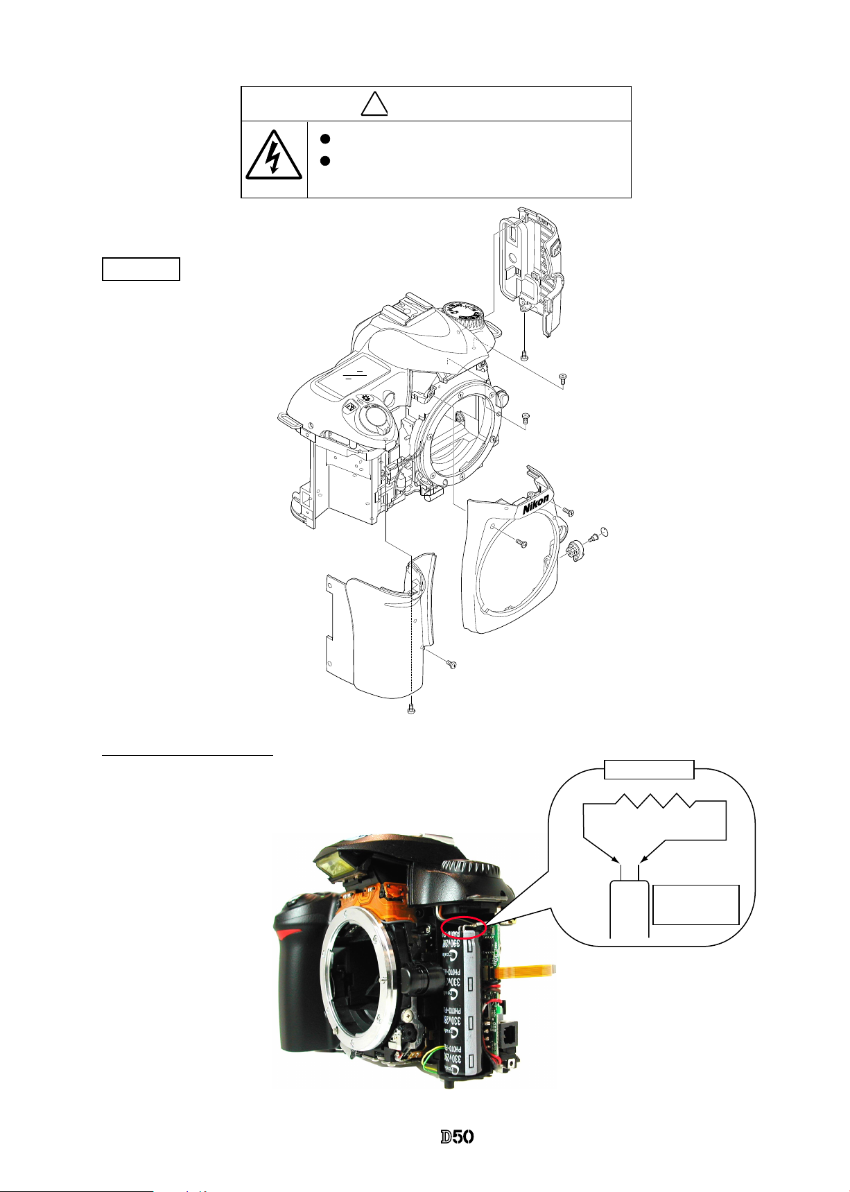
Points to notice for Disassembly / Assembly
�
内部に高電圧部あり。カバーを外す 時は感電に注意すること。
カバーを外した後は、修理指針の指 示に従ってメインコンデン
サーの放電を必ず行うこと。
警告
Note:
①
When disassembling/(re)assembling, be sure to use the conductive mat (J5033) and wrist strap (J5033-5)
for static protection of electrical parts.
②
Before disassembling, be sure to remove batteries or AC power wires.
③
When disassembling, make sure to memorize the processing state of wires and FPC, screws to be xed
and their types, etc.
④ Because the low pass lter of the imaging CCD PCB is easily damaged, handle it with enough care.
Points to notice for Lead-free solder products
・ Lead-free solder is used for this product.
・ For soldering work, the special solder and soldering iron are required.
・ Do NOT mix up lead-free solder with traditional solder.
WARNING
Due to an internal high voltage area,
take extra care not to
get an electric shock when detaching covers.
.
After removing covers, be sure to discharge the main
condenser according to the instructions of repair manuals
.
Note:
When "Seprating Front and Rear bodies","Disassembling Image PCB",and"Disassembling Bayonet",
be sure to perform"Reset of AF defocus compensation amount"by D2X adjustment software after reassembly.
Page 7
- D2 ・ -
VBA12001-R.3668.A
Disassembly
1. Separation of Front and Rear Bodies
Bottom Cover
#5692
#5697
#5677×7
Bottom cover
・
Take out the screws (#5692 and #5697) and 7 screws (#5677).
・
Remove the bottom cover.
Rear cover
・
Take out 4 screws (#623).
・
Cover to remove the rear cover.
Note: Remove the rear cover slowly so as not to cut TFT-PCB
connection FPC of the upper portion of the cover.
#623×4
Rear cover
Page 8
- D3 ・ -
VBA12001-R.3668.A
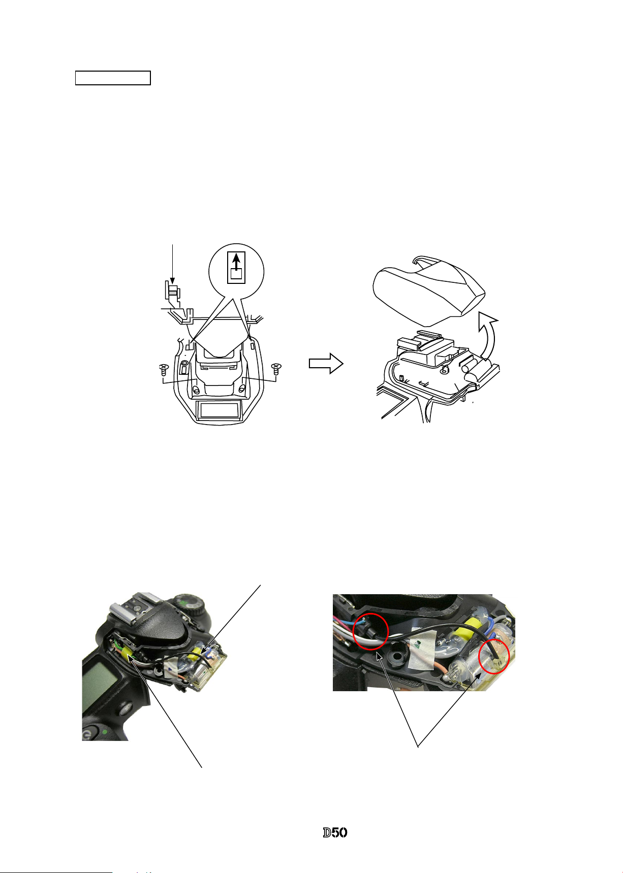
SB pop-up
Approx.2cm
Approx. 4cm
・
Remove TFT-PCB connection FPC from the connector.
・
Cut the tracing lm sheet, etc into the below size of piece. Then insert it into
the clearance of the top cover pop-up part as shown right, and pop it up by
sliding the sheet in the direction of the arrow.
TFT-PCB connection FPC
Page 9
- D4 ・ -
VBA12001-R.3668.A
Discharge Main condenser
・
Discharge the main condenser from its both terminal.
#627 × 3
Main
condenser
2KΩ/5W
�
内部に高電 圧部 あり 。カ バーを外す時は感電に注意す るこ と。
カバーを外 した 後は 、修 理指針の指示に従ってメイン コン デン
サーの放電 を必 ず行 うこ と。
警告
Covers
・
First, remove the front cover (#B5024).
#B5028
WARNING
Due to an internal high voltage area, take extra care not to get an
electric shock when detaching covers.
After removing the covers, be sure to discharge the main
condenser according to the instructions of repar manuals.
#635
#659
#5124
#5121
#611×2
#635
#635
#26
#B5024
A
U
T
O
#611 × 2
Page 10
- D5 ・ -
VBA12001-R.3668.A
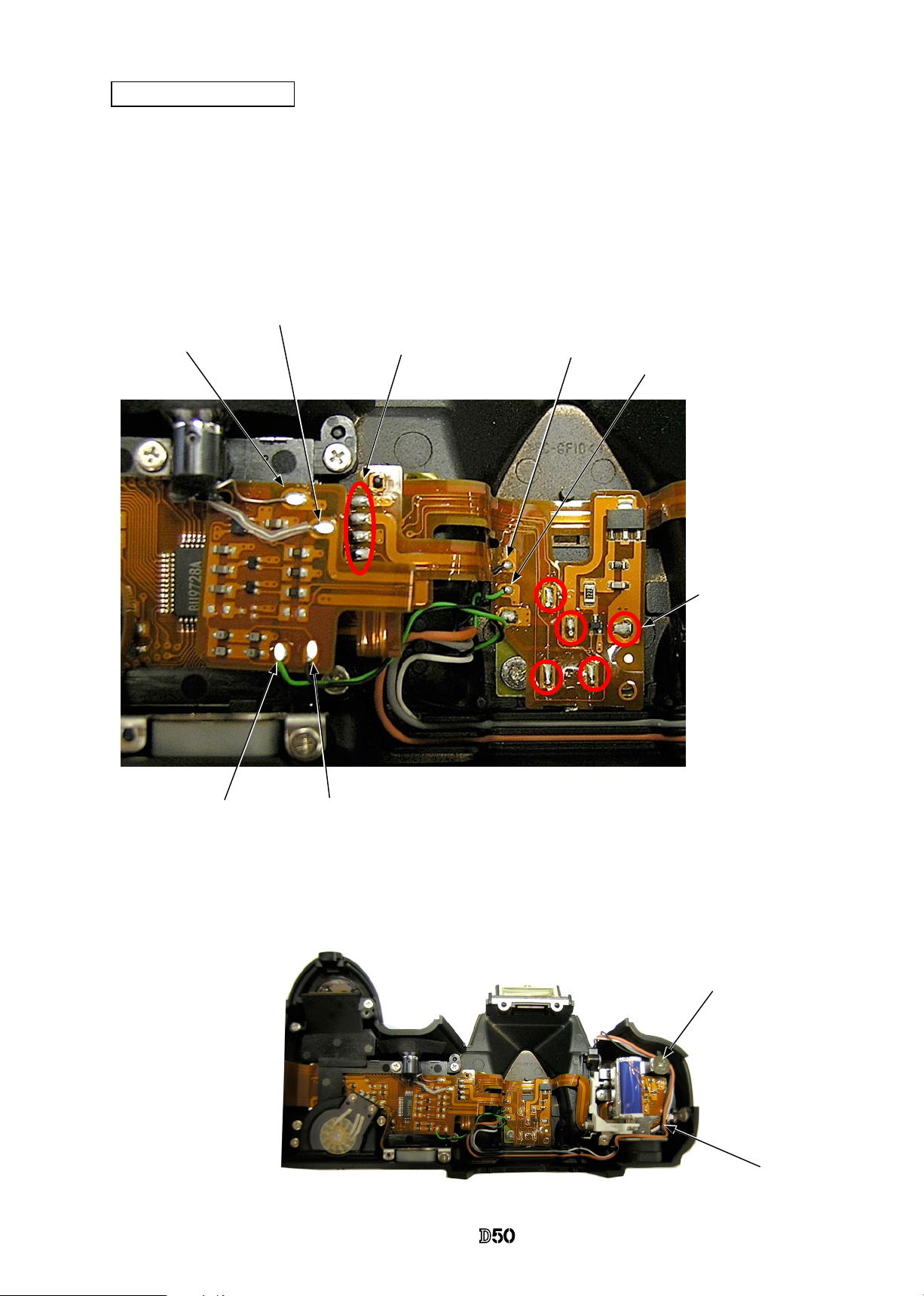
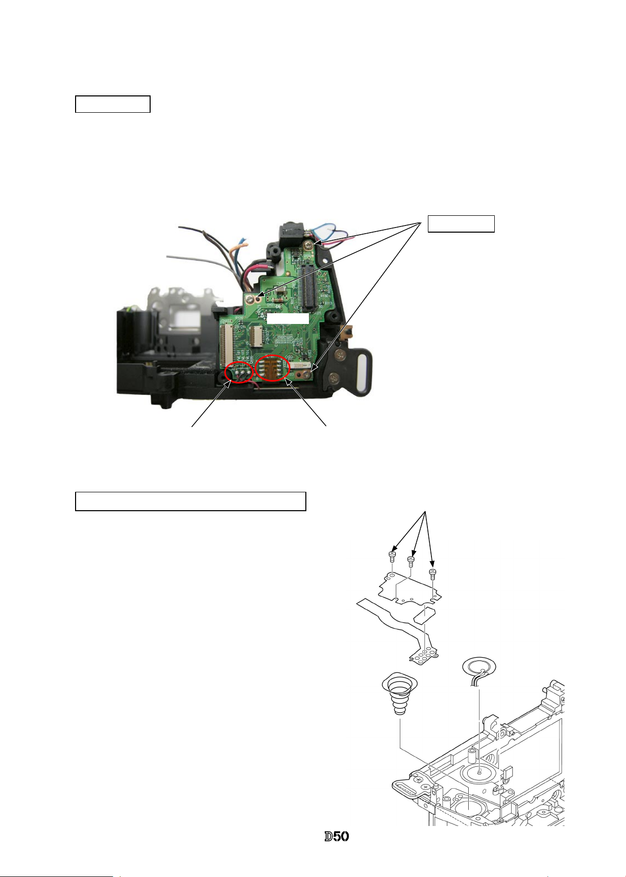
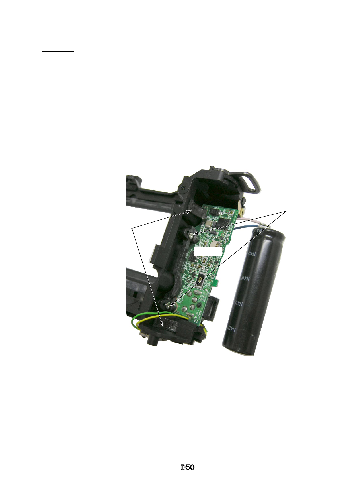
DG shield plate
#78
#627×3
DG-PCB unit
・
Remove 5 connectors.
・
Unsolder 2 reset SW wires.
・
Take out 2 screws (#663) and the screw (#627) to remove the DG-PCB unit (#B2031).
・
Remove 2 soldering bridges.
・
Take out 3 screws (#627).
・
Remove the DG shield plate (#78).
Soldering bridges
Green
Yellow
: Reset SW wire
#663×2
#627
#B2031
Page 11
- D6 ・ -
VBA12001-R.3668.A
・
Take out 3 screws (#669) to remove the CCD/FPC unit (#B2032).
CCD/FPC unit
#669×3
#B2032
Page 12
- D7 ・ -
VBA12001-R.3668.A
Top Cover
・
Unsolder 4 wires.
・
Take out 2 screws each of (#635, #656, and #5618).
The eyepiece frame (#B271) comes off, too.
Black
Orange
White
Gray
・
Remove the top cover FPC (#1007) from the connector.
・
Unsolder 2 wires of the top cover FPC.
* The solder land of gray wire is same as AF assist lanp unit.
Black
*Gray
#
656
#5618×2
#B271
#B0023
#656
#635×2
Top cover FPC
Page 13
- D8 ・ -
VBA12001-R.3668.A
Fig.1
・
Remove the tape (#709).
・
Remove the optical ber (#470) from the sensor.
#629×2
Note) Both ends of the optical ber are just
inserted in each part without any adhesive.
Optical ber
#470
#709
SB upper case
・
Press the pop-up lever A part of the top cover unit so that the built-in SB pops up.
・
Take out 2 screws (#629).
・
Push from beneath the hooking lever of the SB upper case as shown in Fig.1 . Then slide 2 hooks in the
direction of the arrow to remove the lever.
・
Deactivate pop-up of the SB lower case unit, and remove the SB upper case. (Fig.2)
Pop-up lever A part
SB upper case
Fig.2
Hooking lever
SB lower case unit
Page 14
- D9 ・ -
VBA12001-R.3668.A
・
Remove the wire-retaining screw (#650).
・
Remove wires.
Top cover FPC / Wiring
・
Remove the soldering bridges.
・
Remove the 2 solders of AF-assist illuminating lamps.
・
Remove the solders of 2 SPD sensor wires.
・
Remove the solders of 2 pop-up change SW wires.
・
Remove the solders of 5 accesory shoe contacts.
#
650
SPD sensor wire (Green)
SPD sensor wire (Black)
AF-assist illuminating
lamp
AF-assist illuminating lamp
(
covered for insulation
)
Soldering bridges
Pop-up change switch (Black)
Pop-up change switch (Green)
Accessory shoe contact ×5
Wires
Page 15
- D10 ・ -
VBA12001-R.3668.A
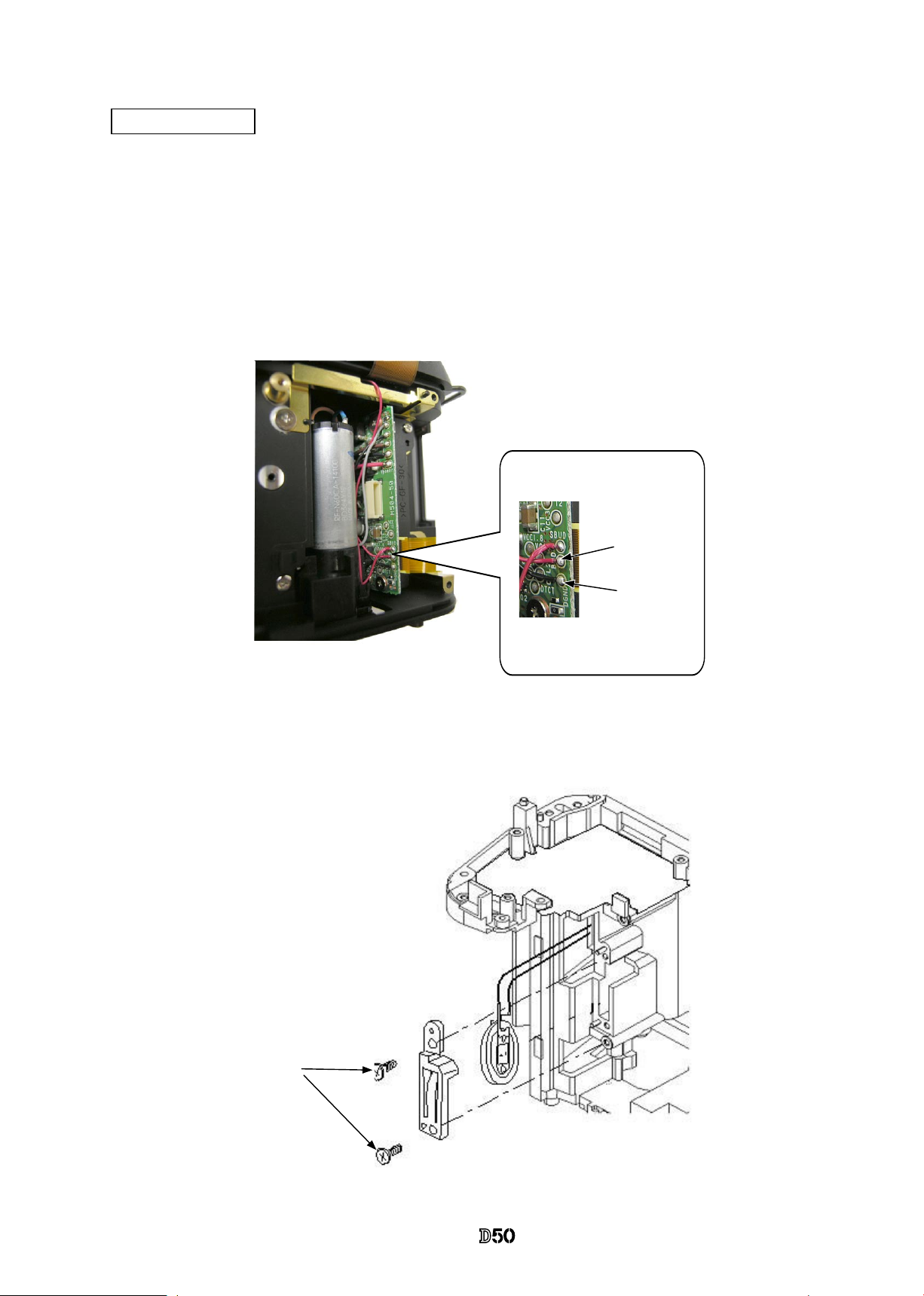
・
Remove #B341 and #B342.
Flash-up spring
#650
#305
#306
#308
2 hooks
#B2302
SB lower case unit
・Unhook the Flash-up spring
(#305).
・Take out the screw (#650) and
remove the Flash-up spring
(#305).
・Pull each wire out of hole.
・Loosen 2 hooks of the collar (#308) to remove it.
・Remove the SB case axle (#306).
・Detach the SB lower case unit (#B2302) from the top cover.
#B341
#B342
Page 16

- D11 ・ -
VBA12001-R.3668.A
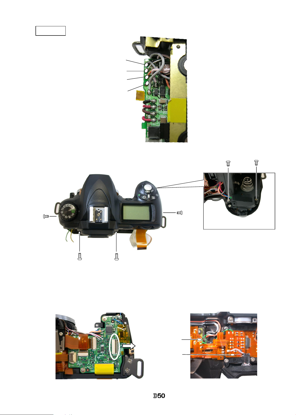
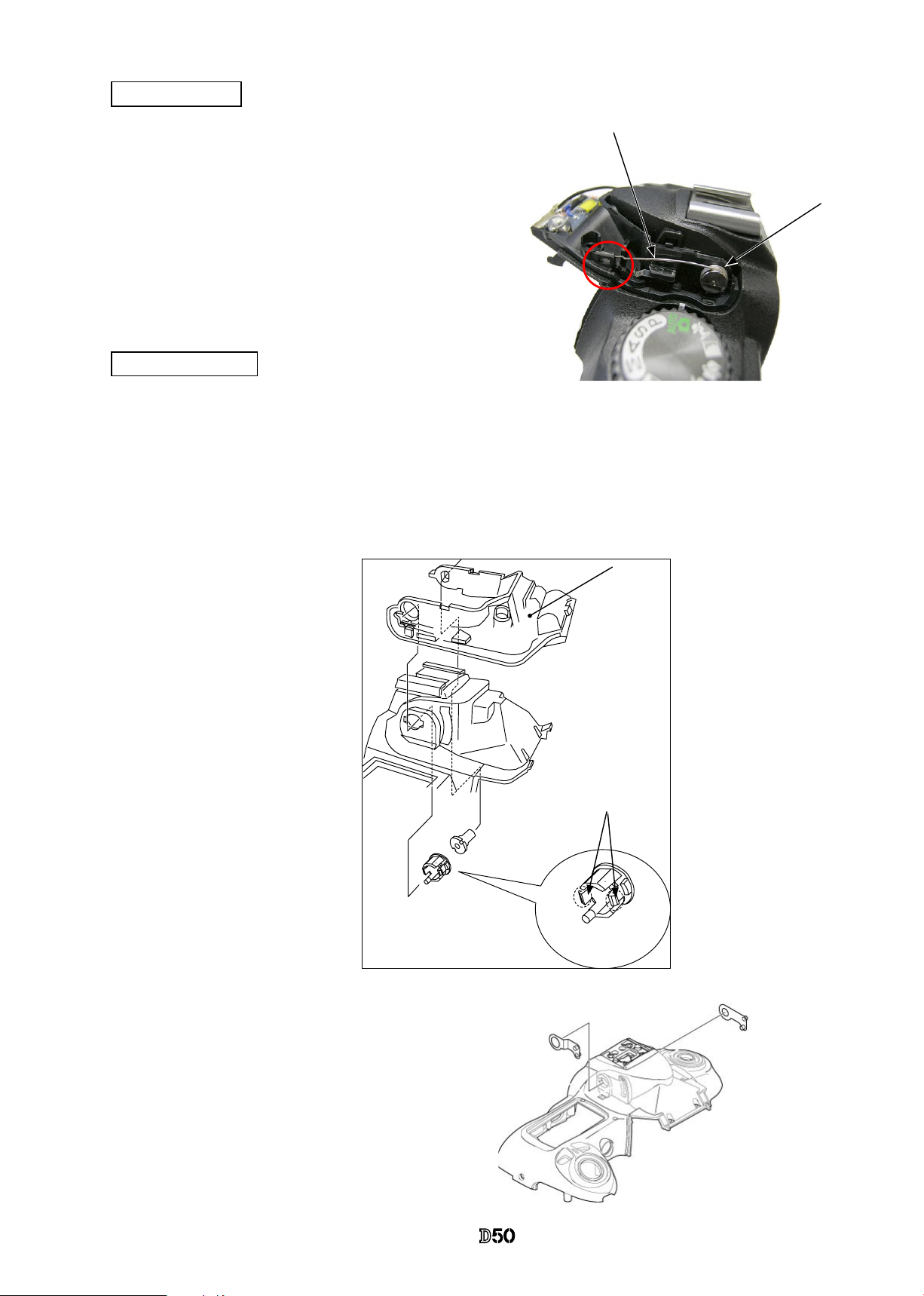
M/DFPC unit
AF-assist illuminating lamp / Command dial
・
Take out 2 screws (#640) to remove the M/DFPC unit (#B2455).
・
Remove the rubber SW (#389) and shooting operation-mode button (#388).
・
Remove the light-leak proof sponge (#766).
・
Take out the screw (#635).
・
Remove the AF-assist illuminating lamp (#B325).
・
Remove 2 screws (#635).
・
Lift to slack the command dial (#B367).
#640 × 2
#388
#389
#B2455
#766
#635
#B325
#B367
#635 × 2
Page 17
- D12 ・ -
VBA12001-R.3668.A
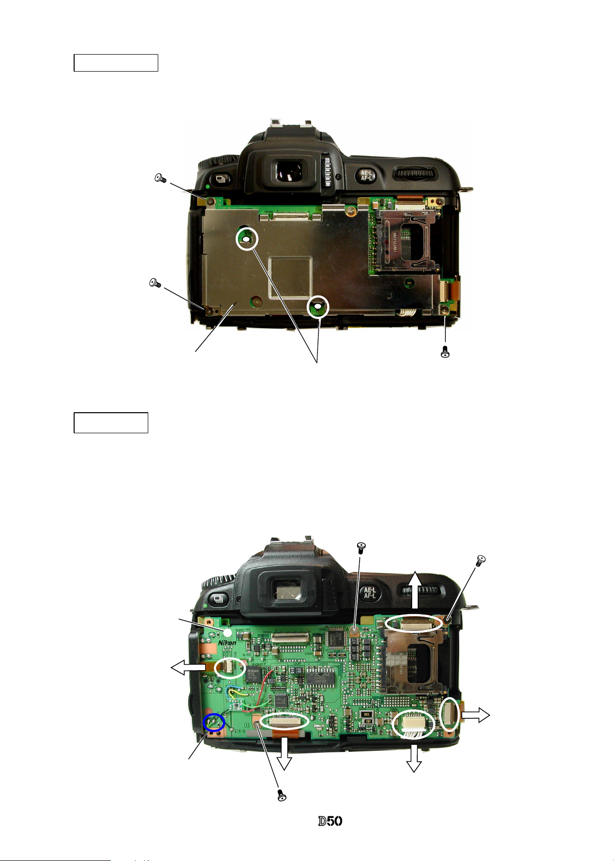
Top cover FPC
・
Take out the screw (#644).
・
Take out 5 screws (#635).
・
Remove the top cover FPC (#B2007).
・
Remove the AE-L rubber SW (#387) and AE-L button (#386).
#B2007
#331
#1044
#B367
#733
#1007
#735
#734
#332 × 2
#330
#386
#387
#644
#635 × 5
Page 18
- D13 ・ -
VBA12001-R.3668.A
Release button / other small parts
#5460
#461
#350
#351
#5345
#
352
#387
#5386
#5381
#382
#347
#348
#604 × 2
#335
#5383
Page 19
- D14 ・ -
VBA12001-R.3668.A
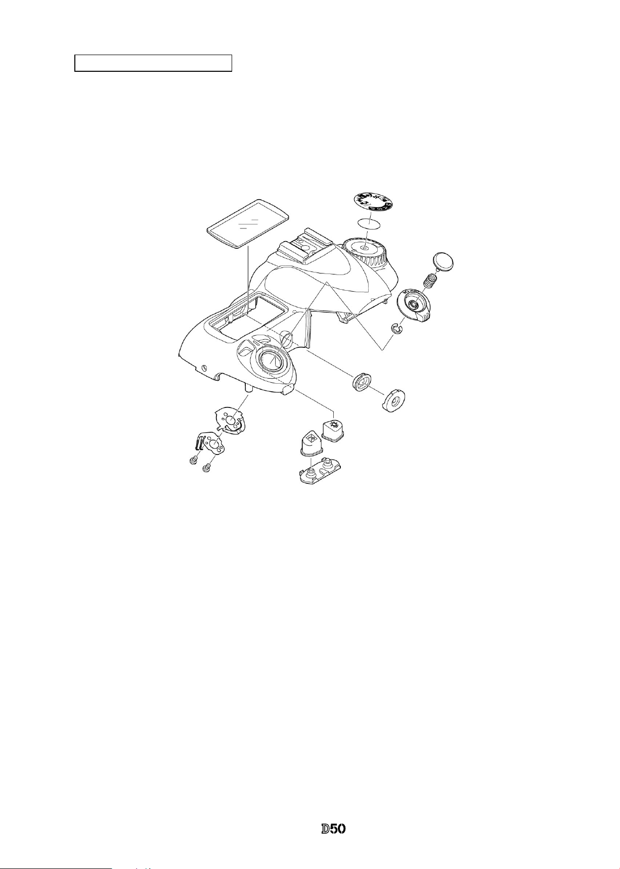
Outer LCD window / shoe mold unit / accessory shoe / other small parts
#452
#454
#654 × 4
#322
#640
#336 × 2
#337 × 2
#453
#338
#5451
B317
#316
#318
#321
#326
#463
Page 20
- D15 ・ -
VBA12001-R.3668.A
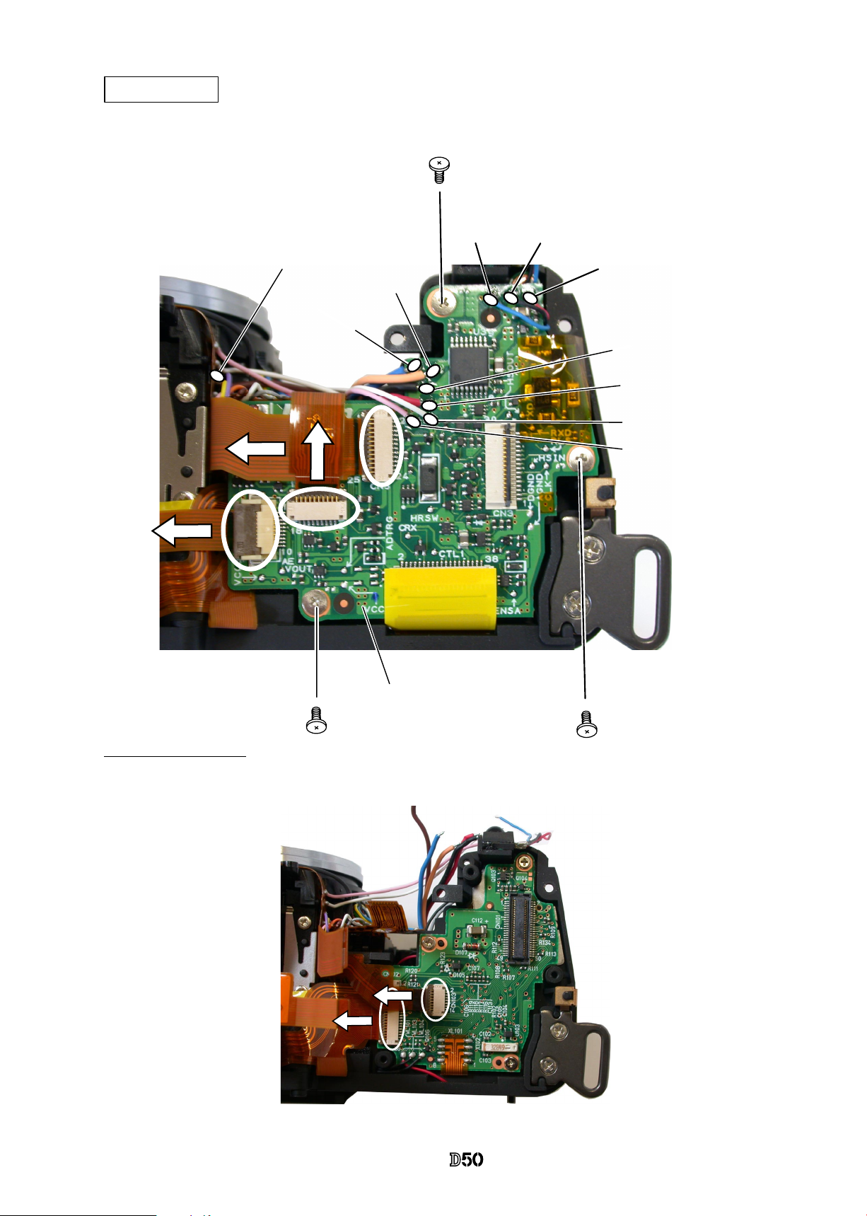
Main PCB unit
Removal of Connector
・
Remove 2 FPCs from the connector
・
Remove 3 FPCs from the connector.
・
Unsolder 10 wires.
・
Take out 3 screws (#640) to remove the
main-PCB unit from the sub-PCB.
Blue
Black
#640×3
Red
Orange
Blue
Black
Red
White
Pink
Main PCB unit #1001
Brown
Page 21
- D16 ・ -
VBA12001-R.3668.A
Separation of Front and Rear bodies
#642×3
Front body
Rear body
#699×3
#634×4
・
Take out 3 screws (#699), 4 screws (#634), and 3 screws (#642) to remove the front body.
Page 22
- D17 ・ -
VBA12001-R.3668.A
2. Rear body
・
Unsolder 3 wires of electronic buzzer .
・
Remove the soldering bridges.
・
Take out 3 screws (#644).
・
Remove Sub-PCB.(#B2002)
・
Take out 3 screws (#673).
・
Remove the retaining plate (#159).
・
Remove the battery-extrusion spring (#158).
・
Remove the electronic buzzer unit (#1055).
Sub-PCB unit
Electronic buzzer unit / Battery-extrusion spring
#
644×3
#673×3
#158
#
159
#1055
3 wires of electronic buzzer .
Soldering bridges
#B2002
Page 23
- D18 ・ -
VBA12001-R.3668.A
・
Unsolder 2 wires of the clock battery unit.
・
Remove 2 screws (#642).
・
Remove the clock battery holder (#73).
・
Remove the clock battery unit (B1059).
#
642×2
Clock battery unit
Black
Red
#73
(
B1059
)
Page 24
- D19 ・ -
VBA12001-R.3668.A
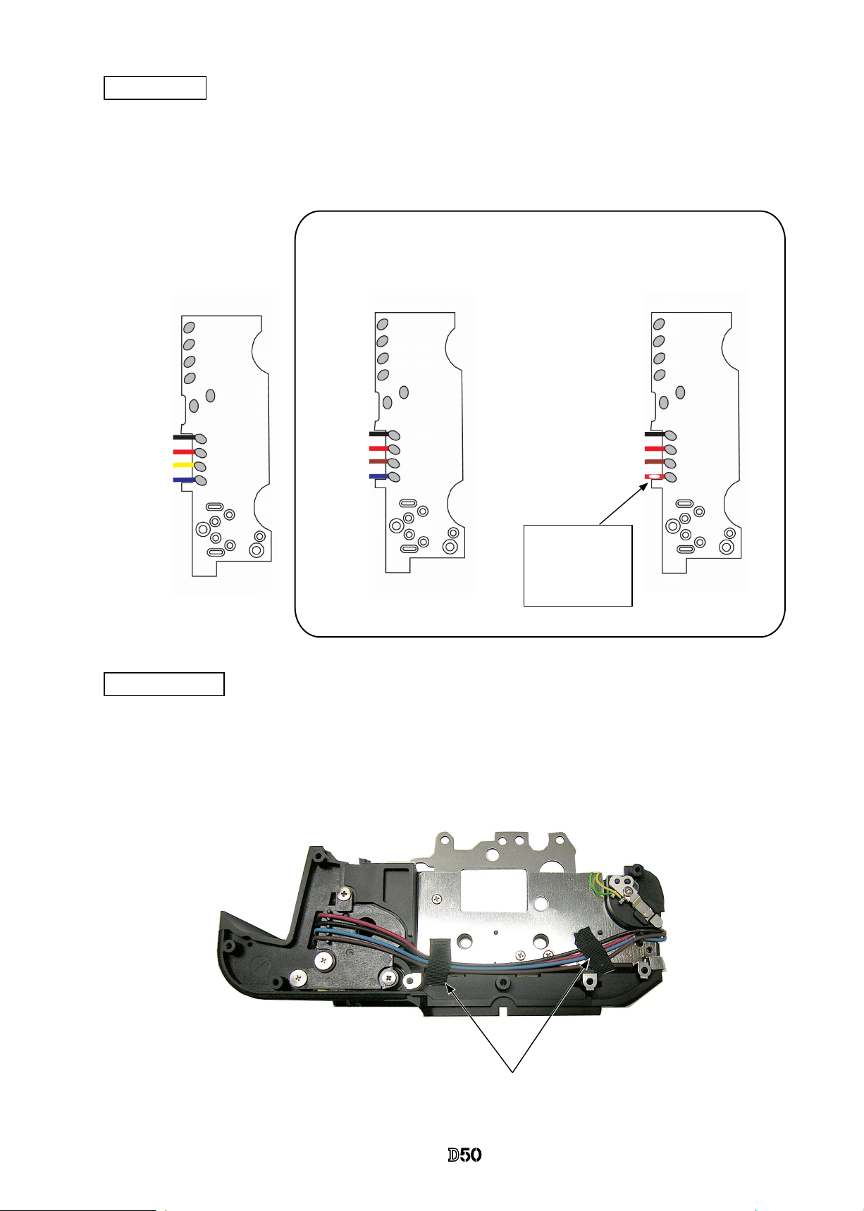
Bottom wires
Black
Red
Yellow
Blue
Wire arrangement tape
#715×2
・
Remove 2 pieces of tape that arrange wires (#715).
・
Remove wires.
・
Unsolder 4 wires of DC/DC PCB unit.
SB-PCBwires
Be careful that some PCBs at the inital stage of mass-production have
different colored wire.
Black
Red
Blown
Blue
Black
Red
Blown
Red
White marking is
painted for
identication.
Page 25

- D20 ・ -
VBA12001-R.3668.A
・
Take out 2 screws (#693).
・
Remove the DC/DC PCB unit (B2030).
#627×2
#633
#693×2
・
Take out 2 screws (#627).
・
Take out the screw (#633).
・
Remove the SQ-PCB (B91).
DC/DC PCB unit
SQ PCB
(B91
)
(
B2030
)
Page 26
- D21 ・ -
VBA12001-R.3668.A
・
Take out 4 screws (#635).
・
Remove the bottom base unit (#66) and bottom conduction plate (#106).
・
Take out the screw (#647).
・
Remove #80.
・
Take out the screw (#633).
・
Remove #81.
・
Remove #2030.
・
Take out 2 screws (#633).
#633×2
Lug plate / Bottom base unit
#80
#647
#633
#81
#2030
#635×4
#106
#66
Page 27
- D22 ・ -
VBA12001-R.3668.A
・
Remove the condenser (B1043).
・
Take out 2 screws (#635).
・
Remove the SB unit (B2041).
SB unit
(
B1043
)
#635×2
(
B2041
)
The condensor (#B1043) is xed
with 2 pieces of the both-sided
adhesive tape (#754).
Page 28
- D23 ・ -
VBA12001-R.3668.A
#680×2
#746
#777
#150
#146
#617×2
#145
#149
#617×2
#76×2
#714
#790
#761
#765
#790×2
#764×2
#747
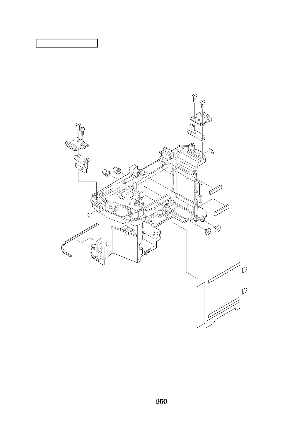
Rear body small parts
Page 29
- D24 ・ -
VBA12001-R.3668.A
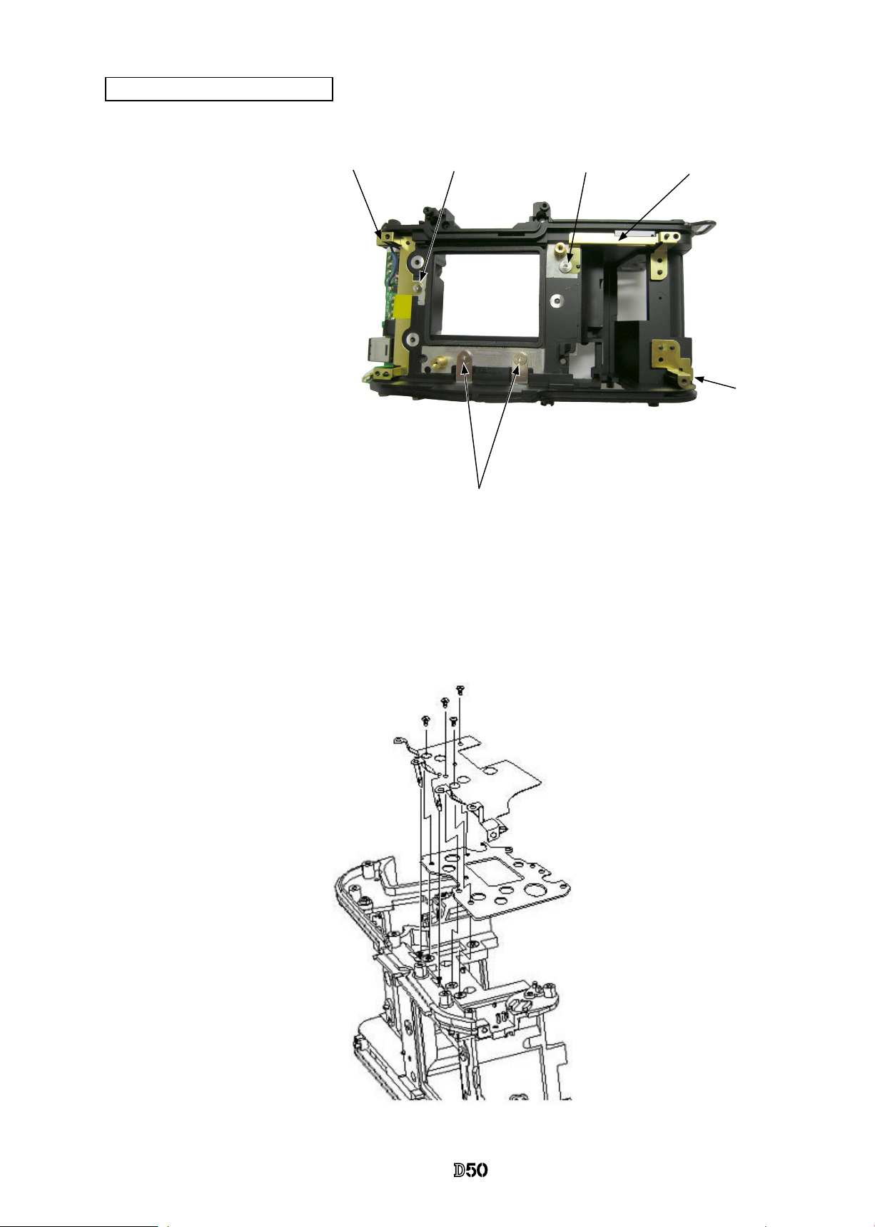
3. Front Body
・
Take out 3 screws (#291) to remove the metering FPC unit (#B2008).
・
3 springs (#290) come off.
・
Take out 2 screws (#635) to remove the metering FPC-base unit (#B286).
・
Remove the tape (#796).
・
Take out the screw (#635) to remove the eyepiece-lens unit (#B261).
Note:
The screws (#291) are attached with the
adhesive.
In case they (#291) are moved, AE CCD
position adjustment (ref. Assembly) becomes
necessary.
#796
Eyepiece unit
Metering FPC unit
#291×3
#290×3
#635×2
#B286
#B2008
#635×2
#B261
Page 30
- D25 ・ -
VBA12001-R.3668.A
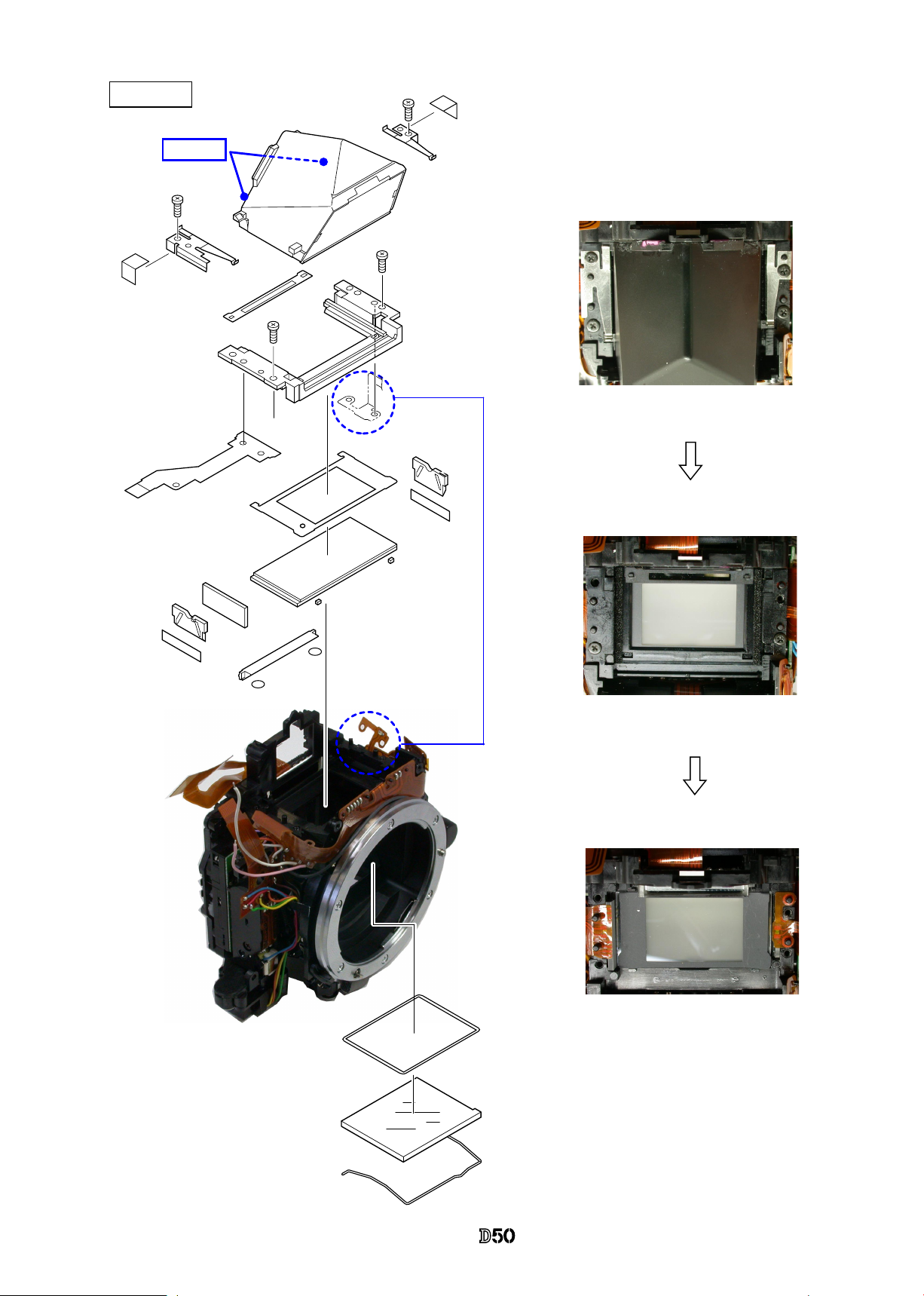
Penta unit
#284
#283
#9
#1046
#B279×2
#282
#B1021
#278
#B277
#642×2
#B4-2
#255
#256
#642×2
#297
#3
#739×2
Adhesive
#709×2
#792A×2
#280×2
Page 31

- D26 ・ -
VBA12001-R.3668.A
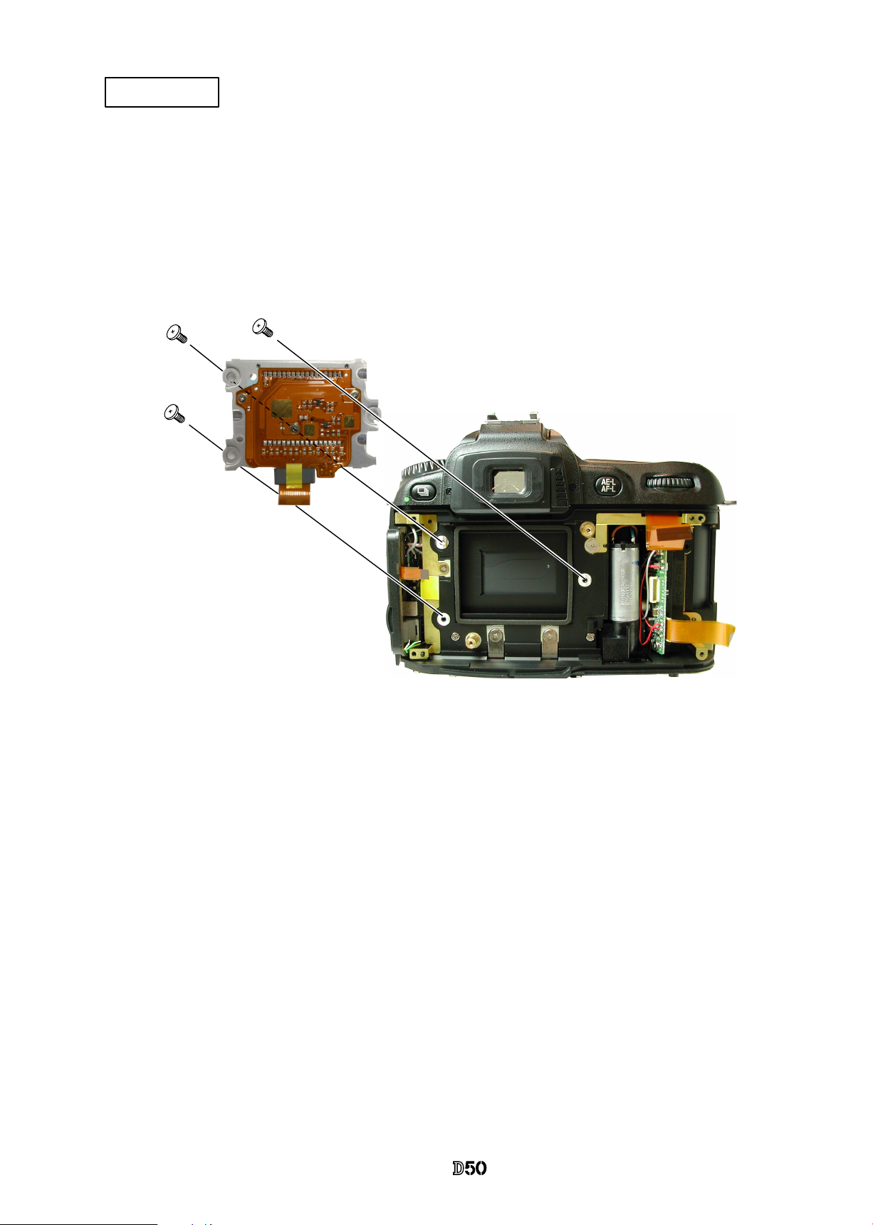
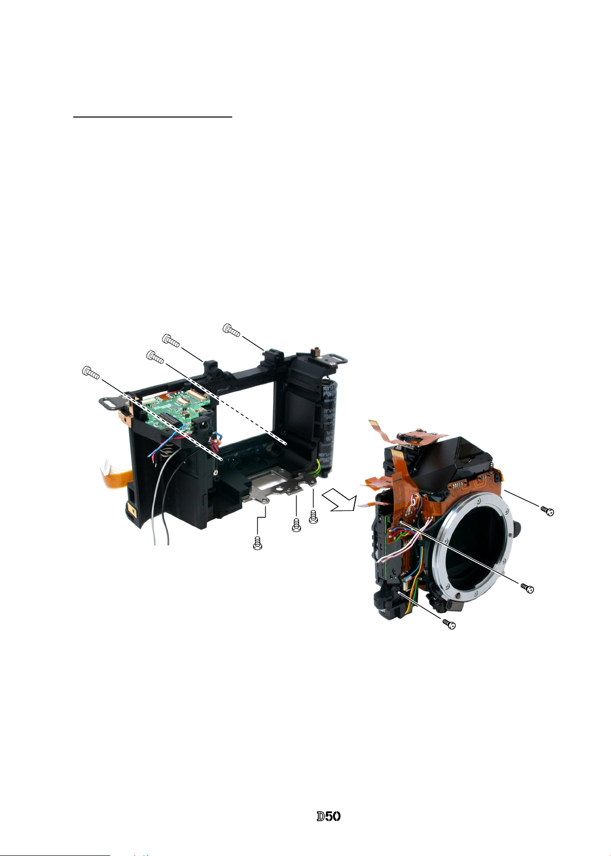
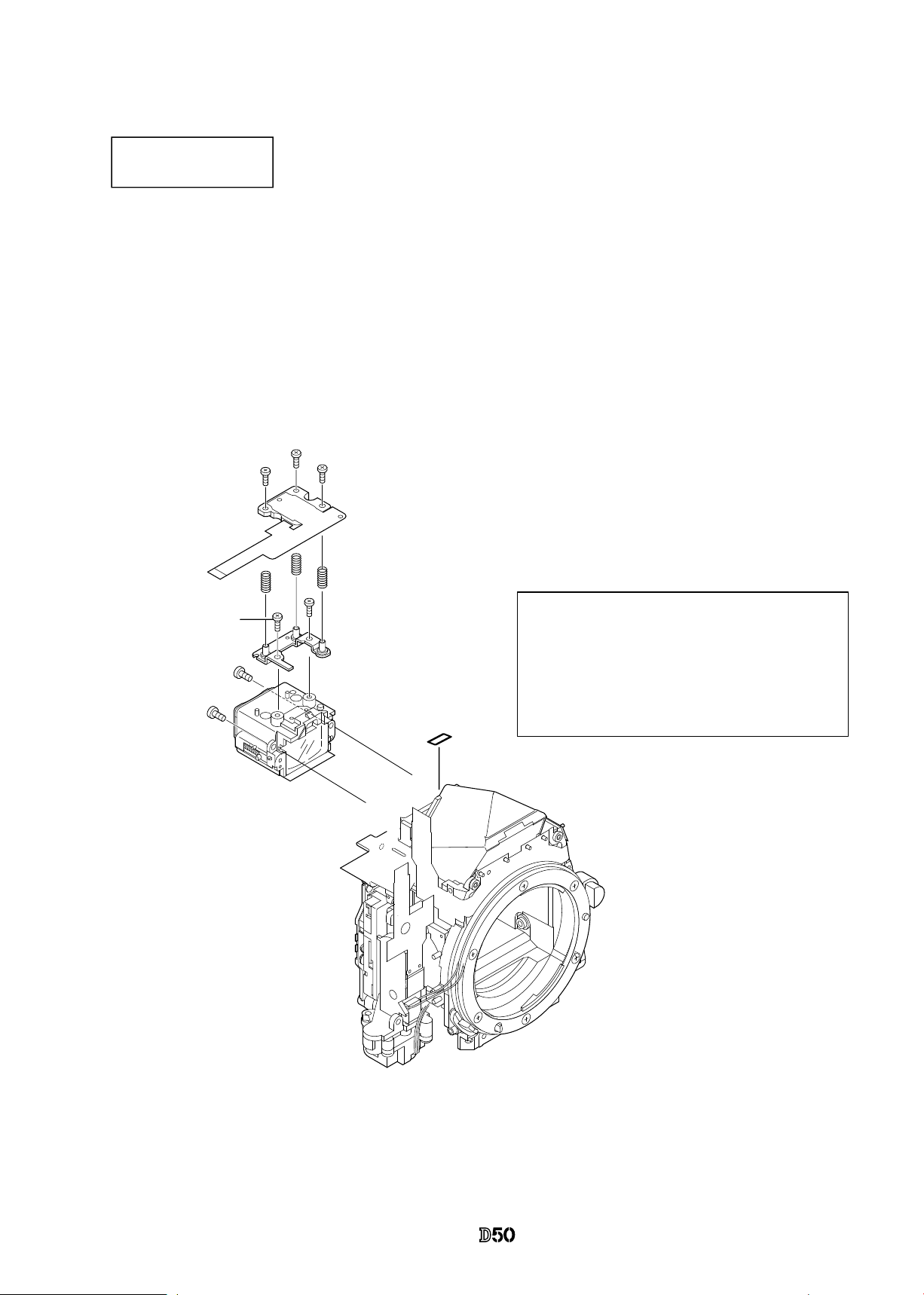
AF PCB unit
Shutter unit
・
Unsolder 7 wires.
・
Take out the screw (#607 and #627) to detach the shutter unit
(#B31).
#B31
#607
#627
#170×3
#636×3
AF PCB unit #B2163
#709×2
AF PCB FPC
・
Remove the tape (#709).
・
Remove AF-PCB connectoin FPC from connector.
・
Take out 3 screws (#636) with Hexagonal wrench
to remove AF PCB unit (#B2163).
・
3 springs (#170) come off, too.
Pink
White
Yellow
Brown
Orange
Gray
Purple
#728
Page 32

- D27 ・ -
VBA12001-R.3668.A
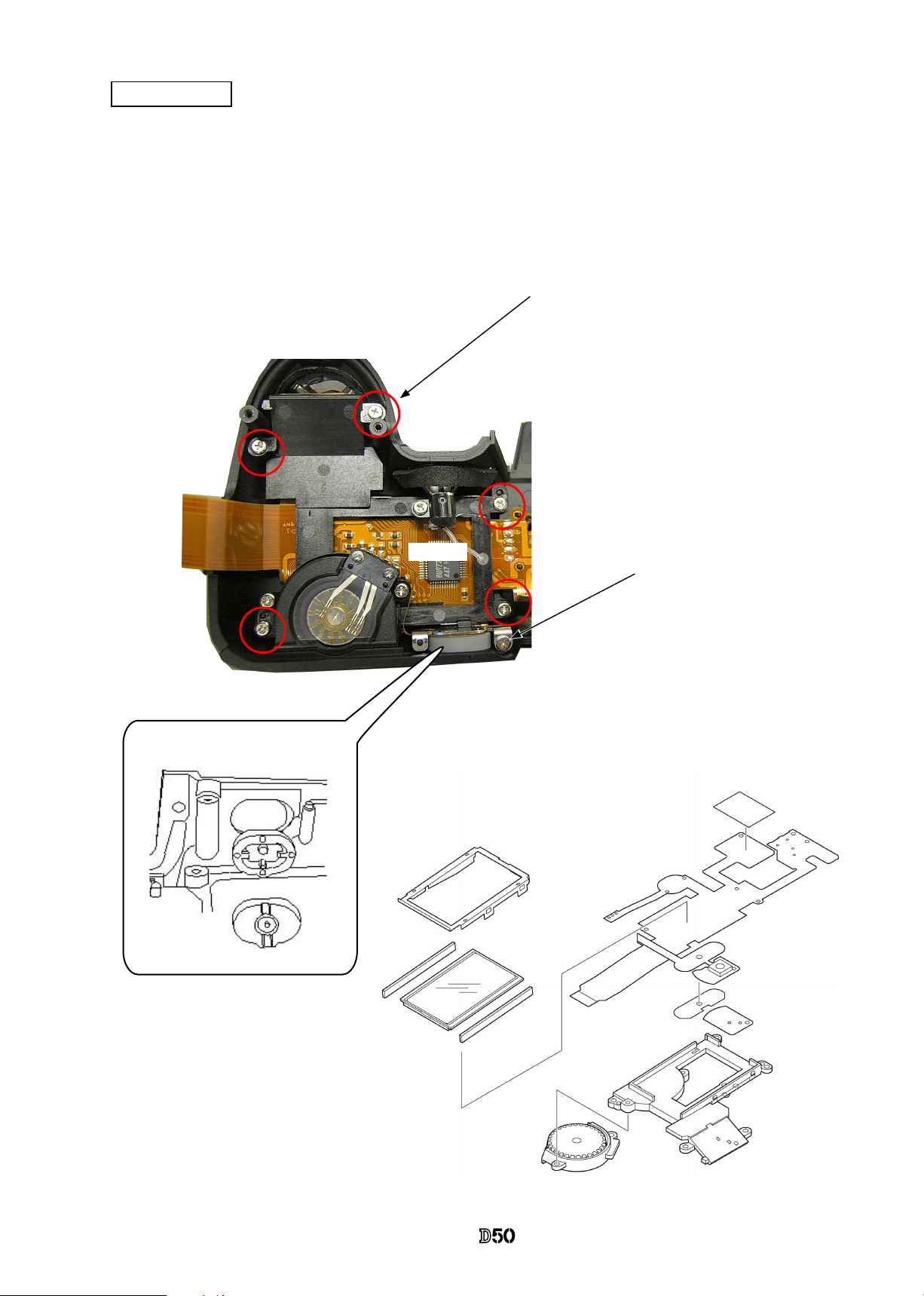
Inner LCD unit
・
Take out 2 screws (#626) to remove the inner LCD
unit (#B2010).
Front body FPC unit
#B2010
#626 × 2
・
Remove the sponge (#797 and #748).
#797
#748
Soldering bridges
Soldering bridges
Black:AF motor
Red:AF motor
Pink:V6
White:LBAT
Yellow:A/M SW
Black:A/M SW
AF PI
FPC
Front body FPC unit: #B1009
#619
Page 33

- D28 ・ -
VBA12001-R.3668.A
Aperture control unit
Procedure
①
Unsolder 2 wires .
②
Remove the screw (#661), spring (#214) and the lever (#254).
③
Take out 3 screws (#642).
④
Press down the aperture lever with Finger to move the aperture coupling lever (#207) in the direction
of arrow(
① )
.
⑤
In state of ④, remove the aperture control unit (#B241) by pulling it in the direction indicated by
arrow (②) while letting the arm (#B241) escape.
Front body viewed from the bottom
#642×3
#254
#214
#661
#B241
Aperture lever
#207
#203
Arrow
②
Arrow
①
#B241
Arm of #B241
Brown:Fmin SW
Black:Fmin SW
Page 34

- D29 ・ -
VBA12001-R.3668.A
#B172
#637×2
#185
#122
#191
#630
#B116
#195
#193
#630
#115
#119
#642
#621
・
First, remove the
horizontal lever
(#193).
AF driving unit
Lens release button
Vertical lever
Horizontal lever
Bayonet unit
A/M-change SW unit
(5)
#660
#111
#131
Soldering bridge of
#126 and #114
#642
#B125
#126
#642×2
#112×3
#132
#135
#114
#648×5
#189
#607
#123
#B2113
#607
Page 35

- D30 ・ -
VBA12001-R.3668.A
Aperture lever unit
F-min Switch unit
#639
#208
#213
#375
#375
#203
#206
#209
#207
#210
#212
#205
#642
#134
#B133
#190
#239
#238
#234
#199
#199
#B2231
#236
Mirror unit
・
Note that 2 pins (#199) and the
pin (#236) are attached with
the Super X.
Page 36

- A1 ・ -
VBA12001-R.3668.A
Assembly/
Adjustment
#239
#238
#234
#199
#199
#B2231
#236
#119
#236
Adhesive:C-8008B
Adhesive:C-8008B
Grease:LEN317A
#236
Apply to the inner diameter
surface where to put #199 in.
・
NOTE: For undescribed tapes and sponges here in"Assembly",
refer to"other tapes/sponges" on PARTS LIST.
1. Front body
Mirror unit
・
With being mirror-up as shown right,
assemble the pins and apply C-8008B
(Adhesive: Super X) on each pin.
Do NOT allow the adhesive
to be forced out on the head
of #199.
Apply the adhesive only on
1/4 periphery of the pin on
mount side.
Page 37

- A2 ・ -
VBA12001-R.3668.A
Aperture lever unit
F-min SW
中
#639
#208
#213
#375
#375
#203
#206
#209
#207
#210
#212
#205
#642
#134
#B133
#190
#1086
#1087
Brown
Black
Grease:
LEN317A
Grease: MZ-800S
#375×2
#205
#212
#213
(short)
(long)
#212
#205
Spring hooking shaft
Grease: LEN317A
Apply to overall of #209 and #210.
Apply inner diameter surface of
#203, #207, and #208.
Apply to periphery of shaft
Position for hooking spring
White
(middle)
Page 38

- A3 ・ -
VBA12001-R.3668.A
1. Turn the sequence white gear of the aperture control unit in the direction of the arrow, and position the arm as
shown in Fig.①.
2. Place #248 in center of movement of range, and lock it with #249. (ref. Fig.①)
3. Insert the arm between #207 and #203. (ref. Fig.②)
4. Attach 3 screws (#642). (ref. Fig.③ and
④)
Fig.
①
Fig.
②
#248
#249
Arm
#
207
#
203
Fig.
③
Fig.
④
#
642
#
642×2
Direction for
positioning
Aperture control unit
*
Note: Be careful not to bend contact blade of F-min SW.
Aperture control unit
Page 39

- A4 ・ -
VBA12001-R.3668.A
#
637×2
#B172
#254
#
214
#
661
#661
・
After screwing the
spring (#214), hook
it to #254.
AF driving unit
#214
・
Position #B172 by fol-
lowing the direction
and screw it.
#637×2
#642
#B125
#126
#B116
Grease: LEN317A
Apply a little on sliding surface
A/M change SW
Lens release button
Page 40

- A5 ・ -
VBA12001-R.3668.A
Position
for hooking
spring#195
#185
#630
#193
Grease: LEN317A
#191
#630
#122
Grease:LEN317A
Apply to inner diameter of
#122 and #191
・
Assemble by the following order.
#
122→
#
191→
#
630
*
Note: Be careful NOT to bend contact
blade of the lens release SW.
Vertical lever
Lens release SW
comes on the lever.
Horizontal lever
・
Insert t he U-shap ed part of
#193 into the groove of the
AF driving shaft (#185).
#195
Page 41

- A6 ・ -
VBA12001-R.3668.A
(5)
Soldering bridge of #126 and #114
Yellow
Black
#126
#119
#115
#642
#621
#135
#112×3
#607
#131
#132
#111
#114
#660
#648×5
#189
#642×2
#607
Grease: LEN317A
#112×3
Bayonet unit
AF lens contacts
A/M change SW cover unit
#123
#B2113
Page 42

- A7 ・ -
VBA12001-R.3668.A
#185
Bayonet mount
1.7±0.15mm
#625
Adhesive: Screw lock
3.4±0.1mm
絞りレバー
Height adjustment of AF coupling shaft
①
Set the A/M change cam (#122) to
AF side. (i.e. The AF coupling
shaft
(#
185) sticks out of the
bayonet.
)
②
Adjust the height of the AF coupling
shaft (#185) with the screw (#625)
so that it becomes 1.7±0.15mm.
③
After the adjustment, x the screw
(#625) with screwlock.
#
122
A/M change cam
Height adjustment of Aperture lever
・
Measure the height of the aperture lever by using the tool (J18004).
Standard: 3.4±0.1mm
In case the value is out of standard, make an adjustment by bending the circled part.
Be careful NOT to bend the inner part of the lever when adjusting!
Aperture lever
Page 43

- A8 ・ -
VBA12001-R.3668.A
#295
#B22
Cross-section view
#B2010
#626×2
#797
#748
Attachment of #797 and #748
#1009
Soldering bridges
Pink:V6
White:LBAT
Soldering bridges
Yellow:A/M SW
Black:A/M SW
・
Insert the tip of AF PI FPC and make a
soldering bridge.
Black:AF motor
Red:AF motor
Front body FPC
Inner LCD unit
・
Attach the sponge (#295) on the front plate (#22).
・
Attach the inner LCD unit (#B2010)
with 2 screws (#626).
・
Attach the
sponge
(#797) and (#748)
#619
Page 44

- A9 ・ -
VBA12001-R.3668.A
・
Solder 9 wires.
#B31
#607
#627
Pink:Shtter
White:Shtter
Yellow:Shtter
Brown:Shutter
Orange:Shutter
Gray:Shutter
Purple:Shtter
・
Make an arrangement of wires
and attach the tape (#713).
Wires arrangement
#713
Shutter unit
・
Attach the shutter unit (#B31) with the screws
(#607 and #627).
Black:F min SW
Brown:F min SW
Page 45

- A10 ・ -
VBA12001-R.3668.A
#728
Horizontal lever (#193)
Position for attaching #728
FPC of AF CCD unit
AF CCD FPC unit
#B2163
#170×3
#636×3
AF CCD FPC unit
#B2163
AF sensor FPC unit
・
Attach 3 screws (#636) with Hexagonal
wrench to screw up but not too tight, then
give it about 1 turn counterclockwise.
・
Attach 2 tapes (#709).
・
Attach #728 so that the FPC of
AF CCD FPC unit can be protected.
#709 × 2
Page 46

- A11 ・ -
VBA12001-R.3668.A
Adhesive: C-8008B
Direction for positioning
of SI glass (#1046)
#284
#297
#3
#283
#9
#1046
#B279×2
#280×2
#282
#B1021
#278
#B277
#642×2
#B4-2
#255
#739×2
Adhere
Penta unit
#709 × 2
#256
#642 × 2
#792A×2
Page 47

- A12 ・ -
VBA12001-R.3668.A
Angle adjustment of Main mirror and sub-mirror
*Tools required:
1.Main mirror 45°Inspection and Adjustment
2. Sub-mirror 47.75° Inspection and Adjustment
J18037
J18362
①
Collimator (J19002)
②
Reection mirror (J18362
)
③
Optical parallel (J18037
)
④
Hexagonal wrench
Main mirror
Eccentric pin for
the main mirror
Collimator
Bayonet
J18324
①
Collimator (J19002)
②
Sub-Mirror 45 deg. inspection tool
(J18324
)
③
Hexagonal wrench
Sub-mirror
Eccentric pin
for the submirror
Collimator
Bayonet
* Standard:
Main mirror Sub-mirror
Left-right
deviation
±30’ or less
__
Up-down
deviation
±10’
+15’~-50'
Distortion
8’or less
8’or less
Up-down
Left-right
Reference
line
Width of line indicates
deviation.
・
Before and after the adjustment, check the accuracy by moving the main mirror up- and downwards a few
times.
・
Check for the up-down deviation. In case the deviation is out of standard, make an adjustment by turning the
eccentric pin with Hexagonal wrench.
・
In case the deviations of up-down and left-right are out of standard, the front plate unit or mirror unit is
regarded as malfunctioning.
・
In case of checking or adjusting only the front body, check again after assembling the front body into the rear
body.
* Note:
Page 48

- A13 ・ -
VBA12001-R.3668.A
#291×3
#290×3
#635×2
#635×2
#B286
#B261
・
Attach 3 screws (#291) until the
metering FPC unit is lightly
xed.
Give the reference screw 1 turn
counterclockwise.
#B2008
#796
Reference screw
Eyepiece unit
Metering FPC unit
・
Position the eyepiece unit (#B261)
downward and x it with 2 screws
(#635).
・
Attach the tape (#796).
・
Fix the metering FPC-base unit
(#B286) with 2 screws (#635).
・
Attach the metering FPC unit (#B2008)
and 3 springs (#290) temporarily with
3 screws (#291)
.
Note: Be careful that slack here
catches the rear body when it
is assembled.
No slack
2 pieces of tape (#709)
2 pieces of tape (#709)
Page 49

- A14 ・ -
VBA12001-R.3668.A
2. Rear body
#680×2
#746
#777
#150
#146
#617×2
#145
#149
#617×2
#76×2
#714
#790
#761
#765
#790×2
#764×2
#747
Rear body small parts
Page 50

- A15 ・ -
VBA12001-R.3668.A
・
Install the SB unit (B2041).
・
Fix 2 screws (#635).
・
Attach 2 pieces of tape (#754).
・
Mount the condenser (#B1043) by positioning it in the direction of the arrow.
#635×2
SB unit
#754×2
(B1043)
(B2041)
Position downwards.
(B2041)
Page 51

- A16 ・ -
VBA12001-R.3668.A
・
Mount the bottom base unit (#66) and bottom conducting plate (#106).
・
Fix 4 screws (#635).
・
Fix 2 screws (#633).
・
Attach #80.
・
Fix the screw (#647).
・
Attach the short-circuit proof tape (#787) on #80.
・
Attach #81.
・
Fix the screw (#633).
・
Attach #2030.
#80 must NOT seat below #150.
Bottom base unit / Lug plate
#80
#150
#635×4
#106
#66
#633×2
#80
#647
#633
#81
#2030
#787
Page 52

- A17 ・ -
VBA12001-R.3668.A
・
Mount the DC/DC PCB unit (B2030).
・
Pass the wires through the holes.
・
Fix 2 screws (#693).
Pass the wires
through the holes.
Pass the wire of the electronic
buzzer (red) through the hole.
#693×2
(
B2030
)
・
Mount the SQ PCB (B91).
・
Arrange wires by pulling them in the direction of the arrow.
・
Fix the screw (#633).
・
Fix 2 screws (#627).
#627×2
#633
Direction for pulling wires
(
B91
)
DC/DC PCB unit
SQ unit
Page 53

- A18 ・ -
VBA12001-R.3668.A
・
Arrange wires.
・
Attach 2 pieces of tape (#715).
Arrange 4 wires of the DC/DC PCB properly
by put each into between bosses as shown
above.
Put 2 of 4 wires each into
between bosses.
To keep wires from covering the AF adjustment
holes, attach 2 pieces of tape (#715).
Bottom wires
・
Solder 4 wires of DC/DC PCB unit.
Black
Red
Yellow
Blue
SB-PCBwires
Be careful that some PCBs at the inital stage of mass-production have
different colored wire.
Black
Red
Blown
Blue
Black
Red
Blown
Red
White marking is
painted for
identication.
AF adjustment holes.
Page 54

- A19 ・ -
VBA12001-R.3668.A
・
Set the clock battery unit (B1059).
・
Pass the wires through the hole.
・
Attach the clock battery holder (#73).
・
Fix 2 screws (#642).
・
Solder 2 wires of the clock battery unit.
#
642×2
#73
#B1059
Pass the wires through the hole.
Clock battery unit
Red
Black
Page 55

- A20 ・ -
VBA12001-R.3668.A
・
Mount the electronic buzzer unit (#1055).
・
Set the battery-extrusion spring (#158).
・
Attach the retaining plate (#159).
・
Fix 3 screws (#673).
・
Mount the sub-PCB.(B2002)
・
Fix 3 screws (#644).
・
Solder 3 wires of the electronic buzzer .
・
Make the soldering bridges.
#673×3
Assemble so that the
soldering portion of
#1055 comes within the
range of the arrow.
Do NOT push central part.
Electronic buzzer unit / Battery-extrusion spring
Sub-PCB unit
#1055
#644×3
Red Black Black
#159
#158
#1055
Soldering bridges
#B2002
Page 56

- A21 ・ -
VBA12001-R.3668.A
①
Do NOT pinch wires and FPCs. Assemble by positioning them.
②
Fix 3 screws (#642) by the following order: ①, ②, and ③.
③
Fix 4 screws (#634) by the following order: ①, ②, ③, and ④.
④
Fix 3 screws (#699) by the following order: ①, ②, and ③.
①
②
③
#642 × 3
Front body
Rear body
#699 × 3
#634 × 4
Arrange FPCs of the inner LCD by putting
them into the clearance between rear body
and eyepiece.
①
①
②
②
③
③
④
3. Mount Front body on Rear body
Mount the front body on the rear body
Direction for
positioning to
attach the front
plate.
Page 57

- A22 ・ -
VBA12001-R.3668.A
・
Measure 4 parts from the bayonet face to the CCD-PCB
attaching face.
Standard:48.25±0.015mm/ Parallelism: within 0.015mm
・
In case it is out of standard, make an adjustment
by loosening screws that attach the front and rear bodies,
or
by putting the washer(s) on the contact surface be-
tween the front body and rear body.
Measuring points
* "0" positioning of the dial gauge
Inspection and Adjustment of Body back
0" position of D50
①
Put the tool (J18001-1) on the surface plate, and set the dial gauge to "0".
②
Turn the index ring to shift the position by "0.42 mm" from "0" that was set in ①.
(This position is "0" of D50.)
③
Measure the body back based on "0" reference position of the index ring.
Surface plate
Note: For some bodies, washer(s) are already put on the attaching face of the CCD-bracket.
There are 2 cases as follows.
1. Purpose:To adjust the height of the camera body
There are indications(color mark) on the camera body side of the CCD-PCB attaching face.
{Blue =0.02mm (#87), Red=0.1mm (#88), Green=0.06mm (#89)}
*
By adding the measured value to the thickness of washers, check if it is within the standard
(48.25±0.015mm).
2. Purpose:To adjust the height of the CCD bracket
There are indications(color mark) of the CCD-bracket attaching face
{
Red 2 lines=0.02mm (#87), Red 1 line=0.1mm (#88)}
*
When the CCD PCB is replaced, remove the washers.
Page 58

- A23 ・ -
VBA12001-R.3668.A
#1023
#1002
#640×3
#1001
#786
#783
①
②
Main PCB unit
・
Solder 1 wire
・
Connect each
FPC to the connectors
in the order of
①
and then
②
.
・
Pass the D/G main FPC (#1023) through the hole
of the rear body.
・
Connect the connectors of the backside of the
main FPC (#1001) and the sub-PCB (#1002).
・
Fix 3 screws (#640).
・
Attach the twe tapes (#783 and #786)
SUB PCB unit
Brown:DC/DC PCB
connectors
Brown:DC/DC PCB
Page 59

- A24 ・ -
VBA12001-R.3668.A
・
Solder 9 wires.
Blue: Remote
Red: Remote
Black: Remote
Orange: Sequence motor
Blue: Sequence motor
Black: DC/DC PCB
Red: DC/DC PCB
Pink: Front body FPC
White: Front body FPC
・
Connect each
FPC to the connectors
in the order of
①
and
②
the
③
.
①
②
③
Page 60

- A25 ・ -
VBA12001-R.3668.A
#669×3
#B2032
CCD/FPC unit
DG PCB unit
*
Note
1. In case a washer is put between the rear body and the
CCD bracket, follow the instructions of Page A22.
2. In case a spacer is attached on "a" part of the body,
do NOT remove and leave it as it is. (There is No
indication of marking.)
・
Attach the CCD/FPC unit (#B2032) with 3 screws (#669).
・
Attach the DG-PCB (#B2031) with 2 screws (#663) and
the screw (#627).
・
Solder 2 wires of the reset SW.
・
Connect 5 connectors.
#663×2
#627
#B2031
: Reset SW wires
Yellow
Green
Directin for positioning
CCD bracket
Page 61

- A26 ・ -
VBA12001-R.3668.A
・
Attach the DG shield plate (#78) with 3 screws (#627).
・
Make 2 soldering bridges.
・
Attach the tape (#799)
#78
Soldering bridge
#627×3
Tape (#799)
Remove backlash of the rear cover.
DG shield plate
Page 62

- A27 ・ -
VBA12001-R.3668.A
・
Procedure
①
To prevent short circuit, attach the grip (#26) with the screw (#635), and
also I/F cover (#B5028) with the screws (#635). Insert
AECCD alignment tool (J15417)
between the FD screen and the SI plate.
*
Position AE-CCD positioning tool in the direction of the arrow to
insert.
②
Connect camera and PC via USB cable UC-E4.
③
Provide power to camera via AC adapter EH-5.
*Note: Be careful of short circuit where there is no cover.
④
Start up the inspection and adjustment software for D50 (J18385),
and select "INSPECTION AND ADJUSTMENT FOR AECCD
POSITION" then "CCD ALIGNMENT INSPECTION AND
ADJUSTMENT".
*
Cover the camera with black cloth, when measured.
⑤
By following instructions on PC, make the position adjustment of
AECCD by the screws (#291 a,b).
⑥
Select “CCD SLANT INSPECTION” of the adjustment software and
make an inspection.
⑦
After the adjustment, x the AECCD by applying Crazy glue slightly..
⑧
Remove EH-5, UC-E4, and AECCD positioning tool(J15417).
⑨
Take out the grip (#26), and I/F cover unit (#B5028).
Adhesive: Super glue
Reference screw
b:#291
AE-CCD positioning
tool (J15417)
・
Atach the metering FPC unit
slightly with 3 screws (#291).
Give the reference screw 1
turn counterclockwise, then
make an adjustment by the
screws (a and b).
Note:
With the metering FPC unit being
attached slightly, if more than 3
turns are given to loose, the head
of the screws touch the top cover.
Inspection and adjustment of AE CCD Alignment
Meterring FPC unit
a:#291
Page 63

- A28 ・ -
VBA12001-R.3668.A
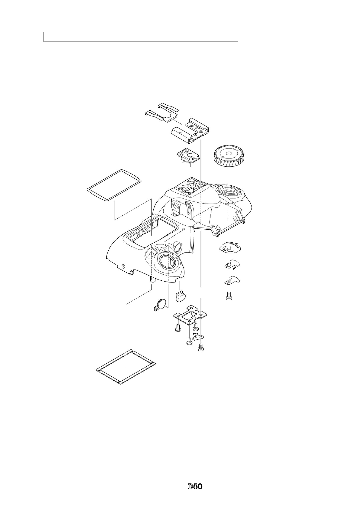
#454
#452
#453
#338
#5451
B317
#316
#318
#336×2
#322
#321
#337×2
#654×4
#463
#326
#640
Outer LCD window / shoe mold unit / accessory shoe / other small parts
A part
Attach #336 and #337 so that they
they are NOT separated by a gap at
"A" part.
Adhesive: Super X
Grease: LEN317A
Grease: LEN317A
Grease: OS-30MF
Top cover grease-applied location
Power dial greaseapplied location
Grease: LEN317A
Mode dial grease-applied location
Page 64

- A29 ・ -
VBA12001-R.3668.A
Release button / other small parts
#5460
#461
#350
#351
#5345
#352
#387
#5386
#5381
#382
#347
#348
#604 × 2
#335
#5383
Page 65

- A30 ・ -
VBA12001-R.3668.A
Top cover FPC
・
Attach the top cover FPC (#B2007).
・
Assemble AE-L button (#386) and AE-L rubber SW (#387).
・
Fix the screw (#644).
・
Fix 5 screws (#635).
#387
#331
#1044
B367
#733
#1007
#735
#734
#332 × 2
#330
#644
#635 × 5
#386
#387
#B2007
Page 66

- A31 ・ -
VBA12001-R.3668.A
Positioning pin
#
635
#B367
AF-assist illuminating lamp / command dial
・
Position the command dial (#B367).
・
Fix 2 screws (#635).
・
Attach the AF assist illuminating lamp (#B325).
・
Fix the screw (#635).
・
Attach the light-leak proof sponge (#766).
#B325
M/DFPC unit
・
Attach the shooting operation-mode button (#388) and
the rubber SW (#389).
・
Mount M/DFPC unit (#B2455).
・
Fix 2 screws (#640).
Position in the direction of
the arrow.
#
766
#
635
#
388
#
389
#640×2
#B2455
Page 67

- A32 ・ -
VBA12001-R.3668.A
SB lower case unit
・
Mount the SB lower case unit (#B2302) on
the top cover.
・
Insert the collar (#308) in the direction
shown in Fig.1 into the top cover, and set it
in place by hooking 2 parts.
・
Put the turning-shaft (#306) in the top cover.
・
Pass each wire through the hole of the collar
(#308).
Grease: MZ-800S
Grease: MZ-800S
Grease:MZ-800S
Inserting d i r e c t i o n o f t h e c ol l ar
(#308)
Fig.1
・
Attach #B341 and #B342.
B341
B342
・
Arrange the wires that were passed through the hold of
the collar as shown below.
・
Fix them with the tape (#709).
#709
#306
#308
#306
#B2302
2 hooks
Page 68

- A33 ・ -
VBA12001-R.3668.A
・ Attach the ash-up spring (#305) and x it with the
screw (#650).
・ Hook the ash-up spring (#305) in the direction of
the arrow.
・
Arrange the wires as shown below.
・
Fix the wire-retaining screw (#650).
#
305
#
650
From the top
Orange
Gray
White
Black
Orange
Gray
White
From the top
Orange
Gray
White
Black
Arrange the wires by putting them into the groove.
#
650
Flash-up spring
Black
Wiring / Top cover FPC
Page 69

- A34 ・ -
VBA12001-R.3668.A
・
Assemble the FPC as shown below.
・
Solder 5 accessory shoe contacts.
・
Solder 2 pop-up change switches.
・
Solder 2 SPD sensor wires.
・
Solder AF-assist illuminating lamp.
・
Make soldering bridges.
AF-assist illuminating
lamp
AF-assist illuminating lamp
(
covered for insulation
)
Soldering bridges
Pop-up change switch (Black)
Pop-up change switch (Green)
A c c e s so r y s h o e
contact ×5
SPD sensor wire (Green)
SPD sensor wire (Black)
Page 70

- A35 ・ -
VBA12001-R.3668.A
・
Attach the optical ber (#470).
SB upper case
・
Mount the SB upper case on the SB lower case. (Fig.1)
・
Press the pop-up lever A part of the top cover unit, and pop up the built-in SB.
・
Conrm that the hooking levers of the SB upper case are surely hooked in the 2 holes. (Fig.2)
・
Fix 2 screws (#629).
Hooking lever
Fig.1
#629×2
Pop-up lever A part
SB lower case unit
SB upper case
Fig.2
#738×2
#738×2
Optical ber
#470
Note) Both ends of the optical ber are just
inserted in each part without any adhesive.
Page 71

- A36 ・ -
VBA12001-R.3668.A
Mount Top cover
・
Solder 2 wires on the top cover FPC unit (#1007).
*
The solder land of gray wire is same as AF assist lanp unit.
・
Connect the top cover FPC to the connector of the main PCB unit (#1001).
*
Insert FPC all the way seated without any slant.
Top cover
Black:DC/DC P
CB
Main PCB unit (#1001)
Top cover FPC
Gray:DC/DC PCB
Page 72

- A37 ・ -
VBA12001-R.3668.A
・
Assemble the eyepiece frame (#B271) by putting the diopter adjusting lever at the lowermost position.
・
Fix 2 screws (#635), 2 screws (#656), and 2 screws (#5618).
*
After pushing outside the AE/AF lock button from the inside of the top cover, assemble the top cover.
#
656
#5618×2
#B271
#635 × 2
#B0023
#656
Diopter adjusting lever
・
Solder 4 wires on the SB PCB unit (#1041).
Gray: Top cover SB
Orange:
Top cover SB
White: Top cover SB
Black: Top cover SB
SB PCB unit (#1041)
Page 73

- A38 ・ -
VBA12001-R.3668.A
・
Assemble the front cover (#5024) at the last stage.
・
Pop up the SB lighting unit by pressing the lock
lver in the direction of the arrow, then x 2
screws (#611).
Adjusting dial
A
U
T
O
#B5028
#659
#5124
#5121
#611×2
#635
#635
#635
#26
#5024
#611×2
Covers
Gap adjustment of SB lighting unit
Standard:0~0.5mm
・
In case it is out of standard, pop the SB unit up and
make an adjustment by turning the adjusting dial with
Hexagonal wrench.
Page 74

- A39 ・ -
VBA12001-R.3668.A
�
�
�
�
�
�
�
�
�
#402
#403
#407
#5424
#5425
#5426
#5427
#5428
#422
#670x3
#405x2
#410
#421
#5401
#404x2
#409
#1037
#1099
#1100
#406
#666x3
#670x3
#415
#414
#413
#681x2
#448
#423
#5429
#408
#1036
#5412
Adhesive:Crazy glue
B5431
#1100
#1099
Yellow
Black
Yellow
Black
Rear cover
Direction
for positoninng
Direction
for positoninng
Direction
for positoninng
Page 75

- A40 ・ -
VBA12001-R.3668.A
Rear cover
・
Connect TFT-PCB connection FPC to the connector of the DG-PCB.
TFT-PCB connection FPC
・
Fix the rear cover with 4 screws (#623).
#623 × 4
Rear cover
Page 76

- A41 ・ -
VBA12001-R.3668.A
・ To connect to PC, as shown below, connect USB cable UC-E4 to the USB terminals of PC and camera.
To USB terminal
J18385
D50 inspection and adjustment
software
AECCD
alignment tool
(J15417)
AF50/1.4D
Flash meter
Not prepared as RJ
Battery tool
J15418
*
Note
:
When checking “battery check”,
be sure to use the battery tool
(J15418).
USB cable UC-E4
Accuracy inspection and adjustment (Camera body)
Stabilized power supply
Set value = 7.8V 0.3Ω 5.0A
or AC adapter EH-5
Shutter tester (EF-8000, etc)
Page 77

- A42 ・ -
VBA12001-R.3668.A
【In case of using USB interface】
PC IBM PC/AT compatible
OS
Windows XP Professional Edition, Windows XP Home Edition,
Windows 2000, Windows 98 Second Edition (SE)
CPU
Pentium Ⅱ 266MHz ~ Pentium 4 2.2GHz
RAM (memory) 64MB or more
HD 6MB-or-more free disk space is required when installing
Monitor resolution 800×600 pixels or more
Interface USB Interface : USB1.1
As long as the above hardware requirements are met, any PC such as desktop or laptop, etc is available.
D50 Inspection and Adjustment Software (J18385)
This inspection and adjustment software runs on Windows.
Install the software by following the below procedure.
<Operating environment>
The following operating environment is required for installing this program on PC.
Page 78

- A43 ・ -
VBA12001-R.3668.A
<Procedure for installation>
The le (D50SOFT.EXE) of this program is provided via FD or e-mail.
Because this is the self-extracting le, decompress the le before installing, following the next procedure.
The operating system used here is "Windows 98 SE".
1. Create a folder for installation under a name you like and PC drive.
(e.g.) C:\D50
Paste the le (D50SOFT.EXE) in the created folder.
2. Double-click on the pasted le to display the following screen.
3. Open the folder D50SOFT , the following 5 les and PTPControl folder are appeared.
Page 79

- A44 ・ -
VBA12001-R.3668.A
< How to install USB driver >
If this program is used by the USB interface, installing the USB driver is necessary.
But if the OS is "Windows XP", the driver is already preloaded so it is not necessary to install it.
1. Set the USB of camera to "PTP".
(SETUP menu → USB setting → PTP)
2. Connect the camera and PC by USB cable.
Turn camera ON.
4. Select "Search for a better drive than the one your device is using now. (Recommended)", and click "Next".
5. Check the box of "Specify a location" and select "¥D50¥D50SOFT¥PTPControl " of C drive. Then click “Next”.
3. When "Add New Hardware Wizard" is displayed, click "Next".
Page 80

- A45 ・ -
VBA12001-R.3668.A
6. Conrm that the driver is located at the right place, and click "Next".
7. Click "Finish" to complete the installation.
Page 81

- A46 ・ -
VBA12001-R.3668.A
< File >
D50.exe Application executable le
Nk_PTP.INF INF le: PTP control driver installation le
NKCamUSD.dll Library le: PTP control driver registration le
NkdPTP.dll Library le: USB communication application extension le
for Windows XP
NkdPTPDi.dll Library le: USB communication application extension le
for Windows 98 SE, Windows 2000
PTPControl PTP driver le storing folder: for Windows 98 SE, Windows 2000
< Point to notice for starting up program >
Before starting up this program, close all the other applications softwares.
If other application softwares are running, this program may not work.
Page 82

- A47 ・ -
VBA12001-R.3668.A
<Start-up of Program>
1. Double-click the le (D50.EXE), then Inspection and adjustment program for D50 starts.
2. To display in Japanese, select the radio button "JAPANESE" in "LANGUAGE" in the lower right-hand
corner of the screen.
3. When the "HISTORY" button at the lower-left is pressed, the program version will be displayed.
4. Select each item button according to operation.
Follow the instructions on the next screen that will be shown after pressing the item button.
5. To nish the program, press the "Close (×)" button in the right-hand corner of the screen or "QUIT.".
Page 83

- A48 ・ -
VBA12001-R.3668.A
Outer LCD indication
Set voltage of Stabilized power supply
①
7.80V
⑦
7.715±0.1V
②
7.415±0.1V
⑥
7.620±0.1V
③
7.320±0.1V
⑤
7.470±0.1V
④
7.170±0.1V
Blink
①
AE CCD alignment inspection and adjustment (ref. Page A27 for details
)
②
AE accuracy inspection and adjustment
③
Aperture accuracy inspection
④
Adjustment for battery check level (Use the battery tool (J15418) and stabilized power supply.
)
⑤
Built-in SB ash inspection and adjustment
〔Tools required〕ref. Page A41.
AE inspection and adjustment
・
Inspection on Battery check indications
After the battery check adjustment, input each voltage of the below into camera, and check the indications of the
outer LCD.
Note: Make an inspection by switching the voltage in the order of ①-⑦.
・
Built-in SB ash inspection and adjustment
Set the distance between camera and ash meter to 1 m, and inspect and adjust the light volume of the built-
in SB. (ref. adjustment software for details)
①
AF accuracy inspection and adjustment (Make all the
following adjustments.)
②
YAW, PITCH inspection and adjustment
③
LARK adjustment (inc.
CCD output adjustment)
〔Tools required〕
1. When adjusting for all adjustment items
ref. Page A41.
2. When inspecting AF accuracy
① AF
adjustment lens (J18266)
②
AF adjusting tool (J15259
)
③
Lens holder for F4 (J15280)
④
AF chart
(J18344)
⑤
Chart illuminator for AF
(J15264)
3. When adjusting YAW, PITCH
YAW, PITCH tool(J18230
)
4. When adjusting LARK
The above tool when inspecting AF accuracy
Note:
When using the adjustment software for the rst time, prepare 5 cameras of D70s (or D70) and input the
average value of the 5 cameras, which was measured when checking the AF accuracy, in "WRITING OF AF
ADJ. LENS OFFSET VALUE" on the main menu.
AF inspection and adjustment
Page 84

- A49 ・ -
VBA12001-R.3668.A
#5692
#5697
#5677×7
Bottom cover
・
Attach the bottom cover with the screw (#5692), the screw (#5697), and 7 screws (#5677).
Bottom cover
・
Replace the nder screen with the innity focus check screen (J15410), and use the reference lens (J18010)
and read the value. In case it is out of standard, increase or decrease washers (#297A or#297B) for
adjustments. * Supply the power (Battery or EH-5) for checking.
∞ Innity alignment & adjustment
Reference
line
"0" position
J18010
Standard:
±0.07mm
(
1 scale
=
0.01mm
)
Value of J18010 Adjustment
+0.07~-0.07 Adjustment unnecessary if within standard
+0.08~+0.15 Decrease washers (#297) (for thinning)
-0.08~-0.15 Increase washers (#297) (for thickening)
+0.15 or more; -0.15 or less Check if Front body or Penta box is not
deformed.
Page 85

- A50 ・ -
VBA12001-R.3668.A
1. D50 adjustment software and updates
Adjustments
Parts to be
replaced
EEPROM
xed
values
AE CCD
positioning
adjustment
AE
accuracy
inspection
& adjust-
ment
Aperture
accuracy
inspection
battery
check level
adjustment
built-in SB
light volume
inspection
& adjust-
ment
AF
accuracy
inspection
& adjust-
ment
VrUP
Shutter unit
Main FPC
○ △ ○ ○ ○ ○ ○ ○
Sub PCB unit
AF sensor unit
○
Top cover or
SB lower case unit
○
DC/DC PCB unit
○ ○
Metering FPC unit
○ ○
Aperture control
PCB unit
○
*
1 Before the adjustment, update the rmware.
*
2 Make an inspection.
* 1
* 2
Necessary adjustments when parts are replaced
Page 86

- A51 ・ -
VBA12001-R.3668.A
2. Shooting image adjustment software and updates
Adjustments
Parts to be
replaced
Sensitivity
Gr/Gb
com-
pensation
ADJ
(R/B lter)
Sensitivity ratio
Gr/Gb com-
pensation
inspection
(No lter)
CCD black
point defect
compensation
CCD white
point defect
compensation
TFT
angle of
view
VrUP
Shutter unit
Main PCB unit
○
AF sensor unit
DC/DC PCB unit
Metering FPC unit
DG PCB unit
○ ○ ○ △ ○ ○ ○
CCD/FPC PCB unit
○ ○ ○ △ ○ ○
TFT monitor
○
*
1 Before the adjustment, update the rmware.
*
2 Make an inspection.
* 1
* 2
* 2
Page 87

- A52 ・ -
VBA12001-R.3668.A
Shooting Image Adjustment
1. Summary
When D50 shooting image-related and listed parts on Page A51 are replaced, be sure to make an adjustment
by the shooting image adjustment software for D70s (J65076). The details of its function and how to use this
software are as follows:
2. Adjustment software function
(1) "Sensitivity" adjustment
(2) Gr/Gb compensation adjustment (R/B lter)
(3) "Sensitivity ratio" adjustment
(4) Gr/Gb compensation inspection (No lter)
(5) CCD black point defect compensation
(6) CCD white point defect compensation
(7) "Sensitivity" and "Sensitivity ratio" reference values calculation
(8) "TFT angle of view" adjustment
(9) Reading of RISC version
※ When the adjustments from (1) to (3) are made, calculate the sensitivity and sensitivity ratio reference
values of (7) by using the reference body in advance, then perform the adjustments.
3. Hardware requirements
OS: Widows98SE,Windows2000,WindowsXP
Japanese or English OS
PC: CPU Pentium Ⅱ or more
Memory 128MB or more
USB1.1
Screen size: 1024×768 pixels or more
4. How to set up
Create any directory in the harddisc of PC, and copy the following les.
・D50IMG.exe・・・・・・・・ Application le
・STD.DAT・・・・・・・・・ Standard le
・NkdPTP.dll・・・・・・・・・USB-communication application extension le for WinXP
・NkdPTPDi.dll・・・・・・・・USB-communication application extension le for Win98SE,Win2000
※ Be sure to copy the above les in the same directory.
5. Install USB driver
When this software is used, USB driver becomes necessary. However, USB-driver installation is not needed
if USB driver has already been installed at the time of installing "D50 inspection and adjustment program".
As for WindowsXP, the installation is neither needed, because it is already included in OS.
Page 88

- A53 ・ -
VBA12001-R.3668.A
Fig.2
Fig.1
6. How to use
(1) Perform the D50IMG.exe to start up the main screen. (ref. Fig.1)
(2) Select ENGLISH / JAPANESE in Language to display the expected menu.(ref. Fig.2)
(3) Click the desired button to start adjustments.
※ When the adjustments from 1. to 3. are made, calculate to get the “Sensitivity” and “Sensitivity ratio”
reference values of (7) by using the reference body beforehand, then perform the adjustments.
(4) Follow the instructions to be displayed on screen.
(5) To complete the procedure, click "QUIT" button or "Close" button at the upper-right corner of the menu.
Page 89

- A54 ・ -
VBA12001-R.3668.A
7. Required equipment and conditions
※ AC adapter EH-5 and USB cable (mini B type) UC-E4 are used for all adjustments so they are not
specied in the list.
Item Required device Setting/Remarks
1
Sensitivity adjustment
・5100K color viewer J63070
(ex-model viewer J63049 is also
available.)
・Luminance meter BM-3000
J63068
・Tool lens(to x aperture) J61185
・ND lter
(ND8×1+ND4×2)
Equivalent to luminance LV13
Aperture F8
52 mm,5-step light reduction; Use
the packaged product
2
Gr/Gb compensation
adjustment (R/B lter)
・5100K color viewer J63070
(ex-model viewer J63049 is also
available.)
・Luminance meter BM-3000
J63068
・Tool lens(Fixed aperture) J61185
・SP3 (R lter) J63087
・SP1 (B lter) J63085
Equivalent to luminance LV13
Aperture F5.6
3
Sensitivity ratio adjustment
・5100K color viewer J63070
(ex-model viewer J63049 is also
available.)
・Luminance meter BM-3000
J63068
・Tool lens(to x aperture) J61185
Equivalent to luminance LV13
Aperture F8; No lter
4
Gr/Gb compensation
inspection (No lter)
・5100K color viewer J63070
(ex-model viewer J63049 is also
available.)
・Luminance meter BM-3000
J63068
・Tool lens(to x aperture) J61185
Equivalent to luminance LV13
Aperture F5.6; No lter
5
CCD black point defect
compensation
・5100K color viewer J63070
(ex-model viewer J63049 is also
available.)
・Luminance meter BM-3000
J63068
・Tool lens(to x aperture) J61185
Equivalent to luminance LV13
Aperture F5.6
6
CCD white point defect
compensation
Body cap or lens cap Environmental temperature
approx. 20 - 25℃
7
Sensitivity, sensitivity ratio
reference value calculation
Same as "Sensitivity adjustment" No lter when sensitivity ratio
reference value is calculated.
8
TFT angle of view adjustment None Only for NTSC (unnecessary for
PAL)
9
Reading of RISC version None
★ New established tool
Page 90

- A55 ・ -
VBA12001-R.3668.A
8. Summary
The summary on each adjustment is as follows:
(1) Sensitivity adjustment
Face the camera to the color viewer of LV13 equiv. putting the ND lter (-5 step) between them, and make
an adjustment by changing the ampgain so that G output can fall in the standard range. Adjust the gain
value so that the G output average value (Average of Gr/Gb) in the center (300×300 pixels) can reach the
target output level (approx. 600LSB). The actual adjustment of the gain value is made only under the
condition of ISO200 and ISO1600, and the medium sensitivity is calculated by the adjustment values of
these 2 conditions.
For target output level, use the G output average of sensitivity reference value (ISO200) that was calculated
by the reference body.
(2) Gr/Gb compensation adjustment (R/B lter)
Face the camera to the light-emitting box (color viewer) of LV13 equiv. putting the SP3 (R lter)/SP1 (B
lter) between them, and make an adjustment so that the output difference in G output average between
G-B line and G-R line when the whole screen is divided into areas can fall in the standard range.
(3) Sensitivity ratio adjustment
Face the camera to the color viewer of LV13 equiv., and make an adjustment so that the R/G, B/G output
becomes the same as the output ratio of the sensitivity ratio reference value that was calculated by the
reference body. Adjust only under the condition of ISO200, and use the average value of the center (300
pixels × 300 pixels).
(4) Gr/Gb compensation inspection (No lter)
None
(5) CCD black point defect compensation
When pixels of which the output level is under specied value with LV13 equiv., are detected, rewrite the
coordinates of the detected pixels as pixel defect compensation data.
(6) CCD white point defect compensation
Take a shot on the dark surface. In case the pixel output is found to be beyond the standard value, store the
detected pixel coordinate as the pixel defect compensation data.
(7) "Sensitivity" and "Sensitivity ratio" reference values calculation
・Sensitivity reference value calculation
By using the reference body, face the camera to the color viewer of LV13 equiv. putting the ND lter (-5
step) between them. Then, store the G output average value of the center (300 pixels × 300 pixels) in
the STD.DAT le as the sensitivity reference value.
・Sensitivity ratio reference value calculation
By using the reference body, face the camera to the color viewer of LV 13 equiv. (without lter). Then,
calculate the sensitivity ratio reference value GR and GB based on the G/R/B output average of the
center (300 pixels × 300 pixels), and store them in the STD.DAT le.
It is necessary to calculate the reference values of "Sensitivity" and "Sensitivity ratio" in order to prevent
the color temperature uctuation caused by color viewer's changes over time from affecting the results of
the shooting image adjustment. By using the reference body, calculate the reference values once in about
every 3 months, when the uorescent of the color viewer is replaced.
Page 91

- A56 ・ -
VBA12001-R.3668.A
(8) TFT view angle adjustment
This is for adjusting the display position of TFT. Make an adjustment only for NTSC. (Unnecessary for
PAL)
(9) Reading of RISC version
Display the RISC rmware version.
Page 92

- A57 ・ -
VBA12001-R.3668.A
9. Procedure
9-1. Shooting image adjustment
● Calculate the "Sensitivity" and "Sensitivity ratio" reference values by using D50 reference body
beforehand, then perform the adjustments. (ref. 9-5.)
● For the shooting image adjustment from (1) to (3), perform all of them in this order. The adjustments from
(1) through (3) are all programmed to be executed in serial order. When (1) is completed, the software
automatically goes on to the next adjustment.
● In case adjustments are interrupted by NG, it is possible to continue the adjustments again after NG. As for
adjustments that were ended with OK, the storage of adjustment values into EEPROM and the ashram-up
are completed.
Start adjustments
・Provide the power for the camera via AC adapter.
・Reset "Custom setting".
・Set "PTP" mode by Setup menu.
・Set the focus mode to M, exposure mode to M, and the exposure compensation to "0" of the camera.
・Connect the camera and PC via USB cable.
・Set the color viewer luminance to LV13 equiv.
(1) Sensitivity adjustment
・Click "SENSITIVITY ADJUSTMENT" of the main menu on screen.
・Attach the tool lens (Aperture F8) and ND lter (ND 8× 1+ ND 4 ×1)to the camera.
・Get the camera closest to the center of the illuminated surface of the color viewer.
・The adjustment starts. When it is completed, "OK" is displayed.
・The software automatically goes on to the next adjustment item.
(2) CCD Gr/Gb compensation adjustment (R/B lter)
・Click "Gr/Gb COMPENSATION ADJ (G FILTER)" on the menu.
・Attach the tool lens (Aperture F5.6) and SP3 (R lter) to the camera.
・Get the camera closest to the center of the illuminated surface of the color viewer.
・The adjustment starts. When it is completed, the next instructions are displayed.
・Attach the tool lens (Aperture F5.6) and SP1 (B lter) to the camera.
・Get the camera closest to the center of the illuminated surface of the color viewer.
・The adjustment starts. When it is completed, "OK" is displayed.
・The software automatically goes on to the next adjustment.
(3) Sensitivity ratio adjustment
・Click "SENSITIVITY ADJUSTMENT" of the main menu on screen.
・Attach the tool lens (Aperture F8) to the camera (without lter).
・Get the camera closest to the center of the illuminated surface of the color viewer.
・The adjustment starts. When it is completed, "OK" is displayed.
*
Note: Adjustments are not possible without resetting "Custom setting" of this camera.
Before the adjustments, record the details of "Custom setting" set by customers if necessary.
Page 93

- A58 ・ -
VBA12001-R.3668.A
9-2. Gr/Gb compensation inspection (No lter)
・Click "SENSITIVITY ADJUSTMENT" of the main menu on screen.
・Attach the tool lens (Aperture F5.6) to the camera (without lter).
・Get the camera closest to the center of the illuminated surface of the color viewer.
・When the inspection is completed, the data is indicated twice and "Gr/Gb COMPENSATION INSP IS
GOOD." is displayed.
9-3. Pixel defect (black spots) compensation
・Set the color viewer luminance to LV13 equiv.
・Provide the power for the camera via AC adapter.
・Reset "Custom setting".
・Set "PTP" mode by Setup menu.
・Set the focus mode to M, exposure mode to M, and the exposure compensation to "0" of the camera.
・Connect the camera and PC via USB cable.
・Click "CCD BLACK POINT DEFECT COMPENSATION" of the menu on screen.
・Attach the tool lens (Aperture F5.6) to the camera (without lter).
・Get the camera closest to the center of the illuminated surface of the color viewer.
・When the adjustment starts, pixel defects are detected, displaying the number of pixels and addresses.
・After conrming the above, click "X" button.
・When it is completed, "OK" is displayed.
9-4. Pixel defect (white spots) compensation
・Check the environmental temperature (approx. 20-25°C.).
・Provide the power for the camera via AC adapter.
・Reset "Custom setting".
・Set "PTP" mode by Setup menu.
・Set the focus mode to M, exposure mode to M, and the exposure compensation to "0" of the camera.
・Connect the camera and PC via USB cable.
・Click "CCD WHITE POINT DEFECT COMPENSATION" of the menu on screen.
・Cap the camera with the body cap or lens cap to shield light from the mount.
・When the adjustment starts, pixel defects are detected, displaying the number of pixels and addresses.
・After conrming the above, click "X" button.
・When it is completed, "OK" is displayed.
*
Note: In some cases, NG occurs due to dusts on the CCD.
Be sure to clean the CCD surface before adjustments.
Page 94

- A59 ・ -
VBA12001-R.3668.A
9-5. Sensitivity ratio reference value calculation
・Set the color viewer luminance to LV13 equiv.
・Provide the power for the camera via AC adapter.
・Reset "Custom setting".
・Set "PTP" mode by Setup menu.
・Set the focus mode to M, exposure mode to M, and the exposure compensation to "0" of the camera.
・Connect the camera and PC via USB cable.
・Select "SENSITIVITY, RATIO REFERENCE VALUE CALC" of the menu on screen.
・The current reference value is displayed on screen.
・Click "SENSITIVITY, RATIO REFERENCE VALUE CALC".
・The calculation of the sensitivity reference value starts. The message to set conditions is displayed.
・Attach the tool lens (Aperture F8) and ND lter (ND 8× 1 + ND 4 ×1)to the camera.
・Get the camera closest to the center of the illuminated surface of the color viewer.
・The adjustment starts. When it is completed, the software goes on to the sensitivity ratio reference value.
・Attach the tool lens (Aperture F8)(Remove ND lter).
・The adjustment starts. When it is completed, the sensitivity and sensitivity reference values are stored in
the standard setting le (STD, DAT).
・After this procedure, when the shooting image adjustment is made, the sensitivity and sensitivity ratio that
were calculated this time are used.
※ Calculate the sensitivity and sensitivity ratio reference values once in about every 3 months, and when the
uorescent of the color viewer is replaced.
9-6. "TFT angle of view" adjustment (only for NTSC; unnecessary for PAL)
・Provide the power for the camera via AC adapter.
・Set "PTP" mode by Setup menu.
・Connect the camera and PC via USB cable.
・Click "TFT VIEW ANGLE ADJUSTMENT" of the menu on screen.
・When the adjustment starts, a frame appears in the LCD area of camera.
・By clicking the "Left", or "Right", or "Up" or "Down" buttons on the window, move the frame from right
to left or up and down to prevent the frame from running off the edge of the TFT monitor of the camera.
9-7. Reading of RISC version
・Provide the power for the camera via AC adapter.
・Set "PTP" mode by Setup menu.
・Connect the camera and PC via USB cable.
・Click "READING OF RISC VERSION" of the menu on screen.
・RISC version is displayed.
9-8. Procedure for upgrading RISC rmware:
・ After preparing the CF card, copy the latest version ( XXXX. BIN) into the root directory.
・ Insert the CF card, and select "FIRMWARE VERSION" from the SETUP menu.
・ Follow the instructions on screen for version upgrading. It takes approx. 3-4 minutes.
・ Check the version of rmware by "RISC VERSION" of the image adjustment software.
Note:
In case incorrect les are included in the CF card, the details for upgrading are not displayed even
after selecting "FIRMWARE VERSION" from the SETUP menu.
Page 95

VBA12001-R.3668.A
ー E1・ ー
SB
XE-
TC
-
XE+
TC+
MC
+
MC
-
Vpower
PGND
DCIN-G
DCIN-V
PGND
PGND
PGND
Vpower
SB
PGND
PGND
DC-IN
Backup
battery
#1030
DC/DC PCB
#1041
SB PCB
青 Blue
黒 Black
橙 Orange
白 White
灰 Gray
Red/Blue
Pink
Condensor
#1036
Back cover
FPC
#1037
TFT monitor
LEDA
LEDK
Reset SW
Reset SW
GND
GND
Vout
#1031
DG PCB
#103
2
CCD FPC
緑 Green
AFLMPGND
POPUPGND
POPUPSW
PGND
SPD-K
AFLMP
#1007
Top Cover FPC
赤 Red
Red eye
lamp
SPD-A
SPD
SQ-M
PGND
Vpower
LBAT
V6
M
SQ Motor
#1001
Main PC
B
SQ-M
赤 Red
黒 Black
青 Blue
青 Blue
Orange
GND
VCC5
REMOTE
橙 Orange
緑 Green
Vout
GND
SQ SW
MUPSW
SQGNDSW
FMINSW
FMIN
GNDSW
MC1
MC2
OPENSW
CLOSESW
SC1
SC2
FMIN SW
AP
MG
#1014
SQ FPC
赤 Red
青 Blue
橙 Orange
茶 Brown
灰 Gray
白 White
紫 Purple
桃 Pink
茶 Brown
黒 Black
Shutter
白 White
(+)
(-)
(+)
茶 Brown
A/M SW
M
AF Motor
AFmotor
GND
PGND
LBAT
V6
SIG
GND
#1009
Front Body FPC
黄 Yellow
Buzzer
#1002
Sub PCB
SBUD
COM
Brown/YeIlow
MP*1-5000/Blown
MP*5001-:Yellow
MP*1-1664/Red
MP*1665-/Blue
▲revise
実体配線図 Wiring Diagram
橙
桃
黒 Black
黒 Black
赤 Red
赤 Red
赤 Red
黒 Black
黒 Black
黒 Black
赤 Red
Pink
桃
黒 Black
黒 Black
緑 Green
灰 Gray
緑 Green
黒 Black
赤 Red
黒 Black
黒 Black
黒 Black
黄 Yellow
黄 Yellow
黄 Yellow
黄 Yellow
メイン基板
SQモーター
上カバーFPC
赤目ランプ
コンデンサー
DC/DC基板
SB基板
DG基板
リセットSW
シャッター
サブ基板
AFモーター
前ボディFPC
ブザー
黒 Black
黒 Black
TFTモニター
裏蓋FPC
Page 96

- T1・ -
VBA12001-R.3668.A
★:新規設定工具・NEW TOOL
工 具・TOOLS
工具番号
Tool No.
名 称
Name of tool
備 考
Others
J15417 AE CCD 位置出し工具
AE CCD positioning tool
J15410 無限合致調整用スクリーン
Innity focus adjustment screen
FOR D70,D70S
J18362 反射ミラー
Reection mirror
FOR D70,D70s
J18385 カメラ部点検、調整ソフト
Inspection and adjustment
software for CAMERA
J65079 撮像部点検、調整ソフト
Inspection and adjustment
software for IMAGING
J18344 AFチャート
AF adjusting chart
FOR D100,D70,D70s
J18230 YAW、PITCH工具
Yaw,Pitch adjustment tool
FOR F5,F100,F90,F90X,D70,D70s
J15259 AF調整工具台
AF adjusting tool
J15280 Zレンズ用支持ホルダー
Lens holder
J15264 高周波タイプ蛍光灯器具
Illumination box for AF
adjustment
J18266 AF調整用Zレンズ(1m用)
Z adjustment lens (For 1m)
For F5,F100,D70,D70s
J19123 シャッタ-試験機 EF- 1(CE)
Shutter Tester EF-1(CE)
共立電機製
KYORITSU ELECTRIC
EF -8000 usable
★
★
★
Page 97

- T2・ -
VBA12001-R.3668.A
★:新規設定工具・NEW TOOL
工具番号
Tool No.
名 称
Name of tool
備 考
Others
J19002 縦型焦点面検査機 LT-500S
Back focus collimator LT-500S
J 19110 usable
J 19110 でも代用可
J18324 サブミラー45°出し工具
Sub mirror angle adjustment tool
FOR F5,F100,F80,F65,D70,D70s
J18037 オプチカルパラレル
Optical parallel
J18004 絞りレバー高さ点検工具
Aperture lever positioning gauge
J19004-1 インジケータ及びスタンド
(ボディバック台、ゲージ)
Dial indicator and Stand
J18001-1 ボディバック出し工具
Body back focus gauge
J19001 無限合致コリメーター F=600mm
Collimator F=600mm
J18010 無限大合致基準レンズ 50/1.8
Innity Standeard Lens 50/1.8
J18267 AF50/1.4D
Lens AF50/1.4D
J15274 J15264 用チャートボード
Chart board for J15264
J15418
電池工具
Battery tool
J61185
撮像関係調整用レンズ
D1 Standard lens
FOR D1,D2H,D70,D70s
★
Page 98

- T3・ -
VBA12001-R.3668.A
工具番号
Tool No.
名 称
Name of tool
備 考
Others
J18191 NDフィルタ-8X
ND lter 8X
FOR D2H,D70,D70s
J18358 NDフィルタ- 4 X
ND lter 4X
1 枚使用
It uses by one
pieces
J63070 カラービュワー
Color Viewer
J63049 でも代用可
J63049 usable
J63068 輝度計(BM-3000)
Luminance Meter BM-3000
J63085 フィルター SP1 (75X75MM)
Filter SP1 (75X75MM)
FOR D2H,D70,D70s
J63087 フィルター SP3 (75X75MM)
Filter SP3 (75X75MM)
FOR D2H,D70,D70s
★:新規設定工具・NEW TOOL
Page 99

- T4・ -
VBA12001-R.3668.A
★:新規設定工具・NEW TOOL
工具番号
Tool No.
名 称
Name of tool
備 考
Others
OS-30MF ドライサ-フ OS-30MF
DRY SURF OS-30MF(OIL BARRIER)
LEN317A グリース LEN317A
Grease LEN317A
EDB0011 ネシ゛ロック(赤)1401C
Screw lock 1401C
C-8008B セメダイン 8008(黒)
Cemedain 8008(BLACK)
MZ-800S ドライサ-フ MZ-800S
DRY SURF MZ-800S
アロンアルファ
Crazy glue
汎用品
RJ is Not available
フラッシュメーター
Flash Meter
汎用品
RJ is Not available
デジタルマルチメータ
Digital meter
汎用品
RJ is Not available
ACアダプター EH-5
AC adapter EH-5
製品転用
RJ is Not available
USBケーブル UC-E4
USB cable UC-E4
製品転用
RJ is Not available
パーソナルコンピュータ
Personal computer
汎用品
RJ is Not available
安定化電源(10 V 5 A )
Power supply(10V 5A)
汎用品
RJ is Not available
へクスキー(φ 1.5mm)
HEX.KEY WRENCH ( φ 1.5mm)
汎用品
RJ is Not available
 Loading...