

Page 1

OPERATOR’S MANUAL
WIRELESS INPUT UNIT
WEE-1000A
Page 2

CONTENTS
Contents
GENERAL HANDLING PRECAUTIONS ....................................................................... i
WARRANTY POLICY ................................................................................................... ii
FCC Part 15 Subpart B Class B .................................................................................. iii
EMC RLATED CAUTION ..............................................................................................v
Conventions Used in this Manual and Instrument........................................................ vi
Dangers, Warnings, Cautions and Notes ........................................................... vi
Precautions for Input Jack Use ................................................................................... vii
Section 1 General ...................................................................................1C.1
Introduction ......................................................................................................................... 1.1
Composition ........................................................................................................................ 1.4
General Safety information ................................................................................................. 1.5
Panel Descriptions ............................................................................................................ 1.15
ZB-101AA Telemetry Unit ....................................................................................... 1.15
ZR-101AA Access Point ......................................................................................... 1.17
JE-011A/JE-012A Electrode Junction Box.............................................................. 1.18
SC-101A Isolator .................................................................................................... 1.19
Section 2 Installation/Preparation .........................................................2C.1
System Location ................................................................................................................. 2.1
Installation Flowchart .......................................................................................................... 2.3
Installing the Access point .................................................................................................. 2.4
Attaching the Access Point to the Wall ...................................................................... 2.5
Attaching the Access Point to the Rack .................................................................... 2.5
Cable Connection ............................................................................................................... 2.6
Connecting the Access point and Electroencephalograph........................................ 2.6
Connecting the Power Cord ................................................................................................ 2.7
Connecting the Power Cord ...................................................................................... 2.7
Equipotential Grounding ........................................................................................... 2.7
Upgrading the EEG System Program ................................................................................. 2.8
Preparing the Telemetry Unit .............................................................................................. 2.9
General ..................................................................................................................... 2.9
Using a Battery ......................................................................................................... 2.9
Inserting the Battery ............................................................................................... 2.11
Charging the Lithium-ion Rechargeable Battery ........................................... 2.12
Remaining Battery Power ............................................................................. 2.13
Connecting the Telemetry unit to the Access point with the Isolator ....................... 2.14
Power On/Off Procedure .................................................................................................. 2.15
Power On Procedure .............................................................................................. 2.15
Power Off Procedure .............................................................................................. 2.17
General Requirements for Connecting in Medical Electrical Systems .............................. 2.18
Operator's Manual WEE-1000 C.1
Page 3

CONTENTS
Section 3 EEG/PSG Measurement.........................................................3C.1
General ............................................................................................................................... 3.1
EEG Waveform Acquisition ....................................................................................... 3.4
About Polysomnography ........................................................................................... 3.4
Flowchart of Waveform Measurement ...................................................................... 3.5
Attaching the Electrodes (EEG Measurement) ................................................................... 3.6
Guidelines for Input Jack Use ................................................................................... 3.6
Required Electrodes ....................................................................................... 3.6
Input Jack Z .................................................................................................... 3.6
Input Jacks C3 and C4 ................................................................................... 3.6
Input Jacks A1 and A2 .................................................................................... 3.6
Checking Original Electrode Potentials for All Active Electrodes .................... 3.6
Introduction to Electrode Position, Derivation and Montage ..................................... 3.7
Electrode Position ........................................................................................... 3.7
Derivation ....................................................................................................... 3.7
Monopolar Derivations (Referential Derivation) .............................................. 3.7
Bipolar Derivation ........................................................................................... 3.8
Montage (Pattern) ........................................................................................... 3.8
Attaching the Electrodes to the Patient ..................................................................... 3.9
EEG Scalp Disk Electrodes .......................................................................... 3.10
Electrode Positions ....................................................................................... 3.10
Earlobe Electrodes ....................................................................................... 3.11
Attaching the Electrodes and Sensors (PSG Measurement) ............................................ 3.12
Measurement Parameters and Attachment Sites ................................................... 3.12
Electroencephalogram (EEG) ....................................................................... 3.12
Electrooculogram (EOG) .............................................................................. 3.12
Electromyogram (EMG) ................................................................................ 3.12
Electrocardiogram (ECG) ............................................................................. 3.12
Attaching the Electrode ................................................................................ 3.13
Respiration (Airflow, Chest, Abdomen) ......................................................... 3.15
Snore ............................................................................................................ 3.16
Body Position ................................................................................................ 3.16
Periodic Limb Movements (PLM) .................................................................. 3.16
Oxygen Saturation (SpO2) ............................................................................ 3.17
Connecting the Electrodes and Sensors to the Electrode Junction Box ........................... 3.19
EEG Measurement ................................................................................................. 3.20
PSG Measurement ................................................................................................. 3.20
Attaching the Telemetry Unit to the Patient ............................................................. 3.21
Changing the Measurement Settings ................................................................................ 3.22
Measuring Waveforms ...................................................................................................... 3.23
C.2 Operator's Manual WEE-1000
Page 4

GENERAL HANDLING PRECAUTIONS
This device is intended for use only by qualified medical personnel.
Use only Nihon Kohden approved products with this device. Use of non-approved products or
in a non-approved manner may affect the performance specifications of the device. This
includes, but is not limited to, batteries, recording paper, pens, extension cables, electrode
leads, input boxes and AC power.
Please read these precautions thoroughly before attempting to operate the instrument.
1. To safely and effectively use the instrument, its operation must be fully understood.
2. When installing or storing the instrument, take the following precautions:
(1) Avoid moisture or contact with water, dust, extreme atmospheric pressure, excessive humidity and temperatures,
poorly ventilated areas, and saline or sulphuric air.
(2) Place the instrument on an even, level floor. Avoid vibration and mechanical shock, even during transport.
(3) Avoid placing in an area where chemicals are stored or where there is danger of gas leakage.
(4) The power line source to be applied to the instrument must correspond in frequency and voltage to product
specifications, and have sufficient current capacity.
(5) Choose a room where a proper grounding facility is available.
3. Before Operation
(1) Check that the instrument is in perfect operating order.
(2) Check that the instrument is grounded properly.
(3) Check that all cords are connected properly.
(4) Pay extra attention when the instrument is in combination with other instruments to avoid misdiagnosis or other
problems.
(5) All circuitry used for direct patient connection must be doubly checked.
(6) Check that battery level is acceptable and battery condition is good when using battery-operated models.
4. During Operation
(1) Both the instrument and the patient must receive continual, careful attention.
(2) Turn power off or remove electrodes and/or transducers when necessary to assure the patient’s safety.
(3) Avoid direct contact between the instrument housing and the patient.
5. To Shutdown After Use
(1) Turn power off with all controls returned to their original positions.
(2) Remove the cords gently; do not use force to remove them.
(3) Clean the instrument together with all accessories for their next use.
6. The instrument must receive expert, professional attention for maintenance and repairs. When the instrument is
not functioning properly, it should be clearly marked to avoid operation while it is out of order.
7. The instrument must not be altered or modified in any way.
8. Maintenance and Inspection:
(1) The instrument and parts must undergo regular maintenance inspection at least every 6 months.
(2) If stored for extended periods without being used, make sure prior to operation that the instrument is in perfect
operating condition.
Operator's Manual WEE-1000 i
Page 5

(3) Technical information such as parts list, descriptions, calibration instructions or other information is available for
qualified user technical personnel upon request from your Nihon Kohden distributor.
9. When the instrument is used with an electrosurgical instrument, pay careful attention to the application and/or
location of electrodes and/or transducers to avoid possible burn to the patient.
10. When the instrument is used with a defibrillator, make sure that the instrument is protected against defibrillator
discharge. If not, remove patient cables and/or transducers from the instrument to avoid possible damage.
WARRANTY POLICY
Nihon Kohden Corporation (NKC) shall warrant its products against all defects in materials and workmanship for one year
from the date of delivery. However, consumable materials such as recording paper, ink, stylus and battery are excluded from
the warranty.
NKC or its authorized agents will repair or replace any products which prove to be defective during the warranty period,
provided these products are used as prescribed by the operating instructions given in the operator’s and service manuals.
No other party is authorized to make any warranty or assume liability for NKC’s products. NKC will not recognize any other
warranty, either implied or in writing. In addition, service, technical modification or any other product change performed by
someone other than NKC or its authorized agents without prior consent of NKC may be cause for voiding this warranty.
Defective products or parts must be returned to NKC or its authorized agents, along with an explanation of the failure.
Shipping costs must be pre-paid.
This warranty does not apply to products that have been modified, disassembled, reinstalled or repaired without Nihon
Kohden approval or which have been subjected to neglect or accident, damage due to accident, fire, lightning, vandalism,
water or other casualty, improper installation or application, or on which the original identification marks have been
removed.
In the USA and Canada other warranty policies may apply.
CAUTION
United States law restricts this device to sale by or on the order of a physician.
ii Operator's Manual WEE-1000
Page 6

FCC Part 15 Subpart B Class B
NOTICE
This equipment has been tested and found to comply with the limits for a Class B digital device,
pursuant to part 15 of the FCC Rules. These limits are designed to provide reasonable protection
against harmful interference in a residential installation.
This equipment generates, uses and can radiate radio frequency energy and, if not installed and used
in accordance with the instructions, may cause harmful interference to radio communications.
However, there is no guarantee that interference will not occur in a particular installation. If this
equipment does cause harmful interference to radio or television reception, which can be determined
by turning the equipment off and on, the user is encouraged to try to correct the interference by one or
more of the following measures:
• Reorient or relocate the receiving antenna.
• Increase the separation between the equipment and the receiver.
• Connect the equipment into an outlet on a circuit different from that to which the receiver is
connected.
• Consult the dealer or an experienced radio/TV technician for help.
FCC WARNING
Changes or modifications not expressly approved by the party responsible for compliance could void
the user’s authority to operate the equipment.
Properly shielded an grounded cables and connectors must be used for connection to host computer and/or
peripherals in order to meet FCC emission limits.
Operator's Manual WEE-1000 iii
Page 7

This device complies with Part 15 of the FCC Rules. Operation is subject to
the following two conditions:
(1) this device may not cause harmful interference, and (2) this device must
accept any interference received, including interference that may cause
undesired operation.
FCC Radiation Exposure Statement
Telemetry Unit (ZB-101AA):
The available scientific evidence does not show that any health problems are
associated with using low power wireless devices. There is no proof, however, that
these low power wireless devices are absolutely safe. Low power Wireless devices
emit low levels of radio frequency energy (RF) in the microwave range while being
used. Whereas high levels of RF can produce health effects (by heating tissue),
exposure to low level RF that does not produce heating effects causes no known
adverse health effects. Many studies of low level RF exposures have not found any
biological effects. Some studies have suggested that some biological effects
might occur, but such findings have not been confirmed by additional research.
The Telemetry Unit (ZB-101AA) has been tested and found to comply with the
Federal Communications Commission (FCC) guidelines on radio frequency energy
(RF) exposures. The maximum SAR levels tested for the Telemetry Unit (ZB-101AA)
has been shown to be 0.736 W/kg at Body.
Use of other installation may not ensure compliance with FCC RF exposure
guidelines.
Access Point (ZR-101AA):
CAUTION
This equipment complies with FCC radiation exposure limits set forth for an
uncontrolled environment.
This equipment should be installed and operated with minimum distance 20cm
between the radiator and body (excluding extremities: hands, wrists and feet)
and must not be co-located or operated with any antenna or transmitter.
iv Operator's Manual WEE-1000
Page 8

EMC RELATED CAUTION
This equipment and/or system complies with the International Standard IEC 60601-1-2 for electromagnetic
compatibility for medical electrical equipment and/or system. However, an electromagnetic environment
that exceeds the limits or levels stipulated in the IEC 60601-1-2, can cause harmful interference to the
equipment and/or system or cause the equipment and/or system to fail to perform its intended function or
degrade its intended performance. Therefore, during the operation of the equipment and/or system, if
there is any undesired deviation from its intended operational performance, you must avoid, identify and
resolve the adverse electromagnetic effect before continuing to use the equipment and/or system.
The following describes some common interference sources and remedial actions:
1.Strong electromagnetic interference from a nearby emitter source such as an authorized radio station or
cellular phone:
Install the equipment and/or system at another location if it is interfered with by an emitter source such
as an authorized radio station. Keep the emitter source such as cellular phone away from the equipment
and/or system.
2.Radio-frequency interference from other equipment through the AC power supply of the equipment and/
or system:
Identify the cause of this interference and if possible remove this interference source. If this is not
possible, use a different power supply.
3.Effect of direct or indirect electrostatic discharge:
Make sure all users and patients in contact with the equipment and/or system are free from direct or
indirect electrostatic energy before using it.
4.Electromagnetic interference with any radio wave receiver such as radio or television:
If the equipment and/or system interferes with any radio wave receiver, locate the equipment and/or
system as far as possible from the radio wave receiver.
If the above suggested remedial actions do not solve the problem, consult your Nihon Kohden
Corporation subsidiary or distributor for additional suggestions.
Operator's Manual WEE-1000 v
Page 9

Conventions Used in this Manual and Instrument
Dangers, Warnings, Cautions and Notes
Warnings, cautions and notes are used in this manual to alert or signal the reader to specific information.
DANGER
A danger is used to alert the user to a hazardous situation which will cause death or serious injury.
WARNING
A warning alerts the user to possible injury or death associated with the use or misuse of the instrument.
CAUTION
A caution alerts the user to possible injury or problems with the instrument associated with its use or
misuse such as instrument malfunction, instrument failure, damage to the instrument, or damage to other
property.
NOTE
A note provides specific information, in the form of recommendations, prerequirements, alternative
methods or supplemental information.
vi Operator's Manual WEE-1000
Page 10

Precautions for Input Jack Use
NOTE
Do not perform EEG measurement without the Z, C3, C4, A1 and A2 electrodes.
Use of input jack Z
Connect the lead from the electrode (Z electrode) attached on the patient’s nasion to the input jack Z on the electrode
junction box. The purpose of this input jack is to eliminate AC interference positively.
NOTE
The input jack Z is also used for checking electrode impedance.
Use of input jacks C3 and C4
Connect the leads from the electrodes attached on the positions C3 and C4 to the input jacks C3 and C4 respectively.
NOTE
• The C3 and C4 electrodes are the system reference electrodes for EEG measurement.
• The input jacks C3 and C4 must be attached for EEG measurement even when the C3 and C4 are not
programmed in any montage.
Use of input jacks A1 and A2, C3 and C4 during skin-electrode impedance check
When checking each electrode impedance, connect the leads from the electrode attached on the positions A1, A2, C3
and C4 to the input jacks A1, A2, C3 and C4 respectively.
NOTE
• The A1 and A2 electrodes are the reference electrodes for skin-electrode impedance check.
• The input jacks A1 and A2 in addition to the Z, C3 and C4 must be attached for the electrode impedance
check.
Checking electrode potentials for all active electrodes
Check the original electrode potential for all active electrodes by programming a montage with the system reference
electrode (Use the pattern VA (factory default setting) or select the 0 V button for reference electrode on the Montage
dialog box). Refer to “Programming Patterns” in Section 4 of the operator’s manual of the electroencephalograph.
The digital EEG displays the EEG waveform in each channel by subtracting two electrode potentials selected to a
montage. The subtracted result will be incorrect, if the electrode attachment is not correct, the original electrode
potential is flat or unstable, or artifact is superimposed on the original electrode potential. Omit the measurement result
if the displayed EEG waveform is incorrect.
Operator's Manual WEE-1000 vii
Page 11

Section 1 General
Introduction ......................................................................................................................... 1.1
Composition ........................................................................................................................ 1.4
General Safety information .................................................................................................. 1.5
Panel Descriptions............................................................................................................. 1.15
ZB-101AA Telemetry Unit ........................................................................................ 1.15
ZR-101AA Access Point.......................................................................................... 1.17
JE-011A/JE-012A Electrode Junction Box ..............................................................1.18
SC-101A Isolator .....................................................................................................1.19
Operator's Manual WEE-1000 1C.1
Page 12

Introduction
1. GENERAL
The WEE-1000A Wireless Input Unit lets you compose a wireless EEG/PSG
measuring system with an EEG-1100/9100/9200 Series Electroencephalograph.
The wireless input unit consists of an electrode junction box, telemetry unit,
access point and isolator. The telemetry unit measures EEG waveforms, ECG
waveforms, EMG waveforms, respiration waveforms, SpO2 and other parameters
and transmits them to the access point by wireless transmission (IEEE 802.11b
compliant) or by cable transmission through the isolator. The access point is
connected to the electroencephalograph by LAN. The electroencephalograph
displays and saves the measurement data.
Features
• Compact and lightweight electrode junction box/telemetry unit
The telemetry unit can be worn by the patient in a pochette and electrode
junction box is contained in the shoulder strap so that the patient is free from an
electroencephalograph and examination room.
• Up to 32 channels of waveforms can be measured.
JE-011A Electrode Junction Box and ZB-101AA Telemetry Unit:
30 channels of EEG waveforms or 22 channels of EEG waveforms, 8 channels of
bipolar signals and 2 channels of DC input signals
• SpO2 measurement
An optional SpO2 probe can directly be connected to the telemetry unit with the
JL-101A SpO2 Adapter (option).
• JE-012A Electrode Junction Box for polysomnogram (PSG) measurement
• Battery operation
The telemetry unit can operate on battery power for 24 hours or more on a
lithium-ion rechargeable battery.
• Backup of transmitted data
The transmitted data is backed up in the telemetry unit to guard against
accidental signal loss
• Communication with the Electroencephalograph
The access point communicates with the electroencephalograph through LAN
(10/100Base T). The measurement data from the telemetry unit can be
transferred to a distant electroencephalograph by LAN.
• Direct connection with the SC-101A Isolator.
The telemetry unit can also be directly connected to the access point with an
SC-101A Isolator. The isolator is useful when there is a lot of radio frequency
interference or to save battery power when the patient is sleeping. DC power is
supplied to the telemetry unit from the access point through the isolator.
Operator's Manual WEE-1000 1.1
Page 13

1. GENERAL
• Easy skin-electrode contact impedance check
The skin-electrode contact impedance check can be performed on both the
telemetry unit and electroencephalograph. The impedance check result is
displayed on the LCD display on the telemetry unit or on the screen on the
electroencephalograph.
• LCD display
The LCD display on the telemetry unit displays the operation status,
communication status and remaining battery power.
• Pochette
The pochette contains the telemetry unit, electrode junction box and isolator for
stable measurement. It reduces the patient burden and during measurement, the
patient can freely move around while wearing the telemetry unit.
NOTE
Use only Nihon Kohden recommended parts and accessories to assure
maximum performance from your instrument.
Trademark
Windows is a registered trade mark of Microsoft Corporation.
1.2 Operator's Manual WEE-1000
Page 14
1. GENERAL
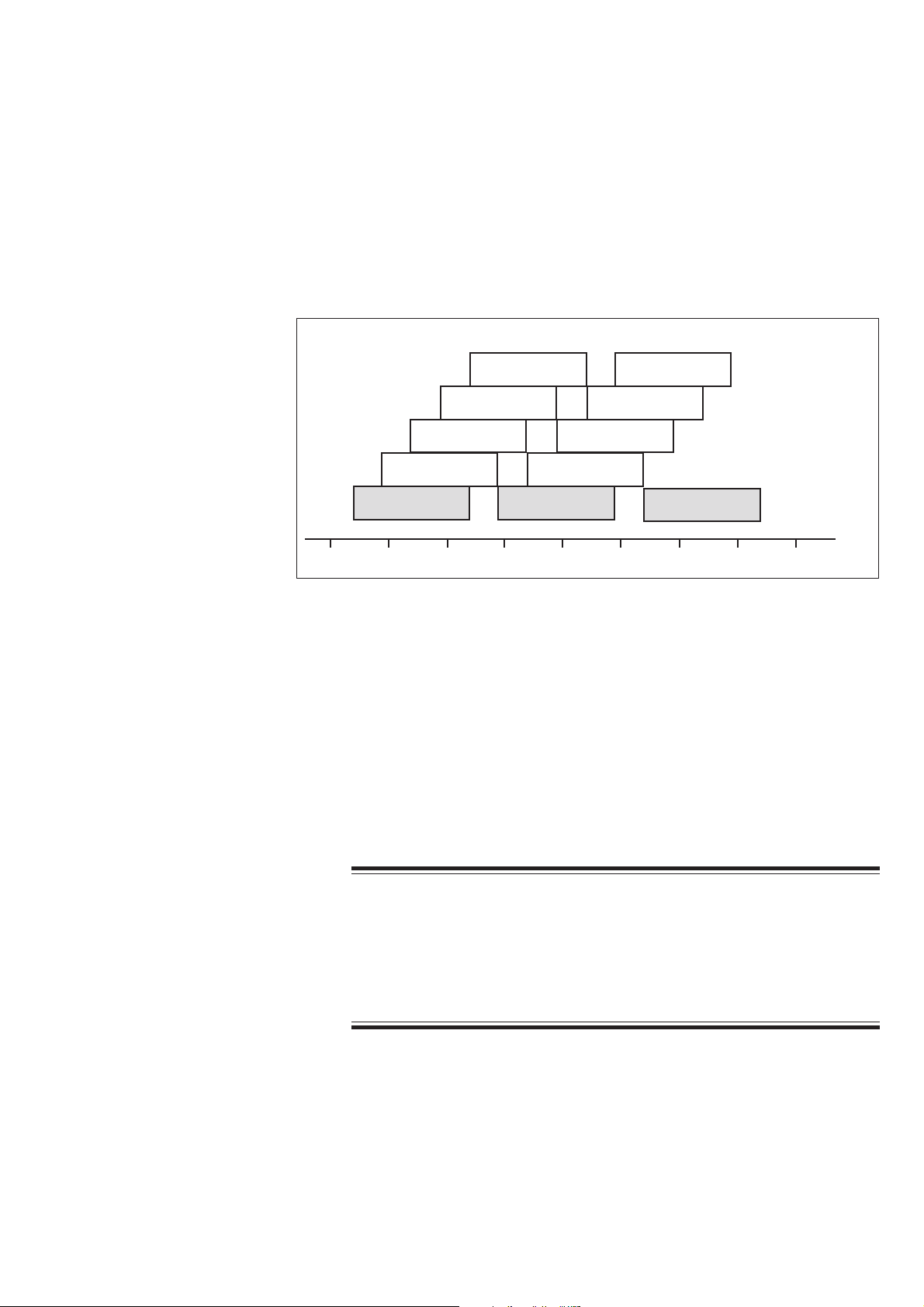
Frequency Band and Channels
The WEE-1000A Wireless Input Unit is a radio wave transmission method used in
small wireless devices such as a PHS or cellular telephone. It uses the 2.4 GHz
radio frequency band and transmits data up to 11 Mbps. This band is
internationally assigned for wireless LAN IEEE 802.11b standard. The frequency
band is divided into 11 channels every 5 MHz. Each channel uses about 22 MHz
frequency bandwidth. However, all channels cannot be used at the same time
because overlapping channels interfere each other.
Channel 5
(2.432)
Channel 4
(2.427)
Channel 3
(2.422)
Channel 2
(2.417)
Channel 1
(2.412)
2.400 2.410 2.420 2.430 2.440 2.450 2.460 2.470 2.480
The WEE-1000 Wireless Input Unit covers channels 1 to 11 and uses up to three
non-overlapping channels (for example, channel 1, channel 6 and channel 11) at
the same time.
The 2.4 GHz frequency band, which is called ISM (Industry Science Medical), is
used for medical devices, ham radio and microwave ovens in addition to wireless
LAN. To prevent radio interference, the wireless input unit uses a spread spectrum
technology.
Channel 6
(2.437)
Channel 8
Channel 7
(2.442)
Channel 10
(2.457)
Channel 9
(2.452)
(2.447)
Channel 11
(2.462)
( ): Center frequency
GHz
WARNING
The wireless input unit complies with radio frequency standards.
• Do not disassemble, repair or modify the wireless input unit.
• Do not peel off the radio frequency standard certification label. If the
label is peeled off, this may result in illegal modification.
Operator's Manual WEE-1000 1.3
Page 15
1. GENERAL
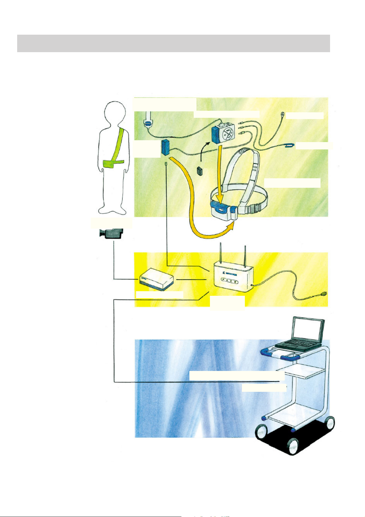
Composition
Electrode junction box,
JE-011A/JE-012A
Telemetry unit, ZB-101AA
Event marker
Video camera
Isolator,
SC-101A
Digital video unit
SpO2 adapter
Pochette, strap, belt
Access point,
ZR-101AA
Electroencephalograph, EEG-1100
EEG-9100/9200
1.4 Operator's Manual WEE-1000
Page 16

General Safety information
• Never use the wireless input unit in a flammable atmosphere (i.e.
areas with flammable anesthetics, concentrated oxygen, hyperbaric
oxygen) or in an environment in which an electrical arc could ignite
an explosion. Otherwise, the unit will explode or catch fire.
• Never use the wireless input unit in a high-pressure oxygen medical
care tank. Otherwise, the unit will explode or catch fire.
Using with an electrical surgical unit (ESU)
• Never use the wireless input unity near the ESU. The unit may
malfunction due to high-frequency noise from the ESU.
• When using wireless input unit with an ESU, refer to the instruction
manual for the ESU. Before measurement, check that the return plate
is correctly attached to the patient and that the unit operates correctly
when using with the ESU. If the return plate is not attached correctly,
it may burn the patient’s skin where the electrodes are attached.
• Before using the ESU, remove all needle electrodes and silver ball
electrodes from the patient. Failure to follow this warning may cause
burn on the patient.
1. GENERAL
DANGER
WARNING
MRI examination
• Do not install the wireless input unit in an MRI examination room.
The unit may not operate properly due to high-frequency magnetic
noise from the MRI.
• When performing MRI tests, remove all electrodes and transducers
from the patient which are connected to the electrode junction box
and telemetry unit. Failure to follow this warning may cause serious
electrical burn on the patient due to local heating caused by dielectric
electromotive force. For details, refer to the instruction manual for the
MRI.
When performing defibrillation
• Before defibrillation, remove from the patient all electrodes and
transducers which are connected to connectors that do not have a
“ ” or “ ” mark. Otherwise, the discharged energy may cause
serious electrical burn or shock to the operator.
• Before defibrillation, remove all electrodes, transducers medical
agents from the patient. If the defibrillator paddle directly contacts
these materials or medical agents, the discharged energy may cause
serious electrical burn to the patient.
Operator's Manual WEE-1000 1.5
Page 17

1. GENERAL
Installation
Warning - continued
• Before defibrillation, all persons must keep clear of the bed and must
not touch the patient or any equipment connected to the patient.
Failure to follow this warning may cause serious electrical burn,
shock or other injury.
WARNING
• Do not install the EEG System Program into a personal computer
which is not specified by Nihon Kohden and connect it to the access
point.
- If the personal computer does not satisfy the performance
specifications and safety standards which are required by Nihon
Kohden, the patient and operator may get electrical shock.
- Nihon Kohden does not warrant if hardware and/or software
becomes defective after installation.
• Only use the provided power cords. If different power cord is used, it
may cause electrical shock.
• For electrical safety, equipotential grounding is required. Consult a
qualified biomedical engineer.
• Connect only the specified instruments to the connectors or socket
marked with , by following the specified procedure. Otherwise,
electrical leakage current may harm the patient and operator.
• Do not install the access point near a microwave oven. The
microwaves from the microwave oven may interfere with the radio
wave communication between the telemetry unit and access point.
Connecting to a Local Area Network
• When connecting the access point and electroencephalograph with a
local area network, connect the access point and
electroencephalograph so that the access point and
electroencephalograph are electrically separated from the local area
network according to the IEC 60601-1-1 “Medical electrical equipment -
Part 1-1: General requirements for safety - Collateral standard: Safety
requirements for medical electrical systems”. Failure to follow this
warning may cause electrical shock to the patient and operator.
• Check that there is no damage on the surface of the network cable. If
it is damaged, it may cause electrical shock to the patient and
operator.
1.6 Operator's Manual WEE-1000
Page 18

1. GENERAL
CAUTION
• When connecting the cables, make sure that all components of the
wireless input unit turned off.
• Only install the specified software in the electroencephalograph.
Otherwise the electroencephalograph may malfunction.
• Do not install the telemetry unit and access point in a place where is
blocked by metal or concrete, or do not install the access point with
its antenna bent. Decreased radio wave causes frequent signal loss
between the telemetry unit and access point.
• Do not give impact to the antenna. This may damage the access point
or cause access point malfunction.
• Use the provided ZR adapter when installing the access point.
Otherwise, the access point may fall off and cause injury.
Battery
• After installing the telemetry unit and access point, check that the
communication between the telemetry unit and access point is
correctly performed without any interference.
WARNING
• Keep the battery away from fire. Do not heat the battery. Otherwise,
the battery explodes.
• Do not immerse the battery in water or seawater. The battery heats up
and rusts and the battery liquid leaks out.
• Never use a battery which is damaged, discolored or has leakage. A
damaged battery explodes if used. If the battery is damaged and the
battery liquid contacts the eyes or skin, wash immediately and
thoroughly with water and see your physician. Never rub your eyes,
otherwise you may lose your eyesight.
• Never disassemble, modify or give impact to the battery. The battery
short-circuits and the battery liquid leaks out.
• Never short-circuit the + and – terminals on the battery with a wire.
• Do not leave the battery where patients can reach it. If a battery is
swallowed, see your physician immediately.
Operator's Manual WEE-1000 1.7
Page 19

1. GENERAL
Warning - continued
• Do not expose the battery to direct sunlight or leave it in a high
temperature place. The lifetime of the battery may be shortened, the
performance of the battery may be degraded and the battery liquid
may leak out.
• Only charge the CGR-B/242 rechargeable lithium-ion battery with the
provided DE-158UA Battery Charger.
• Charge the rechargeable lithium-ion battery at the surrounding
temperatures of 10 to 40°C (50 to 104°F). If the battery is charged
below 10°C or over 40°C, it may leak or heat up. This may damage the
battery.
CAUTION
• Battery replacement should only be done by the operator. During
measurement, when replacing the battery, be careful not to touch the
patient.
• Do not charge a deteriorated battery. Otherwise, the instrument cannot
operate on battery power.
• Before turning the telemetry unit on, make sure that the battery holder
is firmly attached to the telemetry unit. If any static electricity enters
the telemetry unit, it may cause malfunction.
• When the telemetry unit is not used, remove the battery from the
telemetry unit.
• When replacing the battery, while the telemetry unit is connected to
the access point with the isolator, do not touch the metal part of the
connector. Otherwise the telemetry unit may malfunction due to
electrostatic energy.
• Before disposing of the battery, check with your local solid waste
officials for details in your area for recycling options or proper
disposal. The battery is recyclable. At the end of its useful life, under
various state and local laws, it may be illegal to dispose of this battery
into the municipal waste stream.
The lithium-ion rechargeable battery can be used for approximately 300 full
charging cycles. When the battery is charged more than 300 times, the battery
operation time may be reduced.
1.8 Operator's Manual WEE-1000
Page 20

Electrode Attachment/
Cable Connection
1. GENERAL
WARNING
• Do not connect the Z electrode lead plug on the electrode junction
box to a ground or equipotential ground. Otherwise, leakage current
from another instrument cause electrical shock to the patient.
• Only connect a BF type instrument to the DC connector on the
telemetry unit. Otherwise, leakage current from the other instrument
causes electrical shock to the patient.
• Before disconnecting or connecting the cable from/to a connecter on
the telemetry unit, while the telemetry unit is turned on, discharge
electrostatic charge from your body. Otherwise, the telemetry unit
may malfunction due to electrostatic energy.
• When connecting the electrode junction box cable to the electrode
junction box, align the
connector and electrode junction box. Otherwise, leakage current may
cause electrical shock to the patient.
marks on the electrode junction box cable
CAUTION
Using a collodion electrode or EEG paste
• If rash, redness or itch appears on the patient skin from the use of
collodion or EEG paste, immediately remove the collodion or EEG
paste from the skin and perform medical treatment.
• Never allow collodion or acetone to get in the patient’s eyes. If
collodion or acetone accidentally gets in the eyes, immediately and
thoroughly wash eyes with clean water and perform medical treatment
immediately.
• If chemical solution is swallowed, have the person drink water and
vomit the chemical solution. Perform medical treatment immediately.
• Collodion is a volatile solvent. Both patients and medical staff must
take extreme care not to inhale collodion. When using collodion,
make sure there is adequate ventilation. If too much collodion is
inhaled, have the person lie quietly and keep warm in fresh air.
Perform medical treatment immediately.
Operator's Manual WEE-1000 1.9
Page 21

1. GENERAL
Operation
WARNING
When using the NE-224S Sub-dermal Straight Needle Electrode
• Do not use the NE-224S sub-dermal straight needle electrode as a
measurement electrode for the EEG or evoked potential measurement
for any longer than one hour. When measuring the EEG or evoked
potential for over one hour, use the EEG disk electrode.
• Do not check the skin-electrode impedance when using a needle
electrode or intracranial electrode. Failure to follow this warning
injures the patient because these electrodes will be damaged by
electrolyzation inside the body.
• When measuring the patient with the implantable pacemaker, leave the
instrument (telemetry unit and access point) more than 22 cm from the
patient. Otherwise, the radio wave from the telemetry unit or access
point may interfere with the pacemaker.
• Do not delete any system file in the hard disk of the
electroencephalograph. Otherwise the electroencephalograph may
malfunction.
• Periodically back up the EEG data files to prevent loss of data if the
hard disk or MO disk is damaged.
CAUTION
• Do not use a device which uses Bluetooth® wireless technology and
wireless LAN device which complies with IEEE 802.11b near the
wireless input unit at the same time. If they are used together, the
radio waves interfere with each other. This may prevent the
communication between the telemetry unit and access point by
reducing transmission speed and transmission distance.
• Do not give impact to the telemetry unit. Spike noise may be
superimposed on the waveform.
• Use the provided pochette to hold the telemetry unit, electrode
junction box and/or isolator when they are attached to the patient.
• When moving the patient, make sure that the cable connected between
the isolator and access point is disconnected. Otherwise, the patient
may fall over the cable, or the cable may be broken.
• Do not shake or swing the telemetry unit holding the cable connected
to the telemetry unit. The telemetry unit may come off and it may
injure somebody or damage surrounding instruments.
1.10 Operator's Manual WEE-1000
Page 22

1. GENERAL
Caution - continued
• Do not shake or swing the electrode junction box holding the cable or
EEG lead connected to the electrode junction box. The electrode
junction box may come off and it may injure somebody or damage
surrounding instruments.
SpO2 Measurement
WARNING
• Measurement may be incorrect in the following cases.
- When the patient’s carboxyhemoglobin or methemoglobin increases
abnormally
- When dye is injected in the blood
- When using an electrical surgery unit
- During CPR
- When there is body movement
- When there is vibration
- When measuring at a site with venous pulse
- When the pulse wave is small (insufficient peripheral circulation)
- When using an IABP (intra-aortic balloon pump)
• When the SpO2 probe is used on a neonate, low birth weight infant or
patient with a fever or peripheral circulation insufficiency, a slight
burn may result from the probe increasing the skin temperature at the
attached site by 2 or 3°C (4 or 5°F). Periodically check the attached
state of the probe and change the attachment site.
• To avoid poor circulation, do not wrap the tape too tight when fixing
the probe with surgical tape. Check the blood circulation condition by
observing the skin color and congestion at the skin peripheral to the
probe attachment site. Even for short-term monitoring, there may be
burn or pressure necrosis from poor blood circulation.
• When using the probe on the following patients, take extreme care
and change the measurement site more frequently according to
symptoms and degree.
- A patient with a fever
- A patient with a peripheral circulation insufficiency
- Neonate or low birth weight infant with delicate skin
For a patient with a peripheral circulation insufficiency, the
measurement result may be incorrect.
• When not measuring SpO2, disconnect the SpO2 adapter cable from
the telemetry unit. Otherwise, noise from the probe sensor may
interfere and incorrect data is displayed on the screen.
Operator's Manual WEE-1000 1.11
Page 23

1. GENERAL
CAUTION
• Only use the specified probes and JL-101A SpO2 Adapter. Otherwise
SpO2 cannot be monitored properly and instrument performance may
be degraded.
• Do not use a probe which is past the expiration date on the package.
• Do not use a damaged or disassembled probe.
• Disposable probes are not sterilized.
• Use the disposable probe only once and for one patient only. Do not
reuse the disposable probe for another patient. It will cause cross
infection.
• When the attachment site is wet with blood or when the patient has
nail polish on, remove the dirt and nail polish before attaching the
probe. The transmitted light may decrease due to the blood or nail
polish and the measurement data may be incorrect.
• Turn off the power of cellular telephones, small wireless devices and
other devices which produce strong electromagnetic interference.
Otherwise, the waveforms and measurements are affected by
interference and the displayed data may be incorrect.
• Under normal conditions, normal light has negligible effect on this
probe. However, when measuring under strong light (surgical light,
bilirubin light, sunlight, etc.), cover the probe with a blanket or cloth.
Otherwise, the measurement result may be incorrect.
• If the skin gets irritated or redness appears on the skin by the probe,
change the attachment site or stop using the probe.
• For long term monitoring, check the circulation condition by
observing the skin color of the measuring site. To avoid circulation
insufficiency and skin burn, change the measurement site every
specified number of hours. Refer to the operator’s manual of the
probe.
• Do not pull or bend the probe cable, and do not let caster feet run over
the probe cable. Do not immerse the probe cable in chemical
solutions or water. Failure to follow these cautions may cause cable
discontinuity, short circuit, skin burn on the patient and incorrect
measurement data. Replace any broken probe with a new one.
• When removing a probe that is taped to the skin, do not pull the cable
part of the probe because this can damage the probe’s cable
connection.
1.12 Operator's Manual WEE-1000
Page 24

Disinfecting or Sterilizing
Maintenance
1. GENERAL
Caution - continued
• While a patient is on medication which causes vasodilation, the pulse
waveform may change and in rare case SpO2 value may not be
displayed.
CAUTION
Before cleaning or disinfecting, turn off the power of the telemetry
unit and access point, remove the battery from the telemetry unit and
disconnect the AC power cord from the access point. Otherwise you
may get an electrical shock or the instrument may malfunction.
WARNING
The wireless input unit complies with radio frequency standards.
• Do not disassemble, repair or modify the wireless input unit. If there
is any damage or the unit is suspected to be faulty, attach an
“Unusable” or “Repair request” label to the unit and contact your
Nihon Kohden distributor or representative.
• Do not peel off the radio frequency standard certification label. If the
label is peeled off, this may result in illegal modification.
Disposing
CAUTION
When upgrading the system program, contact your NK distributor or
representative. When the upgrading fails, the electroencephalograph
may malfunction.
CAUTION
Before disposing of a component of the wireless input unit, check
with your local solid waste officials for details in your area for
recycling options or proper disposal. When disposing of the
telemetry unit, remove the battery from the telemetry unit.
NOTE
• If any static electricity enters the electrode junction box, spike noise
may be superimposed on the waveform.
Operator's Manual WEE-1000 1.13
Page 25

1. GENERAL
Floppy Disk/CD-ROM Disk
Handling and Storing WARNING
The EEG System Program is protected by copyright law and
international treaties. Unauthorized reproduction or distribution of
this software, or any portion of it, may result in severe civil and
criminal penalties, and will be prosecuted to the maximum extent
possible under law.
CAUTION
• Keep floppy disks away from strong magnetic objects such as a
magnet, TV set or speaker. Otherwise, data in the disk may be lost.
• During measurement, do not insert or remove a CD-R or CD-RW disk
into or from the CD-RW drive. Otherwise, the Acquisition program
may malfunction.
• Do not touch the disk surface of the recorded side (CD-ROM: opposite
side of the label side). If the surface of the disk becomes
contaminated with any foreign substances such as fingerprints,
reading data may be impossible.
• Keep the disk away from direct sunlight and high temperature.
Otherwise, the disk may become deformed.
• Do not handle the disk while smoking or eating.
• Do not get the disk wet.
• Do not put a label on top of another label. Remove the old label
before applying a new label.
• Do not write on the label after the label is attached on the disk.
Otherwise, the disk may be damaged and reading may be impossible.
• Do not bend the disk, put heavy material on the disk, or give a strong
impact to the disk.
• Clean the disk with a disk cleaner. Do not use organic solvents such
as acetone.
• This CD–ROM is not an audio CD and cannot be played with an audio
CD player.
1.14 Operator's Manual WEE-1000
Page 26

1. GENERAL
Panel Descriptions
ZB-101AA Telemetry Unit
WARNING
Connect only the specified instruments to the connectors or socket marked with , by following the
specified procedure. Otherwise, electrical leakage current may harm the patient and operator.
Top panel
7
Front panel Right side panel
1
2
6
3
4
5
8
9
10
11
Name Functions
1. Battery holder Contains the battery. Two types of battery holder are provided. One is for the 9 V
lithium-ion rechargeable battery, the other is for the 9 V 006P lithium battery and
alkaline battery. When setting the battery, make sure that the battery is in the same
direction shown by the figure on the holder.
2. Battery holder release lever Releases the battery holder.
3. LCD display Displays the operation status, communication status and remaining battery power.
Battery mark: Displayed in battery operation. When the isolator is con-
nected, the battery mark goes off.
SpO2 mark: Displays the SpO2 mark when the JL-101A SpO2 Adapter is
connected.
Status display: Displays the result of the selected operation or function and
the supplemental information for each function.
4. FUNCTION key Selects the operation item.
Operator's Manual WEE-1000 1.15
Page 27

1. GENERAL
Name Functions
5. START/OK key The START/OK key works as follow.
• Turns on the power of the telemetry unit when the power is off.
• Performs the operation selected by the FUNCTION key.
6. MARK/kΩ key Adds event marks or changes the impedance threshold
• While acquiring the EEG waveforms, adds event marks (annotations) on the
waveforms.
• When checking the skin-electrode contact impedance, changes the impedance
threshold.
7. Electrode junction box Connects to the electrode junction box.
connector
8. DC connector Inputs analog signals from an external instrument.
WARNING
Only connect a BF type instrument to the DC connector on the
telemetry unit. Otherwise, leakage current from the other instrument
causes electrical shock to the patient.
9. MARK connector Connects the event marker.
10. SpO2 connector Connects an SpO2 probe by way of the optional JL-101A SpO2 Adapter.
11. ISOL connector Connects to the access point by way of the SC-101A Isolator for direct wired
connection.
1.16 Operator's Manual WEE-1000
Page 28

1. GENERAL
ZR-101AA Access Point
WARNING
Connect only the specified instruments to the connectors or socket marked with , by following the
specified procedure. Otherwise, electrical leakage current may harm the patient and operator.
Left side panel
1
2
3
4
5
Name Functions
1. Antenna Diversity antenna
2. PHOTO UNIT connector Connects to the optional LS-901A Photo Control Unit.
Front panel
678
Right side panel
9
10
11
3. ISOLATOR connector Connects to the telemetry unit by way of the SC-101A Isolator for direct wired
connection. DC power is supplied to the telemetry unit through the isolator.
4. DV UNIT connector Connects to the optional DV-101A Digital Video Unit through wired LAN.
5. PC connector Connects to the electroencephalograph through wired LAN.
6. POWER lamp Lights while AC power is supplied to the access point.
7. TX lamp Lights while in contact with the telemetry unit.
8. RX lamp Lights while receiving the data from the telemetry unit.
9. Protective ground terminal Use this terminal when protective grounding is required.
10. Equipotential ground Connects this terminal to the equipotential ground terminal on the wall with the
terminal ground lead when the equipotential grounding is required to ensure electrical
safety.
11. AC SOURCE socket Connects the power cord to supply AC power to the access point. When AC power
is supplied, the access point is turns on and the POWER lamp lights.
Operator's Manual WEE-1000 1.17
Page 29

1. GENERAL
JE-011A/JE-012A Electrode Junction Box
3
4
Bottom panel
Front panel
2
Right side panel
1
Name Function
1. Electrode jack (DIN type) Connects the EEG disk electrode.
2. Extra jack (DIN type) Inputs biological signals other than EEG waveforms.
The following extra jacks can be used as bipolar jacks. To select extra jack or
bipolar jack, refer to the System Programs.
• JE-011A Electrode Junction Box: X2 to X9
• JE-012A Electrode Junction Box: X17 to X24
3. Z jack (DIN type) Reduces the artifact when the electrode for Z on the patient is connected to the Z
jack. Be sure to attach the Z electrode to the patient during measurement
4. Electrode junction box Connects to the telemetry unit.
connector
1.18 Operator's Manual WEE-1000
Page 30

SC-101A Isolator
1. GENERAL
1
2
Name Function
1. ISOL connector Connects the telemetry unit.
2. Access point connector Connects to the access point with the connection cable.
Operator's Manual WEE-1000 1.19
Page 31

Section 2 Installation/Preparation
System Location ................................................................................................................. 2.1
Installation Flowchart .......................................................................................................... 2.3
Installing the Access point ..................................................................................................2.4
Attaching the Access Point to the Wall ...................................................................... 2.5
Attaching the Access Point to the Rack ....................................................................2.5
Cable Connection ................................................................................................................2.6
Connecting the Access point and Electroencephalograph .........................................2.6
Connecting the Power Cord ................................................................................................. 2.7
Connecting the Power Cord ....................................................................................... 2.7
Equipotential Grounding ............................................................................................ 2.7
Upgrading the EEG System Program ..................................................................................2.8
Preparing the Telemetry Unit ................................................................................................ 2.9
General ......................................................................................................................2.9
Using a Battery ......................................................................................................... 2.9
Inserting the Battery ............................................................................................... 2.11
Charging the Lithium-ion Rechargeable Battery ............................................. 2.12
Remaining Battery Power .............................................................................. 2.13
Connecting the Telemetry unit to the Access point with the Isolator ........................ 2.14
Power On/Off Procedure ..................................................................................................2.15
Power On Procedure ...............................................................................................2.15
Power Off Procedure ............................................................................................... 2.17
General Requirements for Connecting in Medical Electrical Systems ............................... 2.18
Operator's Manual WEE-1000 2C.1
Page 32

System Location
2. INSTALLATION/PREPARATION
This wireless input unit measures very small electrical potential changes (5 to 200
µV). Ideally the instrument should be installed in a shielded room which provides
constant environmental conditions. Select the examination locations as follows and
also refer to “GENERAL HANDLING PRECAUTIONS”.
DANGER
• Never use the system in a flammable atmosphere (i.e. areas with
flammable anesthetics, concentrated oxygen, hyperbaric oxygen) or
in an environment in which an electrical arc could ignite an
explosion. Otherwise, the system will explode or catch fire.
• Never use the system in a high-pressure oxygen medical care tank.
Otherwise, the system will explode or catch fire.
WARNING
• Do not install the EEG System Program into a personal computer
which is not specified by Nihon Kohden and connect it to the system.
- If the personal computer does not satisfy the performance
specifications and safety standards which are required by Nihon
Kohden, the patient and operator may get electrical shock.
- Nihon Kohden does not warrant if hardware and/or software
becomes defective after installation.
• Only use the provided power cords. If another power cord is used, it
may cause electrical shock or other injury.
• For electrical safety, equipotential grounding is required. Consult a
qualified biomedical engineer.
• Connect only the specified instruments to the connectors or socket
marked with , by following the specified procedure. Otherwise,
electrical leakage current may harm the patient and operator.
Connecting to a Local Area Network
• When connecting the access point and electroencephalograph with a
local area network, connect the access point and
electroencephalograph so that the access point and
electroencephalograph are electrically separated from the local area
network according to the IEC 60601-1-1 “Medical electrical equipment
- Part 1-1: General requirements for safety - Collateral standard:
Safety requirements for medical electrical systems”. Failure to
follow this warning may cause electrical shock to the patient and
operator.
• Check that there is no damage on the surface of the network cable. If
it is damaged, it may cause electrical shock to the patient and
operator.
Operator's Manual WEE-1000 2.1
Page 33

2. INSTALLATION/PREPARATION
CAUTION
• Select a room with a 3-prong outlet with a ground third contact.
• Do not install the system near equipment with a high power
consumption, such as large X-ray equipment.
• Do not install the system near a power line, dynamo or motor which
has electromagnetic induction.
• Do not install the wireless input unit near an electrosurgical unit or
RF therapeutic equipment.
• Select a room with no excessive noise, vibration, sunlight, high
humidity or water splashes.
• When connecting the cables, make sure that each instrument is
turned off.
• Only install the specified software in the electroencephalograph.
Otherwise the electroencephalograph may malfunction.
• Make sure that there is no influence from a cellular phone.
• Avoid locations where the wireless input unit may receive strong
electromagnetic interference such as radio or TV stations, cellular
phones or mobile two-way radios.
• A sudden loss of power or extreme power surge can damage data.
To assure an uninterrupted power supply, use an uninterruptable
power supply (UPS).
• Do not install the wireless input unit where it will be exposed to
water or chemical solutions. Avoid direct sprinkling, spray or moist
air from the nebulizer or humidifier. These cause malfunction and
shorten the life of the unit.
• After installing the telemetry unit and access point, check that the
communication between the telemetry unit and access point is
correctly performed without any interference.
For external instrument connection and local area network connection, refer to
“General Requirements for Connecting Medical Electrical Systems” in this section.
NOTE
• Do not place blankets or cloth over the access point.
• Do not install the wireless input unit in dusty area.
• Connect the power cable to an AC outlet which can supply enough
AC current to the access point. The access point cannot function
properly with low current.
For electroencephalograph installation, refer to the operator’s manual for the
electroencephalograph.
2.2 Operator's Manual WEE-1000
Page 34

Installation Flowchart
2. INSTALLATION/PREPARATION
1. Install the access point.
2. Connect the access point to the electroencephalograph.
3. Turn on the access point and electroencephalograph.
4. Upgrade the EEG system program to version 05-10 or later.
5. Prepare the telemetry unit.
The network configuration settings of the telemetry unit and access point can
be set on the Acquisition screen.
Operator's Manual WEE-1000 2.3
Page 35

2. INSTALLATION/PREPARATION
Installing the Access point
• When attaching the access point to a wall or rack, you must have a
• Attach the access point securely enough to withstand external force
• Tell the builder the size and weight of the access point. Both size
• Do not install the access point near a microwave oven. The
WARNING
qualified builder attach the access point. Show the builder this
manual.
or vibration caused by an earthquake.
and weight of the access point affect safety.
Dimensions and weight: 240 (W)
(without antenna).
microwaves from the microwave oven may interfere with the radio
wave communication between the telemetry unit and access point.
××
× 55 (D)
××
××
× 200 (H) mm, 1.5 kg
××
CAUTION
• Use the provided ZR adapter when installing the access point.
Otherwise, the access point may fall off and cause injury.
• Use appropriate screws according to the material and structure of
the wall or rack.
• Make sure that there is enough space between the access point and
the wall for adequate ventilation. Leave more than 1 cm of space
between the wall and vent holes on the rear panel of the access
point. Otherwise the internal temperature of the access point rises,
which leads to inaccurate operation and shortens the access point
life.
• Install the access point at least 20 cm away from the operator.
• Do not install the telemetry unit and access point in a place where is
blocked by metal or concrete, or do not install the access point with
its antenna bent. Decreased radio wave causes frequent signal loss
between the telemetry unit and access point.
• Do not install the access point and telemetry unit near a device
which uses Bluetooth® wireless technology or wireless LAN device
which complies with IEEE 802.11b near the wireless input unit at the
same time. If they are used together, the radio waves interfere with
each other. This may prevent the communication between the
telemetry unit and access point by reducing transmission speed and
transmission distance.
• Do not give impact to the antenna. This may damage the access
point or cause access point malfunction.
NOTE
Select a place where the POWER lamp, TX lamp and RX lamp can be
checked.
2.4 Operator's Manual WEE-1000
Page 36

Attaching the Access Point to the Wall
Access
point
ZR adapter
2. INSTALLATION/PREPARATION
1. Attach the ZR adapter to the rear of the access
point and secure it with four M4×8 pan screws with
spring washers.
M4×8 pan screw with
spring washer
2. Attach the ZR adapter to the wall and secure the
ZR adapter with the four pan screws with spring
washers.
Example:
M4 pan screw with
spring washer
Attaching the Access Point to the Rack
Access point
ZR adapter
M4×8 pan screw with
spring washer
1. Attach the ZR adapter to the bottom of the access
point and secure it with four M4×8 pan screws with
spring washers.
2. Attach the ZR adapter to the rack and secure the
ZR adapter with the four pan screws with spring
washers.
Example:
M4 pan screw with
spring washer
Operator's Manual WEE-1000 2.5
Page 37

2. INSTALLATION/PREPARATION
Cable Connection
WARNING
• When connecting the cables, make sure that all components of the
wireless input unit are turned off.
• Connect only the specified instruments to the connectors or socket
Connecting the Access point
and Electroencephalograph
marked with
electrical leakage current may harm the patient and operator.
Connecting to a Local Area Network
• When connecting the access point and electroencephalograph with a
local area network, connect the access point and
electroencephalograph so that the access point and
electroencephalograph are electrically separated from the local area
network according to the IEC 60601-1-1 “Medical electrical equipment
- Part 1-1: General requirements for safety - Collateral standard:
Safety requirements for medical electrical systems”. Failure to follow
this warning may cause electrical shock to the patient and operator.
• Check that there is no damage on the surface of the network cable. If
it is damaged, it may cause electrical shock to the patient and
operator.
1. Connect the provided network cable to the PC connector on the left side panel
of the access point.
, by following the specified procedure. Otherwise,
2. Connect the other side of the network cable to the network connector on the PC
unit of the electroencephalograph.
PC connector
2.6 Operator's Manual WEE-1000
Page 38

Connecting the Power Cord
2. INSTALLATION/PREPARATION
Connecting the Power
Cord
Equipotential Grounding
Connect the provided power cord to the AC SOURCE socket on the right side panel
of the access point and plug the cord into a 3-prong AC outlet.
CAUTION
Only use the provided power cords. If another power cord is used, it
may cause electrical shock.
WARNING
For patient safety, equipotential grounding may be required. Consult
with a qualified biomedical engineer.
When more than one electrical instrument is used, there may be electrical potential
difference between the instruments. Potential difference between instruments may
cause current to flow to the patient connected to the instruments, resulting in
electrical shock (micro shock). Never use any medical equipment in patient
treatment without proper grounding.
Always perform equipotential grounding when required. It is often required in the
operating room, ICU room, CCU room, cardiac catheterization room and X-ray
room. Consult with a biomedical engineer to determine if it is required.
When Equipotential Grounding is Required
Connect the equipotential ground terminal on the right side panel of the access
point to the equipotential ground terminal on the wall with the ground lead.
Operator's Manual WEE-1000 2.7
Page 39

2. INSTALLATION/PREPARATION
Upgrading the EEG System Program
When the system program version of the electroencephalograph is
05-01 or earlier, the access point can not be connected. Upgrade the
system program with the provided system disk.
1. Insert the EEG system program CD-ROM into the CD-ROM drive.
2. From the Start menu, select Run. The Run dialog opens.
3. Type X:\Software\Setup.exe in the Open text box and click the OK button (X
is the CD-ROM drive). The EEG setup program starts copying the files.
4. Follow the instructions on the screen.
NOTE
5. When the setup is complete, restart the computer.
2.8 Operator's Manual WEE-1000
Page 40

Preparing the Telemetry Unit
2. INSTALLATION/PREPARATION
General
Using a Battery
The telemetry unit communicates with the access point by wireless transmission
(IEEE 802.11b compliant). The telemetry unit can also be directly connected to the
access point with an SC-101A Isolator. The isolator is useful when there is a lot of
radio frequency interference or to save battery power when the patient is sleeping.
The telemetry unit can operate on battery power with the following batteries
• CGR-B/242 lithium-ion (LiON) rechargeable battery ×1 (option)
• 006P 9V lithium battery ×1 (U9VL: recommended)
• 006P 9V alkaline battery ×1
Battery operation time (at surrounding temperature: 25°C (77°F))
• Lithium- ion rechargeable battery: 24 hours or more
(10 seconds intermittent transmission)
• 9V lithium battery: About 12 hours
• 9V alkaline battery: About 5 hours
The lithium-ion rechargeable battery can be used for approximately 300 full
charging cycles. When the battery is charged more than 300 times, the battery
operation time may be reduced.
WARNING
• Keep the battery away from fire. Do not heat the battery. Otherwise,
the battery explodes.
• Do not immerse the battery in water or seawater. The battery heats
up and rusts and the battery liquid leaks out.
• Never use a battery which is damaged, discolored or has leakage. A
damaged battery explodes if used. If the battery is damaged and the
battery liquid contacts the eyes or skin, wash immediately and
thoroughly with water and see your physician. Never rub your eyes,
otherwise you may lose your eyesight.
• Never disassemble, modify or give impact to the battery. The battery
short-circuits and the battery liquid leaks out.
• Never short-circuit the + and – terminals on the battery with a wire.
• Do not leave the battery where patients can reach it. If a battery is
swallowed, see your physician immediately.
• Do not expose the battery to direct sunlight or leave it in a high
temperature place. The lifetime of the battery may be shortened, the
performance of the battery may be degraded and the battery liquid
may leak out.
• Only charge the CGR-B/242 rechargeable lithium-ion battery with the
provided DE-158UA Battery Charger.
• Charge the battery at the surrounding temperatures of 10 to 40°C (50
to 104°F). If the battery is charged below 10°C or over 40°C, it may
leak or heat up. This may damage the battery.
Operator's Manual WEE-1000 2.9
Page 41

2. INSTALLATION/PREPARATION
CAUTION
• Battery replacement should only be done by the operator. During
measurement, when replacing the battery, be careful not to touch the
patient.
• Do not charge a deteriorated battery. Otherwise, the instrument
cannot operate on battery power.
• Before turning the telemetry unit on, make sure that the battery
holder is firmly attached to the telemetry unit. If any static electricity
enters the telemetry unit, it may cause malfunction.
• When the telemetry unit is not used, remove the battery from the
telemetry unit.
• When replacing the battery, while the telemetry unit is connected to
the access point with the isolator, do not touch the metal part of the
connector. Otherwise the telemetry unit may malfunction due to
electrostatic energy.
• Before disposing of the battery, check with your local solid waste
officials for details in your area for recycling options or proper
disposal. The battery is recyclable. At the end of its useful life, under
various state and local laws, it may be illegal to dispose of this
battery into the municipal waste stream.
NOTE
Use a fully charged lithium-ion rechargeable battery, a new 006P 9V
lithium battery or new 006P 9V alkaline battery for every
measurement.
2.10 Operator's Manual WEE-1000
Page 42

2. INSTALLATION/PREPARATION
Inserting the Battery
1. Press the battery holder release lever and remove the battery holder from the
telemetry unit.
Battery holder
Battery holder
release lever
2. Insert the battery into the battery holder. Two types of battery holder are
provided. One is for the lithium-ion rechargeable battery, the other is for the
9V 006P lithium battery and alkaline battery. Use the appropriate battery
holder according to the battery. When setting the battery, make sure that the
battery is in the same direction shown by the figure on the holder.
Battery holder for
lithium-ion battery
3. Attach the battery holder to the telemetry unit.
Operator's Manual WEE-1000 2.11
Battery holder for 006P lithium
battery and alkaline battery
Page 43

2. INSTALLATION/PREPARATION
Charging the Lithium-ion Rechargeable Battery
The lithium-ion rechargeable battery can be used for approximately 300 full
charging cycles with the DE-158UA Battery Charger. When the battery is charged
more than 300 times, the battery operation time may be reduced.
WARNING
• Only charge the CGR-B/242 Lithium-ion rechargeable battery with the
provided DE-158UA Battery Charger.
CAUTION
• Battery replacement should only be done by the operator. During
measurement, when replacing the battery, be careful not to touch the
patient.
• When replacing the battery, while the telemetry unit is connected to
the access point with the isolator, do not touch the metal part of the
connector. Otherwise the telemetry unit may malfunction due to
electrostatic energy.
• Do not charge the battery inside the patient environment (IEC 60601-
1-1 2.204*)
* Patient environment
Any area in which intentional or unintentional contact between PATIENT and
parts of SYSTEM or some other persons touching of the SYSTEM can occur.
The two rechargeable batteries can be set in the battery charger at the same time
but the charging is performed for only one battery.
• When the second battery is set in the charger, while a battery is being charged,
the second battery is charged after the first battery charging is complete.
• When two batteries are set in the battery charger before AC power is supplied, the
battery which is set in the channel 1 is charged first.
1. Connect the battery charger to the AC outlet and turn the power on. The power
lamp lights in red.
2. Set the rechargeable battery in the battery charger. Make sure that the battery
is set in the direction shown by the
set in the battery charger, charging starts.
The battery charge lamp (green) indicates the battery charging status:
Lit : The battery is being charged
Blinking: The battery is fully charged.
Off: The battery is too hot (After while, if the battery charge lamp does
not light or blink, the battery may be damaged.
mark. When the batteries is correctly
The rechargeable battery can be fully charged in about 100 minutes.
2.12 Operator's Manual WEE-1000
Page 44

2. INSTALLATION/PREPARATION
Remaining Battery Power
During battery operation, the battery mark appears on the LCD display. You can
check the remaining battery power on the LCD.
1. When the battery is inserted in to the battery holder, press the START/OK key.
The telemetry unit is turned on and the version information is displayed on the
LCD display.
2. Check the battery operation power by pressing the FUNCTION key. The
battery operation power is displayed on the status display.
The battery voltage is shown as follows.
BH: The battery voltage is about 7 V or more.
BL: The battery voltage is less than about 7 V.
Eb: The battery voltage is less than about 6 V
Replace the battery when “BL” or “Eb” is displayed on the LCD display.
When the battery voltage becomes less than 6 V, the beep sounds and a
message to replace the battery is displayed on the Acquisition screen of the
electroencephalograph.
To turn the power off, select “OF” by pressing the FUNCTION key and press
the START/OK key.
Turn the power off, when you detach the battery holder.
Operator's Manual WEE-1000 2.13
Page 45

2. INSTALLATION/PREPARATION
Connecting the Telemetry
unit to the Access point
with the Isolator
The telemetry unit can also be directly connected to the access point with an SC-
101A Isolator. DC power is supplied to the telemetry unit from the access point
through the isolator.
CAUTION
• When connecting the isolator to the telemetry unit, make sure that
telemetry unit is turned off.
• When using the isolator, do not remove the battery holder.
Otherwise, the telemetry unit may malfunction due to static energy.
• When moving the patient, make sure that the cable connected
between the isolator and access point is disconnected. Otherwise,
the patient may fall over the cable, or the cable may get broken.
• When connecting or disconnecting the connection cable to/from the
isolator, hold the connectors. If you hold the cable, the cable may
get broken.
1. Disconnect the connection cable from the isolator which connects the isolator
and access point.
2. Connect the cable from the isolator to the telemetry unit and secure the
connector with the two screws. Use the provided flat-blade screwdriver to
secure the connector.
3. Connect the connection cable to the access point and secure the connector with
the two screws.
4. Connect the AC power cord of the access point to the AC outlet.
5. Connect the other side of the connection cable to the isolator. DC power is
supplied to the telemetry unit and the telemetry unit is turned on. The LCD
display displays the version information, then displays “CL”.
To turn off the telemetry unit, disconnect the connection cable from the
isolator. When the battery is set in the battery holder, the telemetry unit
continues to operate on battery power.
2.14 Operator's Manual WEE-1000
Page 46

Power On/Off Procedure
Power On Procedure
2. INSTALLATION/PREPARATION
CAUTION
• When connecting the isolator to the telemetry unit, make sure that
telemetry unit is turned off.
• When using the isolator, do not remove the battery holder.
Otherwise, the telemetry unit may malfunction due to static energy.
1. Before turning the power on, check the following items. If there is any damage
or the instrument is suspected to be faulty as a result of checking, attach an
“Unusable” or “Repair required” label to the instrument and contact your NK
distributor or representative.
Check items before turning the power on
Overview:
• Telemetry unit, access point and isolator are not dirty, damaged or in contact
with liquid.
• Power cord is not damaged.
• No key on the telemetry unit is broken.
• No electrode is dirty or damaged.
• No electrode lead is frayed or damaged.
• No connection cable is frayed or damaged.
Connection and Setting:
Telemetry unit
• Fully charged lithium-ion battery, a new lithium battery or a new alkaline
battery is inserted.
• Battery is inserted in the correct direction.
• Battery holder is attached to the telemetry unit firmly.
• Isolator is firmly connect to the telemetry unit.
• Electrode junction box is properly connected to the telemetry unit.
Access point
• Power cord and ground lead are properly connected to the access point.
• Access point is properly connected to the electroencephalograph with the
network cable.
Environment
• There is no obstruction between the telemetry unit and access point.
• Bluetooth device or other wireless LAN device is not used near the wireless
input unit.
Operator's Manual WEE-1000 2.15
Page 47

2. INSTALLATION/PREPARATION
Accessories:
• Enough electrodes.
• Enough EEG paste.
• A second battery.
2. Turn the power on
Wireless communication:
1) Connect the AC power cord of the access point to the AC outlet.
2) Press the START/OK key on the telemetry unit.
Wired communication:
1) Connect the telemetry unit and access point with the isolator.
2) Connect the AC power cord of the access point to the AC outlet.
3. After turning the power on, check the following items.
Check items after turning the power on
Overview:
• No fire, smoke or smell.
• No electrical shock when touching the telemetry unit or access point.
• Telemetry unit and access point are not too hot.
• Telemetry unit and access point do not affect surrounding equipment.
Telemetry unit
• No beep sounds.
• No error code is displayed on the LCD screen.
• All keys operate correctly.
Access point
• The power lamp lights.
• TX and RX lamps blinks
• All operation indicators light.
Electroencephalograph
• The communication between the telemetry unit and access point is
established with or without the isolator.
• The message to replace the battery of the telemetry unit is not displayed.
• There is no error message on the screen or malfunction.
• The screen display is correct.
• The time and date display is correct.
• All programs operate correctly.
• All settings (such as montage and amplifier settings) are correct.
• Calibration waveform is properly displayed.
• No noise on the calibration waveform.
• Amplitude of the calibration waveform is correct.
2.16 Operator's Manual WEE-1000
Page 48

2. INSTALLATION/PREPARATION
Power Off Procedure
1. Check the following before turning the power off.
Check items before turning the power off
• All necessary files are saved.
• All programs are closed.
2. Turn the power off.
1) On the telemetry unit, select “OF” by pressing the FUNCTION key, then
press the START/OK key.
2) Disconnect the AC power cord of the access point from the AC outlet.
Check the following items for the next use
• Power of all external instruments are turned off.
• Telemetry unit and access point is not dirty, damaged or in contact with
liquid.
• Power cord is not damaged.
• Telemetry unit is turned off
• No key on the telemetry unit is broken.
• Battery is removed from the battery holder.
• Lithium battery or alkaline battery is correctly disposed of.
• No electrode is dirty or damaged.
• No electrode lead is frayed or damaged.
• No connection cable is frayed or damaged.
• Electrodes and leads are cleaned and disinfected.
• Enough electrodes.
• Enough EEG paste.
Operator's Manual WEE-1000 2.17
Page 49

2. INSTALLATION/PREPARATION
General Requirements for Connecting in Medical Electrical Systems
When more than one electrical instrument is used, there may be electrical potential
difference between the instruments. Potential difference between instruments may
cause current to flow to the patient connected to the instruments, resulting in electrical
shock (micro shock). Therefore, electrical instruments must be appropriately installed
as specified in IEC 60601-1-1.
The following is an excerpt from IEC 60601-1-1 “Medical electrical equipment - Part
1-1: General requirements for safety - Collateral standard: Safety requirements for
medical electrical systems”. For details, refer to IEC 60601-1-1 and consult with a
biomedical engineer.
Examples of combinations of MEDICAL ELECTRICAL EQUIPMENT and non-
medical electrical equipment
Situation No. Equipment A Equipment B Solution
1 IEC 60601/X OK
OK, if ENCLOSURE LEAKAGE
CURRENT is less than 0.5 mA. If
1a IEC XXXXX
2a IEC 60601/X IEC 60601/B OK
2b IEC 60601/F IEC XXXXX for B any one of P, Q, R
2c IEC 60601/B IEC XXXXX
3a IEC 60601/X IEC 60601/B OK
3b IEC 60601/F IEC XXXXX OK
3c IEC 60601/B IEC XXXXX for A solution P
4 see 3a, 3b, 3c
5a IEC 60601/X IEC 60601/B
5b IEC 60601/X IEC XXXXX
6a IEC 60601/X IEC 60601/X OK (with S)
the ENCLOSURE LEAKAGE
CURRENT is more than 0.5 mA:
Solution Q (separating transformers).
for A solution P for B any one of P,
Q, R
for A solution P or S (groundloop
possible)
for A solution P or S (groundloop
possible)
6b IEC 60601/X IEC XXXXX OK (with S)
IEC 60601/B = IEC 60601-1 EQUIPMENT of TYPE B with PATIENT connection
IEC 60601/F = IEC 60601-1 EQUIPMENT of TYPE BF or TYPE CF (or TYPE B
without PATIENT connection)
IEC 60601/X = IEC 60601-1 EQUIPMENT of TYPE B or TYPE BF or TYPE CF
IEC XXXXX = Equipment complying with, e.g. IEC 348, IEC 950 etc.
P: additional protective earth
Q: additional separating transformer
R: floating power supply
S: separation
2.18 Operator's Manual WEE-1000
Page 50

2. INSTALLATION/PREPARATION
Situation No.
1
2
3
4
5
6
PATIENT
ENVIRONMENT
A
PE
A
B
PE PE
A
PE
A
PE
A
PE
A
PE
Medical-use room
B
PE
PE
Non-medical use room
B
B
(V)
PE
B
(V)
PE
Legend:
(V) = Potential difference between different localities
> < = SEPARATION DEVICE
PE = Protective earth
Operator's Manual WEE-1000 2.19
 Loading...