

Page 1
EN - Instructions and warnings for installation and use
IT - Istruzioni ed avvertenze per l’installazione e l’uso
FR - Instructions et avertissements pour l’installation et l’utilisation
ES - Instrucciones y advertencias para la instalación y el uso
DE - Installierungs-und Gebrauchsanleitungen und Hinweise
PL - Instrukcje i ostrzeżenia do instalacji i użytkowania
NL - Aanwijzingen en aanbevelingen voor installatie en gebruik
WALKY
WL1024
WL1024C
Swing gate opener
Page 2

Page 3

EN
English – 1
ENGLISH
Contents
1 - WARNINGS AND GENERAL PRECAUTIONS . . . . . . . . . . . . . . . . . . . . 1
1.1 - Safety warnings . . . . . . . . . . . . . . . . . . . . . . . . . . . . . . . . . . . . . . . . . . 1
1.2 - Warnings for installation . . . . . . . . . . . . . . . . . . . . . . . . . . . . . . . . . . . . 1
1.3 - Warnings for use . . . . . . . . . . . . . . . . . . . . . . . . . . . . . . . . . . . . . . . . . . 1
2 - PRODUCT DESCRIPTION AND INTENDED USE . . . . . . . . . . . . . . . . . 1
3 - INSTALLATION . . . . . . . . . . . . . . . . . . . . . . . . . . . . . . . . . . . . . . . . . . . . 2
3.1 - Pre-installation checks . . . . . . . . . . . . . . . . . . . . . . . . . . . . . . . . . . . . . 2
3.2 - Usage limitation . . . . . . . . . . . . . . . . . . . . . . . . . . . . . . . . . . . . . . . . . . 2
3.3 - Preparatory work prior to installation . . . . . . . . . . . . . . . . . . . . . . . . . . . 2
3.4 - Installation of the gearmotor mod. WL1024C - WL1024 . . . . . . . . . . . . 3
3.4.1 - Establishing the length of the gearmotor arm . . . . . . . . . . . . . . 3
3.4.2 - Installation of a gearmotor with a STANDARD LENGTH ARM . . 3
3.4.3 - Installation of a gearmotor with a SHORTENED ARM . . . . . . . . 4
3.5 - Installation of the multi-purpose lamp mod. WLT on the gearmotor
model WL1024C . . . . . . . . . . . . . . . . . . . . . . . . . . . . . . . . . . . . . . . . . . . . . . 4
3.6 - How to remove the control unit . . . . . . . . . . . . . . . . . . . . . . . . . . . . . . . 5
3.7 - Adjusting the alignment of the gate leaves when closed . . . . . . . . . . . . 5
3.8 - Securing and releasing the gearmotor manually . . . . . . . . . . . . . . . . . . 5
4 - ELECTRICAL CONNECTIONS . . . . . . . . . . . . . . . . . . . . . . . . . . . . . . . 5
4.1 - Description of the electrical connections . . . . . . . . . . . . . . . . . . . . . . . . 5
4.2 - Connecting the power cable . . . . . . . . . . . . . . . . . . . . . . . . . . . . . . . . . 6
4.3 - Connecting the gearmotor without a control unit mod. WL1024 . . . . . . 5
4.4 - Connecting other devices . . . . . . . . . . . . . . . . . . . . . . . . . . . . . . . . . . . 5
4.5 - Addressing the connected devices . . . . . . . . . . . . . . . . . . . . . . . . . . . . 6
4.6 - Initialisation and connection check . . . . . . . . . . . . . . . . . . . . . . . . . . . . 6
4.7 - Recognition of the connected devices . . . . . . . . . . . . . . . . . . . . . . . . . 6
4.8 - Recognition of the positions of the mechanical stops . . . . . . . . . . . . . . 6
4.9 - Gate leaves motion check . . . . . . . . . . . . . . . . . . . . . . . . . . . . . . . . . . 6
5 - TESTING AND COMMISSIONING . . . . . . . . . . . . . . . . . . . . . . . . . . . . . 6
5.1 - Testing . . . . . . . . . . . . . . . . . . . . . . . . . . . . . . . . . . . . . . . . . . . . . . . . . 7
5.2 - Commissioning . . . . . . . . . . . . . . . . . . . . . . . . . . . . . . . . . . . . . . . . . . . 7
6 - PROGRAMMING THE CONTROL UNIT . . . . . . . . . . . . . . . . . . . . . . . . 7
6.1 - Level one programming (ON-OFF) . . . . . . . . . . . . . . . . . . . . . . . . . . . . 7
6.2 - Level two programming (adjustable parameters) . . . . . . . . . . . . . . . . . . 8
6.3 - Memory deletion . . . . . . . . . . . . . . . . . . . . . . . . . . . . . . . . . . . . . . . . . . 8
6.4 - Special functions . . . . . . . . . . . . . . . . . . . . . . . . . . . . . . . . . . . . . . . . . 8
7 - WHAT TO DO IF... (troubleshooting guide) . . . . . . . . . . . . . . . . . . . . . . 9
8 - FURTHER INFORMATION . . . . . . . . . . . . . . . . . . . . . . . . . . . . . . . . . . 10
8.1 - Connection of the OXI radio receiver . . . . . . . . . . . . . . . . . . . . . . . . . . 10
8.2 - Connection and installation of the back-up battery mod. PS424 . . . . . 10
8.3 - Connection of the Oview programmer . . . . . . . . . . . . . . . . . . . . . . . . 10
8.4 - Connection of the Solemyo solar power system . . . . . . . . . . . . . . . . . 10
9 - PRODUCT MAINTENANCE . . . . . . . . . . . . . . . . . . . . . . . . . . . . . . . . . 10
DISPOSING OF THE PRODUCT . . . . . . . . . . . . . . . . . . . . . . . . . . . . . . . . 11
PRODUCT TECHNICAL SPECIFICATIONS . . . . . . . . . . . . . . . . . . . . . . . 11
Product life span . . . . . . . . . . . . . . . . . . . . . . . . . . . . . . . . . . . . . . . . . . . . 12
EC DECLARATION OF CONFORMITY . . . . . . . . . . . . . . . . . . . . . . . . . . . 12
APPENDIX . . . . . . . . . . . . . . . . . . . . . . . . . . . . . . . . . . . . . . . . . . . . . . . . . . I
Instructions and warnings for the user . . . . . . . . . . . . . . . . . . . . . . . . . . . . . III
Images . . . . . . . . . . . . . . . . . . . . . . . . . . . . . . . . . . . . . . . . . . . . . . . . . . . . . X
1.1 - Safety warnings
• IMPORTANT! – This manual contains important instructions and warn-
ings regarding safety. Incorrect installation may cause serious injury. Before
commencing work, all sections of the manual must be read carefully. If in any
doubt, suspend installation and call the Nice Support Service for clarification.
• IMPORTANT! – This manual contains important instructions. Keep it for
future maintenance work and disposal of the product.
• IMPORTANT! – Under the latest European legislation, automatic door
and gate installations must be compliant with the standards specified in
Directive 2006/42/EC (formerly 98/37/EC) (the Machinery Directive) and
the standards EN 12445, EN 12453, EN 12635 and EN 13241-1 in particular, which enable conformity of the automated functionality to be de clared. In the light of the above, all work involving installation, connection, testing and maintenance of the product must be carried out
exclusively by qualified and competent technicians!
1.2 - Warnings for installation
• Before commencing the installation, check if the product is suitable for the
desired type of use (see “Usage limitation” paragraph 3.2 and the "Product
technical specifications”). If it is not suitable, DO NOT continue with the installation.
• All installation and maintenance work must be carried out with the au -
tomation system disconnected from the electricity supply. If the power
disconnection device cannot be seen from where the automation system is
positioned, then before starting work a notice must be attached to the disconnection device bearing the words “CAUTION! MAINTENANCE IN PRO GRESS”.
• The Control unit must be connected to an electricity supply line equipped
with protective earthing.
• Handle the product with care during installation, taking care to avoid crushing, denting or dropping it, or contact with liquids of any kind. Keep the product away from sources of heat and naked flames. Failure to observe the
above can damage the product, and increase the risk of danger or malfunction. Should this occur, suspend installation work immediately and contact
the Nice Support Service.
• Do not modify any part of the product. Prohibited modifications can only lead
to malfunctions. The manufacturer declines all responsibility for damage re sulting from unauthorized changes made to the product.
• If the gate or door being automated has a pedestrian gate, then the system
must include a control device that will inhibit the operation of the motor when
the pedestrian gate is open.
• The product’s packaging material must be disposed of in full compliance with
local regulations.
1.3 - Warnings for use
• The product is not intended for use by persons, including children, with limited physical, sensory or mental capacities, or who lack experience or knowledge, unless supervised or trained in the use of the product by a person
responsible for their safety.
• Any children near the automation system must be kept under supervision to
ensure that they do not play with it.
• Do not allow children to play with the fixed control devices. Keep remote control devices out of the reach of children.
WARNINGS AND GENERAL PRECAUTIONS
1
The devices comprising this product are designed to automate a gate or door
with one or two leaves. IMPORTANT! – Any other use apart from that
described herein, including in different environmental conditions from
those described in this manual is to be considered improper use and is
not permitted!
The principal component of the automation system comprises one or two electric gearmotors (according to the number of leaves to be automated), each
equipped with a direct current motor and epicyclic reduction gear. One of the
gearmotors (mod. WL1024C) has a control unit that controls its operation. The
Control unit consists of a board with a radio receiver for receiving the commands sent by the transmitter.
The control unit is designed for connection to several devices belonging to the
Opera system, the Bluebus system and the Solemyo solar powered system.
If it is mains powered, it can house a back-up battery (mod. PS424, optional
accessory) which in the event of a power cut (electricity black-out) guarantees
that the automated device will perform certain manoeuvres in the hours that follow.
In the event of a power cut, the gate leaves can be moved by releasing the
gearmotor with the dedicated key; to perform the manoeuvre manually please
see chapter 3.8.
PRODUCT DESCRIPTION AND
INTENDED USE
2
Page 4
EN
2 – English
3.1 - Pre-installation checks
Before going ahead with the installation, check the integrity of the product components, and ensure the model chosen is suitable for its intended use and for
the environment in which it is to be installed.
• Check that all the material to be used is in excellent condition and suitable for
its intended use.
• Check that the ground-mounted mechanical stops (not supplied), are present
both when opening and closing the automation system.
• Check that the mechanical structure of the gate is suitable for the installation
of automation and compliant with locally applicable regulations (if necessary,
refer to the label on the gate). This product cannot be used to automate a
gate which is not already in good, safe working order, neither can it fix faults
caused by incorrect installation or poor maintenance of the gate.
• Check that the operating conditions of the devices are compatible with the
usage limitation declared (see paragraph 3.2).
• Move the gate leaves manually in both directions and ensure that the resistance to movement is constant at all points of travel (there should not be any
points where more force or less is required).
• Bring the gate leaves manually into a position at random, then let go and
check that they remain stationary.
• Check that the gearmotor fixing zone is compatible with its overall dimensions (fig. 1).
• Check that the place where the gearmotor is to be installed allows enough
space for its arm to execute its full range of movement.
• Check that there is sufficient room around the gearmotor for it to be released
manually when required.
• Ensure that the surfaces on which the various devices are to be installed are
strong and capable of ensuring a firm hold.
• Ensure that each device is installed in a position which is protected and does
not expose it to accidental impacts.
• Ensure that all the electrical cables to be used are the type listed in Table 1.
3.2 - Usage limitation
Before installing the gearmotor, check that its data complies with the usage limitation specified below and falls within the limits stated in the chapter entitled
“Product technical specifications”:
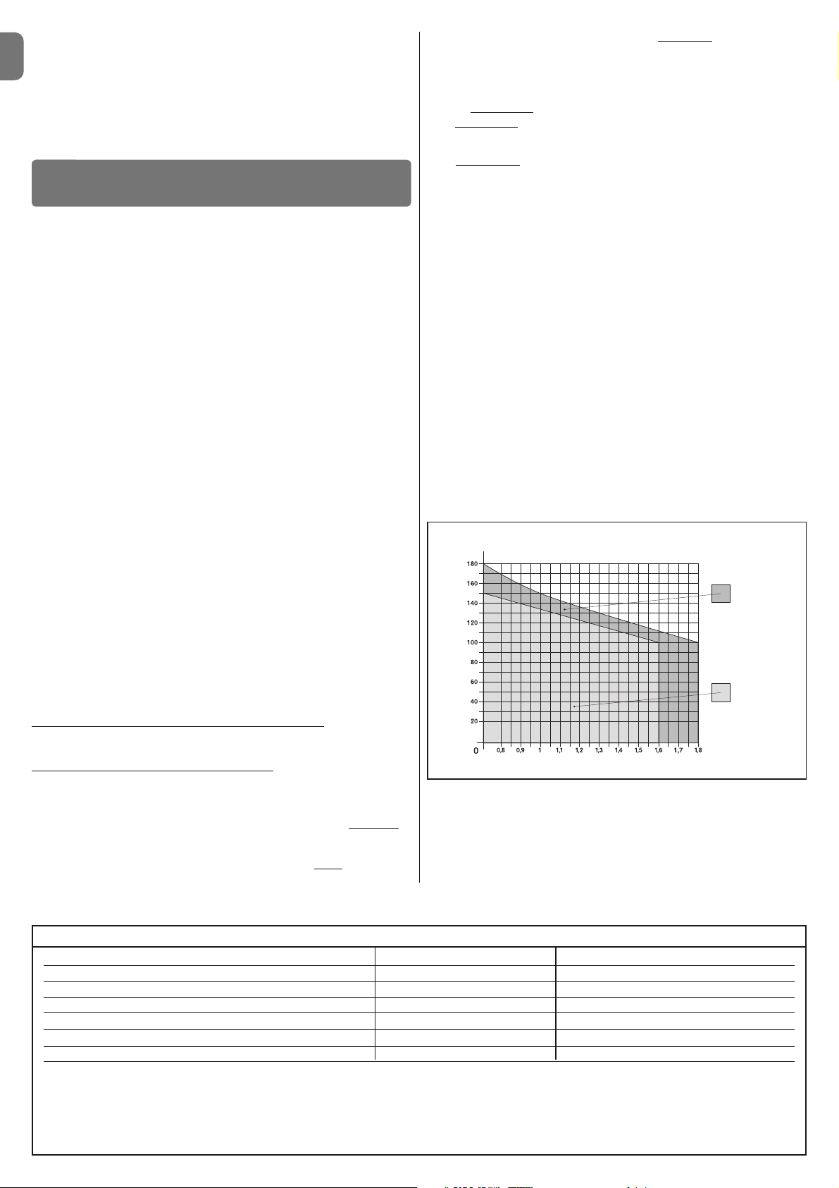
With FULL LENGTH motor arm (as shipped from the factory)
:
- maximum width of leaf: 1,80 m (= maximum weight of leaf: 100 kg)
- maximum height of leaf: 2 m
With SHORTENED motor arm (cut by the installer)
:
- maximum width of leaf: 1,60 m (= maximum weight of leaf: 100 kg)
- maximum height of leaf: 2 m
• Check to run: apply to Graph 1 the weight and width of the leaf; plot two lines
from these points and check that they intersect in one of the two grey areas
of
the graph. Important! - If the lines cross in the white area, this product cannot
be used to automate this particular gate.
• To enable the installation of the gearmotor, the minimum width
of the column
should be 80 mm.
• The gearmotor arm must be positioned in the upper part
of the gate leaf.
IMPORTANT! - The gearmotor must not be mounted upside down, i.e. with
the arm pointing downwards.
• The arm’s fastening bracket must be fitted at one of the strongest parts of the
leaf (e.g. the frame), in order to ensure a firm and safe hold;
• Check distance
“E” (fig. 7):
- If distance
“E” falls in the range 80 mm (minimum) to 299 mm (maximum),
the gearmotor arm will need to be shortened. In such conditions, the leaf will
be able to open by up to 90°.
- If distance “E” is 300 mm or more, there is no need to shorten the gear-
motor arm. In such conditions, the leaf will be able to open by up to 110°.
3.3 - Preparatory work prior to installation
Fig. 2 illustrates an example of an automated system, achieved using Nice
components (some components may not be included in the kit):
a - Gearmotor with control unit mod. WL1024C
b - Gearmotor without control unit mod. WL1024
c - Multi-purpose lamp mod. WLT (to be installed on the gearmotor with con-
trol unit mod. WL1024C); see chapter 3.5 and the lamp’s own instruction
manual
d - Pair of photocells mod. MOFB
e - Digital keyboard (mod. MOTB) - Transponder reader (mod. MOMB) - Key
selector (mod. MOSE)
f - Pair of photocell posts
g - Opening and Closing mechanical stops
h - Electrical lock
These components are positioned according to a typical standard layout.
Referring to fig. 2, establish the approximate position in which to install each
component required for the system. Important – Before commencing installa-
tion, prepare the electrical cables necessary for your system, referring to fig. 2a
and to “Table 1 - Technical characteristics of the electrical cables”.
Important – While laying the tubes for the electrical cables, consider that due
to the possible build-up of water in the aqueducts, the connection tubes could
cause condensation to form inside the control unit and damage the electronic
circuits.
INSTALLATION
3
Connection Type of cable Maximum permitted length
A: POWER cable One 3 x 1.5 mm2cable 30 m (note 1)
B: ELECTRICAL LOCK cable One 2 x 1 mm2cable 6 m
C: BLUEBUS DEVICES cable One 2 x 0.5 mm2cable 20 m (note 2)
D: KEY SELECTOR cable Two 2 x 0.5 mm2 cables (note 3) 50 m
E: GEARMOTOR POWER cable One 3 x 1.5 mm2cable 6 m
EXTERNAL AERIAL cable (optional) One type RG58 screened cable 20 m (recommended less than 5 m)
Note 1 – If the power cable is more than 30 m long, you will need to use a cable with a wider cross-section (3 x 2.5 mm
2
) and you will have to install protective earthing near the automation system.
Note 2 – If the Bluebus cable is more than 20 m long, and up to a maximum of 40 m long, you will need to use a cable with a wider cross-section (2 x 1 mm
2
).
Note 3 – These 2 cables can be replaced with 1 single 4 x 0.5 mm2 cable.
IMPORTANT! – The cables used must be suitable for the type of environment where they are installed.
TABLE 1 - Technical characteristics of the electrical cables
GRAPH 1
For full length
arm
For shortened
arm
WIDTH (m.)
WEIGHT (kg.)
Other available accessories include the receivers designed with “SM” connectors (SMXI, OXI, etc.).
The gearmotor with control unit (mod. WL1024C) is designed to accommodate
the installation of the multi-purpose lamp mod. WLT (see chapter 3.5), which
can operate as a flashing emergency light or courtesy light, depending on the
control unit programming. In addition, it can be used as a twilight by activating
a built-in light sensor; please refer to the relevant instruction manual for specifications.
Page 5
EN
English – 3
3.4 - Installation of the gearmotor mod. WL1024C - WL1024
WARNINGS
• Failure to install correctly can cause serious injury to the person carrying out the work and those using the system.
• Before starting to assemble the automation system, carry out the preliminary checks described in paragraphs 3.1 and 3.2.
• The gearmotor arm can be shortened from the standard length provided. It needs to be reduced in length if there is a fixed obstacle close to
the gearmotor (such as a wall or post) impeding the full range of movement of the arm. In order to establish whether the arm needs to be
shortened, it is therefore necessary to follow the procedure in 3.4.1
before starting the installation
.
Assemble the component parts of the motor arm, referring to fig. 3. Do not in se rt the Benzing retaining ring at this stage (fig. 4). N.B.! - The curved arm
mu st be positioned with the curved part towards the gate leaf, as shown
in fig. 5.
3.4.1 - Establishing the length of the gearmotor arm
01. Determine the VERTICAL position of the gearmotor:
draw a horizontal line on the column at the same height at which the fastening bracket for the arm will be located on the leaf once the installation is
complete.
02. Determine the HORIZONTAL position of the gearmotor:
a) Determine the maximum opening position of the leaf
: determine the
maximum opening angle (maximum 110°).
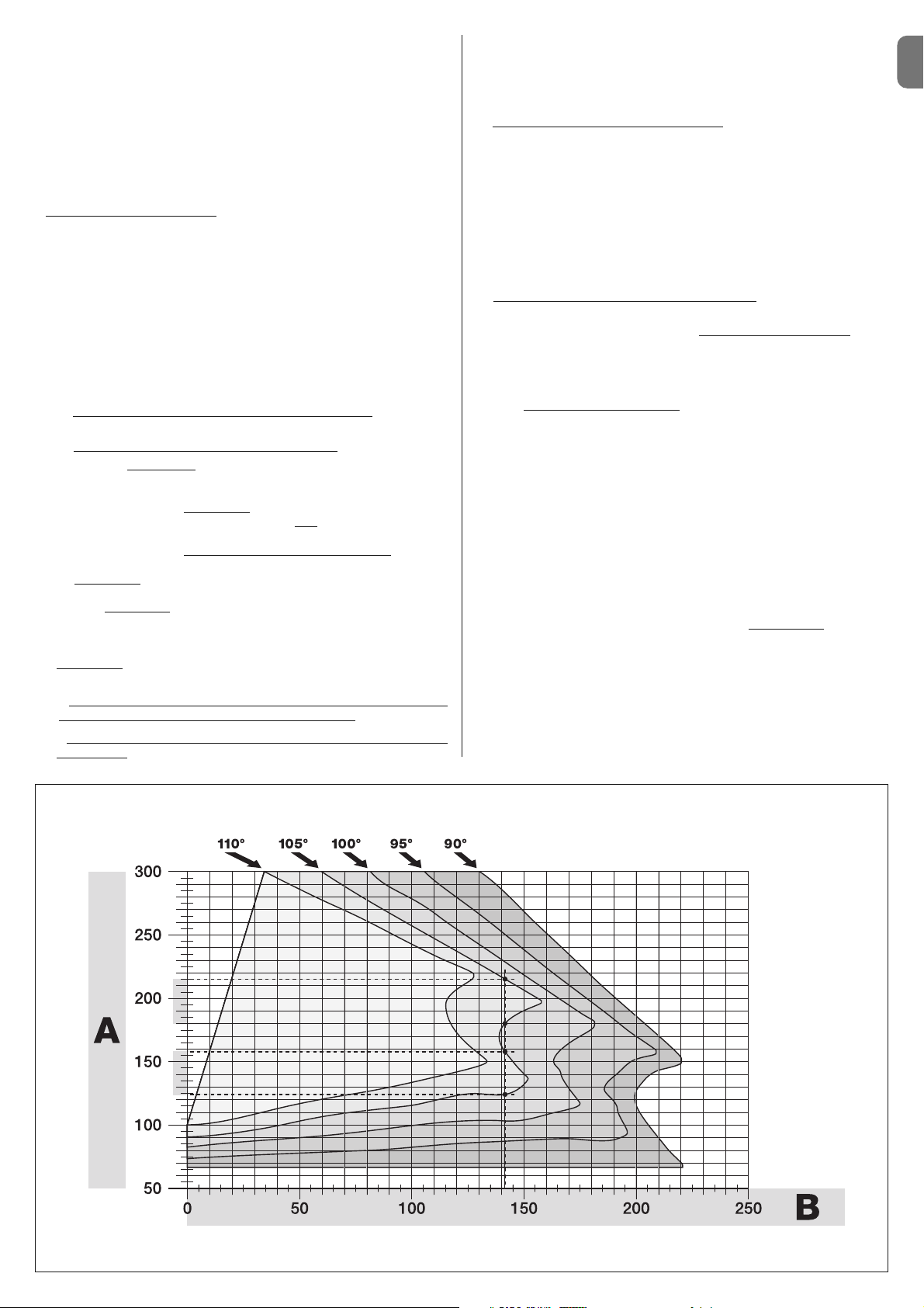
b) Measure distance B and determine distance A
:
1 - Measure distance B
on the column (fig. 5). This is the distance be -
tween the fulcrum of rotation of the gate leaf and the surface of the column
where the rear bracket of the gearmotor will be fixed.
2 - On Graph 2A, mark distance B
, as just measured, and trace a vertical
line from this point until it intersects with the area
which includes the angle
value measured in point a.
3 - At the points where the vertical line intersects with the area
, trace horizontal lines across column “A”, to determine the values which can be used
for distance A
. Then choose a value for A from this range, one of the
smaller values if possible.
4 - Mark distance A
on the column and trace a vertical line corresponding
to it (fig. 6).
5 - If there is a wall or other immovable obstacle near the vertical line,
measure the distance between this line and the obstacle (fig. 7): this is
distance E
.
IMPORTANT!
• If
distance E falls in the range 80 mm (minimum) to 299 mm (maxi-
mum), continue the installation with procedure 3.4.3
.
• If distance E is 300 mm or more, continue the installation with procedure 3.4.2
.
5 - Release the gearmotor with the dedicated key (see chapter 3.8).
3.4.2 - Installation of a gearmotor with a STANDARD LENGTH ARM
Important! - This part of the installation can only be carried out after 3.4.1
has been completed.
01. Affix the gearmotor to the column (fig. 8)
:
a) Hold the gearmotor against the column(*) so that its vertical centre line
corresponds with the vertical line traced earlier (distance A), and its arm
corresponds with the horizontal line traced during procedure 3.4.1. Now
ensure that the gearmotor is completely levelled: if off-axis, it can cause the
automation to malfunction.
(*) Note - If the column surface is between 80 and 135 mm wide, then
before continuing with the installation, the gearmotor’s rear fastening
bracket will need to be rotated by 90°. To rotate the bracket, refer to fig. 9.
b) Mark the fastening points, drill the required holes in the surface of the
column and insert the plugs; now fix the gearmotor in place using suitable
screws and washers.
02. Affix the gearmotor arm to the gate leaf (fig. 8)
:
c) Bring the gate leaf into the fully Closed position;
d) Push forcefully the gearmotor arm to its maximum extension
. Cau-
tion! - Make sure the arm is locked in its end stop;
e) Bring the arm up to the gate leaf and hold the fastening bracket against
the leaf.
f) Ensure that the gearmotor arm is levelled properly, and use a pencil to
mark the centre
of the slot profile on the bracket, to enable fine adjustments to be made to the closure alignment of the leaf in future (see paragraph 3.7).
g) Holding the bracket against the gate leaf with one hand, attempt to open
and close the gate completely, up to the respective mechanical stops.
Important! - If the movement of the arm is hampered during the test
by a wall or other fixed object, stop working on this procedure and go
to procedure 3.4.3.
h) Drill holes in the gate leaf at the points marked and remove the bracket
from the arm and affix it to the gate leaf with suitable screws.
i) Attach the arm to the bracket, inserting the pin and the Benzing retaining
ring. Important - Check that the bracket and the arm are completely level.
Loosen the screws of the bracket and adjust as required to ensure level.
This check can also be performed by measuring a distance of 75 mm (see
fig. 8 phase 2).
l) Fix the end stops to the ground permanently, in the position
determined
at the start of the procedure. Important! - Check that the gate leaf closes
completely against the end stop (not supplied).
m) Finally, bring the leaf manually to around its midpoint of travel and
secure the gearmotor using the dedicated key (see chapter 3.8). Then
manually open the leaf by a few more centimetres.
03. If the gate being automated has two leaves, then to install the other gearmotor repeat all the actions described here in chapter 3.4.
GRAPH 2A
Page 6
EN
4 – English
3.4.3 - Installation of a gearmotor with a SHORTENED ARM
Important! - This part of the installation can only be carried out after 3.4.1
has been completed.
01. Determine a new maximum opening angle for the gate leaf (max 90°)
:
ignoring the maximum opening position established for the leaf during procedure 3.4.1, bring the leaf to a new maximum opening position, ensuring
that the angle does not exceed 90°. Then hold the gate leaf provisionally in
this position using a ground-mounted stop.
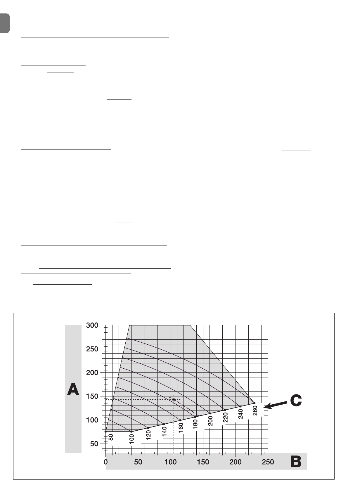
02. Determine distances A - B - C
:
a) Measure distance B (fig. 10) on the column. This is the distance
between the fulcrum of rotation of the gate leaf and the surface of the column where the rear bracket of the gearmotor will be fixed.
b) On Graph 2B, mark distance B
as measured, and trace a vertical line
from this point.
c) On the column, determine the value for distance A
, at which to mount
the rear bracket of the gearmotor (refer to fig. 11). N.B.! - Choose a value
for A, the smaller the better
, in order to keep the motor free of the
obstacle.
d) On Graph 2B, mark distance A
as just measured and plot a horizontal
line from this point until it intersects with the vertical line traced earlier. The
meeting point of these lines defines distance C
, i.e. the distance required
between the two pins on the slotted arm (fig. 12). Example from graph 2B:
if the value of B is 105 mm and A is 143 mm, then point C is 182.
03. Affix the gearmotor to the column (fig. 13)
:
a) Hold the gearmotor against the column (*) so that its vertical centre line
corresponds with the vertical line traced earlier (distance A), and its arm
corresponds with the horizontal line traced during procedure 3.4.1. Now
ensure that the gearmotor is completely levelled: if off-axis, it can cause the
automation to malfunction.
(*) Note - If the column surface is between 80 and 135 mm wide, then
before continuing with the installation, the gearmotor’s rear fastening
bracket will need to be rotated by 90°. To rotate the bracket, refer to fig. 8.
b) Mark the fastening points, drill the required holes in the surface of the
column and insert the plugs; now fix the gearmotor in place using suitable
screws and washers.
04. Shorten the slotted arm (fig. 14)
:
a) To reduce the length of the slotted arm to value C
(as established in
point 02-d), unscrew the nut, remove the stop, adjust the two pins so that
the distance between them is equal to value C, then fasten the nut in position provisionally.
05. Checking the length C of the slotted arm in this context (fig. 15 - 16)
:
a) Bring the gate leaf into the fully Closed position;
b) Fully open the gearmotor arm to its maximum extent (see 15, phase 1);
c) Bring the arm up to the gate leaf and hold the fastening bracket against
the leaf: Important!
- push the curved arm against the leaf, until it is
secured (maximum opening - see fig. 15, phase 1a).
d) Ensure that the gearmotor arm is levelled properly, and use a pencil to
mark the centre
of the slot profile on the bracket, to enable fine adjustments to be made to the closure alignment of the leaf in future (see paragraph 3.7).
e) Provisionally attach the bracket to the gate leaf and bring the leaf into its
maximum opening position against the ground-mounted stop.
f) With the leaf in this position, perform the checks shown in fig. 16 (run a
wire over the two pins of the slotted arm, as far as the leaf hinge). Impor-
tant! - If, in relation to the hinge,
the wire appears in position “BB” as in fig.
16, it will be necessary to extend distance C by a few millimetres. This
must be repeated until the wire reaches position “AA” as in fig. 16 and the
arm is no longer obstructed by the wall or other fixed obstacles.
06. Cutting the slotted arm (fig. 17)
:
After checking that the articulation is operating correctly, cut the slotted
arm in the following manner.
a) Trace a line on the slotted arm in the position exactly as indicated in fig.
17, phase 1. Then remove the arm from the bracket and cut the part of the
arm which is not required.
b) Re-assemble the components of the arm (fig. 3).
07. Affix the gearmotor arm tot he gate leaf (fig. 18
):
a) Drill holes in the gate leaf at the points marked.
b) Remove the bracket from the arm and affix it to the gate leaf with suit-
able screws.
c) Attach the arm to the bracket, inserting the pin and the Benzing retaining
ring. Important - Check that the bracket and the arm are completely level.
Loosen the screws of the bracket and adjust as required to ensure level.
This check can also be performed by measuring a distance of 75 mm (see
fig. 8 phase 2).
d) Fix the end stops to the ground permanently, in the position
determined
at the start of the procedure.
Important! - Check that the gate leaf closes completely against the end
stop. To make fine adjustments to the closure alignment, refer to paragraph
3.7.
e) Finally, bring the leaf manually to around its midpoint of travel and secure
the gearmotor using the dedicated key (see chapter 3.8) Then manually
open the leaf by a few more centimetres.
08. If the gate being automated has two leaves, then to install the other gearmotor repeat all the actions described here in chapter 3.4.
3.5 - Installation of the multi-purpose lamp mod. WLT on the
gearmotor model WL1024C
Warning – WLT can operate as a flashing emergency light or courtesy light,
depending on the control unit programming.
Follow the installation steps shown in fig. 21, making sure the right sequence is
followed and the following warnings are adhered to:
• for phase 4 – Rotate the power unit in the direction of the arrow, keeping a
careful eye on the cables underneath that connect it to the gearmotor.
• for phase 7 – Open out the cables fully and insert the connector into the
FLASH output as shown; secure the cables by inserting them in the cable
gland.
• for phase 11 – Position the electrical board on the pin of the base, depend-
ing on the desired usage: A = diffuse light; B = directional light beam (in this
case, the light beam can be directed by blocking the board in one of the holes
on the base).
GRAPH 2B
Page 7

EN
English – 5
The electrical connection of the various devices (photocells, digital keyboards,
transponder card readers, etc.) of the automation system with a control unit is
carried out with the Nice “Bluebus” system. This system makes it possible to
carry out the electrical connections with the use of just 2 wires along which
both the electricity supply and the communication signals travel. The electrical
connection to be used is parallel and does not require any polarity to be
observed. During the recognition phase, every device connected to the control
unit will be recognised individually by the latter, thanks to a univocal code. Every
time a device is added or removed, you must carry out the control unit recognition phase (see paragraph 4.7).
4.1 - Description of the electrical connections (fig. 23)
M1 gearmotor output 1
ELS utput for 12 VAC electrical lock (max 15 VA). The ELS output can be
programmed with other functions using the Oview programmer (see
chapter 8.3) (e.g. flashing, courtesy light, etc.)
BLUEBUS input for compatible devices (MOFB, MOFOB, MOB and MOTB).
The device connection is in parallel with the use of 2 wires along
which both the electricity supply and the communication signals
travel; there is no need to observe any polarity when making the
connection. Each device is recognised individually by the control
unit because a univocal address is assigned to it during the installation (see paragraph 4.7)
ELECTRICAL CONNECTIONS
4
• for phase 12 – Open out the cable fully, cut the excess portion and position
the cables in such a way that they do not cast any shadows over the LEDs and
the light sensor fitted on the back of the electrical board.
• for phase 13 – The arrow on the cover and the one on the base should align.
Ensure the 4 cogs on the base fit into the grooves inside the cover.
Note – If the WLT multi-purpose lamp is not installed on the upper part of the
“Walky” gearmotor, it should be connected to the ELS terminal as described in
paragraph 4.1- “Description of the electrical connections”.
3.6 - How to remove the control unit
01. Remove the gearmotor’s lower cover (fig. 19 phase 1-2);
02. Undo the 4 screws of the cable sleeve support and remove it (fig. 24
phase 1-2);
03. Pull the control unit about 4 centimetres in the direction of the arrow, and
detach the motor connector (fig. 24 phase 3-4);
04. Finally, remove the control unit completely;
Important! - When reconnecting the motor to the control unit, observe the
polarity of the connector (this can only be inserted one way around!).
3.7 - Adjusting the alignment of the gate leaves when closed
01. Remove the slotted arm from the fastening bracket on the gate leaf;
02. Loosen the screws on the bracket and move it by a few millimetres towards
the gearmotor;
03. Then replace the slotted arm in the bracket, close the leaf and check that it
is both aligned with the other leaf and in contact with the end stop. Impor-
tant! - If necessary, repeat point 02 until an optimum alignment is achieved;
04. Drill a hole in the leaf, to correspond to the hole in the centre of the fastening bracket, and insert a screw. Then fix the bracket permanently in place
by tightening the three screws;
05. Finally, attach the slotted arm to the bracket, inserting the pin and the Benzing retaining ring.
3.8 - Securing and releasing the gearmotor manually
The gearmotor is equipped with a mechanical system which allows the gate to
be opened and closed manually.
These manual operations are required in the event of power cuts, operational
faults, or during installation.
Releasing (fig. 22-A):
01. Raise the flap;
02. Insert the key into the release pin;
03. Turn the key by almost a full turn clockwise.
04. The gate leaf can now be moved manually into the required position.
Securing (fig. 22-B):
01. Turn the key anticlockwise in the release pin and move the gate leaf manu-
ally until you can hear the leaf engage mechanically with the drive mechanism.
02. Remove the key from the pin and rotate the release disc anticlockwise by
90° so that the hole is blocked and replace the flap.
STOP input for devices which, when activated, cause the manoeuvre in
progress to halt immediately, followed by a brief inversion; possibility of connecting NO, NC contacts or devices with a 8.2 kΩ constant resistance output (sensitive edges). Each device connected to
this input is recognised individually by the control unit during the
recognition phase (paragraph 4.7); after this phase, if the control
unit detects any variation with respect to the status recognised, it
causes a STOP. One or more devices - including different ones can be connected to this input:
– several NO devices can be connected in parallel, with no limits as
to quantity;
– several NC devices can be connected in series, with no limits as
to quantity;
– 2 devices with a 8.2 kΩ constant resistance output can be connected in parallel. If there are more than 2 devices, they need to be
connected in a cascade configuration with a single termination
resistance of 8.2 kΩ;
– 2 NO and NC devices can be connected in parallel, connecting in
series with the NC contact a 8.2 kΩ resistance (this makes the
combination of 3 NO - NC and 8.2 kΩ devices possible)
P. P. input for control devices which, when activated, cause the Step-
step manoeuvre to take place; possibility of connecting NO contacts
AERIAL input for the aerial of a radio receiver
4.2 - Connecting the power cable
WARNING: The electricity supply line must be equipped with a device which
ensures the complete disconnection of the automation system from the mains.
The disconnection device’s contacts must have an opening distance which is
sufficient to achieve full disconnection in category III overload conditions, in
conformance with the rules of installation. When the need arises, this device
ensures that the power is disconnected quickly and safely; it must therefore be
positioned where it can be seen from the automation system. If, however, it is
not located in a visible position, it must be provided with a system to prevent
the power supply being reconnected accidentally or without authorisation, in
order to avoid any risk. The product is not supplied with a disconnection
device.
IMPORTANT!
– The connection must be carried out exclusively by qualified experts.
– All electrical connections must be carried out without any mains electri-
cal power supply and with the back-up battery disconnected - where
present in the automation system.
01. Access the power unit by undoing the 3 screws in the gearmotor’s upper
cover and slowly rotate the cover in the direction of the arrow (fig. 24),
keeping a careful eye on the cables underneath;
02. Connect the phase and neutral wires to the power unit terminal board,
observing the instructions on the label; close the earth cable grommet
using the screw (fig. 25): care required! -the terminal should be pointing
towards the opening from which the power cable emerges;
03. Then pull the power cable towards the control unit, so that it is just long
enough to allow the power unit to rotate and the cover to close;
04. Close the power unit cover; tighten the screws on the cable gland; insert
the control unit into its seat, and remount the cable sleeve support;
Important! - Fasten the cover of the power unit with all the screws
and ensure that the seal is well positioned in its seat. If the seal or one
of the screws is missing, this can compromise the electronics inside.
4.3 - Connecting the gearmotor without a control unit mod.
WL1024
01. Remove the lower cover of the gearmotor without control unit, as shown in
fig. 19, phase 1-2;
02. Using a Phillips screwdriver, undo the 4 screws of the cable sleeve support
(fig. 20) and remove it (important! - do not lose the 2 spacers).
03. Loosen the two screws on the cable gland (fig. 20, phase 6) and feed the
connection cable through; connect the 3 cables to the terminal board,
observing the symbols as labelled; then tighten the screws of the cable
gland.
04. Adjust the 2 feet inside the gearmotor with an Allen key, until they are fully
resting on the column (fig. 20, phase 7).
05. Cut the edge of the cable sleeve support (fig. 20, phase 8); put the 2 spac-
ers back into position; remount the cable sleeve support (fig. 20, phase 9)
and replace the gearmotor’s lower cover (fig. 20, phase 10).
4.4 - Connecting other devices
If you need to power further devices in the system, such as a transponder card
reader or the light for the key selector, these devices can be connected to the
control unit on terminals “P.P. (positive)” and “STOP (negative)” (fig. 23). The
supply voltage varies from 18 to 31 VDC when mains or solemyo operated and
from 11 to approx. 14 VDC when operating on back-up battery PS424. The
ma ximum available current is 200 mA.
Note – The voltage available in terminals “P.P.” and “STOP” remains present
even when the “Stand By” function is activated on the board.
Page 8
EN
6 – English
4.5 - Addressing the photocells and other BlueBus devices
To allow the control unit to recognise the photocells connected to the Bluebus
system, these need to be addressed: correctly position the electric jumper of
each device, as shown in fig. 31.
To address other devices, refer to the respective instruction manual.
4.6 - Initialisation and connection check
Once you have powered the control unit, carry out the following checks:
• after a few seconds, check that the “Bluebus” LED (fig. 26) flashes regularly
at a frequency of 1 flash per second;
• check that the LEDs of the photocells, both TX and RX, emit flashes. The type
of flashing emitted, at this stage, is not significant;
• check that the WLT multi-purpose lamp is turned off (set on flashing function)
and connected to the FLASH output on the power supply.
If this does not happen, cut off the electricity supply to the control unit and
check the various electrical connections previously carried out.
4.7 - Recognition of the connected devices
Once initialisation is complete, the control unit must recognise the devices connected to the “Bluebus” and “Stop” inputs.
IMPORTANT! – The recognition phase must be carried out even if the
con trol unit is not connected to any devices.
The control unit is designed to recognise individually the various devices connected to it thanks to the recognition procedure and it can also detect with a
very high degree of precision any possible problems. Consequently, the recognition of devices must be carried out each time a device is connected or
removed.
LEDs “L1” and “L2” on the control unit (fig. 26) emit slow flashes to indicate
that recognition needs to be carried out:
01. Press and keep pressed keys “” and “Set” (fig. 26) simultaneously.
02. Release the keys when LEDs “L1” and “L2” begin to flash quickly (after
approximately 3 seconds).
03. Wait a few seconds for the control unit to complete the device recognition
phase.
04. At the end of this phase, the “Stop” LED should be turned on and LEDs
“L1” and “L2” should turn off (LEDs “L3” and “L4” may start to flash).
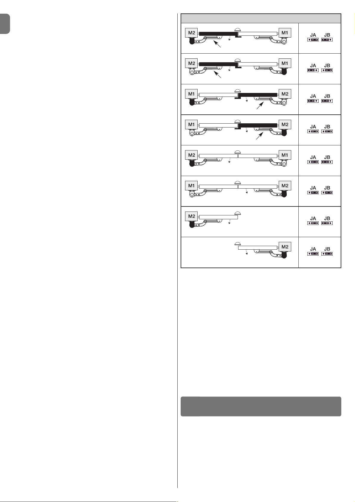
4.8 - Recognition of the positions of the mechanical stops
After the recognition of devices (paragraph 4.7), the control unit must recognise
the positions of the mechanical stops (maximum Opening and maximum Closure);
During this phase, the angle of aperture of the leaf is detected from the closing
mechanical stop to the opening mechanical stop. It is vital that the me -
chanical stops are fixed and sufficiently sturdy.
01. Identify the figure corresponding to your system in Table 2, fix the electric
jumpers JA and JB in place on the control unit, in the position as indicated
in this figure.
02. Release the gearmotors with the dedicated keys (see chapter 3.8) and
bring the leaves to their midpoint of travel so that they are free to open and
close; then secure the gearmotors.
03. On the control unit, press and keep keys “Set” and “” pressed simulta-
neously;
04. When LEDs “L3” and “L4” begin to flash quickly, (after approximately 3
secs.) release the keys;
05. Check that the automated system performs the following sequences of
manoeuvres:
a - Slow closure of gearmotor M1 to the mechanical stop
b - Slow closure of gearmotor M2 to the mechanical stop
c - Slow opening of gearmotor M2 and gearmotor M1 to the mechanical
stop
d - Complete quick closure of gearmotors M1 and M2
• If the first manoeuvre of one or both leaves is not a closing movement,
press any key to halt the recognition phase and check the positioning of
electric jumpers JA and JB referring to Table 2; otherwise, check the polarity of the motor without control unit (mod. WL1024).
• If the first motor to start the closing movement is not M1, press any key
to halt the recognition phase and check the positioning of electric jumpers
JA and JB, referring to Table 2.
• If a device is activated during the recognition phase (photocells, key
selector, pressing of a key, etc.), the recognition phase is immediately halted. It must be repeated in full.
06. At the end of the closing manoeuvre of both motors (d), LEDs “L3” and
“L4” switch off to indicate that the procedure was completed successfully.
4.9 - Gate leaves motion check
At the end of the recognition of the positioning of the mechanical stops, we recommend you make the control unit perform a few opening and closing
manoeuvres, in order to ensure the gate moves correctly, to check for any
assembly and adjustment defects or other problems:
01. Press the Open key (fig. 26) and check that the Opening manoeuvre
includes an acceleration phase, a phase at constant velocity, a deceleration phase and that the leaves stop against the opening mechanical end
stop.
02. Press the Close key (fig. 26) and check that the closing manoeuvre
includes an acceleration phase, a phase at constant velocity, a deceleration phase and that the leaves stop against the closing mechanical end
stop.
03. Check, during manoeuvres, that the flashing performs certain flashes at 0.5
second intervals with the flashing on and 0.5 seconds with the flashing off.
These are the most important phases in the installation of the automation system, in order to guarantee maximum system safety. Testing can also be used to
check the devices in the automation system regularly. The automation system
testing and commissioning phases must be carried out by qualified experts
who must be responsible for determining the tests necessary to check the
solutions adopted vis-à-vis the risks involved, and to check the observance of
all legal and regulatory obligations: in particular all the requirements of the EN
12445 standard which sets forth the test methods for checking automated
gates.
Additional devices must undergo specific testing, both in terms of functionality
as well as their correct interaction with WALKY; please refer to the relevant individual instruction manuals.
TESTING AND COMMISSIONING
5
Overlapping leaf
Overlapping leaf
Overlapping leaf
Overlapping leaf
Control unit
Control unit
Control unit
Control unit
Control unit
Control unit
Control unit
Control unit
TABLE 2
Page 9
EN
English – 7
5.1 - Testing
The sequence of steps to take to carry out testing refers to a typical system (fig. 2):
1 Release the gearmotors manually and check that when you operate the
leaf, at the point designed especially for the manual manoeuvre, the leaves
can either be opened or closed with a force of less than 390 N.
2 Check that the leaf, when left in any position along its travel, does not
move.
3 Secure the gearmotors (see chapter 3.8).
4 IMPORTANT! – Check that the screw connections are screwed in tightly.
5 Using the control devices (transmitter, command button, key selector, etc.),
perform some Gate Opening, Closing and Stop tests, making sure the
movement of the leaves corresponds with each test. It is a good idea to
carry out several tests in order to evaluate the movement of the leaves and
pinpoint any assembly or adjustment defects as well as to check for any
particular points of friction.
6 Check one by one that all the safety devices in the system work properly
(photocells, sensitive edges, etc.). When a device is activated, the “BLUEBUS” LED on the control unit emits two quicker flashes to confirm that
recognition has taken place.
7 If the hazardous situations caused by the movement of the leaves have
been safeguarded by limiting the force of impact, the force must be measured in accordance with the EN 12445 standard and, if necessary, if the
control of the “gearmotor force” is used as an aid to the system to reduce
the force of impact, try and then find the adjustment that achieves the best
results.
8 Affix permanently a label describing how to release the gearmotor manual-
ly in an area adjacent to the automation system.
5.2 - Commissioning
Commissioning can only take place once all the testing phases have been
carried out successfully.
1 Put together the automation system’s technical file, which should include
the following documents: an overall diagram of the automation system, the
diagram of the electrical connections made, the current risk analysis and
the related solutions adopted, the manufacturer’s declaration of conformity
for all the devices used and the declaration of conformity filled in by the in staller.
2 Affix a data plate onto the gate which specifies the following information, at
least: the type of automation system, the name and address of the manufacturer (responsible for the commissioning), the serial number, the year of
manufacture and the EC mark.
3 Fill in the declaration of conformity of the automation system and hand it
over to its owner.
4 Fill in and hand over to the owner of the automation system the “User’s
guide” of the automation system.
5 Fill in and hand over to the owner of the automation system the “Mainte-
nance schedule” which contains instructions on the maintenance of all the
devices in the automation system.
6 Before commissioning the automation system, inform the owner of all the
hazards and residual risks entailed.
For all the documentation mentioned, the Nice technical support service
provides the following: instruction manuals, guides and precompiled forms.
Also visit: www.nice-service.com
TABLE 5 - Level one functions
LED Function Description
L1 Automatic close
L2 Close after photo
L3 Always close
L4 Stand by (Bluebus)
Function ACTIVATED: after an opening manoeuvre, there is a pause (equal to the programmed pause Time) after which the control unit auto-
matically performs a closing manoeuvre. The factory set pause time is 30 sec.
Function
DEACTIVATED: operation is “semi-automatic”.
Function
ACTIVATED: if the photocells are activated during an opening or closing manoeuvre, the pause time is reduced to 5 sec. irrespective of
the programmed “pause time”.
With the “automatic close” function deactivated, if the photocells are activated during the closing manoeuvre, the “automatic close” is activated
with the programmed “pause time”.
Function
ACTIVATED: in the event of a power cut, albeit brief, when the electricity supply returns the control unit detects the open gate and auto-
matically starts a closing manoeuvre, after 5 sec. of pre-flashing.
Function
DEACTIVATED: when the electricity supply returns, the gate will remain as is.
Function
ACTIVATED: 1 minute after the manoeuvre is finished, the control unit turns off the “Bluebus” output (connected devices) and all LEDs
except for the Bluebus LED which will flash more slowly. When the control unit receives a command, it restores normal operation (with a short
delay). This function is designed to reduce consumption levels, which is a key feature when battery or photovoltaic panel powered.
There are three keys on the control unit. These are OPEN (), STOP (SET) and
CLOSE () and they can be used to operate the control unit during the testing
phases as well as for programming the functions available.
The programmable functions available are arranged on 2 levels and their operating status is indicated by the 4 LEDs (L1 ... L4) on the control unit (LED on =
function activated; LED off = function deactivated).
Use the programming keys (fig. 26):
OPEN (): – key to control the gate opening; – selection key during the pro-
gramming phase.
STOP/SET: key to stop a manoeuvre; when pressed for more than 5 seconds,
it allows you to enter the programming phase.
CLOSE (): – key to control the gate closing; – selection key during the pro-
gramming phase.
6.1 - Level one programming (ON-OFF)
All level one functions are programmed at the factory to “OFF” and can be
changed at any time. To check the various functions please see Table 5. For
the programming procedure, please see Table 6.
Note – These procedures can be performed again at any time, even after a new
device has been connected to the control unit.
IMPORTANT – The programming procedure has a maximum time of 10 seconds between one key and another being pressed. After this time, the procedure ends automatically, storing the changes made up until that moment.
PROGRAMMING THE CONTROL UNIT
6
TABLE 6 - Level one programming procedure
01. Press and keep key “Set” pressed for approximately 3 seconds;
02. Release the key when LED “L1” begins to flash;
03. Press key “” or “” to move the flashing LED to the LED representing the function you wish to change;
04. Press the “Set” key to change the status of that function:
(brief flashing = OFF - long flashing = ON);
05. Wait 10 seconds (maximum) to exit programming mode.
Note – To program other functions to “ON” or “OFF” when the procedure is in progress, repeat steps 03 and 04 during the phase itself.
L1
or
3 s
10 s
Page 10
EN
8 – English
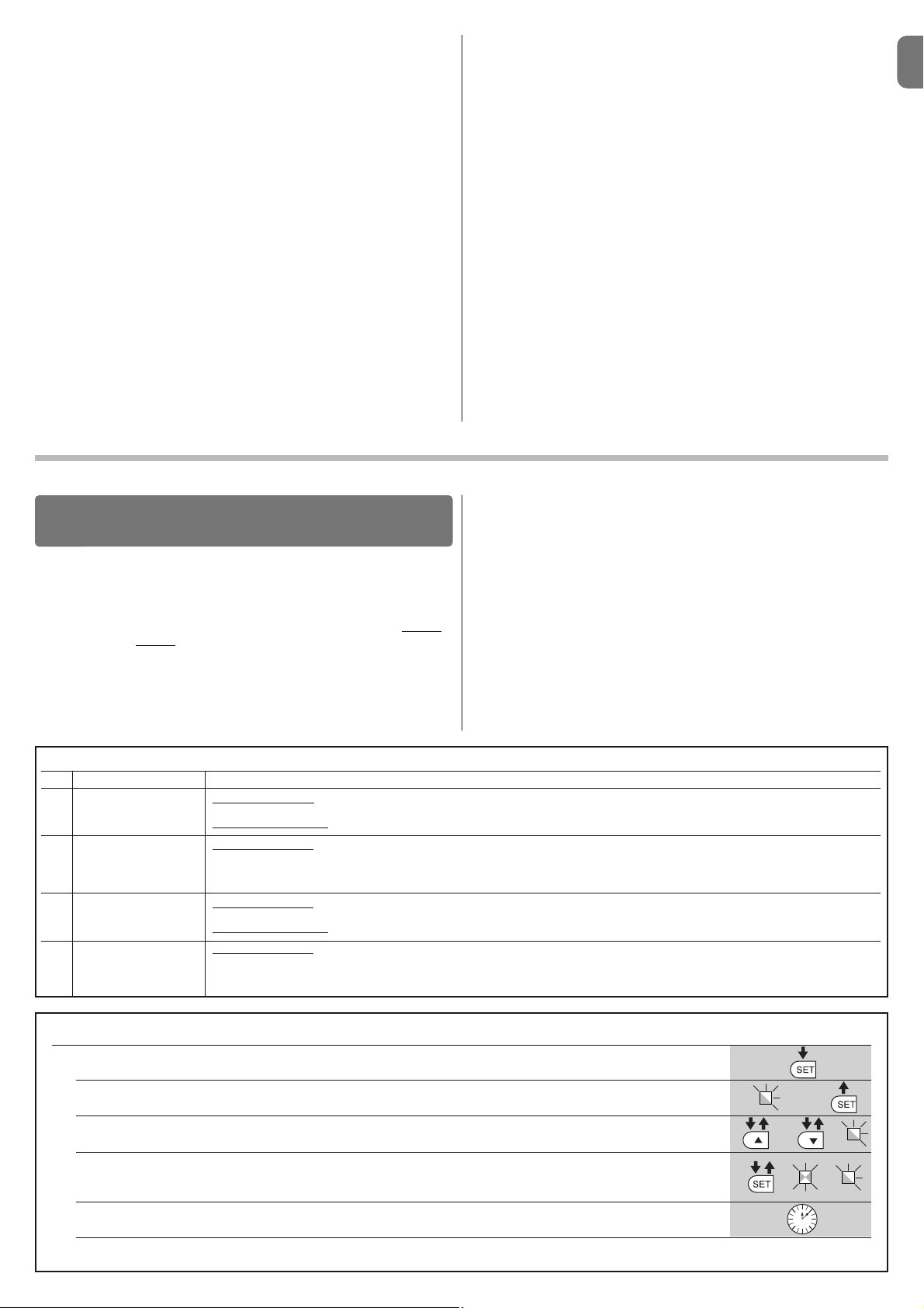
TABLE 7 - Level two programming procedure
01. Press and keep key “Set” pressed for approximately 3 seconds;
02. Release the key when LED “L1” begins to flash;
03. Press key “” or “” to move the flashing LED to the LED representing the “input LED” of the parameter you wish to change;
04. Press and keep pressed the “Set” key until step 06 is complete;
05. Wait approximately 3 seconds until the LED representing the current level of the parameter to be changed is turned on;
06. Press key “” or “” to move the LED representing the value of the parameter;
07. Release the “Set” key;
08. Wait 10 seconds (maximum) to exit programming mode.
Note – To program several parameters when the procedure is in progress, repeat steps 03 to 07 during the phase itself.
L1
or
or
3 s
10 s
6.3 - Memory deletion
To delete the memory of the control unit and restore all the factory settings, proceed as follows: press and keep pressed keys “” and “” until LEDs L1 and
L2 start to flash.
6.4 - Special functions
Function: “Move anyway”
This function makes it possible to operate the automation system even when a
safety device is not working properly or is out of order.
The automation system can be controlled in “push to run” mode as follows:
01. Send a command to operate the gate, using a transmitter or key selector,
etc. If everything is working properly, the gate will move normally, otherwise
proceed as follows:
02. Within 3 seconds, send the command again and keep it activated;
03. After approximately 2 seconds, the gate will perform the manoeuvre
requested in “push to run” mode; i.e. the gate will continue to move only
for as long as the command is activated.
When the safety devices do not work, the flashing light emits a few flashes to
indicate the type of problem (see chapter 7 - Table 10).
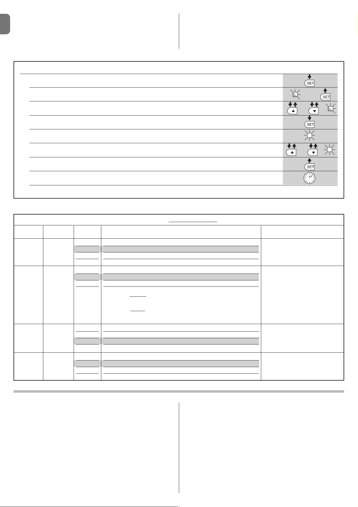
TABLE 8 - Level two functions
input LED Parameter LED Value Description
(level)
L1
L1
L2
L3
L4
5 seconds
30 seconds
60 seconds
120 seconds
Adjusts the pause time, i.e. the amo unt of time before the gate closes au tomatically. Only effective is Close is
activated.
Pause
Time
L2 L1
L2
L3
L4
Opens – stop – closes – stop
Opens – stop – closes – opens
Opens – closes – opens – closes
Apartment building:
• during the opening
manoeuvre, the “Step-Step” and “Opens” commands
do not have any effect; on the other hand, the “Closes” command causes
the movement to be inverted, i.e. the leaves to close.
• during the closing manoeuvre, the “Step-Step” and “Opens” commands
cause the movement to be inverted, i.e. the leaves to open; on the other
hand, the “Closes” command does not have any effect.
Adjusts the sequence of commands
associated with the “Step-Step” in put or radio command.
Note – When L4 is set, the behaviour
of the “Opens” and “Closes” comma n ds is also modified.
Step-Step
Function
L3
L1
L2
L3
L4
Slow
Medium
Fast
Very fast
Adjusts the velocity of the motors du ring normal travel.
Motor
velocity
L4 L1
L2
L3
L4
Level 1 - Minimum force
Level 2 - ...
Level 3 - ...
Level 4 - Maximum force
Adjusts the force of both motors.
Motor
force
6.2 - Level two programming (adjustable parameters)
All level two parameters are programmed at the factory as highlighted in grey in
Table 8 and can be modified at any time following the procedure described in
Table 7.
The parameters are adjustable on a scale of values from 1 to 4; to check the
value corresponding to each LED, please see Table 8. IMPORTANT – The pro-
gramming procedure has a maximum time of 10 seconds between one key and
another being pressed. After this time, the procedure ends automatically, storing the changes made up until that moment.
Page 11

EN
English – 9
Some devices are designed to emit signals which help you recognise their
operating status or any problems.
If the WLT multi-purpose lamp is connected to the FLASH output on the power
supply and set with the flashing function, during the performance of a manoeuvre, it emits a flashing light every second. If any problems are encountered, the
flashing emits shorter flashes, which are repeated twice, divided by a 1 second
pause. Table 10 describes the cause and solution for each type of signal.
The LEDs on the control unit also emit signals; Table 11 describes the cause
and solution for each type of signal.
WHAT TO DO IF... (troubleshooting guide)
7
7 brief flashes
1 second pause
7 brief flashes
Electrical circuits fault Wait at least 30 seconds and then try to repeat the command and if necessary cut off
the power supply; if the status remains the same, there might be a serious failure and the
electrical board may need replacing.
8 brief flashes
1 second pause
8 brief flashes
A command has already been given,
which does not allow any other commands to be performed
Check the nature of the command in progress; it could for example be the command
from a clock on the “STEP-STEP” input.
9 brief flashes
1 second pause
9 brief flashes
The automation system was secured
by a “Secure the automation system”
command
Release the automation system by sending the “Release the automation system” command.
TABLE 10 - Flashing light signals (FLASH)
Flashes Problem Solution
1 brief flashing
1 second pause
1 brief flashing
Error on the Bluebus system The check of the devices connected to the Bluebus system, which is carried out at the
beginning of the manoeuvre, does not correspond to the devices stored during the
recognition phase. There might be devices which are disconnected or out of order, so
you need to check and replace them if necessary. If modifications have been made, you
will need to repeat the recognition of devices (see paragraph 4.7).
2 brief flashes
1 second pause
2 brief flashes
Photocell activation One or more photocells are not are not permitting movement or during travel they
caused the movement to be inverted; check for any obstacles.
3 brief flashes
1 second pause
3 brief flashes
Activation of the “Obstacle Detection"
by the force limiting device
During the movement, the motors encountered greater effort; verify the cause and
increase the force of the motors if necessary
4 brief flashes
1 second pause
4 brief flashes
STOP input activation At the beginning of the manoeuvre or during the movement, one of the devices connect-
ed to the STOP input was activated; verify the cause.
5 brief flashes
1 second pause
5 brief flashes
Error in the internal parameters of the
control unit
Wait at least 30 seconds and then try to repeat the command and if necessary cut off the
power supply; if the status remains the same, there might be a serious failure and the
electrical board may need replacing.
6 brief flashes
1 second pause
6 brief flashes
Maximum limit of consecutive ma noe u vres or manoeuvres per hour ex ce e ded.
Wait a few minutes in order to allow the manoeuvres limiting device to return to below
the maximum limit.
TABLE 11 - Signals from the LEDs on the control unit (fig. 23)
LED Problem Solution
BLUEBUS
Always off
Always on
1 flash per second
2 fast flashes
Series of flashes divided by a
one-second pause
Fault
Serious fault
All ok
Change in the status of the inputs
Other
Ensure the control unit is powered; check whether the fuses have blown.
In this case, check the cause of the fault and replace them with others of
the same value
There is a serious fault: try to cut off the electricity supply to the control unit
and if the status remains, then you will need to replace the electrical board
Normal operation of the control unit
If it normal if a variation in one of the input takes place (PP, STOP):
photocells activation or a command is transmitted with a transmitter
Please refer to Table 10
STOP
Always off
Always on
Activation of the devices connected to the
STOP input
All ok
Check the devices of the STOP input
STOP input activated
P. P.
Always off
Always on
All ok
Activation of the P.P. input
P.P. input deactivated
It is normal if the device connected to the P.P. input is activated
L1 - L2 Slow flashing Change in the number of devices
connected to the Bluebus or device recognition not performed
The recognition of devices must be carried out (see paragraph 4.7)
L3 - L4 Slow flashing The recognition of the positions of the
mechanical stops was not carried out
The recognition must be carried out (see paragraph 4.8).
Page 12

EN
10 – English
The following accessories are envisaged for WALKY (radio receiver): the Oview
programmer, the Solemyo solar power system and the back-up battery mod.
PS424.
8.1 - Connection of the OXI radio receiver
To connect the OXI receiver, first cut off the electricity supply to the control unit
and proceed as illustrated in fig. 27. Table 12 and Table 13 indicate the com-
mands which correspond to the outputs on the control unit.
8.2 - Connection and installation of the back-up battery
mod. PS424
IMPORTANT! - The battery must only be connected to the control unit
after all the phases of installation and programming have been completed, as the battery constitutes a source of emergency power.
To arrange connection to the Solemyo system, follow the stages of assembly
fig. 28.
8.3 - Connection of the Oview programmer
The control unit has a BusT4 connector to which the Oview programming unit
can be connect, and which allows the complete rapid management of the
installation and maintenance phase as well as the diagnosis of the entire
automation system. To access this connector, proceed as shown in fig. 29 and
connect the connector to the dedicated seat. The Oview can be connected to
several Control units simultaneously (up to 5 without any particular precautions,
and up to 60 observing the dedicated warnings) and can stay connected to the
control unit even during the normal operation of the automation system. In this
case, it can be used to send the commands directly tot he control unit using the
specific "user" menu. The Firmware upgrade can also be carried out. If there is
a radio receiver from the OXI family in the control unit, Oview can be used to
gain access to the parameters of the transmitters stored in the receiver itself.
For further information, please consult the relevant instruction manual and the
manual for the “Opera system book” system.
8.4 - Connection of the Solemyo solar power system
IMPORTANT! – When the automation system is powered by the “Solemyo” system, IT MUST NOT BE POWERED concurrently by the electricity
mains.
For further information about the Solemyo system, please refer to its instruction
manual.
To arrange connection to the Solemyo system, follow the stages of assembly
illustrated in fig. 30.
To complete the connection between Solemyo and the gearmotor control unit,
use the dedicated adapter cable.
FURTHER INFORMATION
8
1 Step-Step
2 Partial opening 1
3 Opens
4 Closes
5 Stop
6 Step-Step
Apartment Building
7 Step-Step
high priority
8 Partial opening 2
9 Partial opening 3
10 Opens and Secure
automation system
11 Closes and Secure
automation system
12 Secure automation
system
13 Release automation
system
14 On Timer Courtesy
Light
15 On-Off Courtesy
Light
TABLE 13
OXI / OXIFM /OXIT / OXITFM in mode II extended
No. Command Description
Command “P.P.” (Step-Step)
Command “partial opening 1”
Command “Opens”
Command “Closes”
Stop the manoeuvre
Command in Apartment Building mode
Command even with automation system secured or commands activated
Partial opening (opening of leaf M2 to half of its total travel)
Partial opening (opening of both leaves to half of their total
travel)
Causes an opening manoeuvre at the end of which the
automation system is secured; the control unit does not
accept any other command except for the “Step-Step
high priority”, “Release” automation system or (only from
Oview) the commands: “Release and close” and “Release
and open”
Causes a closing manoeuvre at the end of which the
automation system is secured; the control unit does not
accept any other command except for the “Step-Step
high priority”, “Release” automation system or (only from
Oview) the commands: “Release and close” and “Release
and open”
Causes the manoeuvre to be stopped and the automation
system to be secured; the control unit does not accept
any other command except for the “Step-Step high priority”, “Release2 automation system or (only from Oview) the
commands: “Release and close” and “Release and open”.
Causes the automation system to be released and normal
operation to be restored
The Courtesy light output is turned on with timed switchoff
The Courtesy light output is turned on and off in On-Off
mode
PRODUCT MAINTENANCE
9
In order to keep the safety level constant and to guarantee the maximum life
span of the entire automation system, regular maintenance is vital.
All maintenance work must be carried out in compliance with the safety provisions of this manual and in accordance with existing laws and regulations.
The product requires frequent inspection to check for imbalances of the doors
or signs of wear or damage to the cables. Do not use the product if adjustments or repairs are required.
Important – During the product maintenance or cleaning operations, cut
off the electricity supply to the control unit and any batteries envisaged.
For the other devices in the system, follow the instructions provided in their
respective maintenance schedules.
For gearmotors WL1024C, WL1024, scheduled maintenance is required at the
latest 6 months or 20,000 manoeuvres after the previous maintenance work.
Maintenance can be performed as follows:
01. Cut off any electrical power source, including any back-up batteries;
02. Check the condition and wear of brackets and fixing plugs, paying special
attention to erosion or rusting; replace all parts which do not provide sufficient guarantees;
03. Perform a trial release to ensure it is working properly – see paragraph 3.8.
04. Reconnect the electrical power sources and perform all the checks envis-
aged in chapter 5.1 - Testing.
TABLE 12
SMXI / SMXIS or OXI / OXIFM / OXIT / OXITFM in mode I or Mode II
Output 1
Output 2
Output 3
Output 4
Command “P.P.” (Step-Step)
Command “Partial opening 1”
Command “Opens”
Command “Closes”
Page 13

EN
English – 11
DISPOSING OF THE PRODUCT
This product is an integral part of the automation system, and should
therefore be disposed of together with it.
As for the installation operations, even at the end of this product’s life span, the
dismantling operations must be carried out by qualified experts.
This product is made up of various types of materials: some can be recycled
while others need to be disposed of. Find out about the recycling or disposal
systems envisaged by your local regulations for this product category.
Important! – Parts of the product could contain pollutants or hazardous substances which, if released into the environment, could cause harmful effects to
the environment itself as well as to human health.
As indicated by the symbol opposite, throwing away this
product as domestic waste is strictly forbidden. So dispose
of it as differentiated waste, in accordance with your local
regulations, or return the product to the retailer when you
purchase a new equivalent product.
Important! – the local applicable regulations may envisage heavy sanctions in
the event of illegal disposal of this product.
Disposal of the back-up battery (where present)
Important! – The flat battery contains pollutants and should therefore not be
thrown away as common waste.
It should be disposed of as differentiated waste, as envisaged by your local
applicable regulations.
PRODUCT TECHNICAL SPECIFICATIONS
WARNINGS: • All technical specifications are referred to a room temperature of 20°C (± 5°C). • Nice S.p.a. reserves the right to make any changes deemed necessary to the product at any time while maintaining the same functions and intended use.
Type: Electric gearmotor for automated gates and doors with direct reduction gear and mechanical release mechanism. Only for model WL1024C: built-in control unit and OXI radio receiver
Maximum torque: 100 Nm
Nominal torque: 50 Nm
Idle velocity: 0.20 rad/s - 0.3 rad/s
Velocity at nominal torque: 0.16 rad/s - 0.24 rad/s
Maximum cycle frequency: 100 complete cycles per day (the control unit of WL1024C limits to a maximum of approximately 50 cycles/hour)
Maximum continuous cycle time: approx. 10 minutes
Usage limitation: the product can be used on gates weighing up to 180 kg (0.8 m leaf) pr with a leaf length of up to 1.8 m and an angle of aperture of up to 110°
Power supply: WL1024C: 230 VAC (+10% -15%) 50/60 Hz; WL1024: 24 VDC (50%); WL1024C/V1: 120 VAC (+10% -15%) 50/60 Hz
Emergency power supply: Designed to accommodate back-up battery PS424
Solar panel power supply: designed to accommodate SOLEMYO kit
Nominal absorbed power from electricity mains (WL1024C): 120 W
Nominal absorbed current (WL1024): 2 A; at pick-up the current is 3 A for a maximum time of 2 s
Power absorbed from the electricity mains with “Standby – All (1)” function activated (including the OXI receiver): 3 W
Power absorbed when operating on back-up battery or SOLEMYO KIT with “Standby-All (1)” function activated (including the OXI receiver): less than
100 mW (including the OXI receiver)
Electrical lock output [*]: a 12 VAC max 15 VA electrical lock
Flashing output [*]: a flashing WLT or a 12VDC lamp, 21 W max
BLUEBUS output: an output with maximum load of 15 Bluebus units (maximum 6 pairs of MOFB or MOFOB photocells plus 2 pairs of MOFB or MOFOB pho-
tocells addressed as opening devices plus maximum 4 MOMB or MOTB control devices)
STOP input: for normally closed, normally open contacts or with a constant resistance of 8.2 kΩ; the selection of the type of contact takes place in auto-recog-
nition and a variation compared to the status stored causes the “STOP” command
PP input: for normally open contacts (the closing of the contact causes the Step-Step command)
Radio connector: SM connector for receivers from the SMXI, OXI and OXIFM families
Radio AERIAL input: 50 Ω for type RG58 or similar cable
Programmable functions: 4 ON-OFF type functions (Table 5) and 4 adjustable functions (Table 8)
Functions in auto-recognition: • Auto-recognition of the devices connected to the BlueBus output. • Auto-recognition of the type of device connected to the
“STOP” terminal (NO, NC or 8.2 kΩ resistance contact). • Auto-recognition of the travel of the leaves and automatic calculation of the points of deceleration and
partial opening. • Auto-recognition of operation with one or two motors
Assembly: Vertically, with a dedicated fastening plate
Operating temperature: from -20°C to +50°C (at low temperatures the efficiency of the gearmotor decreases)
Usage in particularly acidic or saline or potentially explosive atmosphere: NO
Protection rating: IP 44 (with casing intact)
Dimensions (mm): 90 x 125 x 385 h
Weight (kg): (WL1024C) 4.8; (WL1024) 4.3
Note:
––––––––––
(1) - Function which can be activated with the Oview programmer.
[*] - The outputs of the terminals on the control unit (“Electrical lock”) and on the power unit (“Flash”) can be reprogrammed with other functions, using the Oview programmer. The elec-
trical characteristics of these two outputs are adapted depending ont he type of function chosen:
• “electrical lock” function: 12VAC, 15VA max;
• “flashing” function: a WLT multi-purpose lamp, or a 12VDC lamp, 21W max;
• other types of functions: a lamp or a relay at 24VDC (-30% and +30%), 4 W max, if the control unit is mains powered, or a lamp or relay at 12VDC (-10% and +25%), 4 W max, if the
control unit is powered by the back-up battery PS424.
Page 14
EN
12 – English
EC DECLARATION OF CONFORMITY
Note - The contents of this declaration correspond to the declarations contained in the latest available revision, prior to printing of this manual, of the official document on file at
the headquarters of Nice S.p.a. This text was readapted for editorial purposes.
Number: 322/WL.. Revision: 0
The undersigned Luigi Paro, as Managing Director, declares on his own responsibility that the product:
Name of manufacturer: NICE s.p.a.
Address: Via Pezza Alta 13, Z.I. Rustignè, 31046 - Oderzo (TV) Italy
Type: Electric gearmotor
Models: WL1024C, WL1024
Accessories: OXI, OVBT, OVBTGSM, SYKCE, PS424
are compliant with the provisions of the following EC directives:
• 98/37/CE (89/392/EEC amended) DIRECTIVE 98/37/EC OF THE EUROPEAN PARLIAMENT AND OF THE COUNCIL of 22 June 1998 concerning standardization of the legislation of member states on machinery
As envisaged in directive 98/37/EC, please note that the commissioning of the above product is not permitted until the machine in which the product is
installed has been identified and declared as conforming to directive 98/37/EC.
The product is also compliant with the provisions of the following EC directives, as amended by Directive 93/68/EEC of the council of 22 July 1993:
• 2006/95/EEC (ex-directive 73/23/EC) DIRECTIVE 2006/95/EC OF THE EUROPEAN PARLIAMENT AND OF THE COUNCIL of 12 December 2006 concerning standardization of member states on electrical material to be used within certain voltage limits
In accordance with the following harmonized standards:
EN 60335-1:1994+A11:1995+A1:1996+A12:1996+A13:1998+A14:1998+A15:2000+A2:2000+A16:2001
• 2004/108/EEC (ex-directive 89/336/EEC) DIRECTIVE 2004/108/EC OF THE EUROPEAN PARLIAMENT AND OF THE COUNCIL of 15 December 2004
concerning standardization of the legislation of member states on electromagnetic compatibility and which repeals 89/336/EEC
In accordance with the following harmonized standards: EN 61000-6-2:2005; EN 61000-6-3:2007
It is also compliant - limited to the applicable parts - with the following standards:
EN 60335-1:2002+A1:2004+A11:2004+A12:2006+ A2:2006, EN 60335-2-103:2003,
EN 13241-1:2003; EN 12453:2002; EN 12445:2002; EN 12978:2003
Oderzo, 29 May 2009 Luigi Paro (Managing Director)
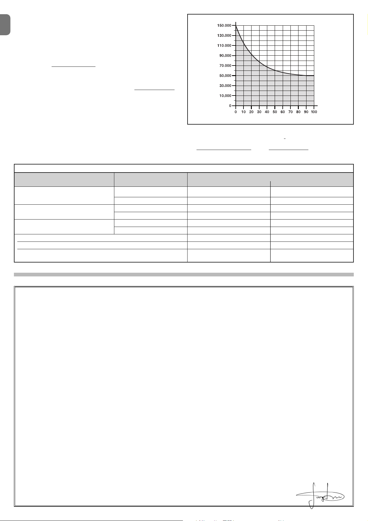
Example of life span calculation for a Walky with full length arm gearmotor (please refer to Table 14 and Graph A): - weight of leaf: 100 kg; - length
of leaf = 1.7 m (strenuousness index: 55%); - no other straining elements present; Total strenuousness index = 55%; Estimated life span = 55.000 manoeuvre
cycles
Product life span
The product life span is its average commercial life. The value of the product life
span is strongly affected by the strenuousness index of the manoeuvres performed by the automation system: i.e. the sum of all the factors which contribute to the product wear (see Table 14).
To determine the probable life span of your automation system, proceed as follows:
01. Calculate the strenuousness index by adding together the percentage values of the items in Table 14;
02. In Graph A trace a vertical line from the value as just calculated until it intersects the curve; from this point, trace a horizontal line until it intersects the line
of the “manoeuvre cycles”. The value determined is the estimated life span
of
your product.
The life span estimate is based on design calculations and on the results of
tests performed on prototypes. Indeed, since it is an estimate, it is in no way a
guarantee as to the actual duration of the product.
GRAPH A
manoeuvre cycles
strenuousness index %
TABLE 14
Strenuousness index
STANDARD LENGTH ARM SHORTENED ARM
< 1,2 m
1,2 - 1,6 m
> 1,6 m
Length of leaf Weight of leaf
Room temperature above 40°C or below 0°C or humidity above 80%
Blind leaf
Installation in windy area
> 100 kg
< 100 kg
> 80 kg
< 80 kg
> 60 kg
< 60 kg
55%
30%
55%
40%
55%
40%
15%
15%
15%
65%
50%
65%
50%
-
15%
10%
10%
Page 15

Italiano – 1
IT
ITALIANO
Sommario
1 - AVVERTENZE E PRECAUZIONI GENERALI . . . . . . . . . . . . . . . . . . . . . 1
1.1 - Avvertenze per la sicurezza . . . . . . . . . . . . . . . . . . . . . . . . . . . . . . . . . . 1
1.2 - Avvertenze per l’installazione . . . . . . . . . . . . . . . . . . . . . . . . . . . . . . . . 1
1.3 - Avvertenze per l’uso . . . . . . . . . . . . . . . . . . . . . . . . . . . . . . . . . . . . . . . 1
2 - DESCRIZIONE DEL PRODOTTO E DESTINAZIONE DUSO . . . . . . . . . 1
3 - INSTALLAZIONE . . . . . . . . . . . . . . . . . . . . . . . . . . . . . . . . . . . . . . . . . . 2
3.1 - Verifiche preliminari all’installazione . . . . . . . . . . . . . . . . . . . . . . . . . . . . 2
3.2 - Limiti d’impiego . . . . . . . . . . . . . . . . . . . . . . . . . . . . . . . . . . . . . . . . . . 2
3.3 - Lavori di predisposizione all’installazione . . . . . . . . . . . . . . . . . . . . . . . . 2
3.4 - Installazione del motoriduttore mod. WL1024C - WL1024 . . . . . . . . . . 3
3.4.1 - Determinare la lunghezza del braccio del motoriduttore . . . . . . . 3
3.4.2 - Installazione del motoriduttore con BRACCIO DI LUNGHEZZA
STANDARD . . . . . . . . . . . . . . . . . . . . . . . . . . . . . . . . . . . . . . . . . . . . . 3
3.4.3 - Installazione del motoriduttore con BRACCIO DI LUNGHEZZA
RIDOTTA . . . . . . . . . . . . . . . . . . . . . . . . . . . . . . . . . . . . . . . . . . . . . . . 4
3.5 - Installazione della lampada multifunzione mod. WLT sul
motoriduttore modello WL1024C . . . . . . . . . . . . . . . . . . . . . . . . . . . . . . . . . 4
3.6 - Come estrarre la centrale di comando . . . . . . . . . . . . . . . . . . . . . . . . . 5
3.7 - Regolazione dell’allineamento delle ante in chiusura . . . . . . . . . . . . . . . 5
3.8 - Sbloccare e bloccare manualmente il motoriduttore . . . . . . . . . . . . . . . 5
4 - COLLEGAMENTI ELETTRICI . . . . . . . . . . . . . . . . . . . . . . . . . . . . . . . . 5
4.1 - Descrizione dei collegamenti elettrici . . . . . . . . . . . . . . . . . . . . . . . . . . . 5
4.2 - Collegamento del cavo di alimentazione . . . . . . . . . . . . . . . . . . . . . . . . 5
4.3 - Collegamento del motoriduttore senza centrale mod. WL1024 . . . . . . . 5
4.4 - Collegamento di altri dispositivi . . . . . . . . . . . . . . . . . . . . . . . . . . . . . . 5
4.5 - Indirizzamento dei dispositivi collegati . . . . . . . . . . . . . . . . . . . . . . . . . . 6
4.6 - Prima accensione e verifica dei collegamenti . . . . . . . . . . . . . . . . . . . . 6
4.7 - Apprendimento dei dispositivi collegati . . . . . . . . . . . . . . . . . . . . . . . . . 6
4.8 - Apprendimento delle posizioni degli arresti meccanici . . . . . . . . . . . . . . 6
4.9 - Verifica del movimento delle ante del cancello . . . . . . . . . . . . . . . . . . . . 6
5 - COLLAUDO E MESSA IN SERVIZIO . . . . . . . . . . . . . . . . . . . . . . . . . . . 6
5.1 - Collaudo . . . . . . . . . . . . . . . . . . . . . . . . . . . . . . . . . . . . . . . . . . . . . . . . 7
5.2 - Messa in servizio . . . . . . . . . . . . . . . . . . . . . . . . . . . . . . . . . . . . . . . . . 7
6 - PROGRAMMAZIONE DELLA CENTRALE DI COMANDO . . . . . . . . . . 7
6.1 - Programmazione primo livello (ON-OFF) . . . . . . . . . . . . . . . . . . . . . . . . 7
6.2 - Programmazione secondo livello (parametri regolabili) . . . . . . . . . . . . . . 8
6.3 - Cancellazione della memoria . . . . . . . . . . . . . . . . . . . . . . . . . . . . . . . . . 8
6.4 - Funzioni speciali . . . . . . . . . . . . . . . . . . . . . . . . . . . . . . . . . . . . . . . . . . 8
7 - COSA FARE SE... (guida alla risoluzione dei problemi) . . . . . . . . . . . . 9
8 - APPROFONDIMENTI . . . . . . . . . . . . . . . . . . . . . . . . . . . . . . . . . . . . . . 10
8.1 - Collegamento del ricevitore radio OXI . . . . . . . . . . . . . . . . . . . . . . . . . 10
8.2 - Collegamento e installazione della batteria tampone mod. PS424 . . . 10
8.3 - Collegamento del programmatore Oview . . . . . . . . . . . . . . . . . . . . . . 10
8.4 - Collegamento del sistema ad energia solare Solemyo . . . . . . . . . . . . . 10
9 - MANUTENZIONE DEL PRODOTTO . . . . . . . . . . . . . . . . . . . . . . . . . . 10
SMALTIMENTO DEL PRODOTTO . . . . . . . . . . . . . . . . . . . . . . . . . . . . . . 11
CARATTERISTICHE TECNICHE DEL PRODOTTO . . . . . . . . . . . . . . . . . 11
Durabilità del prodotto . . . . . . . . . . . . . . . . . . . . . . . . . . . . . . . . . . . . . . . 12
DICHIARAZIONE CE DI CONFORMITÀ . . . . . . . . . . . . . . . . . . . . . . . . . . 12
APPENDICE . . . . . . . . . . . . . . . . . . . . . . . . . . . . . . . . . . . . . . . . . . . . . . . . . I
Istruzioni ed avvertenze destinate all’utilizzatore . . . . . . . . . . . . . . . . . . . . . . IV
Immagini . . . . . . . . . . . . . . . . . . . . . . . . . . . . . . . . . . . . . . . . . . . . . . . . . . . . X
1.1 - Avvertenze per la sicurezza
• ATTENZIONE! – Il presente manuale contiene importanti istruzioni e
avvertenze per la sicurezza. Un’installazione errata può causare gravi ferite.
Prima di iniziare il lavoro è necessario leggere attentamente tutte le parti del
manuale. In caso di dubbi, sospendere l’installazione e richiedere chiarimenti
al Servizio Assistenza Nice.
• ATTENZIONE! – Istruzioni importanti: conservare questo manuale per
eventuali interventi di manutenzione e di smaltimento del prodotto.
• ATTENZIONE! – Secondo la più recente legislazione europea, la realizzazione di una porta o di un cancello automatico deve rispettare le nor
me previste dalla Direttiva 2006/42/CE (ex 98/37/CE) (Direttiva Macchine) e in particolare, le norme EN 12445; EN 12453; EN 12635 e EN
13241-1, che consentono di dichiarare la conformità dell’automazione.
In considerazione di ciò, tutte le operazioni di installazione, di collegamento, di col laudo e di manutenzione del prodotto devono es sere
effettuate es clusivamente da un tecnico qualificato e competente!
1.2 - Avvertenze per l’installazione
• Prima di iniziare l’installazione verificare se il presente prodotto è adatto al tipo
di utilizzo desiderato (vedere i “Limiti d’impiego” paragrafo 3.2 e le “Caratteristiche tecniche del prodotto”). Se non è adatto, NON procedere all’istallazione.
• Tutte le operazioni di installazione e di manutenzione devono avvenire
con l’automazione scollegata dall’alimentazione elettrica. Se il dispositivo di sconnessione dell’alimentazione non è visibile dal luogo dove è posizionato l’automatismo, prima di iniziare il lavoro è necessario attaccare sul di spositivo di sconnessione un cartello con la scritta “ATTENZIONE! MANUTENZIONE IN CORSO”.
• La centrale deve essere collegata ad una linea di alimentazione elettrica dotata di messa a terra di sicurezza.
• Durante l’installazione maneggiare con cura il prodotto evitando schiacciamenti, urti, cadute o contatto con liquidi di qualsiasi natura. Non mettere il
pro dotto vicino a fonti di calore, né esporlo a fiamme libere. Tutte queste azioni possono danneggiarlo ed essere causa di malfunzionamenti o situazioni di
pericolo. Se questo accade, sospendere immediatamente l’installazione e
rivolgersi al Servizio Assistenza Nice.
• Non eseguire modifiche su nessuna parte del prodotto. Operazioni non permesse possono causare solo malfunzionamenti. Il costruttore declina ogni
responsabilità per danni derivanti da modifiche arbitrarie al prodotto.
• Se il cancello o il portone da automatizzare è dotato di una porta pedonale
occorre predisporre l’impianto con un sistema di controllo che inibisca il funzionamento del motore quando la porta pedonale è aperta.
• Il materiale dell’imballo del prodotto deve essere smaltito nel pieno rispetto
della normativa locale.
1.3 - Avvertenze per l’uso
• Il prodotto non è destinato ad essere usato da persone (bambini compresi) le
cui capacità fisiche, sensoriali o mentali siano ridotte, oppure con mancanza
di esperienza o di conoscenza, a meno che esse abbiano potuto beneficiare,
attraverso l’intermediazione di una persona responsabile della loro sicurezza,
di una sorveglianza o di istruzioni riguardanti l’uso del prodotto.
• I bambini che si trovano in prossimità dell’automazione, devono essere sorvegliati; verificare che non giochino con quest’ultima.
• Non permettere ai bambini di giocare con i dispositivi di comando fissi. Tenere i dispositivi di comando portatili (remoti) fuori dalla portata dei bambini.
AVVERTENZE E PRECAUZIONI GE NERALI
1
I dispositivi che compongono il presente prodotto, sono destinati all’automatizzazione di un cancello o di un portone a una o a due ante. AT TENZIONE! –
Qualsiasi altro uso diverso da quello descritto e in con dizioni am bientali
diverse da quelle riportate in questo manuale è da considerarsi improprio
e vietato!
La parte principale dell’automazione è formata da uno o due motoriduttori elettromeccanici (in base al numero di ante da automatizzare), provvisti ognuno di
un motore in corrente continua e di un riduttore epicicloidale. Uno dei motoriduttori (mod. WL1024C) è dotato di una centrale di comando che ne gestisce il
funzionamento. La centrale è formata da una scheda con un ricevitore radio,
per la ricezione dei comandi inviati dal trasmettitore.
La centrale è predisposta per essere collegata a vari dispositivi appartenenti al
Sistema Opera, al sistema Bluebus e al sistema di alimentazione ad energia
solare Solemyo.
Se alimentata da rete, può ospitare una batteria tampone (mod. PS424, accessorio opzionale) che garantisce all'automatismo l’esecuzione di alcune manovre,
nelle ore successive alla mancanza di energia (black-out elettrico).
In caso d’interruzione dell’energia elettrica, è possibile muovere le ante del cancello sbloccando il motoriduttore con l’apposita chiave; per eseguire la manovra manuale, vedere il capitolo 3.8.
DESCRIZIONE DEL PRODOTTO E
DESTINAZIONE DUSO
2
Page 16
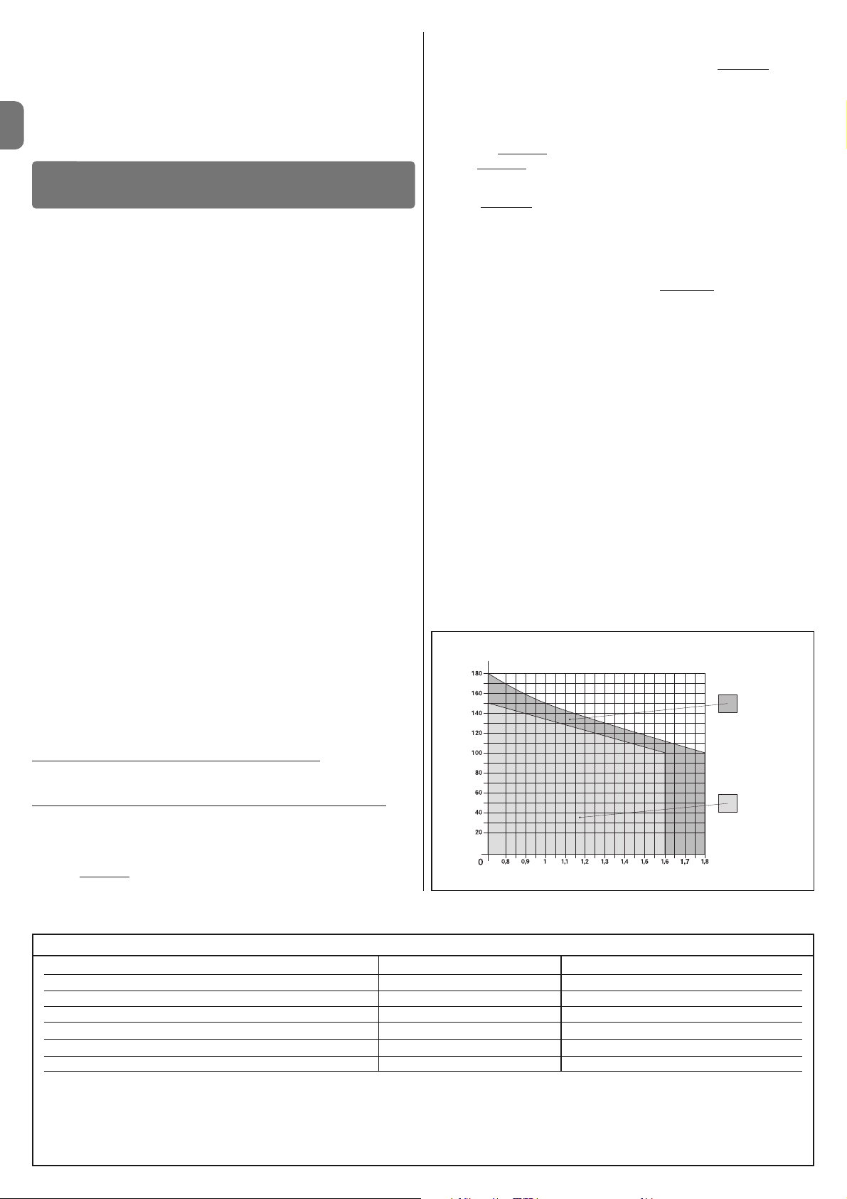
IT
2 – Italiano
3.1 - Verifiche preliminari all’installazione
Prima di procedere all’installazione, è necessario verificare l’integrità dei componenti del prodotto, l’adeguatezza del modello scelto e l’idoneità dell’ambiente destinato all’installazione:
• Verificare che tutto il materiale da utilizzare sia in ottimo stato e adatto all’uso
previsto.
• Verificare che nell’impianto siano presenti gli arresti meccanici a terra (non in
dotazione), sia in chiusura sia in apertura.
• Verificare che la struttura meccanica del cancello sia adatta ad essere automatizzata e conforme alle norme vigenti sul territorio (eventualmente fare riferimento ai dati riportati sull’etichetta del cancello). Il presente prodotto non
può automatizzare un cancello che non sia già efficiente e sicuro; inoltre, non
può risolvere difetti causati da un’installazione errata del cancello o da una
sua cattiva manutenzione.
• Verificare che le condizioni di funzionamento dei dispositivi siano compatibili
con i limiti d'impiego dichiarati (vedere paragrafo 3.2).
• Muovere manualmente le ante del cancello nelle due direzioni e accertarsi
che il movimento avvenga con un attrito costante in ogni punto della corsa
(non devono esserci punti che richiedono uno sforzo maggiore o minore).
• Portare manualmente le ante del cancello in una posizione qualsiasi; quindi
lasciarle ferme e accertarsi che non si muovano.
• Verificare che la zona di fissaggio del motoriduttore sia compatibile con l’ingombro di quest’ultimo (fig. 1).
• Nell’ambiente in cui deve essere installato il motoriduttore, accertarsi che ci
sia lo spazio sufficiente per la rotazione completa del suo braccio.
• Nelle vicinanze del motoriduttore, accertarsi che ci sia spazio sufficiente per
effettuare la manovra manuale di sblocco del motoriduttore.
• Accertarsi che le superfici scelte per installare i vari dispositivi, siano solide e
possano garantire un fissaggio stabile.
• Accertarsi che ciascun dispositivo da installare sia collocato in una posizione
protetta e al riparo da urti accidentali.
• Verificare che tutti i cavi elettrici da utilizzare siano del tipo elencato nella
Tabella 1.
3.2 - Limiti d’impiego
Prima di eseguire l’installazione del motoriduttore, verificare che i suoi dati rientrino nei limiti d’impiego riportati di seguito e nei limiti dei valori riportati nel capitolo “Caratteristiche tecniche del prodotto”:
Con il braccio del motore di lunghezza INTERA (di fabbrica)
:
- larghezza massima dell’anta: 1,80 m (= peso massimo dell’anta: 100 kg)
- altezza massima dell’anta: 2 m
Con il braccio del motore di lunghezza RIDOTTA (tagliato dall’installatore)
:
- larghezza massima dell’anta: 1,60 m (= peso massimo dell’anta: 100 kg)
- altezza massima dell’anta: 2 m
• Verifica da eseguire: riportare sul Grafico 1, il peso e la larghezza dell’anta; trac-
ciare da questi punti due linee e accertarsi che queste vadano ad incrociarsi in una
delle due aree grigie
del grafico. Attenzione! - Se le linee si incrociano nell’area
bianca, non è possibile utilizzare questo prodotto per automatizzare il cancello.
• Per consentire l’installazione del motoriduttore, la larghezza minima del pilastro deve essere di 80 mm.
• Il braccio del motoriduttore deve essere collocato nella parte alta
dell’anta
del cancello.
ATTENZIONE! - È vietato montare il motoriduttore in posizione capovolta, cioè
con il braccio rivolto verso il basso.
• La staffa di fissaggio del braccio deve risultare in una zona robusta dell’anta
(ad esempio, il telaio), per garantire un fissaggio solido e sicuro;
• Verificare la quota
“E” (fig. 7):
- Se la quota
“E” è un valore compreso tra 80 mm (minimo) e 299 mm (mas-
simo), occorre accorciare il braccio del motoriduttore. In queste condizioni,
l’apertura massima dell’anta può arrivare fino a 90°.
- Se la quota “E” è un valore uguale o superiore a 300 mm, non occorre
accorciare il braccio del motoriduttore. In queste condizioni, l’apertura massima dell’anta può arrivare fino a 110°.
3.3 - Lavori di predisposizione all’installazione
La fig. 2 mostra un esempio di impianto di automatizzazione, realizzato con
componenti Nice (alcuni componenti possono non essere presenti nel kit):
a - Motoriduttore con centrale mod. WL1024C
b - Motoriduttore senza centrale mod. WL1024
c - Lampada multifunzione mod. WLT (da installare sul motoriduttore con cen-
trale mod. WL1024C); vedere capitolo 3.5 e proprio manuale istruzioni
d - Coppia di fotocellule mod. MOFB
e - Tastiera digitale (mod. MOTB) - Lettore a transponder (mod. MOMB) - Selet-
tore a chiave (mod. MOSE)
f - Coppia di colonnine per fotocellule
g - Arresti meccanici in Apertura e in Chiusura
h - Elettroserratura
Questi componenti sono posizionati secondo uno schema tipico e usuale.
Facendo riferimento alla fig. 2, stabilire la posizione approssimativa in cui verrà
installato ciascun componente previsto nell’impianto. Importante – Prima di
eseguire l’installazione, preparare i cavi elettrici necessari al vostro impianto,
facendo riferimento alla fig. 2a e alla “Tabella 1 - Caratteristiche tecniche dei
cavi elettrici”.
Attenzione – Durante la posa in opera dei tubi per il passaggio dei cavi elettri-
ci, considerare che a causa di possibili depositi d’acqua presenti nei pozzetti di
derivazione, i tubi di collegamento possono creare fenomeni di condensa all’interno della centrale e danneggiare i circuiti elettronici.
INSTALLAZIONE
3
Collegamento Tipo di cavo Lunghezza massima consentita
A: Cavo ALIMENTAZIONE 1 cavo 3 x 1,5 mm
2
30 m (nota 1)
B: Cavo ELETTROSERRATURA 1 cavo 2 x 1 mm
2
6 m
C: Cavo DISPOSITIVI BLUEBUS 1 cavo 2 x 0,5 mm
2
20 m (nota 2)
D: Cavo SELETTORE A CHIAVE 2 cavi 2 x 0,5 mm2 (nota 3) 50 m
E: Cavo ALIMENTAZIONE MOTORIDUTTORE 1 cavo 3 x 1,5 mm
2
6 m
Cavo ANTENNA ESTERNA (opzionale) 1 cavo schermato tipo RG58 20 m (consigliato minore di 5 m)
Nota 1 – Se il cavo di alimentazione supera i 30 m di lunghezza, occorre utilizzare un cavo con sezione maggiore (3 x 2,5 mm
2
) ed è necessario installare una
messa a terra di sicurezza in prossimità dell’automazione.
Nota 2 – Se il cavo Bluebus supera i 20 m di lunghezza, fino ad un massimo di 40 m, occorre utilizzare un cavo con sezione maggiore (2 x 1 mm2).
Nota 3 – Questi 2 cavi possono essere sostituiti da 1 unico cavo da 4 x 0,5 mm
2
.
ATTENZIONE! – I cavi utilizzati devono essere adatti al tipo di ambiente in cui avviene l’installazione.
TABELLA 1 - Caratteristiche tecniche dei cavi elettrici
GRAFICO 1
Per braccio di
lunghezza intera
Per braccio di
lunghezza ridotta
LARGHEZZA (m.)
PESO (kg.)
Altri accessori disponibili sono i ricevitori predisposti con innesto “SM” (SMXI,
OXI, ecc.).
Sul motoriduttore con centrale (mod. WL1024C) è possibile installare la lampada multifunzione mod. WLT (vedere capitolo 3.5), che può funzionare come
luce di segnalazione lampeggiante o luce di cortesia, secondo la programmazione della centrale. In più, può essere utilizzata come luce crepuscolare attivando un sensore luce integrato; per le specifiche fare riferimento al suo
manuale istruzioni.
Page 17
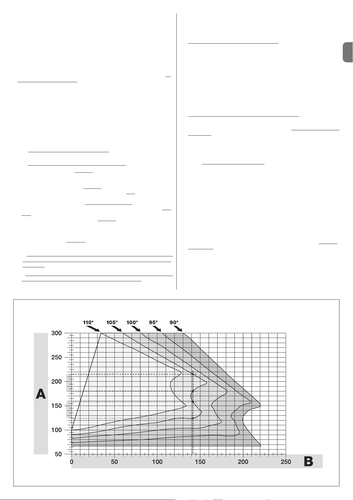
Italiano – 3
IT
3.4 - Installazione del motoriduttore mod. WL1024C - WL1024
AVVERTENZE
• Un’installazione errata può causare gravi ferite alla persona che esegue
il lavoro e alle persone che utilizzeranno l’impianto.
• Prima di iniziare l’assemblaggio dell’automazione, effettuare le ve rifiche
preliminari descritte nel paragrafo 3.1 e 3.2.
• Il braccio del motoriduttore ha la possibilità di essere accorciato rispetto
alla lunghezza standard fornita. Una lunghezza minore è necessaria
quando, a ridosso del motoriduttore, è presente un ostacolo fisso (muro,
palo, ecc.) che impedisce il movimento completo del braccio. Quindi,
per capire se occorre accorciare o meno la lunghezza del braccio, pri
-
ma di iniziare l’installazione
è necessario effettuare la procedura 3.4.1.
Assemblare i componenti che costituiscono il braccio del motore, facendo riferimento alla fig. 3. In questa fase non inserire il benzing di arresto (fig. 4).
IMPORTANTE! - Il braccio curvo deve essere posizionato con la curvatura
rivolta verso l’anta del cancello, come mostrato in fig. 5.
3.4.1 - Determinare la lunghezza del braccio del motoriduttore
01. Stabilire la posizione del motoriduttore in senso VERTICALE:
tracciare sul pilastro una linea orizzontale alla stessa altezza in cui verrà a trovarsi la staffa di fissaggio del braccio sull’anta, dopo l’installazione.
02. Stabilire la posizione del motoriduttore in senso ORIZZONTALE:
a) Stabilire l’apertura massima dell’anta
: determinare l’angolo di massi-
ma apertura (massimo 110°).
b) Misurare la quota B e determinare la quota A:
1 - Misurare sul pilastro la quota B
(fig. 5). Questa è la distanza tra il fulcro
di rotazione dell’anta e la superficie del pilastro dove verrà fissata la staffa
posteriore del motoriduttore.
2 - Segnare sul Grafico 2A la quota B
appena trovata e tracciare da que-
sto punto una linea verticale, fino ad intersecare l’area
che comprende il
valore dell’angolo misurato al punto a.
3 - Nei punti di intersezione tra la linea verticale e l’area
, tracciare delle linee
oriz zontali fino alla colonna “A”, per determinare i valori utilizzabili per la quo
-
ta A
. Quindi, scegliere tra questi un valore di A possibilmente minimo.
4 - Riportare sul pilastro il valore della quota A
e tracciare in corrisponden-
za una linea verticale (fig. 6).
5 - Se nelle vicinanze della linea verticale c’è un muro o un altro ostacolo fisso, misurare la distanza tra questa linea e l’ostacolo (fig. 7):
questa distanza è la quota E
.
ATTENZIONE!
• Se la
quota E è un valore compreso tra 80 mm (minimo) e 299 mm
(massimo), continuare l’installazione effettuando di seguito la procedura 3.4.3
.
• Se la quota E è un valore uguale o superiore a 300 mm, continuare
l’installazione effettuando di seguito la procedura 3.4.2.
5 - Sbloccare il motoriduttore con l’apposita chiave (vedere cap. 3.8).
3.4.2 - Installazione del motoriduttore con BRACCIO DI LUNGHEZZA STANDARD
Attenzione! - Questa installazione può essere eseguita esclusivamente
dopo aver completato la procedura 3.4.1.
01. Fissare il motoriduttore sul pilastro (fig. 8)
:
a) Appoggiare il motoriduttore sul pilastro(*) facendo corrispondere la sua
mezzeria verticale con la linea verticale tracciata prima (quota A), e il suo
braccio, con la linea orizzontale tracciata durante la procedura 3.4.1. In
questa fase, accertarsi che il motoriduttore sia perfettamente in bolla: un
motoriduttore fuori asse può provocare malfunzionamenti all’automazione.
(*) Nota - Se la superficie del pilastro ha una larghezza compresa tra 80 e
135 mm, prima di continuare l’installazione è necessario ruotare di 90° la
staffa posteriore di fissaggio del motoriduttore. Per ruotare la staffa fare
riferimento alla fig. 9.
b) Segnare i punti di fissaggio, forare la superficie del pilastro e inserire i
tasselli; a questo punto, fissare il motoriduttore utilizzando viti e rondelle
adeguate.
02. Fissare il braccio del motoriduttore sull’anta (fig. 8)
:
c) Portare l’anta del cancello nella posizione di massima chiusura;
d) Spingere con forza il braccio del motoriduttore fino alla sua massima
estensione. Attenzione! - Accertarsi che il braccio si blocchi nel suo
finecorsa;
e) Avvicinare il braccio all’anta, appoggiando su quest’ultima la staffa di fis-
saggio.
f) Accertarsi che il braccio del motoriduttore sia in bolla e segnare con una
matita il centro del profilo delle asole della staffa, per permettere in futuro
una regolazione fine della chiusura dell’anta (vedere il paragrafo 3.7).
g) Tenendo con una mano la staffa a contatto con l’anta, provare a effettuare una apertura e una chiusura completa, fino ai rispettivi fermi meccanici. Attenzione! - Se durante la prova il movimento del braccio è osta-
colato da un muro o altro oggetto fisso, interrompere la procedura ed
eseguire la procedura 3.4.3.
h) Forare l’anta nei punti segnati e staccare la staffa dal braccio e fissarla
all’anta del cancello con viti adeguate.
i) Fissare il braccio alla staffa, inserendo il perno e il benzing di arresto.
Importante - Controllare che la staffa e il braccio siano perfettamente in
bolla. Eventualmente allentare le viti della staffa e mettere in bolla. Questa
verifica può essere effettuata anche misurando la quota di 75 mm (vedere
fig. 8 fase 2).
l) Fissare a terra i fermi di finecorsa, in modo stabile e definitivo, nella stes
-
sa posizione
stabilita all’inizio della procedura. Attenzione! - Verificare che
l’anta chiuda perfettamente contro il fermo di finecorsa (non in dotazione).
m) Infine, portare manualmente l’anta del cancello a circa metà della sua cor-
sa e bloccare il motoriduttore con l’apposita chiave (vedere cap. 3.8). Quindi,
spostare manualmente l’anta di pochi centimetri, in direzione dell’apertura.
03. Se il cancello da automatizzare è a due ante, per installare l’altro motoridut-
tore ripetere tutte le operazioni descritte in questo capitolo 3.4.
GRAFICO 2A
Page 18
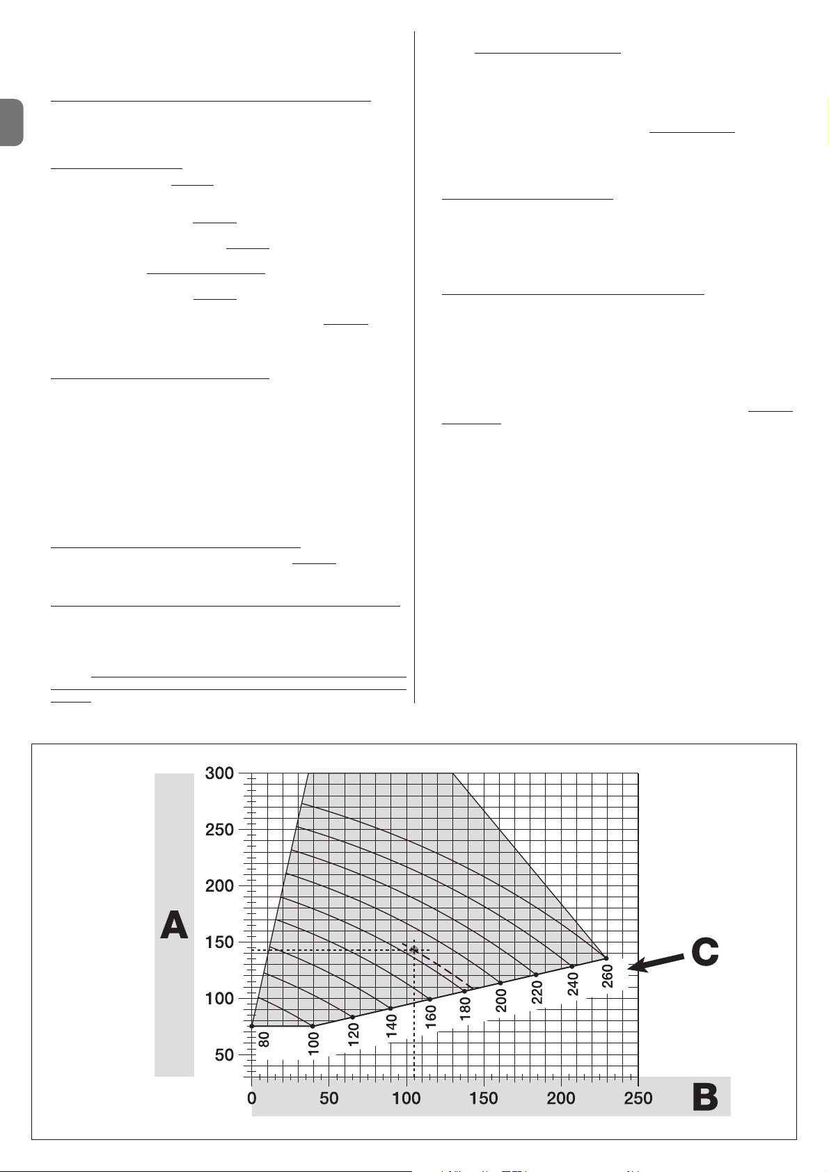
IT
4 – Italiano
3.4.3 - Installazione del motoriduttore con BRACCIO DI LUNGHEZZA RIDOTTA
Attenzione! - Questa installazione può essere eseguita esclusivamente
dopo aver completato la procedura 3.4.1.
01. Definire una nuova apertura massima dell’anta (massimo 90°)
: senza
considerare l’apertura massima dell’anta stabilita durante la procedura
3.4.1, portare l’anta in una nuova posizione di massima apertura, accertandosi che l’angolo non superi i 90°. Quindi, bloccare l’anta in questa posizione con un fermo a terra, fissato in modo provvisorio.
02. Definire le quote A - B - C
:
a) Misurare sul pilastro la quota B
(fig. 10). Questa è la distanza tra il fulcro
di rotazione dell’anta e la superficie del pilastro dove verrà fissata la staffa
posteriore del motoriduttore.
b) Segnare sul Grafico 2B la quota B
appena trovata e tracciare da que-
sto punto una linea verticale.
c) Sul pilastro, stabilire il valore della quota A
in cui fissare la staffa poste-
riore del motoriduttore (fare riferimento alla fig. 11). Importante! - Sceglie-
re un valore di A possibilmente minimo
, per allontanare il motore
dall’ostacolo.
d) Segnare sul Grafico 2B la quota A
appena trovata e tracciare da questo punto una linea orizzontale, fino ad intersecare la linea verticale tracciata prima. Il punto d’incontro tra le due linee definisce la quota C
, cioè la
distanza che deve esserci tra i due perni del braccio asolato (fig. 12).
Esempio presente nel grafico 2B: se il valore di B è 105 mm e A è 143 mm,
il punto C è 182.
03. Fissare il motoriduttore sul pilastro (fig. 13)
:
a) Appoggiare il motoriduttore sul pilastro(*) facendo corrispondere la sua
mezzeria verticale con la linea verticale tracciata prima (quota A), e il suo
braccio, con la linea orizzontale tracciata durante la procedura 3.4.1. In
questa fase, accertarsi che il motoriduttore sia perfettamente in bolla: un
motoriduttore fuori asse può provocare malfunzionamenti all’automazione.
(*) Nota - Se la superficie del pilastro ha una larghezza compresa tra 80 e
135 mm, prima di continuare l’installazione è necessario ruotare di 90° la
staffa posteriore di fissaggio del motoriduttore. Per ruotare la staffa fare
riferimento alla fig. 8.
b) Segnare i punti di fissaggio, forare la superficie del pilastro e inserire i
tasselli; a questo punto, fissare il motoriduttore utilizzando viti e rondelle
adeguate.
04. Ridurre la lunghezza del braccio asolato (fig. 14):
a) Per ridurre la lunghezza del braccio asolato alla quota C (quella trovata
al punto 02-d), svitare il dado, togliere il fermo, distanziare i due perni
secondo la quota C e, infine, chiudere il dado in modo provvisorio.
05. Verificare la quota C del braccio asolato rispetto al contesto (fig. 15 - 16
):
a) Portare l’anta del cancello nella posizione di massima chiusura;
b) Aprire completamente il braccio del motoriduttore, al massimo del suo
angolo di apertura (vedere fig. 15 fase 1);
c) Avvicinare il braccio all’anta, appoggiando su quest’ultima la staffa di fis-
saggio: attenzione!
- spingere con le mani il braccio curvo contro
l’anta, fino al blocco del braccio (massima apertura - vedere fig. 15,
fase 1a).
d) Accertarsi che il braccio del motoriduttore sia in bolla e segnare con una
matita il centro
del profilo delle asole della staffa, per permettere in futuro
una regolazione fine della chiusura dell’anta (vedere il paragrafo 3.7).
e) Fissare provvisoriamente la staffa sull’anta e portare l’anta nella posizio-
ne di massima apertura contro il fermo a terra.
f) Con l’anta in questa posizione, effettuare la verifica mostrata in fig. 16
(tendere un filo passante sopra i due perni del braccio asolato, fino ad arrivare al cardine dell’anta). Attenzione! - Se rispetto al cardine
il filo si trova
in posizione “BB” di fig. 16, è necessario allungare di qualche millimetro la
quota C. Questa operazione deve essere ripetuta fino a quando il filo viene
a trovarsi nella posizione “AA” di fig 16 e fino a quando il braccio non urta
più il muro o altro ostacolo fisso.
06. Tagliare il braccio asolato (fig. 17)
:
Dopo aver verificato il corretto funzionamento dell’articolazione, tagliare il
braccio asolato nel modo seguente.
a) Tracciare una linea sul braccio asolato, nell’esatta posizione indicata in
fig. 17, fase 1. Quindi smontare il braccio dalla staffa e tagliare la parte
superflua del braccio.
b) Assemblare di nuovo i componenti del braccio (fig. 3).
07. Fissare il braccio del motoriduttore sull’anta (fig. 18
):
a) Forare l’anta nei punti segnati precedentemente.
b) Staccare la staffa dal braccio e fissarla all’anta del cancello con viti ade-
guate.
c) Fissare il braccio alla staffa, inserendo il perno e il benzing di arresto.
Importante - Controllare che la staffa e il braccio siano perfettamente in
bolla. Eventualmente allentare le viti della staffa e mettere in bolla. Questa
verifica può essere effettuata anche misurando la quota di 75 mm (vedere
fig. 8 fase 2).
d) Fissare a terra i fermi di finecorsa, in modo stabile e definitivo, nella stes
-
sa posizione stabilita all’inizio della procedura.
Attenzione! - Verificare che l’anta chiuda perfettamente contro il fermo di
finecorsa. Per una regolazione fine della chiusura fare riferimento al paragrafo 3.7.
e) Infine, portare manualmente l’anta del cancello a circa metà della sua
corsa e bloccare il motoriduttore con l’apposita chiave (vedere cap. 3.8)
Quindi, spostare manualmente l’anta di pochi centimetri, in direzione dell’apertura.
08. Se il cancello da automatizzare è a due ante, per installare l’altro motoriduttore ripetere tutte le operazioni descritte in questo capitolo 3.4.
3.5 - Installazione della lampada multifunzione mod. WLT
sul motoriduttore modello WL1024C
Avvertenza – WLT può funzionare come luce di segnalazione lampeggiante o
luce di cortesia, secondo la programmazione della centrale di comando.
Seguire le fasi d’installazione mostrate in fig. 21, rispettando la sequenza indicata e le seguenti avvertenze:
• per la fase 4 – Ruotare l’alimentatore nella direzione della freccia, facendo
attenzione ai cavi sottostanti che lo collegano al motoriduttore.
• per la fase 7 – Distendere bene i cavi e inserire il connettore nell’uscita FLA-
SH come indicato; bloccare i cavi inserendoli nello strozzacavo.
GRAFICO 2B
Page 19

IT
Italiano – 5
Il collegamento elettrico dei vari dispositivi (fotocellule, tastiere digitali, lettori di
tessere a transponder, ecc.) presenti nell'automazione con la centrale di co mando, avviene tramite il sistema “Bluebus” di Nice. Questo sistema, permette
di effettuare i collegamenti elettrici con l’utilizzo di soli 2 conduttori sui quali
transita sia l’alimentazione elettrica sia i segnali di comunicazione. Il collegamento elettrico da utilizzare è di tipo parallelo e non necessita di rispettare alcuna polarità. Durante la fase di apprendimento, ogni dispositivo collegato alla
centrale verrà riconosciuto singolarmente da questa, grazie ad un codice univoco. Ogni volta che verrà aggiunto o eliminato un dispositivo, sarà necessario
eseguire l'apprendimento da parte della centrale (vedere paragrafo 4.7).
4.1 - Descrizione dei collegamenti elettrici (fig. 23)
M1 uscita per motoriduttore 1
ELS uscita per elettroserratura da 12 Vac (massimo 15 VA). L’uscita ELS
può essere programmata con altre funzioni (per esempio lampeggiante, luce di cortesia ecc) tramite il programmatore Oview (vedere
capitolo 8.3).
COLLEGAMENTI ELETTRICI
4
• per la fase 11 – Posizionare la scheda elettrica sul perno della base, secon-
do l’utilizzo desiderato: A = luce diffusa; B = luce a fascio direzionale (in questo
caso il fascio luminoso può essere orientato incastrando la scheda in uno dei
fori predisposti sulla base).
• per la fase 12 – Distendere bene i cavi, tagliare la parte eccedente e posizio-
nare i cavi in modo che non proiettino ombre sui led e sul sensore luce presente sul retro della scheda elettrica.
• per la fase 13 – Far coincidere la freccia presente sul coperchio con quella
presente sulla base. Accertarsi che i 4 denti presenti sulla base si incastrino nelle scanalature interne del coperchio.
Nota – Se la lampada multifunzione WLT non viene installata nella parte superiore del motoriduttore “Walky”, va collegata al morsetto ELS come descritto nel
paragrafo 4.1- “Descrizione dei collegamenti elettrici”.
3.6 - Come estrarre la centrale di comando
01. Togliere il coperchio inferiore del motoriduttore (fig. 19 fase 1-2);
02. Svitare le 4 viti del supporto passacavi e toglierlo (fig. 24 fase 1-2);
03. Tirare la centrale nel senso della freccia, per circa 4 centimetri, e staccare il
connettore del motore (fig. 24 fase 3-4).
04. Infine, estrarre completamente la centrale.
Attenzione! - Nel collegare di nuovo il motore alla centrale, rispettare la polarità
del connettore (questo può essere inserito soltanto in un verso!).
3.7 - Regolazione dell’allineamento delle ante in chiusura
01. Togliere il braccio asolato dalla staffa di fissaggio sull’anta;
02. Allentare le viti della staffa e spostare questa di qualche millimetro, in dire-
zione del motoriduttore;
03. Quindi, rimettere il braccio asolato nella staffa, chiudere l’anta e accertarsi
che questa sia allineata con l’altra anta e che sia a contatto con il fermo di
finecorsa. Attenzione! - Se necessario, ripetere il punto 02 fino ad ottenere un’allineamento ottimale;
04. Praticare un foro sull’anta, in corrispondenza del foro presente nel centro
della staffa di fissaggio, e mettere una vite. Quindi bloccare definitivamente
la staffa serrando le tre viti;
05. Infine, fissare il braccio asolato alla staffa, inserendo il perno e il benzing di
arresto.
3.8 - Sbloccare e bloccare manualmente il motoriduttore
Il motoriduttore è dotato di un sistema di sblocco meccanico che consente di
aprire e chiudere il cancello manualmente.
Queste operazioni manuali devono essere eseguite nei casi di mancanza di corrente elettrica, anomalie di funzionamento o nelle fasi di installazione.
Sboccare (fig. 22-A):
01. Alzare lo sportellino;
02. Inserire la chiave nell’apposito perno di sblocco;
03. Ruotare la chiave in senso orario, compiendo quasi un giro completo.
04. A questo punto sarà possibile muovere manualmente l’anta del cancello
nella posizione desiderata.
Bloccare (fig. 22-B):
Nota – Per effetto dell’elasticità dell’anta, dopo lo sblocco ad anta chiusa
potrebbe non essere possibile eseguire il blocco dell’anta nella stessa posizione.
01. Ruotare in senso antiorario la chiave sul perno di sblocco e muovere
manualmente l’anta fino a quando si sente il rumore meccanico di aggancio dell’anta al meccanismo di traino.
02. Togliere la chiave dal perno e riposizionare lo sportellino.
BLUEBUS ingresso per dispositivi compatibili (MOFB, MOFOB, MOB, MOTB
ecc). Il collegamento dei dispositivi è di tipo parallelo tramite 2 conduttori sui quali transita sia l’alimentazione elettrica sia il segnale di
comunicazione; nell’effettuare il collegamento non è necessario ri spettare alcuna polarità. Ogni dispositivo viene riconosciuto singolarmente dalla Centrale grazie ad un indirizzo univoco che viene assegnato durante l’installazione (vedere paragrafo 4.7)
STOP ingresso per dispositivi che con il loro intervento provocano l’arresto
immediato della manovra in atto, seguito da una breve inversione;
possibilità di collegare contatti di tipo NA, NC oppure dispositivi con
uscita a resistenza costante 8,2 kΩ (bordi sensibili). Ogni dispositivo collegato a questo ingresso, viene riconosciuto singolarmente
dalla centrale durante la fase di apprendimento (paragrafo 4.7);
dopo questa fase, se la centrale rileva una qualsiasi variazione
rispetto allo stato appreso, provoca uno STOP. È possibile collegare a questo ingresso uno o più dispositivi anche diversi tra loro:
– collegare in parallelo più dispositivi NA, senza limiti di quantità;
– collegare in serie più dispositivi NC, senza limiti di quantità;
– collegare in parallelo 2 dispositivi con uscita a resistenza costante
8,2 kΩ. Se sono più di 2 i dispositivi è necessario collegarli a cascata con 1 sola resistenza di terminazione da 8,2 kΩ;
– collegare in parallelo 2 dispositivi NA e NC, mettendo in serie al
contatto NC una resistenza da 8,2 kΩ (questo rende possibile
anche la combinazione tra 3 dispositivi NA - NC e 8,2 kΩ)
P. P. ingresso per dispositivi di comando che intervenendo, provocano la
manovra con modalità Passo Passo; possibilità di collegare contatti
di tipo NA
ANTENNA ingresso per l’antenna di un ricevitore radio
4.2 - Collegamento del cavo di alimentazione
AVVERTENZA: sulla linea elettrica di alimentazione, è necessario prevedere un
dispositivo che assicuri la disconnessione completa dell’automazione dalla
rete. Il dispositivo di disconnessione deve avere i contatti con distanza di apertura tale da consentire la disconnessione completa, nelle condizioni sancite dalla categoria di sovratensione III, conformemente alle regole di installazione. In
caso di necessità, questo dispositivo garantisce una veloce e sicura sconnessione dell’alimentazione; pertanto deve essere posizionato in vista dell’automazione. Se invece è collocato in posizione non visibile, deve avere un sistema
che blocca un’eventuale riconnessione accidentale o non autorizzata dell’alimentazione, al fine di scongiurare qualsiasi pericolo. Il dispositivo di sconnessione non è fornito con il prodotto.
ATTENZIONE!
– Le operazioni di collegamento devono es sere eseguite esclusivamente
da personale qualificato.
– Tutti i collegamenti elettrici devono essere eseguiti in assenza di alimentazione elettrica di rete e con la batteria tampone scollegata, se presente
nell’automazione.
01. Accedere all’alimentatore, svitando le 3 viti presenti sul coperchio superiore
del motoriduttore e ruotare lentamente il coperchio nella direzione della
freccia (fig. 24), facendo attenzione ai cavi sottostanti;
02. Collegare i cavi fase e neutro alla morsettiera dell’alimentatore, rispettando
le indicazioni sull’etichetta; fermare l’occhiello del cavo di terra con la vite
(fig. 25): attenzione! - orientare il capicorda verso l’imboccatura da cui
fuoriesce il cavo di alimentazione;
03. Quindi tirare il cavo di alimentazione verso la centrale, in modo che la sua
lunghezza sia appena sufficiente a far ruotare l’alimentatore e a richiudere il
coperchio;
04. Richiudere il coperchio dell’alimentatore, stringere le viti del pressa cavo,
inserire la centrale nella sua sede e rimontare il supporto passacavi;
Attenzione! - Richiudere il coperchio dell’alimentatore con tutte le viti
e accertarsi che la guarnizione sia ben posizionata nella sua sede. La
mancanza di una vite o della guarnizione può compromettere i circuiti interni.
4.3 - Collegamento del motoriduttore senza centrale mod.
WL1024
01. Togliere il coperchio inferiore del motoriduttore senza centrale come
mostrato in fig. 19, fase 1-2;
02. Svitare con un cacciavite a stella le 4 viti del supporto passacavi (fig. 20) e
toglierlo (attenzione! - non perdere i 2 distanziali).
03. Allentare le due viti del pressa cavo (fig. 20, fase 6) e passare il cavo di col-
legamento; collegare i 3 cavi alla morsettiera rispettando i simboli sull’etichetta; infine stringere le viti del pressa cavo.
04. Utilizzando una chiave a brugola, regolare i 2 piedini all’interno del motori-
duttore, fino a farli poggiare completamente sul pilastro (fig. 20, fase 7).
05. Tagliare il bordo del supporto passacavi (fig. 20, fase 8); rimettere in posi-
zione i 2 distanziali; rimontare il supporto passacavi (fig. 20, fase 9) e rimettere il coperchio inferiore del motoriduttore (fig. 20, fase 10).
4.4 - Collegamento di altri dispositivi
Se si necessita di alimentare ulteriori dispositivi previsti nell’impianto, ad esempio un lettore di tessere a transponder oppure la luce d’illuminazione per il selettore a chiave, è possibile collegare questi dispositivi alla centrale di comando
Page 20

IT
6 – Italiano
sui morsetti “P.P. (positivo)” e “STOP (negativo)” (fig. 23). La tensione di alimentazione va da 18 a 31 Vdc con funzionamento alla tensione di rete o solemyo e
da 11 a 14 Vdc circa con funzionamento a batterie tampone PS424. La corrente massima disponibile di 200 mA.
Nota – La tensione disponibile nei morsetti “P.P.” e “STOP”, rimane presente
anche quando viene attivata la funzione “Stand By” sulla scheda.
4.5 - Indirizzamento delle fotocellule e di altri dispositivi
BlueBus
Per permettere alla centrale di riconoscere le fotocellule collegate al morsetto
Bluebus, è necessario eseguirne l’indirizzamento: posizionare correttamente il
ponticello elettrico presente in ogni dispositivo, come mostrato in fig. 31.
Per eseguire l’indirizzamento di altri dispositivi, consultare i rispettivi manuali
istruzioni.
4.6 - Prima accensione e verifica dei collegamenti
Dopo aver dato alimentazione elettrica alla centrale di comando, eseguire le
seguenti verifiche:
• trascorsi alcuni secondi, verificare che il Led “Bluebus” (fig. 26) lampeggi
regolarmente con frequenza di 1 lampeggio al secondo;
• verificare che i Led delle fotocellule, sia TX sia RX, emettano lampeggi. Il tipo
di lampeggio emesso, in questa fase, non è significativo;
• verificare che sia spenta la lampada multifunzione WLT (impostata con funzio-
ne lampeggiante) collegata all’uscita FLASH presente sull’alimentatore.
Se tutto questo non avviene, è necessario togliere l’alimentazione elettrica alla
centrale e controllare i vari collegamenti elettrici precedentemente effettuati.
4.7 - Apprendimento dei dispositivi collegati
Dopo aver effettuato la prima accensione, è necessario far riconoscere alla
centrale i dispositivi collegati agli ingressi “Bluebus” e “Stop”.
ATTENZIONE! – La fase di apprendimento deve essere eseguita anche
se alla centrale non è collegato alcun dispositivo.
La centrale, è in grado di riconoscere singolarmente i vari dispositivi collegati
grazie alla procedura di apprendimento e anche di rilevare con molta precisione
le possibili anomalie presenti. Per questo, è necessario eseguire l’apprendimento dei dispositivi ogni volta che uno di questi viene collegato oppure viene
rimosso.
I Led “L1” e “L2” presenti sulla centrale (fig. 26), emettono dei lampeggi lenti
per indicare che è necessario eseguire l’apprendimento:
01. Premere e tenere premuti contemporaneamente i tasti “” e “Set” (fig. 26).
02. Rilasciare i tasti quando i led “L1” e “L2” iniziano a lampeggiare veloce-
mente (dopo circa 3 secondi).
03. Attendere alcuni secondi che la centrale completi la fase di apprendimento
dei dispositivi.
04. Al termine di questa fase il Led “Stop” deve essere acceso e i Led “L1” e “L2”
si devono spegnere (potrebbero iniziare a lampeggiare i Led “L3” e “L4”).
4.8 - Apprendimento delle posizioni degli arresti meccanici
Dopo l’apprendimento dei dispositivi (paragrafo 4.7), è necessario eseguire
l’apprendimento da parte della centrale delle posizioni degli arresti meccanici
(massima Apertura e massima Chiusura);
In questa fase viene rilevato l’angolo di apertura della ante dall’arresto meccanico di chiusura fino all’arresto meccanico di apertura. È indispensabile la
presenza di arresti meccanici fissi e sufficientemente robusti.
01. Individuare nella Tabella 2 la figura che corrisponde al vostro impianto,
impostare sulla centrale i ponticelli elettrici, JA e JB, nella stessa posizione
prevista dalla figura individuata.
02. Sbloccare i motoriduttori con le apposite chiavi (vedere capitolo 3.8) e por-
tare le ante a metà corsa in modo che siano libere di muoversi in apertura
e chiusura; poi, bloccare i motoriduttori.
03. Sulla centrale, premere e tenere premuti contemporaneamente i tasti “Set”
e “”;
04. Quando i led “L3” e “L4” iniziano a lampeggiare velocemente, (dopo circa
3 sec.) rilasciare i tasti;
05. Verificare che l’automatismo esegua le seguenti sequenze di manovre:
a - Chiusura lenta del motoriduttore M1 fino all’arresto meccanico
b - Chiusura lenta del motoriduttore M2 fino all’arresto meccanico
c - Apertura lenta del motoriduttore M2 e del motoriduttore M1 fino all’ar-
resto meccanico
d - Chiusura veloce completa del motoriduttore M1 e M2
• Se la prima manovra di una o entrambe le ante non è una chiusura, premere un tasto qualsiasi per fermare la fase di apprendimento e controllare la
posizione dei ponticelli elettrici JA e JB facendo riferimento alla Tabella 2;
oppure, verificare le polarità del motore senza centrale (mod. WL1024).
• Se il primo motore a muovere in chiusura non è M1, premere un tasto
qualsiasi per fermare la fase di apprendimento e controllare la posizione dei
ponticelli elettrici JA e JB, facendo riferimento alla Tabella 2.
• Se durante la fase di apprendimento c’è l’intervento di un qualunque
dispositivo (fotocellule, selettore a chiave, pressione sui tasti ecc.), la fase
di apprendimento verrà immediatamente arrestata. Sarà necessario quindi
ripeterla per intero.
06. Al termine della manovra di chiusura dei 2 motori (d), i led “L3” e “L4” si
spengono ad indicare che la procedura è stata eseguita correttamente.
4.9 - Verifica del movimento delle ante del cancello
Al termine della fase di apprendimento e delle posizioni degli arresti meccanici,
si consiglia di far eseguire alla centrale alcune manovre di apertura e chiusura,
in modo da verificare il corretto movimento del cancello, gli eventuali difetti di
montaggio e di regolazione oppure altre anomalie:
01. Premere il tasto Open (fig. 26) e verificare che durante la manovra di Aper-
tura sia presente la fase di accelerazione, la fase a velocità costante, la fase
di rallentamento e che le ante si fermino contro il finecorsa meccanico di
apertura.
02. Premere il tasto Close (fig. 26) e verificare che durante la manovra di chiu-
sura sia presente la fase di accelerazione, la fase a velocità costante, la fase
di rallentamento e che le ante si fermino contro il finecorsa meccanico di
chiusura.
03. Verificare, durante le manovre, che il lampeggiante esegua alcuni lampeggi
con intervalli di 0,5 secondi a lampeggiante acceso e di 0,5 secondi a lampeggiante spento.
Queste sono le fasi più importanti nella realizzazione dell’automazione, al fine di
garantire la massima sicurezza dell’impianto. Il collaudo può essere usato
anche per verificare periodicamente i dispositivi che compongono l’automazione. Le fasi del collaudo e della messa in servizio dell’automazione devono essere eseguite da personale qualificato ed esperto che dovrà farsi carico di stabilire le prove necessarie a verificare le soluzioni adottate nei confronti dei rischi
presenti, e di verificare il rispetto di quanto previsto da leggi, normative e regolamenti: in particolare, di tutti i requisiti della norma EN 12445 che stabilisce i
metodi di prova per la verifica degli automatismi per cancelli.
I dispositivi aggiuntivi, devono essere sottoposti ad uno specifico collaudo, sia
per quanto riguarda la funzionalità sia per quanto riguarda la loro corretta inte-
COLLAUDO E MESSA IN SERVIZIO
5
Anta che sormonta
Anta che sormonta
Anta che sormonta
Anta che sormonta
Centrale
Centrale
Centrale
Centrale
Centrale
Centrale
Centrale
Centrale
TABELLA 2
Page 21
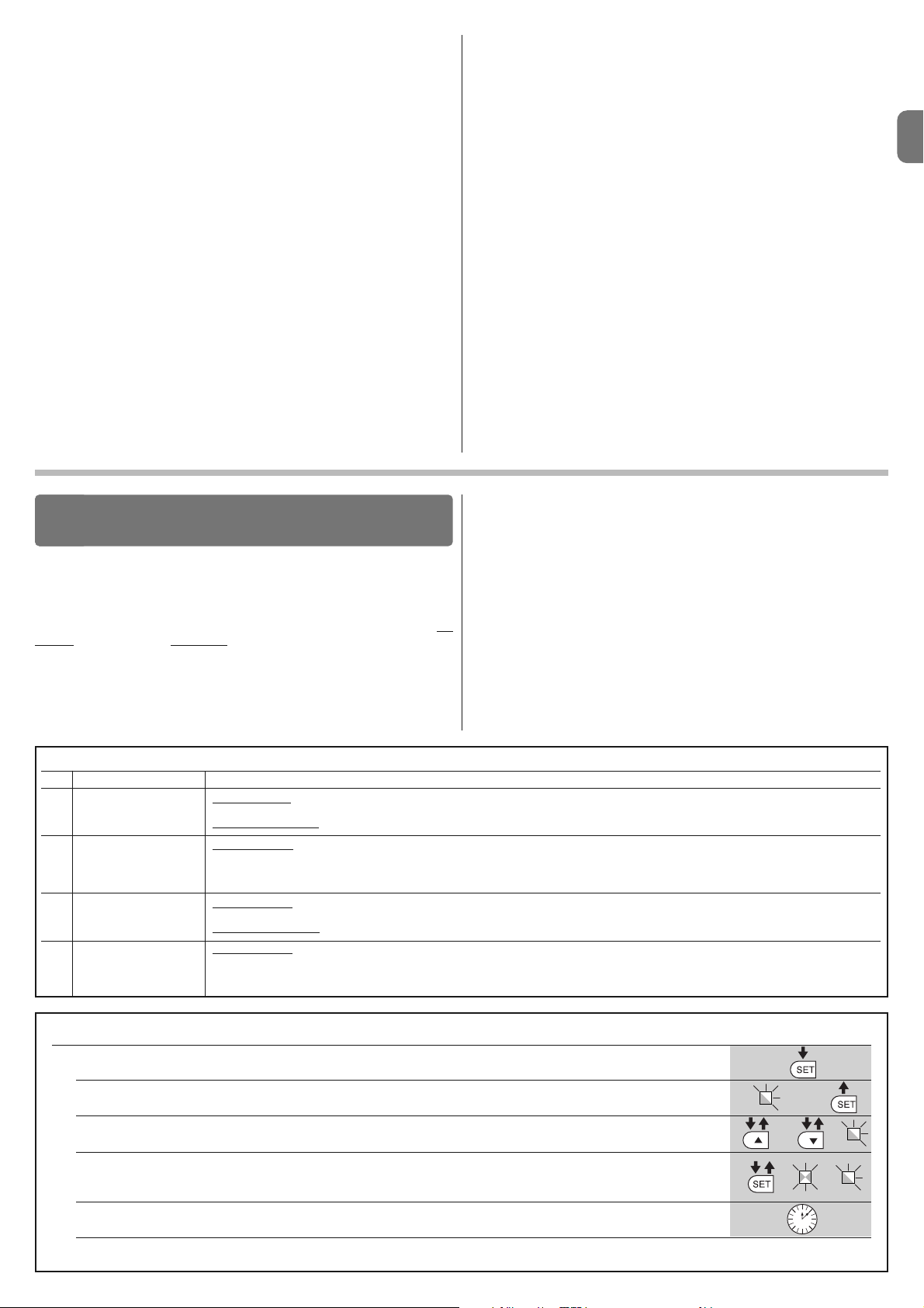
IT
Italiano – 7
razione con WALKY; quindi, fare riferimento ai manuali istruzioni dei singoli
dispositivi.
5.1 - Collaudo
La sequenza di operazioni da eseguire per il collaudo si riferisce ad un impianto
tipico (fig. 2):
1 Sbloccare manualmente i motoriduttori e verificare che agendo sull'anta,
nel punto previsto per la manovra manuale, sia possibile muovere le ante in
apertura e in chiusura con una forza inferiore a 390 N.
2 Verficare che l’anta, lasciata ferma in una qualsiasi posizione della sua cor-
sa, non si muova.
3 Bloccare i motoriduttori (vedere capitolo 3.8).
4 ATTENZIONE! – Verificare che i collegamenti a vite siano avvitati ben stretti.
5 Utilizzando i dispositivi di comando (trasmettitore, pulsante di comando,
selettore a chiave, ecc.), effettuare delle prove di Apertura, Chiusura ed
Arresto del cancello, accertando che il movimento delle ante corrisponda a
quanto previsto. Conviene eseguire diverse prove al fine di valutare il movimento delle ante ed accertare eventuali difetti di montaggio, di regolazione,
nonché la presenza di particolari punti d’attrito.
6 Verificare uno ad uno il corretto funzionamento di tutti i dispositivi di sicu-
rezza presenti nell’impianto (fotocellule, bordi sensibili ecc.). Quando un
dispositivo interviene il led “BLUEBUS”, presente sulla centrale, emette 2
lampeggi più veloci come conferma dell’avvenuto riconoscimento.
7 Se le situazioni pericolose provocate dal movimento delle ante sono state
salvaguardate mediante la limitazione della forza d’impatto si deve eseguire la misura della forza secondo quanto previsto dalla norma EN 12445 ed
eventualmente, se il controllo della “forza motoriduttore” viene usato come
ausilio al sistema per la riduzione della forza d’impatto, provare e infine trovare la regolazione che dia i risultati migliori.
8 Fissare in modo permanente, in una zona adiacente all’automazione, un’eti-
chetta che descrive come sbloccare manualmente il motoriduttore.
5.2 - Messa in servizio
La messa in servizio può avvenire solo dopo aver eseguito con esito positivo tutte le fasi di collaudo.
1 Realizzare il fascicolo tecnico dell’automazione che dovrà comprendere i se -
guenti documenti: un disegno complessivo dell’automazione, lo schema dei
collegamenti elettrici effettuati, l’analisi dei rischi presenti e le relative soluzioni adottate, la dichiarazione di conformità del fabbricante di tutti i dispositivi
utilizzati e la dichiarazione di conformità compilata dall’installatore.
2 Apporre sul cancello una targhetta contenente almeno i seguenti dati: tipo
di automazione, nome e indirizzo del costruttore (responsabile della “messa in servizio”), numero di matricola, anno di costruzione e marchio “CE”.
3 Compilare e consegnare al proprietario dell’automazione la dichiarazione di
conformità dell’automazione.
4 Compilare e consegnare al proprietario dell’automazione il “Manuale per
l’uso” dell’automazione.
5 Compilare e consegnare al proprietario dell’automazione il “Piano di
manutenzione” che raccoglie le prescrizioni sulla manutenzione di tutti i
dispositivi dell’automazione.
6 Prima di mettere in servizio l’automazione informare adeguatamente il pro-
prietario sui pericoli ed i rischi residui ancora presenti.
Per tutta la documentazione citata, Nice attraverso il proprio servizio di
assistenza tecnica, mette a disposizione: manuali d’istruzioni, guide e
moduli precompilati. Vedere anche su: www.nice-service.com
TABELLA 5 - Funzioni di primo livello
Led Funzione Descrizione
L1 Chiusura automatica
L2 Richiudi dopo foto
L3 Chiudi sempre
L4 Stand by (Bluebus)
Funzione ATTIVA: dopo una manovra di apertura, viene eseguita una pausa (pari al Tempo pausa programmato) trascorsa la quale, la centrale avvia
automaticamnete una manovra di chiusura. Il valore di fabbrica del Tempo pausa è pari a 30 sec.
Funzione
NON ATTIVA: il funzionamento è di tipo “semiautomatico”.
Funzione
ATTIVA: se durante la manovra di apertura o chiusura intervengono le fotocellule, il tempo di pausa si riduce a 5 sec. indipendente-
mente dal “tempo pausa” programmato.
Con la “chiusura automatica” disattivata, se durante la Chiusura intervengono le fo tocellule, si attiva la “chiusura automatica” con il “tempo pausa” programmato.
Funzione
ATTIVA: nel caso di un black-out elettrico, anche breve, al ripristino della corrente elettrica la centrale rileva il cancello aperto e automa-
ticamente avvia una manovra di Chiusura, preceduta da 5 sec. di prelampeggio.
Funzione
NON ATTIVA: al ritorno della corrente elettrica il cancello rimane dov'è.
Funzione
ATTIVA: dopo 1 minuto dal termine della ma novra, la centrale spegne l’uscita “Bluebus” (dispositivi collegati) e tutti i led, escluso il led
Bluebus che lampeggerà più lentamente. Quando la centrale riceve un comando ripristina il normale funzionamento (con un breve ritardo). Questa funzione ha lo scopo di ridurre i consumi; aspetto importante con alimentazione a batterie o pannelli fotovoltaici.
Sulla centrale sono presenti 3 tasti OPEN (), STOP (SET), CLOSE () che
possono essere utilizzati sia per comandare la centrale durante le fasi di prova
sia per la programmazione delle funzioni disponibili.
Le funzioni programmabili disponibili sono disposte su 2 livelli e il loro stato di
funzionamento viene segnalato dai 4 led (L1 ... L4) presenti sulla centrale ( led
acceso = funzione attiva; led spento = funzione non attiva).
Utilizzare i tasti di programmazione (fig. 26):
OPEN (): – tasto per comandare l’Apertura del cancello; – tasto di selezione
in fase di programmazione.
STOP/SET: tasto per fermare una manovra; se premuto per più di 5 secondi
permette di entrare in fase di programmazione.
CLOSE (): – tasto per comandare la Chiusura del cancello; – tasto di selezio-
ne in fase di programmazione.
6.1 - Programmazione primo livello (ON-OFF)
Tutte le funzioni del primo livello sono programmate di fabbrica su “OFF” e possono essere modificate in qualsiasi momento. Per verificare le varie funzioni
vedere Tabella 5. Per la procedura di programmazione vedere Tabella 6.
Nota – Queste procedure, possono essere nuovamente eseguite in qualsiasi
momento, anche dopo aver collegato un nuovo dispositivo alla centrale.
IMPORTANTE – La procedura di programmazione presenta un tempo massimo di 10 secondi tra la pressione di un tasto e l’altro. Trascorso questo tempo,
la procedura termina automaticamente memorizzando le modifiche fatte fino a
quel momento.
PROGRAMMAZIONE DELLA CENTRALE
DI COMANDO
6
TABELLA 6 - Procedura di programmazione primo livello
01. Premere e tenere premuto il tasto “Set” per circa 3 secondi;
02. Rilasciare il tasto quando il led “L1” inizia a lampeggiare;
03. Premere il tasto “” o “” per spostare il led lampeggiante sul led che rappresenta la funzione da modificare;
04. Premere il tasto “Set” per cambiare lo stato della funzione:
(lampeggio breve = OFF - lampeggio lungo = ON);
05. Attendere 10 secondi (tempo massimo) per uscire dalla programmazione.
Nota – Per programmare altre funzioni su “ON” oppure “OFF”, durante lesecuzione della procedura, occorre ripetere i punti 03 e 04 durante la fase stessa.
L1
o
3 s
10 s
Page 22
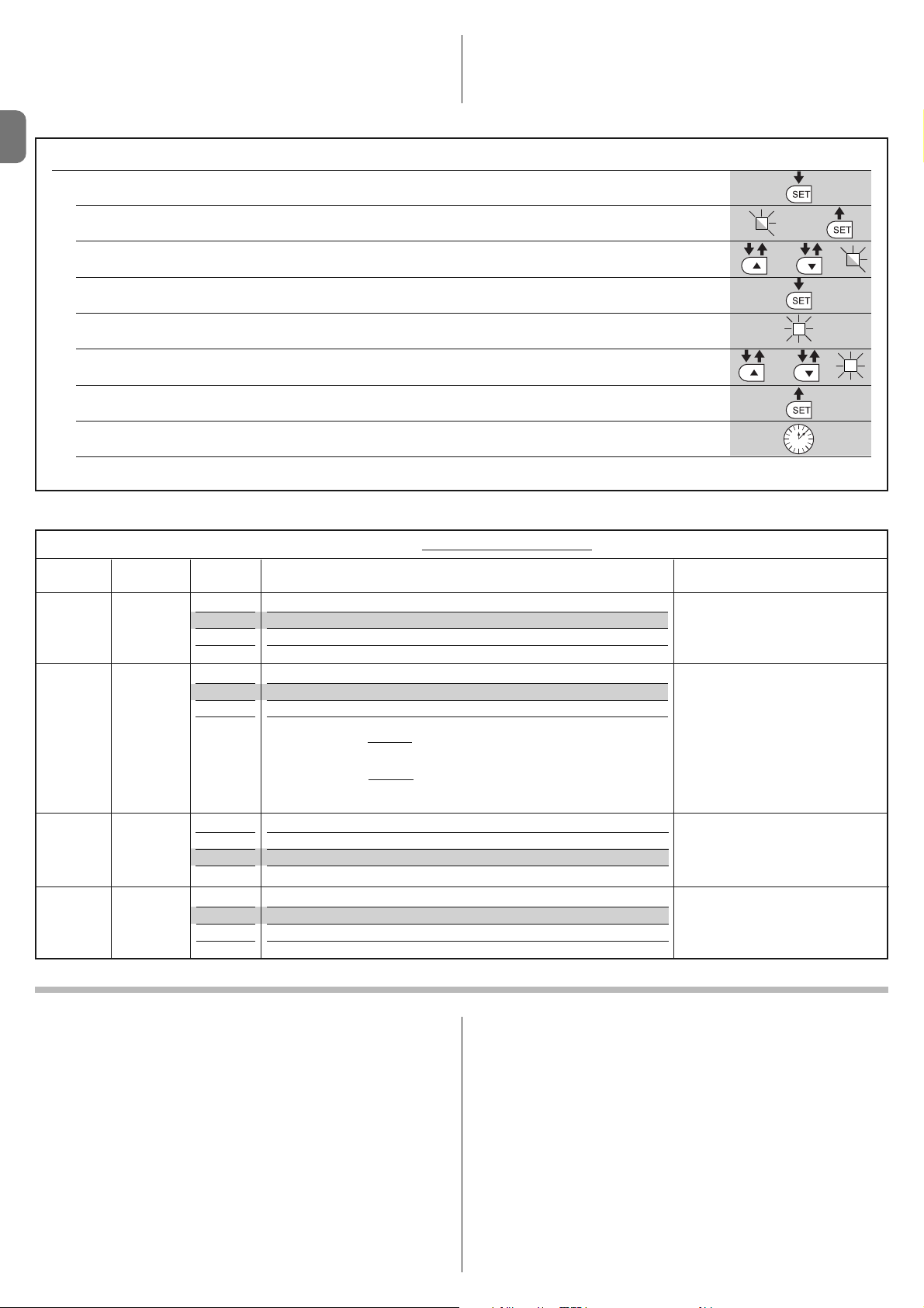
IT
8 – Italiano
TABELLA 7 - Procedura di programmazione secondo livello
01. Premere e tenere premuto il tasto “Set” per circa 3 secondi;
02. Rilasciare il tasto quando il led “L1” inizia a lampeggiare;
03. Premere il tasto “” o “” per spostare il led lampeggiante sul led che rappresenta “led di entrata” del parametro da modificare;
04. Premere e mantenere premuto il tasto “Set” fino alla conclusione del punto 06;
05. Attendere circa 3 secondi, fino a quando si accende il led che rappresenta il livello attuale del parametro da modificare;
06. Premere il tasto “” o “” per spostare il led che rappresenta il valore del parametro;
07. Rilasciare il tasto “Set”;
08. Attendere 10 secondi (tempo massimo) per uscire dalla programmazione.
Nota – Per programmare più parametri, durante lesecuzione della procedura, occorre ripetere le operazioni dal punto 03 al punto 07 durante la fase stessa.
L1
o
o
3 s
10 s
6.3 - Cancellazione della memoria
Per cancellare la memoria della centrale e ripristinare tutte le impostazioni di
fabbrica, procedere nel modo seguente: premere e tenere premuto i tasti “” e
“” fino a quando i led L1 e L2 iniziano a lampeggiare.
6.4 - Funzioni speciali
Funzione: “Muovi comunque”
Questa funzione, permette di far funzionare l’automazione anche quando qualche dispositivo di sicurezza non funziona correttamente oppure è fuori uso.
È possibile comandare l’automazione in modalità “uomo presente”, procedendo nel modo seguente:
01. Inviare un comando per azionare il cancello, con un trasmettitore oppure
con un selettore a chiave, ecc. Se tutto funziona correttamente il cancello
si muoverà regolarmente, altrimenti procedere come di seguito:
02. Entro 3 secondi, azionare nuovamente il comando e mantenerlo azionato;
03. Dopo 2 secondi circa, il cancello effettuerà la manovra richiesta in modalità
a “uomo presente”; cioè, il cancello continuerà a muoversi solo fino a
quando verrà mantenuto azionato il comando.
Quando i dispositivi di sicurezza non funzionano, il se gnalatore lampeggiante
emette alcuni lampeggi per segnalare il tipo di problema (vedere capitolo 7 Tabella 10).
TABELLA 8 - Funzioni di secondo livello
Led di Parametro Led Valore Descrizione
entrata (livello)
L1
L1
L2
L3
L4
5 secondi
30 secondi
60 secondi
120 secondi
Regola il tempo di pausa, cioè il tem po prima della richiusura automatica.
Ha effetto solo se la Chiusura è attiva.
Tempo
Pausa
L2 L1
L2
L3
L4
Apre – stop – chiude – stop
Apre – stop – chiude – apre
Apre – chiude – apre – chiude
Condominiale:
• nella manovra di apertura
il comando “Passo Passo” e “Apre” non provocano nessun effetto; invece, il comando “Chiude” provoca l’inversione del
movimento, cioè la chiusura delle ante.
• nella manovra di chiusura il comando “Passo Passo” e “Apre” provocano
l’inversione del movimento, cioè l’apertura delle ante; invece, il comando
“Chiude” non provoca nessun effetto.
Regola la sequenza di comandi associati all’ingresso “Passo Passo” oppure
al comando radio.
Nota – Impostando L4 viene modificato anche il comportamento dei comandi “Apre” e “Chiude”.
Funzione
Passo
Passo
L3 L1
L2
L3
L4
Lenta
Media
Veloce
Velocissima
Regola la velocità dei motori durante
la corsa normale.
Velocità
motori
L4 L1
L2
L3
L4
Livello 1 - Forza minima
Livello 2 - ...
Livello 3 - ...
Livello 4 - Forza massima
Regola la forza di entrambi i motori.
Forza
motori
6.2 - Programmazione secondo livello (parametri regolabili)
Tutti i parametri del secondo livello sono programmati di fabbrica come evidenziato in colore grigio nella Tabella 8 e possono essere modificate in qualsiasi
momento, procedendo come descritto nella Tabella 7.
I parametri, sono regolabili su una scala di valori da 1 a 4; per verificare il valore
corrispondente ad ogni Led vedere Tabella 8. IMPORTANTE – La procedura di
programmazione presenta un tempo massimo di 10 secondi tra la pressione di
un tasto e l’altro. Trascorso questo tempo, la procedura termina automaticamente memorizzando le modifiche fatte fino a quel momento.
Page 23

IT
Italiano – 9
Alcuni dispositivi sono predisposti per emettere delle segnalazioni con il quale è
possibile riconoscere lo stato di funzionamento oppure di eventuali anomalie.
Se all’uscita FLASH presente sull’alimentatore viene collegata la lampada multifunzione WLT, impostata con funzione lampeggiante, questo durante l’esecuzione di una manovra, emette un lampeggio con cadenza di 1 secondo. Se si
verificano delle anomalie, il lampeggiante emette dei lampeggi più brevi; questi
vengono ripetuti due volte divisi da una pausa di 1 secondo. Nella Tabella 10
sono descritte la causa e la soluzione per ogni tipo di segnalazione.
Anche i Led presenti sulla centrale emettono delle segnalazioni; nella Tabella 11
sono descritte la causa e la soluzione per ogni tipo di segnalazione.
COSA FARE SE... (guida alla risoluzione dei problemi)
7
7 lampeggi brevi
pausa di 1 secondo
7 lampeggi brevi
Anomalia sui circuiti elettrici Attendere almeno 30 secondi e riprovare a inviare un comando ed eventualmente spe-
gnere anche l'alimentazione; se lo stato rimane potrebbe esserci un guasto grave ed
occorre sostituire la scheda elettronica.
8 lampeggi brevi
pausa di 1 secondo
8 lampeggi brevi
È già presente un comando che non
consente di eseguire altri comandi
Verificare la natura del comando sempre presente; ad esempio potrebbe essere il
comando da un orologio sull’ingresso di “PASSO-PASSO”.
9 lampeggi brevi
pausa di 1 secondo
9 lampeggi brevi
L’automazione è stata bloccata da un
comando "Blocca l’automazione".
Sbloccare l’automazione inviando il comando “Sblocca automazione”.
TABELLA 10 - Segnalazioni del segnalatore lampeggiante (FLASH)
Lampeggi Problema Risoluzione
1 lampeggio breve
pausa di 1 secondo
1 lampeggio breve
Errore sul sistema Bluebus La verifica dei dispositivi collegati al sistema Bluebus, che viene eseguita all’inizio della
ma novra, non corrisponde ai dispositivi memorizzati durante la fase di apprendimento. È
possibile che ci siano dispositivi scollegati o guasti, quindi occorre verificare e sostituire.
Se sono state fatte delle modifiche occorre rifare l’apprendimento dei dispositivi (vedere
paragrafo 4.7).
2 lampeggi brevi
pausa di 1 secondo
2 lampeggi brevi
Intervento di una fotocellula Una o più fotocellule non danno il consenso al movimento oppure durante la corsa han-
no provocato una inversione del movimento; verificare se sono presenti ostacoli.
3 lampeggi brevi
pausa di 1 secondo
3 lampeggi brevi
Intervento della funzione
“Rilevamento Ostacoli” da limitatore di
forza
Durante il movimento i motori hanno incontrato un maggiore sforzo; verificare la causa
ed eventualmente aumentare il livello di forza dei motori.
4 lampeggi brevi
pausa di 1 secondo
4 lampeggi brevi
Intervento dell’ingresso di STOP All’inizio della manovra o durante il movimento c’è stato un intervento dei dispositivi col-
legati all’ingresso STOP; verificare la causa.
5 lampeggi brevi
pausa di 1 secondo
5 lampeggi brevi
Errore nei parametri interni della
centrale di comando
Attendere almeno 30 secondi e poi riprovare a dare un comando ed eventualmente spegnere anche l'alimentazione; se lo stato rimane, potrebbe esserci un guasto grave ed
occorre sostituire la scheda elettronica.
6 lampeggi brevi
pausa di 1 secondo
6 lampeggi brevi
Superato il limite massimo di manovre
consecutive o di manovre per ora.
Attendere alcuni minuti in modo da far ritornare il limitatore di ma novre sotto il limite massimo.
TABELLA 11 - Segnalazioni dei Led presenti sulla centrale di comando (fig. 23)
Led Problema Risoluzione
BLUEBUS
Sempre spento
Sempre acceso
1 lampeggio al secondo
2 lampeggi veloci
Serie di lampeggi divisi da una
pausa di 1 secondo
Anomalia
Anomalia grave
Tutto regolare
Variazione dello stato degli ingressi
Varie
Verificare se la centrale è alimentata; verificare che i fusibili non siano
intervenuti. In questo caso verificare la causa del guasto e sostituirli con
altri dello stesso valore
È presente un problema grave: provare a togliere l’alimentazione elettrica
alla centrale e se lo stato permane, occorre sostituire la scheda elettronica
Funzionamento regolare della centrale
È regolare se avviene una variazione in uno degli ingressi (PP, STOP):
intervento delle fotocellule oppure viene trasmesso un comando con un
trasmettitore
Fare riferimento alla Tabella 10
STOP
Sempre spento
Sempre acceso
Intervento dei dispositivi collegati all’ingresso
STOP
Tutto regolare
Verificare i dispositivi dell’ingesso STOP
Ingresso STOP attivo
P. P.
Sempre spento
Sempre acceso
Tutto regolare
Intervento dellingresso P.P.
Ingresso P.P. non attivo
È regolare se è attivo il dispositivo collegato all’ingresso P.P.
L1 - L2 Lampeggio lento Variazione del numero di dispositivi
collegati al Bluebus oppure apprendimento
dispositivo non eseguito
È necessario eseguire l’apprendimento dei dispositivi
(vedere paragrafo 4.7)
L3 - L4 Lampeggio lento Non è mai stato eseguito l’apprendimento
delle posizioni degli arresti meccanici
È necessario eseguire l’apprendimento (vedere paragrafo 4.8).
Page 24

IT
10 – Italiano
Per WALKY sono previsti i seguenti accessori (ricevitore radio): il programmatore Oview, il sistema ad energia solare Solemyo e la batteria tampone mod.
PS424.
8.1 - Collegamento del ricevitore radio OXI
Per collegare il ricevitore OXI, occorre togliere l’alimentazione elettrica alla centrale e procedere come mostrato in fig. 27. Nella Tabella 12 e Tabella 13 sono
riportati i comandi che corrispondono alle uscite presenti sulla centrale.
8.2 - Collegamento e installazione della batteria tampone
mod. PS424
ATTENZIONE! - Il collegamento elettrico della batteria alla centrale deve
essere eseguito soltanto dopo aver concluso tutte le fasi di installazione e
programmazione, in quanto la batteria rappresenta un’alimentazione elettrica di emergenza.
Per installare e collegare la batteria, seguire le fasi di montaggio mostrate nella
fig. 28.
8.3 - Collegamento del programmatore Oview
Sulla centrale è presente il connettore BusT4 al quale è possibile collegare l’unità
di programmazione Oview, che consente una completa e rapida gestione della
fase d’installazione, di manutenzione e di diagnosi dell’intera automazione. Per
accedere al connettore è necessario procedere come mo strato in fig. 29 e collegare il connettore nell’apposita sede. L’Oview può essere collegato a più Centrali simultaneamente (fino a 5 senza particolari precauzioni, fino a 60 seguendo
le apposite avvertenze) e, può restare collegato alla centrale anche durante il
normale funzionamento dell’automazione. In questo caso, può essere utilizzato
per inviare direttamente i comandi alla centrale utilizzando lo specifico menù
“utilizzatore”. È anche possibile eseguire l’aggiornamento del Firmware. Se nella centrale è presente un ricevitore radio appartenente alla famiglia OXI, utilizzando l’Oview è possibile avere accesso ai parametri dei trasmettitori memorizzati nel ricevitore stesso.
Per tutti gli approfondimenti consultare il rispettivo manuale istruzioni ed il
manuale del sistema “Opera system book”.
8.4 - Collegamento del sistema ad energia solare Solemyo
ATTENZIONE! – Quando l’automazione è alimentata dal sistema “Sole myo”, NO N DEVE ES SERE ALI MENTATA con temporaneamente anche
dalla rete elettrica.
Per altre informazioni sul sistema Solemyo fare riferimento al suo manuale istruzioni.
Per predisporre il collegamento del sistema Solemyo, seguire le fasi di montaggio mostrate nella fig. 30.
Per completare il collegamento tra Solemyo e la centrale del motoriduttore utilizzare l’apposito cavo adattatore.
APPROFONDIMENTI
8
1 Passo-Passo
2 Apertura parziale 1
3Apre
4 Chiude
5 Stop
6 Passo-Passo
Condominiale
7 Passo-Passo
alta priorità
8 Apre parziale 2
9 Apre parziale 3
10 Apre e Blocca
automazione
11 Chiude e Blocca
automazione
12 Blocca automazione
13 Sblocca
automazione
14 On Timer
Luce di Cortesia
15 On-Off
Luce di Cortesia
TABELLA 13
OXI / OXIFM /OXIT / OXITFM in modo II esteso
N° Comando Descrizione
Comando “P.P.” (Passo-Passo)
Comando “Apertura parziale 1”
Comando “Apre”
Comando “Chiude”
Arresta la manovra
Comando in modalità Condominiale
Comanda anche con automazione bloccata o comandi
attivi
Apre parziale (apertura dell’anta M2, pari a metà dell’apertura totale)
Apre parziale (apertura delle due ante, pari a metà dell’apertura totale)
Provoca una manovra di apertura e al termine di questa il
blocco dell’automazione; la centrale non accetta nessun
altro comando ad eccezione di “Passo passo alta priorità”,
“Sblocca” automazione oppure (solo da Oview) i comandi:
“Sblocca e chiude” e “Sblocca e apre”
Provoca una manovra di chiusura e al termine di questa il
blocco dell’automazione; la centrale non accetta nessun
altro comando ad eccezione di “Passo passo alta priorità”,
“Sblocca” automazione oppure (solo da Oview) i comandi:
“Sblocca e chiude” e “Sblocca e apre”
Provoca una fermata della manovra ed il blocco dell’automazione; la centrale non accetta nessun altro comando ad
eccezione di “Passo passo alta priorità”, “Sblocca” automazione oppure (solo da Oview) i comandi: “Sblocca e
chiude” e “Sblocca e apre”.
Provoca lo sblocco dell’automazione ed il ripristino del normale funzionamento
Si accende l'uscita Luce di cortesia con spegnimento temporizzato
Si accende e spegne l'uscita Luce di cortesia in modalità
On - Off
MANUTENZIONE DEL PRODOTTO
9
Per mantenere costante il livello di sicurezza e per garantire la massima durata
dell’intera automazione è necessaria una manutenzione regolare.
La manutenzione deve essere effettuata nel pieno rispetto delle prescrizioni sulla sicurezza del presente manuale e secondo quanto previsto dalle leggi e normative vigenti.
Sottoporre di frequente ad esame il prodotto, per verificare se ci sono sbilanciamenti delle ante o segni di usura o danni ai cavi. Non utilizzare il prodotto nel
caso in cui siano necessarie delle riparazioni o delle regolazioni.
Importante – Durante le fasi di manutenzione oppure di pulizia del prodotto, scollegare la centrale dall’alimentazione elettrica e dalle batterie se
previste.
Per gli altri dispositivi presenti nell’impianto, seguire quanto previsto nei rispettivi piani manutenzione.
Per i motoriduttori WL1024C, WL1024 è necessaria una manutenzione programmata al massimo entro 6 mesi o 20.000 manovre dalla precedente manutenzione.
Per eseguire la manutenzione procedere nel modo seguente:
01. Scollegare qualsiasi sorgente di alimentazione elettrica, comprese le eventuali batterie tampone;
02. Verificare lo stato di deterioramento di staffe e tasselli di fissaggio con particolare attenzione a fenomeni di erosione o di ossidazione delle parti; sostituire le parti che non forniscono sufficienti garanzie;
03. Effettuare una prova di sblocco per verificarne il corretto funzionamento
vedi paragrafo 3.8.
04. Ricollegare le sorgenti di alimentazione elettrica ed eseguire tutte le prove e
le verifiche previste nel capitolo 5.1 - Collaudo.
TABELLA 12
SMXI / SMXIS oppure OXI / OXIFM / OXIT / OXITFM in modo I o Modo II
Uscita N°1
Uscita N°2
Uscita N°3
Uscita N°4
Comando “P.P.” (Passo-Passo)
Comando “Apertura parziale 1”
Comando “Apre”
Comando “Chiude”
Page 25

IT
Italiano – 11
SMALTIMENTO DEL PRODOTTO
Questo prodotto è parte integrante dell’automazione, e dunque, deve
essere smaltito insieme con essa.
Come per le operazioni d’installazione, anche al termine della vita di questo
prodotto, le operazioni di smantellamento devono essere eseguite da personale qualificato.
Questo prodotto è costituito da vari tipi di materiali: alcuni possono essere riciclati, altri devono essere smaltiti. Informatevi sui sistemi di riciclaggio o smaltimento previsti dai regolamenti vigenti sul vostro territorio, per questa categoria
di prodotto.
Attenzione! – Alcune parti del prodotto possono contenere sostanze inquinanti o pericolose che, se disperse nell’ambiente, potrebbero provocare effetti dannosi sull’ambiente stesso e sulla salute umana.
Come indicato dal simbolo a lato, è vietato gettare questo
prodotto nei rifiuti domestici. Eseguire quindi la “raccolta
separata” per lo smaltimento, secondo i metodi previsti dai
regolamenti vigenti sul vostro territorio, oppure riconsegnare
il prodotto al venditore nel momento dell’acquisto di un nuovo prodotto equivalente.
Attenzione! – i regolamenti vigenti a livello locale possono prevedere pesanti
sanzioni in caso di smaltimento abusivo di questo prodotto.
Smaltimento della batteria tampone (se presente)
Attenzione! – La batteria scarica contiene sostanze inquinanti e quindi, non
deve essere buttata nei rifiuti comuni.
Occorre smaltirla utilizzando i metodi di raccolta ‘separata’, previsti dalle normative vigenti nel vostro territorio.
CARATTERISTICHE TECNICHE DEL PRODOTTO
AVVERTENZE: • Tutte le caratteristiche tecniche riportate, sono riferite ad una temperatura ambientale di 20°C (± 5°C). • Nice S.p.a. si riserva il diritto di apportare modifiche al prodotto in qualsiasi momento lo riterrà necessario, mantenendone comunque la stessa funzionalità e destinazione d’uso.
Tipologia: Motoriduttore elettromeccanico per automatismi di cancelli e portoni automatici con motore in corrente continua, riduttore epicicloidale, sblocco
meccanico. Solo per modello WL1024C: centrale di comando incorporata e ricevitore radio OXI
Coppia massima: 100 Nm
Coppia nominale: 50 Nm
Velocità a vuoto: 0,20 rad/s - 0,3 rad/s
Velocità alla coppia nominale: 0,16 rad/s - 0,24 rad/s
Frequenza massima dei cicli: 100 cicli completi al giorno (la centrale di WL1024C limita ad un massimo di circa 50 cicli/ora)
Tempo massimo ciclo continuo: 10 minuti circa
Limiti d’impiego: il prodotto può essere utilizzato su cancelli con peso fino a 180 kg (anta da 0,8 m) oppure con lunghezza dell’anta fino a 1,8 m e angolo di
apertura fino 110°
Alimentazione: WL1024C: 230 Vac (+10% -15%) 50/60 Hz; WL1024: 24 Vdc (50%); WL1024C/V1: 120 Vac (+10% -15%) 50/60 Hz
Alimentazione d’emergenza: Predisposizione per batterie tampone PS424
Alimentazione a pannelli solari: predisposizione per Kit SOLEMYO
Potenza nominale assorbita alla rete elettrica (WL1024C): 120 W
Corrente nominale assorbita (WL1024): 2 A; allo spunto la corrente è 3 A per un tempo massimo di 2 s
Potenza assorbita alla rete elettrica con funzione “Standby – Tutto (1)” attiva (compreso il ricevitore OXI): 3 W
Potenza assorbita con funzionamento a batteria tampone o KIT SOLEMYO con funzione “Standby-Tutto (1)” attiva (compreso il ricevitore OXI): inferio-
re a 100 mW
Uscita elettroserratura [*]: una elettroserratura da 12 Vac max 15 VA
Uscita lampeggiante [*]: un lampeggiante WLT oppure una lampada 12Vdc, 21 W max
Uscita BLUEBUS: un’uscita con carico massimo di 15 unità Bluebus (massimo 6 coppie di fotocellule MOFB o MOFOB più 2 coppie di fotocellule MOFB o
MOFOB indirizzate come dispositivi di apertura più massimo 4 dispositivi di comando MOMB o MOTB)
Ingresso STOP: per contatti normalmente chiusi, normalmente aperti oppure a resistenza costante 8,2 kΩ; la selezione del tipo di contatto avviene in auto-
apprendimento ed una variazione rispetto allo stato memorizzato provoca il comando “STOP”
Ingresso PP: per contatti normalmente aperti (la chiusura del contatto provoca il comando Passo Passo)
Innesto radio: connettore SM per ricevitori della famiglia SMXI, OXI e OXIFM
Ingresso ANTENNA Radio: 50 Ω per cavo tipo RG58 o simili
Funzioni programmabili: 4 funzioni di tipo ON-OFF (Tabella 5) e 4 funzioni regolabili (Tabella 8)
Funzioni in auto apprendimento: • Auto apprendimento dei dispositivi collegati all’uscita BlueBus. • Auto apprendimento del tipo di dispositivo collegato al
morsetto “STOP” (contatto NA, NC o resistenza 8,2 kΩ). • Auto apprendimento della corsa delle ante e calcolo in automatico dei punti di rallentamento ed apertura parziale. • Auto apprendimento del funzionamento con uno o due motori
Montaggio: In verticale, con una piastra di fissaggio dedicata
Temperatura di funzionamento: da -20°C a +50°C (alle basse temperature l’efficienza del motoriduttore diminuisce)
Utilizzo in atmosfera particolarmente acida o salina o potenzialmente esplosiva: NO
Grado di protezione: IP 44 (con contenitore integro)
Dimensioni (mm): 90 x 125 x 385 h
Peso (kg): (WL1024C) 4,8; (WL1024) 4,3
Note:
––––––––––
(1) - Funzione attivabile con programmatore Oview.
[*] - Le uscite dei morsetti sulla centrale (“Elettroserratura”) e sull’alimentatore (“Flash”) possono essere riprogrammate con altre funzioni, utilizzando il programmatore Oview. Le caratte-
ristiche elettriche di queste due uscite si adeguano in base al tipo di funzione scelta:
• funzione “elettroserratura”: 12Vac, 15VA max;
• funzione “lampeggiante”: una lampada multifunzione WLT, oppure una lampada a 12Vdc, 21W max;
• altri tipi di funzioni: una lampada o un relè a 24Vdc (-30% e +30%), 4 W max, se il funzionamento della centrale è alla tensione di rete, oppure una lampada o un relè a 12Vdc (-10% e
+25%), 4 W max, se il funzionamento della centrale è a batteria tampone PS424.
Page 26
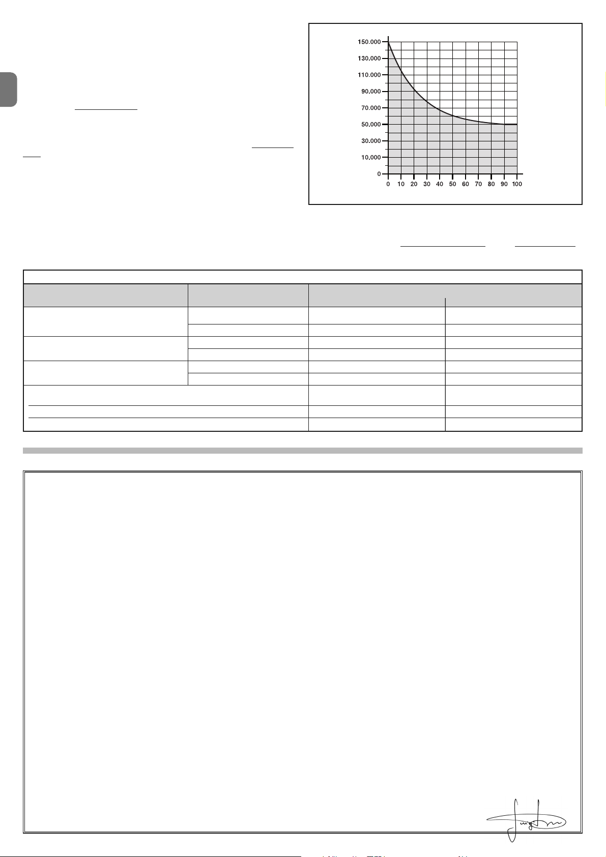
IT
12 – Italiano
DICHIARAZIONE CE DI CONFORMITÀ
Nota - Il contenuto di questa dichiarazione corrisponde a quanto dichiarato nell’ultima revisione disponibile, prima della stampa di questo manuale, del documento ufficiale depositato presso la sede di Nice Spa. Il presente testo è stato riadattato per motivi editoriali.
Numero: 322/WL.. Revisione: 0
Il sottoscritto Luigi Paro in qualità di Amministratore Delegato, dichiara sotto la propria responsabilità che il prodotto:
Nome produttore: NICE s.p.a.
Indirizzo: Via Pezza Alta 13, Z.I. Rustignè, 31046 Oderzo (TV) Italia
Tipo: Motoriduttore elettromeccanico
Modelli: WL1024C, WL1024
Accessori: OXI, OVBT, OVBTGSM, SYKCE, PS424
Risulta conforme a quanto previsto dalle seguenti direttive comunitarie:
• 98/37/CE (89/392/CEE modificata) DIRETTIVA 98/37/CE DEL PARLAMENTO EUROPEO E DEL CONSIGLIO del 22 giugno 1998 concernente il ravvicinamento delle legislazioni degli Stati membri relative alle macchine
Come previsto dalla direttiva 98/37/CE si avverte che non è consentita la messa in servizio del prodotto sopra indicato finché la macchina, in cui il prodotto è incorporato, non sia stata identificata e dichiarata conforme alla direttiva 98/37/CE.
Inoltre il prodotto risulta conforme a quanto previsto dalle seguenti direttive comunitarie, così come modificate dalla Direttiva 93/68/CEE del consiglio del 22
Luglio 1993:
• 2006/95/CEE(ex direttiva 73/23/CE) DIRETTIVA 2006/95/CE DEL PARLAMENTO EUROPEO E DEL CONSIGLIO del 12 dicembre 2006 concernente il
ravvicinamento delle legislazioni degli Stati membri relative al materiale elettrico destinato ad essere adoperato entro taluni limiti di tensione
Secondo le seguenti norme armonizzate:
EN 60335-1:1994+A11:1995+A1:1996+A12:1996+A13:1998+A14:1998+A15:2000+A2:2000+A16:2001
• 2004/108/CEE(ex direttiva 89/336/CEE) DIRETTIVA 2004/108/CE DEL PARLAMENTO EUROPEO E DEL CONSIGLIO del 15 dicembre 2004 concernente il ravvicinamento delle legislazioni degli Stati membri relative alla compatibilità elettromagnetica e che abroga la direttiva 89/336/CEE
Secondo le seguenti norme armonizzate: EN 61000-6-2:2005; EN 61000-6-3:2007
Inoltre risulta conforme; limitatamente per le parti applicabili, alle seguenti norme:
EN 60335-1:2002+A1:2004+A11:2004+A12:2006+ A2:2006, EN 60335-2-103:2003,
EN 13241-1:2003; EN 12453:2002; EN 12445:2002; EN 12978:2003
Oderzo, 29 maggio 2009 Luigi Paro (Amministratore Delegato)
Esempio del calcolo di durabilità di un motoriduttore Walky con braccio
intero (fare riferimento alla Tabella 14 e al Grafico A): - peso dell’anta: 100
Kg; - lunghezza dell’anta = 1,7 m (indice di gravosità: 55%); - non presenti altri
elementi di affaticamento; Indice di gravosità totale
= 55%; Durabilità stimata =
55.000 cicli di manovre
Durabilità del prodotto
La durabilità è la vita economica media del prodotto. Il valore della durabilità è
fortemente influenzato dall’indice di gravosità delle manovre eseguite dall’automatismo: cioè la somma di tutti i fattori che contribuiscono all’usura del prodotto (vedere Tabella 14).
Per stabilire la durabilità probabile del vostro automatismo procedere nel modo
seguente:
01. Calcolare l’indice di gravosità sommando tra loro i valori in percentuale delle voci presenti nella Tabella 14;
02. Nel Grafico A dal valore appena trovato, tracciare una linea verticale fino ad
incrociare la curva; da questo punto tracciare una linea orizzontale fino ad
incrociare la linea dei “cicli di manovre”. Il valore determinato è la durabilità sti
-
mata del vostro prodotto.
La stima di durabilità viene effettuata sulla base dei calcoli progettuali e dei risultati di prove effettuate su prototipi. Infatti, essendo una stima, non rappresenta
alcuna garanzia sull’effettiva durata del prodotto.
GRAFICO A
cicli di manovre
indice di gravosità %
TABELLA 14
Indice di gravosità
BRACCIO LUNGHEZZA STANDARD BRACCIO LUNGHEZZA RIDOTTA
< 1,2 m
1,2 - 1,6 m
> 1,6 m
Lunghezza anta Peso anta
Temperatura ambientale superiore a 40°C o inferiore a 0°C o umidità
superiore all’80%
Anta cieca
Installazione in zona ventosa
> 100 kg
< 100 kg
> 80 kg
< 80 kg
> 60 kg
< 60 kg
55%
30%
55%
40%
55%
40%
15%
15%
15%
65%
50%
65%
50%
-
-
15%
10%
10%
Page 27

FR
Français – 1
FRANÇAIS
Sommaire
1 - RECOMMANDATIONS ET PRÉCAUTIONS GÉNÉRALES . . . . . . . . . . 1
1.1 - Recommandations pour la sécurité . . . . . . . . . . . . . . . . . . . . . . . . . . . . 1
1.2 - Recommandations pour l’installation . . . . . . . . . . . . . . . . . . . . . . . . . . 1
1.3 - Recommandations pour l’utilisation . . . . . . . . . . . . . . . . . . . . . . . . . . . 1
2 - DESCRIPTION DU PRODUIT ET UTILISATION PRÉVUE . . . . . . . . . . . 1
3 - INSTALLATION . . . . . . . . . . . . . . . . . . . . . . . . . . . . . . . . . . . . . . . . . . . . 2
3.1 - Contrôles à effectuer avant l’installation . . . . . . . . . . . . . . . . . . . . . . . . 2
3.2 - Limites d’emploi . . . . . . . . . . . . . . . . . . . . . . . . . . . . . . . . . . . . . . . . . . 2
3.3 - Travaux de préparation pour l’installation . . . . . . . . . . . . . . . . . . . . . . . 2
3.4 - Installation de l’opérateur mod. WL1024C - WL1024 . . . . . . . . . . . . . . 3
3.4.1 - Déterminer la longueur du bras de l’opérateur . . . . . . . . . . . . . . 3
3.4.2 - Installation de l’opérateur avec BRAS DE LONGUEUR STANDARD 3
3.4.3 - Installation de l’opérateur avec BRAS DE LONGUEUR RÉDUITE 4
3.5 - Installation de la lampe multifonctions mod. WLT sur l’opérateur
modèle WL1024C . . . . . . . . . . . . . . . . . . . . . . . . . . . . . . . . . . . . . . . . . . . . . 4
3.6 - Comment extraire la centrale de commande . . . . . . . . . . . . . . . . . . . . . 5
3.7 - Réglage de l’alignement des vantaux en fermeture . . . . . . . . . . . . . . . . 5
3.8 - Débloquer et bloquer manuellement l’opérateur . . . . . . . . . . . . . . . . . . 5
4 - BRANCHEMENTS ÉLECTRIQUES . . . . . . . . . . . . . . . . . . . . . . . . . . . . 5
4.1 - Description des branchements électriques . . . . . . . . . . . . . . . . . . . . . . 5
4.2 - Branchement du câble d’alimentation . . . . . . . . . . . . . . . . . . . . . . . . . . 5
4.3 - Branchement de l’opérateur sans centrale mod. WL1024 . . . . . . . . . . 5
4.4 - Branchement d’autres dispositifs . . . . . . . . . . . . . . . . . . . . . . . . . . . . . 5
4.5 - Adressage des dispositifs branchés . . . . . . . . . . . . . . . . . . . . . . . . . . . 6
4.6 - Premier allumage et contrôle des branchements . . . . . . . . . . . . . . . . . 6
4.7 - Apprentissage des dispositifs branchés . . . . . . . . . . . . . . . . . . . . . . . . 6
4.8 - Apprentissage des positions des arrêts mécaniques . . . . . . . . . . . . . . . 6
4.9 - Contrôle du mouvement des vantaux du portail . . . . . . . . . . . . . . . . . . 6
5 - ESSAI ET MISE EN SERVICE . . . . . . . . . . . . . . . . . . . . . . . . . . . . . . . . 6
5.1 - Essai . . . . . . . . . . . . . . . . . . . . . . . . . . . . . . . . . . . . . . . . . . . . . . . . . . . 7
5.2 - Mise en service . . . . . . . . . . . . . . . . . . . . . . . . . . . . . . . . . . . . . . . . . . . 7
6 - PROGRAMMATION DE LA CENTRALE DE COMMANDE . . . . . . . . . . 7
6.1 - Programmation premier niveau (ON-OFF) . . . . . . . . . . . . . . . . . . . . . . . 7
6.2 - Programmation deuxième niveau (paramètres réglables) . . . . . . . . . . . . 8
6.3 - Effacement de la mémoire . . . . . . . . . . . . . . . . . . . . . . . . . . . . . . . . . . 8
6.4 - Fonctions spéciales . . . . . . . . . . . . . . . . . . . . . . . . . . . . . . . . . . . . . . . 8
7 - QUE FAIRE SI... (guide de résolution des problèmes) . . . . . . . . . . . . . 9
8 - APPROFONDISSEMENTS . . . . . . . . . . . . . . . . . . . . . . . . . . . . . . . . . 10
8.1 - Branchement du récepteur radio OXI . . . . . . . . . . . . . . . . . . . . . . . . . 10
8.2 - Branchement et installation de la batterie tampon mod. PS424 . . . . . 10
8.3 - Branchement du programmateur Oview . . . . . . . . . . . . . . . . . . . . . . . 10
8.4 - Branchement du système à énergie solaire Solemyo . . . . . . . . . . . . . 10
9 - MAINTENANCE DU PRODUIT . . . . . . . . . . . . . . . . . . . . . . . . . . . . . . 10
MISE AU REBUT DU PRODUIT . . . . . . . . . . . . . . . . . . . . . . . . . . . . . . . . 11
CARACTÉRISTIQUES TECHNIQUES DU PRODUIT . . . . . . . . . . . . . . . . .11
Durabilité du produit . . . . . . . . . . . . . . . . . . . . . . . . . . . . . . . . . . . . . . . . . 12
DÉCLARATION CE DE CONFORMITÉ . . . . . . . . . . . . . . . . . . . . . . . . . . . 12
APPENDICE . . . . . . . . . . . . . . . . . . . . . . . . . . . . . . . . . . . . . . . . . . . . . . . . . I
Instructions et recommandations destinées à l’utilisateur . . . . . . . . . . . . . . . V
Images . . . . . . . . . . . . . . . . . . . . . . . . . . . . . . . . . . . . . . . . . . . . . . . . . . . . . X
1.1 - Recommandations pour la sécurité
• ATTENTION ! – Le présent manuel contient d’importantes instructions
et recommandations en matière de sécurité. Une mauvaise installation
peut causer de graves blessures. Avant de commencer le travail, lire attentivement toutes les parties du manuel. En cas de doutes, interrompre l’installation et demander des précisions au service après-vente Nice.
• ATTENTION ! – Instructions importantes : conserver ce manuel pour toute intervention de maintenance et de mise en rebut du produit.
• ATTENTION ! – Conformément à la plus récente législation europé en ne, la réalisation d’un vantail ou d’un portail automatique doit respecter
les normes prévues par la Directive 2006/42/CE (ex 98/37/CE) (Directive
Machines) et en particulier, les normes EN 12445; EN 12453; EN 12635
et EN 13241-1 qui permettent de déclarer la conformité de l’automatisation. Pour cette raison, toutes les opérations d’installation, de branchement, d’essai et de maintenance du produit doivent être confiées
exclusivement à un technicien qualifié et compétent !
1.2 - Recommandations pour l’installation
• Avant de commencer l’installation, contrôler si le présent produit est adapté au
type d'utilisation souhaitée (voir les “Limites d’emploi” paragraphe 3.2 et les
“Caractéristiques techniques du produit”). En cas contraire, NE PAS procéder
à l'installation.
• Toutes les opérations d'installation et de maintenance doivent être
effectuées avec l'automatisation débranchée. Si le dispositif de déconnexion de l’alimentation n’est pas visible du lieu où est positionné l’automatisme, avant de commencer le travail accrocher sur le dispositif de déconnexion un panneau avec écrit “ATTENTION ! MAINTENANCE EN COURS”.
• La centrale doit être branchée à une ligne d’alimentation électrique équipée
de mise à la terre de sécurité.
• Durant l’installation manipuler avec soin le produit afin d’éviter tout écrasement, choc, chute ou contact avec des liquides de toute nature. Ne pas
mettre le produit près de sources de chaleur, ni l’exposer à des flammes
libres. Toutes ces actions peuvent l'endommager et créer des dysfonctionnements ou des situations de danger. Au cas où, interrompre immédiatement
l'installation et s'adresser au service après-vente Nice.
• Aucune modification du produit ne peut être effectuée. Opérations non
admises car celles-ci entraîneraient des dysfonctionnements. Le fabricant
décline toute responsabilité pour dommages dérivant de modifications arbitraires du produit.
• Si le portail à automatiser est équipé d’un vantail pour piétons, préparer l'installation avec un système de contrôle qui désactive le fonctionnement du
moteur lorsque le vantail pour piétons est ouvert.
• Le matériau de l’emballage du produit doit être éliminé conformément aux
normes locales.
1.3 - Recommandations pour l’utilisation
• Le produit n’est pas destiné à être utilisé par des personnes (enfants compris)
dont les capacités physiques, sensorielles ou mentales sont réduites ou man quant d'expérience ou de connaissance, à moins que celles-ci n’aient pu
bénéficier, à travers l'intermédiation d'une personne responsable de leur sé curité, d’une surveillance ou d'instructions concernant l'utilisation du produit.
• Les enfants se trouvant à proximité de l’automatisation doivent être surveillés ;
contrôler qu'ils ne jouent pas avec cette dernière.
• Ne pas laisser les enfants jouer avec les dispositifs de commande fixes. Garder
les dispositifs de commande portables (à distance) hors de la portée des
enfants.
RECOMMANDATIONS ET PRÉCAUTIONS
GÉNÉRALES
1
Les dispositifs qui composent le présent produit sont destinés à l’automatisation d’un portail à un ou deux vantaux. ATTENTION ! – Toute autre utilisation
différente de celle décrite et dans des conditions environnementales différentes de celles reportées dans ce manuel doit être considéré comme
impropre et interdite !
La partie principale de l’automatisme est composée d’un ou de deux opérateurs électromécaniques (suivant le nombre de vantaux à automatiser), équipés
chacun d’un moteur en courant continu et d’un réducteur épicycloïdal. Un des
opérateurs (mod. WL1024C) est équipé d’une centrale de commande qui en
gère le fonctionnement. La centrale est formée d’une carte avec un récepteur
radio incorporé, pour la réception des commandes envoyées par l’émetteur.
La centrale est préparée pour être branchée à différents dispositifs appartenant
au Système Opera, au système Bluebus et au système d’alimentation à énergie
solaire Solemyo.
Si alimentée depuis réseau, elle peut accueillir une batterie tampon (mod.
PS424, accessoire en option) qui en cas de coupure électrique (black-out élec-
DESCRIPTION DU PRODUIT ET
UTILISATION PRÉVUE
2
Page 28
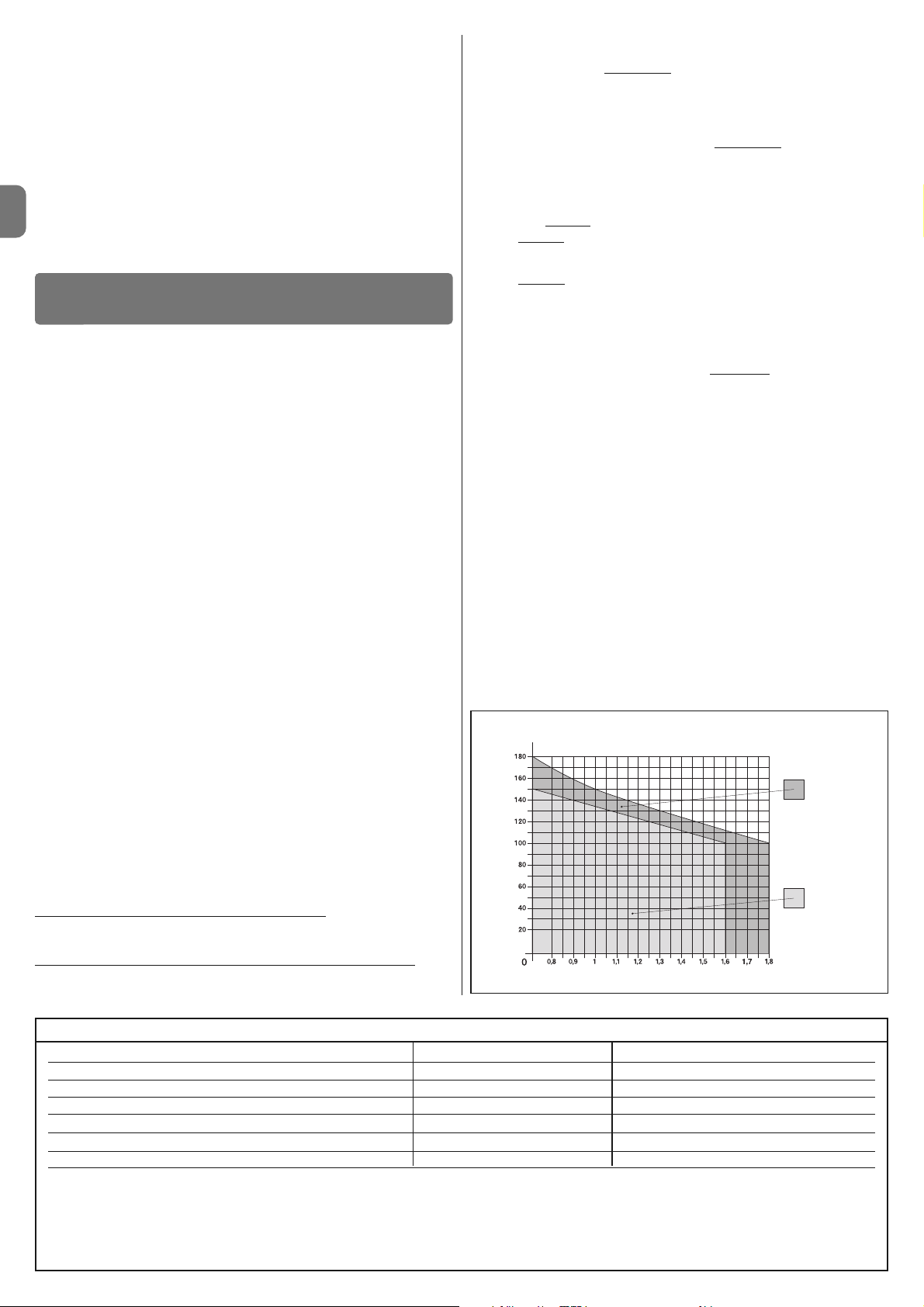
FR
2 – Français
3.1 - Contrôles à effectuer avant l’installation
Avant de procéder à l’installation, il est nécessaire de vérifier l’intégrité des
composants du produit, l’adaptabilité du modèle choisi et la conformité de l’environnement destiné à l’installation :
• Contrôler que tout le matériel à utiliser soit intact et adapté à l’utilisation prévue.
• Contrôler que sur l’installation soient présents les arrêts mécaniques au sol
(non fournis), aussi bien en fermeture qu’en ouverture.
• Contrôler que la structure mécanique du portail soit adaptée pour l’automatisation et conforme aux normes en vigueur sur le territoire (éventuellement se
référer aux données reportées sur l’étiquette du portail). Le présent produit
ne peut automatiser un portail que ci celui-ci est efficace et sûr ; en outre, il
ne peut pas résoudre les défauts causés par une installation erronée du portail ou par une mauvaise maintenance.
• Contrôler que les conditions de fonctionnement des dispositifs soient compatibles avec les limites d’emploi déclarées (voir paragraphe 3.2).
• Bouger manuellement les vantaux du portail dans les deux sens et s’assurer
que le mouvement se produise avec un frottement constant sur chaque point
de la course (il ne doit pas y avoir de moments demandant un effort excessif
ou moindre).
• Amener manuellement les vantaux du portail dans une quelconque position ;
puis les laisser à l’arrêt et s’assurer qu’ils ne bougent pas.
• Contrôler que la zone de fixation de l’opérateur soit compatible avec l’encombrement de ce dernier (fig. 1).
• S’assurer qu’il y ait l’espace suffisant pour la rotation complète du bras sur le
lieu d’installation de l’opérateur.
• S’assurer qu’il y ait l’espace suffisant pour effectuer la manœuvre manuelle
de déblocage de l’opérateur près de celui-ci.
• S’assurer que les surfaces choisies pour installer les différents dispositifs
soient solides et puissent garantir une fixation stable.
• S’assurer que chaque dispositif à installer soit placé dans une position protégée et à l’abri de chocs accidentels.
• Contrôler que tous les câbles électriques à utiliser correspondent au type
énuméré dans le Tableau 1.
3.2 - Limites d’emploi
Avant d’effectuer l’installation de l’opérateur, contrôler que ses données rentrent dans les limites d’emploi reportées ci-dessous et dans les limites des
valeurs reportées au chapitre “Caractéristiques techniques du produit” :
Avec le bras du moteur de longueur ENTIÈRE (d’usine)
:
- largeur maximale du vantail : 1,80 m (= poids maximal du vantail : 100 kg)
- hauteur maximale du vantail : 2 m
Avec le bras du moteur de longueur RÉDUITE (coupée par l’installateur)
:
- largeur maximale du vantail : 1,60 m (= poids maximal du vantail : 100 kg)
- hauteur maximale du vantail : 2 m
• Contrôle à effectuer : reporter sur le Graphique 1, le poids et la largeur du
vantail ; tracer depuis ces points deux lignes et s’assurer que celles-ci se croisent dans une des deux zones grises
du graphique. Attention ! - Si les lignes
se croisent dans la zone blanche, il n’est pas possible d’utiliser ce produit pour
automatiser le portail.
• Afin de permettre l’installation de l’opérateur, la largeur minimale du pilier doit
être de 80 mm.
• Le bras de l’opérateur doit être placé dans la partie haute
du vantail du portail.
ATTENTION ! - Il est interdit de monter l’opérateur dans une position renversée, c’est-à-dire avec le bras orienté vers le bas.
• La patte de fixation du bras doit se trouver dans une zone robuste du vantail
(par exemple, le cadre), pour garantir une fixation solide et sûre ;
• Contrôler la cote
“E” (fig. 7) :
- Si la cote
“E” est une valeur comprise entre 80 mm (minimum) et 299 mm
(maximum), il faut raccourcir le bras de l’opérateur. Dans ces conditions,
l’ouverture maximale du vantail peut arriver jusqu’à 90°.
- Si la cote “E” est une valeur égale ou supérieure à 300 mm, il ne faut pas
raccourcir le bras de l’opérateur. Dans ces conditions, l’ouverture maximale
du vantail peut arriver jusqu’à 110°.
3.3 - Travaux de préparation pour l’installation
La fig. 2 reporte un exemple d'installation d’automatisation, réalisé avec des com-
posants Nice (certains composants peuvent ne pas être présents dans le kit) :
a - Opérateur avec centrale mod. WL1024C
b - Opérateur sans centrale mod. WL1024
c - Lampe multifonctions mod. WLT (à installer sur l’opérateur avec centrale
mod. WL1024C) ; voir chapitre 3.5 et manuel d’instructions
d - Paire de photocellules mod. MOFB
e - Clavier numérique (mod. MOTB) - Lecteur à transponder (mod. MOMB) -
Sélecteur à clé (mod. MOSE)
f - Paire de colonnes pour photocellules
g - Arrêts mécaniques en Ouverture et en Fermeture
h - Serrure électrique
Ces composants sont positionnés selon un schéma typique. En se référant à la
fig. 2, établir la position approximative dans laquelle installer chaque composant prévu sur l’installation. Important – Avant d’effectuer l’installation, préparer les câbles électriques nécessaires pour votre installation, en se référant à la
fig. 2a et au “Tableau 1 - Caractéristiques techniques des câbles électriques”.
Attention – Durant la pose des conduits pour le passage des câbles élec-
triques, considérer qu’à cause de possibles dépôts d’eau présents dans les
regards de dérivation, les conduits de raccordement peuvent créer des phénomènes de condensation à l’intérieur de la centrale et endommager les circuits
électroniques.
INSTALLATION
3
Branchement Type de câble Longueur maximale admise
A : Câble ALIMENTATION 1 câble 3 x 1,5 mm
2
30 m (note 1)
B : Câble SERRURE ÉLECTRIQUE 1 câble 2 x 1 mm
2
6 m
C : Câble DISPOSITIFS BLUEBUS 1 câble 2 x 0,5 mm
2
20 m (note 2)
D : Câble SÉLECTEUR À CLÉ 2 câbles 2 x 0,5 mm2 (note 3) 50 m
E : Câble ALIMENTATION OPÉRATEUR 1 câble 3 x 1,5 mm
2
6 m
Câble ANTENNE EXTERNE (option) 1 câble blindé type RG58 20 m (conseillé inférieur à 5 m)
Note 1 – Si le câble d’alimentation dépasse 30 m de longueur, il faut utiliser un câble avec une section supérieure (3 x 2,5 mm
2
) et il est nécessaire d’installer une mise à la terre de sécurité à proximité de l’automation.
Note 2 – Si le câble Bluebus dépasse 20 m de longueur, jusqu’à un maximum de 40 m, il faut utiliser un câble avec une section supérieure (2 x 1 mm
2
).
Note 3 – Ces 2 câbles peuvent être remplacés par un unique câble de 4 x 0,5 mm2.
ATTENTION ! – Les câbles utilisés doivent être adaptés au type de lieu d’installation.
TABLEAU 1 - Caractéristiques techniques des câbles électriques
GRAPHIQUE1
Pour bras de
longueur entière
Pour bras de
longueur réduite
LARGEUR (m.)
POIDS (kg.)
trique) permet à l’automatisme d’effectuer, dans les heures qui suivent, quel ques manœuvres.
En cas de coupure électrique, il est possible de déplacer les vantaux du portail
en débloquant l’opérateur avec la clé prévue à cet effet ; pour effectuer la
manœuvre manuelle voir chapitre 3.8.
Les autres accessoires disponibles sont les récepteurs prévus avec élément
“SM” (SMXI, OXI, etc.).
Sur l’opérateur avec centrale (mod. WL1024C) il est possible d’installer la lampe multifonctions mod. WLT (voir chapitre 3.5), pouvant fonctionner comme
lumière de signalisation clignotante ou comme lumière de courtoisie, selon la
programmation de la centrale. Elle peut également être utilisée comme lumière
crépusculaire en activant un capteur de lumière intégré ; pour les spécifications
se référer au manuel des instructions.
Page 29
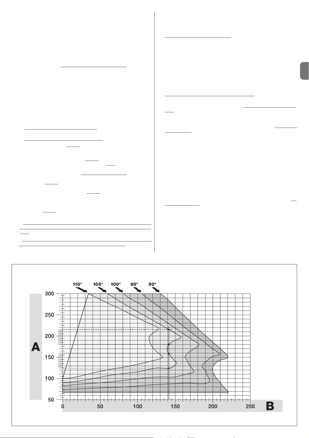
FR
Français – 3
3.4 - Installation de l’opérateur mod. WL1024C - WL1024
RECOMMANDATIONS
• Une installation incorrecte peut causer de graves blessures aux personnes qui effectuent le travail et à celles qui utiliseront le produit.
• Avant de commencer l’assemblage de l’automatisation, effectuer les
contrôles préliminaires décrits aux paragraphes 3.1 et 3.2.
• Le bras de l’opérateur peut être raccourci par rapport à la longueur standard fournie. Une longueur inférieure est nécessaire lorsqu’il y a, contre
l’opérateur, un obstacle fixe (mur, poteau, etc.) qui empêche le mouvement complet du bras. Par conséquent, pour comprendre s’il faut raccourcir ou pas le bras, avant de commencer l’installation
il faut effec-
tuer la procédure 3.4.1.
Assembler les composants qui constituent le bras du moteur, en se référant à
la fig. 3. Durant cette phase ne pas insérer la bague d’arrêt benzing (fig. 4).
IMPORTANT ! - Le bras courbe doit être positionné avec la courbe orientée vers le vantail du portail comme illustré sur la fig. 5.
3.4.1 - Déterminer la longueur du bras de l’opérateur
01. Établir la position de l’opérateur dans le sens VERTICAL :
tracer sur le pi lier une ligne horizontale à la même hauteur que celle où se
trouvera la patte de fixation du bras, après l’installation.
02. Établir la position de l’opérateur dans le sens HORIZONTAL :
a) Établir l’ouverture maximale du vantail
: déterminer l’angle d’ouvertu-
re maximale (maximum 110°).
b) Mesurer la cote B et déterminer la cote A
:
1 - Mesurer sur le pilier la cote B
(fig. 5). C’est la distance entre l’axe de
rotation du vantail et la surface du pilier où sera fixée la patte arrière de
l’opérateur.
2 - Marquer sur le Graphique 2A la cote B à peine trouvée et tracer de -
puis ce point une ligne verticale, jusqu’à croiser la zone qui comprend la va leur de l’angle mesuré au point a.
3 - Aux points d’intersection entre la ligne verticale et la zone, tracer des li gnes horizontales jusqu’à la colonne “A, pour déterminer les valeurs utilisables pour la cote A. Et choisir parmi celles-ci une valeur de A si pos-
sible minimale.
4 - Reporter sur le pilier la valeur de la cote A et tracer à cette hauteur une
li gne verticale (fig. 6).
5 - Si il y a un mur ou un autre obstacle fixe près de la ligne verticale,
mesurer la distance entre cette ligne et l’obstacle (fig. 7) : cette distance est la cote E.
ATTENTION !
• Si la
cote E est une valeur comprise entre 80 mm (minimum) et 299
mm (maximum), continuer l’installation en effectuant la procédure
3.4.3 ci-dessous.
• Si la
cote E est une valeur égale ou supérieure à 300 mm, continuer
l’installation en effectuant la procédure 3.4.2 ci dessous.
5 - Débloquer l’opérateur avec la clé prévue à cet effet (voir chap. 3.8).
3.4.2 - Installation de l’opérateur avec BRAS DE LONGUEUR
STANDARD
Attention ! - Cette installation ne peut être effectuée qu’après avoir com-
plété la procédure 3.4.1.
01. Fixer l’opérateur sur le pilier (fig. 8)
:
a) Poser l’opérateur sur le pilier (*) en faisant coïncider sa ligne médiane ver-
ticale avec la ligne verticale tracée auparavant (cote A) et son bras avec la
ligne horizontale tracée durant la procédure 3.4.1. Durant cette phase,
s’assurer que l’opérateur soit parfaitement à niveau : un opérateur hors axe
peut provoquer des dysfonctionnements à l’automation.
(*) Remarque - Si la surface du pilier a une largeur comprise entre 80 et 135
mm, avant de continuer l’installation il est nécessaire de tourner de 90° la
patte de fixation de l’opérateur. Pour tourner la patte, se référer à la fig. 9.
b) Marquer les points de fixation, percer la surface du pilier et insérer les
chevilles ; puis fixer l’opérateur en utilisant des vis et des rondelles adéquates.
02. Fixer le bras de l’opérateur sur le vantail (fig. 8) :
c) Amener le vantail du portail en position d’ouverture maximale ;
d) Pousser avec force le bras de l'opérateur jusqu'à son extension maxi
male. Attention ! - S'assurer que le bras se bloque dans sa fin de
course ;
e) Approcher le bras au vantail, en posant sur ce dernier la patte de fixation.
f) S’assurer que le bras de l’opérateur soit à niveau et marquer le centre
du
profil des trous de la patte, afin de permettre à l’avenir un réglage précis de
la fermeture du vantail (voir le paragraphe 3.7).
g) En tenant d’une main la patte en contact avec le vantail, essayer d’effectuer une ouverture et une fermeture complète jusqu’aux butées mécaniques respectives. Attention ! - Si durant l’essai le mouvement du
bras est empêché par un mur ou autre objet fixe, interrompre la procédure et effectuer la procédure 3.4.3.
h) Percer le vantail aux points marqués et détacher la patte du bras et la
fixer au vantail du portail avec des vis adéquates.
i) Fixer le bras à la patte, en insérant le pivot et la bague d'arrêt benzing.
Important - Contrôler que la patte et le bras soient parfaitement à niveau.
Si nécessaire, desserrer les vis de la patte et mettre à niveau. Cette vérification peut être aussi effectuée en mesurant la cote de 75 mm (voir fig. 8
phase 2).
l) Fixer au sol les butées de fin de course, de manière stable et définitive, da
-
ns la même position que celle établie au début de la procédure. Attention ! Vérifier que le vantail ferme parfaitement contre la butée de fin de course
(non fournie).
m) Enfin amener manuellement le vantail du portail à environ mi-course et
bloquer l’opérateur avec la clé prévue à cet effet (voir chap. 3.8). Puis, déplacer manuellement le vantail de quelques centimètres, en direction de l’ouverture.
03. Si le portail à automatiser est à deux vantaux, pour installer l’autre opérateur, répéter toutes les opérations décrites dans le chapitre 3.4.
GRAPHIQUE 2A
Page 30
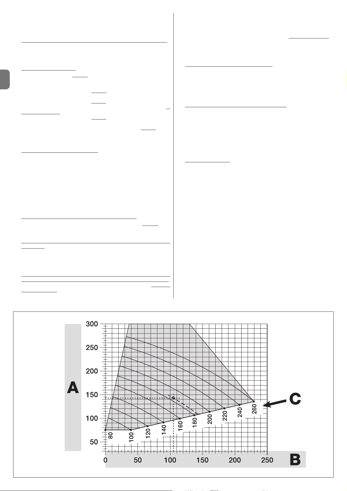
FR
4 – Français
3.4.3 - Installation de l’opérateur avec BRAS DE LONGUEUR
RÉDUITE
Attention ! - Cette installation ne peut être effectuée qu’après avoir com-
plété la procédure 3.4.1.
01. Définir une nouvelle ouverture maximale du vantail (maximum 90°)
:
sans considérer l’ouverture maximale du vantail établie durant la procédure
3.4.1, amener le vantail sur une nouvelle position d’ouverture maximale, en
s’assurant que l’angle ne dépasse pas 90°. Puis, bloquer le vantail dans
cette position avec une butée au sol, fixée de manière provisoire.
02. Définir les cotes A - B - C
:
a) Mesurer sur le pilier la cote B
(fig. 10). C’est la distance entre l’axe de
rotation du vantail et la surface du pilier où sera fixée la patte arrière de
l’opérateur.
b) Marquer sur le Graphique 2B la cote B
à peine trouvée et tracer depuis
ce point une ligne verticale.
c) Sur le pilier, établir la valeur de la cote A
où fixer la patte arrière de l’opé-
rateur (se référer à la fig. 11). Important ! - Choisir une valeur de A si
possible minimale, pour éloigner le moteur de l’obstacle.
d) Marquer sur le Graphique 2B la cote A
à peine trouvée et tracer depuis
ce point une ligne horizontale, jusqu’à croiser la ligne verticale tracée auparavant. Le point de rencontre entre les deux lignes définit la cote C
, c’est-
à-dire la distance qui doit exister entre les deux pivots du bras avec perforations (fig. 12). Exemple présent dans le graphique 2B : si la valeur de B
est 105 mm et A est 143 mm, le point C est 182.
03. Fixer l’opérateur sur le pilier (fig. 13)
:
a) Poser l’opérateur sur le pilier (*) en faisant coïncider sa ligne médiane ver-
ticale avec la ligne verticale tracée auparavant (cote A) et son bras avec la
ligne horizontale tracée durant la procédure 3.4.1. Durant cette phase,
s’assurer que l’opérateur soit parfaitement à niveau : un opérateur hors axe
peut provoquer des dysfonctionnements à l’automation.
(*) Remarque - Si la surface du pilier a une largeur comprise entre 80 et
135 mm, avant de continuer l’installation il est nécessaire de tourner de 90°
la patte de fixation de l’opérateur. Pour tourner la patte, se référer à la fig. 8.
b) Marquer les points de fixation, percer la surface du pilier et insérer les
chevilles ; puis fixer l’opérateur en utilisant des vis et des rondelles adéquates.
04. Réduire la longueur du bras avec perforations (fig. 14)
:
a) Pour réduire la longueur du bras avec perforations à la cote C
(celle
trouvée au point 02-d), dévisser l’écrou, retirer la butée, écarter les pivots
selon la cote C et, enfin, fermer l’écrou de manière provisoire.
05. Contrôler la cote C du bras avec perforations par rapport au contexte
(fig. 15 - 16) :
a) Amener le vantail du portail en position d’ouverture maximale ;
b) Ouvrir complètement le bras de l’opérateur, au maximum de son angle
d’ouverture (voir fig. 15, phase 1);
c) Approcher le bras au vantail, en posant sur ce dernier la patte de fixation :
attention !
- pousser avec les mains le bras courbe contre le vantail,
ju squ’au blocage du bras (ouverture maximale - voir fig. 15, phase 1a).
d) S’assurer que le bras de l’opérateur soit à niveau et marquer le centre
du profil des trous de la patte, afin de permettre à l’avenir un réglage précis
de la fermeture du vantail (voir le paragraphe 3.7).
e) Fixer provisoirement la patte sur le vantail et amener le vantail dans la
position d’ouverture maximale contre la butée au sol.
f) Avec le vantail dans cette position, effectuer le contrôle indiqué sur la fig.
16 (tendre un fil passant au-dessus des deux pivots du bras avec perfora-
tions et arrivant au gond du vantail). Attention ! - Si par rapport au gond
le
fil se trouve en position « BB » de la fig. 16, il faut allonger de quelques millimètres la cote C. Cette opération doit être répétée jusqu’à ce que le fil se
trouve dans la position « AA » de la fig. 16 et jusq’uà ce que le bras ne
heurte plus le mur ou un autre obstacle fixe.
06. Couper le bras avec perforations (fig. 17)
:
Après avoir vérifié le fonctionnement correct de l’articulation, couper le bras
avec perforations de la façon suivante.
a) Tracer une ligne sur le bras avec perforations, dans l’exacte position indiquée à la fig. 17, phase 1. Démonter ensuite le bras par rapport à la patte
et couper la partie superflue du bras.
b) Assembler de nouveau les composants du bras (fig. 3).
07. Fixer le bras de l’opérateur sur le vantail (fig. 18
) :
a) Percer le vantail au niveau des points marqués précédemment.
b) Détacher la patte du bras et la fixer au vantail du portail avec des vis
adéquates.
c) Fixer le bras à la patte, en insérant le pivot et le bague d'arrêt benzing.
Important - Contrôler que la patte et le bras soient parfaitement à niveau.
Si nécessaire, desserrer les vis de la patte et mettre à niveau. Cette vérification peut être aussi effectuée en mesurant la cote de 75 mm (voir fig. 8
phase 2).
d) Fixer au sol les butées de fin de course, de manière stable et définitive,
dans la même position
que celle établie au début de la procédure.
Attention ! - Vérifier que le vantail ferme parfaitement contre la butée de
fin de course. Pour un réglage précis de la fermeture, se référer au paragraphe 3.7.
e) Enfin, amener manuellement le vantail du portail à environ mi-course et
bloquer l’opérateur avec la clé prévue à cet effet (voir chap. 3.8) Puis,
déplacer manuellement le vantail de quelques centimètres, dans le sens de
l’ouverture.
08. Si le portail à automatiser est à deux vantaux, pour installer l’autre opérateur,
répéter toutes les opérations décrites dans le chapitre 3.4.
3.5 - Installation de la lampe multifonctions mod. WLT sur
l’opérateur modèle WL1024C
Recommandation – WLT peut fonctionner comme lumière de signalisation clignotante ou comme lumière de courtoisie, selon la centrale de commande à
laquelle celle-ci est branchée.
Suivre les phases d’installation illustrées à la fig. 21, en respectant la séquence
et les recommandations suivantes :
• pour la phase 4 – Tourner l’alimentateur dans le sens de la flèche, en faisant
attention aux câbles qui le raccordent à l’opérateur.
• pour la phase 7 – Étendre bien les câbles et insérer le connecteur dans la sor tie
FLASH comme indiqué ; bloquer les câbles en les insérant dans le serre-câble.
• pour la phase 11 – Positionner la carte électronique sr le pivot de la base,
selon l’utilisation souhaitée : A = lumière diffuse ; B = lumière à faisceau direc-
GRAPHIQUE 2B
Page 31

FR
Français – 5
Le branchement électrique des différents dispositifs (photocellules, claviers
numériques, lecteurs de cartes à transponder, etc.) présents sur l’automatisation avec la centrale de commande s’effectue moyennant le système “Bluebus”
de Nice. Ce système permet d’effectuer les branchements électriques avec
l’utilisation de seulement 2 connecteurs sur lesquels transite aussi bien l’alimentation électrique que les signaux de communication. Le branchement électrique à utiliser est de type parallèle et ne nécessite pas de respecter les polarités. Durant la phase d’apprentissage, chaque dispositif branché à la centrale
sera reconnu individuellement par celle-ci, grâce à un code univoque. À chaque
fois que sera rajouté ou éliminé un dispositif, il sera nécessaire d’effectuer l’apprentissage de la part de la centrale (voir paragraphe 4.7).
4.1 - Description des branchements électriques (fig. 23)
M1 sortie pour opérateur 1
ELS sortie pour serrure électrique de 12 Vac (maximum 15 VA). La sortie
ELS peut être programmée avec d'autres fonctions (par exemple,
clignotant, lumière de courtoisie, etc) moyennant le programmateur
Oview (voir chapitre 8.3).
BLUEBUS entrée pour dispositifs compatibles (MOFB, MOFOB, MOB, MOTB
etc.). Le branchement des dispositifs est du type parallèle par 2
conducteurs sur lesquels passe aussi bien l'alimentation électrique
que le signal de communication ; en effectuant le branchement, il
n'est pas nécessaire de respecter les polarités. Chaque dispositif est
BRANCHEMENTS ÉLECTRIQUES
4
tionnel (dans ce cas le faisceau lumineux peut être orienté en encastrant la carte dans un des trous prévus sur la base).
• pour la phase 12 – Étendre bien les câbles, couper la partie en plus et positionner les câbles de manière à ce qu’ils ne projettent pas d’ombres sur les leds
et sur le capteur de lumière présent au dos de la carte électronique.
• pour la phase 13 – Faire coïncider entre elles la flèche présente sur le cou-
vercle et celle présente sur la base. S’assurer que les 4 dents présentes sur la
base s’encastrent dans les rainures internes du couvercle.
Remarque – Si la lampe multifonctions WLT n'est pas installée dans la partie
supérieure de l'opérateur “Walky”, elle doit être branchée à la borne ELS comme décrit au paragraphe 4.1- “Description des branchements électriques”.
3.6 - Comment extraire la centrale de commande
01. Retirer le couvercle inférieur de l’opérateur (fig. 19, phase 1-2) ;
02. Dévisser les 4 vis du support passe-câble et le retirer (fig. 24, phase 1-2) ;
03. Tirer la centrale dans le sens de la flèche sur environ 4 centimètres et débran-
cher le connecteur du moteur (fig. 24, phase 3-4) ;
04. Enfin, extraire complètement la centrale.
Attention ! - Lorsque le moteur est de nouveau branché à la centrale, respec-
ter la polarité du connecteur (celui-ci ne peut être inséré que dans un sens !).
3.7 - Réglage de l’alignement des vantaux en fermeture
01. Retirer le bras avec perforations de la patte de fixation sur le vantail ;
02. Desserrer les vis de la patte et déplacer celle-ci de quelques millimètres, en
direction de l’opérateur ;
03. Remettre le bras avec perforations dans la patte, fermer le vantail et s’assurer que celui-ci soit aligné avec l’autre vantail et en contact avec la butée
de fin de course. Attention ! - Si nécessaire, répéter le point 02 jusqu’à
obtenir un alignement optimal ;
04. Percer le vantail, à hauteur du trou présent au centre de la patte de fixation
et mettre une vis. Puis bloquer définitivement la patte en serrant les trois vis ;
05. Enfin, fixer le bras avec perforations à la patte, en insérant le pivot et la
bague d’arrêt benzing.
3.8 - Débloquer et bloquer manuellement l’opérateur
L’opérateur est muni d’un système de déblocage mécanique qui permet d’ouvrir et de fermer manuellement le portail.
Ces opérations manuelles doivent être effectuées en cas de coupure de courant
électrique ou d’anomalies de fonctionnement ou durant les phases d’installation.
Débloquer (fig. 22-A) :
01. Soulever le volet ;
02. Insérer la clé dans le pivot de déblocage prévu à cet effet ;
03. Tourner la clé dans le sens des aiguilles dune montre, en effectuant un tour
complet.
04. Il est maintenant possible de déplacer le vantail du portail dans la position
souhaitée.
Bloquer (fig. 22-B) :
01. Tourner dans le sens contraire des aiguilles d’une montre la clé présente sur
le pivot de déblocage et déplacer manuellement le vantail jusqu’à entendre
le bruit mécanique d’accrochage du vantail au mécanisme de traction.
02. Retirer la clé du pivot et remettre en position le volet.
reconnu individuellement par la Centrale grâce à une adresse univoque qui est assignée pendant l’installation (voir paragraphe 4.7)
STOP entrée pour des dispositifs qui avec leur intervention provoquent
l’arrêt immédiat de la manœuvre en cours, suivi d’une brève inversion ; possibilité de brancher des contacts de type NO, NF ou des
dispositifs avec sortie à résistance constante 8,2 kΩ (bords sensibles). Chaque dispositif branché à cette entrée est reconnu individuellement par la centrale durant la phase d’apprentissage (paragraphe 4.7) ; après cette phase, si la centrale relève une variation
quelconque par rapport à l’état appris, cela provoque un ARRÊT. Il
est possible de brancher à cette entrée un ou plusieurs dispositifs
différents entre eux :
– brancher en parallèle plusieurs dispositifs NO, sans limites de
quantité ;
– brancher en série plusieurs dispositifs NC, sans limites de quantité ;
– brancher en parallèle 2 dispositifs avec sortie à résistance con stante 8,2 kΩ. Si les dispositifs sont plus de 2, il est nécessaire de les
raccorder en cascade avec 1 seule résistance terminale de 8,2 kΩ ;
– brancher en parallèle 2 dispositifs NO et NF, en mettant en série
au contact NF une résistance de 8,2 kΩ (ceci rend également possible la combinaison entre 3 dispositifs NO - NF et 8,2 kΩ)
P. P. entrée pour dispositifs de commande qui intervenant provoquent la
manœuvre avec modalité Pas à Pas ; possibilité de brancher les
contacts de type NO
ANTENNE entrée pour l’antenne d’un récepteur radio
4.2 - Branchement du câble d’alimentation
RECOMMANDATION: sur la ligne électrique d’alimentation, il est nécessaire
de prévoir un dispositif assurant la déconnexion complète de l’automatisation
du réseau. Le dispositif de déconnexion doit avoir les contacts avec une distance d’ouverture permettant la déconnexion complète, dans les conditions
prévues par la catégorie de surtension III et conformément aux règles d’installation. Si nécessaire, ce dispositif garantit une déconnexion rapide et sûre de
l’alimentation ; il doit par conséquent être positionné en vue de l’automatisation. Si par contre il est placé dans une position non visible, il doit avoir un système qui bloque une éventuelle reconnexion accidentelle ou non autorisée de
l’alimentation, afin d’éviter tout danger. Le dispositif de déconnexion n’est pas
fourni avec le produit.
ATTENTION !
– Les opérations de branchements doivent exclusivement être confiées à
un personnel qualifié.
– Tous les branchements électriques doivent être effectués après avoir
coupé l’alimentation électrique de réseau et avec la batterie tampon dé branchée, si présente sur l’automatisation.
01. Accéder à l’alimentateur : dévisser les 3 vis présentes sur le couvercle su périeur de l’opérateur et tourner lentement le couvercle dans la direction de
la flèche (fig. 24),en faisant attention aux câbles sous-jacents.
02. Brancher les câbles de phase et neutre au bornier de l’alimentateur, en respectant les indications présentes sur l’étiquette ; bloquer l’œillet du câble
de terre avec la vis (fig. 25): attention! - orienter la cosse de câble vers
l’embouchure d’ou sort le câble d’alimentation;
03. Tirer sur le câble d’alimentation vers la centrale, de manière à ce que sa
longueur soit à peine suffisante pour faire tourner l’alimentateur et refermer
le couvercle ;
04. Refermer le couvercle de l’alimentateur ; serrer les vis du serre-câble ; insérer la centrale de commande dans son logement ; remonter le support passe-câble.
Attention ! - Fermer le couvercle de l’alimentateur avec toutes les vis
et s’assurer que le joint soit bien positionné dans son logement. L’absence d’une vis ou du joint peut compromettre les circuits internes.
4.3 - Branchement de l’opérateur sans centrale mod. WL1024
01. Retirer le couvercle inférieur de l’opérateur sans centrale comme montré à
la fig. 19, phase 1-2) ;
02. Dévisser à l’aide d’un tournevis à étoile les 4 vis du support passe-câble
(fig. 20) et le retirer (attention ! - ne pas perdre les 2 entretoises).
03. Desserrer les deux vis du serre- câble (fig. 20, phase 6) et passer le câble
de branchement ; brancher les 3 câbles au bornier en respectant les symboles présents sur l'étiquette ; enfin, serrer les vis du serre-câble.
04. À l’aide d’une clé à six pans, régler les 2 pieds à l’intérieur de l’opérateur,
jusqu’à les faire poser complètement sur le pilier (fig. 20, phase 7).
05. Insérer dans les trous du support passe-câble (fig. 20, phase 8) ; remettre
en position les 2 entretoises ; remonter le support passe-câbles (fig. 20,
phase 9) et remettre le couvercle inférieur de l'opérateur (fig. 20, phase 10).
4.4 - Branchement d’autres dispositifs
Au cas où il faudrait alimenter d’autres dispositifs prévus sur l’installation, par
exemple un lecteur de cartes à transponder ou l’éclairage pour le sélecteur à
clé, il est possible de brancher ces dispositifs à la centrale de commande sur
les bornes “P.P. (positif)” et “STOP (négatif)” (fig. 23). La tension d’alimentation
va de 18 à 31 Vdc avec fonctionnement avec tension de réseau ou solemyo et
de environ 11 à 14 Vdc avec fonctionnement avec batterie tampon PS424. Le
courant maximal disponible est de 200 mA.
Note – La tension disponible sur les bornes “P.P.” et “STOP” reste présente
même l’orsquest activée la fonction “Stand By” sur la carte.
Page 32

FR
6 – Français
4.5 - Adressage des photocellules et d’autres dispositifs
BlueBus
Afin de permettre à la centrale de reconnaître les photocellules branchées au
bornier Bluebus, il est nécessaire d’effectuer leur adressage : positionner correctement la connexion volante électrique présente sur chaque dispositif, comme montré à la fig. 31.
Pour effectuer l'adressage d'autres dispositifs, consulter les manuels d'instructions relatifs.
4.6 - Premier allumage et contrôle des branchements
Après avoir transmis l’alimentation électrique à la centrale, effectuer les con trôles suivants :
• une fois écoulées quelques secondes, contrôler que la Led “Bluebus” (fig. 26)
clignote régulièrement avec une fréquence d’un clignotement par seconde ;
• contrôler que les Leds des photocellules, soit TX soit RX, clignotent. Le type
de clignotement émis, durant cette phase, n’est pas significatif ;
• contrôler que la lampe multifonctions WLT (configurée avec fonction cligno-
tante) branchée à la sortie FLASH présente sur l’alimentateur soit éteinte.
En cas contraire, couper l’alimentation électrique de la centrale et contrôler les
différents branchements précédemment effectués.
4.7 - Apprentissage des dispositifs branchés
Après avoir effectué le premier allumage, faire reconnaître à la centrale les dispositifs branchés aux entrées “Bluebus” et “Stop”.
ATTENTION ! – La phase d’apprentissage doit être effectuée même si la
centrale n’est branchée à aucun dispositif.
La centrale est en mesure de reconnaître individuellement les différents dispositifs branchés grâce à la procédure d’apprentissage et même de relever très précisément les possibles anomalies présentes. Pour cela, effectuer l’apprentissage des dispositifs toutes les fois qu’un de ceux-ci est branché ou est retiré.
Les Leds “L1” et “L2” présentes sur la centrale (fig. 26) clignotent lentement
pour indiquer qu’il faut effectuer l'apprentissage :
01. Appuyer et maintenir enfoncées simultanément les touches “” et “Set”
(fig. 26).
02. Relâcher les touches lorsque les leds “L1” et “L2” commencent à clignoter
rapidement (après environ 3 secondes).
03. Attendre quelques secondes pour que la centrale complète la phase d’ap-
prentissage des dispositifs.
04. À la fin de cette phase la Led “Stop” doit être allumée et les Leds “L1” et
“L2” doivent s’éteindre (les Leds “L3” et “L4” pourraient commencer à clignoter).
4.8 - Apprentissage des positions des arrêts mécaniques
Après l’apprentissage des dispositifs (paragraphe 4.7), effectuer l’apprentissage de la part de la centrale des positions des arrêts mécaniques (Ouverture
maximale et Fermeture maximale) ;
Durant cette phase est relevé l’angle d’ouverture des vantaux de l’arrêt mécanique de fermeture jusqu’à l’arrêt mécanique d’ouverture. La présence d'ar-
rêts mécaniques fixes et suffisamment robustes est indispensable.
01. Repérer dans le Tableau 2 la figure qui correspond à votre installation,
configurer sur la centrale les connexions volantes électriques, JA et JB,
dans la même position que celle prévue par la figure.
02. Débloquer les opérateurs avec les clés prévues à cet effet (voir chapitre
3.8) et amener les vantaux à mi-course de manière à ce qu’ils soient libres
de bouger en ouverture et en fermeture ; bloquer ensuite les opérateurs.
03. Sur la centrale, appuyer et maintenir enfoncées simultanément les touches
“Set” et “”;
04. Lorsque les leds “L3” et “L4” commencent à clignoter rapidement (après
environ 3 sec.), relâcher les touches ;
05. Contrôler que l’automatisme effectue les séquences de manœuvres sui-
vantes :
a - Fermeture lente de l’opérateur M1 jusqu’à l’arrêt mécanique
b - Fermeture lente de l’opérateur M2 jusqu’à l’arrêt mécanique
c - Fermeture lente de l’opérateur M2 et de l’opérateur M1 jusqu’à l’arrêt
mécanique
d - Fermeture rapide complète des opérateurs M1 et M2
• Si la première manœuvre d’un ou des deux vantaux n’est pas une fermeture, appuyer sur une touche quelconque pour arrêter la phase d’apprentissage et contrôler la position des connexions volantes électriques JA et
JB en se référant au Tableau 2 ; ou contrôler les polarités du moteur sans
centrale (mod. WL1024).
• Si le premier moteur à déplacer en fermeture n’est pas M1, appuyer sur
une touche quelconque pour arrêter la phase d’apprentissage et contrôler
la position des connexions volantes électriques JA et JB, en se référant au
Tableau 2.
• Si durant la phase d’apprentissage il y a intervention d’un dispositif (photocellules, sélecteur à clé, pression des touches, etc.), la phase d’apprentissage sera immédiatement arrêtée. Il faudra donc la répéter du début jusqu’à la fin.
06. À la fin de la manœuvre de fermeture des 2 moteurs (d), les leds “L3” et “L4”
s’éteignent pour indiquer que la procédure a été effectuée correctement.
4.9 - Contrôle du mouvement des vantaux du portail
À la fin de la phase d’apprentissage et des positions des arrêts mécaniques, il
est conseillé de faire effectuer à la centrale certaines manœuvres d’ouverture et
fermeture, de manière à vérifier le correct mouvement du portail, les éventuels
défauts de montage et de réglage ou d’autres anomalies :
01. Appuyer sur la touche Open (fig. 26) et contrôler que durant la manœuvre
d’Ouverture soit présente la phase d’accélération, la phase à vitesse
constante, la phase de ralentissement et que les vantaux se ferment
contre la fin de course mécanique d’ouverture.
02. Appuyer sur la touche Close (fig. 26) et contrôler que durant la manœuvre
de Fermeture soit présente la phase d’accélération, la phase à vitesse
constante, la phase de ralentissement et que les vantaux se ferment
contre la fin de course mécanique de fermeture.
03. Contrôler, durant les manœuvres, que le clignotant effectue quelques clignotements avec un intervalle de 0,5 seconde avec clignotant allumé et de
0,5 secondes avec clignotant éteint.
Celles-ci sont les phases les plus importantes de la réalisation de l’automatisation, afin de garantir la sécurité maximale de l’installation. L’essai peut également être utilisé pour vérifier périodiquement les dispositifs qui composent l’automatisation. Les phases d’essai et de mise en service de l’automatisation doivent être effectuées par un personnel qualifié et expert qui devra établir les
essais nécessaires pour vérifier les solutions adoptées par rapport aux risques
présents et contrôler le respect de ce qui est prévu par les lois, normes et
règlements : en particulier, de toutes les caractéristiques requises par la norme
EN 12445 qui établit les méthodes d’essai pour le contrôle des automatismes
pour portails.
Les dispositifs supplémentaires doivent être soumis à un essai spécifique, aussi bien pour ce qui concerne la fonctionnalité que pour ce qui concerne leur
correcte interaction avec WALKY. ; se référer aux manuels d’instructions de
chaque dispositif.
ESSAI ET MISE EN SERVICE
5
Vantail qui surmonte
Vantail qui surmonte
Vantail qui surmonte
Vantail qui surmonte
Centrale
Centrale
Centrale
Centrale
Centrale
Centrale
Centrale
Centrale
TABLEAU 2
Page 33

FR
Français – 7
5.1 - Essai
La séquence d’opérations à effectuer pour l’essai se réfère à une installation
typique (fig. 2) :
1 Débloquer manuellement les opérateurs et contrôler que en agissant sur le
van tail, au point prévu pour la manœuvre manuelle, il soit possible de dé placer les vantaux en ouverture et en fermeture avec une force inférieure à 390 N.
2 Contrôler que le vantail, laissé à l’arrêt dans une position de sa course, ne
se déplace.
3 Bloquer les opérateurs (voir chapitre 3.8).
4 ATTENTION ! – Contrôler que les branchements à vis soient bien vissés.
5 En utilisant les dispositifs de commande (émetteur, bouton de commande,
sélecteur à clé, etc.), effectuer des essais d’Ouverture, Fermeture et Arrêt
du portail, en veillant à ce que le mouvement des vantaux corresponde à
ce qui est prévu. Il convient d’effectuer différents essais afin d’évaluer le
mouvement des vantaux et de contrôler d’éventuels défauts de montage,
de réglage ou la présence de points de frottement particuliers.
6 Contrôler un à un le correct fonctionnement de tous les dispositifs de sécu-
rité présents sur l’installation (photocellules, bords sensibles, etc.).
Lorsqu’un dispositif intervient, la led “BLUEBUS”, présente sur la centrale,
émet 2 clignotements plus rapides pour confirmer la reconnaissance.
7 Si les situations dangereuses provoquées par le mouvement des vantaux
ont été prévenues moyennant la limitation de la force d’impact, mesurer la
force selon ce qui est prévu par la norme EN 12445 et éventuellement si le
contrôle de la “force opérateur” est utilisé comme aide au système pour la
réduction de la force d’impact, essayer et enfin trouver le réglage fournissant les meilleurs résultats.
8 Fixer de manière permanente, dans une zone adjacente de l’automatisation,
une étiquette qui décrit comment débloquer manuellement l’opérateur.
5.2 - Mise en service
La mise en service ne peut avoir lieu qu’après avoir effectué de manière
positive toutes les phases d’essai.
1 Préparer le dossier technique de l’automatisation, celui-ci devra com-
prendre les documents suivants : un dessin général de l’automatisation, le
schéma des branchements électriques effectués, l’analyse des risques présents et les relatives solutions adoptées, la déclaration de conformité du
fabricant de tous les dispositifs utilisés et la déclaration de conformité remplie par l’installateur.
2 Accrocher sur le portail une plaquette contenant au moins les données sui-
vantes : type d’automatisation, nom et adresse du fabricant (responsable
de la “mise en service”), numéro de fabrication, année de fabrication et
marque “CE”.
3 Remplir et fournir au propriétaire de l’automatisation la déclaration de
conformité de l’automatisation.
4 Remplir et fournir au propriétaire de l’automatisation le “Manuel d’utilisa-
tion” de l’automatisation.
5 Remplir et fournir au propriétaire de l’automatisation le “Plan de mainte-
nance” qui comprend les prescriptions concernant la maintenance de tous
les dispositifs de l’automatisation.
6 Avant de mettre en service l’automatisation, informer de manière adéquate
le propriétaire sur les dangers et les risques résiduels encore présents.
Pour toute la documentation citée, Nice à travers son propre service d’as-
sistance technique met à disposition : manuels d’instructions, guides et fi ches pré-remplies. Voir aussi sur : www.nice-service.com
TABLEAU 5 - Fonctions de premier niveau
LED Fonction Description
L1 Fermeture automatique
L2 Refermer après photo
L3 Fermer toujours
L4 Stand by (Bluebus)
Fonction ACTIVE : après une manœuvre d’ouverture, une pause est effectuée (égale au Temps de pause programmée). Après celle-ci, la centrale effectue automatiquement une manœuvre de fermeture. La valeur du Temps de pause configurée en usine est égale à 30 sec.
Fonction
NON ACTIVE : le fonctionnement est de type “semi-automatique”.
Fonction
ACTIVE : si durant la manœuvre d’ouverture ou de fermeture interviennent les photocellules, le temps de pause se réduit à 5 sec. indé-
pendamment du “temps de pause” programmé.
Avec la “fermeture automatique” désactivée, si durant la Fermeture interviennent les photocellules, la “fermeture automatique” avec le “temps de
pause” programmé s’active.
Fonction
ACTIVE : en cas de panne d’électricité, même si brève, lors du rétablissement du courant électrique, la centrale relève le portail ouvert
et automatiquement effectue une manœuvre de Fermeture, précédée de 5 sec. de pré-clignotement.
Fonction
NON ACTIVE : lorsque le courant électrique revient, le portail reste là où il est.
Fonction
ACTIVE : 1 minute après la fin de la manœuvre, la centrale éteint la sortie “Bluebus” (dispositifs branchés) et toutes les leds, sauf la led
Bluebus qui clignotera plus lentement. Lorsque la centrale reçoit une commande, celle-ci rétablit le fonctionnement normal (avec un bref retard).
Cette fonction a pour but de réduire les consommations ; aspect important avec alimentation à batteries ou panneaux photovoltaïques.
Sur la centrale sont présentes 3 touches OPEN (), STOP (SET), CLOSE ()
qui peuvent être utilisées aussi bien pour commander la centrale durant les
phases d’essai que pour la programmation des fonctions disponibles.
Les fonctions programmables disponibles sont disposées sur 2 niveaux et leur
état de fonctionnement est signalé par les 4 leds (L1 ... L4) présentes sur la
centrale (led allumée = fonction active ; led éteinte = fonction non active).
Utiliser les touches de programmation (fig. 26) :
OPEN () : – touche pour commander l’Ouverture du portail ; – touche de
sélection en phase de programmation.
STOP/SET : touche pour confirmer une manœuvre ; si enfoncée pendant plus
de 5 secondes, elle permet d’entrer en phase de programmation.
CLOSE () : – touche pour commander la Fermeture du portail ; – touche de
sélection en phase de programmation.
6.1 - Programmation premier niveau (ON-OFF)
Toutes les fonctions du premier niveau sont programmées en usine sur “OFF”
et peuvent être modifiées à tout moment. Pour contrôler les différentes fonctions voir Tableau 5. Pour la procédure de programmation voir Tableau 6.
Note – Ces procédures peuvent être de nouveau effectuées à tout moment,
même après avoir branché un nouveau dispositif à la centrale.
IMPORTANT – La procédure de programmation présente un temps maximal
de 10 secondes entre chaque pression de touche. Une fois ce temps écoulé, la
procédure s’arrête automatiquement en mémorisant les modifications faites
jusqu’à ce moment.
PROGRAMMATION DE LA CENTRALE
DE COMMANDE
6
TABLEAU 6 - Procédure de programmation premier niveau
01. Appuyer et maintenir enfoncée la touche “Set” pendant environ 3 secondes ;
02. Relâcher la touche lorsque la led “L1” commence à clignoter ;
03. Appuyer sur la touche “” ou “” pour passer de la led clignotante à la led qui représente la fonction à modifier ;
04. Appuyer sur la touche “Set” pour changer l’état de la fonction :
(clignotement bref = OFF - clignotement long = ON) ;
05. Attendre 10 secondes (temps maximal) pour sortie de la programmation.
Note – Pour programmer d’autres fonctions sur “ON” ou “OFF”, durant l’exécution de la procédure, répéter les points 03 et 04 durant la phase.
L1
ou
3 s
10 s
Page 34

FR
8 – Français
TABLEAU 7 - Procédure de programmation deuxième niveau
01. Appuyer et maintenir enfoncée la touche “Set” pendant environ 3 secondes ;
02. Relâcher la touche lorsque la led “L1” commence à clignoter ;
03. Appuyer sur la touche “” ou “” pour passer de la led clignotante à la led qui représente la “led d’entrée” du paramètre
à modifier ;
04. Appuyer et maintenir enfoncée la touche “Set” jusqu’à la conclusion du point 06 ;
05. Attendre environ 3 secondes, jusqu’à ce que s’allume la led qui représente le niveau actuel du paramètre à modifier ;
06. Appuyer sur la touche “” ou “” pour changer la led qui représente la valeur du paramètre ;
07. Relâcher la touche “Set” ;
08. Attendre 10 secondes (temps maximal) pour sortie de la programmation.
Note – Pour programmer plusieurs paramètres, durant l’exécution de la procédure, répéter les opérations du point 03 au point 07 durant la phase.
L1
ou
ou
3 s
10 s
6.3 - Effacement de la mémoire
Pour effacer la mémoire de la centrale et rétablir toutes les configurations faites
en usine, procéder de la manière suivante : appuyer et maintenir enfoncées les
touches “” et “” jusqu’à ce que les leds L1 et L2 commencent à clignoter.
6.4 - Fonctions spéciales
Fonction : “Déplacer quand même”
Cette fonction permet de faire fonctionner l’automatisation même lorsque le
dispositif de sécurité ne fonctionne pas correctement ou est hors service.
Il est possible de commander l’automatisation en modalité “homme présent”,
en procédant de la manière suivante :
01. Envoyer une commande pour actionner le portail, avec un émetteur ou un
sélecteur à clé, etc. Si tout fonctionne correctement, le portail se déplacera régulièrement, sinon procéder comme suit :
02. Dans les 3 secondes, actionner de nouveau la commande et la maintenir
actionnée ;
03. Après environ 2 secondes, le portail effectuera la manœuvre requise en
modalité “homme présent” ; le portail ne continuera donc à se déplacer
que lorsque la commande est maintenue actionnée.
Lorsque les dispositifs de sécurité ne fonctionnent pas, le clignotant émet
quelques clignotements pour signaler le type de problème (voir chapitre 7 Tableau 10).
TABLEAU 8 - Fonctions de deuxième niveau
Led de Paramètre Led Valeur Description
entrée (niveau)
L1
L1
L2
L3
L4
5 secondes
30 secondes
60 secondes
120 secondes
Règle le temps de pause avant la refermeture automatique. N’a effet que
si la Fermeture est active.
Temps
Pause
L2 L1
L2
L3
L4
Ouverture – stop – fermeture – stop
Ouverture – stop – fermeture – ouverture
Ouverture – fermeture – ouverture – fermeture
Habitation collective :
• lors de la manœuvre douverture
la commande “Pas à Pas” et “Ouverture”
ne provoquent aucun effet ; par contre, la commande “Fermeture” provoque
l’inversion du mouvement, c’est-à-dire la fermeture des vantaux.
• lors de la manœuvre de fermeture la commande “Pas à Pas” et “Ouverture”
provoquent l’inversion du mouvement, c’est-à-dire l’ouverture des vantaux ;
par contre, la commande “Fermeture” ne provoque aucun effet.
Règle la séquence des commandes
associées à l’entrée “Pas à Pas” ou à
la commande radio.
Note – En configurant L4, le comportement des commandes “Ouverture”
et “Fermeture” est également modifié.
Fonction
Pas à Pas
L3 L1
L2
L3
L4
Lente
Moyenne
Rapide
Très rapide
Règle la vitesse des moteurs durant la
course normale.
Vitesse
des
moteurs
L4 L1
L2
L3
L4
Niveau 1 - Force minimale
Niveau 2 - ...
Niveau 3 - ...
Niveau 4 - Force maximale
Règle la force des deux moteurs.
Force
moteurs
6.2 - Programmation deuxième niveau (paramètres réglables)
Tous les paramètres du deuxième niveau sont programmés en usine et mis en
évidence en gris dans le Tableau 8 et peuvent être modifiés à tout moment, en
procédant comme décrit dans le Tableau 7.
Les paramètres sont réglables sur une échelle de valeurs de 1 à 4 ; pour con -
trô ler la valeur correspondant à chaque Led voir Tableau 8. IMPORTANT – La
procédure de programmation présente un temps maximal de 10 secondes
entre chaque pression de touche. Une fois ce temps écoulé, la procédure s’arrête automatiquement en mémorisant les modifications faites jusqu’à ce
moment.
Page 35

FR
Français – 9
Certains dispositifs sont prédéfinis pour émettre des signalisations grâce auxquelles il est possible de reconnaître l’état de fonctionnement ou les éventuelles
anomalies. Si à la sortie FLASH présente sur l’alimentateur est branchée la lampe
multifonctions WLT, configurée avec fonction clignotante, celle-ci durant l’exécution d’une manœuvre clignote avec un intervalle d’1 seconde. Si se vérifient
des anomalies, le clignotant émet des clignotements plus brefs ; ceux-ci sont ré-
pétés deux fois avec une pause d1 seconde. Dans le Tableau 10 sont décrites
la cause et la solution pour chaque type de signalisation.
Les Leds présentes sur la centrale émettent également des signalisations ; dans
le Tableau 11 sont décrites la cause et la solution pour chaque type de signali-
sation.
QUE FAIRE SI... (guide de résolution des problèmes)
7
7 clignotements brefs
pause de 1 seconde
7 clignotements brefs
Anomalie sur les circuits électriques Attendre au moins 30 secondes, réessayer de transmettre une commande et éventuel-
lement éteindre aussi l’alimentation ; si l’état reste, il pourrait y avoir une panne grave et
il faut remplacer la carte électronique.
8 clignotements brefs
pause de 1 seconde
8 clignotements brefs
Une commande qui ne permet pas
d’e f fectuer d’autres commandes est
dé jà présente
Contrôler la nature de la commande toujours présente ; par exemple il pourrait s’agir de
la commande d'une horloge sur l’entrée de “PAS À PAS.
9 clignotements brefs
pause de 1 seconde
9 clignotements brefs
L’automatisation a été bloquée par
une commande "Bloquer l’automatisation".
Débloquer l’automatisation en envoyant la commande “Débloquer l’automatisation”.
TABLEAU 10 - Signalisations du clignotant (FLASH)
Clignotements Problème Résolution
1 clignotement bref
pause de 1 seconde
1 clignotement bref
Erreur sur le système Bluebus Le contrôle des dispositifs branchés au système Bluebus, qui est effectué au début de la
manœuvre, ne correspond pas aux dispositifs mémorisés durant la phase d’apprentissage. Il est possible que certains dispositifs soient débranchés ou en panne, il faut donc
contrôler et remplacer. Si des modifications ont été apportées, refaire l’apprentissage des
dispositifs (voir paragraphe 4.7).
2 clignotements brefs
pause de 1 seconde
2 clignotements brefs
Intervention d’une photocellule Une ou plusieurs photocellules ne permettent pas le mouvement ou durant la course ont
provoqué une inversion du mouvement ; contrôler si sont présents des obstacles.
3 clignotements brefs
pause de 1 seconde
3 clignotements brefs
Intervention de la fonction “Détection
d’Obstacles” depuis limitateur de force
Durant le mouvement les moteurs ont dû faire un effort supérieur ; vérifier la cause et
éventuellement augmenter le niveau de force des moteurs
4 clignotements brefs
pause de 1 seconde
4 clignotements brefs
Intervention de l’entrée de STOP Au début de la manœuvre ou durant le mouvement, il y a intervention des dispositifs
branchés à l’entrée STOP ; en vérifier la cause.
5 clignotements brefs
pause de 1 seconde
5 clignotements brefs
Erreur au niveau des paramètres
internes de la centrale de commande
Attendre au moins 30 secondes, réessayer de transmettre une commande et éventuellement éteindre aussi l’alimentation ; si l’état reste, il pourrait y avoir une panne grave et
il faut remplacer la carte électronique.
6 clignotements brefs
pause de 1 seconde
6 clignotements brefs
La limite maximale de manœuvres
con sécutives ou de manœuvres par
heure a été dépassée
Attendre quelques minutes de manière à ce que le limitateur de manœuvres retourne
sous la limite maximale.
TABLEAU 11 - Signalisations des Leds présentes sur la centrale de commande (fig. 23)
Led Problème Résolution
BLUEBUS
Toujours éteint
Toujours allumé
1 clignotement par seconde
2 clignotements rapides
Série de clignotements divisés
par une pause de 1 seconde
Anomalie
Anomalie grave
Tout est normal
Variation de l’état des entrées
Divers
Contrôler si la centrale est alimentée ; contrôler si les fusibles ne sont
pas intervenus. Dans ce cas contrôler la cause de la panne et les remplacer avec d’autres de la même valeur
Est présent un problème grave : essayer de débrancher la centrale et si
l’état persiste, remplacer la carte électronique
Fonctionnement régulier de la centrale
Il est régulier si a lieu une variation sur une des entrées (PP, STOP) : inter-
vention des photocellules ou bien est transmise une commande avec un
émetteur
Se référer au Tableau 10
STOP
Toujours éteint
Toujours allumé
Intervention des dispositifs branchés à l’entrée STOP
Tout est normal
Contrôler les dispositifs de l’entrée STOP
Entrée STOP active
P. P.
Toujours éteint
Toujours allumé
Tout est normal
Intervention de l’entrée P.P.
Entrée P.P. non active
Il est régulier si est actif le dispositif branché à l’entrée P.P.
L1 - L2 Clignotement lent Variation du nombre de dispositifs
branchés au Bluebus ou apprentissage du
dispositif non effectué
Il est nécessaire d’effectuer l’apprentissage des dispositifs
(voir paragraphe 4.7)
L3 - L4 Clignotement lent L’apprentissage des positions des arrêts
mécaniques n’a jamais été effectué.
Il est nécessaire d’effectuer l’apprentissage (voir paragraphe 4.8).
Page 36

FR
10 – Français
Pour WALKY sont prévus les accessoires suivants (récepteur radio) : le programmateur Oview, le système à énergie solaire Solemyo et la batterie tampon
mod. PS424.
8.1 - Branchement du récepteur radio OXI
Pour brancher le récepteur OXI, couper l’alimentation électrique de la centrale
et procéder comme illustré à la fig. 27. Dans les Tableaux 12 et 13 sont repor-
tées les commandes qui correspondent aux sorties présentes sur la centrale.
8.2 - Branchement et installation de la batterie tampon
mod. PS424
ATTENTION ! - Le branchement électrique de la batterie à la centrale ne
doit être effectué qu’après avoir conclu toutes les phases d’installation
et de programmation, car la batterie représente une alimentation électrique d’urgence.
Pour installer et brancher la batterie, suivre les phases de montage illustrées à
la fig. 28.
8.3 - Branchement du programmateur Oview
Sur la centrale est présent le connecteur BusT4 auquel il est possible de brancher l’unité de programmation Oview, qui permet une gestion complète et rapide de la phase d’installation, de maintenance et de diagnostic de toute l’automatisation. Pour accéder au connecteur, il est nécessaire de procéder comme
illustré à la fig. 29 et de brancher le connecteur dans le logement prévu à cet
effet. L’Oview peut être branché à plusieurs Centrales simultanément (jusqu’à 5
sans précautions particulières, jusqu’à 60 en suivant les recommandations) et
peut rester branché à la centrale durant le fonctionnement normal de l’automatisation. Dans ce cas, il peut être utilisé pour envoyer directement les commandes à la centrale en utilisant le menu “utilisateur” spécifique. Il est également possible d’effectuer la mise à jour du Firmware. Si sur la centrale est pré-
sent un récepteur radio appartenant à la famille OXI, en utilisant l’Oview il est
possible d’avoir accès aux paramètres des émetteurs mémorisés dans le
récepteur.
Pour tous les approfondissements, consulter le respectif manuel d’instructions
et le manuel du système “Opera system book”.
8.4 - Branchement du système à énergie solaire Solemyo
ATTENTION ! – Lorsque l’automatisation est alimentée par le système
“Solemyo”, elle NE DOIT ÊTRE ALIMENTÉE simultanément par le réseau
électrique.
Pour toute autre information concernant le système Solemyo, se référer au
manuel d’instructions.
Pour préparer le branchement du système Solemyo, suivre les phases de montage illustrées à la fig. 30.
Pour compléter le branchement entre Solemyo et la centrale de l’opérateur, utiliser le câble adaptateur prévu à cet effet.
APPROFONDISSEMENTS
8
1 Pas à pas
2 Ouverture Partielle 1
3 Ouverture
4 Fermeture
5 Stop
6 Pas à Pas
Habitation collective
7 Pas à Pas
haute priorité
8 Ouverture partielle 2
9 Ouverture partielle 3
10 Ouverture et
Blocage
automatisation
11 Fermeture et
Blocage
automatisation
12 Blocage
automatisation
13 Déblocage
automatisation
14 On Timer Lumière
de Courtoisie
15 On-Off Lumière
de Courtoisie
Tableau 13
OXI / OXIFM /OXIT / OXITFM en mode II étendu
N° Commande Description
Commande “P.P.” (Pas à Pas)
Commande “Ouverture partielle 1”
Commande “Ouverture”
Commande “Fermeture”
Arrêt de la manœuvre
Commande en modalité Habitation collective
Commande aussi avec automatisation bloquée ou commandes actives
Ouverture partielle (ouverture du vantail M2, égale à la moitié de l’ouverture totale)
Ouverture partielle (ouverture des deux vantaux, égale à la
moitié de l’ouverture totale)
Provoque une manœuvre d’ouverture et à la fin de celle-ci
le blocage de l’automatisation ; la centrale n’accepte au cune autre commande sauf celle de “Pas à pas haute priorité”, “Déblocage” automatisation ou (uniquement de puis
Ovi ew) les commandes : “Déblocage et fermeture” et “Dé blo cage et ouverture”.
Provoque une manœuvre de fermeture et à la fin de celleci le blocage de l’automatisation ; la centrale n’accepte
aucune autre commande sauf celle de “Pas à pas haute
priorité”, “Déblocage” automatisation ou (uniquement de puis Oview) les commandes : “Déblocage et fermeture” et
“Déblocage et ouverture”.
Provoque un arrêt de la manœuvre et le blocage de l’automatisation ; la centrale n’accepte aucune autre commande
sauf celle de “Pas à pas haute priorité”, “Déblocage” automatisation ou (uniquement depuis Oview) les commandes :
“Déblocage et fermeture” et “Déblocage et ouverture”.
Provoque le déblocage de l’automatisation et le rétablissement du fonctionnement normal
La sortie Lumière de courtoisie avec extinction temporisée
s’allume
La sortie Lumière de courtoisie en modalité On - Off s’allume et s’éteint
MAINTENANCE DU PRODUIT
9
Pour maintenir constant le niveau de sécurité et pour garantir la durée maximale de toute l’automatisation, une maintenance régulière est nécessaire.
La maintenance doit être effectuée dans le respect total des prescriptions sur la
sécurité du présent manuel et conformément à ce qui est prévu par les lois et
normes en vigueur.
Contrôler fréquemment sur le produit qu’il n’y ait pas de déséquilibres des vantaux ou de signes d’usure, ou de dommages aux câbles. Ne pas utiliser le produit au cas où des réparations ou des réglages seraient nécessaires.
Important – Durant les phases de maintenance ou d’entretien du produit,
débrancher la centrale de l’alimentation électrique et des batteries si elles
sont prévues.
Pour les autres dispositifs présents sur l’installation, suivre ce qui est prévu
dans les respectifs plans de maintenance.
Pour les opérateurs WL1024C, WL1024 est nécessaire une maintenance programmée au maximum dans les 6 mois ou 20.000 manœuvres qui suivent la
précédente maintenance.
Pour effectuer la maintenance, procéder de la façon suivante :
01. Débrancher toute source d’alimentation électrique, éventuelles batteries
tampon comprises ;
02. Contrôler l'état de détérioration des pattes et des chevilles de fixation avec
une attention particulière pour les phénomènes d'érosion ou d'oxydation
des parties ; remplacer les parties qui ne fournissent pas de garanties suffisantes ;
03. Effectuer un essai de déblocage pour vérifier son fonctionnement correct,
voir paragraphe 3.8 ;
04. Rebrancher les sources d’alimentation électrique et effectuer tous les
essais et les contrôles prévus au chapitre 5.1 - Essai.
Tableau 12
SMXI / SMXIS ou OXI / OXIFM / OXIT / OXITFM en mode I ou mode II
Sortie N°1
Sortie N°2
Sortie N°3
Sortie N°4
Commande “P.P.” (Pas à Pas
Commande “Ouverture partielle 1”
Commande “Ouverture”
Commande “Fermeture”
Page 37

FR
Français – 11
MISE AU REBUT DU PRODUIT
Ce produit est partie intégrante de l’automatisation et doit donc être éliminé avec celle-ci.
Comme pour les opérations d’installation, même à la fin de la vie de ce produit,
les opérations de démantèlement doivent être effectuées par un personnel
qualifié.
Ce produit est composé de différents types de matériaux : certains peuvent être
recyclés, d’autres doivent être éliminés. S’informer sur les systèmes de recycla ge ou de mise au rebut prévus par les règlements en vigueur sur le territoire,
pour cette catégorie de produit.
Attention ! – Certaines parties du produit peuvent contenir des substances
polluantes ou dangereuses qui, si dispersées dans l’environnement, pourraient
provoquer des effets nocifs sur l’environnement et sur la santé humaine.
Comme indiqué par le symbole ci-contre, il est interdit de
jeter ce produit dans les déchets domestiques. Effectuer une
“collecte séparée” pour la mise au rebut, selon les méthodes
prévues par les règlements en vigueur sur le territoire, ou
amener le produit au vendeur au moment de l’achat d’un
nouveau produit équivalent.
Attention ! – les règlements en vigueur au niveau local peuvent prévoir de
lourdes sanctions en cas de mise au rebut abusif de ce produit.
Mise au rebut de la batterie tampon (si présente)
Attention ! – La batterie déchargée contient des substances polluantes et ne
doit pas être jetée dans les déchets communs.
Il faut l’éliminer en utilisant les méthodes de collecte séparée, prévues par les
normes en vigueur dans le territoire.
CARACTÉRISTIQUES TECHNIQUES DU PRODUIT
RECOMMANDATIONS : • Toutes les caractéristiques techniques reportées se réfèrent à une température ambiante de 20°C (± 5°C). • Nice S.p.a. se réserve le
droit d'apporter des modifications au produit, à tout moment et si considérées nécessaires, tout en maintenant les mêmes fonctionnalités et l'utilisation pour
laquelle celui-ci est prévu.
Typologie : Opérateur électromécanique pour automatismes de portails automatiques avec moteur en courant continu, réducteur épicycloïdal, déblocage mécanique. Uniquement pour modèle WL1024C : centrale de commande incorporée et récepteur radio OXI
Couple maximal : 100 Nm
Couple nominal : 50 Nm
Vitesse à vide : 0,20 rad/s - 0,3 rad/s
Vitesse audu couple nominal : 0,16 rad/s - 0,24 rad/s
Fréquence maximale des cycles : 100 cycles complets par jour (la centrale de WL1024C limite à un maximum d’environ 50)
Temps maximal du cycle continu : 10 minutes environ
Limites d’emploi : le produit peut être utilisé sur des portails ayant un poids allant jusqu’à 180 kg (vantail de 0,8 m) ou une longueur du vantail allant jusqu’à 1.8
m et un angle douverture allant jusqu’à 110°
Alimentation : WL1024C: 230 Vac (+10% -15%) 50/60 Hz; WL1024: 24 Vdc (50%); WL1024C/V1: 120 Vac (+10% -15%) 50/60 Hz
Alimentation d’urgence : Préparation pour batterie tampon PS424
Alimentation à panneaux solaires : préparation pour Kit SOLEMYO
Puissance nominale absorbée au réseau électrique (WL1024C): 120 W
Courant nominal absorbé (WL1024) : 2 A ; au démarrage le courant est de 3 A pour un temps maximal de 2 s
Puissance absorbée au réseau électrique avec fonction “Standby – Tout (1)” active (récepteur OXI compris) : 3 W
Puissance absorbée avec fonctionnement à batterie tampon ou KIT SOLEMYO avec fonction “Standby-Tout (1)” active (y compris le récepteur OXI) :
inférieure à 100 mW
Sortie serrure électrique [*] : une serrure électrique de 12 Vac max 15 VA
Sortie clignotante [*] : un clignotant WLT ou une lampe 12Vdc, 21 W max
Sortie BLUEBUS : une sortie avec chargement maximal de 15 unités Bluebus (maximum 6 paires de photocellules MOFB ou MOFOB plus 2 paires de photo-
cellules MOFB ou MOFOB adressées comme dispositifs d’ouverture, plus un maximum de 4 dispositifs de commande MOMB ou MOTB)
Entrée STOP : pour contacts normalement fermés, normalement ouverts ou à résistance constante 8,2 kΩ ; la sélection du type de contact a lieu en auto-
apprentissage et une variation par rapport à l’état mémorisé provoque la commande “STOP”
Entrée PP : pour contacts normalement ouverts (la fermeture du contact provoque la commande Pas à Pas)
Élément radio : connecteur SM pour récepteurs de la famille SMXI, OXI et OXIFM
Entrée ANTENNE Radio : 50 Ω pour câble type RG58 ou analogues
Fonctions programmables : 4 fonctions de type ON-OFF (Tableau 5) et 4 fonctions réglables (Tableau 8)
Fonctions en auto-apprentissage : • Auto-apprentissage des dispositifs branchés à la sortie BlueBus. • Auto-apprentissage du type de dispositif branché à la
borne “STOP” (contact NO, NF ou résistance 8,2 kΩ). • Auto-apprentissage de la course des vantaux et calcul en automatique des points de ralentissement et
ouverture partielle. • Auto-apprentissage du fonctionnement avec un ou deux moteurs
Montage : En verticale, avec une plaque de fixation dédiée
Température de fonctionnement : de -20°C à +50°C (aux basses températures le rendement de l’opérateur diminue)
Utilisation avec une atmosphère particulièrement acide ou saline ou potentiellement explosive : NON
Degré de protection : IP 44 (avec boîtier intact)
Dimensions (mm) : 90 x 125 x 385 h
Poids (kg) : (WL1024C) 4,8; (WL1024) 4,3
Remarques :
––––––––––
(1) - Fonction activable avec programmateur Oview.
[*] - Les sorties des bornes sur la centrale (“Serrure électrique”) et sur l’alimentateur (“Flash”) peuvent être reprogrammées avec d’autres fonctions, en utilisant le programmateur Oview.
Les caractéristiques électriques de ces deux sorties s’adaptent en fonction du type de fonction choisie :
• fonction “serrure électrique” : 12Vac, 15VA max ;
• fonction “clignotant” : une lampe multifonctions WLT, ou une lampe à 12Vdc, 21W max ;
• autres types de fonction : une lampe ou un relais à 24Vdc (-30% et +30%), 4 W max, si le fonctionnement de la centrale est avec tension de réseau, ou une lampe ou un relais à 12Vdc
(-10% e +25%), 4 W max, si le fonctionnement de la centrale est avec batterie tampon PS424.
Page 38

FR
12 – Français
DÉCLARATION CE DE CONFORMITÉ
Remarque - Le contenu de cette déclaration correspond à ce qui est déclaré dans la dernière révision disponible, avant l’impression de ce manuel, du document officiel déposé auprès du siège de Nice Spa. Le présent texte a été réadapté pour des raisons éditoriales.
Numéro : 322/WL.. Révision : 0
Le soussigné Luigi Paro en tant qu’Administrateur Délégué déclare sous sa propre responsabilité que le produit :
Nom du producteur : NICE s.p.a.
Adresse : Via Pezza Alta 13, Z.I. Rustignè, 31046 Oderzo (TV) Italie
Type : Opérateur électromécanique
Modèles : WL1024C, WL1024
Accessoires : OXI, OVBT, OVBTGSM, SYKCE, PS424
Est conforme à ce qui est prévu par les directives communautaires suivantes :
• 98/37/CE (89/392/CEE modifiée) DIRECTIVE 98/37/CE DU PARLEMENT EUROPÉEN ET DU CONSEIL du 22 juin 1998 concernant le rapprochement
des législations des États membres relatives aux machines.
Comme prévu par la directive 98/37/CE, la mise en service du produit susmentionné n’est pas permise tant que la machine, dans laquelle le produit est
incorporé, n’a pas été identifiée et déclarée conforme à la directive 98/37/CE.
Et le produit est également conforme à ce qui est prévu par les suivantes directives communautaires, tout comme celles modifiées par la Directive
93/68/CEE du conseil du 22 Juillet 1993 :
• 2006/95/CEE(ex directive 73/23/CE) DIRECTIVE 2006/95/CE DU PARLEMENT EUROPÉEN ET DU CONSEIL du 12 décembre 2006 concernant le rapprochement des législations des états membres relatives au matériel électrique destiné à être employé dans certaines limites de tension.
Selon les normes harmonisées suivantes :
EN 60335-1:1994+A11:1995+A1:1996+A12:1996+A13:1998+A14:1998+A15:2000+A2:2000+A16:2001
• 2004/108/CEE(ex directive 89/336/CEE) DIRECTIVE 2004/108/CE DU PARLEMENT EUROPÉEN ET DU CONSEIL du 15 décembre 2004 relative au
rapprochement des législations des États membres concernant la compatibilité électromagnétique et abrogeant la directive 89/336/CEE
Selon les normes harmonisées suivantes : EN 61000-6-2:2005; EN 61000-6-3:2007
Il est en outre conforme ; de manière limitée pour les parties applicables aux normes suivantes :
EN 60335-1:2002+A1:2004+A11:2004+A12:2006+ A2:2006, EN 60335-2-103:2003,
EN 13241-1:2003; EN 12453:2002; EN 12445:2002; EN 12978:2003
Oderzo, 29 mai 2009 Luigi Paro (Administrateur Délégué)
Exemple du calcul de durabilité d'un opérateur Walky avec bras entier (se
référer au Tableau 14 et au Graphique A) : - poids du vantail : 100 Kg ; - lon-
gueur du vantail = 1,7 m (indice de charge de travail : 55%) ; - autres éléments
de frottement non présents ; Indice de charge de travail total = 55%
Durabilité estimée = 55.000 cycles de manœuvres
Durabilité du produit
La durabilité est la vie économique moyenne du produit. La valeur de la durabilité est fortement influencée par l’indice de charge de travail des manœuvres
effectuées par l’automatisme : c’est-à-dire la somme de tous les facteurs qui
contribuent à l’usure du produit (voir Tableau 14).
Pour établir la durabilité probable de l’automatisme, procéder de la façon suivante :
01. Calculer l’indice de charge de travail en additionnant entre eux les valeurs
en pourcentage des points présents dans le Tableau 14 ;
02. Dans le Graphique A de la valeur à peine trouvée, tracer une ligne vertica-
le jusqu’à croiser la courbe ; depuis ce point tracer une ligne horizontale jusqu’à
croiser la ligne des “cycles de manœuvres”. La valeur déterminée est la durabi
-
lité estimée du produit.
L’estime de durabilité est effectuée sur la base des calculs conceptuels et des
résultats d’essais effectués sur les prototypes. En effet, étant une estime, elle
ne représente aucune garantie sur l’effective durée du produit.
GRAPHIQUE A
cycles de manœuvres
indice de charge de travail %
TABLEAU 14
Indice de charge de travail
BRAS DE LONGUEUR STANDARD BRAS DE LONGUEUR RÉDUITE
< 1,2 m
1,2 - 1,6 m
> 1,6 m
Longueur du vantail Poids du vantail
Température ambiante supérieure à 40°C ou inférieure à 0°C ou humidité
supérieure à 80%
Vantail plein
Installation dans une zone ventilée
> 100 kg
< 100 kg
> 80 kg
< 80 kg
> 60 kg
< 60 kg
55%
30%
55%
40%
55%
40%
15%
15%
15%
65%
50%
65%
50%
-
-
15%
10%
10%
Page 39

ES
Español – 1
ESPAÑOL
Índice
1 - ADVERTENCIAS Y PRECAUCIONES GENERALES . . . . . . . . . . . . . . . 1
1.1 - Advertencias de seguridad . . . . . . . . . . . . . . . . . . . . . . . . . . . . . . . . . .1
1.2 - Advertencias de instalación . . . . . . . . . . . . . . . . . . . . . . . . . . . . . . . . . 1
1.3 - Advertencias de uso . . . . . . . . . . . . . . . . . . . . . . . . . . . . . . . . . . . . . . . 1
2 - DESCRIPCIÓN DEL PRODUCTO Y USO PREVISTO . . . . . . . . . . . . . . 1
3 - INSTALACIÓN . . . . . . . . . . . . . . . . . . . . . . . . . . . . . . . . . . . . . . . . . . . . 2
3.1 - Comprobaciones previas a la instalación . . . . . . . . . . . . . . . . . . . . . . . 2
3.2 - Límites de uso . . . . . . . . . . . . . . . . . . . . . . . . . . . . . . . . . . . . . . . . . . . 2
3.3 - Operaciones de preinstalación . . . . . . . . . . . . . . . . . . . . . . . . . . . . . . . 2
3.4 - Instalación del motorreductor mod. WL1024C - WL1024 . . . . . . . . . . . 3
3.4.1 - Determinar la longitud del brazo del motorreductor . . . . . . . . . . . . . 3
3.4.2 - Instalación del motorreductor con BRAZO DE LONGITUD
ESTÁNDAR . . . . . . . . . . . . . . . . . . . . . . . . . . . . . . . . . . . . . . . . . . . . . . . . 3
3.4.3 - Instalación del motorreductor con BRAZO DE LONGITUD
REDUCIDA . . . . . . . . . . . . . . . . . . . . . . . . . . . . . . . . . . . . . . . . . . . . . . . . . 4
3.5 - Instalación de la lámpara multifunción mod. WLT en el motorreductor
modelo WL1024C . . . . . . . . . . . . . . . . . . . . . . . . . . . . . . . . . . . . . . . . . . . . . 4
3.6 - Cómo extraer la central de mando . . . . . . . . . . . . . . . . . . . . . . . . . . . . 5
3.7 - Regulación del alineamiento de las hojas durante el cierre . . . . . . . . . . 5
3.8 - Desbloqueo y bloqueo manual del motorreductor . . . . . . . . . . . . . . . . . 5
4 - CONEXIONES ELÉCTRICAS . . . . . . . . . . . . . . . . . . . . . . . . . . . . . . . . . 5
4.1 - Descripción de las conexiones eléctricas . . . . . . . . . . . . . . . . . . . . . . . 5
4.2 - Conexión del cable de alimentación . . . . . . . . . . . . . . . . . . . . . . . . . . . 5
4.3 - Conexión del motorreductor sin central mod. WL1024 . . . . . . . . . . . . . 5
4.4 - Conexión de otros dispositivos . . . . . . . . . . . . . . . . . . . . . . . . . . . . . . 5
4.5 - Direccionamiento de los dispositivos conectados . . . . . . . . . . . . . . . . . 6
4.6 - Primer encendido y comprobación de las conexiones . . . . . . . . . . . . . 6
4.7 - Aprendizaje de los dispositivos conectados . . . . . . . . . . . . . . . . . . . . . 6
4.8 - Aprendizaje de las posiciones de los topes mecánicos . . . . . . . . . . . . . 6
4.9 - Comprobación del movimiento de las hojas de la puerta . . . . . . . . . . . 6
5 - ENSAYO Y PUESTA EN SERVICIO . . . . . . . . . . . . . . . . . . . . . . . . . . . . 6
5.1 - Ensayo . . . . . . . . . . . . . . . . . . . . . . . . . . . . . . . . . . . . . . . . . . . . . . . . . 7
5.2 - Puesta en servicio . . . . . . . . . . . . . . . . . . . . . . . . . . . . . . . . . . . . . . . . 7
6 - PROGRAMACIÓN DE LA CENTRAL DE MANDO . . . . . . . . . . . . . . . . 7
6.1 - Programación de primer nivel (ON-OFF) . . . . . . . . . . . . . . . . . . . . . . . . 7
6.2 - Programación de segundo nivel (parámetros regulables) . . . . . . . . . . . 8
6.3 - Borrado de la memoria . . . . . . . . . . . . . . . . . . . . . . . . . . . . . . . . . . . . . 8
6.4 - Funciones especiales . . . . . . . . . . . . . . . . . . . . . . . . . . . . . . . . . . . . . . 8
7 - QUÉ HACER SI... (guía de resolución de problemas) . . . . . . . . . . . . . 9
8 - INFORMACIÓN DETALLADA . . . . . . . . . . . . . . . . . . . . . . . . . . . . . . . 10
8.1 - Conexión del radiorreceptor OXI . . . . . . . . . . . . . . . . . . . . . . . . . . . . . 10
8.2 - Conexión e instalación de la batería compensadora mod. PS424 . . . . 10
8.3 - Conexión del programador Oview . . . . . . . . . . . . . . . . . . . . . . . . . . . . 10
8.4 - Conexión del sistema de energía solar Solemyo . . . . . . . . . . . . . . . . . 10
9 - MANTENIMIENTO DEL PRODUCTO . . . . . . . . . . . . . . . . . . . . . . . . . 10
ELIMINACIÓN DEL PRODUCTO . . . . . . . . . . . . . . . . . . . . . . . . . . . . . . . 11
CARACTERÍSTICAS TÉCNICAS DEL PRODUCTO . . . . . . . . . . . . . . . . . 11
Durabilidad del producto . . . . . . . . . . . . . . . . . . . . . . . . . . . . . . . . . . . . . 12
DECLARACIÓN CE DE CONFORMIDAD . . . . . . . . . . . . . . . . . . . . . . . . . 12
APÉNDICE . . . . . . . . . . . . . . . . . . . . . . . . . . . . . . . . . . . . . . . . . . . . . . . . . . I
Instrucciones y advertencias destinadas al usuario . . . . . . . . . . . . . . . . . . . VI
Imágenes . . . . . . . . . . . . . . . . . . . . . . . . . . . . . . . . . . . . . . . . . . . . . . . . . . . X
1.1 - Advertencias de seguridad
• ¡ATENCIÓN! – Este manual contiene importantes instrucciones y ad -
ver tencias acerca de la seguridad. Una instalación incorrecta puede causar graves lesiones. Antes de iniciar los trabajos, es necesario leer detenidamente todas las partes del manual. En caso de dudas, interrumpa la instalación y solicite información al Servicio de Asistencia Nice.
• ¡ATENCIÓN! – Instrucciones importantes: conserve este manual para
posibles intervenciones de mantenimiento y eliminación del producto.
• ¡ATENCIÓN! – Según la más reciente legislación europea, la ejecución
de un portón o puerta automática debe cumplir las normas previstas
por la Directiva 2006/42/CE (ex 98/37/CE) (Directiva de Máquinas) y, e n
con creto, las normas EN 12445; EN 12453; EN 12635 y EN 13241-1, que
per miten declarar la conformidad del automatismo. Considerando lo
anterior, todas las operaciones de instalación, conexión, ensayo y
mant enimiento del producto deberán ser realizadas únicamente por un
técnico cualificado y competente.
1.2 - Advertencias de instalación
• Antes de comenzar la instalación, compruebe si el producto es apto para el
tipo de uso deseado (véanse los “Límites de uso” en el párrafo 3.2 y las
“Características técnicas del producto”). Si no es apto, NO continúe con la
instalación.
• Todas las operaciones de instalación y mantenimiento deben efectuar-
se con el automatismo desconectado de la alimentación eléctrica. Si el
dispositivo de desconexión de la alimentación no resulta visible desde el
lugar en el que está situado el automatismo, antes de comenzar los trabajos
es necesario fijar al dispositivo de desconexión un cartel con el mensaje
“¡ATENCIÓN! MANTENIMIENTO EN CURSO”.
• La central debe ser conectada a una línea de alimentación eléctrica dotada
de puesta a tierra de seguridad.
• Durante la instalación, maneje con cuidado el producto, evitando aplastamientos, golpes, caídas o el contacto con líquidos de cualquier tipo. No coloque el producto cerca de fuentes de calor ni lo exponga a llamas libres.
Todas estas acciones pueden dañarlo y provocar funcionamientos defectuosos o situaciones de peligro. Si ocurriese esto, interrumpa inmediatamente la
instalación y acuda al Servicio de Asistencia Nice.
• No efectúe modificaciones en ninguna parte del producto. Las operaciones
no permitidas no pueden causar más que funcionamientos defectuosos. El
fabricante declina toda responsabilidad por daños derivados de modificaciones arbitrarias del producto.
• Si la puerta o portón que se desea automatizar incluye una puerta peatonal,
es necesario preparar la instalación con un sistema de control que deshabilite el funcionamiento del motor cuando la puerta peatonal esté abierta.
• El material del embalaje del producto debe eliminarse cumpliendo plenamente la normativa local.
1.3 - Advertencias de uso
• El producto no está destinado a su uso por parte de personas (niños incluidos) cuyas capacidades físicas, sensoriales o mentales se hallen disminuidas, o que carezcan de la experiencia o conocimientos necesarios, a no ser
que una persona responsable de su seguridad les proporcione supervisión o
instrucciones acerca del uso del producto.
• Es necesario mantener vigilados a los niños que se encuentren cerca de la
automatismo; asegúrese de que no jueguen con él.
• No permita que los niños jueguen con los dispositivos de mando fijos. Mantenga los dispositivos de mando portátiles (remotos) fuera del alcance de los
niños.
ADVERTENCIAS Y PRECAUCIONES
GENERALES
1
Los dispositivos que componen este producto están destinados a la automatización de una puerta o portón de una o dos hojas. ¡ATENCIÓN! - Cualquier
uso distinto del descrito y en condiciones ambientales diferentes de las
descritas en este manual se considerará impropio y queda prohibido.
La parte principal del automatismo consta de uno o dos motorreductores electromecánicos (dependiendo del número de hojas que se vaya a automatizar),
cada uno de ellos dotado de un motor de corriente continua y un reductor planetario. Uno de los motorreductores (mod. WL1024C) incluye una central de
mando que gestiona su funcionamiento. La central se compone de una tarjeta
con radiorreceptor, para la recepción de mandos enviados desde el transmisor.
La central está preparada para su conexión a diversos dispositivos pertenecientes al Sistema Opera, al sistema Bluebus y al sistema de alimentación por
energía solar Solemyo.
Si se alimenta mediante la red eléctrica, puede alojar una batería compensadora (mod. PS424, accesorio opcional), que en caso de interrupción de la energía
eléctrica (apagón eléctrico) permite que el automatismo efectúe algunas ma niobras durante las horas que siguen.
DESCRIPCIÓN DEL PRODUCTO Y USO
PREVISTO
2
Page 40

ES
2 – Español
3.1 - Comprobaciones previas a la instalación
Antes de comenzar la instalación, es necesario comprobar la integridad de los
componentes del producto, la adecuación del modelo elegido y la idoneidad
del ambiente destinado a su instalación:
• Compruebe que todo el material que se vaya a utilizar esté en perfecto estado y que sea apto para el uso previsto.
• Compruebe que la instalación incluya los topes mecánicos de suelo (no
incluidos), tanto de cierre como de apertura.
• Compruebe que la estructura mecánica de la puerta sea apta para su automatización y conforme a las normas vigentes en el territorio (en caso necesario consulte los datos indicados en la etiqueta de la puerta). Este producto no
puede automatizar una puerta que no sea eficiente y segura de por sí; además, no puede resolver defectos causados por una instalación incorrecta de
la puerta o por un mantenimiento deficiente de esta.
• Compruebe que las condiciones de funcionamiento de los dispositivos sean
compatibles con los límites de uso declarados (véase el párrafo 3.2).
• Mueva manualmente las hojas de la puerta en ambas direcciones y asegúrese de que el movimiento se produzca con una fricción constante en todos los
puntos de la carrera (no debe haber puntos que requieran un esfuerzo mayor
o menor).
• Ponga manualmente las hojas de la puerta en una posición cualquiera; luego
déjelas detenidas y asegúrese de que no se muevan.
• Compruebe que la zona de fijación del motorreductor sea compatible con las
medidas totales de este (fig. 1).
• Asegúrese de que en el ambiente en el que se debe instalar el motorreductor
haya espacio suficiente para la rotación completa de su brazo.
• Asegúrese de que en la zona cercana al motorreductor haya espacio suficiente para efectuar la maniobra manual de desbloqueo del motorreductor.
• Asegúrese de que las superficies elegidas para instalar los diversos dispositivos sean sólidas y capaces de garantizar una fijación estable.
• Asegúrese de que cada uno de los dispositivos a instalar sea colocado en
una posición protegida y resguardada contra golpes accidentales.
• Compruebe que todos los cables eléctricos utilizados sean del tipo indicado
en la Tabla 1.
3.2 - Límites de uso
Antes de instalar el motorreductor, compruebe que sus datos respeten los
siguientes límites de uso y los valores límite indicados en el capítulo “Características técnicas del producto”:
Con el brazo del motor de longitud ENTERA (de fábrica)
:
- anchura máxima de la hoja: 1,80 m (= peso máximo de la hoja: 100 kg)
- altura máxima de la hoja: 2 m
Con el brazo del motor de longitud REDUCIDA (cortado por el instalador)
:
- anchura máxima de la hoja: 1,60 m (= peso máximo de la hoja: 100 kg)
- altura máxima de la hoja: 2 m
• Comprobaciones necesarias: marque en el Gráfico 1 el peso y la anchura de
la hoja; trace dos líneas desde estos puntos y asegúrese de que se crucen en
una de las dos áreas grises
del gráfico. ¡Atención! - Si las líneas se cruzan en
el área blanca, no se podrá utilizar este producto para automatizar la puerta.
• Para permitir la instalación del motorreductor, la anchura mínima
del pilar
debe ser de 80 mm.
• El brazo del motorreductor debe colocarse en la parte alta
de la hoja de la
puerta.
¡ATENCIÓN! - Se prohíbe montar el motorreductor en posición invertida, es
decir, con el brazo orientado hacia abajo.
• El soporte de fijación del brazo debe quedar en una zona robusta de la hoja
(por ejemplo, el bastidor), para garantizar una fijación sólida y segura;
• Compruebe la medida
“E” (fig. 7):
- Si la medida
“E” es un valor comprendido entre 80 mm (mínimo) y 299 mm
(máximo), es necesario acortar el brazo del motorreductor. En estas condiciones, la apertura máxima de la hoja puede llegar hasta los 90°.
- Si la medida “E” es un valor igual o superior a 300 mm, no es necesario
acortar el brazo del motorreductor. En estas condiciones, la apertura máxima de la hoja puede llegar hasta los 110°.
3.3 - Operaciones de preinstalación
La fig. 2 muestra un ejemplo de instalación de automatización realizada con
componentes Nice (algunos componentes pueden no estar incluidos en el kit):
a - Motorreductor con central mod. WL1024C
b - Motorreductor sin central mod. WL1024
c - Lámpara multifunción mod. WLT (para instalar en el motorreductor con cen-
tral mod. WL1024C); véase el capítulo 3.5 y el manual de instrucciones
correspondiente
d - Par de fotocélulas mod. MOFB
e - Teclado digital (mod. MOTB) - Lector de transponder (mod. MOMB) - Selec-
tor de llave (mod. MOSE)
f - Par de columnas para fotocélulas
g - Topes mecánicos de Apertura y Cierre
h - Cerradura eléctrica
La colocación de estos componentes sigue un esquema típico y habitual.
Siguiendo la fig. 2, determine la posición aproximada en la que se instalará
cada componente previsto en la instalación. Importante – Antes de comenzar
la instalación, prepare los cables eléctricos necesarios, consultando la fig. 2a y
la “Tabla 1 - Características técnicas de los cables eléctricos”.
Atención – Durante la colocación de los tubos para el paso de los cables eléctricos, tenga en cuenta que debido a posibles depósitos de agua en las arquetas de derivación, los tubos de conexión pueden generar fenómenos de condensación en el interior de la central y dañar los circuitos electrónicos.
INSTALACIÓN
3
Conexión Tipo de cable Longitud máxima permitida
A: Cable de ALIMENTACIÓN 1 cable 3 x 1,5 mm
2
30 m (nota 1)
B: Cable de la CERRADURA ELÉCTRICA 1 cable 2 x 1 mm
2
6 m
C: Cable de DISPOSITIVOS BLUEBUS 1 cable 2 x 0,5 mm
2
20 m (nota 2)
D: Cable del SELECTOR DE LLAVE 2 cables 2 x 0,5 mm2 (nota 3) 50 m
E: Cable de ALIMENTACIÓN DEL MOTORREDUCTOR 1 cable 3 x 1,5 mm
2
6 m
Cable de ANTENA EXTERNA (opcional) 1 cable blindado tipo RG58 20 m (recomendado menor de 5 m)
Nota 1 – Si el cable de alimentación supera los 30 m de longitud, es necesario utilizar un cable con sección mayor (3 x 2,5 mm
2
) e instalar una puesta a tierra de seguridad cerca del automatismo.
Nota 2 – Si el cable Bluebus supera los 20 m de longitud, hasta un máximo de 40 m, es necesario utilizar un cable con sección mayor (2 x 1 mm
2
).
Nota 3 – Estos 2 cables pueden sustituirse por 1 único cable de 4 x 0,5 mm2.
¡ATENCIÓN! – Los cables utilizados deben ser aptos para el tipo de ambiente en el que se realiza la instalación.
TABLA 1 - Características técnicas de los cables eléctricos
GRÁFICO 1
Para brazo de
longitud entera
Para brazo de
longitud reducida
ANCHURA (m.)
PESO (kg.)
En caso de interrupción de la energía eléctrica, es posible mover las hojas de la
puerta desbloqueando el motorreductor con la llave correspondiente; para
efectuar la maniobra manual, véase el capítulo 3.8.
Otros accesorios disponibles son los receptores preparados con conexión
“SM” (SMXI, OXI, etc.).
En el motorreductor con central (mod. WL1024C) se puede instalar la lámpara
multifunción mod. WLT (véase el capítulo 3.5), que puede funcionar como luz
de señalización intermitente o como luz de cortesía, según la programación de
la central. Además se puede utilizar como luz crepuscular activando un sensor
de luz integrado; para las especificaciones consulte su manual de instrucciones.
Page 41

ES
Español – 3
3.4 - Instalación del motorreductor mod. WL1024C - WL1024
ADVERTENCIAS
• Una instalación incorrecta puede causar graves lesiones a la persona
que efectúa los trabajos y a las personas que utilizarán la instalación.
• Antes de comenzar el montaje del automatismo, efectúe las comprobaciones previas descritas en los párrafos 3.1 y 3.2.
• El brazo del motorreductor puede ser acortado respecto a la longitud
estándar suministrada. Se necesita una menor longitud cuando inmediatamente al lado del motorreductor haya un obstáculo fijo (muro, poste, etc.) que impida el movimiento completo del brazo. Por tanto, para
saber si es necesario o no acortar el brazo, antes de comenzar la insta
-
lación se debe llevar a cabo el procedimiento 3.4.1.
Ensamble los componentes que forman el brazo del motor, consultando la fig.
3. En esta fase no monte el anillo Benzing de bloqueo (fig. 4).
IMPORTANTE - El brazo curvo debe colocarse con la parte curvada orientada hacia la hoja de la puerta, como se muestra en la fig. 5.
3.4.1 - Determinar la longitud del brazo del motorreductor
01. Determine la posición del motorreductor en sentido VERTICAL:
trace en el pilar una línea horizontal a la misma altura a la que se encontrará el soporte de fijación del brazo sobre la hoja tras la instalación.
02. Determine la posición del motorreductor en sentido HORIZONTAL:
a) Determine la apertura máxima de la hoja
: determine el ángulo de
máxima apertura (máximo 110°).
b) Tome la medida B y determine la medida A
:
1 - Tome en el pilar la medida B
(fig. 5). Esta es la distancia entre el fulcro
de rotación de la hoja y la superficie del pilar en la que se fijará el soporte
posterior del motorreductor.
2 - Marque en el Gráfico 2A la medida B hallada y trace desde este pun-
to una línea vertical hasta cruzar el área que contiene el valor del ángulo
medido en el punto a.
3 - En los puntos de intersección entre la línea vertical y el área, trace líneas horizontales hasta la columna “A”, para determinar los valores que se
pueden utilizar para la medida A. A continuación elija entre ellos un
valor para A, a ser posible mínimo.
4 - Marque en el pilar el valor de la medida A y trace una línea vertical
coincidiendo con ella (fig. 6).
5 - Si cerca de la línea vertical hay una pared u otro obstáculo fijo,
mida la distancia entre esta línea y el obstáculo (fig. 7): esta distancia
es la medida E.
¡ATENCIÓN!
• Si la
medida E es un valor comprendido entre 80 mm (mínimo) y
299 mm (máximo), prosiga con la instalación efectuando a continuación el procedimiento 3.4.3.
• Si la
medida E es un valor igual o superior a 300 mm, continúe la
instalación efectuando a continuación el procedimiento 3.4.2.
5 - Desbloquee el motorreductor con la llave correspondiente (véase el
cap. 3.8).
3.4.2 - Instalación del motorreductor con BRAZO DE LONGITUD
ESTÁNDAR
¡Atención! - Esta instalación puede realizarse únicamente tras completar
el procedimiento 3.4.1.
01. Fijación del motorreductor al pilar (fig. 8)
:
a) Apoye el motorreductor contra el pilar (*) haciendo que su eje central ver-
tical coincida con la línea vertical trazada previamente (medida A), y que su
brazo coincida con la línea horizontal trazada durante el procedimiento
3.4.1. En esta fase, asegúrese de que el motorreductor esté perfectamente nivelado: un motorreductor descentrado puede provocar funcionamientos defectuosos del automatismo.
(*) Nota - Si la superficie del pilar tiene una anchura comprendida entre 80
y 135 mm, antes de proseguir con la instalación es necesario girar 90° el
soporte de fijación posterior del motorreductor. Para girar el soporte véase
la fig. 9.
b) Marque los puntos de fijación, taladre la superficie del pilar e introduzca
los tacos; a continuación, fije el motorreductor utilizando tornillos y arandelas adecuados.
02. Fije el brazo del motorreductor a la hoja (fig. 8):
c) Ponga la hoja de la puerta en la posición de máximo cierre;
d) Empuje con fuerza el brazo del motorreductor hasta su máxima exten-
sión. ¡Atención! - Asegúrese de que el brazo se bloquee en su fin de
carrera;
e) Acerque el brazo a la hoja, apoyando contra ella el soporte de fijación.
f) Compruebe que el brazo del motorreductor esté nivelado y marque con
un lápiz el centro
del perfil de los orificios del soporte, para permitir una
regulación precisa del cierre de la hoja en el futuro (véase el párrafo 3.7).
g) Sujetando con una mano el soporte en contacto con la hoja, pruebe a
efectuar una apertura y un cierre completos, hasta los topes mecánicos
correspondientes. ¡Atención! - Si durante la prueba el movimiento del
brazo se ve obstaculizado por una pared u otro objeto fijo, interrumpa
la operación y efectúe el procedimiento 3.4.3.
h) Taladre la hoja en los puntos marcados, separe el soporte del brazo y
fíjelo a la hoja de la puerta con tornillos adecuados.
i) Fije el brazo al soporte, colocando el perno y el anillo Benzing de blo-
queo. Importante - Compruebe que el soporte y el brazo estén perfectamente nivelados. En caso necesario afloje los tornillos del soporte y efectúe
la nivelación. Esta comprobación se puede realizar también tomando la
medida de 75 mm (véase la fig. 8 fase 2).
l) Fije al suelo los topes de fin de carrera, de manera estable y definitiva, en
la misma posición definida al comienzo del procedimiento. ¡Atención! -
Compruebe que la hoja se cierre perfectamente contra el tope de fin de
carrera (no incluido).
m) Por último, ponga manualmente la hoja de la puerta a aproximadamente la mitad de su carrera y bloquee el motorreductor con la llave correspondiente (véase el cap. 3.8). Después mueva la hoja manualmente unos
pocos centímetros, en el sentido de apertura.
03. Si la puerta que se desea automatizar es de doble hoja, para instalar el otro
motorreductor repita todas las operaciones descritas en este capítulo 3.4.
GRÁFICO 2A
Page 42

ES
4 – Español
3.4.3 - Instalación del motorreductor con BRAZO DE LONGITUD
REDUCIDA
¡Atención! - Esta instalación puede realizarse únicamente tras completar
el procedimiento 3.4.1.
01. Defina una nueva apertura máxima de la hoja (máximo 90°)
: sin tener
en cuenta la apertura máxima de la hoja definida durante el procedimiento
3.4.1, ponga la hoja en una nueva posición de máxima apertura, comprobando que el ángulo no supere los 90°. A continuación bloquee la hoja en
esta posición con un tope de suelo, fijado de manera provisional.
02. Defina las medidas A - B - C:
a) Tome en el pilar la medida B (fig. 10). Esta es la distancia entre el fulcro
de rotación de la hoja y la superficie del pilar en la que se fijará el soporte
posterior del motorreductor.
b) Marque en el Gráfico 2B la medida B
hallada y trace desde este pun-
to una línea vertical.
c) Determine en el pilar el valor de la medida A
en la que fijar el soporte
posterior del motorreductor (véase la fig. 11). Importante - Elija un valor
de A mínimo a ser posible
, para alejar el motor del obstáculo.
d) Marque en el Gráfico 2B la medida A
hallada y trace desde este punto una línea horizontal, hasta cortar la línea vertical trazada previamente. El
punto de encuentro entre las dos líneas define la medida C
, es decir, la
distancia que debe haber entre los dos pernos del brazo con ranura (fig.
12). Ejemplo del gráfico 2B: si el valor de B es 105 mm y el de A es 143
mm, el punto C es 182.
03. Fijación del motorreductor al pilar (fig. 13)
:
a) Apoye el motorreductor contra el pilar (*) haciendo que su eje central ver-
tical coincida con la línea vertical trazada previamente (medida A), y que su
brazo coincida con la línea horizontal trazada durante el procedimiento
3.4.1. En esta fase, asegúrese de que el motorreductor esté perfectamente nivelado: un motorreductor descentrado puede provocar funcionamientos defectuosos del automatismo.
(*) Nota - Si la superficie del pilar tiene una anchura comprendida entre 80
y 135 mm, antes de proseguir con la instalación es necesario girar 90° el
soporte de fijación posterior del motorreductor. Para girar el soporte véase
la fig. 8.
b) Marque los puntos de fijación, taladre la superficie del pilar e introduzca
los tacos; a continuación, fije el motorreductor utilizando tornillos y arandelas adecuados.
04. Reducción de la longitud del brazo con ranura (fig. 14):
a) Para reducir la longitud del brazo con ranura a la medida C (la que se
encuentra en el punto 02-d), desenrosque la tuerca, quite el tope, separe
los dos pernos según la medida C y, por último, apriete la tuerca de mane-
ra provisional.
05. Comprobación de la medida C del brazo con ranura en relación al
ambiente circundante (fig. 15 - 16):
a) Ponga la hoja de la puerta en la posición de máximo cierre;
b) Abra completamente el brazo del motorreductor, hasta su máximo
ángulo de apertura (véase la fig. 15, fase 1);
c) Acerque el brazo a la hoja, apoyando contra esta última el soporte de
fijación: ¡atención!
- empuje con las manos el brazo curvo contra la
hoja, hasta que se bloquee el brazo (máxima apertura - véase la fig.
15, fase 1a).
d) Compruebe que el brazo del motorreductor esté nivelado y marque con
un lápiz el centro
del perfil de los orificios del soporte, para permitir una
regulación precisa del cierre de la hoja en el futuro (véase el párrafo 3.7).
e) Fije de manera provisional el soporte sobre la hoja y ponga esta última
en la posición de máxima apertura contra el tope del suelo.
f) Con la hoja en esta posición, efectúe la comprobación mostrada en la
fig. 16 (tienda un hilo que pase por encima de los dos pernos del brazo
con ranura, hasta llegar al gozne de la hoja). ¡Atención! - Si, respecto al
gozne, el hilo se encuentra en la posición “BB” de la fig. 16, es necesario
alargar algunos milímetros la medida C. Deberá repetirse esta operación
hasta que el hilo se encuentre en la posición “AA” de la fig 16 y hasta que
el brazo deje de golpear la pared u otro obstáculo fijo.
06. Corte del brazo con ranura (fig. 17):
Tras comprobar el correcto funcionamiento de la articulación, corte el brazo con ranura de la siguiente manera.
a) Trace una línea en el brazo con ranura exactamente por la posición indicada en la fig. 23, fase 1. Después desmonte el brazo del soporte y corte
la parte sobrante del brazo.
b) Vuelva a ensamblar los componentes del brazo (fig. 3).
07. Fije el brazo del motorreductor a la hoja (fig. 18):
a) Taladre la hoja en los puntos marcados previamente.
b) Separe el soporte del brazo y fíjelo a la hoja de la puerta con tornillos
adecuados.
c) Fije el brazo al soporte, colocando el perno y el anillo Benzing de bloqueo. Importante - Compruebe que el soporte y el brazo estén perfectamente nivelados. En caso necesario afloje los tornillos del soporte y efectúe
la nivelación. Esta comprobación se puede realizar también tomando la
medida de 75 mm (véase la fig. 8 fase 2).
d) Fije al suelo los topes de fin de carrera, de manera estable y definitiva, en
la misma posición definida al comienzo del procedimiento.
¡Atención! - Compruebe que la hoja se cierre perfectamente contra el tope
de fin de carrera. Para un ajuste preciso del cierre, véase el párrafo 3.7.
e) Por último, ponga manualmente la hoja de la puerta a aproximadamente la mitad de su carrera y bloquee el motorreductor con la llave correspondiente (véase el cap. 3.8). Después mueva la hoja manualmente unos
pocos centímetros, en el sentido de apertura.
08. Si la puerta que se desea automatizar es de doble hoja, para instalar el otro
motorreductor repita todas las operaciones descritas en este capítulo 3.4.
3.5 - Instalación de la lámpara multifunción mod. WLT en
el motorreductor modelo WL1024C
Advertencia - La WLT puede funcionar como luz de señalización intermitente o
luz de cortesía, dependiendo de la programación de la central de mando.
Siga las fases de instalación mostradas en la fig. 21, respetando la secuencia
indicada y las siguientes advertencias:
• para la fase 4 – Gire el alimentador en el sentido de la flecha, teniendo cui-
dado con los cables situados debajo, que lo conectan al motorreductor.
• para la fase 7 – Tienda bien los cables e introduzca el conector en la salida
FLASH de la manera indicada; fije los cables introduciéndolos en el sujetacable.
• para la fase 11 – Coloque la tarjeta electrónica en el perno de la base, según
GRÁFICO 2B
Page 43

ES
Español – 5
La conexión eléctrica de los diversos dispositivos (fotocélulas, teclados digitales, lectores de tarjetas transponder, etc.) instalados en el automatismo con la
central de mando se realiza mediante el sistema “Bluebus” de Nice. Este sistema permite efectuar las conexiones eléctricas usando tan solo 2 conductores
por los que viajan tanto la alimentación eléctrica como las señales de comunicación. La conexión eléctrica que se debe utilizar es de tipo paralelo y no
requiere el respeto de ninguna polaridad. Durante la fase de aprendizaje, la
central reconocerá individualmente cada dispositivo conectado a ella, gracias a
un código unívoco. Cada vez que se añada o elimine un dispositivo, será necesario hacer que la central efectúe el aprendizaje (véase el párrafo 4.7).
4.1 - Descripción de las conexiones eléctricas (fig. 23)
M1 salida para motorreductor 1
ELS salida para cerradura eléctrica de 12 Vca (máximo 15 VA). La salida
ELS puede programarse con otras funciones (por ejemplo, luz intermitente, luz de cortesía, etc.) mediante el programador Oview (véase el capítulo 8.3).
BLUEBUS entrada para dispositivos compatibles (MOFB, MOFOB, MOB,
MOTB etc.). La conexión de los dispositivos es de tipo paralelo y se
CONEXIONES ELÉCTRICAS
4
el uso deseado: A = luz difusa; B = luz de haz direccional (en este caso el haz
luminoso puede orientarse acoplando la tarjeta en una de las ranuras dispuestas en la base).
• para la fase 12 – Tienda bien los cables, corte la parte sobrante y colóquelos de manera que no proyecten sombras sobre los leds ni sobre el sensor de
luz situado en la parte trasera de la tarjeta electrónica.
• para la fase 13 – Haga coincidir la flecha de la tapa con la de la base. Asegúrese de que los 4 dientes de la base se encajen en las ranuras internas de la tapa.
Nota – Si la lámpara multifunción WLT no se instala en la parte superior del motorreductor “Walky”, debe conectarse al borne ELS como se describe en el párrafo 4.1- “Descripción de las conexiones eléctricas”.
3.6 - Cómo extraer la central de mando
01. Desmonte la cubierta inferior del motorreductor (fig. 19 fase 1-2);
02. Desenrosque los 4 tornillos del soporte pasacables y extráigalo (fig. 24
fase 1-2);
03. Tire de la central en el sentido de la flecha, unos 4 centímetros, y desco-
necte el conector del motor (fig. 24 fase 3-4);
04. Por último, extraiga completamente la central;
¡Atención! - Al volver a conectar el motor a la central, respete la polaridad del
conector (este solo se puede introducir en un sentido).
3.7 - Regulación del alineamiento de las hojas durante
el cierre
01. Desmonte el brazo con ranura del soporte de fijación de la hoja;
02. Afloje los tornillos del soporte y desplácelo algunos milímetros hacia el
motorreductor;
03. Luego vuelva a montar el brazo con ranura en el soporte, cierre la hoja y
asegúrese de que quede alineada con la otra hoja y en contacto con el
tope de fin de carrera. ¡Atención! - En caso necesario, repita el punto 02
hasta lograr un alineamiento perfecto;
04. Realice un orificio en la hoja, coincidiendo con el orificio central del soporte
de fijación, e introduzca un tornillo. Después fije definitivamente el soporte
apretando los tres tornillos;
05. Por último, fije el brazo con ranura al soporte, montando el perno y el anillo
Benzing de bloqueo.
3.8 - Desbloqueo y bloqueo manual del motorreductor
El motorreductor incluye un sistema de desbloqueo mecánico que permite
abrir y cerrar la puerta manualmente.
Estas operaciones manuales deben efectuarse en caso de interrupción de la cor riente eléctrica, anomalías de funcionamiento o durante las fases de instalación.
Desbloqueo (fig. 22-A):
01. Levante la portezuela;
02. Introduzca la llave en el perno de desbloqueo;
03. Gire la llave en el sentido de las agujas del reloj, realizando un giro casi
completo.
04. Ahora se podrá mover manualmente la hoja de la puerta hasta la posición
deseada.
Bloqueo (fig. 22-B):
01. Gire en sentido contrario al de las agujas del reloj la llave en el perno de
desbloqueo y mueva la hoja manualmente hasta que se oiga el sonido
mecánico de enganche de la hoja al mecanismo de arrastre.
02. Extraiga la llave del perno y vuelva a colocar la portezuela.
realiza mediante 2 conductores por los que viajan tanto la alimentación eléctrica como la señal de comunicación; al realizar la conexión no es necesario respetar ninguna polaridad. Cada dispositivo
es reconocido individualmente por la central gracias a una dirección
unívoca asignada durante la instalación (véase el párrafo 4.7)
STOP entrada para dispositivos que al dispararse provocan la parada
inmediata de la maniobra que se esté ejecutando, seguida de una
breve inversión; posibilidad de conectar contactos de tipo NA, NC
o dispositivos con salida de resistencia constante de 8,2 kΩ (ban-
das sensibles). Durante la fase de aprendizaje, la central reconoce
individualmente cada dispositivo conectado (párrafo 4.7); tras esta
fase, si la central detecta cualquier variación respecto al estado
aprendido, provoca un STOP. Pueden conectarse a esta entrada
uno o varios dispositivos, incluso diferentes entre sí:
– conexión en paralelo de varios dispositivos NA, sin límite de cantidad;
– conexión en serie de varios dispositivos NC, sin límite de cantidad;
– conexión en paralelo de 2 dispositivos con salida de resistencia con stante 8,2 kΩ. Si los dispositivos son más de 2, es necesario conectarlos en cascada con 1 sola resistencia de terminación de 8,2 kΩ;
– conexión en paralelo de 2 dispositivos NA y NC, colocando en
serie al contacto NC una resistencia de 8,2 kΩ (esto permite también la combinación entre 3 dispositivos NA - NC y 8,2 kΩ)
P. P. entrada para dispositivos de control que al dispararse provocan la
maniobra en modalidad Paso a Paso; posibilidad de conectar contactos de tipo NA
ANTENA entrada para la antena de un radiorreceptor
4.2 - Conexión del cable de alimentación
ADVERTENCIA: Es necesario incluir en la línea eléctrica de alimentación un
dispositivo que garantice la desconexión completa del automatismo respecto a
la red. El dispositivo de desconexión debe presentar una separación entre contactos que permita la desconexión completa en las condiciones establecidas
por la categoría de sobretensión III, conforme a las reglas de instalación. En
caso necesario, este dispositivo garantiza una desconexión rápida y segura de
la alimentación. Por tanto, debe colocarse en un lugar visible desde el automatismo. En cambio, si está situado en una posición no visible, debe incluir un sistema que impida una posible reconexión accidental o no autorizada de la alimentación, para prevenir cualquier peligro. El dispositivo de desconexión no se
entrega con el producto.
¡ATENCIÓN!
– Las operaciones de conexión deben ser realizadas únicamente por personal cualificado.
– Todas las conexiones eléctricas deben realizarse sin alimentación eléctrica de red y con la batería compensadora desconectada, si está instalada en el automatismo.
01. Acceda al alimentador, desenroscando los 3 tornillos de la cubierta superior del motorreductor, y gire lentamente la cubierta en el sentido de la flecha (fig. 24), teniendo cuidado con los cables situados debajo;
02. Conecte los cables de fase y neutro a la bornera del alimentador, respetando las indicaciones de la etiqueta; sujete el ojal del cable de tierra con el
tornillo (fig. 25): ¡atención! - oriente el terminal hacia la embocadura de la
que sale el cable de alimentación;
03. Luego tire del cable de alimentación hacia la central, de manera que su longitud resulte apenas suficiente para hacer girar el alimentador y cerrar la
cubierta;
04. Vuelva a cerrar la cubierta del alimentador; apriete los tornillos del sujetacable, introduzca la central en su alojamiento y vuelva a montar el soporte
pasacables.
¡Atención! - Vuelva a cerrar la cubierta del alimentador con todos los
tornillos y asegúrese de que la junta esté bien colocada en su asiento. La ausencia de un tornillo o de la junta puede poner en peligro los
circuitos internos.
4.3 - Conexión del motorreductor sin central mod. WL1024
01. Desmonte la cubierta inferior del motorreductor sin central como se mues-
tra en la fig. 19, fase 1-2;
02. Desenrosque con un destornillador de estrella los 4 tornillos del soporte pa -
sacables (fig. 20) y extráigalo (¡atención! - no pierda los 2 distanciadores).
03. Afloje los dos tornillos del sujetacable (fig. 20, fase 6) y pase el cable de
conexión; conecte los 3 cables a la bornera, respetando los símbolos de la
etiqueta; por último apriete los tornillos del sujetacable.
04. Utilizando una llave Allen, ajuste las 2 patas dentro del motorreductor, has-
ta que se apoyen completamente en el pilar (fig. 20, fase 7).
05. Corte el borde del soporte pasacables (fig. 20, fase 8); vuelva a colocar en
su lugar los 2 distanciadores; vuelva a montar el soporte pasacables (fig.
20, fase 9) y la cubierta inferior del motorreductor (fig. 20, fase 10).
4.4 - Conexión de otros dispositivos
Si se necesita alimentar otros dispositivos previstos en la instalación, como un
lector de tarjetas transponder o la luz de iluminación del selector de llave, es
posible conectarlos a la central de mando en los bornes “P.P. (positivo)” y
“STOP (negativo)” (fig. 23). La tensión de alimentación va desde 18 a 31 Vcc
con funcionamiento a la tensión de red o Solemyo, y desde 11 a 14 Vcc apro-
Page 44

ES
6 – Español
ximadamente con funcionamiento mediante batería compensadora PS424. La
corriente máxima disponible es de 200 mA.
Nota – La tensión disponible en los bornes “P.P.” y “STOP” sigue presente
incluso cuando se activa la función “Stand By” en la tarjeta.
4.5 - Direccionamiento de las fotocélulas y de otros dispositivos BlueBus
Para que la central pueda reconocer las fotocélulas conectadas al borne Bluebus, es necesario direccionarlas: coloque correctamente el puente eléctrico de
cada dispositivo, como se muestra en la fig. 31.
Para realizar el direccionamiento de otros dispositivos, consulte los manuales
de instrucciones correspondientes.
4.6 - Primer encendido y comprobación de las conexiones
Tras conectar la alimentación eléctrica de la central de mando, efectúe las
siguientes comprobaciones:
• pasados algunos segundos, compruebe que el Led “Bluebus” (fig. 26) par-
padee regularmente con frecuencia de 1 parpadeo por segundo;
• compruebe que los Leds de las fotocélulas, tanto TX como RX, parpadeen. El
tipo de parpadeo emitido en esta fase no tiene importancia;
• compruebe que esté apagada la lámpara multifunción WLT (programada con
función intermitente) conectada a la salida FLASH del alimentador.
Si no se produjese lo anterior, será necesario desconectar la alimentación eléctri ca de la central y comprobar las conexiones eléctricas realizadas previamente.
4.7 - Aprendizaje de los dispositivos conectados
Tras realizar el primer encendido, es necesario hacer que la central reconozca
los dispositivos conectados a las entradas “Bluebus” y “Stop”.
¡ATENCIÓN! – Es necesario llevar a cabo la fase de aprendizaje incluso si
no hay ningún dispositivo conectado a la central.
La central puede reconocer individualmente los dispositivos conectados gracias al proceso de aprendizaje, así como detectar de manera muy precisa las
anomalías que se puedan producir. Por ello, es necesario efectuar el aprendizaje de los dispositivos cada vez que se conecta o elimina uno de ellos.
Los Leds “L1” y “L2” de la central (fig. 26), parpadean lentamente para indicar
que es necesario efectuar el aprendizaje:
01. Pulse y mantenga pulsados simultáneamente los botones “” y “Set” (fig. 26).
02. Suelte los botones cuando los leds “L1” y “L2” comiencen a parpadear
rápidamente (tras unos 3 segundos).
03. Espere algunos segundos hasta que la central complete la fase de apren-
dizaje de los dispositivos.
04. Al concluir esta fase, el Led “Stop” debe estar encendido y los Leds “L1” y
“L2” se deben apagar (podrían comenzar a parpadear los Leds “L3” y “L4”).
4.8 - Aprendizaje de las posiciones de los topes mecánicos
Tras el aprendizaje de los dispositivos (párrafo 4.7), es necesario efectuar el
aprendizaje de las posiciones de los topes mecánicos por parte de la central
(máxima apertura y máximo cierre);
En esta fase se mide el ángulo de apertura de las hojas desde el tope mecánico de cierre hasta el tope mecánico de apertura. Es imprescindible que
haya topes mecánicos fijos y lo suficientemente robustos.
01. Localice en la Tabla 2 la figura correspondiente a su instalación y dispon-
ga en la central los puentes eléctricos, JA y JB, en la misma posición prevista por la figura hallada.
02. Desbloquee los motorreductores con las llaves correspondientes (véase el
capítulo 3.8) y ponga las hojas a mitad de su carrera de manera que se
puedan mover libremente en apertura y cierre; luego bloquee los motorreductores.
03. En la central, pulse y mantenga pulsados simultáneamente los botones
“Set” y “”;
04. Cuando los leds “L3” y “L4” comiencen a parpadear rápidamente, (tras
unos 3 seg.) suelte los botones;
05. Compruebe que el automatismo ejecute las siguientes secuencias de
maniobras:
a - Cierre lento del motorreductor M1 hasta el tope mecánico
b - Cierre lento del motorreductor M2 hasta el tope mecánico
c - Apertura lenta del motorreductor M2 y del motorreductor M1 hasta el
tope mecánico
d - Cierre lento completo del motorreductor M1 y M2
• Si la primera maniobra realizada por una o las dos hojas no es un cierre,
pulse cualquier botón para detener la fase de aprendizaje y compruebe la
posición de los puentes eléctricos JA y JB, consultando la Tabla 2; o bien
compruebe la polaridad del motor sin central (mod. WL1024).
• Si el primer motor que efectúa el cierre no es M1, pulse cualquier botón
para interrumpir la fase de aprendizaje y compruebe la posición de los
puentes eléctricos JA y JB, consultando la Tabla 2.
• Si durante la fase de aprendizaje se dispara cualquier dispositivo (fotocélulas, selector de llave, presión sobre los botones, etc.), la fase de aprendizaje se interrumpirá inmediatamente. Por tanto será necesario repetirla por
entero.
06. Al finalizar la maniobra de cierre de los 2 motores (d), los leds “L3” y “L4”
se apagan para indicar que la operación ha tenido éxito.
4.9 - Comprobación del movimiento de las hojas de la puerta
Al finalizar la fase de aprendizaje de las posiciones de los topes mecánicos, se
recomienda hacer que la central ejecute algunas maniobras de apertura y cierre, para comprobar si la puerta se mueve correctamente, si hay defectos de
montaje o de regulación u otras anomalías:
01. Pulse el botón Open (fig. 26) y compruebe que la maniobra de apertura
incluya la fase de aceleración, la fase de velocidad constante y la fase de
deceleración, y que las puertas se detengan contra el fin de carrera mecánico de apertura.
02. Pulse el botón Close (fig. 26) y compruebe que la maniobra de cierre
incluya la fase de aceleración, la fase de velocidad constante y la fase de
deceleración, y que las puertas se detengan contra el fin de carrera mecánico de cierre.
03. Durante las maniobras, compruebe que la luz intermitente emita algunos
parpadeos con intervalos de 0,5 segundos encendida y de 0,5 segundos
apagada.
Estas son las fases más importantes en la preparación del automatismo, ya
que su objetivo es garantizar la máxima seguridad de la instalación. El ensayo
también se puede usar para comprobar periódicamente los dispositivos que
conforman el automatismo. Las fases de ensayo y puesta en servicio del automatismo deben ser realizadas por personal cualificado y experto, que deberá
llevar a cabo las pruebas necesarias para comprobar las soluciones adoptadas
respecto a los riesgos existentes y verificar el cumplimiento de lo previsto por
las leyes, normativas y reglamentos, con especial atención a todos los requisitos de la norma EN 12445, que establece los métodos de prueba para la verificación de los automatismos para puertas.
Los dispositivos adicionales deben ser sometidos a un ensayo específico, tanto en lo referente a su funcionamiento como a su correcta interacción con
WALKY; para ello consulte el manual de instrucciones de cada dispositivo.
ENSAYO Y PUESTA EN SERVICIO
5
Hoja que queda superpuesta
Hoja que queda superpuesta
Hoja que queda superpuesta
Hoja que queda superpuesta
Central
Central
Central
Central
Central
Central
Central
Central
TABLA 2
Page 45

ES
Español – 7
5.1 - Ensayo
La secuencia de operaciones necesarias para el ensayo se refiere a una instalación típica (fig. 2):
1 Desbloquee manualmente los motorreductores y compruebe que, al inter-
venir sobre la hoja en el punto previsto para la maniobra manual, se pueda
mover las hojas en apertura y cierre con una fuerza inferior a 390 N.
2 Compruebe que, cuando se deja la hoja detenida en cualquier posición de
su carrera, no se mueva.
3 Bloquee los motorreductores (véase el capítulo 3.8).
4 ¡ATENCIÓN! – Compruebe que las uniones con tornillos estén bien apretadas.
5 Utilizando los dispositivos de mando (trasmisor, botón de mando, selector
de llave, etc.), haga las pruebas de apertura, cierre y parada de la puerta,
comprobando que el movimiento de las hojas sea el previsto. Conviene llevar a cabo diversas pruebas para evaluar el movimiento de las hojas y verificar si hay errores de montaje, de regulación o puntos de especial fricción.
6 Compruebe el correcto funcionamiento de todos los dispositivos de segu-
ridad de la instalación, uno por uno (fotocélulas, bandas sensibles, etc.).
Cuando se dispara un dispositivo, el led “BLUEBUS”, situado en la central,
emite 2 parpadeos más rápidos para confirmar que se ha efectuado el
reconocimiento.
7 Si las situaciones peligrosas provocadas por el movimiento de las hojas
han sido prevenidas limitando la fuerza de impacto, se deberá efectuar una
medición de la fuerza conforme a lo previsto por la norma EN 12445 y, en
caso necesario, si se utiliza la “fuerza del motorreductor” como ayuda al
sistema para la reducción de la fuerza de impacto, probar hasta hallar la
regulación que dé los mejores resultados.
8 Fije de manera permanente y en una zona adyacente al automatismo una
etiqueta que describa cómo desbloquear manualmente el motorreductor.
5.2 - Puesta en servicio
La puesta en servicio solo es posible tras llevar a cabo con éxito todas las
fases de ensayo.
1 Elabore el expediente técnico del automatismo, que deberá incluir los
siguientes documentos: un dibujo general del automatismo, el esquema de
las conexiones eléctricas realizadas, el análisis de los riesgos existentes y
las soluciones adoptadas al respecto, la declaración de conformidad del
fabricante de todos los dispositivos utilizados y la declaración de conformidad redactada por el instalador .
2 Aplique a la puerta una placa que contenga al menos los siguientes datos:
tipo de automatismo, nombre y dirección del fabricante (responsable de la
“puesta en servicio”), número de serie, año de fabricación y marcado “CE”.
3 Redacte y entregue al propietario del automatismo la declaración de con-
formidad del automatismo.
4 Redacte y entregue al propietario del automatismo el “Manual de uso” del
automatismo.
5 Redacte y entregue al propietario del automatismo el “Plan de manteni-
miento” que reúne las instrucciones de mantenimiento para todos los dis-
positivos del automatismo.
6 Antes de poner en servicio el automatismo, informe adecuadamente al
propietario acerca de los peligros y riesgos residuales todavía existentes.
Para toda la documentación citada, Nice pone a su disposición, a través
de su servicio de asistencia: manuales de instrucciones, guías y formularios ya cumplimentados. Visite también el sitio web: www.nice-service.com
TABLA 5 - Funciones de primer nivel
Led Función Descripción
L1 Cierre automático
L2 Volver a cerrar tras foto
L3 Cerrar siempre
L4 Stand-by (Bluebus)
Función ACTIVADA: tras una maniobra de apertura, se realiza una pausa (igual al Tiempo de pausa programado), transcurrida la cual, la central
ejecuta automáticamente una maniobra de cierre. El valor predeterminado del Tiempo de pausa es de 30 seg.
Función
NO ACTIVADA: el funcionamiento es de tipo “semiautomático”.
Función
ACTIVADA: si durante la maniobra de apertura o cierre se disparan las fotocélulas, el tiempo de pausa se reduce a 5 seg. independien-
temente del “tiempo de pausa” programado.
Con el “cierre automático” desactivado, si se disparan las fotocélulas durante el cierre, se activa el “cierre automático” con el “tiempo de pausa”
programado.
Función
ACTIVADA: en caso de apagón eléctrico, aunque sea breve, al restablecerse la corriente eléctrica la central detecta que la puerta está
abierta y ejecuta automáticamente una maniobra de cierre, tras 5 seg. de parpadeo previo.
Función
NO ACTIVADA: cuando vuelve la corriente eléctrica, la puerta permanece donde está.
Función
ACTIVADA: 1 minuto después de concluir la maniobra, la central apaga la salida “Bluebus” (dispositivos conectados) y todos los leds,
excepto el led Bluebus, que parpadeará más lentamente. Cuando la central recibe un mando, restablece el funcionamiento normal (con un breve retraso). Esta función tiene el objetivo de reducir los consumos, aspecto importante con alimentación por baterías o paneles fotovoltaicos.
La central presenta 3 botones: OPEN (), STOP (SET) y CLOSE (), que se
pueden utilizar tanto para controlar la central durante las fases de prueba como
para la programación de las funciones disponibles.
Las funciones programables disponibles están organizadas en 2 niveles, y su
esta do de funcionamiento se indica mediante los 4 leds (L1 ... L4) situados en la
central (led encendido = función activada; led apagado = función no activada).
Utilice los botones de programación (fig. 26):
OPEN (): – botón para controlar la apertura de la puerta; – botón de selec-
ción durante la fase de programación.
STOP/SET: botón para detener una maniobra; si se pulsa durante más de 5
segundos, se entra en la fase de programación.
CLOSE (): – botón para controlar el cierre de la puerta; – botón de selección
durante la fase de programación.
6.1 - Programación de primer nivel (ON-OFF)
Todas las funciones del primer nivel vienen de fábrica programadas en “OFF” y
se pueden modificar en cualquier momento. Para la comprobación de las
diversas funciones véase la Tabla 5. Para el proceso de programación véase la
Tabla 6.
Nota – Estas operaciones se pueden volver a realizar en cualquier momento,
incluso después de conectar un nuevo dispositivo a la central.
IMPORTANTE – El proceso de programación presenta un tiempo máximo de
10 segundos entre la presión de un botón y la siguiente. Transcurrido este
tiempo, el proceso finaliza automáticamente, memorizando los cambios realizados hasta ese momento.
PROGRAMACIÓN DE LA CENTRAL
DE MANDO
6
TABLA 6 - Proceso de programación de primer nivel
01. Pulse y mantenga pulsado el botón “Set” durante unos 3 segundos;
02. Suelte el botón cuando el led “L1” comience a parpadear;
03. Pulse el botón “” o “” para cambiar el led que parpadea al led que representa la función que se desea modificar;
04. Pulse el botón “Set” para cambiar el estado de la función:
(parpadeo breve = OFF - parpadeo largo = ON);
05. Espere 10 segundos (tiempo máximo) para salir de la programación.
Nota – Para poner otras funciones en “ON” u “OFF”, durante la ejecución del proceso es necesario repetir los puntos 03 y 04 en la misma fase.
L1
o
3 s
10 s
Page 46

ES
8 – Español
TABLA 7 - Proceso de programación de segundo nivel
01. Pulse y mantenga pulsado el botón “Set” durante unos 3 segundos;
02. Suelte el botón cuando el led “L1” comience a parpadear;
03. Pulse el botón “” o “” para cambiar el led que parpadea al led que representa “led de entrada” del parámetro
que se desea modificar;
04. Pulse y mantenga pulsado el botón “Set” hasta la conclusión del punto 06;
05. Espere unos 3 segundos, hasta que se encienda el led que representa el nivel actual del parámetro que se desea modificar;
06. Pulse el botón “” o “” para cambiar el led que representa el valor del parámetro;
07. Suelte el botón “Set”;
08. Espere 10 segundos (tiempo máximo) para salir de la programación.
Nota – Para programar varios parámetros, durante la ejecución del proceso es necesario repetir las operaciones desde el punto 03 al punto 07 durante la
misma fase.
L1
o
o
3 s
10 s
6.3 - Borrado de la memoria
Para borrar la memoria de la central y restaurar todos los ajustes de fábrica,
siga estos pasos: pulse y mantenga pulsados los botones “” y “” hasta que
los leds L1 y L2 comiencen a parpadear.
6.4 - Funciones especiales
Función: “Mover igualmente”
Esta función permite hacer funcionar el automatismo incluso si algún dispositivo de seguridad no funciona correctamente o está fuera de servicio.
Se puede controlar el automatismo en modalidad “hombre presente”, siguien-
do estas instrucciones:
01. Envíe un mando para accionar la puerta, mediante un transmisor o con un
selector de llave, etc. Si todo funciona correctamente, la puerta se moverá
normalmente; en caso contrario siga estos pasos:
02. Antes de que pasen 3 segundos, vuelva a accionar el mando y manténgalo accionado;
03. Pasados unos 2 segundos, la puerta ejecutará la maniobra solicitada en
modalidad “hombre presente”; es decir, la puerta solo se moverá mientras se mantenga accionado el mando.
Cuando los dispositivos de seguridad no funcionan, la luz intermitente emite
al gu nos parpadeos para indicar el tipo de problema (véase el capítulo 7 Tabla 10).
TABLA 8 - Funciones de segundo nivel
Led de Parámetro Led Valor Descripción
entrada (nivel)
L1
L1
L2
L3
L4
5 segundos
30 segundos
60 segundos
120 segundos
Regula el tiempo de pausa, es decir,
el tiempo transcurrido antes del cierre automático. Solo tiene efecto si el
Cierre está activado.
Tiempo
Pausa
L2 L1
L2
L3
L4
Abrir – stop – cerrar – stop
Abrir – stop – cerrar – abrir
Abrir – cerrar – abrir – cerrar
Comunidad:
• durante la maniobra de apertura
, los mandos “Paso a Paso” y “Abrir” no
tienen ningún efecto; en cambio, el mando “Cerrar” provoca la inversión del
movimiento, es decir, el cierre de las hojas.
• durante la maniobra de cierre, los mandos “Paso a Paso” y “Abrir” provocan la inversión del movimiento, es decir, la apertura de las hojas; en cambio, el mando “Cerrar” no tiene ningún efecto.
Regula la secuencia de mandos asociados a la entrada “Paso a Paso” o
al mando radio.
Nota – Al ajustarse L4 se modifica
también el comportamiento de los
mandos “Abrir” y “Cerrar”.
Función
Paso a
Paso
L3
L1
L2
L3
L4
Lenta
Media
Rápida
Muy rápida
Regula la velocidad de los motores
durante la carrera normal.
Velocidad
de los
motores
L4 L1
L2
L3
L4
Nivel 1 - Fuerza mínima
Nivel 2 - ...
Nivel 3 - ...
Nivel 4 - Fuerza máxima
Regula la fuerza de ambos motores.
Fuerza
motores
6.2 - Programación de segundo nivel (parámetros regulables)
Todos los parámetros del segundo nivel vienen programados de fábrica de la
manera resaltada en color gris en la Tabla 8, y se pueden modificar en cualquier momento, siguiendo las indicaciones de la Tabla 7.
Los parámetros se pueden regular en una escala de valores de 1 a 4; para
comprobar el valor correspondiente a cada Led véase la Tabla 8. IMPORTAN-
TE – El proceso de programación presenta un tiempo máximo de 10 segundos
entre la presión de un botón y la siguiente. Transcurrido este tiempo, el proceso finaliza automáticamente, memorizando los cambios realizados hasta ese
momento.
Page 47

ES
Español – 9
Algunos dispositivos están preparados para emitir indicaciones que permiten
conocer el estado de funcionamiento o de posibles anomalías.
Si a la salida FLASH del alimentador se conecta la lámpara multifunción WLT,
programada con función intermitente, durante la ejecución de una maniobra
esta emite un parpadeo a intervalos de 1 segundo. Si se producen anomalías,
la luz intermitente emite parpadeos más breves; estos se repiten dos veces,
separados por una pausa de 1 segundo. En la Tabla 10 se describen la causa
y la solución para cada tipo de indicación.
Los leds de la central también emiten indicaciones; en la Tabla 11 se describen
la causa y la solución para cada tipo de indicación.
QUÉ HACER SI... (guía de resolución de problemas)
7
7 parpadeos breves
pausa de 1 segundo
7 parpadeos breves
Anomalía en los circuitos eléctricos Espere al menos 30 segundos, pruebe de nuevo a efectuar un mando y en caso nece-
sario desconecte también la alimentación; si el estado no cambia, podría haber una avería grave y es necesario sustituir la tarjeta electrónica.
8 parpadeos breves
pausa de 1 segundo
8 parpadeos breves
Ya se está ejecutando un mando que
no permite ejecutar otros
Compruebe el tipo de mando que se está ejecutando; por ejemplo, podría ser el mando
de un reloj en la entrada “PASO A PASO”.
9 parpadeos breves
pausa de 1 segundo
9 parpadeos breves
El automatismo ha sido bloqueado por
un mando “Bloquear automatismo”
Desbloquee el automatismo enviando el mando “Desbloquear automatismo”.
TABLA 10 - Indicaciones de la luz intermitente (FLASH)
Parpadeos Problema Solución
1 parpadeo breve
pausa de 1 segundo
1 parpadeo breve
Error en el sistema Bluebus La comprobación de los dispositivos conectados al sistema Bluebus, realizada al
comienzo de la maniobra, no coincide con los dispositivos memorizados durante la fase
de aprendizaje. Es posible que haya dispositivos desconectados o averiados, por lo que
es necesario comprobarlos y sustituirlos. Si se han efectuado modificaciones, es necesario volver a realizar el aprendizaje de los dispositivos (véase el párrafo 4.7).
2 parpadeos breves
pausa de 1 segundo
2 parpadeos breves
Disparo de una fotocélula Una o varias fotocélulas no dan el asenso al movimiento, o durante la carrera han provo-
cado la inversión del movimiento; compruebe si hay obstáculos.
3 parpadeos breves,
pausa de 1 segundo,
3 parpadeos breves
Disparo de la función “Detección de
Obstáculos” por limitador de fuerza
Durante el movimiento los motores han experimentado un mayor esfuerzo; compruebe
la causa y en caso necesario aumente el nivel de fuerza de los motores
4 parpadeos breves
pausa de 1 segundo
4 parpadeos breves
Disparo de la entrada de STOP Al comienzo de la maniobra o durante el movimiento se han disparado los dispositivos
conectados a la entrada STOP; compruebe la causa.
5 parpadeos breves
pausa de 1 segundo
5 parpadeos breves
Error en los parámetros internos de
la entral de mando
Espere al menos 30 segundos, vuelva a efectuar un mando y en caso necesario desconecte también la alimentación; si el estado no cambia, podría haber una avería grave y
es necesario sustituir la tarjeta electrónica.
6 parpadeos breves
pausa de 1 segundo
6 parpadeos breves
Se ha superado el límite máximo de
maniobras consecutivas o de maniobras por hora.
Espere algunos minutos para que el limitador de maniobras vuelva a descender del límite máximo.
TABLA 11 - Indicaciones de los Leds de la central de mando (fig. 23)
Led Problema Solución
BLUEBUS
Siempre apagado
Siempre encendido
1 parpadeo por segundo
2 parpadeos rápidos
Serie de parpadeos separados
por una pausa de 1 segundo
Anomalía
Anomalía grave
Todo normal
Variación del estado de las entradas
Varias
Compruebe si la central está conectada a la alimentación; compruebe
que no se hayan disparado los fusibles. En este caso halle la causa de la
avería y sustitúyalos por otros del mismo valor
Se ha producido un problema grave: pruebe a desconectar la alimentación eléctrica de la central; si el estado no cambia será necesario sustituir la tarjeta electrónica
Funcionamiento correcto de la central
Es correcto si se produce una variación en una de las entradas (PP, STOP):
disparo de las fotocélulas o se transmite un mando con un transmisor
Véase la Tabla 10
STOP
Siempre apagado
Siempre encendido
Disparo de los dispositivos conectados a la
entrada STOP
Todo normal
Compruebe los dispositivos de la entrada STOP
Entrada STOP activada
P. P.
Siempre apagado
Siempre encendido
Todo normal
Disparo de la entrada P.P.
Entrada P.P. no activada
Es correcto si está activado el dispositivo conectado a la entrada P.P.
L1 - L2 Parpadeo lento Variación del número de dispositivos
conectados al Bluebus o aprendizaje del
dispositivo no efectuado
Es necesario efectuar el aprendizaje de los dispositivos
(véase el párrafo 4.7)
L3 - L4 Parpadeo lento No se ha efectuado nunca el aprendizaje de
las posiciones de los topes mecánicos
Es necesario efectuar el aprendizaje (véase el párrafo 4.8).
Page 48

ES
10 – Español
Para WALKY están disponibles los siguientes accesorios (radiorreceptor): el
programador Oview, el sistema de energía solar Solemyo y la batería compensadora mod. PS424.
8.1 - Conexión del radiorreceptor OXI
Para conectar el receptor OXI es necesario desconectar la alimentación eléctrica de la central y seguir las indicaciones de la fig. 27.La Tabla 12 y la Tabla 13
contienen los mandos correspondientes a las salidas de la central.
8.2 - Conexión e instalación de la batería compensadora
mod. PS424
¡ATENCIÓN! - La conexión eléctrica de la batería a la central debe realizarse solo tras concluir todas las fases de instalación y programación, ya
que la batería constituye una alimentación eléctrica de emergencia.
Para instalar y conectar la batería, siga las fases de montaje mostradas en la
fig. 28.
8.3 - Conexión del programador Oview
La central incluye el conector BusT4, al que se puede conectar la unidad de
programación Oview, que permite una gestión rápida y completa de las fases
de instalación, mantenimiento y diagnóstico de todo el automatismo. Para
acceder al conector es necesario seguir las indicaciones de la fig. 29 y conectar el conector en el alojamiento correspondiente. El Oview puede conectarse a
varias Centrales simultáneamente (hasta 5 sin precauciones especiales, o hasta 60 respetando las advertencias oportunas) y puede permanecer conectado
a la central durante el funcionamiento normal del automatismo. En este caso se
puede utilizar para enviar directamente los mandos a la central mediante el
menú específico “usuario”. También se puede realizar la actualización del Firmware. Si la central incluye un radiorreceptor perteneciente a la familia OXI, utilizando el Oview se puede acceder a los parámetros de los transmisores memorizados en el receptor.
Para la información detallada, consulte el manual de instrucciones correspondiente y el manual del sistema “Opera system book”.
8.4 - Conexión del sistema de energía solar Solemyo
¡ATENCIÓN! – Cuando el automatismo recibe alimentación mediante el
sistema “Solemyo”, NO DEBE ALIMENTARSE al mismo tiempo mediante
la red eléctrica.
Para más información acerca del sistema Solemyo, consulte su manual de instrucciones.
Para preparar la conexión del sistema Solemyo, siga las fases de montaje mostradas en la fig. 30.
Para completar la conexión entre Solemyo y la central del motorreductor, utilice
el cable adaptador correspondiente.
INFORMACIÓN DETALLADA
8
1 Paso a Paso
2 Apertura parcial 1
3 Abrir
4 Cerrar
5 Stop
6 Paso a Paso
Comunidad
7 Paso a Paso
alta prioridad
8 Abrir parcial 2
9 Abrir parcial 3
10 Abrir y Bloquear
automatismo
11 Cerrar y Bloquear
automatismo
12 Bloquear
automatismo
13 Desbloquear
automatismo
14 On Timer
Luz de cortesía
15 On-Off
Luz de cortesía
TABLA 13
OXI / OXIFM /OXIT / OXITFM en modo II ampliado
Nº Mando Descripción
Mando “P.P.” (Paso a Paso)
Mando “Apertura parcial 1”
Mando “Abrir”
Mando “Cerrar”
Detener la maniobra
Mando en modalidad Comunidad
Ejecuta mandos incluso con el automatismo bloqueado o
mando activos
Abrir parcial (apertura de la hoja M2, equivalente a la mitad
de la apertura total)
Abrir parcial (apertura de las dos hojas, equivalente a la
mitad de la apertura total)
Provoca una maniobra de apertura y, al finalizar esta, el
bloqueo del automatismo; la central no acepta ningún otro
mando excepto los de “Paso a paso alta prioridad”, “Desbloquear” automatismo o (solo desde Oview) los mandos:
“Desbloquear y cerrar” y “Desbloquear y abrir”
Provoca una maniobra de cierre y, al finalizar esta, el bloqueo del automatismo; la central no acepta ningún otro
mando excepto los de “Paso a paso alta prioridad”, “Desbloquear” automatismo o (solo desde Oview) los mandos:
“Desbloquear y cerrar” y “Desbloquear y abrir”
Provoca la parada de la maniobra y el bloqueo del automatismo; la central no acepta ningún mando excepto los
de “Paso a paso alta prioridad”, “Desbloquear” automatismo o (solo desde Oview) los mandos: “Desbloquear y
cerrar” y “Desbloquear y abrir”.
Provoca el desbloqueo del automatismo y restablece el
funcionamiento normal
Se enciende la salida Luz de cortesía con apagado temporizado
Se enciende y apaga la salida Luz de cortesía en modalidad On - Off
MANTENIMIENTO DEL PRODUCTO
9
Para mantener constante el nivel de seguridad y garantizar una máxima durabilidad de todo el automatismo, es necesario llevar a cabo un mantenimiento
regular.
El mantenimiento debe realizarse cumpliendo plenamente las prescripciones
de seguridad contenidas en este manual y lo previsto por las leyes y normativas
vigentes.
Someta el producto a revisiones frecuentes, para comprobar si hay desequilibrios de las hojas o signos de desgaste o daños en los cables. No utilice el producto si es necesario efectuar reparaciones o ajustes.
Importante – Durante las fases de mantenimiento o limpieza del producto, desconecte la central de la alimentación eléctrica y de las baterías, si
están previstas.
Para los demás dispositivos incluidos en la instalación, aténgase a lo previsto
en los respectivos planes de mantenimiento.
Para los motorreductores WL1024C, WL1024 es necesario efectuar un mantenimiento programado antes de que transcurran 6 meses o se realicen 20.000
maniobras desde el mantenimiento anterior.
Para realizar el mantenimiento siga estas instrucciones:
01. Desconecte cualquier fuente de alimentación eléctrica, incluidas las posibles baterías compensadoras;
02. Compruebe el estado de deterioro de soportes y tacos de fijación con
especial atención a fenómenos de erosión u oxidación de las piezas; sustituya las piezas que no ofrezcan garantías suficientes;
03. Haga una prueba de desbloqueo para comprobar su correcto funcionamiento (véase el párrafo 3.8).
04. Vuelva a conectar las fuentes de alimentación eléctrica y realice todas las
pruebas y comprobaciones previstas en el capítulo 5.1 - Ensayo.
TABLA 12
SMXI / SMXIS o bien OXI / OXIFM / OXIT / OXITFM en modo I o Modo II
Salida Nº1
Salida Nº2
Salida Nº3
Salida Nº4
Mando “P.P.” (Paso a Paso)
Mando “Apertura parcial 1”
Mando “Abrir”
Mando “Cerrar”
Page 49

ES
Español – 11
ELIMINACIÓN DEL PRODUCTO
Este producto constituye parte integrante del automatismo, por lo que se
debe eliminar junto con él.
Al igual que para las operaciones de instalación, al final de la vida útil de este
producto, las operaciones de desguace también deben ser llevadas a cabo por
personal cualificado.
Este producto está formado por diversos tipos de materiales: algunos de ellos
se pueden reciclar, pero otros deben eliminarse. Infórmese acerca de los sistemas de reciclaje o eliminación previstos por los reglamentos vigentes en su
territorio para esta categoría de producto.
¡Atención! – Algunos componentes del producto pueden contener sustancias
con taminantes o peligrosas que, si se liberan al medio ambiente, podrían tener
efectos nocivos sobre el medio ambiente y sobre la salud de las personas.
Como indica el símbolo de al lado, se prohíbe desechar este
producto junto con los residuos domésticos. Así pues, lleve
a cabo la separación de los residuos según los métodos
previstos por los reglamentos vigentes en su territorio, o
entregue el producto al vendedor cuando adquiera uno nuevo equivalente.
¡Atención! – los reglamentos vigentes a nivel local pueden prever graves sanciones en caso de eliminación incorrecta de este producto.
Eliminación de la batería compensadora (si está instalada)
¡Atención! – La batería descargada contiene sustancias contaminantes y por
tanto no se debe desechar junto con los residuos normales.
Es necesario eliminarla aplicando los métodos de separación de residuos previstos por las normativas vigentes en su territorio.
CARACTERÍSTICAS TÉCNICAS DEL PRODUCTO
ADVERTENCIAS: • Todas las características técnicas indicadas se refieren a una temperatura ambiente de 20°C (± 5°C). • Nice S.p.a. se reserva el derecho a
modificar el producto en cualquier momento que lo considere necesario, manteniendo inalteradas sus funcionalidades y uso previsto.
Tipo: motorreductor electromecánico para la automatización de puertas y portones automáticos con motor de corriente continua, reductor planetario y desbloqueo mecánico. Solo para el modelo WL1024C: central de mando incorporada y radiorreceptor OXI
Par máximo: 100 Nm
Par nominal: 50 Nm
Velocidad en vacío: 0,20 rad/s - 0,3 rad/s
Velocidad con par nominal: 0,16 rad/s - 0,24 rad/s
Frecuencia máxima de los ciclos: 100 ciclos completos al día (la central de WL1024C los limita a un máximo de 50 ciclos/hora)
Tiempo máximo de ciclo continuo: 10 minutos aproximadamente
Límites de uso: el producto puede utilizarse en puertas con peso de hasta 180 kg (hoja de 0,8 m) o con longitud de la hoja de hasta 1,8 m y ángulo de apertu-
ra de hasta 110°
Alimentación: WL1024C: 230 Vca (+10% -15%) 50/60 Hz; WL1024: 24 Vcc (50%); WL1024C/V1: 120 Vca (+10% -15%) 50/60 Hz
Alimentación de emergencia: preparado para batería compensadora PS424
Alimentación por paneles solares: preparado para Kit SOLEMYO
Potencia nominal absorbida de la red eléctrica (WL1024C): 120 W
Corriente nominal absorbida (WL1024): 2 A; en el arranque la corriente es de 3 A durante un tiempo máximo de 2 s
Potencia absorbida de la red eléctrica con la función “Standby – Todo (1)” activada (incluido el radiorreceptor OXI): 3 W
Potencia absorbida durante el funcionamiento con batería compensadora o KIT SOLEMYO con función “Standby-Todo (1)” activada (incluido el
radiorreceptor OXI): inferior a 100 mW
Salida para cerradura eléctrica [*]: una cerradura eléctrica de 12 Vca máx. 15 VA
Salida para luz intermitente [*]: una luz intermitente WLT o una lámpara 12Vcc, 21 W máx.
Salida BLUEBUS: una salida con carga máxima de 15 unidades Bluebus (máximo 6 pares de fotocélulas MOFB o MOFOB más 2 pares de fotocélulas MOFB
o MOFOB direccionadas como dispositivos de apertura más un máximo de 4 dispositivos de mando MOMB o MOTB)
Entrada STOP: para contactos normalmente cerrados, normalmente abiertos o de resistencia constante de 8,2 kΩ; la selección del tipo de contacto se realiza
por autoaprendizaje, y si se produce un cambio respecto al estado memorizado, se provoca el mando “STOP”
Entrada PP: para contactos normalmente abiertos (el cierre del contacto provoca el mando Paso a Paso)
Conexión radio: conector SM para receptores de la familia SMXI, OXI y OXIFM
Entrada para ANTENA Radio: 50 Ω para cable tipo RG58 o similares
Funciones programables: 4 funciones de tipo ON-OFF (Tabla 5) y 4 funciones regulables (Tabla 8)
Funciones de autoaprendizaje: • Autoaprendizaje de los dispositivos conectados a la salida BlueBus. • Autoaprendizaje del tipo de dispositivo conectado al
borne “STOP” (contacto NA, NC o resistencia de 8,2 kΩ). • Autoaprendizaje de la carrera de las hojas y cálculo automático de los puntos de deceleración y
apertura parcial. • Autoaprendizaje del funcionamiento con uno o dos motores
Montaje: en vertical, con una placa de fijación dedicada
Temperatura de funcionamiento: de -20°C a +50°C (con bajas temperaturas la eficiencia del motorreductor disminuye)
Uso en atmósfera particularmente ácida o salina, o potencialmente explosiva: NO
Grado de protección: IP 44 (con la carcasa en perfecto estado)
Medidas (mm): 90 x 125 x 385 h
Peso (kg): (WL1024C) 4,8; (WL1024) 4,3
Notas:
––––––––––
(1) - Función activable con programador Oview.
[*] - Las salidas de los bornes en la central (“Cerradura eléctrica”) y en el alimentador (“Flash”) se pueden reprogramar con otras funciones utilizando el programador Oview. Las carac-
terísticas eléctricas de estas dos salidas se ajustan al tipo de función elegida:
• función “cerradura eléctrica”: 12Vca, 15VA máx.;
• función “intermitente”: una lámpara multifunción WLT o una lámpara a 12Vcc, 21W máx.;
• otros tipos de funciones: una lámpara o un relé a 24Vcc (-30% y +30%), 4 W máx., si el funcionamiento de la central se produce con tensión de red, o bien una lámpara o un relé a
12Vcc (-10% y +25%), 4 W máx., si el funcionamiento de la central se produce con batería compensadora PS424.
Page 50

ES
12 – Español
DECLARACIÓN CE DE CONFORMIDAD
Nota - El contenido de esta declaración se ajusta a lo declarado en la última revisión disponible, antes de la impresión de este manual, del documento oficial depositado en la
sede de Nice Spa. Este texto ha sido readaptado por motivos editoriales.
Número: 322/WL.. Revisión: 0
El infrascrito Luigi Paro, en calidad de Administrador Delegado, declara bajo su propia responsabilidad que el producto:
Nombre del fabricante: NICE s.p.a.
Dirección: Via Pezza Alta 13, Z.I. Rustignè, 31046 Oderzo (TV) Italia
Tipo: Motorreductor electromecánico
Modelos: WL1024C, WL1024
Accesorios: OXI, OVBT, OVBTGSM, SYKCE, PS424
Es conforme a lo previsto por las siguientes directivas comunitarias:
• 98/37/CE (89/392/CEE modificada) DIRECTIVA 98/37/CE DEL PARLAMENTO EUROPEO Y DEL CONSEJO del 22 de junio de 1998 relativa a la aproximación de las legislaciones de los Estados miembros sobre máquinas
Tal y como prevé la directiva 98/37/CE, se advierte que no se permite la puesta en servicio del producto arriba indicado hasta que la máquina, en la que
va incorporado el producto, haya sido identificada y declarada conforme a la directiva 98/37/CE.
Además, el producto es conforme a lo previsto por las siguientes directivas comunitarias, con las modificaciones aportadas por la Directiva 93/68/CEE del
consejo del 22 de julio de 1993:
• 2006/95/CEE(ex directiva 73/23/CE) DIRECTIVA 2006/95/CE DEL PARLAMENTO EUROPEO Y DEL CONSEJO del 12 de diciembre de 2006 relativa a
la aproximación de las legislaciones de los Estados miembros sobre el material eléctrico destinado a ser utilizado en determinados límites de tensión
Según las siguientes normas armonizadas:
EN 60335-1:1994+A11:1995+A1:1996+A12:1996+A13:1998+A14:1998+A15:2000+A2:2000+A16:2001
• 2004/108/CEE(ex directiva 89/336/CEE) DIRECTIVA 2004/108/CE DEL PARLAMENTO EUROPEO Y DEL CONSEJO del 15 de diciembre de 2004 relativa a la aproximación de las legislaciones de los Estados miembros sobre la compatibilidad electromagnética y que deroga la directiva 89/336/CEE
Según las siguientes normas armonizadas: EN 61000-6-2:2005; EN 61000-6-3:2007
Además es conforme, en referencia solo a las partes pertinentes, a las siguientes normas:
EN 60335-1:2002+A1:2004+A11:2004+A12:2006+ A2:2006, EN 60335-2-103:2003,
EN 13241-1:2003; EN 12453:2002; EN 12445:2002; EN 12978:2003
Oderzo, 29 de mayo de 2009 Luigi Paro (Administrador Delegado)
Ejemplo de cálculo de la durabilidad de un motorreductor Walky con brazo entero (véanse la Tabla 14 y el Gráfico A): - peso de la hoja: 100 Kg; - lon-
gitud de la hoja = 1,7 m (coeficiente de desgaste: 55%); - no presenta otros
elementos de desgaste; Coeficiente de desgaste total = 55%; Durabilidad estimada = 55.000 ciclos de maniobras
Durabilidad del producto
La durabilidad y la vida útil media del producto. El valor de la durabilidad
depende en gran medida del coeficiente de desgaste de las maniobras ejecutadas por el automatismo: es decir, la suma de todos los factores que intervienen en el desgaste del producto (véase la Tabla 14).
Para determinar la durabilidad probable de su automatismo, siga estas instrucciones:
01. Calcule el coeficiente de desgaste sumando los distintos valores porcentuales incluidos en la Tabla 14;
02. En el Grafico A, trace, desde el valor recién hallado, una línea vertical hasta cruzar la curva; desde este punto, trace una línea horizontal hasta cruzar la
línea de los “ciclos de maniobras”. El valor hallado es la durabilidad estimada
de su producto.
La estimación de la durabilidad se realiza sobre la base de los cálculos de proyecto y de los resultados de pruebas efectuadas con prototipos. De hecho, al
tratarse de una estimación, no constituye ninguna garantía sobre la durabilidad
efectiva del producto.
GRÁFICO A
ciclos de maniobras
coeficiente de desgaste %
TABLA 14
Coeficiente de desgaste
BRAZO DE LONGITUD ESTÁNDAR BRAZO DE LONGITUD REDUCIDA
< 1,2 m
1,2 - 1,6 m
> 1,6 m
Longitud hoja Peso hoja
Temperatura ambiente superior a 40°C o inferior a 0°C o humedad superior al 80%
Hoja ciega
Instalación en zona ventosa
> 100 kg
< 100 kg
> 80 kg
< 80 kg
> 60 kg
< 60 kg
55%
30%
55%
40%
55%
40%
15%
15%
15%
65%
50%
65%
50%
-
-
15%
10%
10%
Page 51

DE
Deutsch – 1
DEUTSCH
Inhaltsverzeichnis
1 - HINWEISE UND ALLGEMEINE SICHERHEITSMASSNAHMEN . . . . . . 1
1.1 - Sicherheitshinweise . . . . . . . . . . . . . . . . . . . . . . . . . . . . . . . . . . . . . . . 1
1.2 - Installationshinweise . . . . . . . . . . . . . . . . . . . . . . . . . . . . . . . . . . . . . . . 1
1.3 - Gebrauchshinweise . . . . . . . . . . . . . . . . . . . . . . . . . . . . . . . . . . . . . . . 1
2 - PRODUKTBESCHREIBUNG UND BESTIMMUNGSZWECK . . . . . . . . 1
3 - INSTALLATION . . . . . . . . . . . . . . . . . . . . . . . . . . . . . . . . . . . . . . . . . . . . 2
3.1 - Überprüfungen vor der Installation . . . . . . . . . . . . . . . . . . . . . . . . . . . . 2
3.2 - Einsatzgrenzen . . . . . . . . . . . . . . . . . . . . . . . . . . . . . . . . . . . . . . . . . . . 2
3.3 - Installationsvorbereitung . . . . . . . . . . . . . . . . . . . . . . . . . . . . . . . . . . . . 2
3.4 - Installation des Getriebes Mod. WL1024C - WL1024 . . . . . . . . . . . . . . 3
3.4.1 - Die Länge des Getriebeauslegers bestimmen . . . . . . . . . . . . . . 3
3.4.2 - Installation des Getriebes mit AUSLEGER IN STANDARDLÄNGE 3
3.4.3 - Installation des Getriebes mit AUSLEGER IN GEKÜRZTER LÄNGE 4
3.5 - Installation der Multifunktionsleuchte Mod. WLT am Getriebe
Modell WL1024C WL1024C . . . . . . . . . . . . . . . . . . . . . . . . . . . . . . . . . . . . . 4
3.6 - Herausnahme des Steuergerätes . . . . . . . . . . . . . . . . . . . . . . . . . . . . . 5
3.7 - Einstellung der Flügelausrichtung beim Schließen . . . . . . . . . . . . . . . . . 5
3.8 - Blockieren oder Freigeben des Getriebes von Hand . . . . . . . . . . . . . . . 5
4 - ELEKTRISCHE ANSCHLÜSSE . . . . . . . . . . . . . . . . . . . . . . . . . . . . . . . 5
4.1 - Beschreibung der elektrischen Anschlüsse . . . . . . . . . . . . . . . . . . . . . . 5
4.2 - Anschluss des Versorgungskabels . . . . . . . . . . . . . . . . . . . . . . . . . . . . 5
4.3 - Installation des Getriebes ohne Steuergerät Mod. WL1024 . . . . . . . . . . 5
4.4 - Anschluss der übrigen Vorrichtungen . . . . . . . . . . . . . . . . . . . . . . . . . . 6
4.5 - Adressierung der angeschlossenen Vorrichtungen . . . . . . . . . . . . . . . . 6
4.6 - Erste Einschaltung und Anschlussüberprüfung . . . . . . . . . . . . . . . . . . . 6
4.7 - Erlernen der angeschlossenen Vorrichtungen . . . . . . . . . . . . . . . . . . . . 6
4.8 - Erlernen der mechanischen Stoppstellungen . . . . . . . . . . . . . . . . . . . . 6
4.9 - Überprüfung der Torflügelbewegung . . . . . . . . . . . . . . . . . . . . . . . . . . . 6
5 - ENDABNAHME UND INBETRIEBNAHME . . . . . . . . . . . . . . . . . . . . . . 6
5.1 - Endabnahme . . . . . . . . . . . . . . . . . . . . . . . . . . . . . . . . . . . . . . . . . . . . 7
5.2 - Inbetriebnahme . . . . . . . . . . . . . . . . . . . . . . . . . . . . . . . . . . . . . . . . . . . 7
6 - PROGRAMMIERUNG DES STEUERGERÄTES . . . . . . . . . . . . . . . . . . 7
6.1 - Programmierung zweites Niveau (ON-OFF) . . . . . . . . . . . . . . . . . . . . . . 7
6.2 - Programmierung erstes Niveau (einstellbare Parameter) . . . . . . . . . . . . 8
6.3 - Löschung des Speichers . . . . . . . . . . . . . . . . . . . . . . . . . . . . . . . . . . . 8
6.4 - Spezielle Funktionen . . . . . . . . . . . . . . . . . . . . . . . . . . . . . . . . . . . . . . . 8
7 - WAS TUN, WENN... (Leitfaden zur Problemlösung) . . . . . . . . . . . . . . 9
8 - EINGEHENDE ERKLÄRUNGEN . . . . . . . . . . . . . . . . . . . . . . . . . . . . . 10
8.1 - Anschluss des Funkempfängers OXI . . . . . . . . . . . . . . . . . . . . . . . . . . 10
8.2 - Anschluss und Installation der Pufferbatterie Mod. PS424 . . . . . . . . . 10
8.3 - Anschluss des Programmierers Oview . . . . . . . . . . . . . . . . . . . . . . . . 10
8.4 - Anschluss des Solarenergiesystems Solemyo . . . . . . . . . . . . . . . . . . . 10
9 - WARTUNG DES PRODUKTS . . . . . . . . . . . . . . . . . . . . . . . . . . . . . . . 10
ENTSORGUNG DES PRODUKTS . . . . . . . . . . . . . . . . . . . . . . . . . . . . . . . 11
TECHNISCHE MERKMALE DES PRODUKTS . . . . . . . . . . . . . . . . . . . . . 11
Haltbarkeit des Produkts . . . . . . . . . . . . . . . . . . . . . . . . . . . . . . . . . . . . . 12
EU-KONFORMITÄTSERKLÄRUNG . . . . . . . . . . . . . . . . . . . . . . . . . . . . . 12
Anhang . . . . . . . . . . . . . . . . . . . . . . . . . . . . . . . . . . . . . . . . . . . . . . . . . . . . . I
Anweisungen und Hinweise für den Benutzer . . . . . . . . . . . . . . . . . . . . . . . VII
Bilder . . . . . . . . . . . . . . . . . . . . . . . . . . . . . . . . . . . . . . . . . . . . . . . . . . . . . . X
1.1 - Sicherheitshinweise
• ACHTUNG! – Das vorliegende Handbuch enthält wichtige Anweisungen
und Hinweise zur Sicherheit. Eine falsche Installation kann zu schweren
Verletzungen führen. Vor Arbeitsbeginn muss die ganze Gebrauchsanleitung
aufmerksam durchgelesen werden. Bei Zweifeln, die Installation unterbrechen und den Kundendienst Nice um Klärung bitten.
• ACHTUNG! – Wichtige Anweisungen: für Wartungseingriffe und die Entsorgung des Produkts ist diese Gebrauchsanweisung sorgfältig aufzubewahren.
• ACHTUNG! – Nach der neusten Europäischen Gesetzgebung muss die
Ausführung einer Automatiktür oder eines ebensolchen Tors den Normen der Richtlinie 2006/42/CE (vorher 98/37/EG) (Maschinenrichtlinie)
und im Besonderen den Normen EN 12445; EN 12453; EN 12635 und EN
13241-1entsprechen, durch sie wird die vorausgesetzte Konformität der
Automation erklärt. In Anbetracht dessen, müssen alle Installationsund Anschlussarbeiten, die Endabnahme und Wartung des Produkts
ausschließlich von zuständigen und qualifizierten Technikern durchgeführt werden!
1.2 - Installationshinweise
• Vor Installationsbeginn prüfen, ob sich das Produkt für den gewünschten Einsatz eignet (siehe “Einsatzgrenzen” Absatz 3.2 und “Technische Merkmale
des Produkts”). Erweist es sich als ungeeignet, die Installation NICHT vornehmen.
• Bei allen Installations- und Wartungsarbeiten muss die Automation vom
Stromnetz abgetrennt sein. Wenn die Abtrennvorrichtung vom Unterbringungsort der Automatisierung nicht zu sehen ist, muss vor Beginn der Arbeiten auf der Abtrennvorrichtung ein Schild mit der Schrift “ACHTUNG! LAUFENDE WARTUNG” angebracht werden.
• Das Steuergerät muss an eine Stromleitung mit einer sicheren Erdung angeschlossen werden.
• Das Produkt während der Installation vorsichtig handhaben, um Quetschungen,Schläge, Herunterfallen oder Berührung mit Flüssigkeiten gleich welcher
Natur zu vermeiden. Das Produkt keiner Wärmequelle oder einer offenen
Flamme aussetzen. All dies kann zu Beschädigungen führen und Betriebsstörungen oder gefährliche Situationen hervorrufen. Sollte dies der Fall sein,
die Installation sofort abbrechen und den Kundendienst Nice verständigen.
• An keinem Teil des Produkts Änderungen vornehmen. Nicht zulässige Eingriffe verursachen nur Störungen. Für willkürliche Änderungen des Produkts
übernimmt der Hersteller keine Haftung.
• Falls das zu automatisierende Tor eine Gehtür hat, muss mit einem Kontrollsystem dafür gesorgt werden, dass der Motorbetrieb bei offener Gehtür
unterdrückt ist.
• Das Verpackungsmaterial des Produkts muss unter Beachtung der örtlichen
Bestimmungen entsorgt werden.
1.3 - Gebrauchshinweise
• Das Produkt darf nicht von Personen (einschließlich Kinder) mit eingeschränkten körperlichen, geistigen oder wahrnehmlich gestörten Fähigkeiten
oder fehlender Erfahrung oder Kenntnis benutzt werden, es sei denn, eine für
ihre Sicherheit verantwortliche Person überwacht sie oder unterweist sie im
Gebrauch des Produkts.
• Kinder, die sich in der Nähe der Automatisierung aufhalten, müssen beaufsichtigt werden, damit sie nicht mit der letzteren spielen.
• Kinder dürfen nicht mit den befestigten Bedienvorrichtungen spielen. Die
tragbaren Bedienvorrichtungen (Fernbedienungen) gehören nicht in Kinderhände.
HINWEISE UND ALLGEMEINE SICHERHEITSMASSNAHMEN
1
Die Vorrichtungen, aus denen sich dieses Produkt zusammensetzt, sind zur
Automatisierung eines Tors oder einer Tür mit einem oder Flügeln bestimmt.
ACHTUNG! – Jeder andere Gebrauch als der in dieser Gebrauchsanweisung beschriebene in abweichenden Umfeldbedingungen ist als unsachgemäß anzusehen und verboten!
Der Hauptteil der Automatisierung besteht aus einem oder zwei elektromechanischen Getrieben (nach der Anzahl der Flügel, die zu automatisieren sind), ein
jedes verfügt über einen Gleichstrommotor und ein Planetengetriebe. Eines der
Getriebe (Mod. WL1024C) ist mit einem Steuergerät ausgerüstet, das den
Betrieb regelt. Das Steuergerät besteht aus einer Karte mit eingebautem Funkempfänger für den Empfang der Befehle, die vom Sender übertragen werden.
Das Steuergerät ist für den Anschluss an verschiedene Vorrichtungen der Systeme Opera, Bluebus und an das Solarenergiesystem Solemyo vorgerüstet.
Wenn es vom Stromnetz gespeist wird, kann es eine Pufferbatterie aufnehmen
(Mod. PS424, optionales Zubehör), die bei Stromausfall (elektrischer Blackout)
dafür sorgt, dass die Automatik in den nächsten Stunden einige Manöver ausführen kann.
PRODUKTBESCHREIBUNG UND
BESTIMMUNGSZWECK
2
Page 52

DE
2 – Deutsch
3.1 - Überprüfungen vor der Installation
Vor der Installation ist die Unversehrtheit der Produktbauteile, die Eignung des
gewählten Modells und des Installationsortes zu prüfen.
• Prüfen, dass das gesamte zu verwendende Material in einem optimalen
Zustand ist und sich für den vorgesehenen Zweck eignet.
• Prüfen, dass in der Anlage die mechanischen Arretierungen sowohl bei der
Schließung als auch bei der Öffnung am Boden (gehören nicht zum Lieferumfang) vorhanden sind.
• Prüfen, ob sich der mechanische Aufbau des Tors für eine Automatisierung
eignet und den gesetzlichen Bestimmungen des betreffenden Landes entspricht (ggf. die Daten des Toraufklebers zu Hilfe nehmen). Ein nicht bereits
effizientes und sicheres Tor kann mit diesem Produkt nicht automatisiert werden. Darüber hinaus kann es keine Mängel beseitigen, die durch eine falsche
Installation des Tors oder seine vernachlässigte Wartung verursacht wurden.
• Prüfen, ob die Betriebsbedingungen der Vorrichtungen mit den erklärten Einsatzgrenzen kompatibel sind (siehe Absatz 3.2).
• Von Hand die Torflügel in beide Richtungen bewegen, sich dabei vergewissern, dass die Bewegung mit einer konstanten Reibung über den gesamten
Torlauf erfolgt (es dürfen keine Stellen vorhanden sein, die einen geringeren
oder stärkeren Kraftaufwand verlangen).
• Von Hand die Torflügel in eine beliebige Stellung bringen, sie anhalten und
sicher stellen, dass sie sich nicht bewegen.
• Prüfen, ob der Befestigungsbereich des Getriebes für den Platzbedarf des
letzteren ausreicht (Abb. 1).
• Im Umfeld, in dem das Getriebe installiert wird, muss ausreichend Platz für
die komplette Rotation seines Auslegers sein (siehe Abb. 7).
• Sich vergewissern, dass in Getriebenähe ausreichend Platz für die Entriegelung des Getriebes von Hand vorhanden ist.
• Sich vergewissern, dass die Oberflächen, die für die Installation der einzelnen
Vorrichtungen gewählt wurden, solide sind und eine stabile Befestigung
gewährleisten.
• Prüfen, ob jede Vorrichtung, die installiert wird, sich in einer geschützten Stellung befindet und vor Schlägen sicher ist.
• Prüfen, dass alle Elektrokabel, die benutzt werden, den Angaben der Tabelle
1 entsprechen.
3.2 - Einsatzgrenzen
Vor der Installation des Getriebes, prüfen, dass seine Daten innerhalb der nachfolgend aufgeführten Einsatzgrenzen liegen und innerhalb der Werte des Kapitels “Technische Merkmale des Produkts” bleiben:
Bei VOLLER Länge des Motorauslegers (werkseitig)
:
- maximale Breite des Flügels: 1,80 m (= Höchstgewicht des Flügels : 100 kg)
- maximale Höhe des Flügels: 2 m
Bei REDUZIERTER Länge des Motorauslegers (vom Installateur gekürzt)
:
- maximale Breite des Flügels: 1,60 m (= Höchstgewicht des Flügels: 100 kg)
- maximale Höhe des Flügels: 2 m
• Folgende Prüfung vornehmen: Das Gewicht und die Breite des Flügels in der
Grafik 1 eintragen, von diesen zwei Punkten zwei Linien ziehen, die sich in
einem der zwei grauen Felder
der Grafik kreuzen müssen. Achtung! - Wenn
sich die Linien im weißen Feld kreuzen, kann dieses Produkt nicht für die Automatisierung des betreffenden Tors verwendet werden
• Zur Installation des Getriebes muss die Breite des Pfeilers mindestens
80
mm betragen.
• Der Ausleger des Getriebes muss im oberen Teil
des Torflügels unterge-
bracht sein;
ACHTUNG! - Das Getriebe in umgekehrter Stellung, mit dem Ausleger nach
unten, zu montieren, ist verboten.
• Der Befestigungsbügel des Auslegers muss sich zur Gewährleistung einer
soliden und sicheren Befestigung in einem robusten Bereich des Flügels befinden (zum Beispiel am Rahmen);
• Das Maß “E”
(Abb. 7) prüfen:
- Wenn das Maß “E”
ein Wert zwischen 80 mm (mindestens) und 299 mm
(maximal) ist, muss der Ausleger des Getriebes gekürzt werden. Unter diesen Bedingungen kann sich der Flügel bis maximal 90° öffnen.
- Wenn das Maß “E” ein Wert von 300 mm oder darüber ist, muss der Ausleger des Getriebes nicht gekürzt werden. Unter diesen Bedingungen kann
sich der Flügel bis maximal 110° öffnen.
3.3 - Installationsvorbereitung
Die Abb. 2 zeigt das Beispiel einer Automatisierungsanlage mit Bauteilen Nice
(einige Komponenten können auch nicht im Bausatz enthalten sein):
a - Getriebe mit Steuergerät Mod. WL1024C
b - Getriebe ohne Steuergerät Mod. WL1024
c - Multifunktionsleuchte Mod. WLT (am Getriebe mit Steuergerät Mod.
WL1024C zu installieren); siehe Kapitel 3.5 und die eigene Gebrauchsanweisung
d - Lichtschrankenpaar Mod. MOFB
e - Digitale Tastatur (Mod. MOTB) - Transponder (Mod. MOMB) - Schlüssel-
wahlschalter (Mod. MOSE)
f - Säulenpaar für Fotozellen
g - Mechanische Arretierungen in Öffnung und Schließung
h - Elektroschloss
Diese Komponenten sind nach einem typischen und gebräuchlichen Plan
angebracht. Unter Bezugnahme auf die Abb. 2, die annähernde Stellung festlegen, in der jedes Bauteil der Anlage installiert werden soll. Wichtig – Vor der
Installation, die für Ihre Anlage notwendigen Stromkabel vorbereiten, dabei auf
die Abb. 2a und die “Tabelle 1 - Technischen Merkmale der Elektrokabel”
Bezug nehmen.
Achtung – Während der Rohrverlegung für den Kabelverlauf ist zu berücksichtigen, dass durch mögliche Wasserreste in den Abzweigschächten die
Anschlussrohre eine Kondensatbildung im Steuergerät hervorrufen können, die
zu einer Beschädigung der elektronischen Schaltkreise führt.
INSTALLATION
3
Anschluss Kabelart zulässige Gesamtlänge
A: VERSORGUNGSKABEL 1 Kabel 3 x 1,5 mm
2
30 m (Hinweis 1)
B: ELEKTROSCHLOSSKABEL 1 Kabel 2 x 1 mm
2
6 m
C: Kabel BLUEBUS-VORRICHTUNGEN 1 Kabel 2 x 0,5 mm
2
20 m (Hinweis 2)
D: Kabel SCHLÜSSELWAHLSCHALTER 2 Kabel 2 x 0,5 mm2 (Hinweis 3) 50 m
E: Kabel GETRIEBEVERSORGUNG 1 Kabel 3 x 1,5 mm
2
6 m
Kabel AUSSENANTENNE (optional) 1 abgeschirmtes RG 58-Kabel 20 m (empfohlen werden weniger als 5 m)
Hinweis 1 – Wenn das Versorgungskabel länger als 30 m ist, muss ein Kabel mit einem größeren Querschnitt (3 x 2,5 mm
2
) verwendet und eine Sicherheitserdung in der Nahe der Automatisierung installiert werden.
Hinweis 2 – Wenn das Bluebus-Kabel länger als 20 m bis maximal 40 m ist, muss ein Kabel mit einem größeren Querschnitt (2 x 1 mm
2
) verwendet werden.
Hinweis 3 – Diese 2 Kabel können durch 1 einziges Kabel mit 4 x 0,5 mm2ersetzt werden.
ACHTUNG! – Die benutzten Kabel müssen den Umfeld, in dem die Installation erfolgt, angeglichen sein.
TABELLE 1 - Technische Merkmale der Elektrokabel
GRAFIK 1
Für Ausleger mit
voller Länge
Für Ausleger mit
gekürzter Länge
BREITE (m.)
GEWICHT (kg.)
Bei einem Stromausfall können die Torflügel durch Entriegelung des Getriebes
mit dem entsprechenden Schlüssel bewegt werden; für das Manöver von Hand
siehe Kapitel 3.8.
Ein weiteres lieferbares Zubehör sind die Empfänger, die mit der Steckverbindung “SM” (SMXI, OXI, usw.) vorgerüstet sind.
Am Getriebe mit Steuergerät (Mod. WL1024C) kann die Multifunktionsleuchte
Mod. WLT (siehe Kapitel 3.5) installiert werden, die als hinweisendes Blinklicht
oder Notbeleuchtung, je nach Programmierung des Steuergeräts funktionieren
kann. Zusätzlich kann sie durch Aktivierung eines eingebauten Lichtsensors als
Dämmerungslicht benutzt werden; für die Details in der betreffenden Gebrau chsanweisung nachschlagen.
Page 53

DE
Deutsch – 3
GRAFIK 2A
3.4.2 - Installation des Getriebes mit AUSLEGER IN STANDARDLÄNGE
Achtung! - Diese Installation kann erst nach dem Beenden des Vorgangs
3.4.1 durchgeführt werden.
01. Das Getriebe an der Säule befestigen (Abb. 8)
:
a) Das Getriebe an der Säule (*) anlegen, dabei muss seine vertikale Mittel-
linie mit der zuvor gezogenen vertikalen Linie (Maß A) und sein Ausleger mit
der während des Vorgangs 3.4.1 gezogenen horizontalen Linie übereinstimmen. Bei dieser Phase muss man prüfen, dass das Getriebe vollkommen nivelliert ist: ein schief sitzendes Getriebe kann Störungen des Automatikbetriebs hervorrufen.
(*) Hinweis - Wenn die Säulenoberfläche zwischen 80 und 135 mm liegt,
muss man den hinteren Befestigungsbügel um 90° drehen und kann erst
dann die Installation fortsetzen. Zum Drehen des Bügels siehe Abb. 9.
b) Die Bohrpunkte markieren, die Säulenfläche bohren und die Dübel einstecken; an diesem Punkt das Getrieben mit den entsprechenden Schrauben und Unterlegscheiben befestigen.
02. Den Ausleger des Getriebes am Flügel befestigen (Abb. 8):
c) Den Torflügel in die Stellung der maximalen Schließung bringen;
d) Den Getriebeausleger bis zu seiner maximalen Streckung kräftig drü-
cken. Achtung! - Sich vergewissern, das der Ausleger an seinem End-
anschlag anhält;
e) Den Ausleger dem Flügel nähern und den Befestigungsbügel am letzte-
ren anlegen.
f) Sich vergewissern, dass sich der Getriebeausleger in der Waage befindet
und mit einem Bleistift die Mitte des Langlochprofils
des Bügels für ei ne
spätere Feineinstellung der Flügelschließung markieren (siehe Absatz 3.7).
g) Den Bügel mit der Hand in Kontakt mit dem Flügel halten und eine voll-
ständige Öffnung und Schließung bis zu den betreffenden mechanischen
Arretierungen versuchen. Achtung! - Wenn die Bewegung des Ausle-
gers während der Probe durch eine Mauer oder einen anderen festen
Gegenstand behindert wird, den Vorgang unterbrechen und den Vorgang und den Ablauf 3.4.3 durchführen.
h) Den Flügel an den markierten Punkten bohren, den Bügel vom Ausleger
nehmen und mit passenden Schrauben am Torflügel befestigen.
i) Durch Einsetzen des Stiftes und des Benzingringes den Ausleger am
Bügel befestigen. Wichtig - Prüfen, dass sich der Bügel und der Ausleger
vollkommen in der Waage befinden. Gegebenenfalls die Schrauben des
Bügels für das Einstellen lockern. Diese Überprüfung kann auch mit Messen des Maßes 75 mm erfolgen (siehe Abb. 8 Phase 2).
l) Die Arretierungen der Endanschläge stabil und endgültig in der gleichen
Stellung wie zu Beginn des Vorgangs am Boden befestigen. Achtung! Prüfen, dass der Flügel vollkommen am Endanschlag schließt. (gehört nicht
zum Lieferumfang).
m) Zuletzt den Flügel von Hand die Hälfte seiner Strecke zurücklegen lassen und das Getriebe mit dem entsprechenden Schlüssel blockieren (siehe
Kap. 3.8). Anschließend den Flügel um wenige Zentimeter in Richtung der
Öffnung schieben.
03. Wenn das Tor, das automatisiert werden soll, zwei Flügel hat, sind alle in
diesem Kapitel 3.4 beschriebenen Arbeiten mit dem anderen Getriebe zu
wiederholen.
3.4 - Installation des Getriebes Mod. WL1024C - WL1024
HINWEISE
• Eine falsche Installation kann zu schweren Verletzungen der Person, die
die Arbeit ausführt und Personen, die die Anlage benutzen, führen.
• Vor Beginn der Montage der Automatisierung, die im Absatz 3.1 und 3.2
beschriebenen Prüfungen vornehmen.
• Die gelieferte Standardlänge des Getriebeauslegers kann gekürzt werden. Eine geringere Länge kann dann angezeigt sein, wenn sich neben
dem Getriebe ein festes Hindernis befindet (Mauer, Pfahl, usw.), das die
komplette Auslegerbewegung behindert. Daher muss man, um festzustellen, ob die Länge des Auslegers gekürzt werden muss, vor der In
-
stal lation den Vorgang 3.4.1 durchführen.
Die Bauteile, die den Ausleger des Motors bilden, zusammenbauen, dabei auf
die Abb. 3 Bezug nehmen. Den Benzingring in dieser Phase nicht einsetzen
(Abb. 4). WICHTIG - Wie in der Abb. 5 gezeigt, muss der gebogene Ausle-
ger mit der Biegung auf den Torflügel zeigen.
3.4.1 - Die Länge des Getriebeauslegers bestimmen
01. Die Stellung des Getriebes in VERTIKALER Richtung festlegen:
auf der gleichen Höhe, auf der sich nach der Installation der Befestigungsbügel des Auslegers auf dem Flügel befinden wird, eine horizontale Linie
auf dem Pfeiler ziehen.
02. Die Stellung des Getriebes in HORIZONTALER Richtung festlegen:
a) Die maximale Öffnung des Flügels festlegen
: den maximalen Öff-
nungswinkel bestimmen (maximal 110°).
b) Das Maß B messen und das Maß A bestimmen
:
1 - Das Maß B
auf der Säule messen (Abb. 5). Dies ist der Abstand zwi-
schen dem Drehpunkt des Flügels und der Oberfläche der Säule, an der
der hintere Bügel des Getriebes befestigt wird.
2 - Auf der Grafik 2A das so eben gefundene Maß B eintragen und von
diesem Punkt eine vertikale Linie ziehen, bis sie den Bereich kreuzt, der
den im Punkt a gemessenen Winkel beinhaltet.
3 -An den Schnittpunkten der vertikalen Linie und dem Bereich bis zur
Spalte “A” horizontale Linien ziehen, um die benutzbaren Werte für das
Maß A zu bestimmen. Unter diesen Werten einen möglichst niedrigen
Wert A wählen.
4 - Den Wert des Maßes A auf der Säule eintragen und davon ausgehend
eine vertikale Linie ziehen (Abb. 6).
5 - Wenn sich in der Nähe der vertikalen Linie eine Mauer oder ein
anderes festes Hindernis befindet, den Abstand zwischen Linie und
Hindernis messen (Abb. 7): dieser Abstand ist das Maß E.
ACHTUNG!
• Wenn das
Maß E ein Wert zwischen (mindestens) 80 mm und (maxi-
mal) 299 mm ist, die Installation mit dem Ablauf 3.4.3 fortsetzen.
• Wenn das
Maß E genau 300 mm beträgt oder darüber liegt, die
Installation mit dem Ablauf 3.4.2 fortsetzen.
5 - Das Getriebe mit dem entsprechenden Schlüssel entriegeln (siehe
Kap. 3.8).
Page 54

DE
4 – Deutsch
3.4.3 - Installation des Getriebes mit AUSLEGER IN GEKÜRZTER
LÄNGE
Achtung! - Diese Installation kann erst nach dem Beenden des Vorgangs
3.4.1 durchgeführt werden.
01. Eine neue maximale Öffnung des Flügels (maximal 90°)
festlegen:
ohne dabei die maximale Öffnung des Torflügels, die während des Vorgangs 3.4.1 festgelegt wurde, zu berücksichtigen. Den Flügel in eine neue
maximale Stellung bringen, darauf achten, dass der Winkel 90°nicht überschreitet. Dann den Flügel in dieser Stellung mit einer provisorisch befes-
tigten Arretierung am Boden blockieren.
02. Die Maße A - B - C festlegen
:
a) Das Maß B
auf der Säule messen (Abb.10). Dies ist der Abstand zwi-
schen dem Drehpunkt des Flügels und der Oberfläche der Säule, an der
der hintere Bügel des Getriebes befestigt wird.
b) - Auf der Grafik 2B das so eben gefundene Maß B
eintragen und von
diesem Punkt eine vertikale Linie ziehen.
c) An der Säule den Wert des Maßes A
festlegen, an dieser Stelle wird der
hintere Bügel des Getriebes befestigt (siehe Abb. 11). Wichtig! - Einen
mö glichst niedrigen Wert A wählen
, um den Motor vom Hindernis zu
entfernen.
d) Auf der Grafik 2B das so eben gefundene Maß A
eintragen und von diesem Punkt eine horizontale Linie ziehen bis sie die zuvor gezogene vertikale
Linie kreuzt. Der Schnittpunkt der zwei Linien bildet das Maß C, dies ist der
Abstand, der zwischen den zwei Stiften des Auslegerlanglochs vorhanden
sein muss (Abb. 12). Ein Beispiel ist in der Grafik 2B zu sehen: wenn der
Wert B 105 mm entspricht und A 143 mm ist, ist der Punkt C 182.
03. Das Getriebe an der Säule befestigen (Abb. 13)
:
a) Das Getriebe an der Säule (*) anlegen, dabei muss seine vertikale Mittel-
linie mit der zuvor gezogenen vertikalen Linie (Maß A) und sein Ausleger mit
der während des Vorgangs 3.4.1 gezogenen horizontalen Linie übereinstimmen. Bei dieser Phase muss man prüfen, dass das Getriebe vollkommen nivelliert ist: ein schief sitzendes Getriebe kann Störungen des Automatikbetriebs hervorrufen.
(*) Hinweis - Wenn die Säulenoberfläche zwischen 80 und 135 mm liegt,
muss man den hinteren Befestigungsbügel um 90° drehen und kann erst
dann die Installation fortsetzen. Zum Drehen des Bügels siehe Abb. 8.
b) Die Bohrpunkte markieren, die Säulenfläche bohren und die Dübel einstecken; an diesem Punkt das Getrieben mit den entsprechenden Schrauben und Unterlegscheiben befestigen.
04. Die Länge des Auslegers mit Langloch kürzen (Abb. 14):
a) Zum Kürzen der Länge des Auslegers mit Langloch am Maß C (das am
Punkt 02-d gefunden wurde), die Mutter ausschrauben, die Arretierung
wegnehmen, die zwei Stifte entsprechend dem Maß C auseinander rücken
und die Mutter provisorisch schließen.
05. Das Maß C des Auslegers mit Langloch diesbezüglich kontrollieren
(Abb. 15 - 16):
a) Den Torflügel in die Stellung der maximalen Schließung bringen;
b) Den Ausleger des Betriebes bis zu seinem maximalen Öffnungswinkel
vollständig öffnen (siehe Abb. 15, Phase 1);
c) Den Ausleger dem Flügel nähern und den Befestigungsbügel am letzte-
ren anlegen: Achtung!
- mit den Händen, den gerundeten Ausleger
gegen den Flügel drücken, bis der Ausleger blockiert ist (maximale
Öffnung - siehe Abb. 15, Phase 1a).
d) Sich vergewissern, dass sich der Getriebeausleger in der Waage befin-
det und mit einem Bleistift die Mitte
des Langlochprofils des Bügels für eine
spätere Feineinstellung der Flügelschließung markieren (siehe Absatz 3.7).
e) Den Bügel provisorisch am Flügel befestigen den Flügel in die maximale
Öffnungsstellung gegen die Arretierung am Boden bringen.
f) Mit dem Flügel in dieser Stellung, die in der Abb. 16 gezeigte Überprüfung vornehmen (über den zwei Stiften des Auslegers mit Langloch einen
durchgehenden Faden spannen, der bis zur Flügelangel reicht). Achtung! -
Wenn sich im Vergleich zur Angel
der Faden in der Stellung “BB” der Abb.
16 befindet, muss das Maß C um einige Millimeter verlängert werden. Dieser Vorgang muss so lange wiederholt werden, bis sich der Faden in der
Stellung “AA” der Abb. 16 befindet und der Ausleger nicht mehr gegen die
Mauer oder ein anderes festes Hindernis schlägt.
06. Den Ausleger mit Langloch kürzen (Abb. 17)
:
Nach dem der ordnungsgemäße Betrieb des Gelenks geprüft wurde, den
Ausleger mit Langloch wie folgt schneiden.
a) Genau in der Stellung, die in der Abb. 23, Phase 1 gezeigt wird, auf dem
Ausleger mit Langloch eine Linie ziehen. Dann den Ausleger vom Bügel
abnehmen und den unnötigen Teil des Auslegers abschneiden.
b) Die Bauteile des Auslegers wieder zusammenbauen (Abb. 3).
07. Den Ausleger des Getriebes am Flügel befestigen (Abb. 18
):
a) Den Flügel an den zuvor markierten Punkten bohren.
b) Den Bügel vom Ausleger abnehmen und mit passenden Schrauben am
Torflügel befestigen.
c) Durch Einsetzen des Stiftes und des Benzingringes den Ausleger am
Bügel befestigen. Wichtig - Prüfen, dass sich der Bügel und der Ausleger
vollkommen in der Waage befinden. Gegebenenfalls die Schrauben des
Bügels für das Einstellen lockern. Diese Überprüfung kann auch mit Messen des Maßes 75 mm erfolgen (siehe Abb. 8 Phase 2).
d) Die Arretierungen der Endanschläge stabil und endgültig in der gleichen
Stellung wie zu Beginn des Vorgangs am Boden befestigen.
Achtung! - Prüfen, dass der Flügel vollkommen am Endanschlag schließt.
Für eine Feineinstellung der Schließung siehe Absatz 3.7.
e) Zuletzt den Flügel von Hand etwa die Hälfte seiner Strecke zurücklegen
lassen und das Getriebe mit dem entsprechenden Schlüssel blockieren
(siehe Kap. 3.8) Anschließend den Flügel um wenige Zentimeter in Richtung der Öffnung schieben.
08. Wenn das Tor, das automatisiert werden soll, zwei Flügel hat, sind alle in
diesem Kapitel 3.4 beschriebenen Arbeiten mit dem anderen Getriebe zu
wiederholen.
3.5 - Installation der Multifunktionsleuchte Mod. WLT am
Getriebe Modell WL1024C
Hinweis – WLT kann als Blinklicht oder als Notbeleuchtung eingesetzt werden,
je nach Programmierung der Steuereinheit.
Den Installationsphasen, die in den Abb. 21 gezeigt werden folgen, dabei die
angegebene Reihenfolge und folgende Hinweise beachten:
• Für die Phase 4 – Das Netzgerät in Pfeilrichtung drehen, dabei auf die darun-
ter befindlichen Kabel achten, die es an das Getriebe anschließen.
• Für die Phase 7 – Die Kabel gut ausziehen und den Steckverbinder, wie
gezeigt, in den Ausgang FLASH stecken; die Kabel durch Einstecken in die
Kabelklemme befestigen.
GRAFIK 2B
Page 55

DE
Deutsch – 5
Der elektrische Anschluss der einzelnen Vorrichtungen (Fotozellen, digitale Tastaturen, Lesegerät für Transponderausweiskarten, usw.) die in der Automatisierung mit Steuergerät vorhanden sind, erfolgt mit dem “Bluebus”-System von
Nice. Dieses System erlaubt die elektrischen Anschlüsse mit Hilfe von nur 2 Leitern, auf denen die elektrische Versorgung und die Kommunikationssignale weitergeleitet werden. Der verwendete elektrische Anschluss muss parallel sein,
eine Polarität muss dabei nicht beachtet werden. Während der Lernphase wird
jede an das Steuergerät angeschlossene Vorrichtung durch einen eindeutigen
Code einzeln von dieser erkannt. Immer wenn eine Vorrichtung hinzukommt
oder abgetrennt wird, muss das Steuergerät diese lernen (siehe Absatz 4.7).
4.1 - Beschreibung der elektrischen Anschlüsse (Abb. 23)
M1 Ausgang des Getriebes 1
ELS Ausgang für Elektroschloss mit 12 Vac (maximal 15 VA). [*].Der
ELS-Ausgang kann über den Programmierer Oview für andere
Funktionen programmiert werden (zum Beispiel Blinklicht, Notbeleuchtung usw.) (siehe Kapitel 8.3).
BLUEBUS Eingang für kompatible Vorrichtungen (MOFB, MOFOB, MOB,
MOTB usw.). Die Vorrichtungen haben einen parallelen An sch -
ELEKTRISCHE ANSCHLÜSSE
4
• Für die Phase 11 – Die elektrische Karte muss je nach gewünschter Funkti-
on auf dem Stift des Unterteils positioniert werden: A = verteiltes Licht; B =
Lichtstrahl in eine Richtung (in diesem Fall kann der Lichtstrahl ausgerichtet
werden, in dem man die Karte in eine der vorgerüsteten Bohrungen auf dem
Unterteil steckt).
• Für die Phase 12 – Die Kabel gut ausziehen, den überstehenden Teil
abschneiden und die Kabel so anbringen, dass sie keinen Schatten auf die
Leds und auf den Lichtsensor auf der Rückseite der elektrischen Karte werfen.
• Für die Phase 13 – Der Pfeil auf dem Deckel und der Pfeil auf dem Unterteil
müssen übereinstimmen. Sich vergewissern, dass die 4 Zähne auf dem Unterteil in die Innennuten des Deckels eintreten.
Hinweis – Wenn die Multifunktionslampe WLT nicht im oberen Teil des Getriebes “Walky” installiert wird, muss sie, wie im Absatz 4.1 “Beschreibung der elektrischen Anschlüsse” beschrieben, an die Klemme ELS angeschlossen werden.
3.6 - Herausnahme des Steuergerätes
01. Den unteren Deckel des Getriebes abnehmen (Abb. 19 Phase 1-2);
02. Die 4 Schrauben der Kabeldurchlasshalterung herausdrehen und sie ab -
nehmen (Abb. 24 Phase 1-2);
03. Das Steuergerät etwa 4 Zentimeter in Pfeilrichtung ziehen und den Verbin-
der des Motors abtrennen (Abb. 24 Phase 3-4);
04. Zuletzt das Steuergerät ganz herausziehen.
Achtung! - Beim Neuanschluss des Motors an das Steuergerät auf die Polari-
tät des Verbinders achten (er kann nur in eine Richtung eingesetzt werden!).
3.7 - Einstellung der Flügelausrichtung beim Schließen
01. Den Ausleger mit Langloch vom Befestigungsbügel am Flügel abnehmen;
02. Die Schrauben des Bügels lockern und ihn um einige Millimeter in Richtung
Getriebe verschieben;
03. Den Ausleger mit Langloch wieder in den Bügel stecken, den Flügel schließen und prüfen, dass er auf den anderen Flügel ausgerichtet ist und die
Arretierung des Endanschlags berührt. Achtung! - Falls erforderlich, den
Punkt 02 so lange wiederholen bis eine optimale Ausrichtung erreicht ist;
04. In Übereinstimmung mit der Bohrung in der Mitte des Befestigungsbügels
am Flügel eine Bohrung ausführen und eine Schraube einsetzen. Dann den
Bügel mit den drei Schrauben definitiv befestigen;
05. Durch Einsetzen des Stiftes und des Benzingringes den Ausleger mit Langloch am Bügel befestigen.
3.8 - Blockieren oder Freigeben des Getriebes von Hand
Das Getriebe besitzt ein mechanisches Entriegelungssystem, mit dem sich das
Tor von Hand öffnen und schließen lässt.
Diese Handabläufe sind bei Stromausfall, Betriebsstörungen oder während der
Installation zu benutzen.
Entriegeln (Abb. 22-A):
01. Die Klappe hochschieben;
02. Den Schlüssel in den betreffenden Entriegelungsstift stecken.
03. Mit dem Schlüssel im Uhrzeigersinn eine komplette Drehung ausführen.
04. Jetzt kann man den Torflügel von Hand in die gewünschte Stellung bringen.
Verriegeln (Abb. 22-B):
01. Den Schlüssel auf dem Entriegelungsstift gegen den Uhrzeigersinn drehen
und den Flügel von Hand bewegen bis das metallene Einhängegeräusch
des Flügels am Zugmechanismus zu hören ist.
02. Den Schlüssel vom Stift nehmen und die Klappe wieder schließen
luss mit 2 Leitern, über die sowohl die Stromversorgung als
auch das Kommunikationssignal geht, eine Polarität muss beim
Anschließen nicht beachtet werden. Durch eine eindeutige
Adresse, die während der Installation zugewiesen wird, kann
jede Vorrichtung vom Steuergerät einzeln erkannt werden (siehe
Absatz 4.7)
STOP Eingang für Vorrichtungen, deren Eingriff das sofortige Abbre-
chen des laufenden Manövers mit einer anschließenden kurzen
Umkehrung bewirkt; möglicher Anschluss von NA- oder NCKontakten oder Vorrichtungen mit einem Ausgang mit konstantem Widerstand von 8,2 kΩ (resistive Kontaktleiste). Jede an
diesem Eingang angeschlossene Vorrichtung wird vom Steuergerät während der Lernphase einzeln erkannt (Absatz 4.7);
wenn das Steuergerät nach dieser Phase eine Abweichung vom
erlernten Status feststellt, verursacht es ein ANHALTEN. An diesem Eingang können eine oder mehrere auch unterschiedliche
Vorrichtungen angeschlossen werden:
– parallel mehrere NA-Vorrichtungen ohne Mengenbegrenzung
anschließen;
– mehrere NC-Vorrichtungen ohne Mengenbegrenzung serienmäßig anschließen);
– parallel 2 Vorrichtungen mit Ausgang mit konstantem Widerstand 8,2 kΩ anschließen. Sind es mehr als 2 Vorrichtungen
müssen sie als Kaskade mit 1 einzigen Abschlusswiderstand
von 8,2 kΩ angeschlossen werden.
– die 2 NA- und NC-Vorrichtungen parallel anschließen, dabei
serienmäßig am NC-Kontakt einen Widerstand mit 8,2 kΩ einsetzen (dieser ermöglicht auch die Kombination zwischen 3 NA
- NC-Vorrichtungen und 8,2 kΩ).
SchrittbetriebEingang für Bedienvorrichtungen, deren Eingriff ein Manöver im
Schrittmodus bewirkt; Anschluss von NA-Kontakten möglich.
ANTENNE Antenneneingang eines Funkempfängers
4.2 - Anschluss des Versorgungskabels
HINWEIS: an der Versorgungsleitung muss eine Vorrichtung vorhanden sein,
die eine vollständige Abtrennung der Automatisierung vom Netz gewährleistet.
Diese Abtrennvorrichtung muss Kontakte haben, deren Öffnungsweite unter
den Bedingungen der Überspannungskategorie lll die vollständige Abtrennung,
den Installationsvorschriften entsprechend, gewährleistet. Im Notfall garantiert
diese Vorrichtung eine schnelle und sicher Abtrennung der Versorgung; daher
muss sie sichtbar nahe der Automatisierung untergebracht sein. Sollte sie sich
nicht im Sichtbereich befinden, muss sie über ein System verfügen, dass zum
Vermeiden einer jeden Gefahr eine versehentliche und unbefugte Wiederherstellung der Versorgung nicht erlaubt. Diese Abtrennvorrichtung gehört nicht
zum Lieferumfang des Produkts.
ACHTUNG!
– Die Anschlussarbeiten müssen ausschließlich durch qualifiziertes Personal ausgeführt werden.
– Alle elektrischen Anschlüsse müssen bei unterbrochener Stromversorgung und abgetrennter Pufferbatterie, falls in der Automatisierung vorhanden, durchgeführt werden.
01. Für den Zugriff auf das Netzgerät, die 3 Schrauben auf dem oberen Deckel
des Getriebes herausdrehen und den Deckel langsam in Pfeilrichtung drehen (fig. 24), dabei auf die darunter befindlichen Kabel achten.
02. Den Erd- und Nullleiter an der Klemmleiste des Netzgerätes anschließen,
dabei auf die Angaben auf dem Aufkleber achten; die Öse des Erdleiters
mit der Schraube befestigen (Abb. 25): Achtung! - das Kabelendstück auf
die Öffnung richten, aus der das Versorgungskabel austritt.
03. Anschließend das Versorgungskabel so in Richtung Steuergerät ziehen,
dass seine Länge gerade ausreicht, um das Netzgerät zu drehen und den
Deckel wieder zu schließen;
04. Den Deckel des Netzgerätes wieder schließen; die Schrauben der Kabelklemme festziehen; das Steuergerät in seiner Aufnahme unterbringen; die
Kabeldurchlasshalterung wieder montieren.
Achtung! - Den Deckel des Netzgerätes wieder mit allen Schrauben
verschließen und prüfen, ob sich die Dichtung ordnungsgemäß in
ihrer Stellung befindet. Das Fehlen einer Schraube oder der Dichtung
kann die internen Schaltkreise beeinträchtigen.
4.3 - Anschluss des Getriebes ohne Steuergerät Mod. WL1024
01. Wie in Abb. 19 gezeigt, den unteren Deckel des Getriebes ohne Steuerge-
rät abnehmen, Phase 1-2;
02. Mit einem Sternschraubenzieher die 4 Schrauben der Kabeldurchlasshal-
terung (Abb. 20) herausdrehen und sie abnehmen (Achtung! - die 2
Abstandhalter dürfen nicht verloren gehen).
03. Die zwei Schrauben der Kabelklemme lockern (Abb. 20, Phase 6) und das
Anschlusskabel dur chziehen; die 3 Kabel unter Beachtung der Symbole auf
dem Schild an der Klemmleiste befestigen; zuletzt die Schrauben der Kabelklemme anziehen.
04. Mit einem Inbusschlüssel die 2 Füße im Getriebe so einstellen, dass sie
ganz auf der Säule aufliegen (Abb. 20, Phase 7).
05. Den Rand der Kabeldurchlasshalterung abschneiden (Abb. 20, Phase 8);
die 2 Abstandhalter wieder anbringen; die Kabeldurchlasshalterung wieder
montieren (Abb. 20, Phase 9) und den unteren Deckel des Getriebes wieder anbringen (Abb. 20, Phase 10).
Page 56

DE
6 – Deutsch
4.4 - Anschluss der übrigen Vorrichtungen
Wenn noch weitere Vorrichtungen in der Anlage versorgt werden sollen, zum
Beispiel ein Lesegerät für Transponderausweiskarten oder die Beleuchtung für
den Schlüsselwahlschalter, kann man diese Vorrichtungen am Steuergerät an
den Klemmen “Schrittbetrieb (positiv)” und “STOP (negativ)” anschließen (Abb.
26). Die Versorgungsspannung geht von 18 bis 31 Vdc mit Betrieb bei Netzspannung oder Solemyo von etwa 11 bis 14 Vdc mit Betrieb durch Pufferbatterie PS424. Der verfügbare Höchststrom beträgt 200 mA.
Anmerkung – Die an den Klemmen “Schrittbetrieb” und “STOP” verfügbare
Spannung bleibt auch dann vorhanden, wenn auf der Karte die Funktion
“Standby” aktiviert wird.
4.5 - Adressierung der Fotozellen und der anderen BlueBus-Vorrichtungen
Damit das Steuergerät die Fotozellen, die an die BLUEBUS-Klemme angeschlossen sind, erkennt, muss die Adressierung vorgenommen werden: wie in
der Abb. 31 gezeigt, die elektrische Überbrückung einer jeden Vorrichtung ordnungsgemäß positionieren.
Zur Adressierung der übrigen Vorrichtungen, in den entsprechenden Ge brau ch sanweisungen nachschlagen.
4.6 - Erste Einschaltung und Anschlussüberprüfung
Nachdem am Steuergerät Strom anliegt, folgende Überprüfungen vornehmen:
• nach einigen Sekunden, prüfen, ob die Led “Bluebus” (Abb. 26) regelmäßig
einmal pro Sekunde blinkt;
• prüfen, dass die Leds der Fotozellen sowohl TX als auch RX blinken. In dieser
Phase hat die Art des Blinkens keine Bedeutung;
• prüfen, dass die Multifunktionsleuchte WLT ausgeschaltet ist (auf Blinken ein-
gestellt), sie ist an den Ausgang FLASH des Netzgerätes angeschlossen.
Wenn dies nicht der Fall ist, muss das Steuergerät von der Stromversorgung
abgetrennt und die einzelnen, zuvor ausgeführten Anschlüsse müssen überprüft werden.
4.7 - Erlernen der angeschlossenen Vorrichtungen
Nach der ersten Einschaltung muss das Steuergerät die an die Eingänge
“Bluebus” und “Stop” angeschlossenen Vorrichtungen anerkennen.
ACHTUNG! – Die Lernphase ist auch dann durchzuführen, wenn keine
Vorrichtung an das Steuergerät angeschlossen ist.
Durch den Lernvorgang ist das Steuergerät in der Lage, die angeschlossenen
Vorrichtungen einzeln zu erkennen und mit großer Genauigkeit vorhandene
Störungen festzustellen. Deshalb ist es notwendig bei jedem Anschluss oder
Abtrennung den Lernvorgang der Vorrichtungen auszuführen.
Zur Anzeige, dass der Lernvorgang erforderlich ist blinken die Leds “L1” und
“L2” am Steuergerät (Abb. 26) in einem langsamen Rhythmus:
01. Die Tasten “” und “Set” (Abb. 26) drücken und gedrückt halten.
02. Wenn die Leds “L1” und “L2” beginnen schnell zu blinken (nach etwa 3
Sekunden), die Tasten wieder loslassen.
03. Damit das Steuergerät das Erlernen der Vorrichtungen beenden kann,
noch einige Sekunden warten.
04. Nach dieser Phase muss die Led “Stop” eingeschaltet sein und die Led
“L1” und “L2” müssen erlöschen (die Led “L3” und “L4” könnten zu blinken
beginnen).
4.8 - Erlernen der mechanischen Stoppstellungen
Nach dem Erlernen der Vorrichtungen (Absatz 4.7) muss das Steuergerät die
mechanischen Stoppstellungen lernen (maximale Öffnung und maximale
Schließung);
In dieser Phase wird der Öffnungswinkel des Flügels von der mechanischen
Schließarretierung bis zur mechanischen Öffnungsarretierung festgestellt. Das
Vorhandensein der festen mechanischen und ausreichend robusten Arretierungen ist unumgänglich.
01. In der Tabelle 2 die Abbildung suche, die Ihrer Anlage entspricht und am
Steuergerät die elektrischen Überbrückungen JA und JB genau wie in der
Abbildung einstellen.
02. Mit den entsprechenden Schlüsseln die Getriebe entriegeln (siehe Kapitel
3.8) und die Flügel die Hälfte ihrer Strecke zurücklegen lassen, damit sie
sich bei Öffnung und Schließung frei bewegen können; danach die Getriebe blockieren.
03. Am Steuergerät die Tasten “Set” und “” drücken und gedrückt halten;
04. Wenn die Leds “L3” und “L4” schnell zu blinken beginnen (nach etwa 3
Sek.) die Tasten wieder loslassen;
05. Prüfen, dass die Automatisierung folgende Manöversequenzen ausführt:
a - Langsame Schließung des Getriebes M1 bis zur mechanischen Arretierung
b - Langsame Schließung des Getriebes M2 bis zur mechanischen Arretierung
c - Langsame Öffnung des Getriebes M2 und des Getriebes M1 bis zur
mechanischen Arretierung
d - Schnelle vollständige Schließung der Getriebe M1 und M2
• Wenn das erste Manöver eines oder beider Flügel keine Schließung ist,
eine beliebige Taste drücken, um das Erlernen abzubrechen und die Stellung der elektrischen Überbrückungen JA und JB kontrollieren, dabei die
Tabelle 2 beachten; oder die Polarität des Motors ohne Steuergerät (Mod.
WL1024) kontrollieren.
• Wenn der erste Motor, der eine Schließung veranlasst nicht M1 ist, eine
beliebige Taste drücken, um das Erlernen abzubrechen und die Stellung
der elektrischen Überbrückungen JA und JB prüfen, dabei die Tabelle 2
beachten.
• Das Erlernen wird unverzüglich abgebrochen, wenn während des Erlernens eine beliebige Vorrichtung anspricht (Fotozellen, Schlüsselwahlschalter, Drücken der Taste, usw.). Das Erlernen muss von vorn beginnen.
06. Nach dem Schließmanöver der 2 Motoren (d), schalten sich die Leds “L3” und
“L4” aus und zeigen damit an, dass der Vorgang korrekt ausgeführt wurde.
4.9 - Überprüfung der Torflügelbewegung
Nach dem Erlernen und den mechanischen Stoppstellungen sollten am Steuergerät einige Öffnungen und Schließungen veranlasst werden, um die sachgemäße Bewegung des Tors zu kontrollieren und eventuelle Montage- oder Einstellfehler oder andere Störungen festzustellen:
01. Die Taste Open (Abb. 26) drücken und prüfen, ob während des Öffnungs-
manövers die Beschleunigungsphase, die Phase mit konstanter Gesch windigkeit und Verlangsamung vorhanden sind und dass die Flügel am
mechanischen Öffnungs-Endanschlag anhalten.
02. Die Taste Close (Abb. 26) drücken und prüfen, ob während des Schließ-
manövers die Beschleunigungsphase, die Phase mit konstanter Gesch windigkeit und Verlangsamung vorhanden sind und dass die Flügel am
mechanischen Schließ-Endanschlag anhalten.
03. Prüfen, dass das Blinklicht, wenn es eingeschaltet ist, während der Manöver im Abstand von 0,5 Sekunden einige Male blinkt, auch wenn es ausgeschaltet ist muss es im Abstand von 0,5 Sekunden blinken.
Dies sind die wichtigsten Phasen bei der Ausführung der Automatisierung, sie
gewährleisten die maximale Anlagensicherheit. Die Endabnahme kann auch zur
regelmäßigen Kontrolle der Vorrichtungen, aus denen sich die Automatisierung
zusammensetzt, benutzt werden. Die Endabnahme und die Inbetriebnahme
der Automatisierung müssen durch qualifiziertes und erfahrenes Personal erfol-
ENDABNAHME UND INBETRIEBNAHME
5
Überlappender Flügel
Überlappender Flügel
Überlappender Flügel
Überlappender Flügel
Steuergerät
Steuergerät
Steuergerät
Steuergerät
Steuergerät
Steuergerät
Steuergerät
Steuergerät
TABELLE 2
Page 57

DE
Deutsch – 7
gen, das die erforderlichen Tests zur Überprüfung der angewandten Lösungen
zum Schutz gegen die vorhandenen Gefahren bestimmt und die Einhaltung der
gesetzlichen Bestimmungen, Richtlinien und Regelungen prüft: dies sind im
Besonderen alle Anforderungen der Norm EN 12445, die die Testverfahren für
die Überprüfung der Automatisierungen für Tore festlegt.
Die zusätzlichen Vorrichtungen müssen sowohl bezüglich der Funktionstüchtigkeit als auch der Ansprechfähigkeit mit WALKY einer eigenen Endabnahme
unterzogen werden; zu diesem Zweck in den Gebrauchsanweisungen der einzelnen Vorrichtungen nachlesen.
5.1 - Endabnahme
Die Reihenfolge der Vorgänge für die Endabnahme bezieht sich auf eine Standardanlage (Abb. 2):
1 Die Getriebe von Hand entriegeln und an der Stelle am Flügel, die für das
manuelle Manöver vorgesehen ist, prüfen, ob sich die Flügel mit einer Kraft
unter 390 N öffnen und schließen lassen.
2 Prüfen, dass der Flügel sich nicht bewegt, wenn er an einer beliebigen Stel-
le seiner Strecke angehalten wird.
3 Die Getriebe blockieren (siehe Kapitel 3.8).
4 ACHTUNG! – Prüfen, dass die Schraubanschlüsse fest angezogen sind.
5 Mit den Bedienvorrichtungen (Sender, Bedientaste, Schlüsselwählschalter,
usw.), die Öffnung, Schließung und das Anhalten des Tors prüfen, sich vergewissern, dass die Flügelbewegung vorschriftsmäßig abläuft. Einige Proben durchführen, im die Flügelbewegung zu beurteilen und eventuelle
Montage- oder Einstellfehler oder starke Reibungen herauszufinden.
6 Nacheinander alle Sicherheitsvorrichtungen der Anlage auf ihren sachge-
mäßen Betrieb hin prüfen (Fotozellen, Kontaktleisten, usw.). Beim Eingreifen einer Vorrichtung blinkt die Led “BLUEBUS” auf dem Steuergerät zur
Bestätigung der Erkennung zweimal schnell.
7 Wenn die Gefahrensituationen, die durch die Flügelbewegung entstanden
sind, durch die Herabsetzung der Aufprallkraft beseitigt wurden, muss die
Kraft entsprechend der Norm EN 12445 gemessen werden und ggf. wenn
die Kontrolle der “Getriebekraft” als Hilfsmittel zur Herabsetzung der Aufprallkraft benutzt wird, versuchen die Einstellung mit den besten Ergebnissen herauszufinden.
8 In einem Bereich nahe der Automatisierung ein Etikett anbringen, auf dem
die Entriegelung des Getriebes von Hand beschrieben ist.
5.2 - Inbetriebnahme
Die Inbetriebnahme kann erst dann erfolgen, wenn alle Phasen der Endabnahme mit einem positiven Ergebnis abgeschlossen wurden.
1 Die technischen Unterlagen der Automatisierung ausstellen: eine Gesamt-
zeichnung der Automatisierung, den Schaltplan der durchgeführten elektrischen Anschlüsse, die Analyse der vorhandenen Gefahren und die hierfür
angewandten Lösungen und die Konformitätserklärung des Herstellers, die
vom Installateur ausgefüllt wurde.
2 Am Tor ein Schild anbringen, auf dem mindestens die folgenden Daten zu
finden sind: Art der Automatisierung, Name und Adresse des Herstellers
(für die “Inbetriebnahme” verantwortlich), Seriennummer, Baujahr und
“CE”-Kennzeichen.
3 Die Konformitätserklärung der Automatisierung ausfüllen und sie dem
Besitzer des Tors aushändigen.
4 Das "Gebrauchshandbuch" der Automatisierung ausfüllen und es dem
Besitzer des Tors aushändigen.
5 Den “Wartungsplan”, der die Vorschriften zur Wartung aller Vorrichtungen
der Automatisierung zusammenfasst, ausfüllen und dem Besitzer des Tors
aushändigen.
6 Vor der Inbetriebnahme der Automatisierung muss der Besitzer über die
noch vorhandenen Restgefahren informiert werden.
Für alle genannten Unterlagen stellt Nice über den eigenen technischen
Kundendienst folgendes zur Verfügung: Gebrauchsanweisungen, Leitfäden
und vorgedruckte Formulare. Siehe auch unter: www.nice-service.com
TABELLE 5 - Funktionen des ersten Niveaus
Led Funktion Beschreibung
L1 Automatische
Schließung
L2 Nach Foto
wieder schließen
L3 Immer schließen
L4 Standby (Bluebus)
Funktion AKTIVIERT: nach einem Öffnungsmanöver tritt eine Pause ein (nach der programmierten Pausenzeit), nach deren Ablauf veranlasst das
Steuergerät automatisch die Schließung. Der werkseitige Wert der Pausenzeit beträgt 30 Sek.
Funktion NICHT AKTIVIERT
: der Betrieb ist “halbautomatisch”.
Funktion AKTIVIERT
: wenn die Fotozellen während der Öffnung oder Schließung eingreifen, verkürzt sich die Pausenzeit unabhängig von der programmierten "Pausenzeit" auf 5 Sek.
Bei ausgeschalteter “automatischer Schließung” und einem Eingriff der Fotozellen während der Schließung, aktiviert sich die “automatische
Schließung” mit der programmierten “Pausenzeit”.
Funktion AKTIVIERT
: bei einem, wenn auch nur kurzem Stromausfall, erfasst das Steuergerät bei Rückkehr der Stromversorgung das offene Tor
und veranlasst die Schließung, der ein 5 Sekunden dauerndes Blinken vorausgeht.
Funktion NICHT AKTIVIERT
: bei Stromrückkehr bleibt das Tor wo es ist.
Funktion AKTIVIERT
: 1 Minute nach dem Manöver schaltet das Steuergerät den Ausgang “Bluebus” (angeschlossene Vorrichtungen) und alle
Leds aus, davon ausgenommen ist die Bluebus-Led, die langsam weiterblinkt. Wenn das Steuergerät einen Befehl erhält, den Normalbetrieb wieder herzustellen (mit kurzer Verzögerung). Diese Funktion dient der Energieeinsparung; ein wichtiger Aspekt bei der Versorgung mit Batterie oder
Solarzellenpanele.
Am Steuergerät sind die 3 Tasten OPEN (), STOP (SET), CLOSE () vorhan-
den, mit ihnen kann man das Steuergerät während der Tests bedienen, aber
auch die verfügbaren Funktionen programmieren.
Die verfügbaren und programmierbaren Funktionen sind auf 2 Niveaus verteilt, ihr
Be triebsstatus wird von den 4 Leds (L1 ... L4) auf dem Steuergerät angezeigt (ein
-
geschaltete Led = Aktive Funktion; ausgeschaltete Led = nicht aktive Funktion).
Benutzung der Programmierungstasten (Abb. 26):
OPEN (): – Bedientaste zur Toröffnung; – Wahltaste bei der Programmierung.
STOP/SET: Taste zum Anhalten eines Manövers; wird sie länger als 5 Sekun-
den gedrückt, öffnet sich die Programmierung.
CLOSE (): – Bedientaste zur Torschließung; – Wahltaste bei der Programmierung.
6.1 - Programmierung erstes Niveau (ON-OFF)
Alle Funktionen des ersten Niveaus wurden werkseitig mit “OFF” programmiert,
können aber jederzeit geändert werden. Zum Überprüfen der einzelnen Funktionen, siehe Tabelle 5. Für die Programmierung siehe Tabelle 6.
Anmerkung – Diese Abläufe können jederzeit erneut durchgeführt werden,
auch nach dem Anschluss einer neuen Vorrichtung an das Steuergerät.
WICHTIG – Die Programmierung hat eine Höchstzeit von 10 Sekunden zwischen einem Tastendruck und dem nächsten. Nach dieser Zeit endet der
Ablauf automatisch und speichert die bis dahin vorgenommenen Änderungen.
PROGRAMMIERUNG DES STEUERGERÄTES
6
TABELLE 6 - Programmierung erstes Niveau
01. Die Taste “Set” für etwa 3 Sekunden drücken und gedrückt halten.
02. Wenn die Led “L1” zu blinken beginnt, die Taste wieder loslassen;
03. Die Taste “” oder “” drücken, um das Blinken der Led auf die Led der Funktion, die geändert werden soll, zu übertragen;
04. Zur Statusänderung der Funktion die Taste “Set” drücken:
(kurzes Blinken = OFF - langes Blinken = ON);
05. Zum Verlassen der Programmierung 10 Sekunden (Höchstzeit) warten.
Anmerkung – Zum Programmieren weiterer Funktionen auf “ON” oder “OFF” sind während der Durchführung des Ablaufs die Punkte 03 und 04 zu wiederholen.
L1
oder
3 s
10 s
Page 58

DE
8 – Deutsch
TABELLE 7 - Programmierung zweites Niveau
01. Die Taste “Set” für etwa 3 Sekunden drücken und gedrückt halten.
02. Wenn die Led “L1” zu blinken beginnt, die Taste wieder loslassen;
03. Die Taste “” oder “” drücken, um das Blinken der Led auf die Led, die als “Eingangsled” des zu ändernden
Parameters anzusehen ist.
04. Die Taste “Set” bis zum Abschluss des Punktes 06 drücken und gedrückt halten.
05. Etwa 3 Sekunden warten bis sich die Led einschaltet, die das aktuelle Niveau des zu ändernden Parameters darstellt.
06. Die Taste “” oder “” drücken, um die Led des Parameterwertes zu verlegen.
07. Die Taste “Set” wieder loslassen.
08. Zum Verlassen der Programmierung 10 Sekunden (Höchstzeit) warten.
Anmerkung – Um während des Ablaufs mehrere Parameter zu programmieren, müssen die Vorgänge vom Punkt 03 bis zum Punkt 07 während der Phase wiederholt werden.
L1
oder
oder
3 s
10 s
6.3 - Löschung des Speichers
Zur Speicherlöschung des Steuergerätes und Wiederherstellung der werkseitigen Einstellungen, wie folgt vorgehen: die Tasten “” und “” drücken und
gedrückt halten bis die Leds L1 und L2 zu blinken beginnen.
6.4 - Spezielle Funktionen
Funktion: “In jedem Fall bewegen”
Mit dieser Funktion arbeitet die Automatisierung auch wenn eine Sicherheitsvorrichtung nicht richtig funktioniert oder ausgefallen ist.
Die Automatisierung kann im Modus “Totmann”, gesteuert werden, dazu wie
folgt vorgehen:
01. Mit einem Sender oder einem Schlüsselwahlschalter, usw. einen Befehl zur
Betätigung des Tors senden. Wenn alles sachgerecht funktioniert, bewegt
sich das Tor ordnungsgemäß, ansonsten wie folgt vorgehen:
02. Innerhalb 3 Sekunden den Befehl erneut erteilen und ihn betätigt halten;
03. Nach etwa 2 Sekunden führt das Tor das verlangte Manöver im Modus
“Totmann” aus; das heißt, das Tor bewegt sich so lange wie die Bedie-
nung betätigt wird.
Wenn die Sicherheitsvorrichtungen nicht funktionieren, blinkt die Blinkanzeige ei nige Male, um die Art des Problems zu signalisieren (siehe Kapitel 7 - Tabelle 10).
TABELLE 8 - Funktionen des zweiten Niveaus
Led der Parameter Led Wert Beschreibung
Eingang (Niveau)
L1
L1
L2
L3
L4
5 Sekunden
30 Sekunden
60 Sekunden
120 Sekunden
Die Pausenzeit einstellen, das heißt
die Zeit vor der automatischen Sch lie ßung. Hat nur Wirkung wenn die
Sch ließung aktiviert ist.
Zeit
Pause
L2 L1
L2
L3
L4
Öffnen – Stopp – schließen – Stopp
Öffnen – Stopp – schließen – öffnen
Öffnen – schließen – öffnen – schließen
Wohnanlage:
• bei der Öffnung
haben die Befehle “Schrittbetrieb” und “Öffnen” keine Wirkung; dagegen bewirkt der Befehl “Schließen” die Bewegungsumkehr, dass
heißt die Schließung der Flügel.
• Beim Schließen bewirken die Befehle “Schrittbetrieb” und “Öffnen” die
Bewegungsumkehr, dass heißt die Öffnung der Flügel; dagegen hat der
Befehl “Schließen” keine Wirkung.
Regelt die Befehlssequenz, die mit
dem Eingang “Schrittbetrieb” oder
dem Funkbefehl verknüpft ist.
Anmerkung – Stellt man L4 ein, wird
auch das Verhalten der Bedienungen
“Öffnen” und “Schließen” geändert.
Schrittfunktion
L3
L1
L2
L3
L4
Langsam
Mittel
Schnell
Sehr schnell
Regelt während des normalen Laufs
die Motordrehzahl.
Motorendrehzahl
L4 L1
L2
L3
L4
Stufe 1 - Mindeststärke
Stufe 2 - ...
Stufe 3 - ...
Stufe 4 - Höchststärke
Regelt die Stärke beider Motoren.
Motorstärke
6.2 - Programmierung erstes Niveau (einstellbare Parameter)
Alle Parameter des zweiten Niveaus wurden werkseitig so programmiert, wie es
in grau in der Tabelle 8 angezeigt ist, sie können jederzeit, wie in Tabelle 7
beschrieben, geändert werden.
Die Parameter sind auf einer Skala 1 bis 4 einstellbar; zum Kontrollieren des
Wert jeder Led siehe Tabelle 8. WICHTIG – Die Programmierung hat eine
Höchstzeit von 10 Sekunden zwischen einem Tastendruck und dem nächsten.
Nach dieser Zeit endet der Ablauf automatisch und speichert die bis dahin vorgenommenen Änderungen.
Page 59

DE
Deutsch – 9
Einige Vorrichtungen sind für die Anzeige des Betriebsstatus oder eventueller
Störungen vorgerüstet.
Wenn die WLT-Multifunktionsleuchte mit eingestellter Blinkfunktion am Ausgang
FLASH des Netzgerätes angeschlossen ist, blinkt sie während eines Manövers
im Abstand von 1 Sekunde. Beim Auftreten von Störungen werden die Blinkabstände kürzer; sie werden mit einer Pause von 1 Sekunde zweimal wiederholt.
In der Tabelle 10 sind die Ursache und Behebung einer jeden Anzeigenart
beschrieben.
Auch die Leds am Steuergerät geben Signale aus; in der Tabelle 11 sind die
Ursache und Behebung einer jeden Anzeigenart beschrieben.
WAS TUN WENN... (Leitfaden zur Problembeseitigung)
7
7 kurze Blinkzeichen
1 Sekunde Pause
7 kurze Blinkzeichen
Störung an den elektrischen Schaltkreisen
Mindestens 30 Sekunden warten und erneut versuchen den Befehl zu erteilen, ggf. auch
die Versorgung abschalten; bleibt der Status unverändert, könnte ein schwerer Schaden
vorliegen und die elektronische Karte muss ausgetauscht werden.
8 kurze Blinkzeichen
1 Sekunde Pause
8 kurze Blinkzeichen
Ein Befehl weitere Befehle nicht auszuführen, ist bereits vorhanden
Die Art des immer vorhandenen Befehls prüfen; es könnte sich beispielsweise um den
Befehl einer Uhr am Eingang “PASSO-PASSO” handeln.
9 kurze Blinkzeichen
1 Sekunde Pause
9 kurze Blinkzeichen
Die Automatisierung wurde durch ei nen Befehl “Automatisierung blockieren2 blockiert
Die Automatisierung durch Senden des Befehls “Automatisierung entriegeln” freigeben.
TABELLE 10 - Meldungen der Blinkanzeige (FLASH)
Blinken Störung Behebung
1 kurzes Blinken
1 Sekunde Pause
1 kurzes Blinken
Fehler im Bluebus-System Die Überprüfung der an das Bluebus-System angeschlossenen Vorrichtungen, die zu
Beginn des Manövers erfolgt, entspricht nicht den während des Erlernens gespeicherten
Vorrichtungen. Vorrichtungen können abgetrennt oder beschädigt sein, prüfen und austauschen. Falls Änderungen vorgenommen wurden, muss das Erlernen der Vorrichtungen wiederholt werden (siehe Absatz 4.7).
2 kurze Blinkzeichen
1 Sekunde Pause
2 kurze Blinkzeichen
Eingriff einer Fotozelle Eine oder mehrere Fotozellen geben die Bewegung nicht frei oder haben während des
Laufs eine Bewegungsumkehr bewirkt; prüfen, ob Hindernisse vorhanden sind.
3 kurze Blinkzeichen
1 Sekunde Pause
3 kurze Blinkzeichen
Eingreifen der Funktion “Hinderniswahrnehmung” der Kraftbegrenzung
Während der Bewegung haben die Motoren einen größeren Kraftaufwand ausüben
müssen, die Ursache feststellen und ggf. das Kraftniveau der Motoren erhöhen
4 kurze Blinkzeichen
1 Sekunde Pause
4 kurze Blinkzeichen
Eingriff des Eingangs STOP Zu Beginn des Manövers oder während der Bewegung haben die am Eingang STOP
angeschlossen Vorrichtungen eingegriffen; die Ursache feststellen.
5 kurze Blinkzeichen
1 Sekunde Pause
5 kurze Blinkzeichen
Fehler bei den internen Parametern
des Steuergerätes
Mindestens 30 Sekunden warten und erneut versuchen den Befehl zu erteilen, ggf. auch
die Versorgung abschalten; bleibt der Status unverändert, könnte ein schwerer Schaden
vorliegen und die elektronische Karte muss ausgetauscht werden.
6 kurze Blinkzeichen
1 Sekunde Pause
6 kurze Blinkzeichen
Die Höchstzahl der aufeinander folgenden Manöver oder der Manöver
pro Stunde wurde überschritten
Einige Minuten warten, damit der Manöverbegrenzer unter die Höchstgrenze fällt.
TABELLE 11 - Led-Anzeigen am Steuergerät (Abb. 23)
Led Störung Behebung
BLUEBUS
Immer ausgeschaltet
Immer eingeschaltet
1 Blinken pro Sekunde
2 schnelle Blinkanzeigen
Eine Reihe Blinkanzeigen mit 1
Sekunde Pause
Störung
Schwere Störung
Alles regulär
Statusänderung der Eingänge
Verschiedenes
Die Versorgung des Steuergerätes prüfen; kontrollieren, ob die Sicherungen angesprochen haben. In diesem Fall die Ursache des Schadens
feststellen und mit gleichwertigen Sicherungen austauschen
Es liegt eine schwere Störung vor: versuchen, die Stromversorgung vom
Steuergerät abzutrennen, wenn der Status unverändert bleibt, muss die
elektronische Karte ausgetauscht werden
Regulärer Betrieb des Steuergerätes
Er ist regulär, wenn in einem der Eingänge (PP, STOP) eine Veränderung
auftritt: Eingriff der Fotozellen oder von einem Sender wird ein Befehl
übertragen
Siehe Tabelle 10
STOP
Immer ausgeschaltet
Immer eingeschaltet
Eingriff der am Eingang STOP angeschlossenen Vorrichtungen
Alles regulär
Die Vorrichtungen des Eingangs STOP prüfen
Eingang STOP aktiviert
P. P.
Immer ausgeschaltet
Immer eingeschaltet
Alles regulär
Eingriff des Eingangs Schrittbetrieb
Eingang Schrittbetrieb nicht aktiviert
Er ist regulär, wenn die an den Eingang Schrittbetrieb angeschlossene Vor-
richtung aktiviert ist.
L1 - L2 Langsames Blinken Änderung der Vorrichtungsanzahl
die an Bluebus angeschlossen ist oder Erlernen der Vorrichtung nicht durchgeführt
Das Erlernen der Vorrichtungen muss durchgeführt werden
(siehe Absatz 4.7)
L3 - L4 Langsames Blinken Das Erlernen der mechanischen Stoppstel-
lungen wurde nie durchgeführt.
Das Erlernen muss durchgeführt werden (siehe Absatz 4.8).
Page 60

DE
10 – Deutsch
Für WALKY ist folgendes Zubehör (Funkempfänger) vorgesehen: der Programmierer Oview, das Solarenergiesystem Solemyo und die Pufferbatterie Mod.
PS424.
8.1 - Anschluss des Funkempfängers OXI
Zum Anschluss des Empfängers OXI muss die Stromversorgung vom Steuergerät abgetrennt und wie in Abb. 27 gezeigt, vorgegangen werden. In der
Tabelle 12 und 13 sind die Bedienungen, die den Ausgängen am Steuergerät
entsprechen, wiedergegeben.
8.2 - Anschluss und Installation der Pufferbatterie
Mod. PS424
ACHTUNG! - Der Stromanschluss der Batterie an das Steuergerät darf
erst nach Abschluss aller Installations - und Programmierungsarbeiten
erfolgen, da die Batterie eine Notstromversorgung bildet.
Zur Installation und zum Anschluss der Batterie, den in Abb. 28 gezeigten
Montagephasen folgen.
8.3 - Anschluss des Programmierers Oview
Am Steuergerät befindet sich die Steckverbindung BusT4, an der die Programmierungseinheit Oview angeschlossen werden kann. Sie ermöglicht eine vollständige und schnelle Regelung der Installation, Wartung und Diagnose der
gesamten Automatisierung. Für den Zugriff auf die Steckverbindung muss wie
in Abb. 29 gezeigt, vorgegangen werden und der Stecker in der entsprechenden Aufnahme angeschlossen werden. Der Oview kann gleichzeitig an mehrere Steuergeräte gleichzeitig angeschlossen werden (bis zu 5 ohne besondere
Vorsichtsmaßnahmen, bis zu 60 unter Befolgung entsprechenden Sicherheitshinweise). Er kann auch während des normalen Betriebs der Automatisierung
am Steuergerät angeschlossen bleiben. In diesem Fall kann er benutzt werden,
um die Bedienungen mit dem spezifischen "Benutzer"-Menü direkt an das
Steuergerät zu senden. Auch die Firmware kann aktualisiert werden. Wenn im
Steuergerät ein Funkempfänger der Gruppe OXI vorhanden ist, kann man mit
dem Oview auf die Parameter der im Empfänger gespeicherten Sender zu greifen.
Für weitere Erklärungen die entsprechende Gebrauchsanweisung und das
Handbuch des “Opera system book” - Systems zu Rate ziehen.
8.4 - Anschluss des Solarenergiesystems Solemyo
ACHTUNG! – Wenn die Automatisierung vom System “Solemyo” versorgt
wird, DARF SIE NICHT gleichzeitig auch vom Stromnetz VERSORGT
WERDEN.
Für weitere Informationen zum System Solemyo in seiner Gebrauchsanweisung
nachschlagen.
Für den Anschluss des Systems Solemyo, den in der Abb. 30 gezeigten Mon-
tagephasen folgen.
Mit dem entsprechenden Adapterkabel die Verbindung zwischen Solemyo und
dem Steuergerät des Getriebes ergänzen.
EINGEHENDE ERKLÄRUNGEN
8
1 Schrittbetrieb
2 Teilweise Öffnung 1
3 Öffnen
4 Schließen
5 Stop
6 Schrittbetrieb
Wohnanlage
7 Schrittbetrieb hohe
Priorität
8 Teilweise öffnen 2
9 Teilweise öffnen 3
10 Öffnen und
blockieren
Automatisierung
11 Schließen und
blockieren
Automatisierung
12 Automatisierung
blockieren
13 Automatisierung
entriegeln
14 On Timer
Notbeleuchtung
15 On-Off
Notbeleuchtung
TABELLE 13
OXI / OXIFM /OXIT / OXITFM im erweiterten Modus II
N° Bedienung Beschreibung
Bedienung “P.P.” (Schrittbetrieb)
Bedienung “Teilweise Öffnung 1”
Bedienung “Öffnen”
Bedienung “Schließen”
Anhalten des Manövers
Bedienung im Modus Wohnanlage
Befiehlt auch mit blockierter Automatisierung oder aktiven
Bedienungen
Öffnet teilweise (Öffnung des Flügels M2, entspricht der
Hälfte der vollen Öffnung)
Öffnet teilweise (Öffnung beider Flügel, entspricht der Hälfte der vollen Öffnung)
Bewirkt eine Öffnung und blockiert bei deren Ende die
Automatisierung; das Steuergerät akzeptiert keine andere
Bedienung als “Schrittbetrieb hohe Priorität”, Automatisierung “Entriegeln” oder (nur bei Oview) die Bedienungen:
“Entriegeln und schließen” und “Entriegeln und öffnen”
Bewirkt eine Schließung und blockiert bei deren Ende die
Automatisierung; das Steuergerät akzeptiert keine andere
Bedienung als “Schrittbetrieb hohe Priorität”, Automatisierung “Entriegeln” oder (nur bei Oview) die Bedienungen:
“Entriegeln und schließen” und “Entriegeln und öffnen”
Bewirkt den Stillstand des Manövers und die Blockierung
der Automatisierung; das Steuergerät akzeptiert keine an dere Bedienung als “Schrittbetrieb hohe Priorität”, Automatisierung “Entriegeln” oder (nur bei Oview) die Bedienungen:
“En triegeln und schließen” und “Entriegeln und öffnen”.
Bewirkt die Entriegelung der Automatisierung und die Rü cksetzung des Normalbetriebs
Der Ausgang Notbeleuchtung mit zeitgesteuerter Ausschaltung schaltet sich ein.
Der Ausgang Notbeleuchtung schaltet sich im Modus On Off aus und ein.
WARTUNG DES PRODUKTS
9
Um das Sicherheitsniveau immer beizubehalten und die maximale Haltbarkeit
zu gewährleisten, ist eine regelmäßige Wartung notwendig.
Bei der Wartung müssen die Sicherheitsvorschriften dieser Gebrauchsanweisung und die diesbezüglich geltenden gesetzlichen Bestimmungen beachtet
werden.
Zum Feststellen von Verlagerungen der Flügel, Abnutzung oder Schäden an
Kabeln und Federn ist die Automatisierung häufigen Überprüfungen zu unterziehen.
Wichtig – Während der Wartung oder Reinigung der Automatisierung das
Steuergerät von der Stromversorgung abtrennen und falls vorhanden, von
den Batterien.
Für die anderen Vorrichtungen der Anlage, den Angaben der betreffenden Wartungspläne folgen.
Für die Getriebe WL1024C, WL1024 muss maximal innerhalb 6 Monaten oder
nach 20.000 Manövern seit der letzten Instandsetzung eine programmierte
Wartung vorgenommen werden.
Für die Wartung wie folgt vorgehen:
01. Jede Versorgungsquelle, auch eventuell vorhandene Pufferbatterien
abtrennen;
02. Den Abnutzungszustand der Befestigungsbügel und Dübel besonders
gründlich auf Erosion und Oxidation überprüfen; die Teile, die nicht ausreichend sicher sind, austauschen;
03. Zur Überprüfung des ordnungsgemäßen Betriebs, einen Entriegelungstest
durchführen, siehe Absatz 3.8;
04. Die elektrischen Versorgungsquellen wieder anschließen und alle im Kapitel
5.1 - Endabnahme vorgesehenen Tests und Überprüfungen vornehmen.
TABELLE 12
SMXI / SMXIS oder OXI / OXIFM / OXIT / OXITFM in Modus I oder Modus II
Ausgang Nr.1
Ausgang Nr.2
Ausgang Nr.3
Ausgang Nr.4
Bedienung “P.P.” (Schrittbetrieb)
Bedienung “Teilweise Öffnung 1”
Bedienung “Öffnen”
Bedienung “Schließen”
Page 61

DE
Deutsch – 11
ENTSORGUNG DES PRODUKTS
Dieses Produkt ist integrierender Teil der Automatisierung und muss mit
ihr zusammen entsorgt werden.
Auch die Entsorgung, wenn das Produkt nicht mehr gebrauchsfähig ist, muss
genau wie die Installation von qualifiziertem Personal durchgeführt werden.
Dieses Produkt besteht aus unterschiedlichen Materialien: einige sind wiederverwertbar, andere müssen entsorgt werden. Informieren Sie sich über das
Recycling- oder Entsorgungssystem, das von den geltenden Vorschriften in
Ihrem Land vorgesehen ist.
Achtung! – Einige Teile des Produkts können umweltverschmutzende oder
gefährliche Substanzen enthalten, deren Freisetzung eine schädigenden Wirkung auf die Umwelt und die Gesundheit des Menschen haben könnten.
Wie das seitliche Symbol anzeigt, darf dieses Produkt nicht
mit dem Hausmüll beseitigt werden. Daher müssen zur Entsorgung die Komponenten getrennt werden, wie von den
landeseigenen gesetzlichen Regelungen vorgesehen ist
oder man übergibt das Produkt beim Neukauf eines gleichwertigen Produkt dem Händler.
Achtung! – die örtlichen gesetzlichen Regelungen können bei einer gesetzeswidrigen Entsorgung diese Produkts schwere Strafen vorsehen.
Entsorgung der Pufferbatterie (falls vorhanden)
Achtung! – Die leere Batterie enthält umweltverschmutzende Substanzen und
darf nicht in den Hausmüll geworfen werden.
Sie muss nach der Mülltrennungsmethode entsorgt werden, die von den geltenden Bestimmungen Ihres Landes vorgesehen ist.
TECHNISCHE MERKMALE DES PRODUKTS
HINWEISE: • Alle genannten technischen Merkmale beziehen sich auf eine Raumtemperatur von 20°C (± 5°C). • Nice S.p.a. behält sich vor, in jedem beliebigen
Moment Änderungen, die als notwendig angesehen werden, unter Beibehalt der Funktionen und des Bestimmungszwecks am Produkt vorzunehmen.
Typologie: elektromechanisches Getriebe zur Automatisierung von automatischen Toren und Eingangstüren mit Gleichstrommotor, Planetengetriebe und
mechanischer Entriegelung. Nur für Modell WL1024C: eingebautes Steuergerät und Funkempfänger
Maximaler Drehmoment: 100 Nm
Nenndrehmoment: 50 Nm
Leerlaufdrehzahl: 0,20 rad/s - 0,3 rad/s
Drehzahl bei Nenndrehmoments: 0,16 rad/s - 0,24 rad/s
Höchstfrequenz der Zyklen: 100 komplette Zyklen pro Tag (Das Steuergerät WL1024C ist maximal auf etwa 50 beschränkt)
Höchstzeit Dauerzyklus: etwa 10 Minuten
Einsatzgrenzen: das Produkt kann für Tore mit einem Gewicht bis zu 180 kg (Flügel 0,8 m) oder mit einer Flügellänge bis zu 1,8 m und einem Öffnungswinkel
bis 110° benutzt werden.
Versorgung: WL1024C: 230 Vac (+10% -15%) 50/60 Hz; WL1024: 24 Vdc (50%); WL1024C/V1: 120 Vac (+10% -15%) 50/60 Hz
Notversorgung: Vorrüstung für Pufferbatterie PS424
Versorgung mit Solarenergiepanels: Vorrüstung für Bausatz SOLEMYO
Nennleistungsaufnahme am Stromnetz (WL1024C): 120 W
Nennstromaufnahme (WL1024): 2 A; beim Anlauf beträgt der Strom für eine Höchstzeit von 2 Sek. 3 A
Leistungsaufnahme am Stromnetz in aktivierter Funktion “Standby – Alles (1)” (einschließlich des Empfängers OXI): 3 W
Leistungsaufnahme im Betrieb mit Pufferbatterie oder BAUSATZ SOLEMYO in der aktivierten Funktion “Standby-Alles (1)” (einschließlich des Emp-
fängers OXI): weniger als 100 mW
Ausgang Elektroschloss [*]: ein Elektroschloss mit 12 Vac max. 15 VA
Ausgang Blinklicht [*]: ein Blinklicht WLT oder eine Leuchte 12Vdc, max.21 W
Ausgang BLUEBUS: ein Ausgang mit Höchstlast von 15 Bluebus-Einheiten (maximal 6 Fotozellenpaare MOFB oder MOFOB + 2 Fotozellenpaare MOFB oder
MOFOB als Öffnungsvorrichtungen adressiert + maximal 4 Bedienvorrichtungen MOMB oder MOTB)
Eingang STOP: Für normalerweise geschlossene und normalerweise offene Kontakte oder mit konstantem Widerstand von 8,2 kΩ; die Kontaktwahl erfolgt bei
der Automatischen Erlernung und eine Abweichung vom gespeicherten Status löst die Bedienung “STOP” aus.
Eingang Schrittbetrieb: Für normalerweise offene Kontakte (die Schließung des Kontaktes bewirkt die Bedienung Schrittbetrieb)
Funkkopplung: SM-Steckverbinder für Empfänger der Gruppen SMXI, OXI und OXIFM
Eingang FUNKANTENNE: 50 Ω für Kabel RG58 oder ähnliche
Programmierbare Funktionen: 4 Funktionen des Typs ON-OFF (Tabelle 5) und 4 einstellbare Funktionen (Tabelle 8)
Funktionen der automatischen Erlernung: • Automatisches Erlernen der an BlueBus angeschlossenen Vorrichtungen. • Automatisches Erlernen der an die
Klemme “STOP” angeschlossenen Vorrichtung (NA- oder NC-Kontakt oder Widerstand 8,2 kΩ). • Automatisches Erlernen des Flügellaufs und automatische
Berechnung der Punkte für die Verlangsamung und die teilweise Öffnung. • Automatisches Erlernen des Betriebs mit einem oder zwei Motoren
Montage: Vertikal mit einer Befestigungsplatte
Betriebstemperatur: von -20°C bis +50°C ( niedrige Temperaturen setzen die Getriebeleistung herab)
Einsatz in besonders säure- oder salzhaltiger oder potentiell explosionsgefährdeter Umgebung: NEIN
Schutzgrad: IP 44 (mit geschlossenem Behälter)
Maße (mm): 90 x 125 x 385 h
Gewicht (kg): (WL1024C) 4,8; (WL1024) 4,3
Hinweise:
––––––––––
(1) - Mit Programmierer Oview aktivierbare Funktion.
[*] - Die Ausgänge der Klemmen am Steuergerät (“Elektroschloss”) und Netzgerät (“Flash”) können mit anderen Funktionen mit Hilfe des Programmierers Oview neu programmiert wer-
den. Die elektrischen Merkmale dieser zwei Ausgänge passen sich der gewählten Funktion an:
• Funktion “Elektroschloss”: 12Vac, max. 15VA
• Funktion “Blinklicht”: eine WLT-Multifunktionsleuchte oder eine Leuchte mit 12Vdc, max. 21W ;
• andere Funktionsarten: eine Leuchte oder Relais mit 24Vdc (-30% e +30%), max. 4 W, wenn der Betrieb des Steuergerätes mit Netzspannung erfolgt oder eine Leuchte oder Relais mit
12Vdc (-10% und +25%), max. 4 W, wenn der Betrieb des Steuergerätes mit von der Pufferbatterie PS424 gespeist wird.
Page 62

DE
12 – Deutsch
EU-KONFORMITÄTSERKLÄRUNG
nmerkung - Der Inhalt dieser Erklärung entspricht dem des offiziellen Dokumentes, das im Firmensitz der Fa.Nice S.p.a. nach seiner letzten Revision und vor dem Druck dieser
Gebrauchsanleitung hinterlegt wurde. Der vorliegende Text wurde aus verlagstechnischen Gründen neu abgefasst.
Nummer: 322/WL.. Revision: 0
Der Unterzeichnende Luigi Paro in seiner Aufgabe als Vertriebsleiter erklärt auf eigene Verantwortung, dass das Produkt:
Name des Herstellers: NICE s.p.a.
Adresse: Via Pezza Alta 13, Z.I. Rustignè, Oderzo (TV) Italien
Typ: elektromechanisches Getriebe
Modelle: WL1024C, WL1024
Zubehör: OXI, OVBT, OVBTGSM, SYKCE, PS424
Entspricht folgenden Richtlinien der Europäischen Gemeinschaft:
• 98/37/EG (89/392/CEE geändert) RICHTLINIE 98/37/EG DES EUROPÄISCHEN PARLAMENTS UND RATS vom 22. Juni 1998 zur Angleichung der
Rechtsvorschriften der Mitgliedstaaten bezüglich Maschinen
Wie von der Richtlinie 98/37/EG vorgesehen, wird darauf hingewiesen, dass die Inbetriebnahme des oben genannten Produkts nicht zulässig ist, solange die Maschine, in die das Produkt eingebaut wurde, nicht identifiziert und als der Richtlinie 98/37/EG entsprechend, erklärt wurde.
Außerdem entspricht das Produkt den folgenden europäischen Richtlinien, so wie sie von der Richtlinie 93/68/EWG des Rates vom 22. Juli 1993 geändert
wurden:
• 2006/95/EWG (ehemals Richtlinie 73/23/EG) RICHTLINIE 2006/95/EG DES EUROPÄISCHEN PARLAMENTS UND DES RATES vom 12. Dezember
2006 zur Angleichung der Rechtsvorschriften der Mitgliedstaaten betreffend elektrischer Betriebsmittel zur Verwendung innerhalb bestimmter Spannungsgrenzen.
Nach folgenden harmonisierten Normen:
EN 60335-1:1994+A11:1995+A1:1996+A12:1996+A13:1998+A14:1998+A15:2000+A2:2000+A16:2001
• 2004/108/EWG (ehemals Richtlinie 89/336/EWG) RICHTLINIE 2004/108/EG DES EUROPÄISCHEN PARLAMENTS UND DES RATES des 15. Dezembers 2004 zur Angleichung der Rechtsvorschriften der Mitgliedstaaten bezüglich der elektromagnetischen Verträglichkeit und der Aufhebung der Richtlinie 89/336/EWG.
Nach folgenden harmonisierten Normen: EN 61000-6-2:2005; EN 61000-6-3:2007
Entspricht außerdem, auf die anwendbaren Teile beschränkt, folgenden Normen:
EN 60335-1:2002+A1:2004+A11:2004+A12:2006+ A2:2006, EN 60335-2-103:2003,
EN 13241-1:2003; EN 12453:2002; EN 12445:2002; EN 12978:2003
Oderzo, 29. Mai 2009 Luigi Paro (Vertriebsleiter)
Berechnungsbeispiel der Lebensdauer des Getriebes Walky mit vollem
Ausleger (siehe Tabelle 1 und Grafik A): - Flügelgewicht: 100 Kg; - Flügellän-
ge = 1,7 m (Schweregrad: 55%); - weitere verschleißgefährdete Elemente sind
nicht vorhanden; Gesamter Schweregrad = 55%; Geschätzte Haltbarkeit =
55.000 Manöverzyklen
Haltbarkeit des Produkts
Die Haltbarkeit und durchschnittliche Nutzdauer des Produkts. Der Haltbarkeitswert wird stark durch den Schweregrad der Manöver, die von der Automatisierung ausgeführt werden, beeinflusst: das bedeutet, von der Gesamtzahl
der Faktoren, die zur Abnutzung des Produkts beitragen (siehe Tabelle 14).
Um die voraussichtliche Haltbarkeit Ihrer Automatisierung zu bestimmen, wie
folgt vorgehen:
01. Den Schweregrad durch das Summieren aller anteiligen Werte, der in der
Tabelle 14 vorhandenen Punkte berechnen.
02. Vom soeben gefundenen Wert in der Grafik A eine vertikale Linie ziehen bis
sie die Kurve kreuzt; von diesem Punkt eine horizontale Linie ziehen bis sie die
Linie der “Manöverzyklen kreuzt”. Der gefundene Wert ist die geschätzte Halt
-
barkeit ihres Produkts.
Die Schätzung der Haltbarkeit erfolgt auf der Grundlage von Konstruktionsberechnungen und den Testergebnissen an den Prototypen. Da es sich lediglich
um eine Schätzung handelt, ist dies keine Garantie auf die tatsächliche Lebensdauer des Produkts.
GRAFIK A
Manöverzyklen
Schweregrad %
TABELLE 14
Schweregrad
AUSLEGER IN STANDARDLÄNGE AUSLEGER IN GEKÜRZTER LÄNGE
< 1,2 m
1,2 - 1,6 m
> 1,6 m
Flügellänge Flügelgewicht
Umgebungstemperatur über 40°C oder unter 0°C oder Feuchtigkeit über
80%
Voller Flügel
Installation in windiger Zone
> 100 kg
< 100 kg
> 80 kg
< 80 kg
> 60 kg
< 60 kg
55%
30%
55%
40%
55%
40%
15%
15%
15%
65%
50%
65%
50%
-
-
15%
10%
10%
Page 63

PL
Polski – 1
POLSKI
Spis treści
1 - INSTRUKCJE I OGÓLNE ZALECENIA . . . . . . . . . . . . . . . . . . . . . . . . . 1
1.1 - Zalecenia dotyczące bezpieczeństwa . . . . . . . . . . . . . . . . . . . . . . . . . . 1
1.2 - Zalecenia dotyczące montażu . . . . . . . . . . . . . . . . . . . . . . . . . . . . . . . . 1
1.3 - Zalecenia dotyczące obsługi . . . . . . . . . . . . . . . . . . . . . . . . . . . . . . . . . 1
2 - OPIS URZĄDZENIA I JEGO PRZEZNACZENIE . . . . . . . . . . . . . . . . . . 1
3 - MONTAŻ . . . . . . . . . . . . . . . . . . . . . . . . . . . . . . . . . . . . . . . . . . . . . . . . . 2
3.1 - Weryfikacje wstępne przy montażu . . . . . . . . . . . . . . . . . . . . . . . . . . . . 2
3.2 - Zakres zastosowania . . . . . . . . . . . . . . . . . . . . . . . . . . . . . . . . . . . . . . 2
3.3 - Czynności wstępne przy montażu . . . . . . . . . . . . . . . . . . . . . . . . . . . . 2
3.4 - Montaż siłownika mod. WL1024C - WL1024 . . . . . . . . . . . . . . . . . . . . 3
3.4.1 - Określić długość ramienia siłownika . . . . . . . . . . . . . . . . . . . . . . 3
3.4.2 - stalacja siłownika o STANDAROWEJ DŁUGOŚCI RAMIENIA . . . 3
3.4.3 - Instalacja siłownika o ZREDUKOWANEJ DŁUGOŚCI RAMIENIA 4
3.5 - Instalacja wielofunkcyjnej lampy mod. WLT
na siłowniku model WL1024C . . . . . . . . . . . . . . . . . . . . . . . . . . . . . . . . . . . . 4
3.6 - Jak wyjąć centralę sterującą . . . . . . . . . . . . . . . . . . . . . . . . . . . . . . . . . 5
3.7 - Regulacja ustawienia skrzydeł bramy w pozycji zamkniętej . . . . . . . . . . 5
3.8 - Odblokowanie i blokowanie ręczne siłownika . . . . . . . . . . . . . . . . . . . . 5
4 - PODŁĄCZENIA ELEKTRYCZNE . . . . . . . . . . . . . . . . . . . . . . . . . . . . . . 5
4.1 - Opis podłączeń elektrycznych . . . . . . . . . . . . . . . . . . . . . . . . . . . . . . . 5
4.2 - Podłączenie przewodu zasilania . . . . . . . . . . . . . . . . . . . . . . . . . . . . . . 5
4.3 - Podłączenie siłownika bez centrali mod. WL1024 . . . . . . . . . . . . . . . . . 5
4.4 - Podłączenie innych urządzeń . . . . . . . . . . . . . . . . . . . . . . . . . . . . . . . . 5
4.5 - Przydzielanie adresów dołączonym urządzeniom . . . . . . . . . . . . . . . . . 6
4.6 - Pierwsze włączenie i sprawdzenie podłączeń . . . . . . . . . . . . . . . . . . . . 6
4.7 - Rozpoznawanie dołączonych urządzeń . . . . . . . . . . . . . . . . . . . . . . . . 6
4.8 - Rozpoznawanie pozycji ograniczników mechanicznych . . . . . . . . . . . . 6
4.9 - Sprawdzanie ruchu skrzydeł bramy . . . . . . . . . . . . . . . . . . . . . . . . . . . 6
5 - ODBIÓR TECHNICZNY I URUCHAMIANIE . . . . . . . . . . . . . . . . . . . . . 6
5.1 - Odbiór . . . . . . . . . . . . . . . . . . . . . . . . . . . . . . . . . . . . . . . . . . . . . . . . . 7
5.2 - Uruchamianie . . . . . . . . . . . . . . . . . . . . . . . . . . . . . . . . . . . . . . . . . . . . 7
6 - PROGRAMOWANIE CENTRALI STERUJĄCEJ . . . . . . . . . . . . . . . . . . 7
6.1 - Programowanie pierwszego poziomu (WŁ-WYŁ) . . . . . . . . . . . . . . . . . . 7
6.2 - Programowanie drugiego poziomu (parametry regulowane) . . . . . . . . . 8
6.3 - Kasowanie pamięci . . . . . . . . . . . . . . . . . . . . . . . . . . . . . . . . . . . . . . . . 8
6.4 - Funkcje specjalne . . . . . . . . . . . . . . . . . . . . . . . . . . . . . . . . . . . . . . . . . 8
7 - CO ZROBIĆ, GDY... (przewodnik rozwiązywania problemów) . . . . . . 9
8 - INFORMACJE DODATKOWE . . . . . . . . . . . . . . . . . . . . . . . . . . . . . . . 10
8.1 - Podłączenie odbiornika radiowego OXI . . . . . . . . . . . . . . . . . . . . . . . . 12
8.2 - Podłączenie i instalacja akumulatorka rezerwowego mod. PS424 . . . . 13
8.3 - Podłączenie programatora Oview . . . . . . . . . . . . . . . . . . . . . . . . . . . . 13
8.4 - Podłączenie systemu zasilania energią słoneczną Solemyo . . . . . . . . . 10
9 - KONSERWACJA PRODUKTU . . . . . . . . . . . . . . . . . . . . . . . . . . . . . . 10
UTYLIZACJA PRODUKTU . . . . . . . . . . . . . . . . . . . . . . . . . . . . . . . . . . . . 11
CHARAKTERYSTYKA TECHNICZNA PRODUKTU . . . . . . . . . . . . . . . . . 11
Trwałość produktu . . . . . . . . . . . . . . . . . . . . . . . . . . . . . . . . . . . . . . . . . . 12
DEKLARACJA ZGODNOŚCI CE . . . . . . . . . . . . . . . . . . . . . . . . . . . . . . . . 12
Załącznik . . . . . . . . . . . . . . . . . . . . . . . . . . . . . . . . . . . . . . . . . . . . . . . . . . . I
Instrukcje i zalecenia przeznaczone dla użytkownika . . . . . . . . . . . . . . . . . VIII
Zdjęcia . . . . . . . . . . . . . . . . . . . . . . . . . . . . . . . . . . . . . . . . . . . . . . . . . . . . . X
1.1 - Zalecenia dotyczące bezpieczeństwa
• UWAGA! – Niniejsza instrukcja zawiera wskazówki i zalecenia ważne
dla bezpieczeństwa. Nieprawidłowa instalacja urządzenia może doprowadzić do poważnych obrażeń. Przed rozpoczęciem pracy należy dokładnie
przeczytać całą instrukcję obsługi. W przypadku jakichkolwiek wątpliwości,
należy zaprzestać instalacji i zwrócić się o wyjaśnienie do Serwisu Technicznego Nice.
• UWAGA! – Ważne instrukcje: starannie przechowywać tę instrukcję, w
celu ułatwienia ewentualnych operacji dotyczących konserwacji i utylizacji urządzenia.
• UWAGA! – Zgodnie z obowiązującymi przepisami europejskimi, wyko-
na nie automatycznych drzwi garażowych lub bram garażowych musi
być zgodne z normami przewidzianymi przez Dyrektywę 2006/42/WE
(ex 98/37/WE) (Dyrektywa Maszynowa) i w szczególności, normami EN
12445; EN 12453; EN 12635 i EN 13241-1, które pozalają na zadeklarowanie zgodności automatu. W związku z tym, wszelkie operacje instalacji, podłączania, odbioru technicznego czy konserwacji urządzenia
muszą być wykonane wyłącznie przez wykwalifikowanego i kompetentnego technika!
1.2 - Zalecenia dotyczące montażu
• Przed rozpoczęciem montażu należy sprawdzić, czy niniejsze urządzenie jest
odpowiednie do zamierzonego zastosowania (zob. “Zakres zastosowania”
pa ragraf 3.2 oraz “Charakterystyka techniczna produktu”). Jeśli urządzenie
nie jest odpowiednie, NIE rozpoczynać montażu.
• Wszelkie czynności montażowe i konserwacyjne urządzenia muszą być
wykonywane po odłączeniu automatyki od zasilania elektrycznego. Jeśli
urządzenie wyłączające nie jest widoczne z miejsca, w którym umieszczono
siłownik, przez rozpoczęciem pracy należy zawiesić na urządzeniu wyłączającym tablicę z napisem “UWAGA! KONSERWACJA W TOKU”.
• Centrala musi zostać podłączona do lini zasilania elektrycznego wyposażonej
w uziemienie zabezpieczające.
• Podczas montażu należy delikatnie obchodzić się z urządzeniem, chroniąc je
przed zgnieceniem, uderzeniem, upadkiem lub kontaktem z jakiegokolwiek
rodzaju płynami. Nie umieszczać urządzenia w pobliżu źródeł ciepła i nie wy stawiać go na działanie otwartego ognia. Opisane powyżej sytuacje mogą
doprowadzić do uszkodzenia urządzenia, być przyczyną nieprawidłowego
działania lub spowodować zagrożenia. Jeśli doszłoby do którejś z powyżej
opisanych sytuacji, należy natychmiast przerwać montaż i zwrócić się o po moc do Serwisu Technicznego Nice.
• Nie wolno modyfikować żadnej części urządzenia. Operacje tego rodzaju mo gą
jedynie spowodować niewłaściwe działanie. Producent uchyla się od wszelkiej
odpowiedzialności za szkody spowodowane przez zmodyfikowany produkt.
• Jeśli brama lub drzwi garażowe do zautomatyzowania posiadają również
drzwi dla pieszych należy przygotować instalację do podłączenia systemu
kontrolnego, który uniemożliwi działanie siłownika, gdy drzwi dla pieszych
będą otwarte.
• Opakowanie urządzenia musi być zlikwidowane, zgodnie z odpowiednimi
przepisami obowiązującymi na danym terytorium.
1.3 - Zalecenia dotyczące obsługi
• Produkt nie może być użytkowany przez osoby (w tym dzieci) o ograniczeniach fizycznych lub umysłowych, a także przez tych, którzy nie posiadają
stosownego doświadczenia lub wiedzy, o ile nie maja możliwości skorzystania z nadzoru lub instrukcji dotyczących użytkowania produktu, za pośrednictwem osób odpowiedzialnych za ich bezpieczeństwo.
• Dzieci znajdujące się w pobliżu automatyki powinny znajdować się pod nadzorem, aby mieć pewność, iż nie będą bawić się produktem.
• Nie pozwalaj dzieciom bawić się ze stałymi urządzeniami sterującymi. Urządzenia sterujące przenośne (zdalne) należy przechowywać z dala od dzieci.
INSTRUKCJE I OGÓLNE ZALECENIA
1
Urządzenia tworzące niniejszy produkt są przeznaczone do automatyzowania
bramy lub drzwi garażowych jedno- lub dwuskrzydłowych. UWAGA! – Każde
inne użycie niż te opisane oraz warunki otoczeniowe odmienne od tych
określonych w niniejszej instrukcji obsługi są uważane za niewłaściwe i
zabronione!
Główna część automatyki składa się z jednego lub dwóch siłowników elektromechanicznych (ze względu na liczbę skrzydeł do automatyzowania), z których
każdy wyposażony jest w silnik zasilany przez prąd stały i reduktor epicykloidalny. Jeden z siłowników (mod. WL1024C) jest wyposażony w centralę sterowania, która zarządza jej działaniem. Centrala składa się z karty z odbiornikiem
radiowym, do odbioru poleceń wysyłanych z nadajnika.
Centrala została przygotowana do współpracy z różnymi urządzeniami należącymi do Systemu Opera, do systemu Bluebus oraz do systemu zasilania energią słoneczną Solemyo.
Jeśli zasilana z sieci, może być użyty również akumulatorek rezerwowy (mod.
PS424, urządzenie dodatkowe), który w przypadku braku energii elektrycznej
(black-out) gwarantuje wykonanie przez automat, w najbliższych godzinach,
niektórych manewrów.
OPIS URZĄDZENIA I JEGO PRZEZNACZENIE
2
Page 64

PL
2 – Polski
3.1 - Weryfikacje wstępne przy montażu
Przed przystąpieniem do montażu urządzenia należy sprawdzić stan jego komponentów, upewnić się, czy wybrany model jest odpowiedni do zastosowania i
czy warunki otoczenia, w którym przeprowadzona zostanie instalacja, są sprzyjające:
• Sprawdzić, czy cały materiał do użytkowania jest w idealnym stanie, odpowiedni do użycia.
• Sprawdzić, czy ograniczniki mechaniczne (nie zawarte w zestawie), występują w układzie zarówno przy zamykaniu jak i otwieraniu.
• Sprawdzić, czy struktura mechaniczna bramy jest odpowiednia do zautomatyzowania i czy jest zgodna z normami obowiązującymi na danym terytorium
(ewentualnie odwołać się do danych znajdujących się na etykietce bramy).
Niniejsze urządzenie nie może zautomatyzować bramy, która nie jest skuteczna i bezpieczna; ponadto, nie jest w stanie rozwiązać problemów spowodowanych błędną instalacją bramy lub z powodu jej nieprawidłowej konserwacji.
• Sprawdzić, czy warunki robocze urządzeń są kompatybilne z zakresem
zastosowania podanym w instrukcji (zob. paragraf 3.2).
• Ręcznie poruszyć skrzydłami bramy w obie strony i upewnić się, czy na każdym etapie ruch przebiega przy jednakowym tarciu (nie powinno być punktów o zwiększonym tarciu, wymagających zwiększonego lub zmniejszonego
wysiłku).
• Ręcznie doprowadzić skrzydła bramy do dowolnej pozycji; pozostawić je w
wybranym położeniu i sprawdzić, czy pozostaną w bezruchu.
• Sprawdzić, czy strefa zamocowania siłownika jest kompatybilna z wymiarami
bramy (rys. 1).
• Należy upewnić się, czy w otoczeniu, w którym ma zostać zainstalowany
siłownik jest wystarczająco dużo miejsca, by jego ramię mogło wykonać
wymagany obrót.
• Należy upewnić się, czy w pobliżu siłownika jest wystarczająco dużo miejsca
do wykonania manewru ręcznego odblokowania siłownika.
• Upewnić się, czy powierzchnie wybrane do zainstalowania poszczególnych
urządzeń są solidne i czy mogą zagwarantować stabilne mocowanie.
• Upewnić się, czy każde instalowane urządzenie jest umieszczone w pozycji
zabezpieczonej przed przypadkowymi uderzeniami.
• Sprawdzić, czy wszystkie typy kabli elektrycznych przeznaczonych do użycia, są zgodne z rodzajami podanymi w Tabeli 1.
3.2 - Zakres zastosowania
Przed wykonaniem instalacji siłownika, należy sprawdzić, czy jego dane zawierają się w zakresie zastosowania określonym poniżej i w granicach wartości
opisanych w rozdziale “Charakterystyka techniczna produktu”:
Z ramieniem silnika o długości CAŁKOWITEJ (fabrycznie)
:
- maksymalna szerokość skrzydła: 1,80 m (= maksymalny ciężar skrzydła:
100 kg)
- maksymalna wysokość skrzydła: 2 m
Z ramieniem silnika o długości ZREDUKOWANEJ (obcięte przez osobę instalującą)
:
- maksymalna szerokość skrzydła: 1,60 m (= maksymalny ciężar skrzydła:
100 kg)
- maksymalna wysokość skrzydła: 2 m
• Sprawdzić: nanieść ciężar i szerokość skrzydła na Wykres 1; poprowadzić z
obu punktów dwie linie i upewnić się, czy krzyżują się one w jednym z dwóch
szarych obszarów zaznaczonych na wykresie. Uwaga! - Jeśli linie krzyżują się
na białym obszarze, użycie niniejszego produktu do zautomatyzowania bramy
nie jest możliwe.
• Aby zezwolić na przeprowadzenie montażu siłownika, szerokość minimalna
,
na słupku, na którym można zainstalować siłownik wynosi 80 mm.
• Ramię siłownika musi być umieszczone w wysokiej części
skrzydła bramy;
UWAGA! - Zabrania się montażu siłownika w odwrotnej pozycji, czyli ramieniem do dołu.
• Uchwyt mocujący ramię musi znajdować się na masywnej części skrzydła (na
przykład na ramie), aby zagwarantować solidne i pewne zamocowanie ;
• Sprawdzić wymiar “E”
(rys. 7):
- Jeśli wymiar
“E” zawiera się pomiędzy 80 mm (minimum) a 299 mm (mak-
simum), należy skrócić ramię siłownika. W takich warunkach, maksymalne
otwarcie skrzydła może wynosić nawet 90°.
- Jeśli wymiar “E” jest równy lub większy niż 300 mm, nie trzeba skracać
ramienia siłownika. W takich warunkachi, maksymalne otwarcie skrzydła
może wynosić nawet 110°.
3.3 - Czynności wstępne przy montażu
Rys. 2 pokazuje przykład instalacji automatyki wykonanej przy użyciu komponentów Nice (niektóre komponenty mogą nie być zawarte w zestawie):
a - Siłownik z centralą mod. WL1024C
b - Siłownik bez centrali mod. WL1024
c - Lampa wielofunkcyjna mod. WLT (do zainstalowania na siłowniku z centralą
mod. WL1024C); zob. rozdział 3.5 i właściwą instrukcję obsługi.
d - Para fotokomórek mod. MOFB
e - Klawiatura cyfrowa (mod. MOTB) - Czytnik transpondera (mod. MOMB) -
Przełącznik kluczykowy (mod. MOSE)
f - Para kolumn dla fotokomórek
g - Ograniczniki mechaniczne przy Otwarciu i Zamknięciu
h - Elektrozamek
Poszczególne elementy zostały umieszczone zgodnie z typowym schematem.
W odniesieniu do rys. 2, ustalić przybliżoną pozycję, w której zostanie zainstalowany każdy z komponentów przewidziany w instalacji. Ważne – Przed przeprowadzeniem instalacji, należy przygotować przewody elektryczne konieczne
dla Państwa instalacji, odwołując się do rys. 2a i do “Tabeli 1 - Charaktery-
styka techniczna przewodów elektrycznych”.
Uwaga – Podczas kładzenia rur niezbędnych do poprowadzenia przewodów
elektrycznych, należy wziąć pod uwagę, iż na skutek ewentualnego osadzania
się wody w studzienkach, rury łączące mogą doprowadzić do pojawienia się
kondensatu wewnątrz centrali i uszkodzić obwody elektryczne.
MONTAŻ
3
Podłączenie Typ przewodu Dozwolona długość maksymalna
A: Przewód ZASILANIA 1 przewód 3 x 1,5 mm
2
30 m (uwaga 1)
B: Przewód ELEKTROZAMKA 1 przewód 2 x 1 mm
2
6 m
C: Przewód URZĄDZEŃ BLUEBUS 1 przewód 2 x 0,5 mm
2
20 m (uwaga 2)
D: Przewód PRZEŁĄCZNIKA KLUCZYKOWEGO 2 przewody 2 x 0,5 mm2 (uwaga 3) 50 m
E: Przewód ZASILANIA SIŁOWNIKA 1 przewód 3 x 1,5 mm
2
6 m
Przewód ANTENY ZEWNĘTRZNEJ (opcjonalny) 1 przewód ekranowany typu RG58 20 m (zaleca sie mniejszy niż 5 m)
Uwaga 1 – Jeśli przewód zasilania przekracza 30 m długości, należy użyć przewodu o większym przekroju (3 x 2,5 mm
2
) i koniecznie zainstalować uziemienie
w pobliżu automatyki.
Uwaga 2 – Jeśli przewód Bluebus przekracza 20 m długości, aż do maksymalnej wartości 40 m, należy zastosować przewód o większym przekroju (2 x 1 mm2).
Uwaga 3 – Te 2 przewody mogą zostać zastąpione jednym przewodem 4 x 0,5 mm2.
UWAGA! – Stosowane przewody muszą być odpowiednie do typu otoczenia, w którym odbywa się instalacja.
TABELA 1 - Charakerystyka techniczna przewodów elektrycznych
WYKRES 1
Dla ramienia o
pełnej długości
Dla ramienia o
zredukowanej
długości
SZEROKOŚĆ (m.)
CIĘŻAR (kg.)
W przypadku braku energii elektrycznej możliwe jest przesuwanie skrzydeł bramy, odblokowując siłownik za pomocą odpowiedniego klucza; w celu wykonania tego manewru ręcznie, zobacz rozdział 3.8.
Inne akcesoria, które można zastosować, to odbiorniki wyposażone w złącze
“SM” (SMXI, OXI, itd.).
Na siłowniku z centralą (mod. WL1024C) można zainstalować wielofunkcyjną
lampę mod. WLT (zobacz rozdział 3.5), która może działać jako migające światło sygnalizacyjne lub światełko nocne, w zależności od sposobu zaprogramowania centrali sterującej. Ponadto, może być wykorzystana jako światło zmierzchowe poprzez aktywację wbudowanego czujnika światła; w celu uzyskania
szczegółowych informacji należy odwołać się do stosownej instrukcji obsługi.
Page 65

PL
Polski – 3
WYKRES 2A
3.4 - Instalacja siłownika mod. WL1024C - WL1024
OSTRZEŻENIA
• Nieprawidłowa instalacja może skutkować poważnymi obrażeniami dla
osoby wykonującej pracę jak i osób, które będą używać instalacji.
• Przed rozpoczęciem montażu automatu należy przeprowadzić weryfikacje wstępne opisane w paragrafie 3.1 i 3.2.
• Ramię siłownika może być skrócone w odniesieniu do standardowo
dostarczonej długości. Zmniejszona długość jest koniecza, gdy w
pobliżu siłownika znajduje się przeszkoda stała (mur, słup, itd.), która
uniemożliwia całkowity ruch ramienia. W związku z tym, aby zrozumieć,
czy ramię wymaga skrócenia czy też nie, przed rozpoczęciem instalacji
należy koniecznie przeprowadzić procedurę 3.4.1.
Zamontować komponenty wchodzące w skład ramienia siłownika, w oparciu o
rys. 3. Na tym etapie nie należy umieszczać pierścienia blokującego (rys. 4).
WAŻNE! - Wygięte ramię musi być ustawione wygięciem w stronę skrzydła bramy, tak jak wskazano na rys 5.
3.4.1 - Określić długość ramienia siłownika
01. Ustalić pozycję siłownika w kierunku PIONOWYM:
zaznaczyć na słupku linię poziomą na tej samej wysokości, na której
umieszczony zostanie uchwyt mocujący ramię na skrzydle, po instalacji.
02. Ustalić pozycję siłownika w kierunku POZIOMYM:
a) Ustalić maksymalne otwarcie skrzydła bramy
: określić kąt maksy-
malnego otwarcia (maksymalnie 110°).
b) Odmierzyć wymiar B i określić wymiar A:
1 - Odmierzyć na słupku wymiar B
(rys. 5). Jest to odległość pomiędzy
osią obrotu skrzydła a powierzchnią słupka, do którego zostanie zamocowany tylny uchwyt siłownika.
2 - Zaznaczyć na Wykresie 2A wymiar B dopiero co odmierzony i popro-
wadzić z tego punktu linię pionową, aż do skrzyżowania z obszarem zawierającym wartość kąta zmierzonego z punktu a.
3 - W punktach skrzyżowania linii pionowej i obszaru, poprowadzić linie
poziome, aż do kolumny “A”, w celu określenia użytecznego zakresu wartości dla wymiaru A. Wybrać z pomiędzy nich wartość A możliwie jak
najmniejszą.
4 - Zaznaczyć na słupku wartość wymiaru A i naszkicować od niego linię
pionową (rys. 6).
5 - Jeśli w pobliżu linii pionowej znajduje się ściana lub inna przeszkoda stała, zmierzyć odległość pomiędzy tą linią a przeszkodą (rys. 7): ta
odległość to wymiar E.
UWAGA!
• Jeśli
wymiar E zawiera się pomiędzy 80 mm (minimum) a 299 mm
(maksimum), należy kontynuować instalację, wykonując następnie
procedurę 3.4.3.
• Jeśli
wymiar E jest równy lub większy od 300 mm, należy kontynu-
ować instalację, wykonując następnie procedurę 3.4.2.
5 - Odblokować siłowniki za pomocą odpowiedniego klucza (zobacz
rozdz. 3.8).
3.4.2 - Instalacja siłownika o STANDAROWEJ DŁUGOŚCI RAMIENIA
Uwaga! - Ta instalacja może zostać przeprowadzona tylko, jeśli zakoń-
czona została procedura 3.4.1.
01. Zamocować siłownik na słupku (rys. 8)
:
a) Oprzeć siłownik na słupku(*) tak, by jego oś pionowa pokrywała się z
pionową linią wyznaczoną wcześniej (wymiar A), a jego ramię, z linią poziomą wyznaczoną w trakcie procedury 3.4.1. Na tym etapie należy upewnić
się, czy siłownik znajduje się idealnie w wymaganym położeniu (pion):
siłownik znajdujący się poza osią może być przyczyną nieprawidłowego
funkcjonowania automatu.
(*) Uwaga - Jeśli powierzchnia słupka ma szerokość zawierającą się po między 80 a 135 mm, przed kontynuowaniem montażu, należy obrócić o
90° tylny uchwyt mocujący siłownik. W celu obrócenia uchwytu należy
odwołać się do rys. 9.
b) Zaznaczyć punkty mocowania i przy pomocy wiertarki wywiercić otwory
w słupku; rozmieścić kołki rozporowe i zamocować siłownik, używając śrub
i odpowiednich podkładek.
02. Zamocować ramię siłownika na skrzydle bramy (rys. 8)
:
c) Sprowadzić skrzydło bramy do pozycji maksymalnego zamknięcia.
d) Przycisnąć z użyciem siły ramię siłownika a
ż do jego maksymalnego
rozwarcia. Uwaga! - Upewnić się, czy ramię blokuje się na swoim
ograniczniku krańcowym.
e) Zbliżyć ramię do skrzydła, opierając na nim uchwyt mocujący.
f) Upewnić się, czy ramię siłownika jest idealnie wypoziomowane i ołów-
kiem zaznaczyć dokładny
środek otworów na śruby, aby w przyszłości
umożliwić końcową regulację zamknięcia skrzydła (zobacz paragraf 3.7).
g) Przyciskając jedną ręką uchwyt do skrzydła należy spróbować całkowi-
cie otworzyć i zamknąć bramę, aż do odpowiednich ograniczników me chanicznych. Uwaga! - Jeśli podczas próby ruch ramienia jest utru d -
niony z powodu przeszkody takiej jak ściana czy inny stały przedmiot,
należy przerwać procedurę i wykonać procedurę 3.4.3.
h) Przy pomocy wiertarki wywiercić otwory w skrzydle w zaznaczonych
punktach; zdjąć uchwyt ramienia i przymocować go do skrzydła bramy, za
pomocą odpowiednich śrub.
i) Przymocować ramię do uchwytu, umieszczając sworzeń i pierścień blokujący. Ważne - Skontrolować, czy uchwyt i ramię są idealnie wypoziomowane. Ewentualnie poluzować śruby uchwytu i wypoziomować. Ta kontrola może zostać przeprowadzona również poprzez odmierzenie wysokości
75 mm (zobacz rys. 8 faza 2).
l) W sposób pewny i definitywny zamocować na ziemi ograniczniki krańcowe, w tej samej pozycji
, jaka została określona na początku procedury.
Uwaga! - Sprawdzić, czy skrzydło zamyka się idealnie względem ogranicznika krańcowego (nie zawarty w zestawie).
m) Ustawić skrzydło bramy w połowie uchylenia i zablokować siłownik za
pomocą odpowiedniego kluczyka (zobacz rozdz. 3.8). Przesunąć ręcznie
skrzydło o kilka centrymetrów, w kierunku otwarcia.
03. Jeśli brama do automatyzacji jest dwuskrzydłowa, w celu zainstalowania ko lej-
nego siłownika należy powtórzyć wszystkie czynności opisane w rozdziale 3.4.
Page 66

PL
4 – Polski
3.4.3 - Instalacja siłownika o ZREDUKOWANEJ DŁUGOŚCI RAMIENIA
Uwaga! - Ta instalacja może zostać przeprowadzona tylko, jeśli zakoń-
czona została procedura 3.4.1.
01. Zdefiniować nowe maksymalne otwarcie skrzydła bramy (maksimum
90°): nie biorąc pod uwagę maksymalnego Otwarcia skrzydła ustalonego
w trakcie procedury 3.4.1, umieścić skrzydło w nowym położeniu maksymalnego Otwarcia, upewniając się, czy kąt nie przekroczył 90°. Zablokować skrzydło odbojnikiem, zamieszczonym w sposób prowizoryczny.
02. Zdefiniować wymiary A - B - C:
a) Zmierzyć na słupku wymiar B (rys. 10). Jest to odległość pomiędzy
osią obrotu skrzydła a powierzchnią słupka, do którego zostanie zamocowany tylny uchwyt siłownika.
b) Zaznaczyć na Wykresie 2B wymiar B
i poprowadzić z tego punktu linię
pionową.
c) Na słupku, zaznaczyć wartość wymiaru A i zamocować w tym punkcie
tylny uchwyt siłownika (odnieść się do rys. 11). Ważne! - Wybrać wartość
A jak jak najmniejszą
, aby oddalić siłownik od przeszkody.
d) Zaznaczyć na Wykresie 2B wymiar A i poprowadzić z tego punktu linię
poziomą, aż do przecięcia z uprzednio wyznaczoną linią pionową. Punkt
skrzyżowania dwóch linii określa wymiar C
, czyli odległość pomiędzy
dwoma sworzniami ramienia ze szczeliną (rys. 12). Przykład znajdujący się
na Wykresie 2B: jeśli wartość B wynosi 105 mm, a wartość A wynosi 143
mm, punkt C równa się 182.
03. Zamocować siłownik na słupku (rys. 13)
:
a) Oprzeć siłownik na słupku(*) tak, by jego oś pionowa pokrywała się z
pionową linią wyznaczoną wcześniej (wymiar A), a jego ramię, z linią poziomą wyznaczoną w trakcie procedury 3.4.1. Na tym etapie należy upewnić
się, czy siłownik znajduje się idealnie w wymaganym położeniu (pion):
siłownik znajdujący się poza osią może być przyczyną nieprawidłowego
funkcjonowania automatu.
(*) Uwaga - Jeśli powierzchnia słupka ma szerokość zawierającą się po między 80 a 135 mm, przed kontynuowaniem montażu, należy obrócić o
90° tylny uchwyt mocujący siłownik. W celu obrócenia uchwytu należy
odnieść się do rys. 8.
b) Zaznaczyć punkty mocowania i przy pomocy wiertarki wywiercić otwory
w słupku; rozmieścić kołki rozporowe i zamocować siłownik, używając śrub
i odpowiednich podkładek.
04. Zmniejszyć długość ramienia ze szczeliną (rys. 14)
:
a) Aby zmniejszyć długość ramienia ze szczeliną do wymiaru C
(określo-
nego w punkcie 02-d), zdjąć nakrętkę, zdjąć ogranicznik, ustawić w odpowiedniej odległości oba sworznie wg wymiaru C a, następnie nałożyć pro-
wizorycznie nakrętkę.
05. Sprawdzić czy wymiar C ramienia ze szczeliną jest zgodny ( rys.15 - 16
):
a) Sprowadzić skrzydło bramy do pozycji maksymalnego Zamknięcia;
b) Otworzyć całkowicie ramię siłownika, w maksymalnym kącie otwarcia
(zobacz rys. 15, faza 1);
c) Zbliżyć ramię do skrzydła, opierając na nim uchwyt mocujący: uwaga!
rękami docisnąć wygięte ramię względem skrzydła, aż do zablokowania ramienia (maksymalne otwarcie - zobacz rys. 15, faza 1a).
d) Upewnić się, czy ramię siłownika jest idealnie wypoziomowane i ołów-
kiem zaznaczyć dokładny środek otworów na śruby, aby w przyszłości
umożliwić końcową regulację zamknięcia skrzydła (zobacz paragraf 3.7).
e) Zamocować prowizorycznie uchwyt na skrzydle, a następnie umieścić
skrzydło w pozycji maksymalnego Otwarcia, opierając na odbojniku
f) Przy skrzydle umieszczonym w tej pozycji, należy przeprowadzić kontrolę ukazaną na rys. 16 (rozłożyć linkę przechodzącą nad dwoma sworzniami ramienia ze szczeliną, aż do zawiasu skrzydła). Uwaga! - Jeżeli wzglę
-
dem zawiasu linka znajduje się w pozycji “BB” jak na rys. 16, konieczne
jest wydłużenie o kilka milimetrów wymiaru C. Ta czynność musi być
powtarzana, aż do momentu, gdy linka znajdzie się w pozycji “AA”, jak na
rys. 16, i gdy ramię nie będzie juz dotykać muru lub innej stałej przeszkody.
06. Odciąć zbędną część ramienia ze szczeliną (rys. 17)
:
Po sprawdzeniu prawidłowego działania, należy odciąć zbędną część ra mienia ze szczeliną w sposób następujący.
a) Wyznaczyć linię na ramieniu ze szczeliną, w miejscu określonym dokładnie
na rys. 17, faza 1. Zdjąć ramię z uchwytu i odciąć zbędną część ramienia.
b) Ponownie zamontować komponenty ramienia (rys. 3).
07. Zamocować ramię siłownika na skrzydle bramy (rys. 18
):
a) Wykonać otwory w skrzydle w uprzednio oznaczonych punktach.
b) Zdjąć uchwyt ramienia i przymocować go do skrzydła bramy, za pomo-
cą odpowiednich śrub.
c) Przymocować ramię do uchwytu, umieszczając sworzeń i pierścień blokujący. Ważne - Skontrolować, czy uchwyt i ramię są idealnie wypoziomowane. Ewentualnie poluzować śruby uchwytu i wypoziomować. Ta kontrola może zostać przeprowadzona również poprzez odmierzenie wysokości
75 mm (zobacz rys. 8 faza 2).
d) W sposób pewny i definitywny zamocować na ziemi ograniczniki krańcowe, w tej samej pozycji,
jaka została określona na początku procedury.
Uwaga! - Sprawdzić, czy skrzydło zamyka się idealnie względem ogranicznika krańcowego. W celu przeprowadzenia końcowej regulacji zamykania,
zobacz paragraf 3.7.
e) Ustawić skrzydło bramy w połowie uchylenia i zablokować siłownik za
pomocą odpowiedniego kluczyka (zobacz rozdz.3.8). Przesunąć ręcznie
skrzydło o kilka centrymetrów, w kierunku otwarcia.
08. Jeśli brama do automatyzacji jest dwuskrzydłowa, w celu zainstalowania
kolejnego siłownika należy powtórzyć wszystkie czynności opisane w rozdziale 3.4.
3.5 - Instalacja wielofunkcyjnej lampy mod. WLT na
siłowniku model WL1024C
Ostrzeżenie – WLT może działać jako migające światło sygnalizacyjne lub
dodatkowe światło ostrzegawcze, w zależności od sposobu zaprogramowania
centrali sterującej.
Postępować zgodnie z fazami instalacyjnymi ukazanymi na rys. 21, przestrzegając wskazanej kolejności i następujących wskazówek:
• dla fazy 4 – Obrócić zasilacz w kierunku wskazywanym przez strzałkę, zwra-
cając uwagę na znajdujące się poniżej przewody, które łączą go z siłownikiem.
• dla fazy 7 – Odpowiednio rozłożyć przewody i umieścić konektor w wyjściu
FLASH; zablokować przewody, umieszczając je w dławiku.
• dla fazy 11 – Umieścić kartę elektryczną w sworzniu podstawy, w zależności
od zamierzonego użytkowania: A = światło rozproszone; B = światło punktowe
(w tym przypadku strugę strumienia światła można dowolnie ustawiać poprzez
umieszczenie karty w jednym z otworów znajdujących się w podstawie).
WYKRES 2B
Page 67

PL
Polski – 5
Podłączenie elektryczne poszczególnych urządzeń (fotokomórek, klawiatur
cyfrowych, czytników transponderów, itd.) występujących w automatyce z centralą sterującą, jest realizowane przy pomocy systemu “Bluebus” firmy Nice. To
system, który pozwala połączyć urządzenia za pomocą tylko dwóch przewodów zapewniających zasilanie i jednocześnie przekazujących sygnały do centrali. Wykorzystywane połączenie elektryczne jest typu równoległego i nie
wymaga przestrzegania biegunowości. W trakcie fazy rozpoznawania, każde
urządzenie podłączone do centrali zostanie rozpoznane przez nią pojedynczo,
dzięki swojemu adresowi. Za każdym razem, gdy jakieś urządzenie będzie
dodawane lub odłączane, konieczne będzie przeprowadzenie rozpoznania
przez centralę (zobacz paragraf 4.7).
4.1 - Opis podłączeń elektrycznych (rys. 23)
M1 wyjście dla siłownika 1
ELS wyjście dla elektrozamka 12 Vac (maksymalnie 15 VA). Wyjście ELS
może być programowane z innymi funkcjami (na przykład światełko
sygnalizacyjne, światełko nocne) przy pomocy programatora Oview
(zobacz rozdział 8.3).
BLUEBUS wejście dla urządzeń kompatybilnych (MOFB, MOFOB, MOB,
MOTB itd.). Podłączenie urządzeń jest typu równoległego za pomocą 2 przewodów zapewniających zasilanie elektryczne i jednocześnie przekazujących sygnały do centrali; przy wykonywaniu podłą-
PODŁĄCZENIA ELEKTRYCZNE
4
• dla fazy 12 – Odpowiednio rozłożyć przewody,odciąć zbędną część i umieścić je tak, by nie tworzyły cienia na diodach led i czujniku światła umieszczonym z tyłu karty elektrycznej.
• odnośnie fazy 13 – Należy połączyć obie strzałki: tę umieszczoną na pokry-
wie z tą znajdujacą się na podstawie. Upewnić się, czy 4 występy znajdujące
się w podstawie zaczepią się o wewnętrzne rowki pokrywy.
Uwaga – Jeśli lampa wielofunkcyjna WLT nie jest zainstalowana w górnej części siłownika “Walky”, należy podłączyć ją do zacisku ELS tak, jak opisani w
paragrafie 4.1- “Opis podłączeń elektrycznych”.
3.6 - Jak wyjąć centralę sterującą
01. Zdjąć dolną pokrywkę siłownika (rys. 19 faza 1-2);
02. Odkręcić 4 śruby suportu prowadnicy przewodów i wyjąć go (rys. 24 faza 1-2);
03. Wysunąć centralę zgodnie z kierunkiem strzałki, na około 4 centymetry, i
odłączyć wtyczkę silnika (rys. 24 faza 3-4);
04. Na koniec wyjąć całkowicie centralę.
Uwaga! - Przy ponownym podłączaniu silnika do centrali, należy przestrzegać
bie gunowości wtyczki (wtyczka może zostać włożona tylko w określonej pozycji!).
3.7 - Regulacja ustawienia skrzydeł bramy w pozycji
zamkniętej
01. Zdjąć ramię z wycięciem z uchwytu mocującego na skrzydle;
02. Poluzować śruby uchwytu i przesunąć go o kilka millimetrów, w kierunku
siłownika;
03. Następnie umieścić ponownie ramię z wycięciem w uchwycie , zamknąć
skrzydło i upewnić się, czy jest ono dobrze ustawione względem drugiego
skrzydła i czy jest w kontakcie z ogranicznikiem krańcowym. Uwaga! - Jeśli
konieczne, należy powtórzyć punkt 02, aż do uzyskania optymalnego ustawienia;
04. Wykonać otwór na skrzydle,w pobliżu otworu znajdującego się w środku
uchwytu mocującego i umieścić w nim śrubę. Zablokować uchwyt, dokręcając trzy śruby;
05. Przymocować ramię do uchwytu, umieszczając trzpień i pierścień blokujący.
3.8 - Odblokowywanie i blokowanie ręczne siłownika
Siłownik jest wyposażony w system mechanicznego wysprzęglenia, umożliwiający ręczną obsługę bramy.
Ręczną obsługę bramy stosujemy w wypadku awarii zasilania, usterki systemu
lub podczas montażu.
Odblokować (rys. 22-A):
01. Podnieść pokrywkę.
02. Włożyć klucz w odpowiedni trzpień odblokowujący.
03. Przekręcić klucz zgodnie z ruchem wskazówek zegara, wykonując prawie
całkowity obrót.
04. Wyjąć klucz z trzpienia i obrócić pokrywkę o 90°, w kierunku odwrotnym
do ruchu wskazówek zegara, aż do zatkania otworu.
05. Teraz skrzydło bramy można przesunąć ręcznie do żądanej pozycji.
Zablokować (rys. 22-B):
01. Obrócić klucz na trzpieniu blokującym w kierunku odwrotnym do ruchu
wskazówek zegara i przesunąć ręcznie skrzydło bramy do momentu, gdy
zaskoczy mechanizm sprzęgła.
02. Wyjąć klucz z trzpienia i ponownie umieścić pokrywkę.
czenia nie jest konieczne przestrzeganie biegunowości. Każde
urządzenie zostanie rozpoznane przez Centralę pojedynczo, dzięki
swojemu adresowi, który zostaje przydzielony podczas montażu
(zobacz rozdział 4.7).
STOP wejście dla urządzeń, które swoim działaniem powodują natych-
miastowe zatrzymanie wykonywanego polecenia, wykonując przy
tym lekką zmianę kierunku; możliwe jest podłączenie styków typu
NO, NC lub urządzeń o wyjściu o stałym oporze 8,2 kΩ (listwy
ochronne). Każde urządzenie podłączone do tego wejścia, zostaje
rozpoznane pojedynczo przez centralę w trakcie fazy rozpoznawania (paragraf 4.7); po zakończeniu tej fazy, jeśli centrala wykryje
jakąkolwiek nieprawidłowość, uruchomiona zostaje funkcja STOP.
Możliwe jest podłączenie do tego wejścia jedno lub kilku urządzeń
także odmiennych od siebie:
– podłączenie równolegle dowolnej ilości urządzeń NO;
– podłączenie seryjne dowolnej ilości urządzeń NC;
– podłączenie równolegle 2 urządzeń z wyjściem o stałym oporze
8,2 kΩ. W przypadku więcej niż 2 urządzeń konieczne jest podłączenie ich "w kaskadę" przy pomocy 1 oporu 8,2 kΩ;
– podłączyć równolegle 2 urządzenia NO i NC, łącząc szeregowo
styk NC i opór 8,2 kΩ (możliwa jest także kombinacja 3 urządzeń:
NO - NC i 8,2 kΩ)
P. P. wejście dla urządzeń sterujących, których działanie powoduje uru-
chomienie manewru w trybie Krok po Kroku; istnieje możliwość
połączenia styków typu NO
ANTENA wejście dla anteny odbiornika radiowego
4.2 - Podłączenie przewodu zasilania
OSTRZEŻENIE: w obrębie linii zasilania konieczne jest zainstalowanie urządzenia zapewniającego całkowite wyłączenie urządzenia z sieci. Urządzenie wyłączające musi posiadać odpowiednią odległość otwierania styków, która umożliwi całkowite wyłączenie w warunkach określonych jako kategoria przepięcia
III, zgodnie z regułami montażu. Jeśli zajdzie taka konieczność, urządzenie to
gwarantuje szybkie i bezpieczne odcięcie systemu od zasilania; musi być ono
umieszczone w miejscu widocznym dla automatyki. Natomiast jeśli umieszczone jest w niewidocznym miejscu, musi posiadać system blokujący każde ewentualne niezamierzone połączenie lub uruchomienie zasilania, w celu wyeliminowania każdego możliwego niebezpieczeństwa. Urządzenie wyłączające nie jest
dostarczane razem z produktem.
UWAGA!
– Czynności podłączania muszą być przeprowadzane wyłącznie przez
wykwalifikowany personel.
– Wszystkie podłączenia elektryczne muszą być przeprowadzone przy
odłączonym zasilaniu elektrycznym i odłączonym akumulatorku rezerwowym, jeśli występuje w automatyce.
01. Aby uzyskać dostęp do zasilacza, odkręcić 3 śruby znajdujące się na gór-
nej pokrywie siłownika i powoli odkręcić pokrywkę zgodnie z kierunkiem
strzałki (rys. 24), uważając na biegnące poniżej przewody;
02. Podłączyć przewód fazowy i neutralny do zacisków zasilacza, zgodnie ze
wskazówkami na etykietce; przykręcić oczko przewodu uziemienia śrubą
(rys. 25): uwaga! - ustawić końcówkę przewodu w kierunku otworu, z którego wychodzi przewód zasilania;
03. Pociągnąć przewód zasilania w kierunku centrali tak, aby jego długość byla
wystarczająca do obrócenia zasilacza i zamknięcia pokrywy;
04. Zamknąć pokrywkę zasilacza, zacisnąć śruby dławika, umieścić centralę ste-
rującą w gnieździe i zamontować ponownie suport prowadnicy przewodów;
Uwaga! - Zamknąć pokrywkę zasilacza przy pomocy wszystkich śrub
i upewnić się, czy uszczelka jest dobrze umiejscowiona w gnieździe.
Brak jednej śruby czy uszczelki może mieć negatywny wpływ na ob wo dy wewnętrzne.
4.3 - Podłączenie siłownika bez centrali mod. WL1024
01. Zdjąć dolną pokrywę siłownika bez centrali tak, jak ukazano na rys 19,
faza 1-2;
02. Odkręcić za pomocą śrubokręta krzyżakowego 4 śruby suportu prowadni-
cy przewodów (rys. 20) i zdjąć go (uwaga! - nie zgubić 2 elementów
dystansowych).
03. Poluzować dwie śruby dławika (rys. 20, faza 6) i poprowadzić przewód
podłączeniowy; podłączyć 3 żyły do listwy zaciskowej, zgodnie z symbolami na etykietce; na koniec zacisnąć śruby dławika.
04. Używając klucza imbusowego, wyregulować 2 stopki wewnątrz siłownika,
aż do ułożenia ich całkowicie na słupku (rys. 20, faza 7).
05. Uciąć krawędź suportu prowadnicy przewodów (rys. 20, faza 8); ponow-
nie umieścić w pozycji 2 elementy dystansowe; zamontować ponownie
prowadnicę przewodów (rys. 20, faza 9) i ponownie zamontować dolną
pokrywę siłownika (rys. 20, faza 10).
4.4 - Podłączenie innych urządzeń
Jeśli konieczne jest zasilanie dalszych urządzeń przewidzianych w instalacji, np.
czytnika transponderów lub światła oświetlającego przełącznik kluczykowy,
możliwe jest podłączenie tych urządzeń do centrali sterującej przy pomocy
zacisków “P.P. (pozytywny)” i “STOP (negatywny)” (rys. 23). Napięcie zasilania
zawiera się pomiędzy 18 a 31 Vdc przy pracy z siecią zasilania lub solemyo i
Page 68

PL
6 – Polski
pomiędzy 11 a 14 Vdc przy działaniu z akumulatorkiem rezerwowym PS424.
Maksymalna wartość prądu wynosi 200 mA.
Uwaga – Napięcie w zaciskach “P.P.” i “STOP”, jest obecne również, gdy na
karcie aktywowana zostaje funkcja “Stand By”.
4.5 - Przydzielanie adresów fotokomórkom i innym urządze-
niom BlueBus
Aby umożliwić centrali rozpoznanie fotokomórek podłączonych do zacisku Bluebus, konieczne jest przydzielenie im adresów: ustawić prawidłowo zworkę
elektryczną znajdującą się na każdym urządzeniu tak, jak ukazano na rys. 31.
Aby wykonać przydzielenie adresów innym urządzeniom, należy zapoznać się
ze stosownymi instrukcjami obsługi.
4.6 - Pierwsze włączenie i sprawdzenie podłączeń
Po doprowadzeniu zasilania elektrycznego do centrali sterującej, należy przeprowadzić następujące weryfikacje:
• po kilku sekundach, sprawdzić, czy dioda Led “Bluebus” (rys. 26) zapala się
regularnie, tzn. 1 mignięcie na sekundę;
• sprawdzić, czy diody Led fotokomórek, zarówno TX jak i RX, zapalają się.
Sposób migania, na tym etapie, nie ma znaczenia;
• sprawdzić, czy lampa wielofunkcyjna WLT jest wyłączona (ustawiona na funk-
cji migania) i podłączona do wyjścia FLASH znajdującego się na zasilaczu.
Jeśli tak się nie stanie, należy odłączyć zasilanie elektryczne od centrali i skontrolować wcześniej wykonane podłączenia elektryczne.
4.7 - Rozpoznawanie dołączonych urządzeń
Po przeprowadzeniu pierwszego właczenia należy koniecznie przeprowadzić
czynność rozpoznania przez centralę urządzeń podłączonych do wejść “Blue -
bus” i “Stop”.
UWAGA! – Faza rozpoznawania musi zostać przeprowadzona, gdy do
centrali nie jest podłączone żadne urządzenie.
Centrala jest w stanie rozpoznać pojedynczo każde z podłączonych urządzeń,
dzięki procedurze rozpoznawania i wykrywania, z dużą precyzją, zaistniałych
nieprawidłowości w funkcjonowaniu. W związku z tym, konieczne jest przeprowadzenie rozpoznania urządzeń za każdym razem, gdy jedno z urządzeń
zostanie podłączone lub odłączone.
Diody Led “L1” i “L2” znajdujące się na centrali (rys. 26), migają powoli, by
zasygnalizować, iż konieczne jest przeprowadzenie procedury rozpoznawania:
01. Nacisnąć i przytrzymać jednocześnie przyciski “” i “Set” (rys. 26).
02. Zwolnić oba przyciski, gdy diody led “L1” i “L2” zaczną szybko migać (po
około 3 sekundach).
03. Poczekać kilka sekund, aż centrala zakończy fazę rozpoznawania urzą-
dzeń.
04. Po zakończeniu tej fazy dioda Led “Stop” musi być zapalona, a diody Led
“L1” i “L2” muszą zgasnąć (może zdarzyć się, że diody Led “L3” i “L4”
zaczną migać).
4.8 - Rozpoznawanie położenia ograniczników mechanicznych
Po zakończeniu procedury rozpoznawania urządzeń (paragraf 4.7), konieczne
jest przeprowadzenie czynności rozpoznania przez Centralę położenia ograniczników mechanicznych (maksymalne Otwarcie i maksymalne Zamnięcie);
W tej fazie określa się kąt otwarcia skrzydeł od ogranicznika mechanicznego
zamknięcia, aż do ogranicznika mechanicznego otwarcia. Niezbędna jest
obecność stałych ograniczników mechanicznych.
01. Odnaleźć w Tabeli 2 rysunek odpowiadający Państwa systemowi, ustawić
na centrali zworki elektryczne, JA i JB, w tej samej pozycji, jak określono
na rysunku.
02. Odblokować silniki za pomocą odpowiednich kluczyków (zobacz rozdział
3.8) i ustawić skrzydła w połowie skoku tak, by miały swobodę ruchu
otwierania i zamykania; następnie zablokować silniki.
03. Na centrali, nacisnąć i przytrzymać jednocześnie przyciski “Set” i “”;
04. Gdy diody led “L3” i “L4” zaczną szybko migać, (po około 3 sek.) zwolnić
oba przyciski;
05. Sprawdzić, czy automatyka wykonuje następujące sekwencje manewrów:
a - Wolne zamykanie siłownika M1, aż do zatrzymania mechanicznego
a - Wolne zamykanie siłownika M2, aż do zatrzymania mechanicznego
c - Wolne otwieranie siłownika M2 i siłownika M1, aż do zatrzymania
mechanicznego
d - Całkowite szybkie zamykanie siłowników M1 i M2
• Jeśli pierwszym manewrem jednego lub obu skrzydeł nie jest zamknięcie,
nacisnąć jakikolwiek przycisk, by zatrzymać fazę rozpoznawania i sko n trolować pozycję zworków elektrycznych JA i JB, odwołując się do Ta beli
2, lub sprawdzić biegunowość siłownika bez centrali (mod. WL1024).
• Jeśli pierwszym silnikiem w ruchu nie jest M1, nacisnąć jakikolwiek przycisk, aby zatrzymać fazę wczytywania i skontrolować położenie mostków
elektrycznych JA i JB, zgodnie z Tabelą 2.
• Jeśli podczas fazy wczytywania, zadziała któreś z urządzeń (fotokomórki, przełącznik kluczykowy, naciśnięcie klawiszy itd.), faza wczytywania
zostanie natychmiast przerwana. Konieczne więc będzie rozpoczęcie jej
od początku.
06. Po zakończeniu manewru zamknięcia 2 silników (d), diody led “L3” i “L4”
wyłączą się, co oznacza, iż procedura została wykonana prawidłowo.
4.9 - Sprawdzanie ruchu skrzydeł bramy
Po zakończeniu fazy rozpoznawania i pozycji ograniczników mechanicznych,
zaleca się wykonanie przez centralę kilku manewrów otwierania i zamykania
tak, aby móc skontrolować, czy ruch bramy jest prawidłowy, ewentualne błędy
w montażu czy regulacji lub inne nieprawidłowości:
01. Nacisnąć przycisk Open (rys. 26) i sprawdzić, czy w trakcie manewru Otwie-
rania występuje faza przyspieszenia, faza stałej prędkości, faza zwolnienia i
czy skrzydła zatrzymują się na mechanicznym ograniczniku otwierania.
02. Nacisnąć przycisk Open (rys. 26) i sprawdzić, czy w trakcie manewru Za -
my kania występuje faza przyspieszenia, faza stałej prędkości, faza zwolnienia i czy skrzydła zatrzymują się na mechanicznym ograniczniku zamykania.
03. Sprawdzić, czy podczas manewrów, lampa sygnalizacyjna miga w odstę-
pie 0,5 sekundy przy włączonej lampie sygnalizacyjnej i w odstępie 0,5
sekudny przy wyłączonej lampie sygnalizacyjnej.
Oto najważniejsze czynności wybrane tak, by zagwarantować maksimum bezpieczeństwa i niezawodność automatyki. Procedura testowania może być również zastosowana przy okresowej kontroli poszczególnych urządzeń automatyki. Procedura testowania i odbioru musi być przeprowadzona przez wykwalifikowany i doświadczony personel, który musi ocenić jakie testy przeprowadzić,
oceniając wymagany poziom bezpieczeństwa i zgodność instalacji z obowiązującymi przepisami i normami, a szczególnie z postanowieniami EN 12445, która określa metody testów dla systemów automatyki bram.
Urządzenia dodatkowe muszą zostać poddane specjalnej procedurze testowej, zarówno ze względu na ich funkcjonalność jak i odnośnie prawidłowego
współdziałania z WALKY; należy postępować zgodnie z instrukcjami zawartymi
w instrukcjach obsługi poszczególnych urządzeń.
ODBIÓR TECHNICZNY I URUCHAMIANIE
5
Skrzydło podnosi się
Skrzydło podnosi się
Skrzydło podnosi się
Skrzydło podnosi się
Centrala
Centrala
Centrala
Centrala
Centrala
Centrala
Centrala
Centrala
TABELA 2
Page 69

PL
Polski – 7
5.1 - Odbiór
Sekwencja czynności do wykonania podczas procedury testowania odnosi się
do typowej instalacji (rys. 2):
1 Odblokować ręcznie siłowniki i sprawdzić, czy naciskając na skrzydło bra-
my, w miejscu przewidzianym do manewrów ręcznych, możliwe jest przesunięcie skrzydeł bramy podczas otwarcia lub zamknięcia, przy użyciu siły
mniejszej od 390 N.
2 Sprawdzić, czy skrzydło bramy, gdy pozostawione przy jakimkolwiek uchy-
leniu, jest nieruchome.
3 Zablokować siłowniki (zob. rozdział 3.8).
4 UWAGA! – Sprawdzić, czy podłączenia dokonane za pomocą śrub są
odpowiednio ściśnięte.
5 Używając urządzeń sterujących (nadajnika, przycisku sterowania, przełącz-
nika kluczykowego, itd.), wykonać próby Otwarcia, Zamknięcia i Zatrzymania bramy, upewniając się, czy ruch skrzydeł bramy odpowiada temu przewidzianemu. Zaleca się przeprowadzenie wielu, aby następnie móc określić ruch skrzydeł bramy i upewnić się, czy zostały wyeliminowane ewentualne błędy w montażu, błedy regulacyjne lub występowanie punktów tarcia.
6 Sprawdzić działanie wszystkich urządzeń zabezpieczających wchodzą-
cych w skład instalacji: (fotokomórki, listwy ochronne itd.). Gdy urządzenie
uruchomi się, spowoduje 2 szybkie mignięcia diody led “BLUEBUS”, znajdującej się na centrali, jako potwierdzenie przeprowadzonej procedury rozpoznania.
7 Jeśli niebezpieczne sytuacje powodowane przez ruch skrzydeł bramy
zostały wyeliminowane poprzez ograniczenie uderzenia, należy zmierzyć
siłę uderzenia wg normy EN 12445 i ewentualnie, by pomóc systemowi w
ograniczeniu uderzenia, należy spróbować znaleźć regulację dającą najlepsze rezultaty.
8 Zamocować na stałe, w pobliżu automatyki, etykietkę, dotyczącą czynno-
ści ręcznego odblokowywania siłownika.
5.2 - Uruchamianie
Uruchomienie powinno nastąpić dopiero po pomyślnym zakończeniu
wszystkich testów.
1 Sporządzić dokumentację techniczną automatyki, która powinna zawierać
następujące dokumenty: rysunek zestawieniowy automatyki, schemat
połączeń elektrycznych, analizę ryzyka wraz z opisem wdrożonych środków zapobiegawczych, deklarację zgodności producenta wszystkich użytych urządzeń oraz deklarację zgodności wypełnioną przez osobę, która
dokonała montażu.
2 Na bramie umieścić tabliczkę zawierającą przynajmniej następujące dane:
typ automatu, nazwę i adres producenta (osoby odpowiedzialnej za “rozruch”), numer fabryczny, rok produkcji i znak “CE”.
3 Wypełnić Deklarację Zgodności i przekazać ją właścicielowi systemu auto-
matyki.
4 Wypełnić i zwrócić właścicielowi automatyki “Instrukcję obsługi” automa-
tyki.
5 Wypełnić i oddać właścicielowi automatyki “Program przeglądów”, który
powinien zawierać dane dotyczące konserwacji wszystkich urządzeń składowych automatyki.
6 Przed przekazaniem instalacji należy poinformować użytkownika o zagro-
żeniach i niebezpieczeństwach związanych z automatyką.
Odnośnie powyższej dokumentacji, firma Nice dzięki serwisowi obsługi
technicznej oddaje do dyspozycji Klientów: instrukcje obsługi, przewodniki
i wstępnie wypełnione formularze. Odwiedź także: www.nice-service.com
TABELA 5 - Funkcje pierwszego poziomu
dioda Funkcja Opis
L1 Zamknij
automatycznie
L2 Zamknij po
fotokomórce
L3 Zamknij zawsze
L4 Stand by (Bluebus)
Funkcja AKTYWNA: po manewrze zamknięcia, ma miejsce czas pauzy (równy zaprogramowanemu czasowi pauzy), po którego upływie, centrala automatycznie uruchamia manewr zamknięcia. Wartość fabryczna Czasu pauzy wynosi 30 sek.
Funkcja
NIE AKTYWNA: funkcjonuje w trybie “półautomatycznym”.
Funkcja
AKTYWNA: jeśli podczas manewru otwierania lub zamykania zadziałają fotokomórki, czas pauzy zostaje zredukowany o 5 sek. bez
względu na zaprogramowany “czas pauzy”.
Przy wyłączonym “automatycznym zamknięciu”, gdy przy Zamykaniu zadziałają fotokomórki, uruchamiane jest “zamykanie automatyczne” z
zaprogramowanym “czasem pauzy”.
Funkcja
AKTYWNA: w przypadku wystąpienia awarii elektrycznej ( black-out), również krótkotrwałej, przy ponownym włączeniu prądu, centrala
wykrywa otwartą bramę i automatycznie uruchamia manewr Zamknięcia, przed którego rozpoczęciem wykonuje 5- sekundowe miganie.
Funkcja
NIE AKTYWNA: przy ponownym włączeniu prądu, brama pozostanie w położeniu, w jakim znajdowała się wcześniej.
Funkcja
AKTYWNA: po 1 minucie od zakończenia manewru, centrala wyłącza wyjście “Bluebus” (urządzenia podłaczone) i wszystkie diody led,
z wyłączeniem diody led Bluebus, która zacznie nieco wolniej migać. Gdy centrala odbierze polecenie, powraca do normalnej pracy (z małym
opóźnieniem). Ta funkcja ma na celu oszczędność energii; jest niezwykle istotna w przypadku zasilania na baterie lub poprzez panele słoneczne.
Na centrali znajdują się 3 przyciski OPEN (), STOP (SET), CLOSE (), które
mogą być używane zarówno do sterowania centralą podczas faz próbnych jak
i w trakcie programowania dostępnych funkcji.
Dostępne do zaprogramowania funkcje są rozłożone na 2 poziomach, a ich
stan roboczy jest sygnalizowany przez 4 diody led (L1 ... L4) umieszczone na
centrali ( dioda led włączona
= funkcja aktywna; dioda led wyłączona = funkcja
nie aktywna).
Używanie przycisków programowania (rys. 26):
OPEN (): – przycisk sterujący Otwieraniem bramy; – przycisk wyboru w fazie
programowania
STOP/SET: przycisk zatrzymujący manewr; jeśli naciśnięty przez dłużej niż 5
sekund, umożliwia przejście do fazy programowania.
OPEN (): – przycisk sterujący Zamykaniem bramy; – przycisk wyboru w fazie
programowania
6.1 - Programowanie pierwszego poziomu (WŁ-WYŁ)
Wszystkie funkcje pierwszego poziomu są programowane fabrycznie na “OFF”
i mogą zostać zmienione w każdym momencie. Aby sprawdzić poszczególne
funkcje, patrz Tabela 5. Odnośnie procedury programowania, patrz Tabela 6.
Uwaga – Niniejsze procedury mogą zostać ponownie wykonane w dowolnym
momencie, również po podłączeniu do centrali nowego urządzenia.
WAŻNE – Procedura programowania przewiduje maksymalnie przerwę 10
sekund pomiędzy naciśnięciem pierwszego i drugiego przycisku. Po upływie
tego czasu, procedura zostaje automatycznie zakończona, zapamiętując zmiany przeprowadzone do tego momentu.
PROGRAMOWANIE CENTRALI STERUJĄCEJ
6
TABELA 6 - Procedura programowania pierwszego poziomu
01. Nacisnąć i przytrzymać przycisk “Set” przez około 3 sekundy;
02. Zwolnić przycisk, gdy dioda led “L1” zacznie migać;
03. Nacisnąć przycisk “” lub “”, aby przejść z migającej diody led na diodę led przedstawiającą funkcję, która ma ulec zmianie;
04. Nacisnąć przycisk “Set” aby zmienić stan funkcji:
(krótkie mignięcie = OFF - długie mignięcie = ON);
05. Odczekać 10 sekund (czas maksymalny), aby wyjść z fazy programowania.
Uwaga – Aby zaprogramować inne funkcje na “ON” lub “OFF”, podczas wykonywania procedury należy powtórzyć punkty 03 i 04 podczas tej samej fazy.
L1
lub
3 s
10 s
Page 70

TABELA 7 - Procedura programowania pierwszego poziomu
01. Nacisnąć i przytrzymać przycisk “Set” przez około 3 sekundy;
02. Zwolnić przycisk, gdy dioda led “L1” zacznie migać;
03. Nacisnąć przycisk “” lub “”, aby zaczęła migajać “dioda led na wejściu” odpowiadająca parametrowi, który ma
zostać zmieniony;
04. Nacisnąć i przytrzymać przycisk “Set”, aż do zakończenia punktu 06;
05. Odczekać ok. 3 sekundy, aż do momentu, gdy zapali się dioda led odpowiadająca aktualnemu poziomowi parametru,
który ma zostać zmieniony;
06. Za pomocą przycisków“” lub “”, aktywować diodę led, która odpowiada wartości parametru;
07. Potem zwolnić przycisk “Set”;
08. Odczekać 10 sekund (czas maksymalny), aby wyjść z fazy programowania.
Uwaga – Aby zaprogramować większą liczbę parametrów, podczas wykonywania procedury, należy powtórzyć czynności od punktu 03 do punktu 07 podczas tej samej fazy.
PL
8 – Polski
L1
lub
lub
3 s
10 s
6.3 - Kasowanie pamięci
Aby skasować pamięć centrali i powrócić do wszystkich ustawień fabrycznych,
należy postępować następująco: nacisnąć i przytrzymać przyciski “” i “”, aż
do momentu, gdy diody led L1 i L2 zaczną migać.
6.4 - Funkcje specjalne
Funkcja: “Wykonaj manewr mimo wszystko”
Ta funkcja pozwala na pracę automatyki również wtedy, gdy któreś z urządzeń
zabezpieczajacych nie funkcjonuje prawidłowo lub jest uszkodzone.
Możliwe jest sterowanie automatyki w trybie “w obecności operatora”, postępując w sposób następujący:
01. Wybrać polecenie uruchamiające bramę za pomocą nadajnika lub prze-
łącznika kluczykowego, itd. Jeśli wszystko działa prawidłowo, brama porusza się regularnie, w przeciwnym razie należy postępować następująco;
02. Przed upływem 3 sekund należy ponownie wybrać polecenie, które ma
zostać wykonane;
03. Po ok.2 sekundach, brama wykona manewr wymagany w trybie “w obec-
ności operatora”; tzn. brama będzie się poruszać tylko wtedy, gdy wci-
śnięty będzie przycisk polecenia.
Gdy urządzenia zabezpieczające nie działają, lampa sygnalizacyjna miga,
sygnalizując typ zaistniałego problemu (zobacz rozdział 7 - Tabela 10).
TABELA 8 - Funkcje drugiego poziomu
dioda Parametr dioda Led Wartość Opis
wejście (poziom)
L1
L1
L2
L3
L4
5 sekund
30 sekund
60 sekund
120 sekund
Reguluje czas pauzy, tzn. czas przed
ponownym zamknięciem automatyc znym. Zadziała tylko, gdy aktywne je st Zamknięcie.
Czas
Pauzy
L2 L1
L2
L3
L4
Otwiera – stop – zamyka – stop
Otwiera – stop – zamyka – otwiera
Otwiera – zamyka – otwiera – zamyka
Zespół mieszkalny:
• przy manewrze otwierania
polecenia: “Krok po Kroku” i “Otwiera” nie
powodują żadnego ruchu; natomiast polecenie “Zamyka” powoduje zmianę
ruchu, tzn. zamknięcie skrzydeł.
• przy manewrze zamykania polecenia: “Krok po Kroku” i “Otwiera” powodują zmianę ruchu, tzn. otworzenie skrzydeł bramy; natomiast polecenie
“Zamyka” nie powoduje żadnego ruchu.
Reguluje sekwencje poleceń związanych z wejściem “Krok po kroku” lub
ze sterowaniem radiowym.
Uwaga – Ustawiając L4 ulegają
zmianie również polecenia “Otwórz” i
“Zamknij”.
Funkcja
Krok po
Kroku
L3
L1
L2
L3
L4
Wolna
Średnia
Szybka
Bardzo szybka
Reguluje prędkość silników w trakcie
normalnego ruchu.
Prędkość
silników
L4 L1
L2
L3
L4
Poziom 1 - Siła minimalna
Poziom 2 - ...
Poziom 3 - ...
Poziom 4 - Siła maksymalna
Reguluje siłę obu silników.
Siła
silników
6.2 - Programowanie drugiego poziomu
(parametry regulowane)
Wszystkie parametry drugiego poziomu są programowane fabrycznie tak, jak
zaznaczono szarym kolorem w Tabeli 8 i mogą być modyfikowane w dowolnym momencie, postępując zgodnie ze wskazówkami w Tabeli 7.
Parametry, są regulowane w oparciu o skalę wartości od 1 do 4; aby sprawdzić
wartość odpowiadającą każdej diodzie Led, zob. Tabela 8. WAŻNE – Proce-
dura programowania przewiduje maksymalnie przerwę 10 sekund pomiędzy
naciśnięciem pierwszego i drugiego przycisku. Po upływie tego czasu, procedura zostaje automatycznie zakończona, zapamiętując zmiany przeprowadzone do tego momentu.
Page 71

PL
Polski – 9
Niektóre urządzenia są przygotowane do wydawania sygnałów, za pomocą
których można rozpoznać ich stan roboczy lub ewentualne nieprawidłowości.
Jeśli do wyjścia FLASH znajdującym się na zasilaczu zostanie podłączona wielofunkcyjna lampa WLT, ustawiona na funkcji lampy sygnalizacyjnej, przy wykonaniu manewru rozpoczyna miganie z 1-sekundowym odstępem. Jeśli wystąpią jakiekolwiek nieprawidłowości, lampa sygnalizacyjna zacznie wydawać
coraz krótsze sygnały; są one powtarzane dwukrotnie z 1-sekundową przerwą.
W Tabeli 10 opisano przyczyny i rozwiązania odnoszące się do każdego typu
sygnalizacji.
Również diody Led znajdujące się na centrali wydają stosowne sygnały; w
Tabeli 11 opisano przyczyny i rozwiązania odnoszące się do każdego typu
sygnalizacji.
CO ZROBIĆ, GDY... (przewodnik do rozwiązywania problemów)
7
7 krótkie mignięcie
odstęp 1 - sekundowy
7 krótkie mignięcie
Anomalie w obwodach elektrycznych Odczekać przynajmniej 30 sekund, a następnie ponownie spróbować wydać polecenie
i ewentualnie wyłączyć zasilanie; jeśli stan urządzenia nie zmieni się, oznacza to, iż prawdopodobnie doszło do poważnej usterki i należy wymienić kartę elektroniczną.
8 krótkie mignięcie
odstęp 1 - sekundowy
8 krótkie mignięcie
Już wcześniej uruchomione zostało
polecenie, które nie pozwala na wykonanie innych poleceń
Sprawdzić rodzaj polecenia, które zostało wybrane; na przykład, może to być polecenie
wydane z zegara wejściowego “KROK PO KROKU”.
9 krótkie mignięcie
odstęp 1 - sekundowy
9 krótkie mignięcie
Automatyka została zablokowana pr zez polecenie “Zablokuj automatykę”
Odblokować automatykę, wysyłając polecenie “Odblokuj automatykę”.
TABELA 10 - Sygnalizacja lampy sygnalizacyjnej (FLASH)
Miga Problem Rozwiązanie
1 krótkie mignięcie
odstęp 1 - sekundowy
1 krótkie mignięcie
Błąd systemu Bluebus Kontrola urządzeń podłączonych do systemu Bluebus, która jest przeprowadzana na
początku manewru, nie odpowiada urządzeniom zapamiętanym podczas fazy rozpoz nawania. Możliwe jest, iż niektóre z urządzeń będą odłączone lub uszkodzone i w związku z tym należy dokonać ich kontroli i wymiany. Jeżeli dokonano jakichkolwiek modyfikacji należy ponownie przeprowadzić rozpoznawanie urządzeń (zobacz paragraf 4.7).
2 krótkie mignięcie
odstęp 1 - sekundowy
2 krótkie mignięcie
Interwencja fotokomórki Jedna lub więcej fotokomórek nie pozwalają na ruch skrzydeł bramy lub w trakcie ruchu
doszło do cofnięcia ruchu; sprawdzić, czy nie ma przeszkód.
3 krótkie mignięcie
odstęp 1 - sekundowy
3 krótkie mignięcie
Zadziałanie funkcji “Wykrywanie przeszkód” przez ogranicznik siły
Podczas ruchu, silniki zastosowały zwiększoną siłę; sprawdzić przyczynę i ewentualnie
zwiększyć poziom siły silników
4 krótkie mignięcie
odstęp 1 - sekundowy
4 krótkie mignięcie
Interwencja wejścia STOP Na początku manewru lub w trakcie ruchu zadziałały urządzenia podłączone do wejścia
STOP; sprawdzić przyczynę.
5 krótkie mignięcie
odstęp 1 - sekundowy
5 krótkie mignięcie
Błąd wewnętrznych parametrów
centrali sterującej
Odczekać przynajmniej 30 sekund, a następnie ponownie spróbować wydać polecenie i
ewentualnie wyłączyć zasilanie; jeśli stan urządzenia nie zmieni się, oznacza to, iż prawdopodobnie doszło do poważnej usterki i należy wymienić kartę elektroniczną.
6 krótkie mignięcie
odstęp 1 - sekundowy
6 krótkie mignięcie
Przekroczony został maksymalny limit
kolejnych manewrów lub manewrów
wykonanych w ciągu godziny
Należy odczekać kilka minut tak, by ogranicznik manewrów powrócił poniżej wartości
maksymalnego limitu.
TABELA 11 - Sygnalizacja diod Led umieszczonych na centrali sterującej (rys. 23)
dioda Problem Rozwiązanie
BLUEBUS
Zawsze wyłączone
Zawsze włączone
1 mignięcie na sekundę
2 szybkie mignięcia
Seria mignięć oddzielonych 1sekundowym odstępem
Anomalie
Poważne anomalie
Wszystko prawidłowo
Zmiana stanu wejść
Różne
Upewnić się, czy centrala jest zasilana; sprawdzić, czy bezpieczniki nie
zadziałały. W takim wypadku, należy sprawdzić przyczynę usterki i
wymienić bezpieczniki na nowe o tych samych wartościach
Wystąpił poważny problem: spróbować odłączyć zasilanie elektryczne
od centrali i jeśli urządzenie nie zmieni swojego stanu, należy wymienić
kartę elektroniczną
Prawidłowa praca centrali
Jest regularne, jeśli ma miejsce zmiana jednego z wejść (PP, STOP):
zadziałają fotokomórki lub wydane zostanie polecenie przez nadajnik
Odwołać się do Tabeli 10
STOP
Zawsze wyłączone
Zawsze włączone
Interwencja urządzeń podłączonych do wejścia STOP
Wszystko prawidłowo
Sprawdzić urządzenia wejścia STOP
Wejście STOP aktywne
P. P.
Zawsze wyłączone
Zawsze włączone
Wszystko prawidłowo
Interwencja wejścia P.P.
Wejście P.P. nie aktywne
Jest regularne, jeśli urządzenie podłączone do wejścia P.P jest aktywne
L1 - L2 Wolne miganie Zmiana liczby urządzeń
podłączonych do Bluebus lub rozpoznanie
urządzenia nie wykonane
Należy koniecznie wykonać rozpoznanie urządzeń (zob. paragraf 4.7)
L3 - L4 Wolne miganie Nigdy nie zostało wykonane rozpoznanie
pozycji ograniczników mechanicznych
Należy koniecznie przeprowadzić rozpoznanie (zob. paragraf 4.8).
Page 72

PL
10 – Polski
Dla WALKY przewidziano następujące akcesoria (odbiornik radiowy): programator Oview, system zasilany energią słoneczną Solemyo i akumulatorek rezerwowy mod. PS424.
8.1 - Podłączenie odbiornika radiowego OXI
Aby podłączyć odbiornik OXI, należy odłączyć zasilanie elektryczne od centrali i
postępować tak, jak wskazano na rys. 27.W Tabeli 12 i Tabeli 13 opisano
polecenia, które odpowiadają wyjściom znajdującym się na centrali.
8.2 - Podłączenie i instalacja akumulatorka rezerwowego
mod. PS424
UWAGA! - Podłączenie elektryczne akumulatorka do centrali musi być
wykonane tylko po zakończeniu wszystkich etapów montażu i programowania, ponieważ akumualtorek spełnia funkcję zasilania awaryjnego.
Aby zainstalować i podłączyć akumulatorek, należy postępować zgodnie z
fazami montażowymi pokazanymi na rys. 28.
8.3 - Podłączenie programatora Oview
Na centrali umieszczona jest wtyczka BusT4, do której można podłączyć jednostkę programującą Oview, która pozwala na całkowite i szybkie kierowanie
fazą instalacyjną, konserwacyjną i diagnostyczną całej automatyki. Aby uzyskać
dostęp do wtyczki należy koniecznie postępować zgodnie z wskazówkami
zamieszczonymi na rys. 29 i podłączyć wtyczkę do odpowiedniego gniazda.
Oview może zostać podłączony do kilku Centrali jednocześnie (aż do 5 bez
szczególnych zaleceń, aż do 60 - przestrzegając stosownych zaleceń) i może
pozostać podłączony do centrali, także podczas normalnego działania automatyki. W takim przypadku można użyć, w celu bezpośredniego wysłania poleceń
do centrali, specjalnego menu “użytkownik”. Możliwe jest również dokonanie
uaktualnienia Firmware. Jeśli w centrali znajduje się odbiornik radiowy należący
do rodziny OXI, używając Oview można uzyskać dostęp do parametrów nadajników zapisanych przez odbiornik.
Odnośnie wszystkich informacji dodatkowych należy odwołać się do odpowiedniej instrukcji obsługi i instrukcji systemu “Opera system book”.
8.4 - Podłączenie systemu zasilanego energią słoneczną
Solemyo
UWAGA! – Gdy automatyka jest zasilania przez system “Solemyo”, NIE
MUSI BYĆ ZASILANIA jednocześnie z sieci elektrycznej.
W razie dalszych informacji o systemie Solemyo należy odwołać się do stosownej instrukcji obsługi.
Aby przygotować podłączenie do systemu Solemyo, należy postępować zgodnie z fazami montażowymi ukazanymi na rys. 30.
Aby skompletować połączenie pomiędzy Solemyo a centralą siłownika, należy
użyć odpowiedniego kabla przejściowego.
INFORMACJE DODATKOWE
8
1 Krok po Kroku
2 Otwarcie częściowe1
3 Otwiera
4 Zamyka
5 Stop
6 Krok po Kroku
Zespół Mieszkalny
7 Krok po kroku
Priorytet
Otwiera częściowo 2
9 Otwiera częściowo 3
10 Otwiera i Blokuje
automatykę
11 Zamyka i Blokuje
automatykę
12 Blokuje automatykę
13 Odblokowuje
automatykę
14 On Timer
Światełko nocne
15 On-Off
Światełko nocne
TABELA 13
OXI / OXIFM /OXIT / OXITFM w trybie II rozszerzonym
Nr Polecenie Opis
Polecenie “P.P.” (Krok po Kroku)
Polecenie “Otwarcie częściowe 1”
Polecenie “Otwiera”
Polecenie “Zamyka”
Zatrzymuje manewr
Polecenie w trybie Zespół Mieszkalny
Steruje również przy zablokowanej automatycze lub ak tywnych poleceniach
Otwiera częściowo (otwarcie skrzydła M2, równego połowie otwarcia całkowitego)
Otwiera częściowo (otwarcie obu skrzydeł, równych połowie otwarcia całkowitego)
Powoduje manewr otwarcia i po jego zakończeniu blokuje
automatykę; centrala nie akceptuje żadnego innego polecenia, z wyjątkiem “Krok po Kroku Priorytet”, “Odblokuj”
automatykę albo (tylko z Oview) polecenia: “Odblokowuje i
zamyka” oraz “Odblokowuje i otwiera”
Powoduje manewr otwarcia i po jego zakończeniu blokuje
automatykę; centrala nie akceptuje żadnego innego polecenia, z wyjątkiem “Krok po Kroku Priorytet”, “Odblokuj”
automatykę albo (tylko z Oview) polecenia: “Odblokowuje i
zamyka” oraz “Odblokowuje i otwiera”
Powoduje zatrzymanie manewru i blokadę automatyki;
centrala nie akceptuje żadnego innego polecenia, z wyjątkiem “Krok po kroku Priorytet”, “Odblokuj” automatykę
albo (tylko z Oview) polecenia: “Odblokowuje i zamyka”
oraz “Odblokowuje i otwiera”.
Powoduje odblokowanie automatyki i powrót do normalnej pracy
Zapala się wyjście Światełka nocnego z czasowym wyłączeniem
Włącza się lub wyłącza wyjście Światełka nocnego w trybie On - Off
KONSERWACJA PRODUKTU
9
W celu utrzymania stałego poziomu bezpieczeństwa i zagwarantowania maksymalnej trwałości całego systemu automatyki, konieczna jest regularna konserwacja.
Konserwacja powinna zostać przeprowadzona, zgodnie z zaleceniami dotyczącymi bezpieczeństwa, opisanymi w niniejszej instrukcji obsługi oraz obowiązującymi przepisami i normami.
System należy poddawać częstym testom, w celu sprawdzenia, czy występują
braki równowagi skrzydeł, oznaki zużycia lub uszkodzenia przewodów. Nie
używać automatyki, jeśli wymaga ona regulacji lub naprawy.
Ważne –Podczas konserwacji lub czyszczenia produktu, należy odłączyć
centralę od zasilania elektrycznego i od baterii, o ile występują.
Odnośnie innych urządzeń znajdujących się w systemie, należy postępować
zgodnie z odpowiednimi planami konserwacji.
Dla siłowników WL1024C, WL1024 konieczna jest konserwacja planowa, maksymalnie co 6 miesięcy lub 20 000 manewrów od poprzedniej konserwacji.
Aby przeprowadzić konserwację należy postępować w sposób następujący:
01. Odłączyć wszystkie źródła zasilania elektrycznego, wraz z ewentualnymi
akumulatorkami rezerwowymi;
02. Sprawdzić stan zużycia uchwytów i kołków rozporowych ze szczególnym
zwróceniem uwagi na erozję i utlenianie części; wymienić te części, których
stan nie daje wystarczającej gwarancji użytkowej;
03. Wykonać próbę odblokowania, aby sprawdzić ich prawidłową pracę,
zobacz paragraf 3.8.
04. Podłączyć ponownie źródła zasilania elektrycznego i przeprowadzić
wszystkie testy i kontrole przewidziane w rozdziale 5.1 - Odbiór techniczny.
TABELA 12
SMXI / SMXIS lub OXI / OXIFM / OXIT / OXITFM w trybie I lub trybie II
Wyjście nr1
Wyjście nr2
Wyjście nr3
Wyjście nr4
Polecenie “P.P.” (Krok po Kroku)
Polecenie “Otwarcie częściowe 1”
Polecenie “Otwiera”
Polecenie “Zamyka”
Page 73

PL
Polski – 11
UTYLIZACJA PRODUKTU
Produkt ten jest integralną częscią automatyki i w związku z tym musi być
poddany utylizacji razem z nią.
Podobnie jak przy instalacji, także przy zakończeniu użytkowania niniejszego
produktu czynności utylizacji powinny być wykonane przez personel wykwalifikowany.
Niniejszt produkt składa się z różnego rodzaju materiałów: niektóre z nich mogą
być powtórnie użyte, inne muszą zostać poddane utylizacji. Należy zasięgnąć
informacji o systemach wtórnego przerobu i utylizacji, przewidzianych przez
lokalne przepisy dla tej kategorii produktu.
Uwaga! – Niektóre elementy produktu mogą zawierać substancje szkodliwe
lub niebezpieczne, które pozostawione w otoczeniu mogłyby zaszkodzić środowisku lub zdrowiu ludzkiemu.
Zgodnie ze wskazaniem symbolu na rysunku obok, zabronione jest wyrzucanie tego produktu razem z odpadami domowymi. W celu utylizacji produktu należy przeprowadzić “se gre gacje odpadów” na potrzeby utylizacji, według metod pr zewidzianych przez lokalne przepisy, lub zwrócić produkt sprzedawcy podczas zakupu nowego, równorzędnego produktu.
Uwaga! – lokalne przepisy moga przewidywać poważne sankcje w przypadku
samodzielnej likwidacji tego produktu.
Utylizacja akumulatorka rezerwowego (jeśli występuje)
Uwaga! – Rozładowany akumulatorek zawiera substancje zanieczyszczające i
dlatego nie można wyrzucać go do odpadów miejskich.
Należy poddać go utylizacji, używając metod “sortowania” odpadów. zgodnie z
obowiązującymi normami na danym terytorium.
CHARAKTERYSTYKA TECHNICZNA PRODUKTU
OSTRZEŻENIE: • Niniejsza charakterystyka techniczna odnosi się do temperatury środowiskowej równej 20°C (± 5°C). • Nice S.p.a. zastrzega sobie prawo do
dokonywania zmian w produkcie, gdy tylko uzna to za konieczne, zawsze zachowując cechy i przeznaczenie użytkowe produktu.
Typologia: Siłownik elektromechaniczny do automatycznych bram i drzwi z silnikiem zasilanym przez prąd stały, z reduktorem epicykloidalnym, wysprzęglaniem
mechanicznym. Jedynie dla modelu WL1024C: centrala sterująca wbudowana i odbiornik radiowy OXI
Maksymalny moment startowy: 100 Nm
Moment nominalny: 50 Nm
Prędkość na pusto: 0,20 rad/s - 0,3 rad/s
Prędkość do momentu nominalnego: 0,16 rad/s - 0,24 rad/s
Maksymalna częstotliwość cykli pracy: 100 cykli wykonanych w ciągu dnia (centrala WL1024C ogranicza cykle do maksymalnej ilości około 50)
Maksymalny czas ciągłego cyklu pracy: około 10 minut
Zakres zastosowania: produkt może być stosowany dla bram o ciężarze do 180 kg (skrzydło o wartości 0,8 m) lub o długości skrzydła do 1.8 m i kącie otwar-
cia aż do 110°
Zasilanie: WL1024C: 230 Vac (+10% -15%) 50/60 Hz; WL1024: 24 Vdc (50%); WL1024C/V1: 120 Vac (+10% -15%) 50/60 Hz
Zasilanie awaryjne: Przygotowane dla akumulatorków rezerwowych PS424
Zasilanie przez panele słoneczne: przygotowane dla Kit SOLEMYO
Moc nominalna pobierana przez sieć elektryczną (WL1024C): 120 W
Pobierany prąd nominalny (WL1024): 2 A; przy starcie wartość prądu wynosi 3 A przez maksymalny czas 2 s
Pobierana moc sieci elekrycznej przy aktywnej funkcji “Standby – Wszystko (1)” (włącznie z odbiornikiem OXI): 3 W
Pobierana moc podczas pracy z użyciem akumulatorka rezerwowego lub zestawu KIT SOLEMYO z aktywną funkcją “Standby-Wszystko (1)”
(włącznie z odbiornikiem OXI): poniżej 100 mW
Wyjście elektrozamka [*]: elektrozamek 12 Vac max 15 VA
Wyjście lampy sygnalizacyjnej [*]: lampa WLT lub lampa 12Vdc, 21 W max
Wyjście BLUEBUS: wyjście z maksymalnym obciążeniem 15 jednostek Bluebus (maksymalnie 6 par fotokomórek MOFB lub MOFOB plus 2 pary fotokomórek
MOFB lub MOFOB zaadresowanych jako urządzenia otwierające plus maksimum 4 urządzenia sterujące MOMB lub MOTB)
Wejście STOP: dla styków normalnie zamkniętych, normalnie otwartych lub o stałym oporze równym 8,2 kΩ; wybór typu styku ma miejsce poczas samo-roz-
poznawania i każda poźniejsza zmiana względem zapisanego stanu, powoduje uruchomienie polecenia “STOP”
Wejście PP: dla styków normalnie otwartych (zamknięcie styku powoduje uruchomienie polecenia Krok po Kroku)
Złącze radiowe: łącze SM dla odbiorników z rodziny SMXI, OXI i OXIFM
Wejście ANTENY Radia: 50 Ω dla przewodu typu RG58 lub podobnych
Funkcje do zaprogramowania: 4 funkcje typu ON-OFF (Tabela 5) i 4 funkcje do regulacji (Tabela 8)
Funkcje przy samo-rozpoznawaniu: • Samo-rozpoznawanie urządzeń podłączonych do wyjścia BlueBus. • Samo-rozpoznawanie typu urządzenia podłączo-
nego zacisku “STOP” (styk NO, NC lub o oporze 8,2 kΩ). • Samo-rozpoznawanie ruchu skrzydeł i automatyczne obliczenie punktów zwolnienia i częściowego
otwarcia. • Samo-rozpoznawanie działania z jednym lub z dwoma silnikami
Montaż: W pionie, na odpowiedniej płytce mocującej
Temperatura robocza: od -20°C do +50°C (przy niskich temperaturach skuteczność siłownika maleje)
Użytkowanie w atmosferze szczególnie kwaśnej, słonej lub potencjalnie wybuchowej: NIE
Stopień ochrony: IP 44 (z wbudowanym pojemnikiem)
Wymiary (mm): 90 x 125 x 385 h
Ciężar (kg): (WL1024C) 4,8; (WL1024) 4,3
Uwagi:
––––––––––
(1) - Funkcja aktywowana przy pomocy programatora Oview.
[*] - Dla wyjść przewodów na centrali (“Elektrozamek”) i na zasilaczu (“Flash”) można zaprogramować też inne funkcje, używając programatora Oview. Cechy elektryczne tych dwóch
wyjść są dopasowane ze względu na rodzaj wybranej funkcji:
• funkcja “elektrozamek”: 12Vac, 15VA max;
• funkcja “lampa sygnalizacyjna”: lampa wielofunkcyjna WLT lub lampa 12Vdc, 21W max;
• inne funkcje: lampa lub przekaźnik 24Vdc (-30% i +30%), 4 W max, jeśli praca centrali zależy od napięcia sieciowego lub lampa albo przekaźnik 12Vdc (-10% e +25%), 4 W max, jeśli
praca centrali zależy od akumulatorka rezerwowego PS424.
Page 74

PL
12 – Polski
DEKLARACJA ZGODNOŚCI CE
Uwaga - Treść niniejszej deklaracji odnosi się do danych zadeklarowanych w ostatniej dostępnej wersji, przed oddaniem do druku niniejszej instrukcji obsługi, oficjalnego dokumentu zdeponowanego w siedzibie firmy Nice Spa. Niniejszy tekst został dopasowany do celów wydawniczych.
Numer: 322/WL.. Korekta: 0
Niżej podpisany Luigi Paro jako Zarządca Pełnomocny deklaruje na własną wyłączną odpowiedzialność, że produkt:
Nazwa producenta NICE s.p.a.
Adres Via Pezza Alta 13, Z.I. Rustignè, 31046 Oderzo (TV) Italia
Typ: Siłownik elektromechaniczny
Modele: WL1024C, WL1024
Akcesoria: OXI, OVBT, OVBTGSM, SYKCE, PS424
jest zgodny z ustaleniami następujących dyrektyw unijnych:
• 98/37/WE (89/392/EWG zmieniona) DYREKTYWA 98/37/WE PARLAMENTU EUROPEJSKIEGO I RADY z dnia 22 czerwca 1998 w sprawie zbliżenia
ustawodawstw Państw Członkowskich odnoszących się do maszyn
zgodnie z postanowieniami dyrektywy 98/37/WE ostrzega się, iż przekazanie do eksploatacji powyższego produktu nie jest dozwolone, dopóki producent maszyny zawierającej ten produkt nie zidentyfikuje go i nie zadeklaruje jako zgodnego z dyrektywą 98/37/WE.
Ponadto, produkt jest zgodny z następującymi dyrektywami unijnymi, zmienionymi zgodnie z Dyrektywą 93/68/EWG rady z dnia 22 lipca 1993:
• 2006/95/EWG (ex dyrektywa 73/23/WE) DYREKTYWA 2006/95/WE PARLAMENTU EUROPEJSKIEGO I RADY z dnia 12 grudnia 2006 w sprawie zbliże nia ustawodawstw Państw Członkowskich odnoszących się do sprzętu elektrycznego przewidzianego do stosowania w określonych granicach napięcia
Zgodnie z następującymi normami zharmonizowanymi:
EN 60335-1:1994+A11:1995+A1:1996+A12:1996+A13:1998+A14:1998+A15:2000+A2:2000+A16:2001
• 2004/108/EWG (ex dyrektywa 89/336/EWG) DYREKTYWA 2004/108/WE PARLAMENTU EUROPEJSKIEGO I RADY z dnia 15 grudnia 2004 w sprawie
zbliżenia ustawodawstw Państw Członkowskich odnoszących się do kompatybilności elektromagnetycznej i która znosi dyrektywę 89/336/EWG
Zgodnie z następującymi normami zharmonizowanymi: EN 61000-6-2:2005; EN 61000-6-3:2007
Ponadto jest zgodny; wyłącznie dla części stosowanych, z następującymi normami:
EN 60335-1:2002+A1:2004+A11:2004+A12:2006+ A2:2006, EN 60335-2-103:2003,
EN 13241-1:2003; EN 12453:2002; EN 12445:2002; EN 12978:2003
Oderzo, 29 maja 2009 Luigi Paro (Zarządca Pełnomocny)
Przykład obliczania trwałość siłownika Walky z pełnym ramieniem (odwołać się do Tabeli 14 i do Wykresu A): - ciężar skrzydła: 55 Kg; - długość skrzy-
dła = 1,7 m (wskaźnik trudności: 55%); - nie przedstawia pozostałych czynników obciążeniowych; Całkowity wskaźnik trudności = 55%; Szacowana trwałość = 55.000 cykli manewrów
Trwałość produktu
Trwałość produktu odnosi się do średniej żywotności urządzenia. Trwałość produktu jest silnie uzależniona od wskaźnika trudności manewrów wykonywanych przez automatykę, tzn. od sumy wszystkich czynników wpływających na
zużycie produktu (zobacz Tabela 14).
Aby ustalić szacunkową trwałość Państwa systemu automatyki należy postępować następująco:
01. Obliczyć wskaźnik trudności poprzez podsumowanie wartości procentowych danych znajdujących się w Tabeli 14;
02. Na Wykresie A z odnalezionej wartości, poprowadzić linię pionową, aż do
momentu skrzyżowania z linią wygiętą; z tego punktu poprowadzić linię poziomą, aż do skrzyżowania z linią “cykle manewrów”. Ustalona wartość odnosi się
do szacunkowej trwałości
Państwa produktu.
Szacunkową trwałość kalkuluje się w oparciu o obliczenia projektowe i wyniki
testów wykonywanych na prototypach. Należy pamiętać, iż jest to jedynie szacunkowa wartość i w żadnym wypadku nie jest ona gwarancją efektywnej trwałości produktu.
WYKRES A
cykle manewrów
wskaźnik trudności %
TABELA 14
Wskaźnik trudności
STANDAROWEJ DŁUGOŚCI RAMIENIA ZREDUKOWANEJ DŁUGOŚCI RAMIENIA
< 1,2 m
1,2 - 1,6 m
> 1,6 m
Długość skrzydła Ciężar skrzydła
Temperatura otoczeniowa powyżej 40°C lub poniżej zero 0°C albo wilgotność powyżej 80%
Skrzydło puste
Montaż w miejscu wietrznym
> 100 kg
< 100 kg
> 80 kg
< 80 kg
> 60 kg
< 60 kg
55%
30%
55%
40%
55%
40%
15%
15%
15%
65%
50%
65%
50%
-
-
15%
10%
10%
Page 75

NL
Nederlands – 1
NEDERLANDS
Inhoudsopgave
1 - WAARSCHUWINGEN EN ALGEMENE VOORZORGSMAATREGELEN 1
1.1 - Veiligheidswaarschuwingen . . . . . . . . . . . . . . . . . . . . . . . . . . . . . . . . . .1
1.2 - Waarschuwingen voor de installatie . . . . . . . . . . . . . . . . . . . . . . . . . . . .1
1.3 - Waarschuwingen voor het gebruik . . . . . . . . . . . . . . . . . . . . . . . . . . . . .1
2 - BESCHRIJVING VAN HET PRODUCT EN GEBRUIKSBESTEMMING .1
3 - INSTALLATIE . . . . . . . . . . . . . . . . . . . . . . . . . . . . . . . . . . . . . . . . . . . . . 2
3.1 - Aan de installatie voorafgaande werkzaamheden . . . . . . . . . . . . . . . . . .2
3.2 - Gebruiksbeperkingen . . . . . . . . . . . . . . . . . . . . . . . . . . . . . . . . . . . . . . .2
3.3 - Voorbereidende werkzaamheden voor de installatie . . . . . . . . . . . . . . . .2
3.4 - Installatie van de reductiemotor mod. WL1024C - WL1024 . . . . . . . . . .3
3.4.1 - De lengte van de arm van de reductiemotor bepalen . . . . . . . . .3
3.4.2 - Installatie van de reductiemotor met ARM MET
STANDAARDLENGTE . . . . . . . . . . . . . . . . . . . . . . . . . . . . . . . . . . . . . .3
3.4.3 - Installatie van de reductiemotor met INGEKORTE ARM . . . . . . .4
3.5 - Installatie van de multifunctionele lamp mod. WLT op de reductiemotor
model WL1024C . . . . . . . . . . . . . . . . . . . . . . . . . . . . . . . . . . . . . . . . . . . . . . 4
3.6 - De besturingseenheid verwijderen . . . . . . . . . . . . . . . . . . . . . . . . . . . .5
3.7 - De uitlijning van de hekdeuren bij het sluiten afstellen . . . . . . . . . . . . . . 5
3.8 - De reductiemotor handmatig deblokkeren en blokkeren . . . . . . . . . . . . 5
4 - ELEKTRISCHE AANSLUITINGEN . . . . . . . . . . . . . . . . . . . . . . . . . . . . . 5
4.1 - Beschrijving van de elektrische aansluitingen . . . . . . . . . . . . . . . . . . . . 5
4.2 - De stroomkabel aansluiten . . . . . . . . . . . . . . . . . . . . . . . . . . . . . . . . . . .5
4.3 - De reductiemotor zonder besturingseenheid mod. WL1024 aansluiten .5
4.4 - Andere inrichtingen aansluiten . . . . . . . . . . . . . . . . . . . . . . . . . . . . . . . .6
4.5 - De aangesloten inrichtingen adresseren . . . . . . . . . . . . . . . . . . . . . . . . .6
4.6 - Eerste inschakeling en controle van de aansluitingen . . . . . . . . . . . . . . 6
4.7 - De aangesloten inrichtingen herkennen . . . . . . . . . . . . . . . . . . . . . . . . .6
4.8 - De standen van de mechanische aanslagen herkennen . . . . . . . . . . . . 6
4.9 - Controle van de beweging van de hekdeuren . . . . . . . . . . . . . . . . . . . . 6
5 - TESTEN EN INBEDRIJFSTELLING . . . . . . . . . . . . . . . . . . . . . . . . . . . . 6
5.1 - Testen . . . . . . . . . . . . . . . . . . . . . . . . . . . . . . . . . . . . . . . . . . . . . . . . . .7
5.2 - Inbedrijfstelling . . . . . . . . . . . . . . . . . . . . . . . . . . . . . . . . . . . . . . . . . . . .7
6 - PROGRAMMERING VAN DE BESTURINGSEENHEID . . . . . . . . . . . . . 7
6.1 - Programmering van het eerste niveau (ON-OFF) . . . . . . . . . . . . . . . . . . 7
6.2 - Programmering van het tweede niveau (afstelbare parameters) . . . . . . . 8
6.3 - Het geheugen wissen . . . . . . . . . . . . . . . . . . . . . . . . . . . . . . . . . . . . . . 8
6.4 - Speciale functies . . . . . . . . . . . . . . . . . . . . . . . . . . . . . . . . . . . . . . . . . . 8
7 - WAT TE DOEN ALS... (probleemoplossingen) . . . . . . . . . . . . . . . . . . . 9
8 - UITDIEPEN . . . . . . . . . . . . . . . . . . . . . . . . . . . . . . . . . . . . . . . . . . . . . . 10
8.1 - Aansluiting van de radio-ontvanger OXI . . . . . . . . . . . . . . . . . . . . . . . 10
8.2 - Aansluiting en installatie van de bufferbatterij mod. PS424 . . . . . . . . . 10
8.3 - Aansluiting van het programmeertoestel Oview . . . . . . . . . . . . . . . . . . 10
8.4 - Aansluiting van het zonne-energiesysteem Solemyo . . . . . . . . . . . . . . 10
9 - ONDERHOUD VAN HET PRODUCT . . . . . . . . . . . . . . . . . . . . . . . . . . 10
HET PRODUCT AFDANKEN . . . . . . . . . . . . . . . . . . . . . . . . . . . . . . . . . . . 11
TECHNISCHE KENMERKEN VAN HET PRODUCT . . . . . . . . . . . . . . . . . 11
Duurzaamheid van het product . . . . . . . . . . . . . . . . . . . . . . . . . . . . . . . . 12
EG-VERKLARING VAN OVEREENSTEMMING . . . . . . . . . . . . . . . . . . . . 12
BIJLAGE . . . . . . . . . . . . . . . . . . . . . . . . . . . . . . . . . . . . . . . . . . . . . . . . . . . . I
Aanwijzingen en aanbevelingen voor de gebruiker . . . . . . . . . . . . . . . . . . . . IX
Afbeeldingen . . . . . . . . . . . . . . . . . . . . . . . . . . . . . . . . . . . . . . . . . . . . . . . . . X
1.1 - Veiligheidswaarschuwingen
• LET OP! – Deze handleiding bevat belangrijke instructies en waarschu-
wingen voor de veiligheid. Een verkeerde installatie kan ernstig letsel veroorzaken. Voordat u met het werk begint, moet de handleiding aandachtig
helemaal worden doorgelezen. In geval van twijfel stopt u met installeren en
vraagt u de servicedienst van Nice om uitleg.
• LET OP! – Belangrijke aanwijzing: bewaar deze instructies voor eventuele onderhoudswerkzaamheden en om het product af te danken.
• LET OP! – Volgens de meest recente Europese wetgeving moet een
automatische deur of hek de voorschriften van de richtlijn
2006/42/EG
(ex 98/37/EG) (Machinerichtlijn) in acht nemen en in het bijzonder de
voorschriften EN 12445; EN 12453; EN 12635 en EN 13241-1, waarmee
de conformiteit van de automatisering kan worden verklaard. Met het
oog hierop mogen alle werkzaamheden betreffende de installatie, de
aansluiting, het testen en het onderhoud van het product uitsluitend
door een erkende vakman worden verricht!
1.2 - Waarschuwingen voor de installatie
• Voordat u met de installatie begint, controleert u of het aanwezige product
geschikt is voor het gewenste gebruik (zie "Gebruiksbeperkingen" paragraaf
3.2 en de “Technische kenmerken van het product”). Ga NIET over tot de
installatie, als het niet geschikt is.
• Alle installatie- en onderhoudswerkzaamheden moeten worden verricht
bij van het elektriciteitsnet gekoppelde automatisering. Als de ontkoppelinrichting van de voeding niet zichtbaar is vanaf de plaats waar het automatische systeem is geplaatst, moet er voordat met het werk begonnen
wordt een bord op de ontkoppelinrichting worden bevestigd met het
opschrift "LET OP! ONDERHOUD IN UITVOERING”.
• De besturingseenheid moet op een elektrische voedingslijn voorzien van aarding worden aangesloten.
• Behandel het product tijdens de installatie met zorg en voorkom dat het
wordt geplet, er tegen wordt gestoten, dat het valt, of in aanraking komt met
welke vloeistoffen dan ook. Zet het product niet in de buurt van warmtebronnen en stel het niet bloot aan open vuur. Hierdoor kan het beschadigd worden, waardoor storingen of gevaarlijke situaties kunnen ontstaan. Als dit
mocht gebeuren, stopt u de installatie onmiddellijk en wendt u zich tot de
Servicedienst van Nice.
• Wijzig geen enkel deel van het product. Niet toegestane werkzaamheden
kunnen alleen storingen veroorzaken. De fabrikant wijst elke vorm van aansprakelijkheid af voor schade veroorzaakt door willekeurige wijzigingen aan
het product.
• Als het hek of de poort, die moet worden geautomatiseerd, van een voetgangersdeur is voorzien, moet de installatie een controlesysteem krijgen, dat de
werking van de motor blokkeert als de voetgangersdeur open is.
• Het verpakkingsmateriaal van het product moet met inachtneming van de
plaatselijke voorschriften worden weggegooid.
1.3 - Waarschuwingen voor het gebruik
• Het is niet de bedoeling dat dit product wordt gebruikt door personen (kinderen hierbij inbegrepen) met verminderde lichamelijke, sensorische of geestelijke
vermogens, of zonder voldoende ervaring en kennis, tenzij het onder toezi cht
van een voor hun veiligheid verantwoordelijke persoon wordt gebruikt, of hen
door hem goede instructies zijn gegeven over het gebruik van het product.
• Er moet toezicht worden gehouden op kinderen, die zich in de buurt van de
automatisering bevinden. Controleer of ze er niet mee spelen.
• Laat kinderen niet met vaste bedieningsinrichtingen spelen. Houd draagbare
bedieningen (afstandsbedieningen) buiten het bereik van kinderen.
WAARSCHUWINGEN EN ALGEMENE
VOORZORGSMAATREGELEN
1
De inrichtingen waar dit product uit bestaat, zijn bestemd voor de automatisering van een hek of een poort met één of twee deuren. LET OP! - Ieder ander
gebruik dan wat beschreven wordt en onder andere omgevingsomstandigheden dan die in deze handleiding staan, moeten als verkeerd en verboden worden beschouwd!
Het hoofdonderdeel van de automatisering bestaat uit één of twee elektromechanische reductiemotoren (afhankelijk van het aantal deuren dat moet worden
geautomatiseerd), elk voorzien van een gelijkstroommotor en een epicycloïdale
reductor. Eén van de reductiemotoren (mod. WL1024C) is voorzien van een
besturingseenheid, die de werking ervan bestuurt. De besturingseenheid
bestaat uit een printplaat met radio-ontvanger om de opdrachten te ontvangen,
die door de zender zijn verzonden.
De besturingseenheid is ervoor gemaakt om op verschillende inrichtingen te
worden aangesloten, die deel uitmaken van het Opera Systeem, het Bluebus
systeem en het Solemyo voedingssysteem met zonne-energie.
Als ze door het elektriciteitsnet wordt gevoed, kan ze een bufferbatterij (mod.
PS424, optioneel accessoire) bevatten, die bij stroomuitval (elektrische blackout) garandeert dat het automatische systeem in de erop volgende uren enkele
handelingen kan verrichten.
Als de stroom uitvalt, kunnen de hekdeuren worden bewogen door de reduc-
BESCHRIJVING VAN HET PRODUCT EN
GEBRUIKSBESTEMMING
2
Page 76

NL
2 – Nederlands
3.1 - Aan de installatie voorafgaande werkzaamheden
Voordat op de installatie wordt overgegaan, moet worden gecontroleerd of de
onderdelen van het product heel zijn en of het gekozen model en installatiegebied geschikt zijn:
• Controleer of alle materiaal dat gebruikt moet worden zich in zeer goede staat
bevindt en geschikt is voor het voorziene gebruik.
• Controleer of de mechanische aanslagen op de grond (niet bijgeleverd),
zowel bij het sluiten als bij het openen in de installatie aanwezig zijn.
• Controleer of het frame van het hek geschikt is om te worden geautomatiseerd en voldoet aan de in het gebied geldende voorschriften (raadpleeg
eventueel de gegevens op het etiket van het hek). Dit product kan geen hek
automatiseren dat niet al efficiënt en veilig is. Bovendien kan het geen storingen opheffen, veroorzaakt door een verkeerde installatie van het hek of door
slecht onderhoud ervan.
• Controleer of de werkomstandigheden van de inrichtingen compatibel zijn
met de verklaarde gebruiksbeperkingen (zie paragraaf 3.2).
• Beweeg de hekdeuren handmatig in de twee richtingen en verzeker u ervan
dat de beweging op elk punt van de slag met constante wrijving plaatsvindt
(er mogen geen punten zijn waarvoor meer of minder kracht nodig is).
• Zet de hekdeuren handmatig op een willekeurige stand. Laat ze los en verzeker u ervan dat ze zich niet verplaatsen.
• Controleer of het bevestigingsgebied van de reductiemotor compatibel is met
de afmetingen van deze laatste (fig. 1).
• Verzeker u ervan dat er in het gebied waarin de reductiemotor moet worden
ge ïnstalleerd voldoende ruimte is om de arm ervan helemaal te kunnen
draaien.
• Verzeker u ervan dat er in de buurt van de reductiemotor voldoende ruimte is
om de reductiemotor handmatig te deblokkeren.
• Verzeker u ervan dat de oppervlakken die gekozen zijn om de verschillende
inrichtingen te installeren stevig zijn en een stevige bevestiging kunnen garanderen.
• Verzeker u ervan dat elke inrichting die moet worden geïnstalleerd zich op
een beschermde plek bevindt, beschermd tegen per ongeluk stoten.
• Controleer of alle elektrische kabels, die gebruikt moeten worden van het
type zijn, dat in tabel 1 staat.
3.2 - Gebruiksbeperkingen
Voordat u de reductiemotor installeert, controleert u of de gegevens ervan binnen de vervolgens beschreven gebruiksbeperkingen vallen en binnen de grenzen van de waarden, die in het hoofdstuk “Technische kenmerken van het product” staan:
Met een motorarm met VOLLE (fabrieks) lengte
:
- maximumbreedte van de deur: 1,80 m (= maximumgewicht van de deur:
100 kg)
- maximumhoogte van de deur: 2 m
Met INGEKORTE motorarm (door de monteur afgezaagd)
:
- maximumbreedte van de deur: 1,60 m (= maximumgewicht van de deur:
100 kg)
- maximumhoogte van de deur: 2 m
• Te verrichten controle: voer in grafiek 1 het gewicht en de breedte van de
deur in. Trek twee lijnen vanaf deze punten en verzeker u ervan dat ze zich in
één van de twee grijze gebieden
van de grafiek kruisen. Let op! - Als de lijnen
zich in het witte gebied kruisen, kan dit product niet worden gebruikt om het
hek te automatiseren.
• Om de reductiemotor te kunnen installeren, moet de pilaar minstens 80 mm
breed zijn.
• De arm van de reductiemotor moet op het hoge gedeelte
van de hekdeur
worden geplaatst.
LET OP! - Het is verboden de reductiemotor ondersteboven te monteren,
d.w.z. met de arm omlaag.
• De bevestigingsbeugel van de arm moet zich op een stevige plek van de deur
bevinden (bijvoorbeeld, het frame), om een stevige en veilige bevestiging te
garanderen;
• Controleer afmeting
“E” (fig. 7):
- Als de afmeting
“E” tussen de 80 mm (minimum) en 299 mm (maximum)
ligt, moet de arm van de reductiemotor worden ingekort. In deze situatie kan
het hek maximaal 90° worden geopend.
- Als de afmeting “E” 300 mm of meer is, hoeft de arm van de reductiemotor niet te worden ingekort. In deze situatie kan het hek maximaal 110° worden geopend.
3.3 - Voorbereidende werkzaamheden voor de installatie
Fig. 2 toont een voorbeeld van een automatisch systeem dat met Nice onderdelen is verwezenlijkt:
a - Reductiemotor met besturingseenheid mod. WL1024C
b - Reductiemotor zonder besturingseenheid mod. WL1024
c - Multifunctionele lamp mod. WLT (om op de reductiemotor met besturings-
eenheid mod. WL1024C te installeren); zie hoofdstuk 3.5 en de handleiding
ervan
d - Stel fotocellen mod. MOFB
e - Digitaal toetsenbord (mod. MOTB) - Transponderlezer (mod. MOMB) - Sleu-
telschakelaar (mod. MOSE)
f - Stel steunen voor fotocellen
g - Mechanische aanslagen bij openen en sluiten
h - Elektroslot
Deze onderdelen zijn volgens een kenmerkend en gebruikelijk schema
geplaatst. Door fig. 2 te raadplegen, bepaalt u de plaats waar elk onderdeel dat
door het systeem voorzien is ongeveer wordt geplaatst. Belangrijk – Voordat u
de installatie verricht, bereidt u de elektrische kabels voor die voor uw installatie
nodig zijn, door fig. 2a en “Tabel 1 - Technische kenmerken van de elektri-
sche kabels” te raadplegen.
Let op – Houd er tijdens het plaatsen van de buizen waar de elektrische kabels
doorheen moeten rekening mee, dat vanwege mogelijke aanwezigheid van
water in de aftakputten, de aansluitingsbuizen condens in de besturingseenheid kunnen veroorzaken en de elektrische circuits kunnen beschadigen.
INSTALLATIE
3
Aansluiting Type kabel Maximum toegestane lengte
A: VOEDINGSKABEL 1 kabel 3 x 1,5 mm
2
30 m (opmerking 1)
B: Kabel ELEKTROSLOT 1 kabel 2 x 1 mm
2
6 m
C: Kabel BLUEBUS-inrichtingen 1 kabel 2 x 0,5 mm
2
20 m (opmerking 2)
D: Kabel SLEUTELSCHAKELAAR 2 kabels 2 x 0,5 mm2(opmerking 3) 50 m
E: Kabel VOEDING REDUCTIEMOTOR 1 kabel 3 x 1,5 mm
2
6 m
Kabel EXTERNE ANTENNE (optie) 1 afgeschermde kabel type RG58 20 m (het wordt aangeraden dat hij korter is dan 5 m)
Opmerking 1 – Als de voedingskabel langer is dan 30 m, moet een dikkere kabel (3 x 2,5 mm
2
) worden gebruikt en moet een aarding in de buurt van de automatisering worden geïnstalleerd.
Opmerking 2 – Als de Bluebus kabel langer is dan 20 m, tot een maximum van 40 m, moet een dikkere kabel worden gebruikt (2 x 1 mm
2
).
Opmerking 3 – Deze 2 kabels kunnen door één enkele kabel van 4 x 0,5 mm2worden vervangen.
LET OP! – De gebruikte kabels moeten geschikt zijn voor het soort ruimte waarin de installatie plaatsvindt.
TABEL 1 - Technische kenmerken van de elektrische kabels
GRAFIEK 1
Voor arm met
volle lengte
Voor ingekorte
arm
BREEDTE (m.)
GEWICHT (kg.)
tiemotor met de hiervoor bestemde sleutel te deblokkeren.Om de handmatige
manoeuvre te verrichten, raadpleegt u hoofdstuk 3.8.
Andere beschikbare accessoires zijn de ontvangers voorzien van koppeling
“SM” (SMXI, OXI, enz.).
Op de reductiemotor met besturingseenheid (mod. WL1024C) kan een multifunctionele lamp mod. WLT (zie hoofdstuk 3.5) worden geïnstalleerd, die afhankelijk van de programmering van de besturingseenheid als knipperend waarschuwingslicht of verlichting kan fungeren. Het kan bovendien worden gebruikt
als schemerlicht door een ingebouwde sensor in te schakelen. Raadpleeg de
handleiding ervan voor de specificaties.
Page 77

NL
Nederlands – 3
3.4 - Installatie van de reductiemotor mod. WL1024C - WL1024
WAARSCHUWINGEN
• Een verkeerde installatie kan de persoon, die het werk verricht, en de
personen, die de installatie gebruiken, ernstig verwonden.
• Voordat u met de montage van de automatisering begint, verricht u de
voorafgaande controles, die in paragraaf 3.1 en 3.2 beschreven worden.
• De arm van de reductiemotor kan worden ingekort. Hij moet korter zijn
als zich een vast obstakel tegen de reductiemotor bevindt (muur, paal,
enz.), waardoor de arm niet volledig kan bewegen. Om te begrijpen of
de arm al dan niet moet worden ingekort, moet u, voordat u met de
installatie begint procedure 3.4.1 verrichten.
Zet de onderdelen waar de arm van de motor uit bestaat in elkaar en raadpleeg
hierbij fig. 3. Breng in deze fase de benzing borgring niet aan (fig. 4). BELANG-
RIJK! - De gebogen arm moet met de bocht in de richting van de hekdeur
worden geplaatst, zoals in fig. 5 wordt weergegeven.
3.4.1 - De lengte van de arm van de reductiemotor bepalen
01. Bepaal de stand van de reductiemotor in VERTICALE richting:
trek een horizontale lijn op de pilaar op dezelfde hoogte als waarop de
bevestigingsbeugel van de arm na de installatie op de deur komt.
02. Bepaal de stand van de reductiemotor in HORIZONTALE richting:
a) Bepaal de maximale opening van de deur
: stel de maximale ope-
ningshoek vast (maximaal 110°).
b) Meet afmeting B en bepaal afmeting A:
1 - Meet afmeting B
(fig. 5) op de pilaar. Dit is de afstand tussen het
draaipunt van de deur en het oppervlak van de pilaar, waar de beugel voor
de achterkant van de reductiemotor wordt bevestigd.
2 - Geef in grafiek 2A afmeting B aan, die zojuist gevonden is en trek
vanaf dit punt een verticale lijn tot de zone wordt gekruist, die de waarde
van de bij punt a gemeten hoek bevat.
3 - Trek bij de snijpunten tussen de verticale lijn en de zone horizontale lijnen naar kolom “A”, om de waarden vast te stellen, die bij afmeting A
gebruikt kunnen worden. Kies hier vervolgens een mogelijk minimum-
waarde A uit.
4 - Breng de waarde van afmeting A op de pilaar aan en trek een verticale lijn op deze hoogte (fig. 6).
5 - Als zich in de buurt van de verticale lijn een muur of ander vast
obstakel bevindt, meet u de afstand tussen deze lijn en het obstakel
(fig. 7): deze afstand is afmeting E.
LET OP!
• Als
afmeting E tussen 80 mm (minimum) en 299 mm (maximum)
ligt, gaat u met de installatie verder door vervolgens procedure 3.4.3
te verrichten.
• Als
afmeting E 300 mm of meer is, gaat u met de installatie verder
door vervolgens procedure 3.4.2 te verrichten.
5 - Deblokkeer de reductiemotor met de hiervoor bestemde sleutel (zie
hoofdst. 3.8).
3.4.2 - Installatie van de reductiemotor met ARM MET
STANDAARDLENGTE
Let op! - Deze installatie kan uitsluitend worden verricht na procedure
3.4.1 te hebben voltooid.
01. Bevestig de reductiemotor op de pilaar (fig. 8)
:
a) Leg de reductiemotor op de pilaar (*) en laat de verticale middenlijn met de
voorheen getrokken verticale lijn (afmeting A) samenvallen, en zijn arm met
de horizontale lijn, die u tijdens procedure 3.4.1 heeft getrokken. Verzeker u
er tijdens deze fase van dat de reductiemotor perfect waterpas staat: een
excentrische reductiemotor kan storingen in de automatisering veroorzaken.
(*) Opmerking - Als het oppervlak van de pilaar tussen de 80 en 135 mm
breed is, moet de bevestigingsbeugel voor de achterkant van de reductiemotor eerst 90° worden gedraaid, voordat u verder kunt met de installatie.
Om de beugel te draaien, raadpleegt u fig. 9.
b) Geef de bevestigingspunten aan. Boor gaten in de pilaar en breng de
pluggen aan. Bevestig nu de reductiemotor en gebruik hierbij geschikte
schroeven en sluitringen.
02. Bevestig de arm van de reductiemotor op de deur (fig. 8)
:
c) Zet de hekdeur op de maximaal gesloten stand;
d) Duw de arm van de reductiemotor krachtig helemaal uit
. Let op! - Ver-
zeker u ervan dat de arm aan de eindaanslag geblokkeerd wordt;
e) Breng de arm naar de deur toe en leg de bevestigingsbeugel tegen deze
laatste.
f) Verzeker u ervan dat de arm van de reductiemotor waterpas staat en
geef het midden
van het profiel van de slobgaten van de beugel met een
potlood aan, om in de toekomst een fijnafstelling van de sluiting van de
hekdeur mogelijk te maken (zie paragraaf 3.7).
g) Terwijl u de beugel met één hand tegen de deur houdt, probeert u de
deur tot aan de bijbehorende mechanische blokkeerinrichtingen helemaal
te openen en te sluiten. Let op! - Als de beweging van de arm tijdens
de test door een muur of ander vast voorwerp wordt belemmerd,
stopt u de procedure en verricht u procedure 3.4.3.
h) Boor op de aangegeven plaatsen gaten in de hekdeur. Neem de beugel
van de arm en bevestig hem met geschikte schroeven aan de hekdeur.
i) Bevestig de arm aan de beugel en breng de pin en de benzing borgring
aan. Belangrijk - Controleer of de beugel en de arm perfect waterpas zijn.
Draai de schroeven van de beugel eventueel los en zet hem waterpas.
Deze controle kan ook worden verricht door een afmeting van 75 mm te
meten (zie fig. 8 fase 2).
l) Bevestig de blokkeerinrichtingen van de eindaanslag op dezelfde plaats
,
die aan het begin van de procedure is bepaald, stevig en definitief op de
grond. Let op! - Controleer of de deur perfect tegen de blokkeerinrichting
van de eindaanslag sluit (niet bijgeleverd).
m) Zet de hekdeur tenslotte handmatig halverwege de slag en zet de reductiemotor met de speciale sleutel vast (zie hoofdst. 3.8). Verplaats de hekdeur
vervolgens enkele centimeters met de hand in de richting van de opening.
03. Als het hek dat geautomatiseerd moet worden twee deuren heeft, moeten,
om de andere reductiemotor te installeren, alle handelingen worden herhaald, die in dit hoofdstuk 3.4 beschreven worden.
GRAFIEK 2A
Page 78

NL
4 – Nederlands
3.4.3 - Installatie van de reductiemotor met INGEKORTE ARM
Let op! - Deze installatie kan uitsluitend worden verricht na procedure
3.4.1 te hebben voltooid.
01. Bepaal een nieuwe maximumopening van de deur (maximaal 90°)
:
zonder rekening te houden met de maximumopening van de hekdeur, die
tijdens procedure 3.4.1 is vastgesteld, zet u de deur op de nieuwe maximum geopende stand en verzekert u zich ervan dat de hoek niet groter is
dan 90°. Zet de deur vervolgens met een provisorisch op de grond
bevestigde blokkeerinrichting op deze stand vast.
02. Bepaal de afmetingen A - B - C:
a) Meet afmeting B op de pilaar (fig. 10). Dit is de afstand tussen het
draaipunt van de deur en het oppervlak van de pilaar, waar de beugel voor
de achterkant van de reductiemotor wordt bevestigd.
b) Geef in grafiek 2B afmeting B
aan, die zojuist gevonden is en trek van-
af dit punt een verticale lijn.
c) Bepaal de waarde van afmeting A
op de pilaar, waarop de beugel voor
de achterkant van de reductiemotor moet worden bevestigd (raadpleeg
fig. 11). Belangrijk! - Kies een, mogelijk, minimumwaarde
A uit, om de
motor van het obstakel te verwijderen.
d) Geef in grafiek 2B afmeting A
aan, die zojuist gevonden is en trek vanaf dit punt een horizontale lijn, tot de voorheen getrokken verticale lijn wordt
gekruist. Het ontmoetingspunt tussen de twee lijnen geeft afmeting C
aan, d.w.z. de afstand die er moet zijn tussen de twee pinnen van de arm
met slobgat (fig. 12). Voorbeeld aanwezig in grafiek 2B: als de waarde van
B 105 mm is en A is 143 mm, is punt C 182.
03. Bevestig de reductiemotor op de pilaar (fig. 13)
:
a) Leg de reductiemotor op de pilaar(*) en laat de verticale middenlijn met
de voorheen getrokken verticale lijn (afmeting A) samenvallen, en zijn arm
met de horizontale lijn, die u tijdens procedure 3.4.1 heeft getrokken. Verzeker u er tijdens deze fase van dat de reductiemotor perfect waterpas
staat: een excentrische reductiemotor kan storingen in de automatisering
veroorzaken.
(*) Opmerking - Als het oppervlak van de pilaar tussen de 80 en 135 mm
breed is, moet de bevestigingsbeugel voor de achterkant van de reductiemotor eerst 90° worden gedraaid, voordat u verder kunt met de installatie.
Om de beugel te draaien, raadpleegt u fig. 8.
b) Geef de bevestigingspunten aan. Boor gaten in de pilaar en breng de
pluggen aan. Bevestig nu de reductiemotor en gebruik hierbij geschikte
schroeven en sluitringen.
04. Kort de arm met slobgat in (fig. 14):
a) Om de arm met slobgat tot afmeting C in te korten (gevonden bij punt
02-d), draait u de moer los, neemt u de blokkeerinrichting weg, zet u de
twee pinnen volgens afmeting C uit elkaar en sluit u de moer tenslotte
provisorisch.
05. Controleer afmeting C van de arm met slobgat in dit verband (fig. 15 - 16
):
a) Zet de hekdeur op de maximaal gesloten stand;
b) Open de arm van de reductiemotor helemaal op de maximale openings-
hoek (zie fig. 15, fase 1);
c) Breng de arm naar de deur toe en leg de bevestigingsbeugel tegen deze
laatste: let op!
- duw de gebogen arm met de handen tegen de hekdeur, tot de arm wordt geblokkeerd (maximum opening - zie fig. 15,
fase 1a).
d) Verzeker u ervan dat de arm van de reductiemotor waterpas staat en
geef het midden
van het profiel van de slobgaten van de beugel met een
potlood aan, om in de toekomst een fijnafstelling van de sluiting van de
hekdeur mogelijk te maken (zie paragraaf 3.7).
e) Bevestig de beugel provisorisch tegen de hekdeur en zet de deur op de
maximaal geopende stand tegen de blokkeerinrichting op de grond.
f) Verricht de controle die in fig. 16 wordt getoond met de deur op deze
stand (span een draad boven de twee pinnen van de arm met slobgat tot
aan de scharnier van de deur). Let op! - Als de draad zich ten opzichte van
de scharnier op de stand “BB” van fig. 16 bevindt, moet afmeting C enkele millimeters verlengd worden. Deze handeling moet worden herhaald tot
de draad zich op stand “AA" van fig.16 bevindt, en tot de arm niet meer
tegen de muur of ander vast obstakel stoot.
06. Zaag de arm met slobgat af (fig. 17)
:
Na de juiste werking van de beweging te hebben gecontroleerd, zaagt u de
arm met slobgat als volgt af.
a) Trek een lijn op de arm met slobgat, precies op de plaats die in fig. 23
wordt getoond, fase 1. Demonteer de arm vervolgens van de beugel en
zaag het overbodige deel van de arm.
b) Zet de onderdelen van de arm weer in elkaar (fig. 3).
07. Bevestig de arm van de reductiemotor op de deur (fig. 18
):
a) Boor op de voorheen aangegeven punten gaten in de deur.
b) Neem de beugel van de arm en bevestig hem met geschikte schroeven
aan de hekdeur.
c) Bevestig de arm aan de beugel en breng de pin en de benzing borgring
aan. Belangrijk - Controleer of de beugel en de arm perfect waterpas zijn.
Draai de schroeven van de beugel eventueel los en zet hem waterpas.
Deze controle kan ook worden verricht door een afmeting van 75 mm te
meten (zie fig. 8 fase 2).
d) Bevestig de blokkeerinrichtingen van de eindaanslag op dezelfde plaats
die aan het begin van de procedure is bepaald, stevig en definitief op de
grond.
Let op! - Controleer of de deur perfect tegen de blokkeerinrichting van de
eindaanslag sluit. Raadpleeg paragraaf 3.8 voor de fijnafstelling van de sluiting.
e) Zet de hekdeur tenslotte handmatig halverwege de slag en zet de reductiemotor met de speciale sleutel vast (zie hoofdst. 3.7). Verplaats de hekdeur vervolgens handmatig enkele centimeters in de richting van de opening.
08. Als het hek dat geautomatiseerd moet worden twee deuren heeft, moeten,
om de andere reductiemotor te installeren, alle handelingen worden herhaald, die in dit hoofdstuk 3.4 beschreven worden.
3.5 - Installatie van de multifunctionele lamp mod. WLT op
de reductiemotor model WL1024C
Waarschuwing – WLT kan afhankelijk van de programmering van de besturingseenheid als knipperend waarschuwingslicht of verlichting fungeren.
Volg de installatiefasen, die in fig. 21 worden getoond, en neem de aangegeven
volgorde en de volgende waarschuwingen in acht:
• bij fase 4 – Draai het stroomvoorzieningstoestel in de richting van de pijl en
let op de zich eronder bevindende kabels, die hem op de reductiemotor aansluiten.
GRAFIEK 2B
Page 79

NL
Nederlands – 5
De elektrische aansluiting van de verschillende inrichtingen (fotocellen, digitale
toetsenborden, lezers van transponderkaarten, enz.), die in de automatisering
met besturingseenheid aanwezig zijn, vindt plaats via het “Bluebus” systeem
van Nice. Met dit systeem kunnen elektrische aansluitingen worden verricht
met gebruik van slechts 2 geleiders, waarover zowel de elektrische voeding als
de communicatiesignalen lopen. De elektrische aansluiting die moet worden
gebruikt, is van het parallelle type en hoeft geen polariteit in acht te nemen. Tijdens de herkenningsfase wordt iedere inrichting, die op de besturingseenheid
is aangesloten er dankzij een eenduidige code afzonderlijk door herkend. Iedere keer dat een inrichting wordt toegevoegd of weggenomen, moet de herkenning door de besturingseenheid worden verricht (zie paragraaf 4.7).
4.1 - Beschrijving van de elektrische aansluitingen (fig. 23)
M1 uitgang voor reductiemotor 1
ELS uitgang voor elektroslot van 12 Vac (maximum 15 VA). De uitgang
ELS kan via het programmeertoestel Oview met andere functies
worden geprogrammeerd (zie hoofdstuk 8.3) (bijvoorbeeld knipperlicht, verlichting, enz.)
ELEKTRISCHE AANSLUITINGE
4
• bij fase 7 – Leg de kabels goed uitgespreid neer en steek de connector zoals
getoond in de FLASH uitgang. Zet de kabels vast door ze in de kabelklem te
doen.
• bij fase 11 – Plaats de printplaat volgens het gewenste gebruik op de pin van
de basis, : A = diffuus licht; B = gerichte lichtstraal (in dit geval kan de lichtstraal
worden gedraaid door de printplaat in één van de op de onderkant gemaakte
gaten te voegen).
• bij fase 12 – Leg de kabels goed uitgespreid neer, knip het te lange gedeelte
af en plaats de kabels zodanig, dat ze geen schaduwen op de leds en de lichtsensor aan de achterkant van de printplaat werpen.
• bij fase 13 – Laat de pijl op het deksel met die aan de onderkant samenvallen. Verzeker u ervan dat de 4 tanden aan de onderkant in de gleuven in het
deksel worden gevoegd.
Opmerking – Als de multifunctionele lamp WLT niet in het bovenste gedeelte
van de reductiemotor “Walky” wordt geïnstalleerd, moet hij op klem ELS worden aangesloten, zoals beschreven in paragraaf 4.1- “Beschrijving van de elektrische aansluitingen”.
3.6 - De besturingseenheid verwijderen
01. Verwijder het onderste deksel van de reductiemotor (fig. 19 fase 1-2);
02. Schroef de 4 schroeven van de steun van de kabeldoorgang en verwijder hem
(fig. 24 fase 1-2);
03. Trek de besturingseenheid ongeveer 4 centimeter in de richting van de pijl
en neem de connector van de motor (fig. 24 fase 3-4);
04. Verwijder de besturingseenheid tenslotte helemaal.
Let op! - Neem de plaats van de polen in acht als u de motor weer op de
besturingseenheid aansluit (hij kan maar in één richting worden aangebracht!).
3.7 - De uitlijning van de hekdeuren bij het sluiten afstellen
01. Verwijder de arm met slobgat van de bevestigingsbeugel op de hekdeur;
02. Draai de schroeven van de beugel los en verplaats hem enkele millimeters
in de richting van de reductiemotor;
03. Zet de arm met slobgat weer in de beugel terug, sluit de hekdeur en verzeker u ervan dat hij met de andere hekdeur is uitgelijnd en dat hij tegen de
blokkeerinrichting van de eindaanslag staat. Let op! - Indien nodig herhaalt
u punt 02 tot ze optimaal zijn uitgelijnd;
04. Boor een gat in de deur ter hoogte van het gat dat zich in het midden van
de bevestigingsbeugel bevindt, en breng een schroef aan. Zet de beugel
vervolgens definitief vast door de drie schroeven aan te draaien;
05. Bevestig de arm met slobgat tenslotte aan de beugel en breng de pin en de
benzing borgring aan.
3.8 - De reductiemotor handmatig deblokkeren en blokkeren
De reductiemotor is voorzien van een mechanisch deblokkeringssysteem,
waarmee het hek met de hand kan worden geopend en gesloten.
Deze handmatige handelingen moeten worden verricht als de stroom is uitgevallen, bij storingen of tijdens de installatie.
Deblokkeren (fig. 22-A):
01. Open het klepje;
02. Steek de sleutel in de hiervoor bestemde deblokkeerpin;
03. Draai de deblokkeersleutel bijna een hele slag met de klok mee.
04. Nu kan de hekdeur met de hand op de gewenste stand worden gezet.
Blokkeren (fig. 22-B):
01. Draai de sleutel op de deblokkeerpin tegen de klok in en verplaats het hek
met de hand tot u het mechanische geluid hoort, dat wil zeggen dat het
hek aan het aandrijfmechanisme is gekoppeld.
02. Neem de sleutel uit de pin en zet het klepje weer terug.
BLUEBUS ingang voor twee compatibele inrichtingen (MOFB, MOFOB, MOB,
MOTB enz). De aansluiting van de inrichtingen is van het parallelle
type, via 2 geleiders waarover zowel de elektrische voeding, als het
communicatiesignaal lopen; bij de aansluiting hoeft geen polariteit in
acht te worden genomen. Iedere inrichting wordt afzonderlijk, dankzij een eenduidig adres dat tijdens de installatie wordt toegekend,
door de besturingseenheid herkend (zie paragraaf 4.7)
STOP ingang voor inrichtingen die door hun ingreep de lopende handeling
meteen stoppen, gevolgd door een korte omkering van de beweging. Mogelijkheid contacten van het type NO, NC of inrichtingen met
uitgang met een constante weerstand van 8,2 kΩ (veiligheidslijsten)
aan te sluiten. Iedere inrichting die op deze ingang is aangesloten,
wordt afzonderlijk tijdens de herkenningsfase door de besturin g seenheid herkend (paragraaf 4.7). Als de besturingseenheid na deze
fase een verandering ten opzichte van de herkende staat waar ne emt,
veroorzaakt dit een STOP. Op deze ingang kunnen ook één of meerdere onderling verschillende inrichtingen worden aangesloten:
– sluit meerdere parallel geschakelde NO inrichtingen aan, zonder
beperking van aantal;
– sluit meerdere in serie geschakelde NC inrichtingen aan, zonder
beperking van aantal;
– sluit 2 parallel geschakelde inrichtingen aan met uitgang met constante weerstand van 8,2 kΩ. Als er meer dan 2 inrichtingen zijn,
moeten ze in cascade geschakeld worden met 1 enkele afsluitweerstand van 8,2 kΩ;
– sluit 2 NO en NC inrichtingen parallel geschakeld aan en schakel
een weerstand van 8,2 kΩ in serie met het NC contact (hierdoor wor dt de combinatie tussen 3 NO-NC inrichtingen en 8,2 kΩ mogelijk)
P. P. ingang voor besturingsinrichtingen, die als ze ingrijpen een stap
voor stap manoeuvre veroorzaken. Mogelijkheid contacten van het
NO-type aan te sluiten
ANTENNE ingang voor de antenne van een radio-ontvanger
4.2 - De stroomkabel aansluiten
WAARSCHUWING: op de elektrische voedingslijn moet voor een inrichting
worden gezorgd, die garandeert dat de hele automatisering van het net wordt
gekoppeld. De ontkoppelinrichting moet contacten hebben met een zodanige
opening, dat de volledige loskoppeling mogelijk is onder de omstandigheden,
die overeenkomstig de installatievoorschriften door de overspanningscategorie
III worden geregeld. Indien nodig garandeert deze inrichting een snelle en veilige ontkoppeling van de voeding. Ze moet daarom daar geplaatst worden, waar
de automatisering te zien is. Als ze daarentegen op een niet zichtbare plaats is
geplaatst, moet ze een systeem hebben, dat om alle gevaar te voorkomen een
eventuele onvoorziene nieuwe verbinding of niet toegestane verbinding met de
voeding blokkeert. De ontkoppelinrichting wordt niet bij het product geleverd.
LET OP!
– De aansluitingen mogen uitsluitend door vakmensen worden verricht.
– Alle elektrische aansluitingen mogen alleen zonder elektrische netvoe-
ding en met losgekoppelde bufferbatterij, indien in de automatisering
aanwezig, worden verricht.
01. Verschaf u toegang tot het stroomvoorzieningstoestel door de 3 schroeven
op het bovenste deksel van de reductiemotor los te draaien en het deksel
langzaam in de richting van de pijl te draaien (fig. 24). Kijk goed uit voor de
zich eronder bevindende kabels;
02. Sluit de fasekabel en nulleider op het klemmenbord van het stroomvoorzieningstoestel aan en neem de aanwijzingen op het etiket in acht. Zet het oog
van de aardkabel met de schroef vast (fig. 25): let op! - draai de kabel-
schoen in de richting van de uitgang waar de stroomkabel uitkomt;
03. Trek de stroomkabel vervolgens naar de besturingseenheid, zodat hij net
lang genoeg is om het stroomvoorzieningstoestel te laten draaien en het
deksel weer te sluiten;
04. Sluit het deksel van het stroomvoorzieningstoestel weer. Draai de schroeven van de kabelpers weer aan, zet de besturingseenheid weer op zijn
plaats en hermonteer de steun van de kabeldoorgang;
Let op! - Sluit het deksel van het stroomvoorzieningstoestel weer met
alle schroeven en verzeker u ervan dat de dichting goed op zijn plaats
zit. Als er een schroef of de dichting ontbreekt, kan dit de interne circuits schaden.
4.3 - De reductiemotor zonder besturingseenheid
mod. WL1024 aansluiten
01. Verwijder het onderste deksel van de reductiemotor zonder besturingseen-
heid, zoals in fig. 19 wordt getoond, fase 1-2.
02. Schroef de 4 schroeven met een kruisschroevendraaier van de steun van
de ka beldoorgang (fig. 20) en verwijder hem (let op! - raak de 2 afstandsstukken niet kwijt).
03. Schroef de twee schroeven van de kabelpers los (fig. 20, fase 6) en haal de
verbindingskabel er doorheen; sluit de 3 kabels op het klemmenbord aan en
neem de symbolen op het etiket in acht; draai de schroeven van de kabelpers
tenslotte aan.
04. Stel de 2 pootjes in de reductiemotor met een inbussleutel af, tot ze volle-
dig op de pilaar steunen (fig. 20, fase 7).
05. Knip de rand van de steun van de kabeldoorgang (fig. 20, fase 8); breng
de 2 afstandsstukken weer op hun plaats aan; hermonteer de steun van
de kabeldoorgang (fig. 20, fase 9) en breng het onderste deksel van de
reductiemotor weer aan (fig. 20, fase 10).
Page 80

NL
6 – Nederlands
4.4. - Andere inrichtingen aansluiten
Als nog meer inrichtingen in de installatie moeten worden gevoed, bijvoorbeeld
een lezer van transponderkaarten of de verlichting van de sleutelschakelaar,
kunnen deze inrichtingen op de besturingseenheid op de klemmen “P.P. (positief)” en “STOP (negatief)” worden aangesloten (fig. 23). De voedingsspanning
gaat van 18 tot 31 Vdc met werking op de netspanning of solemyo en van 11
tot ongeveer 14 Vdc met werking op bufferbatterij PS424. De maximum
beschikbare stroom is 200 mA.
Opmerking – De spanning die op de klemmen “P.P.” en “STOP” beschikbaar is,
blijft ook aanwezig als de “Stand-by” functie op de printplaat wordt ingeschakeld.
4.5 - De fotocellen en andere BlueBus inrichtingen adresseren
Om het de besturingseenheid mogelijk te maken de fotocellen te herkennen,
die op de Bluebus klem zijn aangesloten, moeten ze worden geadresseerd:
plaats de elektrische bypass, die in iedere inrichting aanwezig is, op de juiste
manier, zoals in fig. 31 wordt getoond.
Om andere inrichtingen te adresseren, raadpleegt u de bijbehorende handleidingen.
4.6 - Eerste inschakeling en controle van de aansluitingen
Na de besturingseenheid elektrisch te hebben gevoed, verricht u de volgende
controles:
• na enkele seconden controleert u of de “Bluebus” Led (fig. 26) regelmatig
elke seconde knippert;
• controleer of de Leds van de fotocellen, zowel de zendende als ontvangende,
knipperen. De manier waarop ze knipperen is in deze fase niet belangrijk;
• controleer of de multifunctionele lamp WLT (ingesteld met functie knipperlicht)
op de FLASH uitgang op het stroomvoorzieningstoestel is aangesloten.
Als dit allemaal niet het geval is, moet de elektrische voeding van de besturingseenheid worden genomen en moeten de verschillende voorheen verrichte
elektrische aansluitingen worden gecontroleerd.
4.7 - De aangesloten inrichtingen herkennen
Na de eerste inschakeling moet de besturingseenheid de op de “Bluebus” en
“Stop” ingangen aangesloten inrichtingen herkennen.
LET OP! – De herkenningsfase moet ook worden verricht als de besturingseenheid op geen enkele inrichting is aangesloten.
De besturingseenheid herkent de verschillende aangesloten inrichtingen dankzij
de herkenningsprocedure afzonderlijk en kan ook de mogelijk aanwezige sto ringen heel nauwkeurig vaststellen. Daarom moet de herkenning van de in richtingen iedere keer dat één ervan wordt aangesloten of verwijderd, worden verricht.
De Leds “L1” en “L2” op de besturingseenheid (fig. 26) knipperen langzaam
om aan te geven, dat de herkenning moet worden verricht:
01. Druk de toetsen “” en “Set” (fig. 26) tegelijk in en houd ze ingedrukt.
02. Laat de toetsen weer los als de leds “L1” en “L2” snel beginnen te knippe-
ren (na ongeveer 3 seconden).
03. Wacht enkele seconden tot de besturingseenheid de herkenningsfase van
de inrichtingen voltooit.
04. Na deze fase moet de Led “Stop” branden en moeten de Leds “L1” en
“L2” uitgaan (de Leds “L3” en “L4” zouden kunnen gaan knipperen).
4.8 - De standen van de mechanische aanslagen herkennen
Na de herkenning van de inrichtingen (paragraaf 4.7) moet de besturingseenheid de plaatsen van de mechanische aanslagen herkennen (maximale opening
en maximale sluiting);
In deze fase wordt de openingshoek van de hekdeur vastgesteld, van de me cha nische sluitingsaanslag tot de mechanische openingsaanslag van de deur.
Het is absoluut noodzakelijk, dat er vaste mechanische aanslagen
zijn, die stevig genoeg zijn.
01. Zoek in tabel 2 de afbeelding van uw installatie en stel de elektrische
bypasses JA en JB op dezelfde plaats als in de gevonden afbeelding op
de besturingseenheid in.
02. Deblokkeer de reductiemotoren met de speciale sleutels (zie hoofdstuk
3.8) en zet de hekdeuren halverwege de slag, zodat ze vrij zijn zich openend of sluitend te bewegen; blokkeer de reductiemotoren vervolgens.
03. Druk de toetsen “Set” en “” tegelijk op de besturingseenheid in en houd
ze ingedrukt.
04. Als de leds “L3” en “L4” snel beginnen te knipperen (na ongeveer 3 secon-
den), laat u de toetsen weer los;
05. Controleer of het automatisme de volgende opeenvolgende manoeuvres
verricht:
a - Langzame sluiting van reductiemotor M1 tot aan de mechanische aanslag
b - Langzame sluiting van reductiemotor M2 tot aan de mechanische aanslag
c - Langzame opening van reductiemotor M2 en van reductiemotor M1 tot
aan de mechanische aanslag
d - Snelle volledige sluiting van reductiemotor M1 en M2
• Als de eerste manoeuvre van één of beide deuren geen sluiting is, drukt
u op een willekeurige toets om de herkenningsfase te stoppen en controleert u de plaats van de elektrische bypasses JA en JB door tabel 2 te
raadplegen; of controleer de polariteit van de motor zonder besturingseenheid (mod. WL1024).
• Als de eerste motor die bij het sluiten begint te lopen niet M1 is, drukt u op
een willekeurige toets om de herkenningsfase te stoppen en controleert u de
plaats van de elektrische bypasses JA en JB, door tabel 2 te raadplegen.
• Als een willekeurige inrichting (fotocellen, sleutelschakelaar, druk op de
toetsen enz.) tijdens de herkenningsfase ingrijpt, wordt ze meteen gestopt.
De herkenningsfase moet dus helemaal herhaald worden.
06. Na de sluitingsmanoeuvre van de 2 motoren (d) gaan de leds “L3” en “L4”
uit, wat aangeeft dat de procedure goed is verricht.
4.9 - Controle van de beweging van de hekdeuren
Na de herkenningsfase en de herkenning van de plaatsen van de mechanische
aanslagen wordt aangeraden de besturingseenheid enkele openings- en sluitingmanoeuvres te laten verrichten, om de juiste beweging van het hek, eventuele montage- of afstelfouten, of andere storingen te controleren:
01. Druk op toets Open (fig. 26) en controleer of tijdens de openingsmanoeu-
vre de versnellingsfase, de fase met constante snelheid, de vertragingsfase aanwezig zijn en of de hekdeuren tegen de mechanische openingseindaanslag stoppen.
02. Druk op toets Close (fig. 26) en controleer of tijdens de sluitingsmanoeu-
vre de versnellingsfase, de fase met constante snelheid, de vertragingsfase aanwezig zijn en of de hekdeuren tegen de mechanische sluitingseindaanslag stoppen.
03. Controleer tijdens de manoeuvres of het knipperlicht als het brandt enkele
keren om de 0,5 seconde knippert en om de 0,5 seconden als het uitgeschakeld is.
Dit zijn de belangrijkste fasen bij de verwezenlijking van de automatisering, om
een maximale veiligheid van de installatie te garanderen. De test kan ook worden gebruikt om de inrichtingen waar de automatisering uit bestaat, periodiek
te controleren. De test- en inbedrijfstellingsfasen van de automatisering moeten
door vakmensen worden verricht, die het op zich moeten nemen de tests te
bepalen, die nodig zijn om de aangenomen oplossingen ten opzichte van de
aanwezige gevaren te controleren en de inachtneming te controleren van wat
door wetten, voorschriften en wettelijke regels wordt voorgeschreven: in het bijzonder van alle vereisten van de norm EN 12445, die de testmethoden bepaalt
om de automatische systemen van hekken te controleren.
De bijkomende inrichtingen moeten een specifieke test ondergaan, zowel wat
betreft de functionaliteit, als hun goede interactie met WALKY; raadpleeg dus
de handleidingen van de afzonderlijke inrichtingen.
TESTEN EN INBEDRIJFSTELLING
5
Aanslagdeur
Aanslagdeur
Aanslagdeur
Aanslagdeur
Besturingseenheid
Besturingseenheid
Besturingseenheid
Besturingseenheid
Besturingseenheid
Besturingseenheid
Besturingseenheid
Besturingseenheid
TABEL 2
Page 81

NL
Nederlands – 7
5.1 - Testen
De volgorde van de voor de test te verrichten handelingen heeft betrekking op
een standaardinstallatie (fig. 2):
1 Deblokkeer de reductiemotoren handmatig en controleer of het op het punt
dat voor de handmatige manoeuvre bestemd is mogelijk is de hekdeur
openend of sluitend te bewegen met minder kracht dan 390 N.
2 Controleer of de hekdeur zich niet beweegt als hij op een willekeurige stand
van de slag wordt losgelaten.
3 Blokkeer de reductiemotoren (zie hoofdstuk 3.8).
4 LET OP! – Controleer of de schroefverbindingen flink stevig zijn aange-
draaid.
5 Terwijl u de besturingsinrichtingen (zender, bedieningsknop, sleutelschake-
laar, enz.) gebruikt, verricht u openings-, sluitings- en stoptests van het hek
en verzekert u zich ervan dat de beweging van de hekdeuren overeenkomt
met wat voorzien is. Het is raadzaam verschillende tests te verrichten om
de beweging van de deuren te beoordelen en eventuele montage- en
afstelfouten en ook bijzondere wrijvingspunten vast te stellen.
6 Controleer de werking van alle veiligheidsinrichtingen van de installatie
(fotocellen, veiligheidslijst, enz.) één voor één. Als een inrichting ingrijpt,
knippert de led “BLUEBUS” op de besturingseenheid 2 keer sneller ter
bevestiging van de plaatsgevonden herkenning.
7 Als de gevaarlijke situaties veroorzaakt door de beweging van de hekdeu-
ren beschermd zijn door de beperking van de botskracht moet de kracht
worden gemeten volgens norm EN 12445. Als de controle van de “kracht
van de reductiemotor” wordt gebruikt als hulpmiddel van het systeem om
de botskracht te verminderen, probeert en zoekt u tenslotte de afstelling,
die voor de beste resultaten zorgt.
8 Bevestig op een plaats bij de automatisering op blijvende wijze een etiket dat
beschrijft hoe de reductiemotor handmatig moet worden gedeblokkeerd.
5.2 - Inbedrijfstelling
De inbedrijfstelling kan uitsluitend plaatsvinden na alle testfasen met
positief resultaat te hebben verricht.
1 Stel een technisch dossier van de automatisering samen, dat de volgende
documenten moet bevatten: een allesomvattende tekening van de automatisering, het schema van de verrichte elektrische aansluitingen, het on derzoek van de aanwezige gevaren en de bijbehorende aangenomen
oplos singen, de verklaring van overeenstemming van de fabrikant van alle
gebruikte inrichtingen en de verklaring van overeenstemming die door de
installateur is opgemaakt.
2 Breng een plaatje op het hek aan met ten minste de volgende gegevens:
soort automatisering, naam en adres van de fabrikant (verantwoordelijke
van de “inbedrijfstelling”), serienummer, bouwjaar en “CE” markering.
3 Stel de verklaring van overeenstemming op en geef ze aan de eigenaar van
de automatisering.
4 Stel de “Gebruikshandleiding” van de automatisering op en geef ze aan
de eigenaar van de automatisering.
5 Stel het “Onderhoudsprogramma” op, met de onderhoudsvoorschriften
van alle inrichtingen van de automatisering en geeft het aan de eigenaar
van de automatisering
6 Voordat u de automatisering in bedrijft stelt, informeert u de eigenaar goed
over de gevaren en restrisico’s die er nog zijn.
Voor de geciteerde documentatie stelt Nice via haar technische service-
dienst het volgende ter beschikking: handleidingen, leidraden en reeds
ingevulde formulieren. Zie ook: www.nice-service.com
TABEL 5 - Functies van het eerste niveau
Led Functie Beschrijving
L1 Automatische sluiting
L2 Na foto sluiten
L3 Altijd sluiten
L4 Stand-by (Bluebus)
Functie INGESCHAKELD: een openingsmanoeuvre wordt gevolgd door een pauze (die de geprogrammeerde pauzetijd duurt), waarna de
besturingseenheid automatisch een sluitingsmanoeuvre verricht. De in de fabriek ingestelde duur van de pauze is 30 sec.
Functie
NIET INGESCHAKELD: de functie is van het "semiautomatische" type.
Functie
INGESCHAKELD: als de fotocellen tijdens de openings- of sluitingsmanoeuvre ingrijpen, wordt de pauze verkort tot 5 sec. onafhankelijk
van de geprogrammeerde “pauzetijd”.
Als de fotocellen bij uitgeschakelde “automatische sluiting” tijdens het sluiten ingrijpen, wordt de “automatische sluiting” met de geprogrammeerde “pauzetijd” ingeschakeld.
Functie
INGESCHAKELD: ook bij een korte stroomuitval stelt de besturingseenheid bij terugkeer van de stroom vast dat het hek geopend is en
schakelt automatisch een sluitingsmanoeuvre in, die voorafgegaan wordt door 5 sec. knipperlicht.
Functie
NIET INGESCHAKELD: als de stroom terugkeert, blijft het hek waar het is.
Functie
INGESCHAKELD:1 minuut na de manoeuvre schakelt de besturingseenheid de “Bluebus” uitgang (aangesloten inrichtingen) en alle leds
uit, op de Bluebus led na, die langzamer knippert. Als de besturingseenheid een opdracht ontvangt, herstelt ze de normale werking (met een korte vertraging). Deze functie heeft als doel het verbruik te verminderen, wat een belangrijk aspect is bij voeding met batterijen of fotovoltaïsche
panelen.
De besturingseenheid heeft 3 toetsen OPEN (), STOP (SET), CLOSE (), die
zo wel voor de bediening van de besturingseenheid tijdens de testfasen ge bruikt kunnen worden, als voor de programmering van de beschikbare functies.
De beschikbare programmeerbare functies zijn over 2 niveaus verdeeld en hun
we r kstaat wordt door 4 leds (L1 ... L4) op de besturingseenheid (brandend led =
functie ingeschakeld; uitgeschakeld led = functie niet ingeschakeld) aangegeven.
De programmeertoetsen gebruiken (fig. 26):
OPEN (): – toets om het hek te openen; – keuzetoets bij de programmerings-
fase.
STOP/SET: toets om een manoeuvre te stoppen; als hij langer dan 5 seconden
ingedrukt gehouden wordt, komt u in de programmeringsfase.
CLOSE (): – toets om het hek te sluiten; – keuzetoets bij de programmerings-
fase.
6.1 - Programmering van het eerste niveau (ON-OFF)
Alle functies van het eerste niveau zijn in de fabriek op “OFF” geprogrammeerd
en kunnen op elk willekeurig moment worden gewijzigd. Zie tabel 5 om de ver-
schillende functies te controleren. Zie tabel 6 voor de programmeringsprocedure.
Opmerking – Deze procedures kunnen op elk willekeurig moment opnieuw
worden verricht, ook na een nieuwe inrichting op de besturingseenheid te hebben aangesloten.
BELANGRIJK – De programmeringsprocedure heeft maximum 10 seconden
tijd tussen de druk op de ene toets en de andere. Na deze tijd wordt de procedure automatisch afgesloten en worden de wijzigingen opgeslagen, die tot dan
zijn verricht.
PROGRAMMERING VAN DE
BESTURINGSEENHEID
6
TABEL 6 - Programmeringsprocedure eerste niveau
01. Druk op toets “Set” en houd hem ongeveer 3 seconden ingedrukt;
02. Laat de toets los als led “L1” begint te knipperen;
03. Druk op toets “” of “” om de knipperende led naar de led te verplaatsen van de functie, die gewijzigd moet worden;
04. Druk op toets “Set” om de staat van de functie te wijzigen:
(kort knipperen = OFF - lang knipperen = ON);
05. Wacht 10 seconden (maximumtijd) om de programmering af te sluiten.
Opmerking – Om andere functies op “ON” of “OFF” te programmeren tijdens het verrichten van de procedure, moeten de punten 03 en 04 tijdens de fase
zelf worden herhaald.
L1
of
3 s
10 s
Page 82

TABEL 7 - Programmeringsprocedure tweede niveau
01. Druk op toets “Set” en houd hem ongeveer 3 seconden ingedrukt;
02. Laat de toets los als led “L1” begint te knipperen;
03. Druk op toets “” of “” om de knipperende led naar de "ingangsled" te verplaatsen van de parameter, die gewijzigd
moet worden;
04. Druk toets “Set” in en houd hem ingedrukt tot punt 06 klaar is;
05. Wacht ongeveer 3 seconden tot de led gaat branden van het actuele niveau van de parameter, die gewijzigd moet worden;
06. Druk op toets “” of “” om de led te verplaatsen, die bij de waarde van de parameter hoort;
07. Laat toets “Set” los;
08. Wacht 10 seconden (maximumtijd) om de programmering af te sluiten.
Opmerking – Om meerdere parameters te programmeren tijdens het verrichten van de procedure, moeten de handelingen van punt 03 tot punt 07 tijdens de
fase zelf worden herhaald.
NL
8 – Nederlands
L1
of
of
3 s
10 s
6.3 - Het geheugen wissen
Om het geheugen van de besturingseenheid te wissen en alle fabrieksinstellingen te herstellen, handelt u als volgt: druk op de toetsen “” en “” en houd ze
ingedrukt tot de leds L1 en L2 beginnen te knipperen.
6.4 - Speciale functies
Functie: “Toch bewegen”
Met de functie kan de automatisering toch werken, ook als een veiligheidsinrichting het niet goed of helemaal niet doet.
De automatisering kan ook op de “dodemansstand” worden bestuurd, door
als volgt te handelen:
01. Stuur een opdracht met een zender of met een sleutelschakelaar, enz. om
het hek in te schakelen. Als alles goed werkt, beweegt het hek zich regelmatig. Handel anders als volgt;
02. Schakel de besturing binnen 3 seconden nogmaals in en houd ze ingeschakeld;
03. Na ongeveer 2 seconden verricht het hek de manoeuvre die op de “dodemansstand”gevraagd is en d.w.z. dat het hek zich alleen blijft bewegen,
zolang de besturing ingeschakeld wordt gehouden.
Als de veiligheidsinrichtingen het niet doen, knippert het knippersignaal enkele
keren om het soort probleem te melden (zie hoofdstuk 7 - tabel 10).
TABEL 8 - Functies van het tweede niveau
Led van Parameter Led Waarde Beschrijving
ingang (niveau)
L1
L1
L2
L3
L4
5 seconden
30 seconden
60 seconden
120 seconden
Stelt de pauzetijd af, d.w.z. de tijd die
voor de automatische sluiting verstrijkt. Heeft alleen effect als de sluiting ingeschakeld is.
Pauzetijd
L2 L1
L2
L3
L4
Openen – stop – sluiten – stop
Openen – stop – sluiten – openen
Openen – sluiten – openen – sluiten
Bij gemeenschappelijk gebruik:
• bij de openingsmanoeuvre
hebben de besturingen “Stap voor stap” en
“Openen” geen enkel effect; de besturing “Sluiten” daarentegen veroorzaakt
een omkering van de beweging, d.w.z. het sluiten van de hekdeuren.
• bij de sluitingsmanoeuvre veroorzaken de besturingen “Stap voor stap” en
“Openen” een omkering van de beweging, d.w.z. het openen van de hekdeuren. De besturing “Sluiten” heeft daarentegen geen enkel effect.
Stel de volgorde van de besturingen
af, die bij de ingang “Stap voor stap”
of bij de radiobesturing horen.
Opmerking – Door L4 in te stellen,
wor dt ook het gedrag van de opdra chten “Openen” en “Sluiten” gewijzigd.
Stap
voor stap
functie
L3
L1
L2
L3
L4
Langzaam
Gemiddeld
Snel
Zeer snel
Stelt de snelheid van de motoren tijdens de normale slag af.
Snelheid
motoren
L4 L1
L2
L3
L4
Niveau 1 - Minimumkracht
Niveau 2 - ...
Niveau 3 - ...
Niveau 4 - Maximumkracht
Stelt de kracht van beide motoren in.
Motorkracht
6.2 - Programmering van het tweede niveau
(afstelbare parameters)
Alle parameters van het tweede niveau zijn in de fabriek geprogrammeerd, volgens de grijze kleur in tabel 8 en kunnen op elk willekeurig moment worden
gewijzigd, zoals beschreven wordt in tabel 7.
De parameters kunnen op een schaal van 1 tot 4 worden afgesteld. Om de bij
iedere led behorende waarde te controleren, raadpleegt u tabel 8. BELANG-
RIJK – De programmeringsprocedure heeft maximum 10 seconden tijd tussen
de druk op de ene toets en de andere. Na deze tijd wordt de procedure automatisch afgesloten en worden de wijzigingen opgeslagen, die tot dan zijn verricht.
Page 83

NL
Nederlands – 9
Sommige inrichtingen kunnen meldingen geven, waarmee de werkstaat, of de
eventuele storingen te herkennen zijn.
Als de multifunctionele lamp WLT met ingestelde knipperfunctie op de FLASH
uitgang van het stroomvoorzieningstoestel is aangesloten, knippert deze om de
seconde tijdens het verrichten van een manoeuvre. Als zich storingen voordoen, knippert het knipperlicht met kortere flitsen. Dit geknipper wordt twee
keer herhaald, met een pauze van 1 seconde ertussen. In tabel 10 worden de
oorzaak en de oplossing van iedere soort melding beschreven.
Ook de Leds op de besturingseenheid geven meldingen. In tabel 11 worden
de oorzaak en de oplossing van iedere soort melding beschreven.
WAT TE DOEN ALS... (probleemoplossingen)
7
7 keer kort knipperen
pauze van 1 seconde
7 keer kort knipperen
Storing in de elektrische circuits Wacht minstens 30 seconden en probeer weer een opdracht te versturen en eventueel
ook de voeding uit te schakelen. Als de staat onveranderd blijft, kan er een ernstige storing zijn en moet de printplaat worden vervangen.
8 keer kort knipperen
pauze van 1 seconde
8 keer kort knipperen
Er is al een opdracht, die niet toestaat
dat andere opdrachten worden verricht
Controleer de oorsprong van de steeds aanwezige opdracht, het kan bijvoorbeeld de
opdracht van een klok op de ingang “STAP VOOR STAP” zijn.
9 keer kort knipperen
pauze van 1 seconde
9 keer kort knipperen
De automatisering is geblokkeerd door
een opdracht “De automatisering blokkeren”
Deblokkeer de automatisering door de opdracht “De automatisering deblokkeren" te
versturen.
TABEL 10 - Meldingen van het knippersignaal (FLASH)
Knipperen Probleem Oplossing
1 keer kort knipperen
pauze van 1 seconde
1 keer kort knipperen
Fout in Bluebus systeem De controle van de inrichtingen die op het Bluebus systeem zijn aangesloten, die aan het
begin van de manoeuvre wordt verricht, komt niet overeen met de inrichtingen die tijdens
de herkenningsfase zijn opgeslagen. Het kan zijn dat inrichtingen losgekoppeld of kapot
zijn, dus moeten ze worden gecontroleerd en vervangen. Als er wijzingen zijn verricht,
moet de herkenning van de inrichtingen opnieuw worden gedaan (zie paragraaf 4.7).
2 keer kort knipperen
pauze van 1 seconde
2 keer kort knipperen
Ingreep van een fotocel Eén of meerdere fotocellen geven geen toestemming voor de beweging, of hebben tij-
dens de slag een omkering van de beweging veroorzaakt. Controleer of er obstakels zijn.
3 keer kort knipperen
pauze van 1 seconde
3 keer kort knipperen
Ingreep van de functie “Obstakeldetectie” door de krachtbegrenzer
Tijdens de beweging zijn de motoren zwaarder belast. Controleer de oorzaak en
verhoog eventueel het krachtniveau van de motoren
4 keer kort knipperen
pauze van 1 seconde
4 keer kort knipperen
Ingreep van de STOP-ingang Aan het begin van de manoeuvre, of tijdens de beweging heeft een ingreep van de op de
STOP-ingang aangesloten inrichtingen plaatsgevonden. Controleer de oorzaak.
5 keer kort knipperen
pauze van 1 seconde
5 keer kort knipperen
Fout in de interne parameters van de
besturingseenheid
Wacht minstens 30 seconden en probeer vervolgens weer een opdracht te geven en
eventueel ook de voeding uit te schakelen. Als de staat onveranderd blijft, kan er een
ernstige storing zijn en moet de printplaat worden vervangen.
6 keer kort knipperen
pauze van 1 seconde
6 keer kort knipperen
Het maximaal aantal opeenvolgende,
of manoeuvres per uur is overschreden
Wacht enkele minuten, zodat het beperkingssysteem van het aantal manoeuvres weer
onder de maximumgrens komt.
TABEL 11 - Meldingen van de Leds op de besturingseenheid (fig. 23)
Led Probleem Oplossing
BLUEBUS
Altijd uit
Altijd aan
1 keer knipperen per seconde
2 keer snel knipperen
Een aantal keren knipperen
gescheiden door een pauze
van 1 seconde
Storing
Ernstige storing
Alles in orde
Verandering in de staat van de ingangen
Diversen
Controleer of de besturingseenheid gevoed wordt; controleer of de zekeringen niet ingegrepen hebben. Controleer in dit geval de oorzaak van de
storing en vervang ze met andere met dezelfde waarde
Er is een ernstig probleem: probeer de elektrische voeding van de besturingseenheid te koppelen en als de staat onveranderd blijft, moet de
printplaat worden vervangen
Goede werking van de besturingseenheid
Het is normaal als er een verandering in één van de ingangen (PP, STOP)
optreedt: ingreep van de fotocellen, of er wordt een opdracht doorgegeven met een zender
Raadpleeg tabel 10
STOP
Altijd uit
Altijd aan
Ingreep van de inrichtingen die op de STOPingang zijn aangesloten
Alles in orde
Controleer de inrichtingen van de STOP-ingang
STOP-ingang ingeschakeld
P. P.
Altijd uit
Altijd aan
Alles in orde
Ingreep van de P.P.-ingang
P.P. -ingang niet ingeschakeld
Het is normaal als de inrichting die op de P.P.-ingang (stap voor stap) is
aangesloten, ingeschakeld is
L1 - L2 Langzaam knipperen Verandering van het aantal inrichtingen
die op de Bluebus zijn aangesloten, of de
herkenning van de inrichting is niet verricht
De herkenning van de inrichtingen moet worden verricht
(zie paragraaf 4.7)
L3 - L4 Langzaam knipperen De herkenning van de plaatsen van de
mechanische aanslagen is nooit verricht
De herkenning moet worden verricht (zie paragraaf 4.8)
Page 84

NL
10 – Nederlands
Bij WALKY zijn de volgende accessoires verkrijgbaar (radio-ontvanger): het programmeertoestel Oview, het zonne-energiesysteem Solemyo en de bufferbatterij mod. PS424.
8.1 - Aansluiting van de radio-ontvanger OXI
Om de ontvanger OXI aan te sluiten, moet de elektrische voeding van de besturingseenheid worden genomen en zoals getoond in fig. 27 worden gehandeld.
In tabel 12 en tabel 13 staan de opdrachten, die overeenkomen met de uitgangen op de besturingseenheid.
8.2 - Aansluiting en installatie van de bufferbatterij
mod. PS424
LET OP! - De batterij mag alleen elektrisch op de besturingseenheid worden aangesloten na alle installatie- en programmeringsfasen te hebben
voltooid, omdat de batterij een elektrische noodvoeding is.
Om de batterij te installeren en aan te sluiten, volgt u de montagefasen, die in
fig. 28 worden getoond.
8.3 - Aansluiting van het programmeertoestel Oview
Op de besturingseenheid bevindt zich de connector BusT4, waarop de programmeringseenheid Oview kan worden aangesloten, die een volledige en
snelle besturing van de installatie,- onderhouds-, en diagnosefase mogelijk
maakt van de hele automatisering. Om toegang te krijgen tot de connector
moet worden gehandeld als in fig. 29 en de connector op zijn plaats worden
aangesloten. Oview kan op meerdere besturingseenheden tegelijk worden aangesloten (tot 5 zonder bijzondere voorzorgsmaatregelen, tot 60 door de speciale waarschuwingen te volgen) en kan ook tijdens de normale werking van de
automatisering op de besturingseenheid aangesloten blijven. In dat geval kan
ze worden gebruikt om opdrachten direct naar de besturingseenheid te sturen,
door het speciale “gebruikersmenu” te gebruiken. Het is ook mogelijk de firm-
ware te updaten. Als er een radio-ontvanger in de besturingseenheid zit, die
deel uitmaakt van de OXI-groep, is het m.b.v. Oview mogelijk toegang te krijgen
tot de parameters van de zenders, die in de ontvanger zelf zijn opgeslagen.
Raadpleeg voor diepgaandere informatie de bijbehorende handleiding en de
systeemhandleiding “Opera system book”.
8.4 - Aansluiting van het zonne-energiesysteem Solemyo
LET OP! – Als de automatisering door het “Solemyo” systeem wordt ge voed, MAG HET NIET tegelijkertijd ook door het elektriciteitsnet GEVOED
WORDEN.
Raadpleeg de handleiding ervan voor meer informatie over het Solemyo-systeem.
Om de aansluiting van het Solemyosysteem voor te bereiden, volgt u de montagefasen, die in fig. 30 worden getoond.
Om de aansluiting tussen Solemyo en de besturingseenheid van de reductiemotor te voltooien, gebruikt u de speciale kabeladapter.
UITDIEPEN
8
1 Stap voor stap
2 Gedeeltelijk openen 1
3 Openen
4 Sluiten
5 Stop
6 Stap voor stap bij
gemeenschappelijke
toepassing
7 Stap voor stap hoge
prioriteit
8 Gedeeltelijk
openen 2
9 Gedeeltelijk
openen 3
10 Automatisering
openen en
blokkeren
11 Automatisering
sluiten en blokkeren
12 Automatisering
blokkeren
13 Automatisering
deblokkeren
14 On Timer Verlichting
15 On -Off Verlichting
TABEL 13
OXI / OXIFM /OXIT / OXITFM bij uitgebreide modus II
Nr. Opdracht Beschrijving
Opdracht “P.P.” (Stap voor stap)
Opdracht “Gedeeltelijk openen 1”
Opdracht “Openen”
Opdracht “Sluiten”
De manoeuvre stoppen
Bediening op de gemeenschappelijke stand
Bediening ook bij geblokkeerde automatisering of ingeschakelde bedieningen
Gedeeltelijk openen (opening van hekdeur M2, gelijk aan
halverwege de volledige opening)
Gedeeltelijk openen (opening van de twee hekdeuren,
gelijk aan halverwege de volledige opening)
Veroorzaakt een openingsmanoeuvre en hierna de blokkering van de automatisering; de besturingseenheid accepteert geen andere opdracht, met uitzondering van “Stap
voor stap hoge prioriteit”, automatisering “Deblokkeren” of
(alleen bij Oview) de opdrachten: “Deblokkeren en sluiten”
en “Deblokkeren en openen”
Veroorzaakt een sluitingsmanoeuvre en hierna de blokkering van de automatisering; de besturingseenheid accepteert geen andere opdracht, met uitzondering van “Stap
voor stap hoge prioriteit”, automatisering “Deblokkeren” of
(alleen bij Oview) de opdrachten: “Deblokkeren en sluiten”
en “Deblokkeren en openen”
Stopt de manoeuvre en blokkeert de automatisering; de
besturingseenheid accepteert geen andere opdracht, met
uitzondering van “Stap voor stap hoge prioriteit”, automatisering “Deblokkeren” of (alleen bij Oview) de opdrachten:
“Deblokkeren en sluiten” en “Deblokkeren en openen”.
Deblokkeert de automatisering en herstelt de normale
werking
De uitgang Verlichting gaat branden met tijdgestuurde uitschakeling
De uitgang Verlichting gaat op de On - Off stand aan en uit
ONDERHOUD VAN HET PRODUCT
9
Om het veiligheidsniveau constant te houden en een maximale levensduur van
de hele automatisering te garanderen, is regelmatig onderhoud nodig.
Het onderhoud moet met volledige inachtneming van de veiligheidsvoorschriften van deze handleiding worden verricht en volgens wat door de geldende
wetten en voorschriften wordt voorgeschreven.
Controleer het product vaak om na te gaan of sprake is van onbalans van de
hekdeuren, tekenen van slijtage, schade aan de elektrische kabels en veren.
Belangrijk – Tijdens de onderhoudsfase of de reiniging van het product
koppelt u de besturingseenheid van de elektrische voeding en van de
batterijen, indien aanwezig.
Voor de andere inrichtingen in de installatie volgt u wat in de respectievelijke
onderhoudsprogramma’s staat.
Bij de reductiemotoren WL1024C, WL1024 is maximaal binnen 6 maanden of
20.000 manoeuvres na het vorige onderhoud een geprogrammeerd onderhoud
nodig.
Handel als volgt om het onderhoud te verrichten.
01. Koppel alle elektrische voedingsbronnen los, inclusief eventuele bufferbatterijen.
02. Controleer de slijtagestaat van de beugels en bevestigingspluggen, met bijzondere aandacht voor afslijting en oxidatie van de delen. Vervang de
delen, die niet voldoende garantie bieden;
03. Verricht een ontgrendelingstest om de goede werking te controleren, zie
paragraaf 3.8.
04. Sluit de elektrische voedingsbronnen weer aan en verricht alle tests en controles die staan in hoofdstuk 5.1 - Testen.
TABEL 12
SMXI / SMXIS of OXI / OXIFM / OXIT / OXITFM bij modus I bij Modus II
Uitgang Nr.1
Uitgang Nr. 2
Uitgang Nr. 3
Uitgang Nr. 4
Opdracht “P.P.” (Stap voor stap)
Opdracht “Gedeeltelijk openen 1”
Opdracht “Openen”
Opdracht “Sluiten”
Page 85

NL
Nederlands – 11
HET PRODUCT AFDANKEN
Dit product maakt integrerend deel uit van de automatisering en moet er
dus samen mee worden afgedankt.
Net als bij de installatie moeten de ontmantelingswerkzaamheden aan het eind
van het leven van het product door vakmensen worden verricht.
Dit product bestaat uit verschillende materialen: sommige kunnen worden
gerecycled, andere moeten worden afgedankt. Win informatie in over de recyclage- of afvoersystemen voorzien door de wettelijke regels, die in uw land voor
deze productcategorie gelden.
Let op! – Sommige delen van het product kunnen vervuilende of gevaarlijke
stoffen bevatten, die als ze in het milieu worden achtergelaten schadelijke effecten op het milieu en de gezond kunnen hebben.
Zoals door het symbool aan de zijkant wordt aangeduid, is
het verboden dit product bij het huishoudelijk afval weg te
gooien. Zamel de afval dus gescheiden in, volgens de wettelijke regels die in uw land gelden, of lever het product bij aankoop van een nieuw gelijkwaardig product bij de dealer in.
Let op! – de lokaal geldende wettelijke regels kunnen zware sancties opleggen
als dit product verkeerd wordt afgedankt.
De bufferbatterij afdanken (indien aanwezig)
Let op! – De lege batterij bevat vervuilende stoffen en mag dus niet bij het
gewone afval worden gedaan.
Ze moet via de gescheiden afvalinzameling worden weggegooid, volgens de
voorschriften die in uw land gelden.
TECHNISCHE KENMERKEN VAN HET PRODUCT
WAARSCHUWING: • Alle hier beschreven technische kenmerken hebben betrekking op een omgevingstemperatuur van 20°C (± 5°C). • Nice S.p.a. behoudt
zich het recht voor op ieder willekeurig moment, dat zij het noodzakelijk acht, wijzigingen aan het product aan te brengen, die echter dezelfde doelmatigheid en
gebruiksbestemming ervan behouden.
Type: elektromechanische reductiemotor voor automatische systemen van automatische hekken en poorten met gelijkstroommotor, epicycloïdale reductor,
mechanisch deblokkeringssysteem. Alleen bij model WL1024C: ingebouwde besturingseenheid en radio-ontvanger OXI
Maximumkoppel: 100 Nm
Nominaal koppel: 50 Nm
Snelheid onbelast: 0,20 rad/s - 0,3 rad/s
Snelheid bij de nominale koppel: 0,16 rad/s - 0,24 rad/s
Maximumfrequentie van de cycli: 100 complete cycli per dag (de besturingseenheid van WL1024C beperkt tot een maximum van ongeveer 50 cycli/uur)
Maximumduur continue cyclus: ongeveer 10 minuten
Gebruiksbeperkingen: het product kan worden gebruikt op hekken met een gewicht tot 180 kg (hekdeur van 0,8 m), of met een lengte van de hekdeur tot 1,8
m en een openingshoek tot 110°
Voeding: WL1024C: 230 Vac (+10% -15%) 50/60 Hz; WL1024: 24 Vdc (50%); WL1024C/V1: 120 Vac (+10% -15%) 50/60 Hz
Noodvoeding: geschikt voor bufferbatterij PS424
Voeding met zonnepanelen: geschikt voor Kit SOLEMYO
Nominaal opgenomen vermogen van het elektriciteitsnet (WL1024C): 120 W
Nominale stroomopname (WL1024): 2 A; de initiële aanloopstroom is 3 A gedurende maximaal 2 s
Opgenomen vermogen van het elektriciteitsnet met “Helemaal stand-by (1)” functie ingeschakeld (inclusief ontvanger OXI): 3 W
Opgenomen vermogen met werking op bufferbatterij, of KIT SOLEMYO met functie “Helemaal stand-by (1)” ingeschakeld (inclusief ontvanger OXI):
minder dan100 mW
Uitgang elektroslot [*]: een elektroslot van 12 Vac max. 15 VA
Uitgang knipperlicht [*]: een WLT knipperlicht, of een lamp van 12Vdc, 21 W max.
BLUEBUS uitgang: een uitgang met een maximumbelasting van 15 Bluebus eenheden (maximum 6 koppels fotocellen MOFB of MOFOB plus 2 koppels foto-
cellen MOFB of MOFOB geadresseerd als openingsinrichtingen plus maximum 4 besturingsinrichtingen MOMB of MOTB)
STOP-ingang: bij normaal gesloten, normaal open contacten, of met constante weerstand van 8,2 kΩ; de keuze van het type contact vindt plaats door de zel-
fleerfunctie en een verandering ten opzichte van de opgeslagen staat veroorzaakt een “STOP” opdracht
PP-ingang: voor normaal open contacten (het sluiten van het contact veroorzaakt de stap voor stap bediening)
Radiokoppeling: SM connector voor ontvangers van de groep SMXI, OXI en OXIFM
Ingang radio ANTENNE: 50 Ω voor kabel type RG58 of dergelijke
Programmeerbare functies: 4 functies van het type ON-OFF (tabel 5) en 4 afstelbare functies (tabel 8)
Zelfleerfuncties: • Zelfleerfunctie van de inrichtingen die op de BlueBus uitgang zijn aangesloten. • Zelfleerfunctie van het type inrichting dat op de “STOP” klem
is aangesloten (NO, NC contact of weerstand van 8,2 kΩ). • Zelfleerfunctie van de slag van de hekdeuren en automatische berekening van de vertragingspunten
en gedeeltelijke opening. • Zelfleerfunctie van de werking van één of twee motoren
Montage: verticaal met een speciale bevestigingsplaat
Werktemperatuur: van -20°C tot +50°C (bij lage temperaturen neemt de efficiëntie van de reductiemotor af)
Gebruik in een bijzonder zure, zoute, of mogelijk explosieve omgeving: NEE
Beschermingsgraad: IP 44 (bij intacte houder)
Afmetingen (mm): 90 x 125 x 385 h
Gewicht (kg): (WL1024C) 4,8; (WL1024) 4,3
Opmerkingen:
––––––––––
(1) - Functies die met het programmeertoestel Oview ingeschakeld kunnen worden.
[*] - De uitgangen van de klemmen op de besturingseenheid (“Elektroslot”) en op het stroomvoorzieningstoestel (“Flash”) kunnen met het programmeertoestel Oview met andere functies
worden geherprogrammeerd. De elektrische kenmerken van deze twee uitgangen passen zich afhankelijk van het gekozen soort functie aan:
• “elektroslot” functie: 12Vac, max. 15VA ;
• “knipperlicht” functie: een multifunctionele lamp WLT, of een lamp van 12Vdc, max. 21W;
• andere soorten functies: een lamp, of een relais van 24Vdc (-30% en +30%), max. 4 W, als de besturingseenheid op netspanning werkt, of een lamp of een relais van 12 Vdc (-10% en
+25%), max. 4 W, als de besturingseenheid met bufferbatterij PS424 werkt.
Page 86

NL
12 – Nederlands
EG- VERKLARING VAN OVEREENSTEMMING
Opmerking - De inhoud van deze verklaring stemt overeen met hetgeen verklaard is in de laatste revisie die beschikbaar was voor het ter perse gaan van deze handleiding, van
het officiële document dat is neergelegd bij het hoofdkantoor van Nice Spa. De hier geschreven tekst is om redactionele redenen aangepast.
Nummer: 322/WL.. Revisie: 0
Ondergetekende, Luigi Paro in hoedanigheid als afgevaardigd bestuurder, verklaart onder eigen verantwoordelijkheid dat het product:
Naam van de fabrikant: NICE s.p.a.
Adres: Via Pezza Alta 13, Z.I. Rustignè, 31046 Oderzo (TV) Italië
Type: Elektromechanische reductiemotor
Modellen: WL1024C, WL1024
Accessoires: OXI, OVBT, OVBTGSM, SYKCE, PS424
in overeenstemming is met de volgende communautaire richtlijn:
• 98/37/EG (gewijzigde 89/392/EEG) RICHTLIJN 98/37/EG VAN HET EUROPEES PARLEMENT EN DE RAAD van 22 juni 1998 betreffende de harmonisering van de wetgevingen der lidstaten met betrekking tot machines
Zoals voorzien door de richtlijn 98/37/EG wordt gewaarschuwd dat het niet is toegestaan bovenstaand product in bedrijf te stellen, zolang de machine
waarin dit product is ingebouwd niet geïdentificeerd is en in overeenstemming met de richtlijn 98/37/EG verklaard is.
Het product is bovendien in overeenstemming met de volgende communautaire richtlijnen, die gewijzigd zijn door de Richtlijn 93/68/EEG van de raad van
22 juli 1993:
• 2006/95/EEG (ex richtlijn 73/23/EG) RICHTLIJN 2006/95/EG VAN HET EUROPEES PARLEMENT EN DE RAAD van 12 december 2006 betreffende de
onderlinge aanpassing van de wetgevingen der lidstaten inzake elektrisch materiaal bestemd voor gebruik binnen bepaalde spanningsgrenzen
Volgens de volgende geharmoniseerde normen:
EN 60335-1:1994+A11:1995+A1:1996+A12:1996+A13:1998+A14:1998+A15:2000+A2:2000+A16:2001
• 2004/108/EEG (ex richtlijn 89/336/EEG) RICHTLIJN 2004/108/EG VAN HET EUROPEES PARLEMENT EN DE RAAD van 15 december 2004 betreffende de onderlinge aanpassing van de wetgevingen der lidstaten inzake elektromagnetische compatibiliteit en tot intrekking van Richtlijn 89/336/EEG
Volgens de volgende geharmoniseerde normen: EN 61000-6-2:2005; EN 61000-6-3:2007
Het is bovendien, beperkt tot de van toepassing zijnde delen, in overeenstemming met de volgende normen:
EN 60335-1:2002+A1:2004+A11:2004+A12:2006+ A2:2006, EN 60335-2-103:2003,
EN 13241-1:2003; EN 12453:2002; EN 12445:2002; EN 12978:2003
Oderzo, 29 mei 2009 Luigi Paro (Afgevaardigd bestuurder)
Voorbeeld van een berekening van de duurzaamheid van een reductiemotor Walky met arm met volle lengte (raadpleeg tabel 14 en grafiek A):
- gewicht van de hekdeur: 100 kg; - lengte van de hekdeur = 1,7 m (belastingsgraad: 55%); - er zijn geen andere vermoeidheidselementen aanwezig; totale
belastingsgraad = 55%; Geschatte duurzaamheid = 55.000 manoeuvrecycli
Duurzaamheid van het product
De duurzaamheid is de gemiddelde economische levensduur van het product.
De levensduur wordt sterk beïnvloed door de belastingsgraad van de door het
automatische systeem verrichte manoeuvres: dat wil zeggen de som van alle
factoren, die bijdragen tot de slijtage van het product (zie tabel 1).
Om de mogelijke duurzaamheid van uw automatische systeem te bepalen,
handelt u als volgt:
01. Bereken de belastingsgraad door alle in percentages uitgedrukte waarden
van de items in tabel 1 op te tellen;
02. In Grafiek A trekt u vanaf de zojuist gevonden waarde een verticale lijn tot
u de kromme kruist; trek vanaf dit punt een horizontale lijn tot u de lijn van de
"manoeuvrecycli" kruist. De vastgestelde waarde is de geschatte duurzaamheid van uw product.
De duurzaamheid wordt geschat op basis van ontwerpberekeningen en van de
re sultaten van tests verricht op prototypes. Aangezien het een schatting is, geeft
het geen enkele garantie over de werkelijke duurzaamheid van het product.
GRAFIEK A
manoeuvrecycli
belastingsgraad %
TABEL 14
Belastingsgraad
ARM MET STANDAARDLENGTE INGEKORTE ARM
< 1,2 m
1,2 - 1,6 m
> 1,6 m
Lengte hekdeur Gewicht hekdeur
Omgevingstemperatuur hoger dan 40°C of lager dan 0°C of grotere vochtigheid dan 80%
Blinde hekdek
Installatie in winderig gebied
> 100 kg
< 100 kg
> 80 kg
< 80 kg
> 60 kg
< 60 kg
55%
30%
55%
40%
55%
40%
15%
15%
15%
65%
50%
65%
50%
-
-
15%
10%
10%
Page 87

I
EN Appendix
• Instructions and warnings for the user
• Images
IT Appendice
• Istruzioni ed avvertenze destinate all’utilizzatore
• Immagini
FR Appendice
• Instructions et recommandations destinées à lutilisateur
• Images
ES Apéndice
• Instrucciones y advertencias destinadas al usuario
• Imágenes
DE Anhang
• Anweisungen und Hinweise für den Benutzer
• Bilder
PL Załącznik
• Instrukcje i zalecenia przeznaczone dla użytkownika
• Zdjęcia
NL Bijlage
• Aanwijzingen en aanbevelingen voor de gebruiker
• Afbeeldingen
Page 88

Page 89

EN
English – III
• If the automation system was secured with the command "Secure
automation system”: after a command is sent, the gate does not move and
the flashing light emits 9 brief flashes.
SECURING AND RELEASING THE GEARMOTOR MANUALLY
The gearmotor is equipped with a mechanical system which allows the gate to
be opened and closed manually.
These manual operations are required in the event of power cuts and operational faults.
Note - When there is no electrical power, the gate can still be moved using
power from the back-up battery (mod. PS424), if included in your system.
Releasing (fig. A):
01. Raise the flap;
02. Insert the key into the release pin;
03. Turn the key by almost a full turn clockwise.
04. The gate leaf can now be moved manually into the required position.
Securing (fig. B):
Note – As an effect of the elasticity of the leaf, after it is released with the leaf
closed, it may not be possible to secure the leaf in the same position.
01. Turn the key anticlockwise in the release pin and move the gate leaf manually until you can hear the leaf engage mechanically with the drive mechanism.
02. Remove the key from the pin and and replace the flap.
Instructions and warnings for the user
Before using the automation system for the first time, allow the installer to
explain the origin of the residual risks and take a few minutes to read this
instruction manual and the warnings for the user which the installer has handed
you. Keep this manual in a safe place for future reference and hand it over to
any new owner of the automation system.
IMPORTANT! – Your automation system is a machine which performs the commands you send it; improper and careless use could
make it become dangerous:
– Do not operate the movement of the automation system if people, ani-
mals or objects lie in its range of action.
– It is strictly forbidden to touch parts of the automation system while the
gate or door are in motion!
– The photocells are not a safety device but one that is auxiliary to safety.
They are built with high reliability technology but they may, under
extreme circumstances, malfunction or indeed fail and, in some cases,
the failure may not immediately be visible. For these reasons, please
observe the following warnings when using the automation system:
- Transit is only permitted if the gate or door is completely open and with
the leaves at a standstill
- IT IS STRICTLY FORBIDDEN to transit while the gate or door is closing!
- Ensure the photocells are working properly on a regular basis.
• Children: an automation system guarantees a high level of safety; indeed,
thanks to its detection systems, it controls and guarantees movement in the
presence of people or objects. It is however prudent to forbid children from
touching or playing near the automation system and not to leave remote controls within their reach to avoid involuntary activation: it is not a game!
• The product is not intended for use by persons, including children, with limited physical, sensory or mental capacities, or who lack experience or knowledge, unless supervised or trained in the use of the product by a person
responsible for their safety.
• Faults: if an operating fault is detected in the automation system, cut off the
electricity supply to the automation system and release the gearmotor manually (see respective instruction manual) to operate the gate manually. Do not perform any repair work but contact your regular installer for assistance.
• Do not change the system or the programming and adjustment parame-
ters of the control unit: this lies within the area of responsibility of your
installer.
• Breakage or lack of power supply: while waiting for your installer to call
by or for the power supply to be re-established, if the system is not equipped
with a back-up battery, the automation system can still be used: simply perform
the manual release of the gearmotor (see the respective instruction manual) and
move the gate leaf manually as required.
• Safety devices out of order: the automation system can still work when a
safety device doesn’t work properly or is out of order. The gate can be controlled in “push to run” mode as follows:
01. Send a command to operate the gate, using a transmitter or key selector,
etc. If everything is working properly, the gate will move normally, otherwise proceed as follows:
02. Within 3 seconds, send the command again and keep it activated;
03. After approximately 2 seconds, the gate will perform the manoeuvre re -
quested in “push to run” mode; i.e. the gate will continue to move only for
as long as the command is activated.
N.B.! – If the safety devices are out of order, we recommend you have
them repaired as soon as possible by qualified experts.
• The testing, routine maintenance and any repair work must be documented
by the person who carries out the work; the documents must be kept by the
owner of the system. The only operations that the user can perform regularly
are the cleaning of the glass covers of the photocells (use a slightly damp soft
cloth) and the removal of any leaves or pebbles which could hamper the
automation system. Important – Before going ahead, to prevent someone from
being able to activate the gate inadvertently, release the gearmotor manually
(see the respective instruction manual).
• Maintenance: in order to keep the safety level constant and to guarantee
the maximum life span of the entire automation system, regular maintenance (at
least every 6 months) is vital. All control, maintenance or repair operations
must only be carried out by qualified experts.
• Disposal: at the end of the life span of the automation system, make sure
that it is dismantled by qualified experts and that the materials are disposed of
in accordance with the applicable local regulations.
1
3
2
1
2
3
B
A
Page 90

IT
IV – Italiano
• Smaltimento: al termine della vita dell’automazione, assicuratevi che lo
smantellamento sia eseguito da personale qualificato e che i materiali vengano
riciclati o smaltiti secondo le norme valide a livello locale.
• Se l’automazione è stata bloccata con il comando “Blocca auto-
mazione”: dopo l’invio di un comando, il cancello non si muove ed il lampeg-
giante emette 9 brevi lampeggi.
SBLOCCARE E BLOCCARE MANUALMENTE IL MOTORIDUTTORE
Il motoriduttore è dotato di un sistema meccanico che consente di aprire e
chiudere il cancello manualmente.
Queste operazioni manuali devono essere eseguite nei casi di mancanza di corrente elettrica, anomalie di funzionamento.
Nota - In caso di mancanza di corrente elettrica, per muovere il cancello è possibile usufruire anche dell’energia fornita dalla batteria tampone (mod. PS424),
se questa è presente nell’impianto.
Sboccare (fig. A):
01. Alzare lo sportellino;
02. Inserire la chiave nell’apposito perno di sblocco;
03. Ruotare la chiave in senso orario, compiendo quasi un giro completo.
04. A questo punto sarà possibile muovere manualmente l’anta del cancello
nella posizione desiderata.
Bloccare (fig. B):
Nota – Per effetto dell’elasticità dell’anta, dopo lo sblocco ad anta chiusa
potrebbe non essere possibile eseguire il blocco dell’anta nella stessa posizione.
01. Ruotare in senso antiorario la chiave sul perno di sblocco e muovere
manualmente l’anta fino a quando si sente il rumore meccanico di aggancio dell’anta al meccanismo di traino.
02. Togliere la chiave dal perno e riposizionare lo sportellino.
Istruzioni ed avvertenze destinate all’utilizzatore
Prima di usare per la prima volta l’automazione, fatevi spiegare dall’installatore
l’origine dei rischi residui e dedicate qualche minuto alla lettura di questo
manuale d’istruzioni ed avvertenze per l’utilizzatore, consegnatovi dall’installatore. Conservate il manuale per ogni dubbio futuro e consegnatelo ad un eventuale nuovo proprietario dell’automazione.
ATTENZIONE! – La vostra automazione è un macchinario che esegue
fedelmente i vostri comandi; un uso incosciente ed improprio può farlo diventare pericoloso:
– Non comandate il movimento dell’automazione se nel suo raggio di
azione si trovano persone, animali o cose.
– È assolutamente vietato toccare parti dell’automazione mentre il can-
cello o il portone è in movimento!
– Le fotocellule non sono un dispositivo di sicurezza ma soltanto un dis-
positivo ausiliario alla sicurezza. Sono costruite con tecnologia ad altissima affidabilità ma possono, in situazioni estreme, subire malfunzionamenti o addirittura guastarsi e, in certi casi, il guasto potrebbe non essere subito evidente. Per questi motivi, durante l’utilizzo dell'automazione
è necessario fare attenzione alle seguenti avvertenze:
- Il transito è consentito solo se il cancello o portone è completamente
aperto e con le ante ferme
- È ASSOLUTAMENTE VIETATO transitare mentre il cancello o il portone
si sta chiudendo!
- Verificare periodicamente il corretto funzionamento delle fotocellule.
• Bambini: un impianto di automazione garantisce un alto grado di si curezza;
infatti, con i suoi sistemi di rilevazione controlla e garantisce il suo movimento in
presenza di persone o cose. È comunque prudente vietare ai bambini di giocare in prossimità dell’automazione e non lasciare i telecomandi alla loro portata
per evitare attivazioni involontarie: non è un gioco!
• Il prodotto non è destinato ad essere utilizzato da persone (bambini compresi) le cui capacità fisiche, sensoriali o mentali siano ridotte, oppure con mancanza di esperienza o di conoscenza, a meno che esse abbiano potuto beneficiare, attraverso l’intermediazione di una persona responsabile della loro sicurezza, di una sorveglianza o di istruzioni riguardanti l’uso del prodotto.
• Anomalie: se viene notato un qualunque comportamento anomalo dell’automazione, togliere l’alimentazione elettrica all’impianto ed eseguire lo sblocco
manuale del motoriduttore (vedere rispettivo manuale istruzioni) per far funzionare manualmente il cancello. Non effettuare alcuna riparazione ma richiedere l’intervento del vostro installatore di fiducia.
• Non modificare l’impianto e i parametri di programmazione e di regola-
zione della centrale di comando: la responsabilità è del vostro installatore.
• Rottura o assenza di alimentazione: in attesa dell’intervento del vostro installatore o del ritorno dell’energia elettrica, se l’impianto non è dotato di batterie
tampone, l’automazione può essere ugualmente utilizzata: occorre eseguire lo
sblocco manuale del motoriduttore (vedere rispettivo manuale istruzioni) e muovere l’anta del cancello manualmente come si desidera.
• Dispositivi di sicurezza fuori uso: è possibile far funzionare l’automazione anche quando qualche dispositivo di sicurezza non funziona correttamente
oppure è fuori uso. È possibile comandare il cancello in modalità “uomo pre-
sente” procedendo nel modo seguente:
01. Inviare un comando per azionare il cancello, con un trasmettitore oppure
con un selettore a chiave, ecc. Se tutto funziona correttamente il cancello si
muoverà regolarmente, altrimenti procedere come di seguito:
02. Entro 3 secondi, azionare nuovamente il comando e mantenerlo azionato;
03. Dopo 2 secondi circa, il cancello effettuerà la manovra ri chiesta in modalità
“uomo presente”; cioè, il cancello continuerà a muoversi solo fino a quan-
do verrà mantenuto azionato il comando.
IMPORTANTE! – Se i dispositivi di sicurezza sono fuori uso, si consiglia di
far eseguire la riparazione al più presto, da un tecnico qualificato.
• Il collaudo, le manutenzioni periodiche e le eventuali riparazioni devono esse-
re documentate da chi esegue il lavoro; i documenti devono essere conservati
dal proprietario dell’impianto. Gli unici interventi che l’utilizzatore può eseguire
periodicamente, sono la pulizia dei vetrini delle fotocellule (utilizzare un panno
morbido e leggermente umido) e la rimozione di eventuali foglie o sassi che
potrebbero ostacolare l’automatismo. Importante – Prima di procedere, per
impedire che qualcuno possa azionare innavertitamente il cancello, sbloccare
manualmente il motoriduttore (vedere rispettivo manuale istruzioni).
• Manutenzione: per mantenere costante il livello di sicurezza e per garantire
la massima durata dell’intera automazione è necessaria una manutenzione
regolare (almeno ogni 6 mesi). Qualunque intervento di controllo, manuten-
zione o riparazione deve essere eseguito solo da personale qualificato.
1
3
2
1
2
3
B
A
Page 91

FR
Français – V
• Mise au rebut : à la fin de la vie de l’automatisation, s’assurer que le dé mantèlement soit effectué par un personnel qualifié et que les matériaux soient
recyclés ou éliminés conformément aux normes en vigueur au niveau local.
• Si l’automatisation a été bloquée avec la commande “Blocage
automatisation” : après l’envoi d’une commande, le portail ne se déplace
pas et le clignotant émet 9 clignotements brefs.
DÉBLOQUER ET BLOQUER MANUELLEMENT L’OPÉRATEUR
L’opérateur est muni d’un système de mécanique qui permet d’ouvrir et de fermer manuellement le portail.
Ces opérations manuelles doivent être effectuées en cas de coupure de courant électrique ou d’anomalies de fonctionnement.
Note - En cas de coupure de courant électrique, pour déplacer le portail il est
possible d’utiliser aussi l’énergie fournie par la batterie tampon (mod. PS424), si
celle-ci est présente sur l’installation.
Débloquer (fig. A) :
01. Soulever le volet ;
02. Insérer la clé dans le pivot de déblocage prévu à cet effet ;
03. Tourner la clé dans le sens des aiguilles d’une montre, en effectuant un
tour complet.
04. Il est maintenant possible de déplacer le vantail du portail dans la position
souhaitée.
Bloquer (fig. B) :
Note – À cause de l’élasticité du vantail, après le déblocage à vantail fermé il
pourrait ne pas être possible d’effectuer le blocage du vantail dans la même
position.
01. Tourner dans le sens contraire des aiguilles dune montre la clé présente
sur le pivot de déblocage et déplacer manuellement le vantail jusqu’à
entendre le bruit mécanique d’accrochage du vantail au mécanisme de
traction.
02. Retirer la clé du pivot et remettre en position le volet.
Instructions et recommandations destinées à l’utilisateur
Avant d’utiliser pour la première fois l’automatisation, se faire expliquer par l’installateur l’origine des risques résiduels et dédier quelques minutes à la lecture
de ce manuel d’instructions et recommandations pour l’utilisateur, fourni par
l’installateur. Conserver le manuel pour chaque doute futur et le transmettre à
un éventuel nouveau propriétaire de l’automatisation.
ATTENTION ! – L’automatisation est une machine qui effectue fidèlement vos commandes ; une utilisation inconsciente et incorrecte
peut le rendre dangereux :
– Ne pas commander le mouvement de l’automatisation si dans son rayon
d’action se trouvent des personnes, des animaux ou des choses.
– Il est absolument interdit de toucher des parties de l’automatisation tan-
dis que le portail est en mouvement !
– Les photocellules ne sont pas un dispositif de sécurité mais seulement
un dispositif de support pour la sécurité. Elles sont construites avec une
te chnologie extrêmement fiable mais peuvent, dans des cas extrêmes,
su bir des dysfonctionnements ou même s’endommager et la panne pourrait ne pas être tout de suite évidente. Pour ces raisons, durant l’utili sa tion de l’automatisation faire attention aux recommandations suivantes :
- Le transit n’est permis que si le portail est complètement ouvert avec
les vantaux à l’arrêt
- IL EST ABSOLUMENT INTERDIT de transiter alors que le portail est en
train de se fermer !
- Contrôler périodiquement le correct fonctionnement des photocellules.
• Enfants : une installation d’automatisation garantit un haut degré de sécuri-
té ; en effet, avec ses systèmes de détection elle contrôle et garantit son mouvement en présence de personnes ou de choses. Il est toutefois prudent d’interdire aux enfants de jouer à proximité de l’automatisation et de ne pas laisser
les télécommandes à leur portée afin d’éviter des activations involontaires : ce
n’est pas un jeu !
• Le produit n’est pas destiné à être utilisé par des personnes (enfants compris)
dont les capacités physiques, sensorielles ou mentales sont réduites ou manquant d’expérience ou de connaissance, à moins que celles-ci n’aient pu bénéficier, à travers l’intermédiation d’une personne responsable de leur sécurité,
d’une surveillance ou d’instructions concernant l’utilisation du produit.
• Anomalies : en cas de comportement anormal de l’automatisation, couper
l’a li mentation électrique de l’installation et effectuer le déblocage manuel de
l’opérateur (voir manuel d’instructions respectif) pour faire fonctionner manuellement le portail. N’effectuer aucune réparation mais demander l’intervention de
l’installateur de confiance.
• Ne pas modifier l’installation et les paramètres de programmation et de
réglage de la centrale de commande : la responsabilité est de l’installateur.
• Rupture et absence d’alimentation : en attendant l’intervention de l’installateur ou du retour de l’énergie électrique, si l’installation est équipée de batterie
tampon, l’automatisation peut quand même être utilisée : il faut effectuer le déblocage manuel de l’opérateur (voir manuel d’instructions respectif) et déplacer le
vantail manuellement comme on le souhaite.
• Dispositifs de sécurité hors service : il est possible de faire fonctionner
l’automatisation même lorsque certains dispositifs de sécurité ne fonctionnent
pas correctement ou sont hors service. Il est possible de commander le portail
en modalité “homme présent” en procédant de la manière suivante :
01. Envoyer une commande pour actionner le portail, avec un émetteur ou un
sélecteur à clé, etc. Si tout fonctionne correctement, le portail se déplacera
régulièrement, sinon procéder comme suit ;
02. Dans les 3 secondes qui suivent, actionner de nouveau la commande et la
maintenir actionnée ;
03. Après environ 2 secondes, le portail effectuera la manœuvre requise en
modalité “homme présent” ; le portail ne continuera donc à se déplacer
que lorsque la commande est maintenue actionnée.
IMPORTANT ! – Si les dispositifs de sécurité sont hors service, il est
conseillé de les faire réparer le plus rapidement possible par un technicien
qualifié.
• L’essai, les opérations périodiques de maintenance et les éventuelles répara-
tions doivent être documentées par la personne qui effectue le travail ; les
documents doivent être conservés par le propriétaire de l’installation. Les
seules interventions que l’utilisateur peut effectuer périodiquement sont l’entretien des vitres des photocellules (utiliser un chiffon doux et légèrement humide)
et l’élimination d’éventuelles feuilles ou de cailloux qui pourraient empêcher
l’au tomatisme. Important – Avant de procéder et afin d’empêcher que quelqu’un puisse actionner accidentellement le portail, débloquer manuellement
l’opérateur (voir le respectif manuel d’instructions).
• Maintenance : pour maintenir constant le niveau de sécurité et pour garantir
la durée maximale de toute l’automatisation, une maintenance régulière est
nécessaire (au moins tous les 6 mois). Toute intervention de contrôle, mainte-
nance ou réparation ne doit être effectuée que par un personnel qualifié.
1
3
2
1
2
3
B
A
Page 92

ES
VI – Español
revisión, mantenimiento o reparación deberá ser efectuada solo por personal cualificado.
• Eliminación: al final de la vida útil del automatismo, asegúrese de que el
desguace sea realizado por personal cualificado y que los materiales sean reciclados o eliminados conforme a las normas vigentes a nivel local.
• Si se ha bloqueado el automatismo con el mando “Bloquear auto-
matismo”: tras enviar un mando, la puerta no se mueve y la luz intermitente
emite 9 parpadeos breves.
DESBLOQUEO Y BLOQUEO MANUAL DEL MOTORREDUCTOR
El motorreductor incluye un sistema mecánico que permite abrir y cerrar la
puerta manualmente.
Estas operaciones manuales deben efectuarse en caso de interrupción de la
corriente eléctrica o anomalías de funcionamiento.
Nota - En caso de interrupción de la corriente eléctrica, para mover la puerta
se puede utilizar también la energía suministrada por la batería compensadora
(mod. PS424), si está incluida en la instalación.
Desbloqueo (fig. A):
01. Levante la portezuela;
02. Introduzca la llave en el perno de desbloqueo;
03. Gire la llave en el sentido de las agujas del reloj, realizando un giro casi
completo.
04. Ahora se podrá mover manualmente la hoja de la puerta hasta la posición
deseada.
Bloqueo (fig. B):
Nota – Debido a la elasticidad de la hoja, tras efectuar el desbloqueo con la
hoja cerrada podría resultar imposible bloquear la hoja en esa misma posición.
01. Gire en sentido contrario al de las agujas del reloj la llave en el perno de
desbloqueo y mueva la hoja manualmente hasta que se oiga el sonido
mecánico de enganche de la hoja al mecanismo de arrastre.
02. Extraiga la llave del perno y vuelva a colocar la portezuela.
Instrucciones y advertencias destinadas al usuario
Antes de utilizar el automatismo por primera vez, solicite al instalador que le
explique el origen de los riesgos residuales, y dedique algunos minutos a la lectura de este manual de instrucciones y advertencias del usuario que le ha
entregado el instalador. Conserve el manual para cualquier duda futura y entréguelo al nuevo propietario en caso de traspaso del automatismo.
¡ATENCIÓN! – Su automatismo es una máquina que lleva a cabo sus
órdenes de manera fiel; un uso imprudente e impropio puede hacer
que resulte peligroso:
– No accione el movimiento del automatismo si hay personas, animales o
cosas en su radio de acción.
– ¡Se prohíbe terminantemente tocar cualquier parte del automatismo
mientras la puerta o portón está en movimiento!
– Las fotocélulas no son un dispositivo de seguridad, sino solo un disposi -
tivo de apoyo a la seguridad. A pesar de haber sido fabricadas con tec nología de altísima fiabilidad, en situaciones extremas pueden experi mentar fallos de funcionamiento o incluso averiarse; en ciertos casos la
avería sufrida podría no resultar evidente. Por estos motivos, durante el
uso del automatismo es necesario respetar las siguientes advertencias:
- El tránsito solo está permitido si la puerta o portón está completamente abierta y con las hojas detenidas
- ¡SE PROHÍBE TERMINANTEMENTE el tránsito mientras la puerta o
portón se está cerrando!
- Compruebe periódicamente el correcto funcionamiento de las fotocélulas.
• Niños: una instalación de automatización garantiza un alto grado de seguridad; de hecho, gracias a sus sistemas de detección, controla y garantiza su
movimiento en presencia de personas o cosas. De todos modos, conviene
impedir que los niños jueguen cerca del automatismo y mantener los mandos a
distancia fuera de su alcance, para evitar activaciones involuntarias: ¡no es un
juguete!
• El producto no está destinado a su uso por parte de personas (niños incluidos) cuyas capacidades físicas, sensoriales o mentales se hallen disminuidas,
o que carezcan de la experiencia o conocimientos necesarios, a no ser que
una persona responsable de su seguridad les proporcione supervisión o instrucciones acerca del uso del producto.
• Anomalías: si se percibe cualquier comportamiento anormal del automatismo, desconecte inmediatamente la alimentación eléctrica de la instalación y de sbloquee manualmente el motorreductor (véase el manual de instrucciones cor respondiente) para hacer funcionar la puerta manualmente. No efectúe ninguna
reparación usted mismo: solicite la intervención de su instalador de confianza.
• No modifique la instalación ni los parámetros de programación y regula-
ción de la central de mando: dichas tareas corresponden a su instalador.
• Rotura o falta de alimentación: a la espera de la intervención de su instalador o de que se restablezca la energía eléctrica, se puede utilizar la instalación de todos modos, aunque no disponga de batería compensadora: es
necesario efectuar el desbloqueo manual del motorreductor (véase el manual
de instrucciones correspondiente) y mover manualmente la hoja de la puerta
hasta la posición deseada.
• Dispositivos de seguridad fuera de servicio: puede hacerse funcionar
el automatismo incluso si alguno de los dispositivos de seguridad no funciona
correctamente o se encuentra fuera de servicio. Se puede controlar la puerta
en modalidad “hombre presente” siguiendo estas instrucciones:
01. Envíe un mando para accionar la puerta, mediante un transmisor o con un
selector de llave, etc. Si todo funciona correctamente, la puerta se moverá normalmente; en caso contrario siga estos pasos:
02. Antes de que pasen 3 segundos, vuelva a accionar el mando y manténgalo accionado;
03. Pasados unos 2 segundos, la puerta ejecutará la maniobra solicitada en
modalidad “hombre presente”; es decir, la puerta solo se moverá mientras se mantenga accionado el mando.
IMPORTANTE – Si los dispositivos de seguridad se encuentran fuera de
servicio, se recomienda encargar su reparación a un técnico cualificado
lo antes posible.
• El ensayo, las operaciones de mantenimiento periódico y las posibles repara-
ciones deberán ser documentadas por quien lleva a cabo las tareas: los documentos deberán ser conservados por el propietario de la instalación. Las únicas intervenciones que puede realizar el usuario periódicamente son la limpieza de los cristales de las fotocélulas (utilice un paño suave y ligeramente humedecido) y la eliminación de posibles hojas o piedras que pudieran suponer un
obstáculo para el automatismo. Importante – Antes de comenzar las operaciones, para impedir que alguien pueda accionar la puerta inadvertidamente,
desbloquee manualmente el motorreductor (véase el manual de instrucciones
correspondiente).
• Mantenimiento: para mantener constante el nivel de seguridad y garantizar
una máxima durabilidad de todo el automatismo, es necesario llevar a cabo un
mantenimiento regular (al menos cada 6 meses). Cualquier intervención de
1
3
2
1
2
3
B
A
Page 93

DE
Deutsch – VII
• Wartung: Um das Sicherheitsniveau immer beizubehalten und die maximale
Haltbarkeit zu gewährleisten ist eine regelmäßige Wartung notwendig (mindestens alle 6 Monate). Jede Kontrolle, Wartung und Reparatur muss von qua-
lifiziertem Personal durchgeführt werden.
• Entsorgung: Wenn die Automatisierung nicht mehr verwendbar ist, sicher
stellen, dass die Zerlegung durch qualifiziertes Personal erfolgt und die Materialien nach den örtlichen, geltenden Bestimmungen wiederverwertet oder entsorgt werden.
• Falls die Automatisierung mit der Bedienung “Automatisierung blo -
ckieren” blockiert wurde: nach dem Senden eines Befehls bewegt sich das
Tor nicht und das Blinklicht blinkt 9-mal kurz auf.
DAS GETRIEBE VON HAND ENTRIEGELN UND BLOCKIEREN
Das Getriebe besitzt ein mechanisches System, mit dem sich das Tor von Hand
öffnen und schließen lässt.
Diese Handabläufe sind bei Stromausfall und Betriebsstörungen zu benutzen.
Hinweis - Bei Stromausfall kann man für die Torbewegung auch die Energie aus
der Pufferbatterie (Mod.PS424) benutzen, falls sie in die Anlage eingebaut ist.
Entriegeln (Abb. A):
01. Die Klappe hochschieben;
02. Den Schlüssel in den betreffenden Entriegelungsstift stecken.
03. Mit dem Schlüssel im Uhrzeigersinn eine komplette Drehung ausführen.
04. Jetzt kann man den Torflügel von Hand in die gewünschte Stellung bringen.
Blockieren (Abb. B):
Anmerkung – Auf Grund der Flügelelastizität könnte nach einer Entriegelung
bei geschlossenem Flügel, die Blockierung des Flügel in der gleichen Stellung
nicht möglich sein.
01. Den Schlüssel auf dem Entriegelungsstift gegen den Uhrzeigersinn drehen
und den Flügel von Hand bewegen bis das metallene Einhängegeräusch
des Flügels am Zugmechanismus zu hören ist.
02. Den Schlüssel vom Stift nehmen und die Klappe wieder schließen.
Anweisungen und Hinweise für den Benutzer
Bevor man zum ersten Mal die Automatisierung benutzt, sich vom Installateur
die Ursache der Restgefahren erklären lassen und die Zeit zum Durchlesen dieser Gebrauchsanweisung und der Hinweise für den Benutzer finden, die vom
Installateur überlassen wurden. Die Gebrauchsanweisung für ein Nachschlagen
bei späteren Zweifeln und für die Weitergabe an einen eventuellen neuen Besitzer der Automatisierung aufbewahren.
ACHTUNG! – Ihre Automatisierung ist ein Gerät , dass getreu Ihre
Befehle ausführt: ein leichtsinniger und unsachgemäßer Gebrauch
kann sie zu einer Gefahrenquelle werden lassen:
– Nicht die Bewegung der Automatisierung veranlassen, wenn sich in
ihrem Aktionsradius Personen, Tiere oder Gegenstände befinden.
– Das Berühren der Automatisierungsteile während der Bewegung des
Tors oder der Eingangstür ist absolut verboten!
– Die Fotozellen sind keine Sicherheitsvorrichtung, sondern nur eine
zusätzliche Einrichtung zur Sicherheit. Sie sind mit einer äußerst zuverlässigen Technologie konstruiert, können aber in extremen Situationen
Störungen aufweisen oder beschädigt werden. In einigen Fällen könnte
der Schaden nicht sofort bemerkt werden. Aus diesen Gründen müssen
während des Gebrauchs der Automatisierung folgende Hinweise beachtet werden:
- Das Durchqueren ist nur erlaubt, wenn das Tor oder die Eingangstür
ganz offen ist und die Flügel stillstehen.
- Wenn sich das das Tor oder die Eingangstür schließt, ist das Durchqueren STRIKT VERBOTEN!
- Den einwandfreien Betrieb der Fotozellen regelmäßig prüfen.
• Kinder: eine Automatisierungsanlage gewährt einen hohen Sicherheitsgrad;
mit ihrem Erfassungssystem kontrolliert und garantiert sie ihre Bewegung in
Anwesenheit von Personen oder Gegenständen. Als Vorsichtsmaßnahme sollten Kinder nicht in der Nähe der Automatisierung spielen und die Fernbedienungen sollten sich außerhalb ihrer Reichweite befinden, um ungewollte Aktivierungen auszuschließen: sie sind kein Spielzeug!
• Das Produkt darf nicht von Personen (einschließlich Kinder) mit eingeschränkten körperlichen, geistigen oder wahrnehmlich gestörten Fähigkeiten oder fehlender Erfahrung oder Kenntnis benutzt werden, es sei denn, eine für ihre
Sicherheit verantwortliche Person überwacht sie oder unterweist sie im
Gebrauch des Produkts.
• Störungen: sobald ein ungewöhnliches Verhalten der Automatisierung auftritt, die Stromversorgung zur Anlage unterbrechen und die manuelle Entriegelung des Getriebes vornehmen (siehe entsprechende Gebrauchsanweisung),
damit das Tor im Handbetrieb arbeitet. Nicht reparieren, sondern einen zuverlässigen Installateur verständigen.
• Die Anlage und die Parameter der Programmierung und der Einstellung
des Steuergerätes nicht ändern: hierfür ist der Installateur verantwortlich.
• Beschädigung oder Stromausfall: während man auf den Installateur
oder auf die Stromrückkehr wartet, kann die Automatisierung auch wenn keine
Pufferbatterie vorhanden ist, trotzdem benutzt werden: von Hand das Getriebe
entriegeln (siehe entsprechende Gebrauchsanweisung) und den Torflügel
manuell wie gewünscht bewegen.
• Ausgefallene Sicherheitsvorkehrungen: die Automatisierung kann
auch dann funktionieren, wenn Sicherheitsvorkehrungen nicht funktionieren
oder ausgefallen sind. Das Tor kann im Modus “Totmann”, bedient werden,
dazu wie folgt vorgehen:
01. Mit einem Sender oder einem Schlüsselwahlschalter, usw. einen Befehl zur
Betätigung des Tors senden. Wenn alles sachgerecht funktioniert, bewegt
sich das Tor ordnungsgemäß, ansonsten wie folgt vorgehen:
02. innerhalb 3 Sekunden den Befehl erneut erteilen und ihn betätigt halten;
03. nach etwa 2 Sekunden führt das Tor das verlangte Manöver im Modus
“Totmann” aus; das heißt, das Tor bewegt sich nur so lange wie die
Bedienung betätigt wird.
WICHTIG! – Wenn die Sicherheitsvorrichtungen ausgefallen sind, sollten
sie so schnell wie möglich von einem qualifizierten Techniker repariert
werden.
• Die Endabnahmen, regelmäßigen Wartungen und eventuelle Reparaturen von
demjenigen, der die Arbeiten durchführt schriftlich festgehalten werden. Die
Schriftstücke müssen vom Anlagenbesitzer aufbewahrt werden. Die einzigen
Eingriffe, die der Besitzer regelmäßig durchführen kann, sind die Reinigung der
Glasscheiben der Fotozellen (ein weiches und leicht angefeuchtetes Tuch
benutzen) und das Entfernen von Blättern und Steinen, die die Automatisierung
behindern könnten. Wichtig – Zuvor muss das Getriebe von Hand entriegelt
werden, damit das Tor nicht unversehens betätigt wird (siehe betreffende
Gebrauchsanweisung).
1
3
2
1
2
3
B
A
Page 94

PL
VIII – Polski
kontrolne, konserwacyjne lub naprawcze muszą być wykonane jedynie
przez wykwalifikowany personel.
• Utylizacja: po zakończeniu żywotności automatyki, czynności związane z
demontażem muszą być wykonane przez wykwalifikowany personel, a materiały muszą zostać poddane utylizacji lub mogą zostać powtórnie użyte, zgodnie z obowiązującymi normami lokalnymi.
• Jeśli automatyka została zablokowana przez polecenie “Zablokuj
automatykę”: po wysłaniu polecenia, brama nie rusza się, a lampa sygnalizacyjna powinna mignąć 9 razy.
ODBLOKOWYWANIE I BLOKOWANIE RĘCZNE SIŁOWNIKA
Siłownik jest wyposażony w system mechanicznego wysprzęglenia, umożliwiający ręczną obsługę bramy.
Obsługę ręczną stosujemy w wypadku awarii zasilania lub usterki systemu.
Uwaga - W przypadku kłopotów z zasilaniem do poruszenia bramy można za -
stosować akumulatorek rezerwowy (mod. PS424), o ile występuje w instalacji.
Odblokować (rys. A):
01. Podnieść pokrywkę;
02. Włożyć klucz w odpowiedni trzpień odblokowujący;
03. Przekręcić klucz zgodnie z ruchem wskazówek zegara, wykonując prawie
całkowity obrót.
04. Teraz skrzydło bramy można przesunąć ręcznie do żądanej pozycji.
Zablokować (rys. B):
Uwaga – W związku z elastycznością skrzydła, po odblokowaniu zamkniętego
skrzydła może nie być możliwe zablokowanie skrzydła w tej samej pozycji.
01. Obrócić klucz na trzpieniu blokującym w kierunku odwrotnym do ruchu
wskazówek zegara i przesunąć ręcznie skrzydło bramy do momentu, gdy
zaskoczy mechanizm sprzęgła.
02. Wyjąć klucz z trzpienia i ponownie umieścić pokrywkę.
Instrukcje i wskazówki dla użytkownika
Przed pierwszym użycie automatyki zaleca się poproszenie osoby, która dokonała montażu o wyjaśnienie, jakie zagrożenia mogą pojawić się w czasie użytkowania bramy oraz zaleca się przeznaczenie kilku minut na przeczytanie
instrukcji i ostrzeżeń dla użytkownika, przekazanych przez osobę, która dokonała montażu. Instrukcję obsługi należy zachować na przyszłość i przekazać ją
ewentualnemu nowemu właścicielowi automatyki.
UWAGA! – Państwa automat jest maszyną, który dokładnie wykonuje Wasze polecenia; niewłaściwe lub nieuprawnione użycie może
stać się niebezpieczne:
– Nie sterujcie ruchem bramy, jeśli w jej pobliżu znajdują się osoby, zwie-
rzęta lub przedmioty.
– Bezwzględnie zabrania się dotykania części automatyki, gdy brama lub
drzwi są w ruchu!
– Fotokomórki nie są urządzeniami zabezpieczającymi, są wyłącznie
pomocniczymi urządzeniami bezpieczeństwa. Zostały skonstruowane w
oparciu o technologię o wysokiej niezawodności, w ekstremalnych sytuacjacj mogą jednakże funkcjonować nieprawidłowo lub nawet ulec
uszkodzeniu, a w niektórych przypadkach uszkodzenie może nie być
natychmiast widoczne. Dlatego, w trakcie użytkowania automatyki należy koniecznie postępować zgodnie z następującymi zaleceniami:
- Przejazd jest dozwolony wyłącznie, jeżeli brama lub drzwi są całkowicie otwarte, a skrzydła unieruchomine.
- BEZWZGLĘDNIE ZABRANIA SIĘ przejeżdżania podczas kiedy brama
lub drzwi zamykają się!
- Należy okresowo sprawdzać prawidłową pracę fotokomórek.
• Dzieci: automatka gwarantuje wysoki poziom bezpieczeństwa, a niezawod-
ne fotokomórki uniemożliwiają wykonanie ruchu w obecności osób lub rzeczy.
Mimo to lepiej zabronić dzieciom bawienia się w pobliżu automatyki oraz nie
zostawiać nigdy pilotów bez nadzoru, aby uniknąć nieumyślnej aktywacji urządzenia: to nie zabawka!
• Produkt nie może być użytkowany przez osoby (w tym dzieci) o ogranicze-
niach fizycznych lub umysłowych, a także przez tych, którzy nie posiadają stosownego doświadczenia lub wiedzy, o ile nie maja możliwości skorzystania z
nadzoru lub instrukcji dotyczących użytkowania produktu, za pośrednictwem
osób odpowiedzialnych za ich bezpieczeństwo.
• Anomalie: w przypadku odnotowania jakichkolwiek anomalii w funkcjono-
waniu automatyki należy odrazu odłączyć zasilanie i wysprzęglić recznie siłownik, (zobacz stosowną instrukcję obsługi), by brama zadziałała w trybie ręcznym. Nie próbować samemu naprawiać urządzenia, lecz zwrócić się o pomoc
do zaufanej osoby ds. instalacji.
• Nie należy modyfikować urządzanie ani parametrów programowania i
regulacju centrali sterującej: za te czynności odpowiedzialna jest osoba
wykonująca instalację.
• Uszkodzenie lub brak zasilania: podczas oczekiwania na osobę ds.
instalacji lub na przywrócenie zasilania, jeśli instalacja nie jest wyposażona w
akumulatorek rezerwowy, automatyka może być normalnie obsługiwana: w tym
celu należy wysprzęglić siłownik (zobacz stosowną instrukcję obsługi) i ręcznie
w dowolny sposób poruszyć skrzydłem bramy.
• Sterowanie przy niesprawnych urządzeniach zabezpieczających:
istnieje możliwość sterowania bramą, nawet wówczas, gdy urządzenia zabezpieczające nie działają prawidłowo. Możliwe jest sterowanie bramy w trybie “w
obecności operatora”, postępując w sposób następujący:
01. Wybrać polecenie uruchamiające bramę za pomocą nadajnika lub przełą c znika kluczykowego, itd. Jeśli wszystko prawidłowo funkcjonuje, brama po rusza się regularnie, w przeciwnym razie należy postępować następująco;
02. Przed upływem 3 sekund należy ponownie wybrać polecenie, które ma
zostać wykonane;
03. Po ok.2 sekundach, brama wykona manew wymagany w trybie “w obec-
ności operatora”; tzn. brama będzie się poruszać tylko wtedy, gdy wci-
śnięty będzie przycisk polecenia.
WAŻNE! – Jeśli urządzenia zabezpieczające są niesprawne, zaleca się jak
najszybsze wykonanie naprawy przez wykwalifikowanego technika.
• Odbiór techniczny, konserwacje okresowe i ewnetualne naprawy muszą być
udokumentowane przez osoby wykonujące te czynności; dokumenty muszą
być zachowane przez właściciela systemu. Jedyne czynności, które może
okresowo wykonywać użytkownik to czyszczenie szybek fotokomórek (użyć
miękkiej i lekko wilgotnej ściereczki) i usuwanie ewentualnych liści lub kamieni,
które mogłyby przeszkodzić w ruchu bramy. Ważne – Przed rozpoczęciem
czynności, aby niedopuścić do przypadkowego uruchomienia bramy przez
kogokolwiek, należy odblokować ręcznie siłownik (zobacz stosowną instrukcję
obsługi).
• Konserwacja: w celu utrzymania stałego poziomu bezpieczeństwa i zagwa-
rantowania maksymalnej trwałości całego systemu automatyki, konieczna jest
regularna konserwacja (przynajmniej co 6 miesięcy). Wszystkie czynności
1
3
2
1
2
3
B
A
Page 95

NL
Nederlands – IX
Alle controles, onderhoud, of reparaties mogen alleen door vakmensen
worden verricht.
• Afdanken: aan het einde van het leven van de automatisering moet u zich
ervan verzekeren, dat de ontmanteling door vakmensen wordt verricht en dat
de materialen volgens de geldende lokale voorschriften worden gerecycled of
afgedankt.
• Als de automatisering met de bediening “Automatisering blokke-
ren” is geblokkeerd: na een opdracht te hebben verstuurd, beweegt het hek
zich niet en knippert het knipperlicht 9 keer kort.
DE REDUCTIEMOTOR HANDMATIG DEBLOKKEREN EN BLOKKEREN
De reductiemotor is voorzien van een mechanisch systeem, waarmee het hek
met de hand kan worden geopend en gesloten.
Deze handmatige handelingen moeten worden verricht als de stroom is uitgevallen en bij storingen in de werking.
Opmerking - Om het hek te verplaatsen als de stroom is uitgevallen, kan ook
gebruik gemaakt worden van de energie van de bufferbatterij (mod. PS424), als
deze zich in de installatie bevindt.
Deblokkeren (fig. A):
01. Open het klepje;
02. Steek de sleutel in de hiervoor bestemde deblokkeerpin;
03. Draai de deblokkeersleutel bijna een hele slag met de klok mee.
04. Nu kan de hekdeur met de hand op de gewenste stand worden gezet.
Blokkeren (fig. B):
Opmerking – Als gevolg van de elasticiteit van de hekdeur kan het mogelijk
zijn, dat de hekdeur niet op dezelfde stand kan worden geblokkeerd na de deur
op de gesloten stand te hebben gedeblokkeerd.
01. Draai de sleutel op de deblokkeerpin tegen de klok in en verplaats het hek
met de hand tot u het mechanische geluid hoort, dat wil zeggen dat het
hek aan het aandrijfmechanisme is gekoppeld.
02. Neem de sleutel uit de pin en zet het klepje weer terug.
Instructies en waarschuwingen voor de gebruiker
Voordat u de automatisering voor de eerste keer gebruikt, moet de installateur
u de oorsprong van de restrisico’s uitleggen. Wijd enkele minuten aan het lezen
van deze handleiding en waarschuwingen voor de gebruiker, die de installateur
u gegeven heeft. Bewaar deze handleiding om haar ook in de toekomst te kunnen raadplegen en geef haar aan een eventuele nieuwe eigenaar van de automatisering.
LET OP! – Uw automatisering is een machine die op betrouwbare
wijze uw opdrachten uitvoert. Door een onverantwoordelijk en
oneigenlijk gebruik kan ze gevaarlijk worden:
– Bedien de beweging van de automatisering niet als zich personen, die-
ren of voorwerpen binnen haar actieradius bevinden.
– Het is strikt verboden aan delen van de automatisering te komen, terwijl
het hek of de poort in beweging is!
– De fotocellen zijn geen veiligheidsinrichting, maar slechts een hulpmid-
del voor de veiligheid. Ze zijn volgens een zeer betrouwbare technologie
gemaakt, maar kunnen onder extreme omstandigheden een storing
hebben of zelfs kapotgaan en in sommige gevallen kan de storing niet
meteen duidelijk zijn. Daarom moet tijdens het gebruik van de automatisering op de volgende waarschuwingen worden gelet:
- De doorgang is alleen toegestaan als het hek of de poort helemaal
geopend is en de deuren stilstaan
- HET IS STRIKT VERBODEN het hek of de poort in of uit te gaan, terwijl
het sluit!
- Controleer de goede werking van de fotocellen regelmatig.
• Kinderen: een automatisering garandeert een hoge veiligheidsgraad. Door
haar detectiesystemen controleert en belet ze de beweging ervan in aanwezigheid van personen of voorwerpen. Het is echter verstandig kinderen te verbieden in de buurt van de automatisering te spelen en de afstandbedieningen buiten hun bereik te houden om ongewenste inschakelingen te vermijden: het is
geen speelgoed!
• Het is niet de bedoeling dat dit product wordt gebruikt door personen (kinderen hierbij inbegrepen) met verminderde lichamelijke, sensorische of geestelijke
vermogens, of zonder voldoende ervaring en kennis, tenzij het onder toezicht
van een voor hun veiligheid verantwoordelijke persoon wordt gebruikt, of hen
door hem goede instructies zijn gegeven over het gebruik van het product.
• Storing: als de automatisering zich ongewoon gedraagt, neemt u de elektrische voeding van de installatie en deblokkeert u de reductiemotor handmatig
(zie de bijbehorende handleiding) om het hek handmatig te laten werken. Probeer het hek niet te repareren, maar wend u tot uw vertrouwde installateur.
• Breng geen wijzigingen aan de installatie en de programmerings- en
afstelparameters van de besturingseenheid aan: dit is de verantwoordelijkheid van uw installateur.
• Defect of stroomuitval: in afwachting van de reparatie door uw installateur
of tot de stroom terugkomt, kan de automatisering als de installatie geen bufferbatterij heeft toch worden gebruikt: de reductiemotor moet handmatig worden
gedeblokkeerd (zie de bijbehorende handleiding). Beweeg de hekdeur met de
hand naar wens.
• Veiligheidsinrichtingen buiten gebruik: u kunt de automatisering toch
laten werken, ook als een veiligheidsinrichting het niet goed of helemaal niet
doet. Het hek kan ook op de “dodemansstand” worden bestuurd, door als
volgt te handelen:
01. Stuur een opdracht met een zender of een sleutelschakelaar, enz. om het
hek in te schakelen. Als alles goed werkt, beweegt het hek zich regelmatig. Handel anders als volgt:
02. schakel de besturing binnen 3 seconden nogmaals in en houd ze ingeschakeld;
03. Na ongeveer 2 seconden verricht het hek de manoeuvre die op de “dodemansstand”gevraagd is en d.w.z. dat het hek zich alleen blijft bewegen,
zolang de besturing ingeschakeld wordt gehouden.
BELANGRIJK! – Als de veiligheidsinrichtingen buiten gebruik zijn, wordt
aangeraden ze zo gauw mogelijk door een vakman te laten repareren.
• De test, het periodieke onderhoud en de eventuele reparaties moeten worden
gedocumenteerd door degene die het werk verricht. De papieren moeten door
de eigenaar van de installatie worden bewaard. De enige ingrepen die de
gebruiker periodiek kan verrichten, zijn het schoonmaken van het glas van de
fotocellen (gebruik een zachte, lichtelijk vochtige doek) en het verwijderen van
eventuele bladeren of stenen, die het automatische systeem kunnen belemmeren. Belangrijk – Voordat u begint, deblokkeert u de reductiemotor handmatig
(zie de bijbehorende handleiding) om te voorkomen dat iemand het hek per
ongeluk in werking kan stellen.
• Onderhoud: om het veiligheidsniveau constant te houden en een maximale
levensduur van de hele automatisering te garanderen, is regelmatig onderhoud
nodig (minstens om de 6 maanden).
1
3
2
1
2
3
B
A
Page 96

X
1
2
2a
385 mm
125 mm85 mm
Page 97

3
XI
6
7
4
5
Page 98

XII
1
2
3 4
~45°
~45°
1
3
a
c
b
OK
OK
b
a
8
a
a
b
5
6
7
8
9 10
11
12 13
Page 99

XIII
75 mm
1
2
3
4
5
6
7
8
9
10
12
11
9
Page 100

XIV
10 11
12
1
2
3 4
13
 Loading...