

Page 1

TT6
EN - Instructions and warnings for
installation and use
IT - Istruzioni ed avvertenze per
l’installazione e l’uso
FR - Instructions et avertissements
pour l’installation et l’utilisation
ES - Instrucciones y advertencias
para la instalación y el uso
DE - Installierungs-und Gebrauchsan-
leitungen und Hinweise
PL - Instrukcje i ostrzeżenia do
instalacji i użytkowania
NL - Aanwijzingen en aanbevelingen
voor installatie en gebruik
Control unit for tubular motors
RS232 interface
Page 2

22
Page 3

English - 1
EN
Original instructions
ENGLISH
1 – WARNINGS
• Caution! It is important to observe these instructions to guarantee the safety of persons.
• Caution! Important safety instructions: store these
instructions in a safe place.
• Caution! All product installation, connection, programming and maintenance operations must be
performed exclusively by a qualified and skilled
technician!
• Do not effect modifications to any part of the product
other than those specified in this manual. Unauthorised operations can lead to hazards and cause malfunctions. The manufacturer declines all liability for dam-
ages caused by makeshift modifications to the product.
• Important! - Do not use substances containing alcohol,
benzene, diluents or other flammable substances. Use of
such substances could damage the product.
• Store this manual with care in a safe place to facilitate any
future product maintenance and programming operations.
• The product packaging material must be disposed of in
full observance of current local regulations governing
waste disposal.
• Use a soft and slightly damp (not wet!) cloth for cleaning
the product’s surfaces.
2 – PRODUCT DESCRIPTION AND INTENDED
USE
The TT6 control unit is designed for use in automation systems applied to awnings, shutters, skylights, vertical curtains, blinds and for controlling video projection screens.
Any other use is to be considered improper and is
strictly prohibited! The manufacturer declines all liability for damage resulting from improper use of the
product and other than as specified in this manual.
The product comprises the following:
- Output for controlling a wire technology motors (for
example, One-Max, To-max or NeoM); the output can be
activated directly through the two buttons: Pup () and
Pdown ();
- TTBUS interface for controlling Nice motors with bus system.
- RS232 interface for connection to PC.
- Activation input (Trigger) for activating or deactivating a
sequence of motors (near the up or down trigger).
The radio interface expands the product’s remote control
range through the Nice radio technology.
3 – INSTALLATION
01. Remove the top cover of the control unit (Fig. 1).
02. In the zones marked accordingly, drill the holes for
routing the cables and for fixing the control unit to the
wall. Caution! – Take suitable precautions to
guarantee the IP protection rating required for
the type of installation. In particular, apply cable
clamps (not supplied) to protect the power
Page 4
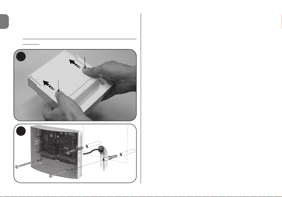
2 - English
EN
cables and control cables against possible traction or torsion.
03. Fix the control unit housing to the wall (Fig. 2).
Caution! – The receiver must be positioned so that
the cables enter the housing exclusively from the
bottom.
1
2
4 – ELECTRICAL CONNECTIONS
Warnings
• When connecting the aerial provided, leave the wire at the
supplied length and lay it straight so as to avoid excessive
bending.
• If the control unit is not in an optimal position and the
radio signal is weak, improve reception by replacing the
aerial supplied with an external version (model ABF or
ABFKIT). The new aerial must be positioned as high as
possible and above any metal or reinforced concrete
structures present in the area.
4.1 – Inputs (Fig. 3 and Table 1)
• L Electrical phase
• N Neutral
• TTBUS: (TTBUS, GND)
• RS232 with dedicated protocol
• 5-24 VDC trigger with programmable On and Off events
– 30+30 programmable events
– Event: address, command
• Two inputs for open-close commands for 85-265 VAC
50/60 Hz mechanical motor
– Open-STOP, Close-STOP operation
– “ON-PRESS” activation
4.2 – Outputs
• Power relay output for controlling a mechanical/electronic
motor with programmable manoeuvres (up and down), activated through two button inputs Pup () and Pdown () of
the 12 V Trigger or via Transmitter.
Page 5
English - 3
EN
TABLE 1
Wiring diagram
1 Electrical phase
2 Neutral
3 Ground
4 Up button linked to the connectable mechanical
motor
5 Down button linked to the connectable mechanical
motor
6 Mechanical motor ground
7 Mechanical motor down phase
8 Mechanical motor common contact
9 Mechanical motor up phase
10 TX signal of the RS232 interface
11 RX signal of the RS232 interface
12 Common contact (GND) of the RS 232 serial signal
13 Signal of the motor with TTBUS (White wire)
14 Common contact of the motor with TTBUS (White/
Black wire)
15 External activation trigger signal (positive pole input)
16 External activation trigger common contact (nega-
tive pole input)
ANT Aerial input
– The activation timer can be adjusted to between 1 sec.
and 240 sec. through the serial port with an internal command.
– The default address of the motor connected to the control
unit is 1.
Refer to Table 2 to check the LEDs present.
16
P
POWER
SUPPLY
100 - 240 V
50 - 60 Hz
TTBUS
TRIGGER 12 V
AERIAL
P
SG
DL7 RL1
PP
DL8 RL2
DL5 P
DL4 TRG
DL6 P
DL3 DL2 DL1
23
RS232
5
SG
3
Page 6

4 - English
EN
TABLE 2 - Signalling LEDs
Led Description
DL1 Red LED Power supply indicator.
DL2 Yellow LED If on, transmitter memorisation is
active.
DL3 Green LED Signals.
DL4 12 V signal trigger indicator.
DL5, DL6 Red LED External buttons open-close in-
dicator for mechanical motor.
DL7, DL8 Red LED Open-close relays activation.
3 - Close
4 - Stop
5 - Close after 10 sec.
6 - Open after 10 sec.
7 - Close after 20 sec.
8 - Open after 20 sec.
9 - Hold-to-run close
10 - Hold-to-run open
11 - Activate the list of programmed command linked to the
12v trigger Up scenario
12 - Activate the list of programmed command linked to the
12v trigger DOWN scenario
13 - Forward radio transmission on RS232 serial
5.1 – Memorising a transmitter in “Mode I”
01. Press and hold P1 on the control unit until the green
LED DL1 lights up (after approx. 4 seconds) then
release; the yellow LED DL2 will also turn on.
02. Within 10 seconds, press and hold any key of the transmit-
ter to be memorised, until the green LED DL1 on the control unit emits the first of 3 flashes to confirm memorisation.
Following these flashes, to memorise another transmitter in
“Mode I”, press any key on the new transmitter within 10
seconds. Lastly, wait until yellow LED DL2 turns off.
Caution! – When attempting to memorise a transmitter that
is already stored, the green LED DL1 will signal this by flashing once.
5.2 – Memorising a transmitter in “Mode II”
01. From the “Mode II” list, select the function to be pro-
grammed (e.g. “Function 8”).
5 – PROGRAMMING
The control unit can memorise transmitters in two modes,
namely Mode I and Mode II:
Mode I
– Button 1 controls the Opening for the pre-set manoeuvre
duration (Tm) (maximum 240 sec.).
– Button 2 controls the Stop.
– Button 3 controls the Closing for the pre-set manoeuvre
duration (Tm) (maximum 240 sec.).
– Button 4 controls the Stop, once again.
Mode II
The transmitter button can be linked to one of the following
functions:
1 - Step-by-step
2 - Open
Page 7

English - 5
EN
02. On the receiver, press P1 the same number of times as
the number identifying the selected function (in our
example, 8 times). On completion, the green LED DL1
emits a number of short flashes corresponding to the
number of times the key was pressed (in our example, 8
short flashes);
03. Within 10 seconds, press and hold the transmitter key
to be memorised, until the green LED DL1 on the
receiver emits the first of 3 flashes to confirm memorisation. After these flashes, to store a new key (even on
another transmitter) with the same function, press this
new key within 10 seconds (yellow LED DL2 on).
04. When attempting to memorise a transmitter that is
already stored, the green LED DL1 will signal this by
flashing once.
5.3 – Deleting all memorised transmitters
01. Press and hold P1 for long on the control unit and check
the sequence of statuses of the green LED DL1.
02. After approximately 4 seconds, it turns on…
03. After approximately 4 seconds, it turns off…
04. After approximately 4 seconds, it starts flashing
...
At this stage:
05. To delete all memorised transmitters, release the receiv-
er key on precisely the third flash
of the green LED
DL1.
06. To delete the entire memory (including transmitter con-
figurations and encoding family), release the key on pre
-
cisely the fifth flash of the green LED DL1.
07. To delete a single transmitter, release the key on pre
-
cisely the seventh flash then press a key (*) on the trans-
mitter to be deleted from the memory within ten seconds (yellow LED DL2 on); the green LED DL1 will emit
5 rapid flashes upon deletion.
08. Repeat the operation within ten seconds (yellow LED
DL2 on) to delete another transmitter.
(*) Note – If the transmitter is memorised in “Mode I”, press any key;
if the transmitter is memorised in “Mode II”, press the memorised
key; if multiple keys are memorised, repeat the procedure for each
memorised key.
5.4 – Communication protocol
CMD [XX] [YY] [AA] [Optional data field] [Carriage Return]
Note – The fields are one space apart.
[CMD] This is a 3-character field. Conventional-
ly, commands sent to the T4/TTBUS
bus will always be in “CMD” form.
[XX] [YY] These are 2-character fields indicating
the device Address and Node, respectively. These two fields are mandatory
and must be entered in hexadecimal
form.
[AA] Field indicating the command to be
sent. It is 2-characters long and is
mandatory. It represents the ID of the
command to be sent according to the
previously-listed commands list (for
example: 04 open; 05 close; etc.).
[Data field] Variable-length optional field. Its size
depends on the type of command
Page 8

6 - English
EN
60 Delete transmitter
65 Delete all memorised transmitters
66 Delete motor parameters
20 Memorise the motor upper limit switch in current
position
21 Memorise the motor lower limit switch in current
position
22 Memorise partial position 1 in current position
23 Memorise partial position 2 in current position
24 Memorise partial position 3 in current position
25 Memorise partial position 4 in current position
26 Memorise partial position 5 in current position
27 Memorise partial position 6 in current position
30 Delete upper limit switch setting
31 Delete lower limit switch setting
32 Delete partial position 1
33 Delete partial position 2
34 Delete partial position 3
35 Delete partial position 4
36 Delete partial position 5
37 Delete partial position 6
05 Up
12 Move a little step up
03 STOP
sent to the device: some commands
do not require data (for example, the
Open command), while others do (for
example, the Open percentage command).
[Carriage Return] Decimal code 13, hexadecimal code
0D; it must always be present and each
string sent must end with this character.
For each command sent, the interface must provide a
response that simply indicates the command reception
(this, however, does not imply that the command has been
executed by the automation). It is a notification that will
currently have a very simple construction, such as the following:
RSP [XX] [YY] [ZZ] [Optional data field] [Carriage Return]
5.5 – Commands list
CMD Description
45 READ PERCENTAGE POSITION 0 - 255
Low limit switch 255 = High limit switch
04 Down
40 OPEN percentage command percentage 0 - 255
0 = Low limit switch 255 = High limit switch
50 Read memorised transmitters
51 Memorise transmitter
Page 9

Response
5.5.2 – STOP command
Stops the motor.
Structure
The data field is empty.
Example
Response
English - 7
EN
13 Move a little step down
06 Move to partial position 1
07 Move to partial position 2
08 Move to partial position 3
09 Move to partial position 4
10 Move to partial position 5
11 Move to partial position 6
Note – The available commands must also be available for the
motor.
5.5.1 – Move to partial position 1, 2, 3, 4, 5, 6
command
Moves the motor to the set position after the partial position
has been assigned.
Structure
The data field is empty.
Example
Start TT ADR
[XX]
TT ENDPOINT
[YY]
Command
[AA]
Data CR
CMD IND 04 06 – –
Start TT ADR
[XX]
TT ENDPOINT
[YY]
Command
[AA]
Data CR
CMD 01 04 06 – –
Start TT ADR
[XX]
TT ENDPOINT
[YY]
Command
[AA]
Data CR
RISP 01 04 06 – –
Start TT ADR
[XX]
TT ENDPOINT
[YY]
Command
[AA]
Data CR
CMD 01 04 06 – –
Start TT ADR
[XX]
TT ENDPOINT
[YY]
Command
[AA]
Data CR
RISP 01 04 06 – –
Start TT ADR
[XX]
TT ENDPOINT
[YY]
Command
[AA]
Data CR
CMD IND 04 03 – –
Page 10

8 - English
EN
5.5.3 – UP command
Commands the motor’s “up” movement until the set limit
switch.
Structure
The data field is empty.
Example
Response
5.5.4 – DOWN command
Commands the motor’s “down” movement until the set limit
switch.
Structure
The data field is empty.
Example
Response
5.5.5 – Move a little step down
Sends a “down” command that it make the smallest movement that the motor can do. Use to set the right position
before setting the limits switch or the partial positions.
Caution
: the up and down directions are correctly
assigned after setting the relevant limit switches.
Structure
The data field is empty.
Example
Start TT ADR
[XX]
TT ENDPOINT
[YY]
Command
[AA]
Data CR
CMD 01 04 05 – –
Start TT ADR
[XX]
TT ENDPOINT
[YY]
Command
[AA]
Data CR
RISP 01 04 05 – –
Start TT ADR
[XX]
TT ENDPOINT
[YY]
Command
[AA]
Data CR
CMD IND 04 04 – –
Start TT ADR
[XX]
TT ENDPOINT
[YY]
Command
[AA]
Data CR
CMD 01 04 04 – –
Start TT ADR
[XX]
TT ENDPOINT
[YY]
Command
[AA]
Data CR
RISP 01 04 04 – –
Start TT ADR
[XX]
TT ENDPOINT
[YY]
Command
[AA]
Data CR
CMD 01 04 13 – –
Start TT ADR
[XX]
TT ENDPOINT
[YY]
Command
[AA]
Data CR
CMD IND 04 13 – –
Start TT ADR
[XX]
TT ENDPOINT
[YY]
Command
[AA]
Data CR
CMD IND 04 05 – –
Page 11

English - 9
EN
5.5.7 – Memorise partial position 1, 2, 3, 4, 5, 6
and limit switch 0 and 1 positions
Assigns the current position to a variable position.
Structure
The data field is empty.
Example
Response
5.5.8 – Delete partial position 1, 2, 3, 4, 5, 6 and
limit switch 0 and 1 positions
Deletes the entered position.
Structure
The data field is empty.
Response
5.5.6 – Move a little step up
Sends an “up” command that it make the smallest movement that the motor can do. Use to set the right position
before setting the limits switch or the partial positions.
Caution
: the up and down directions are correctly
assigned after setting the relevant limit switches.
Structure
The data field is empty.
Example
Response
Start TT ADR
[XX]
TT ENDPOINT
[YY]
Command
[AA]
Data CR
RISP 01 04 13 – –
Start TT ADR
[XX]
TT ENDPOINT
[YY]
Command
[AA]
Data CR
CMD 01 04 12 – –
Start TT ADR
[XX]
TT ENDPOINT
[YY]
Command
[AA]
Data CR
RISP 01 04 12 – –
Start TT ADR
[XX]
TT ENDPOINT
[YY]
Command
[AA]
Data CR
CMD IND 04 12 – –
Start TT ADR
[XX]
TT ENDPOINT
[YY]
Command
[AA]
Data CR
CMD 01 04 20 – –
Start TT ADR
[XX]
TT ENDPOINT
[YY]
Command
[AA]
Data CR
CMD IND 04 – – –
Start TT ADR
[XX]
TT ENDPOINT
[YY]
Command
[AA]
Data CR
RISP 01 04 20 – –
Start TT ADR
[XX]
TT ENDPOINT
[YY]
Command
[AA]
Data CR
CMD IND 04 – – –
Page 12

Example
Response
5.5.9 – Read percentage position 0 - 255; 0 = Low
limit switch, 255 = High limit switch
Reads the current position of the motor in percentage terms.
The PP data field is the percentage position.
Structure
The data field is empty.
Example
10 - English
EN
Response
5.5.10 – Move to percentage position 0 - 255; 0 =
Low limit switch, 255 = High limit switch
Moves the motor to position X.
The PP data field is the percentage position.
Structure
The data field is empty.
Example
Response
Start TT ADR
[XX]
TT ENDPOINT
[YY]
Command
[AA]
Data CR
CMD 01 04 30 – –
Start TT ADR
[XX]
TT ENDPOINT
[YY]
Command
[AA]
Data CR
CMD 01 04 45 – –
Start TT ADR
[XX]
TT ENDPOINT
[YY]
Command
[AA]
Data CR
RISP 01 04 30 – –
Start TT ADR
[XX]
TT ENDPOINT
[YY]
Command
[AA]
Data CR
CMD IND 04 45 – –
Start TT ADR
[XX]
TT ENDPOINT
[YY]
Command
[AA]
Data CR
RISP 01 04 45 128 –
Start TT ADR
[XX]
TT ENDPOINT
[YY]
Command
[AA]
Data CR
CMD 01 04 40 25 –
Start TT ADR
[XX]
TT ENDPOINT
[YY]
Command
[AA]
Data CR
RISP 01 04 40 25 –
Start TT ADR
[XX]
TT ENDPOINT
[YY]
Command
[AA]
Data CR
CMD IND 04 40 PP –
Page 13

English - 11
EN
5.5.11 – Delete all memorised transmitters
command
Deletes all the transmitters from the motor.
Structure
The data field is empty.
Example
Response
5.5.12 – Delete motor parameters command
Deletes all the limit switch data from the motor.
Structure
The data field is empty.
Start TT ADR
[XX]
TT ENDPOINT
[YY]
Command
[AA]
Data CR
CMD 01 04 65 – –
Start TT ADR
[XX]
TT ENDPOINT
[YY]
Command
[AA]
Data CR
RISP 01 04 65 – –
Start TT ADR
[XX]
TT ENDPOINT
[YY]
Command
[AA]
Data CR
CMD IND 04 65 – –
Start TT ADR
[XX]
TT ENDPOINT
[YY]
Command
[AA]
Data CR
CMD IND 04 66 – –
Example
Response
5.6 – Commands for memorising and viewing
lists
Two commands lists (max. 30 commands) can be stored.
The commands are then executed sequentially in the event
of a transition of the 12 V input trigger, or when the up or
down trigger event is set from the transmitter.
The serial port command to store commands that will be
executed when the signal moves from low to high is::
MEM_ON [XX] [YY] [XX1] [YY1] [...] [...] [Carriage Return]
Note – The fields are one space apart and the string ends
with Carriage Return.
Important! - Address 1 is used for sending commands
to the mechanical motor.
The fields are:
MEM_ON It is the string that stores the commands in the
first list.
Start TT ADR
[XX]
TT ENDPOINT
[YY]
Command
[AA]
Data CR
CMD 01 04 66 – –
Start TT ADR
[XX]
TT ENDPOINT
[YY]
Command
[AA]
Data CR
RISP 01 04 66 – –
Page 14

12 - English
EN
Using the previous example, we obtain:
MEM_OFF 02 05 03 04 05 12 [Carriage Return]
The response will be of the following type:
MEM_OFF 02 05 03 04 05 12
LIST TRIGGER OFF:
CMD 1--> addr: 2, cmd: 5
CMD 2--> addr: 3, cmd: 4
CMD 3--> addr: 5, cmd: 12
5.7 – Viewing the commands lists
It is possible to view the two stored lists on the video screen.
It is sufficient to enter the LIST command followed by
“enter” to obtain the complete content of the two lists. The
command is:
LIST [Carriage Return]
For example, by typing “List” after having entered the two
previous commands, we obtain:
LIST
LIST TRIGGER ON:
CMD 1--> addr: 2, cmd: 5
CMD 2--> addr: 3, cmd: 4
CMD 3--> addr: 5, cmd: 12
LIST TRIGGER OFF:
CMD 1--> addr: 2, cmd: 5
[XX] Address of the device to which the command
must be sent, it is mandatorily composed of
two digits in hexadecimal form.
[YY] Command to be sent to the device, it is manda-
torily composed of two digits based on the
above-mentioned commands table.
The subsequent couples [XX] and [YY] represent the other
N commands that can be sent to the motors (max. 30 commands).
For example, for sending the “up” command to device 2, the
“close” command to device 3 and the step-by-step up command to device 5, the relevant command will be:
MEM_ON 02 05 03 04 05 12 [Carriage Return]
The response will be of the following type:
MEM_ON 02 05 03 04 05 12
LIST TRIGGER ON:
CMD 1--> addr: 2, cmd: 5
CMD 2--> addr: 3, cmd: 4
CMD 3--> addr: 5, cmd: 12
The list that manages the event of the down run of the trigger operates in a similar way, except for the command which
in this case is:
MEM_OFF [XX] [YY] [XX1] [YY1] [...] [...] [Carriage Return]
Page 15

English - 13
EN
CMD 2--> addr: 3, cmd: 4
CMD 3--> addr: 5, cmd: 12
5.8 – Command for setting the duration
of the mechanical motor movements
The duration of the mechanical motor movements can be
set. The relevant command is:
SET_TIME [XXX] [Carriage Return]
The fields are one space apart and the string ends with Carriage Return.
The fields are:
SET_TIME Command for setting the duration.
[XXX] Value in seconds (max. 240 sec.).
The default value at initial start-up is 10 seconds and any
modification of this value is stored in the memory.
At the next re-start, the last value stored will be used.
5.9 – Changing a device’s address
The address of a motor can be set using the following command:
ADR [XX] [YY] [Carriage Return]
The fields are one space apart and the string ends with Carriage Return.
The fields are:
[XX] Current address of the motor; the address must
mandatorily contain two digits and must be in
hexadecimal form.
[YY] New address of the motor; the address must
mandatorily contain two digits and must be in
hexadecimal form.
For example, for modifying the motor address from 03 to 07,
use the following command.
ADR 03 07 [Carriage Return]
5.10 – Viewing information on memorised
transmitters
Information on memorised transmitters can be viewed using
the following command:
TLC_STATUS [Carriage Return]
The information regards the number of memorised transmitters and their operating mode.
The typical response will be:
tlc_status
Number of remote control in mem: 3
Number of free position in mem: 29
TLC 1 : Mode 2 - Function number 1 - Key UP
TLC 2 : Mode 1
TLC 3 : Mode 2 - Function number 2 - Key DOWN
Page 16

14 - English
EN
5.11 – Commands which can be activated through
domotic interfaces
In the unit, the command activates the bidirectional transmission of information, the display of radio codes on the
serial and the transmission of the position of the automation
mechanism during the movement.
Type:
WEB_ON [Carriage Return]
In this way the display of the radio codes via the serial, if
saved in the unit, is activated and it is possible to use the
pos command to move the motors by a percentage and
monitor the movement event.
To deactivate use the command:
WEB_OFF [Carriage Return]
In this way the display of the codes is activated.
5.11.1 – Displaying radio codes on serial
If the TT6 receives a radio signal from one of the saved
remote controls, the following info is sent, related to the
transmitter, via the serial.
RAD * 0003E965 0000 0100000000
The first 8 digits represent the code of the remote control, the
next 4 represent the variable part of the code of the remote
control (masked at 0). The last 10 digits represent: the pressed
button in the first 4 numbers, the next 6 are for future uses.
5.11.2 – Motor movement by percentage command
To move the motors by a percentage of their total stroke
(therefore after having set the limit switches) use the command:
POS > [XX] [YY] [PPPP] [ZZZZ] [TT] [Carriage Return]
Where:
[XX] Is the address of the motor.
[YY] Is the node (04 is the default for the screen
motors).
[PPPP] The percentage value you want to reach,
expressed in thousandths.
[ZZZZ] [TT] The last two parameters in the screen motors
are set at FFFF and FF for future developments.
For example, to take motor number 02 to the intermediate
value (0500) of its stroke, the command must be composed
in the following way:
POS # 02 04 0500 FFFF FF
During the movement the strings are sent with the current
position of the motor until reaching the requested position in
the form of async messages, the format is:
POS * 02 04 xxxx FFFF FF
Page 17

English - 15
EN
Where xxxx is the instantaneous position of the motor.
In case of errors of syntax in the command, the error field will
be added to the response with the value 01, the fields will be
filled up to the first incorrect field and the subsequent ones
will be filled with 0xF, e.g.:
POS ! 02 04 FFFF FFFF FF 01
In case of timeout, the error message will have the value 00
as error code, e.g.:
POS ! 02 04 0800 FFFF FF 00
Where xxxx is the instantaneous position of the motor.
The automation mechanism did not respond to the sent
command.
5.11.3 – Motor current position read command
To read the current position of the automation mechanism,
use the command:
POS < [XX] [YY] [AAAA] [ZZZZ] [TT] [Carriage Return]
Where:
[XX] Is the address of the motor.
[YY] Is the node (04 is the default for the
screen motors.
[PPPP] [ZZZZ] [TT] All filled with 0xF in the case of reading.
The response is of the type below:
POS * 02 04 0500 FFFF FF
Where the current position of the motor is indicated.
5.11 – Help commands
The two help commands are:
HELP Command for viewing a description of the
commands available through serial port.
HELP_TTBUS Command for viewing the commands table
for the TTBus.
HELP_TLC Command for viewing the list of functions in
mode 2.
Page 18

16 - English
EN
6 – DISPOSAL OF THE PRODUCT
This product constitutes an integral part of the automation system, therefore it must be disposed of jointly
with the latter.
Likewise for installation operations, when the product reaches
its end-of-life decommissioning operations must be performed by qualified personnel. This product is made up of
different types of material, some of which can be recycled
while others must be disposed of. Seek information on the
recycling and disposal systems available in your area for this
product category.
Beware! – Some parts of the product may contain pollutants or hazardous substances that – if released into the
environment – may cause serious damage to the environment or human health.
As indicated by the adjacent symbol, it is
strictly forbidden to dispose of this product
together with domestic waste. Therefore,
implement separate waste collection criteria
for disposal according to the regulations in
force in your area, or return the product to
the dealer when purchasing a new equivalent version.
Beware! – Local legislation may include the application of
serious fines in the event of improper disposal of this product.
7 – TECHNICAL SPECIFICATIONS
• Power supply: 110 - 240 VAC 50/60 Hz
• Maximum absorbed current: 80 mA in stand-by mode,
3 A at full load
• Encoding: FloR (rolling code)
• Frequency: 433.92 MHz
• Antenna impedance: 52 ohm
• Sensitivity: more than 0,5µV for successful signal
• Range: estimated at 200 m in open space or 35 m inside
buildings
• No. of storable transmitters: 30
• Output: 1 output for controlling a two-phase motor
• Contact capacity: 3 A - 250 V
• Protection rating: IP44 (with container intact)
• Operating temperature: -20° C ÷ +55° C
• Dimensions / weight: 128 x 112 x 43 mm / 260 g
Notes:
– The operating distance between transmitters and
receivers (range) is strongly influenced by other devices
operating in the area and at the same frequency (for example: alarm systems, radio earphones, etc.). In these cases,
Nice cannot provide any guarantee with regard to the actual
range of its devices.
– All technical specifications stated herein refer to an ambient temperature of 20° C (± 5° C).
– Nice reserves the right to effect modifications to the product whenever it deems necessary, while preserving the
product’s intended use and functionality.
Page 19

Italiano - 1
IT
Istruzioni originali
ITALIANO
1 – AVVERTENZE
• Attenzione! - Per la sicurezza delle persone è importante rispettare queste istruzioni.
• Attenzione! - Istruzioni importanti per la sicurezza:
quindi, conservare queste istruzioni.
• Attenzione! - Tutte le operazioni di installazione, di
collegamento, di programmazione e di manutenzione del prodotto devono essere effettuate esclusivamente da un tecnico qualificato e competente!
• Non eseguire modifiche su nessuna parte del prodotto, se non quelle pre viste nel presente manuale.
Operazioni non autorizzate possono essere fonte di
pericolo e causa di malfunzionamento. Il costruttore
declina ogni responsabilità per danni derivanti da
prodotti modificati arbitrariamente.
• Importante! - Non utilizzare liquidi contenenti alcool,
benzene, diluenti o altre so stanze infiammabili. L’uso di
tali sostanze potrebbe danneggiare il prodotto.
• Conservare con cura questo manuale per facilitare eventuali interventi futuri di programmazione o di manutenzione del prodotto.
• Smaltire il materiale dell’imballaggio del prodotto nel pieno
rispetto della normativa in vigore sul territorio.
• Per la pulizia superficiale del prodotto, utilizzare un panno
morbido e leggermente umido (non bagnato!).
2 – DESCRIZIONE DEL PRODOTTO
E DESTINAZIONE D’USO
La centrale TT6 è destinata ad essere utilizzata negli impianti
di automatizzazione per tende da sole, tapparelle, lucernari,
tende verticali, oscuranti e per comandare teli da video proiezione. Ogni altro uso è da considerarsi improprio e
vietato! Il costruttore non risponde dei danni risultanti
da un uso improprio del prodotto, diverso da quanto
previsto nel presente manuale.
Il prodotto presenta:
- uscita per pilotare un motore a due fasi (ad esempio OneMax, To-max oppure NeoM); l’uscita può essere attivata
direttamente dai due pulsanti presenti: Pup () e Pdown
();
- interfaccia TTBUS per pilotare motori Nice con sistema bus
- interfaccia RS232 per collegamento a PC
- ingresso di attivazione (Trigger) per attivare o disattivare
una sequenza di motori (in corrispondenza al “Trigger” di
salita oppure di discesa).
L’interfaccia radio estende le capacità di comando del prodotto in remoto attraverso la tecnologia radio Nice.
3 – INSTALLAZIONE
01. Togliere il coperchio superiore della centrale (fig. 1).
02. Praticare sul contenitore, in corrispondenza dei segni pre-
disposti, i fori necessari al passaggio dei cavi e quelli per il
fissaggio della centrale sulla parete. Attenzione! – Pren-
dere le opportune precauzioni per garantire il grado
di protezione IP richiesto dal tipo di installazione. In
particolare, prevedere dei pressacavi (non forniti)
Page 20
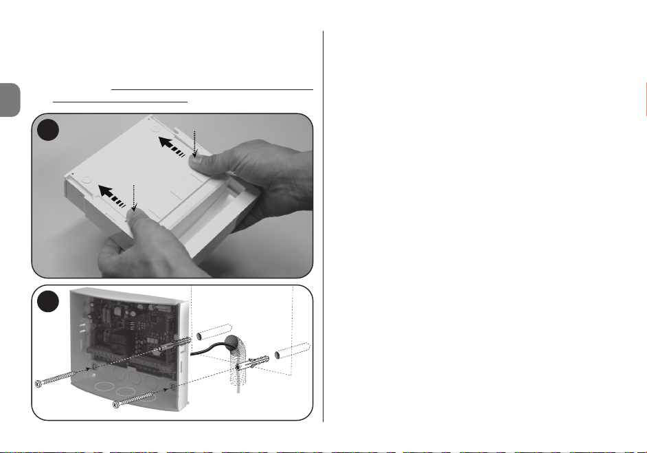
2 - Italiano
IT
per garantire la protezione dei cavi di alimentazione
e comando da possibili trazioni o torsioni.
03. Fissare sulla parete il contenitore dela centrale (fig. 2).
Attenzione! – Il ricevitore deve essere orientato in
modo che i cavi entrino nel contenitore solo ed
esclusivamente dal basso.
1
2
4 – COLLEGAMENTI ELETTRICI
Avvertenze
• Per effettuare il collegamento dell’antenna in dotazione, occorre lasciare il filo con la lunghezza fornita e
posizionarlo in modo rettilineo, evitando curvature ec ces sive.
• Se la centrale si trova in una posizione sfavorevole e il
segnale radio risulta debole, per migliorare la ricezione si
consiglia di sostituire l’antenna in dotazione, con un’antenna esterna (mod. ABF o ABFKIT). La nuova antenna
deve essere posizionata più in alto possibile e al di sopra
di eventuali strutture metalliche o di cemento armato presenti nella zona.
4.1 – Ingressi (fig. 3 e Tabella 1)
• L Fase elettrica
• N Neutro
• TTBUS: (TTBUS, GND)
• RS232 con protocollo dedicato
• “Trigger” 5-24 Vdc con eventi On e Off programmabili
– 30+30 eventi programmabili
– Evento: Indirizzo,comando
• 2 Ingressi per comandi apri-chiudi per motore meccani-
co a 85-265 Vac 50/60 Hz
– Funzionamento Apri-STOP, Chiudi-STOP
– Attivazione “ON-PRESS”
4.2 – Uscite
• Uscita relè di potenza per il pilotaggio di un motore mec-
canico/elettronico con manovre (salita e discesa) program-
Page 21
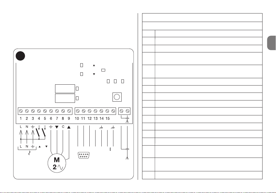
TABELLA 1
Schema dei collegamenti elettrici
1 Fase elettrica
2 Neutro
3 Terra
4 Pulsante di salita abbinato al motore meccanico
collegabile
5 Pulsante di discesa abbinato al motore meccanico
collegabile
6 Terra motore meccanico
7 Fase di discesa motore meccanico
8 Comune del motore meccanico
9 Fase di salita del motore meccanico
10 Segnale di TX dell’interfaccia RS232
11 Segnale di RX dell’interfaccia RS232
12 Comune (GND) del segnale seriale RS232
13 Segnale del motore con TTBUS (filo Bianco)
14 Comune del motore con TTBUS (filo Bianco/Nero)
15 Segnale del “Trigger” esterno di attivazione (ingres-
so con polarità positiva)
16 Comune del “Trigger” esterno di attivazione (ingres-
so con polarità negativa)
ANT Ingresso antenna
Italiano - 3
IT
mabili, attivate dai due ingressi a pulsante Pup () e Pdown
() del “Trigger” 12 V o via Radio.
– Tramite seriale con un comando interno è possibile variare
il timer di attivazione da 1 s a 240 s.
– L’indirizzo di default del motore collegato alla centrale è 1.
Per verificare i Led presenti, vedere Tabella 2.
16
P
POWER
SUPPLY
100 - 240 V
50 - 60 Hz
TTBUS
TRIGGER 12 V
AERIAL
P
SG
DL7 RL1
PP
DL8 RL2
DL5 P
DL4 TRG
DL6 P
DL3 DL2 DL1
23
RS232
5
SG
3
Page 22

TABELLA 2 - Led di segnalazione
Led Descrizione
DL1 Led rosso Indicatore alimentazione.
DL2 Led giallo Se acceso memorizzazione tele-
comandi attiva.
DL3 Led verde Segnalazioni.
DL4 Led indicazione “Trigger” 12 V on.
DL5, DL6 Led rosso Indicatore apri-chiudi pulsanti
esterni per meccanico.
DL7, DL8 Led rosso Attivazione relè apri e chiudi.
4 - Italiano
IT
3- Chiudi
4- Stop
5- Chiudi dopo 10 s
6- Apri dopo 10 s
7- Chiudi dopo 20 s
8- Apri dopo 20 s
9 - Chiudi a uomo presente
10- Apri a uomo presente
11- Attiva scenario Trigger Up
12- Attiva scenario Trigger Down
13- Uscita codice radio su RS232
5.1 – Memorizzazione di un trasmettitore in “Modo I”
01. Sulla centrale, mantenere premuto il tasto P1 fino a quan-
do si accende il Led verde DL1 (dopo circa 4 secondi) e
poi rilasciare il tasto, si accenderà anche il led giallo DL2.
02. Entro 10 secondi, premere e mantenere premuto un
qualsiasi tasto del trasmettitore da memorizzare, fino a
quando il Led verde DL1 della centrale emette il primo
dei 3 lampeggi che segnalano l’avvenuta memorizzazione. Al termine di questi lampeggi, se si desidera memorizzare un altro trasmettitore in “Modo I”, premere entro
10 secondi un tasto qualsiasi di questo nuovo trasmettitore. Infine, attendere lo spegnimento del led giallo DL2.
Attenzione! – Se si prova a memorizzare un trasmettitore
già presente nella memoria, il Led verde DL1 emette 1 lampeggio come segnalazione.
5.2 – Memorizzazione di un trasmettitore in “Modo II”
01. Scegliere nella lista del “Modo II” la funzione che si
desidera programmare (es. “Funzione 8”).
5 – PROGRAMMAZIONE
La centrale può memorizzare i trasmettitori in due modalità,
Modo I e Modo II:
Modo I
– il tasto 1 comanda l’Apertura per il tempo di manovra (Tm)
impostato (massimo 240 sec.);
– il tasto 2 comanda lo Stop;
– il tasto 3 comanda la chiusura per il tempo di manovra
(Tm) impostato (massimo 240 sec.);
– il tasto 4 comanda lo Stop, nuovamente.
Modo II
Il tasto del trasmettitore può essere abbinato ad una delle
seguenti funzioni:
1- Passo passo
2- Apri
Page 23

Italiano - 5
IT
02. Sul ricevitore, premere il tasto P1 un numero di volte
pari al numero che identifica la funzione prescelta nel
nostro esempio, 8 volte). Al termine, il Led verde DL1
emette un numero di lampeggi brevi, uguali al numero
di pressioni esercitate sul tasto (nel nostro esempio, 8
lampeggi brevi).
03. Entro 10 secondi, mantenere premuto sul trasmettitore il
tasto che si desidera memorizzare, fino a quando il Led
verde DL1 del ricevitore emette il primo dei 3 lampeggi
lunghi, che segnalano l’avvenuta memorizzazione. Al
termine di questi lampeggi, se si desidera memorizzare
con la stessa funzione un nuovo tasto (anche di un altro
trasmettitore), premere entro 10 secondi (Led giallo
acceso DL2) questo nuovo tasto.
04. Se si cerca di memorizzare un trasmettitore già presente
in memoria il Led verde DL1 emette un singolo lampeggio come segnalazione.
5.3 – Cancellazione di tutti i trasmettitori memorizzati
01. Mantenere premuto a lungo il tasto P1 della centrale,
osservare la sequenza degli stati che assume il Led verde DL1).
02. Dopo circa 4 secondi, si accende...
03. Dopo circa 4 secondi, si spegne...
04. Dopo circa 4 secondi, inizia a lampeggiare
...
A questo punto:
05. Per cancellare i trasmettitori memorizzati, rilasciare il
tasto del ricevitore esattamente durante il 3° lampeggio
del Led verde DL1;
06. Per cancellare tutta la memoria, rilasciare (comprese le
configurazioni e la famiglia di codifica dei trasmettitori),
rilasciare il tasto esattamente durante il 5° lampeggio
del
Led verde DL1.
07. Per cancellare un singolo trasmettitore rilasciare il tasto
esattamente durante il 7° lampeggio
a questo punto
premere un tasto (*) sul trasmettitore che si desidera
cancellare dalla memoria entro dieci secondi (Led giallo
DL2 acceso) a cancellazione avvenuta il led verde DL1
emetterà 5 lampeggi veloci.
08. Ripetere l’operazione entro dieci secondi (Led giallo
DL2 acceso) per cancellare un altro trasmettitore.
(*) Nota – Se il trasmettitore è memorizzato in “Modo I”, premere un
tasto qualsiasi; se invece è memorizzato in “Modo II”, premere il
tasto memorizzato; se vi fossero più tasti memorizzati, ripetere la
procedura per ognuno di loro.
5.4 – Protocollo di comunicazione
CMD [XX] [YY] [AA] [Campo dati opzionali] [Carriage Return]
Nota – I campi sono distanziati da uno spazio.
[CMD] Campo da 3 caratteri. Per convenzione,
nel caso di invio di comandi verso il
busT4/TTBUS sarà sempre pari a “CMD”.
[XX] [YY] Sono i due campi di due caratteri cia-
scuno indicanti, nell’ordine l’Indirizzo e il
Nodo del dispositivo. Questi due campi
sono obbligatori e andranno scritti in
esadecimale.
[AA] Campo indicante il comando da inviare.
È obbligatorio e la sua lunghezza è di 2
caratteri. Rappresenta l’ID del comando
Page 24

6 - Italiano
IT
50 Leggi trasmettitore in memoria
51 Memorizzazione in memoria
60 Cancellazione in memoria
65 Cancellazione di tutti i trasmettitori in memoria
66 Cancellazione parametri motore
20 Memorizzazione finecorsa 0 in posizione attuale
21 Memorizzazione finecorsa 1 in posizione attuale
22 Memorizzazione quota parziale 1 in posizione attuale
23 Memorizzazione quota parziale 2 in posizione attuale
24 Memorizzazione quota parziale 3 in posizione attuale
25 Memorizzazione quota parziale 4 in posizione attuale
26 Memorizzazione quota parziale 5 in posizione attuale
27 Memorizzazione quota parziale 6 in posizione attuale
30 Cancellazione finecorsa 0
31 Cancellazione finecorsa 1
32 Cancellazione quota parziale 1
33 Cancellazione quota parziale 2
34 Cancellazione quota parziale 3
35 Cancellazione quota parziale 4
36 Cancellazione quota parziale 5
37 Cancellazione quota parziale 6
05 Salita
12 Muovi a piccoli passi in salita
03 STOP
inviabile secondo la lista comandi già elencati (ad esempio: 04 apre; 05 chiude...).
[Campo dati] Campo opzionale di lunghezza variabile.
La sua dimensione dipende dal tipo di
comando inviato al dispositivo: vi saranno comandi che non richiederanno dati
(ad esempio il comando Apre), altri invece sì (ad esempio il comando Apre percentuale).
[Carriage Return] Codice decimale 13, esadecimale 0D;
deve sempre essere presente, ogni stringa
inviata deve terminare con tale carattere.
Ad ogni comando inviato, l’interfaccia dovrà restituire una
risposta di semplice ricezione del comando stesso (questo
non significa poi che il comando sia stato eseguito dall’automazione). Si tratta di una notifica che attualmente avrà un
costrutto molto semplice, come il seguente:
RSP [XX] [YY] [ZZ] [Campo dati opzionali] [Carriage Return]
5.5 – Lista comandi
CMD Descrizione
45 LETTURA DELLA POSIZIONE percentuale 0 - 255
0 = Finecorsa basso 255 = Finecorsa alto
04 Discesa
40 Comando APRI percentuale percentuale 0 - 255
0 = Finecorsa basso 255 = Finecorsa alto
Page 25

Italiano - 7
IT
13 Muovi a piccoli passi in discesa
06 Muovi a quota parziale 1
07 Muovi a quota parziale 2
08 Muovi a quota parziale 3
09 Muovi a quota parziale 4
10 Muovi a quota parziale 5
11 Muovi a quota parziale 6
Nota – I comandi disponibili, devono essere disponibili anche per il
motore.
5.5.1 – Comando di Muovi a quota parziale 1, 2, 3,
4, 5, 6
Dopo l’assegnazione della quota parziale muove il motore
alla quota impostata.
Struttura
Il campo dati è vuoto.
Esempio
Start TT ADR
[XX]
TT ENDPOINT
[YY]
Comando
[AA]
Dati CR
CMD IND 04 06 – –
Start TT ADR
[XX]
TT ENDPOINT
[YY]
Comando
[AA]
Dati CR
CMD 01 04 06 – –
Start TT ADR
[XX]
TT ENDPOINT
[YY]
Comando
[AA]
Dati CR
RISP 01 04 06 – –
Start TT ADR
[XX]
TT ENDPOINT
[YY]
Comando
[AA]
Dati CR
CMD 01 04 06 – –
Start TT ADR
[XX]
TT ENDPOINT
[YY]
Comando
[AA]
Dati CR
RISP 01 04 06 – –
Start TT ADR
[XX]
TT ENDPOINT
[YY]
Comando
[AA]
Dati CR
CMD IND 04 03 – –
Risposta
5.5.2 – Comando di STOP
Ferma il motore.
Struttura
Il campo dati è vuoto.
Esempio
Risposta
Page 26

5.5.3 – Comando di SALITA
Comanda la salita del motore fino al finecorsa settato.
Struttura
Il campo dati è vuoto.
Esempio
Risposta
5.5.4 – Comando di DISCESA
Comanda la discesa del motore fino al finecorsa settato.
Struttura
Il campo dati è vuoto.
8 - Italiano
IT
Esempio
Risposta
5.5.5 – Comando di Muovi a piccoli passi in discesa
Invia un comando di discesa. La versione “step” muove il
motore per piccoli passi, anche oltre il finecorsa.
Attenzione
: il verso di salita e discesa vengono asse-
gnati correttamente dopo aver settato i finecorsa.
Struttura
Il campo dati è vuoto.
Esempio
Start TT ADR
[XX]
TT ENDPOINT
[YY]
Comando
[AA]
Dati CR
CMD 01 04 05 – –
Start TT ADR
[XX]
TT ENDPOINT
[YY]
Comando
[AA]
Dati CR
RISP 01 04 05 – –
Start TT ADR
[XX]
TT ENDPOINT
[YY]
Comando
[AA]
Dati CR
CMD IND 04 04 – –
Start TT ADR
[XX]
TT ENDPOINT
[YY]
Comando
[AA]
Dati CR
CMD 01 04 04 – –
Start TT ADR
[XX]
TT ENDPOINT
[YY]
Comando
[AA]
Dati CR
RISP 01 04 04 – –
Start TT ADR
[XX]
TT ENDPOINT
[YY]
Comando
[AA]
Dati CR
CMD 01 04 13 – –
Start TT ADR
[XX]
TT ENDPOINT
[YY]
Comando
[AA]
Dati CR
CMD IND 04 13 – –
Start TT ADR
[XX]
TT ENDPOINT
[YY]
Comando
[AA]
Dati CR
CMD IND 04 05 – –
Page 27

5.5.7 – Memorizzazione quota parziale 1, 2, 3, 4, 5, 6
e quota fincorsa 0 e 1
Assegna la quota corrente ad una variabile.
Struttura
Il campo dati è vuoto.
Esempio
Risposta
5.5.8 – Cancellazione quota parziale 1, 2, 3, 4, 5, 6
e quota fincorsa 0 e 1
Cancella la quota inserita.
Struttura
Il campo dati è vuoto.
Italiano - 9
IT
Risposta
5.5.6 – Comando di Muovi a piccoli passi in salita
Invia un comando di salita. La versione “step” muove il
motore per piccoli passi, anche oltre il finecorsa.
Attenzione
: il verso di salita e discesa vengono asse-
gnati correttamente dopo aver settato i finecorsa.
Struttura
Il campo dati è vuoto.
Esempio
Risposta
Start TT ADR
[XX]
TT ENDPOINT
[YY]
Comando
[AA]
Dati CR
RISP 01 04 13 – –
Start TT ADR
[XX]
TT ENDPOINT
[YY]
Comando
[AA]
Dati CR
CMD 01 04 12 – –
Start TT ADR
[XX]
TT ENDPOINT
[YY]
Comando
[AA]
Dati CR
RISP 01 04 12 – –
Start TT ADR
[XX]
TT ENDPOINT
[YY]
Comando
[AA]
Dati CR
CMD IND 04 12 – –
Start TT ADR
[XX]
TT ENDPOINT
[YY]
Comando
[AA]
Dati CR
CMD 01 04 20 – –
Start TT ADR
[XX]
TT ENDPOINT
[YY]
Comando
[AA]
Dati CR
CMD IND 04 – – –
Start TT ADR
[XX]
TT ENDPOINT
[YY]
Comando
[AA]
Dati CR
RISP 01 04 20 – –
Start TT ADR
[XX]
TT ENDPOINT
[YY]
Comando
[AA]
Dati CR
CMD IND 04 – – –
Page 28

10 - Italiano
IT
Risposta
5.5.10 – Muovi alla posizione percentuale 0 - 255
0 = Finecorsa basso 255 = Finecorsa alto
Muove il motore alla posizione X.
Il campo dati PP è la posizione percentuale.
Struttura
Il campo dati è vuoto.
Esempio
Risposta
Start TT ADR
[XX]
TT ENDPOINT
[YY]
Comando
[AA]
Dati CR
CMD 01 04 30 – –
Start TT ADR
[XX]
TT ENDPOINT
[YY]
Comando
[AA]
Dati CR
CMD 01 04 45 – –
Start TT ADR
[XX]
TT ENDPOINT
[YY]
Comando
[AA]
Dati CR
RISP 01 04 30 – –
Start TT ADR
[XX]
TT ENDPOINT
[YY]
Comando
[AA]
Dati CR
CMD IND 04 45 – –
Esempio
Risposta
5.5.9 – Lettura della posizione percentuale 0 - 255
0 = Finecorsa basso 255 = Finecorsa alto
Legge la posizione corrente del motore in modo percentuale.
Il campo dati PP è la posizione percentuale.
Struttura
Il campo dati è vuoto.
Esempio
Start TT ADR
[XX]
TT ENDPOINT
[YY]
Comando
[AA]
Dati CR
RISP 01 04 45 128 –
Start TT ADR
[XX]
TT ENDPOINT
[YY]
Comando
[AA]
Dati CR
CMD 01 04 40 25 –
Start TT ADR
[XX]
TT ENDPOINT
[YY]
Comando
[AA]
Dati CR
RISP 01 04 40 25 –
Start TT ADR
[XX]
TT ENDPOINT
[YY]
Comando
[AA]
Dati CR
CMD IND 04 40 PP –
Page 29

Italiano - 11
IT
5.5.11 – Comando di Cancellazione di tutti i
trasmettitori in memoria
Cancella tutti i radio comandi dal motore.
Struttura
Il campo dati è vuoto.
Esempio
Risposta
5.5.12 – Comando di Cancellazione parametri
motore
Cancella tutti i dati finecorsa dal motore.
Struttura
Il campo dati è vuoto.
Start TT ADR
[XX]
TT ENDPOINT
[YY]
Comando
[AA]
Dati CR
CMD 01 04 65 – –
Start TT ADR
[XX]
TT ENDPOINT
[YY]
Comando
[AA]
Dati CR
RISP 01 04 65 – –
Start TT ADR
[XX]
TT ENDPOINT
[YY]
Comando
[AA]
Dati CR
CMD IND 04 65 – –
Start TT ADR
[XX]
TT ENDPOINT
[YY]
Comando
[AA]
Dati CR
CMD IND 04 66 – –
Esempio
Risposta
5.6 – Comandi per memorizzazione e visualizzazione
liste
Possono essere memorizzate due liste di comandi (max 30).
I comandi vengono poi eseguiti in sequenza quando avviene
una transizione del “Trigger” 12 V in ingresso oppure l’evento “Trigger” up o down da trasmettitore.
Il comando da seriale per memorizzare i comandi che verranno eseguiti quando il segnale va da basso ad alto è:
MEM_ON [XX] [YY] [XX1] [YY1] [...] [...] [Carriage Return]
Nota – I campi sono distanziati da uno spazio e la stringa è
terminata dal Carriage Return.
Importante! – L’indirizzo 1 viene utilizzato per inviare
comandi al motore meccanico.
I campi sono:
MEM_ON È la stringa che memorizza i comandi nella prima
lista.
Start TT ADR
[XX]
TT ENDPOINT
[YY]
Comando
[AA]
Dati CR
CMD 01 04 66 – –
Start TT ADR
[XX]
TT ENDPOINT
[YY]
Comando
[AA]
Dati CR
RISP 01 04 66 – –
Page 30

12 - Italiano
IT
Utilizzando l’esempio precedente si ha:
MEM_OFF 02 05 03 04 05 12 [Carriage Return]
La risposta sarà del tipo:
MEM_OFF 02 05 03 04 05 12
LIST TRIGGER OFF:
CMD 1--> addr: 2, cmd: 5
CMD 2--> addr: 3, cmd: 4
CMD 3--> addr: 5, cmd: 12
5.7 – Visualizzare le liste comandi
Esiste inoltre la possibilità di visualizzare le due liste memorizzate a video. È sufficiente dare il comando LIST seguito
da invio per avere l’elenco completo delle due liste. Il
comando è:
LIST [Carriage Return]
Ad esempio digitando List dopo aver dato i due comandi
precedenti avremo:
LIST
LIST TRIGGER ON:
CMD 1--> addr: 2, cmd: 5
CMD 2--> addr: 3, cmd: 4
CMD 3--> addr: 5, cmd: 12
LIST TRIGGER OFF:
CMD 1--> addr: 2, cmd: 5
[XX] Indirizzo del dispositivo a cui si vuole inviare il
comando, è obbligatoriamente composto da
due cifre con rappresentazione esadecimale.
[YY] Comando che si vuole inviare al dispositivo, è
obbligatoriamente composto da due cifre se condo la tabella dei comandi riportata in precedenza.
Le successive coppie [XX] e [YY] rappresentano gli altri N
comandi che si possono inviare ai motori con 30 come
limite.
Ad esempio volendo inviare al dispositivo 2 il comando sali,
al dispositivo 3 il comando chiudi e al 5 il comando di Muovi
a piccoli passi in salita, il comando sarà
MEM_ON 02 05 03 04 05 12 [Carriage Return]
La risposta sarà del tipo:
MEM_ON 02 05 03 04 05 12
LIST TRIGGER ON:
CMD 1--> addr: 2, cmd: 5
CMD 2--> addr: 3, cmd: 4
CMD 3--> addr: 5, cmd: 12
La lista che gestisce l’evento del fronte di discesa del “Trigger” ha un funzionamento analogo eccetto per il comando,
in questo caso si ha:
MEM_OFF [XX] [YY] [XX1] [YY1] [...] [...] [Carriage Return]
Page 31

Italiano - 13
IT
CMD 2--> addr: 3, cmd: 4
CMD 3--> addr: 5, cmd: 12
5.8 – Comando per impostare la durata
dei movimenti del motore meccanico
Il motore meccanico ha un tempo impostabile per la durata
dei movimenti. Il comando che si usa è:
SET_TIME [XXX] [Carriage Return]
I campi sono distanziati da uno spazio e la stringa è terminata dal Carriage Return.
I campi sono:
SET_TIME Comando per impostare il tempo.
[XXX] Valore in secondi (max 240).
Il valore di default alla prima accensione è 10 secondi e viene
salvato in memoria ad ogni cambiamento.
Alla successiva riaccensione viene utilizzato l’ultimo valore
salvato.
5.9 – Cambiare l’indirizzo di un dispositivo
Si può impostare l’indirizzo di un motore con il comando:
ADR [XX] [YY] [Carriage Return]
I campi sono distanziati da uno spazio e la stringa è terminata dal Carriage Return.
I campi sono:
[XX] Indirizzo attuale del motore, l’indirizzo va scritto
obbligatoriamente con due cifre e in formato
esadecimale.
[YY] Nuovo indirizzo del motore, l’indirizzo va scritto
obbligatoriamente con due cifre e in formato
esadecimale.
Ad esempio per cambiare l’indirizzo del motore da 03 a 07
usare il comando.
ADR 03 07 [Carriage Return]
5.10 – Visualizzare informazioni sui telecomandi
memorizzati
Si possono visualizzare informazioni sui telecomandi in
memoria col il comando:
TLC_STATUS [Carriage Return]
Le informazioni riguardano il numero di telecomandi memorizzati e il modo di funzionamento.
Si avrà una risposta del tipo:
tlc_status
Number of remote control in mem: 3
Number of free position in mem: 29
TLC 1 : Mode 2 - Function number 1 - Key UP
TLC 2 : Mode 1
TLC 3 : Mode 2 - Function number 2 - Key DOWN
Page 32

14 - Italiano
IT
5.11.2 – Comando muovi motore a percentuale
Per muovere i motori ad una percentuale della loro corsa
totale (dopo aver impostato i finecorsa quindi) si usa il
comando:
POS > [XX] [YY] [PPPP] [ZZZZ] [TT] [Carriage Return]
Dove:
[XX] È l’indirizzo del motore.
[YY] È il nodo (per i motori screen di default è 04).
[PPPP] Valore percentuale che si vuole raggiungere,
espresso in millesimi.
[ZZZZ] [TT] Gli ultimi due parametri nei motori screen sono
impostati a FFFF e FF per sviluppi futuri.
Ad esempio per portare il motore numero 02 al valore intermedio (0500) della sua corsa dovremo comporre il comando
nel seguente modo:
POS # 02 04 0500 FFFF FF
Durante il movimento vengono inviate le stringhe con la
posizione attuale del motore fino al raggiungimento della
posizione richiesta sotto forma di messaggi asincroni, il formato è:
POS * 02 04 xxxx FFFF FF
5.11 – Comandi attivabili per interfacce domotiche
Il comando attiva nella centrale la trasmissione bidirezionale
di informazioni, visualizzazione dei codici radio su seriale e
trasmissione della posizione dell’automazione durante il
movimento.
Digitare:
WEB_ON [Carriage Return]
In questo modo viene attivata la visualizzazione dei codici
radio via seriale, se memorizzati nella centrale, e si può utilizzare il comando pos per muovere i motori in percentuale e
monitorare l’evento di movimento.
Per disattivare usare il comando:
WEB_OFF [Carriage Return]
In questo modo viene attivata la visualizzazione dei codici.
5.11.1 – Visualizzazione codici radio su seriale
Se la TT6 riceve un segnale radio da uno dei telecomandi
memorizzati trasmette le seguenti info, relative al trasmettitore, via seriale.
RAD * 0003E965 0000 0100000000
Le prime 8 cifre rappresentano il codice del telecomando, le
4 successive rappresentano la parte variabile del codice del
telecomando (mascherate a 0). Nelle ultime 10 cifre sono
rappresentati: nei primi 4 numeri il tasto premuto, le successive 6 sono per usi futuri.
Page 33

Italiano - 15
IT
Dove xxxx è la posizione istantanea del motore.
Nel caso di errore di sintassi del comando verrà aggiunto il
campo errore alla risposta con valore 01 i campi saranno
riempiti fino al primo campo errato e i successivi saranno
riempiti con 0xF, ad esempio:
POS ! 02 04 FFFF FFFF FF 01
In caso di timeout il messaggio di errore avrà come codice
errore il valore 00, ad esempio:
POS ! 02 04 0800 FFFF FF 00
Dove xxxx è la posizione istantanea del motore.
L’automazione non ha risposto al comando inviato.
5.11.3 – Comando leggi posizione attuale motore
Per leggere la posizione attuale dell’automazione si usa il
comando:
POS < [XX] [YY] [AAAA] [ZZZZ] [TT] [Carriage Return]
Dove:
[XX] È l’indirizzo del motore.
[YY] È il nodo (per i motori screen di default
è 04).
[PPPP] [ZZZZ] [TT] Tutti riempiti con 0xF nel caso di lettura.
La risposta è del tipo:
POS * 02 04 0500 FFFF FF
Dove viene indicata la posizione attuale del motore.
5.12 – Comandi help
I due comandi di aiuto sono:
HELP Comando per visualizzare una descrizione
dei comandi disponibili via seriale.
HELP_TTBUS Comando per visualizzare la tabella dei
comandi per il TTBus.
HELP_TLC Comando per visualizzare la lista delle fun-
zioni in modo 2.
Page 34

16 - Italiano
IT
6 – SMALTIMENTO DEL PRODOTTO
Questo prodotto è parte integrante dell’automazione,
e dunque, deve essere smaltito insieme con essa.
Come per le operazioni d’installazione, anche al termine della
vita di questo prodotto, le operazioni di smantellamento devono essere eseguite da personale qualificato. Questo prodotto è costituito da vari tipi di materiali: alcuni possono essere
riciclati, altri devono essere smaltiti. Informatevi sui sistemi di
riciclaggio o smaltimento previsti dai regolamenti vigenti sul vostro territorio, per questa categoria di prodotto.
Attenzione! – Alcune parti del prodotto possono contenere sostanze inquinanti o pericolose che, se disperse nell’ambiente, potrebbero provocare effetti dannosi sull’ambiente stesso e sulla salute umana.
Come indicato dal simbolo a lato, è vietato
gettare questo prodotto nei rifiuti domestici.
Eseguire quindi la “raccolta separata” per lo
smaltimento, secondo i metodi previsti dai
regolamenti vigenti sul vostro territorio,
oppure riconsegnare il prodotto al venditore
nel momento dell’acquisto di un nuovo prodotto equivalente.
Attenzione! – I regolamenti vigenti a livello locale possono
prevedere pesanti sanzioni in caso di smaltimento abusivo di
questo prodotto.
7 – CARATTERISTICHE TECNICHE
• Alimentazione: 110 ÷ 240 Vac 50/60 Hz
• Corrente massima assorbita: 80 mA in stand-by, 3 A a
massimo carico
• Codifiche: FloR (rolling code)
• Frequenza: 433.92 MHz
• Impedenza antenna: 52 ohm
• Sensibilità: migliore di 0,5V per segnale a buon fine
• Portata: stimata in 200 m se in spazio libero e 35 m se
all’interno di edifici
• N° trasmettitori memorizzabili: 30
• Uscita: n° 1 uscita per il pilotaggio di un motore a due fasi
• Capacità dei contatti: 3 A - 250 V
• Grado di protezione: IP44 (a contenitore integro)
• Temperatura di funzionamento: -20 ÷ +55° C
• Dimensioni / peso: 128 x 112 x 43 mm / 260 g
Note:
– La distanza operativa tra trasmettitori e ricevitori (portata) è
fortemente influenzata da altri dispositivi che operano nella
zona ed alla stessa frequenza (ad esempio: sistemi di allarmi, radiocuffie, ecc.). In questi casi, Nice, non può offrire
nessuna garanzia circa la reale portata dei propri dispositivi.
– Tutte le caratteristiche tecniche riportate, sono riferite ad
una temperatura ambientale di 20° C (± 5° C).
– Nice si riserva il diritto di apportare modifiche al prodotto in
qualsiasi momento lo riterrà necessario, mantenendone la
stessa destinazione d’uso e funzionalità.
Page 35

Français - 1
FR
Recommandations spécifiques
FRANÇAIS
1 – RECOMMANDATIONS
• Attention ! - Pour la sécurité des personnes, il est
important de respecter ces instructions.
• Attention! - Instructions importantes pour la sécurité:
conserver par conséquent ces instructions.
• Attention! - Toutes les opérations d’installation, de
connexion, de programmation et de maintenance du
produit doivent être effectuées exclusivement par un
technicien qualifié et compétent!
• Ne pas effectuer de modifications sur des parties du
produit quelles qu’elles soient, en dehors de celles qui
sont décrites dans ce guide. Les opérations non autorisées peuvent être source de danger et entraîner des
problèmes de fonctionnement. Le constructeur décline
toute responsabilité pour les dommages dérivant de
produits modifiés arbitrairement.
• Important! - Ne pas utiliser de substances contenant de l’al-
cool, du benzène, des diluants ou autres substances inflammables. L’utilisation de ces substances pourrait endommager
le produit.
• Conserver avec soin ce guide pour faciliter les éventuelles
interventions futures de programmation et de maintenance du
produit.
• Mettre au rebut les matériaux d’emballage du produit dans le
plein respect des normes locales en vigueur.
• Pour le nettoyage superficiel du produit, utiliser un chiffon
doux et légèrement humide (pas mouillé!).
2 – DESCRIPTION DU PRODUIT ET TYPE
D’UTILISATION
La logique de commande TT6 est prévue pour utilisation dans
des installations d’automatismes de stores, volets roulants, lanterneaux, stores verticaux, occultants et pour commander des
écrans de projection. Toute autre utilisation doit être consi-
dérée comme impropre et interdite! Le constructeur ne
répond pas des dommages résultant d’une utilisation
impropre du produit, différente de ce qui est prévu dans
ce guide.
Ce produit comprend:
- sortie pour piloter un moteur à deux phases (par exemple OneMax, To-max ou bien NeoM); la sortie peut être activée directement par les deux boutons présents: Pup () et Pdown ();
- interface TTBUS pour piloter des moteurs Nice avec système
bus
- interface RS232 pour raccordement à un PC
- entrée d’activation (Trigger) pour activer ou désactiver une
séquence de moteurs (au niveau du «trigger» de montée ou
bien de descente).
L’interface radio étend les capacités de commande du produit à
distance à travers la technologie radio Nice.
3 – INSTALLATION
01. Retirer le couvercle supérieur de la logique de commande
(fig. 1).
02. Pratiquer sur le boîtier, au niveau des marques, les trous
nécessaires au passage des câbles et ceux pour la fixation de
la logique de commande au mur. Attention! Prendre les
précautions nécessaires pour garantir l’indice de protection IP demandé par le type d’installation. En particulier, prévoir des presse-étoupe (non fournis) pour
Page 36

2 - Français
FR
garantir la protection des câbles d’alimentation et de
commande contre le risque de tractions ou de torsions.
03. Fixer au mur le boîtier de la logique de commande (fig. 2).
Attention! – Le récepteur doit être orienté de manière
à ce que les câbles entrent dans le boîtier exclusive
-
ment par le bas.
4 – BRANCHEMENTS ÉLECTRIQUES
Recommandations
• Pour procéder au branchement de l’antenne fournie, laisser la
longueur de fil fournie et positionner ce dernier de manière
rectiligne en évitant les courbes excessives.
• Si la logique de commande se trouve dans une position défavorable et que le signal radio est faible, pour améliorer la
réception il est conseillé de remplacer l’antenne fournie par
une antenne extérieure (mod. ABF ou ABFKIT). La nouvelle
antenne doit être positionnée le plus haut possible et au-dessus d’éventuelles structures métalliques ou de béton armé
présentes dans la zone.
4.1 – Entrées (fig. 3 et Tableau 1)
• L Phase électrique
• N Neutre
• TTBUS: (TTBUS, GND)
• RS232 avec protocole dédié
• «Trigger» 5-24 Vdc avec événements On et Off program-
mables
– 30+30 événements programmables
– Evénement: adresse, commande
• 2 Entrées pour commandes ouvrir /fermer pour moteur
mécanique à 85-265 Vac 50/60 Hz
– Fonctionnement Ouvrir/STOP, Fermer/STOP
– Activation «ON-PRESS»
4.2 – Sorties
• Sortie relais de puissance pour le pilotage d’un moteur méca-
nique/électronique avec manœuvres (montée et descente) programmables, activées par les deux entrées à bouton Pup () et
Pdown () du «Trigger» 12 V ou par Radio.
1
2
Page 37

Français - 3
FR
TABLEAU 1
Schéma des branchements électriques
1 Phase électrique
2 Neutre
3 Terre
4 Bouton de montée associé au moteur mécanique rac-
cordable
5 Bouton de descente associé au moteur mécanique
raccordable
6 Prise de terre du moteur mécanique
7 Phase de descente du moteur mécanique
8 Commun du moteur mécanique
9 Phase de montée du moteur mécanique
10 Signal de TX de l’interface RS232
11 Signal de RX de l’interface RS232
12 Commun (GND) du signal port série RS232
13 Signal du moteur avec TTBUS (fil Blanc)
14 Commun du moteur avec TTBUS (fil Blanc/Noir)
15 Signal du «trigger » externe d’activation (entrée en
polarité positive)
16 Commun du «trigger» externe d’activation (entrée en
polarité négative)
ANT Entrée antenne
– Par l’intermédiaire d’un port série avec commande interne, il est
possible de modifier la minuterie d’activation de 1 à 240 s.
– L’adresse par défaut du moteur raccordé à la logique de
commande est 1.
Pour vérifier les Led présentes, voir Tableau 2.
16
P
POWER
SUPPLY
100 - 240 V
50 - 60 Hz
TTBUS
TRIGGER 12 V
AERIAL
P
SG
DL7 RL1
PP
DL8 RL2
DL5 P
DL4 TRG
DL6 P
DL3 DL2 DL1
23
RS232
5
SG
3
Page 38

TABLEAU 2 - Led de signalisation
Led Description
DL1 Led rouge Indicatrice d’alimentation
DL2 Led jaune Allumée elle indique que la mé mo -
risation des télécommandes est
active.
DL3 Led verte Signalisations.
DL4 Led indication «trigger» 12 V on.
DL5, DL6 Led rouge Indication ouvrir/fermer boutons
externes pour moteur mécanique.
DL7, DL8 Led rouge Activation relais pour ouvrir et fermer.
4 - Français
FR
3- Fermer
4- Stop
5- Fermer au bout de 10 s
6- Ouvrir au bout de 10 s
7- Fermer au bout de 20 s
8- Ouvrir au bout de 20 s
9 – Fermer en action maintenue
10- Ouvrir en action maintenue
11- Active scénario Trigger Up
12- Active scénario Trigger Down
13- Sortie code radio sur RS232
5.1 – Mémorisation d’un émetteur en «Mode I»
01. Sur la logique de commande, maintenir la touche P1 enfon-
cée jusqu’à ce que la Led verte DL1 s’allume (au bout de 4
secondes environ) puis relâcher la touche, la led jaune DL2
s’allumera elle aussi.
02. Dans les 10 secondes, appuyer et maintenir enfoncée une
touche quelconque de l’émetteur à mémoriser, jusqu’à ce
que la led verte DL1 de la logique de commande émette le
premier des 3 clignotements qui signalent que la mémorisation a eu lieu. À la fin de ces clignotements, si l’on souhaite mémoriser un autre émetteur en « Mode I », appuyer
dans les 10 secondes sur une touche quelconque de ce
nouvel émetteur. Attendre enfin que la led jaune DL2
s’éteigne.
Attention! – Si l’on essaie de mémoriser un émetteur déjà présent
dans la mémoire, la led verte DL1 émet 1 clignotement d’avertissement.
5.2 – Mémorisation d’un émetteur en «Mode II»
01. Choisir dans la liste du «Mode II» la fonction que l’on
désire programmer (ex. « Fonction 8 »).
5 – PROGRAMMATION
La logique de commande peut mémoriser les émetteurs en
deux modalités, Mode I et Mode II:
Mode I
– la touche 1 commande l’ouverture pendant le temps de
manœuvre (Tm) programmé (240 secondes maximum);
– la touche 2 commande le Stop;
– la touche 3 commande la fermeture pendant le temps de
manœuvre (Tm) programmé (240 secondes maximum);
– la touche 4 commande le Stop, à nouveau.
Mode II
La touche de l’émetteur peut être associée à l’une des fonctions
suivantes:
1- Pas à pas
2- Ouvrir
Page 39

Français - 5
FR
02. Sur le récepteur, appuyer sur la touche P1 un nombre de
fois égal au nombre qui identifie la fonction choisie (dans
notre exemple, 8 fois). À la fin, la led verte DL1 émet un
nombre de clignotements brefs égal au nombre de pressions exercées sur la touche (dans notre exemple, 8 clignotements brefs).
03. Dans les 10 secondes, maintenir enfoncée sur l’émetteur la
touche que l’on désire mémoriser, jusqu’à ce que la led
verte DL1 du récepteur émette le premier des 3 clignotements longs qui signalent que la mémorisation a eu lieu. À la
fin de ces clignotements, si l’on souhaite mémoriser avec la
même fonction une nouvelle touche (même d’un autre
émetteur), appuyer dans les 10 secondes (led jaune DL2
allumée) sur cette nouvelle touche.
04. Si l’on essaie de mémoriser une télécommande déjà pré-
sente dans la mémoire, la led verte DL1 émet un clignotement d’avertissement.
5.3 – Effacement de tous les émetteurs
mémorisés
01. Maintenir longuement la pression sur la touche P1 de la
logique de commande et observer la séquence des changements d’état de la Led verte DL1.
02. Au bout de 4 secondes environ, elle s’allume...
03. Au bout de 4 secondes environ, elle s’éteint...
04. Au bout de 4 secondes environ, elle commence à cligno
-
ter...
À ce point:
05. Pour effacer les émetteurs mémorisés, relâcher la touche du
récepteur exactement durant le 3e clignotement
de la led
verte DL1 ;
06. Pour effacer toute la mémoire (y compris les configura-
tions et la famille de codage des émetteurs), relâcher la
touche exactement durant le 5e clignotement de la led
verte DL1.
07. Pour n’effacer qu’un seul émetteur, relâcher la touche exac
tement durant le 7e clignotement, dans les dix secondes
qui suivent appuyer sur une touche (*) de la télécommande
qu’on désire effacer de la mémoire (led jaune DL2 allumée),
une fois que l’effacement a été effectué, la led verte DL1
émet 5 clignotements rapides.
08. Répéter cette opération dans les dix secondes (led jaune
DL2 allumée) pour effacer une autre télécommande.
(*) Note Appuyer sur une touche quelconque, si l’émetteur est
mémorisé en « Mode I »; si l’émetteur est mémorisé en « Mode II »,
appuyer sur la touche mémorisée; si plusieurs touches sont mémorisées, répéter la procédure pour chaque touche.
5.4 – Protocole de communication
CMD [XX] [YY] [AA] [Champ données optionnelles] [Carriage Return]
Note –Les champs sont séparés par un espace.
[CMD] Champ à 3 caractères. Par convention,
dans le cas d’envoi de commandes vers
le busT4/TTBUS il sera toujours égal à
«CMD».
[XX] [YY] Ce sont les deux champs de deux carac-
tères chacun qui indiquent, dans l’ordre,
l’adresse et le Nœud du dispositif. Ces
deux champs sont obligatoires et doivent
être effectués en hexadécimal.
[AA] Champ indiquant la commande à envoyer.
Il est obligatoire et doit avoir 2 caractères
de long. Il représente l’ID de la commande
Page 40

6 - Français
FR
50 Lire émetteur en mémoire
51 Enregistrement en mémoire
60 Effacement en mémoire
65 Effacement de tous les émetteurs en mémoire
66 Effacement paramètres moteur
20 Mémorisation fin de course 0 en position actuelle
21 Mémorisation fin de course 1 en position actuelle
22 Mémorisation hauteur partielle 1 en position actuelle
23 Mémorisation hauteur partielle 2 en position actuelle
24 Mémorisation hauteur partielle 3 en position actuelle
25 Mémorisation hauteur partielle 4 en position actuelle
26 Mémorisation hauteur partielle 5 en position actuelle
27 Mémorisation hauteur partielle 6 en position actuelle
30 Effacement fin de course 0
31 Effacement fin de course 1
32 Effacement hauteur partielle 1
33 Effacement hauteur partielle 2
34 Effacement hauteur partielle 3
35 Effacement hauteur partielle 4
36 Effacement hauteur partielle 5
37 Effacement hauteur partielle 6
05 Montée
12 Manœuvrer par petits pas en montée
03 STOP
à envoyer selon la liste des commandes
déjà énumérées (par exemple: 04 ouvre;
05 ferme...).
[Champ données] Champ optionnel de longueur variable. Sa
dimension dépend du type de commande
envoyée au dispositif : il y a des commandes qui ne demanderont pas de données (la commande Ouvre par exemple),
d’autres par contre oui (la commande
Ouvre pourcentage par exemple).
[Carriage Return] Code décimal 13, hexadécimal 0D; il doit
toujours être présent, toute chaîne
envoyée doit finir par ce caractère.
A chaque commande envoyée, l’interface doit retourner une
réponse de simple réception de la commande en question (ce
qui ne veut pas dire que la commande ait été effectuée par l’automatisme). Il s’agit d’une notification qui aura une structure très
simple, comme celle qui suit:
RSP [XX] [YY] [ZZ] [Champ données optionnelles] [Carriage Return]
5.5 – Liste des commandes
CMD Description
45 LECTURE DE LA POSITION percentile 0 - 255
0 = Fin de course bas 255 = Fin de course haut
04 Descente
40 Commande OUVRIR pourcentage 0 - 255
0 = Fin de course bas 255 = Fin de course haut
Page 41

Réponse
5.5.2 – Commande de STOP
Arrête le moteur.
Structure
Le champ données est vide
Exemple
Réponse
5.5.3 – Commande de MONTÉE
Commande la montée du moteur jusqu’à la fin de course réglée.
Français - 7
FR
13 Manœuvrer par petits pas en descente
06 Manœuvrer à hauteur partielle 1
07 Manœuvrer à hauteur partielle 2
08 Manœuvrer à hauteur partielle 3
09 Manœuvrer à hauteur partielle 4
10 Manœuvrer à hauteur partielle 5
11 Manœuvrer à hauteur partielle 6
Note – Les commandes disponibles doivent l’être pour le moteur
aussi.
5.5.1 – Commande de Manœuvre à hauteur
partielle 1, 2, 3, 4, 5, 6
Après attribution d’une hauteur d’ouverture partielle, elle
actionne le moteur au pourcentage sélectionné.
Structure
Le champ données est vide
Exemple
Start TT ADR
[XX]
TT ENDPOINT
[YY]
Commande
[AA]
Données CR
CMD IND 04 06 – –
Start TT ADR
[XX]
TT ENDPOINT
[YY]
Commande
[AA]
Données CR
CMD 01 04 06 – –
Start TT ADR
[XX]
TT ENDPOINT
[YY]
Commande
[AA]
Données CR
CMD IND 04 03 – –
Start TT ADR
[XX]
TT ENDPOINT
[YY]
Commande
[AA]
Données CR
CMD 01 04 06 – –
Start TT ADR
[XX]
TT ENDPOINT
[YY]
Commande
[AA]
Données CR
RISP 01 04 06 – –
Start TT ADR
[XX]
TT ENDPOINT
[YY]
Commande
[AA]
Données CR
RISP 01 04 06 – –
Page 42

8 - Français
FR
Structure
Le champ données est vide.
Exemple
Réponse
5.5.4 – Commande de DESCENTE
Commande la descente du moteur jusqu’à la fin de course
réglée.
Structure
Le champ données est vide.
Exemple
Réponse
5.5.5 – Commande Manœuvrer par petits pas en
descente
Envoi d’une commande de descente. La version « step »
actionne le moteur par petits pas, même au-delà de la fin de
course.
Attention
: il faut attribuer le sens de montée et le sens de
descente après avoir réglé les fins de course.
Structure
Le champ données est vide.
Exemple
Start TT ADR
[XX]
TT ENDPOINT
[YY]
Commande
[AA]
Données CR
CMD IND 04 05 – –
Start TT ADR
[XX]
TT ENDPOINT
[YY]
Commande
[AA]
Données CR
CMD 01 04 05 – –
Start TT ADR
[XX]
TT ENDPOINT
[YY]
Commande
[AA]
Données CR
RISP 01 04 05 – –
Start TT ADR
[XX]
TT ENDPOINT
[YY]
Commande
[AA]
Données CR
CMD IND 04 04 – –
Start TT ADR
[XX]
TT ENDPOINT
[YY]
Commande
[AA]
Données CR
CMD 01 04 04 – –
Start TT ADR
[XX]
TT ENDPOINT
[YY]
Commande
[AA]
Données CR
RISP 01 04 04 – –
Start TT ADR
[XX]
TT ENDPOINT
[YY]
Commande
[AA]
Données CR
CMD IND 04 13 – –
Start TT ADR
[XX]
TT ENDPOINT
[YY]
Commande
[AA]
Données CR
CMD 01 04 13 – –
Page 43

Français - 9
FR
5.5.7 – Mémorisation hauteur partielle 1, 2, 3, 4, 5, 6
et de fin de course 0 et 1
Attribuer la hauteur courante à une variable.
Structure
Le champ données est vide.
Exemple
Réponse
5.5.8 – Effacement hauteur partielle 1, 2, 3, 4, 5, 6
et de fin de course 0 et 1
Efface la hauteur insérée.
Structure
Le champ données est vide.
Réponse
5.5.6 – Commande Manœuvrer par petits pas en
montée
Envoi d’une commande de montée. La version «step» actionne
le moteur par petits pas, même au-delà de la fin de course.
Attention
: il faut attribuer le sens de montée et le sens de
descente après avoir réglé les fins de course.
Structure
Le champ données est vide.
Exemple
Réponse
Start TT ADR
[XX]
TT ENDPOINT
[YY]
Commande
[AA]
Données CR
RISP 01 04 13 – –
Start TT ADR
[XX]
TT ENDPOINT
[YY]
Commande
[AA]
Données CR
CMD IND 04 12 – –
Start TT ADR
[XX]
TT ENDPOINT
[YY]
Commande
[AA]
Données CR
CMD 01 04 12 – –
Start TT ADR
[XX]
TT ENDPOINT
[YY]
Commande
[AA]
Données CR
RISP 01 04 12 – –
Start TT ADR
[XX]
TT ENDPOINT
[YY]
Commande
[AA]
Données CR
CMD IND 04 – – –
Start TT ADR
[XX]
TT ENDPOINT
[YY]
Commande
[AA]
Données CR
CMD 01 04 20 – –
Start TT ADR
[XX]
TT ENDPOINT
[YY]
Commande
[AA]
Données CR
RISP 01 04 20 – –
Start TT ADR
[XX]
TT ENDPOINT
[YY]
Commande
[AA]
Données CR
CMD IND 04 – – –
Page 44

Exemple
Réponse
5.5.9 – Lecture de la position percentile 0 - 255
0 = Fin de course bas 255 = Fin de course haut
Lit la position courante du moteur en pourcentage.
Le champ données PP est la position percentile.
Structure
Le champ données est vide.
Exemple
10 - Français
FR
Réponse
5.5.10 – Déplacer à la position percentile 0 - 255 0 =
Fin de course bas 255 = Fin de course haut
Manœuvre le moteur à la position X.
Le champ données PP est la position percentile.
Structure
Le champ données est vide.
Exemple
Réponse
Start TT ADR
[XX]
TT ENDPOINT
[YY]
Commande
[AA]
Données CR
CMD 01 04 30 – –
Start TT ADR
[XX]
TT ENDPOINT
[YY]
Commande
[AA]
Données CR
RISP 01 04 30 – –
Start TT ADR
[XX]
TT ENDPOINT
[YY]
Commande
[AA]
Données CR
CMD IND 04 45 – –
Start TT ADR
[XX]
TT ENDPOINT
[YY]
Commande
[AA]
Données CR
CMD 01 04 45 – –
Start TT ADR
[XX]
TT ENDPOINT
[YY]
Commande
[AA]
Données CR
RISP 01 04 45 128 –
Start TT ADR
[XX]
TT ENDPOINT
[YY]
Commande
[AA]
Données CR
CMD IND 04 40 PP –
Start TT ADR
[XX]
TT ENDPOINT
[YY]
Commande
[AA]
Données CR
CMD 01 04 40 25 –
Start TT ADR
[XX]
TT ENDPOINT
[YY]
Commande
[AA]
Données CR
RISP 01 04 40 25 –
Page 45

Français - 11
FR
5.5.11 – Commande d’effacement de tous les
émetteurs en mémoire
Efface toutes les commandes radio du moteur.
Structure
Le champ données est vide.
Exemple
Réponse
5.5.12 – Commande d’effacement des paramètres
moteur
Efface toutes les données de fin de course du moteur.
Structure
Le champ données est vide.
Exemple
Réponse
5.6 – Commandes de mémorisation et d’affichage
de listes
Possibilité de mémoriser deux listes de commandes (30 max.). Les
commandes sont ensuite exécutées en séquence quand il y a une
transition en entrée du «trigger» 12V ou bien un événement «trigger» up ou down à partir d’une télécommande.
La commande à partir du port série qui permet de mémoriser les
commandes qui seront effectuées quand le signal va de bas en
haut est:
MEM_ON [XX] [YY] [XX1] [YY1] [...] [...] [Carriage Return]
Note – Les champs sont séparés par un espace et la chaîne finie
par un Carriage Return.
Important! – L’adresse 1 est utilisée pour envoyer les
commandes au moteur mécanique.
Les champs sont:
MEM_ON C’est la chaîne qui mémorise les commandes dans
la première liste.
Start TT ADR
[XX]
TT ENDPOINT
[YY]
Commande
[AA]
Données CR
CMD IND 04 65 – –
Start TT ADR
[XX]
TT ENDPOINT
[YY]
Commande
[AA]
Données CR
CMD 01 04 65 – –
Start TT ADR
[XX]
TT ENDPOINT
[YY]
Commande
[AA]
Données CR
RISP 01 04 65 – –
Start TT ADR
[XX]
TT ENDPOINT
[YY]
Commande
[AA]
Données CR
CMD IND 04 66 – –
Start TT ADR
[XX]
TT ENDPOINT
[YY]
Commande
[AA]
Données CR
CMD 01 04 66 – –
Start TT ADR
[XX]
TT ENDPOINT
[YY]
Commande
[AA]
Données CR
RISP 01 04 66 – –
Page 46

12 - Français
FR
En utilisant l’exemple précédent, on obtient:
MEM_OFF 02 05 03 04 05 12 [Carriage Return]
La réponse sera du type:
MEM_OFF 02 05 03 04 05 12
LIST TRIGGER OFF:
CMD 1--> addr: 2, cmd: 5
CMD 2--> addr: 3, cmd: 4
CMD 3--> addr: 5, cmd: 12
5.7 – Afficher les listes commandes
Il est en outre possible d’afficher à l’écran les deux listes
mémorisées: Il suffit de lancer la commande LIST suivie d’envoi pour obtenir le contenu complet des deux listes. La commande est:
LIST [Carriage Return]
Par exemple, en tapant List après avoir lancé les deux commandes précédentes, on obtiendra:
LIST
LIST TRIGGER ON:
CMD 1--> addr: 2, cmd: 5
CMD 2--> addr: 3, cmd: 4
CMD 3--> addr: 5, cmd: 12
LIST TRIGGER OFF:
CMD 1--> addr: 2, cmd: 5
[XX] Adresse du dispositif auquel on souhaite envoyer la
commande, elle est obligatoirement composée de
deux chiffres en représentation hexadécimale.
[YY] Commande que l’on souhaite envoyer au disposi-
tif, elle est obligatoirement composée de deux
chiffres selon le tableau des commandes qui précède.
Les couples successifs [XX] et [YY] représentent les autres
commandes que l’on peut envoyer aux moteurs, la limite étant
fixée à 30.
Par exemple, si l’on veut envoyer au dispositif 2 la commande
monter, au dispositif 3 la commande fermer et au 5 la commande de Manœuvrer par petits pas en montée, la commande
sera
MEM_ON 02 05 03 04 05 12 [Carriage Return]
La réponse sera du type:
MEM_ON 02 05 03 04 05 12
LIST TRIGGER ON:
CMD 1--> addr: 2, cmd: 5
CMD 2--> addr: 3, cmd: 4
CMD 3--> addr: 5, cmd: 12
La liste qui gère l’événement front descendant du «trigger» a un
fonctionnement similaire sauf pour la commande, dans ce cas
on obtient:
MEM_OFF [XX] [YY] [XX1] [YY1] [...] [...] [Carriage Return]
Page 47

Français - 13
FR
CMD 2--> addr: 3, cmd: 4
CMD 3--> addr: 5, cmd: 12
5.8 – Commande pour sélectionner la durée
des mouvements du moteur mécanique
Le moteur mécanique a un temps programmable pour la
durée de ses mouvements. La commande devant être utilisée
est:
SET_TIME [XXX] [Carriage Return]
Les champs sont séparés par un espace et la chaîne finie par un
Carriage Return.
Les champs sont:
SET_TIME Commande pour sélectionner le temps.
[XXX] Valeur en secondes (240 max.).
La valeur par défaut au premier allumage est de 10 secondes
et est enregistrée dans la mémoire lors de tout changement.
La dernière valeur enregistrée est utilisée au rallumage suivant.
5.9 – Changer l’adresse d’un dispositif
L’adresse d’un moteur peut être sélectionnée à l’aide de la commande:
ADR [XX] [YY] [Carriage Return]
Les champs sont séparés par un espace et la chaîne finie par un
Carriage Return.
Les champs sont:
[XX] Adresse actuelle du moteur, l’adresse doit être
écrite obligatoirement avec deux chiffres et en format hexadécimal.
[YY] Nouvelle adresse du moteur, l’adresse doit être
écrite obligatoirement avec deux chiffres et en format hexadécimal.
Par exemple, pour changer l’adresse du moteur de 03 à 07 utiliser la commande:
ADR 03 07 [Carriage Return]
5.10 – Afficher les informations sur les
télécommandes mémorisées
Il est possible d’afficher des informations sur les télécommandes
mémorisées à l’aide de la commande:
TLC_STATUS [Carriage Return]
Ces informations concernent le nombre de télécommandes
mémorisées et le mode de fonctionnement.
On aura une réponse du type:
tlc_status
Number of remote control in mem: 3
Number of free position in mem: 29
TLC 1 : Mode 2 - Function number 1 - Key UP
TLC 2 : Mode 1
TLC 3 : Mode 2 - Function number 2 - Key DOWN
Page 48

14 - Français
FR
chiffres sont représentés: dans les 4 premiers la touche
enfoncée, les 6 suivant sont réservés pour une utilisation
future.
5.11.2 – Commande d’activation partielle
(en pourcentage) du moteur
Pour déplacer les moteurs à un pourcentage de leur course
totale (après réglage des fins de course) en utilise la commande :
POS > [XX] [YY] [PPPP] [ZZZZ] [TT] [Carriage Return]
Où :
[XX] Est l’adresse du moteur.
[YY] Est le nœud (pour les moteurs screen la valeur
de défaut est 04).
[PPPP] Valeur en pourcentage que l’on désire attein-
dre, exprimée en millièmes.
[ZZZZ] [TT] Les deux derniers paramètres des moteurs
screen sont mis à FF FFFF pour les développements futurs.
Par exemple, pour amener le moteur numéro 02 à une
valeur intermédiaire (0500) de sa couse, il faudra composer
la commande comme suit :
POS # 02 04 0500 FFFF FF
5.11 – Commandes pouvant être activées
pour les interfaces domotiques
La commande active, au sein de la centrale, la transmission
bidirectionnelle des informations, l’affichage des codes radio
sur la porte sérielle et transmet la position de l’automatisme
pendant le mouvement.
Composer :
WEB_ON [Carriage Return]
On obtient de cette manière l’affichage des codes radio via
le port série, si ils sont stockés dans la centrale, et on peut
utiliser la commande pos pour déplacer de façon partielle
(en pourcentage) les moteurs et de surveiller le mouvement.
Pour désactiver utiliser la commande :
WEB_OFF [Carriage Return]
Ceci active l’affichage des codes.
5.11.1 – Visualisation des codes radio sur la porte
sérielle
Si le TT6 reçoit un signal radio à partir d’une télécommande
mémorisée, il communique les informations suivantes, relatives à l’émetteur, via le port série.
RAD * 0003E965 0000 0100000000
Les 8 premiers chiffres représentent le code de la télécommande, les 4 suivant sont la partie variable du code
de la télécommande (masqué à 0). Dans les 10 derniers
Page 49

Français - 15
FR
Pendant le mouvement, les chaînes de caractères (messages) sont envoyés indiquant la position actuelle du moteur
jusqu’à ce que soit atteinte la position demandée, sous la
forme de messages asynchrones, le format est:
POS * 02 04 xxxx FFFF FF
Où xxxx est la position instantanée du moteur.
En cas d’erreur de syntaxe de la commande le champ d’erreur sera ajouté à la réponse et sa valeur sera 01. Les
champs seront remplis jusqu’au premier champ incorrect et
les champs successifs contiendront la valeur 0xF, par exemple :
POS ! 02 04 FFFF FFFF FF 01
En cas de dépassement du temps (timeout) le message
d’erreur aura le code 00, par exemple :
POS ! 02 04 0800 FFFF FF 00
Où xxxx est la position instantanée du moteur.
L’automatisation n’a pas répondu à la commande envoyée.
5.11.3 – Commande de lecture de la position actuelle
du moteur
Pour lire la position actuelle de l’automatisme on utilise la
commande:
POS < [XX] [YY] [AAAA] [ZZZZ] [TT] [Carriage Return]
Où:
[XX] Est l’adresse du moteur.
[YY] Est le nœud (pour les moteurs screen
la valeur de défaut est 04).
[PPPP] [ZZZZ] [TT] Tous contenant 0xF dans le cas de la
lecture.
La réponse est de type :
POS * 02 04 0500 FFFF FF
Où est indiquée la position actuelle du moteur.
5.12 – Commandes d’aide
Les deux commandes d’aide sont:
HELP Commande pour afficher une description des
commandes disponibles par port série.
HELP_TTBUS Commande pour afficher le tableau des com-
mandes pour le TTBus.
HELP_TLC Commande pour afficher la liste des fonctions
en mode 2.
Page 50

16 - Français
FR
6 – MISE AU REBUT DU PRODUIT
Ce produit fait partie intégrante de l’automatisme et doit
donc être mis au rebut avec ce dernier.
Comme pour l’installation, à la fin de la durée de vie de ce produit,
les opérations de démantèlement doivent être effectuées par du
personnel qualifié. Ce produit est constitué de différents types de
matériaux: certains peuvent être recyclés, d’autres doivent être
mis au rebut. Informez-vous sur les systèmes de recyclage ou de
mise au rebut prévus par les normes en vigueur dans votre région
pour cette catégorie de produit.
Attention! – Certains composants du produit peuvent contenir
des substances polluantes ou dangereuses qui pourraient avoir
des effets nuisibles sur l’environnement et sur la santé des personnes s’ils n’étaient pas adéquatement éliminés.
Comme l’indique le symbole ci-contre, il est
interdit de jeter ce produit avec les ordures
ménagères. Procéder à la « collecte différenciée» des composants pour leur traitement
conformément aux méthodes prescrites par les
normes locales en vigueur ou restituer le produit
au vendeur lors de l’achat d’un nouveau produit
équivalent.
Attention! – Les règlements locaux en vigueur peuvent prévoir
de lourdes sanctions en cas d’élimination prohibée de ce produit.
7 – CARACTÉRISTIQUES TECHNIQUES
• Alimentation : 110 ÷ 240 Vca 50/60 Hz
• Courant maximum absorbé: 80 mA en stand-by, 3 A en
charge maxi
• Codages : FloR (rolling code)
• Fréquence : 433,92 MHz
• Impédance antenne : 52 ohms
• Sensibilité : supérieure à 0,5µV pour signal à bonne fin
• Portée : estimée à 200 m en espace libre et à 35 m à l’intérieur d’édifices
• Nombre d’émetteurs mémorisables: 30
• Sortie : 1 sortie pour le pilotage d’un moteur à deux phases
• Capacité des contacts : 3 A 250 V
• Indice de protection : IP44 (avec boîtier intact)
• Température de fonctionnement : -20 ÷ +55° C
• Dimensions / poids : 128 x 112 x 43 mm / 260 g
Notes:
– La distance de fonctionnement entre émetteurs et récepteurs
(portée) est fortement influencée par d’autres dispositifs qui
opèrent dans la zone et à la même fréquence (par exemple: systèmes d’alarmes, écouteurs radio, etc.). Dans ces cas-là, Nice
ne peut offrir aucune garantie sur la portée réelle de ses dispositifs.
– Toutes les caractéristiques techniques se réfèrent à une température ambiante de 20°C (± 5°C).
– Nice se réserve le droit d’apporter des modifications au produit à tout moment si elle le juge nécessaire, en assurant dans
tous les cas les mêmes fonctions et le même type d’utilisation
prévu.
Page 51

Español - 1
ES
Instrucciones originales
ESPAÑOL
1 – ADVERTENCIAS
• ¡Atención! Para la seguridad de las personas es
importante respetar estas instrucciones.
• ¡Atención! Instrucciones importantes para la seguridad: guarde estas instrucciones.
• ¡Atención! Todas las operaciones de instalación,
conexión, programación y mantenimiento del producto deben ser llevadas a cabo exclusivamente
por un técnico cualificado y competente.
• No modifique ninguna pieza del producto si no está
previsto en este manual. Las operaciones no autorizadas pueden ser peligrosas y provocar problemas
de funcionamiento. El fabricante no asumirá ninguna responsabilidad por daños originados por productos modificados arbitrariamente.
• ¡Importante! - No utilice líquidos que contengan alcohol,
benceno, disolventes u otras sustancias inflamables. El
uso de dichas sustancias podría arruinar el producto.
• Conserve con cuidado este manual para facilitar las operaciones futuras de programación o de mantenimiento del
producto.
• El material de embalaje del producto debe ser eliminado
respetando la normativa local.
• Utilice un paño suave y ligeramente humedecido (no
mojado) para la limpieza superficial del producto.
2 – DESCRIPCIÓN DEL PRODUCTO
Y USO PREVISTO
La central TT6 está destinada a utilizarse en sistemas de automatización para toldos, persianas, claraboyas, cortinas verticales y pantallas, y para controlar pantallas de proyección de vídeos. ¡Cualquier otra utilización debe considerarse inade-
cuada y está prohibida! El fabricante no responde de los
daños que pudieran surgir por un uso inadecuado del
producto y diferente de aquel previsto en este manual.
El producto presenta:
- salida para pilotear un motor de dos fases (por ejemplo,
One-Max, To-max o NeoM); la salida se puede activar
directamente con las dos teclas: Pup () y Pdown ();
- interfaz TTBUS para pilotear motores Nice con sistema bus;
- interfaz RS232 para conexión a PC;
- entrada de activación (Trigger) para activar o desactivar
una secuencia de motores (en correspondencia con el
“trigger” de subida o bajada).
La interfaz de radio extiende las capacidades de mando del
producto al telemando a través de la tecnología de radio Nice.
3 – INSTALACIÓN
01. Quite la tapa superior de la central (fig. 1).
02. Haga sobre la caja, donde están predispuestas las mar-
cas, los agujeros necesarios para pasar los cables y
aquellos para fijar la central en la pared. ¡Atención!
Tome las precauciones oportunas para garantizar
el grado de protección IP necesario para el tipo de
instalación. En particular, prevea los prensaestopas (no incluidos) para garantizar la protección de
Page 52

2 - Español
ES
los cables de alimentación y mando contra posibles tirones o torsiones.
03. Fije en la pared el contenedor de la central (fig. 2).
¡Atención! El receptor se debe orientar de manera
que los cables entren en la caja sólo y exclusivamente por debajo.
1
2
4 – CONEXIONES ELÉCTRICAS
Advertencias
• Cuando conecte la antena en dotación, no altere la longitud de cable suministrada y coloque el cable en forma
recta, evitando curvas excesivas.
• Si la central no estuviera en una posición favorable y la señal
de radio fuera débil, para mejorar la recepción se aconseja
sustituir la antena entregada con una antena exterior (mod.
ABF o ABFKIT). La nueva antena debe instalarse lo más
arriba posible y por encima de cualquier estructura metálica
o de cemento armado presente en la zona.
4.1 – Entradas (fig. 3 y Tabla 1)
• L Fase eléctrica
• N Neutro
• TTBUS: (TTBUS, GND)
• RS232 con protocolo dedicado
• “Trigger” 5-24 Vdc con eventos On y Off programables
– 30+30 eventos programables
– Evento: Dirección, mando
• 2 Entradas para los mandos de apertura y cierre para
motor mecánico de 85-265 Vac 50/60 Hz
– Funcionamiento Abrir-STOP, Cerrar-STOP
– Activación “ON-PRESS”
4.2 – Salidas
• Salida relé de potencia para pilotear un motor mecánico /
electrónico con maniobras (subida y bajada) programables,
activadas por las dos entradas de tecla Pup () y Pdown
() del “Trigger” 12 V o vía Radio.
Page 53

Español - 3
ES
TABLA 1
Esquema de conexiones eléctricas
1 Fase eléctrica
2 Neutro
3 Tierra
4 Tecla de subida asociada al motor mecánico conec-
table
5 Tecla de bajada asociada al motor mecánico conec-
table
6 Tierra motor mecánico
7 Fase de bajada motor mecánico
8 Común del motor mecánico
9 Fase de subida motor mecánico
10 Señal de transmisión de la interfaz RS232
11 Señal de recepción de la interfaz RS232
12 Común (GND) de la señal serial RS232
13 Señal del motor con TTBUS (conductor blanco)
14 Común del motor con TTBUS (conductor blanco /
negro)
15 Señal del “trigger” externo de activación (entrada
con polaridad positiva)
16 Común del “trigger” externo de activación (entrada
con polaridad negativa)
ANT Entrada antena
– Es posible variar el timer de activacion entre 1 y 240 s, por
medio de un mando enviado al puerto serial.
– La direccion de fabrica del motor conectado a la central
es 1.
Para verificar los leds ver la Tabla 2.
16
P
POWER
SUPPLY
100 - 240 V
50 - 60 Hz
TTBUS
TRIGGER 12 V
AERIAL
P
SG
DL7 RL1
PP
DL8 RL2
DL5 P
DL4 TRG
DL6 P
DL3 DL2 DL1
23
RS232
5
SG
3
Page 54

4 - Español
ES
TABLA 2 - Leds de señalización
Led Descripción
DL1 Led rojo Indicador alimentación.
DL2 Led amarillo Si está encendido, está activa la
memorización de los telemandos.
DL3 Led verde Señalizaciones.
DL4 Led de indicación de “trigger” 12 V
ON.
DL5, DL6 Led rojo Indicador de apertura-cierre de te-
clas externas para motor mecánico.
DL7, DL8 Led rojo Activación de relé de apertura y
cierre.
2- Abrir
3- Cerrar
4- Parada
5- Cerrar a los 10 s
6- Abrir a los 10 s
7- Cerrar a los 20 s
8- Abrir a los 20 s
9 - Cierre manual
10- Apertura manual
11- Activar situación Trigger Up
12- Activar situación Trigger Down
13- Salida de código radio en RS232
5.1 – Memorización de un transmisor en “Modo I”
01. En la central, mantenga pulsada la tecla P1 hasta cuan-
do se encienda el led verde DL1 (tras unos 4 segundos)
y luego suéltela; se enciende el led amarillo DL2.
02. En un plazo de 10 segundos, pulse y mantenga pulsada
cualquier tecla del transmisor a memorizar, hasta que el
led verde DL1 de la central emita el primero de los 3
destellos que señalizan la memorización efectiva. Al terminar estos destellos, si quiere memorizar otro transmisor en “Modo I”, pulse en un plazo de 10 segundos
cualquier tecla de este nuevo transmisor. Por último,
espere que el led amarillo DL2 se apague.
¡Atención! – Si se intenta memorizar un transmisor ya presente en la memoria, el led verde DL1 emite 1 destello como
señalización.
5.2 – Memorización de un transmisor en “Modo II”
01. Seleccione en la lista del “Modo II” la función que quie-
5 – PROGRAMACIÓN
La central puede memorizar los transmisores en dos modalidades, Modo I y Modo II:
Modo I
– la tecla 1 gestiona la apertura durante el tiempo de
maniobra (Tm) programado (máximo 240 s);
– la tecla 2 gestiona la parada;
– la tecla 3 gestiona el cierre durante el tiempo de maniobra
(Tm) programado (máximo 240 s);
– la tecla 4 gestiona la parada nuevamente.
Modo II
La tecla del transmisor se puede asociar a una de las
siguientes funciones:
1- Paso a paso
Page 55

Español - 5
ES
ra programar (ej. “Función 8”).
02. En el receptor, pulse la tecla P1 una cantidad de veces
equivalente al número que identifica la función seleccionada (en nuestro ejemplo, 8 veces). Al terminar, el led
verde DL1 emitirá un número de destellos breves equivalente al número de veces que se pulsó la tecla (en
nuestro ejemplo, 8 destellos breves);
03. En un plazo de 10 segundos, pulse y mantenga pulsada
la tecla del transmisor que se desea memorizar, hasta
que el led verde DL1 del receptor emita el primero de
los 3 destellos largos que señalizan la memorización
efectiva. Al terminar estos destellos, si quiere memorizar
con la misma función una nueva tecla (incluso de otro
transmisor), pulse en un plazo de 10 segundos (led
amarillo encendido DL2) esta nueva tecla.
04. Si se intenta memorizar un telemando ya presente en la
memoria, el led verde DL1 emite un destello como
señalización.
5.3 – Eliminación de todos los transmisores
memorizados
01. Mantenga pulsada bastante tiempo la tecla P1 de la
central y observe la secuencia de estados del led verde
DL1.
02. A los 4 segundos se enciende...
03. A los 4 segundos se apaga...
04. A los 4 segundos comienza a destellar
...
Entonces:
05. Para borrar los transmisores memorizados, suelte la
tecla del receptor exactamente durante el 3er destello
del led verde DL1;
06. Para borrar toda la memoria (incluidas las configuraciones y
la familia de codificación de los transmisores), suelte la tecla
exactamente durante el 5° destello
del led verde DL1.
07. Para borrar un solo transmisor, suelte la tecla exactamen
te durante el 7° destello; pulse una tecla (*) en el telemando que desea borrar de la memoria en un plazo de diez
segundos (led amarillo DL2 encendido); después de la eliminación, el led verde DL1 emite 5 destellos breves.
08. Repita la operación en un plazo de diez segundos (led
amarillo DL2 encendido) para borrar otro telemando.
(*) Nota si el transmisor está memorizado en “Modo I”, pulse cualquier tecla; si está memorizado en “Modo II”, pulse la tecla memorizada; si hubiera varias teclas memorizadas, repita el procedimiento
para cada una de ellas.
5.4 – Protocolo de comunicación
CMD [XX] [YY] [AA] [Campo datos opcionales] [Carriage Return]
Nota – Los campos están separados por un espacio.
[CMD] Campo de 3 caracteres. Por conven-
cion, los mandos enviados al bus
T4/TTBUS siempre estaran en la forma
"CMD".
[XX] [YY] Son dos campos de dos caracteres
cada uno que indican la dirección y el
nodo del dispositivo, en ese orden.
Estos dos campos son obligatorios y se
deben escribir en hexadecimal.
[AA] Campo que indica el mando a enviar. Es
obligatorio y su tamaño es de 2 caracte-
Page 56

6 - Español
ES
40 Bajada
0 = Final de carrera inferior 255 = Final de carrera
superior
50 Leer transmisor en la memoria
51 Memorización en la memoria
60 Eliminación en la memoria
65 Eliminación de todos los transmisores en la memoria
66 Eliminación de los parámetros del motor
20 Memorización final de carrera 0 en posición actual
21 Memorización final de carrera 1 en posición actual
22 Memorización altura parcial 1 en posición actual
23 Memorización altura parcial 2 en posición actual
24 Memorización altura parcial 3 en posición actual
25 Memorización altura parcial 4 en posición actual
26 Memorización altura parcial 5 en posición actual
27 Memorización altura parcial 6 en posición actual
30 Eliminación final de carrera 0
31 Eliminación final de carrera 1
32 Eliminación altura parcial 1
33 Eliminación altura parcial 2
34 Eliminación altura parcial 3
35 Eliminación altura parcial 4
36 Eliminación altura parcial 5
37 Eliminación altura parcial 6
res. Representa el ID del mando enviable según la lista de mandos indicada
(por ejemplo: 04 abrir; 05 cerrar...).
[Campo datos] Campo opcional de tamaño variable.
Su dimensión depende del tipo de mando enviado al dispositivo: hay mandos
que no requieren datos (por ejemplo, el
mando Abrir), y otros que sí (por ejemplo, el mando Abrir porcentaje).
[Carriage Return] Código decimal 13, hexadecimal 0D;
siempre debe estar presente; cualquier
cadena enviada debe terminar con ese
carácter.
A cada mando enviado, la interfaz debe dar una respuesta
de simple recepción del mando (esto no significa que el
mando haya sido ejecutado por el sistema de automatización). Se trata de una notificación de estructura muy sencilla, a saber:
RSP [XX] [YY] [ZZ] [Campo datos opcionales] [Carriage Return]
5.5 – Lista de mandos
CMD Descripción
45 LECTURA DE LA POSICIÓN porcentual 0 - 255
0 = Final de carrera inferior 255 = Final de carrera
superior
04 Bajada
Page 57

Ejemplo
Respuesta
5.5.2 – Mando de STOP
Para el motor.
Estructura
El campo datos está vacío.
Ejemplo
Respuesta
Español - 7
ES
05 Subida
12 Mover de a pequeños pasos en subida
03 STOP
13 Mover de a pequeños pasos en bajada
06 Mover a altura parcial 1
07 Mover a altura parcial 2
08 Mover a altura parcial 3
09 Mover a altura parcial 4
10 Mover a altura parcial 5
11 Mover a altura parcial 6
Nota – Los mandos disponibles deben estar disponibles también
para el motor.
5.5.1 – Mando de Mover a altura parcial 1, 2, 3,
4, 5, 6
Tras la asignación de la altura parcial, mover el motor a la
altura programada.
Estructura
El campo datos está vacío.
Start TT ADR
[XX]
TT ENDPOINT
[YY]
Mando
[AA]
Datos CR
CMD IND 04 06 – –
Start TT ADR
[XX]
TT ENDPOINT
[YY]
Mando
[AA]
Datos CR
CMD 01 04 06 – –
Start TT ADR
[XX]
TT ENDPOINT
[YY]
Mando
[AA]
Datos CR
RISP 01 04 06 – –
Start TT ADR
[XX]
TT ENDPOINT
[YY]
Mando
[AA]
Datos CR
CMD 01 04 06 – –
Start TT ADR
[XX]
TT ENDPOINT
[YY]
Mando
[AA]
Datos CR
RISP 01 04 06 – –
Start TT ADR
[XX]
TT ENDPOINT
[YY]
Mando
[AA]
Datos CR
CMD IND 04 03 – –
Page 58

8 - Español
ES
5.5.3 – Mando de SUBIDA
Controla la subida del motor hasta el final de carrera configurado.
Estructura
El campo datos está vacío.
Ejemplo
Respuesta
5.5.4 – Mando de BAJADA
Controla la bajada del motor hasta el final de carrera configurado.
Estructura
El campo datos está vacío.
Ejemplo
Respuesta
5.5.5 – Mando de Mover de a pequeños pasos en
bajada
Envía un mando de bajada. La versión “step” mueve el motor
con breves pasos, incluso después del final de carrera.
Atención
: el sentido de subida y de bajada se asigna
correctamente después de configurar el final de carrera.
Estructura
El campo datos está vacío.
Ejemplo
Start TT ADR
[XX]
TT ENDPOINT
[YY]
Mando
[AA]
Datos CR
CMD 01 04 05 – –
Start TT ADR
[XX]
TT ENDPOINT
[YY]
Mando
[AA]
Datos CR
RISP 01 04 05 – –
Start TT ADR
[XX]
TT ENDPOINT
[YY]
Mando
[AA]
Datos CR
CMD IND 04 04 – –
Start TT ADR
[XX]
TT ENDPOINT
[YY]
Mando
[AA]
Datos CR
CMD 01 04 04 – –
Start TT ADR
[XX]
TT ENDPOINT
[YY]
Mando
[AA]
Datos CR
RISP 01 04 04 – –
Start TT ADR
[XX]
TT ENDPOINT
[YY]
Mando
[AA]
Datos CR
CMD 01 04 13 – –
Start TT ADR
[XX]
TT ENDPOINT
[YY]
Mando
[AA]
Datos CR
CMD IND 04 13 – –
Start TT ADR
[XX]
TT ENDPOINT
[YY]
Mando
[AA]
Datos CR
CMD IND 04 05 – –
Page 59

Español - 9
ES
5.5.7 – Memorización altura parcial 1, 2, 3, 4, 5, 6
y altura final de carrera 0 y 1
Asigna la altura corriente a una variable.
Estructura
El campo datos está vacío.
Ejemplo
Respuesta
5.5.8 – Eliminación altura parcial 1, 2, 3, 4, 5, 6 y
altura final de carrera 0 y 1
Borra la altura introducida.
Estructura
El campo datos está vacío.
Respuesta
5.5.6 – Mando de Mover de a pequeños pasos en
subida
Envía un mando de subida. La versión “step” mueve el motor
con breves pasos, incluso después del final de carrera.
Atención
: el sentido de subida y de bajada se asigna
correctamente después de configurar el final de carrera.
Estructura
El campo datos está vacío.
Ejemplo
Respuesta
Start TT ADR
[XX]
TT ENDPOINT
[YY]
Mando
[AA]
Datos CR
RISP 01 04 13 – –
Start TT ADR
[XX]
TT ENDPOINT
[YY]
Mando
[AA]
Datos CR
CMD 01 04 12 – –
Start TT ADR
[XX]
TT ENDPOINT
[YY]
Mando
[AA]
Datos CR
RISP 01 04 12 – –
Start TT ADR
[XX]
TT ENDPOINT
[YY]
Mando
[AA]
Datos CR
CMD IND 04 12 – –
Start TT ADR
[XX]
TT ENDPOINT
[YY]
Mando
[AA]
Datos CR
CMD 01 04 20 – –
Start TT ADR
[XX]
TT ENDPOINT
[YY]
Mando
[AA]
Datos CR
CMD IND 04 – – –
Start TT ADR
[XX]
TT ENDPOINT
[YY]
Mando
[AA]
Datos CR
RISP 01 04 20 – –
Start TT ADR
[XX]
TT ENDPOINT
[YY]
Mando
[AA]
Datos CR
CMD IND 04 – – –
Page 60

Ejemplo
Respuesta
5.5.9 – Lectura de la posición porcentual 0 - 255
0 = Final de carrera inferior 255 = Final de
carrera superior
Lee la posición corriente del motor de modo porcentual.
El campo datos PP es la Posición Porcentual.
Estructura
El campo datos está vacío.
Ejemplo
10 - Español
ES
Respuesta
5.5.10 – Mover a la posición porcentual 0 - 255 0 =
Final de carrera inferior 255 = Final de
carrera superior
Mueve el motor a la posición X.
El campo datos PP es la Posición Porcentual.
Estructura
El campo datos está vacío.
Ejemplo
Respuesta
Start TT ADR
[XX]
TT ENDPOINT
[YY]
Mando
[AA]
Datos CR
CMD 01 04 30 – –
Start TT ADR
[XX]
TT ENDPOINT
[YY]
Mando
[AA]
Datos CR
CMD 01 04 45 – –
Start TT ADR
[XX]
TT ENDPOINT
[YY]
Mando
[AA]
Datos CR
RISP 01 04 30 – –
Start TT ADR
[XX]
TT ENDPOINT
[YY]
Mando
[AA]
Datos CR
CMD IND 04 45 – –
Start TT ADR
[XX]
TT ENDPOINT
[YY]
Mando
[AA]
Datos CR
RISP 01 04 45 128 –
Start TT ADR
[XX]
TT ENDPOINT
[YY]
Mando
[AA]
Datos CR
CMD 01 04 40 25 –
Start TT ADR
[XX]
TT ENDPOINT
[YY]
Mando
[AA]
Datos CR
RISP 01 04 40 25 –
Start TT ADR
[XX]
TT ENDPOINT
[YY]
Mando
[AA]
Datos CR
CMD IND 04 40 PP –
Page 61

Español - 11
ES
5.5.11 – Mando de Eliminación de todos los
transmisores en la memoria
Borra todos los mandos de radio del motor.
Estructura
El campo datos está vacío.
Ejemplo
Respuesta
5.5.12 – Mando de Eliminación de los parámetros
del motor
Borra todos los datos de final de carrera del motor.
Estructura
El campo datos está vacío.
Start TT ADR
[XX]
TT ENDPOINT
[YY]
Mando
[AA]
Datos CR
CMD 01 04 65 – –
Start TT ADR
[XX]
TT ENDPOINT
[YY]
Mando
[AA]
Datos CR
RISP 01 04 65 – –
Start TT ADR
[XX]
TT ENDPOINT
[YY]
Mando
[AA]
Datos CR
CMD IND 04 65 – –
Start TT ADR
[XX]
TT ENDPOINT
[YY]
Mando
[AA]
Datos CR
CMD IND 04 66 – –
Ejemplo
Respuesta
5.6 – Mandos para memorizar y visualizar listas
Se pueden memorizar dos listas de mandos (máx. 30). Los
mandos se ejecutan en secuencia cuando se produce una
transición del “trigger” 12V en entrada o el evento trigger up
o down desde el telemando.
El mando de señal serie para memorizar los mandos que
se ejecuten cuando la señal vaya de abajo hacia arriba
será:
MEM_ON [XX] [YY] [XX1] [YY1] [...] [...] [Carriage Return]
Nota – Los campos están separados por un espacio y la
cadena termina con [Carriage Return].
¡Importante! – La dirección 1 se utiliza para enviar
mandos al motor mecánico.
Los campos son:
MEM_ON Es la cadena que memoriza los mandos en la
primera lista.
Start TT ADR
[XX]
TT ENDPOINT
[YY]
Mando
[AA]
Datos CR
CMD 01 04 66 – –
Start TT ADR
[XX]
TT ENDPOINT
[YY]
Mando
[AA]
Datos CR
RISP 01 04 66 – –
Page 62

12 - Español
ES
Utilizando el ejemplo anterior tenemos:
MEM_OFF 02 05 03 04 05 12 [Carriage Return]
La respuesta será del tipo:
MEM_OFF 02 05 03 04 05 12
LIST TRIGGER OFF:
CMD 1--> addr: 2, cmd: 5
CMD 2--> addr: 3, cmd: 4
CMD 3--> addr: 5, cmd: 12
5.7 – Visualizar las listas de mandos
Existe además la posibilidad de ver en pantalla las dos listas
memorizadas. Es suficiente impartir el mando LIST seguido
de Intro para ver las dos listas. El mando es:
LIST [Carriage Return]
Por ejemplo, si se introduce la palabra List después de
impartir los dos mandos anteriores, tendremos:
LIST
LIST TRIGGER ON:
CMD 1--> addr: 2, cmd: 5
CMD 2--> addr: 3, cmd: 4
CMD 3--> addr: 5, cmd: 12
LIST TRIGGER OFF:
CMD 1--> addr: 2, cmd: 5
[XX] Dirección del dispositivo al que se desea enviar
el mando; se compone obligatoriamente de dos
cifras con representación hexadecimal.
[YY] Mando que se desea enviar al dispositivo; se
compone obligatoriamente de dos cifras según
la tabla de mandos anterior.
Los siguientes pares [XX] y [YY] representan los otros N
mandos que se pueden enviar a los motores, con un límite
de 30.
Por ejemplo, si se desea enviar al dispositivo 2 el mando
Subir, al dispositivo 3 el mando Cerrar y al 5 el mando Mover
de a pequeños pasos en subida, el mando será:
MEM_ON 02 05 03 04 05 12 [Carriage Return]
La respuesta será del tipo:
MEM_ON 02 05 03 04 05 12
LIST TRIGGER ON:
CMD 1--> addr: 2, cmd: 5
CMD 2--> addr: 3, cmd: 4
CMD 3--> addr: 5, cmd: 12
La lista que gestiona el evento del frente de bajada del “trigger” tiene un funcionamiento análogo, salvo por el mando,
que en este caso es:
MEM_OFF [XX] [YY] [XX1] [YY1] [...] [...] [Carriage Return]
Page 63

Español - 13
ES
CMD 2--> addr: 3, cmd: 4
CMD 3--> addr: 5, cmd: 12
5.8 – Mando para programar la duración
de los movimientos del motor mecánico
Es posible programar la duración de los movimientos del
motor mecánico. El mando que se utiliza es:
SET_TIME [XXX] [Carriage Return]
Los campos están separados por un espacio y la cadena
termina con [Carriage Return].
Los campos son:
SET_TIME Mando para programar el tiempo.
[XXX] Valor en segundos (máx 240).
El valor predeterminado al primer encendido es 10 segundos; el valor programado se guarda en la memoria a cada
cambio.
Al encendido siguiente se utiliza el último valor guardado.
5.9 – Cambiar la dirección de un dispositivo
Es posible configurar la dirección de un motor con el mando:
ADR [XX] [YY] [Carriage Return]
I Los campos están separados por un espacio y la cadena
termina con [Carriage Return].
Los campos son:
[XX] Dirección actual del motor; la dirección debe
ser obligatoriamente de dos cifras en formato
hexadecimal.
[YY] Nueva dirección del motor; la dirección debe
ser obligatoriamente de dos cifras en formato
hexadecimal.
Por ejemplo, para cambiar la dirección del motor de 03 a 07,
utilizar el mando.
ADR 03 07 [Carriage Return]
5.10 – Visualizar información sobre los telemandos
memorizados
Es posible visualizar información sobre los telemandos
memorizados utilizando el mando:
TLC_STATUS [Carriage Return]
La información consiste en el número de telemandos
memorizados y el modo de funcionamiento.
La respuesta será del tipo:
tlc_status
Number of remote control in mem: 3
Number of free position in mem: 29
TLC 1 : Mode 2 - Function number 1 - Key UP
TLC 2 : Mode 1
TLC 3 : Mode 2 - Function number 2 - Key DOWN
Page 64

14 - Español
ES
telecomando (completadas con ceros). En las últimas 10
cifras se representa lo siguiente: la sucesión de teclas pulsadas en los 4 primeros números, mientras que los 6 siguientes se reservan para futuros usos.
5.11.2 – Mando para mover el motor mediante
porcentajes
Para mover los motores a un porcentaje de su recorrido
total (después de haber configurado los topes), se usa el
mando:
POS > [XX] [YY] [PPPP] [ZZZZ] [TT] [Carriage Return]
Donde:
[XX] Es la dirección del motor.
[YY] Es el nodo (para los motores de persiana, el
valor predeterminado es 04).
[PPPP] Valor porcentual que se desea alcanzar, expre-
sado en milésimas.
[ZZZZ] [TT] Los dos últimos parámetros en los motores de
persiana se configuran en FFFF y FF para futuros desarrollos.
Por ejemplo, para configurar el motor número 02 en el valor
intermedio (0500) de su recorrido, la sintaxis del comando
debe ser la siguiente:
POS # 02 04 0500 FFFF FF
5.11 – Comandos activables a través de interfaces
domóticas
En la central la transmisión bidireccional de información, el
comando activa la visualización de los códigos de radio a
través del puerto serie y la transmisión de la posición del sistema de automatización durante el movimiento.
Teclee:
WEB_ON [Carriage Return]
De esta forma, se activa la visualización de los códigos de
radio a través del puerto serie en caso de que aquellos
estén memorizados en la central y, además, se puede utilizar el comando POS para mover los motores en porcentajes
y supervisar el movimiento.
Para desactivar este modo, utilice el mando:
WEB_OFF [Carriage Return]
De esta forma, se activa la visualización de los códigos.
5.11.1 – Visualización de los códigos de radio a través
del puerto serie
Si TT6 recibe una señal de radio de uno de los telecomandos memorizados, transmite la siguiente información a través del puerto serie relativa al transmisor.
RAD * 0003E965 0000 0100000000
Las primeras 8 cifras representan el código del telecomando
y las 4 siguientes representan la parte variable del código del
Page 65

Español - 15
ES
Durante el movimiento, se envían los parámetros con la
posición actual del motor hasta alcanzar la posición solicitada en forma de mensajes asíncronos; el formato es:
POS * 02 04 xxxx FFFF FF
Donde xxxx se corresponde con la posición instantánea del
motor.
En el caso de que se produzca un error de la sintaxis del
comando, se añade el campo error a la respuesta con el valor
01 y los campos se rellenarán hasta llegar al primer campo
erróneo y los siguientes se rellenarán con 0xF; por ejemplo:
POS ! 02 04 FFFF FFFF FF 01
En caso de que se agote el tiempo de espera, el valor del
código de error será 00; por ejemplo:
POS ! 02 04 0800 FFFF FF 00
Donde xxxx se corresponde con la posición instantánea del
motor.
El sistema de automatización no ha respondido al comando
enviado.
5.11.3 – Mando para la lectura de la posición actual
del motor
Para leer la posición actual del sistema de automatización,
se usa el mando:
POS < [XX] [YY] [AAAA] [ZZZZ] [TT] [Carriage Return]
Donde:
[XX] Es la dirección del motor.
[YY] Es el nodo (para los motores de per-
siana, el valor predeterminado es 04.
[PPPP] [ZZZZ] [TT] Todos completados con 0xF en el
caso de lectura.
El tipo de respuesta es:
POS * 02 04 0500 FFFF FF
Donde se indica la posición actual del motor.
5.11 – Mandos de ayuda
Los dos mandos de ayuda son:
HELP Mando para visualizar una descripción de
los mandos disponibles vía serie.
HELP_TTBUS Mando para visualizar la tabla de los
mandos para el TTBus.
HELP_TLC Mando para visualizar la lista de las funcio-
nes en modo 2.
Page 66

16 - Español
ES
16
6 – ELIMINACIÓN DEL PRODUCTO
Este producto forma parte de la automatización y, por
consiguiente, debe eliminarse junto con ella.
Al final de la vida útil de este producto, las operaciones de
desguace deben ser efectuadas por personal experto, al
igual que las operaciones de instalación. Este producto está
formado de varios tipos de materiales: algunos pueden reciclarse y otros deben eliminarse. Infórmese sobre los sistemas
de reciclado o de eliminación previstos por las normativas locales vigentes para esta categoría de producto.
¡Atención! – Algunas piezas del producto pueden contener sustancias contaminantes o peligrosas que, si se las
abandona en el medio ambiente, podrían provocar efectos perjudiciales para el medio ambiente y para la salud
humana.
Tal como indica el símbolo al lado, está prohibido arrojar este producto entre los residuos urbanos. Realice la “recogida selectiva” para la eliminación, según los métodos
previstos por las normativas locales vigentes, o bien entregue el producto al vendedor
cuando compre un nuevo producto equivalente.
¡Atención! – Las reglas locales pueden prever sanciones
importantes en caso de eliminación abusiva de este producto.
7 – CARACTERÍSTICAS TÉCNICAS
• Alimentación: 110 ÷ 240 Vac 50/60 Hz
• Corriente máxima absorbida: 80 mA en stand-by, 3 A a
máxima carga
• Códigos: FloR (rolling code)
• Frecuencia: 433.92 MHz
• Impedancia antena: 52 ohmios
• Sensibilidad: más de 0,5 V para señal a buen fin
• Alcance: estimado en 200 m en espacio libre y en 35 m
dentro de edificios
• N° transmisores memorizables:30
• Salida: 1 salida para el piloteo de un motor de dos fases
• Capacidad de los contactos: 3 A - 250 V
• Grado de protección: IP44 (con la caja íntegra)
• Temperatura de funcionamiento: -20 ÷ +55° C
• Medidas / peso: 128 x 112 x 43 mm / 260 g
Notas:
– La distancia de funcionamiento entre transmisores y
receptores (alcance) depende en gran medida de los otros
dispositivos que funcionan en la zona y a la misma frecuencia (por ejemplo: sistemas de alarma, auriculares de radio,
etc.). En estos casos, Nice no ofrece ninguna garantía sobre
el alcance real de sus dispositivos.
– Todas las características técnicas indicadas se refieren a
una temperatura ambiente de 20°C (± 5°C).
– Nice se reserva el derecho de modificar el producto en
cualquier momento, manteniendo las mismas funcionalidades y el mismo uso previsto.
Page 67

Deutsch - 1
DE
Originalanweisungen
DEUTSCH
1 – HINWEISE
• Achtung! - Für die Sicherheit der Personen ist es
wichtig, diese Anweisungen zu befolgen.
• Achtung! - Für die Sicherheit wichtige Anweisungen: Bitte aufbewahren.
• Achtung! - Alle Installations-, Anschluss-, Programmierungs- und Wartungsarbeiten dürfen ausschließlich von einem qualifizierten Techniker ausgeführt werden!
• Nehmen Sie keine Änderungen an den Produktteilen
vor, es sei denn, sie sind in diesem Handbuch vorgesehen. Nicht genehmigte Arbeiten können Gefahren und Störungen hervorrufen. Der Hersteller haftet nicht für Schäden, die durch eigenmächtige
Änderungen an den Produkten entstehen.
• Wichtig! - Verwenden Sie keine Flüssigkeiten, die Alko-
hol, Benzol, Verdünnungsmittel oder sonstige entzündbare Stoffe enthalten. Der Gebrauch dieser Stoffe könnte
das Produkt beschädigen.
• Das vorliegende Handbuch sorgfältig aufbewahren, um
zukünftige Programmierungs- oder Wartungsarbeiten am
Produkt zu erleichtern.
• Das Verpackungsmaterial des Produktes muss unter
Beachtung der örtlichen Vorschriften entsorgt werden.
• Reinigen Sie die Oberflächen des Produktes mit einem
weichen, leicht feuchten Tuch (nicht nass!).
2 – PRODUKTBESCHREIBUNG UND VERWEN-
DUNGSZWECK
Die Steuerung TT6 ist für eine Verwendung in Automatisierungsanlagen bei Markisen, Rollläden, Dachfenstern, Vertikaljalousien, Verdunkelungsrollos sowie für Leinwände zur Videovorführung bestimmt. Jeder andere Gebrauch ist unsach-
gemäß und untersagt! Der Hersteller haftet nicht für
Schäden, die durch missbräuchliche, nicht im vorliegenden Handbuch vorgesehene Verwendung entstehen.
Das Produkt besteht aus folgenden Bauteilen:
- Ausgang zur Steuerung eines 2-Phasen-Motors (beispielsweise One-Max, To-max oder NeoM); der Ausgang kann
direkt mithilfe der zwei vorhandenen Schalter aktiviert werden: Pup () und Pdown ();
- TTBUS-Schnittstelle, zur Steuerung der Nice-Motoren mit
Bus-System
- RS232-Schnittstelle zur Verbindung mit dem PC
- Aktivierungseingang (Trigger), um eine Motorensequenz zu
aktivieren oder deaktivieren (am Trigger zum Hoch- oder
Herunterfahren).
Die Funkschnittstelle ermöglicht die Fernsteuerung des Produkts durch die Nice-Funktechnologie.
3 – INSTALLATION
01. Den oberen Deckel der Steuerung entfernen (Abb. 1).
02. Am Behälter an den angebrachten Zeichen die erforderli-
chen Bohrungen zum Kabeldurchgang und zur Befestigung der Steuerung an der Wand ausführen. Achtung!
Die entsprechenden Vorsichtsmaßnahmen treffen,
um die vom Installationstyp geforderte IP-Schutz-
Page 68

2 - Deutsch
DE
art zu garantieren. Insbesondere sind Kabelhalter
(nicht mitgeliefert) vorzusehen, um den Schutz der
Speise- und Steuerkabel vor einem möglichem Verziehen oder Verdrehen zu gewährleisten.
03. Den Behälter der Steuerung an der Wand befestigen
(Abb. 2). Achtung! – Der Empfänger muss so ausgerichtet werden, dass die Kabel nur von unten in
den Behälter eingeführt werden.
1
2
4 – ELEKTRISCHE ANSCHLÜSSE
Hinweise
• Beim Anschluss der mitgelieferten Antenne das Kabel in
der gelieferten Länge lassen und gerade ausrichten; starke Biegungen sind zu vermeiden.
• Wenn sich die Steuerung in einer ungünstigen Position
befindet und das Funksignal schwach ist, empfiehlt es
sich zur Verbesserung des Empfangs, die mitgelieferte
Antenne durch eine externe Antenne zu ersetzen (Mod.
ABF oder ABFKIT). Die neue Antenne muss so hoch wie
möglich und oberhalb eventueller Metallstrukturen oder
Betonbauten in der Umgebung angebracht werden.
4.1 – Eingänge (Abb. 3 und Tabelle 1)
• L Stromleiter
• N Nullleiter
• TTBUS: (TTBUS, GND)
• RS232 mit entsprechendem Protokoll
• Trigger 5-24 V DC mit programmierbaren ON- und OFF-
Ereignissen
– 30+30 programmierbare Ereignisse
– Ereignis: Adresse, Steuerung
• 2 Eingänge für Öffnungs-/Schließ-Befehle für mechani-
schen Motor mit 85-265 V AC 50/60 Hz
– Öffnen-STOPP / Schließen-STOPP-Betrieb
– ON-PRESS-Aktivierung
4.2 – Ausgänge
• Leistungsausgangsrelais zur Steuerung eines mechani-
schen/elektronischen Motors mit programmierbaren Steue-
Page 69

Deutsch - 3
DE
TABELLE 1
Plan der elektrischen Anschlüsse
1 Stromleiter
2 Nullleiter
3 Erde
4 Taste zum Hochfahren, verbunden mit einem an -
schließbaren mechanischen Motor
5 Taste zum Herunterfahren, verbunden mit einem
anschließbaren mechanischen Motor
6 Erde mechanischer Motor
7 Phase Herunterfahren des mechanischen Motors
8 Basisschaltung des mechanischen Motors
9 Phase Hochfahren des mechanischen Motors
10 TX-Signal der Schnittstelle RS232
11 RX-Signal der Schnittstelle RS232
12 Basisschaltung (GND) des seriellen Signals RS232
13 Signal des Motors mit TTBUS (weißes Kabel)
14 Basisschaltung des Motors mit TTBUS (weißes/
schwarzes Kabel)
15 Signal des externen Aktivierungstriggers (Eingang
mit positiver Polarität)
16 Basisschaltung des externen Aktivierungstriggers
(Eingang mit negativer Polarität)
ANT Eingang Antenne
rungen (Hoch- und Herunterfahren), aktiviert von zwei Pup() und Pdown ()-Tastern des 12 V-Triggers oder per Funk.
– Über einen seriellen Anschluss mit interner Steuerung kann
der Aktivierungstimer von 1 s bis 240 s verändert werden.
– Die Default-Adresse des an die Zentrale angeschlossenen
Motors ist 1.
Zum Prüfen der vorhandenen Leds siehe Tabelle 2.
16
P
POWER
SUPPLY
100 - 240 V
50 - 60 Hz
TTBUS
TRIGGER 12 V
AERIAL
P
SG
DL7 RL1
PP
DL8 RL2
DL5 P
DL4 TRG
DL6 P
DL3 DL2 DL1
23
RS232
5
SG
3
Page 70

4 - Deutsch
DE
TABELLE 2 – Anzeige-Leds
Led Beschreibung
DL1 Rote Led Anzeige Stromversorgung.
DL2 Gelbe Led Falls eingeschaltet, ist die Speiche-
rung der Sender aktiviert.
DL3 Grüne Led Anzeigen.
DL4 Led zur Anzeige des ON-Status
des 12 V-Triggers.
DL5, DL6 Rote Led Anzeige zum Öffnen-/Schließen
der externen Schalter für den mechanischen Motor.
DL7, DL8 Rote Led Aktivierung Öffnungs-/Schließrelais.
3- Schließen
4- Stopp
5- Schließen nach 10 Sek.
6- Öffnen nach 10 Sek.
7- Schließen nach 20 Sek.
8- Öffnen nach 20 Sek.
9 - Schließen Totmann-Modus
10- Öffnen Totmann-Modus
11- Aktiviert Trigger Up-Szenarium
12- Aktiviert Trigger Down-Szenarium
13- Ausgang Funk-Code auf RS232
5.1 – Speichern eines Senders im Modus I
01. Die Taste P1 an der Steuerung gedrückt halten, bis die
grüne Led DL1 (nach circa 4 Sekunden) aufleuchtet. Nach
Loslassen der Taste schaltet sich die gelbe Led DL2 ein.
02. Innerhalb von 10 Sekunden am zu speichernden Sender
eine beliebige Taste drücken und gedrückt halten, bis die
grüne Led DL1 an der Steuerung zum ersten Mal (insgesamt 3 Mal) aufblinkt und so die erfolgte Speicherung
anzeigt. Wenn nach dem Aufblinken ein anderer Sender im
Modus I gespeichert werden soll, innerhalb von 10 Sekunden eine beliebige Taste dieses neuen Senders drücken.
Schließlich das Ausschalten der gelben Led DL2 abwarten.
Achtung! – Falls versucht wird, einen bereits im Speicher
vorhandenen Sender abzuspeichern, leuchtet die grüne Led
DL1 1 Mal zur Anzeige auf.
5.2 – Speichern eines Senders im Modus II
01. In der Auflistung von Modus II die zu programmierende
Funktion wählen (Bsp.: Funktion 8).
5 – PROGRAMMIERUNG
Die Steuerung kann die Sender in zwei Modalitäten speichern, Modus I und Modus II:
Modus I
– Taste 1 steuert die Öffnung für die vorgegebene Schaltzeit
(Tm, maximal 240 Sek.);
– Taste 2 steuert den Stopp;
– Taste 3 steuert die Schließung für die vorgegebene Schalt-
zeit (Tm, maximal 240 Sek.);
– Taste 4 steuert erneut den Stopp.
Modus II
Die Taste des Senders kann mit einer der folgenden Funktionen verbunden werden:
1- Schritt für Schritt
2- Öffnen
Page 71

Deutsch - 5
DE
02. Am Empfänger die Taste P1 so oft drücken, wie es der
Kennzahl der gewählten Funktion entspricht (in unserem
Beispiel 8 Mal). Bei Beendigung blinkt die grüne Led
DL1 so oft kurz auf, wie die Taste gedrückt wurde (in
unserem Beispiel 8 Mal).
03. Innerhalb von 10 Sekunden die Taste am Sender, die
gespeichert werden soll, gedrückt halten, bis die grüne Led
DL1 des Empfängers zum ersten Mal (insgesamt 3 Mal)
lange aufblinkt und so die erfolgte Speicherung anzeigt.
Wenn nach dem Aufblinken eine neue Taste mit derselben
Funktion (auch eines anderen Senders) gespeichert werden
soll, muss diese neue Taste innerhalb von 10 Sekunden
gedrückt werden (die gelbe Led DL2 schaltet sich ein).
04. Falls versucht wird, einen bereits im Speicher vorhande-
nen Sender abzuspeichern, blinkt die grüne Led DL1
zur Anzeige auf.
5.3 – Löschen aller gespeicherten Sender
01. Die Taste P1 der Steuerung lange gedrückt halten und
die Änderung des Betriebsstatus beobachten, den die
grüne Led DL1 jeweils annimmt:
02. Nach circa 4 Sekunden, schaltet sich ... ein.
03. Nach circa 4 Sekunden, schaltet sich ... aus
04. Nach circa 4 Sekunden, beginnt ... aufzublinken.
Nun:
05. Zum Löschen der gespeicherten Sender die Taste des
Empfängers exakt beim 3. Aufblinken
der grünen Led
DL1 loslassen;
06. Zum Löschen des ganzen Speichers (einschließlich Konfi-
gurationen und Codierungsfamilie der Sender) die Taste
exakt beim 5. Aufblinken
der grünen Led DL1 loslassen.
07. Zum Löschen eines einzelnen Senders die Taste exakt
beim 7. Aufblinken loslassen; anschließend innerhalb
von zehn Sekunden eine Taste (*) auf dem Sender drücken, der im Speicher gelöscht werden soll (die gelbe
Led DL2 schaltet sich ein). Bei erfolgter Löschung blinkt
die grüne Led DL1 5 Mal schnell auf.
08. Den Vorgang innerhalb von zehn Sekunden wiederholen
(die gelbe Led DL2 schaltet sich ein), um einen weiteren
Sender zu löschen.
(*) Hinweis Wenn der Sender im Modus I gespeichert ist, eine beliebige Taste drücken; falls er im Modus II gespeichert ist, die gespeicherte Taste drücken. Falls mehrere gespeicherte Tasten vorliegen,
den Vorgang für jede einzelne Taste wiederholen.
5.4 – Kommunikationsprotokoll
CMD [XX] [YY] [AA] [Feld Optionsdaten] [Carriage Return]
Hinweis – Die Felder sind durch ein Leerzeichen von einander getrennt.
[CMD] Feld mit 3 Zeichen. Im Fall des Sendens
von Befehlen zum BusT4/TTBUS wird das
Feld konventionsgemäß immer CMD sein.
[XX] [YY] Zwei Felder mit zwei Zeichen, die jeweils
in Reihenfolge die Adresse und den Knotenpunkt der Vorrichtung anzeigen. Diese
beiden Felder sind Pflichtfelder und müssen hexadezimal geschrieben werden.
[AA] Feld, das den zu sendenden Befehl
anzeigt. Es handelt sich um ein Pflichtfeld mit der Länge von zwei Zeichen,
Page 72

6 - Deutsch
DE
40 Befehl ÖFFNEN Prozentsatz 0 - 255
0 = niedriger Endschalter 255 = hoher Endschalter
50 Sender im Speicher lesen
51 Im Speicher abspeichern
60 Löschen im Speicher
65 Löschen aller Sender im Speicher
66 Löschen der Motor-Parameter
20 Endschalter 0 in derzeitiger Position speichern
21 Endschalter 1 in derzeitiger Position speichern
22 Teilhöhe 1 in derzeitiger Position speichern
23 Teilhöhe 2 in derzeitiger Position speichern
24 Teilhöhe 3 in derzeitiger Position speichern
25 Teilhöhe 4 in derzeitiger Position speichern
26 Teilhöhe 5 in derzeitiger Position speichern
27 Teilhöhe 6 in derzeitiger Position speichern
30 Endschalter 0 löschen
31 Endschalter 1 löschen
32 Teilhöhe 1 löschen
33 Teilhöhe 2 löschen
34 Teilhöhe 3 löschen
35 Teilhöhe 4 löschen
36 Teilhöhe 5 löschen
37 Teilhöhe 6 löschen
05 Up-Bewegung
das die ID des zu sendenden Befehls
gemäß der bereits aufgelisteten Befehlsliste anzeigt (beispielsweise: 04 Öffnen;
05 Schließen...).
[Datenfeld] Optionales Feld veränderlicher Länge.
Seine Größe hängt von dem zur Vorrichtung gesandten Befehlstyp ab: es wird
Befehle geben, die keine Daten verlangen (beispielsweise der Befehl Öffnen),
und andere, die Daten benötigen (z. B.
der Befehl Öffnen Prozentsatz).
[Carriage Return] Dezimalcode 13, Sedezimalcode 0D;
muss immer vorhanden sein, jeder ge sandte String endet mit diesem Zeichen.
Bei jedem gesandten Befehl muss die Schnittstelle eine Antwort zum Empfang des Befehls selbst zurücksenden (was
nicht bedeutet, dass der Befehl von der Automatisierung
ausgeführt wurde). Es handelt sich um eine Meldung mit
einem sehr einfachen Konstrukt, etwa folgendermaßen:
RSP [XX] [YY] [ZZ] [Feld optionale Daten] [Carriage Return]
5.5 – Befehlsliste
CMD Beschreibung
45 POSITIONSANZEIGE Prozentsatz 0 - 255
0 = niedriger Endschalter 255 = hoher Endschalter
04 Down-Bewegung
Page 73

Antwort
5.5.2 – STOPP-Befehl
Stoppt den Motor.
Struktur
Das Datenfeld ist leer.
Beispiel
Antwort
Deutsch - 7
DE
12 Up-Bewegung in kleinen Schritten
03 STOPP
13 Down-Bewegung in kleinen Schritten
06 Zur Teilhöhe 1 bewegen
07 Zur Teilhöhe 2 bewegen
08 Zur Teilhöhe 3 bewegen
09 Zur Teilhöhe 4 bewegen
10 Zur Teilhöhe 5 bewegen
11 Zur Teilhöhe 6 bewegen
Hinweis – Die verfügbaren Befehle müssen auch für den Motor zur
Verfügung stehen.
5.5.1 – Bewegungsbefehl mit Teilhöhe 1, 2, 3, 4, 5, 6
Nach Zuweisung der Teilhöhe wird der Motor auf die festgelegte Höhe bewegt.
Struktur
Das Datenfeld ist leer.
Beispiel
Start TT ADR
[XX]
TT ENDPOINT
[YY]
Befehl
[AA]
Daten CR
CMD IND 04 06 – –
Start TT ADR
[XX]
TT ENDPOINT
[YY]
Befehl
[AA]
Daten CR
CMD 01 04 06 – –
Start TT ADR
[XX]
TT ENDPOINT
[YY]
Befehl
[AA]
Daten CR
RISP 01 04 06 – –
Start TT ADR
[XX]
TT ENDPOINT
[YY]
Befehl
[AA]
Daten CR
CMD 01 04 06 – –
Start TT ADR
[XX]
TT ENDPOINT
[YY]
Befehl
[AA]
Daten CR
RISP 01 04 06 – –
Start TT ADR
[XX]
TT ENDPOINT
[YY]
Befehl
[AA]
Daten CR
CMD IND 04 03 – –
Page 74

8 - Deutsch
DE
5.5.3 – Befehl HOCHFAHREN
Steuert das Hochfahren des Motors bis zum eingestellten
Endschalter.
Struktur
Das Datenfeld ist leer.
Beispiel
Antwort
5.5.4 – Befehl HERUNTERFAHREN
Steuert das Herunterfahren des Motors bis zum eingestellten Endschalter.
Struktur
Das Datenfeld ist leer.
Beispiel
Antwort
5.5.5 – Befehl zur Down-Bewegung in kleinen
Schritten
Sendet einen Befehl zum Herunterfahren. Die Step-Ausführung bewegt den Motor in kleinen Schritten, auch außerhalb
des Endschalters.
Achtung:
Die Richtungen zum Hoch- und Herunterfahren des Motors werden nach der Einstellung der Endschalter festgelegt.
Struktur
Das Datenfeld ist leer.
Beispiel
Start TT ADR
[XX]
TT ENDPOINT
[YY]
Befehl
[AA]
Daten CR
CMD 01 04 05 – –
Start TT ADR
[XX]
TT ENDPOINT
[YY]
Befehl
[AA]
Daten CR
RISP 01 04 05 – –
Start TT ADR
[XX]
TT ENDPOINT
[YY]
Befehl
[AA]
Daten CR
CMD IND 04 04 – –
Start TT ADR
[XX]
TT ENDPOINT
[YY]
Befehl
[AA]
Daten CR
CMD 01 04 04 – –
Start TT ADR
[XX]
TT ENDPOINT
[YY]
Befehl
[AA]
Daten CR
RISP 01 04 04 – –
Start TT ADR
[XX]
TT ENDPOINT
[YY]
Befehl
[AA]
Daten CR
CMD 01 04 13 – –
Start TT ADR
[XX]
TT ENDPOINT
[YY]
Befehl
[AA]
Daten CR
CMD IND 04 13 – –
Start TT ADR
[XX]
TT ENDPOINT
[YY]
Befehl
[AA]
Daten CR
CMD IND 04 05 – –
Page 75

Deutsch - 9
DE
5.5.7 – Speichern der Teilhöhe 1, 2, 3, 4, 5, 6 und
der Höhe der Endschalter 0 + 1
Weist einer Variablen die laufende Höhe zu.
Struktur
Das Datenfeld ist leer.
Beispiel
Antwort
5.5.8 – Löschen der Teilhöhe 1, 2, 3, 4, 5, 6 und
der Höhe der Endschalter 0 + 1
Löscht die eingegebene Höhe.
Struktur
Das Datenfeld ist leer.
Antwort
5.5.6 – Befehl zur Up-Bewegung in kleinen Schritten
Sendet einen Befehl zum HOCHFAHREN. Die Step-Ausführung bewegt den Motor in kleinen Schritten, auch außerhalb
des Endschalters.
Achtung:
Die Richtungen zum Hoch- und Herunterfahren des Motors werden nach der Einstellung der Endschalter festgelegt.
Struktur
Das Datenfeld ist leer.
Beispiel
Antwort
Start TT ADR
[XX]
TT ENDPOINT
[YY]
Befehl
[AA]
Daten CR
RISP 01 04 13 – –
Start TT ADR
[XX]
TT ENDPOINT
[YY]
Befehl
[AA]
Daten CR
CMD 01 04 12 – –
Start TT ADR
[XX]
TT ENDPOINT
[YY]
Befehl
[AA]
Daten CR
RISP 01 04 12 – –
Start TT ADR
[XX]
TT ENDPOINT
[YY]
Befehl
[AA]
Daten CR
CMD IND 04 12 – –
Start TT ADR
[XX]
TT ENDPOINT
[YY]
Befehl
[AA]
Daten CR
CMD 01 04 20 – –
Start TT ADR
[XX]
TT ENDPOINT
[YY]
Befehl
[AA]
Daten CR
CMD IND 04 – – –
Start TT ADR
[XX]
TT ENDPOINT
[YY]
Befehl
[AA]
Daten CR
RISP 01 04 20 – –
Start TT ADR
[XX]
TT ENDPOINT
[YY]
Befehl
[AA]
Daten CR
CMD IND 04 – – –
Page 76

Beispiel
Antwort
5.5.9 – Positionsanzeige in Prozent 0 = niedriger
Endschalter 255 = hoher Endschalter
Gibt die derzeitige Position des Motors als Prozentzahl an.
Das Datenfeld PP entspricht der Prozentposition.
Struktur
Das Datenfeld ist leer.
Beispiel
10 - Deutsch
DE
Antwort
5.5.10 – Bewegung zur Prozentposition 0 = niedriger Endschalter 255 = hoher Endschalter
Bewegt den Motor zur Position X.
Das Datenfeld PP entspricht der Prozentposition.
Struktur
Das Datenfeld ist leer.
Beispiel
Antwort
Start TT ADR
[XX]
TT ENDPOINT
[YY]
Befehl
[AA]
Daten CR
CMD 01 04 30 – –
Start TT ADR
[XX]
TT ENDPOINT
[YY]
Befehl
[AA]
Daten CR
CMD 01 04 45 – –
Start TT ADR
[XX]
TT ENDPOINT
[YY]
Befehl
[AA]
Daten CR
RISP 01 04 30 – –
Start TT ADR
[XX]
TT ENDPOINT
[YY]
Befehl
[AA]
Daten CR
CMD IND 04 45 – –
Start TT ADR
[XX]
TT ENDPOINT
[YY]
Befehl
[AA]
Daten CR
RISP 01 04 45 128 –
Start TT ADR
[XX]
TT ENDPOINT
[YY]
Befehl
[AA]
Daten CR
CMD 01 04 40 25 –
Start TT ADR
[XX]
TT ENDPOINT
[YY]
Befehl
[AA]
Daten CR
RISP 01 04 40 25 –
Start TT ADR
[XX]
TT ENDPOINT
[YY]
Befehl
[AA]
Daten CR
CMD IND 04 40 PP –
Page 77

Deutsch - 11
DE
5.5.11 – Befehl zum Löschen aller Sender im
Speicher
Löscht alle Funkbefehle des Motors.
Struktur
Das Datenfeld ist leer.
Beispiel
Antwort
5.5.12 – Befehl zum Löschen aller Motor-Parameter
Löscht alle Endschalterdaten des Motors.
Struktur
Das Datenfeld ist leer.
Start TT ADR
[XX]
TT ENDPOINT
[YY]
Befehl
[AA]
Daten CR
CMD 01 04 65 – –
Start TT ADR
[XX]
TT ENDPOINT
[YY]
Befehl
[AA]
Daten CR
RISP 01 04 65 – –
Start TT ADR
[XX]
TT ENDPOINT
[YY]
Befehl
[AA]
Daten CR
CMD IND 04 65 – –
Start TT ADR
[XX]
TT ENDPOINT
[YY]
Befehl
[AA]
Daten CR
CMD IND 04 66 – –
Beispiel
Antwort
5.6 – Befehl zur Speicherung und Anzeige der Listen
Es können zwei Befehlslisten gespeichert werden (max. 30
Befehle). Die Befehle werden ausgeführt, wenn ein Übergang des 12V-Triggers im Eingang oder ein Trigger-Ereignis
(Up/Down) per Sender erfolgt.
Der serielle Befehl zum Abspeichern der Befehle, die ausgeführt werden, wenn das Signal von unten nach oben geht,
ist folgender:
MEM_ON [XX] [YY] [XX1] [YY1] [...] [...] [Carriage Return]
Hinweis – Die Felder sind durch ein Leerzeichen voneinander
getrennt und der String endet mit Carriage Return.
Wichtig! – Adresse 1 wird zum Senden von Befehlen
an den mechanischen Motor benutzt.
Die Felder sind:
MEM_ON Der String, der die Befehle in der ersten Liste
speichert.
Start TT ADR
[XX]
TT ENDPOINT
[YY]
Befehl
[AA]
Daten CR
CMD 01 04 66 – –
Start TT ADR
[XX]
TT ENDPOINT
[YY]
Befehl
[AA]
Daten CR
RISP 01 04 66 – –
Page 78

12 - Deutsch
DE
Unter Hinzuziehung des vorherigen Beispiels ergibt sich
dadurch:
MEM_OFF 02 05 03 04 05 12 [Carriage Return]
Die Antwort wird folgender Art sein:
MEM_OFF 02 05 03 04 05 12
LIST TRIGGER OFF:
CMD 1--> addr: 2, cmd: 5
CMD 2--> addr: 3, cmd: 4
CMD 3--> addr: 5, cmd: 12
5.7 – Befehlslisten anzeigen
Es besteht außerdem die Möglichkeit, die beiden abgespeicherten Listen auf dem Bildschirm anzuzeigen. Es reicht aus, den
Befehl LIST, gefolgt von Senden, zu erteilen, um das komplette
Verzeichnis der beiden Listen zu erlangen. Der Befehl lautet:
LIST [Carriage Return]
Wird beispielsweise List nach den beiden vorherigen Befehlen eingegeben, erscheint:
LIST
LIST TRIGGER ON:
CMD 1--> addr: 2, cmd: 5
CMD 2--> addr: 3, cmd: 4
CMD 3--> addr: 5, cmd: 12
LIST TRIGGER OFF:
CMD 1--> addr: 2, cmd: 5
[XX] Adresse der Vorrichtung, an die der Befehl
gesandt werden soll; besteht notwendigerweise
aus zwei Zahlen mit hexadezimaler Darstellung.
[YY] Befehl, der an die Vorrichtung gesandt werden
soll; besteht notwendigerweise aus zwei Zahlen,
gemäß der zuvor angeführten Befehlstabelle.
Die nächsten Paare [XX] und [YY] stellen die anderen xBefehle dar, die an die Motoren gesendet werden können
(30 als Höchstzahl).
Wenn beispielsweise an Vorrichtung 2 der Befehl Hochfahren, an Vorrichtung 3 der Befehl Schließen und an Vorrichtung 5 der Befehl Bewegung in kleinen Schritten geschickt
werden soll, lautet der Befehl
MEM_ON 02 05 03 04 05 12 [Carriage Return]
Die Antwort wird folgender Art sein:
MEM_ON 02 05 03 04 05 12
LIST TRIGGER ON:
CMD 1--> addr: 2, cmd: 5
CMD 2--> addr: 3, cmd: 4
CMD 3--> addr: 5, cmd: 12
Die Liste, die das Ereignis zur Herunterbewegung des Triggers steuert, folgt einer analogen Arbeitsweise, mit Ausnahme der Steuerung; in diesem Fall erscheint folgender String:
MEM_OFF [XX] [YY] [XX1] [YY1] [...] [...] [Carriage Return]
Page 79

Deutsch - 13
DE
CMD 2--> addr: 3, cmd: 4
CMD 3--> addr: 5, cmd: 12
5.8 – Befehl zur Eingabe der Bewegungsdauer des
mechanischen Motors
Beim mechanischen Motor kann die Dauer der Bewegungen festgelegt werden. Der zu verwendende Befehl lautet:
SET_TIME [XXX] [Carriage Return]
Die Felder sind durch ein Leerzeichen voneinander getrennt
und der String endet mit Carriage Return.
Die Felder sind:
SET_TIME Befehl zur Festlegung der Zeit.
[XXX] Wert in Sekunden (max. 240).
Der Standardwert beim ersten Einschalten beträgt 10
Sekunden und wird bei jeder Änderung gespeichert.
Beim nächsten Einschalten wird der zuvor gespeicherte
Wert benutzt.
5.9 – Adresse einer Vorrichtung ändern
Die Adresse eines Motors kann mit folgendem Befehl eingegeben werden:
ADR [XX] [YY] [Carriage Return]
Die Felder sind durch ein Leerzeichen voneinander getrennt
und der String endet mit Carriage Return.
Die Felder sind:
[XX] Derzeitige Adresse des Motors, muss notwen-
digerweise mit zwei Buchstaben und hexadezimal geschrieben sein.
[YY] Neue Adresse des Motors, muss notwendiger-
weise mit zwei Buchstaben und hexadezimal
geschrieben sein.
Um beispielsweise die Adresse des Motors von 03 auf 07 zu
ändern, ist folgender Befehl zu verwenden.
ADR 03 07 [Carriage Return]
5.10 – Informationen zu den gespeicherten
Sendern anzeigen
Es können Informationen zu den Sendern im Speicher mit
folgendem Befehl angezeigt werden:
TLC_STATUS [Carriage Return]
Die Informationen betreffen die Anzahl der gespeicherten
Sender und deren Funktionsweise.
Es erfolgt eine Antwort folgender Art:
tlc_status
Number of remote control in mem: 3
Number of free position in mem: 29
TLC 1 : Mode 2 - Function number 1 - Key UP
TLC 2 : Mode 1
TLC 3 : Mode 2 - Function number 2 - Key DOWN
Page 80

14 - Deutsch
DE
ten 10 Zahlen stehen für: die ersten 4 Nummern für die
gedrückte Taste und die nächsten 6 Nummern für zukünftige Nutzungen.
5.11.2 – Befehl Motor prozentual bewegen
Um die Motoren mit einem Prozentsatz ihres Weges zu
bewegen (nachdem man den Endanschlag eingestellt hat),
benutzt man den Befehl:
POS > [XX] [YY] [PPPP] [ZZZZ] [TT] [Carriage Return]
Wo:
[XX] Die Adresse des Motors ist.
[YY] Der Knoten ist (für Motoren Screen Default 04).
[PPPP] Valore percentuale che si vuole raggiungere,
espresso in millesimi.
[ZZZZ] [TT] Die letzten beiden Parameter in den Motoren
Screen sind auf d FFFF und FF für zukünftige
Entwicklungen eingestellt.
Um den Motor Nummer 02 zum Beispiel auf einen Zwischenwert (0500) seines Weges zu bringen, muss der Befehl
wie folgt aussehen:
POS # 02 04 0500 FFFF FF
Während der Bewegung werden die Kürzel mit der aktuellen
Position des Motors bis zum Erreichen der verlangten Positi-
5.11 – Aktivierbare Bedienungen fürdomotische
Schnittstellen
Der Befehl aktiviert in der Übertragungszentrale in zwei Richtungen von Informationen die Anzeige der Radiocodes auf
serieller Leitung und die Übertragung der Position der Automation während der Bewegung.
Eingabe:
WEB_ON [Carriage Return]
Auf diese Weise wird die Anzeige der Radiocodes aus serieller Leitung aktiviert, wenn diese in der Zentrale gespeichert
sind und man kann den Befehl Pos benutzen, um die Motoren prozentual zu bewegen und die Bewegung zu überwachen.
Zur Deaktivierung nutzt man den Befehl:
WEB_OFF [Carriage Return]
Auf diese Weise wird die Anzeige der Codes aktiviert.
5.11.1 – Anzeige der Radiocodes auf serieller Leitung
Wenn die TT6 ein Radiosignal von einer der gespeicherten
Fernbedienungen empfängt, überträgt sie folgende Informationen in Bezug auf den Transmitter auf serieller Leitung.
RAD * 0003E965 0000 0100000000
Die ersten 8 Zahlen stehen für den Code der Fernbedienung, die 4 darauffolgenden stehen für den variablen Teil
des Codes der Fernbedienung (durch 0 maskiert). Die letz-
Page 81

Deutsch - 15
DE
on in Form von asynchronen Meldungen ausgesendet; das
Format ist:
POS * 02 04 xxxx FFFF FF
Wo xxxx è la posizione istantanea del motore.
die augenblickliche Position des Motors ist.
Tritt ein Syntaxfehler des Befehls auf, wird das Fehlerfeld der
Antwort mit dem Wert 01 hinzugefügt und die Felder werden
bis zum ersten falschen Feld aufgefüllt und die nächsten
werden mit 0xF aufgefüllt; zum Beispiel:
POS ! 02 04 FFFF FFFF FF 01
Bei einem Timeout hat die Fehlermeldung als Fehlercode 00;
zum Beispiel:
POS ! 02 04 0800 FFFF FF 00
Wo xxxx die augenblickliche Position des Motors ist.
Die Automation hat nicht auf den ausgesendeten Befehl reagiert.
5.11.3 – Befehl aktuelle Position des Motors erfassen
Um die aktuelle Position der Automation zu erfassen, nutzt
man den Befehl:
POS < [XX] [YY] [AAAA] [ZZZZ] [TT] [Carriage Return]
Wo:
[XX] Die Adresse des Motors ist.
[YY] Der Knoten ist (für Motoren Screen
Default 04).
[PPPP] [ZZZZ] [TT] Alle aufgefüllt mit 0xF im Fall der Erfas-
sung.
Die Antwort ist vom Typ:
POS * 02 04 0500 FFFF FF
Wo die aktuelle Position des Motors angegeben ist.
5.11 – Help-Befehle
Die beiden Hilfsbefehle sind:
HELP Befehl zur Anzeige einer Beschreibung der
verfügbaren Befehle per seriellem Anschluss.
HELP_TTBUS Befehl zur Anzeige der Befehlstabelle
für den TTBus.
HELP_TLC Befehl zur Anzeige der Liste der Funktionen
in Modus 2.
Page 82

16 - Deutsch
DE
6 – ENTSORGUNG DES PRODUKTES
Das vorliegende Produkt ist Teil der Automatisierung
und muss daher zusammen mit dieser entsorgt werden.
Wie die Installationsarbeiten, müssen am Ende der Lebensdauer dieses Produktes auch alle Arbeiten zur Entsorgung
von Fachpersonal ausgeführt werden. Dieses Produkt besteht aus verschiedenen Stoffen: einige können recycelt, andere müssen hingegen entsorgt werden. Informieren Sie sich
über die Recycling- oder Entsorgungssysteme für dieses Produkt, die von den örtlichen Verordnungen vorgesehen sind.
Achtung! – Bestimmte Teile des Produktes können Schadstoffe oder gefährliche Substanzen enthalten, die – falls sie
in die Umwelt gelangen – schädliche Auswirkungen auf die
Umwelt und die menschliche Gesundheit haben könnten.
Wie durch das nebenstehende Symbol
angegeben, ist es verboten, dieses Produkt
zum Haushaltsmüll zu geben. Entsorgen Sie
es daher differenziert nach den Methoden,
die von den in Ihrem Land geltenden Verordnungen vorgesehen sind. Gegebenenfalls
können Sie das Produkt auch beim Kauf eines neuen,
gleichwertigen Produktes zurückgeben.
Achtung! – Die örtlichen Verordnungen können schwere
Strafen im Fall einer widerrechtlichen Entsorgung dieses
Produktes vorsehen.
7 – TECHNISCHE EIGENSCHAFTEN
• Anschluss: 110 - 240 V AC 50/60 Hz
• Maximale Stromaufnahme: 80 mA im Stand-by, 3 A bei
maximaler Belastung
• Codierungen: FloR (Rolling Code)
• Frequenz: 433.92 MHz
• Impedanz Antenne: 52 Ohm
• Empfindlichkeit: besser als 0,5V bei positivem Signal
• Reichweite: schätzungsweise 200 m im Freien und 35 m
in Gebäuden
• Anzahl der speicherbaren Sender: 30
• Ausgang: 1 Ausgang zur Steuerung eines 2-Phasen-Motors
• Kapazität der Kontakte: 3 A - 250 V
• Schutzart: IP44 (bei unversehrtem Behälter)
• Betriebstemperatur: -20 ÷ +55° C
• Abmessungen/Gewicht: 128 x 112 x 43 mm / 260 g
Hinweise:
– Die Betriebsdistanz zwischen Sendern und Empfängern
(Reichweite) wird stark von anderen Vorrichtungen beeinflusst, die in der Umgebung mit derselben Frequenz eingesetzt werden (beispielsweise Alarmsysteme, Kopfhörer
usw.). In diesem Fall kann Nice keine Garantie über die reelle
Reichweite ihrer Vorrichtungen geben.
– Alle angegebenen technischen Merkmale beziehen sich
auf eine Temperatur von 20° C (± 5° C).
– Nice S.p.a. behält es sich vor, jederzeit notwendige Änderungen am Produkt vorzunehmen, ohne den Verwendungszweck und die Funktionsweise des Produktes zu modifizieren
Page 83

Polski - 1
PL
Instrukcja oryginalna
POLSKI
1 – OSTRZEŻENIA
• Uwaga! - Dla zapewnienia bezpieczeństwa niezbędne
jest stosowanie się do zaleceń niniejszej instrukcji.
• Uwaga! - Instrukcja ważna dla zachowania bezpieczeństwa: w związku powyższym należy ją zachować.
• Uwaga! - Wszystkie czynności związane z instalacją,
podłączeniem, programowaniem i konserwacją produktu mogą być przeprowadzane wyłącznie przez
wykwalifikowanego i kompetentnego technika!
• Nie dokonywać modyfikacji żadnej z części produktu,
oprócz tych, które przewidziano w niniejszej instrukcji.
Czynności nieautoryzowane mogą być źródłem niebezpieczeństwa i przyczyną usterek. Producent jest zwolnio-
ny z wszelkiej odpowiedzialności za szkody spowodowane
przez urządzenie, które poddano arbitralnym modyfikacjom.
• Ważne! - Nie stosować płynów zawierających alkohol,
benzen, rozpuszczalniki lub inne substancje łatwo palne.
Stosowanie takich substancji może spowodować uszkodzenie produktu.
• Niniejszą instrukcję należy starannie przechowywać w
celu ułatwienia ewentualnych przyszłych czynności związanych z programowaniem i konserwacją produktu.
• Materiały opakowaniowe urządzenia należy usunąć zgodnie z przepisami obowiązującymi na danym terytorium.
• Do czyszczenia powierzchni produktu, należy korzystać z
miękkiej, lekko wilgotnej (nie mokrej!) ściereczki.
2 – OPIS PRODUKTUI JEGO PRZEZNACZENIE
Centrala TT6 jest przeznaczona do wykorzystania w systemach automatyzacji do markiz, rolet zewnętrznych i wewnętrznych, świetlików, zasłon pionowych oraz do sterowania ekranami do projekcji wideo. Wszelkie inne użycie jest uznane
za nieprawidłowe i zabronione! Producent nie odpowiada za szkody wynikające z niewłaściwego używania produktu, odmiennego od zastosowania przewidzianego w
niniejszej instrukcji.
Produkt jest wyposażony w:
- wyjście do sterowania silnikiem dwufazowym (np. OneMax, To-max lub NeoM); wyjście można aktywować bezpośrednio dwoma przyciskami: Pup () i Pdown ();
- interfejs TTBUS do sterowania silnikami Nice z systemem
bus
- interfejs RS232 do połączenia z komputerem PC
- wejście aktywacyjne („Trigger”) do aktywowania lub wyłączania sekwencji silników (w zależności od triggera w stanie wysokim lub niskim).
Interfejs radiowy umożliwia zdalne sterowanie urządzeniem
dzięki radiowej technologii Nice.
3 – INSTALACJA
01. Zdjąć pokrywę górną z centrali (rys. 1).
02. Wykonać w obudowie, w oznaczonych miejscach, otwory
potrzebne do przeprowadzenia przewodów oraz do
zamocowania centrali na ścianie. Uwaga! – Przedsięw-
ziąć odpowiednie środki mające na celu zapewnienie stopnia ochrony IP wymaganego dla danego
typu instalacji. W szczególności należy zamontować
Page 84

2 - Polski
PL
przepusty kablowe (niedostarczone w opakowaniu)
w celu zabezpieczenia przewodów zasilających i
sterujących przed naciąganiem lub skręceniem.
03. Przymocować do ściany obudowę centrali (rys. 2). Uwa-
ga! – Odbiornik należy tak ustawić, aby przewody
wchodziły do obudowy tylko i wyłącznie od dołu.
1
2
4 – POŁĄCZENIA ELEKTRYCZNE
Ostrzeżenia
• W celu przyłączenia anteny dostarczonej na wyposażeniu, należy pozostawić przewód w dostarczonej długości i
zamocować go w linii prostej, unikając zagięć.
• Jeśli centrala znajduje się w niekorzystnym położeniu i sygnał radiowy jest słaby, w celu poprawy odbioru zaleca się
wymianę anteny dostarczonej na wyposażaniu na antenę
zewnętrzną (mod. ABF lub ABFKIT). Nową antenę należy
umieścić w jak najwyżej położonym miejscu, ponad ewentualnymi konstrukcjami z metalu lub cementu zbrojonego
obecnymi w okolicy.
4.1 – Wejścia (rys. 3 i Tabela 1)
• L Faza elektryczna
• N Neutralny
• TTBUS: (TTBUS, GND)
• RS232 z dedykowanym protokołem
• „Trigger” (wejście sterowane impulsem napięcia) 5-
24 Vps z programowalnymi zdarzeniami On i Off
– 30+30 programowalnych zdarzeń
– Zdarzenie: Adres, polecenie
• 2 wejścia do poleceń otwórz-zamknij dla silnika z krań-
cówką mechaniczną 85-265 Vpp 50/60 Hz
– Praca w trybie Otwórz-STOP, Zamknij-STOP
– Aktywacja „Impuls”
4.2 – Wyjścia
• Wyjście przekaźnika mocy do sterowania silnikiem z krań-
cówką mechaniczną/elektroniczną z programowalnymi ma-
Page 85

Polski - 3
PL
TABELA 1
Schemat połączeń elektrycznych
1 Faza elektryczna
2 Neutralny
3 Uziemienie
4 Przycisk podnoszenia, który można przypisać silni-
kowi z krańc. mech.
5 Przycisk opuszczania, który można przypisać silni-
kowi z krańc. mech.
6 Uziemienie silnika z krańc. mech.
7 Faza opuszczania silnika z krańc. mech
8 Wspólne połączenie silnika z krańc. mech
9 Faza podnoszenia silnika z krańc. mech.
10 Sygnał TX interfejsu RS232
11 Sygnał RX interfejsu RS232
12 Wspólne połączenie (GND) sygnału szeregowego
RS232
13 Sygnał silnika z TTBUS (przewód biały)
14 Wspólne połączenie silnika z TTBUS (przewód bia-
ło-czarny)
15 Sygnał zewnętrznego „triggera” aktywacyjnego
(wejście z polaryzacją dodatnią)
16 Wspólny zewnętrznego „triggera” aktywacyjnego
(wejście z polaryzacją ujemną)
ANT Wejście anteny
ne wrami (podnoszenie i opuszczanie), aktywowanymi dwoma wejściami z przyciskiem Pup () i Pdown () „Triggera”
12 V lub drogą radiową.
– Dzięki portowi szeregowemu ze sterowaniem wewnętrz-
nym można zmieniać timer aktywacji w zakresie od 1 do
240 sekund.
– Domyślnie ustawiony adres silnika przyłączonego do cen-
trali to 1.
Kontrolki LED omówiono w Tabeli 2.
16
P
POWER
SUPPLY
100 - 240 V
50 - 60 Hz
TTBUS
TRIGGER 12 V
AERIAL
P
SG
DL7 RL1
PP
DL8 RL2
DL5 P
DL4 TRG
DL6 P
DL3 DL2 DL1
23
RS232
5
SG
3
Page 86

4 - Polski
PL
TABELA 2 - Kontrolki sygnalizacyjne
Led Opis
DL1 Dioda czerwona Wskaźnik zasilania.
DL2 Dioda żółta Zapalona oznacza, że zapisy-
wanie pilotów jest aktywne.
DL3 Dioda zielona Sygnalizacje.
DL4 Dioda wskaźnikowa „trigge -
ra” 12 V.
DL5, DL6 Dioda czerwona Wskaźnik otwórz-zamknij
przy cisków zewnętrznych
dla silnika mechanicznego.
DL7, DL8 Dioda czerwona Aktywacja przekaźnika ot -
wórz i zamknij.
3- Zamknij
4- Stop
5- Zamknij po 10 s
6- Otwórz po 10 s
7- Zamknij po 20 s
8- Otwórz po 20 s
9 – Zamknij w trybie manualnym
10- Otwórz w trybie manualnym
11- Aktywuj pilotem scenariusz Trigger Up
12- Aktywuj pilotem scenariusz Trigger Down
13- Wyjście kodu radiowego na RS232
5.1 – Zapisanie nadajnika w „Trybie I”
01. Na centrali należy wcisnąć i przytrzymać przycisk P1 aż
zapali się zielona dioda DL1 (po około 4 sekundach), a
następnie zwolnić przycisk, po czym zapali się również
żółta dioda DL2.
02. W ciągu 10 sekund, należy wcisnąć i przytrzymać jaki-
kolwiek przycisk zapisywanego nadajnika, dopóki zielona dioda DL1 centrali nie błyśnie pierwszym z 3 mignięć
sygnalizujących dokonanie zapisu. Po zakończeniu
owych mignięć, jeśli chce się zapisać inny nadajnik w
„Trybie I”, należy w ciągu 10 sekund nacisnąć jakikol-
wiek przycisk tego nadajnika. Następnie należy poczekać na zgaśnięcie żółtej diody DL2.
Uwaga! – Gdy próbuje się zapisać nadajnik już obecny w
pamięci, zielona dioda DL1 miga 1 raz sygnalizując ten stan.
5.2 – Zapisanie nadajnika w „Trybie II”
01. Wybrać z listy „Trybu II” funkcję, którą chce się zapro-
gramować (np. „Funkcję 8”).
5 – PROGRAMOWANIE
Centrala może zapisać w pamięci nadajniki w jednym z
dwóch trybów, Trybie I i Trybie II:
Tryb I
– przycisk 1 steruje otwieraniem przez ustawiony (maksy-
malnie 240 sek.) czas manewru (Tm);
– przycisk 2 steruje zatrzymaniem;
– przycisk 3 steruje zamykaniem przez ustawiony (maksy-
malnie 240 sek.) czas manewru (Tm);
– przycisk 4 ponownie steruje zatrzymaniem.
Tryb II
Przyciskowi nadajnika można przypisać jedną z poniższych
funkcji:
1- Krok po kroku
2- Otwórz
Page 87

Polski - 5
PL
02. Na odbiorniku nacisnąć przycisk P1 tyle razy, ile wynosi
numer identyfikujący wybraną funkcję (w naszym przykładzie należy nacisnąć go 8 razy). Po zakończeniu tej
czynności zielona dioda DL1 miga krótko tyle razy, ile
razy naciśnięty został przycisk (w naszym przykładzie, to
8 krótkich mignięć).
03. W ciągu 10 sekund, należy wcisnąć i przytrzymać na
nadajniku przycisk, do którego chce się przypisać tą
funkcję, dopóki zielona dioda DL1 odbiornika nie błyśnie
pierwszym z 3 długich mignięć sygnalizujących zapisanie
ustawienia. Po zakończeniu owych mignięć, jeśli chce się
przypisać tę samą funkcję do nowego przycisku (również
w innym nadajniku), należy w ciągu 10 sekund (żółta dioda zapalona DL2) nacisnąć ten przycisk.
04. Gdy próbuje się zapisać pilota już obecnego w pamię-
ci, zielona dioda DL1 miga jeden raz sygnalizując ten
stan.
5.3 – Usuwanie wszystkich zapisanych nadajników
01. Przytrzymać wciśnięty na długo przycisk P1 centrali,
obserwując sekwencję stanów, jakie przyjmuje zielona
dioda DL1).
02. Po około 4 sekundach dioda zapala się...
03. Po około 4 sekundach gaśnie...
04. Po około 4 sekundach zaczyna miga
...
Wówczas:
05. W celu wykasowania zapisanych nadajników, należy
zwolnić przycisk odbiornika dokładnie w chwili trzeciego
mignięcia zielonej diody DL1;
06. W celu wykasowania całej pamięci (wraz z konfiguracja-
mi i rodziną kodowania nadajników), należy zwolnić
przycisk dokładnie w chwili piątego mignięcia
zielonej
diody DL1.
07. W celu wykasowania pojedynczego nadajnika, należy zwolnić przycisk dokładnie podczas siódmego mignięcia
, a
następnie w ciągu 10s nacisnąć przycisk (*) na pilocie, który
chce się usunąć z pamięci (żółta dioda DL2 zapalona); po
wykasowaniu zielona dioda DL1 zamiga szybko 5 razy.
08. Operację należy powtórzyć w ciągu dziesięciu sekund
(zapalona żółta dioda DL2) w celu wykasowania kolejnego pilota.
(*) Uwaga – Jeśli nadajnik jest zapisany w „Trybie I”, należy nacisnąć jakikolwiek przycisk; jeśli zaś jest zapisany w „Trybie II”, należy
nacisnąć zapisany przycisk; jeśli zapisano kilka przycisków, należy
powtórzyć procedurę dla każdego z nich.
5.4 – Protokół komunikacyjny
CMD [XX] [YY] [AA] [Pole danych opcjonalnych] [Carriage Return]
Uwagi – Pola są oddzielone spacją.
[CMD] Pole z 3 znakami. Umownie, w przypadku
przesyłania poleceń do busT4/TUBUS,
będzie zawsze równe „CMD”.
[XX] [YY] Dwa pola, każde dwuznakowe, wskazu-
jące Adres i Węzeł urządzenia. Oba pola
są obowiązkowe i są wypełniane w systemie szesnastkowym.
[AA] Pole oznaczające polecenie do wysła-
nia. Jest obowiązkowe, a jego długość
wynosi 2 znaki. Przedstawia ID polecenia do wysłania zgodnie z listą wymie-
Page 88

6 - Polski
PL
50 Odczytaj nadajniki zapisane w pamięci
51 Zapamiętaj nadajnik
60 Skasuj nadajnik
65 Kasowanie wszystkich nadajników zapisanych w
pamięci
66 Kasowanie parametrów silnika
20 Zapisanie aktualnego położenia jako krańcówki 0
21 Zapisanie aktualnego położenia jako krańcówki 1
22 Zapisanie wartości częściowej 1 w bieżącym położeniu
23 Zapisanie wartości częściowej 2 w bieżącym położeniu
24 Zapisanie wartości częściowej 3 w bieżącym położeniu
25 Zapisanie wartości częściowej 4 w bieżącym położeniu
26 Zapisanie wartości częściowej 5 w bieżącym położeniu
27 Zapisanie wartości częściowej 6 w bieżącym położeniu
30 Kasowanie krańcówki 0
31 Kasowanie krańcówki 1
32 Kasowanie wartości częściowej 1
33 Kasowanie wartości częściowej 2
34 Kasowanie wartości częściowej 3
35 Kasowanie wartości częściowej 4
36 Kasowanie wartości częściowej 5
37 Kasowanie wartości częściowej 6
05 Podnoszenie
12 Podnoś małymi krokami
nionych wcześniej poleceń (np: 04
otwórz; 05 zamknij...).
[Pole danych] Pole opcjonalne o zmiennej długości.
Jego długość zależy od rodzaju polecenia wysłanego do urządzenia: niektóre z
poleceń nie wymagają wprowadzania
danych (na przykład polecenie Otwieranie), inne natomiast tak (na przykład
Otwieranie procentowe).
[Carriage Return] Kod dziesiętny 13, szesnastkowy 0D;
znak ten być zawsze obecny, każdy
string musi być nim zakończony.
Przy każdym wysłanym poleceniu interfejs musi dać odpowiedź odebrania polecenia (nie oznacza to jednak, że polecenie zostanie wykonane przez automatykę). Jest to powiadomienie, które jest bardzo prosto zbudowane, tak jak
poniższy przykład:
RSP [XX] [YY] [ZZ] [Pole danych opcjonalnych] [Carriage Return]
5.5 – Lista poleceń
CMD Opis
45 ODCZYT POŁOŻENIA procentowego 0 - 255
0 = Krańcówka dół 255 = Krańcówka góra
04 Opuszczanie
40 Polecenie OTWÓRZ procentowe wartość procento-
wa 0 - 225
0 = Krańcówka dół 255 = Krańcówka góra
Page 89

Odpowiedź
5.5.2 – Polecenie STOP
Zatrzymuje silnik.
Struktura
Pole danych jest puste.
Przykład
Odpowiedź
Polski - 7
PL
03 STOP
13 Opuszczaj małymi krokami
06 Przesuń do wartości częściowej 1
07 Przesuń do wartości częściowej 2
08 Przesuń do wartości częściowej 3
09 Przesuń do wartości częściowej 4
10 Przesuń do wartości częściowej 5
11 Przesuń do wartości częściowej 6
Uwagi – Dostępne polecenia muszą być dostępne również dla silnika.
5.5.1 – Polecenie Przesuń do wartości częściowej
1, 2, 3, 4, 5, 6
Po przypisaniu wartości częściowej powoduje ruch silnika
do ustawionej wartości.
Struktura
Pole danych jest puste.
Przykład
Start TT ADR
[XX]
TT ENDPOINT
[YY]
Polecenie
[AA]
Dane CR
CMD IND 04 06 – –
Start TT ADR
[XX]
TT ENDPOINT
[YY]
Polecenie
[AA]
Dane CR
CMD 01 04 06 – –
Start TT ADR
[XX]
TT ENDPOINT
[YY]
Polecenie
[AA]
Dane CR
RISP 01 04 06 – –
Start TT ADR
[XX]
TT ENDPOINT
[YY]
Polecenie
[AA]
Dane CR
CMD 01 04 06 – –
Start TT ADR
[XX]
TT ENDPOINT
[YY]
Polecenie
[AA]
Dane CR
RISP 01 04 06 – –
Start TT ADR
[XX]
TT ENDPOINT
[YY]
Polecenie
[AA]
Dane CR
CMD IND 04 03 – –
Page 90

8 - Polski
PL
5.5.3 – Polecenie PODNOSZENIE
Steruje podnoszeniem silnika aż do ustawionej krańcówki.
Struktura
Pole danych jest puste.
Przykład
Odpowiedź
5.5.4 – Polecenie OPUSZCZANIE
Steruje opuszczaniem silnika aż do ustawionej krańcówki.
Struktura
Pole danych jest puste.
Przykład
Odpowiedź
5.5.5 – Polecenie Opuszczaj małymi krokami
Wydaje polecenie opuszczania. Wersja „Małymi krokami”
powoduje przesunięcia silnika o małe kroki, również poza
krańcówkę.
Uwaga
: kierunek podnoszenia i opuszczania zostają pra-
widłowo przypisane po dokonaniu ustawień krańcówek.
Struktura
Pole danych jest puste.
Przykład
Start TT ADR
[XX]
TT ENDPOINT
[YY]
Polecenie
[AA]
Dane CR
CMD 01 04 05 – –
Start TT ADR
[XX]
TT ENDPOINT
[YY]
Polecenie
[AA]
Dane CR
RISP 01 04 05 – –
Start TT ADR
[XX]
TT ENDPOINT
[YY]
Polecenie
[AA]
Dane CR
CMD IND 04 04 – –
Start TT ADR
[XX]
TT ENDPOINT
[YY]
Polecenie
[AA]
Dane CR
CMD 01 04 04 – –
Start TT ADR
[XX]
TT ENDPOINT
[YY]
Polecenie
[AA]
Dane CR
RISP 01 04 04 – –
Start TT ADR
[XX]
TT ENDPOINT
[YY]
Polecenie
[AA]
Dane CR
CMD 01 04 13 – –
Start TT ADR
[XX]
TT ENDPOINT
[YY]
Polecenie
[AA]
Dane CR
CMD IND 04 13 – –
Start TT ADR
[XX]
TT ENDPOINT
[YY]
Polecenie
[AA]
Dane CR
CMD IND 04 05 – –
Page 91

Polski - 9
PL
5.5.7 – Zapisywanie wartości częściowej 1, 2, 3, 4,
5, 6 oraz wartości krańcówki 0 i 1
Przypisuje bieżącą wartość położenia do zmiennej.
Struktura
Pole danych jest puste.
Przykład
Odpowiedź
5.5.8 – Kasowanie wartości częściowej 1, 2, 3, 4,
5, 6 oraz wartości krańcówki 0 i 1
Usuwa wprowadzoną wartość położenia.
Struktura
Pole danych jest puste.
Odpowiedź
5.5.6 – Polecenie Podnoś małymi krokami
Wydaje polecenie podnoszenia. Wersja „Małymi krokami”
powoduje przesunięcia silnika o małe kroki, również poza
krańcówkę.
Uwaga
: kierunek podnoszenia i opuszczania zostają pra-
widłowo przypisane po dokonaniu ustawień krańcówek.
Struktura
Pole danych jest puste.
Przykład
Odpowiedź
Start TT ADR
[XX]
TT ENDPOINT
[YY]
Polecenie
[AA]
Dane CR
RISP 01 04 13 – –
Start TT ADR
[XX]
TT ENDPOINT
[YY]
Polecenie
[AA]
Dane CR
CMD 01 04 12 – –
Start TT ADR
[XX]
TT ENDPOINT
[YY]
Polecenie
[AA]
Dane CR
RISP 01 04 12 – –
Start TT ADR
[XX]
TT ENDPOINT
[YY]
Polecenie
[AA]
Dane CR
CMD IND 04 12 – –
Start TT ADR
[XX]
TT ENDPOINT
[YY]
Polecenie
[AA]
Dane CR
CMD 01 04 20 – –
Start TT ADR
[XX]
TT ENDPOINT
[YY]
Polecenie
[AA]
Dane CR
CMD IND 04 – – –
Start TT ADR
[XX]
TT ENDPOINT
[YY]
Polecenie
[AA]
Dane CR
RISP 01 04 20 – –
Start TT ADR
[XX]
TT ENDPOINT
[YY]
Polecenie
[AA]
Dane CR
CMD IND 04 – – –
Page 92

Przykład
Odpowiedź
5.5.9 – Odczyt położenia procentowego 0 - 255 0 =
Krańcówka dół, 255 = Krańcówka góra
Odczytuje bieżące położenie silnika w trybie procentowym.
Pole danych PP jest położeniem procentowym.
Struktura
Pole danych jest puste.
Przykład
10 - Polski
PL
Odpowiedź
5.5.10 – Przesuń do położenia procentowego 0 - 255
0 = Krańcówka dół, 255 = Krańcówka góra
Przesuwa silnik w położenie X.
Pole danych PP jest położeniem procentowym.
Struktura
Pole danych jest puste.
Przykład
Odpowiedź
Start TT ADR
[XX]
TT ENDPOINT
[YY]
Polecenie
[AA]
Dane CR
CMD 01 04 30 – –
Start TT ADR
[XX]
TT ENDPOINT
[YY]
Polecenie
[AA]
Dane CR
CMD 01 04 45 – –
Start TT ADR
[XX]
TT ENDPOINT
[YY]
Polecenie
[AA]
Dane CR
RISP 01 04 30 – –
Start TT ADR
[XX]
TT ENDPOINT
[YY]
Polecenie
[AA]
Dane CR
CMD IND 04 45 – –
Start TT ADR
[XX]
TT ENDPOINT
[YY]
Polecenie
[AA]
Dane CR
RISP 01 04 45 128 –
Start TT ADR
[XX]
TT ENDPOINT
[YY]
Polecenie
[AA]
Dane CR
CMD 01 04 40 25 –
Start TT ADR
[XX]
TT ENDPOINT
[YY]
Polecenie
[AA]
Dane CR
RISP 01 04 40 25 –
Start TT ADR
[XX]
TT ENDPOINT
[YY]
Polecenie
[AA]
Dane CR
CMD IND 04 40 PP –
Page 93

Polski - 11
PL
5.5.11 – Polecenie Usuwanie wszystkich
nadajników zapisanych w pamięci
Usuwa wszystkie urządzenia sterowania drogą radiową z silnika.
Struktura
Pole danych jest puste.
Przykład
Odpowiedź
5.5.12 – Polecenie Kasowanie parametrów silnika
Usuwa wszystkie dane krańcówek z silnika.
Struktura
Pole danych jest puste.
Start TT ADR
[XX]
TT ENDPOINT
[YY]
Polecenie
[AA]
Dane CR
CMD 01 04 65 – –
Start TT ADR
[XX]
TT ENDPOINT
[YY]
Polecenie
[AA]
Dane CR
RISP 01 04 65 – –
Start TT ADR
[XX]
TT ENDPOINT
[YY]
Polecenie
[AA]
Dane CR
CMD IND 04 65 – –
Start TT ADR
[XX]
TT ENDPOINT
[YY]
Polecenie
[AA]
Dane CR
CMD IND 04 66 – –
Przykład
Odpowiedź
5.6 – Polecenia do zapisywania i wyświetlania list
Można zapisać dwie listy poleceń (max 30). Polecenia zosta-
ją później wykonywane w sekwencji, gdy ma miejsce zmiana
stanu „triggera” 12V na wejściu lub dochodzi do zdarzenia
„trigger” „up” lub „down” z pilota.
Polecenie z portu szeregowego służące do zapisania poleceń, które zostaną wykonane, gdy sygnał przechodzi z
niskiego na wysoki to:
MEM_ON [XX] [YY] [XX1] [YY1] [...] [...] [Carriage Return]
Uwagi – Pola są oddzielone spacją, a string jest zakończony
znakiem powrotu karetki.
Ważne! – Adres 1 jest wykorzystywany do wysyłania
poleceń do silnika z krańc. mech.
Pola to:
MEM_ON String, który zapisuje w pamięci polecenia pierw-
szej listy.
Start TT ADR
[XX]
TT ENDPOINT
[YY]
Polecenie
[AA]
Dane CR
CMD 01 04 66 – –
Start TT ADR
[XX]
TT ENDPOINT
[YY]
Polecenie
[AA]
Dane CR
RISP 01 04 66 – –
Page 94

12 - Polski
PL
Wykorzystując poprzedni przykład otrzymujemy:
MEM_OFF 02 05 03 04 05 12 [Carriage Return]
Odpowiedzią zaś będzie:
MEM_OFF 02 05 03 04 05 12
LIST TRIGGER OFF:
CMD 1--> addr: 2, cmd: 5
CMD 2--> addr: 3, cmd: 4
CMD 3--> addr: 5, cmd: 12
5.7 – Wyświetlanie list poleceń
Istnieje również możliwość wyświetlenia dwóch zapisanych
w pamięci list. W tym celu należy wydać polecenie LIST i
enter, aby uzyskać pełny wykaz obu list. Polecenie to:
LIST [Carriage Return]
Na przykład wpisując List, po uprzednim wydaniu dwóch
omówionych powyżej poleceń, otrzymamy:
LIST
LIST TRIGGER ON:
CMD 1--> addr: 2, cmd: 5
CMD 2--> addr: 3, cmd: 4
CMD 3--> addr: 5, cmd: 12
LIST TRIGGER OFF:
CMD 1--> addr: 2, cmd: 5
[XX] Adres urządzenia, do którego chce się wysłać
polecenie; składa się obowiązkowo z dwóch
cyfr w systemie szesnastkowym.
[YY] Polecenie, jakie chce się przesłać do urządze-
nia; składa się obligatoryjnie z dwóch cyfr
zgodnie z przedstawioną powyżej tabelą poleceń.
Kolejne pary [XX] i [YY] przedstawiają pozostałe N poleceń,
które można wysłać silnikom z ograniczeniem do 30.
Przykład: aby wysłać urządzeniu 2 polecenie Podnoś, urządzeniu 3 polecenie Zamknij, a urządzeniu 5 polecenie Podnoś krok po kroku, pełne polecenie to
MEM_ON 02 05 03 04 05 12 [Carriage Return]
Odpowiedzią zaś będzie:
MEM_ON 02 05 03 04 05 12
LIST TRIGGER ON:
CMD 1--> addr: 2, cmd: 5
CMD 2--> addr: 3, cmd: 4
CMD 3--> addr: 5, cmd: 12
Lista, która zarządza zdarzeniem zmiany stanu „triggera” na
niski działa w analogiczny sposób, z wyjątkiem polecenia,
którym w tym przypadku będzie:
MEM_OFF [XX] [YY] [XX1] [YY1] [...] [...] [Carriage Return]
Page 95

Polski - 13
PL
CMD 2--> addr: 3, cmd: 4
CMD 3--> addr: 5, cmd: 12
5.8 – Polecenie służące do ustawienia czasu
trwania ruchu silnika z krańc. mech.
Możliwe jest ustawienie czasu trwania ruchu silnika z krańc.
mech.: Poleceniem, z którego się korzysta jest:
SET_TIME [XXX] [Carriage Return]
Pola są oddzielone spacją, a string jest zakończony znakiem
powrotu karetki.
Pola to:
SET_TIME Polecenie służące do ustawienia czasu.
[XXX] Wartość w sekundach (maks. 240).
Wartość domyślna przy pierwszym uruchomieniu to 10
sekund, po każdej zmianie nowa wartość zostaje zapisana.
Przy każdym kolejnym uruchomieniu zostaje użyta ostatnia
zapisana wartość.
5.9 – Zmiana adresu urządzenia
Adres silnika można ustawić przy użyciu polecenia:
ADR [XX] [YY] [Carriage Return]
Pola są oddzielone spacją, a string jest zakończony znakiem
powrotu karetki.
Pola to:
[XX] Bieżący adres silnika; jest on zapisywany obli-
gatoryjnie dwoma cyframi przy użyciu systemu
szesnastkowego.
[YY] Nowy adres silnika; jest on zapisywany obliga-
toryjnie dwoma cyframi przy użyciu systemu
szesnastkowego.
Przykład: w celu zmiany adresu silnika z 03 na 07 należy
użyć polecenia.
ADR 03 07 [Carriage Return]
5.10 – Wyświetlanie informacji na zapisanych
pilotach
Informacje na pilotach zapisanych w pamięci można
wyświetlać poleceniem:
TLC_STATUS [Carriage Return]
Informacje dotyczą ilości zapisanych w pamięci pilotów oraz
trybu działania.
Uzyskana odpowiedź będzie tego typu:
tlc_status
Number of remote control in mem: 3
Number of free position in mem: 29
TLC 1 : Mode 2 - Function number 1 - Key UP
TLC 2 : Mode 1
TLC 3 : Mode 2 - Function number 2 - Key DOWN
Page 96

14 - Polski
PL
pierwsze to wciśnięty przycisk, 6 kolejnych przeznaczonych
jest do użytku w przyszłości.
5.11.2 – Polecenie procentowego przesuwania
silnika
Aby przesunąć silniki o procentową wartość ich całkowitego
skoku (zatem po ustawieniu wyłączników krańcowych),
należy użyć polecenia:
POS > [XX] [YY] [PPPP] [ZZZZ] [TT] [Carriage Return]
Gdzie:
[XX] To adres silnika.
[YY] To węzeł (dla silników do ekranów domyślna
wartość to 04).
[PPPP] Wartość procentowa, jaka ma zostać osiągnię-
ta, wyrażona w tysięcznych.
[ZZZZ] [TT] Ostatnie dwa parametry w silnikach do ekra-
nów ustawione są na FFFF i FF do przyszłego
rozwinięcia.
Na przykład, aby przesunąć silnik 02 do wartości pośredniej
(0500) jego skoku, należy wybrać polecenie w następujący
sposób:
POS # 02 04 0500 FFFF FF
Podczas ruchu wysyłane są ciągi z aktualną pozycją silnika,
5.11 – Polecenia aktywowane za pomocą interfejsów
automatyki domowej
Polecenie aktywuje w centrali dwukierunkowy przesył informacji, wyświetlanie kodów radiowych w układzie szeregowym oraz przekazywanie informacji na temat pozycji automatu podczas manewru.
Wybrać:
WEB_ON [Carriage Return]
W ten sposób aktywowane zostaje wyświetlanie kodów
radiowych za pomocą układu szeregowego, jeżeli zostały
one zapisane w centrali. Możliwe jest też wykorzystanie
polecenia „pos”, aby przesunąć silniki o daną wartość procentową i monitorować wykonywanie manewru.
Aby dezaktywować to polecenie, należy użyć polecenia:
WEB_OFF [Carriage Return]
W ten sposób aktywowane jest wyświetlanie kodów.
5.11.1 – Wyświetlanie kodów radiowych w układzie
szeregowym
Jeżeli urządzenie TT6 otrzyma sygnał radiowy z jednego z
zapisanych pilotów, przesyła za pomocą układu szeregowego następujące informacje na temat nadajnika.
RAD * 0003E965 0000 0100000000
Pierwszych 8 cyfr stanowi kod pilota, 4 kolejne to zmienna
część kodu pilota (ukryta za pomocą 0). 10 ostatnich cyfr: 4
Page 97

Polski - 15
PL
aż do osiągnięcia żądanej pozycji w formie asynchronicznych komunikatów. Format:
POS * 02 04 xxxx FFFF FF
Gdzie xxxx to bieżąca pozycja silnika.
W przypadku błędu sekwencji polecenia do odpowiedzi
dodane zostanie pole błędu o wartości 01, pola będą wypełniane aż do pierwszego błędnego pola, a następne zostaną
wypełnione za pomocą 0xF, jak w przykładzie:
POS ! 02 04 FFFF FFFF FF 01
W przypadku przekroczenia czasu oczekiwania kod komunikatu błędu będzie miał wartość 00, na przykład:
POS ! 02 04 0800 FFFF FF 00
Gdzie xxxx to bieżąca pozycja silnika.
Automat nie odpowiedział na wysłane polecenie.
5.11.3 – Polecenie odczytywania aktualnej pozycji
silnika
Aby odczytać aktualną pozycję automatu, należy użyć
następującego polecenia:
POS < [XX] [YY] [AAAA] [ZZZZ] [TT] [Carriage Return]
Gdzie:
[XX] To adres silnika.
[YY] To węzeł (dla silników do ekranów
domyślna wartość to 04).
[PPPP] [ZZZZ] [TT] Wszystkie wypełnione za pomocą 0xF
w przypadku odczytu.
Odpowiedź może być następująca:
POS * 02 04 0500 FFFF FF
Gdzie wskazana zostaje aktualna pozycja silnika.
5.11 – Polecenia help
Trzy polecenia pomocy to:
HELP Polecenie służące do wyświetlenia opisu
poleceń dostępnych przez port szeregowy.
HELP_TTBUS Polecenie służące do wyświetlenia tabeli
poleceń do TTBus.
HELP_TLC Polecenie służące do wyświetlenia listy funk-
cji w trybie 2.
Page 98

16 - Polski
PL
16
6 – USUWANIE PRODUKTU
Niniejszy produkt jest integralną częścią systemu automatyki i w związku z tym należy je usuwać razem z
nim.
Tak jak i operacje instalacyjne, również operacje demontażowe po zakończeniu okresu żywotności produktu, muszą
być przeprowadzane przez wykwalifikowany personel. Niniejszy produkt składa się z różnych rodzajów materiałów: niektóre z nich mogą zostać poddane recyklingowi, inne należy
usunąć. Obowiązkiem użytkownika jest zdobycie informacje
na temat recyklingu lub usuwania w sposób zgodny z przepisami obowiązującymi dla danej kategorii urządzenia na zamieszkiwanym terytorium.
Uwaga! – Niektóre części urządzenia mogą zawierać substancje zanieczyszczające lub niebezpieczne, które, jeżeli
zostaną uwolnione do środowiska, mogą wywierać szkodliwy wpływ na samo środowisko i na zdrowie ludzkie.
Jak wskazuje symbol zamieszczony obok,
wyrzucanie urządzenia razem z odpadami
domowymi jest zabronione. Produkt należy
usuwać zgodnie z zasadami selektywnej
zbiórki odpadów, według metod przewidzianych lokalnymi przepisami, lub zwrócić produkt sprzedawcy podczas zakupu nowego, równorzędnego
produktu.
Uwaga! – Lokalne przepisy mogą przewidywać wysokie
kary w przypadku nielegalnej likwidacji niniejszego urządzenia.
7 – PARAMETRY TECHNICZNE
• Zasilanie: 110 ÷ 240 Vpp 50/60 Hz
• Maksymalny prąd pobierany: 80 mA w stand-by, 3 A
przy maksymalnym obciążeniu
• Kodowania: FloR (rolling code)
• Częstotliwość: 433.92 MHz
• Impedancja anteny: 52 ohm
• Czułość: powyżej 0,5µV dla prawidłowego odbioru
• Zasięg: szacowany na 200 m na zewnątrz i na 35 m
wewnątrz budynków
• Ilość wczytywanych nadajników: 30
• Wyjście: 1 wyjście do sterowania silnikiem dwufazowym
• Obciążalność styków: 3 A - 250 V
• Stopień ochrony: IP44 (z kompletną obudową)
• Temperatura robocza: -20 ÷ +55° C
• Wymiary / waga: 128 x 112 x 43 mm / 260 g
Uwagi:
– Odległość operacyjna pomiędzy nadajnikami i odbiornikami
(zasięg) jest w znacznej mierze uzależniona od innych urządzeń
działających w danej okolicy przy tej samej częstotliwości (na
przykład: systemy alarmowe, słuchawki bezprzewodowe, itp.).
W takich przypadkach firma Nice nie jest w stanie udzielać
gwarancji dotyczących rzeczywistego zasięgu swych urządzeń.
– Wszystkie podane tu parametry techniczne odnoszą się do
temperatury otoczenia równej 20° C (± 5° C).
– Firma Nice zastrzega sobie prawo do wprowadzania zmian
do urządzenia w dowolnej chwili, zachowując te same funkcje i przeznaczenie produktu.
Page 99

Nederlands - 1
NL
Originele instructies
NEDERLANDS
1 – WAARSCHUWINGEN
• Let op! - Voor de veiligheid van de betrokken personen is het belangrijk deze aanwijzingen op te volgen.
• Let op! - Belangrijke aanwijzingen voor de veiligheid: bewaar deze aanwijzingen.
• Let op! - Alle werkzaamheden in verband met de
installatie, de aansluiting, de programmering en het
onderhoud van het product mogen uitsluitend worden uitgevoerd door een gekwalificeerde en bekwame technicus!
• Geen enkel onderdeel van het product mag gewijzigd worden, tenzij dergelijke wijzigingen in deze
handleiding zijn voorzien. Werkzaamheden waarvoor de fabrikant geen toestemming heeft verleend,
kunnen een bron van gevaar vormen en storingen
veroorzaken. De fabrikant aanvaardt geen enkele
aansprakelijkheid voor schade die het gevolg is van
op willekeurige wijze gewijzigde producten.
• Belangrijk! - Gebruik geen vloeistoffen die alcohol, ben-
zeen, verdunningsmiddelen of andere ontvlambare substanties bevatten. Gebruik van dergelijke substanties kan
het product beschadigen.
• Bewaar deze handleiding zorgvuldig, om eventuele toekomstige programmeer- of onderhoudswerkzaamheden
te vergemakkelijken.
• Het verpakkingsmateriaal van het product moet overeen-
komstig de plaatselijk van kracht zijnde voorschriften als
afval worden verwerkt.
• Om de buitenkant van het product te reinigen gebruikt u
een zachte, iets bevochtigde (maar niet natte!) lap.
2 – BESCHRIJVING VAN HET PRODUCT EN
GEBRUIKSBESTEMMING
De besturingseenheid TT6 is bestemd voor het gebruik in
automatiseringsinstallaties voor zonneschermen, rolluiken,
daklichten, verticale elementen, zonweringen en om projectieschermen te bedienen. Ieder ander gebruik dient als
oneigenlijk en dus als verboden te worden beschouwd!
De fabrikant is niet aansprakelijk voor schade die het
gevolg is van een oneigenlijk gebruik van het product,
anders dan in deze handleiding is voorzien.
Het product biedt:
- een uitgang om een tweefasenmotor (bijvoorbeeld One-Max,
To-Max of NeoM) te besturen. De uitgang kan direct geactiveerd worden door de twee toetsen: Pup () en Pdown ();
- TTBus-interface om Nice-motoren met bussysteem te
besturen
- RS232-interface voor aansluiting aan PC
- activeringsingang (trigger) om een reeks motoren te active-
ren of deactiveren (in overeenstemming met de trigger op
de stijgende of dalende flank).
De radiointerface vergroot de besturingsmogelijkheden van
het product op afstand via de Nice-radiotechnologie.
3 – INSTALLATIE
01. Verwijder het bovendeksel van de besturingseenheid
(afb. 1)
Page 100

2 - Nederlands
NL
02. Boor in de houder op de aanwezige merktekens gaten
voor de kabeldoorvoer en gaten voor de bevestiging
van de besturingseenheid aan de wand. Let op! -
Neem de maatregelen die nodig zijn om de door
het installatietype vereiste IP beschermingsklasse
te waarborgen. Er dient met name te worden
gezorgd voor kabelklemmen (niet bijgeleverd) die
de voedings- en stuurkabels moeten beschermen
tegen mogelijke tractie of torsie.
03. Bevestig de houder van de besturingseenheid aan de
wand (afb. 2). Let op! – De ontvanger moet zodanig
geplaatst worden dat de kabels uitsluitend van onde-
ren af de houder binnenkomen.
4 – ELEKTRISCHE AANSLUITINGEN
Waarschuwingen
• Om de meegeleverde antenne aan te sluiten moet het
snoer zijn gehele lengte behouden en recht en zonder te
veel bochten geplaatst worden.
• Als de besturingseenheid zich op een ongunstige plaats
bevindt en het radiosignaal zwak is, kan de ontvangst verbeterd worden door de geleverde antenne te vervangen
door een externe antenne (mod. ABF of ABFKIT). De
nieuwe antenne moet zo hoog mogelijk worden geplaatst,
boven eventuele structuren van metaal of gewapend
beton die zich in de nabijheid bevinden.
4.1 – Ingangen (afb. 3 en Tabel 1)
• L Elektrische fase
• N Nul
• TTBUS: (TTBUS, GND)
• RS232 met specifiek protocol
• Trigger 5-24 Vdc met programmeerbare aan- en uit-
schakeling (On en Off)
– 30+30 programmeerbare gebeurtenissen
– Gebeurtenis: Adres, instructie
• 2 Ingangen voor open- en sluitinstructies voor mechani-
sche motor van 85-265 Vac 50/60 Hz
– Werking Open-STOP, Sluit-STOP
– Activering “ON-PRESS”
4.2 – Uitgangen
• Vermogensrelaisuitgangen voor de besturing van een me -
cha nische/elektronische motor met programmeerbare ma -
1
2
 Loading...