

Page 1

control units
Instrukcje i uwagi dla instalatora
Istruzioni ed avvertenze per l’installatore
Instructions and warnings for the fitter
Instructions et recommandations pour l’installateur
Anweisungen und Hinweise für den Installateur
Instrucciones y advertencias para el instalador
mindy TT1N
Aanwijzingen en aanbevelingen voor de installateur
Page 2
2
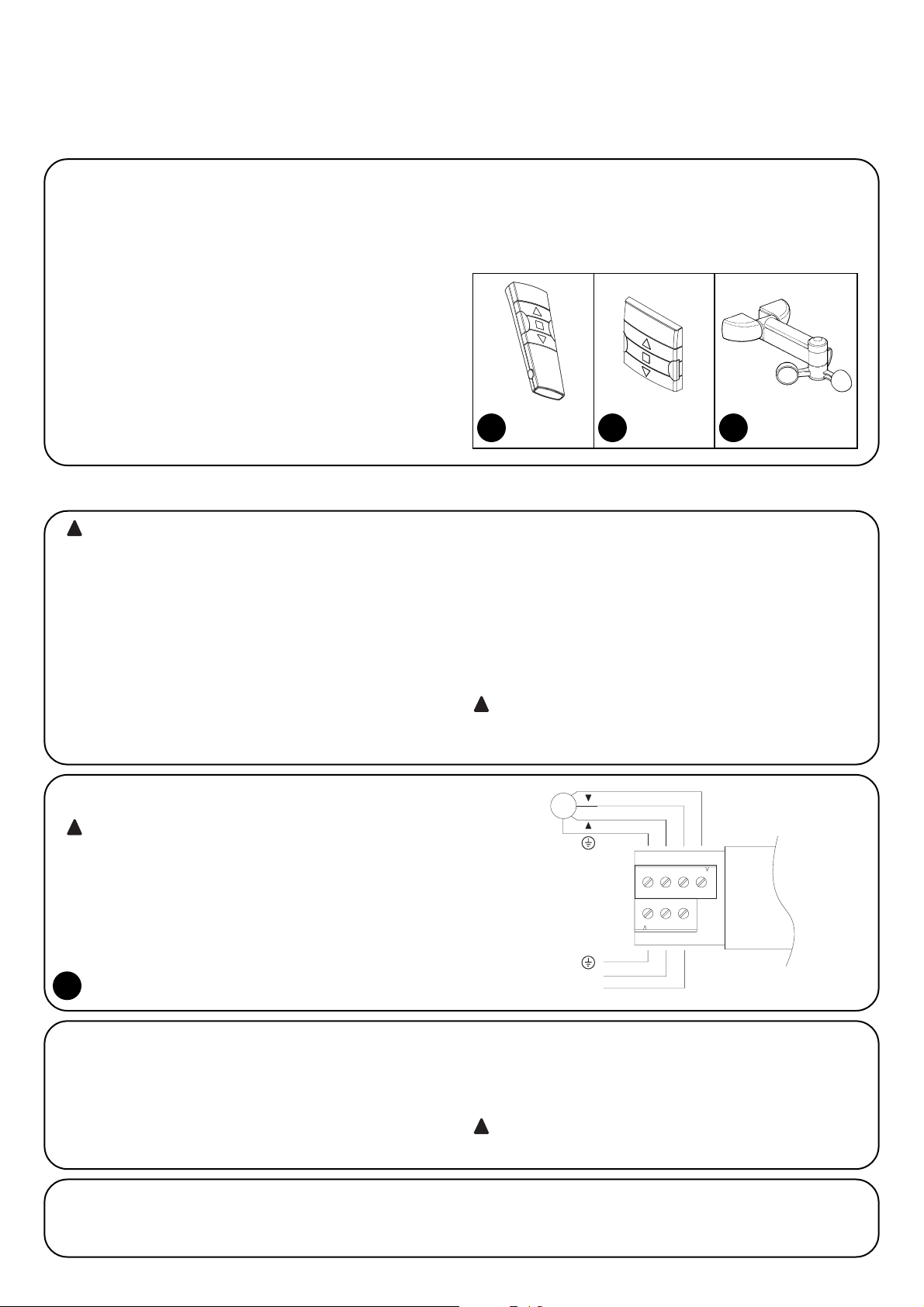
2.1.1) Motor connection
The single-phase asynchronous motor powered by the electrical
mains must be connected on terminals 1-2-3-4 (DOWN, COMMON,
UP, EARTH).
“DOWN” is controlled by the ▼ key on the remote control, and “UP”
by the ▲ key. (anemometer intervention direction).
If the rotation direction is not correct, invert the terminals 1 and 3.
do not connect more than one motor to each control unit;
if necessary, use the appropriate expansion cards.
!
2.1.2) Power supply
The main supply to the unit must be connected using the terminals 5-6-7 (earth, phase, neutral) as shown in Fig. 4
The TT1 control unit enables the control of a single-phase asynchronous motor powered by the electrical mains, with “COMMON” “UP”
“DOWN” type connections, and used for the automation of awnings,
rolling shutters and similar fixtures.
The control unit incorporates a radio receiver operating at a frequency of 433.92 MHz, with rolling code technology that guarantees high
levels of security. Up to 30 transmitters (“ERGO” fig. 1, “PLANO” fig.
2) or radio-controlled sensors (“VOLO S RADIO” fig. 3) can be
memorized for each control unit. After each command, the motor is
powered for the operating time required. An electric limit switch
incorporated in the motor stops the movement when the desired
position is reached. The programming can be done directly from the
transmitters, with beeps that sound to guide users through the various phases. “VOLO S RADIO” climatic sensors (Fig. 3) enable users
to manage the movement of the awnings or rolling shutters automatically, depending on the wind, sun or rain conditions.
N.B.: Besides “ERGO”, “PLANO” and “VOLO S RADIO”, the control
unit can manage other kinds of transmitters and functioning modes,
too. Please refer to Chapter 4 “Additional information” for further
explanations.
Warnings
The TT1 control unit is suitable for the control of a single-phase asynchronous motor powered by the electrical mains and used for the
automation of awnings, rolling shutters and similar fixtures.
Any other use is improper and prohibited. The unit must be installed by
qualified technicians in compliance with the electrical and safety regulations in force.
1) Product description
N
L
5
4
COM
M
6 7
3 2 1
2.1) Electrical connections
Carefully follow all the connection instructions, if you have
any doubts do NOT make experiments but consult the relevant technical specifications sheets which are also available
on the web site www.niceforyou.com
An incorrect connection may cause serious damage to the
control unit.
!
2) Installation
The electrical systems and automations must be installed by
qualified and experienced personnel in compliance with current
legislation. Before you proceed to make any connections make
sure that the power supply is disconnected.
1. Strip the motor cable and the power supply cable about 3 cm
and then the single wires approx. 5 mm.
2. Open the container by removing the “cable cap” as shown in fig. 5.
3. Thread the two cables through the designated holes in the “cable
cap” (see fig. 6).
4. Pull the card a few centimetres out of the container (see fig. 7).
5. Connect the wires to the terminals as shown in fig. 8, observing
the diagram in fig. 4 and the operations described in chapter 2.1.
6. Fold the cables as shown in fig. 9.
7. Push the card inside the container, make sure that the stripped
length of the cable is fully inside the container, then slide the “cap”
until the container closes completely (see fig. 10)
8. The control unit can be fitted directly in the shutter/awning box,
double-sided tape can be used for this. To avoid the risk of water
leaks it should be positioned with the cables towards the bottom
as shown in Fig. 11. Do not place it with the cables towards the
top (Fig. 12).
Do not perforate the container.
!
!
4
1
ERGO
2
PLANO
3
VOLO S RADIO
Page 3
GB
3
2.1.3) Weather sensors
The control unit manages the climatic sensors by means of a “VOLO
S RADIO”-type radio (max. no. 3). Memorisation of a “VOLO S
RADIO” sensor must be carried out like that of a normal transmitter.
Follow the procedure set out in Table “A2”. Intervention levels must
be programmed actually on the “VOLO S RADIO” sensor.
Wind intervention levels must be given priority, followed by the rain and
sun. Please refer to the “VOLO S RADIO” manual for further details.
interventions on the anemometer provoke a command
equivalent to the ▲ key command on the transmitters
!
Each transmitter or radio sensor is recognised by the control unit by
means of an unequivocal “code”. A “memorisation” phase must
therefore be performed in order to allow the control unit to recognise
each single transmitter.
• All the memorisation sequences are timed, that is, they
must be completed within the programmed time limits.
• For transmitters with multiple “groups”, choose the group
the motor must be associated with before proceeding with
the memorisation phase.
•Programming via radio may be done on all the control units
within the range of the transmitter; therefore, only the one
involved in the operation should be kept switched on.
!
3) Programming
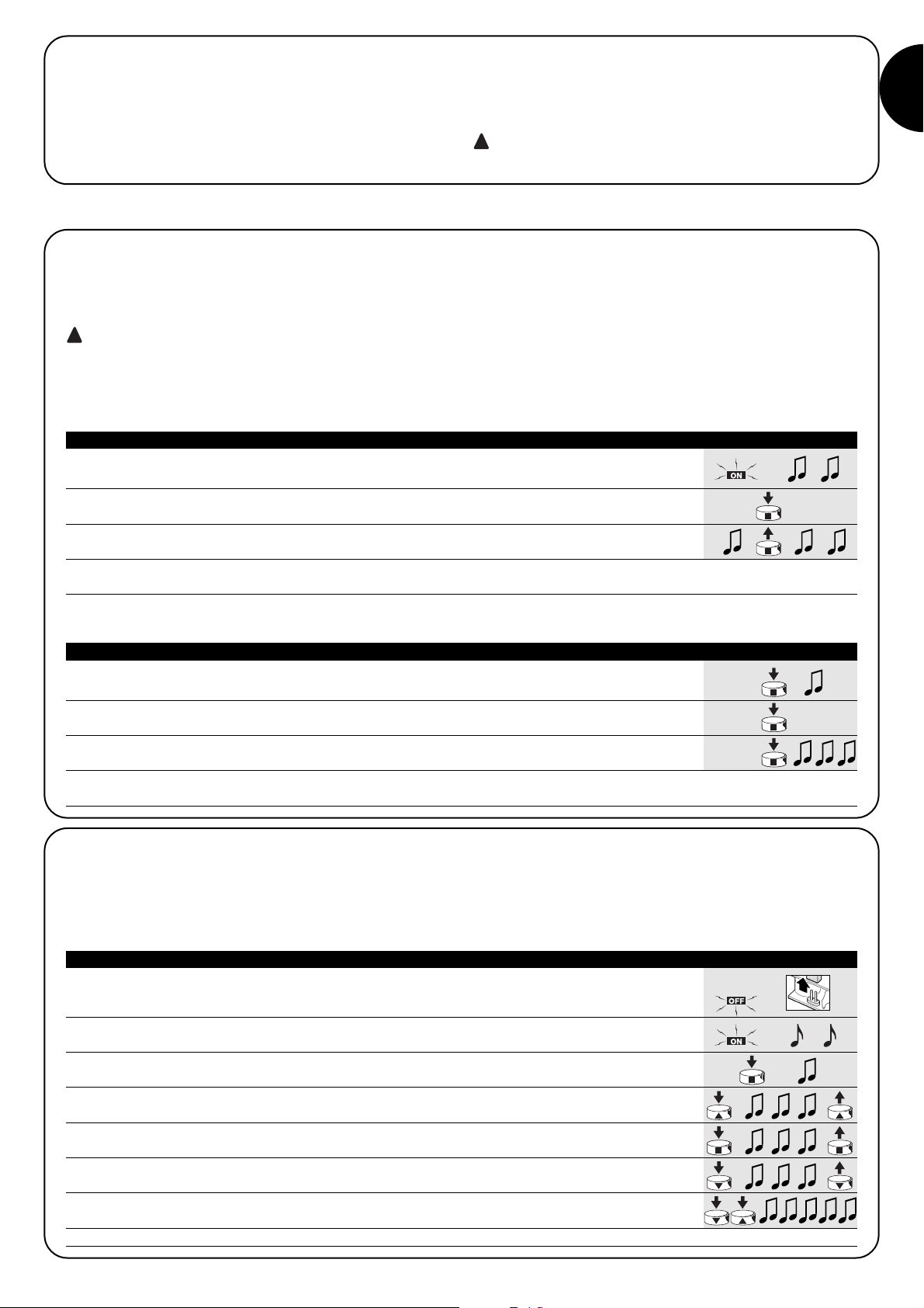
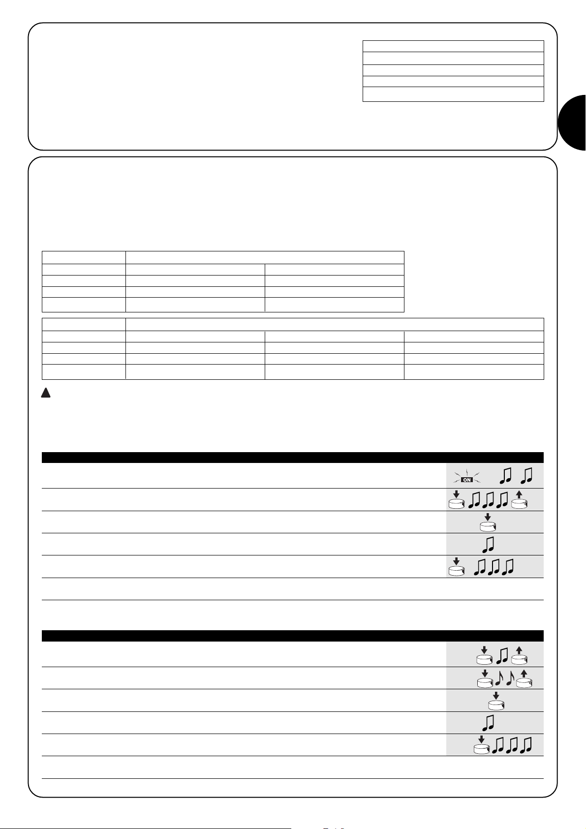
1. As soon as the control unit is powered, 2 long beeps will sound
2. Within 5 seconds press and hold down button ■ of the transmitter to be memorised
(for approx. 3 seconds) 3s
3. Release button ■ when you hear the first of the 3 beeps confirming memorisation
N.B. If transmitters have already been memorised in the control unit, 2 short beeps will be heard when it is switched on. This means that
the above procedure is not valid and another memorisation procedure must be used (Table “A2”).
When the memory contains no codes the first radio control unit can be entered as follows:
1. Press and hold down button ■ of the new transmitter until you hear a beep
(after about 5 seconds) then release it New 5s
2. Press button ■ of a previously memorized transmitter slowly 3 times
Old X3
3. Press button ■ on the new transmitter again, releasing it when you hear the first of the 3 beeps.
New
N.B. 3 long beeps will sound if memorisation has been successfully completed. 6 beeps will sound when the memory is full (30
transmitters), telling you the transmitter cannot be memorised.
When one or more transmitters have already been memorised, others may be enabled as follows:
Table “A1” Memorizing the first transmitter (fig. 13) Example
Table “A2” Memorizing the first transmitter (fig. 14) Example
A Switch the control unit off and cut the jumper on the weld side of the card (see fig. 15).
B Power the control unit and wait for the initial beeps
1 Press and hold down button ■ of a previously memorized transmitter until you hear a beep
(after about 5 seconds) then release it. 5s
2 Press and hold down button ▲ of the transmitter until you hear 3 beeps;
release button ▲ exactly during the third beep.
3 TPress and hold down button ■ of the transmitter until you hear 3 beeps;
release button ■ exactly during the third beep.
4 Press and hold down button ▼ of the transmitter until you hear 3 beeps;
release button ▼ exactly during the third beep.
5 If you wish to delete all the data in the memory, press the ▼ ▲ keys simultaneously
within 2 seconds until you hear the first of 5 beeps, then release them.
N.B. 5 beeps will sound, indicating that all the codes in the memory have been deleted.
If you need to delete all the data contained in the memory of the
control unit, carry out the following procedure.
The memory can be deleted:
• using a non-memorised transmitter starting from point A.
• using a previously memorised transmitter starting the procedure
from point N. 1
You can delete:
• the transmitters only, by stopping at point 4 of the procedure;
• all the data (transmitters and programming the working time), by
carrying out the procedure through to point 5.
➨
➨
Table “A3” Memory deletion (fig. 15) Example
➨
Page 4

4
3.1) Programming the “Working time”
The “Working Time” is the time during which the control unit commands
the motor, and both the factory time and the time after the memory has
been deleted are approximately 150 seconds. If necessary, the running
time can be altered from a minimum of 4 seconds to a maximum of 240.
The programming procedure is carried out in the “self-recognition” state, or
better, by measuring the time necessary to carry out the entire manoeuvre.
The motor must be moved and set next to a limit switch and the
most difficult (and therefore slowest) manoeuvre for the motor measured. This is normally re-winding. The manufacturer recommends
that users programme a working time which is a few seconds longer
than the time which is strictly necessary for the manoeuvre.
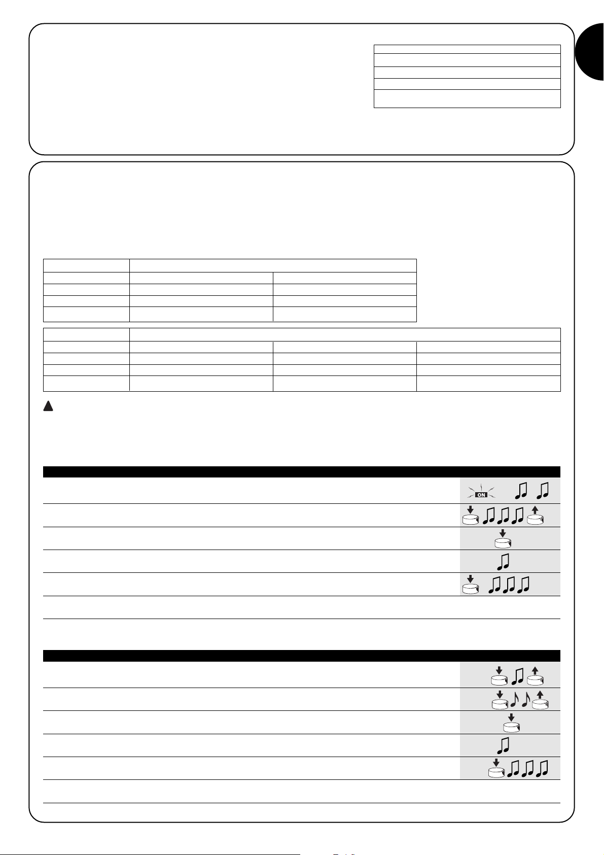
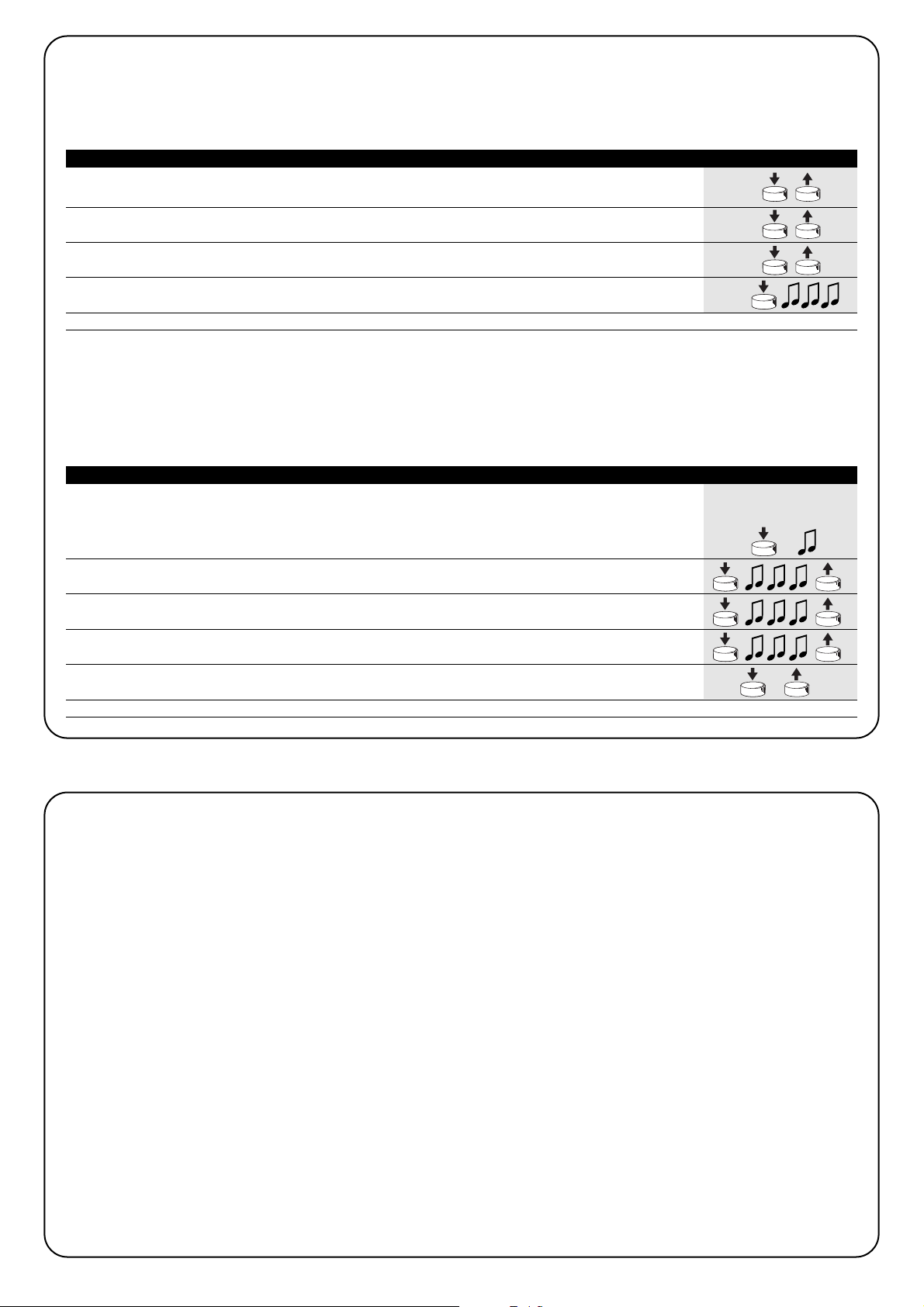
1. Press and hold down button ■ of a previously memorized transmitter until you hear a beep
(after about 5 seconds) then release it. 5s
2. Press key ■ again until you hear 4 short beeps (after approx. 5 seconds), then release
5s
3. Press keys ▲ (or ▼)¸ in order to begin the manoeuvre and start up the time counting phase.
4. Wait for the motor to finish the manoeuvre and after a few seconds press key ■ to stop
the time count. Three beeps will indicate the new working time has been memorised successfully.
N.B. If the user wishes to reset the factory time of 150 seconds, at point 3 s/he must press key 5 until s/he hears the first of 3 beeps
indicating programming has taken place.
Table “A4” Programming the working time (fig. 16) Example
4.1) Usable transmitters
The transmitters which can be used are shown in Table “A5”, together with
their relative radio coding.
The transmitters have different kinds of coding, and the control unit is unable to recognise them simultaneously. The first transmitter memorised will thus determine the type of coding, and consequently the transmitters which can be memorised successively .
All codes must be deleted if the user wishes to change the type of transmitter (see tables “A3” “A10”).
The type of code can be checked by counting the number of beeps which sound when the control unit is switched on.
CODIFICA Trasmettitori
ERGO1 - ERGO4 - ERGO6
PLANO1 - PLANO4 - PLANO6 - PLANO TIME
FLOR Rolling code VOLO S RADIO
FLO1R - FLO2R - FLO4R
VERY VR
SMILO Rolling code SM2 - SM4
FLO Fixed code
FLO1 - FLO2 - FLO4
VERY VE
Table “A5”
4) Additional Information
Besides the transmitters from the “ERGO” and “PLANO” series, the
control unit will also recognise other kinds of transmitters manufactured by NICE (please refer to Chapter 4.1 “Usable transmitters”).
By using a special memorisation procedure for the transmitters, it is
also possible to associate a special command to each of the transmitter keys (refer to Chapter 4.2 “Programming transmitters in Mode
I and Mode II”).
BIP Types of coding for the transmitters memorised
1 short beep Transmitters with FLO coding
2 short beeps Transmitters with FLOR coding
3 short beeps Transmitters with SMILO coding
2 long beeps Empty memory (no memorized transmitter)
Table “A6”
4.2) Memorizing the transmitters in Mode I and Mode II
Tables “A1” and “A2” show the memorisation of transmitters in Mode
I, where each key is allocated a command:
key 1= ▲ = ASCENT
key 2 = ■ = STOP
key 3 = ▼ = DESCENT
The transmitters can also be memorised in Mode II. This mode gives
the user the most flexibility when using the transmitters.
Transmitters in both Mode I and Mode II can be memorised in the
same control unit.
The differences between the 2 programming modes have been
described below:
FLO4R
VERY SM2 SM4
ERGO
PLANO VOLO S RADIO
Page 5
GB
5
4.2.1) Mode I
In this mode, the command associated with the transmitter keys is fixed: key 1 (or ▲)
commands the ascent, key 2 (or ■) commands a stop, key 3 (or ▼) commands the
descent, key 4 (if present) commands a stop.
A single memorization stage is carried out for each transmitter; during this stage it
does not matter which key is pressed, and only one space is occupied in the
memory.
Please refer to Chapter 3 “Programming” for information about how to memorise or delete the transmitters.
Esempio memorization Mode
Key 1 or ▲ ASCENT
Key 2 or ■ STOP
Key 3 or ▼ DESCENT
Key 4 STOP
Example 1 memorization Mode II
Key 1 ASCENT on TT1N no. 1
Key 2 DESCENT on TT1N no. 1
Key 3 ASCENT on TT1N no. 2
Key 4 DESCENT on TT1N no. 2
4.2.2) Mode II
This mode enables the user to associate one of the following commands 1 “step step” (ascent-stop-descent-stop…), 2 “ascent”, 3
“descent”, 4 “stop” with the keys on the transmitter.
Memorisation must be carried out again if the user wishes to allocate another command to another key on the same transmitter.
The choice of which key to press is important during this phase, and space in the memory will be used up for each key memorised.
• The running time cannot be programmed if a transmitter is memorised in Mode II.
•A transmitter programmed in Mode II cannot be used in the “multi-group” mode.
When the memory contains no transmitters the first one can be memorized in mode II as follows:
one or more transmitters have already been memorized, others may be enabled in Mode II as follows:
Example 2 memorization Mode II
Key 1 STEP-BY-STEP on TT1N no. 1
Key 2 STEP-BY-STEP on TT1N no. 2
Key 3 ASCENT on TT1N no. 3
Key 4 DESCENT on TT1N no. 3
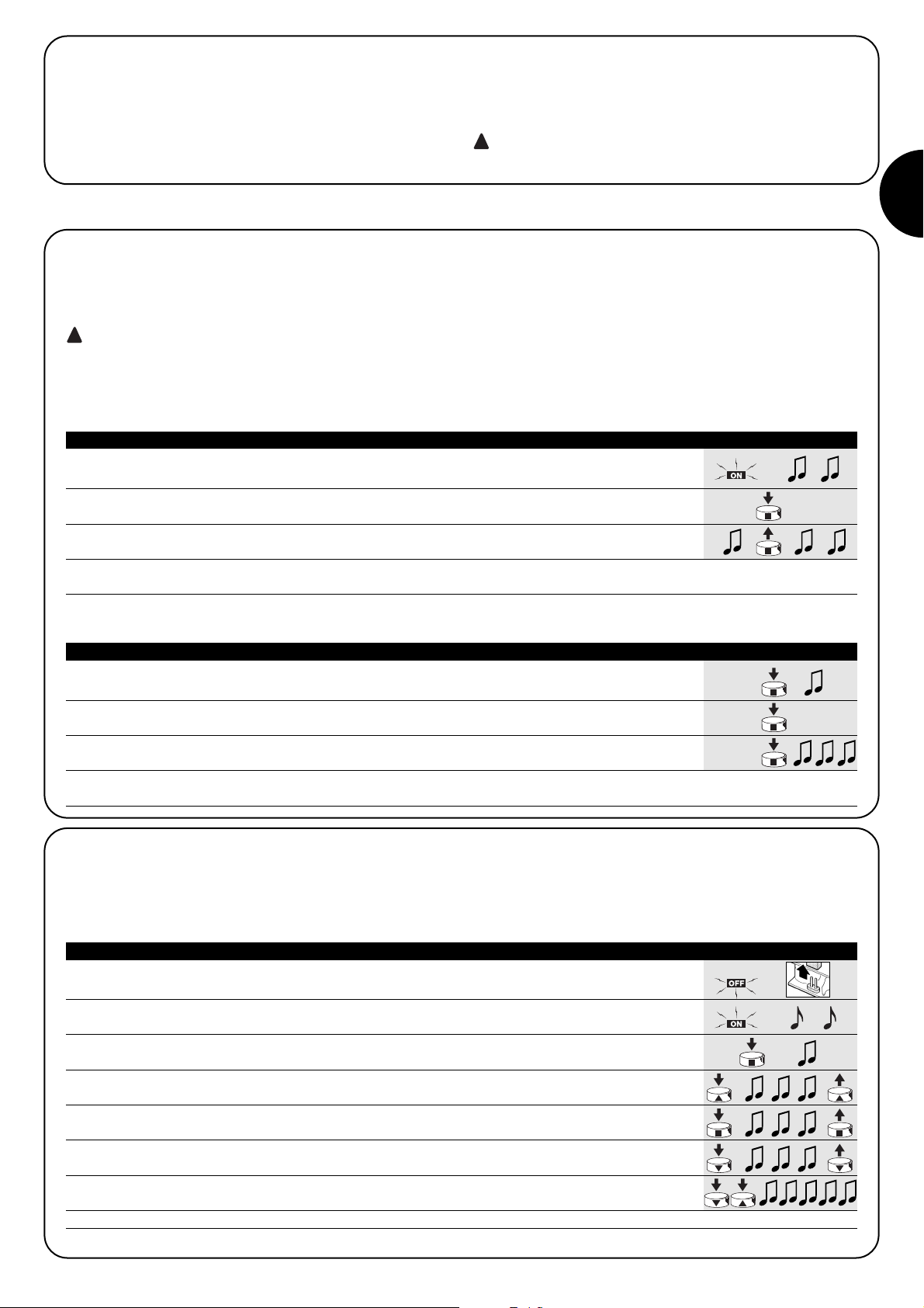
1. 2 long beeps will sound as soon as the control unit is powered.
2. Press the transmitter key to be memorised within 5 seconds, and hold it down until
you hear all 3 beeps indicating memorisation has taken place, then release. 5s
3. Within 3 seconds press the same key of the transmitter as many times as the number
corresponding to the desired command: 1 = “step-by-step” 2 = “ascent” 3 = “descent” 4 = “stop”
1-4 3s
4. After approximately 3 seconds, the user will hear a certain number of beeps.
These beeps correspond to the command selected. 1-4 3s
5. Press the same key again within 2 seconds to confirm programming.
Release this key when you hear the first of the 3 beeps. 2s
N.B. 3 long beeps will sound if memorization has been successful. If, at point 4, the user does not hear the same number of beeps as the
command required, wait for a few seconds to exit the procedure, without confirming the memorisation.
Table “A7” Memorizing the first transmitter in mode II Example
1. Press and hold down the new button to be memorized until you hear a beep
(after about 5 seconds) then release it
New 5s
2. Within 5 seconds, press and hold down the key of a transmitter which has already been
memorised (old) for approximately 5 seconds, until you hear 2 quick beeps, then release.
Old 5s
3.
Within 5 seconds press the same key of the (old) transmitter as many times as the number
corresponding to the desired command: 1 = “step-by-step” 2 = “ascent” 3 = “descent” 4 = “stop” Old
1-4
5s
4. After approximately 3 seconds you will hear several beeps. The number of these beeps will
be the same as the previously selected command. 1-4 3s
5.
Press the new key of the transmitter to memorise again within 2 seconds to confirm programming.
Release when you hear the first of the 3 beeps New
2s
N.B. 3 long beeps will sound if the memorization procedure has been successful. When the memory is full (30 transmitters), 6 beeps will
sound to indicate that the transmitter cannot be memorised.
Table “A8” Memorizing other transmitters in Mode II Example
!
Page 6

6
A new transmitter can easily be memorised, keeping the same features as the old transmitter, by following the procedure detailed in Table
“A9”.
Any new transmitters which are memorised in this manner will take on the same characteristics as the old one. If the old one was memorised in Mode I, the new one will also operate in Mode I. If, on the other hand, the old one was memorised in Mode II, the key of the new
transmitter will also be associated to the same command as the old one..
1. Hold down the key of the new transmitter you wish to memorise for at least 3 seconds,
then release.
New 3s
2. Press the key of the (old) transmitter which has already been enabled for at least 3 seconds,
then release.
Old 3s
3. Press the key of the new transmitter again for at least another 3 seconds, then release.
New 3s
4. Press the key of the old transmitter again until 3 beeps sound to confirm the new
transmitter has been memorised.
Old 3s
N.B. 6 beeps will sound when the memory is full (30 transmitters) in order to indicate that the transmitter cannot be memorised.
Table “A9” Memorizing other transmitters (fig. 14) Example
If you need to delete all the data contained in the memory of the control unit by using a transmitter memorized in Mode II, carry out the
following procedure.
You can delete:
• the transmitters only, by stopping the procedure at point 4;
• all the data (transmitters and programming of the running time), by following the procedure through to point 5.
1. Press and release a key memorised in Mode II. Do not worry if the motor starts up.
Press the same key of the transmitter again and keep it pressed down (the motor must be off)
until you hear a beep, after approximately 5 seconds, then release. 5s
2. Press the same key of the transmitter again and keep it pressed down until you hear 3 beeps.
Release the key during the third beep.
3. Press the same key of the transmitter again and keep it pressed down until you hear 3 beeps.
Release the key during the third beep.
4. Press the same key of the transmitter again and keep it pressed down until you hear 3 beeps.
Release the key during the third beep.
5. If you wish to delete all the data in the memory completely, press the same key again within 2
seconds, then release it. 2s
N.B. After a few seconds, 5 beeps will sound to indicate that all the codes in the memory have been deleted.
Table “A10” Memory deletion with transmitter memorized in Mode II Example
When the control unit is switched on, no beep sounds and the
transmitters do not transmit any commands.
Make sure that the control unit is powered correctly: there must be
mains voltage between terminals 6-7. If the power supply is correct,
there is likely to be a serious fault in the system, and the control unit
will have to be replaced.
After a radio command, you hear 6 beeps and the manoeuvre
does not start
The radio control is out of synch, the transmitter memorization procedure must be repeated.
After a radio command, you hear 10 beeps and then the
manoeuvre starts
The self-diagnosis of the parameters in the memory has detected a
fault. In this case, the user must delete the entire memory, memorise
the remote controls and programme the running time.
You are unable to programme the running time following the
procedure detailed in Table “A4”
If you are unable to programme the running time with the transmitters memorised in Mode II, check that the remote control has been
inserted in the memory in Mode I (key ▲ = ASCENT, key ■ 5 =
STOP, key ▼ = DESCENT)
The motor is “off”, but at times you have to give the step step
command twice in order to start it up.
It may be that the programmed running time is far too long for the
effective duration of the manoeuvre. As the motor will have stopped
next to a limit switch, the control unit may “think” the motor is still
moving because of a previous command. In this case, the first command is interpreted as a STOP and the second as a movement
command. Therefore, the user simply has to programme the running
time correctly in order to solve the problem (refer to Chapter 3.1 )
5) What to do if… a short troubleshooting guide!
➨
Page 7

GB
7
6) Technical characteristics
All technical specifications refer to a temperature of 20°C.
Electronic control unit
Power supply : 230Vac (+10-15%) 50Hz
Maximum motor power : 500W / 400VA
Operating temperature : -20 ÷ 50 °C
Dimensions / weight : 98 x 26 x 20 / 45g
Protection class : IP55 (container undamaged)
Time taken by manoeuvre : From 4 to 250 seconds (factory setting approx. 150 sec.)
Radio receiver
Frequency : 433.92MHz
Coding : FLO (fixed code), FLOR (rolling code) SMILO (rolling code)
N°. of transmitter that can be memorised : 30 (max. 3 weather sensors)
Range of the transmitters :estimated 150 m outdoor, 20 m indoor. *
* The capacity of the transmitters is strongly influenced by other devices with continuous transmissions which operate at the same frequency.
These include alarms, headphones, etc… which interfere with the control unit receiver.
Nice S.p.a reserves the right to make changes to its products at any time as it deems necessary
Declaration of conformity N°: mindy TT1N Rev 0
Nice S.p.a. via Pezza Alta, 13 Rustignè Oderzo (TV) ITALY
declares that the product: “TT1N” complies with the essential safety provisions of Directives:
R&TTE 1999/5/CE
date General Manage
20-01-2004 Lauro Buoro
Page 8

8
2.1.1) Collegamento motore
Il motore asincrono monofase alla tensione di rete deve essere collegato sui morsetti 1-2-3-4 (DISCESA, COMUNE, SALITA, TERRA).
“DISCESA” corrisponde al tasto ▼ dei telecomandi, “SALITA” al
tasto ▲ (direzione intervento anemometro). Se il senso di rotazione
non è corretto scambiare le connessioni dei morsetti 1 e 3.
Non collegare più di un motore per ogni centrale, even-
tualmente usare le apposite espansioni “TTE”
!
2.1.2) Alimentazione
L’alimentazione principale della centrale deve essere eseguita utilizzando i morsetti 5-6-7 (terra, fase, neutro) come indicato in fig. 4.
La centrale di comando TT1N permette di comandare un motore
asincrono monofase alimentato a tensione di rete con collegamenti
tipo “COMUNE” “SALITA” “DISCESA”, utilizzato per automazioni di
tende, tapparelle, e similari.
La centrale incorpora un ricevitore radio che opera alla frequenza di
433.92 MHz con tecnologia rolling code che garantisce elevati livelli
di sicurezza. Per ogni centrale è possibile memorizzare fino a 30 trasmettitori della serie “ERGO”(fig.1), “PLANO” (fig. 2) o radio sensori
“VOLO S RADIO” (fig.3). Dopo ogni comando il motore viene alimentato per il tempo lavoro previsto, un finecorsa elettrico presente
nel motore interrompere il movimento in corrispondenza della posizione voluta. Tutte le programmazioni si possono fare direttamente
dai trasmettitori, un “bip” acustico ne guiderà le varie fasi. Se si utilizzano i radio sensori climatici “VOLO S RADIO” (fig. 3) è possibile
gestire automaticamente il movimento delle tende o tapparelle a
seconda delle condizioni di vento sole o pioggia.
Nota: Oltre ad “ERGO”, “PLANO” e “VOLO S RADIO”, la centrale
può gestire anche altri tipi di trasmettitori ed altre modalità di funzionamento, per informazioni vedere il capitolo 4) “Approfondimenti”.
Avvertenze
La centrale TT1N è adatta al comando di un motore asincrono monofase alimentato a tensione di rete destinato ad automazioni di tende, tapparelle e similari, ogni altro uso è improprio e vietato.
L’installazione deve essere eseguita da personale tecnico nel pieno
rispetto delle normative elettriche e di sicurezza vigenti.
1) Descrizione del prodotto
N
L
5
4
COM
M
6 7
3 2 1
2.1) Collegamenti elettrici
Rispettare scrupolosamente i collegamenti previsti, in
caso di dubbio NON tentare invano, ma consultare le apposite schede tecniche di approfondimento disponibili anche sul
sito www.niceforyou.com
Un collegamento errato può provocare guasti gravi alla centrale.
!
2) Installazione
Gli impianti elettrici e le automazioni devono essere eseguite da personale esperto e qualificato, nel rispetto delle
norme di legge. Tutti i collegamenti devono essere eseguiti
senza presenza di alimentazione elettrica.
1. Sguainare il cavo motore e il cavo di alimentazione per circa 3cm
e poi i singoli fili per circa 5mm.
2. Aprire il contenitore togliendo il tappo passacavi come indicato
nella fig. 5.
3. Passare i due cavi negli appositi fori passacavo del tappo (vedi fig. 6).
4. Estrarre di qualche centimetro la scheda dal contenitore (vedi fig. 7).
5. Collegare i fili ai morsetti come indicato nella fig. 8, rispettando lo
schema di fig. 4 e quanto previsto nel capitolo 2.1) .
6. Ripiegare i cavi come in fig. 9.
7. Spingere la scheda all’interno del contenitore, verificare che la
parte sguainata del cavo sia tutta all’interno del contenitore, far
scorrere il tappo sui cavi fino alla completa chiusura (vedi fig. 10)
8. La centrale può essere posizionata direttamente nel cassonetto,
eventualmente utilizzare il nastro biadesivo per il fissaggio. Per
evitare il rischio di infiltrazioni d’acqua è necessario riporla con i
cavi verso il basso come evidenziato in fig. 11. , evitando assolutamente di porla con i cavi in alto (fig. 12).
Il contenitore non deve essere forato per nessun motivo.
!
!
4
1
ERGO
2
PLANO
3
VOLO S RADIO
Page 9
I
99
2.1.5) Sensori climatici
La centrale gestisce sensori climatici via radio tipo “VOLO S RADIO”
(fino ad un massimo di 3). La memorizzazione di un sensore “VOLO
S RADIO” avviene come un normale trasmettitore: seguire la procedura di tab. “A2”. I livelli di intervento devono essere programmati
direttamente sul sensore “VOLO S RADIO”.
L’intervento prioritario è quello del vento, seguono pioggia e sole, per
i dettagli fare riferimento al manuale di “VOLO S RADIO”.
un intervento dell’anemometro provoca un comando equi-
valente al tasto ▲ dei trasmettitori
!
Ogni trasmettitore o radio-sensore viene riconosciuto dalla centrale
attraverso un “codice” diverso da ogni altro trasmettitore, è necessaria quindi una fase di “memorizzazione” attraverso la quale si predispone la centrale a riconoscere ogni singolo trasmettitore.
•Tutte le sequenze di memorizzazione sono a tempo, cioè
devono essere eseguite entro i limiti di tempo previsti.
• Con trasmettitori che prevedono più “gruppi”, prima di procedere alla memorizzazione occorre scegliere il gruppo al
quale associare la centrale.
• La programmazione via radio può avvenire in tutte le centrali che si trovano nel raggio della portata del trasmettitore; è quindi opportuno tenere alimentata solo quella interessata all’operazione.
!
3) Programmazione
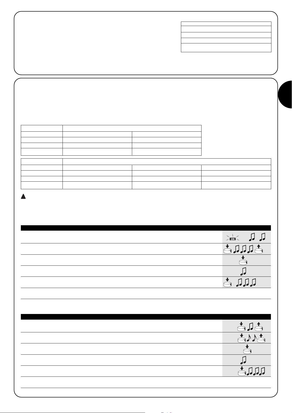
1. Appena data alimentazione alla centrale, si sentiranno 2 bip lunghi (biiip)
2. Entro 5 secondi premere e tener premuto il tasto ■ del trasmettitore da memorizzare
(per circa 3 secondi) 3s
3. Rilasciare il tasto ■ quando si sentirà il primo dei 3 bip che confermano la memorizzazione
Nota: Se nella centrale ci sono già dei trasmettitori memorizzati, all’accensione si udiranno dei bip brevi (bip) e non si potrà procedere
come descritto sopra ma occorre usare l’altra modalità di memorizzazione (Tabella “A2”)
Quando la memoria non contiene nessun trasmettitore si può precedere all’inserimento del primo con la seguente modalità:
1. Tenete premuto il tasto ■ del nuovo trasmettitore fino a sentire un bip (dopo circa 5 secondi)
Nuovo 5s
2. Lentamente premere per 3 volte il tasto ■ di un trasmettere già memorizzato
Vecchio X3
3. Premere ancora il tasto ■ del nuovo trasmettitore e rilasciare al primo dei 3 bip.
Nuovo
Nota: Se la memorizzazione è andata a buon fine si sentiranno 3 bip lunghi. Quando la memoria è piena (30 trasmettitori), 6 Bip
indicheranno che il trasmettitore non può essere memorizzato.
Quando uno o più trasmettitori sono già stati memorizzati, è possibile abilitarne altri in questo modo:
Tabella “A1” Memorizzazione del primo trasmettitore (fig. 13) Esempio
Tabella “A2” Memorizzazione di altri trasmettitori (fig 14) Esempio
A A centrale non alimentata togliere il ponticello presente nella scheda (vedi fig. 15).
Il ponticello deve essere ripristinato al termine della cancellazione.
B Alimentare la centrale ed attendere i bip iniziali.
1 Tenere premuto il tasto ■ di un trasmettitore già memorizzato fino a sentire un bip
(dopo circa 5 secondi) 5s
2 Tenere premuto il tasto ▲ del trasmettitore fino a sentire 3 bip;
rilasciare il tasto ▲ esattamente durante il terzo bip.
3 Tenere premuto il tasto ■ del trasmettitore fino a sentire 3 bip;
rilasciare il tasto ■ esattamente durante il terzo bip
4 Tenere premuto il tasto ▼ del trasmettitore fino a sentire 3 bip;
rilasciare il tasto ▼ esattamente durante il terzo bip
5 Se si vogliono cancellare tutti i dati presenti in memoria, entro 2 secondi, premere
contemporaneamente i 2 tasti ▼ ▲ fino a sentire il primo di 5 bip, poi rilasciarli
Nota: I 5 bip segnalano che tutti i codici in memoria sono stati cancellati.
Se dovesse rendersi necessario cancellare la memoria della centrale, si può eseguire questa procedura.
La cancellazione della memoria è possibile:
• con un trasmettitore non memorizzato iniziando dal punto A.
• con uno già memorizzato iniziando la procedura dal punto N°1
Si possono cancellare:
• solo i trasmettitori, terminando al punto 4
• tutti i dati (trasmettitori e programmazione del tempo lavoro),
completando la procedura fino al punto 5.
➨
➨
Tabella “A3” Cancellazione della memoria (fig. 15) Esempio
➨
Page 10

10
3.1) Programmazione del tempo lavoro
Il “Tempo Lavoro” è il tempo nel quale la centrale comanda il motore; il valore di fabbrica o dopo una cancellazione della memoria è di
circa 150 secondi. Se si desidera, è possibile modificare il tempo
lavoro da un minimo di 4 secondi ad un massimo di 240. La procedura di programmazione si effettua in “auto apprendimento”, cioè
misurando il tempo necessario per effettuare l’intera manovra.
E’ necessario portare il motore in corrispondenza di un finecorsa e
misurare la manovra più gravosa (e quindi più lenta) per il motore,
normalmente il riavvolgimento. E’ consigliabile programmare il tempo lavoro qualche secondo in più rispetto al tempo strettamente
necessario alla manovra.
1. Tenere premuto il tasto ■ di un trasmettitore già memorizzato fino a sentire un bip
(dopo circa 5 secondi), quindi rilasciare. 5s
2. Premere nuovamente il tasto ■ fino a sentire 4 bip brevi (dopo circa 5 secondi), quindi rilasciare
5s
3. Premere il tasto ▲ (o il tasto ▼) per iniziare la manovra e dare inizio alla fase di conteggio
del tempo
4. Attendere che il motore completi la manovra e dopo qualche secondo premere il tasto ■ per
fermare il conteggio del tempo; 3 bip segnaleranno la memorizzazione del nuovo tempo lavoro
Nota: Per ripristinare il tempo lavoro di fabbrica (150 secondi), al punto 3 premere il tasto ■ fino a sentire il primo di 3 bip di avvenuta
programmazione
Tabella “A4” Programmazione tempo lavoro (fig. 16) Esempio
4.1) Trasmettitori utilizzabili
Nella tabella “A5” sono indicati i trasmettitori che possono essere utilizzati con la relativa codifica radio.
Poiché le codifiche dei trasmettitori sono diverse e la centrale non può riconoscerle simultaneamente, il primo trasmettitore memorizzato
determina il tipo di codifica e quindi i trasmettitori che si potranno memorizzare in seguito.
Se si volesse cambiare tipo di trasmettitori è necessario cancellare tutti i codici (vedi tabelle “A3” “A10”).
E’ possibile verificare il tipo di codifica contando il numero di bip emessi dalla centrale al momento dell’accensione.
CODIFICA Trasmettitori
ERGO1 - ERGO4 - ERGO6
PLANO1 - PLANO4 - PLANO6 - PLANO TIME
FLOR Rolling code VOLO S RADIO
FLO1R - FLO2R - FLO4R
VERY VR
SMILO Rolling code SM2 - SM4
FLO Fixed code
FLO1 - FLO2 - FLO4
VERY VE
Tabella “A5”
4) Approfondimenti
La centrale oltre ai trasmettitori della serie “ERGO” e “PLANO”, riconosce altri tipi di trasmettitori prodotti da nice (vedi capitolo 4.1 “Trasmettitori utilizzabili”).
Con opportune procedure di memorizzazione dei trasmettitori è
anche possibile associare a ciascun tasto del trasmettitore un particolare comando (vedi capitolo 4.2 “Programmazione trasmettitori in
Modo I e Modo II”).
BIP Tipo di codifica dei trasmettitori memorizzati
1 bip breve Trasmettitori con codifica FLO
2 bip brevi Trasmettitori con codifica FLOR
3 bip brevi Trasmettitori con codifica SMILO
2 bip lunghi Memoria vuota (nessun trasmettitore memorizzato)
Tabella “A6”
4.2) Memorizzazione dei trasmettitori in Modo I e Modo II
Nelle tabelle “A1” e “A2” è descritta la memorizzazione dei trasmettitori in Modo I dove ad ogni tasto è assegnato un comando:
tasto 1= ▲ = SALITA
tasto 2 = ■ = STOP
tasto 3 = ▼ = DISCESA.
E’ possibile memorizzare i trasmettitori anche in Modo II, questa
modalità permette la massima flessibilità dell’utilizzo dei trasmettitori.
Si possono memorizzare nella stessa centrale trasmettitori sia in
Modo I che in Modo II.
Di seguito si descrivono le differenze tra le 2 modalità di programmazione:
FLO4R
VERY SM2 SM4
ERGO
PLANO VOLO S RADIO
Page 11
I
11
4.2.1) Modo I
In questa modalità il comando associato ai tasti del trasmettitore è fisso: il tasto 1 (o
▲) comanda la salita, il tasto 2 (o ■) comanda uno stop, il tasto 3 (o ▼) comanda la
discesa, un eventuale il tasto 4 comanda uno stop.
Si esegue una unica fase di memorizzazione per ogni trasmettitore e durante questa
fase non ha importanza quale tasto viene premuto; viene occupato un solo
posto in memoria.
Per memorizzare o cancellare i trasmettitori in Modo I vedere il capitolo 3 “Programmazioni”.
Esempio memorizzazione Modo I
Tasto 1 o ▲ SALITA
Tasto 2 o ■ STOP
Tasto 3 o ▼ DISCESA
Tasto 4 STOP
Esempio 1 memorizzazione Modo II
Tasto 1 SALITA su TT1N n°1
Tasto 2 DISCESA su TT1N n°1
Tasto 3 SALITA su TT1N n°2
Tasto 4 DISCESA su TT1N n°2
4.2.2) Modo II
Questa modalità consente di associare ad ogni tasto del trasmettitore uno fra i seguenti comandi: 1 “passo passo” (salita-stop-discesastop…), 2 “salita”, 3 “discesa”, 4 “stop”.
Se si desidera assegnare ad un altro tasto dello stesso trasmettitore un altro comando è necessaria una nuova memorizzazione.
Durante questa fase è importante la scelta del tasto da premere e nella memoria viene occupato un posto per ogni tasto memoriz-
• Non è possibile effettuare la programmazione del tempo lavoro con un trasmettitore memorizzato in Modo II
• Se un trasmettitore è programmato in Modo II non può essere utilizzato in modalità “multigruppo”.
Quando la memoria non contiene nessun trasmettitore si può precedere alla memorizzazione del primo in Modo II con la seguente modalità:
Quando uno o più trasmettitori sono già memorizzati, è possibile memorizzarne altri in Modo II seguendo questa procedura:
Esempio 2 memorizzazione Modo II
Tasto 1 PASSO PASSO su TT1N n°1
Tasto 2 PASSO PASSO su TT1N n°2
Tasto 3 SALITA su TT1N n°3
Tasto 4 DISCESA su TT1N n°3
1. Appena data alimentazione alla centrale, si sentiranno 2 bip lunghi (biiip)
2. Entro 5 secondi premere il tasto da memorizzare del trasmettitore e mantenerlo premuto fino
alla fine di tutti e 3 i bip di avvenuta memorizzazione e poi rilasciare 5s
3. Entro 3 secondi iniziare a premere lo stesso tasto del trasmettitore per un numero di volte
pari al comando desiderato: 1 = “passo-passo” 2 = “salita” 3 = “discesa” 4 = “stop” 1-4 3s
4. Dopo circa 3 secondi si udirà un numero di bip pari al comando selezionata
1-4 3s
5. Entro 2 secondi premere nuovamente lo stesso tasto per confermare la programmazione e
rilasciare al primo dei 3 bip. 2s
Nota: Se la memorizzazione è andata a buon fine si sentiranno 3 bip lunghi. Se al punto 4 non si sente il numero di bip uguale al comando
desiderato, aspettare alcuni secondi per uscire dalla procedura senza confermare la memorizzazione.
Tabella “A7” Memorizzazione del primo trasmettitore in Modo II Esempio
1. Tenere premuto il nuovo tasto da memorizzare del trasmettitore fino a sentire un bip
(dopo circa 5 secondi) poi rilasciare
Nuovo 5s
2. Entro 5 secondi premere e tenere premuto circa 5 secondi il tasto di un trasmettitore già
memorizzato (vecchio) fino a sentire 2 bip veloci, quindi rilasciare.
Vecchio 5s
3. Entro 5 secondi ripremere lo stesso tasto del trasmettitore (vecchio) un numero di volte
uguale al comando desiderato: 1 = “passo-passo” 2 = “salita” 3 = “discesa” 4 = “stop”
Vecchio
1-4
5s
4. Dopo circa 3 secondi si udirà un numero di bip uguale al comando precedentemente
selezionato 1-4 3s
5. Entro 2 secondi premere nuovamente il nuovo tasto da memorizzare del trasmettitore per
confermare la programmazione e rilasciare al primo dei 3 bip.
Nuovo
2s
Nota: Se la memorizzazione è andata a buon fine si sentiranno 3 bip lunghi. Quando la memoria è piena (30 trasmettitori), 6 Bip
indicheranno che il trasmettitore non può essere memorizzato.
Tabella “A8” Memorizzazione di altri trasmettitori in Modo II Esempio
!
Page 12
12
E’ possibile memorizzare in modo semplice un nuovo trasmettitore mantenendo le caratteristiche del vecchio trasmettitore seguendo la procedura di tabella “A9”.
Il nuovo trasmettitore così memorizzato erediterà le caratteristiche di quello vecchio, cioè se il vecchio era memorizzato in Modo I, anche il
nuovo funzionerà in Modo I, se il vecchio era memorizzato in Modo II anche il tasto del nuovo trasmettitore verrà associato allo stesso comando di quello vecchio.
1. Tenere premuto il tasto del nuovo trasmettitore che si vuole memorizzare per almeno 3
secondi poi rilasciare
Nuovo 3s
2. Premere il tasto del trasmettitore già abilitato (vecchio) per almeno 3 secondi poi rilasciare.
Vecchio 3s
3. Ripremere il tasto del nuovo trasmettitore per almeno altri 3 secondi poi rilasciare
Nuovo 3s
4. Ripremere il tasto del vecchio trasmettitore fino a quando 3 bip confermeranno la
memorizzazione del nuovo trasmettitore
Vecchio 3s
Nota: Quando la memoria è piena (30 trasmettitori), 6 Bip indicheranno che il trasmettitore non può essere memorizzato.
Tabella “A9” Memorizzazione di altri trasmettitori Esempio
Se dovesse rendersi necessario cancellare tutti i dati contenuti nella memoria della centrale utilizzando un trasmettitore memorizzato in
Modo II, si può eseguire questa procedura.
Si possono cancellare:
• solo i trasmettitori, terminando al punto 4
• tutti i dati ( trasmettitori e programmazione del tempo lavoro), completando la procedura fino al punto 5.
1. Premere e rilasciare un tasto memorizzato in modo II, non preoccuparsi se il motore si mette
in movimento.
Ripremere e tenere premuto lo stesso tasto del trasmettitore (il motore ora deve essere fermo)
fino a sentire un bip (dopo circa 5 secondi), poi rilasciare. 5s
2. Ripremere e tenere premuto lo stesso tasto del trasmettitore fino a sentire 3 bip;
rilasciare il tasto esattamente durante il terzo bip.
3. Ripremere e tenere premuto lo stesso tasto del trasmettitore fino a sentire 3 bip;
rilasciare il tasto esattamente durante il terzo bip
4. Ripremere e tenere premuto lo stesso tasto del trasmettitore fino a sentire 3 bip;
rilasciare il tasto esattamente durante il terzo bip
5. Se si vogliono cancellare completamente tutti i dati presenti in memoria, entro 2 secondi,
ripremere ancora una volta lo stesso tasto e poi rilasciarlo 2s
Nota: Dopo qualche secondo 5 bip segnalano che tutti i codici in memoria sono stati cancellati.
Tabella “A10” Cancellazione della memoria con trasmettitore memorizzato in Modo II Esempio
Dopo aver alimentato la centrale non si sente nessun bip e i
trasmettitori non comandano.
Verificare che la centrale sia correttamente alimentata: tra i morsetti
6-7 deve essere presente la tensione di rete. Se l’alimentazione è
corretta, è probabile vi sia un guasto grave e la centrale deve essere sostituita
Dopo un comando via radio si sentono 6 Bip e la manovra non
parte
Il radiocomando è fuori sincronismo, bisogna ripetere la memorizzazione del trasmettitore.
Dopo un comando si sentono 10 Bip poi parte la manovra.
L’autodiagnosi dei parametri in memoria ha rilevato qualche anomalia. In questo caso è necessario effettuare una cancellazione totale
della memoria e ripetere la memorizzazione dei telecomandi e la programmazione del tempo lavoro.
Non si riesce a programmare il tempo lavoro seguendo la procedura di tab. “A4”
Non è possibile programmare il tempo lavoro con trasmettitori
memorizzati in Modo II, verificare che il telecomando sia inserito in
memoria in Modo I (tasto ▲ = SALITA, tasto ■ = STOP, tasto ▼ =
DISCESA)
Il motore è fermo, ma a volte devo dare 2 volte il comando di
passo passo per metterlo in moto.
Potrebbe essere che il tempo lavoro programmato sia eccessivamente lungo rispetto alla durata effettiva della manovra: sebbene il
motore sia fermo in corrispondenza di un finecorsa, la centrale
potrebbe considerare il motore ancora in movimento a causa di un
comando precedente. In questo caso il primo comando viene interpretato come uno STOP e il secondo come comando di movimento. In questo caso e sufficiente programmare correttamente il tempo
lavoro (vedere capitolo 3.1 )
5) Cosa fare se... cioè piccola guida se qualcosa non va!
➨
Page 13

I
13
6) Caratteristiche tecniche
Tutte le caratteristiche sono riferite alla temperatura di 20°C
Centrale elettronica
Alimentazione : 230Vac (+10-15%) 50Hz
Potenza massima motori : 500W / 400VA
Temperatura di funzionamento : -20 ÷ 50 °C
Dimensioni / peso : 98 x 26 x 20 / 45g
Grado Protezione : IP55 (contenitore integro)
Te mpo di durata manovra : Da 4 a 250 secondi (di fabbrica circa 150 sec)
Ricevitore radio
Frequenza : 433.92MHz
Codifica : FLO (fixed code), FLOR (rolling code) SMILO (rolling code)
N° trasmettitori memorizzabili : 30 con massimo 3 sensori climatici
Portata dei trasmettitori : stimata in 150 m in spazio libero e 20m se all’interno di edifici *
* La portata dei trasmettitori è fortemente influenzata da altri dispositivi che operano alla stessa frequenza con trasmissioni continue come
allarmi, radiocuffie, ecc… che interferiscono con il ricevitore della centrale.
Nice si riserva il diritto di apportare modifiche ai prodotti in qualsiasi momento riterrà necessario
Dichiarazione di conformità N°: mindy TT1N Rev 0
Nice S.p.a. via Pezza Alta, 13 Rustignè Oderzo (TV) ITALY dichiara che il prodotto: “mindy TT1N” è conforme ai requisiti essenziali richiesti
dalla Direttiva R&TTE 1999/5/CE, per l'uso cui l'apparecchio è destinato.
Data Amministratore Delegato
20-01-2004 Lauro Buoro
Page 14

14
2.1.1) Branchement moteur
Le moteur asynchrone monophasé, alimenté à la tension de secteur,
doit être connecté aux bornes 1-2-3-4 (DESCENTE, COMMUN,
MONTÉE, TERRE).
“DESCENTE” correspond à la touche ▼ des émetteurs, “MONTÉE” à la
touche ▲ (direction intervention anémomètre). Si le sens de rotation n’est
pas correct, échanger les connexions des bornes 1 et 3.
Ne pas brancher plus d’un moteur à chaque logique de
commande, utiliser éventuellement les extensions “TTE”
!
2.1.2) Alimentation
L’alimentation principale de la logique de commande doit être effectuée en utilisant les bornes 5-6-7 (terre, phase, neutre) comme l’indique la fig. 4.
La logique de commande TT1N permet de commander un moteur asynchrone monophasé à la tension de secteur avec connexions type “COMMUN” “MONTÉE” “DESCENTE”, utilisé pour l’automatisation de stores,
volets roulants et similaires.
La logique de commande possède un récepteur radio incorporé qui
fonctionne à la fréquence de 433,92 MHz avec technologie rolling code
qui garantit des niveaux de sécurité élevés. Pour chaque logique de commande, il est possible de mémoriser jusqu’à 30 émetteurs de la série
“ERGO” (fig. 1) et “PLANO” (fig. 2) ou capteurs radio “VOLO S RADIO”
(fig. 3). Après chaque commande, le moteur est alimenté pendant le
temps de travail prévu, un fin de course électrique présent dans le moteur
interrompt le mouvement au niveau de la position voulue. Toutes les programmations peuvent être faites directement avec les émetteurs, un “bip”
sonore en guidera les différentes phases. Si l’on utilise les capteurs climatiques “VOLO S RADIO” (fig. 3), il est possible de gérer automatiquement le mouvement des stores ou des volets roulants suivant les condi-
tions de vent, de soleil ou de pluie.
Note: En dehors de “ERGO”, “PLANO” et “VOLO S RADIO”, la logique
peut gérer aussi d’autres types d’émetteurs et d’autres modes de fonctionnement, pour tout renseignement voir le chapitre 4) “Approfondissements”.
Avertissements
La logique de commande TT1N est destinée à la commande d’un moteur asynchrone monophasé alimenté à la tension de secteur pour l’automatisation de
stores, volets roulants et similaires, toute autre utilisation est impropre et interdite.
L’installation doit être effectuée par du personnel technique dans le plein
respect des normes électriques et de sécurité en vigueur.
1) Description du produit
N
L
5
4
COM
M
6 7
3 2 1
2.1) Branchements électriques
Respecter scrupuleusement les connexions prévues, en
cas de doute, NE PAS tenter en vain mais consulter les
notices techniques d’approfondissement disponibles également sur le site www.niceforyou.com
Une connexion erronée peut endommager gravement la
logique de commande.
!
2) Installation
Les installations électriques et les automatisations doivent
être exécutées par du personnel expérimenté et qualifié dans le
respect des normes en vigueur. Toutes les connexions doivent
être effectuées quand l’installation n’est pas alimentée.
1. Dénuder le câble moteur et le câble d’alimentation sur environ 3 cm
puis chaque conducteur sur environ 5 mm.
2. Ouvrir le boîtier en enlevant le bouchon passe-câbles comme l’indique
la fig. 5.
3. Passer les deux câbles dans les trous passe-câbles du bouchon (voir
fig. 6).
4. Extraire la carte électronique de quelques centimètres (voir fig. 7).
5. Connecter les fils aux bornes comme l’indique la fig. 8 en respectant
le schéma de la fig. 4 et les indications du chapitre 2.1.
6. Replier les câbles comme l’indique la fig. 9.
7. Pousser la carte à l’intérieur du boîtier, vérifier que la partie dénudée
du câble se trouve complètement à l’intérieur du boîtier, faire coulisser
le bouchon jusqu’à la fermeture parfaite du boîtier (voir fig. 10).
8. La logique de commande peut être positionnée directement dans le
caisson, utiliser éventuellement du ruban biadhésif pour la fixation.
Pour éviter le risque d’infiltrations d’eau, il faut la placer avec les câbles
vers le bas comme l’indique la fig. 11, et éviter absolument de la
mettre avec les câbles en haut (fig. 12).
le boîtier ne doit être percé sous aucun prétexte.
!
!
4
1
ERGO
2
PLANO
3
VOLO S RADIO
Page 15

F
15
2.1.3) Capteurs climatiques
La logique de commande gère des capteurs climatiques par radio type
“VOLO S RADIO” (jusqu’à un maximum de 3). La mémorisation d’un
capteur “VOLO S RADIO” s’effectue comme pour un émetteur normal:
suivre la procédure du tab. “A2”. Les niveaux d’intervention doivent être
programmés directement sur le capteur “VOLO S RADIO”. L’intervention
prioritaire est celle du vent, puis celle de la pluie et du soleil. Pour tout
détail se référer au manuel de “VOLO S RADIO”.
Une intervention de l’anémomètre provoque une commande
équivalente à la touche ˘ des émetteurs.
!
Chaque émetteur ou capteur radio est reconnu par la logique de
commande à travers un “code” distinct pour chacun d’eux. Il faut
donc procéder à la “mémorisation”, phase à travers laquelle on prépare la logique de commande à reconnaître chaque émetteur.
•Toutes les séquences de mémorisation sont temporisées, c’est-à-dire qu’elles doivent être effectuées dans les
limites de temps prévues.
•Avec des émetteurs qui prévoient plusieurs “groupes”,
avant de procéder à la mémorisation, il faut choisir le groupe auquel associer la logique de commande.
• La programmation par radio peut avoir lieu dans toutes les
logiques de commande qui se trouvent dans le rayon de
portée de l’émetteur ; il est donc opportun de n’alimenter
que celle qui est concernée par l’opération.
!
3) Programmations
1. Dès que la logique est alimentée, on entend 2 longs bips (biiip)
2. Dans les 5 secondes qui suivent, presser et maintenir enfoncée la touche ■ de l’émetteur
à mémoriser (pendant environ 3 secondes) 3s
3. Relâcher la touche ■ quand on entend le premier des 3 bips qui confirment la mémorisation
Note: Si des émetteurs ont déjà été mémorisés dans la logique, à l’allumage on entend 2 bips brefs (bip) et on ne pourra pas procéder
comme ci-dessus mais il faudra utiliser l’autre mode de mémorisation (Tableau “A2”)
Quand la mémoire ne contient aucun émetteur, on peut procéder à l’enregistrement du premier de la manière suivante:
1. Maintenir enfoncée la touche ■ du nouvel émetteur jusqu’à ce que l’on entende un bip
(au bout d’environ 5 secondes) puis la relâche Nouveau 5s
2. Presser lentement 3 fois la touch ■ d’un émetteur déjà mémorisé
Ancien X3
3. Presser encore la touche ■ du nouvel émetteur et la relâcher au premier des 3 bips
Nouveau
Note: Si la mémorisation a été effectuée correctement, on entendra 3 longs bips. Quand la mémoire est pleine (30 émetteurs), 6 bips
indiqueront que l’émetteur n’a pas pu être mémorisé.
Quand un ou plusieurs émetteurs ont déjà été mémorisés, il est possible d’en activer d’autres en procédant de la façon suivante:
Tableau “A1” Mémorisation du premier émetteur (fig. 13) Exemple
Tableau “A2” Mémorisation d’autres émetteurs (fig. 14) Exemple
A Avec la logique de commande non alimentée, enlever le cavalier présent sur la carte (voir fig. 15).
Le cavalier doit être remis en place à la fin de la procédure d’effacement.
B Alimenter la logique de commande et attendre les bips initiaux
1 Maintenir enfoncée la touche ■ d’un émetteur déjà mémorisé jusqu’à ce que l’on entende un bip
(au bout d’environ 5 secondes) puis la relâcher 5s
2 Maintenir enfoncée la touche ▲ de l’émetteur jusqu’à ce que l’on entende 3 bips ;
relâcher la touche ▲ exactement durant le troisième bip.
3 Maintenir enfoncée la touche ■ de l’émetteur jusqu’à ce que l’on entende 3 bips ;
relâcher la touche ■ exactement durant le troisième bip
4 Maintenir enfoncée la touche ▼ de l’émetteur jusqu’à ce que l’on entende 3 bips ;
relâcher la touche ▼ exactement durant le troisième bip
5
Si l’on souhaite effacer toutes les données présentes dans la mémoire, dans les 2 secondes presser
simultanément les 2 touches ▼ ▲ jusqu’à ce que l’on entende le premier des 5 bips, puis les relâcher.
Note: Les 5 bips signalent que tous les codes en mémoire ont été effacés.
S’il se révèle nécessaire d’effacer la mémoire de la logique de
commande, on peut effectuer cette procédure.
L’effacement de la mémoire est possible:
• avec un émetteur non mémorisé en commençant à partir du point A.
• avec un émetteur déjà mémorisé en commençant la procédure à
partir du point N°1
On peut effacer:
• uniquement les émetteurs en s’arrêtant au point 4
• toutes les données (émetteurs et programmation du temps de
travail), en complétant la procédure jusqu’au point 5.
➨
➨
Tableau “A3” Effacement de la mémoire (fig. 15) Exemple
➨
Page 16

16
3.1) Programmation du temps de travail
Le “Temps de Travail” est le temps pendant lequel la logique commande le
moteur ; la valeur d’usine ou après l’effacement total de la mémoire est d’environ 150 secondes. Si on le désire, il est possible de modifier le temps de
travail d’un minimum de 4 secondes à un maximum de 240. La procédure
de programmation s’effectue en “auto-apprentissage”, c’est-à-dire en mesurant le temps nécessaire pour effectuer toute la manœuvre.
Il faut porter le moteur au niveau d’un fin de course et mesurer la manœuvre
la plus lourde (et donc la plus lente) pour le moteur, normalement le réenroulement. Il est conseillé de programmer le temps de travail quelques secondes
en plus en respectant le temps strictement nécessaire à la manœuvre.
1. Maintenir enfoncée la touche ■ d’un émetteur déjà mémorisé jusqu’à ce que l’on entende
un bip (au bout d’environ 5 secondes) puis la relâcher 5s
2. Presser de nouveau la touche ■ jusqu’à ce que l’on entende 4 bips brefs (au bout d’environ
5 secondes), puis la relâcher 5s
3. Presser la touche ▲ (ou la touche ▼) pour commencer la manœuvre et faire partir
le comptage du temps
4.
Attendre que le moteur complète la manœuvre et au bout de quelques secondes presser la touche ■
pour arrêter le comptage du temps: 3 bips signaleront la mémorisation du nouveau temps de travail
Note: Pour rétablir le temps de travail programmé en usine (150 secondes) au point 3 presser la touche 5 jusqu’à ce que l’on entende le
premier des 3 bips signalant que la programmation a été effectuée.
Tableau “A4” Programmation du temps de travail (fig. 16 Exemple
4.1) Émetteurs utilisables
Le tableau “A5” indique les émetteur utilisables avec le codage radio correspondant.
Vu que les codages des émetteurs sont différents et que la logique de commande ne peut pas les reconnaître simultanément, le premier
émetteur mémorisé détermine le type de codage et donc les émetteurs qui pourront être mémorisés par la suite.
Si l’on souhaite changer le type d’émetteurs, il faut effacer tous les codes (voir tableaux “A3” “A10”).
Il est possible de vérifier le type de codage en comptant le nombre de bips émis par la logique de commande à l’allumage.
CODAGE Émetteurs
ERGO1 - ERGO4 - ERGO6
PLANO1 - PLANO4 - PLANO6 - PLANO TIME
FLOR Rolling code VOLO S RADIO
FLO1R - FLO2R - FLO4R
VERY VR
SMILO Rolling code SM2 - SM4
FLO Fixed code
FLO1 - FLO2 - FLO4
VERY VE
Tableau “A5”
4) Approfondissements
En plus des émetteurs de la série “ERGO” et “PLANO”, la logique
reconnaît d’autres types d’émetteurs produits par Nice (voir chapitre
4.1 “Émetteurs utilisables”).
En suivant certaines procédures de mémorisation des émetteurs, il
est possible d’associer à chaque touche de l’émetteur une commande particulière (voir chapitre 4.2 “Programmation des émetteurs
en Mode I et en Mode II).
BIP Type de codage des émetteurs mémorisés
1 bip bref Émetteurs avec codage FLO
2 bips brefs Émetteurs avec codage FLOR
3 bips brefs Émetteurs avec codage SMILO
2 bips longs Mémoire vide (aucun émetteur mémorisé)
Tableau “A6”
4.2) Mémoire vide (aucun émetteur mémorisé)
Les tableaux “A1” et “A2” décrivent la mémorisation des émetteurs
en Mode I où à chaque touche est associée une commande:
touche 1 = ▲ = MONTÉE
touche 2 = ■ = ARRÊT
touche 3 = ▼ = DESCENTE
Il est possible de mémoriser les émetteurs aussi en Mode II, ce mode
permet une plus grande flexibilité d’utilisation des émetteurs.
Dans la même logique de commande, on peut mémoriser des émetteurs aussi bien en Mode I qu’en Mode II.
Nous décrivons ci-après les différences entre les 2 modalités de programmation.
FLO4R
VERY SM2 SM4
ERGO
PLANO VOLO S RADIO
Page 17
F
17
4.2.1) Mode I
Dans ce mode, la commande associée aux touches de l’émetteur est fixe: la touche
1 (ou ▲) commande la montée, la touche 2 (o ■) commande un arrêt, la touche 3 (o
▼) commande la descente, une éventuelle touche 4 commande un arrêt.
On effectue une unique phase de mémorisation pour chaque émetteur et durant cet-
te phase, la touche pressée n’a pas d’importance ; une seule place est occupée
en mémoire.
Pour mémoriser ou effacer les émetteurs en Mode I voir le chapitre 3 “Programmations”.
Exemple mémorisation Mode I
Touche 1 ou ▲ MONTÉE
Touche 2 ou ■ ARRÊT
Touche 3 ou ▼ DESCENTE
Touche 4 ARRÊT
Exemple 1 mémorisation Mode II
Touche 1 MONTÉE sur TT1N n°1
Touche 2 DESCENTE sur TT1N n°1
Touche 3 MONTÉE sur TT1N n°2
Touche 4 DESCENTE sur TT1N n°2
4.2.2) Mode II
Ce mode permet d’associer à chaque touche de l’émetteur l’une des commandes suivantes: 1 “pas-à-pas” (montée-arrêt-descente-arrêt…),
2 “montée”, 3 “descente”, 4 “arrêt”.
Si l’on souhaite associer à une autre touche du même émetteur une autre commande, il faut effectuer une nouvelle mémorisation.
Durant cette phase le choix de la touche sur laquelle on appuie est important et dans la mémoire une place est occupée pour chaque
touche mémorisée.
• Il n’est pas possible d’effectuer la programmation du temps de travail avec un émetteur mémorisé en Mode II
• Si un émetteur est programmé en Mode II il ne peut pas être utilisé en mode “multigroupe”.
Quand la mémoire ne contient aucun émetteur, on peut procéder à la mémorisation du premier en Mode II de la manière suivante:
Quand un ou plusieurs émetteurs sont déjà mémorisés, il est possible d’en mémoriser d’autres en Mode II en suivant cette procédure:
Esempio 2 mémorisation Mode II
Touche 1 PAS-À-PAS sur TT1N n°1
Touche 2 PAS-À-PAS sur TT1N n°2
Touche 3 MONTÉE sur TT1N n°3
Touche 4 DESCENTE sur TT1N n°3
1. Au moment où la logique de commande est alimentée, on entend 2 longs bips (biiip)
2.
Dans les 5 secondes qui suivent, presser la touche à mémoriser sur l’émetteur et la maintenir enfoncée
jusqu’à la fin des 3 bips signalant que la mémorisation a été effectuée puis la relâcher
5s
3.
Dans les 3 secondes qui suivent, commencer à presser la même touche de l’émetteur un nombre
de fois égal à la commande désirée: 1 = “pas-à-pas” 2 = “montée” 3 = “descente” 4 = “arrêt”
1-4 3s
4. Au bout d’environ 3 secondes on entendra un nombre de bips égal à la commande sélectionnée
1-4 3s
5. Dans les 2 secondes qui suivent, presser de nouveau la même touche pour confirmer
la programmation et la relâcher au premier des 3 bips. 2s
Note: Si la mémorisation a été effectuée correctement, on entendra 3 longs bips. Si au point 4 on n’entend pas le nombre de bips égal à
la commande désirée, attendre quelques secondes pour sortir de la procédure sans confirmer la mémorisation.
Tableau “A7” Mémorisation du premier émetteur en Mode II Exemple
1. Maintenir enfoncée la nouvelle touche à mémoriser sur l’émetteur jusqu’à ce que l’on
entende un bip (au bout d’environ 5 secondes) puis la relâcher
Nouveau 5s
2. Dans les 5 secondes qui suivent presser et maintenir enfoncée environ 5 secondes la touche
d’un émetteur déjà mémorisé (ancien) jusqu’à ce que l’on entende 2 bips rapides, puis la relâcher.
Ancien 5s
3.
Dans les 5 secondes qui suivent, presser de nouveau la même touche de l’émetteur (ancien) un nombre
de fois égal à la commande désirée: 1 = “pas-à-pas” 2 = “montée” 3 = “descente” 4 = “arrêt” Ancien
1-4
5s
4. Au bout d’environ 3 secondes on entendra un nombre de bips égal à la commande
précédemment sélectionnée 1-4 3s
5. Dans les 2 secondes qui suivent, presser de nouveau la nouvelle touche à mémoriser sur
l’émetteur pour confirmer la programmation et la relâcher au premier des 3 bips.
Nouveau
2s
Note: Si la mémorisation a été effectuée correctement, on entendra 3 longs bips. Quand la mémoire est pleine (30 émetteurs), 6 bips
indiqueront que l’émetteur ne peut pas être mémorisé.
Tableau “A8” Mémorisation d’autres émetteurs en Mode II Exemple
!
Page 18

18
Il est possible de mémoriser de manière simple un nouvel émetteur en maintenant les caractéristiques de l’ancien en suivant la procédure du
tableau “A9”.
Le nouvel émetteur ainsi mémorisé héritera des caractéristiques de l’ancien, c’est-à-dire que si l’ancien était mémorisé en Mode I, le nouveau fonctionnera lui aussi en Mode I; si l’ancien était mémorisé en Mode II, la touche du nouvel émetteur sera associée à la même commande que l’ancien.
1. Maintenir enfoncée la touche du nouvel émetteur que l’on désire mémoriser pendant au
moins 3 secondes puis la relâcher
Nouveau 3s
2. Presser la touche de l’émetteur déjà activé (ancien) pendant au moins
3 secondes puis la relâcher
Ancien 3s
3. Presser de nouveau la touche du nouvel émetteur pendant au moins encore
3 secondes puis la relâcher
Nouveau 3s
4. Presser de nouveau la touche de l’ancien émetteur jusqu’à ce l’on entende 3 bips qui
confirment la mémorisation du nouvel émetteur
Ancien 3s
Note: Quand la mémoire est pleine (30 émetteurs), 6 Bips indiqueront que l’émetteur ne peut pas être mémorisé.
Tableau “A9” Mémorisation d’autres émetteurs Exemple
S’il se révèle nécessaire d’effacer toutes les données contenues dans la mémoire de la logique de commande en utilisant un émetteur
mémorisé en Mode II, on peut exécuter cette procédure.
On peut effacer:
• uniquement les émetteurs en s’arrêtant au point 4
• toutes les données (émetteurs et programmation du temps de travail), en complétant la procédure jusqu’au point 5.
1. Presser et relâcher une touche mémorisée en mode II, ne pas se préoccuper si le moteur
se met en marche.
Presser de nouveau et maintenir enfoncée la même touche de l’émetteur (le moteur doit maintenant cesser
son mouvement) jusqu’à ce que l’on entende un bip (au bout d’environ 5 secondes), puis relâcher.
5s
2. Presser de nouveau et maintenir enfoncée la même touche de l’émetteur jusqu’à ce que l’on
entende 3 bips ; relâcher la touche exactement durant le troisième bip.
3. Presser de nouveau et maintenir enfoncée la même touche de l’émetteur jusqu’à ce que l’on
entende 3 bips ; relâcher la touche exactement durant le troisième bip
4. Presser de nouveau et maintenir enfoncée la même touche de l’émetteur jusqu’à ce que l’on
entende 3 bips ; relâcher la touche exactement durant le troisième bip
5. Si l’on veut effacer complètement toutes les données présentes dans la mémoire, dans les
2 secondes presser une nouvelle fois la même touche puis la relâcher 2s
Note: Au bout de quelques secondes, 5 bips signalent que tous les codes en mémoire ont été effacés.
Tableau “A10” Effacement de la mémoire avec émetteur mémorisé en Mode II Exemple
Après l’alimentation de la logique de commande, on n’entend
aucun bip et les émetteurs ne commandent aucun mouvement.
Contrôler que la logique de commande est correctement alimentée:
la tension de secteur doit être présente entre les bornes 6-7. Si l’alimentation est correcte, il y a probablement une panne grave et la
carte doit être remplacée.
Après une commande par radio, on entend 6 bips et la
manœuvre ne démarre pas.
La radiocommande n’est pas synchronisée, il faut répéter la mémorisation de l’émetteur.
Après une commande, on entend 10 Bips puis la manœuvre
démarre.
L’autodiagnostic des paramètres en mémoire a détecté une anomalie quelconque. Dans ce cas il faut effectuer un effacement total de
la mémoire et répéter la mémorisation des émetteurs et la programmation du temps de travail
On n’arrive pas à programmer le temps de travail en suivant
la procédure du tableau “A4”
Il n’est pas possible de programmer le temps de travail avec les
émetteurs mémorisés en Mode II, vérifier que l’émetteur est mémorisé en Mode I (touche ▲ = MONTÉE, touche ■ = ARRÊT, touche ▼
= DESCENTE)
Le moteur est arrêté mais parfois il faut donner deux fois la
commande de pas-à-pas pour le mettre en marche.
Le temps de travail programmé pourrait être trop long par rapport à
la durée effective de la manœuvre même si le moteur est arrêté au
niveau d’un fin de course, la logique de commande pourrait considérer le moteur encore en mouvement à cause d’une commande
précédente. Dans ce cas, la première commande est interprétée
comme un ARRÊT et la deuxième comme une commande de mouvement. Dans ce cas il suffit de programmer correctement le temps
de travail (voir chapitre 3.1 )
5) Que faire si… petit guide en cas de problème !
➨
Page 19

F
19
6) Caractéristiques techniques
Toutes les caractéristiques se réfèrent à une température de 20 °C
Logique de commande
Alimentation : 230Vac (+10-15%) 50Hz
Puissance maximum moteurs : 500W / 400VA
Température de fonctionnement : -20 ÷ 50 °C
Dimensions / poids : 98 x 26 x 20 / 45g
Indice de protection : IP55 (boîtier intact)
Durée manœuvre : De 4 à 250 secondes (en usine env. 150 s)
Récepteur radio
Fréquence : 433.92MHz
Codage : FLO (fixed code), FLOR (rolling code) SMILO (rolling code)
Nombre d’émetteurs mémorisables : 30 avec au maximum 3 capteurs climatiques
Portée des émetteurs : Estimée à 150 m en espace libre et à 20 m à l’intérieur d’édifices *
* La portée des émetteurs est fortement influencée par d’autres dispositifs qui opèrent à la même fréquence avec des émissions continues
telles que les alarmes, les écouteurs radio, etc. et qui interfèrent avec le récepteur de la logique de commande.
Nice se réserve le droit d’apporter des modifications aux produits à tout moment si elle le jugera nécessaire.
Déclaration de conformité N°: mindy TT1N Rev 0
Nice S.p.a. via Pezza Alta, 13 Rustignè Oderzo (TV) ITALY déclare que le produit: “mindy TT1N” est conforme aux conditions essentielles de
sécurité des directives R&TTE 1999/5/CE
Date Administrateur Délégué
20-01-2004 Lauro Buoro
Page 20

20
2.1.1) Anschluss des Motors
Der einphasige Asynchronmotor muss an den Klemmen 1-2-3-4
(AB, GEMEINSAMER LEITER, AUF, ERDE) an der Netzspannung
angeschlossen werden.
“AB” entspricht der Taste ▼ der Fernbedienungen, “AUF” der Taste
▲ (Richtung infolge des Ansprechens des Windwächters). Ist der
Drehsinn unkorrekt, die Anschlüsse der Klemmen 1 und 3 austauschen.
Nicht mehr als einen Motor an jede Steuerung anschließen;
ggf. die speziellen Erweiterungen „TTE“ verwenden.
!
2.1.2) Versorgung
Die Hauptversorgung der Steuerung muss unter Verwendung der Klemmen 5-6-7 (Erde, Phase und Nullleiter) ausgeführt werden, wie in Abb. 2 „Elektrische Anschlüsse“ angegeben.
Mit der Steuerung TT1N können einphasige, mit Netzspannung gespeiste
Asynchronmotoren gesteuert werden, mit Anschlüssen wie “GEMEINSAM” “AUF” “AB”, die zur Automatisierung von Markisen, Rollläden und
ähnlichem verwendet werden.
In die Steuerung ist ein Funkempfänger eingebaut, der auf einer Frequenz
von 433.92 MHz mit Rolling Code Technologie arbeitet und ein hohes
Sicherheitsniveau gewährleistet. Für jede Steuerung können bis zu 30
Sender der Serie “ERGO” (Abb. 1), “PLANO” (Abb. 2) oder Funksensoren
„VOLO S RADIO” (Abb. 3). gespeichert werden.
Nach jedem Befehl wird der Motor die vorgesehene Arbeitszeit über
gespeist; ein elektrischer Endschalter im Motor unterbricht die Bewegung
in der gewünschten Stellung. Alle Programmierungen können direkt über
die Sender erfolgen, ein Biepton wird ihre verschiedenen Phasen anleiten.
Wenn man die funkgesteuerten Wetterwächter “VOLO S RADIO” (Abb. 3)
benutzt, kann die Bewegung der Markisen oder Rollläden je nach Wind,
Sonne oder Regen automatisch betrieben werden.
Anmerkung: Neben “ERGO”, “PLANO” und “VOLO S RADIO” kann die
Steuerung auch andere Sender und andere Betriebsarten betreiben; für
Informationen wird auf Kapitel 4) “Weitere Auskünfte” verwiesen.
Hinweise
D
ie Steuerung TT1N dient zur Schaltung einphasiger, mit Netzspannung gespeister
Asynchronmotoren, die zur Automatisierung von Markisen, Rollläden und ähnlichem
benutzt werden.
Jeder andere Gebrauch ist unsachgemäß und daher verboten.
Die Installation muss von technischem Personal unter voller Einhaltung der gültigen
elektrischen Vorschriften und der Sicherheitsverordnungen durchgeführt werden.
1) Beschreibung des Produkts
N
L
5
4
COM
M
6 7
3 2 1
2.1) Elektrische Anschlüsse
Die Anschlüsse genau wie vorgesehen ausführen; im
Zweifelsfall keine Versuche machen, sondern die dazu
bestimmten technischen Blätter zu Rate ziehen, die auch im
Web unter www.niceforyou.com zur Verfügung stehen.
Ein falscher Anschluss kann schwere Defekte an der Steuerung verursachen.
!
2) Installation
Elektrische Anlagen und Automatisierungen müssen von
erfahrenem und qualifiziertem Personal unter Einhaltung der
gesetzlichen Vorschriften durchgeführt werden. Alle Anschlüsse
müssen ohne Stromversorgung ausgeführt werden.
1. Motorkabel und Versorgungskabel ca. 3 cm abisolieren, dann die ein-
zelnen Drähte ca. 5 mm.
2. Die Box öffnen und den „Stopfen zur Kabeldurchführung“ entfernen,
wie in Abb. 5 gezeigt
3. Die beiden Kabel durch die dazu bestimmten Bohrungen im „Stop-
fen“ führen (siehe Abb. 6)
4. Die Karte ein paar Zentimeter herausziehen (siehe Abb. 7)
5. Die Drähte an die Klemmen wie in Abb. 8 und auf dem Plan in Abb.
4 angegeben und nach den Anweisungen in Kapitel 2.1 anschließen.
6. Die Kabel wie in Abb. 9 gezeigt biegen.
7. Die Steuerkarte in die Box schieben und prüfen, dass sich der abisolierte Kabelteil ganz in der Box befindet. Den „Stopfen“ über die Kabel
gleiten lassen, bis sie ganz zugedeckt sind (siehe Abb. 10).
8. Die Steuerung kann direkt im Kasten untergebracht werden, ggf.
zweiseitiges Klebeband zur Befestigung benutzen. Um Wasserinfiltrationen zu vermeiden, sollte sie mit den Kabeln nach unten gerichtet
angebracht werden, wie in Abb. 1 gezeigt; keinesfalls mit nach oben
gerichteten Kabeln anbringen (Abb. 12).
Die Box darf nie und aus keinem Grunde gelocht werden.
!
!
4
1
ERGO
2
PLANO
3
VOLO S RADIO
Page 21

D
21
2.1.3) Wetterwächter
Die Steuerung betreibt funkgesteuerte Wetterwächter des Typs „VOLO S
RADIO“ (bis max. Nr. 3 Wetterwächter).
Die Speicherung eines Wächters “VOLO S RADIO” erfolgt wie jene eines
normalen Senders nach dem Verfahren in Tab. “A2”. Die Ansprechstufen
müssen direkt am „VOLO S RADIO“ programmiert werden. Den Vorrang
hat der Windwächter, gefolgt von Regen und Sonne; für die Einzelheiten
siehe die Anleitung von “VOLO S RADIO”.
ATTENZIONE: durch die Auslösung des Windwächters wird
derselbe Steuerbefehl wie durch Druck auf die Taste ▲ der Fernbedienungen verursacht.
!
Jeder Sender bzw. jeder funkgesteuerter Sensor wird von der Steuerung
an einem “Code” erkannt, der anders als jeder andere Sendercode ist.
Deshalb ist eine Speicherungsphase notwendig, in der man die Steuerung auf die Erkennung jedes einzelnen Senders vorbereitet.
• Alle Speichersequenzen müssen innerhalb der vorgesehenen Zeitgrenzen ausgeführt werden.
• An Sendern, die mehrere “Gruppen” vorsehen, muss vor der
Speicherung die Gruppe gewählt werden, der die Steuerung
zugeordnet werden soll.
• Die Programmierung per Funk kann an allen Steuerungen
erfolgen, die sich in der Reichweite des Senders befinden,
daher sollte nur die betreffende Steuerung gespeist sein.
!
3) Programmierungen
1. Sobald die Steuerung mit Spannung versorgt ist, wird man 2 lange Bieptöne (biiip) hören.
2. Innerhalb von 5 Sekunden auf Taste ■ des zu speichernden Senders drücken und diese
gedrückt halten (ca. 3 Sekunden lang). 3s
3. Die Taste ■ loslassen, wenn man den ersten der 3 Bieptöne hört, welche die
Speicherung bestätigen.
Anmerkung: Enthält die Steuerung bereits gespeicherte Sender, wird man beim Einschalten 2 kurze Bieptöne (bip) hören; in diesem Fall
kann man nicht wie beschrieben weitermachen, sonders es muss auf die andere Art gespeichert werden.
Ist kein Sender im Speicher enthalten, so kann der erste wie folgt eingegeben werden:
1.
Die Taste ■ des neuen Senders gedrückt halten, bis man einen Biepton hört (nach ca. 5 Sekunden).
Neu 5s
2. Langsam drei Mal auf Taste ■ eines bereits gespeicherten Senders (alt) drücken.
Alt X3
3. Nochmals auf Taste ■ des neuen Senders drücken und die Taste loslassen, wenn man
den ersten der 3 Bieptöne hört.. Neu
Anmerkung: Nach erfolgreicher Speicherung wird man 3 lange Bieptöne hören. Ist der Speicher voll (30 Sender), werden 6 Bieptöne
melden, dass der Sender nicht gespeichert werden kann.
Wenn ein oder mehrere Sender bereits gespeichert sind, können andere wie folgt aktiviert werden:
Tabelle “A1” Speicherung des ersten Senders (Abb. 13) Beispiel
Tabelle “A2” Speicherung anderer Sender (Abb. 14) Beispiel
A Mit nicht gespeister Steuerung die Überbrückung an der Steuerkarte entfernen (siehe Abb. 15).
Die Überbrückung muss nach Beendigung des Löschens wieder hergestellt werden.
B Die Steuerung mit Strom versorgen und warten, bis man die 2 anfänglichen Bieptöne hört.
1 Die Taste ■ eines bereits gespeicherten Senders gedrückt halten, bis man einen Biepton hört
(nach ca. 5 Sekunden), dann loslassen. 5s
2 Die Taste ▲ des Senders gedrückt halten, bis man 3 Bieptöne hört;
die Taste ▲ genau während des dritten Bieptons loslassen.
3 Die Taste ■ des Senders gedrückt halten, bis man 3 Bieptöne hört;
die Taste ■ genau während des dritten Bieptons loslassen.
4 Die Taste ▼ des Senders gedrückt halten, bis man 3 Bieptöne hört;
die Taste ▼ genau während des dritten Bieptons loslassen.
5 Wenn man alle gespeicherten Daten löschen will, innerhalb von 2 Sekunden gleichzeitig auf die
beiden Tasten ▼ ▲ drücken, bis man den ersten von 5 Bieptönen hört, dann die Tasten loslassen.
Anmerkung: Die 5 Bieptöne melden, dass alle gespeicherten Codes gelöscht sind.
Falls ein Löschen des Speichers der Steuerung erforderlich sein sollte,
kann dieses Verfahren ausgeführt werden.
Das Löschen des Speichers ist möglich:
• mit einem nicht gespeicherten Sender, angefangen bei Punkt A.
• mit einem bereits gespeicherten Sender, angefangen bei Punkt Nr.1
Man kann folgendes löschen:
• nur Sender, wobei man bei Punkt Nr. 4 beendet
• alle Daten (Sender und Programmierung der Arbeitszeit), wobei man
das Verfahren bis Punkt Nr. 5 vollendet.
➨
➨
Tabelle “A3” Löschen des Speichers (Abb. 15) Beispiel
➨
Page 22

22
3.1) Programmierung der Arbeitszeit
Die “Arbeitszeit” ist die Zeit, in der die Steuerung den Motor steuert;
der vom Hersteller oder nach einem Löschen des Speichers eingestellte Wert ist ca. 150 Sekunden. Die Arbeitszeit kann, wenn man
es wünscht, von einem Minimum von 4 Sekunden bis zu einem
Maximum von 240 Sekunden geändert werden. Die Programmierung erfolgt mit “Selbsterlernung”, d.h. dass die Zeit gemessen wird,
die zur Durchführung der gesamten Bewegung notwendig ist.
Den Motor an einen Endschalter bringen und die Bewegung messen, die den Motor am meisten beansprucht (daher die langsamste,
gewöhnlich das erneute Aufrollen). Die Arbeitszeit sollte auf ein paar
Sekunden mehr programmiert werden als die Zeit, die zur Durchführung der Bewegung notwendig ist.
1. Die Taste ■ eines bereits gespeicherten Senders gedrückt halten, bis man einen Biepton hört
(nach ca. 5 Sekunden), dann loslassen. 5s
2.
Erneut auf Taste ■ drücken, bis man 4 kurze Bieptöne hört (nach ca. 5 Sekunden), dann loslassen.
5s
3. Auf Taste ▲ (oder Taste ▼) drücken, damit die Bewegung und die Zählung der Zeit beginnen
4.
Warten, bis der Motor die Bewegung beendet hat und nach ein paar Sekunden auf Taste ■ drücken,
um die Zählung der Zeit zu stoppen; 3 Bieptöne werden melden, dass die neue Arbeitszeit gespeichert ist.
Anmerkung: Um die vom Hersteller eingegebene Arbeitszeit (150 Sekunden) rückzustellen, an Punkt Nr. 3 auf Taste 5 drücken, bis man
den ersten der 3 Bieptöne hört, mit denen die erfolgte Programmierung bestätigt wird.
Tabelle “A4” Programmierung der Arbeitszeit (Abb. 16) Beispiel
4.1) Anwendbare Sender
In Tabelle “A5” sind die anwendbaren Sender mit der jeweiligen Funkcodierung angegeben.
Da die Sendercodierungen unterschiedlich sind und die Steuerung sie nicht gleichzeitig erkennen kann, bestimmt der erste gespeicherte Sender den Codierungstyp und daher die Sender, die danach gespeichert werden können.
Wenn man den Sendertyp wechseln will, müssen alle Codes gelöscht werden (siehe Tabellen “A3” “A10”).
Der Codierungstyp kann überprüft werden, indem man die Bieptöne zählt, die von der Steuerung beim Einschalten abgegeben werden.
CODIERUNG Sender
ERGO1 - ERGO4 - ERGO6
PLANO1 - PLANO4 - PLANO6 - PLANO TIME
FLOR Rolling code VOLO S RADIO
FLO1R - FLO2R - FLO4R
VERY VR
SMILO Rolling code SM2 - SM4
FLO Fixed code
FLO1 - FLO2 - FLO4
VERY VE
Tabelle “A5”
4) Weitere Auskünfte
Neben den Sendern der Serien “ERGO” und “PLANO” erkennt die
Steuerung auch andere von Nice hergestellte Sender (siehe Kap. 4.1
“Anwendbare Sender”).
Mit entsprechender Speicherverfahren der Sender kann jeder Sendertaste auch ein besonderer Steuerbefehl zugeordnet werden
(siehe Kap. 4.2 “Programmierung der Sender im Modus I und im
Modus II”).
BIE Codierungstyp der gespeicherten Sender
1 kurzer Biepton Sender mit FLO Codierung
2 kurze Bieptöne Sender mit FLOR Codierung
3 kurze Bieptöne Sender mit SMILO Codierung
4 kurze Bieptöne Speicher leer (kein Sender gespeichert)
Tabelle “A6”
4.2) Speicherung der Sender im Modus I und im Modus II
In den Tabellen “A1” und “A2” ist die Speicherung der Sender im Modus
I beschrieben; in diesem Modus ist jeder Taste ein Steuerbefehl zugeteilt:
Taste 1= ▲ = AUF
Taste 2 = ■ = STOP
Taste 3 = ▼ = AB.
Die Sender können auch im Modus II gespeichert werden; dieser
Modus ermöglicht größte Flexibilität bei der Benutzung der Sender.
In derselben Steuerung können Sender sowohl im Modus I als auch
im Modus II gespeichert werden. Es folgt eine Beschreibung der
Unterschiede zwischen den beiden Programmierungsmodalitäten.
FLO4R
VERY SM2 SM4
ERGO
PLANO VOLO S RADIO
Page 23

D
23
4.2.1) Modus I
Mit dieser Modalität ist der den Sendertasten zugeordnete Steuerbefehl fest: mit Taste
1 (oder ▲) wird der Befehl Auf erteilt, mit Taste 2 (oder ■) der Befehl Stop, mit Taste
3 (oder ▼) der Befehl Ab, eine eventuelle 4. Taste erteilt den Befehl Stop.
Für jeden Sender führt man eine einzige Speicherphase aus und in dieser Phase ist
es nicht wichtig, auf welche Taste gedrückt wird; es wird nur ein Speicherplatz
belegt.
Zum Speichern oder Löschen der Sender im Modus I, siehe Kapitel 3 “Programmierungen”.
Beispiel Speicherung in Modus I
Taste 1 oder ▲ AUF
Taste 2 oder ■ STOP
Taste 3 oder ▼ AB
Taste 4 STOP
Beispiel 1 Speicherung Modus II
Taste 1 AUF an TT1N Nr. 1
Taste 2 AB an TT1N Nr. 1
Taste 3 AUF an TT1N Nr. 2
Taste 4 AB an TT1N Nr. 2
4.2.2) Modus II
Mit dieser Modalität kann jeder Sendertaste einer der folgenden Steuerbefehle zugeteilt werden: 1 “Schrittbetrieb” (Auf-Stop-Ab-Stop…), 2
“Auf”, 3 “Ab”, 4 “Stop”.
Wenn man einer anderen Taste desselben Senders einen anderen Steuerbefehl zuteilen will, muss eine neue Speicherung durchgeführt werden.
In dieser Phase ist die Wahl der gedrückten Taste wichtig, und im Speicher wird für jede gespeicherte Taste ein Platz belegt.
• Die Programmierung der Arbeitszeit kann mit einem in Modus II gespeicherten Sender nicht ausgeführt werden
• Wenn ein Sender im Modus II programmiert ist, kann er in der Modalität “Vielfachgruppe” nicht benutzt werden.
Wenn der Speicher keinen Sender enthält, kann der erste Sender wie folgt im Modus II gespeichert werden:
Wenn einer oder mehrere Sender bereits gespeichert sind, können andere Sender nach dem folgenden Verfahren im Modus II gespeichert werden:
Beispiel 2 Speicherung Modus II
Taste 1 SCHRITTBETRIEB an TT1N Nr. 1
Taste 2 SCHRITTBETRIEB an TT1N Nr. 2
Taste 3 AUF an TT1N Nr. 3
Taste 4 AB an TT1N Nr. 3
1. Sobald die Steuerung versorgt ist, wird man 2 lange Bieptöne (biiip) hören
2.
Innerhalb von 5 Sekunden auf die Taste des zu speichernden Senders drücken und diese gedrückt halten,
bis alle 3 Bieptöne beendet sind, mit denen die erfolgte Speicherung bestätigt wird, dann loslassen.
5s
3. Innerhalb von 3 Sekunden sooft auf dieselbe Sendertaste drücken, wie die Zahl des gewünschten
Steuerbefehls ist: 1 = “Schrittbetrieb” 2 = “Auf” 3 = “Ab” 4 = “Stop” 1-4 3s
4. Nach ca. 3 Sekunden werden so viele Bieptöne abgegeben, wie die Zahl des gewählten
Steuerbefehls ist 1-4 3s
5. Innerhalb von 2 Sekunden erneut auf dieselbe Taste drücken, um die Programmierung zu
bestätigen, und beim ersten der 3 Bieptöne loslassen. 2s
Anmerkung: Wenn die Speicherung gelungen ist, wird man 3 lange Bieptöne hören. Sollte man an Punkt 4 nicht so viele Bieptöne hören, wie die
Zahl des gewünschten Steuerbefehls ist, ein paar Sekunden warten und das Verfahren ohne Bestätigung der Speicherung beenden.
Tabelle “A7” Speicherung des ersten Senders im Modus II Beispiel
1. Die neue zu speichernde Sendertaste gedrückt halten, bis man einen Biepton hört
(nach ca. 5 Sekunden), dann loslassen
Neu 5s
2. Innerhalb von 5 Sekunden für 5 Sekunden auf die Taste eines bereits gespeicherten Senders
drücken (alt) bis man zwei kurze Bieptöne hört, dann loslassen.
Alt 5s
3.
Innerhalb von 5 Sekunden erneut sooft auf dieselbe Taste des Senders (alt) drücken, wie die Zahl des
gewünschten Steuerbefehls ist: 1 = “Schrittbetrieb” 2 = “Auf” 3 = “Ab” 4 = “Stop”
Alt
1-4
5s
4. Nach ca. 3 Sekunden werden so viele Bieptöne abgegeben, wie die Zahl des gewählten
Steuerbefehls ist 1-4 3s
5. Innerhalb von 2 Sekunden erneut auf dieselbe Taste drücken, um die Programmierung zu
bestätigen, und beim ersten der 3 Bieptöne loslassen.
Neu
2s
Anmerkung: Wenn die Speicherung gelungen ist, wird man 3 lange Bieptöne hören. Wenn der Speicher voll ist (30 Sender) wird mit 6
Bieptönen gemeldet, dass der Sender nicht gespeichert werden kann.
Tabelle “A8” Speicherung anderer Sender im Modus II Beispiel
!
Page 24

24
Ein neuer Sender kann mit den Merkmalen des alten Senders nach dem Verfahren in Tabelle “A9” auf einfache Weise gespeichert werden.
Der so gespeicherte neue Sender wird die Merkmale des alten erben, d.h. dass der neue Sender im Modus I funktionieren wird, wenn der
alte in diesem Modus gespeichert war; wenn der alte Sender im Modus II gespeichert war, wird auch der Taste des neuen Senders derselbe Steuerbefehl wie am alten Sender zugeteilt.
1. Die Taste des neuen Senders mindestens 3 Sekunden gedrückt halten, dann loslassen
Neu 3s
2. Die Taste des bereits aktivierten Senders (alt) mindestens 3 Sekunden drücken, dann loslassen.
Alt 3s
3. Erneut die taste des neuen Senders mindestens 3 weitere Sekunden drücken, dann loslassen.
Neu 3s
4. Die Taste des alten Senders erneut drücken, bis man 3 Bieptöne hört, mit denen die
Speicherung des neuen Senders bestätigt wird
Alt 3s
Anmerkung: Wenn der Speicher voll ist (30 Sender) wird mit 6 Bieptönen gemeldet, dass der Sender nicht gespeichert werden kann.
Tabelle “A9” Speicherung anderer Sender Beispiel
Wenn man alle im Speicher der Steuerung enthaltenen Daten mit einem Sender löschen muss, der im Modus II gespeichert ist, kann dieses Verfahren ausgeführt werden:
Man kann löschen:
• nur die Sender, wobei man an Punkt 4 abbricht
• alle Daten (Sender und Programmierung der Arbeitszeit), wobei man das Verfahren nach Punkt 5 beendet.
1. Auf eine in Modus II gespeicherte Taste drücken und loslassen; keine Angst, wenn sich der
Motor in Bewegung setzt.
Dieselbe Sendertaste erneut drücken und gedrückt halten (der Motor muss nun stillstehen),
bis man einen Biepton hört (nach ca. 5 Sekunden), dann loslassen. 5s
2. Dieselbe Sendertaste erneut drücken und gedrückt halten, bis man 3 Bieptöne hört;
die Taste genau während des dritten Bieptons loslassen.
3. Dieselbe Sendertaste erneut drücken und gedrückt halten, bis man 3 Bieptöne hört;
die Taste genau während des dritten Bieptons loslassen.
4. Dieselbe Sendertaste erneut drücken und gedrückt halten, bis man 3 Bieptöne hört;
die Taste genau während des dritten Bieptons loslassen.
5. Wenn man alle Daten im Speicher ganz löschen will, innerhalb von 2 Sekunden erneut auf
dieselbe Taste drücken und loslassen. 2s
Anmerkung: Nach ein paar Sekunden werden 5 Bieptöne melden, dass alle Codes aus dem Speicher gelöscht sind.
Tabelle “A10” Löschen des Speichers mit einem in Modus II gespeichertem Sender Beispiel
Nach der Versorgung der Steuerung hört man keinen Biepton
und die Sender geben keinen Befehl ab.
Prüfen, ob die Steuerung korrekt zwischen den Klemmen 6-7 mit der
Netzspannung gespeist ist. Sollte die Versorgung korrekt sein, liegt
wahrscheinlich ein schwerer Defekt vor und die Steuerung muss
ersetzt werden
Nach einem Befehl per Funk hört man 6 Bieptöne, aber keine
Bewegung erfolgt
Die Funksteuerung ist nicht synchronisiert, der Sender muss neu
gespeichert werden.
Nach einem Befehl hört man 10 Bieptöne, dann erfolgt die
Bewegung.
Die Selbstdiagnose der gespeicherten Parameter hat eine Störung
festgestellt. In diesem Fall muss der Speicher ganz gelöscht werden,
dann die Programmierung der Fernbedienungen und der Arbeitszeit
wiederholen.
Die Programmierung der Arbeitszeit nach dem Verfahren in
Tab. “A4” gelingt nicht
Die Arbeitszeit kann mit in Modus II gespeicherten Sendern nicht
programmiert werden; prüfen, ob die Fernbedienung im Modus I eingegeben ist (Taste ▲ = AUF, Taste ■ = STOP, Taste ▼ = AB).
Der Motor steht, aber ab und zu muss ich den Befehl Schrittbetrieb zweimal geben, damit er sich in Bewegung setzt.
Es könnte sein, dass die Arbeitszeit gegenüber der effektiven Bewegungsdauer zu lang programmiert ist: Obwohl der Motor an einem
Endschalter stillsteht, könnte die Steuerung meinen, dass er sich
aufgrund des vorherigen Steuerbefehls noch bewegt. In diesem Fall
wird der erste Steuerbefehl als ein STOP und der zweite als eine
Bewegung ausgedeutet. Es genügt, die Arbeitszeit korrekt zu programmieren (siehe Kap. 3.1 )
5) Was tun, wenn… kleiner Leitfaden, wenn etwas nicht funktioniert!
➨
Page 25

D
25
6) Technische Merkmale
Alle technischen Merkmale beziehen sich auf eine Temperatur von 20°C
Elektronische Steuerung
Versorgung : 230Vac (+10-15%) 50Hz
Höchstleistung der Motoren : 500W / 400VA
Betriebstemperatur : -20 ÷ 50 °C
Abmessungen / Gewicht : 98 x 26 x 20 / 45g
Schutzart : IP55 (unbeschädigte Box)
Bewegungsdauer : von 4 bis 250 Sekunden (werkseitig auf ca. 150 Sek. eingestellt)
Funkempfänger
Frequenz : 433.92MHz
Codierung : FLO (Fixed Code), FLOR (Rolling Code) SMILO (Rolling Code)
Anzahl speicherbare Sender : 30 mit max. 3 Wetterwächtern
Reichweite der Sender : Auf freiem Feld ca. 150 m und 20 m in Gebäuden.*
* Die Reichweite der Sender kann durch andere Vorrichtungen, die mit derselben Frequenz ständig funktionieren, wie Alarme, Kopfhörer, usw.
und mit dem Empfänger der Steuerung interferieren, stark beeinträchtigt werden.
Nice behält sich das Recht vor, jederzeit Änderungen am Produkt anzubringen.
Konformitätserklärung N°: mindy TT1N Rev 0
Nice S.p.a. via Pezza Alta, 13 Rustignè Oderzo (TV) ITALY erklärt, dass das Produkt:“mindy TT1N” mit den wesentlichen Sicherheitsanforderungen folgender Richtlinien konform ist: R&TTE 1999/5/CE
Datum Der Geschäftsführer
20-01-2004 Lauro Buoro
Page 26

26
2.1.1) Conexión del motor
El motor asincrónico monofásico debe conectarse a la tensión de red entre
los bornes 1-2-3-4 (BAJADA, COMÚN, SUBIDA, TIERRA).
“BAJADA” corresponde al botón ▼ de los mandos a distancia, “SUBIDA” al
botón ▲ ((dirección de activación del anemómetro). Si el sentido de rotación
no fuera correcto, intercambie las conexiones de los bornes 1 y 3.
No conecte más de un motor para cada central, de ser
necesario utilice las ampliaciones “TTE”
!
2.1.2) Alimentación
La alimentación principal de la central debe efectuarse utilizando los bornes 5-6-7 (tierra, fase, neutro) tal como indicado en la fig. 4
La central de mando TT1N permite accionar un motor asincrónico monofásico alimentado con tensión de red con conexiones tipo “COMÚN” “SUBIDA” “BAJADA”, utilizado para automatizar toldos, persianas y similares.
La central incorpora un radiorreceptor que trabaja con una frecuencia de
433.92 MHz con tecnología rolling code, la que garantiza niveles elevados de
seguridad. Para cada central es posible memorizar hasta 30 transmisores de
la serie “ERGO” (fig. 1), “PLANO” (fig.2) o sensores por radio “VOLO S
RADIO” (fig. 3).
Después de cada mando, el motor es alimentado durante el tiempo previsto, un fin de carrera eléctrico instalado en el motor interrumpe el movimiento
coincidiendo en la posición requerida. Todas las programaciones se pueden
hacer directamente desde los transmisores, un “Tono de aviso” le guiará en
las diferentes etapas.
Si se utilizan los sensores por radio climáticos “VOLO S RADIO” (fig. 3) es
posible activar automáticamente el movimiento de los toldos o persianas
según las condiciones de viento, sol o lluvia.
Nota: Además de “ERGO”, “PLANO” y “VOLO S RADIO”, la central también
puede controlar otros tipos de transmisores y otros modos de funcionamiento; para mayores informaciones, véase el capítulo 4) “Profundización”.
Advertencias
La central TT1N es adecuada para accionar un motor asincrónico
monofásico alimentado con tensión de red, destinado a la automatiza-
ción de toldos, persianas y similares; queda prohibido cualquier otro
empleo diferente. La instalación tiene que ser efectuada por personal
técnico, respetando las normas eléctricas y de seguridad vigentes.
1) Descripción del producto
N
L
5
4
COM
M
6 7
3 2 1
2.1) Conexiones eléctricas
Respete escrupulosamente las conexiones previstas, si
tuviera dudas NO pruebe inútilmente, sino que consulte las
fichas técnicas de profundización correspondientes que
están disponibles en el sitio www.niceforyou.com.
Una conexión incorrecta puede provocar averías graves a la
central.
!
2) Instalación
las instalaciones eléctricas y los automatismos deben ser instalados por personal experto y cualificado, respetando las normas
vigentes. Todas las conexiones deben efectuarse sin que haya alimentación eléctrica.
1. Pele el cable del motor y el cable de alimentación 3 cm aproximadamen-
te y después cada hilo alrededor de 5 mm.
2. Abra la caja quitando el tapón pasacable, tal como indicado en la fig. 5.
3. Pase los dos cables por los agujeros del pasacable del tapón (véa-
se fig. 6).
4. Extraiga algunos centímetros la tarjeta de la caja (véase fig. 7).
5. Conecte los hilos a los bornes tal como indicado en la fig. 8, respetando
el esquema de fig. 4 y aquello indicado en el capítulo 2.1).
6. Pliegue los cables como muestra la fig. 9.
7. Empuje la tarjeta hacia adentro de la caja, controle que la parte pelada del
cable esté totalmente adentro de la caja, haga deslizar el tapón hasta
cerrar completamente la caja (véase fig. 10).
8. La central puede colocarse directamente en la caja, si fuera necesario utilice cinta biadhesiva para su fijación. Para evitar el riesgo de infiltraciones
de agua es necesario colocarla con los cables hacia abajo, como se
muestra en la fig. 11, evitando de colocarla con los cables hacia arriba
(fig. 12).
la caja nunca debe ser perforada por ningún motivo.
!
!
4
1
ERGO
2
PLANO
3
VOLO S RADIO
Page 27

E
27
2.1.5) Sensores climáticos
La central controla sensores climáticos por radio tipo “VOLO S
RADIO” (hasta un máximo de 3). La memorización de un sensor
“VOLO S RADIO” se realiza como un transmisor normal: siga el procedimiento de la tab. “A2”. Los niveles de activación deben programarse directamente en el sensor “VOLO S RADIO”. La activación
prioritaria es la de viento, siguen lluvia y sol; para mayores detalles,
refiérase al manual de “VOLO S RADIO”.
un accionamiento del anemómetro provoca un mando
equivalente al botón ▲ de los transmisore
!
Cada transmisor o sensor por radio es reconocido por la central a través
de un "código" que es diferente de cualquier otro transmisor. Por tal
razón, se requiere una etapa de "memorización" con la que se prepara a
la central para que reconozca cada uno de los transmisores.
•
Todas las secuencias de memorización son por tiempo, es decir
que deben efectuarse dentro de los límites de tiempo previstos.
• Con transmisores que prevean varios "grupos", antes de
proceder con la memorización, hay que elegir el grupo al
que asociar la central.
• La programación por radio puede realizarse en todas las
centrales que se encuentran en el radio de alcance del
transmisor y, por eso, es oportuno mantener alimentada
sólo aquella interesada por la programación.
!
3) Programaciones
1. Ni bien se conecta la alimentación a la central, se oirán 2 tonos de aviso largos (biiip).
2. Antes de 5 segundos, presione y mantenga apretado el botón ■ del transmisor a
memorizar (durante alrededor de 3 segundos). 3s
3. Suelte el botón ■ cuando oiga el primero de los 3 tonos de aviso que confirman la memorización
Nota: si la central ya contiene transmisores memorizados, en el momento del encendido se oirán tonos de aviso cortos (bip) y no se
podrá proceder como descrito, sino que habrá que usar el otro procedimiento de memorización (Tabla “A2”).
Cuando en la memoria no hay ningún transmisor, se puede proceder a memorizar el primero de la siguiente manera:
1. Mantenga apretado el botón ■ del transmisor nuevo hasta que oiga un tono de aviso
(después de alrededor de 5 segundos); luego, suéltelo. Nuevo 5s
2. Presione lentamente 3 veces el botón ■ de un transmisor ya memorizado.
Viejo X3
3. Presione de nuevo el botón ■ del nuevo transmisor y suéltelo al oír el primero de los
3 tonos de aviso. Nuevo
Nota: si la memorización ha sido correcta se oirán 3 tonos de aviso prolongados. Cuando la memoria está llena (30 transmisores), 6 tonos
de aviso indicarán que el transmisor no puede ser memorizado.
Cuando han sido memorizados uno o varios transmisores, es posible habilitar otros de la siguiente manera:
Tabla “A1” Memorización del primer transmisor (fig. 13) Ejemplo
Tabla “A2” Memorización de otros transmisores (fig. 14) Ejemplo
A Con la central no alimentada, corte el puente de conexión presente en la tarjeta (véase fig. 15).
El puente de conexión se debe restablecer después del borrado.
B Alimente la central y espere los tonos de aviso iniciales
1 Mantenga apretado el botón ■ de un transmisor ya memorizado hasta que oiga un tono de
aviso (después de alrededor de 5 segundos), después suéltelo. 5s
2 Mantenga apretado el botón ▲ del transmisor hasta que oiga 3 tonos de aviso;
suelte el botón ▲ exactamente durante el tercer tono de aviso.
3 Mantenga apretado el botón ■ del transmisor hasta que oiga 3 tonos de aviso;
suelte el botón ■ exactamente durante el tercer tono de aviso.
4 Mantenga apretado el botón ▼ del transmisor hasta que oiga 3 tonos de aviso;
suelte el botón ▼ exactamente durante el tercer tono de aviso.
5 Si usted desea borrar todos los datos de la memoria, presione juntos, antes de 5 segundos,
los dos botones ▼ y ▲ hasta oír el primero de 5 tonos de aviso; luego, suéltelos.
Nota: los 5 tonos de aviso indican que todos los códigos de la memoria han sido borrados.
Si fuera necesario borrar la memoria de la central se puede seguir
este procedimiento.
La memoria se puede borrar:
• con un transmisor no memorizado, empezando desde el punto A.
• con un transmisor memorizado, empezando el procedimiento
desde el punto N° 1.
Se pueden borrar:
• sólo los transmisores, terminando en el punto 4,
• todos los datos (transmisores y programación de tiempo de fun-
cionamiento), completando el procedimiento hasta el punto 5.
➨
➨
Tabla “A3” Borrado de la memoria (fig. 15) Ejemplo
➨
Page 28

28
3.1) Programación del tiempo de funcionamiento
El “Tiempo de Funcionamiento” es el tiempo durante el cual la central de
acciona el motor; el valor configurado en fábrica o después de borrar la memoria es de alrededor de 150 segundos. Si Ud. lo desea, es posible modificar el
tiempo de funcionamiento desde un mínimo de 4 segundos hasta un máximo
de 240. El procedimiento de programación se realiza en modo “autoaprendizaje”, es decir midiendo el tiempo necesario para efectuar toda la maniobra.
Es necesario colocar el motor en correspondencia con un fin de carrera y
medir la maniobra más difícil (es decir más lenta) para el motor, normalmente
la recogida. Se aconseja programar el tiempo de funcionamiento algunos
segundos de más respecto del tiempo estrictamente necesario para la maniobra.
1. Mantenga apretado el botón ■ de un transmisor memorizado hasta oír un tono de aviso
(después de alrededor de 5 segundos); luego, suéltelo. 5s
2. Presione nuevamente el botón ■ hasta oír 4 tonos de aviso cortos
(después de alrededor de 5 segundos); luego, suéltelo 5s
3. Presione el botón ▲ (o el botón ▼ ) para empezar la maniobra y comenzar la cuenta
del tiempo.
4.
Espere que el motor complete la maniobra y, transcurridos algunos segundos, presione el botón ■para
detener la cuenta del tiempo; 3 tonos de aviso señalarán la memorización del nuevo tiempo de funcionamiento
Nota: para restablecer el tiempo de funcionamiento de fábrica (150 segundos), en el punto 3 presione el botón ■ hasta oír el primero de los
3 tonos de aviso.
Tabla “A4” Programación del tiempo de funcionamiento (fig. 16) Ejemplo
4.1) Transmisores que pueden utilizarse
En la tabla “A5” se indican los transmisores que pueden utilizarse con la
codificación radio correspondiente.
Puesto que las codificaciones de los transmisores son diferentes y la central no puede reconocerlas simultáneamente, el primer transmisor
memorizado determina el tipo de codificación y los transmisores que podrán memorizarse.
Si se desea cambiar el tipo de transmisor es necesario borrar todos los códigos (véanse las tablas “A3” y “A10”).
Es posible comprobar el tipo de codificación contando el número de tonos de aviso emitidos por la central en el momento del encendido.
CODIFICACIÓN Transmisores
ERGO1 - ERGO4 - ERGO6
PLANO1 - PLANO4 - PLANO6 - PLANO TIME
FLOR Rolling code VOLO S RADIO
FLO1R - FLO2R - FLO4R
VERY VR
SMILO Rolling code SM2 - SM4
FLO Fixed code
FLO1 - FLO2 - FLO4
VERY VE
Tabella “A5”
4) Profundización
La central reconoce, además de los transmisores de la serie “ERGO”
y “PLANO”, otros tipos de transmisores fabricados por Nice (véase
el capítulo 4.1 “Transmisores que pueden utilizarse”).
Con procedimientos oportunos de memorización de los transmisores también es posible asociar a cada botón del transmisor un mando particular (véase el capítulo 4.2 “Programación de los transmisores en Modo I y Modo II”).
TONO DE AVISO Tipo de codificación de los transmisores memorizados
1 tono de aviso corto Transmisores con codificación FLO
2 tonos de aviso cortos Transmisores con codificación FLOR
3 tonos de aviso cortos
Transmisores con codificación SMILO
2 tonos de aviso prolongados
Memoria vacía (ningún transmisor memorizados)
Tabla "A6"
4.2) Memorización de los transmisores en Modo I y Modo II
En las tablas “A1” y “A2” se describe la memorización de los transmisores en Modo I donde a cada botón se asigna un mando:
botón 1= ▲ = SUBIDA
botón 2 = ■ = PARADA
botón 3 = ▼ = BAJADA.
También es posible memorizar los transmisores en Modo II; dicho
modo permite la flexibilidad máxima de uso de los transmisores
En la misma central pueden memorizarse transmisores tanto en
Modo I como en Modo II.
A continuación se describen las diferencias entre los 2 modos de programación:
FLO4R
VERY SM2 SM4
ERGO
PLANO VOLO S RADIO
Page 29

E
29
4.2.1) Modo I
En este modo el mando asociado a los botones del transmisor es fijo: el botón 1 (o
▲) acciona la subida, el botón 2 (o ■) acciona una parada, el botón 3 (o ▼) acciona
la bajada y un posible botón 4 acciona una parada.
Para cada transmisor se ejecuta una única etapa de memorización y durante esta etapa no es importante el botón que se presiona; en la memoria se ocupa un solo lugar.
Para memorizar o borrar los transmisores en Modo I, véase el capítulo 3 “Programaciones”.
Ejemplo memorización Modo I
Botón 1 o ▲ SUBIDA
Botón 2 o ■ PARADA
Botón 3 o ▼ BAJADA
Botón 4 PARADA
Ejemplo 1 memorización Modo II
Botón 1 SUBIDA en TT1N n°1
Botón 2 BAJADA en TT1N n°1
Botón 3 SUBIDA en TT1N n°2
Botón 4 BAJADA en TT1N n°2
4.2.2) Modo II
Este modo permite asociar a cada botón del transmisor uno de los siguientes mandos: 1 “paso a paso” (subida-parada-bajada-parada), 2
“subida”, 3 “bajada”, 4 “parada”.
Si se desea asignar a otro botón del mismo transmisor otro mando es necesario realizar otra memorización.
Durante esta etapa es importante elegir el botón a presionar y en la memoria se ocupa un lugar para cada botón memorizado.
• No es posible efectuar la programación del tiempo de funcionamiento con un transmisor en Modo II
• Si un transmisor está programado en Modo II no puede utilizarse en modo “multigrupo”.
Cuando en la memoria no hay ningún transmisor, se puede proceder a memorizar el primero en Modo II de la siguiente manera:
Cuando han sido memorizados uno o varios transmisores, es posible memorizar otros en Modo II de la siguiente manera:
Ejemplo 2 memorización Modo II
Botón 1 PASO A PASO en TT1N n°1
Botón 2 PASO A PASO en TT1N n°2
Botón 3 SUBIDA en TT1N n°3
Botón 4 BAJADA en TT1N n°3
1. Ni bien se conecta la alimentación a la central, se oirán 2 tonos de aviso largos (biiip).
2. ntes de 5 segundos presione el botón a memorizar del transmisor y manténgalo presionado
hasta el final de los 3 tonos de aviso; luego suéltelo 5s
3. Antes de 3 segundos empiece a presionar el mismo botón del transmisor la cantidad de
veces igual al mando deseado: 1 = “paso a paso” 2 = “subida” 3 = “bajada” 4 = “parada” 1-4 3s
4. Después de alrededor de 3 segundos se oirá una cantidad de tonos de aviso igual al
mando seleccionado 1-4 3s
5. Antes de 2 segundos presione nuevamente el mismo botón para confirmar la programación
y suéltelo en el primero de los 3 tonos de aviso. 2s
Nota: si la memorización es correcta se oirán 3 tonos de aviso prolongados. Si en el punto 4 no se oye la cantidad de tonos de aviso
igual al mando deseado, espere algunos segundos para salir del procedimiento sin confirmar la memorización.
Tabla “A7” Memorización del primer transmisor en Modo II Ejemplo
1. Mantenga apretado el nuevo botón a memorizar del transmisor hasta oír un tono de aviso
(después de alrededor de 5 segundos); luego, suéltelo.
Nuevo 5s
2. Antes de 5 segundos presione y mantenga apretado durante 5 segundos el botón de un
transmisor memorizado (viejo) hasta oír 2 tonos de aviso rápidos; luego, suéltelo Viejo
5s
3. Antes de 5 segundos presione el mismo botón del transmisor (viejo) la cantidad de veces
igual al mando deseado: 1 = “paso a paso” 2 = “subida” 3 = “bajada” 4 = “parada” Viejo 1-4
5s
4. Después de alrededor de 3 segundos se oirá la cantidad de tonos de aviso igual al mando
antes seleccionado 1-4 3s
5. Antes de 2 segundos presione nuevamente el nuevo botón a memorizar del transmisor para
confirmar la programación y suéltelo durante el primero de los 3 tonos de aviso.
Nuevo
2s
Nota: si la memorización es correcta se oirán 3 tonos de aviso prolongados. Cuando la memoria está llena (30 transmisores), 6 tonos de
aviso indicarán que el transmisor no puede ser memorizado.
Tabla “A8” Memorización de otros transmisores en Modo II Ejemplo
!
Page 30

30
Es posible memorizar de manera sencilla un nuevo transmisor manteniendo las mismas características del transmisor viejo siguiendo el procedimiento de la tabla “A9”.
El nuevo transmisor memorizado adquirirá las características del transmisor viejo, es decir que si el viejo estaba memorizado en Modo I, también el nuevo funcionará en Modo I y si el viejo estaba memorizado en Modo II, también el botón del nuevo transmisor será asociado al mismo mando del viejo.
1. Mantenga presionado el botón del nuevo transmisor que se desea memorizar durante 3
segundos como mínimo y luego suéltelo.
Nuevo 3s
2. Presione el botón del transmisor habilitado (viejo) durante 3 segundos como mínimo
y luego suéltelo. Viejo
3s
3. Presione de nuevo el botón del nuevo transmisor durante 3 segundos como mínimo
y luego suéltelo
Nuevo 3s
4. Presione de nuevo el botón del transmisor viejo hasta oír 3 tonos de aviso que confirman
la memorización del transmisor nuevo Viejo
3s
Nota: cuando la memoria está llena (30 transmisores), 6 tonos de aviso indicarán que el transmisor no puede ser memorizado
Tabla “A9” Memorización de otros transmisores Ejemplo
Si fuera necesario borrar todos los datos contenidos en la memoria de la central utilizando un transmisor memorizado en Modo II, se puede ejecutar este procedimiento.
Se pueden borrar:
• sólo los transmisores, terminando en el punto 4,
• todos los datos (transmisores y programación del tiempo de funcionamiento), completando el procedimiento hasta el punto 5..
1. Presione y suelte un botón memorizado en modo II; no se preocupe si el motor empieza
a funcionar.
Presione y mantenga presionado el mismo botón del transmisor (el motor debería detenerse)
hasta oír un tono de aviso (transcurridos alrededor de 5 segundos); luego, suéltelo. 5s
2. Presione y mantenga presionado el mismo botón del transmisor hasta oír 3 tonos de aviso;
suelte el botón exactamente durante el tercer tono de aviso
3. Presione y mantenga presionado el mismo botón del transmisor hasta oír 3 tonos de aviso;
suelte el botón exactamente durante el tercer tono de aviso.
4. Presione y mantenga presionado el mismo botón del transmisor hasta oír 3 tonos de aviso;
suelte el botón exactamente durante el tercer tono de aviso.
5. Si se desean borrar completamente todos los datos de la memoria, antes de 2 segundos,
presione nuevamente el mismo botón y luego suéltelo 2s
Nota: Pasados algunos segundos, 5 tonos de aviso indican que todos los códigos de la memoria han sido borrados.
Tabla “A10” Borrado de la memoria con un transmisor memorizado en Modo II Ejemplo
Tras haber alimentado la central no se oye ningún tono de aviso y los transmisores no accionan nada.
Controle que la central esté alimentada correctamente: debe haber
tensión de red entre los bornes 6-7. Si la alimentación es correcta,
es probable que haya una avería grave y entonces habrá que sustituir la central.
Después de un mando por radio se oyen 6 tonos de aviso y la
maniobra no arranca
El radiomando está desincronizado; hay que repetir la memorización
del transmisor.
Después de un mando se oyen 10 tonos de aviso y después
la maniobra arranca
El autodiagnóstico de los parámetros memorizados ha detectado un
desperfecto. En este caso, es necesario borrar completamente la
memoria y repetir la memorización de los mandos a distancia y la
programación del tiempo de funcionamiento.
No se logra programar el tiempo de funcionamiento siguiendo el procedimiento de la tab. “A4”
No es posible programar el tiempo de funcionamiento con transmisores memorizados en Modo II, controle que el mando a distancia
esté memorizado en Modo I (botón ▲ = = SUBIDA, botón ■ =
PARADA, botón ▼ = BAJADA)
El motor está detenido, pero ciertas veces hay que accionar
2 veces el mando de paso a paso para hacerlo funcionar.
odría ser que el tiempo de funcionamiento programado sea excesivo respecto de la duración efectiva de la maniobra; si bien el motor
está detenido en correspondencia de un fin de carrera, la central
podría considerar el motor aún en movimiento a causa de un mando anterior. En este caso, el primer mando es interpretado como una
PARADA y el segundo como mando de movimiento. En este caso
es suficiente programar correctamente el tiempo de funcionamiento
(véase capítulo 3.1 )
5) Qué hacer si… ¡pequeña guía en caso de problemas!
➨
Page 31

E
31
6) Características técnicas
Todas las características se refieren a una temperatura de 20°C
Central electrónica
Alimentación : 230Vac (+10-15%) 50Hz
Potencia máxima motores : 500W / 400VA
Temperatura de funcionamiento : -20 ÷ 50 °C
Medidas / peso : 98 x 26 x 20 / 45g
Clase de protección : IP55 (caja íntegra)
Tiempo de duración maniobra : De 4 a 250 segundos (de fábrica alrededor de 150 seg.)
Radiorreceptor
Frecuencia : 433.92MHz
Codificación : FLO (fixed code), FLOR (rolling code) SMILO (rolling code)
N° transmisores memorizables : 30 con un máximo de 3 sensores climáticos
Alcance de los transmisores : estimado en 150 m al aire libre y en 20m en el interior de edificios*
* El alcance de los transmisores depende mucho de otros dispositivos que funcionan en la misma frecuencia con transmisiones continuas
tales como alarmas, radioauriculares, etc. que interfieren con el receptor de la central.
Nice S.p.a se reserva el derecho de modificar los productos en cualquier momento en que lo considere necesario
Declaración de conformidad N°: mindy TT1N Rev 0
Nice S.p.a. via Pezza Alta, 13 Rustignè Oderzo (TV) ITALY declara que el producto: “mindy TT1N” satisface los requisitos esenciales de seguridad de las directivas: R&TTE 1999/5/CE.
Fecha Director
20-01-2004 Lauro Buoro
Page 32

32
2.1.1) Collegamento motore
Asynchroniczny silnik jednofazowy podłączyć do centrali z wykorzystaniem zacisków na listwie zaciskowej 1-2-3-4 (ODWIJANIE, WSPÓLNY,
NAWIJANIE, UZIEMIENIE).“ODWIJANIE” przypisane jest do przycisku ▼
w nadajnikach, “NAWIJANIE” do przycisku ▲ (kierunek interwencji anemometrycznej). Gdy kierunek obrotu nie jest prawidłowy należy zmienić
podłączenia do zacisków: 1 i 3.
Gdy nie jest to przewidziane, nie podłączać dodatkowych
silników, chyba że z zastosowaniem odpowiednich adapterów “TTE”.
!
2.1.2) Zasilanie
Do zasilania centrali służą zaciski 5-6-7 (uziemienie, faza, neutralny) tak, jak pokazano na rys. 4.
Centrala sterująca TT1N służy do sterowania jednofazowymi silnikami
asynchronicznymi zasilanymi napięciem sieciowym z połączeniami typu
“WSPÓLNY”, “NAWIJANIE”, “OBNIŻANIE”, służącymi do automatyzacji
markiz, rolet i tym podobnych.
Centrala zawiera odbiornik radiowy, który pracuje na częstotliwości 433,92
MHz z technologią rolling code (kod dynamicznie zmienny), gwarantując
wysoki poziom bezpieczeństwa. Do pamięci każdej centrali można wczytać
do 30 nadajników z serii “ERGO”(rys.1), “PLANO” (rys.2) lub czujników
radiowych “VOLO S RADIO” (rys.3).
Po każdej komendzie silnik będzie zasilany na przewidziany czas pracy,
wyłącznik krańcowy elektryczny obecny w silniku lub w instalacji przerywa
ruch w żądanej pozycji.Programowanie dodatkowych funkcji jest
wykonywane nadajnikami. Sygnał akustyczny „bip” będzie kierował
wszystkimi fazami.
Opcjonalne czujniki wiatru, słońca i deszczu “VOLO S RADIO” (rys. 3)
automatycznie kierują systemem, gdy warunki klimatyczne tego wymagają.
Uwaga: Oprócz “ERGO”, “PLANO” i “VOLO S RADIO” centrala może
współpracować także z innymi rodzajami nadajników jak i realizować
inne sposoby funkcjonowania; szczegółowe informacje znajdują się w
rozdziale 4) “Informacje szczegółowe”.
Ostrzeżenia
entrala TT1N jest przeznaczona do sterowania jednofazowym silnikiem
asynchronicznym przeznaczonym do automatyzacji ruchu rolet, markiz lub
tym podobnych.
Każde inne jej zastosowanie jest niewłaściwe i zabronione.
Instalacja musi być wykonana przez techników zgodnie z aktualnymi normami
elektrycznymi i z zachowaniem norm bezpieczeństwa pracy.
1) Opis produktu
N
L
5
4
COM
M
6 7
3 2 1
2.1) Połączenia elektryczne
Skrupulatnie przestrzegać przewidzianych połączeń; w
wypadku niepewności NIE podejmować prób ale zapoznać
się z odpowiednimi szczegółowymi instrukcjami
technicznymi, które dostępne są na stronie internetowej:
www.niceforyou.com.
Błędne wykonanie połączeń może spowodować poważne
uszkodzenie centrali
!
2) Instalowanie
Instalacje elektryczne i mechaniczne muszą być wykonane przez
doświadczony i wykwalifikowany personel zgodnie z
obowiązującymi przepisami prawa. Wszystkie połączenia
wykonywać przy wyłączonym napięciu.
1. Zdjąć zewnętrzną izolację z przewodów silnikowych i z przewodu
zasilającego na długości około 3 cm, a następnie z pojedynczych
przewodów na długości około 5 mm.
2. Otworzyć skrzynkę wyjmując korek przelotki dla przewodów, tak jak to
pokazano na rys. 5.
3. Przełożyć przewody przez odpowiednie otwory przelotki korka (patrz rys. 6).
4. Wyciągnąć na kilka centymetrów płytkę drukowaną z obudowy (patrz rys. 7).
5. Podłączyć przewody do zacisków jak wskazano na rys. 8, zgodnie ze
schematem na rys. 4 i jak opisano w rozdziale 2.1).
6. Zagiąć przewody jak na rys. 9.
7. Wepchnąć płytkę drukowaną do obudowy, sprawdzić, czy odsłonięta część
przewodów znajduje się w całości wewnątrz obudowy, przesunąć korki na
przewodach aż do pełnego zamknięcia (patrz rys. 10).
8. Centralkę można położyć po prostu na boku obudowy, można również
zastosować do jej przymocowania dwustronnie klejącą taśmę. Aby
wyeliminować ryzyko przedostania się wody należy tak ustawić centralkę,
aby przewody wychodziły od spodu, tak jak na rys. 11, nie wolno mocować
centralki przewodami do góry (rys. 12).
W obudowie nie wolno wykonywać żadnych otworów.
!
!
4
1
ERGO
2
PLANO
3
VOLO S RADIO
Page 33

PL
33
2.1.3) Czujniki klimatyczne
Centrala współpracuje poprzez drogę radiową z czujnikami
klimatycznymi typu “VOLO S RADIO” (maksymalnie 3 czujniki).
Wczytywanie czujników “VOLO S RADIO” wykonuje się tak, jak zwykły
nadajnik: czynności wykonać według tabeli “A2”. Poziom interwencji
należy zaprogramować bezpośrednio w czujniku “VOLO S RADIO”. W
pierwszej kolejności należy ustawić poziom interwencji czujnika wiatru,
następnie czujnik deszczu i słońca. Szczegółowe informacje znajdują
się w instrukcji “VOLO S RADIO”.
Interwencja anemometru powoduje to samo, co
naciśnięcieprzycisku ▲ nadajników.
!
Każdy nadajnik rozpoznawany jest przez wbudowany odbiornik w
centrali na podstawie indywidualnego, niepowtarzalnego kodu.
Niezbędna jest więc faza “wczytywania” w trakcie której uczy się
centralę rozpoznawać każdy pojedynczy nadajnik.
• Wszystkie etapy wczytywania są ograniczone czasowo, to
znaczy, że mają być wykonane w określonym czasie.
• Przy nadajnikach, w których przewidziane są “grupy”,
przed przejściem do fazy wczytywania należy wybrać grupę
do której ma przynależeć centrala.
• Programowanie radiowe odbywa się we wszystkich
centralach, które znajdują się w promieniu zasięgu
nadajnika. Należy więc zwrócić uwagę, aby zasilana była
tylko właściwa centrala.
!
3) Programowanie
1. Po podłączeniu napięcia do centrali usłyszymy 2 długie sygnały (biiip)
2. W ciągu 5 sekund przycisnąćo ■ i utrzymać wciśnięty przycisk wczytywanego nadajnika
(przez około 3 sekundy). 3s
3. Zwolnić przycisk ■ kiedy usłyszymy jeden z 3 sygnałów, które potwierdzają wczytanie.
Uwaga: Gdy centrala zawiera już jakieś kody, to po jej włączeniu usłyszymy krótkie sygnały (bip) i nie będzie można postąpić tak jak wyżej
zostało opisane, ale należy zastosować inny sposób wczytywania. (Tabela “A2”)
Gdy w pamięci nie ma wczytanego jeszcze żadnego kodu to wczytanie pierwszego nadajnika należy wykonać według poniższego sposobu:
1. Trzymać wciśnięty przycisk ■ nowego nadajnika aż do usłyszenia “bip”
(po około 5 sekundach), następnie przycisk zwolnić Nuovo 5s
2. Powoli 3 krotnie wcisnąć przycisk ■ jednego z wczytanych już nadajników
Starego
X3
3. Wcisnąć jeszcze raz przycisk ■ nowego nadajnika i zwolnić po pierwszym z 3 „bip”.
Nuovo
Uwaga: Jeśli wczytywanie zostało zakończone pozytywnie, to usłyszymy 3 długie „bip”. Kiedy pamięć jest już zapełniona (30 nadajników), to 6
“bip” poinformuje, że nadajnik nie może być wczytany.
Gdy jeden lub więcej nadajników już zostały wczytane można uaktywnić inne w następujący sposób:
Tabela “A” Wczytywanie pierwszego nadajnika (rys. 13) Przykład
Tabela “A2” Wczytywanie innych nadajników (rys. 14) Przykład
A A centralka nie jest zasilana, zdjąć mostkowanie widoczne na płytce (patrz rys. 15).
Mostek musi być ponownie założony po ukończeniu kasowania.
B Włączyć zasilanie centralki i poczekać na początkowe „bip”.
1 Trzymać wciśnięty przycisk ■ nowego nadajnika aż do usłyszenia “bip”
(po około 5 sekundach), następnie przycisk zwolnić. 5s
2 Przytrzymać wciśnięty przycisk ▲ nadajnika, aż do usłyszenia 3 „bip”; zwolnić przycisk ▲
dokładnie podczas trzeciego „bip”.
3 TTrzymać wciśnięty przycisk ■ nadajnika, aż do usłyszenia 3 „bip”;
następnie zwolnić przycisk ■ dokładnie podczas trzeciego „bip”.
4 Przytrzymać wciśnięty przycisk ▼ nadajnika, aż do usłyszenia 3 bip;
zwolnić przycisk ▼ dokładnie podczas trzeciego bip.
5
Jeśli chcemy wykasować wszystkie dane znajdujące się w pamięci, to w ciągu 2 sekund należy wcisnąć
jednocześnie oba przyciski ▼ ▲ aż do usłyszenia pierwszego z 5 „bip”, następnie przyciski zwolnić.
Uwaga: 5krotne “bip” oznacza, że wszystkie kody w pamięci zostały wykasowane.
Jeśli okaże się konieczne wykasowanie pamięci centralki, to należy
zastosować poniższą procedurę.
Wykasowanie pamięci jest możliwe:
•
Za pomocą nadajnika jeszcze nie wczytanego, rozpoczynając od punktu A.
• Za pomocą nadajnika już wczytanego, rozpoczynając procedurę od
punktu Nr 1
Można wykasować:
• tylko kody nadajników, kończąc w punkcie 4
• twszystkie dane (nadajniki i programowanie czasu pracy), kończąc
procedurę na punkcie 5.
➨
➨
Tabela “A3” Kasowanie pamięci (rys. 15) Przykład
➨
Page 34

34
3.1) Programowanie czasu pracy
“Czas pracy” jest czasem, w którym centralka zasila silnik po
otrzymaniu komendy; ten czas fabrycznie (lub po wykasowaniu
pamięci) ustawiony jest na 150 sekund Jeśli chcemy, można zmienić
czas pracy od minimum 4 sekund do maksimum 240 sekund.
Procedurę programowania wykonuje się w tzw. “auto odczycie”, to
znaczy mierząc czas niezbędny do wykonania całego ruchu.
Silnik należy ustawić przy odpowiednim wyłączniku krańcowym i
zmierzyć czas najtrudniejszego zadania (a więc najpowolniejszego); dla
silnika jest to zwykle nawinięcie. Zaleca się zaprogramować czas pracy
dłuższy o kilka sekund od bezwzględnie potrzebnego do wykonania
zadania.
1. Trzymać wciśnięty przycisk ■ nadajnika już wczytanego aż do usłyszenia “bip”
(po około 5 sekundach), następnie przycisk zwolnić. 5s
2. Wcisnąć ponownie przycisk ■ aż do usłyszenia 4 krótkich “bip” (po około 5 sekundach),
następnie przycisk zwolnić. 5s
3. Wcisnąć przycisk ▲ (lub przycisk ▼) aby rozpocząć ruch i dać impuls do rozpoczęcia fazy
liczenia czasu.
4. Odczekać aż silnik zakończy ruch i po kilku sekundach wcisnąć przycisk ■ aby zatrzymać
zliczanie czasu; 3 “bip” zasygnalizują zapamietanie nowego czasu pracy.
Uwaga: Aby przywrócić pierwotny czas pracy, zaprogramowany u producenta, (150 sekund) w punkcie 3 wcisnąć przycisk aż do usłyszenia
pierwszego z 3 “bip”, mówiących o zakończeniu programowania.
Tabela “A4” Programowanie czasu pracy (rys. 16) Przykład
4.1) Stosowane nadajniki
W tabeli “A5” podane są nadajniki jakie mogą współpracować z centralą.
Ponieważ różne rodziny nadajników mają odmienne sposoby kodowania a centralka nie może ich rozpoznać jednocześnie, to pierwszy wczytany
nadajnik określa typ kodowania, a więc rodzaj nadajników, które będą mogły być następnie wczytane.
Jeśli chcemy zmienić rodzaj nadajników, to należy najpierw wykasować wszystkie kody (patrz tabele “A3” i “A10”).
Można sprawdzić typ kodowania licząc sygnały “bip” wysłane przez centralkę w momencie jej włączenia.
KODOWANIE Nadajniki
ERGO1 - ERGO4 - ERGO6
PLANO1 - PLANO4 - PLANO6 - PLANO TIME
FLOR VOLO S RADIO
FLO1R - FLO2R - FLO4R
VERY VR
SMILO Rolling code SM2 - SM4
FLO Kod stały FLO1 - FLO2 - FLO4
VERY VE
Tabela “A5”
4) AInne informacje
Centralka poza nadajnikami typu “ERGO” i “PLANO” rozpoznaje inne
typy nadajników produkowanych przez firmę Nice (patrz rozdział 4.1
“Stosowane nadajniki”).
Dzięki właściwym procedurom zapisywania nadajników, istnieje
możliwość przypisania do każdego przycisku nadajnika szczególnego
polecenia (patrz rozdział 4.2 “Programowanie nadajników w Trybie I i
Tr ybie II”).
BIP Typ kodowania wczytanych nadajników
1 “bip” krótki Nadajniki z kodowaniem FLO
2 “bip” krótkiei Nadajniki z kodowaniem FLOR
3 “bip” krótkie Nadajniki z kodowaniem SMILO
2 “bip” długie Pamięć pusta (żaden nadajnik nie jest wczytany)
Tabela “A6”
4.2) Wczytywanie nadajnikÛw w Trybie I i Trybie II.
W tabelach “A1” i “A2” jest opisane wczytywanie nadajników w Trybie
I, gdzie do każdego przycisku jest przypisane polecenie:
przycisk 1 = ▲ = NAWIJANIE,
przycisk 2 = ■ = STOP,
przycisk 3 = ▼ = ODWIJANIE.
Można wczytać również nadajniki w Trybie II; ten sposób pozwala na
maksymalny zakres wykorzystania nadajników.
W tej samej centralce można wczytać nadajniki tak w Trybie I jak i w Trybie II.
Poniżej są opisane różnice pomiędzy 2 trybami programowania:
Kod
dynamicznie
zmienny
FLO4R
VERY SM2 SM4
ERGO
PLANO VOLO S RADIO
Page 35

PL
35
4.2.1) Tryb I
W tym trybie polecenie przypisane przyciskom nadajnika jest stałe: przycisk 1 (lub ▲)
steruje nawijaniem, przycisk 2 (lub ■) zatrzymuje silnik, przycisk 3 (lub ▼) steruje
odwijaniem, ewentualny przycisk 4 zatrzymuje.
Wykonuje się jedną fazę zapisywania dla każdego nadajnika, podczas tej fazy nie jest
istotne, który przycisk został wciśnięty; zostaje zajęte tylko jedno miejsce w pamięci.
Aby wczytać lub wykasować nadajniki w Trybie I patrz rozdział 3 “Programowanie”.
Przykład wczytywania w Trybie I
Przycisk 1 lub ▲ NAWIJANIE
Przycisk 2 lub ■ STOP
Przycisk 3 lub▼ ODWIJANIE
Przycisk 4 STOP
Przykład 1 wczytywania w Trybie II
Przycisk 1 NAWIJANIE na TT1N nr1
Przycisk 2 ODWIJANIE na TT1N nr1
Przycisk 3 NAWIJANIE na TT1N nr2
Przycisk 4 ODWIJANIE sna TT1N nr2
4.2.2) Tryb II
Ten tryb pozwala na przypisanie każdemu przyciskowi nadajnika jednego z następujących poleceń: 1 “krok po kroku” (nawijanie-stop-odwijaniestop...), 2 “nawijanie”, 3 “odwijanie”, 4 “stop”.
Jeśli chcemy przypisać innemu przyciskowi tego samego nadajnika inne polecenie to niezbędne jest nowa faza zapisywania.
Podczas tej fazy ważnym jest wybór przycisku, który należy przycisnąć. W pamięci centrali każdy wczytany przycisk zajmie jedno miejsce.
• Nie można wykonać programowania czasu pracy z nadajnikiem wczytanym w Trybie II.
• Jeśli któryś nadajnik jest zaprogramowany w Trybie II nie może być użyty w trybie “multi-grupy”
Kiedy pamięć nie zawiera jeszcze kodu żadnego nadajnika można przystąpić do zapisywania w Trybie II według następującej procedury:
Kiedy jeden lub więcej nadajników jest już wczytanych, to istnieje możliwość zapisywania innych w Trybie II, według następującej procedury:
Przykład 1 wczytywania w Trybie II
Przycisk 1 KROK PO KROKU na TT1N nr1
Przycisk 2 KROK PO KROKU na TT1N nr2
Przycisk 3 NAWIJANIE su TT1N nĄ3
Przycisk 4 ODWIJANIE su TT1N n°3
1. Zaraz po zasileniu centralki usłyszymy 2 długie “bip” (biiip).
2. W ciągu 5 sekund wcisnąć przycisk nadajnika, który chcemy wczytać i trzymać go aż do
zakończenia 3 „bip”, powiadamiającego o wykonaniu zapisywania a następnie go zwolnić. 5s
3. W ciągu 3 sekund rozpocząć wciskanie tego samego przycisku nadajnika; ilość naciśnięć ma
odpowiadać żądanemu poleceniu: 1 = “krok po kroku” 2 = “nawijanie” 3 = “odwijanie” 4 = “stop” 1-4 3s
4. 1 = “krok po kroku” 2 = “nawijanie” 3 = “odwijanie” 4 = “stop” 1-4 3s
5. W ciągu 2 sekund wcisnąć ponownie ten sam przycisk, aby zatwierdzić programowanie i
zwolnić go po usłyszeniu pierwszego z 3 „bip”. 2s
Uwaga: Jeśli wczytywanie zostało wykonane w sposób prawidłowy, to na koniec usłyszymy 3 długie „bip”. Kiedy pamięć jest zapełniona (30
nadajników), to 6 “bip” wskaże, że nadajnik nie może być wczytany.
Tabela “A7” Wczytywanie pierwszego nadajnika w Trybie II Przykład
1. Trzymać wciśnięty przycisk nowego nadajnika, który chcemy wczytać aż do usłyszenia jednego
“bip” (po około 5 sekundach), następnie przycisk zwolnić.
Nuovo 5s
2. W ciągu 5 sekund wcisnąć i trzymać wciśnięty przez około 5 sekund przycisk nadajnika już
wczytanego (starego), aż do usłyszenia 2 szybkich „bip”, następnie przycisk zwolnić.
Starego 5s
3. W ciągu 5 sekund nacisnąć ponownie ten sam przycisk nadajnika (starego) ilość razy
odpowiadającą żądanemu poleceniu: 1 = “krok po kroku” 2 = “nawijanie” 3 = “odwijanie” 4 = “stop”
Starego
1-4
5s
4. Po około 3 sekundach usłyszymy liczbę “bip” odpowiadającą wybranemu
uprzednio poleceniu. 1-4 3s
5. W ciągu 2 sekund wcisnąć ponownie przycisk nowego, wczytywanego nadajnika aby
zatwierdzić programowanie i zwolnić go po usłyszeniu pierwszego z 3 „bip”.
Nuovo
2s
Uwaga: Jeśli wczytywanie zostało wykonane w sposób prawidłowy, to na koniec usłyszymy 3 długie „bip”. Kiedy pamięć jest zapełniona (30
nadajników), to 6 “bip” wskaże, że nadajnik nie może być wczytany.
Tabela “A8” Wczytywanie innych nadajników w Trybie II. Przykład
!
Page 36

36
W prosty sposób można wczytać nowy nadajnik zachowując charakterystyki starego nadajnika według procedury z tabeli “A9”.
Wczytany w ten sposób nowy nadajnik odziedziczy charakterystyki starego, to znaczy jeśli stary był wczytany w Trybie I, to również nowy będzie
pracował w Trybie I, jeśli stary został wczytany w Trybie II, to również przycisk nowego nadajnika będzie przypisany takiemu samemu poleceniu jak
stary.
1. Trzymać wciśnięty przycisk nowego nadajnika, który chcemy wczytać przez co najmniej
3 sekundy, następnie przycisk zwolnić.
Nuovo 3s
2. Wcisnąć przycisk nadajnika już wczytanego (starego) przez co najmniej 3 sekundy,
następnie przycisk zwolnić.
Vecchio 3s
3. Wcisnąć ponownie przycisk nowego nadajnika przez co najmniej 3 sekundy, następnie
przycisk zwolnić.
Nuovo 3s
4. Wcisnąć ponownie przycisk starego nadajnika aż do momentu kiedy 3 “bip” potwierdzą
wczytywanie nowego nadajnika.
Vecchio 3s
Uwaga: Kiedy pamięć jest zapełniona (30 nadajników), to 6 “bip” wskaże, że nadajnik nie może być wczytany.
Tabela “A9” Wczytywanie innych nadajników Przykład
Jeśli okazałoby się koniecznym wykasowanie wszystkich danych znajdujących się w centralce korzystając z nadajnika wczytanego w Trybie II, to
należy postąpić według poniższej procedury.
Można wykasować:
• tylko nadajniki, kończąc na punkcie 4
• wszystkie dane (nadajniki i programowanie czasu pracy), doprowadzając procedurę aż do punktu 5.
1. Wcisnąć i zwolnić któryś przycisk wczytany w trybie II, nie zwracać uwagi jeśli
silnik zacznie pracować.
Ponownie wcisnąć i trzymać wciśnięty ten sam przycisk nadajnika (silnik teraz nie może
pracować) aż do usłyszenia jednego “bip” (po około 5 sekundach), następnie przycisk zwolnić. 5s
2. Ponownie wcisnąć i trzymać wciśnięty ten sam przycisk nadajnika aż do usłyszenia 3 „bip”;
zwolnić przycisk dokładnie podczas trzeciego „bip”.
3. Ponownie wcisnąć i trzymać wciśnięty ten sam przycisk nadajnika aż
do usłyszenia 3 „bip”; zwolnić przycisk dokładnie podczas trzeciego”bip”.
4. Ponownie wcisnąć i trzymać wciśnięty ten sam przycisk nadajnika aż do usłyszenia 3 „bip”;
zwolnić przycisk dokładnie podczas trzeciego „bip”.
5. Jeśli chcemy całkowicie wykasować z pamięci zapisane tam dane, to w ciągu 2 sekund
należy jeszcze raz wcisnąć ten sam przycisk, a następnie go zwolnić. 2s
Po kilku sekundach 5 “bip” zasygnalizuje, że wszystkie kody w pamięci zostały wykasowane.
Tabela “A10” Kasowanie pamięci nadajnikiem wczytanym w Trybie II Przykład
Po zasileniu centralki nie słychać żadnego “bip” i nadajniki
nie sterują nią.
Sprawdzić czy centralka jest prawidłowo zasilana: pomiędzy zaciskami
6-7 musi być napięcie sieci. Jeśli napięcie jest prawidłowe, to możliwe,
że powstało poważne uszkodzenie centralki i że musi być ona
wymieniona.
Po poleceniu wydanym droga radiową słychać 6 “bip” a
polecenie nie jest wykonywane.
Sygnał z nadajnika nie jest rozpoznany, należy powtórzyć wczytywanie
nadajnika.
Po poleceniu słychać 10 “bip” a następnie polecenie jest
wykonywane.
Autodiagnostyka parametrów w pamięci wykryła jakąś niezgodność. W
tym przypadku należy wykonać całkowite wykasowanie pamięci i
powtórzyć wczytywanie zdalnego sterowania i programowanie czasu
pracy.
Nie można zaprogramować czasu pracy według procedury z
tabeli “A4”.
Nie moøna zaprogramowaÊ czasu pracy nadajnikami wczytanymi w
Trybie II. SprawdziÊ, czy zdalne sterowanie jest wczytane do pamiÍci
w Trybie I (przycisk ▲ = NAWIJANIE, przycisk ■ = STOP, przycisk ▼
= ODWIJANIE)
Silnik pracuje, ale czasami muszę 2 razy dawać polecenie
krok po kroku, aby rozpoczął pracę.
Może być tak, że zaprogramowany czas pracy jest wyjątkowo długi w
porównaniu z rzeczywistym czasem manewru: pomimo tego, że silnik
już zatrzymał się po zadziałaniu wyłącznika krańcowego, to centralka
może uważać, że silnik jeszcze pracuje z powodu uprzedniego
polecenia. W tym przypadku pierwsze polecenie jest interpretowane
jako STOP, a drugie jako polecenie pracy. Wystarczy wtedy
zaprogramować właściwy czas pracy (patrz rozdział 3.1).
5) Co robić jeśli to znaczy mały poradnik jeśli coś jest nie tak!
➨
Page 37

PL
37
6) Charakterystyki techniczne
Wszystkie charakterystyki odnoszą się do temperatury 20 C
Centrala elektroniczna
Zasilanie : 230Vac (+10-15%) 50Hz
Maksymalna moc silników : 500W / 400VA
Temperatura pracy : -20 ÷ 50 °C
Wymiary / ciężar : 98 x 26 x 20 / 45g
Klasa zabezpieczenia : IP55 (obudowa zamknięta)
Czas trwania manewru : Od 4 do 250 sekund (ustawienie producenta to około 150 sekund)
Odbiornik radiowy
Częstotliwość : 433.92MHz
Kodowanie : FLO (kod stały), FLOR (kod dynamicznie zmienny) SMILO (kod dynamicznie zmienny)
Ilość nadajników, które mogą być wczytane : 30 z maksymalnie 3 czujnikami klimatycznymi
Zasięg nadajników : około 150 m na wolnej przestrzeni i 20 m wewnątrz budynków*
* Zasięg nadajników jest silnie ograniczony innymi urządzeniami, które pracują na tej samej częstotliwości jak np. alarmy, słuchawki radiowe, itd.,
które zakłócają odbiornik centralki.
Nice S.p.A. rezerwuje sobie prawo do wprowadzania zmian w produktach w każdej chwili kiedy będzie uważała to za niezbędne
Deklaracja zgodności N°: mindy TT1N Rev 0
Nice S.p.a. via Pezza Alta, 13 Rustignè Oderzo (TV) ITALY Oświadcza, że produkt: “mindy TT1N” Jest zgodna z podstawowymi warunkami
bezpieczeństwa poniższych dyrektyw: R&TTE 1999/5/CE.
Data Pełnomocny Zarządca
20-01-2004 Lauro Buoro
Page 38

38
2.1.1) Aansluiting van het elektrisch apparaat
De éénfase-asynchroonmotor moet tussen de klemmetjes 1-2-3-4
op het elektriciteitsnet aangesloten worden (OMLAAG, GEMEENSCHAPPELIJK, OMHOOG, AARDE
“OMLAAG” komt overeen met toets ▼ van de afstandsbedieningen,
“OMHOOG” met toets ▲ (richting inschakeling windmeter). Als de
draairichting niet in orde is, dient u de aansluitingen van de klemmetjes 1 en 3 om te wisselen.
Sluit niet meer dan één enkele motor op elke besturingseenheid aan, gebruik zo nodig de speciale uitbreidingen
“TTE”.
!
2.1.2) Stroomvoorziening
De hoofdstroomvoorziening van de besturingseenheid moet plaats vinden door de klemmetjes 5-6-7 (aarde, fase, nulleider) te gebruiken
zoals dat op afb. 4 is aangegeven
Met de besturingseenheid TT1 kunt u éénfase-asynchroonmotoren aansturen die van stroom voorzien worden door het elektriciteitsnet met aansluitingen van het type “GEMEENSCHAPPELIJK” “OMHOOG”
“OMLAAG” en die gebruikt worden voor automatisering van zonweringen,
rolluiken en dergelijke. In de besturingseenheid is een radio-ontvanger
ingebouwd die werkt op een frequentie van 433,92 MHz met rolling code
technologie welke voor een hoog veiligheidsniveau garant staat. Voor elke
besturingseenheid kunnen er maximaal 14 radiobesturingen van de serie
“ERGO”(afb. 1), “PLANO” (afb.2) of radiosensoren “VOLO S RADIO” (afb.
3) in het geheugen opgeslagen worden. Na elke bedieningsopdracht
wordt de motor voor de geprogrammeerde werkingsduur van stroom
voorzien; een elektrische eindschakelaar in de motor onderbreekt de
manoeuvre bij het bereiken van de gewenste stand. Alle programmeringen kunnen rechtstreeks via de zenders plaats vinden: het geluidssignaal
“beep” zal u daarbij in de verschillende fasen daarvan leiden.
Indien u de klimaatsensoren via radio “VOLO S RADIO” (afb. 3) gebruikt,
kunnen de zonwering of rolluiken automatisch omhoog of omlaag gaan
al naar gelang de omstandigheden van wind, zon of regen dat vereisen.
N.B.: De besturingseenheid kan ook andere typen zenders en andere werkingsmodi beheren; zie voor verdere informatie hoofdstuk 4) “Verdere details”.
Aanbevelingen
De besturingseenheid TT1N is geschikt voor het aansturen van éénfaseasynchroonmotoren die op netstroom werken en bestemd zijn voor de
automatisering van zonweringen, rolluiken en dergelijke; elk ander
gebruik is oneigenlijk gebruik en is verboden. De installatie hiervan moet
plaatsvinden door technisch personeel met inachtneming van de geldende elektriciteits-en veiligheidswetgeving.
1) Beschrijving van het product
N
L
5
4
COM
M
6 7
3 2 1
2.1) Elektrische aansluitingen
Volg nauwgezet de aansluitingen zoals die voorzien zijn; doe
in geval van twijfel GEEN vruchteloze pogingen, maar raadpleeg
de daarvoor bestemde gespecificeerde technische bladen die
ook op de site www.niceforyou.com beschikbaar zijn.
Een verkeerd uitgevoerde aansluiting kan ernstige schade
aan de besturingseenheid veroorzaken.
!
2) Installeren
Elektrische installaties en automatiseringen moeten door ervaren en
gekwalificeerd personeel met inachtneming van de wettelijke voorschriften aangelegd worden. Alle aansluitingen moeten uitgevoerd worden zonder dat er stroom op de installatie staat.
1. Strip de motorkabel en de netkabel over een lengte van ongeveer 3 cm en
daarna de afzonderlijke draden over een lengte van ongeveer 5mm.
2. Open het kastje waarbij u het “dopje van de doorvoeropeningen voor de kabel”
verwijdert zoals dat op afb. 5 is aangegeven
3. Haal de twee kabels door de daarvoor bestemde doorvoeropeningen van “ het
dopje” (zie afb. 6).
4. Haal de kaart enkele centimeter naar buiten (zie afb. 7).
5. Sluit de draden op de klemmetjes aan zoals dat op afb. 8 te zien is, en volg hier-
bij het schema van afb. 4.en wat voorzien is in hoofdstuk 2.1).
6. Buig de kabels terug zoals dat op afb. 9 te zien is.
7. Duw de kaart in het kastje, controleer of het gestripte deel van de kabel helemaal binnen in het kastje zit, verschuif het “dopje” zover dat het kastje helemaal
dicht is (zie afb. 10)
8. De besturingseenheid kan rechtstreeks in de cassette of kast geplaatst worden;
gebruik eventueel tweezijdig kleefbaar plakband voor bevestiging hiervan. Om
het risico op waterinfiltratie te beperken dient u deze zo terug te monteren, dat
de kabels naar beneden gericht zijn, zoals dat op afb. 11 te zien is; zorg ervoor
deze niet met de kabels naar boven gericht (afb. 12) terug te monteren.
Er mogen om geen enkele redenen boringen in het kastje gemaakt
worden.
!
!
4
1
ERGO
2
PLANO
3
VOLO S RADIO
Page 39

NL
39
2.1.3) Klimaatsensoren
De besturingseenheid beheert radio-aangestuurde klimaatsensoren
van het type “VOLO S RADIO” (tot een maximum van 3). De geheugenopslag van een sensor “VOLO S RADIO” vindt op dezelfde
manier plaats als van een normale zender: volg de procedure van
tab. “A2”. Het niveau van inschakeling moet rechtstreeks in de sen-
sor “VOLO S RADIO” geprogrammeerd worden. Inschakeling in verband met de wind heeft de voorrang, daarna komen regen en zon;
voor details gelieve u de handleiding voor “VOLO S RADIO” te raadplegen.
inschakeling van de windmeter brengt een bedieningsopdracht
teweeg die gelijk is aan die van toets ▲ op de afstandsbedieningen.
!
Elke zender of radiosensor wordt door de in de besturingseenheid herkend
via een “code” die van alle andere zenders verschilt. Er is dus een fase nodig
waarin deze “in het geheugen opgeslagen wordt” zodat de besturingseenheid daardoor in staat is elke afzonderlijke zender te herkennen.
• Alle opeenvolgende handelingen van de geheugenopslag zijn
op tijdsduur ingesteld, dat wil zeggen dat zij binnen de voorziene tijdslimieten uitgevoerd dienen te worden.
• Bij zenders die meerdere “groepen” bedienen, dient u alvorens
met het opslaan te beginnen, eerst de groep te selecteren waaraan de besturingseenheid gekoppeld wordt.
•Programmering via radio kan plaats vinden in al die besturings-
eenheden welke zich binnen het bereik van de zender bevinden;
het is dus van belang dat alleen die besturingseenheid onder spanning staat welke geprogrammeerd moet worden.
!
3) Programmeren
1. Zodra de besturingseenheid onder spanning komt te staan, zult u 2 lange geluidssignalen
(beeeep) horen
2. Druk binnen 5 seconden op toets ■ van de zender die in het geheugen moet worden
opgeslagen, en houd die (circa 3 seconden lang) ingedrukt. 3s
3. Laat toets ■ los wanneer u het eerste van de 3 geluidssignalen hoort die bevestigen dat
de zender in het geheugen is opgeslagen.
N.B.: Als er in de besturingseenheid reeds zenders zijn opgeslagen, hoort u bij het aanzetten 2 korte geluidssignalen en kunt u niet, zoals
hierboven beschreven is, te werk gaan, maar dient u de andere manier van geheugenopslag te gebruiken (Tabel“A2”)
Wanneer het geheugen geen enkele zender bevat, kunt u de eerste zender invoeren, en wel op de volgende manier:
1. Houd toets ■ van de nieuwe zender ingedrukt totdat u (na ongeveer 5 seconden)
een geluidssignaal hoort Nuovo 5s
2. Druk 3 maal langzaam op toets ■ van een reeds in het geheugen opgeslagen zender
Vecchio X3
3. Druk nogmaals op toets ■ van de nieuwe zender en laat die bij het eerste van de
3 geluidssignalen los. Nuovo
N.B.: Als het opslaan in het geheugen tot een goed einde is gekomen, zult u 3 lange geluidssignalen horen. Wanneer het geheugen vol is
(30 zenders), zullen 6 geluidssignalen aangeven dat de zender niet in het geheugen kan worden opgeslagen.
Wanneer er reeds één of meerdere zenders in het geheugen zijn opgeslagen, kunt u andere op onderstaande wijze werkzaam maken:
Tabel “A1” Het in het geheugen opslaan van de eerste zender (afb. 13) Voorbeeld
Tabel “A2” Het in het geheugen opslaan van andere zenders (fig 14) Voorbeeld
A
Terwijl de besturingseenheid niet onder spanning staat, verwijdert u het bruggetje op de kaart (zie afb. 15).
Het bruggetje moet weer aangebracht worden na afloop van het wissen van het geheugen.
B Breng de besturingseenheid onder spanning en wacht de geluidssignalen voor
het begin van de procedure af
1 Houd toets ■ 5 van een reeds in het geheugen opgeslagen zender ingedrukt totdat u
(na ongeveer 5 seconden) een geluidssignaal hoort, en laat hem vervolgens los. 5s
2 Houd de toets ▲van de zender ingedrukt totdat u 3 geluidssignalen hoort;
laat de toets ▲ precies tijdens het derde geluidssignaal los
3 Houd de toets ■ van de zender ingedrukt totdat u 3 geluidssignalen hoort;
laat de toets ■ precies tijdens het derde geluidssignaal los
4 Houd de toets ▼ van de zender ingedrukt totdat u 3 geluidssignalen hoort;
laat de toets ▼ precies tijdens het derde geluidssignaal los
5
Indien u alle in het geheugen aanwezige gegevens wilt verwijderen, dient u binnen 2 seconden tegelijkertijd op de 2
toetsen ▼ ▲ te drukken, die ingedrukt te houden totdat u het eerste van de 5 geluidssignalen hoort, en ze dan los te laten
N.B.: De 5 geluidssignalen geven aan dat alle codes uit het geheugen zijn verwijderd.
Mocht het nodig zijn het geheugen van de besturingseenheid te wissen, dan
kunt u onderstaande procedure volgen.
Het wissen van het geheugen is mogelijk:
• door met een zender die niet in het geheugen is opgeslagen bij punt A te beginnen
• door met een zender die al wel in het geheugen is opgeslagen bij punt 1 met
de procedure te beginnen
Uitgewist kunnen worden:
• alleen de zenders, waarbij u op punt 4 stopt
• alle gegevens (zenders en programmering van de werkingsduur), waarbij u
de procedure tot punt 5 helemaal volgt.
➨
➨
Tabel “A3” Wissen van het geheugen (afb. 15) Voorbeeld
➨
Page 40

40
3.1) Programmeren van de werkingsduur
De “Werkingsduur” is de tijd dat de besturingseenheid de motor
aanstuurt; de waarde die in de fabriek is afgesteld of na het wissen
van het geheugen terugkomt is ongeveer 150 seconden. Indien u
dat wenst, kunt u de werkingsduur wijzigen, en wel van een minimum van 4 seconden tot een maximum van 240. De programmeringsprocedure wordt uitgevoerd in “zelfinstelling”, d.w.z. door de tijd
te meten die er nodig is om de gehele manoeuvre uit te voeren.
U dient de motor bij een eindstand te brengen en vandaar de voor
de motor de zwaarste (en dus de langste) manoeuvre (normaal
gesproken het oprollen) te meten. Het verdient aanbeveling de werkingsduur een paar seconden langer te programmeren dan voor de
manoeuvre strikt noodzakelijk is.
Om tot het programmeren over te gaan voert u de stappen van
onderstaande tabel uit.
1. Druk op toets ■ van een reeds in het geheugen opgeslagen zender en houd die ingedrukt
totdat u (na ongeveer 5 seconden) een geluidssignaal hoor en laat hem dan los. 5s
2. Druk opnieuw op toets ■ totdat u (na ongeveer 5 seconden) 4 korte geluidssignalen hoort,
en laat hem dan los 5s
3. Druk op toets ▲ (of toets ▼) om de manoeuvre van start te laten gaan en het meten van
de tijdsduur te laten beginnen
4.
Wacht tot de motor de manoeuvre beëindigd heeft en druk na enkele seconden op toets ■ omhet meten van de
tijdsduur te laten stoppen; 3 geluidssignalen zullen aangeven dat een nieuwe werkingsduur in het geheugen is opgeslagen
N.B.: Om tot de door de fabriek ingestelde werkingsduur (150 seconden) terug te keren, drukt u bij punt 3 op toets 5 totdat u de eerste van
3 geluidssignalen hoort die aangeven dat programmering heeft plaatsgevonden
Tabel “A4” Programmeren werkingsduur (afb. 16) Voorbeeld
4.1) Bruikbare zenders
In tabel “A5” zijn de zenders aangegeven die met de desbetreffende radiocodering gebruikt kunnen worden.
Omdat de zenders verschillende coderingen hebben en de besturingseenheid ze niet tegelijkertijd kan herkennen, bepaalt de eerste zender
die in het geheugen opgeslagen is, het type codering en daarmee de zenders die daarna in het geheugen kunnen worden opgeslagen.
Indien u het type zenders zou willen veranderen, dient u alle codes te wissen (zie de tabellen “A3” “A10”).
U kunt het type codering verifiëren door het aantal geluidssignalen te tellen dat u hoort op het moment dat u de besturingseenheid aan zet.
CODERING Zenders
ERGO1 - ERGO4 - ERGO6
PLANO1 - PLANO4 - PLANO6 - PLANO TIME
FLOR Rolling code VOLO S RADIO
FLO1R - FLO2R - FLO4R
VERY VR
SMILO Rolling code SM2 - SM4
FLO Fixed code
FLO1 - FLO2 - FLO4
VERY VE
Tabel “A5”
4) Verdere details
De besturingseenheid herkent behalve de zenders uit de serie
“ERGO” en “PLANO”ook andere door Nice vervaardigde typen zenders (zie hoofdstuk 4.1 “Bruikbare zenders”).
Met speciale proedures voor geheugenopslag van de zenders kunt
u ook aan elke toets van de zender een speciale bedieningsopdracht
koppelen (zie hoofdstuk 4.2 “Programmeren van zenders in Modus I
en Modus II”).
GELUIDSSIGNALEN TType codering van de in het geheugen opgeslagen zenders
1 kort geluidssignaal Zenders met codering FLO
2 korte geluidssignalen Zenders met codering FLOR
3 korte geluidssignalen Zenders met codering SMILO
2 lange geluidssignalen Geheugen leeg (geen enkele zender in het geheugen opgeslagen)
abel “A6”
4.2) Geheugenopslag van zenders in Modus I en Modus II
In de tabellen “A1” en “A2” wordt de geheugenopslag van de zenders in Modus I beschreven waarbij aan elke toets een bedieningsopdracht is gekoppeld:
toets 1= ▲ = OMHOOG
toets 2 = ■ = STOP
toets 3 = ▼ = OMLAAG
De zenders kunnen ook in Modus II worden opgeslagen; deze modus
biedt u een maximum aan flexibiliteit bij het gebruik van de zenders
In dezelfde besturingseenheid kunt u zenders zowel in Modus I als in
Modus II in het geheugen opslaan.
Hieronder worden de verschillen tussen de 2 manieren van programmeren opslaan beschreven:
FLO4R
VERY SM2 SM4
ERGO
PLANO VOLO S RADIO
Page 41

NL
41
4.2.1) Modo I
In deze modus is de bedieningsopdracht vast gekoppeld aan de toetsen van de zender: toets 1 (of ▲) voor bedieningsopdracht omhoog, toets 2 (of ■) voor bedieningsopdracht stop, toets 3 (of ▼) voor bedieningsopdracht omlaag, een eventuele toets 4
voor bedieningsopdracht stop.
Er wordt slechts één enkele fase van geheugenopslag voor elke zender uitgevoerd en
tijdens deze fase is het niet van belang op welke toets u drukt; er wordt slechts één plaats in het geheugen bezet.
Om zenders in Modus I in het geheugen op te slaan of te wissen gelieve u hoofdstuk 3 “Programmeren” te raadplegen.”.
Voorbeeld Geheugenopslag I
Tasto 1 o ▲ OMHOOG
Tasto 2 o ■ STOP
Tasto 3 o ▼ OMLAAG
Tasto 4 STOP
Voorbeheld 1 Geheugenopslag Modus II
Toets 1 OMHOOG op TT1N n°1
Toets 2 OMLAAG op TT1N n°1
Toets 3 OMHOOG op TT1N n°2
Toets 4 OMLAAG su TT1N n°2
4.2.2) Modus II
Bij deze modus kunt u aan elke toets van de zender één van de volgende bedieningsopdrachten koppelen: 1 “stap voor stap” (omhoogstop-omlaag-stop…), 2 “omhoog”, 3 “omlaag”, 4 “stop”.
Mocht u aan een andere toets van dezelfde zender een andere bedieningsopdracht willen koppelen, dan dient u opnieuw de procedure voor
geheugenopslag te doorlopen. Tijdens deze fase is het van belang welke toets u kiest om op te drukken, en in het geheugen wordt
• Het is bij een zender die in Modus II in het geheugen is opgeslagen, niet mogelijk de werkingsduur te programmeren
• Als een zender in Modus II geprogrammeerd is, kan deze niet in de modus“meerdere groepen” gebruikt worden.
Wanneer het geheugen geen enkele zender bevat, kunt u de eerste zender in Modus II in het geheugen opslaan, en wel op de volgende manier:
Wanneer er reeds één of meerdere zenders in het geheugen zijn opgeslagen, kunt u andere zenders in Modus II met onderstaande procedure in het geheugen opslaan:
Esempio 2 memorizzazione Modo II
Toets 1 STAP VOOR STAP op TT1N n°1
Toets 2 STAP VOOR STAP op TT1N n°2
Toets 3 OMHOOG op TT1N n°3
Toets 4 OMLAAG op TT1N n°3
1. Zodra de besturingseenheid onder spanning komt te staan, zult u 2 lange geluidssignalen
(beeeep) horen
2. Druk binnen 5 seconden op de toets van de zender die in het geheugen moet worden opgeslagen, en houd
die ingedrukt tot na afloop van alle 3 de na afloop van alle 3 de geluidssignalen die aangegeven dat de
geheugenopslag tot stand is gekomen, en laat hem daarna los 5s
3. Begin binnen 3 seconden zoveel maal op diezelfde toets van de zender te drukken als voor de gewenste
bedieningsopdracht nodig is: 1 = “stap-voor-stap” 2 = “omhoog” 3 = “omlaag” 4 = “stop” 1-4 3s
4. Na ongeveer 3 seconden zult u een aantal geluidssignalen horen dat gelijk is aan het getal
van de geselecteerde bedieningsopdracht 1-4 3s
5. Druk binnen 2 seconden opnieuw op dezelfde toets om de programmering te bevestigen, en laat
hem daarna bij het eerste van de 3 geluidssignalen weer los. 2s
N.B.: Als het opslaan in het geheugen tot een goed einde is gekomen zult u 3 lange geluidssignalen horen. Als u op punt 4 niet het juiste
aantal geluidssignalen hoort dat overeenkomt met de gewenste bedieningsopdracht, dient u enkele seconden te wachten alvorens de
procedure te verlaten, zonder de geheugenopslag te bevestigen.
Tabel “A7” Geheugenopslag van de eerste zender in Modus II Voorbeeld
1. Houd de nieuwe in het geheugen te bewaren toets ingedrukt totdat u
(na ongeveer 5 seconden) een geluidssignaal hoort en laat hem daarna los
Nuovo 5s
2.
Druk binnen 5 seconden op de toets van een reeds in het geheugen opgeslagen (oude) zender en houd
die ongeveer 5 seconden ingedrukt tot u 2 korte geluidssignalen hoort, en laat hem daarna weer los. Oude 5s
3. Druk binnen 5 seconden zoveel maal als voor de gewenste bedieningsopdracht nodig is op dezelfde
toets van de (oude) zender: 1 = “stap-voor-stap” 2 = “omhoog” 3 = “omlaag” 4 = “stop”
Oude
1-4
5s
4. Na ongeveer 3 seconden zult u een aantal geluidssignalen horen dat gelijk is aan het getal van de
zojuist geselecteerde bedieningsopdracht 1-4 3s
5.
Druk binnen 2 seconden opnieuw op de nieuwe toets die in het geheugen opgeslagen moet worden van de
zender om de programmering te bevestigen, en laat hem daarna bij het eerste van de 3 geluidssignalen weer los.
Nuovo
2s
N.B.: Als het opslaan in het geheugen tot een goed einde is gekomen, zult u 3 lange geluidssignalen horen. Wanneer het geheugen vol is
(30 zenders), zullen 6 geluidssignalen aangeven dat de zender niet in het geheugen kan worden opgeslagen.
Tabel “A8” Geheugenopslag van andere zenders in Modus II Voorbeeld
!
Page 42

42
Er bestaat een eenvoudige manier om een nieuwe zender in het geheugen op te slaan waarbij de kenmerken van de oude zender behouden blijven; u volgt hiervoor de procedure van tabel “A9”.
De op die manier in het geheugen opgeslagen nieuwe zender zal de kenmerken van de oude erven, dat wil zeggen, als de oude in Modus I
in het geheugen was opgeslagen, dan zal ook de nieuwe in Modus I functioneren; als de oude in Modus II in het geheugen was opgeslagen,
dan zal ook de toets van de nieuwe zender aan dezelfde bedieningsopdracht van de oude gekoppeld worden.
1. Druk op de toets van de nieuwe zender die u in het geheugen wilt opslaan, houd die
tenminste 3 seconden ingedrukt en laat hem daarna weer los
Nuovo 3s
2. Druk tenminste 3 seconden op de toets van de reeds werkzaam gemaakte (oude) zender
en laat hem vervolgens los.
Oude 3s
3. Druk opnieuw tenminste 3 seconden op de toets van de nieuwe zender en laat hem daarna los
Nuovo 3s
4. Druk opnieuw op de toets van de oude zender totdat 3 geluidssignalen zullen bevestigen dat
de nieuwe zender in het geheugen is opgeslagen
Oude 3s
N.B.: Wanneer het geheugen vol is (30 zenders), zullen 6 geluidssignalen aangeven dat de zender niet in het geheugen kan worden
opgeslagen.
Tabel “A9” Geheugenopslag van andere zenders Voorbeeld
Se dovesse rendersi necessario cancellare tutti i dati contenuti nella memoria della centrale utilizzando un trasmettitore memorizzato in
Modo II, si può eseguire questa procedura.
Uitgewist kunnen worden:
• alleen de zenders, waarbij u op punt 4 stopt
• alle gegevens (zenders en programmering van de werkingsduur), waarbij u de procedure tot punt 5 helemaal volgt.
1. Druk op een in modus II in het geheugen opgeslagen toets en laat hem weer los; het is niet
belangrijk als de motor niet van start gaat.
Druk opnieuw op diezelfde toets van de zender en houd die ingedrukt (de motor moet nu stil
staan) totdat u een geluidssignaal hoort, en laat hem daarna los. 5s
2. Druk opnieuw op diezelfde toets van de zender en houd die ingedrukt totdat u 3
geluidssignalen hoort; laat de toets precies tijdens het derde geluidssignaal los.
3. Druk opnieuw op diezelfde toets van de zender en houd die ingedrukt totdat u 3
geluidssignalen hoort; laat de toets precies tijdens het derde geluidssignaal los
4. Druk opnieuw op diezelfde toets van de zender en houd die ingedrukt totdat u 3
geluidssignalen hoort; laat de toets precies tijdens het derde geluidssignaal los.
5. Indien u alle in het geheugen aanwezige gegevens wilt verwijderen, dient u binnen 2
seconden nogmaals op dezelfde toets te drukken en hem daarna los te laten 2s
NB: Na enkele seconden zullen 5 geluidssignalen aangeven dat alle gegevens uit het geheugen zijn gewist.
Tabel “A10” Wissen van het geheugen met een in Modus II in het geheugen opgeslagen zender II Voorbeeld
Nadat u de besturingseenheid onder spanning hebt gezet,
hoort u geen enkel geluidssignaal en de zenders geven geen
bedieningsopdrachten.
Verifieer dat de stroomvoorziening naar de besturingseenheid in orde
is: tussen de klemmetjes 6-7 moet er netspanning staan. Indien de
stroomvoorziening in orde is, zal er waarschijnlijk een ernstig defect
zijn en zal de besturingseenheid vervangen moeten worden
Na een bedieningsopdracht via radio hoort u 6 geluidssignalen maar de manoeuvre start nie
De radiobediening is niet gesynchroniseerd, u dient de zender
opnieuw in het geheugen op te slaan.
Na een bedieningsopdracht hoort u 10 geluidssignalen en
daarna start de manoeuvre
De zelfdiagnose van de parameters in het geheugen heeft enkele
afwijkingen geconstateerd. In dit geval dient u alle gegevens uit het
geheugen te wissen en de afstandsbedieningen opnieuw in het
geheugen op te slaan alsook de werkingsduur opnieuw te programmeren.
U slaagt er niet in de werkingsduur volgens de procedure van
tab. “A4” te programmeren
Het is niet mogelijk de werkingsduur met zenders die in Modus II in
het geheugen zijn opgeslagen, te programmeren; verifieer dat de
afstandsbediening in Modus I in het geheugen is opgeslagen(toets▲
= OMHOOG, toets ■ = STOP, toets ▼ = OMLAAG)
De motor staat stil, maar soms moet u 2 maal de bedieningsopdracht stap voor stap geven om de motor in beweging te
zetten.
Het zou kunnen zijn dat de geprogrammeerde werkingsduur veel te
lang is voor de effectieve tijdsduur van de manoeuvre: hoewel de
motor bij een eindstop stil staat, zou de besturingseenheid er van uit
kunnen gaan dat de motor nog in beweging is als gevolg van een
eerdere bedieningsopdracht. In dat geval wordt de eerste bedieningsopdracht als een STOP geïnterpreteerd en de tweede als een
bedieningsopdracht voor een manoeuvre. In dit geval behoeft u
alleen maar de werkingsduur correct te programmeren (zie hoofdstuk 3.1 )
5) Wat te doen als … ofwel een kleine gids als er iets niet functioneert!
➨
Page 43

NL
43
6) Technische gegevens
Alle gegevens hebben betrekking op een temperatuur van 20°C
Elektronische besturingseenheid
Stroomvoorziening : 230Vac (+10-15%) 50Hz
Maximumvermogen van de motoren : 500W / 400VA
Bedrijfstemperatuur : -20 ÷ 50 °C
Afmetingen / gewicht : 98 x 26 x 20 / 45g
Beschermingsklasse : IP55 (kastje intsct)
Tijdsduur manoeuvre : van 4 tot 250 seconden (fabrieksinstelling circa 150 sec)
Radio-ontvanger
Frequentie : 433.92MHz
Codering : FLO (fixed code), FLOR (rolling code) SMILO (rolling code)
Aantal zenders in het geheugen op te slaan : 30 met maximaal 3 klimaatsensoren
Bereik van de zenders : geschat op 150 m in de vrije ruimte en 20 m binnenshuis*
* Het bereik van de zenders is sterk onderhevig aan de invloed van andere inrichtingen die op dezelfde frequentie met voortdurende zending
werken zoals alarmen, radiokoptelefoons, etc… die interferentie met de radio-ontvanger van de besturingseenheid veroorzaken.
Nice behoudt zich het recht voor op elk gewenst moment wijzigingen in haar producten aan te brengen
Conformiteitsverklaring N°: mindy TT1N Rev 0
Nice S.p.a. via Pezza Alta, 13 Rustignè Oderzo (TV) ITALY verklaart dat het product: “mindy TT1N” conform de essentiële veiligheidseisen
vervat in onderstaande richtlijnen is R&TTE 1999/5/CE
Datum AGedelegeerd Bestuurder
20-01-2004 Lauro Buoro
Page 44

IST 158 4858 REV. 00
Nice SpA
Oderzo TV Italia
Tel. +39.0422.85.38.38
Fax +39.0422.85.35.85
info@niceforyou.com
Nice Padova
Sarmeola di Rubano PD Italia
Tel. +39.049.89.78.93.2
Fax +39.049.89.73.85.2
info.pd@niceforyou.com
Nice Roma
Roma Italia
Tel. +39.06.72.67.17.61
Fax +39.06.72.67.55.20
info.roma@niceforyou.com
Nice France
Buchelay
Tel. +33.(0)1.30.33.95.95
Fax +33.(0)1.30.33.95.96
info@nicefrance.fr
Nice Rhône-Alpes
Decines Charpieu France
Tel. +33.(0)4.78.26.56.53
Fax +33.(0)4.78.26.57.53
info.lyon@nicefrance.fr
Nice France Sud
Aubagne France
Tel. +33.(0)4.42.62.42.52
Fax +33.(0)4.42.62.42.50
info.marseille@nicefrance.fr
Nice Belgium
Leuven (Heverlee)
Tel. +32.(0)16.38.69.00
Fax +32.(0)16.38.69.01
info@nicebelgium.be
Nice España Madrid
Tel. +34.9.16.16.33.00
Fax +34.9.16.16.30.10
Nice España Barcelona
Tel. +34.9.35.88.34.32
Fax +34.9.35.88.42.49
Nice Polska
Pruszków
Tel. +48.22.728.33.22
Fax +48.22.728.25.10
info@nice.com.pl
Nice China
Shanghai
Tel. +86.21.525.706.34
Fax +86.21.621.929.88
info@niceforyou.com.cn
www.niceforyou.com
Nice Gate is the doors and gate automation division of Nice Nice Screen is the rolling shutters and awnings automation division of Nice
13
ON
14
~3 s
+5 s X3 X1
5
9 10 11
6 7 8
12
15
2 s
Only TX
3° bip
3° bip 3° bip+5 s
-2 s X 1
All
16
+5 s +5 s
 Loading...