

Page 1

control units
Instrukcje i uwagi dla instalatora
Instructies en waarschuwingen vorr de installatie
Istruzioni ed avvertenze per l’installatore
Instructions and warnings for the fitter
Instructions et recommandations pour l’installateur
Anweisungen und Hinweise für den Installateur
Instrucciones y advertencias para el instalador
mindy TT1L
Page 2

2
2.1.1) Connecting up the electrical appliance
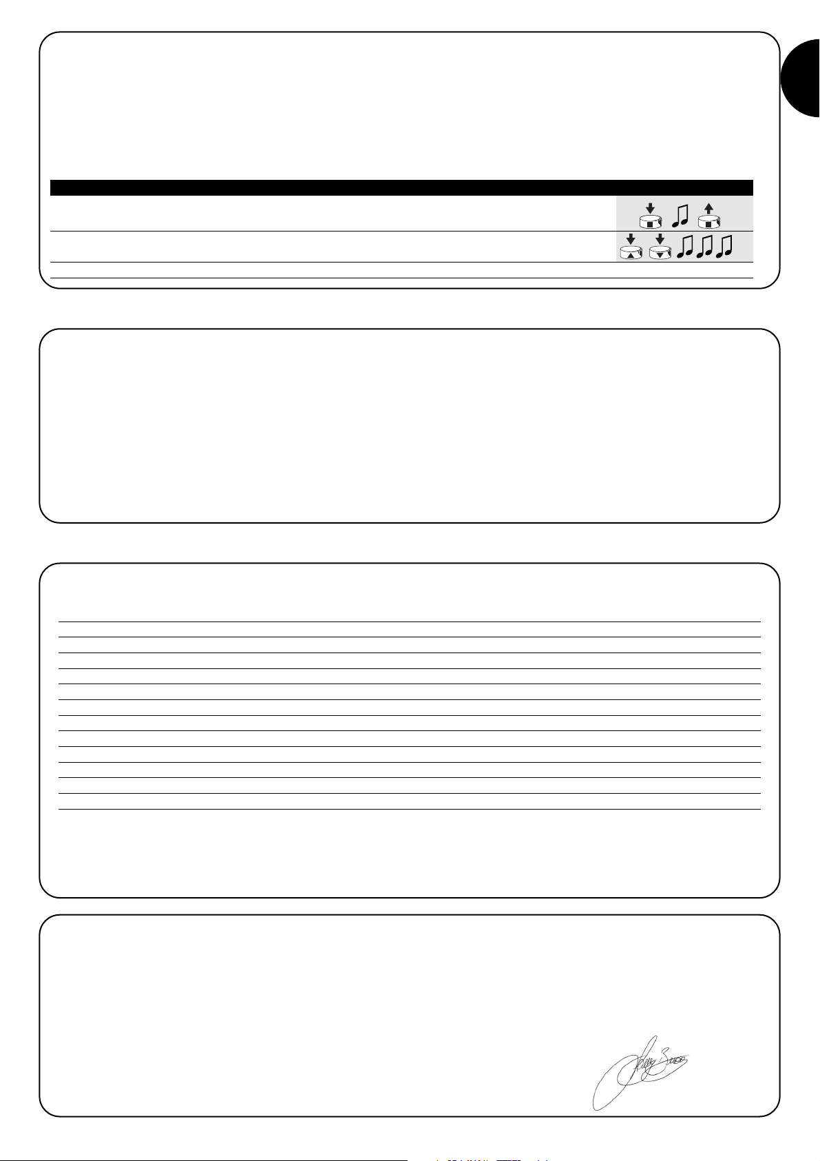
The power supply of the electrical appliance the user wishes to control (max. 500W/400VA) must be connected to output terminals 1-2;
no. 3 is the earth terminal.
2.1.2) Power supply
The main supply to the unit must be connected using the terminals 56-7 (earth, phase, neutral) as shown in Fig. 3 “Electrical Connections”
In the control unit, terminal no. 7 (Neutral) is directly
connected to output terminal 1. This means that even if it
is switched off, the electrical appliance which is to be controlled is not completely disconnected from the electricity
power supply line.
!
The TT1L control unit enables the user to switch electrical appliances on and off using a remote control device. The max. power of
this device must be no greater than 500W (400VA), and powered by
electrical mains voltage. Possible commands are ON/OFF, Man Present and Timed Switch Off (with 2 independent timers).
The control unit incorporates a radio receiver operating at a frequency of 433.92 MHz, with rolling code technology that guarantees high
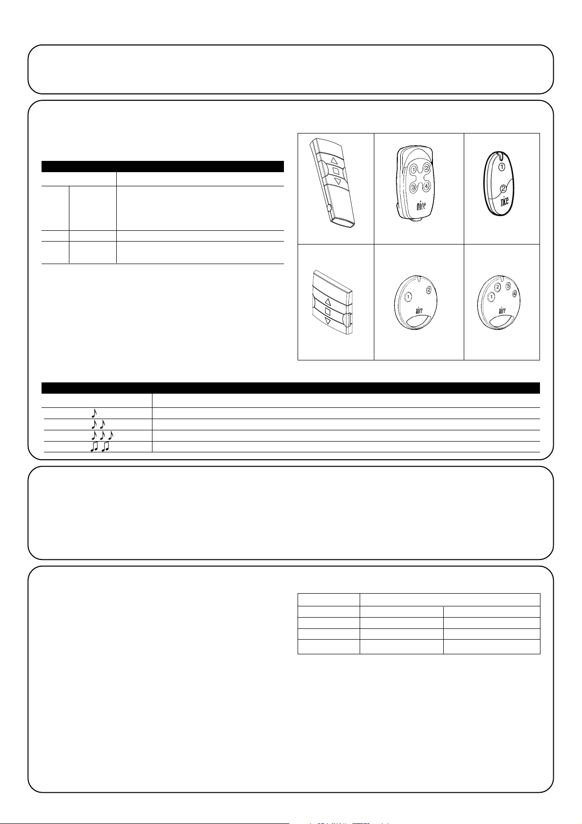
levels of security. Up to 30 transmitters (“FLOR” fig. 1, “VERY” fig. 2)
can be memorized for each control unit. Two keys are used on each
transmitter, one for the Switch ON command and the other for the
Switch OFF command. Any kind of programming can be carried out
directly using the transmitters. A beeping noise will guide the user
through the various phases.
N.B.: The control unit can manage other kinds of transmitters and
functioning modes, too. Please refer to Chapter 4 “Additional information” for further explanations.
Warnings
The TT1L control unit is suitable for the control of a single-phase electrical device powered by the electrical mains, for example, lamps for illumination, motors for irrigation etc.
Any other use is improper and prohibited. The unit must be installed by
qualified technicians in compliance with the electrical and safety regulations currently in force.
1) Product description
2.1) Electrical connections
Carefully follow all the connection instructions, if you
have any doubts do NOT make experiments but consult
the relevant technical specifications sheets which are
also available on the web site www.niceforyou.com
An incorrect connection may cause serious damage to the
control unit.
!
2) Installation
The electrical systems and automations must be
installed by qualified and experienced personnel in compliance with current legislation. Before you proceed to
make any connections make sure that the power supply is
disconnected.
1. Strip the cable of the electric device to be controlled and the
power supply cable about 3 cm and then the single wires approx.
5 mm.
2. Open the container by removing the “cable cap” as shown in fig. 4.
3. Thread the two cables through the designated holes in the “cable cap”
(see fig. 5).
4. Pull the card a few centimetres out of the container (see fig. 6).
5. Connect the wires to the terminals as shown in fig. 7, observing
the diagram in fig. 3 and the operations described in chapter 2.1.
6. Fold the cables as shown in fig. 9. 8.
7. Push the card inside the container, make sure that the stripped
length of the cable is fully inside the container, then slide the “cap”
on the cables until the container closes completely (see fig. 9).
8. Fasten the control unit to a suitable surface, protected against
impact. Double-sided tape can be used for this. To avoid the risk
of water leaks the control unit should be positioned with the
cables towards the bottom as shown in Fig. 10. Do not place it
with the cables towards the top (Fig. 11).
Do not perforate the container.
!
!
3
1
FLOR
2
VERY
Page 3

GB
3
Each transmitter is recognised by the control unit by means of an
unequivocal “code”. A “memorisation” phase must therefore be performed in order to allow the control unit to recognise each single transmitter.
• All the memorisation sequences are timed, that is, they
must be completed within the programmed time limits.
•Programming via radio may be done on all the control units
within the range of the transmitter; therefore, only the one
involved in the operation should be kept switched on.
Two keys are used on each transmitter: key 1 = "ON" and key 2 =
"OFF". In those transmitters with 4 keys, those which remain “empty” can be used to control another control unit: key 3 = "ON" and key
4 = "OFF".".
!
3) Programming
1. As soon as the control unit is powered, 2 long beeps will sound
2. Within 5 seconds press and hold down either key 1 or 2 (or key 3 or 4) on the transmitter
to be memorised (for approx. 3 seconds) 3s
3. Release the key when you hear the first of the 3 beeps confirming memorisation
N.B.: If there are already transmitters memorised in the control unit, short beeps will sound when it is switched on. This means that the
above procedure is not valid and another memorisation procedure must be used (Table “A2”).
When the memory contains no codes the first radio control unit can be entered as follows:
1. Press and hold down either key 1 or 2 (or key 3 or 4) on the new transmitter until you hear a
beep (after about 5 seconds), then release it New 5s
2. Press any key of a just functioning transmitter slowly 3 times
Old X3
3. Press either key 1 or 2 (or key 3 or 4) on the new transmitter again and release it when you
hear the first of the 3 beeps. New
N.B.: If the memorization procedure is successful 3 long beeps will sound. 6 beeps will sound when the memory is full (30 transmitters),
telling you the transmitter cannot be memorised.
When one or more transmitters have already been memorised, others may be enabled as follows:
Table “A1” Memorizing the first transmitter Example
Table “A2” Memorizing other transmitters Example
A Switch the control unit off and cut the jumper on the weld side of the card (see fig. 12).
The jumper must be reconstituted when the deletion procedure has been completed.
B Power the control unit and wait for the initial beeps
1-3
1 Press and hold down key 2 (or 4) of a previously memorized transmitter until you hear a beep
(after about 5 seconds) then release it. 5s
2 After 1 second press the same key again and release it exactly during the third beep.
3 After 1 second press the same key again and release it exactly during the third beep
4 After 1 second press the same key again and release it exactly during the third beep.
5 If you wish to delete all the data in the memory, press the same key again within 2 seconds
until you hear the first of 5 beeps, then release them
N.B.: 5 beeps will indicate that all the codes in the memory have been deleted.
If you need to delete all the data contained in the memory of the
control unit, carry out the procedure on table “A3”.
The memory can be deleted:
• with a non-memorised transmitter by beginning the procedure
from point A, even if a transmitter which has already been memorised is necessary at point 1.
• using a previously memorised transmitter starting the proce-
dure from point N. 1
The following can be erased:
• only the transmitter codes, finishing at point N. 4
• All the data (transmitters and timer programming), completing the
procedure up to point N. 5.
➨
➨
Table “A3” Erasing the memory Example
➨
Page 4

4
4.1) Usable transmitters
The transmitters which can be used are shown in Table “A4”,
together with their relative radio coding.
The transmitters have different kinds of coding, and the control unit
is unable to recognise them simultaneously. The first transmitter
memorised will thus determine the type of coding, and consequently the transmitters which can be memorised successively.
All codes must be deleted if the user wishes to change the
type of transmitter (see tables “A3”).
The type of code can be checked by counting the number of beeps
which sound when the control unit is switched on.
CODING Transmitters
FLO1R - FLO2R - FLO4R
VERY VR
FLOR Rolling code
ERGO1 - ERGO4 - ERGO6
PLANO1 - PLANO4 - PLANO6 - PLANO TIME
SMILO Rolling code SM2 - SM4
FLO Fixed cod
FLO1 - FLO2 - FLO4
VERY VE
Table “A4”
BEEP
Types of coding for the transmitters memorised
1 short beep Transmitters with FLO coding
2 short beeps Transmitters with FLOR coding
3 short beeps Transmitters with SMILO coding
2 long beeps Empty memory (no memorized transmitter)
Table “A5”
4.2) Memorizing the transmitters in Mode I and Mode II
Tables “A1” and “A2” show the memorisation of transmitters in Mode I
The transmitters can also be memorised in Mode II. This mode gives
the user the most flexibility when using the transmitters and the control unit.
Transmitters in both Mode I and Mode II can be memorised in the
same control unit.
The differences between the 2 programming modes have been
described below:
ERGO
PLANO SM2 SM4
4.2.1) Mode I
In this mode, the command associated with the transmitter keys is
fixed: key 1 commands the switching ON, key 2 commands the
switching OFF. If keys 3 and 4 are on the same transmitter, they can
be used to command another control unit: key 3 controls Switching
On = (ON) and key 4 switching off = (OFF).
The user will carry out a single memorisation phase for each transmitter on the control unit. It is not important whether keys 1
or 2 are pressed (or keys 3 or 4) during this phase.
Please refer to Chapter 3 “Programming” for information about how
to memorise or delete the transmitters.
Example memorization mode I
Key 1 ON TT1L no.1
Key 2 OFF TT1L no.1
Key 3 ON TT1L no.2
Key 4 OFF TT1L no.2
4) Additional Information
Besides the transmitters from the “FLOR” and “VERY” series, the control
unit will also recognise other kinds of transmitters manufactured by Nice
(please refer to Chapter 4.1 “Usable transmitters”). Moreover, by using a
special memorisation procedure, it is possible to associate a special
command to each of the transmitter keys (please refer to Chapter 4.2
“Programming transmitters in Mode I and Mode II”).
FLO4R VERY
Page 5

GB
5
Example 1 memorization mode II
Key 1 ON/OFF on TT1L no.1
Key 2 TIMER 1 on TT1L no.1
Key 3 TIMER2 on TT1L no.1
Key 4 MAN PRESENT on TT1L no. 2
When the memory contains no transmitters the first one can be memorized in mode II as follows:
Example 2 memorization mode II
Key 1 ON/OFF on TT1L no.1
Key 2 ON/OFF on TT1L no.2
Key 3 ON/OFF on TT1L no.3
Key 4 TIMER1 on TT1L no.3
1. As soon as the control unit is powered, 2 long beeps will sound
2. Press the transmitter key to be memorised within 5 seconds, and hold it down until you hear
all 3 beeps, then release. 5s
3.
Within 3 seconds press the same key of the transmitter as many times as the number corresponding
to the desired command: 1 = “ON/OFF” 2 = “MAN PRESENT” 3 = “TIMER1” 4 = “TIMER2” 1-4 3s
4. After approximately 3 seconds, the user will hear a certain number of beeps. These beeps
correspond to the command selected. 1-4 3s
5. Press the same key again within 2 seconds to confirm programming. Release this key when
you hear the first of the 3 beeps. 2s
N.B.: If the memorization procedure is successful 3 long beeps will sound. If, at point 4, the user does not hear the same number of
beeps as the command required, wait for a few seconds to exit the procedure, without confirming the memorisation.
Table “A6” Memorizing the first transmitter in mode II Example
1. Press and hold down the new key to be memorized until you hear a beep (after about 5
seconds) then release it
New 5s
2. Within 5 seconds press and hold down the key of a previously memorized (old) transmitter
approx. 5 seconds until you hear 2 short beeps then release it.
Old 5s
3.
Within 5 seconds press the same key of the (old) transmitter as many times as the number corresponding
to the desired command: 1 = “ON/OFF” 2 = “MAN PRESENT” 3 = “TIMER1” 4 = “TIMER2”
Old
1-4
3s
4. After approximately 3 seconds, the user will hear a certain number of beeps. These beeps
correspond to the command selected 1-4 3s
5. Press the new transmitter key to be memorised again within 2 seconds to confirm programming.
Release this key when you hear the first of the 3 beeps.
New
2s
N.B.: If the memorization procedure is successful 3 long beeps will sound.6 beeps will sound when the memory is full (30 transmitters),
telling you the transmitter cannot be memorised.
Table “A7” Memorizing other transmitters in Mode II Example
1. Hold down the key of the new transmitter you wish to memorise for at least 3 seconds,
then release
New 3s
2. Press the key of the (old) transmitter you wish to memorise for at least 3 seconds, then release.
Old 3s
3. Press the key of the new transmitter again for at least another 3 seconds, then release.
4. Press the key of the old transmitter again until 3 beeps sound to confirm the new transmitter
has been memorised.
Old 3s
N.B.: 6 beeps will sound when the memory is full (30 transmitters), telling you the transmitter cannot be memorised.
Table “A8” Memorizing other transmitters Example
4.2.2) Mode II
This mode enables the user to associate one of the following commands to each key of the transmitter:
1 “ON/OFF” (the same key switches on and then off, etc.)
2“MAN PRESENT” (the appliance will only function as long as the
key is pressed down)
3 “TIMER1” after being switched on, the appliance will switch off at
the time set (factory setting: 1 minute)
4 “TIMER2” after being switched on, the appliance will switch off at
the time set (factory setting: 10 minutes).
A memorisation phase for each of the keys on the transmitter must
be carried out on the control unit. During this phase, the user
must press the key the command is to be associated with. If the
user wishes to associate another command to another key on the
transmitter, s/he must carry out another memorisation phase.
The keys on the same transmitter can be associated either with
more commands of the same control unit or with commands from
different control units.
A new transmitter can easily be memorised, keeping the same features as the old transmitter, by following the procedure detailed in Table
“A9”. Any new transmitters which are memorised in this manner will take on the same characteristics as the old one. If the old one was
memorised in Mode I, the new one will also operate in Mode I. If, on the other hand, the old one was memorised in Mode II, the key of the
new transmitter will also be associated to the same command as the old one.
When one or more transmitters have already been memorised, others may be enabled in Mode II as follows:
Page 6

6
If you need to delete all the data contained in the memory of the control unit by using a transmitter memorized in Mode II, carry out the
procedure shown in table “A9”.
Deletion with transmitters memorised in Mode II is a particularly complex procedure and the points below must be observed. The proce-
dure detailed in Table A3 is much simpler if a transmitter which has not been memorised is used.
• Deletion is not possible with transmitters which have a “MAN PRESENT” command. If necessary, a new transmitter and the procedure
detailed in Table “A3” must be used. .
• Se si esegue la procedura con trasmettitori con comando TIMER è necessario partire dal punto A, altrimenti iniziare dal punto 1
You can delete:
• the transmitters only, by stopping at point 4 of the procedure;
• all the data (transmitters, TIMER 1 and TIMER2 duration), by carrying out the procedure through to point 5.
!
A A Switch the control unit off and cut the jumper on the weld side of the card (see fig. 12).
The jumper must be reconstituted when the deletion procedure has been completed.
B Power the control unit and wait for the initial beeps
1-3
C Press and hold down the key with the TIMER command. The relay will switch on, and after
approximately 3 seconds it will switch off. Proceed to point 2 keeping the key held down. 3s
1 If the relay is OFF, press and release the key with the ON/OFF command in order to switch it on 5s
Press the key again and keep it pressed down.
2
After approximately 5 seconds you hear a beep, then release
3 After 1 second press down the same key again and release during the third beep.
4 After 1 second press down the same key again and release during the third beep.
5 After 1 second press down the same key again and release during the third beep.
6 If you wish to delete all the data in the memory, press the same key again within 2 seconds
until you hear the first of 5 beeps, then release it.
N.B.: 5 beeps will indicate that all the codes in the memory have been deleted.
➨
➨
Table “A9” Memory deletion with transmitter memorized in Mode II Example
➨
4.3) Auxiliary Programming
The duration of TIMERS 1 and 2 can be programmed on the control unit, as can the use of 3 key transmitters such as “▲■▼”, Please
refer to the following chapters.
4.3.1) Programming the timers
The control unit enables the user to programme 2 independent timers for switching the relay off automatically after a preset time: “TIMER1”
and “TIMER2”. The time is reset whenever the command is used, and it is possible to anticipate Switching Off either by keeping the TIMER
command active for more than 3 seconds, or by sending an OFF command.
The factory time for the 2 timers, and the time set after the memory has been deleted completely, are 1 minute (TIMER1) and 10 minutes
(TIMER2).
The Switch On time can be programmed from a minimum of 1 second to a maximum of 9 hours.
1. Press and hold down the key on the transmitter relative to the timer you wish to programme.
The relay will switch on (ON).
2. Keep the same key held down. The relay will switch off (OFF) after approximately 3 seconds.
3s
3. Keep the same key held down until the relay switches on again (this will happen after
approximately 8 seconds). The time counting phase will start immediately. Release the key.
8s
4. When the time the user wishes to programme has elapsed, s/he must press one of the keys on
one of the transmitters which has been memorised in the control unit. 3 long beeps will sound
to indicate the time has been memorised, followed by 1 or 2 short beeps to indicate whether
programming refers to TIMER1 or TIMER2. 1-2
Nota: Se si vuole modificare il tempo dei temporizzatori basta ripetere la procedura partendo dal punto 1
Table “A10” Programming the duration of the timers Example
Page 7
GB
7
When the control unit is switched on, no beep sounds and
the transmitters do not transmit any commands.
Make sure that the control unit is powered correctly: there must be
mains voltage between terminals 6-7.If the power supply is correct,
there is likely to be a serious fault in the system, and the control unit
will have to be replaced.
6 beeps will sound after a radio-controlled command. The
relays will neither switch on nor off.
The radio control is out of synch, the transmitter memorization procedure must be repeated.
After a radio command, you hear 10 beeps and then the
relais switches on
The self diagnosis of the parameters in the memory has detected a
fault.
5) What to do if… a short troubleshooting guide!!
6) Technical characteristics
N.B.: all technical specifications refer to a temperature of 20°C.
Electronic control unit
Power supply : 230Vac (+10-15%) 50Hz
Output maximum power : 500W / 400VA
Operating temperature : -20÷55 °C
Dimensions / weight : 98 x 26 x 20 / 45g
Protection class : IP55 (container undamaged)
Timer durations : Factory setting from 1 second to 9 hours TIMER1=1 minute TIMER 2 = 10 minutes
Radio receiver
Frequency : 433.92 MHz
Coding : FLO (fixed code), FLOR (rolling code) SMILO (rolling code)
No. of transmitter that can be memorised : 30
Range of the transmitters : estimated 150 m outdoor, 20 m indoor. *
* The capacity of the transmitters is strongly influenced by other devices with continuous transmissions which operate at the same frequency. These include alarms, headphones, etc… which interfere with the control unit receiver.
Nice S.p.a reserves the right to make changes to its products at any time as it deems necessary
Declaration of conformity N°: mindy TT1L Rev 0
Nice S.p.a. via Pezza Alta, 13 Rustignè Oderzo (TV) ITALY declares that the product: “mindy TT1L” comply with the essential provisions of
European Directive R&TTE 1999/5/EEC, for the uses for which they have been manufactured
Date Managing director
22-01-2004 Lauro Buoro
4.3.2) Using 3 key type transmitters “▲■▼”
If transmitters have keys like “▲■▼” memorised in Mode I, the “OFF” command can be associated to key ▼. for each one of them. This
makes using the “events” forecasted by the transmitters like, for example PLANO TIME, easy. Key ■ will continue carrying out the “OFF”
function.
The transmitter must be memorised in Mode I in order to enable this function, and the said function will only be enabled to that transmitter.
Repeat programming for all the necessary transmitters.
1. Press and hold down key ■ of a previously transmitter memorised in Mode I until you hear
a beep (after about 5 seconds) then release it. 5s
2. Within 3 seconds press simultaneously the two keys ▲▼and hold them down for approx.
5 seconds until 3 beeps sound to confirm the function has been programmed. 3s
N.B.: If the user should wish to exclude the function, s/he must repeat the procedure starting from point 1.
Table “A11” FUNCTION “ON” “OFF” with ▲■▼ Example
Page 8

8
2.1.1) Collegamento dell’apparecchio elettrico
L’alimentazione del dispositivo elettrico che si vuole comandare (max
500W / 400VA) deve essere collegata sui morsetti d’uscita 1-2; il n°
3 è il morsetto di terra.
2.1.2) Alimentazione
L’alimentazione principale alla centrale deve essere fornita utilizzando i morsetti 5-6-7 (terra, fase, neutro) come indicato dalla fig. 3
“Collegamenti elettrici”
Nella centrale il morsetto 7 (Neutro) è collegato direttamente al morsetto 1 d’uscita e quindi il dispositivo elettrico da comandare, anche se spento, non risulta completamente sezionato dalla linea elettrica di alimentazione.
!
La centrale di comando TT1L permette di accendere e spegnere tramite radiocomando, apparecchi elettrici fino ad una potenza di
500W (400VA) alimentati a tensione di rete. Sono possibili comandi
ON/OFF, Uomo Presente e Spegnimento Temporizzato (con 2 timer
indipendenti).
La centrale incorpora un ricevitore radio che opera alla frequenza di
433.92 MHz con tecnologia rolling code che garantisce elevati livelli
di sicurezza. Per ogni centrale è possibile memorizzare fino a 30 trasmettitori della serie “FLOR”(fig.1) o “VERY” (fig. 2). In ogni trasmettitore vengono utilizzati 2 tasti; uno per il comando di accensione
(ON) e l’altro per il comando di spegnimento (OFF). Tutte le programmazioni si possono fare direttamente dai trasmettitori, un “bip”
acustico ne guiderà le varie fasi.
Nota: La centrale può gestire anche altri tipi di trasmettitori ed altre
modalità di funzionamento, vedere il capitolo 4) “Approfondimenti”.
Avvertenze
La centrale TT1L è adatta al comando di un apparecchio elettrico monofase alimentato a tensione di rete, ad esempio: lampade per illuminazione, motori per irrigazione ecc… , ogni altro uso è improprio e vietato.
L’installazione deve essere eseguita da personale tecnico nel pieno
rispetto delle normative elettriche e di sicurezza vigenti.
1) Descrizione del prodotto
2.1) Collegamenti elettrici
Rispettare scrupolosamente i collegamenti previsti, in
caso di dubbio NON tentare invano, ma consultare le
apposite schede tecniche di approfondimento disponibili
anche sul sito www.niceforyou.com
Un collegamento errato può provocare guasti gravi alla
centrale.
!
2) Installazione
Gli impianti elettrici devono essere eseguite da personale esperto e qualificato, nel rispetto delle norme di legge. Tutti i collegamenti devono essere eseguiti senza presenza di alimentazione elettrica.
1. Sguainare il cavo dell’apparecchio elettrico da comandare e il
cavo di alimentazione per circa 3cm e poi i singoli fili per circa
5mm.
2. Aprire il contenitore togliendo il tappo passacavi come indicato
nella fig. 4.
3. Passare i due cavi negli appositi fori passacavo del tappo (vedi fig. 5).
4. Estrarre di qualche centimetro la scheda dal contenitore (vedi fig. 6).
5. Collegare i fili ai morsetti come indicato nella fig. 7, rispettando lo
schema di fig. 3 e quanto previsto nel capitolo 2.1) .
6. Ripiegare i cavi come in fig. 8.
7. Spingere la scheda all’interno del contenitore, verificare che la
parte sguainata dei cavi sia tutta all’interno del contenitore, far
scorrere il tappo sui cavi fino alla completa chiusura (vedi fig. 9)
8. Fissare la centrale su una superficie adeguata e protetta da urti,
utilizzare eventualmente il nastro biadesivo. Per evitare il rischio di
infiltrazioni d’acqua è necessario posizionarla con i cavi verso il
basso come evidenziato in fig. 10. , evitando assolutamente di
porla con i cavi in alto (fig. 11).
Il contenitore non deve essere forato per nessun motivo.
!
!
3
1
FLOR
2
VERY
Page 9

I
9
Ogni trasmettitore viene riconosciuto dalla centrale attraverso un
“codice” diverso da ogni altro trasmettitore, è necessaria quindi una
fase di “memorizzazione” attraverso la quale si predispone la centrale a riconoscere ogni singolo trasmettitore.
•Tutte le sequenze di memorizzazione sono a tempo, cioè
devono essere eseguite entro i limiti di tempo previsti.
• La programmazione via radio può avvenire in tutte le
centrali che si trovano nel raggio della portata del trasmettitore; è quindi opportuno tenere alimentata solo
quella interessata all’operazione.
Per ogni trasmettitore vengono utilizzati 2 tasti: tasto 1 = "ON" e tasto 2
= "OFF". Nei trasmettitori con 4 tasti, quelli rimasti liberi possono essere
usati per comandare un'altra centrale: tasto 3 = "ON" e tasto 4 = "OFF".
!
3) Programmazione
1. Appena data alimentazione alla centrale, si sentiranno 2 bip lunghi (biiip)
2. Entro 5 secondi premere e tener premuto il tasto 1 o 2 (oppure 3 o 4) del trasmettitore
da memorizzare (per circa 3 secondi). 3s
3. Rilasciare il tasto quando si sentirà il primo dei 3 bip che confermano la memorizzazione
Nota: Se nella centrale ci sono già dei trasmettitori memorizzati, all’accensione si udiranno dei bip brevi (bip) e non si potrà procedere
come descritto sopra ma occorre usare l’altra modalità di memorizzazione (Tabella “A2”)
Quando la memoria non contiene nessun trasmettitore si può precedere all’inserimento del primo con la seguente modalità:
1. Tenere premuto il tasto 1 o 2 (oppure 3 o 4) del nuovo trasmettitore fino a sentire un bip
(dopo circa 5 secondi) poi rilasciare Nuovo 5s
2. Lentamente premere per 3 volte un tasto qualsiasi di un trasmettitore già funzionante
Vecchio X3
3. Premere ancora il tasto 1 o 2 (oppure 3 o 4) del nuovo trasmettitore e rilasciare al
primo dei 3 bip. Nuovo
Nota: Se la memorizzazione è andata a buon fine si sentiranno 3 bip lunghi. Quando la memoria è piena (30 trasmettitori),
6 Bip indicheranno che il trasmettitore non può essere memorizzato.
Quando uno o più trasmettitori sono già stati memorizzati, è possibile abilitarne altri in questo modo:
Tabella “A1” Memorizzazione del primo trasmettitore Esempio
Tabella “A2” Memorizzazione di altri trasmettitori Esempio
A A centrale non alimentata togliere il ponticello presente nella scheda (vedi fig. 12).
Il ponticello deve essere ripristinato al termine della cancellazione.
B Alimentare la centrale ed attendere i bip iniziali.
1-3
1 Tenere premuto il tasto 2 (oppure 4) di un trasmettitore già memorizzato fino a sentire un bip
(dopo circa 5 secondi) e rilasciare. 5s
2 Dopo 1 secondo ripremere lo stesso tasto e rilasciare esattamente durante il terzo bip.
3 Dopo 1 secondo ripremere lo stesso tasto e rilasciare esattamente durante il terzo bip.
4 Dopo 1 secondo ripremere lo stesso tasto e rilasciare esattamente durante il terzo bip.
5 Se si vogliono cancellare completamente tutti i dati presenti in memoria, entro 2 secondi,
premere nuovamente lo stesso tasto fino a sentire il primo di 5 bip, poi rilasciarlo
Nota: I 5 bip segnalano che tutti i codici in memoria sono stati cancellati.
Se dovesse rendersi necessario cancellare la memoria della centrale, si può eseguire la procedura di tabella “A3”.
La cancellazione della memoria è possibile:
• con un trasmettitore non memorizzato iniziando la procedura dal
punto A anche se nel punto 1 è richiesto un trasmettitore già
memorizzato.
•con uno già memorizzato iniziando la procedura dal punto N°1
Si possono cancellare:
• solo i trasmettitori, terminando al punto 4
• tutti i dati (trasmettitori e programmazione dei temporizzatori),
completando la procedura fino al punto 5.
➨
➨
Tabella “A3” Cancellazione della memoria Esempio
➨
Page 10
10
4.1) Trasmettitori utilizzabili
Nella tabella “A4” sono indicati i trasmettitori che possono essere utilizzati con la relativa codifica radio.
Poiché le codifiche dei trasmettitori sono diverse e la centrale non
può riconoscerle simultaneamente, il primo trasmettitore memorizzato determina il tipo di codifica e quindi i trasmettitori che si potranno memorizzare in seguito.
Se si volesse cambiare tipo di trasmettitori è necessario
cancellare tutti i codici (vedi tabella “A3”).
E’ possibile verificare il tipo di codifica contando il numero di bip
emessi dalla centrale al momento dell’accensione.
CODIFICA Trasmettitori
FLO1R - FLO2R - FLO4R
VERY VR
FLOR Rolling code
ERGO1 - ERGO4 - ERGO6
PLANO1 - PLANO4 - PLANO6 - PLANO TIME
SMILO Rolling code SM2 - SM4
FLO Fixed cod
FLO1 - FLO2 - FLO4
VERY VE
Tabella “A4”
BIP Tipo di codifica dei trasmettitori memorizzati
1 bip breve Trasmettitori con codifica FLO
2 bip brevi Trasmettitori con codifica FLOR
3 bip brevi Trasmettitori con codifica SMILO
2 bip lunghi Memoria vuota (nessun trasmettitore memorizzato)
Tabella “A5”
4.2) Memorizzazione dei trasmettitori in Modo I e Modo II
Nelle tabelle “A1” e “A2” è descritta la memorizzazione dei trasmettitori in Modo I
E’ possibile memorizzare i trasmettitori anche in Modo II, questa
modalità permette la massima flessibilità dell’utilizzo dei trasmettitori e della centrale.
Si possono memorizzare nella stessa centrale sia trasmettitori in
Modo I che in Modo II.
Di seguito si descrivono le differenze tra le 2 modalità di programmazione:
ERGO
PLANO SM2 SM4
4.2.1) Modo I
In questa modalità il comando associato ai tasti del trasmettitore è
fisso: il tasto 1 comanda l’accensione (ON), il tasto 2 comanda lo
spegnimento (OFF). Gli eventuali tasti 3 e 4 presenti nello stesso trasmettitore possono comandare un’altra centrale: il tasto 3 comanda
l’accensione (ON), il tasto 4 comanda lo spegnimento (OFF).
Sulla centrale si esegue un’ unica fase di memorizzazione per ogni
trasmettitore, durante questa fase non ha importanza se vie-
ne premuto il tasto 1 o 2 (oppure il tasto 3 o 4).
Per memorizzare o cancellare i trasmettitori in Modo I vedere il capitolo 3 “Programmazioni”.
Esempio memorizzazione Modo I
Tasto 1 ON su TT1L n°1
Tasto 2 OFF su TT1L n°1
Tasto 3 ON su TT1L n°2
Tasto 4 OFF su TT1L n°2
4) Approfondimenti
Oltre ai trasmettitori della serie “FLOR” e “VERY”, la centrale riconosce anche altri tipi di trasmettitori prodotti da nice (vedi capitolo 4.1
“Trasmettitori utilizzabili”); inoltre con opportune procedure di memo-
rizzazione è possibile associare a ciascun tasto del trasmettitore un
particolare comando (vedi capitolo 4.2 “Programmazione trasmettitori in Modo I e Modo II”).
FLO4R VERY
Page 11

I
11
Esempio 1 memorizzazione Modo II
Tasto 1 ON/OFF su TT1L n°1
Tasto 2 TIMER1 su TT1L n°1
Tasto 3 TIMER2 su TT1L n°1
Tasto 4 UOMO PRESENTE su TT1L n°2
Quando la memoria non contiene nessun trasmettitore si può precedere alla memorizzazione del primo in Modo II con la seguente modalità:
Esempio 2 memorizzazione Modo II
Tasto 1 ON/OFF su TT1L n°1
Tasto 2 ON/OFF su TT1L n°2
Tasto 3 ON/OFF su TT1L n°3
Tasto 4 TIMER1 su TT1L n°3
1. Appena data alimentazione alla centrale, si sentiranno 2 bip lunghi (biiip)
2. Entro 5 secondi premere il tasto da memorizzare del trasmettitore e mantenerlo premuto fino
alla fine di tutti e 3 i bip , poi rilasciare 5s
3. Entro 3 secondi iniziare a premere lo stesso tasto del trasmettitore per un numero di volte pari
al comando desiderato: 1=“ON/OFF” 2=“UOMO PRESENTE” 3=“TIMER1” 4=“TIMER2” 1-4 3s
4. Dopo circa 3 secondi si udirà un numero di bip pari al comando selezionato
1-4 3s
5. Entro 2 secondi premere nuovamente lo stesso tasto per confermare la programmazione e
rilasciare al primo dei 3 bip. 2s
Nota: Se la memorizzazione è andata a buon fine si sentiranno 3 bip lunghi. Se al punto 4 non si sente il numero di bip uguale al comando
desiderato, aspettare alcuni secondi per uscire dalla procedura senza confermare la memorizzazione.
Tabella “A6” Memorizzazione del primo trasmettitore in Modo II Esempio
1. Tenere premuto il nuovo tasto da memorizzare del trasmettitore fino a sentire un bip
(dopo circa 5 secondi) poi rilasciare
Nuovo 5s
2. Entro 5 secondi premere e tenere premuto circa 5 secondi il tasto di un trasmettitore già
memorizzato (vecchio) fino a sentire 2 bip veloci, quindi rilasciare.
Vecchio 5s
3. Entro 3 secondi ripremere lo stesso tasto del trasmettitore (vecchio) un numero di volte uguale
al comando desiderato: 1=“ON/OFF” 2=“UOMO PRESENTE” 3=“TIMER1” 4=“TIMER2”
Vecchio
1-4
3s
4. Dopo circa 3 secondi si udirà un numero di bip uguale al comando precedentemente
selezionato 1-4 3s
5. Entro 2 secondi premere nuovamente il nuovo tasto da memorizzare del trasmettitore per
confermare la programmazione e rilasciare al primo dei 3 bip.
Nuovo
2s
Nota: Se la memorizzazione è andata a buon fine si sentiranno 3 bip lunghi. Quando la memoria è piena (30 trasmettitori), 6 Bip
indicheranno che il trasmettitore non può essere memorizzato.
Tabella “A7” Memorizzazione di altri trasmettitori in Modo II Esempio
1. Tenere premuto il tasto del nuovo trasmettitore che si vuole memorizzare per almeno 3
secondi poi rilasciare
Nuovo 3s
2. Premere il tasto del trasmettitore già abilitato (vecchio) per almeno 3 secondi poi rilasciare.
Vecchio 3s
3. Ripremere il tasto del nuovo trasmettitore per almeno altri 3 secondi poi rilasciare
Nuovo 3s
4. Ripremere il tasto del vecchio trasmettitore fino a quando 3 bip confermeranno la
memorizzazione del nuovo trasmettitore
Vecchio 3s
Nota: Quando la memoria è piena (30 trasmettitori), 6 Bip indicheranno che il trasmettitore non può essere memorizzato.
Tabella “A8” Memorizzazione di altri trasmettitori Esempio
4.2.2) Modo II
Questa modalità consente di associare ad ogni tasto del trasmettitore uno fra i seguenti tipo di comando:
1 “ON/OFF” (lo stesso tasto accende poi spegne e così via)
2“UOMO PRESENTE” (accensione solamente fino a quando si tie-
ne premuto il tasto)
3 “TIMER1” accensione con spegnimento temporizzato (di fabbrica
dopo 1 minuto)
4 “TIMER2” accensione con spegnimento temporizzato (di fabbrica
dopo 10 minuti).
Sulla centrale si deve eseguire una fase di memorizzazione per ogni
tasto del trasmettitore, durante questa fase si deve premere il
tasto al quale associare il comando. Se ad un altro tasto del
trasmettitore si desidera associare un altro comando occorre fare
un'altra fase di memorizzazione.
I tasti dello stesso trasmettitore possono essere associati a più
comandi della stessa centrale oppure essere associati a comandi di
diverse centrali.
E’ possibile memorizzare in modo semplice un nuovo trasmettitore mantenendo le caratteristiche del vecchio trasmettitore seguendo la procedura di Tabella “A8”. Il nuovo trasmettitore così memorizzato erediterà le caratteristiche di quello vecchio, cioè se il vecchio era memorizzato in Modo I, anche il nuovo funzionerà in Modo I, se il vecchio era memorizzato in Modo II anche il tasto del nuovo trasmettitore verrà
associato allo stesso comando di quello vecchio.
Quando uno o più trasmettitori sono già memorizzati, è possibile memorizzarne altri in Modo II seguendo questa procedura:
Page 12

12
Se dovesse rendersi necessario cancellare tutti i dati contenuti nella memoria della centrale utilizzando un trasmettitore memorizzato in
Modo II, si può eseguire la procedura di tabella “A9”.
La cancellazione con trasmettitori memorizzati in modo II è particolarmente complessa e deve rispettare i punti sottostanti; avendo a
dispone un trasmettitore non memorizzato, risulta molto più semplice la procedura di tab A3.
•Non è possibile effettuare la cancellazione con trasmettitori con comandi a “UOMO PRESENTE”, eventualmente utilizzare un nuovo tra-
smettitore e la procedura di tabella “A3”.
• Se si esegue la procedura con trasmettitori con comando TIMER è necessario partire dal punto A, altrimenti iniziare dal punto 1
Si possono cancellare:
• solo i trasmettitori, terminando al punto 5
• tutti i dati ( trasmettitori, durata del TIMER1 e TIMER2), completando la procedura fino al punto 6.
!
A A centrale non alimentata togliere il ponticello presente nella scheda (vedi fig. 12).
Il ponticello deve essere ripristinato al termine della cancellazione.
B Alimentare la centrale ed attendere i bip iniziali
1-3
C Premere e tener premuto il tasto con il comando TIMER, il relè si accende e dopo circa 3
secondi si spegne; sempre con il tasto premuto proseguire al punto 2. 3s
1 Se il relè è spento premere e rilasciare il tasto con comando ON/OFF per accenderlo.
Ripremere e mantenere premuto il tasto. 5s
2 Dopo 5 circa secondi si sentirà un bip; quindi rilasciare il tasto
3 Dopo 1 secondo ripremere lo stesso tasto e rilasciare esattamente durante il terzo bip.
4 Dopo 1 secondo ripremere lo stesso tasto e rilasciare esattamente durante il terzo bip.
5 Dopo 1 secondo ripremere lo stesso tasto e rilasciare esattamente durante il terzo bip.
6 Se si vogliono cancellare completamente tutti i dati presenti in memoria, entro 2 secondi,
premere nuovamente il tasto fino a sentire il primo di 5 bip, poi rilasciarlo
Nota: I 5 bip segnalano che tutti i codici in memoria sono stati cancellati.
➨
➨
Tabella “A9” Cancellazione della memoria con trasmettitore memorizzato in modoII Esempio
➨
4.3) Programmazioni ausiliarie
Sulla centrale è possibile programmare la durata dei temporizzatori TIMER1 e TIMER2 oppure programmare per l’uso di trasmettitori a 3 tasti
tipo “▲■▼”, vedere i capitoli seguenti.
4.3.1) Programmazione dei temporizzatori
La centrale permette di programmare 2 temporizzatori indipendenti per lo spegnimento automatico del relè dopo un tempo prestabilito:
“TIMER1” e “TIMER2”. Ad ogni comando viene ricaricato il tempo previsto, è possibile anticipare lo spegnimento tenendo attivo il comando
TIMER per più di 3 secondi oppure inviando un comando di OFF.
Di fabbrica o dopo una cancellazione completa della memoria, i tempi previsti per i 2 temporizzatori sono rispettivamente di 1 minuto
(TIMER1) e 10 minuti (TIMER2).
E’ possibile programmare il tempo di accensione da un minimo di 1 secondo ad un massimo di 9 ore.
1. Premere e tenere premuto il tasto del trasmettitore relativo al temporizzatore che si vuole
programmare. Il relè si accende (ON).
2. Mantenere sempre premuto lo stesso tasto, dopo circa 3 secondi il relè si spegne (OFF)
3s
3. Continuare a mantenere sempre premuto lo stesso tasto fino a quando il relè si accende
nuovamente (dopo circa 8 secondi); da questo istante inizia la fase di conteggio del tempo.
Rilasciare il tasto 8s
4. Quando è trascorso il tempo che si desidera programmare premere un tasto di un trasmettitore
memorizzato nella centrale. 3 bip lunghi segnaleranno l’avvenuta memorizzazione del tempo
seguiti da 1 o 2 bip brevi per indicare se la programmazione è relativa al TIMER1 o al TIMER2 1-2
Nota: Se si vuole modificare il tempo dei temporizzatori basta ripetere la procedura partendo dal punto 1
Tabella “A10” Programmazione durata dei temporizzatori Esempio
Page 13

I
13
Dopo aver alimentato la centrale non si sente nessun bip
e i trasmettitori non funzionano.
Verificare che la centrale sia correttamente alimentata: tra i morsetti
6-7 deve essere presente la tensione di rete. Se l’alimentazione è
corretta, è probabile vi sia un guasto grave e la centrale deve essere sostituita
Dopo un comando via radio si sentono 6 Bip e il relè non
accende ne spegne.
Il radiocomando è fuori sincronismo, bisogna ripetere la memorizzazione del trasmettitore.
Dopo un comando si sentono 10 Bip poi il relè si accende
L’autodiagnosi dei parametri in memoria ha rilevato qualche anomalia.
5) Cosa fare se... cioè piccola guida se qualcosa non va!
6) Caratteristiche tecniche
Tutte le caratteristiche sono riferite alla temperatura di 20°C
Centrale elettronica
Alimentazione : 230Vac (+10-15%) 50Hz
Potenza massima uscita : 500W / 400VA
Temperatura di funzionamento : -20÷55 °C
Dimensioni / peso : 98 x 26 x 20 / 45g
Grado Protezione : IP55 (contenitore integro)
Durata Temporizzatori : Programmabile da 1 secondo a 9 ore di fabbrica TIMER1=1 minuto TIMER2= 10 minuti
Ricevitore radio
Frequenza : 433.92 MHz
Codifica : FLO (fixed code), FLOR (rolling code) SMILO (rolling code)
N° trasmettitori memorizzabili : 30
Portata dei trasmettitori : stimata in 150 m in spazio libero e 20m se all’interno di edifici *
* La portata dei trasmettitori è fortemente influenzata da altri dispositivi che operano alla stessa frequenza con trasmissioni continue come
allarmi, radiocuffie, ecc… che interferiscono con il ricevitore della centrale.
Nice si riserva il diritto di apportare modifiche ai prodotti in qualsiasi momento riterrà necessario
Dichiarazione di conformità N°: mindy TT1L Rev 0
Nice S.p.a. via Pezza Alta, 13 Rustignè Oderzo (TV) ITALY dichiara che il prodotto: “mindy TT1L” centrale di comando risulta conforme ai
requisiti essenziali richiesti dalla Direttiva R&TTE 1999/5/CE, per l'uso cui l'apparecchio è destinato.
Data Amministratore Delegato
22 Gennaio 2004 Lauro Buoro
4.3.2) Utilizzo trasmettitori a 3 tasti tipo “▲■▼”
Se si dispone di trasmettitori con tasti tipo “▲■▼” memorizzati in Modo I, per ognuno di essi, è possibile associare il comando “OFF” al
tasto ▼. In questa maniera è possibile utilizzare in modo agevole gli “eventi” previsti dai trasmettitori come ad esempio PLANO TIME. Il tasto
■ continuerà ad eseguire la funzione di “OFF”
Per abilitare questa funzione è necessario che il trasmettitore sia memorizzato in modo I e sarà applicata solo a quel trasmettitore; eventualmente ripetere la programmazione per tutti quelli per tutti quelli desiderati.
1. Premere e mantenere premuto il tasto ■del trasmettitore già memorizzato in Modo I fino a
sentire un biip.(dopo circa 5 secondi) e rilasciare. 5s
2. Entro 3 secondi premere contemporaneamente i 2 tasti ▲▼e mantenerli premuti per circa
altri 5 secondi fino a quando 3 biip segnalano l’avvenuta programmazione della funzione. 3s
Nota: Se si volesse escludere la funzione ripetere la procedura partendo dal punto 1
Tabella “A11” FUNZIONE “ON” “OFF” con ▲■▼ Esempio
Page 14

14
2.1.1) Branchement de l’appareil électrique
L’alimentation du dispositif électrique que l’on désire commander
(max. 500 W / 400 VA) doit être connectée aux bornes de sortie 12 ; la n° 3 est la borne de terre.
2.1.2) Alimentation
L’alimentation principale de la logique de commande doit être fournie en
utilisant les bornes 5-6-7 (terre, phase, neutre) comme l’indique la fig. 3
“Branchements électriques”
Dans la logique de commande la borne 7 (Neutre) est
connectée directement à la borne 1 de sortie et donc le dispositif électrique à commander, même s’il est éteint n’est pas
complètement sectionné de la ligne électrique d’alimentation.
!
La logique de commande TT1L permet d’allumer et d’éteindre à l’aide d’une radiocommande, des appareils électriques jusqu’à une
puissance de 500 W (400 VA) alimentés à la tension de secteur.
Commandes possibles: ON/OFF, “Homme mort” et Extinction temporisée (avec 2 temporisateurs indépendants).
La logique de commande possède un récepteur radio incorporé qui
fonctionne à la fréquence de 433,92 MHz avec technologie rolling
code qui garantit des niveaux de sécurité élevés. Pour chaque logique de commande, il est possible de mémoriser jusqu’à 30 émetteurs de la série “FLOR”(fig.1) ou “VERY” (fig. 2). Dans chaque émetteur on utilise 2 touches ; une pour la commande d’allumage (ON) et
l’autre pour la commande d’extinction (OFF). Toutes les programmations peuvent être faites directement avec les émetteurs, un “bip”
sonore en guidera les différentes phases.
Note: La logique de commande peut gérer aussi d’autres types d’émetteurs et d’autres modes de fonctionnement, pour tout renseignement voir le chapitre 4) “Approfondissements”.
Avertissements
La logique de commande TT1L est destinée à la commande d’un appareil électrique monophasé alimenté à la tension de secteur tel que par
exemple: appareils d’éclairage, moteurs pour irrigation, etc.,
toute autre utilisation est impropre et interdite. L’installation doit être
effectuée par du personnel technique dans le plein respect des normes
électriques et de sécurité en vigueur.
1) Description du produit
2.1) Branchements électriques
Respecter scrupuleusement les connexions prévues,
en cas de doute, NE PAS tenter en vain mais consulter les
notices techniques d’approfondissement disponibles également sur le site www.niceforyou.com
Une connexion erronée peut endommager gravement la
logique de commande.
!
2) Installation
Les installations électriques doivent être exécutées par
du personnel expérimenté et qualifié dans le respect des
normes en vigueur. Toutes les connexions doivent être
effectuées quand l’installation n’est pas alimentée.
1. Dénuder le câble de l’appareil électrique à commander et le câble
d’alimentation sur environ 3 cm puis chaque conducteur sur environ 5 mm.
2. Ouvrir le boîtier en enlevant le bouchon passe-câbles comme l’in-
dique la fig. 4.
3. Passer les deux câbles dans les trous passe-câbles du bouchon (voir
fig. 5).
4. Extraire la carte électronique de quelques centimètres (voir fig. 6).
5. Connecter les fils aux bornes comme l’indique la fig. 7 en respectant le schéma de la fig. 3 et les indications du chapitre 2.1.
6. Replier les câbles comme l’indique la fig. 8
7. Pousser la carte à l’intérieur du boîtier, vérifier que la partie dénudée du
câble se trouve complètement à l’intérieur du boîtier, faire coulisser le
bouchon jusqu’à la fermeture parfaite du boîtier (voir fig. 9)
8. Fixer la logique de commande sur une surface adéquate et à l’abri
des chocs, utiliser éventuellement du ruban biadhésif pour la fixation. Pour éviter le risque d’infiltrations d’eau, il faut la placer avec
les câbles vers le bas comme l’indique la fig. 10, et éviter absolument de la mettre avec les câbles en haut (fig. 11).
le boîtier ne doit être percé sous aucun prétexte.
!
!
3
1
FLOR
2
VERY
Page 15

F
15
Chaque émetteur est reconnu par la logique de commande à travers
un “code” distinct pour chacun d’eux. Il faut donc procéder à la
“mémorisation”, phase à travers laquelle on prépare la logique de
commande à reconnaître chaque émetteur.
•Toutes les séquences de mémorisation sont temporisées, c’est-à-dire qu’elles doivent être effectuées
dans les limites de temps prévues.
• La programmation par radio peut avoir lieu dans toutes
les logiques de commande qui se trouvent dans le rayon
de portée de l’émetteur ; il est donc opportun de n’alimenter que celle qui est concernée par l’opération.
Pour chaque émetteur on n’utilise que 2 touches: touche 1 = "ON"
et touche 2 = "OFF". Dans les émetteurs à 4 touches, les touches
restées libres peuvent être utilisées pour commander une autre
logique de commande: touche 3 = "ON" et touche 4 = "OFF".
!
3) Programmation
1. Dès que la logique est alimentée, on entend 2 longs bips (biiip)
2. Dans les 5 secondes qui suivent, presser et maintenir enfoncée la touche 1 ou 2 (ou 3 ou 4)
de l’émetteur à mémoriser (pendant environ 3 secondes) 3s
3. Relâcher la touche quand on entend le premier des 3 bips qui confirment la mémorisation
Note: Si des émetteurs ont déjà été mémorisés dans la logique, à l’allumage on entend des bips brefs (bip) et on ne pourra pas procéder
comme ci-dessus mais il faudra utiliser l’autre mode de mémorisation (Tableau “A2”)
Quand la mémoire ne contient aucun émetteur, on peut procéder à l’enregistrement du premier de la manière suivante:
1. Maintenir enfoncée la touche 1 ou 2 (ou 3 ou 4) du nouvel émetteur jusqu’à ce que l’on
entende un bip (au bout d’environ 5 secondes) puis la relâcher Nouveau 5s
2. Presser lentement 3 fois une touche quelconque d’un émetteur déjà mémorisé
Ancien X3
3. Presser encore la touche 1 ou 2 (ou 3 ou 4) du nouvel émetteur et la relâcher
au premier des 3 bips Nouveau
Note: Si la mémorisation a été effectuée correctement, on entendra 3 longs bips. Quand la mémoire est pleine (30 émetteurs), 6 bips
indiqueront que l’émetteur n’a pas pu être mémorisé.
Quand un ou plusieurs émetteurs ont déjà été mémorisés, il est possible d’en activer d’autres en procédant de la façon suivante:
Tableau “A1” Mémorisation du premier émetteur Exemple
Tableau “A2” Mémorisation d’autres émetteurs Exemple
A Avec la logique de commande non alimentée, enlever le cavalier présent sur la carte (voir fig. 12). B
Le cavalier doit être remis en place à la fin de la procédure d’effacement.
B Alimenter la logique de commande et attendre les bips initiaux
1-3
1 Maintenir enfoncée la touche 2 (ou 4) d’un émetteur déjà mémorisé jusqu’à ce que l’on
entende 1 bip (au bout d’environ 5 secondes) puis la relâcher. 5s
2 Après 1 seconde presser la même touche et la relâcher exactement durant le troisième bip.
3 Après 1 seconde presser la même touche et la relâcher exactement durant le troisième bip.
4 Après 1 seconde presser la même touche et la relâcher exactement durant le troisième bip.
5
Si l’on souhaite effacer toutes les données présentes dans la mémoire, dans les 2 secondes presser
de nouveau la même touche jusqu’à ce que l’on entende le premier des 5 bips, puis la relâcher.
Note: Les 5 bips signalent que tous les codes en mémoire ont été effacés.
S’il se révèle nécessaire d’effacer la mémoire de la logique de
commande, on peut effectuer la procédure du tableau “A3”.
L’effacement de la mémoire est possible:
• avec un émetteur non mémorisé en commençant à partir du point A
même si dans le point 1 on demande un émetteur déjà mémorisé.
• avec un émetteur déjà mémorisé en commençant la procédure à
partir du point N°1
On peut effacer:
• uniquement les émetteurs en s’arrêtant au point 4
• toutes les données (émetteurs et programmation des temporisateurs), en complétant la procédure jusqu’au point 5.
➨
➨
Tableau “A3” Effacement de la mémoire Exemple
➨
Page 16

16
4.1) Émetteurs utilisables
Le tableau “A4” indique les émetteurs utilisables avec le codage
radio correspondant.
Vu que les codages des émetteurs sont différents et que la logique
de commande ne peut pas les reconnaître simultanément, le premier
émetteur mémorisé détermine le type de codage et donc les émetteurs qui pourront être mémorisés par la suite.
Si l’on souhaite changer le type d’émetteurs, il faut effacer tous les codes (voir tableau “A3”).
Il est possible de vérifier le type de codage en comptant le nombre
de bips émis par la logique de commande à l’allumage.
CODAGE Émetteurs
FLO1R - FLO2R - FLO4R
VERY VR
FLOR Rolling code
ERGO1 - ERGO4 - ERGO6
PLANO1 - PLANO4 - PLANO6 - PLANO TIME
SMILO Rolling code SM2 - SM4
FLO Fixed cod
FLO1 - FLO2 - FLO4
VERY VE
Tableau “A4”
BIP Type de codage des émetteurs mémorisés
1 bip bref Émetteurs avec codage FLO
2 bips brefs Émetteurs avec codage FLOR
3 bips brefs Émetteurs avec codage SMILO
2 bips longs Mémoire vide (aucun émetteur mémorisé)
Tableau “A5”
4.2) Mémorisation des émetteurs en Mode I et en Mode II
Les tableaux “A1” et “A2” décrivent la mémorisation des émetteurs
en Mode I
Il est possible de mémoriser les émetteurs aussi en Mode II, ce
mode permet une plus grande flexibilité d’utilisation des émetteurs et
de la logique.
Dans la même logique de commande, on peut mémoriser des émetteurs aussi bien en Mode I qu’en Mode II.
Nous décrivons ci-après les différences entre les 2 modalités de programmation.
ERGO
PLANO SM2 SM4
4.2.1) Mode I
Dans ce mode, la commande associée aux touches de l’émetteur
est fixe: la touche 1 commande l’allumage (ON), la touche 2 commande l’extinction (OFF). Les éventuelles touches 3 et 4 présentes
dans le même émetteur peuvent commander une autre logique de
commande: la touche 3 commande l’allumage (ON), la touche 4
commande l’extinction (OFF).
Sur la logique de commande on effectue une unique phase de
mémorisation pour chaque émetteur et durant cette phase, la
touche pressée n’a pas d’importance (1 ou 2 ou bien 3 ou
4).
Pour mémoriser ou effacer les émetteurs en Mode I voir le chapitre
3 “Programmations”.”.
Exemple mémorisation Mode I
Touche 1 ON sur TT1L n°1
Touche 2 OFF sur TT1L n°1
Touche 3 ON sur TT1L n°2
Touche 4 OFF sur TT1L n°2
4) Approfondissements
En plus des émetteurs de la série “FLOR” e “VERY”, la logique
reconnaît d’autres types d’émetteurs produits par Nice (voir chapitre
4.1 “Émetteurs utilisables”) ; de plus, en suivant certaines procé-
dures de mémorisation, il est possible d’associer à chaque touche
de l’émetteur une commande particulière (voir chapitre 4.2 “Programmation des émetteurs en Mode I et en Mode II).
FLO4R VERY
Page 17

F
17
Exemple 1 mémorisation Mode II
Touch 1 ON/OFF sur TT1L n°1
Touch 2 TEMPORISATEUR1 sur TT1L n°1
Touch 3 TEMPORISATEUR2 sur TT1L n°1
Touch 4 HOMME MORT sur TT1L n°2
Quand la mémoire ne contient aucun émetteur, on peut procéder à la mémorisation du premier en Mode II de la manière suivante:
Exemple 2 mémorisation Mode II
Touch 1 ON/OFF sur TT1L n°1
Touch 2 ON/OFF sur TT1L n°2
Touch 3 ON/OFF sur TT1L n°3
Touch 4 TEMPORISATEUR1 sur TT1L n°3
1. Au moment où la logique de commande est alimentée, on entend 2 longs bips (biiip)
2. Dans les 5 secondes qui suivent, presser la touche à mémoriser sur l’émetteur et la maintenir
enfoncée jusqu’à la fin des 3 bips puis la relâcher 5s
3.
Dans les 3 secondes qui suivent, commencer à presser la même touche de l’émetteur un nombre de fois égal à
égal à la commande désirée: 1 = “ON/OFF” 2 = “HOMME MORT” 3 = “TEMPORISATEUR1” 4 = “TEMPORISATEUR2”
1-4 3s
4. Au bout d’environ 3 secondes on entendra un nombre de bips égal à la commande sélectionnée
1-4 3s
5. Dans les 2 secondes qui suivent, presser de nouveau la même touche pour confirmer la
programmation et la relâcher au premier des 3 bips. 2s
Note: Si la mémorisation a été effectuée correctement, on entendra 3 longs bips. Si au point 4 on n’entend pas le nombre de bips égal à
la commande désirée, attendre quelques secondes pour sortir de la procédure sans confirmer la mémorisation.e.
Tableau “A6” Mémorisation du premier émetteur en Mode II Exemple
1. Maintenir enfoncée la nouvelle touche à mémoriser sur l’émetteur jusqu’à ce que l’on
entende un bip (au bout d’environ 5 secondes) puis la relâcher
Nouveau 5s
2. Dans les 5 secondes qui suivent presser et maintenir enfoncée environ 5 secondes la touche
d’un émetteur déjà mémorisé (ancien) jusqu’à ce que l’on entende 2 bips rapides, puis la relâcher.
Ancien 5s
3.
Dans les 5 secondes qui suivent, presser de nouveau la même touche de l’émetteur (ancien) un nombre de fois
égal à la commande désirée: 1 = “ON/OFF” 2 = “HOMME MORT” 3 = “TEMPORISATEUR1” 4 = “TEMPORISATEUR2”
Ancien
1-4
3s
4. Au bout d’environ 3 secondes on entendra un nombre de bips égal à la commande
précédemment sélectionnée 1-4 3s
5. Dans les 2 secondes qui suivent, presser de nouveau la nouvelle touche à mémoriser sur
l’émetteur pour confirmer la programmation et la relâcher au premier des 3 bips.
Nouveau
2s
Note: Si la mémorisation a été effectuée correctement, on entendra 3 longs bips. Quand la mémoire est pleine (30 émetteurs), 6 bips
indiqueront que l’émetteur ne peut pas être mémorisé.
Tableau “A7” Mémorisation d’autres émetteurs en Mode II Exemple
1. Maintenir enfoncée la touche du nouvel émetteur que l’on désire mémoriser pendant au
moins 3 secondes puis la relâcher
Nouveau 3s
2. Presser la touche de l’émetteur déjà activé (ancien) pendant au moins 3 secondes puis la relâcher
Ancien 3s
3. Presser de nouveau la touche du nouvel émetteur pendant au moins encore 3
secondes puis la relâcher
Nouveau 3s
4. Presser de nouveau la touche de l’ancien émetteur jusqu’à ce l’on entende 3 bips qui
confirment la mémorisation du nouvel émetteur
Ancien 3s
Note: Quand la mémoire est pleine (30 émetteurs), 6 Bips indiqueront que l’émetteur ne peut pas être mémorisé.
Tableau “A8” Mémorisation d’autres émetteurs Exempl
4.2.2) Mode II
Ce mode permet d’associer à chaque touche de l’émetteur l’une
des commandes suivantes:
1 “ON/OFF” (la même touche allume puis éteint et ainsi de suite)
2 “HOMME MORT” (allumage seulement tant que la touche est
enfoncée)
3 “TEMPORISATEUR1” allumage avec extinction temporisée (régla-
ge usine après 1 minute)
4 “TEMPORISATEUR2” allumage avec extinction temporisée (régla-
ge usine après 10 minutes).
Sur la logique de commande on doit effectuer une phase de mémorisation pour chaque touche de l’émetteur, durant cette phase il faut
presser la touche à laquelle associer la commande. Si l’on souhaite
associer une autre commande à une autre touche de l’émetteur, il
faut effectuer une autre phase de mémorisation.
Les touches du même émetteur peuvent être associées à plusieurs
commandes de la même logique de commande ou peuvent être
associées à des commandes de diverses logiques.
Il est possible de mémoriser de manière simple un nouvel émetteur en maintenant les caractéristiques de l’ancien en suivant la procédure du
tableau “A8”. Le nouvel émetteur ainsi mémorisé héritera des caractéristiques de l’ancien, c’est-à-dire que si l’ancien était mémorisé en Mode
I, le nouveau fonctionnera lui aussi en Mode I ; si l’ancien était mémorisé en Mode II, la touche du nouvel émetteur sera associée à la même
commande que l’ancien.
Quand un ou plusieurs émetteurs sont déjà mémorisés, il est possible d’en mémoriser d’autres en Mode II en suivant cette procédure:
Page 18

18
S’il se révèle nécessaire d’effacer toutes les données contenues dans la mémoire de la logique de commande en utilisant un émetteur mémorisé
en Mode II, on peut exécuter la procédure du tableau “A9”.
La procédure d’effacement avec des émetteurs mémorisés en mode II est particulièrement complexe et doit respecter les points ci-après; ayant
à disposition un émetteur non mémorisé, la procédure du tableau A3 résulte beaucoup plus simple.
• Il n’est pas possible d’effectuer l’effacement avec des émetteurs avec commande “HOMME MORT”, utiliser éventuellement un nouvel émetteur et
la procédure du tableau “A3”.
• Si l’on effectue la procédure avec des émetteurs avec la commande TEMPORISATEUR il faut commencer à partir du point A ou à partir du point 1
On peut effacer:
• uniquement les émetteurs en s’arrêtant au point 4
• toutes les données (émetteurs, durée du TEMPORISATEUR1 et TEMPORISATEUR2), en complétant la procédure jusqu’au point 5.
!
A Avec la logique de commande non alimentée, enlever le cavalier présent sur la carte (voir fig. 12).
Le cavalier doit être remis en place à la fin de la procédure d’effacement.
B Alimenter la logique de commande et attendre les bips initiaux
1-3
C
Presser et maintenir enfoncée la touche avec la commande TEMPORISATEUR, le relais s’allume puis il
s’éteint au bout d’environ 3 secondes ; toujours en continuant à presser la touche continuer au point 2.
3s
1 Si le relais est éteint, presser et relâcher la touche avec commande ON/OFF pour l’allumer. 5s
Presser de nouveau la touche et la maintenir enfoncée.
2 Au bout d’environ 5 secondes on entendra un bip ; relâcher alors la touche
3 Après 1 seconde presser la même touche et la relâcher exactement durant le troisième bip
4 Après 1 seconde presser la même touche et la relâcher exactement durant le troisième bip.
5 Après 1 seconde presser la même touche et la relâcher exactement durant le troisième bip.
6 Si l’on souhaite effacer toutes les données présentes dans la mémoire, dans les 2 secondes
presser de nouveau la touche jusqu’à ce que l’on entende le premier des 5 bips, puis la relâcher.
Note: Les 5 bips signalent que tous les codes en mémoire ont été effacés.
➨
➨
Tableau “A9” Effacement de la mémoire avec émetteur mémorisé en Mode II Exemple
➨
4.3) Programmations auxiliaires
Sur la logique de commande il est possible de programmer la durée des temporisateurs TEMPORISATEUR1 et TEMPORISATEUR2 ou de
programmer pour l’utilisation d’émetteurs à 3 touches types “▲■▼”, voir les chapitres suivants.
4.3.1) Programmation des temporisateurs
La logique de commande permet de programmer 2 temporisateurs indépendants pour l’extinction automatique du relais après l’écoulement
du temps fixé: “TEMPORISATEUR1” et “TEMPORISATEUR2”. À chaque commande le temps prévu est rechargé, il est possible d’anticiper
l’extinction en maintenant la commande TEMPORISATEUR active pendant plus de 3 secondes ou en envoyant une commande de OFF.
Le réglage effectué en usine ou par défaut après un effacement complet de la mémoire prévoit respectivement un temps d’1 minute pour le
TEMPORISATEUR1 et de 10 minutes pour le TEMPORISATEUR2.
Il est possible de programmer le temps d’allumage d’un minimum d’1 seconde à un maximum de 9 heures.
1. Presser et maintenir enfoncée la touche de l’émetteur relative au temporisateur que l’on
désire programmer. Le relais s’allume (ON).
2. Maintenir la pression sur cette touche, au bout de 3 secondes le relais s’éteint (OFF)
3s
3. Continuer à maintenir la pression sur la même touche jusqu’à ce que le relais s’allume de nouveau
(au bout d’environ 8 secondes) ; à partir de ce moment le comptage du temps commence.
Relâcher la touche. 8s
4. Quand le temps que l’on souhaite programmer s’est écoulé presser une touche d’un émetteur
mémorisé dans la logique de commande. On entendra 3 longs bips qui signalent que le temps
a été mémorisé, suivis d’1 ou de 2 bips courts pour indiquer si la programmation est relative au
TEMPORISATEUR1 ou au TEMPORISATEUR2. 1-2
Note: Si l’on souhaite modifier le temps des temporisateurs il suffit de répéter la procédure en partant du point 1.
Tableau “A10” Programmation durée des temporisateurs Exemple
Page 19

F
19
Après l’alimentation de la logique de commande, on n’entend aucun bip et les émetteurs ne fonctionnent pas.
Contrôler que la logique de commande est correctement alimentée:
la tension de secteur doit être présente entre les bornes 6-7. Si l’alimentation est correcte, il y a probablement une panne grave et la
carte doit être remplacée.
Après une commande par radio, on entend 6 bips et la
manœuvre ne démarre pas.
La radiocommande n’est pas synchronisée, il faut répéter la mémorisation de l’émetteur.
Après une commande, on entend 10 Bips puis la
manœuvre démarre.
L’autodiagnostic des paramètres en mémoire a détecté une anomalie quelconque.
5) Que faire si… petit guide en cas de problème !
6) Caractéristiques techniques
Toutes les caractéristiques se réfèrent à une température de 20 °C
Logique de commande
Alimentation : 230Vac (+10-15%) 50Hz
Puissance maximum moteurs : 500W / 400VA
Température de fonctionnement : -20÷55 °C
Dimensions / poids : 98 x 26 x 20 / 45g
Indice de protection : IP55 IP55 (boîtier intact)
Durée Temporisateurs :
Programmable d’1 seconde à 9 heures rég.usine TEMPORISATEUR1=1 minute TEMPORISATEUR2= 10 minutes
Récepteur radio
Fréquence : 433.92 MHz
Codage : FLO (fixed code), FLOR (rolling code) SMILO (rolling code)
Nombre d’émetteurs mémorisables : 30
Portée des émetteurs : Estimée à 150 m en espace libre et à 20 m à l’intérieur d’édifices *
* La portée des émetteurs est fortement influencée par d’autres dispositifs qui opèrent à la même fréquence avec des émissions continues
telles que les alarmes, les écouteurs radio, etc. et qui interfèrent avec le récepteur de la logique de commande.
Nice se réserve le droit d’apporter des modifications aux produits à tout moment si elle le jugera nécessaire.
Déclaration de conformité N°: mindy TT1L Rev 0
Nice S.p.a. via Pezza Alta, 13 Rustignè Oderzo (TV) ITALY déclare que le produit: “mindy TT1L” cest conforme aux conditions essentielles
de sécurité des directives R&TTE 1999/5/CE.
Date Administrateur Délégué
22-01-2004 Lauro Buoro
4.3.2) Utilisation d’émetteurs à trois touches type “▲■▼”
Si l’on dispose d’émetteurs avec touches type “▲■▼” mémorisés en Mode I, pour chacun d’eux il est possible d’associer la commande
“OFF” à la touche ▼. De cette manière, il est possible d’utiliser très simplement les “événements” prévus par des émetteurs type PLANO
TIME. La touche ■ continuera a exécuter la fonction “OFF”
Pour activer cette fonction, il faut que l’émetteur soit mémorisé en Mode I et la fonction sera appliquée uniquement à cet émetteur ; répéter
éventuellement la programmation pour tous les émetteurs désirés.
1. Presser et maintenir enfoncée la touche ■ de l’émetteur déjà mémorisé en Mode I jusqu’à ce
que ‘on entende un bip (au bout d’environ 5 secondes) puis relâcher. 5s
2.
Dans les 3 secondes qui suivent, presser simultanément les 2 touches ▲▼et les maintenir enfoncées
pendant encore 5 secondes jusqu’à ce que 3 bips signalent que la fonction a été programmée.
3s
Note: Si l’on désire exclure la fonction, répéter la procédure à partir du point 1.
Tableau “A11” FONCTION “ON” “OFF”avec ▲■▼ Exemple
Page 20

20
2.1.1) Anschluss des Elektrogeräts
Die Versorgung der elektrischen Vorrichtung, die man steuern will
(max. 500W / 400 VA) muss an den Ausgangsklemmen 1-2 angeschlossen werden, die Klemme Nr. 3 ist die Erdungsklemme.
2.1.2) Versorgung
Die Hauptversorgung zur Steuerung mit über die Klemmen 5-6-7 (Erde, Phase, Nullleiter) geliefert werden, wie in Abb. 3 “Elektrische Anschlüsse” gezeigt.
In der Steuerung ist die Klemme 7 (Nullleiter) direkt mit der
Ausgangsklemme 1 und daher mit der zu steuernden elektrischen Vorrichtung verbunden; auch wenn diese ausgeschaltet
ist, ist sie daher nie vollständig von der elektrischen Versorgungslinie abgetrennt.
!
Mit der Steuerung TT1L können über eine Funkfernbedienung mit
Netzspannung gespeiste, elektrische Geräte bis zu einer Leistung
von 500W (400VA) gesteuert werden; mit der Steuerung können
Befehle wie ON/OFF, Todmann und Ausschaltung mit Zeitgebung (2
unabhängige Timer) erteilt werden.
In die Steuerung ist ein Funkempfänger eingebaut, der auf einer Frequenz von 433.92 MHz mit Rolling Code Technologie arbeitet und
ein hohes Sicherheitsniveau gewährleistet. Für jede Steuerung können bis zu 30 Sender der Serie “FLOR” (Abb. 1) oder “VERY” (Abb.
2) gespeichert werden. An jedem Sender werden 2 Tasten benutzt,
eine für das Einschalten, die andere für das Ausschalten. Alle anderen Programmierungen können direkt über die Sender erfolgen, ein
Biepton wird ihre verschiedenen Phasen anleiten.
Anmerkung: Die Steuerung kann auch andere Sender und andere
Betriebsarten betreiben; für Informationen wird auf Kapitel 4) “Weitere Auskünfte” verwiesen.
Hinweise
Die Steuerung TT1L dient zur Schaltung eines einphasigen, mit Netzspannung gespeisten elektrischen Geräts, wie zum Beispiel von Lampen für die
Beleuchtung, Motoren für die Bewässerung, usw.:
Jeder andere Gebrauch ist unsachgemäß und daher verboten. Die Installation muss von technischem Personal unter voller Einhaltung der gültigen elektrischen Vorschriften und der Sicherheitsverordnungen durchgeführt werden.
1) Beschreibung des Produkts
2.1) Elektrische Anschlüsse
Die Anschlüsse genau wie vorgesehen ausführen; im
Zweifelsfall KEINE Versuche machen, sondern die dazu
bestimmten technischen Blätter zu Rate ziehen, die auch
im Web unter www.niceforyou.com zur Verfügung stehen.
Ein falscher Anschluss kann schwere Defekte an der
Steuerung verursachen.
!
2) Installation
Elektrische Anlagen müssen von erfahrenem und qualifiziertem Personal unter Einhaltung der gesetzlichen
Vorschriften durchgeführt werden. Alle Anschlüsse müssen ohne Stromversorgung ausgeführt werden.
1. Das Kabel des zu steuernden Elektrogeräts und das Versorgungska-
bel ca. 3 cm abisolieren, dann die einzelnen Drähte ca. 5 mm.
2. Die Box öffnen und den „Stopfen zur Kabeldurchführung“ entfernen,
wie in Abb. 4 gezeigt.
3. Die beiden Kabel durch die dazu bestimmten Bohrungen im „Stopfen“
führen (siehe Abb. 5).
4. Die Karte ein paar Zentimeter aus der Box herausziehen (siehe Abb. 6)
5. Die Drähte wie in Abb. 7 und auf dem Plan in Abb. 3 angegeben und
nach den Anweisungen in Kapitel 2.1 anschließen .
6. Die Kabel wie in Abb. 8 gezeigt biegen.
7. Die Steuerkarte in die Box schieben und prüfen, dass sich der abisolierte Kabelteil ganz in der Box befindet. Den „Stopfen“ über die Kabel
gleiten lassen, bis sie ganz zugedeckt sind (siehe Abb. 9).
8. Die Steuerung auf einer geeigneten und vor Stoß geschützten Oberfläche befestigen, ggf. zweiseitiges Klebeband zur Befestigung benutzen. Um Wasserinfiltrationen zu vermeiden, sollte sie mit den Kabeln
nach unten gerichtet angebracht werden, wie in Abb. 10 gezeigt; keinesfalls mit nach oben gerichteten Kabeln anbringen (Abb. 11).
Die Box darf nie und aus keinem Grunde gelocht werden.
!
!
3
1
FLOR
2
VERY
Page 21

D
21
Jeder Sender wird von der Steuerung an einem “Code” erkannt, der
anders als jeder andere Sendercode ist. Deshalb ist eine Speicherungsphase notwendig, in der man die Steuerung auf die Erkennung
jedes einzelnen Senders vorbereitet.
• Alle Speichersequenzen müssen innerhalb der vorgesehenen Zeitgrenzen ausgeführt werden.
• Die Programmierung per Funk kann an allen Steuerungen erfolgen, die sich in der Reichweite des Senders
befinden, daher sollte nur die betreffende Steuerung
gespeist sein.
An jedem Sender werden 2 Tasten benutzt: Taste 1 = "ON" und
Taste 2 = "OFF". An Sendern mit 4 Tasten können die freien Tasten
für eine andere Steuerung benutzt werden: Taste 3 = "ON" und Taste
4 = "OFF".
!
3) Programmierung
1. Sobald die Steuerung mit Spannung versorgt ist, wird man 2 lange Bieptöne (biiip) hören
2. Innerhalb von 5 Sekunden auf Taste 1 oder 2 (bzw. 3 oder 4) des zu speichernden Senders
drücken und diese gedrückt halten (ca. 3 Sekunden lang). 3s
3. Die Taste loslassen, wenn man den ersten der 3 Bieptöne hört,
welche die Speicherung bestätigen
Anmerkung: Enthält die Steuerung bereits gespeicherte Sender, wird man beim Einschalten kurze Bieptöne (bip) hören; in diesem Fall
kann man nicht wie beschrieben weitermachen, sonders es muss auf eine andere Art gespeichert werden (Tabelle “A2”).
Ist kein Sender im Speicher enthalten, so kann der erste wie folgt eingegeben werden:
1. Die Taste 1 oder 2 (bzw. 3 oder 4) des neuen Senders gedrückt halten, bis man einen
Biepton hört (nach ca. 5 Sekunden)
Neu
5s
2. Langsam drei Mal auf eine beliebige Taste eines bereits gespeicherten Senders drücken.
Alt
X3
3. Nochmals auf Taste 1 oder 2 (bzw. 3 oder 4) des neuen Senders drücken und die Taste
loslassen, wenn man den ersten der 3 Bieptöne hört.
Neu
Anmerkung: Nach erfolgreicher Speicherung wird man 3 lange Bieptöne hören. Ist der Speicher voll (30 Codes), werden 6 Bieptöne
melden, dass der Sender nicht gespeichert werden kann.
Wenn ein oder mehrere Sender bereits gespeichert sind, können andere wie folgt aktiviert werden:
Tabelle “A1” Speicherung des ersten Senders Beispiel
Tabelle “A2” Speicherung anderer Sender Beispiel
A Mit nicht gespeister Steuerung die Überbrückung an der Steuerkarte entfernen (siehe Abb. 12).
Die Überbrückung muss nach Beendigung des Löschens wieder hergestellt werden.
B Die Steuerung mit Strom versorgen und warten, bis man die anfänglichen Bieptöne hört 1-3
1 Die Taste 2 (oder 4) eines bereits gespeicherten Senders gedrückt halten, bis man einen
Biepton hört (nach ca. 5 Sekunden), dann loslassen. 5s
2 Nach einer Sekunde erneut auf dieselbe Taste drücken und die Taste genau während
des dritten Bieptons loslassen.
3 Nach einer Sekunde erneut auf dieselbe Taste drücken und die Taste genau während des
dritten Bieptons loslassen.
4 Nach einer Sekunde erneut auf dieselbe Taste drücken und die Taste genau während des
dritten Bieptons loslassen.
5 Wenn man alle gespeicherten Daten löschen will, innerhalb von 2 Sekunden erneut auf
dieselbe Taste drücken, bis man den ersten von 5 Bieptönen hört, dann loslassen.
Anmerkung: Die 5 Bieptöne melden, dass alle gespeicherten Codes gelöscht sind.
Falls ein Löschen des Speichers der Steuerung erforderlich sein
sollte, kann das Verfahren in Tabelle “A3” ausgeführt werden.
Das Löschen des Speichers ist möglich:
•mit einem nicht gespeicherten Sender, angefangen bei Punkt A,
auch wenn in Punkt 1 ein bereits gespeicherter Sender verlangt
ist.
• mit einem bereits gespeicherten Sender, angefangen bei Punkt Nr. 1
Man kann folgendes löschen:
• nur Sender, wobei man bei Punkt Nr. 4 beendet
• alle Daten (Sender und Programmierung der Timer), wobei man
das Verfahren bis Punkt Nr. 5 vollendet.
➨
➨
Tabelle “A3” Löschen des Speichers Beispiel
➨
Page 22

22
4.1) Anwendbare Sender
In Tabelle “A4” sind die anwendbaren Sender mit der jeweiligen
Funkcodierung angegeben.
Da die Sendercodierungen unterschiedlich sind und die Steuerung
sie nicht gleichzeitig erkennen kann, bestimmt der erste gespeicherte Sender den Codierungstyp und daher die Sender, die danach
gespeichert werden können.
Wenn man den Sendertyp wechseln will, müssen alle
Codes gelöscht werden (siehe Tabelle “A3”).
Der Codierungstyp kann überprüft werden, indem man die Bieptöne
zählt, die von der Steuerung beim Einschalten abgegeben werden.
CODIERUNG Sender
FLO1R - FLO2R - FLO4R
VERY VR
FLOR Rolling code
ERGO1 - ERGO4 - ERGO6
PLANO1 - PLANO4 - PLANO6 - PLANO TIME
SMILO Rolling code SM2 - SM4
FLO Fixed cod
FLO1 - FLO2 - FLO4
VERY VE
Tabelle “A4”
BIP Codierungstyp der gespeicherten Sender
1 kurzer Biepton Sender mit FLO Codierung
2 kurze Bieptöne Sender mit FLOR Codierung
3 kurze Bieptöne Sender mit SMILO Codierung
2 lange Bieptöne Speicher leer (kein Sender gespeichert)
Tabelle “A5”
4.2) Speicherung der Sender im Modus I und im Modus II
In den Tabellen “A1” und “A2” ist die Speicherung der Sender im
Modus I beschrieben
Die Sender können auch im Modus II gespeichert werden; dieser
Modus ermöglicht größte Flexibilität bei der Benutzung der Sender.
In derselben Steuerung können Sender sowohl im Modus I als auch
im Modus II gespeichert werden.
Es folgt eine Beschreibung der Unterschiede zwischen den beiden
Programmierungsmodalitäten.
ERGO
PLANO SM2 SM4
4.2.1) Modus I
Mit dieser Modalität ist der den Sendertasten zugeordnete Steuerbefehl fest: mit Taste 1 wird der Befehl Einschalten (ON) erteilt, mit
Taste 2 der Befehl Ausschalten (OFF). Die eventuell an demselben
Sender vorhandenen Tasten 3 und 4 dienen zur Schaltung einer
anderen Steuerung: Taste 3 für Einschalten (ON), und Taste 4 für
Ausschalten (OFF).
Für jeden Sender führt man eine einzige Speicherphase an der
Steuerung aus; in dieser Phase ist es nicht wichtig, ob Taste
1 oder 2 (bzw. 3 oder 4) gedrückt wird.
Zum Speichern oder Löschen der Sender im Modus I, siehe Kapitel
3 “Programmierungen”.
Beispiel Speicherung in Modus I
Taste 1 ON an TT1L Nr.1
Taste 2 OFF an TT1L Nr.1
Taste 3 ON an TT1L Nr.2
Taste 4 OFF an TT1L Nr.2
4) Weitere Auskünfte
Neben den Sendern der Serien “FLOR” und “VERY” erkennt die
Steuerung auch andere von Nice hergestellte Sender (siehe Kap. 4.1
“Anwendbare Sender”). Weiterhin kann mit entsprechenden Spei-
cherverfahren jeder Sendertaste ein besonderer Steuerbefehl zugeordnet werden (siehe Kap. 4.2 “Programmierung der Sender im
Modus I und im Modus II”).
FLO4R VERY
Page 23

D
23
Beispiel 1 Speicherung Modus II
Tasto 1 ON/OFF an TT1L Nr.1
Tasto 2 TIMER1 an TT1L Nr.1
Tasto 3 TIMER2 an TT1L Nr.1
Tasto 4 TODMANN an TT1L Nr.2
Wenn der Speicher keinen Sender enthält, kann der erste Sender wie folgt im Modus II gespeichert werden:
Beispiel 2 Speicherung Modus II
Tasto 1 ON/OFF an TT1L Nr.1
Tasto 2 ON/OFF an TT1L Nr.2
Tasto 3 ON/OFF an TT1L Nr.3
Tasto 4 TIMER1 an TT1L Nr.3
1. Sobald die Steuerung versorgt ist, wird man 2 lange Bieptöne (biiip) hören
2. Innerhalb von 5 Sekunden auf die Taste des zu speichernden Senders drücken und diese
gedrückt halten, bis alle 3 Bieptöne beendet sind, dann loslassen. 5s
3. Innerhalb von 3 Sekunden sooft auf dieselbe Sendertaste drücken, wie die Zahl des gewünschten
Steuerbefehls ist: 1 = “ON/OFF” 2 = “TODMANN” 3 = “TIMER1” 4 = “TIMER2” 1-4 3s
4. Nach ca. 3 Sekunden werden so viele Bieptöne abgegeben, wie die Zahl des gewählten
Steuerbefehls ist 1-4 3s
5. Innerhalb von 2 Sekunden erneut auf dieselbe Taste drücken, um die Programmierung zu
bestätigen, und beim ersten der 3 Bieptöne loslassen. 2s
Anmerkung: Wenn die Speicherung gelungen ist, wird man 3 lange Bieptöne hören. Sollte man an Punkt 4 nicht so viele Bieptöne hören, wie die
Zahl des gewünschten Steuerbefehls ist, ein paar Sekunden warten und das Verfahren ohne Bestätigung der Speicherung beenden.
Tabelle “A6” Speicherung des ersten Senders im Modus II Beispiel
1. IDie neue Sendertaste gedrückt halten, bis man einen Biepton hört (nach ca. 5 Sekunden),
dann loslassen
Neu 5s
2. Innerhalb von 5 Sekunden für 5 Sekunden auf die Taste eines bereits gespeicherten Senders
drücken (alt) bis man zwei kurze Bieptöne hört, dann loslassen.
Alt 5s
3.
IInnerhalb von 5 Sekunden erneut sooft auf dieselbe Taste des Senders (alt) drücken, wie die Zahl
des gewünschten Steuerbefehls ist: 1 = “ON/OFF” 2 = “TODMANN” 3 = “TIMER1” 4 = “TIMER2”
Alt
1-4
3s
4. Nach ca. 3 Sekunden werden so viele Bieptöne abgegeben, wie die Zahl des gewählten
Steuerbefehls ist. 1-4 3s
5. Innerhalb von 2 Sekunden erneut auf dieselbe Taste drücken, um die Programmierung zu
bestätigen, und beim ersten der 3 Bieptöne loslassen.
Neu
2s
Anmerkung: Wenn die Speicherung gelungen ist, wird man 3 lange Bieptöne hören. Wenn der Speicher voll ist (30 Sender) wird mit 6 Bieptönen
gemeldet, dass der Sender nicht gespeichert werden kann.
Tabelle “A7” Speicherung anderer Sender im Modus II Beispiel
1. Die Taste des neuen Senders mindestens 3 Sekunden gedrückt halten, dann loslassen
Neu 3s
2. Die Taste des bereits aktivierten Senders (alt) mindestens 3 Sekunden drücken, dann loslassen.
Alt 3s
3. Erneut die Taste des neuen Senders mindestens 3 weitere Sekunden drücken, dann loslassen
Neu 3s
4. Die Taste des alten Senders erneut drücken, bis man 3 Bieptöne hört, mit denen die
Speicherung des neuen Senders bestätigt wird
Alt 3s
Wenn der Speicher voll ist (30 Sender) wird mit 6 Bieptönen gemeldet, dass der Sender nicht gespeichert werden kann.
Tabelle “A8” Speicherung anderer Sender Beispiel
4.2.2) Modus II
Mit dieser Modalität kann jeder Sendertaste einer der folgenden
Steuerbefehle zugeteilt werden:
1 “ON/OFF” (dieselbe Taste schaltet ein, dann aus usw.)
2 “TODMANN” (Einschalten nur, wenn die Taste gedrückt gehalten
bleibt)
3 “TIMER1” Einschalten mit Ausschalten nach einer bestimmten Zeit
(werkseitige Einstellung 1 Minute)
4 “TIMER2” Einschalten mit Ausschalten nach einer bestimmten Zeit
(werkseitige Einstellung 10 Minuten).
An der Steuerung muss für jede Sendertaste eine Speicherphase
ausgeführt werden; in dieser Phase muss auf die Taste gedrückt
werden, welcher der Steuerbefehl zugeordnet werden soll. Wenn
man einer anderen Sendertaste einen anderen Steuerbefehl zuordnen will, muss eine neue Speicherphase durchgeführt werden.
Den Tasten desselben Senders können mehrere Steuerbefehle für
dieselbe Steuerung oder Steuerbefehle für verschiedene Steuerungen zugeteilt werden.
Ein neuer Sender kann mit den Merkmalen des alten Senders nach dem Verfahren in Tabelle “A8” auf einfache Weise gespeichert werden.
Der so gespeicherte neue Sender wird die Merkmale des alten erben, d.h. dass der neue Sender im Modus I funktionieren wird, wenn der
alte in diesem Modus gespeichert war; wenn der alte Sender im Modus II gespeichert war, wird auch der Taste des neuen Senders derselbe Steuerbefehl wie am alten Sender zugeteilt.
Wenn einer oder mehrere Sender bereits gespeichert sind, können andere Sender nach dem folgenden Verfahren im Modus II gespeichert werden:
Page 24

24
Wenn man alle im Speicher der Steuerung enthaltenen Daten mit einem Sender löschen muss, der im Modus II gespeichert ist, kann
das Verfahren in Tabelle “A9” ausgeführt werden.
Das Löschen mit im Modus II gespeicherten Sendern ist besonders schwierig und muss genau nach den unten angegebenen Punkten
ausgeführt werden; wenn man einen nicht gespeicherten Sender zur Verfügung hat, ist das Verfahren in Tabelle A3 viel einfacher.
•Das Löschen kann mit Sendern mit der Funktion “TODMANN” nicht ausgeführt werden; ggf. mit einem neuen Sender nach dem Verfah-
ren in Tabelle “A3” vorgehen.
•Wenn man das Verfahren mit Sendern mit TIMER Funktion ausführt, muss ab Punkt A angefangen werden, andernfalls ab Punkt 1.
Man kann löschen:
• nur die Sender, wobei man an Punkt 4 abbricht
•alle Daten (Sender, Dauer von TIMER1 und TIMER2), wobei man das Verfahren nach Punkt 5 beendet.
!
A Mit nicht gespeister Steuerung die Überbrückung an der Steuerkarte entfernen (siehe Abb. 12).
Die Überbrückung muss nach Beendigung des Löschens wieder hergestellt werden.
B Die Steuerung mit Strom versorgen und warten, bis man die anfänglichen Bieptöne hört.
1-3
C Auf die Taste mit dem Steuerbefehl TIMER drücken; das Relais schaltet ein und nach ca. 3
Sekunden aus; immer mit gedrückter Taste auf Punkt 2 übergehen. 3s
1 Falls das Relais ausgeschaltet ist, auf die Taste mit dem ON/OFF Befehl drücken und loslassen,
um einzuschalten. Erneut drücken und die Taste gedrückt halten. 5s
2 Nach ca. 5 Sekunden wird man einen Biepton hören: die Taste loslassen
3 Nach 1 Sekunde erneut auf dieselbe Taste drücken und genau während
des dritten Bieptons loslassen.
4 Nach 1 Sekunde erneut auf dieselbe Taste drücken und genau während
des dritten Bieptons loslassen.
5 DNach 1 Sekunde erneut auf dieselbe Taste drücken und genau
während des dritten Bieptons loslassen.
6 Wenn man alle Daten im Speicher ganz löschen will, innerhalb von 2 Sekunden erneut auf
dieselbe Taste drücken, bis man den ersten der 5 Bieptöne hört, und loslassen.
Anmerkung: 5 Bieptöne werden melden, dass alle Codes aus dem Speicher gelöscht sind.
➨
➨
Tabelle “A9” Löschen des Speichers mit einem in Modus II gespeichertem Sender Beispiel
➨
4.3) Weitere Programmierungen
An der Steuerung kann die Dauer von TIMER1 und TIMER2 programmiert werden, oder man kann Sender mit drei Tasten des Typs “▲■▼”, pro-
grammieren – siehe die nachfolgenden Kapitel.
4.3.1) Programmierung der Timer
Mit der Steuerung können 2 unabhängige Timer (“TIMER1” und “TIMER2”) zum automatischen Ausschalten des Relais nach einer vorgegebenen Zeit programmiert werden. Bei jedem Befehl wird die vorgesehene Zeit wieder geladen; das Ausschalten kann auch vorverstellt werden, indem der Steuerbefehl TIMER länger als drei Sekunden gegeben oder ein OFF Befehl erteilt wird.
Werkseitig oder nach einem vollständigen Löschen des Speichers sind die für die beiden Timer vorgesehenen Zeiten jeweils 1 Minute
(TIMER1) und 10 Minuten (TIMER2).
Die Einschaltzeit kann von einem Minimum von 1 Sekunde bis zu einem Maximum von 9 Stunden programmiert werden.
1. Auf die Sendertaste des Timers drücken, den man programmieren will, und gedrückt halten.
Die Relais schaltet ein (ON).
2. Diese Taste immer gedrückt halten; nach ca. 3 Sekunden schaltet die Relais aus (OFF)
3s
3. Diese Taste weiter gedrückt halten, bis die Relais wieder einschaltet (nach ca. 8 Sekunden);
ab diesem Augenblick beginnt die Zeitzählung. Die Taste loslassen. 8s
4. Nach Ablauf der Zeit, die man programmieren will, auf eine Taste eines in der Steuerung
gespeicherten Senders drücken. Drei lange Bieptöne werden die erfolgte Speicherung der Zeit
bestätigen, gefolgt von 1 oder 2 kurzen Bieptönen, die anzeigen, ob sich die Programmierung
auf TIMER1 oder auf TIMER2 bezieht. 1-2
Anmerkung: Wenn man die Zeitgebung ändern will, genügt es, das Verfahren ab Punkt 1 zu wiederholen.
Tabelle “A10” Programmierung der Timer Beispiel
Page 25
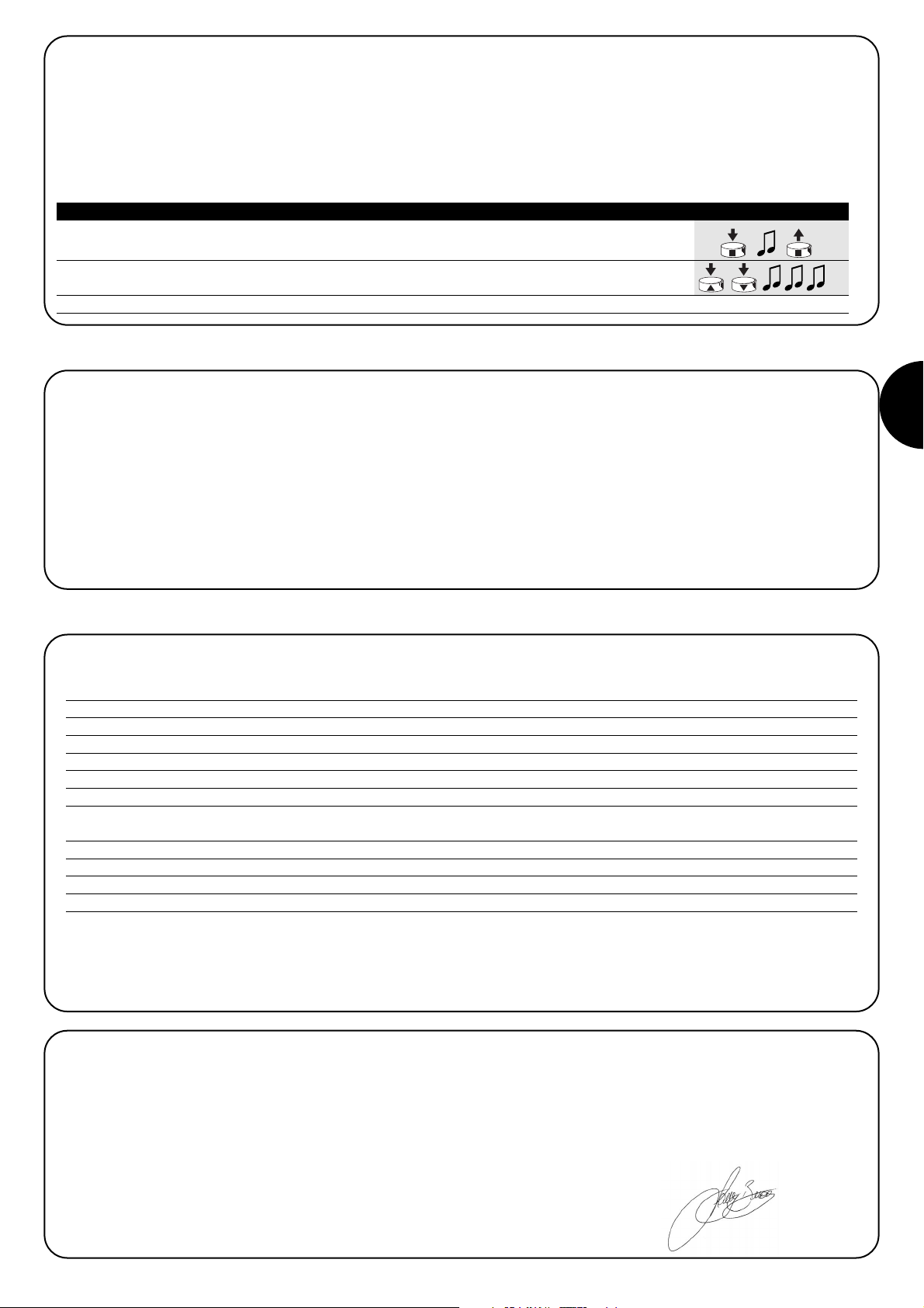
D
25
Nach der Versorgung der Steuerung hört man keinen Biepton und die Sender funktionieren nicht.
Prüfen, ob die Steuerung korrekt zwischen den Klemmen 6-7 mit der
Netzspannung gespeist ist. Sollte die Versorgung korrekt sein, liegt
wahrscheinlich ein schwerer Defekt vor und die Steuerung muss
ersetzt werden
Nach einem Befehl per Funk hört man 6 Bieptöne und die
Relais schaltet weder ein noch aus.
Die Funksteuerung ist nicht synchronisiert, der Sender muss neu
gespeichert werden.
Nach einem Befehl hört man 10 Bieptöne, dann schaltet
die Relais ein.
Die Selbstdiagnose der gespeicherten Parameter hat eine Störung
festgestellt.
5) Was tun, wenn… kleiner Leitfaden, wenn etwas nicht funktioniert!
6) Technische Merkmale
Alle technischen Merkmale beziehen sich auf eine Temperatur von 20°C
Elektronische Steuerung
Versorgung : 230Vac (+10-15%) 50Hz
Max. Ausgangsleistung : 500W / 400VA
Betriebstemperatur : -20÷55 °C
Abmessungen / Gewicht : 98 x 26 x 20 / 45g
Schutzart : IP55 (unbeschädigte Box)
Dauer des Timers :
Programmierbar von 1 Sekunde bis 9 Stunden werkseitig TIMER1=1 Minute TIMER2= 10 Minuten
Funkempfänger
Frequenz : 433.92 MHz
Codierung : FLO (Fixed Code), FLOR (Rolling Code) SMILO (Rolling Code)
Anzahl speicherbare Sender : 30
Reichweite der Sender : Auf freiem Feld ca. 150 m und 20 m in Gebäuden. *
* Die Reichweite der Sender kann durch andere Vorrichtungen, die mit derselben Frequenz ständig funktionieren, wie Alarme, Kopfhörer, usw.
und mit dem Empfänger der Steuerung interferieren, stark beeinträchtigt werden.
Nice behält sich das Recht vor, jederzeit Änderungen am Produkt anzubringen.
Konformitätserklärung N°: mindy TT1L Rev 0
Nice S.p.a. via Pezza Alta, 13 Rustignè Oderzo (TV) ITALY erklärt, dass das Produkt: “mindy TT1L” mit den wesentlichen Sicherheitsanforderungen folgender Richtlinien konform ist: R&TTE 1999/5/CE.
Datum Der Geschäftsführer
22-01-2004 Lauro Buoro
4.3.2) Benutzung der Sender mit 3 Tasten des Typs “▲■▼”
Wenn man über Sender mit Tasten des Typs “▲■▼” verfügt, die im Modus I gespeichert sind, kann an jedem Sender der Taste ▼. Ider
Befehl “OFF” zugeordnet werden. Auf diese Weise können die für Sender wie PLANO TIME vorgesehenen “Ereignisse” leicht benutzt werden. Die Taste ■ wird weiter die Funktion “OFF” ausführen.
Um diese Funktionsweise zu aktivieren, muss der Sender im Modus I gespeichert sein, und sie wird nur für jenen Sender angewendet. Die
Programmierung eventuell für alle gewünschten Sender wiederholen.
1. Auf Taste ■ des im Modus I gespeicherten Senders drücken und gedrückt halten, bis man einen 5s
Biepton hört (nach ca. 5 Sekunden), dann loslassen.
2. Innerhalb von 3 Sekunden, gleichzeitig auf die beiden Tasten ▲▼drücken und diese ca.
5 weitere Sekunden gedrückt halten, bis 3 Bieptöne melden, dass die Funktion programmiert ist. 3s
Anmerkung: Um die Funktion zu deaktivieren, das Verfahren ab Punkt 1 wiederholen.
Tabelle “A11” FUNKTION “ON” “OFF” mit ▲■▼ Beispiel
Page 26
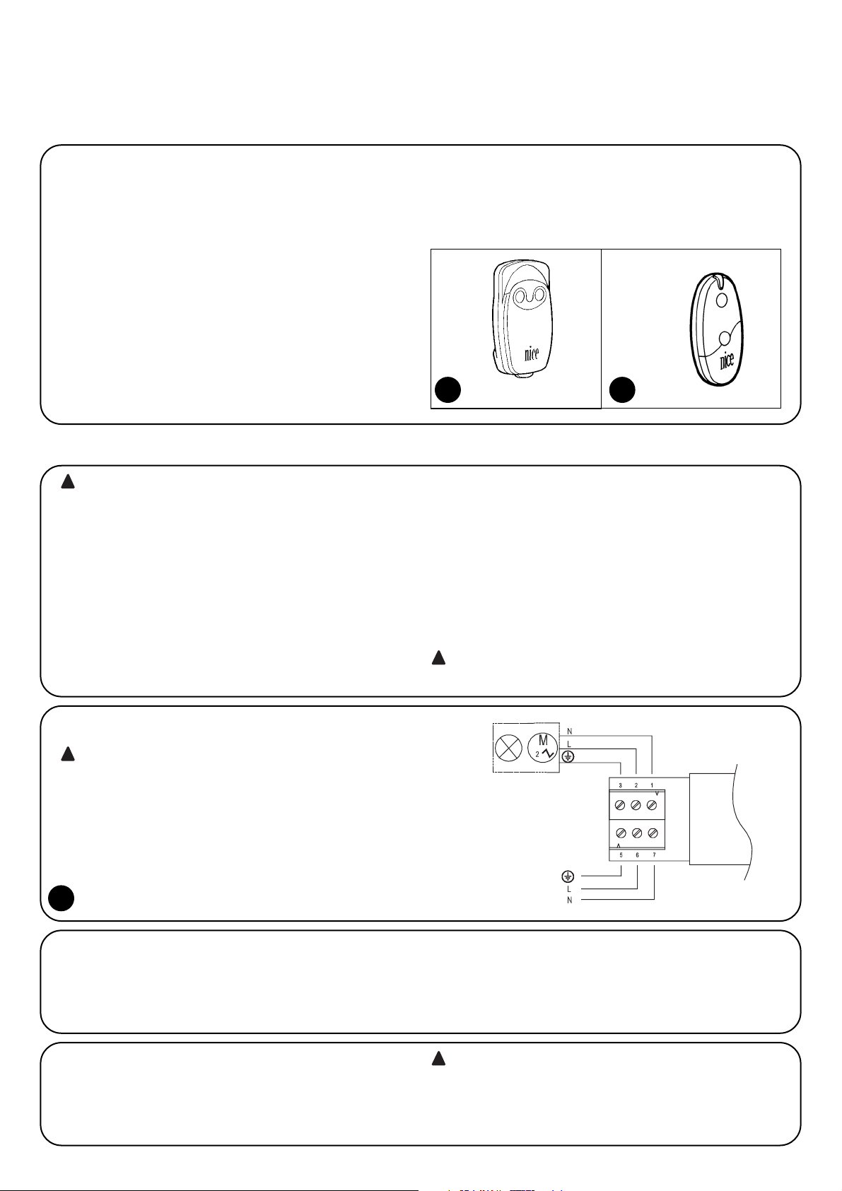
26
2.1.1) Conexión del aparato eléctrico
La alimentación del dispositivo eléctrico que se desea accionar
(máx. 500W / 400VA) debe conectarse a los bornes de salida 1-2;
el n° 3 es el borne de tierra.
2.1.2) Alimentación
La alimentación principal de la central debe suministrarse utilizando
los bornes 5-6-7 (tierra, fase, neutro) tal como indicado en la fig. 3
“Conexiones eléctricas”.
En la central el borne 7 (Neutro) está conectado directamente al borne 1 de salida y, por consiguiente, el dispositivo eléctrico a accionar no queda completamente desconectado de la línea eléctrica de alimentación, aún
estando apagado.
!
La central de mando TT1L permite encender y apagar, mediante
radiomando, aparatos eléctricos de hasta una potencia de 500W
(400VA) alimentados con tensión de red. Hay a disposición mandos
ON/OFF, Hombre Muerto y Apagado Temporizado (con 2 temporizadores independientes).
La central incorpora un radiorreceptor que funciona con una frecuencia de 433.92 MHz con tecnología rolling code, la que garantiza niveles elevados de seguridad. Para cada central es posible
memorizar hasta 30 transmisores de la serie “FLOR” (fig. 1), o
“VERY” (fig.2). En cada transmisor se utilizan 2 botones: uno para el
encendido (ON) y el otro para el apagado (OFF). Todas las programaciones se pueden hacer directamente desde los transmisores, un
tono de aviso le guiará en las distintas etapas.
Nota: La central también puede controlar otros tipos de transmisores y otros modos de funcionamiento; véase el capítulo 4) “Profundización”.
Advertencias
La central TT1L es adecuada para accionar un equipo eléctrico monofásico
alimentado con tensión de red, por ejemplo: lámparas de iluminación, motores de riego, etc.; queda prohibido cualquier otro empleo diferente.
La instalación tiene que ser efectuada por personal técnico, respetando
las normas eléctricas y de seguridad vigentes.
1) Descripción del producto
2.1) Conexiones eléctricas
Respete escrupulosamente las conexiones previstas, si
tuviera dudas NO pruebe inútilmente, sino que consulte
las fichas técnicas de profundización correspondientes
que están disponibles en el sitio www.niceforyou.com.
Una conexión incorrecta puede provocar averías graves a
la central.
!
2) Instalación
las instalaciones eléctricas deben ser efectuadas por personal experto y cualificado, respetando las normas vigentes.
Todas las conexiones deben efectuarse sin que haya alimentación eléctrica.
1. Pele el cable del aparato eléctrico a accionar y el cable de alimenta-
ción 3 cm aproximadamente y después cada hilo alrededor de 5 mm.
2. Abra la caja quitando el tapón pasacable, tal como indicado en la fig.
4.
3. Pase los dos cables por los agujeros del pasacable del tapón (véase
fig. 5).
4. Extraiga algunos centímetros la tarjeta de la caja (véase fig. 6).
5. Conecte los hilos a los bornes tal como indicado en la fig. 7, respe-
tando el esquema de fig. 3 y aquello indicado en el capítulo 2.1) .
6. Pliegue los cables como muestra la fig. 8.
7. Empuje la tarjeta hacia adentro de la caja, controle que la parte pelada de los cables esté totalmente adentro de la caja, haga deslizar el
tapón hasta cerrar completamente la caja (véase fig. 9).
8. Fije la central sobre una superficie adecuada y protegida de los choques, si fuera necesario utilice cinta biadhesiva. Para evitar el riesgo
de infiltraciones de agua es necesario colocarla con los cables hacia
abajo, como se muestra en la fig. 10, evitando de colocarla con los
cables hacia arriba (fig. 11).
la caja nunca debe ser perforada por ningún motivo.
!
!
3
1
FLOR
2
VERY
Page 27

E
27
Cada transmisor es reconocido por la central a través de un "código" que
es diferente de cualquier otro transmisor. Por tal razón, se requiere una
etapa de "memorización" con la que se prepara a la central para que
reconozca cada uno de los transmisores.
•Todas las secuencias de memorización son por tiempo, es decir
que deben efectuarse dentro de los límites de tiempo previstos.
• La programación por radio puede realizarse en todas las
centrales que se encuentran en el radio de alcance del
transmisor y, por eso, es oportuno mantener alimentada sólo
aquella interesada por la programación.
Para cada transmisor se utilizan 2 botones: botón 1 = "ON" y botón 2 =
"OFF". En los transmisores con 4 botones, aquellos que quedan libres pueden utilizarse para accionar otra central: botón 3 = "ON" y botón 4 = "OFF".
!
3) Programación
1. Ni bien se conecta la alimentación a la central, se oirán 2 tonos de aviso largos (biiip).
2. Antes de transcurridos 5 segundos, presione y mantenga presionado el botón 1 ó 2
(o bien 3 ó 4) del transmisor a memorizar (durante alrededor de 3 segundos). 3s
3. Suelte el botón cuando oiga el primero de los 3 tonos de aviso que confirman la memorización
Nota: si la central ya contiene transmisores memorizados, en el momento del encendido se oirán tonos de aviso cortos (bip) y no se
podrá proceder como descrito, sino que habrá que usar el otro procedimiento de memorización (Tabla “A2”).
Cuando en la memoria no hay ningún transmisor, se puede proceder a memorizar el primero de la siguiente manera:
1. Mantenga presionado el botón 1 ó 2 (o bien 3 ó 4) del nuevo transmisor hasta oír un tono de
aviso (después de alrededor de 5 segundos); luego, suéltelo. Nuevo 5s
2. Presione lentamente 3 veces cualquier botón de un transmisor ya memorizado.
Viejo X3
3. Presione de nuevo el botón 1 ó 2 (o bien 3 ó 4) del nuevo transmisor y suéltelo al oír el
primero de los 3 tonos de aviso. Nuevo
Nota: si la memorización es correcta se oirán 3 tonos de aviso prolongados. Cuando la memoria está llena (30 transmisores), 6 tonos de
aviso indicarán que el transmisor no puede ser memorizado.
Cuando han sido memorizados uno o varios transmisores, es posible habilitar otros de la siguiente manera:
Tabla "A1" Memorización del primer transmisor Ejemplo
Tabla “A2” Memorización de otros transmisores Ejemplo
A Con la central no alimentada, corte el puente de conexión presente en la tarjeta (véase fig. 12).
El puente de conexión se debe restablecer después del borrado.
B Alimente la central y espere los tonos de aviso iniciales
1-3
1 Mantenga presionado el botón 2 (o bien 4) de un transmisor memorizado hasta oír un tono
de aviso (después de alrededor de 5 segundos); luego, suéltelo. 5s
2 Después de 1 segundo, presione nuevamente el mismo botón y suéltelo exactamente
durante el tercer tono de aviso.
3 Después de 1 segundo, presione nuevamente el mismo botón y suéltelo exactamente
durante el tercer tono de aviso.
4 Después de 1 segundo, presione nuevamente el mismo botón y suéltelo exactamente
durante el tercer tono de aviso.
5 Si usted desea borrar completamente todos los datos de la memoria, presione, antes de 2
segundos, el mismo botón hasta oír el primero de 5 tonos de aviso; luego, suéltelo.
Nota: los 5 tonos de aviso indican que todos los códigos de la memoria han sido borrados.
Si fuera necesario borrar la memoria de la central se puede ejecutar el procedimiento indicado en la tabla “A3”.
La memoria se puede borrar:
• con un transmisor no memorizado, empezando el procedi-
miento desde el punto A, aunque si en el punto 1 se requiere un
transmisor memorizado.
• con un transmisor memorizado, empezando el procedimien-
to desde el punto N° 1.
Se pueden borrar:
• sólo los transmisores, terminando en el punto 4,
• todos los datos (transmisores y programación de los temporizadores), completando el procedimiento hasta el punto 5.
➨
➨
Tabla “A3” Borrado de la memoria Ejemplo
➨
Page 28

28
4.1) Transmisores que pueden utilizarse
En la tabla “A4” se indican los transmisores que pueden utilizarse
con la codificación radio correspondiente.
Puesto que las codificaciones de los transmisores son diferentes y
la central no puede reconocerlas simultáneamente, el primer transmisor memorizado determina el tipo de codificación y los transmisores que podrán memorizarse.
Si se desea cambiar el tipo de transmisor es necesario
borrar todos los códigos (véase la tabla “A3”).
Es posible comprobar el tipo de codificación contando el número de
tonos de aviso emitidos por la central en el momento del encendido.
CODIFICACIÓN Transmisores
FLO1R - FLO2R - FLO4R
VERY VR
FLOR Rolling code
ERGO1 - ERGO4 - ERGO6
PLANO1 - PLANO4 - PLANO6 - PLANO TIME
SMILO Rolling code SM2 - SM4
FLO Fixed cod
FLO1 - FLO2 - FLO4
VERY VE
Tabla "A4"
BIP Tipo de codificación de los transmisores memorizados
1 tono de aviso corto Transmisores con codificación FLO
2 tonos de aviso cortos Transmisores con codificación FLOR
3 tonos de aviso cortos Transmisores con codificación SMILO
4 tonos de aviso cortos Memoria vacía (ningún transmisor memorizados)
Tabla “A5”
4.2) Memorización de los transmisores en Modo I y Modo II
En las tablas “A1” y “A2” se describe la memorización de los transmisores en Modo I
Ta mbién es posible memorizar los transmisores en Modo II; dicho
modo permite la flexibilidad máxima de uso de los transmisores y de
la central.
En la misma central pueden memorizarse transmisores tanto en
Modo I como en Modo II.
A continuación se describen las diferencias entre los 2 modos de
programación:
ERGO
PLANO SM2 SM4
4.2.1) Modo I
En este modo el mando asociado a los botones del transmisor es
fijo: el botón 1 acciona el encendido (ON), el botón 2 acciona el apagado (OFF). Los botones 3 y 4 presentes en el mismo transmisor
pueden accionar otra central: el botón 3 acciona el encendido (ON),
el botón 4 acciona el apagado (OFF).
En la central se ejecuta una única etapa de memorización para cada
transmisor; durante esta etapa no es importante si se pre-
siona el botón 1 ó 2 (o bien el botón 3 ó 4).
Para memorizar o borrar los transmisores en Modo I, véase el capítulo 3 “Programaciones”.
Esempio memorizzazione Modo I
Botón 1 ON en TT1L n°1
Botón 2 OFF en TT1L n°1
Botón 3 ON en TT1L n°2
Botón 4 OFF en TT1L n°2
4) Profundización
Además de los transmisores de la serie “FLOR” y “VERY”, la central reconoce otros tipos de transmisores producido por Nice (véase el capítulo
4.1 “Transmisores que pueden utilizarse”). Con procedimientos oportu-
nos de memorización de los transmisores también es posible asociar a
cada botón del transmisor un mando particular (véase el capítulo 4.2
“Programación de los transmisores en Modo I y Modo II”).
FLO4R VERY
Page 29

E
29
Ejemplo 1 memorización Modo II
Botón 1 ON/OFF en TT1L n°1
Botón 2 TIMER1 en TT1L n°1
Botón 3 TIMER2 en TT1L n°1
Botón 4 HOMBRE MUERTO en TT1L n°2
Cuando en la memoria no hay ningún transmisor, se puede proceder a memorizar el primero en Modo II de la siguiente manera:
Ejemplo 2 memorización Modo II
Botón 1 ON/OFF en TT1L n°1
Botón 2 ON/OFF en TT1L n°2
Botón 3 ON/OFF en TT1L n°3
Botón 4 TIMER1 en TT1L n°3
1. Ni bien se conecta la alimentación a la central, se oirán 2 tonos de aviso largos (biiip).
2. Antes de 5 segundos presione el botón a memorizar del transmisor y manténgalo presionado
hasta el final de los 3 tonos de aviso; luego suéltelo 5s
3. A
ntes de 3 segundos empiece a presionar el mismo botón del transmisor la cantidad de veces igual
al mando deseado: 1 = “ON/OFF” 2 = “HOMBRE MUERTO” 3 = “TIMER1” 4 = “TIMER2” 1-4 3s
4. Después de alrededor de 3 segundos se oirá una cantidad de tonos de aviso igual al
mando seleccionado 1-4 3s
5. Antes de 2 segundos presione nuevamente el mismo botón para confirmar la programación
y suéltelo en el primero de los 3 tonos de aviso. 2s
Nota: si la memorización es correcta se oirán 3 tonos de aviso prolongados. Si en el punto 4 no se oye la cantidad de tonos de aviso
igual al mando deseado, espere algunos segundos para salir del procedimiento sin confirmar la memorización.
Tabla “A6” Memorización del primer transmisor en Modo II Ejemplo
1. Mantenga presionado el nuevo botón a memorizar del transmisor hasta oír un tono de aviso
(después de alrededor de 5 segundos); luego, suéltelo.
Nuevo 5s
2. Antes de 5 segundos presione y mantenga presionado durante 5 segundos el botón de un
transmisor memorizado (viejo) hasta oír 2 tonos de aviso rápidos; luego, suéltelo
Viejo 5s
3. Antes de 5 segundos presione el mismo botón del transmisor (viejo) la cantidad de veces igual
al mando deseado:1 = “ON/OFF” 2 = “HOMBRE MUERTO” 3 = “TIMER1” 4 = “TIMER2”
Viejo
1-4
3s
4. Después de alrededor de 3 segundos se oirá la cantidad de tonos de aviso igual al mando
antes seleccionado 1-4 3s
5. Antes de 2 segundos presione nuevamente el nuevo botón a memorizar del transmisor para
confirmar la programación y suéltelo durante el primero de los 3 tonos de aviso.
Nuevo
2s
Nota: si la memorización es correcta se oirán 3 tonos de aviso prolongados. Cuando la memoria está llena (30 transmisores), 6 tonos de
aviso indicarán que el transmisor no puede ser memorizado.
Tabla “A7” Memorización de otros transmisores en Modo II Ejemplo
1. Mantenga presionado el botón del nuevo transmisor que se desea memorizar durante 3
segundos como mínimo y luego suéltelo.
Nuevo 3s
2. Presione el botón del transmisor habilitado (viejo) durante 3 segundos como
mínimo y luego suéltelo
Viejo 3s
3. Presione de nuevo el botón del nuevo transmisor durante 3 segundos como
mínimo y luego suéltelo
Nuevo 3s
4. Presione de nuevo el botón del transmisor viejo hasta oír 3 tonos de aviso que confirman la
memorización del transmisor nuevo
Viejo 3s
Nota: cuando la memoria está llena (30 transmisores), 6 tonos de aviso indicarán que el transmisor no puede ser memorizado.
Tabla “A8” Memorización de otros transmisores Ejemplo
4.2.2) Modo II
Este modo permite asociar a cada botón del transmisor uno entre los
siguientes tipos de mando:
1 “ON/OFF” (el mismo botón enciende, luego apaga y así sucesivamente)
2 “HOMBRE MUERTO” (encendido sólo mientras se mantiene presiona-
do el botón)
3 “TIMER1” encendido con apagado temporizado (de fábrica, después de
1 minuto)
4 “TIMER2” encendido con apagado temporizado (de fábrica, después
de 10 minutos).
En la central se debe ejecutar una etapa de memorización para cada
botón del transmisor; durante esta etapa se debe presionar el botón al que
asociar el mando. Si se desea asociar otro mando a otro botón del transmisor, es necesario realizar otra etapa de memorización.
Los botones del mismo transmisor pueden estar asociados a varios mandos de la misma central, o bien estar asociados a mandos de diferentes
centrales.
Es posible memorizar de manera sencilla un nuevo transmisor manteniendo las mismas características del transmisor viejo siguiendo el procedimiento de la tabla “A8”.
El nuevo transmisor memorizado adquirirá las características del transmisor viejo, es decir que si el viejo estaba memorizado en Modo I, también el nuevo funcionará en Modo I y si el viejo estaba memorizado en Modo II, también el botón del nuevo transmisor será asociado al mismo mando del viejo.
Cuando han sido memorizados uno o varios transmisores, es posible memorizar otros en Modo II de la siguiente manera:
Page 30
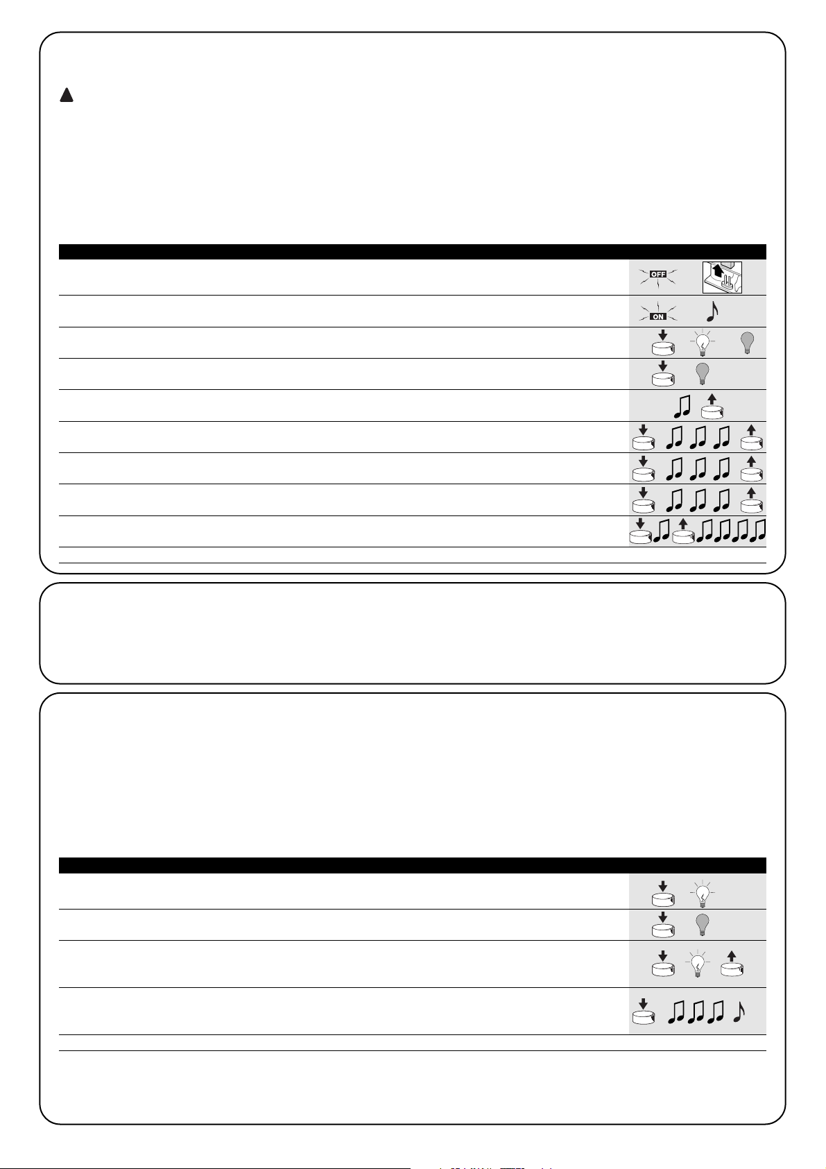
30
Si fuera necesario borrar todos los datos contenidos en la memoria de la central utilizando un transmisor memorizado en Modo II, se puede ejecutar el procedimiento de la tabla “A9”.
El borrado con transmisores memorizados en modo II es muy complejo y debe respetar los siguientes puntos; si Ud. posee un transmi-
sor no memorizado, es mucho más fácil el procedimiento de la tabla A3.
• No es posible efectuar el borrado con transmisores con mandos “HOMBRE MUERTO”, de ser necesario, utilice un nuevo transmisor y siga
el procedimiento de la tabla “A3”.
• Si se sigue el procedimiento con transmisores con mando TIMER es necesario iniciar desde el punto A; en caso contrario, inicie desde el punto 1.
Se pueden borrar:
• sólo los transmisores, terminando en el punto 4,
• todos los datos (transmisores, duración del TIMER1 y TIMER2) completando el procedimiento hasta el punto 5.
!
A Con la central no alimentada, corte el puente de conexión presente en la tarjeta (véase fig. 12).
puente de conexión se debe restablecer después del borrado.
B Alimente la central y espere los tonos de aviso iniciales 1-3
C Presione y mantenga presionado el mando TIMER; el relé se enciende y transcurridos
alrededor de 3 segundos se apaga; siempre con el botón presionado siga con el punto 2. 3s
1 Si el relé está apagado, presione y suelte el botón con el mando ON/OFF para encenderlo. 5s
Presione y mantenga presionado el botón.
2 Transcurridos alrededor de 5 segundos se oirá un tono de aviso; suelte el botón
3 Después de 1 segundo, presione nuevamente el mismo botón y suéltelo exactamente
durante el tercer tono de aviso.
4 Después de 1 segundo, presione nuevamente el mismo botón y suéltelo exactamente
durante el tercer tono de aviso.
5 Después de 1 segundo, presione nuevamente el mismo botón y suéltelo exactamente
durante el tercer tono de aviso.
6 Si usted desea borrar completamente todos los datos de la memoria, presione, antes de 2
segundos, el botón hasta oír el primero de 5 tonos de aviso; luego, suéltelo.
Nota: los 5 tonos de aviso indican que todos los códigos de la memoria han sido borrados.
➨
➨
Tabla “A9” Borrado de la memoria con un transmisor memorizado en Modo II Ejemplo
➨
4.3) Programaciones auxiliares
En la central es posible programar la duración de los temporizadores TIMER1 y TIMER2 o programar para el uso de los transmisores de 3
botones tipo “▲■▼”, véanse los siguientes capítulos.
4.3.1) Programación de los temporizadores
La central permite programar 2 temporizadores independientes para apagar automáticamente el relé después de un tiempo predeterminado: “TIMER1” y “TIMER2”. Cada vez que se acciona el mando se recarga el tiempo previsto; es posible anticipar el apagado manteniendo
activo el mando TIMER durante más de 3 segundos o accionando un mando de OFF.
De fábrica y después de borrar completamente la memoria, los tiempos previstos para los 2 temporizadores son de 1 minuto (TIMER1) y 10
minutos (TIMER2) respectivamente.
Es posible programar el tiempo de encendido desde un mínimo de 1 segundo hasta un máximo de 9 horas.
1. Presione y mantenga presionado el botón del transmisor correspondiente al temporizador
que se desea programar. El relé se enciende (ON).
2. Mantenga siempre presionado el mismo botón; después de 3 segundos el relé se apaga (OFF)
3s
3. Mantenga presionado el mismo botón hasta que se encienda nuevamente el relé
(después de alrededor de 8 segundos); desde este instante, comienza la etapa de cuenta
del tiempo. Suelte el botón. 8s
4.
Cuando haya transcurrido el tiempo que se desea programar, presione un botón de un transmisor
memorizado en la central. 3 tonos de aviso indicarán que la memorización del tiempo se ha ejecutado; luego
se oirán 1 ó 2 tonos de aviso cortos que indicarán si la programación se refiere al TIMER1 o al TIMER2
1-2
Nota: si se desea modificar el tiempo de los temporizadores, es suficiente repetir el procedimiento iniciando desde el punto 1
Tabla “A10” Programación de la duración de los temporizadores Ejemplo
Page 31

E
31
Tras haber alimentado la central no se oye ningún tono de
aviso y los transmisores no funcionan.
Controle que la central esté alimentada correctamente: debe haber
tensión de red entre los bornes 6-7. Si la alimentación es correcta,
es probable que haya una avería grave y entonces habrá que sustituir la central.
ués de un mando por radio se oyen 6 tonos de aviso y el
relé no se enciende ni se apaga.
El radiomando está desincronizado; hay que repetir la memorización
del transmisor.
Después de un mando se oyen 10 tonos de aviso y después el relé se enciende.
El autodiagnóstico de los parámetros en la memoria ha detectado
algún desperfecto.
5) Qué hacer si… ¡pequeña guía en caso de problemas!
6) Características técnicas
Todas las características se refieren a una temperatura de 20°C
Central electrónica
Alimentación : 230Vac (+10-15%) 50Hz
Potencia máxima salida : 500W / 400VA
Temperatura de funcionamiento : -20÷55 °C
Medidas / peso : 98 x 26 x 20 / 45g
Clase de protección : IP55 (caja íntegra)
Duración Temporizadores : Programable de 1 segundo a 9 horas de fábrica TIMER1=1 minuto TIMER2= 10 minutos
Radiorreceptor
Frecuencia : 433.92 MHz
Codificación : FLO (fixed code), FLOR (rolling code) SMILO (rolling code)
N° transmisores memorizables : 30
Alcance de los transmisores : estimado en 150 m al aire libre y en 20m en el interior de edificios *
* El alcance de los transmisores depende mucho de otros dispositivos que funcionan en la misma frecuencia con transmisiones continuas
tales como alarmas, radioauriculares, etc. que interfieren con el receptor de la central..
Nice se reserva el derecho de modificar los productos en cualquier momento en que lo considere necesario
Declaración de conformidad N°: mindy TT1L Rev 0
Nice S.p.a. via Pezza Alta, 13 Rustignè Oderzo (TV) ITALY declara que el producto: “mindy TT1L” satisface los requisitos esenciales de seguridad de las directivas: R&TTE 1999/5/CE.
Fecha Director
22-01-2004 Lauro Buoro
4.3.2) Uso de transmisores con 3 botones tipo “▲■▼”
Si se dispone de transmisores con botones “▲■▼” memorizados en Modo I, para cada uno de estos es posible asociar el mando “OFF”
al botón ▼. De esta manera es posible utilizar fácilmente los “acontecimientos” previstos por los transmisores, por ejemplo PLANO TIME.
El botón ■ seguirá ejecutando la función de “OFF”
Para activar esta función es necesario que el transmisor esté memorizado en modo I; la función se aplicará sólo a ese transmisor; de ser
necesario, repita la programación de todos los transmisores deseados.
1. Presione y mantenga presionado el botón ■ del transmisor ya memorizado en Modo I hasta
que oiga un tono de aviso (después de alrededor de 5 segundos); después, suéltelo. 5s
2.
Antes de 3 segundos, presione simultáneamente los 2 botones ▲▼y manténgalos presionado durantes
otros 5 segundos hasta que 3 tonos de aviso señalen que la programación de la función se ha ejecutado.
3s
Nota: si se desea excluir la función, repita el procedimiento iniciando desde el punto 1
Tabla “A11” FUNCIÓN “ON” “OFF” con ▲■▼ Ejemplo
Page 32

32
2.1.1) Pod czenie urz dzenia elektrycznego
Zasilanie urządzenia elektrycznego, jakim zamierzamy sterować (maks.
500W / 400VA) musi być podłączone do zacisków wyjścia 1-2; zacisk
nr 3 jest zaciskiem uziemiającym.
2.1.2) Zasilanie
Zasilanie centrali musi być doprowadzone do zacisków 5-6-7 (ziemia,
faza, neutralny), tak jak pokazano na rys. 3 “Połączenia elektryczne”.
W centralce zacisk 7 (Neutralny) jest po czony bezpo rednio z zaciskiem 1 wyj cia, a wi c sterowane urz dzenie elektryczne, nawet je li wy czone, nie jest ca kowicie odci te od
zasilaj cej linii elektrycznej.
!
Centralka sterująca TT1L pozwala na włączenie i wyłączenie za
pomocą sterowania radiowego urządzeń elektrycznych o mocy do
500W (400 VA) zasilanych napięciem sieci. Możliwe są następujące
polecenia: ON/OFF (Włącz/Wyłącz), Tryb Manualny i Wyłącznik
Czasowy (z 2 niezależnymi zegarami).
Centrala zawiera odbiornik radiowy, który pracuje na częstotliwości
433,92 MHz z technologią rolling code (kod dynamicznie zmienny),
gwarantując wysokie poziomy bezpieczeństwa. Do pamięci każdej
centrali można wczytać do 30 pilotów z serii “FLOR” (rys. 1) lub “VERY”
(rys. 2). W każdym nadajniku są używane 2 przyciski; jeden do
sterowania włączeniem (ON) i drugi do sterowania wyłączeniem (OFF).
Programowanie parametrów można wykonać bezpośrednio z
nadajników, a sygnał akustyczny “bip” poprowadzi przez poszczególne
fazy programowania.
Uwaga: Centrala może współpracować również z innymi rodzajami
nadajników i w innych trybach działania -zobacz rozdział 4 “Informacje
szczegółowe”.
Uwagi
Centralka TT1L służy do sterowania jednofazowym urządzeniem elektrycznym zasilanym z sieci, jak np. lampy oświetleniowe, silniki pomp do
nawadniania itp., każde inne użycie jest niewłaściwe i zabronione.
Instalowanie musi być przeprowadzone przez wykwalifikowany personel.
Podczas montażu należy przestrzegać obowiązujące przepisy elektryczne
oraz BHP.
1) Opis produktu
2.1) Po czenia elektryczne
Skrupulatnie przestrzegać przewidzianych połączeń; w
wypadku niepewności NIE podejmować prób ale zapoznać
się z odpowiednimi szczegółowymi instrukcjami
technicznymi, które dostępne są na stronie internetowej:
www.niceforyou.com.
B dne wykonanie po cze mo e spowodowa powa ne
uszkodzenie centrali.
!
2) Instalacja
Instalacje elektryczne i automatyki musz by wykonane przez do
wiadczony i wykwalifikowany personel zgodnie z obowi zuj cymi
przepisami prawa. Wszystkie po czenia wykonywa przy wy czonym
napi ciu.
1. Zdjąć zewnętrzną izolację z przewodów urządzenia sterowanego i z
przewodu zasilającego na długości około 3 cm, a następnie z pojedynczych
przewodów na długości około 5 mm.
2. Otworzyć skrzynkę wyjmując korek przelotki dla przewodów, tak jak to
pokazano na rys. 4.
3. Przełożyć przewody przez odpowiednie otwory przelotki korka (patrz rys. 5).
4. Wyciągnąć na kilka centymetrów płytkę drukowaną z obudowy (patrz rys. 6).
5. Podłączyć przewody do zacisków jak pokazano na rys. 7, zgodnie ze
schematem na rys. 3 i jak opisano w rozdziale 2.1).
6. Zagiąć przewody jak na rys. 8.
7. Wepchnąć płytkę drukowaną do obudowy, sprawdzić czy odizolowana
część przewodów znajduje się w całości wewnątrz obudowy, przesunąć
korki na przewodach aż do pełnego zamknięcia (patrz rys. 9).
8. Zamocować centralkę na odpowiedniej powierzchni, zabezpieczonej od
uderzeń, można w tym celu użyć taśmy dwustronnie przylepnej. Aby
wyeliminować ryzyko przedostania się wody należy tak ustawić centralkę,
aby przewody wychodziły od spodu, tak jak na rys. 10. nie wolno mocować
centralki przewodami do góry (rys. 11).
W obudowie nie wolno wykonywa adnych otwor w.
!
!
3
1
FLOR
2
VERY
Page 33

PL
33
Każdy nadajnik rozpoznawany jest przez wbudowany odbiornik w
centrali na podstawie indywidualnego, niepowtarzalnego kodu.
Niezbędna jest więc faza “wczytywania” w trakcie której uczy się
centralę rozpoznawać każdy pojedynczy nadajnik.
• Wszystkie etapy wczytywania s ograniczone czasowo, to
znaczy, e musz by wykonane w okre lonym czasie.
• Programowanie za pomocą radia odbędzie się we
wszystkich centralkach jakie znajdują się w promieniu
działania nadajnika, a więc wskazane jest aby była zasilana
tylko ta która ma wykonać daną operację.
Dla każdego nadajnika są używane 2 przyciski: przycisk 1 = "ON" i przycisk
2 = "OFF". W nadajnikach z 4 przyciskami, te które zostają wolne mogą być
użyte do sterowania inna centralką: przycisk 3 = "ON" i przycisk 4 = "OFF".
!
3) Programowanie
1. Kiedy centralka zostanie podłączona do zasilania, usłyszymy 2 długie sygnały “bip” (biiip)
2. W ciągu 5 sekund wcisnąć przycisk 1 lub 2 (lub 3 lub 4) nadajnika, który ma być wczytany
(przez około 3 sekundy). 3s
3. Zwolnić przycisk kiedy usłyszymy pierwszy z 3 ăbipÓ które potwierdzają wczytanie kodu
Uwaga: Jeśli w centralce są już wczytane jakieś nadajniki, to przy jej włączeniu usłyszymy krótkie „bip” (bip) i nie będzie można tak postąpić jak
to wyżej opisano, lecz należy postąpić w inny sposób (Tabela “A2”).
Kiedy pamięć nie zawiera żadnego nadajnika, aby wprowadzić pierwszy trzeba postąpić w następujący sposób:
1. Trzymać wciśnięty przycisk 1 lub 2 (albo 3 lub 4) nowego nadajnika aż do usłyszenia „bip”
(po około 5 sekundach), następnie przycisk zwolnić Nowy 5s
2. Powoli wcisnąć 3 razy jakikolwiek przycisk nadajnika już uprzednio wczytanego.
Stary X3
3. Wcisnąć jeszcze raz przycisk 1 lub 2 (albo 3 lub 4) nowego nadajnika i zwolnić po pierwszym
z 3 „bip”. Nowy
Uwaga: Jeśli wczytywanie zostało zakończone pozytywnie, to usłyszymy 3 długie „bip”. Kiedy pamięć jest zapełniona (30 nadajników), to 6
„bip” poinformuje, że nadajnik nie może być wczytany.
Jeśli jeden lub więcej nadajników jest już wczytanych, można zapamiętać kolejne nadajniki w następujący sposób:
Tabela “A1” Wczytywanie pierwszego nadajnika
Przykład
Tabela
“A2”
Wczytywanie kolejnych nadajnik w Przykład
A A centralka nie jest zasilana, zdjąć mostkowanie widoczne na płytce (patrz rys. 12).
Mostek musi by ponownie za o ony po uko czeniu kasowania.
B Włączyć zasilanie centralki i poczekać na początkowe „bip”. 1-3
1 Trzymać wciśnięty przycisk 2 (albo 4) nadajnika już zapamiętanego aż do usłyszenia „bip”
(po około 5 sekundach), następnie przycisk zwolnić 5s
2 Po 1 sekundzie wcisnąć ponownie ten sam przycisk i zwolnić go dokładnie podczas
trzeciego „bip”.
3 Po 1 sekundzie wcisnąć ponownie ten sam przycisk i zwolnić go dokładnie podczas
trzeciego „bip”.
4 Po 1 sekundzie wcisnąć ponownie ten sam przycisk i zwolnić go dokładnie podczas
trzeciego „bip”.
5 Jeśli chcemy wykasować wszystkie dane znajdujące się w pamięci, to w ciągu 2 sekund
należy wcisnąć ten sam przycisk aż do usłyszenia pierwszego z 5 „bip”, następnie przycisk zwolnić.
Uwaga: 5 „bip” oznacza, że wszystkie kody w pamięci zostały wykasowane.
Jeśli okaże się konieczne wykasowanie pamięci centralki, to należy
zastosować procedurę z tabeli „A3”.
Wykasowanie pami ci jest mo liwe:
• Przy pomocy nadajnika nie wczytanego rozpoczynając od punktu A
(pomimo, że w punkcie 1 jest żądany nadajnik już wczytany).
• Przy pomocy nadajnika ju wczytanego rozpoczynając procedurę
od punktu Nr 1
Mo na wykasowa:
• tylko nadajniki, kończąc w punkcie 4
• wszystkie dane (nadajniki i programowanie regulatorów czasowych),
kończąc procedurę na punkcie 5.
➨
➨
Tabela
“A3”
Kasowanie pami ci Przykład
➨
Page 34

34
4.1) Stosowane nadajniki
W tabeli “A4” podane są nadajniki jakie mogą współpracować z centralą.
Ponieważ różne rodziny nadajników mają odmienne sposoby
kodowania a centralka nie może ich rozpoznać jednocześnie, to
pierwszy wczytany nadajnik określa typ kodowania, a więc rodzaj
nadajników, które będą mogły być następnie wczytane.
Jeśli chcemy zmienić rodzaj nadajników, to należy najpierw
wykasować wszystkie kody (patrz tabela “A3”).
EŐ Można sprawdzić typ kodowania licząc sygnały „bip” wysłane przez
centralkę w momencie jej włączenia.
CODIFICA Trasmettitori
FLO1R - FLO2R - FLO4R
VERY VR
FLOR Rolling code
ERGO1 - ERGO4 - ERGO6
PLANO1 - PLANO4 - PLANO6 - PLANO TIME
SMILO Rolling code SM2 - SM4
FLO Fixed cod
FLO1 - FLO2 - FLO4
VERY VE
Tabella “A4”
BIP Typ kodowania wczytanych nadajników
1 “bip” krótki Nadajniki z kodowaniem FLO
2 “bip” krótkie Nadajniki z kodowaniem FLOR
3 “bip” krótkie Nadajniki z kodowaniem SMILO
2 “bip” długie Pamięć pusta (żaden nadajnik nie jest wczytany)
Tabela “A5”
4.2) Wczytywanie nadajników w Trybie I i Trybie II.
W tabelach “A1” i “A2” jest opisane wczytywanie nadajników w Trybie I.
Można zapamiętać również nadajniki w Trybie II; ten sposób pozwala na
maksymalny zakres wykorzystania nadajników i centralki.
W tej samej centralce można zapamiętać nadajniki tak w Trybie I jak i w
Trybie II.
Poniżej są opisane różnice pomiędzy 2 trybami programowania:
ERGO
PLANO SM2 SM4
4.2.1) Tryb I
W tym trybie polecenie przypisane przyciskom nadajnika jest stałe:
przycisk 1 steruje włączeniem (ON), przycisk 2 steruje wyłączeniem
(OFF), przyciski 3 i 4 znajdujące się na tym samym nadajniku mogą
sterować inną centralką: przycisk 3 steruje włączeniem (ON), a przycisk
4 steruje wyłączeniem (OFF).
W centralce wykonuje się oddzielną fazę wczytywania dla każdego
nadajnika, podczas tej fazy nie jest istotne czy został wciśnięty
przycisk 1 lub 2 (albo 3 lub 4).
Aby zapamiętać lub wykasować nadajniki w Trybie I - patrz rozdział 3
“Programowanie”.
Przykład wczytywanie w Trybie I
Przycisk 1 ON na TT1L nr1
Przycisk 2 OFF na TT1L nr1
Przycisk 3 ON na TT1L nr2
Przycisk 4 OFF na TT1L nr2
4) Inne informacje
Centralka poza nadajnikami serii “FLOR” i “VERY” rozpoznaje inne typy
nadajników produkowanych przez firmę Nice (patrz rozdział 4.1 “Stosowane nadajniki”); ponadto dzięki właściwym procedurom wczytywa-
nia nadajników, istnieje możliwość przypisania do każdego przycisku
nadajnika jednego, szczególnego polecenia (patrz rozdział 4.2 “Programowanie nadajników w Trybie I i Trybie II”).
FLO4R VERY
Page 35
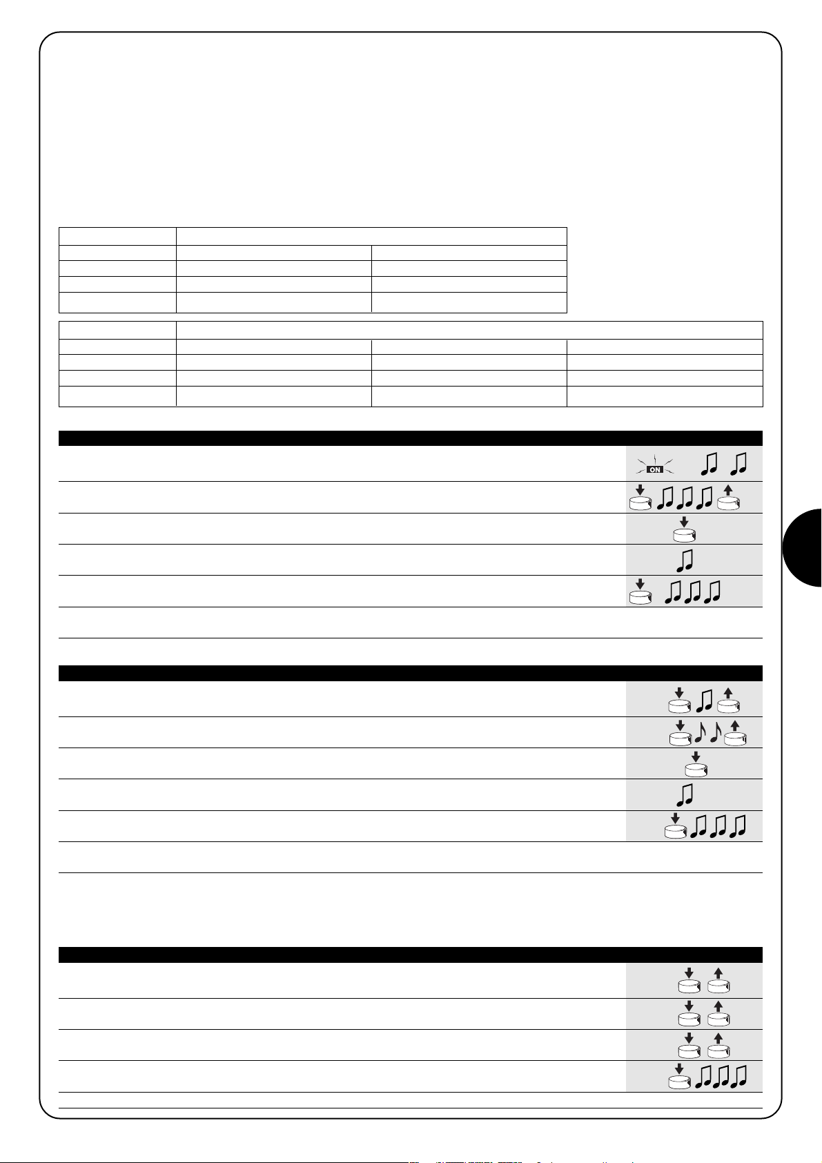
PL
35
Przykład 1 wczytywanie w Trybie II
Przycisk 1 ON/OFF na TT1L nr1
Przycisk 2 TIMER1 na TT1L nr1
Przycisk 3 TIMER2 na TT1L nr1
Przycisk 4 TRYB MANUALNY na TT1L nr2
Kiedy pamięć nie zawiera żadnego nadajnika należy przystąpić do wczytywania w Trybie II według następującej procedury:
Przykład 2 wczytywanie w Trybie II
Przycisko 1 ON/OFF su TT1L nĄ1
Przycisk 2 ON/OFF su TT1L nĄ2
Przycisk 3 ON/OFF su TT1L nĄ3
Przycisk 4 TIMER1 su TT1L nĄ3
1. Zaraz po zasileniu centralki usłyszymy 2 długie „bip” (biiip).
2. W ciągu 5 sekund wcisnąć przycisk, który chcemy wczytać i przytrzymać go aż do
zakończenia 3 „bip” a następnie go zwolnić. 5s
3.
W ciągu 3 sekund rozpocząć wciskanie tego samego przycisku nadajnika; ilość naciśnięć ma odpowiadać
żądanemu poleceniu:1 = “ON/OFF” 2 = “TRYB MANUALNY” 3 = “TIMER1” 4 = “TIMER2” 1-4 3s
4. Po około 3 sekundach usłyszymy liczbę „bip” odpowiadającą wybranemu poleceniu.
1-4 3s
5. W ciągu 2 sekund wcisnąć ponownie ten sam przycisk aby zatwierdzić programowanie, i
zwolnić go po usłyszeniu pierwszego z 3 „bip”. 2s
Uwaga: Jeśli wczytywanie zostało wykonane w sposób prawidłowy, to na koniec usłyszymy 3 długie „bip”. Jeśli w punkcie 4 nie słychać ilości
„bip” odpowiadających żądanemu poleceniu, należy odczekać kilka sekund aby wyjść z procedury bez zatwierdzenia wczytywania.
Tabela “A6” Wczytywanie pierwszego nadajnika w Trybie II Przykład
1. Trzymać wciśnięty przycisk nowego nadajnika (który chcemy wczytać) aż do usłyszenia
jednego „bip” (po około 5 sekundach), następnie przycisk zwolnić.
Nowy 5s
2. EW ciągu 5 sekund wcisnąć i trzymać wciśnięty przez około 5 sekund przycisk nadajnika już
zapamiętanego (starego), aż do usłyszenia 2 szybkich „bip”, następnie przycisk zwolni
Stary 5s
3. W ciągu 5 sekund wcisnąć ponownie ten sam przycisk nadajnika (starego) ilość razy odpowiadającą
żądanemu poleceniu: “ON/OFF” 2 = “TRYB MANUALNY” 3 = “TIMER1” 4 = “TIMER2”
Stary
1-4
3s
4. Po około 3 sekundach usłyszymy liczbę „bip” odpowiadającą wybranemu uprzednio poleceniu. 1-4 3s
5. W ciągu 2 sekund wcisnąć ponownie przycisk nowego nadajnika aby zatwierdzić
programowanie i zwolnić go po usłyszeniu pierwszego z 3 „bip”.
Nowy
2s
Uwaga: Jeśli wczytywanie zostało wykonane w sposób prawidłowy, to na koniec usłyszymy 3 długie „bip”. Kiedy pamięć jest już zapełniona
(30 nadajników), to 6 „bip” wskaże, że nadajnik nie może być wczytany.
Tabela “A7” Wczytywanie kolejnych nadajników w Trybie II. Przykład
1. TTrzymać wciśnięty przycisk nowego nadajnika, który chcemy zapamiętać przez co najmniej 3
sekundy, następnie przycisk zwolnić.
Nowy 3s
2. Wcisnąć przycisk nadajnika już zapamiętanego (starego) przez co najmniej 3 sekundy,
następnie przycisk zwolnić.
Stary 3s
3. Wcisnąć ponownie przycisk nowego nadajnika przez co najmniej 3 sekundy, następnie
przycisk zwolnić.
Nowy 3s
4. Wcisnąć ponownie przycisk starego nadajnika aż do momentu kiedy 3 „bip” potwierdzą
wczytanie nowego nadajnika.
Nowy 3s
Uwaga: Kiedy pamięć jest zapełniona (30 nadajników), to 6 „bip” wskaże, że nadajnik nie może być wczytany.
Tabela “A8” Wczytywanie innych nadajników Przykład
4.2.2) Tryb II
Ten tryb pozwala na przypisanie każdemu przyciskowi nadajnika jedno
z następujących poleceń:
1 “ON/OFF” (ten sam przycisk włącza a potem wyłącza i tak dalej)
2 “TRYB MANUALNY” (włączenie tylko do kiedy przycisk jest wciśnięty)
3 “TIMER1” włączenie z wyłączeniem automatycznym (fabrycznie 1
minuta)
4 “TIMER2” włączenie z wyłączeniem automatycznym (fabrycznie 10
minut)
W centralce należy wykonać oddzielną fazę wczytywania dla każdego
przycisku nadajnika, podczas tej fazy należy wcisnąć przycisk do
którego należy przypisać dane polecenie. Jeśli inny przycisk nadajnika
chce się przypisać do innego polecenia wystarczy wykonać następną
fazę wczytywania.
Przyciski tego samego nadajnika mogą być przypisane większej ilości
poleceń tej samej centralki, albo być przypisane poleceniom różnych
centralek.
W prosty sposób można zapamiętać nowy nadajnik zachowując charakterystyki starego nadajnika według procedury z tabeli “A8”.
Wczytany w ten sposób nowy nadajnik odziedziczy charakterystyki starego, to znaczy jeśli stary był wczytany w Trybie I, to również nowy będzie
pracował w Trybie I, jeśli stary został wczytany w Trybie II, to również przycisk nowego nadajnika będzie przypisany takiemu samemu poleceniu jak
stary.
Kiedy jeden lub więcej nadajników jest już zapamiętanych, to istnieje możliwość wczytywania kolejnych w Trybie II, według następującej procedury:
Page 36

36
Jeśli okazałoby się koniecznym wykasowanie wszystkich danych znajdujących się w centralce korzystając z nadajnika zapamiętanego w Trybie
II, to należy postąpić według procedury z tabeli „A9”
Wykasowanie z nadajnikami wczytanymi w trybie II jest szczególnie skomplikowane i należy przestrzegać poniższe punkty; mając do dyspozycji
jakiś nadajnik który nie został jeszcze wczytany, należy zastosować prostszą procedurę z tabeli A3.
• Nie można wykonać wykasowania z nadajnikami z poleceniem “TRYB MANUALNY”, należy ewentualnie użyć nowego nadajnika i zastosować
procedurę “A3”.
• eśli wykonuje się procedurę z nadajnikami ze sterowaniem TIMER, należy zacząć od punktu A, albo tez zacząć od punktu 1.
Można wykasować:
• tylko nadajniki, kończąc na punkcie 4
• wszystkie dane (nadajniki i czas TIMER 1 i TIMER 2), doprowadzając procedurę aż do punktu 5.
!
A A centralka nie jest zasilana, zdjąć mostkowanie widoczne na płytce (patrz rys. 12).
Mostek musi być ponownie założony po ukończeniu kasowania.
B Włączyć zasilanie centralki i poczekać na początkowe „bip”.
1-3
C Wcisnąć i trzymać wciśnięty przycisk realizujący funkcję TIMER, przekaźnik się załączy i po około
3 sekundach się wyłączy; cały czas nmając wciśnięty przycisk przejść do punktu 2. 3s
1 Jeśli przekaźnik jest wyłączony należy wcisnąć i zwolnić przycisk polecenia ON/OFF aby go załączyć.
Ponownie wcisnąć i przytrzymać wciśnięty przycisk. 5s
2 Po około 5 sekundach usłyszymy jeden „bip”; następnie zwolnić przycisk
3 Po 1 sekundzie ponownie wcisnąć ten sam przycisk i zwolnić go dokładnie
podczas trzeciego „bip”.
4 Po 1 sekundzie ponownie wcisnąć ten sam przycisk i zwolnić go dokładnie
podczas trzeciego „bip”.
5 Po 1 sekundzie ponownie wcisn±Ê ten sam przycisk i zwolniÊ go dok≥adnie
podczas trzeciego „bip”.
6 Jeśli chcemy całkowicie wykasować z pamięci obecne tam dane, to w ciągu 2 sekund należy
jeszcze raz wcisnąć ten sam przycisk aż do usłyszenia 5 „bip”, a następnie go zwolnić.
Uwaga: 5 „bip” zasygnalizuje, że wszystkie kody w pamięci zostały wykasowane.
➨
➨
Tabela “A9” Kasowanie pamięci z nadajnikiem wczytanym w Trybie II Przykład
➨
4.3) Programowanie dodatkowe
W centralce jest możliwe programowanie długości podtrzymania czasowego TIMER1 i TIMER2, albo zaprogramowanie do współpracy z
nadajnikami z 3 przyciskami typu “▲■▼”, patrz następne rozdziały.
4.3.1) Programowanie regulatorów czasowych
Centralka pozwala na zaprogramowanie 2 niezależnych regulatorów czasowych do automatycznego wyłączenia nadajnika po ustalonym wcześniej
czasie: “TIMER1” i “TIMER2”. Przy każdej komendzie powtórnie rozpocznie się odliczanie przewidzianego czasu. Istnieje możliwość przyspieszenia
wyłączenia przez utrzymanie polecenia TIMER przez ponad 3 sekundy albo wysyłając polecenie OFF.
Fabrycznie, albo po całkowitym wykasowaniu pamięci, przewidziane czasy dla 2 regulatorów czasowych są ustawione na 1 minutę (TIMER1) i 10
minut (TIMER2).
Czas podtrzymania można zaprogramować w zakresie od 1 sekundy do 9 godzin.
1. Wcisnąć i przytrzymać wciśnięty przycisk nadajnika odpowiadający regulatorowi czasowemu
który chcemy zaprogramować. Przekaźnik się włączy (ON).
2.
Trzymać cały czas wciśnięty ten sam przycisk, po około 3 sekundach przekaźnik się wyłączy (OFF).
3s
3. Dalej trzymać wciśnięty ten sam przycisk aż do czasu kiedy przekaźnik włączy się ponownie
(po około 8 sekundach); od tego momentu rozpoczyna się faza liczenia czasu.
Zwolnić przycisk. 8s
4. Kiedy minie czas jaki się chce zaprogramować, wcisnąć przycisk nadajnika zapamiętanego w
centralce. 3 długie „bip” zasygnalizują zakończenie wczytywania czasu, i nastąpi 1 lub 2 krótkie „bip”
wskazujące czy programowanie dotyczy TIMER1 lub TIMER2. 1-2
Uwaga: Jeśli chce się zmienić czas regulatorów czasowych wystarczy powtórzyć procedurę rozpoczynając od punktu 1.
Tabela “A10” Programowanie czasu podtrzymania regulatorów czasowych Przykład
Page 37

PL
37
Po zasileniu centralki nie słychać żadnego „bip” i nadajniki
nie działają.
Sprawdzić czy centralka jest prawidłowo zasilana: pomiędzy zaciskami
6-7 musi być napięcie sieci. Jeśli napięcie jest prawidłowe, to możliwe
że powstało poważne uszkodzenie centralki i że musi być ona
wymieniona.
Po poleceniu wydanym drogą radiową słychać 6 „bip” a
przekaźnik nie włącza się i nie wyłącza się.
Sygnał z nadajnika nie jest rozpoznany, należy powtórzyć wczytywanie
nadajnika.
Po poleceniu słychać 10 „bip” a następnie przekaźnik się
włącza.
Autodiagnostyka parametrów w pamięci wykryła jakąś niezgodność.
5) Co robić jeśli to znaczy mały poradnik jeśli coś “nie gra”!
6) Charakterystyki techniczne
Wszystkie charakterystyki odnoszą się do temperatury 20˚ C
Centralka elektroniczna
Zasilanie : 230Vac (+10-15%) 50Hz
Maksymalna moc wyjścia : 500W / 400VA
Temperatura pracy : -20Ö55 ĄC
Wymiary / ciężar : 98 x 26 x 20 / 45g
Klasa zabezpieczenia : IP55 (obudowa zamknięta)
Czas podtrzymania timerów : Można zaprogramować od 1 sekundy do 9 godzin fabrycznie TIMER1=1 minuta TIMER2= 10 minut
Odbiornik radiowy
Częstotliwość : 433.92 MHz
Kodowanie : FLO (kod stały), FLOR (kod dynamicznie zmienny) SMILO (kod dynamicznie zmienny)
Ilość odbiorników jakie można zapamiętać : 30
Zasięg nadajników : około 150 m na wolnej przestrzeni i 20m wewnątrz budynków *
* Zasięg nadajników jest silnie ograniczony innymi urządzeniami, które pracują na samej częstotliwości jak alarmy, słuchawki radiowe itd., które
zakłócają odbiornik centralki.
Nice zastrzega sobie prawo wnoszenia zmian w produktach w kaødym momencie kiedy uzna to za niezbÍdne.
Deklaracja zgodności N°: mindy TT1L Rev 0
Nice S.p.a. via Pezza Alta, 13 Rustignè Oderzo (TV) ITALY Oświadcza, że produkt: “mindy TT1L” Jest zgodna z podstawowymi warunkami bezpieczeństwa poniższych dyrektyw: R&TTE 1999/5/CE.
Data Pełnomocny Zarządca
22-01-2004 Lauro Buoro
4.3.2) Użycie nadajników z 3 przyciskami typu “▲■▼”
Jeśli dysponujemy nadajnikami z przyciskami typu “▲■▼” wczytanymi w Trybie I, dla każdego z nich istnieje możliwość przypisania polecenia
“OFF” przyciskowi ▼. W ten sposób można w poręczny sposób wykorzystać realizowane przez nadajniki “zdarzenia”, jak np. w PLANO TIME.
Przycisk ■ będzie nadal wykonywał funkcję “OFF”.
Aby włączyć tą funkcję konieczne jest aby nadajnik został wczytany w trybie I i zostanie zastosowana tylko do tego nadajnika; ewentualnie
powtórzyć programowanie dla wszystkich dla których jest to niezbędne.
1. Wcisnąć i trzymać wciśnięty przycisk ■ nadajnika aż do usłyszenia „biip” (po około 5
sekundach), następnie przycisk zwolnić 5s
2. W ciągu 3 sekund wcisnąć jednocześnie 2 przyciski ▲▼i trzymać je wciśnięte przez około
5 sekund, aż 3 „biip” zasygnalizują że zostało ukończone programowanie funkcji. 3s
Uwaga: Jeśli chcemy wyłączyć funkcje należy powtórzyć, rozpoczynając od punktu 1.
Tabela “A11” FUNKCJA “ON” “OFF”
▲■▼
Przykład
Page 38

38
2.1.1) Aansluiting van het elektrisch apparaat
De stroomvoorziening van de aan te sturen elektrische inrichting
(max 500W / 400VA) moet op de uitgangsklemmetjes 1-2 aangesloten worden; klemmetje 3 is dat van de aarde.
2.1.2) Stroomvoorziening
De hoofdstroomvoorziening van de besturingseenheid moet via de
klemmetjes 5-6-7 (aarde, fase, nulleider) plaatsvinden zoals dat op
afb. 3 “Elektrische aansluitingen” is aangegeven.
Het klemmetje 7 (Nulleider) is in de besturingseenheid
rechtstreeks op het uitgangsklemmetje 1 aangesloten en
dus is de aan te sturen elektrische inrichting, ook al is die
uitgeschakeld, niet helemaal van het elektriciteitsnet losgekoppeld.
!
Met de besturingseenheid TT1L kunt u via radioaansturing elektrische apparaten tot een maximaal vermogen van 500W (400VA)
inschakelen en uitschakelen. U kunt de volgende bedieningsopdrachten gebruiken: ON/OFF, Dodemansknop en Tijdgebonden Uitschakelen (met 2 onafhankelijk werkende tijdklokken).
In de besturingseenheid is een radio-ontvanger ingebouwd die op
een frequentie van 433,92 MHz werkt met rolling code technologie
welke voor een hoog veiligheidsniveau garant staat. Voor elke besturingseenheid kunnen er maximaal 30 zenders van de serie “FLOR”
(afb. 1) of “VERY” (afb.2) in het geheugen opgeslagen worden. In
elke zender worden er 2 toetsen gebruikt; één voor de bedieningsopdracht inschakelen (ON) en de ander voor de bedieningsopdracht
uitschakelen (OFF). Alle programmeringen kunnen rechtstreeks via
de zenders plaats vinden: het geluidssignaal “beep” zal u daarbij in
de verschillende fasen leiden.
N.B.: De besturingseenheid kan ook andere typen zenders en andere werkingsmodi beheren; zie voor verdere informatie hoofdstuk 4)
“Verdere details”.
Aanbevelingen
De besturingseenheid TT1 is geschikt voor het aansturen van éénfase
elektro-apparatuur dat op netstroom werkt, zoals bijvoorbeeld lampen
voor verlichting, motoren voor irrigatie etc..;
elk ander gebruik is oneigenlijk gebruik en is verboden. De installatie
hiervan moet plaatsvinden door technisch personeel met inachtneming
van de geldende elektriciteits-en veiligheidswetgeving.
1) Beschrijving van het product
2.1) Elektrische aansluitingen
Volg nauwgezet de aansluitingen zoals die voorzien
zijn; doe in geval van twijfel GEEN vruchteloze pogingen,
maar raadpleeg de daarvoor bestemde gespecificeerde
technische bladen die ook op de site www.niceforyou.com
beschikbaar zijn.
Een verkeerd uitgevoerde aansluiting kan ernstige schade
aan de besturingseenheid veroorzaken.
!
2) Installeren
Elektrische installaties en automatiseringen moeten door ervaren
en gekwalificeerd personeel met inachtneming van de wettelijke voorschriften aangelegd worden. Alle aansluitingen moeten uitgevoerd
worden zonder dat er stroom op de installatie staat.
1. Strip de kabel van het aan te sturen elektrische apparaat en de netkabel over
een lengte van ongeveer 3 cm en daarna de afzonderlijke draden over een
lengte van ongeveer 5 mm.
2. Open het kastje waarbij u het “dopje van de doorvoeropeningen voor de kabel”
verwijdert zoals dat op afb. 4 is aangegeven.
3. Haal de twee kabels door de daarvoor bestemde doorvoeropeningen van “ het
dopje” (zie afb. 5).
4. Haal de kaart enkele centimeters naar buiten (zie afb. 6).
5. Sluit de draden op de klemmetjes aan zoals dat op afb. 8 te zien is, en volg hierbij het schema van afb. 3 en wat voorzien is in hoofdstuk 2.1).
6. Buig de kabels terug zoals dat op afb. 8 te zien is.
7. Duw de kaart in het kastje, controleer of het gestripte deel van de kabel helemaal
binnen in het kastje zit, verschuif het “dopje” zover dat het kastje helemaal dicht
is (zie afb. 9).
8. Bevestig de besturingseenheid op een daarvoor geschikt vlak dat tegen schokken bescherm is; gebruik eventueel tweezijdig kleefbaar plakband. Om het risico op waterinfiltratie te beperken dient u deze zo terug te monteren, dat de
kabels naar beneden gericht zijn, zoals dat op afb. 10 te zien is; zorg ervoor
deze niet met de kabels naar boven gericht (afb. 11) terug te monteren.
Er mogen om geen enkele reden boringen in het kastje gemaakt wor
den.
!
!
3
1
FLOR
2
VERY
Page 39

NL
39
Elke zender wordt door de besturingseenheid herkend via een “code” die van
alle andere zenders verschilt. Er is dus een fase nodig waarin deze “in het
geheugen opgeslagen wordt” zodat de besturingseenheid daardoor in staat is
elke afzonderlijke zender te herkennen.
• Alle opeenvolgende handelingen van de geheugenopslag zijn
op een bepaalde tijdsduur ingesteld, dat wil zeggen dat zij binnen de voorziene tijdslimieten uitgevoerd dienen te worden.
• Alle besturingseenheden welke zich binnen het bereik van de
zender bevinden kunnen via de radio geprogrammeerd worden;
het is dus van belang dat alleen die besturingseenheid onder
spanning staat welke geprogrammeerd moet worden.
Voor elke zender worden 2 toetsen gebruikt: toets 1 = "ON" en toets 2 = "OFF".
Bij zenders met 4 toetsen kunnen de vrij gebleven toetsen gebruikt worden om
een andere besturingseenheid aan te sturen: toets 3 = "ON" en toets 4 =
"OFF".
!
3) Programmeren
1. Zodra de besturingseenheid onder spanning komt te staan, zult u 2 lange
geluidssignalen (beeeep) horen
2. Druk binnen 5 seconden op toets 1 of 2 (of 3 of 4) van de zender die in het geheugen moet
worden opgeslagen, en houd die (circa 3 seconden lang) ingedrukt. 3s
3. Laat de toets los wanneer u het eerste van de 3 geluidssignalen hoort die bevestigen dat de
zender in het geheugen is opgeslagen.
N.B.: Als er in de besturingseenheid reeds zenders zijn opgeslagen, hoort u bij het inschakelen 2 korte geluidssignalen en kunt u niet,
zoals hierboven beschreven is, te werk gaan, maar dient u de andere manier van geheugenopslag te gebruiken (Tabel „A2“).
Wanneer het geheugen geen enkele zender bevat, kunt u de eerste zender invoeren, en wel op de volgende manier:
1. Houd toets 1 of 2 (of 3 of 4) van de nieuwe zender ingedrukt totdat u (na ongeveer 5 seconden)
een geluidssignaal hoort Nieuw 5s
2. Druk langzaam 3 maal op een willekeurige toets van een reeds in het geheugen
opgeslagen zender Oud X3
3. Druk nogmaals op toets 1 of 2 (of 3 of 4) van de nieuwe zender en laat die bij het eerste van
de 3 geluidssignalen los Nieuw
N.B.: Als de geheugenopslag tot een goed einde is gekomen, zult u 3 lange geluidssignalen horen. Wanneer het geheugen vol is (30
zenders), zullen 6 geluidssignalen aangeven dat de zender niet in het geheugen kan worden opgeslagen.
Wanneer er reeds één of meerdere zenders in het geheugen zijn opgeslagen, kunt u andere op onderstaande wijze werkzaam maken:
Tabel “A1” Het in het geheugen opslaan van de eerste zender Voorbeeld
Tabel “A2” Het in het geheugen opslaan van andere zenders Voorbeeld
A
Terwijl de besturingseenheid niet onder spanning staat, verwijdert u het bruggetje op de kaart (zie afb. 12).
Het bruggetje moet weer aangebracht worden na afloop van het wissen van het geheugen.
B Breng de besturingseenheid onder spanning en wacht de geluidssignalen voor het
begin van de procedure af 1-3
1 Houd toets 2 (of 4) van de zender ingedrukt totdat u (na ongeveer 5 seconden) een
geluidssignaal hoort en laat de toets los. 5s
2 Druk na 1 seconde opnieuw op dezelfde toets en laat die precies tijdens het
derde geluidssignaal los.
3 Druk na 1 seconde opnieuw op dezelfde toets en laat die precies tijdens het
derde geluidssignaal los.
4 Druk na 1 seconde opnieuw op dezelfde toets en laat die precies tijdens het
derde geluidssignaal los.
5 Indien u alle in het geheugen aanwezige gegevens wilt verwijderen, dient u binnen 2 seconden
opnieuw op dezelfde toets te drukken totdat u het eerste van de 5 geluidssignalen hoort, en
hem dan los te laten.
N.B.: De 5 geluidssignalen geven aan dat alle codes uit het geheugen zijn verwijderd.
Mocht het nodig zijn het geheugen van de besturingseenheid te
wissen, dan kunt u de procedure van tabel “A3” volgen.
Het wissen van het geheugen is mogelijk:
•door met een zender die niet in het geheugen is opgesla-
gen bij punt A te beginnen ook al wordt er op punt 1 om een
reeds in het geheugen opgeslagen zender gevraagd.
• door met een zender die al wel in het geheugen is opgesla-
gen bij punt 1 met de procedure te beginnen
Uitgewist kunnen worden:
• alleen de zenders, waarbij u op punt 4 stopt
solo i trasmettitori, terminando al punto 4
• alle gegevens (zenders en programmering van de tijdklokken),
waarbij u de procedure tot punt 5 helemaal volgt.
➨
➨
Tabel “A3” Wissen van het geheugen Voorbeeld
➨
Page 40

40
4.1) Bruikbare zenders
In tabel “A4” zijn de zenders aangegeven die met de desbetreffende
radiocodering gebruikt kunnen worden.
Omdat de zenders verschillende coderingen hebben en de besturingseenheid ze niet tegelijkertijd kan herkennen, bepaalt de eerste zender die
in het geheugen opgeslagen is, het type codering en daarmee de zenders die daarna in het geheugen kunnen worden opgeslagen.
Indien u het type zenders zou willen veranderen, dient u alle
codes te wissen (zie de tabellen “A3”).
U kunt het type codering verifiëren door het aantal geluidssignalen te tellen dat u hoort op het moment dat u de besturingseenheid in aan zet
CODERING Zenders
FLO1R - FLO2R - FLO4R
VERY VR
FLOR Rolling code
ERGO1 - ERGO4 - ERGO6
PLANO1 - PLANO4 - PLANO6 - PLANO TIME
SMILO Rolling code SM2 - SM4
FLO Fixed cod
FLO1 - FLO2 - FLO4
VERY VE
Tabel “A4”
GELUIDSSIGNALEN Type codering van de in het geheugen opgeslagen zenders
1 kort geluidssignaal Zenders met codering FLO
2 korte geluidssignalen Zenders met codering FLOR
3 korte geluidssignalen Zenders met codering SMILO
2 lange geluidssignalen Geheugen leeg (geen enkele zender in het geheugen opgeslagen)
Tabel “A5
4.2) Geheugenopslag van zenders in Modus I en Modus II
In de tabellen “A1” en “A2” wordt de geheugenopslag van de zenders in Modus I beschreven.
De zenders kunnen ook in Modus II worden opgeslagen; deze
modus biedt u een maximum aan flexibiliteit bij het gebruik van de
zenders en de besturingseenheid.
In dezelfde besturingseenheid kunt u zenders zowel in Modus I als in
Modus II in het geheugen opslaan.
Hieronder worden de verschillen tussen de 2 manieren van programmeren beschreven:
ERGO
PLANO SM2 SM4
4.2.1) Modus I
In deze modus is de bedieningsopdracht vast gekoppeld aan de
toetsen van de zender: toets 1 voor bedieningsopdracht aan (ON),
toets 2 voor bedieningsopdracht uit (OFF). De eventuele toetsen 3
en 4 die zich op dezelfde zender bevinden kunnen een andere
besturingseenheid aansturen: toets 3 voor bedieningsopdracht aan
(ON) en toets 4 voor bedieningsopdracht uit (OFF).
In de besturingseenheid wordt er voor elke zender slechts één enkele fase van geheugenopslag uitgevoerd en tijdens deze fase is
het niet van belang of u op toets 1 of 2 drukt (of op toets
3 of 4).
Om zenders in Modus I in het geheugen op te slaan of te wissen
gelieve u hoofdstuk 3 “Programmeren” te raadplegen.
Voorbeeld geheugenopslag Modus I
Toets 1 ON op TT1L 1
Toets 2 OFF op TT1L 1
Toets 3 ON op TT1L 2
Toets 4 OFF op TT1L 2
De besturingseenheid herkent behalve de zenders uit de serie
“FLOR” en “VERY” ook andere door Nice vervaardigde typen zenders (zie hoofdstuk 4.1 “Bruikbare zenders”); bovendien kunt u met
speciale procedures voor geheugenopslag aan elke toets van de
zender een speciale bedieningsopdracht koppelen (zie hoofdstuk
4.2 “Programmeren van zenders in Modus I en Modus II”).
FLO4R VERY
4) Verdere details
Page 41

NL
41
Voorbeeld 1 geheugenopslag Modus II
Toets 1 ON/OFF op TT1L 1
Toets 2 TIMER1 op TT1L 1
Toets 3 TIMER2 op TT1L 1
Toets 4 DODEMANSKNOP op TT1L 2
Wanneer het geheugen geen enkele zender bevat, kunt u de eerste zender in Modus II in het geheugen opslaan, en wel op de volgende manier:
Voorbeeld 2 geheugenopslag Modus II
Toets 1 ON/OFF op TT1L 1
Toets 2 ON/OFF op TT1L 2
Toets 3 ON/OFF op TT1L 3
Toets 4 TIMER1 op TT1L 3
1. Zodra de besturingseenheid onder spanning komt te staan, zult u 2 lange
geluidssignalen (beeeep) horen
2. Druk binnen 5 seconden op de toets van de zender die in het geheugen moet worden opgeslagen,
en houd die ingedrukt tot na afloop van alle 3 de geluidssignalen en laat hem daarna los 5s
3.
Begin binnen 3 seconden zoveel maal op diezelfde toets van de zender te drukken als voorde gewenste
bedieningsopdracht nodig is: 1 = “ON/OFF” 2 = “DODEMANSKNOP” 3 = “TIMER1” 4 = “TIMER2”
1-4 3s
4. Na ongeveer 3 seconden zult u een aantal geluidssignalen horen dat gelijk is aan het getal
van de geselecteerde bedieningsopdracht 1-4 3s
5. Druk binnen 2 seconden opnieuw op dezelfde toets om de programmering te bevestigen,
en laat hem daarna bij het eerste van de 3 geluidssignalen weer los.. 2s
N.B.: Als de geheugenopslag tot een goed einde is gekomen zult u 3 lange geluidssignalen horen. Als u op punt 4 niet het juiste aantal geluidssignalen hoort dat
overeenkomt met de gewenste bedieningsopdracht, dient u enkele seconden te wachten alvorens de procedure te verlaten, zonder de geheugenopslag te bevestigen.
Tabel “A6” Geheugenopslag van de eerste zender in Modus II Voorbeeld
1. Houd de nieuwe in het geheugen te bewaren toets ingedrukt totdat u (na ongeveer 5
seconden) een geluidssignaal hoort en laat hem daarna los
Nieuw 5s
2.
Druk binnen 5 seconden op de toets van een reeds in het geheugen opgeslagen (oude) zender en houd
die ongeveer 5 seconden ingedrukt tot u 2 korte geluidssignalen hoort, en laat hem daarna weer los. Oud 5s
3.
Druk binnen 5 seconden zoveel maal als voor de gewenste bedieningsopdracht nodig is op dezelfde
toets van de (oude) zender: 1 = “ON/OFF” 2 = “DODEMANSKNOP” 3 = “TIMER1” 4 = “TIMER2” Oud
1-4
3s
4. Na ongeveer 3 seconden zult u een aantal geluidssignalen horen dat gelijk is aan het getal
van de zojuist geselecteerde bedieningsopdracht 1-4 3s
5.
Druk binnen 2 seconden opnieuw op de nieuwe toets die in het geheugen van de zender opgeslagen moet worden
om de programmering te bevestigen, en laat hem daarna bij het eerste van de 3 geluidssignalen weer los.
Nieuw
2s
N.B.: Als de geheugenopslag tot een goed einde is gekomen, zult u 3 lange geluidssignalen horen. Wanneer het geheugen vol is (30
zenders), zullen 6 geluidssignalen aangeven dat de zender niet in het geheugen kan worden opgeslagen.
Tabel “A7” Geheugenopslag van andere zenders in Modus II Voorbeeld
1. Druk op de toets van de nieuwe zender die u in het geheugen wilt opslaan, houd die
tenminste 3 seconden ingedrukt en laat hem daarna weer los
Nieuw 3s
2. Druk tenminste 3 seconden op de toets van de reeds werkzaam gemaakte (oude)
zender en laat hem vervolgens los.
Oud 3s
3. Druk opnieuw tenminste 3 seconden op de toets van de nieuwe zender en laat hem daarna los
Nieuw 3s
4. Druk opnieuw op de toets van de oude zender totdat 3 geluidssignalen zullen bevestigen
dat de nieuwe zender in het geheugen is opgeslagen
Oud 3s
N.B.: Wanneer het geheugen vol is (30 zenders), zullen 6 geluidssignalen aangeven dat de zender niet in het geheugen kan worden opgeslagen.
Tabel “A8” Geheugenopslag van andere zenders Voorbeeld
4.2.2) Modus II
Bij deze modus kunt u aan elke toets van de zender één van de volgen-
de bedieningsopdrachten koppelen:
1 “ON/OFF” (dezelfde toets zorgt voor inschakelen en uitschakelen etc.)
2 “DODEMANSKNOP” (inschakelen alleen zolang de toets ingedrukt
wordt gehouden)
3 “TIMER1” inschakelen en uitschakelen met behulp van een tijdschakel-
klok (in de fabriek afgesteld na 1 minuut)
4 “TIMER2” inschakelen en uitschakelen met behulp van tijdschakelklok
(in de fabriek afgesteld na 10 minuten).
Voor elke toets van de zender dient u in de besturingseenheid de fase van
geheugenopslag uit te voeren; in deze fase dient u die knop in te drukken welke u aan de bedieningsopdracht wilt koppelen. Als u aan een
andere toets van de zender een andere bedieningsopdracht wenst te
koppelen dient u nogmaals een fase van geheugenopslag uit te voeren.
De toetsen van dezelfde zender kunnen aan meerdere bedieningsopdrachten van dezelfde bedieningseenheid gekoppeld worden of aan
bedieningsopdrachten van verschillende bedieningseenheden.
Er bestaat een eenvoudige manier om een nieuwe zender in het geheugen op te slaan waarbij de kenmerken van de oude zender behouden blijven;
u volgt hiervoor de procedure van tabel “A8”. De op die manier in het geheugen opgeslagen nieuwe zender zal de kenmerken van de oude erven, dat
wil zeggen, als de oude in Modus I in het geheugen was opgeslagen, dan zal ook de nieuwe in Modus I functioneren; als de oude in Modus II in het
geheugen was opgeslagen, dan zal ook de toets van de nieuwe zender aan dezelfde bedieningsopdracht van de oude gekoppeld worden.
Wanneer er reeds één of meerdere zenders in het geheugen zijn opgeslagen, kunt u andere zenders met onderstaande procedure in Modus II in het geheugen opslaan:
Page 42

42
Mocht het nodig zijn alle gegevens uit het geheugen van de besturingseenheid te wissen met behulp van een in Modus II in het geheugen opgeslagen zender dan kunt u de procedure van tabel “A9” volgen.
Het wissen van zenders die in modus II zijn opgeslagen is bijzonder ingewikkeld waarbij onderstaande punten in acht genomen dienen te worden;
wanneer u over een niet in het geheugen opgeslagen zender beschikt, is het veel eenvoudiger de procedure van tabel A3 te volgen.
•U kunt niet wissen met zenders die bedieningsopdrachten met “DODEMANSKNOP” uitvoeren, gebruik eventueel een nieuwe zender en
pas de procedure van tabel “A3” toe.
• Als de procedure met een zender met de bedieningsopdracht TIMER wordt uitgevoerd, dient u bij punt A te beginnen, anders begint u bij punt 1
Uitgewist kunnen worden
• de zenders, waarbij u op punt 4 stopt
• alle gegevens (zenders en duur van TIMER1 en TIMER2), waarbij u de procedure helemaal tot punt 5 volgt.
!
A
Terwijl de besturingseenheid niet onder spanning staat, verwijdert u het bruggetje op de kaart (zie afb. 12)
Het bruggetje moet weer aangebracht worden na afloop van het wissen van het geheugen.
B Zet de besturingseenheid onder spanning en wacht op de geluidssignalen die
het begin aangeven 1-3
C Druk op de toets met de bedieningsopdracht TIMER en houd die ingedrukt; het relais gaat
aan en na ongeveer 3 seconden uit; terwijl u de toets ingedrukt houdt, gaat u verder met punt 2. 3s
1 Als het relais uit is, dient u op de toets met de bedieningsopdracht ON/OFF te druk om het
aan te zetten. Druk opnieuw op die toets en houd hem ingedrukt. 5s
2 Na ongeveer 5 seconden zult u een geluidssignaal horen; laat daarna de toets los
3 Druk 1 seconden opnieuw op diezelfde toets en laat de toets precies tijdens het
derde geluidssignaal weer los.
4 Druk 1 seconden opnieuw op diezelfde toets en laat de toets precies tijdens het derde
geluidssignaal weer los.
5 Druk 1 seconden opnieuw op diezelfde toets en laat de toets precies tijdens het
derde geluidssignaal weer los.
6 Indien u alle in het geheugen aanwezige gegevens wilt verwijderen, dient u binnen 2 seconden
nogmaals op dezelfde toets te drukken totdat u het eerste van 5 geluidssignalen hoort, en
hem daarna los te laten
N.B.: De 5 geluidssignalen geven aan dat alle codes uit het geheugen zijn gewist.
➨
➨
Tabel “A9” Wissen van het geheugen met een in Modus II in het geheugen opgeslagen zender Voorbeeld
➨
4.3) Programmeren secundaire functies
In de besturingseenheid kunt u de duur van de tijdschakelklokken TIMER1 en TIMER2 programmeren of het gebruik van zenders met 3 toetsen van het type “▲■▼”, zie hiervoor de onderstaande hoofdstukken.
4.3.1) Programmeren van de tijdschakelklokken
De besturingseenheid biedt de mogelijkheid 2 onafhankelijk tijdschakelklokken te programmeren voor het automatisch uitschakelen van het
relais na een vooraf vastgestelde tijdsduur: “TIMER1” en “TIMER2”. Bij elke bedieningsopdracht wordt de vooraf vastgestelde tijdsduur
opnieuw geladen; u kunt het relais eerder uitschakelen door de bedieningsopdracht TIMER langer dan 3 seconden actief te houden of door
een bedieningsopdracht OFF te verzenden. In de fabriek of wanneer het geheugen helemaal gewist is, bedraagt de tijdsduur van de 2 tijdschakelklokken respectievelijk 1 minuut (TIMER1) en 10 minuten (TIMER2).
U kunt de tijdsduur dat het relais aan is programmeren met een minimum van 1 seconde tot een maximum van 9 uur programmeren.
1. Druk op de toets van de zender overeenkomende met de tijdschakelklok die u wilt
programmeren, en houd die ingedrukt. Het relais gaat aan (ON).
2. Blijf op diezelfde toets drukken; na ongeveer 3 seconden gaat het relais uit (OFF)
3s
3. Blijf nog steeds op diezelfde toets drukken totdat het relais (na ongeveer 8 seconden)
opnieuw aan gaat; van dit moment af begint het meten van de tijdsduur. Laat de toets weer los 8s
4. Wanneer de tijdsduur is verstreken die u wenst te programmeren drukt u op een toets van een
zender die in de besturingseenheid is opgeslagen. 3 Lange geluidssignalen zullen signaleren dat
de tijdsduur in het geheugen is opgeslagen, gevolgd door 1 of 2 korte geluidssignalen om aan
te geven of de programmering betrekking heeft op TIMER1 dan wel op TIMER2 1-2
N.B.: Als u de tijdsduur van de tijdschakelklokken wilt wijzigen kunt u de procedure herhalen door bij punt 1 te beginnen
Tabel “A10” Programmeren van de duur van de tijdschakelklokken Voorbeeld
Page 43
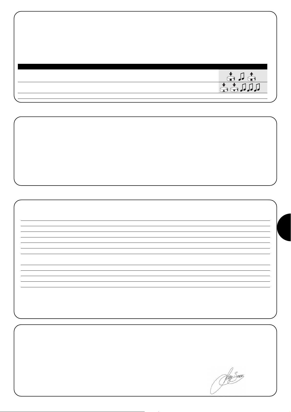
NL
43
Nadat u de besturingseenheid onder spanning hebt gezet,
hoort u geen enkel geluidssignaal en de zenders geven
geen bedieningsopdrachten.
Verifieer dat de stroomvoorziening naar de besturingseenheid in orde
is: tussen de klemmetjes 6-7 moet er netspanning staan. Indien de
stroomvoorziening in orde is, zal er waarschijnlijk een ernstig defect
zijn en zal de besturingseenheid vervangen moeten worden.
Na een bedieningsopdracht hoort u 6 geluidssignalen en
het relais gaat niet aan noch gaat het uit.
De radiobediening is niet gesynchroniseerd, u dient de zender
opnieuw in het geheugen op te slaan.
Na een bedieningsopdracht hoort u 10 geluidssignalen;
daarna gaat het relais aan
De zelfdiagnose van de parameters in het geheugen heeft enkele
afwijkingen geconstateerd.
5) Wat te doen als… ofwel een kleine gids als er iets niet functioneert!
6) Technische kenmerken
Alle gegevens hebben betrekking op een temperatuur van 20°C
Elektronische besturingseenheid
Stroomvoorziening : 230Vac (+10-15%) 50Hz
Maximum vermogen uitgang : 500W / 400VA
Bedrijfstemperatuur : -20÷55 °C
Afmetingen / gewicht : 98 x 26 x 20 / 45g
Beschermingsklasse : IP55 (kastje intact)
Tijdsduur timers
: Programmeerbaar van 1 seconde tot 9 uur fabrieksinstelling TIMER1=1 minuut TIMER2= 10 minuten
Radio-ontvanger
Frequentie : 433.92 MHz
Codering : FLO (fixed code), FLOR (rolling code) SMILO (rolling code)
Aantal zenders in het geheugen op te slaan : 30
Bereik van de zenders : geschat op 150 m in de vrije ruimte en 20 m binnenshuis *
* Het bereik van de zenders is sterk onderhevig aan de invloed van andere inrichtingen die op dezelfde frequentie met voortdurende zending
werken zoals alarmen, radiokoptelefoons, etc… die interferentie met de radio-ontvanger van de besturingseenheid veroorzaken.
Nice behoudt zich het recht voor op elk gewenst moment door haar noodzakelijk geachte wijzigingen in haar producten
aan te brengen
Conformiteitsverklaring N°: mindy TT1L Rev 0
Nice S.p.a. via Pezza Alta, 13 Rustignè Oderzo (TV) ITALY verklaart dat het product: “mindy TT1L” conform de essentiële veiligheidseisen
vervat in onderstaande richtlijnen is R&TTE 1999/5/CE.
Datum AGedelegeerd Bestuurder
22-01-2004 Lauro Buoro
4.3.2) Gebruik van zenders met 3 toetsen van het type “▲■▼”
Als u over zenders met toetsen van het type “▲■▼” beschikt die in Modus I in het geheugen zijn opgeslagen, kunt u voor elk daarvan de
bedieningsopdracht “OFF” aan toets ▼. Ikoppelen. Op deze manier kunt u gemakkelijk de door de zenders voorziene “gebeurtenissen” zoals
bijvoorbeeld PLANO TIME gebruiken. Toets ■ zal de functie “OFF” blijven uitvoeren.
Om deze functie vrij te geven dient de zender in modus I in het geheugen opgeslagen te zijn en zal deze alleen op die zender van toepassing zijn; voer eventueel deze programmering opnieuw voor alle gewenste zenders uit.
1. Druk op toets ■ van de reeds in Modus I opgeslagen zender en houd die ingedrukt totdat u
(na ongeveer 5 seconden) een lang geluidssignaal hoort, en laat hem dan los. 5s
2. Druk binnen 3 seconden tegelijkertijd op de 2 toetsen ▲▼en houd die ongeveer 5 seconden
ingedrukt totdat 3 lange geluidssignalen aangeven dat de functie geprogrammeerd is. 3s
N.B.: Mocht u deze functie willen uitsluiten, dan dient u de procedure opnieuw uit te voeren te beginnen bij punt 1
Tabel “A11” FUNCTIE “ON” “OFF” met ▲■▼ Voorbeeld
Page 44
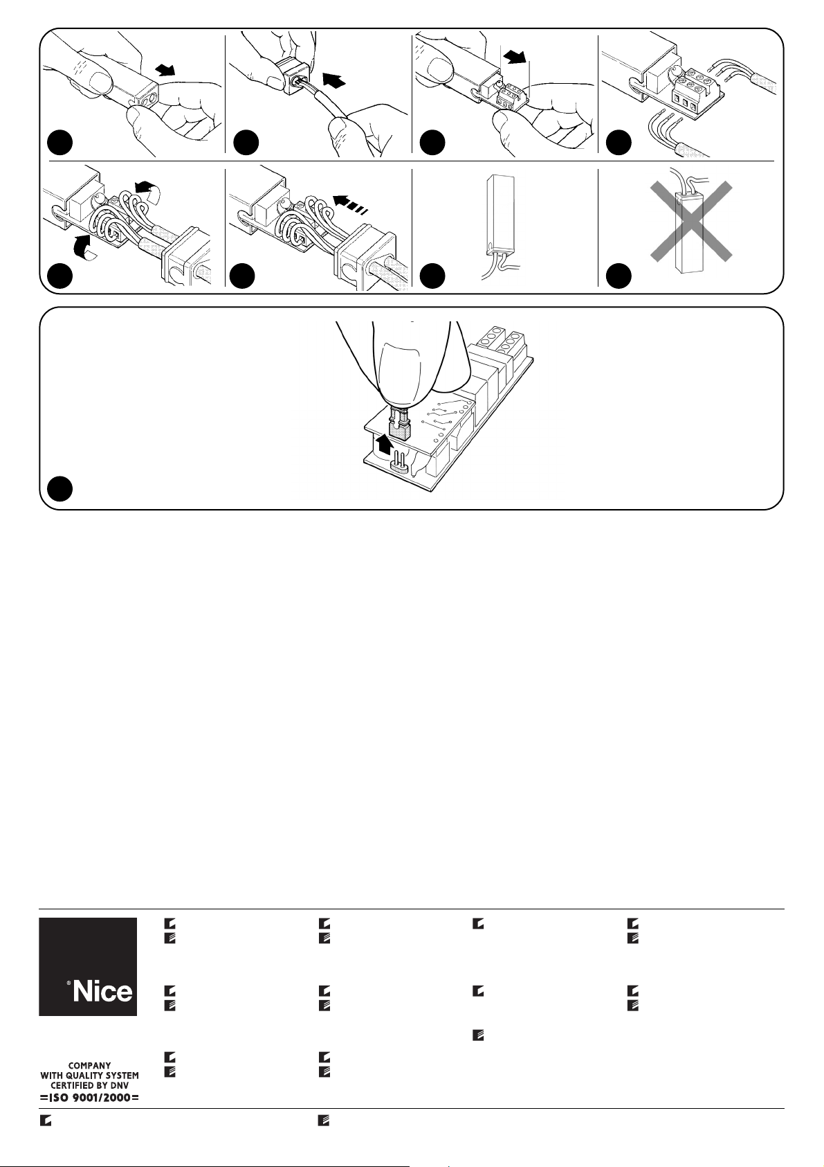
IST 160 4858 REV. 00
Nice SpA
Oderzo TV Italia
Tel. +39.0422.85.38.38
Fax +39.0422.85.35.85
info@niceforyou.com
Nice Padova
Sarmeola di Rubano PD Italia
Tel. +39.049.89.78.93.2
Fax +39.049.89.73.85.2
info.pd@niceforyou.com
Nice Roma
Roma Italia
Tel. +39.06.72.67.17.61
Fax +39.06.72.67.55.20
info.roma@niceforyou.com
Nice France
Buchelay
Tel. +33.(0)1.30.33.95.95
Fax +33.(0)1.30.33.95.96
info@nicefrance.fr
Nice Rhône-Alpes
Decines Charpieu France
Tel. +33.(0)4.78.26.56.53
Fax +33.(0)4.78.26.57.53
info.lyon@nicefrance.fr
Nice France Sud
Aubagne France
Tel. +33.(0)4.42.62.42.52
Fax +33.(0)4.42.62.42.50
info.marseille@nicefrance.fr
Nice Belgium
Leuven (Heverlee)
Tel. +32.(0)16.38.69.00
Fax +32.(0)16.38.69.01
info@nicebelgium.be
Nice España Madrid
Tel. +34.9.16.16.33.00
Fax +34.9.16.16.30.10
Nice España Barcelona
Tel. +34.9.35.88.34.32
Fax +34.9.35.88.42.49
Nice Polska
Pruszków
Tel. +48.22.728.33.22
Fax +48.22.728.25.10
info@nice.com.pl
Nice China
Shanghai
Tel. +86.21.525.706.34
Fax +86.21.621.929.88
info@niceforyou.com.cn
www.niceforyou.com
Nice Gate is the doors and gate automation division of Nice Nice Screen is the rolling shutters and awnings automation division of Nice
4
8 9 10
5 6 7
11
12
 Loading...