

Page 1
I
V. 009
GB F D E
THOR
ISTRUZIONI E
AVVERTENZE
PER
L’INSTALLATORE
Motoriduttore
elettromeccanico
per cancelli
scorrevoli
INSTRUCTIONS
AND
WARNINGS FOR
THE FITTER
Electromechanical
gearmotor for
sliding gates
INSTRUCTIONS
ET
RECOMMANDATIONS PUOR
L’INSTALLATION
Mototréducteur
électromécanique
pour portails
coulissants
ANWEISUNGEN
UND HINWEISE
FÜR DEN
INSTALLATEUR
Elektromechanisc
her Antrieb für
Gleittore
INSTRUCCIONES
Y
ADVERTENCIAS
PARA EL
INSTALADOR
Motorreductor
electromecánico
para cancelas
correderas
QUESTO LIBRETTO È DESTINATO SOLO ALL'INSTALLATORE.
L'installazione dovrà essere effettuata solamente da personale professionalmente qualificato in conformità a quanto previsto dalla
legge n° 46 del 5 marzo 1990 e successive modifiche ed integrazioni e nel pieno rispetto delle norme UNI 8612.
Page 2
2
THOR
MODELLI E CARATTERISTICHE - MODELS AND CHARACTERISTICS - MODÈLES ET CARACTÉRISTIQUES
MODELLE UND MERKMALE - MODELOS Y CARACTERÍSTICAS
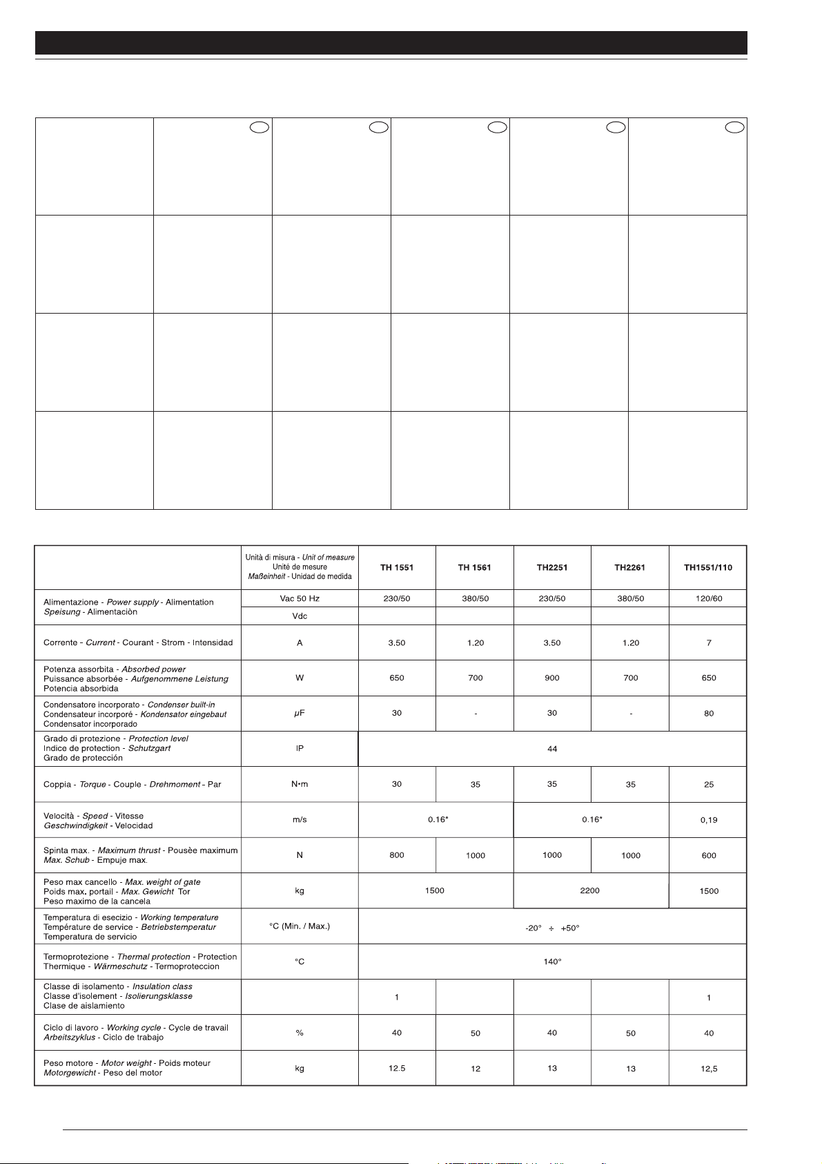
DATI TECNICI - TECHNICAL DATA - DONNÉES TECHNIQUES - TECHNISCHE DATEN - DATOS TÉCNICOS
THOR 1551
THOR 1561
Motoriduttore per
cancelli fino a 1500
Kg, motore 230 V
autoventilato centrale
incorporata.
Motoriduttore per
cancelli fino a 1500
Kg, motore 380 V
autoventilato, senza
centrale.
Gearmotor for
gates up to 1500 kg,
230 V self-ventilated
motor, built-in control
unit.
Gearmotor for gates
up to 1500 kg, 380 V
self-ventilated motor,
without a
control unit.
Motoréducteur
pour portails jusqu’à
1500 kg, moteur 230 V
autoventilé, centrale
incorporée.
Motoréducteur pour
portails jusqu’à 1500
kg, moteur 380 V
autoventilé, sans
centrale.
Getriebemotor für
Tore bis 1500 kg,
230V Motor mit
Eigenbelüftung, mit
eingebauter.
Getriebemotor für Tore
bis 1500 kg, 380V
Motor mit
Eigenbelüftung, ohne
Steuerzentrale
Motorreductor
para verjas de hasta
1500 kg, motor de
230V autoventilado,
central incorporada
Motorreductor para
verjas de hasta 1500
kg, motor de 380V
autoventilado, sin
central.
*
Con pignone Z = 18 - *With pinion Z = 18 - *Avec pignon Z = 18 - *Mit Ritzel Z = 18 - * Con piñón Z = 18
I GB F D E
THOR 2251
THOR 2261
Motoriduttore per
cancelli fino a 2200
kg, motore 230 V
autoventilato centrale
incorporata
Motoriduttore per
cancelli fino a 2200
kg, motore 380 V
autoventilato,
senza centrale.
Gearmotor for
gates up to 2200 kg,
230 V self-ventilated
motor, built-in control
unit.
Gearmotor for gates
up to 2200 kg, 380 V
self-ventilated motor,
without a
control unit.
Motorèducteur
pour portails jusqu’à
2200 kg, moteur 230 V
autoventilè, centrale
incorporèe.
Motorèducteur pour
portails jusqu’à 2200
kg, moteur 380 V
autoventilè,
sans centrale
Getriebemotor für
Tore bis 2200 kg,
230V Motor mit
Eigenbel_ftung, mit
eingebauter.
Getriebemotor für Tore
bis 2200 kg, 380V
Motor mit
Eigenbel_ftung, ohne
Steuerzentrale.
Motorreductor
para verjas de hasta
2200 kg, motor de
230V autoventilado,
central
incorporada.
Motorreductor para
verjas de hasta 2200
kg, motor de 380V
autoventilado,
sin central.
Page 3
3
THOR
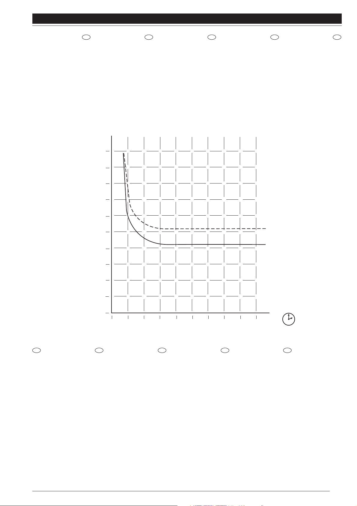
CURVA DI MAX
UTILIZZO
Consente di stabilire il
tempo massimo di
lavoro in funzione della
frequenza di utilizzo.
Posizionarsi quindi per
sicurezza al di sotto
della curva.
CURVE OF
MAXIMUM USE
This curve allows you to
establish maximum
working time according
to the frequency of use.
For safety reasons,
keep below this curve.
COURBE
D’UTILISATION
MAXIMUM
Permet d’établir le
temps maximum de
travail en fonction de la
fréquence d’utilisation.
Par sécurité, se
positionner par
conséquent sous cette
courbe.
HÖCHSTBENUTZUNGSKURVE
Zur Festlegung der
maximalen Arbeitszeit
in Abhängigkeit von der
Benutzungshäufigkeit.
Daher zur Sicherheit
unter dieser Kurve
bleiben.
CURVA DE
USO MÁXIMO
Permite establecer el
tiempo máximo de
trabajo de acuerdo con
la frecuencia de uso.
Por lo tanto, por
razones de seguridad
regule por debajo de
dicha curva.
I GB F D E
Semplificando, la curva
di massimo utilizzo è il
rapporto percentuale
tra il tempo effettivo di
lavoro e la somma tra il
tempo effettivo di lavoro
e tutte le pause.
I dati si riferiscono ad
una temperatura
ambiente di 20°C.
L’esposizione ai raggi
solari, e comunque
l’aumento della
temperatura ambiente
influiscono abbassando
considerevolmente la
curva.
Simplifying, the curve
of maximum use is the
percentage ratio
between actual working
time and the sum
between actual working
time and all the pauses.
The data refer to a
room temperature of
20°C, exposure to the
sun’s rays or a rise in
room temperature are
both influencing factors
and will considerably
lower the curve.
En simplifiant, la
courbe d’utilisation
maximum est le rapport
en pourcentage entre le
temps de travail effectif
et la somme entre le
temps de travail effectif
et toutes les pauses.
Les données se
réfèrent à une
température ambiante
de 20°C, l’exposition
aux rayons solaires et
dans tous les cas,
l’augmentation de la
température ambiante
ont une influence et
abaissent
considérablement la
courbe.
Einfacher gesagt, ist
die
Höchstbenutzungskurv
e das Verhältnis in
Prozenten zwischen
der effektiven
Arbeitszeit und der
Summe der effektiven
Arbeitszeit und aller
Pausen.
Die Daten beziehen
sich auf 20°C
Raumtemperatur.
Sonnenstrahlen und
Erhöhung der
Raumtemperatur
setzen die Kurve
bedeutend herab.
La curva de uso
máximo es la relación
en porcentaje entre el
tiempo efectivo de
trabajo y la suma entre
el tiempo efectivo de
trabajo y todas las
pausas.
Los datos se refieren a
una temperatura
ambiente de 20°C. La
exposición a los rayos
solares y un aumento
de la temperatura
ambiente influyen
bajando
considerablemente la
curva.
I GB F D E
%
100
90
80
70
60
1561
50
1551
40
30
20
10
00
01234578910
h
Page 4
4
THOR
VERIFICHE E
PRELIMINARI
A) Leggere attentamente le
istruzioni. Verificare che il
cancello sia adatto ad
essere automatizzato e
che il tutto risulti conforme
a quanto previsto dalle
normative vigenti.
B) Accertarsi che la
struttura del cancello sia
solida ed appropriata.
C) Accertarsi che il
cancello, durante tutto il
suo movimento, non
subisca punti di attrito e
che non vi sia pericolo di
deragliamento.
D) Accertarsi della
presenza dei franchi di
sicurezza.
CHECKING
AND PRELIMINARY
PROCEDURES
A) Read the instructions
carefully. Make sure the
gate is suitable for
automation and that
everything conforms to
current standards.
B) Make sure the gate’s
structure is solid and
appropriate.
C) Ensure that there is no
point of friction during the
entire movement of the
gate.
and that there is no danger
of derailment.
D) Make sure that the
safety side panels are
installed.
CONTRÔLES
ET OPÉRATIONS
PRÉLIMINAIRES
A) Lire attentivement les
instructions. Vérifier que le
portail est adapté pour
recevoir une
automatisation et que
l’ensemble est conforme
aux prescriptions des
normes en vigueur.
B) S’assurer que la
structure du portail est
solide et appropriée.
C) S’assurer que le portail,
durant tout le mouvement,
n’a pas de points de
frottement et qu’il n’y a pas
de danger de déraillement.
D) S’assure que les côtés
de sécurité sont présents.
PRÜFUNGEN
UND VORBEREITUNGEN
A) Lesen Sie die
Anleitungen aufmerksam
durch. Prüfen Sie, ob das
Tor für eine
Automatisierung geeignet
ist und ob alles mit den
gültigen Vorschriften
übereinstimmt.
B) Sicherstellen, dass die
Struktur des Tores solide
und geeignet ist.
C) Sicherstellen, daß das
Tor während der gesamten
Bewegung auf keine
Reibpunkte trifft und keine
Entgleisungsgefahr
besteht.
D) Sicherstellen, dass die
Sicherheitsfreiräume
vorhanden sind.
CONTROLES
Y OPERACIONES
PRELIMINARES
A) Lea atentamente las
instrucciones. Controle que
la verja pueda ser
automatizada y que todo
resulte conforme con
cuanto previsto por las
normas vigentes.
B) Cerciórese de que la
estructura de la verja sea
sólida y apropiada.
C) Cerciórese de que
durante todo el movimiento
de la verja, esta última no
tenga roces y que no haya
peligro de descarrilamiento.
D) Controle que estén
montados los flancos de
seguridad.
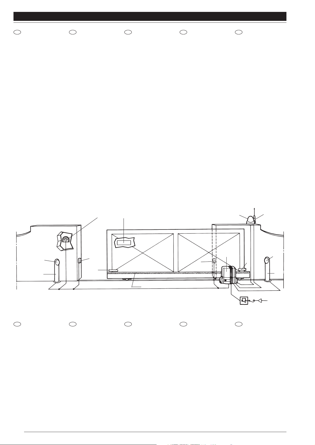
1) Colonnina
2) Fotocellula
3) Selettore a chiave o
tastiera digitale
4)
Cartello di avvertenza
5) Lampeggiatore
6) Antenna
7) Thor
8)
Linea di alimentazione
9) Staffe per finecorsa
10)
Cremagliera
11)
Interruttore generale
12) Interruttore differenziale
1) Column
2) Photocell
3)
Key selector or digital
keypad
4) Warning sign
5) Flashing light
6) Aerial
7) Thor
8) Power supply line
9) Microswitch brackets
10)
Rack
11)
Main switch
12)
Differential switch
1) Colonne de support
2)
Cellule photoélectrique
3) Sélecteur à clé et
clavier digital
4) Panneau
d’avertissement
5) Clignotant
6) Antenne
7) Thor
8) Ligne d’alimentation
9)
Pattes de fin
de
course
10)Crémaillère
11) Interrupteur général
12) Interrupteur
différentiel
1) Säule
2) Photozelle
3)
Schlüsselwählschalter
oder digitale
Tastatur
4) Hinweisschild
5) Blinklicht
6) Antenne
7) Thor
8) Speisungsleitung
9) Anschlagbügel
10)Zahnstange
11) Hauptschalter
12) Differentialschalter
1) Columnita
2) Fotocélula
3) Selector de llave o
teclado digital
4)
Placa de advertencia
5) Luz intermitente
6) Antena
7) Thor
8)
Línea de alimentación
9) Bridas de tope
10)Cremallera
11) Interruptor general
12) Interruptor
diferencial
QUADRO D’INSIEME (Thor 1551con centrale incorporata) - A VIEW OF THE ASSEMBLY (Thor 1551 with built-in control unit)
VUE D’ENSEMBLE (Thor 1551 avec centrale incorporée) - GESAMTANSICHT (Thor 1551 mit eingebauter Steuerzentrale)
DIBUJO DE CONJUNTO (Thor 1551 con central incorporada)
I GB F D E
I
GB F D E
1
2
3
4
5
6
7
8
9
10
2
3x1
2x1
2
9
2
1
1xRG58
2x1,5
3x1,5
11
12
Page 5

5
THOR
INFORMAZIONI PER L’UTENTE
Ad installazione avvenuta, l’utente deve essere informato sulle prestazioni dell’apricancello, e di tutti i rischi che possono derivare
da un uso improprio o scorretto. L’utente deve evitare di porsi in situazioni di pericolo, cioè stazionare nel raggio d’azione del
cancello quando esso è in movimento, non opporsi al movimento del cancello stesso, vietare ai bambini di giocare in prossimità
del cancello e tenere fuori dalla loro portata i telecomandi.
Tutti gli interventi di manutenzione, riparazione o verifiche periodiche devono essere eseguiti da personale professionalmente
qualificato, documentati e custoditi dall’utilizzatore.
• L’utente, in caso di anomalia, deve astenersi da qualsiasi tentativo di intervento e chiamare l’installatore per la riparazione.
• L’utente può solo eseguire la mano
vra manuale.
INFORMATION FOR THE USER
Once installed, the user must be informed about the performance of the gate opening system and of all the risks that could arise
from an improper or incorrect use. The user must avoid placing himself in hazardous situations, that is, staying within the gate’s
range of action when it is moving, trying to resist gate movement; children must not be allowed to play near the gate and always
keep remote controls out of their reach.
All maintenance, repairs or periodical checks must be carried out by professionally qualified personnel, documented and kept by the user.
• In the case of malfunctioning the user must not endeavour to resolve it but call the installer.
• The user can only carry out the man
ual operations.
INFORMATIONS POUR L’USAGER
Lorsque l’installation a été effectuée, l’usager doit être informé sur les performances du dispositif d’automatisation et sur tous les
risques qui peuvent dériver d’une utilisation impropre ou incorrecte. L’usager doit éviter de se mettre en situation de danger, c’està-dire de stationner dans le rayon d’action du portail quand celui-ci est en mouvement ; il ne doit pas s’opposer au mouvement du
portail, il doit interdire aux enfants de jouer à proximité du portail et conserver les télécommandes hors de leur portée.
Toutes les interventions de maintenance, réparation ou les contrôles périodiques doivent être effectuées par du personnel
professionnellement qualifié; les opérations doivent être documentées et la documentation doit être conservée par l’utilisateur.
• En cas d’anomalie, l’usager doit s’abstenir de toute tentative d’intervention et appeler l’installateur pour la réparation
• L’usager peut seulement effectuer la manœuvre
manuelle.
INFORMATIONEN FÜR DEN BENUTZER
Nach erfolgter Installation muss der Benutzer immer über die Leistungen des Toröffners und alle Risikos informiert werden, die
durch einen unsachgemäßen oder unkorrekten Gebrauch entstehen können. Der Benutzer muss vermeiden, sich in
Gefahrensituationen zu begeben, bzw. im Aktionsbereich des Tors zu verweilen, wenn sich das Tor bewegt, sich der Torbewegung
nicht widersetzen, Kindern verbieten, in der Nähe des Tors zu speilen und die Fernsteuerung außer ihrer Reichweite halten.
Alle Eingriffe wie Wartung, Reparatur oder regelmäßige Überprüfungen müssen von beruflich qualifiziertem Personal ausgeführt
werden. Sie müssen mit Unterlagen belegt werden, die vom Benutzer aufzubewahren sind.
• Im Fall von Störungen darf der Benutzer keine Eingriffe ausführen, sondern muss zur Reparatur den Installateur rufen.
• Der Benutzer kann nur die man
uelle Handhabung ausführen.
INFORMACIONES PARA EL USUARIO
Cuando haya finalizado la instalación, informe al usuario sobre el uso del dispositivo para abrir verjas y sobre todos los riesgos
que puede correr a causa de un uso impropio o incorrecto del mismo. El usuario tiene que evitar situaciones de peligro, es decir
pararse en el radio de acción de la verja cuando la misma está en movimiento, oponerse al movimiento de la misma, prohibir a
los niños jugar en proximidad de la verja y mantener fuera del alcance de los mismos los controles remotos.
Todas las operaciones de mantenimiento, reparación o controles periódicos tienen que ser efectuados por personal cualificado,
registradas y conservadas por el usuario.
• En caso de anomalía, el usuario tiene que abstenerse de efectuar cualquier reparación y llamar al instalador.
• El usuario puede efectuar la maniobr
a manual.
✃
I
GB
F
D
E
Page 6

6
THOR
DIMENSIONI D’INGOMBRO - OVERALL DIMENSIONS - DIMENSIONS D’ENCOMBREMENT
RAUMBEDARF - DIMENSIONES EXTERIORES MÁXIMAS
MANOVRA MANUALE - MANUAL OPERATIONS - MANŒUVRE MANUELLE
MANUELLE HANDHABUNG - MANIOBRA MANUAL
1) Ruotare verso l’alto
il copriserratura (1).
2) Inserire la chiave e
ruotarla in senso orario
di 90° (2).
3) Tirare a se la
maniglia agendo
dapprima sulla chiave
stessa fino a portarla
perpendicolare al
THOR (Fig. 5).
Un microinterruttore di
sicurezza fa in modo
che non possa avviarsi
in posizione manuale.
1) Slide the key cover
upwards (1).
2) Insert the key and
turn it 90° clockwise (2).
3) Pull the handle
towards you, turning the
key, until it is
perpendicular to THOR
(Fig. 5).
A safety microswitch
prevents it from being
able to start in the
manual position.
1) Tourner le cacheserrure vers le haut (1)
2) Introduire la clé et la
tourner de 90° dans le
sens des aiguilles d’une
montre (2).
3) Tirer vers soi la
poignée en agissant
d’abord sur la clé
proprement dite de
manière à la placer
perpendiculairement au
THOR (Fig. 5).
Un microinterrupteur de
sécurité fait en sorte
que le dispositif ne
puisse pas se mettre en
marche en position
manuelle.
Die Abdeckung des
Schlosses (1) nach
oben drehen (1)
Den Schlüssel
einstecken und um 90°
nach rechts drehen (2)
Den Griff durch
Betätigung des
Schlüssels nach vorne
ziehen, bis er senkrecht
zu THOR steht (Abb.5).
Ein Mikroschalter
bewirkt, dass er nicht in
manueller Position
angelassen werden
kann.
1) Gire hacia arriba el
cubrecerradura (1).
2) Introduzca la llave y
gírela 90° hacia la
derecha (2).
3) Tire de la manija
hacia Ud., actuando
antes sobre la llave
hasta colocarla
perpendicularmente a
THOR (fig. 5)
Un microinterruptor de
seguridad impide que
se pueda poner en
marcha en posición
manual.
I
GB F D E
GB
F
D
E
Con pignone Z 18,
escluso piastra di fondazione
With pinion Z 18, foundation plate
excluded.
Avec pignon Z 18, plaque de
fondation exclue.
Mit Ritzel Z 18
Fundamentplatte ausgeschlossen
Con piñón Z 18, excluida la placa
de fundación.
✃
I
Fig. 4
Fig. 5
Fig. 6
335
275
203
100
1
2
Page 7

7
THOR
(I) ITALIANO
ATTENZIONE:
Per una corretta sicurezza elettrica e per un buon funzionamento dell’apparecchiatura
è indispensabile eff
ettuare il collegamento a terra.
È estremamente pericoloso
utilizzare il motoriduttore senza la prevista messa a
terra! (anche durante eventuali prove al banco).
(GB) ENGLISH
ATTENTION:
To ensure the unit is correctly installed it is impor
tant to make sure that earth
connections.
Do not install
the gearmotor unit without earthing! (during the tests, too).
(F) FRANÇAIS
ATTENTION:
Pour la securité electrique et pour un bon functionnement de l’appareil, il est indispensab
le
effectuer les bronchements à terre.
Il est dang
ereux utilizeur le actionneur motorèducteur sans la mise à terre prevue! (même
pendant des éssais).
(D) DEUTSCH
ACHTUNG:
Um eine opimale Funktion des Antriebes, sowie die erforderliche elektrische Sichereit des Antriebes
zu gewährleisten, ist es zwingend notwendig den Er
dleiter anzuschließen.
Weder zu Testzwecken noch in Normalbetrieb darf
der Torantrieb ohne Erdung in Betrieb
genommen werden.
(E) ESPANOL
ATTENCIÓN:
Para una correcta seguridad eléctrica y para un buen funcionamiento del aparato, es ob
ligatorio
efectuar la conexion a tierra.
Queda extremadamente peligroso
utilizar el motorreductor sin la prevista puesta a tierra!
(incluso durante eventuales pruebas de banco).
Page 8
8
THOR
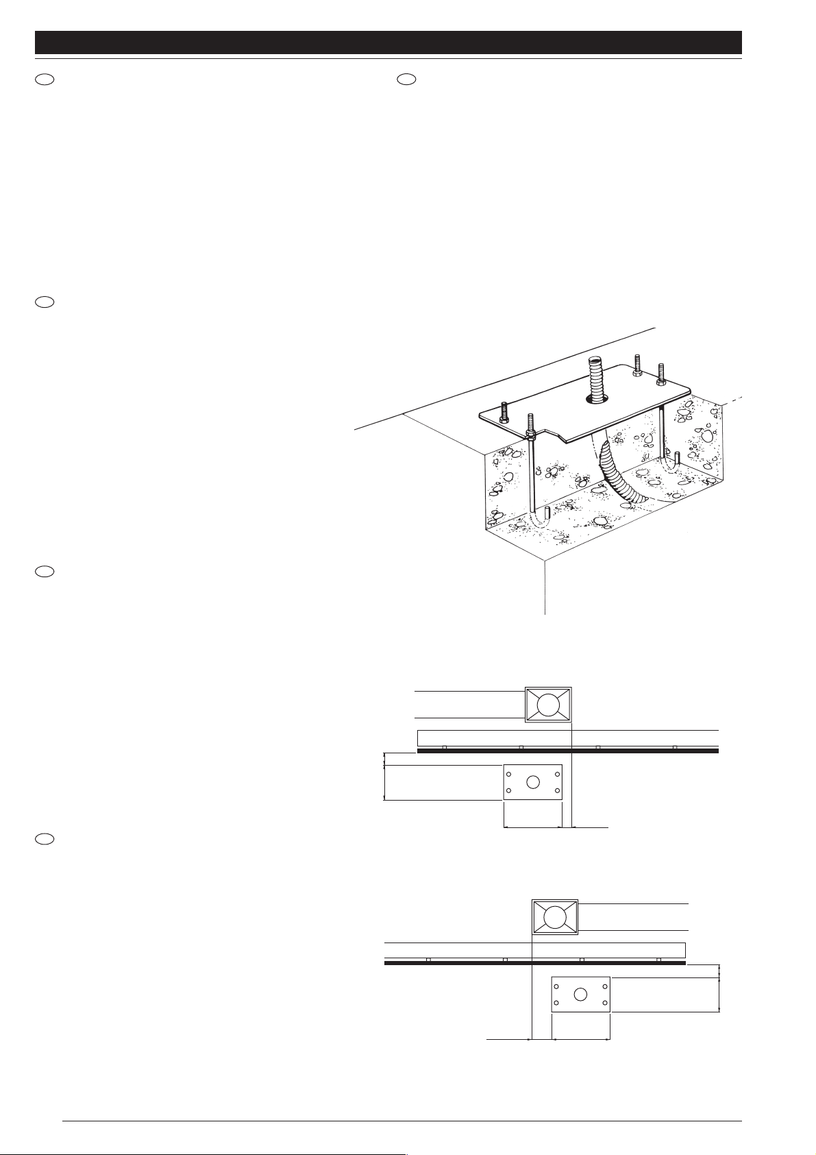
MURATURA DELLA PIASTRA DI FONDAZIONE WALLING THE FOUNDATION PLATE
Avvitare a mano per ognuna delle 4 zanche in dotazione 1 dado M 12
basso per tutto il filetto.
Infilare le quattro zanche nella piastra di fondazione fig. 7
Prevedere una o più guaine per il passaggio di cavi elettrici.
Inserire nel calcestruzzo la piastra avendo cura di metterla
perfettamente in bolla.
È importante rispettare la distanza della piastra di fondazione dalla
cremagliera (bisogna quindi sapere anzi tempo se sarà saldata al
cancello oppure fissata con viti e distanziali), in modo da poter usufruire
del fissaggio asolato del motoriduttore
Screw right down by hand, for each of the 4 fish-tail clamps provided, 1
M12 low nut.
Insert the four clamps in the foundation plate, Fig. 7.
Use one or more sheaths for the passage of the electric cables.
Insert the plate in the concrete, taking care to place it perfectly level.
It is important to observe the distance of the foundation plate from the
rack (hence you must know in advance whether it is going to be welded
to the gate or secured with screws and spacers), so you can make use of
the slotted fixing on the gearmotor.
170 10
170 10
335 0 ÷ 50
335
50 ÷ 100
destro - right - droite
rechts - der.
sinistro - left- gauche
links - izq.
I
GB
F
D
E
SCELLEMENT DE LA PLAQUE DE FONDATION
Visser à la main pour chacune des agrafes fournies 1 écrou
M12 bas jusqu’en bas de la partie filetée.
Enfiler les quatre agrafes dans la plaque de fondation (fig. 7).
Prévoir une ou plusieurs gaines pour le passage des câbles
électriques.
Sceller la plaque dans le ciment en ayant soin de la mettre
parfaitement de niveau.
Il est important de respecter la distance entre la plaque de
fondation et la crémaillère (il faut donc savoir en temps utile si
elle sera soudée au portail ou bien vissée avec les vis et les
entretoises), de manière à pouvoir utiliser la fixation à fente du
motoréducteur.
EINMAUERN DER FUNDAMENTPLATTE
Für jedes der 4 mitgelieferten Verankerungsbeine 1 flache M12
Mutter mit Gewinde ganz von Hand anschrauben.
Die 4 Verankerungsbeine in die Fundamentplatte einstecken,
Abb. 7.
Einen oder mehrere Mäntel für den Durchgang von
Elektrokabeln vorsehen.
Die Platte in den Beton einfügen und perfekt nivellieren.
Wichtig ist, dass der Abstand der Fundamentplatte von der
Zahnstange eingehalten wird (man muss vorher wissen, ob die
Zahnstange an das Tor geschweisst oder mit Schrauben und
Distanzstücken befestigt wird), so dass der Getriebemotor mit
Schlitz befestigt werden kann.
COLOCACIÓN DE LA PLACA DE FUNDACIÓN
Enrosque a mano hasta el fondo las cuatro tuercas M 12 bajas
en las 4 grapas suministradas de serie.
Introduzca las cuatro grapas en la placa de fundación (fig. 7).
Disponga de una o varias vainas para pasar los cables
eléctricos.
Introduzca en el hormigón la placa teniendo cuidado en
colocarla perfectamente nivelada.
Es importante respetar la distancia de la placa de fundación
desde la cremallera (por consiguiente, es necesario saber por
anticipado si ésta será soldada a la verja, o fijada con tornillo y
distanciadores), para poder aprovechar la las ranuras de
regulación de la sujeción del motorreductor.
Fig. 7
Fig. 8
Page 9

9
THOR
FISSAGGIO MOTORIDUTTORE FIXING THE GEARMOTOR
• Togliere le due alette copritivi tirandole verso l’alto.
• Appoggiare il THOR sulla piastra di fondazione murata
preventivamente.
• Avvitare i 4 dadi bassi qualora si voglia regolare in altezza
(max 10 mm) il motoriduttore, altrimenti non utilizzarli. (fig. 10)
Inserire le 4 rondelle.
Bloccare energeticatamente con chiave da mm 19 i dadi M 12
e gli eventuali controdadi bassi.
Inserire le due alette copriviti (estetiche) facendo pressione
dell’alto al basso.
• Remove the two screw covers, pulling them upwards.
• Place THOR on the already walled foundation plate.
• Tighten the 4 low nuts if you wish to adjust the height of the
gearmotor (10 mm maximum), otherwise do not use them
Fig. 10).
Fit the 4 washers.
Tighten firmly the M12 nuts, and any low counter nuts, with a 19
mm size spanner.
Put the screw covers back in place, pushing them down from
the top.
FIXATION MOTORÉDUCTEUR
• Enlever les deux cache-vis en les tirant vers le haut.
• Poser le THOR sur la plaque de fondation
préalablement scellée.
• Visser les 4 écrous bas si on désire régler en hauteur
le motoréducteur (10 mm maximum), en cas contraire,
ne pas les utiliser (fig. 10).
Mettre les 4 rondelles.
Serrer à fond les écrous M12 et les éventuels contreécrous bas avec une clé de 19 mm.
Remettre les deux cache-vis en faisant pression du haut
vers le bas.
BEFESTIGUNG DES GETRIEBEMOTORS
• Die zwei Abdeckflügel nach oben ziehen und entfernen.
• Den THOR auf die vorher eingemauerte
Fundamentplatte stützen.
• Die vier flachen Muttern anschrauben (max. 10 mm),
falls der Getriebemotor in der Höhe verstellt werden
soll, andernfalls die Muttern nicht benutzen, Abb. 10.
Die 4 Unterlegscheiben einfügen.
Die Muttern M12 und die eventuellen flachen
Gegenmuttern energisch mit einem 19 mm Schlüssel
blockieren.
Die zwei Abdeckflügel wieder durch Druck von oben nach
unten einsetzen (nur zur Ästhetik).
SUJECIÓN DEL MOTORREDUCTOR
• Quite las dos aletas que cubren los tornillos, tirándolas
hacia arriba.
• Apoye el THOR sobre la placa de fundación fijada
previamente.
• Enrosque las 4 tuercas bajas si desea regular la altura
del motorreductor (10 mm. máx.), en caso contrario, no
las use (fig. 10).
Introduzca las 4 arandelas.
Apriete firmemente las tuercas M 12 y las posibles
contratuercas bajas con una llave de 19 mm.
Introduzca las dos aletas para cubrir los tornillos
(estéticas) presionando desde arriba hacia abajo.
I GB
F
D
E
Fig. 9
Fig. 10
Page 10
10
THOR
FIXATION DE LA CRÉMAILLÈRE
Sélectionner le “fonctionnement manuel”.
Mettre en appui sur l’engrenage le 1er élément de la crémaillère
(fig. 11) et le bloquer au portail en faisant coulisser ce dernier.
Pour un positionnement correct des autres éléments, il faut utiliser
un élément faisant fonction de contre-crémaillère.
Il est important qu’il y ait un jeu d’au moins 1 mm entre la
crémaillère et l’engrenage de manière que le poids du portail ne
pèse jamais sur le motoréducteur.
Positionner de manière approximative les deux pattes de support
pour microinterrupteur de fin de course sur la crémaillère et, en
agissant manuellement sur le portail, procéder à la fixation
définitive avec les goujons fournis
(fig. 12)
.
Attention: quand la patte de support du microinterrupteur
intervient sur le ressort du motoréducteur, le portail coulisse
encore sur 50 mm environ. Positionner donc les pattes en avant
d’autant pour éviter que le portail se coince.
BEFESTIGUNG DER ZAHNSTANGE
Den THOR auf “manuellen Betrieb” stellen.
Das 1. Zahnstangenelement auf das Zahnrad stützen (Abb. 11)
und am Tor blockieren, dabei den Flügel gleiten lassen.
Für das korrekte Positionieren der anderen Elemente muss ein
Teil benutzt werden, das als Gegenzahnstange dient.
Wichtig ist, dass zwischen Zahnstange und Zahnrad ein Spiel von
mindestens 1 mm ist, so dass das Torgewicht nie auf dem
Getriebemotor liegt.
Die zwei mitgelieferten Anschlagbügel ungefähr an der Zahnstange
anordnen und, indem das Tor manuell betätigt wird, mit den
mitgelieferten Stiftschrauben endgültig befestigen (Abb. 12).
Berücksichtigen, dass das Tor noch etwa 50 mm gleitet, nachdem
der Anschlagbügel auf die Feder des Getriebemotors trifft. Daher
die richtige Vorverstellung der Bügel einhalten, damit das
Klemmen des Tors verhindert wird.
FIJACIÓN DE LA CREMALLERA
Coloque el THOR en “funcionamiento manual”.
Apoye sobre el engranaje el 1° elemento de la cremallera (fig. 11)
y bloquéelo a la verja, haciendo correr la hoja.
Para posicionar correctamente los demás componentes, use un
elemento que cumpla la función de contracremallera.
Es importante que entre la cremallera y el engranaje haya un
juego de 1 mm como mínimo, para que el motorreductor nunca
soporte el peso de la verja.
Coloque aproximadamente las bridas de tope suministradas de
serie sobre la cremallera y, actuando manualmente sobre la verja,
fíjelas definitivamente con los tornillos sin cabeza de serie (fig. 12).
Tenga en cuenta que cuando la brida de tope interviene sobre el
muelle del motorreductor, la verja se deslizará por otros 50 mm
aprox. Por lo tanto, instale las bridas en la posición exacta para
que la verja no se trabe.
F
D
E
Fig. 12
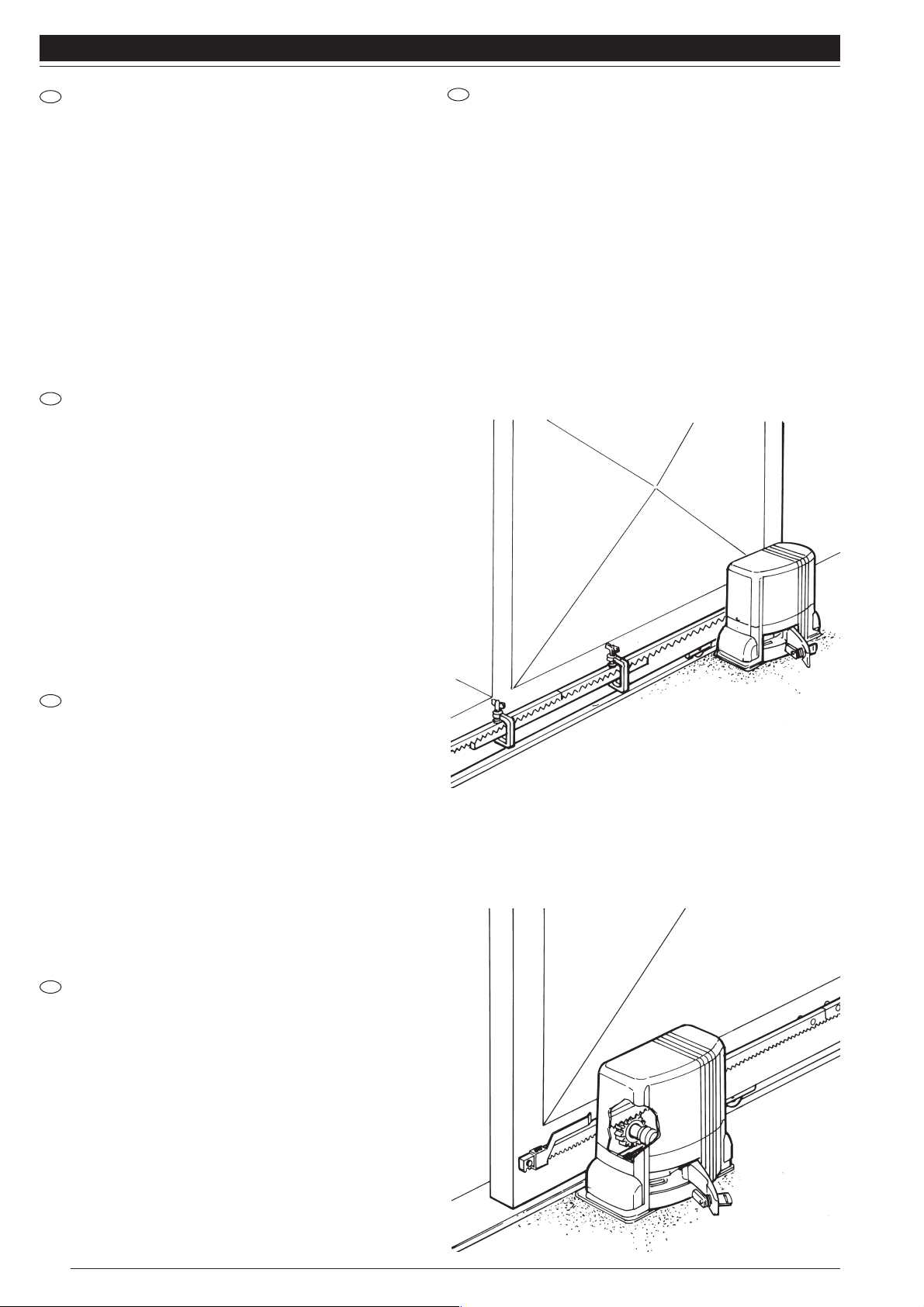
FISSAGGIO DELLA CREMAGLIERA
Predisporre il THOR in “funzionamento manuale”.
Appoggiare sull’ ingranaggio il 1° elemento di cremagliera fig.
11 e bloccarlo al cancello, facendo scorrere l’anta.
Per un corretto posizionamento degli altri elementi è necessario
utilizzare un elemento che funzioni da controcremaglieria.
È importante che fra cremaglieria ed ingranaggio ci sia un gioco
di almeno 1 mm. in modo che il peso del cancello non gravi mai
sul motoriduttore.
Posizionare in modo approssimativo le due staffe di finecorsa in
dotazione, sulla cremagliera, ed agendo manualmente sul cancello,
procedere al fissaggio definitivo con i grani in dotazione (fig. 12).
Tenere presente che quando la staffa di finecorsa interviene
sulla molla del motoriduttore, il cancello scorrerà per altri 50
mm. circa. Tenere quindi il giusto anticipo delle staffe onde
evitare l’incaglio del cancello.
FIXING THE RACK
Select the “manual” functioning mode.
Place the first rack element on the gear (Fig. 11), and lock it to
the gate by letting it slide along.
To ensure correct positioning of the other elements it is necessary
to use an element that functions as a counter-rack,.
It is important that there be a certain amount of play between
rack and gear (at least 1 mm) so the gate’s weight never bears
down on the gearmotor.
Roughly position the two limit switch brackets (provided) on the
rack and, manually moving the gate, fix them definitely with the
dowels provided
(fig. 12).
Attention: when the microswitch bracket operates the gearmotor
spring, the gate will slide about another 50 mm so make sure the
brackets’ timing is correct to avoid the gate getting stuck.
I
GB
Fig. 11
Page 11
11
THOR
Fig. 13
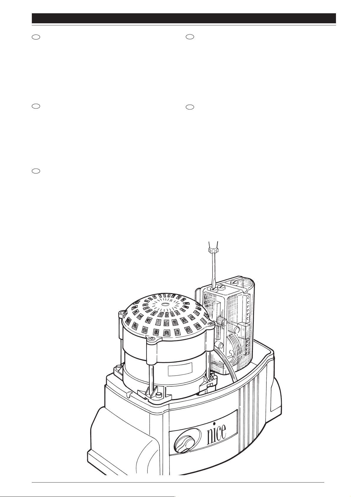
REGOLAZIONE DELLA FRIZIONE ELETTRONICA
TH1551 - TH1551/110
La regolazione della coppia è di tipo elettronico. (Fig. 13)
Attenersi alle istruzioni allegate della centralina elettronica.
EFFETTUARE TUTTE LE REGOLAZIONI RISPETTANDO LE
NORMATIVE VIGENTI.
ADJUSTING THE ELECTRONIC CLUTCH
TH1551 - TH 1551/110
The torque is electronically adjusted (Fig. 13).
Follow the instuctions enclosed with the electronic control
unit. PERFORM ALL ADJUSTMENTS IN COMPLIANCE
WITH CURRENT REGULATIONS.
RÉGLAGE DE L’EMBRAYAGE ÉLECTRONIQUE
TH1551 - TH1551/110
Le réglage du couple est de type électronique (Fig. 13).
Suivre les instuctions fournies avec la centrale électronique.
EFFECTUER TOUS LES RÉGLAGES EN RESPECTANT LES
NORMES EN VIGUEUR.
EINSTELLUNG DER ELEKTRONISCHEN KUPPLUNG
TH1551 - TH1551/110
Die Einstellung des Drehmoments erfolgt elektronisch
(Abbildung 13).
Halten Sie sich an die mit der Steuereinheit gelieferten
Anweisungen.
ALLE EINSTELLUNGS-ARBEITEN UNTER BEACHTUNG
DER GELTENDEN VORSCHRIFTEN VORNEHMEN.
REGULACIÓN DEL EMBRAGUE ELECTRÓNICO
TH1551 - TH1551/110
La regulación del par es de tipo electrónico (Fig. 13).
Seguir las instrucciones adjuntas de la centralina
electrónica.
EFECTUARTODAS LAS REGULACIONES RESPETANDO
LAS NORMAS VIGENTES.
I
GB
F
D
E
Page 12
N° TH1551 TH1561 TH1551/110
TH2251 TH2261
1
2
3
4
5
6
7
8
9
10
11
12
13
14
15
16
17
18
19
20
21
22
23
24
25
26
27
28
29
30
31
32
33
34
35
36
37
38
39
40
41
42
43
44
45
46
47
48
49
50
51
52
53
54
55
56
57
58
59
60
61
62
63
64
65
66
67
68
69
70
71
72
73
74
75
76
77
78
79
80
81
82
83
84
85
BMGTHA 34567
BMGTHC 34567
PPD1179 4540
BMMSA 14567
PPD1178 4540
CM-B 1630
PMD0166 4610
G6X50 5123
PPD1184 4540
BPCO2 4540
THA5
TRA-G 1025
MO-D 2640
MICROI-C 1617
MICROI 1617
30U450A 0727
BMCI 4567
PEDS65A 4650
BMCS 24567
PPD1180 4540
PPD1181 4540
PMD0133 4610
PMCU3010 4630
PECR1175 4610
PPD1182 4540
PPD1183 4540
PMCU6 4630
-
-
-
V6X120 5102
PMD0167 4610
MO-N 5501
PMCU3 4630
PMCSE30 4630
PMDRC5 4610
PMD0131A 4610
PMC128 4630
PMCS10 4630
PPD0120 4540
PMCU10 4630
GOR-Y 5501
BMFP010A 34567
V5X15-A 5102
PMD0628 4610
R12C 5120
PMD0139 4610
PMD0140 4610
MMCOI 2620
V4.2X9.5 5101
V2.9X16 5101
PMCAC1 4630
V4X5 5102
V2.9X6.5A 5101
V3.5X20 5101
EMRO 4870
V4.8X16 5101
R04E 5120
V2.9X9.5A 5101
GOR-L1 5501
RO3 5120
CF0193 5320
CT200 5320
V4X8 5105
V4.2X9.5B 5101
BPC 4540
D6 5102
D12B 5110
D12 5110
EN 4870
G6X14 5123
R12 5120
V6.3X25 5101
C3VF 2015
GOR-M 5501
CGU8B 5310
PMD0885 4610
PMD0886 4610
V10X12A 5102
PMD0165 4610
GOR-W 5501
PMCS6 4630
BMGTHA 34567
BMGTHC 34567
PPD1179 4540
BMMSA 14567
PPD1178 4540
CM-B 1630
PMD0166 4610
G6X50 5123
PPD1184 4540
-
-
MO-D 2640
MICROI-C 1617
MICROI 1617
BMCI 4567
PEDS652A 4650
BMCS 24567
PPD1180 4540
PPD1181 4540
PMD0133 4610
PMCU3010 4630
PECR1175 4610
PPD1182 4540
PPD1183 4540
M12V 1850
PMCU6 4630
MMCP 2620
MMCT 2620
-
V6X120 5102
PMD0167 4610
MO-N 5501
PMCU3 4630
PMCSE30 4630
PMDRC5 4610
PMD0131A 4610
PMC128 4630
PMCS10 4630
PPD0120 4540
PMCU10 4630
GOR-Y 5501
BMFP010A 34567
V5X15-A 5102
PMD0628 4610
R12C 5120
PMD0139 4610
PMD0140 4610
MMCOI 2620
V4.2X9.5 5101
V2.9X16 5101
PMCAC1 4630
V4X5 5102
V2.9X6.5A 5101
V3.5X20 5101
V4.8X16 5101
R04E 5120
GOR-L1 5501
RO3 5120
CF0193 5320
V4X8 5105
V4.2X9.5B 5101
BPC 4540
D6 5102
D12B 5110
D12 5110
EN 4870
G6X14 5123
R12 5120
V6.3X25 5101
GOR-M 5501
CGU8B 5310
PMD0885 4610
PMD0886 4610
V10X12A 5102
PMD0165 4610
GOR-W 5501
PMCS6 4630
BMGTHA 34567
BMGTHC 34567
PPD1179 4540
BMMSA 14567
PPD1178 4540
CM-B 1630
PMD0166 4610
G6X50 5123
PPD1184 4540
BPCO2 4540
THA5
TRA-H 1025
MO-D 2640
MICROI-C 1617
MICROI 1617
80U450 0727
BMCI 4567
PEDS651A 4650
BMCS 24567
PPD1180 4540
PPD1181 4540
PMD0133 4610
PMCU3010 4630
PECR1175 4610
PPD1182 4540
PPD1183 4540
PMCU6 4630
-
-
-
V6X120 5102
PMD0167 4610
MO-N 5501
PMCU3 4630
PMCSE30 4630
PMDRC5 4610
PMD0131A 4610
PMC128 4630
PMCS11 4630
PPD0120 4540
PMCU10 4630
GOR-Y 5501
BMFP010A 34567
V5X15-A 5102
PMD0628 4610
R12C 5120
PMD0139 4610
PMD0140 4610
MMCOI 2620
V4.2X9.5 5101
V2.9X16 5101
PMCAC1 4630
V4X5 5102
V2.9X6.5A 5101
V3.5X20 5101
V4.8X16 5101
R04E 5120
V2.9X9.5A 5101
GOR-L1 5501
RO3 5120
CF0193 5320
CT200 5320
V4X8 5105
V4.2X9.5B 5101
BPC 4540
D6 5102
D12B 5110
D12 5110
EN 4870
G6X14 5123
R12 5120
V6.3X25 5101
C3VF 2015
GOR-M 5501
CGU8B 5310
PMD0885 4610
PMD0886 4610
V10X12A 5102
PMD0165 4610
GOR-W 5501
PMCS6 4630
BMGTHA 34567
BMGTHC 34567
PPD1179 4540
BMMSA 14567
PPD1178 4540
CM-B 1630
PMD0166 4610
G6X50 5123
PPD1184 4540
BPCO2 4540
THA6
TRA105 1030
MO-D 2640
MICROI-C 1617
MICROI 1617
30U450A 0727
BMCI 4567
PEDS658 4650
BMCS 24567
PPD1180 4540
PPD1181 4540
PMD0133 4610
PMCU3010 4630
PECR1176 4610
PPD1182 4540
PPD1183 4540
-
PMCU6 4630
-
-
-
V6X120 5102
PMD0167 4610
MO-N 2640
PMCU3 4630
PMCSE30 4630
PMDRC5 24610
PMD0131A 4610
PMC128 4630
PMCS10 4630
PPD0120 4540
PMCU10 4630
GOR-Y 5501
BMFP010A 34567
V5X15-A 5102
PMD0628 4610
R12C 5120
PMD0139 4610
PMD0140 4610
MMCOI 2620
V4.2X9.5 5101
V2.9X16 5101
PMCAC1 4630
V4X5 5102
V2.9X6.5A 5101
V3.5X20 5101
EMRO 4870
V4.8X16 5101
R04E 5120
V2.9X9.5-A 5101
GOR-L1 5501
R03 5120
-
CF0193 5320
CT200 5320
V4X8 5105
V4.2X9.5B 5101
BPC 4540
D6 5102
D12B 5110
D12 5110
EN 4870
G6X14 5123
R12 5120
V6.3X25 5101
C3VF 2015
GOR-M 5501
CGU8B 5310
PMD0885 4610
PMD0886 4610
V10x12A 5102
PMD0165 4610
GOR-W 5501
PMCS6 4630
BMGTHA 34567
BMGTHC 34567
PPD1179 4540
BMMSA 14567
PPD1178 4540
CM-B 1630
PMD0166 4610
G6X50 5123
PPD1184 4540
BPCO2 4540
-
MO-D 2640
MICROI-C 1617
MICROI 1617
BMCI 4567
PEDS652A 4650
BMCS 24567
PPD1180 4540
PPD1181 4540
PMD0133 4610
PMCU3010 4630
PECR1175 4610
PPD1182 4540
PPD1183 4540
M12V 1850
PMCU6 4630
MMCP 2620
MMCT 262
-
G8X10 5123
V6X120 5102
PMD0167 4610
MO-N 2640
PMCU3 4630
PMCSE30 4630
PMDRC5 24610
PMD0131A 4610
PMC128 4630
PMCS10 4630
PPD0120 4540
PMCU10 4630
GOR-Y 5501
BMFP010A 34567
V5X15-A 5102
PMD0628 4610
R12C 5120
PMD0139 4610
PMD0140 4610
MMCOI 2620
V4.2X9.5 5101
V2.9X16 5101
PMCAC1 4630
V4X5 5102
V2.9X6.5A 5101
V3.5X20 5101
V4.8X16 5101
R04E 5120
GOR-L1 5501
R03 5120
CF0193 5320
V4X8 5105
V4.2X9.5B 5101
BPC 4540
D6 5102
D12B 5110
D12 5110
EN 4870
G6X14 5123
R12 5120
V6.3X25 5101
GOR-M 5501
CGU8B 5310
PMD0885 4610
PMD0886 4610
V10x12A 5102
PMD0165 4610
GOR-W 5501
PMCS6 4630
12
THOR
12
Page 13
THOR
I GB
F D E
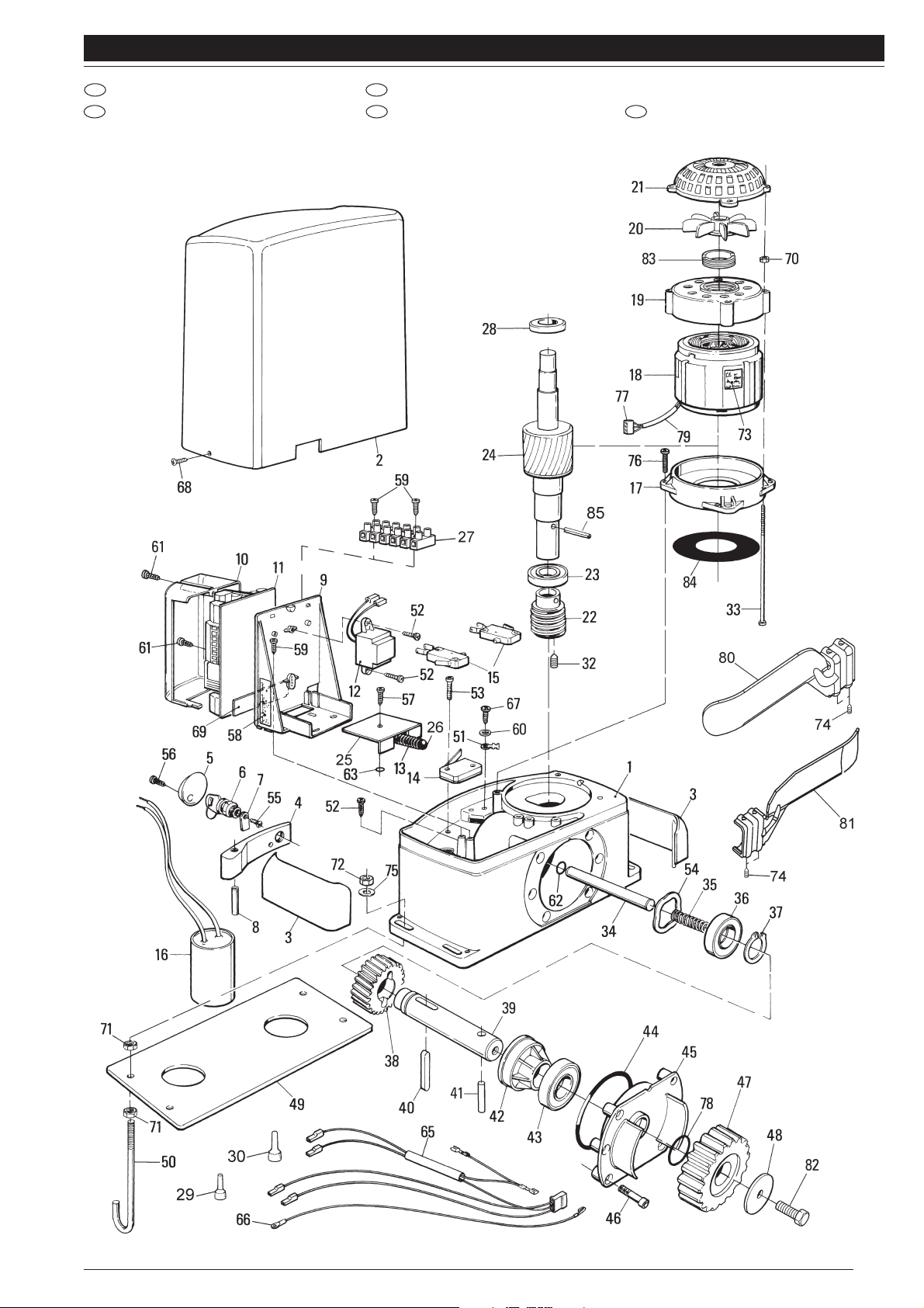
CATALOGO RICAMBI SPARE PARTS CATALOGUE
CATALOGUE DES RECHANGES ERSATZTEILKATALOG CATÁLOGO DE RECAMBIOS
13
Page 14

14
THOR
Page 15

15
THOR
Page 16

(secondo Direttiva 98/37/EC, Allegato II, parte B) (according to 98/37/EC Directive, Enclosure II, part B)
Numero /Number : 176/TH Data / Date: 9/2003 Revisione / Revision: 1
Il sottoscritto Lauro Buoro, Amministratore Delegato, dichiara che il prodotto:
The undersigned Lauro Buoro, General Manager, declares that the product:
Nome produttore / Producer name:
NICE s.p.a.
Indirizzo / Address: Via Pezza Alta 13, 31046 Z.I. Rustignè - ODERZO - ITALY
Tipo / Type: Motoriduttore elettromeccanico 120/230 V a.c. per cancelli scorrevoli
Electromechanical gearmotor for sliding doors
Modello / Model: TH1551, TH2251, TH1561, TH2261
Accessori / Accessories: Scheda PIU’, Ricevitore opzionale mod. K, BIO, FLO, FLOR
PIU’ Expansion card, Radio receivers mod. K, BIO, FLO, FLOR
Risulta conforme a quanto previsto dalle seguenti direttive comunitarie/Appears to be in conformity with the following community (EEC) regulations
Riferimento n° Titolo
Reference n° Title
73/23/CEE DIRETTIVA BASSA TENSIONE/ Low Voltage Directive
89/336/CEE DIRETTIVA COMPATIBILITA’ ELETTROMAGNETICA (EMC) / EMC Electromagnetic Compatibility Directive
98/37/CE (EX 89/392/CEE) DIRETTIVA MACCHINE/Machinery Directive
Risulta conforme a quanto previsto dalle seguenti Norme armonizzate / Appears to be in conformity with the following Harmonized standards regulations
Riferimento n° Edizione Titolo
Livello di valutazione
Classe
Reference n° Issue Title Estimate level Class
EN60335-1 04/1998 Sicurezza degli apparecchi elettrici d’uso domestico e similare – Norme generali.
Safety of household and electrical appliances – General requirements
EN60204-1 09/1993 Sicurezza del macchinario-Equipag. elettrico delle macchine-Parte 1:Reg.generali
Safety of machinery-Electrical equipment of machines-Part 1:General requirements
EN55022 09/1998 Apparecchi per la tecnologia dell’informazione. B
Caratteristiche di radiodisturbo. Limiti e metodi di misura
Information technology equipment – Radio disturbance characteristics
Limits and methods of measurement
ENV50204 04/1996 Campo elettromagnetico irradiato dai radiotelefoni numerici - Prova di immunità. 10V/m A
Radiated electromagnetic fields from digital radio telephones - Immunity test
EN61000-3-2-3 03/1995 Parti 2-3: Armoniche/Flicker A
Parts 2-3: Harmonic/Flicker
Compatibilità elettromagnetica (EMC) / Electromagnetic compatibility (EMC)
Parte 4: Tecniche di prova e di misura / Part 4: Testing and measurement techniques
EN61000-4-2 09/1996 Parte 2: Prove di immunità a scarica elettrostatica 6KV, 8KV B
Part 2: Electrostatic discharge immunity test
EN61000-4-3 11/1997 Parte 3: Prova d’immunità sui campi irradiati a radiofrequenza 10V/m, A
Part 3: Radiated, radio-frequency, electromagnetic field immunity test
EN61000-4-4 09/1996 Parte 4: Test sui transienti veloci/ immunità ai burst 2KV, 1KV B
Part 4: Electrical fast transient/burst immunity test.
EN61000-4-5 06/1997 Parte 5: Prova di immunità ad impulsi 4KV, 2KV B
Part 5: Surge immunity test
EN61000-4-6 11/1997 Parte 6: Immunità ai disturbi condotti, indotti da campi a radiofrequenza 10V A
Part 6: Immunity to conducted disturbances, induced by radio-frequency fields.
EN61000-4-8 06/1997 Parte 8: Prova di immunità a campi magnetici a frequenza di rete 30A/m A
Part 8: Power frequency magnetic field immunity test.
EN61000-4-11 09/1996
Parte 11: Prove di immunità a buchi di tensione, brevi interruzioni e variazioni di tensione
B-C
Part 11: Voltage dips, short interruptions and voltage variations immunity tests
Risulta conforme a quanto previsto dalle altre norme e/o specifiche tecniche di prodotto / Appears to be in conformity with the other standards and/or
product technical
Riferimento n° Edizione Titolo
Livello di valutazione
Classe
Reference n° Issue Title Esimate level Class
EN 12445 11/2000 Industrial, commercial and garage doors and gates - Safety in use of power
operated doors - Test methods
EN 12453 11/2000 Industrial, commercial and garage doors and gates - Safety in use of power
operated doors - Requirements
Inoltre dichiara che non è consentita la messa in servizio del prodotto suindicato finché la macchina, in cui il prodotto stesso è
incorporato, non sia identificata e dichiarata conforme alla direttiva 98/37/CE/He declares, moreover, that it is not allowed to use the above
mentioned product until the machine, in which this product is incorporated, has been identified and declared in conformity with the regulation 98/37/CE.
P.S.: Il prodotto suindicato si intende parte integrante di una delle configurazioni di installazione tipiche, come riportato nei nostri
cataloghi generali / The above mentioned product is meant integral part of the of one of the installation configuration as shown on our general catalogues
Oderzo, 11 Settembre 2003 (Amministratore Delegato)
(General Manager)
Lauro Buoro
Dichiarazione CE di conformità / EC declaration of conformity
ISTTH 4865 REV. 009 - 04/10/2004
Nice SpA
Oderzo TV Italia
Via Pezza Alta, 13 Z.I. Rustignè
Tel. +39.0422.85.38.38
Fax +39.0422.85.35.85
info@niceforyou.com
Nice Belgium
Leuven (Heverlee) B
Tel. +32.(0)16.38.69.00
Fax +32.(0)16.38.69.01
nice.belgium@belgacom.net
Nice España Madrid E
Tel. +34.9.16.16.33.00
Fax +34.9.16.16.30.10
kamarautom@nexo.es
Nice France Buchelay F
Tel. +33.(0)1.30.33.95.95
Fax +33.(0)1.30.33.95.96
info@nicefrance.fr
Nice Polska Pruszków PL
Tel. +48.22.728.33.22
Fax +48.22.728.25.10
nice@nice.com.pl
www.niceforyou.com
A termini di legge ci riserviamo la proprietà di questo manuale con divieto di riprodurlo o di renderlo comunque noto a terzi
o a ditte concorrenti senza nostra autorizzazione.
 Loading...