

Page 1

control unit
Instrukcje i uwagi dla instalatora
Istruzioni ed avvertenze per l’installatore
Instructions and warnings for the fitter
Instructions et recommandations pour l’installateur
Anweisungen und Hinweise für den Installateur
Instrucciones y advertencias para el instalador
TCE
Page 2
2
TCE is a detection unit utilised to produce electro-sensitive protection
equipment (ESPE), complete with 8.2KΩ constant resistance sensor
devices used for the automation of doors and gates. The TCE has 2
independent relay outputs, controlled by 2 separate detection circuits
and its condition is linked to the state of the controlled sensitive device.
If used with suitable electro-sensitive devices and connected up to a
control unit, the TCE will enable the production of a Category 3 safety
device according to Standard EN 954-1. It also has a “Test” input to
use in those control units which provide for the self-diagnosis of safety devices according to Category 2, Standard EN 954-1.
The TCE detection unit is not a safety device in itself but
simply one of the components which make up a safety device.
!
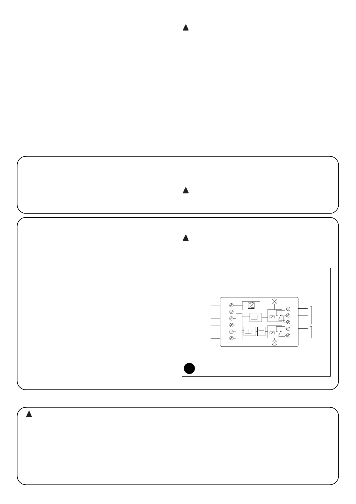
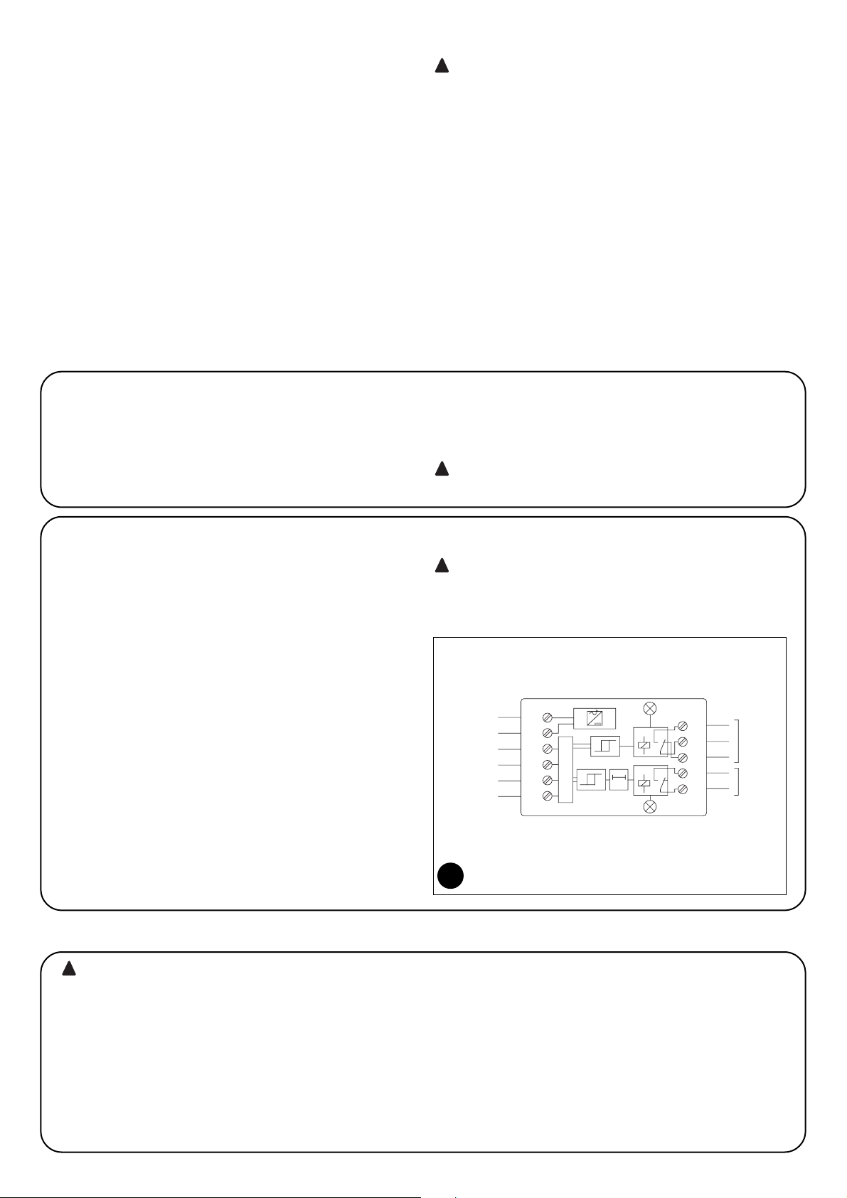
1.1) Operating principles
The TCE consists in 2 window comparators called “C1” and “C2”,
respectively. These comparators are connected up to 2 output relays,
R1 and R2. As long as the resistance value of the sensitive device
remains within the limits of acceptability (4.725Ω ÷ 10.925Ω) the comparators will activate (On) the two output relays. As soon as the sensitive device resistance rises above or drops below said limits, the comparators will deactivate (Off) the outputs. The first relay, which controls
OUT1, will deactivate immediately; the second, which controls OUT2,
will deactivate when T1 timer triggers after a delay of approx. 1.5 seconds. These two outputs - one which triggers immediately and one
which is delayed - have been designed in order that they can be connected up to the control units for gate automations. The first output is
connected up to the input which causes the immediate inversion of
the movement of the leaf, e.g. “Photocell” input. The second output is
either connected in such a way that it will stop and prevent the leaf
from moving, e.g. “Stop” input, or directly to the motor power supply
by means of special interface relays.
The “Phototest” input is used in those control units which provide for
self-diagnosis of the safety devices. It enables the user to simulate
the triggering of the sensitive device so s/he can check the TEC is
operating correctly.
When deciding which type of TCE connection to choose
for the safety device, carefully assess the effects of the TCE
triggering in order to ensure the correct resistance category
will be achieved.
!
Warnings
• This manual contains important information regarding safety. Read all
the instructions before proceeding with the installation. Store this manual safely for future use.
• This manual has been especially written for use by qualified installation
technicians.
No information given in this manual can be considered as being of any
interest to end users!
• Any use of TCE other than that described in this manual is forbidden;
improper use can be dangerous and cause personal injury or damage
to property.
• Do not make modifications to any components unless such action is
specified in these instructions. Operations of this type are likely to lead
to malfunctions. NICE disclaims any liability for damage resulting from
modified products.
• The packing materials of TCE must be disposed of in compliance with
local regulations.
The manufacture of protective devices for automatic gates
and doors is subjected to the following provisions:
• EN 12453 Industrial, commercial and garage doors and gates. Safety
in use of power operated doors – Requirements
• EN 12978 - Industrial, commercial and garage doors and gates. Safety devices for power-operated doors and gates - Requirements and
test methods.
The TCE detection unit must be installed and connected up correctly in
order to produce a safety device. If the necessary provisions are not taken, this will be automatically considered as negligence and deliberate
abuse.
!
1) Description and Application
Only carry out installation once the electricity supply to the
system has been switched off. Disconnect any buffer batteries present.
Mounting
Set the TCE on a surface protected against impact, dust, water and
any other kind of liquid.
!
2) Installation
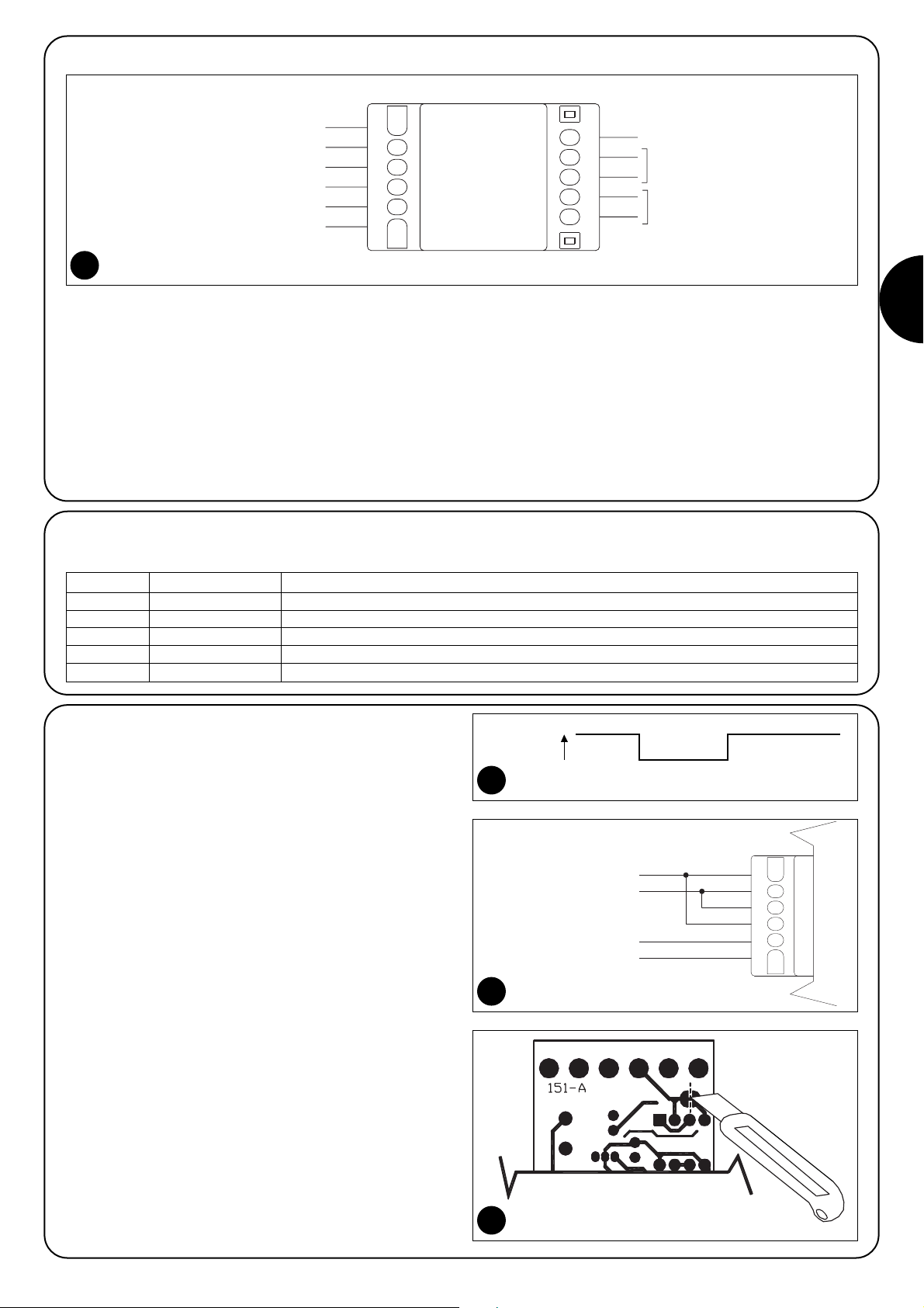
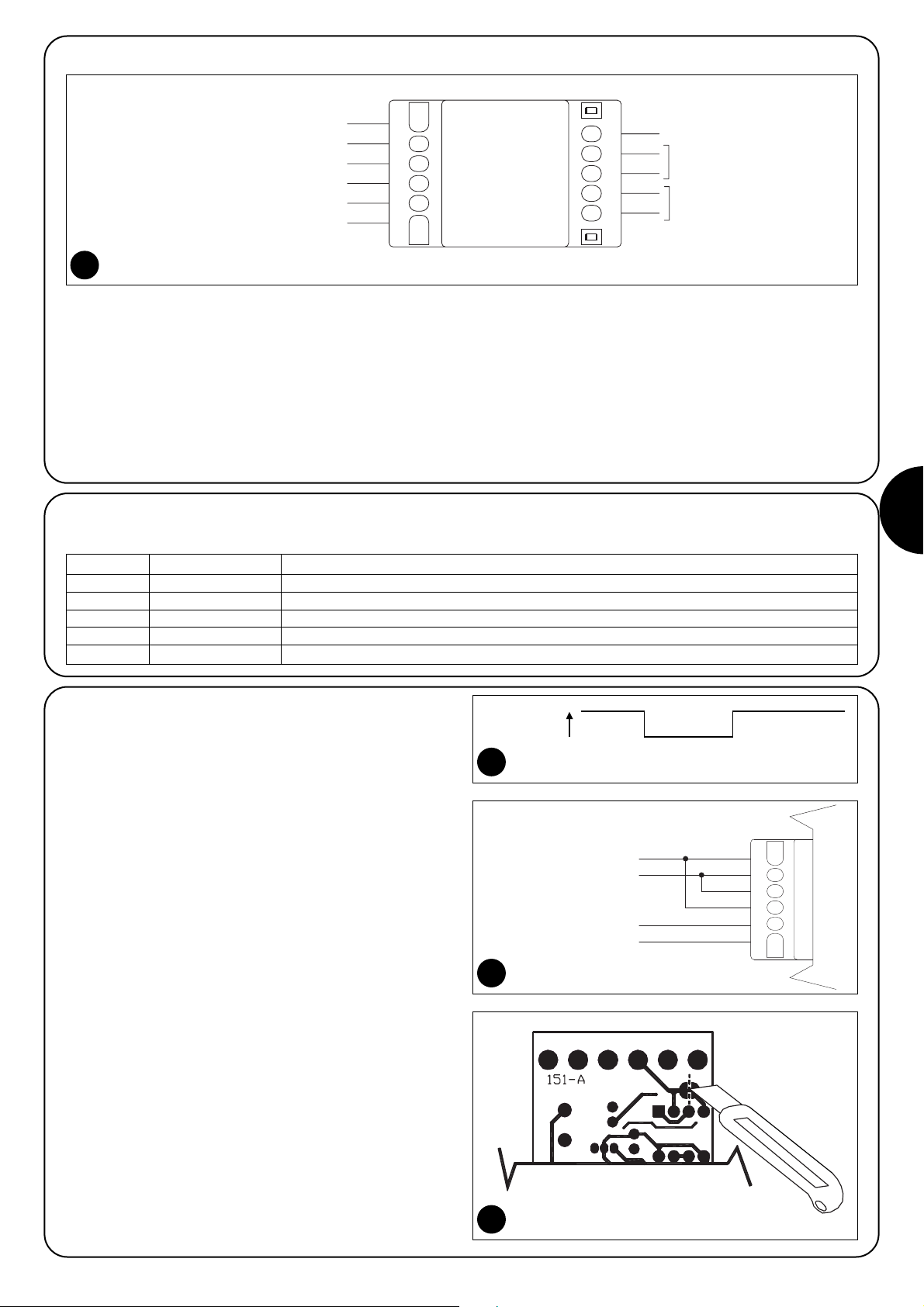
1
2
3
4
5
6
7
8
9
10
11
Led 1
Led 2
POWER SUPPLY
PHOTOTEST
INPUT 8.2KΩ
OUT 1
OUT 2
1
Page 3
GB
3
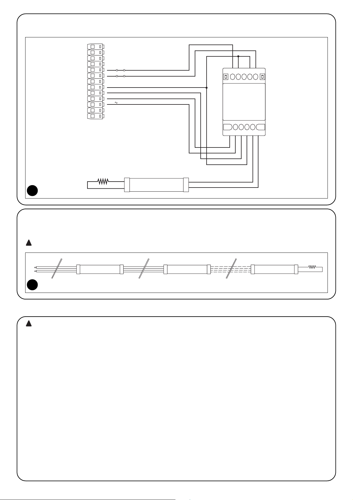
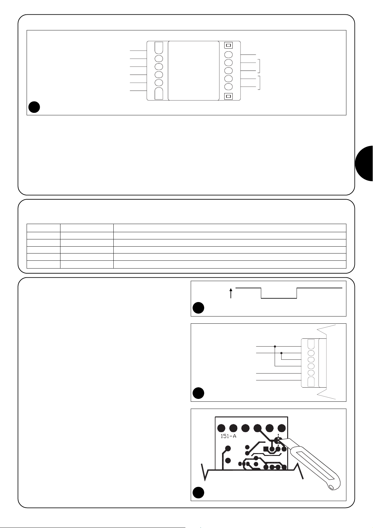
2.3) Phototest
The TCE makes it possible to utilise the test function some of the
automation control units have. The “normal” state is when the “Phototest” input is live, while the “Test” state is activated by disconnecting the power supply from the input, as shown in Figure 3.
The TCE “Phototest” input (Terminals 8-9) must be connected to the
phototest output of the automation control unit. Refer to the relative
instructions if necessary.
If the control unit does not have this “Test” or the user does not wish
to utilise it, then the phototest input must be connected up to the
TCE power supply, as shown in Figure 4.
Technical note: The “Phototest” input can be powered using either
alternating or direct current, and there is no need to respect any kind
of polarity. However, in some control units, this could cause the
incorrect execution of the phototest. If this should occur, after having checked that the connections are correct, cut the track under the
printed circuit as shown in Figure 5 and try again. If the problem presents again, invert the phototest wires (Terminals 8–9), too. The cut
track can be restored at any time, simply by soldering the two bump
contacts.
Phototest: V
Normal Test Normal
3
POWER SUPPLY
12-28Vac 50/60Hz 12-30Vdc
976 8 1110
INPUT 8,2KΩ
4
4
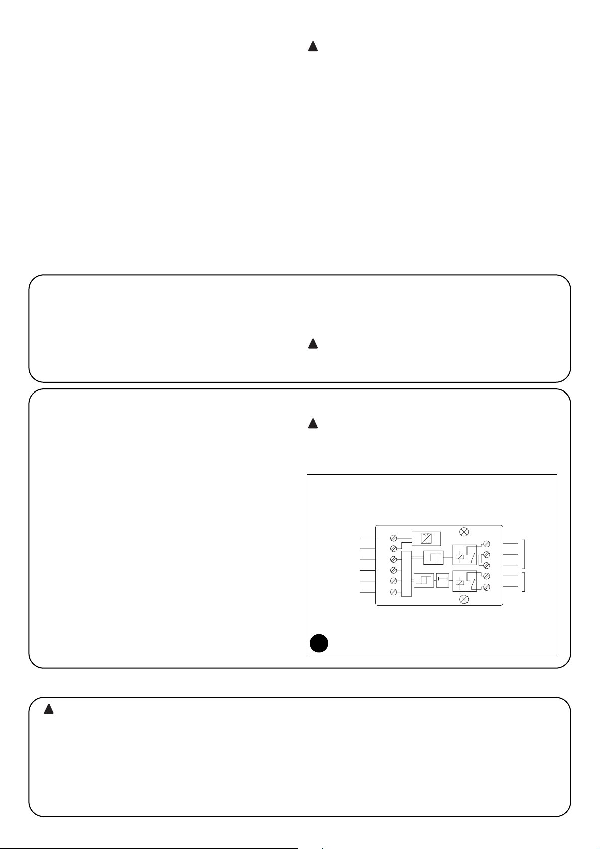
2.1) Electrical connections
Figure 2 shows a typical TCE wiring diagram. Follow these instructions carefully when making electrical connections.
•Refer to the “Technical Features” chapter in order to check the
suitability of the TCE in terms of supply voltage, performance of the
output relay contacts, and the maximum cable length.
• The source of the power supply must be suitably insulated from
the mains by means of insulation transformers which conform with
EN 61558, or equivalent insulation. The power supply and output
contacts of the TCE must be protected against short-circuiting.
• Use wires with a minimum cross-section of 0.25mm
2
.
•Do not connect cables in buried boxes, even if they are completely watertight.
• If there is more than one device with NC contacts for the same
input of the control unit, they must be connected in “SERIES”.
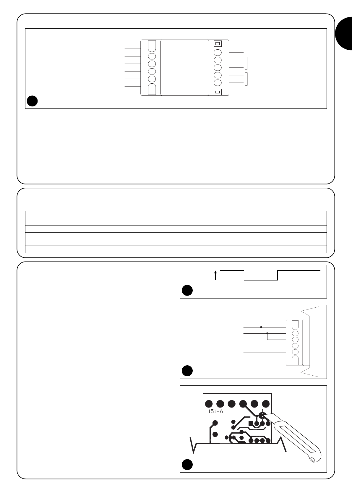
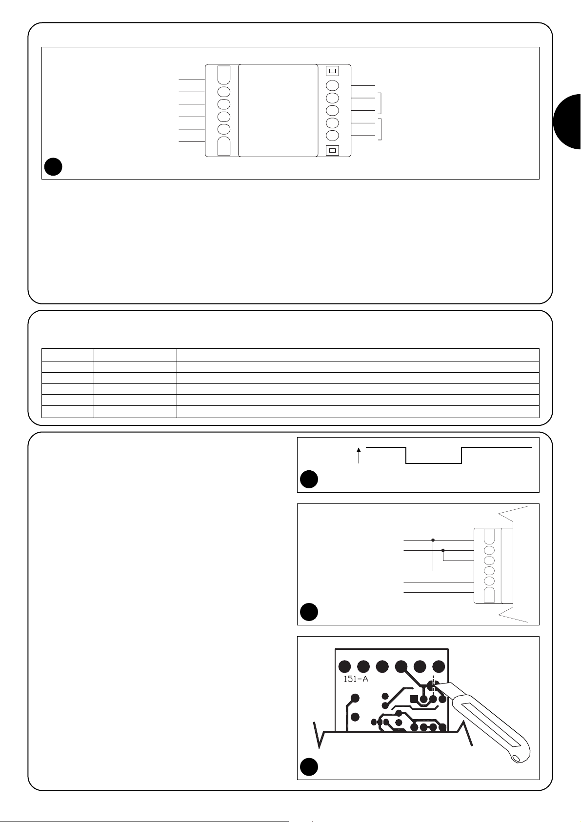
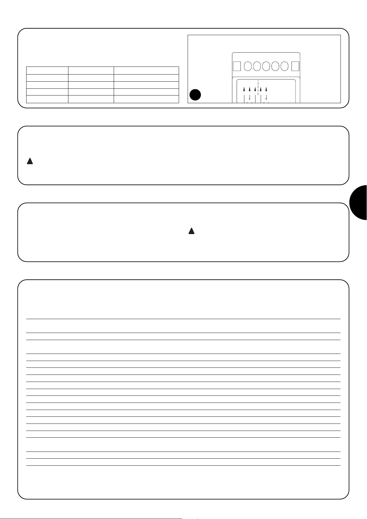
2.2) Description of the connections
Here follows a brief description of the TCE connections to the electro-sensitive device and automation control unit:
12345
678910 11
Led 1
Led 2
COMMON
NC Stop
NO (optional)
COMMON
NC PHOTO
+
-
POWER SUPPLY
12-28Vac 50/60Hz 12-30Vdc
PHOTOTEST
12-28Vac 50/60Hz 12-30Vdc
INPUT 8,2KΩ
2
Terminals FUNCTION Description
1-2 OUT1 Output no. 1 with NC contact, immediate triggering
4-5 OUT2 Output no. 2 with NC contact, delayed triggering
6-7 Power supply 12-24Vac/dc Power supply
8-9 Phototest Test input
10-11 8.2kΩ 8.2kΩ sensitive device input.
Page 4
4
These are the most important operations in the automation designed to guarantee the maximum safety and reliability of the automation system.
The testing of the detection device must be performed by
qualified and experienced personnel who must establish
which tests to conduct on the basis of the risks involved, and
verify the compliance of the system with applicable regulations, legislation and standards, in particular with all the provisions of EN standard 12445 which establishes the test
methods for automation systems for gates.
Testing can also be adopted as a method of periodically checking
that all the various devices in the system are functioning correctly.
The following checks must be made when testing the TCE detection
unit:
1. Make sure that the provisions listed in the «WARNINGS» chapter
have been carefully observed;
2. f the sensitive device is connected, disconnect it from terminals
10 and 11. Use an ohmmeter to measure the resistance value of
the sensitive device. Said value must be between 7700Ω and
8700Ω (nominal 8200Ω).
3. Switch the power supply to the TCE on, and check that the two
LEDs (LED1 and LED2) are off - deactivated state (Off).
4. Connect the sensitive device to Terminals 10 and 11, and check
that LED1 and LED2 are on - activated state (On).
5. Activate the sensitive device and check that LED1 switches off
immediately, and L2 switches off approximately 2 seconds later.
6. Deactivate the sensitive device, and check that both LED1 and
LED2 switch on immediately.
7. Repeat the tests described in stages 5 and 6, and check that
switching the TCE outputs does achieve the results set. These
are normally the immediate inversion of the motor, and stop after
approximately 2 seconds.
8. If the “Test” function has been used, check that the control unit of
the automation carries out the test correctly. What normally happens during the test is that LED1 switches off and switches on
again immediately afterwards.
9. Carefully check the automation as specified in Standards EN
12445 and EN 12978.
!
3) Testing
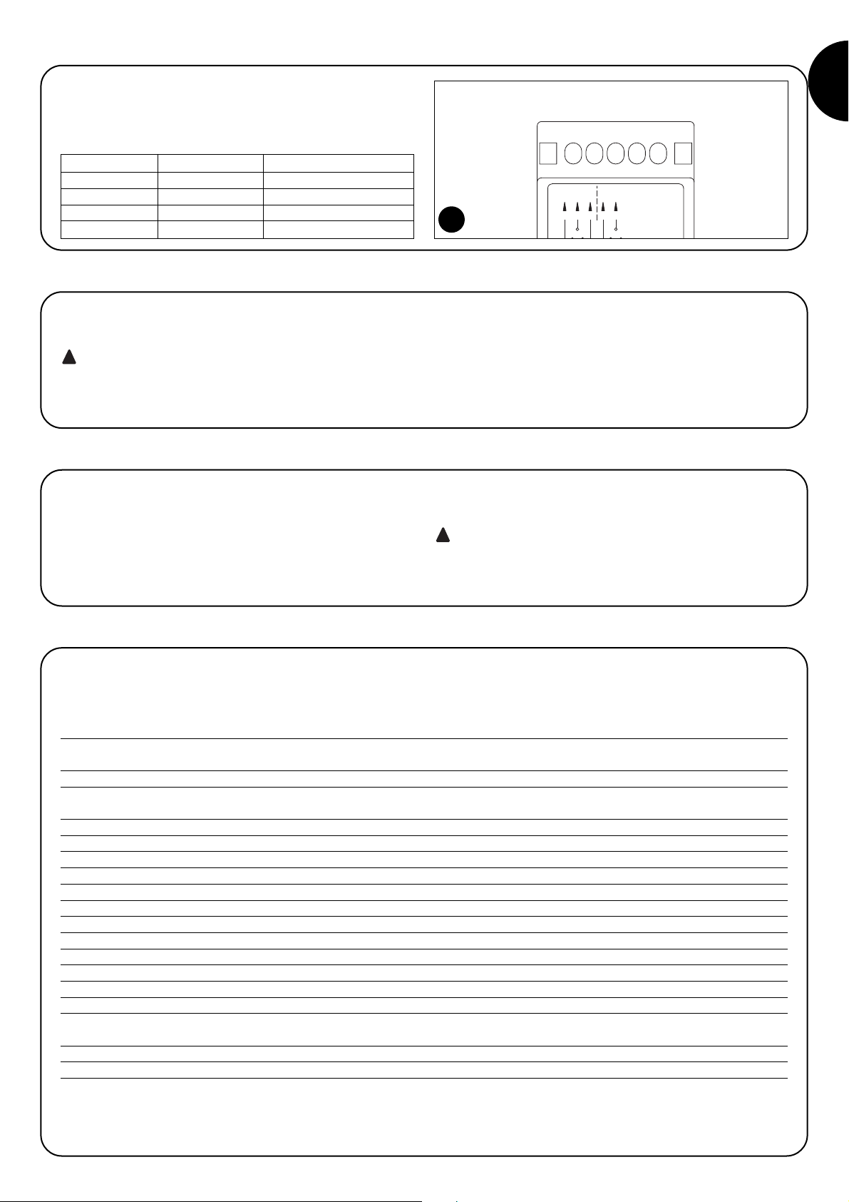
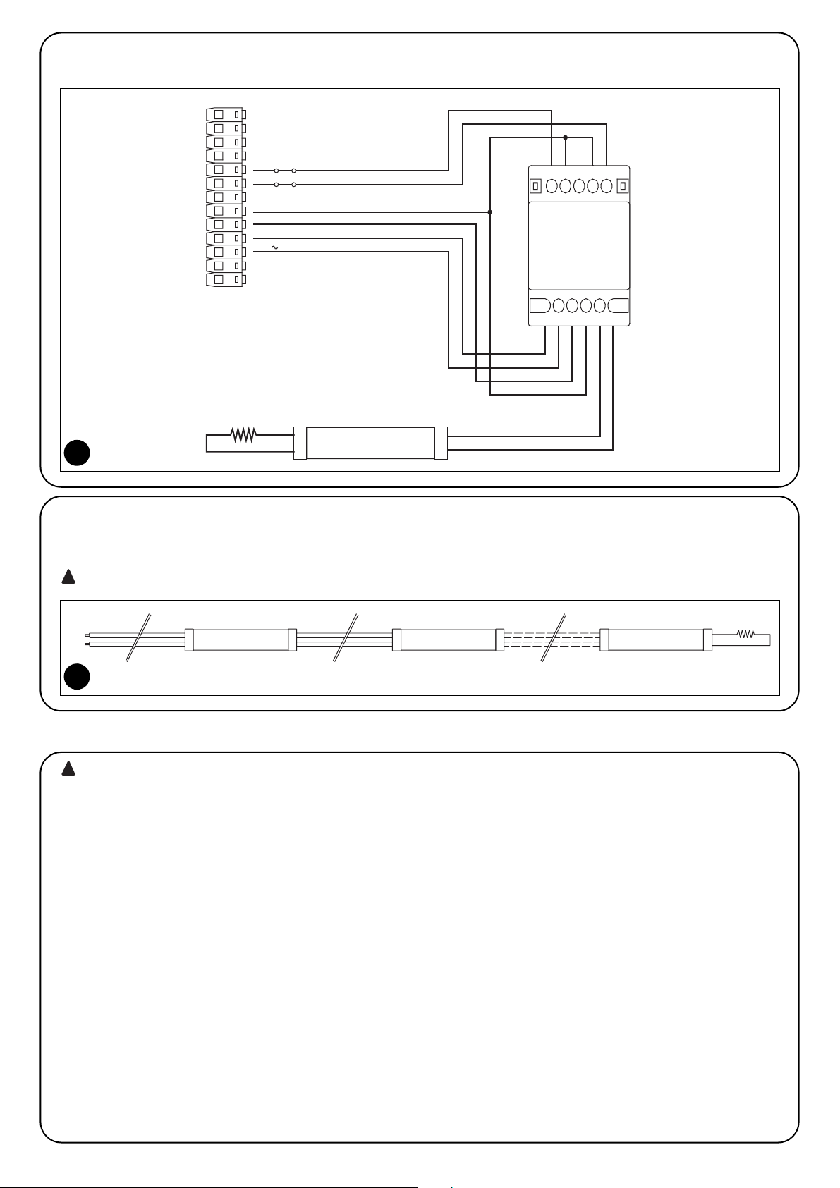
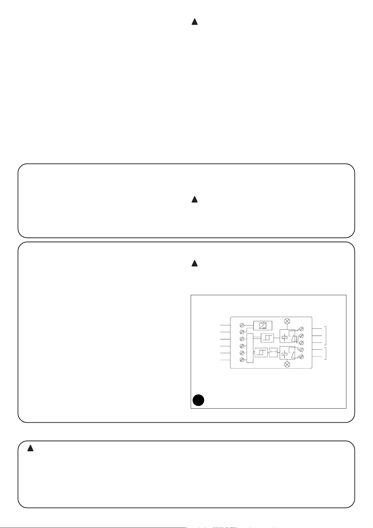
2.4) Example of a connection
Figure 6 shows an example of a TCE connection on a control unit for automations with the Phototest function.
7
8,2KΩ
6
PHOTOTEST
24 V
COMMON
PHOTO
STOP
1
111098
3254
Sensitive device
TCE
6
2.5) Connection of 2 or more sensitive edges
TCE only has one input, but has two or more sensitive devices which carry out the same function. They can be connected “in cascade”, one
after the other (as shown in Figure 7) with a single 8.2KΩ termination resistance.
Constant resistance devices must be connected “in cascade”, and NOT in series or in parallel.
!
Sensitive edge Sensitive edge Sensitive edge
1
2
8,2kΩ
n°
10
11
7
Page 5
GB
5
6) Technical characteristics
Nice S.p.a., in order to improve its products, reserves the right to modify their technical characteristics at any time without prior notice. In any
case, the manufacturer guarantees their functionality and fitness for the intended purposes.
Note: All the technical characteristics refer to a room temperature of 20°C (±5°C)
Technical Features of the TCE detection unit
Type: Detection unit utilised to produce electro-sensitive protection equipment (ESPE), complete with
8.2KΩ constant resistance sensor devices used for the automation of doors and gates.
Adopted technology 2 independent channels with window comparators and relay output
Supply voltage 15÷28Vac (±15%) 50/60Hz; with insulation transformer which conforms with EN 61558
12÷30Vdc (±15%)
Absorbed current with 24 Vac: < 200mA rms
Absorbed current with 24 Vdc: < 50mA
Phototest input voltage: Same limits as “Input Voltage”
Range of the sensitive device input (Rs): Typical 8.2KΩ ± 25% for the activated state (On)
Limits of the activated state (On): with Rs > 4,725Ω and Rs < 10,925Ω
Limits of the deactivated state (Off): with Rs <1,520Ω or Rs > 18,900Ω
Sensitive device cable length: Max. 30m
Out1 Response Time: <5ms (typical 3.3ms)
Out2 Response Time: 1,6s ± 25%
OUT1 and OUT2 output relay contacts: Max. 0.5A and max. 48Vac (resistive load: cosϕ=1)
OUT1 and OUT2 output relay contacts duration: Mechanical lifespan > 1,000,000 cycles; Electrical lifespan > 200,000 cycles (at 0.25A 24Vcc)
Operating temperature: -20 ÷ 55 °C
Use in acid, saline or potentially explosive
atmosphere:
No
Protection class: IP 20
Dimensions and weight: 60x59x422 with flaps 60x38x422 without flaps/approx. 55g
To maintain the guaranteed level of safety of the TCE, regular maintenance must be performed at max. 6 month intervals.
The maintenance operations must be performed in strict
compliance with the safety directions provided in this manual
and according to the applicable legislation and standards.
1. Check all TCE parts for wear with special attention to dirt, erosion, rust, overheating.
2. Perform all tests and checks as envisaged in the section "Testing".
!
5) Maintenance
This product is made up of different materials, some of which can be
recycled, such as plastic container, others must be disposed of as
waste, such as electronic board.
1. Disassemble TCE following in reverse order the procedures
described in chapter “Installation”.
2. As far as possible, separate all parts that can or must be recycled
or disposed of according to special procedures.
3. Sort the various materials and consign them to local licensed
firms for recovery and disposal.
Some electronic components may contain polluting sub-
stances; do not pollute the environment.
!
6) Disposal
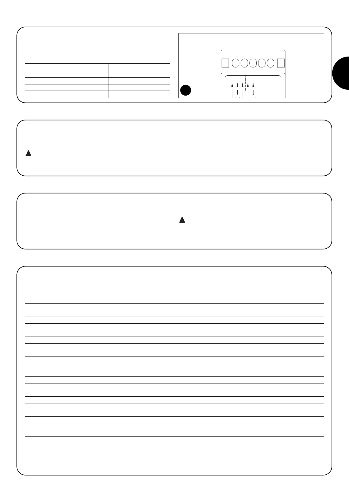
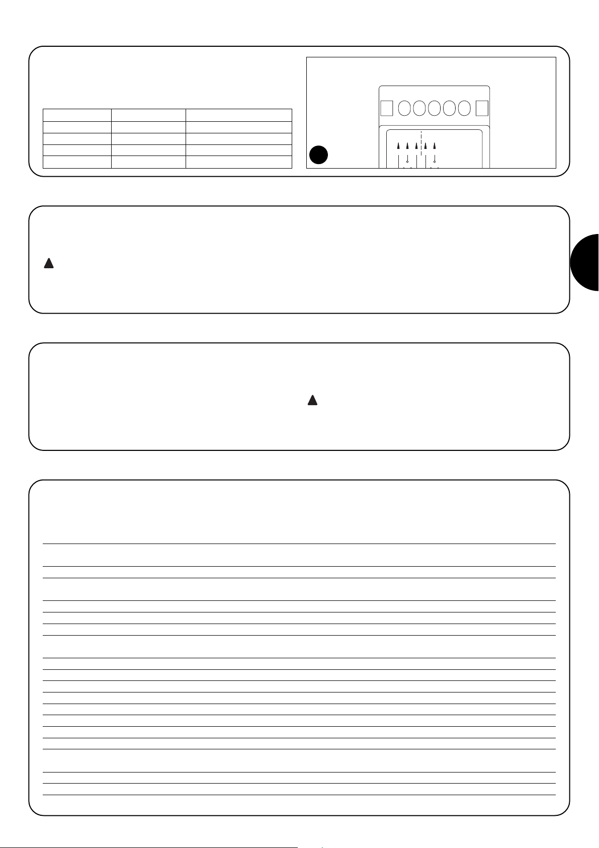
TCE has two signalling LEDs which indicate the state of the relays.
Normally, they are “ON”. If they are off, this indicates a state of alarm,
meaning that the sensitive device has either triggered or malfunctioned.
State Signalling Description
Led1: on OUT1: On Output N°1 Activated
Led1: off OUT1: Off Output N°1 Deactivated
Led2: on OUT1: On Output N°2 Activated
Led2: off OUT1: Off Output N°2 Deactivated
4) Diagnostics and Signals
TACTO
IP10
12 / 24 Vac/dc
Out 0,5A 48Vac/dc
Led 1
3412
NONC
Foto
5
NC
Alt
21 543
Led 2
8
Page 6
6
TCE è una unità di rilevazione che consente di realizzare apparecchi
elettrosensibili di protezione (ESPE) con dispositivi sensori a resistenza costante 8,2KΩ utilizzati nelle automazioni di porte e cancelli. TCE dispone di 2 uscite a relè indipendenti, comandati da 2 circuiti di rilevazione separati la cui condizione è legata dallo stato del
dispositivo sensibile controllato. TCE, abbinato ad adeguati dispositivi elettrosensibili e collegato opportunamente alle centrali di con-
trollo, consente di realizzare dispositivi di sicurezza in categoria 3
secondo la norma EN 954-1; dispone anche di un ingresso di “test”
da utilizzare nelle centrali che prevedono l’autodiagnosi dei dispositivi di sicurezza secondo la categoria 2 della norma EN 954-1.
La sola unità di rilevazione TCE non è un dispositivo di
sicurezza ma solo una parte di esso.
!
1.1) Principio di funzionamento
TCE è composto da 2 comparatori a finestra “C1” e “C2” collegati ai
2 relè di uscita R1 ed R2, fintantoché il valore di resistenza del dispositivo sensibile si mantiene entro i limiti di accettabilità (4.725Ω ÷
10.925Ω) i comparatori attivano (On) le due uscite a relè. Non appena la resistenza del dispositivo sensibile esce dai limiti i comparatori
disattivano (Off) le uscite; il primo relè che comanda OUT1 si disattiva immediatamente il secondo relè che comanda OUT2 si disattiva
con il timer T1 dopo un tempo di ritardo di circa 1,5 secondi. Queste due uscite, una immediata e l’altra ritardata, sono state sudiate
appositamente per il collegamento alle centrali di controllo degli
automatismi per cancelli; la prima uscita va collegata all’ingresso che
provoca l’immediata inversione del moto dell’anta ad esempio
ingresso “Fotocellula”, la seconda uscita va collegata in modo arrestare ed impedire qualsiasi movimento dell’anta, ad esempio ingresso “Alt” oppure, con opportuni relè di interfaccia, direttamente nell’alimentazione dei motori.
L’ingresso di “Fototest”, da utilizzare nelle centrali che prevedono
l’autodiagnosi dei dispositivi di sicurezza, permette di simulare un
intervento del dispositivo sensibile per verificare la corrette funzionalità di TCE.
Nella scelta del tipo di collegamento di TCE per realizzare il dispositivo di sicurezza occorre valutare attentamente gli
effetti dell’intervento di TCE al fine di ottenere la categoria di
resistenza ai guasti richiesta.
!
Avvertenze
•Questo manuale di istruzioni contiene importanti informazioni riguardanti la sicurezza per l’installazione, è necessario leggere tutte le istruzioni prima di procedere all’installazione. Conservare con cura questo
manuale anche per utilizzi futuri.
• Il presente manuale è destinato solamente al personale tecnico qualificato per l'installazione.
Nessuna altra informazione contenuta nel presente fascicolo può
essere considerata d’interesse per l'utilizzatore finale!
•L’uso di TCE diverso da quanto previsto in queste istruzioni è vietato;
usi impropri possono essere causa pericoli o danni a persone e cose.
• Non eseguire modifiche su nessuna parte se non previste nelle presenti istruzioni; operazioni di questo tipo possono solo causare malfunzionamenti; NICE declina ogni responsabilità per danni derivati da
prodotti modificati.
• Il materiale dell’imballaggio di TCE deve essere smaltito nel pieno
rispetto della normativa locale.
La realizzazione di dispositivi di sicurezza per porte e cancel-
li automatici è sottoposta alle seguenti normative:
• EN 12453 Porte e cancelli industriali, commerciali e da autorimessa.
Sicurezza in uso di porte motorizzate - Requisiti
• EN 12978 - Porte e cancelli industriali, commerciali e da garage.
Dispositivi di sicurezza per porte e cancelli motorizzate - Requisiti e
metodi di prova.
L'installazione ed il collegamento dell’unità di rilevazione TCE, con lo
scopo di realizzare un dispositivo di sicurezza, senza soddisfare i requisiti di queste norme corrisponde a negligenza e deliberato abuso.
!
1) Descrizione e destinazione d’uso
Tutte le operazioni d’installazione vanno eseguite in
assenza di tensione all’impianto; nel caso sia presente una
batteria tampone è necessario scollegarla.
Fisaggio
Porre TCE su una superficie adeguatamente protetta da urti, polvere, acqua o liquidi di qualsiasi natura
!
2) Installazione
1
2
3
4
5
6
7
8
9
10
11
Led 1
Led 2
ALIM.
FOTOTEST
IN. 8,2KΩ
OUT 1
OUT 2
1
Page 7
2.3) Fototest
TCE consente di usare la funzione test disponibile in alcune centrali
per automazioni. Lo stato “normale” si ha quando all’ingresso “Fototest” è presente la tensione di alimentazione mentre lo stato di “test”
si attiva togliendo la tensione all’ingresso; come rappresentato dal
diagramma di figura 3.
Normalmente l’ingresso “Fototest” di TCE (morsetti 8-9) deve essere collegato all’ uscita fototest della centrale dell’automazione; eventualmente consultare le relative istruzioni.
Se la centrale non dispone di “test” oppure non si desidera usarlo, è
necessario collegare l’ingresso fototest all’alimentazione di TCE,
come in figura 4.
Nota tecnica: All’ingresso “Fototest” può essere fornita sia tensione
di tipo alternato che di tipo continuo e non è necessario rispettare
alcuna polarità. Questo potrebbe provocare una non corretta esecuzione del test in alcune centrali. In questo caso, dopo aver verificato
che i collegamenti siano corretti occorre tagliare la pista sotto il circuito stampato mostrata in figura 5 e riprovare; se il problema si
ripresenta è necessario invertire anche i conduttori del fototest (morsetti 8–9). La pista tagliata è ripristinabile in qualsiasi momento depositando una goccia di stagno tra le due apposite piazzole.
I
77
Fotototest: V
Normale Test Normale
3
ALIMENTAZIONE
12-28Vac 50/60Hz 12-30Vdc
976 8 1110
INGRESSO 8,2KΩ
4
4
2.1) Collegamenti elettrici
In figura 2 è rappresentato lo schema di collegamento tipico di TCE.
Nell’eseguire i collegamenti elettrici seguire queste prescrizioni.
•Verificare nel capitolo “caratteristiche tecniche” l’idoneità di TCE in
termini di tensione di alimentazione; prestazioni dei contatti dei relè
di uscita e lunghezza massima dei cavi.
• La sorgente di alimentazione deve essere adeguatamente isolata
dalla rete mediante trasformatori di isolamento conformi alla EN
61558 o isolamento equivalente. L’alimentazione ed i contatti di
uscita di TCE devono essere correttamente protetti contro il corto
circuito.
• Usare conduttori con sezione minima pari a 0,25 mm2.
• Evitare di fare connessioni ai cavi in casse interrate anche se completamente stagne.
• Se per lo stesso ingresso della centrale ci sono più dispositivi con
contatti di tipo NC, vanno posti in SERIE tra loro.
2.2) Descrizione dei collegamenti
Riportiamo una breve descrizione dei collegamenti di TCE verso il dispositivo elettrosensibile e la centrale dell’automatismo:
12345
678910 11
Led 1
Led 2
COMUNE
NC Alt
NO (opzionale)
COMUNE
NC Foto
+
-
ALIMENTAZIONE
12-28Vac 50/60Hz 12-30Vdc
FOTOTEST
12-28Vac 50/60Hz 12-30Vdc
INGRESSO 8,2KΩ
2
Morsetti Funzione Descrizione
1-2 OUT1 Uscita N° 1 con contatto NC, intervento immediato
4-5 OUT2 Uscita N° 2 con contatto NC, intervento ritardato
6-7 Alimentazione Alimentazione 12÷24Vac/dc
8-9 Fototest Ingresso per test
10-11 In 8,2kΩ Ingresso per dispositivo sensibile 8,2kΩ.
Page 8
8
Queste sono le fasi più importanti nella realizzazione del
dispositivo al fine di garantire la massima sicurezza.
Il collaudo del dispositivo di rilevazione deve essere eseguita
da personale qualificato ed esperto che dovrà farsi carico di
stabilire le prove previste in funzione dei rischi presenti; e di
verificare il rispetto di quanto previsto da leggi, normative e
regolamenti, ed in particolare tutti i requisiti della norma EN
12445 che stabilisce i metodi di prova per la verifica degli
automatismi per cancelli.
Il collaudo può essere usato anche come verifica periodica dei
dispositivi che compongono il sistema.
Per il collaudo dell’unità di rilevazione TCE sono necessarie queste
verifiche:
1. Verificare che si sia rispettato rigorosamente quanto previsto nel
capitolo “Avvertenze”.
2. Se fosse collegato scollegare il dispositivo sensibile dai morsetti
10 e 11. Con un ohmetro misurare il valore della resistenza del
dispositivo sensibile, il valore deve essere compreso tra 7700Ω e
8700Ω (nominale 8200Ω).
3. Dare alimentazione a TCE e verificare che i due led, LED1 e LED2
siano spenti ad indicare lo stato di disattivo (Off).
4. Collegare il dispositivo sensibile dai morsetti 10 e 11 e verificare
che i due led, LED1 e LED2 siano accesi ad indicare lo stato di
attivo (On).
5. Agire per attivare il dispositivo sensibile e verificare che immediatamente si spenga LED1 e che dopo circa 2 secondi si spenga
anche LED2.
6. Disattivare il dispositivo sensibile e verificare che immediatamente si accendano sia LED1 che LED2.
7. Ripetere le prove dei passi N° 5 e 6 verificando che la commutazioni delle uscite di TCE provochi nella centrale dell’automazione
gli effetti stabiliti, normalmente: immediata inversione del moto e
arresto definitivo dopo circa 2 secondi.
8. Se è stata usata la funzione di “Test” verificare che la centrale dell’automazione esegua correttamente il test, normalmente durante il test si spegne LED1 per accendersi subito dopo.
9. Nell’automazione eseguire tutte le verifiche secondo quanto previsto dalla norma EN 12445 ed EN 12978.
!
3) Collaudo
2.4) Esempio di collegamento
In figura 6 è rappresentato un esempio di collegamento di TCE su di una centrale per automazioni con funzione di Fototest.
7
8,2KΩ
6
FOTOTEST
24 V
COM
FOTO
ALT
1
111098
3254
Dispositivo Sensibile
TCE
6
2.5) Collegamento di 2 o più bordi sensibili
TCE dispone di un solo ingresso, ma due o più dispositivi sensibili che svolgano la stessa funzione, possono essere collegati in cascata l’uno dopo l’altro come in figura 7; ponendo una sola resistenza da 8,2kΩ di terminazione.
I dispositivi a resistenza costante devono essere collegati in cascata e mai in serie o in parallelo tra loro.
!
Bordo Sensibile Bordo Sensibile Bordo Sensibile
1
2
8,2kΩ
n°
10
11
7
Page 9
I
9
6) Caratteristiche tecniche
Allo scopo di migliorare i prodotti, NICE S.p.a. si riserva il diritto di modificare le caratteristiche tecniche in qualsiasi momento e senza preavviso
pur mantenendo funzionalità e destinazione d’uso.
Nota: tutte le caratteristiche tecniche si riferiscono alla temperatura ambiente di 20°C (±5%)
Caratteristiche unità di rilevazione TCE
Tipologia: Unità di rilevazione per realizzare apparecchi elettrosensibili di protezione (ESPE) con
dispositivi sensori a resistenza costante 8,2KΩ utilizzati nelle automazioni di porte e cancelli
Tecnologia adottata: 2 canali indipendenti con comparatori a finestra ed uscita a relè
Tensione di alimentazione: 15÷28Vac (±15%) 50/60Hz; con trasformatore d’isolamento conforme a EN 61558
12÷30Vdc (±15%)
Corrente assorbita con 24Vac: < 200mA rms
Corrente assorbita con 24Vdc: < 50mA
Tensione ingresso Fototest: Stessi limiti di “Tensione di alimentazione”
Gamma dell’ingresso del dispositivo
sensibile (Rs):
Tipico 8,2KΩ± 25% per lo stato di attivo (On)
Limiti stato attivo (On): con Rs > 4.725Ω e Rs < 10925Ω
Limiti stato disattivo (Off): con Rs < 1.520Ω o Rs > 18.900Ω
Lunghezza cavo dispositivo sensibile: Fino a 30m
Tempo di risposta Out1: <5ms (tipico 3,3ms)
Tempo di risposta Out2: 1,6s ± 25%
Contatti relè in uscite OUT1 e OUT2: Massimo 0.5A e massimo 48Vac (carico resistivo: cosϕ=1)
Durata contatti relè uscite OUT1 e OUT2: Vita meccanica > 1.000.000 cicli; elettrica > 200.000 cicli (a 0,25A 24Vcc)
Te mperatura di esercizio: -20 ÷ 55 °C
Utilizzo in atmosfera acida o salina o
potenzialmente esplosiva:
No
Grado di protezione: IP 20
Dimensioni / peso: 60x59x422 con alette 60x38x422 senza alette/ 55g circa
Per mantenere costante il livello di sicurezza garantito da TCE è
necessaria una manutenzione regolare e programmata al massimo
entro 6 mesi dalla precedente manutenzione.
La manutenzione deve essere effettuata nel pieno rispetto delle prescrizioni sulla sicurezza del presente manuale e
secondo quanto previsto dalle leggi e normative vigenti.
1. Verificare lo stato di deterioramento di tutti i materiali che compongono TCE con particolare attenzione a fenomeni di erosione,
ossidazione, surriscaldamento delle parti e presenza di sporcizia
in generale.
2. Eseguire tutte le prove e le verifiche previste nel capitolo Collaudo”.
!
5) Manutenzione
Questo prodotto è costituito da diverse tipologie di materiali, alcuni
di questi possono essere riciclati, as esempio: contenitore in plastica, altri devono essere smaltiti, ad esempio: scheda elettronica.
1. Smontare TCE seguendo il procedimento inverso a quello
descritto nel capitolo: “Installazione”.
2. Separare per quanto possibile le parti che possono o devono
essere riciclate o smaltite in modo diverso.
3. smistare ed affidare i vari materiali così separati ai centri abilitati al
recupero ed allo smaltimento previsti a livello locale.
Alcuni componenti potrebbero contenere sostanze inqui-
nanti, non disperdere nell’ambiente.
!
6) Smaltimento
TCE è dotato di 2 led luminosi di segnalazione che indicano lo stato
dei relè, normalmente essi sono accesi, quando si spengono indicano lo stato di allarme cioè intervento del dispositivo sensibile o malfunzionamento dello stesso.
Stato Segnalazione Descrizione
Led1: acceso OUT1: On Uscita N°1 Attiva
Led1: spento OUT1: Off Uscita N°1 Disattiva
Led2: acceso OUT1: On Uscita N°2 Attiva
Led2: spento OUT1: Off Uscita N°2 Disattiva
4) Diagnostica e segnalazioni
TACTO
IP10
12 / 24 Vac/dc
Out 0,5A 48Vac/dc
Led 1
3412
NONC
Foto
5
NC
Alt
21 543
Led 2
8
Page 10

10
TCE est une unité de détection qui permet de réaliser des équipements de protection électrosensibles (ESPE) avec dispositifs capteurs à résistance constante 8,2KΩ utilisés dans les automatismes
de portes et de portails. TCE dispose de deux sorties à relais indépendants, commandés par 2 circuits de détection séparés dont la
condition est liée à l’état du dispositif sensible contrôlé. TCE, associé à des dispositifs électrosensibles adéquats et connecté correctement aux logiques de commande, permet de réaliser des disposi-
tifs de sécurité appartenant à la catégorie 3 d’après la norme EN
954-1; il dispose aussi d’une entrée de «test» à utiliser dans les
logiques qui prévoient l’autodiagnostic des dispositifs de sécurité
suivant la catégorie 2 de la norme EN 954-1.
L’unité de détection TCE à elle seule n’est pas un disposi-
tif de sécurité mais seulement un composant de celui-ci.
!
1.1) Principe de fonctionnement
TCE est composé de 2 comparateurs à fenêtre «C1» et «C2» reliés
aux 2 relais de sortie R1 et R2. Tant que la valeur de résistance du
dispositif sensible se maintient dans des limites acceptables (4.725Ω
÷ 10.925Ω) les comparateurs activent (On) les deux sorties à relais.
Dès que la résistance du dispositif sensible dépasse les limites, les
comparateurs désactivent (Off) les sorties; le premier relais qui commande OUT1 se désactive immédiatement, le deuxième relais qui
commande OUT2 se désactive avec le temporisateur T1 après un
temps de retard d’environ 1,5 secondes. Ces deux sorties, une
immédiate et l’autre retardée, ont été étudiées tout spécialement
pour la connexion aux logiques de commande des automatismes
pour portails; la première sortie doit être connectée à l’entrée qui
provoque l’inversion immédiate du mouvement du vantail, par
exemple entrée «Photocellule» la deuxième sortie doit être connectée de manière à arrêter et à empêcher tout mouvement du vantail,
par exemple entrée «Stop» ou bien, avec des relais d’interface adéquats, directement dans l’alimentation des moteurs.
L’entrée «Phototest», à utiliser dans les logiques qui prévoient l’autodiagnostic des dispositifs de sécurité, permet de simuler une intervention du dispositif sensible pour vérifier le fonctionnement correct
de TCE.
Dans le choix du type de connexion de TCE pour réaliser
le dispositif de sécurité, il faut évaluer attentivement les effets
de l’intervention de TCE afin d’obtenir la catégorie de résistance aux pannes demandée.
!
Avertissements
•Ce manuel d’instructions contient des informations importantes
concernant la sécurité durant l’installation, il faut lire toutes les instructions avant de procéder à l’installation. Conserver soigneusement ce
manuel en prévision de toute consultation future.
• Le présent manuel est destiné uniquement à du personnel technique
qualifié pour l’installation. Aucune autre information contenue dans la
présente notice ne peut être considérée comme intéressante pour
l’utilisateur final!
• Une utilisation de TCE différente de celle qui est prévue par ces instructions est interdite; les utilisations impropres peuvent être la cause
de dangers ou de dommages aux personnes et aux choses.
• Ne pas effectuer de modifications sur aucune des parties si elles ne
sont pas prévues dans le présent manuel. Des opérations de ce type
entraîneront obligatoirement des problèmes de fonctionnement. NICE
décline toute responsabilité pour les dommages dérivant de produits
modifiés.
• L’emballage de TCE doit être mis au rebut dans le plein respect de la
réglementation locale.
La réalisation de dispositifs de sécurité pour portes et por-
tails automatiques est soumise aux normes suivantes:
• EN 12453 Portes équipant les locaux industriels, commerciaux et de
garage. Sécurité à l’utilisation de portes motorisées - Prescriptions
• EN 12978 - Portes industrielles, commerciales et de garage - Dispositifs de sécurité. Prescriptions et méthodes d'essai
L'installation et la le branchement de l’unité de détection TCE, dans le
but de réaliser un dispositif de sécurité, sans respecter les prescriptions
de ces normes correspond à une négligence et à un abus délibéré.
!
1) Description et type d’utilisation
Toutes les opérations d’installation doivent être exécutées
en l’absence de tension dans le circuit; si une batterie tampon
est présente, il faut la déconnecter.
Fixation
Positionner TCE sur une surface suffisamment à l’abri des chocs, de
la poussière, de l’eau ou des liquides en général.
!
2) Installation
1
2
3
4
5
6
7
8
9
10
11
Led 1
Led 2
Alimentation
Phototest
Entrée
8,2KΩ
OUT 1
OUT 2
1
Page 11
F
11
2.3) Phototest
TCE permet d’utiliser la fonction test disponible dans certaines
logiques de commande pour automatismes. L’état est «normal»
quand la tension d’alimentation est présente à l’entrée «Phototest»
tandis que l’état de «test» s’active quand on coupe la tension à l’entrée, comme l’illustre le diagramme de la figure 3.
Normalement l’entrée «Phototest» de TCE (bornes 8-9) doit être
connectée à la sortie phototest de la logique de commande de l’automatisme; consulter éventuellement les instructions correspondantes.
Si la logique de commande ne dispose pas de «test» ou si l’on ne
souhaite pas l’utiliser, il faut connecter l’entrée phototest à l’alimentation de TCE, comme dans la figure 4.
Note technique: L’entrée «Phototest» peut être alimentée aussi bien
en courant alternatif qu’en courant continu et il n’est pas nécessaire
de respecter une polarité quelconque. Cela pourrait fausser l’exécution du test dans certaines logiques. Dans ce cas, après avoir vérifié
que les connexions sont correctes, il faut couper la piste sous le circuit imprimé illustré dans la figure 5 et refaire une tentative; si le problème persiste, il faut inverser aussi les conducteurs du phototest
(bornes 8–9). La piste coupée peut être rétablie à tout moment en
déposant une goutte d’étain entre les deux plots de contact.
Phototest: V
Normal Test Normal
3
Alimentation
12-28Vac 50/60Hz 12-30Vdc
976 8 1110
Entrée 8,2KΩ
4
4
2.1) Connexions électriques
La figure 2 illustre le schéma de connexion typique de TCE. Pour l’exécution des connexions électriques, suivre les indications ci-après:
• Vérifier dans le chapitre «caractéristiques techniques» que TCE est
compatible en ce qui concerne la tension d’alimentation; vérifier en
outre les performances des contacts des relais et la longueur
maximum des câbles.
• La source d’alimentation doit être doit être correctement isolée du
circuit au moyen de transformateurs d’isolement conformes à la
norme EN 61558 ou isolement équivalent. L’alimentation et les
contacts de sortie de TCE doivent être correctement protégés
contre le court-circuit.
• Utiliser des conducteurs d’une section minimum de 0,25mm
2
.
• Éviter d’effectuer des connexions dans les caissons enterrés
même s’ils sont complètement étanches.
• S’il y a plusieurs dispositifs avec contacts de type NF pour la
même entrée de la logique, ils doivent être placés en série entre
eux.
2.2) Description des connexions
Nous donnons une brève description des connexions de TCE vers le dispositif électrosensible et la logique de l’automatisme:
12345
678910 11
Led 1
Led 2
Commun
NF Stop
NO (opcional)
Commun
NF Photo
+
-
Alimentation
12-28Vac 50/60Hz 12-30Vdc
Phototest
12-28Vac 50/60Hz 12-30Vdc
Entrée 8,2KΩ
2
Bornes Fonction Description
1-2 OUT1 Sortie N°1 avec contact NF, intervention immédiate
4-5 OUT2 Sortie N°2 avec contact NF, intervention retardée
6-7 Alimentation Alimentation 12÷24 Vca/cc
8-9 Phototest Entrée pour test
10-11 Ent. 8,2KΩ Entrée pour dispositif sensible 8,2KΩ.
Page 12

12
Les phases qui suivent sont les plus importantes dans la
réalisation du dispositif pour garantir la sécurité maximum.
L’essai du dispositif de détection doit être effectué par du
personnel qualifié et expérimenté qui devra se charger d’établir les essais prévus en fonction des risques présents et de
vérifier le respect de ce qui est prévu par les lois, les normes
et les réglementations, et en particulier toutes les prescriptions de la norme EN 12445 qui établit les méthodes d’essai
pour la vérification des automatismes pour portails.
L’essai peut être utilisé également comme vérification périodique des
dispositifs qui constituent le système.
Pour l’essai de l’unité de détection TCE il faut procéder aux
contrôles suivants:
1. Vérifier que ce qui est prévu dans le chapitre «Avertissements»
est rigoureusement respecté.
2. S’il est connecté, déconnecter le dispositif sensible des bornes
10 et 11. Avec un ohmmètre, mesurer la valeur de la résistance
du dispositif sensible, la valeur doit être comprise entre 7700Ω et
8700Ω (valeur nominale 8200Ω).
3. Alimenter TCE et vérifier que les deux led, LED1 et LED2 sont
éteintes en indiquant ainsi l’état non actif (Off).
4. Connecter le dispositif sensible aux bornes 10 et 11 et vérifier que
les deux led, LED1 et LED2 sont allumées en indiquant ainsi l’état
actif (On).
5. Agir pour activer le dispositif sensible et vérifier que cela provoque
l’extinction immédiate de LED1 suivie, environ 2 secondes plus
tard de celle de LED2.
6. Désactiver le dispositif sensible et vérifier que cela provoque l’allumage immédiat des deux led LED1 et LED2.
7. Répéter les essais des points N° 5 et 6 en vérifiant que la commutation des sorties de TCE provoque dans la logique de l’automatisme les effets établis, normalement: inversion immédiate du
mouvement et arrêt définitif au bout d’environ 2 secondes.
8. Si la fonction de «Test» a été utilisée, vérifier que la logique de
l’automatisme effectue correctement le test, normalement,
durant le test LED1 s’éteint pour se rallumer juste après.
9. Dans l’automatisme, effectuer toutes les vérifications suivant les
prescriptions des normes EN 12445 et EN 12978.
!
3) Essai
2.4) Exemple de connexion
La figure 6 représente un exemple de connexion de TCE sur une logique pour automatismes avec fonction de Phototest.
7
8,2KΩ
6
Phototest
24 V
Commun
Photo
Stop
1
111098
3254
Dispositif sensible
TCE
6
2.5) Connexion de 2 bords sensibles ou plus
TCE dispose d’une seule entrée, mais deux dispositifs sensibles ou plus qui exercent la même fonction, peuvent être connectés en cascade l’un après l’autre comme dans la figure 7 en mettant une seule résistance de terminaison de 8,2KΩ.
les dispositifs à résistance constante doivent être connectés en cascade et jamais en série ou en parallèle entre eux.
!
Bord sensible Bord sensible Bord sensible
1
2
8,2kΩ
n°
10
11
7
Page 13

F
13
6) Caratteristiche tecniche
Dans le but d’améliorer ses produits, Nice S.p.a se réserve le droit de modifier les caractéristiques à tout moment et sans préavis tout en en
maintenant la fonctionnalité et le type d’utilisation.
N.B.: Toutes les caractéristiques techniques indiquées se réfèrent à une température ambiante de 20°C (±5°C)
Caractéristiques techniques
Typologie: Unité de détection pour réaliser des équipements électrosensibles de protection (ESPE) avec des
dispositifs capteurs à résistance constante 8,2KΩ utilisés dans les automatisations de portes et de portails
Technologie adoptée: 2 canaux indépendants avec comparateurs à fenêtre et sorties à relais
Tension d’alimentation: 15÷28 Vca (±15%) 50/60Hz; avec transformateur d’isolement conforme à EN 61558
12÷30 Vcc (±15%)
Courant absorbé à 24 Vca: < 200 mA rms
Courant absorbé à 24 Vcc: < 50 mA
Tension entrée Phototest: Mêmes limites que «Tension d’alimentation»
Gamme de l’entrée du dispositif sensible (Rs): Typique 8,2KΩ ± 25% pour l’état actif (On)
Limites état actif (On): avec Rs > 4.725Ω et Rs < 10.925Ω
Limites état non actif (Off): avec Rs < 1.520Ω ou Rs > 18.900Ω
Longueur câble dispositif sensible: Jusqu’à 30m
Temps de réponse Out1: <5 ms (typique 3,3 ms)
Temps de réponse Out2: 1,6 s ± 25%
Contacts relais en sortie OUT1 et OUT2: Maximum 0,5 A et maximum 48 Vca (charge résistive: cosϕ=1)
Durée contacts relais en sortie OUT1 et
OUT2:
Vie mécanique > 1.000.000 cycles; électrique > 200.000 cycles (à 0,25A 24 Vcc)
Température de fonctionnement: -20 ÷ 55 °C
Utilisation en atmosphère acide ou saline
Non
ou potentiellement explosive:
Indice de protection: IP 20
Dimensions / poids: 60x59x422 avec ailettes 60x38x422 sans ailettes / 55 g env.
Pour maintenir constant le niveau de sécurité garanti par TCE il faut
effectuer une maintenance régulière et programmée avec un intervalle maximum de 6 mois entre deux interventions.
La maintenance doit être effectuée dans le plein respect
des consignes de sécurité du présent manuel et en respectant les prescriptions des lois et des normes en vigueur.
1. Vérifier l’état de détérioration de tous les matériaux qui constituent TCE en veillant particulièrement aux phénomènes d’érosion, d’oxydation, de surchauffe des parties et de présence de
saleté en général.
2. Effecteur tous les essais et les vérifications prévues dans le chapitre «Essai».
!
5) Maintenance
Ce produit est constitué de différents types de matériaux dont certains peuvent être recyclés, comme par exemple le boîtier en plastique, d’autres doivent être mis au rebut comme par exemple la carte électronique.
1. Démonter TCE en suivant l’ordre inverse à celui qui est décrit
dans le chapitre «Installation».
2. Séparer dans la mesure du possible les parties qui peuvent l’être ou
qui doivent être recyclées ou mises au rebut de manière différente.
3. Trier et déposer les différents matériaux ainsi séparés dans les
centres agréés pour le recyclage et la mise au rebut suivant les
réglementations locales.
Certains composants pourraient contenir des substances
polluantes, ne pas les abandonner dans la nature.
!
6) Mise au rebut
TCE est muni de 2 led lumineuses de signalisation qui indiquent l’état
des relais, normalement elles sont allumées, quand elles s’éteignent
elles indiquent l’état d’alarme c’est-à-dire l’intervention du dispositif
sensible ou un problème de fonctionnement lié à ce dernier.
État Signalisation Description
Led1: allumée OUT1: On Sortie N°1 Active
Led1: éteinte OUT1: Off Sortie N°1 Désactivée
Led2: allumée OUT1: On Sortie N°2 Active
Led2: éteinte OUT1: Off Sortie N°2 Désactivée
4) Diagnostic et signalisation
TACTO
IP10
12 / 24 Vac/dc
Out 0,5A 48Vac/dc
Led 1
3412
NONC
Foto
5
NC
Alt
21 543
Led 2
8
Page 14

14
TCE ist eine Kontrollschnittstelle, mit der elektroempfindliche Schutzgeräte (ESPE) mit Sensoren mit konstantem 8,2KΩ Widerstand,
benutzt für Automatisierungen von Türen und Toren, realisiert werden können. TCE verfügt über 2 unabhängige Relaisausgänge,
gesteuert von 2 getrennten Kontrollkreisläufen, deren Zustand an
den Status der kontrollierten empfindlichen Vorrichtung gebunden
ist. Mit TCE, vereint mit geeigneten elektroempfindlichen Vorrichtungen und an die Steuerungen angeschlossen, können Sicherheitsvor-
richtungen in Klasse 3 gemäß der Norm EN 954-1 realisiert werden;
TCE verfügt auch über einen “Testeingang” für Steuerungen, die eine
Selbstdiagnose der Sicherheitsvorrichtungen gemäß Klasse 2 der
Norm EN 954-1 vorsehen.
TCE für sich allein ist keine Sicherheitsvorrichtung, son-
dern nur ein Teil derselben.
!
1.1) Funktionsprinzip
TCE besteht aus 2 Bereichsvergleichern “C1” und “C2”, die an den
beiden Ausgangsrelais R1 und R2 angeschlossen sind; solange sich
der Widerstandswert der empfindlichen Vorrichtung innerhalb der
Toleranzgrenzen hält (4.725Ω ÷ 10.925Ω), aktivieren die Vergleicher
die beiden Relaisausgänge (On). Sobald der Widerstandswert der
empfindlichen Vorrichtung die Grenzen überschreitet, deaktivieren die
Vergleicher die Ausgänge (Off); das erste Relais, das OUT1 steuert,
deaktiviert sich unverzüglich; das zweite Relais, das OUT2 steuert,
deaktiviert sich mit Timer T1 nach einer Verzögerungszeit von ca. 1,5
Sekunden. Diese beiden Ausgänge, der eine unverzüglich und der
andere verzögert, wurden speziell für den Anschluss an die Steuerungen der Torautomatismen entwickelt; der erste Ausgang muss am
Eingang angeschlossen werden, der die unverzügliche Reversierung
der Bewegung des Torflügels verursacht, also zum Beispiel am Eingang “Photozelle”; der zweite Ausgang muss so angeschlossen werden, dass er jegliche Bewegung des Torflügels anhält und verhindert,
zum Beispiel am Eingang “Halt” oder, mit Hilfe geeigneter Schnittstellenrelais, direkt an der Versorgung der Motoren.
Mit dem Eingang “Photozellentest”, zu verwenden an Steuerungen
mit Selbstdiagnose der Sicherheitsvorrichtungen, kann eine Auslösung der empfindlichen Vorrichtung simuliert und somit das korrekte Funktionieren von TCE überprüft werden..
Um die gewünschte Sicherheitsklasse zu erhalten, sind bei
der Wahl des Anschlusses von TCE zur Realisierung der
Sicherheitsvorrichtung die Wirkungen der Auslösung von TCE
genau zu bewerten.
!
Hinweise
• Das vorliegende Handbuch enthält wichtige Sicherheitshinweise für die
Installation. Es ist sehr wichtig, alle Anweisungen vor der Installation zu
lesen. Das Handbuch auch für zukünftigen Gebrauch sorgfältig aufbewahren.
• Vorliegendes Handbuch ist ausschließlich für technisches Fachpersonal bestimmt, das zur Installation berechtigt ist.
Keine Information in diesem Heft kann als für den Endbenutzer interessant betrachtet werden!
• Ein Einsatz von TCE, der anders als in den vorliegenden Anweisungen
vorgesehen ist, ist untersagt. Unsachgemäßer Gebrauch kann Gefahren und Personen- und Sachschäden verursachen.
• Keine Änderungen an keinem Teil ausführen, falls nicht im vorliegenden
Handbuch vorgesehen. Vorgänge dieser Art können nur Betriebsstörungen verursachen. NICE lehnt jegliche Haftung für Schäden aufgrund geänderter Produkte ab.
• Das Verpackungsmaterial von TCE muss unter voller Einhaltung der
örtlichen Vorschriften entsorgt werden.
Die Realisierung von Sicherheitsvorrichtungen für automati-
sche Türen und Tore untersteht folgenden Vorschriften:
• EN 12453 Türen und Tore für Industrie, Handel und Garagen. Sicherheit beim Gebrauch motorbetriebener Türen - Anforderungen
• EN 12978 - Türen und Tore für Industrie, Handel und Garagen. Sicherheitsvorrichtungen für motorbetriebene Tore – Anforderungen und
Testmethoden
Installation und Anschluss der Kontrollschnittstelle TCE mit dem Zweck,
eine Sicherheitsvorrichtung zu realisieren, ohne aber den Anforderungen
dieser Vorschriften gerecht zu werden, entspricht Fahrlässigkeit und ist
gesetzwidrig.
!
1) Beschreibung und Einsatz
Alle Installationsarbeiten müssen ohne Spannung zur
Anlage ausgeführt werden; eine eventuelle Pufferbatterie
muss abgetrennt werden.
Befestigung
TCE auf einer Fläche anbringen, die vor Stößen, Staub, Wasser
und/oder Flüssigkeiten beliebiger Art geschützt ist.
!
2) Installation
1
2
3
4
5
6
7
8
9
10
11
Led 1
Led 2
VERSORG.
PHOTOZELLENTEST
IN. 8,2KΩ
OUT 1
OUT 2
1
Page 15
D
15
2.3) Photozellentest
TCE gibt die Möglichkeit, die Testfunktion zu benutzen, die an einigen Automatisierungssteuerungen zur Verfügung steht. Den „normalen“ Status hat man, wenn die Versorgungsspannung am Eingang “Photozellentest” anliegt, wogegen sich der “Teststatus” aktiviert, wenn die Spannung zum Eingang abgeschaltet wird; wie auf
dem Diagramm in Abbildung 3 dargestellt.
Gewöhnlich muss der Eingang “Photozellentest” von TCE (Klemmen
8-9) am Ausgang Photozellentest der Steuerung der Automatisierung angeschlossen werden – siehe ggf. auch die jeweiligen Anweisungen.
Falls die Steuerung nicht über die “Testfunktion” verfügt oder man
diese nicht benutzen will, muss der Eingang Photozellentest an der
Versorgung von TCE angeschlossen werden – siehe Abbildung 4.
Technische Anmerkung: am Eingang “Photozellentest” kann sowohl
Wechselspannung als auch Gleichspannung anliegen und es muss
keine Polung beachtet werden. Das könnte an einigen Steuerungen
eine nicht korrekte Durchführung des Tests verursachen. In diesem
Fall zuerst prüfen, ob die Anschlüsse korrekt durchgeführt sind, dann
die Spur unter der Schaltplatte, gezeigt in Abbildung 5, durchschneiden und erneut versuchen; sollte sich das Problem wiederholen, müssen auch die Leiter von Photozellentest (Klemmen 8-9)
untereinander ausgewechselt werden. Die durchgeschnittene Spur
kann jederzeit mit einem Tropfen Zinn zwischen den beiden Stellen
wieder hergestellt werden.
Photozellentest v
Normal Test Normal
3
VERSORGUNG
12-28Vac 50/60Hz 12-30Vdc
976 8 1110
EINGANG 8,2KΩ
4
4
2.1) Elektrische Anschlüsse
In Abbildung 2 ist der typische Schaltplan von TCE gezeigt. Bei der
Durchführung der elektrischen Anschlüsse folgende Anweisungen
befolgen:
• In Kapitel “Technische Merkmale” prüfen, ob TCE für die Installation geeignet ist, was Versorgungsspannung, Leistungen der Ausgangsrelaiskontakte und Höchstlänge der Kabel betrifft.
• Die Versorgungsquelle muss mit Isolationstransformatoren konform mit EN 61558 oder mit einer gleichwertigen Isolierung vom
Netz isoliert sein. Versorgung und Ausgangskontakte von TCE
müssen vor Kurzschluss geschützt sein.
• Leiter mit einem Querschnitt von mindestens 0,25 mm2 benutzen.
•Möglichst keine Verbindungen zu Kabeln in Unterflurkästen
machen, auch wenn diese ganz dicht sind.
• Falls für denselben Steuerungseingang mehrere Vorrichtungen mit
NC-Kontakten vorhanden sind, müssen diese untereinander SERIENGESCHALTET werden.
2.2) Beschreibung der Anschlüsse
Es folgt eine kurze Beschreibung der Anschlüsse von TCE zur elektroempfindlichen Vorrichtung und zur Steuerung des Automatismus::
12345
678910 11
Led 1
Led 2
GEMEINSAMER LEITER
NC Halt
NO (Optional)
GEMEINS
NC Photo
+
-
VERSORGUNG
12-28Vac 50/60Hz 12-30Vdc
PHOTOZELLENTEST
12-28Vac 50/60Hz 12-30Vdc
EINGANG 8,2KΩ
2
Klemmen Funktion Beschreibung
1-2 OUT1 Ausgang Nr. 1 mit NC-Kontakt; unverzügliche Auslösung
4-5 OUT2 Ausgang Nr. 2 mit NC-Kontakt; verzögerte Auslösung
6-7 Versorgung 12÷24Vac/dc Versorgung
8-9 Photozellentest Eingang für Test
10-11 In 8,2KΩ Eingang für empfindliche 8,2KΩ Vorrichtung.
Page 16

16
Um höchste Sicherheit zu gewährleisten, sind die folgenden
Phasen die wichtigsten bei der Realisierung der Vorrichtung.
Die Endprüfung der Kontrollschnittstelle muss von erfahrenem Fachpersonal ausgeführt werden, das zu bestimmen hat,
welche Tests je nach vorhandenen Risiken auszuführen sind,
und das die Übereinstimmung mit Gesetzen, Vorschriften und
insbesondere allen Anforderungen der Norm EN 12445 zu
überprüfen hat, in der die Testmethoden zur Überprüfung der
To rautomatismen angegeben sind.
Die Endprüfung kann auch für eine periodische Überprüfung der
Komponenten der Anlage angewendet werden.
Für die Endprüfung der Kontrollschnittstelle TCE sind folgende Überprüfungen auszuführen:
1. Prüfen, dass das in Kapitel “Hinweise” angegebene genauestens
befolgt worden ist.
2. Falls angeschlossen, die empfindliche Vorrichtung von den Klemmen 10 und 11 abtrennen. Den Widerstandswert der empfindlichen Vorrichtung mit einem Ohmmeter messen; der Wert muss
zwischen 7700Ω und 8700Ω sein (Nennwert 8200Ω).
3. TCE mit Spannung versorgen und prüfen, dass die beiden LEDs,
LED1 und LED2 nicht leuchten und somit den Status “Deaktiviert“
(Off) angeben.
4. Die empfindliche Vorrichtung an den Klemmen 10 un d11 anschließen und prüfen, dass die beiden LEDs, LED1 und LED2 leuchten und somit den Status “Aktiviert“ (On) angeben.
5. Die empfindliche Vorrichtung betätigen und prüfen, dass LED1
unverzüglich erlischt und dass auch LED2 nach ca. 2 Sekunden
erlischt.
6. Die empfindliche Vorrichtung deaktivieren und prüfen, dass LED1
und LED2 unverzüglich aufleuchten.
7. Die Schritte Nr. 5 und 6 wiederholen und prüfen, dass die
Umschaltung der Ausgänge von TCE die gewünschten Wirkungen in der Steuerung der Automatisierung hat, gewöhnlich also
die unverzügliche Reversierung der Bewegung und das endgültige Anhalten nach ca. 2 Sekunden.
8. Falls die “Testfunktion“ benutzt wird, prüfen, dass die Steuerung
der Automatisierung den Test korrekt ausführt. Gewöhnlich
erlischt LED1 während des Tests und leuchtet gleich danach auf.
9. An der Automatisierung alle von den Normen EN 12445 und EN
12978 vorgesehenen Überprüfungen ausführen.
!
3) Endprüfung
2.4) Anschlussbeispiel
In Abbildung 6 ist ein Anschlussbeispiel von TCE an einer Automatisierungssteuerung mit Photozellentestfunktion gezeigt.
7
8,2KΩ
6
PHOTOZELLENTEST
24 V
GEMEINS
PHOTO
HALT
1
111098
3254
Empfindliche Vorrichtung
TCE
6
2.5) Anschluss von 2 oder mehreren Schaltleisten
TCE verfügt über nur einen Eingang, aber zwei oder mehrere empfindliche Vorrichtungen, welche dieselbe Funktion ausüben, können nacheinander kaskadengeschaltet werden, wie in Abbildung 7 gezeigt, mit nur einem 8,2kΩ Widerstand am Ende.
Vorrichtungen mit konstantem Widerstand müssen kaskadengeschaltet werden, niemals serien- oder parallelgeschaltet.
!
Schaltleiste Schaltleiste Schaltleiste
1
2
8,2kΩ
n°
10
11
7
Page 17
D
17
6) Technische Merkmale
Für eine Verbesserung der Produkte behält sich NICE S.p.a. das Recht vor, die technischen Merkmale jederzeit und ohne vorherige Benachrichtigung zu ändern, wobei aber vorgesehene Funktionalitäten und Einsätze garantiert bleiben.
Alle technischen Merkmale beziehen sich auf eine Umgebungstemperatur von 20°C. (±5°C).
Merkmale der Kontrollschnittstelle TCE
Typik:
Kontrollschnittstelle für die Realisierung elektroempfindlicher Schutzgeräte (ESPE) mit Sensoren
mit konstantem 8,2KΩ Widerstand, benutzt in Automatisierungen von Türen und Toren
Angewendete Technologie: 2 unabhängige Kanäle mit Bereichsvergleichern und Relaisausgang
Versorgungsspannung: 15÷28Vac (±15%) 50/60Hz; mit Isolationstransformator konform mit EN 61558
12÷30Vdc (±15%)
Stromaufnahme mit 24Vac: < 200mA rms
Stromaufnahme mit 24Vdc: < 50mA
Spannung Photozellentesteingang: Gleiche Grenzen wie für die “Versorgungsspannung”
Widerstandsbereich des Eingangs der
empfindlichen Vorrichtung (Rs):
Typisch 8,2KΩ ± 25% für den aktivierten Status (On)
Grenzen aktivierter Status (On): mit Rs > 4.725Ω und Rs < 10.925Ω
Grenzen deaktivierter Status (Off): mit Rs < 1.520Ω oder Rs > 18.900Ω
Kabellänge der empfindlichen Vorrichtung: bis 30m
Auslösungszeit Out1: <5ms (typisch 3,3ms)
Auslösungszeit Out2: 1,6s ± 25%
Relaiskontakte der Ausgänge OUT1 und OUT2: Max. 0.5A und max. 48Vac (Ohmsche Belastung: cosϕ=1)
Dauer der Ausgangsrelaiskontakte OUT1 und OUT2: mechanisch: >1.000.000 Zyklen; elektrisch >200.000 Zyklen (bei 0,25A 24Vcc)
Betriebstemperatur: -20 ÷ 55 °C
Benutzung in säure- und salzhaltiger oder
explosionsgefährdeter Atmosphäre:
Nein
Schutzart: IP 20
Abmessungen / Gewicht 60x59x422 mit Befestigungslappen 60x38x422 ohne Lappen/ ca. 55g
Um das von TCE garantierte Sicherheitsniveau konstant zu halten,
ist eine regelmäßige programmierte Wartung mindestens 6 Monate
ab der vorherigen Wartung erforderlich.
Die Wartung muss unter genauester Einhaltung der im
vorliegenden Handbuch verzeichneten Sicherheitsbestimmungen und der Verordnungen der gültigen Gesetze und Vorschriften ausgeführt werden.
1. Den Zustand aller Materialien, aus denen TCE besteht, überprüfen, insbesondere was Erosionen und Roststellen, Übertemperaturen der Teile und Vorhandensein von Schmutz allgemein betrifft.
2. Alle in Kapitel “Endprüfung” vorgesehenen Tests und Kontrollen
ausführen.
!
5) Wartung
Dieses Produkt besteht aus verschiedenen Werkstoffen, von denen
einige recycled werden können, wie zum Beispiel das Plastikgehäuse; andere müssen hingegen entsorgt werden, wie zum Beispiel die
elektronische Steuerkarte.
1. Zur Demontage von TCE das Verfahren in Kapitel “Installation“
umgekehrt ausführen.
2. Die Teile, die recycled oder entsorgt werden können bzw. müssen, soweit möglich sortieren.
3. Die so sortierten Werkstoffe örtlichen Fachzentren für die Rückgewinnung und Entsorgung übergeben.
Einige Bestandteile könnten Schadstoffe enthalten; nicht
in die Umwelt geben.
!
6) Entsorgung
TCE ist mit 2 LEDs ausgestattet, die den Status der Relais anzeigen;
gewöhnlich sind die LEDs eingeschaltet; wenn sie ausgeschaltet sind,
weist dies auf einen Alarmzustand hin bzw. auf die Auslösung der
empfindlichen Vorrichtung oder auf eine Betriebsstörung derselben.
Status Meldung Beschreibung
LED1: ein OUT1: On Ausgang Nr. 1 Aktiviert
LED1: aus OUT1: Off Ausgang Nr. 1 Deaktiviert
LED2: ein OUT1: On Ausgang Nr. 2 Aktiviert
LED2: aus OUT1: Off Ausgang Nr. 2 Deaktiviert
4) Diagnose und Meldungen
TACTO
IP10
12 / 24 Vac/dc
Out 0,5A 48Vac/dc
Led 1
3412
NONC
Foto
5
NC
Alt
21 543
Led 2
8
Page 18
18
La TCE es una unidad de detección que permite efectuar equipos
electrosensibles de protección (ESPE) con dispositivos sensores de
resistencia constante 8,2KΩ utilizados en la automatización de puertas y portones. La TCE dispone de 2 salidas de relés independientes, accionados por 2 circuitos de detección separados cuya condición está supeditada al estado del dispositivo sensible controlado.
La TCE, combinada con dispositivos electrosensibles adecuados y
conectada a las centrales de control, permite realizar dispositivos de
seguridad de categoría 3 según la norma EN 954-1; también dispone de una entrada de “test” a utilizar en las centrales que disponen
de autodiagnóstico de los dispositivos de seguridad según la categoría 2 de la norma EN 954-1.
La unidad de detección TCE sola no es un dispositivo de
seguridad en sí, sino sólo un componente del mismo.
!
1.1) Principio de funcionamiento
La TCE está formada de 2 comparadores de ventana “C1” y “C2”
conectados a los 2 relés de salida R1 y R2, mientras que el valor de
resistencia del dispositivo sensible se mantiene dentro de los límites
de aceptabilidad (4.725Ω ÷ 10.925Ω) los comparadores activan (On)
las dos salidas de relé. Tan pronto como la resistencia del dispositivo
sensible sale de los límites, los comparadores desactivan (Off) las salidas; el primer relé que acciona OUT1 se desactiva de inmediato y el
segundo relé que acciona OUT2 se desactiva con el timer T1 después
de un retardo de unos 1,5 segundos. Dichas dos salidas, una inmediata y otra retardada, fueron estudiadas expresamente para la conexión a las centrales de control de los automatismos para puertas; la
primera salida se conecta a la entrada que provoca la inversión inmediata del movimiento de la hoja, por ejemplo entrada“Fotocélula”, la
segunda salida se conecta a fin de detener e impedir cualquier movimiento de la hoja, por ejemplo la entrada “Stop” o, con relés de interfaz oportunos, directamente en la alimentación de los motores.
La entrada de “Fototest”, a utilizar en las centrales que disponen del
autodiagnóstico de los dispositivos de seguridad, permite simular una
activación del dispositivo sensible para verificar la funcionalidad
correcta de la TCE.
Al elegir el tipo de conexión de la TCE para realizar el dispositivo de seguridad evalúe detenidamente los efectos del
accionamiento de la TCE a fin de obtener la categoría de
seguridad requerida.
!
Advertencias
•Este manual de instrucciones contiene informaciones importantes en
materia de seguridad para la instalación, es necesario leer todas las
instrucciones antes de comenzar la instalación. Conserve este manual
en buenas condiciones para su consultación posterior.
• Este manual está destinado únicamente al personal técnico cualificado para la instalación.
Ninguna información contenida en este manual puede ser considerada de interés para el usuario final.
• Está prohibido utilizar la TCE con una finalidad diferente de aquella dispuesta en estas instrucciones; un uso inadecuado puede causar peligros o daños a las personas o bienes.
• No modifique ninguna parte salvo que esté previsto en estas instrucciones; los trabajos de este tipo pueden causar solamente desperfectos; NICE no es responsable de los daños que deriven de productos
modificados.
• El material de embalaje de la TCE debe eliminarse respetando la normativa local.
La realización de los dispositivos de seguridad para puertas
y portones automáticos está sujeta a las siguientes normativas:
• EN 12453 Puertas industriales, comerciales, de garaje y portones.
Seguridad de utilización de puertas motorizadas. Requisitos.
• EN 12978 - Puertas industriales, comerciales, de garaje y portones –
Dispositivos de seguridad – Requisitos y Métodos de ensayo.
La instalación y conexión de la unidad de detección TCE, con la finalidad de efectuar un dispositivo de seguridad, sin satisfacer los requisitos
de estas normas representa una negligencia y abuso deliberado.
!
1) Descripción y uso previsto
Todas las operaciones de instalación se realizan sin tensión en la instalación; si hay montada una batería compensadora hay que desconectarla.
Fijación
Coloque la TCE sobre una superficie protegida de choques, polvo,
agua o líquidos de cualquier tipo.
!
2) Instalación
1
2
3
4
5
6
7
8
9
10
11
Led 1
Led 2
Alimentación
Fototest
Entrada 8,2KΩ
OUT 1
OUT 2
1
Page 19
E
19
2.3) Fototest
La TCE permite utilizar la función test disponible en algunas centrales para automatismos. El estado es “normal” cuando en la entrada
“Fototest” llega la tensión de alimentación, mientras que el estado
de “test” se activa al cortar la tensión a la entrada; tal como representado por el diagrama de figura 3.
Normalmente, la entrada “Fototest” de la TCE (bornes 8-9) debe
conectarse a la salida fototest de la central de la automatización;
consulte las instrucciones respectivas en su caso.
Si la central no dispone de “test” o usted no quiere utilizarlo, hay que
conectar la entrada fototest a la alimentación de la TCE, tal como
muestra la figura 4.
Nota técnica: En la entrada “Fototest” puede suministrarse tanto
tensión alterna como continua y no hay que respetar ninguna polaridad, lo que podría provocar una ejecución incorrecta del ensayo en
algunas centrales. En tal caso, tras verificar que las conexiones sean
correctas, corte la pista debajo del circuito impreso que se muestra
en la figura 5 y vuelva a probar; si el problema vuelve a presentarse
es necesario invertir también los conductores del fototest (bornes
8–9). La pista cortada puede restablecerse en cualquier momento
depositando una gota de estaño entre los dos contactos de tetón.
Fotototest: V
Normal Test Normal
3
Alimentación
12-28Vac 50/60Hz 12-30Vdc
976 8 1110
Entrada 8,2KΩ
4
4
2.1) Conexiones eléctricas
En la figura 2 está representado el esquema de conexión típico de la
TCE. Al efectuar las conexiones eléctricas siga estas indicaciones
• Controle en el capítulo “características técnicas” la idoneidad de la
TCE en lo referente a la tensión de alimentación; prestaciones de los
contactos de los relés de salida y longitud máxima de los cables.
• La fuente de alimentación debe aislarse de manera adecuada de
la red mediante transformadores de aislamiento conformes a EN
61558 o aislamiento equivalente. La alimentación y los contactos
de salida de la TCE deben protegerse correctamente contra el
cortocircuito.
•Utilice conductores con sección mínima equivalente a 0,25 mm
2
.
•Procure no hacer conexiones a los cables en cajas enterradas,
incluso si son absolutamente herméticas.
• Si para la misma entrada de la central hay diversos dispositivos
con contactos tipo NC, se colocan en SERIE entre sí.
2.2) Descripción de las conexiones
A continuación presentamos una breve descripción de las conexiones de la TCE hacia el dispositivo electrosensible y la central del automatismo:
12345
678910 11
Led 1
Led 2
Común
NC Stop
NO (opcional)
COMUNE
NC Foto
+
-
Alimentación
12-28Vac 50/60Hz 12-30Vdc
Fototest
12-28Vac 50/60Hz 12-30Vdc
Entrada 8,2KΩ
2
Bornes Función Descripción
1-2 OUT1 Salida N° 1 con contacto NC, activación inmediata
4-5 OUT2 Salida N° 2 con contacto NC, activación retardada
6-7 Alimentación Alimentación 12÷24Vac/dc
8-9 Fototest Entrada para ensayo
10-11 In 8,2kΩ Entrada para dispositivo sensible 8,2kΩ
Page 20

20
Estas son las etapas más importantes de la realización
del dispositivo para garantizar la seguridad máxima.
El ensayo y la puesta en servicio del automatismo deben ser
realizados por personal cualificado y experto que deberá
establecer los ensayos previstos de acuerdo con los riesgos
presentes y controlar que se respeten las leyes, normativas y
reglamentos, especialmente todos los requisitos de la norma
EN 12445 que establece los métodos de ensayo de los automatismos para puertas.
El ensayo también puede usarse como control periódico de los dispositivos que componen el sistema.
Para el ensayo del dispositivo de detección TCE hay que efectuar
los siguientes controles:
1. Controle que se respeten estrictamente las indicaciones del capítulo “Advertencias”.
2. Si estuviera conectado el dispositivo sensible, desconéctelo de
los bornes 10 y 11. Con un ohmímetro mida el valor de la resistencia del dispositivo sensible, el valor debe estar comprendido
entre 7700Ω y 8700Ω (nominal 8200Ω).
3. Alimente la TCE y controle que los dos Leds, LED1 y LED2 estén
apagados indicando el estado desactivado (Off).
4. Conecte el dispositivo sensible de los bornes 10 y 11 y compruebe que los dos leds, LED1 y LED2 estén encendidos indicando el estado activo (On).
5. Active el dispositivo sensible y compruebe que inmediatamente
se apague LED1 y que después de unos 2 segundos también se
apague LED2.
6. Desactive el dispositivo sensible y compruebe que LED1 y LED2
se enciendan de inmediato.
7. Repita las pruebas de los pasos N° 5 y 6 verificando que la conmutación de las salidas de la TCE provoque en la central del
automatismo los efectos establecidos, por lo general: inversión
inmediata del movimiento y parada definitiva después de transcurridos unos 2 segundos.
8. Si ha utilizado la función de “Test” compruebe que la central de
la automatización ejecute correctamente el test, normalmente
durante el test se apaga el LED1 que se encenderá inmediatamente después.
9. Lleve a cabo todos los controles en la automatización según lo
dispuesto por las normas EN 12445 y EN 12978.
!
3) Ensayo
2.4) Ejemplo de conexión
En la figura 6 está representado un ejemplo de conexión de la TCE en una central para automatizaciones con función de Fototest.
7
8,2KΩ
6
FOTOTEST
24 V
COMÚN
FOTO
STOP
1
111098
3254
Dispositivo sensible
TCE
6
2.5) Conexión de 2 o varias bandas sensibles
La TCE dispone de una sola entrada, pero pueden conectarse dos o varios dispositivos sensibles que desarrollen la misma función, pueden
conectarse en cascada, uno después de otro, como muestra la figura 7; poniendo una sola resistencia de 8,2kΩ de terminación.
los dispositivos de resistencia constante deben conectarse en cascada y nunca en serie ni en paralelo entre sí.
!
Banda sensible Banda sensible Banda sensible
1
2
8,2kΩ
n°
10
11
7
Page 21
E
21
6) Características técnicas
Nice S.p.a., a fin de mejorar sus productos, se reserva el derecho de modificar las características técnicas en cualquier momento y sin previo aviso, garantizando la funcionalidad y el uso previstos.
Nota: todas las características técnicas se refieren a una temperatura de 20°C (±5%)
Características de la unidad de detección TCE
Tipo:
Unidad de detección para realizar equipos electrosensibles de protección (ESPE) con dispositivos
sensores de resistencia constante 8,2KΩ utilizados en las automatizaciones de puertas y portones
Tecnología adoptada: 2 canales independientes con comparadores de ventana y salida por relé
Tensión de alimentación: 15÷28Vac (±15%) 50/60Hz; con transformador de aislamiento conforme a EN 61558
12÷30Vdc (±15%)
Corriente absorbida con 24Vac: < 200mA rms
Corriente absorbida con 24Vdc: < 50mA
Tensión entrada Fototest: Límites equivalentes a “Tensión de alimentación”
Gama de entrada del dispositivo sensible (Rs): Típico 8,2KΩ± 25% para el estado activo ( On)
Límites estado activo (On): con Rs > 4.725Ω y Rs < 10.925Ω
Límites estado desactivado (On): con Rs > 1.520Ω y Rs < 18.900Ω
Longitud cable dispositivo sensible: Hasta 30m
Tiempo de respuesta Out1: <5ms (típico 3,3ms)
Tiempo de respuesta Out2 1,6s ± 25%
Contactos relé en salidas OUT1 y OUT2: Máximo 0.5A y máximo 48Vac (carga resistiva: cosϕ=1)
Duración contactos relé salidas OUT1 y OUT2: Vida mecánica > 1.000.000 ciclos; eléctrica > 200.000 ciclos (a 0,25A 24Vcc)
Temperatura de funcionamiento: -20 ÷ 55 °C
Empleo en atmósfera ácida, salobre o con
riesgo de explosión:
No
Clase de protección: IP 20
Medidas / peso: 60x59x422 con aletas de fijación 60x38x422 sin aletas de fijación / 55g aprox.
Para mantener constante el nivel de seguridad garantizado por la TCE
es necesario efectuar un mantenimiento regular y programado con una
frecuencia máxima de 6 meses entre un mantenimiento y el anterior.
El mantenimiento debe efectuarse respetando las prescripciones de seguridad de este manual y según las leyes y normativas vigentes.
1. Controle las condiciones de todos los materiales que componen la
TCE, controlando especialmente los fenómenos de corrosión, oxidación y recalentamiento de las piezas y la presencia de suciedad
en general.
2. Realice todos los ensayos y controles previstos en el párrafo “Ensayo”.
!
5) Mantenimiento
Este producto está formado de varios tipos de materiales, algunos
de los cuales pueden reciclarse, por ejemplo: la caja de plástico,
otros deberán ser eliminados: tarjeta electrónica.
1. Desmonte la TCE siguiendo, en el orden inverso, el procedimiento descrito en el capítulo “Instalación”.
2. Separe dentro de lo posible las partes que puedan o deban ser
recicladas o eliminadas de otro modo.
3. Separe y entregue los materiales a las empresas locales autorizadas para la recuperación y eliminación de residuos.
Algunos componentes podrían contener substancias con-
taminantes; no los abandone en el medio ambiente.
!
6) Desguace
La TCE está dotada de 2 leds luminosos de señalización que indican el estado de los relés, por lo general dichos leds están encendidos, cuando se apagan indican el estado de alarma, es decir que se
activó el dispositivo sensible o que éste tiene un desperfecto.
Estado Señalización Descripción
Led1: encendido OUT1: On Salida N°1 Activa
Led1: apagado OUT1: Off Salida N°1 Desactivada
Led2: encendido OUT1: On Salida N°2 Activa
Led2: apagado OUT1: Off Salida N°2 Desactivada
4) Diagnóstico y señales
TACTO
IP10
12 / 24 Vac/dc
Out 0,5A 48Vac/dc
Led 1
3412
NONC
Foto
5
NC
Alt
21 543
Led 2
8
Page 22
22
TCE jest zespołem wykrywającym, który pozwala na wykonanie
elektro-czułej aparatury zabezpieczającej (ESPE) z czujnikami o stałym
oporze 8,2KΩ, wykorzystywanych przy automatyzacji drzwi i bram.
TCE posiada dwa niezależne wyjścia przekaźnikowe, sterowane
dwoma oddzielnymi obwodami wykrywającymi, których stan jest
związany ze stanem urządzenia wykrywającego przeszkodę. TCE,
połączony z odpowiednimi urządzeniami elektro-czułymi jest
podłączony do centrali sterującej i pozwala na wykonanie systemów
zabezpieczających według kategorii 3 według normy EN 954-1;
posiada także wejście do przeprowadzania “testów”, które można
wykorzystać w centralach które posiadają auto-diagnozę urządzeń
zabezpieczających według kategorii 2 normy EN 954-1.
Zespół wykrywający TCE nie jest urządzeniem
zabezpieczającym, a jedynie elementem takiego urządzenia.
!
1.1) Podstawy działania
TCE składa się z dwóch czujników bramkowych “C1” i “C2”
podłączonych do 2 przekaźników wyjścia R1 i R2, w taki sposób, że
jeżeli wartość oporności dołączonej do wejścia IN utrzymuje się w
dopuszczalnych granicznych (4.725Ω ÷ 10.925Ω) czujniki włączają (On)
obydwa wyjścia przekaźnikowe. Gdy tylko oporność urządzenia
wejściowego znajdzie poza dopuszczalnymi granicami, czujniki wyłączają
(Off) wyjścia; pierwszy przekaźnik, który steruje wyjściem OUT 1 wyłącza
się natychmiast, drugi przekaźnik, który steruje wyjściem OUT 2 wyłącza
się przy pomocy zegara T1 po opóźnieniu które wynosi 1,5 sekundy. Te
dwa wyjścia, jedno natychmiastowe i drugie opóźnione, zostały
specjalnie opracowane do połączenia z centralami sterującymi
automatyki bram; pierwsze wyjście jest podłączone do wejścia które
powoduje natychmiastowa zmianę kierunku obrotów silnika siłownika, na
przykład do wejścia “FOTO”, drugie wyjście jest podłączane w taki
sposób aby zatrzymać i uniemożliwić jakikolwiek ruch skrzydła, na
przykład do wejścia “STOP”, albo poprzez odpowiednie przyłącza bezpośrednio do przekaźników zasilania silników.
Wejście “FOTOTEST” jest do wykorzystania w centralach które
przewidują auto-diagnozę urządzeń zabezpieczających, pozwala na
symulowanie zadziałania urządzenia zabezpieczającego, aby sprawdzić
prawidłowe działanie TCE.
Przy wyborze rodzaju podłączenia TCE w celu wykonania
urządzenia zabezpieczającego należy uważnie ocenić efekt
zadziałania TCE tak, aby uzyskać żądana kategorię odporności
na uszkodzenia.
!
Uwagi
• Niniejsza instrukcja zawiera ważne informacje dotyczące bezpieczeństwa
podczas instalowania; należy więc przeczytać całą instrukcję przed
przystąpieniem do instalowania. Należy przechowywać tą instrukcję także
w celu późniejszego jej wykorzystania.
• Ta instrukcja jest przeznaczona wyłącznie dla instalującego,
wykwalifikowanego personelu technicznego, żadna informacja zawarta w
tej instrukcji nie jest przeznaczona dla ostatecznego użytkownika!
• Użytkowanie TCE inne od przewidzianego w instrukcji jest zabronione,
niezgodne użytkowanie może być przyczyną niebezpieczeństwa lub też
wyrządzić szkody ludziom albo innym obiektom.
• Nie dokonywać żadnych modyfikacji urządzenia, jeśli nie są przewidziane
w niniejszej instrukcji; tego rodzaju operacje mogą spowodować jedynie
nieprawidłowe działanie; NICE nie bierze żadnej odpowiedzialności za
szkody wynikłe na skutek modyfikacji produktów.
• Materiał użyty na opakowanie musi być zniszczony zgodnie z
obowiązującymi normami miejscowymi.
Wykonanie urządzeń zabezpieczających dla drzwi i bram
automatycznych jest zgodne z następującymi normami:
• EN 12453 Drzwi i bramy przemysłowe, handlowe i do warsztatów
samochodowych. Bezpieczeństwo użytkowania zamknięć
automatycznych (z napędem) - Warunki
• EN 12978 - Drzwi i bramy przemysłowe, handlowe i garażowe.
Bezpieczeństwo użytkowania zamknięć automatycznych (z napędem) –
Warunki i metody prób
Instalacja i podłączenie zespołu wykrywającego TCE, jako elementu
urządzenia zabezpieczającego bez zachowania warunków tych norm jest
ich lekceważeniem i nadużyciem.
!
1) Opis i przeznaczenie
Wszystkie operacje instalacyjne należy wykonywać przy
odłączonym zasilaniu urządzenia; w przypadku kiedy jest
zainstalowany akumulator awaryjny, należy go odłączyć.
Mocowanie
Ustawić TCE na powierzchni odpowiednio chronionej przed
uderzeniami, pyłem, wodą lub płynami jakiegokolwiek pochodzenia.
!
2) Instalowanie
1
2
3
4
5
6
7
8
9
10
11
Led 1
Led 2
ZASIL.
FOTOTEST
IN. 8,2KΩ
OUT 1
OUT 2
1
Page 23

PL
23
2.3) Fototest
TCE pozwala na użycie funkcji testu jaki jest do dyspozycji w niektórych
centralach automatyzacji. Stan “normalny” mamy, kiedy na wejściu do
“Fototest” znajduje się napięcie zasilania, natomiast stan “test” włącza
się odcinając napięcie na wejściu; tak jak pokazano wykresie na
rysunku 3.
Zwykle wejście “Fototest” TCE (zaciski 8-9) musi być połączone do
wyjścia fototestu centrali automatyzacji; ewentualnie należy sprawdzić
odpowiednią instrukcję.
Kiedy centrala nie posiada “Fototestu”, albo nie chcemy go użyć, to
należy połączyć wejście fototestu do zasilania TCE, tak, jak na rysunku
4.
Uwaga techniczna: Na wejściu do “Fototestu” może być dostarczone
napięcie zmienne jak i stałe i nie trzeba przestrzegać żadnej
biegunowości. Może to spowodować nieprawidłowe wykonanie testu
w niektórych centralach. W takim wypadku, po sprawdzeniu że
połączenia są prawidłowo wykonane, należy przeciąć obwód na płytce
elektronicznej w miejscu pokazanym na rysunku 5 i ponownie
spróbować; jeśli problem się powtórzy, to należy także zamienić
przewody fototestu (zaciski 8-9). Odtworzenie obwodu w stanie
pierwotnym jest możliwe w każdym momencie, przy pomocy kropli
cyny.
Fotototest: V
Normalny Test Normalny
3
ZASILANIE
12-28Vac 50/60Hz 12-30Vdc
976 8 1110
WEJŚCIE 8,2KΩ
4
4
2.1) Podłączenia elektryczne
Na rys. 2 jest przedstawiony typowy schemat podłączenia TCE. Przy
wykonywaniu połączeń elektrycznych należy stosować się do tych
wskazówek.
• Sprawdzić w rozdziale “Charakterystyki techniczne” czy napięcie
zasilania YCE, dane dotyczące styków przekaźnikowych wyjścia i
długość maksymalna przewodów, są właściwe.
• Źródło zasilania musi być we właściwy sposób odizolowane od sieci za
pomocą transformatorów odcinających, zgodnych z normą EN 61558
lub innego równorzędnego odizolowania. Zasilanie i styki wyjścia TCE
muszą być odpowiednio zabezpieczone przed krótkim zwarciem.
• Należy użyć przewody o przekroju minimalnym 0,25 mm
2
.
• Unikać połączeń przewodów w puszkach umieszczonych pod
ziemią, nawet, jeśli posiadają całkowitą izolację.
• Jeśli dla tego samego wejścia centrali jest więcej niż jedno
urządzenie ze stykami typu NC, to należy je wzajemnie połączyć
SZEREGOWO.
2.2) Opis połączeń
Poniżej podajemy krótki opis połączeń TCE w kierunku elektro czułego urządzenia i centrali automatyzacji:
12345
678910 11
Led 1
Led 2
WSPÓLNY
NC Stop
NO (Opcjonalny)
WSPÓLNY
NC Foto
+
-
ZASILANIE
12-28Vac 50/60Hz 12-30Vdc
FOTOTEST
12-28Vac 50/60Hz 12-30Vdc
WEJSCIE 8,2KΩ
2
Zaciski Funkcja Opis
1-2 OUT1 Wyjście N° 1 ze stykiem NC, działanie natychmiastowe
4-5 OUT2 Wyjście N° 2 ze stykiem NC, działanie opóźnione
6-7 Zasilanie Zasilanie 12÷24Vpz/dc
8-9 Fototest Wejście do testu
10-11 Wej. 8,2kW Wejście do czułego urządzenia 8,2kΩ
Page 24
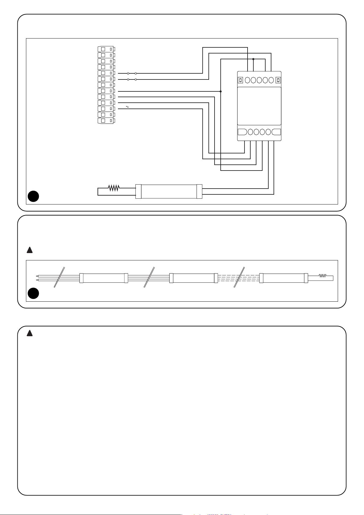
24
UWAGA: To są najważniejsze fazy przy wykonywaniu
systemu zabezpieczającego, tak, aby zapewnić maksymalne
bezpieczeństwo.
Odbiór zespołu wykrywającego przeszkodę musi być wykonany
przez wykwalifikowany personel, który będzie musiał ustalić
poziom bezpieczeństwa w związku z istniejącymi zagrożeniami;
oraz sprawdzić przestrzeganie obowiązujących przepisów
prawnych, norm i uregulowań, a w szczególności wszystkich
warunków normy EN 12445, ustalającej metody prób i kontrolę
mechanizmów automatyki dla bram.
Procedura odbioru może być również stosowana jako okresowa
kontrola urządzeń składających się na system.
W celu przeprowadzenia odbioru zespołu wykrywającego TCE, muszą
być wykonane następujące kontrole:
1. Sprawdzenie, czy wykonano wszystko to, co zostało opisane w
rozdziale “Ostrzeżenia”.
2. Jeśli jest połączone, to należy rozłączyć czułe urządzenie od
zacisków 10 i 11. Za pomocą omomierza zmierzyć wartość
oporności czułego urządzenia, wartość powinna zawierać się
pomiędzy 7700Ω i 8700Ω (nominalne 8200Ω).
3. Podać zasilanie do TCE i sprawdzić czy obydwie lampki led, LED1
i LED2 nie palą się i wskazują stan wyłączenia (Off).
4. Podłączyć czułe urządzenie do zacisków 10 i 11 i sprawdzić czy
dwie lampki led, LED1 i LED2 palą się i wskazują stan aktywny (On).
5. Uaktywnić czułe urządzenia i sprawdzić czy natychmiast gaśnie
LED1 i czy po około 2 sekundach gaśnie również LED2.
6. Wyłączyć czułe urządzenie i sprawdzić czy natychmiast zapalają się
tak LED1 jak i LED2.
7. Powtórzyć próby w punktach 5 i 6 sprawdzając czy przełączenia
wyjść TCE powodują w centrali automatyzacji ustalone stany,
normalnie: niezwłoczne odwrócenie kierunku obrotów silnika i
ostateczne zatrzymanie po około 2 sekundach.
8. Jeśli została użyta funkcja “Test”, to należy sprawdzić, czy centrala
automatyzacji wykonuje go prawidłowo, normalnie, podczas testu
gaśnie lampka LED1 aby zapalić się zaraz po zgaśnięciu.
9. W automatyzacji wykonać wszystkie kontrole według tego co
przewidziano w normie EN 12445 i EN 12978.
!
3) Odbiór
2.4) Przykład połączenia
Na rysunku 6 pokazany jest przykład połączenia TCE do centrali sterującej z funkcją ”Fototest”.
7
8,2KΩ
6
FOTOTEST
24 V
WSPÓLNY
FOTO
STOP
1
111098
3254
Urządzenie czułe
TCE
6
2.5) Połączenie 2 lub więcej oporowych listew bezpieczeństwa
TCE posiada jedno wejście, ale dwa lub więcej urządzeń bezpieczeństwa, które wykonują tą samą funkcję, może być połączonych w kaskadzie
jedno po drugim, tak jak na rysunku 7; przy wykorzystaniu tylko jednego opornika 8,2kΩ na końcu kaskady.
Urządzenia o stałej oporności muszą być zawsze połączone kaskadowo a nigdy szeregowo lub równolegle pomiędzy sobą.
!
Listwa pneumatyczna Listwa pneumatyczna Listwa pneumatyczna
1
2
8,2kΩ
n°
10
11
7
Page 25
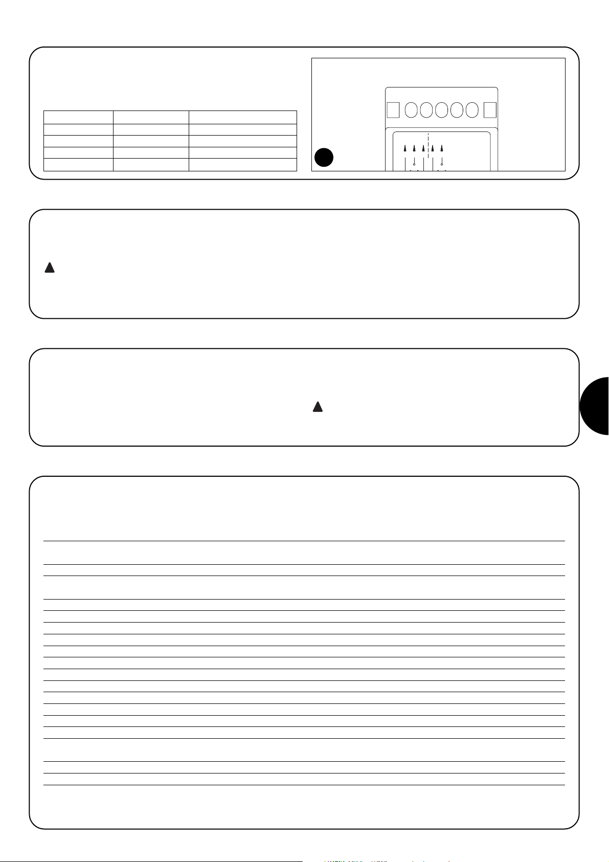
PL
25
6) Charakterystyki techniczne
W celu ulepszania swoich produktów, NICE S.A. zastrzega sobie prawo do zmian charakterystyk technicznych w jakimkolwiek momencie i bez
uprzedniego powiadomienia, utrzymując jednak funkcjonalność i przeznaczenie.
Uwaga: wszystkie charakterystyki techniczne odnoszą się do temperatury otoczenia 20°C (±5%)
Charakterystyka zespołu wykrywającego TCE
Typologia: Zespół wykrywający dla elektro-czułej aparatury zabezpieczającej (ESPE) z czujnikami o
oporności stałej 8,2KΩ, używanych w automatyzacji drzwi i bram.
Zastosowana technologia: 2 niezależne kanały z czujnikami bramkowymi i wyjściem z przekaźnikiem
Napięcie zasilania: 15÷28Vpz (±15%) 50/60Hz; z transformatorem izolującym, zgodnym z EN 61558
12÷30Vps (±15%)
Pobór prądu przy 24Vpz: < 200mA rms
Pobór prądu przy 24Vps: < 50mA
Napięcie wejścia Fototest: Takie same jak “Napięcie zasilania”
Zakres rezystancji czułego urządzenia (Rs): Typowy 8,2KΩ± 25% dla stanu aktywnego (On)
Graniczne stanu aktywnego (On): z Rs > 4.725Ω o Rs < 10.925Ω
Graniczne stanu nieaktywnego (Off): z Rs < 1.520Ω o Rs > 18.900Ω
Długość przewodu urządzenia bezpieczeństwa: Do 30m
Czas odpowiedzi Out1: <5ms (typowy 3,3ms)
Czas odpowiedzi Out2: 1,6s ± 25%
Styki przekaźnika na wyjściach OUT1 i OUT2: Maksymalnie 0.5A i maksymalnie 48Vpz (ładunek rezystywny: cosϕ=1)
Żywotność styków przekaźników wyjść OUT1 i OUT2: Żywotność mechaniczna > 1.000.000 cyklów; elektryczna > 200.000 cykli (przy 0,25A 24Vps)
Temperatura pracy: -20 ÷ 55 °C
Użytkowanie w atmosferze kwaśnej lub słonej lub
potencjalnie wybuchowej:
Nie
Stopień zabezpieczenia: IP 20
Wymiary / ciężar: 60x59x422 ze skrzydełkami 60x38x422 bez skrzydełek/ 55g około
Aby utrzymać stały poziom bezpieczeństwa, gwarantowany przez TCE,
należy przeprowadzać regularnie planowana konserwację, w odstępach
co najmniej 6 miesięcy pomiędzy jednym a następnym przeglądem.
Konserwacja musi być przeprowadzona z pełnym
przestrzeganiem przepisów bezpieczeństwa opisanych w
niniejszej instrukcji, oraz przewidzianych w obowiązującym
prawie i normach.
1. Sprawdzić stan zużycia wszystkich elementów składających się na
TCE, ze szczególnym uwzględnieniem na zjawisko erozji, utlenienia,
przegrzania części i ogólnie zabrudzenia.
2. Wykonać wszystkie próby i kontrole przewidziane w rozdziale4
“Odbiór”
!
5) Konserwacja
Ten produkt składa się z różnego rodzaju materiałów, niektóre z nich
mogą być poddane recyklingowi, na przykład: obudowa z tworzywa,
inne musza być poddane utylizacji, na przykład: płytka elektroniki.
1. Zdemontować TCE w odwrotnej kolejności do opisanej w rozdziale
“Instalowanie”
2. Oddzielić, na ile to możliwe części które muszą być poddane
recyklingowi lub utylizacji w inny sposób.
3. Rozdzielić i przekazać różne materiały do punktów skupu
zajmujących się odzyskiwaniem i utylizacją, znajdujących się na
poziomie lokalnym.
Niektóre elementy mogą zawierać substancje
zanieczyszczające, a więc nie pozostawiać ich w środowisku.
!
6) Utylizacja
TCE posiada 2 diody sygnalizacyjne które wskazują stan
przekaźników, zwykle są zapalone, a kiedy gasną wskazują na stan
alarmu, to znaczy na zadziałanie urządzenia bezpieczeństwa lub jego
niewłaściwe działanie.
Stan Sygnalizacja Opis
Led1: zapalona OUT1: On Wyjście N° 1 Włączone
Led1: zgaszona OUT1: Off Wyjście N°1Wyłączone
Led2: zapalona OUT1: On Wyjście N° 2 Włączone
Led2: zgaszona OUT1: Off Wyjście N° 2 Wyłączone
4) Diagnostyka i sygnalizacja
TACTO
IP10
12 / 24 Vac/dc
Out 0,5A 48Vac/dc
Led 1
3412
NONC
Foto
5
NC
Alt
21 543
Led 2
8
Page 26

CE Declaration of Conformity
(according to Directive 89/336/EC)
Number: 186/TCE/GB Date 10/10/2003 Revision: 0
The undersigned Lauro Buoro, managing director, declares that the following product:
Manufacturer’s name: NICE S.p.A.
Address: Via Pezza Alta 13, 31046 Z.I. Rustignè –ODERZO- ITALY
Model: TCE
Accessories: None
Satisfies the basic requirements of Directive 89/336/EC regarding electromagnetic compatibility.
Moreover, it partially or completely satisfies the requirements set down in the following Standards:
Other Standards applied: EN 12978 (partially, and wherever possible)
EN 61496-1 (partially, and wherever possible)
Managing Director
ODERZO, 10-10-2003 Lauro Buoro
Dichiarazione di conformità
(secondo Direttiva 89/336/CEE)
Numero: 186/TCE/I Data: 10/10/2003 Revisione: 0
Il sottoscritto Lauro Buoro, Amministratore Delegato, dichiara che il prodotto
Nome produttore: NICE S.p.A.
Indirizzo: Via Pezza Alta 13, 31046 Z.I. Rustignè –ODERZO- ITALY
Modello: TCE
Accessori: Nessun accessorio
Soddisfa i requisiti essenziali della Direttiva 89/336/CEE sulla compatibilità elettromagnetica.
Inoltre soddisfa parzialmente o totalmente i requisiti delle seguenti norme
Altre norme applicate: EN 12978 (parzialmente e per quanto applicabile)
EN 61496-1 (parzialmente e per quanto applicabile)
Amministratore Delegato
ODERZO, 30-03-2004 Lauro Buoro
Déclaration CE de conformité
(suivant la directive 89/336/CEE)
Numéro: 186/TCE/F Date: 10/10/2003 Révision: 0
Je, soussigné, Lauro Buoro, Administrateur Délégué, déclare que le produit:
Nom producteur: NICE S.p.A.
Adresse: Via Pezza Alta 13, 31046 Z.I. Rustignè –ODERZO- ITALY
Modèle: TCE
Accessoires: Aucun accessoire
est conforme aux conditions requises par la directive 89/336/CEE sur la compatibilité électromagnétique.
De plus, il est conforme, partiellement ou totalement, aux conditions requises des normes suivantes
Autres normes appliquées: EN 12978 (partiellement et pour ce qui est applicable)
EN 61496-1 (partiellement et pour ce qui est applicable)
Administrateur délégué
ODERZO, 30-03-2004 Lauro Buoro
GB
I
F
Page 27

CE-Konformitätserklärung
(gemäß Richtlinie 89/336/CEE)
Nummer: 186/TCE/D Datum: 10/10/2003 Revision: 0
Der Unterzeichnete Lauro Buoro, Geschäftsführer, erklärt dass das Produkt:
Herstellername: NICE S.p.A.
Adresse: Via Pezza Alta 13, 31046 Z.I. Rustignè –ODERZO- ITALY
Modell: TCE
Zubehör: Kein Zubehör
mit den wichtigsten Anforderungen der Richtlinie 89/336/CEE über die elektromagnetische Verträglichkeit konform ist.
Weiterhin ist es mit den Anforderungen folgender Normen ganz oder teilweise konform:
Sonstige angewendete Normen: EN 12978 (teilweise und soweit anwendbar)
EN 61496-1 (teilweise und soweit anwendbar)
Der Geschäftsführer
ODERZO, 30-03-2004 Lauro Buoro
Declaración de conformidad CE
(según la directiva 89/336/CEE)
Número: 186/TCE/E Fecha: 10/10/2003 Revisión: 0
El suscrito, Lauro Buoro, Administrador Delegado, declara que el producto
Nombre fabricante: NICE S.p.A.
Dirección: Via Pezza Alta 13, 31046 Z.I. Rustignè –ODERZO- ITALY
Modelo: TCE
Accesorios: Ningún accesorio
Satisface los requisitos generales de la Directiva 89/336/CEE en materia de compatibilidad electromagnética.
También satisface parcial o totalmente los requisitos de las siguientes normas
Otras normas aplicadas: EN 12978 (parcialmente y en su parte aplicable)
EN 61496-1 (parcialmente y en su parte aplicable)
Administrador delegado
ODERZO, 30-03-2004 Lauro Buoro
Świadectwo CE zgodności
(według Dyrektywy 89/336/CEE)
Numer: 186/TCE/PL Data: 10/10/2003 Uaktualnienie: 0
Niżej podpisany Lauro Buoro, Zarządca Pełnomocny, deklaruje, że produkt:
Nazwa producenta: NICE S.p.A.
Adres: Via Pezza Alta 13, 31046 Z.I. Rustignè –ODERZO- ITALY
Model: TCE
Akcesoria: Brak
Spełnia podstawowe warunki Dyrektywy 89/336/CEE w zakresie kompatybilności elektromagnetycznej.
Ponadto spełnia częściowo lub całkowicie wymogi następujących norm:
Inne zastosowane normy: EN 12978 (częściowo lub tam gdzie można zastosowana)
EN 61496-1 (częściowo lub tam gdzie można zastosowana)
Zarządca pełnomocny
ODERZO, 30-03-2004 Lauro Buoro
D
E
PL
Page 28

IST151 4862 Rev 00 del 28-05-2004
Nice SpA
Oderzo TV Italia
Tel. +39.0422.85.38.38
Fax +39.0422.85.35.85
info@niceforyou.com
Nice Padova
Sarmeola di Rubano PD Italia
Tel. +39.049.89.78.93.2
Fax +39.049.89.73.85.2
info.pd@niceforyou.com
Nice Roma
Roma Italia
Tel. +39.06.72.67.17.61
Fax +39.06.72.67.55.20
info.roma@niceforyou.com
Nice France
Buchelay
Tel. +33.(0)1.30.33.95.95
Fax +33.(0)1.30.33.95.96
info@nicefrance.fr
Nice Rhône-Alpes
Decines Charpieu France
Tel. +33.(0)4.78.26.56.53
Fax +33.(0)4.78.26.57.53
info.lyon@nicefrance.fr
Nice France Sud
Aubagne France
Tel. +33.(0)4.42.62.42.52
Fax +33.(0)4.42.62.42.50
info.marseille@nicefrance.fr
Nice Belgium
Leuven (Heverlee)
Tel. +32.(0)16.38.69.00
Fax +32.(0)16.38.69.01
info@nicebelgium.be
Nice España Madrid
Tel. +34.9.16.16.33.00
Fax +34.9.16.16.30.10
Nice España Barcelona
Tel. +34.9.35.88.34.32
Fax +34.9.35.88.42.49
Nice Polska
Pruszków
Tel. +48.22.728.33.22
Fax +48.22.728.25.10
info@nice.com.pl
Nice China
Shanghai
Tel. +86.21.525.706.34
Fax +86.21.621.929.88
info@niceforyou.com.cn
www.niceforyou.com
Nice Gate is the doors and gate automation division of Nice Nice Screen is the rolling shutters and awnings automation division of Nice
 Loading...