

Page 1
1
moby
Important information
Congratulations on choosing this Nice product. Please read this
handbook carefully.
To make these instructions easier to follow, we have, wherever possible,
put them in the order in which they will be carried out during the various
system installation phases.
Please read these instructions and the attached “Warnings for fitters” file
carefully before installing the product as they contain important
information concerning safety, installation, use and maintenance
Anything not expressly specified in these instructions is forbidden.
Operations not indicated in these instructions may cause damage to the
product, people and property.
Nice declines all liability for badly built gates or any deformations that may
occur during use.
Do not install the product in explosive atmospheres.
Table of contents: page
1 Product description 2
2 Installation 2
2.1 Preliminary checks 2
2.2 Limits of use 2
2.3 Assembly 3
2.3.1 Fitting the rear bracket 3
2.3.2 Fitting the front bracket 5
2.3.3 Opening the gate outwards 5
2.4 Adjusting the limit switch 5
2.5 Mounting the electric lock (optional accessory) 6
2.6 Typical system layout 6
2.7 Electrical connections 7
page
3 Manual manoeuvre or release 8
4 Testing 8
5 Maintenance 8
5.1 Disposal 8
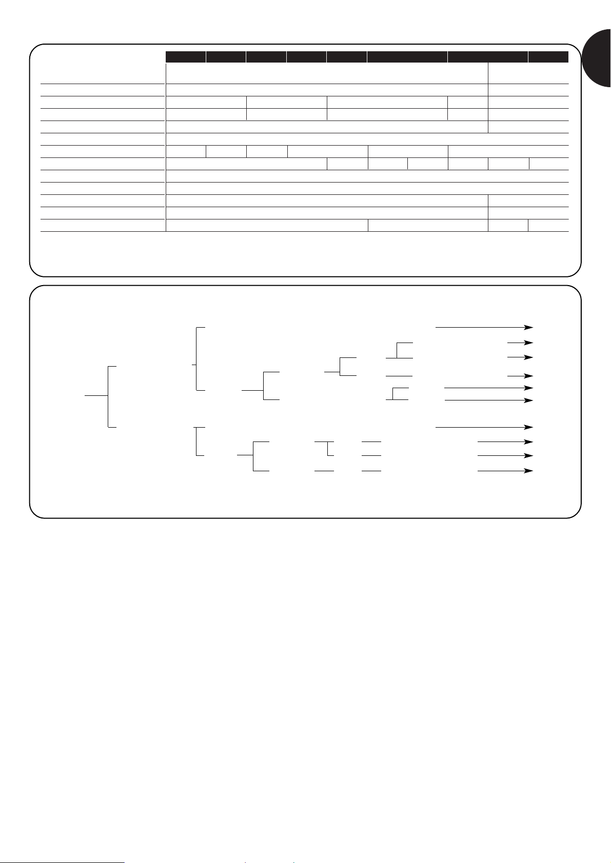
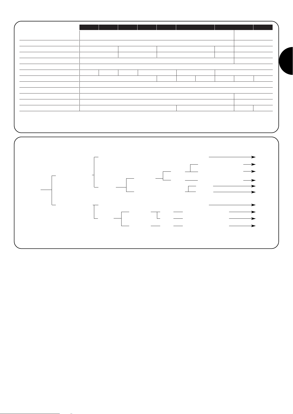
6 Technical specifications 9
6.1 Models and characteristics 9
Instructions and warnings for users 11
of the MOBY gear motor
1
GB
Page 2

2
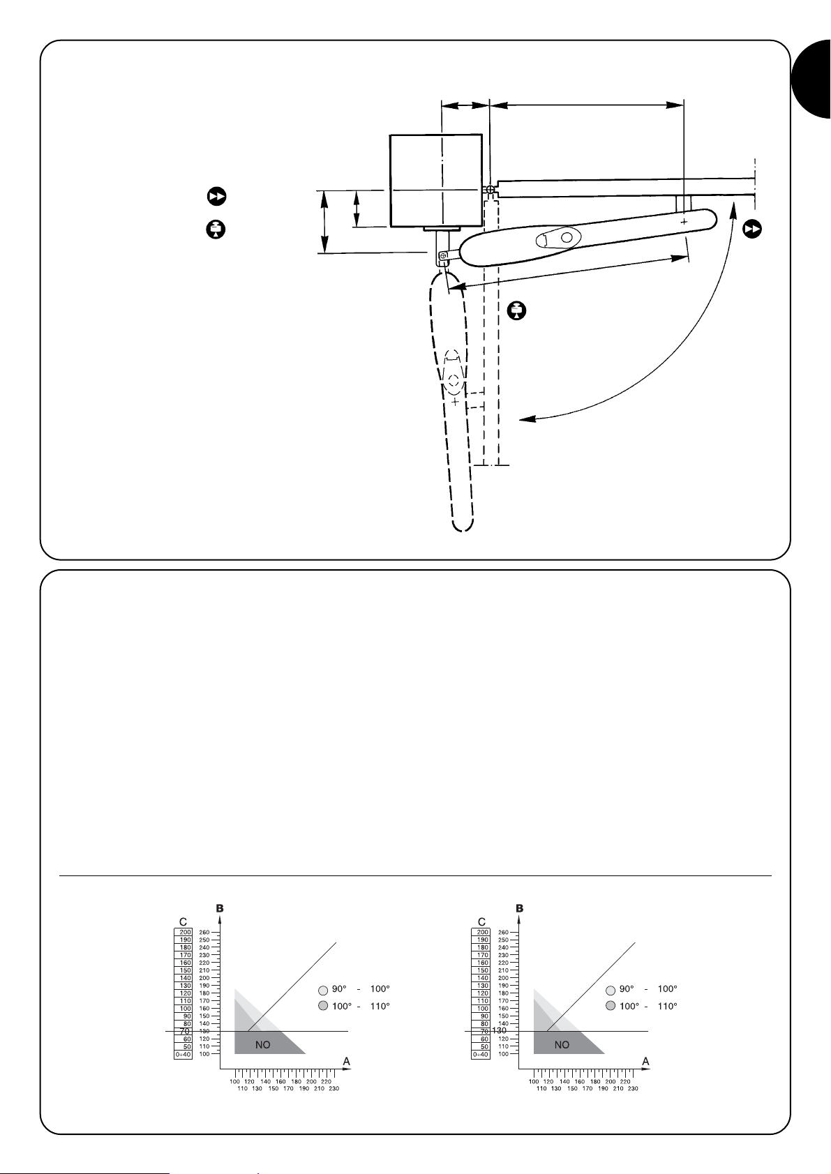
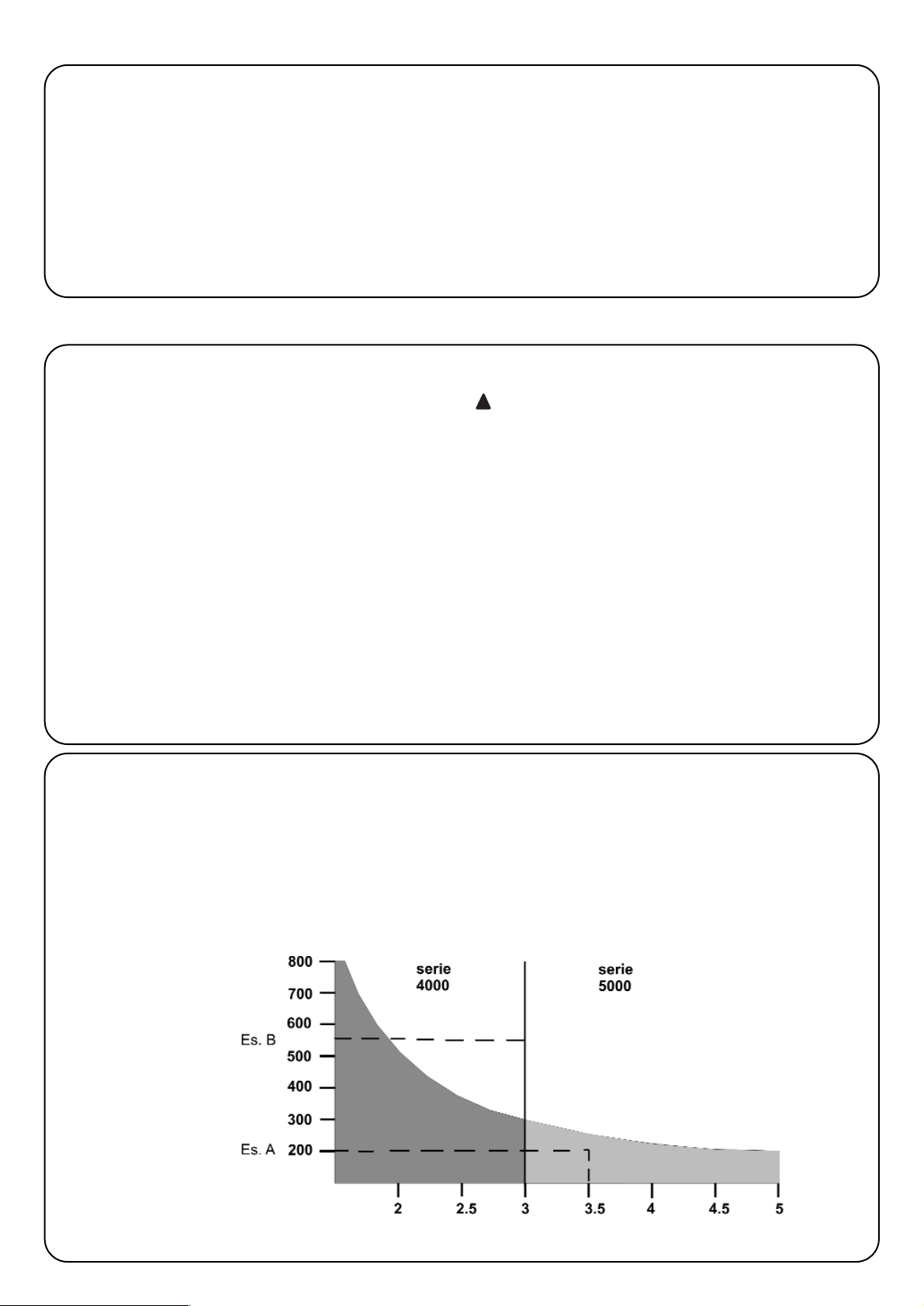
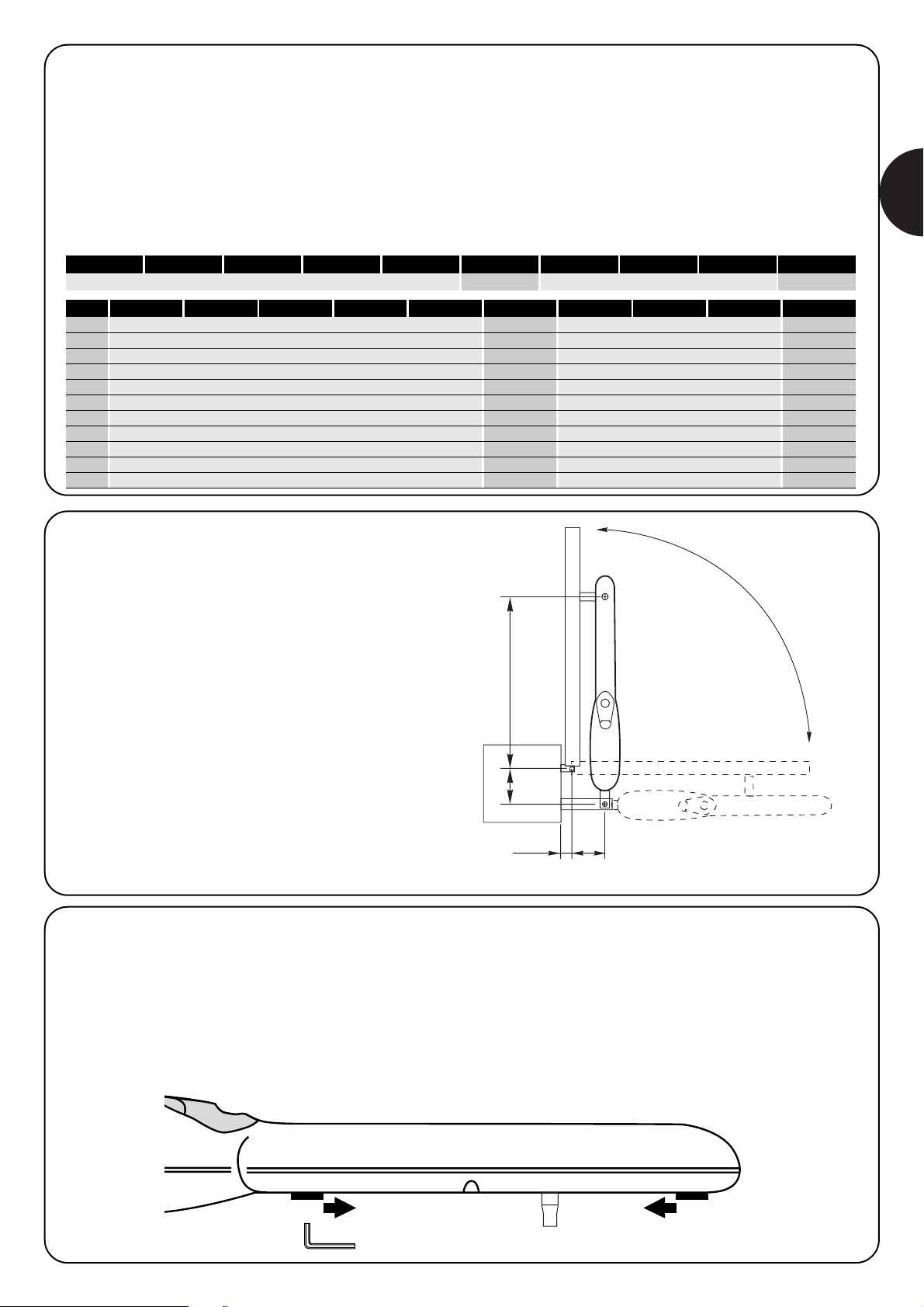
2.2) Limits of use
The shape, the height of the gate (e.g.: blind) and the weather
conditions (e.g.: strong winds) can considerably reduce the values
shown in the graph to the side.
The 24Vdc models are not suitable for use in windy areas
Example of gate:
A) 200kg and 3,5m ok
B) 550kg and 3m no
1) Product description
MOBY is an electromechanical gear motor for automating the
movement of single or double leaf residential gates.
A NICE control unit should be used to ensure the gear motor works
correctly.
The release device allows the gate to be opened manually.
2.1) Preliminary checks
Before proceeding with installation, check that the structure is
suitable, that is, make sure it complies with current standards; make
especially sure that:
• the gate does not stick when opening or closing;
• the gate is well balanced, that is, if it stops in any position it remains
motionless;
• the gate moves silently and smoothly;
• the area identified for fitting the gear motor ensures the gate can be
moved easily and safely;
• the packaging is undamaged, please see fig.1;
• the assembly area is compatible with the size of the gear motor
(fig.2), bearing in mind that the opening of the gate and the motor
thrust applied depend on where the rear bracket is fixed. Before
proceeding with installation, therefore, please read paragraph 2.3
“Assembly”, to make sure the gate has a sufficient opening angle
and thrust to satisfy customer requirements.
Please remember that MOBY powers a gate (with one or
two leafs) which must be in good condition and safe; it
cannot make up for defects caused by incorrect installation
or bad maintenance.
Max. weight of leaf kg
Max. length of leaf m
2) Installation
!
Page 3
3
GB
2.3) Assembly
To assemble the system correctly, check the following points:
1) Projection of column
C
2) Opening angle α
3) Speed
4) Thrust
B
C
AE
D
α
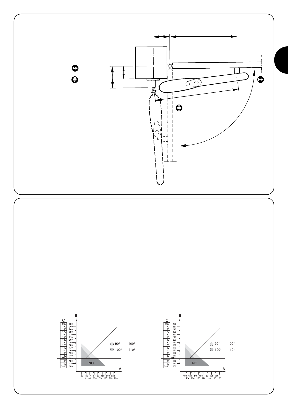
2.3.1) Fixing the rear bracket:
Carry out the following operations:
1.1Measure the value of C (the example shows 70mm).
1.2Find the value of C in the graph of the relative MOBY model and
draw a horizontal line (fig.8).
1.3Find the minimum value of “B” on the graph using the straight line
you have just drawn (the example shows 130 mm fig.9), the area
above the line contains the points where the bracket can be
fixed.
2 There is a relationship between the opening angle of the gate and
the positions of the bracket (A and B) as can be seen in the
graphs relative to each product where the different coloured
areas represent the maximum permitted angles.
If, for example (fig.9), the gate must be opened by 100°÷110°,
A and B must identify a point on the graph belonging to the
corresponding colour area.
3 Inside this area, remember that the thrust applied to the gate and
the opening and closing time are directly proportional to the
values of A and B and that these values must be similar for linear
operation; the recommended installation line should therefore be
respected.
Recommended installation line
Horizontal line Horizontal line
Recommended installation line
Fig. 8 Fig. 9
Example
Page 4
4
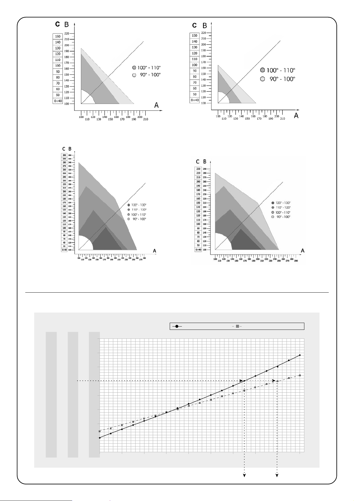
MB4005 - MB4015 - MB4024 - MB4605 - MB4615
opening limit switch
MB4006
opening and closing limit switch
MB5015 - MB5024 - MB5615
opening limit switch
MB5016
opening and closing limit switch
Recommended installation line
Recommended installation line
Recommended installation line
Recommended installation line
50
45
40
35
30
25
20
15
10
25
22
20
17
15
12
10
7
5
17
15
13
12
10
8
7
5
3
13
11
10
8
7
6
5
4
3
10
9
8
7
6
5
4
3
2
100
1m
kg
2345
120 140 160 180 200 220 240 260 280
AB
lunghezza cancello
mm
Opening values
length of gate
Closing values
4 The following graph is useful for establishing maximum thrust at the
end of the gate according to the values of A and B
Page 5
5
GB
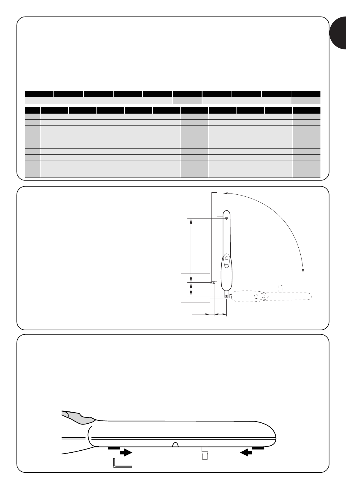
2.3.2) Fixing the front bracket
The front bracket (47) is fitted with its clamp to the gate according to
the distances D and E (see tables);
before fixing permanently:
1. Check that the closing line of the gear motor is perfectly
horizontal (fig.4)
2. Open and close the gate by hand to check it moves smoothly.
3. Remove the gear motor and weld the front bracket (47)
Fixing the rear of the gear motor (fig.5)
Fix MOBY to the bracket (45) using the fork (46), screw (55), washer
(59) and nut (61); completely tighten the latter and then unscrew it by
about 1/10 of a turn to give a little play.
Fixing the front of the gear motor (fig.6)
Fit the front fork of MOBY (34) into the front bracket (47) and clamp
with the screw (56) and washer (60).
2.3.3) Opening the gate outwards
To ensure the gate moves correctly, it may sometimes be necessary
to use a longer bracket (PLA6, optional) as shown in the figure.
D= 740mm D= 710mm D= 880mm D= 850mm
MB4005
MB4005 MB4015 MB4024 MB4605 MB4615 MB4006 MB5015 MB5024 MB5615 MB5016A
100mm
110mm
120mm
130mm
140mm
150mm
160mm
170mm
180mm
190mm
200mm
E= 625mm
E= 615mm
E= 605mm
E= 600mm
E= 590mm
E= 580mm
E= 570mm
E= 560mm
E= 550mm
E= 540mm
E= 530mm
E= 595mm
E= 585mm
E= 575mm
E= 570mm
E= 560mm
E= 550mm
E= 540mm
E= 530mm
E= 520mm
E= 510mm
E= 500mm
E= 775mm
E= 765mm
E= 755mm
E= 750mm
E= 740mm
E= 730mm
E= 720mm
E= 710mm
E= 700mm
E= 690mm
E= 680mm
E= 745mm
E= 735mm
E= 725mm
E= 720mm
E= 710mm
E= 700mm
E= 690mm
E= 680mm
E= 670mm
E= 660mm
E= 650mm
MB4015 MB4024 MB4605 MB4615 MB4006 MB5015 MB5024 MB5615 MB5016
2.4) Adjusting the limit switch
The limit switch allows the stop position of the gate to be adjusted,
thereby eliminating the need for travel stops and preventing the gate
from hitting them. Simultaneously, a microswitch disconnects power
from the motor.
A) Release the gear motor (see chapter 5)
B Loosen the screw (54)
C) Open the gate to the required position
D) Move the limit switch to the required position by turning the
screw
E Tighten the screw (54)
F) Models MB4006 and MB5016 also have a limit switch for the
closing position.
max. 50mm max. 50mm
A
E
B
C
Page 6

6
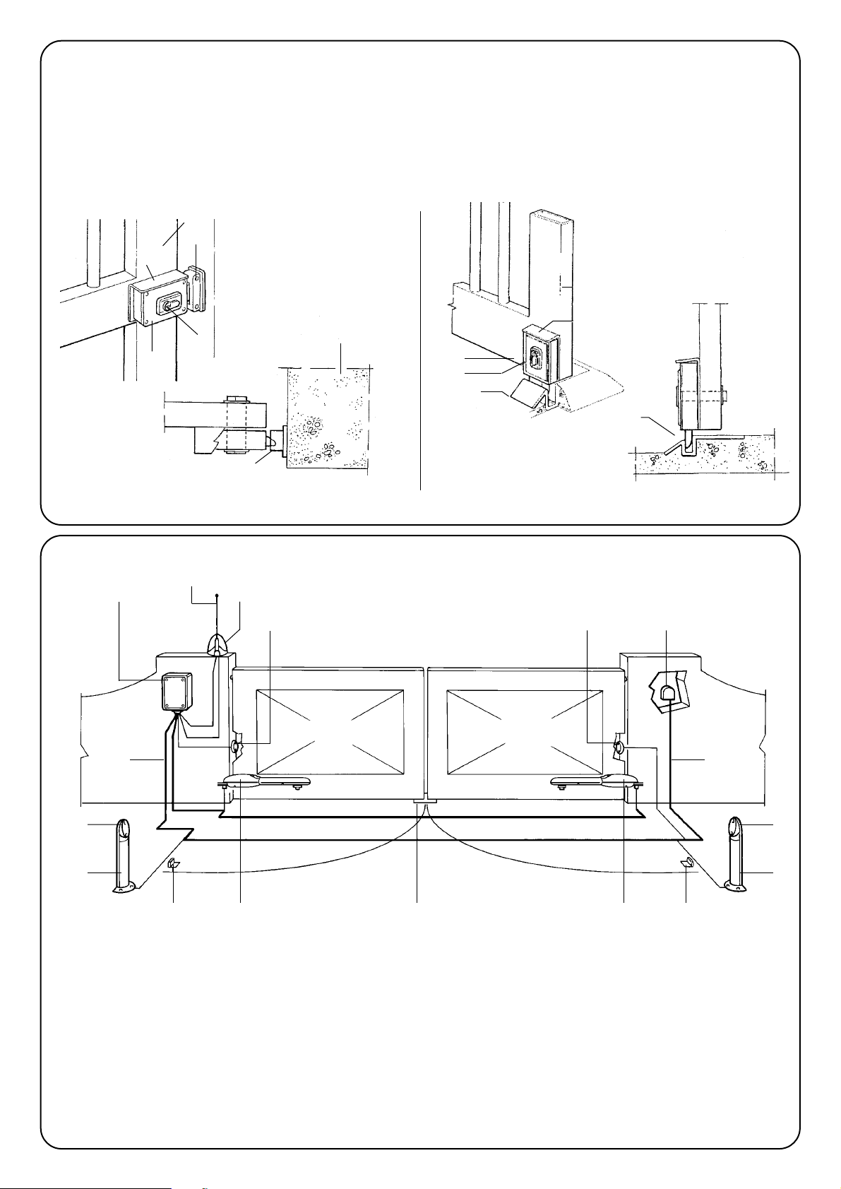
2.5) Mounting the electric lock
(optional accessory)
1 Electric lock
2 Fixing plate for electric lock (specify if horizontal or vertical)
3 Lock bolt strike plate*
4 Strike plate stop
5 Lock bolt
6 Lock
7 Gate
7
3
1
6
2
5
3
6
1
7
2
4
5
Horizontal assembly (for one leaf) Vertical assembly (for two leafs)
1 Column for photocells
2 Pair of opening travel stops
3 Mains power line
4 Control unit
5 Aerial
6 Flashing lamp
7 Photocell
8 Moby actuator
9 Vertical electric lock*
10 Key switch or digital keypad
*to install if the reversible models MB4605 and MB4615 are used or
if the gate exceeds a length of 3 m for each leaf.
2.6) Typical system layout
5
7
7
1
28 9
710
6
4
3 3
7
1
28
Page 7
7
GB
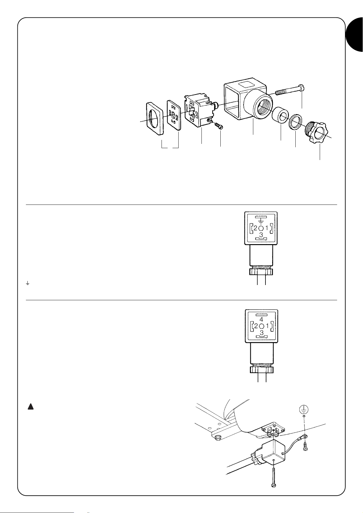
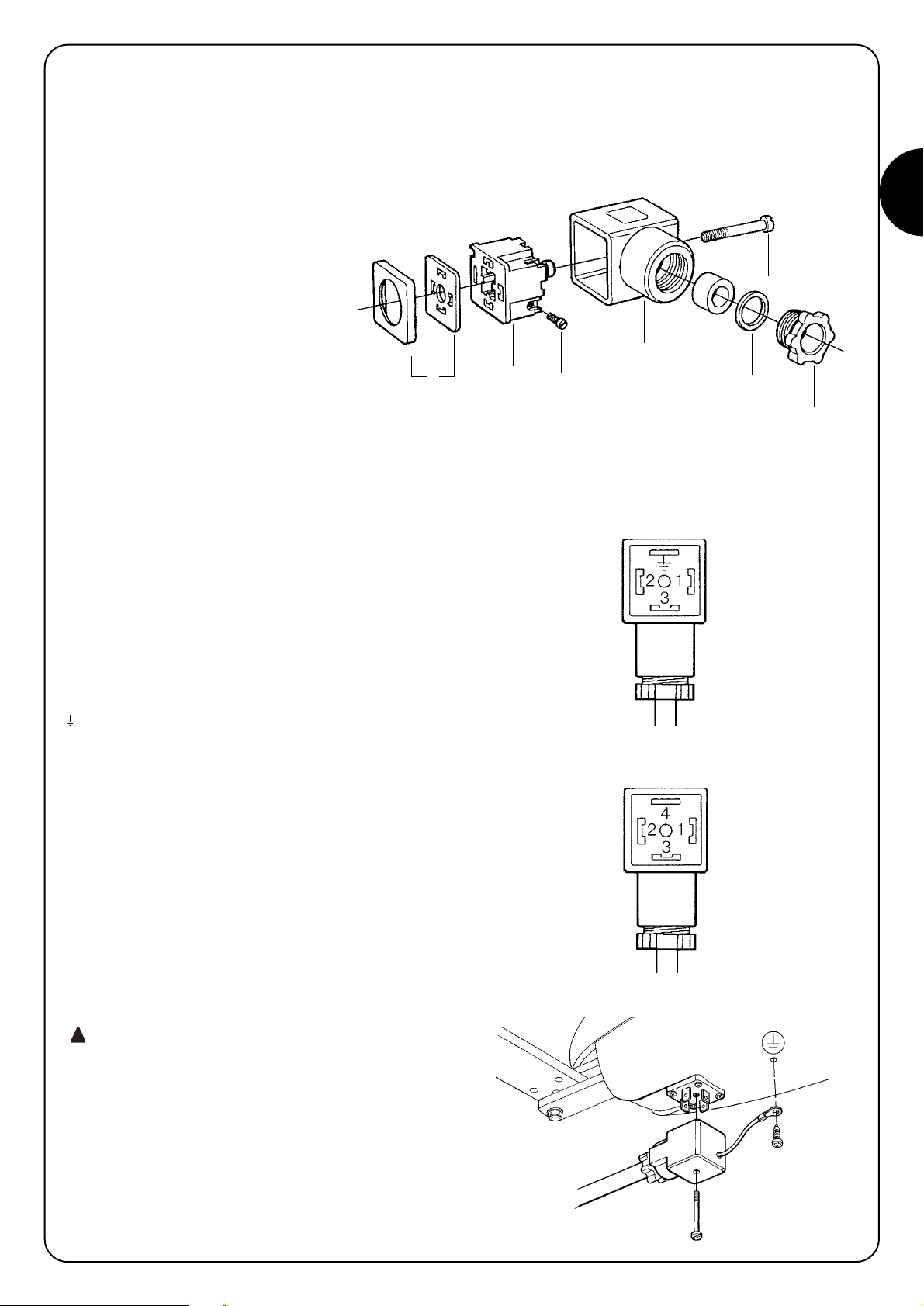
Motor connections for models:
MB4005 - MB4006 - MB4015 - MB4605
MB4615 - MB5015 - MB5016 – MB5615
Connect the cable wires to the “contact carriers 2” following the
indications shown in the figure..
1 = open
2 = close
3 = Common
= Earth
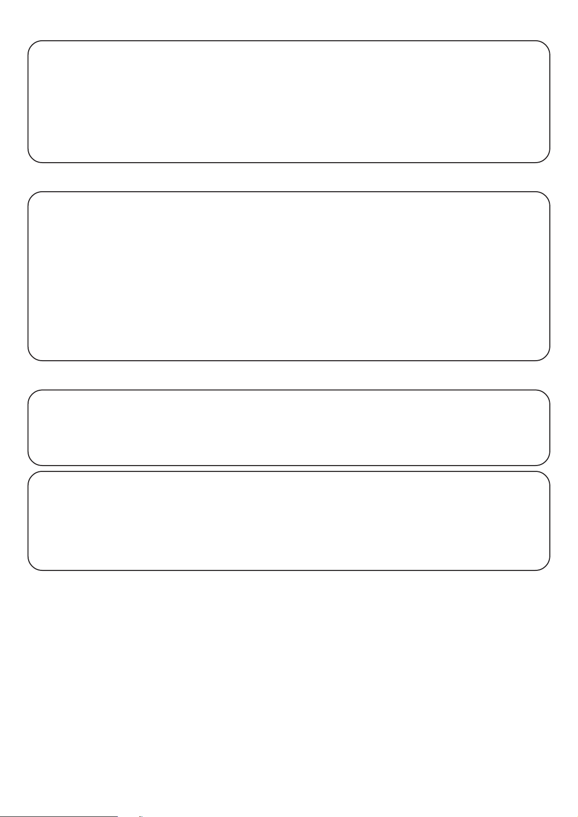
Motor connections for models:
MB4024 – MB5024
Connect the cable wires to the “contact carriers 2” following the
indications shown in the figure.
1 = Motor +
2 = Motor 3 = Encoder +
4 = Encoder -
Always remember to connect the earth cable according
to current standards (EN 60204 - IEC 64-1 – EN 60335) as
shown in the figure.
2.7) Electrical connections:
Connecting the connector
The connector is supplied assembled and is located in the lower part
of the gear motor (see item 48 of the spare parts list inside the cover).
This is used to connect the electrical control unit.
Remove the screw (8) and use a screwdriver to remove the other parts
(as shown in the figure), including the screws (3).
1 Seals
2 Contact carriers
3 Clamping screw
4 Protection
5 Cable holder
6 Washer
7 Cable clamp
8 Fixing screw
N.B.: the connector protects to IP65 DIN 40050 only if it is correctly
mounted as shown in the figure.
1
2
3
4
5
6
7
8
!
Page 8
8
Manual manoeuvre for models:
MB4005 - MB4006 - MB4015 - MB4024 - MB5015
MB5016 - MB5024
The gate must be moved manually (fig. 3) in case of a power failure
or a system fault.
Manual movement allows the gear motor to move freely only if this is
correctly mounted and original accessories have been used.
Manual manoeuvre for reversible models:
MB4605 - MB4615 - MB5615
In these models it is unnecessary to release the gear motor to open
the gate manually (make sure the electric lock is released): just push
hard on the end of the gate.
3) Manual manoeuvre or release
The whole system must be tested by qualified and expert staff who
must perform the tests required, according to the relative risk.
To test MOBY, proceed as follows:
• close the gate;
• disconnect the power supply from the control unit;
• release the gear motor;
• completely open the gate by hand;
• check that the gate does not stick when moving;
• check that when the gate is stopped at any point it remains
motionless;
• check that the safety system and mechanical stops are in good
condition;
• check that the screw connections are perfectly tight;
• check that the lead nut and internally threaded screw are well
greased;
• check that the photocells are clean;
• after the above checks, block the gear motor and power the
control unit.
• MOBY does not have any torque adjustment devices; this kind of
adjustment is therefore made by the control unit.
• measure the force of impact as required by EN12453 and
EN12445 standards
4) Testing
MOBY does not require any special maintenance, but a scheduled
control at least every six months will ensure the gear motor lasts
longer and that the system works correctly and safely.
Maintenance simply involves repeating the test procedure.
5) Maintenance
5.1) Disposal
MOBY comprises various types of materials which must be disposed
of in compliance with the laws of the country of installation. There are
no particular dangers or risks deriving from demolition of the system.
If waste sorting is required, the components should be grouped by
type of material (electrical, aluminium, plastic, etc.).
Page 9
9
GB
( Vac 50Hz)
( V d c )
( A )
( W )
( u F )
( I P )
( m / s )
( m m )
( N )
(°C Min/Max)
( ° C )
( % )
( k g )
2 3 0
2 4
5
1 2 0
7
4 4
0 , 0 1 60 , 0 1 30 , 0 1 90 , 0 1 60 , 0 1 30 , 0 1 6
3 1 02 7 04 7 04 3 04 7 03 1 04 7 0
2 0 0 0
-20 ÷ +50
1 4 0
3 08 0
6767
MB4005 MB4015 MB4605 MB4615 MB4006 MB5015 MB5016 MB5615 MB4024 MB5024
Power input
Current
Condenser incorp.
Protection level
Speed
Travel (Y)
Max. thrust
Operating temp.
Thermal protection
Work cycles
Weight
Absorbed power
1 .1
2 3 0
1 .1
2 3 0
1 .3
300
1 .3
300
6) Technical specifications
6.1) Models and characteristics
MB4005
MB4024
for leafs up to 3
metres
230Vac
with opening and
closing limit switch
with opening and
closing limit switch
reversible
with opening limit switch
with opening limit switch
with opening limit switch
with opening limit switch
with opening limit switch
MB4006
MB4015
MB4605
MB4615
MB5024
MB5015
MB5016
MB5615
irreversible
reversible
fast
slow
fast
slow
slow
fast
slow
24Vdc with encoder, irreversible, opening mechanical stop
230Vac
MOBY
24Vdc with encoder, irreversible, opening mechanical stop
irreversible
for leafs up to 5
metres
Page 10

10
Page 11
gear motor
for swing gates
moby
Instructions and warnings for users of the
MOBY gear motor
✄
Congratulations on choosing a Nice product for your automation
system!
Nice S.p.A. produces components for automating gates, doors,
shutters and awnings: gear motors, control units, radio control units,
flashing lights, photocells and accessories.
Nice only uses first rate materials and production processes and
constantly develops innovative technical, aesthetic and ergonomic
solutions in order to make its products as simple to use as possible:
your fitter will certainly have chosen the most suitable article for your
requirements from the large range of Nice products.
Nice however, is not the producer of your automated system as this is
the result of a process of analysis, evaluation, choice of materials and
installation performed by your fitter.
Each automated system is unique and only your fitter has the experience
and professionalism required to create a system that is tailor-made to
your requirements, featuring long-term safety and reliability, and, above
all, professionally installed and compliant with current regulations.
An automated system is handy to have as well as being a valid security
system. Just a few, simple operations are required to ensure it lasts for
years.
Even if your automated system satisfies regulatory safety levels, this
does not eliminate “residue risks”, that is, the possibility of dangerous
situations being generated, usually due to irresponsible or incorrect use.
For this reason we would like to give you some suggestions on how to
avoid these risks:
• Before using your automated system for the first time, ask
your fitter to explain how residue risks can arise and spend a few
minutes reading the instructions and warnings for the user
handbook that the fitter will have given you. Keep this manual for
future use and, if you should ever sell your automated system, hand it
over to the new owner.
• Your automated system is a machine which carries out your
commands to the letter; irresponsible or incorrect use may cause
it to become dangerous: do not move the automated system if
animals or objects are in its working radius.
GB
Page 12
12
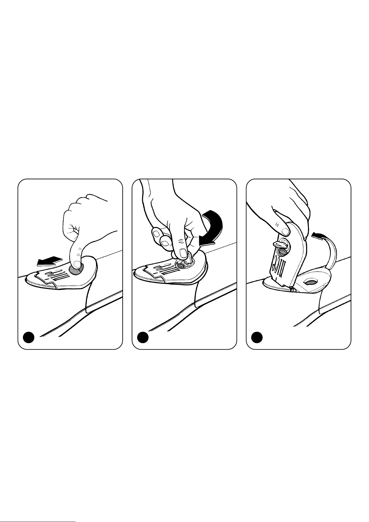
1. Push back the protective membrane as shown in fig. 1
2. insert the key and turn it anti-clockwise as shown in fig. 2
3. Pull up the handle in the direction of the arrow until it reaches the point shown in fig. 3
4. Move the leaf to its maximum opening or closing point
5. Carry out the above operations backwards when locking the system
1 2 3
• Children: an automated system ensures a high level of safety as it
always offers reliable and safe operation and its detection systems
stop it from moving in the presence of people or objects. However,
children should not be allowed to play near it. Do not let them
accidentally use the system by leaving the remote control unit within
their reach: it is not a toy!
• Faults. If you notice any abnormal behaviour, disconnect the system
from the electricity supply immediately and perform the manual
release operation. Do not attempt to make repairs yourself but call in
your fitter: in the meantime the system can work as a non-automated
gate once the gear motor has been released as described further on.
• Maintenance. Just like all machines, your automated system
requires periodic maintenance to ensure it works as long as possible
and in total safety. Agree on a routine maintenance plan with your
fitter; Nice recommends a visit once every six months for normal
residential use but this period can vary depending on how often the
system is used.
All controls, maintenance work or repairs may only be carried out by
qualified personnel.
• Do not modify the system or its programming and adjustment
parameters even if you think you can do it: your fitter is responsible for
this.
• Final testing, routine maintenance and any repairs must be
documented by the fitter and such documents kept by the owner of
the system.
• Disposal. At the end of the life of the automatic system, make sure
that it is demolished by qualified personnel and that the materials are
recycled or disposed of according to local regulations.
• In case of breakage or during a power failure. While waiting for your
fitter to call (or power to come on again if the system does not have
buffer batteries), the system can be used just like any other manual
opening system. To do this, perform the manual release operation:
this can be done by the user and Nice has made it as easy as
possible, without the need for tools or physical effort.
Important: if the radio control unit (if supplied) starts working badly
after a time, or does not work at all, the batteries may be flat (They can
last from several months to two/three years depending on the type). You
can notice this from the fact that the transmission OK LED is faint,
doesn’t light up at all, or lights up for just a moment. Before contacting
your fitter, try exchanging the battery with that of another transmitter you
know that works: if this is the reason for the fault, just replace the battery
with another one of the same kind.
Are you satisfied? If you wish to add a new automated system to
your house, contact your fitter and we at Nice will provide the advice of
a specialist, the most developed products on the market, leading-edge
operativeness and maximum compatibility.
Thank you for reading these suggestions and we trust you are fully
satisfied with your new system: please contact your fitter for all your
current or future requirements.
Page 13
13
moby
Avvertenze importanti
Nice si congratula per la scelta di questo prodotto e vi invita a leggere con
molta attenzione queste pagine.
Per rendere più semplice l’uso di queste istruzioni si è cercato, per
quanto possibile, di impaginarle rispettando l’ordine con cui devono
essere eseguite le varie fasi dell’installazione dell’impianto.
È necessario leggere attentamente le istruzioni e il fascicolo allegato
“Avvertenze per l’installatore” prima di procedere all’installazione, in
quanto forniscono importanti indicazioni riguardanti la sicurezza,
l’installazione, l’uso e la manutenzione.
Tutto quello che non è espressamente previsto in queste istruzioni non è
permesso. Infatti usi non indicati nelle istruzioni potrebbero essere fonte di
danni al prodotto e mettere in pericolo persone e cose.
Nice declina qualsiasi responsabilità dall’inosservanza della buona
tecnica nella costruzione dei cancelli, nonché dalle deformazioni che
potrebbero verificarsi durante l’uso.
Non installare il prodotto in atmosfera esplosiva.
Indice: pag.
1 Descrizione del prodotto 14
2 Installazione 14
2.1 Verifiche preliminari 14
2.2 Limiti d’impiego 14
2.3 Fissaggio 15
2.3.1 Posizionamento della staffa posteriore 15
2.3.2 Posizionamento della staffa anteriore 17
2.3.3 Apertura del cancello verso l’esterno 17
2.4 Regolazione finecorsa 17
2.5 Montaggio elettroserratura (articolo opzionale) 18
2.6 Impianto tipico 18
2.7 Collegamenti elettrici 19
pag.
3 Manovra manuale o sblocco 20
4 Collaudo 20
5 Manutenzione 20
5.1 Smaltimento 20
6 Caratteristiche tecniche 21
6.1 Modelli e caratteristiche 21
Istruzioni ed avvertenze destinate 23
all’utilizzatore del motoriduttore MOBY
I
Page 14
14
2.2) Limiti d’impiego
La forma, l’altezza del cancello (es. cieco) e le condizioni climatiche
(es. vento forte) possono ridurre anche notevolmente i valori riportati
nel grafico a lato.
Si sconsigliano i modelli 24Vdc in zone ventose.
Esempio cancello:
A) 200kg e 3,5m ok
B) 550kg e 3m no
1) Descrizione del prodotto
MOBY è un motoriduttore elettromeccanico per l’automazione di
cancelli ad una o due ante per uso residenziale.
Si consiglia l’utilizzo di una centrale NICE per un corretto
funzionamento del motoriduttore.
Lo sblocco permette di aprire manualmente il cancello.
2.1) Verifiche preliminari
Prima di procedere all’installazione è necessario verificare che la
struttura sia idonea, in altre parole sia conforme alle norme vigenti ed
in particolare verificare che:
• il cancello non presenti punti d’attrito sia in chiusura sia in apertura;
• il cancello sia ben bilanciato, ossia, se fermato in una qualsiasi
posizione non accenni a riprendere il moto;
• il cancello, nella sua corsa, sia silenzioso e regolare;
• la zona individuata per il fissaggio del motoriduttore consenta una
manovra manuale facile e sicura.
• la confezione sia integra, facendo riferimento alla fig. 1;
• verificare che la zona di fissaggio sia compatibile con l’ingombro del
motoriduttore (fig. 2), tenendo presente che l’apertura del cancello
e la forza che il motore esercita su di esso sono dipendenti dal
punto di fissaggio della staffa posteriore. Perciò prima di procedere
all’installazione è necessario leggere il paragrafo 2.3 “Fissaggio”,
per assicurarsi che il cancello abbia angolo di apertura e forza
soddisfacenti le esigenze richieste.
Si ricorda che MOBY motorizza un cancello (ad una o
due ante) di per sé efficiente e sicuro e non sopperisce a
difetti causati da una sbagliata installazione, o da una
cattiva manutenzione.
2) Installazione
Peso max. anta kg
Lunghezza max. anta m
!
Page 15
15
I
2.3) Fissaggio
Per il corretto montaggio sono da verificare i seguenti punti:
1) Ingombro colonna
C
2) Angolo di manovra α
3) Velocità
4) Forza
2.3.1) Posizionamento della staffa posteriore:
Le operazioni da eseguire sono:
1.1Misurare sul posto il valore di C (nell’esempio: 70mm).
1.2Individuare nel grafico relativo al modello di MOBY da installare il
valore di C e tracciare una linea orizzontale (fig. 8).
1.3Individuare il valore di “B minimo” dal grafico con la linea dritta
appena tracciata (nell’esempio: 130mm fig. 9), l’area al di sopra
di tale linea contiene i punti validi per lo staffaggio.
2 Esiste una relazione tra l’angolo di manovra che può eseguire il
cancello e le posizioni di staffaggio (A e B) come evidenziano i
grafici relativi ad ogni prodotto dove aree di colore
differenti rappresentano gli angoli massimi consentiti.
Se, per esempio (fig. 9), si vuole aprire il cancello di
100°÷110°, A e B debbono individuare un punto sul grafico
appartenente all’area del colore corrispondente.
3 All’interno dell’area individuata, ricordiamo che la forza impressa
al cancello, ed il tempo di apertura e chiusura, sono direttamente
proporzionali ai valori di A e B e che per un funzionamento
lineare, tali valori dovranno essere simili fra loro, quindi seguire la
linea di installazione consigliata.
Linea d’installazione consigliata
Linea orizzontale Linea orizzontale
Linea d’installazione consigliata
Fig. 8 Fig. 9
Esempio
B
C
AE
D
α
Page 16

16
MB4005 - MB4015 - MB4024 - MB4605 - MB4615
finecorsa in apertura
MB4006
finecorsa in apertura e chiusura
MB5015 - MB5024 - MB5615
finecorsa in apertura
MB5016
finecorsa in apertura e chiusura
Valori in apertura
lunghezza cancello
Valori in chiusura
4 Il grafico di seguito è utile per stabilire la forza massima all’estremità
del cancello in funzione dei valori di A e B
linea d’installazione consigliata
linea d’installazione consigliata
linea d’installazione consigliata
lunghezza cancello
kg
10
13
9
11
8
10
7
8
6
7
5
6
4
5
3
4
2
3
17
15
13
12
10
1m
2345
25
50
22
45
20
40
17
35
15
30
8
12
25
7
10
20
5
7
15
3
5
10
100
120 140 160 180 200 220 240 260 280
mm
AB
Page 17
17
I
2.3.2) Posizionamento della staffa anteriore
La staffa anteriore (47) va posizionata con apposito morsetto
al cancello rispettando la quota D e la quota E (vedi tabella);
prima di procedere al fissaggio definitivo:
1. Verificare che la linea di chiusura del motoriduttore
sia perfettamente orizzontale (fig. 4)
2. Aprire e chiudere il cancello manualmente per verificare
che il movimento sia regolare.
3. Levare il motoriduttore e saldare la staffa anteriore (47)
Fissaggio posteriore motoriduttore (fig. 5)
Fissare MOBY alla staffa (45) tramite la forcella (46)
con la vite (55), la rondella (59) ed il dado (61); avvitare
completamente quest’ultimo, quindi svitarlo di circa 1/10
di giro per permettere un certo gioco tra le parti.
Fissaggio anteriore motoriduttore (fig. 6)
Inserire la forcella anteriore di MOBY (34) nella staffa anteriore (47)
bloccandolo con la vite (56) e la rondella (60).
2.3.3) Apertura cancello verso l’esterno
Per consentire un movimento corretto talvolta potrebbe rendersi
necessario utilizzare una staffa più lunga (PLA6, opzionale) come
rappresentato in figura.
D= 740mm D= 710mm D= 880mm D= 850mm
MB4005
MB4005 MB4015 MB4024 MB4605 MB4615 MB4006 MB5015 MB5024 MB5615 MB5016A
100mm
110mm
120mm
130mm
140mm
150mm
160mm
170mm
180mm
190mm
200mm
E= 625mm
E= 615mm
E= 605mm
E= 600mm
E= 590mm
E= 580mm
E= 570mm
E= 560mm
E= 550mm
E= 540mm
E= 530mm
E= 595mm
E= 585mm
E= 575mm
E= 570mm
E= 560mm
E= 550mm
E= 540mm
E= 530mm
E= 520mm
E= 510mm
E= 500mm
E= 775mm
E= 765mm
E= 755mm
E= 750mm
E= 740mm
E= 730mm
E= 720mm
E= 710mm
E= 700mm
E= 690mm
E= 680mm
E= 745mm
E= 735mm
E= 725mm
E= 720mm
E= 710mm
E= 700mm
E= 690mm
E= 680mm
E= 670mm
E= 660mm
E= 650mm
MB4015 MB4024 MB4605 MB4615 MB4006 MB5015 MB5024 MB5615 MB5016
2.4) Regolazione finecorsa
Il finecorsa permette di regolare la posizione di arresto del cancello
evitando così di dover usare i franchi di arresto e di fare sbattere
il cancello sugli stessi. Contemporaneamente un microinterruttore
toglie alimentazione al motore.
A) Sbloccare il motoriduttore (vedi capitolo 5)
B) Allentare la vite (54)
C) Aprire il cancello fino alla posizione desiderata
D) Regolare quindi la posizione del blocco di finecorsa fino
a portarlo al punto desiderato agendo sulla vite stessa
E) Bloccare la vite (54)
F) I modelli MB4006 e MB5016 hanno il finecorsa anche
in chiusura.
max. 50mm max. 50mm
A
E
B
C
Page 18
18
2.5) Montaggio elettroserratura
(articolo opzionale)
1 Elettroserratura
2 Piastra di fissaggio elettroserratura
(specificare se orizzontale o verticale)
3 Aggancio chiavistello*
4 Battuta per aggancio
5 Chiavistello
6 Barilotto passante
7 Cancello
7
3
1
6
2
5
3
6
1
7
2
4
5
Fissaggio orizzontale (per una anta) Fissaggio verticale (per due ante)
1 Colonnina per fotocellule
2 Coppia di arresti in apertura
3 Linea elettrica di alimentazione
4 Centrale di comando
5 Antenna
6 Lampeggiante
7 Fotocellula
8 Attuatore Moby
9 Elettroserratura verticale*
10 Selettore a chiave o tastiera digitale
*da installare se si utilizzano i modelli reversibili MB4605 e MB4615,
o qualora il cancello superi i 3m di lunghezza per ogni singola anta.
2.6) Impianto tipico
5
7
7
1
28 9
710
6
4
3 3
7
1
28
Page 19
19
I
Collegamenti del motore per i modelli:
MB4005 - MB4006 - MB4015 - MB4605
MB4615 - MB5015 - MB5016 – MB5615
Collegare i fili del cavo nel “portacontatti 2” seguendo le indicazioni
riportate in figura.
1 = apre
2 = chiude
3 = Comune
= Terra
Collegamenti del motore per i modelli:
MB4024 – MB5024
Collegare i fili del cavo nel “portacontatti 2” seguendo le indicazioni
riportate in figura.
1 = Motore +
2 = Motore 3 = Encoder +
4 = Encoder -
Si ricorda di collegare sempre il cavo di terra come
previsto dalle normative vigenti (EN60204 - CEI64-1 EN60335) come rappresentato in figura.
2.7) Collegamenti elettrici:
Collegamento al connettore
Il connettore è fornito già montato, e si trova nella parte inferiore del
motoriduttore (vedi particolare 48 del quadro ricambi all’interno della
copertina).
Serve per il collegamento alla centrale elettrica.
Svitare la vite (8) e con un cacciavite togliere le altre parti
(come indicato in figura) comprese le viti (3).
1 Guarnizioni
2 Portacontatti
3 Vite serrafilo
4 Protezione
5 Pressacavo
6 Rondella
7 Serracavo
8 Vite di fissaggio
Nota: il connettore garantisce una protezione IP65 DIN 40050
solo se montato correttamente, come rappresentato in figura.
1
2
3
4
5
6
7
8
!
Page 20

20
Manovra manuale per i modelli:
MB4005 - MB4006 - MB4015 - MB4024 - MB5015
MB5016 - MB5024
L’operazione manuale (fig. 3) si deve eseguire nel caso di mancanza
di corrente o in caso di anomalie dell’impianto.
La manovra manuale consente una corsa libera del motoriduttore
solo se montato correttamente e con gli accessori originali.
Manovra manuale per i modelli reversibili:
MB4605 - MB4615 - MB5615
In questi modelli non è necessario sbloccare il motoriduttore
per aprire il cancello manualmente (accertarsi però che
l’elettroserratura sia sbloccata): è sufficiente spingere con una certa
forza il cancello alla sua estremità.
3) Manovra manuale o sblocco
Il collaudo dell’intero impianto deve essere eseguito da personale
esperto e qualificato che deve farsi carico delle prove richieste, in
funzione del rischio presente.
Per il collaudo MOBY seguire questa procedura:
• chiudere il cancello;
• togliere alimentazione alla centrale;
• sbloccare il motoriduttore;
• aprire manualmente il cancello per tutta la sua corsa;
• verificare che il cancello durante il moto non subisca punti d’attrito;
• verificare che il cancello fermato in qualsiasi punto e sbloccato,
non accenni a muoversi;
• verificare che i sistemi di sicurezza e gli arresti meccanici siano
in buono stato;
• verificare che i collegamenti a vite siano ben stretti;
• verificare che la chiocciola e la vite rullata siano bene ingrassate;
• verificare la pulizia delle fotocellule;
• terminate le verifiche ribloccare il motoriduttore e rialimentare
la centrale.
• MOBY è sprovvisto di dispositivi di regolazione di coppia, pertanto
tale regolazione è affidata alla centrale di comando.
• misurare la forza d’impatto come previsto dalla normativa
EN12453 ed EN12445.
4) Collaudo
La manutenzione di MOBY non necessita di accorgimenti particolari,
ma un controllo programmato almeno ogni sei mesi permette di
ottenere una maggiore durata del motoriduttore ed un corretto e
sicuro funzionamento del sistema.
La manutenzione consiste semplicemente nel ripetere la
procedura di collaudo.
5) Manutenzione
5.1) Smaltimento
MOBY è costituito da varie tipologie di materiali e l’eliminazione di
questi va effettuata rispettando le norme vigenti nei singoli Paesi.
Nel caso di demolizione dell‘automatismo non esistono particolari
pericoli o rischi derivati dall’automazione stessa.
E’ opportuno, in caso si debba effettuare una raccolta differenziata,
che i materiali vengano separati per tipologia (parti elettriche,
alluminio, plastica, ecc.).
Page 21
( Vac 50Hz)
( V d c )
( A )
( W )
( u F )
( I P )
( m / s )
( m m )
( N )
(°C Min/Max)
( ° C )
( % )
( k g )
2 3 0
2 4
5
1 2 0
7
4 4
0 , 0 1 60 , 0 1 30 , 0 1 90 , 0 1 60 , 0 1 30 , 0 1 6
3 1 02 7 04 7 04 3 04 7 03 1 04 7 0
2 0 0 0
-20 ÷ +50
1 4 0
3 08 0
6767
MB4005 MB4015 MB4605 MB4615 MB4006 MB5015 MB5016 MB5615 MB4024 MB5024
Alimentazione
Corrente
Condensatore incorp.
Grado di protezione
Velocità
Corsa (Y)
Spinta max.
Temp. di esercizio
Termoprotezione
Cicli di lavoro
Peso
Potenza assorbita
1 .1
2 3 0
1 .1
2 3 0
1 .3
300
1 .3
300
21
I
6) Caratteristiche tecniche
6.1) Modelli e caratteristiche
MB4005
MB4024
per ante fino a 3 metri
230Vac
con finecorsa
in apertura e in chiusura
con finecorsa
in apertura e in chiusura
reversibile
con finecorsa in apertura
con finecorsa in apertura
con finecorsa in apertura
con finecorsa in apertura
con finecorsa in apertura
MB4006
MB4015
MB4605
MB4615
MB5024
MB5015
MB5016
MB5615
irreversibile
reversibile
veloce
lento
veloce
lento
lento
veloce
lento
24Vdc con encoder, irreversibile, arresto meccanico in apertura
230Vac
MOBY
24Vdc con encoder, irreversibile, arresto meccanico in apertura
irreversibile
per ante fino a 5 metri
Page 22

22
Page 23
motoriduttore
per cancelli a battente
moby
I
Istruzioni ed avvertenze destinate
all’utilizzatore del motoriduttore MOBY
Complimenti per aver scelto per la vostra automazione un prodotto Nice!
Nice S.p.A. produce componenti per l’automazione di cancelli, porte,
tapparelle e tende da sole: motoriduttori, centrali di comando,
radiocomandi, lampeggianti, fotocellule e accessori.
Nice utilizza solo materiali e lavorazioni di qualità, e per vocazione ricerca
soluzioni innovative che semplifichino al massimo l’utilizzo delle sue
apparecchiature, curate nelle soluzioni tecniche, estetiche, ergonomiche:
nella grande gamma Nice il vostro installatore avrà senz’altro scelto il
prodotto più adatto alle vostre esigenze.
Nice non è però il produttore della vostra automazione, che è invece il
risultato di un’opera di analisi, valutazione, scelta dei materiali, e
realizzazione dell’impianto eseguita dal vostro installatore di fiducia.
Ogni automazione è unica e solo il vostro installatore possiede l’esperienza
e la professionalità necessarie ad eseguire un impianto secondo le vostre
esigenze, sicuro ed affidabile nel tempo, e soprattutto a regola d’arte,
rispondente cioè alle normative in vigore.
Un impianto di automazione è una bella comodità, oltre che un valido
sistema di sicurezza e, con poche, semplici attenzioni, è destinato a durare
negli anni.
Anche se l’automazione in vostro possesso soddisfa il livello di sicurezza
richiesto dalle normative, questo non esclude l’esistenza di un “rischio
residuo”, cioè la possibilità che si possano generare situazioni di pericolo,
solitamente dovute ad un utilizzo incosciente o addirittura errato, per
questo motivo desideriamo darvi alcuni consigli sui comportamenti da
seguire per evitare ogni inconveniente:
• Prima di usare per la prima volta l’automazione, fatevi spiegare
dall’installatore l’origine dei rischi residui, e dedicate qualche minuto alla
lettura del manuale di istruzioni ed avvertenze per l’utilizzatore
consegnatovi dall’installatore. Conservate il manuale per ogni dubbio
futuro e consegnatelo ad un eventuale nuovo proprietario
dell’automazione.
• La vostra automazione è un macchinario che esegue
fedelmente i vostri comandi; un uso incosciente ed improprio può
farlo diventare pericoloso: non comandate il movimento
dell’automazione se nel suo raggio di azione si trovano persone, animali
o cose.
✄
Page 24

1. Far scorrere la membrana di protezione come in fig. 1
2. Inserire la chiave e ruotarla in senso antiorario come in fig. 2
3. Tirare la maniglia accompagnandola nel senso della freccia fino al punto in fig. 3
4. Agire manualmente sull’anta ed accompagnarla fino al punto di massima apertura o chiusura
5. Per bloccare agire nel senso contrario
• Bambini: un impianto di automazione garantisce un alto grado di
sicurezza, impedendo con i suoi sistemi di rilevazione il movimento in
presenza di persone o cose, e garantendo un’attivazione sempre
prevedibile e sicura. È comunque prudente vietare ai bambini di giocare
in prossimità dell’automazione e per evitare attivazioni involontarie non
lasciare i telecomandi alla loro portata: non è un gioco!
• Anomalie. Non appena notate qualunque comportamento anomalo da
parte dell’automazione, togliete alimentazione elettrica all’impianto ed
eseguite lo sblocco manuale. Non tentate da soli alcuna riparazione, ma
richiedete l’intervento del vostro installatore di fiducia: nel frattempo
l’impianto può funzionare come un’apertura non automatizzata, una
volta sbloccato il motoriduttore come descritto più avanti.
• Manutenzione. Come ogni macchinario la vostra automazione ha
bisogno di una manutenzione periodica affinché possa funzionare più a
lungo possibile ed in completa sicurezza. Concordate con il vostro
installatore un piano di manutenzione con frequenza periodica; Nice
consiglia un intervento ogni 6 mesi per un normale utilizzo domestico,
ma questo periodo può variare in funzione dell’intensità d’uso.
Qualunque intervento di controllo, manutenzione o riparazione deve
essere eseguito solo da personale qualificato.
• Anche se ritenete di saperlo fare, non modificate l’impianto ed i parametri
di programmazione e di regolazione dell’automazione: la responsabilità è
del vostro installatore.
• Il collaudo finale, le manutenzioni periodiche e le eventuali riparazioni
devono essere documentate da chi le esegue e i documenti conservati
dal proprietario dell’impianto.
• Smaltimento. Al termine della vita dell’automazione, assicuratevi che lo
smantellamento sia eseguito da personale qualificato e che i materiali
vengano riciclati o smaltiti secondo le norme valide a livello locale.
• In caso di rotture o assenza di alimentazione. Attendendo
l’intervento del vostro installatore, (o il ritorno dell’energia elettrica se
l’impianto non è dotato di batterie tampone), l’impianto può essere
azionato come una qualunque apertura non automatizzata. Per fare ciò
è necessario eseguire lo sblocco manuale: questa operazione, che è
l’unica che può essere eseguita dall’utilizzatore dell’automazione, è
particolarmente curata da Nice per assicurarvi sempre la massima facilità
di utilizzo, senza uso di attrezzi o necessità di sforzo fisico.
1 2 3
Importante: se il vostro impianto è dotato di un radiocomando che
dopo qualche tempo vi sembra funzionare peggio, oppure non
funzionare affatto, potrebbe semplicemente dipendere dall’esaurimento
della pila (a seconda del tipo, possono trascorrere da diversi mesi fino a
due/tre anni). Ve ne potete accorgere dal fatto che la spia di conferma
della trasmissione è fioca, non si accende affatto, oppure si accende solo
per un breve istante. Prima di rivolgervi all’installatore provate a
scambiare la pila con quella di un altro trasmettitore eventualmente
funzionante: se questa fosse la causa dell’anomalia, sarà sufficiente
sostituire la pila con altra dello stesso tipo.
Siete soddisfatti? Nel caso voleste aggiungere nella vostra casa un
nuovo impianto di automazione, rivolgendovi allo stesso installatore e a
Nice vi garantirete, oltre che la consulenza di uno specialista e i prodotti
più evoluti del mercato, il migliore funzionamento e la massima
compatibilità delle automazioni.
Vi ringraziamo per aver letto queste raccomandazioni, e vi auguriamo la
massima soddisfazione dal vostro nuovo impianto: per ogni esigenza
presente o futura rivolgetevi con fiducia al vostro installatore.
24
Page 25

moby
Recommandations importantes
Nice vous félicite pour avoir choisi ce produit et vous invite à lire très
attentivement ces pages.
Pour faciliter la compréhension de ces instructions, nous avons tenté,
dans la mesure du possible, de les présenter en respectant l’ordre dans
lequel vous devez exécuter les différentes phases d’installation de
l’automatisme.
Il faut lire attentivement les instructions et le fascicule joint
“Recommandations pour l’installateur” avant de procéder à l’installation
car ils fournissent des indications importantes concernant la sécurité,
l’installation, l’utilisation et la maintenance de l’automatisme.
Tout ce qui n’est pas expressément prévu dans ces instructions n’est pas
autorisé. En effet les utilisations non décrites dans les instructions
pourraient être une source de dommages pour le produit et mettre en
danger les personnes et les choses.
Nice décline toute responsabilité en cas de non-observation des règles de
l’art dans la construction des portails à un ou deux battants ainsi que des
déformations qui pourraient se vérifier durant l’utilisation.
Ne pas installer le produit en présence d’atmosphère explosive.
Table des matières: page
1 Description du produit 26
2 Installation 26
2.1 Contrôles préliminaires 26
2.2 Limites d’application 26
2.3 Fixation 27
2.3.1 Positionnement de la platine de fixation arrière 27
2.3.2 Positionnement de la platine de fixation avant 29
2.3.3 Ouverture du portail vers l’extérieur 29
2.4 Réglage du dispositif de fin de course 29
2.5
Montage de la serrure électrique (article en option)
30
2.6 Installation typique 30
2.7 Connexions électriques 31
page
3 Manœuvre manuelle ou débrayage 32
4 Essai de fonctionnement 32
5 Maintenance 32
5.1 Mise au rebut 32
6 Caractéristiques techniques 33
6.1 Modèles et caractéristiques 33
Instructions et recommandations destinées
à l’utilisateur de l’opérateur MOBY 35
25
F
Page 26

26
2.2) Limites d’application
La forme, la hauteur du portail (par ex. un portail plein) et les
conditions climatiques (par ex. vent fort) peuvent réduire
considérablement les valeurs indiquées dans le graphique ci-après.
Nous déconseillons les modèles 24 Vcc dans les zones venteuses.
Exemple portail:
A) 200kg et 3,5m ok
B) 550kg et 3m non
1) Description du produit
MOBY est un opérateur électromécanique pour l’automatisation de
portails à un ou deux battants pour usage résidentiel.
Il est conseillé d’utiliser une armoire de commande NICE pour
assurer le fonctionnement correct de l’opérateur.
Le débrayage permet l’ouverture manuelle du portail.
2.1) Contrôles préliminaires
Avant de procéder à l’installation, il faut vérifier que la structure est
adaptée, en d’autres termes, qu’elle est conforme aux normes en
vigueur et en particulier, il faut vérifier que:
• le portail ne présente pas de points de frottement aussi bien en
fermeture qu’en ouverture;
• le portail est bien équilibré, à savoir, que lorsque qu’il est arrêté dans
une position quelconque, il n’amorce aucun mouvement;
• le portail, dans sa course, est silencieux et régulier;
• la zone choisie pour la fixation de l’opérateur assure une manœuvre
facile et sûre;
• l’emballage contient tous les éléments, comme l’illustre la fig.1;
• la zone de fixation est compatible avec l’encombrement de
l’opérateur (fig.2), en tenant compte que l’ouverture du portail et la
force que le moteur exerce sur lui dépendent du point de fixation de
la platine arrière. Par conséquent, avant de procéder à l’installation,
il faut lire le paragraphe 2.3 “Fixation”, pour s’assurer que le portail
dispose d’un angle d’ouverture et d’une force correspondant aux
conditions requises.
Nous rappelons que MOBY motorise un portail (à un ou
à deux battants) et est en soi efficace et sûr; il ne peut
toutefois suppléer aux défauts causés par une installation
erronée ou par une mauvaise maintenance.
Poids max. battant kg
Longueur max. battant m
2) Installation
!
Page 27

27
F
2.3) Fixation
Pour un montage correct il faut vérifier les points suivants:
1) Saillie colonne
C
2) Angle de manœuvre α
3) Vitesse
4) Force
2.3.1) Positionnement de la platine de fixation
arrière
Les opérations à effectuer sont les suivantes:
1.1Mesurer sur place la valeur de C (dans l’exemple 70 mm).
1.2Identifier dans le graphique relatif au modèle de MOBY à installer
la valeur de C et tracer une ligne horizontale (fig.8).
1.3Identifier la valeur de “B minimum” à partir du graphique avec la
ligne droite tracée précédemment (dans l’exemple: 130 mm
fig.9), la zone située au-dessus de cette ligne contient les points
valables pour la fixation de la platine.
2 I
l existe une relation entre l’angle de manœuvre que peut effectuer
le portail et les positions des platines de fixation (A et B) comme
le montrent les graphiques relatifs au produit où des zones de
couleur différente représentent les angles maximums autorisés.
Si par exemple (fig.9) on veut ouvrir le portail de 100 à 110°, A
et B doivent identifier un point sur le graphique appartenant à la
zone de couleur correspondante.
3 À l’intérieur de la zone identifiée, nous rappelons que la force
imprimée au portail et le temps d’ouverture et de fermeture sont
directement proportionnels aux valeurs de A et B et que pour un
fonctionnement linéaire, ces valeurs devront être similaires; il faut
donc suivre la ligne d’installation conseillée.
ligne d’installation conseillée
ligne horizontale ligne horizontale
ligne d’installation conseillée
Fig. 8 Fig. 9
Exemple
B
C
AE
D
α
Page 28

28
MB4005 - MB4015 - MB4024 - MB4605 - MB4615
butée de fin de course en ouverture
MB4006
butée de fin de course en ouverture et en fermeture
MB5015 - MB5024 - MB5615
butée de fin de course en ouverture
MB5016
butée de fin de course en ouverture et en fermeture
ligne d’installation conseillée
ligne d’installation conseillée
ligne d’installation conseillée
ligne d’installation conseillée
Valeurs en ouverture Valeurs en fermeture
4 Le graphique ci-dessous est utile pour déterminer la force
maximum à l’extrémité du portail en fonction des valeurs de A et B
longueur portail
lunghezza cancello
kg
10
13
9
11
8
10
7
8
6
7
5
6
4
5
3
4
2
3
17
15
13
12
10
1m
2345
25
50
22
45
20
40
17
35
15
30
8
12
25
7
10
20
5
7
15
3
5
10
100
120 140 160 180 200 220 240 260 280
mm
AB
Page 29

29
F
2.3.2)
Positionnement de la platine de fixation avant
La platine de fixation avant (47) doit être positionnée sur le portail avec une
bride spéciale en respectant la mesure D et la mesure E (voir tableau).
Avant de procéder à la fixation définitive:
1. Vérifier que la ligne de fermeture de l’opérateur est
parfaitement horizontale (fig.4).
2. Ouvrir et fermer manuellement le portail pour s’assurer que le
mouvement est régulier.
3. Enlever l’opérateur et souder la platine de fixation avant (47)
Fixation arrière de l’opérateur (fig.5)
Fixer MOBY à la platine (45) par l’intermédiaire de la fourche (46) avec
la vis (55), la rondelle (59) et l’écrou (61); visser à fond ce dernier puis
le dévisser d’environ 1/10e de tour pour permettre un certain jeu
entre les parties.
Fixation avant de l’opérateur (fig.6)
Insérer la fourche avant de MOBY (34) dans la platine avant (47) en
la bloquant avec la vis (56) et la rondelle (60).
2.3.3) Ouverture du portail vers l’extérieur
Pour permettre un mouvement correct, dans certains cas il pourrait
se révéler nécessaire d’utiliser une platine de fixation plus longue
(PLA6, en option) comme l’illustre la figure.
D= 740mm D= 710mm D= 880mm D= 850mm
MB4005
MB4005 MB4015 MB4024 MB4605 MB4615 MB4006 MB5015 MB5024 MB5615 MB5016A
100mm
110mm
120mm
130mm
140mm
150mm
160mm
170mm
180mm
190mm
200mm
E= 625mm
E= 615mm
E= 605mm
E= 600mm
E= 590mm
E= 580mm
E= 570mm
E= 560mm
E= 550mm
E= 540mm
E= 530mm
E= 595mm
E= 585mm
E= 575mm
E= 570mm
E= 560mm
E= 550mm
E= 540mm
E= 530mm
E= 520mm
E= 510mm
E= 500mm
E= 775mm
E= 765mm
E= 755mm
E= 750mm
E= 740mm
E= 730mm
E= 720mm
E= 710mm
E= 700mm
E= 690mm
E= 680mm
E= 745mm
E= 735mm
E= 725mm
E= 720mm
E= 710mm
E= 700mm
E= 690mm
E= 680mm
E= 670mm
E= 660mm
E= 650mm
MB4015 MB4024 MB4605 MB4615 MB4006 MB5015 MB5024 MB5615 MB5016
2.4) Réglage du dispositif de fin de course
Le dispositif de fin de course permet de régler la position d’arrêt du
portail en évitant ainsi de devoir utiliser les butées de sécurité et de
faire battre le portail contre ces butées. Simultanément, un
microinterrupteur coupe l’alimentation du moteur.
A) Débrayer l’opérateur (voir chapitre 5).
B) Desserrer la vis (54).
C) Ouvrir le portail jusqu’à la position désirée.
D) Régler ensuite la position du dispositif de fin de course en le
déplaçant jusqu’au point désiré en agissant sur la vis.
E) Bloquer la vis (54).
F) Les modèles MB4006 et MB5016 ont un dispositif de fin de
course aussi en fermeture.
max. 50mm max. 50mm
A
E
B
C
Page 30

30
2.5) Montage de la serrure électrique
(article en option)
1 Serrure électrique
2 Platine de fixation serrure électrique (préciser la fixation
horizontale ou verticale)
3 Gâche
4 Dormant pour fixation gâche
5 Pêne
6 Barillet passant
7 Portail
7
3
1
6
2
5
3
6
1
7
2
4
5
Fixation horizontale (pour un battant) Fixation verticale (pour deux battants)
1 Colonne pour photocellules
2 Paire de butées en ouverture
3 Ligne électrique d’alimentation
4 Armoire de commande
5 Antenne
6 Clignotant
7 Photocellule
8 Opérateur MOBY
9 Serrure électrique verticale*
10 Sélecteur à clé ou clavier à code
*à installer si on utilise les modèles réversibles MB4605 et MB4615,
ou si le portail dépasse 3 m de longueur pour chaque battant.
2.6) Installation typique
5
7
7
1
28 9
710
6
4
3 3
7
1
28
Page 31

31
F
Connexions du moteur pour les modèles:
MB4005 - MB4006 - MB4015 - MB4605
MB4615 - MB5015 - MB5016 – MB5615
Connecter les fils du câble dans le support des contacts (2) en
suivant les indications de la figure.
1 = ouvre
2 = ferme
3 = commun
= Terre
Connexions du moteur pour les modèles:
MB4024 – MB5024
Connecter les fils du câble dans le support des contacts (2) en
suivant les indications de la figure.
1 = Moteur +
2 = Moteur 3 = Encodeur +
4 = Encodeur -
Nous rappelons qu’il faut toujours connecter le
conducteur de mise à la terre conformément aux
prescriptions des normes en vigueur (EN 60204 - CEI 64-1
- EN 60335) comme l’illustre la figure.
2.7) Connexions électriques:
Connexions au connecteur
Le connecteur est fourni déjà monté et se trouve dans la partie
inférieure de l’opérateur (voir détail 48 du tableau des pièces de
rechange à l’intérieur de la couverture).
Il sert à connecter l’opérateur à l’armoire de commande.
Dévisser la vis (8) et à l’aide d’un tournevis, enlever les autres parties
(comme l’indique la figure) y compris les vis (3).
1 Garnitures
2 Support pour contacts
3 Vis serre-fil
4 Protection
5 Passe-câble
6 Rondelle
7 Serre-câble
8 Vis de fixation
N.B.: le connecteur garantit une protection IP65 DIN 40050
seulement s’il est monté correctement, comme l’illustre la figure.
1
2
3
4
5
6
7
8
!
Page 32

32
Manœuvre manuelle pour les modèles:
MB4005 - MB4006 - MB4015 - MB4024 - MB5015
MB5016 - MB5024
L’opération manuelle (fig.3) doit être effectuée en cas de panne de
courant ou en cas d’anomalie dans le fonctionnement de
l’automatisme.
La manœuvre manuelle permet une course libre de l’opérateur
seulement s’il est monté correctement et avec les accessoires
originaux.
Manœuvre manuelle pour les modèles:
MB4605 - MB4615 - MB5615
Dans ces modèles, il n’est pas nécessaire de débrayer l’opérateur
pour ouvrir manuellement le portail (s’assurer toutefois que la serrure
électrique est débloquée): il suffit de pousser avec une certaine force
à l’extrémité du portail.
3) Manœuvre manuelle ou débrayage
L’essai de fonctionnement de toute l’installation doit être effectué par
du personnel expert et qualifié qui doit se charger des essais requis
en tenant compte du risque présent.
Pour l’essai de MOBY, suivre cette procédure:
• fermer le portail;
• couper l’alimentation de la centrale;
• débrayer l‘opérateur;
• ouvrir manuellement le portail jusqu’en fin de course;
• vérifier l’absence de points de frottement durant le mouvement du
portail;
• vérifier que le portail, s’il est arrêté en un point quelconque et
débrayé, n’amorce aucun mouvement;
• vérifier que les systèmes de sécurité et les butées mécaniques
sont en bon état;
• vérifier que les vis d’assemblage sont serrées à fond;
• vérifier que la vis-mère et la vis sans fin sont bien graissées;
• vérifier la propreté des photocellules;
• après avoir terminé les vérifications, rembrayer l’opérateur et
rétablir l’alimentation de l’armoire de commande.
• MOBY est dépourvu de dispositif de réglage du couple, ce réglage
est donc assuré par l’armoire de commande.
• mesurer la force d’impact conformément aux normes EN12453 et
EN12445.
4) Essai de fonctionnement
MOBY ne requiert pas de maintenance particulière mais un contrôle
programmé au moins tous les six mois permet d’assurer à
l’opérateur une plus longue vie et un fonctionnement correct et sûr
du système.
La maintenance consiste simplement à répéter toute la
procédure de l’essai de fonctionnement.
5) Maintenance
5.1) Mise au rebut
MOBY est constitué de différents types de matériaux et leur mise au
rebut doit être effectuée en respectant les normes en vigueur dans le
pays d’installation.
En cas de démantèlement de l’automatisme, il n’existe pas de
dangers ou risques dérivant de l’automatisme proprement dit.
Dans le cas de récolte différenciée, il est opportun d’effectuer un tri
sélectif suivant le type de matériau (partes électriques, aluminium,
plastique, etc.)
Page 33

33
F
( Vac 50Hz)
( V d c )
( A )
( W )
( u F )
( I P )
( m / s )
( m m )
( N )
(°C Min/Max)
( ° C )
( % )
( k g )
2 3 0
2 4
5
1 2 0
7
4 4
0 , 0 1 60 , 0 1 30 , 0 1 90 , 0 1 60 , 0 1 30 , 0 1 6
3 1 02 7 04 7 04 3 04 7 03 1 04 7 0
2 0 0 0
-20 ÷ +50
1 4 0
3 08 0
6767
MB4005 MB4015 MB4605 MB4615 MB4006 MB5015 MB5016 MB5615 MB4024 MB5024
Alimentation
Courant
Condensateur incorp.
Indice de protection
Vitesse
Course (Y)
Poussée max.
Température de fonctionnement
Protection thermique
Cycles de travail
Poids
Puissance absorbée
1 .1
2 3 0
1 .1
2 3 0
1 .3
300
1 .3
300
6) Caractéristiques techniques
6.1) Modèles et caractéristiques
MB4005
MB4024
pour battants jusqu’à
3 mètres
230Vac
avec microinterrupteur de
fin de course en ouverture
et en fermeture
avec microinterrupteur
de fin de course en
ouverture et en fermeture
réversible
avec microinterrupteur de fin
de course en ouverture
avec microinterrupteur de
fin de course en ouverture
avec microinterrupteur de
fin de course en ouverture
avec microinterrupteur de
fin de course en ouverture
avec microinterrupteur de
fin de course en ouverture
MB4006
MB4015
MB4605
MB4615
MB5024
MB5015
MB5016
MB5615
irréversible
réversible
rapide
lent
rapide
lent
lent
rapide
lent
24 Vcc avec encodeur, irréversible, butée mécanique en ouverture
230Vac
MOBY
24 Vcc avec encodeur, irréversible, butée mécanique en ouverture
irréversible
pour battants jusqu’à
5 mètres
Page 34

34
Page 35

opérateur pour
portails à battants
moby
Félicitations pour avoir choisi un produit Nice pour votre installation
d’automatisation!
Nice S.p.A. produit des composants pour l’automatisme de portails,
portes, volets roulants et stores : opérateurs, armoires de commande,
radiocommandes, clignotants, photocellules et accessoires.
Nice utilise exclusivement des matériaux et des usinages de qualité et
par vocation, elle recherche des solutions innovantes qui simplifient au
maximum l’utilisation de ses appareils, très soignés sur le plan des
solutions techniques, esthétiques et ergonomiques: dans la vaste
gamme Nice, votre installateur aura choisi sans aucun doute le produit
le plus adapté à vos exigences.
Nice n’est toutefois pas le producteur de votre automatisme qui est en
effet le résultat d’un travail d’analyse, évaluation, choix des matériaux et
réalisation de l’installation, exécuté par votre installateur de confiance.
Chaque automatisme est unique et seul votre installateur possède
l’expérience et la compétence professionnelle nécessaires pour réaliser
une installation répondant à vos exigences, sûre et fiable dans le temps
et surtout, exécutée dans les règles de l’art et conforme par conséquent
aux normes en vigueur.
Une installation d’automatisation est une belle commodité ainsi qu’un
système de sécurité valable ; avec quelques attentions très simples, elle
est destinée à durer dans le temps.
Même si l’automatisme en votre possession satisfait le niveau de
sécurité requis par les normes, cela n’exclut pas la persistance d’un
“risque résiduel”, c’est-à-dire la possibilité de situations de danger dues
généralement à une utilisation inconsciente, voire erronée. C’est la
raison pour laquelle nous désirons vous donner quelques conseils sur
les comportements à adopter pour éviter tout inconvénient :
• Avant d’utiliser pour la première fois l’automatisme, faitesvous expliquer par l’installateur l’origine des risques résiduels et
consacrez quelques minutes à la lecture du manuel d’instructions
et d’avertissement pour l’utilisateur qui vous est remis par
l’installateur. Conservez le manuel pour pouvoir le consulter pour
n’importe quel doute futur et remettez-le à l’éventuel nouveau
propriétaire de l’automatisme.
• Votre automatisme est un équipement qui exécute
fidèlement vos commandes; une utilisation inconsciente et
incorrecte peut le rendre dangereux: ne commandez pas le
mouvement de l’automatisme si des personnes, des animaux ou des
objets se trouvent dans son rayon d’action.
✄
F
Instructions et avertissements destinés à
l’utilisateur de l’opérateur MOBY
Page 36

36
1. Faire coulisser le couvercle de protection comme l’illustre la fig. 1
2. Introduire la clé et la tourner dans le sens contraire aux aiguilles d’une montre comme l’illustre la fig. 2
3. Tirer la poignée en l’accompagnant dans le sens de la flèche jusqu’au point indiqué dans la fig. 3
4. Agir manuellement sur la porte ou le portail et l’accompagner jusqu’au point d’ouverture ou de fermeture maximum
5. Pour bloquer, agir dans le sens contraire
• Enfants: une installation d’automatisation garantit un degré de
sécurité élevé en empêchant avec ses systèmes de détection le
mouvement en présence de personnes ou d’objets et en garantissant
une activation toujours prévisible et sûre. Il est prudent toutefois
d’éviter de laisser jouer les enfants à proximité de l’automatisme et
pour éviter les activations involontaires, de ne pas laisser à leur portée
les émetteurs qui commandent la manœuvre: ce n’est pas un jeu!
• Anomalies: si vous notez une anomalie quelconque dans le
fonctionnement de l’automatisme, coupez l’alimentation électrique de
l’installation et procédez au débrayage manuel. Ne tentez jamais de le
réparer vous-même mais demandez l’intervention de votre installateur
de confiance : dans l’intervalle, l’installation peut fonctionner comme
un système non automatisé, après avoir débrayé l’opérateur suivant
les indications données plus loin.
• Maintenance: comme tout appareil, votre automatisme a besoin
d’une maintenance périodique pour pouvoir fonctionner le plus
longtemps possible et en toute sécurité. Établissez avec votre
installateur un plan de maintenance périodique programmée ; Nice
conseille une intervention tous les 6 mois pour une utilisation
domestique normale mais celle période peut varier en fonction de
l’intensité d’utilisation. Toute intervention de contrôle, maintenance ou
réparation doit être exécutée exclusivement par du personnel qualifié.
• Même si vous estimez en être capable, ne modifiez pas l’installation et
les paramètres de programmation et de réglage de l’automatisme : la
responsabilité en incombe à votre installateur.
• L’essai de fonctionnement final, les maintenances périodiques et les
éventuelles réparations doivent être documentés par qui les exécute
et les documents doivent être conservés par le propriétaire de
l’installation.
• Mise au rebut. À la fin de la vie de l’automatisme, assurez-vous que
le démantèlement est effectué par du personnel qualifié et que les
matériaux sont recyclés ou mis au rebut en respectant les normes
locales en vigueur.
• En cas de ruptures ou absence d’alimentation électrique. En
attendant l’intervention de votre installateur (ou le retour du courant si
l’installation est dépourvue de batterie tampon), l’installation peut être
actionnée comme n’importe quel autre système non automatisé. Pour
cela, il faut effectuer le débrayage manuel : cette opération, qui est la
seule pouvant être effectuée par l’utilisateur de l'automatisme, a fait
l’objet d’une étude particulière de la part de Nice pour vous assurer
toujours une utilisation extrêmement simple et aisée, sans aucun outil
ou effort physique.
1 2 3
Important: si votre installation est munie d’une radiocommande qui au
bout d’une certaine période présente des problèmes de fonctionnement
ou ne fonctionne plus du tout, cela pourrait dépendre tout simplement
du fait que la pile est usagée (suivant le type de pile, il peut s’écouler
plusieurs mois jusqu’à deux ou trois ans). Vous pouvez vérifier cet état
de chose si le voyant de confirmation de la transmission est faible, s’il
ne s’allume plus du tout ou s’il ne s’allume qu’un bref instant. Avant de
vous adresser à l’installateur, essayez de remplacer la pile en utilisant
celle d’un autre émetteur qui fonctionne encore : si cette intervention
remédie au problème, il vous suffit de remplacer la pile usagée par une
neuve du même type.
Vous êtes satisfait? Si vous désirez équiper votre maison d’un nouvel
automatisme, adressez-vous au même installateur et à Nice. Vous serez
sûr de bénéficier ainsi, en plus du conseil d’un spécialiste et des
produits les plus évolués du marché, également du meilleur
fonctionnement et de la compatibilité parfaite des différents
automatismes installés.
Nous vous remercions d’avoir lu ces recommandations et nous
espérons que votre nouvelle installation vous donnera entière
satisfaction : pour tout besoin présent ou futur, adressez-vous en toute
confiance à votre installateur.
Page 37

moby
Wichtige Hinweise
Nice gratuliert Ihnen zur Wahl dieses Produktes und bittet Sie, diese
Seiten sehr aufmerksam zu lesen.
Um den Gebrauch dieser Anweisungen so einfach wie möglich zu
machen, wurde soweit möglich versucht, die Seiten in der Reihe
einzuordnen, in der die verschiedenen Installationsschritte der Anlage
auszuführen sind.
Vor der Installation sind die Anweisungen und das anliegende Heft
“Hinweise für den Installateur” aufmerksam zu lesen, da sie, was
Sicherheit, Installation, Bedienung und Wartung betrifft, wichtige
Hinweise liefern.
Alles nicht ausdrücklich in diesen Anweisungen vorgesehene ist
unzulässig; nicht in den Anweisungen vorgesehene Verwendungen
könnten das Produkt beschädigen und Personen und Gegenstände
gefährden.
Nice übernimmt keine Haftung weder für die gute Konstruktionstechnik
der Tore noch für eventuelle Verformungen während des Betriebs.
Das Produkt nicht in Ex-gefährdeter Umgebung installieren.
Inhaltsverzeichnis S.
1 Beschreibung des Produktes 38
2 Installation 38
2.1 Vorprüfungen 38
2.2 Einsatzgrenzen 38
2.3 Befestigung 39
2.3.1 Positionieren des hinteren Bügels 39
2.3.2 Positionieren des vorderen Bügels 41
2.3.3 Öffnung des Tors nach außen 41
2.4 Einstellung des Endschalters 41
2.5 Montage des Elektroschlosses (Optional) 42
2.6 Typische Anlage 42
2.7 Elektrische Anschlüsse 43
S.
3 Manuelle Bewegung oder Entriegelung 44
4 Prüfung 44
5 Wartung 44
5.1 Entsorgung 44
6 Technische Merkmale 45
6.1 Modelle und Merkmale 45
Anweisungen und Hinweise für den
Benutzer des Toröffners MOBY 47
37
D
Page 38

38
2.2) Einsatzgrenzen
Form und Höhe des Tors (z.B. durchgehendes Tor) und die
Wetterbedingungen (z.B. starker Wind) können die im Schaubild
daneben angegebenen Werte auch erheblich reduzieren.
Vom Gebrauch der 24 Vdc Modelle in windigen Gebieten wird
abgeraten.
Beispiel eines Tors:
A) 200 kg und 3,5m ok
B) 550kg und 3m nein
1) 1. Beschreibung des Produktes
MOBY ist ein elektromechanischer Toröffner für die Automatisierung
von ein- oder zweiflügeligen Toren in Wohnhäusern.
Für den korrekten Betrieb des Toröffners wird die Verwendung einer
NICE Steuerung empfohlen.
Dank der Entriegelung kann das Tor von Hand geöffnet werden.
2.1) Vorprüfungen
Vor dem Einbau einer Automatisierung muss geprüft werden, ob die
Struktur dafür geeignet ist bzw. ob sie den gültigen Vorschriften
entspricht.
Insbesondere:
• darf das Tor weder in Öffnung noch in Schließung Reibungsstellen
aufweisen;
• muss das Tor ein gutes Gleichgewicht besitzen bzw. darf es sich
nicht bewegen, wenn es angehalten wird;
• muss das Tor einen leisen und regelmäßigen Lauf haben;
• muss der zur Befestigung des Toröffners gewählte Bereich so sein,
dass die manuelle Bewegung auf leichte und einfache Weise
erfolgen kann;
• muss die Verpackung unbeschädigt sein, siehe dazu Abb.1;
• ist zu prüfen, ob der Befestigungsbereich für die
Gesamtabmessungen des Toröffners geeignet ist (Abb.2), wobei
zu berücksichtigen ist, dass die Toröffnung und die Kraft, die der
Motor auf das Tor ausübt, von der Stelle abhängen, an welcher der
hintere Bügel befestigt wird. Daher muss vor der Installation der
Abschnitt 2.3 „Befestigung“ gelesen werden, um sicherzustellen,
dass der Öffnungswinkel des Tors und die Kraft ausreichend sind.
Es wird daran erinnert, dass MOBY für die
Automatisierung von einem an und für sich effizienten und
sicheren Tor (ein- oder zweiflügeliges Tor) dient, und nicht
dazu, Installationsfehlern oder einer schlechten Wartung
Abhilfe zu schaffen.
Höchstgewicht Torflügel Kg
Höchstlänge Torflügel m
2) Installation
!
Page 39

39
D
2.3) Befestigung
Für die korrekte Montage müssen folgende Punkte überprüft werden:
1)
Vorsprung der Torsäule
C
2) Bewegungswinkel α
3) Geschwindigkeit
4) Kraft
2.3.1) Positionieren des hinteren Bügels:
Die auszuführenden Schritte sind:
1.1Den Wert C an Ort und Stelle messen (z.B. 70 mm).
1.2Im Schaubild durch den Wert C des jeweiligen Modells MOBY
eine horizontale Linie ziehen (Abb.8).
1.3Den Wert „B Minimum“ mit Hilfe der soeben gezogenen
horizontalen Linie im Schaubild ermitteln (im Beispiel: 130 mm –
Abb.9). Der Bereich über dieser Linie enthält die zum
Positionieren des Bügels gültigen Punkte.
2 Der Bewegungswinkel, den das Tor ausführen kann, und die
Positionen der Bügel (A und B) stehen in einem bestimmten
Verhältnis, wie im Schaubild eines jeden Produktes gezeigt, wo
verschiedenfarbige Bereiche die zulässigen Höchstwinkel
darstellen.
Wenn man zum Beispiel das Tor um 100°÷110° öffnen will
(Abb.9), müssen A und B einen Punkt auf dem Schaubild
bestimmen, der zum Bereich mit der entsprechenden Farbe
gehört.
3 Wir erinnern daran, dass innerhalb des ermittelten Bereichs die
Kraft auf dem Tor und die Öffnungs- und Schließzeit zu den
Werten A und B direkt proportional sind und dass diese Werte für
einen linearen Betrieb untereinander ähnlich sein müssen, daher
der empfohlenen Installationslinie folgen.
empfohlene Installationslinie
horizontale Linie horizontale Linie
empfohlene Installationslinie
Abb.8 Abb.9
Beispiel
B
C
AE
D
α
Page 40

40
MB4005 - MB4015 - MB4024 - MB4605 - MB4615
Endschalter in Öffnung
MB4006
Endschalter in Öffnung und Schließung
MB5015 - MB5024 - MB5615
Endschalter in Öffnung
MB5016
Endschalter in Öffnung und Schließung
empfohlene Installationslinie
empfohlene Installationslinie
empfohlene Installationslinie
empfohlene Installationslinie
Werte in Öffnung Werte in Schließung
4
Das hier folgende Schaubild ist nützlich, um die Höchstkraft am Ende
des Tors in Abhängigkeit von den Werten A und B zu bestimmen.
Torlänge
lunghezza cancello
kg
10
13
9
11
8
10
7
8
6
7
5
6
4
5
3
4
2
3
17
15
13
12
10
1m
2345
25
50
22
45
20
40
17
35
15
30
8
12
25
7
10
20
5
7
15
3
5
10
100
120 140 160 180 200 220 240 260 280
mm
AB
Page 41

41
D
2.3.2) Positionieren des vorderen Bügels
Der vordere Bügel (47) muss unter Einhaltung der Maßen D und E
(siehe Tabelle) mit einer Zwinge am Tor befestigt werden.
Vor der endgültigen Befestigung:
1. prüfen, ob der Toröffner beim Schließen perfekt horizontal
bleibt (Abb.4);
2. das Tor von Hand öffnen und schließen, um zu prüfen, ob die
Bewegung regelmäßig ist;
3.
den Toröffner entfernen und den vorderen Bügel anschweißen (47).
Befestigung hinten des Toröffners (Abb.5)
MOBY über die Gabel (46) mit der Schraube (55), der
Unterlegscheibe (59) und der Mutter (61) am Bügel (45) befestigen;
die Mutter zuerst ganz anschrauben, dann um ca. 1/10 Umdrehung
lockern, um ein gewisses Spiel zwischen den Teilen zu ermöglichen.
Befestigung vorne des Toröffners (Abb.6)
Die vordere Gabel (34) von MOBY in den vorderen Bügel (47) einstecken
und mit der Schraube (56) und der Unterlegscheibe (60) blockieren.
2.3.3) Öffnung des Tors nach außen
Um eine korrekte Bewegung zu ermöglichen, könnte der Gebrauch
eines längeren Bügels (PLA6, Optional), wie in der Abbildung
dargestellt, notwendig sein.
D= 740mm D= 710mm D= 880mm D= 850mm
MB4005
MB4005 MB4015 MB4024 MB4605 MB4615 MB4006 MB5015 MB5024 MB5615 MB5016A
100mm
110mm
120mm
130mm
140mm
150mm
160mm
170mm
180mm
190mm
200mm
E= 625mm
E= 615mm
E= 605mm
E= 600mm
E= 590mm
E= 580mm
E= 570mm
E= 560mm
E= 550mm
E= 540mm
E= 530mm
E= 595mm
E= 585mm
E= 575mm
E= 570mm
E= 560mm
E= 550mm
E= 540mm
E= 530mm
E= 520mm
E= 510mm
E= 500mm
E= 775mm
E= 765mm
E= 755mm
E= 750mm
E= 740mm
E= 730mm
E= 720mm
E= 710mm
E= 700mm
E= 690mm
E= 680mm
E= 745mm
E= 735mm
E= 725mm
E= 720mm
E= 710mm
E= 700mm
E= 690mm
E= 680mm
E= 670mm
E= 660mm
E= 650mm
MB4015 MB4024 MB4605 MB4615 MB4006 MB5015 MB5024 MB5615 MB5016
2.4) Einstellung des Endschalters
Mit dem Endschalter kann die Anhaltestellung des Tors eingestellt
werden, wodurch der Gebrauch von Endanschlägen und ein
Aufprallen des Tors auf denselben vermieden wird. Gleichzeitig wird
die Spannung zum Motor durch einen Mikroschalter abgeschaltet.
A) Den Toröffner entriegeln (siehe Abschnitt 5)
B) Die Schraube (54) lockern
C) Das Tor bis zur gewünschten Stellung öffnen
D) Dann die Endschaltersperre durch Betätigung der Schraube
bis zum gewünschten Punkt einstellen
E) Die Schraube (54) anziehen
F) Die Modelle MB4006 und MB5016 haben den Endschalter
auch in Schließung.
max. 50mm max. 50mm
A
E
B
C
Page 42

42
2.5) Montage des Elektroschlosses
(Optional)
1 Elektroschloss
2 Befestigungsplatte für Elektroschloss (angeben, ob horizontal
oder vertikal)
3 Riegeleinspannung
4 Anschlag für Einspannung
5 Riegel
6 Durchgehendes Schlüsselloch
7 To r
7
3
1
6
2
5
3
6
1
7
2
4
5
Horizontale Befestigung (für einen Torflügel) Vertikale Befestigung (für zwei Torflügel)
1 Standsäule für Photozellen
2 Paar Anschläge in Öffnung
3 Netzstromlinie
4 Steuerung
5 Antenne
6 Blinkleuchte
7 Photozelle
8 Toröffner MOBY
9 vertikales Elektroschloss
10 Schlüsseltaster oder drahtloses digitales Codeschloss
* installieren, falls die nicht selbsthemmenden Model MB4605 und
MB4615 benützt werden oder falls jeder Torflügel länger als 3 m ist.
2.6) Typische Anlage
5
7
7
1
28 9
710
6
4
3 3
7
1
28
Page 43

43
D
Anschlüsse des Motors der Modelle:
MB4005 - MB4006 - MB4015 - MB4605
MB4615 - MB5015 - MB5016 – MB5615
Die Drähte des Kabels nach den Anweisungen auf der Abbildung im
“Kontakthalter 2” befestigen.
1 = öffnet
2 = schließt
3 = gemein
= Erde
Anschlüsse des Motors der Modelle:
MB4024 – MB5024
Die Drähte des Kabels nach den Anweisungen auf der Abbildung im
“Kontakthalter 2” befestigen.
1 = Motor +
2 = Motor 3 = Encoder +
4 = Encoder -
Immer das Erdkabel wie auf der Abbildung gezeigt
anschließen, wie von den gültigen Vorschriften vorgesehen
(EN 60204 – CEI 64-1 – EN 60335).
2.7) Elektrische Anschlüsse
Anschluss am Verbinder
Der Verbinder wird bereits montiert geliefert und befindet sich im
unteren Teil des Toröffners (siehe Detail 48 in der Ersatzteilliste im
Deckel).
Der Verbinder dient für den Anschluss mit der Steuerung.
Die Schraube (8) losschrauben und die anderen Teile, Schrauben (3)
inbegriffen, mit einem Schraubenzieher entfernen.
1 Dichtungen
2 Kontakthalter
3 Drahtfeststellschraube
4 Schutz
5 Kabelhalter
6 Unterlegscheibe
7 Kabelfeststeller
8 Befestigungsschraube
Anmerkung: nur wenn der Verbinder richtig wie auf der Abbildung
gezeigt montiert ist, gewährleistet er eine Schutzart IP65 DIN 40050.
1
2
3
4
5
6
7
8
!
Page 44

44
Manuelle Betätigung für die Modelle:
MB4005 - MB4006 - MB4015 - MB4024 - MB5015
MB5016 - MB5024
Die manuelle Betätigung (Abb.3) muss bei Stromausfall oder
Störungen der Anlage ausgeführt werden.
Durch die manuelle Betätigung wird sich der Toröffner nur, falls
korrekt und mit den Original-Zubehörteilen montiert, frei bewegen.
Manuelle Betätigung für die nicht selbsthemmenden Modelle:
MB4605 - MB4615 - MB5615
Bei diesen Modellen ist eine Entriegelung des Toröffners nicht
notwendig, damit das Tor von Hand geöffnet werden kann (es ist
aber sicherzustellen, ob das Elektroschloss entriegelt ist); es genügt,
das Tor mit einer gewissen Kraft an seinem Ende anzuschieben.
3) Manuelle Betätigung oder Entriegelung
Die Prüfung der ganzen Anlage muss von erfahrenem Fachpersonal
ausgeführt werden, das die erforderlichen Tests je nach
vorhandenem Risiko festzulegen hat.
Für die Prüfung von MOBY ist wie folgt vorzugehen:
• das Tor schließen;
• die Spannungsversorgung zur Steuerung abschalten;
• den Toröffner entriegeln;
• das Tor in seinem ganzen Lauf von Hand öffnen;
• prüfen, ob das Tor während seiner Bewegung keinen Reibungen
unterliegt;
• prüfen, ob sich das Tor nicht bewegt, wenn es entriegelt ist und an
einer beliebigen Stelle angehalten wird;
• prüfen, ob die Sicherheitssysteme und die mechanischen
Anschläge in gutem Zustand sind;
• prüfen, ob die Schraubverbindungen fest angezogen sind;
• prüfen, ob die Mutter und die gewalzte Schraube mit
Innengewinde gut eingefettet sind;
• prüfen, ob die Photozellen sauber sind;
• nach den Prüfungen den Toröffner wieder verriegeln und die
Steuerung mit Spannung versorgen;
• MOBY ist nicht mit Drehmomentregelung versehen, diese
Regelung wird daher der Steuerung anvertraut;
• die Aufprallkraft messen, wie von den Normen EN12445 und
EN12453 vorgesehen.
4) Prüfung
MOBY bedarf während seiner Lebensdauer keiner besonderen
Wartungseingriffe, trotzdem garantiert eine regelmäßige Wartung
mindestens alle 6 Monate eine längere Lebensdauer und ein
korrektes und sicheres Funktionieren des Systems.
Die Wartung besteht aus einer Wiederholung des
Prüfverfahrens.
5) Wartung
5.1) Entsorgung
MOBY besteht aus verschiedenen Werkstoffen, die nach den
gültigen Vorschriften der einzelnen Ladender zu entsorgen sind.
Im Falle eines Abbruchs der Automatisierung gibt es keine
besonderen Gefahren oder Risiken aufgrund der Automatisierung
selbst.
Die Werkstoffe müssen nach Typ getrennt werden (elektrische Teile,
Aluminium, Kunststoff, usw.), wenn man sie der differenzierten
Müllabfuhr übergeben will.
Page 45

45
D
( Vac 50Hz)
( V d c )
( A )
( W )
( u F )
( I P )
( m / s )
( m m )
( N )
(°C Min/Max)
( ° C )
( % )
( k g )
2 3 0
2 4
5
1 2 0
7
4 4
0 , 0 1 60 , 0 1 30 , 0 1 90 , 0 1 60 , 0 1 30 , 0 1 6
3 1 02 7 04 7 04 3 04 7 03 1 04 7 0
2 0 0 0
-20 ÷ +50
1 4 0
3 08 0
6767
MB4005 MB4015 MB4605 MB4615 MB4006 MB5015 MB5016 MB5615 MB4024 MB5024
Spannungsversorgung
Strom
Kondensator eingeb.
Schutzart
Geschwindigkeit
Lauf (Y)
Max. Schub
Betriebstemperatur
Wärmeschutz
Arbeitszyklen
Gewicht
Leistungsaufnahme
1 .1
2 3 0
1 .1
2 3 0
1 .3
300
1 .3
300
6) Technische Merkmale
6.1) Modelle und Merkmale
MB4005
MB4024
für Tore bis 3 Meter
230Vac
mit Endschalter in Öffnung
und in Schließung
mit Endschalter in Öffnung
und in Schließung
selbsthemmend
mit Endschalter in Öffnung
mit Endschalter in Öffnung
mit Endschalter in Öffnung
mit Endschalter in Öffnung
mit Endschalter in Öffnung
MB4006
MB4015
MB4605
MB4615
MB5024
MB5015
MB5016
MB5615
nicht
selbsthemmend
selbsthemmend
schnell
langsam
schnell
langsam
langsam
schnell
langsam
24Vdc mit Encoder; nicht selbsthemmend, mechanischer Anschlag
in Öffnung
230Vac
MOBY
24Vdc mit Encoder; selbsthemmend, mechanischer Anschlag in
Öffnung
nicht
selbsthemmend
für Tore bis 5 Meter
Page 46

46
Page 47

Toröffner
für Flügeltore
moby
Wir danken Ihnen, dass Sie ein Nice Produkt für Ihre Automatisierung
gewählt haben!
Nice S.p.A. stellt Komponenten für die Automatisierung von Toren, Türen,
Jalousien und Markisen her: Getriebemotoren, Steuerungen,
Fernbedienungen, Blinkleuchte, Photozellen und andere Zubehörteile.
Nice verwendet nur Qualitätswerkstoffe und –bearbeitungen und ist, da sie
ihrer Tätigkeit mit Leib und Seele gewidmet ist, immer auf der Suche nach
neuen Lösungen, um den Gebrauch der hergestellten Geräte, die von der
Technik, dem Aussehen und der Ergonomie her besonders gepflegt sind,
so einfach wie möglich zu machen: unter den zahlreichen Nice Produkten
wird Ihr Installateur bestimmt das für Sie richtige gewählt haben.
Nice ist aber nicht der Hersteller Ihrer Automatisierung, ein Ganzes, das
sich aus Analysen, Bewertungen, Auswahl der verschiedenen Teile und
Durchführung der Anlage durch Ihren Vertrauensinstallateur ergibt.
Jede Automatisierung ist einzigartig, und nur Ihr Installateur besitzt die
Erfahrung und Professionalität, die notwendig sind, um eine Anlage
auszuführen, die Ihrem Bedarf entspricht, sicher und dauerhaft
zuverlässig, und vor allem fachgerecht gemacht, d.h. den gültigen
Vorschriften entsprechend.
Eine Automatisierungsanlage ist bestimmt bequem, aber auch ein
wertvolles Sicherheitssystem, und mit wenigen, einfachen Maßnahmen
dauert sie lange Jahre.
Auch wenn Ihre Automatisierung den Sicherheitsanforderungen der
Vorschriften gerecht wird, ist dadurch das Vorhandensein eines
“Restrisikos” nicht ausgeschlossen. Damit ist gemeint, dass Gefahren
auftreten können, die normalerweise durch einen verantwortungslosen
oder sogar falschen Gebrauch verursacht werden. Aus diesem Grund
möchten wir Ihnen ein paar Ratschläge geben, wie man sich verhalten
soll, um dies zu vermeiden:
•
Lassen Sie sich vom Installateur die Restrisiken erklären,
bevor Sie Ihre Automatisierung zum ersten Mal verwenden. Widmen Sie
den Anweisungen und Hinweisen für den Benutzer, die Ihnen von
Ihrem Installateur übergeben werden, ein paar Minuten Ihrer Zeit.
Bewahren Sie die Anweisungen für zukünftige Zweifel auf und übergeben
Sie diese einem eventuellen neuen Eigentümer der Automatisierung.
• Ihre Automatisierung ist ein Gerät, das Ihre Befehle getreu
ausführt; ein verantwortungsloser und unsachgemäßer Gebrauch
kann sie gefährlich machen: Bewegungen der Automatisierung sollten
Sie besser nicht machen, wenn sich Personen, Tiere oder
Gegenstände in ihrem Aktionskreis befinden.
✄
D
Anweisungen und Hinweise für den
Benutzer des Toröffners MOBY
Page 48

48
1. Die Schutzmembrane wie in Abb. 1 gezeigt wegschieben
2. Den Schlüssel einstecken und gegen den Uhrzeigersinn drehen – siehe Abb. 2
3. Den Griff in Pfeilrichtung bis zu dem in Abb. 3 gezeigten Punkt ziehen ziehen
4. Den Torflügel von Hand bis zur maximalen Öffnung oder Schließung schieben
5. Zum Verriegeln, auf umgekehrte Weise vorgehen
•
Kinder: eine Automatisierungsanlage gewährleistet ein hohes
Sicherheitsniveau, da aufgrund ihrer Regelsysteme keine Bewegung
stattfinden wird, wenn Personen oder Gegenstände vorhanden sind, was
eine immer vorhersehbare und sichere Aktivierung gewährleistet. Aus
Vorsicht ist es aber immer besser, Kindern das Spielen in der Nähe der
Automatisierung zu verbieten und die Fernbedienungen nicht in ihrer
Reichweite zu lassen: die Automatisierung ist kein Spielzeug!
• Störungen. Schalten Sie die Stromversorgung zur Anlage ab, sobald
Sie ein nicht normales Verhalten der Automatisierung bemerken, und
entriegeln Sie das Tor von Hand. Versuchen Sie nicht, selbst
Reparaturen auszuführen, überlassen Sie diese Ihrem
Vertrauensinstallateur: in der Zwischenzeit, nachdem Sie den
Toröffner wie später beschrieben entriegelt haben, kann die Anlage
wie ein nicht automatisiertes Tor funktionieren.
• Wartung. Wie jedes Gerät bedarf Ihre Automatisierung einer
regelmäßigen Wartung, damit sie so lange wie möglich und
vollkommen sicher funktionieren kann. Vereinbaren Sie mit Ihrem
Installateur einen Wartungsplan mit periodischer Häufigkeit; Nice
empfiehlt bei normalem Gebrauch im Haushalt eine Wartung alle 6
Monate, diese Zeit kann sich aber je nach Verwendung ändern.
Kontrollen, Wartungs- und Reparaturarbeiten dürfen nur von
Fachpersonal ausgeführt werden.
• Auch wenn Sie nach Ihrer Meinung wissen, wie man es macht, sollten
Sie Änderungen der Anlage und der programmierten Parameter und
Regelungen der Automatisierung unterlassen: diese Verantwortung
steht Ihrem Installateur zu.
• Die Endprüfung, die regelmäßigen Wartungen und die eventuellen
Reparaturen müssen vom Ausführenden dokumentiert sein, und
diese Dokumente muss der Eigentümer der Anlage aufbewahren.
• Entsorgung. Versichern Sie sich, dass die Automatisierung am Ende
ihrer Lebensdauer von Fachpersonal abgerüstet wird und dass die
Werkstoffe gemäß den örtlich gültigen Vorschriften rückgewonnen
oder entsorgt werden.
• Sollte die Automatisierung beschädigt oder nicht mit Strom
versorgt sein, warten Sie auf den Eingriff Ihres Installateurs (oder bis der
Strom wieder vorhanden ist, falls die Anlage keine Pufferbatterie hat). Sie
können Ihr Tor trotzdem öffnen, wie wenn es ohne Automatisierung wäre.
Dazu müssen Sie den Toröffner entriegeln. Die Entriegelungsvorrichtung,
die als einziges Teil der Automatisierung vom Benutzer selbst betätigt
werden kann, wird von Nice mit besonderer Sorgfalt hergestellt, da wir
Ihnen immer einfachste Betätigung ohne Gebrauch von Werkzeugen oder
körperlichen Anstrengungen gewährleisten wollen.
1 2 3
Wichtig: falls Ihre Anlage mit einer Fernbedienung ausgestattet ist, die
nach einiger Zeit schlechter oder gar nicht funktioniert, so könnte das
einfach von der Batterie abhängen (je nach Batterietyp, kann dies nach
mehreren Monaten, sogar nach zwei oder drei Jahren der Fall sein).
Dass die Batterie fast leer ist, werden Sie am Bestätigungsleuchtmelder
merken, der immer weniger oder nur ganz kurz aufleuchtet. Versuchen
Sie, die Batterie mit der eines anderen, funktionierenden Senders
auszutauschen, bevor Sie sich an Ihren Installateur wenden: es genügt
gegebenenfalls, die Batterie mit einer gleichen Typs auszutauschen.
Sind Sie zufrieden? Wenden Sie sich an den gleichen Installateur und
an Nice, falls Sie eine weitere Automatisierung in Ihr Haus einbauen
wollen – Sie werden sich dadurch die Beratung eines Fachmanns und
die hoch entwickeltsten Produkte auf dem Markt zusichern, neben
optimalem Betrieb und maximaler Kompatibilität der verschiedenen
Automatisierungen.
Wir danken Ihnen, dass Sie diese Ratschläge gelesen haben und
wünschen Ihnen maximale Zufriedenheit mit Ihrer neuen Anlage: für
jeden gegenwärtigen oder zukünftigen Bedarf können Sie sich mit
Vertrauen an Ihren Installateur wenden.
Page 49

49
moby
Advertencias importantes
Nice les agradece por haber elegido este producto y les invita a leer con
mucha atención estas páginas.
Para simplificar el uso de estas instrucciones, hemos tratado de
compaginarlas respetando el orden con que se deben ejecutar las
diferentes etapas de instalación del equipo.
Es necesario leer con atención las instrucciones y el fascículo adjunto
“Advertencias para el instalador” antes de proceder con la instalación,
puesto que suministran indicaciones importantes acerca de la seguridad,
instalación, uso y mantenimiento.
Todo aquello que no está previsto expresamente en estas instrucciones
no está permitido; en efecto, usos no indicados en las instrucciones
podrían ser fuentes de averías para el producto y poner en peligro las
personas o cosas.
Nice no se asume ninguna responsabilidad por la inobservancia de la
buena técnica en la fabricación de las puertas, o por deformaciones que
se podrían producir durante el uso.
No instale el producto en lugares con riesgo de explosión.
Índice: pág.
1 Descripción del producto 50
2 Instalación 50
2.1 Controles preliminares 50
2.2 Límites de empleo 50
2.3 Sujeción 51
2.3.1 Posicionamiento del estribo trasero 51
2.3.2 Posicionamiento del estribo delantero 53
2.3.3 Apertura de la puerta hacia afuera 53
2.4 Regulación del fin de carrera 53
2.5 Montaje de la electrocerradura (opcional) 54
2.6 Instalación típica 54
2.7 Conexiones eléctricas 55
pág.
3 Maniobra manual o desbloqueo 56
4 Ensayo 56
5 Mantenimiento 56
5.1 Desguace 56
6 Características técnicas 57
6.1 Modelos y características 57
Instrucciones y advertencias destinadas
al usuario del motorreductor MOBY 59
49
E
Page 50

50
2.2) Límites de empleo
La forma, altura de la puerta (por ej. ciega) y las condiciones
climáticas (por ej. viento fuerte) pueden reducir notablemente los
valores indicados en el siguiente gráfico.
En zonas ventosas se aconsejan los modelos 24Vcc.
Ejemplo puerta:
A) 200kg y 3,5m ok
B) 550kg y 3m no
1) Descripción del producto
MOBY es un motorreductor electromecánico para la automatización
de puertas de una o dos hojas para uso residencial.
Se aconseja usar una central NICE para un funcionamiento correcto
del motorreductor.
El desbloqueo permite abrir manualmente la puerta.
2.1) Controles preliminares
Antes de empezar la instalación, es necesario controlar que la
estructura sea adecuada, es decir, conforme a las normas vigentes;
controle especialmente que:
• la puerta no tenga puntos de fricción tanto durante el cierre como
durante la apertura;
• la puerta esté bien equilibrada, es decir que al detenerse en
cualquier posición, no tienda a moverse;
• el movimiento de la puerta sea silencioso y regular;
• la zona en donde se fijará el motorreductor permita una maniobra
manual fácil y segura;
• el paquete esté íntegro, refiérase a la fig.1;
• la zona de sujeción sea compatible con las dimensiones del
motorreductor (fig.2), teniendo en cuenta que la apertura de la
puerta y la fuerza que el motor ejerce sobre la misma dependen del
punto de sujeción del estribo trasero. Por ello, antes de proceder
con la instalación, es necesario leer el párrafo 2.3 “Sujeción”, para
asegurarse de que la puerta tenga un ángulo de apertura y fuerza
que satisfagan las exigencias requeridas.
Recuerde que MOBY motoriza una puerta (de una o dos
hojas) eficiente y segura y no compensa defectos causados
por una instalación incorrecta o por un mantenimiento mal
hecho.
Peso máx. hoja kg
Longitud máx. hoja m
2) Instalación
!
Page 51

51
E
2.3) Sujeción
Para efectuar el montaje correctamente, hay que comprobar los
siguientes puntos:
1) Distancia de la bisagra
C
desde borde columna
2) Ángulo de maniobra
α
3) Velocidad
4) Fuerza
2.3.1) Posicionamiento del estribo trasero:
Las operaciones que se han de cumplir son:
1.1Mida en el lugar el valor C (en el ejemplo 70 mm).
1.2Individúe en el gráfico correspondiente al modelo MOBY que se
ha de instalar, el valor C y trace una línea horizontal (fig.8)
1.3Individúe el valor “B mínimo” del gráfico con la línea horizontal
apenas trazada (en el ejemplo 130 mm fig.9), la zona de arriba
de dicha línea contiene los puntos válidos para la sujeción.
2 Existe una relación entre el ángulo de maniobra que puede
efectuar la puerta y las posiciones de sujeción (A y B), como
muestran los gráficos correspondientes a cada producto en
donde zonas de color diferentes representan los ángulos
máximos permitidos.
Por ejemplo (fig.9), si se desea abrir la puerta 100° ÷ 110°, A y
B deben individuar un punto en el gráfico que pertenezca a la
zona de color correspondiente.
3 En el interior de la zona individuada, se recuerda que la fuerza
dada a la puerta y el tiempo de apertura y cierre, son
directamente proporcionales a los valores A y B, y que para un
funcionamiento lineal, dichos valores deben ser similares entre sí;
luego, siga la línea de instalación aconsejada.
línea de instalación aconsejada
Línea horizontal Línea horizontal
línea de instalación aconsejada
Fig. 8 Fig. 9
Ejemplo
B
C
AE
D
α
Page 52

52
MB4005 - MB4015 - MB4024 - MB4605 - MB4615
fin de carrera de apertura
MB4006
fin de carrera de apertura y cierre
MB5015 - MB5024 - MB5615
fin de carrera de apertura
MB5016
fin de carrera de apertura y cierre
línea de instalación aconsejada
línea de instalación aconsejada
línea de instalación aconsejada
línea de instalación aconsejada
Valores de apertura
longitud puerta
Valores de cierre
4 El siguiente gráfico es útil para establecer la fuerza máxima en el
extremo de la puerta, según los valores A y B.
lunghezza cancello
kg
10
13
9
11
8
10
7
8
6
7
5
6
4
5
3
4
2
3
17
15
13
12
10
1m
2345
25
50
22
45
20
40
17
35
15
30
8
12
25
7
10
20
5
7
15
3
5
10
100
120 140 160 180 200 220 240 260 280
mm
AB
Page 53

53
E
2.3.2) Posicionamiento del estribo delantero
El estribo delantero (47) se debe colocar con el sujetador
correspondiente en la puerta, respetando la cota D y E (véanse las tablas);
antes de proceder con la sujeción definitiva:
1. controle que la línea de cierre del motorreductor sea
perfectamente horizontal (fig.4).
2. abra y cierre la puerta manualmente para controlar que el
movimiento sea regular.
3. extraiga el motorreductor y suelde el estribo delantero (47).
Sujeción trasera del motorreductor (fig.5)
Fije MOBY al estribo (45), por medio de la horquilla (46), con el tornillo
(55), la arandela (59) y la tuerca (61); enrosque completamente esta
última y luego desenrósquela alrededor de 1/10 de vuelta para
permitir un cierto juego entre las piezas.
Sujeción delantera del motorreductor (fig.6)
Introduzca la horquilla delantera de MOBY (34) en el estribo delantero
(47), bloqueándolo con el tornillo (56) y la arandela (60).
2.3.3) Apertura de la puerta hacia afuera
Para permitir un movimiento correcto, ciertas veces podría ser
necesario utilizar un estribo más largo (PLA6, opcional), como
muestra la figura.
D= 740mm D= 710mm D= 880mm D= 850mm
MB4005
MB4005 MB4015 MB4024 MB4605 MB4615 MB4006 MB5015 MB5024 MB5615 MB5016A
100mm
110mm
120mm
130mm
140mm
150mm
160mm
170mm
180mm
190mm
200mm
E= 625mm
E= 615mm
E= 605mm
E= 600mm
E= 590mm
E= 580mm
E= 570mm
E= 560mm
E= 550mm
E= 540mm
E= 530mm
E= 595mm
E= 585mm
E= 575mm
E= 570mm
E= 560mm
E= 550mm
E= 540mm
E= 530mm
E= 520mm
E= 510mm
E= 500mm
E= 775mm
E= 765mm
E= 755mm
E= 750mm
E= 740mm
E= 730mm
E= 720mm
E= 710mm
E= 700mm
E= 690mm
E= 680mm
E= 745mm
E= 735mm
E= 725mm
E= 720mm
E= 710mm
E= 700mm
E= 690mm
E= 680mm
E= 670mm
E= 660mm
E= 650mm
MB4015 MB4024 MB4605 MB4615 MB4006 MB5015 MB5024 MB5615 MB5016
2.4) Regulación del fin de carrera
El fin de carrera permite regular la posición de parada de la puerta,
así evitando usar los topes mecánicos y que la puerta choque contra
los mismos. Simultáneamente, un microinterruptor corta la
alimentación al motor.
A) Desbloquee el motorreductor (véase capítulo 5)
B) Afloje el tornillo (54)
C) Abra la puerta hasta la posición deseada
D) Regule por medio del tornillo la posición del dispositivo de fin
de carrera hasta colocarlo en el punto deseado.
E) Apriete el tornillo (54)
F) Los modelos MB4006 y MB5016 tienen también el fin de
carrera de cierre.
max. 50mm max. 50mm
A
E
B
C
Page 54

54
2.5) Montaje de la electrocerradura
(opcional)
1 Electrocerradura
2 Placa de sujeción de la electrocerradura
(especificar si es horizontal o vertical)
3 Enganche pestillo *
4 Tope para enganche
5 Pestillo
6 Cilindro pasante
7 Puerta
7
3
1
6
2
5
3
6
1
7
2
4
5
Sujeción horizontal (para una hoja) Sujeción vertical (para dos hojas)
1 Columnas para fotocélulas
2 Par de topes de apertura
3 Línea eléctrica de alimentación
4 Central de mando
5 Antena
6 Luz intermitente
7 Fotocélula
8 Actuador MOBY
9 Electrocerradura vertical*
10 Selector de llave o teclado digital
*a instalar si se utilizan los modelos reversibles MB4605 y MB4615,
o si cada hoja de la puerta mide más de 3 m de longitud.
2.6) Instalación típica
5
7
7
1
28 9
710
6
4
3 3
7
1
28
Page 55

55
E
Conexiones del motor para los modelos:
MB4005 - MB4006 - MB4015 - MB4605
MB4615 - MB5015 - MB5016 – MB5615
Conecte los hilos del cable al “portacontactos 2” siguiendo las
indicaciones que muestra la figura.
1 = abrir
2 = cerrar
3 = Común
= Tierra
Conexiones del motor para los modelos:
MB4024 – MB5024
Conecte los hilos del cable al “portacontactos 2” siguiendo las
indicaciones que muestra la figura.
1 = Motor +
2 = Motor 3 = Encoder +
4 = Encoder -
Recuerde conectar siempre el cable de tierra como
previsto por las normativas vigentes (EN 60204 - CEI 64-1
- EN 60335) como muestra la figura.
2.7) Conexiones eléctricas
Conexión al conector
El conector se entrega ya montado y se encuentra en la parte inferior
del motorreductor (véase pieza 48 del cuadro de recambios adentro de
la cubierta).
Sirve para la conexión a la central eléctrica.
Desenrosque el tornillo (8) y, con un destornillador, quite las demás
piezas (como muestra la figura), incluidos los tornillos (3).
1 Juntas
2 Portacontactos
3 Tornillo de apriete del hilo
4 Protección
5 Racor para cable
6 Arandela
7 Aprietacable
8 Tornillo de sujeción
Nota: el conector garantiza una protección IP65 DIN 40050 sólo si
está montado correctamente, como indicado en la figura.
1
2
3
4
5
6
7
8
!
Page 56

56
Maniobra manual para los modelos:
MB4005 - MB4006 - MB4015 - MB4024 - MB5015
MB5016 - MB5024
La operación manual (fig.3) se debe llevar a cabo cuando falta la
corriente o cuando hay alguna irregularidad en la instalación.
La maniobra manual permite una carrera libre del motorreductor sólo
si está montado correctamente y con los accesorios originales.
Maniobra manual para los modelos reversibles:
MB4605 - MB4615 - MB5615
En estos modelos no se requiere desbloquear el motorreductor para
abrir la puerta manualmente (asegúrese de que la electrocerradura
esté desbloqueada); es suficiente empujar con un cierta fuerza la
puerta en sus extremos.
3) Maniobra manual o desbloqueo
El ensayo de toda la instalación tiene que ser efectuado por personal
experto y cualificado, que deberá hacerse cargo de los ensayos
requeridos, según el riesgo presente.
Para probar MOBY, siga este procedimiento:
• cierre la puerta;
• corte la alimentación a la central;
• desbloquee el motorreductor;
• abra manualmente la puerta hasta el tope de apertura;
• controle que la puerta durante el movimiento no tenga puntos de
fricción;
• controle que la puerta, detenida en cualquier posición y
desbloqueada, no tienda a moverse;
• controle que los sistemas de seguridad y los topes mecánicos
estén en buenas condiciones;
• controle que las conexiones de tornillos estén bien apretadas;
• controle que la tuerca y el tornillo laminado estén bien engrasados;
• controle que las fotocélulas estén bien limpias;
• concluya los controles bloqueando nuevamente el motorreductor
y conectando la central.
• MOBY no está equipado con un dispositivo de regulación de par;
por lo tanto dicha regulación la realiza la central de mando.
• mida la fuerza de impacto, como previsto por la normativa EN
12453 y EN 12445.
4) Ensayo
MOBY no requiere trabajos de mantenimiento especiales. Un control
programado cada seis meses como mínimo permite obtener una
mayor duración del motorreductor y un funcionamiento correcto y
seguro del sistema.
El mantenimiento consiste en repetir el procedimiento de
ensayo.
5) Mantenimiento
5.1) Desguace
MOBY está formado de varios tipos de materiales. El desguace de
dichos materiales se debe efectuar respetando las normas locales
vigentes.
En el caso de desguace de la automatización, no existen peligros o
riesgos particulares causados por la misma automatización.
Si se debe realizar una recogida selectiva, es oportuno separar los
materiales por tipo (piezas eléctricas, aluminio, plástico, etc.).
Page 57

57
E
( Vac 50Hz)
( V d c )
( A )
( W )
( u F )
( I P )
( m / seg. )
( m m )
( N )
( % )
( k g )
2 3 0
2 4
5
1 2 0
7
4 4
0 , 0 1 60 , 0 1 30 , 0 1 90 , 0 1 60 , 0 1 30 , 0 1 6
3 1 02 7 04 7 04 3 04 7 03 1 04 7 0
2 0 0 0
-20 ÷ +50
1 4 0
3 08 0
6767
MB4005 MB4015 MB4605 MB4615 MB4006 MB5015 MB5016 MB5615 MB4024 MB5024
Alimentación
Corriente
Condensador incorp.
Grado de protección
Velocidad
Carrera (Y)
Empuje máx.
Temp. de servicio
Protección térmica
Ciclos de trabajo
Peso
Potencia absorbida
1 .1
2 3 0
1 .1
2 3 0
1 .3
300
1 .3
300
(°C)
(°C Mín/Máx.)
6) Características técnicas
6.1) Modelos y características
MB4005
MB4024
para hojas de hasta 3
metros
230Vac
con fin de carrera de
apertura y de cierre
con fin de carrera de
apertura y de cierre
reversible
con fin de carrera de apertura
con fin de carrera de apertura
con fin de carrera de apertura
con fin de carrera de apertura
con fin de carrera de apertura
MB4006
MB4015
MB4605
MB4615
MB5024
MB5015
MB5016
MB5615
irreversible
reversible
rápido
lento
rápido
lento
lento
rápido
lento
24 Vcc con encoder, irreversible, tope mecánico de apertura
230Vac
MOBY
24 Vcc con encoder, irreversible, tope mecánico de apertura
irreversible
para hojas de hasta 5
metros
Page 58

58
Page 59

moby
✄
Instrucciones y advertencias destinadas al
usuario del motorreductor MOBY
E
¡Felicitaciones por haber elegido un producto de automatización Nice!
Nice S.p.A. fabrica componentes para la automatización de cancelas,
puertas, persianas y toldos: motorreductores, centrales de mando,
radiomandos, luces intermitentes, fotocélulas y accesorios.
Nice emplea sólo materiales de calidad y, es su vocación buscar
soluciones innovadoras que simplifiquen al máximo el empleo de sus
aparatos, con soluciones técnicas, estéticas y ergonómicas muy
estudiadas: en la vasta gama de productos Nice, su instalador habrá
elegido sin dudas el producto más adecuado a sus exigencias.
Sin embargo, Nice no es el fabricante de su automatización, que en
cambio es una obra de análisis, elección de los materiales y realización
de la sistema realizada por su instalador de confianza.
Cada automatización es única y sólo su instalador posee la experiencia
y profesionalidad necesarias para ejecutar una instalación según sus
exigencias, segura y confiable en el tiempo, y, sobre todo, según las
reglas del arte, de acuerdo con las normativas vigentes.
Una instalación de automatización es una comodidad además de un
sistema de seguridad válido y, con pocas y simples soluciones, está
destinada a durar por mucho tiempo.
Aunque si su automatización cumple con el nivel de seguridad requerido
por las normas, no queda excluida la posibilidad de un “riesgo residual”,
es decir, la posibilidad de que se puedan producir situaciones
peligrosas, causadas generalmente por un uso inconsciente o
incorrecto; por dicho motivo, deseamos darle algunos consejos sobre el
comportamiento que hay que tener para evitar inconvenientes:
• Antes de usar por primera vez la automatización, pida
explicaciones al instalador sobre el origen de los riesgos residuales, y
dedique algunos minutos a la lectura del manual de instrucciones
y advertencias para el usuario que le ha entregado el instalador.
Conserve el manual para cualquier duda que pueda tener en un futuro
y para entregarlo junto con la automatización en caso de reventa.
• Su automatización es una máquina que sigue fielmente sus
mandos; un uso inconsciente e inadecuado puede volverla peligrosa:
no accione el movimiento de la automatización si en su radio de
acción hay personas, animales o cosas.
motorreductor para
puertas de batiente
Page 60

60
1. Desplace la membrana de protección como muestra la fig. 1
2. Introduzca la llave y gírela hacia la izquierda como muestra la fig. 2
3. Tire de la manilla acompañándola hacia el sentido de la flecha hasta el punto que muestra la fig. 3
4. Abra o cierre manualmente la puerta hasta el fin de carrera
5. Para bloquear, siga los mismos pasos en el orden inverso
1 2 3
• Niños: una instalación de automatización garantiza un elevado grado
de seguridad, impidiendo, con sus sistemas de detección, el
movimiento ante la presencia de personas o cosas, así garantizando
una activación siempre previsible y segura. De todas maneras, es
prudente prohibir a los niños jugar cerca de la automatización y, para
evitar activaciones involuntarias, no deje el control remoto al alcance
de ellos: ¡no es un juguete!
• Irregularidades. Ni bien note algún comportamiento irregular de la
automatización, corte la alimentación eléctrica de la instalación y
realice el desbloqueo manual. No intente repararla por su cuenta, sino
que contacte a su instalador de confianza: Mientras tanto, la
instalación puede funcionar como una puerta no automatizada
cuando se desbloquea el motorreductor como descrito más adelante.
• Mantenimiento. Como toda maquinaria, su automatización requiere
un mantenimiento periódico para que pueda funcionar por el mayor
tiempo posible y con total seguridad. Estipule con su instalador un
plan de mantenimiento periódico; Nice le aconseja realizar un
mantenimiento cada 6 meses para un uso residencial normal, pero
este período puede variar de acuerdo con la intensidad de uso.
Cualquier trabajo de control, mantenimiento o reparación debe ser
llevado a cabo por personal cualificado.
• Aunque si Ud. considera que lo sabe hacer, no modifique la instalación
ni los parámetros de programación y regulación de la automatización:
la responsabilidad es de su instalador.
• El ensayo final, los trabajos de mantenimiento periódicos y las posibles
reparaciones tienen que ser documentados por quien los efectúa y
dichos documentos deben quedar en poder del dueño de la
instalación.
• Desguace. Al final de la vida útil de la automatización, asegúrese de
que el desguace sea efectuado por personal cualificado y que los
materiales sean reciclados o eliminados de acuerdo con las normas
locales vigentes.
• En caso de roturas o falta de alimentación. Mientras espera
que llegue el instalador (o retorne la energía eléctrica, si la instalación
no está equipada con baterías compensadoras), la instalación se
puede accionar como una puerta no automatizada. A tal fin, es
necesario realizar el desbloqueo manual; dicha operación, que es la
única que puede ser efectuada por el usuario de la automatización, ha
sido estudiada profundamente por Nice para asegurarle siempre un
uso fácil, sin necesidad de herramientas o esfuerzos físicos.
Importante: si su instalación está equipada con un radiomando que,
transcurrido un cierto tiempo, le parece que no funcionara
correctamente, o que directamente no funciona, podría ser que la pila
esté agotada (pueden pasar desde varios meses hasta dos o tres años
según el tipo de pila). Ud. podrá darse cuenta de que la batería está
agotada porque la luz del indicador luminoso de confirmación de la
transmisión es débil, no se enciende, o se enciende por poco tiempo.
Antes de contactar al instalador, pruebe a cambiar la pila con la de otro
transmisor que funcione; si el problema fuera este, sustituya la pila con
otra del mismo tipo.
¿Está Ud. satisfecho? Si desea instalar en su casa un sistema de
automatización nuevo, diríjase al instalador y a Nice: tendrá la garantía
de recibir el asesoramiento de un especialista y los productos más
modernos del mercado, el mejor funcionamiento y la máxima
compatibilidad de las automatizaciones.
Le agradecemos por haber leído estas recomendaciones y esperamos
que Ud. esté satisfecho de su nueva instalación: ante cualquier
necesidad, diríjase a su instalador de confianza.
Page 61

moby
Ważne uwagi
Nice gratuluje wyboru tego produktu i zaprasza do bardzo uważnego
przeczytania tej instrukcji.
Aby ułatwić zrozumienie niniejszych instrukcji, zostały one, w miarę
możliwości, podzielone i ustawione według kolejności instalowania
całego urządzenia.
Przed przystąpieniem do czynności instalowania, należy uważnie
przeczytać instrukcje i załączoną broszurkę: “Uwagi dla instalatora”,
ponieważ dostarczają ważnych wskazówek związanych z
bezpieczeństwem, instalowaniem, użytkowaniem i czynnościami
konserwacyjnymi.
Wszystko to, co nie jest przewidziane w poniższych instrukcjach jest
niedozwolone.
Szczególnie, użytkowanie niewskazane w poniższych instrukcjach
może stać się przyczyną spowodowania szkód w produkcie i stworzyć
sytuacje niebezpieczne dla osób i rzeczy.
Nice nie bierze na siebie odpowiedzialności za brak przestrzegania
profesjonalności w wykonaniu bram skrzydłowych oraz za deformacje,
które mogłyby powstać podczas użytkowania.
Nie instalować produktu w pomieszczeniach zagrożonych wybuchem.
Spis: pag.
1 Opis produktu 62
2 Instalowanie 62
2.1 Kontrola wstępna 62
2.2 Zastosowanie 62
2.3 Mocowanie 63
2.3.1 Ustawienie wspornika tylnego 63
2.3.2 Ustawienie wspornika przedniego 65
2.3.3 Otwieranie bramy na zewnątrz 65
2.4 Regulacja wyłącznika krańcowego 65
2.5 Montaż elektrozamknięcia 66
2.6 Urządzenie typowe 66
2.7 Połączenia elektryczne 67
61
PL
pag.
3 Ruch ręczny i odblokada 68
4 Próby ostateczne 68
5 Czynności konserwacyjne 68
5.1 Zbyt 68
6 Dane techniczne 69
5.1 Typy i dane 69
Instrukcje i uwagi dla użytkownika
motoreduktora MOBY 71
Page 62

62
2.2) Zastosowanie
Forma, wysokość bramy (np. “ślepa”) i warunki klimatyczne (np.
silny wiatr) mogą zmniejszyć nawet znacznie przedstawione na
wykresie obok wartości.
W strefach z dużym wiatrem polecamy typy 24 Vps.
Przykład bramy:
A) 200kg i 3,5m ok
B) 550kg i 3m nie
1) Opis produktu
Moby jest motoreduktorem elektromechanicznym automatyzacji
bram jedno dwu skrzydłowych do użytku w zespołach
mieszkalnych.
Mając na uwadze bezbłędne działanie motoreduktora zaleca się
zastosowanie centrali Nice.
Odblokada, wyłącza silnik z korpusu reduktora i służy do ręcznego
otwarcia bramy.
2.1) Kontrola wstępna
Przed przystąpieniem do wykonywania jakiejkolwiek czynności
należy sprawdzić, czy struktura jest odpowiednia, to znaczy
odpowiada aktualnym normom a w szczególności:
•
czy brama nie ma punktów tarcia podczas otwierania i zamykania;
• czy brama jest dobrze wyważona, to znaczy, gdy zostanie
zatrzymana w jakiejkolwiek pozycji nie poruszy się;
• czy ruch bramy jest cichy i regularny i nie wychodzi z linii;
• czy miejsce przeznaczone na zainstalowanie moterduktora jest
odpowiednie na wykonanie ruchu odblokady w sposób łatwy i
bezpieczny;
• opakowanie powinno być w stanie nienaruszonym, według fig.1;
• według fig.2 sprawdzić czy miejsce przeznaczone na
instalowanie jest odpowiednie do wymiarów motoreduktora.
Mając na uwadze, że otwarcie bramy i siła którą silnik przekazuje
na jej otwarcie zależy od punktu przymocowania wspornika
tylnego, przed przejściem do instalowania, należy przeczytać
paragraf 2.3 ”Mocowanie” tak, aby sprawdzić czy brama ma kąt
otwarcia i siłę wystarczającą na zaspokojenie wymagań.
Przypominamy, że MOBY napędza bramę (jedno lub dwu
skrzydłową), jest pewny i wydajny ale nie eliminuje wady
błędnego zainstalowania lub źle wykonywanych czynności
konserwacyjnych.
Waga max Skrzydła kg
Maksymalna długość skrzydła m
2) Instalowanie
!
Page 63

63
PL
2.3) Mocowanie
Aby wykonać prawidłowy montaż należy sprawdzić następujące
punkty:
1) Występ kolumny
C
2) Kąt ruchu α
3) Prędkość
4) Siła
2.3.1) Ustawienie wspornika tylnego:
W tym celu należy wykonać następujące czynności:
1.1Zmierzyć na miejscu wartość C (na przykładzie: 70mm).
1.2Odczytać na wykresie MOBY do zainstalowania wartość C i
zakreělić linię poziomą (fig.8).
1.3Na podstawie wykresu i narysowanej linii (na przykładzie:
130mm (fig.9) określić wartość “B minimum”, powierzchnia
nad tą linią zawiera punkty właściwe gdzie należy zainstalować
wspornik.
2 Istnieje zależność między kątem ruchu, który może wykonać
brama i pozycjami wsporników (A i B). Wykresy
poszczególnych produktów pokazują (paragraf ustawienia
wspornika tylnego), gdzie powierzchnie w różnych kolorach
przedstawiają maksymalnie dozwolone kąty.
Gdy, na przykład (fig.9), chcemy otworzyć bramę na
100°÷110°, to A i B mają określić punkt na wykresie, który
przynależy do odpowiedniego koloru powierzchni.
3 Wewnątrz określonej linii, należy pamiętać, że siła skierowana
na bramę podczas otwierania i zamykania oraz czas
otwierania i zamykania, są proporcjonalne do wartości A i B.
Wartości te do działania liniowego mają być podobne do
siebie, dlatego też należy kierować się zalecaną linią.
Zalecana linia instalowania
Linia pozioma Linia pozioma
Zalecana linia instalowania
Fig. 8 Fig. 9
Przykład
B
C
AE
D
α
Page 64

64
MB4005 - MB4015 - MB4024 - MB4605 - MB4615
wyłącznik krańcowy w otwieraniu
MB4006
wyłącznik krańcowy w otwieraniu i zamykaniu
MB5015 - MB5024 - MB5615
wyłącznik krańcowy w otwieraniu
MB5016
wyłącznik krańcowy w otwieraniu i zamykaniu
Zalecana linia instalowania
Zalecana linia instalowania
Zalecana linia instalowania
Zalecana linia instalowania
wartości w otwieraniu wartości w zamykaniu
4 Poniższy wykres służy do ustalenia maksymalnej siły części
końcowej bramy w stosunku do wartości A i B.
długość bramy
lunghezza cancello
kg
10
13
9
11
8
10
7
8
6
7
5
6
4
5
3
4
2
3
17
15
13
12
10
1m
2345
25
50
22
45
20
40
17
35
15
30
8
12
25
7
10
20
5
7
15
3
5
10
100
120 140 160 180 200 220 240 260 280
mm
AB
Page 65

65
PL
2.3.2) Ustawianie wspornika przedniego
Przestrzegając wartośc D i wartośc E (patrz tabela), wspornik przedni (47)
musi być ustawiony do bramy przy pomocy odpowiedniego zacisku;
Przed przejściem do wykonania ostatecznego mocowania należy:
1. Sprawdzić czy linia zamykania motoreduktora jest dokładnie
pozioma (fig.4)
2. Otworzyć i zamknąć bramę ręcznie, aby sprawdzić czy ruch
jest regularny.
3.
Podnieść motoreduktor i przymocować wspornik przedni (47)
Mocowanie tylnie motoreduktora (fig.5)
Śrubą (55), podkładką (59) i nakrętką (61) przymocować MOBY do
wspornika (45) widełkami (46). Dokręcić nakrętkę do oporu,
następnie odkręcić ją na około 1/10 obrotu w celu stworzenia
pewnego luzu pomiędzy częściami.
Mocowanie przednie motoreduktora (fig.6)
Założyć widełki MOBY przednie (34) do wspornika przedniego (47)
blokując śrubami (56) i podkładką (60).
2.3.3) Otwieranie bramy na zewnątrz
Czasami, aby zagwarantować poprawny ruch, jest konieczne
zastosowanie dłuższego wspornika (PLA6 - opcja), zgodnie z tym,
jak przedstawiono na figurze.
D= 740mm D= 710mm D= 880mm D= 850mm
MB4005
MB4005 MB4015 MB4024 MB4605 MB4615 MB4006 MB5015 MB5024 MB5615 MB5016A
100mm
110mm
120mm
130mm
140mm
150mm
160mm
170mm
180mm
190mm
200mm
E= 625mm
E= 615mm
E= 605mm
E= 600mm
E= 590mm
E= 580mm
E= 570mm
E= 560mm
E= 550mm
E= 540mm
E= 530mm
E= 595mm
E= 585mm
E= 575mm
E= 570mm
E= 560mm
E= 550mm
E= 540mm
E= 530mm
E= 520mm
E= 510mm
E= 500mm
E= 775mm
E= 765mm
E= 755mm
E= 750mm
E= 740mm
E= 730mm
E= 720mm
E= 710mm
E= 700mm
E= 690mm
E= 680mm
E= 745mm
E= 735mm
E= 725mm
E= 720mm
E= 710mm
E= 700mm
E= 690mm
E= 680mm
E= 670mm
E= 660mm
E= 650mm
MB4015 MB4024 MB4605 MB4615 MB4006 MB5015 MB5024 MB5615 MB5016
2.4) Regulacja wyłącznika krańcowego
Wyłącznik krańcowy służy do regulacji pozycji zatrzymania bramy,
unikając w ten sposób zastosowania blokad i uderzania o nie
skrzydeł. Mikroprzełącznik jednocześnie odcina zasilanie silnika.
A) Odblokować motoreduktor (patrz rozdział 5).
B) Poluźnić śrubę (54).
C) Otworzyć bramę do pozycji żądanej.
D) Śrubą regulować pozycję blokady wyłącznika krańcowego
aż do doprowadzenia do żądanego punktu.
E) Dokręcić śrubę (54).
F) Typy MB4006 i MB5016 posiadają wyłącznik krańcowy
nawet w zamykaniu:
max. 50mm max. 50mm
A
E
B
C
Page 66

66
2.5) Montaż elektrozamknięcia
(dodatkowa opcja)
1 Elektrozawór
2 Płyta do mocowania elektrozamknięcia
(zaznaczyć czy poziome czy pionowe)
3 Zaczep na zasuwę*
4 Profil złączowy do zaczepu
5 Zasuwa
6 Beczka przelotowa
7 Brama
7
3
1
6
2
5
3
6
1
7
2
4
5
Mocowanie poziome (dla skrzydła) Mocowanie pionowe (dla dwóch skrzydeł)
1 Kolumna na fotokomórkę
2 Para zatrzymań w otwieraniu
3 Linia elektryczna zasilająca
4 Centrala sterownicza
5 Antena
6 Lampa sygnalizacyjna
7 Fotokomórka
8 Aktuator Moby
9 Elektrozamknięcie pionowe*
10 Selektor kluczowy lub klawiatura numeryczna
*do zainstalowania gdy używane są typy zmienne: MB4605 i MB4615,
lub gdy brama przekracza 3 m długości każdego pojedynczego
skrzydła.
2.6) Urządzenie typowe
5
7
7
1
28 9
710
6
4
3 3
7
1
28
Page 67

67
PL
Podłączenia silnika do:
MB4024 – MB5024
Podłączyć przewody do “tabliczki zaciskowej 2” zgodnie, jak
przedstawiono na figurze:
1 = Silnik+
2 = Silnik 3 = Enkoder +
4 = Enkoder -
Należy pamiętać o podłączeniu uziemienia według norm
(EN60204 - CEI64-1 - EN60335) i jak przedstawiono na
figurze.
2.7) Połączenia elektryczne:
Podłączenie do łącza
Dostarczone łącze jest już zamontowane i znajduje się w części
dolnej motoreduktora (patrz szczegół 48 tablicy części zamiennych
wewnątrz oprawki) .
Służy do połączenia do centrali elektrycznej.
Odkręcić śrubę (8) i ěrubokrętem usunąć inne części (jak pokazano
na figurze) wraz ze śrubami (3).
1 Uszczelki
2 Tabliczka zaciskowa
3 Śruba
4 Zabezpieczenie
5 Przycisk przewodu
6 Podkładka
7 Zacisk przewodu
8 Śruby ustalające
Uwaga: Łącze gwarantuje zabezpieczenie typu IP65 DIN 40050
Tylko wtedy gdy jest poprawnie zamontowane, zgodnie jak
przedstawiono na figurze.
1
2
3
4
5
6
7
8
Podłączenia silnika do:
MB4005 - MB4006 - MB4015 - MB4605
MB4615 - MB5015 - MB5016 – MB5615
Podłączyć przewody do “tabliczki zaciskowej 2” zgodnie, jak
przedstawiono
1 = Otwiera
2 = Zamyka
3 = Wspólny
= Uziemienie
na figurze:
!
Page 68

68
Ruch ręczny do typów:
MB4005 - MB4006 - MB4015 - MB4024 - MB5015
MB5016 - MB5024
Ruch bramy należy wykonywać ręcznie (fig.3) w przypadku braku
prądu lub w przypadku zauważenia nieprawidłowości w
urządzeniu.
Ruch ręczny służy do wykonania wolnego biegu motoreduktora
tylko wtedy, gdy jest właściwie zamontowany i z oryginalnymi
częściami.
Ruch ręczny do typów niezmiennych:
MB4605 - MB4615 - MB5615
W tych modelach, aby otworzyć bramę ręcznie, nie jest konieczne
odblokowanie motoreduktora (sprawdzić jednak, czy
elektrozamknięcie jest zablokowane): wystarczy pchnąć koniec
bramy z pewną siką.
3) Ruch ręczny i odblokada
Próby ostateczne calego urzadzenia moga być wykonane tylko
przez doświadczony i wykwalifikowany personel, który bedzie
odpowiedzialny za wykonanie tych prób w obecności
niebezpieczenstwa. Próby ostateczne WINGO należy wykonać
według poniższej procedury:
• zamknąć brame;
• odciąć napięcie od centrali;
• odblokować motoreduktor;
• ręcznie otworzyć całkowicie bramę;
• sprawdzić czy brama podczas ruchu nie ma punktów tarcia;
• sprawdzić czy zatrzymana brama w jakimkolwiek punkcie nie
porusza się;
• sprawdzić czy systemy bezpieczeństwa sa w dobrym stanie;
• sprawdzić czy połączenia śrubowe są dokręcone do oporu;
• sprawdzić czy ślimak i śruba walcowa sa dobrze nasmarowane;
4) Próby ostateczne
Moby nie wymaga specjalnych czynności konserwacyjnych
podczas jego użytkowania. Okresowe czynności konserwacyjne,
co najmniej co 6 miesięcy, gwarantują długie „życie„
motoreduktora oraz pewne i bezpieczne funkcjonowanie systemu.
Czynności konserwacyjne polegają na powtórzeniu procedury
prób ostatecznych.
5) Czynności konserwacyjne
5.1) Zbyt
Moby zbudowany jest z różnych rodzajów surowców, które muszą
być zbyte we właściwy sposób.
Przy demontażu automatu nie istnieją szczególnie niebezpieczne
sytuacje ani zagrożenia z nim związane
Gdzie istnieje możliwość zbytu zróżnicowanego odpadów, należy
zasięgnąć informacji o sposobach przerobu i zbytu dzieląc
materiał według typologii (części elektryczne, aluminium, plastiki,
itp.)
Page 69

MB4005
MB4024
Do skrzydeł do 3
metrów
230Vpp
z wyłącznikami krańcowymi
w otwieraniu i zamykaniu
z wyłącznikami
krańcowymi w
otwieraniu i zamykaniu
zmienne z wyłącznikami
krańcowymi w otwieraniu
z wyłącznikami
krańcowymi w otwieraniu
z wyłącznikami
krańcowymi w otwieraniu
z wyłącznikami
krańcowymi w otwieraniu
z wyłącznikami
krańcowymi w otwieraniu
MB4006
MB4015
MB4605
MB4615
MB5024
MB5015
MB5016
MB5615
stałe
zmienne
szybki
wolny
szybki
wolny
wolny
szybki
wolny
24Vps z enkoderem, niezmienny, zatrzymanie mechaniczne w
otwieraniu
230Vpp
MOBY
24Vps z enkoderem, stały, zatrzymanie mechaniczne w
otwieraniu
stałe
do skrzydeł do 5
metrów
69
PL
z) 2 3 0
2 4
5
1 2 0
7
4 4
0 , 0 1 60 , 0 1 30 , 0 1 90 , 0 1 60 , 0 1 30 , 0 1 6
3 1 02 7 04 7 04 3 04 7 03 1 04 7 0
2 0 0 0
-20 ÷ +50
1 4 0
3 08 0
6767
MB4005 MB4015 MB4605 MB4615 MB4006 MB5015 MB5016 MB5615 MB4024 MB5024
1 .1
2 3 0
1 .1
2 3 0
1 .3
300
1 .3
300
Z a s i l a n i e (Vpp 50Hz)
( V p s )
P r ą d( A )
Moc absorbowana ( W )
Kondensator wbudowany ( u F )
Stopień zabezpieczenia ( I P )
P r ę d k o ś ć( m / s )
Bieg (Y) ( m m )
Pchnięcie max ( N )
Czas pracy (°C Min/Max)
Termo zabezpieczenie (°C )
Cykle pracy ( % )
Wa g a( k g )
6) Dane techniczne
6.1) Typy i dane
Page 70

70
Page 71

Motoreduktory do
bram skrzydłowych
moby
Gratulacje za wybranie do Waszej automatyki produktu Nice!
Nice S.p.A. produkuje elementy do automatyzacji bram, drzwi, rolet,
zasłon przeciwsłonecznych: motoreduktory, centrale sterowania,
sterownie radiowe, migacze, fotokomórki oraz osprzęt.
Nice wykorzystuje materiały i obróbkę wysokiej jakości, a poprzez
poszukiwania rozwiązań innowacyjnych, które do maximum
upraszczają korzystanie z urządzeń, wyszukiwanych rozwiązaniach
technicznych, estetycznych, ergonomicznych: w całej gamie Nice.
Wasz instalator z pewnością dokona wyboru produktu najbardziej
odpowiadającego Waszym wymaganiom.
Nice jednakże nie jest producentem Waszej automatyzacji, która jest
natomiast wynikiem analizy, oceny, wyboru materiałów i wykonania
urządzenia przez Waszego zaufanego instalatora.
Każda automatyzacja jest jedyna i tylko Wasz instalator posiada
doświadczenie i konieczny profesjonalizm do wykonania urządzenia
zgodnie z Waszymi wymaganiami, pewnie i niezawodnie
jednocześnie, a przede wszystkim zgodnie ze sztuką odpowiadająca
obowiązującym normom.
Urządzenie automatyzacji, poza ważnym systemem bezpieczeństwa,
jest doskonałą wygodą, i ze względu na niektóre proste rozwiązania
jest przeznaczone na wieloletnie działanie.
Nawet, gdy automatyzacja, której jesteście posiadaczami
satysfakcjonuje poziom bezpieczeństwa wymagany normami, nie
wyklucza to jednak istnienia ”cienia ryzyka”, tzn. możliwości
powstania niebezpiecznych sytuacji, zazwyczaj wynikających z
lekkomyślnego lub wręcz błędnego użytkowania. Z tego też powodu
pragniemy udzielić Wam niektórych rad, jak należy postępować, by
uniknąć jakichkolwiek błędów:
• Przed pierwszym użyciem automatyki należy skorzystać z
poleceń instalatora związanych z istniejącym niebezpieczeństwem
i poświęćcie kilka minut na lekturę, dostarczonej przez instalatora
instrukcji obsługi i ostrzeżenia podczas użytkowania.
Zachowajcie instrukcję na wątpliwości w przyszłości, oraz
przekażcie ją ewentualnemu przyszłemu właścicielowi automatyki.
• Wasza automatyzacja jest urządzeniem, które dokładnie wykona
wasze polecenia; użycie lekkomyślne lub niewłaściwe może stać
się niebezpieczne: nie sterujcie ruchu automatyki, jeśli w zasięgu
działania znajdują się osoby, zwierzęta lub rzeczy.
✄
PL
Instrukcje i ostrzeżenia przeznaczone dla
użytkownika motoreduktorów MOBY
Page 72

72
1. Przesunąć ochronną membranę, jak na rys. 1
2. Włożyć klucz i przekręcić go w kierunku przeciwnym do ruchu wskazówek zegara, jak na rys. 2
3. Przesunąć klamkę w kierunku strzałki do punktu, jak na rys. 3
4. Ręcznie przesunąć skrzydło, doprowadzając je do punktu maksymalnego otwarcia lub zamknięcia
5. Celem zablokowania działać w odwrotnym kierunku
• Dzieci: urządzenie automatyzacji gwarantuje wysoki stopień
bezpieczeństwa, zawierający systemy, które nie pozwalają na
uruchomienie w przypadku obecności osób lub rzeczy. W każdym
razie roztropnie jest zabronić dzieciom bawić w pobliżu
automatyzacji, oraz by uniknąć przypadkowego uruchomienia nie
zostawiać pilota w ich zasięgu: to nie jest zabawka!
• Anomalie. Jak tylko zauważycie jakiekolwiek nieprawidłowe
działanie automatyki, odłączcie zasilanie elektryczne urządzenia i
odblokujcie mechanizm ręczny. Nie próbujcie sami napraw, ale
żądajcie interwencji Waszego zaufanego instalatora: w między
czasie urządzenie może działać nie automatycznie, z
odblokowanym motoreduktorem, jak opisano powyżej.
• Czynności konserwacyjne. Jak każde urządzenie, Wasza
automatyzacja, by jak najdłużej i całkowicie bezpiecznie mogła
funkcjonować, wymaga okresowych czynności konserwacyjnych.
Uzgodnijcie z Waszym instalatorem okresowy program tych
czynności: Nice doradza, przy normalnym, domowym
użytkowaniu, wykonania kontroli co 6 miesięcy, okres ten może
być inny w zależności od intensywności użycia. Jakakolwiek
interwencja kontrolna, serwisowa czy naprawcza musi być
przeprowadzona przez personel kwalifikowany.
• Także w przypadku, gdy uważacie, że znacie się na tym, nie
modyfikujcie urządzenia i parametrów programowania oraz
regulacji automatyzacji: odpowiedzialność spoczywa na Waszym
instalatorze.
• Końcowa kolaudacja, serwisy okresowe i ewentualne naprawy
muszą być udokumentowane przez wykonującego, a dokumenty
przechowywane u właściciela urządzenia.
• Zbyt. Po całkowitym zużyciu się automatyzacji, zbyt ma być
wykonany osoby wykwalifikowane a materiały poddane
recyklingowi lub zbyte zgodnie z aktualnie obowiązującymi
normami lokalnymi.
• W przypadku popsucia lub braku zasilania. Czekając na
interwencję Waszego instalatora (lub powrót dopływu energii
elektrycznej, jeśli urządzenie nie jest wyposażone w baterie
rezerwowe), urządzenie może działać, jak każde inne , otwierające
się w sposób nie automatyczny. By to zrobić, należy wykonać
odblokowanie ręczne: ta czynność jest jedyną, która może być
wykonana przez użytkownika automatyzacji. Ta funkcja jest
szczególnie dopracowana przez Nice tak, aby zagwarantować
Wam zawsze najłatwiejsze użytkowanie automatyzacji, bez
wykorzystywania jakichkolwiek narzędzi czy wysiłku fizycznego.
1 2 3
Ważne: Jeśli wasze urządzenie jest wyposażone w sterowanie
radiowe, które po jakimś czasie wydaje Wam się, że działa gorzej lub
nie działa zupełnie, może to zależeć od zwyczajnego wyczerpania się
baterii (w zależności od typu, może ona wyczerpać się po kilku
miesiącach jaki i po dwóch/trzech latach). Możecie to stwierdzić
faktem, że światełko potwierdzające transmisję jest słabe, nie zapala
się wcale, lub zapala się tylko na krótko. Przed udaniem się do
instalatora, spróbujcie wymienić baterię na tę z drugiego przekaŮnika
ewentualnie działającego: gdy będzie to powodem anomalii,
wystarczającym będzie wymienić na baterię tego samego typu
Jesteście zadowoleni? W przypadku, gdybyście chcieli w Waszym
domu zastosować dodakowo nowe urządzenie automatyzacji,
udajcie się do tego samego instalatora a Nice zagwarantuje Wam,
wraz z konsultacją specjalisty, produkty najbardziej innowacyjne
spośród produktów na rynku, pod względem funkcjonowania i z
maksymalną kompatybilnością automatyzacji.
Dziękujemy Wam za przeczytanie tych zaleceń oraz życzymy Wam
największego zadowolenia z Waszego nowego urządzenia: na
jakiekolwiek zapotrzebowanie, dzisiejsze lub w przyszłości udajcie
się z zaufaniem do Waszego instalatora.
Page 73

Dichiarazione CE di conformità / EC declaration of conformity
(secondo Direttiva 98/37/CE, Allegato II, parte B) (according to 98/37/EC Directive, Enclosure II, part B)
Amministratore delegato
(General Manager)
Lauro Buoro
Numero / Number: 142/MB Data / Date: 01/2001 Revisione / Revision: 0
Il sottoscritto Lauro Buoro, Amministratore Delegato, dichiara che il prodotto
The undersigned Lauro Buoro, General Manager of the following producer, declares that the product
Nome produttore / Producer name:NICE S.p.A.
Indirizzo / Address: Via Pezza Alta 13, 31046 Z.I. Rustignè - ODERZO - ITALY
Tipo / Type: Attuatore elettromeccanico “MOBY” per cancelli a battenti / Electromechanical gearmotor for swing gates
Modello / Model: MB4005, MB4006, MB4015, MB4024, MB4605, MB4615, MB5015, MB5015, MB5016, MB5024, MB5615
Accessori / Accessories: Nessun accessorio / No accessory
Risulta conforme a quanto previsto dalle seguenti direttive comunitarie / Appears to be in conformity with the following community (EEC) regulations
Riferimento n° Titolo
Reference n° Title
73/23/CEE, 93/68/CEE DIRETTIVA BASSA TENSIONE e successiva modifica / Low Voltage Directive
89/336/CEE DIRETTIVA COMPATIBILITA’ ELETTROMAGNETICA (EMC) / EMC Electromagnetic Compatibility Directive
98/37/CE (EX 89/392/CEE) DIRETTIVA MACCHINE / Machinery Directive
Risulta conforme a quanto previsto dalle seguenti Norme armonizzate / Appears to be in conformity with the following harmonized standards regulations
Riferimento n° Edizione Titolo Livello di valutazione Classe
Reference n° Issue Title Estimate level Class
EN60335-1 04/1998 Sicurezza degli apparecchi elettrici d’uso domestico e similare. Norme generali
Safety of household and electrical appliances. General requirements
EN60204-1 09/1993 Sicurezza del macchinario - Equipagg. elettrico delle macchine
Parte 1: Reg. generali / Safety of machinery - Electrical equipment of machines
Part 1: General requirements
EN55022 09/1998 Apparecchi per la tecnologia dell’informazione B
Caratteristiche di radiodisturbo. Limiti e metodi di misura
Information technology equipment - Radio disturbance characteristics.
Limits and methods of measurement
Risulta conforme a quanto previsto dalle altre norme e/o specifiche tecniche di prodotto / Appears to be in conformity with the other standards
and/or product technical
Riferimento n° Edizione Titolo Livello di valutazione Classe
Reference n° Issue Title Estimate level Class
EN 12445 11/2000 Industrial, commercial and garage doors and gates
Safety in use of power operated doors - Test methods
EN 12453 11/2000 Industrial, commercial and garage doors and gates
Safety in use of power operated doors - Requirements
Inoltre dichiara che non è consentita la messa in servizio del prodotto suindicato finché la macchina, in cui il prodotto stesso è
incorporato, non sia identificata e dichiarata conforme alla direttiva 98/37/CE / He declares, moreover, that it is not allowed to use the above
mentioned product until the machine, in which this product is incorporated, has been identified and declared in conformity with the regulation 98/37/CE.
P.S.: Il prodotto suindicato si intende parte integrante di una delle configurazioni di installazione tipiche, come riportato nei nostri
cataloghi generali / The above mentioned product is meant integral part of one of the installation configuration as shown on our general catalogues
Oderzo, 20 Dicembre 2000
5 REV.05 del 01/02/2007
6
8
4
OM
T
S
I
Nice SpA
Oderzo
TV Italia
Tel. +39.0422.85.38.38
Fax
+39.0422.85.35.85
info@niceforyou.co
m
Nice
Padova
Sarmeola
di Rubano PD Italia
Tel. +39.049.89.78.93.2
Fax
+39.049.89.73.85.2
info.pd@niceforyou.co
m
Nice
Roma
Roma
Italia
Tel. +39.06.72.67.17.61
Fax
+39.06.72.67.55.20
info.
roma@niceforyou.com
Nice
France
Buchela
y
Tel. +33.(0)1.30.33.95.95
Fax
+33.(0)1.30.33.95.96
info@nicefrance.f
r
Nice
Rhône-Alpes
Decines
Charpieu France
Tel. +33.(0)4.78.26.56.53
Fax
+33.(0)4.78.26.57.53
info.lyon@nicefrance.f
r
Nice
France Sud
Aubagne
France
Tel. +33.(0)4.42.62.42.52
Fax
+33.(0)4.42.62.42.50
info.marseille@nicefrance.f
r
Nice
Belgium
Leuven
(Heverlee)
Tel. +32.(0)16.38.69.00
Fax
+32.(0)16.38.69.01
info@nicebelgium.b
e
Nice
España Madrid
Tel. +34.9.16.16.33.00
Fax
+34.9.16.16.30.10
Nice
España Barcelona
Tel. +34.9.35.88.34.32
Fax
+34.9.35.88.42.49
Nice
Polska
Pruszkó
w
Tel. +48.22.728.33.22
Fax
+48.22.728.25.10
info@nice.com.p
l
Nice
China
Shangha
i
Tel. +86.21.525.706.34
Fax
+86.21.621.929.88
info@niceforyou.com.c
n
www.niceforyou.com
Nice Gate is the doors and gate automation division of Nice Nice Screen is the rolling shutters and awnings automation division of Nice
Page 74

moby
Istruzioni e avvertenze per l’installatore
Instructions and warnings for the fitter
Instructions et recommandations pour l’installation
Anweisungen und hinweise für den installateur
Instrucciones j advertencias para el instalador
Instrukcja dla instalatora
gearmotor
for swing gates
Page 75

1
2
47 Y
110
110mm
803mm (series 5000 L=953)
Page 76

345
Page 77

6
34
47
60
56
Page 78

PLA 6
PLA 7 series 4000
PLA 8 series 5000
PLA 10
PLA 11
MB4006
rif. mod. art.
65 CMMO1 8003
MB4015
rif. mod. art.
32 PMDVR6 4610
33 PPD0943 4610
MB5015
rif. mod. art.
3 BMGWALA 34567
4 BMGWALB 34567
32 PMDVR7 4610
33 PMD0943 4610
MB5016
rif. mod. art.
3 BMGWALA 34567
4 BMGWALB 34567
32 PMDVR7 4610
33 PPD0943 4610
47 PMD0101 4610
65 CMMO2 8003
MB4024
rif. mod. art.
17 V5X10-A 5102
22 PMDCO6 4610
32 PMDVR6 4610
33 PMD0943 4610
64 MBA01
68 PMD0477A 4610
69 PMD0477 4610
70 PPD0234 4610
71 PMD0527 4610
72 PMD0528 4610
74 V6x25 5102
MB5024
rif. mod. art.
3 BMGWALA 34567
4 BMGWALB 34567
17 V5x10-A 5102
22 PMDCO6 4610
32 PMDVR7 4610
33 PMD0943 4610
47 PMD0101 4610
64 MBA01
68 PMD0477A 4610
69 PMD0477 4610
70 PMD0234 4610
71 PMD0527 4610
72 PMD0528 4610
74 V6x25 5102
MB4605
rif. mod. art.
5 PEDS50 4650
6 PMD0468 4610
22 PMDCO7 4610
MB4615
rif. mod. art.
5 PEDS50 4650
6 PMD0468 4610
22 PMDCO7 4610
32 PMDVR6 4610
33 PMD0943 4610
MB5615
rif. mod. art.
3 BMGWALA 34567
4 BMGWALB 34567
5 PEDS50 4650
6 PMD0468 4610
22 PMDCO7 4610
32 PMDVR7 4610
33 PMD0943 4610
47 PMD0101 4610
MB4005
rif. mod. art.
1 BMGMOPA 34567
2 BMGMOPB 34567
3 BMGWAA 34567
4 BMGWAB 34567
5 PEDS501A 4650
6 PECR50C 4670
7 PMCU1 4630
8 PMCU12 4630
9 PMCAC10 4630
10 BMG0780 4567
11 BMG0781 4567
12 V4x65 5102
13 D4-D 5110
14 V4.8x13 5101
15 PMD0576 4610
16 PMCBR 4630
17 n.p.
18 PMDAP4 4610
19 PMC55C 4630
20 PPD0452 4540
21 MO-B 2640
22 PMDC05 4610
23 PMCSE18 4630
24 PMPS5 4610
25 R08C 5120
26 GOR-E1 5501
27 PMDICGM 24610
28 PMCS10 4630
29 PMCU3 4630
30 PMCSE25 4630
31 PMCS51 4630
32 PMDVR5 4610
33 PPD0944 4610
34 PMPU1 8003
35 CM-B 1630
36 BPMMO 4540
37 V4x5 5102
38 BMGMOS 34567
39 MO-S 2640
40 PMCS42 4630
41 V4.2x9 5101
42 BPMW2 4540
43 07U450 0727
44 PMDPA 4610
45 PMDSMP 4610
46 PMD0782 4610
47 PMDSMA 4610
48 C4VFMPM 2065
49 C4VMPM 8003
50 EN 4870
51 PPD1038 4540
52 CMMO 8003
53 D6 5102
54 V6x18A 5102
55 V10x40 5101
56 V8x10 5102
57 V6.3x19 5101
58 V2.9x9.5-A 5101
59 R10 5120
60 R8 5120
61 D10 5110
62 V4x8 5105
63 R04E 5120
64 n.p.
65 n.p.
66 PPD0572 4540
67 PPD1040 4540
68 n.p.
69 n.p.
70 n.p.
71 n.p.
72 n.p.
73 MPFB3 2601
74 n.p.
75 MMCT 2620
76 MO-Z 2640
77 PPD1039 4540
78 BMG0984 4540
79 BMG0985 4540
80 GOR12 5501
81 PPD0231 4610
82 PMCAC41 4630
Page 79

7
 Loading...