

Page 1

EN - Instructions and warnings for installation and use
IT - Istruzioni ed avvertenze per l’installazione e l’uso
FR - Instructions et avertissements pour l’installation et l’utilisation
ES - Instrucciones y advertencias para la instalación y el uso
DE - Installierungs-und Gebrauchsanleitungen und Hinweise
PL - Instrukcje i ostrzeżenia do instalacji i użytkowania
NL - Aanwijzingen en aanbevelingen voor installatie en gebruik
Moon
Control unit
MC424
Page 2

Page 3

EN
English – 1
ENGLISH
Safety warnings
• IMPORTANT! – This manual contains important instructions and warn-
ings for personal safety. Incorrect installation could cause serious physical
injury. Read all parts of the manual carefully before starting work. If in doubt,
interrupt installation and contact the Nice Service Centre for clarifications.
• IMPORTANT! – Important instructions: keep this manual in a safe place
to enable future product maintenance and disposal procedures.
Installation warnings
• Before commencing installation, check that the product is suitable for the
intended kind of use (see paragraph 2.2 “Limits of use” and chapter “Product
technical specifications”). If not suitable, do NOT proceed with installation.
• During installation, handle the product with care, avoiding the risk of crushing,
impact, dropping or contact with any type of liquid. Never place the product
near sources of heat or expose to naked flames. This may damage product
com ponents and cause malfunctions, fire or hazardous situations. If this oc curs, suspend installation immediately and contact the Nice Service Centre.
• Never make modifications to any part of the product. Operations other than
as specified can only cause malfunctions. The manufacturer declines all liability for damage caused by makeshift modifications to the product.
• The product should not be used by children or people with impaired physical,
sensorial or mental capacities or who have not received adequate training in
the safe use of the product.
• On the power line to the system, install a device for disconnection from the
power mains with a gap between contacts that assures complete disconnection in the conditions of overvoltage category III.
• Connect the control unit to an electric power line equipped with an earthing
system.
• The product’s packaging materials must be disposed of in full compliance
with local regulations.
GENERAL SAFETY WARNINGS AND PRECAUTIONS
The MC424 control unit has been designed to control Wingo 24 V electromechanical actuators, for automated swing gates or doors. IMPORTANT! –
Any uses other than those specified herein or in environmental conditions
other than as stated in this manual are to be considered improper and are
strictly prohibited!
The MC424 control unit operates on the basis of a current sensitivity system
which checks the load of the motors connected to it. The system automatically
detects travel stops, memorises the running time of each motor and recognises obstacles during normal movement. This feature makes installation easier as
there is no need to adjust the working times nor the leaf delay.
The control unit is pre-programmed for the normal functions, while more spe cific functions can be chosen following a simple procedure (see chapter 5).
The control unit is designed to be powered by PS124 buffer batteries as emergency power supply in the event of a mains power failure (for further information
see chapter 6.2). It is also designed to be connected to the “Solemyo” solar
energy system (for further information see chapter 6.3).
PRODUCT DESCRIPTION
1
In order to explain certain terms and aspects of an automatic 2-leaf swing door
or gate system refer to the typical system shown in fig 1.
Key to fig. 1:
1.Wingo 24 V electromechanical actuator
2.Electromechanical actuator
3.Lucy24 flashing light
4.Key-operated selector switch
5.“PHOTO” pair of photocells
6.“FOTO1” pair of photocells
7.“PHOTO2” pair of photocells
8. Control unit
In particular, please note that:
• Refer to the product instructions for the characteristics and connection of the
photocells.
• Activation of the “PHOTO” pair of photocells have no effect on the gate during opening, while they reverse movement during closing.
INSTALLATION
2
Summary
GENERAL SAFETY WARNINGS AND PRECAUTIONS . . . . . . . . . 1
1 – PRODUCT DESCRIPTION . . . . . . . . . . . . . . . . . . . . . . . . . . . . . . . . 1
2 – INSTALLATION . . . . . . . . . . . . . . . . . . . . . . . . . . . . . . . . . . . . . . . . . . 1
2.1 - PRELIMINARY CHECKS FOR INSTALLATION . . . . . . . . . . . . . 2
2.2 - PRODUCT APPLICATION LIMITS . . . . . . . . . . . . . . . . . . . . . . . 2
2.3 - INSTALLATION . . . . . . . . . . . . . . . . . . . . . . . . . . . . . . . . . . . . . . 2
2.4 - ELECTRICAL CONNECTIONS . . . . . . . . . . . . . . . . . . . . . . . . . . 2
2.4.1 - Notes on connections . . . . . . . . . . . . . . . . . . . . . . . . . . . 3
2.4.2 - Type of ALT input . . . . . . . . . . . . . . . . . . . . . . . . . . . . . . . 3
2.4.3 - Examples of photocell connections: with the STANDBY
function active and the Phototest function disabled . . . 3
2.4.4 - Examples of photocell connections: with the Phototest .
function active and the STANDBY function disabled . . . 3
2.5 - INITIAL START-UP AND ELECTRICAL CONNECTIONS . . . . . . 3
2.6 - AUTOMATIC LIMIT SWITCH SEARCH . . . . . . . . . . . . . . . . . . . . 3
3 – TESTING AND COMMISSIONING . . . . . . . . . . . . . . . . . . . . . . . . . . 4
3.1 - TESTING . . . . . . . . . . . . . . . . . . . . . . . . . . . . . . . . . . . . . . . . . . . 4
3.2 - COMMISSIONING . . . . . . . . . . . . . . . . . . . . . . . . . . . . . . . . . . . . 4
4 – DIAGNOSTICS . . . . . . . . . . . . . . . . . . . . . . . . . . . . . . . . . . . . . . . . . . 4
5 – PROGRAMMING . . . . . . . . . . . . . . . . . . . . . . . . . . . . . . . . . . . . . . . . 4
5.1 - PRESET FUNCTIONS . . . . . . . . . . . . . . . . . . . . . . . . . . . . . . . . . 4
5.2 - PROGRAMMABLE FUNCTIONS . . . . . . . . . . . . . . . . . . . . . . . . 4
5.2.1 - Direct programming . . . . . . . . . . . . . . . . . . . . . . . . . . . . 4
5.2.2 - First level programming: first part . . . . . . . . . . . . . . . . . 4
5.2.3 - First level programming: second part . . . . . . . . . . . . . . 5
5.2.4 - Second level functions . . . . . . . . . . . . . . . . . . . . . . . . . . 5
5.3 - PROGRAMMING MODES . . . . . . . . . . . . . . . . . . . . . . . . . . . . .
5
5.3.1 - First level programming: functions . . . . . . . . . . . . . . . . . 6
5.3.2 - Second level programming: parameters . . . . . . . . . . . . 6
5.3.3 - Deletion of memory . . . . . . . . . . . . . . . . . . . . . . . . . . . . . 6
5.3.4 - Example of first level programming . . . . . . . . . . . . . . . . 7
5.3.5 - Example of second level programming . . . . . . . . . . . . . 7
5.3.6 - Programming diagrame . . . . . . . . . . . . . . . . . . . . . . . . . 8
6 – FURTHER DETAILS: accessories . . . . . . . . . . . . . . . . . . . . . . . . . . 9
6.1 - CONNECTING A RADIO RECEIVER . . . . . . . . . . . . . . . . . . . . . . 9
6.2 - CONNECTING MODEL PS124 BUFFER BATTERY . . . . . . . . . . 9
6.3 - CONNECTING THE SOLEMYO SYSTEM . . . . . . . . . . . . . . . . . . 9
7 – TROUBLESHOOTING (troubleshooting guide) . . . . . . . . . . . . . . . 9
8 – PRODUCT MAINTENANCE . . . . . . . . . . . . . . . . . . . . . . . . . . . . . . . 9
DISPOSAL OF THE PRODUCT . . . . . . . . . . . . . . . . . . . . . . . . . . . . 9
TECHNICAL CHARACTERISTICS OF THE PRODUCT . . . . . . . . 10
EC DECLARATION OF CONFORMITY . . . . . . . . . . . . . . . . . . . . . 10
RADIO RECEIVER: SMXI - SMIXS . . . . . . . . . . . . . . . . . . . . . . . . 11
1 - PRODUCT DESCRIPTION . . . . . . . . . . . . . . . . . . . . . . . . . . . . . . 11
2 - AERIAL INSTALLATION . . . . . . . . . . . . . . . . . . . . . . . . . . . . . . . . 11
3 - MEMORISING A REMOTE CONTROL . . . . . . . . . . . . . . . . . . . . 11
4 - DELETING ALL TRANSMITTERS . . . . . . . . . . . . . . . . . . . . . . . . 12
TECHNICAL CHARACTERISTICS OF THE PRODUCT . . . . . . . . . . 12
IMAGES . . . . . . . . . . . . . . . . . . . . . . . . . . . . . . . . . . . . . . . . . . . . . I - VII
Page 4

EN
2 – English
Key to figs. 2 - 5a - 5b - 5c:
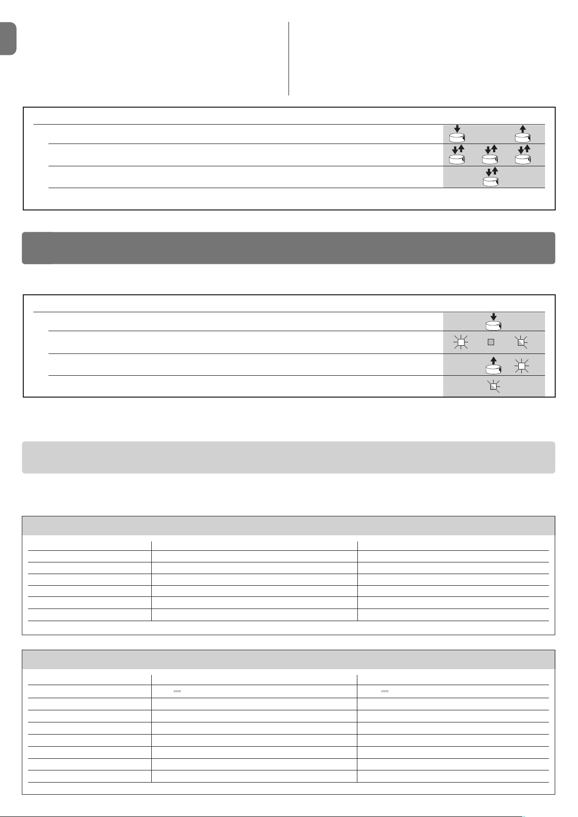
Terminals Function Description Type of cable
L - N - Power supply line Mains power supply 3 x 1,5 mm
2
1÷3 Motor 1 M1 motor connection 3 x 1,5 mm
2
1÷3 Motor 2 M2 motor connection (Note 1) 3 x 1,5 mm
2
4÷5 Flashing light Connection of flashing light 24 V max 25 W 2 x 1 mm
2
6÷7 Open Gate indicator / Connection for Open Gate Indicator 24 V max 5 W or Electric lock12 V SCA: 2 x 0,5 mm
2
Elect.Lock max 25 VA (“See chapter 5 - Programming”) Electric lock: 2 x 1 mm
2
8 Common 24 V Power Supply +24 V for TX photocells with phototest (max. 100 mA); “COMMON” 1 x 0,5 mm
2
(with standby / phototest) for all inputs, safety, with STAND BY function activated (Note 2)
9 0 V Power supply 0V for services 1 x 0,5 mm
2
10 24 V Power input for services, without “Standby” (24 V max 200 mA) 1 x 0,5 mm
2
11 Common 24 V Common for all inputs (+24 V ) without “Standby” 1 x 0,5 mm
2
12 STOP Input with STOP function (emergency, safety shutdown) (Note 3) 1 x 0,5 mm
2
13 PHOTO NC Input for safety devices (photocells, sensitive edges) 1 x 0,5 mm
2
14 PHOTO 1 NC Input for safety devices (photocells, sensitive edges) 1 x 0,5 mm
2
15 STEP BY STEP Input for cyclical functioning (OPEN-STOP-CLOSE-STOP) 1 x 0,5 mm
2
16 AUX Auxiliary input (Note 4) 1 x 0,5 mm
2
17÷18 Aerial Connection for the radio receiver aerial screened cable type RG58
Note 1 – This is not used for single leaf gates (the control unit automatically recognises if only one motor has been installed).
Note 2 – The “Stand By” function serves to reduce consumptions. For further details on the electrical connections refer to paragraph 2.4.1 “Stand by/Phototest
connection” and for programming refer to chapter 5.2.3 “Stand by/Phototest function”.
Note 3 – The STOP input can be used for “NC” or constant resistance 8.2 k
Ω
contacts (please refer to the “Programming” chapter)
Note 4 – The AUX factory auxiliary input is programmed with the “Partial open type 1” function but can be programmed with any of the following functions:
Function Input type Description
PARTIAL OPEN TYPE 1 NO Fully opens the upper leaf
PARTIAL OPEN TYPE 2 NO Opens the two leaf half way
OPEN NO Only carries out the opening manoeuvre
CLOSE NO Only carries out the closing manoeuvre
• Activation of the “PHOTO 1” pair of photocells stops both the opening and
closing manoeuvres.
• Activation of the “PHOTO2” pair of photocells (connected to the suitably programmed AUX input) has no effect during closing while they invert movement
during opening.
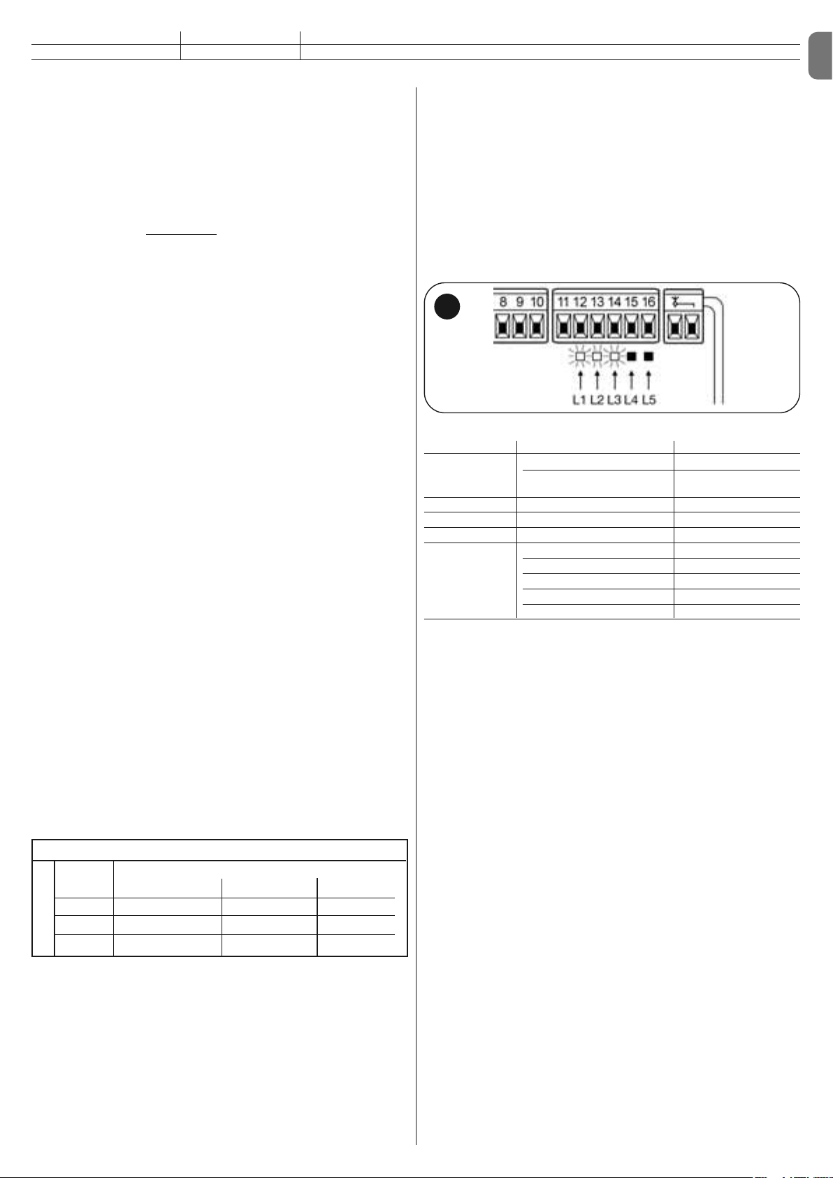
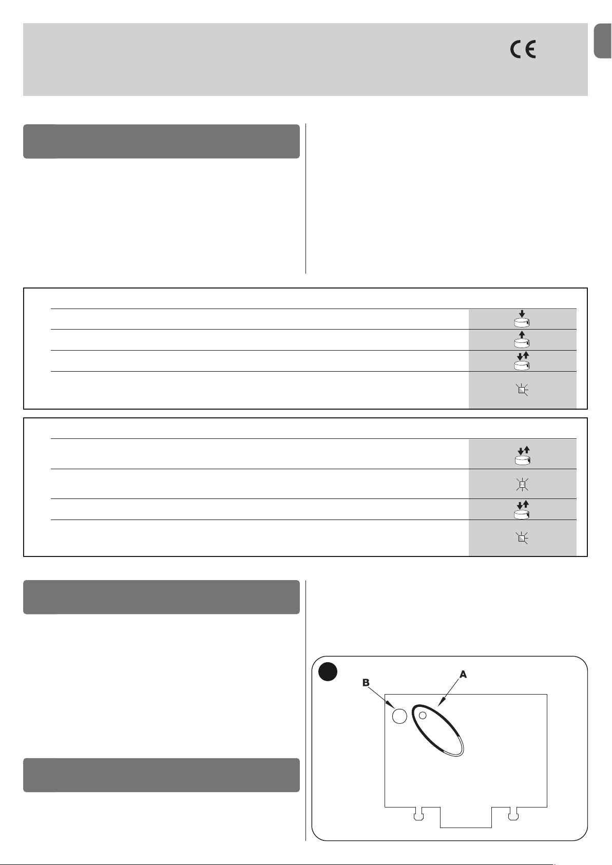
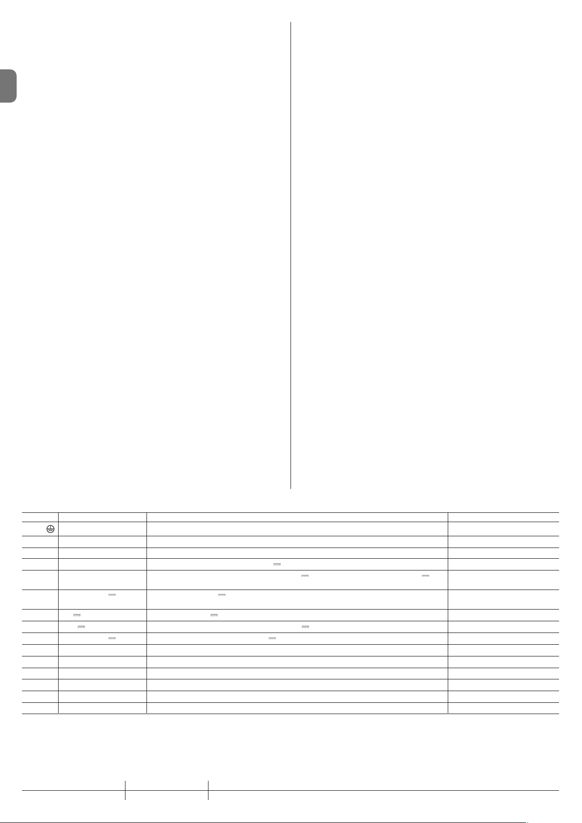
To check the parts of the control unit see fig. 2.
Key to fig. 2:
A. 24V power supply connector
B. M1 motor connector
C. PS124 buffer battery connector / Solemyo solar energy supply
system (for further details see chapter 6.3)
D. 500mA F type services fuse
E. Selector switch for delaying the opening of motor M1 or M2
F. M2 motor terminal
G. Flashing light output terminal
H. Gate open indicator or electric lock output terminal
I. 24Vdc terminals for services and phototest
L. Input terminals
L1…L5. Input and programming LEDs
M. Terminal for radio aerial
N. “SM” radio receiver connector
O. Programming/diagnostics connector
P1, P2, P3. Programming buttons and LEDs
2.1 - Preliminary checks for installation
Before proceeding with installation, check the condition of the product components, suitability of the selected model and conditions of the intended installation environment:
• Ensure that all conditions of use remain within the limits of product application
and within the “Product technical specifications”.
• Ensure that the selected installation environment is compatible with the over-
all dimensions of the product (fig. 3).
• Ensure that the selected surfaces for product installation are solid and guar-
antee a stable fixture.
• Make sure that the fixing zone is not subject to flooding. If necessary, mount
the product raised from the ground.
• Ensure that the space around the product enables easy and safe completion
of manual manoeuvres.
• Make sure that the automation is provided with mechanical stops on both
closing and opening.
2.2 - Product application limits
The product may be used exclusively with Wingo 24 V gearmotors.
2.3 - Installation
To install the control unit, proceed as shown in fig. 4. Also observe the following warnings:
• The control unit is supplied in an enclosure that if correctly installed assures
an IP54 protection rating. The control unit is therefore suitable for installation
outdoors.
• Fix the control unit to a flat, vertical, non-removable surface that is adequately protected from potential impacts. Important! – The bottom of the control unit
must be at least 40 cm from the ground.
• Insert the dedicated cable clamps or pipe glands into the lower part of the
enclosure (fig. 4). Important! – If the cable protection tubes end in a pit, it is
likely that condensation will form inside the control unit, which will damage the
electronic board. In this case, protect the control unit adequately so as to prevent the formation of condensation.
• The cable clamps can be inserted on the long side of the enclosure only if the
control unit is installed in a protected indoor environment.
To install the other devices present in the automation, refer to the relevant
instruction manuals.
2.4 - Electrical connections
IMPORTANT!
– All electrical connections must be made with the unit disconnected from
the mains power supply and with the buffer battery disconnected, if present in the automation.
– Connections must be made exclusively by qualified personnel.
– Make sure that all the electric cables used are of a suitable type.
01. Loosen the screws of the cover.
02. Prepare the electrical cable routing holes.
03. Connect the cables as shown in the wiring diagram in fig. 5. To connect
the electric power cable, see fig. 6. Note – To facilitate cable connections,
the terminals can be removed from their seats.
• With the exception of the photocell inputs when the PHOTOTEST function is
activated, if the inputs of the NC (Normally Closed) contacts are not in use
they should be jumped with the “COMMON” terminal. Refer to paragraph
2.4.3 for further information.
• If there is more than one NC contact on the same input, they must be connected in SERIES.
• If the inputs of the NO (Normally Open) contacts are not used they should be
left free.
• If there is more than one NO contact on the same input, they must be connected in PARALLEL.
• The contacts must be electromechanical and potential-free. Stage connections, such as those defined as “PNP”, “NPN”, “Open Collector”, etc. are not
allowed.
• If the leafs overlap, use jumper E (Fig. 6) to select which motor starts up first
during opening.
Page 5
EN
English – 3
PHOTO 2 NC PHOTO 2 function
DISABLED — No function
2.4.1 - Notes about connections
Most connections are extremely simple and many of them are direct connections to a single user point or contact. The following figures show examples of
how to connect external devices:
• Stand By / Phototest connection
The Stand-by function is active as standard. It is excluded automatically only
when the Phototest function is activated. Note - The Stand-by and Phototest
functions are alternatives as one excludes the other.
The Stand-by function allows consumptions to be reduced. Three types of con-
nections can be obtained:
- with “stand by” active (energy saving
); see electrical diagram in fig. 5a
- standard connection: without “Stand by” and without “Phototest”; see electrical
diagram in fig. 5b
- without “Stand by” and with “Phototest”; see electrical diagram in fig. 5c
When the “Stand-by” function is active, 1 minute after the end of a manoeuvre
the control unit goes into Stand-by, turning off the Inputs and Outputs to
reduce consumptions. The status is indicated by the “OK” LED which begins to
flash more slowly. WARNING – If the control unit is powered from a photovolta-
ic panel (“Solemyo” system) or a buffer battery, the “Stand-by” function must be
activated as shown in the electrical diagram in fig. 5a.
When the “Stand-by” function is not required, the “Phototest” function may be
activated. This verifies at the beginning of a manoeuvre that the connected photocells operate correctly. To use this function, first connect the photocells appropriately (see electrical diagram in fig. 5c) and then activate the function.
Note – When the phototest is activated, the inputs subjected to the test procedure are PHOTO, PHOTO1 and PHOTO2. If one of these inputs is not used it
must be connected to terminal no. 8.
• Key switch connection
Example 1 (fig. 7a): How to connect the switch in order to perform the STEPBY-STEP and STOP functions
Example 2 (fig.7b): How to connect the switch in order to perform the STEPBY-STEP and one of the auxiliary input functions (PARTIAL OPENING, OPEN
ONLY, CLOSE ONLY …)
Note – For electrical connections with the “Stand By” function active, see
“Stand By/Phototest function” in this paragraph 2.4.1.
• Connection for Gate Open Indicator / Electric lock (fig. 8)
If the gate open indicator has been programmed, the output can be used as an
open gate indicator light. The light, flashes slowly during opening and quickly
during closing; If it is on but does not flash, this indicates that the gate is open.
If the light is off, the gate is closed. Se the output has been programmed as an
electric lock, it is activated for 3 seconds each time opening begins.
2.4.2 - STOP type input
The MC424 control unit can be programmed for two types of STOP input:
- NC type STOP for connecting up to NC type contacts.
- Constant resistance STOP. It enables the user to connect up to the control
unit of devices with 8.2kΩ constant resistance (e.g. sensitive edges). The
input measures the value of the resistance and disables the manoeuvre when
the resistance is outside the nominal value. Devices with normally open “NO”
or normally closed “NC” contacts, or multiple devices, even of different types,
can be connected to the constant resistance STOP input, provided that
appropriate adjustments are made; see Table 1.
WARNING! – If the constant resistance STOP input is used to connect
devices with safety functions, only the devices with 8.2 KΩ constant will
resistance output guarantee the fail-safe category 3.
Notes to Table 1:
Note 1 – Any number of NO devices can be connected to each other in paral-
lel, with an 8.2K
Ω
termination resistance (fig. 9a). For electrical connections
with the “Stand By” function active, see “Stand By/Phototest function” in this
paragraph 2.4.1.
Note 2 – The NO and NC combination can be obtained by placing the two contacts in parallel, and placing an 8.2K
Ω
resistance in series with the NC contact.
It is, therefore, possible to combine 3 devices: NO, NC and 8.2K
Ω
(fig. 9b).
Note 3 – Any number of NC devices can be connected in series to each other
and to an 8.2K
Ω
resistance (fig. 9c).
Note 4 – Only one device with an 8.2K
Ω
constant resistance output can be
connected; multiple devices must be connected “in cascade” with a single
8.2K
Ω
termination resistance (fig. 9d).
2.5 - Initial start-up and electrical connections
IMPORTANT! – Connections must be made exclusively by qualified per-
sonnel.
After powering up the control unit, check that all the LEDs flash rapidly for a few
seconds, then perform the following checks:
1. Check that there is a voltage of approximately 30Vdc on terminals 9-10. If
not, unplug the unit immediately and carefully check the connections and
input voltage.
2. After initially flashing rapidly, the P1 LED will indicate the control unit is working correctly by flashing regularly at 1 second intervals. When there is a variation in the inputs, the “P1” led will rapidly flash twice to show that the input
has been recognised.
3. If the connections are correct, the LED for the “NC”-type inputs will be on,
while those for the “NO” type inputs must be off. See fig. A and Table 2.
TABLE 2
INPUT INPUT TYPE STATUS LED
STOP STOP NC L1 On
CONSTANT RESISTANCE L1 On
STOP 8.2 KΩ
PHOTO NC L2 On
FOTO1 NC L3 On
STEP-BY-STEP NO L4 Off
AUX OPEN PARTIALLY type 1 - NO L5 Off
OPEN PARTIALLY type 2 - NO L5 Off
OPEN ONLY - NO L5 Off
CLOSE ONLY - NO L5 Off
FOTO2 - NC L5 On
4.Check that the relative LEDs switch on and off when the devices connected
to the inputs are operated.
5.Check that by pressing P2 both motors perform a short opening manoeuvre,
and the motor of the upper leaf starts first. Block the manoeuvre by pressing P2 again. If the motors do not start up for opening, invert the polarities of
the motor cables. If, however, the first one to move is not the upper leaf,
operate jumper E (fig. 2).
2.6 - Automatic search system for the limit switches
On the successful completion of the various controls, start the automatic
search system phase for the limit switches. This work is necessary as the
MC424 control unit must “measure” how long the opening and closing
manoeuvres take This procedure is completely automatic and detects the
mechanical opening and closing stops by measuring the load on the motors.
Warning! – If this procedure has already been carried out, in order to
reactivate it, the user must first delete the memory (see the “Memory de letion” chapter). In order to check whether the memory contains any li mit
switch parameters, turn the power supply to the control unit on and then
off again. If all the LEDs flash rapidly for approximately 6 seconds, the
me mory is empty. If, however, they only flash for 3 seconds, the memory
already contains some limit switch parameters.
Before starting limit switch searching, make sure that all the safety devices are
enabled (STOP, PHOTO and PHOTO1). The procedure will be immediately
interrupted if a safety device triggers or a command arrives. Ideally the doors
should be half open, although they can be in any position.
Procedure – Press the P2 button (fig. 2) to start begin searching which
includes:
- Both motors open briefly.
- Motor closes the lower leaf until it reaches the mechanical closing stop.
- The upper leaf motor closes until it reaches the mechanical closing stop.
- The motor of the upper leaf begins to open.
- After the programmed delay, opening of the lower leaf begins. If the delay is
in sufficient, block the search by pressing P1 (fig. 2), then modify the time (see
chapter 5).
- The control unit measures the movement required for the motors to reach the
opening mechanical stops.
- Complete closing manoeuvre. The motors can start at different times, the aim
is to prevent the leafs from shearing by maintaining a suitable delay.
- End of the procedure with memorisation of all measurements.
A
1st device type:
NO NC 8,2 KΩ
In parallel (note 1)(note 2) In parallel
NC (note 2) In series (note 3) In series
8,2KΩ In parallel In series (note 4)
TABLE 1
second device type:
Page 6

EN
4 – English
All these phases must take place one after the other without any interference
from the operator. If the procedure does not continue correctly, it must be interrup ted with the P1 button. Repeat the procedure, modifying some parameters if
necessary, for example the current sensitivity cut-in thresholds (see chapter 5).
These are the most important phases of automation set-up for ensuring maximum system safety. The test can also be performed as a periodic check of
automation devices. Testing and commissioning of the automation must be
performed by skilled and qualified personnel, who are responsible for the tests
required to verify the solutions adopted according to the risks present, and for
ensuring observance of all legal provisions, standards and regulations, and in
particular all requirements of the standard EN 12445, which establishes the test
methods for checking automations for doors and gates.
The additional or optional devices must undergo a specific test for functionality
and correct interaction with MC424. Refer to the instruction manuals of the
individual devices.
3.1 - Testing
The testing sequence refers to the control unit programmed with the preset
functions. See paragraph 5.1:
• Make sure that the activation of the STEP-BY-STEP input generates the following sequence of movements: “Open, Stop, Close, Stop”.
• Make sure that the activation of the AUX input (Type 1 partial opening function)
manages the “Open, Stop, Close, Stop” sequence of the motor of the upper
leaf only, while the motor of the lower leaf remains in the closed position.
• Perform an opening manoeuvre and check that:
- the gate continues the opening manoeuvre when PHOTO is engaged
- the opening manoeuvre stops when PHOTO1 is engaged and only continues
when PHOTO1 is disengaged
- The manoeuvre stops when PHOTO2 (if installed) is engaged and the closing
manoeuvre starts
• Make sure that the motor switches off when the door reaches the mechanical
stop.
• Perform an opening manoeuvre and check that:
- The manoeuvre stops when PHOTO is engaged and the opening manoeuvre
starts
- The manoeuvre stops when PHOTO1 is engaged and the opening manoeuvre starts again when PHOTO1 is disengaged
- the gate continues the closing manoeuvre when PHOTO 2 is engaged
• Check that the stopping devices connected to the STOP input immediately
stop all movement.
• Check that the level of the obstacle detection system is suitable for the application:
- During both the opening and the closing manoeuvres, prevent the leaf from
moving by placing an obstacle and check that the manoeuvre inverts before
exceeding the force set down by law
• Other checks may be required depending on which devices are connected to
the inputs.
Warning – If an obstacle is detected as moving in the same direction for 2
consecutive manoeuvres in the same direction, the control unit partially
inverts both motors for just 1 second. At the following command, the leafs
begin the opening manoeuvre and the first current sensitivity cut-in for
each motor is considered as a mechanical stop during the opening cycle.
The same happens when the mains power supply is switched on: the first
command is always an opening manoeuvre and the first obstacle is
always considered as a mechanical stop during the opening cycle.
3.2 - Commissioning
Commissioning can only be performed after positive results of all test
phases.
1 Prepare the automation technical documentation, which must contain the
following documents: overall drawing of the automation, electrical wiring
diagram, risk assessment and relative solutions adopted (refer to the relevant forms on our website www.niceforyou.com), manufacturer’s declara-
tion of conformity for all devices used and installer’s declaration of conformity.
2 Affix a dataplate on the gate, specifying at least the following data: type of
automation, name and address of manufacturer (responsible for commissioning), serial number, year of construction and CE mark.
3 Before commissioning the automation, ensure that the owner is adequately
informed of all associated risks and hazards.
TESTING AND COMMISSIONING
3
The diagnostics LED P2 (fig. 2) indicates any problems or malfunctions re vealed by the control unit during the manoeuvre.
A sequence with a certain number of flashes indicates the type of problem and
remains active until the following manoeuvre begins. The table below summarises this information:
Number Type of malfunction
Led P2 flashes
1 M1 current sensitivity device triggering
2 M2 current sensitivity device triggering
3 STOP input cut-in during the manoeuvre
4 Phototest error
5 Output overcurrent gate open indicator or electric lock
DIAGNOSTICS
4
The MC424 control unit features some programmable functions. These functions are pre-set in a typical configuration which satisfies most automatic systems. These functions can be changed at any time, both before and after
searching automatically for limit switches, by carrying out the relevant programming procedure; see paragraph 5.3.
5.1 - Preset functions
• Motor movement: fast
• Automatic closing: enabled
• Condominium function: disabled
• Pre-flashing disabled
• Close after photo: disabled
• Opening delay: level 2 (10%)
• STAND BY / Phototest: Stand by
• Gate open indicator/Electric Lock: Gate open indicator
• STOP input: NC type
• Heavy gates: disabled
• Proportional gate open indicator: disabled
• Pause time: 20 seconds
• Auxiliary input: type 1 partial opening (only the
upper leaf motor is activated)
• Current sensitivity: Level 2
5.2 - Programmable functions
To ensure the system is best suited to the user’s requirements, and safe in the
various different conditions of use, the MC424 control unit offers the possibility
to programme several functions or parameters, as well as the function of a
number of inputs and outputs.
5.2.1 - Direct programming
• Slow/rapid movement: The user can choose the speed of movement of the
gate, at any time (with the motor arrested) simply by operating the P3 key (fig.
2) at any time the control unit is not being programmed. If LED L3 is off, this
shows that the slow movement has been set, if on the fast one has.
5.2.2 - Level one programming: part one
• Automatic closing: This function features an automatic closing cycle after
the programmed pause time; the pause time is factory set to 20 seconds but
it can be modified to 5, 10, 20, 40 or 80 seconds.
If the function is not activated, the system will run “semi-automatically”.
• “Condominium” function: This function is useful when the automatic sys-
tem is radio-commanded by many different people. If this function is active,
each command received triggers an opening manoeuvre that cannot be interrupted by further commands. If the function has been deactivated, a command causes: OPEN-STOP-CLOSE-STOP.
• Pre-flashing: This function activates the flashing light before the manoeuvre
begins for a time that can be programmed to 3 seconds.
If the function is disabled, the light will start flashing when the manoeuvre
starts.
• Close after photo: During the automatic closing cycle, this function reduces
the pause time to 4 seconds after the PHOTO photocell has disengaged, i.e.
the gate closes 4 seconds after the user has passed through it. If the function
is disabled, the whole programmed pause time will pass.
• Opening delay: During opening, this function causes a delay in the activation
PROGRAMMING
5
Page 7
EN
English – 5
of the lower leaf motor compared with the upper one This is necessary in
order to prevent the leafs from getting stuck. There is always a standard delay
during closing, calculated automatically by the control unit in order to ensure
the same delay as the one programmed for opening.
5.2.3 - Level one programming: part two
• Stand By / Phototest function: The control unit has the “Stand-by” function
preset. If this function is active, 1 minute after the end of a manoeuvre the
control unit turns off the “Stand-by” output (terminal no. 8) and all the Inputs
and other Outputs to reduce consumptions (see electrical diagram in fig. 5a).
This function is obligatory if the control unit is powered exclusively with Solemyo photovoltaic panels. It is also recommended if the control panel is powered from the electric mains and if you wish to extend emergency operation
with the buffer battery PS124. As an alternative to the “Stand-by” function,
the “Phototest” function may be activated. This verifies at the beginning of a
manoeuvre that the connected photocells operate correctly. To use this function, connect the photocells correctly (see electrical diagram in fig. 5c) and
then activate the function.
• Open gate indicator light / electric lock: If the function is activated, termi-
nals 6-7 can be used to connect up the electric lock. If the function is deactivated, terminals 6-7 can be used to connect up a 24V gate open indicator.
• NC Type or Constant Resistance STOP Input: If the function is activated,
the STOP input is set to “8.2KΩ Constant Resistance”. In this case, there
must be a 8.2KΩ +/-25% resistance between the common and the input to
enable the operation. If the function is not set, the configuration of the STOP
input will enable it to function with NC type contacts.
• Light/heavy gates : If the function is activated, the control unit enables the
user to manage heavy gates, setting the acceleration ramps and slowdown
speeds during closing differently. If the function is deactivated, the control unit
will be set to manage light gates.
• Proportional gate open indicator: If the function is activated, the gate open
in dicator output will be set with the proportional flashing light. This means that
during opening, the flashing becomes more intense as the leafs come nearer
to the opening stops; vice-versa, for closing, the flashing becomes less
intense as the leafs come nearer to the closing stops. If the function is deactivated, the light will flash slowly during opening and rapidly during closing.
5.2.4 - Level two functions
• Pause time: The pause time, namely the time which lapses between opening
and closing during automatic functioning, can be programmed to 5, 10, 20,
40, and 80 seconds.
• Auxiliary input AUX: The control unit offers an auxiliary input which can be
set to carry out one of the following 6 functions:
- Partial opening type 1: this carries out the same function as the STEP-BYSTEP input. It causes only the upper leaf to open. It only works if the gate is
closed completely, otherwise the command is interpreted as if it were a
STEP-BY-STEP comman.
- Partial opening type 2: this carries out the same function as the STEP-BYSTEP input. It causes the two leafs to open for half the time it would take
them to open completely. It only works if the gate is closed completely, otherwise the command is interpreted as if it were a STEP-BY-STEP command.
- Open only: this input only causes opening in the Open-Stop-Open-Stop
sequence.
- Close only: this input only causes closing in the Open-Stop-Open-Stop
sequence.
- Photo 2: this carries out the function of the “PHOTO 2” safety device.
- Disabled: the input will not carry out any function
• Discharge time: At the end of the Closing manoeuvre, after the leafs have
reached the totally closed position, the motor continues to “push” the leaf for
a brief interval, to ensure perfect closure. Immediately afterwards, this function activates a very brief inversion of movement to reduce excessive pressure exerted by the motor on the leafs.
• Current sensitivity: The control unit is equipped with a system which meas-
ures the current absorbed by the two motors used to detect the mechanical
stops and any obstacles when the gate is moving. Since the current ab sorbed depends on a number of conditions, including the weight of the gate,
friction, wind and variations in voltage, the cut-in threshold can be changed.
There are 6 levels: 1 is the most sensitive (minimum force), 6 is the least sensitive (maximum force).
WARNING! – If the “current sensitivity” function (together with other
vital features) is adjusted correctly, the system will comply with European standards, EN 12453 and EN 12445, which require techniques or
devices to be used to limit force and danger during the functioning of
automatic gates and doors are moved.
• Leaf delay: The delay in starting up the motor of the lower leaf can be pro-
grammed to 5, 10, 20, 30 or 40% of the working time.
5.3 - Programming
All the functions described in paragraph 5.2 “Programmable functions” chapter
can be selected by means of a programming phase which terminates by memorising the choices made. The control unit therefore has a memory which stores
the functions and parameters relative to the automation process.
The P1, P2 and P3 buttons are used for all the programming phases, while the
5 LEDs (L1, L2…L5) indicate the selected parameter.
There are two different programming levels:
• At level 1, the functions can be enabled or disabled. Each Led (L1, L2…L5)
corresponds to a function: if the Led is on, the function is active; if it is off, it is
deactivated.
Level one consists in 2 parts which can be selected using the P3 button. The
cor responding LED P3 indicates which of the 2 parts has been selected.
Level one (P1 Led lit): part two (P3 Led lit)
L1 Led L2 Led L3 Led L4 Led L5 Led
Stand By / Electric lock Resistance Heavy gates Gate open
Phototest stop proportional
Level one (P1 Led lit): part one ( P3 Led off)
L1 Led L2 Led L3 Led L4 Led L5 Led
Closing Function Pre-flash Close after Delay in
Automatic Condominium photo opening
• It is possible to pass to the second level from level one of part one. At this
second level the user can choose the parameter relating to the function. A
different value corresponds to each LED which must be associated to the
parameter.
Level one (P1 Led lit): part two (P3 Led lit)
L1 Led L2 Led L3 Led L4 Led L5 Led
Stand By / Electric lock Resistance Heavy gates Gate open
Phototest stop proportional
Level one (P1 Led lit): part one (led P3 off)
L1 Led L2 Led L3 Led L4 Led L5 Led
Closing Function Pre-flashing Close after Delay in
automatic condominium photo opening
Level two:
Parameter: Parameter: Parameter: Parameter: Parameter:
Time AUX input Time Current Leaf delay
pause discharge sensitivity
L1: 5s L1: Open L1: no L1: Level 1 L1: 5%s
partial TYPE 1 discharge (more sensitive)
L2: 10s L2: Open L2: 0.3s L2: Level 2 L2: 10%
partial TYPE 2
L3: 20s L3: Open Only L3: 0.7s L3: Level 3 L3: 20%
L4: 40s L4: Close Only L4: 1.3s L4: Level 4 L4: 30%
L5: 80s L5: Photo 2 L5: 2s L5: Level 5 L5: 40%
(less sensitive)
All LEDs off: All LEDs off:
input Level 6
not used (max current
sensitività )
Page 8
5.3.1 - Level one programming: functions
At level 1, the functions can be enabled or disabled. At level one, LED P1 is
EN
always on; if LEDs L1, L2…L5 are on, the functions are activated; if the LEDs
are off, the functions are deactivated. A flashing LED indicates which function
has been selected, short flashes indicate the function has been deactivated;
long flashes indicate the function has been activated. Press P3 to pass from
part one programming to part two programming, and vice-versa.
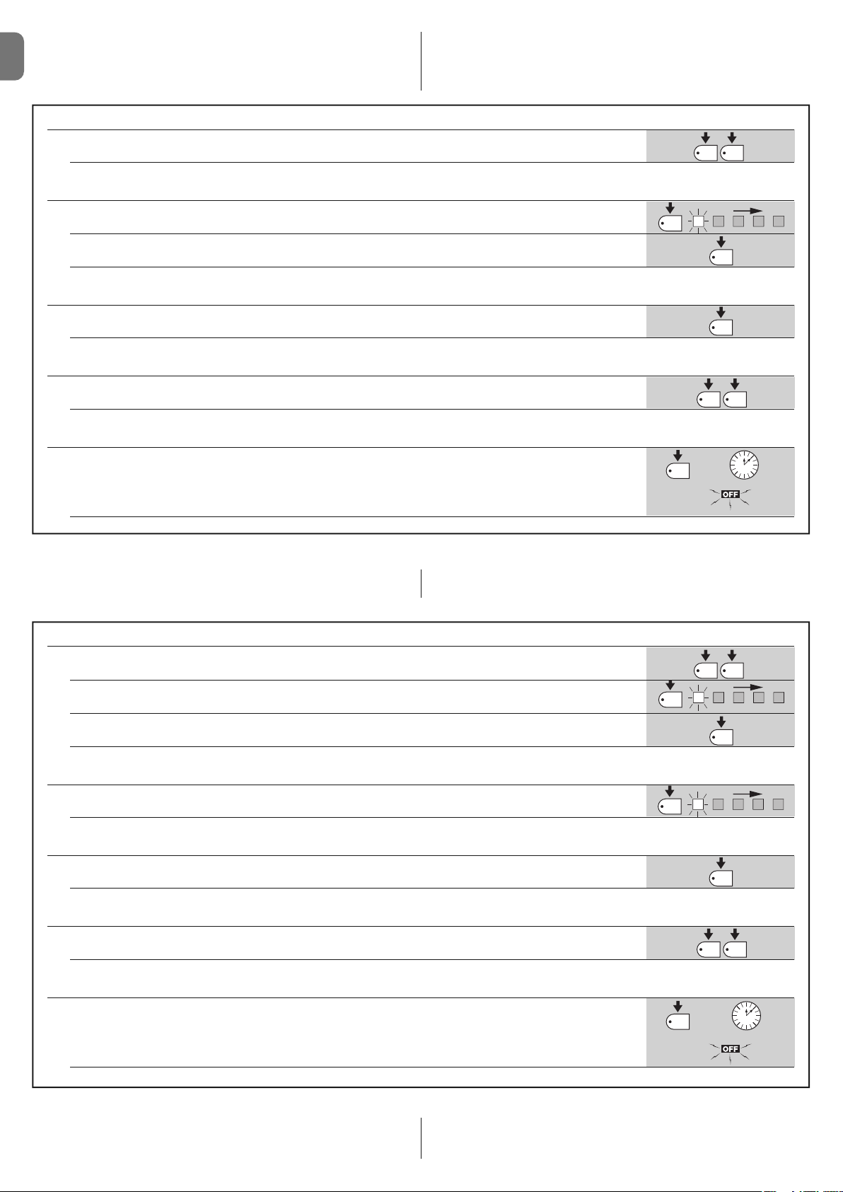
TABLE A1 - Entering level one programming
01. Press and hold down buttons P1 and P2 for at least 3 seconds
The programming mode has been entered if all the Leds start flashing quickly
TABLE A2 - Activating or deactivating a function
01. Press P1 repeatedly until the flashing Led reaches the function required
02. Press P1 repeatedly until the flashing Led reaches the function required
TABLE A3 - To pass from part one to part two of level one (and vice-versa)
01. Press P3. button
TABLE A4 - To exit level one and save the modifications
01. Press P1 and then immediately P2, holding them both down for at least 3 seconds
TABLE A5 - Exiting level one and delete the modifications
01. Either press P1 for at least 3 seconds, or wait for 1 minute, or disconnect the power supply
3s
P1
P1
P1 P2
P2
P3
P1 P2
or
3 s
60s
5.3.2 - Level two programming: parameters
The function parameter can be chosen at level two. Level two can only be
TABLE B1 - Entering level two programming
01. Enter level one programming by pressing P1 and P2 for at least 3 seconds
02. Select the function by pressing P1 until the flashing Led reaches the point required
03. Enter level two by pressing the P2 button for at least 3 seconds
TABLE B2 - Selecting the parameter
01. Press P2 repeatedly until the Led reaches the desired parameter
TABLE B3 - Returning to level one
01. Press P1
or
reached from level one. At level 2 the P1 Led flashes quickly while the 5 Leds
(L1, L2…L5) indicate the selected parameter.
P1 P2
P1
P2
P2
P1
3 s
3 s
TABLE B4 - Exiting level one and saving modifications
01. Press P1 and then immediately P2, holding them both down for at least 3 seconds
TABLE B5 - Exiting level one and cancelling modifications
01. Either press P1 for at least 3 seconds, or wait for 1 minute, or disconnect the power supply
5.3.3 - Memory deletion
Each new programme replaces the previous settings. It is usually unnecessary
to “delete all” the parameters”. If required, the memory can be totally deleted by
6 – English
performing this simple operation: WARNING – As all the functions return to
their pre-set values after the memory is deleted, a new search for the limit switches must be carried out.
3s
P1
or
P1 P2
or
60s
Page 9
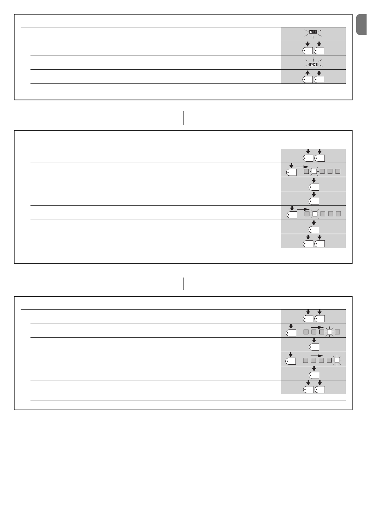
TABLE C1 - Delete memory
01. Switch the power supply to the control box off, and wait until all the LEDs have gone off (remove fuse F1 if necessary)
EN
02. Press P1 and P2 on the board down and keep them pressed down
03. Switch the power supply on again
04. Wait at least 3 seconds before releasing the two keys
If the memory was deleted correctly, all the Leds will switch off for 1 second
5.3.4 - Example of level one programming
The following examples show how to activate or deactivate a level one function,
the “Condominium” function, for example, and prepare the “Gate Open Indicator” output in order to activate the electric lock.
Example of level one programming:
activate the “Condominium” function and “Electric lock” output
01. Access the level one programming mode by pressing P1 and P2, and keeping them pressed down for at least 3 seconds
02. Press P1 once to move the flashing Led to the Led 2 (the flashes will be short)
03. Activate the “Condominium” function by pressing P2 (the flashes will be longer)
04. Press P3 once in order to activate part two (the P3 LED will switch on)
05. Press P1 once to move the flashing Led to the Led 2 (the flashes will be short)
P1
P1
x1
P1 P2
P1 P2
P1 P2
2
P2
P3
2
3s
3s
06. Activate the “Electric lock” output by pressing P2 (the flashes will be longer)
07. Exit programming (with memorisation) by pressing P1 and then immediately P2, holding them both down
for at least 3 seconds
5.3.5 - Example of level two programming
modify current sensitivity intil “level 5”.
This example shows how to modify a level two parameter, for example, how to
Example of level two programming: modifying “current sensitivity”
01. Access the level one programming mode by pressing P1 and P2 for at least 3 seconds
02. Press P1 three times to move the flashing Led to the Led 4
03. Access level two by pressing P2 for at least 3 seconds
04. Press P2 three times until Led 5 switches on
05. Return to level one by pressing P1
06. Exit programming (with memorisation) by pressing P1 and then immediately P2, holding them both down
for at least 3 seconds
P2
P1
x3
x3
P2
P1 P2
P1 P2
P2
P1
P1 P2
3s
3s
4
3s
5
3s
English – 7
Page 10
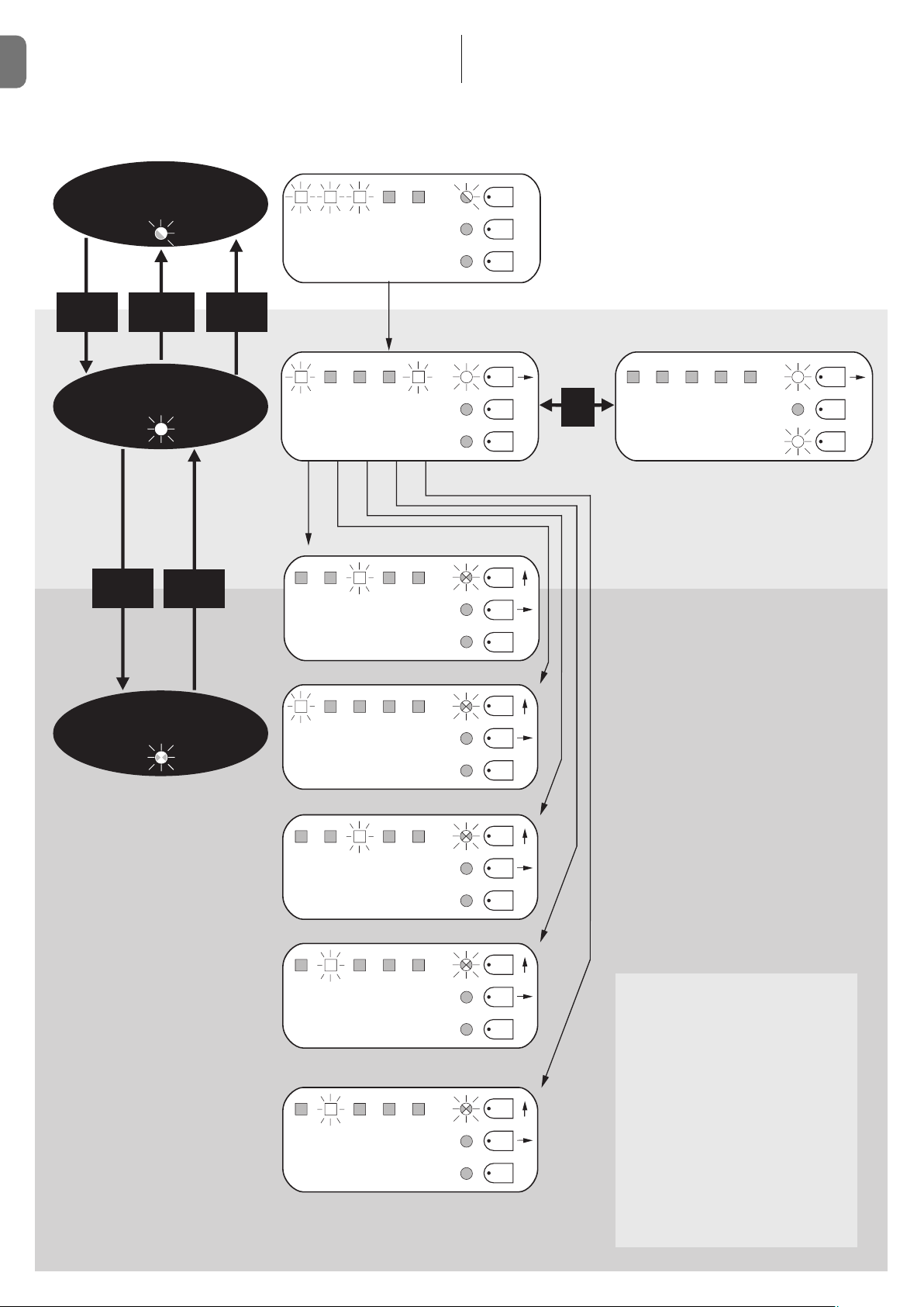
5.3.6 - Programming diagram
The following figure shows the complete programming diagram of the functions
EN
and relative parameters.
Normal
operation
Led P1 Slow flashing
ALT Photo Photo1Step
step
by
AUX
This figure also shows the functions and parameters either as they were initially
or following total memory deletion.
P1
P2
P3
P1+P2
for 3 secs
P1
for 3 secs
(NO SAVE)
Level one
Led P1 On permanently
P2
for 3 secs
P1
Level two
Led P1 Rapid flashing
P1+P2
for 3 secs
(SAVE)
Autom.
Cond. Pre-
closing
5 10 20
type 1
type 2
p.o
p.o
Close
after
Photo
Opening
delay
flashing
PAU SE TIME
40 80
seconds
AUXILIARY INPUT (*)
only
only
closing
Photo 2
opening
P1
P2
P3
P1
P2
P3
P1
P2
P1
Stand
Electric
Resist.
Heavy
On
Off
P3
by /
Phototest
Lock
STOP.
gates
Proportional
Gate
Open
P2
On
Off
P3
DISCHARGE
0 0,3 0,7
1,3 2
seconds
CURRENT SENSITIVITY
123
45
Level
All Leds off · max. current sensitivity
OPENING DELAY
5 10 20%30 40
P3
P1
P2
P3
P1
P2
P3
P1
P2
P3
(*)
a.p. type 1 type 1 partial open, upper leaf
moves [N.O.]
a.p. type 2 type 2 partial opening, both
motors move for 1/2 the working
time set [N.O.]
Only open open stop open stop…
[N.O.]
Only closed close stop close stop…
[N.O.]
Photo 2 used as photo 2 [N.C.]
8 – English
Page 11
EN
English – 9
6.1 - Connecting a radio receiver
The control unit has a connector for fitting a 4 channel radio card complete with
SM slot. This remote control device functions by means of transmitters which
act on the inputs as per the following table:
Output Receiver Control unit input
N° 1 Step by step
N° 2 AUX (reset value: Partially Open 1)
N° 3 “Open only”
N° 4 “Close only”
6.2 - Connecting model PS124 buffer battery
PS124 buffer batteries can be used to supply the control unit in case of network blackouts. To install and connect the battery, proceed as shown in fig. 10.
6.3 - Connecting the Solemyo system
The control unit is designed to be powered with the “Solemyo” photovoltaic
system (photovoltaic panel and 24 V battery). To connect the Solemyo battery
to the control unit, use the socket on the control unit that is normally used for
the buffer battery (see paragraph 6.2).
IMPORTANT!
- When the automation is powered by the “Solemyo” system, it MUST
NOT BE POWERED at the same time from the electrical mains.
- The Solemyo system can be used only if the Standby function on the con trol unit is ON and the connections are as shown in the diagram in fig. 5a.
FURTHER DETAILS: accessories
6
No LEDs are on:
• Check whether the control unit is powered (measure a voltage of about
30Vdc at terminals 9-10 (or 24 Vdc with battery power).
• Check the 2 fuses, if not even the P1 Led is on or flashing a serious fault has
probably occurred and the control unit must therefore be replaced.
The P1 LED flashes regularly but the input LED’s L1, L2...L5 do not reflect
the state of the respective inputs
• Switch the unit off for the moment in order to exit a possible programming
phase.
• Carefully check the connections on terminals 11 to 16.
LED P1 flashes every 4 seconds
• The control unit is in Stand by status.
The “Automatic search” procedure does not start up
• The “Automatic search” procedure only starts if it has never been performed
before or if the memory has been deleted. To check whether the memory is
empty switch off the unit for a moment. When it is switched on again, all the
Leds should flash rapidly for about 6 seconds. If they only flash for 3 seconds, the memory already contains valid values. If a new “Automatic search”
is required, the memory must be completely deleted.
The “Automatic search” procedure has never been performed but it either
does not start or it behaves incorrectly
• The system and all the safety devices must be operative in order to activate
the “Automatic search” procedure.
• Make sure that no device connected to the inputs cuts in during the “Automatic search” procedure.
• In order for the “Automatic search” procedure to start correctly, the input
Leds must be on as shown in fig. 11, the P1 Led must flash once a second.
The “Automatic search” procedure was performed correctly but the
manoeuvre does not start
• Check that the safety device (STOP, PHOTO, PHOTO1 and, if installed,
PHOTO2) Leds are on and that the relative command Led (STEP-BY-STEP
or AUX) remains on for the entire duration of the command.
• If the “Phototest” function is activated but the photocells do not function correctly, the DIAGNOSTICS LED indicates the fault by flashing four times.
The gate inverts the direction while moving
An inversion is caused by:
• The photocells triggering (PHOTO2 during the opening manoeuvre, PHOTO
or PHOTO1 during the closing manoeuvre). In this case, check the photocell
connections and input LEDs.
• The current sensitivity device triggers while the motors are moving (not near
TROUBLESHOOTING
(troubleshooting guide)
7
the mechanical stops, therefore). This is considered as an obstacle and
causes an inversion. To find out if the current sensitivity device has triggered,
count how many times the Diagnostics LED flashes: 1 flash indicates that the
current sensitivity device triggered on account of motor 1, 2 flashes indicate
that this was caused by motor 2.
PRODUCT MAINTENANCE
8
As the MC424 control unit is electronic it requires no particular maintenance.
However, at least every six months the efficiency of the entire system must be
checked according to the information described in chapter 3.
DISPOSAL OF THE PRODUCT
This product is an integral part of the automation, and therefore, they
must be disposed of together.
As for the installation operations, at the end of the life of this product, the dismantling operations must be performed by qualified personnel.
This product is made from different types of materials: some can be recycled,
others must be disposed of. Please inform yourselves on the recycling or disposal systems provided for by the laws in force in your area, for this category of
product.
CAUTION! – some parts of the product can contain polluting or dangerous
substances which, if dispersed in the environment, may cause serious harm to
the environment and human health.
As indicated by the symbol at the side, it is forbidden to
throw this product into domestic refuse. Therefore, follow the
“separated collection” instructions for disposal, according to
the methods provided for by local regulations in force, or
redeliver the product to the retailer at the moment of purchase of a new, equivalent product.
CAUTION! – the regulations in force at local level may envisage heavy sanctions in case of abusive disposal of this product.
Page 12
EN
10 – English
EC DECLARATION OF CONFORMITY
Note - The contents of this declaration correspond to declarations in the last revision of the official document deposited at the registered offices of Nice Spa available before this
manual was printed. The text herein has been re-edited for editorial purposes.
Number: 296/MC424 Revision: 0
The undersigned, Lauro Buoro, in the role of Managing Director, declares under his sole responsibility, that the product:
Manufacturer’s Name: NICE s.p.a.
Address: Via Pezza Alta 13, Z.I. Rustignè, 31046 Oderzo (TV) Italy
Type: Two 24 Vdc motor control unit
Models: MC424
Accessories: SMXI, SMXIS radio receiver
conform with the requirements of the following EC directives:
• 98/37/EC (89/392/EEC amended); DIRECTIVE 98/37/EC OF THE EUROPEAN PARLIAMENT AND COUNCIL of 22 June 1998 regarding the approximation of member state legislation relating to machinery.
As established in directive 98/37/EC, the above-mentioned product may not be started up unless the machine in which the product is incorporated has
been identified and declared as conforming to directive 98/37/EC.
The product also complies with the requirements of the following EC directives:
• 2006/95/EEC (ex directive 73/23/EEC); DIRECTIVE 2006/95/EEC OF THE EUROPEAN PARLIAMENT AND COUNCIL of 12 December 2006 regarding
the approximation of member state legislation relating to electrical material intended for use within specific voltage limits
According to the following harmonised standards: EN 60335-1:1994+A11:1995+A1:1996+A12:1996+A13:1998+A14:1998+A15:2000+A2:2000+
A16:2001
• 2004/108/EEC (ex directive 89/336/EEC); DIRECTIVE 2004/108/EEC OF THE EUROPEAN PARLIAMENT AND COUNCIL of 15 December 2004 regarding the approximation of member state legislation relating to electromagnetic compatibility, repealing directive 89/336/EEC
According to the following harmonised standards: EN 61000-6-2:2001; EN 61000-6-3:2001+A11:2004
The product also complies, within the constraints of applicable parts, with the following standards:
EN 60335-1:2002+A1:2004+A11:2004+A12:2006+ A2:2006, EN 60335-2-103:2003, EN 13241-1:2003; EN 12453:2002; EN 12445:2002;
EN 12978:2003
Oderzo, 25 September 2008 Lauro Buoro (Managing Director)
WARNINGS: • All technical characteristics stated refer to an ambient temperature of 20°C (±5°C). • Nice S.p.a reserves the right to modify the product at any
timee, while maintaining the same functionalities and intended use.
Mains power supply MC424 Control units: 230 V~ ±10% 50 ÷ 60 Hz
MC424/V1 Control units: 120 V~ ±10% 50 ÷ 60 Hz
Max absorbed power 170 W
Emergency power supply for PS124 buffer batteries and for Solemyo solar kit
Maximum motor current: 3A (with a “level 6” current sensitivity cut in)
Service power output 24 V 200 mA maximum current (the voltage can vary from 16 to 33 V )
Phototest Output 24 V 100 mA maximum current (the voltage can vary from 16 to 33 V )
Flashing lamp output for flashing lamp 24 V , maximum power 25 W (the voltage can vary from 16 to 33 V )
Gate open indicator output for indicator lamps at 24 V maximum power 5 W (the voltage can vary from 16 to 33V )
or electric locks 12 V~ 25 W
STOP Input for NC contacts or constant resistance 8,2 KΩ +/- 25%
Working time automatic detection
Pause time programmable at 5, 10, 20, 40, 80 seconds
Discharge time programmable to 0, 0.3, 0.7, 1.3, 2 seconds
Leaf delay in open cycle programmable at 5, 10, 20, 30 and 40 % of working time
Leaf delay in close cycle automatic detection
1st motor output for Wingo WG4024 - WG5024
2nd motor output for Wingo WG4024 - WG5024
Max. cable length 230 V power supply 30 m
Solemyo solar power kit 3 m
motors 10 m
other inputs/outputs 30 m
flashing light 10 m
SCA 30 m
electric lock 10 m
aerial 20 m (recommended less than 3 m)
Radio receiver “SM” type coupling for receivers SMXI, SMXIS, OXI (Mode I and Mode II)
Temperatura di esercizio from - 20 to 50 °C
Protection rating IP 54 with enclosure intact
Dimensions (mm) 310 x 232 x H 122
Weight (kg) 4,1
TECHNICAL CHARACTERISTICS OF THE PRODUCT
Page 13
EN
English – 11
smxi - smixs radio receiver
0682
SMXI and SMXIS are 4-channel radio receivers for control units equipped with
SM-type connector. The peculiarity of compatible transmitters is that the identification code is different for each transmitter. Therefore, in order to allow the
receiver to recognise a determined transmitter, the recognition code must be
memorised. This operation must repeated for each transmitter required to communicate with the control unit.
Notes:
– Up to a maximum of 256 transmitters can be memorised in the receiver. No
one transmitter can be cancelled; all the codes must be deleted
– For more advanced functions use the appropriate programming unit.
PRODUCT DESCRIPTION
1
The receiver features 4 outputs, all available on the underlying connector. To
find out which function is performed by each output, see chapter 6.1.
During the transmitter code memorisation phase, one of these two options may
be chosen:
Mode I - Table B1: Each transmitter button activates the corresponding output in the receiver, that is, button 1 activates output 1, button 2 activates output
2, and so on. In this case there is a single memorisation phase for each transmitter; during this phase, it doesn’t matter which button is pressed and just one
memory sector is occupied.
Mode II - Table B2: Each transmitter button can be associated with a particular output in the receiver, e.g., button 1 activates output 2, button 2 activates
output 1, and so on. In this case, the transmitter must be memorised, pressing
the required button, for each output to activate. Naturally, each button can activate just one output while the same output can be activated by more than one
button. One memory section is occupied for each button.
TABLE B1 - Mode I memorising (All buttons are memorised on the related receiver output)
01. Press and hold down the receiver button for at least 3 seconds
02. Release the button when the Led lights up
03. Push, for at least 2 seconds, any of the buttons of the transmitter to be memorised within 10 seconds
Note – If the procedure was memorised correctly, the Led on the receiver will flash 3 times. If there are other transmitters
to memorise, repeat step 3 within another 10 seconds. The memorisation phase finishes if no new codes are received
for 10 seconds.
3s
2s
x3
INSTALLING THE AERIAL
2
The receiver requires an ABF or ABFKIT type aerial to work properly; without an
aerial the range is limited to just a few metres. The aerial must be installed as
high as possible; if there are metal or reinforced concrete structures nearby you
can install the aerial on top. If the cable supplied with the aerial is too short, use
a coaxial cable with 50-Ohm impedance (e.g. low dispersion RG58), the cable
must be no longer than 10 m.
If the aerial is installed in a place that is not connected to earth (masonry structures), the braid’s terminal can be earthed to provide a larger range of action.
The earth point must, of course, be local and of good quality. If an ABF or
ABFKIT aerial cannot be installed, you can get quite good results using the
length of wire supplied with the receiver as the aerial, laying it flat.
WARNING – When the memorisation phase is activated, any tran smitter correctly recognised within the reception range of the radio
is memorised. Consider this aspect with care and remove the aerial if necessary to reduce the capacity of the receiver.
MEMORISING A REMOTE CONTROL
3
The procedures for memorising the remote controls must be performed within
a certain time limit; please read and understand the whole procedure before
starting.
In order to carry out the following procedure, it is necessary to use the button
located on the box of the radio receiver (reference A, Fig. 1a), and the corresponding LED (reference B, Fig. 1a) to the left of the button.
1a
TABLE B2 - Mode II memorising (A specific receiver output can be associated to each button)
01. Press and release the receiver button as many times as the number of the desired output (Once for output No. 1,
twice for output No. 2)
02. Check that the LED emits the same number of flashes as the desired output, repeated over 10 seconds in regular
intervals (1 flash if output No. 1, 2 flashes if output No. 2)
03. Within 10 seconds press the desired button on the transmitter to be memorised, holding it down for at least 2 seconds.
Note – If the procedure was memorised correctly, the Led on the receiver will flash 3 times. If there are other transmitters
to memorise, repeat step 3 within another 10 seconds. The memorisation phase finishes if no new codes are received
for 10 seconds.
2s
x3
RX
RX
RX
TX
TX
Page 14
EN
12 – English
Remote memorising
It is possible to enter a new transmitter in the receiver memory without using
the keypad. A previously memorised and operational remote control must be
available. The new transmitter will “inherit” the characteristics of the previously
memorised one. Therefore, if the first transmitter is memorised in mode I, the
new one will also be memorised in mode I and any of the buttons of the transmitter can be pressed. If the first transmitter is memorised in mode II the new
one will also be memorised in mode II but the button activating the required
output must be pressed on the first transmitter as must the button required to
be memorised on the second. You need to read all the instructions in advance
so you can perform the operations in sequence without interruptions. Now, with
the two remote controls (the NEW one requiring code memorisation and the
OLD one that is already memorised), position yourself within the operating
range of the radio controls (within maximum range) and carry out the instructions listed in the table.
All the memorised codes can be deleted as follows:
DELETING ALL TRANSMITTERS
4
TECHNICAL CHARACTERISTICS OF THE PRODUCT
Receivers: SMXI SMXIS
Decoding Rolling code 52 bit FLOR Rolling code 64 bit SMILO
Transmitter compatibility FLOR, VERY VR, NICE WAY, ERGO, PLANO, NICE ONE SMILO
Frequency 433.92 MHz 433.92 MHz
Input impedance 52 KΩ 52 KΩ
Outputs 4 (on SM connector) 4 (on SM connector)
Sensitivity better than 0.5 µV better than 0.5 µV
Working temp. from -10°C to + 55° C from -10°C to + 55° C
Transmitters: FLO2R SMILO
Buttons 1, 2 or 4 according to the versions 2 or 4
Power input 12 V Batt. 23 A 12 V Batt. 23 A
Absorption 10 mA 25 mA
Transmission frequency 433.92 MHz 433.92 MHz
Working temp. from -10°C to + 55° C from -10°C to + 55° C
Radiated power estimated approximately 1 mW E.R.P. estimated approximately 1 mW E.R.P.
Range estimated 200 m (outdoors); 35 m (indoors) estimated 200 m (outdoors); 35 m (indoors)
Dimensions / Weight 69 x 39 x 15,5 mm / 31 g. Ø 48 mm x H 14 mm - 14 g
Encoding digital (4.5 x10¹⁵combinations) digital (18 x 1015combinations)
WARNINGS: • All technical characteristics stated refer to an ambient temperature of 20°C (±5°C). • Nice S.p.a reserves the right to modify the product at any
timee, while maintaining the same functionalities and intended use. • The range of the transmitters and the reception capacity of the receivers may be subject to
interference that may alter their performance. In the event of interference, Nice cannot guarantee the effective capacity of their devices.
TABLE B3 - Remote Memorising
01. Press the button on the NEW transmitter for at least 5 seconds and then release
02. Press the button on the OLD transmitter 3 times slowly
03. Press the button on the NEW transmitter slowly and then release
Note – If there are other transmitters to memorise, repeat the above steps for each new transmitter.
1s
x1
1s1s
x5s
TABLE B4 - Deleting all transmitters
01. Press the receiver button and hold it down
02. Wait for the Led to light up, then wait for it to switch off and then wait for it to flash 3 times
03. Release the button exactly during the third flash
Note – if the procedure was performed correctly, the Led will flash 5 times after a few moments.
x3
3°
x5
TX
TX TX TX
TX
RX
RX
TX
Page 15

IT
Italiano – 1
ITALIANO
Sommario
AVVERTENZE E PRECAUZIONI GENERALI . . . . . . . . . . . . . . . . . . 1
1 – DESCRIZIONE DEL PRODOTTO . . . . . . . . . . . . . . . . . . . . . . . . . . . 1
2 – INSTALLAZIONE . . . . . . . . . . . . . . . . . . . . . . . . . . . . . . . . . . . . . . . . 1
2.1 - VERIFICHE PRELIMINARI ALL’INSTALLAZIONE . . . . . . . . . . . 2
2.2 - LIMITI D’IMPIEGO DEL PRODOTTO . . . . . . . . . . . . . . . . . . . . . 2
2.3 - INSTALLAZIONE . . . . . . . . . . . . . . . . . . . . . . . . . . . . . . . . . . . . 2
2.4 - COLLEGAMENTI ELETTRICI . . . . . . . . . . . . . . . . . . . . . . . . . . . 2
2.4.1 - Note sulle connessioni . . . . . . . . . . . . . . . . . . . . . . . . . . 3
2.4.2 - Tipologia di ingresso ALT . . . . . . . . . . . . . . . . . . . . . . . . 3
2.4.3 - Esempi di collegamenti fotocellule: con la funzione . . . .
STAND BY attiva e la funzione fototest disattiva . . . . . . 3
2.4.4 - Esempi di collegamenti fotocellule: con la funzione . . . .
fototest attiva e la funzione STAND BY disattiva . . . . . . 3
2.5 - PRIMA ACCENSIONE E VERIFICA DEI COLLEGAMENTI . . . . . 3
2.6 - RICERCA AUTOMATICA DEI FINECORSA . . . . . . . . . . . . . . . . 3
3 – COLLAUDO E MESSA IN SERVIZIO . . . . . . . . . . . . . . . . . . . . . . . . 4
3.1 - COLLAUDO . . . . . . . . . . . . . . . . . . . . . . . . . . . . . . . . . . . . . . . . . 4
3.2 - MESSA IN SERVIZIO . . . . . . . . . . . . . . . . . . . . . . . . . . . . . . . . . . 4
4 – DIAGNOSTICA . . . . . . . . . . . . . . . . . . . . . . . . . . . . . . . . . . . . . . . . . . 4
5 – PROGRAMMAZIONE . . . . . . . . . . . . . . . . . . . . . . . . . . . . . . . . . . . . . 4
5.1 - FUNZIONI PRE-IMPOSTATE . . . . . . . . . . . . . . . . . . . . . . . . . . . 4
5.2 - FUNZIONI PROGRAMMABILI . . . . . . . . . . . . . . . . . . . . . . . . . . 4
5.2.1 - Programmazione diretta . . . . . . . . . . . . . . . . . . . . . . . . . 4
5.2.2 - Programmazione di primo livello: prima parte . . . . . . . 4
5.2.3 - Programmazione di primo livello: seconda parte . . . . . 5
5.2.4 - Funzioni di secondo livello . . . . . . . . . . . . . . . . . . . . . . . 5
5.3 - MODALITÀ DI PROGRAMMAZIONE . . . . . . . . . . . . . . . . . . . . .
5
5.3.1 - Programmazione primo livello: funzioni . . . . . . . . . . . . . 6
5.3.2 - Programmazione secondo livello: parametri . . . . . . . . . 6
5.3.3 - Cancellazione della memoria . . . . . . . . . . . . . . . . . . . . . 6
5.3.4 - Esempio di programmazione primo livello . . . . . . . . . . . 7
5.3.5 - Esempio di programmazione secondo livello . . . . . . . . 7
5.3.6 - Schema per la programmazione . . . . . . . . . . . . . . . . . . 8
6 – APPROFONDIMENTI: accessori . . . . . . . . . . . . . . . . . . . . . . . . . . . 9
6.1 - COLLEGAMENTO DI UN RICEVITORE RADIO . . . . . . . . . . . . . 9
6.2 - COLLEGAMENTO DELLA BATTERIA TAMPONE MOD. PS124 9
6.3 - COLLEGAMENTO DEL SISTEMA SOLEMYO . . . . . . . . . . . . . . 9
7 – COSA FARE SE...(guida alla risoluzione dei problemi) . . . . . . . 9
8 – MANUTENZIONE DEL PRODOTTO . . . . . . . . . . . . . . . . . . . . . . . . . 9
SMALTIMENTO DEL PRODOTTO . . . . . . . . . . . . . . . . . . . . . . . . . . 9
CARATTERISTICHE TECNICHE DEL PRODOTTO . . . . . . . . . . . 10
CE DICHIARAZIONE DI CONFORMITÀ . . . . . . . . . . . . . . . . . . . . 10
RICEVITORE RADIO: SMXI - SMIXS . . . . . . . . . . . . . . . . . . . . . . 11
1 - DESCRIZIONE DEL PRODOTTO . . . . . . . . . . . . . . . . . . . . . . . . . 11
2 - INSTALLAZIONE ANTENNA . . . . . . . . . . . . . . . . . . . . . . . . . . . . 11
3 - MEMORIZZAZIONE DI UN TELECOMANDO . . . . . . . . . . . . . . . 11
4 - CANCELLAZIONE DI TUTTI I TRASMETTITORI . . . . . . . . . . . . . 12
CARATTERISTICHE TECNICHE DEL PRODOTTO . . . . . . . . . . . . . . 12
IMMAGINI . . . . . . . . . . . . . . . . . . . . . . . . . . . . . . . . . . . . . . . . . . . I - VII
Avvertenze per la sicurezza
• ATTENZIONE! – Il presente manuale contiene importanti istruzioni e
avvertenze per la sicurezza delle persone. Un’installazione errata può causare gravi ferite. Prima di iniziare il lavoro è necessario leggere attentamente
tutte le parti del manuale. In caso di dubbi, sospendere l’installazione e richiedere chiarimenti al Servizio Assistenza Nice.
• ATTENZIONE! – Istruzioni importanti: conservare questo manuale per
eventuali interventi futuri di manutenzione e di smaltimento del prodotto.
Avvertenze per l’installazione
• Prima di iniziare l’installazione verificare se il presente prodotto è adatto al tipo
di utilizzo desiderato (vedere paragrafo 2.2 “Limiti d’impiego” e capitolo
“Caratteristiche tecniche del prodotto”). Se non è adatto, NON procedere
all’istallazione.
• Durante l’installazione maneggiare con cura il prodotto evitando schiacciamenti, urti, cadute o contatto con liquidi di qualsiasi natura. Non mettere il
prodotto vicino a fonti di calore, né esporlo a fiamme libere. Tutte queste azioni possono danneggiarlo ed essere causa di malfunzionamenti o situazioni di
pericolo. Se questo accade, sospendere immediatamente l’installazione e
rivolgersi al Servizio Assistenza Nice.
• Non eseguire modifiche su nessuna parte del prodotto. Operazioni non permesse possono causare solo malfunzionamenti. Il costruttore declina ogni
responsabilità per danni derivanti da modifiche arbitrarie al prodotto.
• Il prodotto non è destinato ad essere usato da persone (bambini compresi) le
cui capacità fisiche, sensoriali o mentali siano ridotte, oppure con mancanza
di esperienza o di conoscenza, a meno che esse abbiano potuto beneficiare,
attraverso l’intermediazione di una persona responsabile della loro sicurezza,
di una sorveglianza o di istruzioni riguardanti l’uso del prodotto.
• Non permettere ai bambini di giocare con i dispositivi di comando dell’automazione. Tenere i trasmettitori lontano dalla portata dei bambini
• I bambini devono essere sorvegliati per sincerarsi che non giochino con l’apparecchio.
• Prevedere nella rete di alimentazione dell’impianto un dispositivo di disconnessione con una distanza di apertura dei contatti che consenta la disconnessione completa nelle condizioni dettate dalla categoria di sovratensione III.
• La Centrale deve essere collegata ad una linea di alimentazione elettrica
dotata di messa a terra di sicurezza.
• Il materiale dell’imballo del prodotto deve essere smaltito nel pieno rispetto
della normativa locale.
AVVERTENZE E PRECAUZIONI GENERALI
La centrale MC424 è destinata al comando di attuatori elettromeccanici Wingo
a 24 V, per l’automazione di cancelli o porte ad ante battenti. ATTENZIONE! –
Qualsiasi altro uso diverso da quello descritto e in condizioni am bientali
diverse da quelle riportate in questo manuale è da considerarsi improprio
e vietato!
La centrale MC424 dispone di un sistema che verifica lo sforzo dei motori ad
essa collegati (amperometrica), questo sistema permette di rilevare automaticamente i finecorsa, memorizzare il tempo lavoro di ogni singolo motore e di riconoscere eventuali ostacoli durante il movimento normale. Questa caratteristica
rende più semplice l’installazione visto che non serve nessuna regolazione dei
tempi di lavoro e di sfasamento delle ante.
La centrale è pre-programmata sulle funzioni normalmente richieste, eventualmente attraverso una semplice procedura si possono scegliere funzioni più
specifiche (vedere capitolo 5).
La centrale, è predisposta per essere alimentata da batterie tampone PS124
come alimentazione di emergenza, in caso di mancanza di tensione di rete (per
approfondimenti vedere capitolo 6.2); è anche predisposta per essere collegata al sistema di alimentazione ad energia solare “Solemyo” (per approfondimenti vedere capitolo 6.3).
DESCRIZIONE DEL PRODOTTO
1
Per chiarire alcuni termini ed alcuni aspetti di un impianto di automazione per
porte o cancelli a 2 ante a battente fare riferimento all’impianto tipico mostrato
in fig. 1.
Legenda fig. 1:
1. Attuatore elettromeccanico Wingo a 24 V
2. Attuatore elettromeccanico Wingo a 24 V
3. Lampeggiante Lucy24
INSTALLAZIONE
2
Page 16
Legenda delle fig. 2 - 5a - 5b - 5c:
Morsetti Funzione Descrizione Tipo cavo
L - N - Linea di alim. Alimentazione da rete 3 x 1,5 mm
2
1÷3 Motore 1 Collegamento del motore M1 3 x 1,5 mm
2
1÷3 Motore 2 Collegamento del motore M2 (Nota 1) 3 x 1,5 mm
2
4÷5 Lampeggiante Collegamento del lampeggiante 24 V max 25 W 2 x 1 mm
2
6÷7 SCA / Elettroserratura Collegamento per Spia Cancello Aperto 24 V max 5 W o Elettroserratura 12 V SCA: 2 x 0,5 mm
2
max 25 VA (vedere capitolo 5 - Programmazione) Elettroserratura: 2 x 1 mm
2
8 Comune 24 V Alimentazione +24 V per TX fotocellule con fototest (max 100 mA); “COMUNE” 1 x 0,5 mm
2
(con stand by / fototest) per tutti gli ingressi di sicurezza, con funzione STAND BY attiva (Nota 2)
9 0 V Alimentazione 0 V per servizi 1 x 0,5 mm
2
10 24 V Alimentazione servizi, senza “Stand by” (24 V max 200 mA) 1 x 0,5 mm
2
11 Comune 24 V Comune per tutti gli ingressi (+24 V ) senza “Stand by” 1 x 0,5 mm
2
12 ALT Ingresso con funzione di STOP (emergenza, blocco di sicurezza) (Nota 3) 1 x 0,5 mm
2
13 FOTO Ingresso NC per dispositivi di sicurezza (fotocellule, bordi sensibili) 1 x 0,5 mm
2
14 FOTO1 Ingresso NC per dispositivi di sicurezza (fotocellule, bordi sensibili) 1 x 0,5 mm
2
15 PASSO-PASSO Ingresso per funzionamento ciclico (APRE-STOP-CHIUDE-STOP) 1 x 0,5 mm
2
16 AUX Ingresso ausiliario (Nota 4) 1 x 0,5 mm
2
17÷18 Antenna Collegamento antenna del ricevitore radio cavo schermato tipo RG58
Nota 1 – Non usato per cancelli ad una sola anta (la centrale riconosce automaticamente se c’è un solo motore installato)
Nota 2 – La funzione “Stand By” serve per ridurre i consumi; per approfondimenti sui collegamenti elettrici vedere paragrafo 2.4.1 “Collegamento Stand by/Foto-
test” e per la programmazione vedere capitolo 5.2.3 “Funzione Stand by/Fototest.
Nota 3 – L’ingresso ALT può essere utilizzato per contatti NC oppure a resistenza costante 8,2 K
Ω
(vedere capitolo “Programmazione”)
Nota 4 – L’ingresso ausiliario AUX di fabbrica è programmato con la funzione “Apre parziale tipo 1”, ma può essere programmato con una delle seguenti funzioni:
Funzione Tipo ingresso Descrizione
APRE PARZIALE TIPO 1 NA Apre completamente l’anta superiore
IT
2 – Italiano
4. Selettore a chiave
5. Coppia di fotocellule “FOTO”
6. Coppia di fotocellule “FOTO1”
7. Coppia di fotocellule “FOTO2”
8. Centrale di comando
In particolare ricordiamo che:
• Per le caratteristiche e il collegamento delle fotocellule fare riferimento alle istruzioni specifiche del prodotto.
• L’intervento della coppia di fotocellule “FOTO” in apertura non ha effetto mentre provoca una inversione durante la chiusura.
• L’intervento della coppia di fotocellule “FOTO1” blocca la manovra sia in
apertura che in chiusura.
• L’intervento della coppia di fotocellule “FOTO2” (collegata sull’ingresso AUX
opportunamente programmato) in chiusura non ha effetto mentre provoca
una inversione durante l’apertura.
Per verificare le parti della centrale vedere fig. 2.
Legenda fig. 2:
A. Connettore alimentazione 24 V
B. Connettore motore M1
C. Connettore per batteria tampone PS124 / sistema di alimentazione
a energia solare Solemyo (per approfondimenti vedere capitolo 6.3)
D. Fusibile servizi (500 mA) tipo F
E. Selettore ritardo apertura motore M1 o M2
F. Morsetto motore M2
G. Morsetto uscita lampeggiante
H. Morsetto uscita SCA o elettroserratura
I: Morsetti 24 Vdc per servizi e fototest
L. Morsetti per ingressi
L1…L5. Led ingressi e programmazione
M. Morsetto per antenna radio
N. Innesto “SM” per ricevitore radio
O. Connettore per programmazione/diagnostica
P1, P2, P3. Pulsanti e led per programmazione
2.1 - Verifiche preliminari all’installazione
Prima di procedere all’installazione, è necessario verificare l’integrità dei componenti del prodotto, l’adeguatezza del modello scelto e l’idoneità dell’ambiente destinato all’installazione:
• Verificare che tutte le condizioni di utilizzo rientrino nei “limiti d’impiego” e nel-
le “Caratteristiche tecniche” del prodotto”.
• Verificare che l’ambiente scelto per l’installazione sia compatibile con l’ingom-
bro totale del prodotto (fig. 3).
• Verificare che la superficie scelta per l’installazione del prodotto sia solida e
possa garantire un fissaggio stabile.
• Verificare che la zona di fissaggio non sia soggetta ad allagamenti; prevedere
il montaggio del prodotto adeguatamente sollevato da terra.
• Verificare che lo spazio intorno al prodotto consenta una facile e sicura ese-
cuzione delle manovre manuali.
• Verificare che nell’automazione siano presenti gli arresti meccanici sia in Chiu-
sura sia in Apertura.
2.2 - Limiti d’impiego del prodotto
Il prodotto può essere utilizzato esclusivamente con i motoriduttori Wingo a 24 V.
2.3 - Installazione
Per il fissaggio della Centrale, procedere come mostrato in fig. 4. Inoltre, rispet-
tare le seguenti avvertenze:
• La centrale viene fornita in un contenitore che, se adeguatamente installato,
garantisce un grado di protezione classificato IP54. Pertanto la centrale è adatta ad essere installata anche all'esterno.
• Fissare la centrale su una superficie irremovibile, verticale, piana e adeguatamente protetta da possibili urti. Attenzione! – La parte inferiore della centrale
deve distare almeno 40 cm dal terreno.
• Inserire gli appositi passacavi o passatubi nella parte inferiore del contenitore
(fig. 4). Attenzione! – Se i tubi di protezione dei cavi terminano in un pozzetto,
è probabile che all'interno del contenitore della centrale si formi della condensa,
danneggiando così la scheda elettronica. In questo caso, proteggere adeguatamente la centrale in modo da prevenire la formazione di condensa.
• È possibile inserire i passacavi sul lato lungo del contenitore soltanto se la
centrale viene installata all'interno, in ambiente protetto.
Per eseguire l’installazione degli altri dispositivi presenti nell’automazione, fare
riferimento ai rispettivi manuali d’istruzioni.
2.4 - Collegamenti elettrici
ATTENZIONE!
– Tutti i collegamenti elettrici devono essere eseguiti in assenza di alimentazione elettrica di rete e con la batteria tampone scollegata, se presente
nell’automazione.
– Le operazioni di collegamento devono es sere eseguite esclusivamente
da personale qualificato.
– Verificare che tutti i cavi elettrici da utilizzare siano del tipo adatto.
01. Svitare le viti del coperchio;
02. Predisporre i fori per il passaggio dei cavi elettrici;
03. Eseguire i collegamenti dei cavi facendo riferimento allo schema elettrico di
fig. 5. Per collegare il cavo dell’alimentazione elettrica, vedere fig. 6.
Nota – Per facilitare i collegamenti dei cavi, è possibile estrarre i morsetti
dalle proprie sedi.
• Gli ingressi dei contatti di tipo NC (Normalmente Chiuso), se non usati, vanno ponticellati con “COMUNE” (escluso gli ingressi delle fotocellule se viene
attivata la funzione FOTOTEST, per chiarimenti vedere il paragrafo 2.4.3).
• Se per lo stesso ingresso ci sono più contatti NC vanno posti in SERIE tra di
loro.
• Gli ingressi dei contatti di tipo NA (Normalmente Aperto) se non usati vanno
lasciati liberi.
• Se per lo stesso ingresso ci sono più contatti NA vanno posti in PARALLELO
tra di loro.
• I contatti devono essere assolutamente di tipo elettromeccanico e svincolati
da qualsiasi potenziale, non sono ammessi collegamenti a stadi tipo quelli
definiti "PNP", "NPN", "Open Collector" ecc.
• Nel caso di ante sovrapposte, tramite il ponticello E (fig. 2) è possibile selezionare quale motore deve partire per primo in apertura.
Page 17
IT
Italiano – 3
APRE PARZIALE TIPO 2 NA Aprono le 2 ante fino a metà della corsa
APRE NA Esegue solo la manovra di apre
CHIUDE NA Esegue solo la manovra di chiude
FOTO 2 NC Funzione FOTO 2
ESCLUSO -- Nessuna funzione
2.4.1 - Note sulle connessioni
La maggior parte dei collegamenti è estremamente semplice, buona parte sono
collegamenti diretti ad un singolo utilizzatore o contatto. Nella figure seguenti
sono indicati alcuni esempi su come collegare i dispositivi esterni:
• Collegamento Stand By / Fototest
La funzione Stand-by è attiva di serie; viene esclusa automaticamente solo quando si attiva la funzione Fototest. Nota - Le funzioni Stand-by e Fototest sono
alternative, in quanto una esclude l'altra.
La funzione Stand-by permette di ridurre i consumi; è possibile ottenere tre tipi di
collegamento:
- con “stand by” attivo (risparmio energetico); vedere schema elettrico di fig. 5a
- collegamento standard: senza “stand by” e senza “fototest”; vedere schema
elettrico di fig. 5b
- senza “stand by” e con “fototest”; vedere schema elettrico di fig. 5c
Con la funzione “Stand-by” attiva, trascorso 1 minuto dal termine di una mano-
vra, la centrale entra in Stand-by, spegnendo tutti gli Ingressi e le Uscite per
ridurre i consumi. Lo stato viene segnalato dal led “OK” che inizia a lampeggiare più lentamente. AVVERTENZA - Se la centrale è alimentata con un pannello
fotovoltaico (sistema “Solemyo”) o con una batteria tampone, è necessario attivare la funzione “Stand-by” come schema elettrico di fig. 5a.
Quando la funzione “Stand-by” non serve, si può attivare la funzione “Fototest”
che permette di verificare, all’inizio di una manovra, il corretto funzionamento
delle fotocellule collegate. Per utilizzare questa funzione occorre prima collegare
opportunamente le fotocellule (vedere vedere schema elettrico di fig. 5c) e poi
attivare la funzione.
Nota – Attivando il fototest, gli ingressi soggetti alla procedura di test sono
FOTO, FOTO1 e FOTO2. Se uno di questi ingressi non è utilizzato è necessario
collegarlo al morsetto n° 8.
• Collegamento Selettore a chiave
Esempio 1 (fig. 7a): Come collegare il selettore per effettuare le funzioni PASSO-PASSO e ALT
Esempio 2 (fig. 7b): Come collegare il selettore per effettuare le funzioni PASSO PASSO e una di quelle previste dall’ingresso ausiliario (APERTURA PARZIALE, SOLO APRE, SOLO CHIUDE…)
Nota – Per i collegamenti elettrici con la funzione “Stand By” attiva, vedere
“
Funzione Stand By/Fototest” in questo paragrafo 2.4.1.
• Collegamento Spia Cancello Aperto / Elettroserratura (fig. 8)
Se programmato S.C.A., l’uscita può essere usata come spia cancello aperto.
La spia, lampeggia lentamente in apertura mentre, in chiusura lampeggia velocemente; rimane accesa fissa con cancello fermo aperto e spenta con cancello
chiuso. Se l’uscita è programmata come elettroserratura, viene attivata per 3
secondi ad ogni inizio manovra di apertura.
2.4.2 - Tipologia di ingresso ALT
La centrale MC424 può essere programmata per due tipologie di ingresso ALT:
- Alt tipo NC per collegamento a contatti tipo NC.
- Alt a resistenza costante. Permette di collegare alla centrale dispositivi con
uscita a resistenza costante 8,2 KΩ (es. bordi sensibili). L’ ingresso misura il
va lore della resistenza e toglie il consenso alla manovra quando la resistenza
esce dal valore nominale. Con opportuni accorgimenti è possibile collegare
all’ingresso alt a resistenza costante anche dispositivi con contatti normalmente aperti “NA” normalmente chiusi “NC” ed eventualmente più di un
dispositivo, anche di tipo diverso; vedere Tabella 1.
ATTENZIONE! – Se l’ingresso Alt a resistenza costante è usato per collegare dispositivi con funzioni di sicurezza, solo i dispositivi con uscita a resistenza costante 8,2 KΩ garantiscono la categoria 3 di sicurezza ai guasti.
1° dispositivo tipo:
NA NC 8,2 KΩ
NA In parallelo (nota 1)(nota 2) In parallelo
NC (nota 2) In serie (nota 3) In serie
8,2KΩ In parallelo In serie (nota 4)
TABELLA 1
2° dispositivo tipo:
Note alla Tabella 1:
Nota 1 – Uno o più dispositivi NA si possono collegare in parallelo tra di loro
senza alcun limite di quantità con una resistenza di terminazione da 8,2 K
Ω
(fig. 9a). Per i collegamenti elettrici con la funzione “Stand By” attiva, vedere
“
Funzione Stand By/Fototest” in questo paragrafo 2.4.1.
Nota 2 – La combinazione NA ed NC è possibile ponendo i 2 contatti in parallelo tra loro con l’avvertenza di porre in serie al contatto NC una resistenza da
8,2 K
Ω
(è quindi possibile anche la combinazione di 3 dispositivi: NA, NC e 8,2
K
Ω
(fig. 9b).
Nota 3 – Uno o più dispositivi NC si possono collegare in serie tra di loro e ad
una resistenza di 8,2K
Ω
senza alcun limite di quantità (fig. 9c).
Nota 4 – Solo un dispositivo con uscita a resistenza costante 8,2 K
Ω
può essere collegato; eventualmente più dispositivi devono essere collegati “in cascata”
con una sola resistenza di terminazione da 8,2 KΩ (fig. 9d).
2.5 - Prima accensione e verifica dei collegamenti
ATTENZIONE! – Le operazioni di collegamento devono es sere eseguite
esclusivamente da personale qualificato.
Dopo aver dato alimentazione elettrica alla Centrale di comando, verificare che
tutti i Led lampeggino velocemente per qualche secondo; poi eseguire le
seguenti verifiche:
1. Verificare che sui morsetti 9-10 sia presente una tensione di circa 30 Vdc; se
i valori non corrispondono togliere subito alimentazione e verificare con
maggior attenzione i collegamenti e la tensione di alimentazione.
2. Dopo il lampeggio veloce iniziale, il Led P1 segnala il corretto funzionamen-
to della centrale con un lampeggio regolare con cadenza di un secondo.
Quando sugli ingressi si ha una variazione, il LED “P1” effettua un doppio
lampeggio veloce segnalando che è stato riconosciuto l’ingresso.
3. Se i collegamenti sono corretti, gli ingressi di tipo “NC”, devono avere il cor-
rispondente Led acceso, mentre gli ingressi di tipo “NA”, devono avere il
corrispondente Led spento. Vedere fig. A e Tabella 2.
TABELLA 2
INGRESSO TIPO INGRESSO STATO LED
ALT ALT NC L1 Acceso
ALT RESISTENZA L1 Acceso
COSTANTE 8,2 KΩ
FOTO NC L2 Acceso
FOTO1 NC L3 Acceso
P.P. NA L4 Spento
AUX APRE PARZIALE tipo 1 - NA L5 Spento
APRE PARZIALE tipo 2 - NA L5 Spento
SOLO APRE - NA L5 Spento
SOLO CHIUDE - NA L5 Spento
FOTO2 - NC L5 Acceso
4. Verificare che agendo sui dispositivi collegati sugli ingressi si spengano o si
accendano i relativi Led.
5. Verificare che premendo il tasto P2, entrambi i motori effettuano una breve
manovra di apertura con il motore dell’anta superiore che parte per primo.
Bloccare la manovra ripremendo il tasto P2. Se i motori non partono in apertura, invertire le polarità dei cavi motore, mentre se il primo a muoversi non è
quello dell’anta superiore, agire sul ponticello E (fig. 2).
2.6 - Ricerca automatica dei finecorsa
Terminate le verifiche si può dare inizio alla fase ricerca automatica degli arresti
meccanici, questa operazione è necessaria perché la centrale MC424 deve
“misurare” i tempi di durata delle manovre di apertura e chiusura. Questa procedura è completamente automatica e si basa sulla misura dello sforzo dei
motori per il rilevamento degli arresti meccanici in apertura e chiusura.
Attenzione! – Se questa procedura è già stata eseguita per poterla riattivare occorre prima cancellare a memoria (vedere capitolo “Cancellazione
della memoria”). Per verificare se la memoria contiene i parametri dei finecorsa, spegnere e poi riaccendere l’alimentazione alla centrale. Se tutti i
Led lampeggiano velocemente per circa 6 secondi la memoria è vuota; se
il lampeggio dura solo 3 secondi, la memoria contiene già i parametri dei
finecorsa.
Prima di iniziare la ricerca dei finecorsa, verificare che tutti i dispositivi di sicurezza diano il loro consenso (ALT, FOTO e FOTO1 attivi). L’attivazione di una
sicurezza o l’arrivo di un comando durante la procedura, ne provoca l’interruzione immediata. Le ante possono essere in una qualunque posizione ma è
A
Page 18

IT
4 – Italiano
preferibile che siano circa a metà corsa.
Procedura – Premere il pulsante P2 (fig. 2) per avviare la fase di ricerca che
prevede:
- Breve apertura di entrambi i motori.
- Chiusura del motore dell’anta inferiore fino all’arresto meccanico in chiusura.
- Chiusura del motore dell’anta superiore fino all’arresto meccanico in chiusura.
- Inizio apertura del motore dell’anta superiore.
- Dopo lo sfasamento previsto, inizio apertura dell’anta inferiore. Se lo sfasa-
mento non è sufficiente, bloccare la ricerca premendo il tasto P1 (fig. 2), quin-
di modificare il tempo (vedere capitolo 5).
- La centrale esegue la misura del movimento necessario affinché del i motori
raggiungono gli arresti meccanici in apertura.
- Manovra completa di chiusura. I motori possono partire in momenti diversi, lo
scopo è di arrivare in chiusura mantenendo uno sfasamento idoneo per evitare il pericolo di cesoiamento tra le ante.
-
Fine della procedura con memorizzazione di tutte le misure effettuate.
Tutte queste fasi avvengono una di seguito all’altra, senza nessun intervento
da parte dell’operatore. Se per qualche motivo la procedura non avanza correttamente, è necessario interromperla premendo il tasto P1. Quindi ripetere la
procedura, eventualmente modificando dei parametri, ad esempio le soglie di
intervento dell’amperometrica (vedere il capitolo 5).
Queste sono le fasi più importanti nella realizzazione dell’automazione, al fine di
garantire la massima sicurezza dell’impianto. Il collaudo può essere usato
anche per verificare periodicamente i dispositivi che compongono l’automazione. Le fasi del collaudo e della messa in servizio dell’automazione devono essere eseguite da personale qualificato ed esperto che dovrà farsi carico di stabilire le prove necessarie a verificare le soluzioni adottate nei confronti dei rischi
presenti, e di verificare il rispetto di quanto previsto da leggi, normative e regolamenti: in particolare, di tutti i requisiti della norma EN 12445 che stabilisce i
metodi di prova per la verifica degli automatismi per cancelli.
I dispositivi aggiuntivi oppure opzionali, devono essere sottoposti ad uno specifico collaudo, sia per quanto riguarda la funzionalità sia per quanto riguarda la
loro corretta interazione con MC424; quindi, fare riferimento ai manuali istruzioni dei singoli dispositivi.
3.1 - Collaudo
La sequenza di verifiche si riferisce alla centrale programmata con le funzioni
pre-impostate, vedere il paragrafo 5.1:
• Verificare che l’attivazione dell’ingresso PASSO-PASSO attivi la sequenza
“Apre, Stop, Chiude, Stop”.
• Verificare che l’attivazione dell’ingresso AUX (funzione apertura parziale Tipo
1) gestisca la sequenza “Apre, Stop, Chiude, Stop” solo del motore dell’anta
superiore mentre, il motore dell’anta inferiore rimane fermo in chiusura.
• Far partire una manovra di apertura e verificare che:
- Impegnando FOTO il cancello continui la manovra di apertura
- impegnando FOTO1 la manovra si fermi fino a quando FOTO1 si disimpegna,
poi la manovra riprenderà il suo movimento di apertura
- Se installata FOTO2, dopo aver impegnato questo dispositivo, la manovra
deve fermarsi e ripartire in chiusura
• Verificare che quando l’anta raggiunge l’arresto meccanico in apertura, i
motori vengano spenti.
• Far partire una manovra di chiusura e verificare che:
- Impegnando FOTO la manovra si fermi e riprenda in apertura.
- Impegnando FOTO1 la manovra si fermi fino a quando FOTO1 si disimpegna,
e poi la manovra riparta in apertura
- impegnando FOTO2 il cancello continui la manovra di chiusura
• Verificare che i dispositivi di arresto collegati all’ingresso di ALT provochino
l’arresto immediato di qualsiasi movimento in corso
• Verificare che il livello del sistema di rilevamento ostacoli sia idoneo all’applicazione:
- Durante la manovra, sia in apertura che in chiusura, impedire il movimento
dell’anta simulando un ostacolo e verificare che la manovra si inverta prima di
superare la forza prevista dalle normative
• Altre verifiche possono essere richieste in funzione dei dispositivi collegati
sugli ingressi.
Attenzione – Se per 2 manovre consecutive nella stessa direzione viene
rilevato un ostacolo, la centrale effettua un’inversione parziale di entrambi i motori per 1 solo secondo. Al comando successivo le ante partono in
apertura e il primo intervento di amperometrica per ogni motore viene
considerato come arresto meccanico in apertura. Questo è lo stesso
comportamento che si ha quando si ripristina l’alimentazione di rete: il
primo comando è sempre di apertura e il primo ostacolo viene considerato sempre come arresto meccanico in apertura.
3.2 - Messa in servizio
La messa in servizio può avvenire solo dopo aver eseguito con esito positivo tutte le fasi di collaudo.
COLLAUDO E MESSA IN SERVIZIO
3
1 Realizzare il fascicolo tecnico dell’automazione che dovrà comprendere i
seguenti documenti: un disegno complessivo dell’automazione, lo schema
dei collegamenti elettrici effettuati, l’analisi dei rischi presenti e le relative
soluzioni adottate (vedere nel sito www.niceforyou.com i moduli da compilare), la dichiarazione di conformità del fabbricante di tutti i dispositivi utilizzati e la dichiarazione di conformità compilata dall’installatore.
2 Apporre sul cancello una targhetta contenente almeno i seguenti dati: tipo
di automazione, nome e indirizzo del costruttore (responsabile della “messa
in servizio”), numero di matricola, anno di costruzione e marchio “CE”.
3 Prima di mettere in servizio l’automatismo informare adeguatamente il pro-
prietario sui pericoli ed i rischi residui ancora presenti.
Il led Diagnostica P2 (fig. 2) segnala eventuali anomalie o comportamenti rilevati dalla centrale durante la manovra.
Una sequenza con un determinato numero di lampeggi indica il tipo di problema e rimane attivo fino all’inizio della manovra successiva. Qui sotto la tabella
riassuntiva:
Numero Tipo di anomalia
Lampeggi led P2
1 Intervento amperometrica M1
2 Intervento amperometrica M2
3 Intervento ingresso ALT durante la manovra
4 Errore Fototest
5 Sovracorrente uscita SCA o elettroserratura
DIAGNOSTICA
4
La centrale MC424 dispone di alcune funzioni programmabili. Queste funzioni
vengono pre-impostate in una configurazione tipica che soddisfa la maggior
parte delle automazioni. Le funzioni possono essere cambiate in qualsiasi
momento, sia prima che dopo la fase di ricerca automatica dei finecorsa, attraverso una opportuna procedura di programmazione; vedere paragrafo 5.3.
5.1 - Funzioni pre-impostate
• Movimento motori: veloce
• Chiusura automatica: attiva
• Condominiale: disattivo
• Prelampeggio: disattivo
• Richiudi dopo foto: disattivo
• Ritardo in apertura: livello 2 (10%)
• STAND BY / Fototest: Stand by
• SCA/Elettroserratura: SCA
• Ingresso ALT: tipo NC
• Cancelli pesanti: disattivo
• SCA proporzionale: disattivo
• Tempo pausa: 20 secondi
• Ingresso ausiliario: apertura parziale Tipo 1 (attiva solo motore
dell’anta superiore)
• Sensibilità amperometrica: Grado 2
5.2 - Funzioni programmabili
Per rendere l’impianto più adatto alle esigenze dell’utilizzatore e più sicure nelle
varie condizioni d’uso, la centrale MC424 permette di programmare alcune funzioni o parametri, nonché la funzione di alcuni ingressi ed uscite.
5.2.1 - Programmazioni dirette
• Movimento Lento/Veloce: È possibile scegliere la velocità di movimento del
cancello in qualunque momento (con motore fermo) agendo semplicemente
sul tasto P3 (fig. 2) quando la centrale non si trova in uno stato di programmazione. Il led P3 spento indica che è impostato il movimento lento, acceso
che è impostato quello veloce.
5.2.2 - Programmazioni di primo livello: prima parte
• Chiusura automatica: Questa funzione prevede una chiusura automatica
dopo il tempo pausa programmato, inizialmente il tempo pausa è impostato
a 20 secondi ma può essere modificato a 5, 10, 20, 40, 80 secondi.
Se la funzione non è attivata, il comportamento è di tipo “semiautomatico”.
• Funzione “Condominiale”: Questo comportamento è utile quando molte
PROGRAMMAZIONE
5
Page 19
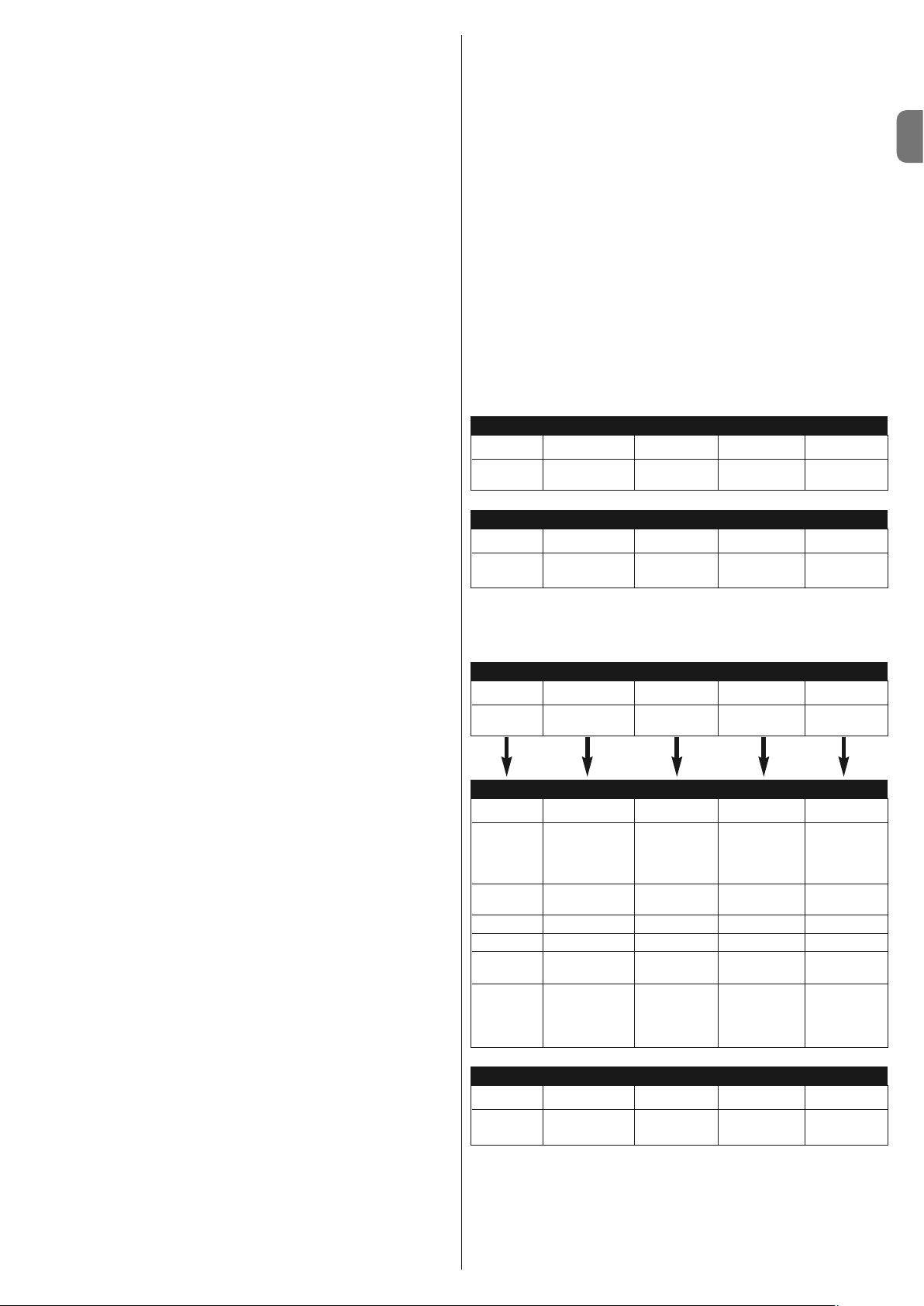
IT
Italiano – 5
persone usano l’automazione con comando via radio. Se questa funzione è
attiva, ogni comando ricevuto provoca una manovra di apertura che non può
essere interrotta da ulteriori impulsi di comando. Se la funzione non è attivata, un comando provoca: APRE-STOP-CHIUDE-STOP.
• Prelampeggio: La funzione permette di attivare il lampeggiante prima dell’ini-
zio della manovra per il tempo di 3 secondi.
Se la funzione non è attivata, il lampeggiante inizia a lampeggiare alla parten-
za della manovra.
• Richiudi dopo foto: Con la chiusura automatica, la funzione permette di
ridurre il tempo pausa a 4 secondi dopo il disimpegno della fotocellula FOTO,
cioè il cancello si chiude 4 secondi dopo che l’utilizzatore è transitato. Se la
funzione non è attivata viene effettuato tutto il tempo di pausa programmato
• Ritardo in apertura: Questa funzione provoca in apertura un ritardo nell’atti-
vazione del motore dell’anta inferiore rispetto a quella superiore necessario
per evitare che le ante possano incagliarsi. Lo sfasamento in chiusura è sempre presente ed è calcolato automaticamente dalla centrale in modo da ottenere lo stesso sfasamento programmato in apertura.
5.2.3 - Programmazioni di primo livello: seconda parte
• Funzione Stand By / Fototest: La centrale ha la funzione “Stand by” pre-
impostata; se questa è attiva, dopo 1 minuto dal termine di una manovra, la
centrale spegne l’uscita “Stand by” (morsetto n° 8), tutti gli Ingressi e le altre
Uscite per ridurre i consumi (vedere schema elettrico di fig. 5a). Questa funzione è obbligatoria se la centrale viene alimentata esclusivamente con pannelli fotovoltaici Solemyo. È consigliata anche se la centrale è alimentata dalla rete elettrica e si desidera aumentare il funzionamento in emergenza con
batteria tampone PS124. In alternativa allo “Stand by”, può essere attivata la
funzione “Fototest” che verifica il corretto funzionamento delle fotocellule collegate all’inizio di una manovra. Per utilizzare questa funzione occorre collegare correttamente le fotocellule (vedere schema elettrico di fig. 5c) e poi attivare la funzione.
• Uscita Spia cancello Aperto / Elettroserratura: Se la funzione è attivata, i
morsetti 6-7 possono essere utilizzati per collegare l’elettroserratura. Se la
funzione non è attivata, i morsetti 6-7 possono essere utilizzati per collegare
una spia di segnalazione di cancello aperto (24 V).
• Ingresso ALT tipo NC o a Resistenza costante: Se la funzione è attivata,
l’ingresso di ALT è impostato a “Resistenza Costante 8.2 KΩ”, in questo caso
per dare il consenso alla manovra, tra il comune e l’ingresso deve essere presente una resistenza da 8.2 KΩ +/-25%. Se la funzione non è impostata, l’ingresso di ALT è configurato per funzionare con contatti del tipo NC.
• Cancelli Leggeri/Pesanti: Se la funzione è attivata, la centrale prevede la
possibilità di gestire cancelli pesanti impostando in modo differente le rampe
di accelerazione e le velocità di rallentamento in chiusura. Se la funzione non
è attivata, la centrale è impostata per gestire cancelli leggeri.
• SCA proporzionale: Se la funzione è attivata, l’uscita SCA è impostata con
lampeggio proporzionale, ossia nella manovra di apertura l’intensità del lampeggio va aumentando man mano che le ante si avvicinano ai finecorsa di
apertura, viceversa nella manovra di chiusura l’intensità del lampeggio va
diminuendo man mano che le ante si avvicinano ai finecorsa di chiusura. Se
la funzione non è attivata, si ha un lampeggio lento in apertura e veloce in
chiusura.
5.2.4 - Funzioni di secondo livello
• Tempo pausa: Il tempo pausa, ossia il tempo intercorso tra la fine di una
manovra di apertura e l’inizio della chiusura automatica, può essere programmato a 5, 10, 20, 40, e 80 secondi.
• Ingresso ausiliario AUX: La centrale prevede un ingresso ausiliario che può
essere configurato in una delle seguenti 6 funzioni:
-
Apertura parziale tipo 1: esegue la stessa funzione dell’ingresso PASSO-PASSO provocando l’apertura solo dell’anta superiore. Funziona solo da cancello
completamente chiuso, altrimenti il comando viene interpretato come se fosse un
comando PASSO-PASSO
- Apertura parziale tipo 2: esegue la stessa funzione dell’ingresso PASSOPASSO provocando l’apertura delle due ante per metà del tempo previsto
per l’apertura totale. Funziona solo da cancello completamente chiuso, altrimenti il comando viene interpretato come se fosse un comando PASSOPASSO
- Solo Apre: questo ingresso esegue solo l’apertura con la sequenza ApreStop-Apre-Stop
- Solo Chiude: questo ingresso esegue solo la chiusura con la sequenza
Chiude-Stop-Chiude-Stop
- Foto 2: esegue la funzione del dispositivo di sicurezza “FOTO 2”
- Escluso: l’ingresso non gestisce nessuna funzione
• Tempo di scaricamento: al termine della manovra di Chiusura, dopo che le
ante hanno raggiunto la chiusura totale, il motore blocca le ante con la forza
programmata. Subito dopo, se questa funzione è attiva, viene comandata
una brevissima inversione del moto allo scopo di allentare la pressione in
eccesso esercitata dal motore sulle ante.
• Sensibilità amperometrica: La centrale dispone di un sistema per la misura
della corrente assorbita dai due motori che viene usato per rilevare i finecorsa
meccanici ed eventuali ostacoli durante il movimento del cancello. Poiché la
corrente assorbita dipende da condizioni variabili (peso cancello, attriti vari,
colpi di vento, variazioni di tensione, ecc..) è stata prevista la possibilità di
modificare la soglia di intervento. Sono previsti 6 livelli: grado 1 è quello più
sensibile (forza minima), grado 6 è quello meno sensibile (forza massima).
ATTENZIONE! – La funzione “amperometrica” opportunamente regolata
(assieme ad altri indispensabili accorgimenti) può essere utile per l’osservanza delle normative europee, EN 12453 ed EN 12445, che richiedono
l’utilizzo di tecniche o dispositivi al fine di limitare le forze e la pericolosità
nel movimento delle porte e cancelli automatici.
• Ritardo anta: Il ritardo in partenza del motore dell’anta inferiore può essere
programmato al 5, 10, 20, 30 o 40% del tempo lavoro.
5.3 - Modalità di programmazione
Tutte le funzioni descritte nel paragrafo 5.2 “Funzioni programmabili”, possono
essere scelte attraverso una fase di programmazione che termina con la
memorizzazione delle scelte fatte. Nella centrale c’è una memoria che mantiene le funzioni e i parametri relativi all’automazione.
Per tutte le fasi di programmazione si utilizzano i tasti P1 P2 e P3, mentre i 5
Led L1,L2…L5 indicheranno il parametro selezionato.
Sono previsti 2 livelli di programmazione:
• Nel primo livello è possibile attivare o disattivare le funzioni. Ogni Led L1,
L2…L5 corrisponde ad una funzione, se il Led è acceso la funzione è attiva,
se spento è disattiva.
l primo livello è costituito da 2 parti selezionabili premendo il tasto P3. Il corrispondente LED P3 indica quale delle 2 parti è selezionata.
Primo livello (Led P1 fisso): seconda parte (led P3
acceso)
Led L1 Led L2 Led L3 Led L4 Led L5
Stand By / Elettroserratura Alt resistivo Cancelli SCA
Fototest pesanti proporzionale
Primo livello (Led P1 fisso): prima parte (led P3 spento)
Led L1 Led L2 Led L3 Led L4 Led L5
Chiusura Funzione Prelampeggio Richiudi dopo Ritardo in
automatica condominiale foto apertura
• Dal primo livello della prima parte, è possibile passare al secondo livello in
cui è possibile scegliere il parametro relativo alla funzione, ad ogni Led corrisponde un diverso valore da associare al parametro.
Primo livello (Led P1 fisso): seconda parte (led P3
acceso)
Led L1 Led L2 Led L3 Led L4 Led L5
Stand By / Elettroserratura Alt resistivo Cancelli SCA
Fototest pesanti proporzionale
Primo livello (Led P1 fisso): prima parte (led P3 spento)
Led L1 Led L2 Led L3 Led L4 Led L5
Chiusura Funzione Prelampeggio Richiudi dopo Ritardo in
automatica condominiale foto apertura
Secondo livello:
Parametro: Parametro: Parametro: Parametro: Parametro:
Tempo Ingresso AUX Tempo Sensibilità Ritardo anta
pausa scaricamento amperometrica
L1: 5s L1: Apre L1: nessun L1: Grado 1 L1: 5%s
parziale TIPO 1 scaricamento (più sensibile)
L2: 10s L2: Apre L2: 0,3s L2: Grado 2 L2: 10%
parziale TIPO 2
L3: 20s L3: Solo Apre L3: 0,7s L3: Grado 3 L3: 20%
L4: 40s L4: Solo Chiude L4: 1,3s L4: Grado 4 L4: 30%
L5: 80s L5: Foto 2 L5: 2s L5: Grado 5 L5: 40%
(meno sensibile)
Tutti i LED spenti: Tutti i LED spenti:
ingresso Grado 6
non usato (amperometrica
max)
Page 20
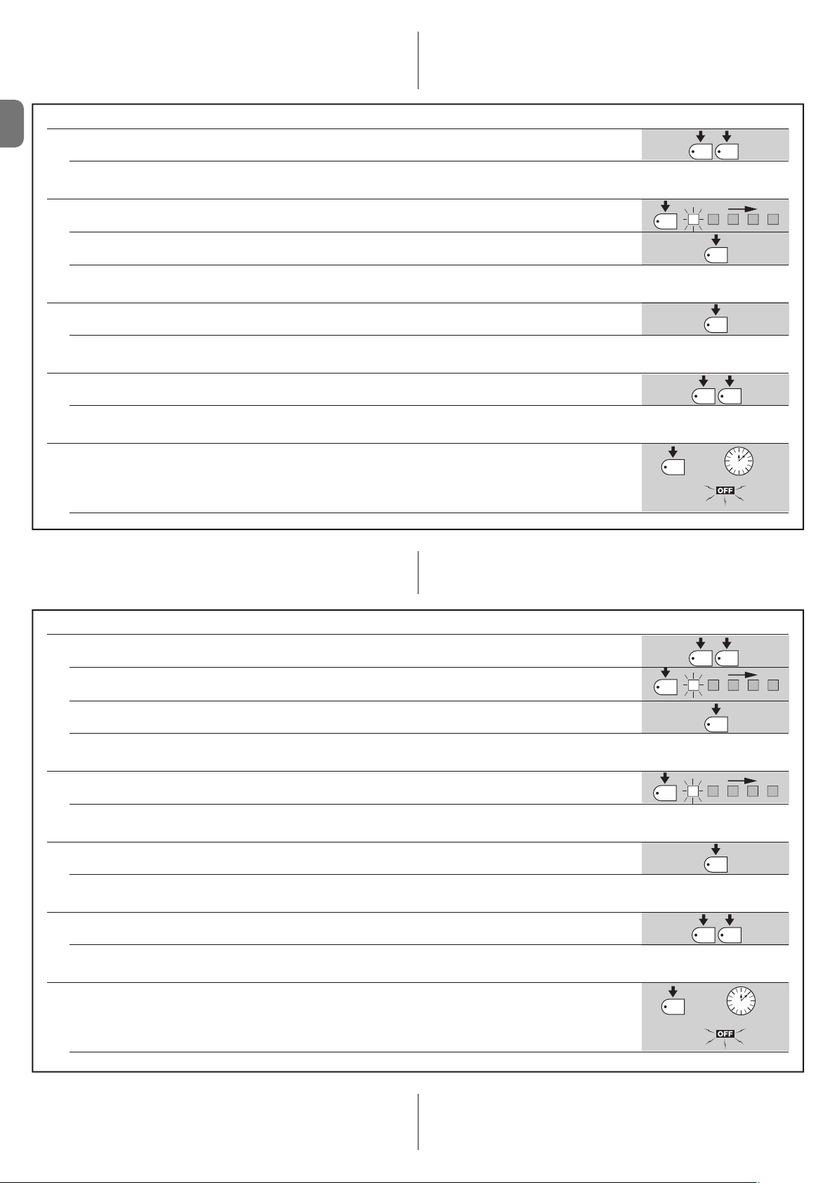
5.3.1 - Programmazione primo livello: funzioni
Nel primo livello è possibile attivare o disattivare le funzioni. Nel primo livello il
Led P1 è sempre acceso, i Led L1,L2…L5 accesi indicano le funzioni attive, i
Led spenti indicano le funzioni disattive. Il Led lampeggiante indica la funzione
selezionata, se il lampeggio è breve la funzione è disattiva, se il lampeggio è lungo la funzione è attiva. Per passare dalla programmazione prima parte alla seconda parte e viceversa premere il tasto P3.
IT
01. Tenere premuti i tasti P1 e P2 per almeno 3 secondi
Un lampeggio veloce di tutti i Led indica che si è entrati in programmazione
TABELLA A1 - Per entrare nella programmazione primo livello
TABELLA A2 - Per attivare o disattivare una funzione
01. Premere ripetutamente P1 fino a portare il Led lampeggiante sulla funzione desiderata
02. Premere P2 per attivare o disattivare la funzione
TABELLA A3 - Per passare dalla prima alla seconda parte del primo livello (e viceversa)
01. Premere il pulsante P3
TABELLA A4 - Per uscire dal primo livello confermando le modifiche
01. Tenere premuto il tasto P1 e immediatamente dopo il tasto P2, mantenendoli premuti per almeno 3 secondi
TABELLA A5 - Per uscire dal primo livello annullando le modifiche
01. Premere P1 per almeno 3 secondi, oppure attendere 1 minuto, oppure spegnere alimentazione
3s
P1
P1
oppure
P1 P2
P1 P2
oppure
P2
P3
3 s
60s
5.3.2 - Programmazione secondo livello: parametri
Nel secondo livello è possibile scegliere i parametri relativi alle funzioni. Il secondo livello si raggiunge solo passando per il primo livello.
Nel secondo livello il Led P1 lampeggia velocemente mentre gli altri 5 led
L1,L2…L5 indicano il parametro selezionato.
TABELLA B1 - Per entrare nella programmazione secondo livello
01. Entrare in programmazione primo livello premendo P1 e P2 per almeno 3 secondi
02. Selezionare la funzione premendo P1 fino a portare il Led lampeggiante sul punto desiderato
03. Entrare nel secondo livello tenendo premuto il tasto P2 per almeno 3 secondi
TABELLA B2 - Per scegliere parametro
01. Premere ripetutamente P2 fino a portare il Led sul parametro desiderato
TABELLA B3 - Per tornare al primo livello
01. Premere il pulsante P1
TABELLA B4 - Per uscire dal primo livello confermando le modifiche
01. Tenere premuto il tasto P1 e immediatamente dopo il tasto P2, mantenendoli premuti per almeno 3 secondi
P1
P2
P1 P2
P2
P1
P1 P2
3 s
3 s
3 s
TABELLA B5 - Per uscire dal primo livello annullando le modifiche
01. Premere P1 per almeno 3 secondi, oppure attendere 1 minuto, oppure spegnere alimentazione
5.3.3 - Cancellazione della memoria
Ogni nuova programmazione sostituisce le impostazioni precedenti, quindi normalmente non è necessario “cancellare tutti i parametri”. In ogni caso la cancellazione totale della memoria è possibile con questa semplice operazione:
6 – Italiano
ATTENZIONE – Dopo la cancellazione della memoria, tutte le funzioni
ritornano ai valori pre-impostati ed è necessario procedere ad una nuova
ricerca dei finecorsa.
3s
P1
oppure
oppure
60s
Page 21
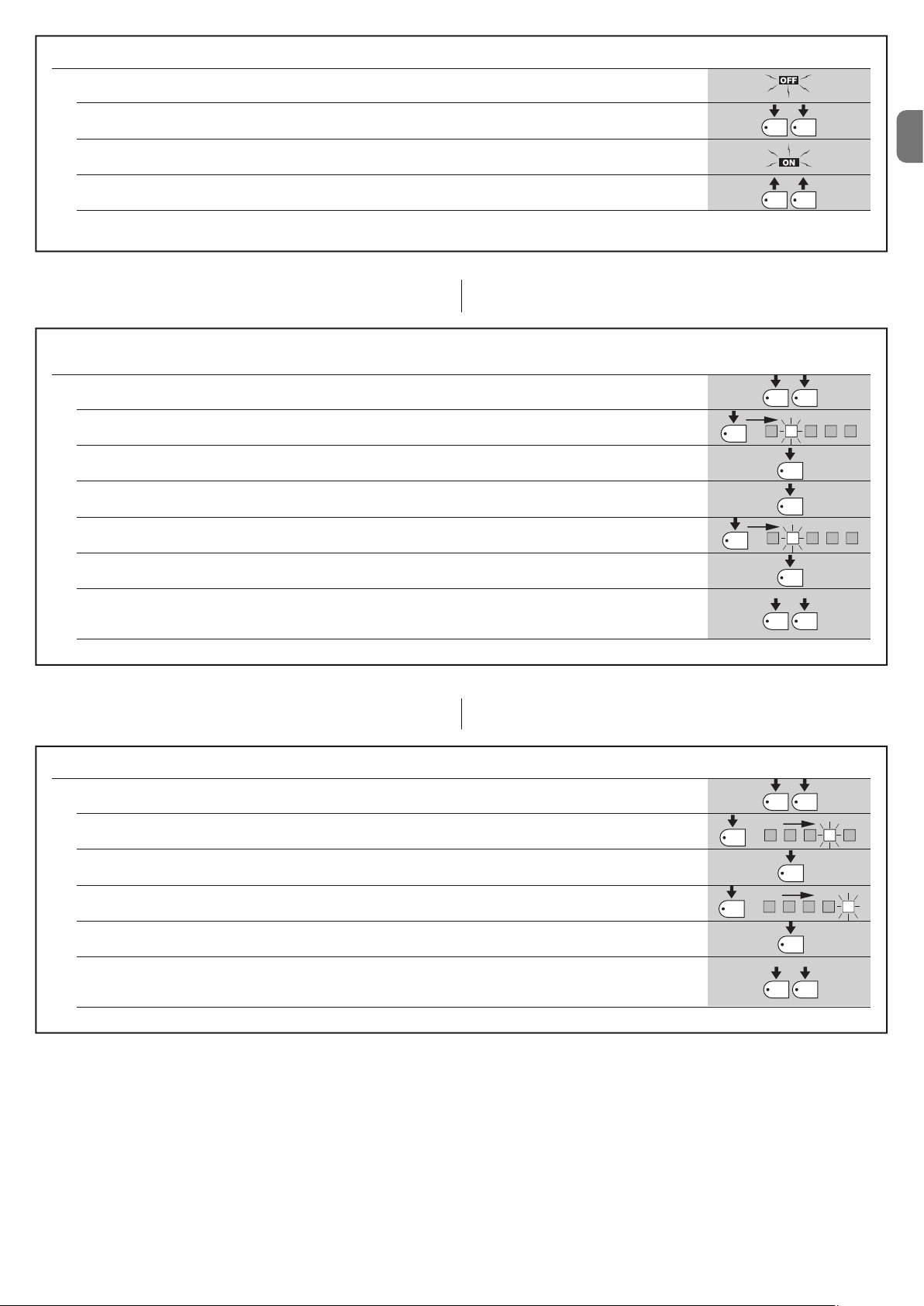
TABELLA C1 - Per cancellare la memoria
01. Spegnere l’alimentazione alla centrale ed aspettare che tutti i LED siano spenti (eventualmente togliere il fusibile F1)
02. Premere e tenere premuti i due tasti P1 e P2 sulla scheda
03. Ridare alimentazione alla centrale
04. Attendere almeno 3 secondi quindi rilasciare i due tasti
Se la cancellazione della memoria è andata a buon fine tutti il led si spengono per 1 secondo
5.3.4 - Esempio di programmazione primo livello
In questi esempi riporteremo i passi necessari per attivare e disattivare una fun-
zione al primo livello, come esempio si attiverà la funzione “Condominiale” e si
predispone l’uscita “SCA” per attivare l’elettroserratura.
Esempio di programmazione primo livello:
attivare la funzione “Condominiale” e attivare uscita per “elettroserratura”
01. Entrare in programmazione primo livello premendo P1 e P2 per almeno 3 secondi
02. Premere 1 volta P1 fino a portare il Led lampeggiante sul led 2 (il lampeggio è breve)
03. Attivare la funzione “Condominiale” premendo P2 (il lampeggio sarà lungo)
04. Premere una volta P3 per attivare la seconda parte (si accende il led di P3)
05. Premere 1 volta P1 per portare il Led lampeggiante sul led 2 (il lampeggio è breve)
P1
P1
x1
P1 P2
P1 P2
P1 P2
2
P2
P3
2
IT
3s
3s
06. Attivare l’uscita “Elettroserratura” premendo P2 (il lampeggio sarà lungo)
07. Uscire dalla programmazione, con memorizzazione, tenendo premuto il tasto P1 e immediatamente dopo il tasto P2,
mantenendoli premuti per almeno 3 secondi
5.3.5 - Esempio di programmazione secondo livello
In questo esempio riporteremo i passi necessari per modificare un parametro al
secondo livello, come esempio si modificherà la sensibilità dell’amperometrica
fino a “livello 5”.
Esempio di programmazione secondo livello: modificare la “sensibilità dell’amperometrica”
01. Entrare in programmazione primo livello premendo P1 e P2 per almeno 3 secondi
02. Premere 3 volte P1 fino a portare il Led lampeggiante sul led 4
03. Passare al secondo livello premendo P2 per almeno 3 secondi
04. Premere 3 volte P2 fino a che il led 5 è acceso
05. Tornare al primo livello premendo P1
06. Uscire dalla programmazione, con memorizzazione, tenendo premuto il tasto P1 e immediatamente dopo il tasto P2,
mantenendoli premuti per almeno 3 secondi
P2
P1
x3
x3
P2
P1 P2
P1 P2
P2
P1
P1 P2
3s
3s
4
3s
5
3s
Italiano – 7
Page 22
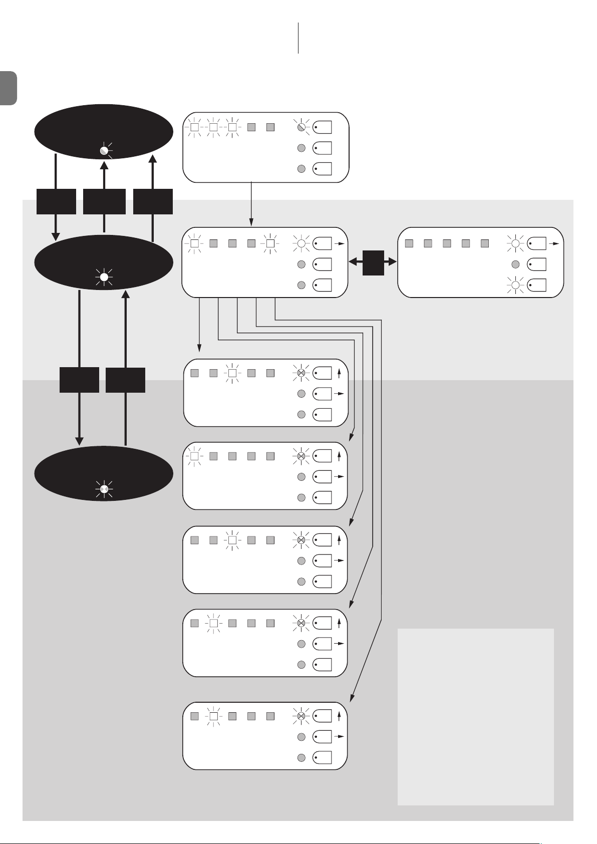
5.3.6 - Schema per la programmazione
Nella seguente figura è riportato lo schema completo della programmazione
delle funzioni e dei relativi parametri. Nella stessa figura sono indicate le funzio-
IT
Funzionamento
Normale
Led P1 lampeggio lento
ALT Foto Foto1Passo
Passo
AUX
ni ed i parametri pre-impostati inizialmente o dopo una cancellazione completa
della memoria.
P1
P2
P3
P1+P2
per 3 sec
P1
per 3 sec
(non salva)
per 3 sec
Primo Livello
Led P1 acceso fisso
P2
per 3 sec
P1
Secondo Livello
Led P1 lampeggio veloce
P1+P2
(salva)
Chius.
Cond. Prel. Rich.
Auto
Dopo
foto
TEMPO PAUSA
5 10 20
40 80
secondi
INGRESSO AUSILIARIO (*)
a.p.
a.p.
solo
Tipo 1
Tipo 2
apre
solo
chiude
Rit.
Aper.
Foto 2
P1
P2
P3
P1
P2
P3
P1
P2
P1
Stantby
On
Off
P3
Fotot.
Elettros. ALT
Res.
Canc.
Pesanti
SCA
Prop.
P2
On
Off
P3
SCARICAMENTO
0 0,3 0,7
1,3 2
secondi
SENSIBILITÀ AMPEROMETRICA
123
45
grado
tutti i Led spenti · amperometrica max
RITARDO IN APERTURA
5 10 20%30 40
P3
P1
P2
P3
P1
P2
P3
P1
P2
P3
(*)
a.p. TIPO 1 Apertura parziale tipo 1,
movimento della sola anta
superiore [contatto N.A.]
a.p. TIPO 2 Apertura parziale tipo 2,
movimento di entrambi i motori
per 1/2 del tempo lavoro
[contatto N.A.]
Solo Open open stop open stop...
[contatto N.A.]
Solo Chiude chiude stop chiude stop...
[contatto N.A.]
Photo 2 Utilizzato come photo 2
[contatto N.C.]
8 – Italiano
Page 23
IT
Italiano – 9
6.1 - Collegamento di un ricevitore radio
La centrale dispone di un connettore per l’inserimento di una scheda radio a 4
canali con innesto SM, che permette di comandare la centrale a distanza tramite trasmettitori che agiscono sugli ingressi come dalla seguente tabella:
Uscita Ricevitore Ingresso centrale
N° 1 Passo Passo
N° 2 AUX (valore preimpostato: Apre parziale 1)
N° 3 “Solo Apre”
N° 4 “Solo Chiude”
6.2 - Collegamento della batteria tampone mod. PS124
La centrale è predisposta per essere alimentata da batterie tampone PS124 in
caso di mancanza di tensione di rete. Per eseguire l’installazione e il collegamento della batteria, procedere come mostrato in fig. 10.
6.3 - Collegamento del sistema Solemyo
La centrale è predisposta per essere alimentata con il sistema di alimentazione
fotovoltaica “Solemyo” (pannello fotovoltaico e batteria a 24 V). Per collegare
l'accumulatore di Solemyo alla centrale, utilizzare su quest'ultima la presa normalmente utilizzata per la batteria tampone (vedere paragrafo 6.2).
IMPORTANTE!
- Quando l’automazione viene alimentata dal sistema “Solemyo”, questa
NON DEVE E SSER E ALIM ENTATA co ntemporaneamente anche dalla rete
elettrica.
- Il sistema “Solemyo” può essere utilizzato solo se nella centrale è attiva
(ON) la funzione “Stand by” e se le connessioni rispettano lo schema di
fig. 5a.
APPROFONDIMENTI: accessori
6
Nessun LED risulta acceso:
• Verificare se la centrale è alimentata: misurare sui morsetti 9-10 una tensione
di circa 30 Vdc (oppure 24 Vdc con alimentazione a batteria).
• Verificare i 2 fusibili, se neppure il Led P1 è acceso o lampeggiante è probabile sia presente un guasto grave quindi la centrale dovrà essere sostituita.
Il Led P1 lampeggia regolarmente ma i led ingressi L1, L2...L5 non rispecchiano lo stato dei rispettivi ingressi
• Spegnere momentaneamente l’alimentazione per uscire da una possibile
fase di programmazione.
• Verificare con attenzione i collegamenti sui morsetti 11..16
Il Led P1 lampeggia ogni 4 secondi
• La centrale è nello stato di Stand by.
Non si avvia la procedura di “Ricerca automatica”
• La procedura di “Ricerca automatica” si attiva solo se non è mai stata effettuata o se la memoria è stata cancellata. Per verificare se la memoria è vuota
spegnere momentaneamente l’alimentazione, all’accensione tutti i LED devono lampeggiare velocemente per circa 6 secondi. Se lampeggiano solo per 3
secondi la memoria contiene già valori validi. Se si vuole eseguire una nuova
“Ricerca automatica” è necessario cancellare completamente la memoria.
La “Ricerca automatica” non è mai stata eseguita ma la procedura non si
avvia o si comporta erroneamente
• Per attivare la procedura di “Ricerca automatica” è necessario che l’impianto
con tutti i dispositivi di sicurezza risulti funzionante.
• Assicurarsi che nessun dispositivo collegato agli ingressi intervenga durante
la “Ricerca automatica”.
• Perché la “Ricerca automatica” si avvii correttamente, i Led sugli ingressi
devono essere accesi come indicato in fig. 11, il Led P1 deve lampeggiare
una volta al secondo.
La “Ricerca automatica”è stata eseguita correttamente ma la manovra
non parte
• Verificare che i LED delle sicurezze (ALT, FOTO, FOTO1 ed eventualmente
FOTO2) siano accesi e che il LED del comando che viene attivato (PASSOPASSO o AUX) si accenda per la durata del comando.
• Se è attivo il funzionamento “Fototest” e le fotocellule non funzionano correttamente, il Led DIAGNOSTICA segnala l’anomalia con 4 lampeggi.
Durante il movimento il cancello effettua un’inversione
Le cause che provocano un’inversione sono:
• Un intervento delle fotocellule (FOTO2 in apertura, FOTO o FOTO1 durante la
chiusura); in questo caso controllare i collegamenti delle fotocellule ed eventualmente verificare i LED di segnalazione degli ingressi.
• Un intervento dell’amperometrica durante la corsa dei motori (quindi non vicino agli arresti meccanici) viene considerato come ostacolo e provoca una
COSA FARE SE...
(guida alla risoluzione dei problemi)
7
inversione. Per controllare se è avvenuto un intervento amperometrica contare i lampeggi del LED Diagnostica: 1 lampeggio segnala l’intervento di amperometrica sul motore 1, 2 lampeggi sul motore 2.
MANUTENZIONE DEL PRODOTTO
8
La centrale MC424, come parte elettronica, non necessita di alcuna manutenzione particolare. Verificare comunque periodicamente, almeno ogni 6 mesi, la
perfetta efficienza dell’intero impianto secondo quanto riportato nel capitolo 3.
SMALTIMENTO DEL PRODOTTO
Questo prodotto è parte integrante dell’automazione, e dunque, deve
essere smaltito insieme con essa.
Come per le operazioni d’installazione, anche al termine della vita di questo
prodotto, le operazioni di smantellamento devono essere eseguite da personale qualificato.
Questo prodotto è costituito da vari tipi di materiali: alcuni possono essere riciclati, altri devono essere smaltiti. Informatevi sui sistemi di riciclaggio o smaltimento previsti dai regolamenti vigenti sul vostro territorio, per questa categoria
di prodotto.
Attenzione! – alcune parti del prodotto possono contenere sostanze inquinanti o pericolose che, se disperse nell’ambiente, potrebbero provocare effetti dannosi sull’ambiente stesso e sulla salute umana.
Come indicato dal simbolo a lato, è vietato gettare questo
prodotto nei rifiuti domestici. Eseguire quindi la “raccolta
separata” per lo smaltimento, secondo i metodi previsti dai
regolamenti vigenti sul vostro territorio, oppure riconsegnare
il prodotto al venditore nel momento dell’acquisto di un nuovo prodotto equivalente.
Attenzione! – i regolamenti vigenti a livello locale possono prevedere pesanti
sanzioni in caso di smaltimento abusivo di questo prodotto.
Page 24

IT
10 – Italiano
DICHIARAZIONE CE DI CONFORMITÀ
Nota - Il contenuto di questa dichiarazione corrisponde a quanto dichiarato nell’ultima revisione disponibile, prima della stampa di questo manuale, del documento ufficiale depositato presso la sede di Nice Spa. Il presente testo è stato riadattato per motivi editoriali.
Numero: 296/MC424 Revisione: 0
Il sottoscritto Lauro Buoro in qualità di Amministratore Delegato, dichiara sotto la propria responsabilità che il prodotto:
Nome produttore: NICE s.p.a.
Indirizzo: Via Pezza Alta 13, Z.I. Rustignè, 31046 Oderzo (TV) Italia
Tipo: Centrale di comando a 2 motori 24 Vd.c.
Modelli: MC424
Accessori: Ricevente radio SMXI, SMXIS
Risulta conforme a quanto previsto dalle seguenti direttive comunitarie:
• 98/37/CE (89/392/CEE modificata) DIRETTIVA 98/37/CE DEL PARLAMENTO EUROPEO E DEL CONSIGLIO del 22 giugno 1998 concernente il ravvicinamento delle legislazioni degli Stati membri relative alle macchine
Come previsto dalla direttiva 98/37/CE si avverte che non è consentita la messa in servizio del prodotto sopra indicato finché la macchina, in cui il prodotto è incorporato, non sia stata identificata e dichiarata conforme alla direttiva 98/37/CE.
Inoltre il prodotto risulta conforme a quanto previsto dalle seguenti direttive comunitarie:
• 2006/95/CEE(ex direttiva 73/23/CE) DIRETTIVA 2006/95/CE DEL PARLAMENTO EUROPEO E DEL CONSIGLIO del 12 dicembre 2006 concernente il
ravvicinamento delle legislazioni degli Stati membri relative al materiale elettrico destinato ad essere adoperato entro taluni limiti di tensione
Secondo le seguenti norme armonizzate: EN 60335-1:1994+A11:1995+A1:1996+A12:1996+A13:1998+A14:1998+A15:2000+A2:2000+A16:2001
• 2004/108/CEE(ex direttiva 89/336/CEE) DIRETTIVA 2004/108/CE DEL PARLAMENTO EUROPEO E DEL CONSIGLIO del 15 dicembre 2004 concernente il ravvicinamento delle legislazioni degli Stati membri relative alla compatibilità elettromagnetica e che abroga la direttiva 89/336/CEE
Secondo le seguenti norme armonizzate: EN 61000-6-2:2001; EN 61000-6-3:2001+A11:2004
Inoltre risulta conforme; limitatamente per le parti applicabili, alle seguenti norme:
EN 60335-1:2002+A1:2004+A11:2004+A12:2006+ A2:2006, EN 60335-2-103:2003, EN 13241-1:2003; EN 12453:2002; EN 12445:2002;
EN 12978:2003
Oderzo, 25 settembre 2008
Lauro Buoro (Amministratore Delegato)
AVVERTENZE: • Tutte le caratteristiche tecniche riportate, sono riferite ad una temperatura ambientale di 20°C (± 5°C). • Nice S.p.a. si riserva il diritto di appor-
tare modifiche al prodotto in qualsiasi momento lo riterrà necessario, mantenendone comunque la stessa funzionalità e destinazione d’uso.
Alimentazione di rete Centrale MC424: 230 V~ ±10% 50 - 60 Hz
Centrale MC424/V1: 120 V~ ±10% 50 - 60 Hz
Potenza max assorbita 170 W
Alimentazione di emergenza predisposta per batterie tampone PS124 e per kit solare Solemyo
Corrente massima motori 3 A (con livello intervento amperometrica “grado 6”)
Uscita alimentazione servizi 24 V corrente massima 200 mA (la tensione può variare da 16 a 33 V )
Uscita fototest 24 V corrente massima 100 mA (la tensione può variare da 16 a 33 V )
Uscita lampeggiante per lampeggianti 24 V , potenza massima 25 W (la tensione può variare da 16 a 33 V )
Uscita spia cancello per lampade 24 V potenza massima 5 W (la tensione può variare da 16 a 33 V )
oppure elettroserrature 12 V~ 25 W
Ingresso ALT per contatti NC oppure resistenza costante 8,2 KΩ +/- 25%
Tempo lavoro rilevato automaticamente
Tempo pausa programmabile a 5, 10, 20, 40, 80 secondi
Tempo scaricamento programmabile a 0, 0,3, 0,7, 1,3, 2 secondi
Ritardo anta in apertura programmabile a 5, 10, 20, 30 e 40% del tempo lavoro
Ritardo anta in chiusura rilevato automaticamente
Uscita 1° motore per motori Wingo WG4024 - WG5024
Uscita 2° motore per motori Wingo WG4024 - WG5024
Lunghezza max cavi alimentazione 230 V 30 m
alimentazione kit solare Solemyo 3 m
motori 10 m
altri ingressi/uscite 30 m
lampeggiante 10 m
SCA 30 m
elettroserratura 10 m
antenna 20 m (consigliato minore di 3 m)
Ricevitore radio Innesto tipo “SM” per ricevitori SMXI, SMXIS, OXI (Modo I e Modo II)
Temperatura di esercizio da - 20 a 50 °C
Grado di protezione IP 54 a contenitore integro
Dimensioni (mm) 310 x 232 x H 122
Peso (kg) 4,1
CARATTERISTICHE TECNICHE DEL PRODOTTO
Page 25
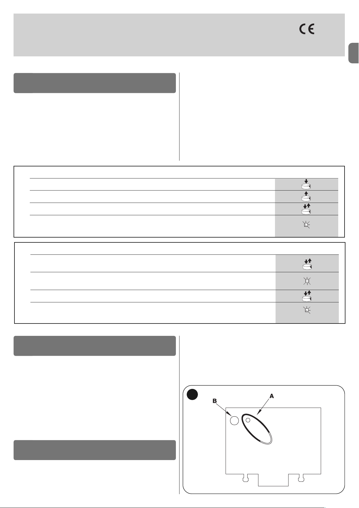
IT
Italiano – 11
smxi - smixs ricevitore radio
0682
SMXI, SMXIS sono ricevitori radio a 4 canali per centrali dotate dell’inesto SM. I
trasmettitori compatibili hanno la particolarità che il codice di riconoscimento
risulta diverso per ogni trasmettitore. Quindi per permettere al ricevitore di riconoscere un determinato trasmettitore occorre procedere alla memorizzazione
del codice di riconoscimento. Questa operazione di inserimento va ripetuta per
ogni trasmettitore che si voglia utilizzare per comandare la centrale.
Note:
– Nel ricevitore posso essere memorizzati fino ad un massimo di 256 trasmet
titori. Non è prevista la cancellazione di un singolo trasmettitore ma solo la cancellazione totale di tutti i codici.
– Per funzioni più avanzate utilizzare l’apposita unità di programmazione.
DESCRIZIONE DEL PRODOTTO
1
Il ricevitore dispone di 4 uscite Tutte disponibili sul connettore sottostante, per
sapere quale funzione è svolta da ogni uscita vedere capitolo 6.1.
Nella fase di memorizzazione del codice del trasmettitore è possibile scegliere
tra queste 2 opzioni:
Modo I - Tabella B1: ogni tasto del trasmettitore attiva la corrisponde uscita
nel ricevitore, cioè il tasto 1 attiva l’uscita 1, il tasto 2 attiva l’uscita 2, e così via.
In questo caso c’è un’unica fase di memorizzazione per ogni trasmettitore,
durante questa fase non ha importanza quale tasto viene premuto, e viene
occupato un solo posto in memoria.
Modo II - Tabella B2: ad ogni tasto del trasmettitore può essere associata
una particolare uscita del ricevitore, esempio il tasto 1 attiva l’uscita 2, il tasto 2
attiva l’uscita 1, eccetera. In questo caso bisogna memorizzare il trasmettitore,
premendo il tasto desiderato, per ogni uscita da attivare. Naturalmente ogni
tasto può attivare una sola uscita, mentre la stessa uscita può essere attivata
da più tasti. Viene occupato un posto in memoria per ogni tasto.
TABELLA B1 - Memorizzazione modo I (tutti i tasti vengono memorizzati sulla rispettiva uscita della ricevente)
01. Premere e tenere premuto il pulsante sul ricevitore per almeno 3 secondi
02. Quando il Led si accende, rilasciare il pulsante
03.
Entro 10 secondi premere per almeno 2 secondi un qualsiasi tasto del trasmettitore da memorizzare
Nota –
se la memorizzazione è andata a buon fine il Led sul ricevitore farà 3 lampeggi se ci sono altri trasmettitori da
memorizzare, ripetere il passo 3 entro altri 10 secondi la fase di memorizzazione termina se per 10 secondi non vengono
ricevuti nuovi codici
3s
2s
x3
INSTALLAZIONE ANTENNA
2
Per ottenere un buon funzionamento il ricevitore necessita di un’antenna di tipo
ABF o ABFKIT; senza antenna la portata si riduce a pochi metri. L’antenna deve
essere installata più in alto possibile; in presenza di strutture metalliche o di
cemento armato, installare l’antenna al di sopra di queste. Se il cavo in dotazione all’antenna è troppo corto, impiegare cavo coassiale con impedenza 50 ohm
(es. RG58 a bassa perdita), il cavo non deve superare la lunghezza di 10 m.
Qualora l’antenna installata dove non ci sia un buon piano di terra (strutture
murarie) è possibile collegare il morsetto della calza a terra ottenendo così una
maggiore portata. Naturalmente la presa di terra deve essere nelle vicinanze e
di buona qualità. Nel caso non sia possibile installare l’antenna accordata ABF
o ABFKIT si possono ottenere dei discreti risultati usando come antenna lo
spezzone di filo fornito col ricevitore, montato disteso.
ATTENZIONE – Quando si attiva la fase di memorizzazione, qualsiasi trasmettitore correttamente riconosciuto nel raggio di ricezione
della radio viene memorizzato. Valutare con attenzione questo
aspetto, eventualmente staccare l’antenna per ridurre la capacità
del ricevitore.
MEMORIZZAZIONE DI UN TELECOMANDO
3
Le procedure per la memorizzazione dei telecomandi hanno un tempo limite
per essere eseguite; è necessario quindi leggere e comprendere tutta la procedura prima di iniziare le operazioni.
Per eseguire la procedura seguente, è necessario utilizzare il pulsante presente sul box del ricevitore radio (riferimento A, fig. 1a) ed il rispettivo Led (riferi-
mento B, fig. 1a) alla sinistra del tasto.
1a
TABELLA B2 - Memorizzazione modo II (ad ogni tasto può essere associata una particolare uscita della ricevente)
01.
Premere e rilasciare il pulsante sul ricevitore un numero di volte uguale
all'uscita desiderata
(1 volta per uscita n°1, 2 volte per uscita n°2)
02. Verificare che il Led emette un numero di lampeggi uguali all'uscita voluta, ripetuti a cadenza regolare nei 10 sec.
(1 lampeggio se uscita n°1, 2 lampeggi se uscita n°2)
03.
Entro 10 secondi premere per almeno 2 secondi il tasto desiderato del trasmettitore da memorizzare
Nota –
se la memorizzazione è andata a buon fine il Led sul ricevitore farà 3 lampeggi se ci sono altri trasmettitori da
memorizzare, ripetere il passo 3 entro altri 10 secondi la fase di memorizzazione termina se per 10 secondi non vengono
ricevuti nuovi codici
2s
x3
RX
RX
RX
TX
TX
Page 26
IT
12 – Italiano
Memorizzazione a distanza
È possibile memorizzare un nuovo trasmettitore nella memoria del ricevitore
senza agire direttamente sul tastino. È necessario disporre di un telecomando
già memorizzato e funzionante. Il nuovo trasmettitore “erediterà” le caratteristiche di quello già memorizzato. Quindi se il primo trasmettitore è memorizzato in
modo I anche il nuovo sarà memorizzato in modo I e si potranno premere uno
qualunque dei tasti dei trasmettitori. Se il primo trasmettitore è memorizzato in
modo II anche il nuovo sarà memorizzato in modo II ma occorre premere, nel
primo trasmettitore il tasto che attiva l’uscita desiderata, e nel secondo trasmettitore il tasto che si vuol memorizzare. È necessario leggere tutte le istruzioni per poi eseguire le operazioni una dopo l’altra senza interruzioni. Ora con i
due telecomandi che chiameremo NUOVO quello con il codice da inserire, e
VECCHIO quello già memorizzato, porsi nel raggio di azione dei radiocomandi
(entro la portata massima) ed eseguire i passi riportati in tabella.
TABELLA B4 - Cancellazione di tutti i trasmettitori
01. Premere e tenere premuto il pulsante sul ricevitore
02. Aspettare che il Led si accenda, poi aspettare che si spenga, quindi aspettare che emetta 3 lampeggi
03. Rilasciare il tasto esattamente durante il 3° lampeggio
Nota –
se
a procedura è andata a buon fine, dopo qualche istante, il Led emetterà 5 lampeggi
x3
3°
x5
È possibile cancellare tutti i codici presenti in memoria con la seguente procedura:
CANCELLAZIONE DI TUTTI I TRASMETTITORI
4
CARATTERISTICHE TECNICHE DEL PRODOTTO
Ricevitori: SMXI SMXIS
Decodifica Rolling code a 52 bit FLOR Rolling code a 64 bit SMILO
Compatibilità trasmettitori FLOR, VERY VR, NICE WAY, ERGO, PLANO, NICE ONE SMILO
Frequenza 433.92 MHz 433.92 MHz
Impedenza di ingresso 52 KΩ 52 KΩ
Uscite 4 (su connettore SM) 4 (su connettore SM)
Sensibilità migliore di 0.5 µV migliore di 0.5 µV
Temperatura di funzionamento da -10° C a + 55° C da -10° C a + 55° C
Trasmettitori: FLO2R SMILO
Tasti 1, 2 oppure 4 a seconda delle versioni 2 oppure 4
Alimentazione 12 V Batt. 23 A 12 V Batt. 23 A
Assorbimento 10 mA 25 mA
Frequenza di trasmissione 433.92 MHz 433.92 MHz
Temp. di funzionamento da -10° C a + 55° C a -10° C a + 55° C
Potenza irradiata stimata circa 1 mW E.R.P. stimata circa 1 mW E.R.P.
Portata stimata 200 m (al l’esterno); 35 m (se all’interno di edifici) stimata 200 m (al l’esterno); 35 m (se all’interno di edifici)
Dimensioni / Peso 69 x 39 x 15,5 mm / 31 g. Ø 48 mm x H 14 mm - 14 g
Codifica digitale (4,5 milioni di miliardi di combinazioni) digitale (18 miliardi di miliardi di combinazioni)
AVVERTENZE: • Tutte le caratteristiche tecniche riportate, sono riferite ad una temperatura ambientale di 20°C (± 5°C). • Nice S.p.a. si riserva il diritto di appor-
tare modifiche al prodotto in qualsiasi momento lo riterrà necessario, mantenendone comunque la stessa funzionalità e destinazione d’uso. • La portata dei trasmettitori e la capacità di ricezione dei Ricevitori può essere soggetta ad interferenze che ne possono alterare le prestazioni. Nei casi di queste interferenze, Nice
non può offrire nessuna garanzia circa la reale portata dei propri dispositivi.
TABELLA B3 - Memorizzazione a distanza
01. Premere per almeno 5 secondi il tasto sul NUOVO trasmettitore, poi rilasciare
02. Premere lentamente per 3 volte il tasto sul VECCHIO trasmettitore
03. Premere lentamente per 1 volta il tasto sul NUOVO trasmettitore, poi rilasciare
Nota –
se
ci sono altri trasmettitori da memorizzare, ripetere tutti i passi per ogni nuovo trasmettitore
1s
x1
1s1s
x5s
TX
TX TX TX
TX
TX
RX
RX
Page 27

FR
Français – 1
FRANÇAIS
Recommandations pour la sécurité
• ATTENTION ! – Ce guide contient des instructions et des recommanda-
tions importantes pour la sécurité des personnes. Une installation erronée peut causer de graves blessures. Avant de procéder à l’installation, il faut
lire attentivement toutes les parties du guide. En cas de doutes, suspendre
l’installation et demander des éclaircissements au Service Assistance Nice.
• ATTENTION ! – Instructions importantes : conserver avec soin ce guide
pour faciliter les éventuelles interventions futures de maintenance ou de
mise au rebut du produit.
Avertissements pour l’installation
• Avant de commencer l’installation, vérifier si le présent produit est adapté au
type d’utilisation désirée (voir paragraphe 2.2 « Limites d’utilisation » et chapitre « Caractéristiques techniques du produit »). S’il n’est pas adapté, NE PAS
procéder à l’installation.
• Au cours de l’installation, manipuler le produit avec précaution en évitant les
écrasements, les chocs, les chutes ou le contact avec des liquides de n’importe quelle nature. Ne pas mettre le produit à proximité de fortes sources de
chaleur ni l’exposer à des flammes vives. Toutes ces actions peuvent l’endommager et causer des problèmes de fonctionnement ou des situations de
danger. Si cela se produit, suspendre immédiatement l’installation et s’adresser au service après-vente Nice.
• Ne pas effectuer de modifications sur une partie quelconque du produit. Les
opérations non autorisées ne peuvent que provoquer des problèmes de
fonctionnement. Le constructeur décline toute responsabilité pour les dommages dérivant de modifications arbitraires au produit.
• Le produit n’est pas destiné à être utilisé par des personnes (enfants compris) aux capacités physiques, sensorielles ou mentales réduites, ou manquant d’expérience ou de connaissances, à moins que celles-ci aient pu
bénéficier, par l’intermédiaire d’une personne responsable de leur sécurité,
d’une surveillance ou d’instructions sur l’utilisation du produit.
• Ne pas laisser les enfants jouer avec les dispositifs de commande de l’automatisme. Conserver les émetteurs hors de portée des enfants.
• Les enfants doivent être surveillés pour s’assurer qu’ils ne jouent pas avec
l’appareil.
• Prévoir, sur la ligne d’alimentation de l’installation, un dispositif de déconne xion avec une distance d’ouverture des contacts permettant la déconnexion
complète dans les conditions prescrites par la catégorie de surtension III.
• La logique de commande doit être connectée à une ligne d’alimentation électrique avec mise à la terre.
• Les matériaux de l’emballage du produit doivent être mis au rebut dans le
plein respect des normes locales en vigueur.
RECOMMANDATIONS ET PRÉCAUTIONS
GÉNÉRALES
La logique de commande MC424 est destinée à la commande d’opérateurs
électromécaniques Wingo à 24 V, pour l’automatisation de portes ou portails
battants. ATTENTION ! - Toute autre utilisation que celle décrite et dans
des conditions ambiantes différentes de celles indiquées dans ce guide
doit être considérée comme impropre et interdite !
La logique de commande MC424 dispose d’un système qui vérifie l’effort des
moteurs qui lui sont connectés (ampèremétrique) ; ce système permet de
détecter automatiquement les fins de course, de mémoriser le temps de travail
de chaque moteur et de reconnaître les éventuels obstacles au cours d’une
manœuvre normale. Cette caractéristique facilite l’installation vu qu’il n’y a
besoin d’aucun réglage des temps de travail et de décalage des vantaux.
La logique de commande est préprogrammée sur les fonctions normalement
demandées ; éventuellement, à travers une simple procédure, on peut choisir
des fonctions plus spécifiques (voir chapitre 5).
La logique de commande est prévue pour être alimentées par des batteries
tampon PS124 comme alimentation de secours, en cas de coupure de la tension de secteur (pour tout détail voir chapitre 6.2) ; elle est prévue également
pour être connectée au système d’alimentation à énergie solaire « Solemyo »
(pour tout détail voir chapitre 6.3).
DESCRIPTION DU PRODUIT
1
Pour préciser certains termes et certains aspects d’une installation d’automatisation de portes ou portails à 2 battants, se référer à l’installation typique illustrée fig. 1.
Légende fig. 1 :
1. Opérateur électromécanique Wingo à 24 V
2. Opérateur électromécanique Wingo à 24 V
INSTALLATION
2
Sommaire
AVERTISSEMENTS ET PRÉCAUTIONS GÉNÉRALES . . . . . . . . . 1
1 – DESCRIPTION DU PRODUIT . . . . . . . . . . . . . . . . . . . . . . . . . . . . . . 1
2 – INSTALLATION . . . . . . . . . . . . . . . . . . . . . . . . . . . . . . . . . . . . . . . . . . 1
2.1 - CONTRÔLES AVANT L’INSTALLATION . . . . . . . . . . . . . . . . . . . 2
2.2 - LIMITES D’UTILISATION DU PRODUIT . . . . . . . . . . . . . . . . . . . 2
2.3 - INSTALLATION . . . . . . . . . . . . . . . . . . . . . . . . . . . . . . . . . . . . . . 2
2.4 - CONNEXIONS ÉLECTRIQUES . . . . . . . . . . . . . . . . . . . . . . . . . . 2
2.4.1 - Notes sur les connexions . . . . . . . . . . . . . . . . . . . . . . . . 3
2.4.2 - Typologie d’entrée HALTE . . . . . . . . . . . . . . . . . . . . . . . . 3
2.4.3 - Exemples de connexions photocellules : avec la fonction
STAND-BY active et la fonction phototest désactive . . . . . . . . 3
2.4.4 - Exemples de connexions photocellules : avec la fonction
phototest active et la fonction STAND-BY désactivée . . . . . . . 3
2.5 - PREMIÈRE MISE EN SERVICE ET VÉRIFICATION . . . . . . . . . . .
DES CONNEXIONSI . . . . . . . . . . . . . . . . . . . . . . . . . . . . . . . . . . . . . . 3
2.6 - RECHERCHE AUTOMATIQUE DES FINS DE COURSE . . . . . . 3
3 – ESSAI ET MISE EN SERVICE . . . . . . . . . . . . . . . . . . . . . . . . . . . . . 4
3.1 - ESSAI . . . . . . . . . . . . . . . . . . . . . . . . . . . . . . . . . . . . . . . . . . . . . . 4
3.2 - MISE EN SERVICE . . . . . . . . . . . . . . . . . . . . . . . . . . . . . . . . . . . 4
4 – DIAGNOSTIC . . . . . . . . . . . . . . . . . . . . . . . . . . . . . . . . . . . . . . . . . . . 4
5 – PROGRAMMATION . . . . . . . . . . . . . . . . . . . . . . . . . . . . . . . . . . . . . . 4
5.1 - FONCTIONS PRÉPROGRAMMÉES . . . . . . . . . . . . . . . . . . . . . . 5
5.2 - FONCTIONS PROGRAMMABLES . . . . . . . . . . . . . . . . . . . . . . . 5
5.2.1 - Programmation directe . . . . . . . . . . . . . . . . . . . . . . . . . . 5
5.2.2 - Programmation de premier niveau : première partie . . 5
5.2.3 - Programmation de premier niveau : deuxième partie . . 5
5.2.4 - Fonctions de deuxième niveau . . . . . . . . . . . . . . . . . . . . 5
5.3 - MODALITÉS DE PROGRAMMA
TION . . . . . . . . . . . . . . . . . . . . 5
5.3.1 - Programmation de premier niveau : fonctions . . . . . . . 6
5.3.2 - Programmation de deuxième niveau : paramètres . . . . 6
5.3.3 - Effacement de la mémoire . . . . . . . . . . . . . . . . . . . . . . . 6
5.3.4 - Exemple de programmation de premier niveauo . . . . . 7
5.3.5 - Exemple de programmation de deuxième niveau . . . . . 7
5.3.6 - Schéma pour la programmation . . . . . . . . . . . . . . . . . . . 8
6 – APPROFONDISSEMENTS : accessoires . . . . . . . . . . . . . . . . . . . . 9
6.1 - CONNEXION D’UN RÉCEPTEUR RADIO . . . . . . . . . . . . . . . . . . 9
6.2 - CONNEXION DE LA BATTERIE TAMPON MOD. PS1244 . . . . . 9
6.3 - CONNEXION DU SYSTÈME SOLEMYO . . . . . . . . . . . . . . . . . . . 9
7 – QUE FAIRE SI…(guide en cas de problèmes) . . . . . . . . . . . . . . . 9
8 – MAINTENANCE DU PRODUIT . . . . . . . . . . . . . . . . . . . . . . . . . . . . . 9
MISE AU REBUT DU PRODUIT . . . . . . . . . . . . . . . . . . . . . . . . . . . . 9
CARACTÉRISTIQUES TECHNIQUES DU PRODUIT . . . . . . . . . . 10
CE DÉCLARATION DE CONFORMITÉ . . . . . . . . . . . . . . . . . . . . . 10
RÉCEPTEUR RADIO : SMXI - SMIXS . . . . . . . . . . . . . . . . . . . . . . 11
1 - DESCRIPTION DU PRODUIT . . . . . . . . . . . . . . . . . . . . . . . . . . . 11
2 - INSTALLATION ANTENNE . . . . . . . . . . . . . . . . . . . . . . . . . . . . . . 11
3 - MÉMORISATION D’UN ÉMETTEUR . . . . . . . . . . . . . . . . . . . . . . 11
4 - EFFACEMENT DE TOUS LES ÉMETTEURS . . . . . . . . . . . . . . . . 12
CARACTÉRISTIQUES TECHNIQUES DU PRODUIT . . . . . . . . . . . . 12
IMAGES . . . . . . . . . . . . . . . . . . . . . . . . . . . . . . . . . . . . . . . . . . . . . I - VII
Page 28
FR
2 – Français
Légende des fig. 2 - 5a - 5b - 5c :
Bornes Fonction Description Type de câble
L - N - Ligne d’alim. Alimentation de secteur 3 x 1,5 mm
2
1÷3 Moteur 1 Connexion du moteur M1 3 x 1,5 mm
2
1÷3 Moteur 2 Connexion du moteur M2 (Note 1) 3 x 1,5 mm
2
4÷5 Clignotant Connexion du clignotant 24 V max 25 W 2 x 1 mm
2
6÷7 SCA / Serrure électrique Connexion pour Voyant Portail Ouvert 24 V max. 5 W ou Serrure électrique 12 V SCA: 2 x 0,5 mm
2
max. 25 VA (voir chapitre 5 - Programmation) Serrure électrique :2 x 1 mm
2
8 Commun 24 V Alimentation +24 V pour TX photocellules avec phototest (max. 100 mA) ; « COMMUN » 1 x 0,5 mm
2
(avec stand-by / phototest) pour toutes les entrées de sécurité, avec fonction STAND-BY active (Note 2)
9 0 V Alimentation 0 V pour services 1 x 0,5 mm
2
10 24 V Alimentation services, sans « Stand-by » (24 V max. 200 mA) 1 x 0,5 mm
2
11 Comune 24 V Commun pour toutes les entrées (+24 V ) sans « Stand-by » 1 x 0,5 mm
2
12 HALTE Entrée avec fonction de STOP (urgence, blocage de sécurité) (Note 3) 1 x 0,5 mm
2
13 PHOTO Entrée NF pour dispositifs de sécurité (photocellules, bords sensibles) 1 x 0,5 mm
2
14 PHOTO1 Entrée NF pour dispositifs de sécurité (photocellules, bords sensibles) 1 x 0,5 mm
2
15 PAS À PAS Entrée pour fonctionnement cyclique (OUVRE-STOP-FERME-STOP) 1 x 0,5 mm
2
16 AUX Entrée auxiliaire (Note 4) 1 x 0,5 mm
2
17÷18 Antenne Connexion antenne du récepteur radio câble blindé type RG58
Note 1 – Non utilisée pour portails à un seul battant (la logique de commande reconnaît automatiquement s’il n’y a qu’un seul moteur installé)
Note 2 – La fonction « Stand-by » sert à réduire les consommations ; pour tout détail sur les connexions électriques voir paragraphe 2.4.1 « Connexion Stand-
by/Phototest » et pour la programmation voir chapitre 5.2.3 « Fonction Stand-by/Phototest ».
Note 3 – L’entrée HALTE peut être utilisée pour des contacts NF ou à résistance constante 8,2 k
Ω
(voir chapitre « Programmation »)
Note 4 – L’entrée auxiliaire AUX est programmée en usine avec la fonction « Ouverture partielle type 1 », mais elle peut être programmée avec l’une des fonctions
suivantes :
Fonction Type d’entrée Description
OUVERTURE PARTIELLE TYPE 1 NO Le vantail supérieur s’ouvre complètement
3. Clignotant Lucy24
4. Sélecteur à clé
5. Paire de photocellules « PHOTO »
6. Paire de photocellules « PHOTO1 »
7. Paire de photocellules « PHOTO2 »
8. Logique de commande
En particulier nous rappelons que :
• Pour les caractéristiques et la connexion des photocellules se référer aux ins-
tructions spécifiques du produit.
• L’intervention de la paire de photocellules « PHOTO » en ouverture n’a pas
d’effet tandis qu’elle provoque une inversion durant la fermeture.
• L’intervention de la paire de photocellules « PHOTO1 » bloque la manœuvre
aussi bien en ouverture qu’en fermeture.
• L’intervention de la paire de photocellules « PHOTO2 » (connectée à l’entrée
AUX opportunément programmée) en fermeture n’a pas d’effet tandis qu’elle
provoque une inversion durant l’ouverture.
Pour vérifier les parties de la logique de commande, voir fig. 2.
Légende fig. 2 :
A. Connecteur alimentation 24 V
B. Connecteur moteur M1
C. Connecteur pour batterie tampon PS124 / système d’alimentation
à énergie solaire Solemyo (pour tout détail voir chapitre 6.3)
D. Fusible services (500 mA) type F
E. Sélecteur retard ouverture moteur M1 ou M2
F. Borne moteur M2
G. Borne sortie clignotant
H. Borne sortie SCA (voyant portail ouvert) ou serrure électrique
I. Bornes 24 Vcc pour services et phototest
L. Bornes pour entrées
L1…L5. Leds entrées et programmation
M. Borne pour antenne radio
N. Connecteur « SM » pour récepteur radio
O. Connecteur pour programmation/diagnostic
P1, P2, P3. Touches et leds pour programmation
2.1 - Contrôles avant l’installation
Avant d’effectuer l’installation, il est nécessaire de vérifier l’intégrité des composants du produit, l’adéquation du modèle choisi et son adaptation au lieu prévu
pour son installation :
• Vérifier que toutes les conditions d’application rentrent dans les « limites d’utilisation » et dans les « caractéristiques techniques » du produit.
• Vérifier que l’environnement choisi pour l’installation est compatible avec l’encombrement total du produit (fig. 3).
• Vérifier que la surface choisie pour l’installation du produit est solide et peut
garantir une fixation stable.
• Vérifier que la zone de fixation n’est pas sujette à inondation ; prévoir le montage du produit à une hauteur suffisante par rapport au sol.
• Vérifier que l’espace autour du produit permet une exécution facile et sûre
des manœuvres manuelles.
• Vérifier la présence de butées mécaniques dans l’installation aussi bien en
Fermeture qu’en Ouverture.
2.2 - Limites d’utilisation du produit
Le présent produit peut être utilisé exclusivement avec les opérateurs Wingo à 24 V.
2.3 - Installation
Pour la fixation de la Logique, procéder comme indiqué fig. 4. Par ailleurs, respecter les consignes suivantes :
• La logique de commande est fournie dans un boîtier qui, s’il est correctement
installé, garantit un indice de protection IP54. Par conséquent, la logique de
commande est adaptée pour être installée aussi à l’extérieur.
• Fixer la logique de commande sur une surface inamovible, verticale, plate et à
l’abri du risque de chocs. Attention ! – La partie inférieure de la logique doit se
trouver à au moins 40 cm au dessus du sol.
• Monter les passe-câbles ou les passe-gaines dans la partie inférieure du boîtier (fig. 4). Attention ! – Si les gaines de protection des câbles aboutissent à un
puisard, il est probable que de la condensation se formera à l’intérieur du boîtier de la logique en endommageant par conséquent la carte électronique.
Dans ce cas, protéger la logique de commande de manière adéquate afin
d’empêcher la formation de condensation.
• On peut monter les passe-câbles sur le côté long du boîtier uniquement si la
logique de commande est installée à l’intérieur, dans un endroit protégé.
Pour effectuer l’installation des autres dispositifs présents dans l’automatisme,
se référer aux guides d’instructions respectives.
2.4 - Connexions électriques
ATTENTION !
– Toutes les connexions électriques doivent être effectuées en l’absence
d’alimentation de secteur et avec la batterie tampon déconnectée si elle
est présente dans l’installation.
– Les opérations de branchement doivent être effectuées exclusivement
par du personnel qualifié.
– Vérifier que tous les câbles électriques à utiliser sont du type adapté.
01. Dévisser les vis du couvercle ;
02. Préparer les trous pour le passage des câbles électriques ;
03. Procéder à la connexion des câbles en se référant au schéma électrique
de la fig. 5. Pour connecter le câble de l’alimentation électrique, voir fig. 6.
Note – Pour faciliter les connexions des câbles, on peut extraire les bornes
de leur logement.
• Les entrées des contacts de type NF (Normalement Fermé), si elles ne sont
pas utilisées, doivent être shuntées avec « COMMUN » (à l’exclusion des
entrées des photocellules si la fonction PHOTOTEST est activée, pour tout
détail voir le paragraphe 2.4.3).
• S’il y a plusieurs contacts NF pour la même entrée, ils doivent être mis en
SÉRIE entre eux.
• Les entrées des contacts de type NO (Normalement Ouvert), si elles ne sont
pas utilisées, doivent être laissées libres.
• S’il y a plusieurs contacts NO pour la même entrée, ils doivent être mis en
PARALLÈLE entre eux.
• Les contacts doivent absolument être de type électromécanique et libres de
tout potentiel, les connexions à étages type « PNP », « NPN », « Open Collector » etc. ne sont pas admises.
• En cas de vantail superposé, à l’aide du cavalier E (fig. 2) il est possible de
sélectionner quel moteur doit démarrer en premier en ouverture.
Page 29
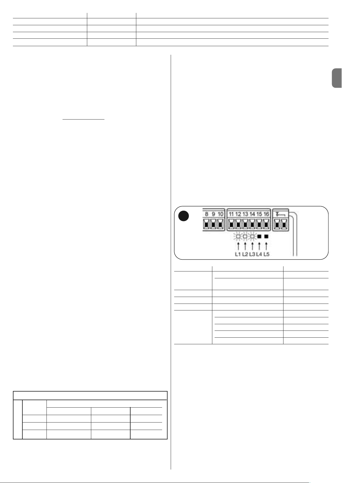
FR
Français – 3
OUVERTURE PARTIELLE TYPE 2 NO Les 2 vantaux s’ouvrent jusqu’à mi-course
OUVERTURE NO Seule la manœuvre d’ouverture est exécutée
FERMETURE NO Seule la manœuvre de fermeture est exécutée
PHOTO 2 NF Fonction PHOTO 2
EXCLU -- Aucune fonction
2.4.1 - Notes sur les connexions
La plupart des connexions sont extrêmement simples, une bonne partie d’entre elles sont des connexions directes à une unique utilisation ou à un seul
contact. Les figures ci-après donnent quelques exemples sur comment con necter les dispositifs extérieurs :
• Connexion Stand-by / Phototest
La fonction Stand-by est active de série ; elle est exclue automatiquement uniquement quand on désire activer la fonction Phototest. Note - Les fonctions
Stand-by et Phototest sont alternatives, dans la mesure où l’une exclut l’autre.
La fonction permet de réduire la consommation d’énergie on peut obtenir trois
types de connexions :
- avec « stand-by » actif (économie d’énergie
) ; voir schéma électrique fig. 5a
- connexion standard : sans « stand-by » et sans « phototest »; voir schéma
électrique fig. 5b
- sans « stand-by » et avec « phototest » ; voir schéma électrique fig. 5c
Avec la fonction « Stand-by » active, 1 minute après la fin d’une manœuvre, la
logique de commande entre en Stand-by, en éteignant toutes les Entrées et les
Sorties pour réduire la consommation d’énergie. L’état est signalé par la led
« OK » qui commence à clignoter plus lentement. AVERTISSEMENT - Si la
logique de commande est alimentée par un panneau photovoltaïque (système
« Solemyo ») ou une batterie tampon, il faut activer la fonction « Stand-by »
conformément au schéma électrique fig. 5a.
Quand la fonction « Stand-by » n’est pas utilisée, on peut activer la fonction
« Phototest » qui permet de vérifier, au début d’une manœuvre, le fonctionnement correct des photocellules connectées. Pour utiliser cette fonction, il faut
d’abord connecter correctement les photocellules (voir schéma électrique fig.
5c) puis activer la fonction.
Note – En activant le phototest, les entrées sujettes à la procédure de test sont
PHOTO, PHOTO1 et PHOTO2. Si l’une de ces entrées n’est pas utilisée, il faut
la connecter à la borne n° 8.
• Connexion Sélecteur à clé
Exemple 1 (fig. 7a) : Comment connecter le sélecteur pour effectuer les fonctions PAS À PAS et HALTE
Exemple 2 (fig. 7b) : Comment connecter le sélecteur pour effectuer les fonctions PAS À PAS et l’une de celles prévues par l’entrée auxiliaire (OUVERTURE
PARTIELLE, SEULEMENT OUVERTURE, SEULEMENT FERMETURE…)
Note – Pour les connexions électriques avec la fonction « Stand-by » active,
voir « Fonction Stand-by/Phototest » dans ce paragraphe 2.4.1.
• Connexion Voyant Portail Ouvert / Serrure électrique (fig. 8)
Si elle est programmée comme « S.C.A. », la sortie peut être utilisée comme
voyant portail ouvert. Le voyant clignote lentement en ouverture tandis qu’en
fermeture il clignote rapidement ; il reste allumé fixe quand le portail est ouvert
à l’arrêt et éteint avec le portail fermé. Si la sortie est programmée comme serrure électrique, elle est activée pendant 3 secondes à chaque début de ma nœuvre d’ouverture.
2.4.2 - Typologie d’entrée HALTE
La logique de commande MC424 peut être programmée pour deux typologies
d’entrée HALTE :
- Halte type NF pour connexion à des contacts type NF.
- Halte à résistance constante. Elle permet de connecter à la logique des
dispositifs avec sortie à résistance constante 8,2 kΩ (ex. bords sensibles).
L’entrée mesure la valeur de la résistance et nie l’accord à la manœuvre
quand la résistance sort des limites de la valeur nominale. En prenant certaines dispositions, il est possible de connecter à l’entrée halte à résistance
constante également des dispositifs avec contacts normalement ouverts
« NO » normalement fermés « NF » et éventuellement plus d’un dispositif,
même de type différent ; Voir Tableau 1.
ATTENTION ! – Si l’entrée Halte à résistance constante est utilisée pour
connecter des dispositifs avec fonctions de sécurité, seuls les dispositifs
avec sortie à résistance constante 8,2 kΩ garantissent la catégorie 3 de
sécurité aux pannes.
1erdispositif type:
NO NF 8,2KΩ
NO En parallèle (note 1)(note 2) En parallèle
NF (note 2) En série (note 3) En série
8,2KΩ En parallèle En série (note 4)
TABLEAU 1
2
e
dispositif type:
Notes sur le Tableau 1 :
Note 1 – Un ou plusieurs dispositifs NO peuvent être connectés en parallèle
entre eux sans aucune limite de quantité avec une résistance terminale de 8,2
k
Ω
(fig. 9a). Pour les connexions électriques avec la fonction « Stand-by »
active, voir « Fonction Stand-by/Phototest » dans ce paragraphe 2.4.1.
Note 2 – Il est possible de combiner NO et NF en mettant les deux contacts en
parallèle, en prenant la précaution de mettre en série au contact NF une résistance de 8,2 k
Ω
(il est donc possible de combiner 3 dispositifs : NO, NF et 8,2
kΩ (fig. 9b).
Note 3 – Un ou plusieurs dispositifs NO peuvent être connectés en série entre
eux et à une résistance de 8,2 k
Ω
sans aucune limite de quantité (fig. 9c).
Note 4 – Seul un dispositif avec sortie à résistance constante 8,2 k
Ω
peut être
connecté ; éventuellement, plusieurs dispositifs doivent être connectés « en
cascade » avec une seule résistance terminale de 8,2 kΩ (fig. 9d).
2.5 - Première mise en service et vérification des connexions
ATTENTION ! – Les opérations de branchement doivent être effectuées
exclusivement par du personnel qualifié.
Après avoir alimenté électriquement la logique de commande, vérifier que tou tes les leds clignotent rapidement pendant quelques secondes ; ensuite, effectuer les contrôles suivants :
1. Vérifier qu’il y a aux bornes 9-10 une tension d’environ 30 Vcc ; si les valeurs
ne correspondent pas, couper immédiatement l’alimentation et vérifier plus
attentivement les connexions et la tension d’alimentation.
2. Après le clignotement rapide initial, la led P1 signale le fonctionnement cor-
rect de la logique par un clignotement régulier au rythme d’une seconde.
Quand on a une variation sur les entrées, la led « P1 » effectue un double clignotement rapide en signalant que l’entrée a été reconnue.
3. Si les connexions sont correctes, les entrées de type « NF » doivent avoir la
led correspondante allumée tandis que les entrées de type « NO », doivent
avoir la led correspondante éteinte. Voir fig. A et Tableau 2.
TABLEAU 2
ENTRÉE TYPE ENTRÉE ÉTAT LED
HALTE HALTE NF L1 Allumée
HALTE RÉSISTANCE L1 Allumée
CONSTANTE 8,2KΩ
PHOTO NF L2 Allumée
PHOTO1 NF L3 Allumée
PAS-À-PAS NO L4 Éteinte
AUX OUV. PARTIELLE type 1 - NO L5 Éteinte
OUV. PARTIELLE type 2 - NO L5 Éteinte
SEULEMENT OUVERTURE - NO L5 Éteinte
SEULEMENT FERMETURE - NO L5 Éteinte
PHOTO2 NF L5 Allumée
4.Vérifier qu’en agissant sur les dispositifs connectés aux entrées, les leds cor-
respondantes s’allument ou s’éteignent.
5.Vérifier qu’en pressant la touche P2, les deux moteurs effectuent une brève
manœuvre d’ouverture avec le moteur du vantail supérieur qui démarre en
pre mier. Bloquer la manœuvre en pressant de nouveau la touche P2. Si les
moteurs ne démarrent pas en ouverture, inverser les polarités des câbles
moteur, tandis que si le premier à démarrer n’est pas celui du vantail supérieur, agir sur le cavalier E (fig. 2).
2.6 - Recherche automatique des fins de course
Quand les contrôles sont terminés, on peut commencer la recherche automatique des butées mécaniques, cette opération est nécessaire parce que la
logique de commande MC424 doit « mesurer » les temps de durée des ma nœuvres d’ouverture et de fermeture. Cette procédure est complètement automatique et se base sur la mesure de l’effort des moteurs pour la détection des
butées mécaniques en ouverture et en fermeture.
Attention ! – Si cette procédure a déjà été exécutée, pour pouvoir la
réactiver, il faut d’abord effacer la mémoire (voir chapitre « Effacement de
la mémoire »). Pour vérifier si la mémoire contient les paramètres des fins
de course, éteindre puis rallumer l’alimentation de la logique de comman de. Si toutes les leds clignotent rapidement pendant environ 6 secondes
la mémoire est vide ; si le clignotement ne dure que 3 secon des, la mé moire contient déjà les paramètres des fins de course.
A
Page 30

FR
4 – Français
Avant de commencer la recherche des fins de course, vérifier que tous les dispositifs de sécurité donnent leur accord (HALTE, PHOTO et PHOTO1 actifs).
L’activation d’une sécurité ou l’arrivée d’une commande durant la procédure,
en provoque l’interruption immédiate. Les vantaux peuvent se trouver dans une
position mais il est préférable qu’ils soient environ à mi-course.
Procédure – Presser la touche P2 (fig. 2) pour lancer la phase de recher che qui prévoit :
- Brève ouverture des deux moteurs.
- Fermeture du moteur du vantail inférieur jusqu’à la butée mécanique en fermeture.
- Fermeture du moteur du vantail supérieur jusqu’à la butée mécanique en fermeture.
- Début ouverture du moteur du vantail supérieur.
- Après le décalage prévu, début ouverture du vantail inférieur. Si le décalage
est insuffisant, bloquer la recherche en pressant la touche P1 (fig. 2), puis
modifier le temps (voir chapitre 5).
- La logique de commande effectue la mesure du mouvement nécessaire pour
que les moteurs atteignent les butées mécaniques en ouverture.
- Manœuvre complète de fermeture. Les moteurs peuvent partir à des
moments différents, le but est d’arriver en fermeture en maintenant un décalage approprié pour éviter le danger de cisaillement entre les vantaux.
- Fin de la procédure avec mémorisation de toutes les mesures effectuées.
Toutes ces phases ont lieu l’une après l’autre, sans aucune intervention de la
part de l’opérateur. Si pour une raison quelconque la procédure ne s’exécute
pas correctement, il faut l’interrompre en pressant la touche P1. Répéter
ensuite la procédure, éventuellement en modifiant des paramètres, par exemple les seuils d’intervention de la fonction ampèremétrique (voir le chapitre 5).
Il s’agit des phases les plus importantes dans la réalisation de l’automatisation
afin de garantir la sécurité maximum de l’installation. La procédure d’essai peut
être utilisée aussi pour vérifier périodiquement les dispositifs qui composent
l’automatisation. Les phases de l’essai et de la mise en service de l’automatisme doivent être effectuées par du personnel qualifié et expérimenté qui devra
se charger d’établir les essais nécessaires pour vérifier les solutions adoptées
en fonction du risque présent et s’assurer du respect de tout que ce qui est
prévu par les lois, les normes et les réglementations, en particulier, de toutes les
prescriptions de la norme EN 12445 qui établit les méthodes d’essai pour le
contrôle des automatismes de portails.
Les dispositifs supplémentaires ou en option, doivent être soumis à un essai
spécifique, aussi bien en ce qui concerne leur bon fonctionnement que leur
interaction correcte avec MC424 ; se référer par conséquent aux guides d’instructions de chaque dispositif.
3.1 - Essai
La séquence de vérifications se réfère à la logique de commande programmée
avec les fonctions préprogrammées, voir le paragraphe 5.1 :
• Vérifier que l’activation de l’entrée PAS À PAS active la séquence « Ouverture,
Stop, Fermeture, Stop ».
• Vérifier que l’activation de l’entrée AUX (fonction ouverture partielle Type 1) gè re
la séquence « Ouverture, Stop, Fermeture, Stop » seulement du moteur du vantail supérieur tandis que le moteur du vantail inférieur reste arrêté en fermeture.
• Commander une manœuvre d’ouverture et vérifier que :
- Quand on sollicite PHOTO, le portail continue la manœuvre d’ouverture.
- Quand on sollicite PHOTO1, la manœuvre s’arrête jusqu’à ce que PHOTO1
soit libérée, puis la manœuvre reprend le mouvement d’ouverture.
- Si PHOTO2 est installée, après avoir sollicité ce dispositif, la manœuvre doit
s’arrêter puis repartir en fermeture.
• Vérifier que quand le vantail arrive à la butée de fin de course mécanique en
ouverture, les moteurs s’éteignent.
• Commander une manœuvre de fermeture et vérifier que :
- Quand on sollicite PHOTO, la manœuvre s’arrête et repart en ouverture.
- Quand on sollicite PHOTO1, la manœuvre s’arrête jusqu’à ce que PHOTO1
soit libérée, puis la manœuvre reprend le mouvement d’ouverture
- Quand on sollicite PHOTO2, le portail continue la manœuvre de fermeture
• Vérifier que les dispositifs d’arrêt connectés à l’entrée STOP provoquent l’arrêt immédiat de n’importe quel mouvement en cours.
• Vérifier que le niveau du système de détection des obstacles est adapté à
l’application :
- Durant la manœuvre, aussi bien en ouverture qu’en fermeture, empêcher le
mouvement du vantail en simulant un obstacle et vérifier que la manœuvre
s’invertit avant de dépasser la force prévue par les normes.
• D’autres vérifications pourront être nécessaires en fonction des dispositifs
connectés aux entrées.
Attention – Si pendant 2 manœuvres consécutives dans la même direction un obstacle est libéré, la logique de commande effectue une inversion partielle des deux moteurs pendant 1 seule seconde. À la commande
successive, les vantaux partent en ouverture et la première intervention
de la fonction ampèremétrique pour chaque moteur est considérée
comme butée mécanique en ouverture. On a le même comportement
quand l’alimentation de secteur est rétablie : la première commande est
toujours d’ouverture et le premier obstacle est toujours considéré comme
butée mécanique en ouverture.
ESSAI ET MISE EN SERVICE
3
3.2 - Mise en service
La mise en service ne peut avoir lieu que si toutes les phases d’essai ont
été effectuées avec résultat positif.
1 Réaliser le dossier technique de l’automatisme qui devra comprendre les
documents suivants : le dessin d’ensemble de l’automatisme, le schéma
des connexions électriques, l’analyse des risques présents et les solutions
adoptées (voir les documents à remplir sur le site www.niceforyou.com), la
déclaration de conformité du fabricant de tous les dispositifs utilisés et la
déclaration de conformité remplie par l’installateur.
2 Appliquer sur le portail une plaquette contenant au moins les données sui-
vantes : type d’automatisme, nom et adresse du constructeur (responsable
de la « mise en service »), numéro de série, année de construction et mar que CE ;
3 Avant de mettre l’automatisme en service, informer de manière adéquate le
propriétaire sur les risques résiduels.
La led Diagnostic P2 (fig. 2) signale les éventuelles anomalies ou comportements détectés par la logique de commande durant la manœuvre.
Une séquence avec un nombre de clignotements donnés indique le type de
problème et reste active jusqu’au début de la manœuvre successive. Ci-après,
tableau récapitulatif :
Numéro Type d’anomalie
Clignotements LED P2
1 Intervention fonction ampèremétrique M1
2 Intervention fonction ampèremétrique M2
3 Intervention entrée HALTE durant la manœuvre
4 Erreur phototest
5 Surintensité sortie SCA ou serrure électrique
DIAGNOSTIC
4
La logique de commande MC424 dispose de certaines fonctions programmables. Ces fonctions sont préprogrammées dans une configuration typique qui
satisfait la plupart des automatismes. Les fonctions peuvent être changées à
tout moment, aussi bien avant qu’après la phase de recherche automatique
des fins de course, à travers une procédure de programmation spécifique ; voir
paragraphe 5.3.
5.1 - Fonctions préprogrammées
• Mouvement moteurs : rapide
• Fermeture automatique : active
• Fonctionnement collectif : désactivé
• Préclignotement : désactivé
• Refermeture immédiate après
passage devant photocellule : désactivée
• Retard en ouverture : niveau 2 (10%)
• STAND-BY / Phototest : Stand-by
• SCA/Serrure électrique : SCA
• Entrée HALTE : type NF
• Portails lourds : désactivée
• SCA proportionnel : désactivée
• Temps de pause : 20 secondes
• Entrée auxiliaire : ouverture partielle Type 1 (active uniquement
le moteur du vantail supérieur)
• Sensibilité ampèremétrique : Degré 2
5.2 - Fonctions programmables
Pour rendre l’installation plus adaptée aux exigences de l’utilisateur et plus sûre
dans les différentes conditions d’utilisation, la logique de commande MC424
permet de programmer certaines fonctions ou paramètres, ainsi que la fonction
de certaines entrées et sorties.
5.2.1 - Programmazioni dirette
• Mouvement Lent/Rapide : Il est possible de choisir la vitesse de mouvement du portail à tout moment (avec moteur à l’arrêt) en agissant simplement
sur la touche P3 (fig. 2) quand la logique de commande ne se trouve pas
dans un état de programmation. La led P3 éteinte indique que le mouvement
lent est programmé, vice versa la led allumée correspond au mouvement
rapide.
5.2.2 - Programmation de premier niveau : première partie
• Fermeture automatique : Cette fonction prévoit une fermeture automatique
après le temps de pause programmé, initialement le temps de pause est fixé
à 20 secondes mais il peut être modifié à 5, 10, 20, 40, 80 secondes.
PROGRAMMATION
5
Page 31

FR
Français – 5
Si la fonction n’est pas active, le comportement est de type « semi-automatique ».
• Fonction collective : Cette fonction est utile quand beaucoup de personnes
utilisent l’automatisme avec commande par radio. Si cette fonction est
active, chaque commande reçue provoque une manœuvre d’ouverture qui
ne peut pas être interrompue par d’autres impulsions de commande. Si la
fonction n’est pas activée, une commande provoque : OUV.-STOP-FERM.STOP.
• Préclignotement : La fonction permet d’activer le clignotant avant le début
de la manœuvre pendant 3 secondes.
Si la fonction n’est pas activée, le clignotant commence à clignoter au commencement de la manœuvre.
• Refermeture immédiate après passage devant photocellule : Avec la fer-
meture automatique, la fonction permet de réduire le temps de pause à 4
secondes après la libération de la photocellule PHOTO, c’est-à-dire que le
portail se ferme 4 secondes après le passage de l’utilisateur. Si la fonction
n’est pas activée, tout le temps de pause programmé s’écoule.
• Retard en ouverture : Cette fonction provoque en ouverture un retard dans
l’activation du moteur du vantail inférieur par rapport au vantail supérieur
nécessaire pour éviter que les vantaux puissent se coincer. Le décalage en
fermeture est toujours présent et est calculé automatiquement par la logique
de manière à obtenir le même décalage programmé en ouverture.
5.2.3 - Programmation de premier niveau : deuxième partie
• Fonction stand-by / Phototest : La logique de commande a la fonction
« Stand-by » préprogrammée ; si cette fonction est active, 1 minute après la
fin d’une manœuvre, la logique de commande éteint la sortie « Stand-by »
(borne n°8), toutes les Entrées et les Sorties pour réduire la consommation
d’énergie (voir schéma électrique fig. 5a). Cette fonction est obligatoire si la
logique de commande est alimentée exclusivement par des panneaux photovoltaïques Solemyo. Elle est conseillée également si la logique de commande
est alimentée par le secteur électrique et si l’on souhaite augmenter le fonctionnement en urgence avec batterie tampon PS124. En alternative à la fonction « Stand-by », on peut activer la fonction « Phototest » qui vérifier le fonctionnement correct des photocellules connectées au début d’une manœuvre. Pour utiliser cette fonction, il faut d’abord connecter correctement les
photocellules (voir schéma électrique fig. 5c) puis activer la fonction.
• Sortie voyant portail ouvert /Serrure électrique : Si la fonction est activée,
les bornes 6-7 peuvent être utilisées pour connecter la serrure électrique. Si
la fonction n’est pas activée, les bornes 6-7 peuvent être utilisées pour
connecter un voyant de signalisation de portail ouvert (24 V).
• Entrée HALTE type NF à résistance constante : Si la fonction est activée,
l’entrée de HALTE est programmée à « résistance constante 8,2 kΩ », dans
ce cas pour autoriser la manœuvre, entre le commun et l’entrée il doit y avoir
une résistance de 8,2 kΩ +/-25%. Si la fonction n’est pas programmée, l’entrée de HALTE est configurée pour fonctionner avec des contacts de type NF.
• Portails légers/lourds : Si la fonction est activée, la logique de commande
prévoit la possibilité de gérer des portails lourds en réglant de manière différente les rampes d’accélération et les vitesses de ralentissement en fermeture. Si la fonction n’est pas activée, la logique de commande est programmée pour gérer des portails légers.
• SCA proportionnel : Si la fonction est activée, la sortie SCA est programmée
avec clignotement proportionnel, c’est-à-dire que dans la manœuvre d’ouverture l’intensité du clignotement augmente au fur et à mesure que les vantaux se rapprochent des fins de course d’ouverture, vice versa dans la
manœuvre de fermeture l’intensité du clignotement diminue au fur et à
mesure que les vantaux se rapprochent des fins de course de fermeture. Si la
fonction n’est pas activée, on a un clignotement lent en ouverture et rapide
en fermeture.
5.2.4 - Fonctions de deuxième niveau
• Temps de pause : Le temps de pause, c’est-à-dire le temps écoulé entre la
fin d’une manœuvre d’ouverture et le début de la fermeture automatique,
peut être programmé à 5, 10, 20, 40, et 80 secondes.
• Entrée auxiliaire AUX : La logique de commande prévoit une entrée auxi-
liaire qui peut être configurée dans l’une des 6 fonctions suivantes :
- Ouverture partielle type 1 : effectue la même fonction que l’entrée PAS À
PAS en provoquant l’ouverture uniquement du vantail supérieur. Fonctionne
uniquement avec le portail complètement fermé, autrement la commande est
interprétée comme s’il s’agissait d’une commande PAS À PAS
- Ouverture partielle type 2 : effectue la même fonction que l’entrée PAS À
PAS en provoquant l’ouverture des deux vantaux pour la moitié du temps
prévu pour l’ouverture totale. Fonctionne uniquement avec le portail complètement fermé, autrement la commande est interprétée comme s’il s’agissait
d’une commande PAS À PAS
- Seulement Ouverture : cette entrée effectue uniquement l’ouverture avec
la séquence Ouv.-Stop-Ouv.-Stop
- Seulement Fermeture : cette entrée effectue uniquement la fermeture
avec la séquence Ferm.-Stop-Ferm.-Stop
- Photo 2 : effectue la fonction du dispositif de sécurité « PHOTO 2 »
- Exclu : l’entrée ne gère aucune fonction
• Temps de décharge : à la fin de la manœuvre de Fermeture, quand les van-
taux ont atteint la fermeture totale, le moteur bloque les vantaux avec la force
programmée. Juste après, si cette fonction de commande est active, une
brève inversion du mouvement est commandée afin de décharger la pression
en excès exercée par le moteur sur les vantaux.
• Sensibilité ampèremétrique : La logique de commande dispose d’un système pour la mesure du courant absorbé par les deux moteurs qui est utilisé
pour détecter les fins de course mécaniques et les éventuels obstacles
durant le mouvement du portail. Le courant absorbé dépendant de conditions variables (poids portail, frottements divers, coups de vent, variations de
tension, etc..) il a été prévu de pouvoir modifier le seuil d’intervention. Il est
prévu 6 niveaux : le degré 1 est le plus sensible (force minimum), le degré 6
est le moins sensible (force maximum).
ATTENTION ! – La fonction « ampèremétrique » opportunément réglée
(ainsi que d’autres aspects indispensables) peut être utile pour le respect des normes européennes, EN 12453 et EN 12445, qui demandent
l’utilisation de techniques ou dispositifs afin de limiter les forces et la
dangerosité dans le mouvement des portes et portails automatiques.
• Retard vantail : Le retard au démarrage du moteur du vantail inférieur peut
être programmé à 5, 10, 20, 30 ou 40% du temps de travail.
5.3 - Modalités de programmation
Toutes les fonctions décrites dans le paragraphe 5.2 « Fonctions programmables », peuvent être choisies à travers une phase de programmation qui se termine par la mémorisation des choix effectués. Dans la logique de commande, il
y a une mémoire qui maintient les fonctions et les paramètres relatifs à l’automatisme.
Pour toutes les phases de programmation on utilise les touches P1 P2 et P3,
tandis que les 5 leds L1,L2…L5 indiqueront le paramètre sélectionné.
Il est prévu 2 niveaux de programmation :
• Dans le premier niveau il est possible d’activer ou de désactiver les fonctions. Chaque led L1, L2…L5 correspond à une fonction, si la led est allumée, la fonction est active, si elle est éteinte, elle est désactivée.
Le premier niveau est constitué de 2 parties sélectionnables en pressant la
touche P3. La LED P3 correspondante indique laquelle des 2 parties est sélectionnée.
Premier niveau (led P1 fixe) : deuxième partie (led P3 allumée)
Led L1 Led L2 Led L3 Led L4 Led L5
Stand by / Serrure Halte résistif Portails lourds SCA
Phototest proportionnel
Premier niveau (led P1 fixe) : première partie (led P3 éteinte)
Led L1 Led L2 Led L3 Led L4 Led L5
Fermeture
Fonction Préclignotement
Referme après Retard
automatique collective photo en ouverture
• Du premier niveau de la première partie, on peut passer au deuxième
niveau où il est possible de choisir le paramètre relatif à la fonction, à chaque
led correspond une valeur différente à associer au paramètre.
Premier niveau (led P1 fixe) : deuxième partie (led P3 allumée)
Led L1 Led L2 Led L3 Led L4 Led L5
Stand by / Serrure électrique Halte résistif Portails lourds SCA
Phototest proportionnel
Premier niveau (led P1 fixe) : première partie (led P3 éteinte)
Led L1 Led L2 Led L3 Led L4 Led L5
Fermeture
Fonction Préclignotement
Referme après Décalage
automatique collective photo en ouverture
Deuxième niveau :
Paramètre :Paramètre :Paramètre :Paramètre :Paramètre :
Temps Entrée AUX Temps de Sensibilité Retard
de pause décharge
ampèremétrique
vantail
L1 : 5s L1 : Ouvverture L1 : Aucune L1 : Degré 1 L1 : 5%s
partielle type 1 décharge (plus sensible)
L2 : 10s L2 : Ouvverture L2 : 0,3s L2 : Degré 2 L2 : 10%
partielle type 2
L3 : 20s L3 : Seulement L3 : 0,7s L3 : Degré 3 L3 : 20%
Ouverture
L4 : 40s L4 : Seulement L4 : 1,3s L4 : Degré 4 L4 : 30%
Fermeture
L5 : 80s L5 : Photo 2 L5 : 2s L5 : Degré 5 L5 : 40%
(moins sensible)
Toutes les Toutes les éteintes :
leds éteintes : Degré 6 (sensibilité
entrée non ampèremétrique
utilisée max.)
Page 32

5.3.1 - Programmation de premier niveau : fonctions
Dans le premier niveau il est possible d’activer ou de désactiver les fonctions.
Dans le premier niveau la led P1 est toujours allumée, les leds L1,L2…L5 allumées indiquent les fonctions actives, les leds éteintes indiquent les fonctions
TABLEAU A1 - Pour entrer dans la programmation premier niveau
01. Presser les touches P1 et P2 pendant au moins 3 secondes
Un clignotement rapide de toutes les leds indique que l’on est entré en programmation
désactivées. La led clignotante indique la fonction sélectionnée, si le clignotement est bref la fonction est désactivée, si le clignotement est long la fonction
est active. Pour passer de la programmation première partie à la deuxième partie et vice versa presser la touche P3.
P1 P2
FR
01. Presser plusieurs fois de suite P1 jusqu’à porter la led clignotante sur la fonction désirée
02. Presser P2 pour activer ou désactiver la fonction
TABLEAU A2 - Pour activer ou désactiver une fonction
TABLEAU A3 - Pour passer de la première à la deuxième partie du premier niveau (et vice versa)
01. Presser la touche P3
TABLEAU A4 - Pour sortir du premier niveau en confirmant les modifications
01. Appuyer sur la touche P1 puis juste après sur la touche P2, en les maintenant enfoncées pendant au moins 3 secondes
TABLEAU A5 - Pour sortir du premier niveau en annulant les modifications
01. Presser P1 pendant au moins 3 secondes, ou attendre 1 minute, ou éteindre l’alimentation
5.3.2 - Programmation de deuxième niveau : paramètres
Dans le deuxième niveau il est possible de choisir les paramètres relatifs aux
fonctions. Le deuxième niveau est atteint uniquement en passant par le premier
niveau.
Dans le deuxième niveau, la led P1 clignote rapidement tandis que les 5 autres
leds L1,L2…L5 indiquent le paramètre sélectionné.
3s
P1
P1
ou
ou
P2
P3
P1 P2
3 s
60s
TABLEAU B1 - Pour entrer dans la programmation deuxième niveau
01. Entrer en programmation premier niveau en pressant les touches P1 et P2 pendant au moins 3 secondes
02. Sélectionner la fonction en pressant P1 jusqu’à ce que la led clignotante se déplace sur le point désiré
03. Entrer dans le deuxième niveau en pressant la touche P2 pendant au moins 3 secondes
TABLEAU B2 - Pour choisir le paramètre
01. Presser plusieurs fois P2 jusqu’à ce que la led se déplace sur le paramètre désiré
TABLEAU B3 - Pour revenir au premier niveau
01. Presser la touche P1
TABLEAU B4 - Pour sortir du premier niveau en confirmant les modifications
01. Appuyer sur la touche P1 puis juste après sur la touche P2, en les maintenant enfoncées pendant au moins 3 secondes
TABLEAU B5 - Pour sortir du premier niveau en annulant les modifications
01. Presser P1 pendant au moins 3 secondes, ou attendre 1 minute, ou éteindre l’alimentation
3s
P1
P2
P1
P1 P2
P2
P1
P1 P2
ou
3 s
3 s
3 s
60s
5.3.3 - Effacement de la mémoire
Chaque nouvelle programmation remplace les précédentes, normalement, il
n’est donc pas nécessaire « d’effacer tous les paramètres ». Dans tous les cas,
l’effacement total de la mémoire est possible avec cette simple opération :
6 – Français
ou
ATTENTION - Après l’effacement de la mémoire, toutes les fonctions
reviennent aux valeurs préprogrammées et il est nécessaire de procéder
à une nouvelle recherche des fins de course.
Page 33
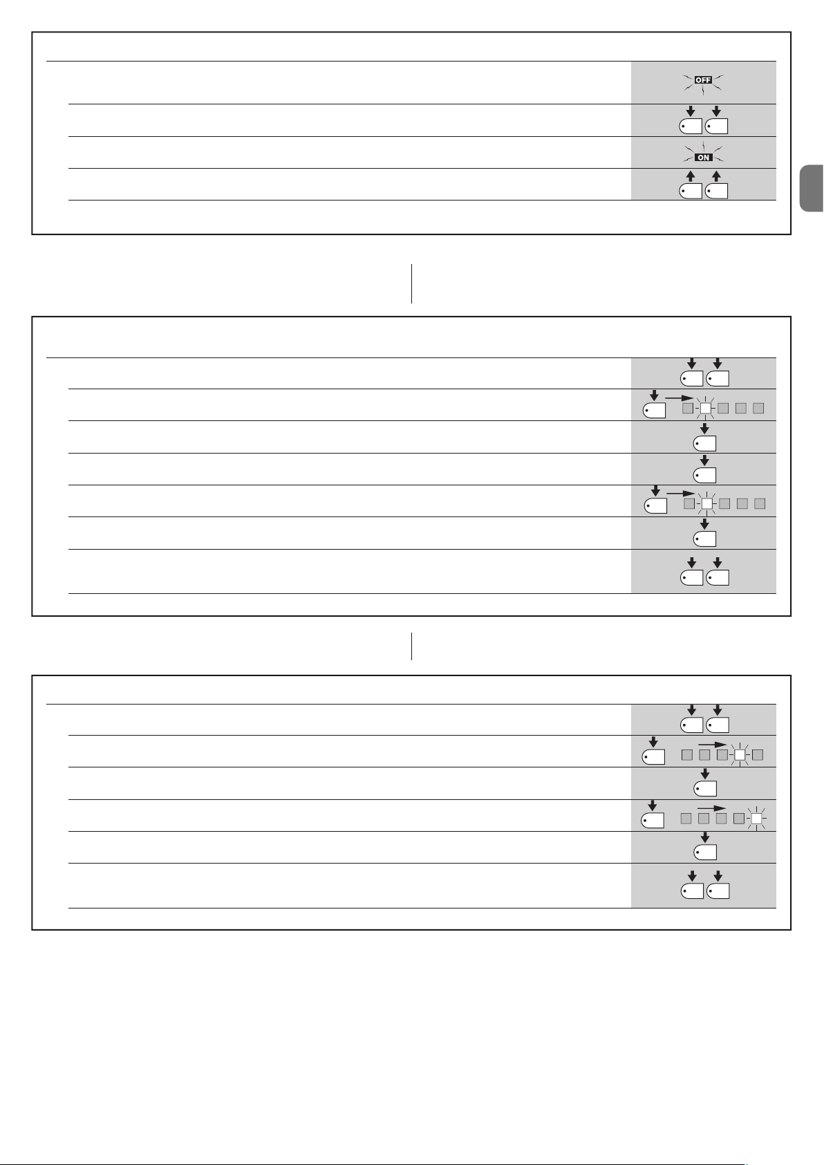
TABLEAU C1 - Pour effacer la mémoire
01. Éteindre l’alimentation de la logique de commande et attendre que toutes les leds soient éteintes
(éventuellement enlever le fusible F1)
02. Presser et maintenir enfoncées les deux touches P1 et P2 sur la carte électronique
03. Remettre la logique sous tension
04. Attendre au moins 3 secondes puis relâcher les deux touches
Si l’effacement de la mémoire a été effectué correctement, toutes les leds s’éteignent pendant 1 seconde
5.3.4 - Exemple de programmation de premier niveau
Ci-après, nous indiquons les étapes nécessaires pour activer et désactiver une
fonction « Collective » et la programmation de la sortie « SCA » pour activer la
serrure électrique.
fonction au premier niveau ; nous prenons comme exemple l’activation de la
Exemple de programmation de premier niveau :
activer la fonction « collective » et activer la sortie pour « serrure électrique »
01. Entrer en programmation premier niveau en pressant les touches P1 et P2 pendant au moins 3 secondes
02. Presser 1 fois P1 jusqu’à ce que le clignotement se déplace sur la led 2 (le clignotement est bref)
03. Activer la fonction « Collective » en pressant P2 (le clignotement sera long)
04. Presser une fois P3 pour activer la deuxième partie (la led de P3 s’allume)
05. Presser 1 fois P1 jusqu’à ce que le clignotement se déplace sur la led 2 (le clignotement est bref)
P1
P1
x1
P1 P2
P1 P2
P1 P2
2
P2
P3
2
3s
3s
FR
06. Activer la sortie « Serrure électrique » en pressant P2 (le clignotement sera long)
07. Sortir de la programmation, avec mémorisation, en appuyant sur la touche P1 puis juste après sur la touche P2,
en les maintenant enfoncées pendant au moins 3 secondes
5.3.5 - Exemple de programmation de deuxième niveau
Ci-après, nous indiquons les étapes nécessaires pour modifier un paramètre au
deuxième niveau ; nous prenons comme exemple la modification de la sensibilité ampèremétrique jusqu’au « niveau 5 ».
Exemple de programmation de deuxième niveau : modifier la « sensibilité ampèremétrique »
01. Entrer en programmation premier niveau en pressant les touches P1 et P2 pendant au moins 3 secondes
02. Presser 3 fois la touche P1 pour déplacer la led clignotante sur la led 4
03. Passer au deuxième niveau en pressant P2 pendant au moins 3 secondes
04. Presser 3 fois P2 jusqu’à ce que la led 5 s’allume
05. Revenir au premier niveau en pressant P1
06. Sortir de la programmation, avec mémorisation, en appuyant sur la touche P1 puis juste après sur la touche P2,
en les maintenant enfoncées pendant au moins 3 secondes
P2
P1
x3
x3
P2
P1 P2
P1 P2
P2
P1
P1 P2
3s
3s
4
3s
5
3s
Français – 7
Page 34

5.3.6 - Schéma pour la programmation
La figure ci-dessous donne le schéma complet de la programmation des fonctions et des paramètres correspondants. Dans la même figure sont indiquées
Fonctionnement
normal
FR
Led P1 Clignotement lent
HALTE Photo Photo1Pas
à-pas
AUX
les fonctions et les paramètres préprogrammés initialement ou après un effacement complet de la mémoire.
P1
P2
P3
P1+P2
pendant 3 s
P1
pendant 3 s
(ne pas sauvegarder)
P1+P2
pendant 3 s
(sauvegarder)
Premier Niveau
Led P1 allumée fixe
P2
pendant 3 s
P1
Deuxième niveau
Led P1 clignotement rapide
Autom. Collectif Précl.
5 10 20
secondes
Entrée auxiliaire (*)
o.p.
o.p.
type 2
ouvre
seul.
type 1
Referme
Décalage
ap. photo
Temps de pause
40 80
ferme
Photo 2
seul.
P1
P2
P3
P1
P2
P3
P1
P2
P1
Stand-by
On
Off
P3
Phototest
Serrure Stop
résistif
Portails
lourds
SCA
proport.
P2
On
Off
P3
P3
Décharge
P1
0 0,3 0,7
secondes
1,3 2
P2
P3
Sensibilité ampèremétrique
P1
123
degré
45
P2
P3
toutes les LED éteintes · force ampèremétrique max.
Décalage en ouverture
P1
5 10 20%30 40
P2
P3
(*)
o.p. TYPE 1 Ouverture partielle type 1,
mouvement uniquement du vantail
supérieur [contact N.O.]
o.p. TYPE 2 Ouverture partielle type 2,
mouvement des deux moteurs
pour la moitié du temps de travail
[contact N.O.]
Seulement ouverture stop ouvre stop...
ouverture [contact N.O.]
Seulemen fermeture stop ferme stop...
fermeture [contact N.O.]
Photo 2 utilisé comme photo 2
[contact N.F.]
8 – Français
Page 35

FR
Français – 9
6.1 - Connexion d’un récepteur radio
La logique de commande dispose d’un connecteur pour l’embrochage d’une
car te radio à 4 canaux avec connecteur SM, qui permet de commander la
logique de commande à distance au moyen d’émetteurs qui agissent sur les
entrées conformément au tableau ci-dessous :
Sortie Récepteur Entrée Logique de commande
N° 1 Pas à pas
N° 2 AUX (valeur préprogrammée : Ouverture partielle 1)
N° 3 « Seulement ouverture »
N° 4 « Seulement fermeture »
6.2 - Connexion de la batterie tampon mod. PS124
La logique de commande est prévue pour être alimentée par des batteries tampon PS124 en cas de coupure de courant de secteur. Pour effectuer l’installation et la connexion de la batterie, procéder comme indiqué fig. 10.
6.3 - Connexion du système Solemyo
La logique de commande est prévue pour être alimentée par le système d’alimentation photovoltaïque « Solemyo » (panneau photovoltaïque et batterie à 24
V). Pour connecter l’accumulateur de « Solemyo » à la logique, utiliser sur celleci la prise normalement utilisée pour la batterie tampon (voir paragraphe 6.2).
IMPORTANT !
- Quand l’automatisme est alimenté par le système « Solemyo », il NE DOIT
PAS ÊTRE ALIMENTÉ simultanément aussi par le secteur électrique.
- Le système « Solemyo » peut être utilisé seulement si dans la logique de
commande la fonction « Stand-by » est activée (ON) et si les connexions
respectent le schéma de la fig. 5a.
APPROFONDISSEMENTS : accessoires
6
Aucune LED n’est allumée :
• Vérifier si la logique de commande est alimentée : vérifier la présence aux
bornes 9-10 d’une tension d’environ 30 Vcc (ou 24 Vcc avec alimentation
par batterie).
• Vérifier les 2 fusibles, si la led P1 n’est pas allumée ou clignotante elle non
plus, on est probablement en présence d’une panne grave et la logique de
commande devra être remplacée.
La led P1 clignote régulièrement mais les leds entrées L1, L2...L5 ne reflètent pas l’état des entrées respectives
• Éteindre momentanément l’alimentation pour sortir d’une éventuelle phase
de programmation.
• Vérifier attentivement les connexions sur les bornes 11..16
La led P1 clignote toutes les 4 secondes
• La logique de commande est en « stand-by ».
La procédure de « Recherche automatique » ne démarre pas
• La procédure de « Recherche automatique » s’active uniquement si elle n’a
jamais été effectuée ou si la mémoire a été effacée. Pour vérifier si la mémoire
est vide, éteindre momentanément l’alimentation, à l’allumage toutes les leds
doivent clignoter rapidement pendant environ 6 secondes. Si elles ne clignotent que pendant 3 secondes, la mémoire contient déjà des valeurs valables.
Si l’on veut effectuer une nouvelle « Recherche automatique » il faut effacer
complètement la mémoire.
La « Recherche automatique » n’a jamais été effectuée mais la procédure
ne démarre pas ou se comporte de façon erronée
• Pour activer la procédure de « Recherche automatique » il faut que l’installation et tous les dispositifs de sécurité fonctionnent parfaitement.
• S’assurer qu’aucun dispositif connecté aux entrées n’intervient durant la
« Recherche automatique ».
• Pour que la « Recherche automatique » démarre correctement, les leds sur
les entrées doivent être allumées comme indiqué fig. 11, la led P1 doit clignoter au rythme d’une seconde.
La « Recherche automatique » a été effectuée correctement mais la
manœuvre ne démarre pas
• Vérifier que les leds des sécurités (HALTE, PHOTO, PHOTO1 et éventuellement PHOTO2) sont allumées et que la led de la commande qui est activée
(PAS À PAS ou AUX) s’allume pendant la durée de la commande.
• Si le fonctionnement « Phototest » est activé et que les photocellules ne
fonctionnent pas correctement, la led DIAGNOSTIC signale l’anomalie par 4
clignotements.
Durant le mouvement, le portail effectue une inversion
Les causes qui provoquent une inversion sont :
• Une intervention des photocellules (PHOTO2 en ouverture, PHOTO ou
QUE FAIRE SI…
(guide pour la résolution des problèmes)
7
PHOTO1 durant la fermeture) ; dans ce cas, contrôler les connexions des
photocellules et vérifier éventuellement les leds de signalisation des entrées.
• Une intervention de la fonction ampèremétrique durant la course des
moteurs (et donc pas à proximité des butées mécaniques) est considérée
comme un obstacle et provoque une inversion. Pour contrôler s’il y a eu une
intervention de la fonction ampèremétrique, compter les clignotements de la
led Diagnostic : 1 clignotement signale l’intervention de la fonction ampèremétrique sur le moteur n° 1, 2 clignotements sur le moteur n° 2.
MAINTENANCE DU PRODUIT
8
La logique de commande MC424, en tant que partie électronique, n’a besoin
d’aucune maintenance particulière. Vérifier toutefois périodiquement, au moins
tous les 6 mois, le bon fonctionnement de toute l’installation suivant ce qui est
indiqué dans le chapitre 3.
MISE AU REBUT DU PRODUIT
Ce produit est partie intégrante de l’automatisme et doit donc être mis au
rebut avec ce dernier.
Comme pour l’installation, à la fin de la durée de vie de ce produit, les opérations de démantèlement doivent être effectuées par du personnel qualifié.
Ce produit est constitué de différents types de matériaux : certains peuvent être
recyclés, d’autres doivent être mis au rebut. Informez-vous sur les systèmes de
recyclage ou de mise au rebut prévus par les règlements, en vigueur dans votre
pays, pour cette catégorie de produit.
Attention ! – certains composants du produit peuvent contenir des substances
polluantes ou dangereuses qui pourraient avoir des effets nuisibles sur l’environnement et sur la santé des personnes s’ils étaient jetés dans la nature.
Comme l’indique le symbole ci-contre, il est interdit de jeter
ce produit avec les ordures ménagères. Par conséquent, utiliser la méthode de la « collecte sélective » pour la mise au
rebut des composants conformément aux prescriptions des
normes en vigueur dans le pays d’utilisation ou restituer le
produit au vendeur lors de l’achat d’un nouveau produit
équivalent.
Attention ! – les règlements locaux en vigueur peuvent appliquer de lourdes
sanctions en cas d’élimination illicite de ce produit.
Page 36

FR
10 – Français
DÉCLARATION CE DE CONFORMITÉ
Note - Le contenu de cette déclaration de conformité correspond à la dernière révision disponible - avant l’impression de la présente notice technique – du document officiel
déposé au siège de Nice S.p.a. Ce texte a été réélaboré pour des raisons d’édition.
Numéro : 296/MC424 Révision : 0
Je soussigné Lauro Buoro en qualité d’Administrateur Délégué, déclare sous mon entière responsabilité que le produit :
Nom du producteur : NICE s.p.a.
Adresse : Via Pezza Alta 13, 31046 Z.I. Rustignè, Oderzo (TV) Italie
Type : Logique de commande pour 2 moteurs 24 V c.c.
Modèles : MC424
Accessoires : Récepteur radio SMXI, SMXIS
Est conforme à ce qui est prévu par les directives communautaires suivantes :
• 98/37/CE (89/392/CEE modifiée) DIRECTIVE 98/37/CE DU PARLEMENT EUROPÉEN ET DU CONSEIL du 22 juin 1998 concernant le rapprochement
des législations des États membres relatives aux machines
Comme le prévoit la directive 98/37/CE, nous avertissons que la mise en service du produit susmentionné n’est pas autorisée tant que la machine dans
laquelle le produit est incorporé n’a pas été identifiée et déclarée conforme à la directive 98/37/CE.
Le produit est aussi conforme à ce qui est prévu par les directives communautaires suivantes :
• 2006/95/CEE (ex directive 73/23/CE), DIRECTIVE 2006/95/CE DU PARLEMENT EUROPÉEN ET DU CONSEIL du 12 décembre 2006 concernant le rapprochement des législations des États membres relatives au matériel électrique destiné à être employé dans certaines limites de tension
Selon les normes harmonisées suivantes : EN 60335-1:1994+A11:1995+A1:1996+A12:1996+A13:1998+A14:1998+A15:2000+A2:2000+A16:2001
• 2004/108/CEE (ex directive 89/336/CEE), DIRECTIVE 2004/108/CE DU PARLEMENT EUROPÉEN ET DU CONSEIL du 15 décembre 2004 concernant
le rapprochement des législations des États membres relatives à la compatibilité électromagnétique et abrogeant la directive 89/336/CEE
Selon les normes harmonisées suivantes : EN 61000-6-2:2001; EN 61000-6-3:2001+A11:2004
En outre, il est conforme, uniquement en ce qui concerne les parties applicables, aux normes suivantes :
EN 60335-1:2002+A1:2004+A11:2004+A12:2006+ A2:2006, EN 60335-2-103:2003, EN 13241-1:2003; EN 12453:2002; EN 12445:2002;
EN 12978:2003
Oderzo, 25 septembre 2008
Lauro Buoro (Administrateur Délégué)
AVERTISSEMENTS : • Toutes les caractéristiques techniques indiquées se réfèrent à une température ambiante de 20 °C (± 5 °C). • Nice S.p.a. se réserve le
droit d’apporter des modifications au produit à tout moment si elle le jugera nécessaire, en garantissant dans tous les cas les mêmes fonctions et le même type
d’utilisation prévu.
Alimentation de secteur Logique de commande MC424:230 V~ ±10% 50 - 60 Hz
Logique de commande MC424/V1: 120 V~ ±10% 50 - 60 Hz
Puissance max. absorbée 170 W
Alimentation de secours par batteries tampon PS124 et par kit solaire Solemyo
Courant maximum moteurs 3 A (avec niveau intervention fonction ampèremétrique « degré 6 »)
Sortie alimentation services 24 V courant maximum 200 mA (la tension peut varier de 16 à 33 V )
Sortie phototest 24 V courant maximum 100 mA (la tension peut varier de 16 à 33 V )
Sortie clignotant pour clignotants 24 V , puissance maximum 25 W (la tension peut varier de 16 à 33 V )
Sortie voyant portail pour lampes 24 V puissance maximum 5 W (la tension peut varier de 16 à 33 V )
ou serrure électrique 12 V~ 25 W
Entrée HALTE pour contacts NF ou résistance constante 8,2 KΩ +/- 25%
Temps de travail mesuré automatiquement
Temps de pause programmable à 5, 10, 20, 40, 80 secondes
Temps de décharge programmable à 0, 0,3, 0,7, 1,3, 2 secondes
Retard vantail en ouverture programmable à 5, 10, 20, 30 e 40% du temps de travail
Retard vantail en fermeture mesuré automatiquement
Sortie 1ermoteur pour moteurs Wingo WG4024 - WG5024
Sortie 2emoteur pour moteurs Wingo WG4024 - WG5024
Longueur max. câbles alimentation 230 V 30 m
alimentation kit solaire Solemyo 3 m
moteursi 10 m
autres entrées/sorties 30 m
clignotant 10 m
SCA 30 m
serrure électrique 10 m
antenne 20 m (longueur conseillée : moins de 3 m)
Récepteur radio connecteur type « SM » pour récepteurs SMXI, SMXIS, OXI (Mode I et Mode II)
Température de service de - 20 à 50 °C
Indice de protection IP 54 (avec boîtier intact)
Dimensions (mm) 310 x 232 x H 122
Poids (kg) 4,1
CARACTÉRISTIQUES TECHNIQUES DU PRODUIT
Page 37

FR
Français – 11
smxi - smixs récepteur radio
0682
SMXI, SMXIS sont des récepteurs radio à 4 canaux pour logiques de commandes munies de connecteur SM. Les émetteurs compatibles ont pour particularité que le code de reconnaissance est différent pour chaque émetteur.
Ainsi, pour permettre au récepteur de reconnaître un émetteur donné, il faut
procéder à la mémorisation du code de reconnaissance. Cette opération de
mémorisation doit être répétée pour chaque émetteur que l’on souhaite utiliser
pour commander la logique de commande.
Notes :
– Dans le récepteur, on peut mémoriser jusqu’à un maximum de 256 émet-
teurs. Il n’est pas prévu de pouvoir effacer seulement un émetteur mais uniquement la totalité des codes.
– Pour des fonctions avancées, utiliser l’unité de programmation prévue à cet effet.
DESCRIPTION DU PRODUIT
1
Le récepteur dispose de 4 sorties, toutes disponibles sur le connecteur situé en
des sous, pour savoir quelle fonction est assurée par chaque sortie voir chapitre 6.1.
Dans la phase de mémorisation du code de l’émetteur, il est possible choisir
entre ces 2 options :
Mode I - Tableau B2 : Chaque touche de l’émetteur active la sortie correspon dante dans le récepteur, c’est-à-dire que la touche 1 active la sortie 1, la
touche 2 active la sor tie 2, et ainsi de suite. Dans ce cas, il y a une seule phase
de mémorisation pour chaque émetteur ; peu importe, durant cette phase,
quelle touche est pressée et un seul emplacement est occupé dans la mémoire.
Mode II - Tableau B2 : On peut associer à chaque touche de l’émetteur une
sortie particulière du récepteur, par exemple la touche 1 active la sortie 2, la
touche 2 active la sortie 2, et ainsi de suite. Dans ce cas, il faut mémoriser
l’émetteur, en ap puyant sur la touche voulue, pour chaque sortie à activer.
Naturellement cha que touche peut activer une seule sortie, tandis que la même
sortie peut être activée par plusieurs touches. À chaque touche correspond
d’occupation d’un emplacement dans la mémoire.
TABLEAU B1 - Mémorisation mode I (toutes les touches sont mémorisées sur la sortie respective du récepteur)
01. Presser et maintenir enfoncée la touche sur le récepteur pendant au moins 3 secondes
02. Quand la led s’allume, relâcher la touche
03.
Dans les 10 secondes qui suivent, presser pendant au moins 2 secondes une touche quelconque de l’émetteur à mémoriser
Note – si la mémorisation a été effectuée correctement, la led sur le récepteur émettra 3 clignotements ; s’il y a d’autres
émetteurs à mémoriser, répéter la phase 3 dans les 10 secondes qui suivent ; la phase de mémorisation prend fin si
aucun nouveau code n’est reçu dans les 10 secondes qui suivent une mémorisation
3s
2s
x3
INSTALLATION ANTENNE
2
Pour obtenir un bon fonctionnement le récepteur a besoin d’une antenne type
ABF ou ABFKIT ; sans antenne, la portée se réduit à quelques mètres. L’antenne doit être installée le plus en hauteur possible ; en présence de structures
en métal ou en béton armé, installer l’antenne au-dessus de celles-ci. Si le
câble fourni avec l’antenne est trop court, utiliser un câble coaxial avec une
impédance de 50 ohms (ex. RG58 à faible perte), le câble ne doit pas dépasser
la longueur de 10 m.
Si l’antenne et installée dans un endroit dépourvu d’un bon plan de terre (structures en maçonnerie) il est possible de connecter la borne du conducteur extérieur à la terre en améliorant ainsi la portée. Naturellement la prise de terre doit
être à proximité et de bonne qualité. S’il n’est pas possible d’installer l’antenne
accordée ABF ou ABFKIT on peut obtenir de bons résultats en utilisant comme
antenne le bout de fil fourni avec le récepteur, en le montant étendu à plat.
ATTENTION – Quand on active la phase de mémorisation, n’importe
quel émetteur correctement reconnu dans le rayon de réception de
la radio est mémorisé. Évaluer attentivement cet aspect, débrancher
éventuellement l’antenne pour réduire la capacité du récepteur.
MÉMORISATION D’UN ÉMETTEUR
3
Les procédures pour la mémorisation des émetteurs ont un temps d’exécution
limite ; Il faut donc lire et comprendre toute la procédure avant de commencer
les opérations.
Pour effectuer la procédure ci-après, il faut utiliser la touche présente sur le boîtier du récepteur radio (référence A, fig. 1a) et la led correspondante (référence
B, fig. 1a) à gauche de la touche.
1a
TABLEAU B2 - Mémorisation mode II (à chaque touche peut être associée une sortie particulière du récepteur)
01. Presser et relâcher la touche sur le récepteur un nombre de fois égal à la sortie désirée
(1 fois pour sortie n°1, 2 fois pour sortie n°2)
02. Vérifier que la led émet un nombre de clignotements égal à la sortie désirée, répétés à un rythme régulier dans les
10 secondes (1 clignotement si sortie n°1, 2 clignotements si sortie n°2)
03. Dans les 10 secondes qui suivent, presser pendant au moins 2 secondes la touche désirée de l’émetteur à mémoriser
Note – si la mémorisation a été effectuée correctement, la led sur le récepteur émettra 3 clignotements ; s’il y a d’autres
émetteurs à mémoriser, répéter la phase 3 dans les 10 secondes qui suivent ; la phase de mémorisation prend fin si aucun
nouveau code n’est reçu dans les 10 secondes qui suivent une mémorisation
2s
x3
RX
RX
RX
TX
TX
Page 38

FR
12 – Français
Mémorisation à distance
Il est possible de mémoriser un nouvel émetteur dans la mémoire du récepteur sans agir directement sur la touche. Pour cela, il faut disposer d’un émetteur déjà mémorisé et fonctionnant correctement. Le nouvel émetteur « héritera » des caractéristiques de celui qui est déjà mémorisé. Par conséquent, si
le premier émetteur est mémorisé en mode I, le nouveau sera mémorisé lui
aussi en mode I et on pourra presser une touche quelconque des émetteurs.
Si l’émetteur est mémorisé en mode I, le nouveau sera mémorisé lui aussi en
mode II mais il faut presser, sur le premier émetteur, la touche qui active la sortie désirée, et sur le deuxième émetteur, la touche que l’on désire mémoriser.
Il faut lire toutes les instructions pour exécuter ensuite toutes les opérations
l’une après l’autre, sans interruptions. Maintenant, avec les deux émetteurs
que nous appellerons NOUVEAU celui avec le code à insérer, et ANCIEN celui
déjà mémorisé, se placer dans le rayon d’action des radiocommandes (dans
les limites de portée maximum) et effectuer les étapes indiquées dans le
tableau.
TABLEAU B4 - Effacement de tous les émetteurs
01. Presser et maintenir enfoncée la touche sur le récepteur
02. Attendre que la led s’allume puis attendre qu’elle s’éteigne et enfin attendre qu’elle émette 3 clignotements
03. Relâcher la touche exactement durant le 3eclignotement
Note – Si la procédure a été effectuée correctement, au bout de quelques instants, la led émettra 5 clignotements
x3
3°
x5
Il est possible d’effacer tous les codes présents dans la mémoire avec la procédure suivante :
EFFACEMENT DE TOUS LES ÉMETTEURS
4
CARACTÉRISTIQUES TECHNIQUES DU PRODUIT
Récepteurs : SMXI SMXIS
Décodage Code tournant à 52 bits FLOR Code tournant à 64 bits SMILO
Compatibilité émetteurs FLOR, VERY VR, NICE WAY, ERGO, PLANO, NICE ONE SMILO
Fréquence 433.92 MHz 433.92 MHz
Impédance d’entrée 52 KΩ 52 KΩ
Sorties 4 (sur connecteur SM) 4 (sur connecteur SM)
Sensibilité supérieure à 0.5 µV supérieure à 0.5 µV
Température de fonctionnement de -10 °C à + 55° C de -10 °C à + 55° C
Émetteurs : FLO2R SMILO
Touches 1, 2 ou 4 suivant les versions 2 ou 4
Alimentation 12 V Batt. 23 A 12 V Batt. 23 A
Absorption 10 mA 25 mA
Fréquence de transmission 433.92 MHz 433.92 MHz
Temp.
de fonctionnement
de -10 °C à + 55° C de -10 °C à + 55° C
Puissance rayonnée estimée à environ 1 mW PAR estimée à environ 1 mW PAR
Portée estimée à 200 m (à l’extérieur) ; 35 m (à l’intérieur d’édifices) estimée à 200 m (à l’extérieur) ; 35 m (à l’intérieur
d’édifices)
Dimensions / poids 69 x 39 x 15,5 mm / 31 g. Ø 48 mm x H 14 mm - 14 g
Codage numérique (4,5 millions de milliards de combinaisons) numérique (18 milliards de milliards de combinaisons)
AVERTISSEMENTS : • Toutes les caractéristiques techniques indiquées se réfèrent à une température ambiante de 20 °C (± 5 °C). • Nice S.p.a. se réserve le
droit d’apporter des modifications au produit à tout moment si elle le jugera nécessaire, en garantissant dans tous les cas les mêmes fonctions et le même type
d’utilisation prévu. • La portée des émetteurs et la capacité de réception des récepteurs peut être sujette à des interférences qui peuvent en altérer les performances. En cas d’interférences, Nice ne peut offrir aucune garantie sur la portée réelle de ses dispositifs.
TABLEAU B3 - Mémorisation à distance
01. Presser pendant au moins 5 secondes la touche sur le NOUVEL émetteur, puis la relâcher
02. Presser lentement 3 fois la touche sur l’ANCIEN émetteur
03. Presser lentement 1 fois la touche sur le NOUVEL émetteur, puis la relâcher
Note – s’il y a d’autres émetteurs à mémoriser, répéter toutes les phases pour chaque nouvel émetteur
1s
x1
1s1s
x5s
TX
TX TX TX
TX
TX
RX
RX
Page 39

ES
Español – 1
ESPAÑOL
Advertencias de seguridad
• ¡ATENCIÓN! – El presente manual contiene instrucciones y advertencias
importantes para la seguridad de las personas. Una instalación incorrecta
podría provocar heridas graves. Antes de comenzar a trabajar es necesario
leer detenidamente todas las partes del manual. Si tuviera dudas, suspenda la
instalación y solicite aclaraciones al Servicio de Asistencia de Nice.
• ¡ATENCIÓN! – Instrucciones importantes: guarde este manual para
cuando deba llevar a cabo los trabajos de mantenimiento o cuando
deba eliminar el producto.
Advertencias para la instalación
• Antes de comenzar la instalación, controle que el producto sea adecuado
para el tipo de uso deseado (véase el párrafo 2.2 “Límites de empleo” y el ca pítulo “Características técnicas del producto”). Si no fuera adecuado, NO lo
instale.
• Durante la instalación manipule con cuidado el producto, evitando aplastamientos, golpes, caídas o contacto con líquidos de cualquier tipo. No coloque el producto cerca de fuentes de calor ni lo exponga al fuego. Esto podría
averiarlo y provocar desperfectos de funcionamiento o situaciones peligrosas. Si así fuera, suspenda inmediatamente la instalación y contacte con el
Servicio de Asistencia Nice.
• No modifique ninguna pieza del producto. Las operaciones no permitidas
pueden provocar desperfectos de funcionamiento. El fabricante no se asumirá ninguna responsabilidad por daños originados por modificaciones arbitrarias hechas al producto.
• El producto no está destinado para ser utilizado por personas (niños incluidos) cuyas capacidades físicas, sensoriales o mentales sean reducidas, o sin
experiencia ni conocimientos, salvo que dichas personas estén acompañadas por una persona responsable de su seguridad o hayan sido instruidas
sobre el uso del producto.
• No permita que los niños jueguen con los dispositivos de mando del automatismo. Mantenga los transmisores lejos del alcance de los niños.
• Vigile los niños para que no jueguen con el aparato.
• Monte en la red de alimentación de la instalación un dispositivo de desconexión
con una distancia de apertura de los contactos que permita la desconexión
completa de las condiciones establecidas para la categoría III de sobretensión.
• Conecte la Central a una línea de alimentación eléctrica equipada con puesta a tierra de seguridad.
• El material de embalaje del producto deberá ser eliminado respetando la normativa local.
ADVERTENCIAS Y PRECAUCIONES
GENERALES
La central MC424 está destinada al accionamiento de los actuadores electromecánicos Wingo de 24 V para la automatización de cancelas o puertas de
hojas de batiente. ¡ATENCIÓN! – ¡Cualquier empleo diferente de aquel
descrito y en condiciones ambientales diversas de aquellas indicadas en
este manual debe ser considerado inadecuado y está prohibido!
La central MC424 incorpora un sistema que controla el esfuerzo de los motores conectados (dispositivo amperimétrico); este sistema permite detectar
automáticamente los fines de carrera, memorizar el tiempo de funcionamiento
de cada motor y reconocer los obstáculos durante el movimiento normal.
Dicha característica facilita la instalación porque no sirve regular los tiempos de
funcionamiento y de desincronización de las hojas.
La central está preprogramada en las funciones solicitadas normalmente; de
ser necesario, mediante un procedimiento sencillo se pueden seleccionar funciones más específicas (véase el capítulo 5).
La central está preparada para ser alimentada con baterías compensadoras
PS124 como alimentación de emergencia en el caso de corte de la tensión de
red (para más informaciones consulte el capítulo 6.2); también está preparada
para ser conectada al sistema de alimentación de energía solar “Solemyo”
(para más informaciones consulte el capítulo 6.3).
DESCRIPCIÓN DEL PRODUCTO
1
Para más aclaraciones sobre algunos términos y aspectos de una instalación
de automatización para puertas o cancelas de 2 hojas de batiente, tome como
referencia la instalación típica que se muestra en la fig. 1.
Leyenda fig. 1:
1. Actuador electromecánico Wingo de 24 V
2. Actuador electromecánico Wingo de 24 V
3. Luz intermitente Lucy24
INSTALACIÓN
2
Índice
ADVERTENCIAS Y PRECAUCIONES GENERALES . . . . . . . . . . . 1
1 – DESCRIPCIÓN DEL PRODUCTO . . . . . . . . . . . . . . . . . . . . . . . . . . . 1
2 – INSTALACIÓN . . . . . . . . . . . . . . . . . . . . . . . . . . . . . . . . . . . . . . . . . . . 1
2.1 - CONTROLES PRELIMINARES A LA INSTALACIÓN . . . . . . . . . 2
2.2 - LÍMITES DE EMPLEO DEL PRODUCTO . . . . . . . . . . . . . . . . . . 2
2.3 - INSTALACIÓN . . . . . . . . . . . . . . . . . . . . . . . . . . . . . . . . . . . . . . 2
2.4 - CONEXIONES ELÉCTRICAS . . . . . . . . . . . . . . . . . . . . . . . . . . . 2
2.4.1 - Notas sobre las conexiones . . . . . . . . . . . . . . . . . . . . . . 3
2.4.2 - Tipo de entrada ALT . . . . . . . . . . . . . . . . . . . . . . . . . . . . 3
2.4.3 - Ejemplos de conexiones de las fotocélulas: con la . . . .
función STAND BY activa y la función fototest desactivada 3
2.4.4 - Ejemplos de conexiones de las fotocélulas: con la . . . . .
función fototest activa y la función STAND BY desactivada 3
2.5 - PRIMER ENCENDIDO Y CONTROL DE LAS CONEXIONES . . . 3
2.6 - BÚSQUEDA AUTOMÁTICA DE LOS FINES DE CARRERA . . . . 3
3 – ENSAYO Y PUESTA EN SERVICIO . . . . . . . . . . . . . . . . . . . . . . . . . 4
3.1 - ENSAYO . . . . . . . . . . . . . . . . . . . . . . . . . . . . . . . . . . . . . . . . . . . . 4
3.2 - PUESTA EN SERVICIO . . . . . . . . . . . . . . . . . . . . . . . . . . . . . . . . 4
4 – DIAGNÓSTICO . . . . . . . . . . . . . . . . . . . . . . . . . . . . . . . . . . . . . . . . . . 4
5 – PROGRAMACIÓN . . . . . . . . . . . . . . . . . . . . . . . . . . . . . . . . . . . . . . . 4
5.1 - FUNCIONES PRECONFIGURADAS . . . . . . . . . . . . . . . . . . . . . . 4
5.2 - FUNCIONES PROGRAMABLES . . . . . . . . . . . . . . . . . . . . . . . . . 4
5.2.1 - Programación directa . . . . . . . . . . . . . . . . . . . . . . . . . . . 4
5.2.2 - Programación de primer nivel: primera parte . . . . . . . . 4
5.2.3 - Programación de primer nivel: segunda parte . . . . . . . 5
5.2.4 - Funciones de segundo nivel . . . . . . . . . . . . . . . . . . . . . . 5
5.3 - MODALIDADES DE PROGRAMACIÓN
. . . . . . . . . . . . . . . . . . . 5
5.3.1 - Programación de primer nivel: funciones
. . . . . . . . . . . 6
5.3.2 - Programación de segundo nivel: parámetros . . . . . . . . 6
5.3.3 - Borrado de la memoria . . . . . . . . . . . . . . . . . . . . . . . . . . 6
5.3.4 - Ejemplo de programación de primer nivel . . . . . . . . . . . 7
5.3.5 - Ejemplo de programación de segundo nivel . . . . . . . . . 7
5.3.6 - Esquema para la programación . . . . . . . . . . . . . . . . . . . 8
6 – MÁS INFORMACIONES: accesorios . . . . . . . . . . . . . . . . . . . . . . . . 9
6.1 - CONEXIÓN DE UN RECEPTOR . . . . . . . . . . . . . . . . . . . . . . . . . 9
6.2 - CONEXIÓN DE LA BATERÍA COMPENSADORA MOD. PS124 .9
6.3 - CONEXIÓN DEL SISTEMA SOLEMYO . . . . . . . . . . . . . . . . . . . . 9
7 – QUÉ HACER SI… (guía para solucionar los problemas) . . . . . . 9
8 – MANTENIMIENTO DEL PRODUCTO . . . . . . . . . . . . . . . . . . . . . . . . 9
ELIMINACIÓN DEL PRODUCTO . . . . . . . . . . . . . . . . . . . . . . . . . . . 9
CARACTERÍSTICAS TÉCNICAS DEL PRODUCTO . . . . . . . . . . . 10
DECLARACIÓN DE CONFORMIDAD CE . . . . . . . . . . . . . . . . . . . 10
RECEPTOR: SMXI - SMIXS . . . . . . . . . . . . . . . . . . . . . . . . . . . . . . 11
1 - DESCRIPCIÓN DEL PRODUCTO . . . . . . . . . . . . . . . . . . . . . . . . 11
2 - INSTALACIÓN DE LA ANTENA . . . . . . . . . . . . . . . . . . . . . . . . . . 11
3 - MEMORIZACIÓN DE UN TELEMANDO . . . . . . . . . . . . . . . . . . . 11
4 - BORRADO DE TODOS LOS TRANSMISORES . . . . . . . . . . . . . . 12
CARACTERÍSTICAS TÉCNICAS DEL PRODUCTO . . . . . . . . . . . . . 12
IMÁGENES . . . . . . . . . . . . . . . . . . . . . . . . . . . . . . . . . . . . . . . . . . I - VII
Page 40

ES
2 – Español
Leyenda de las figs. 2 - 5a - 5b - 5c:
Bornes Función Descripción Tipo de cable
L - N - Línea de alim. Alimentación de red 3 x 1,5 mm
2
1÷3 Motor 1 Conexión del motor M1 3 x 1,5 mm
2
1÷3 Motor 2 Conexión del motor M2 (Nota 1) 3 x 1,5 mm
2
4÷5 Luz intermitente Conexión de la luz intermitente 24 V máx 25 W 2 x 1 mm
2
6÷7 SCA / Electrocerradura Conexión para Indicador Cancela Abierta 24 V máx. 5 W o Electrocerradura 12 V SCA: 2 x 0,5 mm
2
max 25 VA (vedere capitolo 5 - Programmazione) Elettroserratura: 2 x 1 mm
2
8 Común 24 V Alimentazione +24 V per TX fotocellule con fototest (max 100 mA); “COMÚN” para i 1 x 0,5 mm
2
(con stand by / fototest) todas las entradas de seguridad, con función STAND BY activa (Nota 2)
9 0 V Alimentación de 0 V para los equipos de servicio 1 x 0,5 mm
2
10 24 V Alimentación de los equipos de servicio, sin “Stand by” (24 V máx 200 mA) 1 x 0,5 mm
2
11 Común 24 V Común para todas las entradas (+24 V ) sin “Stand by” 1 x 0,5 mm
2
12 ALT Entrada con función de PARADA (emergencia, bloqueo de seguridad) (Nota 3) 1 x 0,5 mm
2
13 FOTO Entrada NC para dispositivos de seguridad (fotocélulas, bandas sensibles) 1 x 0,5 mm
2
14 FOTO1 Entrada NC para dispositivos de seguridad (fotocélulas, bandas sensibles) 1 x 0,5 mm
2
15 PASO A PASO Entrada para funcionamiento cíclico (ABRIR-STOP-CERRAR-STOP) 1 x 0,5 mm
2
16 AUX Entrada auxiliar (Nota 4) 1 x 0,5 mm
2
17÷18 Antena Conexión antena del receptor cable blindado tipo RG58
Nota 1 – No utilizada para cancelas de una sola hoja (la central reconoce automáticamente si hay un solo motor instalado)
Nota 2 – La función “Stand By” sirve para disminuir los consumos; para más informaciones sobre las conexiones eléctricas, véase el párrafo 2.4.1 “Conexión
Stand by/Fototest” y, para la programación, véase el capítulo 5.2.3 “Función Stand by/Fototest"
Nota 3 – La entrada ALT puede utilizarse para los contactos NC o bien con resistencia constante 8,2 K
Ω
(véase el capítulo “Programación”)
Nota 4 – La entrada auxiliar AUX está programada de fábrica con la función “Abrir parcial tipo 1”, pero puede programarse con una de las siguientes funciones:
Función Tipo entrada Descripción
ABRIR PARCIAL TIPO 1 NA Abre completamente la hoja superior
4. Selector de llave
5. Par de fotocélulas “FOTO”
6. Par de fotocélulas “FOTO1”
7. Par de fotocélulas “FOTO2”
8. Central de mando
Se recuerda que:
• Para las características y la conexión de las fotocélulas, consulte las instrucciones específicas del producto.
• La activación del par de fotocélulas “FOTO” durante la apertura no tiene ningún efecto, mientras que provoca una inversión durante el cierre.
• La activación del par de fotocélulas “FOTO1” bloquea el movimiento de apertura y de cierre.
• La activación del par de fotocélulas “FOTO2” (conectado en la entrada AUX
programada adecuadamente) durante el cierre no tiene ningún efecto, mientras que provoca una inversión durante la apertura.
Para comprobar las piezas de la central, véase la fig. 2.
Leyenda fig. 2:
A. Conector de alimentación de 24 V
B. Conector del motor M1
C. Conector para la batería compensadora PS124 / sistema de
alimentación de energía solar Solemyo (para más informaciones,
véase el capítulo 6.3)
D. Fusible para los equipos de servicio (500 mA) tipo F
E. Selector de retardo de la apertura del motor M1 o M2
F. Borne del motor M2
G. Borne de salida de la luz intermitente
H. Borne de salida SCA o electrocerradura
I. Bornes de 24 Vdc para los equipos de servicio y fototest
L. Bornes para las entradas
L1…L5. Led de entradas y programación
M. Borne para la antena radio
N. Conexión “SM” para el receptor
O. Conector para la programación/diagnóstico
P1, P2, P3. Botones y leds de programación
2.1 - Controles preliminares para la instalación
Antes de proceder con la instalación, controle la integridad de los componentes del producto, que el modelo corresponda con el pedido y que sea idóneo
para el entorno en el cual deberá ser instalado.
• Controle que todas las condiciones de uso estén dentro de los “límites de
empleo” y “Características técnicas del producto”.
• Controle que el entorno escogido para la instalación sea compatible con las
medidas totales del producto (fig. 3).
• Controle que la superficie escogida para la instalación del producto sea sóli-
da y que pueda garantizar una fijación estable.
• Controle que la zona de fijación no pueda inundarse; prevea el montaje del
producto levantado del suelo.
• Controle que el espacio alrededor del producto permita una ejecución fácil y
segura de los movimientos manuales.
• Controle que en el automatismo se encuentren los topes mecánicos de Cie-
rre y de Apertura.
2.2 - Límites de empleo del producto
El producto se debe utilizar únicamente con los motorreductores Wingo de 24 V.
2.3 - Instalación
Para fijar la Central, proceda como se muestra en la fig. 4. También respete las
siguientes advertencias:
• La central se entrega en una caja que, si se la instala correctamente, garantiza un grado de protección IP54. Por consiguiente, la central es adecuada para
ser instalada incluso en exteriores.
• Fije la central sobre una superficie fija, vertical, en plano y protegida adecuadamente de posibles golpes. ¡Atención! – La parte inferior de la central debe
quedar a al menos 40 cm del suelo.
• Monte los prensaestopas o pasatubos en la parte inferior de la caja (fig. 4).
¡Atención! – Si los tubos de protección de los cables terminaran en un pozo,
es probable que en el interior de la caja de la central se forme condensado,
averiando la tarjeta electrónica. En este caso, proteja adecuadamente la central
para prevenir la formación de condensado.
• Es posible colocar los prensaestopas del lado más largo de la caja únicamente si la central fuera instalada en interiores, en un entorno protegido.
Para instalar los demás dispositivos presentes en la automatización, consulte
los manuales de instrucción respectivos.
2.4 - Conexiones eléctricas
¡ATENCIÓN!
– Todas las conexiones eléctricas deben hacerse con la corriente eléctrica de red desactivada y con la batería compensadora desconectada, si
estuviera presente en el automatismo.
– Las operaciones de conexión deben ser realizadas exclusivamente por
personal cualificado.
– Controle que todos los cables eléctricos que deba utilizar sean adecuados.
01. Desenrosque los tornillos de la tapa;
02. Prepare los orificios para pasar los cables eléctricos;
03. Conecte los cables tomando como referencia el esquema eléctrico de la
fig. 5. Para conectar el cable de la alimentación eléctrica, véase la fig. 6.
Nota – Para facilitar las conexiones de los cables es posible quitar los bornes de sus alojamientos.
• Si no se utilizaran las entradas de los contactos NC (Normalmente Cerrado), de ben ser puenteadas con “COMÚN” (excluidas las entradas de las fotocélulas si
se activara la función FOTOTEST; para más aclaraciones, véase el párrafo 2.4.3).
• Si para la misma entrada hubiera varios contactos NC, habrá que conectarlos en SERIE entre sí.
• Si no se utilizaran las entradas de los contactos NA (Normalmente Abierto),
déjelas libres.
• Si para la misma entrada hubiera varios contactos NC, habrá que conectarlos en PARALELO entre sí.
• Los contactos deben ser, obligatoriamente, electromecánicos y sin potencia;
no se admiten conexiones en etapas como aquellas denominadas “PNP”,
“NPN”, “Open Collector”, etc.
• En el caso de hojas superpuestas, mediante el puente de conexión E (fig. 2)
es posible seleccionar el motor que debe arrancar primero durante el movimiento de apertura.
Page 41

ES
Español – 3
ABRIR PARCIAL TIPO 2 NA Abre las 2 hojas hasta la mitad de la carrera
ABRIR NA Ejecuta sólo el movimiento de apertura
CERRAR NA Ejecuta sólo el movimiento de cierre
FOTO 2 NC Función FOTO 2
DESACTIVADA -- Ninguna función
2.4.1 - Notas sobre las conexiones
La mayoría de las conexiones son muy sencillas de hacer; una gran parte de
éstas son conexiones directas a un solo equipo o contacto. En las siguientes
figuras se muestran algunos ejemplos para conectar los dispositivos exteriores:
• Conexión Stand By / Fototest
La función Stand-by está activa de serie; se desactiva automáticamente sólo
cuando se activa la función Fototest. Nota - Las funciones Stand-by y Fototest
son alternativas porque una desactiva la otra.
La función Stand-by permite reducir los consumos; es posible obtener tres
tipos de conexiones:
- con “stand by” activa (ahorro de energía
); véase el esquema eléctrico de la fig. 5a
- conexión estándar: sin “stand by” y sin “fototest”; véase el esquema eléctrico
de la fig. 5b
- sin “stand by” y con “fototest”; véase el esquema eléctrico de la fig. 5c
Con la función “Stand-by” activa, transcurrido un minuto desde el final de un
movimiento, la central se colocará en Stand-by, apagando todas las Entradas y
las Salidas para disminuir los consumos. La condición será señalada por el led
“OK” que comenzará a destellar más lento. ADVERTENCIA – Si la central
estuviera alimentada con un panel fotovoltaico (sistema “Solemyo”) o con una
batería compensadora, habrá que activar la función “Stand-by”, tal como se
muestra en el esquema eléctrico de fig. 5a.
Cuando no sirva la función “Stand-by”, se podrá activar la función “Fototest”
que permite comprobar, al comienzo de un movimiento, el funcionamiento
correcto de las fotocélulas conectadas. Para utilizar esta función primero habrá
que conectar oportunamente las fotocélulas (véase el esquema eléctrico de la
fig. 5c) y después activar la función.
Nota – Activando el fototest, las entradas que intervienen en el procedimiento
de test son FOTO, FOTO1 y FOTO2. Si no se utilizara una de estas entradas,
habrá que conectarla al borne n° 8.
• Conexión Selector de llave
Ejemplo 1 (fig. 7a): Cómo conectar el selector para las funciones PASO A
PASO y ALT
Ejemplo 2 (fig. 7b): Cómo conectar el selector para las funciones PASO A
PASO y una de aquellas previstas para la entrada auxiliar (APERTURA PARCIAL, SÓLO ABRIR, SÓLO CERRAR, etc.)
Nota – Para las conexiones eléctricas con la función “Stand By” activa, véase
“Función Stand By/Fototest” en este párrafo 2.4.1.
• Conexión Indicador Cancela Abierta / Electrocerradura (fig. 8)
Si estuviera programado S.C.A., la salida podrá utilizarse como indicador cancela abierta. El indicador destellará lentamente durante la apertura, mientras que
destellará rápidamente durante el cierre; quedará encendido con luz fija cuando
la cancela esté detenida en posición abierta y quedará apagado cuando la cancela esté cerrada. Si la salida estuviera programada como electrocerradura, se
activará durante 3 segundos cada vez que comience el movimiento de apertura.
2.4.2 - Tipo de entrada ALT
La central MC424 puede programarse para dos tipos de entrada ALT:
- Alt tipo NC para la conexión a contactos NC.
- Alt de resistencia constante. Permite conectar a la central dispositivos con
salida de resistencia constante 8,2 KΩ (ejemplo bandas sensibles). La entrada mide el valor de la resistencia y desactiva el movimiento cuando la resistencia sale del valor nominal. Mediante oportunas soluciones, también es
posible conectar en la entrada alt de resistencia constante algunos dispositivos con contactos normalmente abiertos “NA”, normalmente cerrados “NC”
y varios dispositivos, incluso de diferentes tipos; véase la Tabla 1.
¡ATENCIÓN! – Si se utilizara la entrada ALT de resistencia constante para
conectar dispositivos con funciones de seguridad, sólo los dispositivos
con salida de resistencia constante 8,2 KΩ garantizan la categoría de
seguridad 3 contra las averías.
1° dispositivo tipo:
NA NC 8,2 KΩ
NA En paralelo (nota 1)(nota 2) En paralelo
NC (nota 2) En serie (nota 3) En serie
8,2KΩ En paralelo En serie (nota 4)
TABLA 1
2° dispositivo tipo:
Notas de la Tabla 1:
Nota 1 – Uno o varios dispositivos NA se pueden conectar en paralelo entre sí
sin límites de cantidad con una resistencia de terminación de 8,2 K
Ω
(fig. 9a).
Para las conexiones eléctricas con la función “Stand By” activa, véase “Función
Stand By/Fototest” en este párrafo 2.4.1.
Nota 2 – La combinación NA y NC es posible colocando los 2 contactos en
paralelo entre sí, teniendo cuidado en conectar en serie el contacto NC con
una resistencia de 8,2 KΩ [también es posible la combinación de 3 dispositivos: NA, NC y 8,2 KΩ (fig. 9b)].
Nota 3 – Uno o varios dispositivos NC se pueden conectar en serie entre sí y a
una resistencia de 8,2K
Ω
sin ningún límite de cantidad (fig. 9c).
Nota 4 – Sólo un dispositivo con salida de resistencia constante 8,2 KΩpuede
conectarse; si fuera necesario, varios dispositivos pueden conectarse “en cascada” con una sola resistencia de terminación de 8,2 KΩ (fig. 9d).
2.5 - Primer encendido y control de las conexiones eléctricas
¡ATENCIÓN! – Las operaciones de conexión deben ser realizadas exclu-
sivamente por personal cualificado.
Después de haber conectado la alimentación eléctrica de la Central de mando,
controle que todos los Leds destellen rápidamente durante algunos segundos;
posteriormente realice los siguientes controles:
1. Controle que en los bornes 9-10 haya una tensión de alrededor de 30 Vdc;
si los valores fueran incorrectos, corte inmediatamente la alimentación y
controle detenidamente las conexiones y la tensión de alimentación.
2. Después del destello rápido inicial, el Led P1 señalará el funcionamiento
correcto de la central con un destello regular cada un segundo. Cuando en
las entradas se produzca una variación, el LED “P1” realizará dos destellos
rápidos que significa que la entrada ha sido reconocida.
3. Si las conexiones son correctas, las entradas “NC” deberán tener el Led
encendido, mientras que las entradas “NA” deberán tener el Led apagado.
Véanse la fig. A y la Tabla 2.
TABLA 2
ENTRADA TIPO ENTRADA CONDICIÓN LED
ALT ALT NC L1 Encendido
ALT RESISTENCIA L1 Encendido
CONSTANTE 8,2 KΩ
FOTO NC L2 Encendido
FOTO1 NC L3 Encendido
P.P. NA L4 Apagado
AUX ABRIR PARCIAL tipo 1 - NA L5 Apagado
ABRIR PARCIAL tipo 2 - NA L5 Apagado
SÓLO ABRIR - NA L5 Apagado
SÓLO CERRAR - NA L5 Apagado
FOTO2 NC L5 Encendido
4. Controle que al activar los dispositivos conectados en las entradas se apa-
guen o se enciendan los Leds correspondientes.
5. Compruebe que al pulsar el botón P2 ambos motores realicen un movi-
miento breve de apertura, arrancando primero el motor de la hoja superior.
Bloquee el movimiento pulsando de nuevo el botón P2. Si los motores no
arrancaran en el sentido de apertura, invierta las polaridades de los cables
del motor, mientras que si el primer motor que se mueve no es el de la hoja
superior, cambie el puente de conexión E (fig. 2).
2.6 - Búsqueda automática de los fines de carrera
Finalizados los controles, se puede comenzar con la etapa de búsqueda automática de los topes mecánicos que sirve para que la central MC424 “mida” los
tiempos de duración de los movimientos de apertura y cierre. Este procedimiento es completamente automático y se basa sobre la medición del esfuerzo
de los motores para la detección de los topes mecánicos de apertura y cierre.
¡Atención! – Si ya se hubiera hecho este procedimiento, para reactivarlo,
primero habrá que borrar la memoria (véase el capítulo “Borrado de la
memoria”). Para comprobar si la memoria contiene los parámetros de los
fines de carrera, corte y active nuevamente la alimentación de la central.
Si todos los Leds destellaran rápidamente durante 6 segundos, significa
que la memoria está vacía; si el destello durara sólo 3 segundos, significa
que la memoria contiene los parámetros de los fines de carrera.
Antes de comenzar la búsqueda de los fines de carrera, controle que todos los
dispositivos de seguridad den su autorización (ALT, FOTO y FOTO1 activos). La
activación de un dispositivo de seguridad o la llegada de un mando durante el
procedimiento provoca la interrupción inmediata. Las hojas pueden estar en
A
Page 42

ES
4 – Español
cualquier posición, pero es preferible que estén en la mitad de la carrera.
Procedimiento – Pulse el botón P2 (fig. 2) para comenzar la etapa de búsqueda deseada:
- Breve apertura de ambos motores.
- Cierre del motor de la hoja inferior hasta la parada mecánica durante el cierre.
- Cierre del motor de la hoja superior hasta la parada mecánica durante el cierre.
- Comienzo de la apertura del motor de la hoja superior.
- Después de la desincronización prevista, comienzo de la apertura de la hoja
inferior. Si la desincronización no fuera suficiente, bloquee la búsqueda pulsando el botón P1 (fig. 2) y modifique el tiempo (véase el capítulo 5).
- La central realiza la medición del movimiento necesario para que los motores
alcancen los topes mecánicos de apertura.
- Movimiento completo de cierre. Los motores pueden arrancar en diferentes
momentos; la finalidad es llegar al cierre manteniendo una desincronización
adecuada para evitar el peligro de amputación entre las hojas.
- Fin del procedimiento con memorización de todas las mediciones efectuadas.
Todas estas etapas se llevan a cabo una detrás de otra, sin que el operador
deba intervenir. Si por algún motivo el procedimiento no avanzara correctamente, habrá que interrumpirla pulsando el botón P1. Repita el procedimiento
modificando los parámetros, por ejemplo los umbrales de activación del dispositivo amperimétrico (véase el capítulo 5).
Estas son las etapas más importantes en la realización de la automatización
para garantizar la seguridad máxima de la instalación. El ensayo también puede utilizarse para comprobar periódicamente los dispositivos que componen la
automatización. El ensayo y la puesta en servicio de la automatización deben
ser realizados por personal cualificado y experto que deberá establecer los
ensayos necesarios para verificar las soluciones adoptadas para los riesgos
presentes, y deberá controlar que se respeten las leyes, normativas y reglamentos, especialmente todos los requisitos de la norma EN 12445 que establece los métodos de ensayo de las automatizaciones para cancelas.
Los dispositivos adicionales u opcionales deben ser sometidos a una prueba
específica, tanto en lo que concierne el funcionamiento como en lo que concierne su interacción correcta con MC424; por consiguiente, tome como referencia los manuales de instrucciones de cada dispositivos.
3.1 - Ensayo
La secuencia de control se refiere a la central programada con las funciones
preconfiguradas, véase el párrafo 5.1:
• Controle que la activación de la entrada PASO A PASO active la secuencia
“Abrir, Stop, Cerrar, Stop”.
• Controle que la activación de la entrada AUX (función apertura parcial Tipo 1) go bierne la secuencia “Abrir, Stop, Cerrar, Stop” sólo del motor de la hoja su pe rior,
mientras que el motor de la hoja inferior quede detenido en la posición de cierre.
• Active un movimiento de apertura y controle que:
- cubriendo FOTO la cancela siga el movimiento de apertura.
- cubriendo FOTO1 el movimiento se detenga hasta que FOTO1 quede libre,
posteriormente la maniobra deberá reanudar su movimiento de apertura.
- si está instalada FOTO2, tras haber cubierto este dispositivo, el movimiento
deberá detenerse y arrancar con un movimiento de cierre.
• Controle que cuando la hoja llega al tope mecánico de apertura, los motores
se detengan.
• Active una maniobra de cierre y controle que:
- cubriendo FOTO la maniobra se detenga y que se reanude la maniobra de
apertura.
- cubriendo FOTO1 la maniobra se detenga hasta que FOTO1 quede libre, luego la maniobra deberá reanudar su movimiento de apertura.
- cubriendo FOTO2 la cancela siga la maniobra de cierre.
• Controle que los dispositivos de parada conectados a la entrada de ALT provo quen la parada inmediata de cualquier movimiento que se esté efectuando.
• Controle que el nivel del sistema de detección de obstáculos sea idóneo para
la aplicación:
- durante el movimiento de apertura y de cierre, impida que la hoja se mueva
simulando un obstáculo y controle que el movimiento invierta el sentido antes
de superar la fuerza prevista por las normativas.
• Otros controles pueden ser necesarios según los dispositivos conectados a
las entradas.
Atención – Si durante dos movimientos consecutivos en la misma dirección se detectara un obstáculo, la central realizará una inversión parcial
de ambos motores durante un segundo. Al accionar nuevamente el mando, las hojas se abrirán y la primera activación del dispositivo amperimétrico de cada motor será considerada como una parada mecánica durante la apertura. Esto es lo mismo que sucede cuando se restablece la alimentación de red: el primer mando siempre es de apertura y el primer
obstáculo será considerado como parada mecánica durante la apertura.
3.2 - Puesta en servicio
La puesta en servicio puede llevarse a cabo sólo después de haber realizado correctamente todas las etapas de ensayo.
ENSAYO Y PUESTA EN SERVICIO
3
1 Realice el expediente técnico de la automatización que deberá incluir los
siguientes documentos: un dibujo de conjunto de la automatización, el
esquema de las conexiones eléctricas hechas, el análisis de los riesgos
presentes y soluciones adoptadas (véase en la página web www.nicefor-
you.com los formularios a cumplimentar), la declaración de conformidad
del fabricante de todos los dispositivos utilizados y la declaración de conformidad cumplimentada por el instalador.
2 Aplique en la cancela una placa con los siguientes datos: tipo de automati-
zación, nombre y dirección del fabricante (responsable de la “puesta en servicio”), número de matrícula, año de fabricación y marcado “CE”.
3 Antes de poner en servicio el automatismo, informe adecuadamente al
dueño sobre los peligros y riesgos presentes.
El led Diagnóstico P2 (fig. 2) señala posibles desperfectos o comportamientos
detectados por la central durante el movimiento.
Una secuencia de un determinado número de destellos indica el tipo de problema y quedará activo hasta que comience el movimiento siguiente. A continuación, indicamos una tabla recapitulativa:
Número Tipo de desperfecto
Destellos led P2
1 Activación amperimétrico M1
2 Activación amperimétrico M2
3 Activación entrada ALT durante el movimiento
4 Error fototest
5 Sobrecorriente salida SCA o electrocerradura
DIAGNÓSTICO
4
La central MC424 incorpora algunas funciones programables. Estas funciones
están preconfiguradas en una regulación típica que sirve para la mayoría de los
automatismos. Las funciones pueden cambiarse en cualquier momento, es
decir antes o después de la búsqueda automática de los fines de carrera, realizando un procedimiento de programación; véase el párrafo 5.3.
5.1 - Funciones preconfiguradas
• Movimiento motores: rápido
• Cierre automático: activo
• Comunitario: desactivado
• Destello previo: desactivado
• Cerrar después de fotocélula: desactivado
• Retardo en apertura: nivel 2 (10%)
• STAND BY / Fototest: Stand by
• SCA/Electrocerradura: SCA
• Entrada ALT: tipo NC
• Cancelas pesadas: desactivado
• SCA proporcional: desactivado
• Tiempo de pausa: 20 segundos
• Entrada auxiliar: apertura parcial Tipo 1 (activa sólo el motor
de la hoja superior)
• Sensibilidad amperimétrica: Grado 2
5.2 - Funciones programables
Para que la instalación sea más adecuada a las necesidades del usuario y más
segura durante el uso, la central MC424 permite programar algunas funciones
o parámetros y la función de algunas entradas y salidas.
5.2.1 - Programaciones directas
• Movimiento Lento/Rápido: en cualquier momento es posible seleccionar la
velocidad de movimiento de la cancela (con el motor detenido) utilizando
simplemente el botón P3 (fig. 2) cuando la central no está en condición de
programación. El led P3 apagado indica que se ha configurado el movimiento lento, encendido indica que se ha configurado el movimiento rápido.
5.2.2 - Programaciones de primer nivel: primera parte
• Cierre automático: esta función prevé un cierre automático después del
tiem po de pausa programado; inicialmente el tiempo de pausa está configura do en 20 segundos pero puede ser modificado en 5, 10, 20, 40, 80 segundos.
Si la función estuviera desactivada, el comportamiento será “semiautomático”.
PROGRAMACIÓN
5
Page 43

ES
Español – 5
• Función “Comunitaria”: este comportamiento es útil cuando muchas per-
so nas utilizan el automatismo con accionamiento mediante radio. Si esta función estuviera activa, cada mando recibido provoca un movimiento de apertu ra que no podrá ser interrumpido por otros impulsos de mando. Si la funci ón no estuviera activa, un mando provocará: ABRIR-STOP-CERRAR-STOP.
• Destello previo: la función permite activar durante 3 segundos el destello
antes de comenzar un movimiento.
Si la función estuviera desactivada, la luz intermitente comenzará a destellar
cuando comience el movimiento.
• Cerrar después de foto: con el cierre automático, la función permite dismi-
nuir el tiempo de pausa en 4 segundos después de que la fotocélula FOTO
quede descubierta, es decir que la cancela se cerrará 4 segundos después
de que el usuario haya pasado. Si la función no estuviera activa, transcurrirá
todo el tiempo de pausa programado.
• Retardo en apertura: esta función provoca un retardo durante la apertura
de la activación del motor de la hoja inferior respecto de la hoja superior que
sirve para que las hojas no se encastren entre sí. La desincronización durante el cierre siempre está activa y es calculada automáticamente por la central
a fin de obtener la misma desincronización programada para la apertura.
5.2.3 - Programaciones de primer nivel: segunda parte
• Función Stand By / Fototest: la central tiene la función “Stand by” precon-
figurada; si estuviera activa, después de un minuto a partir del final de un
movimiento, la central apagará la salida “Stand by” (borne n° 8), todas las
entradas y las demás salidas a fin de disminuir los consumos (véase el
esquema eléctrico de la fig. 5a). Esta función es obligatoria si la central está
alimentada exclusivamente con paneles fotovoltaicos Solemyo. También es
aconsejable cuando la central esté alimentada por la red eléctrica y se deseara aumentar el funcionamiento de emergencia con la batería compensadora PS124. Como alternativa al “Stand by” se podrá activar la función “Fototest” que controla el funcionamiento correcto de las fotocélulas conectadas
al inicio de un movimiento. Para utilizar esta función primero habrá que
conectar correctamente las fotocélulas (véase el esquema eléctrico de la fig.
5c) y después activar la función.
• Salida Indicador Cancela Abierta / Electrocerradura: si la función estuvie-
ra activa, los bornes 6-7 podrán ser utilizados para conectar la electrocerradura. Si la función no estuviera activa, los bornes 6-7 podrán ser utilizados
para conectar un indicador luminoso de cancela abierta (24 V).
• Entrada ALT NC o de Resistencia constante: si la función estuviera activa,
la entrada ALT estará regulada en “Resistencia Constante 8.2 KΩ”, en este
ca so, para dar la autorización al movimiento, entre el común y la entrada de be haber una resistencia de 8.2 KΩ +/-25%. Si la función no estuviera regulada, la entrada ALT estará configurada para funcionar con contactos NC.
• Cancelas Ligeras/Pesadas: si la función estuviera activa, la central prevé la
posibilidad de gobernar cancelas pesadas configurando de manera diferente
las rampas de aceleración y las velocidades de desaceleración durante el
cierre. Si la función no estuviera activa, la central estará regulada para gobernar cancelas ligeras.
• SCA proporcional: si la función estuviera activa, la salida SCA estará regula-
da con destello proporcional, es decir en el movimiento de apertura la intensidad del destello aumentará a medida que las hojas se acerquen a los fines
de carrera de apertura; viceversa, en el movimiento de cierre la intensidad del
destello disminuirá a medida que las hojas se acerquen a los fines de carrera
de cierre. Si la función estuviera desactivada, el destello será lento durante la
apertura y rápido durante el cierre.
5.2.4 - Funciones de segundo nivel
• Tiempo de pausa: el tiempo de pausa, es decir, el tiempo que transcurre
desde el final de un movimiento de apertura hasta el comienzo del cierre
automático, puede ser programado en 5, 10, 20, 40 y 80 segundos.
• Entrada auxiliar AUX: la central incorpora una entrada auxiliar que puede
ser configurada en una de las siguientes 6 funciones:
- Apertura parcial tipo 1: ejecuta la misma función que la entrada PASO A
PASO provocando la apertura sólo de la hoja superior. Funciona sólo con la
cancela completamente cerrada, en caso contrario el mando será interpretado como si fuera un mando PASO A PASO
- Apertura parcial tipo 2: ejecuta la misma función que la entrada PASO A
PASO provocando la apertura de las dos hojas durante la mitad del tiempo
previsto para la apertura total. Funciona sólo con la cancela completamente
cerrada, en caso contrario el mando será interpretado como si fuera un mando PASO A PASO
- Sólo Abrir: esta entrada ejecuta sólo la apertura con la secuencia AbrirStop-Abrir-Stop
- Sólo Cerrar: esta entrada ejecuta sólo el cierre con la secuencia Cerrar-
Stop-Cerrar-Stop
- Foto 2: ejecuta la función del dispositivo de seguridad “FOTO 2”
- Desactivada: la entrada no gobierna ninguna función
• Tiempo de descarga: al final del Cierre, después de que las hojas se hayan
cerrado totalmente, el motor bloqueará las hojas con la fuerza programada.
Inmediatamente después, si esta función estuviera activa, se accionará una
breve inversión del movimiento a fin de disminuir la presión excesiva ejercida
por el motor sobre las hojas.
• Sensibilidad amperimétrica: la central incorpora un sistema para medir la
corriente absorbida por los dos motores que se utiliza para detectar los fines
de carrera mecánicos y los posibles obstáculos durante el movimiento de la
cancela. Dado que la corriente absorbida depende de condiciones variables
(peso de la cancela, fricciones, ráfagas de viento, variaciones de tensión,
etc.) se ha previsto la posibilidad de modificar el umbral de activación. Hay
previstos 6 niveles: el grado 1 es aquel más sensible (fuerza mínima), el grado 6 es aquel menos sensible (fuerza máxima).
ATENCIÓN! – La función “amperimétrica” regulada correctamente (junto con otras soluciones indispensables) puede ser útil para la observancia de las normativas europeas EN 12453 y EN 12445, que requieren el
uso de técnicas o dispositivos para limitar las fuerzas y el peligro
durante los movimientos de las puertas y cancelas automáticas.
• Retardo hoja: el retardo durante el arranque del motor de la hoja inferior se
puede programar en 5, 10, 20, 30 ó 40 % del tiempo de funcionamiento.
5.3 - Modalidades de programación
Todas las funciones descritas en el párrafo 5.2 “Funciones programables” pueden seleccionarse realizando una etapa de programación que finaliza con la
memorización de dicha selección. La central incorpora una memoria que mantiene las funciones y los parámetros relativos al automatismo.
Para todas las etapas de programación se utilizan los botones P1 P2 y P3,
mientras que los 5 Leds L1,L2…L5 indicarán el parámetro seleccionado.
Hay previstos 2 niveles de programación:
• En el primer nivel es posible activar o desactivar las funciones. Cada Led
L1, L2…L5 corresponde a una función, si el Led estuviera encendido, la fun-
ción estará activa; si estuviera apagado, estará desactivada.
El primer nivel está formado de 2 partes que se pueden seleccionar con el
botón P3. El LED P3 correspondiente indica la parte seleccionada.
Primer nivel (Led P1 fijo): segunda parte (led P3 encendido)
Led L1 Led L2 Led L3 Led L4 Led L5
Stand By / Electrocerradura Alt resistiva Cancelas SCA
Fototest pesadas proporcional
Primer nivel (Led P1 fijo): primera parte (led P3 apagado)
Led L1 Led L2 Led L3 Led L4 Led L5
Cierre Función Destello previo Cerrar después Retardo en
automático comunitario foto apertura
• Desde el primer nivel de la primera parte es posible pasar al segundo nivel
donde es posible seleccionar el parámetro relativo a la función; a cada Led
corresponde un valor diferente a asociar al parámetro.
Primer nivel (Led P1 fijo): segunda parte (led P3 encendido)
Led L1 Led L2 Led L3 Led L4 Led L5
Stand By / Electrocerradura Alt resistiva Cancelas SCA
Fototest pesadas proporcional
Primer nivel (Led P1 fijo): primera parte (led P3 apagado)
Led L1 Led L2 Led L3 Led L4 Led L5
Cierre Función Destello previo Cerrar después Retardo en
automático comunitario foto apertura
Segundo nivel:
Parámetro: Parámetro: Parámetro: Parámetro: Parámetro:
Tiempo Entrada AUX Tiempo Sensibilidad Retardo hoja
pausa descarga amperimétrico
L1: 5s L1: Abrir L1: ninguna L1: Grado 1 L1: 5%s
parcial TIPO 1 descarga (más sensible)
L2: 10s L2: Abrir L2: 0,3s L2: Grado 2 L2: 10%
parcial TIPO 2
L3: 20s L3: Sólo Abrir L3: 0,7s L3: Grado 3 L3: 20%
L4: 40s L4: Sólo Cerrar L4: 1,3s L4: Grado 4 L4: 30%
L5: 80s L5: Foto 2 L5: 2s L5: Grado 5 L5: 40%
(menos sensible)
Todos los LEDs Todos los LEDs
apagados:
apagados: Grado 6
entrada no utilizada (amperimétrico
máx.)
Page 44

5.3.1 - Programación de primer nivel: funciones
En el primer nivel es posible activar o desactivar las funciones. En el primer nivel
el Led P1 siempre está encendido, los Leds L1,L2…L5 encendidos indican las
funciones activas, los Leds apagados indican las funciones desactivadas. El
Led intermitente indica la función seleccionada, si el destello fuera breve la función estará desactivada, si el destello fuera largo la función estará activa. Para
pasar de la programación primera parte a la segunda parte y viceversa, pulse el
botón P3.
TABLA A1 - Para entrar en la programación de primer nivel
01. Mantenga pulsados los botones P1 y P2 durante al menos 3 segundos
Un destello rápido de todos los Leds indicará que se entra en programación
TABLA A2 - Para activar o desactivar una función
01. Pulse varias veces el botón P1 hasta que el Led intermitente se coloque en la función deseada
02. Pulse P2 para activar o desactivar la función
ES
TABLA A3 - Para pasar desde la primera a la segunda parte del primer nivel (y viceversa)
01. Pulse el botón P3
TABLA A4 - Para salir del primer nivel confirmando las modificaciones
01. Mantenga pulsado el botón P1 e, inmediatamente después, el botón P2, manteniéndolos pulsados durante
al menos 3 segundos
P1
P1 P2
P2
P3
P1 P2
3 s
TABLA A5 - Para salir del primer nivel anulando las modificaciones
01. Pulse el botón P1 durante al menos 3 segundos, o bien espere un minuto o apague la alimentación
5.3.2 - Programación de segundo nivel: parámetros
En el segundo nivel es posible seleccionar los parámetros relativos a las funciones. Al segundo nivel se llega pasando por el primer nivel.
En el segundo nivel el Led P1 destella rápidamente mientras que los demás 5
Leds L1,L2…L5 indican el parámetro seleccionado.
TABLA B1 - Para entrar en la programación de segundo nivel
01. Entre en la programación de primer nivel pulsando P1 y P2 durante al menos 3 segundos
02. Seleccione la función pulsando P1 hasta que el Led intermitente se coloque en el punto deseado
03. Entre en el segundo nivel manteniendo pulsado el botón P2 durante al menos 3 segundos
TABLA B2 - Para seleccionar el parámetro
01. Pulse varias veces el botón P2 hasta que el Led se coloque en el parámetro deseado
TABLA B3 - Para volver al primer nivel
01. Pulse el botón P1
3s
P1
o bien
P1
P2
o bien
P1 P2
P2
P1
60s
3 s
3 s
TABLA B4 - Para salir del primer nivel confirmando las modificaciones
01. Mantenga pulsado el botón P1 e, inmediatamente después, el botón P2, manteniéndolos pulsados durante
al menos 3 segundos
TABLA B5 - Para salir del primer nivel anulando las modificaciones
01. Pulse el botón P1 durante al menos 3 segundos, o bien espere un minuto o apague la alimentación
5.3.3 - Borrado de la memoria
Cada vez que se realiza una nueva programación se sustituyen las configuraciones anteriores; por consiguiente, no es necesario "borrar todos los parámetros”. De todas maneras, la memoria se puede borrar completamente con esta
6 – Español
operación: ATENCIÓN – Después de borrar la memoria, todas las funcio-
nes vuelven a los valores preconfigurados y será necesario proceder con
una nueva búsqueda de los fines de carrera.
3s
P1
o bien
P1 P2
o bien
3 s
60s
Page 45

TABLA C1 - Para borrar la memoria
01. Apague la alimentación de la central y espere que todos los LEDs estén apagados (de ser necesario quite el fusible F1)
02. Pulse y mantenga pulsados los dos botones P1 P2 en la tarjeta
03. Active de nuevo la alimentación de la central
04. Espere al menos 3 segundos y suelte los dos botones
Si la memoria se hubiera borrado correctamente, todos los leds se apagarán durante un segundo
5.3.4 - Ejemplo de programación de primer nivel
En estos ejemplos indicaremos los pasos necesarios para activar o desactivar
una función de primer nivel; como ejemplo se activará la función “Comunitario”
y se preparará la salida “SCA” para activar la electrocerradura.
Ejemplo de programación de primer nivel:
activar la función “Comunitario” y activar la salida para “electrocerradura”
01. Entre en la programación de primer nivel pulsando P1 y P2 durante al menos 3 segundos
02. Pulse una vez el botón P1 hasta que el Led intermitente se coloque en el led 2 (el destello será breve)
03. Active la función "Comunitario" pulsando P2 (el destello será largo)
04. Pulse una vez el botón P3 para activar la segunda parte (se encenderá el led de P3)
05. Pulse una vez el botón P1 hasta que el Led intermitente se coloque en el led 2 (el destello será breve)
P1
P1
x1
P1 P2
P1 P2
P1 P2
2
P2
P3
2
3s
ES
3s
06. Active la salida "Electrocerradura" pulsando P2 (el destello será largo)
07. Salga de la programación, después de memorizar las modificaciones, manteniendo pulsado el botón P1 e,
inmediatamente después, el botón P2, manteniéndolos pulsados durante al menos 3 segundos
5.3.5 - Ejemplo de programación de segundo nivel
En este ejemplo se indican los pasos necesarios para modificar un parámetro
de segundo nivel; como ejemplo se modificará la sensibilidad amperimétrica
hasta el “nivel 5”.
Ejemplo de programación de segundo nivel: modificar la “sensibilidad amperimétrica”
01. Entre en la programación de primer nivel pulsando P1 y P2 durante al menos 3 segundos
02. Pulse tres veces el botón P1 hasta que el Led intermitente se coloque en el led 4
03. Pase al segundo nivel pulsando P2 durante al menos 3 segundos
04. Pulse tres veces el botón P2 hasta que el led 5 se encienda
05. Vuelva al primer nivel pulsando P1
06. Salga de la programación, después de memorizar las modificaciones, manteniendo pulsado el botón P1 e,
inmediatamente después, el botón P2, manteniéndolos pulsados durante al menos 3 segundos
P2
P1
x3
x3
P2
P1 P2
P1 P2
P2
P1
P1 P2
3s
3s
4
3s
5
3s
Español – 7
Page 46

5.3.6 - Esquema para la programación
En la siguiente figura se indica el esquema completo de la programación de las
funciones y de sus parámetros. En la misma figura se indican las funciones y
Funcionamiento
Normal
Led P1 Destello lento
STOP
Fotocélula Fotocélula1Paso a
Paso
AUX
los parámetros preconfigurados antes o después de borrar completamente la
memoria.
P1
P2
P3
ES
P1+P2
por 3 seg
P1
por 3 seg
(no memorizar)
P1+P2
por 3 seg
(memorizar)
Primer Nivel
Led P1 encendido continuo
P2
por 3 seg
P1
Segundo Nivel
Led P1 destello rápido
Cierre
Comunitario
auto.
5 10 20
a.p.
a.p.
Tipo 1
Tipo 2
Destello
Cerrar
después
de
fotocélula
Retardo
Apertura
previo
TIEMPO DE PAUSA
40 80
segundos
ENTRADA AUXILIAR (*)
sólo
sólo
cerrar
Fotocélula
2
abrir
P1
P2
P3
P1
P2
P3
P1
P2
P1
Stand by
On
Off
P3
Fototest
Electrocer.Stop
resistivo
Puertas
pesadas
SCA
proporcional
P2
On
Off
P3
P3
DESCARGA
P1
0 0,3 0,7
segundos
1,3 2
P2
P3
SENSIBILIDAD SISTEMA AMPERIMÉTRICO
P1
123
grado
45
P2
P3
todos los Leds apagados · sistema amperimétrico max
RETARDO DURANTE APERTURA
P1
5 10 20%30 40
P2
P3
(*)
a.p. TIPO 1 Apertura parcial tipo 1,
movimiento de la hoja superior
[contacto N.A.]
a.p. TIPO 2 Apertura parcial tipo 2,
movimiento de ambos motores
durante la mitad del tiempo de
funcionamiento [contacto N.A.]
Sólo Abrir abrir stop abrir stop...
[contacto N.A.]
Sólo Cerrar cerrar stop cerrar stop...
[contacto N.A.]
Foto 2 Utilizado como foto 2
[contacto N.C.]
8 – Español
Page 47

ES
Español – 9
6.1 - Conexión de un receptor
La central incorpora un conector para conectar una tarjeta radio de 4 canales
con enchufe SM que permite accionar la central a distancia mediante transmisores que actúan sobre las entradas, tal como indicado en la siguiente tabla:
Salida Receptor Entrada central
N° 1 Paso a paso
N° 2 AUX (valor preconfigurado: Abrir parcial 1)
N° 3 “Sólo Abrir”
N° 4 “Sólo Cerrar”
6.2 - Conexión de la batería compensadora mod. PS124
La central puede ser alimentada con baterías de compensación PS124 en ca so de corte de tensión de red. Para instalar y conectar la batería, proceda
como se muestra en la fig. 10.
6.3 - Conexión del sistema Solemyo
La central puede ser alimentada con el sistema de alimentación fotovoltaica
“Solemyo” (panel fotovoltaico y batería de 24 V). Para conectar el acumulador
de Solemyo a la central, utilice en esta última el conector hembra utilizado normalmente para la batería de compensación (véase el párrafo 6.2).
¡IMPORTANTE!
- Cuando el automatismo está alimentado por el sistema “Solemyo”, NO
DEBE ESTAR ALIMENTADO simultáneamente por la red eléctrica.
- El sistema “Solemyo” puede utilizarse solamente si en la central está
activa (ON) la función “Stand by” y si las conexiones respetan el esquema
de fig. 5a.
MÁS INFORMACIONES: accesorios
6
No se enciende ningún LED
• Controle que la central esté alimentada: mida en los bornes 9-10 una tensión
de alrededor de 30 Vdc (o bien 24 Vdc con alimentación con batería).
• Controle los 2 fusibles; si ni siquiera el Led P1 se enciendiera o destellara es
probable que haya un desperfecto grave y entonces habrá que sustituir la
central.
El Led P1 destella regularmente pero los leds entradas L1, L2...L5 no
señalan la condición de las respectivas entradas
• Apague momentáneamente la alimentación para salir de una etapa de programación.
• Controle detenidamente las conexiones en los bornes 11..16
El Led P1 destella cada 4 segundos
• La central está en la condición de Stand by.
El procedimiento de “Búsqueda automática” no comienza
• El procedimiento de “Búsqueda automática” se activa sólo si nunca se había
realizado antes o si se ha borrado la memoria. Para comprobar que la
memoria está vacía, apague momentáneamente la alimentación, al reencenderse, todos los LEDs deberán destellar rápidamente durante unos 6 segundos. Si destellaran sólo durante tres segundos, significa que la memoria ya
contiene los valores válidos. Si se deseara realizar una nueva “Búsqueda
automática”, tendrá que borrar completamente la memoria.
Nunca se ha realizado la “Búsqueda automática” pero el procedimiento
no comienza o lo hace incorrectamente
• Para activar el procedimiento de “Búsqueda automática” es necesario que la
instalación y todos sus dispositivos de seguridad funcionen correctamente.
• Asegúrese de que no se active ningún dispositivo conectado a las entradas
durante la “Búsqueda automática”.
• Para que la “Búsqueda automática” comience correctamente, los Leds en
las entradas deberán estar encendidos tal como indicado en la fig. 11, el
Led P1 deberá destellar una vez por segundo.
La “Búsqueda automática” se ha ejecutado correctamente pero el movimiento no comienza
• Controle que los LEDs de los dispositivos de seguridad (ALT, FOTO, FOTO1
y FOTO2 en su caso) estén encendidos y que el LED del mando que se active (PASO A PASO o AUX) se encienda durante toda la duración del mando.
• Si el funcionamiento “Fototest” estuviera activo y las fotocélulas no funcionaran correctamente, el Led DIAGNÓSTICO señalará el desperfecto con 4
destellos.
Durante el movimiento la cancela realiza una inversión
Los motivos que provocan una inversión son:
• Una activación de las fotocélulas (FOTO2 durante la apertura, FOTO o
FOTO1 durante el cierre); en este caso controle las conexiones de las fotocélulas y compruebe los LEDs de señalización de las entradas.
• Una activación del dispositivo amperimétrico durante el funcionamiento de
QUÉ HACER SI ...
(guía para solucionar los problemas)
7
los motores (es decir no cercano a los topes mecánicos) es considerada
como un obstáculo y provoca una inversión. Para controlar si se ha activado
el dispositivo amperimétrico, cuente los destellos del LED Diagnóstica: un
destello señala la activación del dispositivo amperimétrico en el motor 1, dos
destellos en el motor 2.
MANTENIMIENTO DEL PRODUCTO
8
La central MC424, como elemento electrónico, no necesita ningún tipo de
mantenimiento específico. De todas maneras, compruebe periódicamente, al
menos cada 6 meses, que la instalación interior funcione según las indicaciones dadas en el capítulo 3.
ELIMINACIÓN DEL PRODUCTO
Este producto forma parte integrante del automatismo y, por consiguiente, deberá ser eliminado junto con éste.
Al igual que para las operaciones de instalación, también al final de la vida útil
de este producto las operaciones de desguace deben ser llevadas a cabo por
personal experto.
Este producto está formado de varios tipos de materiales: algunos podrán ser
reciclados y otros deberán ser eliminados. Infórmese sobre los sistemas de
reciclaje o de eliminación previstos por las normativas vigentes locales para
esta categoría de productos.
¡Atención! – algunas piezas del producto pueden contener sustancias contaminantes o peligrosas que, si se las abandonara en el medio ambiente, podrían
provocar efectos perjudiciales para el mismo medio ambiente y para la salud
humana.
Tal como indicado por el símbolo de aquí al lado, está prohibido arrojar este producto en los residuos urbanos. Realice
la “recogida selectiva” para la eliminación, según los métodos previstos por las normativas vigentes locales, o bien
entregue el producto al vendedor cuando compre un nuevo
producto equivalente.
¡Atención! – las normas locales vigentes pueden prever sanciones importantes
en el caso de eliminación abusiva de este producto.
Page 48

ES
10 – Español
DECLARACIÓN DE CONFORMIDAD CE
Nota - el contenido de esta declaración corresponde a aquello declarado en la última revisión disponible, antes de la impresión de este manual, del documento oficial depositado en la sede de Nice Spa. El texto de este manual ha sido readaptado por motivos de impresión.
Número: 296/MC424 Revisión: 0
El suscrito Lauro Buoro, en su carácter de Administrador Delegado, declara bajo su responsabilidad que el producto:
Nombre del fabricante: NICE s.p.a.
Dirección: Via Pezza Alta 13, Z.I. Rustignè, 31046 - Oderzo (TV) Italia
Tipo: Central de mando de 2 motores de 24 Vd.c.
Modelos: MC424
Accesorios: Receptor SMXI, SMXIS
Satisface los requisitos previstos por las siguientes directivas comunitarias:
• 98/37/CE (89/393/CEE modificada) DIRECTIVA 98/37/CE DEL PARLAMENTO EUROPEO Y DEL CONSEJO del 22 de junio de 1998 acerca de la aproximación de las legislaciones de los Estados miembros relativas a las máquinas
Tal como previsto por la directiva 98/37/CE se advierte que está prohibido poner en servicio el producto antedicho hasta que la máquina en la que está
incorporado no sea identificada y declarada conforme a la directiva 98/37/CE.
Además el producto es conforme a las prescripciones de las siguientes directivas comunitarias:
• 2006/95/CEE (ex Directiva 73/23/CE) DIRECTIVA 2006/95/CE DEL PARLAMENTO EUROPEO Y DEL CONSEJO del 12 de diciembre de 2006 acerca de
la aproximación de las legislaciones de los Estados miembros relativas al material eléctrico destinado a ser utilizado dentro de dichos límites de tensión
Según las siguientes normas armonizadas: EN 60335-1:1994+A11:1995+A1:1996+A12:1996+A13:1998+A14:1998+A15:2000+A2:2000+A16:2001
• 2004/108/CEE (ex Directiva 89/336/CEE) DIRECTIVA 2004/108/CE DEL PARLAMENTO EUROPEO Y DEL CONSEJO del 15 de diciembre de 2004
acerca de la aproximación de las legislaciones de los Estados miembros relativas a la compatibilidad electromagnética y que abroga la Directiva
89/336/CEE
Según las siguientes normas armonizadas: EN 61000-6-2:2001, EN 61000-6-3:2001+A11:2004
También es conforme, sólo para las piezas aplicables, a las siguientes normas:
EN 60335-1:2002+A1:2004+A11:2004+A12:2006+ A2:2006, EN 60335-2-103:2003, EN 13241-1:2003; EN 12453:2002; EN 12445:2002;
EN 12978:2003
Oderzo, 25 de septiembre 2008
Lauro Buoro (Administrador Delegado)
AVVERTENZE: • Tutte le caratteristiche tecniche riportate, sono riferite ad una temperatura ambientale di 20°C (± 5°C). • Nice S.p.a. si riserva il diritto di appor-
tare modifiche al prodotto in qualsiasi momento lo riterrà necessario, mantenendone comunque la stessa funzionalità e destinazione d’uso.
Alimentación de red Central MC424: 230 V~ ±10% 50 - 60 Hz
Central MC424/V1: 120 V~ ±10% 50 - 60 Hz
Potencia máx. absorbida 170 W
Alimentación de emergencia predispuesta para batería tampón PS124 y para kit solar Solemyo
Corriente máxima motores 3 A (con nivel de activación amperimétrica “grado 6”))
Salida alimentación equipos de servicio 24 V corriente máxima 200 mA (la tensión puede variar de 16 a 33 V )
Salida fototest 24 V corriente máxima 100 mA (la tensión puede variar de 16 a 33 V )
Salida luz intermitente para luces intermitentes 24 V , potencia máxima 25 W (la tensión puede variar de 16 a 33 V )
Salida indicador cancela para luz 24 V potencia máxima 5 W (la tensión puede variar de 16 a 33 V )
o bien electrocerraduras 12 V~ 25 W
Entrada ALT para contactos NC o resistencia constante 8,2 KΩ +/- 25%
Tiempo de funcionamiento medido automáticamente
Tiempo de pausa programable a 5, 10, 20, 40, 80 segundos
Tiempo de descarga programable en 0, 0,3, 0,7, 1,3, 2 segundos
Retardo hoja durante la apertura programable en 5, 10, 20, 30, 40% del tiempo de funcionamiento
Retardo hoja durante el cierre medido automáticamente
Salida 1° motor para motores Wingo WG4024 - WG5024
Salida 2° motor para motores Wingo WG4024 - WG5024
Longitud máx. de los cables alimentación 230 V 30 m
alimentación kit solar Solemyo 3 m
motores 10 m
otras entradas/salidas 30 m
luz intermitente 10 m
SCA 30 m
electrocerradura 10 m
antena 20 m (aconsejado menos de 3 m)
Receptor Enchufe “SM” para receptores SMXI, SMXIS, OXI (Modo I y Modo II)
Temperatura de funcionamiento de - 20 a 50 °C
Clase de protección IP 54 con caja íntegra
Dimensiones (mm) 310 x 232 x H 122
Peso (kg) 4,1
CARACTERÍSTICAS TÉCNICAS DEL PRODUCTO
Page 49
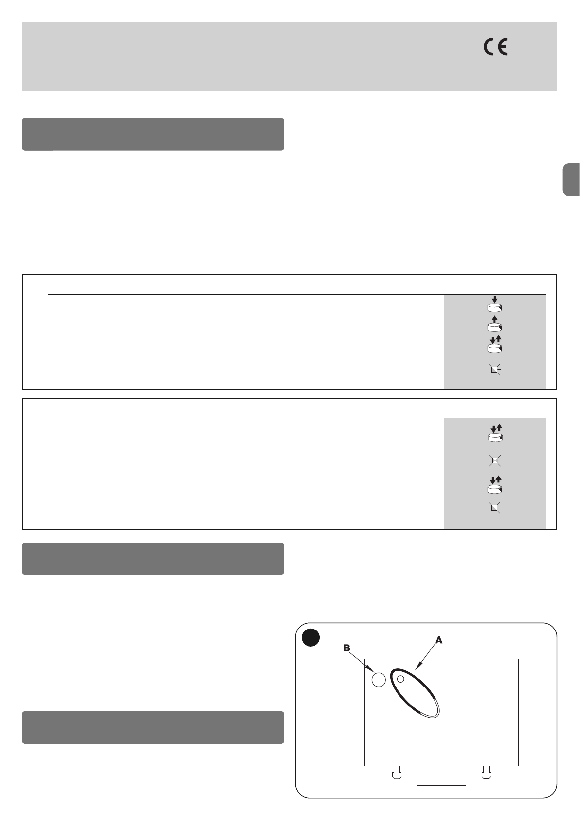
ES
Español – 11
smxi - smixs receptor
0682
SMXI y SMXIS son receptores de 4 canales para centrales que incorporan un
en chufe SM. Los transmisores compatibles tienen la particularidad de que el có digo de reconocimiento sea diferente para cada transmisor. Por lo tanto, pa ra
que el receptor reconozca un determinado transmisor, es necesario memori zar
el código de reconocimiento. Dicha operación de memorización deberá re petirse para cada transmisor que se desee utilizar en el accionamiento de la central.
Notas:
– En el receptor se pueden memorizar hasta un máximo de 256 transmisores.
No está previsto borrar un solo transmisor sino que está previsto borrar únicamente todos los códigos.
– Para funciones más avanzadas, utilice la unidad de programación específica.
DESCRIPCIÓN DEL PRODUCTO
1
El receptor incorpora 4 salidas disponibles en el conector inferior; para conocer
la función de cada salida, véase el capítulo 6.1.
Durante la memorización del código del transmisor es posible seleccionar entre
estas dos opciones:
Modo I - Tabla B1: Cada botón del transmisor activa la salida correspondiente en el receptor, es decir el botón 1 activa la salida 1, el botón 2 activa la
salida 2 y así sucesivamente. En este caso, para cada transmisor existe una
única etapa de memorización y durante esta etapa no es importante el botón
que se pulse; en la memoria se ocupa un solo lugar.
Modo II - Tabla B2: A cada botón del transmisor se le puede asociar una
salida específica del receptor, por ejemplo el botón 1 activa la salida 2, el botón
2 activa la salida 1, etc.. En este caso hay que memorizar el transmisor pulsando el botón deseado para cada salida a activar. Naturalmente, cada botón puede activar una sola salida, mientras que la misma salida puede ser activada por
varios botones. Cada botón ocupa un lugar en la memoria.
TABLA B1 - Memorización modo I (todos los botones son memorizados en la salida respectiva del receptor)
01. Pulse y mantenga pulsado el botón en el receptor durante al menos 3 segundos
02. Cuando se encienda el Led, suelte el botón
03.
Antes de 10 segundos, pulse durante al menos 2 segundos cualquier botón del transmisor que deba memorizar
Nota –
si la memorización fuera correcta, el Led del receptor destellará 3 veces y, si hubiera que memorizar otros
transmisores, repita el punto 3 antes de transcurridos otros 10 segundos. La memorización termina si durante
10 segundos no se reciben nuevos códigos
3s
2s
x3
INSTALACIÓN DE LA ANTENA
2
Para obtener un funcionamiento correcto, el receptor necesita una antena tipo
ABF o ABFKIT; sin la antena, el alcance se limita a pocos metros. La antena
debe instalarse lo más alto posible; ante la presencia de estructuras metálicas
o de cemento armado, instale la antena por encima de estas. Si el cable suministrado con la antena fuera muy corto, utilice un cable coaxial con impedancia
50 ohm (ej. RG58 de baja pérdida), el cable no debe medir más de 10 m de
longitud.
Si la antena estuviera instalada en una pared, es posible conectar el borne de
la trenza a tierra para obtener un mayor alcance. Naturalmente la toma a tierra
debe estar cerca y ser de buena calidad. Si no fuera posible instalar la antena
sintonizada ABF o ABFKIT se podrán obtener resultados discretos utilizando
como antena el trozo de hilo suministrado con el receptor, montado extendido.
ATENCIÓN – Cuando se active la etapa de memorización, se memorizará cualquier transmisor reconocido correctamente que se
encuentre dentro del radio de recepción de la onda radio. Evalúe
con atención este aspecto y, de ser necesario, desconecte la antena para reducir la capacidad del receptor.
MEMORIZACIÓN DE UN TELEMANDO
3
Los procedimientos para la memorización de los telemandos tienen un límite
de tiempo para realizarlos; por consiguiente es necesario leer y entender todo
el procedimiento antes de comenzar las operaciones.
Para realizar el siguiente procedimiento, utilice el botón presente en la caja del
receptor (referencia A, fig. 1a) y el Led (referencia B, fig. 1a) situado a la
izquierda del botón.
1a
TABLA B2 - Memorización modo II (a cada botón se le puede asociar una salida específica del receptor)
01.
Pulse y suelte el botón del receptor una cantidad de veces equivalente a la salida deseada
(1 vez para la salida n° 1, 2 veces para la salida n°2)
02. Controle que el Led emita una cantidad de destellos equivalente a la salida deseada, repetidos con una frecuencia
regular dentro de los 10 seg. (1 destello si la salida es la n° 1, 2 destellos si la salida es la n° 2)
03.
Antes de 10 segundos, pulse durante al menos 2 segundos el botón deseado del transmisor que se ha de memorizar
Nota –
si la memorización fuera correcta, el Led del receptor destellará 3 veces y si hubiera que memorizar otros
transmisores, repita el punto 3 antes de transcurridos otros 10 segundos. La memorización termina si durante
10 segundos no se reciben nuevos códigos a memorizar
2s
x3
RX
RX
RX
TX
TX
Page 50

ES
12 – Español
Memorización a distancia
Es posible memorizar un nuevo transmisor en la memoria del receptor sin utilizar directamente el botón. Es necesario tener a mano un telemando ya memorizado y que funcione. El nuevo transmisor "heredará" las características del
transmisor memorizado. Por consiguiente, si el primer transmisor está memorizado en modo I, el nuevo transmisor también se memorizará en modo I y se
podrá pulsar cualquier botón de los transmisores. Si el primer transmisor está
memorizado en modo 1, también el nuevo transmisor se memorizará en modo
1, pero será necesario en el primer transmisor pulsar el botón que activa la salida deseada, y en el segundo transmisor el botón que se desea memorizar.
Para realizar las operaciones una después de otra sin interrupciones, es necesario leer todas las instrucciones. Entonces, con los dos transmisores, que llamaremos NUEVO a aquel con el código a memorizar y VIEJO a aquel memorizado, colóquese dentro del radio de acción de los radiomandos (alcance máximo) y realice los pasos indicados en la tabla.
TABLA B4 - Borrado de todos los transmisores
01. Pulse y mantenga pulsado el botón en el receptor
02. Espere que el Led se encienda y que se apague; posteriormente espere que emita 3 destellos
03. Suelte el botón exactamente durante el 3° destello
Nota –
si el procedimiento se concluye correctamente, transcurrido un instante, el Led destellará 5 veces
x3
3°
x5
Mediante el siguiente procedimiento es posible borrar todos los códigos memorizados:
BORRADO DE TODOS LOS TRANSMISORES
4
CARACTERÍSTICAS TÉCNICAS DEL PRODUCTO
Receptores: SMXI SMXIS
Decodificación Rolling code de 52 bit FLOR Rolling code de 64 bit SMILO
Compatibilidad transmisores FLOR, VERY VR, NICE WAY, ERGO, PLANO, NICE ONE SMILO
Frecuencia 433.92 MHz 433.92 MHz
Impedancia de entrada 52 KΩ 52 KΩ
Salidas 4 (en conector SM) 4 (en conector SM)
Sensibilidad superior a 0.5 µV superior a 0.5 µV
Temperatura de funcionamiento de -10° C a + 55° C de -10° C a + 55° C
Transmisores: FLO2R SMILO
Botones 1, 2 según las versiones 2 ó 4
Alimentación 12 V Bat. 23 A 12 V Bat. 23 A
Absorción 10 mA 25 mA
Frecuencia de transmisión 433.92 MHz 433.92 MHz
Temp. de funcionamiento de -10° C a + 55° C de -10° C a + 55° C
Potencia irradiada estimada en alrededor de 1 mW e.r.p estimada en alrededor de 1 mW e.r.p
Alcance estimado en 200 m (en exteriores); 35 m estimado en 200 m (en exteriores); 35 m
(en interiores de edificios) (en interiores de edificios)
Dimensiones / Peso 69 x 39 x 15,5 mm / 31 g. Ø 48 mm x H 14 mm - 14 g
Codificación digital (4,50 mil billones de combinaciones) digital (18 trillones de combinaciones)
ADVERTENCIAS: • Todas las características técnicas indicadas se refieren a una temperatura de 20°C (± 5°C). • Nice S.p.a. se reserva el derecho de modificar
el producto en cualquier momento que lo considere necesario, manteniendo las mismas funcionalidades y el mismo uso previsto. • El alcance de los transmisores
y la capacidad de recepción de los Receptores puede estar afectada por interferencias que podrían alterar las prestaciones. En casos de interferencias, Nice no
ofrece ninguna garantía sobre el alcance real de sus dispositivos.
TABLA B3 - Memorización a distancia
01. Pulse durante al menos 5 segundos el botón en el NUEVO transmisor; después suéltelo
02. Pulse lentamente 3 veces el botón en el transmisor VIEJO
03. Pulse lentamente 1 vez el botón en el transmisor NUEVO; después suéltelo
Nota –
si hubiera que memorizar otros transmisores, repita todos los pasos para cada transmisor nuevo
1s
x1
1s1s
x5s
TX
TX TX TX
TX
RX
RX
TX
Page 51

DE
Deutsch – 1
DEUTSCH
Sicherheitshinweise
• ACHTUNG! – Das vorliegende Handbuch enthält für die Sicherheit von
Per sonen wichtige Anweisungen und Hinweise. Die Personen können dur ch eine falsche Installation schwer verletzt werden. Daher ist es wichtig, alle
Abschnitte des Handbuchs vor Installationsbeginn zu lesen. Im Zweifelsfall die
Installation unterbrechen und den Nice Kundendienst um Erklärungen bitten.
• ACHTUNG! – Wichtige Anweisungen: Bewahren Sie das vorliegende
Handbuch auf, um zukünftige Entsorgungs- oder Wartungsarbeiten am
Produkt zu erleichtern.
Hinweise zur Installation
• Vor der Installation prüfen, ob dieses Produkt für die gewünschte Anwendung
geeignet ist (siehe Abschnitt 2.2 “Anwendungslimits“ und Kapitel „Technische
Produkteigenschaften“). Wenn es nicht geeignet ist, NICHT zur Installation
fortschreiten.
• Das Produkt bei der Installation vorsichtig behandeln; keinen Quetschungen,
Stößen, Stürzen oder Kontakt mit beliebigen Flüssigkeiten aussetzen. Das
Produkt keinen Wärmequellen oder offenen Flammen aussetzen. Solche
Handlungen können es schädigen und Betriebsstörungen oder Gefahren verursachen. Sollte dies der Fall sein, die Installation unverzüglich unterbrechen
und den Nice Kundendienst kontaktieren.
• Keine Änderungen am Produkt vornehmen. Unerlaubte Vorgänge können
mangelhafte Funktionen hervorrufen. Der Hersteller übernimmt keinerlei Haftung für Schäden, die durch willkürlich veränderte Produkte entstanden sind.
• Das Produkt darf nicht von Personen (einschließlich Kindern) verwendet werden, deren physische, empfindungsbezogene oder geistige Fähigkeiten einge schränkt sind, oder die keine Erfahrung oder Kenntnisse besitzen, außer
wenn diese mittels einer für ihre Sicherheit verantwortlichen Person überwa cht
werden oder Anleitungen über die Anwendung des Produkts erhalten haben.
• Kinder dürfen nicht mit den Steuerungen der Automatisierung spielen. Die
Sender nicht in der Reichweite von Kindern halten.
• Kinder müssen überwacht werden, um sicherzustellen, dass sie nicht mit
dem Gerät spielen.
• Im Speisungsnetz der Anlage eine Trennvorrichtung mit einem Kontaktöffnungsabstand vorsehen, der die vollständige Trennung laut den Vorschriften
der Überspannungskategorie III ermöglicht.
• Die Steuerung muss an einer elektrischen Versorgungsleitung mit Sicherheitserdung angeschlossen sein.
• Das Verpackungsmaterial des Produkts muss unter voller Einhaltung der örtlichen Vorschriften entsorgt werden.
ALLGEMEINE SICHERHEITSHINWEISE UND
MASSNAHMEN
Der Zweck der Steuerung MC424 ist die Schaltung von 24 V elektromechanischen Toröffnern Wingo für die Automatisierung von Toren oder Drehtoren;
ACHTUNG! – Jeder andere Einsatz ist unzulässig und verboten, auch ein
Einsatz unter anderen Bedingungen, als hier aufgeführt, ist als falsch zu
betrachten und somit verboten!
Die Funktionsweise der Steuerung MC424 beruht auf einem System, das die
Kraftaufwendung der Antriebe misst (Strommessung), die an ihr angeschlossen
sind. Das System ermöglicht es, die Endlaufstellung automatisch wahrzunehmen, die Arbeitszeit eines jeden Antriebs zu speichern und eventuelle Hindernisse beim Normalbetrieb zu entdecken. Diese Eigenschaften machen die
Installation einfacher, da eine Einstellung der Betriebszeiten und der Verschiebung der Torflügel nicht erforderlich ist.
Die gewöhnlich gewünschten Funktionen sind bereits programmiert; mit einem
einfachen Verfahren können auch spezifischere Funktionen programmiert werden (siehe Kapitel 5).
Die Steuerung kann bei Stromausfall über eine Pufferbatterie PS124 gespeist
werden. Wenn Netzspannung fehlt (zur Vertiefung siehe Kapitel 6.2) ist sie auch
vorgerüstet, um an das Solarspeisungssystem „Solemyo“ angeschlossen werden zu können (zur Vertiefung siehe Kapitel 6.3).
BESCHREIBUNG DES PRODUKTS
1
Um einige Ausdrücke und Aspekte einer Automatisierungsanlage für 2-flügelige Drehtüren oder Drehtore zu klären, beziehen Sie sich auf das typische
Anwendungsbeispiel auf Abb.1.
Zeichenerklärung Abb. 1:
1.24 V Elektromechanischer Toröffner Wingo
2.24 V Elektromechanischer Toröffner Wingo
3.Blinkleuchte Lucy24
INSTALLATION
2
Inhaltsverzeichnis
ALLGEMEINE SICHERHEITSHINWEISE UND MASSNAHMEN . . 1
1 – BESCHREIBUNG DES PRODUKTS . . . . . . . . . . . . . . . . . . . . . . . . . 1
2 – INSTALLATION . . . . . . . . . . . . . . . . . . . . . . . . . . . . . . . . . . . . . . . . . . 1
2.1 - ÜBERPRÜFUNGEN VOR DER INSTALLATION . . . . . . . . . . . . . 2
2.2 - EINSATZGRENZEN DES PRODUKTS . . . . . . . . . . . . . . . . . . . . 2
2.3 - INSTALLATION . . . . . . . . . . . . . . . . . . . . . . . . . . . . . . . . . . . . . . 2
2.4 - ELEKTRISCHE ANSCHLÜSSE . . . . . . . . . . . . . . . . . . . . . . . . . . 2
2.4.1 - Anmerkungen zu den Anschlüssen . . . . . . . . . . . . . . . . 3
2.4.2 - Typologie eines Eingangs STOPP . . . . . . . . . . . . . . . . . . 3
2.4.3 - Anschlussbeispiele von Photozellen mit aktiver Funktion
STAND BY und deaktivierter Funktion Phototest . . . . . . 3
2.4.4 - Anschlussbeispiele von Photozellen mit aktivierter . . . . .
Phototestfunktion und deaktivierter Funktion STAND BY 3
2.5 - ERSTES EINSCHALTEN UND ÜBERPRÜFUNG DER . . . . . . . . .
ELEKTRISCHEN ANSCHLÜSSE . . . . . . . . . . . . . . . . . . . . . . . . . 3
2.6 - AUTOMATISCHE SUCHE DER ENDANSCHLÄGE . . . . . . . . . . 3
3 – ABNAHME UND INBETRIEBSETZUNG . . . . . . . . . . . . . . . . . . . . . 4
3.1 - ABNAHME . . . . . . . . . . . . . . . . . . . . . . . . . . . . . . . . . . . . . . . . . . 4
3.2 - INBETRIEBSETZUNG . . . . . . . . . . . . . . . . . . . . . . . . . . . . . . . . . 4
4 – DIAGNOSE . . . . . . . . . . . . . . . . . . . . . . . . . . . . . . . . . . . . . . . . . . . . . 4
5 – PROGRAMMIERUNG . . . . . . . . . . . . . . . . . . . . . . . . . . . . . . . . . . . . . 4
5.1 - BEREITS PROGRAMMIERTE FUNKTIONEN . . . . . . . . . . . . . . . 4
5.2 - PROGRAMMIERBARE FUNKTIONEN . . . . . . . . . . . . . . . . . . . . 4
5.2.1 - Direktprogrammierung . . . . . . . . . . . . . . . . . . . . . . . . . . 5
5.2.2 - Erste Programmierungsstufe: Teil 1 . . . . . . . . . . . . . . . . 5
5.2.3 - Erste Programmierungsstufe: Teil 2 . . . . . . . . . . . . . . . . 5
5.2.4 - Funktionen auf 2. Stufe . . . . . . . . . . . . . . . . . . . . . . . . . . 5
5.3 - 2 PROGRAMMIERUNGSMODALITÄTEN . . . . . . . . . . . . . . . . .
5
5.3.1 - Erste Programmierungsstufe: Funktionen . . . . . . . . . . . 6
5.3.2 - Zweite Programmierungsstufe: Parameter . . . . . . . . . . 6
5.3.3 - Löschen des Speichers . . . . . . . . . . . . . . . . . . . . . . . . . . 6
5.3.4 - Erste Programmierungsstufe: Beispiel . . . . . . . . . . . . . . 7
5.3.5 - Zweite Programmierungsstufe: Beispiel . . . . . . . . . . . . 7
5.3.6 - Programmierungsschema . . . . . . . . . . . . . . . . . . . . . . . . 8
6 – WEITERE AUSKÜNFTE Zubehör . . . . . . . . . . . . . . . . . . . . . . . . . . 9
6.1 - ANSCHLUSS EINES FUNKEMPFÄNGERS . . . . . . . . . . . . . . . . 9
6.2 - ANSCHLUSS DER PUFFERBATTERIE MOD. PS124 . . . . . . . . 9
6.3 - ANSCHLUSS DES SYSTEMS SOLEMYO . . . . . . . . . . . . . . . . . 9
7 – WAS TUN WENN... (Leitfaden zum Lösen von Problemen) . . . . 9
8 – WARTUNG DES PRODUKTS . . . . . . . . . . . . . . . . . . . . . . . . . . . . . . 9
ENTSORGUNG DES PRODUKTS . . . . . . . . . . . . . . . . . . . . . . . . . . 9
TECHNISCHE MERKMALE DES PRODUKTS . . . . . . . . . . . . . . . 10
CE-KONFORMITÄTSERKLÄRUNG . . . . . . . . . . . . . . . . . . . . . . . . 10
FUNKEMPFÄNGER: SMXI - SMIXS . . . . . . . . . . . . . . . . . . . . . . . 11
1 - BESCHREIBUNG DES PRODUKTS . . . . . . . . . . . . . . . . . . . . . . 11
2 - ANTENNENINSTALLATION . . . . . . . . . . . . . . . . . . . . . . . . . . . . . 11
3 - SPEICHERUNG EINER FERNSTEUERUNG . . . . . . . . . . . . . . . . 11
4 - LÖSCHEN ALLER SENDER . . . . . . . . . . . . . . . . . . . . . . . . . . . . . 12
TECHNISCHE MERKMALE DES PRODUKTS . . . . . . . . . . . . . . . . . 12
DARSTELLUNGEN . . . . . . . . . . . . . . . . . . . . . . . . . . . . . . . . . . . . I - VII
Page 52

DE
2 – Deutsch
Zeichenerklärung der Abb. 2 - 5a - 5b - 5c:
Klemmen Funktion Beschreibung Kabeltyp
L - N - Netzstromleitung Netzstromversorgung 3 x 1,5 mm
2
1÷3 Antrieb 1 Anschluss des Antriebs M1 3 x 1,5 mm
2
1÷3 Antrieb 2 Anschluss des Antriebs M2 (Hinweis 1) 3 x 1,5 mm
2
4÷5 Blinkleuchte Anschluss der Blinkleuchte, 24 V max 25 W 2 x 1 mm
2
6÷7 SCA / Elektroschloss Anschluss für Kontrolllampe Tor Geöffnet 24 V max 5 W oder für SCA: 2 x 0,5 mm
2
Elektroschloss 12 V max 25 VA (siehe Kapitel 5 - Programmierung) Elektroschloss: 2 x 1 mm
2
8
Gemeinsamer Leiter 24 V
+24V Versorgung TX-Photozellen für Phototest (max. 100mA); “GEMEINSAM” 1 x 0,5 mm
2
(mit Standby / Phototest) für alle Sicherheitseingänge, mit aktivierter Funktion STAND BY (Hinweis 2)
9 0 V 0 V Versorgung für Nebeneinrichtungen 1 x 0,5 mm
2
10 24 V Speisung Nebeneinrichtungen, ohne Standby (24 V max 200 mA) 1 x 0,5 mm
2
11
Gemeinsamer Leiter 24
V Gemeinsamer Leiter für alle Eingänge (+24 V ) ohne “Stand by” 1 x 0,5 mm
2
12 STOPP Eingang mit STOP-Funktion (Notfall, Sicherheitsabschaltung) (Hinweis 3) 1 x 0,5 mm
2
13 PHOTO NC-Eingang für Sicherheitsvorrichtungen (Photozellen, Schaltleisten) 1 x 0,5 mm
2
14 PHOTO1 NC-Eingang für Sicherheitsvorrichtungen (Photozellen, Schaltleisten) 1 x 0,5 mm
2
15 SCHRITTBETRIEB Eingang für zyklischen Betrieb (ÖFFNET-STOPP-SCHLIESST-STOPP) 1 x 0,5 mm
2
16 AUX Hilfseingang (Hinweis 4) 1 x 0,5 mm
2
17÷18 Antenne Anschluss der Antenne des Funkempfängers Abschirmkabel RG58
Hinweis 1 – Nicht für einteilige Tore benützt (die Steuerung erkennt automatisch, wenn nur ein Antrieb installiert ist).
Hinweis 2 – Die Funktion “Stand By” dient zur Reduzierung des Verbrauchs; zur Vertiefung der Stromanschlüsse siehe Abschnitt 2.4.1 “Anschluss Stand by/Pho-
totest” und zur Programmierung siehe Kapitel 5.2.3 “Funktion Stand by/Phototest.
Hinweis 3 – Der Eingang STOPP kann für NC-Kontakte oder mit konstantem 8,2 K
Ω
Widerstand benutzt werden (siehe Kapitel “Programmierung”)
Hinweis 4 – Der werkseitige Nebenanschluss AUX wird mit der Funktion “Teilöffnung Typ 1” programmiert, kann aber mit einer der folgenden Funktionen programmiert werden:
4.Schlüsseltaster
5.Photozellenpaar “PHOTO”
6.Photozellenpaar “PHOTO1”
7.Photozellenpaar “PHOTO2”
8.Steuerung
Insbesondere erinnern wir daran, dass:
• Für die Merkmale und den Anschluss der Photozellen auf die jeweiligen
Anweisungen des Produkts Bezug zu nehmen ist.
• Der Eingriff des Photozellenpaars “PHOTO” ist beim Öffnen wirkungslos,
während es beim Schließvorgang für das Umkehren der Bewegung sorgt;
• Der Eingriff des Photozellenpaars “PHOTO1” blockiert die Bewegung sowohl
beim Öffnen als auch beim Schließen.
• Der Eingriff des Photozellenpaars “PHOTO2” (am entsprechend programmierten Eingang AUX angeschlossen) hat beim Schließen keine Auswirkung,
wogegen es beim Öffnen für das Umkehren der Bewegung sorgt.
Zur Prüfung der Steuerungsteile siehe Abb. 2.
Zeichenerklärung Abb. 2:
A. Verbinder der 24V Versorgung
B. Verbinder für Antrieb M1
C. Verbinder für Pufferbatterie PS124 / Speisungssystem mit
Solarenergie Solemyo (zur Vertiefung siehe Kapitel 6.3)
D. Sicherung der Nebeneinrichtungen (500mA) Typ F
E. Wählschalter für Öffnungsverzögerung von Antrieb M1 oder M2
F. Klemme für Antrieb M2
G. Klemme für Blinkleuchteausgang
H. Klemme für Ausgang von SCA oder Elektroschloss
I. 24Vdc Klemmen für Nebeneinrichtungen und Phototest
L. Klemmen für Eingänge
L1…L5. LEDs Eingänge und Programmierung
M. Klemme für Funkantenne
N. Steckvorrichtung “SM” für Funkempfänger
O. Verbinder für Programmierung/Diagnose
P1, P2, P3. Tasten und LEDs für die Programmierung
2.1 - Überprüfungen vor der Installation
Vor Arbeitsbeginn die Eignung des gewählten Modells und der für die Installation bestimmten Umgebung prüfen:
• Prüfen, ob alle Anwendungsbedingungen innerhalb der “Anwendungslimits”
liegen und den “Technischen Eigenschaften” des Produkts entsprechen.
• Prüfen, ob die zur Installation gewählte Umgebung mit dem Gesamtplatzbe-
darf des Produkts kompatibel ist (Abb. 3).
• Prüfen, ob die für die Installation gewählte Oberfläche solide ist und daher
eine stabile Befestigung garantieren kann.
• Prüfen, ob sich der Bereich, in dem das Produkt befestigt wird, nicht über-
schwemmt werden kann; das Produkt ggf. über dem Boden installieren.
• Prüfen, ob der Platz um das Produkt eine leichte und sichere Ausführung der
Handbewegungen ermöglicht.
• Prüfen, ob in der Automatisierung mechanische Stopps während des Schlie-
ßens und Öffnens vorliegen.
2.2 - Einsatzgrenzen des Produkts
Das Produkt darf nur mit den Toröffnern Wingo 24V eingesetzt werden.
2.3 - Installation
Zur Befestigung der Steuerung wie in Abb. 4 gezeigt vorgehen. Weiterhin befolgen Sie diese Hinweise:
• Die Steuerung wird in einem Behälter geliefert, der bei korrekter Installation,
einen unter IP54 eingestuften Schutzgrad garantiert. Somit kann die Steuerung
auch extern installiert werden.
• Die Steuerung auf eine unbewegliche, vertikale, flache und vor Stößen
geschützte Oberfläche befestigen. Achtung! - Der untere Teil der Steuerung
muss mindestens 40 cm vom Boden abstehen.
• Die hierfür vorgesehenen Kabel- oder Rohrführungen in den unteren Teil des
Behälters einfügen (Abb. 4). Achtung! - Wenn die Schutzrohre der Kabel in
einem Schacht enden, ist es wahrscheinlich, dass innerhalb des Behälters der
Steuerung Kondenswasser entsteht und so die elektronische Karte beschädigt.
In diesem Fall muss die Steuerung entsprechend geschützt werden, um einer
Kondenswasserbildung vorzubeugen.
• Es ist möglich, die Kabelführungen entlang der langen Seite des Behälters
einzusetzen, wenn die Steuerung intern in einer geschützten Umgebung installiert wird.
Um die Installation der anderen Vorrichtungen in der Automatisierung auszuführen, bezieht man sich auf die jeweiligen Gebrauchsanleitungen.
2.4 - Elektrische Anschlüsse
ACHTUNG!
– Alle Anschlüsse müssen ohne Netzstromspeisung und bei abgetrennter
Pufferbatterie ausgeführt werden, wenn diese in der Automatisierung vorhanden ist.
– Die Anschlussarbeiten dürfen nur von qualifiziertem Personal ausgeführt werden.
– Prüfen, ob alle zu verwendenden Stromkabel geeignet sind.
01. Die Deckelschrauben abschrauben;
02. Die Bohrungen zum Durchführen der Elektrokabel vorbereiten;
03. Die Anschlüsse der Kabel in Bezug auf den Schaltplan Abb. 5 ausführen.
Zum Anschluss des Kabels der Stromspeisung siehe Abb. 6.
Hinweis – Zur Erleichterung der Kabelanschlüsse können die Klemmen
aus ihrem Sitz gezogen werden.
• Die Eingänge der NC-Kontakte (gewöhnlich geschlossen) müssen, falls nicht
benutzt, mit dem “GEMEINSAMEN LEITER” überbrückt werden (mit Ausnahme der Eingänge der Photozellen, falls die Funktion PHOTOTEST aktiviert wird; für weitere Erläuterungen siehe Punkt 2.4.3).
• Falls für den gleichen Eingang mehrere NC-Kontakte vorhanden sind, müssen sie untereinander SERIENGESCHALTET werden.
• Die Eingänge der NO-Kontakte (gewöhnlich geöffnete Kontakte) sind, falls
nicht benützt, frei zu lassen.
• Falls für den gleichen Eingang mehrere NO-Kontakte vorhanden sind, müssen sie untereinander PARALLEL GESCHALTET werden.
• Die Kontakte müssen unbedingt elektromechanischmechanische Kontakte
und frei von jedem Potential sein; stufenweise Anschlüsse wie “PNP”,
“NPN”, “Open Collector” usw. sind unzulässig.
• Im Falle von überlagerten Torflügeln, kann mit Hilfe der Überbrückung E
(Abb. 2) gewählt werden, welcher Antrieb zur Öffnung zuerst starten muss.
Page 53
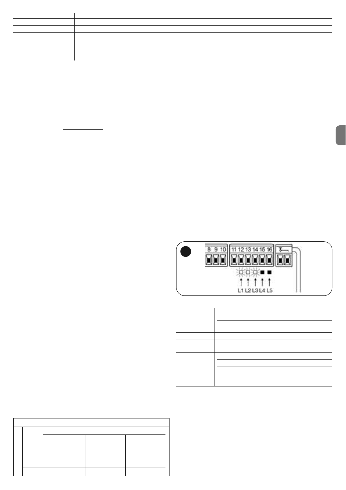
DE
Deutsch – 3
Funktion Eingangstyp Beschreibung
TEILÖFFNUNG TYP 1 NO Öffnet überlagerten Flügel ganz
TEILÖFFNUNG TYP 2 NO Die 2 Flügel öffnen sich bis zur Hälfte des Laufs
ÖFFNET NO führt nur die Öffnungsbewegung aus
SCHLIESST NO führt nur die Schließbewegung aus
PHOTO 2 NC Funktion PHOTO 2
ABGESTELLT -- Keine Funktion
2.4.1 - Anmerkungen zu den Verbindungen
Die meisten Verbindungen sind sehr einfach, großteils handelt es sich um Di rektverbindungen zu einem einzelnen Verbraucher oder Kontakt. Auf den folgenden Abbildungen ist mit einigen Beispielen gezeigt, wie die externen Vorrichtungen anzuschließen sind:
•
Anschluss Standby / Phototest
Die Funktion Standby ist serienmäßig aktiv; sie wird automatisch ausgeschlossen, wenn die Funktion Phototest aktiviert werden soll. Hinweis - Die Funktio-
nen Stand-by und Phototest erfolgen alternativ, da eine die andere ausschließt.
Die Funktion Standby ermöglicht die Reduzierung des Verbrauchs; es ist möglich, drei Anschlussarten zu erreichen:
- Bei aktivem “Standby” (Energieeinsparung
); siehe Schaltplan Abb. 5a.
- Standardanschluss: Ohne “Standby” und ohne “Phototest”; siehe Schaltplan
Abb. 5b.
- Ohne “Standby” und ohne “Phototest”; siehe Schaltplan Abb. 5c.
Mit der aktiven Funktion “Standby” geht die Steuerung 1 Minute nach einer Be -
wegung auf Standby über, wobei alle Eingänge und Ausgänge zur Reduzierung
des Verbrauchs ausgeschaltet werden. Der Zustand wird durch die Led “OK”
angezeigt, die langsamer zu blinken beginnt. HINWEIS - Wenn die Steuerung
mit einem Photovoltaikkollektor (System “Solemyo”) oder mit einer Pufferbatterie gespeist wird, wird die Funktion “Standby” laut Schaltplan Abb. 5a aktiviert.
Wenn die Funktion “Standby2 nicht nötig ist, kann die Funktion “Phototest” ak tiviert werden, die ab Beginn einer Bewegung die korrekte Funktion der angeschlossenen Photozellen prüft. Zur Anwendung dieser Funktion müssen zuerst
die Photozellen angeschlossen (siehe Schaltplan Abb. 5c) und dann die Funktion aktiviert werden.
Hinweis – Nach Aktivierung des Phototests lauten die einem Testverfahren un terworfenen Eingänge PHOTO, PHOTO1 und PHOTO2. Wenn einer dieser Eingänge nicht benützt wird, muss er an die Klemme Nr. 8 angeschlossen werden.
•
Anschluss des Schlüsseltasters
Beispiel 1 (Abb. 7a): Anschluss des Schlüsseltasters zur Durchführung der
Funktionen SCHRITTBETRIEB und STOPP.
Beispiel 2 (Abb. 7b): Anschluss des Schlüsseltasters zur Durchführung der
Funktionen SCHRITTBETRIEB und einer der Funktionen, die für den Hilfseingang vorgesehen sind (TEILÖFFNUNG, NUR ÖFFNUNG, NUR SCHLIESSUNG...)
Hinweis – Für die Stromanschlüsse mit aktivierter Funktion “Stand By” siehe
“Funktion Stand By/Phototest” in diesem Abschnitt 2.4.1.
•
Anschluss der Kontrolllampe Tor Geöffnet / Elektroschlosses
(Abb. 8)
Falls S.C.A. programmiert ist, kann der Ausgang als Kontrolllampe Tor Geöffnet
benutzt werden. Bei Öffnung erfolgt ein langsames Blinken, beim Schließen ein
Schnellblinken. Ein fest leuchtendes Licht bedeutet, dass das Tor geöffnet ist
und steht; ausgeschaltet dagegen bei geschlossenem Tor. Falls der Ausgang
als Elektroschloss programmiert ist, wird das Elektroschloss 3 Sekunden lang
bei jedem Öffnungsbeginn aktiviert.
2.4.2 - Typologie eines Eingangs STOPP
Die Steuerung MC424 kann für zwei Typologien des Eingangs STOPP programmiert werden:
- Stopp mit NC für den Anschluss an NC-Kontakte.
- Stopp mit konstantem Widerstand Für den Anschluss an der Steuerung
von Vorrichtungen mit Ausgang mit konstantem 8,2KΩ Widerstand (z.B.
Schaltleisten). Der Eingang misst den Wert des Widerstands und gibt die
Zustimmung zur Bewegung nicht, wenn der Widerstand nicht innerhalb des
Nennwertes ist. Durch geeignete Maßnahmen können am Eingang Stopp mit
konstantem Widerstand auch Vorrichtungen mit gewöhnlich geöffneten NOKontakten, gewöhnlich geschlossenen NC-Kontakten und ggf. mehr als eine
Vorrichtung auch anderen Typs angeschlossen werden. Hierzu nach Tabelle
1 vorgehen:
ACHTUNG! – Falls der Eingang Stopp mit konstantem Widerstand für
den Anschluss von Vorrichtungen mit Sicherheitsfunktionen benutzt wird,
garantieren nur die Vorrichtungen mit Ausgang mit konstantem 8,2KΩ
Widerstand die Sicherheitsklasse 3 gegen Störungen.
Anmerkungen zur Tabelle 1:
Anmerkung 1 – Eine oder mehrere NO-Vorrichtungen können untereinander
ohne Einschränkung der Menge mit einem Endwiderstand von 8,2K
Ω
parallel
geschaltet werden (Abb. 9a). Für die Stromanschlüsse mit aktivierter Funktion
“Stand By” siehe “Funktion Stand By/Phototest” in diesem Abschnitt 2.4.1.
Anmerkung 2 – Die Kombination von NO und NC ist möglich, wenn die 2 Konta k te untereinander parallel geschaltet werden, wobei am NC-Kontakt ein
8,2KΩWiderstand seriengeschaltet werden muss (was heißt, dass auch eine
Kom bination von drei Vorrichtungen -NO, NC und 8,2KΩ- möglich ist). (Abb. 9b).
Anmerkung 3 – Eine oder mehrere NC-Vorrichtungen können untereinander
und an einen 8,2KΩWiderstand ohne Einschränkung der Menge seriengeschaltet werden. (Abb. 9c)
Anmerkung 4 – Nur eine Vorrichtung mit Ausgang mit konstantem 8,2K
Ω
Widerstand kann angeschlossen sein; mehrere Vorrichtungen müssen eventuell mit nur einem Endwiderstand von 8,2KΩkaskadengeschaltet sein (Abb. 9d)
2.5 - Erstes Einschalten und Überprüfung der Elektrischen
Anschlüsse
ACHTUNG! – Die Anschlussarbeiten dürfen nur von qualifiziertem Perso-
nal ausgeführt werden.
Nachdem die Steuerung stromgespeist wurde, prüfen, ob alle Leds ein paar
Sekunden schnell blinken; dann die folgenden Prüfungen vornehmen:
1.Prüfen, ob an den Klemmen 9-10 eine Spannung von ca. 30Vdc vorhanden
ist; falls die Werte nicht übereinstimmen, die Versorgung unverzüglich ab trennen und Anschlüsse sowie Versorgungsspannung genauer überprüfen.
2. Nach dem anfänglichen Schnellblinken meldet die LED P1 den korrekten
Betrieb der Steuerung durch ein reguläres Blinken einmal pro Sekunde.
Wenn eine Variation an den Eingängen erfolgt, führt die LED “P1” ein schnelles Doppelblinken aus und meldet somit, dass der Eingang erkannt ist.
3. Falls die Anschlüsse korrekt sind, müssen die “NC”-Eingänge die jeweilige
LED eingeschaltet haben, wogegen die “NO”- Eingänge die jeweilige LED
ausgeschaltet haben müssen. Siehe Abb. A und Tabelle 2.
TABELLE 2
EINGANG EINGANGSTYP ZUSTAND LED
STOPP STOPP NC L1 Ein
STOPP KONSTANTER L1 Ein
WIDERSTAND 8,2 KΩ
PHOTO NC L2 Ein
PHOTO1 NC L3 Ein
P.P. NO L4 Aus
AUX TEILÖFFNUNG Typ 1 - NO L5 Aus
TEILÖFFNUNG Typ 2 - NO L5 Aus
NUR ÖFFNUNG - NO L5 Aus
NUR SCHLIEßUNG - NO L5 Aus
PHOTO2 - NC L5 Ein
4. Prüfen, dass sich die jeweiligen LEDs ein- oder ausschalten, wenn man die
Vorrichtungen betätigt, die an den Eingängen angeschlossen sind.
5.Prüfen, dass durch Druck auf Taste P2 beide Antriebe eine kurze Öffnungs-
bewegung ausführen, wobei der Antrieb des oberen Torflügels als erster
starten muss. Die Bewegung durch erneuten Druck auf Taste P2 anhalten.
Falls die Antriebe nicht während der Öffnung starten, die Polung der
Antriebskabel umkehren; falls dagegen als erster nicht der Antrieb des oberen Torflügels startet, die Überbrückung E betätigen (Abb. 2).
2.6 - Automatische Suche der Endanschläge
Nachdem die Überprüfungen und Einstellungen beendet sind, kann man auf
die automatische Suche der mechanischen Endanschläge übergehen; dieser
Vorgang ist notwendig, weil die Steuerung MC424 die Zeitdauer der Öffnungsund Schließbewegungen “messen” muss. Dieses Verfahren zur Erkennung der
mechanischen Endanschläge während der Öffnung und Schließung ist vollkommen automatisch und beruht auf der Kraftmessung der Antriebe.
A
1. Vorrichtung Typ:
NO NC 8,2KΩ
NO Parallel geschaltet (Anmerkung 2) Parallel geschaltet
(Anmerkung 1)
NC (Anmerkung 2) Seriengeschaltet Seriengeschaltet
(Anmerkung 3)
8,2KΩ Parallel geschaltet Seriengeschaltet (Anmerkung 4)
TABELLE 1
2. Vorrichtung Typ:
Page 54

DE
4 – Deutsch
Achtung! – Falls dieses Verfahren bereits ausgeführt worden ist, muss
vor seiner erneuten Durchführung der Speicher gelöscht werden (siehe
Kapitel “Löschen des Speichers”). Um zu prüfen, ob der Speicher die
Parameter der Endanschläge enthält, die Versorgung zur Steuerung ab schalten, dann wieder einschalten. Falls alle LEDs ca. 6 Sekunden schnell
blinken, ist der Speicher leer; falls das Schnellblinken nur 3 Se kunden
dauert, enthält der Speicher bereits die Parameter der Endanschläge.
Vor Beginn der Suche der Endanschläge muss geprüft werden, ob alle Sicherheitsvorrichtungen ihre Zustimmung geben (STOPP, PHOTO und PHOTO1
aktiviert). Die Aktivierung einer Sicherheitsvorrichtung oder die Ankunft eines
Steuerbefehls während dem Verfahren verursacht dessen unverzügliche Unterbrechung. Die Torflügel können sich in beliebiger Stellung befinden, vorzugsweise sollten sie aber auf ca. Hälfte Lauf sein.
Verfahren – Den Druckknopf P2 (Abb. 2) drücken, dann die Suchphase zu
starten, die folgendes vorsieht:
- Kurze Öffnung durch beide Antriebe.
- Schließung durch den Antrieb des unteren Flügels bis zum mechanischen
Endanschlag während der Schließung.
- Schließung des Antriebs des oberen Flügels bis zum mechanischen Endanschlag während der Schließung.
- Öffnung durch den Antrieb des oberen Flügels.
- Nach der vorgesehenen Verstellung beginnt die Öffnung des unteren Torflügels. Sollte die Verstellung nicht ausreichend sein, die Suche durch Druck auf
Taste P1 (Abb. 2) unterbrechen, dann die Zeit ändern (siehe Kapitel 5).
- Die Steuerung nimmt die Messung der Bewegung vor, damit die Antriebe die
mechanischen Endanschläge bei Öffnung erreichen.
- Vollständige Schließbewegung. Die Antriebe können zu verschiedenen Zeiten
starten. Der Zweck ist, dass die Schließung mit einer bestimmten Verstellung
erfolgt, so dass die Torflügel nicht zusammenstoßen.
- Ende des Verfahrens mit Speicherung aller durchgeführten Messungen.
Alle Abläufe müssen hintereinander ohne Eingriff des Bedieners erfolgen.
Sollte das Verfahren aus irgendeinem Grund nicht korrekt fortschreiten, muss
es durch Druck auf Taste P1 unterbrochen werden. Dann das Verfahren wiederholen und ggf. die Parameter ändern, z.B. die Eingriffsgrenzen der Strommessung (siehe Kapitel 5).
Um die höchste Sicherheit der Anlage zu gewährleisten, sind das die wichtigsten Phasen bei der Realisierung der Automation. Das Abnahmeverfahren kann
auch für die regelmäßigen Überprüfungen der Vorrichtungen benutzt werden,
aus denen die Automation besteht. Die Abnahme und die Inbetriebsetzung der
Automation müssen von erfahrenem Fachpersonal ausgeführt werden, das die
erforderlichen Tests zur Überprüfung der je nach vorhandenem Risiko angewendeten Lösungen festzulegen und die Einhaltung der von Gesetzen, Vorschriften und Verordnungen vorgesehenen Punkte zu überprüfen hat. Insbesondere aller Anforderungen der Norm EN 12445, in der die Testmethoden zur
Überprüfung von Torautomatismen festgelegt sind.
Die zusätzlichen oder optionalen Vorrichtungen müssen einer spezifischen
Abnahme unterzogen werden, was die Funktionstüchtigkeit und ihre korrekte
Zwischenwirkung mit MC424 betrifft; somit bezieht man sich auf die Ge brau chsanleitungen der einzelnen Vorrichtungen
3.1 - Abnahme
Die Prüfungsfolge bezieht sich auf die mit den voreingestellten Funktionen programmierte Steuerung; siehe Abschnitt 5.1:
• Prüfen, ob die Aktivierung des Eingangs SCHRITTBETRIEB folgende Se quenz verursacht: Öffnet - Stopp - Schließt - Stopp.
• Prüfen, ob die Aktivierung des Eingangs AUX (Funktion Teilöffnung Typ 1) folgende Sequenz verursacht: Öffnet-Stopp-Schließt-Stopp nur mit dem An trieb des oberen Flügels, wogegen der Antrieb des unteren Flügels während
der Schließung stehen bleibt.
• Eine Öffnungsbewegung starten und folgendes überprüfen:
- Durch Aktivierung von PHOTO muss das Tor die Öffnungsbewegung fortsetzen.
- Durch Aktivierung von PHOTO1 muss die Bewegung stoppen, bis PHOTO1
wieder frei ist, dann wird die Öffnungsbewegung fortgesetzt.
- Falls PHOTO2 installiert ist, muss die Bewegung nach Aktivierung dieser Vorrichtung anhalten und dann während der Schließung erfolgen.
• Prüfen, ob sich die Antriebe abschalten, wenn der Torflügel den mechanischen Endanschlag während der Öffnung erreicht.
• Eine Schließbewegung starten und folgendes überprüfen:
- Durch Aktivierung von PHOTO muss die Bewegung stoppen, dann erfolgt
eine Öffnung.
- Durch Aktivierung von PHOTO1 muss die Bewegung stoppen, bis PHOTO1
wieder frei ist, dann erfolgt eine Öffnung.
- Durch Aktivierung von PHOTO2 setzt das Tor die Schließbewegung fort.
• Prüfen, ob die am Eingang STOPP angeschlossenen Notvorrichtungen das
unverzügliche Anhalten jeder laufenden Bewegung verursachen.
• Prüfen, ob die Stufe des Systems, das die Hindernisse wahrnimmt, der jeweiligen Anwendung entspricht.
- Während der Öffnungs- bzw. Schließbewegung ein Hindernis simulieren und
prüfen, ob die Bewegungsrichtung wechselt, bevor die in den Normen vorgeschriebene Kraft überschritten wird.
ABNAHME UND INBETRIEBSETZUNG
3
• Je nach den mit den Eingängen verbundenen Vorrichtungen könnten weitere
Kontrollen nötig sein.
Achtung – Wenn bei zwei hintereinander ausgeführten Bewegungen in die
gleiche Richtung ein Hindernis wahrgenommen wird, führt die Steuerung
nur 1 Sekunde lang eine teilweise Richtungsumkehrung beider Antriebe
aus. Beim nächsten Steuerbefehl beginnt die Öffnung der Torflügel, und
der erste Eingriff der Strommessung für jeden Antrieb wird als Endanschlag während der Öffnung betrachtet. Dasselbe erfolgt, wenn die Netzstromversorgung wieder hergestellt wird: Der erste Befehl ist immer eine
Öffnung und das erste Hindernis wird immer als Endanschlag während
der Öffnung betrachtet.
3.2 - Inbetriebsetzung
Die Inbetriebsetzung darf erst erfolgen, nachdem alle Abnahmephasen
erfolgreich beendet sind.
1 Erstellten Sie die technischen Unterlagen der Automation. Sie müssen min-
destens folgendes umfassen: Eine Gesamtzeichnung der Automatisierung,
der Plan der ausgeführten Stromanschlüsse, die Analyse der vorhandenen
Risiken und die entsprechenden angewendeten Lösungen (siehe die auszufüllenden Formulare im Internet unter www.niceforyou.com), die Konformitätserklärung des Herstellers für alle benutzten Vorrichtungen und die
vom Installateur ausgefüllte Konformitätserklärung .
2 Bringen Sie am Tor ein Schild mit mindestens folgenden Daten an: Automa-
tionstyp, Name und Adresse des Herstellers (Verantwortlicher der “Inbetriebsetzung”), Seriennummer, Baujahr und CE-Markierung.
3 Informieren Sie den Inhaber vor der Inbetriebsetzung der Automation über
die noch vorhandenen Gefahren und Risiken.
Die LED Diagnose P2 (Abb. 2) zeigt eventuelle Störungen oder ungewöhnliche
Verhalten an, die von der Steuerung während der Bewegung wahrgenommen
werden.
Das Problem wird durch eine bestimmte Anzahl an Blinkvorgängen angegeben;
die Anzeige bleibt bis zum Beginn der nächsten Bewegung aktiviert. Es folgt
eine zusammenfassende Tabelle:
Anzahl Blinkvorgänge Störung
von LED P2
1 Ansprechen der Strommessung von M1
2 Ansprechen der Strommessung von M2
3 Auslösung des Eingangs STOPP während der
Bewegung
4 Fehler bei Phototest
5 Überstrom an Ausgang SCA oder Elektroschloss
Die Steuerung POA1 verfügt über einige programmierbare Funktionen. Nach
der Suchphase werden diese in einer bestimmten Konfiguration vorprogrammiert, die den meisten Automatisierungen gerecht wird. Die Funktionen können
jederzeit sowohl vor als auch nach der automatischen Suchphase der Endanschläge durch einen entsprechenden Programmiervorgang geändert werden;
siehe Abschnitt 5.3.
5.1 - Bereits programmierte Funktionen
• Antriebsbewegung: Schnell
• Automatische Schließung: aktiviert
• Wohnblockbetrieb: deaktiviert
• Vorwarnen: deaktiviert
• Erneutes Schließen nach Photo: deaktiviert
• Verzögerung während der Öffnung Stufe 2 (10%)
• STAND BY / Phototest: Stand by
• SCA/Elektroschloss: SCA
• Eingang STOPP: Typ NC
• Schwere Tore: deaktiviert
• SCA proportional: deaktiviert
• Pausezeit: 20 Sekunden
• Hilfseingang: Teilöffnung Typ 1 (aktiviert nur den
Antrieb des oberen Torflügels)
• Ansprechvermögen der Strommessung Stufe 2
5.2 - Programmierbare Funktionen
Damit die Anlage dem Bedarf des Benutzers besser angepasst werden kann
und unter den verschiedenen Einsatzbedingungen sicherer ist, können mit der
Steuerung MC424 einige Funktionen oder Parameter sowie die Funktion einiger Ein- und Ausgänge programmiert werden.
DIAGNOSE
4
PROGRAMMIERUNG
5
Page 55

DE
Deutsch – 5
5.2.1 - Direktprogrammierung
• Langsame/schnelle Bewegung: Die Bewegungsgeschwindigkeit des Tors
kann jederzeit (bei stehendem Antrieb) einfach durch die Betätigung von Taste P3 (Abb. 2) gewählt werden, wobei sich die Steuerung aber nicht im Programmierungsstatus befinden darf. Die ausgeschaltete LED L3 bedeutet,
dass die langsame Geschwindigkeit eingestellt ist, wenn sie leuchtet, ist die
schnelle Geschwindigkeit eingestellt.
5.2.2 - Erste Programmierungsstufe: Teil 1
• Automatische Schließung: Diese Funktion sieht ein automatisches Schlie-
ßen nach der programmierten Pausezeit vor; ursprünglich ist die eingestellte
Pausezeit 20 Sekunden, kann aber auf 5, 10, 20, 40 oder 80 Sekunden
geändert werden.
Wenn die Funktion deaktiviert ist, so ist das Verhalten “halbautomatisch”.
• Funktion “Wohnblockbetrieb”: Diese Funktion ist nützlich, wenn mehrere
Personen die Automatisierung mit der Funksteuerung bedienen. Wenn diese
Funktion aktiviert ist, verursacht jeder erhaltene Steuerbefehl eine Öffnungsbewegung, die durch weitere Befehle nicht unterbrochen werden kann.
Wenn die Funktion deaktiviert ist, verursacht ein Steuerbefehl ein ÖFFNET STOPP - SCHLIESST - STOPP.
• Vorwarnen: Mit dieser Funktion kann die Blinkleuchte vor Beginn der Bewe-
gung für eine Zeit von 3 Sekunden aktiviert werden.
Wenn die Funktion deaktiviert ist, so beginnt die Blinkleuchte das Blinken am
Beginn der Bewegung.
• Erneutes Schließen nach Photo: Durch die automatische Schließung kann
mit dieser Funktion die Pausezeit nach dem Freiwerden der Photozelle PHOTO auf 4 Sekunden verkürzt werden, d.h. dass sich das Tor 4 Sekunden
nach Durchgang des Benutzers schließen wird. Wenn die Funktion deaktiviert
ist, wird die ganze programmierte Pausezeit ablaufen.
• Verzögerung während der Öffnung Diese Funktion verursacht während der
Öffnung einen Einschaltverzug des Antriebs des unteren Torflügels im Vergleich zum oberen, so dass sich die beiden Torflügel nicht verfangen können.
Die Verstellung während der Schließung ist immer vorhanden und wird automatisch von der Steuerung berechnet, so dass dieselbe Verstellung wie während der Öffnung erfolgt.
5.2.3 - Erste Programmierungsstufe: Teil 2
• Funktion Stand By / Phototest: Die Steuerung weist eine voreingestellte
Funktion “Stand by” auf; wenn diese aktiv ist, schaltet die Steuerung 1 Minute ab dem Ende einer Bewegung den Ausgang “Stand by” (Klemme Nr. 8),
alle Eingänge und Ausgänge zur Reduzierung des Verbrauchs aus (siehe
Schaltplan Abb. 5a). Diese Funktion ist obligatorisch, wenn die Steuerung
ausschließlich mit Photovoltaikkollektoren Solemyo gespeist wird. Auch empfohlen, wenn die Steuerung durch das Stromnetz gespeist wird und die Notfallfunktion mit Pufferbatterie PS124 erhöht werden soll. Alternativ zum
“Stand by” kann die Funktion “Phototest” aktiviert werden, die die korrekte
Funktion der angeschlossenen Photozellen am Beginn einer Bewegung prüft.
Zur Anwendung dieser Funktion müssen die Photozellen korrekt angeschlossen (siehe Schaltplan Abb. 5c) und dann die Funktion aktiviert werden.
• Ausgang Kontrolllampe Tor Geöffnet (SCA) / Elektroschloss Wenn die
Funktion aktiviert ist, können die Klemmen 6-7 für den Anschluss eines
Codeschlosses benutzt werden. Wenn die Funktion deaktiviert ist, können
die Klemmen 6-7 für den Anschluss einer Kontrolllampe Tor Geöffnet (24V)
benutzt werden.
• Eingang STOPP, NC-Typ oder mit konstantem Widerstand Wenn die
Funktion aktiviert ist, so ist der Eingang STOPP auf “konstanter 8,2KΩ Wider-
stand” eingestellt; in diesem Fall muss, damit die Zustimmung zur Bewegung
erteilt wird, zwischen gemeinsamen Leiter und dem Eingang ein Widerstand
von 8,2KΩ +/-25% vorhanden sein. Wenn die Funktion deaktiviert ist, so
funktioniert der Eingang STOPP mit NC-Kontakten.
• Leichte / schwere Tore: Wenn die Funktion aktiviert ist, kann die Steuerung
auch schwere Tore betreiben, indem sie Beschleunigung und Verlangsamung
während der Schließung anders einstellt. Wenn die Funktion deaktiviert ist, so
ist die Steuerung auf leichte Tore eingestellt.
• SCA proportional: Wenn die Funktion aktiviert ist, so ist der Ausgang SCA
auf Proportionalblinken eingestellt, d.h. dass während der Öffnung das Blinken immer schneller erfolgen wird, je mehr sich die Torflügel den Endanschlägen während der Öffnung nähern, und immer langsamer während der Schließung, je mehr sich die Torflügel den Endanschlägen während der Schließung
nähern. Wenn die Funktion deaktiviert ist, erfolgt ein langsames Blinken während der Öffnung und ein schnelles während der Schließung.
5.2.4 - Funktionen auf 2. Stufe
• Pausezeit: Die Pausezeit bzw. die Zeit zwischen den Öffnungs- und Schließ-
bewegungen beim automatischen Betrieb, kann auf 5, 10, 20, 40 und 80 Se kunden programmiert werden.
• Hilfseingang AUX: Die Steuerung hat einen Hilfseingang, der auf eine der 6
folgenden Funktionen konfiguriert werden kann:
- Teilöffnung Typ 1: erfüllt dieselbe Funktion wie der Eingang SCHRITTBE-
TRIEB und löst nur die Öffnung des oberen Torflügels aus
. Funktioniert nur
mit ganz geschlossenem Tor, andernfalls wird der Befehl wie ein SCHRITTBETRIEB-Befehl ausgelegt.
- Teilöffnung Typ 2: erfüllt dieselbe Funktion wie der Eingang SCHRITTBE-
TRIEB und löst die Öffnung der beiden Torflügel für die Hälfte der Zeit aus, die
für die Ganzöffnung vorgesehen ist. Funktioniert nur mit ganz geschlossenem
Tor, andernfalls wird der Befehl wie ein SCHRITTBETRIEB-Befehl ausgelegt.
- Nur Öffnung: diese Funktion führt nur die Öffnung aus, mit der Sequenz
Öffnet - Stopp - Öffnet - Stopp
- Nur Schließung: Dieser Eingang führt nur die Schließung aus, mit der
Sequenz Schließt - Stopp - Schließt - Stopp.
- Photo 2: führt die Funktion der Sicherheitsvorrichtung “PHOTO 2” aus
- Aus: der Eingang führt keine Funktion aus
• Entladungszeit: Am Ende der Schließbewegung, nachdem die Flügel ganz
geschlossen sind, sperrt der Antrieb die Flügel mit der programmierten Kraftausübung. Gleich danach verursacht diese aktivierte Funktion eine sehr kurze Umkehrung, um den überschüssigen Druck zu entladen, den der Antrieb
auf die Torflügel ausübt.
• Ansprechvermögen der Strommessung: Die Steuerung verfügt über ein
System zur Messung der Stromaufnahme der beiden Antriebe, das benutzt
wird, um die mechanischen Endanschläge und eventuelle Hindernisse während der Torbewegung wahrzunehmen. Da die Stromaufnahme von verschiedenen Bedingungen abhängt (Torgewicht, Reibungen, Windstöße, Spannungsschwankungen usw.), besteht die Möglichkeit, die Eingriffsgrenze zu
ändern. Es sind 6 Stufen vorgesehen: Stufe 1 ist die empfindlichste (Mindestkraft), Stufe 6 die weniger empfindliche (Höchstkraft).
ACHTUNG! – Die sachgemäß eingestellte “Strommessfunktion” (ge meinsam mit anderen nötigen Maßnahmen) kann für die Einhaltung der
europäischen Normen EN 12453 und EN 12445, welche den Einsatz von
Techniken oder Vorrichtungen fordert, um die Kräfte zu begrenzen und
die Gefahr durch die Bewegung automatischer Türen und Tore einzuschränken, nützlich sein.
• Verzögerungszeit Torflügel: Der Einschaltverzug des Antriebs des unteren Tor-
flügels kann auf 5, 10, 20, 30 oder 40% der Arbeitszeit programmiert werden.
5.3 - Programmierungsmodalitäten
Alle in Kapitel 5.2 “programmierbare Funktionen” beschriebenen Funktionen
können während des Programmierens ausgewählt und anschließend gespeichert werden. Der Speicher in der Steuerung erhält die Funktionen und Parameter der Automatisierung aufrecht.
Für alle Programmierungsphasen werden die Tasten P1, P2 und P3 verwendet,
wogegen die 5 LEDs L1, L2…L5 den gewählten Parameter angeben werden.
Es sind 2 Programmierungsstufen vorgesehen:
• Auf der ersten Stufe können die Funktionen aktiviert bzw. deaktiviert wer-
den. Jede LED L1, L2…L5 entspricht einer Funktion; die Funktion ist aktiviert,
wenn die LED leuchtet, und deaktiviert, wenn die LED nicht leuchtet.
Die erste Stufe besteht aus 2 Teilen, die durch Druck auf Taste P3 auszuwählen
sind. Die entsprechende LED P3 zeigt an, welcher der 2 Teile ausgewählt ist.
Erste Stufe LED P1 leuchtet fest): Teil 2 (LED P3 ein)
Led L1 Led L2 Led L3 Led L4 Led L5
STAND BY / Elektroschloss Stopp durch Schwere Tore SCA
Phototest
resistiven Widerstand
proportional
Erste Stufe (LED P1 leuchtet fest): Teil 2 (LED P3 ein)
Led L1 Led L2 Led L3 Led L4 Led L5
STAND BY / Elektroschloss Stopp durch Schwere Tore SCA
Phototest
resistiven Widerstand
proportional
Erste Stufe (LED P1 leuchtet fest): Teil 1 (LED P3 aus)
Led L1 Led L2 Led L3 Led L4 Led L5
Automatische Funktion Vorwarnen
Erneutes Schließen
Verzögerung während
Schließung Wohnblockbetrieb nach Foto der Öffnung
Zweite Stufe:
Parameter: Parameter: Parameter: Parameter: Parameter:
Pausezeit Eingang AUX Entladungszeit
Ansprechvermögen
Verzögerungszeit
Strommessung Torflügel
L1: 5
Sek. L1: Öffnen L1: kein Zubehör L1: Stufe 1 L1: 5%
teilweise Typ 1 Entladen (empfindlicher)
L2: 10
Sek. L2: Öffnen L2: 0,3 Sek. L2: Stufe 2 L2: 10%
teilweise Typ 2
L3: 20
Sek. L3: NUR ÖFFNUNG L3: 0,7 Sek. L3: Stufe 3 L3: 20%
L4: 40
Sek.
L4:
NUR SCHLIESSUNG
L4: 1,3 Sek. L4: Stufe 4 L4: 30%
L5: 80
Sek. L5: Photo 2 L5: 2 Sek. L5: Stufe 5 L5: 40%
(weniger empfindlich)
Alle LEDs aus: Alle LEDs aus:
EINGANG Stufe 6 (max.
Nicht benützt Strommessung)
Erste Stufe (LED P1 leuchtet fest): Teil 1 (LED P3 aus)
Led L1 Led L2 Led L3 Led L4 Led L5
Automatische Funktion Vorwarnen
Erneutes Schließen
Verzögerung während
Schließung Wohnblockbetrieb nach Foto der Öffnung
Page 56

5.3.1 - Erste Programmierungsstufe: Funktionen
Auf der ersten Stufe können die Funktionen aktiviert bzw. deaktiviert werden.
Auf der ersten Stufe ist die LED P1 immer eingeschaltet, die eingeschalteten
LEDs L1,L2…L5 geben die aktivierten Funktionen an, die ausgeschalteten
LEDs die deaktivierten Funktionen. Die blinkende LED bedeutet, dass die Funktion gewählt ist, wenn das Blinken kurz ist, ist die Funktion deaktiviert, bei langem Blinken ist die Funktion aktiviert. Zum Übergang von Teil 1 der Programmierung auf Teil 2 und umgekehrt, Taste P3 drücken.
TABELLE A1: Zugang zur ersten Programmierungsstufe
01. Tasten P1 und P2 mindestens 3 Sekunden lang gedrückt halten
Ein Schnellblinken aller LEDs bedeutet, dass man sich unter Programmierung befindet
TABELLE A2 - Aktivieren oder Deaktivieren einer Funktion
01. Mehrmals P1 drücken, bis die blinkende LED auf der gewünschten Funktion ist
02. P2 drücken, um die Funktion zu aktivieren oder zu deaktivieren
TABELLE A3 - Übergang von Teil 1 auf Teil 2 der ersten Stufe (und umgekehrt)
01. Taste P3 drücken
DE
TABELLE A4 - Ausgang aus der ersten Stufe und Bestätigung der Änderungen
01. Die Taste P1 und sofort danach die Taste P2 gedrückt halten, diese mindestens 3 Sekunden gedrückt halten
TABELLE A5 - Ausgang aus der ersten Stufe ohne Bestätigung der Änderungen
01. P1 mindestens 3 Sekunden lang gedrückt halten oder 1 Minute warten oder die Versorgung abschalten
P1 P2
P1
P2
P3
P1 P2
3s oder 60s
P1
3 s
5.3.2 - Zweite Programmierungsstufe: Parameter
Auf der zweiten Stufe kann man die Parameter der jeweiligen Funktionen wählen. Die zweite Stufe erreicht man erst nach Durchgang der ersten.
Auf der zweiten Stufe blinkt die LED P1 schnell, wogegen die 5 anderen LEDs
L1, L2…L5 den gewählten Parameter angeben.
TABELLE B1 - Zugang zur zweiten Programmierungsstufe
01. Durch Druck von P1 und P2 für mindestens 3 Sekunden auf die erste Programmierungsstufe gehen
02. Die Funktion durch Druck auf P1 auswählen, bis sich die blinkende LED auf der gewünschten Funktion befindet
03. Taste P2 mindestens 3 Sekunden lang gedrückt halten und so auf die zweite Stufe gehen
TABELLE B2 - Auswahl des Parameters
01. Mehrmals P2 drücken, bis die blinkende LED auf dem gewünschten Parameter ist
TABELLE B3 - Rückkehr zur ersten Stufe
01. Taste P1 drücken
TABELLE B4 - Ausgang aus der ersten Stufe und Bestätigung der Änderungen
01. Die Taste P1 und sofort danach die Taste P2 gedrückt halten, diese mindestens 3 Sekunden gedrückt halten.
P1
P2
oder
P1 P2
P2
P1
P1 P2
3 s
3 s
3 s
TABELLE B5 - Ausgang aus der ersten Stufe ohne Bestätigung der Änderungen
01. P1 mindestens 3 Sekunden lang gedrückt halten oder 1 Minute warten oder die Versorgung abschalten
5.3.3 - Löschen des Speichers
Jede neue Programmierung ersetzt die früheren Einstellungen, deshalb ist es
gewöhnlich nicht nötig, “alle Parameter zu löschen”. Allerdings kann der Speicher mit diesem einfachen Vorgang ganz gelöscht werden: ACHTUNG – Nach
6 – Deutsch
dem Löschen des Speichers kehren alle Funktionen auf die vorprogrammierten Werte zurück und die Suche der mechanischen Endanschläge
muss neu ausgeführt werden.
P1
3s oder 60s
oder
Page 57

TABELLE C1 - Löschen des Speichers
01. Die Stromversorgung zur Steuerung abschalten und warten, dass alle LEDs ausgeschaltet sind
(ggf. die Sicherung F1 entfernen)
02. Die beiden Tasten P1 P2 auf der Steuerkarte drücken und gedrückt halten
03. Die Stromversorgung zur Steuerung wieder einschalten
04. Mindestens 3 Sekunden warten, dann die beiden Tasten loslassen
Falls das Löschen des Speichers erfolgreich war, werden sich alle LEDs 1 Sekunde lang ausschalten
5.3.4 - Erste Programmierungsstufe: Beispiel
In diesen Beispielen geben wir die Schritte an, die notwendig sind, um eine
die Funktion “Wohnblockbetrieb” aktiviert und der Ausgang “SCA” auf die Aktivierung des Elektroschlosses eingestellt.
Funktion der ersten Stufe zu aktivieren bzw. zu deaktivieren. Als Beispiel wird
Erste Programmierungsstufe – Beispiel:
Aktivierung der Funktion “Wohnblockbetrieb” und Aktivierung des Ausgangs auf “Elektroschloss”
01. Durch Druck von P1 und P2 für mindestens 3 Sekunden auf die erste Programmierungsstufe gehen
02. 1 Mal P1 drücken, bis sich die Blinkanzeige auf LED 2 befindet (kurzes Blinken)
03. Die Funktion “Wohnblockbetrieb” durch Druck auf P2 aktivieren (langes Blinken)
04. 1 Mal P3 drücken, um den zweiten Teil zu aktivieren (die LED von P3 leuchtet auf)
05. 1 Mal P1 drücken, bis sich die Blinkanzeige auf LED 2 befindet (kurzes Blinken)
P1
P1
x1
P1 P2
P1 P2
P1 P2
2
P2
P3
2
3s
DE
3s
06. Den Ausgang “Elektroschloss” durch Druck auf P2 aktivieren (langes Blinken)
07. Aus der Programmierung mit Speicherung gehen, indem die Taste P1 und sofort danach die Taste P2 gedrückt
gehalten wird; diese mindestens 3 Sekunden gedrückt halten
5.3.5 - Zweite Programmierungsstufe: Beispiel
In diesem Beispiel geben wir die Schritte an, die notwendig sind, um einen
Parameter der zweiten Stufe zu ändern. Als Beispiel wird das Ansprechvermögen der Strommessung bis auf “Stufe 5” geändert.
Zweite Programmierungsstufe – Beispiel: Änderung des “Ansprechvermögens der Strommessung”
01. Durch Druck von P1 und P2 für mindestens 3 Sekunden auf die erste Programmierungsstufe gehen
02. 3 Mal P1 drücken, bis sich die Blinkanzeige auf LED 4 befindet
03. Durch mindestens 3 Sekunden langen Druck auf P2 auf die zweite Stufe übergehen
04. 3 Mal P2 drücken, bis LED 5 aufleuchtet
05. Durch Druck auf P1 zur ersten Stufe zurückkehren
06. Aus der Programmierung mit Speicherung gehen, indem die Taste P1 und sofort danach die Taste P2 gedrückt
gehalten wird; diese mindestens 3 Sekunden gedrückt halten
P2
P1
x3
x3
P2
P1 P2
P1 P2
P2
P1
P1 P2
3s
3s
4
3s
5
3s
Deutsch – 7
Page 58

5.3.6 - Programmierungsschema
Auf der folgenden Abbildung ist das komplette Programmierungsschema der
Funktionen und der jeweiligen Parameter gezeigt. Auf dieser Abbildung sind
auch die ursprünglich eingegebenen Funktionen und Parameter bzw. die Funktionen und Parameter angegeben, die nach einem vollständigen Löschen des
Speichers eingestellt sind.
DE
Normalbetrieb
Led P1 Langsamblinken
P1+P2
3 Sek.lang
P1
3 Sek.lang
(nicht speichert)
Erste Stufe
Led P1 leuchtet fest
P2
3 Sek.lang
P1
P1+P2
3 Sek.lang
(
speichert
)
STOP Foto Foto
Automatische
Schließung
Wohnblockbetrieb
5 10 20
Sekunden
1
Schrittbetrieb
Vorwarnen
Zulauf nach Foto
PAUSEZEIT
40 80
AUX
Verzögerung
in Öffnung
P1
P2
P3
P1
P2
P3
P1
P2
P3
P1
On
Off
P3
Stand by
Phototest
Codeschloss
Stop durch resistiven
Widerstand
Schwere Tore
SCA proportional
P2
P3
On
Off
Zweite Stufe
Led P1 Schnellblinken
HILFSEINGANG (*)
P1
o.p.
Typ 1
o.p.
Typ 2
Nur Öffnung
Foto 2
Nur Schließung
P2
P3
ENTLADEN
P1
0 0,3 0,7
Sekunden
1,3 2
P2
P3
ANSPRECHVERMÖGEN STROMMESSUNG
P1
123
Stufe
45
P2
P3
alle Leuchtanzeigen aus · max. Stromaufnahme
VERZÖGERUNG IN ÖFFNUNG
P1
5 10 20%30 40
P2
P3
(*)
T.Ö. Typ 1 Teilöffnung Typ 1,
Bewegung des oberen Flügels
[NO-Kontakt]
T.Ö. Typ 2 Teilöffnung Typ 2,
Bewegung beider Antriebe für
die Hälfte der Arbeitszeit
[NO-Kontakt]
Nur Öffnung öffnet Stopp öffnet Stopp...
[NO-Kontakt]
Nur Schließung schließt Stopp schließt Stopp...
[NO-Kontakt.]
8 – Deutsch
Photo 2 als Photo 2 benutzt
[NC-Kontakt]
Page 59

DE
Deutsch – 9
6.1 - Anschluss eines Funkempfängers
An der Steuerung befindet sich ein Verbinder für das Einstecken einer 4-kanaligen SM-Funkkarte, mit der die Steuerung über Sender, die nach der folgenden
Tabelle auf die Eingänge einwirken, ferngesteuert werden kann.
Empfängerausgang Eingang der Steuerung
Nr. 1 Schrittbetrieb
Nr. 2 AUX (wieder eingestellter Wert: Teilöffnung Typ 1)
Nr. 3 “Nur Öffnung”
Nr. 4 “Nur Schließung”
6.2 - Anschluss der Pufferbatterie Mod. PS124
Die Steuerung kann bei Stromausfall über eine Pufferbatterie PS124 gespeist
werden. Zur Ausführung der Installation und Anschluss der Batterie, wie in
Abb. 10 gezeigt vorgehen.
6.3 - Anschluss des Systems Solemyo
Die Steuerung ist vorgerüstet, um mit dem Photovoltaik-Speisungssystem
“Solemyo” gespeist zu werden (Photovoltaikkollektor und 24V-Batterie). Um den
Speicher “Solemyo” an die Steuerung anzuschließen, für diese die normalerweise für die Pufferbatterie bestimmte Steckdose verwenden (siehe Abb. 6.2).
WICHTIG!
- Wenn die Automatisierung durch das System “Solemyo” gespeist wird,
darf sie NICHT GLEICHZEITIG auch durch das Stromnetz gespeist werden.
- Das System “Solemyo” kann nur verwendet werden, wenn in der Steuerung die Funktion „Stand by" Aktiv ist (ON) und wenn die Anschlüsse das
Schema der Abb. 5a einhalten.
WEITERE AUSKÜNFTE Zubehör
6
Keine LED ein:
• Prüfen Sie, ob die Steuerung gespeist ist. An den Klemmen 9-10 eine Spannung von zirka 30 Vdc messen (oder 24Vdc bei Batteriespeisung).
• Die beiden Sicherungen überprüfen; sollte nicht einmal die LED P1 eingeschaltet sein oder blinken, könnte es sich um einen schwereren Schaden
handeln, deshalb muss die Steuerung ausgetauscht werden.
Die LED P1 blinkt regelmäßig, aber die LEDs EINGÄNGE L1, L2.. L5 spiegeln den Status der entsprechenden Eingänge nicht wider.
• Die Stromversorgung vorübergehend ausschalten, um aus einer möglichen
Programmierphase auszusteigen.
• Die Verbindungen an den Klemmen 11..16 genau überprüfen.
Die Led P1 blinkt alle 4 Sekunden.
• Die Steuerung ist im Zustand Standby.
Das “automatische Suchverfahren” erfolgt nicht
• Das “automatische Suchverfahren” erfolgt nur, wenn es vorher nie ausgeführt
wurde oder wenn der Speicher gelöscht wurde. Um festzustellen, ob der
Speicher leer ist, die Stromversorgung vorübergehend ausschalten; beim
Einschalten müssen alle LEDs ca. 6 Sekunden lang schnell blinken. Wenn sie
nur 3 Sekunden lang blinken, enthält der Speicher bereits gültige Werte. Für
eine neue “automatische Suche” muss der Speicher ganz gelöscht werden.
Das “automatische Suchverfahren” ist noch nie ausgeführt worden, trotzdem erfolgt das Verfahren nicht oder falsch
• Um das “automatische Suchverfahren” zu aktivieren, muss die ganze Anlage
mit allen Sicherheitsvorrichtungen funktionieren.
• Sicher stellen, dass keine der mit den Eingängen verbundene Vorrichtungen
während der “automatischen Suche” ausgelöst wird.
• Damit die “automatische Suche” korrekt beginnt, müssen die LEDs an den
Eingängen wie in Abb. 11 angegeben eingeschaltet sein. LED P1 muss einmal pro Sekunde blinken.
Die “automatische Suche” wurde korrekt durchgeführt, aber es erfolgt
keine Bewegung.
• Prüfen, dass die LEDs der Sicherheitsvorrichtungen (STOPP, PHOTO, PHOTO1 und eventuell PHOTO2) eingeschaltet sind und die LED des aktivierten
Steuerbefehls (SCHRITTBETRIEB oder AUX) während des Befehls aufleuchtet.
• Falls die Funktion “Phototest” aktiviert ist und die Photozellen nicht korrekt
funktionieren, meldet die DIAGNOSE-LED die Störung durch ein 4-maliges
Blinken.
Während der Bewegung führt das Tor eine Umkehrung aus.
Die Ursachen für eine Umkehrung sind:
• Ein Ansprechen der Photozellen (PHOTO2 während der Öffnung, PHOTO
oder PHOTO1 während der Schließung); in diesem Fall die Verbindungen der
Photozellen und ggf. die Anzeige-LEDs der Eingänge überprüfen.
WAS TUN, WENN…
(Leitfaden zum Lösen von Problemen)
7
• Ein Ansprechen der Strommessung während des Betriebs der Antriebe (also
entfernt von den mechanischen Endanschlägen) wird als Hindernis gedeutet
und verursacht eine Umkehrung. Um zu prüfen, ob die Strommessung eingegriffen hat, zählen, wie oft die DIAGNOSE-LED blinkt: 1 Blinken zeigt an,
dass das Ansprechen der Strommessung an Antrieb 1 erfolgte, 2 Mal Blinken an Antrieb 2.
WARTUNG DES PRODUKTS
8
Die Steuerung MC424, ein elektronisches Element, bedarf keiner besonderen
Wartung. Dennoch regelmäßig mindestens alle 6 Monate die einwandfreie Effizienz der ganzen Anlage nach den Angaben in Kapitel 3 kontrollieren.
ENTSORGUNG DES PRODUKTS
Das vorliegende Produkt ist Bestandteil der Automation und muss daher
zusammen mit ihr entsorgt werden.
Wie die Installationsarbeiten muss auch die Abrüstung am Ende der Lebensdauer dieses Produkts durch Fachpersonal ausgeführt werden.
Dieses Produkt besteht aus verschiedenen Stoffen, von denen einige recycelt
werden können, andere müssen hingegen entsorgt werden. Informieren Sie
sich über die Recycling- oder Entsorgungssysteme für dieses Produkt, die von
den in Ihrem Gebiet gültigen Verordnungen vorgesehen sind.
Achtung! – Bestimmte Teile des Produkts können Schadstoffe oder gefährliche
Substanzen enthalten, die, falls in die Umwelt geworfen, schädliche Wirkungen
auf die Umwelt und die Gesundheit der Menschen haben könnten.
Wie durch das Symbol seitlich angegeben, ist es verboten,
dieses Produkt zum Haushaltsmüll zu geben. Daher getrennt
gemäß den Methoden entsorgen, die von den in Ihrem
Gebiet gültigen Verordnungen vorgesehen sind, oder das
Produkt dem Verkäufer beim Kauf eines neuen, gleichwertigen Produkts zurückgeben.
Achtung! – die örtlichen Verordnungen können schwere Strafen im Fall einer
widerrechtlichen Entsorgung dieses Produkts vorsehen.
Page 60

DE
10 – Deutsch
CE-KONFORMITÄTSERKLÄRUNG
Anmerkung - Der Inhalt dieser Konformitätserklärung entspricht dem der letzten verfügbaren Revision der offiziellen Unterlagen vor dem Druck dieses Handbuchs, die sich im
Firmensitz der Nice S.p.a. befinden Der hier vorliegende Text wurde aus Herausgebergründen angepasst.
Nr.: 296/MC424 Revision: 0
Der Unterzeichnete Lauro Buoro erklärt als Geschäftsführer unter seiner Haftung, dass das Produkt:
Herstellername: NICE s.p.a.
Adresse: Via Pezza Alta 13, Z.I. Rustignè, 31046 Oderzo (TV) Italien
Typ: Steuerung mit 2 Antrieben 24 Vdc.
Modelle: MC424
Zubehör: Funkempfänger SMXI, SMXIS
mit den Vorschriften der folgenden gemeinschaftlichen Richtlinien konform ist:
• 98/37/EG (89/392/EWG geändert) RICHTLINIE 98/37/EG DES EUROPAPARLAMENTS UND DES EUROPARATES vom 22. Juni 1998 für die Annäherung der Gesetzgebung der Mitgliedstaaten bezüglich Maschinen.
Wie von der Richtlinie 98/37/EG vorgesehen, wird darauf hingewiesen, dass die Inbetriebsetzung des oben genannten Produkts erst gestattet ist, nachdem die Maschine, in die das Produkt eingegliedert ist, als konform mit der Richtlinie 98/37/EG gekennzeichnet und erklärt worden ist.
Außerdem ist das Produkt mit den Vorschriften der folgenden gemeinschaftlichen Richtlinien konform:
• 2006/95/EWG (ehemalige Richtlinie 73/23/EG) RICHTLINIE 2006/95/EG DES EUROPÄISCHEN PARLAMENTS UND DES RATES vom 12. Dezember
2006 zur Angleichung der Rechtsvorschriften der Mitgliedstaaten betreffend elektrische Betriebsmittel zur Verwendung innerhalb bestimmter Spannungsgrenzen
Gemäß der folgenden harmonisierten Normen: EN 60335-1:1994+A11:1995+A1:1996+A12:1996+A13:1998+A14:1998+A15:2000+A2:2000+A16:2001
• 2004/108/EWG (ehemalige Richtlinie 89/336/EWG) RICHTLINIE 2004/108/EG DES EUROPÄISCHEN PARLAMENTS UND DES RATES vom 15. Dezember 2004 zur Angleichung der Rechtsvorschriften der Mitgliedstaaten über die elektromagnetische Verträglichkeit und zur Aufhebung der Richtlini89
336e//EWG
Gemäß der folgenden harmonisierten Normen: EN 61000-6-2:2001; EN 61000-6-3:2001+A11:2004
Außerdem, nur was die anwendbaren Teile betrifft, mit folgenden Normen konform:
EN 60335-1:2002+A1:2004+A11:2004+A12:2006+ A2:2006, EN 60335-2-103:2003, EN 13241-1:2003; EN 12453:2002; EN 12445:2002;
EN 12978:2003
Oderzo, den 25. September 2008
Lauro Buoro (Geschäftsführer)
HINWEISE: • Alle angegebenen technischen Merkmale beziehen sich auf eine Temperatur von 20°C (± 5°C). • Nice S.p.a. behält sich das Recht vor, jederzeit für
notwendig betrachtete Änderungen am Produkt vorzunehmen, wobei Funktionalitäten und Einsatzzweck beibehalten werden.
Netzstromversorgung Steuerung MC424: 230 V~ ±10% 50 - 60 Hz
Steuerung MC424/V1: 120 V~ ±10% 50 - 60 Hz
Max. Leistungsaufnahme 170 W
Notversorgung vorgerüstet für Pufferbatterien PS124 und für Solar-Kit Solemyo
Max. Stromaufnahme der Antriebe 3 A (Ansprechen der Strommessung “Stufe 6”)
Ausgang für die Versorgung von Nebeneinrichtungen 24 V 24Vdc Höchststrom 200mA (Spannung von 16 bis 33 V dc)
Ausgang Phototest 24 V dc Höchststrom 100mA (Spannung von 16 bis 33 V dc)
Ausgang Blinkleuchte für 24 V dc Blinkleuchten, Höchstleistung 25W (Spannung von 16 bis 33 V dc)
Ausgang Kontrolllampe Tor für 24 V 24Vdc Lampen, Höchstleistung 5W (Spannung von 16 bis 33 V dc)
oder Elektroschloss 12 V~ 25 W
Eingang Stopp für NC-Kontakte oder konstanten 8,2 KΩ Widerstand +/- 25%
Arbeitszeit automatisch gemessen
Pausezeit programmierbar auf 5, 10, 20, 40, 80 Sekunden
Entladungszeit programmierbar auf 0, 0,3, 0,7, 1,3, 2 Sekunden
Verzögerung Torflügel während der Öffnung programmierbar auf 5, 10, 20, 30, 40% der Arbeitszeit
Verzögerung Torflügel während der Schließung automatisch gemessen
Ausgang 1. Antrieb für Antriebe Wingo WG4024 - WG5024
Ausgang 2. Antrieb für Antriebe Wingo WG4024 - WG5024
Max. Kabellänge Stromversorgung 230 V 30 m
Speisung über Solar-Kit Solemyo 3 m
Antriebe 10 m
andere Eingänge/Ausgänge 30 m
Blinkleuchte 10 m
SCA 30 m
Elektroschloss 10 m
Antenne 20 m (unter 3 m empfohlen)
Funkempfänger Kupplung Typ “SM” für Empfänger SMXI, SMXIS, OXI (Modus I und Modus II)
Betriebstemperatur von -20 bis 50 °C
Schutzart IP 54 (unbeschädigtes Gehäuse)
Abmessungen (mm) 310 x 232 x H 122
Gewicht (kg) 4,1
TECHNISCHE MERKMALE DES PRODUKTS
Page 61

DE
Deutsch – 11
smxi - smixs Funkempfänger
0682
SMXI, SMXIS sind 4-Kanal-Funkempfänger für Steuerungen, die mit Steckverbinder SM ausgestattet sind. Die kompatiblen Sender haben die Besonderheit,
dass der Erkennungscode für jeden Sender anders ist. Damit der Empfänger
einen bestimmten Sender erkennt, muss der Erkennungscode gespeichert
werden. Dieser Vorgang wird für jeden Sender, der zur Steuerung der Steuerzentrale benutzt werden soll, einzeln wiederholt.
Anmerkungen:
– Im Empfänger können bis max. 256 Sender gespeichert werden. Ein einzelner
Sender kann nicht gelöscht werden, die Codenummern können nur alle gleichzeitig gelöscht werden.
- Für fortgeschrittenere Funktionen verwenden Sie bitte das spezielle Programmierungsgerät.
BESCHREIBUNG DES PRODUKTS
1
Der Empfänger hat 4 Ausgänge, die alle am Verbinder unten zur Verfügung stehen; um zu wissen, welche Funktion jeder Ausgang hat, wird auf die Anweisungen laut Kapitel 6.1 verwiesen.
In der Speicherphase der Codenummer des Senders stehen 2 Möglichkeiten
zur Auswahl:
Modus I - Tabelle B1: Jede Taste des Senders aktiviert den entsprechenden
Ausgang des Empfängers, d.h. die Taste 1 aktiviert Ausgang 1, Taste 2 aktiviert
Ausgang 2, usw. In diesem Fall gibt es nur eine Speicherphase für jeden Sender. Während dieser Phase ist es unwichtig, welche Taste gedrückt wird, es
wird nur eine einzige Speicherstelle besetzt.
Modus II - Tabelle B1: Jeder Taste des Senders kann ein bestimmter Ausgang des Empfängers zugeordnet werden, z.B. Taste 1 aktiviert Ausgang 2,
Taste 2 aktiviert Ausgang 1 usw. In diesem Fall muss der Sender gespeichert
werden, indem man die gewünschte Taste für jeden Ausgang, der aktiviert werden soll, drückt. Natürlich kann jede Taste nur einen einzigen Ausgang aktivieren, während derselbe Ausgang durch Drücken mehrerer Tasten aktiviert werden kann. Für jede Taste wird nur eine Speicherstelle belegt.
TABELLE B1 - Speichern I (Alle Tasten werden am jeweiligen Ausgang des Empfängers gespeichert)
01. Drücken Sie den Druckknopf mindestens 3 Sekunden lang
02. Wenn die Leuchtanzeige aufleuchtet, lassen Sie den Druckknopf los
03. Innerhalb von 10 Sekunden mindestens 2 Sekunden lang auf eine beliebige Taste des zu speichernden Senders drücken
Anmerkung – Wenn richtig gespeichert wurde, leuchtet die Leuchtanzeige des Empfängers dreimal auf. Wenn Sie weitere
Sender speichern möchten, wiederholen Sie den Vorgang 3 innerhalb von weiteren 10 Sekunden
3s
2s
x3
INSTALLIEREN EINER ANTENNE
2
Für einen einwandfreien Betrieb muss der Empfänger mit einer ABF- oder ABFKIT-Antenne ausgestattet werden; ohne Antenne ist die Leistung auf wenige
Meter begrenzt. Die Antenne muss so hoch wie möglich angebracht werden;
wenn Strukturen aus Metall oder Stahlbeton vorhanden sind, installieren Sie die
Antenne über diesen Strukturen. Wenn das zur Antenne gehörige Kabel zu kurz
ist, benutzen Sie ein Koaxialkabel mit 50 Ohm Impedanz (z.B. RG58 mit niedrigem Verlust), das Kabel darf nicht länger als 10 m sein.
Wenn die Antenne nicht auf einer ebenen Unterlage (Wand) montiert wird, kann
die Klemme des Geflechts geerdet werden, um eine größere Leistung zu
gewährleisten. Natürlich muss die Erdung sachgemäß in der Nähe ausgeführt
werden. Sollte die Montage einer ABF- oder ABFKIT-Antenne unmöglich sein,
können gute Ergebnisse mit der dem Empfänger beiliegenden Leitung als
Antenne erzielt werden.
ACHTUNG –
In der Speicherphase wird jeder richtig erkannte
Sender im Empfangsbereich des Funks gespeichert. Beachten
Sie dies aufmerksam und stecken Sie eventuell die Antenne
aus, um die Leistung des Empfängers zu reduzieren.
SPEICHERN EINER FERNBEDIENUNG
3
Die Speichervorgänge zum Speichern der Fernbedienungen sind zeitlich
begrenzt: deshalb ist es wichtig, sich den ganzen Speichervorgang vor dem
Speichern durchzulesen und zu verstehen.
Zur Durchführung des folgenden Verfahrens müssen die Taste am Gehäuse
des Funkempfängers (siehe A, Abb. 1b) und die jeweilige Led (siehe B, Abb.
1b) links neben der Taste benutzt werden.
1a
TABELLE B2 - Speichern Art II (Jeder Taste kann ein besonderer Ausgang des Empfängers zugeordnet werden)
01. Drücken Sie den Druckknopf auf dem Empfänger und lassen Sie ihn sooft los, wie die Zahl des gewünschten
Ausgangs ist (1 Mal für Ausgang Nr. 1, 2 Mal für Ausgang Nr. 2)
02. Prüfen, ob die LED sooft blinkt, wie der gewünschte Ausgang lautet (regelmäßig in 10 Sekunden wiederholt)
(1 Mal Blinken für Ausgang Nr. 1, 2 Mal Blinken für Ausgang Nr. 2)
03.
Drücken Sie die gewünschte Taste des zu speichernden Senders innerhalb von 10 Sekunden mindestens 2 Sekunden lang
Anmerkung – Wenn richtig gespeichert wurde, leuchtet die Leuchtanzeige des Empfängers dreimal auf. Wenn Sie
weitere Sender speichern möchten, wiederholen Sie Vorgang 3 innerhalb von weiteren 10 Sekunden
2s
x3
RX
RX
RX
TX
TX
Page 62

DE
12 – Deutsch
Fernspeicherung
Ein neuer Sender kann im Speicher des Empfängers auch ohne Drücken des
Tastenfeldes gespeichert werden, wenn man eine bereits gespeicherte und
funktionierende Fernbedienung besitzt. Der neue Sender erhält die Eigenschaften des bereits gespeicherten Senders. Deshalb wird der neue Sender auf
Modus I gespeichert, wenn der alte Sender auf Modus I gespeichert ist. Dazu
kann eine beliebige Sendertaste gedrückt werden. Wenn der erste Sender auf
Modus II gespeichert wurde, wird auch der neue auf Modus II gespeichert;
allerdings muss auf dem ersten Sender die Taste gedrückt werden, die den
gewünschten Ausgang aktiviert und auf dem zweiten Sender die Taste, die
gespeichert werden soll. Vor der Durchführung der einzelnen Vorgänge müssen
alle Anweisungen gelesen werden. Sich nun mit den beiden Fernbedienungen
(die, in die der Code eingegeben werden muss, werden wir mit NEU bezeichnen, die, mit dem bereits gespeicherten Code, mit ALT) in den Aktionskreis der
Funksteuerungen (innerhalb der maximalen Reichweite) begeben und die in der
Tabelle verzeichneten Schritte durchführen.
TABELLE B4 - Löschen aller Sender
01. Drücken Sie den Empfängern und halten Sie ihn gedrückt
02. Warten Sie bis die Leuchtanzeige angeht und anschließend wieder ausgeht, solange, bis diese dreimal aufgeleuchtet hat
03. Lassen Sie die Taste genau während dem 3. Blinken los
Anmerkung – Wenn der Vorgang richtig ausgeführt wurde, leuchtet die Leuchtanzeige kurz danach fünfmal auf
x3
3°
x5
Dank folgendem Ablauf können alle Codenummern des Speichers gelöscht werden.
LÖSCHEN ALLER SENDER
4
TECHNISCHE MERKMALE DES PRODUKTS
Empfänger: SMXI SMXIS
Decodierung Rolling code 52 bit FLOR Rolling code 64 bit SMILO
Kompatibilität der Sender FLOR, VERY VR, NICE WAY, ERGO, PLANO, NICE ONE SMILO
Frequenz 433.92 MHz 433.92 MHz
Eingangsimpedanz 52 KΩ 52 KΩ
Ausgänge 4 (auf Verbinder SM) 4 (auf Verbinder SM)
Empfindlichkeit besser als 0.5 µV besser als 0.5 µV
Betriebstemperatur -10° C bis + 55° C -10° C bis + 55° C
SENDER: FLO2R SMILO
Tasten 1, 2 oder 4 je nach Version 2 oder 4
Stromversorgung 12 V Batt. 23 A 12 V Batt. 23 A
Aufnahme 10 mA 25 mA
Übertragungsfrequenz 433.92 MHz 433.92 MHz
Betriebstemp. -10° C bis + 55° C -10° C bis + 55° C
Abgestrahlte Leistung Geschätzt: ca. 1 mW e.r.p. Geschätzt: ca. 1 mW e.r.p.
Reichweite Geschätzt: 200 m (außen); 35 m (in Gebäuden) Geschätzt: 200 m (außen); 35 m (in Gebäuden)
Abmessungen / Gewicht 69 x 39 x 15,5 mm / 31 g. Ø 48 mm x H 14 mm - 14 g
Codierung digital (4,5 Millionen Milliarden an Kombinationen) Digital (18 Milliarden Milliarden an Kombinationen)
HINWEISE: • Alle angegebenen technischen Merkmale beziehen sich auf eine Temperatur von 20°C (± 5°C). • Nice S.p.a. behält sich das Recht vor, jederzeit für
notwendig betrachtete Änderungen am Produkt vorzunehmen, wobei Funktionalitäten und Einsatzzweck beibehalten werden. • Die Reichweite der Sender und
die Empfangskapazität der Empfänger kann Störungen unterworfen sein, die die Leistungen beeinträchtigen. Im Fall von Interferenzen kann Nice daher die effektive Reichweite ihrer Vorrichtungen nicht garantieren.
TABELLE B3 - Fernspeicherung
01. Mindestens 5 Sek. auf die Taste des NEUEN Senders drücken, dann loslassen
02. Mal langsam auf die Taste des ALTEN Senders drücken
03. 1 Mal langsam auf die Taste des NEUEN Senders drücken, dann loslassen
Anmerkung – Zur Speicherung weiterer Sender, alle Schritte für jeden neuen Sender wiederholen
1s
x1
1s1s
x5s
TX
TX TX TX
TX
TX
RX
RX
Page 63

PL
Polski – 1
POLSKI
Zalecenia dotyczące bezpieczeństwa
• UWAGA! – Niniejsza instrukcja zawiera uwagi i zalecenia ważne dla be -
z pieczeństwa osób obsługujących urządzenie. Nieprawidłowo wykonana
instalacja może być przyczyną poważnych obrażeń. Dlatego też przed rozpoczęciem pracy należy dokładnie przeczytać każdą część instrukcji. Przerwać
instalowanie urządzenia w przypadku wątpliwości jakiegokolwiek charakteru i
zwrócić się o ewentualne wyjaśnienia do Serwisu Technicznego Nice.
• UWAGA! – starannie przechowywać tę instrukcję w celu ułatwienia
ewentualnych operacji konserwacji i utylizacji urządzenia.
Zalecenia dotyczące instalacji
• Przed rozpoczęciem instalacji sprawdź, czy urządzenie jest odpowiednie dla
określonego zastosowania (patrz paragraf 2.2 “Ograniczenia zastosowania”
oraz rozdział “Parametry techniczne urządzenia”).
Jeżeli nie jest ono odpowiednie NIE przystępuj do jego instalacji.
• Podczas montażu ostrożnie obchodź się z urządzeniem, unikaj zgnieceń,
uderzeń, upadków lub zetknięcia z jakimikolwiek płynami. Nie umieszczaj
urządzenia w pobliżu źródeł ciepła i nie narażaj go na działanie otwartego
ognia. Opisane wyżej sytuacje mogą być przyczyną uszkodzenia urządzenia,
jego nieprawidłowego funkcjonowania lub też mogą powodować zagrożenia.
Jeżeli jednak doszłoby do którejś z opisanych wyżej sytuacji natychmiast
przerwij montaż i zwróć się o pomoc do Serwisu Technicznego Nice.
• Nie wprowadzaj modyfikacji do żadnej części urządzenia. Operacje niedozwolone mogą wyłącznie powodować jego nieprawidłowe funkcjonowanie.
Producent zrzeka się wszelkiej odpowiedzialności za szkody, wynikające z
samowolnie wykonywanych modyfikacji urządzenia.
• Urządzenie nie jest przeznaczone do użytku przez osoby, (włącznie z dziećmi)
o zredukowanych zdolnościach fizycznych, czuciowych i umysłowych lub
nieposiadające doświadczenia w obsłudze lub znajomości urządzenia, chyba
że mogły one skorzystać, poprzez pośrednictwo osoby odpowiedzialnej za
ich bezpieczeństwo, z nadzoru lub instrukcji dotyczących obsługi.
• Nie pozwalaj dzieciom bawić się urządzeniami sterującymi automatyką. Przechowuj nadajniki z dala od zasięgu dzieci.
• Dzieci muszą znajdować się pod nadzorem osób dorosłych, których obowiązkiem jest upewnić się, że nie bawią się one urządzeniem.
• Na linii zasilającej automatykę, prowadzącej z sieci elektrycznej należy przewidzieć wbudowanie urządzenia rozłączającego zasilanie i gwarantującego
odległość pomiędzy stykami, umożliwiającą całkowite rozłączenie w warunkach III kategorii przepięcia.
• Podłącz centralę do linii zasilania elektrycznego wyposażoną w uziemienie.
• Opakowanie urządzenia musi być zlikwidowane zgodnie z odpowiednimi
przepisami obowiązującymi na danym terytorium.
INSTRUKCJE I ZALECENIA DOTYCZĄCE
BEZPIECZEŃSTWA
Centrala MC424 przeznaczona jest do sterowania siłowników elektromechanicznych Wingo na 24V, wykorzystywanych do automatyzacji bram lub drzwi
skrzydłowych. UWAGA! – Każde inne jej zastosowanie, odmienne od opi-
sanego oraz zastosowanie w warunkach środowiskowych odmiennych
od podanych w tej instrukcji jest niewłaściwe i zabronione!
Centrala MC424 wyposażona jest w system weryfikujący obciążenie silników
do niej podłączonych (amperometryka); ten system służy do automatycznego
odczytywania pozycji krańcowych, zapisywania czasu pracy każdego silnika
oraz do wykrywania ewentualnych przeszkód, które mogą wystąpić podczas
normalnego ruchu. Ta cecha ułatwia jego instalowanie, ponieważ nie wymaga
regulacji czasu pracy i przesunięcia fazowego skrzydeł bramy.
Centrala została zaprogramowana fabrycznie na funkcje najczęściej używane;
możliwy jest wybór dodatkowych, specyficznych funkcji z zastosowaniem prostej procedury programowania (patrz rozdział 5).
Centrala jest przystosowana do zasilania pobieranego z akumulatora awaryjnego PS124, realizującego zasilanie awaryjne w przypadku przerwy w dopływie
napięcia sieciowego, (aby uzyskać więcej informacji należy przeczytać rozdział
6.2). Jest ona również przystosowana do podłączenia do systemu zasilania
energią słoneczną - “Solemyo”, (aby uzyskać więcej informacji należy przeczytać rozdział 6.3).
OPIS URZĄDZENIA
1
Mając na celu wyjaśnienie niektórych pojęć i aspektów dotyczących drzwi lub
bram dwuskrzydłowych przedstawiamy poniżej typową instalację rys. 1.
Legenda rys. 1:
1. Siłownik elektromechaniczny Wingo na 24V
2. Silownik elektromechaniczny Wingo na 24V
3. Lampa ostrzegawcza Lucy24
4. Przełącznik kluczowy
INSTALACJA
2
Spis treści
INSTRUKCJE I ZALECENIA DOTYCZĄCE BEZPIECZEŃSTWA .1
1 – OPIS URZĄDZENIA . . . . . . . . . . . . . . . . . . . . . . . . . . . . . . . . . . . . . . 1
2 – INSTALACJA . . . . . . . . . . . . . . . . . . . . . . . . . . . . . . . . . . . . . . . . . . . 1
2.1 - KONTROLA WSTĘPNA DO WYKONANIA PODCZAS . . . . . . . . .
INSTALACJA . . . . . . . . . . . . . . . . . . . . . . . . . . . . . . . . . . . . . . . 2
2.2 - OGRANICZENIA ZASTOSOWANIA URZĄDZENIA . . . . . . . . . . 2
2.3 - INSTALACJA . . . . . . . . . . . . . . . . . . . . . . . . . . . . . . . . . . . . . . . 2
2.4 - PODŁĄCZENIA ELEKTRYCZNE . . . . . . . . . . . . . . . . . . . . . . . . . 2
2.4.1 - Uwagi dotyczące połączeń . . . . . . . . . . . . . . . . . . . . . . . 3
2.4.2 - Rodzaje wejścia STOP . . . . . . . . . . . . . . . . . . . . . . . . . . 3
2.4.3 - Przykłady połączenia fotokomórek: z aktywną funkcją . .
STAND BY i nieaktywną funkcją fototest . . . . . . . . . . . . 3
2.4.4 - Przykłady połączenia fotokomórek: z aktywną funkcją . .
fototest i nieaktywną funkcją STAND BY . . . . . . . . . . . . 3
2.5 - PIERWSZE WŁĄCZENIE I KONTROLA POŁĄCZEŃ . . . . . . . . . 3
2.6 - AUTOMATYCZNE WYSZUKIWANIE POŁOŻEŃ KRAŃCOWYCH 3
3 – PRÓBA ODBIORCZA I PRZEKAZANIE DO EKSPLOATACJI . . . . 4
3.1 - PRÓBA ODBIORCZA . . . . . . . . . . . . . . . . . . . . . . . . . . . . . . . . . 4
3.2 - PRZEKAZANIE DO EKSPLOATACJI . . . . . . . . . . . . . . . . . . . . . . 4
4 – DIAGNOSTYKA . . . . . . . . . . . . . . . . . . . . . . . . . . . . . . . . . . . . . . . . . 4
5 – PROGRAMOWANIE . . . . . . . . . . . . . . . . . . . . . . . . . . . . . . . . . . . . . . 4
5.1 - FUNKCJE USTAWIONE FABRYCZNIE . . . . . . . . . . . . . . . . . . . . 4
5.2 - FUNKCJE PROGRAMOWALNE . . . . . . . . . . . . . . . . . . . . . . . . . 4
5.2.1 - Programowanie bezpośrednie . . . . . . . . . . . . . . . . . . . . 5
5.2.2 - Funkcje na pierwszym poziomie programowania: . . . . .
pierwsza część . . . . . . . . . . . . . . . . . . . . . . . . . . . . . . . . . . . 5
5.2.3 - Funkcje na pierwszym poziomie programowania: . . . . .
druga część . . . . . . . . . . . . . . . . . . . . . . . . . . . . . . . . . . .
5
5.2.4 - Funkcje na drugim poziomieprogramowania . . . . . . . . 5
5.3 - TR
YB PROGRAMOWANIA . . . . . . . . . . . . . . . . . . . . . . . . . . . . . 5
5.3.1 - Programowanie na pierwszym poziomie: funkcje . . . . . 6
5.3.2 - Programowanie na drugim poziomie: parametry . . . . . 6
5.3.3 - Kasowanie pamięci . . . . . . . . . . . . . . . . . . . . . . . . . . . . . 6
5.3.4 - Przykład programowania na pierwszym poziomie . . . . 7
5.3.5 - Przykład programowania na drugim poziomie . . . . . . . 7
5.3.6 - Schemat programowania . . . . . . . . . . . . . . . . . . . . . . . . 8
6 – SZCZEGÓŁOWE INFORMACJE o akcesoriach . . . . . . . . . . . . . . 9
6.1 - PODŁĄCZENIE ODBIORNIKA RADIOWEGO . . . . . . . . . . . . . . . 9
6.2 - PODŁĄCZENIE AKUMULATORA AWARYJNEGO MOD. PS124 . 9
6.3 - PODŁĄCZENIE SYSTEMU SOLEMYO . . . . . . . . . . . . . . . . . . . . 9
7 – CO ZROBIĆ JEŚLI...(przewodnik do rozwiązywania problemów) 9
8 – KONSERWACJA URZĄDZENIA . . . . . . . . . . . . . . . . . . . . . . . . . . . . 9
UTYLIZACJA URZĄDZENIA . . . . . . . . . . . . . . . . . . . . . . . . . . . . . . . 9
PARAMETRY TECHNICZNE URZĄDZENIA . . . . . . . . . . . . . . . . . 10
DEKLARACJA ZGODNOŚCI CE . . . . . . . . . . . . . . . . . . . . . . . . . . 10
ODBIORNIK RADIOWY: SMXI - SMIXS . . . . . . . . . . . . . . . . . . . . 11
1 - OPIS URZĄDZENIA . . . . . . . . . . . . . . . . . . . . . . . . . . . . . . . . . . . 11
2 - INSTALOWANIE ANTENY . . . . . . . . . . . . . . . . . . . . . . . . . . . . . . 11
3 - WCZYTYWANIE PILOTA . . . . . . . . . . . . . . . . . . . . . . . . . . . . . . . 11
4 - KASOWANIE WSZYSTKICH KODÓW NADAJNIKÓW . . . . . . . . 12
PARAMETRY TECHNICZNE URZĄDZENIA . . . . . . . . . . . . . . . . . . . 12
ZDJĘCIA . . . . . . . . . . . . . . . . . . . . . . . . . . . . . . . . . . . . . . . . . . . . I - VII
Page 64

PL
2 – Polski
Legenda do rys. 2 - 5a - 5b - 5c:
Zaciski Funkcja Opis Rodzaj przewodu
L - N - Zasilanie Zasilanie sieciowe 230Vpp/50Hz 3 x 1,5 mm
2
1÷3 Silnik 1 Podłączenie silnika M1 3 x 1,5 mm
2
1÷3 Silnik 2 Podłączenie silnika M2 (Uwaga 1) 3 x 1,5 mm
2
4÷5 Lampa ostrzegawcza Podłączenie lampy ostrzegawczej 24 V max 25 W 2 x 1 mm
2
6÷7 SCA / Zamek elektryczny Podłączenie dla Kontrolki stanu bramy 24 V max 5W lub Zamka elektrycznego 12 V SCA: 2 x 0,5 mm
2
max 25 VA (patrz rozdział 5 - Programowanie)
Zamek elektryczny:
2 x 1 mm
2
8 Wspólne 24 V Zasilanie +24 V dla TX fotokomórek z fototestem (max 100mA); 1 x 0,5 mm
2
(z funkcją stand by/fototest)
“WSPóLNE” dla wszystkich (Uwaga 2)
9 0 V Zasilanie urządzeń 0V 1 x 0,5 mm
2
10 24 V Zasilanie urządzeń, bez funkcji “Stand by” (24 V max 200 mA) 1 x 0,5 mm
2
11 Wspólne 24 V Wspólne dla wszystkich wejść (+24 V ) nie zawierających “Stand by” 1 x 0,5 mm
2
12 STOP Wejście z funkcją STOP (awaryjne zatrzymanie, blokada zabezpieczająca) (Uwaga 3) 1 x 0,5 mm
2
13 FOTOKOMÓRKA Wejście typu NC przeznaczone dla urządzeń zabezpieczających (fotokomórki, 1 x 0,5 mm
2
listwy bezpieczeństwa)
14 FOTO1 Wejście typu NC dla urządzeń zabezpieczających (fotokomórki, listwy bezpieczeństwa) 1 x 0,5 mm
2
15 KROK po KROKU Wejście przeznaczone dla sterowania w trybie: OTWARCIE-STOP-ZAMKNIĘCIE-STOP) 1 x 0,5 mm
2
16 AUX Wejście pomocnicze (Uwaga 4) 1 x 0,5 mm
2
17÷18 Antena Podłączenie anteny odbiornika radiowego przewód koncentryczny,
ekranowany typu RG58
Uwaga 1 – Nie używany do bram jednoskrzydłowych (centrala rozpoznaje automatycznie, czy został zamontowany tylko jeden silnik)
Uwaga 2 – Funkcja “Stand By” służy do zmniejszenia zużycia energii; aby uzyskać więcej informacji o połączeniach elektrycznych przeczytaj paragraf 2.4.1 “Pod-
łączenie Stand by/Fototest”, natomiast w przypadku programowania przeczytaj rozdział 5.2.3 “Funkcja Stand by/Fototest”
Uwaga 3 – Wejście STOP może być używane dla styków typu NC lub ze stałą rezystancją 8,2k
Ω
(przeczytaj rozdział “Programowanie”)
Uwaga 4 – Wejście pomocnicze AUX jest zaprogramowane fabrycznie dla funkcji “Otwarcie częściowe typu 1”, może być również przeprogramowane na jedną z
następujących funkcji:
5. Dwie fotokomórki “FOTO”
6. Dwie fotokomórki “FOTO1”
7. Dwie fotokomórki “FOTO2”
8. Centrala sterująca
W szczególności przypominamy, że:
• Dane techniczne oraz sposób podłączenia fotokomórek zamieszczone są we
właściwych instrukcjach urządzenia.
• Zadziałanie dwóch fotokomórek “FOTO” nie daje żadnego efektu podczas
otwierania bramy, powoduje natomiast zmianę kierunku podczas jej zamykania.
• Zadziałanie dwóch fotokomórek “FOTO1” powoduje zablokowanie manewru
zarówno podczas otwierania jak i podczas zamykania bramy.
• Zadziałanie dwóch fotokomórek “FOTO2”, (podłączonych do odpowiednio
zaprogramowanego wejścia AUX) nie daje żadnego efektu podczas zamykania bramy, powoduje natomiast zmianę kierunku podczas jej otwierania.
Aby rozpoznać elementy centrali należy obejrzeć rys. 2.
Legenda do rys. 2:
A. Złącze zasilania 24V
B. Złącze silnika M1
C. Złącze akumulatora awaryjnego PS124 lub systemu zasilania
słonecznego Solemyo (aby uzyskać więcej informacji należy
przeczytać rozdział 6.3)
D. Bezpiecznik topikowy dla urządzeń (500mA) typu F
E. Przełącznik opóźnienia silnika M1 lub M2
F. Złącze silnika M2
G. Zacisk wyjściowy lampy ostrzegawczej
H. Zacisk wyjścia SCA lub zamka elektrycznego
I. Zaciski 24Vps do zasilania urządzeń zewnętrznych i fototestu
L. Zaciski dla wejść alarmowych i sterujących
L1…L5. Diody stanu wejść i programowania
M. Zacisk do podłączenia anteny
N. Złącze “SM” dla odbiornika radiowego
O. Złącze do programowania/diagnostyki
P1, P2, P3. Przyciski i diody wykorzystywane do programowania
2.1 - Kontrola wstępna do wykonania przed instalacją
Przed przystąpieniem do instalacji urządzenia należy sprawdzić stan jego komponentów, dostosowanie wybranego modelu do danej bramy, jak również
warunki otoczenia instalacji.
• Sprawdź, czy wszystkie warunki zastosowania są zgodne z “Ograniczeniami
zastosowania” oraz “Parametrami technicznymi urządzenia”.
• Sprawdź, czy otoczenie wybrane do montażu nie koliduje z całkowitymi
wymiarami gabarytowymi urządzenia (rys. 3).
• Sprawdź, czy powierzchnia wybrana do montażu urządzenia jest trwała i
może zagwarantować stabilne jego przymocowanie.
• Sprawdź, czy strefa mocowania nie jest narażona na zalanie i zamontuj urzą-
dzenie na odpowiedniej wysokości nad ziemią.
• Sprawdź, czy przestrzeń znajdująca się wokół urządzenia umożliwia łatwe i
bezpieczne wykonywanie manewrów w trybie ręcznym.
• Sprawdź, czy automatyka wyposażona jest w NIEZBĘDNE ograniczniki me -
chaniczne, funkcjonujące zarówno podczas zamykania jak i otwierania bramy.
2.2 - Ograniczenia zastosowania urządzenia
Urządzenie może być używane wyłącznie z motoreduktorami Wingo na 24V.
2.3 - Instalacja
Podczas mocowania centrali należy postępować jak pokazano na rys. 4.
Ponadto należy również przestrzegać następujące zalecenia:
• Centrala jest dostarczana w obudowie, która, jeżeli zostanie odpowiednio
zamontowana, gwarantuje stopień zabezpieczenia sklasyfikowany jako IP54.
Dlatego też centrala jest dostosowana do montażu również na zewnątrz.
• Przymocuj centralę na powierzchni stabilnej, pionowej, płaskiej i odpowiednio
zabezpieczonej przed uderzeniami.
Uwaga! – Dolna część centrali musi znajdować się na wysokości co najmniej
40 cm nad podłożem.
• Włóż specjalne dławice kablowe lub przelotki do dolnej części obudowy (rys. 4).
Uwaga! – Jeżeli końce rurek zabezpieczających kable znajdują się w studzien-
ce, możliwe jest, że wewnątrz obudowy centrali powstanie kondensat pary
wodnej, który może przyczynić się do uszkodzenia płyty elektronicznej. W tym
przypadku należy odpowiednio zabezpieczyć centralę w sposób zapobiegający powstawaniu kondensatu.
• Dławice kablowe (doprowadzenie przewodów) można umieścić na dłuższym
boku obudowy jedynie w przypadku, kiedy centrala jest instalowana wewnątrz
budynków, w zabezpieczonym otoczeniu.
Aby zamontować inne urządzenia znajdujące się w automatyce należy zastosować się do odpowiednich instrukcji obsługi.
2.4 - Podłączenia elektryczne
UWAGA!
– Wszystkie podłączenia elektryczne muszą być wykonywane po wcześniejszym odłączeniu napięcie sieciowego i akumulatora awaryjnego,
jeżeli występuje w automacie.
– Operacje podłączenia muszą być wykonywane wyłącznie przez personel wykwalifikowany.
– Sprawdź, czy wszystkie zastosowane przewody elektryczne są odpowiedniego typu.
01. Wykręć śruby z pokrywy centrali;
02. Wykonaj otwory umożliwiające przeprowadzenie przewodów elektrycznych;
03. Podczas wykonywania podłączeń odwołaj się do schematu elektrycznego
za mieszczonego na rys. 5. Aby podłączyć przewód zasilający obejrzyj rys. 6.
Uwaga – Aby ułatwić podłączenia przewodów możesz wyjąć zaciski z
gniazd w płycie centrali.
• W przypadku, kiedy wejścia styków typu NC (Zwykle Zamknięty) nie są używane należy zmostkować je z zaciskiem “WSPÓLNY”, (za wyjątkiem wejść
fo tokomórek w przypadku, gdy włączona jest funkcja FOTOTEST. Szczegółowe wyjaśnienia są zamieszczone w paragrafie 2.4.3).
• Jeżeli do tego samego wejścia podłączysz kilka styków typu NC, musisz je
połączyć ze sobą SZEREGOWO.
• W przypadku, kiedy wejścia styków typu NO (Zwykle Otwarte) nie będą używane nie mogą być do nich podłączane żadne przewody.
• Jeżeli do tego samego wejścia podłączysz kilka styków typu NO musisz je
połączyć ze sobą RÓWNOLEGLE.
• Styki muszą być typu elektromechanicznego i muszą być pozbawione jakiegokolwiek potencjału; nie są dozwolone podłączenia typu “PNP”, “NPN”,
“Open Collector” itp.
• W wypadku, gdy skrzydła bramy nakładają się na siebie, możesz wybrać
przy pomocy mostka E (rys. 2), który silnik powinien włączyć się jako pierwszy podczas otwierania.
Page 65

PL
Polski – 3
Funkcja Typ wejścia Opis
OTWARCIE CZęścIOWE TYPU 1 NO Otwiera całkowicie górne skrzydło
OTWARCIE CZęśCIOWE TYPU 2 NO Otwiera oba skrzydła do połowy
OTWARCIE NO Wykonuje tylko manewr otwierania
ZAMYKANIE NO Wykonuje tylko manewr zamykania
FOTO 2 NC Funkcja FOTO 2
WYKLUCZONY -- Brak funkcji
2.4.1 - Uwagi dotyczące połączeń
Większość połączeń jest nadzwyczaj prosta, część z nich są to bezpośrednie po łączenia z pojedynczym urządzeniem lub stykiem. Na zamieszczonych niżej ry sunkach przedstawione są niektóre przykłady połączeń urządzeń zewnętrznych:
• Połączenie Stand By / Fototest
Funkcja Stand-by jest ustawiana fabrycznie, jako aktywna; zostanie ona automatycznie wyłączona jedynie w przypadku uaktywnienia funkcji Fototest. Uwa-
ga - Funkcje Stand-by i Fototest mogą być uaktywniane na przemian, ponieważ wykluczają się wzajemnie.
Funkcja Stand-by umożliwia zredukowanie zużycia energii elektrycznej; jest
możliwe uzyskania trzech rodzajów połączeń:
- z aktywną funkcją “stand by” (oszczędność energii
); patrz schemat elektrycz-
ny na rys. 5a
- połączenie standard: bez funkcji “stand by” i bez funkcji “fototest”; patrz
schemat elektryczny na rys. 5b
- bez funkcji “stand by” i z funkcją “fototest”; patrz schemat elektryczny na rys. 5c
W przypadku, kiedy aktywna jest funkcja “Stand-by”, po upłynięciu 1 minuty od
za kończenia manewru centrala przechodzi do stanu Stand-by („uśpienia”),
wyłączając wszystkie wejścia i wyjścia w celu zredukowania zużycia energii.
Ten stan zostanie zasygnalizowany przez diodę “OK”, która zaczyna migać
wolniej. UWAGA - Jeżeli centrala jest zasilana z panelu słonecznego (system
“Solemyo”) lub z akumulatora awaryjnego, należy uaktywnić funkcję “Standby”, jak pokazano na schemacie elektrycznym przedstawionym na rys. 5a.
W przypadku, kiedy funkcja “Stand-by” nie jest konieczna, można uaktywnić
funkcję “Fototest”, która umożliwia sprawdzenie prawidłowego funkcjonowania
podłączonych fotokomórek na początku manewru. Aby móc wykorzystać tę
funkcję należy najpierw odpowiednio podłączyć fotokomórki (patrz schemat
elektryczny na rys. 5c) i następnie uaktywnić funkcję.
Uwaga – Po uaktywnieniu funkcji fototest, wejścia, które podlegają procedurze
testu są to wejścia: FOTO, FOTO1 i FOTO2. Jeżeli któreś z tych wejść nie bę d zie używane należy je połączyć z zaciskiem nr 8.
• Podłączenie przełącznika kluczowego
Przykład 1 (rys. 7a): Jak należy podłączyć przełącznik kluczowy, aby wykonać
funkcje KROK po KROKU i STOP
Przyklad 2 (rys. 7b): Jak należy podłączyć przełącznik, aby wykonać funkcje
KROK po KROKU oraz jedną z funkcji przewidzianych przez wejście pomocnicze, (OTWARCIE CZĘŚCIOWE, TYLKO OTWARCIE, TYLKO ZAMKNIĘCIE…)
Uwaga – Przed wykonaniem podłączeń elektrycznych z aktywną funkcją “Sta nd By” należy przeczytać rozdział “Funkcja Stand By/Fototest” zamieszczony w
paragrafie 2.4.1.
• Podłączenie Kontrolki Stanu Bramy / Zamka elektrycznego (rys. 8)
Jeżeli wyjście 6-7 zostało zaprogramowane, jako „kontrolka stanu bramy”,
lampka do niego podłączona podczas otwierania bramy miga powoli, natomiast podczas jej zamykania miga szybko; świeci się światełkiem stałym podczas, kiedy brama jest nieruchoma w pozycji otwartej (całkowicie lub częściowo) i nie świeci się podczas, kiedy jest ona zamknięta. Jeżeli wyjście zostało
zaprogramowane, jako zamek elektryczny, zostanie ono uaktywnione przez 3
sekundy na początku każdego manewru otwierania.
2.4.2 - Rodzaje wejścia STOP
Centrala MC424 może zostać zaprogramowana na dwa rodzaje wejść STOP:
- Stop typu NC umożliwiający połączenie ze stykami typu NC.
- Stop ze stałą rezystancją. Umożliwia podłączenie do centrali urządzeń
zawierających wyjście o stałej rezystancji 8,2 KΩ (np. listwy rezystancyjne).
Wejście mierzy wartość rezystancji i nie wydaje zezwolenia na wykonanie
manewru w przypadku odchyłek od wartości nominalnej. Posługując się
tabelą 1, można również podłączyć do wejścia stop o stałej rezystancji urządzenia ze stykami zwykle otwartymi typu “NO”, zwykle zamkniętymi typu
“NC” oraz ewentualnie kilka dodatkowych urządzeń, nawet różnego typu.
UWAGA! – Jeżeli wejście Stop o stałej rezystancji jest wykorzystywane
do podłączenia urządzeń pełniących funkcje zabezpieczające, jedynie
urządzenia z wyjściem o stałej rezystancji 8,2 KΩ gwarantują 3-ą kategorię bezpieczeństwa.
1-eurządzenie typu
NO NC 8,2 KΩ
NO Połączenie równoległe (uwaga 2) Połączenie
(uwaga 1) równoległe
NC (uwaga 2) Połączenie szeregowe Połączenie
(uwaga 3) szeregowe
8,2KΩ Połączenie równoległe Połączenie szeregowe (uwaga 4)
TABELA 1
2
-e
urządzenie typu
Uwagi do Tabeli 1:
Uwaga 1 – Istnieje możliwość równoległego połączenia jednego lub kilku urzą-
dzeń typu NO z rezystancją końcowa 8,2 K
Ω
bez żadnego ograniczenia ilo-
ściowego (rys. 9a). Przed wykonaniem połączeń elektrycznych z aktywną funkcją “Stand By” należy przeczytać rozdział “Funkcja Stand By/Fototest”, za mieszczony w paragrafie 2.4.1.
Uwaga 2 – Kombinacja NO i NC są możliwe przy równoległym połaczeniu obu
rodzajów styków, pod warunkiem, że styki NC zostaną dodatkowo szeregowo
połączone z rezystancją 8,2 K
Ω
(jest więc również możliwa kombinacja 3 urzą-
dzeń: NO, NC i 8,2 K
Ω
(fig. 9b).
Uwaga 3 – Istnieje możliwość szeregowego połączenia jednego lub kilku urząd zeń
typu NO lub z rezystancją 8,2K
Ω
bez żadnego ograniczenia ilościowego (rys. 9c).
Uwaga 4 – Do wyjścia o stałej rezystancji 8,2 K
Ω
można podłączyć tylko jedno
urządzenie; można ewentualnie podłączyć kilka urządzeń do tylko jednej rezystancji końcowej 8,2 K
Ω
wykorzystując “połączenie kaskadowe” (rys. 9d).
2.5 - Pierwsze włączenie i kontrola połączeń
UWAGA! – Operacje podłączenia muszą być wykonywane wyłącznie
przez personel wykwalifikowany.
Po podłączeniu zasilania elektrycznego do centrali sterującej należy sprawdzić,
czy wszystkie diody będą szybko migać przez kilka sekund, następnie należy
wykonać następujące kontrole:
1. Sprawdź, czy na zaciskach 9-10 jest obecne napięcie o wartości około
30Vps; jeżeli wartości nie są zgodne natychmiast odłącz napięcie i dokładnie sprawdź połączenia oraz napięcie zasilania sieciowego.
2. Po początkowym szybkim miganiu dioda P1 sygnalizuje prawidłowe funk-
cjonowanie centrali za pomocą regularnego migania z częstotliwością raz
na sekundę. Kiedy na którymś z wejść alarmowych lub sterujących nastąpi
zmiana, DIODA “P1” wykona podwójne szybkie błyśnięcie sygnalizujące, że
stan wejścia został zmieniony.
3. Jeżeli połączenia są wykonane prawidłowo, odpowiadająca wejściom typu
“NC” dioda musi się świecić, nie może natomiast świecić się dioda odpowiadająca wejściom typu “NO”. Patrz rys. A i Tabela 2.
TABELA 2
WEJŚCIE TYP WEJŚCIA STAN DIODY
STOP STOP NC L1 Świeci
STOP REZYSTANCJA L1 Świeci
STAŁA 8,2 KΩ
FOTO NC L2 Świeci
FOTO1 NC L3 Świeci
P.P. NO L4 Zgaszona
AUX OTWARCIE CZĘŚCIOWE typu 1 - NO L5 Zgaszona
OTWARCIE CZĘŚCIOWE typu 2 - NO L5 Zgaszona
TYLKO OTWARCIE - NO L5 Zgaszona
TYLKO ZAMKNIĘCIE - NO L5 Zgaszona
FOTO2 - NC L5 Świeci
4. Sprawdź, czy w czasie zadziałania urządzeń podłączonych do wejść odpo-
wiednie diody zgasną lub się zaświecą.
5. Sprawdź, czy po wciśnięciu przycisku P2 oba silniki wykonają krótki ruch
otwierania oraz czy silnik skrzydła wierzchniego włączy się, jako pierwszy.
Zatrzymaj wykonywany manewr ponownie wciskając przycisk P2. Jeżeli
któryś z silników nie ruszy w stronę otwierania bramy należy zamienić biegunowość przewodów zasilania tego silnika, jeżeli natomiast jako pierwszy
nie włączy się silnik uruchamiający skrzydło wierzchnie należy przestawić
mostek E (rys. 2).
2.6 - Automatyczne wyszukiwanie położeń krańcowych
Po zakończeniu weryfikacji można rozpocząć fazę automatycznego wyszukiwania położeń ograniczników mechanicznych. Ta operacja jest niezbędna,
ponieważ centrala MC424 musi “zmierzyć” czas trwania manewrów otwierania
i zamykania. Ta procedura jest całkowicie automatyczna i opiera się na pomiarze obciążenia silników podczas wyszukiwania ograniczników mechanicznych
otwierania i zamykania.
Uwaga! – Jeżeli ta procedura została już wykonana, aby móc ją ponownie
uruchomić należy najpierw skasować pamięć, (przeczytaj rozdział “Kaso-
A
Page 66

PL
4 – Polski
wanie pamięci”). Aby sprawdzić, czy pamięć zawiera już parametry położeń granicznych należy odłączyć i ponownie podłączyć zasilanie do centrali. Jeżeli wszystkie diody będą szybko migać przez około 6 sekund,
oznacza to, że pamięć jest pusta; jeżeli natomiast miganie potrwa tylko 3
sekundy pamięć zawiera już parametry położeń krańcowych.
Przed rozpoczęciem wyszukiwania położeń krańcowych sprawdź, czy wszystkie urządzenia zabezpieczające udzielają pozwolenia na ruch (wejścia STOP,
FOTO i FOTO1 – odpowiednie diody się świecą). Uaktywnienie zabezpieczenia
lub podanie jakiejś komendy sterującej podczas trwania procedury powoduje
natychmiastowe przerwanie ruchu. Podczas wykonywania tej operacji skrzydła
bramy mogą znajdować się w dowolnej pozycji, jednakże zalecamy, aby znajdowały się one mniej-więcej w połowie uchylenia.
Procedura – Wciśnij przycisk P2 (rys. 2), aby rozpocząć fazę wyszukiwania, która przewiduje:
- Krótki ruch obu siłowników w kierunku otwierania.
- Zamknięcie skrzydła spodniego, aż do ogranicznika mechanicznego zamykania.
- Zamknięcie skrzydła wierzchniego, aż do ogranicznika mechanicznego
zamykania.
- Otwieranie skrzydła wierzchniego – do pełnego otwarcia.
- Po przewidzianym opóźnieniu rozpoczyna się otwieranie skrzydła spodniego
– do pełnego otwarcia. Jeżeli opóźnienie nie jest wystarczające, należy
zatrzymać procedurę wciskając przycisk P1 (rys. 2) i następnie zmienić czas
opóźnienia (patrz rozdział 5).
- W czasie otwierania obu skrzydeł centrala dokonuje pomiaru drogi (czasu) aż
do osiągnięcia przez siłowniki ograniczników mechanicznych otwierania.
- Kompletny manewr zamykania. Silniki rozpoczną pracę z przesunięciem czasowym, którego celem jest zabezpieczenie przed zakleszczeniem obu skrzydeł o siebie oraz uniknięcie niebezpieczeństwa zgniecenia przeszkody znajdującej się pomiędzy skrzydłami.
- Zakończenie procedury przy całkowicie zamkniętej bramie, z zapamiętaniem
wszystkich wykonanych pomiarów.
Wszystkie te fazy następują jedna po drugiej, bez interwencji operatora. Jeżeli
z jakiegokolwiek powodu procedura nie jest wykonywana prawidłowo przerwij
ją wciskając przycisk P1. Następnie powtórz procedurę, ewentualnie zmień
parametry, na przykład progi czułości amperometrycznej (przeczytaj rozdział 5).
Poniżej opisane są najważniejsze etapy następujące podczas realizacji automatyki, mające na celu zagwarantowanie maksymalnego bezpieczeństwa. Próba
odbiorcza może być wykonywana również w celu przeprowadzenia okresowej
kontroli urządzeń, które składają się na automatykę. Etapy próby odbiorczej i
przekazania automatyki do eksploatacji muszą być wykonywane przez personel wykwalifikowany i doświadczony, który musi ustalić niezbędne rodzaje prób,
mające na celu sprawdzenie rozwiązań zastosowanych w stosunku do występujących niebezpieczeństw oraz sprawdzenie przestrzegania zaleceń, przewidzianych przez obowiązujące przepisy i ustawy: w szczególności muszą być
spełniane wszystkie wymogi normy EN 12445, która ustala metody prób weryfikacyjnych przeznaczone dla automatyki do bram.
Urządzenia dodatkowe lub opcjonalne muszą zostać poddane specyficznej
próbie odbiorczej, zarówno pod względem funkcjonalności jak i prawidłowego
współdziałania z MC424; w związku z tym należy odwołać się do instrukcji
obsługi tych urządzeń.
3.1 - Próba odbiorcza
Kolejność wykonywanych operacji dotyczy centrali już zaprogramowanej, z
funkcjami w ustawieniu fabrycznym (przeczytaj paragraf 5.1).
• Sprawdź, czy uaktywnienie wejścia KROK po KROKU powoduje uaktywnienie bramy w sekwencji ruchów: “Otwieranie, Stop, Zamykanie, Stop”.
• Sprawdź, czy uaktywnienie wejścia AUX (funkcja częściowego otwarcia Typu
1) powoduje Otwieranie, Stop, Zamykanie, Stop - tylko siłownika skrzydła
wierzchniego, podczas kiedy siłownik skrzydła spodniego pozostaje nieruchomy w pozycji zamkniętej.
• Włącz manewr otwierania i sprawdź, czy:
- Po zasłonięciu linii FOTO brama kontynuuje otwieranie
- Po zasłonięciu FOTO1 manewr zostanie zatrzymany dopóki FOTO1 nie zostanie odsłonięta, i następnie zostanie wznowiony - nadal w kierunku otwierania
- Jeżeli FOTO2 została zainstalowana, po jej zasłonięciu manewr otwierania
musi zostać zatrzymany, po czym zostanie on wznowiony w stronę zamykania
• Sprawdź, czy w momencie, kiedy skrzydła dotrą do ogranicznika mechanicznego otwierania silniki wyłączą się.
• Włącz manewr zamykania i sprawdź, czy:
- Po zasłonięciu FOTO manewr zostanie zatrzymany i następnie zostanie wz nowiony w stronę otwierania.
- Po zasłonięciu FOTO1 manewr zostanie zatrzymany, dopóki FOTO1 nie zo sta nie odsłonięta i następnie zostanie wznowiony - ale w stronę otwierania
- Po zasłonięciu FOTO2 brama kontynuuje wykonywanie manewru zamykania
• Sprawdź, czy urządzenia zatrzymujące, podłączone do wejścia STOP, powodują natychmiastowe zatrzymanie każdego wykonywanego ruchu, bez wz ględu na jego kierunek.
• Sprawdź, czy poziom czułości systemu wykrywania przeszkód jest odpowi e d ni dla danego zastosowania:
- Podczas wykonywania manewru, zarówno otwierania jak i zamykania, zablokuj ruch skrzydła symulując przeszkodę i sprawdź, czy kierunek wykonywa-
PRÓBA ODBIORCZA I PRZEKAZANIE DO
EKSPLOATACJI
3
nia manewru zostanie zmieniony przed przekroczeniem siły przewidzianej
przez obowiązujące przepisy
• W zależności od rodzaju urządzeń podłączonych do wejść centrali może być
wymagane wykonanie dodatkowych prób.
Uwaga – Jeżeli podczas wykonywania dwóch kolejnych manewrów w tym
samym kierunku zostanie wykryta przeszkoda, centrala zmieni kierunek
obu silników na czas 1 sekundy. Po wydaniu następnego polecenia skrzydła otworzą się, a pierwsze zadziałanie funkcji amperometrycznej dla każdego silnika, zostanie rozpoznane, jako ogranicznik mechaniczny otwierania. To samo zachowanie uzyskiwane jest w przypadku ponownego
podłączenia zasilania sieciowego: pierwsze polecenie (na wejście krok po
kroku) spowoduje zawsze otwieranie a pierwsza przeszkoda zostanie rozpoznana zawsze, jako ogranicznik mechaniczny otwierania.
3.2 - Przekazanie do eksploatacji
Przekazanie urządzenia do eksploatacji może nastąpić dopiero po wykonaniu wszystkich faz próby odbiorczej i uzyskaniu wyniku pozytywnego.
1 Przygotuj książkę techniczną automatu, która musi zawierać następujące do -
kumenty: rysunek całościowy automatu, schemat wykonanych połączeń ele k trycznych, analizę występujących zagrożeń i odnośne, zastosowane rozwiązania, (na stronie www.niceforyou.com znajdziesz formularze do wypełnienia), deklaracje zgodności producenta dla wszystkich zastosowanych ur ządzeń oraz deklarację zgodności automatyki, wypełnioną przez instalatora.
2 Zawieś na bramie tabliczkę, zawierającą co najmniej następujące dane: typ
automatu, nazwę i adres producenta (osoby odpowiedzialnej za “przekazanie do eksploatacji”), numer seryjny, rok produkcji i oznakowanie “CE”.
3 Przed przekazaniem automatu do eksploatacji należy odpowiednio poinformo-
wać właściciela o zagrożeniach i występującym nadal ryzyku szczątkowym.
Dioda Diagnostyka (rys. 2) sygnalizuje ewentualne anomalie lub błędy odczytane przez centralę podczas ruchu.
Seria określonej ilości błysków wskazuje rodzaj problemu i sygnalizacja ta
pozostaje aktywna aż do rozpoczęcia następnego ruchu. Poniżej zamieszczona jest tabela podsumowująca:
Ilość błysków Typ anomalii
diody P2
1 Interwencja amperometryczna silnika M1
2 Interwencja amperometryczna silnika M2
3 Interwencja wejścia STOP podczas ruchu
4 Błąd fototestu
5 Przeciążenie wyjścia SCA lub zamka elektrycznego
DIAGNOSTYKA
4
Centrala MC424 posiada kilka funkcji programowalnych. Są one ustawiane
fabrycznie w konfiguracji, która jest odpowiednia dla przeciętnej automatyki.
Funkcje mogą być zmieniane w każdej chwili, zarówno przed jak i po wykonaniu automatycznego wyszukiwania pozycji krańcowych, z zastosowaniem
odpowiedniej procedury programowania; patrz paragraf 5.3.
5.1 - Funkcje ustawione fabrycznie
• Ruch silników: szybki
• Automatyczne zamykanie: aktywne
• Funkcjonowanie w bloku mieszkalnym: nieaktywne
• Miganie wstępne lampy: nieaktywne
• Zamknij po foto: nieaktywne
• Opóźnienie podczas otwierania: poziom 2 (10%)
• STAND BY/Fototest: Stand by
• SCA/Zamek elektryczny: SCA
• Wejście STOP: typu NC
• Ciężkie bramy: nieaktywne
• SCA proporcjonalny: nieaktywne
• Pauza przed zamknięciem: 20 sekund
• Wejście pomocnicze AUX: otwieranie częściowe Typu 1
(tylko skrzydło wierzchnie)
• Czułość amperometryczna: 2 poziom
5.2 - Funkcje programowalne
Aby dostosować instalację do potrzeb użytkownika i uczynić ją bardziej bezpieczną w różnych warunkach zastosowania, centrala MC424 umożliwia przeprogramowanie kilku funkcji lub ich parametrów oraz zmianę funkcjonowania
niektórych wejść i wyjść.
PROGRAMOWANIE
5
Page 67

PL
Polski – 5
5.2.1 - Programowanie bezpośrednie
• Ruchy Wolny/Szybki: Prędkość ruchu bramy może być zmieniana w każdej
chwili (przy niepracujących silnikach), poprzez wciśnięcie przycisku P3 (rys. 2),
podczas kiedy centrala nie znajduje się w stanie programowania. Zgaszona dioda P3 wskazuje, że został ustawiony ruch wolny, dioda świecąca - ruch szybki.
5.2.2 - Funkcje na pierwszym poziomie: pierwsza część
• Automatyczne zamykanie: Ta funkcja przewiduje automatyczne zamykanie
bramy po zaprogramowanym czasie przerwy; początkowo czas ten jest ustawiony na 20 sekund, ale może zostać zmieniony na 5, 10, 20, 40 i 80 sekund.
Jeżeli ta funkcja nie jest aktywna urządzenie funkcjonuje w trybie “półautomatycznym”.
• Funkcja “Blok mieszkalny”: Ta funkcja jest użyteczna w przypadku używa-
nia automatyki przez wiele osób, za pomocą pilotów radiowych. Jeżeli ta
funkcja jest aktywna, manewr otwierania nie może być przerwany przez inne
impulsy sterujące – innych użytkowników. Jeżeli funkcja nie jest aktywna,
kolejne polecenia różnych użytkowników powodują sekwencję ruchów:
OTWARCIE-STOP-ZAMKNIĘCIE-STOP.
• Miganie wstępne: Ta funkcja umożliwia uaktywnienie lampy ostrzegawczej
na 3 sekundy przed rozpoczęciem manewru.
Jeżeli funkcja nie jest aktywna, lampa ostrzegawcza zaczyna migać przy rozpoczęciu ruchu.
• Zamknij po foto: Podczas automatycznego zamykania bramy funkcja ta
umożliwia skrócenie czasu trwania przerwy do 4 sekund, po uprzednim przecięciu i odsłonięciu linii FOTO. Oznacza to, że brama zamknie się po upływie
4 sekund od przejścia użytkownika. Jeżeli funkcja nie jest aktywna zostanie
odliczony zaprogramowany czas przerwy.
• Opóźnienie podczas otwierania: Ta funkcja powoduje opóźnienie urucho-
mienia silnika skrzydła spodniego w stosunku do skrzydła wierzchniego podczas otwierania bramy; to opóźnienie jest niezbędne w celu uniknięcia zablokowania się skrzydeł bramy. Przesunięcie fazowe podczas zamykania bramy
jest zawsze aktywne i jest ono obliczane automatycznie przez centralę, w
sposób umożliwiający uzyskanie tego samego przesunięcia, które zostało
zaprogramowane podczas otwierania.
5.2.3 - Funkcje na pierwszym poziomie programowania: druga część
• Funkcja Stand By/Fototest: Centrala realizuje funkcję “Stand by” w usta-
wie niu fabrycznym; jeżeli jest ona aktywna, centrala wyłącza wyjście “Stand
by” (zacisk nr 8) oraz wszystkie wejścia i pozostałe wyjścia, w celu obniżenia
zu życia energii po upływie 1 minuty od zakończenia ostatniego manewru;
(patrz schemat elektryczny na rys. 5a). Ta funkcja jest obowiązkowa, jeżeli
cen trala jest zasilana wyłącznie z paneli słonecznych Solemyo. Jest zalecana
również w przypadku, kiedy centrala jest zasilana z sieci elektrycznej i zamierza się rozszerzyć jej możliwości poprzez zastosowanie akumulatora awaryjnego PS124. Alternatywą “Stand by” jest funkcja “Fototest”, która sprawdza
prawidłowe działanie fotokomórek na początku każdego manewru. Aby móc
wykorzystać tę funkcję należy najpierw odpowiednio podłączyć fotokomórki
(patrz schemat elektryczny na rys. 5c) i następnie uaktywnić tą funkcję.
• Wyjście Kontrolka stanu bramy (SCA)/Zamek elektryczny: Jeżeli ta funk-
cja jest aktywna, zaciski 6-7 mogą być używane do podłączenia zamka elektrycznego. Jeżeli funkcja nie jest aktywna zaciski 6-7 mogą być używane do
podłączenia kontrolki sygnalizującej stan bramy (24V).
• Wejście STOP typu NC lub o stałej rezystancji: Jeżeli ta funkcja jest ak -
tywna, wejście STOP jest ustawione na “Stałą Rezystancję 8,2k ”, w tym
przypadku, aby uzyskać pozwolenie na wykonanie manewru, pomiędzy
wspólnym a wejściem musi być podłączona rezystancja wartości 8,2k +/25%. Jeżeli funkcja nie jest włączona, wejście STOP jest skonfigurowane do
współpracy ze stykami typu NC.
• Bramy lekkie/ciężkie: Jeżeli ta funkcja jest aktywna centrala umożliwia auto-
matyzację bram ciężkich, zarządzając w specjalny sposób przyspieszaniem
skrzydeł przy otwieraniu oraz zwalnianiem podczas zamykania. Jeżeli funkcja
nie jest aktywna centrala jest ustawiona na obsługę bram lekkich.
• SCA proporcjonalny: Jeżeli ta funkcja jest aktywna wyjście SCA jest usta-
wione na miganie proporcjonalne: podczas otwierania bramy natężenie migania wzrasta stopniowo, proporcjonalnie do zbliżania się skrzydeł do położenia
pełnego otwarcia, i odwrotnie, podczas zamykania natężenie migania zmniejsza się stopniowo, w miarę zbliżania się skrzydeł do pozycji pełnego zmknięcia. Jeżeli ta funkcja nie jest aktywna, kontrolka miga wolno podczas otwierania i szybko podczas zamykania.
5.2.4 - Funkcje na drugim poziomie programowania
• Czas trwania przerwy: Czas trwania przerwy, czyli czas upływający pomiędzy
zakończeniem manewru otwierania i rozpoczęciem manewru automatycznego
zamykania może zostać zaprogramowany na 5, 10, 20, 40 i 80 sekund.
• Wejście pomocnicze AUX: Centrala posiada wejście pomocnicze, które
może realizować jedną z 6 funkcji:
- Otwieranie częściowe typu 1: działa jak wejście KROK po KROKU, ale
powoduje ruch tylko skrzydła wierzchniego. Działa tak tylko w przypadku bramy całkowicie zamkniętej, w przeciwnym przypadku polecenie jest rozumiane, jako polecenie KROK po KROKU dla obu skrzydeł.
- Otwieranie częściowe typu 2: działa jak wejście KROK po KROKU, powodując jednak otwarcie obu skrzydeł bramy do połowy skoku. Działa tak tylko
w przypadku bramy całkowicie zamkniętej, w przeciwnym przypadku polecenie jest rozumiane jakoklasyczne polecenie KROK po KROKU – z pełnym
zakresem ruchu obu skrzydeł.
- Tylko Otwarcie: sekwencja ruchów: Otwieranie-Stop-Otwieranie-Stop…
- Tylko Zamknięcie: sekwencja ruchów: Zamykanie-Stop-Zamykanie-Stop…
- Foto 2: pełni funkcję wejścia dla linii “FOTO 2”
- Wykluczony: nie steruje żadną funkcją- wejście nieaktywne.
• Czas odprężenia: po zakończeniu manewru zamykania i po całkowitym
zamknięciu się skrzydeł bramy siłowniki dociskają skrzydła z zaprogramowa-
ną siłą. Bezpośrednio po ich dociśnięciu, jeżeli ta funkcja jest aktywna, następuje krótki ruch silników w przeciwną stronę - w celu zmniejszenia nadmiernego nacisku, wywieranego przez siłowniki na oba skrzydła.
• Czułość amperometryczna: Centrala wyposażona jest w system służący do
pomiaru prądu pobieranego przez oba silniki, co jest wykorzystywane do
wykrywania ograniczników mechanicznych oraz ewentualnych przeszkód
podczas ruchu bramy. Ponieważ prąd pobierany zależy od zmiennych
warunków (ciężar bramy, różny poziom tarcia, uderzenia wiatru, zmiany
napięcia, itp..) została przewidziana możliwość zmiany progu czułości układu.
Przewidzianych jest 6 różnych poziomów: stopień 1 jest najbardziej czuły
(najniższa siła), stopień 6 jest najmniej czuły (najwyższa siła).
UWAGA! – Odpowiednio wyregulowana funkcja “amperometryczna”
(wraz z innymi niezbędnymi zmianami) może być użyteczna dla przestrzegania przepisów europejskich, dyrektywy EN 12453 i EN 12445,
które wymagają zastosowania odpowiednich technik lub urządzeń w
celu ograniczenia siły oraz stopnia niebezpieczeństwa podczas ruchu
drzwi i bram automatycznych.
• Opóźnienie skrzydła: Opóźnienie dla włączenia silnika skrzydła spodniego
może zostać zaprogramowane na 5, 10, 20, 30 lub 40% czasu trwania pełnego manewru.
5.3 - Programowanie
Wszystkie funkcje opisane w paragrafie 5.2 “Funkcje programowalne” mogą
być wybierane podczas fazy programowania, która kończy się zapamiętaniem
dokonanego wyboru. W centrali znajduje się pamięć, w której zachowywane są
wszystkie funkcje i parametry automatyki.
Podczas programowania wykorzystywane są przyciski P1, P2 i P3, natomiast 5
diod: L1,L2…L5 wskazuje wybraną funkcję/parametr.
Przewidziane są dwa poziomy programowania:
• Na pierwszym poziomie jest możliwe uaktywnianie lub wyłączanie funkcji.
Każda dioda: L1, L2…L5 odpowiada jednej funkcji. Jeżeli dioda świeci się
oznacza to, że dana funkcja jest aktywna, jeżeli natomiast dioda nie świeci –
dana funkcja jest nieaktywna.
Pierwszy poziom składa się z dwóch części wybieranych przyciskiem P3. Odpowiadająca mu DIODA P3 wskazuje, która z dwóch części została wybrana.
Poziom pierwszy (Dioda P1 świeci): część druga (Dioda P3 zapalona)
Dioda L1 Dioda L2 Dioda L3 Dioda L4 Dioda L5
Stand By / Zamek Stop zu Bramy ciężkie SCA
Fototest elektryczny rezystancją proporcjonalny
Poziom pierwszy (Dioda P1 świeci): część pierwsza (Dioda P3 zgaszona)
Dioda L1 Dioda L2 Dioda L3 Dioda L4 Dioda L5
Zamykanie Blok Miganie Zamknij po Opóźnienie
automatyczne mieszkalny wstępne fotokomórce
podczas otwierania
• Z pierwszej części pierwszego poziomu trybu programowania można przejść
do drugiego poziomu, w którym jest możliwe wybranie parametru odpowiadającego danej funkcji; każdej diodzie odpowiada inna wartość parametru.
Poziojm pierwszy (Dioda P1 świeci się): część druga (Dioda P3 świeci się)
Dioda L1 Dioda L2 Dioda L3 Dioda L4 Dioda L5
Stand By / Zamek Stop zu Bramy ciężkie SCA
Fototest elektryczny rezystancją proporcjonalny
Poziom pierwszy (Dioda P1 świeci): część pierwsza (Dioda P3 zgaszona)
Dioda L1 Dioda L2 Dioda L3 Dioda L4 Dioda L5
Zamykanie Blok Miganie Zamknij po Opóźnienie
automatyczne mieszkalny wstępne fotokomórce
podczas otwierania
Drugi poziom:
Parametr: Parametr: Parametr: Parametr: Parametr:
Czas trwania Wejście AUX Czas Czułość Opóźnienie
przerwy odprężenia
amperometryczna
skrzydła
L1: 5s L1: Otwarcie L1: brak L1: 1-y stopień L1: 5%s
częściowe TYPU 1 odprężenia (większa czułość)
L2: 10s L2: Otwarcie L2: 0,3s L2: 2-i stopień L2: 10%
częściowe TYPU 2
L3: 20s L3: Tylko Otwarcie L3: 0,7s L3: 3-i stopień L3: 20%
L4: 40s L4:
Tylko Zamknięcie
L4: 1,3s L4: 4-y stopień L4: 30%
L5: 80s L5: Foto 2 L5: 2s L5: 5-y stopień L5: 40%
(mniejsza czułość)
Wszystkie DIODY Wszystkie DIODY
zgaszone: wejście zgaszone:
nie wykorzystane 6-y stopień
(amperometryczny
max. siła)
Page 68

5.3.1 - Programowanie na pierwszym poziomie: funkcje
Na pierwszym poziomie jest możliwe uaktywnianie lub wyłączanie poszczególnych funkcji. Na tym poziomie dioda P1 świeci się zawsze; świecące się diody
L1, L2…L5 wskazują funkcje aktywne, natomiast nie świecące się diody wskazują funkcje nieaktywne. Migająca dioda wskazuje funkcję wybraną do progra-
mowania; jeżeli miganie jest krótkie (czas świecenia krótszy niż czas pauzy)
funkcja ta jest nieaktywna, jeżeli natomiast miganie jest długie (czas świecenia
dłuższy niż czas pauzy) funkcja jest aktywna. Aby przejść z pierwszej części
programowania do drugiej części i odwrotnie wciśnij przycisk P3.
TABELA A1 - Aby wejść do programowania pierwszego poziomu
01. Wciśnij i przytrzymaj przyciski P1 i P2 przez co najmniej 3 sekundy
Krótkie miganie wszystkich diod wskazuje wejście do programowania
TABELA A2 - Aby uaktywnić lub wyłączyć funkcję
01. Kilkakrotnie wciśnij przycisk P1, aż do uzyskania migania diody odpowiadającej wybranej funkcji
02. Wciśnij krótko przycisk P2, aby uaktywnić lub wyłączyć daną funkcję
TABELA A3 - Aby przejść z pierwszej części pierwszego poziomu do drugiej części (i odwrotnie)
01. Wciśnij przycisk P3
TABELA A4 - Aby wyjść z pierwszego poziomu zatwierdzając wprowadzone zmiany
01. Przytrzymaj wciśnięty najpierw przycisk P1 i zaraz po nim przycisk P2 przez co najmniej 3 sekundy
PL
TABELA A5 - Aby wyjść z pierwszego poziomu anulując wprowadzone zmiany
01. Wciśnij i przytrzymaj przycisk P1 przez co najmniej 3 sekundy lub odczekaj 1 minutę lub wyłącz zasilanie
3s
P1
P1
P1 P2
P2
P3
P1 P2
lub
3 s
60s
5.3.2 - Programowanie na drugim poziomie: parametry
Na drugim poziomie można ustawić parametr odpowiadający danej funkcji. Do
drugiego poziomu można przejść wyłącznie przez pierwszy poziom.
Na drugim poziomie dioda P1 szybko miga a diody L1,L2…L5 wskazują
wybrany parametr.
TABELA B1 - Aby wejść do programowania drugiego poziomu
01. Wejdź do programowania pierwszego poziomu wciskając przyciski P1 i P2 przez co najmniej 3 sekundy
02. Wybierz funkcję wciskając P1, aż do uzyskania migania diody we właściwym miejscu
03. Wejdź do drugiego poziomu trzymając wciśnięty przycisk P2 przez co najmniej 3 sekundy
TABELA B2 - Aby wybrać parametr
01. Kilkakrotnie wciśnij przycisk P2, aż do uzyskania migania diody odpowiadającej danemu parametrowi
TABELA B3 - Aby wrócić do pierwszego poziomu
01. Wciśnij przycisk P1
TABELA B4 - Aby wyjść z pierwszego poziomu zatwierdzając wprowadzone zmiany
01. Przytrzymaj wciśnięty najpierw przycisk P1 i zaraz po nim przycisk P2 przez co najmniej 3 sekundy
P1
P2
lub
P1 P2
P2
P1
P1 P2
3 s
3 s
3 s
TABELA B5 - Aby wyjść z pierwszego poziomu anulując wprowadzone zmiany
01. Wciśnij i przytrzymaj przycisk P1przez co najmniej 3 sekundy lub odczekaj 1 minutę lub wyłącz zasilanie
5.3.3 - Kasowanie pamięci
Każde nowe programowanie zastępuje poprzednie ustawienia, w związku z
tym zwykle nie jest konieczne “kasowanie wszystkich parametrów”. Całkowite skasowanie pamięci jest możliwe dzięki wykonaniu tej prostej operacji:
6 – Polski
UWAGA – Po skasowaniu pamięci wszystkie funkcje powracają do
fabrycznie ustawionych wartości i jest konieczne ponowne wyszukiwanie
pozycji krańcowych.
3s
P1
lub
lub
60s
Page 69

TABELA C1 - Aby skasować pamięć
01. Odłącz zasilanie od centrali i odczekaj, aż wszystkie DIODY zgasną (ewentualnie wyjmij bezpiecznik F1)
02. Wciśnij i przytrzymaj oba przyciski P1 P2 znajdujące się w centrali
03. Ponownie podłącz zasilanie do centrali
04. Odczekaj co najmniej 3 sekundy, następnie zwolnij oba przyciski
Jeżeli kasowanie pamięci zostało wykonane prawidłowo, wszystkie diody zgasną na 1 sekundę
5.3.4 - Przykład programowania na pierwszym poziomie
Na poniższych przykładach zostaną wskazane kroki, niezbędne dla uaktywnie-
uaktywniona funkcja “Blok mieszkalny” a wyjście “SCA” zostanie przeprogramowane dla podłączenia zamka elektrycznego.
nia lub wyłączenia danej funkcji na pierwszym poziomie; jako przykład zostanie
Przykład programowania pierwszego poziomu:
uaktywnienie funkcji “Blok mieszkalny” oraz wyjścia SCA dla “zamka elektrycznego”
01. Wejdź do programowania pierwszego poziomu wciskając przyciski P1 i P2 przez co najmniej 3 sekundy
02. Wciśnij jeden raz przycisk P1, dopóki nie zacznie migać dioda 2 (miganie jest krótkie)
03. Uaktywnij funkcję “Blok mieszkalny” wciskając P2 (miganie diody 2 będzie teraz długie)
04. Wciśnij jeden raz przycisk P3, aby przejść do drugiej części pierwszego poziomu programowania
(zaświeci się dioda przy przycisku P3)
05. Wciśnij jeden raz przycisk P1, dopóki nie zacznie migać dioda 2 (miganie będzie krótkie)
P1
P1
x1
P1 P2
P1 P2
P1 P2
2
P2
P3
2
3s
3s
PL
06. Uaktywnij wyjście “Zamek elektryczny” wciskając P2 (miganie będzie teraz długie)
07. Wyjdź z procedury programowania z wczytywaniem trzymając wciśnięty najpierw przycisk P1 i zaraz po nim
przycisk P2 przez co najmniej 3 sekundy
5.3.5 - Przykład programowania na drugim poziomie
Na poniższym przykładzie zostaną wskazane kroki niezbędne dla dokonania
zmiany parametru na drugim poziomie; jako przykład zostanie zmieniona czułość amperometryczna - na “poziom 5”.
Przykład programowania drugiego poziomu: zmiana “czułości amperometrycznej”
01. Wejdź do programowania pierwszego poziomu wciskając przyciski P1 i P2 przez co najmniej 3 sekundy
02. Wciśnij trzy razy przycisk P1, dopóki nie zacznie migać dioda 4
03. Przejdź do drugiego poziomu wciskając przycisk P2 przez co najmniej 3 sekundy
04. Wciśnij trzy razy przycisk P2, dopóki dioda 5 nie zaświeci się
05. Wróć do pierwszego poziomu wciskając przycisk P1
06. Wyjdź z procedury programowania z wczytywaniem trzymając wciśnięty najpierw przycisk P1 i zaraz po nim
przycisk P2 przez co najmniej 3 sekundy
P2
P1
x3
x3
P2
P1 P2
P1 P2
P2
P1
P1 P2
3s
3s
4
3s
5
3s
Polski – 7
Page 70

PL
8 – Polski
5.3.6 - Schemat programowania
Na poniższym rysunku przedstawiony jest kompletny schemat programowania
funkcji i odnośnych parametrów. Na tym samym rysunku pokazane są również
funkcje i parametry ustawione fabrycznie lub po całkowitym skasowaniu
pamięci.
STOP F oto Foto1Krok
po
kroku
AUX
Normalny stan
pracy
Dioda P1 błyska wolno
Poziom 1
Dioda P1 świeci na stałe
Poziom 2
Dioda P1 błyska szybko
typ 1
furtka furtka
typ 2
tylko
otwiera
tylko
zamyka
Foto 2
Wszystkie diody zgaszone - największa siła
P1+P2
przez 3 s.
P1
przez 3 s.
(rezygnacja)
P1+P2 -- Najpierw P1 !
przez 3 s.
(zapamietaj)
Autom.
zamyk.
z.mieszk. Wstęp.
świecenie
Zamknij
po
Foto
Opóźnienie
otwierania
Wł.
Wył.
Wł.
Wył.
WEJŚCIE UNIWERSALNE AUX (*)
ODPRĘŻENIE
sekund
SIŁA NACISKU SKRZYDEŁ
123
Poziom
45
OPÓŹNIENIE DRUGIEGO SKRZYDŁA
51020%30 40
51020
sekund
40 80
CZAS PAUZY
P1
P2
przez 3 s.
P1
P1
P2
P3
P1
P2
P3
P1
P2
P3
P1
P2
P3
P1
P2
P3
P1
P2
P3
P2
P3
Stand
by
Fototest
Elektro-
zamek
Rezyst.
STO P
Ciężkie
bramy
P roporcionalne
światełko
P3
P1
P2
P3
0 0,3 0,7 1,3 2
(*)
“furtka” 1 - Otwieranie częściowe 1-go typu,
go TYPU ruch samego skrzydła wierzchniego
[wejście typu N.A.]
“furtka” 2 - Otwieranie częściowe 2-go typu,
go TYPU ruch obu silników
przez połowę czasu pracy
[wejście typu N.A.]
Tylko
otwieranie stop otwieranie stop...
Otwieranie [wejście typu N.A.]
Tylko
zamykanie stop zamykanie stop...
Zamknięcie [wejście typu N.A.]
Foto 2 Wykorzystywany jako foto 2
[wejście typu N.C.]
Page 71

PL
Polski – 9
6.1 - Podłączanie odbiornika radiowego
Centrala wyposażona jest w złącze typu SM, dla wpięcia 4-kanałowego odbiornika radiowego, przy pomocy którego możliwe jest zdalne sterowanie automatyką za pomocą nadajników radiowych, jak pokazano w poniższej tabeli:
Wyjście odbiornika Wejście centrali
Nr 1 Krok po Kroku
Nr 2
AUX (fabrycznie: Otwieranie częściowe typu 1)
Nr 3 “Tylko Otwieranie”
Nr 4 “Tylko Zamykanie”
6.2 - Podłączanie akumulatora awaryjnego mod. PS124
Centrala jest przystosowana do zasilania z akumulatora awaryjnego PS124 w
przypadku przerwy w zasilaniu z sieci. Aby zainstalować i podłączyć akumulator należy postępować jak pokazano na rys. 10.
6.3 - Podłączanie systemu Solemyo
Centrala jest przystosowana do zasilania przez system zasilania energią słoneczną "Solemyo" (panel słoneczny i akumulator na 24V). Aby podłączyć akumulator Solemyo do centrali należy wykorzystać w niej gniazdko przeznaczone
dla akumulatora awaryjnego (patrz paragraf 6.2).
WAŻNE!
- Podczas, kiedy automatyka jest zasilana przez system “Solemyo”, nie
MOŻE ONA BYĆ jednocześnie ZASILANA z sieci elektrycznej.
- System “Solemyo” może być używany wyłącznie, jeśli w centrali jest
aktywna (ON) funkcja “Stand by” oraz jeśli połączenia zostały wykonane
zgodnie ze schematami zamieszczonymi na rys. 5a.
SZCZEGÓŁOWE INFORMACJE o akcesoriach
6
Nie świeci się żadna DIODA:
• Sprawdź, czy centrala jest zasilana: zmierz napięcie na zaciskach 9-10,
powinno ono wynosić około 30Vps (lub 24Vps w przypadku zasilania pobieranego z akumulatora).
• Sprawdź oba bezpieczniki; jeżeli dioda P1 nie świeci się lub nie miga możli-
we, że nastąpiło poważne uszkodzenie, w związku z tym należy wymienić
centralę.
Dioda P1 miga prawidłowo ale diody wejść L1, L2...L5 nie wskazują stanu
odpowiadających im wejść
• Wyłącz chwilowo zasilanie, aby wyjść z fazy programowania.
• Dokładnie sprawdź połączenia na zaciskach 11..16
Dioda P1 miga co 4 sekundy
• Centrala znajduje się w stanie Stand by.
Nie włącza się procedura “Automatyczne wyszukiwanie”
• Procedura “Automatyczne wyszukiwanie” uaktywnia się wyłącznie, jeśli nie
była nigdy wcześniej aktywna lub jeżeli pamięć została skasowana. Aby
sprawdzić, czy pamięć jest pusta należy chwilowo wyłączyć zasilanie. Po
jego ponownym włączeniu wszystkie DIODY powinny szybko migać przez
około 6 sekund. Jeżeli migają one tylko przez 3 sekundy oznacza to, że w
pamięci zachowane są już jakieś wartości. Jeżeli zamierza się wykonać nowe
“Automatyczne wyszukiwanie” należy najpierw całkowicie skasować pamięć.
“Automatyczne wyszukiwanie” nie zostało nigdy wykonane, jednakże
procedura nie uruchamia się lub zachowuje się w sposób nieprawidłowy
• Aby uaktywnić procedurę “Automatycznego wyszukiwania” instalacja i
wszystkie urządzenia zabezpieczające muszą funkcjonować prawidłowo.
• Upewnij się, że żadne z urządzeń zabezpieczających, podłączonych do cen-
trali nie jest w stanie alarmu podczas “Automatycznego wyszukiwania”.
• Aby “Automatyczne wyszukiwanie” mogło zostać uruchomione, diody na
wejściach muszą świecić się, jak pokazano na rys. 11, dioda P1 musi migać
w odstępach jednosekundowych.
“Automatyczne wyszukiwanie” zostało prawidłowo wykonane, ale ruch
nie rozpoczyna się
• Sprawdź, czy DIODY bezpieczeństwa (STOP, FOTO, FOTO1 i ewentualnie
FOTO2) świecą się, a DIODA dotycząca wejścia (polecenia), które zostanie
uaktywnione (KROK po KROKU lub AUX) zaświeci się na czas trwania tego
polecenia – podania na wejście impulsu sterującego.
• Jeżeli została uaktywniona funkcja “Fototest” a fotokomórki nie funkcjonują
prawidłowo, dioda DIAGNOSTYKA sygnalizuje anomalię za pomocą 4 błysków.
Podczas ruchu bramy następuje zmiana kierunku
Przyczyny, które powodują zmianę kierunku są następujące:
• Interwencja fotokomórek (FOTO2 podczas otwierania, FOTO lub FOTO1
CO ZROBIĆ JEŚLI…
(przewodnik do rozwiązywania problemów)
7
podczas zamykania); w tym przypadku należy sprawdzić połączenia fotokomórek i ewentualnie sprawdzić DIODY przy odpowiednich wejściach.
• Interwencja amperometryczna podczas pracy silników (a więc w pewnej
odległości od ograniczników mechanicznych), działa ona, jak po rozpoznaniu
przeszkody i powoduje zmianę kierunku - rewers. Aby sprawdzić, czy nastąpiła interwencja amperometryczna należy policzyć błyski DIODY Diagnostyka: 1 błysk sygnalizuje interwencję amperometryczną silnika 1, 2 błyski
sygnalizują interwencję silnika 2.
KONSERWACJA URZĄDZENIA
8
Centrala MC424 jako element elektroniczny nie wymaga żadnej szczególnej
konserwacji. Mimo to sprawdzaj okresowo, co najmniej raz na 6 miesięcy, prawidłowe działanie całej instalacji i skuteczność zabezpieczeń, zgodnie z zaleceniami zamieszczonymi w rozdziale 3.
UTYLIZACJA URZĄDZENIA
To urządzenie jest integralną częścią automatu, dlatego też powinno
zostać zlikwidowane razem z nim.
Zarówno podczas wykonywania operacji instalacji jak również po zakończeniu
okresu eksploatacji urządzenia, operacje utylizacji muszą być wykonywane
przez personel wykwalifikowany.
Niniejsze urządzenie składa się z różnych rodzajów materiałów: niektóre z nich
mogą być ponownie używane, inne nadają się do wyrzucenia. Należy zgromadzić niezbędne informacje dotyczące placówek zajmujących się recyrkulacją
lub utylizacją materiałów, zgodnie z przepisami obowiązującymi dla danej kategorii urządzenia na Waszym terytorium.
Uwaga! – niektóre części urządzenia mogą zawierać substancje zanieczyszczające lub niebezpieczne, które jeżeli zostaną porzucone w otoczeniu, mogą
wywierać szkodliwy wpływ na środowisko i zdrowie ludzkie.
Jak wskazuje symbol zamieszczony obok, zabrania się
wyrzucania urządzenia razem z odpadami domowymi. Należy więc przeprowadzić “selektywną zbiórkę odpadów”,
zgodnie z metodami przewidzianymi przez przepisy obowiązujące na Waszym terytorium lub oddać urządzenie do
sprzedawcy podczas dokonywania zakupu nowego ekwiwalentnego urządzenia.
Uwaga! – lokalne przepisy mogą przewidywać wysokie kary za nielegalną likwidację niniejszego urządzenia.
Page 72

PL
10 – Polski
DEKLARACJA ZGODNOŚCI CE
Uwaga - Zawartość niniejszej deklaracji odpowiada oświadczeniom znajdującym się w dokumencie urzędowym, złożonym w siedzibie firmy Nice S.p.a., a w szczególności w
ostatniej korekcie dostępnej przed wydrukowaniem tej instrukcji. Tekst w niej zawarty został dostosowany w celach wydawniczych.
Numer: 296/MC424 Wydanie: 0
Niżej podpisany Lauro Buoro w charakterze Członka Zarządu Spółki, oświadcza na własna odpowiedzialność, że urządzenie:
Nazwa producenta: NICE s.p.a.
Adres: Via Pezza Alta 13, Z.I. Rustignè, 31046 - Oderzo (TV) Włochy
Tipo: Centrala sterująca na 2 silniki 24 Vd.c.
Modelli: MC424
Accessori: Odbiornik radiowy SMXI, SMXIS
Jest zgodne z założeniami następujących dyrektyw unijnych:
• 98/37/WE (zmodyfikowana 89/392/EWG), DYREKTYWA 98/37/WE PARLAMENTU EUROPEJSKIEGO I RADY z dnia 22 czerwca 1998 roku, w sprawie
zbliżenia legislacyjnego krajów członkowskich dotycząca maszyn
Jak przewidziano w dyrektywie 98/37/WE ostrzega się, że nie jest dozwolone wprowadzanie wyżej wymienionego urządzenia do eksploatacji, dopóki
producent maszyny, w którą zostanie ono wbudowane, nie wykona identyfikacji i deklaracji zgodnie z dyrektywą 98/37/WE.
Ponadto urządzenie jest zgodne z założeniami następujących dyrektyw unijnych:
• 2006/95/EWG(ex dyrektywa 73/23/WE), DYREKTYWA 2006/95/WE PARLAMENTU EUROPEJSKIEGO I RADY z dnia 12 grudnia 2006 roku, dotycząca zbliżenia legislacyjnego krajów członkowskich, w odniesieniu do materiałów elektrycznych, przeznaczonych do pracy w niektórych ograniczeniach napięciowych
Zgodnie z następującymi normami zharmonizowanymi:
EN 60335-1:1994+A11:1995+A1:1996+A12:1996+A13:1998+A14:1998+A15:2000+A2:2000+A16:2001
• 2004/108/EWG(ex dyrektywa 89/336/EWG), DYREKTYWA 2004/108/WE PARLAMENTU EUROPEJSKIEGO I RADY z dnia 15 grudnia 2004 roku, dotycząca zbliżenia legislacyjnego krajów członkowskich dotycząca kompatybilności elektromagnetycznej i która uchyla dyrektywę 89/336/EWG
Zgodnie z następującymi normami zharmonizowanymi: EN 61000-6-2:2001; EN 61000-6-3:2001+A11:2004
Ponadto jest zgodne w sposób ograniczony dla zastosowanych elementów z następującymi normami:
EN 60335-1:2002+A1:2004+A11:2004+A12:2006+ A2:2006, EN 60335-2-103:2003, EN 13241-1:2003; EN 12453:2002; EN 12445:2002;
EN 12978:2003
Oderzo, dnia 25 września 2008 roku
Lauro Buoro (Członek Zarządz Spółki)
ZALECENIA: • Wszystkie podane parametry techniczne dotyczą temperatury otoczenia 20°C (± 5°C). • Nice S.p.a. zastrzega sobie prawo do wprowadzania w
urządzeniu zmian w każdej chwili, kiedy uzna je za konieczne, zachowując te same funkcje i przeznaczenie.
Zasilanie sieciowe Centrala MC424: 230 V~ ±10% 50 - 60 Hz
Centrala MC424/V1: 120 V~ ±10% 50 - 60 Hz
Maks. moc pobierana 170 W
Zasilanie awaryjne przystosowane dla akumulatora awaryjnego PS124 oraz dla zestawu słonecznego Solemyo
Maksymalny prąd silników 3 A (poziom zadziałania amperometrycznego “6-o stopnia”)
Wyjście zasilające urządzenia dodatkowe 24 V prąd maksymalny 200mA (napięcie może zmieniać się od 16 do 33V )
Wyjście fototest 24 V prąd maksymalny 100mA (napięcie może zmieniać się od 16 do 33 V )
Wyjście lampy ostrzegawczej dla lamp ostrzegawczych 24 V , maksymalna moc 25W (napięcie może zmieniać się od 16 do 33 V )
Wyjście lampki stanu bramy dla żarówek 24 V maksymalna moc 5W (napięcie może zmieniać się od 16 do 33 V )
lub zamki elektryczne 12 V~ 25 W
Wejście STOP dla styków typu NC lub o stałej rezystancji 8,2 KΩ +/- 25%
Czas pracy odczytywany automatycznie
Czas trwania przerwy programowalny na 5, 10, 20, 40, 80 sekund
Czas odprężenia programowalny na 0, 0,3, 0,7, 1,3, 2 sekund
Opóźnienie skrzydła podczas otwierania programowalne na 5, 10, 20, 30 i 40% czasu pełnego ruchu
Opóźnienie skrzydła podczas zamykania odczytywane automatycznie
Wyjście 1-go silnika dla siłowników Wingo WG4024 - WG5024
Wyjście 2-go silnika dla siłowników Wingo WG4024 - WG5024
Maksymalna długość przewodów zasilanie 230Vpp 30 m
zasilanie zestawu słonecznego Solemyo 3 m
silniki 10 m
inne wejścia/wyjścia 30 m
lampa ostrzegawcza 10 m
SCA 30 m
zamek elektyczny 10 m
antena 20 m (zalecany przewód krótszy od 3m)
Odbiornik radiowy Gniazdo typu “SM” dla odbiorników SMXI, SMXIS, OXI (Tryb I i Tryb II)
Temperatura eksploatacji od - 20 do 50 °C
Stopień zabezpieczenia IP 54 (z zamkniętą obudową)
Wymiary (mm) 310 x 232 x H 122
Waga (kg) 4,1
PARAMETRY TECHNICZNE URZĄDZENIA
Page 73
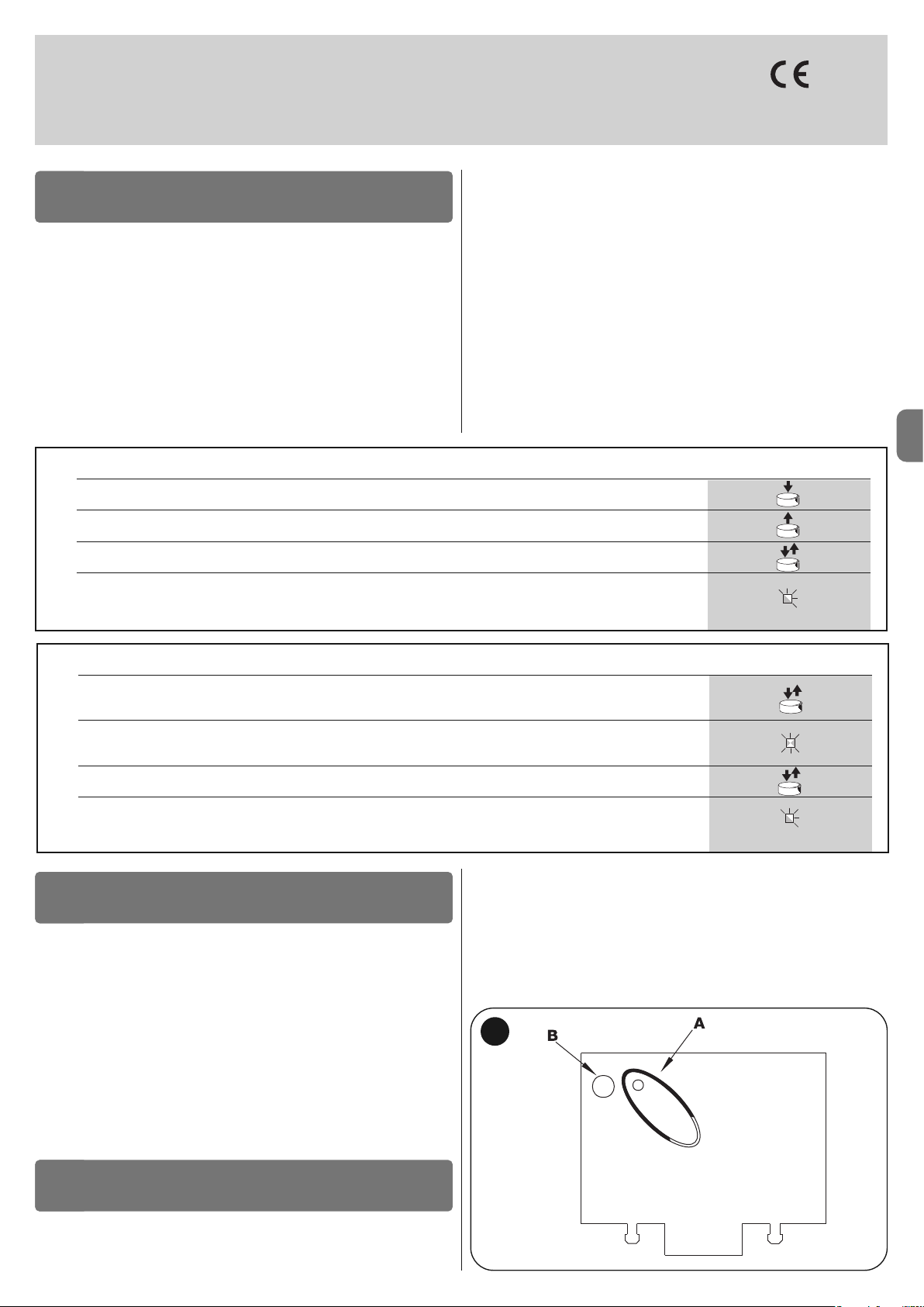
PL
Polski – 11
smxi - smixs odbiornik radiowy
0682
SMXI, SMXIS są 4-kanałowymi odbiornikami radiowymi przeznaczonymi dla
central wyposażonych w gniazdo SM. Specyficzną cechą kompatybilnych z
nimi nadajników jest kod rozpoznawania, który jest inny dla każdego nadajnika.
W związku z tym, aby umożliwić odbiornikowi rozpoznanie określonego nadajnika należy rozpocząć od wczytania kodu rozpoznawania. Tę operację wczytywania należy powtórzyć dla każdego nadajnika, który zamierza się wykorzystać
do sterowania centralą.
Uwagi:
– W odbiorniku można zapamietać maksymalnie do 256 nadajników. Nie jest
przewidziane kasowanie kodu pojedynczego nadajnika, mogą jedynie zostać
skasowane wszystkie kody.
– W przypadku funkcji bardziej zaawansowanych należy wykorzystać specjalne
urządzenie do programowania.
Odbiornik posiada 4 wyjścia. Każde z nich jest dostępne w znajdującym się w
OPIS URZĄDZENIA
1
odbiorniku złączu; aby dowiedzieć się, która funkcja jest wykonywana przez
każde wyjście należy przeczytać rozdział 6.1.
Podczas fazy wczytywania kodu nadajnika można wybrać jedną, spośród
przedstawionych niżej dwóch opcji:
Tryb I - Tabela B1: Każdy kolejny przycisk nadajnika uaktywnia odpowiednie
wyjście w odbiorniku, czyli przycisk 1 uaktywnia wyjście 1, przycisk 2 uaktywnia wyjście 2, przycisk 3 – wyjście 3 i przycisk 4 – wyjście 4. W tym przypadku
dla danego nadajnika obowiązuje tylko jedna procedura wczytania; podczas tej
fazy nie jest ważne, który przycisk nadajnika zostanie wciśnięty. Wczytają się od
razu wszystkie a w pamięci odbiornika zostanie zajęte tylko jedno miejsce (jedna komórka pamięci).
Tryb II - Tabela B2: Do każdego przycisku nadajnika może zostać przypisane DOWOLNE(!) wyjście w odbiorniku, na przykład przycisk 1 uaktywnia wyjście 2, przycisk 4 uaktywnia wyjście 1, i tak dalej. W tym przypadku należy
wczytać nadajnik, wciskając ten przycisk, który ma potem uruchamiać dane
wyjście odbiornika (czyli daną funkcję). Oczywiście każdy przycisk może uaktywniać tylko jedno wyjście, natomiast to samo wyjście może być uaktywniane
przez kilka przycisków. W tym trybie wczytywania każdy przycisk zajmuje jedno
miejsce w pamięci odbiornika.
TABELA B1 - Wczytywanie w trybie I (wszystkie przyciski zostaną kolejno przyporządkowane odpowiadającym im wyjściom odbiornika)
01. Wciśnij i przytrzymaj przycisk na odbiorniku przez co najmniej trzy sekundy
02. Kiedy zaświeci się dioda zwolnij przycisk
03. W ciągu 10 sekund przytrzymaj wciśnięty przez co najmniej 2 sekundy dowolny przycisk wczytywanego nadajnika
Uwaga – jeżeli wczytywanie zostało wykonane prawidłowo, dioda na odbiorniku wykona 3 błyski, jeżeli zamierza się
wczytać dodatkowe nadajniki należy powtórzyć krok 3 w ciągu następnych 10 sekund; faza wczytywania zakończy się,
jeżeli w ciągu tych 10 sekund nie zostaną odebrane przez odbiornik nowe kody
3s
2s
x3
INSTALOWANIE ANTENY
2
Aby odbiornik funkcjonował prawidłowo należy zamontować i podłączyć do
niego antenę typu ABF lub ABFKIT; bez właściwej anteny zasięg urządzenia jest
redukowany do kilku metrów. Antenę należy umieścić najwyżej jak tylko jest to
mo żliwe, ponad ewentualnymi konstrukcjami metalowymi lub wykonanymi z
betonu zbrojonego, jeśli znajdują się one w pobliżu. Jako przewód antenowy na leży zastosować przewód koncentryczny z impedancją 50 (np. RG58 o ni ski ch
stratach), długość przewodu nie może przekraczać 10m.
W przypadku, kiedy antena została zainstalowana w miejscu nie połączonym z
“ziemią” (konstrukcje murowane) w celu zwiększenia zasięgu można połączyć
oplot przewodu z lokalnym uziemieniem dobrej jakości. W przypadku, kiedy nie
jest możliwe zainstalowanie anteny typu ABF lub ABFKIT, można uzyskać
dosyć dobre wyniki używając w jej zastępstwie kawałka przewodu dołączonego fabrycznie do każdego odbiornika radiowego, próbując różne jego ustawienia w przestrzeni.
UWAGA – Po uruchomieniu procedury wczytywania pilotów nastąpi
wczytanie każdego nadajnika (działającego w tym systemie) prawidłowo rozpoznanego w zasięgu odbioru radiowego. Należy uwz -
WCZYTYWANIE PILOTA
3
ględnić te właściwości, ewentualnie odłączyć antenę, aby zapobiec
wczytywaniu nieautoryzowanych odbiorników.
Procedury wczytywania pilotów muszą zostać wykonane w określonym czasie;
przed rozpoczęciem operacji należy więc najpierw przeczytać i zrozumieć całą
procedurę.
Aby wykonać poniższą procedurę należy wykorzystać przycisk znajdujący się
na obudowie odbiornika radiowego (odniesienie A, rys. 1a) i odpowiednią diodę (odniesienie B, rys. 1a)), znajdującą się po lewej stronie przycisku.
1a
TABELA B2 - Wczytywanie w trybie II (każdemu dowolnemu przyciskowi może zostać przypisane dowolne wyjście odbiornika)
01. Krótko naciskaj przycisk na odbiorniku taką ilość razy, która odpowiada wybranej funkcji (czyli wybranemu wyjściu
odbiornika: 1 raz dla wyjścia nr 1, 2 razy dla wyjścia nr 2, 3 razy dla wyjścia 3, 4 razy dla wyjścia 4)
02. Sprawdź, czy dioda wykona tę samą ilość błysków, która odpowiada wybranemu wyjściu, błyski muszą powtarzać
się z regularną częstotliwością przez 10 sek. (1 błyśnięcie dla wyjścia nr 1, 2 błyśnięcia dla wyjścia nr 2 itd.)
03. W ciągu 10 sekund naciśnij i przytrzymaj przez co najmniej 2 sekundy odpowiedni przycisk wczytywanego nadajnika
Uwaga – jeżeli wczytywanie zostało wykonane prawidłowo, dioda na odbiorniku wykona 3 błyski; w przypadku, kiedy
zamierza się wczytać dodatkowe nadajniki należy powtórzyć krok 3 w ciągu następnych 10 sekund; faza wczytywania
zostanie zakończona, jeżeli w ciągu tych 10 sekund nie zostaną odebrane przez odbiornik nowe kody
2s
x3
RX
RX
RX
TX
TX
Page 74

PL
12 – Polski
Wczytywanie “na odległość”
Istnieje możliwość wczytania nowego nadajnika do pamięci odbiornika bez
konieczności bezpośredniego wciskania przycisku tego odbiornika. W tym celu
należy posiadać wczytany wcześniej i funkcjonujący pilot – “stary”. “Nowy”
nadajnik “przyjmie” parametry “starego” nadajnika. W związku z tym, jeżeli
pierwszy nadajnik został wczytany w trybie I również nowy nadajnik zostanie
wczytany w trybie I; w czasie wczytywania będzie można wcisnąć dowolny
przycisk na nadajniku “starym” i dowolny na “nowym”. Jeżeli “stary” nadajnik
został wczytany w trybie II, “nowy” nadajnik też zostanie wczytany w trybie II.
Wtedy na “starym” nadajniku należy wcisnąć przycisk, który uaktywnia dane
wyjście odbiornika radiowego, natomiast na “nowym” nadajniku należy wcisnąć ten przycisk, który dane wyjście też ma uaktywniać. Przeczytaj wszystkie
instrukcje, aby móc następnie wykonać kolejne operacje nie przerywając ich.
Teraz, trzymając w rękach oba piloty - NOWY (którego kod chcemy wczytać do
odbiornika) oraz STARY (który jest już wczytany), ustaw się w pobliżu odbiornika radiowego, w zasięgu działania pilotów i wykonaj kroki zamieszczone w
tabeli.
TABELA B4 - Usuwanie z pamięci kodów wszystkich nadajników
01. Wciśnij i przytrzymaj przycisk na odbiorniku
02. Odczekaj, dopóki nie zaświeci się dioda, następnie odczekaj dopóki nie zgaśnie, teraz odczekaj aż wykona 3 błyski
03. Zwolnij przycisk dokładnie podczas 3 błysku
Uwaga –jeżeli procedura została wykonana prawidłowo, po kilku chwilach dioda wykona 5 błysków
x3
3°
x5
Istnieje możliwość skasowania wszystkich kodów znajdujących się w pamięci z zastosowaniem następującej procedury:
KASOWANIE WSZYSTKICH NADAJNIKÓW
4
PARAMETRY TECHNICZNE URZĄDZENIA
Odbiorniki: SMXI SMXIS
Dekodowanie Z kodowaniem Rolling code na 52 bity FLOR Z kodowaniem Rolling code na 64 bity SMILO
Kompatybilność nadajników FLOR, VERY VR, NICE WAY, ERGO, PLANO, NICE ONE SMILO
Częstotliwość 433.92 MHz 433.92 MHz
Impedancja wejściowa 52 K 52 K
Wyjścia 4 (na złączu SM) 4 (na złączu SM)
Czułość większa od 0.5 μV większa od 0.5 μV
Temperatura pracy od -10°C do + 55° C od -10°C do + 55° C
Nadajniki: FLO2R SMILO
Przyciski 1, 2 lub 4 w zależności od wersji 2 lub 4
Zasilanie 12 V Batt. 23 A 12 V Batt. 23 A
Pobór prądu 10 mA 25 mA
Częstotliwość transmisji 433.92 MHz 433.92 MHz
Temp. funkcjonowania od -10°C do +55°C od -10°C do +55°C
Moc promieniowania oszacowana na około 1mW E.R.P. oszacowana na około 1mW E.R.P.
Zasięg do 200m (na zewnątrz); do 35m (wewnątrz budynków) do 200m (na zewnątrz); do 35m (wewnątrz budynków)
Wymiary/Waga 69 x 39 x 15,5 mm / 31 g. Ø 48 mm x H 14 mm - 14 g
Kodowanie cyfrowe (4,5 miliona miliardów kombinacji) cyfrowe (18 miliardów miliardów kombinacji)
ZALECENIA: • Wszystkie podane parametry techniczne dotyczą temperatury otoczenia 20°C (± 5°C). • Nice S.p.a. zastrzega sobie prawo do wprowadzania
zmian w urządzeniu w każdej chwili, kiedy uzna je za konieczne, zachowując te same funkcje i przeznaczenie. • Zasięg nadajników i zdolność odbioru odbiorników może ulegać zakłóceniom, które mogą zmieniać ich osiągi. W tym przypadku firma Nice nie może udzielić żadnej gwarancji na rzeczywisty zasięg własnych
urządzeń.
TABELA B3 - Wczytywanie na odległość
01. Przytrzymaj wciśnięty przez co najmniej 5 sekund przycisk na NOWYM nadajniku i następnie zwolnij
02. Wciśnij powoli trzy razy przycisk STAREGO nadajnika
03. Wciśnij powoli jeden raz przycisk na NOWYM nadajniku
Uwaga – jeżeli należy wczytać dodatkowe nadajniki powtórz wszystkie kroki dla każdego nowego nadajnika
1s
x1
1s1s
x5s
TX
TX TX TX
TX
TX
RX
RX
Page 75

NL
Nederlands – 1
NEDERLANDS
Aanbevelingen voor de veiligheid
• LET OP! – Deze handleiding bevat belangrijke aanwijzingen voor de
vei ligheid van de betrokken personen. Een onjuiste installatie kan ernstig
letsel veroorzaken. Alvorens met de werkzaamheden te beginnen dient u de
handleiding volledig door te lezen. In geval van twijfel, het product niet installeren en opheldering vragen aan de klantenservice van Nice.
• LET OP! – Belangrijke aanwijzingen: bewaar deze handleiding voor eventuele toekomstige onderhoudswerkzaamheden of de verwerking als afval
van het afgedankte product.
Aanbevelingen voor de installatie
• Voordat u met de installatie begint, dient u te controleren of dit product
geschikt is voor het beoogde gebruik (zie paragraaf 2.2 “Gebruikslimieten” en
het hoofdstuk “Technische gegevens van het product”). Als het product niet
geschikt is, dient u het NIET te installeren.
• Behandel het product gedurende de installatie voorzichtig en voorkom
samendrukking, stoten, valpartijen of contact met vloeistoffen van welke
soort dan ook. Plaats het product niet in de buurt van warmtebronnen en stel
hem niet bloot aan open vuur. Een dergelijke handelswijze kan het product
beschadigen en storingen of gevaarlijke situaties veroorzaken. Als dit
gebeurt, de installatie onmiddellijk onderbreken en contact opnemen met de
klantenservice van Nice.
• Voer geen wijzigingen uit op onderdelen van het product. Niet-toegestane
handelingen zullen slechts storingen in de werking veroorzaken. De fabrikant
aanvaardt geen aansprakelijkheid voor schade die het gevolg is van op willekeurige wijze gewijzigde inrichtingen.
• Het product is niet bestemd om gebruikt te worden door personen (inclusief
kinderen) wier fysieke, zintuiglijke of mentale vermogens beperkt zijn of die
niet over genoeg ervaring of kennis beschikken, tenzij deze personen onder
toezicht staan van een persoon die voor hun veiligheid verantwoordelijk is of
instructies hebben ontvangen over het gebruik van het product.
• Laat kinderen niet met de bedieningsinrichtingen van de automatisering spelen. Houd de zenders buiten bereik van kinderen.
• Kinderen dienen in het oog te worden gehouden om er zeker van te zijn dat
ze niet met het apparaat spelen.
• In het voedingsnet van de installatie dient een afkoppelingsinrichting te worden geïnstalleerd met een openingsafstand tussen de contacten die een volledige afkoppeling toelaat in de condities die worden voorgeschreven door
de overspanningscategorie III.
• De besturingseenheid moet worden aangesloten op een elektrische voedingsleiding die correct geaard is.
• De afvalverwerking van het verpakkingsmateriaal van het product moet volgens de plaatselijk geldende regels plaatsvinden.
ALGEMENE AANBEVELINGEN EN
VOORZORGSMAATREGELEN
De besturingseenheid MC424 is bestemd voor het aansturen van elektromechanische 24 V aandrijvingen Wingo, voor de automatisering van poorten of
deuren met draaivleugels. LET OP! – Ieder gebruik dat afwijkt van wat hier
beschreven is en in andere omgevingscondities dan in deze handleiding
zijn vermeld dient als oneigenlijk en dus als verboden te worden
beschouwd!
De besturingseenheid MC424 beschikt over een systeem dat de belasting van
de op de eenheid aangesloten motoren verifieert (amperometrisch), met dit systeem kunnen de eindaanslagen automatisch gedetecteerd worden, de bedrijfstijd van elke afzonderlijke motor in het geheugen opgeslagen worden en eventuele obstakels tijdens de normale beweging herkend worden. Dit kenmerk
maakt het installeren veel eenvoudiger gezien het feit dat er geen enkele instelling van de bedrijfstijden en vertraging van de ene vleugel ten opzichte van de
andere (faseverschil) nodig is.
De besturingseenheid is voorgeprogrammeerd op de normaal vereiste functies;
eventueel kunnen er via een eenvoudige procedure meer specifieke functies
gekozen worden (zie hoofdstuk 5).
Het is mogelijk de besturingseenheid bij een stroomuitval van stroom te voorzien via de bufferbatterijen PS124 (zie voor meer details hoofdstuk 6.2); de
besturingseenheid kan ook worden aangesloten op het voedingssysteem op
zonne-energie “Solemyo” (zie voor meer details hoofdstuk 6.3).
BESCHRIJVING VAN HET PRODUCT
1
Om enkele termen en aspecten van een automatiseringsinstallatie voor deuren
of poorten met 2 vleugels te verduidelijken, verwijzen wij u naar de standaardinstallatie die te zien is op afb. 1.
INSTALLATIE
2
Inhoudsopgave
ALGEMENE AANBEVELINGEN EN VOORZORGSMAATREGELEN 1
1 – BESCHRIJVING VAN HET PRODUCT . . . . . . . . . . . . . . . . . . . . . . . 1
2 – INSTALLAZIONE . . . . . . . . . . . . . . . . . . . . . . . . . . . . . . . . . . . . . . . . 1
2.1 - CONTROLES VOORAFGAAND AAN DE INSTALLATIE . . . . . . 2
2.2 - GEBRUIKSLIMIETEN VAN HET PRODUCT . . . . . . . . . . . . . . . . 2
2.3 - INSTALLATIE . . . . . . . . . . . . . . . . . . . . . . . . . . . . . . . . . . . . . . . 2
2.4 - ELEKTRISCHE AANSLUITINGEN . . . . . . . . . . . . . . . . . . . . . . . . 2
2.4.1 - Opmerkingen over de aansluitingen . . . . . . . . . . . . . . . . 3
2.4.2 - Typologie ingang ALT . . . . . . . . . . . . . . . . . . . . . . . . . . . 3
2.4.3 - Voorbeelden van aansluitingen fotocellen met geactiveerde
STAND BY-functie en gedeactiveerde fototest-functie . 3
2.4.4 - Voorbeelden van aansluitingen met geactiveerde . . . . . .
fototest-functie en gedeactiveerde STAND BY-functie .3
2.5 - EERSTE INSCHAKELING EN CONTROLE VAN DE . . . . . . . . . . .
AANSLUITINGEN . . . . . . . . . . . . . . . . . . . . . . . . . . . . . . . . . . . . 3
2.6 - AUTOMATISCH ZOEKEN VAN DE EINDAANSLAGEN . . . . . . . 3
3 – EINDTEST EN INBEDRIJFSTELLING . . . . . . . . . . . . . . . . . . . . . . . 4
3.1 - EINDTEST . . . . . . . . . . . . . . . . . . . . . . . . . . . . . . . . . . . . . . . . . . 4
3.2 - INBEDRIJFSTELLING . . . . . . . . . . . . . . . . . . . . . . . . . . . . . . . . . 4
4 – DIAGNOSTIEK . . . . . . . . . . . . . . . . . . . . . . . . . . . . . . . . . . . . . . . . . . 4
5 – PROGRAMMERING . . . . . . . . . . . . . . . . . . . . . . . . . . . . . . . . . . . . . . 4
5.1 - VOORINGESTELDE FUNCTIES . . . . . . . . . . . . . . . . . . . . . . . . . 4
5.2 - PROGRAMMEERBARE FUNCTIES . . . . . . . . . . . . . . . . . . . . . . 5
5.2.1 - Directe programmering . . . . . . . . . . . . . . . . . . . . . . . . . . 5
5.2.2 - Programmering eerste niveau: eerste deel . . . . . . . . . . 5
5.2.3 - Programmering eerste niveau: tweede deel . . . . . . . . . 5
5.2.4 - Functies tweede niveau . . . . . . . . . . . . . . . . . . . . . . . . . 5
5.3 - PROGRAMMEERMODI . . . . . . . . . . . . . . . . . . . . . . . . . . . . . . .
5
5.3.1 - Programmering eerste niveau: functies . . . . . . . . . . . . . 6
5.3.2 - Programmering tweede niveau: parameters . . . . . . . . . 6
5.3.3 - Wissen van het geheugen . . . . . . . . . . . . . . . . . . . . . . . . 6
5.3.4 - Voorbeeld van programmering eerste niveau . . . . . . . . 7
5.3.5 - Voorbeeld van programmering tweede niveau . . . . . . . 7
5.3.6 - Programmeerschema . . . . . . . . . . . . . . . . . . . . . . . . . . . 8
6 – VERDERE DETAILS: accessoires . . . . . . . . . . . . . . . . . . . . . . . . . . 9
6.1 - AANSLUITING VAN EEN RADIO-ONTVANGER . . . . . . . . . . . . . 9
6.2 - AANSLUITING VAN DE BUFFERBATTERIJ MOD. PS124 . . . . . 9
6.3 - AANSLUITING VAN HET SOLEMYO-SYSTEEM . . . . . . . . . . . . 9
7 – WAT TE DOEN ALS...
(handleiding voor het oplossen van problemen) . . . . . . . . . . . . . 9
8 – ONDERHOUD VAN HET PRODUCT . . . . . . . . . . . . . . . . . . . . . . . . . 9
AFDANKEN VAN HET PRODUCT . . . . . . . . . . . . . . . . . . . . . . . . . . 9
TECHNISCHE GEGEVENS VAN HET PRODUCT . . . . . . . . . . . . . 10
EG-VERKLARING VAN OVEREENSTEMMING . . . . . . . . . . . . . . . 10
RADIO-ONTVANGER: SMXI - SMIXS . . . . . . . . . . . . . . . . . . . . . . 11
1 - BESCHRIJVING VAN HET PRODUCT . . . . . . . . . . . . . . . . . . . . . 11
2 - INSTALLATIE ANTENNE . . . . . . . . . . . . . . . . . . . . . . . . . . . . . . . 11
3 - OPSLAAN VAN EEN AFSTANDSBEDIENING . . . . . . . . . . . . . . . 11
4 - WISSEN VAN ALLE ZENDERS . . . . . . . . . . . . . . . . . . . . . . . . . . 12
TECHNISCHE GEGEVENS VAN HET PRODUCT . . . . . . . . . . . . . . . 12
AFBEELDINGEN . . . . . . . . . . . . . . . . . . . . . . . . . . . . . . . . . . . . . I - VII
Page 76

NL
2 – Nederlands
Legenda van de afb. 2 - 5a - 5b - 5c:
Klemmen Functie Beschrijving Kabeltype
L - N - Voedingsleiding Netvoeding 3 x 1,5 mm
2
1÷3 Motor 1 Aansluiting van de motor M1 3 x 1,5 mm
2
1÷3 Motor 2 Aansluiting van de motor M2 (Opmerking 1) 3 x 1,5 mm
2
4÷5 Knipperlicht Aansluiting van het knipperlicht 24 V max. 25 W 2 x 1 mm
2
6÷7 SCA (lampje Poort Aansluiting voor lampje Poort Open 24 V max. 5 W of elektrische slot 12 V SCA: 2 x 0,5 mm
2
Open) / Elektrisch slot max. 25 VA ((zie hoofdstuk 5 - Programmering) Elektrisch slot: 2 x 1 mm
2
8
Gemeenschappelijk 24
V Voeding +24 V voor TX fotocellen met fototest (max.100 mA); “GEMEENSCHAPPELIJK” 1 x 0,5 mm
2
(met stand by / fototest) voor alle veiligheidsingangen, met geactiveerde STAND BY-functie (Opmerking 2)
9 0 V 0 V Voeding voor gebruikers 1 x 0,5 mm
2
10 24 V Voeding gebruikers, zonder “Stand by” (24 V max. 200 mA) 1 x 0,5 mm
2
11
Gemeenschappelijk 24 V
Gemeenschappelijk voor alle ingangen (+24 V ) zonder “Stand by” 1 x 0,5 mm
2
12 ALT Ingang met STOP-functie (noodstop, veiligheidsblokkering) (Opmerking 3) 1 x 0,5 mm
2
13 FOTO NC ingang voor veiligheidsinrichtingen (fotocellen, contactlijsten) 1 x 0,5 mm
2
14 FOTO1 NC ingang voor veiligheidsinrichtingen (fotocellen, contactlijsten) 1 x 0,5 mm
2
15 STAP-VOOR-STAP Ingang voor cyclische werking (OPEN-STOP-SLUIT-STOP) 1 x 0,5 mm
2
16 AUX Hulpingang (Opmerking 4) 1 x 0,5 mm
2
17÷18 Antenne Aansluiting antenne van de radio-ontvanger afgeschermde kabel type RG58
Opmerking 1 – Niet gebruikt voor poorten met één enkele vleugel (de besturingseenheid herkent automatisch of er één enkele motor geïnstalleerd is)
Opmerking 2 – De “Stand By”-functie dient ervoor het stroomverbruik te verminderen; zie voor meer details over de elektrische aansluitingen paragraaf 2.4.1
“Aansluiting Stand by/Fototest” en voor de programmering hoofdstuk 5.2.3 “Functie Stand by/Fototest
Opmerking 3 – De ingang ALT kan gebruikt worden voor NC contacten of op constante weerstand van 8,2 K
Ω
(zie het hoofdstuk “Programmering”)
Opmerking 4 – In de fabriek is de hulpingang AUX geprogrammeerd met de functie “Open gedeeltelijk type 1”, maar deze ingang kan ook met één van de volgende functies geprogrammeerd worden:
Legenda afb. 1:
1.Elektromechanische 24 V aandrijving Wingo
2.Elektromechanische 24 V aandrijving Wingo
3.Knipperlicht Lucy24
4.Sleutelschakelaar
5.Stel fotocellen “FOTO”
6.Stel fotocellen “FOTO1”
7.Stel fotocellen “FOTO2”
8.Besturingseenheid
Met name herinneren wij aan het volgende:
• Voor de kenmerken en de aansluiting van de fotocellen gelieve u de specifie-
ke instructies van het product te raadplegen.
• De activering van het stel fotocellen “FOTO” heeft bij de openingsbeweging
geen effect, terwijl bij de sluitbeweging een omkering wordt bewerkstelligd.
• De activering van het stel fotocellen “FOTO1” blokkeert de manoeuvre zowel
bij de openings- als bij de sluitbeweging.
• De activering van het stel fotocellen “FOTO2” aangesloten op de daarvoor
geprogrammeerde ingang AUX) heeft bij de sluitbeweging geen effect, terwijl
bij de openingsbeweging een omkering wordt bewerkstelligd.
Zie, om de onderdelen van de besturingseenheid te controleren, afb. 2.
Legenda afb. 2:
A. Connector 24 V stroomtoevoer
B. Connector motor M1
C. Connector voor bufferbatterij PS124 / voedingssysteem op
zonne-energie Solemyo (zie voor meer details hoofdstuk 6.3)
D. Zekering gebruikers (500 mA) type F
E. Keuzeschakelaar vertraging opening motor M1 of M2
F. Klem motor M2
G. Klem uitgang knipperlicht
H. Klem uitgang SCA (lampje Poort Open) of elektrisch slot
I: 24 Vdc klemmen voor gebruikers en fototest
L. Klemmen voor ingangen
L1…L5. Leds ingangen en programmering
M. Klem voor radioantenne
N. Plug-in “SM” voor radio-ontvanger
O. Connector voor programmering/diagnostiek
P1, P2, P3. Drukknoppen en leds voor programmering
2.1 - Controles voorafgaand aan de installatie
Voordat u gaat installeren dient u te controleren of de onderdelen van het product intact zijn, het gekozen model adequaat is en de omgeving van installatie
geschikt:
• Controleer of alle gebruikscondities stroken met de “gebruikslimieten” en de
“Technische gegevens van het product”.
• Controleer of de voor de installatie gekozen ruimte compatibel is met de
totaalafmetingen van het product (afb. 3).
• Controleer of het voor de installatie van het product gekozen vlak van stevig
materiaal is en een stabiele bevestiging kan verzekeren.
• Controleer of er op de plaats van bevestiging geen kans op wateroverlast
bestaat; monteer het product hoog genoeg boven de grond.
• Controleer of er genoeg ruimte rond het product is om de handmatige
manoeuvres gemakkelijk en veilig uit te kunnen voeren.
• Controleer of de mechanische stops voor zowel de Sluitbeweging als de
Openingsbeweging van de automatisering aanwezig zijn.
2.2 - Gebruikslimieten van het product
Het product mag uitsluitend gebruikt worden met de 24 V Wingo reductiemotoren.
2.3 - Installatie
Ga voor de bevestiging van de besturingseenheid te werk zoals te zien is op
afb. 4. Neem daarnaast de volgende aanbevelingen in acht:
• De besturingseenheid wordt geleverd in een kast die, indien adequaat geïnstalleerd, beschermingsklasse IP54 garandeert. De besturingseenheid is daarom ook geschikt voor installatie buitenshuis.
• Bevestig de besturingseenheid op een vaste, verticale en vlakke ondergrond,
op een plaats waar hij beschermd is tegen mogelijke stoten. Let op! – Het
onderste gedeelte van de besturingseenheid moet zich op een afstand van
minstens 40 cm van de grond bevinden.
• Installeer de hiervoor bestemde kabel- of buisdoorvoeren in het onderste
gedeelte van de kast (afb. 4). Let op! – Als de beschermbuizen van de kabels
uitkomen in een put, is het waarschijnlijk dat er zich binnen de kast van de
besturingseenheid condens zal vormen, die beschadiging van de elektronische
kaart veroorzaakt. In dit geval dient u te zorgen voor een afdoende bescherming van de besturingseenheid, om condensvorming te voorkomen.
• De kabeldoorvoeren kunnen alleen op de lange zijde van de kast worden
geïnstalleerd als de besturingseenheid binnenshuis, op een beschermde
plaats, wordt opgesteld.
Zie voor de installatie van de overige inrichtingen van de automatisering de
betreffende instructiehandleidingen.
2.4 - Elektrische aansluitingen
LET OP!
– Bij het uitvoeren van elektrische aansluitingen mag de installatie absoluut niet op de netspanning zijn aangesloten en moet de bufferbatterij van
de automatisering, indien aanwezig, zijn afgekoppeld.
– De aansluitwerkzaamheden mogen uitsluitend door gekwalificeerd personeel worden uitgevoerd.
– Controleer of alle gebruikte elektriciteitskabels van het juiste type zijn.
01. Draai de schroeven van het deksel los;
02. Maak de gaten voor het doorvoeren van de elektriciteitskabels;
03. Sluit de kabels aan volgens het elektrische schema van afb. 5. Zie voor de
aansluiting van de voedingskabel afb. 6.
Opmerking – Om het aansluiten van de kabels te vergemakkelijken, is het
mogelijk de klemmen uit hun behuizingen te halen.
• De ingangen van de contacten van het type NC (normaal gesloten), indien niet
gebruikt, dienen via een geleidingsbrug met “GEMEENSCHAPPELIJK” verbonden te worden (met uitzondering van de ingangen van de fotocellen indien
de functie FOTOTEST geactiveerd wordt, zie voor details paragraaf 2.4.3).
• Als er voor dezelfde ingang meerdere NC contacten zijn, dan worden die
onderling SERIEEL geschakeld.
• De ingangen van de contacten van het type NO (normaal open) dienen,
indien niet gebruikt, vrij gehouden te worden.
• Als er voor dezelfde ingang meerdere NO contacten zijn, dan worden die
onderling PARALLEL geschakeld.
• De contacten moeten absoluut van het elektromechanische type zijn en
mogen geen enkel potentiaal hebben; aansluitingen in fasen, zoals “PNP”,
“NPN”, “Open Collector” etc., zijn niet toegelaten.
• In het geval van boven elkaar geplaatste vleugels kunt u, via de geleidingsbrug E (afb. 2) selecteren welke motor bij het openen als eerste moet starten.
Page 77

NL
Nederlands – 3
Functie Type ingang Beschrijving
OPEN GEDEELTELIJK TYPE 1 NO De bovenste vleugel gaat helemaal open
OPEN GEDEELTELIJK TYPE 2 NO De 2 vleugels gaan half open
OPEN NO Alleen de openingsmanoeuvre wordt uitgevoerd
SLUIT NO Alleen de sluitmanoeuvre wordt uitgevoerd
FOTO 2 NC Functie FOTO 2
UITGESLOTEN -- Geen enkele functie
2.4.1 - Opmerkingen over de aansluitingen
Het merendeel van de aansluitingen is uiterst eenvoudig, voor een groot deel
betreft het rechtstreekse aansluitingen op één enkele gebruiker of contact. Op
onderstaande afbeeldingen zijn enkele voorbeelden gegeven over hoe u externe inrichtingen dient aan te sluiten:
• Aansluiting Stand By / Fototest
De Stand-by-functies is standaard actief; de functie wordt alleen automatisch
uitgesloten wanneer de functie Fototest geactiveerd wordt. Opmerking - De
functies Stand-by en Fototest kunnen alleen om de beurt actief zijn, de ene
functie sluit de andere namelijk uit.
De Stand-by-functie maakt het mogelijk het stroomverbruik te verminderen; er
zijn drie soorten aansluitingen mogelijk:
- met “stand by” actief (energiebesparing
); zie het schakelschema van afb. 5a
- standaard aansluiting: zonder “stand by” en zonder “fototest”; zie het scha-
kelschema van afb. 5b
- zonder “stand by” en met “fototest”; zie het schakelschema van afb. 5c
Met geactiveerde “Stand-by”-functie zal de besturingseenheid, 1 minuut na het
beëindigen van een manoeuvre, in Stand-by schakelen; hierbij worden alle
ingangen en uitgangen uitgeschakeld, om zo stroom te besparen. Deze status
wordt gesignaleerd door de led “OK” die langzamer gaat knipperen. WAAR-
SCHUWING - Als de besturingseenheid wordt gevoed met een zonnepaneel
(“Solemyo”-systeem) of bufferbatterij, is het noodzakelijk de “Stand-by”-functie
te activeren zoals in het schakelschema van afb. 5a.
Wanneer de “Stand-by”-functie niet nodig is, kan de “Fototest”-functie geactiveerd worden. Hiermee kunt u aan het begin van een manoeuvre controleren of
de aangesloten fotocellen correct werken. Om deze functie te gebruiken dient
u eerst de fotocellen correct aan te sluiten (zie schakelschema van afb. 5c) en
vervolgens de functie te activeren.
Opmerking – Als u de fototest activeert, zijn de aan de testprocedure onderworpen ingangen FOTO, FOTO1 en FOTO2. Als één van deze ingangen niet
wordt gebruikt, moet deze op de klem 8 aangesloten worden.
• Aansluiting sleutelschakelaar
Voorbeeld 1 (afb. 7a): De keuzeschakelaar aansluiten om de functies STAPVOOR-STAP en ALT uit te voeren.
Voorbeeld 2 (afb. 7b): De sleutelschakelaar aansluiten om de functies STAPVOOR-STAP en één van de voor de hulpingang voorziene functies (OPEN
GEDEELTELIJK, ALLEEN OPENEN, ALLEEN SLUITEN...) uit te voeren.
Opmerking – Zie voor de elektrische aansluitingen met geactiveerde “Stand
By”-functie “Functie Stand By/Fototest” in deze paragraaf 2.4.1.
• Aansluiting lampje Poort Open / Elektrische slot (afb. 8)
Als de SCA (lampje Poort Open) geprogrammeerd is, kan de uitgang gebruikt
worden als lampje Poort Open. Het lampje knippert langzaam gedurende de
openingsbeweging en snel bij de sluitbeweging; het brandt vast bij stilstaande
geopende poort en is uit wanneer de poort gesloten is. Als de uitgang geprogrammeerd is als elektrisch slot, wordt hij bij ieder begin van een openingsmanoeuvre 3 seconden lang geactiveerd.
2.4.2 - Typologie ingang ALT
De besturingseenheid MC424 kan geprogrammeerd worden voor twee soorten
ALT-ingangen:
- Alt type NC voor aansluiting op contacten van het type NC.
- Alt met constante weerstand. Hiermee kunt u inrichtingen met een uitgang
met constante weerstand 8,2 KΩ (bijv. contactlijsten) op de besturingseenheid aansluiten. De ingang meet de waarde van de weerstand en trekt toestemming voor de manoeuvre in wanneer de weerstand buiten het nominale
bereik komt. Met de juiste aanpassingen kunt u op de Alt-ingang met constante weerstand ook inrichtingen met normaal geopende (“NO”) contacten,
normaal gesloten (“NC”) contacten en eventueel meer dan één inrichting, ook
van verschillend type, aansluiten, zie Tabel 1.
LET OP! – Als de Alt-ingang met constante weerstand gebruikt wordt om
inrichtingen met veiligheidsfuncties aan te sluiten, garanderen alleen de
inrichtingen met uitgang met constante weerstand 8,2 KΩ de veiligheidscategorie 3 tegen storingen.
1einrichting type:
NO NC 8,2 KΩ
NO Parallelschakeling (opmerking 2) Parallelschakeling
(opmerking 1)
NC (opmerking 2) Serieschakeling Serieschakeling
(opmerking 3)
8,2KΩ Parallelschakeling Serieschakeling (opmerking 4)
TABEL 1
2
e
inrichting type:
Opmerkingen bij Tabel 1:
Opmerking 1 – Eén of meerdere NO inrichtingen kunnen zonder enige beperking
van het aantal inrichtingen onderling parallel geschakeld worden met een eind weerstand van 8,2 K
Ω
(afb. 9a). Zie voor de elektrische aansluitingen met geactiveerde “Stand By”-functie “Functie Stand By/Fototest” in deze paragraaf 2.4.1.
Opmerking 2 – De combinatie NO en NC is mogelijk door de 2 contacten
onderling parallel te schakelen waarbij in serie met het NC contact een weerstand van 8,2 K
Ω
geschakeld moet worden ((ook de combinatie van 3 inrichtin-
gen: NO, NC en 8,2 K
Ω
is dus mogelijk (afb. 9b).
Opmerking 3 – Eén of meer NC inrichtingen kunnen onderling in serie en met
een weerstand van 8,2K
Ω
worden verbonden zonder enige beperking van het
aantal inrichtingen (afb. 9c).
Opmerking 4 – Alleen een inrichting met een uitgang met constante weerstand
8,2 K
Ω
kan aangesloten worden; eventueel moeten meerdere inrichtingen “in
cascadeschakeling” met een enkele eind- weerstand van 8,2 K
Ω
aangesloten
worden (afb. 9d).
2.5 - Eerste inschakeling en controle van de aansluitingen
LET OP! – De aansluitwerkzaamheden mogen uitsluitend door gekwalifi-
ceerd personeel worden uitgevoerd.
Na stroom aan de besturingseenheid te hebben gegeven, dient u te controleren
of alle leds gedurende enkele seconden snel knipperen. Voer vervolgens de volgende controles uit:
1. Controleer of op de klemmen 9-10 een spanning van ongeveer 30 Vdc staat;
als dat niet het geval is, sluit de stroomvoorziening dan onmiddellijk af en
controleerde aansluitingen en de spanning van de stroomvoorziening beter.
2. Na eerst snel geknipperd te hebben, signaleert de led P1 dat de besturings-
eenheid correct functioneert door regelmatig te knipperen, met tussenpozen van een seconde. Wanneer er een variatie op de ingangen is, zal de
LED “P1” tweemaal snel knipperen waarmee aangegeven wordt dat de
ingang herkend is.
3. Als de aansluitingen correct zijn, moeten de desbetreffende leds van de
ingangen van het type “NC” branden, terwijl de bij de ingangen van het type
“NO” horende leds uit moeten zijn. Zie afb. A en Tabel 2.
TABEL 2
INGANG TYPE INGANG STATUS LED
ALT ALT NC L1 aan
ALT WEERSTAND L1 aan
CONTANTE 8,2 KΩ
FOTO NC L2 aan
FOTO1 NC L3 aan
P.P. NO L4 uit
AUX OPEN GEDEELTELIJK type 1 - NO L5 uit
OPEN GEDEELTELIJK type 2 - NO L5 uit
ALLEEN OPENEN - NO L5 uit
ALLEEN SLUITEN - NO L5 uit
FOTO2 - NC L5 aan
4. Verifieer dat, wanneer u de inrichtingen activeert die op de ingangen aange-
sloten zijn, de desbetreffende leds uitgaan of gaan branden.
5. Verifieer dat, wanneer u op toets P2 drukt, beide motoren een korte ope-
ningsmanoeuvre uitvoeren waarbij de motor van de bovenste vleugel als
eerste start. Onderbreek de manoeuvre door opnieuw op toets P2 te drukken. Als de motor bij het openen niet starten, dient u de polen van de motorkabels om te draaien. Als de eerste motor die start niet de motor van de
bovenste vleugel is, dient u de geleidingsbrug E (afb. 2) om te zetten.
2.6 - Automatisch zoeken van de eindaanslagen
Na afloop van de controles kunt beginnen met het automatisch zoeken van de
mechanische stops; dit is nodig omdat de besturingseenheid MC424 de duur
van de openings- en sluitmanoeuvres moet “meten”. Deze procedure is geheel
automatisch en baseert zich op het meten van de belasting van de motoren om
de mechanische stops bij opening en sluiting te detecteren.
A
Page 78

NL
4 – Nederlands
Let op! - Als deze procedure reeds is uitgevoerd dient u, om deze
opnieuw te activeren, eerst het geheugen te wissen (zie hoofdstuk “Wissen van het geheugen”). Om te controleren of het geheugen de parameters van de eindaanslagen bevat, eerst de stroomvoorziening van de
besturingseenheid uit- en vervolgens weer inschakelen. Als alle leds
ongeveer 6 seconden snel knipperen is het geheugen leeg; als ze maar 3
seconden knipperen,bevat het geheugen de parameters van de eindaanslagen reeds.
Alvorens met het zoeken van de eindaanslagen te beginnen dient u te controleren of alle veiligheidsinrichtingen hun toestemming daarvoor geven (ALT, FOTO
en FOTO1 geactiveerd). Activering van een veiligheidsinrichting of het binnenkomen van een bedieningsinstructie tijdens de procedure heeft tot gevolg dat
deze onmiddellijk onderbroken wordt. De vleugels kunnen zich in iedere willekeurige positie bevinden, maar het verdient de voorkeur dat ze ongeveer halverwege staan.
Procedure – Druk op de knop P2 (afb. 2) om de zoekfase te starten. Deze
fase bestaat uit:
- Korte openingsbeweging van beide motoren.
- Sluitbeweging van de motor van de onderste vleugel tot aan de mechanische
stop van de sluitbeweging.
- Sluitbeweging van de motor van de bovenste vleugel tot aan de mechanische stop van de sluitbeweging.
- Begin openingsbeweging van de motor van de bovenste vleugel.
- Na het voorziene faseverschil (vertraging), begin openingsbeweging van de
onderste vleugel. Als de vertraging niet voldoende is, dient u het zoeken te
onderbreken met de toets P1 (afb. 2), en vervolgens de tijdsinstelling te veranderen (zie hoofdstuk 5).
- De besturingseenheid meet de beweging die nodig is om de motoren de
mechanische stops van de openingsbeweging te laten bereiken.
- Complete sluitmanoeuvre. De motoren kunnen op verschillende momenten
starten, het doel hiervan is bij het bereiken van de gesloten stand een faseverschil (vertraging) te handhaven die volstaat om het gevaar voor interferentie tussen de vleugels te vermijden.
- Einde van de procedure met opslag in het geheugen van alle verrichte metingen.
Al deze fasen worden de een na de ander uitgevoerd, zonder dat de gebruiker
iets hoeft te doen. Als de procedure om welke reden dan ook niet goed verloopt, dient u hem te onderbreken door op de toets P1 te drukken. Vervolgens
herhaalt u de procedure, waarbij u eventueel parameters wijzigt, bijvoorbeeld
de activeringsdrempel van de stroommeting (zie hoofdstuk 5).
Dit zijn de belangrijkste fasen bij de aanleg van de automatisering teneinde een
zo groot mogelijke veiligheid van de installatie te garanderen. De eindtest kan
ook gebruikt worden om de inrichtingen, waaruit de automatisering is opgebo uwd, periodiek te controleren. De fasen van de eindtest en de inbedrijfstelling
van de automatisering moeten worden uitgevoerd door gekwalificeerd en ervaren personeel dat dient te bepalen welke tests in functie van de bestaande risico’s noodzakelijk zijn en te controleren of de wettelijke voorschriften, normen en
re gels en met name alle vereisten van norm EN 12445, die de testmethodes vo or de controle van automatiseringen voor poorten bepaalt, in acht genomen zijn.
De extra of optionele inrichtingen moeten worden onderworpen aan een specifieke eindtest, zowel voor wat betreft de werking als voor wat betreft de juiste
interactie met de MC424; raadpleeg de instructiehandleidingen van de afzonderlijke inrichtingen.
3.1 - Eindtest
De reeks van tests heeft betrekking op de besturingseenheid die geprogrammeerd is met de vooringestelde functies, zie paragraaf 5.1:
• Controleer of de activering van de ingang STAP-VOOR-STAP de reeks
“Open, Stop, Sluit, Stop” activeert.
• Controleer of de activering van de ingang AUX (functie gedeeltelijk openen
Type 1) de reeks: Open, Stop,Sluit, Stop” van alleen de motor van de bovenste vleugel aanstuurt, terwijl de motor van de onderste vleugel in gesloten
stand blijft staan.
• Laat een openingsmanoeuvre van start gaan en controleer of het volgende
gebeurt:
- bij het afdekken van FOTO zet de poort de openingsmanoeuvre voort.
- bij het afdekken van FOTO1 stopt de manoeuvre totdat FOTO1 weer vrij is,
daarna wordt de openingsmanoeuvre voortgezet.
- Indien FOTO2 geïnstalleerd is, moet de manoeuvre nadat deze inrichting
afgedekt is, stoppen en moet de poort naar gesloten stand teruglopen.
• Controleer of, wanneer de vleugel de mechanische stop van de openingsbeweging bereikt,de motoren worden uitgeschakeld.
• Laat een sluitmanoeuvre van start gaan en controleer het volgende:
- bij het afdekken van FOTO stopt de manoeuvre stopt de manoeuvre totdat
FOTO1 weer vrij is.
- bij het afdekken van FOTO1 stopt de manoeuvre totdat FOTO1 weer vrij is,
en wordt de manoeuvre vervolgens voortgezet in openingsrichting.
- bij het afdekken van FOTO2 zet de poort de sluitmanoeuvre voort.
• Controleer of de stopinrichtingen die zijn verbonden met de ingang ALT iedere beweging onmiddellijk stopzetten.
• Controleer of het niveau van het obstakeldetectiesysteem geschikt is voor de
toepassing:
- Verhinder gedurende de manoeuvre (zowel bij het openen als bij het sluiten)
de beweging van de vleugel om een obstakel te simuleren en controleer of de
EINDTEST EN INBEDRIJFSTELLING
3
manoeuvre wordt omgekeerd voordat de door de normen voorgeschreven
kracht wordt overschreden.
• Afhankelijk van de met de ingangen verbonden inrichtingen kunnen er nog
andere controles vereist zijn.
Let op – Als er gedurende 2 achtereenvolgende manoeuvres in dezelfde
richting een obstakel wordt gedetecteerd, zal de besturingseenheid een
gedeeltelijke omkering van beide motoren uitvoeren die slechts 1 seconde duurt. Bij de volgende bedieningsinstructie starten de vleugels in de
openingsrichting en wordt de eerste activering van de stroommeting voor
elke motor beschouwd als mechanische stop bij de openingsbeweging.
De automatisering gedraagt zich op dezelfde manier als bij een hervatting
van de netvoeding: de eerste instructie is altijd voor een openingsmanoeuvre en het eerste obstakel wordt altijd beschouwd als mechanische
stop bij de openingsbeweging.
3.2 - Inbedrijfstelling
Inbedrijfstelling kan alleen plaatsvinden nadat alle fasen van de eindtest
met succes zijn afgesloten.
1 Maak een technisch dossier van de automatisering, dat de volgende docu-
menten moet omvatten: een overzichtstekening van de automatisering, het
schema van de tot stand gebrachte elektrische aansluitingen, de risicoanalyse en de toegepaste oplossingen (zie op de site www.niceforyou.com de
formulieren die moeten worden ingevuld), de verklaring van overeenstemming van de fabrikant van alle gebruikte inrichtingen en de door de installateur ingevulde verklaring van overeenstemming.
2 Breng een plaatje op de poort aan met daarop tenminste de volgende ge -
gevens: type automatisering, naam en adres van de fabrikant (verantwoordelijk voor de “inbedrijfstelling”), serienummer, bouwjaar en “CE”-keurmerk.
3 Alvorens de automatisering in bedrijf te stellen, dient u de eigenaar afdoen-
de te informeren over de gevaren en restrisico’s die nog aanwezig zijn.
De led Diagnostiek P2 (afb. 2) signaleert eventuele storingen of ongewone
gedragingen die door de besturingseenheid tijdens de manoeuvre geconstateerd worden.
Het soort probleem wordt door een reeks met een bepaald aantal knipperingen
aangegeven en deze signalering blijft tot de volgende manoeuvre actief. Hier
volgt een overzichtstabel:
Aantal Soort storing
Knipperingen led P2
1 Activering stroommeting M1
2 Activering stroommeting M2
3 Activering ingang ALT tijdens de manoeuvre
4 Fout Fototest
5 Overstroom uitgang SCA of elektrisch slot
DIAGNOSTIEK
4
De besturingseenheid MC424 beschikt over enkele programmeerbare functies.
Deze functies worden vooringesteld in een standaardconfiguratie die voor het
grootste deel van de automatiseringen voldoende geschikt is. Deze functies
kunnen op elk gewenst moment gewijzigd worden, zowel voor als na de automatische zoekfase van de eindaanslagen, via een speciale programmeringsprocedure; zie paragraaf 5.3.
5.1 - Vooringestelde functies
• Beweging motoren: snel
• Automatisch sluiten: actief
• Woonblok: gedeactiveerd
• Voorwaarschuwing: gedeactiveerd
• Sluit na foto: gedeactiveerd
• Vertraging bij openen: niveau 2 (10%)
• STAND BY / Fototest: Stand by
• SCA/Elektrisch slot: SCA
• Ingang ALT: type NC
• Zware poorten: gedeactiveerd
• SCA proportioneel: gedeactiveerd
• Pauzeduur: 20 seconden
• Hulpingang: gedeeltelijke opening Type 1 (activeert alleen de
motor van de bovenste vleugel)
• Gevoeligheid stroommeting: Klasse 2
5.2 - Programmeerbare functies
Opdat de installatie beter aansluit op de eisen van de gebruiker en veiliger is bij
de verschillende gebruikscondities, bestaat de mogelijkheid via de besturingseenheid MC424 bepaalde functies of parameters en de functie van bepaalde
ingangen en uitgangen programmeren.
PROGRAMMERING
5
Page 79

NL
Nederlands – 5
5.2.1 - Directe programmering
• Langzame/snelle beweging: Het is op elk willekeurig moment mogelijk de
be wegingssnelheid van de poort te kiezen (met stilstaande motor), hiervoor ge bruikt u de toets P3 (afb. 2) wanneer de centrale zich niet in een programme -
erstatus bevindt. Als de led P3 uit is, betekent dit dat de langzame beweging is
ingesteld, als de led brandt betekent dit dat de hoge snelheid is ingesteld.
5.2.2 - Programmering eerste niveau: eerste deel
• Automatisch sluiten: met deze functie wordt de poort na afloop van de ge -
pro grammeerde pauzeduur automatisch gesloten, aanvankelijk is de pauzeduur ingesteld op 20 seconden maar dit kan in 5,10,20,40 of 80 seconden
gewijzigd worden.
Als de functie niet wordt geactiveerd, is het gedrag van de poort “semi-automatisch”.
• Functie “Woonblok”: deze functie is nuttig wanneer er veel mensen zijn die
de installatie met een afstandbediening gebruiken. Als deze functie geactive erd is, veroorzaakt elke ontvangen bedieningsinstructie een openingsmanoeuvre die niet door verdere bedieningsimpulsen onderbroken kan worden.
Als de functie niet geactiveerd is, veroorzaakt een bedieningsinstructie
OPEN-STOP-SLUIT-STOP.
• Voorwaarschuwing: Met deze functie kan het waarschuwingslicht geacti-
veerd worden voordat de manoeuvre van start gaat, het licht wordt 3 seconden ingeschakeld.
Als de functie niet wordt geactiveerd, gaat het waarschuwingslicht knipperen
als de manoeuvre van start gaat.
• Sluit na foto: in geval van automatische sluiting kunt u met deze functie de
pauzeduur op 4 seconden terugbrengen nadat de fotocel FOTO is vrijgemaakt, dat wil zeggen de poort sluit 4 seconden nadat de gebruiker er doorheen is gegaan. Als de functie niet wordt geactiveerd, heeft de pauzeduur de
geprogrammeerde duur.
• Vertraging bij openen: met deze functie verkrijgt u bij het openen een ver-
traging in de activering van de onderste vleugel ten opzichte van de bovenste
vleugel om te voorkomen dat de vleugels tegen elkaar kunnen slaan. Het
faseverschil bij het sluiten is altijd aanwezig en wordt automatisch door de
besturingseenheid berekend om altijd hetzelfde geprogrammeerde faseverschil bij het openen te verkrijgen.
5.2.3 - Programmering eerste niveau: tweede deel
• Functie Stand By / Fototest: op de besturingseenheid is de functie “Stand
by” vooringesteld; als deze functie actief is zal de besturingseenheid 1 minuut
na afloop van een manoeuvre de uitgang“Stand by” (klem 8), alle ingangen en
de andere uitgangen uitschakelen om het stroomverbruik te beperken (zie het
schakelschema van afb. 5a). Deze functie is verplicht indien de besturingseenheid uitsluitend via Solemyo zonnepanelen wordt gevoed. De functie
wordt ook aanbevolen wanneer de besturingseenheid via het elektriciteitsnet
wordt gevoed en u de werking op noodvoeding (bufferbatterij PS124) wilt verhogen. Als alternatief voor “Stand by” kan de functie “Fototest” worden geactiveerd: deze functie controleert aan het begin van een manoeuvre of de aangesloten fotocellen correct werken. Om deze functie te gebruiken, dient u de
fotocellen correct aan te sluiten (zie schakelschema van afb. 5c) en vervolgens de functie te activeren.
• Uitgang lampje Poort Open / Elektrisch slot: als de functie wordt geactive -
erd, kunnen de klemmen 6-7 gebruikt worden om het elektrische slot aan te
sluiten. Als de functie niet wordt geactiveerd, kunnen de klemmen 6-7 ge bruikt worden voor aansluiting van een controlelampje voor poort open (24 V).
• Ingang ALT van het type NC of met Constante weerstand: als de functie
wordt geactiveerd, wordt de ALT ingang op “Constante weerstand 8.2 KΩ”
ingesteld, in dit geval moet er, om toestemming voor de manoeuvre te geven,
tussen de gemeenschappelijke geleider en de ingang een weerstand van 8.2
KΩ +/-25% aanwezig zijn. Als de functie niet is ingesteld, wordt de ingang
ALT geconfigureerd om te werken met contacten van het type NC.
• Lichte/zware poorten: als de functie wordt geactiveerd, kan de besturingseen-
heid ook zware poorten aansturen door de versnelling en de vertragingssnelheid bij het sluiten op een andere manier in te stellen. Als de functie niet wordt
geactiveerd, is de besturingseenheid ingesteld om lichte poorten aan te sturen.
• SCA proportioneel: als deze functie wordt geactiveerd, is de uitgang SCA
op proportioneel knipperen ingesteld, ofwel bij de openingsmanoeuvre gaat
de lamp steeds sneller knipperen naarmate de vleugels dichterbij de openingseindaanslagen komen, daarentegen wordt bij de sluitmanoeuvre het
knipperen minder intensief al naar gelang de vleugels dichterbij de sluitingseindaanslagen komen. Als de functie niet wordt geactiveerd, knippert het
licht langzaam bij het openen en snel bij het sluiten.
5.2.4 - Functies tweede niveau
• Pauzeduur: de pauzeduur, oftewel de tijd die verstrijkt tussen het einde van
een openingsmanoeuvre en het begin van de automatische sluiting, kan op
5, 10, 20, 40 en 80 seconden geprogrammeerd worden.
• Hulpingang AUX: De besturingseenheid heeft een hulpingang die kan wor-
den geconfigureerd voor één van de volgende 6 functies:
- Gedeeltelijk openen type 1: deze voert dezelfde functie als de ingang
STAP-VOOR-STAP uit en veroorzaakt alleen de opening van de bovenste
vleugel. Deze functie werkt alleen als de poort helemaal dicht is, anders wordt
ze geïnterpreteerd alsof het een bedieningsinstructie STAP-VOOR-STAP was.
- Gedeeltelijk openen type 2: deze voert dezelfde functie als de ingang
STAP-VOOR-STAP uit en veroorzaakt de opening van de beide vleugels voor
de helft van de tijd die voorzien is voor volledige opening. Deze functie werkt
alleen als de poort helemaal dicht is, anders wordt ze geïnterpreteerd alsof
het een bedieningsinstructie STAP-VOOR-STAP was.
- Alleen openen: deze ingang voert alleen de opening uit met de volgorde
Open-Stop-Open-Stop
- Alleen sluiten: deze ingang voert alleen de sluiting uit met de volgorde
Sluit-Stop-Sluit-Stop
- Foto 2: voert de functie van de veiligheidsinrichting “FOTO 2” uit
- Uitgesloten: de ingang beheert geen enkele functie
• Drukafvoertijd: na afloop van de sluitmanoeuvre, nadat de vleugels volledig
gesloten zijn, blokkeert de motor de vleugels met een geprogrammeerde
kracht. Meteen daarna wordt, als deze functie actief is, een zeer korte omkering van de beweging aangestuurd die ervoor dient de overtollige druk die de
motor op de vleugels uitoefent af te voeren.
• Gevoeligheid stroommeting: de besturingseenheid beschikt over een systeem voor het meten van de door de twee motoren opgenomen stroom dat
gebruikt wordt om de mechanische eindaanslagen en eventuele obstakels tijdens de beweging van de poort te detecteren. Aangezien de opgenomen
stroom afhangt van verschillende omstandigheden (gewicht poort, allerlei
soorten wrijvingen, windstoten, spanningsvariaties, etc..) is er voorzien in een
mogelijkheid de activeringsdrempel te veranderen. Er zijn 6 niveaus voorzien:
graad 1 is de gevoeligste (minimumkracht), graad 6 is de minst gevoelige
(maximumkracht).
LET OP! – De functie “stroommeting” kan, wanneer deze correct is
afgesteld (in combinatie met andere noodzakelijke maatregelen) nuttig
zijn voor het in acht nemen van de Europese voorschriften, EN 12453 en
EN 12445, die het gebruik van technieken of inrichtingen vereisen die
tot doel hebben de krachten en het gevaar van bewegende automatische deuren en poorten te beperken.
• Vertraging vleugel: de vertraging in het starten van de motor van de onderste vle -
u gel kan op 5, 10, 20, 30 of 40% van de bedrijfsduur gepr
ogrammeerd worden.
5.3 - Programmeermodi
Alle in paragraaf 5.2 “Programmeerbare functies” beschreven functies kunnen via
een programmeringsfase geselecteerd worden. Aan het eind van deze fase worden de gemaakte keuzes in het geheugen opgeslagen. In de besturingseenheid zit
een geheugen dat de functies en de parameters van de automatisering bewaart.
Voor alle programmeringsfasen worden de toetsen P1 P2 en P3 gebruikt, terwijl
de 5 leds L1 ,L2…L5 de geselecteerde parameter aangeven.
Er zijn 2 programmeringsniveaus:
• Op het eerste niveau kunt u de functies activeren of deactiveren. Elke Led
L1, L2…. L5 behoort bij een bepaalde functie; als de led brandt, is die functie geactiveerd, als de led uit is, is die functie niet geactiveerd.
Het eerste niveau bestaat uit 2 delen welke u kunt selecteren door op toets P3
te drukken. De bijbehorende LED P3 geeft aan welk van de 2 delen geselecteerd is.
Eerste niveau (Led P1 brandt continu): tweede deel (led P3 aan)
Led L1 Led L2 Led L3 Led L4 Led L5
Stand By / Elektrisch slot Alt door Zware SCA
Fototest weerstand poorten proportioneel
Eerste niveau (Led P1 brandt continu): eerste deel (led P3 uit)
Led L1 Led L2 Led L3 Led L4 Led L5
Automatisch Functie Voorwaarschu- Sluit na Vertraging bij
sluiten woonblok wing foto openen
• Vanuit het eerste niveau van het eerste deel kunt u overgaan naar het tweede
niveau waar u de bij die functie behorende parameter kunt selecteren; elke
led komt met een andere aan de parameter te koppelen waarde overeen.
Eerste niveau (Led P1 brandt continu): tweede deel (led P3 aan)
Led L1 Led L2 Led L3 Led L4 Led L5
Stand By / Elektrisch slot Alt door Zware SCA
Fototest weerstand poorten proportioneel
Eerste niveau (Led P1 brandt continu): eerste deel (led P3 uit)
Led L1 Led L2 Led L3 Led L4 Led L5
Automatisch Functie Voorwaarschu- Sluit na Vertraging bij
sluiten woonblok wing foto openen
Tweede niveau:
Parameter: Parameter: Parameter: Parameter: Parameter:
Pauze- Ingang AUX Drukafvoer- Gevoeligheid Vertraging
duur tijd stroommeting vleugel
L1: 5s L1:
Open L1: geen L1: Graad 1
L1: 5%s
gedeeltelijk TYPE 1
drukafvoer (gevoeliger)
L2: 10s L2:
Open
L2: 0,3s L2:
Graad
2 L2: 10%
gedeeltelijk TYPE 2
L3: 20s L3:
Alleen openen
L3: 0,7s L3:
Graad
3 L3: 20%
L4: 40s L4:
Alleen sluiten
L4: 1,3s L4:
Graad
4 L4: 30%
L5: 80s L5: Foto 2 L5: 2s L5:
Graad
5 L5: 40%
(minder gevoelig)
Alle LEDs uit: Alle LEDs uit:
ingang Graad
6
niet gebruikt (stroommeting
max)
Page 80

5.3.1 - Programmering eerste niveau: functies
Op het eerste niveau kunt u de functies activeren of deactiveren. Op het eerste
niveau is de led P1 altijd aan en geven de brandende leds L1, L2…L5 de actieve
functies aan, terwijl de niet-brandende leds aangeven dat de functies niet actief
zijn. De knipperende led geeft de geselecteerde functie aan; als het lampje snel
knippert betekent dit dat de functie niet actief is, als het lampje langzaam knippert is de functie actief. Om van het eerste deel van de programmeringnaar naar
het tweede deel over te gaan, en omgekeerd, dient u op toets P3 te drukken.
TABEL A1 - Oproepen van programmering eerste niveau
01. Houd de toetsen P1 en P2 tenminste gedurende 3 seconden ingedrukt
Snel knipperen van alle leds geeft aan dat de programmeermodus geactiveerd werd
TABEL A2 - Activeren of deactiveren van een functie
01. Druk meermaals op P1 totdat de knipperende led op de gewenste functie is gekomen
02. Druk op P2 om deze functie te activeren of te deactiveren
TABEL A3 - Overgaan van eerste deel naar tweede deel van het eerste niveau (en omgekeerd)
01. Druk op de toets P3
TABEL A4 - Verlaten van het eerste niveau met bevestiging van de wijzigingen
01. Houd de toets P1 ingedrukt en onmiddellijk daarna de toets P2, en houd beide toetsen minstens 3 seconden ingedrukt
TABEL A5 - Verlaten van het eerste niveau met annulering van de wijzigingen
01. Druk tenminste 3 seconden op P1, of wacht 1 minuut, of schakel de stroomvoorziening uit
NL
3s
P1
P1
P1 P2
P2
P3
P1 P2
of
3 s
60s,
5.3.2 - Programmering tweede niveau: parameters
Op het tweede niveau kunt u de parameters met betrekking tot de functies
selecteren. U kunt alleen via het eerste naar het tweede niveau gaan.
Op het tweede niveau knippert de led P1 snel, terwijl de andere 5 leds L1, L2...
L5 de geselecteerde parameter aangeven.
TABEL B1 - Oproepen van programmering tweede niveau
01. Roep de programmering eerste niveau op door tenminste 3 seconden op P1 en P2 te drukken
02. Selecteer de functie door op de toets P1 te drukken totdat de knipperende led op het gewenste punt staat
03. Ga het tweede niveau binnen door de toets P2 tenminste 3 seconden ingedrukt te houden
TABEL B2 - Kiezen van een parameter
01. Druk meermaals op P2 totdat de led op de gewenste parameter is gekomen
TABEL B3 - Teruggaan naar het eerste niveau
01. Druk op de toets P1
TABEL B4 - Verlaten van het eerste niveau met bevestiging van de wijzigingen
01. Houd de toets P1 ingedrukt en onmiddellijk daarna de toets P2, en houd beide toetsen minstens 3 seconden ingedrukt
P1
P2
of
P1 P2
P2
P1
P1 P2
3 s
3 s
3 s
TABEL B5 - Verlaten van het eerste niveau met annulering van de wijzigingen
01. Druk tenminste 3 seconden op P1, of wacht 1 minuut, of schakel de stroomvoorziening uit
5.3.3 - Wissen van het geheugen
Bij elke nieuwe programmering worden de voorgaande instellingen vervangen,
het is dus normaal gesproken niet nodig “alle parameters te wissen”. In elke ge val kunt u het geheugen helemaal wissen door onderstaande eenvoudige han-
6 – Nederlands
delingen te verrichten: LET OP – Nadat het geheugen is gewist keren alle
functies op de vooraf ingestelde waarden terug en dient u opnieuw de
eindaanslagen te zoeken.
3s
P1
of
60s
of
Page 81

TABEL C1 - Wissen van het geheugen
01. Schakel de stroomvoorziening naar de besturingseenheid uit en wacht totdat alle LEDs uit zijn
(verwijder eventueel de zekering F1)
02. Druk op de twee toetsen P1 P2 op de kaart en houd die ingedrukt
03. Schakel de stroomvoorziening naar de besturingseenheid weer in
04. Wacht tenminste 3 seconden en laat vervolgens de twee toetsen los
Als het wissen van het geheugen tot een goed einde is gekomen gaan alle leds 1 seconde uit
5.3.4 - Voorbeeld van programmering eerste niveau
In deze voorbeelden laten wij u de stappen zien die noodzakelijk zijn om een
ring van de functie "Woonblok" en voorbereiding van de uitgang "SCA" om het
elektrische slot te activeren.
functie op het eerste niveau te activeren of te deactiveren, bijvoorbeeld active-
Voorbeeld van programmering eerste niveau:
activeer de functie “Woonblok” en activeer de uitgang voor “elektrisch slot”
01. Roep de programmering eerste niveau op door tenminste 3 seconden op P1 en P2 te drukken
02. Druk 1 maal op P1 totdat de knipperende led op led 2 staat (led knippert snel)
03. Activeer de functie "Woonblok" door op P2 te drukken (led knippert langzaam)
04. Druk één maal op P3 voor het activeren van deel twee (de led van P3 gaat aan)
05. Druk 1 maal op P1 om de knipperende led op led 2 te brengen (led knippert snel)
P1
P1
x1
P1 P2
P1 P2
P1 P2
2
P2
P3
2
3s
3s
NL
06. Activeer de uitgang "Elektrisch slot" door op P2 te drukken (led knippert langzaam)
07. Sluit de programmering af, na de gegevens te hebben opgeslagen door de toets P1 ingedrukt te houden en
onmiddellijk daarna de toets P2, en beide toetsen minstens 3 seconden ingedrukt te houden
5.3.5 - Voorbeeld van programmering tweede niveau
In dit voorbeeld laten wij u de stappen zien die noodzakelijk zijn om een para-
meter op het tweede niveau te wijzigen; als voorbeeld wijzigen we de gevoeligheid van de stroommeting op “niveau 5”.
Voorbeeld van programmering van het tweede niveau: wijzigen van de “gevoeligheid van de stroommeting”
01. Roep de programmering eerste niveau op door tenminste 3 seconden op P1 en P2 te drukken
02. Druk 3 maal op P1 totdat de knipperende led op led 4 komt
03. Ga naar het tweede niveau door tenminste 3 seconden op P2 te drukken
04. Druk 3 maal op P2 totdat de led 5 gaat branden
05. Ga terug naar het eerste niveau door op P1 te drukken
06. Sluit de programmering af, na de gegevens te hebben opgeslagen door de toets P1 ingedrukt te houden en
onmiddellijk daarna de toets P2, en beide toetsen minstens 3 seconden ingedrukt te houden
P2
P1
x3
x3
P2
P1 P2
P1 P2
P2
P1
P1 P2
3s
3s
4
3s
5
3s
Nederlands – 7
Page 82
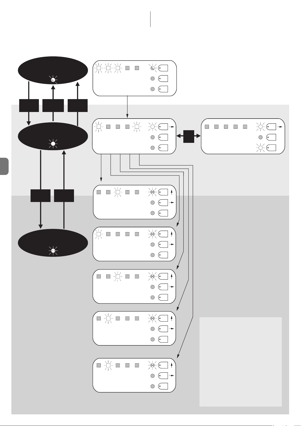
5.3.6 - Programmeerschema
Op onderstaande afbeelding vindt u het complete schema voor programmering
van de functies en de daarbij horende parameters. Op deze afbeelding zijn ook
de functies en parameters aangegeven die aanvankelijk of na volledig wissen
van het geheugen vooringesteld (fabrieksinstelling) zijn.
NL
Normale Werking
Led P1 knippert langzaam
P1+P2
gedurende
3 sec.
P1
gedurende
3 sec.
(bewaart niet)
P1+P2
gedurende
3 sec.
(bewaart)
Eerste niveau
Led P1 brandt continu
P2
gedurende
3 sec.
P1
STOP Foto Foto 1 Stap
- Eerst P1!
Auto.
Woonbl. VrW. Terug
Sluiten
5 10 20
seconden
AUX
voor
Stap
Vertr.
na foto
Open.
PAUZEDUUR
40 80
P1
P2
P3
P1
P2
P3
P1
P2
P3
On
Off
P3
Stand
by
Fototest
Elektros. STOP
Wrst.
Zware
Poorten
SCA
Prop.
P1
P2
P3
On
Off
Tweede niveau
Led P1 knippert snel
HULPINGANG (*)
a.p.
a.p.
Alleen
Alleen
Type 1
Type 2
openen
sluiten
Foto 2
DRUKAFVOER
0 0,3 0,7
1,3 2
seconden
GEVOELIGHEID STROOMMETING
1 2 3
graad
4 5
alle Leds uit. - max. stroommeting
VERTRAGING IN HET OPENEN
5 10 20
%
30 40
P1
P2
P3
P1
P2
P3
P1
P2
P3
P1
P2
P3
(*)
a.p. TYPE 1 Gedeeltelijke opening type 1,
alleen manoeuvre van de
bovenste vleugel [NO contact]
a.p. TYPE 2 Gedeeltelijke opening type 2,
manoeuvre van beide motoren
gedurende de 1/2 van de
bedrijfstijd [NO contact]
Alleen openen open stop open stop...
[NO contact]
Alleen sluiten sluit stop sluit stop...
[NO contact]
Foto 2 Gebruikt als foto 2
[NC contact]
8 – Nederlands
Page 83

NL
Nederlands – 9
6.1 - Aansluiting van een radio-ontvanger
De besturingseenheid is voorzien van een connector voor het insteken van een
radiokaart met 4 kanalen met plug-in SM, die het mogelijk maakt de besturingseenheid op afstand te bedienen via zenders die de ingangen aansturen,
zoals in de volgende tabel te zien is:
Uitgang ontvanger Ingang besturingseenheid
Nr. 1 Stap-voor-stap
Nr. 2 AUX (vooringestelde waarde: Open gedeeltelijk 1)
Nr. 3 “Alleen openen”
Nr. 4 “Alleen sluiten”
6.2 - Aansluiting van de bufferbatterij mod. PS124
De besturingseenheid kan bij een stroomuitval gevoed worden via de bufferbatterij PS124. Voor het installeren en aansluiten van de batterij gaat u te werk
zoals aangegeven op afb. 10.
6.3 - Aansluiting van het Solemyo-systeem
De besturingseenheid kan ook van stroom voorzien worden via het voedingssysteem op zonne-energie "Solemyo" (zonnepaneel en batterij van 24 V). Om
de accumulator van Solemyo aan te sluiten op de besturingseenheid, gebruikt
u op de besturingseenheid de aansluiting die normaal gebruikt wordt voor de
buf ferbatterij (zie paragraaf 6.2).
BELANGRIJK!
- Wanneer de automatisering van stroom wordt voorzien door het systeem “Solemyo”, mag deze NIET TEGELIJKERTIJD OOK GEVOED worden door het elektriciteitsnet.
- Het systeem “Solemyo” kan alleen gebruikt worden indien in de besturingseenheid de functie “Stand by” geactiveerd is (ON) en de aansluitingen overeenstemmen met het schema van afb. 5a.
VERDERE DETAILS: accessoires
6
Er brandt geen enkele LED:
• Controleer of de besturingseenheid stroom krijgt: op de klemmen 9-10 moet
u een spanning van ongeveer 30 Vdc meten (of 24 Vdc met batterijvoeding).
• Controleer de 2 zekeringen, als de led P1 niet brandt of knippert gaat het
waarschijnlijk om een ernstige storing en dient de besturingseenheid vervangen te worden.
De led P1 knippert normaal maar de leds van de ingangen L1, L2...L5
komen niet met de staat van de desbetreffende ingangen overeen
• Schakel de stroomvoorziening even uit om een eventuele programmeringsfase te verlaten.
• Controleer nauwkeurig de aansluitingen op de klemmen 11..16.
De led P1 knippert iedere 4 seconden
• De besturingseenheid is in de status Stand by.
De procedure “Automatisch zoeken” gaat niet van start
• De procedure “Automatisch zoeken” wordt alleen geactiveerd als die nooit is
uitgevoerd of als het geheugen is gewist. Om te controleren of het geheugen
leeg is, dient u de stroomvoorziening even uit te schakelen: als u de stroom
weer inschakelt dienen alle leds 6 seconden snel te knipperen. Als ze maar 3
seconden knipperen, bevat het geheugen al geldige waarden. Als u een
nieuwe procedure “Automatisch zoeken” wilt uitvoeren, dient u het geheugen eerst compleet te wissen.
De procedure “Automatisch zoeken” is nooit uitgevoerd, maar de procedure gaat niet van start of verloopt niet goed
• Voor het activeren van de procedure “Automatisch zoeken” dient de installatie met alle veiligheidsinrichtingen te werken.
• Vergewis u ervan dat geen enkele op de ingangen aangesloten inrichting in
werking treedt tijdens het “Automatisch zoeken”.
• Om het “Automatisch zoeken” correct te laten starten, moeten de leds op de
ingangen branden zoals aangegeven op afb. 11, en moet de led P1 eenmaal
per seconden knipperen.
De procedure”Automatisch zoeken”is correct uitgevoerd maar de
manoeuvre gaat niet van start
• Controleer of de LEDs van de beveiligingen (ALT, FOTO, FOTO1 en eventueel
FOTO2) branden en of de LEDs van de bedieningsinstructie die geactiveerd
wordt (STAP-VOOR-STAP of AUX) gaat branden voor de duur van de bedieningsinstructie.
• Als de functie “Fototest” actief is en de fotocellen niet correct functioneren,
signaleert de led DIAGNOSTIEK de storing door 4 maal te knipperen.
Tijdens de manoeuvre keert de poort om
De oorzaken voor een omkering zijn:
WAT TE DOEN ALS...
(leidraad bij het oplossen van de problemen)
7
• De fotocellen (FOTO2 bij opening, FOTO of FOTO1 tijdens sluiting) treden in
werking; controleer in dit geval de aansluitingen van de fotocellen en verifieer
eventueel de signaleringbedlampjes van de ingangen.
• De stroommeting treedt in werking wanneer de motoren draaien (dus niet
dichtbij de mechanische stops) en dit wordt als een obstakel gezien waardoor de vleugel omkeert. Om na te gaan of de stroommeting in werking is
gekomen dient u te tellen hoeveel maal de led Diagnostiek knippert: 1 maal
knipperen geeft aan dat de stroommeting op motor 1 in werking is gekomen,
2 maal op motor 2.
ONDERHOUD VAN HET PRODUCT
8
Voor de besturingseenheid MC424 als elektronische component is geen enkel
speciaal onderhoud vereist. Controleer echter periodiek, minstens eenmaal in
de 6 maanden, aan de hand van de aanwijzingen uit hoofdstuk 3 of de gehele
installatie in goede staat van werking is.
AFDANKEN VAN HET PRODUCT
Dit product maakt integraal deel uit van de automatisering en moet dan
ook samen met de automatisering worden afgedankt.
De ontmantelingwerkzaamheden aan het eind van de levensduur van dit product moeten, net als de installatiewerkzaamheden, worden uitgevoerd door
gekwalificeerd personeel.
Dit product is opgebouwd uit verschillende soorten materiaal: sommigen hiervan kunnen gerecycled worden, anderen moeten als afval worden verwerkt.
Win informatie in over de recycling- of afvalverwerkingsystemen die voor deze
productcategorie zijn voorzien door de in uw land geldende voorschriften.
Let op! – Sommige delen van het product kunnen vervuilende of gevaarlijke
substanties bevatten die, indien ze in het milieu terechtkomen, schadelijke
effecten kunnen hebben op de omgeving of op de gezondheid van personen.
Zoals aangegeven door het symbool hiernaast, is het verboden dit product met het gewone huisvuil weg te gooien. Volg
een “gescheiden afvalverwerking” volgens de methodes die
voorzien zijn door de in uw land geldende voorschriften, of
lever het product weer in bij de verkoper op het moment dat
u een nieuw gelijksoortig product aanschaft.
Let op! – De plaatselijk geldende voorschriften kunnen zware sancties voorzien
in het geval u de voorschriften voor afvalverwerking van dit product niet
opvolgt.
Page 84

NL
10 – Nederlands
EG-VERKLARING VAN OVEREENSTEMMING
Opmerking - De inhoud van deze verklaring stemt overeen met hetgeen verklaard is in de laatste revisie die beschikbaar was voor het ter perse gaan van deze handleiding, van
het officiële document dat is neergelegd bij de vestiging van Nice Spa. Deze tekst werd om uitgeversredenen heraangepast.
Nummer: 296/MC424 Herziening: 0
Ondergetekende Lauro Buoro, in diens hoedanigheid van Gedelegeerd Bestuurder, verklaart onder eigen verantwoordelijkheid dat het product:
Naam fabrikant: NICE s.p.a.
Adres: Via Pezza Alta 13, Z.I. Rustignè, 31046 Oderzo (TV) Italië
Type: Besturingseenheid met 2 motoren 24 Vd.c.
Modellen: MC424
Accessoires: Radio-ontvanger SMXI, SMXIS
Voldoet aan hetgeen voorzien wordt door de volgende communautaire richtlijnen:
• 98/37/EG (gewijzigde 89/392/EEG) RICHTLIJN 98/37/EG VAN HET EUROPESE PARLEMENT EN VAN DE RAAD d.d. 22 juni 1998 te zijn betreffende
harmonisering in de wetgeving van de Lidstaten met betrekking tot machines
Zoals voorzien in de richtlijn 98/37/EG waarschuwt men dat het niet toegestaan is bovenstaand product in bedrijf te stellen wanneer de machine waarin
dit product is ingebouwd niet geïdentificeerd is en conform de richtlijn 98/37/EG verklaard is.
Bovendien voldoet het product aan hetgeen voorzien wordt door de volgende communautaire richtlijnen:
• 2006/95/EEG (ex richtlijn 73/23/EG) RICHTLIJN 2006/95/EG VAN HET EUROPESE PARLEMENT EN DE RAAD van 12 december 2006 met betrekking
tot de onderlinge aanpassing van de wetgevingen van de Lidstaten met betrekking tot elektrisch materiaal dat bestemd is om binnen bepaalde spanningslimieten gebruikt te worden
Volgens de volgende geharmoniseerde normen: EN 60335-1:1994+A11:1995+A1:1996+A12:1996+A13:1998+A14:1998+A15:2000+A2:2000+A16:2001
• 2004/108/EEG(ex richtlijn 89/336/EEG) RICHTLIJN 2004/108/EG VAN HET EUROPESE PARLEMENT EN DE RAAD van 15 december 2004 met betrekking tot de onderlinge aanpassing van de wetgevingen van de Lidstaten met betrekking tot de elektromagnetische compatibiliteit waarmee de richtlijn
89/336/EEG wordt afgeschaft
Volgens de volgende geharmoniseerde normen: EN 61000-6-2:2001; EN 61000-6-3:2001+A11:2004
En daarnaast, beperkt tot de van toepassing zijnde onderdelen, voldoet aan de volgende normen:
EN 60335-1:2002+A1:2004+A11:2004+A12:2006+ A2:2006, EN 60335-2-103:2003, EN 13241-1:2003; EN 12453:2002; EN 12445:2002;
EN 12978:2003
Oderzo, 25 september 2008
Lauro Buoro (Gedelegeerd Bestuurder)
WAARSCHUWING: • Alle vermelde technische kenmerken hebben betrekking op een omgevingstemperatuur van 20°C (± 5°C). • Nice S.p.a. behoudt zich het
recht voor om, op elk moment dat dit noodzakelijk geacht wordt, wijzigingen aan het product aan te brengen, waarbij hoe dan ook de functionaliteit en de
gebruiksbestemming ervan gelijk blijven.
Netvoeding Besturingseenheid MC424: 230 V~ ±10% 50 - 60 Hz
Besturingseenheid MC424/V1: 120 V~ ±10% 50 - 60 Hz
Max. opgenomen vermogen 170 W
Noodvoeding geschikt voor gebruik met bufferbatterij PS124 en voor zonne-energieset Solemyo
Maximumstroom motoren 3 A (met activeringsniveau stroommeting“graad 6”)
Uitgang stroomvoorziening gebruikers 24 V maximumstroom 200 mA (de spanning kan variëren van 16 tot 33 V )
Uitgang fototest 24 V maximumstroom 100 mA (de spanning kan variëren van 16 tot 33 V )
Uitgang knipperlicht voor 24 V , knipperlichten, maximumvermogen 25 W (de spanning kan variëren van 16 tot 33 V )
Uitgang lampje poort voor 24 V lampje maximumvermogen 5 W (de spanning kan variëren van 16 tot 33 V )
of elektrische sloten van 12 V~ 25 W
Ingang ALT voor NC contacten of constante weerstand 8,2 KΩ +/- 25%
Bedrijfstijd automatisch gedetecteerd
Pauzeduur programmeerbaar op 5, 10, 20, 40, 80 seconden
Drukafvoertijd programmeerbaar op 0, 0,3, 0,7, 1,3, 2 seconden
Vertraging vleugel bij opening programmeerbaar op 5, 10, 20, 30 en 40% van de bedrijfstijd
Vertraging vleugel bij sluiting automatisch gedetecteerd
Uitgang 1emotor voor motoren Wingo WG4024 - WG5024
Uitgang 2emotor voor motoren Wingo WG4024 - WG5024
Max. lengte kabels voeding 230 V 30 m
voeding zonne-energieset Solemyo 3 m
motoren 10 m
overige ingangen/uitgangen 30 m
knipperlicht 10 m
SCA 30 m
elektrisch slot 10 m
antenne 20 m (een lengte van minder dan 3 m wordt aanbevolen)
Radio-ontvanger Plug-in type “SM” voor ontvangers SMXI, SMXIS, OXI (Modus I en Modus II)
Bedrijfstemperatuur van - 20 tot 50 °C
Beschermingsklasse IP 54 met intacte kast
Afmetingen (mm) 310 x 232 x H 122
Gewicht (kg) 4,1
TECHNISCHE GEGEVENS VAN HET PRODUCT
Page 85

NL
Nederlands – 11
smxi - smixs radio-ontvanger
0682
SMXI, SMXIS zijn radio-ontvangers met 4 kanalen voor besturingseenheden vo or zien van een plug-in SM. De compatibele zenders hebben de eigenschap dat
de herkenningscode voor elke zender verschillend is. Opdat de ontvanger een
be paalde zender kan herkennen, dient u daarom de herkenningscode in het ge heugen op te slaan. Elke zender die u voor het aansturen van de besturingseenheid wilt gebruiken, dient afzonderlijk in het geheugen te worden opgeslagen.
Opmerkingen:
– Er kunnen maximaal 256 zenders in het geheugen van de ontvanger opgesla-
gen worden. Het is niet mogelijk één aparte zender wissen, alleen totaal wissen
van alle codes is mogelijk.
– Voor meer gecompliceerde functies gelieve u de speciale programmeringseenheid te gebruiken.
BESCHRIJVING VAN HET PRODUCT
1
De ontvanger beschikt over 4 uitgangen, allemaal beschikbaar op de onderliggende connector, om te weten welke functie door elk van de uitgangen wordt
uitgevoerd raadpleegt u hoofdstuk 6.1.
Bij de opslagfase van de zendercode kunt u tussen de volgende 2 opties kiezen:
Modus I - Tabel B1: Iedere toets van de zender activeert de overeenkomsti-
ge uitgang van de ontvanger, dat wil zeggen, toets 1 activeert uitgang 1, toets
2 activeert uitgang 2 enzovoorts. In dit geval is er een enkele opslagfase voor
elke zender, gedurende deze fase maakt het niet uit welke toets er wordt ingedrukt, en er wordt slechts één plaats in het geheugen bezet.
Modus II - Tabel B2: Aan iedere toets van de zender kan een bepaalde uitgang van de ontvanger worden gekoppeld, bijvoorbeeld toets 1 activeert uitgang 2, toets 2 activeert uitgang 1 enzovoorts. In dit geval moet de zender in
het geheugen worden opgeslagen door voor iedere te activeren uitgang de
gewenste toets in te drukken. Uiteraard kan iedere toets slechts één uitgang
activeren, terwijl dezelfde uitgang door meerdere toetsen geactiveerd kan worden. Voor iedere toets wordt één geheugenplaats bezet.
TABEL B1 - Geheugenopslag modus I (alle toetsen worden op de betreffende uitgang van de ontvanger opgeslagen)
01. Druk op de toets op de ontvanger en houd die tenminste 3 seconden ingedrukt
02. Wanneer de led gaat branden laat u de toets los
03. Druk binnen 10 seconden tenminste 2 seconden lang op een willekeurige toets van de in het geheugen te bewaren zender
Opmerking – als het opslaan goed verlopen is zal de led op de ontvanger 3 maal knipperen, als er nog andere zenders
moeten worden opgeslagen, herhaalt u stap 3 binnen 10 seconden, de opslagfase wordt afgesloten als er gedurende
10 seconden geen nieuwe codes meer binnenkomen
3s
2s
x3
INSTALLATIE ANTENNE
2
Voor een goede ontvangst van de ontvanger hebt u een antenne van het type
ABF of ABFKIT nodig; zonder antenne wordt het bereik tot enkele meters
beperkt. De antenne moet zo hoog mogelijk gemonteerd worden; bij aanwezigheid van structuren van metaal of gewapend beton, dient u de antenne hoger
dan deze structuren te monteren. Als de bij de antenne geleverde kabel te kort
is, gebruikt u een coaxiale kabel met impedantie 50 ohm (bijv. RG58 met laag
verlies), de kabel mag niet langer dan 10 meter zijn.
Wanneer de antenne geïnstalleerd is op een plaats waar geen goed grondvlak is
(gemetselde structuren) is het mogelijk het kabelomhulsel met de aarde te verbinden om het bereik zo te vergroten. Het spreekt vanzelf dat de aardverbinding
zich in de nabijheid moet bevinden en van goede kwaliteit moet zijn. Indien het
niet mogelijk is de specifieke antenne ABF of ABFKIT te installeren, kunnen ook
redelijke resultaten worden verkregen door het bij de ontvanger geleverde stuk
draad als antenne te gebruiken (liggend gemonteerd).
LET OP – Wanneer de procedure voor geheugenopslag geactiveerd
wordt, wordt elke correct herkende zender binnen het ontvangstbereik van de radio-ontvanger in het geheugen opgeslagen. Denk
OPSLAAN VAN EEN AFSTANDSBEDIENING
3
hieraan en koppel eventueel de antenne af om de ontvangst van de
ontvanger te verkleinen.
De procedures voor opslag van de afstandsbedieningen hebben een maximumtijd waarbinnen ze uitgevoerd moeten worden; u dient dus eerst de gehele procedure aandachtig door te nemen alvorens te beginnen.
Om de volgende procedure uit te voeren, moet u de knop op de box van de
radio-ontvanger (referentie A, afb. 1a) en de bijbehorende led (referentie B,
afb. 1a) links van de toets gebruiken.
1a
TABEL B2 - Geheugenopslag modus II (aan iedere toets kan een bepaalde uitgang van de ontvanger worden gekoppeld)
01. Druk zoveel maal op de toets op de ontvanger als overeenkomt met de gewenste uitgang
(1 maal voor uitgang 1, 2 maal voor uitgang 2)
02. Controleer of het aantal maal dat de led knippert, met regelmatige tussenpozen van 10 seconden, gelijk is aan het
nummer van de gewenste uitgang (1 maal knipperen voor uitgang nr. 1, 2 maal knipperen voor uitgang nr. 2)
03. Druk binnen 10 seconden tenminste 2 seconden op de gewenste toets van de zender die bewaard moet worden
Opmerking – als het opslaan goed verlopen is zal de led op de ontvanger 3 maal knipperen, als er nog andere zenders
moeten worden opgeslagen, herhaalt u stap 3 binnen 10 seconden, de opslagfase wordt afgesloten als er gedurende
10 seconden geen nieuwe codes meer binnenkomen
2s
x3
RX
RX
RX
TX
TX
Page 86

NL
12 – Nederlands
Geheugenopslag op afstand
U kunt een nieuwe zender in het geheugen van de ontvanger opslaan zonder
de toets te gebruiken. U dient dan over een afstandsbediening te beschikken
welke al in het geheugen is opgeslagen en die goed werkt. De nieuwe zender
“erft” de eigenschappen van de reeds opgeslagen zender. Dus als de eerste
zender is opgeslagen in modus I, zal ook de nieuwe zender in modus I worden
opgeslagen en kan op een willekeurige toets van de zenders worden gedrukt.
Als de eerste zender in modus II opgeslagen is, zal ook de nieuwe zender in
modus II bewaard worden maar dient u bij de eerste zender op die toets te
drukken die de gewenste uitgang activeert, en bij de tweede zender de toets
die u wilt opslaan. U dient alle aanwijzingen eerst goed door te nemen om de
handelingen daarna zonder onderbrekingen uit te voeren. Nu gaat u met de
twee afstandsbedieningen, waarvan we die waar de code moet worden ingevoerd NIEUWE zullen noemen, en die welke de code reeds in het geheugen
heeft OUDE, binnen het bereik van de radio-ontvangers staan (binnen het maximale bereik) en voert u de in de tabel opgevoerde stappen uit.
TABEL B4 - Wissen van alle zenders
01. Druk op de toets op de ontvanger en houd die ingedrukt
02. Wacht totdat de led gaat branden, wacht nu tot de led uit gaat en wacht vervolgens tot hij 3 maal knippert
03. Laat de toets exact gedurende de 3de knippering los
Opmerking – als de procedure tot een goed einde is gekomen, zal de led na enige ogenblikken 5 maal knipperen
x3
3°
x5
U kunt alle in het geheugen aanwezige codes met onderstaande procedures wissen:
WISSEN VAN ALLE ZENDERS
4
TECHNISCHE GEGEVENS VAN HET PRODUCT
Ontvangers: SMXI SMXIS
Decodering Rolling code 52 bit FLOR Rolling code 64 bit SMILO
Compatibiliteit zenders FLOR, VERY VR, NICE WAY, ERGO, PLANO, NICE ONE SMILO
Frequentie 433.92 MHz 433.92 MHz
Ingangsimpedantie 52 KΩ 52 KΩ
Uitgangen 4 (op connector SM) 4 (op connector SM)
Gevoeligheid beter dan 0.5 µV beter dan 0.5 µV
Bedrijfstemperatuur van -10° C tot + 55° C van -10° C tot + 55° C
Zenders: FLO2R SMILO
Toetsen 1, 2 of 4 afhankelijk van de uitvoeringen 2 of 4
Voeding 12 V batt. 23 A 12 V batt. 23 A
Stroomopname 10 mA 25 mA
Zendfrequentie 433.92 MHz 433.92 MHz
Bedrijfstemperatuur van -10° C tot + 55° C van -10° C tot + 55° C
Uitgestraald vermogen geschat op circa 1 mW E.R.P. Geschat op circa 1 mW E.R.P.
Bereik geschat op 200 m (buiten); 35 m (in gebouwen) geschat op 200 m (buiten); 35 m (in gebouwen)
Afmetingen / Gewicht 69 x 39 x 15,5 mm / 31 g. Ø 48 mm x H 14 mm - 14 g
Codering digitaal (4,5 miljoen miljard combinaties) digitaal (18 miljard miljard combinaties)
WAARSCHUWING: • Alle vermelde technische kenmerken hebben betrekking op een omgevingstemperatuur van 20°C (± 5°C). • Nice S.p.a. behoudt zich het
recht voor om, op elk moment dat dit noodzakelijk geacht wordt, wijzigingen aan het product aan te brengen, waarbij hoe dan ook de functionaliteit en de
gebruiksbestemming ervan gelijk blijven. • Het bereik van de zenders en de ontvangstcapaciteit van de ontvangers kan onderhevig zijn aan interferenties, die de
prestaties ervan kunnen beïnvloeden. In dergelijke gevallen kan Nice geen enkele garantie bieden met betrekking tot het effectieve bereik van haar inrichtingen.
TABEL B3 - Geheugenopslag op afstand
01. Druk tenminste 5 seconden op de toets op de NIEUWE zender, laat hem daarna los
02. Druk 3 maal langzaam op de toets op de OUDE zender
03. Druk 1 maal langzaam op de toets op de NIEUWE zender, laat hem daarna los
Opmerking – als er nog andere zenders in het geheugen moeten worden opgeslagen dient u alle stappen voor elke nieuwe zender uit te voeren
1s
x1
1s1s
x5s
TX
TX TX TX
TX
TX
RX
RX
Page 87

I
EN
IT
FR
ESDEPL
NL
EN - Images
IT - Immagini
FR - Images
ES - Imágenes
DE - Bilder
PL - Zdjęcia
NL - Afbeeldingen
Page 88

1
3
8
4
7
7
1
2
55
6 6
2
M1
L
N
M2
EN - E = Electric jumper
IT - E = Ponticello elettrico
FR - E = Cavalier électrique
ES - E = Conexión eléctrico
DE - E = Brücke
PL - E = Mostek elektryczny
NL - E = Elektrische
geleidingsbrug
D
C
B
A
FE GH I L M
4 5 6 8 9 10 11 12 13 14 15 167123
L1...L5
P1
P2
P3
N
123
O
II
Page 89

3
232 mm
122 mm
310 mm
4
205
237
5a
EN- Connection with “Stand by” active (energy saving)
IT - Collegamento con “Stand by” attivo (risparmio energetico)
FR- Connexion avec « stand-by » actif (économie d’énergie)
ES- Conexión con “Stand by” activo (ahorro energético)
DE- Anschluss mit aktivem “Standby” (Energieeinsparung)”
PL - Połączenie z aktywną funkcją “Stand by” (oszczędność energii)
NL- Aansluiting met “Stand by” actief (energiebesparing)
TX RX
PHOTO2
III
Page 90

5b
EN- Standard connection: without using Standby or Phototest
IT - Collegamento standard: senza utilizzare “Stand by” e senza “Fototest”
FR- Connexion standard : sans utiliser « Stand by » et sans « Phototest »
ES- Conexión estándar: sin utilizar “Stand by” y sin “Fototest”
DE- Standardanschluss: ohne Nutzung des “Stand by” und ohne “Fototest”
PL - Połączenie standard: bez wykorzystywania funkcji “Stand by”
i bez “Fototestu”
NL- Standaard aansluiting: zonder gebruik van “Stand by”
en zonder "Fototest”
TX RX
5c
EN- Connection without “Stand by” with “Phototest”
IT - Collegamento senza “Stand by” con “Fototest”
FR- Connexion sans « stand-by » et avec « phototest »
ES- Conexión sin “Stand by” con “Fototest”
DE- Ohne “Standby” und ohne “Phototest”
PL - Połączenie bez funkcji “Stand by” i z funkcją “Fototest”
NL- Aansluiting zonder “Stand by” met “Fototest”
TX RX
6
IV
Page 91

6
7a
7b
STEP BY STEP
NC NO C C NO NC
15
11
11
12
ALT
EN- For the ALT connection with “Stand by” active, connect terminal
no. 8 and not no. 11
IT - Per il collegamento ALT, con “stand by” attiva, collegare il
morsetto n° 8 e non il n° 11
FR- Pour la connexion HALTE, avec « stand-by » actif, connecter la
borne n° 8 et pas la n° 11
STEP BY STEP
8
33 V
max 5 W
AUX
NC NO C C NO NC
15
11
11
16
7
12 V~
max 25 VA
ES- Para la conexión ALT, con “stand by” activo, conecte el borne n°
8 y no el n° 11
DE- Für den Anschluss STOPP, bei aktivem Standby, die Klemme Nr.
8 und nicht 11 anschließen
PL - Aby wykonać połączenie STOP z aktywną funkcją “stand by”
należy połączyć zacisk nr 8 a nie nr 11
NL- Voor de aansluiting ALT, met actieve “stand by”, sluit u de klem
8 aan en niet de klem 11
9a
11
NA
NA
8,2K!
12
9b 9c
11
12
EN- With Stand by active connect terminal no. 8 and not no. 11
IT - Con Stand by attiva collegare il morsetto n° 8 e non il n° 11
FR- Avec Stand-by actif connecter la borne n° 8 et pas la n° 11
ES- Con “Stand by” activo, conecte el borne n° 8 y no el n° 11
6
7
NC
NA
8,2K!
DE- Bei aktivem Standby, die Klemme Nr. 8 und und nicht 11 anschließen
PL - Z aktywną funkcją Stand by należy połączyć zacisk nr 8 a nie nr 11
NL- Met actieve Stand by sluit u klem 8 aan en niet klem 11
11
NC
NC
12
8,2K!
9d
11
12
1
Sensitive edge
IT - Bordo sensibile
FR - Bord sensible
ES - Banda sensible
DE - Schaltleiste
PL - Listwa optyczna
NL - Contactlijst
2
Sensitive edge
IT - Bordo sensibile
FR - Bord sensible
ES - Banda sensible
DE - Schaltleiste
PL - Listwa optyczna
NL - Contactlijst
IT - Bordo sensibile
FR - Bord sensible
ES - Banda sensible
DE - Schaltleiste
PL - Listwa optyczna
NL - Contactlijst
n
Sensitive edge
8,2K!
V
Page 92

VI
1110
Page 93

Page 94

Page 95

Page 96

Codice: IST280.4858 – Rev. 01 del 15 – 12 – 2008
Nice Turkey
Kadikoy Istanbul Turkey
Ph. +90.216.456.34.97
Fax +90.216.455.78.29
info@tr.niceforyou.com
Nice UK
Sutton in Ashfield
United Kingdom
Ph. +44.16.23.55.80.86
Fax +44.16.23.55.05.49
info@uk.niceforyou.com
Nice Australia
Wetherill Park Australia
Ph. +61.(0)2.96.04.25.70
Fax +61.(0)2.96.04.25.73
info@au.niceforyou.com
Nice China
Shanghai P. R. China
Ph. +86.21.575.701.46/45
Fax +86.21.575.701.44
info@cn.niceforyou.com
Nice USA
Jacksonville Florida USA
Ph. +1.904.786.7133
Fax +1.904.786.7640
info@us.niceforyou.com
www.niceforyou.com
Headquarters
Nice SpA
Oderzo TV Italia
Ph. +39.0422.85.38.38
Fax +39.0422.85.35.85
info@niceforyou.com
Nice in Italy
Nice Padova
Sarmeola di Rubano PD Italia
Ph. +39.049.89.78.93.2
Fax +39.049.89.73.85.2
infopd@niceforyou.com
Nice Roma
Roma RM Italia
Ph. +39.06.72.67.17.61
Fax +39.06.72.67.55.20
inforoma@niceforyou.com
Nice Worldwide
Nice France
Buchelay France
Ph. +33.(0)1.30.33.95.95
Fax +33.(0)1.30.33.95.96
info@fr.niceforyou.com
Nice France Sud
Aubagne France
Ph. +33.(0)4.42.62.42.52
Fax. +33.(0)4.42.62.42.50
infomarseille@fr.niceforyou.com
Nice France Rhône Alpes
Decines Charpieu France
Ph. +33.(0)4.78.26.56.53
Fax +33.(0)4.78.26.57.53
infolyon@fr.niceforyou.com
Nice Belgium
Leuven (Heverlee) Belgium
Ph. +32.(0)16.38.69.00
Fax +32.(0)16.38.69.01
info@be.niceforyou.com
Nice Deutschland
Gelnhausen Deutschland
Ph. +49.(0)6051.91.520
Fax +49.(0)6051.91.52.119
info@de.niceforyou.com
Nice España Madrid
Mostoles Madrid España
Ph. +34.(0)9.16.16.33.00
Fax +34.(0)9.16.16.30.10
info@es.niceforyou.com
Nice España Barcelona
Sant Quirze del Valles
Barcelona España
Ph. +34.(0)9.37.84.77.75
Fax +34.(0)9.37.84.77.72
info@es.niceforyou.com
Nice Polska
Pruszków Polska
Ph. +48.(022).759.40.00
Fax +48.(022).759.40.22
info@pl.niceforyou.com
Nice Portugal
Mem Martins Portugal
Ph. +351.21.922.82.10
Fax +351.21.922.82.19
info@pt.niceforyou.com
Nice Romania
Cluj Napoca Romania
Ph./Fax +40.(0)264.453.127
info@ro.niceforyou.com
 Loading...