

Page 1
Instrukcje i uwagi dla instalatora
Istruzioni ed avvertenze per l’installatore
Instructions and warnings for the fitter
Instructions et recommandations pour l’installateur
Anweisungen und Hinweise für den Installateur
Instrucciones y advertencias para el instalador
control unit
IB
Page 2

2
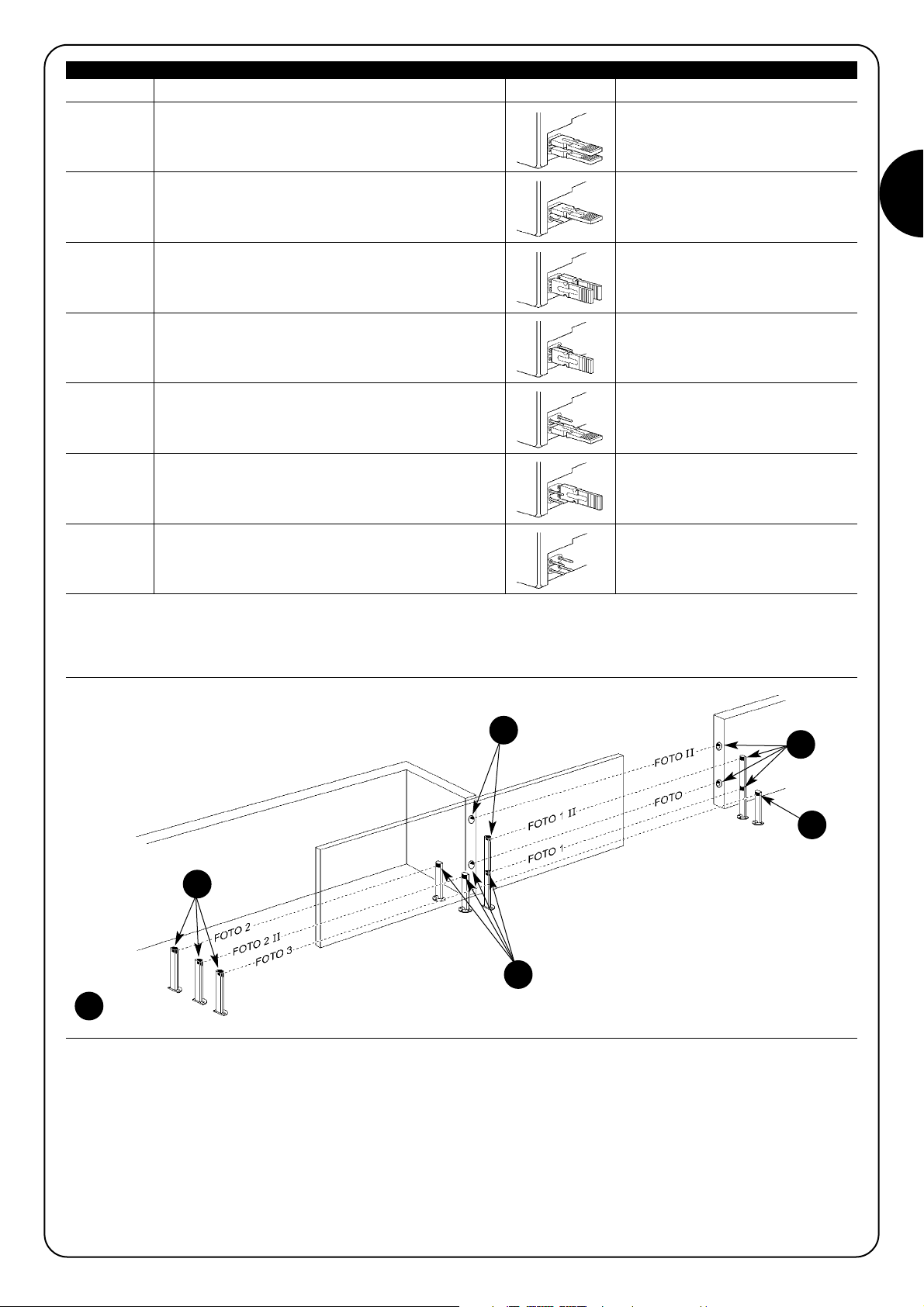
3.1) "Single-leaf" type systems
In "single-leaf" type systems the photocells can be positioned in the same way as for Figura 1 sliding gates or as for Figura 2 sectional doors.
The figures show the maximum number of photocells possible, although a smaller number may be installed; during programming unit IB will
automatically recognise the devices that are effectively connected.
For unit IB to identify photocells connected to bluebus each must be assigned an address in accordance with its specific function in the system. The addressing operation is performed by setting up the jumpers as specified in table 2 for each TX / RX pair.
1) Warnings:
This manual has been especially written for use by
qualified fitters. No information given in this manual can
be considered as being of interest to end users!
This manual refers to IB only and cannot be used for different products.
• The installation, testing and commissioning of door and gate
automation systems must be performed by qualified and experienced personnel.
• The persons responsible for installation must establish which tests
are to be conducted based on the risks involved, and verify the
compliance of the system with applicable regulations, legislation
and standards.
• Before starting to install the product read all the instructions in this
manual thoroughly: improper use of the product or erroneous connections could reduce safety levels or cause malfunctions.
• Before starting the installation procedure check the suitability of
the product for the intended application; use special care to check
that the values given in the "Technical Specifications" chapter are
compatible with the application, otherwise unit IB cannot be used.
Unit IB is an interface that makes it possible to connect detectors with
bluebus technology (MOFB and MOFOB photocells) to control units
with inputs for conventional NC type contacts.
The use of the IB unit with MOFB and MOFOB photocells makes it
possible to create detectors (D type to standard 12453) that can be
used with door and gate automation systems. Use of the fototest
function makes it possible to attain safety category 2 in compliance
with EN 954-1.
Bluebus technology is easy to install because just two wires (no
polarity) are needed to connect all the devices in parallel; also, it
solves inter-detector interference problems by means of an automatic synchronism system.
2) Product description and intended use
3) Installation
Warning: the unit must be installed with the power supply disconnected.
Warning: before installing the unit carry out risk analysis
to calculate the number of detectors required in relation
to the specific automation system.
Device IB can be used in various types of automation system for
doors and gates, with installation options potentially varying in relation to the specific system; refer to table 1 for installation and programming.
!
Type of system Installation: see chapter: Programming: see table
Sliding gate
Sectional door
3.1 "Single-leaf" type systems Table 5
Swing gate
Projecting up-and-over door
3.2 "Double-leaf" type systems Table 6
Table 1
1 2
Page 3
GB
3
Table 2: "Single-leaf" type systems
NOTE (for FOTO 3): it is not normally necessary to observe any restrictions in the position of the pair of elements (TX-RX) that make up each
photocell system; however, if photocell FOTO 3 is used in conjunction with photocell FOTO II, the positions illustrated in figure 3 must be
observed.
Note A: photocells FOTO, FOTO II, FOTO 1 and FOTO 1 II change the status of the "foto" relay; when any one of these four photocells is
engaged IB will open the contact of the "foto" output relay.
Note B: photocells FOTO 2 and FOTO 2 II change the status of the "foto 2" relay; when either of these two photocells is engaged IB will
open the contact of the "foto 2" relay.
Note C: photocell FOTO 3 changes the status of the "foto" and "foto 2" relay; when this photocell is engaged IB will open the contacts of
the two relays "foto" and "foto 2".
In "single leaf" configuration the "foto 1" relay output is not used and the contact remains constantly in the NO position.
3
TX
TX
RX
RX
TX
Photocell Jumpers Activation on IB outpu
"External low-mounted" photocell on sliding gate or
"foto" relay
FOTO internal low-mounted" photocell on sectional
(see note A).
door with activation during closing.
"External high-mounted" photocell on sliding gate or
"foto" relay
FOTO II "internal high-mounted" photocell on sectional door with
(see note A)
activation during closing.
"Internal low-mounted" photocell on sliding gate or
"foto" relay
FOTO 1 "external low-mounted" photocell on sectional door
(see note A)
with activation during closing.
"Internal high-mounted" photocell on sliding gate or
"foto" relay
FOTO 1 II "external high-mounted" photocell on sectional door with
(see note A)
activation during closing.
FOTO 2 "External" photocell with activation during opening.
"foto 2" relay
(see note B)
FOTO 2 II "Internal" photocell with activation during opening.
"foto 2" relay
(see note B)
FOTO 3
S
ingle" photocell covering the entire automation system with
Both "foto" and "foto 2" relays
activation both during opening and during closing. (see note C)
Page 4
4
3.2) "Double-leaf" type systems.
In automation systems for "double-leaf" doors or gates the photocells can be positioned as shown in figure 4 for gates or as shown in figure 5 for projecting up-and-over doors.
The figures show the maximum number of photocells possible, although a smaller number may be installed; during programming unit IB will
automatically recognise the devices that are effectively connected.
For unit IB to identify photocells connected to bluebus each must be assigned an address in accordance with its specific function in the system. The addressing operation is performed by setting up the jumpers as specified in table 3 for each TX / RX pair.
Table 3 "Double-leaf" type systems
Warning: during the opening and closing phases the door must
not engage photocells FOTO 1 and FOTO 1 II.
4
5
Photocell Jumpers Activation on IB output
"External low-mounted" photocell on double-leaf system or
"foto" relay
FOTO "internal low-mounted" photocell on projecting up-and-over
(see note A)
door wit activation during closing.
"Outside high-mounted" photocell on two-leaf system or
"foto" relay
FOTO II "inside high-mounted" photocell on projecting up-and-over
(see note A)
door with activation during closing.
"Internal low-mounted" photocell on double-leaf system or
"foto 1" relay
FOTO 1 "external low-mounted" photocell on projecting up-and-over
(see note B)
door with activation both during closing and during opening.
"Internal high-mounted" photocell on double-leaf system or
"foto 1" relay
FOTO 1 II "external high-mounted" photocell on projecting up-and-over
(see note B)
door with activation both during closing and during opening.
FOTO 2 "Right-hand" photocell with activation during opening.
"foto 2" relay
(see note C)
FOTO 2 II "Left-hand" photocell with activation during opening.
"foto 2" relay
(see note C)
Note A: photocells FOTO, FOTO II change the status of the "foto" relay: when either of these two photocells is engaged unit IB will open
the contact of the "foto" output relay.
Note B: photocells FOTO 1 and FOTO 1 II change the status of the "foto 1" relay: when either of these two photocells is engaged unit IB
will open the contact of the "foto 1" relay.
Note C: photocells FOTO 2 and FOTO 2 II change the status of the "foto 2" relay: when either of these two photocells is engaged unit IB
will open the contact of the "foto 2" relay.
Page 5
GB
5
6
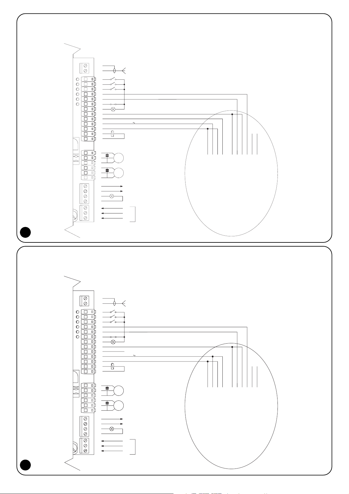
(Red, Black) 24V power supply
(Blue,Blue) fototest input
(Grey,Grey) "foto" relay output (NC)
(White,White) "foto 1" relay output (NC)
(Purple,purple) "foto 2" relay output (NC)
Bluebus cable
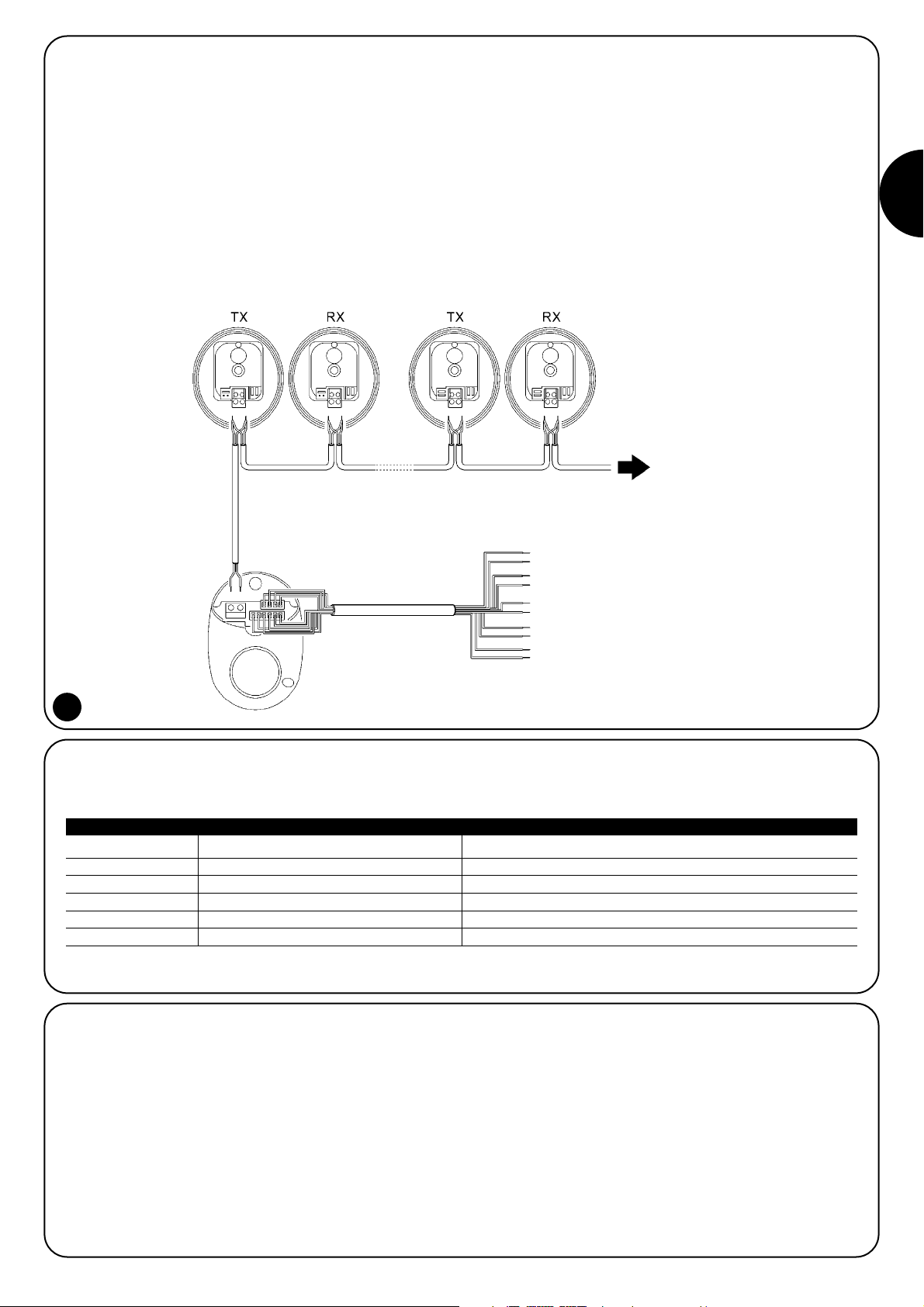
3.3.1) Description of connections.
The following is a brief description of the electrical connections relative to unit IB.
Wire colour Function Description.
Red,Black 24V ac/dc power supply Power line 18÷28 Vac; 16÷35 Vdc
Blue,Blue fototest fototest input (normally active) (NC)
Grey, Grey "foto" output "foto" relay voltage-free contact output (NC)
White, White "foto1" output "foto1" relay voltage-free contact output (NC)
Purple, Purple "foto2" output "foto2" relay voltage-free contact output (NC)
Table 4: Connections
3.3.2) Fototest.
Unit IB is equipped with an input for testing the entire detector when
so requested by the control unit, with the scope of attaining safety
category 2 in compliance with EN 954-1
The IB unit fototest input must be connected to the control unit
fototest output; there is no need to observe any particular polarity
(see example in figure 7). If the control unit is not equipped with
fototest or if it is not required, the fototest input must be connected
to the same power supply as IB on the red and black wires (see
example in figure 8).
3.3) Electrical connections
Unit IB has 3 relay outputs: “foto”, “foto 1” and “foto 2” with NC (normally closed) contact prearranged for connection to the corresponding inputs on automation system control units.
If the control unit is not equipped with one or more "foto" inputs the
relative IB output wires must not be used, in this case it is pointless
to install the photocells that would normally interact with these outputs.
For connection of bluebus devices use 2x0.5mm
2
cable up to a max-
imum length of 20m, and 2x1mm
2
cable up to a maximum length of
50m.
Page 6
6
IB
11
MOTOR 2 OPEN
GND
MOTOR 1 CLOSE
MOTOR 1 COMMON
MOTOR 1 OPEN
LIGHT
COURTESY
Max 40W
FLASHING LIGHT
POWER SUPPLY
F
1
N
M1
6
2
3
5
4
7
8
10
9
FOTOTEST
200mA
24 V
FOTO1
MOTOR 2 COMMON
MOTOR 2 CLOSE
FOTO
P.P.
STOP
OPEN
CLOSE
12 Vcc MAX 25 W
COM
ELECTRIC LOCK
SCA
21
M2
15
13
12
18
16
17
19
20
23
22
26
24
25
27
White
Red
Black
Blue
Blue
Grey
Grey
Purple
White
Purple
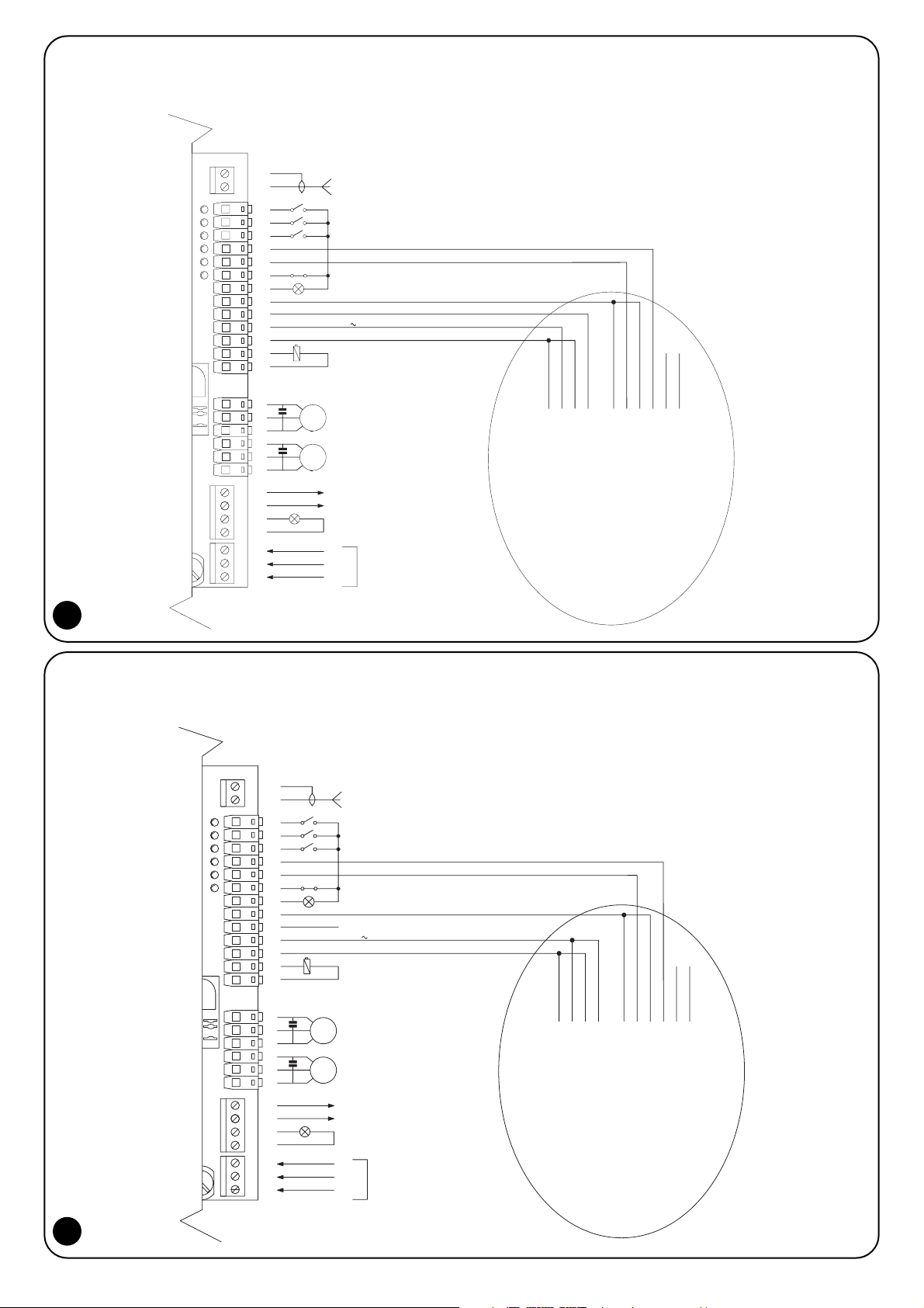
3.3.3) Example of use of unit IB with A60 control unit and fototest.
Figure 7 shows a connection example for unit IB with an A60 control unit with fototest.
IB
11
MOTOR 2 OPEN
GND
MOTOR 1 CLOSE
MOTOR 1 COMMON
MOTOR 1 OPEN
LIGHT
COURTESY
Max 40W
FLASHING LIGHT
POWER SUPPLY
F
1
N
M1
6
2
3
5
4
7
8
10
9
FOTOTEST
200mA
24 V
FOTO1
MOTOR 2 COMMON
MOTOR 2 CLOSE
FOTO
P.P.
STOP
OPEN
CLOSE
12 Vcc MAX 25 W
COM
ELECTRIC LOCK
SCA
21
M2
15
13
12
18
16
17
19
20
23
22
26
24
25
27
White
Red
Black
Blue
Blue
Grey
Grey
Purple
White
Purple
3.3.4) Example of use of unit IB with A60 control unit without fototest.
Figure 8 shows a connection example of unit IB with an A60 control unit without fototest.
7
8
Page 7
GB
7
During the programming phase unit IB performs its auto-teach routine
and checks that the photocells connected to bluebus are functioning
correctly; all parameters remain stored also following a power loss.
Programming must be executed in the automation system installation
phase or whenever devices are added to or removed from the system.
Programming is not required if the photocells are replaced, providing
the new photocell is given the same address as the removed unit.
The two different automation types: "single leaf" and "double leaf"
must be programmed by means of a different procedure: see table 5
for "single leaf" or table 6 for "double leaf".
4) Programming
Warning: the testing and commissioning operations must be
performed by qualified and experienced personnel who must establish which tests to conduct on the basis of the risks involved, and
verify the compliance of the system with applicable regulations, legislation and standards, in particular with all the provisions of EN standard 12445 which establishes the test methods for gate automation
systems.
5) Testing and commissioning
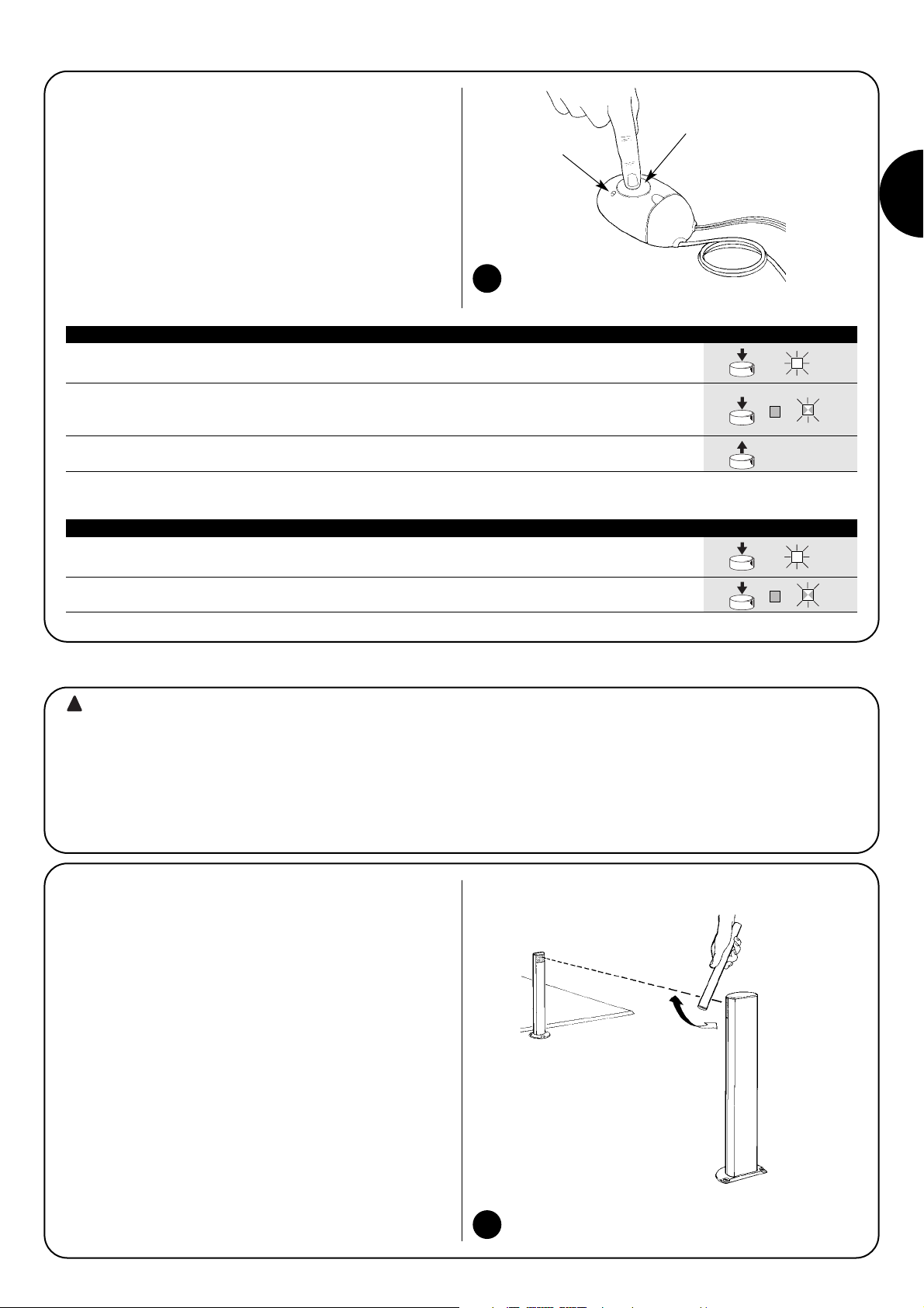
1. Press and hold down key "P"; LED "L" will light steadily after approximately 3 seconds
3s
2. With the key still pressed wait for approximately 4 seconds so that IB can complete the
connected devices auto-teach cycle. When the auto-teach cycle is terminated
LED "L" switches off and then starts flashing as normal. 4s
3. Release key “P”.
Note: for "single leaf" systems the link between the photocells and relays is shown in table 2
P
P
P
Table 5: "Single-leaf" type programming
1. Press and hold down key "P"; LED "L" will light steadily after approximately 3 seconds
at which point release the key. 3s
2. Wait for approximately 4 seconds so that IB can complete the connected devices auto-teach
cycle.When the auto-teach cycle is terminated LED "L" switches off and then starts flashing as normal.
4s
Note: for "double leaf" systems the link between the photocells and relays is shown in table 3
P
Table 6: "Double-leaf" type programming
P
5.1) Testing
Testing is the most important stage in the automation system installation procedure in order to ensure the maximum safety levels.
Testing can also be adopted as a method of periodically checking
that all the various devices in the system are functioning correctly.
1. Ensure that the instructions outlined in chapter 1 "WARNINGS"
have been observed in full.
2. Check that the photocells are functioning perfectly; check in par-
ticular that there is no interference with other devices. Take a 5
cm diameter cylinder 30 cm in length and cause it to transit
across the optical axis first close to the transmitter (TX) and then
close to the receiver (RX) and finally at the mid-point between the
two, and check that the device trips in all cases, switching from
active status to alarm status and vice versa.
3. For each photocell trip check also that the control unit performs
the correct operation; e.g. activation of FOTO during the closing
cycle should result in reversal of the direction of movement.
9
10
“P” Programming button
“L” Led
!
Page 8
8
Warning: maintenance operations must be performed in strict
compliance with the safety directions provided in this manual and in
compliance with applicable legislation and standards.
1. Periodically check unit IB and relative photocells (at least every 6
months). This procedure must be performed by executing all the
tests and checks specified in heading 5.1 "Testing".
2. Check that unit IB does not display any signs of deterioration such
as traces of humidity, oxidation, etc. If signs of deterioration are
observed, unit IB must be replaced.
3. Unit IB is designed to function in normal conditions for at least 10
years, therefore the frequency maintenance
should be increased once this period has elapsed.
6) Maintenance
Warning: certain components of the unit may contain pollu-
tants; do not pollute the environment.
This product is made from various kinds of material, some of which
can be recycled. Make sure you recycle or dispose of the product in
compliance with laws and regulations in force locally.
7) Disposal
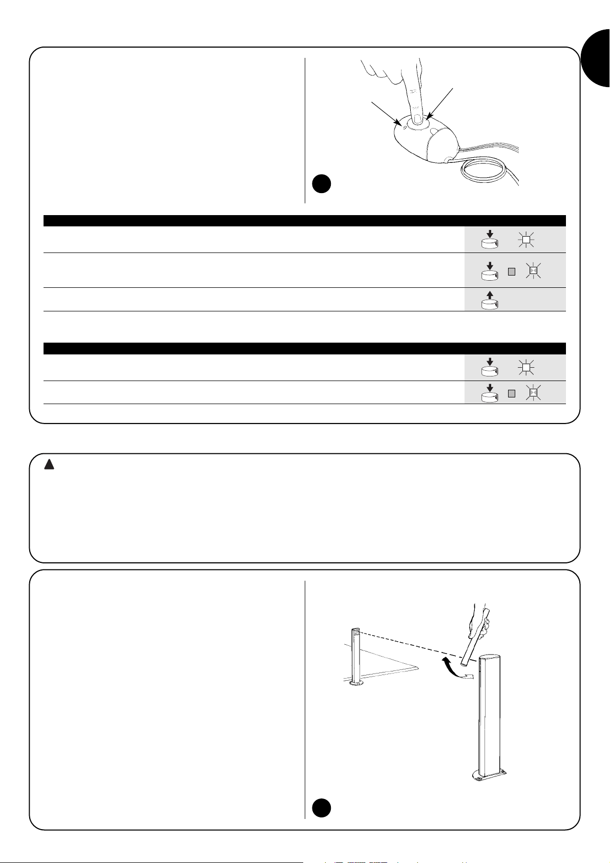
Unit IB is equipped with a LED "L" (see figure 7), the signals of which depend on the operating status.
8) Diagnostics and signals
LED "L" signals Status Action
0.5 seconds ON and
0.5 seconds OFF Normal operation Device healthy
alternately
Off IB not powered or faulty
Check power supply on red and black wires; if voltage is
correct then unit IB is probably faulty.
During the programming phase it is normal for the LED
Steadily illuminated Programming or fault to remain lit for approximately 4 seconds. In other circumstances
this signal probably indicates the presence of a fault.
High frequency flashing As soon as power is connected it is normal for the LED
Initialisation or bluebus excessive to flash at high frequency for approximately 2 seconds.
current draw In other circumstances this signal indicates a bluebus
overload; check connected devices for short circuits or faults.
Check that the photocells are positioned as shown in the
High frequency flash repeated
Negative result of fototest
figures relative to the programming type.
after one second intervals Ensure that no other optical devices are interfering with the
photocells.
Two high frequency flashes
Configuration of devices that are not installed Program unit IB (see chapter 4)
repeated at one second intervals
Three high frequency flashes
The devices currently installed on the bluebus are
If devices have been added to or removed from the system
repeated at one second intervals
different from the devices stored in the memory
the unit must be reprogrammed (see chapter 0)
Four high frequency flashes Data in the IB unit memory (devices) are
Repeat programming procedure (see chapter 4)
repeated at one second intervals
incorrect
Five high frequency flashes Data in the IB unit memory (system type)
Repeat programming procedure (see chapter 4)
repeated at one second intervals
are incorrect
Six high frequency flashes System type programming procedure
Program unit IB (see chapter 4)
repeated at one second intervals
has not been executed
Table 6: LED "L" diagnostics
5.2) Commissioning
Warning: commissioning can take place only after all the test-
ing phases of the automation system have been terminated successfully. It is not permissible to execute partial commissioning or to
enable use of the system in makeshift conditions.
1. Befor e commissioning the automation system inform the owner of
any residual hazards and risks.
2. When creating the technical folder to accompany the automation
system the following documents are mandatory: assembly drawing (e.g. Figure 1), electrical wiring diagram (e.g. Figure 8), risk
analysis and solutions adopted; declaration of conformity of the
manufacturer of all the devices utilised (for unit IB use the “EC
Declaration of Conformity" contained in this manual).
3. Include the maintenance prescriptions for unit IB with the system
maintenance plan (see chapter 6).
!
!
!
Page 9

GB
9
9) Technical specifications
NICE S.p.a. observes a continuous improvement policy and reserves the right to modify the technical specifications at any time without
notice. In such cases specified functionality and intended use will not be affected.
Note: all technical specifications refer to a temperature of 20°C.
Product type : Interface for detectors with bluebus technology and control units for door
and gate automation systems with NC type input
Technology employed : Cyclic polling of installed devices
Power supply : 16÷35 Vdc 18÷28 Vac
Current draw with 24 Vdc power supply : 50mA (add approx. 50mA for each pair of photocells).
Current draw with 24 Vac power supply : 44mA (add approx. 40mA for each pair of photocells).
Bluebus output : One with maximum load of 9 bluebus units
Total length of bluebus cable : 50m
Fototest input power supply : 16÷35 Vdc 18÷28 Vac
Fototest execution time : < di 700ms
Number of outputs : 3 (“foto”, “foto 1”, “foto 2”)
Relay contact rating : 0.5 A max. with 48 Vac/dc max.
Relay contacts lifetime : > 600,000 cycles AC11 or DC11
Enclosure protection rating : IP30
Use in acidic, saline or explosive atmosphere : NO
Operating temperature : -20°C + 55°C
Dimensions / weigh : 86x58x22 mm / 72g
Nice S.p.a. reserves the right to modify its products at any time.
Page 10
3.1) Impianti tipo "una anta"
Nell’automazione di impianti tipo "una anta" le fotocellule possono essere poste come Figura 1 per cancelli scorrevoli oppure come in Figura 2 per portoni sezionali.
Nelle figure si rappresenta il numero massimo di fotocellule possibili ma se ne possono installare anche solo una parte; nella fase di programmazione IB riconoscerà automaticamente i dispositivi effettivamente presenti.
Perché IB possa riconoscere le fotocellule collegate a bluebus è necessario assegnare ad ognuna un indirizzo in base alla funzione svolta.
L’operazione di indirizzamento avviene ponendo i ponticelli come previsto dalla tabella 2 su ogni coppia di TX ed RX.
10
1) Avvertenze:
Il presente manuale è destinato solamente al personale
tecnico qualificato per l'installazione; nessuna informazione contenuta nel presente fascicolo può essere considerata d’interesse per l'utilizzatore finale!
Questo manuale è riferito a IB e non deve essere utilizzato per prodotti diversi.
•L’installazione, il collaudo e la messa in servizio delle automazioni
per porte e cancelli deve essere eseguita da personale qualificato
ed esperto.
• Chi esegue l'installazione deve farsi carico di stabilire le prove pre-
viste in funzione dei rischi presenti e di verificare il rispetto di quanto previsto da leggi, normative e regolamenti.
• Prima di iniziare l’installazione è necessario leggere attentamente
tutte le istruzioni: l’uso improprio o un errore di collegamento
potrebbe pregiudicare la sicurezza o il corretto funzionamento dei
dispositivi.
• Prima di iniziare l'installazione verificare l'idoneità del dispositivo
all'uso richiesto; verificare con particolare attenzione la corrispondenza dei valori riportati nel capitolo "Caratteristiche tecniche"; in
caso contrario IB non può essere usato.
Il dispositivo IB è una interfaccia che consente di collegare rilevatori di
presenza con tecnologia bluebus (fotocellule MOFB e MOFOB) a centrali che prevedono ingressi per contatti tradizionali di tipo NC.
L'unione di IB con MOFB e MOFOB permette di realizzare rilevatori
di presenza (tipo D secondo la norma 12453) utilizzabili in automatismi per cancelli e porte automatiche. Utilizzando la funzione di fototest è possibile raggiungere la categoria 2 di sicurezza ai guasti
secondo la norma EN 954-1.
La tecnologia bluebus consente una facile installazione perché
bastano due fili (senza polarità) per collegare in parallelo tutti i dispositivi; inoltre permette di risolvere il problema dell'interferenza tra i rilevatori attraverso un sistema di sincronismo automatico.
2) Descrizione del prodotto e destinazione d’uso
3) Installazione
L’installazione deve essere eseguita in assenza di tensione all’impianto.
Prima dell'installazione è necessario eseguire l’analisi dei
rischi e valutare quanti rilevatori di presenza sono necessari in base all'impianto da automatizzare.
Il dispositivo IB può essere usato in vari tipi di impianti d’automazione per porte e cancelli, le possibilità di installazione dei rilevatori possono cambiare in funzione dell’impianto; vedere tabella 1 per l'installazione e la programmazione.
!
Tipo di impianto Installazione: vedere capitolo Programmazione: vedere tabella
Cancello "scorrevole"
Portone "sezionale"
3.1 Impianti tipo "una anta" Tabella 5
Cancello ad "ante battenti"
Portone "basculante debordante"
3.2 Impianti tipo "due ante" Tabella 6
Tabella 1
1 2
Page 11
I
11
Tabella 2 Impianti tipo "una anta"
Nota (per FOTO 3): normalmente non è necessario rispettare alcun vincolo nelle posizioni delle coppie di elementi (TX-RX) che compongo-
no le varie fotocellule; solo nel caso venga utilizzata sia la fotocellula FOTO 3 con la fotocellula FOTO II è necessario rispettare la posizione
degli elementi come indicato in figura 3.
Nota A: le fotocellule FOTO, FOTO II, FOTO 1 e FOTO 1 II agiscono sullo stato del relè “foto”, è sufficiente che una delle quattro fotocellule sia oscurata perché IB apra il contatto del relè di uscita “foto”.
Nota B: le fotocellule FOTO 2 e FOTO 2 II agiscono sullo stato del relè “foto 2”, è sufficiente che una delle due fotocellule sia oscurata perché IB apra il contatto del relè “foto 2”.
Nota C: la fotocellula FOTO 3 agisce sullo stato del relè “foto” e “foto 2”, è sufficiente che la fotocellula sia oscurata perché IB apra il contatto dei due relè “foto” e “foto 2”.
Nella configurazione "una anta" l'uscita relè "foto 1" non è usata ed il contatto rimane sempre in posizione NO.
3
TX
TX
RX
RX
TX
Fotocellula Ponticelli Intervento su uscita IB
FOTO
Fotocellula “esterna bassa” su scorrevole o “interna bassa” Relè “foto”
su sezionale con intervento in chiusura. (vedere nota A)
FOTO II
Fotocellula “esterna alta” su scorrevole o “interna alta” Relè “foto”
su sezionale con intervento in chiusura. (vedere nota A)
FOTO 1
Fotocellula “interna bassa” su scorrevole o “esterna bassa” Relè “foto”
su sezionale con intervento in chiusura. (vedere nota A)
FOTO 1 II
Fotocellula “interna alta” su scorrevole o “esterna alta” Relè “foto”
su sezionale con intervento in chiusura. (vedere nota A)
FOTO 2 Fotocellula “esterna” con intervento in apertura.
Relè “foto 2”
(vedere nota B)
FOTO 2 II Fotocellula “interna” con intervento in apertura.
Relè “foto 2”
(vedere nota B)
FOTO 3
Fotocellula “unica” che copre tutto l'automatismo con Sia relè “foto” sia relè “foto 2”
intervento sia in apertura sia in chiusura. (vedere nota C)
Page 12

3.2) Impianti tipo "due ante"
Nell’automazione di impianti tipo "due ante" le fotocellule possono essere poste come in figura 4 per cancelli a due ante battenti oppure come
in figura 5 per portoni basculanti debordanti.
Nelle figure si rappresenta il numero massimo di fotocellule possibili ma se ne possono installare anche solo una parte; nella fase di programmazione IB riconoscerà automaticamente i dispositivi effettivamente presenti.
Perché IB possa riconoscere le fotocellule collegate a bluebus è necessario assegnare ad ognuna un indirizzo in base alla funzione svolta.
L’operazione di indirizzamento avviene ponendo i ponticelli come previsto dalla tabella 3 su ogni coppia di TX ed RX.
12
Tabella 3 Impianti tipo "due ante"
Attenzione: durante la fase di apertura o chiusura il portone non
deve oscurare le fotocellule FOTO 1 e FOTO 1 II.
4
5
Fotocellula Ponticelli Intervento su uscita IB
FOTO
Fotocellula “esterna bassa” su due ante o “interna bassa” Relè “foto”
su basculante debordante con intervento in chiusura. (vedere nota A)
FOTO II
Fotocellula “esterna alta” su due ante o “interna alta” su Relè “foto”
basculante debordante con intervento in chiusura. (vedere nota A)
FOTO 1
Fotocellula "interna bassa" su due ante o "esterna bassa" Relè “foto 1”
su basculante debordante con intervento sia in chiusura (vedere nota B)
sia in apertura.
Fotocellula "interna alta" su due ante o "esterna alta"
Relè “foto 1”
FOTO 1 II su basculante debordante con intervento sia in chiusura
(vedere nota B)
sia in apertura
FOTO 2 Fotocellula “destra” con intervento in apertura.
Relè “foto 2”
(vedere nota C)
FOTO 2 II Fotocellula “sinistra” con intervento in apertura.
Relè “foto 2”
(vedere nota C)
Nota A: le fotocellule FOTO, FOTO II, agiscono sullo stato del relè “foto”, è sufficiente che una delle due fotocellule sia oscurata perché IB
apra il contatto del relè di uscita “foto”.
Nota B: le fotocellule FOTO 1 e FOTO 1 II agiscono sullo stato del relè “foto 1”, è sufficiente che una delle due fotocellule sia oscurata perché IB apra il contatto del relè “foto 1”.
Nota C: le fotocellule FOTO 2 e FOTO 2 II agiscono sullo stato del relè “foto 2”, è sufficiente che una delle due fotocellule sia oscurata perché IB apra il contatto del relè “foto 2”.
Page 13
I
13
6
(Rosso,Nero) Alimentazione 24V
(Blu,Blu) Ingresso fototest
(Grigio,Grigio) Uscita relè Foto (NC)
(Bianco,Bianco) Uscita relè Foto 1 (NC)
(Viola,Viola) Uscita relè Foto 2 (NC)
Cavo bluebus
3.3.1) Descrizione dei collegamenti.
Riportiamo una breve descrizione dei collegamenti elettrici dal dispositivo IB.
Colore cavetti Funzione Descrizione
Rosso,Nero Alimentazione 24V ac/dc Linea di alimentazione 18÷28 Vac; 16÷35 Vdc
Blu,Blu Fototest Ingresso (normalmente attivo) del fototest
Grigio,Grigio Uscita "foto" Uscita contatto pulito del relè “foto” (NC)
Bianco,Bianco Uscita "foto1" Uscita contatto pulito del relè “foto 1” (NC)
Viola,Viola Uscita "foto 2" Uscita contatto pulito del relè “foto 2” (NC)
Tabella 4 Collegamenti
3.3.2) Fototest
IB dispone di un ingresso per eseguire il test, quando la centrale lo
richiede, dell'intero rilevatore di presenza con lo scopo di ottenere la
categoria 2 di sicurezza ai guasti secondo la norma EN 954-1
L’ingresso fototest di IB deve essere collegato all’uscita fototest della centrale; non è necessario rispettare alcuna polarità (vedere esempio in figura 7).
Se la centrale non dispone di fototest oppure non si desidera usarlo, è necessario collegare l’ingresso di fototest alla stessa alimentazione di IB sui fili rosso e nero (vedere esempio in figura 8).
3.3) Collegamenti elettrici
IB dispone di 3 uscite a relè “foto”, “foto 1” e “foto 2” con contatto
normalmente chiuso (NC) predisposte per essere collegate ai rispettivi ingressi delle centrali dell'automazione.
Nel caso la centrale non disponga di uno o più ingressi "foto" è
necessario lasciare liberi i relativi cavetti di uscita di IB e come conseguenza è inutile installare le fotocellule che agirebbero su queste
uscite.
Per il collegamento dei dispositivi bluebus è consigliabile usare cavo
2x0,5mm
2
fino ad una lunghezza di 20m, poi si consiglia di utilizzare
cavo 2x1mm
2
per lunghezze fino a 50m.
Page 14
14
IB
11
MOTORE 2 APRE
GND
MOTORE 1 CHIUDE
MOTORE 1 COMUNE
MOTORE 1 APRE
CORTESIA
LUCE DI
Max 40W
LUX
ALIMENTAZIONE
DA RETE
F
1
N
M1
6
2
3
5
4
7
8
10
9
FOTOTEST
200mA
24 V
FOTO1
MOTORE 2 COMUNE
MOTORE 2 CHIUDE
FOTO
P.P.
ALT
AP
CH
12 Vcc MAX 25 W
COM
ELETTROSERRATURA
SCA
21
M2
15
13
12
18
16
17
19
20
23
22
26
24
25
27
BIANCO
ROSSO
NERO
BLU
BLU
GRIGIO
GRIGIO
VIOLA
BIANCO
VIOLA
3.3.3) Esempio d’utilizzo di IB con centrale A60 e fototest.
La figura 7 è un esempio di collegamento del dispositivo IB ad una centrale A60 con fototest.
IB
11
MOTORE 2 APRE
GND
MOTORE 1 CHIUDE
MOTORE 1 COMUNE
MOTORE 1 APRE
CORTESIA
LUCE DI
Max 40W
LUX
ALIMENTAZIONE
DA RETE
F
1
N
M1
6
2
3
5
4
7
8
10
9
FOTOTEST
200mA
24 V
FOTO1
MOTORE 2 COMUNE
MOTORE 2 CHIUDE
FOTO
P.P.
ALT
AP
CH
12 Vcc MAX 25 W
COM
ELETTROSERRATURA
SCA
21
M2
15
13
12
18
16
17
19
20
23
22
26
24
25
27
BIANCO
ROSSO
NERO
BLU
BLU
GRIGIO
GRIGIO
VIOLA
BIANCO
VIOLA
3.3.4) Esempio d’utilizzo di IB con centrale A60 senza fototest
La figura 8 è un esempio di collegamento del dispositivo IB ad una centrale A60 senza fototest.
7
8
Page 15
I
15
Durante la fase di programmazione IB esegue l’autoapprendimento e
la verifica del corretto funzionamento delle fotocellule collegate a bluebus; tutti i parametri rimangono memorizzati anche in assenza di alimentazione. La programmazione deve essere eseguita in fase di
installazione dell’automazione, oppure ogni volta che si aggiungono o
rimuovono dei dispositivi. Non è necessaria la programmazione quando si sostituiscono delle fotocellule se si mantiene lo stesso indirizzo
dell'originale.
Le due diverse tipologie di automazione, "una anta" e "due ante" devono essere programmate tramite una diversa procedura di programmazione: vedere tabella 5 per "una anta" o tabella 6 per "due ante".
4) Programmazione
Attenzione: il collaudo e la messa in servizio dell’automazione
deve essere eseguita da personale qualificato ed esperto che dovrà
farsi carico di stabilire le prove previste in funzione dei rischi presenti; di verificare il rispetto di quanto previsto da leggi, normative, regolamenti ed in particolare tutti i requisiti della norma EN 12445, la quale stabilisce i metodi di prova per la verifica degli automatismi per
cancelli.
5) Collaudo e messa in servizio
1. Premere e tenere premuto il tasto “P”, dopo circa tre secondi il led “L” si accende
a luce fissa 3s
2. Con il pulsante ancora premuto attendere circa quattro secondi che IB completi
l’apprendimento dei dispositivi collegati, al termine dell’apprendimento il led “L” si spegne e
riprende il normale lampeggio 4s
3. Rilasciare il pulsante “P”
Nota: per gli impianti tipo "una anta" il legame tra le fotocellule ed i relè è riportato in tabella 2
P
P
P
Tabella 5 Programmazione tipo "una anta" Esempio
1. Premere e tenere premuto il tasto “P”, dopo circa tre secondi il led “L” si accende a luce
fissa, quindi rilasciare il tasto. 3s
2. Attendere circa quattro secondi che IB completi l’apprendimento dei dispositivi collegati, al
termine dell’apprendimento il led “L” si spegne e riprende il normale lampeggio. 4s
Nota: per gli impianti tipo "due ante" il legame tra le fotocellule ed i relè è riportato in tabella 3
P
Tabella 6 Programmazione tipo "due ante" Esempio
P
5.1) Collaudo
Il collaudo è la fase più importante nella realizzazione dell’automazione al fine di garantire la massima sicurezza.
Il collaudo può essere usato anche come verifica periodica dei
dispositivi che compongono il sistema.
1. Verificare che sia stato rispettato rigorosamente quanto previsto
nel capitolo 1 “AVVERTENZE”.
2. Verificare il perfetto funzionamento delle fotocellule ed in partico-
lare che non vi siano interferenze con altri dispositivi. Passare un
cilindro di diametro 5cm e lunghezza 30 cm sull’asse ottico prima
vicino al TX, poi vicino al RX e infine al centro tra i due e verificare che in tutti i casi il dispositivo intervenga passando dallo stato
di attivo a quello di allarme e viceversa.
3. Verificare che, per ogni intervento di fotocellula, la centrale ese-
gua l'operazione prevista; ad esempio intervenendo su FOTO nella manovra di chiusura avvenga l'inversione del movimento.
9
10
“P” Pulsante per programmazione
“L” Led
!
Page 16

16
Attenzione: la manutenzione deve essere effettuata nel pieno
rispetto delle prescrizioni sulla sicurezza del presente manuale e
secondo quanto previsto dalle leggi e normative vigenti.
1. Verificare periodicamente, almeno ogni 6 mesi, il dispositivo IB e
le relative fotocellule. A tale scopo eseguire per intero le prove e
le verifiche previste nel paragrafo “5.1 Collaudo”.
2. Nel dispositivo IB verificare che non ci sia la presenza di tracce
che possano indicare rischi di non perfetto stato di conservazione, ad esempio tracce di umidità, ossidi, ecc. In questo caso IB
va sostituito.
3. Il dispositivo IB è stato studiato per funzionare in condizioni normali almeno 10 anni, è quindi opportuno intensificare la frequenza di manutenzione trascorso questo periodo.
6) Manutenzione
Attenzione: alcuni componenti potrebbero contenere sostanze
inquinanti, non disperdere nell’ambiente.
Questo prodotto è costituito da vari tipi di materiali, alcuni dei quali
possono essere riciclati. Informatevi sui sistemi di riciclaggio o smaltimento del prodotto attenendovi alle norme di legge vigenti a livello
locale.
7) Smaltimento
Sul dispositivo IB è presente un led "L" (vedere figura 7) che fornisce delle segnalazioni luminose in base allo stato di funzionamento.
8) Diagnostica e segnalazioni
Segnalazione Led L Stato Azione
0,5 secondi ON e
0,5 secondi OFF Funzionamento normale Tutto OK
alternativamente
Spento IB non alimentato oppure guasto
Verificare la tensione sui cavetti rosso e nero, se la tensione è
corretta è probabile che IB sia guasto
Durante la fase di programmazione è normale che il led
Acceso fisso Programmazione oppure guasto rimanga acceso per circa 4 secondi
Altrimenti è probabile ci sia un guasto
Lampeggio veloce Appena data alimentazione è normale un lampeggio veloce
Inizializzazione oppure assorbimento di per circa 2 secondi
corrente eccessivo nel "bluebus" Altrimenti c'è un sovraccarico nel "bluebus"; controllare che
non ci siano cortocircuiti o guasti sui dispositivi collegati
Controllare di aver posizionato le fotocellule come indicato
Un lampeggio veloce
Esito negativo nel fototest
nelle figure relative alla programmazione.
ripetuto dopo un secondo Controllare che non ci siano altri dispositivi ottici che
interferiscono con le fotocellule.
Due lampeggi veloci ripetuti
Configurazione dispositivi assente Eseguire la programmazione (vedi capitolo 4)
dopo un secondo
Tre lampeggi veloci ripetuti I dispositivi attualmente presenti sul Se sono stati aggiunti o tolti dei dispositivi è necessario
dopo un secondo bluebus sono diversi da quelli memorizzati rifare la programmazione (vedi capitolo 4)
Quattro lampeggi veloci I dati nella memoria di IB (dispositivi)
Si consiglia di rifare la programmazione (vedi capitolo 4)
ripetuti dopo un secondo non sono corretti
Cinque lampeggi veloci I dati nella memoria di IB (tipo impianto)
Si consiglia di rifare la programmazione (vedi capitolo 4)
ripetuti dopo un secondo non sono corretti
Sei lampeggi veloci ripetuti La programmazione del tipo di impianto
Eseguire la programmazione (vedi capitolo 4)
dopo un secondo non è mai stata eseguita
Tabella 6 diagnostica led "L"
5.2) Messa in servizio
Attenzione: la messa in servizio può avvenire solo dopo aver
eseguito con esito positivo tutte le fasi di collaudo dell'automazione.
Non è consentita la messa in servizio parziale o in situazioni “provvisorie”.
1. Prima di mettere in servizio l’automatismo informare adeguatamente il proprietario sui pericoli ed i rischi eventualmente ancora
presenti.
2. Nel realizzare il fascicolo tecnico dell’automazione si dovrà comprendere almeno: disegno complessivo (ad esempio Figura 1),
schema dei collegamenti elettrici (ad esempio Figura 8), analisi dei
rischi e relative soluzioni adottate; la dichiarazione di conformità
del fabbricante di tutti i dispositivi utilizzati (per IB utilizzare la
“Dichiarazione CE di conformità" presente su questo manuale).
3. Nel piano di manutenzione inserire le prescrizioni sulla manutenzione di IB (vedere capitolo 6).
!
!
!
Page 17

I
17
9) Caratteristiche tecniche
Allo scopo di migliorare i prodotti, NICE S.p.A. si riserva il diritto di modificare le caratteristiche tecniche in qualsiasi momento e senza
preavviso, garantendo comunque funzionalità e destinazione d’uso previste.
Nota: tutte le caratteristiche tecniche sono riferite alla temperatura di 20°C.
Tipo di prodotto : Interfaccia per rilevatori di presenza con tecnologia bluebus e centrali per
automazione di porte e cancelli con ingresso tipo NC
Tecnologia adottata : Interrogazione ciclica dei dispositivi presenti
Alimentazione : 16÷35 Vdc 18÷28 Vac
Assorbimento con alimentazione 24 Vdc : 50mA (aggiungere circa 50mA per ogni coppia di fotocellule).
Assorbimento con alimentazione 24 Vac : 44mA (aggiungere circa 40mA per ogni coppia di fotocellule).
Uscita bluebus : Una con un carico massimo di 9 unità bluebus
Lunghezza massima complessiva cavo bluebus : 50m
Alimentazione Ingresso fototest : 16÷35 Vdc 18÷28 Vac
Tempo per l'esecuzione del fototest : < di 700ms
Numero uscite : 3 (“foto”, “foto 1”, “foto 2”)
Caratteristica contatti relè : Massimo 0.5 A con massimo 48 Vac/dc
Durata contatti relè : > a 600.000 interventi AC11 o DC11
Grado di protezione contenitore : IP30
Utilizzo in atmosfera acida, salina o potenzialmente esplosiva : NO
Temperatura di esercizio : -20°C + 55°C
Dimensioni / peso : 86x58x22 mm / 72g
Nice S.p.a. si riserva il diritto di apportare modifiche ai prodotti in qualsiasi momento riterrà necessario
Page 18

18
3.1) Automatismes type “un élément”
Dans les automatismes type “un élément” les photocellules peuvent être disposées comme dans la Figure 1 pour les portails coulissants ou
bien comme dans la Figure 2 pour les portes sectionnelles.
Dans les figures, on représente le nombre maximum de photocellules possibles mais on peut n’en installer qu’une partie; en phase de programmation, IB reconnaîtra automatiquement les dispositifs effectivement présents.
Pour qu’IB puisse reconnaître les photocellules connectées à bluebus il faut attribuer à chacune d’elle une adresse suivant la fonction exercée. L’opération d’adressage s’effectue en plaçant les cavaliers suivant les indications du tableau 2 sur chaque paire de TX et RX.
1) Avertissements:
Ce manuel est destiné exclusivement au personnel technique qualifié pour l’installation; aucune information
contenue dans ce fascicule ne peut être considérée comme intéressante pour l’utilisateur final!
Ce manuel se réfère à IB et ne doit pas être utilisé pour
des produits différents.
•L’installation, l’essai et la mise en service des automatismes pour
portes et portails doit être effectuée par du personnel qualifié et
expérimenté.
• Qui effectue l’installation doit se charger d’établir les essais prévus
en fonction des risques présents et de vérifier le respect de ce qui
est prévu par les lois, les normes et les réglementations.
•Avant de commencer l’installation, il faut lire attentivement toutes
les instructions: l’utilisation impropre ou une erreur de connexion
pourrait compromettre la sécurité ou le fonctionnement correct
des dispositifs.
•Avant de commencer l’installation, vérifier que le dispositif est
adapté à l’application souhaitée; vérifier en particulier la correspondance des valeurs indiquées dans le chapitre “Caractéristiques
techniques”; en cas contraire, IB ne peut pas être utilisé.
Le dispositif IB est une interface qui permet de connecter des détecteurs de présence avec technologie bluebus (photocellules MOFB et
MOFOB) à des logiques de commande qui prévoient des entrées pour
contacts traditionnels de type NC.
L'union d’IB avec MOFB et MOFOB permet de réaliser des détecteurs de présence (type D selon la norme 12453) utilisables dans
des automatismes pour portails et portes automatiques. En utilisant
la fonction de fototest, il est possible d’atteindre la catégorie 2 de
sécurité aux pannes selon la norme EN 954-1.
La technologie bluebus permet une installation aisée car il suffit de
deux fils (sans polarité) pour connecter en parallèle tous les dispositifs; en outre, cela permet de résoudre le problème de l’interférence
entre les détecteurs à travers un système de synchronisme automatique.
2) Description du produit et application
3) Installation
Attention: l’installation doit être effectuée en l’absence
de tension dans l’installation.
Attention: avant l’installation, il faut effectuer l’analyse
des risques et évaluer combien de détecteurs de présence sont nécessaires suivant l’installation à automatiser.
Le dispositif IB peut être utilisé dans différents types d’automatismes
de portes et de portails, les possibilités d’installation des détecteurs
peuvent changer en fonction de l’installation; voir tableau 1 pour
l’installation et la programmation.
!
Type d’automatisme Installation: voir chapitre Programmation: voir tableau
Portail “coulissant”
Porte “sectionnelle”
3.1 Automatismes type “un élément” Tableau 5
Portail à “battants”
Porte “basculante débordante”
3.2 Automatismes type “deux éléments” Tableau 6
Tableau 1
1 2
Page 19

F
19
Tableau 2 Automatismes type “un élément”
NOTE (pour FOTO 3): normalement il n’y a aucune contrainte à respecter dans le positionnement des paires d’éléments (TX-RX) qui com-
posent les différentes photocellules; uniquement si on utilise la photocellule FOTO 3 avec la photocellule FOTO II, il faut respecter la position
des éléments comme l’indique la figure 3.
Note A: les photocellules FOTO, FOTO II, FOTO 1 et FOTO 1 II agissent sur l’état du relais “foto”, il suffit que l’une des quatre photocellules
soit obscurcie pour qu’IB ouvre le contact du relais de sortie “foto”.
Note B: les photocellules FOTO 2 et FOTO 2 II agissent sur l’état relais “foto 2”, il suffit que l’une des deux photocellules soit obscurcie pour
qu’IB ouvre le contact du relais “foto 2”.
Note C: la photocellule FOTO 3 agit sur l’état du relais “foto” et “foto 2”, il suffit que la photocellule soit obscur cie pour qu’IB ouvr e le contact
des deux relais “foto” et “foto 2”.
Dans la configuration “un élément” la sortie relais “foto 1” n’est pas utilisée et le contact reste toujours en position NO.
3
TX
TX
RX
RX
TX
Photocellule Ponticelli Cavaliers Intervention sur sortie IB
Photocellule “extérieure basse” sur portail coulissant ou
Relais “foto”
FOTO “intérieure basse” sur porte sectionnelle avec intervention
(voir note A)
en fermeture.
Photocellule “extérieure haute” sur portail coulissant ou
Relais “foto”
FOTO II “intérieure haute” sur porte sectionnelle avec intervention
(voir note A)
en fermeture.
Photocellule “intérieure basse” sur portail coulissant ou
Relais “foto”
FOTO 1 “extérieure basse” sur porte sectionnelle avec intervention
(voir note A)
en fermeture.
Photocellule “intérieure haute” sur portail coulissant ou
Relais “foto”
FOTO 1 II “extérieure haute” sur porte sectionnelle avec intervention
(voir note A)
en fermeture
FOTO 2 Photocellule “extérieure” avec intervention en ouverture.
Relais “foto 2”
(voir note B)
FOTO 2 II Photocellule “intérieure” avec intervention en ouverture.
Relais “foto 2”
(voir note B)
FOTO 3
Photocellule “unique” couvrant tout l’automatisme avec
Aussi bien relais “foto” que relais “foto 2”
avec intervention aussi bien en ouverture qu’en fermeture (voir note C)
Page 20

20
3.2) Automatismes type “deux éléments”.
Dans les automatismes type “deux éléments” les photocellules peuvent être placées comme dans la figure 4 pour les portails à deux battants ou comme dans la figure 5 pour les portes basculantes débordantes.
Dans les figures, on représente le nombre maximum de photocellules possibles mais on peut n’en installer qu’une partie; en phase de programmation, IB reconnaîtra automatiquement les dispositifs effectivement présents.
Pour qu’IB puisse reconnaître les photocellules connectées à bluebus il faut attribuer à chacune d’elle une adresse suivant la fonction exercée. L’opération d’adressage s’effectue en plaçant les cavaliers suivant les indications du tableau 3 sur chaque paire de TX et RX.
Tableau 3: Automatismes type “deux éléments”
Attention: durant la phase d’ouverture ou de fermeture, la porte
ne doit pas obscurcir les photocellules FOTO 1 et FOTO 1 II.
4
5
Photocellule Cavaliers Intervention sur sortie IB
Photocellule “extérieure basse” sur deux éléments ou
Relais “foto”
FOTO “intérieure basse” sur porte basculante débordante avec
(voir note A)
intervention en fermeture.
Photocellule “extérieure haute” sur deux éléments ou
Relais “foto”
FOTO II ou “intérieure haute” sur porte basculante débordante avec
(voir note A)
intervention en fermeture.
Photocellule “intérieure basse” sur deux éléments ou
Relais “foto 1”
FOTO 1 “extérieure basse” sur porte basculante débordante avec
(voir note B
)
intervention en fermeture et en ouverture.
Photocellule “intérieure haute” sur deux éléments ou
Relais “foto 1”
FOTO 1 II “extérieure haute” sur porte basculante débordante avec
(voir note B)
intervention en fermeture et enouverture.
FOTO 2 Photocellule “droite” avec intervention en ouverture.
Relais “foto 2”
(voir note C)
FOTO 2 II Photocellule “gauche” avec intervention en ouverture.
Relais “foto 2”
(voir note C)
Note A: lles photocellules FOTO, FOTO II, agissent sur l’état du relais “foto”, il suffit que l’une des deux photocellules soit obscurcie pour
qu’IB ouvre le contact du relais de sortie “foto”.
Note B: les photocellules FOTO 1 et FOTO 1 II agissent sur l’état du relais “foto 1”, il suffit que l’une des deux photocellules soit obscurcie
pour qu’IB ouvre le contact du relais “foto 1”.
Note C: les photocellules FOTO 2 et FOTO 2 II agissent sur l’état du relais “foto 2”, il suffit que l’une des deux photocellules soit obscurcie
pour qu’IB ouvre le contact du relais “foto 2”.
Page 21

F
21
6
(Rouge, Noir) Alimentation 24V
((Bleu, Bleu) Entrée fototest
(Gris, Gris) Sortie relais “foto” (NC)
(Blanc, Blanc) Sortie relais “foto 1” (NC)
(Violet, Violet) Sortie relais “foto 2” (NC)
Câble bluebus
3.3.1) Description des connexions.
Nous donnons une brève description des connexions électriques du dispositif IB.
Couleur câbles Fonction Description.
Rouge, Noir Alimentation 24 Vac/dc Ligne d’alimentation 18 ÷ 28 Vac; 16 ÷ 35 Vdc
Bleu, Bleu Fototest Entrée (normalement active) du fototest
Gris, Gris Sortie “foto” Sortie contact sans potentiel du relais “foto” NC
Blanc, Blanc Sortie “foto1” Sortie contact sans potentiel du relais “foto 1” NC
Violet, Violet Sortie “foto 2” Sortie contact sans potentiel du relais “foto 2” NC
Tableau 4: Connexions
3.3.2) Fototest
IB dispose d’une entrée pour effectuer le test, quand la logique de
commande le demande, de tout le détecteur de présence, dans le
but d’obtenir la catégorie 2 de sécurité aux pannes selon la norme
EN 954-1
L’entrée fototest d’IB doit être connectée à la sortie fototest de la
logique de commande; il n’est pas nécessaire de respecter une
polarité quelconque (voir exemple figure 7). Si la logique de commande ne dispose pas de fototest ou si l’on ne souhaite pas l’utiliser, il faut connecter l’entrée de fototest à l’alimentation d’IB sur les
conducteurs rouge et noir (voir exemple figure 8).
3.3) Connexions électriques.
IB dispose de 3 sorties à relais “foto”, “foto 1” et “foto 2” avec
contact normalement fermé (NC) prévues pour être connectées aux
entrées respectives des logiques de commande de l’automatisme.
Si la logique de commande ne dispose pas d’une ou plusieurs
entrées “foto” il faut laisser libres les câbles de sortie correspondants
sur IB et il est donc inutile d’installer les photocellules qui agiraient
sur ces sorties.
Pour la connexion des dispositifs bluebus, il est conseillé d’utiliser un
câble de2x0,5mm
2
jusqu’à une longueur de 20m, et un câble de
2x1mm
2
pour les longueurs jusqu’à 50m.
Page 22

22
IB
11
MOTEUR 2 OUVRE
GND
MOTEUR 1 FERME
MOTEUR 1 COMMUN
MOTEUR 1 OUVRE
AUTOMATIQUE
ÈCLAIRAGE
Max 40W
CLIGNOTANT
ALIMENTATION
F
1
N
M1
6
2
3
5
4
7
8
10
9
FOTOTEST
200mA
24 V
FOTO1
MOTEUR 2 COMMUN
MOTEUR 2 FERME
FOTO
P.P.
HALTE
OUVRE
FERME
12 Vcc MAX 25 W
COMMUN
SERRURE ELÈCTRIQUE
SCA
21
M2
15
13
12
18
16
17
19
20
23
22
26
24
25
27
Blanc
Rouge
Noir
Bleu
Bleu
Gris
Gris
Violet
Blanc
Violet
3.3.3) Exemple d’utilisation d’IB avec logique de commande A60 et fototest.
La figure 7 est un exemple de connexion du dispositif IB à une logique de commande A60 avec fototest.
IB
11
MOTEUR 2 OUVRE
GND
MOTEUR 1 FERME
MOTEUR 1 COMMUN
MOTEUR 1 OUVRE
AUTOMATIQUE
ÈCLAIRAGE
Max 40W
Clignotant
ALIMENTATION
F
1
N
M1
6
2
3
5
4
7
8
10
9
FOTOTEST
200mA
24 V
FOTO1
MOTEUR 2 COMMUN
MOTEUR 2 FERME
FOTO
P.P.
HALTE
OUVRE
FERME
12 Vcc MAX 25 W
COMMUN
SERRURE ELÈCTRIQUE
SCA
21
M2
15
13
12
18
16
17
19
20
23
22
26
24
25
27
Blanc
Rouge
Noir
Bleu
Bleu
Gris
Gris
Violet
Blanc
Violet
3.3.4) Exemple d’utilisation d’IB avec logique de commande A60 sans fototest.
La figure 8 est un exemple de connexion du dispositif IB à une logique de commande A60 sans fototest.
7
8
Page 23

F
23
Durant la phase de programmation, IB effectue l’auto-apprentissage
et la vérification du fonctionnement correct des photocellules
connectées à bluebus; tous les paramètres restent en mémoire
même en l’absence de tension. La programmation doit être effectuée en phase d’installation de l’automatisme ou à chaque fois que
l’on ajoute ou que l’on supprime des dispositifs. Il n’est pas nécessaire de procéder à la programmation quand on remplace des photocellules si l’on maintient la même adresse que l’originale.
Les deux différents types d’automatismes, “un élément” et “deux éléments”
doivent être programmés avec une procédure de programmation différente: voir tableau 5 pour “un élément” ou tableau 6 pour “deux éléments”.
4) Programmation.
Attention: l’essai et la mise en service de l'automatisme doi-
vent être effectués par du personnel qualifié et expérimenté qui
devra se charger d’établir les essais prévus en fonction des risques
présents; de vérifier le respect de ce qui est prévu par les lois, les
normes et les réglementations et en particulier, de toutes les conditions requises par la norme EN 12445, qui établit les méthodes d’essai pour le contrôle des automatismes pour portails.
5) Essai et mise en service
1. Presser et maintenir enfoncée la touche “P”, au bout d’environ
trois secondes la led “L” s’allume avec lumière fixe 3s
2. Tout en continuant à presser la touche, attendre environ quatre secondes qu’IB complète
l’apprentissage des dispositifs connectés, à la fin de l’apprentissage la led “L” s’éteint et
reprend le clignotement normal 4s
3. Relâcher la touche “P”.
Note: pour les automatismes type “un élément” le lien entre les photocellules et les relais est indiqué dans le tableau 2
P
P
P
Tableau 5 Programmation type “un élément” Exemple
1. Presser et maintenir enfoncée la touche “P”, au bout d’environ trois secondes
la led “L” s’allume avec lumière fixe, puis relâcher la touche. 3s
2. Attendre environ quatre secondes qu’IB complète l’apprentissage des dispositifs connectés,
à la fin de l’apprentissage la led “L” s’éteint et reprend le clignotement normal. 4s
Note: pour les automatismes type “deux éléments” le lien entre les photocellules et les relais est indiqué dans le tableau 3.
P
Tableau 6 Programmation type “deux éléments” Exemple
P
5.1) Essai
L’essai est la phase la plus importante dans la réalisation de l’automatisation et représente la condition sine qua non pour garantir la sécurité
maximum.
L’essai peut être utilisé également comme vérification périodique des dispositifs qui composent le système.
1. Vérifier que les consignes figurant dans le chapitre 1 “AVERTISSE-
MENTS” ont été rigoureusement respectées.
2. Vérifier le parfait fonctionnement des photocellules et en particulier
qu’il n’y a pas d’interférences avec d’autres dispositifs. Passer un
cylindre d’un diamètre de 5 cm et d’une longueur de 30 cm sur l’axe
optique, d’abord à proximité de TX, puis de RX, et enfin au centre
entre les deux et vérifier que dans tous les cas, le dispositif intervient
en passant de l’état d’actif à l’état d’alarme et vice versa.
3. Vérifier que, pour chaque intervention de photocellule, la logique effec-
tue l’opération prévue; par exemple en intervenant sur FOTO dans la
manœuvre de fermeture l’inversion du mouvement s’effectue.
9
10
Touche de programmation
“L” led “P”
!
Page 24

24
Attention: la maintenance doit être effectuée dans le plein res-
pect des consignes de sécurité du présent manuel et suivant les
prescriptions des lois et normes en vigueur.
1. Vérifier périodiquement, au moins tous les 6 mois, le dispositif IB
et les photocellules correspondantes. Pour cela, effectuer tous
les essais et contrôles prévus au paragraphe “5.1 Essai”.
2. Dans le dispositif IB vérifie qu’il n’y a pas de traces qui pourraient
indiquer le risque d’un mauvais état de conservation, par exemple
des traces d’humidité, d’oxydes, etc. Dans ce cas, IB doit être
remplacé.
3. Le dispositif IB a été étudié pour fonctionner dans des conditions
normales au moins 10 ans, il est donc bon d’intensifier la fréquence des contrôles de maintenance passée cette période.
6) Maintenance
Attention: certains composants électroniques pourraient contenir
des substances polluantes, ne pas les abandonner dans la nature.
Ce produit est constitué de différents types de matériaux dont certains peuvent être recyclés. Informez-vous sur les systèmes de recyclage ou de mise au rebut du produit en respectant les normes
locales en vigueur.
7) Mise au rebut
Sur le dispositif IB est présente une led “L” (voir figure 7) qui émet des signaux lumineux suivant l’état de fonctionnement.
8) Diagnostic et signalisations
Signalisation Led L État Action
0,5 seconde ON et
0,5 seconde OFF Fonctionnement normal. Tout OK
alternativement
Éteinte IB non alimenté ou en panne.
Vérifier la tension sur les câbles rouge et noir, si la tension est
correcte, IB est probablement en panne.
Durant la phase de programmation, il est normal que la led
Allumée fixe Programmation ou panne reste allumée pendant environ 4 secondes.
Autrement, il y a probablement une panne.
Clignotement rapide Juste après avoir alimenté le dispositif, un clignotement
Initialisation ou absorption de rapide d’environ 2 secondes est normal. Autrement, il y a
courant excessive dans le bluebus surcharge dans le bluebus; contrôler qu’il n’y a pas de
courts-circuits ou de pannes sur les dispositifs connctés.
Contrôler d’avoir positionné les photocellules suivant les
Un clignotement rapide
Résultat négatif du fototest
indications des figures relatives à la programmation. Contrôler
répété après une seconde qu’il n’y a pas d’autres dispositifs optiques qui
interfèrent avec les photocellules.
Deux clignotements rapides
Configuration dispositifs absente Effectuer la programmation (voir chapitre 4)
répétés après une seconde
Trois clignotements rapides Les dispositifs actuellement présents sur le Si des dispositifs ont été ajoutés ou supprimés
répétés après une seconde
bluebus sont différents de ceux qui sont mémorisés
il faut refaire la programmation (voir chapitre 4)
Quatre clignotements rapides Les données dans la mémoire d’IB
Il est conseillé de refaire la programmation (voir chapitre 4)
répétés après une seconde (dispositifs) ne sont pas correctes
Cinq clignotements rapides Les données dans la mémoire d’IB
Il est conseillé de refaire la programmation (voir chapitre 4)
répétés après une seconde type d’automatisme) ne sont pas correctes
Six clignotements rapides La programmation du type d’automatisme
Effectuer la programmation (voir chapitre 4)
répétés après une seconde n’a jamais été effectuée.
Tableau 6 diagnostic led “L”
5.2) Mise en service
Attention: la mise en service peut se faire seulement après
avoir effectué avec résultat positif toutes les phases d’essai de l’automatisme. La mise en service partielle ou dans des situations “provisoires” n’est pas autorisée.
1. Avant de mettre en service l’automatisme, informer de manière
adéquate le propriétaire sur les dangers et les risques qui sont
éventuellement encore présents.
2. Le fascicule technique de l’automatisme devra comprendre: vue
d’ensemble (par exemple Figure 1), schéma des connexions
électriques (par exemple Figure 8), analyse des risques et des
solutions adoptées; déclaration de conformité du fabricant de
tous les dispositifs utilisés (pour IB utiliser la “Déclaration CE de
conformité” présente dans ce manuel).
3. Dans le plan de maintenance, insérer les prescriptions sur la
maintenance d’IB (voir chapitre 6).
!
!
!
Page 25

F
25
9) Caractéristiques techniques
Dans le but d’améliorer ses produits, NICE S.p.A. se réserve le droit de modifier les caractéristiques techniques à tout moment et sans
préavis, en garantissant dans tous les cas le bon fonctionnement et le type d’utilisation prévus.
N.B.: toutes les caractéristiques techniques se réfèrent à la température de 20°C.
Type de produit : I
nterface pour les détecteurs de présence avec technologie bluebus et logiques
de commande pour l’automatisation de portes et de portails avec entrée type NC
Technologie adoptée : Interrogation cyclique des dispositifs présents
Alimentation : 16÷35 Vdc 18÷28 Vac
Absorption avec alimentation 24 Vdc : 50mA (ajouter environ 50 mA pour chaque paire de photocellules).
Absorption avec alimentation 24 Vac : 44mA (ajouter environ 40 mA pour chaque paire de photocellules).
Sortie bluebus : Une avec une charge maximum de 9 unités bluebus
Longueur maximum totale câble bluebus : 50m
Alimentazione Ingresso fototest : 16÷35 Vdc 18÷28 Vac
Alimentation Entrée fototest : < à 700ms
Nombre de sorties : 3 (“foto”, “foto 1”, “foto 2”)
Caractéristique contacts relais : Maximum 0.5 A avec maximum 48 Vac/dc
Durée contacts relais : > à 600.000 interventions AC11 ou DC11
Indice de protection boîtier : IP30
Utilisation en atmosphère acide, saline ou potentiellement explosive
: Non
Température de service : -20°C + 55°C
Dimensions / poids : 86x58x22 mm / 72g
Nice S.p.a. se réserve le droit d’apporter des modifications aux produits à tout moment si elle le jugera nécessaire.
Page 26

26
3.1) Anlagen mit "einem Flügel"
Bei der Automatisierung von Anlagen mit "einem Flügel" können die Photozellen für Schiebetore wie in Abbildung 1 angebracht werden, oder
für Sektionaltore wie in Abbildung 2.
Auf den Abbildungen ist die Höchstmenge an Photozellen gezeigt, es kann aber auch nur ein Teil dieser Photozellen installiert werden; bei
der Programmierung wird IB die effektiv vorhandenen Vorrichtungen automatisch erkennen.
Damit IB die am Bluebus angeschlossenen Photozellen erkennen kann, muss jeder Photozelle je nach ausgeübter Funktion eine Adresse
zugeteilt werden. Die Adressierung erfolgt, indem die Überbrückungen gemäß der Tabelle 2 auf jedes TX und RX Paar gelegt werden.
1) Hinweise:
Die vorliegende Anleitung ist nur für technisches Personal
bestimmt, das für die Installation qualifiziert ist. Keine im
vorliegenden Heft enthaltene Information kann als interessant für den Endbenutzer betrachtet werden! Die vorliegende
Anleitung bezieht sich auf das Produkt IB und darf für andere Produkte nicht benutzt werden.
• Installation, Endprüfung und Inbetriebsetzung der Automatisierungen
für Türen und Tore müssen von erfahrenem Fachpersonal ausgeführt
werden
.
• Derjenige, der die Installation ausführt, muss bestimmen, welche Tests je
nach vorhandenen Risiken auszuführen sind, und er muss prüfen, dass
gesetzliche Verordnungen, Vorschriften und Regelungen eingehalten sind.
•Vor Beginn der Installation müssen alle Anweisungen genau gelesen werden: unsachgemäße Bedienung oder Anschlussfehler
könnten die Sicherheit oder den korrekten Betrieb der Vorrichtungen beeinträchtigen.
•Vor Beginn der Installation ist zu prüfen, ob die Vorrichtung für den
gewünschten Einsatz geeignet ist; besonders genau prüfen, dass
die Werte in Kapitel “Technische Merkmale” übereinstimmen,
andernfalls kann das Produkt IB nicht benutzt werden.
Die Vorrichtung IB ist eine Schnittstelle, mit der Präsenzdetektoren mit
Bluebus Technologie (Photozellen MOFB und MOFOB) an Steuerungen angeschlossen werden können, die mit konventionellen NC-Kontakten versehen sind.
Dank der Vereinigung von IB mit MOFB und MOFOB entstehen Präsenzdetektoren (Typ D gemäß Norm 12453), die an Torautomatismen und automatischen Türen benutzt werden können. Mit der
Funktion fototest kann gemäß Norm EN 954-1 die Sicherheitskate-
gorie 2 gegen Defekte erreicht werden.
Die bluebus Technologie ermöglicht eine einfache Installation, da nur
zwei Drähte (ohne Polung) genügen, um alle Vorrichtungen parallel
anzuschließen; weiterhin kann mit ihr durch ein automatisches Synchrosystem das Interferenzproblem zwischen Detektoren gelöst
werden.
2) Beschreibung des Produktes und Einsatz
3) Installation.
Achtung: die Installation muss ohne Spannung zur
Anlage ausgeführt werden.
Achtung: vor der Installation ist die Risikoanalyse auszuführen; weiterhin ist zu bewerten, wie viele Präsenzdetektoren für die zu automatisierende Anlage notwendig sind.
Die Vorrichtung IB kann an verschiedenen Typen von Automatisierungsanlagen für Türen und Tore eingesetzt werden; die Installationsmöglichkeiten der Detektoren können je nach Anlage unterschiedlich sein. Siehe Tabelle 1 für Installation und Programmierung.
!
Anlagentyp Installation: siehe Kapitel Programmierung: siehe Tabelle
“Schiebetor“
“Sektionaltor”
3.1 Anlagen mit "einem Flügel" Tabelle 5
Tor mit "anschlagenden Flügeln"
"Ausfahrendes Schwingtor
3.2 Anlagen mit "zwei Flügeln" Tabelle 6
Tabelle 1
1 2
Page 27

D
27
Tabelle 2 Anlagen mit "einem Flügel"
ANMERKUNG (für FOTO 3): gewöhnlich sind keine besonderen Stellungen der Paare der Photozellenelemente (TX-RX) einzuhalten; nur
wenn sowohl die Photozelle FOTO 3 als auch die Photozelle FOTO II benutzt werden, muss die Stellung der Elemente wie in Abbildung 3
sein.
Anmerkung A: die Photozellen FOTO, FOTO II, FOTO 1 und FOTO 1 II wirken auf den Status des Relais “foto” ein; es genügt, dass eine
der vier Photozellen verdunkelt wird, damit IB den Kontakt des Ausgangsrelais “foto” öffnet.
Anmerkung B: die Photozellen FOTO 2 und FOTO 2 II wirken auf den Status des Relais “foto 2”, ein; es genügt, dass eine der zwei Photozellen verdunkelt wird, damit IB den Kontakt des Relais “foto 2” öffnet.
Anmerkung C: Anmerkung C: die Photozelle FOTO 3 wirkt auf den Status des Relais “foto” und “foto 2” ein; es genügt, dass die Photozelle verdunkelt wird, damit IB den Kontakt der beiden Relais “foto” und “foto 2” öffnet.
In der Gestaltung mit "einem Flügel" ist der Relaisausgang "foto 1" nicht benutzt, und der Kontakt bleibt immer in der NO-Position.
3
TX
TX
RX
RX
TX
Photozelle
Überbrückungen
Auslösung an Ausgang IB
FOTO
Photozelle “außen unten” an Schiebetor oder “innen unten” Relais “foto”
an Sektionaltor mit Auslösung in Schließung. (siehe Anmerkung A)
FOTO II
Photozelle “außen oben” an Schiebetor oder “innen oben” Relais “foto”
an Sektionaltor mit Auslösung in Schließung. (siehe Anmerkung A)
FOTO 1
Photozelle “innen unten” an Schiebetor oder “außen unten” Relais “foto”
an Sektionaltor mit Auslösung in Schließung. (siehe Anmerkung A)
FOTO 1 II
Photozelle “innen oben” an Schiebetor oder “außen oben” Relais “foto”
an Sektionaltor mit Auslösung in Schließung. (siehe Anmerkung A)
FOTO 2 FPhotozelle “außen” mit Auslösung in Öffnung.
Relais “foto 2”
(siehe Anmerkung B)
FOTO 2 II Photozelle “innen” mit Auslösung in Öffnung.
Relais “foto 2”
(siehe Anmerkung B)
FOTO 3
“nur eine” Photozelle für den ganzen Automatismus,
Sowohl Relais “foto” als auch
mit Auslösung in Öffnung und Schließung.
Relais “foto 2”
(siehe Anmerkung C)
Page 28

28
3.2) Anlagen mit "zwei Flügeln".
Bei der Automatisierung von Anlagen mit "zwei Flügeln" können die Photozellen für Tore mit zwei anschlagenden Flügeln wie in Abbildung 4
angebracht werden, oder für ausfahrende Schwingtore wie in Abbildung 5.
Auf den Abbildungen ist die Höchstmenge an Photozellen gezeigt, es kann aber auch nur ein Teil dieser Photozellen installiert werden; bei
der Programmierung wird IB die effektiv vorhandenen Vorrichtungen automatisch erkennen.
Damit IB die am Bluebus angeschlossenen Photozellen erkennen kann, muss jeder Photozelle je nach ausgeübter Funktion eine Adresse
zugeteilt werden. Die Adressierung erfolgt, indem die Überbrückungen gemäß der Tabelle 3 auf jedes TX und RX Paar gelegt werden.
Tabelle 3 Anlagen mit "zwei Flügeln"
Achtung: die Photozellen FOTO 1 und FOTO 1 II dürfen während
Öffnung oder Schließung vom Tor nicht verdunkelt werden.
4
5
Photozelle
Überbrückungen
Auslösung an Ausgang
FOTO
Photozelle “außen unten” an zwei Flügeln oder “innen unten” Relais “foto”
an ausfahrendem Schwingtor mit Auslösung in Schließung. (siehe Anmerkung A)
FOTO II
Photozelle “außen oben” an zwei Flügeln oder “innen oben” Relais “foto”
an ausfahrendem Schwingtor mit Auslösung in Schließung. (siehe Anmerkung A)
Photozelle “innen unten” an zwei Flügeln oder “außen unten”
Relais “foto”
FOTO 1 an ausfahrendem Schwingtor mit Auslösung in Schließung
(siehe Anmerkung B)
und Öffnung.
Photozelle “innen oben” an zwei Flügeln oder “außen oben”
Relais “foto”
FOTO 1 II an ausfahrendem Schwingtor mit Auslösung in Schließung
(siehe Anmerkung B)
und Öffnung.
FOTO 2 Photozelle “rechts” mit Auslösung in Öffnung.
Relais “foto”
(siehe Anmerkung C)
FOTO 2 II Photozelle “links” mit Auslösung in Öffnung.
Relais “foto”
(siehe Anmerkung C)
Anmerkung A: die Photozellen FOTO, FOTO II wirken auf den Status des Relais “foto” ein; es genügt, dass eine der zwei Photozellen verdunkelt wird, damit IB den Kontakt des Ausgangsrelais “foto” öffnet.
Anmerkung B: die Photozellen FOTO 1 und FOTO 1 II wirken auf den Status des Relais “foto 1”, ein; es genügt, dass eine der zwei Photozellen verdunkelt wird, damit IB den Kontakt des Relais “foto 1” öffnet.
Anmerkung C: die Photozellen FOTO 2 und FOTO 2 II wirken auf den Status des Relais “foto 2” ein; es genügt, dass eine der zwei Photozellen verdunkelt wird, damit IB den Kontakt des Relais “foto 2” öffnet.
Page 29

D
29
6
(rot, schwarz) 24V Versorgung
(blau, blau) Eingang fototest
(grau, grau) Ausgang Relais “foto” (NC)
(weiß, weiß) Ausgang Relais “foto 1” (NC)
(violett, violett) Ausgang Relais “foto 2” (NC)
Bluebus Kabel
3.3.1) Beschreibung der Anschlüsse.
Es folgt eine kurze Beschreibung der elektrischen Anschlüsse von der Vorrichtung IB aus.
Kabelfarbe Funktion Beschreibung.
rot, schwarz 24V ac/dc Versorgung Versorgungslinie 18 ÷ 28 Vac; 16 ÷ 35 Vdc
blau, blau Fototest Eingang (gewöhnlich aktiviert) für den fototest.
grau, grau Ausgang "foto" Ausgang spannungsfreier Kontakt des Relais “foto” (NC)
weiß, weiß Ausgang "foto1" Ausgang spannungsfreier Kontakt des Relais“foto 1” (NC)
violett, violett Ausgang "foto 2" Ausgang spannungsfreier Kontakt des Relais“foto 2” (NC)
Tabelle 4 Anschlüsse
3.3.2) Fototest.
IB verfügt über einen Eingang, um den Test des ganzen Präsenzdetektors auszuführen, wenn es die Steuerung verlangt, mit dem Zweck,
gemäß der Norm EN 954-1 die Sicherheitskategorie Nr. 2 gegen
Defekte zu erreichen.
Der Eingang fototest von IB muss an den Ausgang fototest der Steuerung angeschlossen werden; die Beachtung einer Polung ist nicht erforderlich (siehe Beispiel in Abbildung 7). Falls die Steuerung nicht über den
fototest verfügt oder man ihn nicht benutzen will, muss der Eingang
fototest an den roten und schwarzen Drähten der Versorgung von IB
angeschlossen werden (siehe Beispiel in Abbildung 8).
3.3) Elektrische Anschlüsse
IB verfügt über 3 Relaisausgänge “foto”, “foto 1” und “foto 2” mit
gewöhnlich geschlossenem Kontakt (NC), vorbereitet für den
Anschluss an die jeweiligen Eingänge der Steuerungen der Automatisierung.
Falls die Steuerung über einen oder mehrere Eingänge "foto" nicht
verfügt, müssen die entsprechenden Ausgangsdrähte von IB, folglich wäre es unnütz, Photozellen zu installieren, die auf diese Ausgänge einwirken würden.
Für den Anschluss der Bluebus Vorrichtungen wird empfohlen, ein
Kabel mit Querschnitt 2x0,5mm
2
bis zu 20m Länge zu benutzen,
und für Längen bis zu 50m ein Kabel mit Querschnitt 2x1mm
2
.
Page 30

30
IB
11
MOTOR 2 AUF
GND
MOTOR 1 ZU
MOTOR 1 GEMEIN
MOTOR 1 AUF
Beleuchtung
Zusätzliche
Max 40W
Blinkleuchte
SPEISUNG
F
1
N
M1
6
2
3
5
4
7
8
10
9
FOTOTEST
200mA
24 V
FOTO1
MOTOR 2 GEMEIN
MOTOR 2 ZU
FOTO
P.P.
HALT
AUF
ZU
12 Vcc MAX 25 W
GEMEINV
ELEKTROSCHLOSS
SCA
21
M2
15
13
12
18
16
17
19
20
23
22
26
24
25
27
weiß
rot
schwarz
blau
blau
grau
grau
violett
weiß
violett
3.3.3) Beispiel Benutzung von IB mit Steuerung A60 und fototest.
In Abbildung 7 ist ein Anschlussbeispiel der Vorrichtung IB an einer Steuerung A60 mit fototest gezeigt.
IB
11
MOTOR 2 AUF
GND
MOTOR 1 ZU
MOTOR 1 GEMEIN
MOTOR 1 AUF
Beleuchtung
Zusätzliche
Max 40W
Blinkleuchte
SPEISUNG
F
1
N
M1
6
2
3
5
4
7
8
10
9
FOTOTEST
200mA
24 V
FOTO1
MOTOR 2 GEMEIN
MOTOR 2 ZU
FOTO
P.P.
HALT
AUF
ZU
12 Vcc MAX 25 W
GEMEIN
ELEKTROSCHLOSS
SCA
21
M2
15
13
12
18
16
17
19
20
23
22
26
24
25
27
Weiß
Rot
Schwarz
Blau
Blau
Grau
Grau
Violett
Weiß
Violett
3.3.4) Beispiel: Benutzung von IB mit Steuerung A60 ohne fototest.
In Abbildung 8 ist ein Anschlussbeispiel der Vorrichtung IB an einer Steuerung A60 ohne fototest gezeigt.
7
8
Page 31

D
31
Während der Programmierung führt IB die Selbsterlernung und Überprüfung des korrekten Betrieb der an bluebus angeschlossenen Photozellen aus; alle Parameter bleiben auch bei Stromausfall gespeichert. Die
Programmierung muss bei der Installation der Automatisierung oder
jedes Mal ausgeführt werden, wenn man Vorrichtungen hinzufügt oder
entfernt. Eine Programmierung ist nicht erforderlich, wenn man Photozellen ersetzt, dabei aber dieselbe Adressierung wie am Original bleibt.
Die beiden verschiedenen Automatisierungstypiken ("ein Flügel" und
"zwei Flügel") müssen mit einem unterschiedlichen Programmierungsverfahren programmiert werden: siehe Tabelle 5 für "einen Flügel" oder
Tabelle 6 für "zwei Flügel".
4) Programmierung.
Achtung: Endprüfung und Inbetriebsetzung der Automatisie-
rung müssen von erfahrenem Fachpersonal ausgeführt werden, das
zu bestimmen hat, welche Tests je nach vorhandenen Risiken auszuführen sind, und das die Übereinstimmung mit Gesetzen, Vorschriften und insbesondere allen Anforderungen der Norm EN 12445
zu überprüfen hat, in der die Testmethoden zur Überprüfung der
Automatismen für Tore angegeben sind.
5) Endprüfung und Inbetriebsetzung
1. Auf Taste “P” drücken und gedrückt halten; nach ca. 3 Sekunden leuchtet die LED “L” fest auf
3s
2. Die Taste weiter gedrückt halten und ca. vier Sekunden warten, so dass IB die Erlernung
der angeschlossenen Vorrichtungen beendet; am Ende der Erlernung wird die LED “L”
erlöschen und wieder normal blinken. 4s
3. Taste “P” loslassen.
Anmerkung: für die Anlagentypik mit "einem Flügel" ist die Bindung zwischen Photozellen und Relais in Tabelle 2 angegeben.
P
P
P
Tabelle 5 Programmierungsverfahren für "einen Flügel" Beispiel
1. Auf Taste “P” drücken und gedrückt halten; nach ca. 3 Sekunden leuchtet die LED
“L” fest auf. Dann die Taste loslassen. 3s
2. Ca. vier Sekunden warten, so dass IB die Erlernung der angeschlossenen Vorrichtungen
beendet; am Ende der Erlernung wird die LED “L” erlöschen und wieder normal blinken. 4s
Anmerkung: für die Anlagentypik mit "zwei Flügeln" ist die Bindung zwischen Photozellen und Relais in Tabelle 3 angegeben.
P
Tabelle 6 Programmierungsverfahren für "zwei Flügel" Beispiel
P
5.1) Endprüfung
Die Endprüfung ist mit Bezug auf die Sicherheit die wichtigste Phase bei der Durchführung der Automatisierung.
Das für die Endprüfung benutzte Verfahren kann auch zur regelmäßigen Überprüfung der verschiedenen Vorrichtungen des
Systems verwendet werden.
1. Prüfen, ob alles in Kapitel 1 “HINWEISE” angegebene genaue-
stens eingehalten ist.
2. Den einwandfreien Betrieb der Photozellen prüfen, insbesondere
kontrollieren, dass keine Interferenzen mit anderen Vorrichtungen
vorliegen. Einen Zylinder mit 5 cm Durchmesser und 30 cm Länge auf der optischen Achse zuerst nah an TX, dann nah an RX
und abschließend in ihrer Mitte durchführen und prüfen, dass die
Vorrichtung in allen Fällen ausgelöst wird und vom aktiven
Zustand auf den Alarmzustand übergeht und umgekehrt.
3. Prüfen, dass die Steuerung bei jeder Auslösung der Photozelle
den vorgesehenen Vorgang durchführt. Wenn zum Beispiel
während der Schließung FOTO ausgelöst wird, muss die Umkehrung der Bewegung erfolgen.
9
10
“L” Led
“P” Programmierungstaste
!
Page 32

32
Achtung: Die Wartung muss unter genauester Einhaltung der
im vorliegenden Handbuch verzeichneten Sicherheitsbestimmungen
und der Veror dnungen der gültigen Gesetze und Vorschriften ausgeführt werden.
1. Die Vorrichtung IB sowie die entspr echenden Photozellen r egelmäßig,
mindestens alle 6 Monate überprüfen. Hierzu alle in “5.1 Endprüfung”
vorgesehenen Tests und Überprüfungen ausführen
2. An der Vorrichtung IB überprüfen, dass keine Spuren vorhanden
sind, die auf einen nicht einwandfreien Konservierungszustand
hinweisen können (wie zum Beispiel Spuren von Feuchtigkeit,
Rost, usw.). IB muss in solchen Fällen ersetzt werden.
3. Die Vorrichtung IB wurde für mindestens 10 Betriebsjahre unter
normalen Bedingungen konstruiert, daher sollte die Wartung
nach Ablauf dieser Zeit häufiger ausgeführt werden.
6) Wartung
Achtung: einige Bestandteile könnten Schadstoffe enthalten;
nicht in die Umwelt geben.
Dieses Produkt besteht aus verschiedenen Stoffen, von denen einige recycled werden können. Informieren Sie sich, wie das Produkt
recycled oder entsorgt werden kann und halten Sie sich an die örtlich gültigen Vorschriften.
7) Entsorgung
An der Vorrichtung IB befindet sich eine Led "L" (siehe Abbildung 7), die je nach Betriebsstatus Leuchtanzeigen abgibt.
8) Diagnose und Anzeigen
Anzeige Led L Status Wirkung
0,5 Sekunden ON und
0,5 Sekunden OFF, Normalbetrieb. Alles OK
abwechselnd.
Ausgeschaltet IB nicht gespeist oder defekt.
Spannung am roten und am schwarzen Draht überprüfen;
falls die Spannung korrekt ist, ist IB wahrscheinlich defekt.
Während der Programmierung ist es normal, dass die Led
Leuchtet fest Programmierung oder Defekt ca. 4 Sekunden lang fest leuchtet.
Andernfalls liegt wahrscheinlich ein Defekt vor.
Schnellblinken Gleich nach Einschalten der Stromversorgung ist ein 2
nitialisierung oder zu starke Stromaufnahme Sekunden langes Schnellblinken normal. Andernfalls liegt
Stromaufnahme im bluebus eine Überlast im bluebus vor; die angeschlossenen
Vorrichtungen auf Kurzschlüsse oder Defekte kontrollieren.
Ein Schnellblinken, das Prüfen, dass die Photozellen wie auf den Abbildungen in
sich nach einer Sekunde
Erfolgloser fototest.
Programmierung positioniert sind. Prüfen, dass keine
wiederholt anderen Vorrichtungen mit den Photozellen
interferieren.
Zwei Mal Schnellblinken, das sich
Keine Konfiguration der Vorrichtungen Programmierung ausführen (siehe Kapitel 4)
nach einer Sekunde wiederholt
Drei Mal Schnellblinken, das sich
Die derzeit im Bluebus vorhandenen Die Programmierung muss wiederholt werden, falls
nach einer Sekunde wiederholt
Vorrichtungen sind anders als die gespeicherten
Vorrichtungen hinzugefügt oder entfernt worden sind (siehe Kapitel 4)
Vier Mal Schnellblinken, das sich
Die in IB gespeicherten Daten
Programmierung wiederholen (siehe Kapitel 4)
nach einer Sekunde wiederholt
(Vorrichtungen) sind unkorrekt.
Fünf Mal Schnellblinken, das sich
Die in IB gespeicherten Daten (Anlagentypik)
Programmierung wiederholen (siehe Kapitel 4)
nach einer Sekunde wiederholt
sind unkorrekt
Sechs Mal Schnellblinken, das sich
Die Programmierung der Anlagentypik
Programmierung ausführen (siehe Kapitel 4)
nach einer Sekunde wiederholt
ist nie ausgeführt worden.
Tabelle 6 Diagnose-Led "L"
5.2) Inbetriebsetzung
Achtung: die Inbetriebsetzung darf erst erfolgen, nachdem alle
Prüfungen der Automatisierung erfolgreich beendet sind. Eine teilweise oder vorübergehende Inbetriebsetzung ist unzulässig.
1. Vor der Inbetriebsetzung des Automatismus, den Inhaber über
eventuell vorhandene restliche Gefahren und Risiken informieren.
2. Die technischen Unterlagen der Automatisierung zusammenstellen, mit mindestens: Gesamtzeichnung (z.B. Abbildung 1),
Schaltplan (z.B. Abbildung 8), Risikoanalyse und jeweilige angewendete Lösungen, Konformitätserklärung des Herstellers für alle
benutzten Vorrichtungen (für IB die diesem Handbuch anliegende
“CE-Konformitätserklärung” verwenden
3. In den Wartungsplan die für IB vorgeschriebenen Wartungsarbeiten einfügen (siehe Kapitel 6).
!
!
!
Page 33

D
9) Technische Merkmale
Für eine Verbesserung der Produkte behält sich NICE S.p.A. das Recht vor, die technischen Merkmale jederzeit und ohne vorherige
Benachrichtigung zu ändern, wobei aber vorgesehene Funktionalitäten und Einsätze garantiert bleiben.
Bitte bemerken: alle technischen Merkmale beziehen sich auf eine Temperatur von 20°C.
Typik : Schnittstelle für Präsenzdetektoren mit Bluebus Technologie und
Steuerungen für die Automatisierung von Türen und Toren mit NC-Eingang
Angewendete Technologie : Zyklische Befragung der angeschlossenen Vorrichtungen
Stromversorgung : 16÷35 Vdc 18÷28 Vac
Aufnahme bei einer Versorgung von 24 Vdc : 50mA (ca. 50mA für jedes Photozellenpaar hinzufügen)..
Aufnahme bei einer Versorgung von 24 Vac : 44mA (ca. 40mA für jedes Photozellenpaar hinzufügen).
Ausgang Bluebus : Ein Ausgang mit einer Höchstlast von 9 bluebus Einheiten
Maximale Gesamtlänge des bluebus Kabels : 50m
Stromversorgung Phototesteingang : 16÷35 Vdc 18÷28 Vac
Durchführungszeit des Phototests : < di 700ms
Anzahl der Ausgänge : 3 (“foto”, “foto 1”, “foto 2”)
Merkmal Relaiskontakte : max. 0.5 A mit max. 48 Vac/dc
Dauer Relaiskontakte : > bei 600.000 Auslösungen AC11 oder DC11
Schutzart Gehäuse : IP30
Benutzung in säure- und salzhaltiger oder
explosionsgefährdeter Atmosphäre : NO
Betriebstemperatur : -20°C + 55°C
Abmessungen / Gewicht : 86x58x22 mm / 72g
Nice S.p.a. behält sich das Recht vor, jederzeit Änderungen am Produkt anzubringen.
Page 34

34
3.1) Instalaciones de "una hoja"
En la automatización de instalaciones de “una hoja” las fotocélulas pueden situarse tal como muestra la Figura 1 para puertas de corredera, o bien como muestra la Figura 2 para puertas seccionales.
En las figuras se indica la cantidad máxima de fotocélulas que pueden instalarse; sin embargo, pueden instalarse también sólo algunas;
durante la programación, el IB reconocerá automáticamente los dispositivos instalados efectivamente.
Para que el IB pueda reconocer las fotocélulas conectadas a bluebus, es necesario asignar a cada una de ellas una dirección según la función
que deba cumplir. El direccionamiento se realiza colocando los conectores puente tal como se indica en la tabla 2 en cada par de TX y RX.
1) Advertencias:
Este manual está destinado únicamente al personal técnico cualificado para la instalación; ninguna información
contenida en este manual puede ser considerada de interés para el usuario final. Este manual se refiere al IB y no
debe utilizarse para otros productos.
• La instalación, ensayo y puesta en servicio de los automatismos
para puertas y cancelas deben ser hechos por personal cualificado y experto.
• La persona que realiza la instalación debe encargarse de establecer los
ensayos previstos en función de los riesgos presentes y comprobar
que se respeten las leyes, normativas y reglamentos previstos.
• Antes de empezar la instalación, es necesario leer con atención
todas las instrucciones: un uso inadecuado o un error de conexión
podrían perjudicar la seguridad o el funcionamiento correcto de los
dispositivos.
• Antes de empezar la instalación, controle que el dispositivo sea
adecuado para el uso requerido; compruebe que los valores mencionados en el capítulo “Características técnicas” correspondan al
modelo de dispositivo; en caso contrario, no use el IB.
El dispositivo IB es una interfaz que permite conectar detectores de
presencia con tecnología bluebus (fotocélulas MOFB y MOFOB) a
centrales que dispongan de entradas para contactos tradicionales
tipo NC. La unión de IB con MOFB y MOFOB permite realizar detectores de presencia (tipo D según la norma 12453) a utilizar en automatismos para cancelas y puertas automáticas. Utilizando la función
fototest es posible lograr la categoría 2 de seguridad contra las averías, según la norma EN 954-1.
La tecnología bluebus permite realizar una instalación sencilla, porque se requieren sólo dos hilos (sin polaridad) para conectar en
paralelo todos los dispositivos; además permite resolver el problema
de la interferencia entre los detectores a través de un sistema de
sincronización automático.
2) Descripción del producto y uso adecuado
3) Instalación
Atención: la instalación debe efectuarse con la instalación sin tensión.
Atención: antes de efectuar la instalación, es necesario
analizar los riesgos y evaluar la cantidad de detectores de
presencia que se necesitan en función de la instalación
que se ha de automatizar.
El dispositivo IB puede utilizarse en diferentes tipos de instalaciones
de automatización para puertas y cancelas, las posibilidades de
montaje de los detectores puede cambiar en función de la instalación; para el montaje y la programación, consulte la tabla 1.
!
Tipo de instalación Instalación: véase el capítulo Programación: véase la tabla
Puerta de corredera
Puerta seccional
3.1 Impianti tipo "una anta" Tabla 5
Puerta de batiente
Puerta basculante desbordante
3.2 Impianti tipo "due ante" Tabla 6
Tabla 1
1 2
Page 35

E
35
Tabla 2 Instalaciones de "una hoja"
Nota (para FOTO 3): por lo general, no es necesario respetar las posiciones de los pares de elementos (TX-RX) que componen las diferen-
tes fotocélulas; únicamente cuando se utiliza la fotocélula FOTO 3 con la fotocélula FOTO II es necesario respetar la posición de los elementos, tal como indicado en la figura 3.
Nota A: llas fotocélulas FOTO, FOTO II, FOTO 1 y FOTO 1 II actúan sobre el estado del relé “foto”; es suficiente que una de las cuatro fotocélulas quede cubierta para que el IB abra el contacto del relé de salida “foto”.
Nota B: las fotocélulas FOTO 2 y FOTO 2 II actúan sobre el estado del relé “foto 2”; es suficiente que una de las dos fotocélulas quede
cubierta para que el IB abra el contacto del relé “foto 2”.
Nota C: la fotocélula FOTO 3 actúa sobre el estado de los relés “foto” y “foto 2”; es suficiente que la fotocélula quede cubierta para que el
IB abra el contacto de los dos relés “foto” y “foto 2”.
En la configuración de "una hoja" la salida relé "foto 1" no se usa y el contacto siempre queda en la posición NO.
3
TX
TX
RX
RX
TX
Fotocélula
Conectores puente
Acción sobre salida IB
FOTO
Fotocélula “exterior baja” en puerta de corredera o “interior Relé “foto”
baja” en puerta seccional con activación en el cierre. (véase la nota A)
FOTO II
Fotocélula “exterior alta” en puerta de corredera, o “interior Relé “foto”
alta” en puerta seccional con activación en el cierre. (véase la nota A)
FOTO 1
Fotocélula “interior baja” en puerta de corredera, o “exterior Relé “foto”
baja” en puerta seccional con activación en el cierre (véase la nota A)
FOTO 1 II
Fotocélula “interior alta” en puerta de corredera, o “exterior Relé “foto”
alta” en puerta seccional con activación en el cierre. (véase la nota A)
FOTO 2 Fotocélula “exterior” con activación en la apertura.
Relé “foto 2”
(véase la nota B)
FOTO 2 II Fotocélula “interior” con activación en la apertura
Relé “foto 2”
(véase la nota B)
FOTO 3
Fotocélula “única” que cubre todo el automatismo Tanto relé “foto” como relé “foto 2”
con activación en la apertura y en el cierre. (véase la nota C)
Page 36

36
3.2) Instalaciones de "dos hojas"
En la automatización de instalaciones de “dos hojas” las fotocélulas pueden colocarse como muestra la figura 4 para puertas de dos hojas,
o como muestra la figura 5 para puertas basculantes desbordantes.
En las figuras se indica la cantidad máxima de fotocélulas que pueden instalarse; sin embargo, pueden instalarse sólo algunas; durante la
programación, el IB reconocerá automáticamente los dispositivos instalados efectivamente.
Para que el IB pueda reconocer las fotocélulas conectadas a bluebus, es necesario asignar a cada una de ellas una dirección según la función
que deba cumplir. El direccionamiento se realiza colocando los conectores puente tal como se indica en la tabla 3 en cada par de TX y RX.
Tabla 3 Instalaciones de "dos hojas"
Atención: durante la apertura y cierre la puerta no debe cubrir las
fotocélulas FOTO 1 y FOTO 1 II.
4
5
Fotocélulas
Conectores puente
Acción sobre salida IB
Fotocélula “exterior baja” en puerta de dos hojas,
Relé “foto”
FOTO o “interior baja” en puerta basculante desbordante
(véase la nota A)
con activación en el cierre.
II Fotocélula “exterior alta” en puerta de dos hojas,
Relé “foto”
FOTO II o “interior alta”en puerta basculante desbordante
(véase la nota A)
con activación en el cierre.
Fotocélula “interior baja” en puerta de dos hojas,
Relé “foto 1”
FOTO 1 o “exterior baja” en puerta basculante desbordante con
(véase la nota B)
activación en el cierre y en la apertura.
Fotocélula “interior alta” en puerta de dos hojas,
Relé “foto 1”
FOTO 1 II o “exterior alta” en puerta basculante desbordante con
(véase la nota B)
activación en el cierre y en la apertura.
FOTO 2 Fotocélula “derecha” con activación en la apertura
Relé “foto 2”
(véase la nota C)
FOTO 2 II Fotocélula “izquierda” con activación en la apertura
Relé “foto 2”
(véase la nota C)
Nota A: las fotocélulas FOTO y FOTO II actúan sobre el estado del relé “foto”; es suficiente que una de las dos fotocélulas quede cubierta
para que el IB abra el contacto del relé de salida “foto”.
Nota B: las fotocélulas FOTO 1 y FOTO 1 II actúan sobre el estado del relé “foto 1”; es suficiente que una de las dos fotocélulas quede
cubierta, para que el IB abra el contacto del relé “foto 1”.
Nota C: las fotocélulas FOTO 2 y FOTO 2 II actúan sobre el estado del relé “foto 2”; es suficiente que una de las dos fotocélulas quede
cubierta, para que el IB abra el contacto del relé “foto 2”.
Page 37

E
37
6
(Rojo, Negro) Alimentación 24V
(Azul, Azul) Entrada fototest
(Gris, Gris) Salida relé “foto” (NC)
(Blanco, Blanco) Salida relé “foto 1” (NC)
(Violeta, Violeta) Salida relé “foto 2” (NC)
Cable bluebus
3.3.1) Descripción de las conexiones
Describimos brevemente las conexiones eléctricas del dispositivo IB.
Color cables Función Descripción.
Rojo, Negro Alimentación 24V ac/dc Línea de alimentación 18 ÷ 28 Vac; 16 ÷ 35 Vdc
Azul, Azul Fototest Entrada (normalmente activo) del fototest.
Gris, Gris Salida "foto" Salida contacto sin tensión del relé “foto” (NC)
Blanco, Blanco Salida "foto1" Salida contacto sin tensión del relé “foto 1” (NC)
Violeta, Violeta Salida "foto 2" Salida contacto sin tensión del relé “foto 2” (NC)
Tabla 4 Conexiones
3.3.2) Fototest
El IB dispone de una entrada para ejecutar el test, cuando la central
lo requiere, de todo el detector de presencia a fin de obtener la categoría 2 de seguridad contra las averías, según la norma EN 954-1
La entrada fototest del IB debe conectarse a la salida fototest de la
central; no es necesario respetar ninguna polaridad (véase el ejemplo en la figura 7). Si la central no dispone de fototest o si no se
desea utilizarlo, hay que conectar la entrada de fototest a la misma
alimentación del IB en los cables rojo y negro (véase el ejemplo en la
figura 8).
3.3) Conexiones eléctricas
El IB dispone de 3 salidas de relé “foto”, “foto 1” y “foto 2” con contacto normalmente cerrado (NC) listas para ser conectadas a las
entradas correspondientes de las centrales del automatismo.
Si la central no dispusiera de una o diversas entradas "foto" hay que
dejar libres los cables de salida del IB y, por consiguiente, es inútil
instalar las fotocélulas que actuarían sobre tales salidas.
Para la conexión de los dispositivos bluebus se aconseja instalar un
cable de 2x0,5mm
2
hasta 20m de longitud; para longitudes de has-
ta 50m, utilice un cable de 2x1mm
2
.
Page 38

38
IB
11
MOTOR 2 ABRIR
GND
MOTOR 1 CERRAR
MOTOR 1 COMUNE
MOTOR 1 ABRIR
CORTESIA
LUZE DE
Max 40W
LUZ
ALIMENTACIÓN
F
1
N
M1
6
2
3
5
4
7
8
10
9
FOTOTEST
200mA
24 V
FOTO1
MOTOR 2 COMUNE
MOTOR 2 CERRAR
FOTO
P.P.
STOP
ABRIR
CERRAR
12 Vcc MAX 25 W
COM
ELECTROCERRADURA
SCA
21
M2
15
13
12
18
16
17
19
20
23
22
26
24
25
27
Blanco
Rojo
Negro
Azul
Azul
Gris
Gris
Violeta
Blanco
Violeta
3.3.3) Ejemplo de utilización del IB con central A60 y fototest.
La figura 7 es un ejemplo de conexión del dispositivo IB a una central A60 con fototest.
IB
11
MOTOR 2 ABRIR
GND
MOTOR 1 CERRAR
MOTOR 1 COMUNE
MOTOR 1 ABRIR
CORTESIA
LUZE DE
Max 40W
LUZ
ALIMENTACIÓN
F
1
N
M1
6
2
3
5
4
7
8
10
9
FOTOTEST
200mA
24 V
FOTO1
MOTOR 2 COMUNE
MOTOR 2 CERRAR
FOTO
P.P.
STOP
ABRIR
CERRAR
12 Vcc MAX 25 W
COM
ELECTROCERRADURA
SCA
21
M2
15
13
12
18
16
17
19
20
23
22
26
24
25
27
Blanco
Rojo
Negro
Azul
Azul
Gris
Gris
Violeta
Blanco
Violeta
3.3.4) Ejemplo de utilización del IB con central A60 sin fototest.
La figura 8 es un ejemplo de conexión del dispositivo IB a una central A60 sin fototest.
7
8
Page 39

E
39
Durante la programación, el IB efectúa el autoaprendizaje y la verificación del funcionamiento correcto de las fotocélulas conectadas a
bluebus; todos los parámetros quedan memorizados también si falta
la alimentación. La programación debe efectuarse cuando se instala
el automatismo o bien cada vez que se añaden o quitan dispositivos.
No es necesario realizar la programación cuando se sustituyen las
fotocélulas si se mantiene la misma dirección del original.
Los dos tipos diferentes de automatización, de “una hoja” y de “dos
hojas”, deben programarse mediante un procedimiento de programación diferente: véase la tabla 5 para "una hoja" o la tabla 6 para "dos
hojas".
4) Programación
Atención: El ensayo y la puesta en servicio del automatismo
deben ser realizados por personal cualificado y experto que deberá
establecer los ensayos previstos de acuerdo con los riesgos presentes y controlar que se respeten las leyes, normativas y reglamentos, especialmente todos los requisitos de la norma EN 12445
que establece los métodos de ensayo de los automatismos para
puertas.
5) Ensayo y puesta en servicio
1. Presione y mantenga presionado el botón “P”, transcurridos alrededor de tres segundos,
el led “L” se enciende con luz fija 3s
2. Manteniendo el botón todavía presionado espere unos cuatro segundos a que el IB
complete el aprendizaje de los dispositivos conectados; al concluir el aprendizaje,
el led “L” se apaga y reanuda el parpadeo normal. 4s
3. Suelte el botón “P”.
Nota: para las instalaciones de “una hoja”, en la tabla 2 se indica la asociación entre las fotocélulas y los relés.
P
P
P
Tabla 5 Programación de "una hoja" Ejemplo
1. Presione y mantenga presionado el botón “P”; transcurridos alrededor de tres segundos
el led “L” se enciende con luz fija, ahora suelte del botón. 3s
2. Espere unos cuatro segundos a que el IB complete el aprendizaje de los dispositivos
conectados al concluir el aprendizaje, el led “L” se apaga y reanuda el parpadeo normal. 4s
Nota: para las instalaciones de "dos hojas", en la tabla 3 se indica la asociación entre las fotocélulas y los relés
P
Tabla 6 Programación de "dos hojas" Ejemplo
P
5.1) Ensayo
El ensayo es la etapa más importante en la realización del automatismo a fin de garantizar la máxima seguridad.
El ensayo también puede usarse como control periódico de los dispositivos que componen el sistema.
1. Controle que se respeten estrictamente las indicaciones del capí-
tulo 1 “ADVERTENCIAS”.
2. Controle que las fotocélulas funcionen perfectamente y que no
haya interferencias con otros dispositivos. Pase un cilindro de 5
cm de diámetro y de 30 cm de longitud por el eje óptico, primero cerca del TX y después cerca del RX y por último por el centro entre los dos y controle que el dispositivo se accione siempre
pasando del estado activo al estado de alarma y viceversa.
3. Controle que cada vez que se active la fotocélula, la central cum-
pla la operación prevista; por ejemplo, al intervenir en FOTO
durante la maniobra de cierre, debe producirse la inversión del
movimiento.
9
10
““P” Botón para programación
“L”Led
!
Page 40

40
Atención: el mantenimiento debe efectuarse respetando las
prescripciones de seguridad de este manual y según las leyes y normativas vigentes.
1. Controle periódicamente, cada 6 meses por lo menos, el dispo-
sitivo IB y sus fotocélulas. A tal fin, realice todos los ensayos y
controles previstos en el párrafo “5.1 Ensayo”.
2. Controle que en el dispositivo IB no haya indicios que puedan
indicar riesgos de conservación inadecuada del producto, por
ejemplo manchas de humedad, óxido, etc. En dicho caso, sustituya el IB.
3. El dispositivo IB ha sido estudiado para funcionar en condiciones
normales durante 10 años como mínimo, por lo que es oportuno
intensificar la frecuencia de mantenimiento transcurrido dicho
período.
6) Mantenimiento
Atención: algunos componentes podrían contener substancias
contaminantes; no los abandone en el medio ambiente.
Este producto está formado de diferentes tipos de materiales, algunos de ellos pueden reciclarse. Infórmese sobre los sistemas de
reciclaje o eliminación del producto respetando las normas locales
vigentes.
7) Eliminación
En el dispositivo IB hay un led "L" (véase la figura 7) que provee las señales luminosas según el estado de funcionamiento.
8) Diagnóstico y señales
Señal Led L Estado Acción
0,5 segundos ON y
0,5 segundos OFF Funcionamiento normal. Todo OK
alternativamente
Apagado IB no alimentado o averiado.
Controle la tensión en los cables rojo y negro, si la tensión es
correcta es probable que el IB esté averiado.
Durante la programación es normal que el led quede
Encendido fijo. Programación o avería encendido durante alrededor de 4 segundos
De no ser así, es probable que esté averiado.
Parpadeo rápido Ni bien se conecta la alimentación es normal que parpadee
Inicialización o absorción de corriente rápidamente durante alrededor de 2 segundos. De no ser así,
excesiva en el bluebus hay una sobrecarga en el bluebus; controle que no haya
cortocircuitos o averías en los dispositivos conectados.
Controle que las fotocélulas estén situadas tal como
Un parpadeo rápido repetido
Resultado del fototest negativo
muestran las figuras relativas a la programación
después de un segundo Controle que no haya otros dispositivos
ópticos que interfieran con las fotocélulas.
2 parpadeos rápidos repetidos
Configuración de dispositivos ausente. Realice la programación (véase capítulo 4)
transcurrido un segundo
3 parpadeos rápidos repetidos
Los dispositivos presentes actualmente en el Si se han añadido o quitado dispositivos hay que hacer
transcurrido un segundo
bluebus son diferentes de aquellos memorizados
de nuevo la programación (véase el capítulo 4)
4 parpadeos rápidos repetidos
Los datos en la memoria del IB (dispositivos) Se recomienda hacer de nuevo la programación
transcurrido un segundo son incorrectos (véase el capítulo 4)
5 parpadeos rápidos repetidos
Los datos en la memoria del IB (tipo de Se recomienda hacer de nuevo la programación
transcurrido un segundo instalación) son incorrectos. (véase el capítulo 4)
6 parpadeos rápidos repetidos
Nunca se ha programado el tipo de
Realice la programación (véase el capítulo 4)
transcurrido un segundo instalación.
Tabla 6 diagnóstico led "L"
5.2) Puesta en servicio
Atención: la puesta en servicio puede llevarse a cabo sólo des-
pués de haber efectuado correctamente todas las etapas de ensayo del automatismo. No está admitida la puesta en servicio parcial o
en situaciones “precarias”.
1. Antes de poner en servicio el automatismo, informe adecuadamente al propietario sobre los peligros y riesgos aún presentes.
2. Realice el fascículo técnico del automatismo que deberá estar formado de: dibujo de conjunto (por ejemplo figura 1), esquema de
las conexiones eléctricas (por ejemplo figura 8), análisis de los
riesgos y soluciones adoptadas, declaración de conformidad del
fabricante de todos los dispositivos utilizados (para el IB utilice la
“Declaración de conformidad CE” adjunta a este manual).
3. En el plan de mantenimiento incluya las prescripciones sobre el
mantenimiento del IB (véase el capítulo 6).
!
!
!
Page 41

E
41
9) Características técnicas
Nice S.p.a., a fin de mejorar sus productos, se reserva el derecho de modificar las características técnicas en cualquier momento y sin
previo aviso, garantizando la funcionalidad y el uso previstos.
Nota: todas las características técnicas se refieren a una temperatura de 20°C
Tipo de producto : Interfaz para detectores de presencia con tecnología bluebus y centrales
para automatización de puertas con entrada tipo NC
Tecnología adoptada : Interrogación cíclica de los dispositivos instalados
Alimentación : 16÷35 Vdc 18÷28 Vac
Absorción con alimentación 24 Vdc : 50mA (añadir alrededor de 50mA por cada par de fotocélulas)
Absorción con alimentación 24 Vac : 44mA (añadir alrededor de 40mA por cada par de fotocélulas)
Salida bluebus : Una con una carga máxima de 9 unidades bluebus
Longitud máxima total del cable bluebus : 50m
Alimentación entrada fototest : 16÷35 Vdc 18÷28 Vac
Tiempo para la ejecución del fototest : < de 700ms
Número de salidas : 3 (“foto”, “foto 1”, “foto 2”)
Característica contactos relé Máximo : 0.5 A con máximo 48 Vac/dcdc
Duración contactos relé : > a 600.000 intervenciones AC11 o DC1111
Grado de protección caja : IP30
Empleo en atmósfera ácida, salobre o con riesgo de explosión : NO
Temperatura de trabajo : -20°C + 55°C
Dimensiones / peso : 86x58x22 mm / 72g
Nice S.p.a. se reserva el derecho de modificar los productos en cualquier momento en que lo considere necesario.
Page 42

42
3.1) Instalacja typu "jednoskrzydłowego"
W automatyce typu "jednoskrzydłowego” w bramach przesuwnych fotokomórki można ustawić tak, jak na rysunku 1, a dla bram sekcyjnych tak,
jak przedstawiono na rysunku 2.
Na rysunkach przedstawiona została maksymalna ilość fotokomórek, można jednak zainstalować ich mniej; w fazie programowania IB
automatycznie rozpozna urządzenia rzeczywiście zainstalowane.
Aby IB rozpoznał fotokomórki podłączone do bluebus, należy nadać każdej adres odpowiedni do wykonywanej funkcji miejsca instalacji.
Czynności związane z nadaniem adresu polegają na założeniu mostka (zworki) w każdej fotokomórce TX i RX tak, jak przedstawiono w tabeli 2.
1) Ostrzeżenie:
Niniejsza instrukcja przeznaczona jest jedynie dla personelu
technicznego z odpowiednimi kwalifikacjami do instalowania.
Żadne informacje znajdujące się w niniejszej instrukcji nie są
skierowane do końcowego użytkownika. Instrukcja ta odnosi
się tylko do IB i nie może być zastosowana do innych
produktów.
• Instalowanie, próby odbiorcze i rozruch automatyki drzwi i bram musi
być wykonany przez wykwalifikowany personel.
• Ten, kto wykonuje instalację zobowiązany jest do ustalenia
przewidzianych prób mając na uwadze istniejące ryzyko.
Zobowiązany jest również do sprawdzenia czy normy i przepisy
dotyczące automatyki są przestrzegane.
• Przed rozpoczęciem instalowania należy uważnie przeczytać
niniejszą instrukcję. Niewłaściwe użytkowanie lub błąd w
połączeniach może obniżyć bezpieczeństwo i spowodować
nieprawidłowe funkcjonowanie urządzeń.
• Przed instalowaniem należy również sprawdzić czy urządzenie
posiada wymagane cechy; zweryfikować czy parametry automatyki
zgadzają się z wartościami znajdującymi się w rozdziale "Dane
techniczne”. W przeciwnym wypadku IB nie może być zastosowany.
Urządzenie IB jest interfejsem, który służy do połączenia czujników
obecności wykonanych w technologii „bluebus” (fotokomórki MOFB i
MOFOB) z klasycznymi centralami, które posiadają wejścia dla styków
tradycyjnych typu NC (Zwykle Zamknięte).
LPołączenie IB z MOFB i MOFOB służy do zrealizowania systemu
ochrony (typu D według normy 12453), który stosowany jest w
automatyce do bram i drzwi automatycznych. Stosując funkcję
fototestu można osiągnąć 2 kategorię bezpieczeństwa zgodnie z
normą EN 954-1.
Dzięki zastosowaniu technologii bluebus instalowanie staje się
nadzwyczaj łatwe; do połączenia wszystkich urządzeń równolegle
wystarczą dwa przewody (bez zachowania biegunowości).
Technologia, w której zastosowany jest system synchronizacji
automatycznej, rozwiązuje problem interferencji pomiędzy
fotokomórkami.
2) Opis produktu i przeznaczenie.
3) Instalowanie
Uwaga: Instalowanie wykonać po odłączeniu zasilania.
Uwaga: przed instalowaniem wykonać należy analizę ryzyka i
określić ilość niezbędnych fotokomórek dla danej instalacji
automatyki.
Urządzenie IB może być zastosowane w różnych rodzajach instalacji
automatyki do drzwi i bram. Sposób instalowania czujników jezt różny
w zależności od typu instalacji; patrz tabela 1 - instalowanie i
programowanie.
!
Typ instalacji Instalowanie: patrz rozdział Programowanie: patrz tabela
Brama "przesuwna”
Brama "sekcyjna” 3.1 IInstalacja typu "jednoskrzydłowego” Tabela 5
Brama z "dwuskrzydłowa”
Brama "wahadłowa” 3.2 Instalacja typu "dwuskrzydłowego” Tabela 6
Tabela 1
1 2
Page 43

PL
43
Tabela 2 Instalacje typu “jednoskrzydłowego”
UWAGA (dla FOTO 3): Zwykle nie ma ograniczeń w ustawieniu par elementów (TX – RX), które tworzą poszczególne fotokomórki; tylko w wypadku
zastosowania fotokomórki FOTO 3 razem z FOTO II należy przestrzegać rozmieszczenia elementów tak, jak przedstawiono na rysunku 3.
Uwaga A: Fotokomórki FOTO, FOTO II, FOTO 1 i FOTO 1 II mają wpływ na stan przekaźnika “foto”; gdy jedna z tych czterech linii fotokomórek
zostanie zasłonięta to IB otworzy styk przekaźnika wyjścia “foto”.
Uwaga B: Fotokomórki FOTO 2 i FOTO 2 II mają wpływ na stan przekaźnika “foto 2”; gdy jedna z dwóch linii fotokomórek zostanie zasłonięta to
IB otworzy styk przekaźnika wyjścia “foto 2”.
Uwaga C: Fotokomórka FOTO 3 ma wpływ na stan przekaźnika “foto” i “foto 2”, gdy linia ta zostanie zasłonięta to IB otworzy styk dwóch
przekaźników “foto” i “foto 2”.
W konfiguracji typu "jednoskrzydłowego" wyjście przekaźnika "foto 1” nie jest używane i styk pozostanie w pozycji NO (Zwykle Otwarty).
3
TX
TX
RX
RX
TX
Fotokomórka Mostk Interwencja na wyjściu IB
Fotokomórka "zewnętrzna dolna” na bramie przesuwnej lub
Przekaźnik: “foto”
FOTO "wewnętrzna dolna” na bramie sekcyjnej z interwencją przy
(patrz uwaga A)
zamykaniu.
Fotokomórka "zewnętrzna górna” na bramie przesuwnej
Przekaźnik: “foto”
FOTO II lub "wewnętrzna górna” na bramie sekcyjnej z interwencją
(patrz uwaga A)
przy zamykaniu.
Fotokomórka "wewnętrzna dolna” na bramie przesuwnej
Przekaźnik: “foto”
FOTO 1 "zewnętrzna dolna” na bramie sekcyjnej z interwencją
(patrz uwaga A)
przy zamykaniu.
FOTO 1 II
Fotokomórka "wewnętrzna górna” na bramie przesuwnej
Przekaźnik: “foto”
lub "zewnętrzna górna” na bramie sekcyjnej z interwencją
(patrz uwaga A)
przy zamykaniu.
FOTO 2 Fotokomórka "zewnętrzna” z interwencją w otwieraniu.
Przekaźnik: “foto2”
(patrz uwaga B)
FOTO 2 II Fotokomórka "wewnętrzna” z interwencją w otwieraniu.
Przekaźnik: “foto2”
(patrz uwaga B)
FOTO 3
Fotokomórka "jedyna”, która obsługuje całą automatykę z Przekaźnik “foto” i przekaźnik
interwencją w otwieraniu i zamykaniu. (patrz uwaga C).
Page 44

44
3.2) Instalacja typu „dwuskrzydłowego”
W automatyce typu "dwuskrzydłowego” w bramach dwuskrzydłowych fotokomórki można ustawić tak, jak na rysunku 4, a dla bram wahadłowych
tak, jak przedstawiono na rysunku 5.
Na rysunkach przedstawiona została maksymalna ilość fotokomórek, można jednak zainstalować ich mniej; w fazie programowania IB
automatycznie rozpozna urządzenia rzeczywiście zaistalowane.
Aby IB rozpoznał fotokomórki podłączone do bluebus, należy nadać każdej adres odpowiedni do wykonywanej funkcji-miejsca instalacji.
Czynności związane z nadaniem adresu polegają na założeniu mostka (zworki) w każdej fotokomórce TX i RX tak, jak przedstawiono w tabeli 3.
Tabela 3 Instalacja typu „dwuskrzydłowego”.
Uwaga: Podczas fazy otwierania i zamykania brama nie może
zasłaniać fotokomórek FOTO 1 i FOTO 1II.
4
5
Fotokomórka Mostki (zworki) Interwencja na wyjściu IB.
Fotokomórka "zewnętrzna dolna” na bramie dwuskrzydłowej
Przekaźnik: “foto”
FOTO lub "wewnętrzna dolna” na bramie wahadłowej z interwencją
(patrz uwaga A)
przy zamykaniu.
Fotokomórka "zewnętrzna górna” na bramie dwuskrzydłowej
Przekaźnik: “foto”
FOTO II lub "wewnętrzna górna” na bramie wahadłowej z interwencją
(patrz uwaga A)
przy zamykaniu.
Fotokomórka "wewnętrzna dolna" na dwóch skrzydłach lub
Przekaźnik: “foto 1”
FOTO 1 “zewnętrzny dolna" na wahadłowych wystających z interwencją
(patrz uwaga B)
podczas zamykania jak i otwierania.
Fotokomórka "wewnętrzna górna" na dwóch skrzydłach lub
Przekaźnik: “foto 1”
FOTO 1 II "zewnętrzny górna" na wahadłowych wystających z interwencją
(patrz uwaga B)
podczas zamykania jak i otwierania.
FOTO 2 Fotokomórka "prawa” z interwencją w otwieraniu.
Przekaźnik: “foto 2”
(patrz uwaga C)
FOTO 2 II Fotokomórka "lewa” z interwencją w otwieraniu.
Przekaźnik: “foto 2”
(patrz uwaga C)
Uwaga A: Fotokomórki FOTO, FOTO II mają wpływ na stan przekaźnika “foto”; gdy jedna z tych dwóch linii fotokomórek zostanie zasłonięta to
IB otworzy styk przekaźnika wyjścia “foto”
Uwaga B: Fotokomórki FOTO 1 i FOTO 1 II mają wpływ na stan przekaźnika “foto 1”; gdy jedna z tych dwóch linii fotokomórek zostanie zasłonięta
to IB otworzy styk przekaźnika wyjścia “foto 1”.
Uwaga C: Fotokomórki FOTO 2 i FOTO 2 II mają wpływ na stan przekaźnika “foto 2”; gdy jedna z dwóch linii fotokomórek zostanie zasłonięta to
IB otworzy styk przekaźnika wyjścia “foto 2”.
Page 45

PL
45
6
1 (Czerwony, Czarny) Zasilanie 24 V
2 (Niebieski, Niebieski) Wejście fototestu
3 (Szary, Szary) Wyjście przekaźnika "foto”
(NC) Zwykle Zamknięty
3 (Biały, Biały) Wyjście przekaźnika "foto
1” (NC) Zwykle Zamknięty
5 (Fioletowy, Fioletowy) Wyjście przekaźnika "foto
2” (NC) Zwykle Zamknięty
Linia bluebus
3.3.1) Opis połączeń.
Przedstawiamy krótki opis połączeń elektrycznych urządzenia IB.
Kolor przewodów Funkcja Opis
Czerwony, Czarny Zasilanie 24 V pp/ps Linia zasilająca 18÷28 Vpp; 16÷35 Vps
Niebieski, Niebieski Fototest Wejście (zwykle aktywne) fototestu
Szary, Szary Wyjście "foto" Wyjście styków przekaźnika "foto” (NC)
Biały, Biały Wyjście "foto1" Wyjście styków przekaźnika "foto 1” (NC)
Fioletowy, Fioletowy Wyjście "foto 2" Wyjście styków przekaźnika "foto 2” (NC)
Tabela 4 Połączenia
3.3.2) Fototest
IB posiada wejście do wykonania testów wszystkich fotokomórek
wówczas, kiedy centrala tego zażąda. Test ten jest niezbędny w celu
uzyskania 2 kategorii w ramach poziomu bezpieczeństwa zgodnie z
normą EN 954-1.
Wejście fototestu IB musi być podłączone do wyjścia fototestu w
centrali. Nie ma tu potrzeby przestrzegania biegunowości (patrz
przykład na rysunku 7). Gdy centrala nie posiada funkcji fototestu lub,
gdy nie zamierzamy jej zastosować należy podłączyć wejście fototestu
do zacisków zasilających IB (tam gdzie przewody czerwony i czarnypatrz przykład na rysunku 8).
3.3) Połączenia elektryczne
IB posiada 3 wyjścia przekaźnikowe “foto”, “foto 1” i “foto 2” ze stykami
normalnie zamkniętymi (NC), dostosowanymi do podłączenia do
właściwych wejść w centralach sterujących.
W przypadku, gdy centrala nie posiada któregoś wejścia ”foto” należy
pozostawić w stanie wolnym właściwe przewody wyjścia IB. Nie ma
więc sensu zainstalowanie fotokomórek, które miałyby wpływ na te
wyjścia.
Przy łączeniu urządzeń bluebus zaleca się zastosowanie przewodu
2x0,5mm
2
(do 20 metrów długości przewodu), lubprzewodu 2x1mm
2
powyżej 20, do 50 metrów.
1
2
3
4
5
Page 46

46
IB
11
MOTOR 2 OTWIERA
GND
MOTOR 1 ZAMYKA
MOTOR 1 WSPÓLNY
MOTOR 1 OTWIERA
OŚWIETLENIE
POMOCNICZE
Max 40W
LAMPA
ZASILANIE
F
1
N
M1
6
2
3
5
4
7
8
10
9
FOTOTEST
200mA
24 V
FOTO1
MOTOR 2 WSPÓLNY
MOTOR 2 ZAMYKA
FOTO
KROK PO KROKU
STOP
Otwiera
Zamyka
12 Vcc MAX 25 W
WSPÓLNY
ELEKTROZAMEK
SCA
21
M2
15
13
12
18
16
17
19
20
23
22
26
24
25
27
Bia≥y
Czerwony
Czarny
Niebieski
Niebieski
Szary
Szary
Fioletowy
Bia≥y
Fioletowy
3.3.3) Przykład zastosowania IB z centralą A60 i z fototestem
Rysunek 7 jest przykładem podłączenia urządzenia IB do centrali A60 z fototestem.
IB
11
MOTOR 2 OTWIERA
GND
MOTOR 1 ZAMYKA
MOTOR 1 WSPÓLNY
MOTOR 1 OTWIERA
OŚWIETLENIE
POMOCNICZE
Max 40W
LAMPA
ZASILANIE
F
1
N
M1
6
2
3
5
4
7
8
10
9
FOTOTEST
200mA
24 V
FOTO1
MOTOR 2 WSPÓLNY
MOTOR 2 ZAMYKA
FOTO
KROK PO KROKU.
STOP
Otwiera
Zamyka
12 Vcc MAX 25 W
WSPÓLNY
ELEKTROZAMEK
SCA
21
M2
15
13
12
18
16
17
19
20
23
22
26
24
25
27
Biały
Czerwony
Czarny
Niebieski
Niebieski
Szary
Szary
Fioletowy
Biały
Fioletowy
3.3.4) Przykład zastosowania IB z centralą A60 bez fototestu
Rysunek 8 jest przykładem podłączenia urządzenia IB do centrali A60 bez fototestu.
7
8
Page 47

PL
47
Podczas fazy programowania IB wykonuje autoodczyt i kontrolę
funkcjonowania fotokomórek podłączonych do bluebus;
wszystkie parametry zostaną zapamiętane i przechowane w pamieci nawet,
gdy zdarzy się awaria zasilania.
Programowanie musi być wykonane w fazie instalowania automatyki lub za
każdym razem, kiedy dodaje się lub usuwa urządzenia.
Programowanie nie jest potrzebne, kiedy wymienia się fotokomórki, ale
pozostawiony jest jej oryginalny adres.
Dwa różne rodzaje automatyki, "jednoskrzydłowej” i "dwuskrzydłowej” należy
zaprogramować różnymi procedurami programowania.
patrz tabela 5 dla "jednoskrzydłowych” lub tabela 6 dla "dwuskrzydłowych"
4) Programowanie
Uwaga: Próby ostateczne automatyki muszą być wykonane przez
doświadczony i wykwalifikowany personel ze względu na to, że niosą
pewne zagrożenia. Sprawdzić również czy wszelkie normy prawne,
bezpieczeństwa i regulaminy są przestrzegane a szczególnie norma EN
12445, która ustala sposoby wykonywania kontroli automatyki bram.
5) Próby odbiorcze i rozruch
1. Nacisnąć i utrzymać pod naciskiem przycisk "P”. Po około trzech sekundach dioda
"L” zaświeci się światłem ciągłym. 3s
2. Wciskając przycisk poczekać jeszcze około 4 sekund, aby IB zakończył autoodczyt.
Wówczas dioda "L” przestanie świecić się w sposób ciągły i zacznie pulsować. 4s
3. Zwolnić przycisk "P”.
Uwaga: informacje odnoszące się do instalacji typu "jednoskrzydłowego” i związane z zależnością pomiędzy fotokomórkami i przekaźnikami
przedstawione są w tabeli 2.
P
P
P
Tabela 5 Programowanie typu „jednoskrzydłowego” Przykład
1. Nacisnąć i utrzymać pod naciskiem przycisk "P”. Po około trzech sekundach dioda "L"
zaświeci się światłem ciągłym. Wówczas zwolnić przycisk. 3s
2. Odczekać około 4sekundy tak, aby IB zakończył autoodczyt podłączonych urządzeń.
Po zakończeniu odczytu dioda "L" wyłączy się i zacznie pulsować. 4s
Uwaga: informacje odnoszące się do instalacji typu "dwuskrzydłowego" i związane z zależnością pomiędzy fotokomórkami i przekaźnikami
przedstawione są w tabeli 3.
P
Tabela 6 Programowanie typu „dwuskrzydłowego” Przykład
P
5.1) Próby odbiorcze
Próby są fazą najważniejszą w realizacji automatyki i mają na celu
zagwarantowanie jej bezpieczeństwa.
Próby odbiorcze można też stosować przy okresowej kontroli części
składowych systemu.
1. Sprawdzić, czy warunki zawarte w rozdziale 1 "Ostrzeżenia" zostały
spełnione.
2. Sprawdzić funkcjonowanie fotokomórek i czy inne urządzenia nie
zakłócają ich działania.Przesunąć cylinder o średnicy 5 cm i
długości 30 cm w poprzek osi optycznej; zbliżyć cylinder do
fotokomórki TX, następnie do RX i na koniec przesunąć po środku
pomiędzy dwoma fotokomórkami. Sprawdzić czy w tych trzech
fazach linia FOTO zainterweniuje, czyli przejdzie ze stanu aktywnego
do stanu alarmowego i na odwrót.
3. Sprawdzić, czy po każdej interwencji fotokomórki centrala
odpowiednio zachowa się; np., przecięcie FOTO w ruchu
zamykania spowoduje zmianę kierunku ruchu.
9
10
Przycisk programowania
Dioda “L”
!
Page 48

48
Uwaga: czynności konserwacyjne należy wykonać ściśle
przestrzegając norm bezpieczeństwa umieszczonych w niniejszej
instrukcji oraz innych aktualnie obowiązujących przepisów.
1. Co jakiś czas, np. co 6 miesięcy sprawdzać funkcjonowanie
urządzenia IB i fotokomórek. W tym celu wykonać kompletną
kontrolę urządzenia według paragrafu 5.1 "Próby odbiorcze".
2. Zwrócić uwagę czy IB jest w dobrym stanie, czy na skutek jego
złego zabezpieczenia nie pojawiły się ślady wilgoci, rdzy, oksydacji,
itp. Gdy stan urządzenia nie jest odpowiedni należy je wymienić.
3. Urządzenie IB zostało tak skonstruowane, że czas funkcjonowania
w normalnych warunkach przewiduje się na okres około 10 lat.
Zaleca się więc wykonanie czynności konserwacyjnych częściej.
6) Czynności konserwacyjne
Uwaga: Niektóre elementy mogą zawierać substancje trujące, nie
wolno ich porzucać w przypadkowych miejscach.
Produkt ten składa się z wielu surowców, niektóre z nich mogą być
wtórnie przerobione. Należy zasięgnąć informacji odnośnie sposobów
przerobu i utylizacji materiałów według aktualnie obowiązujących norm
miejscowych.
7) Utylizacja
Na urządzeniu IB znajduje się dioda "L" (patrz rysunek 7), która informuje sygnalizacją świetlną o stanie funkcjonowania.
8) Diagnostyka i sygnalizacja
Sygnalizacja Diody Stan Czynność
0,5 sekundy ON i
0,5 sekundy OFF Funkcjonowanie prawidłowe Wszystko OK.
(pulsowanie)
Nie świeci się IB nie jest zasilane lub jest uszkodzone. Gdy na przewodzie czerwonym i czarnym jest napięcie to
możliwe jest, że IB jest uszkodzone.
W czasie programowania normalne jest, że dioda świeci się
Dioda świeci się Programowanie w toku lub uszkodzenie. przez 4 sekundy. W innym przypadku jest możliwe, że
światłem stałym. urządzenie jest popsute.
Zaraz po włączeniu zasilania normalne jest szybkie pulsowanie
Dioda szybko pulsuje Faza początkowa lub nadmierny przez około 2 sekundy. W innym przypadku zaistniało
pobór prądu w bluebus. przeciążenie bluebus. Możliwość wystąpienia zwarcia lub
uszkodzenia któregoś z urządzeń.
Sprawdzić, czy fotokomórki zostały ustawione tak, jak
Szybkie i powtarzające się co Negatywny wynik fototestu. przedstawiono na rysunkach związanych z programowaniem.
sekundę pulsowanie diody. Sprawdzić, czy przypadkiem inne urządzenia nie
wywołują zakłóceń w pracy fotokomórek.
Podwójne szybkie mignięcie diody
Układ niezaprogramowany Wykonać programowanie (patrz rozdział 4)
powtarzające się co cekundę
Potrójne szybkie mignięcia diody,
Urządzenia podłączone doe bluebus Gdy zostały zamontowane dodatkowe urządzenia należy
powtarzające się co sekundę. są inne od zapamiętanych. zaprogramować system od nowa (patrz rozdział 4)
Cztery szybkie mignięcia diody,
Dane w pamiÍci IB nie s± prawid≥owe.
Dane w pamięci IB nie są prawidłowe
powtarzające się co sekundę. programowanie (patrz rozdział 4).
Pięć szybkich mignięć diody, Dane w pamięci IB (rozpoznanie rodzaju
Zalecamy aby powtórzyć programowanie (patrz rozdział 4)
powtarzające się co sekundę. urządzenia) nie są prawidłowe.
Sześć szybkich mignięć diody, Nie przeprowadzono w ogóle procedury
Wykonać programowanie (patrz rozdział 4).
powtarzające się co sekundę.
programowania.
Tabela 6 diagnostyka diody „L”
5.2) Rozruch
Attenzione: Automatyka może być przekazana do eksploatacji po
uzyskaniu pozytywnych wyników z poszczególnych faz testów
odbiorczych. Niedozwolone jest przekazanie częściowe lub
"tymczasowe”.
1. PPrzed przekazaniem automatyki należy poinformować właściciela
o zagrożeniach i ryzyku zwiazanym z jej eksploatacją.
2. Dokumentacja techniczna automatyki powinna zawierać co najmniej:
schemat połączeń elektrycznych (np. rysunek 8), analizę ryzyka i
zastosowane układy bezpieczeństwa; deklarację zgodności
producenta wszystkich zastosowanych urządzeń (dla IB zastosować
"Deklarację zgodności CE" znajdującą się w niniejszych instrukcjach).
3. NW programie czynności konserwacyjnych należy umieścić także
instrukcje czynności konserwacyjnych IB (patrz rozdział 6).
!
!
!
Page 49

PL
49
9) Dane techniczne
Firma Nice S.p.A. ma prawo wprowadzać zmiany w parametrach technicznych własnych produktów w jakiejkolwiek chwili i bez uprzedzenia, ale
gwarantując ich funkcjonalność i przewidziane instrukcją zastosowanie.
Uwaga: wszystkie cechy techniczne odnoszą się do temperatury pracy równej 20° C
Rodzaj produktu : Interfejs czujników obecności z technologią bluebus do centrali automatyki
drzwi i bram z wejściami typu NC (Zwykle zamknięte).
Zastosowana technologia : Kontrola cykliczna podłączonych urządzeń.
Zasilanie : 16 ÷ 35 Vps 18 ÷ 28 Vpp
Pobór prądu przy zasilaniu 24 Vps : 50mA (dodać około 50mA dla każdej pary fotokomórek).
Pobór prądu przy zasilaniu 24 Vpp : 44mA (dodać około 40mA dla każdej pary fotokomórek).
Wyjście bluebus : jedno z maksymalną ilością 9 urządzeń bluebus
Całkowita max. długość linii bluebus : 50m
Zasilanie wejścia fototestu : 16 ÷ 35 Vps, 18 ÷ 28 Vpp
Czas na wykonanie fototestu : < niż 700ms
Ilość wyjść : 3 ("foto", "foto 1", "foto 2")
Obciążalność styków przekaźnika: : Maksymalnie 0.5 A przy maksimum 48 Vpp/ps
Trwałość styków przekaźnika: : niż 600.000 zadziałań AC11 lub DC11
Stopień zabezpieczenia obudowy : IP30
Zastosowanie w atmosferze kwaśnej, solnej
lub potencjalnie wybuchowej : NIEDOPUSZCZALNE
Temperatura pracy : -20°C + 55°C
Wymiary / waga : 86x58x22 mm / 72g
Nice S.p.a. rezerwuje sobie prawo do wprowadzania zmian w produktach w każdej chwili.
Page 50

Page 51

Page 52

Dichiarazione CE di conformità / EC declaration of conformity
(secondo Direttiva 89/336/CEE) (according to 89/336/EEC Directive)
Numero / Number: 178/IB Data / Date: 10/10/2003 Revisione / Revision: 0
Il sottoscritto Lauro Buoro, Amministratore Delegato, dichiara che il prodotto
The undersigned Lauro Buoro, General Manager of the following producer, declares that the product
Nome produttore / Producer name: NICE S.p.a.
Indirizzo / Address: Via Pezza Alta 13, 31046 Z.I. Rustignè - ODERZO - ITALY
Modello / Model: IB
Accessori / Accessories: Nessun accessorio / No accessory
Soddisfa i requisiti essenziali della Direttiva 89/336/CEE sulla compatibilità elettromagnetica. / Meets the essential requirements of
Directive 89/336/EEC concerning electromagnetic compatibility.
Oderzo, 10 Ottobre 2003
Amministratore delegato
(General Manager)
Lauro Buoro
IST 153 4864 REV. 00
www.niceforyou.com
Nice S.p.a. Oderzo TV Italia
Via Pezza Alta, 13 Z.I. Rustignè
Tel. +39.0422.85.38.38
Fax +39.0422.85.35.85
info@niceforyou.com
Nice Padova Sarmeola I
Tel. +39.049.89.78.93.2
Fax +39.049.89.73.85.2
info.pd@niceforyou.com
Nice Roma I
Tel. +39.06.72.67.17.61
Fax +39.06.72.67.55.20
info.roma@niceforyou.com
Nice Belgium
Leuven (Heverlee) B
Tel. +32.(0)16.38.69.00
Fax +32.(0)16.38.69.01
info@nicebelgium.be
Nice España Madrid E
Tel. +34.9.16.16.33.00
Fax +34.9.16.16.30.10
kamarautom@nexo.es
Nice France Buchelay F
Tel. +33.(0)1.30.33.95.95
Fax +33.(0)1.30.33.95.96
info@nicefrance.fr
Nice France Sud Aubagne F
Tel. +33.(0)4.42.62.42.52
Fax +33.(0)4.42.62.42.50
info.marseille@nicefrance.fr
Nice Rhône-Alpes
Decines Charpieu F
Tel. +33.(0)4.78.26.56.53
Fax +33.(0)4.78.26.57.53
info.lyon@nicefrance.fr
Nice Polska Pruszków PL
Tel. +48.22.728.33.22
Fax +48.22.728.25.10
nice@nice.com.pl
 Loading...