

Page 1
FT210
Optical Device
Installation instructions and warnings
Istruzioni ed avvertenze per l’installatore
Instructions et avertissements pour l'installateur
Anweisungen und Hinweise für den Installateur
Instrucciones y advertencias para el instalador
Aanwijzingen en aanbevelingen voor de installateur
Instrukcje i ostrzeżenia dla instalatora
Page 2

Page 3

3
GB
FT210 is a device that resolves the problems of electrical connections of sensitive edges on the moving leaf. The device
comprises a battery powered infrared beam transmitter (TX)
that is positioned on the mobile leaf on which is connected the
sensitive edge. In addition to this is a normally powered receiver (RX) which is positioned on the fixed section: 12÷24Vac/dc.
The 8,2kΩ constant resistance type sensitive edge is continually controlled by the transmitter and the activation or deactivation is transmitted to the receiver. Based on the status of
the sensitive edge, the RX receiver interprets the information
received and, on the basis of the on-board status, activates/deactivates the two output relays ALT and ALT1 (also
PHOTO if jumper JP2 of receiver is deactivated See table 2).
Communication between the TX and the RX is codified by
means of high security techniques, such that the entire
device complies to the failsafe category 3 according to the
EN 954-1 standard and can therefore be used in EN 12978
standard PSPE systems.
The FT210 photocell assembled following the instructions and including the TCB65 sensitive edge, has been
certified by the manufacturer as conforming to the following standards:
• EN 954-1 - Machine safety - Parts of the control system
related to safety - General design principles
• EN 1760-2 - Machine safety - Pressure sensitive protection
devices - General design and test principles for pressure
sensitive edges and bars.
• EN 12978 - Industrial, commercial and garage doors and
gates. Safety devices for power operated doors and gates
- Test methods and requirements.
Warning: the FT210 does not comprise a complete safety
device but is only part of it!
The TX and RX are positioned so that the optical communication takes place through the gap (see figure 1), the device
can also be used as a presence sensor (type D according to
the EN 12453 standard). In fact, the object that interrupts the
beam deactivates the third relay of output PHOTO.
1) Warnings:
This manual contains important information regarding safety
during installation, therefore before starting installation, it is
important that you read all the information contained herein.
Store this manual in a safe place for future use.
Due to the dangers which may arise during both the installation and use of the FT210, installation must be carried out in
full respect of the laws, provisions and rules currently in force
in order to ensure maximum safety.
According to the most recent European legislation, the
automation of a door or gate is governed by the provisions listed in Directive 98/37/CE (Machine Directive)
and, more specifically, to provisions: EN 13241-1 (harmonized standard); EN 12445; EN 12453 and EN 12635,
which enable to declare the conformity of the product
to the machine directive.
Further information, risk analysis guidelines and how to draw
up the Technical Documentation is available at: www.niceforyou.com. This manual has been especially written for use
by qualified fitters, none of the information provided in this
manual can be considered as being of interest to end users!
• The use of FT210 which is not explicitly provided for in these
instructions is not permitted. Improper use may cause damage and personal injury.
• Do not modify any components unless such action is
specified in these instructions. Operations of this kind are
likely to lead to malfunctions. NICE disclaims any liability for
damage resulting from modified products.
• FT210 must only function through TX-RX direct interpolation. The use of through reflection is prohibited.
• Use suitable conductors for the electrical connections as
specified in the “installation” chapter.
• Make sure that the electrical power supply and the other
use parameters correspond to the values indicated in
“technical characteristics” table.
• The manufacture of safety devices for automatic doors and
gates is subjected to the following standards:
• EN 12453 - Industrial, commercial and garage doors
and gates. Safety in use of power operated doors Requirements.
• EN 12978 - Industrial, commercial and garage doors
and gates. Safety devices for power operated doors and
gates - Requirements and test methods.
The installation and connection of the FT210 as a safety
device must be performed in compliance to the said standards, if the necessary provisions are not taken, this will be
automatically considered as negligence and deliberate abuse.
Particular warnings concerning the suitable use of this product in relation to the 89/336/EEC “Electromagnetic Compatibility” Directive and subsequent modifications 92/31/EEC
and 93/68/EEC:
This product has been subjected to tests regarding the electromagnetic compatibility in the most critical of use conditions, in the configurations foreseen in this instructions manual and in combination with articles present in the Nice S.p.a.
product catalogue. The electromagnetic compatibility may
not be guaranteed if used in configurations or with other
products that have not been foreseen; the use of the product
is prohibited in these situations until the correspondence to
the requirements foreseen by the directive have been verified
by those performing the installation.
2) Product description and applications
1
TX
RX
Page 4
4
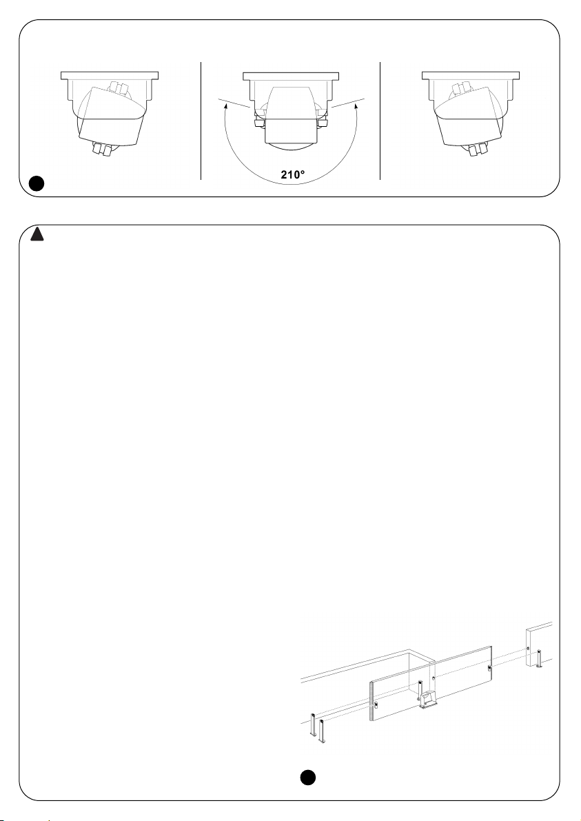
Because the F210 photocells have a horizontal scope of 210° and a vertical scope of 30°, they can also be applied on uneven
surfaces where the correct alignment between TX and RX is not normally possible (see figure 2).
The system must be disconnected from the mains
power supply during installation. If buffer batteries are
present, these must also be disconnected.
3.1) Preliminary checks
Due to the peculiarity and uniqueness of the product, certain
aspects concerning the operating principles must be evaluated before proceeding with the installation in order to ensure
maximum safety and functionality.
• Check carefully that the use parameters conform to the
data indicated in the “technical characteristics” chapter. If
in doubt, do not use the product and ask clarification from
the Nice technical assistance department.
• The transmitter continuously controls the status of the sen-
sitive edge and transmits the information to the receiver. In
order to reduce the consumption of the battery and maintain the required safety level, this operation is performed
with 2 different “speeds”: SLOW when the gate is at a
standstill; FAST when the gate is moving. The transmitter
detects when the gate is moving through a special sensor
that detects the vibration of the moving gate. As soon as
the gate begins to move the transmitter switches to the
FAST mode and remains so until the gate is motionless for
10 or 90 seconds (see jumpers JP2 and JP3 in table 1).
• In order to guarantee the required safety level, the receiver
must detect the status of the gate, above all to verify if the
SLOW or FAST mode of the gate is correct.
This control mechanism occurs through the “PHOTOTEST”
input of the receiver (see connection examples in figures 18
and 19). A Phototest is normally performed in the control unit
at the beginning of each manoeuvre. In this way the receiver of the FT210 is informed that the gate is about to move.
• If the control unit does not have Phototest the FT210 can
in any case be used by connecting the PHOTOTEST input
of the FT210 to the SCA (Gate open indicator) output of
the control unit. In this case a flashing signal should be
present on the SCA output during the entire duration of the
movement (see the connection example in figure 20).
• If the control unit does not even have an SCA output, the
FT210 should be programmed in the continuous FAST mode
by disconnecting the JP3 jumper on the TX (see table 1).
• In the control unit in which the beginning of the opening
manoeuvre and the automatic closure is performed, the
communication from the FAST mode to the SLOW mode
must be held for 90 seconds when the gate stops (see JP2
in table 1). In this way the TX remains in the FAST mode for
the entire opening time of the gate. The pause time of the
control unit must obviously be less than 90 seconds.
• FT210 has been designed not to interfere with and not to
be interfered with by other photocells, meaning that the
FT210 can be used along with other photocells. Functioning is guaranteed with at least one other couple of Nice
photocells whereas functioning may not be guaranteed
with more than one couple or photocells of another make.
To check that there are no effects caused by other devices,
carefully perform the testing procedure indicated in chapter 4 and check the related signals in table 5.
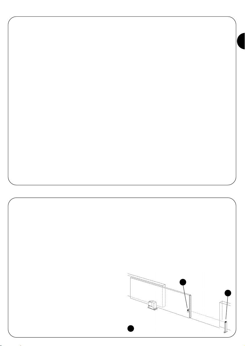
Two FT210 devices can in any case be placed to control
the front and rear parts of the same gate, being that the
two TX transmit the signals in the opposite direction.
• Two FT210 devices cannot be positioned to control the
same area. If a receiver receives the signal of two transmitters, it activates the “safety” mode and blocks the gate
movement. See the related signal in table 5.
Figure 3 illustrates an example of correct installation.
!
3) Installation
2
3
Page 5

5
GB
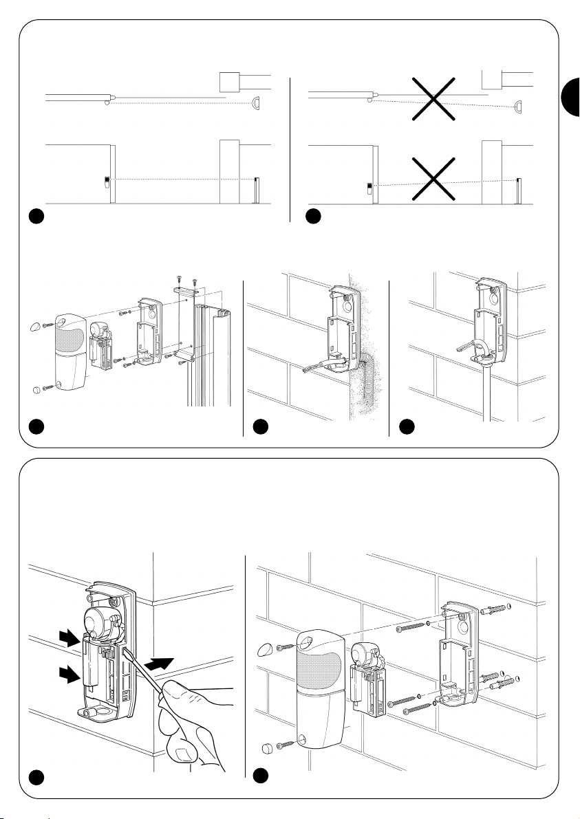
• The FT210 TX transmitter emits a beam with an angle of approximately ±4°, therefore a perfect alignment between TX and
RX is necessary that remains intact throughout the entire course of the gate.
Figure 4 illustrates an example of correct assembly; figure 5 illustrates two examples of incorrect assembly.
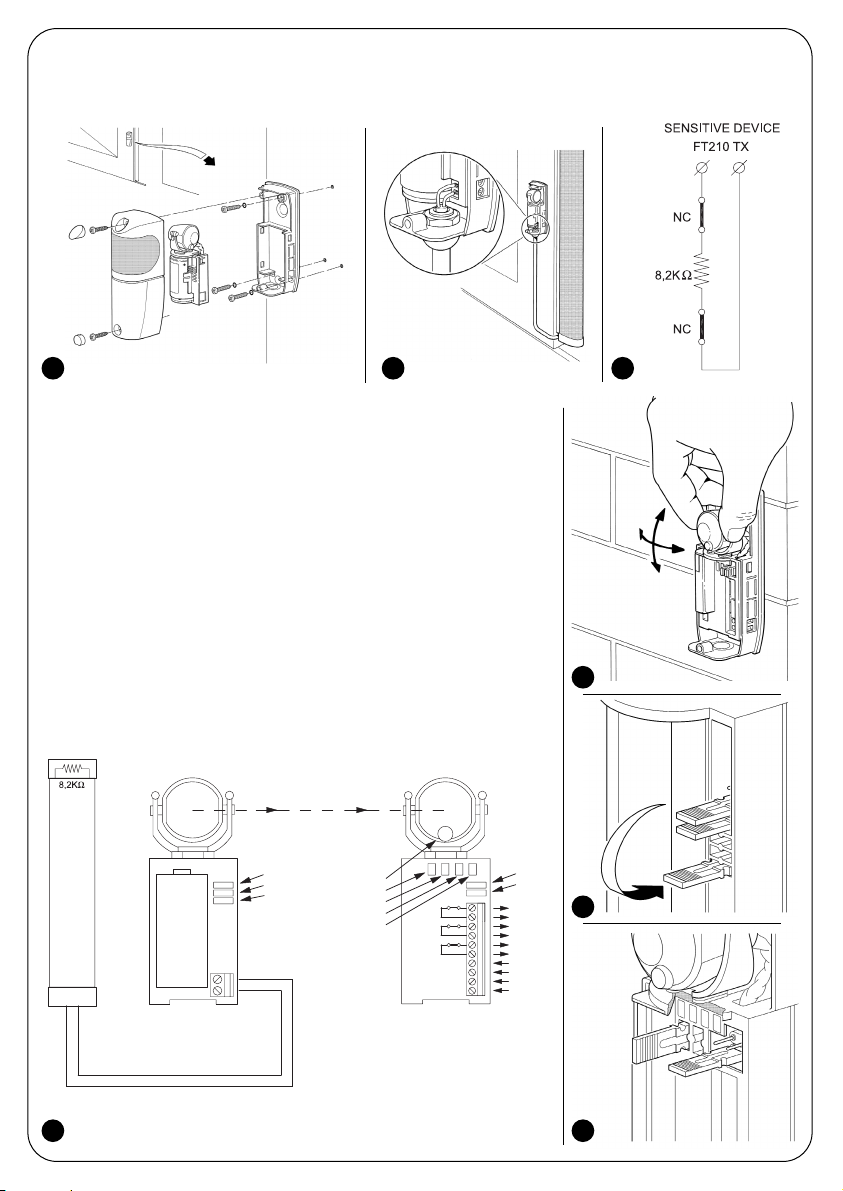
• If necessary, the receiver can be fitted on a special MOCF post with related FA2 accessories (see figure 6), or fixed to the
wall. In this case the cables can arrive from the base (see figure 7) or below, in which case it is necessary to use “PG9” type
cable clip (see figure 8).
3.2) Fixing of the devices
Perform the installation and fixing of the devices following the operations below:
1. To separate the control unit from the base, use a screwdriver to lever the three clips as indicated in fig. 9
2. Fix the receiver as shown in fig. 10.
4 5
6 7 8
9
10
Page 6
6
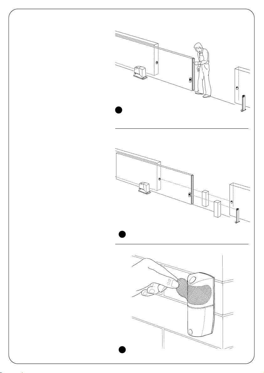
3. Assemble the transmitter on the mobile leaf as shown in figure 11.
4. Connect the 8,2KΩ, constant resistance type sensitive edge on the transmitter as shown in figure 12. The resistance on the
TX terminals is removed and used as a termination on the sensitive edge or does not need to be used if the sensitive edge
already has a terminating resistance.
If the sensitive edge has an output with 2 separate NC contacts, it can be connected
as shown in figure 13 placing the 8,2KΩ resistance in series between the two contacts. Make sure that the sensitive edge complies with the failsafe category 3 according to the EN 954-1 standard.
Warning: do not use sensitive edges that have only one NC type contact because
they do not have the necessary failsafe category required by the said standard.
5. Carry out the electrical connections following that which is indicated in the control
unit instructions manual. Also see the connection examples in chapter 3.3 “Electrical
connections”.
6. Direct the lenses as shown in fig. 14 in order to obtain the correct alignment
between the TX and RX. The correct alignment will be verified in chapter 4 “Testing”.
7. Program the jumpers on both the TX and RX (see figure 15) for the desired operation
following that indicated in table 1 and 2. Position the jumpers that are not used in their
locations for future use (see figures 16 and 17)
PHOTOTEST
PHOTOTEST
0Vac/dc
24Vac/dc
RXTX
L
L1
L2
L3
L4
JP1
JP2
JP1
JP2
JP3
-
+
ALT
COM
ALT1
COM
PHOTO
COM
Sensitive Device
3,6 V
11 12 13
14
16
1715
Page 7
7
GB
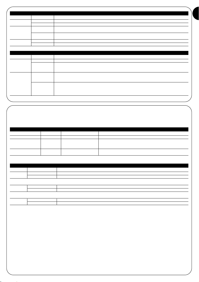
Jumper Position Description
Connected Phototest input connected to the Phototest output of the control unit.
Phototest input connected to the S.C.A. output of the control unit; or the input Phototest
Disconnected disconnected if the control unit is not fitted with Phototest or output SCA (Caution: possible
only with JP3 on TX deactivated)
The interruption of the infrared beam causes the PHOTO contact to open.
The activation of the sensitive edge causes the ALT contact to open and the ALT1 after 1.5
seconds.
The interruption of the infrared beam causes the PHOTO contact to open.
The activation of the sensitive edge causes the ALT contact to open and the ALT1 after 1.5
seconds.
To be used in control units that do not foresee the inversion when ALT cuts in.
Disconnected
JP2
Jumper Position Description
Connected Transmitter power suitable for gates up to 15 meters.
Disconnected Transmitter power suitable for gates up to 7 meters.
Connected Change over to SLOW transmission after 10 seconds from the end of the manoeuvre
(see JP3).
Disconnected Change over to SLOW transmission after 90 seconds from the end of the manoeuvre
(see JP3).
Connected Change over to SLOW transmission at the end of the manoeuvre.
Disconnected Never changes over to SLOW transmission but remains in the FAST mode.
Table 1: TX transmitter jumpers
JP1
JP2
JP3
Table 2: RX receiver jumpers
JP1
Connected
3.3) Electrical connections
This chapter describes the electrical connections and illustrates various possible connection layouts based on the type of control unit used on the automation system. If in doubt, do not use the product and contact the Nice technical assistance department.
Connection Cable type Max. length Description
12÷24V 2x0,5mm230m AC or DC receiver power supply
Phototest 2x0,25mm230m Start of manoeuvre test input, which can be connected to
the AC or DC voltage and is not limited by the power supply
terminals.
Output contacts 2x0,25mm230m Output relay contacts; normally closed (NC) when the receiver
is powered and active (see table 4)
Table 3: List of connections
Output Relay contact Description
PHOTO
Closed There are no obstacles and the TX data is received correctly.
Open Obstacles are present and the TX data is not received.
The PHOTO output (Photocell) must be connected to the control unit input that causes the inversion of the manoeuvre,
which is normally used by the D type presence sensor.
ALT
Closed No pressure is applied to the sensitive edge connected to the TX.
Open Pressure is applied to the sensitive edge connected to the TX.
The ALT output must be connected to the control unit input that causes the stop and eventual inversion of the manoeuvre,
which is normally used by PSPE pressure sensitive safety devices.
ALT1
Closed No pressure is applied to the sensitive edge connected to the TX.
Open After 1.5 seconds if pressure is applied to the sensitive edge connected to the TX.
The ALT1 output must be connected to the second input of the control unit that causes the stop and eventual inversion of the
manoeuvre, which is normally used by PSPE pressure sensitive safety devices.
In the event that this second input is not available on the control unit it is possible:
• to use the ALT1 output to control a relay of suitable capacity that directly cuts the power to the motor (see figure 18).
• not to use the ALT1 output and disconnect the JP2 on the RX, in this way when the sensitive edge is activated the PHOTO
contact is opened which also guarantees the failsafe category 3.
Table 4: RX output description
Page 8

8
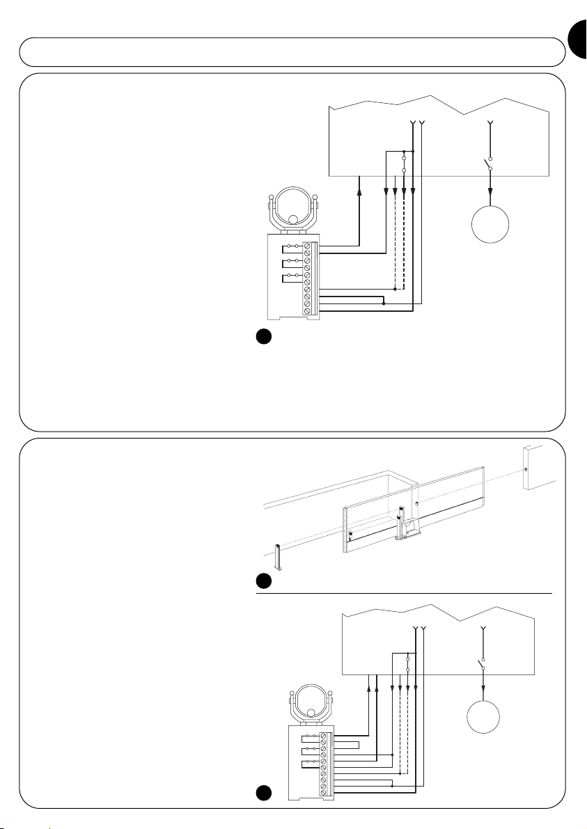
3.3.1) General connection example
Figure 18 shows a connection example of the
FT210 to a general control unit with PHOTO input;
ALT has a Phototest output. In this configuration,
set the RX jumpers as follows:
• JP1 connected
• JP2 activated, if activation of the ALT input of
the control unit causes shutdown and
inversion of movement (in this way the relay
connected to ALT1 in figure 18 can be
eliminated and the contact of ALT1 can be
placed in series to PHOTO and connected
to the PHOTO input of the control unit as
shown in figure 19 and 20)
deactivated, if activation of the ALT input
of the control unit causes only shutdown of
movement
M1
PHOTO
COM
ALT
COM
PHOTOTEST
PHOTOTEST
0Vac
24Vac
PHOTO
ALT
COM
PHOTOTEST
24Vac
0V
230Vac
Relè con bobina a
24Vac
FT210
ALT1
COM
3.3.2) Connection example with “Pho-
totest” equipped control unit
Figure 19 shows a connection example of the
FT210 to the ROBO “RO300” model gearmotor
with the use of the Phototest function. In this configuration, set the RX jumpers as follows:
• JP1 connected
• JP2 connected (control unit with inversion of
movement on activation of ALT input
PHOTO
COM
ALT
COM
ALT1
COM
PHOTOTEST
PHOTOTEST
0Vac
24Vac
FT210
FCC
FCA
PHOTO
P.P.
POWER LINE
1
2
3
GND
L
N
5
4
6
7
LUX
Max 40W
COURTESY
LIGHT
11
9
8
10
12
13
PHOTOTEST
24 Vac
0 Vac
ALT
P.P.
PHOTO
3.3.3) Connection example with “SCA”
equipped control unit
Figure 20 shows a connection example of the
FT210 to the ROBO “RO1000” model gearmotor
with the use of the SCA output.
In this configuration, set the RX receiver jumpers
as follows:
• JP1 disconnected
• JP2 activated (control unit with inversion of
movement on activation of ALT input)
PHOTO
COM
ALT
COM
ALT1
COM
PHOTOTEST
PHOTOTEST
0Vac
24Vac
FT210
43
1
3
2
4
PHOTO
FCC
FCA
CH
P.P.
AP
10
7
5
6
9
8
13
12
11
41
42
44
50 Hz
220 V
LUX
PHOTO
COM
200mA
24 V ~
ALT
SCA
CH
AP
P.P.
2¯ Ch
RADIO
ANT.
18
19
20
Page 9

9
GB
Each individual component of the automation system requires a specific testing phase. Perform the following sequence of operations for the testing of the FT210. The sequence is repeated for each device in the event 2 devices are present, one on the
front of the gate and one on the back of the gate (see figure 3).
Warning: some points require that the gate is in movement for the control; as the automation MAY not be adequately SAFE,
the maximum attention must be given during these controls.
1. Make sure that all that is foreseen in the present manual, in particular chapters 1 “Warnings” and 3 “Installation” is fully abided by.
2. Release and fully open the gate leaf so that the TX is at the maximum possible distance from the RX.
3. Make sure that there are no obstacles between the Tx and the RX.
4. If present, disconnect the power supply to the receiver and remove the battery from the transmitter.
5. Disconnect the sensitive device from the TX terminals and measure the resistance of the device with an ohmmeter, check-
ing that the value is between 7700Ω and 8700Ω (nominal 8200Ω).
6. Push the sensitive edge to activate it and measure once again the resistance. Check that the resistance is lower than 1000Ω
or higher than 16500Ω.
7. Reconnect the sensitive device to the TX terminals.
8. Connect the power supply to the receiver and check that the L1 (Ir Level) L2 (Phototest Ko) and L3 (Sensitive Device Ko)
LEDs are on. Check that the L4 LED (Sensitive Device Ok) is off (see figure 30).
9. Remove the JP3 jumper on the TX so that it always transmits in the FAST mode.
10. If the distance between the TX and the RX exceeds 7 m check that the JP1 jumper on the TX is connected (this meaning
programmed for distances up to 15 m).
11. Insert the FTA1 or FTA2 battery into the TX (see figure 33 or 34).
12. Check that the L1 (Ir level) LED on the RX receiver flashes; the L2 (Phototest Ko) LED and the L4 (Sensitive device Ok) LEDs
are on and that the L3 ((Sensitive device Ko) LED is off.
13. If necessary, improve the alignment by directing the TX and RX lenses as shown in figure 14. By performing the L1 (Ir lev-
el) LED signal the speed of the flashing is less and the alignment is greater. The adjustment is at its best when the LED flashes slowly at a maximum of 3 flashes a second.
14. Repeat the test placing the top protection covers both on TX and RX. Note that the RX cover is fitted with a damper filter
that simulates adverse weather conditions which could arise during use.
15. Move the gate leaf along the entire course and check, through the flashes of the L1 LED, that the alignment remains above
the optimum.
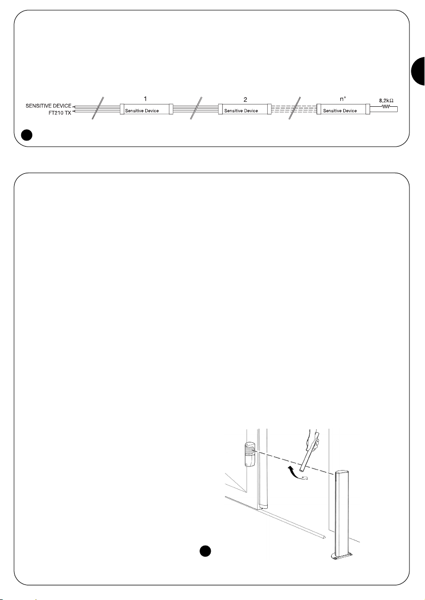
16. To check the optical presence sensor (type D) of
the FT210, and to make sure that there is no interference with other devices, pass a 50 mm diameter cylinder across the optical axis, first near the TX, then near
the RX and finally between the two (see figure 22) and
make sure that in all cases the device is triggered,
switching from the active status to the alarm status
(LED L1 ON) and vice versa.
3.3.4) Connection of 2 or more sensitive edges
The FT210 has only one sensitive edge input, but 2 or more sensitive edges that perform the same function can be cascade
connected one after the other as in figure 21 applying a single 8.2KΩ termination resistance.
Warning: the constant resistance devices must be cascade connected and never in series or parallel to one another!
4) Testing
21
22
Page 10

23
24
25
10
17. To check the PSPE pressure sensitive device of
the FT210, push and release the sensitive edge as
shown in figure 23 and check that the L4 LED turns
off and that the L3 LED turns on and vice versa.
18. If this is the preferred program, connect the JP3
jumper on the TX so that the transmission changes
over to SLOW a few seconds after the movement
has finished.
19. If the operation in the previous point has been
performed; check that the transmitter changes over
to SLOW after the foreseen time has past (see JP2
in table 1). The transmission in the SLOW mode can
be recognised through four short flashes of the L1
LED followed by a pause.
20. Mechanically connect the leaf to the motor and
perform a manoeuvre of the gate.
In the meantime, check that the L2 LED turns off at
the beginning of the manoeuvre, indicating that the
vibration sensor test of the moving gate has been
performed correctly.
21. Perform various gate manoeuvres and check
that the opening and closing are correctly performed
without the inversion of the movement.
22. Perform further manoeuvres, and during the clo-
sure activate the optical presence sensor as indicated in point 15 and check that the foreseen action is
performed such as the inversion of the movement.
23. Perform additional manoeuvres and during the
closure activate the sensitive edge as indicated in
point 16 and check that the foreseen action is performed such as the inversion of the movement.
24. The control of the FT210 optical presence sen-
sor (type D), according to the EN 12445 standard, is
performed with the 700x300x200mm test parallelepiped with 3 black faces and 3 polished white or
mirrored faces as indicated in figure 24 and according to chapter 7 of the EN 12445:2000 standard (or
enclosure A of prEN12445:2005).
25. The control of the PSPE pressure sensitive
device of the FT210 according to the EN 12445
standard, is performed by measuring the force at
the points foreseen in chapter 5 of the EN 12445
standard, if the hazardous situations, which have
been caused by the movement of the leaf, have
been safeguarded through the limitation of the
impact force (type C).
26. After verifying all the above points, remove the
damper filter from the glass panel on the RX receiver as shown in figure 25.
27. Make sure that all casings of the various devices
are closed when testing is complete
Page 11
11
GB
5.1) Example of how the FT210 can be used as
photocell
The FT210 can be used as a simple type D presence sensor without having to connect to the sensitive edge.
Figure 26 illustrates a connection example with this
type of application of the FT210 photocell device.
In this case it is necessary to:
1. Perform the assembly as indicated in the “Instal-
lation” paragraph.
2. Deactivate jumper JP3 of the transmitter to
ensure that transmission is always HIGH SPEED.
3. Use the receiver PHOTO output only
4. Connect and use the Phototest if the control unit
supports this function. In this case jumper JP1 of the
receiver must be inserted.
5. If the control unit has output SCA only, connect it to
the Phototest input of the receiver. Jumper JP1 of the
receiver must be deactivated.
6. If there is not usable output on the control unit (Pho-
totest or SCA), leave the Phototest input of the receiver and deactivate the jumper JP1 of the receiver.
Note: The FAST transmission mode reduces the battery life of the transmitter. In this case the estimated life of a C type battery (FTA1 kit) is as follows:
• approximately 24 months for gates up to 7 m (JP1 jumper of the transmitter disconnected)
• approximately 18 months for gates up to 15 m (JP1 jumper of the transmitter connected)
M1
PHOTO
COM
ALT
COM
PHOTOTEST/SCA
PHOTOTEST/SCA
0Vac
24Vac
PHOTO
COM
SCA
PHOTOTEST
24Vac
0V
230Vac
FT210
ALT1
COM
5) Additional information
Personalisation and how to look for and deal with faults on the FT210 will be dealt with in this chapter.
26
5.2) Example of using FT210 only as detector of
sensitive edge detector
If FT210 is used only as detector of the sensitive
edge status, and therefore without the presence
detector function, the photocell device should be
installed as shown in figure 27.
In this case, the following is necessary:
1. Perform the assembly phase as described in the
paragraph “Installation”.
2. Connect the receiver of FT210 to the control unit
as shown in figure 28, placing the contacts PHOTO
and ALT in series.
3. Insert Jumper JP2 of the receiver.
4. Connect and use Phototest if the control unit
manages this function. In this case jumper JP1 of
the receiver and jumper JP3 of the transmitter must
be inserted.
5. If the control unit has output SCA only, connect it
to the Phototest input of the receiver. Jumper JP1 of
the receiver must be deactivated, while jumper JP3
of the transmitter must be inserted.
6. If there is not usable output on the control unit
(Phototest or SCA), do not connect anything to the
Phototest input of the receiver, deactivate the
jumper JP1 of the receiver and jumper JP3 of the
transmitter.
M1
PHOTO
COM
ALT
COM
PHOTOTEST/SCA
PHOTOTEST/SCA
0Vac
24Vac
PHOTO
ALT
COM
SCA
PHOTOTEST
24Vac
0V
230Vac
FT210
ALT1
COM
27
28
Page 12

12
5.3) Example of connection of FT210 to control
unit with ALT input with constant resistance at
8.2kohm
If the control unit has an ALT input with constant
resistance of 8.2kohm , place a 8.2kohm resistance
in series with the two contacts PHOTO and ALT of
the receiver as shown in figure 29
PHOTOTEST
PHOTOTEST
0Vac/dc
24Vac/dc
PHOTO
ALT1
ALT
ALT
COM
29
5.4) Signals
The FT210 receiver has various LED signals (see figure 30)
that give luminous signals based on the operational status.
30
The sensitive edge connected to the transmitter is active.
On
(ALT contact: closed)
Off
(ALT contact: closed)
LED L3 (red) Cause Action
LED L4 (green) Cause Action
LED L1 (red) Cause Action
7 short flashes
Pause
7 short flashes
Replace the transmitter battery as soon as possible
with another of the same type.
Table 5: Signals
LED L (red) Cause Action
2 short flashes
Pause
2 short flashes
TX flat battery signal.
Regular flash
The rate of the flash indicates the quality of
the reception: the slower the flash the
greater the reception.
Everything Ok if the flash is slow: maximum 3 per
second, otherwise the alignment of the TX and RX
must be checked.
On
No signal, The “PHOTO” contact remains
open.
Remove the obstacle or improve the TX and RX
alignment.
4 short flashes
Pause
4 short flashes
The transmitter is in the SLOW mode. Everything Ok if the gate is not moving.
5 short flashes
Pause
5 short flashes
The receiver receives interference from
unrecognisable infrared signals.
An unknown transmitter is sending a signal towards
the receiver, try to remove the interference; check
the alignment of all devices present.
The receiver receives the signal from a second FT210 transmitter.
Eliminate the second transmitter. Two FT210 transmitters cannot be positioned in the same area.
On
Signals an error during the test at the
beginning of the manoeuvre and the transmitter changes over to the FAST mode.
Connection or programming of the PHOTOTEST
input error. Possible poor functioning of the movement sensor.
LED L2 (yellow) Cause Action
Off
The test at the beginning of the last
manoeuvre was correct.
Everything Ok
On
(ALT contact: open)
The sensitive edge that is connected to the
transmitter is active.
Check the reason the edge was activated.
The sensitive edge connected to the transmitter is not active.
Everything Ok
The sensitive edge connected to the transmitter is not active.
Everything Ok
Off
(ALT contact: open)
Check the reason the edge was activated.
Page 13

The gate stops during the movement or the manoeuvre is
inverted; the LED L3 (red) is on and the LED L4 (green) is off
The sensitive edge has cut-in. Remove the possible obstacle
and check that the sensitive edge is working correctly.
13
GB
Symptoms Advisable checks
Table 6: Fault diagnostics
The gate cannot be controlled; all the LEDs on the FT210
receiver are off
Check if the receiver is connected to the power supply by
measuring the voltage on the 12/24V terminals.
The gates starts to move but stops after 1 second; LED 2 (yellow) is on
The outcome of the test at the beginning of the manoeuvre was
negative and there is a possible connection or programming
error or there is a fault in the TX movement sensor of the gate.
The gate stops during the manoeuvre the manoeuvre is inversed; the LED L1 (red) is constantly on.
Check for possible obstacles or the alignment of the TX and
RX through the entire course of the gate.
Sometimes the gate stops during the movement or the manoeuvre
is inverted; the LED L1 (red) flashes rapidly when the gate is open.
Check the alignment between the TX and RX throughout the
entire course of the gate.
On activation of the device, the receiver has yellow led L2 lit
and red led L1 flashing. If the infrared beam is interrupted, led
L1 is permanently lit, but no relay activation is heard
The receiver is set to Phototest mode (JP1 inserted) but has
still not performed the test at the start of the manoeuvre. If the
central has the Phototest function, leave jumper JP1 of the
receiver inserted, check the connections and perform an
automation manoeuvre. If the control does not have the Phototest function, the jumper JP1 must be inserted incorrectly.
Deactivate the jumper and check that the relays are activated,
interrupting the infrared beam.
Sometimes the gate stops during the movement or the manoeuvre is inverted; sometimes everything blocks and cannot be controlled; the LED L2 (red) continues to make 2 short flashes.
The TX battery is flat and communication between the TX and
RX does not occur when conditions are poor. The flashing
LED L (red) indicates that the battery need changing.
The following accessories are available:
• FA1: metal vandal-proof casing, fitted as in figure 32
• FA2:
ixing brackets for “MOCF” posts, fitted as in figure 33
• FTA1: 3.6V battery; 7Ah type C, fitted as in figure 34
• FTA2: 3.6V battery; 2Ah type AA, fitted as in figure 35
8) Accessories
32 33 34 35
5.5) Troubleshooting
Table 6 gives possible indications on how to deal with malfunctions that may be met during installation or due to a fault.
6) Maintenance
The FT210 does not require any particular maintenance, however a control should be performed at least once every six months
to check the integrity of FT210 photocell (presence of dampness, rust, etc), cleaning of the external casing and testing as
described in chapter 4 “Testing”. The FT210 photocell has been designed to function under normal conditions for at least 10
years, therefore maintenance should be performed more frequently once this period has expired.
As in installation, also at the end of product lifetime, the disassembly and scrapping operations must be performed by qualified personnel. This product is made up of different types of material, some
of which can be recycled while others must be disposed of. Seek
information on the recycling and disposal systems envisaged by the
local regulations in your area for this product category.
Caution: some parts of the product may contain pollutant or hazardous substances which, if disposed of into the environment,
may cause serious damage to the environment or physical health.
As indicated by the symbol in figure 31, disposal of this product
in domestic waste is strictly prohibited. Separate the waste into
categories for disposal, according to the
methods envisaged by current legislation in
your area, or return the product to the retailer when purchasing a new version. Local
legislation may envisage serious fines in the
event of abusive disposal of this product.
Warning: the product operates with batteries that could contain
polluting substances and therefore should not be disposed of
along with household waste. After they have been removed from
the product (see paragraph “Battery replacement” in chapter
“FT210B installation instructions and warnings”) they should be
disposed of in compliance with the legislations locally in force.
7) Disposal
31
Page 14

Useful range
14
Dimensions 46 x 128 h 45mm.
Operating temperature
Protection class casing
Assembly
Use in acid, saline or potentially explosive
atmosphere
Output relay contacts capacity
Failsafe category
1.5s ± 3%.
ALT output response time
PHOTO output response time
Directional capacity
TX transmission angle
Typical 8,2KΩ +22%/-65% for the on status (ON)
ON limits: with Rs > 2.870Ω and Rs < 10.010Ω
OFF limits: with Rs < 2.590Ω or Rs > 11.060Ω
Output relay contacts duration
9) Technical characteristics
In order to improve its products, NICE S.p.a. reserves the right to modify them at any time without prior notice. In any case, the manufacturer guarantees their functionality and fitness for the intended purposes. Note: all the technical characteristics refer to a temperature of 20°C.
FT210 technical characteristics
Type
Device for the optical status transmission of a constant resistance sensitive
edge positioned on the moving part, comprising a battery powered infrared
transmitter (TX) that is positioned on the moving leaf, to which is connected
the sensitive edge, and a receiver (RX) positioned on the fixed part.
Adopted technology TX-RX direct optical interpolation with modulated and coded infrared beam.
Receiver power supply
12÷24Vac/dc; limits: 10÷35 Vdc; 11÷28Vac 50/60Hz; with EN 61558 insu-
lating transformer.
Receiver absorbed current Approx. 120mA at 12Vdc; 70mA at 24Vac.
Phototest input voltage The same limits as “Receiver power supply”.
Transmitter power supply 3.6 V with type C or AA lithium battery.
Transmitter battery life
Estimated at approx. 15 years with the type C battery, 7Ah capacity; (“resi-
dential” use: TX-RX distance up to 7m; with 20 manoeuvres per day of 90”)
Estimated at approx. 5.5 years with the type C battery, 7Ah capacity;
(“industrial” use: TX-RX distance up to 15m; with 200 manoeuvres per day
of 90”)
Estimated at approx. 6 years with the type AA battery, 2Ah capacity; (“resi-
dential” use: TX-RX distance up to 7m; with 20 manoeuvres per day of 90”)
Device input range
Sensitive (Rs)
Type D presence sensor detection capacity
Opaque objects located on the optical axis between TX and RX, larger than
50 mm and moving slower than 1.6m/s.
+/- 4° (value taken at 50% of the capacity).
RX reception angle +/- 3° (value taken at 50% of the capacity).
approx. 210° on the horizontal axis and 30° on the vertical axis
7 m or 15m (with JP1 inserted on TX) for maximum TX-RX misalignment ±2°
(the range may be further reduced in the presence of particularly intense
atmospheric conditions: fog, rain, snow, dust, etc.)
Maximum range (under optimum conditions)
15m or 30m (with JP1 inserted on TX) for maximum TX-RX misalignment ±
2°.
<45ms (typical 31ms).
<30ms (typical 28ms).
ALT1 output response time
3 or 2 (according to the EN 954-1 standard) according to the type of the
output connections and PHOTOTEST input
Maximum 0.5A and maximum 48Vac (resistive load: cos=1).
Mechanical life > 1.000.000 cycles; electrical > 200.000 cycles (resistive
load: 0.25A; 24Vdc).
IP44.
RX: Vertically wall mounted or on “MOCF” posts with “FA2” bracket.
TX: directly on the gate with the supplied screws.
No.
Weight
Receiver 135g.
Transmitter 165 g with FTA1 or 140 g with FTA2
-20 ÷55°C.
Page 15

15
GB
FT210 installation instructions and warnings
A B
C
D E
These instructions can be incorporated with the “Instructions
and warnings for the use of the automation” which the
installer must give the owner of the automation, and must be
incorporated by them.
• Maintenance: Like any machine, your automation needs
regular periodic maintenance to ensure its long life and
total safety. Arrange a periodic maintenance schedule with
your installation technician. Nice recommends that maintenance checks should be carried out every six months for
normal domestic use, but this interval may vary depending
on the intensity of use. Only qualified personnel are authorized to carry out checks, maintenance operations and
repairs.
• Do not modify the system or its programming and adjustment parameters in any way, even if you feel capable of
doing it: your installation technician is responsible for the
system.
• The final test, the periodic maintenance operations and any
repairs must be documented by the person who has performed them; these documents must remain under the
custody of the owner of the system
• The only recommended maintenance operations that the
user can perform periodically concern the cleaning of the
photocell glasses and the removal of leaves and debris
that may impede the automation. To prevent anyone from
activating the gate, release the automation system and use
a slightly damp cloth to clean.
• Disposal: At the end of its useful life, the automation must
be dismantled by qualified personnel, and the materials
must be recycled or disposed of in compliance with the
legislation locally in force.
• Replacement of the FT210 battery
The transmitter on the mobile leaf of the gate has a special 3.6 V lithium battery that, depending on the use conditions, has an estimated life of approximately 2 years. A
signal is given a few months before the battery is completely flat in order to give ample time for replacement.
It's time to change the battery if the receiver on the fixed
section (on the wall as in figure A or on the post as in figure B) gives the following signal: 2 short flashes followed
by a 1 second pause.
The battery is housed in the transmitter on the gate leaf; for
replacement:
1) Remove the screw caps as in figure C.
2) Unscrew the screws that hold the cover and remove it as
in figure C.
3) Use a screwdriver to leaver out the flat battery.
4) Wait about 10 seconds before introducing the new battery.
5) Make sure the polarity is correct; the plus is at the top.
6) Introduce the battery as in figure D or E depending on the
type used.
7) Secure the cover with the screws and replace the caps.
There are 2 types of battery:
• FTA1: 3.6V battery; 7Ah type C, fitted as in figure D.
• FTA2: 3.6V battery; 2Ah type AA, fitted as in figure E.
Caution: batteries used in this product are not normal
alkaline versions.
Contact Nice s.p.a. to request the spare battery kits
“FTA1” or “FTA2”.
Warning: the product operates with bat-
teries that could contain polluting substances and therefore should not be disposed of along with household waste.
After they have been removed from the
product (see paragraph “Battery replacement” in chapter “FT210B installation instructions and warnings”) they should be disposed of in compliance with the legislations locally in force.
Page 16

Page 17
17
I
FT210 è un dispositivo che consente di risolvere il problema
dei collegamenti elettrici di bordi sensibili posti su ante in
movimento. E' composto da un trasmettitore a raggi infrarossi (TX), alimentato con batteria a lunga durata, che va posto
sull'anta mobile nel quale viene collegato il bordo sensibile. A
questo si aggiunge un ricevitore (RX) posto nella parte fissa
ed alimentato normalmente: 12÷24Vac/dc.
Il bordo sensibile, di tipo a resistenza costante 8,2kohm viene
verificato continuamente dal trasmettitore e lo stato di attivazione o meno viene inviato al ricevitore. Il ricevitore RX interpreta l'informazione ricevuta ed, in base allo stato del bordo, attiva o meno i 2 relè di uscita ALT e ALT1 (anche FOTO se il ponticello JP2 del ricevitore è disinserito. Vedere tabella 2). La
comunicazione tra TX ed RX è codificata con tecniche ad alta
sicurezza tale che l'intero dispositivo risponde alla categoria 3
di sicurezza ai guasti secondo la norma EN 954-1 ed è quindi
utilizzabile in sistemi PSPE conformi alla norma EN 12978.
Il fotodispositivo FT210 assemblato come da istruzioni
e completo di apposito bordo sensibile TCB65, è stato
certificato dal produttore risultando conforme alle
seguenti normative:
• EN 954-1 Sicurezza del macchinario - Parti dei sistemi di
comando legate alla sicurezza - Principi generali per la
progettazione.
• EN 1760-2 Sicurezza del macchinario - Dispositivi di protezione sensibili alla pressione - Principi generali per la progettazione e la prova di bordi e barre sensibili alla pressione.
• EN 12978 - Porte e cancelli industriali, commerciali e da
garage. Dispositivi di sicurezza per porte e cancelli motorizzate - Requisiti e metodi di prova.
Attenzione: il solo FT210 non è un dispositivo di sicurezza
completo ma solo una parte di esso!
Se TX ed RX vengono posti in modo che la comunicazione
ottica avvenga attraverso il varco (vedi figura 1), il dispositivo
può essere utilizzato anche come rilevatore di presenza (tipo
D secondo la norma EN 12453); infatti, un oggetto che interrompe il raggio provoca la disattivazione dello specifico terzo
relè di uscita FOTO.
1) Avvertenze
Questo manuale d'istruzioni contiene importanti informazioni
riguardanti la sicurezza per l'installazione, è necessario leggere tutte le istruzioni prima di procedere all'installazione. Conservare con cura questo manuale anche per utilizzi futuri.
Considerando i pericoli che si possono verificare durante l'installazione e l'uso di FT210, per la massima sicurezza è
necessario che l'installazione avvenga nel pieno rispetto di
leggi, norme e regolamenti.
Secondo la più recente legislazione europea, l'automazione di una porta o cancello ricade in quanto previsto
dalla Direttiva 98/37/CE (Direttiva Macchine) e nel particolare, alle norme: EN 13241-1 (norma armonizzata); EN
12445; EN 12453 ed EN 12635, che consentono di
dichiarare la conformità alla direttiva macchine.
Ulteriori informazioni, linee guida all'analisi dei rischi ed alla
realizzazione del Fascicolo Tecnico, sono disponibili su:
“www.niceforyou.com”. Il presente manuale è destinato solamente al personale tecnico qualificato per l'installazione, nessuna altra informazione contenuta nel presente fascicolo può
essere considerata d'interesse per l'utilizzatore finale!
• L'uso di FT210 diverso da quanto previsto in queste istruzioni è vietato; usi impropri possono essere causa pericoli o
danni a persone e cose.
• Non eseguire modifiche su nessuna parte se non previste
nelle presenti istruzioni; operazioni di questo tipo possono
solo causare malfunzionamenti; NICE declina ogni responsabilità per danni derivati da prodotti modificati.
• FT210 deve funzionare esclusivamente per interpolazione
diretta TX-RX; è vietato l'uso per riflessione.
• Per i collegamenti elettrici utilizzare conduttori adeguati
come riportato nel capitolo “installazione”.
• Accertarsi che l'alimentazione elettrica e gli altri parametri
d'utilizzo corrispondano ai valori riportati nella tabella
“caratteristiche tecniche”.
• La realizzazione di dispositivi di sicurezza per porte e cancelli automatici è sottoposta alle seguenti normative:
• EN 12453 Porte e cancelli industriali, commerciali e da
autorimessa. Sicurezza in uso di porte motorizzate Requisiti.
• EN 12978 Porte e cancelli industriali, commerciali e da
garage. Dispositivi di sicurezza per porte e cancelli
motorizzate - Requisiti e metodi di prova.
L'installazione ed il collegamento di FT210 con lo scopo di
realizzare un dispositivo di sicurezza, senza soddisfare i
requisiti di queste norme, corrisponde a negligenza e deliberato abuso!
Avvertenze particolari sull'idoneità all'uso di questo prodotto
in relazione alla Direttiva "Compatibilità Elettromagnetica"
89/336/CEE e successiva modifiche 92/31/CEE e
93/68/CEE:
Questo prodotto è stato sottoposto alle prove relative alla
compatibilità elettromagnetica nelle situazioni d'uso più critiche, nelle configurazioni previste in questo manuale di istruzioni ed in abbinamento con gli articoli presenti nel catalogo
prodotti di Nice S.p.a.. Potrebbe non essere garatita la compatibilità elettromagnetica se il prodotto è usato in configurazioni diverse o con altri prodotti non previsti; è vietato l'uso
del prodotto in queste situazioni finché chi esegue l'installazione non abbia verificato la rispondenza ai requisiti previsti
dalla direttiva.
2) Descrizione del prodotto e destinazione d'uso
1
TX
RX
Page 18

18
Con la possibilità d'orientamento di 210° sull'asse orizzontale e 30° sull'asse verticale, FT210 è utilizzabile anche dove superfici di fissaggio impedirebbero un corretto allineamento tra TX e RX (vedi figura 2).
Tutte le operazioni d'installazione vanno eseguite
in assenza di tensione all'impianto; nel caso sia presente la batteria tampone, è necessario scollegarla.
3.1) Verifiche preliminari
Vista la particolarità ed unicità del prodotto, prima di procedere con l'installazione occorre valutare alcuni aspetti relativi
al principio di funzionamento in modo da ottenere la massima sicurezza e funzionalità.
• Verificare attentamente che i parametri di utilizzo siano
concordi con i dati riportati nel capitolo “caratteristiche tecniche”. In caso di dubbio non utilizzare il prodotto e
richiedere chiarimenti al servizio di assistenza tecnica di
Nice.
• Il trasmettitore verifica continuamente lo stato del bordo
sensibile ed invia l'informazione al ricevitore. Per ridurre il
consumo della batteria e mantenere comunque la sicurezza richiesta, questa attività viene svolta con 2 diverse
"velocità": LENTO quando il cancello è fermo; VELOCE
quando il cancello è in movimento. Il trasmettitore
riconosce lo stato di cancello in movimento attraverso uno
speciale sensore che rileva le vibrazioni del cancello in
movimento. Non appena il cancello inizia il movimento il
trasmettitore passa in modalità VELOCE e vi rimane fino a
quando il cancello rimane fermo per 10 o 90 secondi
(vedere ponticelli JP2 e JP3 in tabella 1).
• Per garantire il livello di sicurezza richiesto, il ricevitore deve
conoscere lo stato del cancello, soprattutto per verificare
se la modalità LENTO o VELOCE del trasmettitore è corretta. Questo meccanismo di controllo avviene attraverso
l'ingresso "FOTOTEST" del ricevitore (vedere anche gli
esempi di collegamento in figura 18 e 19). Generalmente
nelle centrali di comando ad ogni inizio manovra, viene
eseguito un Fototest; in questo modo il ricevitore di FT210
viene informato che tra pochi istanti inizierà il movimento
del cancello.
• Se la centrale di comando non dispone di Fototest è pos-
sibile utilizzare ugualmente il dispositivo FT210 collegando
l'ingresso di FOTOTEST di FT210 alla uscita S.C.A (Spia
Cancello Aperto) della centrale; in questo caso occorre
che sull'uscita SCA sia presente un segnale intermittente
(lampeggio) durante tutta la durata della manovra (vedere
esempio di collegamento in figura 20).
• Se la centrale di comando non dispone nemmeno dell'us-
cita SCA, FT210 dovrà essere programmato in modalità
VELOCE continua disinserendo il ponticello JP3 sul TX
(vedere tabella 1).
• Nelle centrali, in cui il FOTOTEST è eseguito solo all'inizio
della manovra di apertura e c'è la richiusura automatica, è
necessaria la ritenuta di 90 secondi nella commutazione da
modalità VELOCE a LENTA alla fermata del cancello (vedere
JP2 in tabella 1). In questo modo il TX rimarrà in modalità
VELOCE per tutto il tempo di apertura del cancello. Ovviamente il tempo pausa della centrale deve essere inferiore a
90 secondi.
• FT210 è stato studiato per non provocare disturbi ad altre
fotocellule e per non essere disturbato da esse; questo
significa che FT210 può essere abbinato con altre fotocellule. E' garantito il funzionamento con almeno un'altra coppia di fotocellule prodotte da Nice mentre potrebbe non
essere garantito il funzionamento con più di una coppia
oppure con fotocellule di altri produttori. In ogni caso, per
verificare che non vi siano influenze con altri dispositivi
eseguire scrupolosamente la procedura di collaudo prevista nel capitolo 4 e verificare la specifica segnalazione in
tabella 5. Si possono comunque porre due dispositivi
FT210 per controllare la parte anteriore e posteriore di uno
stesso cancello, visto che in questo caso i due TX inviano
il segnale in due direzioni opposte.
• Non possono essere posti due dispositivi FT210 per controllare la stessa area; se un ricevitore dovesse rilevare il
segnale di due trasmettitori si metterebbe nello stato di
“sicurezza” impedendo il movimento del cancello. Vedere
la specifica segnalazione in tabella 5.
Un esempio di corretta installazione è rappresentato in figura 3.
!
3) Installazione
2
3
Page 19
19
I
• Il trasmettitore TX della FT210 emette un raggio con un angolo di circa ±4° è quindi necessario un perfetto allineamento tra
TX ed RX che deve rimanere costante lungo tutta la corsa del cancello.
In figura 4 è riportato un montaggio corretto; in figura 5 sono riportati due esempi di montaggio errato.
• A seconda delle necessità, il ricevitore può essere installato su apposita colonnina MOCF con lo specifico accessorio FA2
(vedere figura 6) oppure fissato a muro; in questo caso l'ingresso del cavo può avvenire dal fondo (vedere figura 7) oppure
dal basso; in questo caso è necessario aggiungere un pressacavo di tipo “PG9” (vedere figura 8).
3.2) Fissaggio dei dispositivi
Eseguire l'installazione ed il fissaggio dei dispositivi secondo la seguente sequenza di operazioni:
1. Per facilitare le operazioni di fissaggio è possibile separare la scheda elettronica dal fondo facendo leva con un cacciavite
nei tre incastri come indicato in figura 9.
2. Effettuare il fissaggio del ricevitore come indicato in figura 10.
4 5
6 7 8
9
10
Page 20

20
3. Montare il trasmettitore sull'anta mobile come indicato in figura 11.
4. Sul trasmettitore eseguire il collegamento elettrico del bordo sensibile, di tipo a resistenza costante 8,2KΩ, come indicato in
figura 12. La resistenza presente sui morsetti del TX va rimossa ed utilizzata come terminazione del bordo sensibile oppure può
essere non usata nel caso il bordo disponga di una sua resistenza di terminazione.
Nel caso il bordo sensibile disponga di uscita con 2 contatti NC disponibili separatamente è possibile collegarlo come indicato in figura 13 ponendo la resistenza da
8,2KΩ in serie tra i due contatti. Verificare che il costruttore del bordo sensibile dichiari almeno la categoria 3 di sicurezza ai guasti secondo la norma EN 954-1.
Attenzione: non utilizzare bordi sensibili che hanno come uscita un singolo contatto
di tipo NC, non avrebbero la categoria di resistenza ai guasti richiesta dalle normative.
5. Eseguire i collegamenti elettrici secondo quanto riportato nel manuale di istruzione
della centrale di comando. Vedere anche gli esempi di collegamento nel capitolo 3.3
“Collegamenti elettrici”.
6. Orientare le lenti come indicato in figura 14 in modo da ottenere il migliore allinea-
mento possibile tra TX e RX. Il corretto allineamento verrà poi verificato nel capitolo 4
“Collaudo”.
7. Programmare i ponticelli presenti sia su TX che su RX (vedere figura 15 ) per il funzio-
namento desiderato secondo quanto indicato nelle tabelle 1 e 2. Per utilizzi futuri, riporre gli eventuali ponticelli non usati nello specifico vano (vedere figure 16 e 17).
FOTOTEST
FOTOTEST
0Vac/dc
24Vac/dc
RXTX
L
L1
L2
L3
L4
JP1
JP2
JP1
JP2
JP3
-
+
ALT
COM
ALT1
COM
FOTO
COM
Sensitive Device
3,6 V
11 12 13
14
16
1715
Page 21

21
I
3.3) Collegamenti elettrici
In questo capitolo vengono descritti i collegamenti elettrici e riportati alcuni schemi di collegamento possibili in base al tipo di
centrale di controllo utilizzata nell'automazione. In caso di dubbio non utilizzare il prodotto e richiedere chiarimenti al servizio di
assistenza tecnica di Nice.
Collegamento Tipo cavo Lunghezza massima Descrizione
12÷24V 2x0,5mm230m Alimentazione del ricevitore; in corrente continua
oppure corrente alternata.
Fototest 2x0,25mm230m Ingresso per test ad inizio manovra; può essere
collegato a tensioni in corrente continua oppure corrente
alternata; non è vincolato dai morsetti di alimentazione.
Contatti uscite 2x0,25mm230m Contatti dei relè di uscita; normalmente chiusi (NC) quando
il ricevitore è alimentato ed in stato di attivo (vedere tabella 4).
Tabella 3: elenco collegamenti
Uscita Contatto relè Descrizione
FOTO
Chiuso Non ci sono ostacoli e c'è ricezione corretta dei dati trasmessi dal TX.
Aperto Ci sono ostacoli e non c'è ricezione dei dati trasmessi dal TX.
L'uscita FOTO (fotocellula) deve essere collegata nell'ingresso della centrale che provoca l'inversione del movimento, normalmente destinato al rivelatore di presenza tipo D.
ALT
Chiuso Il bordo sensibile collegato sul TX non sottoposto a pressione.
Aperto Il bordo sensibile collegato sul TX è sottoposto a pressione.
L'uscita ALT deve essere collegata all'ingresso della centrale che provoca l'arresto e l'eventuale l'inversione del movimento,
normalmente destinato ai dispositivi di sicurezza sensibili alla pressione PSPE.
ALT1
Chiuso Il bordo sensibile collegato sul TX non sottoposto a pressione.
Aperto Dopo 1,5 secondi se il bordo sensibile collegato sul TX è sottoposto a pressione.
L'uscita ALT1 deve essere collegata al secondo ingresso della centrale che provoca l'arresto e l'eventuale inversione del movimento, normalmente destinato ai dispositivi di sicurezza sensibili alla pressione PSPE.
Nel caso non sia disponibile questo secondo ingresso sulla centrale è possibile:
• usare l'uscita ALT1 per comandare un relè di adeguata potenza che tagli l'alimentazione direttamente al motore (vedere figura 18).
• non utilizzare l'uscita ALT1 e disinserire JP2 sull'RX, in questo modo l'attivazione del bordo sensibile provoca l'apertura del
contatto FOTO garantendo anche in questo caso la categoria 3 di sicurezza ai guasti.
Tabella 4: descrizione uscite RX
Ponticello Posizione Descrizione
Inserito Ingresso Fototest collegato alla uscita Fototest della centrale.
Ingresso Fototest collegato alla uscita SCA della centrale; oppure ingresso Fototest scollegato
Disinserito se la centrale non dispone né di Fototest né di uscita SCA (Attenzione: possibile solo con JP3 su
TX
disinserito)
L'interruzione del raggio infrarosso provoca l'apertura del contatto FOTO.
L'attivazione del bordo sensibile provoca l'apertura del contatto ALT e dopo 1,5s quella del
contatto ALT1.
L'interruzione del raggio infrarosso provoca l'apertura del contatto FOTO.
L'attivazione del bordo sensibile provoca l'apertura del contatto FOTO e dopo 1,5s quella
del contatto ALT e ALT1.
Da usare in quelle centrali che non prevedono l'inversione con intervento di ALT.
Disinserito
JP2
Ponticello Posizione Descrizione
Inserito Potenza del trasmettitore adatta per cancelli fino a 15 metri.
Disinserito Potenza del trasmettitore adatta per cancelli fino a 7 metri.
Inserito Commuta in trasmissione LENTA dopo 10 secondi al termine della manovra
(vedere anche JP3).
Disinserito Commuta in trasmissione LENTA dopo 90 secondi al termine della manovra
(vedere anche JP3).
Inserito Al termine della manovra commuta in trasmissione LENTA.
Disinserito Non commuta mai in trasmissione LENTA ma rimane sempre in modo VELOCE.
Tabella 1: ponticelli sul trasmettitore TX
JP1
JP2
JP3
Tabella 2: ponticelli sul ricevitore RX
JP1
Inserito
Page 22

2222
3.3.1) Esempio di collegamento generico
In figura 18 è riportato un esempio di collegamento
di FT210 ad una centrale generica con ingressi
FOTO, ALT e dotata di uscita per Fototest. In questa
configurazione, impostare i ponticelli del ricevitore
RX nel seguente modo:
• JP1 inserito
• JP2 inserito, se l'attivazione dell'ingresso ALT
della centrale provoca l'arresto e l'inversione
del moto (in questo caso il relè collegato ad
ALT1 in figura 18 può essere eliminato e il
contatto di ALT1 deve essere posto in serie a
FOTO e collegato all'ingresso di FOTO della
centrale come in figura 19 e 20)
disinserito, se l'attivazione dell'ingresso
ALT della centrale provoca solo l'arresto del
moto.
M1
FOTO
COM
ALT
COM
FOTOTEST
FOTOTEST
0Vac
24Vac
FOTO
ALT
COM
FOTOTEST
24Vac
0V
230Vac
Relè con bobina a
24Vac
FT210
ALT1
COM
3.3.2) Esempio di collegamento con centra-
le dotata di "Fototest"
In figura 19 è riportato un esempio di collegamento
di FT210 alla centrale del motoriduttore ROBO
modello "RO300" con l'impiego della funzione di
Fototest. In questa configurazione, impostare i ponticelli del ricevitore RX nel seguente modo.
• JP1 inserito
• JP2 inserito (centrale con inversione del moto
all'attivazione dell'ingresso di ALT)
FOTO
COM
ALT
COM
ALT1
COM
FOTOTEST
FOTOTEST
0Vac
24Vac
FT210
FCC
FCA
FOTO
P.P.
ALIMENTAZIONE
1
2
3
GND
L
N
DA RETE
5
4
6
7
LUX
Max 40W
CORTESIA
LUCE DI
11
9
8
10
12
13
FOTOTEST
24 Vac
0 Vac
ALT
P.P.
FOTO
3.3.3) Esempio di collegamento con centra-
le dotata di uscita SCA
In figura 20 riportato un esempio di collegamento di
FT210 alla centrale del motoriduttore ROBO modello RO1000 con l'impiego dell'uscita SCA.
In questa configurazione, impostare i ponticelli del
ricevitore RX nel seguente modo.
• JP1 disinserito
• JP2 inserito (centrale con inversione del moto
all'attivazione dell'ingresso di ALT)
FOTO
COM
ALT
COM
ALT1
COM
FOTOTEST
FOTOTEST
0Vac
24Vac
FT210
43
1
3
2
4
FOTO
FCC
FCA
CH
P.P.
AP
10
7
5
6
9
8
13
12
11
41
42
44
50 Hz
220 V
LUX
FOTO
COM
200mA
24 V ~
ALT
SCA
CH
AP
P.P.
2¯ Ch
RADIO
ANT.
18
19
20
Page 23
23
I
Ogni singolo componente dell'automatismo, richiede una specifica fase di collaudo. Per il collaudo di "FT210" eseguire la
seguente sequenza di operazioni. Nel caso siano presenti 2 dispositivi, uno nella parte anteriore dell'anta ed uno nella parte
posteriore (vedere figura 3) la sequenza va ripetuta per ogni dispositivo.
Attenzione: in alcuni punti sono richieste delle verifiche con il cancello in movimento; poiché l'automazione POTREBBE non
essere adeguatamente SICURA occorre porre la massima attenzione nel fare queste verifiche.
1. Verificare che sia stato rispettato rigorosamente tutto quanto previsto nel presente manuale ed in particolare nei capitoli 1 “Avver-
tenze” e 3 “Installazione”.
2. Sbloccare ed aprire completamente l'anta del cancello; in modo di porre il TX alla massima distanza dal RX.
3. Verificare che non vi sia alcun ostacolo tra TX ed RX.
4. Se presente scollegare l'alimentazione elettrica al ricevitore e togliere la batteria al trasmettitore.
5. Scollegare il dispositivo sensibile dai morsetti del TX e con un ohmetro misurare il valore della resistenza del dispositivo e
verificare che il valore si compreso tra 7700Ω e 8700Ω (nominale 8200Ω).
6. Premere per attivare il bordo sensibile e misurare nuovamente il valore della resistenza; verificare che il valore sia minore di
1000Ω oppure superiore a 16500Ω.
7. Ricollegare il dispositivo sensibile ai morsetti del TX.
8. Fornire alimentazione elettrica al ricevitore e verificare che i led L1 (Ir Level) L2 (Fototest Ko) ed L3 (Sensitive Device Ko) sia-
no accesi; verificare che il led L4 (Sensitive Device Ok) sia spento (vedere figura 30).
9. Togliere il ponticello JP3 sul TX in modo che questo trasmetta sempre in modalità VELOCE.
10. Se la distanza tra TX ed RX supera i 7m verificare che il ponticello JP1 sul TX sia inserito (quindi programmato per distan-
ze fino a 15m).
11. Nel TX inserire la batteria FTA1 oppure FTA2 (vedere figure 33 e 34).
12. Nel ricevitore RX verificare che il led L1 (Ir Level) lampeggi; che i led L2 (Fototest Ko) ed L4 (Sensitive Device Ok) siano acce-
si e che il led L3 (Sensitive Device Ko) sia spento.
13. Se necessario migliorare l'allineamento intervenendo sull'orientamento delle lenti del TX e del RX, come indicato in figura
14. Seguire la segnalazione del led L1 (Ir Level) minore è la velocità del lampeggio e migliore è l'allineamento; la regolazione
ottimale si ha quando il led L1 lampeggia lentamente, massimo 3 lampeggi al secondo.
14. Ripetere la prova ponendo i gusci di protezione superiore sia su TX che su RX. Da notare che sul guscio dell'RX, c'è un fil-
tro attenuatore che simula le condizioni climatiche avverse che si potranno verificare durante l'uso.
15. Spostare l'anta del cancello lungo tutta la corsa e
verificare con il lampeggio del led L1 che l'allineamento rimanga sempre ottimale.
16. Nella verifica di FT210 nella parte relativa al rileva-
tore di presenza ottico (tipo D), ed in particolare che
non ci siano interferenze con altri dispositivi, passare
un cilindro di diametro 50mm sull'asse ottico prima
vicino al TX, poi vicino al RX e infine al centro tra i due
(vedi figura 22). Verificare che in tutti i casi il dispositivo intervenga passando dallo stato di attivo a quello di
allarme (led L1 acceso) e viceversa.
3.3.4) Collegamento di 2 o più bordi sensibili
Il trasmettitore di FT210 dispone di un solo ingresso per bordi sensibili, ma due o più dispositivi sensibili che svolgano la stessa funzione, possono essere collegati in cascata l'uno dopo l'altro come in figura 21 ponendo una sola resistenza da 8,2kΩ di
terminazione.
Attenzione: i dispositivi a resistenza costante devono essere collegati in cascata e mai in serie o in parallelo tra loro!
4) Collaudo
21
22
Page 24
2424
17. Per la verifica di FT210 nella parte relativa al
dispositivo sensibile alla pressione PSPE premere e
rilasciare il bordo sensibile come indicato in figura 23.
Verificare che il led L4 si spenga e si accenda il led
L3 e viceversa.
18. Se questa è la programmazione preferita, inseri-
re il ponticello JP3 sul TX in modo che alcuni secondi dopo il termine del movimento la trasmissione
commuti in modalità LENTA.
19. Nel caso sia stata eseguita l'operazione descrit-
ta al punto precedente; verificare che trascorso il
tempo previsto (vedere JP2 in tabella 1) il trasmettitore commuti in modalità LENTA. La trasmissione in
modalità LENTA si riconosce perché il led L1 fa ripetutamente quattro lampeggi brevi seguiti da una
pausa.
20. Agganciare meccanicamente l'anta al motore ed
eseguire una manovra comandata del cancello. Verificare nel frattempo che all'inizio della manovra il led
L2 si spenga indicando che il test del sensore che
rileva le vibrazioni del cancello in movimento è andato a buon fine.
21. Eseguire varie manovre comandate del cancello
e verificare che l'apertura e la chiusura avvengano
correttamente e senza inversioni del movimento.
22. Eseguire altre manovre e durante la manovra di
chiusura intervenire sul rivelatore di presenza ottico
come indicato nel punto 15 e verificare che provochi
l'azione prevista ad esempio l'inversione di movimento.
23. Eseguire altre manovre e nella manovra di chiu-
sura intervenire sul bordo sensibile come indicato
nel punto 16 e verificare che provochi l'azione prevista ad esempio l'inversione di movimento.
24. La verifica secondo la norma EN 12445 di
FT210 nella parte relativa al rilevatore di presenza
ottico (tipo D), va fatta con il parallelepipedo di test
700x300x200mm con 3 lati nero opaco e 3 lati bianco lucido oppure a specchio come indicato in figura
24e secondo quanto richiesto dal capitolo 7 dalla
norma EN 12445:2000 (oppure allegato A in
prEN12445:2005).
25. La verifica secondo la norma EN 12445 di
FT210 nella parte relativa al dispositivo sensibile alla
pressione PSPE; se le situazioni pericolose provocate dal movimento dell'anta sono state salvaguardate mediante la limitazione della forza d'impatto (tipo
C) va fatta eseguendo la misura della forza con lo
specifico strumento nei punti previsti secondo quanto richiesto dal capitolo 5 dalla norma EN 12445.
26. Dopo aver verificato tutti i punti precedenti,
togliere il filtro attenuatore dal vetrino del ricevitore
RX, come indicato in figura 25.
27. Al termine del collaudo ricordarsi di chiudere tut-
ti i contenitori dei vari dispostivi.
23
24
25
Page 25

5.1) Esempio di utilizzo di FT210 solo come rileva-
tore di presenza
E' possibile utilizzare FT210 come semplice rilevatore di presenza tipo D, senza quindi il collegamento al
bordo sensibile.
In figura 26 è riportato un esempio di collegamento
con questo tipo di utilizzo del fotodispositivo FT210.
In questo caso è necessario:
1. Eseguire le fasi di montaggio come riportato al
paragrafo “Installazione”.
2. Disinserire il ponticello “JP3” del trasmettitore in
modo che la trasmissione avvenga sempre in modo
VELOCE
3. Utilizzare solo l'uscita FOTO del ricevitore.
4. Collegare ed utilizzare il Fototest se la centrale
gestisce questa funzione. In questo caso il ponticello JP1 del ricevitore và inserito.
5. Se la centrale dispone solo dell'uscita SCA, colle-
garla all'ingresso Fototest del ricevitore. Il ponticello
JP1 del ricevitore và disinserito.
6. Se non si dispone sulla centrale di nessuna usci-
ta utilizzabile (Fototest o SCA), lasciare scollegatol'ingresso Fototest del ricevitore e disinserire il ponticello JP1 del ricevitore.
Nota: La modalità di trasmissione VELOCE riduce la durata della batteria del trasmettitore. In questo caso la durata di una batteria tipo “C” (kit FTA1) è così stimata:
• circa 24 mesi per cancelli fino a 7m (ponticello JP1 del trasmettitore disinserito).
• circa 18 mesi per cancelli fino a 15m (ponticello JP1 del trasmettitore inserito).
M1
FOTO
COM
ALT
COM
FOTOTEST/SCA
FOTOTEST/SCA
0Vac
24Vac
FOTO
COM
SCA
FOTOTEST
24Vac
0V
230Vac
FT210
ALT1
COM
25
I
5) Approfondimenti
In questo capitolo verranno trattate le possibilità di personalizzazione diagnostica e ricerca guasti su FT210.
26
5.2) Esempio di utilizzo di FT210 come solo rileva-
tore dello stato del bordo sensibile
Nel caso FT210 venga utilizzato solo come rilevatore dello stato del bordo sensibile, senza quindi la
funzione di rilevatore di presenza, si consiglia di
installare il fotodispositivo come in figura 27.
In questo caso è necessario:
1. Eseguire le fasi di montaggio come riportato al
paragrafo “Installazione”.
2. Collegare il ricevitore di FT210 alla centrale come
in figura 28, ponendo in serie i contatti di FOTO e
ALT.
3. Inserire il ponticello JP2 del ricevitore
4. Collegare ed utilizzare il Fototest se la centrale
gestisce questa funzione. In questo caso il ponticello JP1 del ricevitore e il ponticello JP3 del trasmettitore vanno inseriti
5. Se la centrale dispone solo dell'uscita SCA, colle-
garla all'ingresso Fototest del ricevitore. Il ponticello
JP1 del ricevitore và disinserito, mentre il ponticello
JP3 del trasmettitore và inserito
6. Se non si dispone sulla centrale di nessuna usci-
ta utilizzabile (Fototest o SCA), non collegare niente
all'ingresso Fototest del ricevitore, disinserire il ponticello JP1 del ricevitore e il ponticello JP3 del trasmettitore.
M1
FOTO
COM
ALT
COM
FOTOTEST/SCA
FOTOTEST/SCA
0Vac
24Vac
ALT
FOTO
COM
SCA
FOTOTEST
24Vac
0V
230Vac
FT210
ALT1
COM
27
28
Page 26

26
5.3) Esempio di collegamento di FT210 a centra-
le con ingresso di ALT a resistenza costante
8,2kohm.
Nel caso la centrale disponga di ingresso di ALT a
resistenza costante 8,2kohm, porre in serie ai due
contatti FOTO e ALT del ricevitore, una resistenza da
8,2Kohm come indicato in figura 29.
FOTOTEST
FOTOTEST
0Vac/dc
24Vac/dc
FOTO
ALT1
ALT
ALT
COM
29
Il bordo sensibile collegato al trasmettitore è
attivato.
5.4) Segnalazioni
Il ricevitore FT210 ha alcuni led di segnalazione (vedere figura 30) che forniscono delle segnalazioni luminose in base allo
stato di funzionamento.
30
Acceso
(contatto ALT: chiuso)
Spento
(contatto ALT: chiuso)
Led L3 (rosso) Causa Azione
Led L4 (verde) Causa Azione
Led L1 (rosso) Causa Azione
7 lampeggi brevi
pausa
7 lampeggi brevi
Sostituire quanto prima la batteria sul trasmettitore
con una dello stesso modello.
Tabella 5: segnalazioni
Led L (rosso) Causa Azione
2 lampeggi brevi
pausa
2 lampeggi brevi
Segnalazione batteria scarica sul TX.
Lampeggio regolare
La frequenza di lampeggio indica la bontà
della ricezione: più lento è il lampeggio e
migliore è la ricezione.
Tutto Ok se il lampeggio è lento: massimo 3 al
secondo, altrimenti occorre controllare l'allineamento
tra TX ed RX.
Acceso
Assenza di segnale, il contatto “FOTO”
rimane aperto.
Rimuovere l'ostacolo oppure migliorare l'allineamento tra TX e RX.
4 lampeggi brevi
pausa
4 lampeggi brevi
Il trasmettitore è in modalità LENTA. Tutto OK se il cancello è fermo.
5 lampeggi brevi
pausa
5 lampeggi brevi
Il ricevitore capta del segnale infrarosso non
riconoscibile che interferisce.
Un trasmettitore estraneo invia un segnale verso il
ricevitore, cercare di eliminare l'interferenza; controllare l'allineamento di tutti i dispositivi presenti.
Il ricevitore capta il segnale infrarosso di un
secondo trasmettitore FT210.
Eliminare il secondo trasmettitore. Due trasmettitori
FT210 non possono essere posti sulla stessa area.
Acceso
Segnala errore nel test ad inizio manovra ed
il trasmettitore non è commutato in modo
VELOCE.
Errore nel collegamento o programmazione dell'ingresso FOTOTEST. Probabile cattivo funzionamento
del sensore di movimento.
Led L2 (giallo) Causa Azione
Spento
Il test ad inizio dell'ultima manovra è stato
regolare.
Tutto OK
Acceso
(contatto ALT: aperto)
Il bordo sensibile collegato al trasmettitore è
attivato.
Verificare le cause dell'attivazione del bordo.
Il bordo sensibile collegato al trasmettitore
non è attivato.
Tutto OK
Il bordo sensibile collegato al trasmettitore
non è attivato.
Tutto OK
Spento
(contatto ALT: aperto)
Verificare le cause dell'attivazione del bordo.
Page 27

All'accensione del dispositivo, il ricevitore presenta il led
L2 giallo acceso ed il led L1 rosso lampeggiante. Se viene oscurato il fascio infrarosso, il led L1 rosso si accende fisso, ma non si sente scattare nessun relè.
Ogni tanto, durante la corsa il cancello si ferma o inverte la
manovra; talvolta si blocca del tutto e non è possibile comandarlo; il led L (rosso) fa continuamente 2 brevi lampeggi.
Durante la corsa il cancello si ferma o inverte la manovra; il led L1 (rosso) si è acceso fisso.
Durante la corsa il cancello si ferma o inverte la manovra;
il led L3 (rosso) è acceso e il led L4 (verde) è spento.
27
I
Sono disponibili i seguenti accessori:
• FA1: contenitore metallico antivandalico, da montare come
in figura 32.
• FA2:
staffa di fissaggio su colonnine “MOCF”, da montare
come in figura 33.
• FTA1: batteria 3,6V; 7Ah taglia C, da montare come in figura 34.
• FTA2: batteria 3,6V; 2Ah taglia AA, da montare come in
figura 35.
8) Accessori
32 33 34 35
5.5) Risoluzione dei problemi
Nella tabella 6 è possibile trovare utili indicazioni per affrontare casi di malfunzionamento in cui è possibile incorrere durante l'installazione o a causa di un guasto.
Sintomi Verifiche consigliate
Tabella 6: ricerca guasti
Non è possibile comandare il cancello; tutti i led su ricevitore di FT210 sono spenti.
Verificare se il ricevitore è alimentato misurando la tensione sui morsetti 12/24V.
Il cancello inizia il movimento ma dopo 1 secondo si ferma; il led 2 (giallo) è acceso.
Non è andato a buon fine il test ad inizio manovra ed è probabile un
errore nei collegamenti o di programmazione o un guasto nel sensore di movimento del cancello presente nel TX.
Verificare eventuali ostacoli o l'allineamento tra TX e RX lungo tutta la
corsa del cancello.
E' intervenuto il bordo sensibile. Rimuovere l'eventuale ostacolo o
controllare il corretto funzionamento del bordo.
Ogni tanto, durante la corsa il cancello si ferma o inverte la manovra; a cancello aperto il led L1 (rosso) lampeggia velocemente.
Verificare l'allineamento tra TX e RX lungo tutta la corsa del cancello.
Il ricevitore è impostato in modalità Fototest (JP1 inserito), ma non ha
eseguito ancora il test ad inizio manovra. Se si dispone di centrale
con fototest, lasciare inserito il ponticello JP1 del ricevitore, verificare
i collegamenti e far eseguire una manovra all'automazione. Se la centrale non dispone di uscita Fototest, sicuramente il ponticello JP1 è
posto erroneamente inserito. Disinserire il ponticello e verificare che i
relè scattino oscurando il fascio infrarosso.
La batteria nel TX è scarica e nelle condizioni più sfavorevoli non
avviene la comunicazione tra TX ed RX. Il lampeggio del led L (rosso)
indica che è necessario cambiarla.
6) Manutenzione
La manutenzione di FT210 non necessita di accorgimenti particolari, ma è necessario un controllo almeno ogni 6 mesi nel quale venga verificato lo stato del fotodispositivo FT210 (presenza di umidità, ossidi, ecc.), venga eseguita la pulizia dell'involucro
esterno, e rieseguito il collaudo come descritto nel capitolo 4 “Collaudo”. FT210 è stato studiato per funzionare in condizioni
normali almeno 10 anni, è opportuno intensificare la frequenza di manutenzione trascorso questo periodo.
Come per l'installazione, anche al termine della vita di questo prodotto, le operazioni di smantellamento devono essere eseguite da
personale qualificato. Questo prodotto è costituito da vari tipi di
materiali, alcuni possono essere riciclati altri devono essere smaltiti; informatevi sui sistemi di riciclaggio o smaltimento previsti dai
regolamenti locali per questa categoria di prodotto.
Attenzione: alcune parti del prodotto possono contenere sostanze inquinanti o pericolose, se disperse potrebbero provocare
effetti dannosi sull'ambiente e sulla salute umana.
Come indicato dal simbolo di figura 31 è vietato gettare questo
prodotto nei rifiuti domestici. Eseguire la "raccolta separata" per lo
smaltimento secondo i metodi previsti dai regolamenti locali;
oppure riconsegnare il prodotto al venditore
nel momento dell'acquisto di un nuovo prodotto equivalente.Regolamenti locali possono prevedere pesanti sanzioni in caso di
smaltimento abusivo di questo prodotto.
Attenzione: il prodotto funziona con batterie che potrebbero
contenere sostanze inquinanti e quindi non devono essere buttate nei rifiuti comuni. Dopo averle rimosse dal prodotto (vedere il
paragrafo "Sostituzione batteria" al capitolo "Istruzioni ed avvertenze destinate all'utilizzatore di FT210B") occorre smaltirle
secondo i metodi previsti, per le batterie, dai regolamenti locali”.
7) Smaltimento
31
Page 28

Angolo di ricezione RX
28
Dimensioni 46 x 128 h 45mm.
Temperatura di esercizio
Grado di protezione contenitore
Montaggio
Utilizzo in atmosfera acida, salina o potenzialmente esplosiva
Capacità contatti relè in uscita
Categoria di resistenza ai guasti
1,5s ± 3%.
Tempo di risposta uscita ALT
Tempo di risposta uscita FOTO
Orientabilità
Angolo di trasmissione TX
Tipico 8,2KΩ +22%/-65% per lo stato di attivo (On)
Limiti stato attivo (On): con Rs > 2.870Ω e Rs < 10.010Ω
Limiti stato disattivo (Off): con Rs < 2.590Ω o Rs > 11.060Ω
Durata contatti relè in uscita
9) Caratteristiche tecniche
Allo scopo di migliorare i prodotti, NICE S.p.a. si riserva il diritto di modificare le caratteristiche tecniche in qualsiasi momento e senza preavviso,
garantendo comunque funzionalità e destinazione d'uso previste. Nota: tutte le caratteristiche tecniche sono riferite alla temperatura di 20°C.
Caratteristiche tecniche FT210
Tipologia
Dispositivo per la trasmissione via ottica dello stato di un bordo sensibile di tipo
a resistenza costante posto su parti in movimento; composto da un trasmettitore a raggi infrarossi (TX) alimentato a batteria posto sull'anta in movimento
nel quale viene collegato il bordo sensibile e da un ricevitore (RX) posto nella
parte fissa.
Tecnologia adottata
Trasmissione per interpolazione ottica diretta TX-RX con raggio infrarosso
modulato e codificato.
Alimentazione ricevitore
12÷24Vac/dc; limiti: 10÷35 Vcc; 11÷28Vac 50/60Hz; con trasformatore d'iso-
lamento conforme a EN 61558.
Corrente assorbita ricevitore Circa 120mA a 12Vcc; 70mA a 24Vac.
Tensione ingresso “Fototest” Stessi limiti di “Alimentazione ricevitore”.
Alimentazione trasmettitore 3,6V con batterie al litio tipo C oppure AA.
Durata batteria trasmettitore
Stimata in circa oltre 15 anni con batteria tipo C, capacità 7Ah; (uso “residen-
ziale”: distanza TX-RX fino a 7m; con 20 manovre al giorno della durata di 90s).
Stimata in circa 5,5 anni con batteria tipo C, capacità 7Ah; (uso “industriale”:
distanza TX-RX fino a 15m; con 200 manovre al giorno della durata di 90s).
Stimata in circa 6 anni con batteria tipo AA, capacità 2Ah; (uso “residenziale”:
distanza TX-RX fino a 7m; con 20 manovre al giorno della durata di 90s).
Gamma dell'ingresso del dispositivo
Sensibile (Rs)
Capacità di rilevamento del rivelatore di presenza tipo D
Oggetti opachi posti sull'asse ottico tra TX-RX con dimensioni maggiori di
50mm e velocità minore di 1,6m/s.
+/- 4° (valore rilevato al 50% della portata).
+/- 3° (valore rilevato al 50% della portata).
circa 210° nell'asse orizzontale e 30° nell'asse verticale.
Portata utile
7m oppure 15m (con JP1 su TX inserito) con disassamento TX-RX massimo
± 2° (la portata potrebbe ridursi ulteriormente in caso di fenomeni atmosferici
particolarmente intensi:nebbia, pioggia, neve, polvere, ecc..).
Portata massima (in condizioni ottimali)
15m oppure 30m (con JP1 su TX inserito) con disassamento TX-RX massi-
mo ± 2°.
<45ms (tipico 31ms).
<30ms (tipico 28ms).
Tempo di risposta uscita ALT1
3 oppure 2 (secondo la norma EN 954-1) a seconda del tipo di collegamento
delle uscite ed ingresso FOTOTEST
Massimo 0.5A e massimo 48Vac (carico resistivo: cos=1).
Vita meccanica > 1.000.000 cicli; elettrica > 200.000 cicli (carico resistivo:
0,25A; 24Vcc).
IP44.
RX: verticale a parete o su colonnina “MOCF” con staffa di fissaggio “FA2”.
TX: direttamente sul cancello con viti fornite in dotazione.
No.
Peso
Ricevitore: 135g.
Trasmettitore 165g con FTA1 oppure 140g con FTA2.
-20 ÷55°C.
Page 29

29
I
Queste istruzioni possono integrare le “Istruzioni ed avvertenze per l'uso dell'automazione” che l'installatore deve consegnare al proprietario dell'automazione e comunque devono
essere integrate da esse.
• Manutenzione: Come ogni macchinario la vostra automa-
zione ha bisogno di una manutenzione periodica affinché
possa funzionare più a lungo possibile ed in completa sicurezza. Concordate con il vostro installatore un piano di
manutenzione con frequenza periodica; Nice consiglia un
intervento ogni 6 mesi per un normale utilizzo domestico,
ma questo periodo può variare in funzione dell'intensità d'uso. Qualunque intervento di controllo, manutenzione o riparazione deve essere eseguito solo da personale qualificato.
• Anche se ritenete di saperlo fare, non modificate l'impianto
ed i parametri di programmazione e di regolazione dell'automazione: la responsabilità è del vostro installatore.
• Il collaudo, le manutenzioni periodiche e le eventuali riparazioni devono essere documentate da chi le esegue e i
documenti conservati dal proprietario dell'impianto.
• Gli unici interventi che vi sono possibili e vi consigliamo di
effettuare periodicamente sono la pulizia dei vetrini delle fotocellule e la rimozione di eventuali foglie o sassi che potrebbero ostacolare l'automatismo. Per impedire che qualcuno
possa azionare il cancello, prima di procedere, ricordatevi di
sbloccare l'automatismo e di utilizzare per la pulizia solamente un panno leggermente inumidito con acqua.
• Smaltimento: Al termine della vita dell'automazione, assicuratevi che lo smantellamento sia eseguito da personale
qualificato e che i materiali vengano riciclati o smaltiti
secondo le norme valide a livello locale.
• Sostituzione della batteria del trasmettitore di FT210.
Il trasmettitore, posto nell'anta in movimento del cancello,
dispone di una speciale batteria al litio da 3,6V. La durata
stimata è di diversi anni; dipende delle condizioni d'utilizzo.
E' prevista una segnalazione qualche mese prima che la
batteria si sia completamente esaurita in modo che abbiate il tempo per la sostituzione.
E' il momento di cambiare la batteria se nel ricevitore posto
nella parte fissa (a muro come in figura A o su colonnina
come in figura B) notate questa segnalazione: 2 lampeg-
gi brevi seguiti da una pausa di 1 secondo.
La batteria è nel trasmettitore posto nell'anta del cancello;
per la sostituzione occorre:
1) Togliere i tappi che coprono le viti come in figura C.
2) Svitare le viti che fissano il coperchio e toglierlo come in
figura C.
3) Togliere la batteria esaurita facendo leva con un cacciavite.
4) Aspettare circa 10 secondi prima di inserire la batteria nuova.
5) Porre attenzione alla polarità: il positivo è verso l'alto.
6) Inserire la nuova batteria come da figure D o E, in base al
modello utilizzato.
7) Fissare il coperchio con le viti ed inserire gli appositi tappi.
Sono disponibili 2 tipi di batteria:
• FTA1: batteria 3,6V; 7Ah taglia C, da montare come in figu-
ra D.
• FTA2: batteria 3,6V; 2Ah taglia AA, da montare come in
figura E.
Attenzione: le batterie utilizzate in questo prodotto non
sono normali batterie alcaline.
Richiedere a Nice s.p.a. i kit batteria di ricambio “FTA1”
o “FTA2”.
Attenzione: il prodotto funziona con bat-
terie che potrebbero contenere sostanze
inquinanti e quindi non devono essere
buttate nei rifiuti comuni. Dopo averle
rimosse dal prodotto (vedere il paragrafo
"Sostituzione batteria" al capitolo "Istruzioni ed avvertenze destinate all'utilizzatore di FT210B")
occorre smaltirle secondo i metodi previsti, per le batterie, dai
regolamenti locali”.
Istruzioni ed avvertenze destinate all'utilizzatore di FT210
A B
C
D E
Page 30

Page 31

31
F
FT210 est un dispositif qui permet de résoudre le problème des
connexions électriques de bords sensibles placés sur les vantaux en mouvement. Il est composé d'un émetteur à rayons
infrarouges (TX), alimenté par une batterie longue durée, qui
doit être placé sur le vantail mobile sur lequel se trouve le bord
sensible. Il est complété par un récepteur (RX) placé dans la
partie fixe et alimenté normalement: 12÷24 Vca/cc.
Le bord sensible, du type à résistance constante 8,2KΩ, est
vérifié continuellement par l'émetteur et l'état d'activation ou
pas est envoyé au récepteur. Le récepteur RX interprète l'information reçue et suivant l'état du bord sensible, actif ou pas, les
2 relais de sortie ALT et ALT1 (et PHOTO si le cavalier JP2 du
récepteur est déconnecté. Voir le Tableau 2). La communication entre TX et RX est codée avec des techniques haute sécurité telles que tout le dispositif satisfait la catégorie 3 de sécurité aux pannes selon la norme EN 954-1 et est donc utilisable
dans des systèmes PSPE conformes à la norme EN 12978.
Le dispositif à photocellules FT210 assemblé conformément aux instructions et complété par le bord sensible TCB65, a été certifié par le producteur comme
étant conforme aux normes suivantes:
• EN 954-1 Sécurité des machines - Parties des systèmes
de commande relatives à la sécurité - Principes généraux
de conception
• EN 1760-2 Sécurité des machines - Dispositifs de protec-
tion sensibles à la pression - Principes généraux de conception et d'essai des bords et barres sensibles à la pression.
• EN 12978 - Portes et portails équipant les locaux industriels et
commerciaux et les garages. Dispositifs de sécurité pour portes et portails motorisés - Prescriptions et méthodes d'essai.
Attention: FT210 seul n'est pas un dispositif de sécurité
complet mais seulement une partie du dispositif!
Si TX et RX sont positionnés de manière que la communication optique s'effectue à travers le passage (voir figure 1), le
dispositif peut être utilisé également comme détecteur de
présence (type D selon la norme EN 12453); en effet, un
objet qui interrompt le rayon provoque la désactivation du
troisième relais spécifique de sortie PHOTO.
1) Avertissements
Ce manuel d'instructions contient des informations importantes concernant la sécurité pour l'installation, il faut lire toutes
les instructions avant de procéder à l'installation. Conserver
avec soin ce manuel également pour des consultations futures. Compte tenu des dangers qui peuvent se vérifier durant
l'installation et l'utilisation de FT210, pour le maximum de
sécurité il faut que l'installation soit faite dans le plein respect
des lois, normes et règlements.
D'après la législation européenne la plus récente, l'automatisation d'une porte ou d'un portail possède les caractéristiques prévues par la Directive 98/37/CE (Directive Machines) et en particulier par les normes: EN 13241-1 (norme
harmonisée); EN 12445; EN 12453 et EN 12635, qui permettent de déclarer la conformité à la directive machines.
D'autres informations et les conseils pour l'analyse des risques
et la réalisation du dossier technique sont disponibles sur le site:
“www.niceforyou.com”. La présente notice est destinée uniquement au personnel technique qualifié pour l'installation. Aucune
autre information contenue dans la présente notice ne peut être
considérée comme intéressante pour l'utilisateur final!
•
Une utilisation de FT210 différente de ce qui est prévu dans cette notice est interdite; des utilisations impropres peuvent être
source de dangers ou de dommages aux personnes et aux choses.
• Ne pas effectuer de modifications sur aucune des parties
si elles ne sont pas prévues dans le présent manuel. Des
opérations de ce type entraîneront obligatoirement des
problèmes de fonctionnement. NICE décline toute responsabilité pour les dommages dérivant de produits modifiés.
• FT210 doit fonctionner exclusivement par interpolation
directe TX-RX; l'utilisation par réflexion est interdite.
•
Pour les connexions électriques, utiliser des conducteurs adéquats conformément aux indications du chapitre «installation».
• S'assurer que l'alimentation électrique et les autres paramètres d'utilisation correspondent aux valeurs contenues
dans le tableau des «caractéristiques techniques».
• La réalisation de dispositifs de sécurité pour portes et portails automatiques est soumise aux normes suivantes:
• EN 12453 Portes et portails équipant les locaux indus-
triels et commerciaux et les garages. Sécurité à l'utilisation des portes motorisées - Prescriptions.
•
EN 12978 - Portes et portails équipant les locaux industriels et
commerciaux et les garages. Dispositifs de sécurité pour portes et portails motorisés - Prescriptions et méthodes d'essai.
L'installation et la connexion de FT210 dans le but de réaliser un dispositif de sécurité, sans satisfaire les exigences
essentielles de ces normes, équivaut à une négligence et
constitue un abus délibéré!
Avertissements particuliers sur l'appropriation à l'utilisation
de ce produit par rapport à la Directive «Compatibilité électromagnétique» 89/336/CEE et modifications successives
92/31/CEE et 93/68/CEE:
Ce produit a été soumis aux essais relatifs à la compatibilité
électromagnétique dans les situations d'utilisation les plus
critiques, dans les configurations prévues dans ce manuel
d'instructions et associé avec les articles présents dans le
catalogue de produits de Nice S.p.A. La compatibilité
électromagnétique pourrait ne pas être garantie si le produit
est utilisé dans des configurations ou avec d'autres produits
non prévus; l'utilisation du produit dans ces situations est
interdite tant que l'installateur n'a pas vérifié la conformité aux
critères prévus par la directive.
2) Description du produit et application
1
TX
RX
Page 32

32
Avec la possibilité d'orientation de 210° sur l'axe horizontal et de 30° sur l'axe vertical, FT210 est également utilisable dans les
cas où les surfaces de fixation ne permettent pas un alignement TX-RX correct (voir figure 2).
Toutes les opérations d'installation doivent être
effectuées sans tension dans l'installation; si la batterie tampon est présente, il faut la déconnecter.
3.1) Contrôles préliminaires
Vu la particularité et le caractère unique du produit, avant de
procéder à l'installation il faut évaluer certains aspects relatifs
au principe de fonctionnement afin d'obtenir le maximum de
sécurité et de fonctionnalité.
• Vérifier attentivement que les paramètres d'utilisation sont
compatibles avec les données figurant dans le chapitre
«caractéristiques techniques». En cas de doute, ne pas
utiliser le produit et demander des éclaircissements au service après-vente Nice.
• L'émetteur vérifie continuellement l'état du bord sensible et
envoie l'information au récepteur. Pour réduire l'usure de la
batterie tout en maintenant le niveau de sécurité demandé,
cette activité est effectuée à 2 «vitesses» différentes: LENTE quand le portail est arrêté; RAPIDE quand le portail est
en mouvement. L'émetteur reconnaît l'état de portail en
mouvement à travers un capteur spécial qui détecte les
vibrations du portail en mouvement. Dès que le portail
commence le mouvement, l'émetteur passe en mode
RAPIDE et y reste jusqu'à ce que le portail reste arrêté
pendant 10 ou 90 secondes (voir cavaliers JP2 et JP3
dans le tableau 1).
• Pour garantir le niveau de sécurité demandé, le récepteur
doit connaître l'état du portail, surtout pour vérifier l'état du
portail si la modalité LENTE ou RAPIDE de l'émetteur est
correcte. Ce contrôle s'effectue à travers l'entrée
«PHOTOTEST» du récepteur (voir aussi les exemples de
connexion, figures 18 et 19). Généralement, dans les
logiques de commande, un «Phototest» est effectué à
chaque début de manœuvre;de cette manière le récepteur
de FT210 est informé que le mouvement du portail commencera juste après.
• Si la logique de commande ne dispose pas de Phototest,
on peut utiliser quand même le dispositif FT210 en
connectant l'entrée PHOTOTEST de FT210 à la sortie SCA
(voyant Portail ouvert) de la logique;dans ce cas, il faut
avoir sur la sortie SCA un signal intermittent (clignotement)
pendant toute la durée de la manœuvre (voir exemple de
connexion figure 20).
• Si la logique de commande ne dispose pas non plus de la
sortie SCA, FT210 devra être programmé en modalité
RAPIDE continue en désactivant le cavalier JP3 sur le TX
(voir tableau 1).
• Dans les logiques où le PHOTOTEST est exécuté seulement
au début de la manœuvre et où il y a une refermeture automatique, la retenue de 90 secondes est nécessaire dans la commutation de modalité RAPIDE à LENTE à l'arrêt du portail (voir
JP2 dans le tableau 1).De cette manière, le TX restera en mode
RAPIDE pendant tout le temps d'ouverture du portail.
Évidemment, le temps de pause de la logique de commande doit être inférieur à 90 secondes.
• FT210 a été conçu pour ne pas gêner les autres photocellules et pour ne pas être gêné par elles; cela signifie que
FT210 peut être associé à d'autres photocellules. Le fonctionnement avec au moins une autre paire de photocellules produites par Nice est garanti alors que le fonctionnement avec plus d'une paire ou avec des photocellules
d'autres producteurs pourrait ne pas être garanti. Dans
tous les cas, pour exclure l'influence d'autres dispositifs,
effectuer scrupuleusement la procédure d'essai prévue au
chapitre 4 et vérifier la signalisation spécifique dans le
tableau 5. Dans tous les cas, on peut mettre deux dispositifs FT210 pour contrôler les zones situées devant et derrière un même portail, vu que dans ce cas les deux TX
envoient le signal dans deux directions opposées.
• On ne peut pas installer deux dispositifs FT210 pour
contrôler la même zone;si un récepteur devait détecter le
signal de deux émetteurs, il se mettrait dans l'état de
«sécurité» en empêchant le mouvement du portail. Voir la
signalisation spécifique dans le tableau 5.
Un exemple d'installation correcte est illustré dans la figure 3.
!
3) Installation
2
3
Page 33

33
F
• L'émetteur TX de la photocellule FT210 émet un rayon avec un angle d'environ ±4°, on doit donc avoir un alignement parfait entre TX et RX qui doit rester constant sur toute la course du portail.
La figure 4 illustre un montage correct;la figure 5 donne deux exemples de montage incorrect.
• Suivant les besoins, le récepteur peut être installé sur une colonne MOCF avec l'accessoire spécifique FA2 (voir figure 6), ou
fixé au mur;dans ce cas, l'entrée du câble peut s'effectuer par le fond (voir fig. 7), il faut alors ajouter un presse-étoupe de
type PG9 (voir fig. 8).
3.2) Fixation des dispositifs
Installer et fixer les dispositifs en exécutant dans l'ordre les opérations ci-dessous:
1. Pour faciliter les opérations de fixation, on peut détacher la carte électronique du fond en faisant levier avec un tournevis
dans les trois encastrements, comme l'indique la figure 9.
2. Effectuer la fixation du récepteur comme l'indique la figure 10.
4 5
6 7 8
9
10
Page 34

34
3. Monter l'émetteur sur le vantail mobile comme l'indique la figure 11.
4. Sur l'émetteur, effectuer la connexion électrique du bord sensible, du type à résistance constante 8,2KΩ, comme l'indique
la figure 12. La résistance présente sur les bornes du TX doit être enlevée et utilisée comme terminaison du bord sensible ou
bien, on peut ne pas l'utiliser si le bord dispose d'une résistance de terminaison.
Si le bord sensible dispose de sortie avec 2 contacts NF disponibles séparément, on
peut la connecter comme l'indique la figure 13 en mettant la résistance de 8,2KΩ en
série entre les deux contacts. Vérifier que le constructeur du bord sensible déclare au
moins la catégorie 3 de sécurité en cas de panne conformément à la norme EN 954-1.
ATTENTION: ne pas utiliser de bords sensibles qui ont comme sortie un simple contact
de type NF, il n'aurait pas la catégorie de résistance aux pannes requise par les normes.
5. Effectuer les connexions électriques conformément aux instructions de la notice
technique de la logique de commande. Voir également les exemples de connexion
dans le chapitre 3.3 «Connexions électriques».
6. Orienter les verres comme indiqué sur la fig. 14 de manière à obtenir un alignement
parfait du TX et du RX. L'alignement correct sera vérifié ensuite dans le chapitre 4
«Essais».
7. Programmer les cavaliers présents tant sur TX que sur RX (voir figure 15) pour le fonc-
tionnement désiré suivant les indications du tableau 1 et 2. Pour les utilisations futures,
remettre les éventuels cavaliers inutilisés dans le logement spécifique (voir figures 16 et
17).
PHOTOTEST
PHOTOTEST
0Vac/dc
24Vac/dc
RXTX
L
L1
L2
L3
L4
JP1
JP2
JP1
JP2
JP3
-
+
STOP
COM
STOP1
COM
PHOTO
COM
Sensitive Device
3,6 V
11 12 13
14
16
1715
Page 35

35
F
Cavalier Position Description
Connecté Entrée Phototest connectée à la sortie Phototest de la logique de commande.
Entrée Phototest connectée à la sortie S.C.A. de la logique de commande; ou entrée
Déconnecté Phototest déconnectée si la logique ne dispose ni de Phototest ni de sortie SCA (attention:
possible seulement avec JP3 sur TX déconnecté)
L'interruption du rayon infrarouge provoque l'ouverture du contact PHOTO.
L'activation du bord sensible provoque l'ouverture du contact STOP et au bout d'1,5 s celle
du contact STOP1.
L'interruption du rayon infrarouge provoque l'ouverture du contact PHOTO.
L'activation du bord sensible provoque l'ouverture du contact PHOTO et au bout d'1,5 s
celle des contacts STOP et STOP1.
À utiliser dans les logiques de commande qui ne prévoient pas l'inversion avec intervention
de STOP.
Déconnecté
JP2
Cavalier Position Description
Connecté Puissance de l'émetteur adaptée à des portails jusqu'à 15 mètres.
Déconnecté Puissance de l'émetteur adaptée à des portails jusqu'à 7 mètres.
Connecté Commute en transmission LENTE au bout de 10 secondes à la fin de la manœuvre (voir
aussi JP3).
Déconnecté Commute en transmission LENTE au bout de 90 secondes à la fin de la manœuvre (voir
aussi JP3).
Connecté À la fin de la manœuvre, commute en transmission LENTE.
Déconnecté Ne commute jamais en transmission LENTE mais reste toujours en manière RAPIDE.
Tableau 1: cavaliers sur l'émetteur TX
JP1
JP2
JP3
Tableau 2: cavaliers sur le récepteur RX
JP1
Connecté
3.3) Branchements électriques
Ce chapitre décrit les connexions électriques et indique certains schémas de connexion possibles suivant le type de logique
de commande utilisée pour l'automatisation. En cas de doute, ne pas utiliser le produit et demander des éclaircissements au
service après-vente Nice.
Connexion Type de câble Longueur maximum Description
12÷24V 2x0,5mm
2
30m Alimentation du récepteur: en courant continu ou en
courant alternatif.
Phototest 2x0,25mm
2
30m Entrée pour test au début de la manœuvre;elle peut être
connectée à des tensions en courant continu ou en courant
alternatif;elle n'est pas influencée par les bornes d'alimentation.
Contacts sortie 2x0,25mm
2
30m Contacts des relais de sortie;normalement fermés (NF)
quand le récepteur est alimenté et en état d'actif (voir tableau 4)
Tableau 3: liste des connexions
Sortie Contact relais Description
PHOTO
Fermé Il n'y a pas d'obstacles et il y a réception correcte des données transmises par le TX.
Ouvert Il y a des obstacles et il n'y a pas de réception des données transmises par le TX.
La sortie PHOTO (photocellule) doit être connectée à l'entrée de la logique qui provoque l'inversion de mouvement, normalement destinée au détecteur de présence type D.
STOP
Fermé Le bord sensible connecté sur le TX n'est pas soumis à pression.
Ouvert Le bord sensible connecté sur le TX est soumis à pression.
L'uscita ALT deve essere collegata all'ingresso della centrale che provoca l'arresto e l'eventuale l'inversione del movimento,
normalmente destinato ai dispositivi di sicurezza sensibili alla pressione PSPE.
STOP1
Fermé Le bord sensible connecté sur le TX n'est pas soumis à pression.
Ouvert Au bout d'1,5 s, si le bord sensible connecté sur le TX est soumis à pression.
La sortie STOP doit être connectée à l'entrée de la logique qui provoque l'arrêt et l'éventuelle inversion de mouvement, normalement destinée aux dispositifs de sécurité sensibles à la pression PSPE.
Si la logique est dépourvue de cette deuxième entrée, il est possible:
• d'utiliser la sortie STOP1 pour commander un relais de puissance adéquate qui coupe l'alimentation directement au moteur
(voir figure 18).
• de ne pas utiliser la sortie STOP1 et désactiver JP2 sur le RX, dans ce cas l'activation du bord sensible provoque l'ouverture du contact PHOTO en garantissant dans ce cas aussi la catégorie 3 de sécurité aux pannes.
Tableau 4: description sorties RX
Page 36

36
3.3.1) Exemple de connexion générique
La figure 16 donne un exemple de connexion de
FT210 à une logique générique avec entrées
PHOTO, STOP et munie de sortie pour Phototest.
Dans cette configuration, régler les cavaliers du
récepteur RX de la façon suivante:
• JP1 connectée
• JP2 connectée, si l'activation de l'entrée ALT
de la logique de commande provoque l'arrêt de l'inversion du mouvement (dans ce
cas, le relais connecté à ALT1 dans la figure 18 peut être éliminé et le contact de
ALT1 doit être mis en série à PHOTO et
connecté à l'entrée de PHOTO de la
logique comme dans la figure 19 et 20)
déconnectée, si l'activation de l'entrée
ALT de la logique provoque seulement l'arrêt du mouvement
M1
PHOTO
COM
STOP
COM
PHOTOTEST
PHOTOTEST
0Vac
24Vac
PHOTO
STOP
COM
PHOTOTEST
24Vac
0V
230Vac
Relè con bobina a
24Vac
FT210
STOP1
COM
3.3.2) Exemple de connexion avec logique
munie de “Phototest”
Dans la figure 19 un exemple de connexion de
FT210 à la logique de l'opérateur ROBO modèle
«RO300» avec l'emploi de la fonction de Phototest. Dans cette configuration, régler les cavaliers
du récepteur RX de la façon suivante:
• JP1 connecté
• JP2 connecté, (logique avec inversion du
mouvement à l'activation de l'entrée de
ALT)
PHOTO
COM
STOP
COM
STOP1
COM
FT210
FCC
FCA
PHOTO
P.P.
ALIMENTATION
1
2
3
GND
L
N
DE SECTEUR
5
4
6
7
LUX
Max 40W
AUTOMATIQUE
ÈCLAIRAGE
11
9
8
10
12
13
PHOTOTEST
24 Vac
0 Vac
STOP
P.P.
PHOTO
PHOTOTEST
PHOTOTEST
0Vac
24Vac
3.3.3) Exemple de connexion avec logique
munie de sortie SCA
Dans la figure 20, un exemple de connexion de
FT210 à la logique de l'opérateur ROBO modèle
«RO1000» avec l'emploi de la sortie SCA.
Dans cette configuration, régler les cavaliers du
récepteur RX de la façon suivante:
• JP1 déconnecté
• JP2 connectée (logique avec inversion du
mouvement à l'activation de l'entrée de
ALT)
FT210
43
1
3
2
4
PHOTO
FCC
FCA
CH
P.P.
AP
10
7
5
6
9
8
13
12
11
41
42
44
50 Hz
220 V
LUX
PHOTO
COM
200mA
24 V ~
STOP
SCA
CH
AP
P.P.
2¯ Ch
RADIO
ANT.
PHOTO
COM
STOP
COM
STOP1
COM
PHOTOTEST
PHOTOTEST
0Vac
24Vac
18
19
20
Page 37

37
F
Chaque composant de l'automatisme demande une phase de d'essai spécifique. Pour l'essai de FT210, effectuer la série d'opérations ci-après: Si l'automatisme inclut 2 dispositifs, un devant le vantail et l'autre derrière (voir figure 3), la séquence doit
être répétée pour chaque dispositif.
Attention: dans certains points, des vérifications sont nécessaires avec le portail en mouvement;vu que l'automatisation
POURRAIT ne pas être suffisamment SÛRE il faut faire très attention durant ces essais.he.
1. Vérifier que tout ce qui est prévu dans le présent manuel est rigoureusement respecté et en particulier dans les chapitres 1 «Aver-
tissements» et 3 «Installation».
2. Débrayer et ouvrir complètement le vantail de manière à mettre le TX le plus loin possible du RX.
3. Vérifier qu'il n'y a aucun obstacle entre le TX et le RX.
4. Si elle est présente, couper l'alimentation électrique du récepteur et enlever la batterie de l'émetteur.
5. Déconnecter le dispositif du TX puis avec un ohmmètre, mesurer la valeur de résistance du dispositif sensible et vérifier que
la valeur est comprise entre 7700Ω et 8700Ω (nominale 8200Ω).
6. Exercer une pression sur le bord sensible pour l'activer et mesurer de nouveau la valeur de la résistance;vérifier que la valeur
est inférieure à 1000Ω oppure superiore a 16500Ω.
7. Reconnecter le dispositif sensible aux bornes du TX
8. Fournir l'alimentation électrique au récepteur et vérifier que les leds L1 (Ir Level) L2 (Fototest Ko) et L3 (Sensitive Device Ko)
sont allumées;vérifier que la led L4 (Sensitive Device Ok) est éteinte (voir figure 30).
9. Enlever le cavalier JP3 sur le TX de manière que celui-ci transmette toujours en mode RAPIDE.
10. Si la distance entre TX et RX dépasse 7m, vérifier que le cavalier JP1 sur le TX est activé (et donc programmé pour des
distances jusqu'à 15m).
11. Dans le TX mettre la batterie FTA1 ou FTA2 (voir figures 33 ou 34).
12. Dans le récepteur RX, vérifier que la led L1 (Ir Level) clignote, que les leds L2 (Phototest Ko) et L4 (Sensitive Device Ok)
sont allumées et que la led L3 (Sensitive Device Ko) est éteinte.
13. Si nécessaire, améliorer l'alignement en intervenant sur l'orientation des verres du TX et du RX comme indiqué sur la fig.
14. Suivre la signalisation de la led L1(Ir Level) plus la vitesse du clignotement est basse, meilleur est l'alignement;on a un régla-
ge optimal quand la led L1 clignote lentement, au maximum 3 clignotements par seconde.
14. Répéter l'essai en mettant les coques de protection supérieures tant sur TX que sur RX. Noter que sur la coque du RX, il
y a un filtre atténuateur qui simule les conditions climatiques adverses qui pourront se vérifier durant l'utilisation.
15. Déplacer le vantail sur toute sa course et vérifier avec le clignotement de la led L1 que l'alignement reste toujours optimal.
16. Pour le contrôle de FT210 dans la partie relative au
détecteur de présence optique (type D), et en particulier
pour contrôler qu'il n'y a pas d'interférences avec d'autres dispositifs, passer un cylindre d'un diamètre de 50
mm sur l'axe optique, d'abord à proximité de TX, puis de
RX, et enfin au centre entre les deux (voir fig. 22). Vérifier
que dans tous les cas le dispositif intervient en passant de
l'état d'actif à l'état d'alarme (led L1 allumée) et vice versa.
3.3.4) Connexion de 2 bords sensibles ou plus
L'émetteur de FT210 dispose d'une seule entrée pour bords sensibles mais deux dispositifs sensibles ou plus qui assurent la
même fonction peuvent être connectés en cascade l'un après l'autre comme dans la figure 21, en mettant une seule résistance de terminaison de 8,2kΩ.
Attention: les dispositifs à résistance constante doivent être connectés en cascade et jamais en série ou en parallèle entre eux!
4) Essai
21
22
Page 38

23
24
25
38
17. Pour la vérification de FT210 dans la partie rela-
tive au dispositif sensible à la pression PSPE, presser
et relâcher le bord sensible comme l'indique la figure
23 et vérifier que la led L4 s'éteint, que la led L3 s'allume et vice-versa.
18. S'il s'agit de la programmation préférée, mettre
le cavalier JP3 sur le TX de manière que quelques
secondes après la fin du mouvement la transmission
commute en modalité LENTE.
19. Si l'opération décrite au point précédent a été
effectuée, vérifier qu'à la fin du temps prévu (voir
JP2 dans le tableau 1) l'émetteur commute en
modalité LENTE. La transmission en modalité LENTE se reconnaît parce que la led L1 fait plusieurs fois
quatre clignotements brefs suivis d'une pause.
20. Accrocher mécaniquement le vantail au moteur
et effectuer une manœuvre commandée du portail.
Vérifier dans l'intervalle qu'au début de la manœuvre la led L2 s'éteint en indiquant que le test du capteur qui détecte les vibrations du portail en mouvement s'est conclu positivement.
21. Effectuer plusieurs manœuvres commandées du
portail et vérifier que l'ouverture et la fermeture s'effectuent correctement et sans inversions du mouvement.
22. Effectuer d'autres manœuvres et durant la
manœuvre de fermeture, intervenir sur le détecteur
de présence optique comme l'indique le point 15 et
vérifier que cela provoque l'action prévue, par exemple l'inversion de mouvement.
23. Effectuer d'autres manœuvres et durant la
manœuvre de fermeture, intervenir sur le bord sensible comme l'indique le point 16 et vérifier que cela
provoque l'action prévue, par exemple l'inversion de
mouvement.
24. Le contrôle de FT210 conformément à la norme
EN 124,5 dans la partie relative au détecteur de présence optique (type D) doit être faite avec le corps
d'épreuve 700x300x200 mm à 3 faces noir mat et 3
faces blanc brillant ou bien avec faces réfléchissantes comme l'indique la figure 24e suivant les prescriptions du chapitre 7 de la norme EN 12445:2000
(ou annexe A prEN12445:2005).
25. Le contrôle de FT210 conformément à la norme
EN 12445 dans la partie relative au dispositif sensible à la pression PSPE, si la protection contre les
situations dangereuses provoquées par le mouvement du vantail a été assurée à travers la limitation
de la force d'impact (type C), doit être fait en effectuant la mesure de la force avec l'instrument spécifique aux endroits prévus, conformément aux prescriptions du chapitre 5 de la norme EN 12445.
26. Après avoir vérifié tous les points précédents,
enlever le filtre atténuateur du verre du récepteur RX,
comme l'indique la figure 25.
27. À la fin de l'essai, ne pas oublier de fermer tous
les boîtiers des différents dispositifs.
Page 39

39
F
5.1) Exemple d'utilisation de FT210 comme
détecteur de présence
Il est possible d'utiliser FT210 comme simple détecteur de présence type D, donc sans connexion du
bord sensible.
La figure 26 contient un exemple de connexion avec
ce type d'utilisation du dispositif FT210.
Dans ce cas, il faut:
1. Exécuter les phases de montage suivant les indi-
cations du paragraphe «Installation».
2. Déconnecter le cavalier JP3 de l'émetteur de
manière que la transmission s'effectue toujours en
mode RAPIDE.
3. Utiliser toujours la sortie PHOTO du récepteur.
4. Connecter et utiliser le PHOTOTEST si la logique
gère cette fonction. Dans ce cas le cavalier JP1 du
récepteur doit être connecté.
5. Si la logique dispose uniquement de la sortie
SCA, la connecter à l'entrée Phototest du récepteur.
Le cavalier JP1 du récepteur doit être déconnecté.
6. Se on ne dispose d'aucune sortie utilisable sur la
logique (Phototest ou SCA), laisser déconnectée
l'entrée Phototest du récepteur et déconnecter le
cavalier JP1 du récepteur.
Note: La modalité de transmission RAPIDE réduit la durée de la batterie de l'émetteur. Dans ce cas, la durée d'une batterie
type “C” (kit FTA1) est évaluée à:
• environ 24 mois pour les portails jusqu'à 7 m (cavalier JP1 de l'émetteur désactivé)
• environ 18 mois pour les portails jusqu'à 15 m (cavalier JP1de l'émetteur activé)
M1
PHOTO
COM
STOP
COM
PHOTOTEST/SCA
PHOTOTEST/SCA
0Vac
24Vac
PHOTO
COM
SCA
PHOTOEST
24Vac
0V
230Vac
FT210
STOP1
COM
5) Approfondissements
Ce chapitre explique les possibilités de personnalisation diagnostic et recherche des pannes sur FT210.
26
5.2) Exemple d'utilisation de FT210 uniquement
comme détecteur de l'état du bord sensible
Si FT210 est utilisé uniquement comme détecteur
de l'état du bord sensible, sans la fonction de détecteur de présence, nous conseillons d'installer le
dispositif comme dans la figure 27.
Dans ce cas, il faut:
1. Exécuter les phases de montage suivant les indi-
cations du paragraphe «Installation».
2. Connecter le récepteur de FT210 à la logique
comme dans la figure 28, en mettant en série les
contacts de PHOTO et ALT.
3. Connecter le cavalier JP2 du récepteur.
4. Connecter et utiliser le phototest si la logique gère
cette fonction. Dans ce cas le cavalier JP1 du
récepteur et le cavalier JP3 de l'émetteur doivent
être connectés
5. Si la logique dispose uniquement de la sortie
SCA, la connecter à l'entrée Phototest du récepteur.
Le cavalier JP1 du récepteur doit être déconnecté,
tandis que le cavalier JP3 de l'émetteur doit être
connecté
6. Se on ne dispose d'aucune sortie utilisable sur la
logique (Phototest ou SCA), ne rien connecter à
l'entrée Phototest du récepteur, déconnecter le
cavalier JP1 du récepteur et le cavalier JP3 de l'émetteur.
M1
STOP
PHOTO
COM
SCA
PHOTOTEST
24Vac
0V
230Vac
FT210
PHOTO
COM
STOP
COM
STOP1
COM
PHOTOTEST/SCA
PHOTOTEST/SCA
0Vac
24Vac
27
28
Page 40

40
5.3) Exemple de connexion de FT210 à la
logique avec l'entrée de ALT à résistance constante 8,2kΩ
Si la logique dispose d'entrée de ALT à résistance
constante 8,2kΩ, mettre en série aux deux contacts
PHOTO et ALT du récepteur, une résistance de
8,2kΩ comme l'indique la figure 29
PHOTOTEST
PHOTOTEST
0Vac/dc
24Vac/dc
PHOTO
STOP1
STOP
STOP
COM
29
Le bord sensible connecté à l'émetteur est
activé
5.4) Signalisations
Le récepteur FT210 a quelques leds de signalisation (voir
figure 30) qui fournissent des indications lumineuses suivant
l'état de fonctionnement.
30
Allumée
(contact STOP: fermé)
Éteinte
(contact STOP: fermé)
Led L3 (rouge) Cause Action
Led L4 (verte) Cause Action
Led L1 (rouge) Cause Action
7 clignotements brefs
pause
7 clignotements brefs
Remplacer le plus vite possible la batterie sur l'émetteur avec une autre du même modèle.
Tableau 5: signalisations
Led L (rouge) Cause Action
2 clignotements brefs
pause
2 clignotements brefs
Signalisation batterie épuisée sur le TX.
Clignotement régulier
La fréquence de clignotement indique la
précision de la réception: plus le clignotement est lent et plus la réception est bonne
Tout est OK si le clignotement est lent: 3 clignotements maximum par seconde, en cas contraire il
faut contrôler l'alignement entre TX et RX.
Allumée
Absence de signal, le contact «PHOTO»
reste ouvert
Enlever l'obstacle ou améliorer l'alignement entre TX
et RX
4 clignotements brefs
pause
4 clignotements brefs
L'émetteur est en modalité LENTE Tout est OK si le portail est arrêté
5 clignotements brefs
pause
5 clignotements brefs
Le récepteur capte l'interférence d'un signal
infrarouge non identifiable.
Un émetteur étranger envoie un signal vers le récepteur, essayer d'éliminer l'interférence;contrôler l'alignement de tous les dispositifs présents.
Le récepteur capte le signal infrarouge d'un
deuxième émetteur FT210.
Éliminer le deuxième émetteur. Il ne peut pas y avoir
deux émetteurs FT210 dans la même zone.
Allumée
Signale une erreur dans le test au début de
la manœuvre et l'émetteur est commuté en
mode RAPIDE
Erreur dans la connexion ou dans la programmation
de l'entrée PHOTOTEST. Mauvais fonctionnement
probable du capteur de mouvement
Led L2 (jaune) Cause Action
Éteinte
Le test au début de la dernière manœuvre
a été régulier
Tout est OK
Allumée
(contact STOP: ouvert)
Le bord sensible connecté à l'émetteur est
activé
Vérifier les causes de l'activation du bord
Le bord sensible connecté à l'émetteur
n'est pas activé
Tout est OK
Le bord sensible connecté à l'émetteur
n'est pas activé
Tout est OK
Éteinte
(contact STOP: ouvert)
Vérifier les causes de l'activation du bord
Page 41

41
F
5.5) Résolution des problèmes
Dans le tableau N°6 on peut trouver des indications utiles pour affronter les éventuels problèmes de fonctionnement pouvant
se vérifier durant l'installation ou à cause d'une panne.
Symptômes Vérifications conseillées
Tableau N°6: recherche des pannes
Il n'est pas possible de commander le portail;toutes les leds
sur le récepteur de FT210 sont éteintes.
Vérifier si le récepteur est alimenté en mesurant la tension sur
les bornes 12/24 V.
le portail commence la manœuvre mais s'arête au bout d'1
seconde; la led 2 (jaune) est allumée.
Le test au début de la manœuvre ne s'est pas conclu positivement et il y a probablement une erreur dans les connexions ou
dans la programmation ou bien il y a une panne dans le cap-
teur de mouvement du portail présent dans le TX.
Durant la course, le portail s'arrête ou inverse la manœuvre;la
led L1 (rouge) est allumée fixe.
Vérifier les éventuels obstacles ou l'alignement entre TX et RX
sur toute la course du portail.
Durant la course, le portail s'arrête ou inverse la manœuvre; la
led L3 (rouge est allumée et la led L4 (verte) est éteinte
Le bord sensible est intervenu. Éliminer l'éventuel obstacle ou
contrôler le fonctionnement correct du bord.
De temps en temps, durant la course le portail s'arrête ou
inverse la manœuvre ;avec le portail ouvert la led L1 (rouge) clignote rapidement.
Vérifier l'alignement entre TX et RX sur toute la course du por-
tail.
À l'allumage du dispositif, le récepteur présente la led L2 jaune allumée et la led L1 rouge clignotante. Si le faisceau infrarouge est masqué, la led L1 rouge s'allume fixe, mais on ne
sent le déclenchement d'aucun relais.
Le récepteur est sélectionné en mode Phototest (JP1 connecté),
mais n'a pas encore exécuté le test au début de la manœuvre. Si
la logique de commande dispose de phototest, laisser connecté
le cavalier JP1 du récepteur, vérifier les connexions et faire faire
une manœuvre à l'automatisme. Si la logique de commande ne
dispose pas de sortie Phototest, le cavalier JP1 est sûrement
connecté par erreur. Déconnecter le cavalier et vérifier que les
relais se déclenchent en masquant le faisceau infrarouge.
De temps en temps, durant la course le portail s'arrête ou
inverse la manœuvre;parfois il se bloque complètement et il
n'est pas possible de le commander; la led L (rouge) fait
continuellement 2 clignotements brefs.
La batterie du TX est épuisée et dans les conditions plus défa-
vorables, il n'y a pas de communication entre TX et RX. Le cli-
gnotement de la led L (rouge) indique qu'il faut la changer.
Le dispositif est disponible avec les accessoires suivants:
• FA1: boîtier métallique antivandale à monter comme indi-
qué sur la figure 32.
• FA2: patte de fixation sur les colonnettes «MOCF», à monter
comme indiqué sur la figure 33.
• FTA1: batterie 3,6 V, 7 Ah type C, à monter comme sur la
figure 34.
• FTA2: batteries 3,6 V, 2 Ah type AA, à monter comme sur
la figure 35.
8) Accessoires
32 33 34 35
6) Maintenance
La maintenance de FT210 ne nécessite pas de soins particuliers, mais il faut effectuer un contrôle au moins tous les 6 mois pour
vérifier l'état du dispositif à photocellules FT210 (présence d'humidité, oxydation, etc.); à cette occasion, il faut nettoyer le boîtier et refaire l'essai suivant les indications du chapitre 4 «Essai». FT210 a été étudié pour fonctionner dans des conditions normales au moins 10 ans, il est donc bon d'intensifier la fréquence des contrôles de maintenance passée cette période.
Comme pour l'installation, à la fin de la durée de vie de ce produit, les
opérations de démantèlement doivent être effectuées par du personnel
qualifié. Ce produit est constitué de différents types de matériaux dont
certains peuvent être recyclés et d'autres devront être mis au rebut;
informez-vous sur les systèmes de recyclage ou d'élimination prévus
par les normes locales en vigueur pour cette catégorie de produit.
Attention: certains composants du produit peuvent contenir des
substances polluantes ou dangereuses qui pourraient avoir des
effets nuisibles sur l'environnement et sur la santé des personnes
s'ils n'étaient pas adéquatement éliminés.
Comme l'indique le symbole de la figure 31, il est interdit de jeter ce
produit avec les ordures ménagères. Procéder par conséquent à la
«collecte différenciée» des composants pour leur traitement conformément aux méthodes prescrites par les normes locales en vigueur
ou restituer le produit au vendeur lors de l'achat d'un nouveau produit équivalent. Certains règlements locaux peuvent appliquer
de lourdes sanctions en cas d'élimination
prohibée de ce produit.
Attention: le produit fonctionne avec des batteries qui pourraient
contenir des substances polluantes et qui ne doivent donc pas être
jetées avec les ordures ménagères. Une fois qu'elles ont été retirées du produit (voir le paragraphe «Remplacement de la batterie»,
dans le chapitre «Instructions et recommandations destinées à l'utilisateur de FT210B»), il faut les traiter selon les méthodes prévues,
pour les batteries, par les normes locales en vigueur.
7) Mise au rebut
31
Page 42

42
Angle de réception RX
Dimensions 46 x 128 h 45mm.
Température de fonctionnement
Indice de protection boîtier
Montage
Utilisation en atmosphère acide, saline ou
potentiellement explosive
Capacité contacts relais en sortie
Catégorie de résistance aux pannes
1,5 s ± 3%.
Temps de réponse sortie STOP
Temps de réponse sortie PHOTO
Possibilité d'orientation
Angle de transmission TX
Typique 8,2KΩ +22%/-65% pour l'état activé (On)
Limites état activé (On): avec Rs > 2 870Ω et Rs < 10 010Ω
Limites état désactivé (Off): avec Rs > 2 590Ω ou Rs < 11 060Ω
Durée contacts relais en sortie
9) Caractéristiques techniques
Dans le but d'améliorer les produits, Nice S.p.a. se réserve le droit d'en modifier à tout moment et sans préavis les caractéristiques techniques, en garantissant dans tous les cas le bon fonctionnement et le type d'utilisation prévus. Note: toutes les caractéristiques techniques se réfèrent à la température de 20°C.
Caractéristiques techniques FT210
Typologie
Dispositif pour la transmission optique de l'état d'un bord sensible du type à
résistance constante placé sur les parties en mouvement; Il est composé
d'un émetteur à rayons infrarouges (TX), alimenté par une batterie longue
durée, qui doit être placé sur le vantail mobile auquel est connecté le bord
sensible et d'un récepteur (RX) placé sur la partie fixe.
Technologie adoptée
Transmission par interpolation optique directe TX-RX avec rayon infrarouge
modulé et codé.
Alimentation récepteur
12÷24 Vca/cc;limites: 10÷35 Vcc; 11÷28 Vca 50/60 Hz; avec transformateur
d'isolement conforme à la norme EN 61558.
Courant absorbé récepteur Environ 120 mA à 12Vcc; 70 mA à 24 Vca
Tension entrée «Phototest» Même limites que «Alimentation récepteur»
Alimentation émetteur 3,6V avec batteries au lithium type C ou AA
Durée batterie émetteur:
Estimée à plus de 15 ans avec batterie type C, capacité 7Ah, (usage «rési-
dentiel»: distance TX-RX jusqu'à 7 m, avec 20 manœuvres par jour d'une
durée de 90 s)
Estimée à environ 5,5 ans avec batterie type C, capacité 7Ah, (usage «indus-
triel»: distance TX-RX jusqu'à 15 m, avec 200 manœuvres par jour d'une
durée de 90 s)
Estimée à environ 6 ans avec batterie type AA, capacité 2 Ah, (usage «résidentiel»:
distance TX-RX jusqu'à 7 m, avec 20 manœuvres par jour d'une durée de 90 s)
Gamme de l'entrée du dispositif
Sensible (Rs)
Capacité de détection du détecteur de présence type D
Objets opaques situés sur l'axe optique entre TX-RX de dimensions supé-
rieures à 50 mm et vitesse inférieure à 1,6 m/s.
+/- 4° (valeur mesurée à 50 % de la portée).
+/- 3° (valeur mesurée à 50 % de la portée).
environ 210° dans l'axe horizontal et 30° dans l'axe vertical.
Portée utile
7 m ou 15 m (avec JP1 sur TX activé) avec un désalignement TX-RX maxi-
mum de ± 2°
(la portée peut se réduire en cas de conditions météorologiques particulière-
ment critiques: brouillard, pluie, neige, poussière, etc.)
Portée maximale(dans les conditions optimales)
15 m ou 30 m (avec JP1 sut TX activé) avec un désalignement TX-RX maxi-
mum de ± 2°.
< 45 ms (typique 31 ms).
< 30 ms (typique 28 ms).
Temps de réponse sortie STOP1
3 ou 2 (d'après la norme EN 954-1) suivant le type de connexion des sorties
et entrée PHOTOTEST
Maximum 0,5A et maximum 48 Vca (charge à variation de résistance: cos=1).
Vie mécanique > 1 000 000 cycles; vie électrique > 200 000 cycles (charge
à variation de résistance: 0,25°; 24 Vcc).
IP44.
RX: vertical au mur ou sur une colonnette «MOCF» avec patte de fixation «FA2»
TX: directement sur le portail avec vis fournies.
Non.
Poids
Récepteur: 135g
Émetteur 165 g avec FTA1 ou 140 g avec FTA2
-20 ÷55°C.
Page 43

43
F
Instructions et recommandations destinées à l'utilisateur de FT210
A B
C
D E
Ces instructions peuvent intégrer les «Instructions et recommandations pour l'utilisation» que l'installateur doit remettre
au propriétaire de l'automatisme et doivent dans tous les cas
être intégrées par celles-ci.
• Maintenance: Comme toutes les machines, votre automa-
tisme a besoin d'une maintenance périodique pour pouvoir
fonctionner le plus longtemps possible et en toute sécurité.
Établissez avec votre installateur un plan de maintenance
périodique programmée; Nice conseille une intervention tous
les 6 mois pour une utilisation domestique normale mais cette période peut varier en fonction de l'intensité d'utilisation.
Toute intervention de contrôle, maintenance ou réparation
doit être exécutée exclusivement par du personnel qualifié.
• Même si vous estimez en être capable, ne modifiez pas l'installation et les paramètres de programmation et de réglage de
l'automatisme: la responsabilité en incombe à votre installateur.
• L'essai de fonctionnement, les maintenances périodiques
et les éventuelles réparations doivent être documentés par
la personne qui s'en charge et les documents doivent être
conservés par le propriétaire de l'installation.
• Les seules interventions que l'utilisateur peut et doit effectuer périodiquement sont le nettoyage des verres des
photocellules et l'élimination des feuilles et des cailloux qui
pourraient bloquer l'automatisme. Pour empêcher que
quelqu'un puisse actionner le portail, avant de continuer,
n'oubliez pas de débrayer l'automatisme (comme nous le
décrivons plus loin) et d'utiliser pour le nettoyage uniquement un chiffon légèrement imbibé d'eau.
• Mise au rebut: À la fin de la vie de l'automatisme, assurezvous que le démantèlement est effectué par du personnel
qualifié et que les matériaux sont recyclés ou mis au rebut
en respectant les normes locales en vigueur.
• Remplacement de la batterie de l'émetteur de FT210.
L'émetteur, situé sur le vantail mobile du portail, dispose
d'une batterie spéciale au lithium de 3,6 V. Sa durée estimée est de plusieurs années, suivant les conditions d'utilisation. Il est prévu une signalisation de quelques mois
avant que la batterie soit complètement épuisée de manière à avoir le temps de procéder au remplacement.
Il est temps de remplacer la batterie si dans le récepteur
situé dans la partie fixe (au mur comme dans la figure A ou
sur la colonnette comme dans la figure B) vous remarquez
cette signalisation: 2 clignotements brefs suivis d'une
pause d'1 seconde.
La batterie est dans l'émetteur situé sur le vantail du portail;
pour le remplacement, il faut:
1) Enlever les bouchons qui couvrent les vis comme sur la
figure C.
2) Dévisser les vis qui fixent le couvercle et l'enlever comme
sur la figure C.
3) Enlever la batterie épuisée en faisant levier avec un tournevis.
4) Attendre environ 10 secondes avant de mettre la batterie
neuve.
5) Faire attention à la polarité: le pôle positif est vers le haut.
6) Mettre la nouvelle batterie comme sur les figures D ou E,
suivant le modèle utilisé.
7) Fixer le couvercle avec les vis et remettre les bouchons
cache-vis.
Il existe 2 types de batterie:
• FTA1: batterie 3,6 V, 7 Ah type C, à monter comme sur la
figure D.
• FTA2: batteries 3,6 V, 2 Ah type AA, à monter comme sur
la figure E.
Attention: les batteries utilisées dans ce produit ne
sont pas des batteries alcalines normales.
Demander à Nice s.p.a. les kits batterie de rechange
«FTA1» ou «FTA2».
Attention: le produit fonctionne avec des
batteries qui pourraient contenir des substances polluantes et qui ne doivent donc
pas être jetées avec les ordures ménagères. Une fois qu'elles ont été retirées du
produit (voir le paragraphe «Remplacement de la batterie», dans le chapitre «Instructions et recommandations destinées à l'utilisateur de FT210B»), il faut les
traiter selon les méthodes prévues, pour les batteries, par les
normes locales en vigueur.
Page 44

Page 45

45
D
FT210 ist eine Vorrichtung, mit der das Problem der elektrischen
Verbindungen von Schaltleisten an sich bewegenden Torflügeln
gelöst werden kann. FT210 besteht aus einem Infrarotsender
(TX), der über eine lang dauernde Batterie gespeist ist und auf
dem beweglichen Torflügel angebracht wird, an dem die Schaltleiste angeschlossen ist. Hinzu kommt ein Empfänger (RX) am
festen Teil, der gewöhnlich mit 12÷24Vac/dc gespeist ist.
Die Schaltleiste mit konstantem 8,2KΩ Widerstand wird vom
Sender ständig überwacht; der Aktivierungs- bzw. Deaktivierungsstatus wird zum Empfänger übertragen. Der Empfänger
RX deutet die erhaltene Information aus und aktiviert die beiden
Ausgangsrelais STOP und STOP1 (auch FOTO, falls die Überbrückung JP2 des Empfängers ausgeschaltet ist) je nach Status der Schaltleiste oder nicht. Siehe Tabelle Nr. 2). Die Kommunikation zwischen TX und RX ist mit so sicheren Techniken
codiert, dass die gesamte Vorrichtung der Fehlertoleranzklasse
3 gemäß EN 954-1 entspricht. Sie kann daher an PSPE-Systemen, die mit EN 12978 konform sind, benutzt werden.
Die gemäß Anleitung zusammengebaute Fotovorrichtung
FT210 komplett mit ihrer Schaltleiste TCB65 wurde vom
Hersteller zertifiziert und ist konform mit folgenden Normen:
•
EN 954-1 Sicherheit von Maschinen - An die Sicherheit gebundene Teile der Steuersysteme - Allgemeine Planungsgrundsätze.
• EN 1760-2 Sicherheit von Maschinen - Druckempfindliche
Schutzvorrichtungen - Allgemeine Grundsätze für die Planung
und den Test druckempfindlicher Leisten und Stangen
• EN 12978 Türen und Tore für Industrie, Handel und Garagen. Sicherheitsvorrichtungen für motorbetriebene Türen
und Tore - Anforderungen und Testmethoden.
Achtung: die Vorrichtung FT210 allein ist keine komplette
Sicherheitsvorrichtung, sondern nur ein Teil einer Sicherheitsvorrichtung!
Wenn TX und RX so angebracht werden, dass die optische
Kommunikation durch die Durchfahrt (siehe Abbildung 1)
erfolgt, kann die Vorrichtung auch als Präsenzdetektor (des
Typs D gemäß EN 12453) benutzt werden, da ein Gegenstand, der den Strahl unterbricht, die Deaktivierung des dritten Relais von Ausgang FOTO verursacht.
1) Hinweise
Diese Anleitung enthält wichtige Sicherheitsinformationen für
die Installation; vor der Installation alle Anweisungen lesen. Dieses Handbuch auch für die Zukunft sorgfältig aufbewahren.
Unter Berücksichtigung der Gefahren, die bei Installation und
Bedienung von FT210 auftreten können, muss die Installation
für größte Sicherheit unter voller Einhaltung von Gesetzen,
Vorschriften und Verordnungen erfolgen.
Nach der neuesten europäischen Gesetzgebung,
gehört die Automatisierung einer Tür oder eines Tors zu
den Verordnungen der Richtlinie 98/37/CE (Maschinenrichtlinie) und insbesondere zu den Vorschriften: EN
13241-1 (harmonisierte Norm); EN 12445; EN 12453 und
EN 12635, die es erlauben, die Konformität mit der
Maschinenrichtlinie zu erklären.
Weitere Auskünfte und Hinweise zur Analyse der Risiken und der
Realisierung der Technischen Unterlagen stehen im Internet
unter “www.niceforyou.com” zur Verfügung. Die vorliegende
Anleitung ist nur für technisches, zur Installation qualifiziertes Personal bestimmt; keine im vorliegenden Heft enthaltene Information ist als interessant für den Endbenutzer zu betrachten!
• Ein Gebrauch von FT210, der anders als in diesen Anweisungen vorgesehen ist, ist verboten. Ein unsachgemäßer
Gebrauch kann Gefahren und Personen- oder Sachschäden verursachen.
• Keine Änderungen an beliebigen Teilen ausführen, falls nicht
im vorliegenden Handbuch vorgesehen. Vorgänge dieser Art
können nur Betriebsstörungen verursachen. NICE lehnt jegliche Haftung für Schäden aufgrund geänderter Produkte ab.
• FT210 darf ausschließlich durch direkte Interpolation zwischen TX und RX funktionieren; ein Gebrauch durch Rükkstrahlung ist untersagt.
• Für die elektrischen Anschlüsse sind geeignete Leiter zu
verwenden, wie in Kapitel “Installation” angegeben.
• Sicher stellen, dass die Stromversorgung und die anderen
Betriebsparameter mit den Werten in Tabelle “technische
Merkmale” übereinstimmen.
• Die Realisierung von Sicherheitsvorrichtungen für automatische Türen und Tore untersteht folgenden Vorschriften:
• EN 12453 Türen und Tore für Industrie, Handel und
Garagen. Sicherheit bei der Bedienung motorbetriebener Türen - Anforderungen.
• EN 12978 Türen und Tore für Industrie, Handel und
Garagen. Sicherheitsvorrichtungen für motorbetriebene
Türen und Tore - Anforderungen und Testmethoden.
Die Installation und der Anschluss von FR210 mit dem
Zweck, eine Sicherheitsvorrichtung zu realisieren, ohne dass
aber den Anforderungen dieser Vorschriften gerecht wird,
entsprechen Fahrlässigkeit und Missbrauch!
Besondere Hinweise über die Eignung dieses Produktes mit Bezugnahme auf die Richtlinie 89/336/CEE “Elektromagnetische Verträglichkeit” und spätere Änderungen 92/31/CEE und 93/68/CEE:
Dieses Produkt in den in der vorliegenden Anleitung vorgesehenen Konfigurationen und in Kombination mit den von Nice S.p.A.
hergestellten Artikeln im Katalog wurde unter den schwierigsten
Einsatzbedingungen Tests der elektromagnetischen Verträglichkeit
unterzogen. Die elektromagnetische Verträglichkeit könnte nicht
garantiert sein, wenn das Produkt in anderen Konfigurationen oder
mit anderen, nicht vorgesehenen Produkten benutzt wird; der
Gebrauch des Produktes in solchen Situationen ist untersagt, bis
der die Installation Ausführende die Übereinstimmung mit den laut
Richtlinie vorgesehenen Anforderungen überprüft hat.
2) Produktbeschreibung und Einsatz
1
TX
RX
Page 46

46
Da FT210 horizontal um 210° und vertikal um 30° geschwenkt werden kann, kann die Vorrichtung auch dort benutzt werden,
wo eine korrekte Fluchtung von TX mit RX aufgrund der Befestigungsflächen nicht möglich wäre (siehe Abbildung 2).
Alle Installationsarbeiten müssen ohne Spannung
zur Anlage ausgeführt werden; die Pufferbatterie, falls
vorhanden, muss abgetrennt werden.Achtung: alle
Installationsarbeiten müssen ohne Spannung zur Anlage ausgeführt werden; die Pufferbatterie, falls vorhanden, muss abgetrennt werden.
3.1) Vorprüfungen
Aufgrund der Besonderheit und Einzigartigkeit des Produkts sind vor
der Installation, um maximale Sicherheit und Funktionalität zu erzielen, einige Aspekte bezüglich des Funktionsprinzips zu bewerten.
• Genau prüfen, dass die Einsatzparameter mit den Anga-
ben im Kapitel “Technische Merkmale” übereinstimmen.
Das Produkt im Zweifelsfall nicht benutzen und beim technischen Service von NICE Erläuterungen einholen.
• Der Sender überprüft den Status der Schaltleiste ständig
und sendet die Information zum Empfänger. Um den Verbrauch der Batterie zu reduzieren und dennoch die erforderliche Sicherheit beizubehalten, wird diese Tätigkeit mit
2 verschiedenen "Geschwindigkeiten" ausgeführt: LANGSAM, wenn das Tor steht; SCHNELL, wenn sich das Tor
bewegt. Der Sender erkennt das sich bewegende Tor über
einen speziellen Sensor, der die Vibrationen der Torbewegung wahrnimmt. Sobald das Tor die Bewegung beginnt,
geht der Sender auf SCHNELL über und bleibt so, bis das
Tor 10 oder 90 Sekunden lang stehen bleibt (siehe die
Überbrückungen JP2 und JP3 in Tabelle 1).
• Um das erforderliche Sicherheitsniveau zu garantieren,
muss der Empfänger den Status des Tors kennen, vor allem
um zu prüfen, ob der Modus LANGSAM oder SCHNELL
des Senders korrekt ist. Diese Kontrolle erfolgt über den
Eingang "FOTOTEST" des Empfängers (siehe auch die
Anschlussbeispiele in den Abb. 18 und 19). Gewöhnlich
wird in den Steuerung bei jedem Bewegungsbeginn ein
Photozellentest ausgeführt; auf diese Weise wird der Empfänger der Vorrichtung FT210 informiert, dass die Torbewegung in kürzester Zeit starten wird.
• Wenn die Steuerung nicht über den Photozellentest verfügt,
kann die Vorrichtung gleichfalls benutzt werden, indem der
Eingang FOTOTEST von FT210 am Ausgang SCA der Steuerung angeschlossen wird; in diesem Fall muss am Ausgang
SCA (Kontrolllampe Tor Auf) während der gesamten Bewegungsdauer ein intermittierendes Signal (Blinken) vorhanden
sein (siehe Anschlussbeispiel in Abbildung 20).
• Sollte die Steuerung auch nicht über den Ausgang SCA
verfügen, muss FT210 auf die Modalität IMMER SCHNELL
programmiert werden, indem die Überbrückung JP3 an TX
abgeschaltet wird (siehe Tabelle 1).
• An den Steuerungen mit PHOTOZELLENTEST nur am
Anfang der Öffnungsbewegung und mit automatischem
Zulauf, ist der 90 Sekunden lange Rückhalt bei der
Umschaltung von SCHNELL auf LANGSAM beim Anhalten
des Tors notwendig (siehe JP2 in Tabelle 1). Auf diese Weise
wird TX während der gesamten Toröffnungszeit auf
SCHNELL bleiben.
Die Pausezeit der Steuerung muss natürlich unter 90
Sekunden sein.
• FT210 wurde so entwickelt, dass sie keine Störungen an
anderen Photozellen verursacht und von diesen nicht
gestört wird; das bedeutet, dass FT210 mit anderen
Photozellen kombiniert werden kann. Es wird der Betrieb
mit mindestens einem anderen, von NICE hergestellten
Photozellenpaar garantiert, wogegen der Betrieb mit mehr
als einem Paar oder mit Photozellen anderer Hersteller
nicht garantiert sein könnte. Um zu prüfen, dass keine Einflüsse durch andere Vorrichtungen vorhanden sind, das in
Kap. 4 vorgesehene Abnahmeverfahren genauestens ausführen und die Meldung in Tabelle 5 überprüfen.
Es können auch zwei FT210 installiert werden, um die Vorder- und die Rückseite desselben Tors zu überwachen, da
die beiden TX in diesem Fall das Signal in zwei entgegengesetzte Richtungen senden.
• Zwei FT210 zur Überwachung desselben Bereichs können
nicht installiert werden; wenn ein Empfänger das Signal
von zwei Sendern wahrnehmen sollte, wird er auf den
“Notzustand” übergehen und die Torbewegung verhindern. Siehe die spezielle Meldung in Tabelle 5.
Ein Beispiel für eine korrekte Installation ist in Abbildung 3 gezeigt.
!
3) Installation
2
3
Page 47

47
D
• Der Sender TX von FT210 gibt einen Strahl mit einem Winkel von ca. ±4° ab. Daher ist eine einwandfreie Fluchtung von TX
mit RX notwendig, die im gesamten Torlauf gleich sein muss.
In Abbildung 4 ist eine korrekte Montage gezeigt; Abbildung 5 zeigt zwei Beispiele für eine falsche Montage.
4 5
6 7 8
9
10
• Je nach Bedarf kann der Empfänger mit Hilfe des Zubehörs FA2 auf einer Standsäule MOCF installiert (siehe Abbildung 6)
oder an der Mauer befestigt werden; in diesem Fall können die Kabel von der Hinterseite (siehe Abbildung 7) oder von unten
eingeführt werden; in diesem Fall muss ein Kabelhalter des Typs “PG9” hinzugefügt werden (siehe Abbildung 8).
3.2) Befestigung der Vorrichtungen
Die Vorrichtungen in dieser Reihenfolgen installieren und befestigen:
1. Die Vorrichtungen in dieser Reihenfolgen installieren und befestigen:
Um die Befestigung zu erleichtern, kann die elektronische Karte vom Hinterteil getrennt werden, indem mit einem Schraubenzieher an den drei Einspannstellen angehoben wird - siehe Abbildung 9.
2. Den Empfänger wie in Abbildung 10 gezeigt befestigen
Page 48

48
Falls die Schaltleiste über einen Ausgang mit 2 gesonderten NC-Kontakten verfügt, kann
sie wie in Abbildung 13 gezeigt angeschlossen werden, wobei der 8,2KΩ Widerstand zwischen den beiden Kontakten seriengeschaltet wird. Prüfen, dass der Schaltleistenhersteller diese mindestens in Fehlertoleranzklasse 3 gemäß EN 954-1 klassiert hat.
Achtung: keine Schaltleisten verwenden, die als Ausgang einen NC-Einzelkontakt
haben, da sie die vorschriftsmäßige Fehlertoleranzklasse nicht haben.
5. Die elektrischen Anschlüsse gemäß den Angaben in den Anleitungen der Steuerung
ausführen. Siehe auch die Anschlussbeispiele in Kapitel 3.3 “Elektrische Anschlüsse”.
6. Die Linsen wie in Abbildung 14 gezeigt ausrichten, so dass TX einwandfrei mit RX
gefluchtet ist. Die korrekte Fluchtung wird dann gemäß Kapitel 4 “Abnahme” überprüft.
7. Die Überbrückungen sowohl an TX als auch an RX nach den Angaben in Tabelle 1und
2 je nach gewünschter Funktionsweise programmieren (siehe Abbildung 15). Eventuelle
nicht benutzte Überbrückungen für einen zukünftigen Gebrauch im dazu vorgesehenen
Raum unterbringen (siehe die Abbildungen 16 und 17).
FOTOTEST
FOTOTEST
0Vac/dc
24Vac/dc
RXTX
L
L1
L2
L3
L4
JP1
JP2
JP1
JP2
JP3
-
+
STOP
COM
STOP1
COM
FOTO
COM
Sensitive Device
3,6 V
11 12 13
14
16
1715
3. Den Sender wie in Abbildung 11 gezeigt auf den beweglichen Torflügel montieren.
4. Die Schaltleiste mit konstantem 8,2KΩ, Widerstand am Sender anschließen, wie in Abbildung 12 gezeigt. Der Widerstand
an den Klemmen von TX muss entfernt und als Endverschluss der Schaltleiste benutzt werden, oder er kann auch nicht benutzt
werden, falls die Schaltleiste über ihren eigenen Endwiderstand verfügt.
Page 49

49
D
Überbrückung
Position Beschreibung
Eingeschaltet Eingang Fototest angeschlossen am Ausgang Fototest der Steuerung.
Eingang Fototest angeschlossen am Ausgang S.C.A. der Steuerung; oder Eingang Fototest
Ausgeschaltet abgetrennt, falls die Steuerung weder über Fototest noch Ausgang SCA verfügt (Achtung:
nur mit ausgeschalteter JP3 an TX möglich)
Die Unterbrechung des Infrarotstrahls verursacht die Öffnung des Kontakts FOTO.
Die Aktivierung der Schaltleiste verursacht die Öffnung des Kontakts STOP und nach 1,5s
jene des Kontakts STOP1
Die Unterbrechung des Infrarotstrahls verursacht die Öffnung des Kontakts FOTO.
Die Aktivierung der Schaltleiste verursacht die Öffnung des Kontakts FOTO und nach 1,5s
jene des Kontakts STOP und STOP1.
Für jene Steuerungen, die keine Umkehrung mit Auslösung von STOP vorsehen.
Ausgeschaltet
JP2
Überbrückung
Position Beschreibung
Eingeschaltet für Tore bis 15 Meter geeignete Senderleistung.
Ausgeschaltet für Tore bis 7 Meter geeignete Senderleistung.
Eingeschaltet Schaltet 10 Sekunden nach Ende der Bewegung auf LANGSAME Sendung um
(siehe auch JP3).
Ausgeschaltet Schaltet 90 Sekunden nach Ende der Bewegung auf LANGSAME Sendung um
(siehe auch JP3).
Eingeschaltet Schaltet am Ende der Bewegung auf LANGSAME Sendung um.
Ausgeschaltet Schaltet nie auf LANGSAME Sendung um, sondern bleibt immer auf SCHNELL.
Tabelle Nr.1: Überbrückungen am Sender TX
JP1
JP2
JP3
Tabelle Nr.2: Überbrückungen am Empfänger RX
JP1
Eingeschaltet
3.3) Elektrische Anschlüsse
In diesem Kapitel sind die elektrischen Anschlüsse beschrieben und einige mögliche Schaltpläne je nach an der Automatisierung benutzter Steuerung angegeben. Das Produkt im Zweifelsfall nicht benutzen und beim technischen Service von NICE
Erläuterungen einholen.
Anschluss Kabeltyp Höchstlänge Beschreibung
12÷24V 2x0,5mm230m Versorgung des Empfängers, in Gleich- oder Wechselstrom.
Fototest 2x0,25mm230m Eingang für den Test bei Bewegungsbeginn; kann an
Gleichspannungen oder an Wechselstrom angeschlossen
sein; ist nicht an die Versorgungsklemmen gebunden.
Kontakte der Ausgänge
2x0,25mm230m Kontakte der Ausgangsrelais; bei gespeistem und aktivem
Empfänger sind sie gewöhnlich geschlossen (NC) - siehe
Tabelle Nr. 4.
Tabelle Nr. 3: Liste der Anschlüsse
Ausgang Relaiskontakt Beschreibung
FOTO
Geschlossen Keine Hindernisse vorhanden und korrekter Empfang der von TX übertragenen Daten.
Geöffnet Hindernisse vorhanden und kein Empfang der von TX übertragenen Daten.
Der Ausgang FOTO (Photozelle) muss am Eingang der Steuerung angeschlossen sein, der die Umkehrung der Bewegung
verursacht und gewöhnlich für den Präsenzdetektor des Typs D dient.
ALT
Geschlossen Nicht gedrückte und an TX angeschlossene Schaltleiste.
Geöffnet Gedrückte und an TX angeschlossene Schaltleiste.
Der Ausgang STOP muss am Eingang der Steuerung angeschlossen sein, der das Anhalten und die eventuelle Umkehrung
der Bewegung verursacht und gewöhnlich für die druckempfindlichen Sicherheitsvorrichtungen PSPE dient.
ALT1
Geschlossen Nicht gedrückte und an TX angeschlossene Schaltleiste.
Geöffnet Nach 1,5 Sekunden, falls die an TX angeschlossene Schaltleiste gedrückt wird.
Der Ausgang STOP1 muss am zweiten Eingang der Steuerung angeschlossen sein, der das Anhalten und die eventuelle
Umkehrung der Bewegung verursacht und gewöhnlich für die druckempfindlichen Sicherheitsvorrichtungen PSPE dient.
Sollte dieser zweite Eingang an der Steuerung nicht zur Verfügung stehen:
• kann der Ausgang STOP1 benutzt werden, um ein Relais mit geeigneter Leistung zu schalten, das die Versorgung direkt zum
Motor unterbricht (siehe Abbildung 18);
• kann der Ausgang STOP1 nicht benutzt und JP2 an RX entfernt werden; auf diese Weise verursacht die Aktivierung der
Schaltleiste die Öffnung des Kontakts FOTO, wodurch auch in diesem Fall die Fehlertoleranzklasse 3 gewährleistet bleibt.
Tabelle Nr.4: Beschreibung der Ausgänge von RX
Page 50

50
3.3.1) Allgemeines Anschlussbeispiel
In Abbildung 18 ist ein Anschlussbeispiel von
FT210 an einer generellen Steuerung gezeigt, die
über die Eingänge FOTO, STOP und einen Ausgang für den Photozellentest verfügt. Für diese
Konfiguration sind die Überbrückungen des Empfängers RX wie folgt einzustellen:
• JP1 eingeschaltet
• JP2 eingeschaltet, wenn die Aktivierung des
Ausgangs STOP der Steuerung das Anhalten und die Umkehrung der Bewegung verursacht (in diesem Fall kann das mit STOP1
in Abbildung 18 verbundene Relais beseitigt
werden und der Kontakt von STOP1 muss
mit FOTO seriengeschaltet und mit dem Eingang FOTO der Steuerung verbunden werden, wie in Abb. 19 und 20 gezeigt)
ausgeschaltet, wenn die Aktivierung des
Ausgangs STOP der Steuerung das Anhalten der Bewegung verursacht.
M1
FOTO
COM
STOP
COM
FOTOTEST
FOTOTEST
0Vac
24Vac
FOTO
STOP
COM
FOTOTEST
24Vac
0V
230Vac
Relè con bobina a
24Vac
FT210
STOP1
COM
3.3.2) Anschlussbeispiel an einer Steue-
rung mit Photozellentest
In Abbildung 19 ist ein Anschlussbeispiel von
FT210 an der Steuerung Mod. “RO300” des Torantriebs ROBO gezeigt. Die Steuerung
“RO300”verfügt über die Funktion Photozellentest.
Für diese Konfiguration sind die Überbrückungen
des Empfängers RX wie folgt einzustellen:
• JP1 eingeschaltet
• JP2 eingeschaltet (Steuerung mit Umkehrung
der Bewegung bei der Aktivierung des Eingangs STOP)
FOTO
COM
ALT
COM
ALT1
COM
FOTOTEST
FOTOTEST
0Vac
24Vac
FT210
FCC
FCA
FOTO
P.P.
NETZSPANNUNGSVERSORGUNG
1
2
3
GND
L
N
5
4
6
7
LUX
Max 40W
BELEUCHTUNG
ZUSÄTZLICHE
11
9
8
10
12
13
FOTOTEST
24 Vac
0 Vac
ALT
P.P.
FOTO
3.3.3) Anschlussbeispiel an einer Steue-
rung mit Ausgang SCA
In Abbildung 20 ist ein Anschlussbeispiel von
FT210 an der Steuerung Mod. RO1000 des Torantriebs ROBO gezeigt, mit Benutzung des Ausgangs SCA.
Für diese Konfiguration sind die Überbrückungen
des Empfängers RX wie folgt einzustellen:
• JP1 eingeschaltet
• JP2 eingeschaltet (Steuerung mit Umkehrung
der Bewegung bei der Aktivierung des Eingangs STOP)
FOTO
COM
STOP
COM
STOP1
COM
FOTOTEST
FOTOTEST
0Vac
24Vac
FT210
43
1
3
2
4
FOTO
FCC
FCA
CH
P.P.
AP
10
7
5
6
9
8
13
12
11
41
42
44
50 Hz
220 V
LUX
FOTO
COM
200mA
24 V ~
ALT
SCA
CH
AP
P.P.
2¯ Ch
RADIO
ANT.
18
19
20
Page 51

51
D
Für jedes einzelne Bestandteil des Automatismus muss eine spezielle Abnahme erfolgen. Für die Abnahme von “FT210” ist folgende Arbeitssequenz durchzuführen: Falls 2 Vorrichtungen vorhanden sind (eine an der Vorderseite des Torflügels, die andere an der Rückseite - siehe Abbildung 3) muss die Sequenz für jede Vorrichtung wiederholt werden.
Achtung: an einigen Stellen sind Überprüfungen mit sich bewegendem Tor erforderlich; da die Automatisierung nicht entsprechend SICHER SEIN KÖNNTE, ist bei diesen Überprüfungen größte Vorsicht geboten.
1. Prüfen, ob alles in der vorliegenden Anweisung und insbesondere das in Kapitel 1 “Hinweise” und 3 “Installation” angegebene
genauestens eingehalten ist.
2. Das Tor entriegeln und den Torflügel ganz öffnen, so dass TX so weit wie möglich von RX entfernt ist.
3. Prüfen, dass zwischen TX und RX keine Hindernisse vorhanden sind.
4. Falls vorhanden, die Stromversorgung zum Empfänger abtrennen und die Senderbatterie herausnehmen.
5. Die empfindliche Vorrichtung von den Klemmen des TX abtrennen und den Widerstandswert der Vorrichtung mit einem
Ohmmeter messen. Prüfen, ob der Wert zwischen 7700Ω und 8700Ω liegt (Nennwert 8200Ω).
6. Auf die Schaltleiste drücken, um sie zu aktivieren, und den Widerstand erneut messen; prüfen, ob der Wert unter1000Ω oder
über 16500Ω ist.
7. Die empfindliche Vorrichtung wieder an den TX Klemmen anschließen.
8. Den Empfänger mit Strom versorgen und prüfen, ob die LEDs L1 (Ir Level) L2 (Fototest Ko) und L3 (Sensitive Device Ko)
leuchten; prüfen, ob die LED L4 (Sensitive Device Ok) ausgeschaltet ist (siehe Abbildung 31).
9. Die Überbrückung JP3 an TX entfernen, so dass dieser immer SCHNELL sendet.
10. Falls die Entfernung zwischen TX und RX über 7m ist, prüfen, ob die Überbrückung JP1 an TX eingeschaltet und daher für
Entfernungen bis 15m programmiert ist.
11. An TX, die Batterie FTA1 oder FTA2 einbauen (siehe die Abbildungen 33 oder 34).
12. Am Empfänger prüfen, ob die LED L1 (Ir Level) blinkt, ob L2 (Fototest Ko) und L4 (Sensitive Device Ok) leuchten und ob
die L3 (Sensitive Device Ko) ausgeschaltet ist.
13. Ggf. die Fluchtung der Linsen von TX und RX optimieren - siehe Abbildung 14. Die Anzeigen der LED L1 (Ir Level) beach-
ten: je langsamer die LED blinkt, umso besser ist die Fluchtung; die optimale Einstellung hat man, wenn L1 langsam, max. 3
Mal pro Sekunde blinkt.
14. Den Test mit Anbringung der oberen Schutzvorrichtungen sowohl an TX als auch an RX wiederholen. Bitte bemerken: an
der Schutzvorrichtung von RX befindet sich ein Dämpfungsfilter, der schlechtes Wetter bei der Bedienung
simuliert.
15. Den Torflügel auf der gesamten Lauflänge
bewegen und anhand des Blinkens von L1 prüfen,
dass die Fluchtung immer optimal bleibt.
16. Zur Überprüfung von FT210, was den Teil mit dem
optischen Präsenzdetektor betrifft, und insbesondere
um zu prüfen, dass keine Interferenzen mit anderen
Vorrichtungen vorhanden sind, einen Zylinder mit
50mm Durchmesser auf der optischen Achse zuerst
nah an TX, dann nah an RX und abschließend in ihrer
Mitte durchführen (siehe Abbildung 22). Prüfen, dass
die Vorrichtung in allen Fällen ausgelöst wird und vom
aktiven Zustand auf den Alarmzustand übergeht(L1
leuchtet) und umgekehrt.
3.3.4) Anschluss von 2 oder mehreren Schaltleisten
Der Sender von FT210 verfügt über nur einen Eingang für Schaltleisten, aber zwei oder mehrere empfindliche Vorrichtungen,
welche dieselbe Funktion ausführen, können wie in Abbildung 21 gezeigt nacheinander kaskadengeschaltet werden, wobei nur
ein 8,2kΩ Endwiderstand.
Achtung: die Vorrichtungen mit konstantem Widerstand müssen miteinander kaskadengeschaltet werden, niemals serienoder parallelgeschaltet!
4) Abnahme
21
22
Page 52

23
24
25
52
17. Zur Überprüfung von FT210, was den Teil mit der
druckempfindlichen Vorrichtung betrifft, die Schaltleiste drücken und loslassen, wie auf Abbildung 23
gezeigt, und prüfen, ob sich L4 ausschaltet und L3
einschaltet, und umgekehrt.
18. Falls das die vorgezogene Programmierung ist,
die Überbrückung JP3 an TX einschalten, so dass
die Sendung nach ein paar Sekunden ab Bewegungsende auf LANGSAM umschaltet.
19. Falls der im vorherigen Punkt beschriebene Vor-
gang ausgeführt worden ist, prüfen, ob der Sender
nach der vorgesehenen Zeit (siehe JP2 in Tabelle 1)
auf LANGSAM umschaltet. Die Sendung im LANGSAMEN Modus ist daran zu erkennen, dass L2
wiederholt vier Mal kurz blinkt, gefolgt von einer
Pause.
20. Den Torflügel wieder am Motor einkuppeln und
dem Tor eine Bewegung ausführen lassen. Dabei
überprüfen, dass sich L2 bei Beginn der Bewegung
ausschaltet, was bedeutet, dass der Test des Sensors, der die Vibrationen der Torbewegung wahrnimmt, erfolgreich war.
21. Dem Tor verschiedene Bewegungen ausführen
lassen und prüfen, dass Öffnung und Schließung korrekt und ohne Bewegungsumkehrungen erfolgen.
22. Weitere Bewegungen ausführen und den opti-
schen Präsenzdetektor während der Schließung
auslösen, wie in Punkt 15 angegeben; prüfen, ob
die vorgesehene Handlung wie zum Beispiel eine
Bewegungsumkehrung verursacht wird.
23. Weitere Bewegungen ausführen und während der
Schließung die Schaltleiste auslösen, wie in Punkt 16
angegeben; prüfen, ob die vorgesehene Handlung
wie zum Beispiel eine Bewegungsumkehrung verursacht wird.
24. Die Überprüfung von FT210, was den Teil mit
dem optischen Präsenzdetektor (des Typs D) betrifft,
muss gemäß EN 12445 mit einem 700x300x200
mm großen Parallelflach mit 3 matt-schwarzen Seiten und 3 weißglänzenden Seiten oder 3 Spiegelseiten ausgeführt werden, wie in Abb. 24 angegeben
und in Kap. 7 der Norm EN 12445:2000 (oder Anlage A in prEN12445:2005) verlangt.
25. Die Überprüfung von FT210, was den Teil mit
der druckempfindlichen Vorrichtung PSPE betrifft,
muss gemäß EN 12445 durch die Messung der
Kraft an den vorgesehenen Stellen und mit dem
speziellen Instrument ausgeführt werden, wie in
Kapitel 5 der Norm EN 12445 verlangt, falls die
durch die Torbewegung verursachten Gefahren
mittels Begrenzung der Aufprallkraft gesichert sind.
26. Den Dämpfungsfilter nach Überprüfung aller vor-
herigen Punkte vom Glas des Empfängers RX entfernen, wie in Abbildung 25 gezeigt.
27. Am Ende der Abnahme alle Gehäuse der ver-
schiedenen Vorrichtungen wieder schließen.
Page 53

53
D
5.1) Beispiel: Benutzung von FT210 als Präsenz-
detektor
FT210 kann auch als einfacher Präsenzdetektor des
Typs D, daher ohne Verbindung mit Schaltleiste benutzt
werden. Die Abbildung 26 zeigt ein Anschlussbeispiel
mit dieser Einsatzart der Photovorrichtung FT210.
In diesem Fall ist folgendes notwendig:
1. Die Montagephasen wie in Par. “Installation”
angegeben ausführen.
2. Die Überbrückung “JP3” des Senders ausschalten, so
dass die Sendung immer im Modus SCHNELL erfolgt.
3. Nur den Ausgang FOTO des Empfängers benutzen
.
4. Fototest anschließen und benutzen, falls die Steuerung
diese Funktion vorsieht. In diesem Fall muss die Überbrückung JP1 des Empfängers eingeschaltet werden.
5. Wenn die Steuerung nur über den Ausgang SCA
verfügt, muss dieser am Eingang Fototest des Empfängers angeschlossen werden. Die Überbrückung
JP1 des Empfängers muss ausgeschaltet werden.
6. Wenn man an der Steuerung über gar keinen ver-
wendbaren Ausgang (Fototest oder SCA) verfügt, den
Eingang Fototest des Empfängers nicht anschließen und
die Überbrückung JP1 des Empfängers ausschalten.
Anmerkung: Der Sendemodus SCHNELL verkürzt die Dauer der Senderbatterie. In diesem Fall ist die Dauer einer Batterie des
Typs “C” (Kit FTA1):
• ca. 24 Monate für Tore bis 7m (Überbrückung JP1 des Senders ausgeschaltet)
• ca. 18 Monate für Tore bis 15m (Überbrückung JP1 des Senders eingeschaltet)
M1
FOTO
COM
STOP
COM
FOTOTEST/SCA
FOTOTEST/SCA
0Vac
24Vac
FOTO
COM
SCA
FOTOTEST
24Vac
0V
230Vac
FT210
STOP1
COM
5) Weitere Auskünfte
In diesem Kapitel werden die Möglichkeiten für eine persönliche Gestaltung, die Diagnose und die Fehlersuche an FT210 behandelt.
26
5.2) Anwendungsbeispiel von FT210 als "nur Sta-
tusdetektor der Schaltleiste".
Wenn FT210 nur als Statusdetektor der Schaltleiste,
daher ohne die Funktion Präsenzdetektor benutzt
wird, sollte die Photovorrichtung wie in Abbildung 27
gezeigt installiert werden.
In diesem Fall ist folgendes notwendig:
1. Die Montageschritte wie in Par. “Installation”
angegeben ausführen.
2. Den Empfänger von FT210 wie in Abbildung 28
gezeigt an der Steuerung anschließen und die Kontakte von FOTO und STOP serienschalten.
3. Die Überbrückung JP1 des Empfängers einschal-
ten.
4. Fototest anschließen und benutzen, falls die Steu-
erung diese Funktion vorsieht. In diesem Fall müssen die Überbrückungen JP1 des Empfängers und
JP3 des Senders eingeschaltet werden.
5. Wenn die Steuerung nur über den Ausgang SCA
verfügt, muss dieser am Eingang Fototest des Empfängers angeschlossen werden. Die Überbrückung
JP1 des Empfängers muss ausgeschaltet sein,
wogegen die Überbrückung JP3 des Senders eingeschaltet sein muss.
6. Wenn man an der Steuerung über gar keinen ver-
wendbaren Ausgang (Fototest oder SCA) verfügt, an
Eingang Fototest des Empfängers nichts anschließen und die Überbrückungen JP1 des Empfängers
und JP3 des Senders ausschalten.
M1
FOTO
COM
STOP
COM
FOTOTEST/SCA
FOTOTEST/SCA
0Vac
24Vac
STOP
FOTO
COM
SCA
FOTOTEST
24Vac
0V
230Vac
FT210
STOP1
COM
27
28
Page 54

54
5.3) Anschlussbeispiel von FT210 an einer Steu-
erung mit Eingang STOP mit konstantem 8,2kΩ
Widerstand.
Falls die Steuerung über einen Eingang STOP mit
konstantem 8,2kΩ Widerstand verfügt, muss ein
8,2kΩ Widerstand mit den beiden Kontakten FOTO
und STOP des Empfängers seriengeschaltet werden, wie in Abbildung 30 gezeigt.
FOTOTEST
FOTOTEST
0Vac/dc
24Vac/dc
FOTO
STOP1
STOP
STOP
COM
29
Die Ursachen für die Aktivierung der Schaltleiste überprüfen.
Die an TX angeschlossene Schaltleiste ist
aktiviert.
5.4) Meldungen
Der Empfänger von FT210 verfügt über LEDs (siehe Abbildung 30), die je nach Betriebsstatus verschiedene Leuchtanzeigen liefern.
30
Ein (Kontakt STOP
geschlossen)
Aus (Kontakt STOP
geschlossen)
Led L3 (rot) Ursache Handlung
Led L4 (grün) Ursache Handlung
LED L1 (rot) Ursache Handlung
7-Mal Schnellblinken
Pause
7-Mal Schnellblinken
Die Senderbatterie so schnell wie möglich mit einer
neuen desselben Modells ersetzen.
LED L (rot) Ursache Handlung
2-Mal Schnellblinken
Pause
2-Mal Schnellblinken
Meldung - Batterie leer an TX
regelmäßiges Blinken
Die Blinkfrequenz weist auf die Empfangsgüte hin: je langsamer das Blinken ist,
umso besser ist der Empfang
Alles OK, wenn das Blinken langsam ist, max. 3 Mal
pro Sekunde, andernfalls muss die Fluchtung zwischen TX und RX kontrolliert werden.
Ein
Kein Signal, der Kontakt “FOTO” bleibt
geöffnet.
Das Hindernis entfernen oder die Fluchtung zwischen TX und RX verbessern.
4-Mal Schnellblinken
Pause
4-Mal Schnellblinken
Sender im Modus LANGSAM Alles OK, wenn das Tor steht
5-Mal Schnellblinken
Pause
5-Mal Schnellblinken
Der Empfänger erhält ein Infrarotsignal, das er
nicht erkennt und das interferiert.
Ein fremder Sender überträgt ein Signal zum Empfänger; die Interferenz beseitigen und die Fluchtung aller
vorhandenen Vorrichtungen kontrollieren.
Der Empfänger erhält das Infrarotsignal
eines zweiten Senders FT210.
Den zweiten Sender beseitigen. Zwei Sender FT210
können nicht in demselben Bereich angebracht sein.
Ein
Meldet einen Fehler beim Test am Bewegungsanfang, und der Sender ist nicht auf
SCHNELL umgeschaltet.
Fehler beim Anschluss oder bei der Programmierung
des Eingangs FOTOTEST. Wahrscheinlicher schlechter Betrieb des Bewegungssensors.
Led L2 (gelb) Ursache Handlung
Aus
Der Test am Beginn der letzten Bewegung
war in Ordnung.
Alles OK
Ein (Kontakt STOP
geöffnet)
Die an TX angeschlossene Schaltleiste ist
aktiviert.
Die Ursachen für die Aktivierung der Schaltleiste überprüfen.
Die an TX angeschlossene Schaltleiste ist
nicht aktiviert
Alles OK
Die an TX angeschlossene Schaltleiste ist
nicht aktiviert.
Alles OK
Aus (Kontakt STOP
geöffnet)
Tabelle Nr. 5: Meldungen
Page 55

55
D
Symptome Empfohlene Überprüfungen
Tabelle Nr. 6: Fehlersuche
Das Tor kann nicht bewegt werden; alle LEDs am Empfänger
von FT210 sind ausgeschaltet.
Prüfen, ob der Empfänger gespeist ist und ob ca. 12/24V
Spannung an den Klemmen anliegt.
Das Tor beginnt die Bewegung, stoppt aber nach 1 Sekunde;
LED 2 (gelb) eingeschaltet
Der Test bei Bewegungsbeginn war nicht positiv und wahrscheinlicher Fehler in den Anschlüssen oder der Programmierung oder Defekt des Torbewegungssensors an TX.
Das Tor stoppt während des Laufs oder kehrt die Bewegung
um; L1 (rot) ist fest leuchtend eingeschaltet.
Das Vorhandensein eventueller Hindernisse und die Fluchtung
zwischen TX und Rx auf der gesamten Lauflänge überprüfen.
Das Tor stoppt während des Laufs oder kehrt die Bewegung
um; L3 (rot) ist eingeschaltet und L4 (grün) ist ausgeschaltet.
Die Schaltleiste wurde ausgelöst. Das eventuelle Hindernis
entfernen oder korrekten Betrieb der Schaltleiste überprüfen.
Ab und zu stoppt das Tor während des Laufs oder kehrt die
Bewegung um; L1 (rot) blinkt schnell.
Die Fluchtung zwischen TX und Rx auf der gesamten Lauflänge überprüfen.
Beim Einschalten der Vorrichtung wird die gelbe LED L2 am
Empfänger leuchten und die rote LED L1 blinken. Wenn man
den Infrarotstrahl abblendet, wird die LED L1 fest leuchten,
aber man hört kein Auslösen eines Relais.
Der Empfänger ist auf den Modus Fototest (JP1 eingeschaltet) eingestellt, hat den Test bei Beginn der Bewegung aber noch nicht
ausgeführt. Wenn man über eine Steuerung mit Fototest verfügt,
die Überbrückung JP1 des Empfängers eingeschaltet lassen, die
Anschlüsse überprüfen und der Automatisierung eine Bewegung
durchführen lassen. Wenn die Steuerung nicht über einen Ausgang Fototest verfügt, ist die Überbrückung JP1 bestimmt falsch
eingeschaltet. Die Überbrückung ausschalten, den Infrarotstrahl
abblenden und prüfen, dass die Relais auslösen.
Ab und zu stoppt das Tor während des Laufs oder kehrt die Bewegung um, manchmal blockiert es sich auch ganz und kann nicht
mehr bewegt werden; die LED L (rot) blinkt ständig 2 Mal schnell.
Die Batterie im TX ist leer und im schlechtesten Zustand erfolgt
keine Kommunikation zwischen TX und RX. Das Blinken der LED
L (rot) bedeutet, dass die Batterie gewechselt werden muss.
Zur Verfügung steht folgendes Zubehör:
• FA1: aufbruchsicheres Metallgehäuse; Montage gemäß
Abbildung 32.
• FA2: Bügel für die Befestigung auf Standsäulen “MOCF”; Mon-
tage gemäß Abbildung 33.
• FTA1: 3,6V, 7Ah Batterie Größe; Montage gemäß Abbildung 34.
• FTA2: 3,6V, 2Ah Batterie Größe; Montage gemäß Abbildung
35.
8) Zubehör
32 33 34 35
5.5) Probleme und deren Lösungen
In Tabelle Nr. 6 sind nützliche Hinweise zu finden, um eventuelle Betriebsstörungen zu beheben, die bei der Installation oder im
Falle von Defekten auftreten können.
6) Wartung
Die Vorrichtung FT210 bedarf keiner besonderen Wartung, dennoch muss FT210 aber mindestens alle 6 Monate kontrolliert
werden, mit Überprüfung des Zustandes der Fotovorrichtung (Vorhandensein von Feuchtigkeit, Rost, usw.), Reinigung des
Außengehäuses sowie erneuter Durchführung der in Kapitel 4 beschriebenen “Abnahme”. FT210 wurde entwickelt, um unter
normalen Bedingungen mindestens 10 Jahre zu funktionieren; nach dieser Zeit sollte die Wartung häufiger ausgeführt werden.
Wie die Installationsarbeiten muss auch die Abrüstung am Ende der
Lebensdauer dieses Produktes von Fachpersonal ausgeführt werden. Dieses Produkt besteht aus verschiedenen Stoffen, von denen
einige recycled werden können. Informieren Sie sich über die Recycling- oder Entsorgungssysteme, die für diese Produktkategorie
von den örtlich gültigen Vorschriften vorgesehen sind.
Achtung: bestimmte Teile des Produktes können Schadstoffe
oder gefährliche Substanzen enthalten, die, falls in die Umwelt
gegeben, schädliche Wirkungen auf die Umwelt und die Gesundheit der Menschen haben könnten.
Wie durch das Symbol in Abb. 31 angegeben, ist es verboten,
dieses Produkt zum Haushaltmüll zu geben. Daher differenziert
nach den Methoden entsorgen, die von den örtlich gültigen Ver-
ordnungen vorgesehen sind, oder das Produkt dem Verkäufer beim Kauf eines neuen,
gleichwertigen Produktes zurückgeben. Die
örtlichen Verordnungen können schwere
Strafen im Fall einer widerrechtlichen Entsorgung dieses Produktes vorsehen.
Achtung: das Produkt funktioniert mit Batterien, die Schadstoffe enthalten könnten und daher nicht in den Hausmüll gegeben werden dürfen. Nachdem sie aus dem Produkt genommen sind (siehe Par. "Ersatz
der Batterie" in Kap. "Anweisungen und Hinweise für den Benutzer von
FT210B") müssen sie nach den Methoden entsorgt werden, die für
Batterien von den örtlichen Verordnungen vorgesehen sind.
7) Entsorgung
31
Page 56

Empfänger: 135g.
Sender 165g mit FTA1 oder 140g mit FTA2.
Gewicht
56
Empfangswinkel von RX
Abmessungen 46 x 128 h 45mm.
Betriebstemperatur
Schutzart Gehäuse
Montage
Benutzung in säure- und salzhaltiger oder
potentiell explosionsgefährdeter Umgebung
Kapazität der Ausgangsrelaiskontakte
Fehlertoleranzklasse
1,5s ± 3%.
Ansprechzeit des Ausgangs STOP
Ansprechzeit des Ausgangs FOTO
Ausrichtbarkeit
Übertragungswinkel von TX
mit 8,2KΩ Widerstand; +22%/-65% für den Status „aktiviert“ (EIN)
Grenzwerte im aktiven Status (EIN): mit Rs > 2.870Ω und Rs < 10.010Ω
Grenzwerte im nicht aktiven Status (AUS): mit Rs < 2.590Ω oder Rs > 11.060Ω
Dauer der Ausgangsrelaiskontakte
9) Technische Merkmale
Für eine Verbesserung der Produkte behält sich NICE S.p.A. das Recht vor, die technischen Merkmale jederzeit und ohne vorherige Benachrichtigung zu ändern,
wobei aber die vorgesehenen Funktionalitäten und Einsätze garantiert bleiben. Anmerkung: alle technischen Merkmale beziehen sich auf eine Temperatur von 20°C.
Technische Merkmale von FT210
Typik
Vorrichtung für die optische Übertragung des Status einer an sich bewegenden Teilen angebrachten Schaltleiste mit konstantem Widerstand, bestehend
aus einem über Batterie gespeisten Infrarotsender (TX), angebracht auf dem
sich bewegenden Torflügel, an dem die Schaltleiste angeschlossen ist, und
aus einem auf dem festem Teil angebrachten Empfänger (RX).
Angewendete Technologie
Übertragung durch optische Direktinterpolation von TX und RX mit moduliertem und codiertem Infrarotstrahl.
Empfängerversorgung
12÷24Vac/dc; Grenzwerte: 10÷35 Vcc; 11÷28Vac 50/60Hz; mit Isolations-
transformator gemäß EN 61558.
Stromaufnahme des Empfängers ca. 120mA bei 12Vcc; 70mA bei 24Vac
Spannung am Eingang “Fototest” Gleiche Grenzwerte der „Empfängerversorgung“
Senderversorgung 3,6V mit Lithiumbatterie des Typs C oder AA
Dauer der Senderbatterie
schätzungsweise länger als 15 Jahre mit 7Ah Batterie des Typs C (Einsatz an
Wohngebäuden: Entfernung zwischen TX und RX bis 7m bei 20 Bewegungen
pro Tag mit einer Dauer von 90 Sekunden). Schätzungsweise ca. 5,5 Jahre
mit 7Ah Batterie des Typs C (Einsatz an Industriegebäuden: Entfernung zwi-
schen TX und RX bis 15m bei 200 Bewegungen pro Tag mit einer Dauer von
90 Sekunden). Schätzungsweise ca. 6 Jahre mit 2Ah Batterie des Typs AA
(Einsatz an Wohngebäuden: Entfernung zwischen TX und RX bis 7m bei 20
Bewegungen pro Tag mit einer Dauer von 90 Sekunden).
Bereich des Eingangs der
empfindlichen Vorrichtung (Rs)
Detektionsvermögen des Präsenzdetektors
Typ D
Matte Gegenstände auf der optischen Achse zwischen TX und RX mit einer
Größe über 50 mm und einer Geschwindigkeit unter 1,6m/s.
+/- 4° (bei 50% der Reichweite gemessener Wert)
+/- 3° (bei 50% der Reichweite gemessener Wert)
ca. 210° horizontal, 30° vertikal
Nutzreichweite
7m oder 15m (mit JP1 eingeschaltet an TX) bei einer maximalen Nichtfluch-
tung zwischen TX und RX von ± 2° (die Reichweite könnte sich bei
besonders schlechten Umgebungsbedingungen wie Nebel, Regen, Schnee,
Staub, usw. weiter reduzieren)
Max. Reichweite
(unter optimalen Bedingungen)
15m oder 30m (mit JP1 eingeschaltet an TX) bei einer maximalen Nichtfluch-
tung zwischen TX und RX von ± 2°.
<45ms (typisch 31ms)
<30ms (typisch 28ms)
Ansprechzeit des Ausgangs STOP1
3 oder 2 (gemäß Norm EN 954-1), je nach Anschlusstyp der Ausgänge
und Eingang FOTOTEST
max. 0.5A und max. 48Vac (resistive Last: cos=1).
Mechanische Lebensdauer > 1.000.000 Zyklen; elektrische Lebensdauer >
200.000 Zyklen (resistive Last: 0,25A; 24Vcc).
IP44.
RX: vertikale Wandmontage oder auf Standsäule “MOCF” mit Befestigungs-
bügel “FA2”
TX: direkt am Tor mit den mitgelieferten Schrauben.
Nein.
-20 ÷55°C.
Page 57

57
D
Anweisungen und Hinweise für den Benutzer von FT210
A B
C
D E
Die vorliegenden Anweisungen können und müssen die
“Anweisungen und Hinweise für den Gebrauch der Automatisierung” ergänzen, die der Installateur dem Besitzer der
Automatisierung übergeben muss.
• Wartung: wie jede Maschine benötigt auch Ihre Automatisierung eine regelmäßige Wartung, damit sie so lange wie möglich und in voller Sicherheit funktionieren kann. Vereinbaren Sie
mit Ihrem Installateur einen programmierten Wartungsplan.
Nice empfiehlt eine programmierte Wartung alle sechs Monate
bei Normalgebrauch für den Haushalt, dieser Zeitraum kann
aber je nachdem, wie häufig die Anlage benutzt wird, unterschiedlich sein. Arbeiten wie Wartung, Kontrollen und Reparaturen dürfen nur von Fachpersonal ausgeführt werden.
• Auch wenn Sie meinen, dass Sie wissen, wie das gemacht
wird, ändern Sie die Anlage und die programmierten Parameter sowie die Einstellungen der Automatisierung nicht:
diese Verantwortung steht Ihrem Installateur zu.
• Die Endabnahme, die periodischen Wartungen und eventuelle Reparaturen müssen von dem, der diese Arbeiten
ausführt, belegt sein, und diese Belege müssen vom Besitzer der Anlage aufbewahrt werden.
• Die einzigen Eingriffe, die Sie ausführen und periodisch
auch ausführen sollten, sind die Reinigung der Gläser an
den Photozellen und die Entfernung eventueller Blätter
oder Steine, die den Automatismus behindern könnten.
Um zu verhindern, dass jemand das Tor betätigt, entriegeln
Sie vor diesen Arbeiten den Automatismus. Zur Reinigung
nur ein mit Wasser leicht benetztes Tuch verwenden.
• Entsorgung: Versichern Sie sich, dass die Entsorgung am
Ende der Lebensdauer Ihrer Automatisierung von Fachpersonal gemacht wird und dass die Materialien nach den örtlich gültigen Vorschriften recycled oder entsorgt werden.
• Ersatz der Senderbatterie von FT210.
Der Sender am sich bewegenden Torflügel verfügt über
eine spezielle, 3,6V Lithiumbatterie. Die geschätzte
Lebensdauer istmehrere Jahre und hängt von den
Betriebsbedingungen ab. Einige Monate, bevor die Batte-
rie ganz leer ist, ist eine Meldung vorgesehen, so dass Sie
genügend Zeit zum Auswechseln der Batterie haben.
Wenn sie am Empfänger am festen Teil (an der Mauer wie
in Abb. A oder auf Standsäule wie in Abb. B) diese Meldung bemerken: 2 Mal Schnellblinken gefolgt von
einer 1s langen Pause.
Muss die Batterie im Sender am Torflügel gewechselt werden. Hierzu:
1) Die Kappen entfernen, mit denen die Schrauben bedeckt
sind - siehe Abb. C.
2) Die Deckelschrauben lösen und den Deckel entfernen siehe Abb. C.
3) Die alte Batterie mit einem Schraubenzieher anheben und
herausnehmen.
4) Vor dem Einfügen der neuen Batterie ca. 10 Sekunden warten.
5) Die Polung beachten: Pluspol nach oben.
6) Die neue Batterie gemäß Abb. D oder E und je nach
benutztem Modell einfügen.
7) Den Deckel mit den Schrauben befestigen und die Kappen
einfügen.
Zur Verfügung stehen 2 Batterietypen:
• FTA1: 3,6V, 7Ah Batterie Größe C; Montage gemäß Abbildung D.
• FTA2: 3,6V, 2Ah Batterie Größe AA; Montage gemäß Abbildung E.
Achtung: die in diesem Produkt benutzten Batterien
sind keine konventionellen Alkalibatterien.
Der Ersatzbatterie-Kit “FTA1” oder “FTA2” kann bei
Nice s.p.a. bestellt werden.
Achtung: das Produkt funktioniert mit Batte-
rien, die Schadstoffe enthalten könnten und
daher nicht in den Hausmüll gegeben werden dürfen. Nachdem sie aus dem Produkt
genommen sind (siehe Par. "Ersatz der Batterie" in Kap. "Anweisungen und Hinweise für
den Benutzer von FT210B") müssen sie nach den Methoden entsorgt werden, die für Batterien von den örtlichen Verordnungen
vorgesehen sind.
Page 58

Page 59

59
E
1) Advertencias
Este manual de instrucciones contiene informaciones importantes en materia de seguridad para la instalación, es necesario leer detenidamente todas las instrucciones antes de
comenzar la instalación. Conserve este manual en buenas
condiciones para su consultación posterior.
Considerando los peligros que pueden generarse durante la
instalación y el uso de FT210, para la seguridad máxima es
necesario que la instalación sea realizada respetando plenamente las leyes, normas y reglamentos.
Según la legislación europea más reciente, la realización de una puerta o portón automático entra en el
ámbito de las disposiciones de la Directiva 98/37/CE
(Directiva de Máquinas) y, en particular, en las normas:
EN 13241-1 (norma armonizada); EN 12445; EN 12453 y
EN 12635, que permiten declarar la conformidad con la
directiva de máquinas.
Otras informaciones, directrices para el análisis de los riesgos y la realización del Expediente Técnico están disponibles
en:“www.niceforyou.com”. Este manual está destinado únicamente al personal técnico cualificado para la instalación;
ninguna información contenida en este manual puede ser
considerada de interés para el usuario final!
• Está prohibido utilizar FT210 para una finalidad diferente de
aquella dispuesta en estas instrucciones; un uso inadecuado
puede ser peligroso o causar daños a las personas o bienes.
• No modifique ninguna parte salvo si está previsto en estas
instrucciones; los trabajos de este tipo pueden causar
solamente desperfectos; NICE no es responsable de los
daños que deriven de productos modificados.
• FT210 debe funcionar solamente por interpolación directa
TX-RX; está prohibido utilizarla por reflexión.
• Para las conexiones eléctricas utilice conductores adecuados tal como indicado en el capítulo “instalación”.
• Controle que la alimentación eléctrica y los demás parámetros de uso correspondan con los valores indicados en
la tabla “características técnicas”.
• La realización de los dispositivos de seguridad para puertas y
cancelas automáticas está sujeta a las siguientes normativas:
• EN 12453 Puertas industriales, comerciales, de garaje y
portones. Seguridad de utilización de puertas motorizadas - Requisitos.
• EN 12978 - Puertas industriales, comerciales, de garaje y
portones - Dispositivos de seguridad para puertas y portones motorizados - Requisitos y métodos de ensayo.
La instalación y la conexión de FT210, con la finalidad de
efectuar un dispositivo de seguridad, sin satisfacer los requisitos de estas normas representa una negligencia y abuso
deliberado.
Advertencias especiales sobre la idoneidad para el uso de
este producto con relación a la Directiva "Compatibilidad
Electromagnética" 89/336/CEE y modificación siguiente
92/31/CEE y 93/68/CEE:
Este producto ha sido sometido a los ensayos en materia de
compatibilidad electromagnética en las situaciones de uso
más duras, en las configuraciones previstas en este manual de
instrucciones y en combinación con los artículos presentes en
el catálogo de productos de Nice S.p.A. Si el producto se utilizara con configuraciones o con otros productos no previstos,
podría perderse la garantía de la compatibilidad electromagnética; en dichas condiciones, está prohibido el uso del producto hasta que la persona que efectúa la instalación haya verificado que responde a los requisitos previstos por la directiva.
2) Descripción del producto y uso previsto
1
FT210 es un dispositivo que permite resolver el problema de
las conexiones eléctricas de las bandas sensibles montadas
en las hojas móviles. Está formado de un transmisor de rayos
infrarrojos (TX), alimentado por una batería de larga duración,
que se monta sobre la hoja móvil en la que se conecta la
banda sensible. A esto se suma un receptor (RX), situado en
la parte fija, alimentado normalmente: 12÷24Vac/dc.
La banda sensible de resistencia constante 8,2kΩ es controlada continuamente por el transmisor, y el estado de activación o
desactivación es enviado al receptor. El receptor RX interpreta
la información recibida y según el estado de la banda, activa o
desactiva los 2 relés de salida STOP y STOP1 (también FOTO
si el puente de conexión JP2 del receptor está desconectado.
Véase la tabla 2). La comunicación entre TX y RX está codificada con técnicas de alta seguridad que permiten que todo el
dispositivo responda a la categoría 3 de seguridad referida a las
averías, según la norma EN 954-1, y, por consiguiente, puede
utilizarse en sistemas PSPE conformes a la norma EN 12978.
El fotodispositivo FT210, ensamblado según las instrucciones y dotado de banda sensible TCB65, ha sido
certificado por el fabricante resultando conforme a las
siguientes normativas:
• EN 954-1 Seguridad de las máquinas. Partes de los sistemas de mando relativas a la seguridad. Parte 1: principios
generales para el diseño.
• EN 1760-2 Seguridad de las máquinas. Dispositivos de protección sensibles a la presión. Parte 2: Principios generales
para el diseño y ensayo de paragolpes, placas, cables y dispositivos similares sensibles a la presión.
• EN 12978 - Puertas industriales, comerciales, de garaje y
portones - Dispositivos de seguridad - Requisitos y Métodos de ensayo.
Atención: el FT210 solo no es un dispositivo de seguridad completo sino que es sólo una parte de este!
Si TX y RX se colocan de manera que la comunicación óptica se
realice mediante el paso (véase la figura 1), el dispositivo puede
utilizarse también como detector de presencia (tipo D según la
norma EN 12453); en efecto, un objeto que interrumpe el rayo
provoca la desactivación del tercer relé de salida FOTOCÉLULA.
TX
RX
Page 60

60
Dado que es posible orientarlo a 210° sobre el eje horizontal y 30° sobre el eje vertical, el FT210 también puede utilizarse donde las superficies de fijación impiden una alineación correcta entre TX y RX (véase la figura 2).
Todas las operaciones de instalación deben realizarse sin tensión en la instalación; si hubiera una batería compensadora montada, desconéctela.
3.1) Controles preliminares
Dada la peculiaridad y la unicidad del producto, antes de
proceder con la instalación, es necesario evaluar algunos
aspectos relativos al principio de funcionamiento para poder
obtener la máxima seguridad y funcionalidad.
• Controle detenidamente que los parámetros de utilización
concuerden con los datos indicados en el capítulo “Características técnicas”. Si tuviera dudas, no utilice el producto
y contacte con el servicio de asistencia técnica de Nice.
• El transmisor controla continuamente el estado de la ban-
da sensible y envía la información al receptor. Para reducir
el consumo de la batería y mantener la seguridad necesaria, dicha actividad se desarrolla con 2 “velocidades” diferentes: LENTA cuando la cancela está detenida; RÁPIDA
cuando la cancela está moviéndose. El transmisor reconoce que la cancela se está moviendo mediante un sensor
especial que detecta las vibraciones de la cancela en
movimiento. Ni bien la cancela empieza a moverse, el
transmisor pasa al modo RÁPIDO y permanece así hasta
que la cancela deja de moverse durante 10 ó 90 segundos
(véanse los puentes de conexión JP2 y JP3 en la tabla 1).
• Para garantizar el nivel de seguridad requerido, el receptor
debe conocer el estado de la cancela, especialmente para
verificar si el modo LENTO o RÁPIDO del transmisor es
correcto. Este mecanismo de control se conecta a la
entrada "FOTOTEST" del receptor (véanse también los
ejemplos de conexión en las figuras 18 y 19). Generalmente, en las centrales de mando, cada vez que inicia una
maniobra, se ejecuta un Fototest; de esta manera, el
receptor de FT210 recibe la información que dentro de
pocos instantes la cancela empezará a moverse.
• Si la central de mando no está dotada de Fototest, es
posible utilizar igualmente el dispositivo FT210, conectando la entrada de FOTOTEST de FT210 a la salida SCA
(Indicador luminoso Cancela Abierta) de la central; en este
caso, es necesario que en la salida SCA haya una señal
intermitente (parpadeo) durante toda la duración de la
maniobra (véase el ejemplo de conexión en la figura 20).
•
Si la central de mando tampoco está dotada de la salida
SCA, habrá que programar FT210 en modo RÁPIDO continuo, desconectando el puente de conexión JP3 en el TX
(véase la tabla 1).
• En las centrales, donde el FOTOTEST se ejecuta única-
mente al comienzo de la apertura y existe el cierre automá-
tico, es necesaria la pausa de 90 segundos en la conmutación de modo RÁPIDO a modo LENTO cuando se detiene la cancela (véase JP2 en la tabla 1). De esta manera, el
TX permanecerá en modo RÁPIDO durante todo el tiempo
de apertura de la cancela.
Obviamente, el tiempo de pausa de la central debe ser
inferior a 90 segundos.
• FT210 ha sido estudiado para no provocar perturbaciones
a otras fotocélulas y para no ser perturbado por éstas;
esto significa que FT210 puede combinarse con otras
fotocélulas. Se garantiza el funcionamiento con al menos
otro par de fotocélulas fabricado por Nice, mientras que
no se garantiza el funcionamiento con más de un par o
con fotocélulas de otra marca. De todas maneras, para
comprobar que no haya problemas con otros dispositivos,
siga escrupulosamente el procedimiento de ensayo indicado en el capítulo 4 y controle la señalización específica en
la tabla 5.
Se pueden montar dos dispositivos FT210 para controlar
la parte delantera y trasera de una misma cancela, dado
que en este caso los dos TX envían la señal hacia dos
direcciones opuestas.
• No pueden montarse dos dispositivos FT210 para controlar la misma zona; si un receptor debe detectar la señal de
dos transmisores, entraría en estado de “seguridad”, impidiendo el movimiento de la cancela. Véase la señalización
específica en la tabla 5.
En la figura 3 se muestra un ejemplo de instalación correcta.
!
3) Instalación
2
3
Page 61

61
E
• El transmisor TX del FT210 emite un rayo con un ángulo de unos ±4°, por lo tanto, es necesario efectuar una alineación perfecta entre TX y RX, que debe mantenerse constante a lo largo de toda la carrera de la cancela.
En la figura 4 se muestra un montaje correcto; en la figura 5 se muestran dos ejemplos de montaje incorrecto.
• Según las necesidades, el receptor puede instalarse en una columna MOCF con el accesorio específico FA2 (véase la figura 6), o bien puede fijarse a la pared; en este caso, el cable puede entrar desde el fondo (véase la figura 7) o desde abajo;
en este último caso, hay que montar un prensaestopas tipo “PG9” (véase la figura 8).
3.2) Fijación de los dispositivos
Instale y fije los dispositivos según la siguiente secuencia de operaciones:
1. Para facilitar la fijación es posible separar la tarjeta electrónica del fondo haciendo palanca con un destornillador en los tres
encastres, tal como indicado en la figura 9.
2. Fije el receptor, tal como indicado en la figura 10.
4 5
6 7 8
9
10
Page 62

62
Si la banda sensible tiene una salida con 2 contactos NC disponibles por separado,
es posible conectarla tal como indicado en la figura 13, conectando la resistencia de
8,2KΩ en serie entre los dos contactos. Controle que el fabricante de la banda sensible declare como mínimo la categoría 3 de seguridad referida a las averías, según la
norma EN 954-1.
Atención: no utilice bandas sensibles que tengan como salida un contacto NC; no
tendrían la categoría de seguridad referida a las averías requerida por las normativas.
5. Realice las conexiones eléctricas según las indicaciones del manual de instruccio-
nes de la central de mando. Véanse también los ejemplos de conexión en el capítulo
3.3 “Conexiones eléctricas”.
6. Oriente las lentes tal como indicado en la figura 14 para alinear de la mejor mane-
ra posible el TX con el RX. La alineación debe comprobarse tal como indicado en el
capítulo 4 “Ensayo”.
7. Programe los puentes presentes en TX y en RX (véase la figura 15) para el funcionamien-
to deseado según lo indicado en la tabla 1 y 2. Para poderlos utilizar posteriormente, coloque los puentes que no se utilicen en el alojamiento específico (véanse las figuras 16 y 17).
FOTOTEST
FOTOTEST
0Vac/dc
24Vac/dc
RXTX
L
L1
L2
L3
L4
JP1
JP2
JP1
JP2
JP3
-
+
STOP
COM
STOP1
COM
FOTOCÉLULA
COM
Sensitive Device
3,6 V
11 12 13
14
16
1715
3. Monte el transmisor en la hoja móvil, tal como indicado en la figura 11.
4. Realice en el transmisor la conexión eléctrica de la banda sensible, de resistencia constante 8,2KΩ, tal como se muestra
en la figura 12. La resistencia en los bornes del TX debe quitarse y utilizarse como terminal de la banda sensible, o bien puede no utilizarse cuando la banda tenga una resistencia de terminación propia.
Page 63

Puente de conexión Posición Descripción
Conectado Potencia del transmisor adecuada para cancelas de hasta 15 metros.
Desconectado
Potencia del transmisor adecuada para cancelas de hasta 7 metros.
Conectado Conmuta a la transmisión LENTA después de 10 segundos al final de la maniobra
(véase también JP3).
Desconectado
Conmuta a la transmisión LENTA después de 90 segundos al final de la maniobra
(véase también JP3).
Conectado Al final de la maniobra, conmuta a la transmisión LENTA.
Desconectado
Nunca conmuta a la transmisión LENTA sino que siempre queda en modo RÁPIDO.
JP1
JP2
JP3
63
E
Puente de conexión Posizione Descrizione
Conectado Entrada Fototest conectada a la salida Fototest de la central.
Entrada Fototest conectada a la salida SCA de la central; o entrada Fototest
Desconectado
desconectada si la central no incorpora ni Fototest ni la salida SCA (Atención: posible
únicamente con JP3 en TX desconectado)
La interrupción del rayo infrarrojo provoca la apertura del contacto FOTOCÉLULA.
La activación de la banda sensible provoca la apertura del contacto STOP y después
de 1,5 seg. la del contacto STOP1.
La interrupción del rayo infrarrojo provoca la apertura del contacto FOTOCÉLULA
La activación de la banda sensible provoca la apertura del contacto FOTOCÉLULA y
después de 1,5 seg. la de los contactos STOP y STOP1. Utilícese en las centrales
que no prevean la inversión con activación de STOP.
Desconectado
JP2
Tabla 1: puentes de conexión en el transmisor TX
Tabla 2: puentes de conexión en el receptor RX
JP1
3.3) Conexiones eléctricas
En este capítulo se describen las conexiones eléctricas y algunos esquemas de conexión posibles según el tipo de central de
control utilizada en la automatización. Si tuviera dudas, no utilice el producto y contacte con el servicio de asistencia técnica
de Nice.
Tabla 3: lista de las conexiones
Salida Contacto relé Descripción
FOTOCÉLULA
Cerrado No hay obstáculos y la recepción de los datos transmitidos desde el TX es correcta.
Abierto Hay obstáculos y la recepción de los datos transmitidos desde el TX es incorrecta.
La salida FOTOCÉLULA debe conectarse a la entrada de la central que provoca la inversión del movimiento, normalmente
destinada al detector de presencia tipo D.
STOP
Cerrado La banda sensible conectada en el TX no está presionada.
Abierto La banda sensible conectada en el TX está presionada.
La salida STOP debe conectarse a la entrada de la central que provoca la parada y la inversión del movimiento, normalmente destinada a los dispositivos de seguridad sensibles a la presión PSPE.
STOP1
Cerrado La banda sensible conectada en el TX no está presionada.
Abierto Después de 1,5 segundos, si la banda sensible conectada en el TX está presionada.
La salida STOP1 debe conectarse a la segunda entrada de la central que provoca la parada y la inversión del movimiento, normalmente destinada a los dispositivos de seguridad sensibles a la presión PSPE.
Si esta segunda entrada no estuviera disponible en la central, es posible:
• usar la salida STOP1 para accionar un relé de potencia adecuada que corte la alimentación directamente al motor (véase la
figura 18).
• no utilizar la salida STOP1 ni desconectar JP2 en el RX, de esta manera la activación de la banda sensible provoca la apertura del contacto FOTOCÉLULA, garantizando en este caso la categoría 3 de seguridad referida a las averías.
Tabla 4: descripción de las salidas RX
Conectado
Conexión Tipo de cable Longitud máxima Descripción
12÷24V 2x0,5mm
2
30m Alimentación del receptor; en corriente continua o bien
corriente alterna.
Fototest 2x0,25mm230m Entrada para test al inicio de la maniobra; puede conectarse a
tensiones de corriente continua o corriente alterna; no
depende de los bornes de alimentación.
Contactos salidas 2x0,25mm230m Contactos de los relés de salida; normalmente cerrados (NC)
cuando el receptor está alimentado y activo (véase la tabla 4).
Page 64

64
3.3.1) Ejemplo de conexión genérica
En la figura 18 se indica un ejemplo de conexión de
FT210 a una central genérica con entradas FOTOCÉLULA, STOP y dotada de salida para Fototest.
En esta configuración, ajuste los puentes de conexión del receptor RX de la siguiente manera:
• JP1 conectado
• JP2 activo, si la activación de la entrada STOP
de la central provoca la parada y la inversión del movimiento (en este caso el relé
conectado a STOP1 en la figura 18 puede
eliminarse y el contacto de STOP1 debe
colocarse en serie a FOTO y conectarse a
la entrada de FOTO de la central, como se
muestra en las figuras 19 y 20)
desactivado, si la activación de la entrada
STOP de la central provoca únicamente la
parada del movimiento
M1
FOTOCÉLULA
COM
STOP
COM
FOTOTEST
FOTOTEST
0Vac
24Vac
FOTOCÉLULA
STOP
COM
FOTOTEST
24Vac
0V
230Vac
Relè con bobina a
24Vac
FT210
STOP1
COM
3.3.2) Ejemplo de conexión con central
dotada de “Fototest”
En la figura 19 se indica un ejemplo de conexión de
FT210 a la central del motorreductor ROBO modelo “RO300” utilizando la función de Fototest. En
esta configuración, ajuste los puentes de conexión
del receptor RX de la siguiente manera:
• JP1 conectad
• JP2 conectad (central con inversión del movi-
miento al activarse la entrada de STOP)
FOTOCÉLULA
COM
STOP
COM
STOP1
COM
FOTOTEST
FOTOTEST
0Vac
24Vac
FT210
FCC
FCA
FOTOCÈLULA
P.P.
ALIMENTACIÓN
1
2
3
GND
L
N
DE RED
5
4
6
7
LUX
Max 40W
CORTESIA
LUZ DE
11
9
8
10
12
13
FOTOTEST
24 Vac
0 Vac
STOP
P.P.
FOTOCÉLULA
3.3.3) Ejemplo de conexión con central dota-
da de salida SCA
En la figura 20 se indica un ejemplo de conexión de
FT210 a la central del motorreductor ROBO modelo RO1000 utilizando la salida SCA.
En esta configuración, ajuste los puentes de conexión del receptor RX de la siguiente manera:
• JP1 desconectado
• JP2 conectado activo (central con inversión del
movimiento al activarse la entrada de STOP)
FOTOCÉLULA
COM
STOP
COM
STOP1
COM
FOTOTEST
FOTOTEST
0Vac
24Vac
FT210
43
1
3
2
4
FOTO
FCC
FCA
CH
P.P.
AP
10
7
5
6
9
8
13
12
11
41
42
44
50 Hz
220 V
LUX
FOTOCÉLULA
COM
200mA
24 V ~
STOP
SCA
CH
AP
P.P.
2¯ Ch
RADIO
ANT.
18
19
20
Page 65

65
E
Cada componente de la automatización requiere una etapa de ensayo específica. Para el ensayo de “FT210”, efectúe la
siguiente secuencia de operaciones. Si hubiera 2 dispositivos, uno en la parte delantera de la hoja y otra en la parte trasera
(véase la figura 3), habrá que repetir la secuencia para cada dispositivo.
Atención: en algunos puntos podría ser necesario efectuar controles con la cancela en movimiento; dado que la automatización PODRÍA ser INSEGURA; tenga mucho cuidado cuando efectúe dichos controles.
1. Controle que se hayan respetado estrictamente las indicaciones dadas en este manual y especialmente aquellas de los capítulos
1 “Advertencias” y 3 “Instalación”.
2. Desbloquee y abra completamente la hoja de la cancela para que el TX se encuentre lo más lejos posible del RX.
3. Controle que no haya ningún obstáculo entre TX y RX.
4. Desconecte la alimentación eléctrica del receptor y quite la batería del transmisor.
5. Desconecte el dispositivo sensible de los bornes del TX y, con un ohmímetro, mida el valor de la resistencia del dispositivo
y controle que el valor esté comprendido entre 7700Ω y 8700Ω (nominal 8200Ω).
6. Presione la banda sensible para activarla y mida nuevamente el valor de la resistencia; controle que el valor sea menor que
1000Ω o bien superior que 16500Ω.
7. Conecte nuevamente el dispositivo sensible a los bornes del TX.
8. Conecte la alimentación eléctrica al receptor y controle que los leds L1 (Ir Level), L2 (Fototest Ko) y L3 (Sensitive Device Ko)
estén encendidos; controle que el led L4 (Sensitive Device Ok) esté apagado (véase la figura 30).
9. Corte el puente de conexión JP3 en el TX para que éste transmita siempre en modo RÁPIDO.
10. Si la distancia entre TX y RX supera 7 m, controle que el puente de conexión JP1 en el TX esté conectado (es decir pro-
gramado para distancias de hasta 15m).
11. Introduzca la batería FTA1 o bien FTA2 en el TX (véanse las figuras 33 ó 34).
12. En el receptor RX, controle que el led L1 (Ir Level) parpadee; que los leds L2 (Fototest Ko) y L4 (Sensitive Device Ok) estén
encendidos y que el led L3 (Sensitive Device Ko) esté apagado.
13. Si hubiera que mejorar la alineación, modifique la orientación de las lentes del TX y del RX, tal como indicado en la figura
14. Siga las señales del led L1 (Ir Level): cuanto menor es la velocidad de parpadeo mejor es la alineación; la regulación ideal
se obtiene cuando el led L1 parpadea lentamente, máximo 3 parpadeos por segundo.
14. Repita la prueba colocando las tapas de protección superiores tanto en TX como en RX. Nótese de que en la tapa del RX
hay un filtro atenuador que simula las condiciones climáticas adversas que podrían producirse durante el uso.
15. Desplace la hoja de la cancela a lo largo de toda
su carrera y controle con el parpadeo del led L1 que
la alineación siempre sea excelente.
16. Para controlar FT210, en la parte correspondiente
al detector de presencia óptico (tipo D), y especialmente para que no haya interferencias con otros dispositivos, pase un cilindro de 50mm de diámetro por
el eje óptico, primero cerca del TX, después cerca del
RX y por último por el centro entre los dos puntos
(véase la figura 22). Controle que el dispositivo siempre se accione pasando del estado activo al estado de
alarma (led L1 encendido) y viceversa.
3.3.4) Conexión de 2 o varias bandas sensibles
El transmisor de FT210 dispone de una sola entrada para bandas sensibles; sin embargo, dos o varios dispositivos sensibles,
que cumplan la misma función, pueden conectarse en cascada, uno después de otro, como se muestra en la figura 21,
poniendo una sola resistencia de 8,2kΩ de terminación.
Atención: los dispositivos de resistencia constante deben conectarse en cascada y nunca en serie ni en paralelo entre sí.
4) Ensayo
21
22
Page 66

23
24
25
66
17. Para comprobar FT210 en la parte correspon-
diente al dispositivo sensible a la presión PSPE, presione y suelte la banda sensible tal como se muestra
en la figura 23; compruebe que el led L4 se apague
y que el led L3 se encienda y viceversa.
18. Si esta es la programación preferida, conecte el
puente de conexión JP3 en el TX de manera que,
después de algunos segundos después de la conclusión del movimiento, la transmisión se conmute a
modo LENTO.
19. Si se ha efectuado la operación descrita en el
punto anterior, controle que, transcurrido el tiempo
previsto (véase JP2 en la tabla 1), el transmisor se
conmute a modo LENTO. La transmisión en modo
LENTO se reconoce porque el led L1 parpadea brevemente cuatro veces seguido de una pausa.
20. Enganche mecánicamente la hoja al motor y
accione una maniobra de la cancela. Mientras tanto, controle que al comienzo de la maniobra, el led
L2 se apague, indicando que el test del sensor, que
detecta las vibraciones de la cancela en movimiento, haya concluido.
21. Accione varias maniobras de la cancela y con-
trole que la apertura y el cierre se realicen correctamente y sin inversiones del movimiento.
22. Efectúe otras maniobras y, durante la maniobra
de cierre, active el detector de presencia óptico, tal
como indicado en el punto 15, y controle que provoque la accione prevista, por ejemplo, la inversión
del movimiento.
23. Efectúe otras maniobras y, durante la maniobra
de cierre, active la banda sensible, tal como indicado en el punto 16, y controle que provoque la accione prevista, por ejemplo, la inversión del movimiento.
24. Según la norma EN 12445, el control de la par-
te correspondiente al detector de presencia óptico
(tipo D) de FT210 debe hacerse con el paralelepípedo de ensayo de 700x300x200mm, con 3 lados de
color negro mate y 3 lados de color blanco brillante
o bien pulidos, tal como indicado en la figura 24 y
según lo mencionado en el capítulo7 de la norma
EN 12445:2000 (o bien en el anexo A de
prEN12445:2005).
25. Según la norma EN 12445, el control de la par-
te correspondiente al dispositivo sensible a la presión PSPE de FT210, si las situaciones peligrosas
causadas por el movimiento de la hoja han sido prevenidas limitando la fuerza de impacto (tipo C), hay
que medir la fuerza con el instrumento específico en
los puntos previstos, según el capítulo 5 de la norma EN 12445.
26. Después de haber comprobado todos los pun-
tos anteriores, quite el filtro atenuador del cristal del
receptor RX, tal como indicado en la figura 25.
27. Al final del ensayo, recuerde cerrar todas las
cajas de los dispositivos.
Page 67

67
E
5.1) Ejemplo de utilización de FT210 como
detector de presencia
Es posible utilizar FT210 como un detector de presencia tipo D sin la conexión a la banda sensible.
En la figura 26 se muestra un ejemplo de conexión
con este tipo de utilización del fotodispositivo FT210.
En este caso es necesario:
1. Efectuar las etapas de montaje, tal como indica-
do en el párrafo “Instalación”.
2. Desconectar el puente de conexión “JP3” del
transmisor de manera que la transmisión siempre
sea en modo RÁPIDO.
3. Utilizar sólo la salida FOTOCÉLULA del receptor.
4. Conectar y utilizar el Fototest si la central gestio-
na esta función. En este caso, hay que activar el
puente de conexión JP1 del receptor.
5. Si la central incorpora sólo la salida SCA, conéc-
tela a la entrada Fototest del receptor. Hay que desactivar el puente de conexión JP1 del receptor.
6. Si en la central no hay ninguna salida que pueda
utilizarse (Fototest o SCA), deje desconectada la
entrada Fototest del receptor y desconecte el puente de conexión JP1 del receptor.
Nota: El modo de transmisión RÁPIDO reduce la duración de la batería del transmisor. En este caso, la duración de una batería tipo “C” (kit FTA1) puede estimarse de la siguiente manera:
• alrededor de 24 meses para cancelas de hasta 7 m (puente de conexión JP1 del transmisor desconectado)
• alrededor de 18 meses para cancelas de hasta 15 m (puente de conexión JP1 del transmisor conectado)
M1
FOTOCÉLULA
COM
STOP
COM
FOTOTEST/SCA
FOTOTEST/SCA
0Vac
24Vac
FOTOÉLULA
COM
SCA
FOTOTEST
24Vac
0V
230Vac
FT210
STOP1
COM
5) Otras informaciones
En este capítulo se tratan las posibilidades de personalización, diagnóstico y búsqueda de las averías sobre FT210.
26
5.2) Ejemplo de utilización de FT210 sólo como
detector del estado de la banda sensible
Si FT210 se utiliza únicamente como detector del
estado de la banda sensible, sin la función de detector de presencia, se aconseja instalar el fotodispositivo tal como se muestra en la figura 27.
En este caso es necesario:
1. Efectuar las etapas de montaje, tal como indica-
do en el párrafo “Instalación”.
2. Conectar el receptor de FT210 a la central, tal
como se muestra en la figura 28, colocando en serie
los contactos de FOTO y STOP.
3. Desactivar el puente de conexión JP2 del recep-
tor.
4. Conectar y utilizar el Fototest si la central gestio-
na esta función. En este caso, hay que activar el
puente de conexión JP1 del receptor y el puente de
conexión JP3 del transmisor.
5. Si la central incorpora sólo la salida SCA, conéc-
tela a la entrada Fototest del receptor. Hay que desactivar el puente de conexión JP1 del receptor,
mientras que hay que activar el puente de conexión
JP3 del transmisor
6. Si en la central no hay ninguna salida que pueda
utilizarse (Fototest o SCA), no conecte nada a la
entrada Fototest del receptor, desconecte el puente
de conexión JP1 del receptor y el puente de conexión JP3 del transmisor.
M1
FOTOCÉLULA
COM
STOP
COM
FOTOTEST/SCA
FOTOTEST/SCA
0Vac
24Vac
STOP
FOTOCÉLULA
COM
SCA
FOTOTEST
24Vac
0V
230Vac
FT210
STOP1
COM
27
28
Page 68

68
5.3) Ejemplo de conexión de FT210 a la central
con entrada de STOP de resistencia constante
8,2kohm
Si la central incorpora la entrada STOP de resistencia constante 8,2kohm, conecte en serie una resistencia de 8,2Kohm a los dos contactos FOTO y
STOP del receptor, tal como se muestra en la figura
29.
FOTOTEST
FOTOTEST
0Vac/dc
24Vac/dc
FOTOCÉLULA
STOP1
STOP
STOP
COM
29
La banda sensible conectada al transmisor
está activa.
5.4) Señalizaciones
El receptor FT210 tiene algunos leds de señalización (véase
la figura 30) que suministran señales luminosas según el
estado de funcionamiento.
30
Encendido (contacto
STOP: cerrado)
Apagado (contacto
STOP: cerrado)
Led L3 (rojo) Causa Acción
Led L4 (verde) Causa Acción
Led L1 (rojo) Causa Acción
7 parpadeos cortos
pausa
7 parpadeos cortos
Sustituya lo antes posible la batería en el transmisor
con una del mismo modelo.
Tabla 5: señalizaciones
Led L (rojo) Causa Acción
2 parpadeos cortos
pausa
2 parpadeos cortos
Señalización batería agotada en el TX
Parpadeo regular
La frecuencia de parpadeo indica la calidad
de la recepción: cuanto más lento es el
parpadeo mejor es la recepción.
Todo correcto si el parpadeo es lento: al máximo 3
por segundo, en caso contrario, controle la alineación entre TX y RX.
Encendido
Ausencia de señal, el contacto “FOTOCÉLULA” permanece abierto
Quite el obstáculo o mejore la alineación entre TX y
RX.
4 parpadeos cortos
pausa
4 parpadeos cortos
El transmisor se encuentra en modo LENTO.
Todo correcto si la cancela está detenida
5 parpadeos cortos
pausa
5 parpadeos cortos
El receptor capta una señal de rayo infrarrojo
no reconocible que interfiere.
Un transmisor desconocido envía una señal hacia el
receptor, trate de eliminar la interferencia; controle la
alineación de todos los dispositivos montados.
El receptor capta la señal de rayo infrarrojo
de un segundo transmisor FT210
Elimine el segundo transmisor. Dos transmisores
FT210 no pueden colocarse en la misma zona.
Encendido
Señala un error en el test al inicio de la
maniobra y que el transmisor no está conmutado a modo RÁPIDO
Error en la conexión o programación de la entrada
FOTOTEST. Es probable que el sensor de movimiento funcione mal.
Led L2 (amarillo) Causa Acción
Apagado
El test al inicio de la última maniobra ha
sido regular.
Todo correcto
Encendido (contacto
STOP: abierto)
La banda sensible conectada al transmisor
está activa.
Controle las causas de la activación de la banda.
La banda sensible conectada al transmisor
no está activa.
Todo correcto
La banda sensible conectada al transmisor
no está activa.
Todo correcto
Apagado (contacto
STOP: abierto)
Controle las causas de la activación de la banda.
Page 69

69
E
5.5) Solución de los problemas
En la tabla 6 pueden consultarse indicaciones útiles para solucionar problemas de funcionamiento, que podrían producirse
durante la instalación, o por una avería del sistema.
Síntomas Controles aconsejados
Tabla 6: búsqueda de las averías
No es posible accionar la cancela; todos los leds del receptor
de FT210 están apagados.
Controle que el receptor esté alimentado midiendo la tensión
en los bornes 12/24V.
La cancela comienza a moverse, pero después de 1 segundo
se detiene; el led 2 (amarillo) está encendido
El test, al comienzo de la maniobra, ha dado resultados negativos y es probable que haya un error en las conexiones o en
la programación, o una avería en el sensor de movimiento de
la cancela presente en el TX.
Durante la carrera, la cancela se detiene o invierte la maniobra; el led L1 (rojo) está encendido con luz fija
Controle que no haya obstáculos o que la alineación entre TX
y RX, a lo largo de la carrera de la cancela, sea correcta.
Durante la carrera, la cancela se detiene o invierte la maniobra;
el led L3 (rojo) está encendido y el led L4 (verde) está apagado.
Se ha accionado la banda sensible. Quite el obstáculo o con-
trole que la banda funcione correctamente.
De vez en cuando, durante su carrera la cancela se detiene o
invierte la maniobra; con la cancela abierta, el led L1 (rojo) parpadea rápidamente.
Controle la alineación entre TX y RX a lo largo de la carrera de
la cancela.
Al encenderse el dispositivo, el receptor presenta el led L2
amarillo encendido y el led L1 rojo intermitente. Si se cubre el
haz infrarrojo, el led L1 rojo se enciende con luz fija, pero no
se siente que se active ningún relé.
El receptor está configurado en modalidad Fototest (JP1 activo),
pero todavía no ha efectuado el test al comienzo del movimien-
to. Si se dispone de central con fototest, deje conectado el
puente de conexión JP1 del receptor, controle las conexiones y
realice una maniobra de la automatización. Si la central no incor-
pora la salida Fototest, es casi seguro que el puente de cone-
xión JP1 esté mal conectado. Desconecte el puente de cone-
xión y controle que el relé se active, cubriendo el haz infrarrojo.
De vez en cuando, durante su carrera la cancela se detiene o
invierte la maniobra; ciertas veces se bloquea completamente y no
es posible accionarla; el led L (rojo) realiza 2 parpadeos cortos.
La batería en el TX está agotada y en las condiciones más
desfavorables no se produce la comunicación entre TX y RX.
El led L (rojo) parpadea indicando que es necesario sustituirla.
Están disponibles los siguientes accesorios:
• FA1: caja metálica antivandalismo a montar como se
muestra en la figura 32.
• FA2: estribo de fijación en columnas “MOCF” a montar como
se muestra en la figura 33.
• FTA1: batería 3,6V; 7Ah tamaño C a montar como se
muestra en la figura 34.
• FTA2: batería 3,6V; 2Ah tamaño AA a montar como se
muestra en la figura 35.
8) Accesorios
32 33 34 35
6) Mantenimiento
El FT210 no requiere cuidados particulares, pero es necesario controlar cada 6 meses como mínimo el estado del fotodispositivo FT210 (presencia de humedad, oxidación, etc.), limpiar la cubierta externa y realizar el ensayo tal como descrito en el
capítulo 4 “Ensayo”. FT210 ha sido diseñado para funcionar en condiciones normales por lo menos durante 10 años, por lo
que es oportuno intensificar la frecuencia de mantenimiento una vez superado dicho período.
Al igual que para la instalación, también las operaciones de desguace, al final de la vida útil de este producto, deben ser efectuadas por personal cualificado. Este producto está formado de diversos tipos de materiales, algunos pueden reciclarse y otros deben
ser eliminados. Infórmese sobre los sistemas de reciclaje o de eliminación del producto respetando las normas locales vigentes para
este tipo de categoría de producto.
Atención: algunas partes del producto pueden contener sustancias contaminantes o peligrosas; si se abandonarán en el medio
ambiente podrían ser perjudiciales para el ambiente y para la
salud de las personas.
Como indicado por el símbolo de la figura 31, está prohibido arrojar
este producto en los residuos domésticos. Para la eliminación, reali-
ce la recogida diferencial, según los métodos
previstos por las reglas locales, o bien entregue
el producto al vendedor cuando compre un
nuevo producto equivalente. Las reglas locales
pueden prever sanciones importantes en el
caso de eliminación abusiva de este producto.
Atención: el producto funciona con baterías que podrían contener sustancias contaminantes y, por dicho motivo, no deben abandonarse en los residuos normales. Después de haberlas desmontado del producto (véase el párrafo “Sustitución de la batería” en
el capítulo “Instrucciones y advertencias destinadas al usuario de
FT210B”) hay que eliminarlas según los métodos previstos, para
las baterías, por las reglas locales.
7) Desguace
31
Page 70

70
Ángulo de recepción RX
Dimensiones 46 x 128 h 45mm.
Temperatura de funcionamiento
Clase de protección caja
Montaje
Utilización en atmósfera ácida, salina o
potencialmente explosiva
Capacidad de los contactos relé en salida
Categoría de resistencia referida a las averías
1,5s ± 3%
Tiempo de respuesta salida STOP
Tiempo de respuesta salida FOTOCÉLULA
Orientación
Ángulo de transmisión TX
Tipico 8,2KΩ +22%/-65% para el estado activo (On)
Límites estado activo (On): con Rs > 2.870Ω y Rs < 10.010Ω
Límites estado desactivado (Off): con Rs < 2.590Ω o Rs > 11.060Ω
Duración de los contactos relé en salida
9) Características técnicas
Nice S.p.a., a fin de mejorar sus productos, se reserva el derecho de modificar las características técnicas en cualquier momento y sin previo aviso, garantizando la funcionalidad y el uso previstos. Nota: todas las características técnicas se refieren a una temperatura de 20°C.
Características técnicas FT210
Tipo
Dispositivo para la transmisión óptica del estado de una banda sensible de
resistencia constante montado en partes móviles. Está formado de un transmisor de rayos infrarrojos (TX), alimentado por una batería, que se monta
sobre la hoja móvil en la que se conecta la banda sensible, y de un receptor
(RX), situado en la parte fija.
Tecnología adoptada
Transmisión por interpolación óptica directa TX-RX con rayo infrarrojo modulado y codificado.
Alimentación del receptor
12÷24Vac/dc; límites: 10÷35 Vcc; 11÷28Vac 50/60Hz; con transformador
de aislamiento conforme a EN 61558.
Corriente absorbida del receptor Alrededor de 120mA a 12Vcc; 70mA a 24Vac.
Tensión de la entrada “Fototest” Mismos límites de “Alimentación del receptor”.
Alimentación del transmisor 3,6V con baterías de litio tipo C o bien AA
Duración de la batería del transmisor
Estimada en alrededor de más de 15 años con batería tipo C, capacidad
7Ah; (uso “residencial”: distancia TX-RX hasta 7 m; con 20 maniobras por
día de 90 seg. de duración). Estimada en alrededor de más de 5,5 años con
batería tipo C, capacidad 7Ah; (uso “industrial”: distancia TX-RX hasta 15 m;
con 200 maniobras por día de 90 seg. de duración). Estimada en alrededor
de 6 años con batería tipo AA, capacidad 2Ah; (uso “residencial”: distancia
TX-RX hasta 7 m; con 20 maniobras por día de 90 seg. de duración).
Gama de la entrada del dispositivo
Sensible (Rs)
Capacidad de detección del detector de presencia tipo D
Objetos opacos situados en el eje óptico entre TX y RX con dimensiones
mayores que 50 mm y velocidad menor que 1,6m/s.
+/- 4° (valor detectado al 50% del alcance).
+/- 3° (valor detectado al 50% del alcance).
alrededor de 210° en el eje horizontal y 30° en el eje vertical.
Alcance útil
7 m o 15 m (con JP1 en TX conectado) con desalineación TX-RX máxima ±
2°.
(el alcance podría disminuir aún más en el caso de fenómenos atmosféricos
muy intensos: niebla, lluvia, nieve, polvo, etc.).
Alcance máximo (en condiciones ideales)
15 m o 30 m (con JP1 en TX conectado) con desalineación TX-RX máxima
± 2°.
<45ms (típico 31ms).
<30ms (típico 28ms).
Tiempo de respuesta salida STOP1
3 ó 2 (según la norma EN 954-1), de acuerdo con el tipo de conexión de las
salidas y entrada FOTOTEST
Máximo 0.5A y máximo 48Vac (carga resistiva: cos=1).
Vida mecánica > 1.000.000 ciclos; eléctrica > 200.000 ciclos (carga resisti-
va: 0,25A; 24Vcc).
IP44.
RX: vertical en pared o en columna “MOCF” con estribo de fijación “FA2”.
TX: directamente en la cancela con tornillos suministrados de serie.
No.
Peso
Receptor: 135g.
Transmisor 165g con FTA1, o bien 140g con FTA2.
-20 ÷55°C.
Page 71

71
E
Instrucciones y advertencias para al usuario de FT210
A B
C
D E
Estas instrucciones pueden integrar las “Instrucciones y
advertencias para el uso de la automatización” que el instalador debe entregar al dueño de la automatización, pero que
deben estar integradas por estas.
• Mantenimiento: para garantizar una larga vida útil y para un
funcionamiento seguro, la instalación, al igual que cualquier otra
maquinaria, requiere un mantenimiento periódico. Establezca
con su instalador un plan de mantenimiento con frecuencia
periódica. Nice aconseja realizar un mantenimiento cada 6
meses para un uso residencial normal, que puede variar según
la intensidad de uso. Cualquier tipo de control, mantenimiento o
reparación debe ser realizado sólo por personal cualificado.
• Aunque piense que lo sabe hacer, no modifique la instalación ni los parámetros de programación y regulación del
automatismo: la responsabilidad es de su instalador.
• El ensayo, los trabajos de mantenimiento periódico y las
posibles reparaciones deben ser documentados por quien
los efectúa y los documentos tienen que ser conservados
por el dueño de la instalación.
• Las únicas operaciones que pueden hacerse y que le aconsejamos efectuar periódicamente son la limpieza de los
vidrios de las fotocélulas y la eliminación de hojas o piedras
que podrían obstaculizar el automatismo. Para que nadie
pueda accionar la cancela, antes de proceder recuerde desbloquear el automatismo y utilizar para la limpieza únicamente un paño ligeramente humedecido con agua.
• Desguace: al final de la vida útil del automatismo, el desguace debe ser realizado por personal cualificado y los
materiales deben ser reciclados o eliminados según las
normas locales vigentes.
• Sustitución de la batería del transmisor de FT210.
El transmisor, situado en la hoja móvil de la cancela, dispone
de una batería de litio especial de 3,6V. La duración estimada es de varios años, depende de las condiciones de uso. El
dispositivo dispone de una señal que se visualiza algunos
meses antes de que la batería se agote completamente para
que Ud. tenga el tiempo suficiente para sustituirla.
La batería debe sustituirse si en el receptor, situado en la
parte fija (en la pared como en la figura A o en la columna
como en la figura B), notara esta señal: 2 parpadeos cor-
tos seguidos de una pausa de 1 segundo.
La batería se encuentra en el transmisor situado en la hoja
de la cancela; para su sustitución es necesario:
1) Quitar los tapones que cubren los tornillos, como se
muestra en la figura C.
2) Desenroscar los tornillos que fijan la tapa y quitarlos como
se muestra en la figura C.
3) Quitar la batería agotada haciendo palanca con un destornillador.
4) Esperar unos 10 segundos antes de montar la batería nueva
.
5) Observar la polaridad: el polo positivo debe colocarse
hacia arriba.
6) Montar la nueva batería como se muestra en las figuras D
o E, según el modelo utilizado.
7) Fijar la tapa con los tornillos y colocar los tapones correspondientes.
Hay disponibles 2 tipos de batería:
• FTA1: batería 3,6V; 7Ah tamaño C a montar como se
muestra en la figura D.
• FTA2: batería 3,6V; 2Ah tamaño AA a montar como se
muestra en la figura E.
Atención: las baterías utilizadas en este producto no
son baterías alcalinas normales.
Solicite a Nice s.p.a. los kits de batería de recambio
“FTA1” o “FTA2”.
Atención: el producto funciona con bate-
rías que podrían contener sustancias contaminantes y, por dicho motivo, no deben
abandonarse en los residuos normales.
Después de haberlas desmontado del
producto (véase el párrafo “Sustitución de
la batería” en el capítulo “Instrucciones y advertencias destinadas al usuario de FT210B”) hay que eliminarlas según los
métodos previstos, para las baterías, por las reglas locales.
Page 72

Page 73

73
PL
FT210 jest to urządzenie, które służy do rozwiązania
problemów z połączeniami elektrycznymi listew krawędziowych
zamontowanych na ruchomych skrzydłach. Składa się z
nadajnika działającego na podczerwień (TX), zasilanego
pojemną baterią, instalowanego na skrzydle ruchomym, na
którym montowana jest listwa krawędziowa, oraz z normalnie
zasilanego (12÷24Vpp/ps) odbiornika (RX) zamontowanego na
nieruchomej części bramy.
Listwa krawędziowa, o oporności 8,2kΩ jest pod stałą kontrolą
nadajnika, a sygnał w momencie zadziałania listwy wysyłany jest
do odbiornika. Odbiornik RX przetwarza odebrany sygnał i
odpowiednio do stanu listwy krawędziowej, uaktywnia, lub nie, 2
przekaźniki wyjścia STOP i STOP1 (nawet FOTO, jeśli mostek JP2
obiornika jest wyłączony). Patrz tabela 2). Połączenie pomiędzy TX
i RX jest kodowane w systemie o wysokim poziomie
bezpieczeństwa czyli, że całe urządzenie przynależy do 3 kategorii
odporności na usterkę według normy EN 954-1, które może być
stosowane w systemach PSPE zgodnie z normą EN 12978.
Urządzenie fotooptyczne FT210, poskładane zgodnie z
instrukcjami i skompletowane z listwą krawędziową
TCB65 posiada certyfikat producenta potwierdzający,
że odpowiada następującym normom:
• Urządzenie fotooptyczne FT210, poskładane zgodnie z
instrukcjami i skompletowane z listwą krawędziową TCB65
posiada certyfikat producenta potwierdzający, że odpowiada
następującym normom:
•
EN 1760-2 Bezpieczeństwo maszyn - Urządzenia
zabezpieczające reagujące na nacisk - Główne podstawy do
projektowania i wykonywania testów reagujących na nacisk.
•
EN 12978 - Drzwi i bramy przemysłowe, handlowe i do garażu.
Urządzenia zabezpieczające do bram i drzwi zautomatyzowanych
- Wymagania i sposoby wykonywania prób.
Uwaga: FT210 nie jest kompletnym urządzeniem
zabezpieczającym, jest tylko częścią składową takiego
urządzenia! Jeżeli TX i RX zostaną ustawione taki sposób, że
połączenie na linii optycznej przebiegało będzie poprzez
chroniony obszar (patrz rys. 1), wówczas urządzenie może być
wykorzystane również jako wykrywacz obecności (typ D według
normy EN 12453); przedmiot, który przerywa wiązkę światła
powoduje wyłączenie trzeciego przekaźnika wyjściaFOTO.
1) Ostrzeżenia
Ta instrukcja zawiera ważne informacje dotyczące
bezpieczeństwa podczas instalowania, należy się z nią zapoznać
przed rozpoczęciem prac instalacyjnych. Niniejszą instrukcję
należy przechowywać w celu ewentualnej, przyszłej konsultacji.
Biorąc pod uwagę niebezpieczeństwa, jakie mogą wystąpić
podczas instalowania i użytkowania FT210, dla zwiększenia
bezpieczeństwa, instalacja musi odpowiadać przepisom,
normom i uregulowaniom prawnym.
Według obowiązujących przepisów europejskich,
wykonanie drzwi lub bramy automatycznej musi być
zgodne z Dyrektywą 98/37/CE (Dyrektywa Maszynowa),
a w szczególności musi odpowiadać normom: EN
13241-1 (norma zharmonizowana); EN 12445; EN 12453 i
EN 12635, które pozwalają na wystawienie
oświadczenia zgodności z dyrektywą maszyn.
Dodatkowe informacje, wytyczne do analiz zagro_e_ i Ksi__ka
Techniczna, s_ dost_pne na: www.niceforyou.com. Niniejsza
instrukcja przeznaczona jest jedynie dla personelu
technicznego z odpowiednimi kwalifikacjami do instalowania.
_adne informacje znajduj_ce si_ w niniejszej instrukcji nie s_
skierowane do ko_cowego u_ytkownika!
• Użycie FT210 do innych celów niż przewidziano w niniejszej
instrukcji jest zabronione; użycie niezgodne z
przeznaczeniem może spowodować zagrożenie i wyrządzić
szkody ludziom oraz uszkodzić inne obiekty.
• Nie wykonywać żadnych zmian i modyfikacji, jeśli nie są one
przewidziane w niniejszej instrukcji; operacje tego rodzaju
mogą jedynie spowodować niewłaściwe działanie; NICE nie
bierze odpowiedzialności za szkody spowodowane przez
zmodyfikowany produkt.
• FT210 może funkcjonować tylko przy bezpośrednim
kontakcie optycznym TX-RX; zabronione jest użytkowanie z
wykorzystaniem lusterka.
• Dla podłączeń elektrycznych stosować odpowiednie
przewody, jak to wskazano w rozdziale „Instalacja”.
•
Upewnić się, czy zasilanie elektryczne oraz inne parametry użytkowe
odpowiadają wartościom podanym w tabeli „Dane techniczne”.
• Upewnić się, czy zasilanie elektryczne oraz inne parametry
użytkowe odpowiadają wartościom podanym w tabeli „Dane
techniczne”.
• EN 12453 Drzwi i bramy przemysłowe, handlowe i do garażu.
Bezpieczeństwo użytkowania drzwi zautomatyzowanych –
Wymagania.
•
EN 12978 - Drzwi i bramy przemysłowe, handlowe i do garażu.
Urządzenia zabezpieczające do bram i drzwi zautomatyzowanych
– Wymagania i sposoby wykonywania prób.
Instalacja i podłączenie FT210 w celu realizacji urządzenia
zabezpieczającego bez spełnienia wymagań powyższych norm
uważane jest za niedbałość i samowolne nadużycie!
Szczególną uwagę należy zwrócić na użytkowanie niniejszego
produktu z punktu widzenia dyrektywy o “Zgodności
elektromagnetycznej” 89/336/CEE wraz z późniejszymi
zmianami 92/31/CEE oraz 93/68/CEE:
Niniejszy produkt został poddany badaniom w zakresie zgodności
elektromagnetycznej w skrajnych sytuacjach użytkowania, w
konfiguracjach przewidywanych w niniejszym podręczniku
użytkownika oraz w połączeniu z artykułami znajdującymi się w
katalogu produktów firmy Nice S.p.a. Zgodność elektromagnetyczna
może nie być zagwarantowana, jeśli produkt użytkowany będzie w
połączeniu z innymi wyrobami nieprzewidzianymi przez Nice;
zabronione jest użytkowanie niniejszego produktu w takich
sytuacjach póki osoba dokonująca instalacji nie upewni się co do
zgodności z wymaganiami zawartymi w dyrektywie.
2) Opis produktu i przeznaczenie
1
TX
RX
Page 74

74
Fotokomórkę FT210 można zastosować również tam, gdzie powierzchnie do mocowania nie są zbyt równe i utrudniają ustawienie
TX i RX w linii; można je obrócić o 210° w płaszczyźnie poziomej oraz o 30° w płaszczyźnie pionowej (patrz rysunku 2).
Wszystkie czynności wykonywać po odłączeniu
centrali od zasilania i akumulatora awaryjnego (gdy
jest używany).
3.1) Kontrola wstępna
Ze względu na szczególną specyfikę urządzenia przed jego
zainstalowaniem należy przeanalizować niektóre aspekty
związane z podstawowymi funkcjami w celu osiągnięcia
maksymalnego poziomu bezpieczeństwa i funkcjonalności.
• Uważnie sprawdzić czy parametry użytkowania zgadzają się
z danymi znajdującymi się w rozdziale “Dane techniczne”. W
przypadku niepewności nie używać produktu i zażądać
wyjaśnień w Serwisie Technicznym firmy Nice.
• Nadajnik kontroluje w sposób systematyczny stan listwy
krawędziowej i wysyła informacje do odbiornika. Aby
zmniejszyć zużycie baterii i jednocześnie utrzymać
wymagany poziom bezpieczeństwa operacja ta wykonywana
jest z zastosowaniem 2 “prędkości”: WOLNA kiedy brama
nie porusza się; SZYBKA, kiedy brama porusza się. Nadajnik
rozpoznaje stan bramy za pomocą specjalnego czujnika,
który odczytuje wibracje poruszającej się bramy. Gdy tylko
brama zaczyna się poruszać nadajnik przechodzi do
sposobu SZYBKIEGO i pozostaje w tym trybie do momentu,
kiedy brama zatrzyma się na 10 lub 90 sekund (patrz mostki
JP2 JP3 w tabeli 1).
• W celu zagwarantowania wymaganego poziomu
bezpieczeństwa odbiornik musi zawsze znać stan bramy, a
szczególnie po to, aby sprawdzić, czy wybór sposobu
WOLNEGO czy SZYBKIEGO przez nadajnik jest prawidłowy.
Ta kontrola odbywa się poprzez wejście “FOTOTESTU”
odbiornika (patrz przykład połączeń na rysunku 18 i 19).
Zwykle w centralach sterujących przy każdym ruchu
wykonywany jest Fototest; w ten sposób odbiornik FT210 o
trzymuje informacje o tym, że za kilka sekund zacznie się
ruch bramy.
• Jeżeli centrala sterująca nie posiada funkcji Fototestu, można
również zastosować urządzenie FT210 podłączając jego
wejście FOTOTESTU z wyjściem SCA (Lampka kontrolna
otwartej bramy) w centrali; w tym przypadku wyjście SCA
powinno znajdować się w trybie podstawowym (migająca
lampka), który ma sygnalizować ruch bramy (patrz przykład
połączeń na rysunku 20).
• Jeśli centrala sterująca nie posiada nawet wyjścia SCA,
FT210 musi być zaprogramowana w trybie SZYBKIM na
stałe poprzez rozłączenie mostka JP3 na TX (patrz tabela 1).
• W centralach, w których FOTOTEST jest wykonywany tylko
na początku ruchu otwierania i w których istnieje funkcja
zamykania automatycznego niezbędne jest ustawienie na 90
sekund w przełączeniu sposobu SZYBKIEGO na WOLNY
przy zamknięciu bramy (patrz JP2 w tabeli 1). W tym
sposobie TX pozostanie w sposobie SZYBKIM przez cały
czas fazy otwierania bramy. Oczywiście, czas pauzy w
centrali ma być krótszy od 90 sekund.
• FT210 została opracowana tak, aby nie wywoływała
zakłóceń z innymi fotokomórkami i na odwrót; oznacza to, że
FT210 może być dostosowana również do innych
fotokomórek. Zagwarantowane jest funkcjonowanie z więcej
niż z jedną parą fotokomórek lub z fotokomórkami innych
producentów. W każdym przypadku, aby sprawdzić czy nie
ma oddziaływania na inne urządzenia, należy wykonać
skrupulatną procedurę prób odbiorczych jaka jest opisana w
rozdziale 4 i porównać ze specyficzną sygnalizacją opisaną
w tabeli 5.
Można również zamontować dwa urządzenia FT210 na
bramie; jedno do kontroli części przedniej i drugie do kontroli
części tylnej tej ponieważ w takim przypadku oba TX wysyłają
sygnały w przeciwnych kierunkach.
• Nie można wykorzystać dwóch FT210 do kontroli tego
samego obszaru; jeżeli odbiornik odczyta sygnał
pochodzący z dwóch nadajników może przejść do stanu
“alarmu” nie pozwalając na poruszenie się bramy. Patrz
specyfikacja sygnalizacji w tabeli 5.
Przykład prawidłowej instalacji przedstawiony jest na rysunku 3.
!
3) Instalowanie
2
3
Page 75

75
PL
• Nadajnik TX z zestawu FT210 wysyła wiązkę rozbieżną pod kątem około ±4° więc niezbędne jest prawidłowe i trwałe ustawienie
TX i RX na całej długości ruchu bramy.
Na rysunku 4 przedstawiony jest przykład prawidłowego montażu, a na rysunku 5 przedstawione są błędne przykłady montażu.
• W zależności od konieczności odbiornik może być zainstalowany na odpowiedniej kolumience MOCF ze specjalnym wspornikiem
FA2 (patrz rys 6) lub może być przymocowany do ściany; w tym przypadku przewód może wejść od tylnej ścianki (patrz rysunek
7) lub od dołu; w takim przypadku należy zastosować przelotkę typu “PG9” (patrz rysunek 8).
3.2) Mocowanie urządzeń
Wykonać instalację i mocowanie urządzeń według następującej kolejności:
1. Aby ułatwić czynności mocowania można oddzielić płytkę elektroniki od obudowy poprzez podważenie jej śrubokrętem w trzech
punktach zaczepu tak, jak pokazano na rysunku 9.
2. Wykonać mocowanie odbiornika tak, jak wskazano na rysunku 10.
4 5
6 7 8
9
10
Page 76

76
W przypadku, kiedy listwa krawędziowa posiada na wyjściu 2 pary styków NC dostępne
oddzielnie, można wówczas podłączyć ją tak, jak przedstawiono na rysunku 13
ustawiając opór równy 8,2KΩ W przypadku, kiedy listwa krawędziowa posiada na wyjściu
2 pary styków NC dostępne oddzielnie, można wówczas podłączyć ją tak, jak
przedstawiono na rysunku 13 ustawiając opór równy.
Uwaga: Nie używać listew krawędziowych, które posiadają jako wyjście pojedynczy styk
typu NC, bo wówczas nie posiadają żadnej kategorii odporności na usterkę, wymaganej
przez normę.
5. Wykonać połączenia tak, jak przedstawiono w instrukcji centrali sterującej. Patrz
również przykłady połączeń w rozdziale 3.3 “Połączenia elektryczne”.
6. Ustawić soczewki tak, jak wskazano na rysunku 14 i tak, aby uzyskać jak najlepsze
ustawienie w linii TX i RX. Prawidłowe ustawienie w linii będzie sprawdzane w rozdziale 4
“Próby odbiorcze”.
7. Zaprogramować mostki znajdujące się w TX oraz w RX (patrz rysunek 15) odpowiednio
do żądanego sposobu funkcjonowania według tabeli 1. Mając na uwadze przyszłe
ewentualne użytkowanie należy ustawić nieużywane mostki według rys. 16 i 17.
FOTOTEST
FOTOTEST
0Vac/dc
24Vac/dc
RXTX
L
L1
L2
L3
L4
JP1
JP2
JP1
JP2
JP3
-
+
STOP
COM
STOP1
COM
FOTO
COM
Sensitive Device
3,6 V
11 12 13
14
16
1715
3. Zamontować nadajnik na ruchomym skrzydle tak, jak wskazano na rysunku 11.
4. Podłączyć przewody elektryczne listwy krawędziowej o oporności 8,2KΩ, tak, jak wskazano na rysunku 12. Rezystor znajdujący
się w zaciskach TX ma być usunięty i zastosowany jako końcówka listwy krawędziowej lub też nie, jeżeli listwa posiada swój rezystor
końcowy.
Page 77

77
PL
Mostek Mostek Pozycja
Założony Wejście Fototestu podłączone do wyjścia Fototestu centrali.
Wejście Fototestu podłączone do wyjścia SCA centrali; lub wejścia Fototestu odłączonego jeśli
Zdjęty centrala nie posiada ani Fototestu ani wyjścia SCA (Uwaga: Możliwe jest tylko z JP3 na TX
wyłączonym)
Przerwanie promienia podczerwieni powoduje otwarcie styku FOTO
Uaktywnienie listwy krawędziowej powoduje otwarcie styku STOP i po 1,5s styku STOP1
Przerwanie promienia podczerwieni powoduje otwarcie styku FOTO
Uaktywnienie listwy krawędziowej powoduje otwarcie styku FOTO i po 1,5s styku STOP i STOP1.
Stosować w centralach, które nie posiadają funkcji zmiany kierunku ruchu po interwencji STOP.
Zdjęty
JP2
Mostek Pozycja Opis
Założony Moc nadajnika dostosowana do bram o długości do 15 metrów.
Zdjęty Moc nadajnika dostosowana do bram o długości maksymalnej do 7 metrów.
Założony Przełącza na transmisję danych WOLNA po 10 sekundach po zakończeniu ruchu (patrz
również JP3)
Zdjęty Przełącza na transmisję danych WOLNA po 90 sekundach po zakończeniu ruchu (patrz
również JP3)
Założony Po zakończeniu ruchu przełącza na transmisję danych WOLNA
Zdjęty Nigdy nie przełącza na transmisję WOLNA ale pozostaje zawsze w trybie SZYBKA.
Tabela 1: Mostki w nadajniku TX
JP1
JP2
JP3
Tabela 2: mostki na odbiorniku RX
JP1
Założony
3.3) Połączenia elektryczne
W tym rozdziale opisane są połączenia elektryczne i przedstawione są również niektóre schematy połączeń w zależności od typu
centrali zastosowanej w automatyce. W przypadku niepewności nie używać produktu i zażądać wyjaśnień w Serwisie Technicznym
firmy Nice.
Podłączenie Rodzaj przewodu Maksymalna długość Opis
12÷24V 2x0,5mm
2
30m Zasilanie odbiornika; prądem stałym lub zmiennym
Fototest 2x0,25mm
2
30m Wejście dla testu rozpoczęcia ruchu; może być podłączone
do prądu stałego lub zmiennego.
Styki wyjść 2x0,25mm
2
30m Styki przekaźników wyjścia; zwykle zamknięte (NC) kiedy
odbiornik jest zasilany i jest w stanie aktywnym (patrz tabela 4)
Tabela 3: Spis połączeń
Wyjście Styk przekaźnika Opis
FOTO
Zamknięty Nie ma przeszkód i odbiór danych z TX jest prawidłowy.
Otwarty Są przeszkody i odbiór danych z TX nie jest prawidłowy.
Wyjście FOTO (fotokomórka) ma być podłączone do wejścia centrali, które powoduje zmianę kierunku ruchu, zwykle
przeznaczonego da czujnika obecności typu D.
STOP
Zamknięty Listwa krawędziowa podłączona do TX nie jest naciśnięta.
Otwarty Listwa krawędziowa podłączona do TX jest pod naciskiem.
Wyjście STOP ma być podłączone do wejścia centrali, które powoduje zatrzymanie i ewentualnie zmianę kierunku ruchu,
zwykle przeznaczonego dla urządzeń zabezpieczających reagujących na nacisk PSPE.
STOP1
Zamknięty Listwa krawędziowa podłączona do TX nie jest naciśnięta.
Otwarty Po 1,5 sekundy jeżeli listwa podłączona do TX jest naciśnięta.
Wyjście STOP1 ma być podłączone do wejścia centrali, które powoduje zatrzymanie i ewentualnie zmianę kierunku ruchu, zwykle
przeznaczonego dla urządzeń zabezpieczających reagujących na nacisk PSPE
W przypadku braku drugiego wejścia w centrali można:
•
Wykorzystać wyjście STOP1 do sterowania przekaźnikiem o właściwej mocy tak, aby odciął zasilanie bezpośrednio w silniku
(patrz rysunek 18).
•
nie wykorzystywać wyjścia STOP1 i wyłączyć JP2 w RX, tym sposobem uaktywnienie listwy krawędziowej powoduje otwarcie
styku FOTO gwarantując również w tym przypadku 3 kategorię odporności na usterkę.
Tabela 4: Opis wyjść RX
Page 78

78
3.3.1) Przykład podstawowych połączeń
Na rysunku 18 pokazany jest przykład podłączenia
FT210 do typowej centrali z wejściami FOTO i
STOP, posiadającej wyjście dla Fototestu. W tej
konfiguracji ustawić mostki odbiornika RX w
następujący sposób
• JP1 założony
• JP2 włączony, jeśli uaktywnienie wejścia STOP
centrali powiduje zatrzymanie lub cofnięcie
ruchu (w tym przypadku przekaźnik
podłączony do STOP1 na rysunku 18 może
zostać usunięty, a kontakt STOP1 ma być
ustawiony szeregowo z FOTO o podłączony
do wejścia FOTO centrali tak, jak
przedstawiono na rys. 19 i 20).
wyłączony, jeśli uaktywnienie wejścia
STOP centrali powoduje zatrzymanie ruchu
M1
FOTO
COM
STOP
COM
FOTOTEST
FOTOTEST
0Vac
24Vac
FOTO
STOP
COM
FOTOTEST
24Vac
0V
230Vac
Relè con bobina a
24Vac
FT210
STOP1
COM
3.3.2) Przykład połączenia do centrali z
funkcją “Fototestu”
Na rysunku 19 przedstawiony jest przykład
podłączenia FT210 do centrali siłownika ROBO model “RO300” z zastosowaniem funkcji Fototestu.
W tej konfiguracji ustawić mostki odbiornika RX w
następujący sposób:
• JP1 założony
• JP2 założony (centrala z cofnięciem ruchu po
uaktywnieniu wejścia STOP)
FOTO
COM
STOP
COM
STOP1
COM
FOTOTEST
FOTOTEST
0Vac
24Vac
FT210
FCC
FCA
FOTO
P.P.
ZASILANIA Z SIECI
1
2
3
GND
L
N
5
4
6
7
LUX
Max 40W
ŚWIATE
WIATEŁKO
11
9
8
10
12
13
FOTOTEST
24 Vac
0 Vac
STOP
P.P.
FOTO
3.3.3) Przykład połączeń z centralą posiadającą
wyjście SCA
Na rysunku 20 przedstawiono przykład podłączeń
FT210 do centrali siłownika ROBO - model RO1000
z zastosowaniem wyjścia SCA.
W tej konfiguracji ustawić mostki odbiornika RX w
następujący sposób:
• JP1 założony
• JP2 włączony (centrala z cofnięciem ruchu po
uaktywnieniu wejścia STOP)
FOTO
COM
STOP
COM
STOP1
COM
FOTOTEST
FOTOTEST
0Vac
24Vac
FT210
43
1
3
2
4
FOTO
FCC
FCA
CH
P.P.
AP
10
7
5
6
9
8
13
12
11
41
42
44
50 Hz
220 V
LUX
FOTO
COM
200mA
24 V ~
ALT
SCA
CH
AP
P.P.
2¯ Ch
RADIO
ANT.
18
19
20
Page 79

79
PL
Każda pojedyncza część składowa automatyki wymaga specyficznej próby odbiorczej. Do wykonania prób odbiorczych “FT210”
należy wykonać następujące czynności: W przypadku 2 par urządzeń, jednego w części przedniej skrzydła a drugiego w części
tylnej skrzydła (patrz rysunek 3), sekwencja ma być powtórzona dla każdego urządzenia oddzielnie.
Uwaga: W niektórych punktach wymagane są próby przy bramie w ruchu; jako że automatyka w tej fazie MOŻE nie być
dostatecznie PEWNA należy zwrócić szczególną uwagę przy wykonywaniu tych prób.
1. Sprawdzić czy były rygorystycznie przestrzegane zalecenia zawarte w niniejszym podręczniku, a w szczególności w rozdziale 1
“Ostrzeżenia” i 3 „Instalacja”
2. Wysprzęglić i otworzyć całkowicie skrzydło bramy tak, aby ustawić TX jak najdalej od RX.
3. sprawdzić obecność przeszkód pomiędzy TX i RX.
4. Odłączyć zasilanie elektryczne odbiornika i wyjąć baterię nadajnika.
5. Odłączyć urządzenie ochronne od zacisków TX i omomierzem zmierzyć wartość oporu urządzenia, po czym sprawdzić czy
wartość zawiera się pomiędzy 7700Ω a 8700Ω (nominalne 8200Ω).
6. Przycisnąć, aby uaktywnić, listwę krawędziową i zmierzyć ponownie wartość oporu; sprawdzić czy wartość jest mniejsza od1000
16500Ω.
7. Ponownie podłączyć listwę do styków TX.
8. Podłączyć zasilanie do odbiornika i sprawdzić czy dioda L1 (Ir Level), L2 (Fototest Ko) i L3 (Sensitive Device Ko) świecą się;
sprawdzić czy dioda L4 (Sensitive Device Ok.) zgasła (patrz rysunek 30).
9. Usunąć mostek JP3 w TX w taki sposób, aby wciąż transmitował dane w sposobie SZYBKIM.
10. Jeśli odległość pomiędzy TX i RX jest większa od 7m sprawdzić czy mostek JP1 w TX jest założony (czyli zaprogramowany na
odległość do 15m).
11. W TX założyć baterię FTA1 lub FTA2 (patrz rysunki 33 lub 34).
12. W odbiorniku urządzenia RX sprawdzić, czy dioda L1 (Ir Level) miga; czy diody L2 (Fototest Ko) i L4 (Sensitive Device Ok) świecą
się i czy dioda L3 (Sensitive Device Ko) jest zgaszona.
13. Jeśli jest to konieczne, należy wyregulować ustawienie liniowe regulując soczewki w TX i w RX, tak, jak wskazano na rysunku
14. Kierować się sygnalizacją diody L1 (Ir Level): im mniejsza jest prędkość migania to lepsze jest ustawienie liniowe. Optymalne
wyregulowanie jest wówczas, kiedy dioda L1 błyska powoli czyli maksymalnie 3 mignięcia na sekundę.
14. Powtórzyć próbę umieszczając zabezpieczenia górne na TX i na RX. Należy zauważyć, że na zabezpieczeniu RX znajduje się
filtr tłumiący, który symuluje warunki klimatyczne, jakie można napotkać podczas użytkowania.
15. Przesunąć skrzydło bramy przez całą długość i
sprawdzić czy miganie diody L1 jak i ustawienie liniowe
są cały czas optymalne.
16. W celu dokonania oceny funkcjonowania FT210 w
części związanej z odczytem optycznym przeszkody
(typu D), a zwłaszcza potwierdzenia braku zakłóceń od
innych urządzeń, przesunąć walec o średnicy 50mm w
poprzek osi optycznej, najpierw w pobliżu TX, następnie
w pobliżu RX a potem w połowie odległości między nimi
(patrz rysunek 22) i sprawdzić, czy we wszystkich tych
przypadkach urządzenie zadziała przechodząc ze stanu
aktywnego do stanu alarmu (dioda L1 świeci się) i
odwrotnie.
3.3.4) Podłączenie 2 lub więcej listew krawędziowych
Nadajnik urządzenia FT210 posiada tylko jedno wejście dla listwy krawędziowej, ale zaakceptuje dwa lub więcej urządzeń
ochronnych, które spełniają tą samą funkcję, muszą one być podłączenie w kaskadzie jeden za drugim tak, jak przedstawiono na
rysunku 21 z jednym tylko opornikiem 8,2kΩ na końcu.
Uwaga: Urządzenia ze stałym oporem mają być podłączone w kaskadzie ale nigdy szeregowo lub równolegle pomiędzy sobą!
4) Próby odbiorcze
21
22
Page 80

23
24
25
80
17. Aby sprawdzić FT210 w części związanej z
urządzeniem reagującym na nacisk PSPE, nacisnąć i
zwolnić listwę krawędziową tak, jak pokazano na
rysunku 23 i sprawdzić czy dioda L4 zgaśnie, a dioda
L3 zaświeci się i na odwrót.
18. Jeśli ten sposób programowania jest preferowany
założyć mostek JP3 w TX w taki sposób, aby po kilku
sekundach po zakończeniu ruchu transmisja przeszła
na sposób WOLNY.
19. W przypadku gdy czynność opisana w
poprzednim punkcie została wykonana należy
sprawdzić czy po określonym czasie (patrz JP2 w
tabeli 1) nadajnik przejdzie na tryb WOLNY. Transmisję
w trybie WOLNYM można rozpoznać obserwując
diodę L1, która mignie krótko cztery razy, następnie
będzie przerwa i następnie będzie powtarzała ten sam
cykl mignięć.
20. Zasprzęglić bramę z silnikiem i włączyć siłownik.
Sprawdzić czy na początku ruchu dioda L2 zgaśnie
wskazując, że test czujnika, który odczytuje wibracje
bramy w ruchu, zakończył się pomyślnie.
21. Wykonać bramą kilka manewrów i sprawdzić czy
otwieranie i zamykanie odbywa się prawidłowo i bez
samoczynnej zmiany kierunku ruchu.
22. Wykonać kolejne próby ruchu i podczas fazy
zamykania dokonać kontroli czujnika optycznego
według wskazówek w punkcie 15 i sprawdzić czy
spowoduje to właściwe zachowanie bramy, czyli na
przykład zmianę kierunku ruchu.
23. W czasie dalszych prób, podczas fazy zamykania
nacisnąć na listwę krawędziową tak, jak wskazano w
punkcie 16 i sprawdzić czy spowoduje to właściwe
zachowanie bramy, czyli na przykład zmianę kierunku
ruchu.
24. Kontrola zgodnie z normą EN 12445 dla FT210 w
części związanej z czujnikiem optycznym (typu D), ma
być wykonana poprzez zastosowanie równoległościanu
próbnego 700x300x200mm mającego 3 boki z jasną i
odbijającą powierzchnią oraz 3 boki z ciemną i matową
powierzchnią, jak przedstawiono na rysunku 24 i
według wymagań znajdujących się w rozdziale 7 wg.
normy EN 12445:2000 (lub załączniku A w
prEN12445:2005).
25. Kontrola zgodnie z normą EN 12445 dla FT210 w
części związanej z urządzeniem reagującym na nacisk
PSPE; jeżeli niebezpieczne sytuacje wywołane
ruchem bramy zostały zlikwidowane poprzez
zmniejszenie siły uderzenia (typu C), należy wykonać
pomiar siły właściwym przyrządem i we właściwych
punktach według tego co przewidziano w normie EN
12445.
26. Po sprawdzeniu wszystkich poprzednich
punktów, usunąć filtr tłumikowy z szybki odbiornika RX
tak, ja wskazano na rysunku 25.
27. Po zakończeniu prób odbiorczych należy pamiętać
o zamknięciu wszystkich obudów poszczególnych
urządzeń.
Page 81

81
PL
5.1) Przykład wykorzystania FT210 jako
wykrywacza obecności
FT210 można zastosować jako prosty wykrywacz
obecności typu D bez podłączenia listwy krawędziowej.
Na rysunku 26 przedstawiono przykład połączenia do
tego typu zastosowania urządzenia optycznego FT210.
W tym przypadku należy:
1. Wykonać fazy montażu przedstawione w paragrafie
“Instalowanie”.
2. Odłączyć mostek “JP3” nadajnika w taki sposób,
aby transmisja odbywała się w sposób SZYBKI.
3. Zastosować tylko wyjście odbiornika - FOTO.
4. Podłączyć i wykorzystać Fototest, jeśli centrala
zarządza taką funkcją. W tym przypadku mostek JP1
odbiornika ma być włączony.
5. Jeśli centrala posiada tylko wyjście SCA, należy ją
podłączyć do wejścia Fototest odbiornika. Mostek
JP1 odbiornika ma być rozłączony.
6. Jeśli na centrali nie ma żadnego wolnego wyjścia
(Fototest lub SCA), pozostawić wejście Fototest
odbiornika odłączone i rozłączyć mostek JP1
odbiornika.
Uwaga: Sposób transmisji SZYBKI zmniejsza trwałość baterii nadajnika. W takim przypadku trwałość baterii typu “C” (zestaw FTA1)
jest szacowana następująco:
• około 24 miesięcy dla bram o dł. maksymalnie do 7m (mostek JP1 odbiornika zdjęty)
• około18 miesięcy dla bram o dł. maksymalnie do 15m (mostek JP1 odbiornika założony)
M1
FOTO
COM
STOP
COM
FOTOTEST/SCA
FOTOTEST/SCA
0Vac
24Vac
FOTO
COM
SCA
FOTOTEST
24Vac
0V
230Vac
FT210
STOP1
COM
5) Rozszerzenie wiadomości
W tym rozdziale będą przedstawione możliwości personalizacji diagnostyki i poszukiwania anomalii w FT210.
26
5.2) Przykład użytkowania FT210 jako tylko
odbiornika stanu listwy krawędziowej
Gdy przypadku FT210 został zastosowany odbiornik
stanu listwy krawędziowej, bez funkcji odczytu
obecności, zaleca się zainstalowania urządzenia
optycznego tak, jak przedstawiono na rysunku 27.
W tym przypadku należy:
1. Wykonać fazy montażu przedstawionej w paragrafie
“Instalowanie”.
2. Podłączyć odbiornik FT210 do centrali tak, jak
przedstawiono na rysunku 28, tworząc wiele stykóe
FOTO i STOP.
3. Stworzyć mostek JP2 odbiornika.
4. Podłączyć i wykorzystać Fototest jeśli centrala
zarządza taką funkcją. W tym przypadku mostek JP1
odbiornika i mostek JP3 nadajnika mają być
rozłączone.
5. Jeśli centrala posiada tylko wyjście SCA, należy ją
podłączyć do wejścia Fototest odbiornika. Mostek
JP1 odbiornika ma być rozłączony, a mostek JP3
nadajnika ma być stworzony.
6. Jeśli na centrali nie ma żadnego wolnego wyjścia
(Fototest lub SCA), pozostawić wejście Fototest
odbiornika odłączone, rozłączyć mostek JP1
odbiornika i mostek JP3 nadajnika.
M1
FOTO
COM
STOP
COM
FOTOTEST/SCA
FOTOTEST/SCA
0Vac
24Vac
STOP
FOTO
COM
SCA
FOTOTEST
24Vac
0V
230Vac
FT210
STOP1
COM
27
28
Page 82

82
5.3) Przykład połączenia FT210 do centrali z
wejściem STOP ze stałymoporem 8,2kohm
W przypadku gdy centrala posiada wejście STOP na
opór równy 8,2kohm, ustawić szeregowo dwa styki
FOTO i STOP odbiornika opór 8,2kohm tak, jak
wskazano na rysunku 29.
FOTOTEST
FOTOTEST
0Vac/dc
24Vac/dc
FOTO
STOP1
STOP
STOP
COM
29
5.4) Sygnalizacja
Odbiornik FT210 posiada kilka diod sygnalizacyjnych (patrz
rysunek 30), które sygnalizują różne stany funkcjonowania.
30
Listwa krawędziowa podłączona do nadajnika
jest uaktywniona
Włączona
(styk STOP: zamknięty)
Wyłączona
(styk STOP: zamknięty)
Dioda L3 (czerwona) Przyczyna Działanie
Dioda L4 (zielona) Przyczyna Działaniee
Dioda L1 (czerwona) Przyczyna Działanie
7 krótkich mignięć
przerwa
7 krótkich mignięć
Jak najszybciej wymienić baterię w nadajniku na
identyczną
Tabela 5: sygnalizacja
Dioda L (czerwona) Przyczyna Działanie
2 krótkie mignięcia
przerwa
2 krótkie mignięcia
Sygnalizacja rozładowanej baterii w TX
Miganie regularne
Częstotliwość migania wskazuje na jakość
odbioru: im wolniejsze miganie tym lepszy
odbiór.
Wszystko Ok jeśli miganie jest wolne: maksymalnie 3
mignięcia na sekundę, w przeciwnym wypadku należy
sprawdzić ustawienie liniowe TX i RX
Świeci się Brak sygnału, styk “FOTO” pozostaje otwarty
Usunąć przeszkodę lub poprawić ustawienie liniowe
pomiędzy TX i RX
4 krótkie mignięcia
przerwa
4 krótkie mignięcia
Nadajnik w trybie WOLNYM Wszystko OK jeżeli brama nie rusza się
5 krótkich mignięć
przerwa
5 krótkich mignięć
Odbiornik odbiera sygnał podczerwieni, który
zakłóca odbiór i którego nie rozpoznaje
Obcy nadajnik wysyła sygnał w kierunku odbiornika,
należy usunąć zakłócenie; sprawdzić ustawienie
liniowe wszystkich urządzeń
Odbiornik odbiera sygnał podczerwieni
pochodzący z drugiego nadajnika FT210.
Usunąć drugi nadajnik. Dwa nadajniki FT210 nie mogą
być ustawione na tym samym obszarze.
Włączona
Sygnalizuje błąd testu początku ruchu i
nadajnik nie przechodzi na sposób SZYBKI
Błąd w połączeniu lub programowaniu wejścia
FOTOTESTu Prawdopodobne wadliwe funkcjonowanie
czujnika ruchu
Dioda L2 (żółta) Przyczyna Działanie
Wyłączona
Test początku ruchu zakończył się
pozytywnie.
Wszystko OK
Włączona
(Styk STOP: otwarty)
Listwa krawędziowa podłączona do nadajnika
jest uaktywniona
Sprawdzić powód uaktywnienia listwy
Listwa krawędziowa podłączona do nadajnika
nie jest uaktywniona
Wszystko OK
Listwa krawędziowa podłączona do nadajnika
nie jest uaktywniona
Wszystko OK
Wyłączona
(styk STOP: otwarty)
Sprawdzić powód uaktywnienia listwy
Page 83

83
PL
Podczas uruchomienia urządzenia dioda L2 świeci się
żółtym światełkiem, a dioda L1 czerwonym przerywnym.
Jeśli pasmo podczerwieni zostanie przerwane wówczas
czerwona dioda L1 będzie świeciła się światłem stałym i
nie uaktywni się żaden przekaźnik.
Co jakiś czas podczas ruchu brama zatrzymuje się i zmienia
kierunek ruchu; czasami brama całkowicie blokuje się; dioda
L (czerwona) wciąż wydaje 2 krótkie mignięcia
Podczas ruchu brama zatrzymuje się i zmienia kierunek
ruchu; dioda L1 (czerwona) świeci się w sposób ciągły
Podczas ruchu brama zatrzymuje się i zmienia kierunek
ruchu; dioda L3 (czerwona) świeci się a dioda L4 (zielona)
jest zgaszona.
Do dyspozycji są następujące akcesoria:
• FA1: Pojemnik “pancerny”, który należy zamontować jak
pokazano na rysunku 32
• FA2: uchwyt mocujący na kolumienkach “MOCF”, który
należy zamontować jak pokazano na rysunku 33
• FTA1: bateria 3,6V; 7Ah wymiar C, którą należy zamontować
jak pokazano na rysunku 34
• FTA2: bateria 3,6V; 2Ah wymiar AA, którą należy zamontować
jak pokazano na rysunku 35
8) Akcesoria
32 33 34 35
5.5) Rozwiązanie problemów
W tabeli 6 można znaleźć użyteczne wskazówki związane z ewentualnym wadliwym funkcjonowaniem, które można zastosować
podczas instalowania lub w przypadku awarii..
Objawy Zalecana kontrola
Tabela 6: rozpoznawanie- usterek
Nie można sterować bramą; wszystkie diody odbiornika
FT210 są zgaszone.
Sprawdzić czy odbiornik jest zasilany poprzez zmierzenie napięcia w
stykach: 12/24V.
Brama zaczyna ruch ale po 1 sekundzie zatrzymuje się;
dioda 2 (żółta) świeci się
Test początku ruchu nie powiódł się, możliwy błąd w połączeniu lub
programowaniu, lub usterka czujnika ruchu bramy znajdująca się w TX.
Sprawdzić obecność przeszkód lub ustawienie liniowe TX i RX wzdłuż
całej drogi bramy
Zainterweniowała listwa krawędziowa. Usunąć przeszkodę lub
sprawdzić funkcjonowanie listwy krawędziowej
Co jakiś czas brama zatrzymuje się i zmienia kierunek ruchu;
brama jest otwarta i dioda L1 (czerwona) szybko miga
Sprawdzić ustawienie liniowe pomiędzy TX i RX wzdłuż całej drogi
bramy
Odbiornik jest ustawiony w modalności Fototest (JP1 włączony) ale
jeszcze nie wykonał testu uruchamiającego. Jeśli posiada się centralę z
fototestem, pozostawić mostek JP1 odbiornika złączony , sprawdzić
połączenia i uruchomić na jeden raz automatykę. Jeśli centrala nie
posiada wyjścia Fototestu to na pewno mostek JP1 został błędnie
załączony. Rozłączyć mostek i sprawdzić, czy przekaźnik uaktywnią się
przerywając pasmo podczerwieni.
Bateria w TX jest rozładowana i połączenie pomiędzy TX i RX nie
może się zrealizować. Miganie diody L (czerwona) wskazuje, że należy
wymienić baterię.
6) Konserwacja
Urządzenie FT210 nie wymaga specyficznych czynności konserwacyjnych ale co 6 miesięcy należy sprawdzić stan urządzenia
(zawilgocenie, ślady utleniania, itp.), należy wyczyścić obudowę zewnętrzną i soczewki według instrukcji opisanych w rozdziale 4
“Próby odbiorcze”. FT210 została opracowana do pracy w warunkach normalnych przez co najmniej 10 lat, należy więc po tym
okresie częściej dokonywać konserwacji urządzenia.
Tak, jak w przypadku instalowania, tak po upływie okresu użytkowania
tego produktu czynności demontażu powinny być wykonywane przez
wykwalifikowany personel.
Wyrób ten składa się z różnego rodzaju materiałów, niektóre z nich
mogą być odzyskane, inne muszą zostać utylizowane, należy
zasięgnąć informacji na temat systemów recyklingu lub utylizacji
przewidywanych dla tego rodzaju produktu przez lokalne przepisy.
Uwaga: niektóre części wyrobu mogą zawierać substancje
zanieczyszczające lub stwarzające zagrożenie, jeśli trafią one do
środowiska, mogą wywołać skutki szkodliwe dla niego i dla zdrowia
ludzkiego.
Jak wskazuje symbol z rys. 31 zabrania się wyrzucać ten produkt
wraz z odpadkami domowymi. Należy przeprowadzić “zbiórkę
selektywną” na potrzeby utylizacji zgodnie ze
sposobami przewidzianymi w miejscowych
przepisach lub zwrócić produkt do
sprzedawcy z chwilą zakupu nowego,
równoważnego wyrobu. Miejscowe przepisy
mogą przewidywać ciężkie sankcje w
przypadku samowolnej utylizacji tego wyrobu
Uwaga: produkt działa na baterie, które mogą zawierać substancje
zanieczyszczające środowisko, nie wyrzucać tego produktu do
pojemników na zwykłe odpadki. Po ich wyciągnięciu z urządzenia
(patrz paragraf “Wymiana baterii” w rozdziale “Instrukcje i ostrzeżenia
dla użytkownika FT210B” należy je zbyć zgodnie z obowiązującymi
normami miejscowymi dotyczącymi zużytych baterii.
7) Utylizacja:
31
Page 84

84
Kąt odbioru RX
Wymiary 46 x 128 h 45mm.
Temperatura pracy
Stopień zabezpieczenia obudowa
Montaż
Użytkowanie w środowisku kwaśnym, słonym
lub potencjalnie wybuchowym
Obciążalność styków przekaźników wyjścia
Kategoria odporności na usterkę
1,5s ± 3%
Czas odpowiedzi wyjścia STOP
Czas odpowiedzi wyjścia FOTO
Regulacja
Kąt transmisji TX
Typowo 8,2KΩ +22%/-65% dla stanu aktywnego (On)
Zakres stanu aktywnego (On): przy Rs > 2.870Ω i Rs < 10.010Ω
Zakres stanu wyłączonego (Off): przy Rs < 2.590Ω lub Rs > 11.060Ω
Trwałość styków przekaźników na wyjściu
9) Dane techniczne
W celu zapewnienia stałej poprawy własnych wyrobów NICE S.p.a zastrzega sobie prawo do zmiany danych technicznych w dowolnym czasie i bez uprzedniego zawiadomienia, gwarantując jednocześnie zachowanie takiej samej funkcjonalności i przeznaczenia wyrobu. Uwaga: wszystkie dane techniczne odnoszą się do temperatury20°C.
Dane techniczne urządzenia FT210
Typologia
Urządzenie do transmisji drogą optyczną stanu listwy krawędziowej ze stałą
rezystancją, zamontowanej na części ruchomej; składa się ono z nadajnika
wysyłającego promień podczerwieni (TX), zasilanego baterią, zamontowanego
na ruchomym skrzydle, do którego podłączona jest listwa krawędziowa i z
odbiornika (RX) znajdującego się na nieruchomej części bramy.
Zastosowana technologia
Transmisja przy bezpośrednim kontakcie optycznym TX-RX, promieniem światła
podczerwonego modulowanego i kodowanego.
Zasilanie odbiornika
12÷24Vpp/ps; zakres: 10÷35 Vps; 11÷28Vpp 50/60Hz; z transformatorem
separującym zgodnym z EN 61558
Prąd pobierany przez odbiornik około 120mA - 12Vps; 70mA - 24Vpp
Napięcie wejścia “Fototest” Te same zakresy co “Zasilanie odbiornika”
Zasilanie nadajnika 3,6V z baterią litową typu C lub AA
Trwałość baterii nadajnika
Oszacowana na 15 lat z baterią typu C, pojemność 7Ah; (użytkowanie “w
zespołach mieszkaniowych”: odległość TX-RX do 7m; 20 ruchów na dzień -
każdy ruch 90s)
Oszacowana na około 5,5 lat z baterią typu C, pojemność 7Ah; (do użytku w
przemyśle: odległość TX-RX do 15m; 200 ruchów na dzień - każdy ruch 90s)
Oszacowana na około 6 lat z baterią typu AA, pojemność 2Ah; (do użytku w
zespołach mieszkalnych: odległość TX-RX do 7m; 20 ruchów na dzień - każdy
ruch 90s)
Rodzaj wejścia urządzenia
Czułe (Rs)
Zdolność odczytu czujnika obecności typu D
Przedmioty z ciemną i matową powierzchnią w osi optycznej TX-RX z
wymiarami większymi niż 50mm i o prędkości mniejszej od 1,6m/s
+/- 4
°
(wartość odczytana w 50% zasięgu)
+/- 3°(wartość odczytana w 50% zasięgu)
około 210 w osi poziomej i 30
°
Zasięg użytkowy
7m lub 15m (przy JP1 założonym w TX ) przy rozbieżności osi TX-RX
maksymalnie ±2°
(zasięg może zmniejszyć się jeszcze bardziej w przypadku zjawisk
atmosferycznych, a zwłaszcza gęstej mgły, deszczu, śniegu, kurzu, itp.)
Zasięg maksymalny
(w optymalnych warunkach) 15m lub 30m (przy JP1 założonym w TX) przy
rozbieżności osi TX-RX maksymalnie ±2°
<45ms (typowy 31ms)
<30ms (typowy 28ms)
Czas odpowiedzi wyjścia STOP1
3 lub 2 (według normy EN 954-1) w zależności od typu połączeń wyjść I
wejścia FOTOTEST
maksymalnie 0.5A i maksymalnie 48Vpp (współczynnik cos=1).
Trwałość mechaniczna > 1.000.000 cykli; elektryczna > 200.000 cykli (przy
obciążeniu 0,25A; 24Vps)
IP44.
RX: Pionowo do ściany lub na kolumience “MOCF” z uchwytem mocującym “FA2”
TX: Bezpośrednio na bramie poprzez przykręcenie śrubami (na wyposażeniu).
Nie
Ciężar
odbiornik: 135g
Nadajnik 165g z FTA1 lub 140g z FTA2
-20 ÷55°C.
Page 85

85
PL
Instrukcje i ostrzeżenia przeznaczone dla użytkownika FT210
A B
C
D E
Instrukcje te muszą być zintegrowane z “Instrukcją i
ostrzeżeniami związanymi z automatyką”, które instalator winien
przekazać właścicielowi automatyki.
• Czynności konserwacyjne: Jak każde urządzenie, wasza
automatyka wymaga okresowej konserwacji, aby mogła
pracować możliwie długo i z zachowaniem pełnego
bezpieczeństwa. Uzgodnijcie z waszym instalatorem plan
okresowej konserwacji; Nice zaleca wykonywanie tych prac
co 6 miesięcy w warunkach normalnego użytkowania
domowego, lecz okres ten może się zmieniać w zależności
od intensywności użytkowania. Wszelkie prace kontrolne,
konserwacyjne lub naprawcze powinny być wykonywane
wyłącznie przez wykwalifikowany personel.
• Nawet jeśli uważacie, że potraficie to zrobić, nie zmieniajcie
instalacji ani parametrów programowania i regulacji automatyki:
odpowiedzialność za to spoczywa na waszym instalatorze.
• Odbiór, okresowe konserwacje oraz ewentualne naprawy powinny
być udokumentowane przez wykonującego je, a dokumenty
powinny być przechowywane przez właściciela urządzenia.
• Jedyne prace, jakie są dla państwa możliwe do wykonania i
zalecamy ich okresowe wykonywanie, to czyszczenie
szkiełek fotokomórek oraz usuwanie ewentualnych liści lub
kamieni, które mogłyby przeszkodzić w pracy automatyki. W
celu niedopuszczenia, aby ktokolwiek mógł uruchomić
bramę, przed podjęciem działania należy pamiętać o
wysprzęgleniu automatyki, a do czyszczenia używać
wyłącznie szmatki lekko zwilżonej wodą.
• Utylizacja: Na zakończenie użytkowania automatyki należy
upewnić się, że utylizacja zostanie wykonana przez
wykwalifikowany personel i że materiały zostaną wykorzystane
ponownie lub zutylizowane według lokalnie obowiązujących norm.
• Wymiana baterii nadajnika urządzenia FT210
Nadajnik znajdujący się w ruchomym skrzydle posiada
specjalną baterię litową 3,6V. Trwałość baterii oszacowana
jest na wiele lat; trwałość jej zależy od warunków
użytkowania. Przewidziana sygnalizacja pojawia się na kilka
miesięcy przed całkowitym wyczerpaniem się baterii po to,
aby dać czas użytkownikowi na jej wymianę.
Właściwy moment na wymianę baterii jest wówczas, kiedy
na odbiorniku znajdującym się na części stałej (przy ścianie
jak wskazano na rysunku A lub na kolumience jak wskazano
na rysunku B) pojawi się następująca sygnalizacja: 2 krótkie
mignięcia z 1- sekundową przerwą.
Bateria nadajnika znajdująca się na skrzydle bramy; aby ją
wymienić należy:
1) Ściągnąć zaślepki śrub tak, jak wskazano na rysunku C.
2) Wykręcić śruby mocujące pokrywkę i usunąć ją tak, jak
wskazano na rysunku C.
3) Wyciągnąć baterię podważając ją śrubokrętem.
4) Odczekać co najmniej 10 sekund przed założeniem nowej baterii.
5) Założyć ją zgodnie z biegunowością: plus w kierunku do góry.
6) Założyć nową baterię tak, jak przedstawiono na rysunku D
lub E, w zależności do używanego typu.
7) Przykręcić pokrywkę śrubami i założyć właściwe zaślepki.
Do dyspozycji są 2 rodzaje baterii:
• FTA1: bateria 3,6V; 7Ah wymiar C, którą należy zamontować
jak pokazano na rysunku D
• FTA2: bateria 3,6V; 2Ah wymiar AA, którą należy zamontować
jak pokazano na rysunku E
Uwaga: Baterie stosowane w tym produkcie są
bateriami alkalinowymi.
Zarządać od firmy Nice s.p.a zestaw baterii
wymiennych “FTA1” o “FTA2”.
Uwaga: produkt działa na baterie, które
mogą zawierać substancje zanieczyszczające
środowisko, nie wyrzucać tego produktu do
pojemników na zwykłe odpadki. Po ich
wyciągnięciu z urządzenia (patrz paragraf
“Wymiana baterii” w rozdziale “Instrukcje i
ostrzeżenia dla użytkownika FT210B” należy je zbyć zgodnie z
obowiązującymi normami miejscowymi dotyczącymi zużytych
baterii.
Page 86

Page 87

87
NL
FT210 is een inrichting waarmee het mogelijk is het probleem
van de elektrische aansluitingen van contactlijsten op bewegende vleugels op te lossen. Ze bestaat uit een zender met infrarode stralen (TX), die door een batterij met lange levensduur van
stroom wordt voorzien; ze dient op de bewegende vleugel aangebracht te worden waarop de contactlijst gekoppeld wordt.
Hierbij komt een ontvanger (RX) die op het vaste deel wordt
aangebracht en normaal van stroom wordt voorzien:
12÷24Vac/dc.
De contactlijst, van het type met een constante
weerstand 8,2KΩ, wordt voortdurend door de zender gecontroleerd en de status van activering of inactivering wordt naar de
ontvanger verzonden. De ontvanger RX interpreteert de ontvangen informatie en. op grond van de status van de lijst activeert hij
al dan niet de 2 relais van de uitgang ALT en ALT1 (ook FOTO als
de jumper JP2 van de ontvanger uitgeschakeld is. Zie tabel 2). De
communicatie tussen TX en RX is met zeer veilige technieken
gecodeerd zodat de gehele inrichting conform de veiligheidscategorie 3 voor defecten volgens de norm EN 954-1 is en dus bruikbaar is in systemen PSPE conform de norm EN 12978.
Wanneer de fotoinrichting FT210 geassembleerd is volgens de aanwijzingen en voorzien is van de specifieke
contactlijst TCB65, verklaart de fabrikant dat die in
overeenstemming is met onderstaande normen:
• Wanneer de fotoinrichting FT210 geassembleerd is vol-
gens de aanwijzingen en voorzien is van de specifieke contactlijst TCB65, verklaart de fabrikant dat die in overeenstemming is met onderstaande normen:
• EN 1760-2 Veiligheid van machines - Veiligheidsinrichtingen
die op indrukken daarvan reageren - Algemene beginselen
voor het ontwerpen en testen van contactlijsten en -staven.
• EN 12978 - Deuren en poorten voor industrie handel en
garages. Veiligheidsinrichtingen voor door motoren aangedreven deuren en poorten - Vereisten en testmethodeno
Let op: de FT210 alleen is geen volledige veiligheidsinrichting maar maakt slechts deel daarvan uit!
Als TX en RX zo worden gepositioneerd dat de optische
communicatie via de opening plaatsvindt (zie afbeelding 1),
kan de inrichting ook gebruikt worden als obstakeldetectieinrichting (type D volgens de norm EN 12453); een voorwerp
dat de straal onderbreekt, veroorzaakt immers deactivering
van het specifieke derde relais van uitgang FOTO.
1) Aanbevelingen
Deze handleiding met aanwijzingen bevat belangrijke informatie met betrekking tot de veiligiheid voor de installatie; u dient
alle aanwijzingen eerst te lezen voordat u met de installatie
gaat beginnen. Bewaar deze handleiding zorgvuldig zodat ze
ook in de toekomst geraadpleegd kan worden. Met het oog op
de gevaren die zich tijdens het installeren en het gebruik van
FT210 kunnen voordoen, is het voor een zo groot mogelijke
veiligheid noodzakelijk dat de installatie met volledige inachtneming van wetten, normen en voorschriften uitgevoerd wordt.
Volgens de meest recente Europese wetgeving vatlt de
automatisering van een deur of een poort onder de bepalingen van de Richtlijn 98/37/EG (Machinerichtlijn) en met
name, onder de normen: EN 13241-1 (geharmoniseerde
norm); EN 12445; EN 12453 en EN 12635, op grond waarvan het mogelijk is te verklaren dat de automatisering in
overeenstemming met de Machinerichtlijn is.
Verdere inlichtingen, richtlijnen ten aanzien van risico's en het
samenstellen van het technisch dossier zijn beschikbaar
op:“www.niceforyou.com”. Deze handleiding is uitsluitend
bestemd voor technisch personeel dat voor de installatie gekwalificeerd is en geen enkele andere informatie die in dit dossier is vervat, kan als interessant voor de eindgebruiker worden beschouwd!
• Leder ander gebruik van FT210 dan van wat in deze aanwijzingen voorzien is, is verboden; oneigenlijk gebruik kan gevaar
of schaden en letsel aan zaken en mensen veroorzaken.
•
Breng geen wijzigingen aan onderdelen aan, indien dit niet in deze
handleiding is voorzien. Dergelijke handelingen kunnen alleen
maar storingen veroorzaken. NICE wijst elke aansprakelijkheid
voor schade tengevolge van gewijzigde artikelen van de hand.
• FT210 mag uitsluitend via rechtstreekse interpolatie functioneren; gebruik via reflectie
• Gebruik de juiste geleiders voor de elektrische aansluitingen
zoals u dat in het hoofdstuk “Installatie” kunt vinden.
•
Vergewis u ervan dat de elektrische stroomvoorziening en de
overige gebruiksparameters overeenstemmen met de waarden
zoals die in de tabel “Technische gegevens” opgevoerd zijn.
• Vervaardiging van veiligheidsinrichtingen voor automatische deuren en poorten is onderworpen aan onderstaande regelgeving:
• EN 12453 Deuren en poorten voor industrie, handel en
garages. Veiligheid bij het gebruik van door motoren
aangedreven deuren - Vereisten
• EN 12978 - Deuren en poorten voor industrie, handel en
garages. Veiligheidsinrichtingen voor door motoren aangedreven deuren en poorten - Vereisten en testmethodes.
Installatie en aansluiting van FT210 met het doel een veiligheidsinrichting te vervaardigen, zonder aan de vereisten van
deze normen te voldoen komt overeen met nalatigheid en
opzettelijk misbruik!
Bijzondere aanbevelingen ten aanzien van de gebruiksgeschiktheid van dit product in samenhang met de Richtlijn
"Elektromagnetische Compatibiliteit" 89/336/EEG en daaropvolgende wijzigingen 92/31/EEG en 93/68/EEG:
Dit product is in de meeste kritieke gebruikssituaties onderworpen aan tests met betrekking tot elektromagnetische
compatibiliteit, in de configuraties zoals die in deze handleiding voorzien zijn en in combinatie met de artikelen uit de
productencatalogus van Nice S.p.A. De elektromagnetische
compatibiliteit zou niet gegarandeerd kunnen worden als het
product gebruikt wordt met andere producten, die niet voorzien zijn; het is verboden dit product in deze situaties te
gebruiken tot de installateur heeft gecontroleerd of het voldoet aan de in de richtlijn gestelde eisen.
2) Beschrijving van het product en gebruiksdoel
1
TX
RX
Page 88

88
Met de mogelijkheid de FT210 over 210° op de horizontale as en 30° op de verticale as te richten, kan ze ook gebruikt worden waar bevestigingsvlakken een correcte uitlijning tussen TX en RX zouden beletten (zie afbeelding 2).
Alle installatiewerkzaamheden dienen uitgevoerd
te worden terwijl er geen stroom op de installatie staat;
indien er een bufferbatterij aanwezig is, dient deze losgekoppeld te worden.
3.1) Controles vooraf
Omdat het product zo bijzonder en uniek is, dient u alvorens
met de installatie te beginnen enkele aspecten met betrekking tot het werkingsprincipe te beoordelen teneinde een zo
groot mogelijke veiligheid en functionaliteit te verkrijgen.
• Controleer zorgvuldig of de gebruiksparameters overeen-
komen met de gegevens zoals die in het hoofdstuk “technische gegevens” zijn vermeld. Gebruik in geval van twijfel
het product niet en vraag de technische dienst van Nice
om opheldering.
• De zender controleert voortdurend de staat van de contact-
lijst en verzendt de informatie naar de ontvanger. Om het verbruik van de batterij te beperken maar toch de verlangde veiligheid te garanderen, gebeurt dit met 2 verschillende "snelheden": LANGZAAM wanner de poort stil staat; SNEL wanneer de poort in beweging is. De zender herkent de staat van
de poort in beweging via een speciale sensor die de trillingen
van de poort in beweging waarneemt. Zodra de poort in
beweging komt, gaat de zender over naar de modus SNEL
en blijft daar tot wanneer de poort 10 of 90 seconden stil blijft
staan (zie jumpers JP2 en JP3 in tabel 1).
• Om het verlangde veiligheidsniveau te kunnen garanderen
moet de ontvanger de staat van de poort kennen, vooral om
te controleren of de modus LANGZAAM of SNEL van de
zender correct is. Dit controlemechanisme vindt via de
ingang "FOTOTEST" van de ontvanger plaats (zie ook de
voorbeelden van aansluiting op afbeelding 18 en 19). Over
het algemeen wordt er in de besturingseenheden aan het
begin van elke manoeuvre een Fototest uitgevoerd; op deze
manier wordt de ontvanger van FT210 erover geïnformeerd
dat de poort binnen enkele momenten zal gaan bewegen.
• Als de besturingseenheid niet over Fototest beschikt, is het
toch mogelijk de inrichting FT210 te gebruiken, en wel
door de ingang FOTOTEST van FT210 op de uitgang SCA
van de besturingseenheid aan te sluiten; in dat geval dient
er op de uitgang SCA (Controlelampje Poort Open) een
onderbroken (knipperend) signaal tijdens de gehele duur
van de manoeuvre aanwezig te zijn (zie voorbeeld voor
aansluiting op afbeelding 20).
• Als de besturingseenheid evenmin over de uitgang SCA
beschikt, zal de FT210 in de voortdurende modus SNEL
geprogrammeerd moeten worden door de jumper JP3 op TX
los te halen (zie tabel 1).
• In de besturingseenheden waarin de FOTOTEST alleen aan
het begin van de openingsmanoeuvre wordt uitgevoerd en
de sluiting weer automatisch verloopt, is het noodzakelijk 90
seconden te wachten bij de overschakeling van de modus
SNEL naar LANGZAAM wanneer de poort gesloten is (zie
JP2 in tabel 1). Op deze manier zal de TX voor de gehele
openingsduur van de poort in de modus SNEL blijven.
Natuurlijk moet de pauzeduur van de besturingseenheid
korter dan 90 seconden zijn.
• FT210 is uitgedacht om andere fotocellen niet te storen en
om door hen niet gestoord te worden; dit betekent dat
FT210 met andere fotocellen gecombineerd kan worden.
Werking wordt gegarandeerd met tenminste één ander stel
door Nice vervaardigde fotocellen, terwijl de werking met
meer dan een stel of met fotocellen van andere fabrikanten
niet gegarandeerd zou kunnen worden. In elk geval dient
u, om te controleren dat er geen interferentie met andere
inrichtingen bestaat, zorgvuldig de procedure voor de
eindtekst zoals die in hoofdstuk 4 voorzien is, uit te voeren
en de specifieke signalering in tabel 5 te controleren
U kunt echter twee inrichtingen FT210 gebruiken om de
voorzijde en achterzijde van een zelfde poort te controleren, gezien het feit dat in dit geval de twee TX het signaal
in twee tegenoverliggende richtingen verzenden.
• Er kunnen geen twee inrichtingen FT210 gebruikt worden
om hetzelfde gebied te controleren; als een ontvanger het
signaal van twee zenders mocht waarnemen zou deze zich
in de staat van “veiligheid” stellen en beletten dat de poort
zou bewegen. Zie de specifieke signalering in tabel 5.
Een voorbeeld van een correcte installatie ziet u op afbeelding 3.
!
3) Installatie
2
3
Page 89

89
NL
• De zender TX van de FT210 zendt een straal uit onder een hoek van ongeveer ±4°; een perfecte uitlijning tussen TX en RX
is dientengevolge noodzakelijk die over de gehele loop van de poort constant moet blijven.
Op afbeelding 4 ziet u een correcte montage; op afbeelding 5 vindt u twee voorbeelden van een verkeerde montage.
• Al naar gelang de noodzaak kan de ontvanger geïnstalleerd worden op het speciale zuiltje MOCF met het daarvoor bestemde
accessoire FA2 (zie afbeelding 6) of aan de wand bevestigd worden; in dit geval kan de kabel vanaf de bodem binnenkomen
(zie afbeelding 7) of van beneden; in dit geval dient u een kabelklem van het type “PG9” toe te voegen (zie afbeelding 8).
3.2) Bevestiging van de inrichtingen
Verricht de installatie en de bevestiging van de inrichtingen in de hieronder vermelde volgorde:
1. Om het bevestigen gemakkelijker te maken is het mogelijk de elektronische kaart van de bodem te scheiden door deze met
een schroevendraaier in de drie klikverbindingen op te tillen zoals dat op afbeelding 9 is aangegeven
2. Bevestig de ontvanger zoals dat op afbeelding 10 is aangegeven.
4 5
6 7 8
9
10
Page 90

90
3. Monteer de zender op de beweegbare vleugel zoals dat op afbeelding 11 is aangegeven
4. Voer op de zender de elektrische aansluiting van de contactlijst, van het type met constante weerstand 8,2KΩ, uit, zoals dat op
afbeelding 12 te zien is. De weerstand die op de klemmetjes van de TX aanwezig is, dient verwijderd te worden en gebruikt te worden
als eindweerstand van de contactlijst, of kan niet gebruikt worden indien de lijst over een eigen eindweerstand beschikt.
Indien de contactlijst over een uitgang met 2 onafhankelijk beschikbare contacten NC
beschikt, is het mogelijk deze aan te sluiten - zoals dat op afbeelding 13 weergegeven
is - door de weerstand van 8,2KΩ in serie tussen de twee contacten te plaatsen. Controleer of de fabrikant van de contactlijst tenminste de veiligheidscategorie 3 voor
defecten volgens de norm EN 954-1 certificeert.
Let op!: gebruik geen contactlijsten die als uitgang één enkel contact van het type NC hebben, daar zij niet de door de normen verlangde categorie van weerstand zouden hebben.
5. Verricht de elektrische aansluitingen volgens de aanwijzingen vervat in de handlei-
ding van de besturingseenheid. Zie ook de voorbeelden van aansluiting in het hoofdstuk 3.3 “Elektrische aansluitingen”.
6. Richt de lenzen zoals dat op afbeelding 14 te zien is zodat u de best mogelijke uit-
lijning tussen TX en RX verkrijgt. De correcte uitlijning zal daarna in het hoofdstuk 4
“Eindtest” gecontroleerd worden.
7. Programmeer de jumpers zowel op TX als op RX (zie afbeelding 15) volgens de aan-
wijzingen in de tabel 1-2 voor de gewenste werking. Leg de eventueel niet gebruikte jumpers in het vakje daarvoor zodat u die later nog zou kunnen gebruiken (zie de afbeeldingen 16 - 17).
FOTOTEST
FOTOTEST
0Vac/dc
24Vac/dc
RXTX
L
L1
L2
L3
L4
JP1
JP2
JP1
JP2
JP3
-
+
ALT
COM
ALT1
COM
FOTO
COM
Sensitive Device
3,6 V
11 12 13
14
16
1715
Page 91

91
NL
Jumper Positie Beschrijving
Ingeschakeld Ingang Fototest aangesloten op de uitgang Fototest van de besturingseenheid
Ingang Fototest aangesloten op de uitgang S.C.A. van de besturingseenheid; of ingang
Uitgeschakeld Fototest onaangesloten als de besturingseenheid noch over Fototest noch over de uitgang
SCA beschikt (Let op: alleen mogelijk wanneer JP3 op de TX uitgeschakeld is)
Onderbreking van de infrarode straal veroorzaakt opening van het contact FOTO
Activering van de contactlijst veroorzaakt opening van het contact ALT en na 1,5s van het
contact ALT1
Onderbreking van de infrarode straal veroorzaakt opening van het contact FOTO
Activering van de contactlijst veroorzaakt opening van het contact ALT en na 1,5s van het
contact ALT en ALT1. Te gebruiken in die besturingseenheden welke geen omkering voor
zien bij tussenkomst van ALT.
Uitgeschakeld
JP2
Jumper Positie Beschrijving
Ingeschakeld Vermogen van de zender geschikt voor poorten tot 15 meter
Uitgeschakeld Vermogen van de zender geschikt voor poorten tot 7 meter
Ingeschakeld Schakelt over op overseining LANGZAAM 10 seconden na afloop van de manoeuvre (zie
ook JP3)
Uitgeschakeld Schakelt over op overseining LANGZAAM 90 seconden na afloop van de manoeuvre (zie
ook JP3)
Ingeschakeld Na afloop van de manoeuvre schakelt over op overseining LANGZAAM
Uitgeschakeld Schakelt nooit over op overseining LANGZAAM maar blijft altijd in de modus SNEL
Tabel 1: jumpers op de zender TX
JP1
JP2
JP3
Tabel 2: jumpers op de ontvanger RX
JP1
Ingeschakeld
3.3) Elektrische aansluitingen
In dit hoofdstuk worden de elektrische aansluitingen beschreven en enkele mogelijke aansluitingsschema's op basis van het
type besturingseenheid dat in de automatisering gebruikt is. Gebruik in geval van twijfel het product niet en vraag de technische dienst van Nice om informatie.
Aansluiting Type kabel Maximale lengte Beschrijving
12÷24V 2x0,5mm230m Stroomvoorziening van de ontvanger; gelijkstroom of wissel
stroom
Fototest 2x0,25mm230m
Ingang voor test aan het begin van de manoeuvre; deze kan
aangesloten worden op spanningen in gelijkstroom of wisselstroom;
dit is niet gebonden aan de klemmetjes voor stroomtoevoer.
Contacten uitgangen 2x0,25mm230m Contacten van de uitgangrelais; normaal dicht (NC) wanneer
de ontvanger onder spanning staat en actief is (zie tabel 4)
Tabel 3: lijst van aansluitingen
Uitgang Contact relais Beschrijving
FOTO
Dicht Er zijn geen obstakels en de door TX verzonden gegevens worden correct ontvangen.
Open Er zijn obstakels en de door TX verzonden gegevens worden niet correct ontvangen.
De uitgang FOTO (fotocel) dient op de ingang van de besturingseenheid aangesloten te worden die omkering van de
manoeuvre veroorzaakt, normaal bestemd voor obstakeldetectie-inrichting van het type D
ALT
Dicht Op de contactlijst aangesloten op de TX wordt geen druk uitgeoefend
Open Op de contactlijst aangesloten op de TX wordt druk uitgeoefend
De uitgang ALT moet aangesloten worden op de ingang van de besturingseenheid die een stop veroorzaakt en eventuele
omkering van de bewegingsrichting, normaal bestemd voor de contactinrichtingen PSPE
ALT1
Dicht Op de contactlijst aangesloten op de TX wordt geen druk uitgeoefend
Open Na 1,5 seconden als er op de op TX aangesloten contactlijst druk uitgeoefend wordt
De uitgang ALT1 moet op de tweede ingang van de besturingseenheid worden aangesloten die een stop veroorzaakt en eventuele omkering van de bewegingsrichting, normaal bestemd voor de contactinrichtingen PSPE.
Indien deze tweede ingang op de besturingseenheid niet beschikbaar is, kunt u het volgende doen:
• Gebruik de uitgang ALT1 om een relais met een adequaat vermogen aan te sturen die de stroomvoorziening rechtstreeks
naar de motor onderbreekt (zie afbeelding 18).
• Gebruik de uitgang ALT1 niet en schakel JP2 op de RX uit; op deze manier veroorzaakt activering van de contactlijst dat het
contact FOTO open gaat waarbij ook in dit geval de veiligheidscategorie 3 bij defecten gegarandeerd wordt.
Tabel 4: beschrijving uitgangen RX
Page 92

92
3.3.1) Voorbeeld van algemene aansluiting
Op afbeelding 18 zie u een voorbeeld van een algemene aansluiting van FT210 op een besturingseenheid met ingangen FOTO; ALT en voorzien van uitgang voor Fototest. In deze configuratie dient u de
jumpers van de ontvanger RX als volgt in te stellen:
• JP1 ingeschakeld
• JP2
ingeschakeld, als activering van de ingang
ALT van de besturingseenheid onderbreking
en omkering van de beweging tot gevolg
heeft (in dit geval kan het op ALT1 op afbeelding 18 aangesloten relais verwijderd worden
en moet het contact van ALT1 serieel op
FOTO worden geschakeld en op de ingang
FOTO van de besturingseenheid aangesloten, zoals u op afbeelding 19 en 20 ziet)
uitgeschakeld, als activering van de
ingang ALT van de besturingseenheid
alleen tot gevolg heeft dat de beweging
onderbroken wordt
M1
FOTO
COM
ALT
COM
FOTOTEST
FOTOTEST
0Vac
24Vac
FOTO
ALT
COM
FOTOTEST
24Vac
0V
230Vac
Relè con bobina a
24Vac
FT210
ALT1
COM
3.3.2) Voorbeeld van aansluiting met bestu-
ringseenheid voorzien van “Fototest”
Op afbeelding 19 vindt u een voorbeeld van aansluiting van FT210 op de besturingseenheid van de
reductiemotor ROBO model “RO300” met gebruikmaking van de functie Fototest. In deze configuratie
dient u de jumpers van de ontvanger RX als volgt in
te stellen:
• JP1 ingeschakeld
• JP2 ingeschakeld (besturingseenheid met
omkering van de beweging bij activering van
de ingang ALT)
FOTO
COM
ALT
COM
ALT1
COM
FOTOTEST
FOTOTEST
0Vac
24Vac
FT210
FCC
FCA
FOTO
P.P.
STROOMTOEVOER
1
2
3
GND
L
N
5
4
6
7
LUX
Max 40W
GEBRUIKERSLICHT
11
9
8
10
12
13
FOTOTEST
24 Vac
0 Vac
ALT
P.P.
FOTO
3.3.3) Voorbeeld van aansluiting met bestu-
ringseenheid voorzien van uitgang SCA
Op afbeelding 20 vindt u een voorbeeld van aansluiting van FT210 op de besturingseenheid van de
reductiemotor ROBO model RO1000 waarbij
gebruik gemaakt wordt van de uitgang SCA.
In deze configuratie dient u de jumpers van de ontvanger RX als volgt in te stellen:
• JP1 uitgeschakeld
• JP2 iingeschakeld (besturingseenheid met
omkering van de beweging bij activering van
de ingang ALT)
FOTO
COM
ALT
COM
ALT1
COM
FOTOTEST
FOTOTEST
0Vac
24Vac
FT210
43
1
3
2
4
FOTO
FCC
FCA
CH
P.P.
AP
10
7
5
6
9
8
13
12
11
41
42
44
50 Hz
220 V
LUX
FOTO
COM
200mA
24 V ~
ALT
SCA
CH
AP
P.P.
2¯ Ch
RADIO
ANT.
18
19
20
Page 93

93
NL
Elke afzonderlijke component van het automatisme veriest een specifieke eindtest. Voor de eindtest van “FT210” dient u de
volgende reeks handelingen te verrichten. Indien er 2 inrichtingen aanwezig zijn, één aan de voorzijde van de vleugel en een
aan de achterzijde (zie afbeelding 3) dienen de handeling voor beide inrichtingen uitgevoerd te worden.
Let op!: op sommige punten zijn er controles vereist waarbij de poort in beweging is; aangezien de automatisering dan niet voldoende VEILIG ZOU KUNNEN ZIJN, dient u de grootste oplettendheid te betrachten bij het verrichten van deze controles.
1. Controleer dat alle voorschriften uit deze handleiding en met name die uit de hoofdstukken 1 “Aanbevelingen” en 3 “Installatie”
nauwgezet in acht zijn genomen
2. Ongrendel de vleugel van de poort helemaal en open deze, waarbij u de TX zover mogelijk van de RX plaats.
3. Verifieer dat er geen enkel obstakel is tussen TX en RX.
4. Indien er stroom aanwezig is dient u die van de ontvanger los te koppelen en de batterij uit de zender te halen.
5. Haal de contactinrichting van de klemmetjes van de TX en meet met een ohmeter de waarde van de weerstand van deze
inrichting; controleer of de waarde tussen 7700Ω en 8700Ω (nominal 8200Ω ligt).
6. Druk op de contactlijst om die te activeren en meet opnieuw de waarde van de weerstand; controleer of de waarde lager
dan 1000Ω of hoger dan 16500Ω is.
7. Sluit de contactinrichting weer op de klemmetjes van de TX aan
8. Voorzie de ontvanger weer van elektrische stroom en controleer of de ledlampjes L1 (Ir Level), L2 (Fototest Ko) en L3 (Sen-
sitive Device Ko) branden; controleer of het ledlampje L4 (Sensitive Device Ok) uit is (zie afbeelding 30).
9. Haal de jumper JP3 op de TX weg zodat deze altijd in de modus SNEL uitseint.
10. Als de afstand tussen TX en RX de 7m overschrijdt, dient u te controleren of de jumper JP1 op de TX ingeschakeld is (dus
geprogrammeerd voor afstanden van maximaal 15m).
11. Breng de batterij FTA1 of FTA2 op de TX aan (zie de afbeeldingen 33 of 34).
12. Controleer op de ontvanger RX of het ledlampje L1 (Ir Level) knippert; of de ledlampjes L2 (Fototest Ko) en L4 (Sensitive
Device Ok) branden en het ledlampje L3 (Sensitive Device Ko) uit is.
13. Zo nodig kunt de uitlijning verbeteren door de lenzen op de TX en de RX te richten, zoals u kunt zien op afbeelding 14.
Volg de signalering van het ledlampje (Ir Level); hoe kleiner de snelheid is, hoe beter de uitlijning; optimale afstelling er is wanneer het ledlampje L1 langzaam knippert, ten hoogste 3 knipperingen per seconde.
14. Voer de test opnieuw uit waarbij u de het bovendeel van het veiligheidsomhulsel zowel op de TX als op de RX aanbrengt. Let
erop dat op het omhulsel van de RX een filter zit dat slechte weersomstandigheden die zich bij gebruik kunnen voordoen, nabootst.
15. Verplaats de poortvleugel over de gehele loop-
lengte en controleer aan de hand van het knipperen
van het ledlampje L1 of de uitlijning nog steeds optimaal blijft.
16. Verifieer bij het controleren van FT210 of de opti-
sche detectie-eenheid (type D) correct werkt; ga met
name na of er geen interfentie met andere inrichtingen
optreedt; hiervoor beweegt u een cilinder met een
doorsnede van 50mm op de optische as, eerst in de
nabijheid van de TX, daarna in de nabijheid van de RX
en tenslotte midden tussen die twee in (zie afbeelding
22). Controleer of in alle gevallen de inrichting in wer-
king treedt door van de actieve staat op de alarmtoestand over te gaan (led L1 aan) en andersom.
3.3.4) Aansluiting van 2 of meer contactlijsten
De zender van FT210 beschikt over één enkele ingang voor contactlijsten, maar het is mogelijk twee of meer contactlijsten die
dezelfde functie vervullen, via een cascadeschakeling de één na de ander zoals dat op afbeelding 21 te zien is, aan te sluiten
waarbij één enkele weerstand van 8,2kohm. Aan het eind geplaatst wordt.
Let op!: de inrichtingen met een constante weerstand moeten via een cascadeschakeling gekoppeld worden en nooit serieel
of parallel aan elkaar!
4) Eindtest
21
22
Page 94

23
24
25
94
17. Verifieer bij het controleren van FT210 of de con-
tactinrichting PSPE correct werkt; druk op de contactlijst en laat die weer los zoals dat op afbeelding
23te zien is en ga na of het ledlampje L4 uit gaat en
het ledlampje L3 aan gaat en omgekeerd.
18. Als dit de gewenste programmering is, brengt u
de jumper JP3 op de TX aan zodat enige seconden
na afloop van de manoeuvre de overseining op de in
de modus LANGZAAM overschakelt.
19. Indien de in het voorgaande punt beschreven
handeling uitgevoerd is, dient u te controleren of na
afloop van de voorziene tijd (zie JP2 in tabel 1) de
zender op de modus LANGZAAM overschakelt. U
herkent overseining in de modus LANGZAAM doordat het ledlampje L1 herhaaldelijk vier maal kort
knippert gevolgd door een pauze.
20. Haak de vleugel mechanisch aan de motor en
voer een aangestuurde manoeuvre van de poort uit.
Controleer intussen of bij het begin van de manoeuvre het ledlampje L2 dooft waarmee aangegeven
wordt dat de test van de sensor die de trillingen van
de bewegende poort meet, tot een goed einde is
gekomen.
21. Voer verschillende manoeuvres met de poort uit
en controleer of de openings-en sluitmanoeuvre correct en zonder omkering van de manoeuvre plaats
vinden.
22. Voer nog enkele manoeuvres uit en handel tij-
dens de sluitmanoeuvre op de optische obstakeldetectie-inrichting zoals dat in punt 15 is aangegeven;
controleer of de voorziene handeling bijvoorbeeld
omkering van de manoeuvre teweeg brengt.
23. Voer nog enkele manoeuvres uit en handel tij-
dens de sluitmanoeuvre op de contactlijst zoals dat
op punt 16 is aangegeven; controleer of de voorziene handeling bijvoorbeeld omkering van de
manoeuvre teweeg brengt.
24. Controle van de optische obstakeldetectie-
inrichting (type D) volgens de norm EN 12445 di
FT210; deze controle dient uitgevoerd te worden
volgens de eisen uit hoofdstuk 7 van de norm EN
12445:2000 (of bijlage A in prEN12445:2005) met
het testblok 700x300x200mm waarvan 3 vlakken
mat zwart zijn en 3 glanzend wit of spiegelend, zoals
te zien op afbeelding 24e.
25. Controle van de contactinrichting PSPE van
FT210 volgens de norm EN 12445; indien gevaarlijke situaties als gevolg van de beweging van de
vleugel worden voorkomen door de stootkracht te
beperken (type C). dient deze kracht volgens de
voorschriften uit hoofdstuk 5 van de norm EN 12445
met het specifieke instrument op de voorziene punten gemeten te worden.
26. Na alle voorgaande punten gecontroleerd te heb-
ben haalt u het filter van het glaasje van de ontvanger RX weg, zoals dat op afbeelding 25 te zien is.
27. Na afloop van de eindtest gelieve u eraan te
denken alle kastjes van de verschillende inrichtingen
te sluiten.
Page 95

95
NL
5.1) Voorbeelden van toepassing van FT210 als
obstakeldetectie-inrichting
U kunt de FT210 als een eenvoudige obstakeldetectie-inrichting van het type D, dus zonder aansluiting
op de contactlijst, gebruiken. Op afbeelding 26 ziet
u een voorbeeld van aansluiting bij dit soort gebruik
van de foto-inrichting FT210.
In dit geval dient u als volgt te werk te gaan:
1. Verricht de montage zoals dat in de paragraaf
“Installatie” behandeld is.
2. Schakel de jumper “JP3” van de zender uit zodat
overdracht steeds in de modus SNEL verloopt
3. Gebruik alleen de uitgang FOTO van de ontvanger.
4. Sluit aan en gebruik de Fototest als de besturings-
eenheid deze functie aanstuurt. In dit geval dient de
jumper JP1 van de ontvanger ingeschakeld te worden.
5. Als de besturingseenheid alleen over de uitgang
SCA beschikt, dient u deze op de ingang Fototest van
de ontvanger aan te sluiten. De jumper JP1 van de
ontvanger moet uitgeschakeld worden.
6. Als u op de besturingseenheid over geen enkele bruik-
bare uitgang (Fototest of SCA) beschikt, dient u de ingang
Fototest van de ontvanger onaangesloten te laten en de
jumper JP1 van de ontvanger uit te schakelen.
N.B.: De modus van overseining SNEL vermindert de levensduur van de batterij van de zender. In dit geval wordt de levensduur van
een batterij type “C” (kit FTA1) als volgt geschat:
• circa 24 maanden voor poorten tot 7m (jumper JP1 van de zender uitgeschakeld)
• circa 18 maanden voor poorten tot 15m (jumper JP1 van de zender ingeschakeld)
M1
FOTO
COM
ALT
COM
FOTOTEST/SCA
FOTOTEST/SCA
0Vac
24Vac
FOTO
COM
SCA
FOTOTEST
24Vac
0V
230Vac
FT210
ALT1
COM
5) Verdere details
In dit hoofdstuk zullen de mogelijkheden voor persoonlijke aanpassing, diagnostiek en opsporing van storingen op FT210 worden behandeld
26
5.2) Voorbeeld van hoe FT210 alleen gebruikt
wordt als melder van de status van de contactlijst
Indien FT210 alleen gebruikt wordt als melder van de
status van de contactlijst, dus zonder de functie van
obstakelmelder, is het raadzaam de foto-inrichting te
installeren zoals dat op afbeelding 27 te zien is.
In dit geval dient u als volgt te werk te gaan:
1. Voer de montage uit zoals dat in de paragraaf
“Installatie” beschreven is.
2. Sluit de ontvanger van FT210 op de besturings-
eenheid aan, zoals dat op afbeelding 28 te zien is,
waarbij u de contacten van FOTO en ALT serieel
schakelt.
3. Schakel de jumper JP2 van de ontvanger in
4. Sluit de Fototest aan en gebruik deze als de
besturingseenheid deze functie beheert. In dit geval
dienen de jumper JP1 van de ontvanger en de jumper JP3 van de zender ingeschakeld te worden
5. Als de besturingseenheid alleen over de uitgang
SCA beschikt, sluit u deze op de ingang Fototest van
de ontvanger aan. De jumper JP1 van de ontvanger
dient uitgeschakeld te worden, terwijl de jumper JP3
van de zender ingeschakeld moet worden.
6. Als u op de besturingseenheid over geen enkele
bruikbare uitgang (Fototest of SCA beschikt), dient u
de ingang Fototest van de ontvanger onaangesloten
te laten en de jumper JP1 van de ontvanger en de
jumper JP3 van de zender uit te schakelen.
M1
FOTO
COM
ALT
COM
FOTOTEST/SCA
FOTOTEST/SCA
0Vac
24Vac
ALT
FOTO
COM
SCA
FOTOTEST
24Vac
0V
230Vac
FT210
ALT1
COM
27
28
Page 96

96
5.3) Voorbeeld van aansluiting van FT210 op de
besturingseenheid met ingang ALT op constante weerstand 8,2kohm
Indien de besturingseenheid over een ingang ALT op
een constante weerstand 8,2kohm beschikt, sluit u
een weerstand van 8,2Kohm serieel op de twee
contacten FOTO en ALT van de ontvanger aan,
zoals dat op afbeelding 29 is aangegeven.
FOTOTEST
FOTOTEST
0Vac/dc
24Vac/dc
FOTO
ALT1
ALT
ALT
COM
29
De op de zender aangesloten contactlijst
wordt geactiveerd
5.4) Signaleringen
De ontvanger FT210 heeft enkele signaleringsledlampjes (zie
afbeelding 30) die een visuele signalering geven op grond van
de werkingsstatus.
30
Aan
(contact ALT: dicht)
Uit
(contact ALT: dicht)
Led L3 (rood) Oorzaak Handeling
Led L4 (groen) Oorzaak Handeling
Led L1 (rood) Oorzaak Handeling
7 korte knipperingen
pauze
7 korte knipperingen
Vervang zo snel mogelijk de batterij op de zender
met eentje van hetzelfde model
Tabel 5: signaleringen
Led L (rood) Oorzaak Handeling
2 korte knipperingen
pauze
2 korte knipperingen
Signalering batterij leeg op de TX
Knippert regelmatig
De frequentie van de knipperingen geeft
aan hoe goed de ontvangst is: hoe langzamer ze knipperen hoe beter is de ontvangst
Alles OK als het lichtje langzaam knippert: ten hoogste 3 per seconde; anders dient u de uitlijning tussen TX en RX te controleren
Aan
Geen signaal, het contact “FOTO” blijft
open
Verwijder het obstakel of corrigeer de uitlijning tussen TX en RX
4 korte knipperingen
pauze
4 korte knipperingen
De zender is in de modus LANGZAAM Alles OK als de poort stil staat
5 korte knipperingen
pauze
5 korte knipperingen
De ontvanger vangt het onherkenbare infrarode signaal op waardoor interferentie plaats
vindt
Een vreemde zender zendt een signaal naar de ontvanger, probeer de interferentie weg te nemen; controleer de uitlijning van alle aanwezige inrichtingen
De ontvanger vangt het infrarode signaal
van een tweede zender FT210 op
Haal de tweede zender weg. Twee zenders FT210
mogen niet op het zelfde gebied geplaatst worden
Aan
Signaleert fout in de test aan het begin van
de manoeuvre en de zender is niet op de
modus SNEL overgeschakeld
Fout in de aansluiting of programmering van de
ingang FOTOTEST. Waarschijnlijk functioneert de
bewegingssensor niet goed
Led L2 (geel) Oorzaak Handeling
Uit
De test aan het begin van de laatste
manoeuvre was normaal
Alles OK
Aan
(contact ALT: open)
De op de zender aangesloten contactlijst
wordt geactiveerd
Controleer de oorzaken van activering van de contactlijst
De op de zender aangesloten contactlijst
wordt niet geactiveerd
Alles OK
De op de zender aangesloten contactlijst
wordt niet geactiveerd
Alles OK
Uit
(contact ALT: open)
Controleer de oorzaken van activering van de contactlijst.
Page 97

97
NL
5.5) Oplossen van problemen
In tabel 6 kunt u nuttige aanwijzingen vinden om om storingen te verhelpen die u tijdens de installatie of bij een eventueel defect
tegen kunt komen.
Symptomen Aanbevolen controles
Tabel 6: opsporen van storingen
De poort kan niet aangestuurd worden; alle ledlampjes op de
ontvanger van FT210 zijn uit.
Controleer of de ontvanger van stroom wordt voorzien door
de spanning op de klemmetjes 12/24V te meten.
De poort start een manoeuvre maar stopt na 1 seconde;
het ledlampje 2 (geel) brandt
De test aan het begin van de manoeuvre is niet tot een goed
einde gekomen en er is waarschijnlijk een fout in de aansluitingen of in de programmering; ook kan het zijn dat er defect
is in de bewegingssensor van de poort op de TX
Tijdens de manoeuvre stopt de poort of wordt de manoeuvre
omgekeerd; het ledlampje L1 (rood) brandt ononderbroken
Controleer op eventuele obstakels en op de uitlijning tussen
TX en RX lover de gehele loop van de poort
Tijdens de manoeuvre stopt de poort of wordt de manoeuvre omgekeerd; het ledlampje L3 (rood) is aan en het ledlampje L4 (groen) is uit.
De contactlijst is in werking getreden. Verwijder het eventuele
obstakel of controleer of de lijst correct functioneert
Zo af en toe stopt de poort tijdens de manoeuvre of wordt de
manoeuvre omgekeerd; wanneer de poort open is, knippert
het ledlampje L1 (rood) snel
Controleer de uitlijning tussen TX en RX over de gehele loop
van de poort
Wanneer de inrichting aangezet wordt, gaat op de ontvanger
het oranje ledlampje L2 branden en gaat het rode ledlampje
L1 knipperen. Als de infraroodbundel wordt onderbroken gaat
het rode ledlampje L1 continu branden, maar u hoort geen
enkel relais klikken.
De ontvanger is in de modus Fototest (JP1 ingeschakeld) ingesteld, maar heeft de test bij het begin van de manoeuvre nog
niet uitgevoerd. Als u over een besturingseenheid met fototest
beschikt, laat u de jumper JP1 van de ontvanger ingeschakeld,
controleert u de aansluitingen en laat u het automatisme een
manoeuvre uitvoeren. Als de besturingseenheid niet over de
uitgang Fototest beschikt, is de jumper JP1 zeker per ongeluk
ingeschakeld. Schakel de jumper uit en controleer of de relais
in werking treden en de infraroodbundel onderbreken.
Zo af en toe stopt de poort tijdens de manoeuvre of wordt de
manoeuvre omgekeerd; soms raakt hij geheel geblokkeerd en
kan hij niet meer aangestuurd worden; het ledlampje L (rood)
geeft voortdurend 2 korte knipperingen
De batterij van de TX èis leeg en onder ongunstige omstandigheden vindt er geen communicatie tussen TX en RX plaats.
Het ledlampje L (rood) knippert om aan te geven dat de batterij vervangen moet worden.
Onderstaande accessoires zijn leverbaar:
• FA1: metalen vandalismebestendige box, te monteren
zoals dat op afbeelding 32 te zien is
• FA2: bevestigingsbeugel voor de zuitljes “MOCF”, te monteren
zoals dat op afbeelding 33 te zien is
• FTA1: batterij 3,6V; 7Ah maat C, te monteren zoals dat op
afbeelding 34 te zien is
• FTA2: batterij 3,6V; 2Ah maat AA, te monteren zoals dat op
afbeelding 35 te zien is
8) Accessoires
32 33 34 35
6) Onderhoud
FT210 vereist geen bijzonder onderhoud, maar tenminste eens per half jaar is het noodzakelijk een controle uit te voeren op de staat van
de fotoinrichting FT210 (aanwezigheid van vocht, roestvorming, etc.); bovendien moet dan de buitenkant van het kastje schoongemaakt
worden en de eindtest zoals die in hoofdstuk 4 “Eindtest” beschreven is, uitgevoerd worden. FT210 is ontworpen om onder normale
omstandigheden tenminste 10 jaar te functioneren; het is raadzaam na afloop van die periode de onderhoudsfrequentie op te voeren.
Wanneer de levensduur van dit product ten einde is, dienen, zoals
dit ook bij de installatiewerkzaamheden het geval is, de ontmantelingswerkzaamheden door gekwalificeerd personeel uitgevoerd te
worden. Dit product bestaat uit verschillende soorten materialen,
waarvan sommige gerecycleerd kunnen worden. Win inlichtingen
over de methoden van hergebruik of afvalverwerking in zoals die
voor dit soort producten in de plaatselijke regelgeving voorzien zijn.
Let op!: Sommige delen van dit product kunnen vervuilende of
gevaarlijke stoffen bevatten; als die in het milieu terecht zouden
komen zouden ze schadelijke gevolgen voor het milieu en de
menselijke gezondheid kunnen hebben.
Zoals u kunt zien aan het symbool op afbeelding 31 is het verboden
dit product met het gewone huisvuil weg te gooien. Scheid uw afval
voor verwerking op een manier zoals die in de
plaatselijke regelgeving voorzien is; of lever het
product bij uw leverancier in wanneer u een
nieuw gelijksoortig product koopt. De plaatselijke regelgeving kan zware straffen voorzien in
geval van illegale dumping van dit product.
Let op!: het product werkt op batterijen die vervuilende stoffen
zouden kunnen bevatten en die dus niet met het gewone afval
weggegooid mogen worden. Nadat u ze uit het product gehaald
hebt (zie de paragraaf "Vervanging van de batterijen " in het het
hoofdstuk "Aanwijzingen en aanbevelingen voor de gebruiker van
FT210B") dient u deze te verwerken op een manier zoals dat in de
plaatselijke regelgeving voor batterijen voorzien is.
7) Afvalverwerking
31
Page 98

98
Ontvanghoek RX
Afmetingen 46 x 128 h 45mm.
Bedrijfstemperatuur
Beveiligingsklasse kastje
Montage
Gebruik in zure, zoute of potentieel explosieve atmosfeer
Capaciteit contacten relais op uitgang
Bestendigheidscategorie defecten
1,5s ± 3%
Reactietijd uitgang ALT
Reactietijd uitgang FOTO
Richtbaarheid
Zendhoek TX
Typisch 8,2KΩ +22%/-65% voor de actieve status (On)
Limieten actieve status (On): bij Rs > 2.870Ω en Rs < 10.010Ω
Limieten niet-actieve status (Off): bij Rs < 2.590Ω of Rs > 11.060Ω
Duur contacten relais in uitgang
9) Echnische gegevens
Teneinde haar producten steeds meer te vervolmaken behoudt NICE S.p.a. zich het recht voor op elk gewenst moment en zonder voorbericht wijzigingen in haar producten aan te brengen, waarbij functionaliteit en gebruiksdoel echter gehandhaafd blijven. N.B.: alle technische gegevens hebben betrekking op een temperatuur van 20°C.
Technische gegevens FT210
Typologie
Inrichting voor optische overseining van de status van een contactlijst van
het type met constante weerstand op bewegende delen; bestaande uit een
zender met infrarode stralen (TX) die van stroom wordt voorzien door een
batterij die zich op de bewegende vleugel bevindt waaraan de contactlijst
gekoppeld wordt, en uit een ontvanger (RX) op het vaste deel
Toegepaste technologie
Trasmissione door rechtstreekse optische interpolatie TX-RX met gemoduleerde en gecodeerde infrarode straal.
Stroomvoorziening ontvanger
12÷24Vac/dc; limieten: 10÷35 Vcc; 11÷28Vac 50/60Hz; met isoleringstrans-
formator conform EN 61558
Opgenomen stroom ontvanger Circa 120mA op 12Vcc; 70mA op 24Vac
Spanning ingang “Fototest” Zelfde limieten als “Stroomvoorziening ontvanger”
Stroomvoorziening zender 3,6V met lithiumbatterijen type C of AA
Levensduur batterij zender
Geschat op circa ruim 15 jaar met batterij type C, capaciteit 7Ah; (gebruik
“woonomgeving”: afstand TX-RX ten hoogste 7m; bij 20 manoeuvres per dag
met een duur van 90s). Geschat op circa 5,5 jaar met batterij type C, capaciteit
7Ah; (gebruik “industriële omgeving”: afstand TX-RX ten hoogste 15m; bij 200
manoeuvres per dag met een duur van 90s). Geschat op circa 6 jaar met batterij
type AA, capaciteit 2Ah; (gebruik “woonomgeving”: afstand TX-RX ten hoogste
7m; bij 20 manoeuvres per dag met een duur van 90s)
Gamma van de ingang van de contactinrichting (Rs)
Waarnemingsvermogen van de obstakeldetectie-inrichting type D
Ondoorzichtige voorwerpen op de optische as tussen TX-RX die groter dan
50mm zijn en een sneheid van minder dan 1,6m/s hebben
+/- 4° (gemeten waarde op 50% van het bereik)
+/- 3° (gemeten waarde op 50% van het bereik)
circa 210° op de horizontale as en 30° op de verticale as
Nuttig bereik
7m of 15m (bij JP1 op TX ingeschakeld) met asafwijking TX-RX van maxi-
maal ± 2°
(Het bereik zou verder kunnen afnemen in geval van bijzonder hevige kli-
maatsomstandigheden zoals mist, regen, sneeuw, stof, etc..)
Maximaal bereik
(onder optimale omstandigheden)
15m of 30m (bij JP1 op TX ingeschakeld) met asafwijking TX-RX van maxi-
maal ± 2°
<45ms (typisch 31ms)
<30ms (typisch 28ms)
Reactietijd uitgang ALT1
3 of 2 (volgens de norm EN 954-1) al naar gelang het type aansluiting van de
uitgangen en ingang FOTOTEST
Maximaal 0,5A en maximaal 48Vac (belasting weerstand: cos=1).
Mechanische levensduur > 1.000.000 cycli; elektrische levensduur >
200.000 cycli (belasting weerstand: 0,25A; 24Vcc)
IP44.
RX: verticaal aan de wand of op het zuiltje “MOCF” met de bevestigingsbeugel “FA2”
TX: rechtstreeks op de poort met de meegeleverde schroeven.
Nee
Gewicht
Ontvanger: 135g.
Zender 165g met FTA1 of 140g met FTA2
-20 ÷55°C.
Page 99

Deze aanwijzingen kunnen de “Aanwijzingen en aanbevelingen
voor het gebruik van de automatisering” aanvullen die de
installateur aan de eigenaar van de automatisering moet overhandigen en moeten in ieder geval met die aanwijzingen aangevuld worden.
• Onderhoud: Zoals elke machine heeft uw installatie periodiek
onderhoud nodig om haar zo lang mogelijk en geheel veilig te
laten werken. Stel met uw installateur een onderhoudsplan
met periodieke frequentie op; ice raadt bij normaal gebruik bij
een woning een onderhoudsbezoek om het half jaar aan, maar
dit tijdsbestek kan variëren in functie van een meer of minder
intensief gebruik. Alle controle-, onderhouds- of reparatiewerkzaamheden mogen uitsluitend door gekwalificeerd personeel
worden uitgevoerd.
• Ook al bent u van mening dit te kunnen doen, breng geen
wijzigingen aan de installatie en de programmerings- en
afstellingsparameters van uw automatiseringsinstallatie
aan: uw installateur is aansprakelijk..
• De eindtest, de periodieke nderhoudswerkzaamheden en
de eventuele reparatiewerkzaamheden dienen gedocumenteerd te worden door wie die uitvoert en de documenten dienen door de eigenaar van de installatie bewaard te
worden.
• De enige werkzaamheden die de gebruiker regelmatig kan en
moet uitvoeren zijn het reinigen van de glaasjes van de fotocellen en het verwijderen van bladeren en stenen die het automatisme in diens werking kunnen belemmeren. Om te voorkomen dat iemand de poort in beweging kan bregen dient u
eraan te denken voordat u dit gaat doen het automatisme
(zoals verderop beschreven) te ontgrendelen en voor het
schoonmaken alleen een enigszins vochtige in water gedrenkte doek te gebruiken.
• Afvalverwerking: Als de automatisering niet meer gebruikt
kan worden, dient u zich ervan te vergewissen dat de
sloop daarvan door gekwalificeerd personeel wordt uitgevoerd en dat het materiaal volgens de plaatselijk geldende
voorschriften wordt hergebruikt of naar de afvalverwerking
wordt gezonden.
• Vervangen van de batterij van de zender van FT210
De zender, die zich op de bewegende vleugel van de poort
bevindt, beschikt over een speciale lithiumbatterij van 3,6V. De
levensduur hiervan wordt op meerdere jaren geschat; dit hangt
van de gebruiksomstandigheden af. Er is in een signalering
voorzien die enkele maanden voordat de batterij helemaal leeg
is aangeeft dat het tijd wordt deze te vervangen; u hebt hier
dan ruim te tijd voor.
Het moment om de batterij te wisselen is gekomen wanneer u
op de ontvanger die zich in het vaste deel bevindt (aan de
wand zoals op afbeelding A te zien is of op het zuiltje volgens
afbeelding B) onderstaande signalering ziet: 2 korte knippe-
ringen gevolgd door een pauze van 1 seconde.
De batterij bevindt zich in de zender op de poortvleugel; om
deze te vervangen gaat u als volgt te werk:
1) Verwijder de dopjes die de schroeven afdekken zoals dat
op afbeelding C te zien is
2) Draai de schroeven los die de dekplaat vasthouden en verwijder dat zoals op afbeelding C te zien is
3) Verwijder de lege batterij met behulp van een schroevendraaier
4) Wacht ongeveer 10 seconden voordat u een nieuwe batterij gaat inzetten
5) Let goed op de polariteit: de plus bevindt zich naar boven
6) Breng de nieuwe batterij aan zoals u dat op afbeelding D
of E kunt zien, op basis van het gebruikte model
7) Bevestig de dekplaat met de schroeven en breng de dopjes aan
Er zijn 2 soorten batterijen beschikbaar:
• FTA1: batterij 3,6V; 7Ah maat C, te monteren zoals op
afbeelding D te zien is.
• FTA2: batterij 3,6V; 2Ah maat AA, te monteren zoals op
afbeelding E te zien is.
Let op!: de batterijen die in dit product gebruikt worden
zijn geen normale alkalische batterijen.
Bestel bij Nice s.p.a. de sets batterijen “FTA1” of
“FTA2”.
Let op!: het product werkt op batterijen
die vervuilende stoffen zouden kunnen
bevatten en die dus niet met het gewone
afval weggegooid mogen worden. Nadat
u ze uit het product gehaald hebt (zie de
paragraaf "Vervanging van de batterijen "
in het het hoofdstuk "Aanwijzingen en
aanbevelingen voor de gebruiker van FT210B") dient u deze
te verwerken op een manier zoals dat in de plaatselijke regelgeving voor batterijen voorzien is.
99
NL
Aanwijzingen en aanbevelingen bestemd voor de gebruiker van FT210
A B
C
D E
Page 100

 Loading...