

Page 1

Page 2

Revised – August 20, 2013
Trademarks: NewTek, TriCaster, TriCaster XD, TCXD8000, TriCaster 8000, TriCaster TCXD8000, TCXD850, TCXD850
EXTREME, TriCaster TCXD850 EXTREME, TriCaster 850 EXTREME, TriCaster EXTREME, TriCaster 850, TCXD450, TCXD450
EXTREME, TriCaster TCXD450 EXTREME, TriCaster 450 EXTREME, TriCaster 450, TCXD455, TriCaster 455, TriCaster
TCXD455, TriCaster 855, TCXD855, TriCaster TCXD855, IsoCorder, TCXD300, TriCaster 300, TriCaster TCXD300, TCXD40,
TriCaster 40, TriCaster TCXD40, TriCaster PRO, TriCaster STUDIO, TriCaster BROADCAST, TriCaster DUO, ProTek, ProTek
Care, ProTek Elite, iVGA, SpeedEDIT, 3PLAY, 3Play, 3Play 820, 3PXD820, 3Play 330, 3PXD330, LiveText, DataLink, LiveSet,
TriCaster Virtual Set Editor, TriCaster VSE, LiveMatte, TimeWarp, VT, VT[3], VT[4], V[T5], Video Toaster, Toaster, Inspire
3D, 3D Arsenal, Aura, LightWave, LightWave 3D and LightWave CORE are trademarks, service marks, and registered
trademarks of NewTek. All other brand names, product names, or trademarks belong to their respective holders.
Page 3

TABLE OF CONTENTS
Table of Contents ....................................................................................................................... i
PART I (Getting Started).............................................................................................................. 1
1 About This Manual .............................................................................................................. 3
2 Introduction ........................................................................................................................ 5
2.1 Overview ........................................................................................................................... 5
2.2 Startup Screen ................................................................................................................... 6
2.3 Live Desktop ...................................................................................................................... 6
2.4 Features ............................................................................................................................ 7
Physical ..................................................................................................................... 7 2.4.1
(Multi-Tier Failsafe) ................................................................................................... 8 2.4.2
A/V Input and Output ............................................................................................... 9 2.4.3
Timecode .................................................................................................................. 9
2.4.4
Alpha Channel I/O ..................................................................................................... 9 2.4.5
Monitoring .............................................................................................................. 10 2.4.6
Video Processing ..................................................................................................... 10 2.4.7
The Switcher ........................................................................................................... 11 2.4.8
Video Layers and Transitions .................................................................................. 11 2.4.9
Record and Stream ................................................................................................. 13 2.4.10
Import and Export ................................................................................................... 14 2.4.11
Audio Mixer............................................................................................................. 14 2.4.12
Integrated Media Players ........................................................................................ 15 2.4.13
Keying, Virtual Sets and Virtual Inputs .................................................................... 16 2.4.14
Graphics .................................................................................................................. 17 2.4.15
Edit .......................................................................................................................... 17 2.4.16
Optional Control Surfaces ....................................................................................... 17 2.4.17
3 Setting Up ......................................................................................................................... 19
3.1 Command and Control .................................................................................................... 19
i
Page 4

3.2 Activating & Authorizing Windows® ............................................................................... 20
3.3 TriCaster License and Registration .................................................................................. 21
Online Registration ................................................................................................. 22 3.3.1
Registering by Telephone ....................................................................................... 22 3.3.2
3.4 Rack Mounting TriCaster................................................................................................. 23
3.5 Input Connections ........................................................................................................... 23
Connect A/V Sources .............................................................................................. 23 3.5.1
3.6 Genlock Connection ........................................................................................................ 25
3.7 Timecode Connection ...................................................................................................... 25
3.8 Output Connections ........................................................................................................ 25
A/V Output .............................................................................................................. 26 3.8.1
HD and SD ............................................................................................................... 26 3.8.2
Supplemental Video Outputs .................................................................................. 28 3.8.3
3.9 Tally Lights ...................................................................................................................... 28
External Connections .............................................................................................. 28 3.9.1
3.10 Starting a Session ............................................................................................................ 29
3.11 Configure Video Output .................................................................................................. 32
SD Analog Configuration ......................................................................................... 32 3.11.1
3.12 Configure Aux Video Output ........................................................................................... 33
3.13 Configure Multiview Output ........................................................................................... 33
3.14 Configure Video Input ..................................................................................................... 34
3.15 Configure Audio .............................................................................................................. 35
3.16 Configure Genlock ........................................................................................................... 37
3.17 Configure Timecode ........................................................................................................ 38
3.18 Networking ..................................................................................................................... 38
4 Live Production Walkthrough............................................................................................ 41
4.1 Creating a Session ........................................................................................................... 41
ii
Page 5

4.2 Importing Content ........................................................................................................... 42
4.3 Monitoring ...................................................................................................................... 43
Program and Preview .............................................................................................. 43 4.3.1
All Monitors ............................................................................................................ 44 4.3.2
External and Internal Monitors ............................................................................... 45 4.3.3
Scopes ..................................................................................................................... 46 4.3.4
4.4 Audio Mixer ..................................................................................................................... 47
Mute, Mono and Balance ....................................................................................... 47 4.4.1
Pan .......................................................................................................................... 50 4.4.2
Talk .......................................................................................................................... 50 4.4.3
Follow ...................................................................................................................... 51 4.4.4
4.5 Network Sources ............................................................................................................. 52
iVGA Clients............................................................................................................. 53 4.5.1
Apple AirPlay ........................................................................................................... 54 4.5.2
LiveText™ ................................................................................................................ 54 4.5.3
4.6 Live Switching.................................................................................................................. 54
Switcher Rows ......................................................................................................... 54 4.6.1
Transitions ............................................................................................................... 58 4.6.2
4.7 Record and Grab ............................................................................................................. 63
Record ..................................................................................................................... 64 4.7.1
Grab ........................................................................................................................ 65 4.7.2
4.8 Media Players ................................................................................................................. 66
DDR 1 and 2 ............................................................................................................ 66 4.8.1
Graphics, Still & Title ............................................................................................... 71 4.8.2
4.9 LiveMatte ........................................................................................................................ 75
4.10 Virtual Inputs................................................................................................................... 78
Composing Inputs A and B ...................................................................................... 78 4.10.1
Adding an Upstream Overlay .................................................................................. 80 4.10.2
LiveSet™ .................................................................................................................. 81 4.10.3
4.11 Frame Buffers .................................................................................................................. 84
4.12 Streaming ........................................................................................................................ 86
iii
Page 6

Streaming Configuration ......................................................................................... 87 4.12.1
Simple Pull Streaming ............................................................................................. 87 4.12.2
Push and Flash Streaming ....................................................................................... 89 4.12.3
Capturing the Stream .............................................................................................. 89 4.12.4
PART II (Reference) ................................................................................................................... 91
5 The Startup Screen ............................................................................................................ 93
5.1 Introduction to Sessions .................................................................................................. 94
5.2 The Home Page ............................................................................................................... 95
New (Session) .......................................................................................................... 96 5.2.1
Open (Session) ........................................................................................................ 98 5.2.2
Shutdown .............................................................................................................. 100 5.2.3
Help ....................................................................................................................... 105 5.2.4
Add-Ons ................................................................................................................ 105 5.2.5
5.3 The Session Page ........................................................................................................... 106
Live ........................................................................................................................ 106 5.3.1
Graphics ................................................................................................................ 107 5.3.2
Manage ................................................................................................................. 108 5.3.3
6 Live Desktop: Overview .................................................................................................. 117
6.1 Display Requirements ................................................................................................... 117
6.2 Overview ....................................................................................................................... 118
6.3 A Few Hints ................................................................................................................... 118
6.4 Customizing the Live Desktop ....................................................................................... 119
Desktop Options Menu ......................................................................................... 119 6.4.1
Rename ................................................................................................................. 120 6.4.2
Dual Displays and Monitoring ............................................................................... 121 6.4.3
6.5 Titlebar Tips .................................................................................................................. 122
Status Bar .............................................................................................................. 123 6.5.1
Eject ...................................................................................................................... 123 6.5.2
7 I/O Configuration ............................................................................................................ 125
iv
Page 7

7.1 Output Configuration .................................................................................................... 125
Output Controls .................................................................................................... 126 7.1.1
Proc Amp ............................................................................................................... 127 7.1.2
SD Analog Connections ......................................................................................... 129 7.1.3
Aux Output ............................................................................................................ 130 7.1.4
Failsafe .................................................................................................................. 132 7.1.5
Multiview Output .................................................................................................. 133 7.1.6
Genlock ................................................................................................................. 135 7.1.7
Center Frequency .................................................................................................. 137
7.1.8
7.2 Input Configuration ....................................................................................................... 137
Connection Type ................................................................................................... 137 7.2.1
Act as Alpha .......................................................................................................... 140 7.2.2
Proc Amp ............................................................................................................... 142 7.2.3
LiveMatte & Crop .................................................................................................. 142 7.2.4
7.3 Timecode Configuration ................................................................................................ 143
Subtract 12 Hours ................................................................................................. 144 7.3.1
Production Time .................................................................................................... 144 7.3.2
LTC Timecode ........................................................................................................ 145 7.3.3
8 Switcher, Transitions and Overlay ................................................................................... 146
8.1 Switcher Rows ............................................................................................................... 146
Utility (and Delegate) ............................................................................................ 147 8.1.1
Program and Preview ............................................................................................ 148 8.1.2
8.2 Video Layers .................................................................................................................. 149
8.3 Transitions..................................................................................................................... 150
Local Controls ........................................................................................................ 151
8.3.1
Main Controls........................................................................................................ 157 8.3.2
T-Bar ...................................................................................................................... 159 8.3.3
9 Desktop Monitors ........................................................................................................... 161
9.1 Program and Preview .................................................................................................... 161
Configuration Indicators ....................................................................................... 162 9.1.1
9.2 Look Ahead Preview ...................................................................................................... 162
v
Page 8

9.3 All Monitors Tab ............................................................................................................ 164
Contextual Tools ................................................................................................... 164 9.3.1
Interactive Control ................................................................................................ 166 9.3.2
9.4 External Monitors Tab................................................................................................... 167
Contextual Tools ................................................................................................... 167 9.4.1
9.5 Internal Monitors Tab ................................................................................................... 168
9.6 Scopes Tab .................................................................................................................... 168
10 Media Players (DDRs, Still, Title and Audio) ................................................................ 171
10.1 Specialized Media Players ............................................................................................. 171
10.2 Shared Features ............................................................................................................ 172
Playlists ................................................................................................................. 172 10.2.1
Media Browser ...................................................................................................... 176 10.2.2
Player Controls ...................................................................................................... 179 10.2.3
Preset Bin .............................................................................................................. 181 10.2.4
Speed .................................................................................................................... 182 10.2.5
10.3 Frame Buffers ................................................................................................................ 182
Unique Advantages ............................................................................................... 183 10.3.1
Network Sharing ................................................................................................... 184 10.3.2
10.4 Editing Title Pages ......................................................................................................... 185
11 LiveMatte & Crop ........................................................................................................ 189
11.1 Chromakeying ............................................................................................................... 190
11.2 Matte ............................................................................................................................ 191
Color ...................................................................................................................... 191 11.2.1
Tolerance .............................................................................................................. 192 11.2.2
Smoothness........................................................................................................... 192 11.2.3
Luma Limit ............................................................................................................. 192 11.2.4
11.3 Spill Suppression............................................................................................................ 193
11.4 Crop ............................................................................................................................... 193
11.5 Compositing .................................................................................................................. 194
vi
Page 9

11.6 Fine Tuning .................................................................................................................... 195
11.7 Practical Staging for LiveMatte ..................................................................................... 196
Lighting .................................................................................................................. 196 11.7.1
Connection Considerations ................................................................................... 196 11.7.2
12 Virtual Inputs .............................................................................................................. 199
12.1 Primary Video Sources .................................................................................................. 200
12.2 Position ......................................................................................................................... 200
12.3 Overlay .......................................................................................................................... 202
12.4 LiveSet ........................................................................................................................... 203
LiveSet Selection ................................................................................................... 203 12.4.1
Video Sources ....................................................................................................... 204 12.4.2
Zoom Presets ........................................................................................................ 205 12.4.3
Zoom T-Bar ............................................................................................................ 206 12.4.4
Input Position ........................................................................................................ 206 12.4.5
Animate Zoom....................................................................................................... 207 12.4.6
12.5 Effects ........................................................................................................................... 208
13 Audio .......................................................................................................................... 209
13.1 External Audio ............................................................................................................... 210
Mute...................................................................................................................... 211 13.1.1
Connection Type ................................................................................................... 211 13.1.2
Microphone Specific Controls ............................................................................... 212 13.1.3
More Basic Controls .............................................................................................. 214 13.1.4
Audio Groups ........................................................................................................ 218 13.1.5
13.2 Internal Audio ............................................................................................................... 219
Net 1 and Net 2 ..................................................................................................... 220 13.2.1
Effects (Transitions) .............................................................................................. 220 13.2.2
Media Players ........................................................................................................ 220 13.2.3
13.3 Output Controls ............................................................................................................. 220
Aux and Stream ..................................................................................................... 220 13.3.1
Master (and Phones) ............................................................................................. 222 13.3.2
vii
Page 10

13.4 Advanced Audio Configuration ..................................................................................... 222
Equalizer................................................................................................................ 222 13.4.1
Compressor Limiter ............................................................................................... 222 13.4.2
13.5 Preset Bin ...................................................................................................................... 224
14 Network Sources ......................................................................................................... 225
14.1 iVGA .............................................................................................................................. 225
iVGA for OS X® ...................................................................................................... 225 14.1.1
IVGA PRO™ (WINDOWS) ....................................................................................... 227 14.1.2
14.2 AirPlay® ......................................................................................................................... 233
14.3 LiveText ......................................................................................................................... 234
14.4 3Play™ ........................................................................................................................... 234
15 Streaming .................................................................................................................... 235
15.1 Overview ....................................................................................................................... 236
Compact View ....................................................................................................... 237 15.1.1
15.2 Web Browser ................................................................................................................. 237
15.3 Connection Options ....................................................................................................... 238
Browser Based ...................................................................................................... 239 15.3.1
Windows Media Pull ............................................................................................. 243 15.3.2
Windows Media Push ........................................................................................... 244 15.3.3
15.4 Audio Headroom ........................................................................................................... 245
15.5 Capturing the Stream .................................................................................................... 245
15.6 Streaming Strategies ..................................................................................................... 246
On Demand, or Live? ............................................................................................. 246 15.6.1
Streaming Protocols .............................................................................................. 249 15.6.2
Streaming Media Providers ................................................................................... 251 15.6.3
Other Resources.................................................................................................... 252 15.6.4
15.7 Production and Capture Considerations ....................................................................... 252
15.8 Diagnostics and Troubleshooting .................................................................................. 253
viii
Page 11

Testing your stream .............................................................................................. 253 15.8.1
Is it Really a TriCaster Issue? ................................................................................. 261 15.8.2
16 Record and Grab ......................................................................................................... 263
16.1 Record ........................................................................................................................... 263
Record Configuration ............................................................................................ 263 16.1.1
16.2 Grab .............................................................................................................................. 269
17 SpeedEDIT and LiveText .............................................................................................. 271
17.1 SpeedEDIT ..................................................................................................................... 271
SpeedEDIT Projects and Display ............................................................................ 271 17.1.1
IEEE1394 I/O Output ............................................................................................. 272 17.1.2
SpeedEDIT Desktop ............................................................................................... 272 17.1.3
17.2 LiveText ......................................................................................................................... 272
Sessions, Projects and Display .............................................................................. 273 17.2.1
Files/Filebin ........................................................................................................... 273 17.2.2
Naming Stand-in Images ....................................................................................... 274
17.2.3
PART III (Appendices) ............................................................................................................. 275
A How Do I … ? ................................................................................................................... 277
A.1 Connections ................................................................................................................... 280
A.1.1 Connect cameras? ................................................................................................. 280
A.1.2 Connect fill + alpha sources? ................................................................................ 281
A.1.3 Configure alpha Matte Output? ............................................................................ 281
A.1.4 Color correct mismatched cameras? .................................................................... 281
A.1.5 Connect monitors? ................................................................................................ 282
A.1.6 Connect a supported external control surface? ................................................... 284
A.1.7 Insert/Remove a Drive From TriCaster’s Removable Drive Bay ............................ 285
A.1.8 Connect An External Hard Drive?.......................................................................... 286
A.1.9 Eject A Hard Drive? ............................................................................................... 286
A.1.10 Connect tally lights? .............................................................................................. 287
A.1.11 Connect to a Network? ......................................................................................... 287
A.1.12 Locate a specific TriCaster on my network? ......................................................... 287
ix
Page 12

A.1.13 Connect to an AirPlay® Source? ............................................................................ 287
A.1.14 Resolve iVGA PRO Quirks ...................................................................................... 290
A.1.15 Enable Termination for Video Inputs? .................................................................. 290
A.2 Sessions ......................................................................................................................... 291
A.2.1 Start an SD Session? .............................................................................................. 291
A.2.2 Start an HD Session? ............................................................................................. 291
A.2.3 Work on a Stored Session? ................................................................................... 292
A.2.4 Backup a Session? ................................................................................................. 292
A.2.5 Restore a Session? ................................................................................................ 293
A.2.6 Delete a Session (and its Content)? ...................................................................... 293
A.2.7 Manage Selected Content inside a Session? ......................................................... 293
A.2.8 Rename a Session?................................................................................................ 293
A.2.9 Duplicate a session? .............................................................................................. 294
A.3 Live Production .............................................................................................................. 294
A.3.1 Make Custom Transitions and LiveSets? ............................................................... 294
A.3.2 Restore the Default LiveSet? ................................................................................. 294
A.3.3 Set up the ‘Nightly Show A’ LiveSet? .................................................................... 294
A.3.4 Initiate Streaming? ................................................................................................ 296
A.3.5 Find my Captured Stream file? ............................................................................. 296
A.3.6 Record my Program? ............................................................................................ 296
A.3.7 Find my Recorded Program File? .......................................................................... 297
A.3.8 Change Playback Speed for Clips in the DDR (Media Player)? .............................. 297
A.3.9 Deal With DDR (Media Player) Clips That Seem Blurry? ....................................... 297
A.3.10 Get Stubborn Clips to Play in the DDR? ................................................................ 298
A.3.11 Change Colors for an Entire Title Playlist at Once? ............................................... 300
A.3.12 Get Live Title Pages (.cgxml) to Respect All LiveText Font Attributes? ................. 301
A.3.13 Prepare a Matched Group of Virtual Inputs? ........................................................ 301
A.3.14 Improve the Quality of Multiview Output? .......................................................... 302
A.3.15 View Media Player Time Data on Multiview Out when Set to ‘All Sources’? ....... 302
A.4 Files ............................................................................................................................... 302
A.4.1 Manage Files? ....................................................................................................... 302
A.4.2 Change the MPEG-2 Recording Quality?............................................................... 302
A.4.3 Import Media Files? .............................................................................................. 303
A.4.4 Prepare Clips with Embedded Alpha Channel? ..................................................... 303
x
Page 13

A.4.5 Prepare clips for TriCaster Playback Using Apple® Final Cut Pro? ........................ 304
A.4.6 Add an External File Location to the File Browser? .............................................. 304
A.4.7 Remove a Location From the File Browser? ......................................................... 304
A.4.8 Export files to an External Drive? .......................................................................... 305
A.4.9 Export TriCaster files for Cross-platform use? ...................................................... 305
A.4.10 Import/Export Files Larger Than 4 Gigabytes?...................................................... 306
A.4.11 Repair damaged recordings? ................................................................................ 306
A.4.12 Avoid the Error “…copy this file without its properties?” ..................................... 306
A.4.13 Free up Space by Deleting the Demo Clips? ......................................................... 307
A.5 Software, Maintenance and Updates ........................................................................... 307
A.5.1 Improve Performance? ......................................................................................... 307
A.5.2 Resolve Serious Instability or Dropped frames? ................................................... 307
A.5.3 Update TriCaster? ................................................................................................. 307
A.5.4 Update the Flash® and/or Windows Media Encoder®? ........................................ 308
A.5.5 Install Virus Protection? ........................................................................................ 308
A.5.6 Install My Favorite Software (or Codec)? ............................................................. 309
A.5.7 Restore TriCaster Software ................................................................................... 309
A.5.8 Avoid file path problems due to unique characters in some languages? ............. 312
A.6 Registration And Tech Support ..................................................................................... 312
A.6.1 Register TriCaster? ................................................................................................ 312
A.6.2 Contact Technical Support? .................................................................................. 313
A.6.3 Find TriCaster’s Hardware/Firmware Revision Numbers? .................................... 313
A.7 Miscellaneous ............................................................................................................... 313
A.7.1 Access System Administration Features? ............................................................. 313
A.7.2 Return to TriCaster from Administrator Mode ..................................................... 313
A.7.3 Access Windows®? ................................................................................................ 313
A.7.4 Return to TriCaster from the Windows® Desktop ................................................ 314
A.7.5 Add A Custom Streaming Profile to the Configure Stream Connection Panel? .... 314
A.8 More Questions and Answers ....................................................................................... 317
A.8.1 Can I do anything to improve latency/audio sync? ............................................... 317
A.8.2 Why is my power supply beeping? ....................................................................... 318
A.8.3 Why Do Some Thumbnail Icons Look Wrong? ...................................................... 318
B Performance Considerations ........................................................................................... 319
xi
Page 14

B.1 Testing, One Two … ....................................................................................................... 319
B.2 iVGA and Performance .................................................................................................. 319
B.3 IMAG and Latency ......................................................................................................... 320
B.3.1 Relativity and the Speed of Light .......................................................................... 320
B.3.2 Latency and Your Audience................................................................................... 321
B.3.3 Latency and Your TriCaster ................................................................................... 321
B.3.4 Other Sources of Latency ...................................................................................... 322
C Video Calibration ............................................................................................................ 325
C.1 What (And Where) to Calibrate? .................................................................................. 325
C.2 Calibrating Video Sources ............................................................................................. 326
C.2.1 Setting Black and White ........................................................................................ 326
C.2.2 Adjusting Color ...................................................................................................... 328
C.2.3 Color Metrics ......................................................................................................... 329
C.3 Calibrating Your Monitors ............................................................................................. 331
C.3.1 Computer Monitor ................................................................................................ 331
C.3.2 Program Output Monitor ...................................................................................... 332
C.3.3 Setting Black and White ........................................................................................ 332
C.3.4 Color Adjustments ................................................................................................ 335
D Keystroke Shortcuts ........................................................................................................ 337
D.1 Switcher… ...................................................................................................................... 337
D.2 T-Bar.............................................................................................................................. 338
D.3 Virtual Inputs................................................................................................................. 338
D.4 Record and Grab ................................................................. Error! Bookmark not defined.
D.5 Tabs ............................................................................................................................... 339
D.6 DDR 1 ............................................................................................................................ 339
D.7 DDR 2 ............................................................................................................................ 339
D.8 Still ................................................................................................................................ 340
D.9 Title (or Graphics) .......................................................................................................... 340
xii
Page 15

D.10 Sounds ........................................................................................................................... 340
D.11 General .......................................................................................................................... 341
D.11.1 Selection and Navigation ...................................................................................... 341
D.11.2 Misc. ...................................................................................................................... 341
E Reliability Testing ............................................................................................................ 343
Index ...................................................................................................................................... 345
Credits .................................................................................................................................... 350
xiii
Page 16

Page 17

PART I (GETTING STARTED)
Introducing TriCaster™ – connections and registration, a top-level overview of primary features,
and a hands-on tour to get you started.
Page | 1
Page 18

Page 19

Hate reading manuals? If so, you are part of the majority (estimates are that
between 60 and 97% of the human race concur). Most prefer to jump right
in, maybe asking a friend for occasional help – and who can blame them?
This manual attempts to tell you what you need to know in a friendly, concise
way, while also providing a deeper reference section you can turn to when
you really need specifics.
1 AB O U T THIS MANUA L
Even if you hate reading, please take a moment to peruse at least this section, which explains the
manual structure. You may find you can escape with a minimum of reading. (Or, if you are a
devout reader, you can be the hero others turn to for expert advice.)
Part I – Getting Started: introduction to TriCaster; connecting devices (cameras, monitors,
etc.) and registration, ending with the Live Production Walkthrough – a brisk jog through
fundamentals, about 50 pages (if you’re a quick study, this may provide all you need).
Part II – Reference: chapters in this section cover every arcane detail related to using
TriCaster (for those who need it, and those who just like to know everything).
Part III – Appendices: leads off with a handy section titled “How do I …?“, a helpful question
and answer section with its own brief index. When you have a specific need, you may well
find a quick answer here, along with cross references to more detailed information when
appropriate. Appendix D lists all shortcut keys. Part III is also home to a comprehensive
keyword index.
(This User Guide discusses two TriCaster models differentiated principally by the input and
output configurations they offer. In most other respects operations and the interface are quite
similar, and a common description will suffice for our purposes. Wherever a significant
difference appears, it is noted in context.)
Page | 3
Page 20

Page 21

Thank you for purchasing this NewTek™ product. Your TriCaster™ belongs to
a large family of video systems and software with a remarkable heritage. A
bona fide video pioneer, NewTek is justifiably proud of its record of
innovation, ongoing commitment to design excellence, and superb product
support.
This chapter provides a quick tour of the major components of your new
TriCaster system.
2 IN T RODUCTION
2.1 OV E R VIEW
Traditionally, producing live high definition television has been very costly, requiring very
expensive equipment and a large crew. TriCaster™ changed all that. In one compact system, you
can have a complete set of tools to create, broadcast, web stream and project your production.
TriCaster even includes NewTek’s revolutionary LiveSet™ system to provide you with network
quality virtual sets for ‘bigger than life’ production capabilities.
TriCaster thus sets a new benchmark for “portable live production”. Simply put, it is the most
complete, reliable and efficient system available for live production and web streaming. Its
capabilities are equally well suited to broadcast center control room installation or remote
production location, and it requires just one person to operate. No matter what your live
broadcast ambitions are, a TriCaster can help you fulfill them.
With TriCaster you can produce and distribute live video programs from diverse sources and
materials in both Standard and High Definition. Use multiple cameras, recorded digital video,
PowerPoint™ presentations on networked laptops, live web pages, digital photos and graphics,
and much more.
TriCaster also supports Apple’s AirPlay® protocol, allowing compatible off-the-shelf mobile video
devices (such as iPhone® and iPad®) to stream content wirelessly to TriCaster. Your
presentations can simultaneously be displayed by video projectors, television monitors,
broadcast by traditional means, and streamed in high quality on the Internet.
Page | 5
Page 22

2.2 ST A R TUP SCREEN
When you power up TriCaster the Startup Screen appears. This is your command center for
initiating most other operations.
Figure 1
The Home Page of the Startup Screen allows you to define and open sessions, each of which can
be customized for various productions or other purposes. Later, when you re-open a session, all
of its assets and settings are remembered.
After creating a session (or opening an existing one), you are taken to the Session Page. Here you
can launch the Live Desktop (for live production), or perhaps choose to Edit, prepare Graphics
(title pages), Manage content, or even create custom transitions.
2.3 LI V E DESKTOP
TriCaster’s live production features are all available from its unique Live Desktop, which in many
ways mimics familiar production equipment. However, the Live Desktop provides far more
functionality than that of similar single-purpose devices, all in one place.
The various features, controls and modules comprising TriCaster’s Live Desktop are arranged in
three horizontal bands, as seen in Figure 2.
Page | 6
Page 23

Monitoring
Live Control
Tabbed Modules
Figure 2
The uppermost area is devoted to monitoring. The Switcher section is centrally located, and is
also home to the Transition and Overlay controls. The bottom-most section of the Live Desktop
holds side-by-side tabbed panels featuring media players (DDR, Still and Title), Virtual Input
setup, and the Audio Mixer.
2.4 FE A T URES
Here’s a brief overview of just some of TriCaster’s key features:
PHYSICAL 2.4.1
TRICASTER 455
Rugged 2U rack-mount case ensures robust, reliable and quiet performance in fixed or
mobile installations.
Page | 7
Page 24

Massive storage capacity – the internal drive holds approximately 20 hours of 1080i, and
the removable drive bay can be used to add to this capacity.
All audio and video, monitoring and network connectors are easily accessible from the
rear for convenient installation in industry standard 19” rack-mount configurations.
Audio and video connectors are industry standard (XLR, ¼” phono or BNC as
appropriate), ensuring broad compatibility and secure, locked connections. Headphone
output uses a standard 1/4” stereo phone jack, and an HDMI port supplies an added
Program output.
TRICASTER 855
Rugged 4U rack-mount case with redundant power supplies ensures robust, reliable and
quiet performance in fixed or mobile installations.
Massive storage capacity – the internal drive holds approximately 50 hours of 1080i, and
the removable drive bay can be used to add to this capacity.
All audio and video, monitoring and network connectors are easily accessible from the
rear for convenient installation in industry standard 19” rack-mount configurations.
Audio and video connectors are industry standard (XLR, ¼” phono or BNC as
appropriate), ensuring broad compatibility and secure, locked connections. Headphone
output uses a standard 1/4” stereo phone jack, and the HDMI port supplies an added
Program output.
(MULTI-T I E R FAILSAFE ) 2.4.2
TriCaster’s ‘Always on Air’ features provide multi-tiered redundant failsafe mechanisms in both
hardware and software. To name just a few:
Failsafe software monitors live performance and automatically re-starts modules if any
unexpected error condition calls for it.
Video pass-through ensures that as long there is AC power, in a case of catastrophic
software condition, audio and video from the last input are routed to Program output.
Streaming output and recording also continue in such cases.
Page | 8
Page 25

A/V INPUT A N D OUTPUT 2.4.3
Live switch between as many as eight (TriCaster 855) SDI and analog HD or SD cameras.
Professional BNC video connectors provide increased durability and reliability for
camera connections.
Input and mix 16:9 and 4:3 formats.
Freely mix SD and HD sources in both HD and SD sessions.
Output HD sessions as SD (4:3 or 16:9) and HD simultaneously from HD sessions.
Multiple Media Player modules allow you to insert pre-recorded video, music, sounds
and imagery into your live presentations.
Select Microsoft Windows® or Apple Macintosh® computers on the same network as
Switcher inputs for your live productions using NewTek's iVGA client.
Assign one or both Network inputs on the Switcher to receive AirPlay® streams and
switch live or recorded content directly from your compatible Apple mobile device or
computer.
Mix internal and external audio sources.
Supply external audio via analog or SDI Embedded audio.
Send Aux (Auxiliary) video output to a projection system or secondary monitor at
resolutions up to 1920x1080.
Send either Aux or Master audio to the Aux audio outputs.
Take advantage of an additional Program output via an HDMI connector.
Broadcast your Program to the Internet.
TIMECODE 2.4.4
TriCaster generates and displays ‘local timecode’ based on the system clock.
MPEG-2 recordings include full ‘per frame’ time-code.
TriCaster supports industry standard (LTC) external timecode.
IsoCorder™ multi-stream recording allows recorded clips from multiple sources to easily
be aligned for synchronized post show editing using their embedded timecode.
ALPHA CHANNEL I / O 2.4.5
TriCaster allows alternate video inputs to be configured as alpha channel inputs for the
TriCaster Switcher.
Page | 9
Page 26

Alpha channel output is supported on TriCaster’s Aux video output channel.
MONITORING 2.4.6
Figure 3
TriCaster’s Live Desktop includes large Program output and Look Ahead Preview monitors with
associated controls. Also, freely toggle between viewing:
All Monitors - onscreen monitors for all sources (Figure 3).
External Monitors – Live video sources supplied to TriCaster’s video inputs.
Internal Monitors – all internal sources, including Media Players and Network sources.
Scopes – Waveform and Vectorscope monitors and full color source monitor.
Secondary Multiview monitor output options including:
o All sources plus Preview, Program and clock
o Waveform, Vectorscope and video monitor
o More …
VIDEO PROC E S SI NG 2.4.7
Proc Amps for every source preserve pristine image and color fidelity through the entire
pipeline to final output.
Separate control over the Brightness, Contrast, Hue and Saturation for every video
source, along with White Balance and U and V Offset.
Individual Proc Amp controls for Program and Multiview outputs.
Page | 10
Page 27

Figure 6
THE SWITCHER 2.4.8
TriCaster’s Switcher layout is consistent for all models, but the number of inputs available varies.
TriCaster 455 provides a 14-channel switcher, while TriCaster 855 offers 24-channel support.
Figure 4 – TriCaster 455
Figure 5 – TriCaster 855
The three-row (Utility, Program, and Preview) Switcher allows you to freely hot-punch between
external sources (Cameras or Network 1 or 2), internal sources (Media Players) and Virtual
Inputs, or Take/Transition between Preview and Program sources.
Use Utility row selections to delegate video and
graphics sources to various internal video
busses, including the two primary DSK (Overlay)
channels, AUX OUT, or to the FX bus (used as a
secondary source for virtual sets or for
other purposes).
VIDEO LAYERS A N D TRANS I T I O NS 2.4.9
The Transition section of TriCaster’s Live Desktop provides powerful tools for arranging and
displaying the numerous video and graphic layers contributing to TriCaster’s ultimate program
output.
Page | 11
Page 28

Figure 7
Display of one or more user-delegated video layers, including FTB (Fade to Black) is
controlled by the main T-bar, supplemented by one-click Take or Auto buttons.
Local Transition controls for BKGD (Background) and DSK layers provide flexible and
independent configuration and control of these layers and their transitions. Select
different transition effects for each layer, and adjust Transition Speed (variable and
presets), Reverse and Ping Pong options.
Powerful and great looking Animation Store Transitions that support full-color
embedded overlays and separate in/out sounds.
DSK CHANNELS
Figure 8
TriCaster’s DSK layers support dual-channel downstream keyed (or alpha) overlays. Assign any
Switcher source or a dedicated Frame Buffer to either channel. DSK channels can be displayed in
tandem or independently, or swapped – again, with independent custom transitions.
You might use the Graphics or DDR modules to overlay title pages, including scrolls, crawls and
lower-thirds – or delegate a Camera input or Network source as an overlay (using the Switcher’s
Page | 12
Page 29

Utility row). Alternatively, use the Frame Buffer feature to assign a specific title or image to any
overlay channel, and even update it in realtime over a network using external graphics or titling
software.
Independent Crop, Position, 3D Rotation, and Scale controls for each DSK channel permit you (for
example) to configure two live sources as ‘Picture in Picture’ elements using the DSK channels,
freely switching them on and off (with or without individual custom effects), with or without
changing the BKGD (Background) video layer using the Program and Preview rows on the
Switcher.
RECO R D AND STREAM 2.4.10
Record your live-switched production at full resolution to a multi-platform compatible
format.
Recorded MPEG-2 files have embedded timecode.
Choose how far below 0dB FS (the maximum digital level) to set nominal level; record
files with headroom levels of up to 20dB.
Store approximately 20 hours of 1080i video (or 155 hours of SD).
Simultaneous output for broadcast, projector and live web stream to in-house and
remote audiences.
Use either Windows Media™ or Flash Media™ streaming.
Archive your Internet stream.
Connecting to multiple content delivery networks is a snap using the Configure Stream
Connection panel.
IsoCorder™ technology lets you record up to eight (855 model) a/v sources at once,
including all camera inputs, or a custom set of sources chosen from Program, Aux and
camera sources.
Multiple encoding formats, including the default Quicktime as well, MPEG-2, AVI, ® and
H.264 (m4v).
Capture MPEG-2 clips with embedded LTC (linear timecode).
Use NewTek’s TimeWarp™ instant replay control surface without interrupting full-time
recording of your program (or other sources).
Page | 13
Page 30

IMP O R T AND EXPOR T 2.4.11
IMPORT MEDIA
Clicking the Import Media link in Startup opens a dedicated Import Media module in Startup,
providing a convenient one-stop approach to managing productions assets.
Batch import media files for use in TriCaster’s Media Players.
Imported files are automatically categorized and sent to the correct locations, making
them easy to find and use during live productions.
Optionally transcode selected to high quality and TriCaster-friendly file formats,
ensuring smooth playback.
EXPORTING CONTENT
The Export Media function allows you to create a batch list of files for export, and optionally
select new file formats for the exported media.
AUDIO MIXER 2.4.12
TriCaster provides extensive multi-channel audio control and management in two dedicated
tabbed panels.
Adjust individual audio sources (internal and external) and introduce them into your
program manually or automatically.
Control output levels for program, headphones, auxiliary output and stream separately.
Convenient mixer presets allow single-click access to prepared setups.
Audio follow video options.
Page | 14
Page 31

Advanced audio controls including:
o Seven-band equalization along with
compressor/limiter for each source
and also every output.
o Source grouping and multi-bus
routing options.
Figure 9
INTEGR A T ED MEDIA P L AYERS 2.4.13
Figure 10
TriCaster’s numerous specialized Media Players and title system serve up graphics, titles, video
clips and audio files quickly and easily during your live productions.
Add a/v clips, sound files or still image files to Media Player playlists.
Trim and re-order playlist entries.
Store playlists as presets for easy recall.
Flexible playback controls include variable Speed and Loop options.
Page | 15
Page 32

Media Players have volume and more elaborate controls in the mixer, along with
convenient per clip audio level adjustments right in the playlist.
Start and stop playback manually or automatically based on Switcher activity.
Use two Media Players to create automated ‘slide-shows’, complete with transitions.
Assign titles, graphics or a/v clips to multiple DSK or Overlay channels.
Edit titles live, even while ‘on air’.
KEY I N G , VIRTUAL SET S AND V I R TUAL INPUT S 2.4.14
Use LiveMatte™ realtime keying technology for green/blue screen effects.
Apply independent LiveMatte settings to all video sources.
Virtual Inputs (Figure 11) permit M/E (Mix/Effect) style compositions of two primary
switcher sources, with convenient Scale, Position, Crop and Rotation controls.
Figure 11
Achieve the look of a sophisticated studio setting in a very small space with NewTek’s
astonishing LiveSet™ virtual set technology.
Zoom in/out on LiveSets during your live productions right from the Live Desktop.
Virtual Inputs also sport an integrated overlay channel (selected from any Switcher
source or an assigned Frame Buffer graphic) with its own position controls.
Convenient presets allow single-click access to pre-configured Virtual Input setups.
Page | 16
Page 33

Figure 12
GRAP H I C S 2.4.15
Also part of TriCaster’s integrated software suite is LiveText, NewTek’s professional titling and
graphics application. LiveText allows you to create your own custom title pages and motion
graphics, including scrolls and crawls.
EDIT 2.4.16
The TriCaster version of NewTek’s popular and versatile non-linear video editing program
SpeedEDIT™ is available to TriCaster 455 and 855 owners by download without added cost, as
well. Installed as a TriCaster Add-On, SpeedEDIT provides powerful, professional tools to let you
prepare movies for insertion into your live productions, or perform broadcast quality post
production work on recorded programs.
Edit, import and export in full HD resolution.
Realtime external hardware project preview in HD or SD.
Import and export file format support includes QuickTime, AVI and MPEG-2 for
versatility in program delivery.
In summary, TriCaster gives you the combined power of both a network control room and a
complete post-production facility in one simple to use broadcast appliance. Let’s jump in now.
First, we’ll get you connected. Following that, we’ll begin to explore TriCaster’s most important
features.
OPT I O NA L CONTROL SU R FACES 2.4.17
Several optional TriCaster control surface
are offered, including models designed
for primary control and others for
specific purposes such as instant replay.
Control surfaces make many operations
even more convenient, and there’s sure
to be one or more that makes an ideal
companion for your system.
Page | 17
Page 34

Page 35

This chapter explains how to properly connect power, external control
devices, monitors and audio visual sources to your NewTek TriCaster™
system.
It also reviews registration for warranty purposes and technical support. After
completing this short section, you’ll be all set to continue into the
Walkthrough chapter that follows it.
3 SETT I NG UP
To begin, let’s review ‘what came in the box’:
NewTek TriCaster™
Keys to front panel of case
Four attachable rubber feet (for desktop use)
A/C power cable(s)
BNC removal tool (to assist with cable connection and removal)
DVI to VGA adapter
NewTek mouse and keyboard
Quick Start Guide
NewTek 3PLAY™ brochure
NewTek TriCaster registration reminder card
New product letter
3.1 CO M MAND AND CONTR O L
1. Connect an external computer monitor to the (uncapped) DVI port on the backplate
(labeled Interface on TriCaster 855). For TriCaster 455, use the DVI connector nearest to
the Video In group for the interface monitor connection. (DVI connectors located at left
near the network port are normally capped and should not be used.)
Note: TriCaster’s interface requires a minimum screen resolution of 1600x1050.
2. Connect the mouse and keyboard to USB ports on TriCaster.
3. Connect the A/C power cord(s) from the three-prong connections on TriCaster’s
backplate to an external power receptacle (see Hint below).
4. Turn on the computer monitor.
Page | 19
Page 36

‘Modified sine wave’ UPS devices are
popular due to low manufacturing costs.
However, such units should generally be
viewed as being of low quality and possibly
inadequate to fully protect the system from
For a modest added cost, consider a "pure
sine wave" UPS. These units can be relied
on to supply very clean power, eliminating
potential problems, and are recommended
5. Press the Power switch located on
TriCaster’s faceplate.
At this point, the blue Power LED will
illuminate, and the adjacent hard drive
activity light should flicker as the device
boots up. (If this does not happen, check
your connections and retry).
Though not a requirement, we do strongly
recommend that you connect TriCaster using
an uninterruptable power supply (UPS), as
for any ‘mission critical’ system. Likewise,
consider A/C “power conditioning”,
especially in situations where local power is
unreliable or ‘noisy’.
Surge protection is especially important in some
locales. Power conditioners can reduce wear on TriCaster’s
power supplies and other electronics, and provide a further
measure of protection from surges, spikes, lightning and high voltage.
A word about UPS devices:
abnormal power events..
for applications demanding high reliability.
3.2 AC T IV AT ING & AU T H O RIZING WIND O W S®
(Your dealer may have performed this operation for you as part of his pre -delivery service.)
When you see the Welcome to Windows screen:
1. Click Next at lower right.
2. Choose your time zone.
3. Accept the license agreement.
4. Enter your 25-digit key (generally, the sticker is affixed inside the front door of the case).
5. Decline automatic updates (by clicking “not right now”).
6. Give TriCaster a distinct computer name for networking.
You can authorize your Windows installation by network or by telephone. Assuming you have an
Internet connection available, and have connected TriCaster to it with an Ethernet cable, the
Page | 20
Page 37

Figure 13
Internet is the fastest method of activation. (See Section 3.17 and Chapter 14 for more on
network connections.)
1. Click ‘Obtain IP and DNS automatically’.
2. Agree to activate Windows. This activation is permanent, and you won’t see these
screens again. (Registration with Microsoft is optional).
3. Assign a name to the administrator account. You may type your name, company, or
perhaps simply “TriCaster”.
4. Click Finish, and TriCaster will re-start.
After restarting and accepting NewTek’s User Agreement, the interface will load automatically.
3.3 TR I C ASTER LICE NS E AND REG I S T RATION
On launch, TriCaster presents an End User
License Agreement dialog. After you accept this,
the Registration dialog shown in Figure 13 is
presented.
If necessary, enter the unique TriCaster Serial
Number and Product ID for your system.
TriCaster’s video output will show a watermark
until the system is registered and unlocked (by
entering the registration code).
Hint: If the Serial number doesn’t appear automatically, and you can’t find it on your unit, you can
obtain it from the registration webpage mentioned in the next section, or by calling Customer
Support Desk (open seven days a week).
You can register and obtain your registration code either by telephone, or online (directly from
TriCaster or from another system connected to the Internet) as described next.
Page | 21
Page 38

Hint: For later convenience, record the registration code for your TriCaster on the sticker provided
for the purpose inside the front access panel of the system.
ONLINE REGIS T R AT ION 3.3.1
If you have connected your TriCaster to the Internet, simply click the button under Step 2 in the
registration dialog. This will take you to the Registration page (http://register.newtek.com) in
the Customer Care section of NewTek’s website where you will find further directions.
Hint: More information on connecting TriCaster to a network can be found in Section 3.17 and
Chapter 14.
Otherwise, you can visit the registration webpage from another system with Internet access. In
either case, after registering on the website, enter the resulting registration code into the field
provided at Step 4 of the dialog.
Hint: It’s a very good idea to record the login name and password you choose when creating your
website profile and keep them in a safe place. Jot down registration code too; it could come in
very handy if you ever need to restore the TriCaster software to its as-shipped state when you
don’t have access to the Internet.
Check your personal area of the site from time to time afterward; among other things, you’ll be
able to download any free software updates that are made available going forward.
REGISTERING B Y TELEP H O NE 3.3.2
NewTek’s Customer Care center can also handle registration requests by telephone, if that is
more convenient (when opportunity permits, you should still visit the website as discussed above
to gain access to software updates). Please have your Product ID (from the Registration dialog
mentioned earlier) handy when you call. The phone numbers for Customer Service follow:
Telephone: (US) 1-800-862-7837
(Outside US) +1-210-370-8000
Fax: 210-370-8001
Note: For Technical Support contact information, please see Section A.6.2.
Page | 22
Page 39

3.4 RA C K MOUNTING T R ICASTER
Your TriCaster is designed for convenient mounting in standard 19” racks (mounting rails
designed for different TriCaster models are available separately from NewTek Sales).
Please keep in mind that adequate cooling is a very important requirement for virtually all
electronic and digital equipment, and this is true of TriCaster as well. We recommend allowing
1.5 to 2 inches of space on all sides for cool (i.e., comfortable ‘room temperature’) air to circulate
around the chassis. Good ventilation at the front and rear panel of TriCaster 855 is important;
When operating TriCaster in a ‘road case’ for mobile production, it’s best to do so with both the
front and back covers (of the road case) removed. For TriCaster 455, take special care not to
obstruct vents on the system’s sides and upper surface as well.
When designing enclosures or mounting the unit, supplying good free air movement around the
chassis, as discussed above, should be viewed as a critical design consideration. This is especially
true in fixed installations where TriCaster will be installed inside furniture-style enclosures.
3.5 INP U T CONNECTIONS
CONNECT A/V S O URCES 3.5.1
External audio and video sources are connected to the appropriate inputs on TriCaster’s
backplate.
Figure 14 – TriCaster 455
Page | 23
Page 40

Figure 15 – TriCaster 855
Note: Hardware details as depicted are subject to change without prior notice.
1. Connect video sources to the appropriate connectors in the VIDEO IN section, whether
SDI, Component, Y/C (S-Video) or Composite (may require RCA to BNC adapter).
a. SDI – Attach SDI source connectors to upper row of BNC connectors in the
Video In group (marked SDI).
Page | 24
Hint: If your equipment supports SDI, this is your best quality I/O option.
b. Component – Attach the appropriate BNC connectors from your sources to all
three analog BNC connectors (labeled Y, Pb and Pr) in each column in the Video
In group.
c. Y/C – If your S-Video equipment and cabling has the usual 4-pin mini-DIN
connectors, you will need an S-Video to dual BNC adapter. To connect Y/C
sources, attach the Y (luma) connector of your source to the second analog
BNC connector (labeled Pb). Attach the source’s C (chroma) connector to the
bottom connector (labeled Pr).
d. Composite – Attach the composite source’s connector (may require an RCA to
BNC adapter) to the second connector (labeled Y).
Page 41

Note: The video broadcast standard (such as NTSC, NTSC-J or PAL) of all video sources connected
for a given session must be the same.
2. To input analog audio along with the video, connect the external audio sources to the
XLR or ¼” connectors in the Audio In group box. Two connectors, labeled “a” and “b”,
are provided for each input group. We’ll discuss audio Connection Type options a bit
later, in Section 3.15.
Note: SDI video sources with embedded audio do not need a separate analog audio connection.
3.6 GE N L OCK CONNECTI O N
The Genlock input on TriCaster’s backplate is for connection of a ‘house sync’ or reference signal
(often a ‘black burst’ signal intended specifically for this purpose). Many studios use this method
to synchronize equipment in the video chain.
Genlocking is commonplace in higher-end production environments, and genlock connections
are usually found on professional gear. If your equipment allows you to do so, you should
genlock all cameras supplying TriCaster, and TriCaster itself.
To genlock TriCaster, supply the reference signal from the ‘house sync generator’ to TriCaster’s
Genlock In connector.
3.7 TI M ECODE CONNECT I O N
TriCaster supports external linear timecode (LTC). Connect the cable from your timecode
generator to one of the connectors in Audio Input 7 for TriCaster 855; TriCaster 455 uses Audio
Input 3. External timecode is enabled and configured in the Live Desktop (see Sections 3.17 and
7.3).
3.8 OU T PUT CONNECTIO N S
Next we’ll discuss the audio and video output connectors along with relevant settings.
We’ll start with video output, not only so you can view your results, but because some aspects
are best considered before even beginning a TriCaster session.
Page | 25
Page 42

A/V OUTPUT 3.8.1
TriCaster provides separate video and audio output connector groups, and very flexible options
for display of your live and recorded video streams. Here are some of the possibilities:
Simultaneously send output to standard and/or high definition devices from HD sessions.
Simultaneously send program output to both analog and digital devices.
Send program output or other layouts to a secondary monitor or projector using Multiview.
Stream program output to the Internet via a suitable network connection.
HD AND SD 3.8.2
As mentioned earlier, for HD sessions TriCaster supports simultaneous output of both SD
(Standard Definition) and HD (High Definition) video.
The Video Output section on TriCaster’s backplate provides vertical columns of four BNC
connectors, offering the following connection possibilities for live production:
Column 1 video output format is determined by the session (see Section 5.1)
o When the session is SD 4:3 or 16:9, output is likewise SD 4:3 or 16:9.
o When the session is HD, output is HD.
Column 2 outputs are user-configurable, and can be set up in the Live Desktop (Output
Configuration panel).
o For TriCaster 855, Row 2 outputs a secondary, configurable copy of the main
Program video stream.
o TriCaster 455 employs Row 2 to supply the AUX video output, which has even
more options.
TriCaster 855 (only) provides a third video output column, using it for AUX output.
Page | 26
Page 43

Figure 16
1. Connect downstream video devices to the appropriate output connectors in
the VIDEO OUT section, whether SDI, Component, Y/C (BNC) or Composite.
Please note that the latter two formats may require RCA (cinch plug) or Svideo (4 pin mini-DIN) to BNC adapters, and also that both of these
connection options support output at SD resolution only.
a. SDI – Attach SDI connectors to the uppermost row of BNC
connectors in the VIDEO OUT group, labeled 1, 2 and AUX.
Hint: If your equipment supports SDI, this is your best quality option.
b. Component – Attach your device to the second, third and fourth
BNC connectors (Y, Pb and Pr).
c. Y/C – If your S-Video equipment and cabling has the usual 4-pin mini-DIN
connectors, you will need an ‘S-Video to dual BNC’ adapter. Attach the Y (luma)
connector of your device to the second analog BNC connector row (labeled Pb at far
left in the VIDEO IN group). Attach the C (chroma) connector to the third analog
connector (labeled Pr).
d. Composite – Attach the device’s connector to the first (top) analog connector,
labeled Y.
2. Connect TriCaster’s audio outputs:
a. Analog audio – Connect external audio devices to the connectors in the AUDIO
OUT section.
Note that there are two pairs of two connectors each; Connectors 1a and 1b
provide Program (Master) output, while 2a and 2b are designated AUX
(Auxiliary Output). These two output sections are configured and controlled
separately in the Live Desktop.
b. Digital audio – A separate digital audio connection is not necessary for SDI
output with embedded audio.
Page | 27
Page 44

Hint: TriCaster’s SDI and analog output sections can be used simultaneously. For example, you
could use the Composite output to view your program on a local composite monitor at the same
time as you use the SDI connection to supply broadcast equipment.
SUPPLEMENTA L VIDEO O U TPUTS 3.8.3
Additional dedicated video outputs make it possible to connect monitors or projection devices to
TriCaster for a variety of purposes including program output for IMAG (Image Magnification)
installations or flexible monitoring for the convenience of the operator.
1. An HDMI connector provides an additional primary Program output. Simply connect a
suitable external monitor or device to the HDMI connector on the backplane
2. TriCaster’s Multiview output may be supplied by a DVI connector (TriCaster 855) or an
HDMI connector found beside the main Interface DVI connector (TriCaster 455). Again,
connect a suitable external monitor or device. The new device should be recognized
and enabled by the system automatically. This output offers a variety of optional
monitoring layouts that can be selected at any time in TriCaster’s Live Desktop.
Note: For best results in IMAG applications, it is important to configure Multiview Output to the
native resolution of the external projector.
3.9 TA L LY LIGHTS
TriCaster’s Tally Light support allows you to connect external tally lights and similar devices.
These typically provide a red LED for the video input that is currently selected on the Switcher’s
Program row.
EXTERNAL CONNEC T IONS 3.9.1
Here is a pin-out listing for TriCaster’s DB15 Tally connector:
Page | 28
Page 45

Pin1 – LED1
Pin2 – LED2
Pin3 – LED3
Pin4 – LED4
Pin5 – LED5 (855 only)
Pin6 – LED6 (855 only)
Pin7 – LED7 (855 only)
Pin8 – LED8 (855 only)
Pin9 – GND
Pin10 – GND
Pin11 – GPI1
Pin12 – GPI2
Pin13 – NC
Pin14 – 3.3V (with 20 Ohms current limit)
Pin15 – NC
ENGINEERING NOTES
Pins 1-8 are ‘hot’ when the LED should be illuminated.
Each LED pin (pins 1 - 8) has a 200 ohm current limiting resistor inside TriCaster.
With no load (open circuit) pins 1 - 8 can reach 5V. With a typical LED load, they can be
expected to reach about 3V.
GPI stands for General Purpose Interface. Pins 11 and 12 are assigned for possible future
use as GPI1 and GPI2 connections, but support for GPI triggers has not been
implemented in TriCaster at this time.)
To prevent damage to TriCaster’s components when making external connections to the
tally light jacks, care should be taken that connection to Pins designated GND (Ground)
are always at ground potential.
3.10 STARTING A SESSION
If TriCaster is not already running, power it up now to reveal the Startup Screen. (If TriCaster is
already running, and is in the Live Desktop or another area of the interface, you may need to click
the small [x] button at upper-right to exit, or click the Back arrow at upper-left in the Session
Page to return to the Home Page.)
The Startup Screen consists of two similar pages – Home and Session. Among other things, the
Home Page is where you choose basic TriCaster session settings (see Section 5.1 for a discussion
of sessions).
Page | 29
Page 46

THE HOME PAGE
Figure 17
When no previously created sessions exist, the icon ring dominating the Home Page defaults to
New, inviting you to create a new session. A link labeled Enter Session Name is shown at the top
of the right-hand pane when New is selected on the icon ring. Click in this area to modify the
name using the keyboard if you like. (The default name is the current date.)
Note: TriCaster supports a variety of optional session configurations for live production. You can
choose either HD (High Definition) or SD (Standard Definition) operating modes.
SD options include both 4:3 and 16:9 (widescreen) image aspects. TriCaster Multi-standard
models permit you to select from different video standards according to your locale, choosing
between NSTC, NTSC-J (Japan) or PAL.
Continue with session creation by designating the Video Standard used in your locale (Multistandard models only). For the moment, let’s choose 1080i for Resolution (even if the cameras
you plan to connect are SD 4:3), then click the Start Session link below.
By default, new sessions are created on TriCaster’s D: (Media) drive (see Section 5.2.1 for a
discussion of session Volume options).
Page | 30
Page 47

THE SESSION PAGE
Clicking Start Session will take you to the Session Page. As our intention is to configure our
connections (done in TriCaster’s Live Desktop), click Live on the icon ring.
Figure 18
Simply click the link labeled Start Live Production to launch the Live Desktop, which is likely where
you will spend most of your time working with TriCaster.
THE LIVE DESKTOP
Initially, as you have yet to configure input devices or add content, the Live Desktop will look a bit
barren (Figure 19).
Figure 19
Page | 31
Page 48

Take a quick look around, but then let’s continue to configure your devices. (We had a brief
glimpse at the Live Desktop back in section 2.3, but we’ll examine it more closely in Chapter 4,
Live Production – coming up soon.)
3.11 CONFIGURE VIDEO OU T PUT
TriCaster provides complete video input monitoring right on the Live Desktop. This allows you to
operate it without even connecting downstream video monitors or devices. You might do just
that in the case of productions intended primarily for live streaming.
In other cases, however, you will likely connect external monitors to the VIDEO OUT connectors
on TriCaster’s backplate (see Section 3.7). High definition video monitors should be connected to
either SDI or Component connections.
SD A N A L OG CONFIGUR A T ION 3.11.1
For standard definition monitoring, however, several types of analog connections are currently in
popular use. These include Composite, Y/C (also known as S-Video) and – at the upper end of the
analog quality range – Component. To connect an analog standard definition monitor for use in
live production*, you must specify the connection type in the Output Configuration panel.
*Note: Analog connections for SpeedEDIT™ and LiveText™ output are pre-defined, and cannot be
user-modified. Please see Chapter 17 for details.
Figure 20
1. Move your mouse pointer over the large Program Output monitor on the Live Desktop.
2. Click the Configure button (gear) that appears above its top-right corner (Figure 20) to
open the Output Configuration panel.
The first tab in this panel is labeled Output. Optional settings for SD Analog Connections are
located in the central part of the panel.
Page | 32
Page 49

Figure 21
These settings provide optional configurations for
the first output connection, designated as Output 1
(a.k.a. Program out).
Note that the video format for Row 1 output (and,
for TriCaster 855, Row 2) invariably conforms to the
format you chose for the session (e.g., 1080i). The
only suitable analog connection type for HD is
component, so the SD Analog Connection options
are ghosted in HD sessions.
By contrast, SD sessions do support several optional connection types. Choose between
Component connection or Composite + Y/C in this case. Selecting Composite + Y/C sends
composite video output to the second BNC connector in an output row (Y), and Y/C to the third
and fourth connectors (Pb and Pr, respectively).
Figure 22
The Aux video output allows you to
choose a different video source for
output if you wish, using the Source
menu.
You can also choose from a wide array of output formats, and opt to send either the Master or
Aux audio mix to accompany it. Aux configuration and options are detailed later, in Section 7.1.4
3.12 CONFIGURE AUX VIDEO OUTPUT
3.13 CONFIGURE MULTIVIE W OUTPUT
The next tab in the Output Configuration panel is Multiview. Settings in this tab determine what
is displayed on TriCaster’s secondary DVI output, and the resolution of that display. You might
use this output for subsidiary monitoring purposes, or perhaps to supply a projection system.
Page | 33
Page 50

Figure 23
The Screen Layout drop-down menu provides
numerous optional displays, including Program,
Preview or FX monitors, an All Sources (monitors
for all Switcher sources, plus a clock) option, and
many more.
Set the VGA Output Resolution to the native
resolution of the external device, and test the
different display options to find a suitable
setting.
3.14 CONFIGURE VIDEO INPU T
Let’s continue by configuring the video sources you connected earlier (Section 3.4):
1. Click the All Monitors tab at upper-left on the Live Desktop.
2. Move your mouse back and forth over the input monitors. Notice that a Configure
button (gear icon) appears above the top-right corner of each input monitor as you do
so.
3. Click the Configuration button to open a tabbed settings panel for Camera 1 (Figure 24).
Figure 24
Page | 34
Page 51

4. Click the Connection Type button to reveal a drop-down menu listing a variety of
connection types. Select the correct format, such as 720p (Component), or 1080i (SDI),
etc., for the video source you plan to connect to this input.
5. Close the Configuration panel for now (note that you can click the Close button or
simply ‘click outside’ the panel to close it).
6. Continue to configure all connected external video sources in the same manner.
We’ll look at the other options and settings in the Configuration panel later (see Section 7.2), but
at this point you should be able to view the video inputs you have configured on their respective
monitors.
3.15 CONFIGURE AUDIO
Click the External Audio tab in the lower-left quadrant of the Live Desktop to reveal set up and
control features for external audio sources.
Figure 25
The tab houses individual control panels for each of the external audio inputs on TriCaster’s
backplate (Inputs 1-4).
Page | 35
Page 52

Figure 26
Figure 27
Hint: Audio tab layouts for different TriCaster models vary. For example, TriCaster 855 has eight
audio inputs rather than four, so Network source controls are located in the Internal Audio tab.
TriCaster 455 presents Network controls in External Audio (Figure 25).
There is a source Type selector drop-down at the top of the control
panels for each Input. Clicking it reveals the list of Connection Types
(Figure 26).
Options include Mic 1, 2 (with and without phantom power), Line,
SDI Embedded, and in some cases, Line Quad. (The latter option
combines two neighboring input pairs as a one 4 channel source
governed by a single Gain slider.)
After connecting audio sources to the input connectors (see also
Section 3.5.1), the first thing to do is set the correct Type using the
drop-down menu:
Select Mic 1, 2 for professional grade microphones or other low impedance connections
(use the Phantom option for condenser microphones requiring supplementary power).
Choose Line for higher impedance device connections (such as a CD player, computer
audio output or VCR), or Line Quad where required.
Select SDI Embedded to access digital audio from an SDI video source.
Note: Analog levels conform to SMPTE RP-155. The maximum input/output level is +24 dBu,
nominal input level +4 dBu (-20dBFS), and the sample rate is 96 kHz.
The Gain sliders (next to the VU meters) default to their lowest settings on first launch. After
adding audio sources, slowly bring these sliders up to pass their signals through the system.
Hint: Most numeric controls in TriCaster can be reset to their defaults using Shift + double-click on
the control knob. The default for Gain sliders is 0dBVU, equivalent for our purposes to -20dBFS.
Some variation exists as respects signal levels from individual sources, even
within the same type. For Mic (and Mic + Phantom) connections, the Trim
controls provide a preliminary adjustment allowing you to fine tune the input
level. Use Trim to bring levels for microphone into a useful range on the meter.
Page | 36
Page 53

Figure 28
Note: In digital audio systems, signal levels exceeding allowable values are ‘clipped’ (uniformly
assigned the maximum level value), inevitably entailing audible issues that cannot be corrected
later. The Audio Headroom setting In Record Configuration allows you to offset input signal levels
to provide a safety margin (see the heading Audio Headroom in Section 16.1.1). This can greatly
reduce the possibility of clipping in captured files. Beyond this, use Trim and Gain controls
judiciously to avoid over-modulation.
Compressor/Limiters in TriCaster’s Advanced Audio Configuration panels also provide powerful
tool to help avoid prevent clipping – see Section 13.4.
3.16 CONFIGUR E GENLOCK
1. If the Live Desktop isn’t already open, launch a TriCaster session from Startup.
2. Access the Output Configuration panel by clicking the Configure button (gear icon) that
appears at upper-right when you move the mouse over the main Program Output
monitor on the Live Desktop.
3. Click the Genlock tab in the Output Configuration panel (Figure 29).
4. The default Reference Type in the Genlock settings is SD (Bi-level), as this is currently the
most common reference signal type. However, if you supply an HD reference signal to
the Genlock input, you may want to change the setting to HD (Tri-level).
Figure 29
Page | 37
Page 54

5. With the aid of downstream Waveform and Vector Scopes, adjust TriCaster’s Horizontal
and Vertical Position and Phase settings in the Genlock section of the I/O Configuration
panel.
Ideally both the cameras and the TriCaster should be genlocked. If they are not genlocked to the
same reference signal as the TriCaster output, a TBC (Time Base Correction) operation is
automatically applied. Time Base Correction may drop or insert occasional frames as necessary
to maintain sync, hence is a less desirable approach.
Note: For a deeper discussion of genlocking, please see Section 7.1.7.
3.17 CONFIGURE T IMECODE
TriCaster uses the system clock to generate ‘local timecode’ for the time display shown in the
Live Desktop and to be embedded in captured MPEG-2 video clips.
To configure timecode, click the configure button (gear) next to the timecode display in the Live
Desktop titlebar. Please see section 7.3 for more detail.
If you have an external linear timecode (LTC) source, you can use that timecode reference
instead of relying on the local (system) time.
A switch in the Timecode Configuration panel to enable this support - please see Section 13.4 for
more detail.
3.18 NETWORK I N G
TriCaster is capable of displaying screens from networked computers running NewTek’s iVGA™
client software, output from other supported applications (such as NewTek’s own LiveText™),
video streamed from additional TriCaster or 3Play™ systems on the network, or from Apple
AirPlay®.
Generally, simply connecting a suitable cable from the Ethernet port on TriCaster’s backplate to
your external network is all that is required to add TriCaster to a local area network (LAN). In
some settings, additional steps (beyond those mentioned when we discussed Microsoft
Windows® activation in 3.2) may be required.
Page | 38
Page 55

You can access the system Network and Sharing control panel to accomplish more extensive
configuration tasks – see Settings: Configure Network under the heading Administrator Mode in
Section 5.2.3. If further help connecting is required, please consult your system administrator.
The next section (Chapter 4, Live Production Walkthrough) will guide you through your first
experience using TriCaster.
Page | 39
Page 56

Page 57

This chapter provides a quick hands-on tour of the major components and
functions of your NewTek TriCaster™. In a very short time, these basics will be
second nature to you.
More detailed reference material on all aspects of TriCaster follows in Part II
(Reference).
4 LI VE PRODUCTION WALKTHROU G H
Having made the essential external connections in the previous section, let’s start your first
TriCaster™ session, and skim through some important fundamentals:
Startup and Import
Monitoring and related features.
Audio mixing (and the Follow feature).
Network sources.
Switching between video sources, and using transitions.
Program Output and Recording.
Playing stored clips using the DDR (‘Digital Disk Recorder’).
Adding (and editing) title pages and graphics.
Using LiveMatte to create a simple chromakey effect.
Virtual Inputs.
Creating a LiveSet (virtual set) shot.
Streaming to the Internet.
4.1 CR E AT ING A SES SION
We ran through the basics of starting new sessions and configuring input and output devices in
sections 3.10 through 3.16. If you need to review this information, go ahead and do so now.
(We’ll look at them individually again later in Part II (Reference), too.)
1. In the initial Startup Screen, create a new 1080i session - name it “Practice Session”.
2. The Session Page will appear when you click Start Session.
Page | 41
Page 58

Let’s import a few files that we’ll use later in our walkthrough:
4. Click the Import Media button at lower-right.
Figure 31
5. Click Add in the Import Media panel (Figure 31) to open a system File Explorer.
6. Navigate to C:\TriCaster\Documentation\Walkthrough Content.
7. Press Ctrl + a (to multi-select everything in the folder shown in the File Explorer) – then
click Open, adding these items to the file pane of the Import Media panel (Figure 31).
8. Click Import (different media types are automatically sorted into their respective
destination folders on import). We’ll use these files later.
3. Click Manage on the icon ring (Figure 30).
Figure 30
4.2 IM P ORTING CONTENT
Page | 42
Page 59

Figure 32
TriCaster’s ‘Look Ahead’ Preview monitor
reflects the outcome of the upcoming
switching operation.
The Program monitor displays what
you are sending to downstream
devices and your audience.
Hint: Although you might well never even notice, a two minute initialization period begins after
you start (or re-start) TriCaster. This ‘warm-up’ period allows the system to stabilize, ensuring
consistent performance of various components (for example, video clips playing in the DDR before
the end of initialization could skip some frames). See Section 6.5.1 for more information.
We are ready now to commence our tour of the Live Desktop, beginning with further
consideration of monitoring features and options.
4.3 MO NI T ORING
PROGRAM AND PREVIEW 4.3.1
Inevitably, you’ll be paying a lot of attention to the main Program and Preview monitors (Figure
32), occupying the right half of the upper (monitoring) section in the Live Desktop by default.
Situated beneath these principal monitors are Stream, Record and Grab buttons, their respective
Configuration buttons, and time/counter fields (we’ll look at those features later). A convenient
master volume knob appears here, too (notice the VU meter monitor overlays in Figure 32).
Page | 43
Page 60
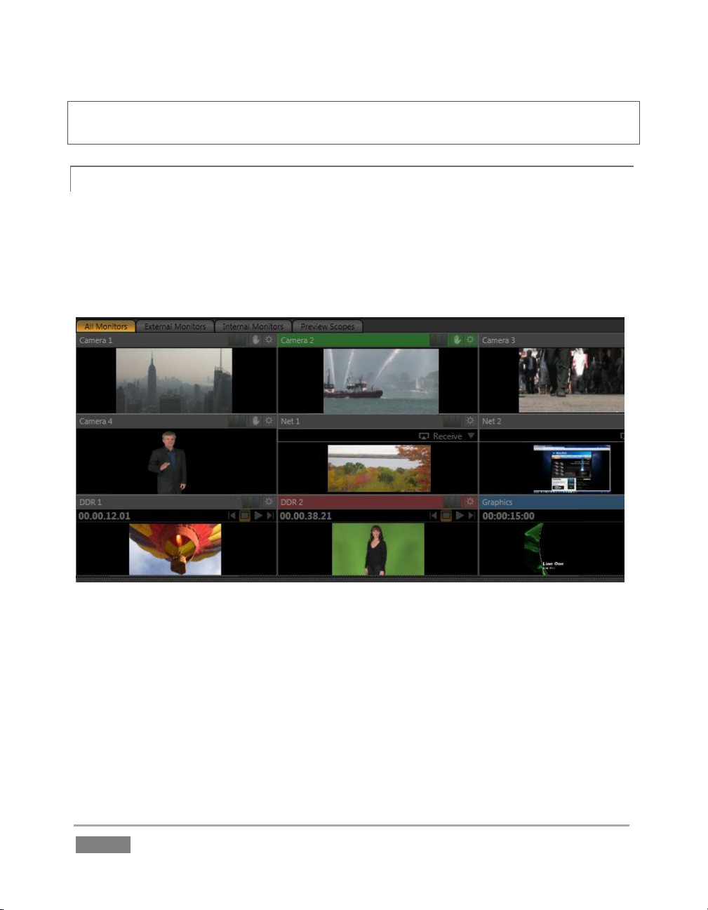
Hint: Move your mouse over Program Output, then click the Configure button (gear) that appears
above it to open a tabbed panel containing Proc Amp, Multiview and Genlock settings.
ALL MONITORS 4.3.2
Click the All Monitors tab at upper left to view dedicated monitors for all camera inputs, along
with an array of other sources. These include monitors showing the current playlist items in the
two DDRs, Graphics module, and Network sources – such as an iVGA input from another
computer on the network, a title overlay from a networked LiveText™ workstation, or Apple
AirPlay® stream.
Figure 33
Just as Audio tab layouts for different TriCaster models vary, so too do the monitoring tab
layouts. For example, for TriCaster 855 the All Monitors tab shows eight camera monitors, while
TriCaster 455 naturally has half that number. Otherwise, though, the various aspects of the
interface are quite similar.
The header of the monitor for the video layer source currently selected on the Program row is
highlighted in red.
Page | 44
Page 61

Figure 34
The monitor titlebar for the Preview row selection has a green tint, while the titlebar for the FX
source monitor is blue. Note that many of these onscreen monitors are interactive:
1. Click a (source) monitor once to select that source on the Switcher’s Preview row.
2. Click the monitor with the green highlight again to perform a simple Take, swapping the
Program and Preview row selections. Looked at another way, what you have done is
swap the BKGD (Background) video layer sources – without changing the display status
of any other video layers.
3. Double-click any source monitor to send it immediately to Program output.
And, as discussed back in Section 3.14, these monitors display a Configuration button allowing
input type selection and more, including Proc Amp (see Section 7.2.3) and LiveMatte controls
(see Section 4.9), and indicators depicting the on/off status of these features.
Further, some onscreen monitors provide other contextual controls and displays including things
like Play or Stop (Freeze), current position (timecode) in a clip, and Network source selection (see
Section 9.3.1).
EXTERNAL AND I N T E RNAL MONITORS 4.3.3
These two tabs offer other monitor layouts that you may find useful, especially when used in
concert with complementary Multiview monitor layouts.
Page | 45
Page 62

Figure 36
SCOPES 4.3.4
Figure 35
In this configuration, the tabbed monitoring area in the Live Desktop displays Waveform and
Vectorscope displays (along with a full color source video pane), invaluable for calibrating your
video sources.
1. Click the Scopes monitor tab.
2. Move your mouse pointer over the vertical divider separating the Scopes pane from the
main Preview monitor at right – click and drag the divider as far as it will go to the right.
3. Drag the horizontal divider separating the monitoring section from the Switcher area
below downward until you’ve got nice big scopes to work with (Figure 35).
4. Move the mouse onto the video monitor at left, and click the Configure button (gear) at
right in its titlebar to display the Configuration panel for the video source.
A drop-down menu at upper-left lets you choose whether the current
source for the scopes (and full-color monitor) is drawn from the Preview
row selection, Program row, or the FX row.
Feel free to experiment with the controls, but before leaving, restore the
monitoring panes to their default size as follows:
5. Move the mouse above one of the Desktop dividers you previously dragged, and
double-click it. Then repeat this process for the other divider, too.
Page | 46
Page 63
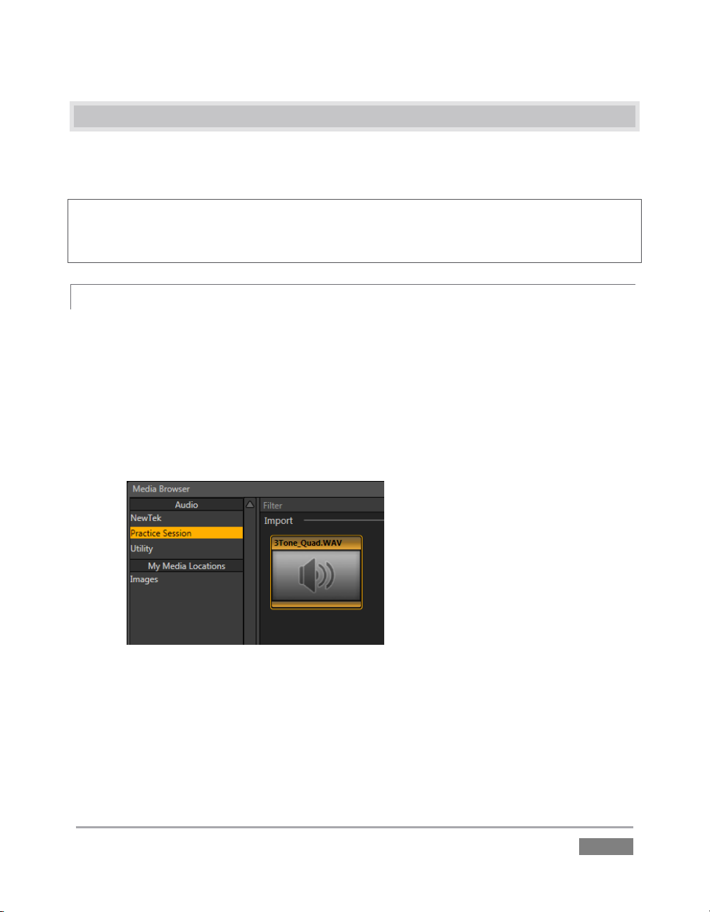
4.4 AU D IO MIXER
Having previously connected and configured your audio inputs, let’s explore a few of the
standard features in TriCaster’s two Audio Mixer tabs.
Hint: You will need to have speakers connected to (at least) the first two connectors (channel 1
and 2) in the PGM row of TriCaster’s Audio Out section (even better, if you have them handy,
connect a pair of stereo headphones and put them on).
MUTE, MONO A N D BALANCE 4.4.1
1. Click the Sound tab (at right below the Switcher area of the Live Desktop).
2. Click the Add button in the Sound pane.
3. Click the Practice Session entry under the heading Audio in the Location list at left (this
Location entry was created automatically when we imported files back in Section 4.2,
Importing Content).
Figure 37
4. Find the icon named “3tone_quad.WAV” in the file pane. This is a four channel audio
file, with a mid-range tone on channel 1, a higher tone on channel 2, while both
channels 3 and 4 both carry a lower tone.
5. Select the icon for this file, and click OK to add this sound file to the DDR 1 playlist.
Page | 47
Page 64
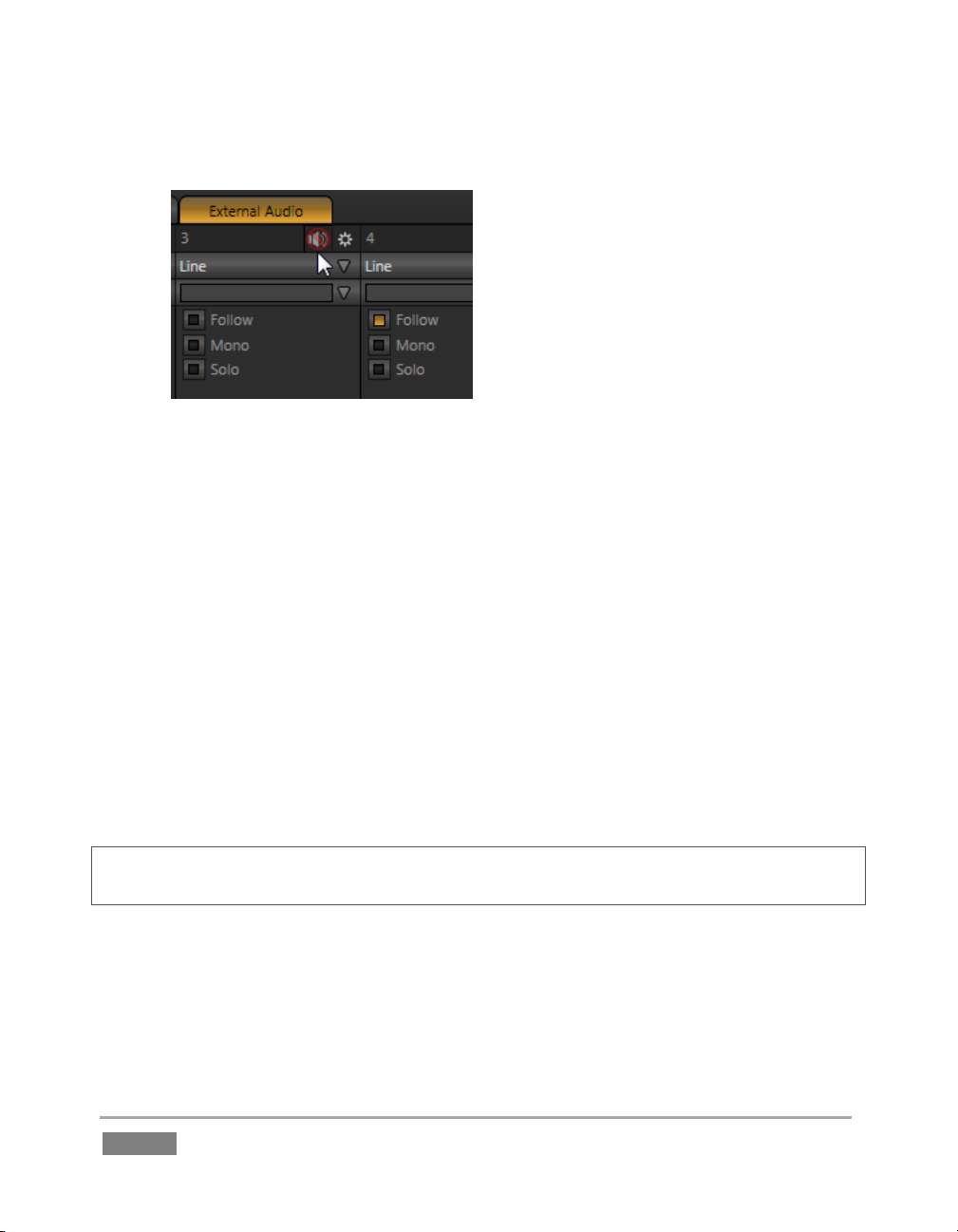
6. Turn on both Single and Loop for the DDR, then turn off Follow for DDR 1.
Figure 38
7. To avoid confusion later, click the External Audio tab and Mute any inputs that currently
show live audio on their respective VU meters (by clicking the speaker icons in the
titlebar of each control group so they show a red stroke through them) – see Figure 38.
8. Click the Internal Audio tab, and make sure audio for the Sound player is not muted.
9. Set the Sound player Gain slider to 0dB (you can do this quickly by holding down the
keyboard Shift key while double-clicking the Gain knob).
10. Click the Sound tab, and then click the sound player’s Play button.
If you have stereo speakers or headphones connected, you should now hear two distinct tones –
a mid-range tone from the left speaker (connected to Output CH1) and a higher pitched tone
from the right speaker (connected to Output CH2).
Hint: If you happen to have a ‘surround sound’ speaker setup with front and rear speakers, you
will also hear another even lower tone coming from the rear speakers.
11. The VU meter for Sound in the Internal Audio tab will show matching levels for all four
input channels.
Page | 48
Page 65

Figure 39
12. Next, drag the Balance slider all the way to the left. As you do so,
observe that the level shown for channel 2 and channel 4 are
gradually reduced. At the extreme left position, these two channels
are completely silent. Only the mid-range tone (on channel 1) is
heard (in a stereo environment), and only from the left speaker at
that.
Moving the slider to the right (of center) has the opposite effect,
reducing channels 1 and 3 – doing so without any effect on the
other 2 channels. At the extreme right position, only the mid-range
tone from the DDR file is audible (and only from the right speaker).
The lesson here is that (unlike either Mono or Pan, considered shortly)
Balance does not ‘move’ audio from one channel to another. You cannot use
Balance to ‘blend’ channel 1 with channel 2, for example. Rather, Balance
regulates the levels for one pair of channels (1 and 3, or 2 and 4) at a time,
and does not affect the other pair in doing so.
Let’s consider the effect of the Mono switch next:
13. Center the Balance control once again, so that you hear the mid-tone exclusively from
the left speaker, and higher tone from the right only.
14. Click the Mono switch. Notice that now a blend of the (channel 1) mid-range tone and
(channel 2) higher tone issue from both speakers.
15. To confirm that for yourself, slide the Balance knob to the extreme left. Although sound
is now issuing only from the left speaker, you can hear both tones.
16. Click Stop in the Sound player.
Note: the Mono switch has no effect on channels 3 and 4. These two channels are never blended
with channels 1 and 2 on output.
Page | 49
Page 66

Figure 40
A Pan slider is provided for both channels of External Audio
sources (when Mic is selected). Sliding the Pan knob left or
right actually moves (or ‘pans’) the audio from its original
channel onto its neighbor.
For example, when the Pan knob for Mic 2 is at the
extreme right, all of the sound from that source is sent to
output channel 2. Moving the slider leftward places an
increasing amount of the sound from Mic 2 on output
channel 1.
When the slider reaches the extreme left position, the sound from Mic 2 is now entirely sent to
output channel 1.
Pan
PAN 4.4.2
The Pan control looks much like the Balance slider, but has special abilities. Like Talk, Pan is only
available when the one of the two Mic input Types is chosen.
Hint: In their default center position, the two Pan controls have exactly the same effect as clicking
Mono. Actually, this is why a Mono is not needed in this case.
Pan thus provides precise control over where the audio from either Mic input is heard – whether
exclusively on output channel 1, 2, or whether differing levels from either source is sent to both
outputs.
TALK 4.4.3
Talk is an abbreviation of “Talk Over”. The Talk feature is only shown for inputs when they are
set to Mic.
17. Start the Sound player playing the audio tone file again.
18. With Input 1 set to Mic 1, 2, enable its Talk switch, watching the Sound player’s VU
Enabling it causes the level for all other audio sources to drop off by 20dB, allowing Mic 1 and 2
to dominate output. This is very useful for public address announcements, which is its principal
purpose.
Page | 50
meter as you do so.
Page 67
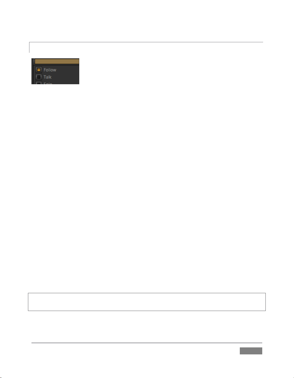
FOLLOW 4.4.4
Figure 41
19. Connect cameras to both Video In rows 1 and 2.
20. Connect two (audibly different) active audio sources to Audio In rows 1 and 2.
21. Enable the Follow switch in the Audio Mixer for both Input 1 and Input 2.
22. Select the button for video Input 1 on the Switcher’s Program row.
23. Select the button for video Input 2 on the Switcher’s Preview row.
24. Click the Audio Mixer tab.
25. Click the Switcher’s Take button
Notice that when the video source assigned to Input 1 is on output, you hear its associated audio
input. When you perform a Take placing Input 2 on output, the audio source connected to row 2
in the Audio In section is heard.
When Follow is enabled for an audio source, its sound is automatically sent to output whenever
the associated video source is displayed on output. In this case, the levels shown in the VU meter
for that audio source are drawn in color. When you switch away from that video source, the VU
meter still shows its audio level, but the graph is drawn in grayscale (providing confirmation that
audio is present, but indicating that it is not going live to Program out).
Hint: Follow even works when the associated video source is displayed on Output as an Overlay or
Virtual Input source.
Page | 51
Page 68

Figure 42
FOLLOW AND AUDIO GROUPING
Each audio control group has an additional drop-down located just below the Connection Type
menu. This is the Audio Group control.
Grouping allows you to gang multiple audio sources together. When
Follow is enabled for a group member, the sound from the entire
audio group is heard whenever the corresponding video source is
displayed.
Let’s test this:
1. Supply live sound to audio input 1 and 2, and set both inputs to a single group (color)
using the drop-down Group menu.
2. Enable Follow for Camera 1 and Camera 3 (but not Camera 2).
3. Select Camera 1 on the Switcher’s Program row. The audio from both input 1 and 2
should be audible.
4. Switch to Camera 3. The audio from inputs 1 and 2 is muted on output. (If audio input
3 has sound, you will hear it instead.)
Switch to Camera 2. Even though Follow is not turned on for input 2, you will nevertheless hear
sound from both input 1 and input 2 again. (This is because another input in the same group
does have Follow enabled.)
4.5 NE T W ORK SOURCES
Perhaps you’d like to be able to add Microsoft PowerPoint® output, web pages, Skype® video
calls, application displays, titles and graphics from NewTek’s LiveText™ or other exotic content to
your productions. TriCaster™ supports all such displays from computers on the same network as
Network (1 and 2) sources on the Switcher, via the supplied iVGA™ client application (not
required for LiveText).
Page | 52
Page 69

IVGA CLIENTS 4.5.1
1. For a Microsoft Windows® client, copy the iVGA program from the Extras folder (inside
C:\TriCaster) to the sending computer.
For OS X client systems, copy the appropriate iVGA.dmg.zip for your version of OS X
from the same folder to the Mac. Unzip it by double-clicking it; mount the disk image
(.dmg file) in the same manner, then drag the iVGA program icon into Applications. (See
Section 14.1 for more detail).
2. Connect TriCaster to the client computer via the local network.
3. Double-click the iVGA icon on the second computer.
After agreeing to the NewTek license (and a moment or two for the network connection to be
established) the name of the remote computer is added (along with “Black” and any other
networked systems with iVGA running on them) to the iVGA client list.
Note: Gigabit networking is highly recommended, and should be considered mandatory for HD
sessions in particular.
Figure 43
When TriCaster recognizes qualified network sources, it adds them to a drop-down menu for
quick selection (Figure 43).
4. Move your mouse pointer over a Network monitor in the All Monitors tabbed view.
5. Click the triangular menu button above the monitor to select a networked source (or
change the current selection) from the menu that appears.
Page | 53
Page 70

Hint: iVGA places a red-green-blue status icon on the client system. For a Windows-based system,
the icon is in the task tray; on Macintosh systems, it is shown in the dock. This indicates this
computer’s display is ready to send to TriCaster. The icon is animated when the iVGA source is
selected as the active Network source in TriCaster.
APPLE AIRP L AY 4.5.2
See Section 14.2 for details on using devices and applications supporting Apple AirPlay® as
network sources for TriCaster.
LIVETEXT™ 4.5.3
NewTek’s (optional) standalone LiveText™ application offers features that are very similar to
TriCaster’s integrated LiveText (see Chapter 17), but installs separately on a compatible Microsoft
Windows® computer.
A (networked) LiveText workstation effectively constitutes a dedicated CG and title solution for
TriCaster presentations. (This is a wonderful addition for those times when you could really use
another pair of hands.) When running on the network connected computer, LiveText is listed in
the Network selection drop-down menus (just as an iVGA source would be).
When you select LiveText (and click the Live button in LiveText), the current title page is available
via the Network buttons on TriCaster’s Switcher or in its DSK channels. For more information on
installing and using this great tool, please refer to the Chapter 17.
4.6 LI V E SWITCHING
Back in Section 3.4, you connected cameras to inputs on TriCaster’s backplate and configured
them. If you haven’t already done so, let’s explore basic Switcher operations.
SWITCHER ROWS 4.6.1
The Switcher features 3 rows of labeled buttons. From top to bottom, the three rows are labeled
Utility, Program and Preview. Each button on a Switcher row represents one of the many and
varied video sources available. The first button group at left on any row represents Cameras,
while others represent other special sources (discussed soon).
Page | 54
Page 71

Figure 46
Three of the four primary
video layers – BKGD, DSK
Figure 44 – TriCaster 455
Figure 45 – TriCaster 855
Clicking a button in any row selects the active source for that row. Utility row selections serve
various special purposes that we’ll come to a bit later. Your Program and Preview row selections
determine the content of the BKGD (Background) video layer.
VIDEO LAYERS
TriCaster video output often consists of multiple sources of imagery, added together layer on
layer to form a composite. The Switcher and Transition controls allow you to manage these
video layers to show the viewer just what you want him to see.
1, and DSK 2.
Page | 55
Page 72

The BKGD (Background) video layer constitutes the base of the video composition ultimately sent
to Program Output. Based on your Switcher operations, as many as three other primary video
layers may be superimposed above the BKGD layer on output:
The DSK 1 and DSK 2 video layers are most commonly used to apply graphics or titles to
the BKGD layer (DSK stands for ‘Down Stream Keyer’).
FTB (Fade to Black) constitutes a final video layer prior to output – one that can obscure
all others when called upon to do so. (FTB is less commonly used, and unlike the other
primary video layers, has no local transition controls - Figure 46).
As stated in the previous section, the Program and Preview row selections determine the content
of the BKGD (Background) video layer. The Preview row selection is normally cued up for the next
Take (cut) or Transition operation. Either operation, once completed, results in the original
Program and Preview row selections exchanging places. (Of course during a transition, portions
of both the Program and Preview row selections can be seen in varying amounts.)
The BKGD layer composition can include other content as well, as we’ll see later in Sections 4.9
(LiveMatte) and 4.10 (Virtual Inputs).
Hint: By default, selecting a tabbed module (DDR1, Still, etc.) on the Preview row automatically
shows the corresponding control panel in the tabbed panes below. Click the Desktop Options
button (gear), at extreme right just above the tabbed panes, to enable or disable this behavior.
CONFIGURING CAMERAS
Let’s try out some of these concepts, shall we? (If you previously configured some cameras, feel
free to skip ahead to the next sub-heading – The Utility Row).
1. First, confirm that the Connection Type selected for your video sources is correct.
a. Move your mouse over an Input monitor (All Monitors view).
b. Open the Configuration panel for that video source by clicking the Configure
button (gear) that appears in the monitor’s titlebar.
c. Choose a Connection Type setting that is appropriate for the camera.
d. Close the Configuration panel.
2. Repeat the steps above for all connected cameras.
Page | 56
Page 73

Figure 47
3. Click the Switcher button labeled ‘1’ on the
Program row to send Camera 1 to
TriCaster’s BKGD layer (the button turns
red, denoting its selected state).
(For experimental purposes, feel free to use
internal sources such as Media Players
rather than live cameras if you like – see
Section 4.8).
4. Click to select Camera 2 on the Preview row
(the button will light up in green).
5. Note that the titlebars of the corresponding
source monitors (All Monitor view) are now
also tinted red and green, respectively.
THE UTILITY ROW
Let’s take a moment to discuss the Utility row now. The steps we take here will come into play a
bit further on in our exploration.
Figure 48
Notice that a group of controls labeled Utility Delegate is provided to the right of the Utility row,
as shown in Figure 48). The group contains buttons labeled FX, AUX OUT, DSK 1 and DSK 2. The
selection you make here govern the Utility row buttons.
1. Click the tab for the Graphics tab (TriCaster 855 has a dedicated Title module you can
use instead), and Add a title to the playlist; choose one that does not cover the entire
screen.
Page | 57
Page 74

Main Layer Controls
Local Layer Controls
Figure 50
Figure 49
2. Add a different title to the playlist for DDR 2 (or Still, for TriCaster 855).
3. Click the button labeled DSK 1 in
the Utility Delegate group; this
delegates the Utility row to
control the DSK 1 source.
4. Click the Graphics (or Title)
button in the Utility row – note
that the label above the DSK 1
delegate button updates when
you do so.
5. Click the DSK 2 button in the Utility Delegate group, and use the Utility row to assign
DDR 2 as the current source for DSK 2.
TRANSITIONS 4.6.2
Now we’re ready now to try out the features in the Transition section, to the right of the
Switcher rows.
As shown in Figure 50, the Transition section is organized into two groups – the main layer
controls at left, with local layer controls at right. The latter group is divided vertically into
individual sections for the BKGD, DSK 1 and DSK 2 video layers.
Page | 58
Page 75

Controls for each layer are stacked in order of their appearance from ‘bottom to top’ on Program
output – first BKGD, then the other two layers in order. (FTB, the final video layer, has no
optional settings; thus it does not appear in this area.)
LOCAL CONTROLS
Let’s begin our exploration of switching with local controls and the BKGD (Background) layer.
Figure 51
1. Select Camera 1 on the Switcher’s Program row.
2. Select Camera 2 on the Preview row.
3. Click the All Monitors tab, and notice that the red and green highlighted titlebars
conform to the selections you just made.
4. Click the local Take button for the BKGD layer (Figure 51).
a. Camera 1 is removed from Program Out.
b. Camera 2 (previously the Preview row selection) moves to Program output.
c. The Camera 2 button is now lit up on the Program row.
d. The Camera 1 button is lit up on the Preview row.
e. The red and green monitor titlebars have been swapped.
Page | 59
Page 76

5. Now click the local Auto button for the BKGD layer. The Program and Preview row
selections swap again, but this time, rather than a simple (and instant) Cut, the change
employs the currently selected transition – by default, a Fade.
6. The icon for the current Transition for the BKGD layer has a gold border in the Transition
Bin at right. Click a different icon to select a different transition, and click Auto again.
7. To replace the current transition in the Transition Bin with a different one, follow these
steps:
a. Click a transition ‘slot’ other than Fade (the left-mot icon), and then click the
configuration (gear) button at extreme right.
b. Click the drop-down menu in the configuration panel, select Browse, and
choose a new transition from the many supplied with TriCaster (Figure 52).
Figure 52
8. To change the duration of the transition, click the drop-down menu next to the local
Auto button. (The time for the transition is shown as seconds and frames.)
9. Now click the local Auto button for the DSK 1 layer. Since Graphics is assigned to DSK 1,
the currently selected item in that Media Player transitions in to appear above the BKGD
layer.
MAIN CONTROLS
Having seen how local Transition controls work, let’s move on to their main counterparts.
Page | 60
Page 77

Figure 53
10. In the main Transition control group (Figure 53), click the BKGD button above the T-Bar.
This delegates the controls below to affect the Background video layer – only.
11. Click the button labeled Auto below the T-Bar (again, the main Auto button, not to be
confused with the local Auto buttons at right).
Figure 54
12. Click a different transition icon in the BKGD Transition Bin, and click the Auto button
again. (TriCaster supplies a wealth of transitions to suit every need).
13. Select a slower transition speed for the BKGD layer using the drop-down as before, and
click Auto again to test the new transition rate.
Note that local configuration settings for the BKGD layer do affect transitions performed using
the main controls:
Hint: Manually control the progress of a transition by grabbing the T-bar with the left mouse
button and dragging it downward.
14. Earlier, we displayed DSK 1, using its local Take button. The BKGD transitions we’ve
made did not affect it, so it should still be displayed (if you removed it from view while
experimenting, please restore it before continuing).
Page | 61
Page 78

Figure 55
15. With the BKGD delegate button lit up, press Ctrl on your keyboard, and keep it pressed
while you click the buttons for both DSK 1 and DSK 2 – then release it.
Your Transition Delegate buttons should resemble Figure 55, with three delegates multi-selected.
Note also that the Take button for DSK 1 is illuminated in Figure 55, and the progress gauge
beneath the Delegate button likewise shows that DSK 1 is fully displayed.
LOOK AHEAD PREVIEW
Back in Section 4.3.4 we promised to spend some time on the Look Ahead Preview monitor, and
the time has finally arrived for us to do so together.
Figure 56
Page | 62
Page 79

1. Cast your eyes over the Preview and Program monitors; consider what you see there,
and how it relates to the Transition Delegate controls:
a. The Program monitor shows DSK 1, currently assigned to Graphics (or Title),
over the current BKGD layer. The latter, at the moment, is the Program row
selection.
b. The Preview monitor shows DSK 2, assigned to Still (or DDR 2) overlaid on the
current Preview row selection.
The Look Ahead Preview monitor (or simply, Preview) is showing us the composition that will
result if a Take or Transition operation is performed – a look into the future, if you will.
2. Hold down Ctrl on the keyboard, and click the BKGD Delegate button (de-selecting it).
Note that, after de-selecting the BKGD delegate button, the Preview monitor no longer shows the
Switcher’s Preview row selection. Why is that? At this moment, only the DSK 1 and DSK 2
buttons remain lit – thus only those two video layers will be affected by a main Take or Auto
operation. The result will be as follows:
DSK 1, currently seen on Program out, will be removed from view
DSK 2 will be overlaid above Program instead.
The BKGD layer will not change in this case. Hence Preview correctly depicts the
outcome of a Take or Auto, just as we’ve mentioned.
The Look Ahead Preview allows you to switch with real confidence; the Transition Delegate
features provide flexible and convenient video layer management, and thus enhanced control
over your ultimate Program output composition.
4.7 RE C ORD AND GRAB
Figure 57
Located immediately beneath the Program monitor are Record, Stream and Grab buttons (along
with their respective Configure buttons). We’ll discuss streaming further on, but let’s consider
Record and Grab here.
Page | 63
Page 80

RECORD 4.7.1
Figure 58
1. Click the Configuration button (gear) next to Record (Figure 58).
2. The Record Configuration panel opens (Figure 59).
3. Click in the Base Name field, and enter a unique name for the captured file(s).
Hint: TriCaster stores recordings at (drivename):\Media\Clips\sessionname\Capture (where
“drivename” and “sessionname” are appropriate entries for your system and session).
Figure 59
The default Encoding options and Destination will work just fine for our current purposes, so let’s
continue:
4. If necessary, select PGM as the Source to be recorded.
5. You could optionally enable the Add to DDR Playlist switch to automatically add newly
recorded clips to the (currently designated DDR) playlist – but let’s not do that yet.
With IsoCorder™ technology, TriCaster can capture multiple a/v sources simultaneously. The
first of these sources is the Primary source, and defaults to PGM (Program output). Additional
sources in many combinations can be added in a Secondary recording group shown below. The
options are discussed in more depth in Chapter 16, entitled Record and Grab.
Page | 64
Page 81

6. Click Close.
7. Make sure you have an active source playing on Program output.
8. Press the Record button (Figure 58) – it will illuminate, and the neighboring timecode
field will begin keeping track of the duration of your recording.
9. After a little while, press Record again to stop recording.
This configuration will record everything that is displayed on Program Output in this manner,
letting you capture your entire live production for posterity if you like; it also provides a way for
you to capture clips for playback (from TriCaster’s DDRs) during your live events.
GRAB 4.7.2
Figure 60
The Grab feature is similar to Record, just described - except of course that it grabs a fresh still
image from Program Output each time you click the Grab button.
Also, in place of an option to add the captured file(s) to a DDR, you may enable an Add to Still
Playlist switch, with the result that every time you click Grab a new image is added to the Still
Media Player.
Page | 65
Page 82

4.8 ME DIA PLAYERS
DDR 1 AND 2 4.8.1
TriCaster’s two DDRs (Digital Disk Recorders) are powerful media players, and can greatly
enhance your live productions. DDRs have three siblings that we’ll discuss later – the Still and
Title players, and the Sound player.)
1. Show DDR 1 by clicking its tab beneath the Switcher.
Figure 61
ADDING FILES
Figure 62
Page | 66
Page 83

Figure 63
2. Click the Add button in the DDR 1 pane (Figure 62) to open a Media Browser.
3. Click the name for your current TriCaster session (Practice Session, if you’ve been
following along) beneath the Clips header in the left-hand column of the Media Browser.
4. The file pane at right displays icons for recordings made in the session. It should list the
file you recorded earlier (in Section 4.7.1) under a group header labeled Capture – click
the icon to select it, and then click OK.
5. You may wish to add several more files to experiment with (DDR 1 and 2 also support
most popular audio file formats).
Hint: See also the sub-heading entitled Section 10.2.1 regarding per clip audio levels.
The playlist of the two DDRs as well as Sounds has an additional audio
feature. The icons of files with audio will display a small configure (gear)
icon at lower right. Click this icon to pop up a small level slider.
Note: When playing files located in TriCaster's 'capture folders', DDRs automatically adjust the
audio level according to the current Audio Headroom setting in the Record Configuration panel.
This results in an improved match between the default playback level for captured audio and
imported sounds or music (for which nominal levels are unknown).
TRANSPORT CONTROLS
Figure 64
Page | 67
Page 84

6. Click the newly added icon in the playlist, and press the Play button in the player’s
footer (Figure 64).
a. The video clip you recorded should play on the DDR onscreen monitor (All
Monitors view).
b. Click DDR 1 on the Switcher’s Program row, it will appear on Program Output.
7. Click the Stop button.
Notice that if you move the mouse pointer over the Speed slider, it changes to a doubleheaded arrow, indicating you can drag the slider to a new value if you wish.
8. Instead, try this: simply click inside the Speed slider (engaging direct edit mode), type
“50” and press Enter to change the Speed to 50%.
9. Click Play again, and observe that playback is now in slow motion.
10. Adjust Speed again – notice that you can even modify Speed during playback.
11. Click Stop.
TRIMMING AND SCRUBBING
Let’s spend a moment learning how to trim a clip in the DDR. To do this you will use tools in the
Scrub Bar immediately beneath the playlist pane (Figure 65).
Figure 65
Drag the Scrub Bar’s square blue knob left or right to change the current play position. Trimming
is accomplished by dragging the start and end points for the clip using the blue ] and [ bracket
controls at either end. (The mouse pointer changes to a double-headed arrow when you move it
over a trim control.)
Page | 68
Page 85

12. Click the first (top-left) clip in the playlist, highlighting it.
13. Drag the trim controls to shorten the clip’s runtime to 10 seconds (watching the
Duration display to the right of the Scrub Bar helps when trimming).
14. Record a few more clips, if you haven’t already done so, and add several to the playlist
(either automatically or by using the Add button).
SINGLE AND AUTOPLAY
15. Click the Single switch (Figure 66).
Figure 66
16. Double-click the first clip in the DDR playlist to play it (double-clicking is another way to
engage Play). With Single mode engaged, playback automatically stops at the end of the
current clip.
17. Select Camera 1 on the Switcher’s Preview row (DDR 1 is already selected on the
Program row).
18. Enable the Autoplay switch for DDR 1.
19. Play the first clip in the playlist again. This time, just as the clip approaches its end, the
Switcher automatically performs a transition (the sources on Program and Preview are
automatically swapped), leaving Camera 1 on Program output.
20. After a few moments, click either Take or Transition in the Switcher’s Transition section.
Page | 69
Page 86

Notice that a transition is performed (returning DDR 1 from Preview to Program) and, more
importantly, the next item in the playlist begins to play automatically -- right on time. When it
ends, another automatic transition occurs, restoring Camera 1 to Program output.
Let’s try Autoplay without Single mode:
21. Click Stop (if necessary).
22. Uncheck Single, leaving Autoplay engaged.
23. With DDR 1 on Program, and Camera 1 on Preview, highlight a fairly long clip (say, a
minute or more).
24. Click Play.
25. After a few seconds, perform a Take and watch what happens:
a. Naturally, DDR 1 and Camera 1 are swapped on the Switcher.
b. DDR playback is stopped at the current frame of the current clip.
26. Perform another Take
a. As expected, DDR 1 is restored to Program output.
b. Playback re-commences at the next frame of the current clip; The DDR did not
automatically jump ahead to the next clip this time.
You may find Single mode your usual choice, but it can be useful to turn it off (as just described)
at other times. Perhaps a live speaker is presenting a long clip, but wants to be free to interrupt
it with live commentary at any time. Turning Single off (with Autoplay on) works perfectly in this
scenario. The TriCaster operator can click Take or Transition freely, confident that DDR playback
will resume at precisely the right frame when he does so again.
PRESETS
Let’s consider one more powerful feature common to TriCaster’s media players – the Presets Bin.
These bins run vertically down the outer edges of all Media Player (and Audio Mixer) modules,
providing instant access to custom playlists and configurations.
Page | 70
Page 87

Figure 67
Normally hidden, the preset bins fly out when you move the mouse pointer to
the edge of the screen.
Presets store other information about the current state of the module, too,
including playback position, selection status, and so on. In many ways,
presets act like tabs that reveal even more media players.
27. Click a different preset icon, and use the Add button to populate it.
28. Switch back and forth between presets, noting as you do how
various attributes are retained.
29. Try copying and pasting playlist icons between two presets (right-click on an icon to
access the context menu containing Cut, Copy and Paste).
30. Notice that if a clip is playing, a Stop action occurs when you change presets.
GRAPHICS, S T IL L & TITL E 4.8.2
TriCaster 855 provides dedicated players for Still and Title, while TriCaster 455 offers a combined
Graphics player. In either case, all of these are actually essentially the same, identified by name
mostly for convenience in use. All are similar to DDRs, just discussed, but for the fact that they
do not offer clip playback.
Whether your TriCaster has a combined Graphics player, or individual Still and Title players, the
type of media files they support remains largely the same. Each of these players, regardless of
title, can display TriCaster title pages and popular still image file formats.
Hint: The DDRs can play all of the above media types as well as video clips and sound files.
EXPLORING AUTOPLAY AND SINGLE
The controls of the graphics players are identical to those of the DDR apart from the omission of
a playback Speed control (which would be superfluous and possibly confusing). Rather than
cover these again, let’s have a little fun:
Page | 71
Page 88

1. Click both DDR 1 and the Graphics (or Still) tabs, so you can see both players. (TriCaster
855 owners can use Still and Title instead).
2. Click any icon in the DDR 1 playlist, and press CTRL + a on the keyboard, to select all of
the playlist entries.
3. Press Delete on your keyboard, clearing out the entire playlist (this is a non-destructive
deletion, never fear).
4. Repeat the two steps above for Graphics (Still).
5. Add some image files (a dozen or more) to DDR 1 (you can use some of the images from
the NewTek Content group under the Still location heading for this example).
6. Click on one the icons about halfway through the playlist, highlighting it.
7. Hold down the Shift key, and click the last icon in the playlist. This will multi-select all of
the files from the first one you clicked to the last one (the icons are given a lighter
outline to show their selection status).
8. Right-click anywhere in the playlist, and select Cut from the context menu.
9. Right-click in the playlist area of the second Media Player, and select Paste.
Let’s pause to review. To this point, we've prepared two Media Players with similar playlists
consisting of a series of still images.
Hint: Still image files default to a fifteen second duration when added to a playlist.
Fine, but ‘what about the aforementioned fun’, you ask? Indeed, let us press on:
10. Turn Single and Autoplay on, and make sure Loop is off for both Media Players.
11. Select DDR 1 on the Switcher’s Program row.
12. Select Graphics (Still) on the Switcher’s Preview row.
Page | 72
Page 89

13. Click the first entry in both playlists (to set the current position).
14. Press DDR 1’s Play button, and watch the ‘hands-free’ slideshow.
Let’s consider what is happening:
When playback of the first DDR playlist entry reaches its end:
o The DDR’s Autoplay setting invokes an automatic BKGD layer transition to Still
o And stops DDR 1 playback
o Then, unseen on Program output, cues up its next playlist item.
Simultaneously, the Graphics (Still) player’s Autoplay setting initiates playback of its first
playlist entry.
When playback of that item is reached:
o The Graphics (Still) player’s Autoplay function performs another transition,
returning DDR 1 to the Program row
o And stops Graphics (Still) playback
o Then, unseen on Program output, the Graphics (Still) player cues up its next
playlist entry.
Next, DDR 1’s Autoplay setting automatically starts playing its next playlist item. The
cycle repeats until all items play through or is interrupted by user actions.
TITLE
TriCaster title pages can actually be added to any of the Media Players (apart from the Sounds
player). The Media Players can also display bitmap files exported from third-party graphics
applications (or overlay them using the DSKs when the files are either keyed or have an
embedded alpha channel) – all of which is quite handy. However, TriCaster’s native title pages
have some distinct advantages over a common still image. Let’s try them out:
1. Click Add, and use the Media Browser to select a few of the prepared title pages from
the NewTek location listed under Titles in the Location List at left.
Page | 73
Page 90

2. Click an icon to highlight it in the Media Player playlist.
3. Display the title page on Program Output by selecting the correct Media Player on the
Switcher’s Program row.
4. Move the mouse over a different title page icon, and click the Configure button (gear)
that appears in its lower-right corner.
5. The Title Page Editor shown in Figure 68 will appear.
Figure 68
6. Move the mouse over the default text shown in the Title Page Editor’s preview pane,
and notice that a white bounding-box appears as you locate editable items.
7. Double-click inside the bounding-box for a line of text to open a text entry field; type
something different, then press Enter on the keyboard to accept the changes.
8. Notice that you were able to edit a page without disturbing the title already displayed
on Program Output - Click the Close button.
9. Repeat your text edit operation, but this time modify the title that is displayed on
Program Output – notice this time that the display updates immediately.
Page | 74
Page 91

Figure 69
10. Try changing the Font, Size and other attributes for a line of text, using the tools in the
Title Page Editor’s titlebar (Figure 69).
11. Click the Close button.
4.9 LI V E MATTE
Let’s try something different now – using LiveMatte to create a typical ‘weather report’ shot.
(We’ll use a pre-recorded sample clip for this task, but of course if you happen to have a
greenscreen studio ready to use, just skip the first three steps below, and select the appropriate
Input button on the Switcher’s Program row - instead of the DDR).
Figure 70
1. Change the Switcher’s Program row selection to V1, and enable the BKGD delegate
button in the Transition section of the Switcher.
2. Remove any extraneous DSKs left from earlier operations from view, using the local
Take buttons in the Transition section of the Switcher.
Page | 75
Page 92

Figure 71
3. Click the tab labeled V1 (Figure 71) below the Switcher to reveal the panel for Virtual
Input 1.
4. Make sure the current LiveSet selection (shown at upper-left just below the tab, is
Default > A over B (Figure 71).
Figure 72
5. Notice that the lower portion of the Virtual Input panel contains two source button rows
labeled Input A and Input B (Figure 72).
a. Select DDR 1 in the button row labeled Input A.
b. Select the Graphics (or Still) button in the Input B row.
6. Click the DDR 1 tab, and Add the video clip named Kiki 1 Center.mpg from the Green
Screen group inside the Clips>NewTek location.
7. Click the Graphics (or Still) tab, and add the image named texas_weathermap.png (from
Practice Session, under Still in the Location list).
8. If you are not already viewing All Monitors, click that tab at the top of TriCaster’s Live
Desktop.
9. Move your mouse pointer over the DDR 1 monitor, and click the Configure button (gear)
that pops up at right in the titlebar above the monitor.
Page | 76
Page 93

10. Click the LiveMatte tab in the Configuration panel that opens.
Figure 73
11. Click on the Color button in the Matte section of the panel, and keep the mouse button
depressed.
12. Drag the eye-dropper pointer over the green background in the DDR’s monitor, and then
release it (Figure 73). This establishes the primary key Color.
13. The default LiveMatte settings (Tolerance and Smoothness) are close enough for this
little demonstration, so you can close the Configuration panel now.
We’ll look at the details of LiveMatte in more depth in Part II (the Reference section), but already
your result (as viewed on Program output) should look very similar to Figure 70. TriCaster
doesn’t stop here, though. Let's look a little more closely at TriCaster’s powerful Virtual Inputs.
Page | 77
Page 94

4.10 VIRTUAL IN P UTS
Virtual Input buttons sit innocuously on TriCaster’s Switcher rows just like other video inputs, but
in fact they possess very powerful features. They can be likened to the M/E (Mix/Effect) rows of
a traditional video switcher, in that they permit a composition to be prepared from multiple
sources. In addition to the two sources just considered (Inputs A and B), Virtual Inputs provide
an integrated Overlay channel, as well.
COM P OSING INPUTS A AND B 4.10.1
When we ended the previous section, the simple ‘weather map’ setup (Figure 70) we created
was on Program Out. Again, remember that LiveMatte is already enabled for the greenscreen
shot from our previous exercise.
We can use a few of the unique features of Virtual Inputs to dress up our production. For
example, we might want to transpose the greenscreen talent shot to one side, placing it offcenter in the result.
Figure 74
1. Click the Position button just to the right of the Input A row to open the Position panel
(Figure 74) for Input A.
Page | 78
Page 95

There are three sets of numeric sliders in the Position group in this panel: one with a fourpointed arrow button above, a rotation group, and another identified by a magnifying glass
button. Experiment with these controls a bit to see how they work.
Hint: Shift + double-click a control to reset it to defaults.
You can drag the mouse over the top buttons in each group to freely adjust Position, Rotation or
Size on multiple axes at once, or use the numeric sliders below to adjust just one property. As
currently configured, Program output displays the result of changes you make; of course, during
a live production you’d likely use Preview to set this up, instead.
Hint: When the Lock (padlock) button for the Size controls is lit, vertical and horizontal
adjustments are locked together – adjusting one affects both. When unlocked, the vertical and
horizontal scaling factors are independent.
Drag vertically over the ‘magnifying glass’ button to modify vertical scale, or drag laterally to
adjust the horizontal scale. Another way to constrain the action to one axis is to hold down the
Ctrl key before dragging.
2. Click Reset Positioning to restore default Position, Rotation and Size.
3. Drag the horizontal (upper) Position mini-slider to the right, locating the foreground
(talent) shot as seen in Figure 75.
Figure 75
Page | 79
Page 96

Without having moved the physical camera, we have changed the apparent position of our talent
relative to the virtual backdrop.
ADD I N G AN UPSTREAM OVERLAY 4.10.2
Figure 76
Just above the Input A row, you’ll see a control area labeled Overlay, with its own source row
along with other controls.
The Overlay feature in Virtual Input works very much like the two downstream DSK video layers
we used back in Sections 4.6.1 and 4.6.2, but is upstream of the Switcher. Thus content in this
overlay channel thus appears beneath anything you display in those two video layers on Program
Output.
4. Access the Graphics or Title player, and click the “Breaking News.CGXML” icon
(imported back in Section 4.2) from the Practice Sessions folder.
5. Edit the top line in the title to say “5 Day Forecast”, as shown in Figure 77.
6. Select Graphics (Title) in the V1 tab’s Overlay row, and display the Virtual Input’s overlay
channel by clicking the Auto button in the Overlay Transition area of the VI tab).
Figure 77
Page | 80
Page 97

As you can see, we have replicated on our earlier composition (which relied on the FX channel),
with additional benefits:
The title page can be displayed automatically or independently when you select V1 on
the Switcher, and both of the primary DSK video layers are left free for other uses.
Virtual Inputs allow you to offset (and even scale) the primary video source – of course
this works every bit as well with live camera streams.
As well, since the entire composition is now represented by a single button on the Switcher, it is
very easy to Take or Transition directly to it with a single click – and it is just as easy to transition
from one Virtual Input to another.
Of course, this is just one way to use the basic Virtual Input features. The creative possibilities
are endless. For example, Figure 78 shows Input A (with LiveMatte enabled) keyed over Input B,
with the Virtual Input’s integrated Overlay channel use to add a PiP (Picture in Picture) effect.
Figure 78
Again, note that this setup leaves both primary DSK channels available for other purposes, such
as adding two more live PiPs, graphics or a title composition.
LIVE S E T ™ 4.10.3
We’ve saved the best for last in connection with Virtual Inputs, however. This is also where we
gain access to TriCaster’s virtual set technology called LiveSet.
Page | 81
Page 98

Hint: Actually, if you’ve been following along, you have already used a LiveSet – a very simple
composition named “A over B” (Figure 79), the default.
Figure 79
As its name implies, A over B simply produces a composite of the video source you select as Input
A displayed on top of Input B. In cases where LiveMatte is active for Input A, or if Input A has an
alpha channel (as might be the case, for example, for a 32bit image file), or for that matter, if
Input A is scaled down or repositioned – Input B will automatically show through transparent
areas in the composition (we can see that result in Figure 78).
The name of the current LiveSet is shown above the Zoom Preset thumbnail icons at the top of
the Virtual Input tab – in this case, we see “NewTek > Default > A over B”, identifying the specific
LiveSet, a member of the “Default” group in the “NewTek” folder - Figure 79.
Let’s try something more sophisticated now:
1. Click Take (or de-select the BKGD delegate) in the Transitions section of the Switcher, to
place V1 on Preview.
2. Add the file TriCaster Spin Logo (Long).avi from the NewTek > Logos group to DDR 2.
Enable the Single, and Autoplay switches for both DDR 1 and DDR 2.
3. Click the Configure (gear) button beside the current LiveSet name in the V1 tab to
display a Media Browser.
4. Select NewTek in the left-hand column under the heading LiveSets.
5. In the file pane at right, click the thumbnail icon named Center in the World Update
group, and then click OK at the bottom of the Media Browser.
Page | 82
Page 99

6. Select DDR 2 as the source for Input B.
The Zoom Preset icons in the Virtual Input tab and the name above will update, showing that the
current LiveSet is now NewTek > World Update > Center.
Figure 80
Assuming that you still have LiveMatte enabled for the DDR, V1’s Input A selector set to DDR and
Input B set to Still, a little adjustment in the Positioner for Input A is all that it should take to
produce a result similar to Figure 80 on Preview.
Input A is the primary input for the LiveSet, while Input B serves as a secondary source – in this
case assigned to the virtual desk-front monitor.
7. Enable the BKGD delegate in the Switcher’s Transition control group, and click the main
Auto button. Both DDRs will begin running their currently selected clips simultaneously
thanks to Autoplay (of course normally your foreground shot would be supplied by a
camera).
Figure 81
Page | 83
Page 100

8. Now, click the second Zoom Preset icon (Figure 81).
Observe that the view on Program output (Figure 82) has now zoomed in by 33% - the value
shown in the adjustable zoom slider above Zoom Preset 2.
Figure 82
9. Enable the Animate Zoom switch, and click Zoom Preset 4.
The zoom gradually changes from the starting position to the level assigned to Preset 4 (100%).
The timing for the change is controlled by the nearby duration time controls.
Using the other Virtual Inputs along with convenient presets, you can easily mimic a very large
studio complex from a much smaller location.
4.11 FRAME BU F F E RS
To this point, we have used photos, graphics and titles from TriCaster’s Media Players as sources
for several different exercises. Of course, for Overlay and DSK purposes, this requires you to be
sure that that the current playlist entry in the respective Media Player is the right one for the
moment.
TriCaster’s Frame Buffers provide an alternative workflow that not only prevents selection
‘accidents’, but also offers other benefits.
Page | 84
 Loading...