

25MM RACE SERIES TUB ULAR FRONT ANTI-ROLL BAR – PART #15.02.25.3
Fits 2006-up Audi A3(8P) FWD, 2008-09 Audi TT(8J) FWD, 2006-up VW EOS, GTI MKV/VI, Jetta V/VI, Rabbit & Tiguan FWD
PARTS LIST: TOOLS REQUIRED:
1 – 25mm TUBULAR ANTI-ROLL BAR 1 – SILICONE GREASE 1 – T25 TORX 1 – RATCHET 1 – 10mm SOCKET 1 – 13mm SOCKET
2 – U-CLAMP w/BASE 2 – URETHANE BUSHINGS 1 – 16mm SOCKET 1 – 18mm SOCKET 1 – 18mm WRENCH 1 – WD-40
1. Park vehicle on a flat, level surface
capable of supporting the vehicle’s
weight on a jack and jack stands. Using
the manufacture’s recommended lifting
point(s), raise front of vehicle and
support with jack stands. NEVER
WORK ON A VEHICLE SUPPORTED
ONLY WITH A JACK!
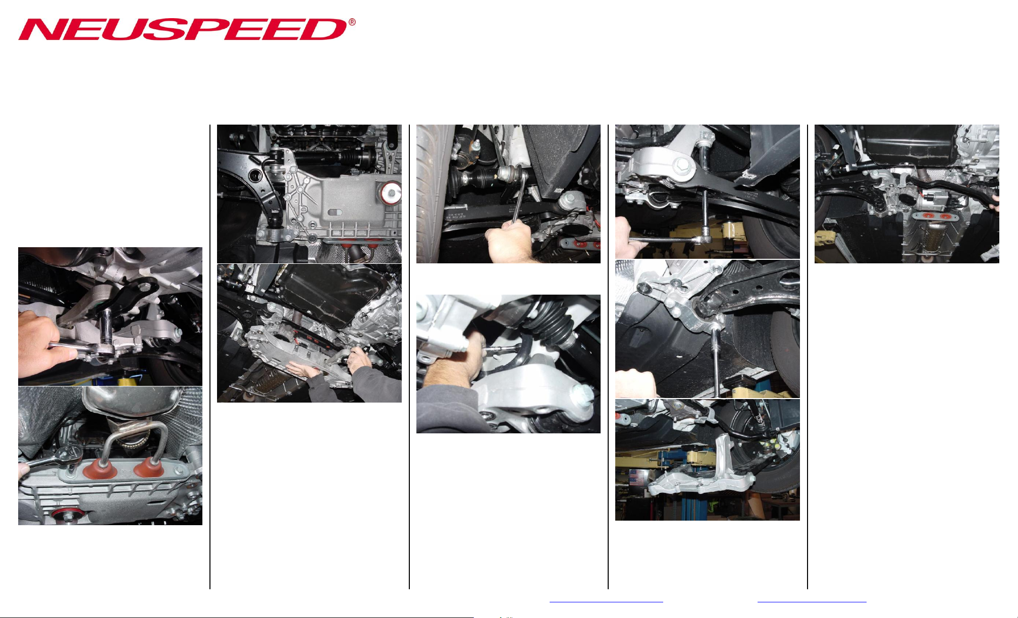
2. Remove lower engine splash pan (8)
T25 Torx screws.
5. Unbolt anti-roll bar from end-links
18mm hex nut.
8. Remove original anti-roll bar. Pull out
driver’s side first, then lift up steering
rack on passenger’s side to ease
removal.
9. With supplied grease, lubricate inside of
supplied urethane bushings. Install
bushings onto NEUSPEED anti-roll bar
just inside of stop washers.
3. Unbolt torque arm from transmission
housing (2) 16mm hex bolts and
exhaust down-pipe support bracket from
rear of aluminum sub-frame (2) 13mm
hex bolts.
NEUSPEED® • 3300 Corte Malpaso • Camarillo, CA 93012 • 805.388.7171 • 805.388.0030 FAX • information@neuspeed.com • Visit us on the web…http://www.neuspeed.com
4. Unbolt and remove aluminum sub-frame
from vehicle:
(4) 16mm hex bolts [Steering Rack]
(4) 13mm hex bolts [Bushing Clamps]
(4) 18mm hex bolts [Sub-frame Mount]
The two rear sub-frame bolts are
special, do not mix. Please see bolt
location photo at end of document for
bolt identification and locations.
6. Driver’s side of vehicle: Unbolt plastic
wire guide from aluminum control arm
mount 10mm hex bolt.
7. Unbolt aluminum control arm mount
from uni-body and let swing down.
NOTE: Because of enlarged mounting
holes, use marking pen to mark location
of control arm mount to uni-body. This
will aid in keeping the original
alignment.
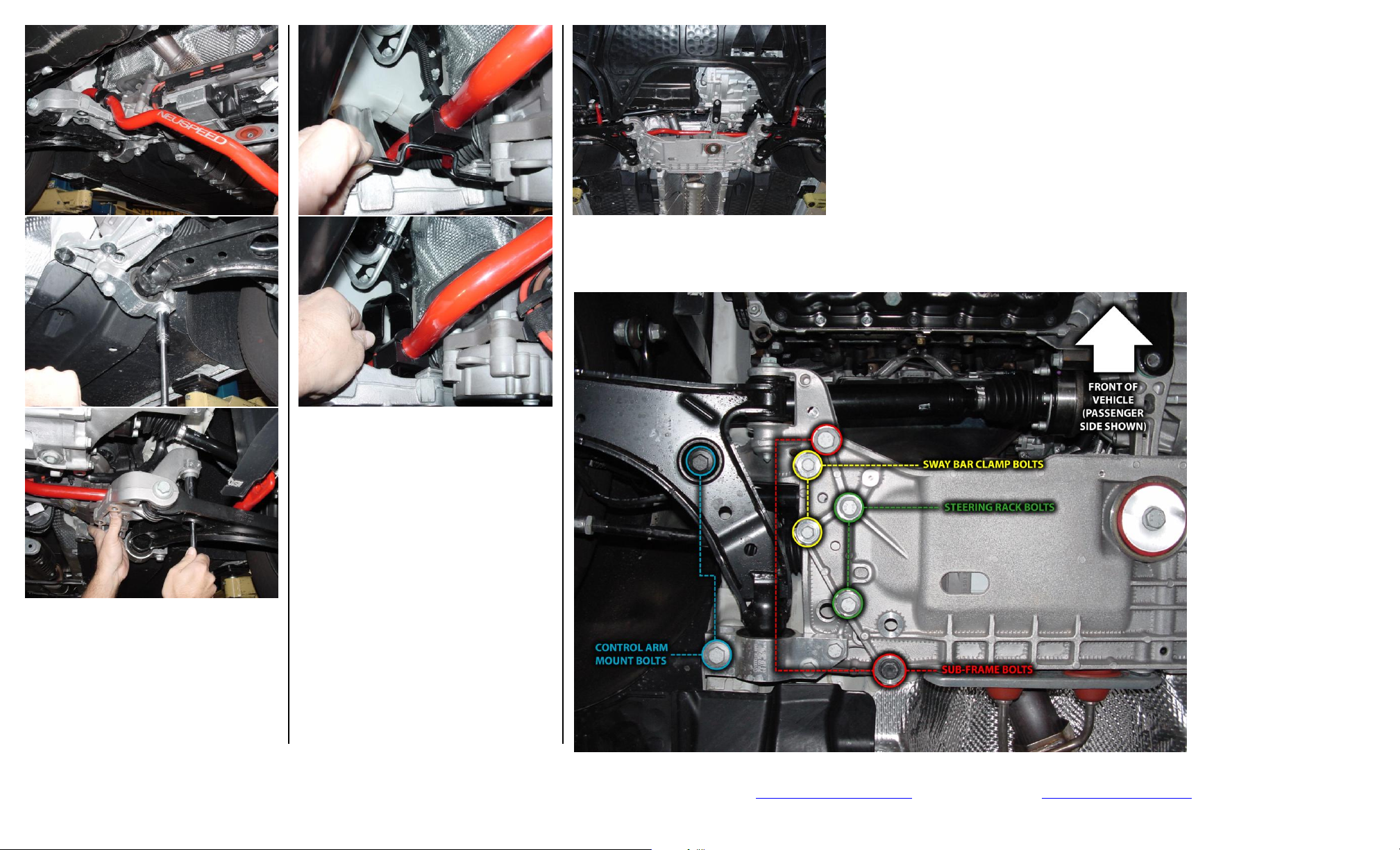
BOLT IDENTIFICATION AND LOCATION PHOTO
©Copyright 2007, NEUSPEED® All rights reserved.
Reproduction in whole or in part prohibited.
DOC.15.02.25.3 Rev. 02.09.07
14. Reinstall plastic wire guide, torque arm
bolts and engine splash pan.
15. Double-check complete installation and
TEST DRIVE CAREFULLY!
12. Put into position urethane bushing base
and “U” bracket.
13. Reinstall aluminum sub-frame, start all
bolts by hand and use WD-40 or
equivalent on bolt threads. When
installing anti-roll bushing clamp bolts,
make sure bolts go thru bushing base
then thread into nuts on “U” bracket.
First; line up pen marks on uni-body
and tighten control arm mounting bolts,
then evenly tighten all other bolts.
TORQUE SPECS:
10. Install NEUSPEED anti-roll bar
passenger’s side first. Lift up aluminum
control arm mount and guide steering
rack alignment bushings onto mount.
Hand-tighten bolts.
11. Attach original end-links to anti-roll bar
with original nuts and tighten.
Control arm mount & sub-frame: 18mm hex
bolts 70Nm (52 Ft.-Lbs.) + 1/4 turn
Steering rack: 16mm hex bolts 50Nm (37
Ft-Lbs.) + 1/4 turn
Anti-roll bar clamp bolts: 13mm hex bolts
20Nm (15 Ft-Lbs.) + 1/4 turn
Torque arm mount at transmission: 16mm
hex bolts 40Nm (30 Ft-Lbs.) + 1/4 turn
NEUSPEED® • 3300 Corte Malpaso • Camarillo, CA 93012 • 805.388.7171 • 805.388.0030 FAX • information@neuspeed.com • Visit us on the web…http://www.neuspeed.com
 Loading...