

Page 1

ProSafe Wireless-N Access Point WNAP320
Reference Manual
350 East Plumeria Drive
San Jose, CA 95134
USA
January 26, 2011
202-10724-01
v1.0
Page 2

ProSafe Wireless-N Access Point WNAP320 Reference Manual
©2011 NETGEAR, Inc. All rights reserved.
No part of this publication may be reproduced, transmitted, transcribed, stored in a retrieval system, or translated
into any language in any form or by any means without the written permission of NETGEAR, Inc.
Techni c a l Supp o rt
Thank you for choosing NETGEAR. T o register your product, get the latest product updates, or get support online,
visit us at http://support.netgear.com.
Phone (US & Canada only): 1-888-NETGEAR
Phone (Other Countries): See Support information
card.
Trademarks
NETGEAR, the NETGEAR logo, ReadyNAS, ProSafe, Smart Wizard, Auto Uplink, X-RAID2, and NeoTV are
trademarks or registered trademarks of NETGEAR, Inc. Microsoft, Windows, Windows NT, and Vista are
registered trademarks of Microsoft Corporation. Other brand and product names are registered trademarks or
trademarks of their respective holders.
Statement of Conditions
To improve internal design, operational function, and/or reliability, NETGEAR reserves the right to make changes
to the products described in this document without notice. NETGEAR does not assume any liability that may occur
due to the use, or application of, the product(s) or circuit layout(s) described herein.
Revision History
Publication Part Number Version Publish Date Comments
202-10724-01 v1.0 January 2011 First publication
2 |
Page 3

Contents
Chapter 1 Introduction
Chapter 2 Installation and Basic Configuration
About the ProSafe Wireless-N Access Point WNAP320 . . . . . . . . . . . . . . .6
What Is In the Box? . . . . . . . . . . . . . . . . . . . . . . . . . . . . . . . . . . . . . . . . . . .7
System Requirements . . . . . . . .
Key Features and Standards . . . . . . . . . . . . . . . . . . . . . . . . . . . . . . . . . . . .7
Supported Standards and Conventions . . . . . . . . . . . . . . . . . . . . . . . . . .8
Key Features . . . . . . . . . . . . . . . . . . . . . . . . . . . . . . . . . . . . . . . . . . . . . .8
802.11b/g/n Standards–Based Wireless Networking . . . . . . . . . . . . . . .10
Autosensing Ethernet Connections with Auto Uplink
Hardware Description. . . . . . . . . . . . . . . . . . . . . . . . . . . . . . . . . . . . . . . . .10
Top Panel. . . . . . . . . . . . . . . . . . . . . . . . . . . . . . . . . . . . . . . . . . . . . . . .11
Rear Panel . . . . . . . . . . . . . . . . . . . . . . . . . . . . . . . . . . . . . . . . . . . . . . .12
Bottom Panel with Product Label . . . . . . . . . . . . . . . . . . . . . . . . . . . . . .13
What You Need before You Begin . . . . . . . . . . . . . . . . . . . . . . . . . . . . . . .14
Wireless Equipment Placement and Range G
Ethernet Cabling Requirements . . . . . . . . . . . . . . . . . . . . . . . . . . . . . . .15
LAN Configuration Requirements. . . . . . . . . . . . . . . . . . . . . . . . . . . . . .15
Computer Hardware Requirements
Install and Configure the Wireless Access Point . . . . . . . . . . . . . . . . . . . .16
Connect the Wireless Access Point
Log In to the Wireless Access Point
Configure Basic General System Settings
Configure IP Settings and Optional DHCP
Configure Basic Wireless Settings . . . . . . . . . . . . . . . . . . . . . . . . . . . . .23
Test Basic Wireless Connectivity . . . . . . . . . . . . . . . . . . . . . . . . . . . . . . . .27
Mount the Wireless Access Point. . . . . . . . .
Ceiling Installation . . . . . . . . . . . . . . . . . . . . . . . . . . . . . . . . . . . . . . . . .28
Wall Installation . . . . . . . . . . . . . . . . . . . . . . . . . . . . . . . . . . . . . . . . . . .30
Desk Installation . . . . . . . . . . . . . . . . . . . . . . . . . . . . . . . . . . . . . . . . . . .33
. . . . . . . . . . . . . . . . . . . . . . . . . . . . . . . . .7
. . . . . . . . . . . . . . .10
uidelines. . . . . . . . . . . . .14
. . . . . . . . . . . . . . . . . . . . . . . . . . . .15
to Computer. . . . . . . . . . . . . . . . . .16
. . . . . . . . . . . . . . . . . . . . . . . . . . . .18
and Time Settings . . . . . . . .19
Server Settings . . . . . . . . . .21
. . . . . . . . . . . . . . . . . . . . . . .28
Chapter 3 Wireless Configuration and Security
Wireless Data Security Options . . . . . . . . . . . . . . . . . . . . . . . . . . . . . . . . .34
Security Profiles . . . . . . . . . . . . . . . . . . . . . . . . . . . . . . . . . . . . . . . . . . . . .36
Before You Change the SSID, WEP, and WPA Settings . . . . . . . . . . . .38
Configure and Enable Security Profiles . . . .
Configure RADIUS Server Settings . . . . . . . . .
Restrict Wireless Access by MAC Address . . . . . . . . . . . . . . . . . . . . . . . .50
. . . . . . . . . . . . . . . . . . . . .39
. . . . . . . . . . . . . . . . . . . . .48
Contents | 3
Page 4

ProSafe Wireless-N Access Point WNAP320 Reference Manual
Schedule the Wireless Radio . . . . . . . . . . . . . . . . . . . . . . . . . . . . . . . . . . .52
Configure Basic Wireless Quality of Service . . . . . . . . . . . . . . . . . . . . . . .52
Chapter 4 Management
Enable Remote Management. . . . . . . . . . . . . . . . . . . . . . . . . . . . . . . . . . .55
SNMP Management. . . . . . . . . . . . . . . . . . . . . . . . . . . . . . . . . . . . . . . .56
Secure Shell and Telnet Management. . . . . . . . . . . . . . . . . . . . . . . . . . 57
Upgrade the Wireless Access Point
Manage the Configuration File or Reset to Factory
Save the Configuration. . . . . . . . . . . . . . . . . . . . . . . . . . . . . . . . . . . . . .60
Restore the Configuration. . . . . . . . . . . . . . . . . . . . . . . . . . . . . . . . . . . . 61
Restore the Wireless Access Point to the
Reboot the Wireless Access Point without Restoring
Default Configuration . . . . . . . . . . . . . . . . . . . . . . . . . . . . . . . . . . . . . . .63
Change the Administrator Password . . . . . . . . . . . . . . . . . . . . . . . . . . . . . 64
Enable the Syslog Server. . . . . . . . . . . . . . . . . . . . . . . . . . . . . . . . . . . . . . 65
Monitor the Wireless Access Point. . . . . . . . . . . . . . . . . . . . . . . . . . . . . . . 66
View System Information . . . . . . . . . . . . . . . . . . . . . . . . . . . . . . . . . . . . 66
Monitor Wireless Stations. . . . . . . . . . . . . . . . . . . . . . . . . . . . . . . . . . . .68
View the Activity Log . . . . . . . . . . . . . . . . . . . . . . . . . . . . . . . . . . . . . . .70
Traffic Statistics . . . . . . . . . . . . . . . . . . . . . . . . . . . . . . . . . . . . . . . . . . .71
Enable Rogue AP Detection and Monitor Access
Enable and Configure Rogue AP Detection. . .
View and Save Access Point Lists . . . . . . . . . . . . . . . . . . . . . . . . . . . . .74
Software . . . . . . . . . . . . . . . . . . . . . .58
Defaults . . . . . . . . . . . 60
Factory Default Settings. . . . 62
the
Points. . . . . . . . . . . . . . 72
. . . . . . . . . . . . . . . . . . . 72
Chapter 5 Advanced Configuration
Spanning Tree Protocol and 802.1Q VLAN . . . . . . . . . . . . . . . . . . . . . . . . 76
Hotspot Settings. . . . . . . . . . . . . . . . . . . . . . . . . . . . . . . . . . . . . . . . . . . . .78
Configure Advanced Wireless Settings . . . . . .
Configure Advanced QoS Settings. . . . . . . . . . . . . . . . . . . . . . . . . . . . . . .81
Configure Wireless Bridging. . . . . . . . . . . . . . . . . . . . . . . . . . . . . . . . . . . . 84
Configure a Point-to-Point Wireless Network. . . . . . . . . . . . . . . . . . . . . 85
Configure a Point-to-Multipoint Wireless Net
Configure the Wireless Access Point for Repeat
Configure the Wireless Access Point for Client
. . . . . . . . . . . . . . . . . . . . .79
work . . . . . . . . . . . . . . . . .88
er Mode . . . . . . . . . . .92
Mode . . . . . . . . . . . . . . 96
Chapter 6 Troubleshooting
Basic Functioning. . . . . . . . . . . . . . . . . . . . . . . . . . . . . . . . . . . . . . . . . . . .98
No LEDs Are Lit on the Wireless Access Point
The Active LED or the LAN LED Is Not Lit . . . . . . . . . . . . . . . . . . . . . . . 99
The WLAN LED Does Not Light Up . . . . . . . . . . . . . . . . . . . . . . . . . . . . 99
You Cannot Access the Internet or the LAN from a
Wireless-Capable Computer . . . . . . . . . . . . . . . . . . . . . . . . . . . . . . . . . . .99
You Cannot Configure the Wireless Access Point from a Browser . . . . .100
When You Enter a URL or IP Address a Time-O
Troubleshooting a TCP/IP Network
Using the Ping Utility . . . . . . . . . . . .101
. . . . . . . . . . . . . . . . . . . 98
ut Error Occurs. . . . . . .101
4 | Contents
Page 5

ProSafe Wireless-N Access Point WNAP320 Reference Manual
Testing the LAN Path to Your Wireless Access Point . . . . . . . . . . . . .101
Testing the Path from Your Computer to a Remote Device . . . . . . . . .102
Problems with Date and Time . . . . . . . . . . . . . . . . . . . . . . . . . . . . . . . . .103
Use the Packet Capture Tool . . . . . . . . . . . . . . . . . . . . . . . . . . . . . . . . . .103
Appendix A Supplemental Information
Related Documents . . . . . . . . . . . . . . . . . . . . . . . . . . . . . . . . . . . . . . . . .105
Technical Specifications. . . . . . . . . . . . . . . . . . . . . . . . . . . . . . . . . . . . . .106
Factory Default Settings . . . . . . . . . . . . . . . . . . . . . . . . . . . . . . . . . . . . . .107
Appendix B Command-Line Reference
Appendix C Notification of Compliance
Index
Contents | 5
Page 6

1. Introduction
This chapter introduces the ProSafe Wireless-N Access Point WNAP320 and describes some of
the key features. This chapter includes the following sections:
• About the ProSafe Wireless-N Access Point WNAP320 on this page
• What Is In the Box? on p
• System Requirements on p
age 7
age 7
1
• Key Features and Standards on p
• Hardware Description on p
age 10
age 7
About the ProSafe Wireless-N Access Point WNAP320
The ProSafe Wireless-N Access Point WNAP320 is the basic building block of a wireless
LAN infrastructure. It provides connectivity between wired Ethernet networks and
radio-equipped wireless notebook systems, desktop systems, print servers, and other
devices.
The wireless access point provides wireless connectivity
within a fixed range or area of coverage—interacting with a wireless network interface card
(NIC) through an antenna. Typically, an individual in-building wireless access point provides
a maximum connectivity area of about a 500-foot radius. The ProSafe Wireless-N Access
Point WNAP320 can support up to 64 users simultaneously in a range of several hundred
feet.
The ProSafe Wireless-N Access Point WNAP320 acts as a bridge between the wired LAN
and wire
backbone can further increase the wireless network coverage. As a mobile computing device
moves out of the range of one wireless access point, it moves in to the range of an other. As a
result, wireless clients can freely roam from one wireless access point to another and still
maintain seamless connection to the network.
less clients. Connecting multiple wireless access points through a wired Ethernet
to multiple wireless network devices
The autosensing capability of the ProSafe Wirele
transmission at up to 300 Mbps, or at reduced speeds to compensate for distance or
electromagnetic interference.
ss-N Access Point WNAP320 allows packet
Chapter 1. Introduction | 6
Page 7

ProSafe Wireless-N Access Point WNAP320 Reference Manual
What Is In the Box?
The product package should contain the following items:
• ProSafe Wirele
• Power ada
• S
traight-through Category 5 Ethernet cable
• NE
• Resou
• W
Contact your reseller or customer support in your a
parts.
Refer to the NETGEAR website at http://kbserver.netgear
number of customer support in your area. You should keep the Inst
the original packing materials, and use the packing materials to repack the wireless access
point if you need to return it for repair.
To qualify for product updates and product warranty
on the NETGEAR website at http://my.netgear.com/r
TGEAR WNAP320 Wireless-N Access Point Installation Guide
rce CD, which includes this manual
all-mount kit made up of brackets and hardware
ss-N Access Point WNAP320
pter and cord (12 VCD, 1.0A)
rea if there are any missing or damaged
.com/main.asp for the telephone
allation Guide, along with
, NETGEAR encourages you to register
egistration/login.aspx.
System Requirements
Before installing the wireless access point, make sure that your system meets these
requirements:
• A 10/10
• The Cate
package, or one like it
• A 100–
• A W
Mozilla 1.5 or later
• At lea
• An 802
wireless adapter
0/1000 Mbps local area network device such as a hub or switch
gory 5 UTP straight-through Ethernet cable with RJ-45 connector included in the
120V, 50–60 Hz AC power source
eb browser for configuration, such as Microsoft Internet Explorer 6.0 or later, or
st one computer with the TCP/IP protocol installed
.11b/g- or 802.11n/g-compliant device, such as the NETGEAR WNDA3100
Key Features and Standards
The ProSafe Wireless-N Access Point WNAP320 is easy to use and provides solid wireless
and networking support. It also offers a wide range of security options.
Chapter 1. Introduction | 7
Page 8

ProSafe Wireless-N Access Point WNAP320 Reference Manual
Supported Standards and Conventions
The ProSafe Wireless-N Access Point WNAP320 supports the following standards and
conventions:
tandards compliance. The wireless access point complies with the IEEE 802.11 b/g
• S
standards for wireless LANs, and is Wi-Fi certified for 802.11n standard.
• Ful
• Multiple
l WPA and WPA2 support. The wireless access point provides WPA and WPA2
enterprise-class strong security with RADIUS and certificate authentication as well as
dynamic encryption key generation. The WPA-PSK and WPA2-PSK preshared key
authentication is without the overhead of RADIUS servers but with all of the strong
security of WPA.
BSSIDs. The wireless access point supports multiple BSSIDs. When a wireless
access point is connected to a wired network and a set of wireless stations, it is called a
basic service set (BSS). The basic service set identifier (BSSID) is a unique identifier
attached to the header of packets sent over a WLAN that differentiates one WLAN from
another when a mobile device tries to connect to the network.
The multiple BSSID feature allows you to configure up to eight SSIDs on your wireless
access point an
SSIDs are active, and the network devices can connect to the wireless access point by
using any of these SSIDs.
• DHCP client
upon request. The wireless access point can act as a client and obtain information from
your DHCP server; it can also act as a DHCP server and provide network information for
wireless clients.
• SNMP Supp
Management Information Base (MIB) management.
• 802.1
Q VLAN (virtual LAN) support. A network of computers that behave as if they are
connected to the same network even though they might actually be physically located on
different segments of a LAN. VLANs are configured through software rather than
hardware, which makes them extremely flexible. VLANs are very useful for user and host
management, bandwidth allocation, and resource optimization.
d assign different configuration settings to each SSID. All the configured
support. DHCP provides a dynamic IP address to PCs and other devices
ort. Support for Simple Network Management Protocol (SNMP)
Key Features
The ProSafe Wireless-N Access Point WNAP320 provides solid functionality, including the
following features:
• Multiple operating
- W
ireless access point. Operates as a standard 802.11b/g/n wireless access point.
modes:
- Point-to-point bridge. In
with another bridge-mode wireless station or wireless access point. Network
authentication should be used to protect this communication.
- Point-to-multipoint bridge. Sel
for a group of bridge-mode wireless stations. The other bridge-mode wireless stations
8 | Chapter 1. Introduction
this mode, the wireless access point communicates only
ect this only if this wireless access point is the master
Page 9

ProSafe Wireless-N Access Point WNAP320 Reference Manual
send all traffic to this master, and do not communicate directly with each other.
Network authentication should be used to protect this traffic.
- W
ireless repeater. In this mode, the wireless access point does not function as an
access point but communicates only with wireless stations that function in repeater
mode, point-to-point bridge mode, and point-to-multipoint-bridge mode. Network
authentication should be used to protect this communication.
- Clie
nt. In this mode, the wireless access point functions as a client bridge only, and
sends all traffic to a remote wireless access point or peer device.
• Hot
spot settings. You can allow all HTTP (TCP, port 80) requests to be captured and
redirected to the URL you specify.
• Upg
radeable firmware. Firmware is stored in a flash memory. You can upgrade it easily,
using only your Web browser, and you can upgrade it remotely. You can also use the
command-line interface.
• Rogue AP detectio
n. The Rogue AP filtering feature ensures that unknown APs are not
given access to any part of the LAN.
• Ac
cess control. The Access Control MAC address filtering feature can ensure that only
trusted wireless stations can use the wireless access point to gain access to your LAN.
• Security profil
es. When using multiple BSSIDs, you can configure unique security
settings (encryption, SSID, and so on) for each BSSID.
• Hidden m
ode. The SSID is not broadcast, assuring only clients configured with the
correct SSID can connect.
• Configuration
• Secure an
backup. Configuration settings can be backed up to a file and restored.
d economical operation. Adjustable power output allows more secure or
economical operation.
• Powe
r over Ethernet. Power can be supplied to the wireless access point over the
Ethernet port from any 802.3af-compliant midspan or end-span source.
• Autosens
ing Ethernet connection with Auto Uplink™ interface. Connects to
10/100/1000 Mbps IEEE 802.3 Ethernet networks.
• LED indica
tors. Power/Test, Active, LAN, and WLAN for each radio mode are easily
identified.
• W
i-FI Multimedia (WMM) support. WMM is a subset of the 802.11e standard. WMM
allows wireless traffic to have a range of priorities, depending on the kind of data.
Time-dependent information, like video or audio, has a higher priority than normal traffic.
For WMM to function correctly, wireless clients must also support WMM.
• Qua
lity of Service (QoS) support. You can configure parameters that affect traffic
flowing from the wireless access point to the client station and traffic flowing from the
client station to the wireless access point. The QoS feature allows you to prioritize traffic,
such as voice and video traffic, so that packets do not get dropped.
• VLAN security profile
the security profile is modified.
s. Each security profile is automatically allocated a VLAN ID when
Chapter 1. Introduction | 9
Page 10

ProSafe Wireless-N Access Point WNAP320 Reference Manual
802.11b/g/n Standards–Based Wireless Networking
The ProSafe Wireless-N Access Point WNAP320 provides a bridge between wired Ethernet
LANs and 802.11b/g- and 802.11n-compatible wireless LAN networks. It provides
connectivity between wired Ethernet networks and radio-equipped wireless notebook
systems, desktop systems, print servers, and other devices. Additionally, the wireless access
point supports the following wireless features:
• Aggre
• Redu
• Multiple input
• Distribu
retransmission of unacknowledged frames)
• R
• Beacon g
• Packet
• Auto
• Roaming
gation support
ced InterFrame spacing support
, multiple output (MIMO) support
ted coordinated function (CSMA/CA, back-off procedure, ACK procedure,
TS/CTS handshake
eneration
fragmentation and reassembly
or long preamble
among wireless access points on the same subnet
Autosensing Ethernet Connections with Auto Uplink
The ProSafe Wireless-N Access Point WNAP320 can connect to a standard Ethernet
network. The LAN interface is autosensing and capable of full-duplex or half-duplex
operation.
The wireless access point incorporates Auto Uplink
automatically senses whether the Ethernet cable plugged into the port should have a
“normal” connection such as to a computer or an “uplink” connection such as to a switch or
hub. That port then configures itself correctly. This feature also eliminates any concerns
about crossover cables, as Auto Uplink accommodates either type of cable to make the right
connection.
TM
technology. The Ethernet port
Hardware Description
This section describes the top and rear hardware functions of the ProSafe Wireless-N Access
Point WNAP320.
10 | Chapter 1. Introduction
Page 11
ProSafe Wireless-N Access Point WNAP320 Reference Manual
1
2
3
4
Top Pa nel
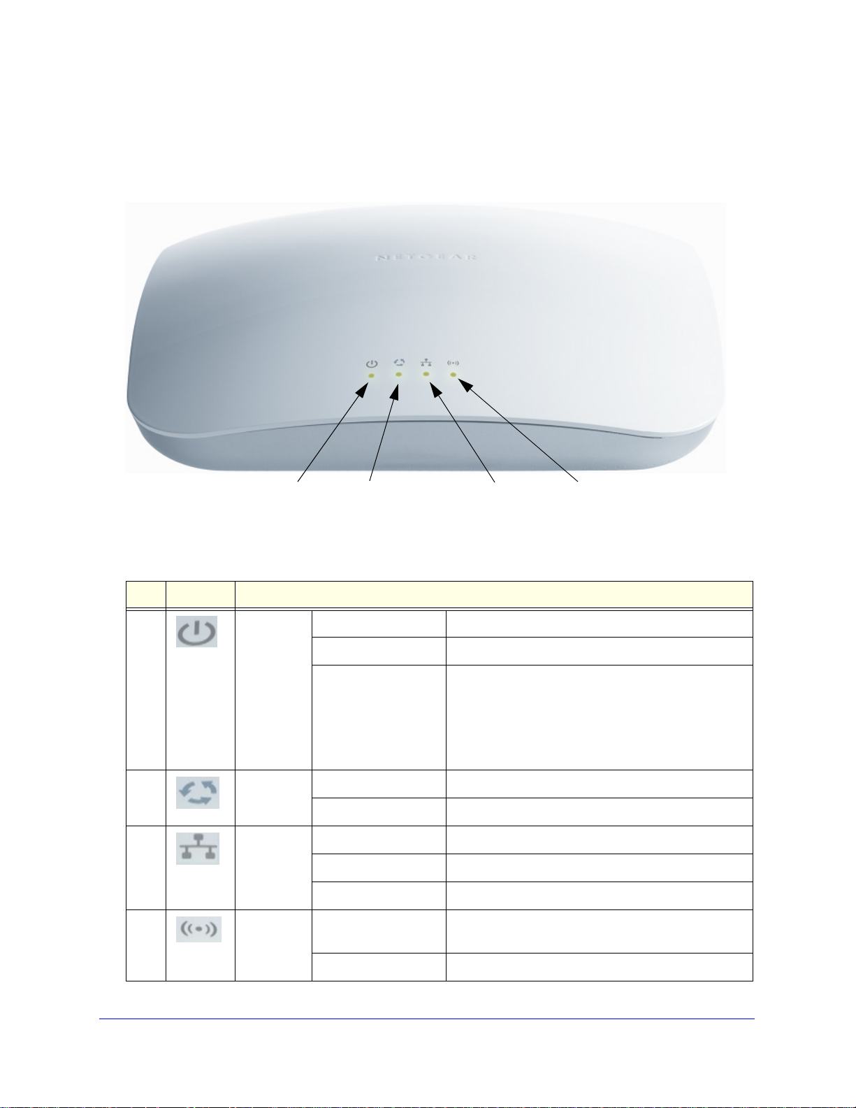
The ProSafe Wireless-N Access Point WNAP320 LEDs are described in the following figure
and table:
Figure 1.
Table 1. Top Panel LEDs
Item LED Description
1 Power/Test Off Power is off.
On (green) Power is on.
Amber, then blinking
een
gr
2 Active Off No Ethernet traffic is detected or no lin
On or blinking (green) Ethernet traffic is detected.
3 LAN Off 10 Mbps or no link is detected.
Amber 10/100 Mbps link is detected.
Green 1000 Mbps link is detected.
A self-test is running or software is being loaded.
During startup, the LED is first steady amber, then
goes off, and then blinks green before turning steady
green after about 45 seconds. If after 1 minute the
mains amber or continues to blink green, it
LED re
indicates a system fault.
k is detected.
4 WLAN Off Wireless LAN is not ready or no wireless activity is
detected.
On or blinking (green) Wireless LAN is ready or wireless activity
Chapter 1. Introduction | 11
is detected.
Page 12
ProSafe Wireless-N Access Point WNAP320 Reference Manual
1
23 4
567
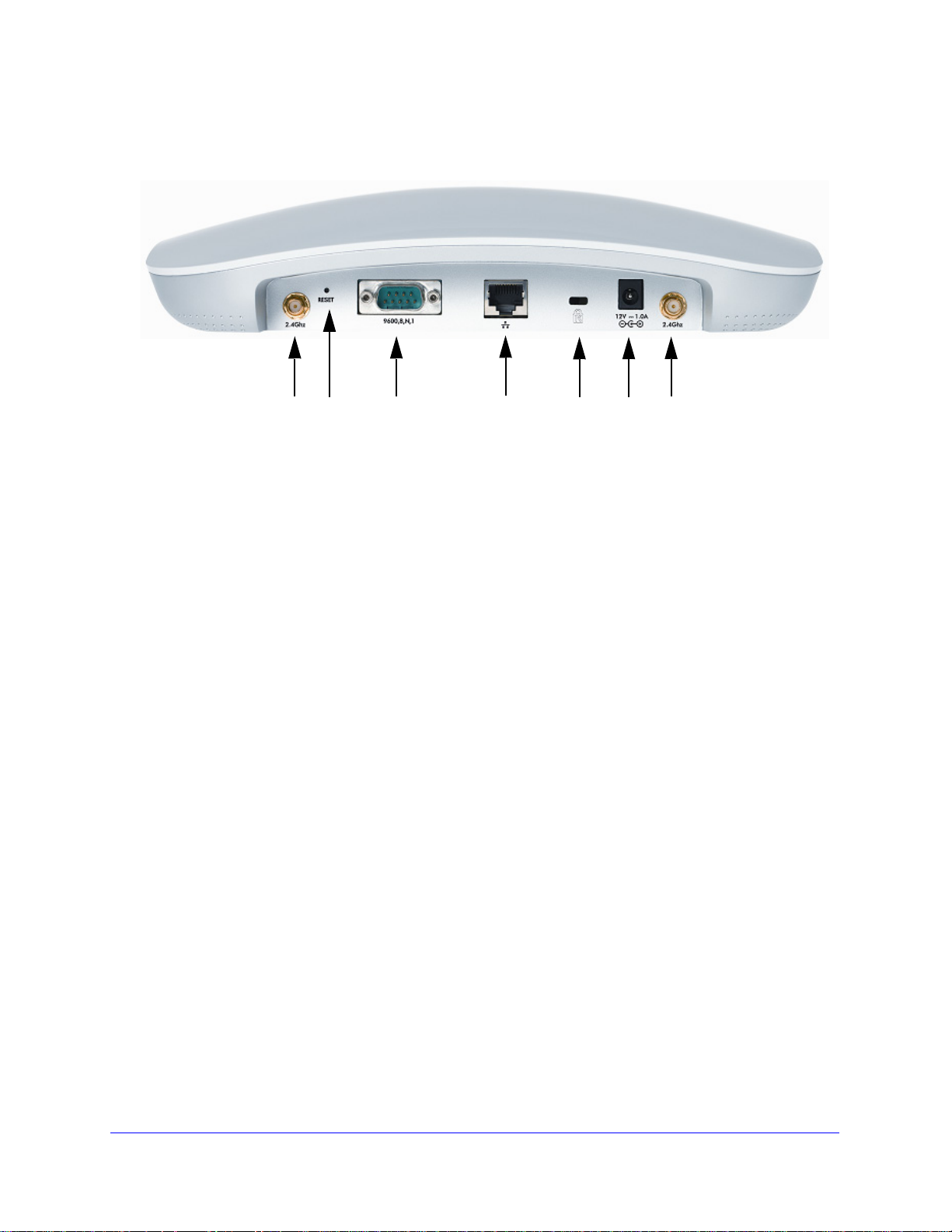
Rear Panel
Figure 2.
The rear panel functions of the ProSafe Wireless-N Access Point WNAP320 are described in
the following list:
1. Reverse SMA
2. Fa
ctory default Reset button. Using a sharp object, press and hold t his button for about
connector for an optional 2.4-GHz antenna.
5 seconds to reset the wireless access point to factory defaults settings. All configuration
ings are lost, and the default password is restored. For more information, see Restore
sett
the Wireless Access Point to the Factory Default Settings o
3. Console port
for connecting to an optional console terminal. The port has a DB9 male
n page 62.
connector and supports the following settings: 9600 K default baud rate, (8) data bits, no (N)
parity bit, and one (1) stop bit.
4. 10/
100/1000BASE-T Gigabit Ethernet (RJ-45) port with Auto Uplink (Auto MDI-X) with
IEEE 802.3af Power over Ethernet (PoE) support for connection to a switch or router.
5. Cable security lock recept
6. Power
7. Reverse SMA
socket for a 12 VDC, 1A power adapter.
connector for an optional 2.4-GHz antenna.
acle for an optional lock.
12 | Chapter 1. Introduction
Page 13
ProSafe Wireless-N Access Point WNAP320 Reference Manual
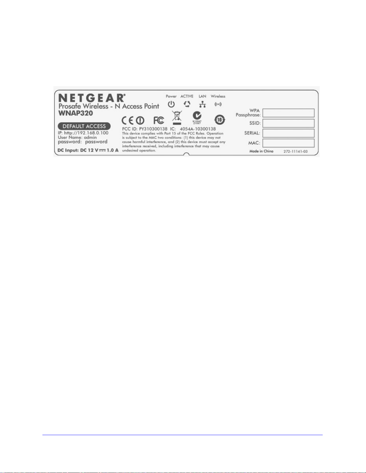
Bottom Panel with Product Label
The product label on the bottom of the wireless access point’s enclosure displays factory
default settings, regulatory compliance, and other information:
Figure 3.
Chapter 1. Introduction | 13
Page 14

2. Installation and Basic Configuration
This chapter describes how to install and configure your access point for wireless connectivity to
your LAN. This basic configuration will enable computers with 802.11b/g or 802.11n wireless
adapters to connect to the Internet, or access printers and files on your LAN. In planning your
wireless network, consider the level of security required. Chapter 3, Wireless Configuration and
Security, describes how to set up wireless security for your n
following sections:
• What You Need before You Begin on this page
• Install and Configure the Wireless Access Point on page 16
• Test Basic Wireless Connectivity on page 27
• Mount the Wireless Access Point o
Note: In this chapter and in all further chapters, the WNAP320 is referred
to as the wireless access point.
n page 28
etwork. This chapter includes the
2
What You Need before You Begin
You need to consider the following guidelines and requirements before you can set up your
wireless access point. See also System Requirements on p
Wireless Equipment Placement and Range Guidelines
The range of your wireless connection can vary significantly based on the location of the
wireless access point. The latency, data throughput performance, and notebook power
consumption of wireless adapters also vary depending on your configuration choices.
Note: Failure to follow these guidelines can result in significant
performance degradation or inability to wirelessly connect to the
wireless access point. For complete performance specifications,
see Appendix A, Supplemental Information.
Chapter 2. Installation and Basic Configuration | 14
age 7.
Page 15

ProSafe Wireless-N Access Point WNAP320 Reference Manual
For best results, place your wireless access point according to the following general
guidelines:
• Near the
• In an
line-of-sight access (even if through walls).
• A
way from sources of interference, such as PCs, microwaves ovens, and 2.4-GHz
cordless phones.
• A
way from large metal surfaces or water.
• Placing
Placing an external antenna in a horizontal position provides best up-and-down
coverage. (An external antenna does not come standard with the WNAP320 wireless
access point.)
• If you are
points use different radio frequency channels to reduce interference. The recommended
channel spacing between adjacent wireless access points is five channels (for example,
use channels 1 and 6, or 6 and 11, or 1 and 11).
The time it takes to establish a wireless connection can vary depending on both you r security
settings
encryption can consume more battery power on a notebook computer.
center of the area in which your PCs will operate.
elevated location such as a high shelf where the wirelessly connected PCs have
an external antenna in a vertical position provides best side-to-side coverage.
using multiple wireless access points, it is better if adjacent wireless access
and placement. WEP connections can take slightly longer to establish. Also, WEP
Ethernet Cabling Requirements
The wireless access point connects to your LAN using twisted-pair Catego ry 5 Ethernet cable
with RJ-45 connectors.
LAN Configuration Requirements
For the initial configuration of your wireless access point, you need to co nnect a computer to
the wireless access point.
Note: For assistance with DHCP configuration, see the Preparing Your
Network document that you can access from Related Documents in
Appendix A.
Computer Hardware Requirements
To connect to the wireless access point on your network, each computer must have a
802.11b/g or 802.11n wireless adapter installed.
Chapter 2. Installation and Basic Configuration | 15
Page 16

ProSafe Wireless-N Access Point WNAP320 Reference Manual
Install and Configure the Wireless Access Point
Before installing the wireless access point, make sure that your Ethernet network is up and
working. You will be connecting the wireless access point to the Ethernet network. Then
computers with 802.11b/g or 802.11n wireless adapters will be able to communicate with the
Ethernet network.
In order for this to work correctly, verify that you have met all of the system requirements,
hown in System Requirements on p
s
age 7.
Install and configure your wireless access point in
1. Connect the Wireless Access Point to Computer on this page.
2. Log In to the Wireless Access Point on page 18.
3. Configure Basic General System Settings
4. Configure IP Settings and Optional DHCP Server Settings on page 21
5. Configure Basic Wireless Settings on page 23.
the order of the following sections:
and Time Settings on page 19.
Connect the Wireless Access Point to Computer
Tip: Before you place the wireless access point in an elevated position that is
difficult to reach, first set up and test the wireless access point to verify
wireless network connectivity.
To set up the wireless access point:
1. Unp
2. Prep
3. Connect an Ethern
ack the box and verify the contents.
are a computer with an Ethernet adapter. If this computer is already part of your
network, record its TCP/IP configuration settings. Configure the computer with a static IP
address of 192.168.0.210 and 255.255.255.0 as the sub net mask.
et cable from the wireless access point to the computer (point A in the
following figure).
4. Securely insert
.
16 | Chapter 2. Installation and Basic Configuration
(point B in the following figure).
the other end of the cable into the wireless access point’s Ethernet port
Page 17
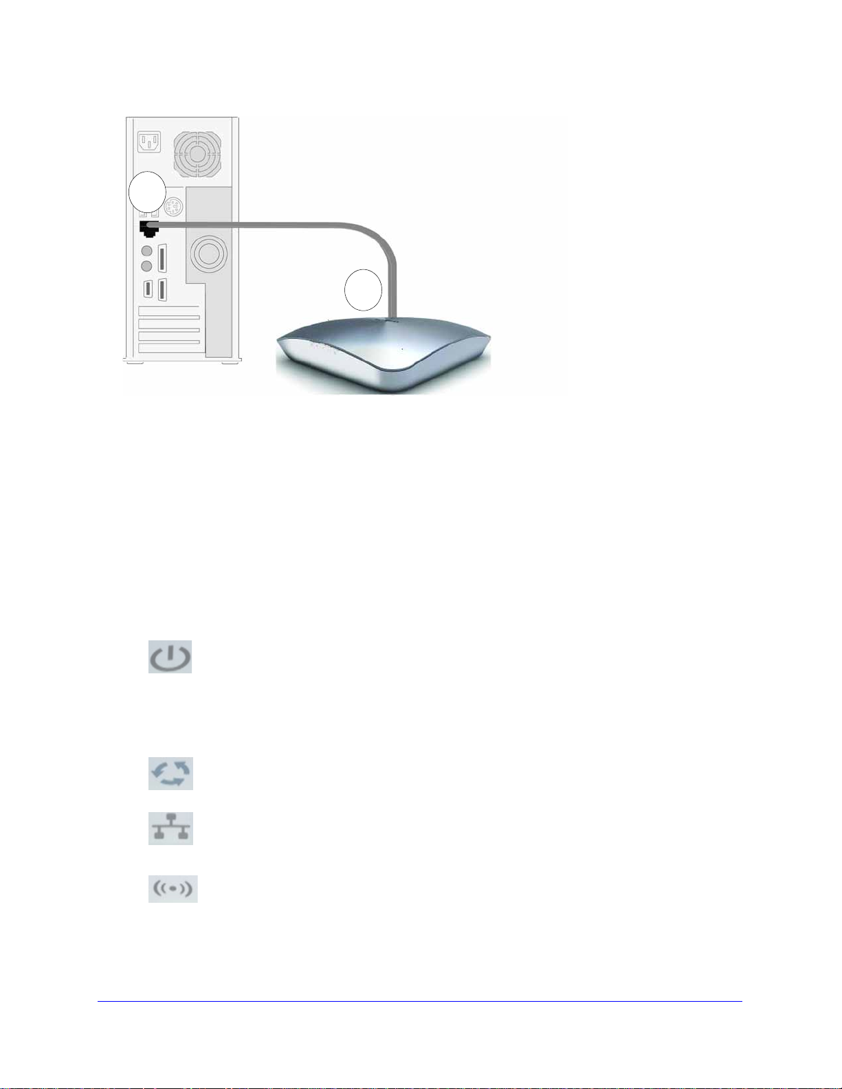
ProSafe Wireless-N Access Point WNAP320 Reference Manual
A
B
Ethernet cable
Ethernet port
WNAP320
Figure 4.
5. Turn on your computer.
6. Conn
7. V
ect the power adapter to the wireless access point.
Tip: Th
erify the following:
(steady green). If after 1 minute the Power/Test LED is not lit or is still blinking,
check the connections and see if the power outlet is controlled by a wall switch
that is turned off.
e wireless access point supports Power over Ethernet (PoE). If you
have a switch that provides PoE, you will not need to use the power
adapter to power the wireless access point. This can be especially
convenient when the wireless access point is installed in a high location
far away from a power outlet.
Power/T est LED.
first turned on. (To be exact, during startup, the LED is first steady amber, then
oes off, and then blinks green.) After about 45 seconds, the LED should stay lit
g
Active LED.
LAN LED. The L
for 100 Mbps, and no light for 10 Mbps. If the LAN LED is not lit, make sure that
t
he Ethernet cable is securely attached at both ends.
The Power/Test LED blinks when the wireless access point is
The Active LED is lit or blinks green when there is Ethernet traffic.
AN LED indicates the LAN speed: green for 1000 Mbps, amber
WLAN LED. The WLAN
is ready.
LED is lit or blinks green when the wireless LAN (WLAN)
Chapter 2. Installation and Basic Configuration | 17
Page 18
ProSafe Wireless-N Access Point WNAP320 Reference Manual
Log In to the Wireless Access Point
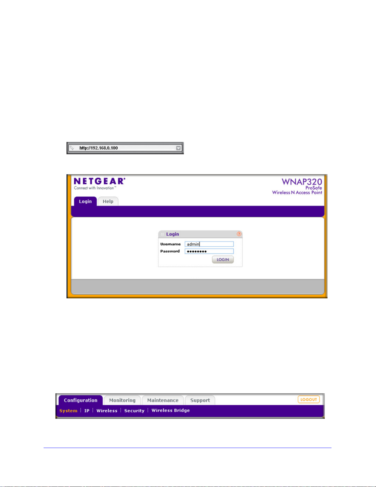
The default IP address of your wireless access point is http://192.168.0.100. The wireless
access point is set, by default, for the DHCP client to be disabled.
To log in to the wireless access point:
1. Op
2. Connect to the wire
en a Web browser such as Microsoft Internet Explorer 6.0 or later, or Mozilla Firefox
1.5 or later.
into your browser.
The Login screen opens:
less access point by entering its default address of http://192.168.0.100
Figure 5.
3. Enter the default user name of admin and the default password of password.
4. Click Lo
Configuration tab of the main menu as shown in Figure 8 on p
gin. The Web browser displays the basic General system settings screen under the
age 19.
Web Management Interface
The navigation tabs across the top of the Web Management Interface provide access to all
the configuration functions of the wireless access point, and remain constant. The menu
items in the blue bar change according to the navigation tab that is selected.
Figure 6.
18 | Chapter 2. Installation and Basic Configuration
Page 19
ProSafe Wireless-N Access Point WNAP320 Reference Manual
The bottom right corner of all screens that allow you to make configuration changes show the
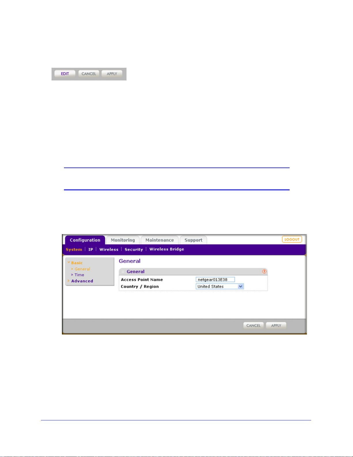
Apply and Cancel buttons, and on several screens the Edit button.
Figure 7.
These buttons have the following functions:
• Edit. Allows you to
• Cancel.
Cancels all configuration changes that you made on the screen.
• Apply . Saves a
edit the existing configuration.
nd applies all configuration changes that you made on the screen.
Configure Basic General System Settings and Time Settings
Note: After you have successfully logged in to the wireless access point,
the basic General system settings screen displays.
To configure basic system settings:
1. Select Configurati
screen displays:
on > System > Basic > Gen er al. The basic General system settings
Figure 8.
Chapter 2. Installation and Basic Configuration | 19
Page 20
ProSafe Wireless-N Access Point WNAP320 Reference Manual
2. Specify the fields as explained in the following table:
Table 2. Basic General System Settings
Field Description
Access Point Name This unique name is the wireless access poi
on the rear label of the wireless access point. The default is netgearxxxxxx, where
xxxxxxx represents the last 6 digits of the wireless access point MAC address. You
can replace the default name with a unique name up to 15 characters long. The
access point name can be retrieved through SNMP.
Country/Region From the Country/Region drop-down list, se
access point is installed.
Note: It might not be legal to operate this wireless access point in a region other than
of those identified in this field.
one
3. Click Apply
to save your settings.
To configure time settings:
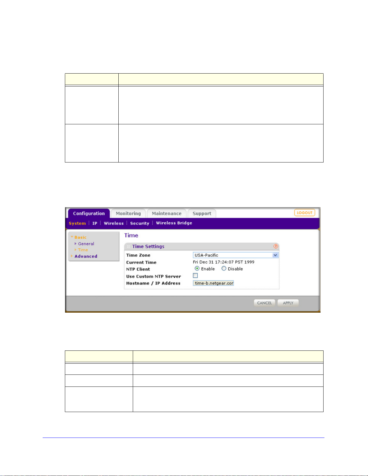
1. Select Confi
guration > System > Basic > Tim e. The Time screen displays:
nt NetBIOS name. The name is printed
lect the country where the wireless
Figure 9.
2. Specify the fields as explained in the following table:
Table 3. Time System Settings
Field Description
Time Zone Select the time zone to
Current Time This is a nonconfigurable field that
NTP Client Enable the Network Time Protocol (NTP) cli
wireless access point with an NTP server. By default the Enable radio button is
selected.
20 | Chapter 2. Installation and Basic Configuration
match your location.
displays the current date and time.
ent to synchronize the time of the
Page 21
ProSafe Wireless-N Access Point WNAP320 Reference Manual
Table 3. Time System Settings (Continued)
Field Description
Use Custom NTP Server Select this check box to If you want to use a custom NTP server.
Note: You must have an Internet connection to use an NTP server that is not
r local network.
on you
Hostname /
IP Address
Enter the host name or IP address of the custom NTP server.
The default is time-b.netgear.com.
3. Click Apply to save your settings.
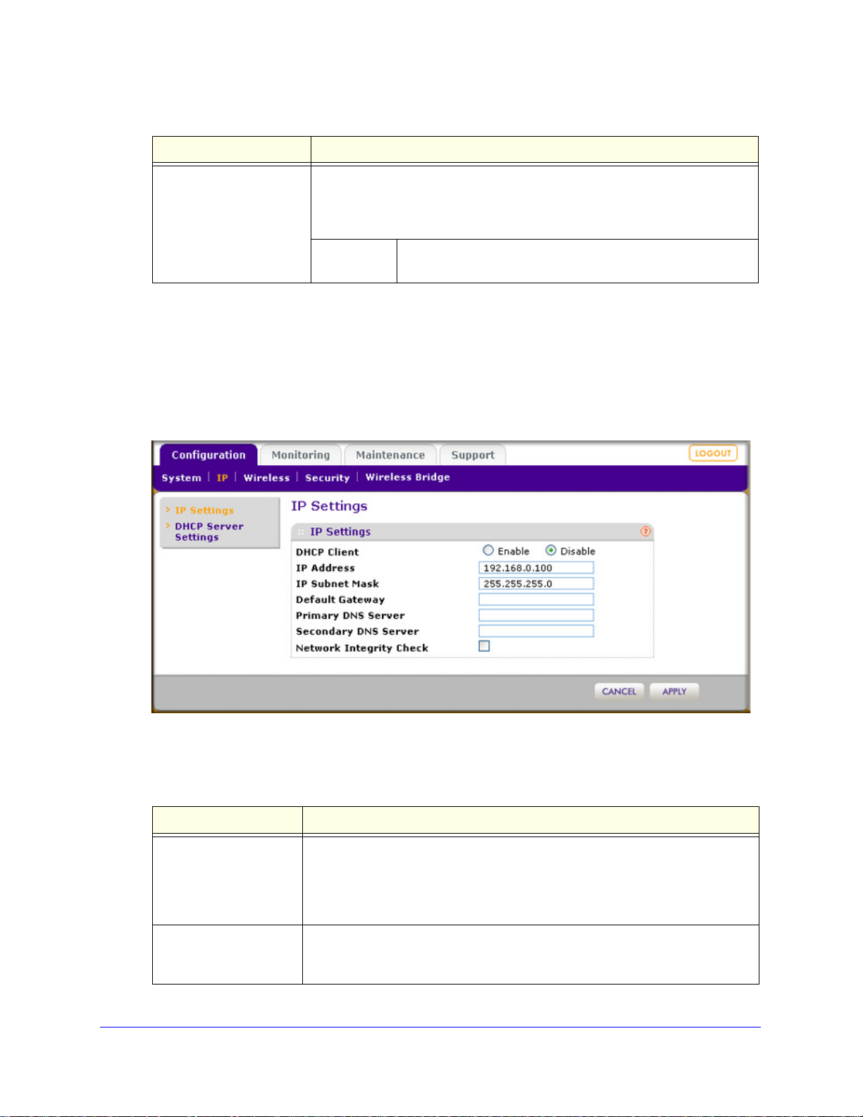
Configure IP Settings and Optional DHCP Server Settings
To configure the IP settings:
1. Select Con
figuration > IP > IP Settings. The IP Settings screen displays:
Figure 10.
2. Specify the fields as explained in the following table:
Table 4. IP Settings
Field Description
DHCP Client By default, the Dynamic Host Con
you have a DHCP server on your LAN and you select the Enable check box, the
wireless access point will receive its IP address, subnet mask, and default
gateway settings automatically from the DHCP server on your network when you
connect the wireless access point to your LAN.
IP Address Enter the IP address of your wireless access poi
192.168.0.100. To change the address, enter an unused IP address from the
address range used on your LAN, or enable DHCP the server.
Chapter 2. Installation and Basic Configuration | 21
figuration Protocol (DHCP) client is disabled. If
nt. The default IP address is
Page 22
ProSafe Wireless-N Access Point WNAP320 Reference Manual
Table 4. IP Settings (Continued)
Field Description
IP Subnet Mask Enter the network number portion of an IP address. Unless you are
implementing subnetting, enter 255.255.0.0 as the subnet mask.
Default Gateway Enter the IP address of the ISP’s router
connect.
Primary DNS Server
Secondary DNS Server
Network Integrity Check Select this check box to validate that the up
Enter the IP address of the primary and secondary DNS servers.
A DNS server is a host on the Internet th
www.netgear.com) to numeric IP addresses. Typically your ISP transfers the IP
address of one or two DNS servers to your wireless access point during login. If
the ISP does not transfer an address, you must obtain it from the ISP and enter it
manually in this field.
wireless associations. Ensure that the default gateway is configured.
to which the wireless access point will
at translates Internet names (such as
stream link is active before allowing
3. Click Apply to save your settings.
The wireless access point provides a built-in DHCP serve
r for wireless clients only, which can
be especially useful in small networks. When the DHCP server is enabled, the wireless
access point provides preconfigured TCP/IP configurations to all connected wireless stations.
To configure DHCP server settings:
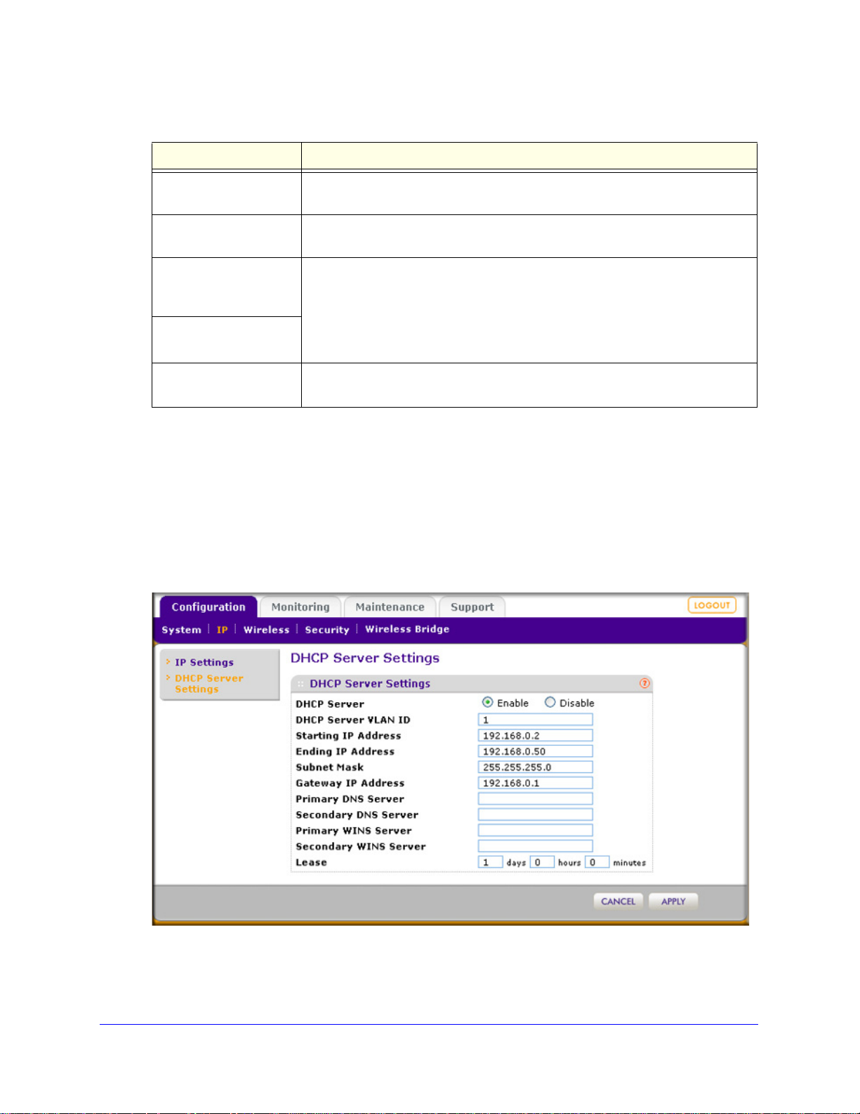
1. Select Confi
guration > IP > DHCP Server Settings. The DHCP Server Settings screen
displays:
Figure 11.
22 | Chapter 2. Installation and Basic Configuration
Page 23

ProSafe Wireless-N Access Point WNAP320 Reference Manual
2. Specify the fields as explained in the following table:
Table 5. LAN Settings
Field Description
DHCP Server Select the DHCP Server check box to enable the DHCP server. Use the default settings or
specify the pool of IP addresses to be assigned by setting the starting IP address and
ending IP address. These addresses should be part of the same IP address subnet as the
wireless access point’s LAN IP address.
DHCP Server VLAN ID Enter the DHCP server VLAN ID. The VLAN ID range is between
nd 4094.
1 a
Starting IP Address Enter the first address in the range of IP addresses to be
assigne
Ending IP Address Enter the last address in the range of IP addresses to be
assigne
Subnet Mask Enter the subnet mask to be used by DHCP clients. The default
ma
d to DHCP clients. The default address is 192.168.1.02.
d to DHCP clients. The default address is 192.168.1.50.
sk is 255.255.255.0.
Gateway IP Address Enter the IP address of the default routing gateway to be used by
DHCP clients. The default address is 192.168.0.1.
primary Domain Name Server (DNS)
ndary WINS server for the
3. Click App
Primary DNS Address Enter the IP address of the
server available to DHCP clients.
Secondary DNS Address Enter the IP address of the secondary DNS server available to
DHCP cl
Primary WINS Server Enter the IP address of the primary WINS server for the network.
Secondary WINS Server Enter the IP address of the seco
network.
Lease Enter the period that the DHCP server grants to DHCP clients to
use the assigned IP addresses. The default time is 1 day.
ients.
ly to save your settings.
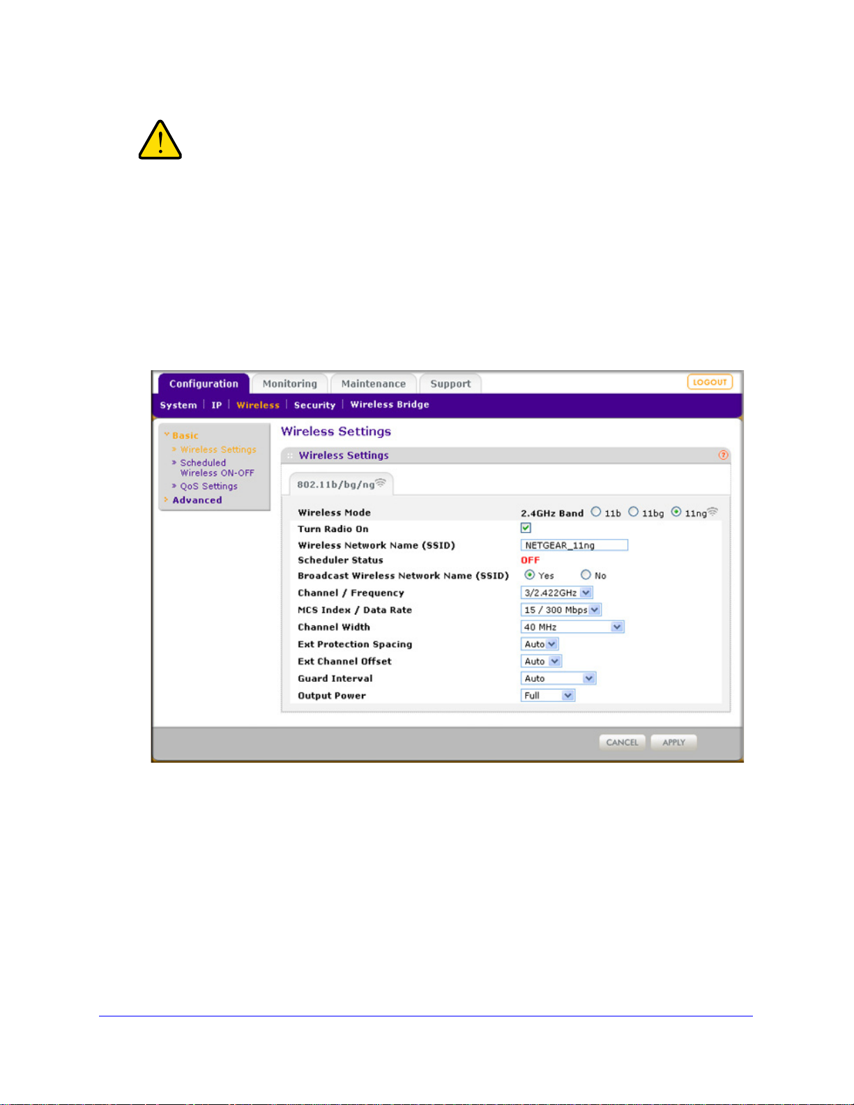
Configure Basic Wireless Settings
For proper compliance and compatibility between similar pro ducts in your coverage area, you
must correctly configure 802.11b/g/n wireless adapter settings, including the operating
channel and country. The basic wireless network settings must be set correctly for wireless
devices to connect to your network. For other wireless features, including wireless security,
see Chapter 3, Wireless Configuration and Security.
Chapter 2. Installation and Basic Configuration | 23
Page 24
ProSafe Wireless-N Access Point WNAP320 Reference Manual
WARNING!
If you configure the wireless access point from a wireless
computer and you change the wireless access point’s SSID,
channel, or wireless security settings, you will lose your wireless
connection when you click Apply. You must then change the
wireless settings of your computer to match the wireless access
point’s new settings.
To configure the 802.11b/g/n wireless settings:
1. Select Configuration
> Wireless > Basic > Wireless Settings. The basic Wireless
Settings screen displays. (The following figure shows the 11ng setting.)
Figure 12.
24 | Chapter 2. Installation and Basic Configuration
Page 25

ProSafe Wireless-N Access Point WNAP320 Reference Manual
2. Specify the fields as explained the following table:
Table 6. Basic Wireless Settings
Field Descriptions
Wireless Mode Select the wireless operating mode that you want to use by selecting one of the
following radio buttons:
b. 802.11b wireless stations only.
• 11
11bg. Both 802.11b and 802.11g wireless stations can be used.
•
• 11ng. Both 802.11n and 802.11g wirele ss stations can be used. This is the
default setting.
Turn Radio On Th e radio is enabled by default. To turn off the radio, clear the T
check box. Doing so disables access through the wireless access point, which
can be helpful for configuration, network tuning, or troubleshooting activities.
Wireless Network Name
SSID)
(
Scheduler Status This is a nonconfigurable field that show th
Broadcast Wireless
Network Name (SSID)
Channel / Frequency From the drop-down list, select the channel you wish to use on your wireless
11ng mode only
Note: For most
networks, the
settings will work fine.
default
Enter a 32-character (maximum) service set identifier (SSID); the characters are
case-sensitive. The default is NETGEAR_11ng. The SSID assigned to a wireless
device must match the wireless access point’s SSID for the wireless device to
communicate with the wireless access point. If the SSIDs do not match, you will
not get a wireless connection to the wireless access point.
e status of the wireless scheduler. For
more information, see Schedule the Wireless Radio on page 52.
Select the Ye
SSID, allowing wireless stations that have a null (blank) SSID to adopt the
wireless access point’s SSID. Yes is the default setting. To prevent the SSID
from being broadcast, select the No radio button.
The wireless channels to use in the United States and Canada are 1 to 11;
LAN.
for Europe and Australia, 1 to 13. The default setting is Auto.
Note: It should not be necessary to change the wireless channel unless you
expe
Should this happen, you might want to experiment with different channels to see
which is the best. For more information, see the guidelines following this table.
MCS Index / Data
Rate
Channel Width From the drop-down list, select a channel width. The options
s radio button to enable the wireless access point to broadcasts its
rience interference (indicated by lost connections or slow data transfers).
From the drop-down list, select a Modulation and Coding
Scheme (MCS) in
network. The default setting is Best. For a list of all options
that you can select from in 11ng mode, see Factory Default
Settings in Appendix A.
are Dynami
channel improves the performance, but some legacy devices
can operate only in either 20 MHz or 40 MHz.
dex and transmit data rate for the wireless
c 20/40 MHz, 20 MHz, or 40 MHz. A wider
urn Radio On
Ext Protection
acing
Sp
When you select a channel width of Dynamic 20/40 MHz or
40 MHz, you also need to select protection spacing for the
extension channel from the Ext Protection Spacing
drop-down list. In addition to the default value Auto, you can
also select a value of 20 or 25.
Chapter 2. Installation and Basic Configuration | 25
Page 26

ProSafe Wireless-N Access Point WNAP320 Reference Manual
Table 6. Basic Wireless Settings (Continued)
Field Descriptions
11ng mode only
(continued)
11b and 11bg modes
ly
on
Output Power From the drop-down list, select the transmission power of the wireless access
Channel Bonding This drop-down list lets you to specify channels to bond. The available options
Ext Channel
Offset
Guard Interval From the drop-down list, select the guard interval to protect
Data Rate From the drop-down list, select the transmit data rate of the
int. The default is Full.
po
Note: Increasing the power improves performance, but if two or more wireless
ccess points are operating in the same area, on the same channel, it can cause
a
interference.
Note: Make sure that you comply with the regul
frequency (RF) output power in your country.
are 20 MHz, 20/40 MHz, and 40 MHz.
When you select a channel width of Dynamic 20/40 MHz or
40 MHz, you also need to select the offset for the extension
channel from the Ext Channel Offset drop-down list. In
addition to the default value Auto, you can also select Upper
or Lower.
transmissio
value Auto, you can also select Long - 800 ns. Some legacy
devices can operate only with a long guard interval.
wireless network. The default setting is Best. For a list of all
options that you can select from in 11b mode and 11bg mode,
see Factory Default Settings in Appendix A.
ns from interference. In addition to the default
atory requirements for total radio
3. If you have changed the wireless mode and selected the Turn Radio On check box, a
popup window appears: click OK to confirm your change.
4. Click Apply
You should not need to change the operating fre
to save your settings.
quency (channel) unless you notice
interference problems, or are setting up the wireless access point near another wireless
access point. Observe the following guidelines:
• Wireless a
ccess points use a fixed channel. You can select a channel that provides
the least interference and best performance. In the United States and Canada,
11 channels are available.
• If
you are using multiple wireless access points, it is better if adjacent wireless access
points use different channels to reduce interference. The recommended channel
spacing between adjacent wireless access points is 5 channels (for example, use
channels 1 and 6, or 6 and 11).
• In
infrastructure mode, wireless stations normally scan all channels, looking for a
wireless access point. If more than one wireless access point can be used, the one
with the strongest signal is used. This can happen only when the wireless access
points use the same SSID. The WNAP320 wireless access point functions in
infrastructure mode by default.
26 | Chapter 2. Installation and Basic Configuration
Page 27

ProSafe Wireless-N Access Point WNAP320 Reference Manual
WARNING!
Note: For more information about wireless channels, see the article
“Wireless Networking Basics” available on the NETGEAR website.
A link to this article and other articles of interest can be found in
Related Documents in Appendix A.
Note: For information about how to configure advanced wireless settings,
see Configure Advanced Wireless Settings on page 79.
Test Basic Wireless Connectivity
After you have configured the wireless access point as explained in the previous sections,
test your computers for wireless connectivity before you position and mount the wireless
access point at its permanent position.
To test for wireless connectivity:
1. Con
2. V
3. V
figure the 802.11b/g or 802.11n wireless adapters of your computers so that they all
have the same SSID and channel that you have configured on the wireless access
point.
erify that your computers have a wireless link to the w i re l es s ac c e ss p oi n t , a n d if you
have enabled the DHCP server on the wir el es s a cc e ss po in t , ve r if y t ha t your computers
are able to obtain an IP address through DHCP from the wire le s s a cc e ss p o in t.
erify network connectivity by using a browser such as Internet Explorer 6.0 or later or
Mozilla Firefox 1.5 or later to browse the Internet, or check for file and printer access on your
network.
Note: If you have trouble connecting to the wireless access point, see
Chapter 6, Troubleshooting.
Before you deploy the wireless access point in your network, set
up wireless security and other wireless features as described in
Chapter 3, Wireless Configuration and Security.
In addition to wireless security and other wirele
access point in your network, configure any additional features as described in Chapter 4,
Management and Chapter 5, Advanced Configuration.
ss features, before you deploy the wireless
Chapter 2. Installation and Basic Configuration | 27
Page 28
ProSafe Wireless-N Access Point WNAP320 Reference Manual
Mounting plate
Clamp with screws
After you have completed the configuration of the wireless access point, you can reconfig ure
the computer that you used for this process back to its original TCP/IP settings.
Mount the Wireless Access Point
This section includes the following subsections:
• Ceiling Installation on this page
• Wall Installation on p
• Desk Installation on p
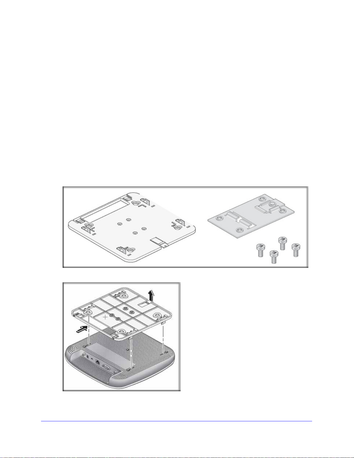
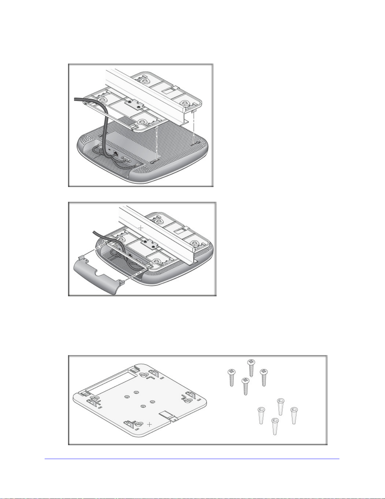
Ceiling Installation
To install the wireless access point using the ceiling installation kit:
erify the package content of the ceiling installation kit.
1. V
age 30
age 33
2. Det
28 | Chapter 2. Installation and Basic Configuration
ach the mounting plate from the wireless access point.
Page 29
ProSafe Wireless-N Access Point WNAP320 Reference Manual
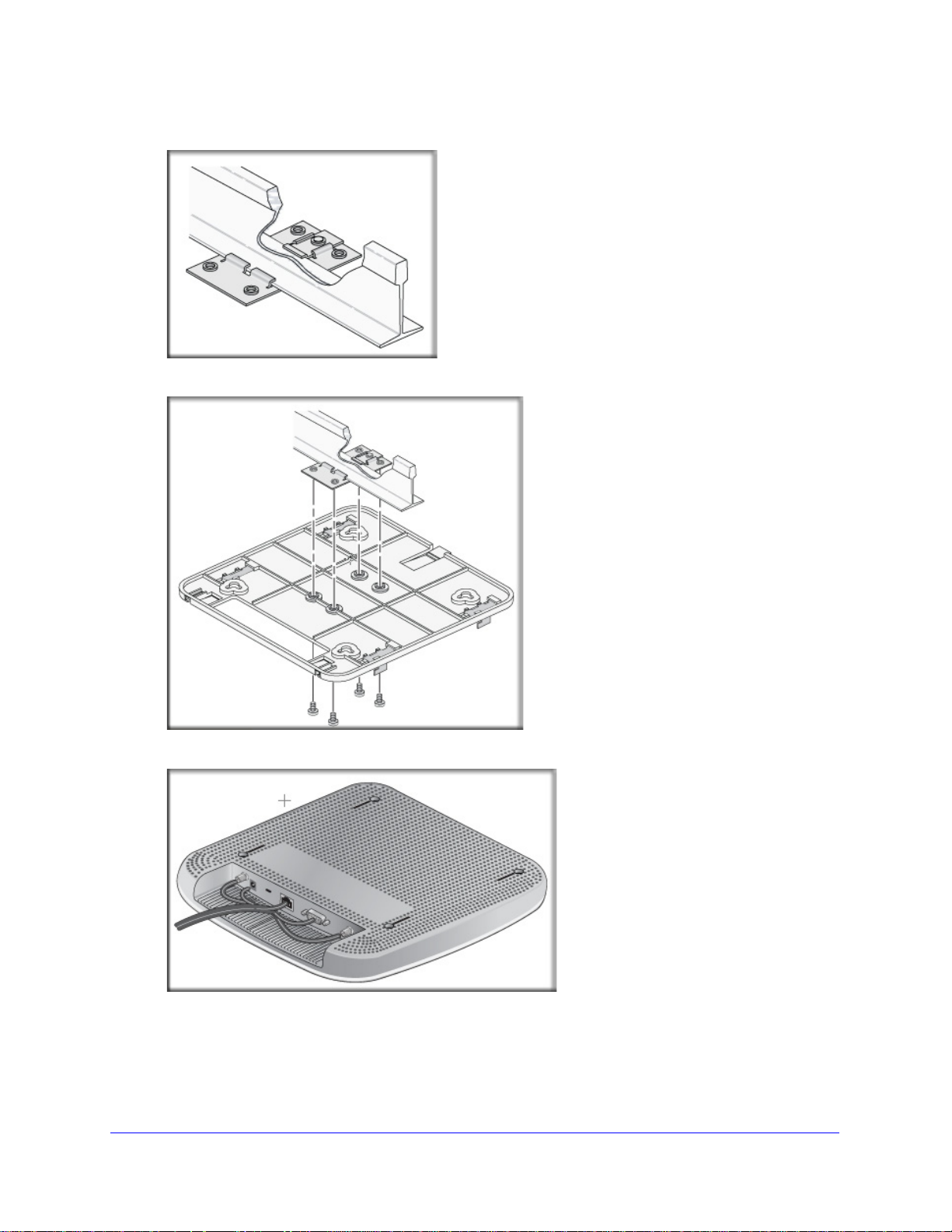
3. Attach the clamp to the ceiling rail.
4. Att
ach the mounting plate to the clamp.
5. Conn
ect the cables to the wireless access point.
Chapter 2. Installation and Basic Configuration | 29
Page 30
ProSafe Wireless-N Access Point WNAP320 Reference Manual
Mounting plate
Screws and
wall supports
6. Attach the wireless access point to the mounting plate.
7. Att
ach the cover to the wireless access point.
Wall Installation
To install the wireless access point using the wall installation kit:
1. V
erify the package content of the wall installation kit.
30 | Chapter 2. Installation and Basic Configuration
Page 31

ProSafe Wireless-N Access Point WNAP320 Reference Manual
2. Detach the mounting plate from the wireless access point.
3. Att
ach the mounting plate to the wall.
4. Conn
ect the cables to the wireless access point.
Chapter 2. Installation and Basic Configuration | 31
Page 32

ProSafe Wireless-N Access Point WNAP320 Reference Manual
5. Attach the wireless access point to the mounting plate.
6. Att
ach the cover to the wireless access point.
32 | Chapter 2. Installation and Basic Configuration
Page 33

ProSafe Wireless-N Access Point WNAP320 Reference Manual
Rubber feet
Desk Installation
To install the wireless access point on a desk, attach the rubber feet to the holes in the
bottom of the wireless access point.
Chapter 2. Installation and Basic Configuration | 33
Page 34

3. Wireless Configuration and Security
WARNING!
This chapter describes how to configure the wireless features of your ProSafe Wireless-N
Access Point WNAP320. The chapter includes the following sections:
• Wireless Data Security Options on this page
• Security Profiles on
• Configure RADIUS Server Settings on p
page 36
age 48
3
• Restrict Wireless Access by MAC Address on p
• Schedule the Wireless Radio on p
• Configure Basic Wireless Quality of Service on p
Before you set up wireless security and additional wireless featu
chapter, connect the wireless access point, get the Internet connection working, and
configure the 802.1 1b , 11bg, or 1 1ng wireless settings as described in Chapter 2, Installation
and Basic Configuration. The wireless access point should work with an Ethernet LAN
connection, and wireless connectivity should have bee
security and additional wireless features. In planning your wireless network, consider the
level of security required.
If you are configuring the wireless access point from a wireless
computer and you change the wireless access point’s SSID,
channel, or wireless security settings, you will lose your wireless
connection when you click Apply. You must then change the
wireless settings of your computer to match the wireless access
point’s new settings.
age 52
age 50
age 52
res that are described in this
n verified before you set up wireless
Wireless Data Security Options
Indoors, computers can connect over 802.11n wireless networks at a maximum range of
300 feet. Typ ically, a wireless access point inside a bu
100 foot radius. Such distances can allow for others outside your immediate area to access
your network.
Chapter 3. Wireless Configuration and Security | 34
ilding works best with devices within a
Page 35

ProSafe Wireless-N Access Point WNAP320 Reference Manual
Unlike wired network data, your wireless data transmissions can extend beyond your walls
and can be received by anyone with a compatible adapter. For this reason, use the security
features of your wireless equipment. The wireless access point provides highly effective
security features that are covered in detail in this chapter. Deploy the security features
appropriate to your needs.
Figure 13.
There are several ways you can enhance the security of your wireless network:
• Use mul
tiple BSSIDs combined with VLANs. You can configure combinations of
VLANS and BSSIDs with stronger or less restrictive access security according to your
requirements. For example, visitors could be given wireless Internet access but be
excluded from any access to your internal network. For information about how to
configure BSSIDs, see Configure and Enable Security Profiles on p
• Restrict acces
s based by MAC address. You can allow only trusted PCs to connect so
age 39.
that unknown PCs cannot wirelessly connect to the wireless access point. Restricting
access by MAC address adds an obstacle against unwante d access to your netwo rk, but
the data broadcast over the wireless link is fully exposed. For information about how to
restrict access by MAC address, see Restrict Wireless Access by MAC Address on
page 50.
urn off the broadcast of the wireless network name (SSID). If you disable broadcast
• T
of the SSID, only devices that have the correct SSID can connect. This nullifies the
wireless network discovery feature of some products, such as Windows XP, but the data
is still exposed. For information about how to turn of broadcast of the SSID, see
Configure and Enable Security Profiles on p
• WEP. Wire
d Equivalent Privacy (WEP) data encryption provides data security. WEP
age 39.
shared key authentication and WEP data encryption block all but the most determined
eavesdropper. This data encryption mode has been superseded by WPA-PSK and
WPA2-PSK.
For information about how to configure WEP, see Configure and Enable Security Profiles
on page 39 and Configure an Open System with WEP or Shared Key with WEP on
page 43.
• Legac
y 802.1X. Legacy 80.1X uses RADIUS-based 802.1x authentication but no data
encryption.
Chapter 3. Wireless Configuration and Security | 35
Page 36

ProSafe Wireless-N Access Point WNAP320 Reference Manual
• WPA and WPA-PSK (TKIP). Wi-Fi Protected Access (WPA) data encryption provides
strong data security with Temporal Key Integrity Protocol (TKIP) encryption. The very
strong authentication along with dynamic per frame rekeying of WPA make it virtually
impossible to compromise.
WPA uses RADIUS-based 802.1x authentication; for more information, see Configure
and Enable Security Profiles on p
RADIUS, and WPA & WPA2 with RADIUS on p
WPA-PSK uses a pre-shared key (PSK) for authentication; for more information, see
Configure and Enable Security Profiles on
WPA2-PSK, and WPA-PSK & WPA2-PSK on
age 39 and Configure WPA with RADIUS, WPA2 with
age 45.
page 39 and Configure WPA-PSK,
page 46.
• WP
• WP
A2 and WP A2-PSK (AES). Wi-Fi Protected Access version 2 (WPA2) data encryption
provides strong data security with Advanced Encryption Standard (AES) encryption. The
very strong authentication along with dynamic per frame rekeying of WPA2 make it
virtually impossible to compromise.
WPA2 uses RADIUS-based 802.1x authentication; for more information, see Configure
and Enable Security Profiles on p
RADIUS, and WPA & WPA2 with RADIUS on p
WPA2-PSK uses a pre-shared key (PSK) for authentication; for more information, see
Configure and Enable Security Profiles on
WPA2-PSK, and WPA-PSK & WPA2-PSK on
A & WP A2 and WPA-PSK & WPA2-PSK mixed modes. These modes support data
encryption either with both WPA and WPA2 clients or with both WPA-PSK and
WPA2-PSK clients and provide the most reliable security.
WPA & WPA2 uses RADIUS-based 802.1x authentication; for more information, see
Configure and Enable Security Profiles on
WPA2 with RADIUS, and WPA & WPA2 with RADIUS on p
WPA-PSK & WPA2-PSK uses a pre-shared key (PSK
information, see Configure and Enable Security Profiles on p
WPA-PSK, WPA2-PSK, and WPA-PSK & WPA2-PSK on p
age 39 and Configure WPA with RADIUS, WPA2 with
age 45.
page 39 and Configure WPA-PSK,
page 46.
page 39 and Configure WPA with RADIUS,
age 45.
) for authentication; for more
age 39 and Configure
age 46.
Security Profiles
Security profiles let you configure unique security settings for each SSID. The wireless
access point supports up to eight BSSIDs that you can configure on the individual Edit
Wireless Network screens that are accessible from the Edit Security Profile screen (see
Configure and Enable Security Profiles on
36 | Chapter 3. Wireless Configuration and Security
page 39).
Page 37

ProSafe Wireless-N Access Point WNAP320 Reference Manual
To set up a security profile you select its network authentication type, data encryption,
wireless client security separation, and VLAN ID:
• Netwo
rk authentication
The wireless access point is set by default as an open system with no authentication.
hen you configure network authentication, bear in mind that not all wireless adapters
W
support WPA or WPA2. Windows XP, Windows 2000 with Service Pack 3, and Windows
Vista do include the client software that supports WPA. However, client software is
required on the client. Consult the product documentation for your wireless adapter and
WPA or WPA2 client software for instructions on configuring WPA2 settings.
For information about the types of network authe
supports, see Configure and Enable Security Profiles on
• Dat
a encryption
ntication that the wireless access point
page 39.
Select the data encryption that you want to use. The available options depend on the
n
etwork authentication setting described earlier (otherwise, the default is None). The data
encryption settings are explained in Configure and Enable Security Profiles on p
• W
ireless client security separation
If enabled, the associated wireless clients (u
sing the same SSID) will not be able to
communicate with each other. This feature is useful for hotspots and other public access
situations. By default, wireless client separation is disabled. For more information, see
Configure and Enable Security Profiles on p
age 39.
• VLAN ID
If enabled and if the network devices (hubs and switches) on you
r LAN support the VLAN
(802.1Q) standard, the default VLAN ID for the wireless access point will be associated
with each profile. The default VLAN ID must match the IDs that are used by the other
network devices. For more information, see Configure and Enable Security Profiles on
page 39.
age 39.
Some concepts and guidelines regarding the SSID a
• A basic
service set (BSS) is a group of wireless stations and a single wireless access
re explained in the following list:
point, all using the same service set identifier (BSSID)
• An extended
service set (ESS) is a group of wireless stations and multiple wireless
access points, all using the same identifier (ESSID).
• Dif
ferent wireless access points within an ESS can use different channels. To reduce
interference, adjacent wireless access points should use different channels.
• Roaming is the
ability of wireless stations to connect wirelessly when they physically
move from one BSS to another within the same ESS. The wireless station automatically
changes to the wireless access point with the least interference or best performance.
Chapter 3. Wireless Configuration and Security | 37
Page 38

ProSafe Wireless-N Access Point WNAP320 Reference Manual
Before You Change the SSID, WEP, and WPA Settings
For a new wireless network, print or copy this form and fill in the settings. For an existing
wireless network, the network administrator can provide this information. Be sure to set the
Country/Region correctly as the first step. Store this information in a safe place.
• SS
• WEP Key Size, Key Format Passphrase, and Authentication
• WP
ID: The service set identification (SSID) identifies the wireless local area network. You
can customize it by using up to 32 alphanumeric characters. Write your SSID on the line.
SSID:
Choose the key size by circling one: 64, 128, or 152 bits.
Choose the key format by circling one: ASCII or HEX.
Choose the authentication type by circling one: Open or Shared.
Passphrase:
Note: If you sele
they are set to shared key and have the same keys in the same positions as those in the
wireless access point.
Record the WPA-PSK passphrase:
___________________________________
Note: The SSID in the wireless access point is the SSID you configure in
the wireless adapter card. All wireless nodes in the same network
must be configured with the same SSID.
___________________________________
ct shared key, the other devices in the network will not connect unless
A-PSK (Pre-Shared Key) and WP A2-PSK
WPA-PSK Passphrase:
Record the WPA2-PSK passphrase:
WPA2-PSK Passphrase:
• WP A RADIUS Settings
For WPA, record the following settings for the p
Server Name/IP Address: Primary
Port:
Shared Secret:
• WP
38 | Chapter 3. Wireless Configuration and Security
A2 RADIUS Settings
For WPA2, record the following settings for the
Server Name/IP Address: Primary
Port:
Shared Secret:
___________________________________
___________________________________
___________________________________
___________________________________
________________________________
________________________________
________________ Secondary _________________
________________ Secondary _________________
rimary and secondary RADIUS servers:
primary and secondary RADIUS servers:
Page 39

ProSafe Wireless-N Access Point WNAP320 Reference Manual
Configure and Enable Security Profiles
To configure and enable a security profile:
1. Select Con
figuration > Security > Profile Settings. The Profile Settings screen
displays, showing eight wireless security profiles:
Figure 14.
The following table explains the fields of the Profile Settings screen:
Table 7. Profile Settings Screen
Field Description
Profile Name The unique name of the wireless security profile that makes it easy to
recog
nize the profile.
SSID The wireless network name (SSID) for the wireless security profile.
Security The configured wireless authentication method for the wireless security
file.
pro
VLAN The default VLAN ID that is associated with the wireless security profile.
Enable The check box that lets you select the wireless security profile so you can
able it by clicking Apply.
en
2. T
o configure or edit a wireless security profile, select the corresponding radio button to the
left of the wireless security profile. The Edit Security Profile screen opens for the selected
wireless security profile (see the following figure). The first section on the screen is the
Profile Definition section; the second section is the Authentication Settings section. These
sections are explained separately.
Chapter 3. Wireless Configuration and Security | 39
Page 40

ProSafe Wireless-N Access Point WNAP320 Reference Manual
Figure 15.
3. Specify the settings of the Profile Definition section of the Edit Security Profile screen as
explained in the following table:
Table 8. Profile Definition Settings of the Edit Security Profile Screen
Field Description
Profile Name Enter a unique name of the wireless security profile
recognize the profile. The default names are NETGEAR, NETGEAR-1,
NETGEAR-2, and so on through NETGEAR-7. You can enter a value of up
to 32 alphanumeric characters.
Wireless Network Name
(SSID)
Broadcast Wireless
twork Name (SSID)
Ne
4. S
pecify the settings of the Authentication Settings section of the Edit Security Profile screen
The wireless network name (SSID) for the wirel
default names are NETGEAR_11ng, NETGEAR_11ng-1,
NETGEAR_11ng-2, and so on through NETGEAR_11ng-7.
Select the Yes radio button to enable the wireless access point to
broadcasts its SSID, allowing wireless stations that have a null (blank)
SSID to adopt the wireless access point’s SSID. Yes is the default setting.
To prevent the SSID from being broadcast, select the No radio button.
that makes it easy to
ess security profile. The
as explained in the following table.
40 | Chapter 3. Wireless Configuration and Security
Page 41

ProSafe Wireless-N Access Point WNAP320 Reference Manual
The wireless access point is set by default as an open system with no authentication.
When you configure network authentication, bear in mind the following:
• If you are
using access point mode (which is the default mode if you did not enable
wireless bridging), then all options are available. In other modes such as bridge
mode, some options might be unavailable.
• Not all wireless adap
ters support WPA or WPA2. Windows XP, Windows 2000 with
Service Pack 3, and Windows Vista do include the client sof tware that support s WPA.
However, client software is required on the client. Consult the product documentation
for your wireless adapter and WPA or WPA2 client software for instructions on
configuring WPA2 settings.
Table 9. Authentication Settings of the Edit Se curity P rof ile Scree n
Field Description
Network Authentication
and
Data Encryption
Note: The data
encryption
are displayed on screen
depend on you selection
from the Network
Authentication
drop-down list.
fields that
Open System This is the default setting. You can use an open system
t any encryption or with WEP encryption.
withou
See Configure an Open System with WEP or Shared Key
with WEP on p
Shared Key You must use WEP encryption and enter at least one
shared key.
See Configure an Open System with W
with WEP on page 43.
Legacy 802.1x You must configure the RADIUS server settings to use this
option.
See Configure Legacy 802.1X on
age 43.
EP or Shared Key
page 45.
WPA with RADIUS Y ou must configure the RADIUS server settings to use this
option.
See Configure WPA with RADIUS, WPA2 with RADIUS,
and WPA & WPA2 with RADIUS o
WPA2 with RADIUS Select this setting only if a
selected, you must use AES encryption and configure the
RADIUS server settings.
See Configure WPA with RADIUS, WPA2 with RADIUS,
and WPA & WPA2 with RADIUS o
WPA and WPA2
with RADIUS
WPA-PSK You must use TKIP or TKIP + AES encryption and enter a
Select this setting to allow clients to use either WPA (with
TKIP) or WP A2 (with AES). If selected, you must use TKIP
+ AES encryption and configure the RADIUS server
settings.
See Configure WPA with RADIUS, WPA2 with RADIUS,
and WPA & WPA2 with RADIUS o
WP
A passphrase (network key).
See Configure WPA-PSK, WPA2-
WPA2-PSK on p
age 46.
ll clients support WPA2. If
n page 45.
n page 45.
n page 45.
PSK, and WPA-PSK &
Chapter 3. Wireless Configuration and Security | 41
Page 42

ProSafe Wireless-N Access Point WNAP320 Reference Manual
Table 9. Authentication Settings of the Edit Security Profile Screen (Continued)
Field Description
Network Authentication
and
Data Encryption
(continued)
Wireless Client Security
aration
Sep
Dynamic VLAN From the drop-down list, select how VLANs
WPA2-PSK Select this only if all clients sup
must use AES and TKIP + AES encryption and enter a
WPA passphrase (network key).
See Configure WPA-PSK, WPA2-PSK, and WP
WPA2-PSK on page 46.
WPA-PSK and
A2-PSK
WP
If you enable wireless client security separation by selecting Enable from the
drop-down list, the associated wireless clients are not be able to communicate
with each other. By default, Disable is selected from the drop-down list. This
feature is intended for hotspots and other public access situations.
following selections:
able. Disables dynamic VLANs, and enables static VLANs. This is the
• Dis
default setting.
tional. Enables dynamic VLANs but if a RADIUS server does not return a
• Op
VLAN ID, the wireless station is still allowed to connect to the wireless access
point.
• Require
VLAN ID, the wireless station is not authenticated and cannot connect to the
wireless access point.
For dynamic VLANs to operate (that is, the sele
the following is required:
• The hubs and switches on your L
standard.
• The authentication is set to any RADIUS
network authentication in the wireless security profile or the remote MAC
address database authentication for the MAC Authentication feature can be
used.
d. Enables dynamic VLANs. If a RADIUS server does not return a
Select this setting to allow clients to use either WPA (with
TKIP) or WP A2 (with AES). If selected, you must use TKIP
+ AES encryption and enter a WPA passphrase (network
key).
See Configure WPA-PSK, WPA2-PSK, and WP
WPA2-PSK on page 46.
AN must support the VLAN (802.1Q)
port WPA2. If selected, you
A-PSK &
A-PSK &
operate by making one of the
ction is Optional or Required),
type authentication: either the
VLAN ID Enter the default VLAN ID that must be associated with this wireless
profile. The default VLAN ID is 1. The VLAN ID must match the VLAN ID that is
used by the other devices in your network.
42 | Chapter 3. Wireless Configuration and Security
security
Page 43

ProSafe Wireless-N Access Point WNAP320 Reference Manual
WARNING!
Table 9. Authentication Settings of the Edit Security Profile Screen (Continued)
Field Description
Access Control
Access Control Policy
Note: Access control functions only when sta
select Disable from the Dynamic VLAN drop-down list.
The Access Control radio buttons let you enable or disable access control
h a RADIUS server for the wireless security the profile:
throug
• Disab
• Enable. Access
The Access Control Policy radio buttons let you enable or disable the access
control policy
• Disa
• Enable. If a
le. Access control is disabled. This is the default setting.
control is enabled, and wireless stations are a uthenticated
through a RADIUS server; either the network authentication in th e wireless
security profile or the remote MAC address database authentication for the
MAC Authentication feature must be enabled.
Note: Access control policy functions only whe
is, you select Disable from the Dynamic VLAN drop-down list, and when you
select the Enable Access Control radio button.
for wireless stations:
ble. If a RADIUS server does not return a (static) VLAN ID, the wireless
station is still allowed to connect to the wireless access point.
RADIUS server does not return a (static) VLAN ID, the wireless
station is not authenticated and cannot connect to the wireless access point.
tic VLANs are enabled, that is, you
n static VLANs are enabled, that
5. Click Apply to save your settings.
If you use a wireless computer to configure wireless security
settings, you will be disconnected when you click Apply.
Reconfigure your wireless computer to match the new settings, or
access the wireless access point from a wired computer to make
further changes.
For more information about wireless security options, see the Wirele ss Ne tworking Basics
document that you can access from Related Documents in Appendix A.
Configure an Open System with WEP or Shared Key with WEP
Wether you use an open system with WEP or shared key with WEP, specify the fields that are
explained in the following table.
• Ope
n System with WEP
An open system can function without any encryption or with pre-shared WEP key
e
ncryption without RADIUS authentication. The security level of static WEP is not very
strong.
Chapter 3. Wireless Configuration and Security | 43
Page 44

ProSafe Wireless-N Access Point WNAP320 Reference Manual
When you select Open System from the Network Authentication drop-down list and any
selection other than None from the Data Encryption drop-down list, the screen expands to
display the WEP fields:
Figure 16.
• Shared Key with WEP
Shared key provides pre-shared WEP key encryption with
out RADIUS authentication.
The security level of static WEP is not very strong. When you select Shared Key from the
Network Authentication drop-down list, the screen expands to display the WEP fields:
Figure 17.
Table 10. WEP Encryption Settings
Field Descriptions
Data Encryption Select the encryption key size from the drop-down list:
it WEP. Standard WEP encryption, using 40/64-bit encryption.
• 64-b
• 128-b
• 15
it WEP. Standard WEP encryption, using 104/128-bit encryption.
2-bit WEP. Proprietary WEP encryption mode, using 128+24 bits encryption. This
mode functions only with other wireless station that support this mode.
Passphrase Enter a passphrase. The passphrase length must be between 8 and 63 characters
(inclusive). The secret passphrase allows you to automatically generate the keys by
clicking Generate Keys. The default passphrase is sharedsecret.
You can display the actual passphrase by selecting the Sh
radio button.
44 | Chapter 3. Wireless Configuration and Security
ow Passphrase in Clear Text
Page 45

ProSafe Wireless-N Access Point WNAP320 Reference Manual
Table 10. WEP Encryption Settings (Continued)
Field Descriptions
Encryption Key
(Key1–Key4)
Show Passphrase in
r Text
Clea
Either manually enter a key or allow the key to be automatically generated by clicking
Generate Key .
• For ASCII format, depending on the key size selected, the manually entered encryption
st have a length of 5 (64-bit WEP), 13 (128-bit WEP), or 16 (152-bit WEP)
key mu
characters.
• For HEX format, depending on the key size se
automatically generated encryption key must have a length of 10 (64-bit WEP), 26
(128-bit WEP), or 32 (152-bit WEP) characters.
Note: Wireless stations must use the key to access the wireless
Note: Not all wireless adapters support passphrase key gen eration.
Select the Yes radio button to display the actual passphrase in the Passphrase field. The
default setting is No.
lected, the manually entered or
access point.
Configure Legacy 802.1X
To use legacy 802.1X security, you must define RADIUS server settings. For information
about RADIUS servers, see Configure RADIUS Server Settings o
When you select Lega
cy 802.1X from the Network Authentication drop-down list, the Data
Encryption drop-down list becomes nonoperational (it shows None only). You need to define
the RADIUS servers only to use legacy 802.1X security.
n page 48.
Figure 18.
Configure WPA with RADIUS, WPA2 with RADIUS, and WPA & WPA2 with
RADIUS
WPA, WPA2, and WPA & WPA2 security requires RADIUS-based 802.1x authentication, so
you also must define RADIUS server settings. For information about RADIUS servers, see
Configure RADIUS Server Settings o
The selections that are available from the Da
of WP A authentication that you select from the Network Authentication drop-down list and are
shown in the following table.
• WP
A with RADIUS
Figure 19.
n page 48.
ta Encryption drop-down list depend on the type
Chapter 3. Wireless Configuration and Security | 45
Page 46

ProSafe Wireless-N Access Point WNAP320 Reference Manual
• WPA2 with RADIUS
Figure 20.
• WPA & WPA2 with RADIUS
Figure 21.
Table 11. WPA with RADIUS, WPA2 with RADIUS, and WPA & WPA2 with RADIUS Settings
Field Descriptions
TKIP Temporal Key Integrity Protocol (TKIP) is the st
can also use TKIP with WPA2.
Note: TKIP provides only legacy (slower) rates of op
authentication with AES encryption if you want to use the 11n rates and speed.
AES Advanced Encryption Standard (AES) is the standard encryption method used with WPA2.
Note: Although some wire less clients might support AES with WPA, the WNAP320 wireless
access
TKIP + AES The TKIP + AES encryption method is supported both for WPA and WPA2. Broadcast packets
use TKIP
use AES. For the WPA & WPA2 mixed mode, TKIP + AES is the only supported data encryption
method.
point does not support WPA with AES.
. For unicast (point-to-point) transmissions, WPA clients use TKIP, and WPA2 clients
andard encryption method used with WPA. You
eration. NETGEAR recommends WPA2
Configure WPA-PSK, WPA2-PSK, and WPA-PSK & WPA2-PSK
WPA-PSK, WPA-PSK, and WPA-PSK & WPA2-PSK authentication use a pre-shared key
(PSK) and do not require authentication from a RADIUS server.
The selections that are available from the Dat
of WPA-PSK authentication that you select from the Network Authentication drop-down list
and are shown in the following table.
a Encryption drop-down list depend on the type
46 | Chapter 3. Wireless Configuration and Security
Page 47

ProSafe Wireless-N Access Point WNAP320 Reference Manual
• WPA-PSK
Figure 22.
• WPA2-PSK
Figure 23.
• WPA-PSK & WPA2-PSK
Figure 24.
Table 12. WPA-PSK, WPA2-PSK, and
Field Descriptions
Data Encryption TKIP Temporal Key Integrity Protocol (TKIP) is th
used with WPA. You can also use TKIP with WPA2.
Note: TKIP provides only legacy (sl ower) rates of operation. NETGEAR
recommends
11n rates and speed.
AES Advanced Encryption Standard (AES) is the st
with WPA2.
Note: Although some wireless clients might support AES with WPA, the
WNAP32
WPA-PSK & WPA2-PSK Settings
WPA2 authentication with AES encryption if you want to use the
0 wireless access point does not support WPA with AES.
e standard encryption method
andard encryption method used
TKIP + AES TKIP + AES supports both WPA and WPA2. Broadcast packets use TKIP. For
cast (point-to-point) transmissions, WPA clients use TKIP, and WPA2
uni
clients use AES.
For the WPA & WPA2 mixed mode, TKIP
encryption method.
+ AES is the only supported data
Chapter 3. Wireless Configuration and Security | 47
Page 48

ProSafe Wireless-N Access Point WNAP320 Reference Manual
Table 12. WPA-PSK, WPA2-PSK, and WPA-PSK & WPA2-PSK Settings (Continued)
Field Descriptions
Passphrase Enter a passphrase. The passphrase length must be between 8 and 63 characters
(inclusive). The default passphrase is sharedsecret.
You can display the actual passphrase by selecting the Sh
radio button.
ow Passphrase in Clear Text
Show Passphrase
Clear Text
in
Select the Yes radio button to display the actual passphrase in the Passphrase field. The
default setting is No.
Configure RADIUS Server Settings
For authentication, accounting, or both authentication and accounting using RADIUS, you
must configure primary servers and optional secondary servers. These RADIUS server
settings can apply to all devices that are connected to the wireless access point.
To configure the RADIUS server settings:
1. Select Configuration
Server Settings screen displays. (The following figure shows some examples.)
> Security > Advanced > Radius Server Settings. The Radius
Figure 25.
48 | Chapter 3. Wireless Configuration and Security
Page 49

ProSafe Wireless-N Access Point WNAP320 Reference Manual
2. Specify the settings as explained in the following table:
Table 13. RADIUS Server Settings
Field Descriptions
RADIUS Server Settings
Primary
Authentication Server
Secondary
Authentication Server
Primary
Accounting Server
IP Address Enter th e IP address of the primary RADIUS server for
authentication.
Authentication
Port
Secret Enter the shared key that is used between the wireless access point
IP Address Enter th e IP address of the secondary RADIUS server for
Authentication
Port
Secret Enter the shared key that is used between the wireless access point
IP Address Enter th e IP address of the primary RADIUS server for accounting.
Authentication
Port
Secret Enter the shared key that is used between the wireless access point
Enter the UDP port number of the wireless access point that is used
to access the
default port number is 1812.
d the primary RADIUS server during authentication.
an
thentication. The secondary RADIUS server is used when the
au
primary RADIUS server is not available.
Enter the UDP port number of the wireless access point that is used
to access the
default port number is 1812.
d the secondary RADIUS server during authentication.
an
Enter the UDP port number of the wireless access point that is used
to access the
port number is 1813.
d the primary RADIUS server during the accounting process.
an
primary RADIUS server for authentication. The
secondary RADIUS server for authentication. The
primary RADIUS server for accounting. The default
Secondary
Accounting Server
Authentication Settings
Reauthentication
ime (Seconds)
T
Update Global Key
ry (Seconds)
Eve
3. Click App
ly to save your settings.
IP Address Enter th e IP address of the secondary RADIUS server for
unting. The secondary RADIUS server is used when the
acco
primary RADIUS server is not available.
Authentication
Port
Secret Enter the shared key that is used between the wireless access point
The interval in seconds after which the supplicant is reauthenticated with the
RADIUS server. The default interval is 3600 seconds (1 hour). Enter 0 to disable
reauthentication.
Select the check box to allow the global key update, and enter the interval in
seconds. The check box is selected by default, and the default interval is
1800 seconds (30 minutes). Clear the check box to prevent the global key update.
Enter the UDP port number of the wireless access point that is used
to access
port number is 1813.
an
the secondary RADIUS server for accounting. The default
d the secondary RADIUS server during the accounting process.
Chapter 3. Wireless Configuration and Security | 49
Page 50

ProSafe Wireless-N Access Point WNAP320 Reference Manual
Restrict Wireless Access by MAC Address
For increased security, you can restrict access to an SSID by allowing access to only specific
computers or wireless stations based on their MAC addresses. You can restrict access to
only trusted computers so that unknown computers cannot wirelessly connect to the wireless
access point. MAC address filtering adds an obstacle against unwanted access to your
network, but the data broadcast over the wireless link is fully exposed.
Note: For wireless adapters, you can usually find the MAC address printed
on the wireless adapter.
To restrict access based on MAC addresses:
1. Select Configuration
Authentication screen displays. (The following figure shows one example.)
Figure 26.
2. Select the Turn Access Control On check box to enable the access control feature.
3. From
the Select Access Control Database drop-down list, select one of the following
database options:
• Loc
• Remote
al MAC Address Database. The wireless access point uses the local MAC
address database for access control. This is the default setting.
MAC Address Database. The wireless access point uses the MAC address
database on an external RADIUS server on the LAN for access control. If you select
this database, you first must configure the RADIUS server settings (see Configure
RADIUS Server Settings o
> Security > Advanced > MAC Authentication. The MAC
n page 48).
50 | Chapter 3. Wireless Configuration and Security
Page 51

ProSafe Wireless-N Access Point WNAP320 Reference Manual
WARNING!
4. Click Refresh to refresh the Available Wireless Stations table. The wir el e ss ac ce s s p oi nt
places the MAC addresses of the attached wireless stations in this table.
5. Popula
• Select MAC ad
te the Trusted Wireless Stations table by one of the following methods:
dresses from the Available Wireless Stations table:
a. S
elect individual check boxes for MAC addresses, or select all MAC addresses by
selecting the check box in the heading.
b. Click Move to transfer the MAC a
ddresses from the Available Wireless Stations
table to the Trusted Wireless Stations table.
• Enter MAC
a. Ent
addresses manually:
er a MAC address directly in the Trusted Wireless Stations table.
b. Click Add.
To delete a MAC address from the Trusted Wireless Stations table, sele c t indivi dual ch e ck
boxes for MAC add
resses, or select all MAC addresses by selecting the check box in the
heading, and then click Delete.
6. Click App
ly to save your settings.
Now, only devices in the Trusted Wireless Stations table are allowed to wirelessly connect
t
o the wireless access point.
When configuring the wireless access point from a wireless
computer whose MAC address is not in the access control list,
you will lose your wireless connection when you click Apply. You
must then access the wireless access point from a wired
computer or from a wireless computer which is on the access
control list to make any further changes.
Chapter 3. Wireless Configuration and Security | 51
Page 52

ProSafe Wireless-N Access Point WNAP320 Reference Manual
Schedule the Wireless Radio
Scheduled Wireless On/Off is a green feature that allows you to turn off the wireless radio
during scheduled vacations, office shutdowns, on evenings, or on weekends.
To schedule the radio:
1. Select Configuration
> Wireless > Basic > Scheduled Wireless ON-OFF. The
Scheduled Wireless ON-OFF screen displays:
Figure 27.
2. Specify the settings as explained in the following table:
Table 14. Schedule Wireless Radio On/Off Settings
Field Description
Schedule Wireless on-off Select the On ra
selected.
Radio off schedule Select check boxes to specify the days when
be turned off. By default, Saturday and Sunday are selected.
Radio ON Time Fill in the time that you want the radio to be turned back on. Use 24-hour time
format.
Radio OFF Time Fill in the time that you want the radio to be turned off. Use 24-hour time format.
3. Click Apply to save
your settings.
dio button to enable the timer. By default, the Off radio button is
you want to schedule the radio to
Configure Basic Wireless Quality of Service
Wi-Fi Multimedia (WMM) is a subset of the 802.11e standard. WMM allows wireless traffic to
have a range of priorities, depending on the type of data. Time-dependent information, such
52 | Chapter 3. Wireless Configuration and Security
Page 53

ProSafe Wireless-N Access Point WNAP320 Reference Manual
as video or audio, has a higher priority than normal traffic. For WMM to function correctly,
wireless clients must also support WMM.
By enabling WMM, you allow Quality of Service (QoS) co
ntrol for upstream traffic flowing
from a wireless station to the wireless access point and for downstream traffic flowing from
the wireless access point to a wireless station.
WMM defines the following four queues in decreasing order of priority:
• Vo
ice. The highest priority queue with minimum delay, which makes it ideal for
applications like VoIP and streaming media.
• V
ideo. The second highest priority queue with low delay is given to this queue. Video
applications are routed to this queue.
• Best Effort. The
medium priority queue with medium delay is given to this queue. Most
standard IP application use this queue.
• Background. Low priority queu
e with high throughput. Applications, such as FTP, that
are not time-sensitive but require high throughput can use this queue.
The WMM Powersave feature saves power for ba
ttery-powered equipment by increasing the
efficiency and flexibility of data transmission.
Note: For information about how to configure advanced wireless QoS, that
is, to configure specific Enhanced Distributed Channel Access
(EDCA) settings, see
Configure Advanced QoS Settings on
page 81.
To configure basic wireless QoS:
1. Select Con
figuration > Wireless > Basic > QoS Settings. The basic QoS Settings
screen displays:
Figure 28.
Chapter 3. Wireless Configuration and Security | 53
Page 54

ProSafe Wireless-N Access Point WNAP320 Reference Manual
2. Enable or disable the WMM features:
• Enabl
e Wi-Fi Multimedia (WMM). To enable this feature, select the Enable radio
button, which is the default setting. Select the Disable button to disable the feature.
• WMM Powersa
default setting. Select the Disable button to disable the feature.
3. Click Apply to save
ve. To enable this feature, select the Enable radio button, which is the
your settings.
54 | Chapter 3. Wireless Configuration and Security
Page 55

4. Management
This chapter describes how to use the management and monitoring features of your ProSafe
Wireless-N Access Point WNAP320. This chapter includes the following sections:
• Enable Remote Management on this page
• Upgrade the Wireless Access Point Software on p
• Manage the Configuration File or Reset to Factory Defaults o
age 58
n page 60
4
• Change the Administrator Password on
• Enable the Syslog Server on p
• Monitor the Wireless Access Point on p
• Enable Rogue AP Detection and Monitor Access Points on p
age 65
page 64
age 66
age 72
Enable Remote Management
Both SNMP and the remote console Secure Shell (SSH) are enabled by default, which
allows for remote management of the wireless access point from a client running SNMP
management software, as well as from a secure shell (SSH) client. The Telnet console is
disabled by default.
Chapter 4. Management | 55
Page 56

ProSafe Wireless-N Access Point WNAP320 Reference Manual
SNMP Management
To set up an SNMP management interface:
1. Select Ma
intenance > Remote Management > SNMP. The SNMP screen displays:
Figure 29.
2. Specify the settings as explained in the following table:
Table 15. SNMP Settings
Field Description
SNMP Select the Enable radio button to allow the SNMP network management
software, such as HP OpenView, to manage the wireless access point
through SNMPv1/v2 protocol. By default, the Disable radio button is
selected.
Read-Only Community Name Enter the community string to allow the SNMP manager to read the
ireless access point’s Management Information Base (MIB) objects. The
w
default is public.
Read-Write Community Name Enter the community string to allow the SNMP manager to read and write
eless access point’s MIB objects. The default is private.
the wir
Trap Community Name The community string to allow the SNMP manager to send traps. The
default is
IP Address to Receive Traps The IP address of the SNMP manager
wireless access point.
Trap Port The port number of the SNMP manager to receive traps sent from the
ireless access point. The default is 162.
w
3. Click Apply to save
your settings.
trap.
to receive traps sent from the
56 | Chapter 4. Management
Page 57

ProSafe Wireless-N Access Point WNAP320 Reference Manual
Secure Shell and Telnet Management
To configure remote console features:
1. Select Mainte
nance > Remote Management > Remote Console. The Remote
Console screen displays:
Figure 30.
2. Enable or disable the remote console features:
• Secure Shel
l (SSH). To enable this feature, select the Enable radio button, which is
the default setting. Select the Disable button to disable the feature.
• T
elnet. To enable this feature, select the Enable radio button. Select the Disable
button to disable the feature, which is the default setting.
3. Click App
ly to save your settings.
To manage the wireless access point over a Telnet connection:
1. Open
a secure Telnet session from your computer to the wireless access point. A
screen similar to the following should display:
Figure 31.
2. Enter the login name and password (admin and password are the defaults).
After successful login, the >
prompt should appear preceded by the name of the wireless
access point. In this example, the prompt is netgear334408.
Chapter 4. Management | 57
Page 58

ProSafe Wireless-N Access Point WNAP320 Reference Manual
WARNING!
IMPORTANT:
3. Enter the CLI commands that you want to use. You can enter show configuration to
display the available CLI commands. The CLI commands are also listed in Appendix B,
Command-Line Reference.
Upgrade the Wireless Access Point Software
The software of the wireless access point is stored in flash memory and can be upgraded as
NETGEAR releases new software. You can download upgrade files from the NETGEAR
website. If the upgrade file is compressed (.zip file), you must first extract the image (.rmt) file
before sending it to the wireless access point. You can send the upgrade file using your
browser. There are two methods to perform a software upgrade that are described in the
following sections:
• Web Browser Upgrade Procedure on p
• TFTP Server Upgrade Procedure on p
Note: The Web browser that you use to upload new firmware into the
wireless access point must support HTTP uploads. Use a browser
such as Microsoft Internet Explorer 6.0 or later or Mozilla 1.5 or later.
Note: You cannot perform the software upgrade from a computer that is
connected to the wireless access point over a wireless link. You
must use a computer that is connected to the wireless access point
over an Ethernet cable.
When uploading software to the wireless access point, do not
interrupt the Web browser by closing the window, clicking a link,
or loading a new page. If the browser is interrupted, the upload
might fail, corrupt the software, and render the wireless access
point completely inoperable.
age 59
age 59
In some cases, such as a major upgrade, you might need to erase
the configuration and manually reconfigure your wireless access
point after upgrading it. See the release notes included with the
software to find out if you need to reconfigure the wireless access
point.
58 | Chapter 4. Management
Page 59

ProSafe Wireless-N Access Point WNAP320 Reference Manual
Web Browser Upgrade Procedure
To use a Web browser to upgrade the wireless access point firmware:
1. Download th
e new software file from the NETGEAR website and save it to your hard
disk.
2. If necessary
3. If available,
4. Select Main
, unzip the n ew so ft wa r e f il e.
read the release notes before upgrading the software.
tenance > Upgrade > Firmware Upgrade. The Firmware Upgrade screen
displays:
Figure 32.
5. Click Browse and locate the image (.zip) upgrade file.
6. Click App
ly to initiate the upgrade process.
During the upgrade process, the wireless access point auto
matically restarts. The
upgrade process typically takes several minutes. When the Test LED turns of f, wait a few
more seconds before doing anything with the wireless access point.
erify that the new software file has been installed by selecting Monitoring > System. The
7. V
System screen displays (see Figure 40 on p
age 66). The firmware version is shown in the
Access Point Information section of the screen.
TFTP Server Upgrade Procedure
To use this method, you must have a TFTP server set up.
To use a TFTP server to upgrade the wireless access point firmware:
1. Download th
disk.
2. Place the sof
3. If available,
e new software file from the NETGEAR website and save it to your hard
tware file in your TFTP server location. (You do not need to unzip the file.)
read the release notes before upgrading the software.
Chapter 4. Management | 59
Page 60

ProSafe Wireless-N Access Point WNAP320 Reference Manual
4. Select Maintenance > Upgrade > Firmware Upgrade TFTP. The Firmware Upgrade TFTP
screen displays:
Figure 33.
5. Specify the following information:
• Firmware File
• TFT
P Server IP. The IP address of your TFTP server.
Name. The name of the unzipped software file.
6. Click Apply
During the upgrade process, the wireless access point automatically restarts. The
upgra
de process typically takes several minutes. When the Test LED turns off, wait a few
more seconds before doing anything with the wireless access point.
erify that the new software file has been installed by selecting Monitoring > System. The
7. V
System screen displays (see Figure 40 on p
Access Point Information section of the screen.
to initiate the upgrade process.
age 66). The firmware version is shown in the
Manage the Configuration File or Reset to Factory Defaults
The wireless access point settings are stored in the configuration file. You can save this file
(back it up) to a computer, restore it from a computer, or reset it to factory default settings.
Save the Configuration
To save your settings:
1. Select M
displays (see the following figure).
2. Click Backup. Y
wir el es s a c ce ss po i nt and prompts you for a location on your computer to store the file.
aintenance > Upgrade > Backup Settings. The Backup Settings screen
our browser extracts the configuration file (the file name is config) from the
3. Fo
60 | Chapter 4. Management
llow the instructions of your browser to save the file.
Page 61

ProSafe Wireless-N Access Point WNAP320 Reference Manual
IMPORTANT:
Figure 34.
Restore the Configuration
During the restoration process, do not try to go online, turn off the
wireless access point, shut down the computer , or do anything else
to the wireless access point until it finishes restarting!
To restore your settings from a saved configuration file:
1. Select M
aintenance > Upgrade > Restore Settings. The Restore Settings screen
displays:
Figure 35.
2. Click Browse and locate the saved configuration file (the file name is config).
3. Click App
ly to initiate the restoration process. During the restoration process, the wireless
access point automatically restarts. The restoration process typically takes about 1 minute.
When the Test LED turns off, wait a few more seconds before doing anything with the
wireless access point.
Chapter 4. Management | 61
Page 62

ProSafe Wireless-N Access Point WNAP320 Reference Manual
IMPORTANT:
Restore the Wireless Access Point to the Factory Default Settings
You can restore the wireless access point to the factory default settings by two methods that
are described in the following sections:
• Use the Web Management Interface to Restore Factory Default Settings on this page
• Use the Reset Button to Restore Factory Default Settings o
Note: After you have restored the factory default settings on the wireless
access point:
* All custo
* The login
* The de
* The DHCP
* The Access Point Name
the label on the bottom of the unit.
m configurations will be lost.
password will be password.
fault LAN IP address will be 192.168.0.100.
client will be disabled.
field will be reset to the name printed on
n page 63
Use the Web Management Interface to Restore Factory Default Settings
During the restoration process, do not try to go online, turn off the
wireless access point, shut down the computer , or do anything else
to the wireless access point until it finishes restarting!
To restore the factory default settings using the Web Management Interface:
1. Select Ma
displays (see the following figure).
2. Select the Ye
3. Click Apply
During the restoration process, the wireless access point au
restoration process typically takes about 1 minute. When the Test LED turns off, wait a
few more seconds before doing anything with the wireless access point.
intenance > Reset > Restore Defaults. The Restore Defaults screen
s radio button. (By def ault, the No radio button is selected.)
to reset the w ir e le ss ac c es s p oi n t to the factory default settings.
tomatically restarts. The
62 | Chapter 4. Management
Page 63

ProSafe Wireless-N Access Point WNAP320 Reference Manual
Figure 36.
Use the Reset Button to Restore Factory Default Settings
To restore the factory default settings when you do not know the login user name, login
password, or IP address, you must use the Reset button on the rear panel of the wireless
access point (see Figure 2 on
page 12).
To restore the factory default settings using the Reset button:
1. Using a sharp obje
LED b li n ks ra pi d ly ) to reset the wireless access point to factory def aults settings.
Note: Pressing the Reset button for a shorter period of time simply causes
the wireless access point to reboot.
2. Release the Reset button.
During the restoration process, the wireless a
restoration process typically takes about 1 minute. When the Test LED turns off, wait a
few more seconds before doing anything with the wireless access point.
ct, press and hold the Reset button for about 5 seconds (un ti l t he Test
ccess point automatically restarts. The
Reboot the Wireless Access Point without Restoring the Default Configuration
If you do not have physical access to the wireless access point to switch it off and on again,
you can use the software to reboot the wireless access point.
Chapter 4. Management | 63
Page 64

ProSafe Wireless-N Access Point WNAP320 Reference Manual
To reboot the wireless access point:
1. Select Ma
Figure 37.
2. Select the Yes radio button. (By default, the No radio button is selected.)
3. Click Apply
The reboot process typically takes about 1 minute. When the Test LED turns off, wait a
few mo
intenance > Reset > Reboot AP. The Reboot AP screen displays:
to reboot th e wi r e le s s ac c es s po i n t .
re seconds before doing anything with the wireless access point.
Change the Administrator Password
The default password is password. You should change this password to a more secure
password. You cannot change the administrator login name (admin).
The ideal password should co
mixture of letters (both uppercase and lowercase), numbers, and symbols. Your password
can be up to 30 characters.
To change the administrator password:
1. Select Ma
displays:
Figure 38.
intenance > Password > Change Password. The Change Password screen
ntain no dictionary words from any language, and should be a
64 | Chapter 4. Management
Page 65

ProSafe Wireless-N Access Point WNAP320 Reference Manual
2. Take one of the following actions:
• En
ter a new password twice: once in the New Password field and again in the Repeat
New Password field.
• Next t
o Restore Default Password, select the Yes radio button to restore the default
password. By default, the No radio button is selected.
3. Click App
If you have restored the default password, the login password will be p
ly to save your settings.
assword. If you
have configured a new password, write it down in a secure place.
Enable the Syslog Server
The Syslog screen allows you to enable the syslog option if you have a syslog serve r on your
LAN. If syslog is enabled, the wireless access point sends its syslog files to the syslog server.
To enable a syslog server:
1. Select Con
figuration > System > Advanced > Syslog. The Syslog screen displays:
Figure 39.
Specify the settings as explained in the following table:
Table 16. Syslog Settings
Field Description
Enable Syslog Select the check box to enable the syslog option. By default, the syslog option
is disabled.
Syslog Server IP Address Enter the IP address of the syslog
sends the syslog files.
Port Number Enter the port number that is configured on the syslog server. The default port
number is 514.
2. . Click Appl
y to save your se ttings.
server to which the wireless access point
Chapter 4. Management | 65
Page 66

ProSafe Wireless-N Access Point WNAP320 Reference Manual
Monitor the Wireless Access Point
The wireless access point provides a variety of status and usage information that is
discussed in the following sections:
• View System Information on p
• Monitor Wireless Stations on p
• View the Activity Log on
• Traffic Statistics on p
age 71
age 66
age 68
page 70
View System Information
The System screen provides a summary of the current wireless access point configuration
settings, including current IP settings and current wireless settings. This information is read
only, so any changes must be made on other screens.
To view the System screen, select Monitoring > Sys
tem:
Figure 40.
66 | Chapter 4. Management
Page 67

ProSafe Wireless-N Access Point WNAP320 Reference Manual
The following table explains the fields of the System screen:
Table 17. System Screen Fields
Field Description
Access Point Information
Access Point Name The NetBIOS name. For information about how to change the default name, see
Configure Basic General System Settings and Time Settings on page 19.
Ethernet MAC Address The MAC address of the wireless access point’s Ethernet port.
Wireless MAC Address The MAC address of the wireless access point’
Country/Region The country or region for which the wireless
information about how to change the country or region, see Configure Basic
General System Settings and Time Settings on page 19.
Note: It might not be legal to operate this wireless access point in a country or
n other than one of those identified in this field.
regio
Firmware Version The versi on of the firmware that is currently installed.
Current Time The current time. For information about how to change the time settings, see
Configure Basic General System Settings and Time Settings on page 19.
Current IP Settings
For information about how to change any of these IP settings, see Configure IP Settings and Optional DHCP
Server Settings on page 21.
IP Address The IP address of the wireless access point.
Subnet Mask The subnet mask for the wireless access point.
Default Gateway The default gateway for the wireless acces
DHCP Client Enabled indicates that the current IP address was obtained from a DHCP server
on your LAN network. Disabled indicates a static IP configuration.
Current Wireless Settings for 802.11n/g
s wireless card.
access point is licensed for use. For
s point communication.
Access Point Mode The operating mode of the wireless access point. One of the following modes is
icated:
ind
• Access Point
• Point-to-Point Bridge
• Point-to-Point Bridge with Access Point
• Multi-Point Bridge with/witho
For information about how to change the mode, see Configure Wireless Bridging
on page 84.
Channel / Frequency The channel the wireless port is using. 11 is the defau
is Auto. For information about how to change the channel and frequency, see
Configure Basic Wireless Settings on page 23.
Rogue AP Detection Enabled indicates that rogue AP detection is ena
not.
ut client association
lt channel when the setting
bled; Disabled indicates that it is
Chapter 4. Management | 67
Page 68

ProSafe Wireless-N Access Point WNAP320 Reference Manual
Monitor Wireless Stations
The Wireless St ations screen contains the Ava ilable Wireless S tations table. This t able shows
all IP devices that are associated with the wireless access point in the wireless network that
is defined by the wireless network name (SSID). The table heading indicates the wireless
mode (802.11b, 802.11bg, or 802.11ng).
Note: A wireless network can include multiple wireless access points, all
using the same network name (SSID). This extends the reach of the
wireless network and allows users to roam from one wireless access
point to another, providing seamless network connectivity. Under
these circumstances, be aware that the Available Wireless Stations
table includes only the stations associated with this wireless access
point.
To view the attached wireless stations, and to view details for a wireless station:
1. Select Mon
Figure 41.
To update the list, click Refresh. If the wireless access point is rebooted, the wireless
station data is lost until the wireless access point rediscovers the devices. To force the
wireless access point to look for associated devices, click Refresh.
For each device, the Available Wireless S
SSID, channel, rate, state, type, AID, mode, and status. For information about these and
more fields, see the following table.
itoring > Wireless Stations. The Wireless Stations screen displays:
tations table shows the MAC address, BSSID,
68 | Chapter 4. Management
Page 69

ProSafe Wireless-N Access Point WNAP320 Reference Manual
2. To view details of a wireless station, select the corresponding radio button, and then click
Details. The Wireless Stations Details screen displays:
Figure 42.
The following table explains the fields of the Wireless Stations Details screen:
Table 18. Wireless Stations Details Fields
Field Description
MAC Address The MAC address of the wireless station.
BSSID The BSSID that the wireless station is using.
SSID The SSID that the wireless station is using.
Channel The channel that the wireless station is using.
Rate The transmit data rate in Mbps of the wireless station.
State The features that are enabl
Type The authentication and encryption type that the wireless station is using.
AID The associated identifier (AID) of the wireless station.
Mode The wireless mode in which the wireless station is operating.
ed on the wireless station.
Chapter 4. Management | 69
Page 70

ProSafe Wireless-N Access Point WNAP320 Reference Manual
Table 18. Wireless Stations Details Fields (Continued)
Field Description
Status The wireless status of the wireless station (Associated).
RSSI The received signal strength indicator (RSSI) of the wireless station.
Idle Time The time since the last frame was received from the wireless station.
Tx Sequence The sequence number of the last frame that wa
Rx Sequence The sequence number of the last frame that was received from the wireless station.
Capability The capability summary of the wireless station that was detected during association.
Cipher The cipher that is used by the wireless station
SNR The signal-to-noise ratio (SNR) that indicates how much the signal of the wireless
station has been corrupted by noise.
Recv. Bytes The number of bytes received on the wireless st
Trans. bytes The number of bytes transmitted by the wireless station since it last started up.
Assoc. Time S tamp The time when these details of the wireless station were retrieved.
IP Address The IP address of the wireless station.
Channel Width The channel width at which the
wireless station operates.
s transmitted to the wireless station.
and that defines the type of encryption.
ation since it last started up.
View the Activity Log
You can view the wireless access point’s activity log onscreen and save the logs.
To display the activity log and save it:
1. Select Mon
itoring > Logs. The Logs screen displays:
Figure 43.
70 | Chapter 4. Management
Page 71

ProSafe Wireless-N Access Point WNAP320 Reference Manual
2. Click Save As to save the log contents to a f ile on your computer or to a disk drive.
To update the display on screen, click Refresh; to clear
the log content, click Clear.
Traffic Statistics
The St atistics screen disp lays information for both wire d (LAN) and wireless (WLAN) network
traffic.
To display the Statistics screen, select Monitoring >
Statistics:
Figure 44.
To update the statistics information, click Refresh.
The following table explains the field
Table 19. Statistics Fields
Field Description
Wired Ethernet
Packets The number of packets received and
connection since the wireless access point was restarted.
Bytes The number of bytes received and transmitte
since the wireless access point was restarted.
s of the Statistics screen:
transmitted over the Ethernet
d over the Ethernet connection
Chapter 4. Management | 71
Page 72

ProSafe Wireless-N Access Point WNAP320 Reference Manual
Table 19. Statistics Fields (Continued)
Field Description
Wireless 802.11b, Wireless 802.11bg, or Wireless 801.11ng
The section heading depends on the configured wireless mode.
Unicast Packets The number of unicast packets received and transmitted over the wireless
nection since the wireless access point was restarted.
con
Broadcast Packets The number of broadcast packets received and transmitted over the
reless connection since the wireless access point was restarted.
wi
Multicast Packets The number of multicast packets received and transmitted over the wireless
connection since the wireless access point was restarted.
Total Packets The total number of packets received an
connection since the wireless access point was restarted.
Total Bytes The total number of bytes received an
connection since the wireless access point was restarted.
Client Association
802.11b Radio,
802.11bg Radio, or
802.11ng Radio
The number of associated clients connecte
wireless mode.
d transmitted over the wireless
d transmitted over the wireless
d to the radio in the configured
Enable Rogue AP Detection and Monitor Access Points
Enable and Configure Rogue AP Detection
The wireless access point can detect rogue access points and prevent them from connecting
to the wireless access point. The wireless access point maintains a list of access points it
detects in the area. Initially all detected access points are displayed in the Unknown AP List.
You restrict communication to approved access points by adding them to the Known AP List
and enabling the rogue AP detection feature.
If you enable rogue AP detection, the wireless access point continuously scans the wireless
network and
72 | Chapter 4. Management
collects information about all access point on its channel.
Page 73

ProSafe Wireless-N Access Point WNAP320 Reference Manual
To enable and configure rogue AP detection:
1. Select Con
figuration > Security > Advanced > Rogue AP. The Rogue AP screen
displays. (The following figure shows examples in the Known AP List and Unknown AP
List.)
Figure 45.
2. Click Refresh to let the wireless access point discover the acce ss points and populate the
Unknown AP List.
3. In the
Unknown AP List, select individual check boxes for access points, or select all access
points by selecting the check box in the column heading.
4. Click Mo
ve to transfer the access points from the Unknown AP List to the Known AP List.
5. Select th
6. Click App
e Turn Rog ue AP Detection On check box to enable rogue AP detection.
ly to save your settings.
To remove APs from the Known AP List and return then to the Unknown AP List:
n the Known AP List, select individual check boxes for access points, or select all
1. I
access points by selecting the check box in the column heading.
2. Click Dele
te.
To import a file with a precompiled list of access points into the Known AP List:
ake one of the following actions:
1. T
• Se
lect the Replace radio button to let the imported list with access points replace the
existing Known AP List.
• Select the
Merge radio button to add the imported list with access points to the
existing Known AP List.
2. Click Br
owse and locate the file that contains the list wi th ac ce s s p oi nt s. This file must be
a simple text file with one MAC address per line.
Chapter 4. Management | 73
Page 74

ProSafe Wireless-N Access Point WNAP320 Reference Manual
3. Select the file, and click Open.
4. Click Apply
to upload the lis t w it h a cc es s p o in ts to the Known AP List.
View and Save Access Point Lists
The wireless access point detects nearby APs and wireless stations and maintains them in a
list. You can use this list to prevent them from connecting to the wireless access point.
To view the Unknown AP List and save it to a file:
1. Select Mon
itoring > Rogue AP > Unknown AP List. The Unknown AP List screen
displays:
Figure 46.
2. Click Refresh to let the wireless access point discover the access points and populate the
Unknown AP List.
The following table explains the fields
Table 20. Unknown AP List Fields
Field Description
of the Unknown AP List screen:
MAC Address The MAC address of the unknown AP.
SSID The SSID that the unknown AP is using.
Privacy Indicates whether or not security is en
Channel The channel that the unknown AP is using.
Rate The transmit data rate in Mbps of the unknown the AP.
Beacon Int. The interval for each beacon transmission in ms.
# of Beacons The number of beacons transmitted b
Last Beacon The timestamp that indicates the time when the most recent beacon was
74 | Chapter 4. Management
disabled).
access point has detected.
tected.
de
abled (1 means enabled; 0 means
y the unknown AP that the wireless
Page 75

ProSafe Wireless-N Access Point WNAP320 Reference Manual
3. Click Save to export the list of unknown or known APs to a file. A window opens so you can
browse to the location where you want to save the file. The default file name is macList.txt.
If you wish, you can now import the saved list into the Known AP List on the Rogue AP
screen (see Enable and Configure Rogue AP Detection on p
age 72).
To view the Known AP List and save it to a file:
1. Select Monitoring >
2. Click Refresh
to let the wireless access point discover the access points and populate the
Rogue AP > Known AP List. The Known AP List screen displays:
Known AP List.
The following table explains the fields of the Known AP List screen:
Table 21. Known AP List Fields
Field Description
MAC Address The MAC address of the known AP.
SSID The SSID that the known AP is using.
Channel The channel that the known AP is using.
3. Click Save to
export the list of known access points to a file. A window opens so you can
browse to the location where you want to save the file. The default file name is macList.txt.
You can now import the saved list into the Known AP List o
Enable and Configure Rogue AP Detection on p
age 72).
n the Rogue AP screen (see
Chapter 4. Management | 75
Page 76

5. Advanced Configuration
This chapter describes how to configure the advanced features of your ProSafe Wireless-N
Access Point WNAP320. The chapter includes the following sections:
• Spanning Tree Protocol and 802.1Q VLAN on this page
• Hotspot Settings on p
• Configure Advanced Wireless Settings o
age 78
n page 79
5
• Configure Advanced QoS Settings on
• Configure Wireless Bridging on p
page 81
age 84
Spanning Tree Protocol and 802.1Q VLAN
The advanced General system settings screen allows you to enable the Spanning Tree
Protocol (STP) and configure the VLANs.
STP provides network traffic optimization in locations wh
are active.
The 802.1Q VLAN protocol on the wireless access point logically separates traffic on the
sam
e physical network:
• Unt
agged VLAN. When the wireless access point sends frames that are associated with
the untagged VLAN from its Ethernet interface, those frames are untagged. When the
wireless access point receives untagged frames over its Ethernet interface, t hose frames
are assigned to the untagged VLAN.
Note: Select the Untagged VLAN check box only if the hubs and switches
on your LAN support the 802.1Q VLAN protocol. Likewise, change
the untagged VLAN value only if the hubs a nd switches on your LAN
support the 802.1Q VLAN protocol. Selecting the Untagged VLAN
check box or changing the untagged VLAN value will result in a loss
of IP connectivity if the hubs and switches on your LAN have not yet
been configured with the corresponding VLAN.
ere multiple wireless access points
Chapter 5. Advanced Configuration | 76
Page 77

ProSafe Wireless-N Access Point WNAP320 Reference Manual
• Tagged VLAN. When you clear the Unt agged VLAN check box, the wireless access point
tags all frames that are sent from its Ethernet interface. Only incoming frames that are
tagged with known VLAN IDs are accepted.
• Man
agement VLAN. The management VLAN can be active only when the wireless
access point functions as a point-to-point or point-to-multipoint bridge (see Configure
Wireless Bridging on p
age 84). The management VLAN is used for managing traffic
(Telnet, SNMP, and HTTP) to and from the wireless access point.
Frames belonging to the management VLAN are
not given any 802.1Q header when they
are sent over the trunk. If a port is in a single VLAN, it can be untagged. But if the port
needs to be a member of multiple VLANs, it must be tagged.
To configure STP and VLANs:
1. Select Config
uring > System > Advanced > General. The advanced General system
settings screen displays:
Figure 47.
2. Specify the settings as explained in the following table:
Table 22. STP and VLAN Settings
Field Description
Spanning Tree Protocol
Spanning Tree Protocol Select the Enable radi
default, the Disable radio button is selected.
802.1Q VLAN
Untagged VLAN Select the Unt
VLAN. By default, the Untagged VLAN check box is selected.
Specify a VLAN ID. The default VLAN ID is 1.
agged VLAN check box to configure one VLAN as an untagged
o button to enable STP to prevent path redundancy. By
Chapter 5. Advanced Configuration | 77
Page 78

ProSafe Wireless-N Access Point WNAP320 Reference Manual
Table 22. STP and VLAN Settings (Continued)
Field Description
Management VLAN Specify an ID for the VLAN from which the wireless access point can be
managed. The default VLAN ID is 1.
Note: If you configure the VLAN ID as 0 (zero), the wireless access point can be
ged over any VLAN, and frames that belong to the management VLAN are
mana
not tagged with an 802.1Q header when sent over the trunk.
3. Click Apply to save your settings.
Hotspot Settings
If the wireless access point functions as a public access point and you want it to capt ure an d
redirect all HTTP requests (over TCP, port 80), set up a hotspot server to redirect the
requests to the specified URL and manage the clients. For example, you can redirect HTTP
requests to a Web server for authentication, timing control, or ad vertising. A hotel might want
all wireless connections to go to its server to start a billing transaction.
Note: The redirection occurs only the first time that a wireless client opens
a Web browser.
To set up a hotspot server:
1. Select Configuration
Figure 48.
> System > Advanced > Hotspot. The Hotspot screen displays:
2. To enable HTTP redirection, select the Enable radio button. By default, the Disable radio
button is selected.
the Redirect URL field, enter the URL of the Web server to which you wish to redirect
3. In
HTTP requests.
78 | Chapter 5. Advanced Configuration
Page 79

ProSafe Wireless-N Access Point WNAP320 Reference Manual
4. Click Apply to save your settings. All HTTP requests are now redirected to the specified
URL.
Configure Advanced Wireless Settings
You use the advanced Wireless Settings screen to configure and enable various WLAN
settings for 802.11b, 802.11bg, or 802.11ng wireless mode. The active wireless mode is
indicated on screen. (For information about hot to change the wireless mode, see Configure
Basic Wireless Settings on page 23.)
The default WLAN settings normally work well. However
fine-tune the overall performance of your wireless access point for your environment.
To configure advanced wireless settings:
1. Select Con
Wireless Settings screen displays. (The following figure shows the 11ng settings—see
the wireless icon that is displayed next to ng.)
figuration > Wireless > Advanced > Wireless Settings. The advanced
, you can use these settings to
Figure 49.
Chapter 5. Advanced Configuration | 79
Page 80

ProSafe Wireless-N Access Point WNAP320 Reference Manual
2. Specify the settings as explained in the following table:
Table 23. Advanced Wireless Settings
Field Description
RTS Threshold (0–2347) En ter the Request to Send (RTS) threshold. The default setting is
.
2347
If the packet size is equal to or less than the R
wireless access point uses the Carrier Sense Multiple Access with
Collision Detection (CSMA/CD) mechanism, and the data frame is
transmitted immediately after the silence period.
If the packet size is larger than the R
point uses the CSMA with Collision Avoidance (CSMA/CA)
mechanism. In this situation, the transmitting station sends an RTS
packet to the receiving station, and waits for the receiving station to
return a Clear to Send (CTS) packet before sending the actual packet
data.
Fragmentation Length (256–2346) Enter the maximum packet size that is used for the fragmentation of
a packets. Packets that are larger than the specified fragmentation
dat
length are broken up into smaller packets before being transmitted.
The fragmentation length must be an even number. The default
setting is 2346.
TS threshold, the wireless access
TS threshold, the
Beacon Interval (100–1000) Enter the interval between 100 ms and 1000 ms for each beacon
smission, which allows the wireless access point to synchronize
tran
the wireless network. The default setting is 100.
Aggregation Length (1024–65535) Enter the maximum length of Aggregated MAC Protocol Data Unit
(AMPDU) p
network performance. Aggregation is a mechanism used to achieve
higher throughput. The default setting is 65535.
AMPDU Select the Enable rad
MAC frames into a single large frame to achieve higher throughput.
Enabling Aggregated MAC Protocol Data Unit (AMPDU) could lead to
better network performance. By default, the Enable radio button is
selected.
RIFS Transmission Select the En
frames at different transmit powers. Enabling Reduced Interframe
Space (RIFS) could lead to better network performance. By default,
the Disable radio button is selected.
DTIM Interval (1–255) Enter the Delivery Traffic Indication Message (DTIM) interval, also
ferred to as the data beacon rate, which indicates the beacon
re
delivery traffic indication message period in multiples of beacon
intervals. This value must be between 1 and 255. The default setting
is 3.
Preamble Type Select one of the following radio butto
• Lo
connection or a slightly longer rang e. A short transmit preamble
gives better performance.
• Auto. T
preambles. The default setting is Auto.
ackets. Larger aggregation lengths could lead to better
io button to allow the aggregation of several
able radio button to allow transmission of successive
ns to specify the preamble type:
ng. A long transmit preamble might provide a more reliable
he Auto settings automatically handles both long and short
80 | Chapter 5. Advanced Configuration
Page 81

ProSafe Wireless-N Access Point WNAP320 Reference Manual
Table 23. Advanced Wireless Settings (Continued)
Field Description
Antenna Select one of the following radio buttons to specify the antenna:
ternal. Enables the internal antenna. This is the default setting.
• In
• External. Enables an optional external ante nna.
802.1 1d Select this check box to enable support for additional regulatory
ins that are not in the current standard; support includes the
doma
addition of a country information element to beacons, probe requests,
and probe responses. This check box is selected by default.
Client Isolation From the drop-down list, select one of the following options:
• Enable. Co
associated to different virtual access points (VAPs) is blocked.
• Disab
associated to different VAPs is allowed. This is the default setting.
mmunication between wireless clients that are
le. Communication between wireless clients that are
Max. Wireless Clients Enter the maximum number of
simultaneously connect to the wireless access point at one time. The
default setting is 64 clients.
wireless clients that can
3. Click Apply to save your settings.
Configure Advanced QoS Settings
For most networks, the default Quality of Service (QoS) queue settings work well. For
information about how to configure basic QoS, see Configure Basic Wireless Quality of
Service on p
You can specify the settings on multiple queues for increased throughput and better
erformance of differentiated wireless traffic such as Voice-over-IP (VoIP), other types of
p
audio, video, and streaming media, as well as traditional IP data.
The advanced QoS options on the wireless
• AP
Access (EDCA) settings for different types of data transmitted from the wireless access
point to wireless clients.
• S
tation EDCA parameters. Specify the station EDCA parameters for different types of
data transmitted from the wireless clients to the wireless access point. If WMM is
disabled, you cannot configure the S t ation EDCA parameters. (For information a bout how
to enable WMM, see Configure Basic Wireless Quality of Service on
age 52.
access point are as follows:
EDCA parameters. Specify the access point (AP) Enhanced Distributed Channel
page 52.)
When you configure the EDCA settings, the wireless access point can le
verage existing
information in the IP packet header that is related to the Type of Service (ToS). The wireless
access point examines the ToS field in the headers of all packet s that it pr ocesses. Based on
the value in a packet’s ToS field, the wireless access point prioritizes the packet for
transmission by assigning it to one of the queues. A different type of data is associated with
each queue. You can configure how the wireless access point treats each queue.
Chapter 5. Advanced Configuration | 81
Page 82

ProSafe Wireless-N Access Point WNAP320 Reference Manual
The queues defined for different types of data transmitted from AP-to-station and
station-to-AP are:
• Dat
a 0 (Best Effort). Medium priority queue, medium throughput and delay. Most
traditional IP data is sent to this queue.
• Dat
a 1 (Background). Lowest priority queue, high throughput. Bulk data that requires
maximum throughput and is not time-sensitive is sent to this queue (FTP data, for
example).
• Dat
a 2 (Video). Highest priority queue, minimum delay. Time-sensitive video data is
automatically sent to this queue.
• Dat
a 3 (V oice). Highest priority queue , minimum delay. Time-sensitive data such as VoIP
and streaming media are automatically sent to this queue.
To configure advanced QoS:
1. Select Configuration
> Wireless > Advanced > QoS Settings. The advanced QoS
Settings screen displays:
Figure 50.
82 | Chapter 5. Advanced Configuration
Page 83

ProSafe Wireless-N Access Point WNAP320 Reference Manual
2. Specify the settings as explained in the following table:
Table 24. EDCA Settings
Field Description
AP EDCA parameters
AIFS Enter the Arbitration Inter-Frame Spacing (AIFS) interval that
specifies the wait time (in milliseconds) between data frames. A
higher AIFS value means a higher priority for a queue. Valid values for
AIFS are 0 through 8.
The default values are: Data 0: 3; Da
cwMin Enter the Minimum Contention Window (cwMin) value that specifies
the upper limit (in milliseconds) of a range from which the initial
random back-off wait time is determined. Decreasing this value
increases the priority of the queue. The value for cwMin must be lower
than the value for cwMax. Valid values are 0, 1, 3, 7, 15, 31, 63, 127,
255, 511, or 1023.
The default values are: Data 0: 15; Data 1: 15; Data 2: 7; Data 3: 3.
ta 1: 7; Data 2: 1; Data 3: 1.
cwMax Enter the Maximum Contention Window (cwMax) value that specifies
e upper limit (in milliseconds) for the doubling of the random
th
back-off value. Decreasing this value increases the priority of the
queue. The value for cwMax must be higher than the value for cwMin.
Valid values are 0, 1, 3, 7, 15, 31, 63, 127, 255, 511, or 1023.
The default values are: Data 0: 63; Data 1: 1023; Data 2: 15;
Data 3: 7.
Max. Burst Enter the maximum burst value that specifie
length (in microseconds) allowed for packet bursts on the wireless
network. A packet burst is a collection of multiple frames transmitted
without header information. Decreasing this value increases the
priority of the queue. Valid values for maximum burst length are all
multiples of 32 between 0 and 8192, inclusive of 0 and 8192.
The default values are: Data 0: 0; Data 1: 0; Data 2: 3008;
Data 3: 1504.
Station EDCA parameters
AIFS Enter the Arbitration Inter-Frame Spacing (AIFS) interval that
specifies the wai
higher AIFS value means a higher priority for a queue. Valid values for
AIFS are 0 through 8.
The default values are: Data 0: 3; Da
cwMin Enter the Minimum Contention Window (cwMin) value that specifies
th
e upper limit (in milliseconds) of a range from which the initial
random back-off wait time is determined. Decreasing this value
increases the priority of the queue. The value for cwMin must be lower
than the value for cwMax. Valid values are 0, 1, 3, 7, 15, 31, 63, 127,
255, 511, or 1023.
The default values are: Data 0: 15; Data 1: 15; Data 2: 7; Data 3: 3.
t time (in milliseconds) between data frames. A
s the maximum burst
ta 1: 7; Data 2: 2; Data 3: 2.
Chapter 5. Advanced Configuration | 83
Page 84

ProSafe Wireless-N Access Point WNAP320 Reference Manual
Table 24. EDCA Settings (Continued)
Field Description
cwMax Enter the Maximum Contention Window (cwMax) value that specifies
the upper limit (in milliseconds) for the doubling of the random
back-off value. Decreasing this value increases the priority of the
queue. The value for cwMax must be higher than the value for cwMin.
Valid values are 0, 1, 3, 7, 15, 31, 63, 127, 255, 511, or 1023.
The default values are: Data 0: 1023; Data 1: 1023; Data 2: 15;
Data 3: 7.
TXOP Limit Enter the Transmission Opportunity (TXOP) value
time interval (in microseconds) in which a client station can initiate
transmissions on the wireless medium (WM). Decreasing this value
increases the priority of the queue. Valid values for TXOP Limit are all
multiples of 32 between 0 and 8192, inclusive of 0 and 8192.
The default values are: Data 0: 0; Data 1: 0; Data 2: 3008;
Data 3: 1504.
that specifies the
3. Click Apply to save your settings.
Configure Wireless Bridging
The wireless access point supports a wireless distributing system (WDS) that lets you build
large bridged wireless networks. You can select from the following wireless access point
modes:
ireless point-to-point bridge. In this mode, the wireless access point can
• W
communicate with another bridge-mode wireless station and, as an option, also with
wireless clients. Use WEP, WPA-PSK, or WPA2-PSK to secure the communication. For
information about how to configure this mode, see Configure a Point-to-Point Wireless
Network o
• W
ireless point-to-multipoint bridge. In this mode, the wireless access point is the
master for a group of bridge-mode wireless stations. As an option, the wireless access
point can also communicate with wireless clients. You can configure up to four profiles.
n page 85.
The other bridge-mode wireless stations mu st be set t o point-t o-point b ridge mode, using
the MAC address o
f the master wireless access point. Rather than communicating
directly with each other, all other bridge-mode wireless stations send their traffic to the
master wireless access point. Use WEP, WPA-PSK, or WPA2-PSK to secure the
communication. For information about how to configure this mode, see Configure a
Point-to-Multipoint Wireless Network on p
• Rep
eater mode. In this mode, this wireless access point operates as a repeater only, and
sends all traffic to a remote access point. Repeater mode does not support
communication with wireless clients, that is, wireless clients cannot associate with the
wireless access point when the wireless access point operates as a repeater. Use WEP,
WPA-PSK, or WPA2-PSK to secure the communication. For information about how to
configure this mode, see Configure the Wireless Access Point for Repeater Mode on
page 92.
84 | Chapter 5. Advanced Configuration
age 88.
Page 85

ProSafe Wireless-N Access Point WNAP320 Reference Manual
Wireless PC card
in a notebook computer
Wireless PC card
in a notebook computer
Point-to-point
bridge mode
Point-to-point
bridge mode
Router
Hub or switch
• Client mode. In this mode, the wireless access point operates as a client bridge only , and
sends all traffic to the remote wireless access point or peer device. You can enable MAC
cloning in client mode. For information about how to configure this mode, see Configure
the Wireless Access Point for Client Mode on
page 96.
Configure a Point-to-Point Wireless Network
In point-to-point bridge mode, the wireless access point communicates with another
bridge-mode wireless station. Use wireless security to protect this communication. The
following figure shows an example in which two wireless access points (APs) function in
point-to-point bridge mode:
Figure 51.
To configure a point-to-point wireless network:
1. Con
figure the wireless access point (AP1 on LAN Segment 1 in the previous figure) as
a point-to-point bridge:
a. Select Co
Figure 52 on
b. Select
nfiguration > Wireless Bridge. The Bridging screen displays (see
page 86).
the Enable Wireless Bridging check box. The Local MAC Address field is a
nonconfigurable field that shows the MAC address of the wireless access point.
c. Select
d. I
the Wireless Point-to-Point Bridge radio button.
f you want to enable wireless client association while the wireless access point
functions as a point-to-point bridge, select the Enable Wireless Client Association
check box.
Chapter 5. Advanced Configuration | 85
Page 86

ProSafe Wireless-N Access Point WNAP320 Reference Manual
Figure 52.
e. Click Edit to configure the security profile settings. The Edit Security Profile screen
displays:
Figure 53.
f. Specify the settings as explained in the following table:
Table 25. Point-to-Point Bridge Profile and Authentication Settings
Field Description
Profile Definition
Profile Name Enter a profile name that is easy to remember. The default name is
NETGEAR-WDS-1.
Remote MAC Address Enter the MAC address of the remote wireless access point (the MAC
dress of AP2 on LAN Segment 1 in Figure 51 on p
ad
86 | Chapter 5. Advanced Configuration
age 85).
Page 87

ProSafe Wireless-N Access Point WNAP320 Reference Manual
Table 25. Point-to-Point Bridge Profile and Authentication Settings (Continued)
Field Description
Authentication Settings
Network Authentication
and
Data Encryption
From the Network Authentication drop-down list, select Open System,
WPA-PSK, or WPA2-PSK. Your selection determines the options that the
Data Encryption drop-down list provides, and whether or not the WPA
Passphrase (Network Key) field displays.
Open System Although you can use the bridge communication without any
thentication and encryption, NETGEAR recommends that
au
you use WEP if you do select an open system. From the
Data Encryption drop-down list, select one of the following:
• None. No authen
• 64-bit WEP. Standard WEP encryption, using 40/64-bi t
encryption.
it WEP. Standard WEP encryption, using 104/128-bit
• 128-b
encryption.
2-bit WEP. Proprietary WEP encryption mode, using
• 15
128+24 bits encryption. This mode functions only with
other wireless station that support this mode.
WPA-PSK TKIP (T
encryption method used with WPA-PSK and the only
selection possible from the Data Encryption drop-down list.
In the WPA Passphrase (Netw
passphrase. The passphrase length must be between 8 and
63 characters (inclusive).
WPA2-PSK AES (Advance
encryption method used with WPA2-PSK and the only
selection possible from the Data Encryption drop-down list.
In the WPA Passphrase (Netw
passphrase. The passphrase length must be between 8 and
63 characters (inclusive).
emporal Key Integrity Protocol) is the standard
tication and encryption.
ork Key) field, enter a
d Encryption Standard) is the standard
ork Key) field, enter a
Note: NETGEAR recommends WPA2-PSK authentication
th AES encryption if you want to use the 11n rates and
wi
speed.
g. Click Apply to save your security profile settings. The Bridging screen displays
again.
f the correct profile name and security option are displayed in the table, select the
h. I
check box in the Enable column.
i. Click Apply in th
2. Conf
igure a second wir el es s a cc e ss p o in t (AP2) on LAN Segment 2 (see Figure 51 on
e Bridging screen to save your point-to-point bridge settings.
page 85) in point-to-point bridge mode.
AP1 must have AP2’s MAC address in its Remote MAC Address field, and AP2 must
h
ave AP1’s MAC address in its Remote MAC Address field.
Chapter 5. Advanced Configuration | 87
Page 88

ProSafe Wireless-N Access Point WNAP320 Reference Manual
Wireless PC card
in a notebook computer
Point-to-point
bridge mode
Multipoint
bridge mode
Point-to-point
bridge mode
Router
Hub or switch
Hub or switch
3. Configure and verify the following settings for both wir e le ss ac c es s p oi n ts :
• V
erify the LAN network configuration of the wireless access points. Both must be
configured to operate in the same LAN network address range as the LAN devices.
• Both
wireless access points must use the same channel, authentication mode, and
security settings.
4. V
erify connectivity across the LAN 1 and LAN 2.
A computer on either LAN segment should be able to
connect to the Internet or share files
and printers of any other computers or servers connected to LAN Segment 1 or LAN
Segment 2.
Configure a Point-to-Multipoint Wireless Network
In a point-to-multipoint bridge, the wireless access point is the master for a group of
bridge-mode wireless access points. All traffic is sent to the master rather than to the other
wireless access points. Use wireless security to protect this communication.
For each wireless access point that you want the master to be able
configure a security profile with a unique name and the MAC address of the wireless access
point. You can configure up to four such security profiles (NETGEAR-WDS-1,
NETGEAR-WDS-2, and so on).
The following figure shows an example in
which AP1 functions in point-to-multipoint bridge
mode and AP2 and AP3 function in point-to-point bridge mode:
to connect to, you need to
88 | Chapter 5. Advanced Configuration
Figure 54.
Page 89

ProSafe Wireless-N Access Point WNAP320 Reference Manual
To configure a point-to-multipoint wireless network:
1. Con
figure the security profiles on the wireless access point (AP1 on LAN Segment 1 in
the previous figure):
a. Select Co
Figure 55.
nfiguration > Wireless Bridge. The Bridging screen displays:
b. Select the Enable Wireless Bridging check box. The Local MAC Address field is a
nonconfigurable field that shows the MAC address of the wireless access point.
c. Select
d. T
the Wireless Point-to-Multi-Point Bridge radio button.
he profile table shows four security profiles. Choose a security profile to edit by
selecting the corresponding radio button to the left of the profile.
e. Click Edit to con
figure the selected security profile settings. The Edit Security Profile
screen displays for the selected security profile. (The following figure contains some
examples.)
Figure 56.
Chapter 5. Advanced Configuration | 89
Page 90

ProSafe Wireless-N Access Point WNAP320 Reference Manual
f. Specify the settings as explained in the following table:
Table 26. Point-to-Multipoint Bridge Profile and Authentication Settings
Field Description
Profile Definition
Profile Name Enter a profile name that is easy to remember . The default names for the four
rity profiles are NETGEAR-WDS-1, NETGEAR-WDS-2,
secu
NETGEAR-WDS-3, and NETGEAR-WDS-4.
Remote MAC Address Enter the MAC address of the remote wireless access point (the MAC
page 88).
Authentication Settings
dress of AP2 or AP 3 on LAN Segment 1 in Figure 54 on
ad
Network Authentication
and
Data Encryption
From the Network Authentication drop-down list, select Open System,
WPA-PSK, or WPA2-PSK. Your selection determines the options that the
Data Encryption drop-down list provides, and whether or not the WPA
Passphrase (Network Key) field displays.
Open System Although you can use the bridge co
authentication and encryption, NETGEAR recommends that
you use WEP if you do select an open system. From the
Data Encryption drop-down list, select one of the following:
• None. No
• 64-b
encryption.
8-bit WEP. Standard WEP encryption, using 104/128-bit
• 12
encryption.
• 152
128+24 bits encryption. This mode functions only with
other wireless station that support this mode.
WPA-PSK TKIP (T
encryption method used with WPA-PSK and the only
selection possible from the Data Encryption drop-down list.
In the WPA Passphrase (Network Key) field, enter a
assphrase. The passphrase length must be between 8 and
p
63 characters (inclusive).
WPA2-PSK AES (Adva
encryption method used with WPA2-PSK and the only
selection possible from the Data Encryption drop-down list.
In the WPA Passphrase (Network Key) field, enter a
assphrase. The passphrase length must be between 8 and
p
63 characters (inclusive).
authentication and encryption.
it WEP. Standard WEP encryption, using 40/64-bit
-bit WEP. Proprietary WEP encryption mode, using
emporal Key Integrity Protocol) is the standard
nced Encryption Standard) is the standard
mmunication without any
g. Click Apply to
save your security profile settings. The Bridging screen displays
again.
h. Repeat step b through step g for any other security profile that you want to edit.
90 | Chapter 5. Advanced Configuration
Note: NETGEAR recommends WPA2-PSK authentication
with AES en
speed.
cryption if you want to use the 11n rates and
Page 91

ProSafe Wireless-N Access Point WNAP320 Reference Manual
For example, first configure security profile NETGEAR-WDS-1 with the MAC address
of AP2, and then configure security profile NETGEAR-WDS-2 with the MAC address
of AP3 (see Figure 54 on p
age 88).
2. Activate the wireless access
point (AP1 on LAN Segment 1 in Figure 54 on page 88) as
a point-to-multipoint bridge (that is, it is the master in the wireless network):
a. On th
b. Select
c. Select the Ena
e Bridging screen, select the Enable Wireless Bridging check box.
the Wireless Point-to-Multi-Point Bridge radio button.
ble Wireless Client Association check box to enable wireless client
association.
Note: If you do not select the Enable Wireless Client Association check
box, the wireless access point will not function in point-to-multipoint
bridge but in repeater mode.
d. If the correct profile names and security options are displayed in the table, select the
check boxes in the Enable column for all security profiles that you want to enable.
e. Click Apply in th
e Bridging screen to activate your point-to-multipoint bridge
settings.
3. Conf
igure AP2 on LAN Segment 2 (see Figure 54 on page 88) in point-to-point bridge mode
with the remote MAC address of AP1.
4. Conf
igure AP3 on LAN Segment 3 (see Figure 54 on page 88) in point-to-point bridge mode
with the remote MAC address of AP1.
5. V
erify the following for all wireless access points:
• On
ly AP1 on LAN Segment 1 is configured in point-to-multipoint bridge mode, and all
others APs are configured in point-to-point bridge mode.
• AP2
and AP3 (the point-to-point APs) must have AP1’s MAC address in their Remote
MAC Address field.
• All APs must be
on the same LAN, that is, the LAN IP addresses of all APs must be in
the same network as the LAN devices.
• If you use DHCP
, all wireless access points must obtain an IP address automatically
(as a DHCP client). For more information, see Configure IP Settings and Optional
DHCP Server Settings on page 21.
• All wireless a
ccess points must use the same channel, authentication mode, and
security settings.
6. V
erify connectivity across the LANs:
• A compute
r on any LAN segment should be able to connect to the Internet or share
files and printers with any other PCs or servers connected to any of the three LAN
segments.
Chapter 5. Advanced Configuration | 91
Page 92

ProSafe Wireless-N Access Point WNAP320 Reference Manual
Repeater mode
Repeater mode
Repeater mode
Router
Hub or switch
Note: You can extend this multipoint bridging configuration by adding
additional wireless access points that are configured in point-to-point
mode for each additional LAN segment. Furthermore, you can
extend the range of the wireless network with NETGEAR wireless
antenna accessories.
Configure the Wireless Access Point for Repeater Mode
In repeater mode, the wireless access point operates as a repeater only, without
communication with other wireless clients. All traffic is sent to the remote or downstream
wireless access point. You can configure up to four security profiles to enable the wireless
access point to function as a repeater for four remote wireless access points. Each security
profile requires a unique name and must include the MAC address of the remote wireless
access point. You can configure up to four such security profiles (NETGEAR-WDS-1,
NETGEAR-WDS-2, and so on).
The following figure shows an example in
which AP1, AP2, and AP3 function in repeater
bridge mode. AP2 requires a security profile for AP1 and another one for AP3:
Figure 57.
92 | Chapter 5. Advanced Configuration
Page 93

ProSafe Wireless-N Access Point WNAP320 Reference Manual
To configure the wireless access point as a wireless repeater:
1. Con
figure the security profiles on the wireless access point (AP2 in the previous figure):
a. Select Co
Figure 58.
nfiguration > Wireless Bridge. The Bridging screen displays:
b. Select the Enable Wireless Bridging check box. The Local MAC Address field is a
nonconfigurable field that shows the MAC address of the wireless access point.
c. Select
d. T
the Wireless Point-to-Multi-Point Bridge radio button.
he profile table shows four security profiles. Choose a security profile to edit by
selecting the corresponding radio button to the left of the profile.
e. Click Edit to con
figure the selected security profile settings. The Edit Security Profile
screen displays for the selected security profile. (The following figure contains some
examples.)
Figure 59.
Chapter 5. Advanced Configuration | 93
Page 94

ProSafe Wireless-N Access Point WNAP320 Reference Manual
f. Specify the settings as explained in the following table:
Table 27. Repeater Profile and Authentication Settings
Field Description
Profile Definition
Profile Name Enter a profile name that is easy to remember . The default names for the four
rity profiles are NETGEAR-WDS-1, NETGEAR-WDS-2,
secu
NETGEAR-WDS-3, and NETGEAR-WDS-4.
Remote MAC Address Enter the MAC address of the remote wireless access point (the MAC
page 92).
Authentication Settings
dress of AP1 or AP3 in Figure 57 on
ad
Network Authentication
and
Data Encryption
From the Network Authentication drop-down list, select Open System,
WPA-PSK, or WPA2-PSK. Your selection determines the options that the
Data Encryption drop-down list provides, and whether or not the WPA
Passphrase (Network Key) field displays.
Open System Although you can use the bridge co
authentication and encryption, NETGEAR recommends that
you use WEP if you do select an open system. From the
Data Encryption drop-down list, select one of the following:
• None. No
• 64-b
encryption.
8-bit WEP. Standard WEP encryption, using 104/128-bit
• 12
encryption.
• 152
128+24 bits encryption. This mode functions only with
other wireless station that support this mode.
WPA-PSK TKIP (T
encryption method used with WPA-PSK and the only
selection possible from the Data Encryption drop-down list.
In the WPA Passphrase (Network Key) field, enter a
assphrase. The passphrase length must be between 8 and
p
63 characters (inclusive).
WPA2-PSK AES (Adva
encryption method used with WPA2-PSK and the only
selection possible from the Data Encryption drop-down list.
In the WPA Passphrase (Network Key) field, enter a
assphrase. The passphrase length must be between 8 and
p
63 characters (inclusive).
authentication and encryption.
it WEP. Standard WEP encryption, using 40/64-bit
-bit WEP. Proprietary WEP encryption mode, using
emporal Key Integrity Protocol) is the standard
nced Encryption Standard) is the standard
mmunication without any
g. Click Apply to
save your security profile settings. The Bridging screen displays
again.
h. Repeat step b through step g for any other security profile that you want to edit.
94 | Chapter 5. Advanced Configuration
Note: NETGEAR recommends WPA2-PSK authentication
with AES en
speed.
cryption if you want to use the 11n rates and
Page 95

ProSafe Wireless-N Access Point WNAP320 Reference Manual
For example, first configure security profile NETGEAR-WDS-1 with the MAC address
of AP1, and then configure security profile NETGEAR-WDS-2 with the MAC address
of AP3 (see Figure 57 on p
age 92).
2. Activate repe
a. On th
b. Select
c. Clear th
association (see the red circle in Figure 58 o
ater mode on the wireless access point (AP2 in Figure 57 on page 92):
e Bridging screen, select the Enable Wireless Bridging check box.
the Wireless Point-to-Multi-Point Bridge radio button.
e Enable Wireless Client Association check box to disable wireless client
n page 93).
Note: I f y ou d o no t c lear the Enable Wireless Client Association check box,
the wireless access point will not function in repeater mode but in
point-to-multipoint bridge mode.
d. If the correct profile names and security options are displayed in the table, select the
check boxes in the Enable column for all security profiles that you want to enable.
e. Click Apply in th
3. Conf
igure AP1 on LAN Segment 1 (see Figure 57 on page 92) in repeater mode with the
e Bridging screen to activate your repeater settings.
remote MAC address of AP2.
4. Conf
igure AP3 on LAN Segment 3 (see Figure 57 on page 92) in repeater mode with the
remote MAC address of AP2.
5. V
erify the following for all wireless access points:
• All APs must be
on the same LAN, that is, the LAN IP addresses of all APs must be in
the same network as the LAN devices.
• If you use DHCP
, all wireless access points must obtain an IP address automatically
(as a DHCP client). For more information, see Configure IP Settings and Optional
DHCP Server Settings on page 21.
• All wireless a
ccess points must use the same channel, authentication mode, and
security settings.
6. V
erify connectivity across the LANs:
• A compute
r on any LAN segment should be able to connect to the Internet or share
files and printers with any other PCs or servers connected to any of the two LAN
segments.
Note: You can extend the repeating functionality by adding up to two more
wireless access points that are configured in repeater mode.
However, since repeaters communicate in half-duplex mode, the
bandwidth decreases as you add repeaters to the network. Also, you
can extend the range of the wireless network with NETGEAR
wireless antenna accessories.
Chapter 5. Advanced Configuration | 95
Page 96

ProSafe Wireless-N Access Point WNAP320 Reference Manual
Configure the Wireless Access Point for Client Mode
In client mode, the wireless access point operates as a client bridge only and sends all tra f fic
to the selected remote wireless access point or peer device.
To configure the wireless access point for client mode:
1. Select Configuration
Figure 60.
2. Select the Enable Wireless Bridging check box. The Local MAC Address field is a
nonconfigurable field that shows the MAC address of the wireless access point.
3. Select the Client
selected the Client button.)
4. As
an option, you can now enable MAC cloning, which allows only wireless connections to
computers or wireless stations for which you have added the MAC address to the
Trusted Wireless Stations table. For more information, see Restrict Wireless Access by
MAC Address on p
> Wireless Bridge. The Bridging screen displays:
radio button. (The Edit button becomes nonoperational after you have
age 50.
To enable MAC cloning:
a. Next t
b. In the MAC
5. Click Apply to save
96 | Chapter 5. Advanced Configuration
o MAC Clone, select the Enable radio button. By default, the Disable radio
button is selected.
Clone Address field, enter the MAC address.
your settings.
Page 97

6. Troubleshooting
This chapter provides information about troubleshooting your ProSafe Wireless-N Access Point
WNAP320. After each problem description, instructions are given to help you diagnose and
solve the problem. For the common problems listed, go to the section indicated.
6
• Is
• Have
• I cannot
• I cannot
• A time-out
• I cannot
• I want
the wireless access point on?
Go to Basic Functioning on p
I connected the wireless access point correctly?
Go to Basic Functioning on p
access the Internet or the LAN.
Go to You Ca nnot Access the Internet or the LAN from a Wireless-Cap able Co mputer on
page 99.
access the wireless access point from a browser.
Go to You Cannot Configure the Wireless Access Point from a Browser on p
occurs.
Go to When You Enter a URL or IP Address a Time-Out Error Occurs on p
remember the wireless access point’s configuration password.
Go to Change the Administrator Password on p
to clear the configuration and start over again.
Go to Restore the Wireless Access Point to the Factory Default Settings on p
age 98.
age 98.
age 100.
age 101.
age 64.
age 62.
• The
The wireless access point provides a packet capture tool that enables you to perform
problem diagnoses.
Tool o
date or time is not correct.
Go to Problems with Date and Time on p
For information about how to use this tool, go to Use the Packet Capture
n page 103.
age 103.
Chapter 6. Troubleshooting | 97
Page 98

ProSafe Wireless-N Access Point WNAP320 Reference Manual
Basic Functioning
After you turn on power to the wireless access point, check that the following sequence
of events occurs:
• Th
• Th
• Th
• Th
If any of these conditions does not occur, see to the appropriate following section.
e Power/Test LED is first steady amber, then goes off, and then blinks green before
turning steady green after about 45 seconds.
e Active LED is lit or blinks green when there is Ethernet traffic.
e LAN LED indicates the LAN speed: green for 1000 Mbps, amber for 100 Mbps, and
no light for 10 Mbps.
e WLAN LED is lit or blinks green when the wireless LAN (WLAN) is ready.
No LEDs Are Lit on the Wireless Access Point
It takes a few seconds for the power LED to light up. Wait a minute and ch eck the Power LED
status on the wireless access point. If the wireless access point has no power:
If you use a PoE switch to provide power to the wireless access point, check these
:
items
• Make sure
is correctly connected at both ends.
• Ma
• Make
ke sure that the power cord of the PoE switch is plugged into a working power outlet or
power strip.
that the Ethernet cable between the wireless access point and the PoE switch
sure that your PoE switch is functioning normally.
If you use a power cord to provide power to the wireless access point, check these
:
items
• Make
• Make
• Make
98 | Chapter 6. T roubleshooting
sure that the power cord is connected to the wireless access point.
sure that the power adapter is connected to a functioning power outlet. If it is in a
power strip, make sure that the power strip is turned on. If it is plugged directly into the
wall, verify that it is not a switched outlet.
sure that you are using the correct NETGEAR power adapter that is supplied with
your wireless access point.
Page 99

ProSafe Wireless-N Access Point WNAP320 Reference Manual
The Active LED or the LAN LED Is Not Lit
There is a hardware connection problem.
Check these items:
• Make sure
and the network device—hub, (PoE) switch, or router.
• Make sure tha
• Make sure tha
cable. If the network device has Auto Uplink™ (MDI/MDIX) ports, you can use either a
crossover cable or a normal patch cable.
that the cable connectors are securely plugged in at the wireless access point
t the connected device is turned on.
t the correct cable is used. Use a standard Category 5 Ethernet patch
The WLAN LED Does Not Light Up
The wireless access point’s antenna is not working.
Check these items:
• If the
• Make sure tha
Contact NETGEAR technical support if the WLAN LED remains off.
WLAN LED remains off, either disconnect the cable to the PoE switch and then
reconnect it again, or disconnect the adapter from its power source and then plug it in
again.
t optional external antennas are tightly connected to the wireless access
point.
You Cannot Access the Internet or the LAN from a Wireless-Capable Computer
There is a configuration problem.
Check these items:
• Y
ou might not have restarted the computer with the wireless adapter to allow TCP/IP
changes take effect. Restart the computer.
• The computer wit
communicate with the network. Restart the computer and check that TCP/IP is set up
correctly for that network. In Windows, the usual setting for Network Properties is to
obtain an IP address automatically.
• The wireless acce
wireless access point’s default configuration against the configuration of other devices in
your network.
• Make sure tha
computer with the wireless adapter are the same as those of the wireless access point.
h the wireless adapter might not have the correct TCP/IP settings to
ss point’s default values might not work with your network. Check the
t the SSID, network authentication, and data encryption settings of the
Chapter 6. Troubleshooting | 99
Page 100

ProSafe Wireless-N Access Point WNAP320 Reference Manual
• Ping the IP address of the wireless access point to verify that there is a wireless
connection between the computer with the wireless adapter and the wireless access
point. If the ping fails, check the network configuration (for the wireless access point, see
Configure IP Settings and Optional DHCP Server Settings on page 21).
• Ping the
adapter to the default gateway . If the ping fails, check the network con figuration or call the
Internet Service Provider (ISP).
default gateway to verify that there is a path from the computer with the wireless
You Cannot Configure the Wireless Access Point from a Browser
Check these items:
• Th
• If
• If
• If
• Make
• T
• Make sure
If the wireless access point does not save changes you have made in the Web
Man
e wireless access point is correctly installed, it is powered on, and LAN connections
are okay. Check that the Active LED and LAN LED are on to verify that the Ethernet
connection is okay.
your computer uses a fixed (static) IP address, ensure that it is using an IP address in
the range of the wireless access point. The wireless access point’s default IP address is
192.168.0.100, and its subnet mask is 255.255.255.0 with DHCP disabled. Make sure
that your network configuration settings are correct.
you are using the NetBIOS name of the wireless access point to connect, ensure that
your computer and the wireless access point are on the same network segment or that
there is a WINS server on your network.
your computer is set to Obtain an IP address automatically (DHCP client), restart it.
sure that your browser has Java, JavaScript, or ActiveX enabled. If you are using
Internet Explorer, click Refresh to be sure that the Java applet is loaded.
ry quitting the browser and launching it again.
that you are using the correct login information. The factory default lo gin name
is admin, and the password is password. Make sure that Caps Lock is off when entering
this information.
agement Interface, check the following:
• W
hen entering configuration settings, be sure to click the Apply button before moving to
another screen or tab, or your changes are lost.
• Click the Refresh
occurred, but the Web browser might be caching the old configuration.
100 | Chapter 6. T roubleshooting
or Reload button in the Web browser. The changes might have
 Loading...