

Page 1
WG103 ProSafe 802.11g
Wireless Access Point
Reference Manual
NETGEAR, Inc.
350 East Plumeria Drive
San Jose, CA 95134 USA
202-10468-01
February 2009
v.1 .0
Page 2

Technical Support
Please register to obtain technical support. Please retain your proof of purchase and warranty information.
To register your product, get product support or obtain product information and product documentation, go
to
http://www.netgear.com. If you do not have access to the World Wide Web, you may register your
product by filling out the registration card and mailing it to NETGEAR customer service.
You will find technical support information at:
http://www.netgear.com through the customer service area. If you want to contact technical support by
telephone, see the support information card for the correct telephone number for your country.
© 2009 by NETGEAR, Inc. All rights reserved.
Trademarks
NETGEAR is a registered trademark of NETGEAR, INC. Windows is a registered trademark of Microsoft Corporation.
Other brand and product names are trademarks or registered trademarks of their respective holders. Information is
subject to change without notice. All rights reserved.
Statement of Conditions
NOTE: In the interest of improving internal design, operational function, and/or reliability, NETGEAR reserves the
right to make changes to the products described in this document without notice. NETGEAR does not assume
any liability that may occur due to the use or application of the product(s) or circuit layout(s) described herein.
NOTE: Modifications made to the product, unless expressly approved by Netgear, could void the user’s authority to
operate the equipment. NETGEAR does not assume any liability that may occur due to such condition.
NOTE: The availability of some specific channels and/or operational frequency bands are country-dependent and have
been programmed in the firmware at the factory to match the intended destination. The firmware setting is not
accessible by the end user.
FCC Statement
Declaration of Conformity
We, Netgear,
350 East Plumeria Drive
San Jose, CA 95134 USA
Tel: +1 408 907 8000
declare under our sole responsibility that the product(s)
WG103 (Model Designation)
802.11g Pro Saf e Wireless Access Point (Product Name)
complies with Part 15 of FCC Rules.
NOTE: This equipment has been tested and found to comply with th e limits for a Class B digital device, pursuant to Part
15 of the FCC Rules. These limits are designed to provide reasonable protection against harmful interference in a
ii
v1.0, February 2009
Page 3

residential installation. This equipment generates, uses, and can radiate radio frequency energy and, if not installed and
used in accordance with the instructions, may cause harmful interference to rad io com munications.
However, there is no guarantee that interference will not occur in a particular installation. If this equipment does cause
harmful interference to radio or television reception, which can be determined by turning the equipment off and on, the
user is encouraged to try and correct the interference by one or more of the following measures:
• Reorient or locate the receiving antenna.
• Increase the separation between the equipment and receiver.
• Connect the equipment into an outlet on a circuit different from that to which the receiver is connected.
• Consult the dealer or an experienced radio/TV technician for help.
FCC CAUTION: To assure continued compliance, any changes or modifications not expressly approved by the party
responsible for compliance could void the user’s authority to operate this equipment.
Operation is subject to the following two conditions: (1) this device may not cause harmful interference, and (2) this
device must accept any interference received, including interference that may cause undesired operation.
Placement and Range Guidelines
Indoors, computers can connect over 802.11 wireless networks at a maximum range of several hundred feet for
802.11b/g devices. However , the operating distance or range of your wireless connection can var y significantly, based on
the physical placement of the wireless access point.
For best results, identify a location for your wireless access point according to these guidelines:
• Away from potential sources of interference, such as PCs, large metal surfaces, microwaves, and 2.4 GHz cordless
phones.
• In an elevated location such as a high shelf that is near the center of the wireless coverage area for all mobile
devices.
Failure to follow these guidelines can result in significant performance degradation or inability to wirelessly connect to
the wireless access point.
RF Exposure Warning for North America and Australia
Warning! To meet FCC and other national safety guidelines for RF exposure, the antennas for this device (see below)
must be installed to ensure a minimum separation distance of 20cm (7.9 in.) from persons. Further, the antennas shall not
be colocated with other antennas or radio transmitters. See
accessories approved to be used with the WG103 in North America and Australia.
www.netgear.com for an updated list of wireless
Industry Canada Compliance Statement
This Class B Digital apparatus meets all the requirements of the Canadian Interference Causing Equipment Regulations
ICES 003.
Cet appareil numerique de classe B respecte les exigences du reglement du Canada sur le materiel brouilleur NMB-003.
Operation is subject to the following two conditions: (1) This device may not cause harmful interference, and (2) this
device must accept any interference received, including interference that may cause undesired operation.
This device has been designed to operate with an antenna having a maximum gain of 5 dB. An antenna that has a higher
gain is strictly prohibited per regulations of Industry Canada. The required antenna impedance is 50 ohms.
v1.0, February 2009
iii
Page 4

Radiation Exposure Statement: This equipment complies with IC radiation exposure limits set forth for an
uncontrolled environment. This equipment should be installed and operated with minimum distance of 20cm (7.9 in.)
between the radiator and a person.
Europe – Declaration of Conformity in Languages of the European Community
Cesky [Czech] NETGEAR Inc. tímto prohlašuje, že tento WG103 ProSafe 802.11g Wireless Access
Point je ve shode se základními požadavky a dalšími príslušnými ustanoveními
smernice 1999/5/ES.
Dansk
[Danish]
Deutsch
[German]
Eesti
[Estonian]
English Hereby, NETGEAR Inc., declares that this WG103 ProSafe 802.11g Wireless Access
Español
[Spanish]
Ελληνική
[Greek]
Français
[French]
Italiano [Italian] Con la presente NETGEAR Inc. dichiara che questo WG103 ProSafe 802.11g Wireless
Undertegnede NETGEAR Inc. erklærer herved, at følgende udstyr WG103 ProSafe
802.11g Wireless Access Point overholder de væsentlige krav og øvrige relevante krav
i direktiv 1999/5/EF.
Hiermit erklärt NETGEAR Inc., dass sich das Gerät WG103 ProSafe 802.11g Wireless
Access Point in Übereinstimmung mit den grundlegenden Anforderungen und den
übrigen einschlägigen Bestimmungen der Richtlinie 1999/5/EG befindet.
Käesolevaga kinnitab NETGEAR Inc. seadme WG103 ProSafe 802.11g Wireless
Access Point vastavust direktiivi 1999/5/EÜ põhinõuetele ja nimetatud direktiivist
tulenevatele teistele asjakohastele sätetele.
Point is in compliance with the essential requirements and other relevant provisions of
Directive 1999/5/EC.
Por medio de la presente NETGEAR Inc. declara que el WG103 ProSafe 802.11g
Wireless Access Point cumple con los requisitos esenciales y cualesquiera otras
disposiciones aplicables o exigibles de la Directiva 1999/5/CE.
ΜΕ ΤΗΝ ΠΑΡΟΥΣΑ NETGEAR Inc. ΔΗΛΩΝΕΙ ΟΤΙ WG103 ProSafe 802.11g Wireless
Access Point ΣΥΜΜΟΡΦΩΝΕΤΑΙ ΠΡΟΣ ΤΙΣ ΟΥΣΙΩΔΕΙΣ ΑΠΑΙΤΗΣΕΙΣ ΚΑΙ ΤΙΣ
ΛΟΙΠΕΣ ΣΧΕΤΙΚΕΣ ΔΙΑΤΑΞΕΙΣ ΤΗΣ ΟΔΗΓΙΑΣ 1999/5/ΕΚ.
Par la présente NETGEAR Inc. déclare que l'appareil WG103 ProSafe 802.11g
Wireless Access Point est conforme aux exigences essentielles et aux autres
dispositions pertinentes de la directive 1999/5/CE.
Access Point è conforme ai requisiti essenziali ed alle altre disposizioni pertinenti
stabilite dalla direttiva 1999/5/CE.
Latviski
[Latvian]
Lietuvių
[Lithuanian]
iv
NETGEAR Inc. deklarē, ka WG103 ProSafe 802.11g Wireless Access Point
Ar šo
atbilst Direktīvas 1999/5/EK būtiskajām prasībām un citiem ar to saistītajiem
noteikumiem.
Šiuo NETGEAR Inc. deklaruoja, kad šis WG103 ProSafe 802.11g Wireless Access
Point atitinka esminius reikalavimus ir kitas 1999/5/EB Direktyvos nuostatas.
v1.0, February 2009
Page 5

Nederlands
[Dutch]
Malti [Maltese] Hawnhekk, NETGEAR Inc., jiddikjara li dan WG103 ProSafe 802.11g Wireless Access
Hierbij verklaart NETGEAR Inc. dat het toestel WG103 ProSafe 802.11g Wireless
Access Point in overeenstemming is met de essentiële eisen en de andere relevante
bepalingen van richtlijn 1999/5/EG.
Point jikkonforma mal-htigijiet essenzjali u ma provvedimenti ohrajn relevanti li hemm
fid-Dirrettiva 1999/5/EC.
Magyar
[Hungarian]
Polski [Polish] Niniejszym NETGEAR Inc. oświadcza, że WG103 ProSafe 802.11g Wireless Access
Português
[Portuguese]
Slovensko
[Slovenian]
Slovensky
[Slovak]
Suomi
[Finnish]
Svenska
[Swedish]
Íslenska
[Icelandic]
Alulírott, NETGEAR Inc. nyilatkozom, hogy a WG103 ProSafe 802.11g Wireless
Access Point megfelel a vonatkozó alapvetõ követelményeknek és az 1999/5/EC
irányelv egyéb elõírásainak.
Point jest zgodny z zasadniczymi wymogami oraz pozostałymi stosownymi
postanowieniami Dyrektywy 1999/5/EC.
NETGEAR Inc. declara que este WG103 ProSafe 802.11g Wireless Access Point está
conforme com os requisitos essenciais e outras disposições da Directiva 1999/5/CE.
NETGEAR Inc. izjavlja, da je ta WG103 ProSafe 802.11g Wireless Access Point v
skladu z bistvenimi zahtevami in ostalimi relevantnimi določili direktive 1999/5/ES.
NETGEAR Inc. týmto vyhlasuje, _e WG103 ProSafe 802.11g Wireless Access Point
spĺňa základné po_iadavky a všetky príslušné ustanovenia Smernice 1999/5/ES.
NETGEAR Inc. vakuuttaa täten että WG103 ProSafe 802.11g Wireless Access Point
tyyppinen laite on direktiivin 1999/5/EY oleellisten vaatimusten ja sitä koskevien
direktiivin muiden ehtojen mukainen.
Härmed intygar NETGEAR Inc. att denna WG103 ProSafe 802.11g Wireless Access
Point står I överensstämmelse med de väsentliga egenskapskrav och övriga relevanta
bestämmelser som framgår av direktiv 1999/5/EG.
Hér með lýsir NETGEAR Inc. yfir því að WG103 ProSafe 802.11g Wireless Access
Point er í samræmi við grunnkröfur og aðrar kröfur, sem gerðar eru í tilskipun 1999/5/
EC.
Norsk
[Norwegian]
Bestätigung des Herstellers/Importeurs
Es wird hiermit bestätigt, daß das WG103 ProSafe 802.11g Wireless Access Point gemäß der im BMPT -AmtsblVfg 243/
1991 und Vfg 46/1992 aufgeführten Bestimmungen entstört ist. Das vorschriftsmäßige Betreiben einiger Geräte (z.B.
Testsender) kann jedoch gewissen Beschränkungen unterliegen. Lesen Sie dazu bitte die Anmerkungen in der
Betriebsanleitung.
Das Bundesamt für Zulassungen in der Telekommunikation wurde davon unterrichtet, daß dieses Gerät auf den Markt
gebracht wurde und es ist berechtigt, die Serie auf die Erfüllung der Vorschriften hin zu überprüfen.
NETGEAR Inc. erklærer herved at utstyret WG103 ProSafe 802.11g Wireless Access
er i samsvar med de grunnleggende krav og øvrige relevante krav i direktiv 1999/
Point
5/EF.
v1.0, February 2009
v
Page 6

Certificate of the Manufacturer/Importer
It is hereby certified that the WG103 ProSafe 802.11g W ireless Access Point has been suppressed in accordance with the
conditions set out in the BMPT-AmtsblVfg 243/1991 and Vfg 46/1992. The operation of some equipment (for example,
test transmitters) in accordance with the regulations may, however, be subject to certain restrictions. Please refer to the
notes in the operating instructions.
Federal Office for Telecommunications Approvals has been notified of the placing of this equipment on the market
and has been granted the right to test the series for compliance with the regulations.
Please go to http://www.netgear.com and use the search feature to find an updated list of wireless accessories
approved to be used with the WG103 in the European Community.
Product and Publication Details
Model Number: WG103
Publication Date: February 2009
Product Family: Wireless Access Point
Product Name: WG103 ProSafe 802.11g Wireless Access Point
Home or Business Product: Business
Language: English
Publication Part Number: 202-10468-01
vi
v1.0, February 2009
Page 7

Contents
WG103 ProSafe 802.11g Wireless Access Point Reference Manual
About This Manual
How to Use This Book ...................................................................................................... xi
Conventions, Formats, and Scope ...................................................................................xii
How to Use This Manual .................................................................................................xiii
How to Print This Manual ................................................................................................xiii
Revision History ...............................................................................................................xiv
Chapter 1
Introduction
About the Wireless Access Point ....................................................................................1-1
Supported Features, Standards, and Conventions .........................................................1-1
Supported Standards and Conventions ...................................................................1-1
Key Features ............................................................................................................1-2
802.11g Standards-based Wireless Networking ......................................................1-3
Wi-Fi Multimedia (WMM) Support ............................................................................1-4
System Requirements ....................................................................................................1-4
What’s In the Box? .........................................................................................................1-4
Hardware Description .....................................................................................................1-5
Front Panel ...............................................................................................................1-5
Rear Panel ...............................................................................................................1-6
Bottom Panel ............................................................................................................1-7
Chapter 2
Basic Installation and Configuration
What You Need before You Begin ..................................................................................2-1
Wireless Equipment Placement and Range Guidelines ...........................................2-1
Ethernet Cabling Requirements ...............................................................................2-2
LAN Configuration Requirements ............................................................................2-2
Computer Hardware Requirements .........................................................................2-2
Installing and Configuring the Wireless Access Point ....................................................2-2
v1.0, February 2009
vii
Page 8

WG103 ProSafe 802.11g Wireless Access Point Reference Manual
Connect the Wireless Access Point to a Computer .................................................2-3
Log in to the Wireless Access Point .........................................................................2-4
Configure LAN Access and Set the Time .................................................................2-5
Configure Basic IP Settings .....................................................................................2-7
Configure Basic Wireless Settings ...........................................................................2-8
Configure Basic QoS Settings ................................................................................ 2-11
Testing Basic Wireless Connectivity .............................................................................2-12
Deploying the Wireless Access Point ...........................................................................2-12
Chapter 3
Wireless Security
Wireless Data Security Options ......................................................................................3-1
Security Profiles ..............................................................................................................3-3
Before You Change the SSID and WEP Settings ....................................................3-4
Creating and Editing Security Profiles ......................................................................3-5
Configuring the RADIUS Server Settings .......................................................................3-9
Configuring WEP ..........................................................................................................3-10
Configuring WPA ..........................................................................................................3-12
Restricting Wireless Access by MAC Address .............................................................3-14
Chapter 4
Managing Your Network
Backing Up, Restoring, and Erasing Your Settings ........................................................4-1
Backing up the Configuration ...................................................................................4-1
Restoring the Configuration .....................................................................................4-2
Rebooting and Restoring the Default Configuration .................................................4-3
Upgrading the Wireless Access Point Firmware ............................................................4-5
Network Management Information .................................................................................4-6
Viewing the Activity Log ...........................................................................................4-6
Viewing System Information .....................................................................................4-8
Viewing Statistics ...................................................................................................4-10
Viewing the Available Wireless Stations Table .......................................................4-12
Viewing AP Statistics ..............................................................................................4-13
Changing the Administrator Password .........................................................................4-15
Remote Management ...................................................................................................4-16
SNMP Remote Management .................................................................................4-16
Remote Console ....................................................................................................4-18
viii Contents
v1.0, February 2009
Page 9

WG103 ProSafe 802.11g Wireless Access Point Reference Manual
Enabling Rogue AP Detection ......................................................................................4-19
Importing Rogue APs List from a File ....................................................................4-20
Chapter 5
Advanced Configuration
Ethernet Link Configuration ............................................................................................5-1
Hotspot Settings .............................................................................................................5-2
802.1Q VLAN Settings ...................................................................................................5-3
Configuring Advanced Wireless LAN Settings ...............................................................5-5
Configuring Advanced QoS Settings ..............................................................................5-6
Wireless Bridging and Repeating ...................................................................................5-9
How to Configure Point-to-Point Bridge Mode .......................................................5-10
How Configure Point to Multi-Point Bridge Mode ................................................... 5-11
How to Configure Repeater Mode ..........................................................................5-13
Chapter 6
Troubleshooting
Basic Functioning ...........................................................................................................6-1
No LEDs are Lit on the Wireless Access Point ........................................................6-2
The LAN LED is Not Lit ............................................................................................6-2
The Wireless LAN Activity LED Does Not Light Up .................................................6-2
The Test LED Remains Amber .................................................................................6-3
You Cannot Access the Internet or the LAN from a
Wireless-Capable Computer ..........................................................................................6-3
You Cannot Configure the Wireless Access Point from a Browser ................................6-4
When You Enter a URL or IP Address a Time-out Error Occurs ....................................6-5
Using the Reset Button to Restore Factory Default Settings ..........................................6-5
Appendix A
Technical Specifications
General Specifications ................................................................................................... A-1
Default Factory Settings ................................................................................................ A-2
Appendix B
Related Documents
Appendix C
Command Line Reference
Command Set ................................................................................................................ C-1
Index
Contents ix
v1.0, February 2009
Page 10

WG103 ProSafe 802.11g Wireless Access Point Reference Manual
x Contents
v1.0, February 2009
Page 11

About This Manual
The NETGEAR® WG103 ProSafe® 802.11g Wireless Access Point Reference Manual describes
how to install, configure and troubleshoot the WG103 ProSafe 802.11g Wireless Ac cess Point.
The information in this manual is intended for readers with intermediate computer and Internet
skills.
How to Use This Book
This document describes configuration menu commands for the WG103 Access Point software.
The commands can all be accessed from the Web interface.
• Chapter 1, “Introduction,” describes the features and hardware of your WG103 Access Point.
• Chapter 2, “Basic Installation and Configuration,” describes how to install and configure your
WG103 Access Point for wireless connectivity.
• Chapter 3, “Wireless Security,” describes how to wireless security for your WG103 Access
Point and wireless network.
• Chapter 4, “Managing Your Network,” describes how to perform network management tasks.
• Chapter 5, “Advanced Configuration,” describes how to configure advanced features such as
advanced wireless settings and advanced QoS settings.
• Chapter 6, “Troubleshooting,” describes how to troubleshoot your WG103 Access Point.
• Appendix A, “Technical Specifications,” provide s WG103 Access Point specifications and
factory default settings.
• Appendix B, “Related Documents,” provides links to reference documents.
• Appendix C, “Command Line Reference,” provides the command line interface (CLI) of your
WG103 Access Point.
v1.0, February 2009
xi
Page 12
WG103 ProSafe 802.11g Wireless Access Point Reference Manual
Conventions, Formats, and Scope
The conventions, formats, and scope of this manual are described in the following paragraphs:
• Typographical Conventions. This manual uses the following typographical conventions:
Italic Emphasis, books, CDs, file and server names, extensions
Bold User input, IP addresses, GUI screen text
Fixed Command prompt, CLI text, code
italic URL links
• Formats. This manual uses the following formats to highlight special messages:
Note: This format is used to highlight information of importance or special interest.
Tip: This format is used to highlight a procedure that will save time or resources.
Warning: Ignoring this type of note may result in a malfunction or damage to the
equipment.
Danger: This is a safety warning. Failure to take heed of this notice may result in
personal injury or death.
• Scope. This manual is written for the WG103 Access Point according to these specifications:
Product Version WG103 ProSafe 802.11g Wireless Access Point
Manual Publication Date February 2009
xii About This Manual
v1.0, February 2009
Page 13
WG103 ProSafe 802.11g Wireless Access Point Reference Manual
Note: Product updates are available on the NETGEAR, Inc. website at
http://www.netgear.com/support.
How to Use This Manual
The HTML version of this manual includes the following:
• Buttons, and , for browsing forward or backward through the manual one page
at a time.
•A button that displays the table of contents and a button that displays an index.
Double-click a link in the table of contents or index to navigate directly to where the topic is
described in the manual.
•A button to access the full NETGEAR, Inc. online knowledge base for the product
model.
• Links to PDF versions of the full manual and individual chapters.
How to Print This Manual
To print this manual, you can choose one of the following options, according to your needs.
• Printing a page from HTML. Each page in the HTML version of the manual is dedicated to
a major topic. Select File > Print from the browser menu to print the page contents.
• Printing from PDF. Your computer must have the free Adobe Acrobat reader installed in
order to view and print PDF files. The Acrobat reader is available on the Adobe Web site at
http://www.adobe.com.
– Printing a PDF chapter. Use the PDF of This Chapter link at the top left corner of any
page.
• Click the PDF of This Chapter link at the top left corner of any page in the chapter
you want to print. The PDF version of the chapter you were viewing opens in a
browser window.
• Click the print icon in the upper left of your browser window.
About This Manual xiii
v1.0, February 2009
Page 14
WG103 ProSafe 802.11g Wireless Access Point Reference Manual
– Printing a PDF version of the complete manual. Use the Complete PDF Manual link
at the top left corner of any page.
• Click the Complete PDF Manual link at the top left corner of any page in the manual.
The PDF version of the complete manual opens in a browser window.
• Click the print icon in the upper left corner of your browser window.
Tip: If your printer supports printing two pages on a single sheet of paper, you can
save paper and printer ink by selecting this feature.
Revision History
Part Number
202-10468-01 1.0 February 2009 Initial release of this Reference Manual
Version
Number
Date Description
xiv About This Manual
v1.0, February 2009
Page 15

Chapter 1
Introduction
This chapter introduces the WG103 ProSafe 802.11g Wireless Access Point. Minimal
requirements for installation are in “System Requirements” on page 1-4.
About the Wireless Access Point
The WG103 is the basic building block of a wireless LAN infrastructure. It provides connectivity
between Ethernet wired networks and radio-equipped wireless notebook systems, desktop
systems, print servers, and other devices.
The WG103 antenna interacts with wireless network interface cards (NIC) in wireless devices
within a fixed range or area of coverage. Typically, a wireless access point inside a building works
best with devices within a 100 foot radius. The WG103 can support a small group of users in a
range of several hundred feet. Most wireless access points are rated between 30-50 users
simultaneously.
The WG103 acts as a bridge between the wired LAN and wireless clients. Connecting multiple
WG103 access points via a wired Ethernet backbone can further lengthen the wireless network
coverage. As a mobile computing device moves out of the range of one wireless access point, it
moves into the range of another. As a result, wireless clients can freely roam from one wireless
access point to another and still maintain seamless connection to the network.
Supported Features, Sta ndards, and Conventions
The WG103 is easy to use and provides complete wireless and networking support.
Supported Standards and Conventions
The following standards and conventions are supported:
• Standards Compliant. The wireless access point complies with the IEEE 802.11g for
Wireless LANs.
• WEP support. Support for WEP is included. 64-bit, 128-bit, and 152-bit keys are supported.
1-1
v1.0, February 2009
Page 16

WG103 ProSafe 802.11g Wireless Access Point Reference Manual
• Full WPA and WPA2 support. WPA and WPA2 enterprise class strong security with
RADIUS and certificate authentication as well as dynamic encryption key generation.
WPA-PSK and WPA2-PSK pre-shared key authentication without the overhead of RADIUS
servers but with all of the strong security of WPA.
• DHCP Client Support. DHCP provides a dynamic IP address to PCs and other devices upon
request. The WG103 can act as a client and obtain information from your DHPC server.
• Multiple BSSIDs. Support for multiple BSSIDs. When one AP is connected to a wired
network and a set of wireless stations it is referred to as a Basic Service Set (BSS). The Basic
Service Set Identifier (BSSID) is a 32-character unique identifier attached to the header of
packets sent over a WLAN that differentiate one WLAN from another when a mobile device
tries to connect to the network.
• SNMP Support. Support for Simple Network Management Protocol (SNMP) Management
Information Base (MIB) management.
Key Features
The WG103 provides solid functionality, including these features
• Multiple Operating Modes
– Wireless Access Point. Operates as a standard 802.11g wireless access point.
– Point-to-point bridge. In this mode, the WG103 communicates only with another
bridge-mode wireless access point. Y ou must enter the MAC address (physical address) of
the other bridge-mode wireless access point in the field provided. Wireless security should
be used to protect this communication.
– Point-to-multi-point bridge. Select this mode only if this WG103 is the “master” for a
group of bridge-mode wireless access points. The other bridge-mode wireless access
points must be set to point-to-point bridge mode, usi ng the WG103’ s MAC add ress. Th ey
then send all traffic to this “master”, rather than communicate directly with each other.
Wireless security should be used to protect this traffic.
– Wireless repeater. In this half-duplex mode, the WG103 communicates only with another
repeater-mode wireless access point. You must enter the MAC address of both adjacent
repeater-mode wireless access points in the fields provided. Wireless security should be
used to protect this communication.
• Upgradeable Firmware. Firmware is stored in a flash memory and can be upgraded easily
using only your Web browser, or remotely with a CLI or through SNMP.
• Access Control. The Access Control MAC address filtering feature can ensure that only
trusted wireless stations can use the WG103 to gain access to your LAN.
1-2 Introduction
v1.0, February 2009
Page 17

WG103 ProSafe 802.11g Wireless Access Point Reference Manual
• Security Profiles. When using multiple BSSIDs, you can configure unique security settings
(encryption, MAC filtering, etc.) for each BSSID.
• Simple Configuration. If the default settings are unsuitable, they are easy to change.
• Hidden Mode. In this mode the SSID is not broadcast, assuring only clients configured with
the correct SSID can connect.
• Configuration Backup. Configuration settings can be backed up to a file and restored.
• Ethernet Interface. Connects to 10/100 Mbps IEEE 802.3 Ethernet networks.
• Power over Ethernet. Power can be supplied to the WG103 over the Ethernet port from any
802.3af compliant mid-span or end-span source such as the NETGEAR FSM7326P Managed
Power over Ethernet Layer 3 managed switch.
• LED Indicators. Power, test, LAN speed, LAN activity, and wirele ss activity are easily
identified.
• VLAN Support. Short for virtual LAN, a network of computers that behave as if they are
connected to the same network even though they may actually be physically located on
different segments of a LAN. VLANs are configured through software rather than hardware,
which makes them extremely flexible. VLANs are very useful for user/host management,
bandwidth allocation and resource optimization.
802.11g Standards-based Wireless Networking
The WG103 provides a bridge between Ethernet wired LANs and 802.11g compatible wireless
LAN networks. The WG103 also supports the following wireless features:
• Distributed coordinated function (CSMA/CA, Back off procedure, ACK procedure,
retransmission of unacknowledged frames)
• RTS/CTS handshake
• Beacon generation
• Packet fragmentation and reassembly
• Short or long preamble
• Roaming among wireless access points on the same subnet
• Super G—a proprietary chipset feature that has been developed to give wireless data rates of
up to 108 Mbps. This higher throughput is achieved by having the features–bursting,
compression, dynamic turbo, and fast frames–together.
Introduction 1-3
v1.0, February 2009
Page 18

WG103 ProSafe 802.11g Wireless Access Point Reference Manual
Wi-Fi Multimedia (WMM) Support
WMM is a subset of the 802.11e standard. WMM allows wireless traffic to have a range of
priorities, depending on the kind of data. Time-dependent information, like video or audio, has a
higher priority than normal traffic. For WMM to function correctly, wireless clients must also
support WMM.
System Requirements
Before installing the WG103, make sure your system meets these requirements:
• A 10/100 Mbps local area network device such as a hub or switch.
• The category 5 UTP straight-through Ethernet cable with RJ-45 connector included in the
package, or one like it
• A 100-240 V, 50-60 HZ AC power source.
• A Web browser for configuration such as Microsoft Internet Explorer 6.0 or above, or Mozilla
Firefox 1.5 or above.
• At least one computer with the TCP/IP protocol installed.
• 802.11g or 802.11b-compliant devices, such as the NETGEAR WG511 Wireless Adapter.
What’s In the Box?
The product package should contain the following items:
• WG103 ProSafe 802.11g Wireless Access Point.
• Power adapter and cord.
• Straight-through category 5 Ethernet cable.
• Resource CD for the Reference Manual.
• Installation Guide for the WG103 ProSafe 802.11g Wireless Access Point.
• Support registration card.
Contact your reseller or customer support in your area if there are any missing or damaged parts.
See the Support Information Card for the telephone number of customer support in your area. You
should keep the Support Information card, along with the original packing materials, and use the
1-4 Introduction
v1.0, February 2009
Page 19
WG103 ProSafe 802.11g Wireless Access Point Reference Manual
Power
LAN
WLAN
Test
packing materials to repack the WG103 if you need to return it for repair. To qualify for product
updates and product warranty registrations, we encourage you to register on the NETGEAR Web
site at: http://www.netgear.com.
Hardware Description
The hardware functions of the WG103 front and rear panels are described below.
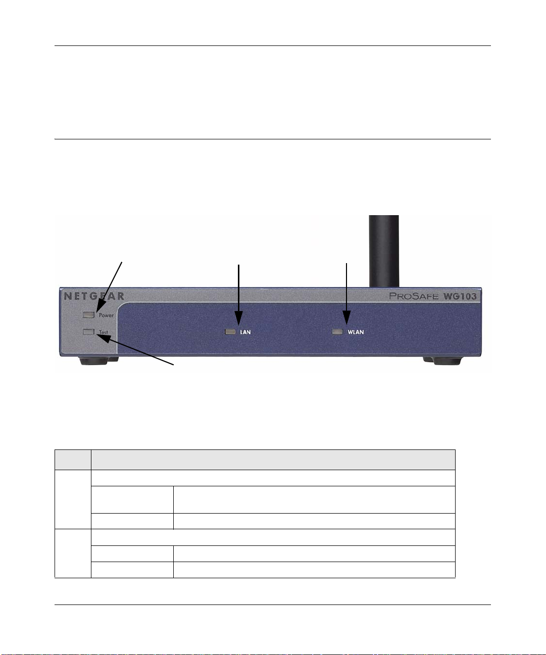
Front Panel
Figure 1-1
V iewed from left to right, the WG103 has these four status LEDs: P WR, TEST, LAN, and WLAN.
Ta ble 1-1. Front Panel LEDs
LED Description
Power Power Indicator
Off No power. If this LED does not come on with the power adapter and
cord correctly installed, see Chapter 6, “Troubleshooting.”
On Power is on.
Test Self Test Indicator
Green Blink Self-test in progress or loading software.
Amber on System fault or firmware upgrade failure
Introduction 1-5
v1.0, February 2009
Page 20
WG103 ProSafe 802.11g Wireless Access Point Reference Manual
1
2
3
4
5
6
Table 1-1. Front Panel LEDs (continued)
LED Description
LAN Ethernet link indicator
Off No connection detected on the Ethernet link
Amber On 10 Mbps Ethernet link detected
Amber Flashing Data is being transmitted or received on the 10 Mbps Ethernet link
Green On 100 Mbps Fast Ethernet link detected.
Green Flashing Data is being transmitted or received on the 100 Mbps Ethernet link
WLAN Wireless LAN Link Activity Indicator
Off No wireless link activity.
Green Blink Wireless link activity.
Rear Panel
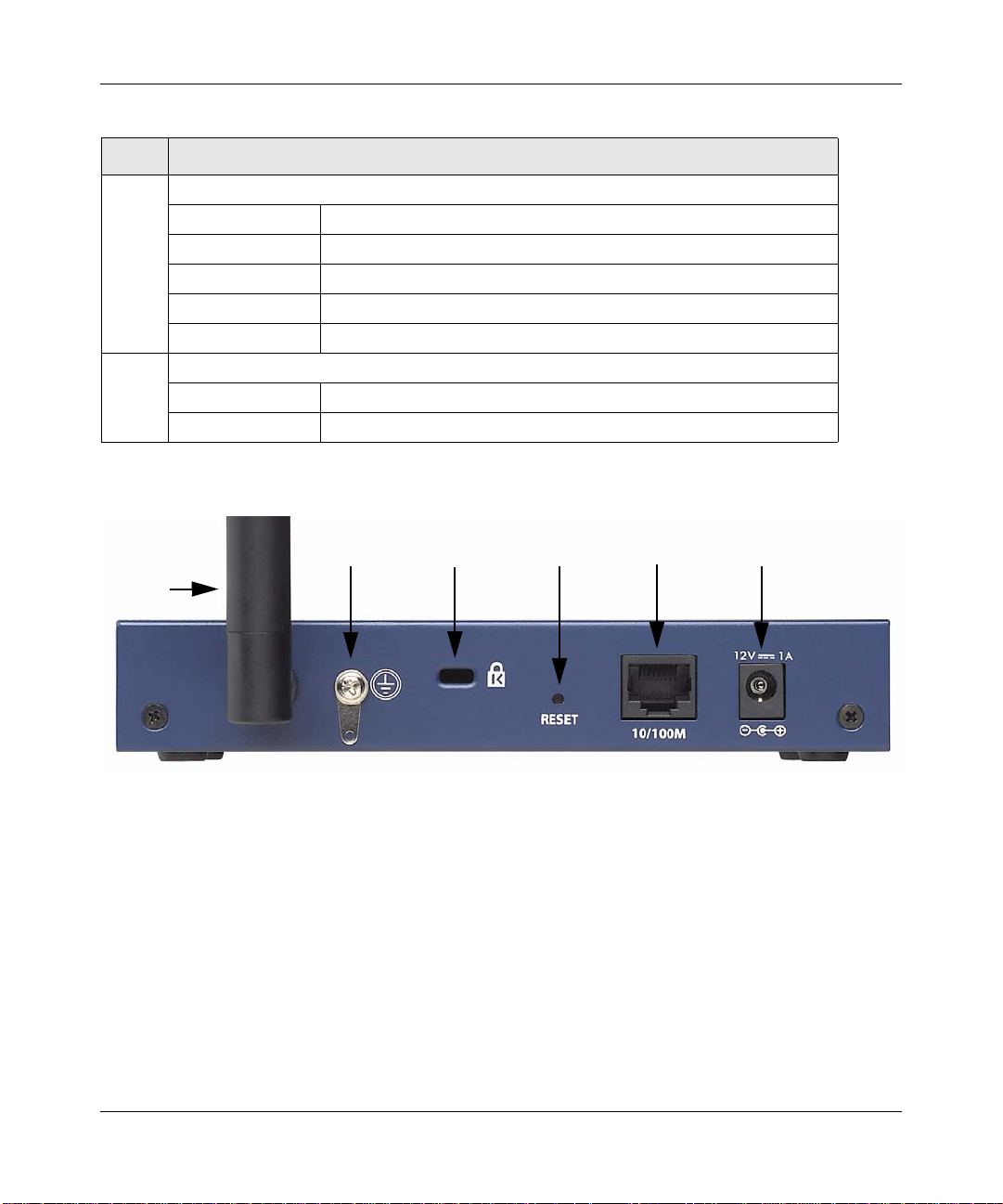
Figure 1-2
Viewed from left to right, the rear panel of the WG103 provides the following:
1. Detachable antenna.
2. Ground connector.
3. Security slot to allow you to lock the WG103 (you must provide the lock).
4. Reset button. This restores the default factory settings.
1-6 Introduction
v1.0, February 2009
Page 21
WG103 ProSafe 802.11g Wireless Access Point Reference Manual
5. RJ-45 Ethernet LAN/POE Port. Use the WG103 Ethernet RJ-45 port to connect to an Ethernet
LAN through a device such as a hub, switch, router, or Power Over Ethernet (POE) switch.
6. Power socket. This connects to the WG103 power adapter.
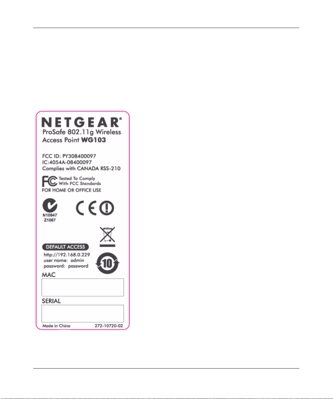
Bottom Panel
The bottom panel of the WG103 contains a label that shows compliance information, factory
default login information, and the MAC and serial numbers.
Figure 1-3
Introduction 1-7
v1.0, February 2009
Page 22

WG103 ProSafe 802.11g Wireless Access Point Reference Manual
1-8 Introduction
v1.0, February 2009
Page 23
Chapter 2
Basic Installation and Configuration
This chapter describes how to install and configure your WG103 ProSafe 802.11g Wireless Access
Point for wireless connectivity to your LAN. This basic configuration will enable computers with
802.11b or 802.1 1g wireless adapters to connect to the Internet, or access printers and files on your
LAN. In planning your wireless network, consider the level of security required. Chapter 3,
“Wireless Security” describes how to set up wireless security for your network.
This chapter includes:
• “What You Need before You Begin” on this page
• “Installing and Configuring the Wireless Access Point” on page 2-2
• “Testing Basic Wireless Connectivity” on page 2-12
• “Deploying the Wireless Access Point” on page 2-12
What You Need before You Begin
You need to consider the following guidelines and requirements before you can set up your
wireless access point. See also “System Requirements” on page 1-4.
Wireless Equipment Placement and Range Guidelines
The range of your wireless connection can vary significantly based on the location of the wireless
access point. The latency, data throughput performance, and notebook power consumption of
wireless adapters also vary depending on your configuration choices.
Note: Failure to follow these guidelines can result in significant performance degradation
or inability to wirelessly connect to the wireless access point. For complete
performance specifications, see Appendix A, “Technical Specifications.”
For best results, place your wireless access point according to the following guidelines:
• Near the center of the area in which your PCs will operate.
• In an elevated location such as a high shelf where the wirelessly connected PCs have line-ofsight access (even if through walls).
2-1
v1.0, February 2009
Page 24
WG103 ProSafe 802.11g Wireless Access Point Reference Manual
• Away from sources of interference, such as PCs, microwaves ovens, and 2.4 GHz cordless
phones.
• Away from large metal surfaces or water.
• Putting the antenna in a vertical position provides best side-to-side coverage. Putting the
antenna in a horizontal position provides best up-and-down coverage.
• If using multiple wireless access points, it is better if adjacent wireless access points use
different radio frequency channels to reduce interference. The recommended channel spacing
between adjacent wireless access points is five channels (for example, use channels 1 and 6, or
6 and 11, or 1 and 11).
The time it takes to establish a wireless connection can vary depending on both your security
settings, and placement. WEP connections can take slightly longer to establish. Also, WEP
encryption can consume more battery power on a notebook computer.
Ethernet Cabling Requirements
The wireless access point connects to your LAN via twisted-pair category 5 Ethernet cable with
RJ-45 connectors.
LAN Configuration Requirements
For the initial configuration of your wireless access point, you need to connect a computer to the
wireless access point.
Note: For assistance with DHCP configuration, see the online document that you can
access from “Preparing Your Network” in Appendix B.
Computer Hardware Requirements
To connect to the wireless access point on your network, each computer must have a 802.11g or
802.11b wireless adapter installed.
Installing and Configuring the Wireless Access Point
Before installing the wireless access point, make sure that your Ethernet network is up and
working. You will be connecting the wireless access point to the Ethernet network. Then
computers with 802.11b or 802.11g wireless adapters will be able to communicate with the
Ethernet network.
2-2 Basic Installation and Configuration
v1.0, February 2009
Page 25
WG103 ProSafe 802.11g Wireless Access Point Reference Manual
In order for this to work correctly, verify that you have met all of the system requirements, shown
in “System Requirements” on page 1-4.
Install and configure your wireless access point in this order:
1. Connect the Wireless Access Point to a Computer.
2. Log in to the Wireless Access Point.
3. Configure LAN Access and Set the Time.
4. Configure Basic IP Settings.
5. Configure Basic Wireless Settings.
6. Configure Basic QoS Settings.
Connect the Wireless Access Point to a Computer
Set up the wireless access point:
Tip: Before mounting the wireless access point in a high location, first set up and test
the wireless access point to verify wireless network connectivity.
1. Unpack the box and verify the contents.
2. Prepare a computer with an Ethernet adapter. If this computer is already part of yo ur network,
record its TCP/IP configuration settings.
3. Configure the computer with a static IP address of 192.168.0.210 and 255.255.255.0 as the
subnet mask.
4. Connect an Ethernet cable from the wireless access point to the computer.
5. Turn on your computer, connect the power adapter to the wireless access point, and verify the
following:
• Power LED. The power LED (PWR) should be lit. If the power LED is not lit, check the
connections and check to see if the power outlet is controlled by a wall switch that is
turned off.
• Test LED. The test LED (TEST) blinks when the wireless a ccess point is first turned on.
• LAN LED. The LAN LED (LAN) on the wireless access point should be lit (amber for a
10 Mbps connection and green for a 100 Mbps connection). If not, make sure the Ethernet
cable is securely attached at both ends.
Basic Installation and Configuration 2-3
v1.0, February 2009
Page 26
WG103 ProSafe 802.11g Wireless Access Point Reference Manual
Log in to the Wireless Access Point
The default IP address of your wireless access point is 192.168.0.229. The wireless access point is
set, by default, for the DHCP client to be disabled.
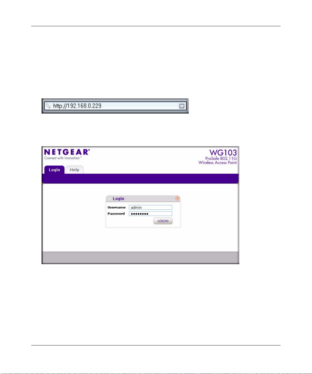
1. Open a Web browser such as Internet Explorer or Mozilla Firefox.
2. Connect to the wireless access point by entering its default address of http://192.168.0.229
into your browser:
Figure 2-1
3. The Login screen opens:
Figure 2-2
4. Enter the default user name of admin and the default password of password.
5. Click Login. The Web browser displays the Basic General Settings screen under the
Configuration tab of the main menu as shown in Figure 2-3 on page 2-5.
2-4 Basic Installation and Configuration
v1.0, February 2009
Page 27
WG103 ProSafe 802.11g Wireless Access Point Reference Manual
Configure LAN Access and Set the Time
First, configure LAN access, and then set the time:
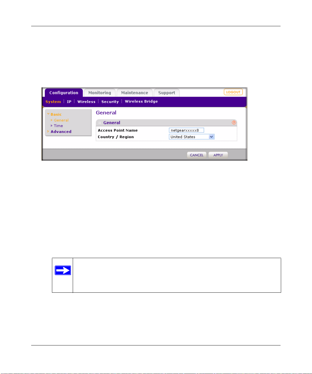
1. Log in to the wireless access point as described in “Log in to the Wireless Access Point” on
page 2-4. The Web browser displays the General screen. (The full path to his screen is
Configuration > System > Basic > General.)
Figure 2-3
2. Specify the following fields, or use the default values, which work for most users and
situations:
• Access Point name. This unique name is the wireless access point NetBIOS name. The
device can be accessed by entering either its name or IP address in the location bar of your
browser.The default wireless access point name is on the bottom label of the wireless
access point. You can modify the default name with a unique name up to 15 characters
long. The default is netgearxxxxxx8, where xxxxx represents the first five digits of the last
six digits of the wireless access point’s MAC address.These five digits are followed by an
eight (8).
Note: The MAC address for the wireless access point always ends with a
zero (0) but the NetBIOS name always ends with an eight (8). For
example, if the MAC address 1234567890A0, then the NetBIOS name is
netgear7890A8.
• Country/Region. This is the region where the wireless access point can be used. It may
not be legal to operate the wireless features of the wireless access point in a region other
than one of those identified in this field. For products sold in the United States, the
Country/Region field is preset according to regulatory requirements. For products sold
outside the United States, a country domain must be selected.
Basic Installation and Configuration 2-5
v1.0, February 2009
Page 28
WG103 ProSafe 802.11g Wireless Access Point Reference Manual
3. Click Apply to save your settings.
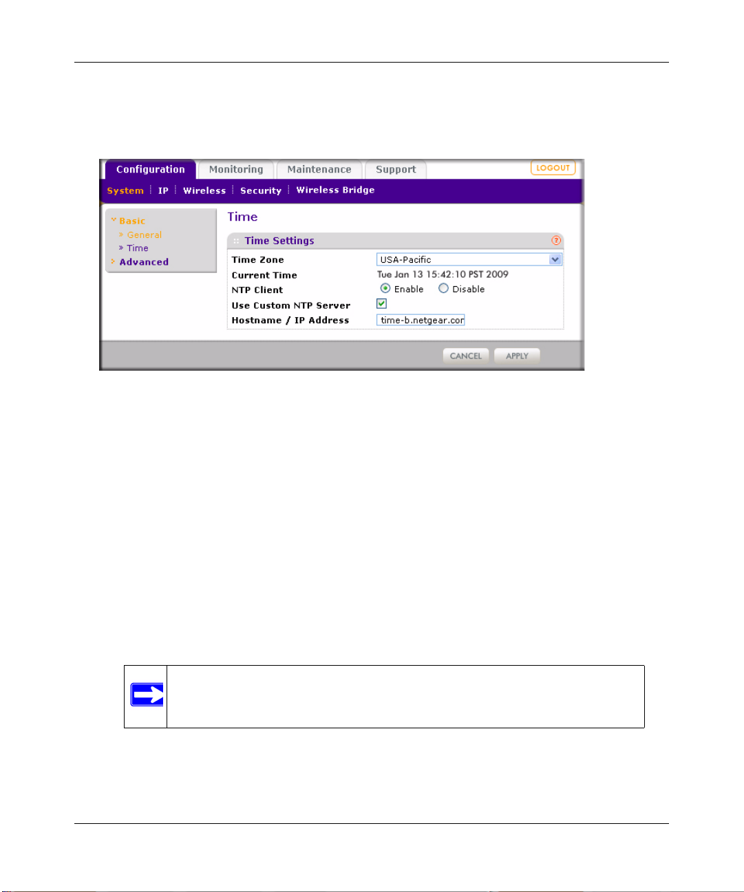
4. Click Time. The Time Settings screen appears. (The full path to his screen is Configuration >
System > Basic > Time.)
Figure 2-4
Specify the following fields:
• Time Zone. Select the time zone to match your location.
• Current Time. The current time, as used on the wireless access point, is displayed.
• NTP Client. Select one of the following radio buttons:
– Enable. Your wireless access point synchroniz es with a Network Time Protocol
(NTP) server.
– Disable. Your wireless access point does not synchronize with an NTP server.
• Use Custom NTP Server. Enable this check box if you want to use a custom NTP server.
• Hostname / IP Address. Provide the hostname or IP address of the time server that the
wireless access point must use to keep its time correct. The default is time-b.netgear.com.
Note: You must have an Internet connection to use an NTP server that is not
on your local network.
5. Click Apply to save your settings.
2-6 Basic Installation and Configuration
v1.0, February 2009
Page 29

WG103 ProSafe 802.11g Wireless Access Point Reference Manual
Configure Basic IP Settings
Configure the basic IP settings:
1. Log in to the wireless access point as described in “Log in to the Wireless Access Point” on
page 2-4.
2. Select Configuration > IP. The IP Settings screen displays:
Figure 2-5
Specify the following fields:
• DHCP Client. By default, the Dynamic Host Configuration Protocol (DHCP) client is
disabled. After installation, you can enable DHCP to let the wireless access point get its
TCP/IP configuration from the DHCP server on your network. The wireless access point
gets the IP address, subnet mask and the default gateway settings automatically from the
DHCP server if DHCP is enabled.
• IP Address. The default IP address is 192.168.0.229. If you want to change the address,
enter an unused IP address from the address range that is used on your LAN, or enable
DHCP.
• IP Subnet Mask. Enter the subnet mask value used on your LAN. The default is
255.255.255.0.
• Default Gateway. Enter the IP address of the gateway for your LAN. For more complex
networks, enter the address of the router for the network segment to which the wireless
access point is connected.
Basic Installation and Configuration 2-7
v1.0, February 2009
Page 30
WG103 ProSafe 802.11g Wireless Access Point Reference Manual
• Primary DNS Server. Enter the IP address of the domain name system (DNS) server you
wish to use.
• Secondary DNS Server. Enter the IP address of a secondary DNS server, which will be
used when the primary DNS server is not available
• Network Integrity Check. Select this check box to enable the wireless access point to
validate that the upstream link is active before allowing wireless associations.If you select
this check box, you must ensure that your default gateway is configured.
3. Click Apply to save your settings.
Configure Basic Wireless Settings
Warning: If you configure the wireless access point from a wireless computer and
you change the wireless access point’s SSID, channel or wireless security
settings, you will lose your wireless connection when you click Apply .
You must then change the wireless settings of your computer to match the
wireless access point’s new settings.
To configure the basic wireless settings:
1. Log in to the wireless access point as described in “Log in to the Wireless Access Point” on
page 2-4.
2. Select Configuration > Wireless. The Wireless Settings screen displays (see Figure 2-6 on
page 2-9).
2-8 Basic Installation and Configuration
v1.0, February 2009
Page 31

Figure 2-6
WG103 ProSafe 802.11g Wireless Access Point Reference Manual
3. Specify the following fields:
• Wireless Mode. Select the desired wireless operating mode. The options are:
– 11b. All 802.11b wireless stations can be used. 802.11g wireless stations can still be
used if they can operate in 802.11b mode.
– 11bg. Both 802.11g and 802.11b wireless stations can be used. This is the default
mode.
• Turn Radio On. On by default, you can also turn off the radio to disable access through
the wireless access point. Doing so can be helpful for configuration, network tuning, or
troubleshooting activities.
Wireless Network Name (SSID). The SSID is also known as the wireless network name. The
SSID separates network traffic from different wireless networks. To connect any wireless
device to a wireless network, you need to use the SSID. The wireless access point default
SSID is: NETGEAR_11g for the first profile, NETGEAR_11g-1 for the second profile,
NETGEAR_11g-2 for the third profile, NETGEAR_11g-3 for the fourth profile, and so on.
You can enter a value of up to 32 alphanumeric characters. For more information about SSIDs,
see “Security Profiles” on page 3-3.
Basic Installation and Configuration 2-9
v1.0, February 2009
Page 32

WG103 ProSafe 802.11g Wireless Access Point Reference Manual
Note: The SSID of any wireless adapters must match the SSID of the wireless access
point. If they do not match, a wireless connection to the wireless access point
cannot be established.
• Broadcast Wireless Network Name (SSID). Select a radio button to enable or disable
broadcast of the SSID. If you disable broadcast of the SSID, only stations that know the
SSID can connect to the wireless access point. Disabling the SSID broadcast somewhat
hampers the wireless network discovery feature of some products. Broadcast of the SSID
is enabled by default.
• Channel / Frequency. This drop-down menu lets you specify which operating frequency
is used. The default setting is Auto. You should not need to change the ch annel u nless y ou
notice interference problems, or are setting up the wireless access point near another
wireless access point.Observe the following guidelines:
– Wireless access points use a fixed channel. You can select the channel used. This lets
you choose a channel that provides the least interference and best performance. In the
USA and Canada, 11 channels are available.
– If using multiple wireless access points, it is better if adjacent wireless access points
use different channels to reduce interference. The recommended channel spacing
between adjacent wireless access points is five channels (for example, use channels 1
and 6, or 6 and
11).
– In “infrastructure” mode, wireless stations normally scan all channels, looking for a
wireless access point. If more than one wireless access point can be used, the one with
the strongest signal is used. This can happen only when the wireless access points use
the same SSID.
See the online document that you can access from “Wireless Networking Basics” in
Appendix B for more information about wireless channels.
• Data Rate. This drop-down menu lets you specify the transmit data rate of the wireless
network. The default settings is Best. The smallest data rate that you can select is 1 Mbps;
the largest is 54 Mbps.
• Output Power. This drop-down menu lets you specify the transmit signal strength of the
wireless access point. The options are Full, Half, Quarter, Eighth, and Minimum. Decrease
the transmit power if two or more wireless access points are close together and using the
same channel frequency. The default settings is Full.
4. Click Apply to save your settings.
2-10 Basic Installation and Configuration
v1.0, February 2009
Page 33

WG103 ProSafe 802.11g Wireless Access Point Reference Manual
Configure Basic QoS Settings
The QoS screen lets you modify the quality of service (QoS) settings for upstream traffic flowing
from a client station to the wireless access point and the downstream traffic flowing from the
wireless access point to a client station.
To configure the basic QoS settings:
1. Log in to the wireless access point as described in “Log in to the Wireless Access Point” on
page 2-4.
2. Select Configuration > Wireless > Basis > QoS Settings. The basic QoS Settings screen
displays:
Figure 2-7
3. Specify the following fields:
• Wi-Fi Multimedia (WMM). Select the Enable radio button to ensure that applications
that require better throughput and performance are provided special queues with higher
priority. For example, video and audio applications are given higher priority over
applications, such as FTP. This feature is enabled by default.
• WMM Powersave. Select the Enable radio button to let power-saving devices that
connect to the wireless access point conserve power. This feature is enabled by default.
4. Click Apply to save your settings.
Basic Installation and Configuration 2-11
v1.0, February 2009
Page 34

WG103 ProSafe 802.11g Wireless Access Point Reference Manual
Testing Basic Wireless Connectivity
After you have installed and configured the wireless access point as explained in the previous
section, test your computers for wireless connectivity:
1. Configure the wireless adapters of your computers so that they all have the same SSID and
channel that you have configured on the wireless access point.
2. Verify that your computers have a wireless link to the wireless access point and are able to
obtain an IP address through DHCP from the wireless access point.
If you have trouble connecting to the wireless access point, see Chapter 6, “Troubleshooting.”
Now that your computers can connect to the wireless access point, you can configure the wireless
security as described in Chapter 3, “Wireless Security.”
Deploying the Wireless Access Point
After you have tested basic wireless connectivity (see the previous section) and have set up
wireless security as described in Chapter 3, “Wireless Security,” you are ready to deploy the
wireless access point in your network. If needed, you can now reconfigure the computer that you
used for this process back to its original TCP/IP settings.
To deploy the wireless access point
1. Disconnect the wireless access point and position it where you will deploy it. The best location
is elevated, such as wall mounted or on the top of a cubicle, at the center of your wireless
coverage area, and within line of sight of all the mobile devices.
2. Position the antenna. Vertical positioning provides best side-to-side coverage. Horizontal
positioning provides best top-to-bottom coverage.
Note: Consult the antenna positioning and wireless mode configuration
information in Chapter 5, “Advanced Configuration.”
3. Connect an Ethernet cable from your wireless access point to a LAN port on your router,
switch, or hub.
2-12 Basic Installation and Configuration
v1.0, February 2009
Page 35

WG103 ProSafe 802.11g Wireless Access Point Reference Manual
Note: By default, the wireless access point is set with the DHCP client disabled.
If your network uses dynamic IP addresses, you must change this setting.
4. Connect the power adapter to the wireless access point, and plug the power adapter in to a
power outlet. The PWR and LAN LEDs should light up.
Tip: The wireless access point supports Power Over Ethernet (PoE). If you have a
switch that provides PoE, you will not need to use the power adapter to power
the wireless access point. This can be especially convenient when the wireless
access point is installed in a high location far away from a power outlet.
5. Verify wireless connectivity.
Using a computer with an 802.11b or 802.11g wireless adapter with the correct wireless
settings (see “Testing Basic Wireless Connectivity” on page 2-12), verify connectivity by
using a browser such as Internet Explorer or Mozilla Firefox to browse the Internet, or check
for file and printer access on your network.
Note: If you are unable to connect, see Chapter 6, “Troubleshooting.”
Basic Installation and Configuration 2-13
v1.0, February 2009
Page 36

WG103 ProSafe 802.11g Wireless Access Point Reference Manual
2-14 Basic Installation and Configuration
v1.0, February 2009
Page 37

WG103 ProSafe 802.11g Wireless Access Point Reference Manual
Chapter 3
Wireless Security
This chapter describes how to use your WG103 ProSafe 802.11g Wireless Access Point to set up
wireless security for your wireless network.
This chapter includes:
• “Wireless Data Security Options” on this page
• “Security Profiles” on page 3-3
• “Configuring the RADIUS Server Settings” on page 3-9
• “Configuring WEP” on page 3-10
• “Configuring WPA” on page 3-12
• “Restricting Wireless Access by MAC Address” on page 3-14
Wireless Data Security Options
Indoors, computers can connect over 802.11g wireless networks at a maximum range of 300 feet.
Typically, a wireless access point inside a building works best with devices within a 100 foot
radius. Such distances can allow for others outside your immediate area to access your network.
Unlike wired network data, your wireless data transmissions can extend beyond your walls and
can be received by anyone with a compatible adapter. For this reason, use the security features of
your wireless equipment. The wireless access point provides highly effective security features that
are covered in detail in this chapter. Deploy the security features appropriate to your needs.
Wireless Security 3-1
v1.0, February 2009
Page 38

WG103 ProSafe 802.11g Wireless Access Point Reference Manual
Figure 3-1
There are several ways you can enhance the security of your wireless network:
• Use Multiple BSSIDs combined with VLANs. You can configure combinations of VLANS
and BSSIDs with stronger or less restrictive access security according to your requirements.
For example, visitors could be given wireless Internet access but be excluded from any access
to your internal network. For information about how to configure BSSIDs, see “Creating and
Editing Security Profiles” on page 3-5.
• Restrict Access based by MAC address. You can allow only trusted PCs to connect so that
unknown PCs cannot wirelessly connect to the wireless access point. Restricting access by
MAC address adds an obstacle against unwanted access to your network, but the data
broadcast over the wireless link is fully exposed. For information about how to restrict access
by MAC address, see “Restricting Wireless Access by MAC Address” on page 3-14.
• T urn off the br oadcast of the wire less network name (SSID). If you disable broadcast of the
SSID, only devices that have the correct SSID can connect. This nullifies the wireless network
discovery feature of some products, such as Windows XP, but the data is still exposed. For
information about how to turn of broadcast of the SSID, see “Creating and Editing Security
Profiles” on page 3-5.
• WEP. Wired Equivalent Privacy (WEP) data encryption provides data security. WEP Shared
Key authentication and WEP data encryption block all but the most determined eavesdropper.
This data encryption mode has been superseded by WPA-PSK and WPA2-PSK. For
information about how to configure WEP, see “Configuring WEP” on page 3-10.
3-2 Wireless Security
v1.0, February 2009
Page 39

WG103 ProSafe 802.11g Wireless Access Point Reference Manual
• WPA, WPA-PSK, WPA2, or WPA2-PSK. Wi-Fi Protected Access (WPA and WPA2) data
encryption provides data security. The very strong authentication along with dynamic per
frame rekeying of WPA make it virtually impossible to compromise. For information about
how to configure WEP, see “Configuring WPA” on page 3-12.
• WPA with RADIUS (WPA-802.1x), WPA2 with RADIUS (WPA2-802.1x), or WPA and
WPA2 with RADIUS (WPA-802.1x+WPA2-802.1x). Wi-Fi Protected Access (WPA and
WPA2) data encryption provides data security. The very strong authentication along with
dynamic per frame rekeying of WPA make it virtually impossible to compromise. For
information about how to configure WEP, see “Configuring WPA” on page 3-12.
Security Profiles
Security profiles let you configure unique security settings for each SSID. The wireless access
point supports up to eight BSSIDs that you can configure in the Profile Settings screen (see
“Creating and Editing Security Profiles” on page 3-5). To set up a security profile you select its
network authentication type, data encryption, wireless client security separation, and VLAN ID:
• Network Authentication
The wireless access point is set by default as an open system with no authentication. When you
configure network authentication, bear in mind the following:
– If you are using Access Point mode, then all options are available. In other modes such as
Repeater or Bridge, some options may be unavailable.
– Not all wireless adapters support WPA or WPA2. Windows XP, Windows 2000 with
Service Pack 3, and Windows Vista do include the client software that supports WPA.
However, client software is required on the client. Consult the product documentation for
your wireless adapter and WPA or WPA2 client software for instructions on configuring
WPA2 settings.
You can configure the wireless access point to use the types of network authentication that are
shown in Table 3-1 on page 3-7.
• Data Encryption
Select the data encryption that you want to use. The available options depend on the network
authentication setting above (otherwise, the default is None). The Data Encryption settings are
explained in Table 3-2 on page 3-8.
Wireless Security 3-3
v1.0, February 2009
Page 40

WG103 ProSafe 802.11g Wireless Access Point Reference Manual
• Wireless Client Security Separation
If enabled, the associated wireless clients (using the same SSID) will not be able to
communicate with each other. This feature is used for hotspots and other public access
situations. The default settings is disabled.
• VLAN ID
If enabled and if the network devices (hubs and switches) on your LAN support the VLAN
(802.1Q) standard, the default VLAN ID for the wireless access point will be associated with
each profile. The default profile VLAN ID must match the IDs that are used by the other
network devices.
Before You Change the SSID and WEP Settings
For a new wireless network, print or copy this form and fill in the settings. For an existing wireless
network, the network administrator can provide this information. Be sure to set the
Country/Region correctly as the first step. Store this information in a safe place.
• SSID: The Service Set Identification (SSID) identifies the wireless local area network. You
may customize it by using up to 32 alphanumeric characters. Write your SSID on the line.
SSID: _________________________ __________
Note: The SSID in the wireless access point is the SSID you configure in the wireless adapter
card. All wireless nodes in the same network must be configured with the same SSID:
• Authentication
Circle one: Open System or Shared Key. Choose “Shared Key” for more security.
Note: If you select shared key, the other devices in the network will not connect unless they
are set to Shared Key and have the same keys in the same positions as those in the WG103.
• WEP Encryption Keys
For all four 802.11b keys, choose the Key Size. Circle one: 64, 128, or 152 bits
Key 1: ___________________________________
Key 2: ___________________________________
Key 3: ___________________________________
Key 4: ___________________________________
• WPA-PSK (Pre-Shared Key) WPA2-PSK (Pre-Shared Key)
Record the WPA-PSK key: Record the WPA2-PSK key:
Key: ________________________________
Key: _______________________________
3-4 Wireless Security
v1.0, February 2009
Page 41

WG103 ProSafe 802.11g Wireless Access Point Reference Manual
• WPA RADIUS Settings
For WPA, record the following settings for the primary and secondary RADIUS servers:
Server Name/IP Address: Primary _________________
Port: ___________________________________
Shared Secret: ___________________________________
Secondary __________________
• WPA2 RADIUS Settings
For WPA2, record the following settings for the primary and secondary RADIUS servers:
Server Name/IP Address: Primary _________________
Port: ___________________________________
Shared Secret: ___________________________________
Secondary __________________
Creating and Editing Security Profiles
To create or edit a security profile with its own unique BSSID:
1. Log in to the wireless access point at its default LAN address of http://192.168.0.229 with its
default user name of admin and default password of password, or using whatever password
and LAN address you have chosen for the wireless access point.
2. Select Configuration > Security > Profile Settings. The Profile Settings screen displays
information about the eight profiles:
Figure 3-2
Wireless Security 3-5
v1.0, February 2009
Page 42

WG103 ProSafe 802.11g Wireless Access Point Reference Manual
3. T o select a security profile without editing it, select the correspon ding check box in the Enab le
column and proceed to step 6. To edit a security profile, select the corresponding radio button
from the list, and click Edit. The Edit Security Profile screen opens for the selected security
profile. Figure 3-3 shows an example with a Open System network authentication.
Figure 3-3
4. Enter the profile definitions in the Edit Security Profile screen:
• Security Profile Name. Use a name that makes it easy to recognize the profile, and to tell
profiles apart.
• Wireless Network Name (SSID). The SSID is also known as the wireless network name.
The SSID separates network traffic from different wireless networks. To connect any
wireless device to a wireless network, you need to use the SSID. The wireless access point
default SSID is: NETGEAR_11g for the first profile, NETGEAR_11g-1 for the second
profile, NETGEAR_11g-2 for the third profile, NETGEAR_11g-3 for the fourth profile,
and so on. You can enter a value of up to 32 alphanumeric characters.
Some concepts and guidelines regarding the SSID are explained below:
– A Basic Service Set (BSS) is a group of wireless stations and a single wireless access
point, all using the same SSID.
– An Extended Service Set (ESS) is a group of wireless stations and multiple wireless
access points, all using the same ID (ESSID).
3-6 Wireless Security
v1.0, February 2009
Page 43

WG103 ProSafe 802.11g Wireless Access Point Reference Manual
– Different wireless access points within an ESS can use different channels. To reduce
interference, adjacent wireless access points should use different channels.
– Roaming is the ability of wireless stations to connect wirelessly when they physically
move from one BSS to another within the same ESS. The wireless station
automatically changes to the wireless access point with the least interference or best
performance.
• Broadcast Wireless Network Name (SSID). These radio buttons let you enable and
disable the SSID broadcast. If disable the SSID broadcast, then only stations that know the
SSID can connect. Disabling the SSID broadcast somewhat hampers the wireless network
discovery feature of some products. The default is to enable SSID broadcast.
5. Enter the authentication settings in the Edit Security Profile screen:
• Network Authentication. Use the information in the following table to set the network
authentication.
Table 3-1. Network Authentication Types
Field Description
Open System Can be used with WEP encryption, or no encryption. See “Configuring
WEP” on page 3-10.
Shared Key WEP must be used. At least one shared key must be entered. See
“Configuring WEP” on page 3-10.
Legacy 802.1x You must configure the RADIUS Server Settings to use this option. See
“Configuring WPA” on page 3-12.
WPA with Radius You must configure the RADIUS Server Settings to use this option. See
“Configuring WPA” on page 3-12.
WPA2 with Radius WPA2 is a later version of WPA. Select this option only if all clients support
WPA2. If selected, you must use AES encryption, and configure the
RADIUS Server Settings Screen. See “Configuring WPA” on page 3-12.
WPA & WPA2 with
Radius
WPA-PSK You must use TKIP encryption, and enter the WPA passphrase (Network
This selection allows clients to use either WPA (with TKIP) or WPA2 (with
AES). If selected, encryption must be TKIP + AES, and you must also
configure the RADIUS Server Settings Screen. See “Configuring WPA” on
page 3-12.
key). See “Configuring WPA” on page 3-12.
Wireless Security 3-7
v1.0, February 2009
Page 44

WG103 ProSafe 802.11g Wireless Access Point Reference Manual
Table 3-1. Network Authentication Types (continued)
Field Description
WPA2-PSK WPA2 is a later version of WPA. Select this option only if all clients support
WPA2. If selected, you must use AES encryption, and enter the WPA
passphrase (Network key). See “Configuring WPA” on page 3-12.
WPA-PSK &
WPA2-PSK
This option allows clients to use either WPA (with TKIP) or WPA2 (with
AES). If selected, encryption must be TKIP + AES. The WPA passphrase
(Network key) must also be entered. See “Configuring WPA” on page 3-12.
• Data Encryption. Use the information in the following table to configure the data
encryption. Note that the types of data encryption that are available depend on the
selection of the network authentication type.
Table 3-2. Data Encryption Settings
Field Description
None No encryption is used.
64 bits WEP Standard WEP encryption, using 40/64 bit encryption. See “Configuring
WEP” on page 3-10.
128 bits WEP Standard WEP encryption, using 104/128 bit encryption. See “Configuring
WEP” on page 3-10.
152 bits WEP Proprietary mode that will work only with other wireless devices that
support this mode. See “Configuring WEP” on page 3-10.
TKIP This is the standard encryption method used with WPA. See “Configuring
WPA” on page 3-12.
AES This is the standard encryption method for WPA2. Some clients may
support AES with WPA, but this is not supported by this wireless access
point. See “Configuring WPA” on page 3-12.
TKIP + AES This setting supports both WPA and WPA2. Broadcast packets use TKIP.
For unicast (point-to-point) transmissions, WPA clients use TKIP, and
WPA2 clients use AES. See “Configuring WPA” on page 3-12.
• Wireless Client Security Separation. Wireless client security separation must be enabled
to block unicast, multicast, and broadcast traffic between the clients of the same virtual
access point (VAP). From the pull-down menu, select one of the following options:
– Disable. Allows unicast, multicast, and broadcast traffic between all wireless stations.
– Enable. Blocks unicast, multicast, and broadcast traffic between all wireless stations.
3-8 Wireless Security
v1.0, February 2009
Page 45

WG103 ProSafe 802.11g Wireless Access Point Reference Manual
• VLAN ID. Enter the VLAN ID that is associated with this profile.
6. Click Apply to save your settings.
Configuring the RADIUS Server Settings
To view or change the RADIUS server settings:
1. Log in to the wireless access point at its default LAN address of http://192.168.0.229 with its
default user name of admin and default password of password, or using whatever password
and LAN address you have chosen for the wireless access point.
2. Select Configuration > Security > Advanced > Radius Server Settings. The Radius Server
Settings screen displays:
Figure 3-4
3. View or change the RADIUS server and authentication settings:
• Primary Authentication Server
Secondary Authentication Server
Primary Accounting Server
Secondary Accounting Server
Wireless Security 3-9
v1.0, February 2009
Page 46

WG103 ProSafe 802.11g Wireless Access Point Reference Manual
For authentication, accounting, or both authentication and accounting using RADIUS, you
must configure primary servers. Complete the IP Address, Port No. and Shared Secret
fields to enable communication with the RADIUS server. You can configure a secondary
RADIUS server that is used in case the primary RADIUS server fails.
– IP Address. The IP address of the RADIUS server.
– Port Number. The port number of the RADIUS server. The default port for an
authentication server is 1812; the default port for a accounting server is 1813.
– Shared Secret. This value is shared between the wireless access point and the
RADIUS server while authenticating the supplicant.
• Reauthentication Time (Seconds). The time interval in seconds after which the
supplicant will be authenticated again with the RADIUS server. The default is 3600
seconds.
• Update Global Key Every (Seconds). Select this check box to enable re-keying of the
global key, and enter a value in seconds. The global key re-key can be done based on time
interval in seconds. The default is 1800 seconds.
4. Enter the settings, and click Apply.
Configuring WEP
Note: If you use a wireless computer to configure wireless security settings, you will be
disconnected when you click Apply. Reconfigure your wireless computer to match
the new settings, or access the wireless access point from a wired computer to
make further changes.
To configure WEP data encryption:
1. Log in to the wireless access point at its default LAN address of http://192.168.0.229 with its
default user name of admin, and default password of password, or using whatever password
and LAN address you have chosen for the wireless access point.
2. Select Configuration > Security > Profile Settings. The Profile Settings screen displays (see
Figure 3-2 on page 3-5.)
3. Select a profile by selecting the corresponding radio button from the list, and click Edit. The
Edit Security Profile screen displays. Figure 3-5 on page 3-11 shows an example with a Shared
Key network authentication.
3-10 Wireless Security
v1.0, February 2009
Page 47

WG103 ProSafe 802.11g Wireless Access Point Reference Manual
Figure 3-5
4. From the Network Authentication pull-down menu, select Open System or Shared Key.
Note: The authentication scheme is separate from the data encryption. You can select
an authentication scheme that requires a shared key but still leaves the data
transmissions unencrypted. If you require strong security, use both the Shared
Key and WEP encryption settings.
5. From the Data Encryption pull-down menu, select 64 bit WEP, 128 bit WEP, or
152 bit WEP.
6. Passphrase. To use a passphrase to generate the WEP keys, enter a word or group of
characters, and click Generate Keys. The four key fields will be automatically populated with
key values. You can also enter the keys manually.
Wireless Security 3-11
v1.0, February 2009
Page 48

WG103 ProSafe 802.11g Wireless Access Point Reference Manual
7. Key 1, Key 2, Key 3, Key 4. If you choose to enter the keys manually, enter hexadecimal
digits (any combination of 0–9, a–f, or A–F). Select the key to be used as the default key. Data
transmissions are always encrypted using the default key. The other keys can be used only to
decrypt received data. These key values must be identical on all computers and access points
in your network.
8. Wireless Client Security Separation if required. Enable this option, if required. (For more
information, see “Security Profiles” on page 3-3.)
9. VLAN ID. Enter the VLAN ID that is associated with this profile.
10. Click Apply to save your settings.
For more information about WEP, see the online document that you can access from “Wireless
Networking Basics” in Appendix B.
Configuring WPA
WPA-PSK data encryption provides data security. The very strong authentication along with
dynamic per frame rekeying of WPA makes it virtually impossible to compromise.
Not all wireless adapters support Wi-Fi Protected Access (WPA). Consult the product
documentation for your wireless adapter for instructions for configuring WPA settings.
Note: If you use a wireless computer to configure wireless security settings, you will be
disconnected when you click Apply. Reconfigure your wireless computer to match
the new settings, or access the wireless access point from a wired computer to
make further changes.
To configure WPA data encryption:
1. Log in to the wireless access point at its default LAN address of http://192.168.0.229 with its
default user name of admin and default password of password, or using whatever password
and LAN address you have chosen for the wireless access point.
2. Select Configuration > Security > Profile Settings. The Profile Settings screen displays (see
Figure 3-2 on page 3-5.)
3-12 Wireless Security
v1.0, February 2009
Page 49

WG103 ProSafe 802.11g Wireless Access Point Reference Manual
3. Select a profile by selecting the corresponding radio button from the list, and click Edit.The
Edit Security Profile screen displays. Figure 3-5 shows an example with a WPA2-PSK
network authentication.
Figure 3-6
4. From the Network Authentication pull-down menu, select the WPA or WPA2 option of your
choice:
• Legacy 802.1X.
• WPA with Radius.
• WPA2 with Radius.
• WPA & WPA2 with Radius.
• WPA-PSK.
• WPA2-PSK.
• WPA-PSK & WPA2-PSK.
Some options require that you configure one ore more RADIUS servers (see “Configuring the
RADIUS Server Settings” on page 3-9).
5. If you have selected WPA-PSK, WPA2-PSK, or WPA-PSK & WPA2-PSK, enter the
passphrase in the WPA Passphrase (Network Key) field. All wireless stations must use the
same passphrase (network key). The passphrase must be from 8 to 63 characters in length.
Wireless Security 3-13
v1.0, February 2009
Page 50

WG103 ProSafe 802.11g Wireless Access Point Reference Manual
6. Wireless Client Security Separation if required. Enable this option, if required. (For more
information, see “Security Profiles” on page 3-3.)
7. VLAN ID. Enter the VLAN ID associated with this profile.
8. To save your settings, click Apply.
For more information about WPA, see the online document that you can access from “Wireless
Networking Basics” in Appendix B.
Restricting Wireless Access by MAC Address
For increased security, you can restrict access to the wireless network to allow only specific
computers or wireless cards based on their MAC addresses. Y ou can restrict access to only trusted
computers so that unknown computers cannot wirelessly connect to the wireless access point.
MAC address filtering adds an obstacle against unwanted access to your network, but the data
broadcast over the wireless link is fully exposed.
Note: For wireless adapters, you can usually find the MAC address printed on the
wireless adapter.
To restrict access based on MAC addresses:
1. Log in to the wireless access point at its default LAN address of http://192.168.0.229 with its
default user name of admin, and default password of password, or using whatever password
and LAN address you have chosen for the wireless access point.
Note: When configuring the wireless access point from a wireless computer whose
MAC address is not in the access control list, if you select Turn Access Control
On, you will lose your wireless connection when you click Apply. You must
then access the wireless access point from a wired computer or from a wireless
computer which is on the access control list to make any further changes.
3-14 Wireless Security
v1.0, February 2009
Page 51

WG103 ProSafe 802.11g Wireless Access Point Reference Manual
2. Select Configuration > Security > Advanced > MAC Authentication. The MAC
Authentication screen displays.
Figure 3-7
3. Select the Turn Access Control On check box.
4. From the Select Access Control Database pull-down menu, select to use a remote MAC
address database that is stored on a RADIUS server or to use the local MAC address database
that is stored on the wireless access point:
• Remote MAC Address Database. You must configure the RADIUS server settings first
“Configuring the RADIUS Server Settings” on page 3-9).
(see
• Local MAC Address Database. There are two methods to enter a MAC address in the
Trusted Wireless Stations table:
– Select a station ID and MAC address from the list of available wireless cards that the
wireless access point has found in your area (click Refresh to refresh the list), and
then click Move to enter the MAC address in the Trusted Wireless Stations table.
– Manually enter the MAC address for a device that you plan to use in the Trusted
Wireless Stations table, and then click Add.
Repeat these procedures for each additional device you want to add to the list. To delete a
MAC address from the Trusted Wireless Stations table, select the address, and then click
Delete.
5. Click Apply to save your settings. Now, only devices on this list will be allowed to wirelessly
connect to the wireless access point.
Wireless Security 3-15
v1.0, February 2009
Page 52

WG103 ProSafe 802.11g Wireless Access Point Reference Manual
3-16 Wireless Security
v1.0, February 2009
Page 53

Chapter 4
Managing Your Network
This chapter describes how to use the management features of your WG103 ProSafe 802.11g
Wireless Access Point.
This chapter includes:
• “Backing Up, Restoring, and Erasing Your Settings” on this page
• “Upgrading the Wireless Access Point Firmware” on page 4-5
• “Network Management Information” on page 4-6
• “Changing the Administrator Password” on page 4-15
• “Remote Management” on page 4-16
• “Enabling Rogue AP Detection” on page 4-19
Backing Up, Restoring, and Erasing Your Settings
The configuration settings of the wireless access point are stored in a configuration file in the
wireless access point. This file can be backed up to a computer, restored from a computer, or
reverted to factory default settings. The following procedures explain how to do these tasks.
Backing up the Configuration
To back up the configuration:
1. Log in to the wireless access point at its default LAN address of http://192.168.0.229 with its
default user name of admin and default password of password, or using whatever password
and LAN address you have chosen for the wireless access point.
2. Select Maintenance > Upgrade > Backup Settings. The Backup Settings screen displays
(see Figure 4-1 on page 4-2).
4-1
v1.0, February 2009
Page 54

WG103 ProSafe 802.11g Wireless Access Point Reference Manual
Figure 4-1
3. To save your settings, click Backup. Your browser extracts the configuration file from the
wireless access point and prompts you for a location on your computer to store the file. You
can give the file a meaningful name at this time, such as WG103.cfg.
Restoring the Configuration
To restore your settings from a saved configuration file:
1. Log in to the wireless access point at its default LAN address of http://192.168.0.229 with its
default user name of admin and default password of password, or using whatever password
and LAN address you have chosen for the wireless access point.
2. Select Maintenance > Upgrade > Restore Settings. The Restore Settings screen displays.
Figure 4-2
3. Enter the full path to the file on your computer or click Browse to locate the file.
4. Click Apply to upload the file. After completing the upload, the wireless access point reboots
automatically.
4-2 Managing Your Network
v1.0, February 2009
Page 55

WG103 ProSafe 802.11g Wireless Access Point Reference Manual
Rebooting and Restoring the Default Configuration
You can erase the wireless access point configurations, and return to the factory default settings.
After erasing, the wireless access point’s password will be password, the SSID will be
NETGEAR, the DHCP client will be disabled, the default LAN IP address will be 192.168.0.229,
and the access wireless access point name is reset to the name printed on the label on the bottom of
the unit.
Using the Reset Button to Reboot or Restore Factory Default Settings
If you do not know the login password or IP address, you can still restore the factory default
configuration settings with the Reset button. This button is on the rear panel of the wireless access
point (see “Rear Panel” on page 1-6). The Reset button has two functions:
• Reboot. When pressed and released, the wireless access point reboots (restarts).
• Reset to Factory Defaults. When pressed and held down, it clears all data and restores all
settings to the factory default values.
To clear all data and restore the factory default values:
1. Hold the Reset button until the LEDs blink twice, usually more than five seconds.
2. Release the Reset button.
The factory default configuration has now been restored, and the wireless access point is ready for
use.
Using the Software to Reboot the Wireless Access Point
To use the software to reboot the wireless access point:
1. Log in to the wireless access point at its default LAN address of http://192.168.0.229 with its
default user name of admin and default password of password, or using whatever password
and LAN address you have chosen for the wireless access point.
2. Select Maintenance > Reset > Reboot AP. The Reboot AP screen displays (see Figure 4-3 on
page 4-4).
Managing Your Network 4-3
v1.0, February 2009
Page 56

WG103 ProSafe 802.11g Wireless Access Point Reference Manual
Figure 4-3
3. Select the Yes radio button.
4. Click Apply to reboot the wireless access point.
Using the Software to Restore Factory Default Settings
To use the software to restore all settings to the factory default values:
1. Log in to the wireless access point at its default LAN address of http://192.168.0.229 with its
default user name of admin and default password of password, or using whatever password
and LAN address you have chosen for the wireless access point.
2. Select Maintenance > Reset > Restore Defaults. The Restore Defaults screen displays.
Figure 4-4
3. Select the Yes radio button.
4. Click Apply. The factory default settings will be restored.
4-4 Managing Your Network
v1.0, February 2009
Page 57

WG103 ProSafe 802.11g Wireless Access Point Reference Manual
Upgrading the Wireless Access Point Firmware
Warning: When uploading firmware to the wireless access point, do not interrupt the
W eb browser by closing the window, clicking a link, or loading a new page. If
the browser is interrupted, the upload may fail, corrupt the firmware, and
render the wireless access point completely inoperable.
You cannot upgrade the firmware from a computer that is connected to the wireless access point
with a wireless link. Y ou must use a computer that is connected to the wireless access point with an
Ethernet cable.
The wireless access point firmware is stored in flash memory, and can be upgraded as NETGRA
releases new firmware. You can download the upgrade file (in tar format) from the NETGEAR
Web site.
Note: The Web browser used to upload new firmware into the wireless access point must
support HTTP uploads, such as Microsoft Internet Explorer 6.0 or later, or Mozilla
Firefox 1.5 or later.
To upgrade the firmware on the wireless access point:
1. Download the upgrade file from NETGEAR and save it to your hard disk.
1. Log in to the wireless access point at its default LAN address of http://192.168.0.229 with its
default user name of admin and default password of password, or using whatever password
and LAN address you have chosen for the wireless access point.
2. Back up the current configuration as described in “Backing up the Configuration” on page 4-1.
3. Select Maintenance > Upgrade > Firmware Upgrade. The Firmware Upgrade screen
displays Figure 4-5 on page 4-6).
Managing Your Network 4-5
v1.0, February 2009
Page 58

WG103 ProSafe 802.11g Wireless Access Point Reference Manual
Figure 4-5
4. Click Browse to navigate to the location where the upgrade file is stored.
5. Click Apply to upgrade the firmware.
When the upload completes, your wireless access point automatically restarts. In some cases, you
might need to reconfigure the wireless access point after upgrading.
Network Management Information
The wireless access point provides a variety of status and usage information, which are discussed
in the following sections.
Viewing the Activity Log
You can view the activity log on screen or send it to a syslog server.
Viewing the Activity Log on Screen
To view the activity log on screen:
1. Log in to the wireless access point at its default LAN address of http://192.168.0.229 with its
default user name of admin and default password of password, or using whatever password
and LAN address you have chosen for the wireless access point.
4-6 Managing Your Network
v1.0, February 2009
Page 59

WG103 ProSafe 802.11g Wireless Access Point Reference Manual
2. Select Monitoring > Logs. The Logs screen displays.
Figure 4-6
The Activity Log Window displays the wireless access point’s system activity.
To save the screen to a file, click Save As. To refresh the screen, click Refresh.
Sending the Activity Log to a Syslog Server
To send the activity log to a syslog server:
1. Log in to the wireless access point at its default LAN address of http://192.168.0.229 with its
default user name of admin and default password of password, or using whatever password
and LAN address you have chosen for the wireless access point.
2. Select Configuration > System > Advanced > Syslog. The Syslog screen displays (see
Figure 4-7 on page 4-8).
Managing Your Network 4-7
v1.0, February 2009
Page 60

WG103 ProSafe 802.11g Wireless Access Point Reference Manual
Figure 4-7
3. Enter the syslog information in the following fields:
• Enable Syslog. Select this check box to enable the syslog server.
• Syslog Server IP address. The IP address of the syslog server.
• Port Number. The port number that is configured on the syslog server on your LAN. The
default port is 514.
4. Click Apply. The wireless access point sends all the system activity information to the
specified IP address.
Viewing System Information
The System Information is a summary of the wireless access point configuration settings.
To view the system informa tion screen:
1. Log in to the wireless access point at its default LAN address of http://192.168.0.229 with its
default user name of admin and default password of password, or using whatever password
and LAN address you have chosen for the wireless access point.
2. Select Monitoring > System. The System information screen displays (see Figure 4-8 on page
4-9). Table 4-1 on page 4-9 describes the system information fields.
4-8 Managing Your Network
v1.0, February 2009
Page 61

WG103 ProSafe 802.11g Wireless Access Point Reference Manual
Figure 4-8
Table 4-1. System Information Fields
Field Description
Access Point Information.
You can configure these settings in “Configure LAN Access and Set the Time” on page 2-5.
Access Point Name
(NetBIOS name)
MAC Address The MAC Address of the wireless access point’s Ethernet port.
Country/Region The domain or region for which the wireless access point is licensed for
Firmware Version The version of the firmware currently installed.
Current Time System time as available on the wireless access point.
The default name may be changed if desired.
use. It may not be legal to operate this wireless access point in a region
other than one of those identified in this field.
Managing Your Network 4-9
v1.0, February 2009
Page 62

WG103 ProSafe 802.11g Wireless Access Point Reference Manual
Table 4-1. System Information Fields (continued)
Field Description
Current IP Settings
You can configure these settings in “Configure Basic IP Settings” on page 2-7.
IP Address The IP address of the wireless access point.
Subnet Mask The subnet mask for the wireless access point.
Default Gateway The default gateway for the wireless access point communication.
DHCP Client If this is enabled, the current IP address was obtained from a DHCP
server on your network. Disabled indicates a static IP configuration.
Current Wireless Settings
Access Point Mode The operating mode of the wireless access point: access point, point-
to-point bridge, multi-point bridge, or repeater. To change these
settings, see “Wireless Bridging and Repeating” on page 5-9.
Channel/Frequency The channel the wireless port uses. The default channel setting is
automatic channel selection. To change these settings, see “Configure
Basic Wireless Settings” on page 2-8. For the frequencies used on
each channel, see the online document that you can access from
“Wireless Networking Basics” in Appendix B.
Rogue AP Detection Indicates whether rogue AP detection is enabled or not. To change
these settings, see “Enabling Rogue AP Detection” on page 4-19.
Viewing Statistics
To view the network traffic statistics for the wired (Ethernet LAN) and wireless (WLAN)
interfaces of the wireless access point:
1. Log in to the wireless access point at its default LAN address of http://192.168.0.229 with its
default user name of admin and default password of password, or using whatever password
and LAN address you have chosen for the wireless access point.
2. Select Monitoring > Statistics. The Statistics screen displays (see Figure 4-9 on page 4-11).
Table 4-2 on page 4-11 describes the statistics fields.
4-10 Managing Your Network
v1.0, February 2009
Page 63

Figure 4-9
WG103 ProSafe 802.11g Wireless Access Point Reference Manual
Click Refresh to update the current statistics.
Table 4-2. Network Statistics
Field Description
Wired Ethernet Received/Transmitted
Packets The number of packets sent since the wireless access point was restarted.
Bytes The number of bytes sent since the wireless access point was restarted.
Wireless LAN Received/Transmitted
Unicast Packets The Unicast packets sent since the wireless access point was restarted.
Broadcast Packets The Broadcast packets sent since the wireless access point was restarted.
Multicast Packets The Multicast packets sent since the wireless access point was restarted.
Total Packets The Wireless packets sent since the wireless access point was restarted.
Total Bytes The Wireless bytes sent since the wireless access point was restarted.
Managing Your Network 4-11
v1.0, February 2009
Page 64

WG103 ProSafe 802.11g Wireless Access Point Reference Manual
Viewing the Available Wireless Stations Table
The Av ailable Wireless Stations table contains a table of all wireless devices associated with the
wireless access point for the wireless network name (SSID).
To display the Available Wireless Stations table:
1. Log in to the wireless access point at its default LAN address of http://192.168.0.229 with its
default user name of admin and default password of password, or using whatever password
and LAN address you have chosen for the wireless access point.
2. Select Monitoring > Wireless Stations. The Available Wireless Stations table displays.
Figure 4-10
For each device, the table shows details such as the MAC address, BSSID, SSID, channel,
rate, and status (whether or not the device is allowed to communicate with the wireless access
point). For full details about a wireless station, select the corresponding radio button, and click
Details.
Note that if the wireless access point is rebooted, the table data is lost until the wireless access
point rediscovers the devices. T o force the wireless access point to look for associated devices,
click Refresh.
4-12 Managing Your Network
v1.0, February 2009
Page 65

WG103 ProSafe 802.11g Wireless Access Point Reference Manual
Note: A wireless network can include multiple wireless access points, all using the
same network name (SSID). This extends the reach of the wireless network.
Users can roam from one wireless access point to another, providing seamless
network connectivity. If this is the case, only the stations associated with this
wireless access point are shown in the Available Wireless Stations table.
Viewing AP Statistics
The wireless access point can detect both unknown (rogue) and known APs and wireless stations.
For information about excluding rogue APs and wireless stations, see “Enabling Rogue AP
Detection” on page 4-19.
Viewing the Unknown AP List
To display the Unknown AP List:
1. Log in to the wireless access point at its default LAN address of http://192.168.0.229 with its
default user name of admin and default password of password, or using whatever password
and LAN address you have chosen for the wireless access point.
2. Select Monitoring > Rogue AP > Unknown AP List. The Unknown AP List displays:
Figure 4-11
Managing Your Network 4-13
v1.0, February 2009
Page 66

WG103 ProSafe 802.11g Wireless Access Point Reference Manual
To save the screen to a file, click Save. The default file name is WG103UnknownAP.cfg. To
refresh the screen, click Refresh.
Viewing the Known AP List
To display the Known AP List:
1. Log in to the wireless access point at its default LAN address of http://192.168.0.229 with its
default user name of admin and default password of password, or using whatever password
and LAN address you have chosen for the wireless access point.
2. Select Monitoring > Rogue AP > Known AP List. The Known AP List displays:
Figure 4-12
To save the screen to a file, click Save. The default file name is WG103KnownAP.cfg. To
refresh the screen, click Refresh.
4-14 Managing Your Network
v1.0, February 2009
Page 67

WG103 ProSafe 802.11g Wireless Access Point Reference Manual
Changing the Administrator Password
The default password for the is password. Change this password to a more secure password. You
cannot change the user name.
Tip: Be sure to change the wireless access point default password to a very secure
password. The ideal password should contain no dictionary words from any
language, and should be a mixture of letters (both upper case and lower case),
numbers, and symbols. Your password can be up to 30 characters.
To change the password:
1. Log in to the wireless access point at its default LAN address of http://192.168.0.229 with its
default user name of admin and default password of password, or using whatever password
and LAN address you have chosen for the wireless access point.
2. Select Maintenance > Password > Change Password. The Change Password screen
displays:
Figure 4-13
To change the password:
1. Enter the old password.
2. Enter the new password twice.
3. Next to Restore Default Password, select the No check box.
4. Click Apply to save your change.
Managing Your Network 4-15
v1.0, February 2009
Page 68

WG103 ProSafe 802.11g Wireless Access Point Reference Manual
To restore the default password:
1. Next to Restore Default Password, select the Yes check box.
2. Click Apply to save your change.
Remote Management
You can remotely configure, upgrade, and check the status of your wireless access point by using
Simple Network Management Protocol (SNMP) or by using the command-line interface (CLI) via
a secure shell (SSH) or (secure) Telnet connection.
SNMP Remote Management
Simple Network Management Protocol (SNMP) forms part of the internet protocol suite as defined
by the Internet Engineering T ask F orce (IETF). SN MP is used in network management systems to
monitor network-attached devices for conditions that warrant administrative attention.
SNMP exposes management data in the form of variables on the managed systems, which describe
the system configuration. These variables can then be queried (and sometimes set) by managing
applications
Enable SNMP to allow SNMP network management software such as HP OpenView to manage
the wireless access point via the SNMPv1/v2 protocol.
To enable remote management:
1. Log in to the wireless access point at its default LAN address of http://192.168.0.229 with its
default user name of admin and default password of password, or using whatever password
and LAN address you have chosen for the wireless access point.
2. Select Maintenance > Remote Management > SNMP. The SNMP Settings screen displays
(see Figure 4-14 on page 4-17).
4-16 Managing Your Network
v1.0, February 2009
Page 69

WG103 ProSafe 802.11g Wireless Access Point Reference Manual
Figure 4-14
3. Select the Enable radio button to enable SNMP remote management.
4. Enter the following information according to the requirements of your location:
• Read-Only Community Name. The community string to allow the SNMP manager to
read the MIB objects of the wireless access point. The default setting is public.
• Read-Write Community Name. The community string to allow the SNMP manager to
read and write the MIB objects of the wireless access point. The default setting is private.
• Trap Community Name. The community name that is associated with the IP address to
receive traps.
• IP Address to Receive Traps. Enter the IP address of the device that should receive the
traps that are sent from the wireless access point. If you do not want traps to be sent, leave
this field blank.
• Trap Port. The port number where traps will be sent. The default port is 514.
• SNMP Manager IP address. Enter the IP address of the SNMP manager. If this address
is set to 255.255.255.255, any SNMP manager will be allowed.
5. Click Apply to save your changes.
Managing Your Network 4-17
v1.0, February 2009
Page 70

WG103 ProSafe 802.11g Wireless Access Point Reference Manual
Remote Console
The wireless access point includes a command line interface (CLI). You can access the CLI from a
Telnet client over the Ethernet port of the wireless access point. The CLI commands are listed in
Appendix C, “Command Line Reference.”
Note: You must use a secure Telnet client such as Absolute Telnet. Also, when you
configure the client, use the SSH1, 3DES option. When you use the T elnet client to
connect over the Ethernet port, use the IP address of the wireless access point as
the host name.
The remote console lets you enable secure shell (SSH) and (secure) Telnet.
To use the remote console:
1. Log in to the wireless access point at its default LAN address of http://192.168.0.229 with its
default user name of admin and default password of password, or using whatever password
and LAN address you have chosen for the wireless access point.
2. Select Maintenance > Remote Management > Remote Console. The Remote Console
screen displays:
Figure 4-15
3. Make your selection:
• Secure Shell (SSH). Select the Enable radio button to allow remote access to the wireless
access point through secure shell and secure Telnet. The default is Enable.
• Telnet. Select the Enable radio button to restrict access to the wireless access point
through regular Telnet. The default is Disable.
4-18 Managing Your Network
v1.0, February 2009
Page 71

WG103 ProSafe 802.11g Wireless Access Point Reference Manual
Enabling Rogue AP Detection
The wireless access point can detect unknown (rogue) APs and wireless stations and can prevent
them from connecting to the wireless access point.
To enable rogue AP detection:
1. Log in to the wireless access point at its default LAN address of http://192.168.0.229 with its
default user name of admin and default password of password, or using whatever password
and LAN address you have chosen for the wireless access point.
2. Select Configuration > Security > Advanced > Rogue AP. The Rogue AP screen displays:
Figure 4-16
3. Select the Turn Rogue AP Detection On check box to enable rogue AP detection.
4. Click Apply to activate rogue AP detection. The wireless access point continuously scans the
wireless network and collects information about all APs detected on its channel.
There are several other actions you can initiate from the Rogue AP screen. These actions are
described in Table 4-3 on page 4-20.
Managing Your Network 4-19
v1.0, February 2009
Page 72

WG103 ProSafe 802.11g Wireless Access Point Reference Manual
Table 4-3. Rogue AP Screen Actions
Action Description
Import AP List from a file See “Importing Rogue APs List from a File” on this page.
Refresh Under the Unknown AP List, click Refresh to discover the APs
Move Select an AP from the Unknown AP List by selecting the corresponding
check box, and then click Move to add the AP to the Known AP List.
Delete Select an AP from the Known AP List by selecting the corresponding
check box, and then click Delete to remove an AP from the Known AP
List.
Apply Click Apply to save your changes.
Importing Rogue APs List from a File
To replace the existing Known AP list:
1. Create a text file that contains the MAC address of each known AP, separated by a space. The
following example shows a list of six known APs that an administrator might upload to the
wireless access point:
00:0c:41:d7:ee:a5 00:0f:b5:92:cd:49 00:12:17:70:85:3d
00:14:bf:ae:b1:e4 00:40:f4:f8:47:03 00:0c:41:d7:ee:b4
2. Select one of the following options:
• Select the Replace radio button to replace the existing list of known APs.
• Select the Merge radio button to add the new MAC addresses to the existing list.
3. Click Browse and navigate to the location where you saved the text file.
4. Select the file and click Open.
5. Click Apply to upload the list to the wireless access point.
4-20 Managing Your Network
v1.0, February 2009
Page 73

Chapter 5
Advanced Configuration
This chapter describes how to configure the advanced features of your WG103 ProSafe 802.11g
Wireless Access Point. These features can generally be found under Advanced under the main
options of the Configuration tab such as System, Wireless, and Security (as an example, see
Figure 5-1 on page 5-2).
This chapter includes:
• “Ethernet Link Configuration” on this page.
• “Hotspot Settings” on page 5-2. This section describes how to redirect HTTP requests.
• “802.1Q VLAN Settings” on page 5-3
• “Configuring Advanced Wireless LAN Settings” on page 5-5
• “Configuring Advanced QoS Settings” on page 5-6. This section describes how to configure
station and access point Enhanced Distributed Channel Access (EDCA) settings.
• “Wireless Bridging and Repeating” on page 5-9
Ethernet Link Configuration
The Ethernet link configuration settings allow you to select or set the type of Ethernet link for the
wireless access point.
To configure Ethernet links:
1. Log in to the wireless access point at its default LAN address of http://192.168.0.229 with its
default user name of admin and default password of password, or using whatever password
and LAN address you have chosen for the wireless access point.
2. Select Configuration > System > Advanced > Ethernet. The Ethernet settings screen
displays (see Figure 5-1 on page 5-2).
5-1
v1.0, February 2009
Page 74

WG103 ProSafe 802.11g Wireless Access Point Reference Manual
Figure 5-1
3. Select the Configuration Type. Select automatic or manual configuration:
• Auto. Detects and sets the speed and type of the Ethernet link automatically.
• Manual. Lets you select from four different speeds and types:
If you make this selection, you must set the Speed. Select one of the following speeds:
10Mbps Half Duplex, 10Mbps Full Duplex, 100Mbps Half Duplex, or 100Mbps Full
Duplex.
4. Click Apply to save your settings.
Hotspot Settings
If you want the wireless access point to capture and redirect the first HTTP (TCP , port 80) request,
use this feature. For example, a hotel might want to direct all wireless connections to its server to
start a billing transaction, or an ISP might want to direct wireless connections to a login page.
To configure hotspots:
1. Log in to the wireless access point at its default LAN address of http://192.168.0.229 with its
default user name of admin and default password of password, or using whatever password
and LAN address you have chosen for the wireless access point.
2. Select Configuration > System > Advanced > Hotspots. The Hotspots settings screen
displays (see Figure 5-2 on page 5-3).
5-2 Advanced Configuration
v1.0, February 2009
Page 75

WG103 ProSafe 802.11g Wireless Access Point Reference Manual
Figure 5-2
3. Enter the following settings:
• HTTP Redirect,. Select the Enable radio button to redirect a HTTP request.
• Redirect URL. Enter the URL to which the HTTP request must be redirected.
4. Click Apply to save your settings. The Hotspot feature is now enabled and the first HTTP
request will be redirected to the supplied URL.
802.1Q VLAN Settings
The 802.1Q VLAN protocol on the wireless access point logically separates traffic on the same
physical network.
To configure VLAN settings:
1. Log in to the wireless access point at its default LAN address of http://192.168.0.229 with its
default user name of admin and default password of password, or using whatever password
and LAN address you have chosen for the wireless access point.
2. Select Configuration > System > Advanced > General. T802.1Q VLAN settings screen
displays (see Figure 5-3 on page 5-4).
Advanced Configuration 5-3
v1.0, February 2009
Page 76

WG103 ProSafe 802.11g Wireless Access Point Reference Manual
:
Figure 5-3
3. Make selections from the following options:
• Untagged VLAN. When checked, this option allows one VLAN to be configured as an
“untagged VLAN.” When the wireless access point sends frames associated with the
untagged VLAN out the LAN (Ethernet) interface, those frames will be untagged. When
the wireless access point receives untagged traffic from the LAN (Ethernet) interface,
those frames are assigned to the untagged VLAN.
When unchecked, the wireless access point tags all outgoing LAN (Ethernet) frames, and
accepts only incoming frames that are tagged with known VLAN IDs.
Note: The Untagged VLAN checkbox should be unchecked only if the hubs or
switches on your LAN support the VLAN (802.1Q) standard. Likewise,
the Untagged VLAN value should be changed only if the hubs or switches
on your LAN support the VLAN (802.1Q) standard. Changing either of
these values will result in a loss of IP connectivity if the hubs or switches
on your network have not yet been configured with the corresponding
VLANs.
• Management VLAN. Management VLANs are used for managing traffic (Telnet, SNMP , and
HTTP) to and from the wireless access point.
Frames belonging to the Management VLAN are not given any 802.1Q header when sent over
the trunk. If a port is in a single VLAN, it can be untagged. But if the port needs to be a
member of multiple VLANs, it must be tagged.
4. Click Apply to save your settings.
5-4 Advanced Configuration
v1.0, February 2009
Page 77

WG103 ProSafe 802.11g Wireless Access Point Reference Manual
Configuring Advanced Wireless LAN Settings
The advanced wireless settings normally do not need to be changed. The default advanced wireless
LAN settings usually work well. If you want the wireless access point to operate in Super-G mode,
use this feature.
To change the wireless access point’s advanced wireless settings:
1. Log in to the wireless access point at its default LAN address of http://192.168.0.229 with its
default user name of admin and default password of password, or using whatever password
and LAN address you have chosen for the wireless access point.
2. Select Configuration > Wireless > Advanced > Wireless Settings. The Wireless Settings
screen displays:
Figure 5-4
3. Make selections from the following options:
• Super-G Mode. Super-G mode is a proprietary extension to the 802.11g standard, which
can double the throughput to 108 Mbps. Only compatible wireless stations can use this
mode. To select this mode, select the Enable radio button. Super-G mode is disabled by
default.
Advanced Configuration 5-5
v1.0, February 2009
Page 78

WG103 ProSafe 802.11g Wireless Access Point Reference Manual
• RTS Threshold. (Request to Send Threshold.) The packet size that is used to determine if
it should use the Carrier Sense Multiple Access with Collision Detection mechanism
(CSMA/CD) or the CSMA/CA mechanism for packet transmission. With CSMA/CD, the
transmitting station sends the packet as soon as it has waited for the silence period. With
CSMA/CA, the transmitting station sends an RTS packet to the receiving station, and
waits for the receiving station to send back a Clear to Send (CTS) packet before sending
the packet data. The default is 2347.
• Fragmentation Length. This is the maximum packet size used for fragmentation. Packets
larger than this size will be fragmented. The default is 2346.
• Beacon Interval. The interval time (between 100ms and 1000ms) for each beacon
transmission. The default is 100.
• DTIM Interval. The Delivery Traffic Indication Message (DTIM) specifies the data
beacon rate between 1 and 255. The default is 3.
• Preamble Type. Select one of the following radio buttons:
– Auto. A short transmit preamble gives better performance. Auto automatically
handles both long and short preambles. The default setting is Auto.
– Long. A long transmit preamble may provide a more reliable connection or slightly
longer range.
• Client Isolation. If enabled, wireless clients with different SSIDs will not be able to
communicate with one another. Client isolation affects only the communication between
the clients of different virtual access points (VAPs). From the pull-down menu, select one
of the following options:
– Disable. Allows unicast, multicast, and broadcast traffic between all wireless stations.
– Enable. Blocks unicast, multicast, and broadcast traffic between all wireless stations.
• Max. Wireless Clients. The maximum number of wireless clients that can associate. The
default is 64. If set to zero, any number of clients can connect.
4. Click Apply to save your settings.
Configuring Advanced QoS Settings
Wi-Fi Multimedia (WMM) is a subset of the 802.11e standard. WMM allows Quality of Service
(QoS) for wireless traffic; depending on the type of data. a range of priorities can be set. Timedependent information, such as video or audio, has a higher priority than normal traffic. For
WMM to function correctly, Wireless clients must also support WMM.
5-6 Advanced Configuration
v1.0, February 2009
Page 79

WG103 ProSafe 802.11g Wireless Access Point Reference Manual
To configure advanced QoS:
1. Log in to the wireless access point at its default LAN address of http://192.168.0.229 with its
default user name of admin and default password of password, or using whatever password
and LAN address you have chosen for the wireless access point.
2. Select Configuration > Wireless > Advanced > QoS Settings. The QoS Settings screen
displays:
Figure 5-5
For most networks, the default QoS queue parameter settings work well. QoS provides you
with the ability to specify parameters on multiple queues for increased throughput and better
performance of differentiated wireless traffic, like Voice-over-IP (VoIP), other types of audio,
video, and streaming media, as well as traditional IP data.
3. Configure the QoS options. Ta ble 5-1 describes the settings for the QoS queues.
• AP EDCA Parameters. Specify the Access Point (AP) Enhanced Distributed Channel
Access (EDCA) parameters for different types of data transmitted from the wireless access
point to the wireless client.
Advanced Configuration 5-7
v1.0, February 2009
Page 80

WG103 ProSafe 802.11g Wireless Access Point Reference Manual
• Station EDCA Parameters. Specify the Station EDCA parameters for different types of
data transmitted from the wireless client to the wireless access point. If WMM is disabled,
you cannot configure Station EDCA parameters (see “Configure Basic QoS Settings” on
page 2-11).
4. Click Apply to save your settings.
Table 5-1. QoS Queues and Settings
QoS Queue Description
Data 0 (Best Effort) Lowest priority queue, high throughput. Bulk data that requires
maximum throughput and is not time-sensitive is sent to this queue
(FTP data, for example).
Data 1 (Background) Medium priority queue, medium throughput and delay. Most traditional
IP data is sent to this queue.
Data 2 (Video) High priority queue, minimum delay. Time-sensitive video data is
automatically sent to this queue.
Data 3 (Voice) High priority queue, minimum delay. Time-sensitive data such as VoIP
and streaming media are automatically sent to this queue.
AIFS (Arbitration Inter-Frame
Space)
cwMin (Minimum Contention
Window)
cwMax (Maximum Contention
Window)
Max. Burst Length
(AP EDCA parameters only)
TXOP Limit
(Station EDCA parameters only)
Specifies a wait time (in milliseconds) for data frames. Valid values for
AIFS are 1 through 255.
Upper limit (in milliseconds) of a range from which the initial random
backoff wait time is determined. Valid values for the “cwmin” are 1, 3,
7, 15, 31, 63, 127, 255, 511, or 1024. The value for cwMin must be
lower than the value for cwMax.
Upper limit (in milliseconds) for the doubling of the random backoff
value. Valid values for the “cwmax” are 1, 3, 7, 15, 31, 63, 127, 255,
511, or 1024. The value for cwMax must be higher than the value for
cwMin.
Specifies in milliseconds the Maximum Burst Length allowed for
packet bursts on the wireless network. A packet burst is a collection of
multiple frames transmitted without header information. Valid values
for maximum burst length are 0.0 through 999.9.
Specifies in milliseconds the Transmission Opportunity (TXOP) for a
client station to initiate transmissions on the wireless medium (WM).
Decreasing this value increases the priority of the queue. Valid values
for the maximum TXOP limit are 0.0 through 999.9.
5-8 Advanced Configuration
v1.0, February 2009
Page 81

WG103 ProSafe 802.11g Wireless Access Point Reference Manual
Wireless Bridging and Repeating
The wireless access point lets you build large bridged wireless networks. Examples of wireless
bridged configurations are:
• Point-to-point bridge. The wireless access point communicates with another bridge-mode
wireless access point. See “How to Configure Point-to-Point Bridge Mode” on page 5-10.
• Multi-point bridge. The wireless access point is the “master” for a group of bridge-mode
wireless access points. Then all traffic is sent to this “master,” rather than to the other wireless
access points. See “How Configure Point to Multi-Point Bridge Mode” on page 5-11.
• Repeater. The wireless access point sends all traffic to the remote AP. See “How to Configure
Repeater Mode” on page 5-13.
To display the bridging and repeating functions:
1. Log in to the wireless access point at its default LAN address of http://192.168.0.229 with its
default user name of admin and default password of password, or using whatever password
and LAN address you have chosen for the wireless access point.
2. Select Configuration > Wireless Bridge. The Bridging and Repeating screen displays (see
Figure 5-6 on page 5-9).
Figure 5-6
Advanced Configuration 5-9
v1.0, February 2009
Page 82

WG103 ProSafe 802.11g Wireless Access Point Reference Manual
How to Configure Point-to-Point Bridge Mode
In point-to-point (P2P) bridge mode, the wireless access point communicates with another bridgemode wireless station. Use wireless security to protect this communication. The following figure
shows an example in which two wireless access points (APs) function in point-to-point bridge
mode.
Figure 5-7
To set up a point-to-point bridge configuration.
1. Configure point-to-point bridge mode from the Bridging and Repeating screen of the wireless
access point (AP1 on LAN Segment 1 in Figure 5-7):
a. Select the Enable Wireless Bridging and Repeating check box.
b. Select the Wireless Point-to-Point Bridge radio button.
c. As an option, you can enable wireless client associations with the wireless access point.
Associate the wireless access point with wireless clients from the table with wireless
clients by selecting the corresponding check boxes in the Enable column.
d. Click Edit to open the Edit Security Profile screen and enter the MAC address of the
corresponding bridge-mode wireless access point (AP2 on LAN Segment 2 in
Figure 5-7)
in the Remote MAC Address field.
e. WEP, WPA-PSK, and WPA2-PSK are supported. NETGEAR recommends that you use
WPA2-PSK to protect this communication.
f. Click Apply to save your settings.
5-10 Advanced Configuration
v1.0, February 2009
Page 83

WG103 ProSafe 802.11g Wireless Access Point Reference Manual
2. Configure the other wireless access point (AP2 on LAN Segment 2 in Figure 5-7 on page
5-10) in point-to-point bridge mode.
AP1 must have AP2’s MAC address in its Remote MAC Address field and AP2 must have
AP1’s MAC address in its Remote MAC Address field.
3. Configure and verify the following for both wireless access points:
• Verify the LAN network configuration of the wireless access points. Both must be
configured to operate in the same LAN network address range as the LAN devices.
• Both wireless access points must use the same ESSID, channel, authentication mode, and
security settings.
4. Verify connectivity across LAN 1 and LAN 2.
A computer on either LAN segment should be able to connect to the Internet or share files and
printers of any other computers or servers connected to LAN Segment 1 or LAN Segment 2.
How Configure Point to Multi-Point Bridge Mode
Set up a point to multi-point (P2MP) bridge only if the wireless access point (the WG103) is the
“master” for a group of bridge-mode wireless access points. Then all traffic is sent to this “master,”
rather than to the other wireless access points. Up to four profiles can be configured.
The following figure shows an example of a point to multi-point bridge mode configuration.
Figure 5-8
Advanced Configuration 5-11
v1.0, February 2009
Page 84

WG103 ProSafe 802.11g Wireless Access Point Reference Manual
To set up the point to multi-point bridge configuration:
1. Configure point-to-point bridge mode from the Bridging and Repeating screen of the wireless
access point (AP1 on LAN Segment 1 in Figure 5-8 on page 5-11):
a. Select the Enable Wireless Bridging and Repeating check box.
b. Select the Wireless Point-to-Multipoint Bridge radio button.
c. Click Edit to open the Edit Security Profile screen and enter the MAC addresses of the
corresponding wireless access points (AP2 on LAN Segment 2 and AP3 on LAN
Segment
3 in Figure 5-8 on page 5-11) in the Remote MAC Address fields.
d. WEP, WPA-PSK, and WPA2-PSK are supported. NETGEAR recommends that you use
WPA2-PSK to protect this communication.
e. Click Apply to save your settings.
2. Configure AP2 on LAN Segment 2 and AP3 on LAN Segment 3 (see Fi gure 5-8 on page 5-11)
in point-to-point bridge mode with the remote MAC address of AP1.
3. Verify the following for all wireless access points:
• The LAN network configuration of the wireless access points are configured to operate in
the same LAN network address range as the LAN devices.
• Only AP1 on LAN Segment 1 is configured in point-to-multi-point bridge mode, and all
others APs are configured in point-to-point bridge mode.
• All point-to-point APs must have AP1’s MAC address in their Remote AP MAC address
field.
• All APs must be on the same LAN. That is, the LAN IP addresses of all APs must be in
the same network.
• If using DHCP, all wireless access points should be set to obtain an IP address
automatically (as a DHCP client). For more information, see “Configure Basic IP
Settings” on page 2-7.
• All wireless access points must use the same ESSID, channel, authentication mode, and
security settings.
4. Verify connectivity across the LANs:
• A computer on any LAN segment should be able to connect to the Internet or share files
and printers with any other PCs or servers connected to any of the three LAN segments.
5-12 Advanced Configuration
v1.0, February 2009
Page 85

WG103 ProSafe 802.11g Wireless Access Point Reference Manual
• Wireless stations will not be able to connect to any wireless access points in this
configuration (see Figure 5-8 on page 5-11). If you require wireless stations to access any
LAN segment, you can use additional wireless access points configured in regular access
point mode to any LAN segment.
Note: You can extend this multi-point bridging configuration by adding additional
wireless access points that are configured in point-to-point mode for each
additional LAN segment. Furthermore, you can extend the range of the wireless
network with NETGEAR wireless antenna accessories.
How to Configure Repeater Mode
Select this option to enable the wireless access point to operate as a repeater only without
communication with other wireless clients. All traffic is sent to the remote or “downstream”
wireless access point. Up to four profiles can be configured.
The following figure shows an example of a repeater mode configuration.
Figure 5-9
Advanced Configuration 5-13
v1.0, February 2009
Page 86

WG103 ProSafe 802.11g Wireless Access Point Reference Manual
To configure a LAN segment using the wireless access point in repeater mode:
1. Configure repeater mode from the Bridging and Repeating screen of the wireless access point
(AP1 on LAN Segment 1 in Figure 5-9 on page 5-13):
a. Select the Enable Wireless Bridging and Repeating check box.
b. Select the Repeater radio button.
c. Click Edit to open the Edit Security Profile screen and enter the MAC address of the
“downstream” wireless access point (AP2 in
Figure 5-9 on page 5-13) in the Remote
MAC Address field.
d. WEP, WPA-PSK, and WPA2-PSK are supported. NETGEAR recommends that you use
WPA2-PSK to protect this communication.
e. Click Apply to save your settings.
2. Configure AP2 in repeater mode with the MAC address of the “upstream” wireless access
point (AP1).
Note: In Figure 5-9 on page 5-13, AP2 has the same relation to AP3 in LAN
Segment 3 as AP1 in LAN Segment 1 has to AP2. Configure AP2 and AP3
accordingly.
3. Verify the following for all wireless access points:
• The LAN network configuration of the wireless access points are configured to operate in
the same LAN network address range as the LAN devices.
• All APs must be on the same LAN. That is, the LAN IP addresses of all APs must be in
the same network.
• If using DHCP, all wireless access points should be set to obtain an IP address
automatically (as a DHCP client). For more information, see “Configure Basic IP
Settings” on page 2-7.
• All wireless access points must use the same ESSID, channel, authentication mode, and
security settings.
4. Verify connectivity across the LAN.
Note: Wireless stations will not be able to connect to any wireless access point that
functions in repeater mode.
5-14 Advanced Configuration
v1.0, February 2009
Page 87

WG103 ProSafe 802.11g Wireless Access Point Reference Manual
Note: You can extend the repeating functionality by adding up to two more wireless
access points that are configured in repeater mode. However, since repeaters
communicate in half-duplex mode, the bandwidth decreases as you add repeaters
to the network. Also, you can extend the range of the wireless network with
NETGEAR wireless antenna accessories.
Advanced Configuration 5-15
v1.0, February 2009
Page 88

WG103 ProSafe 802.11g Wireless Access Point Reference Manual
5-16 Advanced Configuration
v1.0, February 2009
Page 89

Chapter 6
Troubleshooting
This chapter provides information about troubleshooting your WG103 ProSafe 802.11g Wireless
Access Point. After each problem description, instructions are given to help you diagnose and
solve the problem. For the common problems listed, go to the section indicated.
• Is the wireless access point on?
Go to “Basic Functioning” on this page.
• Have I connected the wireless access point correctly?
Go to “Basic Functioning” on this page.
• I cannot access the Internet or the LAN.
Go to “You Cannot Access the Internet or the LAN from a Wireless-Capable Computer” on
page 6-3.
• I cannot access the wireless access point from a browser.
Go to “You Cannot Configure the Wireless Access Point from a Browser” on page 6-4.
• A time-out occurs.
Go to “When You Enter a URL or IP Address a Time-out Error Occurs” on page 6-5.
• I cannot remember the wireless access point’s configuration password.
Go to “Changing the Administrator Password” on page 4-15.
• I want to clear the configuration and start over again.
Go to “Using the Reset Button to Restore Factory Default Settings” on page 6-5.
Basic Functioning
After you turn on power to the wireless access point, the following sequence of events should
occur:
• The power LED (PWR) should be lit.
• The test LED (TEST) should blink.
v1.0, February 2009
6-1
Page 90

WG103 ProSafe 802.11g Wireless Access Point Reference Manual
• The LAN LED (LAN) should be lit (amber for a 10 Mbps connection and green for a
100 Mbps connection).
If any of these conditions do not occur, see to the appropriate following section.
No LEDs are Lit on the Wireless Access Point
It takes a few seconds for the power LED (PWR) to light up. Wait a minute and check the power
LED status on the wireless access point. If the wireless access point has no power:
• Make sure the power cord is connected to the access point and plugged in to a working power
outlet or power strip. If it is plugged directly into the wall, verify that it is not a switched
outlet.
• Make sure you are using the correct NETGEAR power adapter supplied with your wireless
access point.
The LAN LED is Not Lit
There is a hardware connection problem. Check these items:
• Make sure the cable connectors are securely plugged in at the wireless access point and the
network device (hub, switch, or router). A switch, hub, or router must be installed between the
wireless access point and the Ethernet LAN or broadband modem.
• Make sure the connected device is turned on.
• Be sure the correct cable is used. Use a standard Category 5 Ethernet patch cable. If the
network device has Auto Uplink™ (MDI/MDIX) ports, you can use either a crossover cable or
a normal patch cable.
The Wireless LAN Activity LED Does Not Light Up
The wireless access point’s antennae are not working.
• If the Wireless LAN (WLAN) activity LED stays off, disconnect the adapter from its power
source and then plug it in again.
• Make sure the antennas are tightly connected to the wireless access point.
• Contact NETGEAR if the WLAN light remains off while the wireless access point is
transmitting or receiving data.
6-2 Troubleshooting
v1.0, February 2009
Page 91

WG103 ProSafe 802.11g Wireless Access Point Reference Manual
The Test LED Remains Amber
There is a system fault or a firmware upgrade failure.
• Reload or upgrade the firmware (see “Upgrading the Wireless Access Point Firmware” on
page 4-5).
• Contact NETGEAR if the Test LED remains amber after you have upgraded the firmware.
You Cannot Access the Internet or the LAN from a Wireless-Capable Computer
There is a configuration problem. Check the following:
• You may not have restarted the computer with the wireless adapter to allow TCP/IP changes
take effect. Restart the computer.
• The computer with the wireless adapter may not have the correct TCP/IP settings to
communicate with the network. Restart the computer and check that TCP/IP is set up properly
for that network. The usual setting for Windows the Network Properties is set to “Obtain an IP
address automatically.”
• The wireless access point’s default values may not work with your network. Check the
wireless access point default configuration against the configuration of other devices in your
network.
• Make sure that the SSID, network authentication, and data encryption settings of the computer
with the wireless adapter are same as those of the wireless access point.
• Ping the IP address of the wireless access point to verify that there is a wireless connection
between the computer with the wireless adapter and the wireless access point. If the ping fails,
check the network configuration.
• Ping the default gateway to verify that there is a path from the computer with the wireless
adapter to the default gateway. If the ping fails, check the network configuration or call the
Internet service provider (ISP).
Troubleshooting 6-3
v1.0, February 2009
Page 92

WG103 ProSafe 802.11g Wireless Access Point Reference Manual
You Cannot Configure the Wireless Access Point from a Browser
Check the following:
• The wireless access point is properly installed, LAN connections are OK, and it is powered on.
Check that the LAN port LED is on (amber indicating a 10 Mbps Ethernet connection or green
indicating a 100 Mbps Ethernet connection) to verify that the Ethernet connection is OK.
• If you are using the NetBIOS name of the wireless access point to connect, ensure that your
computer and the wireless access point are on the same network segment or that there is a
WINS server on your network.
• If your computer uses a fixed (static) IP address, ensure that it is using an IP address in the
range of the wireless access point. The wireless access point default IP address is
192.168.0.229 and the default subnet mask is 255.255.255.0. The wireless access point default
setting is for a static IP address. If the network where you are connecting it is using DHCP,
configure it accordingly (see “Configure Basic IP Settings” on page 2-7).
• Make sure that your browser has Java, JavaScript, or ActiveX enabled. If you are using
Internet Explorer, click Refresh to be sure that the Java applet is loaded.
• Try quitting the browser and launching it again.
• Make sure that you are using the correct login information. The factory default login name is
admin, and the password is password. Make sure that Caps Lock is off when entering this
information.
If the wireless access point does not save changes you have made in the Web configuration
interface, check the following:
• When entering configuration settings, be sure to click the Apply button before moving to
another screen or tab, or your changes are lost.
• Click the Refresh or Reload button in the W eb browser. The changes might have occurred, but
the Web browser might be caching the old configuration.
6-4 Troubleshooting
v1.0, February 2009
Page 93

WG103 ProSafe 802.11g Wireless Access Point Reference Manual
When You Enter a URL or IP Address a Time-out Error Occurs
A number of things could be causing this. Try the following troubleshooting steps.
• Check whether other computers on the LAN work. If they do, ensure that your computer’s
TCP/IP settings are correct. If you use a fixed (static) IP address, check the subnet mask,
default gateway, DNS, and IP addresses. (see “Configure Basic IP Settings” on page 2-7).
• If the computers are configured correctly, but s till not working, ensure that the wireless access
point is connected and turned on. Connect to it and check its settings. If you cannot connect to
the wireless access point, check the LAN and power connections.
• If the wireless access point is configured correctly, check your Internet connection (for
example, your cable modem) to make sure that it is working correctly.
Using the Reset Button to Restore Factory Default Settings
The Reset button (see “Rear Panel” on page 1-6) has two functions:
• Reboot. When pressed and released, the wireless access point reboots (restarts).
• Reset to Factory Defaults. When pressed and held down, it clears all data and restores all
settings to the factory default values.
To clear all data and restore the factory default values:
1. Press the Reset button until the LEDs blink twice, usually more than five seconds.
2. Release the Reset button. The factory default configuration has now been restored, and the
wireless access point is ready for use.
Troubleshooting 6-5
v1.0, February 2009
Page 94

WG103 ProSafe 802.11g Wireless Access Point Reference Manual
6-6 Troubleshooting
v1.0, February 2009
Page 95

Appendix A
Technical Specifications
This appendix provides technical specifications and factory default settings for the WG103
ProSafe 802.11g Wireless Access Point.
General Specifications
Specification Description
Network Management • Web-based configuration and status monitoring
• Remote console using the CLI
• SNMP support.
Maximum Clients Limited by the amount of wireless network traffic generated by each node;
typically 15 to 20 nodes.
Status LEDs Power/Ethernet LAN/Wireless LAN/Test
Power Adapter 12V DC, 1 A
Electromagnetic Compliance FCC Part 15 Class B, CE, C-TICK
Physical Specifications Dimensions (length x width x height):
158 mm x 101 mm x 29 mm [6.22 in. x 3.98 in. x 1.14 in.]
Weight: 402.5 g [0.89 lbs]
Environmental Specifications Operating temperature: 0 to 45° C
Operating humidity: 10-90%, non-condensing
Data Encoding 802.11b: 1 and 2 Mbps, Direct Sequence Spread Spectrum (DSSS)
802.11b: 5.5 and 11 Mbps, Complementary Code Keying (CCK)
802.11g: All rates, Orthogonal Frequency Division Multiplexing (OFDM)
Maximum Computers Per
Wireless Network
802.11b and g
Radio Data Rate
802.11b and g
Operating Frequencies and
Channels
Antenna One (1) external 5 dBi 2.4 GHz detachable antenna
802.11 Security 40-bits (also called 64-bits), 128, and 152-bits WEP data encryption; WPA
Limited by the amount of wireless network traffic generated by each node.
Typically 30-70 nodes.
1, 2, 5.5, 6, 9, 11, 12, 18, 24, 36, 48, 54, and 108 Mbps (Auto-rate capable)
2.412 ~ 2.462 GHz (North America), Channels 1-11
2.412 ~ 2.472 GHz (Europe including France and Spain, and Japan),
Channels 1-13
and WPA2
Technical Specifications A-1
v1.0, February 2009
Page 96

WG103 ProSafe 802.11g Wireless Access Point Reference Manual
Default Factory Settings
When you first receive your wireless access point, the default factory settings are set as shown
below . You can restore these defaults with the Reset button on the rear panel (see “Rear Panel” on
page 1-6).
Feature Factory Default Settings
User Name (case sensitive) admin
Password (case sensitive) password
Operating Mode Access Point
Access Point Name netgearxxxxx8 where xxxxx are the last five digits of the
wireless access point's MAC address
Built-in DHCP client DHCP client disabled, it uses the default IP address
IP Configuration IP Address: 192.168.0.229
Subnet Mask: 255.255.255.0
Gateway: 0.0.0.0
Network Name (SSID) NETGEAR
Broadcast Network Name (SSID) Enabled
Super-G Mode Disabled
WEP/WPA Disabled
MAC Access Control Disabled
Restricting connectivity based on MAC Access
Control List
Time Zone USA-Pacific
SNMP Disabled
VLAN (802.1Q) Disabled
WMM Support Enabled
WMM Power Save Enabled
Disabled
A-2 Technical Specifications
v1.0, February 2009
Page 97

Appendix B
Related Documents
This appendix provides links to reference documents you can use to gain a more complete
understanding of the technologies used in your NETGEAR product.
Document Link
ITCP/IP Networking Basics
Wireless Networking Basics
Preparing Your Network
Virtual Private Networking
Basics
Glossary
http://documentation.netgear.com/reference/enu/tcpip/index.htm
http://documentation.netgear.com/reference/enu/wireless/index.htm
http://documentation.netgear.com/reference/enu/wsdhcp/index.htm
http://documentation.netgear.com/reference/enu/vpn/index.htm
http://documentation.netgear.com/reference/enu/glossary/index.htm
Related Documents B-1
v1.0, February 2009
Page 98

WG103 ProSafe 802.11g Wireless Access Point Reference Manual
B-2 Related Documents
v1.0, February 2009
Page 99

Appendix C
Command Line Reference
The WG103 ProSafe 802.11g Wireless Access Point (AP) can be configured either through the
command line interface (CLI), a Web browser, or a MIB browser. The CLI allows viewing and
modification of the configuration from a terminal or PC through a telnet connection.
Command Set
KEYWORD DESCRIPTION
-------------------------------------- ---------------------|-backup-configuration --backup configuration
|-config> --configuration setting
| |-apname --access point name
| |-country --country/region
| |-dhcp> --DHCP server
| | |-dns-server --DNS server
| | |-gateway --default gateway
| | |-ip-address --IP range
| | |-lease-time --lease time
| | |-status --status
| | |-subnet-mask --subnet mask
| | |-wins-server --WINS server
| |
| |-http-redirect --enable HTTP redirection
| |-http-redirect-url --HTTP redirection URL
| |-interface> --select wireless lan interface
| | |-wlan> --wireless LAN interface setting
| | | |-2.4GHz> --2.4 GHz wireless LAN interface setting
| | | | |-aggregation-length --aggregated packet size
| | | | |-ampdu --aggregated MAC Protocol Data Unit
| | | | |-beacon-interval --wireless beacon period in TU(1024 us)
| | | | |-channel --wireless channel (depends on country
| | | | | and wireless mode)
| | | | |-channelwidth --wireless channel width
| | | | |-dtim-interval --wireless DTIM period in beacon interval
| | | | |-extension-protection-spacing --wireless extension protection spacing
| | | | |-fragmentation-length --wireless fragmentation threshold(even
| | | | | only)
| | | | |-guardinterval --interval (from interference from other
Command Line Reference C-1
v1.0, February 2009
Page 100

WG103 ProSafe 802.11g Wireless Access Point Reference Manual
| | | | | transmissions)
| | | | |-knownap-add --add known access point
| | | | |-knownap-del --delete known access point
| | | | |-macacl-add --add wireless access control (ACL)
| | | | |-macacl-database --delete wireless access control (ACL)
| | | | | database
| | | | |-macacl-del --delete wireless access control (ACL)
| | | | |-mcsrate --transmit data rate
| | | | |-mode --enable wireless access control (ACL)
| | | | |-operation-mode --wireless operation mode
| | | | |-power --wireless transmit power
| | | | |-preamble --wireless preamble (only effect on
| | | | | 802.11b rates)
| | | | |-radio --enable wireless radio
| | | | |-rate --wireless transmission date rate
| | | | |-rifs-transmission --enable successive frame transmission at
| | | | | different transmit powers
| | | | |-rogue-ap-detection --enable rogue access point detection
| | | | |-rts-threshold --wireless RTS/CTS threshold
| | | | |-security-profile> --create security profile
| | | | | |-1> --1st security profile
| | | | | | |-authentication --authentication type
| | | | | | |-encryption --data encryption
| | | | | | |-hide-network-name --hide network name
| | | | | | |-key1 --wireless wep key 1
| | | | | | |-key2 --wireless wep key 2
| | | | | | |-key3 --wireless wep key 3
| | | | | | |-key4 --wireless wep key 4
| | | | | | |-keyno --key number
| | | | | | |-name --profile name
| | | | | | |-presharedkey --pre-shared key
| | | | | | |-security-separation --disable associated wireless client
| | | | | | | communication
| | | | | | |-ssid --network name (1-32 chars)
| | | | | | |-status --profile status
| | | | | | |-vlan-id --VLAN id
| | | | | | |-wep-pass-phrase --wireless wep passphrase key
| | | | | | |-wepkeytype --wireless wep key type
| | | | | |
| | | | | |-2> --2nd security profile
| | | | | | |-authentication --authentication type
| | | | | | |-encryption --data encryption
| | | | | | |-hide-network-name --hide network name
| | | | | | -key1 --wireless wep key 1
| | | | | | |-key2 --wireless wep key 2
| | | | | | |-key3 --wireless wep key 3
| | | | | | |-key4 --wireless wep key 4
| | | | | | |-keyno --key number
C-2 Command Line Reference
v1.0, February 2009
 Loading...