

Page 1

WG102-500, WGAP150 ProSafe™ 802.11g Wireless Access Point
Reference Manual
350 East Plumeria Drive
San Jose, CA 95134
USA
December 2010
202-10755-01
1.1
Page 2

WG102-500, WGAP150 ProSafe™ 802.11g Wireless Access Point
©2010 NETGEAR, Inc. All rights reserved.
No part of this publication may be reproduced, transmitted, transcribed, stored in a retrieval system, or translated
into any language in any form or by any means without the written permission of NETGEAR, Inc.
Technical Support
Thank you for choosing NETGEAR. To register your product, get the latest product updates, or get support online,
visit us at http://support.netgear.com.
Phone (US & Canada only): 1-888-NETGEAR
Phone (Other Countries): See Support information card.
Trademarks
NETGEAR, the NETGEAR logo, ReadyNAS, ProSafe, Smart Wizard, Auto Uplink, X-RAID2, and NeoTV are
trademarks or registered trademarks of NETGEAR, Inc. Microsoft, Windows, Windows NT, and Vista are
registered trademarks of Microsoft Corporation. Other brand and product names are registered trademarks or
trademarks of their respective holders.
Statement of Conditions
To improve internal design, operational function, and/or reliability, NETGEAR reserves the right to make changes
to the products described in this document without notice. NETGEAR does not assume any liability that may occur
due to the use, or application of, the product(s) or circuit layout(s) described herein.
Revision History
Publication Part Number Version Publish Date Comments
202-10755-01 1.1 December 2010 Removed Resource CD
2 |
Page 3

WG102-500, WGAP150 ProSafe™ 802.11g Wireless Access Point
Table of Contents
Chapter 1 Introduction
About the Wireless Access Point . . . . . . . . . . . . . . . . . . . . . . . . . . . . . . . . 7
Supported Features, Standards, and Conventions . . . . . . . . . . . . . . . . . . 8
Supported Standards and Conventions . . . . . . . . . . . . . . . . . . . . . . . . . 8
Key Features . . . . . . . . . . . . . . . . . . . . . . . . . . . . . . . . . . . . . . . . . . . . . 8
802.11g Standards-based Wireless Networking . . . . . . . . . . . . . . . . . . 9
Wi-Fi Multimedia (WMM) Support . . . . . . . . . . . . . . . . . . . . . . . . . . . . . .9
System Requirements . . . . . . . . . . . . . . . . . . . . . . . . . . . . . . . . . . . . . . . .10
What’s In the Box? . . . . . . . . . . . . . . . . . . . . . . . . . . . . . . . . . . . . . . . . . 10
Hardware Description . . . . . . . . . . . . . . . . . . . . . . . . . . . . . . . . . . . . . . . 11
Rear Panel . . . . . . . . . . . . . . . . . . . . . . . . . . . . . . . . . . . . . . . . . . . . . . 11
Recommendations for Placement of the Wireless Access Point . . . . . 12
Chapter 2 Installation and Basic Configuration
What You Need before You Begin . . . . . . . . . . . . . . . . . . . . . . . . . . . . . . .13
Wireless Equipment Placement and Range Guidelines. . . . . . . . . . . . .13
Ethernet Cabling Requirements . . . . . . . . . . . . . . . . . . . . . . . . . . . . . . .14
LAN Configuration Requirements. . . . . . . . . . . . . . . . . . . . . . . . . . . . . .14
Computer Hardware Requirements . . . . . . . . . . . . . . . . . . . . . . . . . . . .15
Installing and Configuring the Wireless Access Point . . . . . . . . . . . . . . . .15
Connecting the Wireless Access Point to Computer . . . . . . . . . . . . . . .15
Logging in to the Wireless Access Point . . . . . . . . . . . . . . . . . . . . . . . .17
Web Interface Menu. . . . . . . . . . . . . . . . . . . . . . . . . . . . . . . . . . . . . . . .18
Configuring Basic System Settings, IP Settings, and LAN Settings. . . .18
Configuring Basic System Settings . . . . . . . . . . . . . . . . . . . . . . . . .19
Configuring IP Settings . . . . . . . . . . . . . . . . . . . . . . . . . . . . . . . . . .20
Configuring LAN Settings. . . . . . . . . . . . . . . . . . . . . . . . . . . . . . . . .23
Configuring Basic Wireless Settings. . . . . . . . . . . . . . . . . . . . . . . . . . . .24
Configuring 802.11b/g Wireless Settings. . . . . . . . . . . . . . . . . . . . .25
Configuring Basic Wireless Network Settings . . . . . . . . . . . . . . . . .27
Testing Basic Wireless Connectivity. . . . . . . . . . . . . . . . . . . . . . . . . . . . . .31
Table of Contents | 3
Page 4

WG102-500, WGAP150 ProSafe™ 802.11g Wireless Access Point
Chapter 3 Wireless Configuration and Security
Wireless Data Security Options . . . . . . . . . . . . . . . . . . . . . . . . . . . . . . . . .33
Security Profiles . . . . . . . . . . . . . . . . . . . . . . . . . . . . . . . . . . . . . . . . . . . . .35
Before You Change the SSID, WEP, and WPA Settings . . . . . . . . . . . .36
Creating and Editing Security Profiles . . . . . . . . . . . . . . . . . . . . . . . . . .37
Configuring Static WEP . . . . . . . . . . . . . . . . . . . . . . . . . . . . . . . . . .40
Configuring Legacy 802.1X (or Dynamic WEP). . . . . . . . . . . . . . . .41
Configuring WPA and WPA-PSK (TKIP) . . . . . . . . . . . . . . . . . . . . .41
Configuring WPA2 and WPA2-PSK (AES). . . . . . . . . . . . . . . . . . . .43
Configuring WPA+WPA2 / WPA-PSK+WPA2-PSK Mixed Modes. .44
Configuring RADIUS Server Settings. . . . . . . . . . . . . . . . . . . . . . . . . . . . .45
Configuring General RADIUS Server Settings . . . . . . . . . . . . . . . . . . . .45
Configuring Alternate RADIUS Server Settings . . . . . . . . . . . . . . . . . . .48
Selecting the 802.1x EAPOL Version. . . . . . . . . . . . . . . . . . . . . . . . . . .48
WAPI Certificates . . . . . . . . . . . . . . . . . . . . . . . . . . . . . . . . . . . . . . . . . . . .49
Restricting Wireless Access by MAC Address . . . . . . . . . . . . . . . . . . . . . .50
Configuring Alternate DHCP Server Settings. . . . . . . . . . . . . . . . . . . . . . .52
Configuring Wireless Quality of Service . . . . . . . . . . . . . . . . . . . . . . . . . . .54
Configuring Wireless Traffic Shaping . . . . . . . . . . . . . . . . . . . . . . . . . . .54
Configuring Wireless Traffic Filtering . . . . . . . . . . . . . . . . . . . . . . . . . . .55
Configuring Advanced QoS Settings . . . . . . . . . . . . . . . . . . . . . . . . . . .57
Configuring Wireless Client Separation . . . . . . . . . . . . . . . . . . . . . . . . . . .58
Globally Enabling Wireless Client Configuration . . . . . . . . . . . . . . .58
Refining Wireless Client Separation. . . . . . . . . . . . . . . . . . . . . . . . .58
Chapter 4 Managing Your Network
Backing Up, Restoring, and Erasing Your Settings . . . . . . . . . . . . . . . . . .61
Backing up the Configuration . . . . . . . . . . . . . . . . . . . . . . . . . . . . . . . . .62
Restoring the Configuration . . . . . . . . . . . . . . . . . . . . . . . . . . . . . . . . . .62
Rebooting and Restoring the Default Configuration. . . . . . . . . . . . . . . .63
Using the Software to Reboot and Restore Factory Defaults. . . . . .63
Using the Reset Button to Reboot and Restore Factory Default . . .63
Saving the Configuration to Flash Memory. . . . . . . . . . . . . . . . . . . . . . .63
Scheduling to Activate the Changes. . . . . . . . . . . . . . . . . . . . . . . . . . . .64
Rebooting without Restoring the Default Configuration . . . . . . . . . . . . .64
Upgrading the Wireless Access Point Firmware. . . . . . . . . . . . . . . . . . . . .65
Changing the Administrator Password and User Name. . . . . . . . . . . . . . .66
Changing the Administrator Password . . . . . . . . . . . . . . . . . . . . . . . . . .66
Changing the Administrator User Name. . . . . . . . . . . . . . . . . . . . . . . . .67
Viewing Network Management Information . . . . . . . . . . . . . . . . . . . . . . . .68
Viewing the Activity Log . . . . . . . . . . . . . . . . . . . . . . . . . . . . . . . . . . . . .68
Viewing the Activity Log on Screen . . . . . . . . . . . . . . . . . . . . . . . . .68
Sending the Activity Log to a Syslog Server . . . . . . . . . . . . . . . . . .69
Viewing System Information. . . . . . . . . . . . . . . . . . . . . . . . . . . . . . . . . .70
Viewing the Basic System Information Screen. . . . . . . . . . . . . . . . .71
Viewing the L2TP Tunnel Information Screen . . . . . . . . . . . . . . . . .73
4 | Table of Contents
Page 5

WG102-500, WGAP150 ProSafe™ 802.11g Wireless Access Point
Viewing the Flash Management Information Screen . . . . . . . . . . . .74
Viewing Wireless Information. . . . . . . . . . . . . . . . . . . . . . . . . . . . . . . . .74
Viewing the Basic Wireless Information Screen. . . . . . . . . . . . . . . .75
Viewing the Wireless Clients Information Screen . . . . . . . . . . . . . .75
Viewing Neighbor APs Information. . . . . . . . . . . . . . . . . . . . . . . . . . . . .76
Configuring Remote Management . . . . . . . . . . . . . . . . . . . . . . . . . . . . . . .78
Web Management Access . . . . . . . . . . . . . . . . . . . . . . . . . . . . . . . . . . .78
Configuring Web Management Access . . . . . . . . . . . . . . . . . . . . . .78
Disabling Web Management Access from Wireless Clients . . . . . .80
Disabling Web Management Access Entirely . . . . . . . . . . . . . . . . .81
Configuring L2TP Tunnel Management . . . . . . . . . . . . . . . . . . . . . . . . .82
Configuring Telnet Server Access . . . . . . . . . . . . . . . . . . . . . . . . . . . . .84
SNMP Remote Management . . . . . . . . . . . . . . . . . . . . . . . . . . . . . . . . .85
Configuring SNMP Settings . . . . . . . . . . . . . . . . . . . . . . . . . . . . . . .85
Configuring SNMP Communities . . . . . . . . . . . . . . . . . . . . . . . . . . .86
Configuring SNMP Users. . . . . . . . . . . . . . . . . . . . . . . . . . . . . . . . .88
Configuring TR069 Operation. . . . . . . . . . . . . . . . . . . . . . . . . . . . . . . . . . .90
Scheduling Management Tasks. . . . . . . . . . . . . . . . . . . . . . . . . . . . . . . . .91
Accessing Online Documentation. . . . . . . . . . . . . . . . . . . . . . . . . . . . . . . .93
Chapter 5 Advanced Configuration
Accessing Online Documentation. . . . . . . . . . . . . . . . . . . . . . . . . . . . . . . .93
Configuring Ethernet Links. . . . . . . . . . . . . . . . . . . . . . . . . . . . . . . . . . . . .95
Configuring Hotspots (Captive Portals) . . . . . . . . . . . . . . . . . . . . . . . . . . .96
Configuring Advanced Wireless Settings . . . . . . . . . . . . . . . . . . . . . . . . . .98
Configuring Neighbor AP Discovery. . . . . . . . . . . . . . . . . . . . . . . . . . . . .101
Configuring Wireless Bridging and Repeating . . . . . . . . . . . . . . . . . . . . .102
Configuring Point-to-Point Bridge Mode. . . . . . . . . . . . . . . . . . . . . . . .104
Configuring Point to Multi-Point Bridge Mode. . . . . . . . . . . . . . . . . . . .106
Configuring Repeater Mode . . . . . . . . . . . . . . . . . . . . . . . . . . . . . . . . .108
Table of Contents | 5
Page 6

WG102-500, WGAP150 ProSafe™ 802.11g Wireless Access Point
Chapter 6 Troubleshooting
Basic Functioning . . . . . . . . . . . . . . . . . . . . . . . . . . . . . . . . . . . . . . . . . . .112
No LEDs are Lit on the Wireless Access Point. . . . . . . . . . . . . . . . . . .112
The LAN LED is Not Lit. . . . . . . . . . . . . . . . . . . . . . . . . . . . . . . . . . . . .112
The Wi-Fi LED Does Not Light Up During Wireless Activity. . . . . . . . .112
You Cannot Access the Internet or the LAN from a
Wireless-Capable Computer. . . . . . . . . . . . . . . . . . . . . . . . . . . . . . . . . . .113
You Cannot Configure the Wireless Access Point from a Browser . . . . .113
When You Enter a URL or IP Address a Time-out Error Occurs . . . . . . .114
Troubleshooting a TCP/IP Network Using the Ping Utility . . . . . . . . . . . .114
Testing the LAN Path to Your Wireless Access Point . . . . . . . . . . . . .115
Testing the Path from Your Computer to a Remote Device . . . . . . . . .115
Using the Reset Button to Restore Factory Default Settings . . . . . . . . . .116
Problems with Date and Time. . . . . . . . . . . . . . . . . . . . . . . . . . . . . . . . . .116
Using the Diagnostic Tools. . . . . . . . . . . . . . . . . . . . . . . . . . . . . . . . . . . .117
Health Check . . . . . . . . . . . . . . . . . . . . . . . . . . . . . . . . . . . . . . . . . . . .117
Using the Ping, Traceroute, and NsLookup Utility . . . . . . . . . . . . . . . .118
Downloading Debug Information . . . . . . . . . . . . . . . . . . . . . . . . . . . . .119
Appendix A Technical Specifications
General Specifications . . . . . . . . . . . . . . . . . . . . . . . . . . . . . . . . . . . . . . .121
Default Factory Settings . . . . . . . . . . . . . . . . . . . . . . . . . . . . . . . . . . . . . .122
Appendix B Related Documents
Index
6 | Table of Contents
Page 7

1.
Introduction
The NETGEAR® WG102-500, WGAP150 ProSafe™ 802.11g Wireless Access Point Reference
manual describes how to install, configure and troubleshoot the wireless access point. The
information in this manual is intended for readers with intermediate computer and Internet skills
The remainder of this chapter introduces the wireless access point. Minimal requirements for
installation are on
page 10.
1
About the Wireless Access Point
The wireless access point is the basic building block of a wireless LAN infrastructure. It
provides connectivity between Ethernet wired networks and radio-equipped wireless
notebook systems, desktop systems, print servers, and other devices.
The wireless access point interacts with wireless network interface cards (NIC) in wireless
devices within a fixed range or area of coverage. Typically, a wireless access point inside a
building works best with devices within a 100 foot radius. The WGAP150 can support a small
group of users in a range of several hundred feet. Most wireless access points are rated
between 30 users simultaneously.
Note: The WGAP150 requires an external antenna to be connected to the
WGAP150 before powering on the access point. An external
antenna is not included in the product package and must be
purchased separately. The environment in which you deploy the
WGAP150 determines the type of antenna that functions best with
the WGAP150.
The WGAP150 acts as a bridge between the wired LAN and wireless clients. Connecting
multiple WGAP150 access points via a wired Ethernet backbone can further lengthen the
wireless network coverage. As a mobile computing device moves out of the range of one
wireless access point, it moves into the range of another. As a result, wireless clients can
freely roam from one wireless access point to another and still maintain seamless connection
to the network.
| 7
Page 8

WG102-500, WGAP150 ProSafe™ 802.11g Wireless Access Point
Supported Features, Standards, and Conventions
The WGAP150 is easy to use and provides complete wireless and networking support.
Supported Standards and Conventions
The following standards and conventions are supported:
• Standards Compliant. The wireless access point complies with the IEEE 802.11n for
Wireless LANs.
• WEP support. Support for WEP is included. 64-bit, 128-bit, and 152-bit keys are
supported.
• Full WPA and WPA2 support. WPA and WPA2 enterprise class strong security with
RADIUS and certificate authentication as well as dynamic encryption key generation.
WPA-PSK and WPA2-PSK pre-shared key authentication without the overhead of
RADIUS servers but with all of the strong security of WPA.
• DHCP Client Support. DHCP provides a dynamic IP address to PCs and other devices
upon request. The WGAP150 can act as a client and obtain information from your DHPC
server.
• Multiple BSSIDs. Support for multiple BSSIDs. When one AP is connected to a wired
network and a set of wireless stations it is referred to as a Basic Service Set (BSS). The
wireless access point supports multiple wireless security profiles, each with their own
Service Set Identifier (SSID) and Basic SSID (BSSID). The SSID and BSSID are
attached to the header of packets sent over a WLAN to differentiate one WLAN from
another when a mobile device tries to connect to the network. The BSSID for a wireless
security profile consist of the MAC address of the wireless access point with the last digit
altered.
• SNMP Support. Support for Simple Network Management Protocol (SNMP) Management
Information Base (MIB) management.
Key Features
The WGAP150 provides solid functionality, including these features:
• Choice of Operating Modes
- Wireless Access Point. Operates as a standard 802.11n wireless access point.
- Wireless Distribution System. You can build large bridged wireless networks by
using the wireless access point to configure a wireless distribution system (WDS).
The wireless access point can be configured to function as a point-to-point bridge,
point-to-multi-point bridge, or wireless repeater.
• Hotspot Capability. HTTP requests can be captured and redirected.
• Upgradeable Firmware. Firmware is stored in a flash memory and can be upgraded
easily using only your Web browser, or remotely with a CLI or through SNMP.
8 |
Page 9

WG102-500, WGAP150 ProSafe™ 802.11g Wireless Access Point
• Access Control. The Access Control MAC address filtering feature can ensure that only
trusted wireless stations can use the WGAP150 to gain access to your LAN.
• Security Profiles. When using multiple BSSIDs, you can configure unique security
settings (encryption, MAC filtering, etc.) for each BSSID.
• Wireless Quality of Service. When using multiple BSSIDs, you can allocate quality of
service (QoS) levels, set traffic bandwidth limits, and configure advanced QoS settings
for each BSSID.
• Simple Configuration. If the default settings are unsuitable, they are easy to change.
• Hidden Mode. In this mode, the SSID is not broadcast, assuring only clients configured
with the correct SSID can connect.
• Configuration Backup. Configuration settings can be backed up to a file and restored.
• Ethernet Interface. Connects to 10/100 Mbps IEEE 802.3 Ethernet networks.
• Power over Ethernet. Power must be supplied to the access point over the Ethernet port
from any 802.3af compliant mid-span or end-span source such as the NETGEAR
FSM7326P Managed Power over Ethernet Layer 3 managed switch.
• LED Indicators. Power, LAN activity, and wireless activity are easily identified.
• VLAN Support. Short for a virtual LAN, a network of computers that behave as if they are
connected to the same network even though they may actually be physically located on
different segments of a LAN. VLANs are configured through software rather than
hardware, which makes them extremely flexible. VLANs are very useful for user/host
management, bandwidth allocation and resource optimization.
802.11g Standards-based Wireless Networking
The WGAP150 provides a bridge between Ethernet wired LANs and 802.11g compatible
wireless LAN networks. The WGAP150 also supports the following wireless features:
• Distributed coordinated function (CSMA/CA, Back off procedure, ACK procedure,
retransmission of unacknowledged frames)
• RTS/CTS handshake
• Beacon generation
• Packet fragmentation and reassembly
• Short or long preamble
• Roaming among wireless access points on the same subnet
Wi-Fi Multimedia (WMM) Support
WMM is a subset of the 802.11e standard. WMM allows wireless traffic to have a range of
priorities, depending on the kind of data. Time-dependent information, like video or audio,
has a higher priority than normal traffic. For WMM to function correctly, wireless clients must
also support WMM.
| 9
Page 10

WG102-500, WGAP150 ProSafe™ 802.11g Wireless Access Point
System Requirements
Before installing the WGAP150, make sure your system meets these requirements:
• A category 5 UTP straight-through Ethernet cable with RJ-45 connector.
• An external antenna.
• A Web browser for configuration such as Microsoft Internet Explorer 6.0 or above, or
Mozilla Firefox 1.5 or above.
• At least one computer with the TCP/IP protocol installed.
• 802.11b/g compliant devices, such as the NETGEAR WG511, WG111, or WN111
Wireless Adapters.
What’s In the Box?
The product package should contain the following items:
• NETGEAR WG102-500, WGAP150 ProSafe™ 802.11g Wireless Access Point
• Power adapter and cord
• Straight-through category 5 Ethernet cable
• Installation Guide
• Support registration card
Contact your reseller or customer support in your area if there are any missing or damaged
parts. See the Support Information Card for the telephone number of customer support in
your area. You should keep the Support Information card, along with the original packing
materials, and use the packing materials to repack the WGAP150 if you need to return it for
repair. To qualify for product updates and product warranty registrations, we encourage you
to register on the NETGEAR Web site at:
http://www.netgear.com.
10 |
Page 11
WG102-500, WGAP150 ProSafe™ 802.11g Wireless Access Point
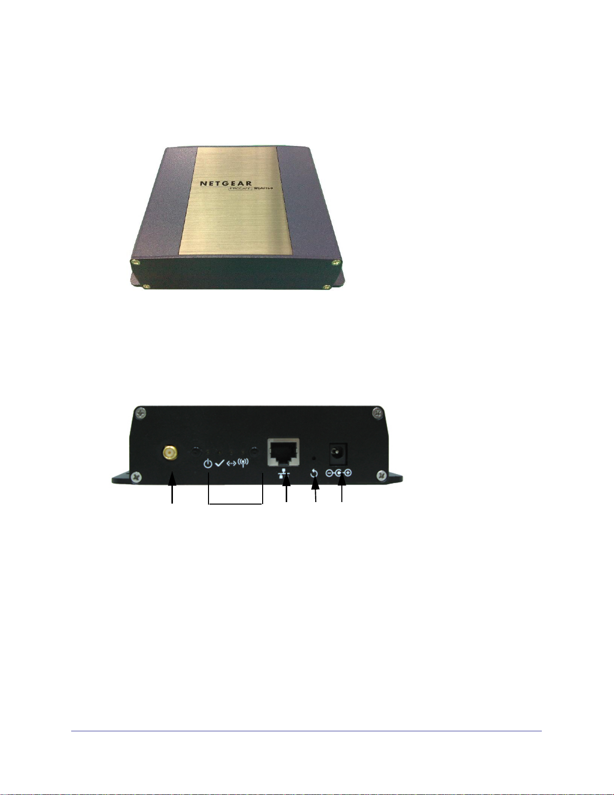
Hardware Description
The following figure shows a top view of the WGAP150
Figure 1-1
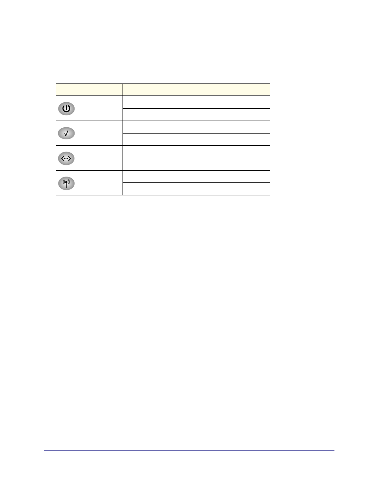
Rear Panel
The following figure shows a rear panel view of the WGAP150:
1
Figure 1-2
Viewed from left to right, the rear panel of the WGAP150 provides the following connectors
and buttons:
1. Antenna. An RP-SMA connector for connecting an external antenna, which does not
come standard with the WGAP150.
2. LAN Connector. A 10/100BaseT Ethernet connector, normally to be connected to a back
haul network.
LEDs
2
3
4
3. Reset Button. A reset button to be depressed with a pin. Depress and hold for at least
5
seconds to restore factory defaults. (For more information, see “Rebooting and Restoring
the Default Configuration” on page 63.)
4. Power Connector. A connector for 12 VDC power input, to be connected with the supplied
power adaptor.
| 11
Page 12
WG102-500, WGAP150 ProSafe™ 802.11g Wireless Access Point
Viewed from left to right, the WGAP150 has these four status LEDs: Power, Status, Ethernet,
and Wi-Fi (also referred to as WLAN light or Wireless activity light):
Table 1-1.
LED Activity Description
Power Off Power off
On (Green) Power on
Status Off The unit is initializing.
On (Green) The unit is ready.
LAN Off The Ethernet port is not connected.
On The Ethernet port is connected.
Wi-Fi Off Wireless is not ready.
On Wireless is ready.
Recommendations for Placement of the Wireless Access Point
The following are recommendations for the placement of the wireless access point and the
positioning of its antenna:
• The best location for the wireless access point is elevated, such as wall mounted or on
the top of a cubicle, at the center of your wireless coverage area, and within line of sight
of all the mobile devices.
• Vertical positioning of the antenna provides best side-to-side coverage. Horizontal
positioning provides best top-to-bottom coverage.
12 |
Page 13

2.
Installation and Basic Configuration
This chapter describes how to install and configure your access point for wireless
connectivity to your LAN. This basic configuration will enable computers with 802.11b/g or
802.11n wireless adapters to connect to the Internet, or access printers and files on your
LAN. In planning your wireless network, consider the level of security required.
describes how to set up wireless security for your network.
Note: In this chapter and in all further chapters, the WGAP150 is referred
to as the wireless access point.
This chapter includes:
• What You Need before You Begin ” on this page
• “Installing and Configuring the Wireless Access Point” on page 15
• “Testing Basic Wireless Connectivity” on page 31
Chapter 3
2
What You Need before You Begin
You need to consider the following guidelines and requirements before you can set up your
wireless access point. See also
Wireless Equipment Placement and Range Guidelines
The range of your wireless connection can vary significantly based on the location of the
wireless access point. The latency, data throughput performance, and notebook power
consumption of wireless adapters also vary depending on your configuration choices.
“System Requirements” on page 15.
| 13
Page 14

WG102-500, WGAP150 ProSafe™ 802.11g Wireless Access Point
Note: Failure to follow these guidelines can result in significant
performance degradation or inability to wirelessly connect to the
wireless access point. For complete performance specifications, see
Appendix A.
For best results, place your wireless access point according to the following general
guidelines:
• Near the center of the area in which your PCs will operate.
• In an elevated location such as a high shelf where the wirelessly connected PCs have
line-of-sight access (even if through walls).
• Away from sources of interference, such as PCs, microwaves ovens, and 2.4 GHz
cordless phones.
• Away from large metal surfaces or water.
• Placing an external antenna in a vertical position provides best side-to-side coverage.
Placing an external antenna in a horizontal position provides best up-and-down
coverage. (An external antenna does not come standard with the WGAP150.)
• If using multiple wireless access points, it is better if adjacent wireless access points use
different radio frequency channels to reduce interference. The recommended channel
spacing between adjacent wireless access points is five channels (for example, use
channels 1 and 6, or 6 and 11, or 1 and 11).
The time it takes to establish a wireless connection can vary depending on both your security
settings, and placement. WEP connections can take slightly longer to establish. Also, WEP
encryption can consume more battery power on a notebook computer.
Ethernet Cabling Requirements
The wireless access point connects to your LAN via twisted-pair category 5 Ethernet cable
with RJ-45 connectors.
LAN Configuration Requirements
For the initial configuration of your wireless access point, you need to connect a computer to
the wireless access point.
Note: For assistance with DHCP configuration, see the online document
that you can access from “Preparing Your Network” in Appendix B.
14 |
Page 15

WG102-500, WGAP150 ProSafe™ 802.11g Wireless Access Point
Computer Hardware Requirements
To connect to the wireless access point on your network, each computer must have a
802.11b/g or 802.11n wireless adapter installed.
Installing and Configuring the Wireless Access Point
Before installing the wireless access point, make sure that your Ethernet network is up and
working. You will be connecting the wireless access point to the Ethernet network. Then
computers with 802.11b/g or 802.11n wireless adapters will be able to communicate with the
Ethernet network.
In order for this to work correctly, verify that you have met all of the system requirements,
shown in
Install and configure your wireless access point in the order of the following sections:
1. Connecting the Wireless Access Point to Computer ” on this page.
2. “Logging in to the Wireless Access Point” on page 17.
3. “Configuring Basic System Settings, IP Settings, and LAN Settings” on page 18.
4. “Configuring Basic Wireless Network Settings” on page 27.
“System Requirements” on page 10.
Connecting the Wireless Access Point to Computer
To set up the wireless access point:
Tip: Before you place the wireless access point in an elevated position that is
difficult to reach, first set up and test the wireless access point to verify
wireless network connectivity.
1. Unpack the box and verify the contents.
2. Prepare a computer with an Ethernet adapter. If this computer is already part of your
network, record its TCP/IP configuration settings. Configure the computer with a static IP
address of 192.168.0.210 and 255.255.255.0 as the subnet mask.
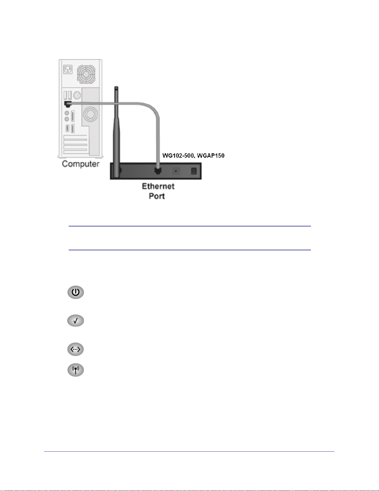
3. Connect an Ethernet cable from the wireless access point to the computer (point A in
Figure 2-1 on page 16).
4. Securely insert the other end of the cable into the wireless access point’s Ethernet port
(point B in
Figure 2-1 on page 16).
| 15
Page 16
WG102-500, WGAP150 ProSafe™ 802.11g Wireless Access Point
.
A
B
Figure 2-1
Note: Figure 2-1 shows the WGAP150 with an external antenna, which
does not come standard with the product.
5. Turn on your computer, connect the power adapter to the wireless access point and verify
the following:
Power LED. The powerLEDt on the wireless access point should be steady green.
If the power light is not lit, check the connections, and check if the power outlet is
controlled by a wall switch that is turned off.
Status LED. The status LED on the wireless access point should be blinking red
while the wireless access point starts up. When the startup process is complete,
the status LED should be steady green to indicate the access point is ready.
LAN LED. The LAN LED on the wireless access point should be blinking green. If
it is not, make sure that the Ethernet cable is securely attached at both ends.
Wi-Fi LED. The Wi-Fi LED on the wireless access point should be blinking green
when the wireless LAN (WLAN) is ready.
16 |
Tip: The wireless access point supports Power Over Ethernet (PoE). If you
have a switch that provides PoE, you will not need to use the power
adapter to power the wireless access point. This can be especially
convenient when the wireless access point is installed in a high location
far away from a power outlet.
Page 17
WG102-500, WGAP150 ProSafe™ 802.11g Wireless Access Point
Logging in to the Wireless Access Point
The default IP address of your wireless access point is 192.168.0.229. The wireless access
point is set, by default, for the DHCP client to be disabled.
To log in to the wireless access point:
1. Open a Web browser such as Microsoft Internet Explorer 6.0 or above, or Mozilla
Firefox 1.5 or above.
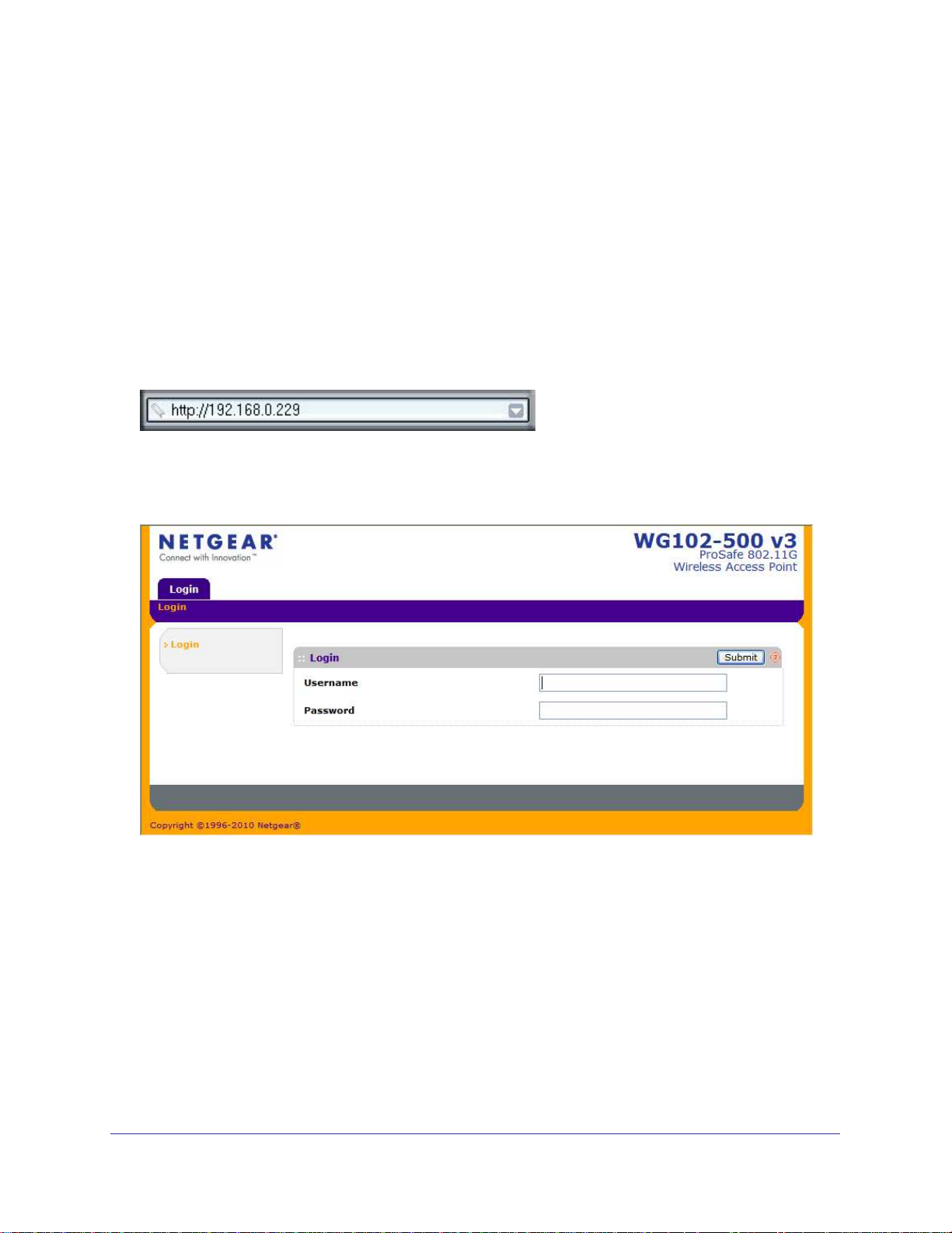
2. Connect to the wireless access point by entering its default address of http://192.168.0.229
into your browser:
Figure 2-2
The Login screen opens.
Figure 2-3
3. Enter the default user name of admin and the default password of password.
4. Click OK. The Web browser displays the Basic General Settings screen under the
Configuration tab of the main menu as shown in
Figure 2-6 on page 19.
| 17
Page 18
WG102-500, WGAP150 ProSafe™ 802.11g Wireless Access Point
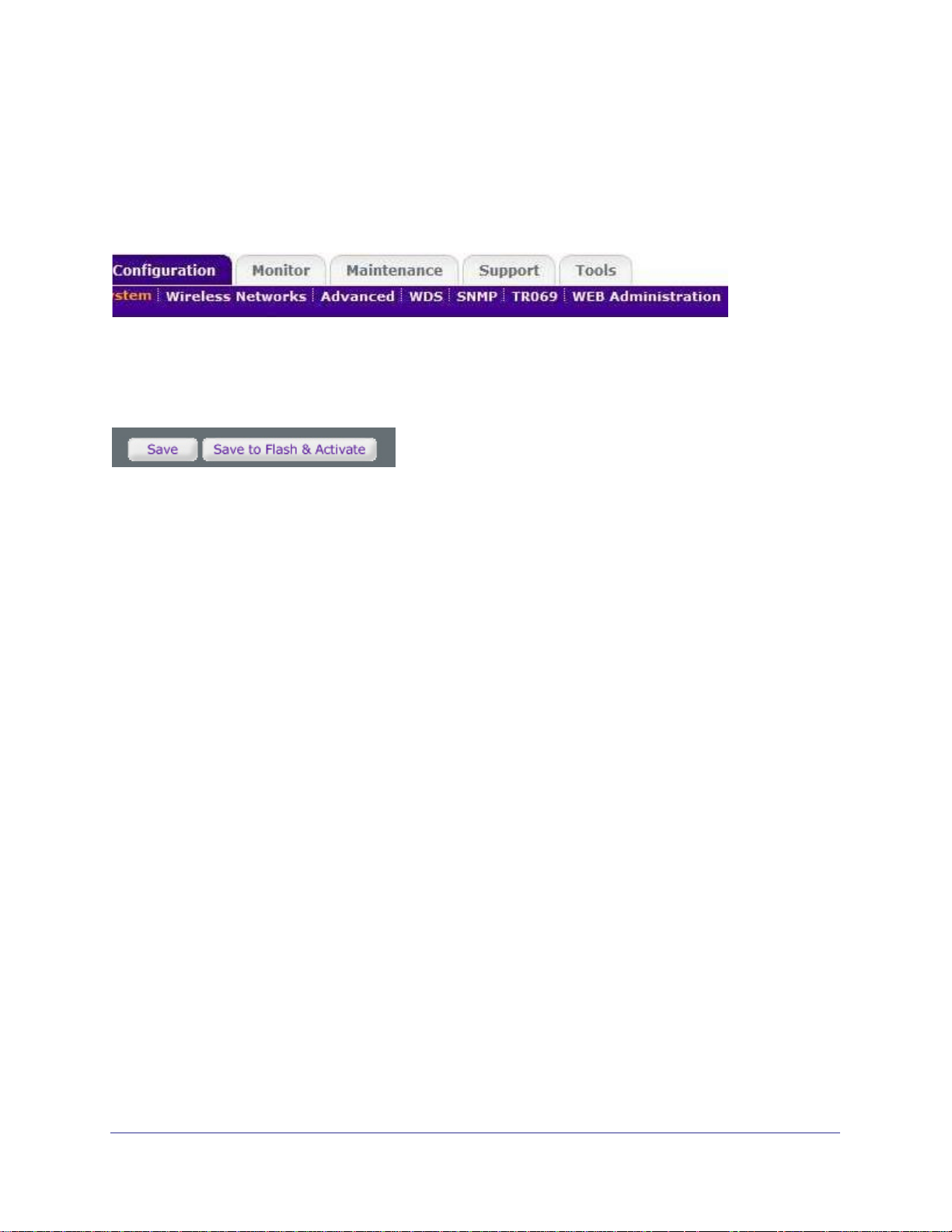
Web Interface Menu
The navigation tabs across the top of the Web interface menu provide access to all the
configuration functions of the wireless access point, and remain constant. The menu items in
the blue bar change according to the navigation tab that is selected.
Figure 2-4
The bottom right corner of the Basic Settings screen and any other screen that allows you to
make configuration changes shows the Save and Save to Flash & Activate buttons.
Figure 2-5
These buttons have the following functions:
• Save. Saves any configuration changes but does not activate the new configuration, and
the changes are lost when you reload the wireless access point.
• Save to Flash & Activate. Activates any configuration changes and saves them to the
flash memory, allowing the changes to remain active after the wireless access point has
been reloaded.
Configuring Basic System Settings, IP Settings, and LAN Settings
The Basic Settings screen consists of three sections: Basic System Settings, IP Settings, and
LAN Settings. Depending on the selections that you make, the IP Settings section and the
LAN Settings section shows different fields for you to configure.
To open the Basic Settings screen, log in to the wireless access point as described in
“Logging in to the Wireless Access Point” on page 17. The Web browser displays the Basic
18 |
Page 19
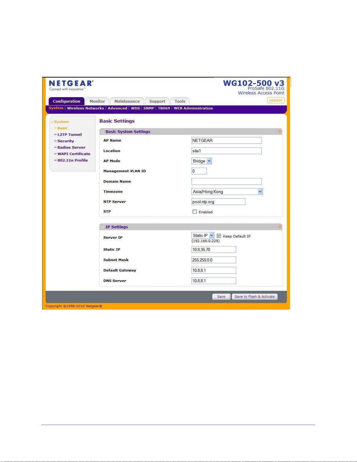
WG102-500, WGAP150 ProSafe™ 802.11g Wireless Access Point
Settings screen (see Figure 2-6 on page 19). The full path to this screen is Configuration >
System > Basic.
Figure 2-6
Configuring Basic System Settings
To configure the basic system settings:
| 19
Page 20

WG102-500, WGAP150 ProSafe™ 802.11g Wireless Access Point
1. Specify the fields in the Basic System Settings section of the Basic Settings screen (see
Figure 2-6) as explained in Table 2-1.
Table 2-1. Basic System Settings
Field Description
AP Name Assign a unique name to the wireless access point.The default name is NETGEAR.
The AP name can be retrieved through SNMP.
Location Assign a unique name to the location of the wireless access point.The default name is
site1. The site name can be retrieved through SNMP.
AP Mode Select one mode from the pull-down menu:
• Bridge. The wireless access point functions as a bridge, for example, between a
wired and a wireless network. This is the default setting.
• Router. The wireless access point functions as a router. When you select this
mode, the Management VLAN ID becomes inactive and the LAN settings appear at
the bottom of the Basic Settings screen (see “Configuring LAN Settings” on page
23).
Management
VLAN ID
Domain Name Select an easily recognizable domain name to facilitate web management and the
Time Zone Select the time zone to match your location.
NTP Server If you want to use a Network Time Protocol (NTP) server, enter its host name.
STP Select the STP checkbox to enable the Spanning Tree Protocol (STP) to prevent path
The management VLAN can be active only when the wireless access point functions
as a bridge. Specify a VLAN ID from which the wireless access point can be managed.
The default setting is zero, which allows for management of the wireless access point
from any VLAN, and which prevents frames belonging to the Management VLAN from
being tagged with an 802.1Q header when sent over the trunk.
redirection of HTTP requests.
Note: You must have an Internet connection to use an NTP server that is not on your
local network.L
redundancy. When the STP checkbox is selected, two more options appear on the
Basic Settings screen.
Bridge
Priority
Ethernet Path
Cost
Enter the priority for root switch election. The default is 32768.
Enter the best path cost from the switch to the root switch. The default
is 100.
2. Click Save or Save to Flash & Activate to save your settings.
Configuring IP Settings
To configure the IP settings:
1. Specify how the wireless access point acquires its IP address by making a selection
from the Server IP pull-down menu in the IP Settings section of the Basic Settings
screen (see Figure 2-7 on page 21):
• DHCP. The IP address, subnet mask, and the default gateway settings for the
wireless access point are acquired automatically from a Dynamic Host Configuration
20 |
Page 21
WG102-500, WGAP150 ProSafe™ 802.11g Wireless Access Point
Protocol (DHCP) server on the Ethernet segment (see “Configuring LAN Settings” on
page 23). This is the default settings; no further configuration is required.
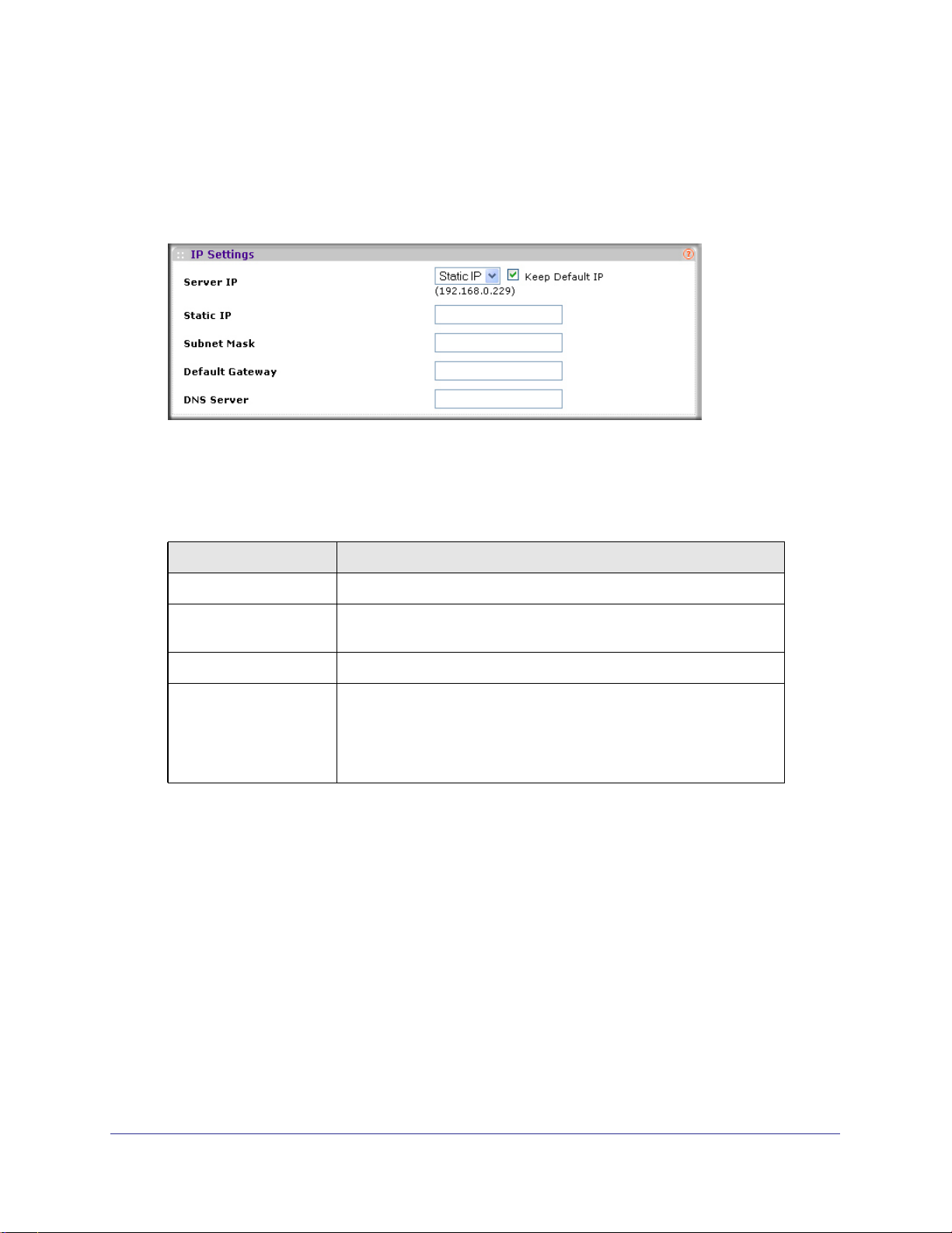
• Static IP. Your Internet Service Provider (ISP) has assigned you a permanent, fixed
(static) IP address. When you select Static IP, the IP Settings section of the Basic
Settings screen expands:
Figure 2-7
Specify the static IP fields as explained in Table 2-2.
Table 2-2. Static IP Settings
Field Description
Static IP The fixed IP address that your ISP has assigned to you.
Subnet Mask The network number portion of an IP address. Unless you are
implementing subnetting, use 255.255.0.0 as the subnet mask.
Default Gateway The ISP’s router to which the wireless access point will connect.
DNS Server A DNS server is a host on the Internet that translates Internet names
(such as www.netgear.com) to numeric IP addresses. Typically your
ISP transfers the IP address of one or two DNS servers to your wireless
access point during login. If the ISP does not transfer an address, you
must obtain it from the ISP and enter it manually in this field.
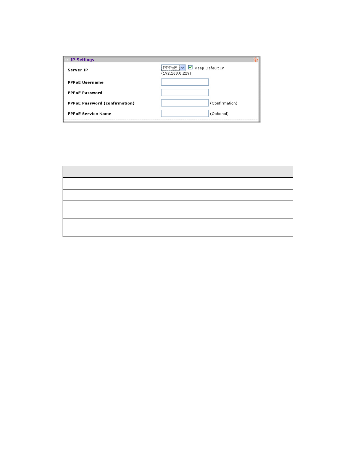
• PPPoE. You connect to your ISP over a PPP over Ethernet (PPPoE) line, and your
ISP has assigned you a user name, password, and, possibly, a service name. The
PPPoE mode is available only if you selected “Router” as the AP mode (see
“Configuring Basic System Settings” on page 19). When you select PPPoE, the IP
Settings section of the Basic Settings screen expands (see Figure 2-8 on page 22).
| 21
Page 22
WG102-500, WGAP150 ProSafe™ 802.11g Wireless Access Point
Figure 2-8
Specify the PPPoE fields as explained in Table 2-3.
Table 2-3. PPPoE Settings
Field Description
PPPoE Username The PPPoE user name that your ISP has assigned to you.
PPPoE Password The PPPoE password that your ISP has assigned to you.
PPPoE Password
(confirmation)
PPPoE Service Name The PPPoE service name that your ISP has assigned to you. If your
Repeat the PPPoE password that your ISP has assigned to you.
ISP did not assign you a service name, leave this field blank.
2. If you want to use the default IP address of the wireless access point (192.168.0.229) and
the default server IP settings that are defined in “Configuring LAN Settings” on page 23,
select the Keep Default IP checkbox.
3. Click Save or Save to Flash & Activate to save your settings.
22 |
Page 23
WG102-500, WGAP150 ProSafe™ 802.11g Wireless Access Point
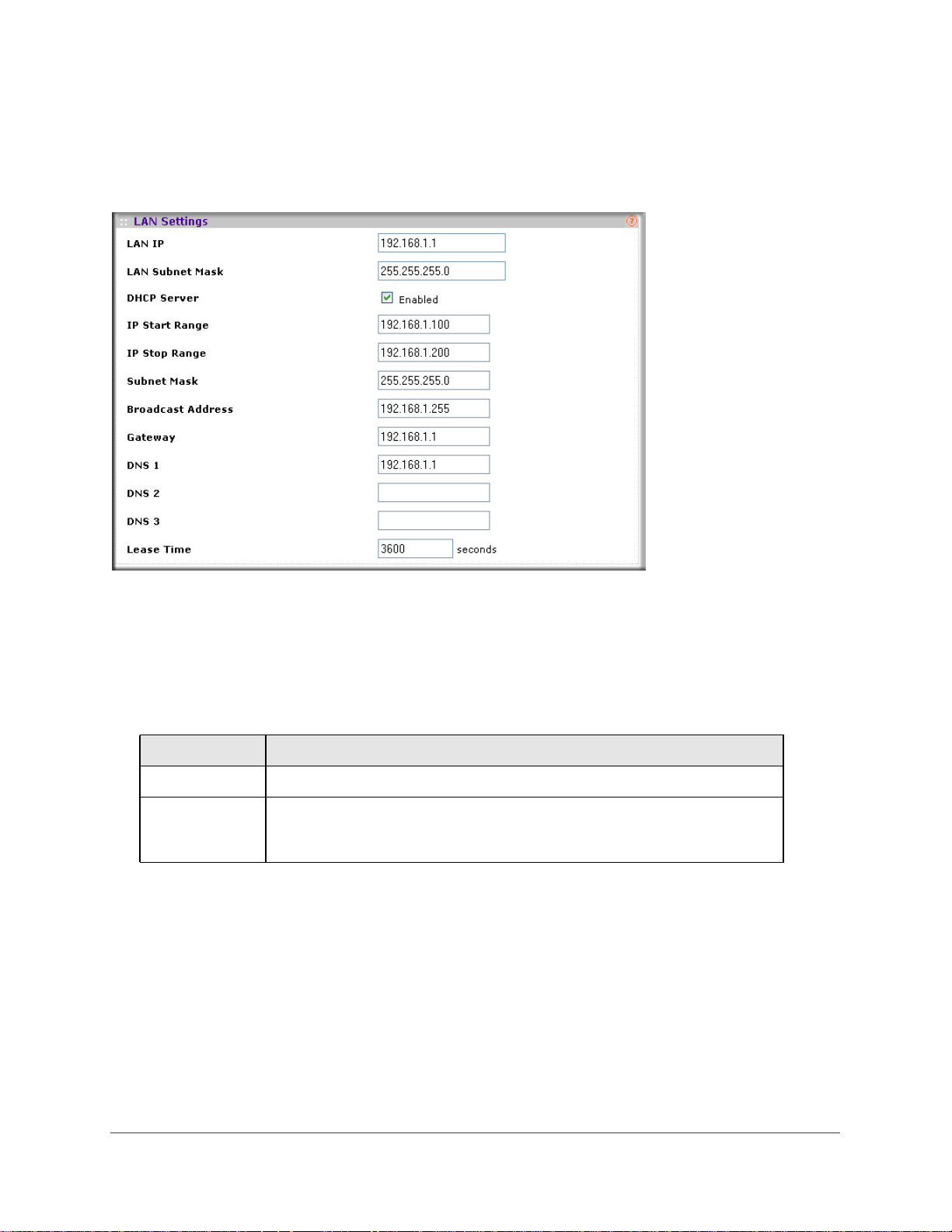
Configuring LAN Settings
If you selected “Router” as the AP mode (see “Configuring Basic System Settings” on page
19), the LAN Settings section appears at the bottom of the Basic Settings screen.
Figure 2-9
To configure the LAN settings:
1. Specify the fields as explained in Table 2-4, or use the default values, which work for
most users and situations.
Table 2-4. LAN Settings
Field Description
LAN IP The LAN IP address of the wireless access point.
LAN Subnet Mask The LAN subnet mask of the wireless access point. Combined with the LAN IP
address, the LAN subnet mask enables a device to determine which other
addresses are local to it, and which must be reached through a gateway.
| 23
Page 24

WG102-500, WGAP150 ProSafe™ 802.11g Wireless Access Point
Table 2-4. LAN Settings (continued)
Field Description
DHCP Server The wireless access point is set up by default to function as a DHCP server, which
provides TCP/IP configuration for computers that are connected to it. You can
either use the default settings or specify the pool of IP addresses to be assigned by
setting the starting IP address and ending IP address. These addresses should be
part of the same IP address subnet as the wireless access point’s LAN IP address.
Select the DHCP Server checkbox to enable the DHCP server. The screen
expands, enabling you to configure the following DHCP server fields.
IP Start Range The first address in the range of IP addresses to be assigned to
DHCP clients. The default address is 192.168.1.100.
IP Stop Range The last address in the range of IP addresses to be assigned to
DHCP clients. The default address is 192.168.1.200.
Subnet Mask The subnet mask to be used by DHCP clients. The default mask
is 255.255.255.0.
Broadcast
Address
Gateway The IP address of the default routing gateway to be used by
DNS 1 The IP address of the primary static Domain Name Server (DNS)
DNS 2 The IP address of the secondary static DNS server available to
DNS 3 The IP address of the tertiary static DNS server available to
Lease Time The period that the DHCP server grants to the DHCP clients to
The broadcast IP address to be used by DHCP clients. The
default address is 192.168.1.255.
DHCP clients. The default address is 192.168.1.1.
server available to DHCP clients. The default address is
192.168.1.1.
DHCP clients.This server is used when the primary DNS server
is not available.
DHCP clients. This server is used when the primary and
secondary DNS servers are not available.
use the assigned IP addresses. The default time is 3600 seconds
(1 hour).
2. Click Save or Save to Flash & Activate to save your settings.
Configuring Basic Wireless Settings
For proper compliance and compatibility between similar products in your area, you must
correctly configure 802.11b/g wireless adapter settings, including the operating channel and
country. The basic wireless network settings must be set correctly for wireless devices to
connect to your network. For other wireless features, including wireless security, see
Chapter 3.”
24 |
Page 25
WG102-500, WGAP150 ProSafe™ 802.11g Wireless Access Point
WARNING!
If you configure the wireless access point from a wireless
computer and you change the wireless access point’s SSID,
channel, or wireless security settings, you will lose your wireless
connection when you click Save to Flash and Activate. You must
then change the wireless settings of your computer to match the
wireless access point’s new settings.
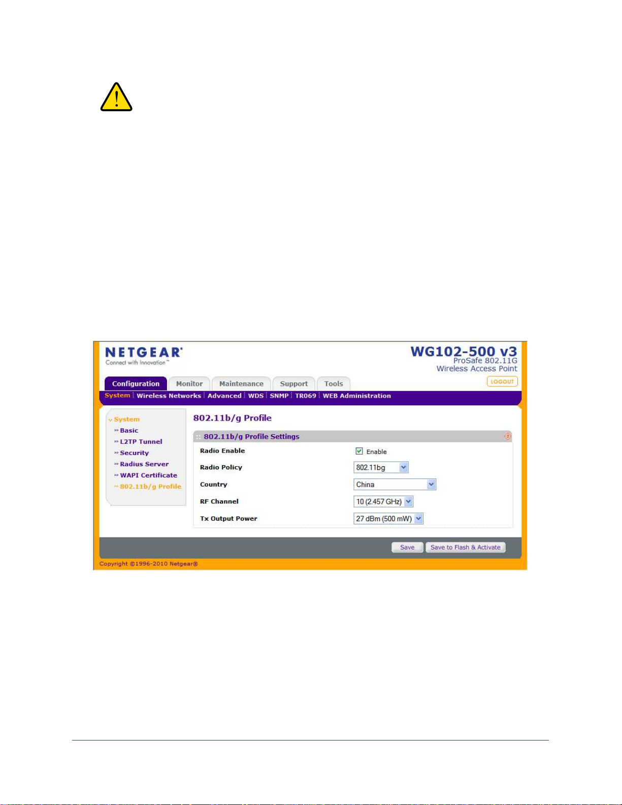
Configuring 802.11b/g Wireless Settings
To configure the 802.11b/g wireless settings:
1. Log in to the wireless access point at its default LAN address of http://192.168.0.229
with its default user name of admin and default password of password, or using
whatever LAN address, user name, and password you have chosen for the wireless
access point.
2. Select Configuration > System > 802.11b/g Profile. The 802.11b/g Profile screen displays.
Figure 2-10
| 25
Page 26

WG102-500, WGAP150 ProSafe™ 802.11g Wireless Access Point
3. Specify the 802.11n profile fields as explained Table 2-5.
Table 2-5. 802.11b/g Profile Settings
Field Descriptions
Radio Enable The radio is enabled by default. To turn off the radio, deselect the Radio Enable
checkbox. Doing so disables access through the wireless access point, which can
be helpful for configuration, network tuning, or troubleshooting activities.
Radio Policy Select one of the following modes from the pull-down menu:
• 802.11b/g. The wireless access point accepts both 802.11b and 802.11g client
association requests. This mode is also referred to as Mixed Mode.
• 802.11b Only. The wireless access point accepts 802.11b client association
requests only.
• 802.11g Only. The wireless access point accepts 802.11g client association
requests only.
Country This pull-down menu lets you specify your country/region.
RF Channel This pull-down menu lets you to specify the 802.11 channel. The available options
for 802.11b or 802.11g are from 1 to 11 for the U.S. (which is the default setting) and
from 1 to 13 for Europe. For automatic channel selection, select Auto. For more
information about operating frequencies, see the guidelines about channels below
this table.
Tx Output Power This pull-down menu lets you to specify the transmission power. The available
options are from 27 dBm to 18 dBm. By default, the Tx Output Power is 27 dBm.
Note: Make sure that you comply with the regulatory requirements for total radio
frequency (RF) output power in your country.
You should not need to change the operating frequency (channel) unless you notice
interference problems, or are setting up the wireless access point near another wireless
access point. Observe the following guidelines:
• Wireless access points use a fixed channel. You can select a channel that provides
the least interference and best performance. In the USA and Canada, 11 channels
are available.
• If using multiple wireless access points, it is better if adjacent wireless access points
use different channels to reduce interference. The recommended channel spacing
between adjacent wireless access points is five channels (for example, use channels
1 and 6, or 6 and 11).
• In “infrastructure” mode, wireless stations normally scan all channels, looking for a
wireless access point. If more than one wireless access point can be used, the one
with the strongest signal is used. This can happen only when the wireless access
points use the same SSID. The WGAP150 wireless access point functions in
“infrastructure” mode by default.
For more information about wireless channels, see the online document that you can
access from “Wireless Networking Basics” in Appendix B.
4. Click Save or Save to Flash & Activate to save your settings.
26 |
Page 27
WG102-500, WGAP150 ProSafe™ 802.11g Wireless Access Point
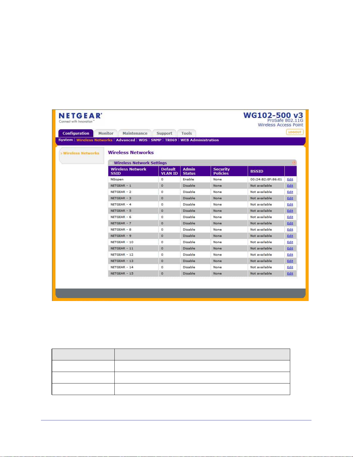
Configuring Basic Wireless Network Settings
To configure the basic wireless network settings:
1. Log in to the wireless access point at its default LAN address of http://192.168.0.229
with its default user name of admin and default password of password, or using
whatever LAN address, user name, and password you have chosen for the wireless
access point.
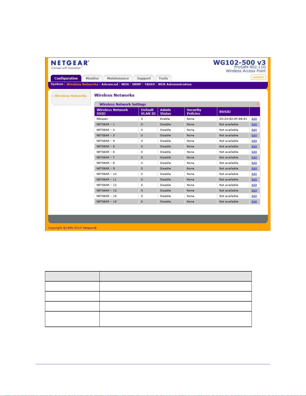
2. Select Configuration > Wireless Networks. The Wireless Networks screen displays.
Figure 2-11
Table 2-6 on page 27 explains the fields of the Wireless Network Settings table.
Table 2-6. Wireless Network Settings
Field Description
Wireless Network SSID The wireless network name (SSID) for the wireless security profile.
Default VLAN ID The default VLAN ID that is associated with the wireless security profile.
Admin Status The status of the wireless security profile (Enabled or Disabled).
| 27
Page 28
WG102-500, WGAP150 ProSafe™ 802.11g Wireless Access Point
Table 2-6. Wireless Network Settings (continued)
Field Description
Security Policies The configured wireless authentication and encryption methods for the
wireless security profile.
BSSID The detailed BSSID for the wireless security profile. This BSSID consist of
the MAC address of the wireless access point with the last digit altered. If
the MAC address ends with F0, the BSSID for the first profile ends with F1,
for the second profile with F2, for the third profile with F3, and so on.
Edit (hyperlink) The hyperlink to the Edit Wireless Network screen with the configurable
fields for the wireless security profile.
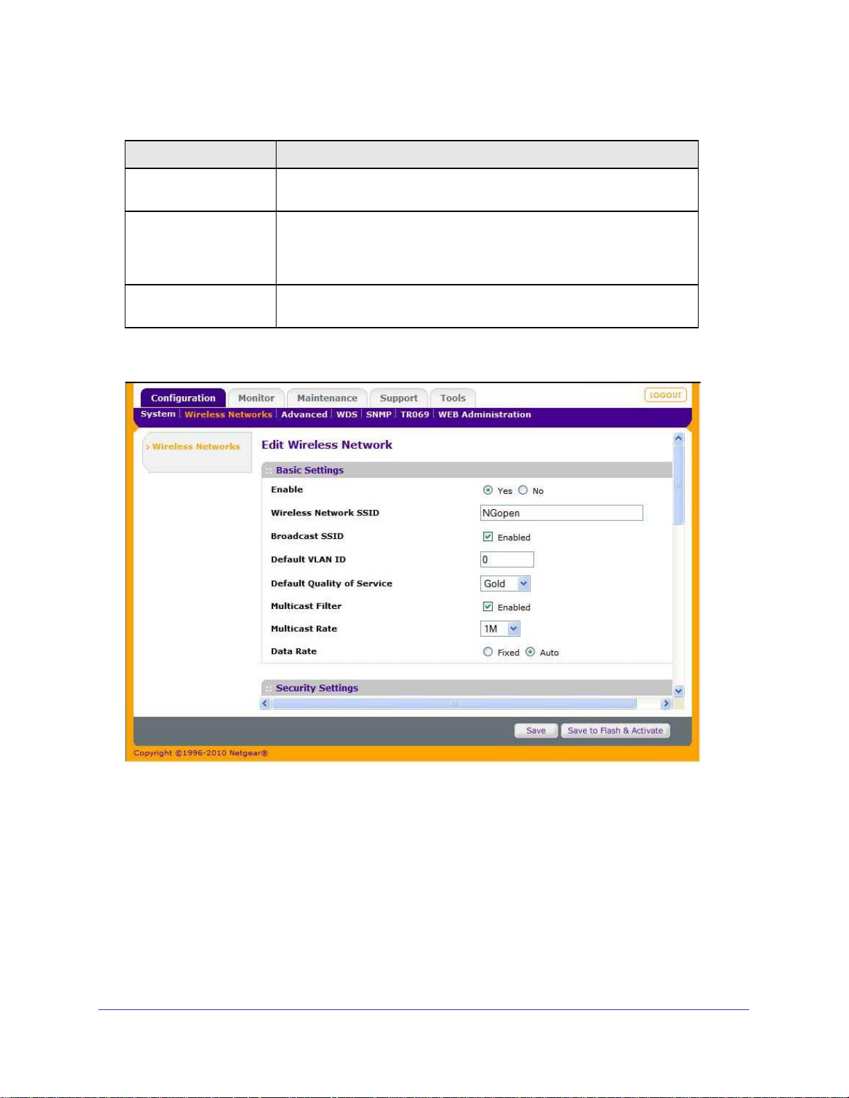
3. Click the Edit hyperlink of the first wireless security profile (NETGEAR - 0). The Edit Wireless
Network screen opens for the first wireless security profile.
Figure 2-12
28 |
Page 29

WG102-500, WGAP150 ProSafe™ 802.11g Wireless Access Point
4. In the Basic Settings section of the Edit Wireless Network screen, specify the fields as
explained in
Table 2-7. Wireless Network Settings
Field Description
Enable Select one of the following options:
Table 2-7.
• Yes. Select this radio button to enable the wireless security profile. This
is the default setting.
• No. Select this radio button to disable the wireless security profile.
Wireless Network SSID The SSID is also known as the wireless network name. The SSID
separates network traffic from different wireless networks. To connect any
wireless device to a wireless network, you need to use the SSID. The
wireless access point default SSIDs are: NETGEAR_0 for the first profile,
NETGEAR_1 for the second profile, NETGEAR_2 for the third profile, and
so on. You can enter a value of up to 32 alphanumeric characters. For more
information about SSIDs, see
Note: The SSID of any wireless adapters must match the SSID of the
wireless access point. If they do not match, a wireless connection to the
wireless access point cannot be established.
“Security Profiles” on page 35.
Broadcast SSID Select the Broadcast SSID checkbox to enable broadcast of the SSID. If
you disable broadcast of the SSID, only stations that know the SSID can
connect to the wireless access point. Disabling the SSID broadcast
somewhat hampers the wireless network discovery feature of some
products. Broadcast of the SSID is enabled by default.
Default VLAN ID Specify the default VLAN ID that is associated with the wireless security
profile and that will be tagged on all egress packets. The default VLAN can
be active only when the wireless access point functions as a bridge (for
more information, see
Note: The default VLAN ID can be specified in an authentication reply from
the RADIUS server. However, if a per-user VLAN ID is specified in the
authentication reply from the RADIUS server, the value that is specified in
default VLAN ID will be overridden.
Default Quality of Service Select one of the following Quality of Service (QoS) options from the
pull-down menu:
“Configuring Basic System Settings” on page 19).
• Gold. Wireless traffic is sent with a best-effort priority. For example, you
could assign this level to voice and video traffic.
• Silver. Wireless traffic is sent in the background. For example, you
could assign this level to regular data traffic.
• Bronze. Wireless traffic is sent with the lowest priority (“spare”). For
example, you could assign this level to FTP traffic.
| 29
Page 30

WG102-500, WGAP150 ProSafe™ 802.11g Wireless Access Point
Table 2-7. Wireless Network Settings (continued)
Field Description
Multicast Filter Select the Multicast Filter checkbox to enable filtering of egress multicast
packets that are sent from the wireless access point.
Multicast Rate Select the data rate for egress multicast packets from the pull-down menu.
The smallest data rate that you can select is 1 Mbps; the largest is
54
Mbps. The default rate is 1 Mbps.
Data Rate Select one of the following options:
• Fixed. All data packets are transmitted according to the transmit rate
that you select from the pull-down menu. The smallest data rate that you
can select is 1 Mbps; the largest is 54 Mbps. The default rate is 1 Mbps.
• Auto. All data packets are transmitted according to the automatically
selected best transmit rate.
5. Click Save or Save to Flash & Activate to save your settings.
Note: Other wireless settings on the Edit Wireless Network screen are
discussed in Chapter 3, “Wireless Configuration and Security.”
30 |
Page 31

WG102-500, WGAP150 ProSafe™ 802.11g Wireless Access Point
Testing Basic Wireless Connectivity
After you configured the wireless access point as explained in the previous section, test your
computers for wireless connectivity before you position and mount the wireless access point at
its permanent position:
1. 1. Configure the 802.11b/g or 802.11n wireless adapters of your computers so that they
all have the same SSID and channel that you have configured on the wireless access
point.
2. 2. Verify that your computers have a wireless link to the wireless access point and are able
to obtain an IP address through DHCP from the wireless access point.
3. 3. Verify network connectivity by using a browser such as Internet Explorer 6.0 or above, or
Mozilla Firefox 1.5 or above to browse the Internet, or check for file and printer access on
your network.
Note: If you have trouble connecting to the wireless access point, see
Chapter 6.
WARNING!
Before you deploy the wireless access point in your network, set
up wireless security and other wireless features as described in
Chapter 3.
In addition to wireless security and other wireless features, before you deploy the wireless
access point in your network, configure any additional features as described in Chapter 4 and
Chapter 5. After you have completed the configuration of the wireless access point, you can
reconfigure the computer that you used for this process back to its original TCP/IP settings.
| 31
Page 32

WG102-500, WGAP150 ProSafe™ 802.11g Wireless Access Point
32 |
Page 33

3.
Wireless Configuration and Security
This chapter describes how to configure the wireless features of your wireless access point.
In planning your wireless network, consider the level of security required.
WARNING!
If you are configuring the wireless access point from a wireless
PC and you change the wireless access point’s SSID, channel, or
wireless security settings, you will lose your wireless connection
when you click Apply. You must then change the wireless settings
of your PC to match the wireless access point’s new settings.
Before you set up wireless security and additional wireless features that are described in this
chapter, connect the wireless access point, get the Internet connection working, configure
802.11b/g wireless settings, and configure basic wireless network settings, as described in
Chapter 2. The wireless access point should work with an Ethernet LAN connection and
wireless connectivity should have been verified before you set up wireless security and
additional wireless features.
3
This chapter includes:
• Wireless Data Security Options on this page
• “Security Profiles” on page 35
• “Configuring RADIUS Server Settings” on page 45
• “WAPI Certificates” on page 49
• “Configuring Alternate DHCP Server Settings” on page 52
• “Configuring Wireless Quality of Service” on page 54
• “Configuring Wireless Client Separation” on page 58
Wireless Data Security Options
Indoors, computers can connect over 802.11n wireless networks at a maximum range of 300
feet. Typically, a wireless access point inside a building works best with devices within a 100
| 33
Page 34

WG102-500, WGAP150 ProSafe™ 802.11g Wireless Access Point
foot radius. Such distances can allow for others outside your immediate area to access your
network.
Unlike wired network data, your wireless data transmissions can extend beyond your walls
and can be received by anyone with a compatible adapter. For this reason, use the security
features of your wireless equipment. The wireless access point provides highly effective
security features that are covered in detail in this chapter. Deploy the security features
appropriate to your needs.
Figure 3-1
Note: Figure 3-1 shows the WGAP150 with an external antenna, which
does not come standard with the product.
There are several ways you can enhance the security of your wireless network:
• Use Multiple BSSIDs combined with VLANs. You can configure combinations of
VLANS and BSSIDs with stronger or less restrictive access security according to your
requirements. For example, visitors could be given wireless Internet access but be
excluded from any access to your internal network. For information about how to
configure BSSIDs, see
“Creating and Editing Security Profiles” on page 37.
• Restrict Access based by MAC address. You can allow only trusted PCs to connect so
that unknown PCs cannot wirelessly connect to the wireless access point. Restricting
access by MAC address adds an obstacle against unwanted access to your network, but
the data broadcast over the wireless link is fully exposed. For information about how to
restrict access by MAC address, see
“WAPI Certificates” on page 49.
• Turn off the broadcast of the wireless network name (SSID). If you disable broadcast
of the SSID, only devices that have the correct SSID can connect. This nullifies the
wireless network discovery feature of some products, such as Windows XP, but the data
is still exposed. For information about how to turn of broadcast of the SSID, see
“Creating
and Editing Security Profiles” on page 37.
34 |
Page 35

WG102-500, WGAP150 ProSafe™ 802.11g Wireless Access Point
• WEP. Wired Equivalent Privacy (WEP) data encryption provides data security. WEP
Shared Key authentication and WEP data encryption block all but the most determined
eavesdropper. This data encryption mode has been superseded by WPA-PSK and
WPA2-PSK. For information about how to configure static and dynamic WEP, see
“Configuring Static WEP” on page 40 and “Configuring Legacy 802.1X (or Dynamic
WEP)” on page 41.
• WPA and WPA-PSK (TKIP). Wi-Fi Protected Access (WPA) data encryption provides
strong data security with Temporal Key Integrity Protocol (TKIP) encryption. The very
strong authentication along with dynamic per frame rekeying of WPA make it virtually
impossible to compromise. WPA uses RADIUS-based 802.1x authentication; WPA-PSK
uses a pre-shared key (PSK) for authentication. For information about how to configure
WPA, see
• WPA2 and WPA2-PSK (AES). Wi-Fi Protected Access version 2 (WPA2) data encryption
provides strong data security with Advanced Encryption Standard (AES) encryption. The
very strong authentication along with dynamic per frame rekeying of WPA2 make it
virtually impossible to compromise. WPA2 uses RADIUS-based 802.1x authentication;
WPA2-PSK uses a pre-shared key (PSK) for authentication. For information about how to
configure WPA2, see
• WPA+WPA2 and WPA-PSK+WPA2-PSK Mixed Modes. These modes support data
encryption either with both WPA and WPA2 clients or with both WPA-PSK and
WPA2-PSK clients and provide the most reliable security. For information about how to
configure WPA+WPA2 and WPA-PSK+WPA2-PSK, see
WPA-PSK+WPA2-PSK Mixed Modes” on page 44.
“Configuring WPA and WPA-PSK (TKIP)” on page 41.
“Configuring WPA2 and WPA2-PSK (AES)” on page 43.
“Configuring WPA+WPA2 and
Security Profiles
Security profiles let you configure unique security settings for each SSID. The wireless
access point supports up to 16 BSSIDs that you can configure in the individual Edit Wireless
Network screens that are accessible from the Wireless Networks screen (see
Editing Security Profiles” on page 37).
To set up a security profile you select its network authentication type, data encryption,
wireless client security separation, and VLAN ID:
• Network Authentication
The wireless access point is set by default as an open system with no authentication.
When you configure network authentication, bear in mind that not all wireless adapters
support WPA or WPA2. Windows XP, Windows 2000 with Service Pack 3, and Windows
Vista do include the client software that supports WPA. However, client software is
required on the client. Consult the product documentation for your wireless adapter and
WPA or WPA2 client software for instructions on configuring WPA2 settings.
For information about the types of network authentication that the wireless access point
supports, see
• Data Encryption
Select the data encryption that you want to use. The available options depend on the
“Creating and Editing Security Profiles” on page 37.
“Creating and
| 35
Page 36

WG102-500, WGAP150 ProSafe™ 802.11g Wireless Access Point
network authentication setting above (otherwise, the default is None). The data
encryption settings are explained in
• Wireless Client Security Separation
If enabled, the associated wireless clients (using the same SSID) will not be able to
communicate with each other. This feature is useful for hotspots and other public access
situations. By default, wireless client separation is disabled. For more information, see
“Configuring Wireless Client Separation” on page 58.
• VLAN ID
If enabled and if the network devices (hubs and switches) on your LAN support the VLAN
(802.1Q) standard, the default VLAN ID for the wireless access point will be associated
with each profile. The default VLAN ID must match the IDs that are used by the other
network devices. This feature is available only when the AP Mode is set to Bridge (see
“Configuring Basic Wireless Network Settings” on page 27).
Some concepts and guidelines regarding the SSID are explained below:
• A Basic Service Set (BSS) is a group of wireless stations and a single wireless access
point, all using the same SSID.
“Creating and Editing Security Profiles” on page 37.
• An Extended Service Set (ESS) is a group of wireless stations and multiple wireless
access points, all using the same ID (ESSID).
• Different wireless access points within an ESS can use different channels. To reduce
interference, adjacent wireless access points should use different channels.
• Roaming is the ability of wireless stations to connect wirelessly when they physically
move from one BSS to another within the same ESS. The wireless station automatically
changes to the wireless access point with the least interference or best performance.
Before You Change the SSID, WEP, and WPA Settings
For a new wireless network, print or copy this form and fill in the settings. For an existing
wireless network, the network administrator can provide this information. Be sure to set the
Country/Region correctly as the first step. Store this information in a safe place.
• SSID: The Service Set Identification (SSID) identifies the wireless local area network.
You may customize it by using up to 32 alphanumeric characters. Write your SSID on the
line.
SSID: ___________________________________
Note: The SSID in the wireless access point is the SSID you configure in
the wireless adapter card. All wireless nodes in the same network
must be configured with the same SSID:
• WEP Key Size, Key Format Passphrase, and Authentication
Choose the key size by circling one: 64, 128, or 152 bits.
36 |
Page 37

WG102-500, WGAP150 ProSafe™ 802.11g Wireless Access Point
Choose the key format by circling one: ASCII or HEX.
Choose the authentication type by circling one: Open or Shared.
Passphrase: ___________________________________
Note: If you select shared key, the other devices in the network will not connect unless
they are set to shared key and have the same keys in the same positions as those in the
wireless access point.
• WPA-PSK (Pre-Shared Key), WPA2-PSK (Pre-Shared Key)
Record the WPA-PSK passphrase: Record the WPA2-PSK passphrase:
WPA-PSK Passphrase: ________________________________
WPA2-PSK Passphrase: ________________________________
• WPA RADIUS Settings
For WPA, record the following settings for the primary and secondary RADIUS servers:
Server Name/IP Address: Primary _________________ Secondary
__________________
Port: ___________________________________
Shared Secret: ___________________________________
• WPA2 RADIUS Settings
For WPA2, record the following settings for the primary and secondary RADIUS servers:
Server Name/IP Address: Primary _________________ Secondary
__________________
Port: ___________________________________
Shared Secret: ___________________________________
Creating and Editing Security Profiles
To create or edit a security profile with its own unique BSSID:
1. Log in to the wireless access point at its default LAN address of http://192.168.0.229
with its default user name of admin and default password of password, or using
whatever LAN address, user name, and password you have chosen for the wireless
access point.
| 37
Page 38
WG102-500, WGAP150 ProSafe™ 802.11g Wireless Access Point
2. Select Configuration > Wireless Networks. The Wireless Networks screen opens,
displaying 16 wireless security profiles.
Figure 3-2
Table 3-1 explains the fields of the Wireless Network Settings table.
Table 3-1. Wireless Network Settings
Field Description
Wireless Network SSID The wireless network name (SSID) for the wireless security profile.
Default VLAN ID The default VLAN ID that is associated with the wireless security profile.
Admin Status The status of the wireless security profile (Enabled or Disabled).
Security Policies The configured wireless authentication and encryption methods for the
wireless security profile.
38 |
Page 39

WG102-500, WGAP150 ProSafe™ 802.11g Wireless Access Point
Table 3-1. Wireless Network Settings (continued)
Field Description
BSSID The detailed BSSID for the wireless security profile. This BSSID consist of
the MAC address of the wireless access point with the last digit altered. If
the MAC address ends with F0, the BSSID for the first profile ends with F1,
for the second profile with F2, for the thirds profile with F3, and so on.
Edit (hyperlink) The hyperlink to the Edit Wireless Network screen with the configurable
fields for the wireless security profile.
3. To configure or edit a wireless security profile, select the corresponding Edit hyperlink to the
right of the wireless security profile. The Edit Wireless Network screen opens for the
selected wireless security profile. The first section on the screen is the Basic Settings
section.
“Configuring Basic Wireless Network Settings” on page 27 explains the fields in this
section. Scroll down to the Security Settings section.
Figure 3-3
4. Select one of the following security options from the Security Policy pull-down menu:
• None. No security is the default settings.
• Static WEP. See “Configuring Static WEP” on page 40.
• 802.1X. See “Configuring Legacy 802.1X (or Dynamic WEP)” on page 41.
• WPA-TKIP. See “Configuring WPA and WPA-PSK (TKIP)” on page 41.
• WPA2-AES. See “Configuring WPA2 and WPA2-PSK (AES)” on page 43.
• WPA-TKIP and WPA2-AES. See “Configuring WPA+WPA2 and
WPA-PSK+WPA2-PSK Mixed Modes” on page 44.
5. Click Save or Save to Flash & Activate to save your settings.
Note: If you use a wireless computer to configure wireless security
settings, you will be disconnected when you click Save to Flash and
Activate. Reconfigure your wireless computer to match the new
settings, or access the wireless access point from a wired computer
to make further changes.
For more information about wireless security options, see the online document that you can
access from
“Wireless Networking Basics” in Appendix B.
| 39
Page 40

WG102-500, WGAP150 ProSafe™ 802.11g Wireless Access Point
Configuring Static WEP
Static WEP provides pre-shared WEP key encryption without (RADIUS) authentication. The
security level of static WEP is not very strong.When you select Static WEP from the Security
Policy pull-down menu, the section expands to display the static WEP fields.
Figure 3-4
Specify the fields that are explained in Table 3-2.
Table 3-2.
Field Descriptions
Key Size This pull-down menu lets you select the encryption key size:
• 40 bits (64-bit WEP)
• 104 bits (128-bit WEP)
• 128 bits (152-bit WEP)
Key Format This pull-down menu lets you select the encryption key format:
• ASCII. The ASCII format applies only to encryption keys that are manually entered.
• HEX. The HEX format applies both to keys that are manually entered and that are
automatically generated.
Note: For automatic encryption key generation, the strongest encryption is provided by a
combination of a key with 128-bits and the HEX key format.
Passphrase Enter a passphrase. The passphrase length must be between 8 and 63 characters
(inclusive). To generate an encryption key, click Generate Key.
Encryption Key Either manually enter a key or allow the key to be automatically generated by clicking
Generate Key.
• For ASCII format, depending on the key size selected, the manually entered
encryption key must have a length of 5, 13, or 16 characters.
• For HEX format, depending on the key size selected, the manually entered or
automatically generated encryption key must have a length of 10, 26, or 32 characters.
Wireless stations must use the key to access the wireless access point.
Note: Not all wireless adapters support passphrase key generation.
40 |
Page 41

WG102-500, WGAP150 ProSafe™ 802.11g Wireless Access Point
Table 3-2.
Field Descriptions
Shared Key
Authentication
The default authentication setting is Open System authentication. Select the Shared Key
Authentication checkbox to enable shared key authentication.
Note: The authentication method is separate from the data encryption. You can select an
authentication method that requires a shared key but still leaves the data transmissions
unencrypted. If you require strong security, use both the Shared Key and WEP
encryption settings.
Configuring Legacy 802.1X (or Dynamic WEP)
To use legacy 802.1X security, you also must define RADIUS server settings. For information
about RADIUS servers, see “Configuring RADIUS Server Settings” on page 45.
When you select 802.1X from the Security Policy pull-down menu, the section expands to
display the 802.1X fields.
Figure 3-5
Specify the fields that are explained in Table 3-3.
Table 3-3.
Field Descriptions
WEP Key Size This pull-down menu lets you select the encryption key size:
• 40 bits (64-bit WEP)
• 104 bits (128-bit WEP)
Rekeying Period The period during which the broadcast key remains valid. When the period expires, the
broadcast key is no longer valid and must be renewed. The default is 14400 seconds
(4 hours). To disable re-keying, enter a value of 0.
Configuring WPA and WPA-PSK (TKIP)
WPA security requires RADIUS-based 802.1x authentication, so you also must define
RADIUS server settings. For information about RADIUS servers, see “Configuring RADIUS
Server Settings” on page 45. WPA-PSK security uses a pre-shared key (PSK) and does not
require authentication from a RADIUS server. Both methods use Temporal Key Integrity
Protocol (TKIP) encryption.
| 41
Page 42

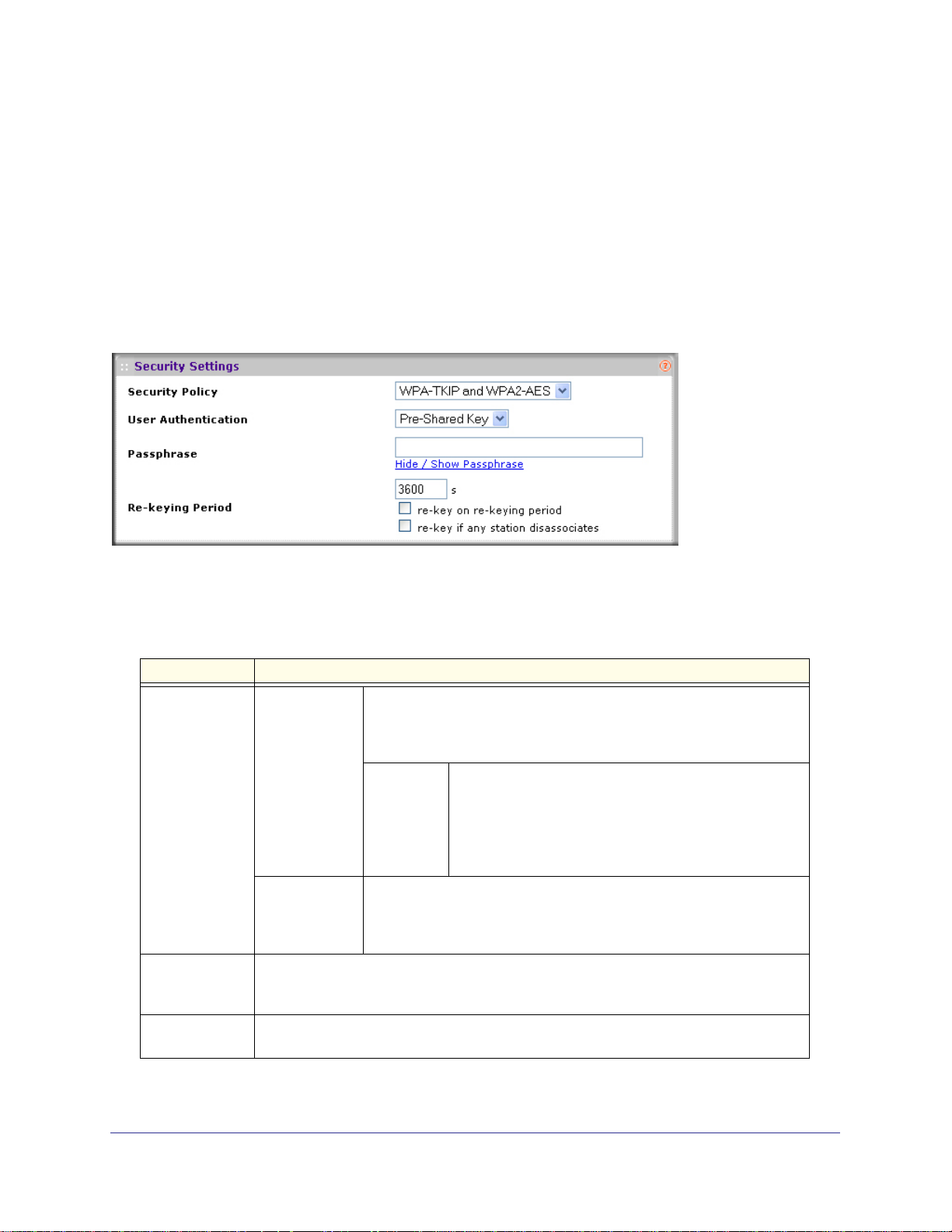
WG102-500, WGAP150 ProSafe™ 802.11g Wireless Access Point
When you select WPA-TKIP from the Security Policy pull-down menu, the section expands to
display the WPA-TKIP fields. Figure 3-6 shows Pre-Shared Key user authentication as an
example.
Figure 3-6
Specify the fields that are explained in Table 3-4.
Table 3-4.
Field Descriptions
User
Authentication
Re-Keying
Period
Pre-Shared Key From the User Authentication pull-down menu, select the Pre-Shared
Key to enable WPA-PSK. WPA-PSK does not require a RADIUS server
for authentication, but you must specify a passphrase.
Passphrase Enter a passphrase with a length must between 8 and 63
RADIUS From the User Authentication pull-down menu, select RADIUS to
enable WPA, which requires a RADIUS server for authentication (see
“Configuring RADIUS Server Settings” on page 45). This is the default
user authentication setting.
The period during which the broadcast key remains valid. When the period expires, the
broadcast key is no longer valid and must be renewed. The default is 3600 seconds
(1 hour).
characters (inclusive).
Click the Hide / Show Passphrase hyperlink to switch
between hiding and showing the passphrase on screen.
Hiding the passphrase provides added security in a
public environment.
Re-key on
re-keying period
Re-key if any
station
disassociates
42 |
Select the Re-key on re-keying period checkbox to require rekeying after the rekeying
period has expired.
Select the Re-key if any station disassociates checkbox to require rekeying after any
wireless station logs off from the wireless access point.
Page 43

WG102-500, WGAP150 ProSafe™ 802.11g Wireless Access Point
Configuring WPA2 and WPA2-PSK (AES)
WPA2 security requires RADIUS-based 802.1x authentication, so you also must define
RADIUS server settings. For information about RADIUS servers, see “Configuring RADIUS
Server Settings” on page 45. WPA2-PSK security uses a pre-shared key (PSK) and does not
require authentication from a RADIUS server. Both methods use Advanced Encryption
Standard (AES) encryption.
When you select WPA2-AES from the Security Policy pull-down menu, the section expands
to display the WPA2-AES fields. Figure 3-7 on page 43 shows RADIUS user authentication
as an example.
Figure 3-7
Specify the fields that are explained in Table 3-5
Table 3-5.
Field Descriptions
User
Authentication
Re-Keying
Period
Pre-Shared Key From the User Authentication pull-down menu, select the Pre-Shared
Key to enable WPA2-PSK. WPA2-PSK does not require a RADIUS
server for authentication, but you must specify a passphrase.
Passphrase Enter a passphrase with a length must between 8 and 63
RADIUS From the User Authentication pull-down menu, select RADIUS to
enable WPA2, which requires a RADIUS server for authentication (see
“Configuring RADIUS Server Settings” on page 45). This is the default
user authentication setting.
The period during which the broadcast key remains valid. When the period expires, the
broadcast key is no longer valid and must be renewed. The default is 3600 seconds
(1 hour).
.
characters (inclusive).
Click the Hide / Show Passphrase hyperlink to switch
between hiding and showing the passphrase on screen.
Hiding the passphrase provides added security in a
public environment.
Re-key on
re-keying period
Re-key if any
station
disassociates
Select the Re-key on re-keying period checkbox to require rekeying after the rekeying
period has expired.
Select the Re-key if any station disassociates checkbox to require rekeying after any
wireless station logs off from the wireless access point.
| 43
Page 44
WG102-500, WGAP150 ProSafe™ 802.11g Wireless Access Point
Configuring WPA+WPA2 and WPA-PSK+WPA2-PSK Mixed Modes
WPA+WPA2 security requires RADIUS-based 802.1x authentication, so you also must define
RADIUS server settings. For information about RADIUS servers, see
Server Settings” on page 45. WPA-PSK+WPA2-PSK security uses a pre-shared key (PSK)
and does not require authentication from a RADIUS server. Depending on the wireless client,
these mixed modes use either TKIP or AES encryption.
When you select WPA-TKIP and WPA2-AES from the Security Policy pull-down menu, the
section expands to display the WPA-TKIP and WPA2-AES fields.
Pre-Shared Key user authentication as an example.
“Configuring RADIUS
Figure 3-8 shows
Figure 3-8
Specify the fields that are explained in Table 3-6.
Table 3-6.
Field Descriptions
User
Authentication
Re-Keying
Period
Re-key on
re-keying period
Pre-Shared Key From the User Authentication pull-down menu, select the Pre-Shared
Key to enable WPA-PSK+WPA2-PSK. This mixed mode does not
require a RADIUS server for authentication, but you must specify a
passphrase.
Passphrase Enter a passphrase with a length must between 8 and 63
RADIUS From the User Authentication pull-down menu, select RADIUS to
enable WPA+WPA2, which requires a RADIUS server for
authentication (see
45). This is the default user authentication setting.
The period during which the broadcast key remains valid. When the period expires, the
broadcast key is no longer valid and must be renewed. The default is 3600 seconds
(1
hour).
Select the Re-key on re-keying period checkbox to require rekeying after the rekeying
period has expired.
characters (inclusive).
Click the Hide / Show Passphrase hyperlink to switch
between hiding and showing the passphrase on screen.
Hiding the passphrase provides added security in a
public environment.
“Configuring RADIUS Server Settings” on page
44 |
Page 45

WG102-500, WGAP150 ProSafe™ 802.11g Wireless Access Point
Table 3-6.
Field Descriptions
Re-key if any
station
disassociates
Select the Re-key if any station disassociates checkbox to require rekeying after any
wireless station logs off from the wireless access point.
Configuring RADIUS Server Settings
For authentication, accounting, or both authentication and accounting using RADIUS, you
must configure primary servers and optional secondary servers. The general RADIUS server
settings can apply to all devices that are connected to the wireless access point. For each
individual SSID, you can also configure alternate RADIUS server settings that override the
general RADIUS server settings and that apply only to the devices that are connected to the
SSID.
Configuring General RADIUS Server Settings
To view or change the general RADIUS server settings:
1. Log in to the wireless access point at its default LAN address of http://192.168.0.229
with its default user name of admin and default password of password, or using
whatever LAN address, user name, and password you have chosen for the wireless
access point.
2. Select Configuration > System > Radius Server. The Radius Server screen displays (see
Figure 3-9 on page 46).
| 45
Page 46
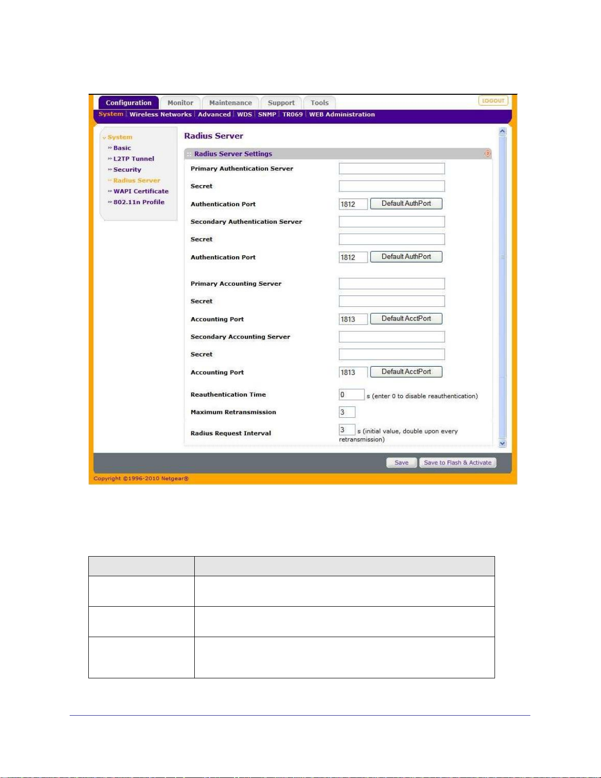
WG102-500, WGAP150 ProSafe™ 802.11g Wireless Access Point
Figure 3-9
3. Specify the fields that are explained in Table 3-7.
Table 3-7. RADIUS Server Settings
Field Descriptions
Primary Authentication
Server
Secret The shared key between the wireless access point and the primary RADIUS
Authentication Port The UDP port number on the wireless access point that is used to access
46 |
The IP address of the primary RADIUS server for authentication. The
default address is 0.0.0.0.
server during authentication.
the primary RADIUS server for authentication. Click Default AuthPort to
revert to the default port, which is number 1812.
Page 47

WG102-500, WGAP150 ProSafe™ 802.11g Wireless Access Point
Table 3-7. RADIUS Server Settings (continued)
Field Descriptions
Secondary
Authentication Server
Secret The shared key between the wireless access point and the secondary
Authentication Port The UDP port number on the wireless access point that is used to access
Primary Accounting
Server
Secret The shared key between the wireless access point and the primary RADIUS
Authentication Port The UDP port number on the wireless access point that is used to access
Secondary Accounting
Server
Secret The shared key between the wireless access point and the secondary
The IP address of the secondary RADIUS server for authentication. The
default address is 0.0.0.0. The secondary RADIUS server is used when the
primary RADIUS server is not available.
RADIUS server during authentication.
the secondary RADIUS server for authentication. Click Default AuthPort to
revert to the default port, which is number 1812.
The IP address of the primary RADIUS server for accounting. The default
address is 0.0.0.0.
server during the accounting process.
the primary RADIUS server for accounting. Click Default AuthPort to revert
to the default port, which is number 1813.
The IP address of the secondary RADIUS server for accounting. The default
address is 0.0.0.0. The secondary RADIUS server is used when the primary
RADIUS server is not available.
RADIUS server during the accounting process.
Authentication Port The UDP port number on the wireless access point that is used to access
the secondary RADIUS server for accounting. Click Default AuthPort to
revert to the default port, which is number 1813.
Reauthentication Time The time in seconds that the RADIUS request attempts should continue
after the first authentication attempt. Enter 0 to disable reauthentication,
which is the default setting.
Maximum
Retransmission
Radius Request Interval The interval in seconds between each RADIUS request attempt. The
The maximum number of RADIUS request attempts after the first
authentication attempt. The default is 3 attempts.
specified time interval is doubled for every retransmission. The default is
3
seconds.
4. Click Save or Save to Flash & Activate to save your settings.
| 47
Page 48

WG102-500, WGAP150 ProSafe™ 802.11g Wireless Access Point
Configuring Alternate RADIUS Server Settings
Alternate RADIUS server settings override the general RADIUS server settings and apply
only to the devices that are connected to the individual SSID for which you configure the
Alternate RADIUS server settings.
To configure alternate RADIUS server settings for an individual SSID:
1. Log in to the wireless access point at its default LAN address of http://192.168.0.229
with its default user name of admin and default password of password, or using
whatever LAN address, user name, and password you have chosen for the wireless
access point.
2. Select Configuration > Wireless Networks. The Wireless Networks screen opens,
displaying 16 wireless security profiles (see
3. To configure or edit a wireless security profile, select the corresponding Edit hyperlink to the
right of the wireless security profile. The Edit Wireless Network screen opens for the
selected wireless security profile. Scroll down to the Alternative Radius Server Settings
section.
4. Select the Alternative Radius Server Enabled checkbox. The screen expands to display the
Alternative Radius Server fields. The fields are identical to the fields on the Radius Server
screen (see
5. Specify the fields that are explained in Table 3-7 on page 46.
6. Click Save or Save to Flash & Activate to save your settings.
Figure 3-9 on page 46) but apply only to the selected wireless security profile.
Figure 3-2 on page 38).
Selecting the 802.1x EAPOL Version
Most wireless devices support 802.1x Extensible Authentication Protocol over LAN version 2
(EAPOL v2) for RADIUS authentication. To accommodate wireless devices that do not
support EAPOL v2, you can configure the wireless access point to use both EAPOL v1 and
v2.
To configure the EAPOL version:
1. Log in to the wireless access point at its default LAN address of http://192.168.0.229
with its default user name of admin and default password of password, or using
whatever LAN address, user name, and password you have chosen for the wireless
access point.
2. Select Configuration > System > Security. The Security screen displays (see Figure 3-10
on page 49).
48 |
Page 49
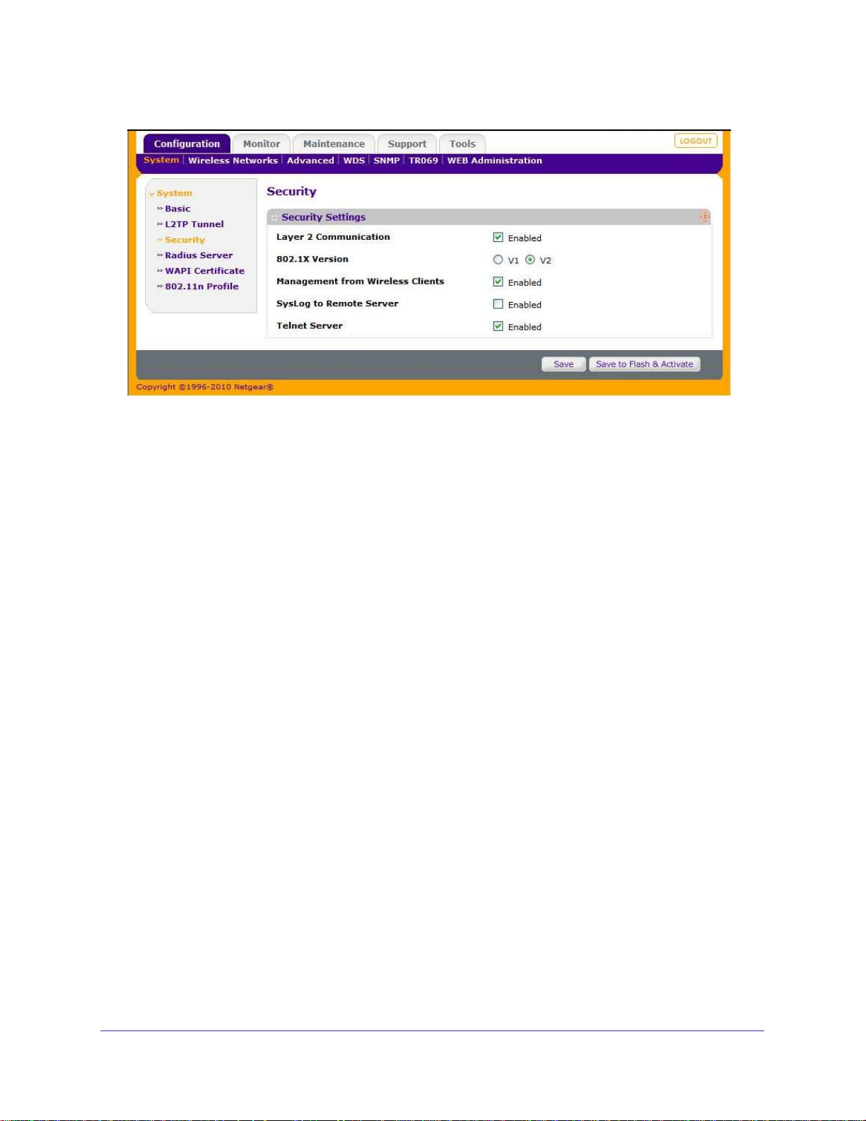
WG102-500, WGAP150 ProSafe™ 802.11g Wireless Access Point
Figure 3-10
3. Next to 802.1X Version, select one of the following radio buttons:
• v1. Both EAPOL v1 and v2 devices can associate with the wireless access point.
• v2. Only EAPOL v2 devices can associate with the wireless access point. This is the
default setting.
4. Click Save or Save to Flash & Activate to save your settings.
WAPI Certificates
You can Install WAPI certificates to be used for authentication. You will need the following
information:
• Authentication Server IP - Server IP for WAPI authentication
• ASU Certification - Certificate for ASU
• User Certification - Certificate for the User Account
To install WAPI Certificates:
1. Select Configuration > System > WAPI Certificate. The WAPI Certificate screen
displays.
2. Enter the Server address and Certificates to be uploaded.
3. Click Install.
| 49
Page 50

WG102-500, WGAP150 ProSafe™ 802.11g Wireless Access Point
Figure 3-11
Restricting Wireless Access by MAC Address
For increased security, you can restrict access to an SSID to allow only specific computers or
wireless cards based on their MAC addresses. You can restrict access to only trusted
computers so that unknown computers cannot wirelessly connect to the wireless access
point. MAC address filtering adds an obstacle against unwanted access to your network, but
the data broadcast over the wireless link is fully exposed.
Note: For wireless adapters, you can usually find the MAC address printed
on the wireless adapter.
To restrict access based on MAC addresses for an individual SSID:
1. Log in to the wireless access point at its default LAN address of http://192.168.0.229
with its default user name of admin and default password of password, or using
whatever LAN address, user name, and password you have chosen for the wireless
access point.
50 |
Page 51

WG102-500, WGAP150 ProSafe™ 802.11g Wireless Access Point
2. Select Configuration > Wireless Networks. The Wireless Networks screen opens,
displaying 16 wireless security profiles (see
Figure 3-2 on page 38).
3. To configure or edit a wireless security profile, select the corresponding Edit hyperlink to the
right of the wireless security profile. The Edit Wireless Network screen opens for the
selected wireless security profile. Scroll down to the Access Control Settings section.
4. From the Access Control pull-down menu, select one of the following options:
• None. Access control is disabled. This is the default setting.
• Deny all except listed. Access control is denied to all wireless clients of the SSID
except for the trusted wireless clients whose MAC addresses are listed in the Listed
MAC Addresses table. When you select this option, the screen expands to display the
MAC Insertion Tool and the Listed MAC Addresses table, as shown in
Figure 3-12 on
page 51.
• Accept all except listed. Access control is granted to all wireless clients of the SSID
except for the wireless clients whose MAC addresses are listed in the Listed MAC
Addresses table. When you select this option, the screen expands to display the MAC
Insertion Tool and the Listed MAC Addresses table.
There is one Listed MAC Addresses table to deny access and another one to grant
access. Your selection from the Access Control pull-down menu determines which table
is displayed (see
Figure 3-12 on page 51).
Figure 3-12
There are two methods to add MAC addresses to the Listed MAC Addresses table:
• Manually enter one or more MAC addresses in the User defined MACs window of the
MAC Insertion Tool, then click <<< Add to list.
• Select one or more MAC addresses from the Connected clients window of the MAC
Insertion Tool, then click <<< Add to list.
| 51
Page 52
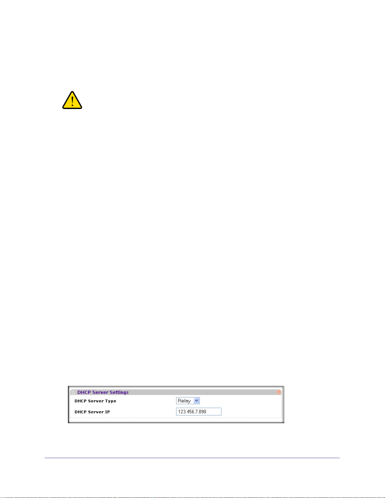
WG102-500, WGAP150 ProSafe™ 802.11g Wireless Access Point
To delete MAC addresses from the Listed MAC Addresses table, select (highlight) one or
more MAC addresses in the Listed MAC Addresses table, then click Delete highlighted.
5. Click Save or Save to Flash & Activate to save your settings.
WARNING!
When configuring the wireless access point from a wireless
computer whose MAC address is not in the access control list,
you will lose your wireless connection when you click Save or
Save to Flash & Activate. You must then access the wireless
access point from a wired computer or from a wireless computer
which is on the access control list to make any further changes.
Configuring Alternate DHCP Server Settings
In addition to the general DHCP server settings for the LAN segment (see “Configuring LAN
Settings” on page 23), you can specify alternate DHCP server settings for an individual SSID.
DHCP requests can be relayed to a remote DHCP server or fulfilled by a local DHCP server.
To configure alternate DHCP server settings for an individual SSID:
1. Log in to the wireless access point at its default LAN address of http://192.168.0.229
with its default user name of admin and default password of password, or using
whatever LAN address, user name, and password you have chosen for the wireless
access point.
2. Select Configuration > Wireless Networks. The Wireless Networks screen opens,
displaying 16 wireless security profiles (see
3. To configure or edit a wireless security profile, select the corresponding Edit hyperlink to the
right of the wireless security profile. The Edit Wireless Network screen opens for the
selected wireless security profile. Scroll down to the DHCP Server Settings section.
4. From the DHCP Server Type pull-down menu, select one of the following options:
• None. DHCP requests are forwarded to the LAN segment and not fulfilled by the
wireless segment. This is the default setting.
• Relay. The wireless access point forwards DHCP requests to a remote DHCP server.
When you select this option, the screen expands as shown in
IP address of the remote DHCP server in the DHCP Server IP field.
Figure 3-2 on page 38).
Figure 3-13. Enter the
52 |
Figure 3-13
Page 53

WG102-500, WGAP150 ProSafe™ 802.11g Wireless Access Point
• Server. The wireless access point allocates and provides IP addresses locally. When
you select this option, the screen expands as shown in Figure 3-14 on page 53.
Specify the fields as explained in Table 3-8 on page 53. There are no default values
for this screen.
Figure 3-14
.
Table 3-8. Alternate DHCP Server Settings
Field Description
IP Start Range The first address in the range of IP addresses to be assigned to DHCP clients.
IP Stop Range The last address in the range of IP addresses to be assigned to DHCP clients.
Subnet Mask The subnet mask to be used by DHCP clients.
Broadcast
Address
Gateway The IP address of the default routing gateway to be used by DHCP clients.
DNS 1 The IP address of the primary static Domain Name Server (DNS) server
DNS 2 The IP address of the secondary static DNS server available to DHCP
DNS 3 The IP address of the tertiary static DNS server available to DHCP clients. This
The broadcast IP address to be used by DHCP clients.
available to DHCP clients.
clients.This server is used when the primary DNS server is not available.
server is used when the primary and secondary DNS servers are not available.
Domain The domain name to be used by DHCP clients.
Lease Time The period that the DHCP server grants to the DHCP clients to use the assigned
IP addresses.
5. Click Save or Save to Flash & Activate to save your settings.
| 53
Page 54
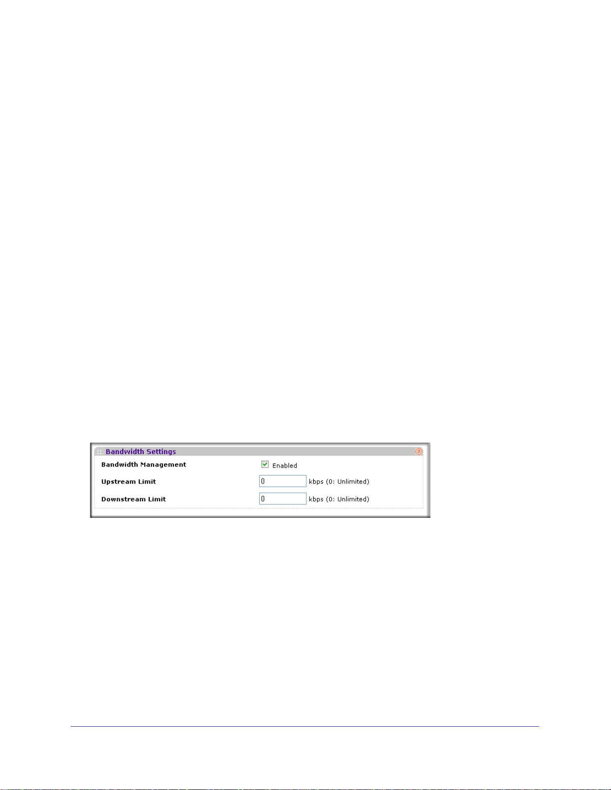
WG102-500, WGAP150 ProSafe™ 802.11g Wireless Access Point
Configuring Wireless Quality of Service
To control reliability and availability of the wireless access point, you can allocate quality of
service (QoS) levels per SSID. For information about general default QoS levels (Gold,
Silver, and Bronze), multicast filtering, and multicast data rates, see
Wireless Network Settings” on page 27, in particular Figure 2-12 and Table 2-7. In addition to
these general QoS settings, you can assign specific traffic bandwidth limits (also referred to
as traffic shaping), filter incoming traffic, and configure advanced QoS settings, all per
individual SSID.
Configuring Wireless Traffic Shaping
To set limits on the bandwidth of incoming and outgoing wireless traffic for an individual
SSID:
1. Log in to the wireless access point at its default LAN address of http://192.168.0.229
with its default user name of admin and default password of password, or using
whatever LAN address, user name, and password you have chosen for the wireless
access point.
“Configuring Basic
2. Select Configuration > Wireless Networks. The Wireless Networks screen opens,
displaying 16 wireless security profiles (see
3. To configure or edit a wireless security profile, select the corresponding Edit hyperlink to the
right of the wireless security profile. The Edit Wireless Network screen opens for the
selected wireless security profile. Scroll down to the Bandwidth Settings section.
4. Select the Bandwidth Management Enabled checkbox. The screen expands to display the
Upstream Limit and Downstream Limit fields.
Figure 3-15
5. Specify the bandwidth limits:
• Upstream Limit. Specify the bandwidth limit for outgoing traffic limit in kbps. The
default is zero, which specifies unlimited bandwidth.
• Downstream Limit. Specify the bandwidth limit for incoming traffic in kbps. The
default is zero, which specifies unlimited bandwidth.
6. Click Save or Save to Flash & Activate to save your settings.
Figure 3-2 on page 38).
54 |
Page 55

WG102-500, WGAP150 ProSafe™ 802.11g Wireless Access Point
Configuring Wireless Traffic Filtering
You can filter incoming wireless traffic based on MAC addresses, IP addresses, and
protocols. Traffic can be either accepted or dropped.
To configure filters for incoming wireless traffic for an individual SSID:
1. Log in to the wireless access point at its default LAN address of http://192.168.0.229
with its default user name of admin and default password of password, or using
whatever LAN address, user name, and password you have chosen for the wireless
access point.
2. Select Configuration > Wireless Networks. The Wireless Networks screen opens,
displaying 16 wireless security profiles (see
3. To configure or edit a wireless security profile, select the corresponding Edit hyperlink to the
right of the wireless security profile. The Edit Wireless Network screen opens for the
selected wireless security profile. Scroll down to the Filter Settings section.
4. Select the Wireless Network Filter Enabled checkbox. The screen expands to display the
filter fields and policy table.
Figure 3-2 on page 38).
Figure 3-16
| 55
Page 56

WG102-500, WGAP150 ProSafe™ 802.11g Wireless Access Point
5. Specify the fields as explained in Table 3-9.
Table 3-9. Filter Settings
Field Descriptions
Name Assign a name to the filter policy.
Source MAC
Address
Destination MAC
Address
Source IP Address
/ Netmask
Destination IP
Address / Netmask
Source Port The source port of the incoming traffic. This field is applicable only when you select
Destination Port The destination port for the incoming traffic. This field is applicable only when you
Protocol Select the protocol(s) to which the filter rule should apply from the pull-down menu:
The source MAC address of the incoming traffic
The destination MAC address for the incoming traffic.
The source IP address and optional netmask of the incoming traffic. This field is
not applicable when you select ARP as the protocol.
The destination IP address and optional netmask for the incoming traffic. This field
is not applicable when you select ARP as the protocol.
TCP or UDP as the protocol.
select TCP or UDP as the protocol.
• tcp. The rule applies only to incoming Transmission Control Protocol (TCP)
traffic.
• udp. The rule applies only to incoming User Datagram Protocol (UDP) traffic.
• icmp. The rule applies only to incoming Internet Control Message Protocol
(ICMP) traffic.
• arp. The rule applies only to incoming Address Resolution Protocol (ARP)
traffic.
• all. The rule applies to incoming traffic of any protocol. This is the default
setting.
Policy Select the policy action from the pull-down menu:
• accept. All incoming traffic that matches the policy is accepted.
• drop. All incoming traffic that matches the policy is dropped. This is the default
setting.
Enable The policy is activated by default after you have added the policy to the policy table
and you have clicked Save or Save to Flash & Activate.
Deselect the Enabled checkbox to add the policy to the policy table without
allowing it to be activated after you have clicked Save or Save to Flash & Activate.
After you have specified the filter fields, click Add to List to add the policy to the policy
table or click Clear to clear the filter fields and return the settings to default.
If you want to remove a policy from the policy table, click Remove in the rightmost column
of the policy that you want to remove.
6. Click Save or Save to Flash & Activate to save your settings.
56 |
Page 57
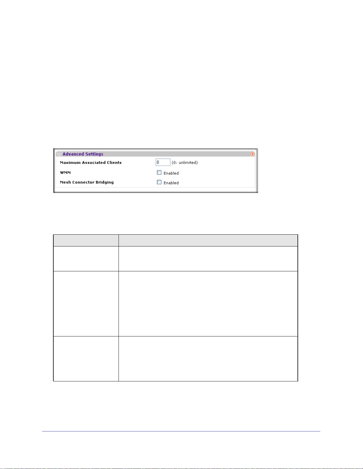
WG102-500, WGAP150 ProSafe™ 802.11g Wireless Access Point
Configuring Advanced QoS Settings
To configure advanced QoS settings for an individual SSID:
1. Log in to the wireless access point at its default LAN address of http://192.168.0.229
with its default user name of admin and default password of password, or using
whatever LAN address, user name, and password you have chosen for the wireless
access point.
2. Select Configuration > Wireless Networks. The Wireless Networks screen opens,
displaying 16 wireless security profiles (see Figure 3-2 on page 38).
3. To configure or edit a wireless security profile, select the corresponding Edit hyperlink to the
right of the wireless security profile. The Edit Wireless Network screen opens for the
selected wireless security profile. Scroll down to the Advanced Settings section.
Figure 3-17
4. Specify the Advanced Settings fields as explained in Table 3-10.
Table 3-10. Advanced (QoS) Settings
Field Descriptions
Maximum Associated
Clients
WMM Wi-Fi Multimedia (WMM) is a subset of the 802.11e standard. WMM allows
Mesh Connector Bridging The Mesh Connector Bridging feature allows wireless devices with
Specify the maximum number of wireless clients that are allowed to
connect to the SSID. The default setting is 0, which indicates a limitless
number of wireless clients.
QoS for wireless traffic; it provides applications that require better
throughput and performance special queues with higher priority. For
example, time-dependent information such as video and audio are given
higher priority over applications such as FTP.
WMM is enabled by default for the SSID. Deselect the Enabled checkbox
to disable WMM for the SSID.
Note: For WMM to function correctly, wireless clients must also support
WMM.
wireless distribution system (WDS) capability to receive packets with four
addresses in the 802.11 header, thereby allowing a transparent bridge to
be formed between the wireless access point and wireless devices.
Mesh Connector Bridging is disabled by default for the SSID. Select the
Enabled checkbox to enable the Mesh Connector Bridging for the SSID.
5. Click Save or Save to Flash & Activate to save your settings.
| 57
Page 58

WG102-500, WGAP150 ProSafe™ 802.11g Wireless Access Point
Configuring Wireless Client Separation
Wireless client separation prevents associated wireless clients (using the same SSID) from
communicating with each other, which is useful for hotspots and other public access
situations. This feature is either globally enabled or globally disabled. However, per individual
SSID, you can specify to allow or block unicast and/or broadcast and multicast traffic
between the clients of that same SSID.
Globally Enabling Wireless Client Configuration
To enable wireless client separation:
1. Log in to the wireless access point at its default LAN address of http://192.168.0.229
with its default user name of admin and default password of password, or using
whatever LAN address, user name, and password you have chosen for the wireless
access point.
2. Select Configuration > System > Security. The Security screen displays (see Figure 3-18
on page 58).
Figure 3-18
3. Next to Layer 2 Communication, select the Enabled checkbox. This checkbox is deselected
by default.
4. Click Save or Save to Flash & Activate to save your settings.
Refining Wireless Client Separation
To configure wireless client separation for an individual SSID, and to allow or block unicast,
broadcast, and multicast traffic between the clients of the same SSID:
1. Log in to the wireless access point at its default LAN address of http://192.168.0.229
with its default user name of admin and default password of password, or using
whatever LAN address, user name, and password you have chosen for the wireless
access point.
58 |
Page 59

WG102-500, WGAP150 ProSafe™ 802.11g Wireless Access Point
2. Select Configuration > Wireless Networks. The Wireless Networks screen opens,
displaying 16 wireless security profiles (see Figure 3-2 on page 38).
3. To configure or edit a wireless security profile, select the corresponding Edit hyperlink to the
right of the wireless security profile. The Edit Wireless Network screen opens for the
selected wireless security profile. Scroll down to the Alternative Layer 2 Communication
Settings section.
4. Select the Alternative Layer 2 Communication Enabled checkbox. The screen expands to
let you configure the wireless client separation settings.
Figure 3-19
5. Enter the wireless client separation settings (also referred to as alternate Layer 2
communication settings) as explained in Table 3-11.
Table 3-11. Wireless Client Separation Settings
Field Descriptions
Separate Unicast Packets By default, unicast packets are blocked between clients of the SSID.
Deselect the Enabled checkbox to allow unicast packets between clients
of the SSID.
Separate
Broadcast/Multicast
packets
Separate between SSIDs By default, communication between clients of the SSID and clients of
By default, broadcast and multicast packets are blocked between clients
of the SSID. Deselect the Enabled checkbox to allow broadcast and
multicast packets between clients of the SSID.
other SSIDs is blocked. Deselect the Enabled checkbox to allow
communication between clients of the SSID and clients of other SSIDs.
6. Click Save or Save to Flash & Activate to save your settings.
| 59
Page 60

WG102-500, WGAP150 ProSafe™ 802.11g Wireless Access Point
60 |
Page 61

4.
Managing Your Network
This chapter describes how to use the management features of your wireless access point.
This chapter includes:
• Backing Up, Restoring, and Erasing Your Settings ” on this page
• “Upgrading the Wireless Access Point Firmware” on page 65
• “Changing the Administrator Password and User Name” on page 66
• “Viewing Network Management Information” on page 68
• “Configuring Remote Management” on page 78
• “Scheduling Management Tasks” on page 91
Backing Up, Restoring, and Erasing Your Settings
The configuration settings of the wireless access point are stored in a configuration file in the
wireless access point. From the Configuration screen, this file can be backed up to a
computer, restored from a computer, or reverted to factory default settings.
4
To access the Configuration screen:
1. Log in to the wireless access point at its default LAN address of http://192.168.0.229
with its default user name of admin and default password of password, or using
whatever LAN address, user name, and password you have chosen for the wireless
access point.
2. Select Maintenance > Config. The Configuration screen displays (see Figure 4-1 on page
62).
| 61
Page 62

WG102-500, WGAP150 ProSafe™ 802.11g Wireless Access Point
Figure 4-1
The following sections explain how to back up the configuration file, restore the configuration
file, revert the configuration file to factory default settings, and perform other tasks from the
Configuration screen.
Backing up the Configuration
To back up the configuration file:
1. On the Configuration screen (see Figure 4-1), next to Download Active Configuration,
click Proceed.
2. Your browser extracts the configuration file from the wireless access point and prompts you
for a location on your computer to store the file. You can give the file a meaningful name at
this time, such as WGAP150.cfg.
Restoring the Configuration
To restore your settings from a saved configuration file:
1. On the Configuration screen (see Figure 4-1 on page 62), under Upload Configuration,
enter the full path to the file in the Configuration File field, or click Browse to locate the
file.
2. Next to Upload Configuration, click Proceed. If your browser requires a confirmation to
proceed, confirm the action.
62 |
Page 63

WG102-500, WGAP150 ProSafe™ 802.11g Wireless Access Point
3. After completing the upload, the changes do not take effect until you activate them. On the
Configuration screen, next to Activate Changes, click Proceed. If your browser requires a
confirmation to proceed, confirm the action.
Rebooting and Restoring the Default Configuration
You can erase the wireless access point configurations, and return to the factory default
settings. After erasing, the wireless access point’s default LAN IP address will be
192.168.0.229, the default login user name will be admin, and the default login password will
be password.
Using the Software to Reboot and Restore Factory Default Settings
To use the software clear all or selected data and restore the factory default values:
1. On the Configuration screen (see Figure 4-1 on page 62), below Restore Factory
Default, next to Preserve Settings, select the Network settings checkbox if you want to
preserve the network settings such as the server IP address, subnet mask, default
gateway, DNS server, and management VLAN ID. If you do not want to preserver these
settings, deselect the Network settings checkbox.
2. Next to Restore Factory Default, click Proceed. If your browser requires a confirmation to
proceed, confirm the action. A few seconds later, only the power LED of the wireless access
point remains on, indicating that the wireless access point has rebooted.
After several minutes, the factory default configuration will be restored, and the wireless
access point will be ready for use.
Using the Reset Button to Reboot and Restore Factory Default Settings
If you do not know the LAN IP address, login user name, or login password, you can still
restore the factory default configuration settings with the Reset button. This button is on the
rear panel of the wireless access point (see
To use the Reset button to clear all data and restore the factory default values:
1. Push and hold the Reset button for about five seconds. (You may have to push hard.)
2. Release the Reset button. A few seconds later, only the power LED of the wireless access
point remains on, indicating that the wireless access point has rebooted.
After several minutes, the factory default configuration will be restored, and the wireless
access point will be ready for use.
“Rear Panel” on page 11).
Saving the Configuration to Flash Memory
This procedure saves any configuration changes to the internal flash memory, allowing the
changes to remain active after the wireless access point has been reloaded.To save the
configuration to flash memory:
On the Configuration screen (see Figure 4-1 on page 62), next to Save Configuration to
Flash, click Proceed. If your browser requires a confirmation to proceed, confirm the action.
| 63
Page 64

WG102-500, WGAP150 ProSafe™ 802.11g Wireless Access Point
Scheduling to Activate the Changes
This procedure lets you schedule the activation of any configuration changes, so that
changes can be activated at a time when a minimum number of users are impacted.
However, this procedure does not save the changes to flash memory, so the changes are lost
when you reload the wireless access point.
To schedule the activation of changes:
1. On the Configuration screen (see Figure 4-1 on page 62), in the Delay Options field
below Activate Changes, enter the time in seconds that the activation should be
delayed. The default is zero seconds, which means that there is no delay and the
changes are activated immediately.
2. Below Activate Changes, click Proceed. If your browser requires a confirmation to proceed,
confirm the action.
Rebooting without Restoring the Default Configuration
You can reboot the wireless access point without restoring the default configuration by using
the software reboot button on the Miscellaneous screen:
1. Log in to the wireless access point at its default LAN address of http://192.168.0.229
with its default user name of admin and default password of password, or using
whatever LAN address, user name, and password you have chosen for the wireless
access point.
2. Select Maintenance >Misc. The Miscellaneous screen displays. This screen also lets you
download debug information (see
displays the current firmware version.
“Downloading Debug Information” on page 119) and
Figure 4-2
3. Next to Reboot, select the flash memory to reboot from and click Proceed. If your browser
requires a confirmation to proceed, confirm the action. A few seconds later, only the power
64 |
Page 65

WG102-500, WGAP150 ProSafe™ 802.11g Wireless Access Point
LED of the wireless access point remains on, indicating that the wireless access point has
rebooted.
After several minutes the wireless access point will be ready for use.
Upgrading the Wireless Access Point Firmware
WARNING!
When uploading firmware to the wireless access point, do not
interrupt the Web browser by closing the window, clicking a link,
or loading a new page. If the browser is interrupted, the upload
may fail, corrupt the firmware, and render the wireless access
point completely inoperable.
The wireless access point firmware is stored in flash memory, and can be upgraded as
NETGEAR releases new firmware. You can download the upgrade file (in tar format) from
the NETGEAR Web site.
Note: The Web browser used to upload new firmware into the wireless
access point must support HTTP uploads, such as Microsoft Internet
Explorer 6.0 or later, or Mozilla Firefox 1.5 or later.
To upgrade the firmware on the wireless access point:
1. Download the upgrade file from NETGEAR and save it to your hard disk.
2. Log in to the wireless access point at its default LAN address of http://192.168.0.229 with its
default user name of admin and default password of password, or using whatever LAN
address, user name, and password you have chosen for the wireless access point.
3. Back up the current configuration as described in “Backing up the Configuration” on page
62.
| 65
Page 66

WG102-500, WGAP150 ProSafe™ 802.11g Wireless Access Point
4. Select Maintenance >Firmware. The Firmware screen displays, showing the current
firmware version. The
symbol indicates the Flash module selected.
Figure 4-3
5. Next to Firmware Image File, click Browse to navigate to the location where the upgrade file
is stored.
6. The Click Proceed to upgrade the firmware. If your browser requires a confirmation to
proceed, confirm the action. A few seconds later, only the power LED of the wireless access
point remains on, indicating that the wireless access point has rebooted.
When the upload completes, your wireless access point automatically restarts. After several
minutes, the wireless access point will be ready for use. In some cases, you might need to
reconfigure the wireless access point after upgrading.
Changing the Administrator Password and User Name
The default administrator user name to access the wireless access point is admin and the
default administrator password is password. Change the user name to a unique name that
makes sense to you and the password to a more secure password.
Tip: Be sure to change the wireless access point default password to a very
secure password. The ideal password should contain no dictionary
words from any language, and should be a mixture of letters (both upper
case and lower case), numbers, and symbols. Your password can be up
to 30 characters.
Changing the Administrator Password
To change the password:
66 |
Page 67
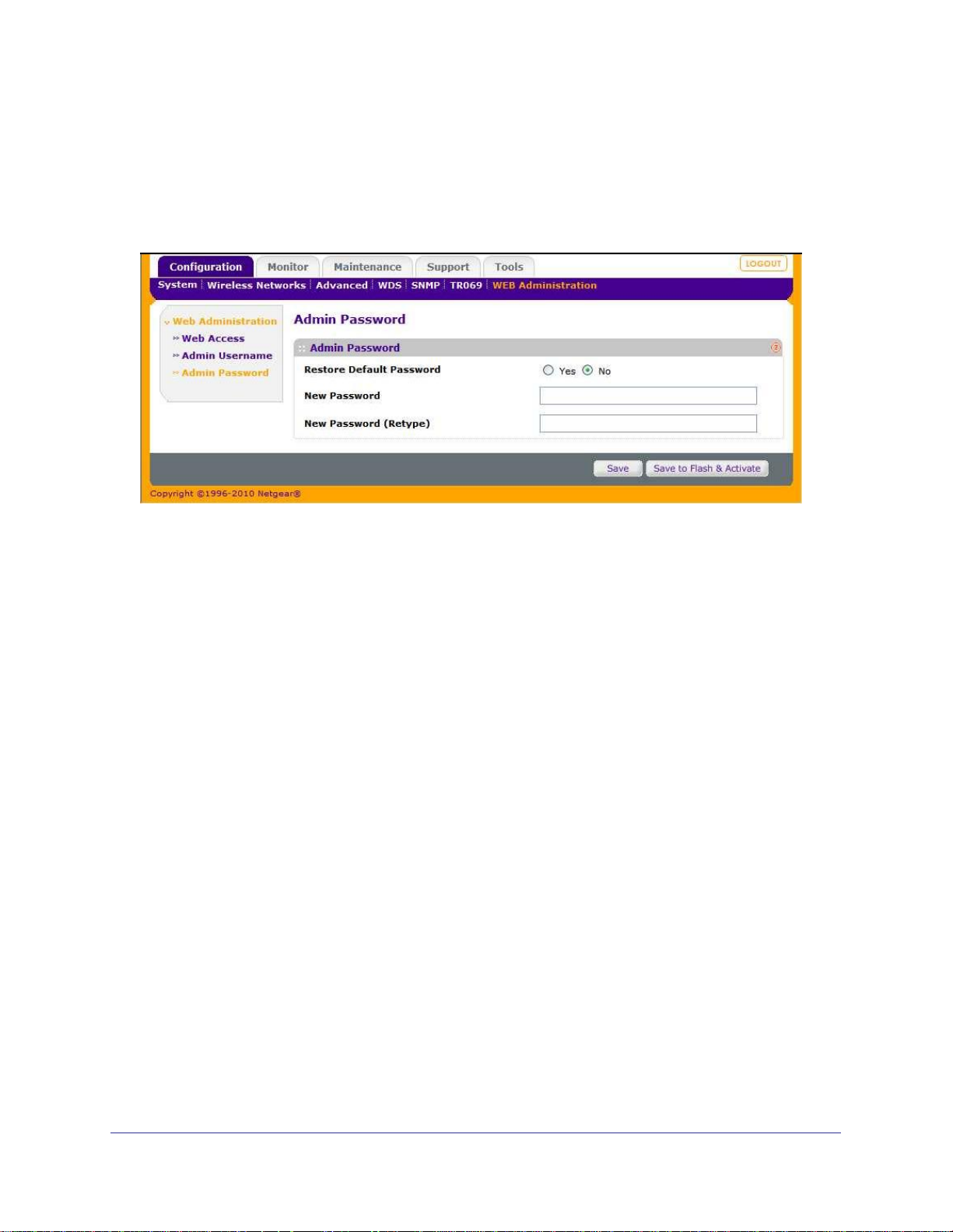
WG102-500, WGAP150 ProSafe™ 802.11g Wireless Access Point
1. Log in to the wireless access point at its default LAN address of http://192.168.0.229
with its default user name of admin and default password of password, or using
whatever LAN address, user name, and password you have chosen for the wireless
access point.
2. Select Configuration >WEB Administration > Admin Password. The Admin Password
screen displays.
Figure 4-4
3. Next to Restore Default password, select the No radio button.
4. Enter the new password in the New Password field.
5. Repeat the new password in the New Password (Retype) field.
6. Click Save or Save to Flash & Activate to save your settings.
To restore the default password:
1. Next to Restore Default password, select the Yes radio button.
2. Click Save or Save to Flash & Activate to save your settings.
Changing the Administrator User Name
To change the user name:
1. Log in to the wireless access point at its default LAN address of http://192.168.0.229
with its default user name of admin and default password of password, or using
whatever LAN address, user name, and password you have chosen for the wireless
access point.
| 67
Page 68
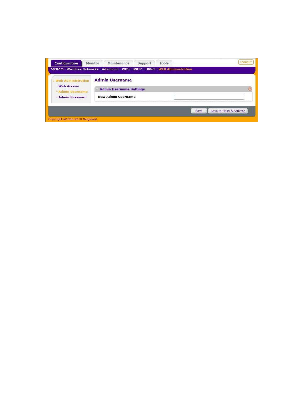
WG102-500, WGAP150 ProSafe™ 802.11g Wireless Access Point
2. Select Configuration >WEB Administration > Admin Username. The Admin Username
screen displays.
Figure 4-5
3. Enter the new user name in the New Admin Username field.
4. Click Save or Save to Flash & Activate to save your settings.
Viewing Network Management Information
The wireless access point provides a variety of status and usage information, which are
discussed in the following sections.
Viewing the Activity Log
You can view the activity log on screen or send it to a syslog server.
Viewing the Activity Log on Screen
To view the activity log on screen:
1. Log in to the wireless access point at its default LAN address of http://192.168.0.229
with its default user name of admin and default password of password, or using
whatever LAN address, user name, and password you have chosen for the wireless
access point.
68 |
Page 69
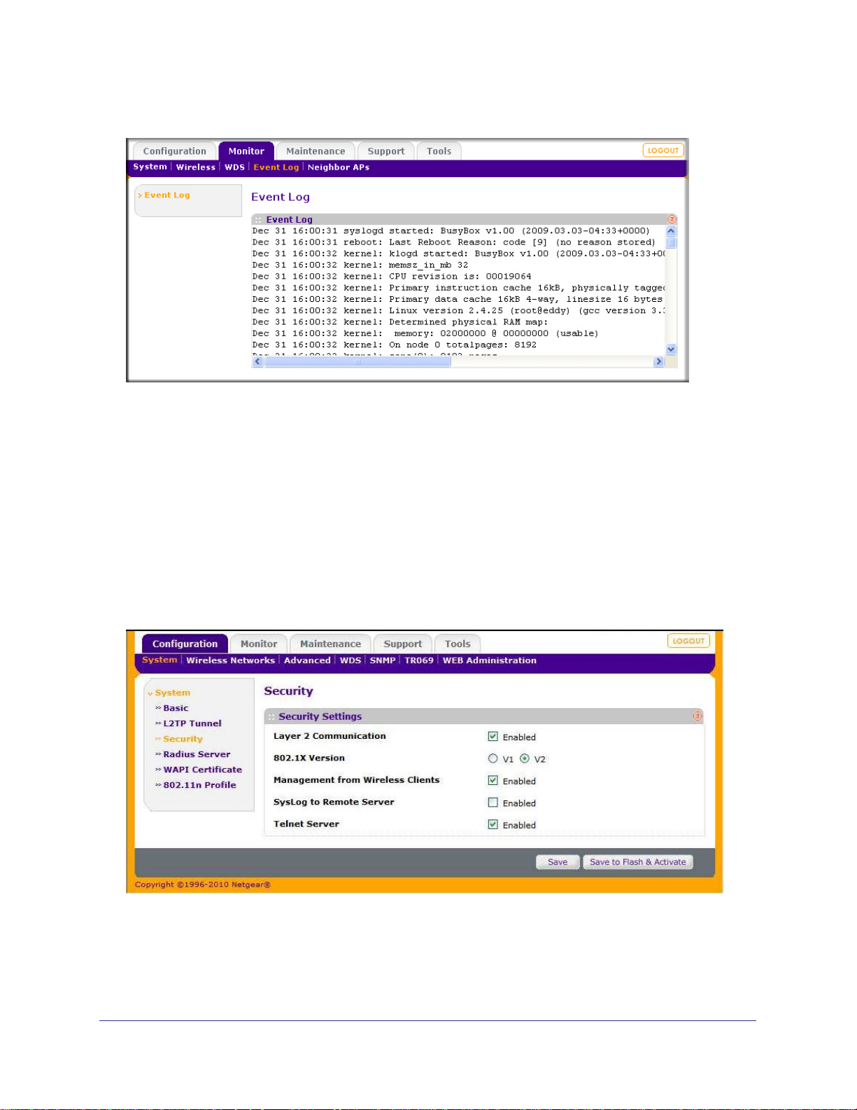
WG102-500, WGAP150 ProSafe™ 802.11g Wireless Access Point
2. Select Monitor > Event Log. The Event Log screen displays.
Figure 4-6
The Activity Log Window displays the wireless access point’s system activity.
Sending the Activity Log to a Syslog Server
To send the activity log to a syslog server:
1. Log in to the wireless access point at its default LAN address of http://192.168.0.229
with its default user name of admin and default password of password, or using
whatever LAN address, user name, and password you have chosen for the wireless
access point.
2. Select Configuration > System > Security. The Security Settings screen displays.
Figure 4-7
3. Select the Syslog to Remote Server Enabled checkbox to enable the syslog connection.
The screen expands, enabling you to configure the syslog server fields.
| 69
Page 70

WG102-500, WGAP150 ProSafe™ 802.11g Wireless Access Point
4. Enter the syslog information in the following fields:
• Syslog Server Address. The IP address of the syslog server.
• SysLog Server Port. The port number for the syslog server on the LAN segment. The
default port is 514.
5. Click Save or Save to Flash & Activate to save your settings.
Viewing System Information
The System Information is a summary of the wireless access point configuration settings.
To view the system information screens:
1. Log in to the wireless access point at its default LAN address of http://192.168.0.229
with its default user name of admin and default password of password, or using
whatever LAN address, user name, and password you have chosen for the wireless
access point.
2. Select Monitor > System and then Basic, L2TP Tunnel, or Flash Management. These
three screens are shown below and their fields are explained in the tables below.
70 |
Page 71
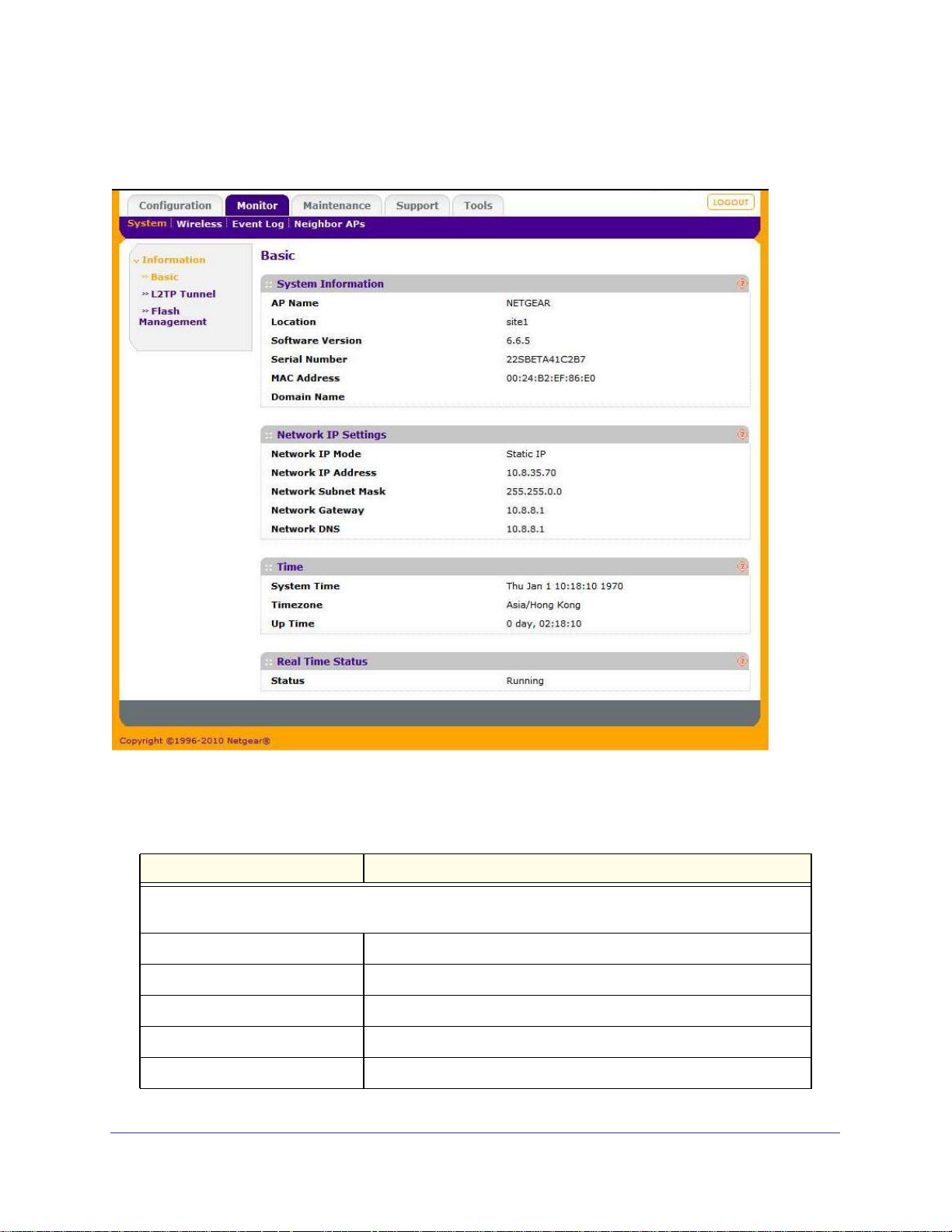
WG102-500, WGAP150 ProSafe™ 802.11g Wireless Access Point
Viewing the Basic System Information Screen
Figure 4-8
Table 4-1.
Field Description
System Information
You can configure some of these settings in “Configuring Basic System Settings” on page 19
AP Name The name of the wireless access point.
Location The name of the location of the wireless access point.
Software Version The version of the firmware currently installed.
Serial Number The serial number of the wireless access point.
MAC Address The MAC Address of the wireless access point’s Ethernet port.
| 71
Page 72

WG102-500, WGAP150 ProSafe™ 802.11g Wireless Access Point
Table 4-1.
Field Description
Domain Name The optional name of the domain.
Network IP Settings
You can configure these settings in “Configuring IP Settings” on page 20.
Network IP Mode The IP setting that specifies how the wireless access point acquires its
IP address (DHCP, static IP, or PPPoE).
Network IP Address The IP address of the wireless access point.
Network Subnet Mask The subnet mask of the wireless access point.
Network Gateway The default gateway for the wireless access point’s communication.
Network DNS The DNS server for the wireless access point.
Time
System Time System time as available on the wireless access point.
Timezone The time zone in which the wireless access point operates. To set the
time zone, see
Up Time The period that the wireless access point has been operating since it
was turned on.
Real Time Status
Status The current status of the wireless access point. The modes are:
“Configuring Basic System Settings” on page 19.
• Running. The wireless access point is in operation.
• Activating. The configuration is being saved and activated.
• Starting up. The wireless access point is booting.
• Rebooting. The wireless access point is rebooting via software.
72 |
Page 73
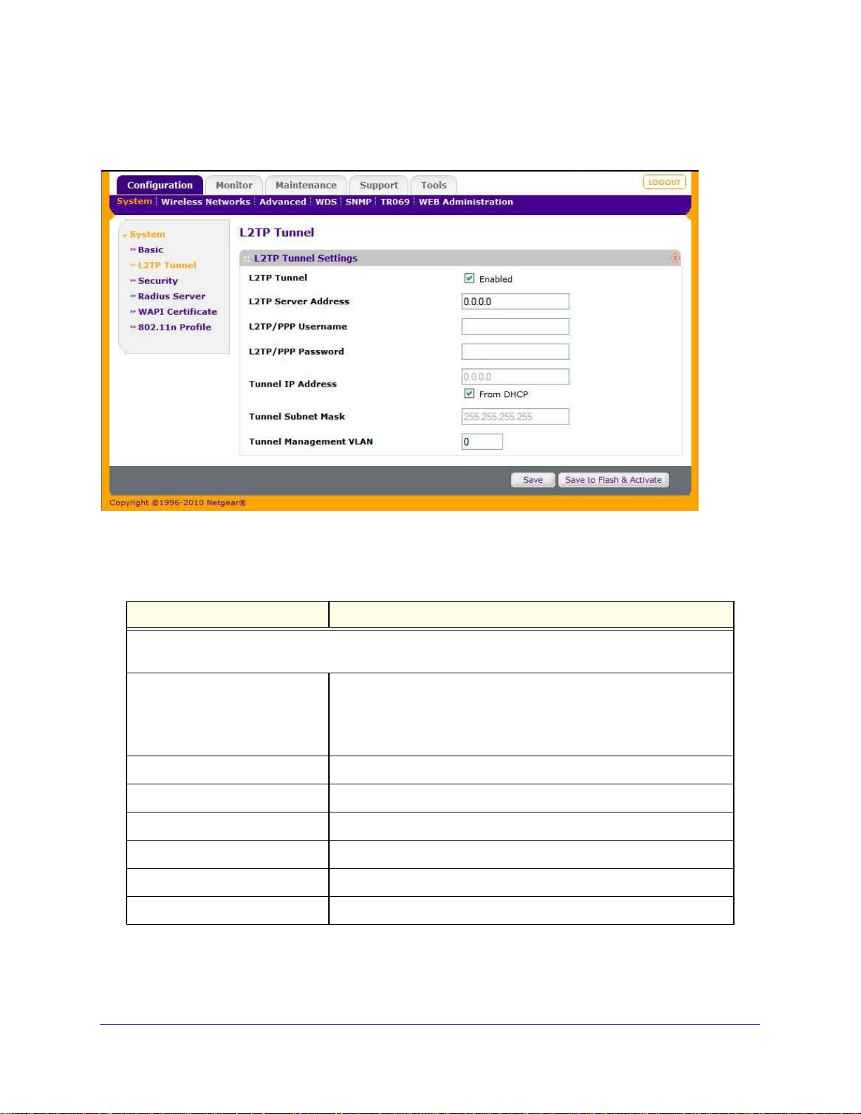
WG102-500, WGAP150 ProSafe™ 802.11g Wireless Access Point
Viewing the L2TP Tunnel Information Screen
Figure 4-9
Table 4-2.
Field Description
System Information
You can configure these settings in “Configuring L2TP Tunnel Management” on page 82.
Status The current status of the L2TP tunnel. The modes are:
• Disabled. The L2TP tunnel is torn down.
• Connecting. The L2TP tunnel is in the process of being set up.
• Connected. The L2TP tunnel is up.
Server Address Address of the L2TP Server.
Username L2TP/PPP username.
Password L2TP/PPP password.
Tunnel IP Address The IP address of the L2TP tunnel.
Tunnel Netmask The subnet mask of the L2TP tunnel.
Management VLAN Name of Management VLAN.
| 73
Page 74

WG102-500, WGAP150 ProSafe™ 802.11g Wireless Access Point
Viewing the Flash Management Information Screen
Figure 4-10
Table 4-3.
Field Description
Flash Management
Firmware Version The version of the firmware currently stored in the Flash memory.
Flash Status The status of the active flash memory. The modes are:
• Bootable. The flash memory is bootable.
• ---. The flash memory is not bootable.
Boot from The
Firmware Upgrade Target The
indicates the Flash memory to boot from.
indicates the Flash memory to overwrite with new firmware.
Viewing Wireless Information
To view the system information screens:
1. Log in to the wireless access point at its default LAN address of http://192.168.0.229
with its default user name of admin and default password of password, or using
whatever LAN address, user name, and password you have chosen for the wireless
access point.
2. Select Monitor > Wireless and then Basic or Client. These two screens are shown below
and their fields are explained in the tables below.
74 |
Page 75

WG102-500, WGAP150 ProSafe™ 802.11g Wireless Access Point
Viewing the Basic Wireless Information Screen
Figure 4-11
Table 4-4.
Field Description
Wireless Information
Name The name of the wireless access point. To change the AP name, see
“Configuring Basic System Settings” on page 19.
Number of WLANs The number of wireless networks that are enabled on the wireless
access point.
Current Clients The number of wireless clients that are attached to the wireless access
point
Current Channel The RF channel that is in use. To change the RF channel, see
“Configuring 802.11b/g Wireless Settings” on page 25.
Viewing the Wireless Clients Information Screen
Figure 4-12
| 75
Page 76

WG102-500, WGAP150 ProSafe™ 802.11g Wireless Access Point
Table 4-5.
Field Description
Wireless Client
Manufacturer The manufacturer of the wireless client. This information is based on
the prefix of the wireless client’s MAC address.
MAC Address The wireless client’s MAC address.
WLAN SSID The wireless network to which the wireless client is attached.
VID The VLAN ID that is used on the wireless network to which the wireless
client is attached.
Type The radio policy of the wireless client (802.11b, 802.11g, or 892.11n).
Authentication The authentication method between the wireless client and the wireless
network to which the wireless client is attached.
Status The status of the wireless client attachment and the period that the
wireless client has been attached.
Detail button Click Detail to display details about each wireless client that is attached
to the wireless access point.
Note: A wireless network can include multiple wireless access points, all
using the same network name (SSID). This extends the reach of the
wireless network. Users can roam from one wireless access point to
another, providing seamless network connectivity. If this is the case,
only the stations associated with this wireless access point are
shown on the wireless clients information screen.
Viewing Neighbor APs Information
To view the neighbor APs information screen:
1. Log in to the wireless access point at its default LAN address of http://192.168.0.229
with its default user name of admin and default password of password, or using
whatever LAN address, user name, and password you have chosen for the wireless
access point.
2. Select Monitor > Neighbor APs. The Neighbor APs screen displays (see Figure 4-13 on
page 77). Table 4-6 on page 77 explains the fields.
76 |
Page 77

WG102-500, WGAP150 ProSafe™ 802.11g Wireless Access Point
Figure 4-13
Table 4-6. Neighbor APs Information Fields
Field Description
Neighbor APs Discovery Settings
You can configure these settings in “Configuring Neighbor AP Discovery” on page 101.
Neighbor AP Discovery The status (enabled or disabled) of the Neighbor AP Discovery feature.
Scanning Interval The frequency in seconds that the wireless access point scans the
channels to discover neighboring APs.
Scanning Time The time in milliseconds that the wireless access point scans a channel to
discover neighboring APs.
Neighbor AP List
Manufacturer The manufacturer of the neighboring AP. This information is based on the
prefix of the wireless client’s MAC address.
SSID The wireless network name (SSID) of the neighboring AP.
Ch The active RF channel of the neighboring AP.
RSSI The received signal strength indication (RSSI) of the neighboring AP.
BSSID The MAC address of the neighboring AP.
Security The type of wireless security of the neighboring AP.
Last Seen The time stamp of the last scan.
Status The state of the neighboring AP.
To sort the Neighbor APs table, use the Group by pull-down menu above the table or
click on a column heading.
| 77
Page 78

WG102-500, WGAP150 ProSafe™ 802.11g Wireless Access Point
To specify the number of neighboring APs that are shown in the table, use the pull-down
menu below the table and click the Refresh hyperlink.
Configuring Remote Management
You can remotely configure, upgrade, and check the status of your wireless access point by
using a variety of methods:
• Establish an Internet connection (either wired or wireless) to the wireless access point.
• Establish an L2TP management tunnel from a server to the wireless access point
• Establish a Telnet connection.
• Use the Simple Network Management Protocol (SNMP) in a network management
system.
Web Management Access
You can enable or disable the capability to log in to the wireless access point at its default
LAN address of http://192.168.0.229, using a wired or wireless connection. This capability is
enabled by default. If you disable the capability, you must use an SNMP or Telnet connection
to re-enable the capability, or reset the wireless access point to its factory default settings.
Configuring Web Management Access
To configure Web management:
1. Log in to the wireless access point at its default LAN address of http://192.168.0.229
with its default user name of admin and default password of password, or using
whatever LAN address, user name, and password you have chosen for the wireless
access point.
2. Select Configuration > WEB Administration > Web Access. The Web Access screen
displays (see
Figure 4-14 on page 79).
78 |
Page 79

WG102-500, WGAP150 ProSafe™ 802.11g Wireless Access Point
Figure 4-14
3. Complete the Web access fields and select the Web access radio buttons and checkboxes
as explained in
Table 4-7. Web Access Settings
Field Description
Access Settings
Web Access Protocol Select a radio button to specify a protocol:
Table 4-7.
• HTTP. Hypertext Transfer Protocol.
• HTTPS. Hypertext Transfer Protocol over Secure Socket Layer. This
option is more secure,
Management Port The wireless access point’s port for web management access. The
default port is 80 for HTTP and 443 for HTTPS.
HTTP to HTTPS Redirection By default, HTTP requests are automatically redirected to the HTTPS
port. Deselect the Enable checkbox to disable this redirection.
| 79
Page 80
WG102-500, WGAP150 ProSafe™ 802.11g Wireless Access Point
Table 4-7. Web Access Settings (continued)
Field Description
Management IP
Web Access Control Web access control is disabled by default. Select the Enable checkbox
to specify clients that are allowed Web management access. The
screen expands to display the fields that let you add clients to the
Management IP table. After you have completed these fields, click the
Add button to add the client to the table. Only clients in the Management
IP table are allowed Web management access.
To delete a client from the table, click the Del button to the right of the
client.
IP Address The IP address of the client that is allowed Web
management access.
Subnet Mask The subnet mask of the client that is allowed Web
management access.
WARNING!
If you specify clients in the Management IP table but do not
include the computer that you are accessing the Web
management interface from, you will lose your Web management
access when you click Save to Flash and Activate. You must then
access the Web management interface from one of the clients that
are specified in the Management IP table.
4. Click Save or Save to Flash & Activate to save your settings.
Disabling Web Management Access from Wireless Clients
As an added security measure, you can disable Web management access from wireless
clients. You can still access Web management over a wired connection.
To disable Web management access from wireless clients.
1. Log in to the wireless access point at its default LAN address of http://192.168.0.229
with its default user name of admin and default password of password, or using
whatever LAN address, user name, and password you have chosen for the wireless
access point.
2. Select Configuration > System > Security. The Security screen displays (see Figure 4-15
on page 81).
80 |
Page 81

WG102-500, WGAP150 ProSafe™ 802.11g Wireless Access Point
Figure 4-15
3. Next to Management from Wireless Clients, the Enabled checkbox is selected by default. To
disable Web management from wireless clients, deselect the Enabled checkbox.
WARNING!
If you access the wireless access point from a wireless client and
you disable management from wireless clients, you will lose your
Web management access when you click Save to Flash and
Activate. You must then access the Web management interface
from a client over a wired connection.
4. Click Save or Save to Flash & Activate to save your settings
Disabling Web Management Access Entirely
Disabling Web management access entirely prevents both wired and wireless clients to log in
to the wireless access point at its default LAN address of http://192.168.0.229.
WARNING!
If you disable Web management access entirely, you will lose your
Web management access when you click Save to Flash and
Activate. You must then use an SNMP or Telnet connection to
re-enable Web management access, or push the Reset button to
reset the wireless access point to its factory default settings.
| 81
Page 82
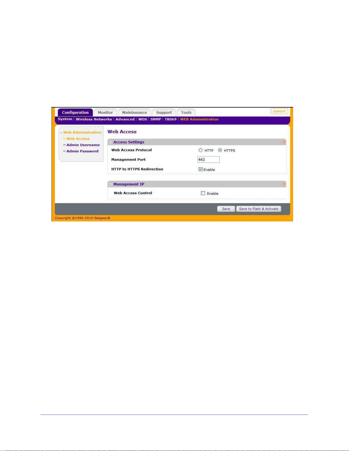
WG102-500, WGAP150 ProSafe™ 802.11g Wireless Access Point
To disable Web management:
1. Log in to the wireless access point at its default LAN address of http://192.168.0.229
with its default user name of admin and default password of password, or using
whatever LAN address, user name, and password you have chosen for the wireless
access point.
2. Select Configuration > WEB Administration > Web Administration. The Web
Administration screen displays.
Figure 4-16
3. Next to Web Admin Interface, the Enable radio button is selected by default. To disable Web
management, select the Disable radio button.
4. Click Save or Save to Flash & Activate to save your settings
Configuring L2TP Tunnel Management
An L2TP tunnel from the wireless access point to a server allows for centralized traffic
management.
To configure L2TP tunnel management:
1. Log in to the wireless access point at its default LAN address of http://192.168.0.229
with its default user name of admin and default password of password, or using
whatever LAN address, user name, and password you have chosen for the wireless
access point.
2. Select Configuration > System > L2TP Tunnel.
3. Select the L2TP Tunnel Enabled checkbox. The screen expands to let you configure the
L2TP tunnel settings (see
Figure 4-17 on page 83).
82 |
Page 83
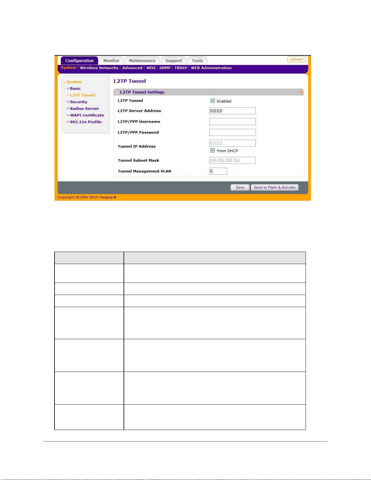
WG102-500, WGAP150 ProSafe™ 802.11g Wireless Access Point
Figure 4-17
4. Complete the L2TP tunnel fields and select the L2TP tunnel checkboxes as explained in
Table 4-8. These settings are typically provided by your Internet Service Provider (ISP).
Table 4-8. L2TP Tunnel Settings
Field Description
L2TP Server Address Enter the IP address of the server with which the wireless access point
establishes an L2TP tunnel.
L2TP/PPP Username Enter the user name to access the L2TP server.
L2TP/PPP Password Enter the password to authenticate your connection with the L2TP server.
From DHCP By default, the IP address and subnet mask for the wireless access point
are acquired from a DHCP server over the L2TP tunnel. Deselect the
From DHCP checkbox to enter the tunnel IP address and tunnel subnet
mask in the following fields.
Tunnel IP Address Enter the wireless access point’s IP address to communicate with the
L2TP server over the L2TP tunnel.
Note: This field is applicable only if the From DHCP checkbox is
deselected.
Tunnel Subnet Mask Enter the wireless access point’s subnet mask to communicate with the
L2TP server over the L2TP tunnel.
Note: This field is applicable only if the From DHCP checkbox is
deselected.
Tunnel Management VLAN Specify the VLAN ID from which Web management access is allowed over
the L2TP tunnel. The default settings is zero, which means that Web
management access is allowed from any VLAN.
| 83
Page 84

WG102-500, WGAP150 ProSafe™ 802.11g Wireless Access Point
5. Click Save or Save to Flash & Activate to save your settings.
Configuring Telnet Server Access
You can allow a remote host to establish a Telnet connection to the wireless access point
over the LAN port. The following Telnet commands are supported on the wireless access
point:
Set SSID (sets the SSID)
Set Channel (sets the channel)
Set Radio Mode (sets the radio mode to b, b/g, or g-only)
Set Data Rate (sets the data rate to auto or fixed)
Get Firmware Version (shows the firmware version)
Get Serial Number (shows the serial number)
Get Lan MAC Address (shows the LAN MAC address)
Get Wi-Fi MAC Address (shows the wireless interface MAC address)
Apply Config (Restart Connection) (re-applies the configuration)
Clear Config (clears the configuration)
Reboot (reboots the unit)
To allow Telnet access from a remote host:
1. Log in to the wireless access point at its default LAN address of http://192.168.0.229
with its default user name of admin and default password of password, or using
whatever LAN address, user name, and password you have chosen for the wireless
access point.
2. Select Configuration > System > Security. The Security screen displays (see Figure 4-18
on page 85).
84 |
Page 85
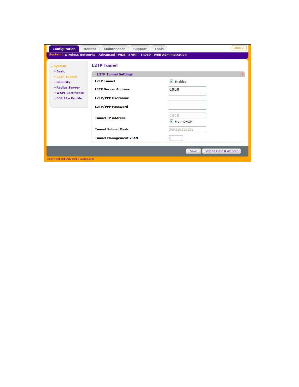
WG102-500, WGAP150 ProSafe™ 802.11g Wireless Access Point
Figure 4-18
3. Next to Telnet Server, select the Enabled checkbox. This checkbox is deselected by default.
4. Click Save or Save to Flash & Activate to save your settings.
SNMP Remote Management
SNMP forms part of the internet protocol suite as defined by the Internet Engineering Task
Force (IETF). SNMP is used in network management systems to monitor network-attached
devices for conditions that warrant administrative attention.
SNMP exposes management data in the form of variables on the managed systems, which
describe the system configuration. These variables can then be queried (and sometimes set)
by managing applications
Enable SNMP to allow SNMP network management software such as HP OpenView to
manage the wireless access point via the SNMPv1, SNMPv2, and/or SNMPv3 protocol.
Configuring SNMP Settings
To configure and enable SNMP:
1. Log in to the wireless access point at its default LAN address of http://192.168.0.229
with its default user name of admin and default password of password, or using
whatever LAN address, user name, and password you have chosen for the wireless
access point.
2. Select Configuration > SNMP > Basic. The SNMP Basic Settings screen displays (see
Figure 4-19 on page 86).
| 85
Page 86

WG102-500, WGAP150 ProSafe™ 802.11g Wireless Access Point
Figure 4-19
3. Complete the basic SNMP fields and select the basic SNMP checkboxes as explained in
Table 4-9.
Table 4-9. SNMP Basic Settings
Field Description
Server Name Assign a unique name to the SNMP server. The default name is
NETGEAR.
SNMPv1 SNMP version 1 (SNMPv1) is supported by default. Deselect the Enable
checkbox to disable support for SNMPv1.
SNMPv2 SNMP version 2 (SNMPv2) is supported by default. Deselect the Enable
checkbox to disable support for SNMPv2.
SNMPv3 SNMP version 3 (SNMPv3) is supported by default. Deselect the Enable
checkbox to disable support for SNMPv3.
SNMP Trap SNMP traps are enabled by default. Deselect the Enable checkbox to
disable SNMP traps.
SNMP Trap Receiver Name Enter the name of the device that should receive the traps that are sent
from the wireless access point.
SNMP Trap IP Address Enter the IP address of the device that should receive the traps that are
sent from the wireless access point.
4. Click Save or Save to Flash & Activate to save your settings.
Configuring SNMP Communities
To configure SNMP communities:
86 |
Page 87

WG102-500, WGAP150 ProSafe™ 802.11g Wireless Access Point
1. Log in to the wireless access point at its default LAN address of http://192.168.0.229
with its default user name of admin and default password of password, or using
whatever LAN address, user name, and password you have chosen for the wireless
access point.
2. Select Configuration > SNMP > Communities. The SNMP Communities Settings screen
displays.
Figure 4-20
3. Click the Edit hyperlink for one of the two communities in the SNMP Communities Settings
table. The Edit Communities screen displays.
Figure 4-21
| 87
Page 88

WG102-500, WGAP150 ProSafe™ 802.11g Wireless Access Point
4. Complete the SNMP community fields and select the Status checkbox as explained in
Table 4-10.
Table 4-10. SNMP Community Settings
Field Description
Community Name The community string to allow the SNMP manager to access the MIB
objects of the wireless access point. The default setting is public (for
Access Mode “Read Only”) or private (for Access Mode “Read & Write”).
IP Address The IP address of the SNMP manager that is allowed to access the MIB
objects of the wireless access point.
IP Mask The subnet masks of the SNMP manager that is allowed to access the
MIB objects of the wireless access point.
Access Mode This field cannot be changed: the setting is “Read Only” for the SNMP
community with the default name “public” and “Read & Write” for the
SNMP community with the default name “private.”
Status Select the Enable radio button to allow the community to access the MIB
objects of the wireless access point. If you want to configure but not
enable the community, select the Disable radio button.
5. Click Save or Save to Flash & Activate to save your settings.
Configuring SNMP Users
SNMPv3 allows users that are allowed to access an SNMP agent to be authenticated and
communication with the SNMP agent to be encrypted.
To configure individual SNMPv3 users and security:
1. Log in to the wireless access point at its default LAN address of http://192.168.0.229
with its default user name of admin and default password of password, or using
whatever LAN address, user name, and password you have chosen for the wireless
access point.
2. Select Configuration > SNMP > Users. The SNMP Users Settings screen displays (see
Figure 4-22 on page 89).
88 |
Page 89

WG102-500, WGAP150 ProSafe™ 802.11g Wireless Access Point
Figure 4-22
3. Take one of the following actions:
• Click the Add button to add a new SNMP user. The Edit Users screen displays (see
Figure 4-23 on page 89).
• Click the Edit hyperlink to the right of an existing user in the SNMP Users Settings
table. The Edit Users screen displays (see
Figure 4-23 on page 89).
• Click the Remove hyperlink to the right of an existing user in the SNMP Users
Settings table to delete the user.
Figure 4-23
| 89
Page 90

WG102-500, WGAP150 ProSafe™ 802.11g Wireless Access Point
4. If you selected to add or edit an SNMP user, complete the SNMP user fields and select a
Status checkbox as explained in Table 4-11.
Table 4-11. SNMP User Settings
Field Description
SNMPv3 User Name The name of the SNMPv3 user that is allowed to access the SNMP
agent that collects the MIB objects from the wireless access point.
Authentication Protocol The protocol for authenticating the SNMPv3 user. This pull-down menu
lets you select one of the following authentication protocols:
• HMAC-MD5. Hashing for Message Authentication (HMAC) algorithm
in combination with Message Digest 5 (MD5).
• HMAC-SHA. HMAC in combination with Secure Hash Algorithm
(SHA).
Authentication Password The password that an SNMPv3 user must enter to be granted access to
the SNMP agent that collects the MIB objects from the wireless access
point.
Privacy Protocol The encryption method for the communication between the SNMPv3
user and the SNMP agent that collects the MIB objects from the wireless
access point. This pull-down menu lets you select one of the following
options:
• None. No encryption method.
• CBC-DES. Cipher Block Chaining (CBC) mode to the Data
Encryption Standard (DES) algorithm.
Privacy Password The password that an SNMPv3 user must enter to allow decryption of
the MIB objects that the SNMP agent collects from the wireless access
point. This field is applicable only when you select CBC-DES as the
privacy protocol.
Status Select the Enable checkbox to allow the SNMPv3 user to access the
SNMP agent that collects the MIB objects of the wireless access point. If
you want to configure but not enable the SNMPv3 user, select the
Disable checkbox.
5. Click Save or Save to Flash & Activate to save your settings.
Configuring TR069 Operation
TR-069 feature provides secure communication between the CPE and an Auto-Configuration
Server (ACS). The CPE WAN Management Protocol defines the mechanism to control CPE
configuration, CPE firmware and other management functions into a common framework.
The following settings and options are available: Enabled, ACS Server URL, ACS Username,
ACS Password, Periodic Inform Interval
Enable/Disable - TR069 client
ACS Server URL - Defines ACS server specific URL
ACS Username - Defines ACS Username for TR069 login
90 |
Page 91

WG102-500, WGAP150 ProSafe™ 802.11g Wireless Access Point
ACS Password - Defines ACS password for TR069 login
Periodic Inform Interval - Interval for client to push information to ACS server
To configure TR-069 operation:
1. Log in to the wireless access point at its default LAN address of http://192.168.0.229
with its default user name of admin and default password of password, or using
whatever LAN address, user name, and password you have chosen for the wireless
access point.
2. Select Configuration > TR069. The TR-069 Settings screen displays.
Figure 4-24
3. Enter the Server address, user name, password, and interval to be used for TR-069
management.
4. Click Save (or Save & Activate).
Scheduling Management Tasks
You can schedule management tasks to be performed at a time that you expect that there
will be minimal network traffic. These tasks include automatically rebooting the wireless
access point and automatically letting the wireless access point select the best RF channels
to avoid a congested channels. The best RF channel selection will occur only if there are no
clients associated with the wireless access point at the time that the automatic channel
selection is scheduled.
To schedule management tasks:
1. Log in to the wireless access point at its default LAN address of http://192.168.0.229
with its default user name of admin and default password of password, or using
whatever LAN address, user name, and password you have chosen for the wireless
access point.
| 91
Page 92
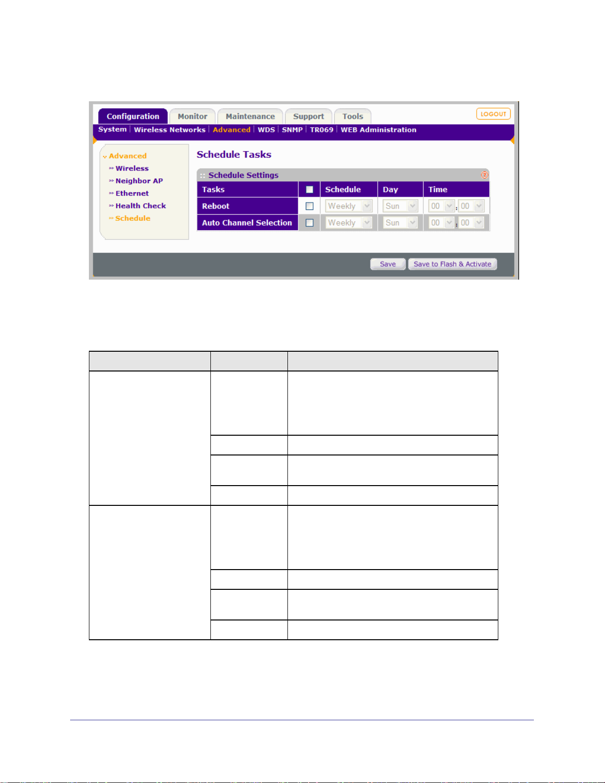
WG102-500, WGAP150 ProSafe™ 802.11g Wireless Access Point
2. Select Configuration > Advanced > Schedule. The Schedule Tasks screen displays.
Figure 4-25
3. Schedule one or both tasks for the wireless access point as explained in Table 4-12.
Table 4-12. Schedule Tasks Settings
Task Field Description
Reboot Checkbox Select the checkbox next to Reboot to enable a
previously scheduled reboot task or to configure a
reboot task.
Note: To enable and/or configure all tasks, select
the checkbox next to Tasks in the table heading.
Schedule Select Monthly, Weekly, or Daily.
Day If monthly, select the day of the month; if weekly,
select the day of the week.
Time Select the hour and minutes.
Auto Channel Selection Checkbox Select the checkbox next to Auto Channel Selection
to enable a previously scheduled channel selection
task or to configure a channel selection task.
Note: To enable and/or configure all tasks, select
the checkbox next to Tasks in the table heading.
Schedule Select Monthly, Weekly, or Daily.
Day If monthly, select the day of the month; if weekly,
select the day of the week.
Time Select the hour and minutes.
4. Click Save or Save to Flash & Activate to save your settings.
92 |
Page 93

WG102-500, WGAP150 ProSafe™ 802.11g Wireless Access Point
Accessing Online Documentation
This reference manual (also referred to as user manual) is accessible from the Web
interface.
To access the reference manual online from the Web interface:
1. Log in to the wireless access point at its default LAN address of http://192.168.0.229
with its default user name of admin and default password of password, or using
whatever LAN address, user name, and password you have chosen for the wireless
access point.
2. Select Support.
3. Click on the user manual hyperlink for the wireless access point.
| 93
Page 94

WG102-500, WGAP150 ProSafe™ 802.11g Wireless Access Point
94 |
Page 95

5.
Advanced Configuration
This chapter describes how to configure the advanced features of your wireless access
point. This chapter includes:
• Configuring Ethernet Links on this page.
• “Configuring Hotspots (Captive Portals)” on page 96
• “Configuring Advanced Wireless Settings” on page 98
• “Configuring Neighbor AP Discovery” on page 101
• “Configuring Wireless Bridging and Repeating” on page 102
Configuring Ethernet Links
The Ethernet link settings allow you to select the type of Ethernet link for the wireless access
point.
To configure Ethernet links:
5
1. Log in to the wireless access point at its default LAN address of http://192.168.0.229
with its default user name of admin and default password of password, or using
whatever LAN address, user name, and password you have chosen for the wireless
access point.
2. Select Configuration > Advanced > Ethernet. The Ethernet settings screen displays.
| 95
Page 96
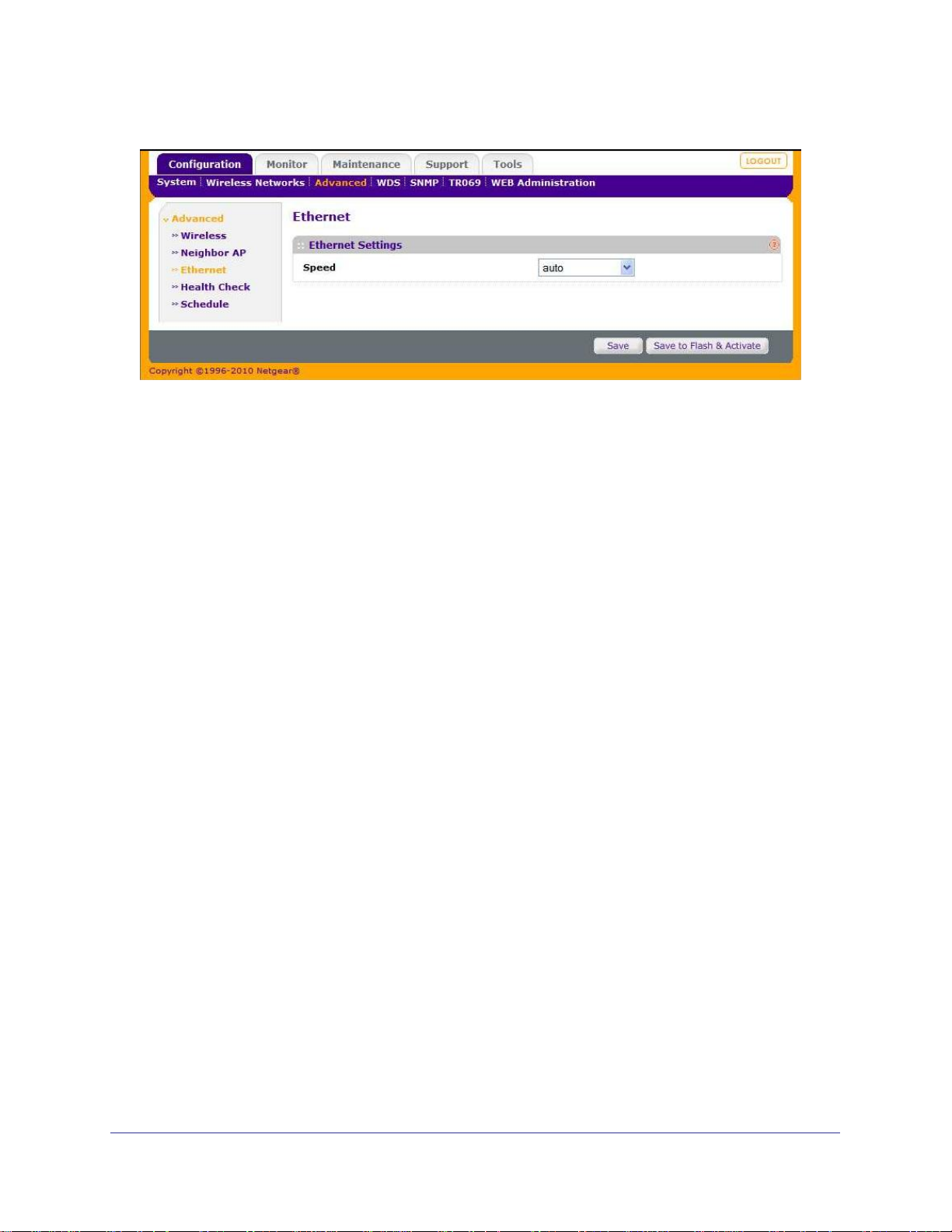
WG102-500, WGAP150 ProSafe™ 802.11g Wireless Access Point
Figure 5-1
3. From the Speed pull-down menu, select one of the following options:
• auto. Detects and sets the speed and type of the Ethernet link automatically.
• 100baseTx-FD. 100-Mbps full-duplex speed.
• 100baseTx-HD. 100-Mbps half-duplex speed.
• 10baseT-FD. 10-Mbps full-duplex speed.
• 10baseT-HD. 10-Mbps half-duplex speed.
• Manual. Lets you select from four different speeds and types:
• Click Save or Save to Flash & Activate to save your settings.
Configuring Hotspots (Captive Portals)
If you want the wireless access point to capture and redirect the first HTTP or HTTPS
request, use the Hotspot feature (also referred to as the Captive Portal feature). For example,
a hotel might want to direct all wireless connections to its server to start a billing transaction,
or an ISP might want to direct wireless connections to a login page.
To configure hotspots:
1. Log in to the wireless access point at its default LAN address of http://192.168.0.229
with its default user name of admin and default password of password, or using
whatever LAN address, user name, and password you have chosen for the wireless
access point.
2. Select Configuration > Wireless Networks. The Wireless Networks screen opens,
displaying 16 wireless security profiles (see
3. To configure hotspots for a wireless security profile, select the corresponding Edit hyperlink
to the right of the wireless security profile. The Edit Wireless Network screen opens for the
selected wireless security profile. Scroll down to the Portal Settings section.
4. Select the Captive Portal Enable checkbox. The screen expands to let you configure the
hotspot settings (see
Figure 5-2 on page 5-97).
Figure 3-2 on page 3-38).
96 |
Page 97

WG102-500, WGAP150 ProSafe™ 802.11g Wireless Access Point
Figure 5-2
5. Enter the hotspot settings as explained in Table 5-1.
Table 5-1. Hotspot (or Captive Portal) Settings
Field Description
Redirect URL Select one of the following options from the pull-down menu:
• HTTP. The URL to which the user must be redirected starts with HTTP.
• HTTPS. The URL to which the user must be redirected starts with
HTTPS.
To the right of the pull-down menu, enter the URL to which the user must be
redirected.
Authentication URL Select one of the following options from the pull-down menu:
• HTTP. The URL for user authentication starts with HTTP.
• HTTPS. The URL for user authentication starts with HTTPS.
To the right of the pull-down menu, enter the URL for user authentication.
Access Timeout The time in seconds after which the user is redirected to the Redirect URL.
The default is zero, which means that redirection is disabled and the user is
not automatically redirected to the Redirect URL.
Inactive Timeout The time in seconds after which the user must be re-authenticated. The
default is 300 seconds (5 minutes).
| 97
Page 98

WG102-500, WGAP150 ProSafe™ 802.11g Wireless Access Point
Table 5-1. Hotspot (or Captive Portal) Settings (continued)
Field Description
Pass-through IPs The IP addresses that a user can go to without being redirected to the
Redirect URL or without being authenticated, that is, the IP addresses that
form the walled garden. You can enter up to three IP addresses with their
subnet masks. The subnet masks must be entered in Classless Inter-Domain
Routing (CIDR) notation.
Authorized MAC
Addresses
Authentication Method The method to perform user authentication. The pull-down menu lets you to
The MAC addresses for which authentication and redirection are bypassed.
This option is particularly useful when wireless devices do not have browser
capability, such as wireless VoIP phones.
There are two methods to use the MAC Insertion Tool to add MAC addresses
to the Authorized MAC Addresses table:
User defined
MACs:
Connected clients: Select one or more listed MAC addresses for which
Note: To delete MAC addresses from the Authorized MAC Addresses table,
select (highlight) one or more MAC addresses in the Authorized MAC
Addresses table, then click Delete highlighted.
make one of the following selections:
Manually enter one or more MAC addresses for which
authentication and redirection must be bypassed. Then,
click <<< Add to list.
authentication and redirection must be bypassed. Then,
click <<< Add to list.
• No Authentication. This is the default setting.
• Plain Key Authentication. You must specify an authentication key.
• Shared Key Authentication. You must specify an authentication key.
• RADIUS Authentication. A RADIUS server is required (see “Configuring
RADIUS Server Settings” on page 45).
Authentication Key The authentication key for Plain Key Authentication and
Shared Key Authentication.
6. Click Save or Save to Flash & Activate to save your settings.
The Hotspot feature is now enabled and the first HTTP or HTTPS request will be
redirected to the supplied Redirect URL. For information about wireless client separation,
which is useful for hotspots and other public access situations, see
“Configuring Wireless
Client Separation” on page 58.
Configuring Advanced Wireless Settings
The advanced wireless settings normally do not need to be changed. The default advanced
wireless settings usually work well.
To change the wireless access point’s advanced wireless settings:
98 |
Page 99
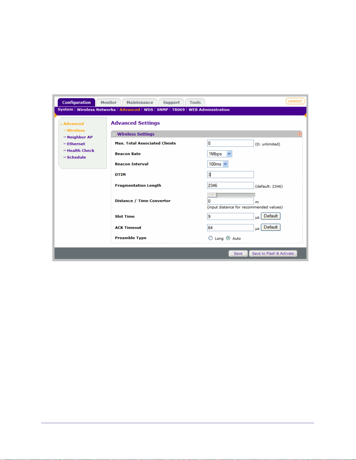
WG102-500, WGAP150 ProSafe™ 802.11g Wireless Access Point
1. Log in to the wireless access point at its default LAN address of http://192.168.0.229
with its default user name of admin and default password of password, or using
whatever LAN address, user name, and password you have chosen for the wireless
access point.
2. Select Configuration > Advanced > Wireless. The Advanced (Wireless) Settings screen
displays:
Figure 5-3
3. Specify the advanced wireless settings as explained in Table 5-2
| 99
Page 100

WG102-500, WGAP150 ProSafe™ 802.11g Wireless Access Point
4.
Click Save or Save to Flash & Activate to save your settings.
Table 5-2. Advanced Wireless Settings
Field Description
Max. Total Associated
Clients
Beacon Rate Select the beacon transmit bit rate from the pull-down menu:
Specify the total maximum number of wireless clients that are allowed to
connect to the wireless access point. The default setting is 0, which
indicates a limitless number of wireless clients.
Note: The “Configuring Advanced QoS Settings” on page 57 explains how
to specify the maximum number of wireless clients that are allowed to
connect to an individual SSID. The maximum total associated clients for
the wireless access point overrides the sum of all wireless clients that are
allowed to connect to all 16 SSIDs.
• 1Mbps. This is the default setting.
• 2Mbps.
• 5.5Mbps.
• 6Mbps.
• 11Mbps.
Beacon Interval Select the interval for each beacon transmission from the pull-down menu:
• 100ms.This is the default setting.
• 250ms.
• 500ms.
DTIM The frequency for the beacon to include a Delivery Traffic Indication
Message (DTIM) in milliseconds. The default setting is 3 milliseconds.
Fragmentation Length This is the maximum packet size that is used for fragmentation. Packets
larger than this size will be fragmented. The default is 2346.
Distance / Time Convertor Use the on-screen slider to determine the recommended values for the slot
time, ACK timeout, and CTS timeout (see below). You can also enter the
distance in meters in the field below the slider, and then click in one of the
three fields below to determine the recommended values. The default value
is 0 meters.
Slot Time The period in microseconds before packet transmission occurs from the
wireless access point. (The slot time usually equals the maximum
theoretical time for a packet to travel from the wireless access point to the
target and back.) The default setting is 9 microseconds. Click Default to
return the field to its default value.
ACK Timeout The period in microseconds that is allowed for reception of an
acknowledgement (ACK) packet by the wireless access point before the
packet retransmission occurs. The default setting is 48 microseconds. Click
Default to return the field to its default value.
Preamble Type Select one of the following radio buttons:
• Auto. A short transmit preamble provides better performance. Auto
automatically handles both long and short preambles. The default setting
is Auto.
Long. A long transmit preamble may provide a more reliable connection or
slightly longer range.
100 |
 Loading...