

Page 1
WFS709TP ProSafe Smart Wireless Switch Software Administration Manual
NETGEAR, Inc.
4500 Great America Parkway
Santa Clara, CA 95054 USA
202-10265-01
June 2007
Page 2

© 2007 by NETGEAR, Inc. All rights reserved.
Technical Support
Please refer to the support information card that shipped with your product. By registering your product at
http://www.netgear.com/register, we can provide you with faster expert technical support and timely notices of product
and software upgrades.
NETGEAR, INC. Support Information
Phone: 1-888-NETGEAR, for US & Canada only. For other countries, see your Support information card.
E-mail: support@netgear.com
North American NETGEAR
http://www.netgear.com
Trademarks
NETGEAR, the NETGEAR logo, and Auto Uplink are trademarks or registered trademarks of NETGEAR, Inc. Other
brand and product names are registered trademarks or trademarks of their respective holders. Portions of this document
are copyright Intoto, Inc.
Statement of Conditions
In the interest of improving internal design, operational function, and/or reliability, NETGEAR reserves the right to
make changes to the products described in this document without notice.
NETGEAR does not assume any liability that may occur due to the use or application of the product(s) or circuit
layout(s) described herein.
Certificate of the Manufacturer/Importer
It is hereby certified that the WFS709TP ProSafe Smart Wireless Switch has been suppressed in accordance with the
conditions set out in the BMPT-AmtsblVfg 243/1991 and Vfg 46/1992. The operation of some equipment (for example,
test transmitters) in accordance with the regulations may, however, be subject to certain restrictions. Please refer to the
notes in the operating instructions.
The Federal Office for Telecommunications Approvals has been notified of the placing of this equipment on the market
and has been granted the right to test the series for compliance with the regulations.
Bestätigung des Herstellers/Importeurs
Es wird hiermit bestätigt, daß dasWFS709TP ProSafe Smart Wireless Switch gemäß der im BMPT-AmtsblVfg 243/1991
und Vfg 46/1992 aufgeführten Bestimmungen entstört ist. Das vorschriftsmäßige Betreiben einiger Geräte (z.B.
Testsender) kann jedoch gewissen Beschränkungen unterliegen. Lesen Sie dazu bitte die Anmerkungen in der
Betriebsanleitung.
Das Bundesamt für Zulassungen in der Telekommunikation wurde davon unterrichtet, daß dieses Gerät auf den Markt
gebracht wurde und es ist berechtigt, die Serie auf die Erfüllung der Vorschriften hin zu überprüfen.
Regulatory Compliance Information
This section includes user requirements for operating this product in accordance with National laws for usage of radio
spectrum and operation of radio devices. Failure of the end user to comply with the applicable requirements may result
in unlawful operation and adverse action against the end user by the applicable National regulatory authority.
ii
v1.0, June 2007
Page 3
NOTE: This product's firmware limits operation to only the channels allowed in a particular Region or Country.
Therefore, all options described in this user's guide may not be available in your version of the product.
United States
FCC Class A
This equipment has been tested and found to comply with the limits for a Class A digital device, pursuant to Part 15 of
the FCC Rules. These limits are designed to provide rea sonable protection against harmful interference when the
equipment is operated in a commercial environment. This equipment generates, uses, and can radiate radio frequency
energy and, if not installed and used in accordance with the instruction manual, may cause harmful interfe rence to radio
communications. Operation of this equipment in a residential area is likely to cause harmful interference in which case
the user will be required to correct the interference at their own expense.
Any changes or modifications not expressly approved by the party responsible for compliance could void the user’s
authority to operate this equipment.
This product is UL Listed (UL60950).
Canada
This digital apparatus does not exceed the Class A limits for radio noise emissions from digital apparatus as set out in the
interference-causing equipment standard entitled “Digital Apparatus,” ICES-003 of the Department of Communications.
Cet appareil numérique respecte les limites de bruit s ra dioélectriques applicables aux appareils numériques de Classe A
prescrites dans la norme sur le matériel brouilleur: “Appareils Numériques,” NMB-003 édictée par le ministère des
Communications.
This product complies with CAN/CSA C22.2 No 60950 standards.
Europe
The WFS709TP ProSafe Smart Wireless Switch is compliant with the following EU Council Directives: 89/336/EEC
and LVD 73/23/EEC. Compliance is verified by testing to the following standards: EN55022 Class A, EN55024, and
EN60950.
Warning: This is a Class A product. In a domestic environment, this product may cause radio interference
in which case the user may be required to take adequate measures
Japan
This equipment is in the Class A category (information equipment to be used in commerc ial and/ or indu strial areas) and
conforms to the standards set by the Voluntary Control Council for Interference by Data Processing Equipment and
Electronic Office Machines that are aimed at preventing radio interference in commercial and/or industrial areas.
Consequently, when this equipment is used in a residential area or in an adjacent area thereto, radio interference may be
caused to equipment such as radios and TV receivers.
v1.0, June 2007
iii
Page 4
VCCI - Class A
Korea
Class A
Australia/New Zealand
This product complies with AS/NZS CISPR 22 Class A standards.
Rest of World
This product complies with CISPR 22 Class A standards
Lithium Battery Safety Notice
This product contains a lithium battery which is replaceable only by a trained technician
Caution: The lithium battery may explode if it is incorrectly replaced. A trained technician should replace the battery
with the same or equivalent type battery recommended by the manufacturer. Dispose of used batteries according to the
manufacturer’s instructions
iv
v1.0, June 2007
Page 5
European Union RoHS
Netgear products comply with the EU Restriction of Hazardous Substances Directive
2002/95/EC (RoHS). EU RoHS restricts the use of specific hazardous materials in the
manufacture of electrical and electronic equipment. Specifically, restricted materials
under the RoHS Directive are Lead (including Solder used in printed circuit
assemblies), Cadmium, Mercury, Hexavalent Chromium, and Bromine compounds of
PBB and PBDE. Some Netgear products are subject to the exemptions listed in RoHS
Directive Annex 7 (Lead in solder used in printed circuit assemblies). Products and
packaging will be marked with the "RoHS" label shown at the left indicating
conformance to this Directive.
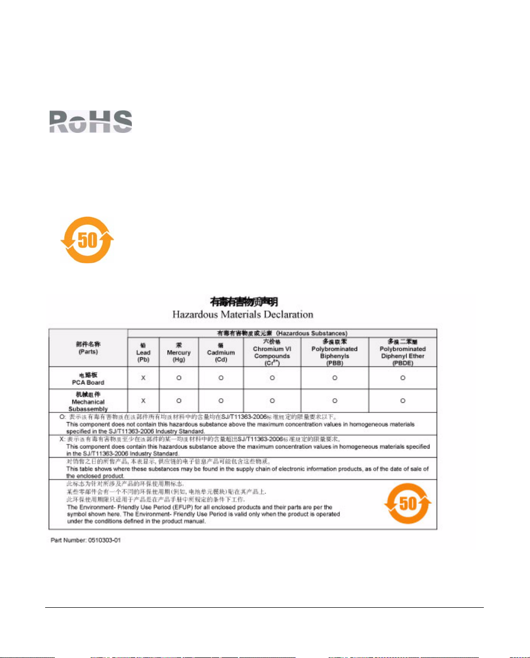
China RoHS
Netgear products comply with China environmental declaration requirements and are
labeled with the "EFUP 50" label shown at the left.
v1.0, June 2007
v
Page 6

Product and Publication Details
Model Number: WFS709TP
Publication Date: June 2007
Product Family: Wireless
Product Name: WFS709TP ProSafe Smart Wireless Switch
Home or Business Product: Business
Language: English
Publication Part Number: 202-10265-01
Publication Version Number: 1.0
vi
v1.0, June 2007
Page 7

Contents
About This Manual
Conventions, Formats, and Scope .................................................................................. xiii
How to Use This Manual ................................................................................................. xiv
How to Print this Manual.................................................................................................. xiv
Revision History................... ... ... ... .... .......................................... ..................................... xv
Chapter 1.
Overview of the WFS709TP
WFS709TP System Components ...................................................................................1-1
NETGEAR ProSafe Access Points .................................................................. ... ... ..1-1
WFS709TP ProSafe Switches .................................................................................1-5
WFS709TP Software ...............................................................................................1-7
Basic WLAN Configuration .............................................................................................1-8
Authentication ..........................................................................................................1-8
Encryption ..............................................................................................................1-10
VLAN ..................................... ................................. ................................ ................1-11
Wireless Client Access to the WLAN ............................................................................1-13
Association ................................... ................................ .................................... ...... 1-13
Authentication ........................................................................................................1-14
Client Mobility and AP Association .........................................................................1-15
Configuring and Managing the WFS709TP ..................... ............................................. 1-16
Tools ................................ ................................ ............................. .......................... 1-18
Chapter 2.
Deploying a Basic WFS709TP System
Configuration Overview ................................................... ... ... .... ... ... ... .... ........................2-1
Deployment Scenario #1 ..........................................................................................2-1
Deployment Scenario #2 ..........................................................................................2-2
Deployment Scenario #3 ..........................................................................................2-4
Configuring the WFS709TP ............................................................................................2-5
Run the Initial Setup . .... ... ... ... .... ... ... .......................................... ...............................2-6
v1.0, June 2007
vii
Page 8

WFS709TP ProSafe Smart Wireless Switch Hardware Installation Guide
Configure the Switch for the Access Points .............................................................2-8
Configure a VLAN for Network Connection ............................................................2-10
Connect the WFS709TP to the Network ................................................................2-12
Configure the Loopback for the WFS709TP ..........................................................2-13
Deploying APs ....................................... ... .... ... ... ... .......................................... .............2-14
Enable APs to Connect to the WFS709TP ............................................................2-15
Install APs ..............................................................................................................2-18
Provision APs .........................................................................................................2-18
Additional Configuration ........................... .... ... ... ... ... .......................................... .... ... ...2-20
Chapter 3.
Configuring Network Parameters
Configuring VLANs .........................................................................................................3-1
Assigning a Static Address to a VLAN .....................................................................3-2
Configuring a VLAN to Receive a Dynamic Address ...............................................3-3
Configuring Static Routes ...............................................................................................3-5
Configuring the Loopback IP Address ............................................................................3-6
Chapter 4.
RF Plan
RF Plan Overview ...........................................................................................................4-1
Before You Begin ............................................................................................................4-2
Task Ov erview .... ... ... .... ... ....................................... ... ... ... .... ... ... ... .... ........................4-2
Planning Requirements ............................................................................................4-2
Using RF Plan ................................................................................................................4-3
Building List Page ........................................ ... .......................................... ...............4-4
Building Specification Overview Page .......................... ... .... ... ... ... .... ... ... ... ... .... ... ... ..4-4
Building Dimension Page ....................................................... ... ... .... ... ... ... ...............4-5
AP Modeling Parameters Page ................................................................................4-7
AM Modeling Parameters Page ...............................................................................4-9
Planning Floors Page .............................................................................................4-10
AP Planning Page ..................................................................................................4-17
AM Planning Page .................................................................................................4-19
Exporting and Importing Files ................................................................................4-20
Locate ....................................................................................................................4-21
RF Plan Example ..........................................................................................................4-22
Sample Building .....................................................................................................4-22
viii Contents
v1.0, June 2007
Page 9

WFS709TP ProSafe Smart Wireless Switch Hardware Installation Guide
Create a Building ....................................................................................................4-23
Model the Access Points .... ... .... ... ... ... .... ... .............................................................4-24
Model the Air Monitors ................. ... ... .... ... ... ... ... .... ... .......................................... ...4-25
Add and Edit a Floor ..............................................................................................4-25
Defining Areas ........................................................................................................4-26
Running the AP Plan ..............................................................................................4-29
Running the AM Plan .............................................................................................4-30
Chapter 5.
Configuring WLANS
Before You Begin ............................................................................................................5-1
Determine the Authentication Method ....................................... ............................... 5-2
Determine the Default VLAN ....................................................................................5-4
Basic WLAN Configuration in the Browser Interface ...................................................... 5-4
Example Configuration .............................................................................................5-7
Advanced WLAN Configuration in the Browser Interface .......................... ..................... 5-9
Configuring Global Parameters ................................................................................5-9
Configuring Location-Specific Parameters .............................................................5-10
Add or Modify SSIDs ..............................................................................................5-10
Configure AP Information .......................................................................................5-12
Configuring Radio Settings ....................................................................................5-14
Example Configuration ...........................................................................................5-17
IntelliFi RF Management ..............................................................................................5-19
Channel Setting ......................................................................................................5-19
Power Setting .........................................................................................................5-19
Advantages of Using IRM ......................................... ... ... .... ... ... ... .... ... ... ... ... .... ... ...5-19
Configuring IRM .....................................................................................................5-20
Chapter 6.
Configuring AAA Servers
Configuring an External RADIUS Server ........................................................................6-1
Adding Users to the Internal Database ...........................................................................6-3
Configuring Authentication Timers ................................................ ...... ....... ...... ....... ...... ..6-4
Chapter 7.
Configuring 802.1x Authentication
802.1x Authentication .....................................................................................................7-1
Authentication with a RADIUS Server ......................................................................7-2
Contents ix
v1.0, June 2007
Page 10

WFS709TP ProSafe Smart Wireless Switch Hardware Installation Guide
Authentication Terminated on WFS709TP ................... ... .... ... ... ... .... ... ... ... ... .... ... ... ..7-3
Configuring 802.1x Authentication ..................................................................................7-4
802.1x Authentication Page .....................................................................................7-5
Advanced Configuration Options for 802.1x ...................................................................7-6
Chapter 8.
Configuring the Captive Portal
Overview of Captive Portal Functions ............................................................................8-1
Configuring Captive Portal ..............................................................................................8-2
Configuring Advanced Captive Portal Options ...............................................................8-3
Configuring the AAA Server for Captive Portal ...............................................................8-5
Changing the Protocol to HTTP ...............................................................................8-5
Personalizing the Captive Portal Page ...........................................................................8-6
Chapter 9.
Configuring MAC-Based Authentication
Configuring the WFS709TP ............................................................................................9-1
Configuring Users ...........................................................................................................9-2
Chapter 10.
Adding Local WFS709TPs
Moving to a Multi-Switch Environment .........................................................................10-1
Configuring Local WFS709TPs ....................................................................................10-2
Configuring the Local WFS709TP ..........................................................................10-2
Configuring L2/L3 Settings .....................................................................................10-2
Configuring Trusted Ports ......................................................................................10-3
Configuring APs .....................................................................................................10-3
Rebooting APs .......................................................................................................10-4
Chapter 11.
Configuring Redundancy
Virtual Router Redundancy Protocol ............................................................................11-1
Redundancy Configuration ...........................................................................................11-1
Configuring Local WFS709TP Redundancy ..........................................................11-2
Master WFS709TP Redundancy ...........................................................................11-4
Master-Local WFS709TP Redundancy ..................................................................11-5
Chapter 12.
Configuring Wireless Intrusion Protection
Rogue/Interfering AP Detection ....................................................................................12-1
Enabling AP Learning ............................................................................................12-2
x Contents
v1.0, June 2007
Page 11

WFS709TP ProSafe Smart Wireless Switch Hardware Installation Guide
Classifying APs ......................................................................................................12-2
Configuring Rogue AP Detection ...........................................................................12-4
Misconfigured AP Detection .........................................................................................12-5
Configuring Misconfigured AP Protection ..............................................................12-5
Chapter 13.
Configuring Management Utilities
Configuring Management Users ...................................................................................13-1
Configuring SNMP ........................................................................................................13-2
SNMP for the WFS709TP ......................................................................................13-2
SNMP for Access Points ........................................................................................13-4
SNMP Traps ...........................................................................................................13-9
Configuring Logging .............................................................................................13-12
Creating Guest Accounts ............................................................................................13-14
Managing Files on the WFS709TP .............................................................................13-16
Managing Image Files ........ ... .... ... ... .......................................... ... .... ... ... ... ... .... ... .13-17
Backing Up and Restoring the Flash File System ..................... ........................... 13-17
Copying Log Files ................................................................................................13-18
Copying Other Files .............................................................................................13-18
Installing a Server Certificate ......................................................................................13-19
Chapter 14.
Configuring WFS709TP for Voice
Voice over IP Proxy ARP ....................... ... .... ... .......................................... ... ... ... ..........14-1
Battery Boost ................................................................................................................14-2
Limiting the Number of Active Voice Calls ....................... ... ... .... ... ... ... .... ... ...................14-3
WPA Fast Handover .....................................................................................................14-4
Appendix A.
Configuring DHCP with Vendor-Specific Options
Overview ................................... ................ ................ ................. ................ ................ .... A-1
Windows-Based DHCP Servers .................................................................................... A-2
Configuring Option 60 ............................................................................................. A-2
Configuring Option 43 ............................................................................................. A-3
Linux DHCP Servers ..................................................................................................... A-4
Appendix B.
Windows Client Example Configuration for 802.1x
Window XP Wireless Client Example Configuration .............. .................... ................... . B-1
Contents xi
v1.0, June 2007
Page 12

WFS709TP ProSafe Smart Wireless Switch Hardware Installation Guide
Appendix C.
Internal Captive Portal
Creating a New Internal Web Page .................................... ... .... ... ... ... .... ... ... ... ... .... .......C-1
Basic HTML Example .............................................................................................. C-3
Installing a New Captive Portal Page ........... ... ... ... ... .... ... ... ... .... ... ... ... .... ... ... ... ... .... ... ... . C-4
Displaying Authentication Error Message ......................................................................C-4
Language Customization ............................................................................................... C-6
Customizing the Welcome Page ................................................................................. C-12
Customizing the Pop-Up Box ...................................................................................... C-14
Customizing the Logged Out Box ................................................................................C-15
Appendix D.
Related Documents
Index 1
xii Contents
v1.0, June 2007
Page 13
About This Manual
The WFS709TP ProSafe™ Smart Wireless Switch Software Administration Manual describes how
to deploy and configure the WFS709TP ProSafe Smart Wireless Switch. It also includes
instructions for and examples of commonly used wireless LAN (WLAN) switch configurations
such as Virtual Private Networks (VPNs) and redundancy.
Conventions, Formats, and Scope
The conventions, formats, and scope of this manual are described in the following paragraphs:
• Typographical Conventions. This manual uses the following typographical conventions:
Italic Emphasis, books, CDs, file and server names, extensions
Bold User input, IP addresses, GUI screen text
Fixed Command prompt, CLI text, code
italic URL links
• Formats. This manual uses the following formats to highlight special messages:
Note: This format is used to highlight information of importance or special interest.
Tip: This format is used to highlight a procedure that will save time or resources.
Warning: Ignoring this type of note may result in a malfunction or damage to the
equipment.
v1.0, June 2007
xiii
Page 14
WFS709TP ProSafe Smart Wireless Switch Software Administration Manual
Danger: This is a safety warning. Failure to take heed of this notice may result in
personal injury or death.
• Scope. This manual is written for the WFS709TP according to these specifications:
Product Version WFS709TP ProSafe Smart Wireless Switch
Manual Publication Date June 2007
For more information about network amd wireless technologies, see the links to the NETGEAR
website in Appendix D, “Related Documents”.
Note: Product updates are available on the NETGEAR, Inc. website at
http://www.netgear.com/support.
How to Use This Manual
The HTML version of this manual includes the following:
• Buttons, and , for browsing forwards or backwards through the manual one page
at a time
• A button that displays the table of contents and an button. Double-click on a
link in the table of contents or index to navigate directly to where the topic is described in the
manual
• A button to access the full NETGEAR, Inc. online knowledge base for the product
model
• Links to PDF versions of the full manual and individual chapters
How to Print this Manual
To print this manual, choose one of the following options:
• Printing a Page from HTML. Each page in the HTML version of the manual is dedicated to
a major topic. Select File > Print from the browser menu to print the page contents.
xiv About This Manual
v1.0, June 2007
Page 15
WFS709TP ProSafe Smart Wireless Switch Software Administration Manual
• Printing from PDF. Your computer must have the free Adobe Acrobat reader installed in
order to view and print PDF files. The Acrobat reader is available on the Adobe website at
http://www.adobe.com.
– Printing a PDF Chapter. Use the PDF of This Chapter link at the top left of any page.
• Click the PDF of This Chapter link at the top left of any page in the chapter you want
to print. The PDF version of the chapter you were viewing opens in a browser
window.
• Click the print icon in the upper left of your browser window.
– Printing a PDF version of the Complete Manual. Use the Complete PDF Manual link
at the top left of any page.
• Click the Complete PDF Manual link at the top left of any page in the manual. The
PDF version of the complete manual opens in a browser window.
• Click the print icon in the upper left of your browser window.
Tip: If your printer supports printing two pages on a single sheet of paper, you can
save paper and printer ink by selecting this feature.
Revision History
Part Number
202-10265-01 1.0 June 2007 Initial NETGEAR release.
About This Manual xv
Version
Number
Date Description
v1.0, June 2007
Page 16

WFS709TP ProSafe Smart Wireless Switch Software Administration Manual
xvi About This Manual
v1.0, June 2007
Page 17

Chapter 1
Overview of the WFS709TP
The WFS709TP ProSafe Smart Wireless Switch is a full-featured wireless switch that centrally
manages NETGEAR Light access points, delivering integrated wireless mobility, security, and
converged services for both wired and wireless users.
This chapter describes the components and features of the WFS709TP ProSafe Smart Wireless
Switch, in the following topics:
• “WFS709TP System Components” on page 1-1
• “Basic WLAN Configuration” on page 1-8
• “Wireless Client Access to the WLAN” on page 1-13
• “Configuring and Managing the WFS709TP” on page 1-16
WFS709TP System Components
The WFS709TP ProSafe Smart Wireless Switch system consists of the following components:
• “NETGEAR ProSafe Access Points” on page 1-1
• “WFS709TP ProSafe Switches” on page 1-5
• “WFS709TP Software” on page 1-7
The following sections describe each of these components.
NETGEAR ProSafe Access Points
The NETGEAR ProSafe WAGL102 and ProSafe WGL102 access points (APs) are designed for
the WFS709TP, and provide the best features and easiest integration. Several other NETGEAR
access point products can also be repurposed to work with the WFS709TP. Refer to the
NETGEAR support site for a list of which NETGEAR APs can be repurposed, and for instructions
on how to do so.
An AP broadcasts its configured service set identifier (SSID), which corresponds to a specific
wireless local area network (WLAN). Wireless clients discover APs by listening for broadcast
beacons or by sending active probes to search for APs with a specific SSID.
1-1
v1.0, June 2007
Page 18

WFS709TP ProSafe Smart Wireless Switch Software Administration Manual
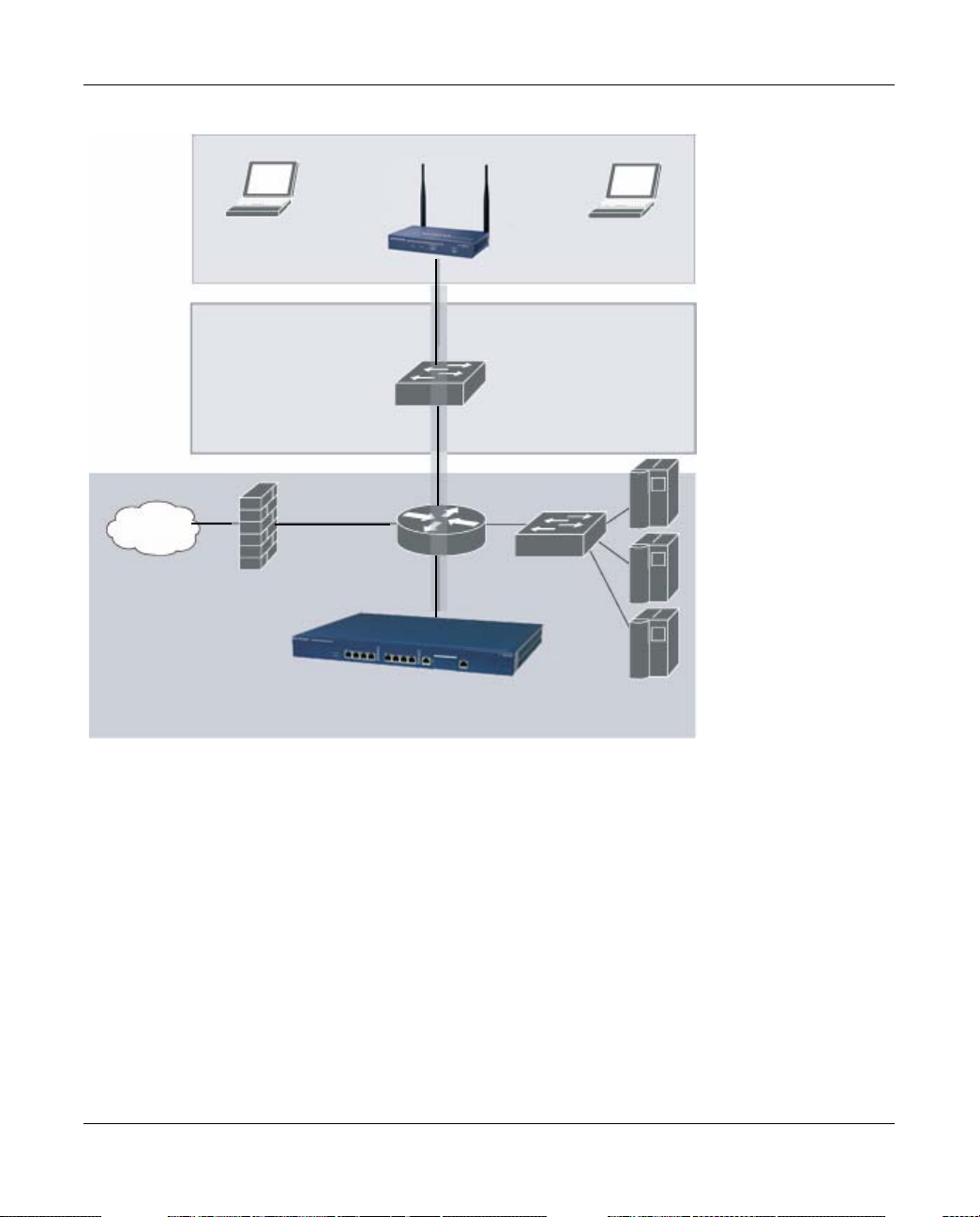
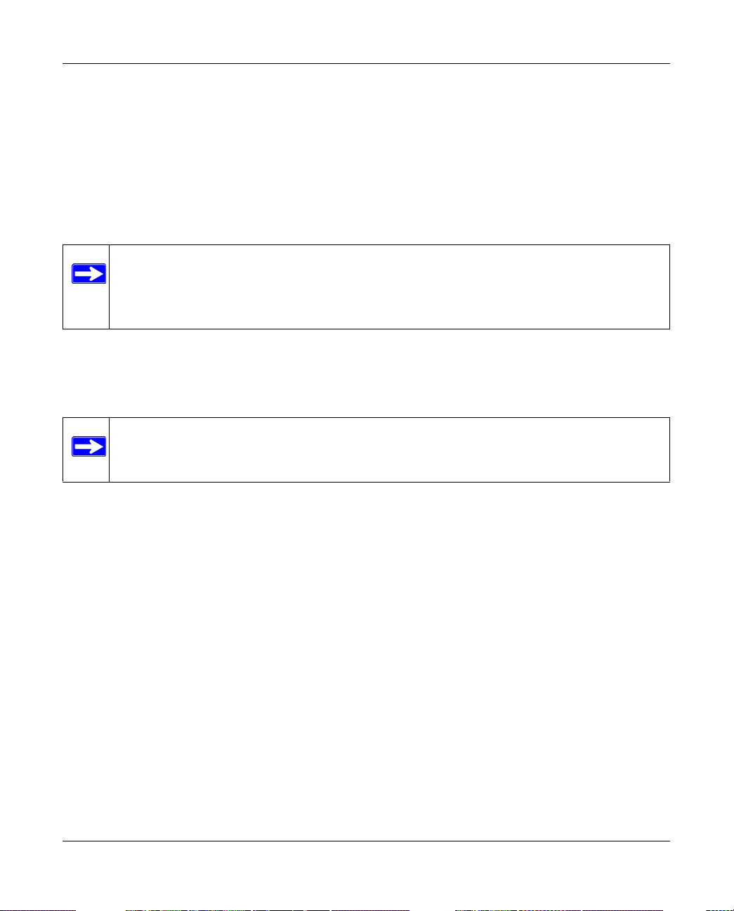
You can connect an AP to a WFS709TP either directly with an Ethernet cable or remotely through
an IP network. Figure 1-1 shows two APs connected to an WFS709TP. One AP is connected to a
switch in the wiring closet that is connected to a router in the data center where the WFS709TP is
located. The Ethernet port on the other AP is cabled directly to a port on the WFS709TP.
Floor
Wiring
closet
Data center
Internet
Netgear AP
connected
through an IP
network
Netgear AP connected
WFS709TP
with an Ethernet cable
Figure 1-1
Access points used with the WFS709TP are Light APs, which means their primary function is to
receive and transmit wireless RF signals; other WLAN processing is left to the WFS709TP itself.
When powered on, an AP locates its host switch through a variety of methods, including the Aruba
Discovery Protocol (ADP), Domain Name Service (DNS), or D ynamic Host Configuration
1-2 Overview of the WFS709TP
v1.0, June 2007
Page 19

WFS709TP ProSafe Smart Wireless Switch Software Administration Manual
Protocol (DHCP). Once an AP locates its host switch, it automatically builds a secure Generic
Routing Encapsulation (GRE) tunnel to it (Figure 1-2). The AP then downloads its firmware and
configuration from the switch through the tunnel.
Netgear AP
Floor
GRE tunnel
Wiring
closet
Internet
GRE
tunnel
Data center
Figure 1-2
WFS709TP
Client traffic received by the AP is immediately sent through the tunnel to the host WFS709TP
(Figure 1-3), which performs packet processing such as encryption and decryption, authentication,
and policy enforcement
Overview of the WFS709TP 1-3
v1.0, June 2007
Page 20
WFS709TP ProSafe Smart Wireless Switch Software Administration Manual
.
Wireless clients
Floor
Netgear AP
Wiring
closet
Internet
WFS709TP
Data center
Figure 1-3
Automatic RF Channel and Power Settings
IntelliFi RF Management (IRM) is a radio frequency (RF) resource allocation algorithm that you
can enable and configure in the WFS709TP system. When IRM is enabled, each AP can determine
the optimum channel selection and transmitter power setting to minimize interference and
maximize coverage and throughput. The APs scan for better channels at periodic intervals and
report information to the WFS709TP. The WFS709TP analyzes reports from all APs and
coordinates changes, resulting in a higher-performance RF environment.
If an AP fails for any reason, the system’ s self-healing mechanism automatically ensures coverage
for wireless users. The WFS709TP detects the failed AP and instructs neighboring APs to increase
power levels to compensate.
1-4 Overview of the WFS709TP
v1.0, June 2007
Page 21

WFS709TP ProSafe Smart Wireless Switch Software Administration Manual
You can also enable WFS709TPs to detect coverage holes, or areas where a good RF signal is not
adequately reaching wireless clients.
RF Monitoring
An AP can function as either a dedicated or shared Air Monitor (AM) to monitor the RF spectrum
to detect intrusions, denial of service (DoS) attacks, and other vulnerabilities. A dedicated AM
performs monitoring functions exclusively and does not service wireless clients or advertise
SSIDs. A shared AM performs monitoring functions in addition to servicing wireless clients.
Every AP automatically monitors the channel on which it services wireless clients. You can
configure the AP to perform off-channel scanning, where the AP spends brief time intervals
scanning other channels. However, the more clients an AP services, the less time it has to perform
off-channel scanning. If air monitoring functions are critical to your network, designate a few APs
as dedicated AMs.
You can configure dedicated AMs to perform the following functions:
• Detect, locate, and disable rogue APs (APs that are not authorized or sanctioned by network
administrators)
• Detect and disable ad-hoc networks
• Detect and disable honeypot APs
• Detect wireless bridges
• Capture remote packets
If you only need air monitoring functions periodically, you can configure APs to operate
temporarily as AMs. You can also configure dedicated AMs to automatically convert into APs if
an AP failure occurs or when there is a high level of traffic on the network.
WFS709TP ProSafe Switches
All APs are connected either directly or remotely through an IP network to the WFS709TP
ProSafe Smart Wireless Switch. The WFS709TP is an enterprise-class switch that bridges wireless
client traffic to and from traditional wired networks and performs high-speed Layer 2 or Layer 3
packet forwarding between Ethernet ports. While APs provide radio services only, the WFS709TP
performs upper-layer media access control (MAC) processing, such as encryption and
authentication, as well as centralized configuration and management of SSIDs and RF
characteristics for the APs. This allows you to deploy APs with little or no physical change to an
existing wired infrastructure.
Overview of the WFS709TP 1-5
v1.0, June 2007
Page 22
WFS709TP ProSafe Smart Wireless Switch Software Administration Manual
WFS709TP switches provide 10/100 Mbps Fast Ethernet, IEEE 802.3af-compliant ports that can
provide Power over Ethernet (PoE) to directly connected APs. When you connect a PoE-capable
port on the WFS709TP to a PoE-compatible device such as an AP, the port automatically detects
the device and provides operating power through the connected Ethernet cable. This allows APs to
be installed in areas where electrical outlets are unavailable, undesirable, or not permitted, such as
in the plenum or in air-handling spaces.
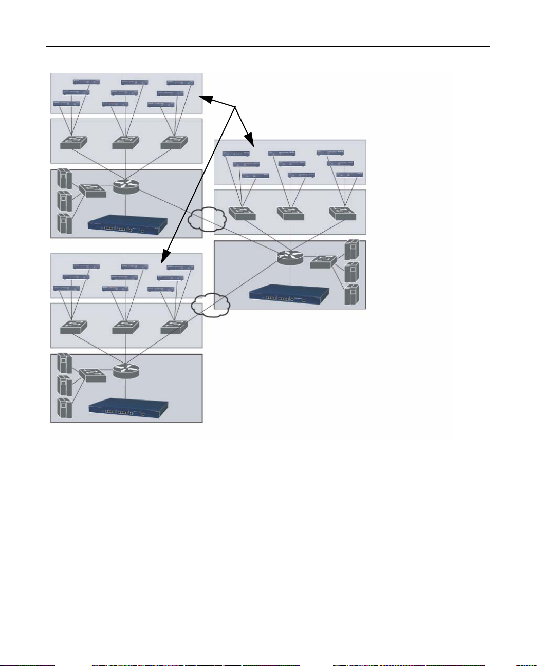
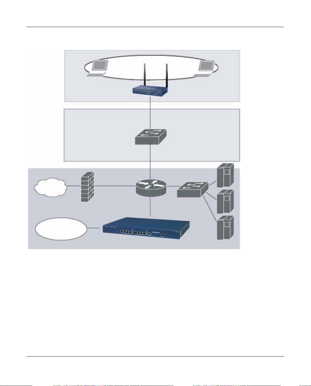
At least one WFS709TP is the master switch while non-master switches are referred to as local
switches (Figure 1-4). A master WFS709TP offers a single point of configuration that is
automatically replicated from the master to local WFS709TPs throughout the network.
Local WFS709TPs offer local points of traffic aggregation and management for APs and services.
A local WFS709TP can perform any supported function (for example , WLAN m anagement or
policy enforcement). However, these services are always configured on the master WFS709TP and
are “pushed” to specified local WFS709TPs.
An AP obtains its firmware image and configuration from a master switch; it can also be instructed
by a master switch to obtain its software from a local switch.
Note: For information about configuring the switch for master or local status, see the
“Run the Initial Setup” on page 2-6.
1-6 Overview of the WFS709TP
v1.0, June 2007
Page 23
WFS709TP ProSafe Smart Wireless Switch Software Administration Manual
.
NETGEAR Wireless APs
Local WFS709TP
Master WFS709TP
Local WFS709TP
Figure 1-4
Your network can include one master WFS709TP, one or more backup master WFS709TPs, and
any number of local WFS709TPs. Master WFS709TPs do not share information with each other,
so APs that share roaming tables, security policies, and other configurations should be managed by
the same master WFS709TP.
WFS709TP Software
The WFS709TP ProSafe Smart Wireless Switch software is a suite of mobility applications that
runs on all WFS709TPs and allows you to configure and manage the wireless and mobile user
environment.
Overview of the WFS709TP 1-7
v1.0, June 2007
Page 24

WFS709TP ProSafe Smart Wireless Switch Software Administration Manual
The base configuration software includes the following functions:
• Centralized configuration and management of APs
• Wireless client authentication to an external authentication ser ver or to the WFS709TP’s local
database
•Encryption
• Mobility with fast roaming
• RF management and analysis tools
Basic WLAN Configuration
You have a wide variety of options for authentication, encryption, acc ess management, and user
rights when you configure a WLAN in a WFS709TP system. However, you must configure the
following basic elements:
• An SSID that uniquely identifies the WLAN
• Layer 2 authentication to protect against unauthorized access to the WLAN
• Layer 2 encryption to ensure the privacy and confidentiality of the data transmitted to and
from the network
• A user role and virtual local area network (VLAN) for the authenticated client
This section describes authentication, encryption, and VLAN configuration in the WFS709TP
system.
Authentication
A user must authenticate to the system in order to access WLAN resources. There are several types
of Layer 2 security mechanisms allowed by the IEEE 802.11 standard that you can employ,
including those that require an external RADIUS authentication server.
• None (also called open system authentication). This is the default authentication protocol. The
client’s identity, in the form of the Media Access Control (MAC) address of the wireless
adapter in the wireless client, is passed to the WFS709TP. Essentially, any client requesting
access to the WLAN is authenticated.
1-8 Overview of the WFS709TP
v1.0, June 2007
Page 25
WFS709TP ProSafe Smart Wireless Switch Software Administration Manual
• IEEE 802.1x. The IEEE 802.1x authentication standard allows for the use of keys that are
dynamically generated on a per-user basic (as opposed to a static key that is the same on all
devices in the network).
Note: The 802.1x standard requires the use of a RADIUS authentication server. Most
Lightweight Directory Access Protocol (LDAP) servers do not support 802.1x.
With 802.1x authentication, a supplicant is the wireless client that wants to gain access to the
network and the device that communicates with both the supplicant and the authentication
server is the authenticator. In this system, the WFS709TP is the 802.1x authenticator, relaying
authentication requests between the authentication server and the supplicant.
Note: During the authentication process, the supplicant (the wireless client) and the
RADIUS authentication server negotiate the type of Extensible Authentication
Protocol (EAP) they will use for the authentication transaction. The EAP type
is completely transparent to the WFS709TP and has no impact on its
configuration.
• Wi-Fi Protected Access (WPA). WPA implements most of the IEEE 802.11i standard. It is
designed for use with an 802.1x authentication server (the Wi-Fi Alliance refers to this mode
as WPA-Enterprise). WPA uses the Temporal Key Integrity Protocol (TKIP) to dynamically
change keys and RC4 stream cipher to encrypt data.
• WPA in pre-shared key (PSK) mode (WPA-PSK). With WPA-PSK, all clients use the same
key (the Wi-Fi Alliance refers to this mode as WPA-Personal).
Note: In PSK mode, users must enter a passphrase 8–63 characters in length to access
the network. PSK is intended for home and small office networks where
operating an 802.1x authentication server is not practical
• WPA2. WPA2 implements the full IEEE 802.11i standard. In addition to WPA features,
WPA2 provides Counter Mode with Cipher Blocking Chaining Message Authentication Code
Protocol (CCMP) for encryption that uses the Advanced Encryption Standard (AES)
algorithm. The Wi-Fi Alliance refers to this mode as WPA2-Enterprise.
• WPA2-PSK. WPA2-PSK is WPA2 used in PSK mode, where all clients use the same key. The
Wi-Fi Alliance refers to this mode as WPA2-Personal.
Overview of the WFS709TP 1-9
v1.0, June 2007
Page 26
WFS709TP ProSafe Smart Wireless Switch Software Administration Manual
Encryption
The Layer 2 encryption option you can select depends upon the authentication method chosen.
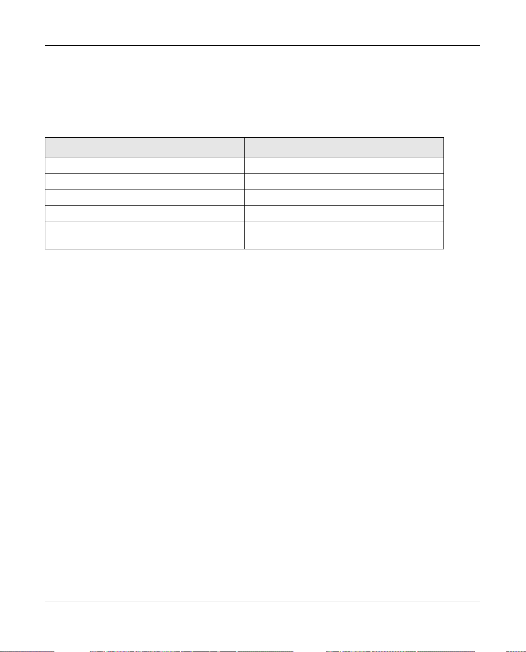
Table 1-1 lists the authentication methods available, with their corresponding encryption options.
Table 1-1. Encryption Options by Authentication Method
Authentication Method Encryption Option
None Null or Static WEP
802.1x Dynamic WEP
WPA or WPA-PSK only TKIP
WPA2 or WPA2-PSK only AES
Combination of WP A or WPA-PSK and WPA2 or
WPA2-PSK
You can configure the following data encryption options for the WLAN:
• Null. No encryption is used and packets passing between the wireless client and WFS709TP
are in clear text.
• Wired Equivalent Protocol (WEP). Defined by the original IEEE 802.11 standard, WEP
uses the RC4 stream cipher with 40-bit and 128-bit encryption keys. The management and
distribution of WEP keys is performed outside of the 802.11 protocol. There are two forms of
WEP keys:
Mixed TKIP/AES
– Static WEP requires you to manually enter the key for each client and on the WFS709TP.
– Dynamic WEP allows the keys to be automatically derived for each client for a specific
authentication method during the authentication process. Dynamic WEP requires 802.1x
authentication.
• Temporal Key Integrity Protocol (TKIP). TKIP ensures that the encryption key is changed
for every data packet. You specify TKIP encryption for WPA and WPA-PSK authentication.
• Advanced Encryption Standard (AES). AES is an encryption cipher that uses the Countermode CBC-MAC (Cipher Block Chaining-Message Authentication Code) Protocol (CCMP)
mandated by the IEEE 802.11i standard. AES-CCMP is specifically designed for IEEE 802.11
encryption and encrypts parts of the 802.11 MAC headers as well as the data payload. You can
specify AES-CCMP encryption with WPA2 or WPA2-PSK authentication.
• Mixed TKIP/AES-CCM. This option allows the WFS709TP to use TKIP encryption with
WPA or WPA-PSK clients and use AES encryption with WPA2 or WPA2-PSK clients. Mixed
TKIP/AES-CCM allows you to deploy the system in environments containing existing
WLANs that use different authen tication and encryption methods.
1-10 Overview of the WFS709TP
v1.0, June 2007
Page 27
WFS709TP ProSafe Smart Wireless Switch Software Administration Manual
VLAN
Each authenticated user is placed into a VLAN, which determines the user’s DHCP server, IP
address, and Layer 2 connection. While you could place all authenticated wireless users into a
single VLAN, the system allows you to group wireless users into separate VLANs. This enables
you to differentiate groups of wireless users and their access to network resources. For example,
you might place authorized employee users into one VLAN and itinerant users, such as contractors
or guests, into a separate VLAN.
Note: You create the VLANs for wireless users only on the WFS709TP. You do not need
to create the VLANs anywhere else on your network. Because wireless clients are
tunneled to the WFS709TP, it appears to the rest of the network as if the clients
were directly connected to the WFS709TP.
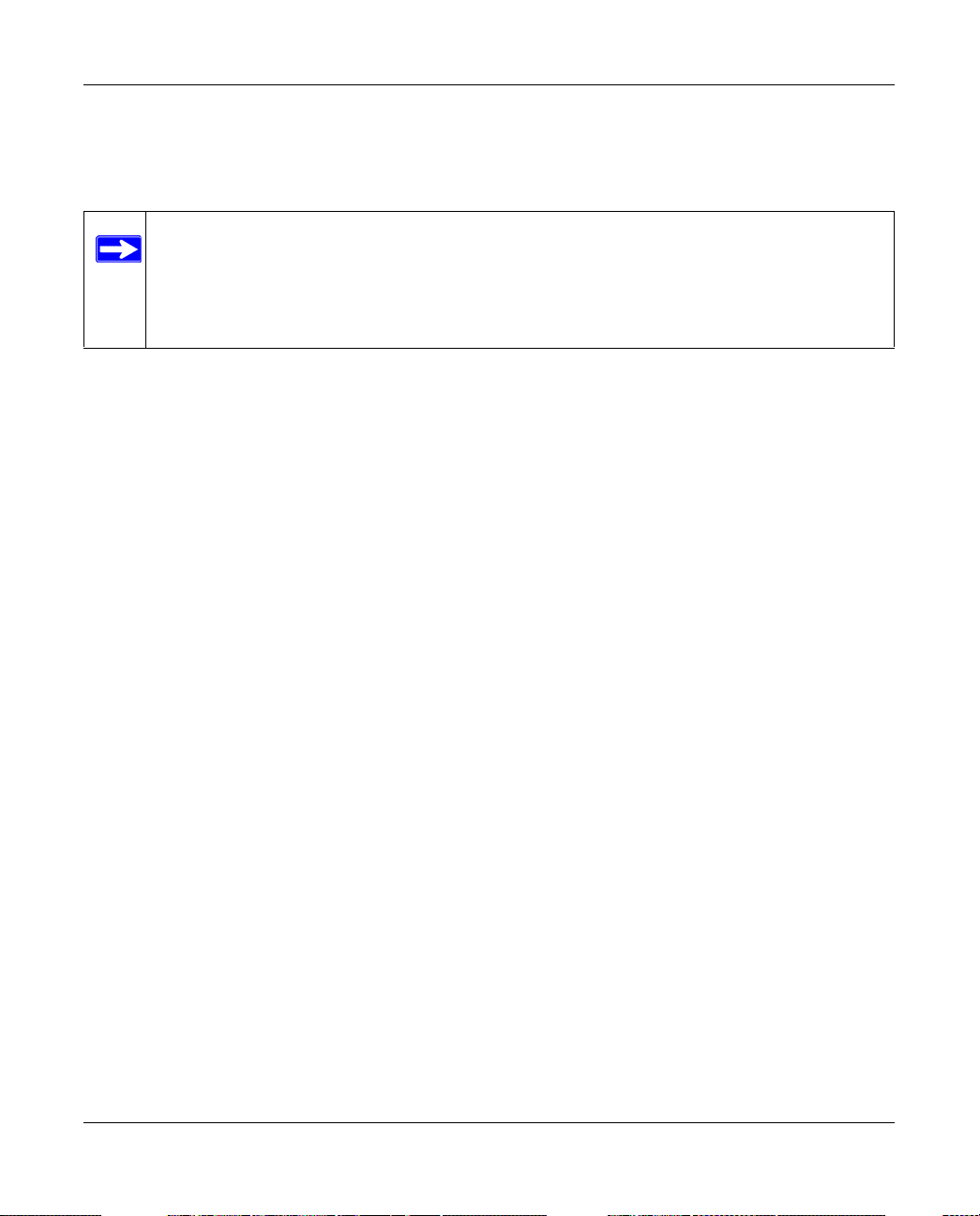
For example, in the topology shown in Figure 1-5, authenticated wireless users are placed on
VLAN 20. You configure VLAN 20 only on the WFS709TP; you do not need to configure VLAN
20 on any other device in the network.
Note: To allow data to be routed to VLAN 20, you must configure a static route to VLAN
20 on an upstream router in the wired network
Overview of the WFS709TP 1-11
v1.0, June 2007
Page 28
WFS709TP ProSafe Smart Wireless Switch Software Administration Manual
.
VLAN 20
Floor
Netgear AP
Wiring
closet
Internet
VLAN 20
Data center
Figure 1-5
WFS709TP
A user is assigned to a VLAN by one of several methods, and there is an order of precedence to
these methods.The methods for assignment of VLANs are (from lowest to highest precedence):
1. The VLAN is configured for the AP location.
2. The VLAN is derived from rules based on user attributes SSID, BSSID (Basic Service Set
Identifier), user MAC, location, and encryption type. W ithin the set of possible user -derivation
rules, a rule that derives a specific VLAN takes precedence over a rule that derives a user role
that may have a VLAN configured for it.
3. The VLAN is configured for a default role for an authentication method, such as 802.1x or
VPN.
1-12 Overview of the WFS709TP
v1.0, June 2007
Page 29

WFS709TP ProSafe Smart Wireless Switch Software Administration Manual
4. The VLAN is derived from attributes returned by the authentication server (server-derived
rule). Within a set of server-derived rules, a rule that derives a specific VLAN takes
precedence over a rule that derives a user role that may have a VLAN configured for it.
5. The VLAN is derived from Microsoft Tunnel attributes (Tunnel-Type, Tunnel Medium Type,
and Tunnel Private Group ID). All three attributes must be present. This does not require any
server-derived rule.
6. The VLAN is derived from NETGEAR vendor-specific attributes (VSAs) for RADIUS server
authentication. This does not require any server-derived rule.
If a NETGEAR VSA is present, it overrides any previous VLAN assignment.
Wireless Client Access to the WLAN
Wireless clients communicate through a WLAN with the wired network and other wireless clients
in a WFS709TP system. There are two phases to the process by which a wireless client gains
access to a WLAN:
1. Association of the radio network interface card (NIC) in the PC with an AP, as described by
the IEEE 802.11 standard. This association allows data link (Layer 2) connectivity.
2. Authentication of the client/user before network access is allowed.
Association
APs send out beacons that contain the SSIDs of specific WLANs; the user can select the network
they want to join. Wireless clients can also send out probes to locate a WLAN within range or to
locate a specific SSID, and APs within range of the client respond. Along with the SSID, an AP
also sends out the following information:
• Data rates supported by the WLAN. Clients can determine which WLAN to associate with
based on the supported data rate.
• WLAN requirements for the client. For example, clients may need to use TKIP for encrypting
data transmitted on the WLAN.
Overview of the WFS709TP 1-13
v1.0, June 2007
Page 30
WFS709TP ProSafe Smart Wireless Switch Software Administration Manual
The client determines which AP is best for connecting to the WLAN and attempts to associate with
it. During the association exchange, the client and WFS709TP negotiate the data rate,
authentication method, and other options.
Note: Because an AP connected to a WFS709TP is a Thin AP, all wireless traffic it
receives is immediately sent through a GRE tunnel to the WFS709TP. The
WFS709TP responds to client requests and communicates with an authentication
server on behalf of the client. Therefore, the client authentication and association
processes occur between the wireless client and the WFS709TP.
Authentication
Authentication provides a way to identify a user and provide appropriate access to the network for
that user. One or more authentication methods may be used, ranging from secure authentication
methods such as 802.1x and captive portal to less secure methods such as MAC address
authentication.
802.1x Authentication
802.1x is an IEEE standard used for authenticating clients on any IEEE 802 network. It is an open
authentication framework, allowing multiple authentication protocols to operate within the
framework. 802.1x operates as a Layer 2 protocol. Successful 802.1x authentication must
complete before any higher-layer communication with the network, such as a DHCP exchange to
obtain an IP address, is allowed.
802.1x is key-generating, which means that the output of the authentication process can be used to
assign dynamic per-user encryption keys. While the configuration of 802.1x authentication on the
WFS709TP is fairly simple, 802.1x can require significant work in configuring an external
authentication server and wireless client devices.
Captive Portal
Captive Portal allows a wireless client to authenticate using a web-based portal. Captive portals
are typically used in public access wireless hotspots or for hotel in-room Internet access. After a
user associates to the wireless network, their device is assigned an IP address. The user must start
a web browser and pass an authentication check before access to the network is granted.
Captive portal authentication is the simplest form of authentication to use and requires no software
installation or configuration on the client. The username/password exchange is encrypted using
standard SSL encryption. However, portal authentication does not provide any form of encryption
1-14 Overview of the WFS709TP
v1.0, June 2007
Page 31

WFS709TP ProSafe Smart Wireless Switch Software Administration Manual
beyond the authentication process; to ensure privacy of user data, some form of link-layer
encryption (such as WEP or WPA-PSK) should be used when sensitive data will be sent over the
wireless network.
MAC Address Authentication
MAC address authentication is the process of examining the media access control (MAC) address
of an associated device, comparing it to an internal or RADIUS database, and changing the user
role to an authenticated state. MAC address authentication is not a secure form of authentication,
as the MAC address of a network interface card (NIC) can be changed in software. MAC address
authentication is useful for devices that cannot support a more secure form of authentication, such
as barcode scanners, voice handsets, or manufacturing instrumentation sensors.
User roles mapped to MAC address authentication should be linked to restrictive policies to permit
only the minimum required communication. Whenever possible, WEP encryption should also be
employed to prevent unauthorized devices from joining the network.
Client Mobility and AP Association
When a wireless client associates with an AP, it retains the association for as long as possible.
Generally, a wireless client only drops the association if the number of errors in data transmission
is too high or the signal strength is too weak.
When a wireless client roams from one AP to another, the WFS709TP can automatically maintain
the client’s authentication and state information. Clients do not need to reauthenticate or
reassociate; the client only changes the radio that it uses. A client roaming between APs that are
connected to the same WFS709TP maintains its original IP address and existing IP sessions.
You can also enable client mobility on all switches in a master WFS709TP’s hierarchy . This allows
clients to roam between APs that are connected to different switches without needing to
reauthenticate or obtain a new IP address. When a client associates with an AP, the client
information is sent to the master WFS709TP. The master WFS709TP pushes out the client
information to all local switches in its hierarchy. If the client roams to an AP connected to a
different switch, the new switch recognizes the client and tunnels the client traffic back to the
original switch.
Overview of the WFS709TP 1-15
v1.0, June 2007
Page 32

WFS709TP ProSafe Smart Wireless Switch Software Administration Manual
Configuring and Managing the WFS709TP
The browser interface allows you to configure and manage WFS709TPs. The browser interface is
accessible through a standard web browser from a remote management console or workstation.
Before you can use the management interface from a remote console or workstation, you must
configure the WFS709TP with an IP address and default gateway and connect it to your network.
See Chapter 2, “Deploying a Basic WFS709TP System” for more information.
Note: In this manual, the instructions for reaching a specific browser interface page are
shortened to specify the sequence of tab or page selections; for example, “Navigate
to the Configuration > Basic > Network > VLAN page.”
All WFS709TPs have a serial port for connecting to a local console, and a 10/100 Mbps Fast
Ethernet port for out-of-band management. Refer to the document WFS709TP ProSafe Smart
Wireless Switch Har d ware Installation Guide for more information about the switch’s ports.
Note: You can find the WFS709TP ProSafe Smart W ireless Switch Hardware Installation
Guide in PDF form on the WFS709TP Resource CD. It is also available from the
NETGEAR support site.
To use the browser interface, enter the IP address of the WFS709TP in a web browser.
Note: The WFS709TP browser interface requires Internet Explorer 6.0 or higher. Other
browsers may work, but have limited functionality and are therefore not supported.
1-16 Overview of the WFS709TP
v1.0, June 2007
Page 33

WFS709TP ProSafe Smart Wireless Switch Software Administration Manual
When you connect to the WFS709TP using the browser interface, the system displays the login
page (Figure 1-6). Log in using the administrator user account. The password does not display.
Figure 1-6
When you are logged in, the browser window shows the default Monitor Summary page
(Figure 1-7).
Figure 1-7
The following features are present in all browser interface pages:
• T abs at the top of the page allow you to select tools available in the browser interface. Click on
a tab to select the tool.
Overview of the WFS709TP 1-17
v1.0, June 2007
Page 34

WFS709TP ProSafe Smart Wireless Switch Software Administration Manual
• When you select a tab, the tool and its available pages appear in the navigation pane. You can
navigate to any of the listed pages by clicking on the page name.
Note: Some of the items in the listed pages are merely headings for their subpages
and cannot be selected. Selectable pages become highlighted when you place
the cursor over them. Non-selectable items do not react.
• The name of the currently selected page is highlighted in the page tree.
• The main page display area displays all the information and/or input fields relevant to the
current page of the current tool.
• The Logout button at the top right corner of the page allows you to end your browser interface
session.
Tools
The tool bar at the top of the browser window contains tabs for the various tools available. Click
on the tab to select the tool. Table 1-2 lists the tools that are available in the browser interface.
Table 1-2. Browser Interface Tools
Menu Description
Configuration This tool allows you to configure the system.
Monitoring This tool allows you to view the status of the components and clients in the
system, the connections on the local WFS709TP, WLANs, and custom logs.
Diagnostics This tool allows you to run ping and traceroute, store and view output files for
technical support, and view AP configuration and statistics.
Maintenance This tool allows you to upgrade the image file, load licenses, copy files to/from
flash, configure and reboot APs, and configure the captive portal feature
Plan This tool enables you to design the WLAN deployment for your environment and
provides coverage maps and AP and AM placement locations.
Events This tool allows you to view events in the system and create event reports.
Reports This tool allows you to view reports on APs (including rogue and interfering APs)
and clients and create custom reports.
Configuration Tool
The Configuration pages are divided into two main branches: Basic pages provide a way to
configure common network tasks, while the Advanced pages allow you to configure oth er features
of the system.
1-18 Overview of the WFS709TP
v1.0, June 2007
Page 35

WFS709TP ProSafe Smart Wireless Switch Software Administration Manual
Table 1-3 describes the Basic Configuration pages in the browser interface.
Table 1-3. Configuration Pages (Basic)
Page Description
WLAN These pages allow you to configure an SSID and related WLAN options.
Security These pages allow you to configure the security Profile for Rogue AP detection.
Network These pages allow you to configure ports, VLANs, IP interfaces, and DHCP-
related information.
Management These pages allow you to configure the system clock, SNMP-related
information, and management access.
Access Point Installation
Wizard
This page allows you to discover and configure Light Access Points connected
to the Switch.
The following buttons are available on both the Basic and Advanced Configuration pages:
• Apply. Accepts all configuration changes made on the current page.
• Save Configuration (appears in top right corner of the browser interface when the
Configuration tool is selected). Saves all applied configuration changes made during the
current configuration session. Saved settings are retained when the WFS709TP is rebooted or
powered off while unsaved configuration changes are lost.
• Clear. Resets options on current page to the last-applied or saved settings.
• Add. Adds a new item to the current page. Typically a set of relevant configuration fields for
the item to be added is displayed.
• Edit. Allows you to edit the configuration of the selected item.
• Delete. Removes the selected item from the page configuration.
Note: By default, clicking Apply does not save the configuration. Once you finish
configuring the switch, always remember to click Save Configuration.
Overview of the WFS709TP 1-19
v1.0, June 2007
Page 36

WFS709TP ProSafe Smart Wireless Switch Software Administration Manual
1-20 Overview of the WFS709TP
v1.0, June 2007
Page 37

Chapter 2
Deploying a Basic WFS709TP System
This chapter describes how to connect a WFS709TP ProSafe Smart Wireless Switch and access
points (APs) to your wired network.
It includes the following topics:
• “Configuration Overview” on page 2-1
• “Configuring the WFS709TP” on page 2-5
• “Deploying APs” on page 2-14
• “Additional Configuration” on page 2-20
Configuration Overview
This section describes the tasks you need to perform in connecting a WFS709TP and APs to your
wired network in three typical deployment scenarios.
Deployment Scenario #1
Router is
default
gateway for
WFS709TP
and clients
Figure 2-1
In the deployment scenario shown in Figure 2-1, the APs and WFS709TP are on the same
subnetwork and will use IP addresses assigned to the subnetwork. There are no routers between
the APs and the WFS709TP; APs can be physically connected directly to the WFS709TP. The
uplink port on the WFS709TP is connected to a Layer 2 switch or router.
You need to perform the following tasks:
1. Run the initial setup (see“Run the Initial Setup” on page 2-6).
v1.0, June 2007
2-1
Page 38

WFS709TP ProSafe Smart Wireless Switch Software Administration Manual
• Set the IP address of VLAN 1.
• Set the default gateway to the IP address of the interface of the upstream router to which
you will connect the WFS709TP.
2. Connect the uplink port on the WFS709TP to the switch or router interface. By default, all
ports on the WFS709TP are access ports and will carry traffic for a single VLAN.
3. Deploy the APs. The APs will use the ADP protocol to locate the WFS709TP.
You would then configure the SSIDs with VLAN 1 as the assigned VLAN for all us ers.
Deployment Scenario #2
Floor 3
subnet
Floor 2
subnet
Floor 1
subnet
Data center
WFS709TP
is default
gateway
for clients
Figure 2-2
2-2 Deploying a Basic WFS709TP System
v1.0, June 2007
Page 39

WFS709TP ProSafe Smart Wireless Switch Software Administration Manual
Figure 2-2 shows a deployment scenario where the APs a nd the WFS709TP are on different
subnetworks and the APs are on multiple subnetworks. The WFS709TP acts as a router for the
wireless user subnetworks. (It is the default gateway for the wireless clients.) The uplink port on
the WFS709TP is connected to a Layer 2 switch or router; this port is an access port in VLAN 1.
You need to perform the following tasks:
1. Run the initial setup (see“Run the Initial Setup” on page 2-6).
• Set the IP address for VLAN 1.
• Set the default gateway to the IP address of the interface of the upstream router to which
you will connect the WFS709TP.
2. Connect the uplink port on the WFS709TP to the switch or router interface.
3. Deploy the APs. The APs will use DNS or DHCP to locate the WFS709TP.
You would then need to configure VLANs for the wireless user subnetworks on the WFS709TP,
and configure SSIDs with the VLANs assigned for each wireless user subnetwork.
Note: Each wireless user VLAN must be configured on the WFS709TP with an IP
address. On the uplink switch or router, you must configure static routes for each
user VLAN, with the WFS709TP’s VLAN 1 IP address as the next hop.
Deploying a Basic WFS709TP System 2-3
v1.0, June 2007
Page 40

WFS709TP ProSafe Smart Wireless Switch Software Administration Manual
Deployment Scenario #3
Floor 3
subnet
Floor 2
subnet
Floor 1
subnet
Data
center
carries client
traffic
Router is default
gateway for
WFS709TP and
clients
Trunk port
Figure 2-3
In this deployment scenario (Figure 2-3), the APs and the WFS709TP are on different
subnetworks and the APs are on multiple subnetworks, with routers between the APs and the
WFS709TP. The WFS709TP is connected to a Layer 2 switch or router through a trunk port that
carries traffic for all wireless user VLANs. An upstream router functions as the default gateway for
the wireless users.
Note: This deployment scenario does not use VLAN 1 to connect to the Layer 2 switch or
router through the trunk port. When the initial setup prompts you for the IP address
and default gateway for VLAN 1, use the default values. In later steps, you will
configure the appropriate VLAN to connect to the switch or router as well as the
default gateway.
2-4 Deploying a Basic WFS709TP System
v1.0, June 2007
Page 41

WFS709TP ProSafe Smart Wireless Switch Software Administration Manual
You need to perform the following tasks:
1. Run the initial setup (see“Run the Initial Setup” on page 2-6).
• Use the default IP address for VLAN 1. Since VLAN 1 is not used to connect to the Layer
2 switch or router through the trunk port, you need to configure the appropriate VLAN in
a later step.
•Do not specify a default gateway (use the default “none”). In a later step, you configure
the default gateway.
2. Create a VLAN that has the same VLAN ID as the VLAN on the switch or router to which you
will connect the WFS709TP. Add the uplink port on the WFS709TP to this VLAN and
configure the port as a trunk port.
3. Add user VLANs to the trunk port.
4. Configure the default gateway on the WFS709TP. This gateway is the IP address of the router
to which you will connect the WFS709TP.
5. Configure the loopback interface for the WFS709TP.
6. Connect the uplink port on the WFS709TP to the switch or router interface.
7. Deploy the APs. The APs will use DNS or DHCP to locate WFS709TP.
You would then configure VLANs on the WFS709TP for the wireless user subnetworks and
configure SSIDs with the VLANs assigned for each wireless user subnetwork.
Configuring the WFS709TP
The tasks in deploying a basic WFS709TP system fall into two main areas:
• Configuring and connecting the WFS709TP to the wired network (described in this section)
• Deploying APs (described later in this chapter)
To connect the WFS709TP to the wired network, you need to perform the following tasks:
1. Run the initial setup to configure administrative information for the WFS709TP.
Deploying a Basic WFS709TP System 2-5
v1.0, June 2007
Page 42

WFS709TP ProSafe Smart Wireless Switch Software Administration Manual
2. (“Deployment Scenario #3” only) Configure a VLAN to connect the WFS709TP to your
network.
Note: You do not need to perform this step if you are using VLAN 1 to connect the
WFS709TP to the wired network.
3. Connect the ports on the WFS709TP to your network.
4. (Optional) Configure a loopback address for the WFS709TP.
Note: You do not need to perform this step if you are using the VLAN 1 IP address as
the WFS709TP’s IP address.
Run the Initial Setup
When you connect to theWFS709TP for the first time using either a serial console or a web
browser, the initial setup automatically launches. The initial setup requires you to set a master or
local role for the WFS709TP and passwords for administrator and configuration access. Y ou must
also specify the country code for the country in which the WFS709TP will operate; this sets the
regulatory domain for the radio frequencies that the APs use.
The initial setup requires that you configure an IP address for the VLAN 1 interface, which you
can use to access and configure the WFS709TP remotely via a Secure Shell (SSH) or browser
interface session. Configuring an IP address for the VLAN 1 interface ensures that there is an IP
address and default gateway assigned to the WFS709TP upon completion of the initial setup.
Warning: Do not connect the WFS709TP Smart Wireless Switch to your network
before you run the initial setup for these reasons:
• The switch boots up with a default IP address which could interfere with
your network.
• The DHCP server on the switch is first enabled and then disabled after setup
is complete. If you connect the switch to your network before completing
the initial setup, the DHCP server is active on your network
2-6 Deploying a Basic WFS709TP System
v1.0, June 2007
Page 43

WFS709TP ProSafe Smart Wireless Switch Software Administration Manual
To run the initial setup:
1. Connect the WFS709TP Smart Wireless Switch to your computer.
a. Unpack the box and verify the contents.
b. Prepare a PC with an Ethernet adapter.
If this PC is already part of your network, record its TCP/IP configuration settings.
Configure the PC with a static IP address of 192.168.0.200.
c. Connect an Ethernet cable to the PC.
d. Securely insert the other end of the cable into one of the Fast Ethernet Ports on the
WFS709TP.
e. Connect the power cord for the WFS709TP.
f. Turn on your computer, open a web browser, and connect to http://192.168.0.250
(Figure 2-4).
Figure 2-4
2. Enter the following information:
• System name. A user-defined name for the switch (up to 64 characters).
• VLAN 1 IP address & subnetwork mask—the IP address that the switch will use to
communicate with other switches and with access points.
• Default gateway . The default gateway on the switch’s planned subnetwork (the default
gateway and VLAN 1 IP address must be in the same network).
• Role. Enter one of these roles for the switch:
Deploying a Basic WFS709TP System 2-7
v1.0, June 2007
Page 44

WFS709TP ProSafe Smart Wireless Switch Software Administration Manual
• Master (if this will be the only switch on the network)
• Local (if this will be managed by a master switch)
• Country code. The two-letter code for the country in which the switch will operate from
the drop-down menu.
This determines the 802.11 wireless transmission spectrum. You are responsible for
assigning the correct country code and for changing it if the switch is moved to another
country. Improper country code assignment can disrupt wireless transmissions. Most
countries impose penalties and sanctions for operators of wireless networks with devices
set to improper country codes.
• Master switch IP (if the switch is local). The IP address of this switch’s master switch.
• Admin user password. For logging into the switch (up to 32 characters).
You must enter this password in order to further configure the switch; there is no factory
provided password.
• Date and time. Time, date, and time zone. (If you are going to use an NTP server, the
switch will pick up the date and time from this server later.)
3. Click Save and Reboot.
The switch will reboot, using the new configuration. (This can take up to 2 minutes). After
reboot you will probably not have network connectivity on your PC. Reconfigure your PC to
match the settings you just configured for the switch and then proceed to the access point
configuration.
Note: Later, if needed, you can reconfigure the PC you used in step 1 back to its
original TCP/IP settings.
Configure the Switch for the Access Points
1. Connect the WFS709TP Smart Wireless Switch to your PC using an Ethernet cable to one of
the Fast Ethernet Ports.
2. In the web browser of your PC:
a. Enter the IP address of your master switch. See step 2 of “Run the Initial Setup” on
page 2-6.
b. Log in using the admin user account and password (Figure 2-5). See step 2 of “Run the
Initial Setup” on page 2-6.
2-8 Deploying a Basic WFS709TP System
v1.0, June 2007
Page 45

WFS709TP ProSafe Smart Wireless Switch Software Administration Manual
Figure 2-5
c. In the Configuration UI, click the Configuration tab>Advanced option>DHCP Server,
then enter the information to configure the DHCP server. (Figure 2-6)
Figure 2-6
Connect the access points directly to the switch using an Ethernet cable to one of the Fast
Ethernet Ports on the switch (this does not need to be the final installation location for the
access points). Allow up to 10 minutes for the switch to locate and download firmware to
the access point(s).
3. In the web browser of your PC, navigate to the Access Point Installation Wizard:
a. Verify that the access point(s) are detected by the system by clicking the Configuration tab
> Basic option > Access Point Installation Wizard > Monitoring. Unconfigured access
points will be listed as unprovisioned.
b. Follow the prompts of the Wizard to complete configuration of the switch for all access
points.
4. Refer to the documentation included with the access points to complete their installation.
Deploying a Basic WFS709TP System 2-9
v1.0, June 2007
Page 46

WFS709TP ProSafe Smart Wireless Switch Software Administration Manual
Configure a VLAN for Network Connection
Follow the instructions in this section only if you need to configure a trunk port between the
WFS709TP and another Layer 2 switch (as in “Deployment Scenario #3” on page 2-4).
This section shows how to use the browser interface for the following configurations:
• Create a VLAN on the WFS709TP and assign it an IP address.
• Assign to the VLAN the port or ports that you will use to connect the WFS709TP to the
network. (For example, the uplink ports that you connect to a router are usually Gigabit ports.)
• Configure the ports as trunk ports.
• Configure a default gateway for the WFS709TP.
Note: In the browser interface configuration pages, clicking the Apply button saves
configuration changes so they are retained after the WFS709TP is rebooted.
Create the VLAN
The following configurations create VLAN 5 and assign it the IP address 10.3.22.20/24.
1. Navigate to the Configuration > Basic > Network >VLAN page.
2. Click Add to create a new VLAN.
3. On the Add New VLAN screen (Figure 2-7), enter 5 for the VLAN ID and click Apply.
Figure 2-7
2-10 Deploying a Basic WFS709TP System
v1.0, June 2007
Page 47

WFS709TP ProSafe Smart Wireless Switch Software Administration Manual
4. Navigate to the Configuration > Basic > Network > IP Interfaces page (Figure 2-8). Click Edit
for the VLAN you just added. Enter the IP address and network mask of the VLAN interface.
If required, you can also configure the address of the DHCP server for the VLAN by clicking
Add.
Figure 2-8
5. Click Apply to apply and save this configuration.
Configure the Trunk Port
The following procedure configures a Gigabit Ethernet port as a trunk port.
1. Navigate to the Configuration > Basic > Network > Port page (Figure 2-8).
2. To add a port to the VLAN, click the port in the Port Selection section.
3. For Port Mode, select Trunk.
4. For Native VLAN, select VLAN 5 from the scrolling list, then click the
Deploying a Basic WFS709TP System 2-11
← arrow.
v1.0, June 2007
Page 48

WFS709TP ProSafe Smart Wireless Switch Software Administration Manual
Figure 2-9
5. Click Apply .
Configure the Default Gateway
The following configuration assigns a default gateway for the WFS709TP.
1. Navigate to the Configuration > Advanced > Switch > General > IP Routing page.
2. In the Default Gateway field, enter 10.3.22.1.
3. Click Apply .
Connect the WFS709TP to the Network
Connect the ports on the WFS709TP to the appropriately configured ports on an L2 switch or
router. Make sure that you have the correct cables and that the port LEDs indicate proper
connections. Refer to the document WFS709TP ProSafe Smart Wireless Switch Hardware
Installation Guide for port LED and cable descriptions.
Note: You can find the WFS709TP ProSafe Smart W ireless Switch Hardware Installation
Guide in PDF form on the WFS709TP Resource CD. It is also available from the
NETGEAR support site at http://www.netgear.com/support.
To verify that the WFS709TP is accessible on the network:
2-12 Deploying a Basic WFS709TP System
v1.0, June 2007
Page 49

WFS709TP ProSafe Smart Wireless Switch Software Administration Manual
• If you are using VLAN 1 to connect the WFS709TP to the network (see “Deployment
Scenario #1” on page 2-1 and “Deployment Scenario #2” on page 2-2), ping the VLAN 1 IP
address from a workstation on the network.
• If you created and configured a new VLAN (see “Deployment Scenario #3” on page 2-4), ping
the IP address of the new VLAN from a workstation on the network.
Configure the Loopback for the WFS709TP
You need to configure a loopback address if you are not using VLAN 1 to connect the WFS709TP
to the network (“Deployment Scenario #3”). The loopback address is used as the WFS709TP’s IP
address. If you do not configure a loopback address, the IP address assigned to VLAN 1 is used as
the WFS709TP’s IP address.
Note: After you configure or mo dify a loopback address, you must reboot the WFS709 TP
for the change to take effect.
The loopback address can be part of the IP address space assigned to a VLAN interface. In the
example topology used in the procedure “Create the VLAN” on page 2-10, the VLAN 5 interface
on the WFS709TP was previously configured with the IP address 10.3.22.20/24. The loopback IP
address in this example will be 10.3.22.220.
Note: You configure the loopback address as a host address with a 32-bit netmask. The
loopback address should be routable from all external networks.
To set the loopback address through the browser interface:
1. Navigate to the Configuration > Advanced > Switch > General page (Figure 2-10).
2. Enter the IP address for the loopback address.
Deploying a Basic WFS709TP System 2-13
v1.0, June 2007
Page 50

WFS709TP ProSafe Smart Wireless Switch Software Administration Manual
Figure 2-10
3. Click Apply at the bottom of the page (you may need to scroll down the page).
4. At the top of the page, click Save Configuration.
You need to reboot the WFS709TP for the new IP address to take effect.
5. Navigate to the Maintenance > Switch > Reboot Switch page (Figure 2-11).
Figure 2-11
6. Click Continue.
Deploying APs
APs and AMs are designed to require only minimal provisioning to make them fully operational in
a WFS709TP system. Once APs have established communication with the WFS709TP, you can
apply advanced configuration to individual APs or globally across the entire system using the
browser interface on the WFS709TP.
You can deploy APs from the browser interface by performing the following tasks:
1. Ensure that the APs can locate the WFS709TP when they are connected to the network. There
are several ways in which APs can locate the WFS709TP (see “Locate the WFS709TP” on
page 2-16).
2. Install the APs by connecting the AP to an Ethernet port and, optionally, to a power source.
2-14 Deploying a Basic WFS709TP System
v1.0, June 2007
Page 51

WFS709TP ProSafe Smart Wireless Switch Software Administration Manual
3. On the WFS709TP, configure the APs. (See “Configure the Switch for the Acc ess Points” on
page 2-8)
The following sections describe the steps for these tasks.
Enable APs to Connect to the WFS709TP
Before you install APs in a network environment, you must ensure that the APs will be able to
connect to the WFS709TP when powered on. Specifically, you need to ensure the following:
• When connected to the network, each AP is assigned a valid IP address
• The APs are able to locate the WFS709TP
Note: All APs designed or modified to work with the WFS709TP use Trivial File
Transfer Protocol (TFTP) the first time they boot to obtain their software image
and configuration from the WFS709TP. After their initial boot, the APs use FTP to
obtain software images and configurations from the WFS709TP.
Enable APs to Obtain IP Addresses
Each AP requires a unique IP address on a subnetwork that has connectivity to a WFS709TP.
NETGEAR recommends using the Dynamic Host Configuration Protocol (DHCP) to provide IP
addresses for APs. The DHCP server can be an existing network server or a WFS709TP
configured as a DHCP server.
You can use an existing DHCP server in the same subnetwork as the AP to provide the AP with its
IP information. You can also configure a device in the same subnetwork to act as a relay agent for
a DHCP server on a different subnetwork. Refer to the vendor documentation for your DHCP
server or relay agent for more information.
If an AP is on the same subnetwork as the master WFS709TP, you can configure the WFS709TP
as a DHCP server to assign an IP address to the AP. The WFS709TP must be the only DHCP
server for this subnetwork.
To enable DHCP server capability on a WFS709TP:
1. Navigate to the Configuration > Advanced > Switch > General > DHCP Server page
(Figure 2-12).
Deploying a Basic WFS709TP System 2-15
v1.0, June 2007
Page 52

WFS709TP ProSafe Smart Wireless Switch Software Administration Manual
Figure 2-12
2. Select the Enable DHCP Server checkbox.
3. In the Pool Configuration section, click Add.
Figure 2-13
4. On the Add DHCP Pool page, enter information about the subnetwork for which IP addresses
are to be assigned (Figure 2-13). Click Done.
5. If there are addresses that should not be assigned in the subnetwork:
a. Click Add in the Excluded Address Range section.
b. Enter the address range in the Add Excluded Address section.
c. Click Done.
6. Click Apply at the bottom of the page.
7. At the top of the page, click Save Configuration.
Locate the WFS709TP
An AP can discover the IP address of the WFS709TP in one of the following ways:
• From a DNS server
2-16 Deploying a Basic WFS709TP System
v1.0, June 2007
Page 53

WFS709TP ProSafe Smart Wireless Switch Software Administration Manual
• From a DHCP server
• Using the ADPprotocol
From a DNS Server. NETGEAR APs are factory-configured to use the host name netgear-
master for the WFS709TP. For the DNS server to resolve this host name to the IP address of the
WFS709TP you must configure an entry on the DNS server for the name netgear-master.
Using a DNS server to provide APs with the IP address of the master WFS709TP involves
minimal changes to the network and provides the greatest flexibility in the placement of APs.
Note: For information on how to configure a host name entry on the DNS server, refer to
the vendor documentation for your server.
From a DHCP Server. You can configure a DHCP server to provide the WFS709TP’s IP
address. You need to configure the DHCP server to send the WFS709TP’s IP address using the
DHCP vendor-specific attribute option 43. NETGEAR APs identify themselves with a vendor
class identifier set to NetgearAP in their DHCP request. When the DHCP server responds to the
request, it will send the WFS709TP’s IP address as the value of option 43.
Note: For more information on how to configure vendor-specific information on a DHCP
server, see Appendix A, “Configuring DHCP with Vendor-Specific Options” or
refer to the vendor documentation for your server.
Using ADP. The Aruba Discovery Protocol (ADP) is enabled by default on all NETGEAR APs
and WFS709TPs. To use ADP, all APs and WFS709TPs must be connected to the same Layer 2
network. If the devices are on different networks, a Layer 3-compatible discovery mechanism,
such as DNS, DHCP, or Internet Grou p Management Protocol (IGMP) forwarding, must be used
instead.
With ADP, APs send out periodic multicast and broadcast queries to locate the WFS709TP. You
may need to perform additional network configuration, depending on whether the APs are in the
same broadcast domain as the WFS709TP:
• If the APs are in the same broadcast domain as the WFS709TP, the WFS709TP automatically
responds to AP queries with its IP address.
Deploying a Basic WFS709TP System 2-17
v1.0, June 2007
Page 54

WFS709TP ProSafe Smart Wireless Switch Software Administration Manual
• If the APs are not in the same broadcast domain as the WFS709TP, you need to enable
multicast on the network for the WFS709TP to respond to the AP queries. ADP multicast
queries are sent to the IP multicast group address 224.0.82.11. You also need to make sure that
all routers are configured to listen for IGMP join requests from the WFS709TP and that they
can route these multicast packets.
Install APs
When deploying APs, note the AP’s MAC address and serial number as well as its physical
location on the placement map. This is useful in assigning location code identifiers to APs (see “To
configure the location code for an AP:” on page 2-18), which greatly enhances location-based
services and wireless network calibration.
You can either connect the AP directly to a port on the WFS709TP, or connect the AP to another
switch or router that has Layer 2 or Layer 3 connectivity to the WFS709TP.
If the Ethernet port is an 802.3af Power over Ethernet (PoE) port, the AP automatically uses it to
power up. If a PoE port is not available, use the AC adapter shipped with the access point to power
the AP.
Once an AP is connected to the network and powered up, it attempts to locate its WFS709TP using
one of the methods described in “Locate the WFS709TP” on page 2-16.
Provision APs
The next step in AP deployment is to configure or provision each AP. You must minimally
configure each AP with a unique location code that is used for location servicing. The location
code is in the numerical format 1.2.3, where 1 specifies the building, 2 specifies the floor, and 3
specifies the location.
You can also configure IntelliFi RF Management (IRM), a mechanism that enables NETGEAR
APs to optimize their functions in any RF environment. (See “Automatic RF Channel and Power
Settings” on page 1-4.)
To configure the location code for an AP:
1. Navigate to the Maintenance > Program AP page (Figure 2-14).
This page displays a list of APs that have registered with the WFS709TP with either their
default location code (-1.-1.-1) or their currently configured location code (if the AP has
already been provisioned).
2-18 Deploying a Basic WFS709TP System
v1.0, June 2007
Page 55

WFS709TP ProSafe Smart Wireless Switch Software Administration Manual
Figure 2-14
2. Select the AP that is to be configured from the list by selecting the checkbox to the left of the
AP and then clicking the Provision button.
Figure 2-15
3. On the Provision page (Figure 2-15), enter the location code in the format explained at the
beginning of this section.
4. Enter the antenna gain in dBi (for example, enter 5.0). This information is mandatory, as the
AP cannot bring up its radio interface or function as an AP without it.
5. Click Apply and Reboot to apply the configuration to the AP.
Note: The configuration does not take effect until the AP is rebooted
Deploying a Basic WFS709TP System 2-19
v1.0, June 2007
Page 56

WFS709TP ProSafe Smart Wireless Switch Software Administration Manual
Additional Configuration
After you have installed a basic WFS709TP system, the APs advertise the default netgear-ap
SSID. Wireless users can connect to this SSID, but because you have not yet configured
authentication, policies, or user roles, they will not have access to the network. Other chapters in
this manual describe how to build upon this basic deployment to configure user roles,
authentication, authentication servers, and other wireless features.
Chapter 5, “Configuring WLANS” describes how to configure WLANs using the browser
interface. If you used the AP Installation Wizard in the browser interface to program and install
your APs, you are redirected to the WLAN Basic Configuration page where you can configure the
SSID and authentication for a WLAN.
2-20 Deploying a Basic WFS709TP System
v1.0, June 2007
Page 57

Chapter 3
Configuring Network Parameters
This chapter describes basic network configuration on the WFS709TP ProSafe Smart Wireless
Switch. It includes the following topics:
• “Configuring VLANs” on page 3-1
• “Configuring Static Routes” on page 3-5
• “Configuring the Loopback IP Address” on page 3-6
Configuring VLANs
The WFS709TP ProSafe Smart Wireless Switch operates as a Layer 2 switch that uses a VLAN as
a broadcast domain. As a Layer 2 switch, the WFS709TP requires an external router to route
traffic between VLANs. The WFS709TP can also operate as a Layer 3 switch that can route traffic
between VLANs defined on the switch.
You can configure one or more physical ports on the WFS709TP to be membe rs of a VLAN.
Additionally, each wireless client association constitutes a connection to a virtual port on the
switch, with membership in a specified VLAN. You can place all authenticated wireless users into
a single VLAN or into different VLANs, depending upon your network. VLANs can exist only
inside the WFS709TP; you must use 802.1q VLAN tagging to extend them outside the switch.
You can optionally configure an IP address and netmask for a VLA N on the WFS709TP. The IP
address is up when at least one physical port in the VLAN is up. The VLAN IP address can be
used as a gateway by external devices; packets directed to a VLAN IP address that are not destined
for the switch are forwarded according to the WFS709TP’s IP routing table.
Creating a VLAN
To create or edit a VLAN:
1. Navigate to the Configuration > Basic > Network > VLAN page on the browser interface.
2. Click Add to create a new VLAN. (To edit an existing VLAN, click Edit for the VLAN entry.)
3-1
v1.0, June 2007
Page 58

WFS709TP ProSafe Smart Wireless Switch Software Administration Manual
3. On the Add New VLAN screen (Figure 3-1), enter the VLAN ID.
Figure 3-1
4. T o add physical port s to the VLAN, click Add in the VLAN Members section, then select the
port to add to the VLAN.
• You can specify whether the port uses 802.1q tagging.
• For ports that use 802.1q tagging, you can also specify whether the VLAN is the native
VLAN for the port (frames on the native VLAN are not tagged).
5. Click Add.
6. Click Apply .
Assigning a Static Address to a VLAN
To assign a static IP address to a VLAN:
1. Navigate to the Configuration > Basic > Network > IP Interfaces page on the browser interface
(Figure 3-2).
2. Click Edit for the VLAN you just added.
3-2 Configuring Network Parameters
v1.0, June 2007
Page 59

WFS709TP ProSafe Smart Wireless Switch Software Administration Manual
3. Enter the IP address and network mask of the VLAN interface. If required, you can also
configure the address of the DHCP server for the VLAN by clicking Add.
Figure 3-2
4. Click Apply .
Configuring a VLAN to Receive a Dynamic Address
A VLAN on the WFS709TP obtains its IP address in one of the following ways:
• Manually configured by the network administrator . This is the default method and is described
in “Assigning a Static Address to a VLAN” on page 3-2. At least one VLAN on the switch
must be assigned a static IP address.
• Dynamically assigned from a Dynamic Host Configuration Protocol (DHCP) server. These
methods are described in the following section.
In a branch office, you can connect a WFS709TP to an uplink switch or server that dynamically
assigns IP addresses to connected devices. For example, the switch can be connected to a DSL or
cable modem, or a broadband remote access server (BRAS). Figure 3-3 shows a branch office
where a WFS709TP connects to a cable modem. VLAN 1 has a static IP address, while VLAN 2
has a dynamic IP address assigned via DHCP on the uplink device. The DHCP server on the
WFS709TP assigns IP addresses to users on the local network from a configured pool of IP
addresses.
VLAN 1
To local
network
WFS709TP
Figure 3-3
Configuring Network Parameters 3-3
VLAN 2
To
Internet
Cable modem or BRAS
v1.0, June 2007
Page 60

WFS709TP ProSafe Smart Wireless Switch Software Administration Manual
T o allow the WFS709TP to obtain a dynamic IP address for a VLAN, you enable the DHCP client
on the WFS709TP for the VLAN.
The following restrictions apply when enabling DHCP on the WFS709TP:
• You can enable the DHCP client on only one VLAN on the WFS709TP; this VLAN cannot be
VLAN 1.
• Only one port in the VLAN can be connected to the modem or uplink switch.
• At least one interface in the VLAN must be in the up state before the DHCP client requests an
IP address from the server.
• Only one VLAN on the WFS709TP can obtain its IP address through DHCP.
Enabling the DHCP Client
The DHCP server assigns an IP address for a specified amount of time called a lease. The switch
automatically renews the lease before it expires. When you shut down the VLAN, the DHCP lease
is released.
To enable the DHCP client on a VLAN:
1. Navigate to the Configuration > Advanced > Switch > General > VLAN page.
2. Click Add to create a new VLAN or click Edit for a previously created VLAN.
3. Select Obtain an IP address from DHCP.
4. Select the port that is connected to the modem or uplink switch.
5. Click Apply .
Default Gateway from DHCP
You can specify that the router IP address obtaine d from the DHCP server be used as the default
gateway for the switch. To do this:
1. Navigate to the Configuration > Advanced > Switch > IP Routing page.
2. For Default Gateway, select Obtain an IP address automatically.
3. Select Apply.
DNS/WINS Server from DHCP
The DHCP server can also provide the IP address of a Domain Name Service (DNS) server or
NetBIOS name server, which can be passed to wireless clients through the switch’s internal DHCP
server.
3-4 Configuring Network Parameters
v1.0, June 2007
Page 61

WFS709TP ProSafe Smart Wireless Switch Software Administration Manual
For example, the following steps configure the DHCP server on the WFS709TP to assign
addresses to authenticated employees; the IP address of the DNS server obtained by the
WFS709TP via DHCP is provided to clients along with their IP address.
1. Navigate to the Configuration > Advanced > Switch > General > DHCP Server page.
2. Select Enable DCHP Server.
3. Under Pool Configuration, select Add.
4. For Pool Name, enter employee-pool.
5. For Default Router, enter 10.1.1.254.
6. For DNS Servers, select Import from DHCP.
7. For WINS Servers, select Import from DHCP.
8. For Network, enter 10.1.1.0 for IP Address and 255.255.255.0 for netmask.
9. Click Done.
Configuring Static Routes
To configure a static route (such as a default route) on the WFS709TP, do the following:
1. Navigate to the Configuration > Advanced > Switch > General > IP Routing page
(Figure 3-4).
2. Click Add to add a static route to a destination network or host. Enter the destination IP and
network mask (255.255.255.255 for a host route) and the next-hop IP address.
Figure 3-4
Configuring Network Parameters 3-5
v1.0, June 2007
Page 62

WFS709TP ProSafe Smart Wireless Switch Software Administration Manual
3. Click Done to add the entry.
Note: The route has not yet been added to the routing table.
4. Click Apply to add this route to the routing table.
The message Configuration Updated Successfully confirms that the route has been added.
Configuring the Loopback IP Address
The loopback IP address is a logical IP interface that is used by the WFS709TP to communicate
with APs. If you do not configure a loopback address for the switch, the IP address of the lowestnumbered VLAN interface (typically VLAN 1) is used.
The WFS709TP uses the loopback address as its IP address for terminating Virtual Private
Network (VPN) and Generic Routing Encapsulation (GRE) tunnels, for originating requests to
RADIUS servers, and for accepting administrative communications. You configure the loopback
address as a host address with a 32-bit netmask. The loopback address is not bound to any specific
interface and is operational at all times. To make use of this interface, ensure that the IP address is
reachable through one of the VLAN interfaces. It should be routable from all external networks.
You can modify or delete the IP address of the loopback interface on the WFS709TP. However,
you cannot delete the loopback address if there is no IP address configured for the VLAN 1
interface; if you attempt to do so, you will be prompted for a new IP address for the VLAN 1
interface. You also cannot delete the IP address for the VLAN 1 interface if there is no loopback
address configured; you will be prompted for a new loopback address.
Note: Any change in the WFS709TP’s IP address requires a reboot.
To configure or change the loopback IP address on the WFS709TP:
3-6 Configuring Network Parameters
v1.0, June 2007
Page 63

WFS709TP ProSafe Smart Wireless Switch Software Administration Manual
1. Navigate to the Configuration > Advanced > Switch > General page on the browser interface
(Figure 3-5).
Figure 3-5
2. Modify the loopback IP address in the Loopback Interface section on this page as required.
Click Apply to apply this configuration.
Warning: If you are using the loopback IP address to access the browser interface,
changing the loopback IP address will result in loss of connectivity. Use
one of the VLAN interface IP addresses to access the browser interface.
3. Navigate to the Maintenance > Switch > Reboot Switch page (Figure 3-6) to reboot the
WFS709TP and apply the change of loopback IP address.
Figure 3-6
4. Click Continue to save the configuration.
5. When prompted that the changes were written successfully to flash (Figure 3-7), click OK.
Figure 3-7
The WFS709TP boots up with the changed loopback IP address.
Configuring Network Parameters 3-7
v1.0, June 2007
Page 64

WFS709TP ProSafe Smart Wireless Switch Software Administration Manual
3-8 Configuring Network Parameters
v1.0, June 2007
Page 65

Chapter 4
RF Plan
RF Plan is a built-in wireless deployment modeling tool that enables you to design an efficient
wireless local area network (WLAN) for your corporate environment, optimizing coverage and
performance, and eliminating complicated WLAN network setup.
This chapter describes the following topics:
• “RF Plan Overview” on page 4-1
• “Before You Begin” on page 4-2
• “Using RF Plan” on page 4-3
• “RF Plan Example” on page 4-22
RF Plan Overview
RF Plan provides the following functionality:
• Defines WLAN coverage
• Defines WLAN environment security coverage
• Assesses equipment requirements
• Optimizes radio resources
RF Plan provides a view of each floor, allowing you to specify how Wi-Fi coverage should be
provided. It then provides coverage maps and access point (AP) and air monitor (AM) placement
locations. Real-time calibration lets you characterize the indoor propagation of RF signals to
determine the best channel and transmission power settings for each AP or AM. You can program
the calibration to occur automatically, or you can manually launch the calibration at any time to
quickly adapt to changes in the wireless environment.
4-1
v1.0, June 2007
Page 66

WFS709TP ProSafe Smart Wireless Switch Software Administration Manual
Before You Begin
Before you use RF Plan, review the following steps to create a building model and plan the WLAN
for the model.
Task Overview
1. Gather information about your building’s dimensions and floor plan.
2. Determine the level of coverage you want for your APs and AMs.
3. Create a new building and add its dimensions.
4. Enter the parameters of your AP coverage.
5. Enter the parameters of your AM coverage.
6. Add floors to your building and import the floor plans.
7. Define special areas.
8. Generate suggested AP and AM tables by executing the AP/AM Plan features.
Planning Requirements
Collect the following information before using RF Plan to expedite your planning efforts.
• Building dimensions
• Number of floors
• Distance between floors
• Number of users and number of users per AP
• Radio type or types
• Overlap factor
• Desired data rates for APs
• Desired monitoring rates for AMs
• Areas where you do not necessarily want coverage
• Areas where you do not want or cannot deploy an AP or AM
• Any area where you want to deploy a fixed AP or AM
4-2 RF Plan
v1.0, June 2007
Page 67

WFS709TP ProSafe Smart Wireless Switch Software Administration Manual
Use a worksheet similar to the following to collect your information:
Table 4-1.
Building Dimensions
Height: Width:
Number of Floors:
User Information
Number of Users: Users per AP:
Radio Types:
Overlap Factor:
AP Desired Rates
802.11b|g:
802.11a:
AM Desired Rates
802.11b|g:
802.11a:
Don’t Care/Don’t Deploy Areas:
Using RF Plan
This section describes how to use RF Plan and how to enter information in RF Plan pages.
To start RF Plan, click the Plan tab in the browser interface menu bar.
When you start RF Plan, the browser window shows the Building List page (Figure 4-1).
Figure 4-1
RF Plan 4-3
v1.0, June 2007
Page 68

WFS709TP ProSafe Smart Wireless Switch Software Administration Manual
Building List Page
Building List is the first page you see when you start RF Plan. This list contains all the buildings
you have defined using the RF Plan tool. The first time you run the application, there are no
buildings in the list.
You can add, edit, and delete buildings using this page. You can also import an d expor t buildin g
information. This page includes the following buttons:
• New Building. Use this button to create a new building.
• Edit Buildings. Use this button to edit existing buildings in the building list. To edit a
building, select the checkbox next to the building ID, then click Edit Building.
Note: When you add or edit a building, you can access other RF Plan pages
• Delete Buildings. Use this button to delete existing buildings in the building list. T o delete a
building, select the checkbox next to the building ID, then click Delete Building.
• Export. Use this button to export a database file with all the specifications and background
images of one or more selected buildings in the building list.
• Import. Use this button to import database files that define buildings into the RF Plan building
list.
Note: See “Exporting and Importing Files” on page 4-20 for more information about
exporting and importing RF Plan database files.
• Locate. Use this button to find a building.
Building Specification Overview Page
The Building Specification Overview page (Figure 4-2) shows the default values for a building
that you are adding or the current values for a building that you are modifying.
4-4 RF Plan
v1.0, June 2007
Page 69

WFS709TP ProSafe Smart Wireless Switch Software Administration Manual
Figure 4-2
The Overview page includes the following:
• Building Dimensions. Your building’s name and dimensions
• Access Point Modeling Parameters.
• Air Monitor Modeling Parameters.
• Building Dimensions button (in the upper right of the page). Click this button to edit the
building dimensions settings.
There are several ways you can navigate through RF Plan pages when you create or edit
information for a building.
• The navigation pane on the left side of the browser window displays RF Plan pages in the
order in which they should be accessed when you are creating a new building. If you are
editing a building, simply click the name of the page you want to display or modify.
• A button for the next page appears in the upper right of the page. You can click this button to
display the next page in the sequence. For example, the Building Dimension button appears in
the Building Specification Overview page.
• Clicking Apply on editable pages also sequences you to the next page. For example, when you
click Apply in the Building Dimension page, the AP Modeling Parameters page displays.
Building Dimension Page
The Building Dimension page (Figure 4-3) allows you to specify the name and identification for
the building and its dimensions.
RF Plan 4-5
v1.0, June 2007
Page 70

WFS709TP ProSafe Smart Wireless Switch Software Administration Manual
Figure 4-3
Enter the following information:
• Building ID. The valid range for this field is any integer from 1 to 255.
• Building Name. The Building Name is an alphanumeric string up to 64 characters in length.
• Width and Length. Enter the rectangular exterior dimensions of the building. The valid range
for this field is any integer from 1 to a value corresponding to 1x10
12
.
If your building has an irregular shape, the width and length should represent the maximum
width and length of the overall footprint of the building as seen from above. Figure 4-4 shows
how to measure the coverage area for irregular shapes.
Figure 4-4
4-6 RF Plan
v1.0, June 2007
Page 71

WFS709TP ProSafe Smart Wireless Switch Software Administration Manual
When width and length are specified, RF Plan creates a rectangular area in the Planning
feature pages that represent the overall area covered by the building. You need to import an
appropriate background image (“Floor Editor Dialog Box” on page 4-12) to aid you in
defining areas that don’t require coverage or areas in which you do not wish to deploy APs and
AMs (“Area Editor Dialog Box” on page 4-13).
• Inter-Floor Height. This is the distance between floor surfaces in the building.
Note: The inter-floor height is not the distance from floor to ceiling. Some buildings
have a large space between the interior ceilings and the floor above.
The valid range for this field is any integer from 1 to a value corresponding to 1x10
12
.
• Floors. Enter the number of floors in your building. The valid range for this field is any
12
integer from 1 to a value corresponding to 1x10
.
• Unit. Specify the unit of measurement for the dimensions you specified on the page. The
choices are feet and meters.
AP Modeling Parameters Page
The AP Modeling Parameters page (Figure 4-5) allows you to specify the information necessary
for RF Plan to determine the appropriate placement of your APs.
Figure 4-5
Controls on this page allow you to select or control the following functions, which are described in
further detail in this section:
• Radio Type. Use this pull-down menu to specify the radio type.
• AP Type. Use this drop-down box to select the AP model.
• Overlap Factor. Use this field and pull-down to specify an AP coverage overlap factor.
RF Plan 4-7
v1.0, June 2007
Page 72

WFS709TP ProSafe Smart Wireless Switch Software Administration Manual
• Design Model. Use these radio buttons to specify which design model to use in the placement
of APs.
• Users. Use this field to specify the number of users on your WLAN.
• Rates. Use this pull-down to specify the data rates desired on APs.
Radio Type
Specify the radio type or types of your APs using the pull-down Radio Type menu. Available
Radio Type choices are:
• 801.11a. 5-GHz, Orthogonal Frequency Division Multiplexing (OFDM) with data rates up to
54 Mbps.
• 802.11b. 2.4-GHz, Direct Spread Spectrum (DSSS) multiplexing with data rates up to 11
Mbps.
• 802.11g. 2.4-GHZ, OFDM/CCK (Complementary Code Keying) with data rates up to 54
Mbps.
Overlap Factor
The overlap factor is the amount of signal area overlap when the APs are operating. Overlap is
important if an AP fails, as it allows the network to self-heal with adjacent APs powering up to
assume some of the load from the failed device. Although there might be no holes in coverage in
when this occurs, there is likely to be a loss of throughput. Increasing the overlap allows for higher
throughputs when an AP has failed, and also allows for future capacity as the number of users
increases.
The valid range of values for the overlap factor is from 100% to 1000%.
Design Model
Three radio buttons on the page allow you to control the kind of model used to determine the
number and type of APs:
• Coverage. Use this option to let RF Plan automatically determine the number of APs based on
desired data rates and the configuration of your building.
• Capacity. Use this option to let RF Plan determine the number of APs based on the total
number of users, ratio of users to APs, and desired data rates.
• Custom. Use this option to specify a fixed number of APs.
The desired rate is selectable from 1 to 54 Mbps in both the Coverage and Capacity models.
4-8 RF Plan
v1.0, June 2007
Page 73

WFS709TP ProSafe Smart Wireless Switch Software Administration Manual
Users
Note: The Users text boxes are active only when the Capacity model is selected.
• Enter the number of users you expect to have on your WLAN in the Users text box.
• Enter the number of users per AP you expect in the Users/AP text box.
The numbers entered in the these two text boxes must be non-zero integers between 1 and 255,
inclusive.
Rates
Note: The Rate pull-down menus are active only when the Coverage or Capacity design
models are selected.
Select the desired data rates from the pull-down menus for 802.11b/g and 802.11a.
High data transmission rates require an increased number of APs to be placed in your building.
Carefully evaluate the data rate needs of your users.
AM Modeling Parameters Page
The AM Modeling Parameters page (Figure 4-6) allows you to specify the information necessary
for RF Plan to determine the appropriate placement of your air monitors.
Figure 4-6
Controls on this page allow you to select the following functions, which are described in more
detail in this section:
RF Plan 4-9
v1.0, June 2007
Page 74

WFS709TP ProSafe Smart Wireless Switch Software Administration Manual
• Design Model. Use these radio buttons to specify a design model to use in the placement of
AMs.
• Monitor Rate. Use this pull-down menu to specify the desired monitor rate for the AMs.
• AMs. Use this field to manually specify the number of AMs to deploy (Custom Model only).
Design Model
Two radio buttons on the page allow you to specify the model used to determine the number and
type of AMs.
• Coverage. Use this option to let RF Plan automatically determine the number of AMs based
on desired monitor rates and the configuration of the building.
The desired rate is selectable from 1 to 54 Mbps in the Coverage model.
• Custom. Use this option to specify a fixed number of AMs. When the AM Plan portion of RF
Plan is executed, RF Plan distributes the AMs evenly.
Note: The monitor rates you select for the AMs should be less than the data rates you
selected for the APs. If you set the rate for the AMs at a value equal to that
specified for the corresponding PHY type AP, RF Plan allocates one AM per AP . If
you specify a monitor rate greater than the data rate, RF Plan allocates more than
one AM per AP.
Monitor Rates
Use the drop-down menus to select the desired monitor rates for 802.11b/g and 802.11a AMs.
Note: This option is available only when the Coverage design model is selected.
Planning Floors Page
The Planning Floors page (Figure 4-7) enables you to see the footprint of your floors.
4-10 RF Plan
v1.0, June 2007
Page 75

WFS709TP ProSafe Smart Wireless Switch Software Administration Manual
Figure 4-7
You can select or adjust the following features, which are described in more detail in this section:
• Zoom. Use this pull-down menu or type a zoom factor in the text field to increase or decrease
the size of the displayed floor area.
• Approximate Coverage Map. Use this pull-down to select a particular radio type for which
to show estimated coverage.
• Coverage Rate. Use this pull-down to modify the coverage areas based on a different data
rate.
• Edit Floor. Click this link to launch the Floor Editor dialog box. See “Floor Editor Dialog
Box” on page 4-12.
• New in Areas section. Click this link to launch the Area Editor dialog box. “Area Editor
Dialog Box” on page 4-13.
• New in Suggested Access Points and Air Monitors. Click this link to launch the Suggested
Access Point Editor dialog box. “Access Point Editor Page” on page 4-15.
Zoom
The Zoom control sets the viewing size of the floor image. It is adjustable in discrete steps from
10% to 1000%. You can either select a value from the pull-down zoom menu or specify a value in
the text box to the left of the pull-down. When you specify a value, RF Plan adjusts the values in
the pull-down to display a set of values both above and below the value you typed in the text box.
RF Plan 4-11
v1.0, June 2007
Page 76

WFS709TP ProSafe Smart Wireless Switch Software Administration Manual
Coverage
Select a radio type from the Coverage pull-down menu to view the approximate coverage area for
each of the APs that RF Plan has deployed in the AP Plan or AM Plan (Figure 4-8). Adjusting the
Coverage values help you to understand how the AP coverage works in your building.
Note: You will not see coverage areas displayed here until you have executed either an
AP Plan or an AM Plan.
Figure 4-8
Coverage Rate
Adjusting the coverage rate also affects the size of the coverage areas for AMs. Adjusting the rate
values helps you to understand how the coverage works in your proposed building.
Floor Editor Dialog Box
The Floor Editor dialog box (Figure 4-9) allows you to specify the background image and name
the floor. The Floor Editor is accessible from the Floors Page by clicking on the Edit Floor link.
4-12 RF Plan
v1.0, June 2007
Page 77

WFS709TP ProSafe Smart Wireless Switch Software Administration Manual
Figure 4-9
Naming. You can name the floor anything you choose as long as the name is an alphanumeric
string with a maximum length of 64 characters. The name you specify appears to the right of the
Floor Number displayed above the background image in the Planning view.
Background Images. You can import a background floor plan image into RF Plan for each
floor. A background image is extremely helpful when specifying areas where coverage is not
desired or areas where an AP or AM is not to be physically deployed.
Select a background image using the Browse button on the Floor Editor dialog box.
• File T ype and Size. Background images mu st be JPEG format and cannot exceed 2048 x 2048
pixels in size. If you attempt to import a file with a larger pixel footprint, the image will not
scale to fit the image area in the floor display area.
Note: Because background images for your floors are embedded in the XML file that
defines your building, minimize the file size of the JPEGs that you use for your
backgrounds. You can minimize the file size by selecting maximum
compression (lowest quality) in most graphics programs.
• Image Scaling. Images are scaled (stretched) to fit the display area. The display area aspect
ratio is determined by the building dimensions specified on the Dimension page.
Area Editor Dialog Box
The Area Editor dialog box (Figure 4-10) allows you to specify areas on your building’s floors
where you either do not care about coverage, or where you do not want to place an AP or AM. You
specify these areas by placing them on top of the background image using the Area Editor. Open
the Area Editor dialog box by clicking New in the Areas section.
RF Plan 4-13
v1.0, June 2007
Page 78

WFS709TP ProSafe Smart Wireless Switch Software Administration Manual
Figure 4-10
Naming. You can name an area using an alphanumeric string of characters with a maximum
length of 64 characters. Give areas meaningful names so that they are easily identified.
Locating and Sizing. Specify absolute coordinates for the lower left corner and upper right
corner of the box that represents the area you are defining. The datum for measurement is the
lower left corner of the rectangular display area that represents your building’s footprint. The
coordinates of the upper right corner of the display area are the absolute (no unit of measure)
values of the dimensions you gave your building when you defined it with the dimension feature.
Note: The location is zero-based. Values range from 0 to (height - 1 and width - 1). For
example, if you defined your building to be 200 feet wide and 400 feet long, the
coordinates of the upper right corner would be (199, 399).
Don’t Care areas are displayed as orange rectangles (Figure 4-11) and Don’t Deploy areas are
displayed as yellow rectangles (Figure 4-12). Y ou can drag yo ur defined area to the location where
you want it, and resize it by dragging one or more of the handles in the corners of the rectangle.
Figure 4-11
Figure 4-12
4-14 RF Plan
v1.0, June 2007
Page 79

WFS709TP ProSafe Smart Wireless Switch Software Administration Manual
Access Point Editor Page
The Access Point Editor (Figure 4-13) allows you to manually create or modify a suggested AP.
Figure 4-13
Naming. RF Plan automatically names APs using the default convention ap number, where
number starts at 1 and increments by one for each new AP. When you manually create an AP, the
new AP is assigned the next number and is added to the bottom of the suggested AP list.
You can name an AP anything you wish. The name must consist of alphanumeric characters and be
64 characters or less in length.
X and Y Coordinates. The physical location of the AP is specified by X-Y coordinates that
begin at the lower left corner of the display area, as shown in Figure 4-14. The numbers you
specify in the X and Y text boxes are whole units. The Y coordinate increases as a point moves up
the display, and the X coordinate increases as it moves from left to right across the display.
Figure 4-14
RF Plan 4-15
v1.0, June 2007
Page 80

WFS709TP ProSafe Smart Wireless Switch Software Administration Manual
Fixed. Fixed APs do not move when RF Plan executes the positioning algorithm.
Note: You would typically set a fixed AP when you have a specific room, such as a
conference room, in which you want saturated coverage. Consider also using fixed
APs for areas with unusually high user density.
Choose Yes or No from the drop-down menu. Choosing Yes locks the position of the AP as it is
shown in the coordinate boxes of the Access Editor. Choosing No allows RF Plan to move the AP
as necessary to achieve best performance.
PHY Types. The PHY Type drop-down menu allows you to specify what radio mode the AP
uses. You can choose from one of the following:
• 802.11a/b/g
• 802.11a
• 802.1 b/g
802.11 Types. The 802.11 b/g and 802.11a Type drop-down menus allow you to choose the
mode of operation for the AP. You can set the mode of operation to either Access Point or Air
Monitor.
802.11 Channels. The 802.11a and 802.11b/g channel drop-down menus allow you to select
from the available channels.
Note: The channels available vary depending on the regulatory domain (country) in
which the device is being operated.
• 802.11a channels begin at channel 34 at a frequency of 5.170 MHz and increase in 20-MHz
steps through channel 161 at 5.805 Mhz.
• 802.11b/g channels begin at 1 and are numbered consecutively through 14. The frequencies
begin at 2.412 MHz on channel 1 and increase in 22-MHz steps to Channel 14 at 2.48 4 MHz.
802.11 Power Levels. The power level drop-down menus allow you to specify the transmission
power of the AP. Choices are OFF, 0, 1, 2, 3, and 4. A setting of 4 applies the maximum Effective
Isotropic Radiated Power (EIRP) allowed in the regulatory domain (country) in which you are
operating the AP.
Memo. The Memo text field allows you to enter notes regarding the AP. You can enter a
maximum of 256 alphanumeric characters in the Memo field.
4-16 RF Plan
v1.0, June 2007
Page 81

WFS709TP ProSafe Smart Wireless Switch Software Administration Manual
AP Planning Page
The AP Planning page (Figure 4-15) uses the information entered in the modeling pages to locate
access points in the buildings you described.
Figure 4-15
Initialize
Initialize the optimizing algorithm by clicking the Initialize button. This makes an initial
placement of the APs and prepares RF Plan for the task of determining the optimum location for
each AP. As soon as you click Initialize, you will see the AP symbols appear on the floor plan.
Colored circles around the AP symbols (shown in Figure 4-16) indicate the approximate coverage
of the individual AP, and the color of the circle represents the channel on which the AP is
operating. The circles appear after you select an approximate coverage value on one of the Floors
pages. You can also click an AP icon and drag it to manually reposition it.
RF Plan 4-17
v1.0, June 2007
Page 82

WFS709TP ProSafe Smart Wireless Switch Software Administration Manual
Figure 4-16
Start
Click Start to launch the optimizing algorithm. The AP symbols move on the page as RF Plan
finds the optimum location for each.
The process may take several minutes. You can watch the progress on the status bar of your
browser. The algorithm stops when the movement is less than a threshold value calculated based
on the number of APs. The threshold value is also displayed in the status bar at the bottom of the
browser window.
Note: IRM scanning must be enabled for the AP and AM plans to work properly. Enable
IRM in the configuration > advanced > radio > page for all the radios.
Viewing the Results
You can view the results of optimizing algorithm two ways: graphically and in a table of suggested
APs. To obtain information about a specific AP, place the cursor over its symbol. An information
box appears (Figure 4-17) containing information about the AP’s exact location, PHY type,
channel, power, and so on.
4-18 RF Plan
v1.0, June 2007
Page 83

WFS709TP ProSafe Smart Wireless Switch Software Administration Manual
Figure 4-17
The Suggested Access Points and Air Monitors table (Figure 4-18) lists the coordinates, power,
location, power setting, and channel for each of the APs shown in the floor plan.
Figure 4-18
AM Planning Page
The AM Planning page calculates the optimum placement for the air monitors.
Initialize
Initialize the algorithm by clicking Initialize. This makes an initial placement of the AMs and
prepares RF Plan for the task of determining the optimum location for each of the AMs. When you
click Initialize, the AM symbols appear on the floor plan.
Start
Click Start to launch the optimizing algorithm. The AM symbols move on the page as RF Plan
finds the optimum location for each.
The process may take several minutes. Progress is displayed on the status bar of your browser. The
algorithm stops when the movement is less than a threshold value calculated based on the number
of AMs. The threshold value is also displayed in the status bar at the bottom of the browser
window.
Viewing the Results
Viewing the results of the AM Planning feature is similar to that for the AP Planning feature.You
can view the results of the optimizing algorithm two ways: graphically and in a table of suggested
RF Plan 4-19
v1.0, June 2007
Page 84

WFS709TP ProSafe Smart Wireless Switch Software Administration Manual
AMs. T o obtain information about a specific AM, place the cursor over its symbol. An information
box appears (Figure 4-19), containing information about the AM’s exact location, PHY type,
channel, power, and so on.
Figure 4-19
The Suggested Access Points and Air Monitors table (Figure 4-20) lists the coordinates, power,
location, power setting, and channel for each of the AMs that are shown in the floor plan.
Figure 4-20
Exporting and Importing Files
The Export and Import buttons on the Building List page allow you to export and import files that
define the parameters of your buildings. You can export a file so that it can be imported into and
used to automatically configure a WFS709TP. On a WFS709TP, you can import a file that has
been exported from another WFS709TP or from the standalone version of RF Plan that runs as a
Windows application.
The files that you export and import are XML files and, depending on how many floors are in your
buildings and how many background images you have for your floors, they can be quite large. (See
“Background Images” on page 4-13.)
Export Buildings Page
To export a file that defines the parameters of one or more buildings, select the buildings to be
exported in the Building List page and then click Export (Figure 4-21).
4-20 RF Plan
v1.0, June 2007
Page 85

WFS709TP ProSafe Smart Wireless Switch Software Administration Manual
Figure 4-21
When exporting a building file, NETGEAR recommends that you select the Include Images
checkbox.
When you click the Save to a file... button, you are prompted for the location and name for the
exported file. Be sure to give the file the.XML file extension, for example, My_Building.XML.
Import Buildings Page
You can import only XML files exported from another WFS709TP or from the standalone version
of RF Plan that runs as a Windows application.
Importing any other file, including XML files from other applications, might result in
unpredictable results.
T o import a file that defines the parameters of one or more buildings, click the Import button in the
Building List page (Figure 4-22).
Figure 4-22
In the Import Buildings page, click Browse to select the file to be imported, then click the Import
button.
Locate
The Locate button on the Building List page allows you to search for APs or AMs on a buildingby-building basis. To use this feature, select the building in which you want to search, and click
Locate.
RF Plan 4-21
v1.0, June 2007
Page 86

WFS709TP ProSafe Smart Wireless Switch Software Administration Manual
The Deployed Access Points and Air Monitors table displays information on each of these devices.
• To add a device, click Add Device.
• To delete a device, click Remove Device.
• To select a device, click Choose Devices.
RF Plan Example
This section guides you through the process of creating a building and using RF Plan to populate it
with APs and AMs.
Sample Building
The following planning summary shows the information to be used in this example.
Table 4-2.
Building Dimensions
Height: 100 Width: 100
Number of Floors: 2
User Information
Number of Users: Users per AP: N/A
Radio Types: a,. b, g
Overlap Factor: Medium (150%)
AP Desired Rates
802.11b|g: 48 Mbps 802.11a: 48 Mbps
AM Desired Rates
802.11b|g: 24 802.11a: 24
Don’t Care/Don’t Deploy Areas:
Shipping & Receiving = Don’t Care
Lobby = Don’t Deploy
4-22 RF Plan
v1.0, June 2007
Page 87

WFS709TP ProSafe Smart Wireless Switch Software Administration Manual
Create a Building
In this section you create a building using the information supplied in the planning summary.
1. Click New Building.
The Overview page appears.
2. Click Save.
3. Click Building Dimension.
The Specification page appears.
4. Enter the information shown in Table 4-3 into the text boxes (Figure 4-23).
Table 4-3. Building Planning Specifications
Text Box Information
Building ID 1
Building Name My building
Width 100
Length 100
Inter Floor Height 20
Units Feet
Floors 2
Figure 4-23
5. Click Save.
6. Click Apply .
RF Plan automatically moves to the next page in the list. In this case RF Plan moves to the AP
Modeling Parameters page.
RF Plan 4-23
v1.0, June 2007
Page 88

WFS709TP ProSafe Smart Wireless Switch Software Administration Manual
Model the Access Points
You now determine how many APs are required to cover your building with a specified data
transfer rate and overlap.
In this example, you use the Coverage Model. The following assumptions are made about the
performance of the WLAN:
• Radio Types: a/b/g
• Overlap factor: Medium (150%)
• 802.11a desired rate: 48 Mbps
• 802.11b desired rate: 48 Mbps
To model the access points:
1. Select 801.11 a|b|g from the Radio Type drop-down menu.
2. Select Medium from the Overlap Factor drop-down menu.
Notice that the percentage show at the left of the drop-down menu changes to 150%.
3. Select 48 from the 802.11 b|g Desired Rate drop-down menu.
4. Select 48 from the 801.11 a Desired Rate drop-down menu.
Notice that the number of required APs has changed to 9. (Figure 4-24)
Figure 4-24
5. Click Save, then Apply.
RF Plan moves to the AM Modeling Parameters page.
4-24 RF Plan
v1.0, June 2007
Page 89

WFS709TP ProSafe Smart Wireless Switch Software Administration Manual
Model the Air Monitors
You now determine how many AMs are required to provide a specified monitoring rate. In this
example you continue to use the Coverage Model and make the following assumptions:
• 802.11 b|g monitor rate: 48 Mbps
• 802.11 a monitor rate: 48 Mbps
To model the air monitors:
1. Select 24 from the 802.11 b|g Monitor Rate drop-down menu.
2. Select 24 from the 802.11 a Monitor Rate drop-down menu.
Notice that the number of required AMs is now 3. (Figure 4-25)
Figure 4-25
3. Click Save, then Apply.
RF Plan moves to the Planning page.
Add and Edit a Floor
You now add floor plans to your floors (Figure 4-26). In this section you:
• Add a background image floor plan for each floor
• Name the floors
Note: This section uses example floor plans that are provided with the Windows
application version of RF Plan.
To add the background image and name the first floor:
1. In the Planning page, click the Edit Floor link at the right of the Floor 1 indicator.
RF Plan 4-25
v1.0, June 2007
Page 90

WFS709TP ProSafe Smart Wireless Switch Software Administration Manual
2. Type Entrance Level in the Name box of the Floor Editor Dialog.
3. Use the Browse button to locate the background image for the first floor.
4. Click Apply .
To add the background image and name the second floor:
1. Click the Edit Floor link at the right of the Floor 2 indicator.
2. Type Second Level in the Name box of the Floor Editor Dialog.
3. Use the Browse button to locate the background image for the second floor.
4. Click Apply .
5. Click Save on the Planning page.
Figure 4-26
Defining Areas
Before you advance to the AP and AM Planning pages, you want to define special areas where you
do not want to physically deploy an AP or AP, or where you do not care if there is coverage or not.
4-26 RF Plan
v1.0, June 2007
Page 91

WFS709TP ProSafe Smart Wireless Switch Software Administration Manual
This example assumes the following:
• You do not care if you have coverage in the Shipping and Receiving areas.
• You do not want to deploy APs or AMs in the Lobby Area.
Create a Don’t Care Area
To create a Don’t Care area:
1. Click AP Plan in the Feature Tree at the left side of the browser window.
Note: You can zoom in on the floor plan using the Zoom pull-down near the top of
the AP Planning page, or type a zoom value in the text box at the left of the
pull-down and press the enter key on your keyboard.
2. In the Planning page, click the New link in the Areas section under Floor 1.
This opens the Area Editor.
3. Type Shipping and Receiving in the Name text box in the Area Editor.
4. Select Don’t Care from the Type pull-down menu box.
5. Click Apply .
An orange box appears near the center of the floor plan.
The information you typed in the editor appears in th e box. You see the name and type of area,
as well as the coordinates of the lower left corner and upper right corner of the box.
Note: The x = 0 and y = 0 coordinates correspond to the lower left corner of the
layout space.
6. Using your mouse, click and drag the box over the Shipping and Receiving area.
7. Drag one corner of the box to a corresponding corner of the Shipping and Receiving area and
using one of the corner handles of the box, stretch it to fit exactly over the Shipping and
Receiving area.
Your floor plan with the Don’t Care box should look similar to Figure 4-27.
RF Plan 4-27
v1.0, June 2007
Page 92

WFS709TP ProSafe Smart Wireless Switch Software Administration Manual
Figure 4-27
8. Click Save.
Create a Don’t Deploy Area
To create a Don’t Deploy area:
1. Click the New link in the Areas section under Floor 1 to open the Area Editor.
2. Type Lobby in the Name text box in the Area Editor.
3. Select Don’t Deploy from the Type pull-down menu box.
4. Click Apply .
An yellow box appears near the center of the floor plan.
The information you typed in the editor appears in th e box. You see the name and type of area,
as well as the coordinates of the lower left corner and upper right corner of the box.
Note: The x = 0 and y = 0 coordinates correspond to the lower left corner of the
layout space.
5. Using your mouse, click and drag the box over the Lobby area on the floor plan.
4-28 RF Plan
v1.0, June 2007
Page 93

WFS709TP ProSafe Smart Wireless Switch Software Administration Manual
6. Drag one corner of the box to a corresponding corner of the lobby and using one of the corner
handles of the box, stretch it to fit exactly over the lobby area.
Your floor plan with the Don’t Deploy box added should look similar to Figure 4-28.
Figure 4-28
7. Click Save.
Running the AP Plan
In this section you run the algorithm that searches for the best place to put the APs.
To zoom in on the floor plan, use the Zoom pull-down near the top of the AP Planning page, or
type a zoom factor in the text box at the left of the pull-down and press the Enter.
Notice that the number of required APs is nine, the same value that you saw when you modeled
your APs. Notice also that none of the APs show on the floor plan yet.
1. Click Initialize.
A total of nine AP symbols appears on the two floor diagrams: four on Floor 1 and five on
Floor 2. The Suggested Access Points tables below each floor diagram have also been
populated with information about the suggested APs for each corresponding floor.
2. Click Start.
After you initialize the APs, you must start the algorithm. The APs move around on the floor
plans as the algorithm is running.
RF Plan 4-29
v1.0, June 2007
Page 94

WFS709TP ProSafe Smart Wireless Switch Software Administration Manual
The algorithm stops when the movement is less than a threshold value calculated based on the
number of APs. The threshold value is displayed in the status bar at the bottom of the browser
window.
Note: To see the approximate coverage areas of each of the APs, select an AP type
from the Approx. Coverage pull-down box and select a rate from the Coverage
Rate pull-down box.
The result should look similar to Figure 4-29.
Figure 4-29
3. Click Save, then click AM Planning.
Running the AM Plan
Running the AM Plan algorithm is similar to running the AP Plan.
1. Click Initialize then Start.
The algorithm stops when the movement is less than a threshold value calculated based on the
number of AMs. The threshold value is displayed in the status bar at the bottom of the browser
window.
4-30 RF Plan
v1.0, June 2007
Page 95

2. Click Save.
WFS709TP ProSafe Smart Wireless Switch Software Administration Manual
RF Plan 4-31
v1.0, June 2007
Page 96

WFS709TP ProSafe Smart Wireless Switch Software Administration Manual
4-32 RF Plan
v1.0, June 2007
Page 97

Chapter 5
Configuring WLANS
This chapter explains how to configure a wireless LAN (WLAN) using the browser interface. It
includes the following topics:
• “Before You Begin” on page 5-1
• “Basic WLAN Configuration in the Browser Interface” on page 5-4
• “Advanced WLAN Configuration in the Browser Interface” on page 5-9
• “IntelliFi RF Management” on page 5-19
Before You Begin
This section describes tasks that you need to do prior to configuring a WLAN.
You have a wide variety of options for authentication, encryption, acc ess management, and user
rights when you configure a WLAN with a WFS709TP ProSafe Smart W ireless Switch. However,
you must configure the following basic elements:
• A Service Set Identifier (SSID) that uniquely identifies the WLAN.
• Layer 2 authentication to protect against unauthorized access to the WLAN. The
authentication method you choose determines the following:
• Layer 2 encryption to ensure the privacy and confidentiality of the data transmitted to and
from the network.
• An authentication server used to validate the user. Authentication can be performed using
an external authentication server, such as a RADIUS server, or the WFS709TP’s internal
database.
• A virtual local area network (VLAN) on the WFS709TP into which wireless clients who
successfully associate to the access point (AP) are placed.
v1.0, June 2007
5-1
Page 98

WFS709TP ProSafe Smart Wireless Switch Software Administration Manual
Determine the Authentication Method
A user must authenticate to the system in order to access WLAN resources. Table 5-1 describes the
types of authentication that you can configure for a WLAN.
Table 5-1. Authentication Methods
Method Description
None (also called open
system authentication)
IEEE 802.1x The IEEE 802.1x authentication standard allows for the use of keys that are
Wi-Fi Protected Access
(WPA)
WPA in pre-shared key
(PSK) mode (WPA-PSK)
WPA2 WPA2 implements the full IEEE 802.11i standard. In addition to WPA features,
WPA2-PSK WPA2-PSK is WPA2 used in PSK mode, where all clients use the same key.
Captive Portal Captive Portal allows users to authenticate using a web-based portal. Captive
MAC Allows the media access control (MAC) address of a device to be authenticated
This is the default authentication protocol. The client’s identity, in the form of the
media access control (MAC) address of the wireless adapter in the wireless
client, is passed to the WFS709TP. Essentially, any client requesting access to
the WLAN is authenticated.
dynamically generated on a per-user basic (as opposed to a static key that is the
same on all devices in the network).
The 802.1x standard requires the use of a RADIUS authentication server. Most
Lightweight Directory Access Protocol (LDAP) servers do not support 802.1x.
WPA implements most of the IEEE 802.11i standard. It is designed for use with
an 802.1x authentication server (the Wi-Fi Alliance refers to this mode as WP AEnterprise). WP A uses the Temporal Key Integrity Protocol (TKIP) to dynamically
change keys and RC4 stream cipher to encrypt data.
With WPA-PSK, all clients use the same key (the Wi-Fi Alliance refers to this
mode as WPA-Personal).
In PSK mode, users must enter a passphrase from 8-63 characters to access
the network. PSK is intended for home and small office networks where
operating an 802.1x authentication server is not practical.
WPA2 provides Counter Mode with Cipher Blocking Chaining Message
Authentication Code Protocol (CCMP) for encryption that uses the Advanced
Encryption Standard (AES) algorithm. (The Wi-Fi Alliance refers to this mode as
WPA2-Enterprise.)
(The Wi-Fi Alliance refers to this mode as WPA2-Personal.)
Portal users can be authenticated to an external authentication server or to the
internal database on the WFS709TP. Captive Portal authentication does not
provide any type of data encryption beyond the SSL encryption used during the
authentication. You can configure WEP encryption or WPA-PSK, or WPA2-PSK
authentication in conjunction with Captive Portal.
to an external authentication server or to the internal database on the
WFS709TP. You can configure MAC authentication in conjunction with WPAPSK or WPA2-PSK authentication.
5-2 Configuring WLANS
v1.0, June 2007
Page 99

WFS709TP ProSafe Smart Wireless Switch Software Administration Manual
The Layer 2 encryption depends upon the authentication method chosen (Table 5-2).
Table 5-2. Encryption Options by Authentication Method
Authentication Method Encryption Option
None Open (Null) or Static WEP
802.1x Dynamic WEP
WPA or WPA-PSK TKIP
WPA2, WPA2-PSK, or xSec AES
Combination of WPA or WPA-PSK and WPA2 or
WPA2-PSK
Mixed TKIP/AES
For more information about data encryption options for the WLAN, see “Encryption” on
page 1-10.
Authentication Server
If an external authentication server, such as a RADIUS server, will be used to validate the wireless
user, the server administrator must configure the server to support this authentication. The
administrator must also configure the server to allow communication with the WFS709TP.
If the internal database in the WFS709TP will be used to validate the wireless user, you must
configure user entries in the database.
Table 5-3 is a summary of the authentication servers that you can configure for each authentication
type in your WLAN.
Table 5-3. Supported Authentication Servers by Authentication Types
Authentication Type
RADIUS LDAP Internal DB
802,1x Yes Yes** Yes*
WPA Yes Yes** Yes*
WPA-PSK N/A N/A N/A
WPA2 Yes Yes** Yes*
WPA-PSK2 N/A N/A N/A
Captive Portal Yes Yes Yes
MAC Yes Yes Yes
* Only when the AAA FastConnect feature is enabled. See “Configuring 802.1x Authentication” on page 7-4.
Configuring WLANS 5-3
Authentication Servers
v1.0, June 2007
Page 100

WFS709TP ProSafe Smart Wireless Switch Software Administration Manual
** Only when the AAA FastConnect feature is enabled and EAP-Generic Token Card (EAP-GTC) is used within the Protected
EAP tunnel. See “Configuring 802.1x Authentication” on page 7-4.
Determine the Default VLAN
Each SSID is linked to a VLAN on the WFS709TP. Successful wireless client association to an
AP places the user into the default VLAN specified by the SSID configuration. The default VLAN
can be overridden by authentication server attributes; if you are authenticating a user to an external
authentication server, the user VLAN can be based on attributes returned by the server during
authentication.
Basic WLAN Configuration in the Browser Interface
The WLAN Basic Configuration page in the browser interface allows you to define many useful
options that pertain to a specific SSID without having to navigate to other configuration pages.
These options include:
•SSID
• Radio type: 802.11a, 802.11b/g, or 802.11a/b/g
• Layer 2 authentication and encryption type
• “Advanced” authentication features such as Captive Portal, VPN, and MAC authentication, in
addition to Layer 2 authentication
• Authentication server: either RADIUS or the WFS709TP’s internal database
Note: If the authentication server is a RADIUS server, you can configure server
parameters on the WLAN Basic Configuration page
• VLAN into which wireless clients are placed
When you configure a WLAN in the WLAN Basic Configuration page, the SSID will not be
hidden in beacons sent by the AP. In addition, the system does not send the SSID in response to
broadcast probe requests sent by clients.
Note the following about using the WLAN Basic Configuration page:
• The SSID configuration is global, that is, it applies to all APs in the network. If you need to
configure a WLAN for a set of APs in a specific location—for example, a WLAN that only
applies to a particular building or floor—you must configure the SSID using the WLAN
Advanced Configuration pages.
5-4 Configuring WLANS
v1.0, June 2007
 Loading...