

Page 1

ProSAFE Wireless Controller WC9500
Reference Manual
May, 2013
202-11224-02
350 East Plumeria Drive
San Jose, CA 95134
USA
Page 2

ProSAFE Wireless Controller WC9500
Support
Thank you for selecting NETGEAR products.
After installing your device, locate the serial number on the label of your product and use it to register your product
at https://my.netgear.com. You must register your product before you can use NETGEAR telephone support.
NETGEAR recommends registering your product through the NETGEAR website. For product updates and web
support, visit http://support.netgear.com.
Phone (US & Canada only): 1-888-NETGEAR.
Phone (Other Countries): Check the list of phone numbers at
http://support.netgear.com/general/contact/default.aspx.
Trademarks
NETGEAR, the NETGEAR logo, and Connect with Innovation are trademarks and/or registered trademarks of
NETGEAR, Inc. and/or its subsidiaries in the United States and/or other countries. Information is subject to change
without notice. © NETGEAR, Inc. All rights reserved.
Revision History
Publication Part Number Publish Date Comments
202-11224-02 May 2013 Color correction and minor nontechnical edits
202-11224-01 April 2013 First publication
2
Page 3

Contents
Chapter 1 Introduction
Chapter 2 System Planning and Deployment Scenarios
Key Features and Capabilities. . . . . . . . . . . . . . . . . . . . . . . . . . . . . . . . . . . 9
Package Contents. . . . . . . . . . . . . . . . . . . . . . . . . . . . . . . . . . . . . . . . . . . 11
Hardware Features . . . . . . . . . . . . . . . . . . . . . . . . . . . . . . . . . . . . . . . . . . 11
Front Panel Ports, Slots, and LEDs. . . . . . . . . . . . . . . . . . . . . . . . . . . . 11
Back Panel Features . . . . . . . . . . . . . . . . . . . . . . . . . . . . . . . . . . . . . . . 13
Bottom Panel with Product Label. . . . . . . . . . . . . . . . . . . . . . . . . . . . . . 14
WC9500 Wireless Controller System Components. . . . . . . . . . . . . . . . . . 14
NETGEAR ProSAFE Access Points . . . . . . . . . . . . . . . . . . . . . . . . . . . . . 15
What Can You Do with the WC9500 Wireless Controller? . . . . . . . . . . . . 16
Licenses . . . . . . . . . . . . . . . . . . . . . . . . . . . . . . . . . . . . . . . . . . . . . . . . . . 18
Maintenance and Support . . . . . . . . . . . . . . . . . . . . . . . . . . . . . . . . . . . . . 18
Basic and Advanced Setting Concepts . . . . . . . . . . . . . . . . . . . . . . . . . . . 20
Profile Group Concepts . . . . . . . . . . . . . . . . . . . . . . . . . . . . . . . . . . . . . . . 21
Basic Profile. . . . . . . . . . . . . . . . . . . . . . . . . . . . . . . . . . . . . . . . . . . . . . 21
Advanced Profile . . . . . . . . . . . . . . . . . . . . . . . . . . . . . . . . . . . . . . . . . . 21
System Planning . . . . . . . . . . . . . . . . . . . . . . . . . . . . . . . . . . . . . . . . . . . . 23
Preinstallation Planning. . . . . . . . . . . . . . . . . . . . . . . . . . . . . . . . . . . . . 23
Before You Configure a Wireless Controller . . . . . . . . . . . . . . . . . . . . . 23
High-Level Configuration Examples . . . . . . . . . . . . . . . . . . . . . . . . . . . . . 26
Single Controller Configuration with Basic Profile Group . . . . . . . . . . . 26
Single Controller Configuration with Advanced Profile Groups . . . . . . . 27
Management VLAN and Data VLAN Strategies . . . . . . . . . . . . . . . . . . . . 27
High-Level Deployment Scenarios . . . . . . . . . . . . . . . . . . . . . . . . . . . . . . 29
Scenario Example 1: Network with Single VLAN. . . . . . . . . . . . . . . . . . 29
Scenario Example 2: Advanced Network with VLANs and SSIDs. . . . . 31
Scenario Example 3: Advanced Network . . . . . . . . . . . . . . . . . . . . . . . 34
Chapter 3 Installation and Configuration Overview
Initial Set up and Log in. . . . . . . . . . . . . . . . . . . . . . . . . . . . . . . . . . . . . . . 39
Web Management Interface Layout . . . . . . . . . . . . . . . . . . . . . . . . . . . . . 41
Roadmap for Initial Configuration . . . . . . . . . . . . . . . . . . . . . . . . . . . . . . . 42
Roadmap for Configuring Management of Your Wireless Network. . . . . . 43
Choose a Location for the Wireless Controller . . . . . . . . . . . . . . . . . . . . . 45
Deploy the Wireless Controller . . . . . . . . . . . . . . . . . . . . . . . . . . . . . . . . . 45
Table of Contents | 3
Page 4

ProSAFE Wireless Controller WC9500
Chapter 4 Configure the System and Network
Settings and Register the Licenses
Configure General Settings . . . . . . . . . . . . . . . . . . . . . . . . . . . . . . . . . . . .47
Manage the Time Settings . . . . . . . . . . . . . . . . . . . . . . . . . . . . . . . . . . . . .48
IP and VLAN Settings. . . . . . . . . . . . . . . . . . . . . . . . . . . . . . . . . . . . . . . . .49
Management VLAN Concepts . . . . . . . . . . . . . . . . . . . . . . . . . . . . . . . .49
Untagged VLAN Concepts . . . . . . . . . . . . . . . . . . . . . . . . . . . . . . . . . . .49
Configure the IP and VLAN Settings . . . . . . . . . . . . . . . . . . . . . . . . . . .49
Manage the DHCP Server . . . . . . . . . . . . . . . . . . . . . . . . . . . . . . . . . . . . .51
Register Your Licenses . . . . . . . . . . . . . . . . . . . . . . . . . . . . . . . . . . . . . . .54
Configure the License Server Settings. . . . . . . . . . . . . . . . . . . . . . . . . .54
Register Your Licenses with the License Server . . . . . . . . . . . . . . . . . .55
Manage Certificates . . . . . . . . . . . . . . . . . . . . . . . . . . . . . . . . . . . . . . . . . .57
Configure Log, Syslog, Alarm Notification, and Email Settings . . . . . . . . .58
Configure Log Settings. . . . . . . . . . . . . . . . . . . . . . . . . . . . . . . . . . . . . .58
Configure Syslog Settings . . . . . . . . . . . . . . . . . . . . . . . . . . . . . . . . . . .60
Configure Alarm Notification Settings. . . . . . . . . . . . . . . . . . . . . . . . . . .61
Configure the Email Notification Server . . . . . . . . . . . . . . . . . . . . . . . . .62
Chapter 5 Manage Security Profiles and Profile Groups
Wireless Security Profile Concepts . . . . . . . . . . . . . . . . . . . . . . . . . . . . . .64
Small WLAN Networks. . . . . . . . . . . . . . . . . . . . . . . . . . . . . . . . . . . . . .64
Larger WLAN Networks . . . . . . . . . . . . . . . . . . . . . . . . . . . . . . . . . . . . .65
Profile Naming Conventions. . . . . . . . . . . . . . . . . . . . . . . . . . . . . . . . . .65
Considerations Before You Configure Profiles. . . . . . . . . . . . . . . . . . . .65
Basic and Advanced Security Configuration Concepts . . . . . . . . . . . . .66
Configure Security Profiles for the Basic Profile Group . . . . . . . . . . . . . . .67
Configure Profiles in the Basic Profile Group. . . . . . . . . . . . . . . . . . . . .67
Edit and Remove Profiles in the Basic Profile Group. . . . . . . . . . . . . . .70
Configure Security Profiles for Advanced Profile Groups. . . . . . . . . . . . . .71
Advanced Profile Groups . . . . . . . . . . . . . . . . . . . . . . . . . . . . . . . . . . . .71
Configure Profiles in an Advanced Profile Group. . . . . . . . . . . . . . . . . .73
Edit and Remove Profiles in an Advanced Profile Group. . . . . . . . . . . .76
Network Authentication and Data Encryption Options . . . . . . . . . . . . . . . .77
Manage MAC Authentication and MAC Authentication Groups. . . . . . . . .81
Guidelines for External MAC Authentication . . . . . . . . . . . . . . . . . . . . .81
Configure Basic Local MAC Authentication Settings . . . . . . . . . . . . . . .82
Configure Local MAC Authentication Groups. . . . . . . . . . . . . . . . . . . . .84
Manage Authentication Servers and Authentication Server Groups . . . . .85
Configure Basic Authentication Server Settings. . . . . . . . . . . . . . . . . . .86
Configure RADIUS Authentication Server Groups. . . . . . . . . . . . . . . . .88
Chapter 6 Discover and Manage Access Points
Access Point Discovery Guidelines . . . . . . . . . . . . . . . . . . . . . . . . . . . . . .91
General Discovery Guidelines . . . . . . . . . . . . . . . . . . . . . . . . . . . . . . . .91
Layer 3 Discovery Guidelines. . . . . . . . . . . . . . . . . . . . . . . . . . . . . . . . .91
4
Page 5

ProSAFE Wireless Controller WC9500
Discover Access Points with the Discovery Wizard . . . . . . . . . . . . . . . . . .92
Access Points in Factory Default State and Access Points in
a Layer 2 Subnet . . . . . . . . . . . . . . . . . . . . . . . . . . . . . . . . . . . . . . . . . .92
Access Points Installed and Working in Standalone Mode in
Different Layer 3 Networks. . . . . . . . . . . . . . . . . . . . . . . . . . . . . . . . . . .96
Manage the Managed AP List . . . . . . . . . . . . . . . . . . . . . . . . . . . . . . . . .100
View the Managed AP List . . . . . . . . . . . . . . . . . . . . . . . . . . . . . . . . . .100
Edit Access Point Information on the Managed AP List . . . . . . . . . . . .101
Remove Access Points from the Managed AP List . . . . . . . . . . . . . . .104
Assign Access Points to Advanced Profile Groups . . . . . . . . . . . . . . . . .104
Chapter 7 Manage Rogue Access Points,
Guest Network Access, and Users
Manage Rogue Access Points . . . . . . . . . . . . . . . . . . . . . . . . . . . . . . . . .108
Configure Basic Rogue Detection Settings. . . . . . . . . . . . . . . . . . . . . .108
Classify Rogue Access Points . . . . . . . . . . . . . . . . . . . . . . . . . . . . . . .109
Import a List of Known Access Points from a File . . . . . . . . . . . . . . . .110
Manage Guest Network Access. . . . . . . . . . . . . . . . . . . . . . . . . . . . . . . .111
Portal Concepts . . . . . . . . . . . . . . . . . . . . . . . . . . . . . . . . . . . . . . . . . .111
Configure a Portal. . . . . . . . . . . . . . . . . . . . . . . . . . . . . . . . . . . . . . . . .113
Manage Users, Accounts, and Passwords. . . . . . . . . . . . . . . . . . . . . . . .116
Add a Management User . . . . . . . . . . . . . . . . . . . . . . . . . . . . . . . . . . .116
Add a WiFi Client . . . . . . . . . . . . . . . . . . . . . . . . . . . . . . . . . . . . . . . . .118
Add a Captive Portal Account. . . . . . . . . . . . . . . . . . . . . . . . . . . . . . . .119
Add a Captive Portal User . . . . . . . . . . . . . . . . . . . . . . . . . . . . . . . . . .120
Edit or Remove a User or Account. . . . . . . . . . . . . . . . . . . . . . . . . . . .122
Export a List of Users or Accounts . . . . . . . . . . . . . . . . . . . . . . . . . . . .123
Chapter 8 Configure Wireless and QoS Settings
Basic and Advanced Wireless and QoS Configuration Concepts . . . . . .125
Configure the Radio . . . . . . . . . . . . . . . . . . . . . . . . . . . . . . . . . . . . . . . . .126
Configure the Radio for the Basic Profile Group. . . . . . . . . . . . . . . . . .126
Configure the Radio for an Advanced Profile Group . . . . . . . . . . . . . .127
Configure Wireless Settings. . . . . . . . . . . . . . . . . . . . . . . . . . . . . . . . . . .128
Configure Wireless Settings for the Basic Profile Group . . . . . . . . . . .128
Override Channel and Transmission Power in the Basic Profile Group131
Configure Wireless Settings for an Advanced Profile Group . . . . . . . .133
Override Channel and Transmission Power in an Advanced
Profile Group. . . . . . . . . . . . . . . . . . . . . . . . . . . . . . . . . . . . . . . . . . . . .135
Configure Channels . . . . . . . . . . . . . . . . . . . . . . . . . . . . . . . . . . . . . . . . .137
Specify RF Management . . . . . . . . . . . . . . . . . . . . . . . . . . . . . . . . . . . . .140
WLAN Healing . . . . . . . . . . . . . . . . . . . . . . . . . . . . . . . . . . . . . . . . . . .140
RF Management for the Basic Profile Group . . . . . . . . . . . . . . . . . . . .141
RF Management for an Advanced Profile Group . . . . . . . . . . . . . . . . .142
Configure QoS for Advanced Profile Groups . . . . . . . . . . . . . . . . . . . . . .144
Configure Load Balancing . . . . . . . . . . . . . . . . . . . . . . . . . . . . . . . . . . . .147
Configure Rate Limiting . . . . . . . . . . . . . . . . . . . . . . . . . . . . . . . . . . . . . .148
5
Page 6

ProSAFE Wireless Controller WC9500
Rate Limiting for the Basic Profile Group . . . . . . . . . . . . . . . . . . . . . . .149
Rate Limiting for an Advanced Profile Group. . . . . . . . . . . . . . . . . . . .150
Chapter 9 Maintain the Wireless Controller and Access Points
Manage the Configuration File. . . . . . . . . . . . . . . . . . . . . . . . . . . . . . . . .152
Back Up the Configuration File. . . . . . . . . . . . . . . . . . . . . . . . . . . . . . .152
Restore the Configuration File . . . . . . . . . . . . . . . . . . . . . . . . . . . . . . .153
Upgrade the Firmware . . . . . . . . . . . . . . . . . . . . . . . . . . . . . . . . . . . . .153
Reboot or Reset the Wireless Controller . . . . . . . . . . . . . . . . . . . . . . . . .156
Manage Remote Access . . . . . . . . . . . . . . . . . . . . . . . . . . . . . . . . . . . . .157
Specify Session Time-Outs . . . . . . . . . . . . . . . . . . . . . . . . . . . . . . . . . . .159
View Alerts and Events and Save the Logs . . . . . . . . . . . . . . . . . . . . . . .159
Query the System Logs . . . . . . . . . . . . . . . . . . . . . . . . . . . . . . . . . . . .159
View Alerts and Events. . . . . . . . . . . . . . . . . . . . . . . . . . . . . . . . . . . . .162
Manage Licenses. . . . . . . . . . . . . . . . . . . . . . . . . . . . . . . . . . . . . . . . . . .165
View Your Licenses . . . . . . . . . . . . . . . . . . . . . . . . . . . . . . . . . . . . . . .165
Retrieve Your Licenses . . . . . . . . . . . . . . . . . . . . . . . . . . . . . . . . . . . .167
Reboot Access Points . . . . . . . . . . . . . . . . . . . . . . . . . . . . . . . . . . . . . . .167
Configure Multicast Firmware Upgrade for Access Points. . . . . . . . . . . .168
Change the Multicast Firmware Upgrade Settings. . . . . . . . . . . . . . . .169
Disable Multicast Firmware Upgrade . . . . . . . . . . . . . . . . . . . . . . . . . .169
Chapter 10 Monitor the Wireless Network and Its Components
Common Tasks on the Monitoring Screens. . . . . . . . . . . . . . . . . . . . . . .172
Monitor the Wireless Controller . . . . . . . . . . . . . . . . . . . . . . . . . . . . . . . .173
View the Wireless Controller Summary Screen . . . . . . . . . . . . . . . . . .173
View Wireless Controller Usage. . . . . . . . . . . . . . . . . . . . . . . . . . . . . . 175
View Access Points Managed by the Wireless Controller . . . . . . . . . .176
View Clients Managed by the Wireless Controller . . . . . . . . . . . . . . . .180
View Neighboring Clients Detected by the Wireless Controller . . . . . .184
View Neighboring Access Points Detected by the Wireless Controller 185
View Security Profiles Managed by the Wireless Controller. . . . . . . . .186
View DHCP Leases Provided by the Wireless Controller. . . . . . . . . . .187
View Captive Portal Users Managed by the Wireless Controller . . . . .188
Monitor the SSIDs . . . . . . . . . . . . . . . . . . . . . . . . . . . . . . . . . . . . . . . . . .188
Monitor Local Clients . . . . . . . . . . . . . . . . . . . . . . . . . . . . . . . . . . . . . . . .193
Chapter 11 Troubleshooting
Troubleshoot Basic Functioning. . . . . . . . . . . . . . . . . . . . . . . . . . . . . . . .198
Power LED Is Not Lit . . . . . . . . . . . . . . . . . . . . . . . . . . . . . . . . . . . . . .198
Status LED Never Turns Off. . . . . . . . . . . . . . . . . . . . . . . . . . . . . . . . .198
Ethernet Port LEDs Are Not Lit. . . . . . . . . . . . . . . . . . . . . . . . . . . . . . .199
Troubleshoot the Web Management Interface. . . . . . . . . . . . . . . . . . . . .199
Ethernet Cabling. . . . . . . . . . . . . . . . . . . . . . . . . . . . . . . . . . . . . . . . . .199
IP Address Configuration . . . . . . . . . . . . . . . . . . . . . . . . . . . . . . . . . . .199
Internet Browser. . . . . . . . . . . . . . . . . . . . . . . . . . . . . . . . . . . . . . . . . .200
6
Page 7

ProSAFE Wireless Controller WC9500
Troubleshoot a TCP/IP Network Using the Ping Utility. . . . . . . . . . . . . . .200
Use the Reset Button to Restore Default Settings . . . . . . . . . . . . . . . . . .201
Problems with Date and Time . . . . . . . . . . . . . . . . . . . . . . . . . . . . . . . . .202
Problems with Access Points . . . . . . . . . . . . . . . . . . . . . . . . . . . . . . . . . .202
Discovery Problems . . . . . . . . . . . . . . . . . . . . . . . . . . . . . . . . . . . . . . .202
Connection Problems . . . . . . . . . . . . . . . . . . . . . . . . . . . . . . . . . . . . . .203
Network Performance and Rogue Access Point Detection . . . . . . . . .203
Use the Diagnostic Tools on the Wireless Controller. . . . . . . . . . . . . . . .203
Appendix A Factory Default Settings and Technical Specifications
Factory Default Settings. . . . . . . . . . . . . . . . . . . . . . . . . . . . . . . . . . . . . .206
Technical Specifications. . . . . . . . . . . . . . . . . . . . . . . . . . . . . . . . . . . . . .206
Password Requirements . . . . . . . . . . . . . . . . . . . . . . . . . . . . . . . . . . . . .207
Index
7
Page 8

1. Introduction
This chapter includes the following sections:
• Key Features and Capabilities
• Package Contents
• Hardware Features
• WC9500 Wireless Controller System Components
• NETGEAR ProSAFE Access Points
• What Can You Do with the WC9500 Wireless Controller?
• Licenses
• Maintenance and Support
Note: For more information about the topics covered in this manual, visit
the support website at http://support.netgear.com.
1
Note: Firmware updates with new features and bug fixes are made
available from time to time on downloadcenter.netgear.com. Some
products can regularly check the site and download new firmware,
or you can check for and download new firmware manually
features or behavior of your product do not match what is described
in this guide, you might need to update your firmware.
8
. If the
Page 9

ProSAFE Wireless Controller WC9500
Key Features and Capabilities
The NETGEAR ProSAFE Wireless Controller WC9500 is a high-capacity, secured wireless
controller intended for medium- to large-sized businesses, higher education institutions,
hospitals, and hotels.
One wireless controller with the appropriate licenses can support up to 600 access points
(APs) with up to 6,000 users. In a stacked configuration (supported in a future release), a
stack of three wireless controllers can support up to 18,000 users. The wireless controller
supports the IEEE 802.1
wireless controller allows you to manage your wireless network from a central point,
implement security features centrally, support Layer 2 and Layer 3 fast roaming, configure a
guest access captive portal, and support voice over Wi-Fi (VoWi-Fi).
The wireless controller is equipped with two 10 Gigabit Ethernet (10GbE) slots with standard
SFP+ form factor for optional 10GBASE or 1000BASE GBICs. One RJ-45 Gigabit Ethernet
port is available to access the wireless controller for management and for data and control
communications between the wireless controller and the access points.
1a/b/g/n protocols and is 802.11ac ready for future deployment. The
The wireless controller provides the following key features and capabilities:
• Scalable architecture
- Purchased licenses in increments of 10, 50, or 100 access points allow for support of
up to a maximum number of 200 access points on a single wireless controller.
single license for 200 access points is also available.
- Support of 802.11a, 802.1
1b, 802.11g, and 802.11n modes. Ready for 802.11ac
mode for future deployment.
- Support for an extra power supply.
• Autodiscovery of access points
- Autodiscovery of access points in the same Layer 2 domain.
- Autodiscovery of access points across a Layer 3 domain.
- Automatic download of wireless controller–based firmware to discovered access
points that are added to the managed access point list.
• Centralized management
- Single point of management for the entire wireless network.
- Automatic firmware upgrade to all managed access points.
- DHCP server for IP address provisioning.
- Configurable management VLAN.
• Security
- Identity-based security authentication with an external RADIUS or LDAP (Active
Directory) server
- Support for nine access point profile groups
, or with an internal authentication server
1
(one basic and eight advanced) on one
.
wireless controller.
A
1. Number of profile groups depends on the access point model used with the wireless controller.
Introduction
9
Page 10

ProSAFE Wireless Controller WC9500
- Up to eight profiles per access point profile group and eight profiles per radio
(therefore, dual-band access points can support up to 16 profiles in one access point
profile group).
- Support for up to 144 profiles
1
on one wireless controller (eight profiles per access
point group and eight groups per radio). Each profile supports settings for SSID,
network authentication, data encryption, client separation, VLAN, MAC ACL, and
wireless QoS.
- Rogue access point detection and classification.
- Guest access and captive portal access with cost and expiration accounting.
- Scheduled wireless on/of
f times.
• Wi-Fi Multimedia Quality of Service and advanced wireless features
- Wi-Fi Multimedia (WMM) support for video, audio, and voice over Wi-Fi (VoWi-Fi).
- WMM power save option.
- Automatic WLAN healing mechanism ensures seamless coverage for wireless users.
- Layer 2 and Layer 3 seamless roaming support.
- Local Layer 2 traf
fic switching and Layer 3 traf
fic processing at access point level for
fast processing.
• RF management
- Automatic control of access point transmit power and channel allocation to reduce
interference.
- Automatic load balancing of clients across access points.
- Rate limiting per profile.
• Monitoring and reporting
- Monitoring of the status of the network, wireless controllers, WLANs, and clients, and
network usage statistics.
- Specific health monitoring of access points.
- Logging and emailing of system events, RF events, load-balancing events, and
rate-limiting events.
For a list of all features and capabilities of the wireless controller, see the datasheet that you
can download from http://support.netgear.com/product/WC9500.
1. Number of profiles depends on the access point model used with the wireless controller.
Introduction
10
Page 11

ProSAFE Wireless Controller WC9500
Package Contents
The ProSAFE Wireless Controller WC9500 product package contains the following items:
• ProSAFE Wireless Controller WC9500 appliance
• One
• Rubber feet (four) with adhesive backing
• One rack-mount kit
• Straight-through Category 5 Ethernet cable
• ProSAFE W
AC power cable
ireless Controller WC9500 Installation Guide
If any of the parts are incorrect, missing, or damaged, contact your NETGEAR dealer
the carton, including the original packing materials, in case you need to return the product for
repair.
Hardware Features
The front panel ports, slots, and LEDs, back panel components, and bottom label of the
wireless controller are described in this section.
Front Panel Ports, Slots, and LEDs
The following figure shows the front panel of the wireless controller.
Figure 1. Front panel
The following figure shows a close-up of the left side of the front panel.
. Keep
USB port
Reset
Power
Status
Fan
Stack
Master
ID
USB
Digital access point counter
LED Mode:
Green= Link at 10G, Blink Green=10G Active,
Yellow=Link at 1G, Blink Yellow=1G Active
Reset button
LEDs (top to bottom):
Power, Status, Fan, Stack Master
Figure 2. Front panel close-up
Slots and LEDs
for optional
SFP GBIC modules
Introduction
11
LED Mode:
Left LED: Green=Link at 1G E,
Yellow=Link at 10/100M
Right LED:Green=Link,
Green Blink=Active
Ethernet port and LEDs
Page 12

ProSAFE Wireless Controller WC9500
From left to right, the wireless controller’s front panel shows the following counter, LEDs,
button, ports, and slots:
• Digital counter. Displays the number of connected access points that are in a healthy
state.
• From top to bottom:
- Power LED
- Status LED
- Fan LED
- Stack Master LED
These LEDs are described in Table 1 on page 12.
• Reset button. Using a sharp object, press and hold this button for about 10 seconds until
the Status LED flashes and the wireless controller returns to factory default settings. If
you reset the wireless controller, all configuration settings are lost and the default
password is restored.
• USB port.
Allows for external storage for floor heat maps, which will be supported in a
future release.
• SFP slots
. T
wo SFP slots for optional 10GE SFP+ or 1G SFP gigabit interface converters
(GBICs), each slot with an LED.
• Ethernet port. One 10/100/1000 Mbps LAN Ethernet port with an RJ-45 connector, left
LED, and right LED.
The Ethernet port provides switched N-way, automatic speed
negotiating, auto MDI/MDIX technology.
• Console port. RS232 port for connecting to an optional console terminal. The port has a
DB9 male connector
. The default baud rate is 9600 K. The configuration is 8 bits, no
parity, and 1 stop bit. The console port is for debugging under guidance of NETGEAR
technical support only.
The function of each LED is described in the following table:
Table 1. LED functions
LED Status Description
Power LED Green The green Power LED should be lit when the wireless controller is on.
Off If the power LED is not lit when the wireless controller is on, check the
connections and check to see if the power outlet is controlled by a wall
switch that is turned off (see
Status LED Yellow The wireless controller is initializing. After approximately two minutes, when
the wireless controller has completed its initialization, the Status LED turns
green. If the Status LED remains yellow
Status LED Never T
urns Off on page 198).
Power LED Is Not Lit on page 198).
, the initialization has failed (see
Green The wireless controller has completed its initialization successfully. The
Status LED should be steady green during normal operation.
Introduction
12
Page 13

ProSAFE Wireless Controller WC9500
Table 1. LED functions (continued)
LED Status Description
Status LED
(continued)
Fan LED Green The fans are functioning correctly.
Stack Master
LED
SFP slot LEDs Green The slot is operating at 10G.
Left Ethernet
port LED
Off The wireless controller does not have power.
Blinking yellow Firmware is being upgraded.
Yellow One or more fans are not functioning correctly.
Green The wireless controller functions as the primary controller (master) in a stack.
(Stacking will be supported in a future release.)
Yellow The wireless controller functions as a secondary controller (slave) in a stack.
(Stacking will be supported in a future release.)
Blinking green Data is being transmitted or received at 10G.
Yellow The slot is operating at 1G.
Blinking yellow Data is being transmitted or received at 1G.
Off The port has no physical link, that is, no Ethernet cable is plugged into the
wireless controller (see Ethernet Port LEDs Are Not Lit on page 199).
Green The port has detected a link with a connected Ethernet device.
Blinking green Data is being transmitted or received by the port.
Right Ethernet
port LED
Off The port has no physical link, that is, no Ethernet cable is plugged into the
wireless controller (see Ethernet Port LEDs Are Not Lit on page 199).
Green The port is operating at 1000 Mbps.
Yellow The port is operating at 100 Mbps or 10 Mbps.
Back Panel Features
The wireless controller comes with a single internal power supply but supports an optional
second power supply for power redundancy. The power supplies are hot-swappable.
The following figure shows the back panel components of the wireless controller with a single
power supply.
Power supply
Figure 3. Back panel
Slot for an optional
second power supply
Introduction
13
Page 14

ProSAFE Wireless Controller WC9500
From left to right, the wireless controller’s back panel components are:
• Power supply. 100–240V, 5A, 47–63 Hz power supply, which includes the following
external components:
- AC power socket. Attach the power cord to this socket. (There is no separate on/off
power switch.)
- Handle
- LED. The LED is lit green when the power supply functions correctly
power is not supplied to the power supply, or there is a problem.
• Fans
. The handle allows for easy removal and insertion.
. If the LED is off,
. Two double fans, each of which can be easily exchanged.
Bottom Panel with Product Label
The product label on the bottom of the wireless controller’s enclosure displays the default IP
address, default user name, and default password, as well as regulatory compliance, input
power, and other information.
Figure 4. Product label
WC9500 Wireless Controller System Components
A WC9500 wireless controller system consists of one or more wireless controllers and a
collection of access points that are organized into groups based on location or network
access.
The wireless controller system can include a single wireless controller, a single wireless
controller with a backup wireless controller for N:1 redundancy, or a group of up to three
stacked wireless controllers, with or without a redundant wireless controller. Redundancy and
stacking will be supported in a future release.
Introduction
14
Page 15

ProSAFE Wireless Controller WC9500
The WC9500 wireless controller system supports the following access point models:
• NETGEAR WNAP210v2 ProSAFE Wireless-N Access Point
• NETGEAR WNAP320 ProSAFE Wireless-N Access Point
• NETGEAR WNDAP350 ProSAFE Dual Band Wireless-N Access Point
• NETGEAR WNDAP360 ProSAFE Dual Band Wireless-N Access Point
• NETGEAR WNDAP380R ProSAFE Dual Band Wireless-N Access Point with RFID
support
Future releases might support additional access point models.
NETGEAR ProSAFE Access Points
Y ou can connect access points to the wireless controller either directly with an Ethernet cable
through a router or switch, or remotely through an IP network. After you have used the
automatic discovery process and added access points to the managed access point list on
the wireless controller, the wireless controller converts the standard access points to
dependent access points by pushing firmware to the access points. From then on, you can
centrally manage and monitor the access points.
A WC9500 wireless controller system can support the following access points:
• WNAP210v2 ProSAFE W
- Supports 802.11b, 802.1
- Supports Power over Ethernet (PoE) with a power consumption of up to 5.8W.
- All WNAP210v2 firmware versions are supported.
For product documentation and firmware, see
http://downloadcenter
Note: The WNAP210v1 (also referred to as just the WNAP210 without a
version number) cannot function in a WC9500 wireless controller system, but
the WNAP210v2 can.
• WNAP320 ProSAFE W
- Supports 802.11b, 802.1
- Supports Power over Ethernet (PoE) with a power consumption of up to 5.8W.
- Accepts optional antennas.
- Requires minimum firmware version 2.1.1 or a newer version.
For product documentation and firmware, see
http://downloadcenter
ireless-N
1g, and 802.11n network devices.
.netgear.com/en/product/WNAP210.
ireless-N
1g, and 802.11n network devices.
.netgear.com/en/product/WNAP320.
Access Point
Access Point
• WNDAP350 ProSAFE Dual Band W
- Supports 802.11a, 802.1
- Supports PoE with a power consumption of up to 10.75W.
1b, 802.11g, and 802.11n network devices.
ireless-N
Introduction
15
Access Point
Page 16

ProSAFE Wireless Controller WC9500
- Concurrent operation in 2.4 GHz and 5 GHz radio band while in 802.11n mode.
- Accepts optional antennas.
- Requires minimum firmware version 2.1.7 or a newer version.
For product documentation and firmware, see
http://support.netgear.com/product/WNDAP350.
• WNDAP360 ProSAFE Dual Band W
- Supports 802.11a, 802.1
- Supports PoE with a power consumption of up to 10.51W.
- Concurrent operation in 2.4 GHz and 5 GHz radio band while in 802.11n mode.
- Accepts optional antennas.
- Requires minimum firmware version 2.1.6 or a newer version.
For product documentation and firmware, see
http://support.netgear
• WNDAP380R ProSAFE Dual Band W
- Supports 802.11a, 802.1
- Supports PoE with a power consumption of up to 10.51W.
- Concurrent operation in 2.4 GHz and 5 GHz radio band while in 802.11n mode.
- Can integrate an RFID module for support of RFID devices and tags.
- All WNDAP380R firmware versions are supported.
For product documentation and firmware, see
http://support.netgear
.com/product/WNDAP360.
.com/product/WNDAP380R.
1b, 802.11g, and 802.11n network devices.
1b, 802.11g, and 802.11n network devices.
ireless-N
ireless-N
Access Point
Access Point with RFID support
What Can You Do with the WC9500 Wireless Controller?
These are some of the tasks that you can perform with a WC9500 wireless controller:
• Organize the Network
- Create access point profiles. Organize access points in profiles to dif
between SSIDs, client authentication, authentication settings, and wireless QoS
settings.
- Create access point profile
profile groups to differentiate between buildings, floors, businesses, business
divisions, and so on. Easily assign access points to profile groups or change
assignments.
For more information, see
Chapter 5, Manage Security Profiles and Profile Groups.
groups. Organize access point profiles in access point
Introduction
ferentiate
16
Page 17

ProSAFE Wireless Controller WC9500
• Discover Access Points in the Network and Provision IP Addresses and Firmware
- Discover access points in the network. The access points can be in factory default
state or functioning in standalone mode, but after discovery by the wireless controller
and addition to the managed access point list, the access points become dependent
(managed) access points.
- Provision IP addresses to the access points. Use the internal DHCP server to
provision IP addresses to all or selected managed access points in the network.
- Upgrade access point firmware. Update and synchronize new firmware versions to
all managed access points in the network.
For more information, see Chapter 6, Discover and Manage Access Points.
• Centrally Manage Security in the Network
- Manage secure access to the network and secure data transmission. Manage
client authentication, encryption, wireless client security separation, and MAC
authentication in access point profiles.
- Manage authentication servers for the network. Manage all internal and external
authentication servers for the entire network or for access point profile groups.
- Manage MAC authentication. Specify trusted and untrusted MAC addresses for the
entire network.
- Manage rogue access points. Manage rogue access points and their associated
clients in the network.
- Manage guest access. Manage guest access and captive portal access to the
network.
For more information, see Chapter 7, Manage Rogue Access Points, Guest Network
Access, and Users.
• Centrally Manage the W
ireless Settings for the Network
- Schedule the radios. Schedule the entire network to go offline, or schedule access
point profile groups to go of
fline.
- Manage wireless settings and channel allocation. Manage the wireless settings
such as wireless mode, data rate, and channel width for the entire network or for
access point profile groups, and manage channel allocation for the entire network.
- Manage QoS settings. Manage QoS queue settings for data, background, video,
and voice traffic for access point profile groups.
- Configure RF management settings. Configure WLAN healing and wireless
coverage hole detection for the entire network or for access point profile groups.
For more information, see
Chapter 8, Configure Wireless and QoS Settings.
• Monitor the Network and Its Components
- Monitor the status of all wireless devices. V
iew the status of the wireless
controllers, access points, clients, access point profiles, and the entire network, and
view network usage statistics.
- Monitor network health
. See which access points are healthy and which ones are
down or compromised.
Introduction
17
Page 18

ProSAFE Wireless Controller WC9500
For more information, see Chapter 10, Monitor the Wireless Network and
Its Components.
Licenses
By default, the wireless controller comes with a trial license for five access points. You need
to purchase and register licenses for the access points in your network. You can purchase a
single 200–access point license or licenses in 10–, 50–, or 100–access point increments for
support of up to 200 access points on a single wireless controller:
• 10–AP license. WC10APL
• 50–AP license. WC50APL
• 100–AP license. WC100APL
• 200–AP license. WC200APL
Licenses are tied to the serial number of the wireless controller.
For more information, see the datasheet that you can download from
http://support.netgear.com/product/WC9500.
For information about how to register and manage your licenses, see Register Your Licenses
on page 54 and Manage Licenses on page 165.
Maintenance and Support
NETGEAR offers technical support seven days a week, 24 hours a day. Information about
support is available on the NETGEAR ProSupport website at
http://kb.netgear.com/app/answers/detail/a_id/212.
Introduction
18
Page 19

2. System Planning and Deployment
Scenarios
This chapter includes the following sections:
• Basic and Advanced Setting Concepts
• Profile Group Concepts
• System Planning
• High-Level Configuration Examples
• Management VLAN and Data VLAN Strategies
• High-Level Deployment Scenarios
2
19
Page 20

ProSAFE Wireless Controller WC9500
Basic and Advanced Setting Concepts
Y ou can deploy the wireless controller in a small wireless network with 10 or 20 access points
or in a large wireless network with up to 600 access points. Small networks require a basic
configuration, but large networks can become very complex and require you to configure the
advanced features of the wireless controller.
Depending on your network configuration, use basic settings or advanced settings to manage
your access points:
• Basic settings for a typical network. The basic settings work with most common
network configurations. For example, all access points on the WLAN are for the same
organization or business and therefore adhere to the same policies and use a small
number of service set identifiers (SSIDs, or network names).
• Advanced settings for access point profile groups. If you have a large wireless
network, or if separate networks share a single WLAN, use the advanced settings to set
up multiple access point profile groups with multiple security profiles (SSIDs with
associated security settings). For example, a shopping mall might need several access
point profile groups if several businesses share a WLAN but each business has its own
network. Larger networks could require multiple access point profile groups to allow
ferent policies per building or department. The access points could have dif
dif
security profiles per building and department, for example, one for guests, one for
management, and one for sales.
ferent
Note: Access point profile groups are also referred to as just profile
groups.
Profiles, security profiles, and SSIDs (that is, SSIDs with associated
security settings) are terms that are interchangeable.
To accommodate all types of networks, almost all configuration menus of the web
management interface are divided into basic and advanced submenus. The following figure
shows an example of the Configuration > Security > Basic submenu on the left and the
Configuration > Security > Advanced submenu on the right:
Figure 5. Basic and advanced submenus
System Planning and Deployment Scenarios
20
Page 21

ProSAFE Wireless Controller WC9500
Before you start the configuration of your wireless controller, decide whether you can use a
basic configuration (that is, follow the Basic submenus) or need to use an advanced
configuration (that is, follow the Advanced submenus). Once you have made your choice,
configuring the wireless controller should be fairly easy if you consistently follow either the
Basic submenus or the Advanced submenus.
Profile Group Concepts
Each access point can support up to eight security profiles (16 for dual-band access points),
each with its own SSID, security settings, MAC ACL, rate-limiting settings, WMM, and so on.
The wireless controller follows the same architecture. A profile group on the wireless
controller includes all the features that you can configure for an individual access point: up to
eight profiles (16 for dual-band access points), each of which has its own SSID, security,
MAC ACL, rate-limiting settings, WMM settings, and so on.
Basic Profile
The basic profile includes all the settings that are required to configure a fully functional
access point with up to eight security profiles (16 for dual-band access points).
After you have used the automatic discovery process and added access points to the
managed AP list on the wireless controller, the access points are assigned by default to the
basic profile group.
If your network requires the wireless controller to manage multiple access points with
different configurations, use the advanced profile.
Advanced Profile
The advanced profile lets you configure up to eight access point profile groups. Each group
includes all the settings that are required to configure a fully functional access point with up to
eight security profiles (16 for dual-band access points).
For example, if there are four buildings, each with a different wireless network, you simply
create four profile groups. Y
group, all access points in another building to a second profile group, and so on.
For each profile group, you can create an individual radio on/off schedule, RF management
settings, MAC ACL authentication, and an authentication server
group (2.4 GHz radio and 5 GHz radio), you can create individual wireless settings, WMM,
and rate-limit settings.
ou then assign all access points in one building to one profile
. For each radio in a profile
The following figure shows the advanced profile group architecture. The structure that is
shown under Group-1 is implemented in all profile groups (that is, Group-2 through Group-8):
System Planning and Deployment Scenarios
21
Page 22

ProSAFE Wireless Controller WC9500
Group-1
Group-2
Group-3
Group-4
2.4 GHz
radio
1
2
34
5678
Security profiles
Figure 6. Advanced profile group architecture
Group-5
5 GHz
radio
1
Group-6
23
Security profiles
Group-7
4
56
Group-8
78
The following figure shows an example of three access point profile groups, in which the first
profile group (Group-1) has five security profiles. For each profile in this profile group, the
profile name, radio mode, and authentication setting are shown. (Group-1 is the default group
in the advanced profile group configuration; you need to create the other profiles groups.)
Figure 7. Example of profile groups with security profiles
System Planning and Deployment Scenarios
22
Page 23

ProSAFE Wireless Controller WC9500
System Planning
This section includes the following subsections:
• Preinstallation Planning
• Before You Configure a Wireless Controller
Preinstallation Planning
Before you install any wireless controllers, determine the following:
• Number of access points required to provide seamless coverage
• Number of licenses required to cover all access points that need to be managed
• Number of wireless controllers required
• 802.1
NETGEAR recommends that you perform a site survey:
1 frequency band and the channels that are optimal for WiFi usage
• Run a spectrum analysis of channels of the site to determine the current RF behavior and
detect both 802.11 and non-802.1
• Run an access point-to-client connectivity test to determine the maximum throughput
achievable on the client.
• Identify potential RF obstructions and interference sources.
• Determine areas where denser coverage might be required because of heavier usage.
1 noise.
Before You Configure a Wireless Controller
These sections assume that you have deployed at least one wireless controller in your
network and are ready to configure the wireless controller. For information about how to
deploy the wireless controller in your network, see the ProSAFE Wireless Controller WC9500
Installation Guide that you can download from http://support.netgear.com/product/WC9500.
For many configurations, you can use the default wireless settings. The IP address, VLAN,
DHCP server, client authentication, and data encryption settings are specific to your
environment. Following are short sections that describe these settings (except for IP address
settings, which are self-explanatory). For information about how to configure these settings,
see the relevant sections.
Management VLAN
The management VLAN is the dedicated VLAN for access to the wireless controller. All traf fic
that is directed to the wireless controller, including HTTP, HTTPS, SNMP, and SSH traffic, is
carried over the management VLAN.
If the management VLAN is also configured as a tagged VLAN (the most common
configuration), the packets to and from the wireless controller carry the 802.1Q VLAN header
with the assigned VLAN number. If the management VLAN is marked as untagged, the
System Planning and Deployment Scenarios
23
Page 24

ProSAFE Wireless Controller WC9500
packets that are sent from the wireless controller do not carry the 802.1Q header, and all
untagged packets that are sent to the wireless controller are treated as management VLAN
traffic.
Note: Use a tagged VLAN or change the tagged VLAN ID only if the hubs and
switches on your LAN support 802.1Q. If they do not, and you have not
configured a tagged VLAN with the same VLAN ID on the hubs and
switches in your network, IP connectivity might be lost.
The wireless controller needs to have IP connectivity with the access points through the
management VLAN. If the wireless controller and the access points are on different
management VLANs, external VLAN routing needs to allow IP connectivity between the
wireless controller and the access points.
For information about how to configure management VLANs, see
page 49.
IP and VLAN Settings on
Client VLANs
Each authenticated wireless user is placed into a VLAN that determines the user’s DHCP
server, IP address, and Layer 2 connection. Although you could place all authenticated
wireless users into the single VLAN that is specified in the basic security profile, the wireless
controller allows you to group wireless users into separate VLANs based on the wireless
SSID to differentiate access to network resources. For example, you might place authorized
employee users into one VLAN, and itinerant users, such as contractors or guests, into a
separate VLAN. To use different VLANs, you need to create different security profiles.
For information about how to configure regular VLANs, see IP and VLAN Settings on
page 49.
DHCP Server
The wireless controller can function as a DHCP server and assign IP addresses to both
wireless and wired devices that are connected to it. You can add up to 64 DHCP server pools,
each assigned to a different VLAN.
Client Authentication and Data Encryption
A user needs to authenticate to the WLAN to be able to access WLAN resources. The
wireless controller supports several types of security methods, including those that require an
external RADIUS or LDAP authentication server.
System Planning and Deployment Scenarios
24
Page 25

ProSAFE Wireless Controller WC9500
The encryption option that you can select depends upon the authentication method that you
have selected. The following table lists the authentication methods available, with their
corresponding encryption options:
Table 2. Authentication and encryption options
Authentication Method Encryption Option Authentication Server
Open System 64-bit, 128-bit, or 152-bit WEP None
Shared Key 64-bit, 128-bit, or 152-bit WEP None
WPA-PSK TKIP or TKIP+AES None
WPA2-PSK AES or TKIP+AES None
WPA-PSK and WPA2-PSK TKIP+AES None
WPA TKIP or TKIP+AES One of the following authentication servers:
• External RADIUS server
• Internal authentication server
• External LDAP server
WPA2 AES or TKIP+AES One of the following authentication servers:
• External RADIUS server
• Internal authentication server
• External LDAP server
WPA and WPA2 TKIP+AES One of the following authentication servers:
• External RADIUS server
• Internal authentication server
• External LDAP server
For information about how to configure client authentication, data encryption, and
authentication servers, see Chapter 5, Manage Security Profiles and Profile Groups.
System Planning and Deployment Scenarios
25
Page 26

ProSAFE Wireless Controller WC9500
High-Level Configuration Examples
This section includes the following subsections:
• Single Controller Configuration with Basic Profile Group
• Single Controller Configuration with Advanced Profile Groups
Single Controller Configuration with Basic Profile Group
A basic configuration consists of a single wireless controller that controls a collection of
access points that are organized into the basic default group.
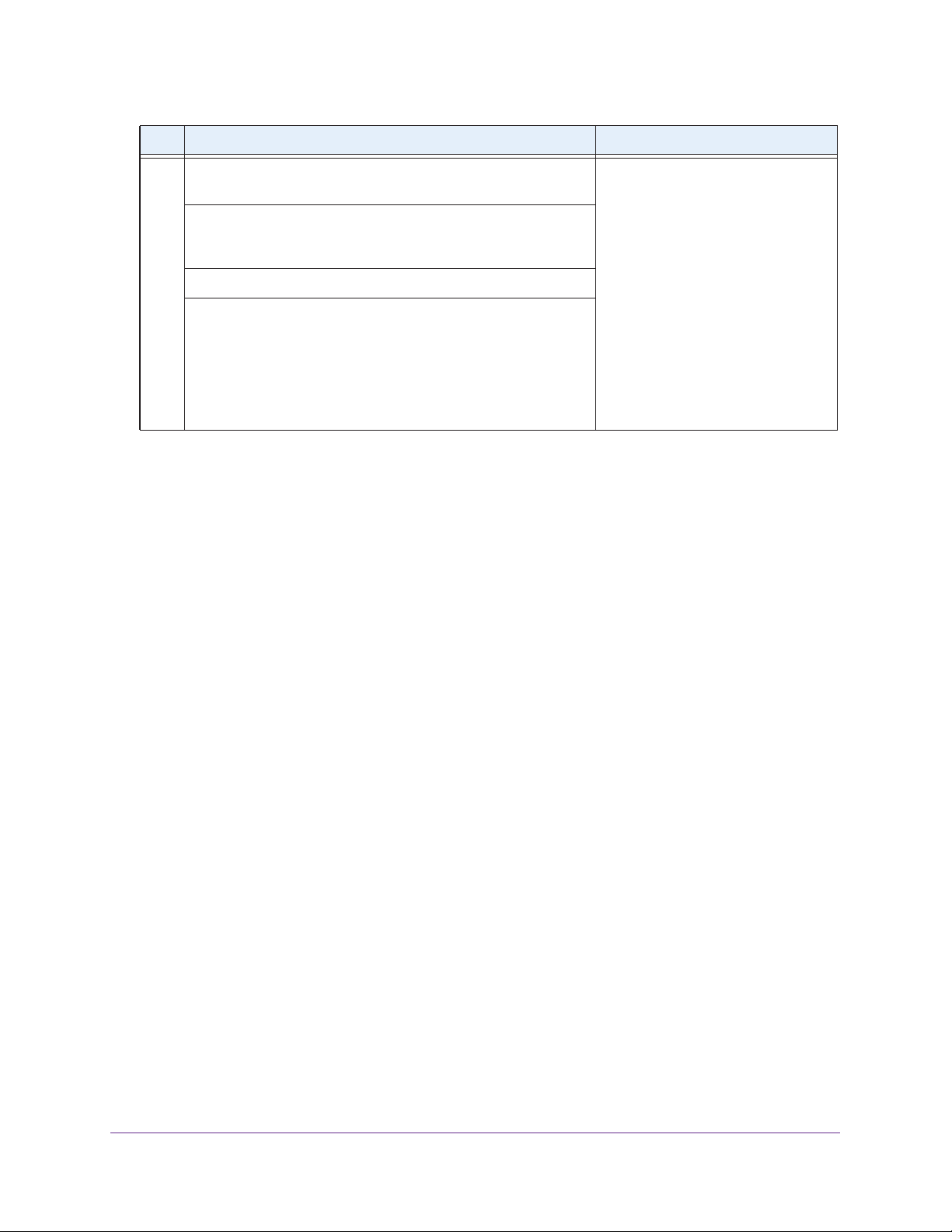
To set up a single wireless controller system with a basic profile group:
Step Configuration Web Management Interface Path
1. Configure the system and network settings of the wireless
controller:
1. Configure the country code of operation.
2. Configure the time settings.
3. Configure the IP address of the wireless controller.
4. Verify that VLAN 1 is set as the management VLAN and is
marked as untagged.
By default, VLAN 1 an untagged management VLAN.
5. If no network DHCP server is accessible to the access points,
configure the wireless controller’s DHCP server.
2. Configure up to eight profiles, and for each profile, do at least the
following:
1. Configure an SSID for wireless access.
2. Configure the network authentication and data encryption.
3. Assign the VLAN.
4. If necessary for the selected network authentication option,
configure the authentication server.
3. Run the Discovery Wizard and add the access points to the
managed access point list.
Configuration > System > General
Configuration > System > Time
Configuration > System > IP/VLAN
Configuration > System > DHCP
Server
Configuration > Profile > Basic
Configuration > Security > Basic >
Authentication Server
Access Point > Discovery Wizard
System Planning and Deployment Scenarios
26
Page 27

ProSAFE Wireless Controller WC9500
Single Controller Configuration with Advanced Profile Groups
A more complex configuration consists of a single wireless controller that controls a collection
of access points that are organized in access point profile groups and might use several
profiles in each access point profile group.
To set up a single wireless controller system with advanced profile groups:
Step Configuration Web Management Interface Path
1. Configure the system and network settings of the wireless
controller:
1. Configure the country code of operation.
2. Configure the time settings.
3. Configure the IP address of the wireless controller.
4. Verify that VLAN 1 is set as the management VLAN and is
marked as untagged.
By default, VLAN 1 an untagged management VLAN.
5. If no network DHCP server is accessible to the access points,
configure the wireless controller’s DHCP server.
2. Configure up to eight access point profile groups, and for each
access point profile in a group, do at least the following:
1. Configure an SSID for wireless access.
2. Configure the network authentication and data encryption.
3. Assign the VLAN.
4. If necessary for the selected network authentication option,
configure the authentication server.
3. Run the Discovery Wizard and add the access points to the
managed access point list.
Configuration > System > General
Configuration > System > Time
Configuration > System > IP/VLAN
Configuration > System > DHCP
Server
Configuration > Profile > Advanced
Configuration > Security >
Advanced > Authentication Server
Access Point > Discovery Wizard
4. Assign the access points to the access point profile groups (also
referred to as WLAN groups).
Configuration > WLAN Network
Management VLAN and Data VLAN Strategies
If your network includes 10 or more access points, NETGEAR recommends that you set up
at least two VLAN groups: a management VLAN group and a data VLAN group. If your
network is large, you should create a number of data VLAN groups. Setting up data VLANs
for clients allows you to:
• Segregate traffic by user category
• Create different policies such as access policies that are based on user category
System Planning and Deployment Scenarios
27
Page 28

ProSAFE Wireless Controller WC9500
The following illustration shows a simplified view of how you can use VLANs to segregate
traffic by user category:
Internet
Management VLAN 100 Ethernet traffic
Finance VLAN 10 Ethernet traffic
Employee VLAN 20 Ethernet traffic
Network printer
Deploy the wireless controller
on a trunk port if you use the
internal DHCP server
Wireless controller
WC9500
Finance
computer
PoE switch
Finance
computer
Employee
Employee
computer
computer
Figure 8. Example: Use VLANs to segregate traffic by user categories
Backend L3 switch
or router
Access point
WNDAP360
Employee
computer
The wireless controller uses the management VLAN to continually exchange packets with the
access points. For large networks, if all traffic uses a single VLAN, the client traffic could
potentially flood the network. If this happens, and the wireless controller is not able to
exchange packets with the access points, it can cause network performance to slow down,
and the access points can lose their connectivity with the wireless controller.
If you use the internal DHCP server of the wireless controller, you should deploy the wireless
controller on a trunk port on your switch.
The trunk port should have access to all VLANs.
Use a high-speed port on your switch as the trunk port to accommodate the traffic load of the
trunk. If you use an external DHCP server
, you do not need to deploy the wireless controller
on a trunk port on your switch.
System Planning and Deployment Scenarios
28
Page 29

ProSAFE Wireless Controller WC9500
High-Level Deployment Scenarios
This section provides three deployment scenarios to illustrate how the wireless controller can
function in various network configurations:
• Scenario Example 1: Network with Single VLAN
• Scenario Example 2: Advanced Network with VLANs and SSIDs
• Scenario Example 3: Advanced Network
Scenario Example 1: Network with Single VLAN
The following sample scenario consists of a simple network with a wireless controller, PoE
switch, Layer 3 switch or router, and access points:
Internet
Management VLAN Ethernet traffic
All client Ethernet traffic
Deploy the wireless controller
on a trunk port if you use the
internal DHCP server
Wireless controller
WC9500
Finance
computer
PoE switch
Marketing
computer
Network printer
Employee
computer
Backend L3 switch
or router
Access point
WNDAP360
Employee
computer
Figure 9. Example: Basic network with a single VLAN
System Planning and Deployment Scenarios
29
Page 30

ProSAFE Wireless Controller WC9500
The access points and wireless controller are connected in the same subnet and use the
same IP address range that is assigned for that subnet. There are no routers between the
access points and the wireless controller. The access points are connected to a PoE switch,
which, in turn, is connected to the wireless controller. The uplink of the PoE switch connects
to a Layer 3 switch or router that provides Internet access.
To provision the wireless controller:
Step Configuration Web Management Interface Path
1. Configure the system and network settings of the wireless
controller:
1. Configure the country code of operation.
2. Configure the time settings.
3. Configure the IP address of the wireless controller.
4. Verify that VLAN 1 is set as the management VLAN and is
marked as untagged.
By default, VLAN 1 an untagged management VLAN.
5. If no network DHCP server is accessible to the access points,
configure the wireless controller’s DHCP server.
2. Configure up to eight profiles, and for each profile, do at least the
following:
1. Configure an SSID for wireless access.
2. Configure the network authentication and data encryption.
3. Assign the VLAN.
4. If necessary for the selected network authentication option,
configure the authentication server.
3. Use any port of the wireless controller to connect the wireless
PoE switch.
Configuration > System > General
Configuration > System > Time
Configuration > System > IP/VLAN
Configuration > System > DHCP
Server
Configuration > Profile > Basic
Configuration > Security > Basic >
Authentication Server
4. Deploy the access points and connect them to the same wireless
PoE switch.
System Planning and Deployment Scenarios
30
Page 31
ProSAFE Wireless Controller WC9500
Step Configuration Web Management Interface Path
5. When the access points are operating, open the Discovery
Wizard to do the following:
1. Specify the state of the access points by selecting the Out of
Factory and L2 Subnet APs radio button or the Installed
and working in Standalone Mode radio button.
2. Run the Discovery Wizard.
3. Select and add the access points that you want to be managed
by the wireless controller to the managed list.
Note: By default, all access points are added to the basic group
and all settings from the basic group (profile definition, client
authentication, authentication settings, and wireless QoS) are
applied to the access points.
Access Point > Discovery Wizard
Scenario Example 2: Advanced Network with VLANs and SSIDs
The following sample scenario consists of an advanced network with a wireless controller,
PoE switch, Layer 3 switch or router, access points, and several VLANs and SSIDs. These
are the VLANs in the wireless controller system:
• VLAN 1, the default untagged VLAN to access the wireless controller
• VLAN 10, a tagged client VLAN
• VLAN 20, another tagged client VLAN
• VLAN 100, a tagged management VLAN
System Planning and Deployment Scenarios
31
Page 32
ProSAFE Wireless Controller WC9500
Management VLAN 100 Ethernet traffic
Client VLAN 10 Ethernet traffic
Client VLAN 20 Ethernet traffic
SSID 1
Client VLAN 10
WC9500 PoE switch
Backend L3 switch
or router
Internet
SSID 2
Client VLAN 20
WNDAP360
WNDAP360
Figure 10. Example: Advanced network with VLANs and SSIDs
The access points and wireless controller are connected in the same subnet and same VLAN
and use the same IP address range that is assigned for that subnet. There are no routers
between the access points and the wireless controller. The access points are connected to a
PoE switch, which, in turn, is connected to the wireless controller. The uplink of the PoE
switch connects to a Layer 3 switch or router that provides Internet access.
This network configuration has the following prerequisites:
• VLANs 10, 20, and 100 are tagged VLANs and are configured on both the wireless
controller and the PoE switch.
• The wireless controller is connected to the PoE switch through default VLAN 1. You
manage the wireless controller from a computer over VLAN 1 through the PoE switch.
• The DHCP server on the wireless controller is configured in management VLAN 100 to
enable the access points to receive an IP address through VLAN 100.
• The PoE switch port to which the wireless controller is connected is configured as a
tagged port to allow tagged traffic from VLAN 100.
System Planning and Deployment Scenarios
32
Page 33

ProSAFE Wireless Controller WC9500
To provision the wireless controller:
Step Configuration Web management interface path
1. Configure the basic system settings:
1. Configure the country code of operation.
2. Configure the time settings.
3. Configure the IP address of wireless controller.
4. For initial discovery and configuration of the access points,
temporarily configure management VLAN 100 as an
untagged management VLAN on the wireless controller.
5. Clear the Untagged Vlan check box.
Default VLAN 1 changes to a tagged VLAN.
2. For initial discovery and configuration of the access points,
temporarily configure management VLAN 100 as an untagged
management on the PoE switch.
3. Configure either the network’s DHCP server or the wireless
controller’s DHCP server to use VLAN 100.
If you use the wireless controller’s DHCP server:
1. Configure the IP address range for VLAN 100.
2. Configure the other DHCP server fields, including the
gateway and DNS servers.
4. Configure the following profiles, and configure network
authentication and data encryption for these profiles:
Configuration > System > General
Configuration > System > Time
Configuration > System > IP/VLAN
Configuration > System > DHCP
Server
1. A profile with SSID 1 and VLAN 10.
2. A profile with SSID 2 and VLAN 20.
3. If necessary for the selected network authentication options,
configure one or more authentication servers.
5. Connect the wireless controller to the PoE switch.
6. Before you connect the access points to the PoE switch, verify
that the switch ports to which you intend to connect the access
points are configured as access ports in management VLAN 100.
7. Deploy the access points and connect them to the designated
PoE switch ports.
System Planning and Deployment Scenarios
Configuration > Profile > Basic
Configuration > Security > Basic >
Authentication Server
33
Page 34

ProSAFE Wireless Controller WC9500
Step Configuration Web management interface path
8. When the access points are operating, open the Discovery
Wizard to do the following:
1. Specify the state of the access points by selecting the Out of
Factory and L2 Subnet APs radio button.
2. Run the Discovery Wizard.
3. Select and add the access points that you want to be managed
by the wireless controller to the managed list.
Note: By adding the access points to managed list, you enable
them to receive an IP address from the DHCP server over
management VLAN 100.
9. For each access point on the managed list, clear the Untagged
Vlan check box and configure VLAN 100 as the management
VLAN.
Doing so causes the access points to lose connectivity with the
wireless controller.
10. Restore connectivity between the access points and the wireless
controller by changing the PoE switch ports to which the access
points are connected to tagged ports.
During the discovery process, these switch ports were access
ports in management VLAN 100.
Access Point > Discovery Wizard
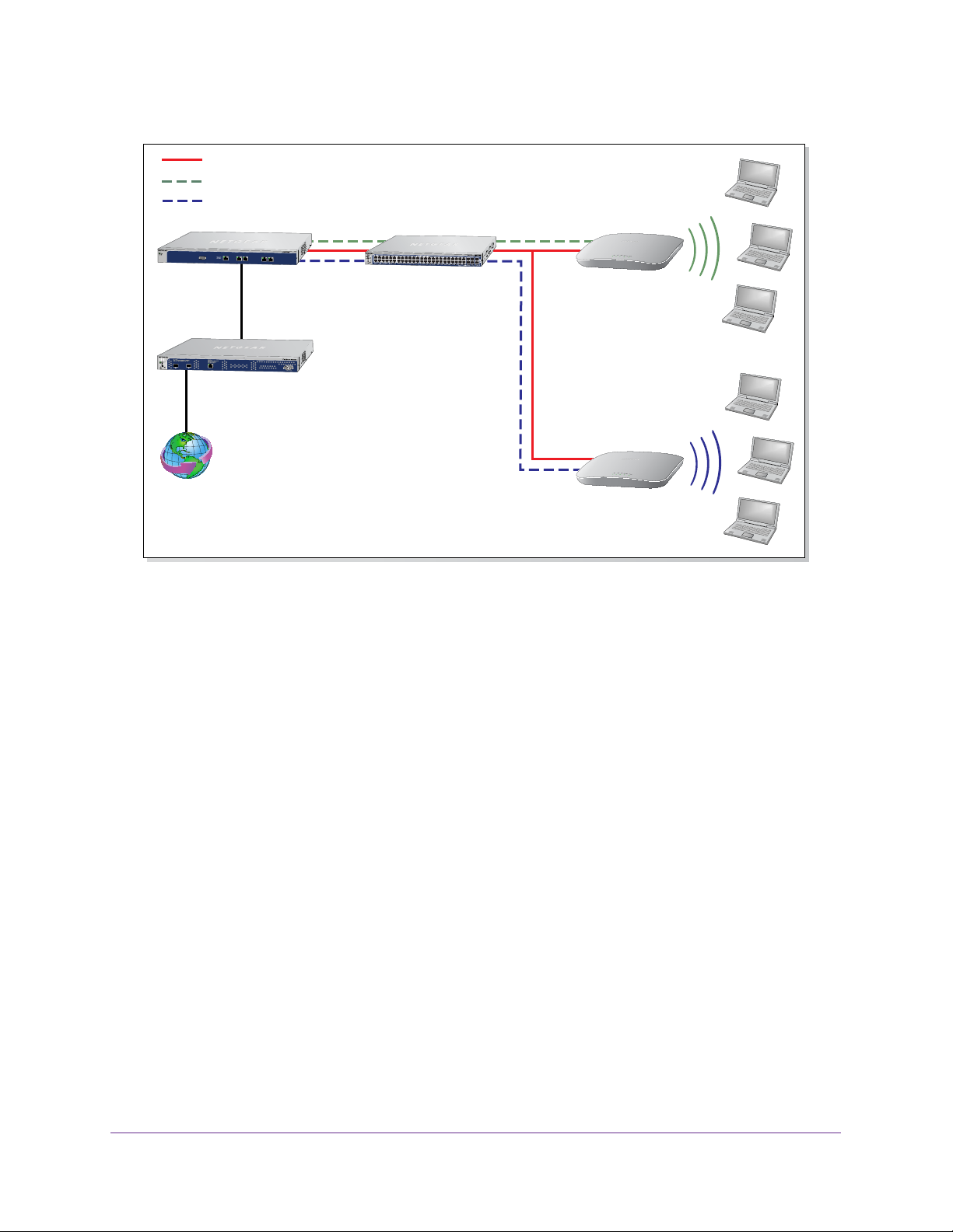
Scenario Example 3: Advanced Network
The following sample scenario consists of an advanced network with one wireless controller,
one core switch, two PoE switches in different buildings, access points, and several VLANs
and SSIDs.
These are the components in the wireless controller system:
• One wireless controller
• 50 access points (managed by the wireless controller through management VLAN 1)
• Four VLANs: VLAN 10, VLAN 20, VLAN 30, and VLAN 40
• Three SSIDs: SSID 1, SSID 2, and SSID 3
In this scenario, the VLANs and SSIDs are used to accommodate traffic for different user
groups in a school that is spread out over two buildings.
• Building 1:
- SSID 1 in VLAN 10 for staf
- SSID 2 in VLAN 20 for middle school students
- SSID 3 in VLAN 30 for guests
f traffic
System Planning and Deployment Scenarios
34
Page 35

ProSAFE Wireless Controller WC9500
• Building 2:
- SSID 1 in VLAN 10 for staff traffic
- SSID 2 in VLAN 40 for high school students
- SSID 3 in VLAN 30 for guests
Internet
Backend L3 switch
or router
WC9500
Staff VLAN 10 Ethernet traffic
Middle school VLAN 20 Ethernet traffic
High school VLAN 40 Ethernet traffic
Guest VLAN 30 Ethernet traffic
Core switch
Building 1
SSID 1 Staff VLAN 10
SSID 2 Middle school VLAN 20
SSID 3 Guest VLAN 30
PoE switch
WNDAP360
Building 2
SSID 1 Staff VLAN 10
SSID 2 High school VLAN 40
SSID 3 Guest VLAN 30
PoE switch
WNDAP360
Figure 11. Example: Advanced network
The access points and wireless controllers are connected in the same subnet and same
VLAN and use the same IP address range that is assigned for that subnet. The core switch is
located between the wireless controllers and the PoE switches, to which the access points
are connected. The core switch provides Internet access.
This network configuration has the following prerequisites:
• VLAN 1 is configured on the wireless controllers, core switch, and PoE switches. This
VLAN is untagged.
• VLANs 10, 20, and 30 are configured on the wireless controllers, core switch, and the
PoE switch in Building 1. These VLANs are tagged.
• VLANs 1, 10, 20, 30, and 40 are configured on the wireless controllers, core switch, and
PoE switches. Except for VLAN 1, these VLANs are tagged.
System Planning and Deployment Scenarios
35
Page 36

ProSAFE Wireless Controller WC9500
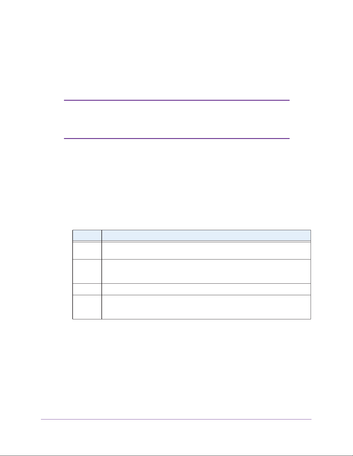
To provision the wireless controller:
Step Configuration Web management interface path
1. Configure the basic system settings:
1. Configure the country code of operation.
2. Configure the time settings.
3. Configure the IP address of wireless controller.
4. Verify that VLAN 1 is set as the management VLAN and is
marked as untagged.
By default, VLAN 1 an untagged management VLAN.
2. Configure the following profiles, and configure network
authentication and data encryption for these profiles:
1. A profile with SSID 1 and VLAN 10.
2. A profile with SSID 2 and VLAN 20.
3. A profile with SSID 2 and VLAN 30.
4. A profile with SSID 3 and VLAN 40.
5. If necessary for the selected network authentication options,
configure one or more authentication servers.
3. Configure the following profile groups:
1. A profile group with the name Building 1, to which you add the
following profiles:
- The profile with SSID 1 and VLAN 10
- The profile with SSID 2 and VLAN 20
- The profile with SSID 2 and VLAN 30
Configuration > System > General
Configuration > System > Time
Configuration > System > IP/VLAN
Configuration > Profile > Basic
Configuration > Security > Basic >
Authentication Server
Configuration > Profile > Advanced
2. A profile group with the name Building 2, to which you add the
following profiles:
- The profile with SSID 1 and VLAN 10
- The profile with SSID 2 and VLAN 30
- The profile with SSID 3 and VLAN 40
4. Deploy the access points and connect them to PoE switches.
System Planning and Deployment Scenarios
36
Page 37

ProSAFE Wireless Controller WC9500
Step Configuration Web management interface path
5. When the access points are operating, open the Discovery
Wizard to do the following:
1. Specify the state of the access points by selecting the Out of
Factory and L2 Subnet APs radio button.
2. Run the Discovery Wizard.
3. Select and add the access points that you want to be managed
by the wireless controller to the managed list.
Note: By default, all access points are added to the basic group.
6. Assign the access points to the access point profile groups (also
referred to as WLAN groups) Building 1 and Building 2.
Access Point > Discovery Wizard
Configuration > WLAN Network
System Planning and Deployment Scenarios
37
Page 38

3. Installation and Configuration
Overview
This chapter includes the following sections:
• Initial Set up and Log in
• Web Management Interface Layout
• Roadmap for Initial Configuration
• Roadmap for Configuring Management of Your Wireless Network
• Choose a Location for the Wireless Controller
• Deploy the Wireless Controller
3
38
Page 39
ProSAFE Wireless Controller WC9500
Initial Set up and Log in
To set up and log in to the wireless controller, follow the steps in this section. You can also
access the ProSAFE Wireless Controller WC9500 Installation Guide that you can download
from http://support.netgear.com/product/WC9500.
Note: To log in to the wireless controller, you need to use a web browser
such as Microsoft Internet Explorer 8 or later or Mozilla Firefox 18 or
later, or Google Chrome 24 or later with JavaScript, cookies, and
SSL enabled.
To set up and log in to the wireless controller:
1. Connect the wireless controller to your computer:
a. Configure a computer with a static IP address of 192.168.0.210 and 255.255.255.0
as the subnet mask.
b. Connect the wireless controller to the computer through the network or directly to the
wireless controller’
c. Connect the power cord from the wireless controller to an AC power outlet.
d. Verify that the following LEDs on the front panel are lit:
s Ethernet port.
LED Description
Power The green Power LED is lit. If the Power LED is not lit, check the connections and check to
see if the power outlet is controlled by a wall switch that is turned off.
Status The Status LED is lit yellow while the wireless controller is initializing. After approximately
two minutes, when the wireless controller has completed its initialization, the Status LED
turns green.
Fan The green Fan LED is lit, indicating that the fans are functioning correctly
Ethernet The right Ethernet port LED is lit green for a 1000 Mbps connection or yellow for a
100 Mbps or 10 Mbps connection. If it is not, make sure that the Ethernet cable is securely
attached at both ends.
.
2. Log in to the wireless controller:
a. Open your browser and type http://192.168.0.250 in the browser’s address field.
Installation and Configuration Overview
39
Page 40

ProSAFE Wireless Controller WC9500
The wireless controller’s login screen displays:
b. When prompted, enter admin for the user name and password for the password,
both in lowercase letters.
c. Click Login.
The wireless controller’s web management interface opens and displays the
Summary screen (the path is Monitor > Controller > Summary), which shows the
network status and related information:
For information about the network status and related information, see View the
Wireless Controller Summary Screen on page 173.
For information about the layout and general characteristics of the web management
interface, see the following section, Web Management Interface Layout.
Installation and Configuration Overview
40
Page 41
ProSAFE Wireless Controller WC9500
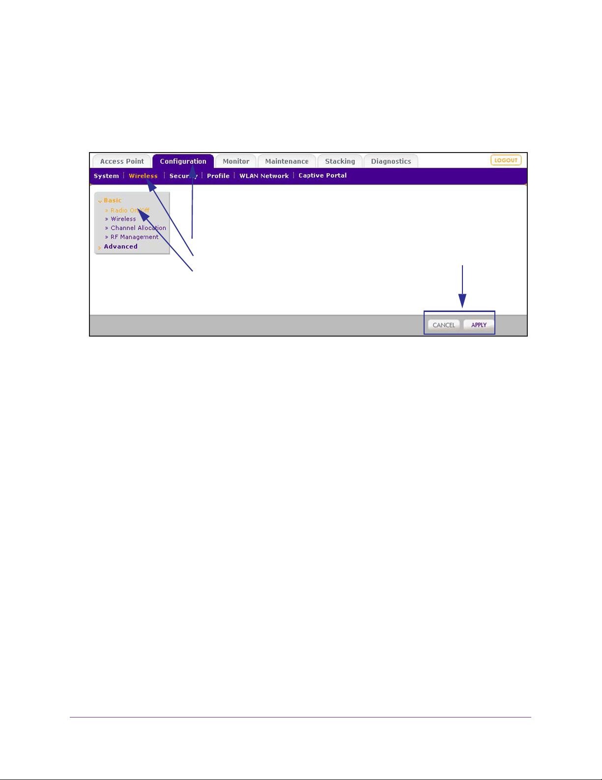
Web Management Interface Layout
The following figure shows the menus at the top and the left of the wireless controller’s web
management interface (the screen’s content has been removed for more clarity).
1st level: Main menu tab
2nd level: Configuration menu tab
3rd level: Submenu link
Action buttons
Figure 12. Web management interface components
A web management interface screen can include the following components:
• 1st level: Main menu tab. The main menu tabs in the light gray bar across the top of the
web management interface provide access to all configuration menu tabs of the wireless
controller and remain constant. When you select a main menu tab, the letters are
displayed in white against a blue background.
• 2nd level: Configuration menu tab.
(immediately below the main menu bar) change according to the main menu tab that you
select. When you select a configuration menu tab, the letters are displayed in orange
against a blue background.
• 3rd level: Submenu link. Each configuration menu tab has one or more submenu links
that are listed on the left side of the screen in a gray box. When you select a submenu
link, the text is displayed in orange against a gray background. On many screens, the
submenus are divided into a Basic submenu and an
• Action buttons. Action buttons let you change the configuration or navigate through the
web management interface. These are the most common action buttons:
- Apply. Saves all configuration changes made on the current screen. Saved settings
are retained when the wireless controller is powered off or rebooted, while unsaved
configuration changes are lost.
- Cancel. Resets options on the current screen to the last-applied or -saved settings.
- Add
- Edit. Allows you to edit the configuration of the selected item.
.
Adds an item to the screen. Typically, a pop-up screen opens that enables you
to enter information in additional fields.
The configuration menu tabs in the blue bar
Advanced submenu.
Installation and Configuration Overview
41
Page 42

ProSAFE Wireless Controller WC9500
- Delete or Remove. Removes the selected item from the table or screen
configuration.
- Back. Return to the previous screen.
- Next.
Advance to the next screen.
Roadmap for Initial Configuration
After you have connected and logged in to the wireless controller, you need to perform the
initial configuration. If you are not sure how you are going to deploy the wireless controller in
your network, NETGEAR recommends that you read Chapter 2, System Planning and
Deployment Scenarios.
This section is a roadmap for basic configuration only: It provides high-level configuration
steps with references to the sections or chapters that provide detailed configuration steps.
To perform the initial configuration of the wireless controller:
1. Select Configuration > System > General.
The General Settings screen displays.
2. Enter a name for the wireless controller and select the country in which the wireless
controller is used.
3. Click Apply.
4. Select Configuration > System > T
The Time Setting screen displays.
5. Select the time zone in which the wireless controller is used. Optionally, configure the NTP
settings.
For more information, see
6. Click Apply.
7. Select Configuration > System > IP/VLAN.
The IP Settings screen displays.
8. Enter the IP settings for your network and the VLANs that you want to assign to the wireless
controller.
Note: A management VLAN is used for all SNMP and HTTP traffic to and from
the wireless controller and managed access points.
Manage the Time Settings on page 48.
ime
.
Note: Clear the Untagged VLAN check box only if the hubs and switches in
your network support the VLAN (802.1Q) standard. Likewise, change the
untagged VLAN value only if the hubs and switches in your network support the
VLAN (802.1Q) standard.
For more information, see IP and VLAN Settings on page 49.
Installation and Configuration Overview
42
Page 43

ProSAFE Wireless Controller WC9500
9. Click Apply.
10. (Optional) If no DHCP server is available in your network, configure the wireless controller’s
DHCP server
For more information, see Manage the DHCP Server on page 51.
11. Click Apply.
The connection to the wireless controller is terminated because you have changed its IP
address.
12. Reconfigure your computer with an IP address and subnet mask that is in the same
IP subnet as the new IP address of the wireless controller.
13. Log back in to the wireless controller using its new IP address.
Continue with the following section, Roadmap for Configuring Management of Your
Wireless Network.
.
Roadmap for Configuring Management of Your Wireless Network
After you have performed the initial configuration and changed the IP address to an address
that is specific to your network (see the previous section, Roadmap for Initial Configuration),
you are ready to configure the wireless controller for management of your wireless network.
This section is a roadmap only: It provides high-level configuration steps with references to
the sections or chapters that provide detailed configuration steps.
To configure the wireless controller for management of your wireless network:
1. Register the licenses.
For more information, see Register Your Licenses on page 54.
2. (Optional but recommended) Replace the default certificate with a custom certificate for
certificate-based authentication of the
For more information, see Manage Certificates on page 57.
3. (Optional but recommended) Configure logs, alerts, and alarms.
For more information, see Configure Log, Syslog, Alarm Notification, and Email Settings
on page 58.
4. Configure security profiles:
a. Configure the security profiles for the basic profile group or for advanced profile
groups.
internal authentication server.
For detailed configuration steps, see:
• Configure Security Profiles for the Basic Profile Group on page 67
• Configure Security Profiles for Advanced Profile Groups on page 71
b. (Optional) Configure authentication servers.
Installation and Configuration Overview
43
Page 44

ProSAFE Wireless Controller WC9500
For more information, see Manage Authentication Servers and Authentication Server
Groups on page 85.
c. (Optional) Configure MAC authentication.
For more information, see Manage MAC Authentication and MAC Authentication
Groups on page 81.
d. (Optional) Assign the authentication servers and MAC
ACLs to the security profiles.
For more information, see:
• Configure Security Profiles for the Basic Profile Group on page 67
• Configure Security Profiles for Advanced Profile Groups on page 71
5. Configure the managed access point list:
a. Run the Discovery Wizard and add access points to the managed list.
For more information, see Discover Access Points with the Discovery Wizard on
page 92.
b. (Optional) Configure access points that are on the managed list.
For more information, see Manage the Managed AP List on page 100.
c. (Optional) Assign
access
points to advanced profile groups:
For more information, see Assign Access Points to Advanced Profile Groups on
page 104.
6. (Optional) Configure rogue access point detection.
For more information, see Manage Rogue Access Points on page 108.
7. (Optional) Configure a guest portal or captive portal.
For more information, see Manage Guest Network Access on page 111.
8. (Optional) Configure user accounts and portal accounts.
For more information, see Manage Users, Accounts, and Passwords on page 116.
9. (Optional) Configure wireless and QoS settings.
For more information, see Chapter 8, Configure Wireless and QoS Settings.
10. (Optional but recommended) Back up the configuration.
For more information, see Back Up the Configuration File on page 152.
Installation and Configuration Overview
44
Page 45

ProSAFE Wireless Controller WC9500
Choose a Location for the Wireless Controller
The wireless controller is suitable for use in an office environment where it can be
freestanding on its runner feet or mounted into a standard 19-inch equipment rack.
Alternatively, you can rack-mount the wireless controller in a wiring closet or equipment
room. A mounting kit, containing two mounting brackets and screws, is provided in the
wireless controller package.
Consider the following when deciding where to position the wireless controller:
• The unit is accessible and cables can be connected easily.
• Cabling is away from sources of electrical noise. These include lift shafts, microwave
ovens, and air-conditioning units.
• Water or moisture cannot enter the case of the unit.
• Airflow around the unit and through the vents in the side of the case is not restricted.
Provide a minimum of 25 mm or one inch clearance.
• The air is as free of dust as possible.
• T
emperature operating limits are not likely to be exceeded. Install the unit in a clean,
air-conditioned environment. For information about the recommended operating
temperatures for the wireless controller, see
Technical Specifications.
Appendix A, Factory Default Settings and
Deploy the Wireless Controller
After you have followed the steps in the Roadmap for Initial Configuration on page 42 and the
Roadmap for Configuring Management of Your Wireless Network on page 43, you are ready
to deploy the wireless controller in your network.
To deploy the wireless controller:
1. Disconnect the wireless controller from the computer that you used for configuration.
2. (Optional) Reconfigure the computer back to its original
3. Place the wireless controller where you intend to deploy it.
4. Connect an Ethernet cable from the wireless controller to a switch or router on your wired
network.
5. Connect the power cord to the wireless controller and plug the power cord into a power
outlet.
The Power
Troubleshoot Basic Functioning on page 198.
, Status, and Ethernet LEDs should light. If any of these do not light, see
TCP/IP settings.
Installation and Configuration Overview
45
Page 46

4. Configure the System and Network
Settings and Register the Licenses
This chapter includes the following sections:
• Configure General Settings
• Manage the Time Settings
• IP and VLAN Settings
• Manage the DHCP Server
• Register Your Licenses
• Manage Certificates
• Configure Log, Syslog, Alarm Notification, and Email Settings
4
46
Page 47
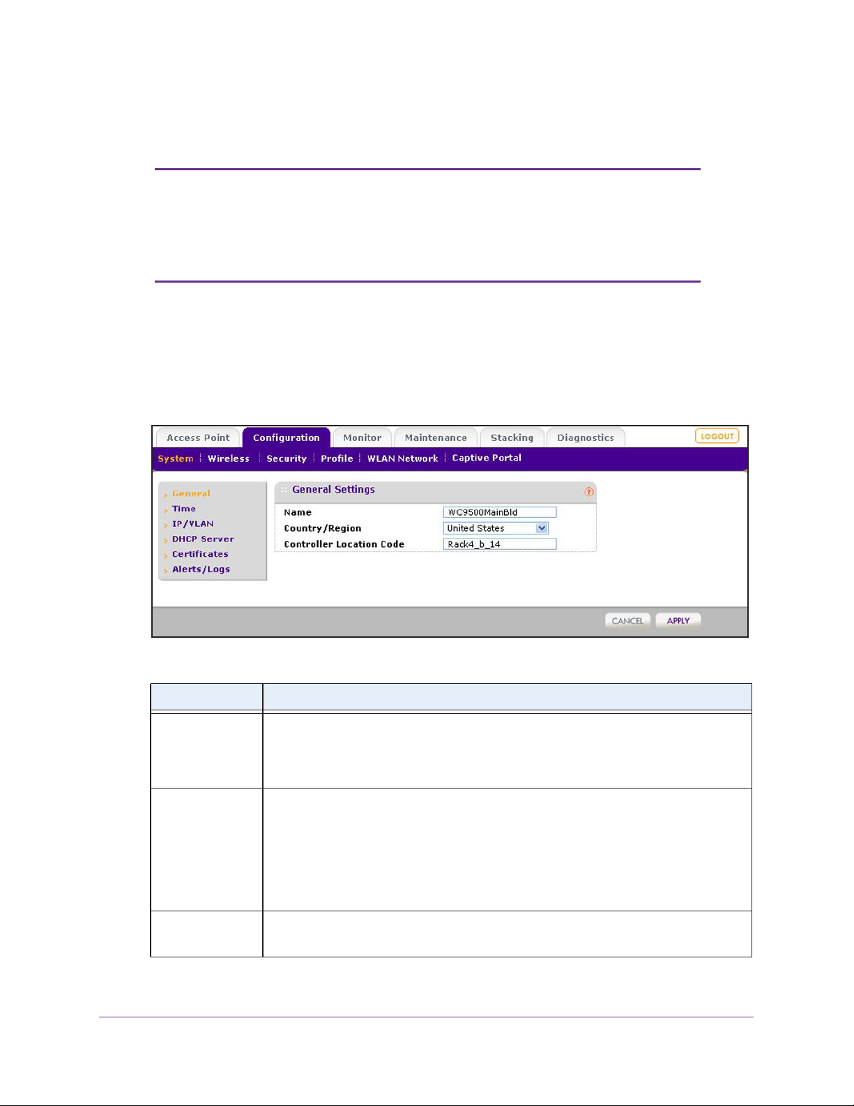
ProSAFE Wireless Controller WC9500
Configure General Settings
Note: You need to select the correct country or region of operation. It might
not be legal to operate the access points in a country or region not
shown here. If your location is not listed, check with your local
government agency or check the NETGEAR website for more
information about which channels to use.
The General Settings screen lets you configure the basic settings of your wireless controller.
To configure general settings:
1. Select Configuration > System > General.
The General Settings screen displays:
2. Configure the settings as described in the following table:
Setting Description
Name Enter a unique value as the wireless controller name. NETGEAR recommends
changing the name as soon as possible after setting up.
The name needs to contain only alphabetical characters, numbers, and hyphens, and
needs to be 31 characters or less.
Country/Region From the menu, select the region of operation for the wireless controller and the access
points managed by the wireless controller.
This setting is crucial for optimal performance of the wireless controller. The wireless
controller uses the country code to determine the best wireless settings for your access
points. In the United States, the country is preset and cannot be changed on the access
Controller
Location Code
points. If the country or region is not set up correctly
be able to access the access points.
(Optional) Enter a code to identify the physical location of the wireless controller.
This is especially useful if you use more than one wireless controller.
, the wireless controller might not
3. Click Apply.
Configure the System and Network Settings and Register the Licenses
47
Page 48
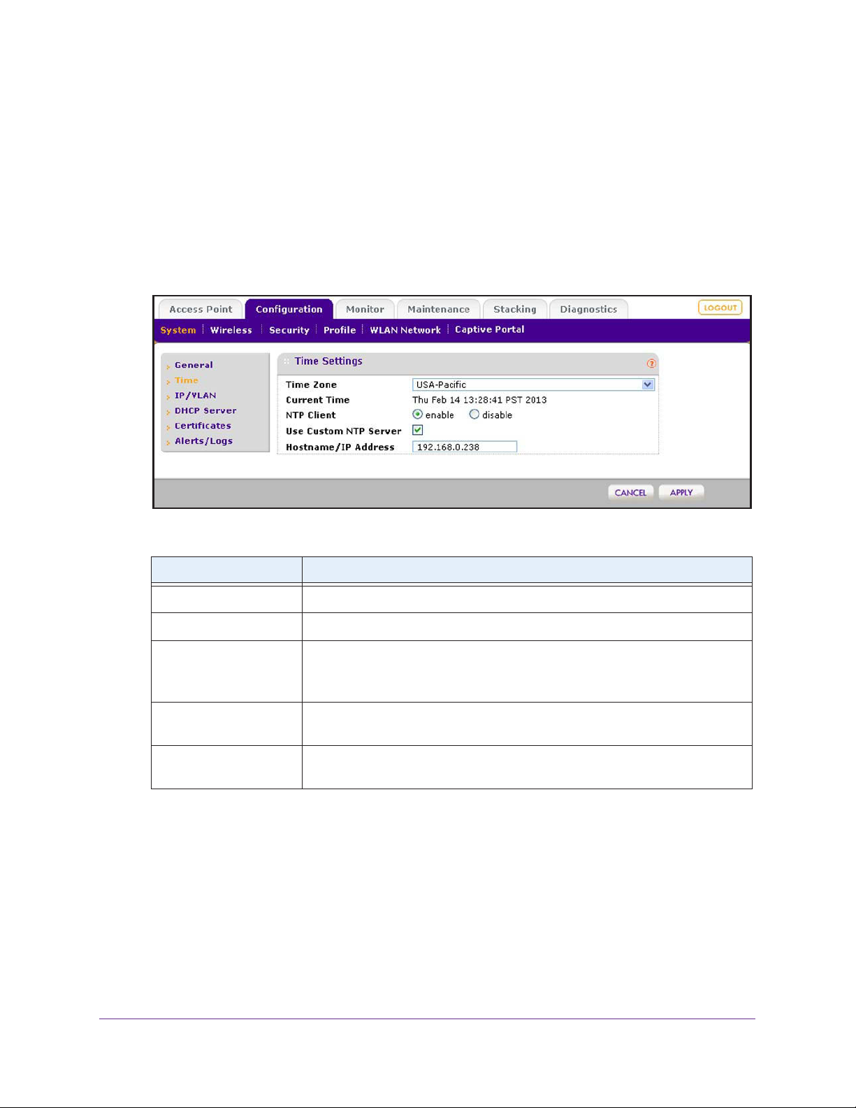
ProSAFE Wireless Controller WC9500
Manage the Time Settings
This screen lets you configure the time-related settings of your wireless controller and
managed access points.
To configure time settings:
1. Select Configuration > System > Time.
The T
ime Settings screen displays:
2. Configure the settings as described in the following table:
Setting Description
Time Zone From the menu, select the local time zone for your country or region.
Current Time This is a nonconfigurable field that displays the current time at your location.
NTP Client Select the Enable radio button to use a Network
synchronize the clock of the wireless controller and managed access points.
Select the Disable
Use Custom NTP Server Select this check box if you want to use an alternate NTP server . By default, the
NETGEAR NTP server is used.
Hostname/IP Address Enter the host name or IP address of the NTP server
NTP server
radio button if you do not want to use an NTP server
.
Time Protocol (NTP) server to
, if you are using a custom
3. Click Apply.
.
Configure the System and Network Settings and Register the Licenses
48
Page 49

ProSAFE Wireless Controller WC9500
IP and VLAN Settings
The IP Settings screen lets you configure the management IP address and VLAN settings of
the wireless controller.
Management VLAN Concepts
Management VLANs are used for all SNMP and HTTP traffic to and from the wireless
controller and managed access points.
For large deployments, NETGEAR recommends that the wireless controller and access
points are in separate VLANs to ensure uninterrupted connectivity between the wireless
controller and the access points.
The wireless controller and access points share heartbeat messages to keep synchronized
and share configurations and client key data to facilitate seamless roaming.
Untagged VLAN Concepts
When the Untagged VLAN check box is selected on the IP Settings screen, one VLAN can
be configured as an untagged VLAN:
• When the wireless controller sends frames associated with the untagged VLAN to the
LAN (Ethernet) interface, those frames do not carry an 802.1Q VLAN header.
• When the wireless controller receives untagged traffic from the LAN (Ethernet) interface,
those frames are assigned to the untagged VLAN.
If the Untagged VLAN check box is cleared, the wireless controller tags all outgoing LAN
(Ethernet) frames, and accepts only incoming frames that are tagged with known VLAN IDs.
Note: Clear the Untagged VLAN check box only if the hubs and switches
on your LAN support the VLAN (802.1Q) standard. Likewise, change
the untagged VLAN value only if the hubs and switches on your LAN
support the VLAN (802.1Q) standard.
Changing either of these values results in a loss of IP connectivity if the hubs and switches
on your network have not yet been configured with the corresponding VLANs.
Configure the IP and VLAN Settings
To configure IP/VLAN settings:
1. Select Configuration > System > IP/VLAN.
Configure the System and Network Settings and Register the Licenses
49
Page 50
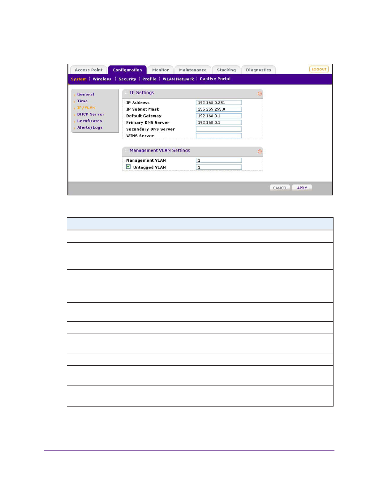
ProSAFE Wireless Controller WC9500
The IP Settings screen displays:
2. Configure the settings as described in the following table:
Setting Description
IP Settings section
IP Address Enter the IP address of the wireless controller.
The default IP address is 192.168.0.250. To change it, enter an available IP
address from the address range used on your LAN.
IP Subnet Mask Enter the subnet mask value used on your LAN.
The default value is 255.255.255.0.
Default Gateway Enter the IP address of the gateway for your LAN.
Primary DNS Server Enter the IP address of the primary Domain Name Server (DNS) that you want to
use.
Secondary DNS Server Enter the IP address of the secondary DNS that you want to use.
WINS Server Enter the IP address of the Windows Internet Name Service (WINS) that you want
to use.
Management VLAN Settings section
Management VLAN Enter the management VLAN.
For information, see Management VLAN Concepts on page 49.
Untagged VLAN Select this check box if the configured VLAN is untagged.
For information, see Untagged VLAN Concepts on page 49.
3. Click Apply.
Configure the System and Network Settings and Register the Licenses
50
Page 51

ProSAFE Wireless Controller WC9500
Manage the DHCP Server
Note: Make sure that a DHCP server is available; otherwise, the Discovery
Wizard does not function correctly. If you already have a DHCP
server on your network, do not enable the DHCP server on the
wireless controller.
The wireless controller can function as a DHCP server. You can add multiple DHCP server
pools for different VLANs. By default, there is no DHCP server pool. The DHCP Server List
screen lets you add a DHCP server pool.
To add a DHCP server and configure its settings:
1. Select Configuration > System > DHCP Server.
The DHCP Server List screen displays. The following figure shows part of the DHCP
Server List screen. Because this is a wide screen, it is shown in the following two figures:
The DHCP Server List shows the DHCP servers that are already configured on the
wireless controller.
Configure the System and Network Settings and Register the Licenses
51
Page 52
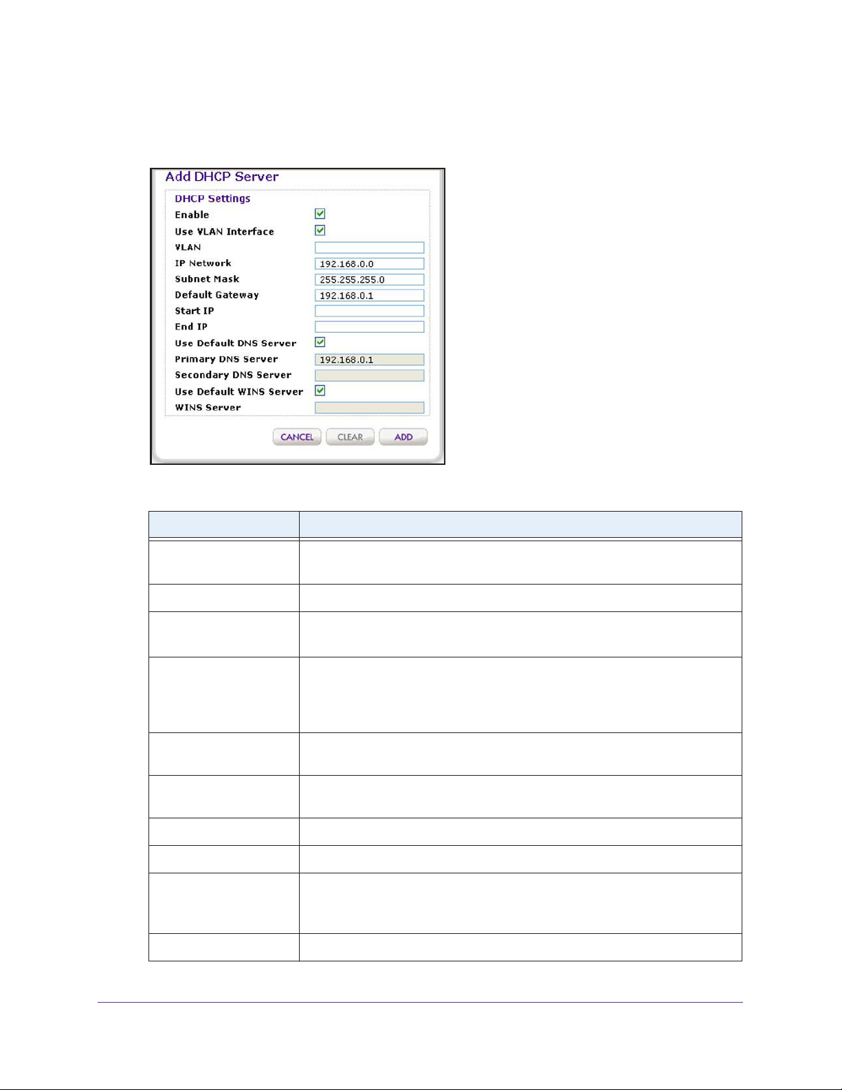
ProSAFE Wireless Controller WC9500
2. Click Add.
The Add DHCP Server pop-up screen displays:
3. Configure the settings as described in the following table:
Setting Description
Enabled Select this check box to enable the DHCP server.
When the check box is cleared, the DHCP server is disabled.
Use VLAN Interface Select this check box to allow the DHCP server to function with multiple VLANs.
VLAN Enter the DHCP server VLAN ID.
The range is between 1 and 4094. The DHCP server services this VLAN.
IP Network Enter the IP address for the wireless controller in the VLAN that you have
specified in the VLAN field.
If you have not selected the Use VLAN Interface check box, the IP address of
the wireless controller’
Subnet Mask Enter the subnet mask that is assigned to the wireless clients by the DHCP
server.
Default Gateway Enter the IP address of the default network gateway for all traf
local network.
Start IP Enter the start IP address of the range that the DHCP server can assign.
End IP Enter the end IP address of the range that the DHCP server can assign.
s management VLAN is used.
fic beyond the
Use Default DNS Server Select this check box to allow the DHCP server to use the wireless controller’
default DNS servers.
The Primary DNS Server and Secondary DNS Server fields are masked out.
Primary DNS Server Enter the IP address of the primary DNS server for the network.
Configure the System and Network Settings and Register the Licenses
52
s
Page 53

ProSAFE Wireless Controller WC9500
Setting Description
Secondary DNS Server Enter the IP address of the secondary DNS server for the network.
Use Default WINS Server Select this check box to allow the DHCP server to use the wireless controller’s
default WINS server.
The WINS Server field is masked out.
WINS Server
Enter the IP address of the WINS server for the network.
4. Click Add.
The new DHCP server is added to the DHCP Server List.
To edit a DHCP server:
1. Select Configuration > System > DHCP Server.
The DHCP Server List screen displays.
2. Select the radio button in the Edit/Remove column that corresponds to the DHCP server that
you want to edit.
3. Click Edit.
The Edit DHCP Server pop-up screen displays:
4. Make your changes (see the previous table).
5. Click Apply.
To delete a DHCP server:
1. Select Configuration > System > DHCP Server.
The DHCP Server List screen displays.
2. Select the radio button in the Edit/Remove column that corresponds to the DHCP server that
you want to remove.
3. Click Remove.
Configure the System and Network Settings and Register the Licenses
53
Page 54

ProSAFE Wireless Controller WC9500
Register Your Licenses
Make sure that your licenses cover the number of access points in your network. Before you
can register your licenses, you need to configure the license server settings.
Note: When you install your licenses, they replace the default trial license
for five access points.
For more information about licenses, see Licenses on page 18 and Manage Licenses on
page 165.
Configure the License Server Settings
Although you generally do not need to change the default license update server, you need to
make sure that the wireless controller can reach the license update server.
To configure the license server settings:
1. Select Maintenance > License.
2. Click the Server Settings tab.
The Server Settings screen displays:
Configure the System and Network Settings and Register the Licenses
54
Page 55

ProSAFE Wireless Controller WC9500
3. Configure the settings as described in the following table:
Setting Description
Update From Select one of the following radio buttons to specify the license update server:
• Default Update Server.
• Specify Update Server. You need to specify the license update server
the Server Address field.
Server Address Enter the IP address or FQDN of the server from which you
import your licenses.
By default, the FQDN of the NETGEAR license server is
update1.eng.netgear
The default license update server is used.
.com.
. Fill in
Use a Proxy Server to
Connect to the Internet
This Proxy Server
Requires Authentication
Select this check box if you use a proxy server to connect to the Internet.
Proxy Server Enter the IP address or FQDN of the proxy server.
Proxy Port Enter the port that the proxy server uses.
If the proxy server requires authentication, specify the user name and password.
User Name Enter the user name to access the proxy server
Password Enter the password to access the proxy server.
.
4. Click Apply.
Register Your Licenses with the License Server
You need to have purchased licenses before you can register them. For more information,
see Licenses on page 18)
To register your licenses:
1. Make sure that the wireless controller is connected to the Internet.
2. Select Maintenance > License.
3. Click the Registration tab.
Configure the System and Network Settings and Register the Licenses
55
Page 56

ProSAFE Wireless Controller WC9500
The Registration screen displays. The following figure shows some licenses already
registered and installed. If you register licenses for the first time, the screen does not yet
show any licenses.
4. Complete the Customer Information fields with the customer information that is associated
with the key that you want to add and register.
These fields are self-explanatory.
5. Complete the VAR Information fields with the value-added reseller (VAR) information that is
associated with the key that you want to add and register
.
These fields are self-explanatory.
Configure the System and Network Settings and Register the Licenses
56
Page 57

ProSAFE Wireless Controller WC9500
6. In the Registration Key field at the top of the screen, enter the registration key for the license
that you want to add and register.
7. Click Add.
The license is added to the table. The key details have the same meaning as those
shown on the Inventory screen (see the Key Details section in the table in View Y our
Licenses on page 165).
8. Click Apply.
Your license is registered.
9. (Optional) Repeat these steps to register another license.
The wireless controller lets you remove license keys that are invalid or that did not register
successfully with the license server
successfully with the license server.
To remove a license:
1. Select Maintenance > License.
2. Click the Registration tab.
. However
, you cannot remove licenses that registered
The Registration screen displays.
3. In the table, select the radio button that corresponds to the license that you want to remove.
4. Click Delete.
Manage Certificates
The internal authentication server for certificate-based authentication requires you to install a
certificate on the wireless controller. A default self-signed server certificate is installed on the
wireless controller. However, NETGEAR strongly recommends that you replace this default
certificate with a custom certificate issued for your site or domain by a trusted certificate
authority (CA).
To obtain a security certificate for the wireless controller, generate and submit a certificate
signing request (CSR) to the CA of your choice. Upon receiving the CA-signed server
certificate, install the certificate from your computer as described in this section. Certificates
need to be in X.509 PEM format.
To add certificates:
1. Select Configuration > System > Certificates.
Configure the System and Network Settings and Register the Licenses
57
Page 58
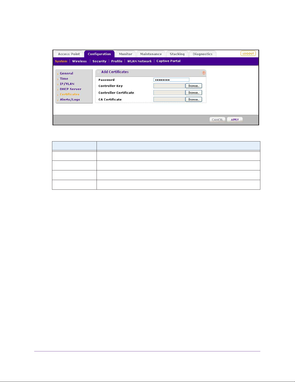
ProSAFE Wireless Controller WC9500
The Add Certificates screen displays:
2. Configure the settings as described in the following table:
Setting Description
Password Enter the password for wireless controller certificates.
Controller Key Click Browse, and select the controller key.
Controller Certificate Click Browse, and select the controller certificate.
CA Certificate Click Browse
3. Click Apply.
, and select the CA certificate.
Configure Log, Syslog, Alarm Notification, and Email Settings
From the Alerts/Logs menu you can configure the logs, syslog, and the alarms, and specify
the email address from which alerts originate.
Configure Log Settings
For the logs, you can either configure event tracing or select a log level. These selections are
mutually exclusive.
Event tracing can help you to debug the wireless network. Event tracing generates logs from
the wireless controller and from all controlled access points, and saves these logs in a file on
the wireless controller. The file can become large quickly.
To configure the log settings and view the logs:
1. Select Configuration > System > Alerts/Logs > Logs/Syslog.
Configure the System and Network Settings and Register the Licenses
58
Page 59
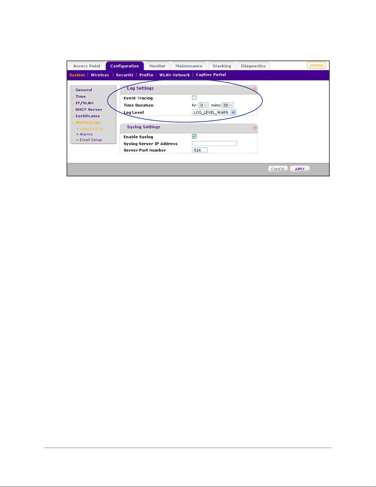
ProSAFE Wireless Controller WC9500
The Logs Settings screen displays:
2. In the Logs Settings section of the screen, configure either event tracing or a log level (these
selections are mutually exclusive):
• Event tracing.
To configure event tracing:
a. Select the
Event Tracing check box.
b. Next to Time Duration, use the menus to specify the period during which event
tracing should occur
.
• Log level. From the Log Level menu, select one of the following levels:
- LOG_LEVEL_CRIT. Critical errors only are logged.
- LOG_LEVEL_ERR. Noncritical errors and critical errors are logged.
- LOG_LEVEL_W
LOG_LEVEL_NOTICE. Notifications, warnings, noncritical errors, and critical
-
ARN. Warnings, noncritical errors, and critical errors are logged.
errors are logged.
- LOG_LEVEL_INFO. Informational messages, notifications, warnings, noncritical
errors, and critical errors are logged.
3. Click Apply.
For information about saving and clearing the logs, see View Alerts and Events and Save the
Logs on page 159.
Configure the System and Network Settings and Register the Licenses
59
Page 60

ProSAFE Wireless Controller WC9500
Configure Syslog Settings
This screen lets you configure the settings to connect to a syslog server, if you have one
configured in your network.
To configure syslog settings:
1. Select Configuration > System > Alerts/Logs > Logs/Syslog.
The Logs Settings screen displays:
2. In the Syslog Settings section of the screen, configure the settings as described in the
following table:
Setting Description
Enable Syslog Enable the syslog settings, if you have a syslog server on your network.
Syslog Server IP Address Enter the IP address to which the wireless controller and managed access
points send all syslogs, if the Syslog check box is selected.
Server Port Number Enter the number of the port at which your syslog server is configured to listen to
requests.
3. Click Apply.
Configure the System and Network Settings and Register the Licenses
60
Page 61

ProSAFE Wireless Controller WC9500
Configure Alarm Notification Settings
You can classify certain events as critical, major, normal, or minor. Some events you can
classify only as critical or major. For example, on the RF Management screen, you can
specify whether a coverage hole should be classified as critical or major (see RF
Management for the Basic Profile Group on page 141).
To configure alarm actions:
1. Select Configuration > System > Alerts/Logs > Alarms.
The
Alarm Actions screen displays:
2. For each alarm severity (Minor, Normal, Major, and Critical), select the desired action from
its corresponding Action menu.
• No Action. When the alarm occurs, no action is taken.
• Add To Syslog. When the alarm occurs, the wireless controller adds an entry to the
syslog.
• Send Email. When the alarm occurs, the wireless controller sends an email.
3. For each alarm severity for which you have selected the Send Email option in the previous
step, enter an email address.
4. Click Apply.
Configure the System and Network Settings and Register the Licenses
61
Page 62
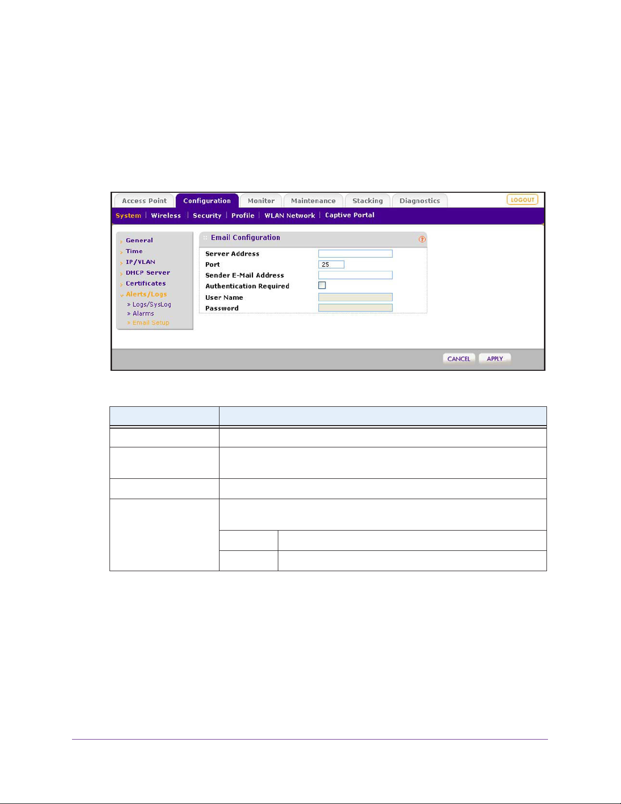
ProSAFE Wireless Controller WC9500
Configure the Email Notification Server
The email notification server is the location from which the email alerts originate.
To configure email settings:
1. Select Configuration > System > Alerts/Logs > Email Setup.
The Email Configuration screen displays:
2. Configure the settings as described in the following table:
Setting Description
Server Address Enter the IP address of the server from which email notifications are sent.
Port Enter the port number of the server from which email notifications are sent. The
default is port number 25.
Sender Email Address Enter the email address from which email notifications are sent.
Authentication Required Select this check box if the email server requires authentication, and complete
the User Name and Password fields.
User Name Enter the user name that is associated with the email server.
Password Enter the password that is associated with the email server.
3. Click Apply.
Configure the System and Network Settings and Register the Licenses
62
Page 63

5. Manage Security Profiles and
Profile Groups
This chapter includes the following sections:
• Wireless Security Profile Concepts
• Configure Security Profiles for the Basic Profile Group
• Configure Security Profiles for Advanced Profile Groups
• Network Authentication and Data Encryption Options
• Manage MAC Authentication and MAC Authentication Groups
• Manage Authentication Servers and Authentication Server Groups
Note: In this chapter and in the following chapters, access point profile
groups are referred to as just profile groups.
Profiles, security profiles, and SSIDs (that is, SSIDs with associated
security settings) are terms that are interchangeable.
5
63
Page 64

ProSAFE Wireless Controller WC9500
Wireless Security Profile Concepts
Profiles are sets of configurations that you can apply to an access point. The configuration
includes radio parameters, load-balancing parameters, and rate-limit parameters. Each
wireless radio on an access point can support eight profiles. This means that the dual-band
WNDAP350 access point can support a total of 16 profiles. Therefore, in one profile group on
the wireless controller, you can configure up to eight profiles for each radio, that is, up to
eight profiles for the 2.4 GHz radio and up to eight profiles for the 5 GHz radio.
Setting up profiles allows you to configure the WLAN network offline. Then, when the WLAN
network is operating, you can push the configuration onto managed access points.
configure profiles and profile groups without taking the state of the access points into
consideration. When the access points connect to the wireless controller, the profile
configurations are pushed onto the access points.
Note: If an access point is removed from its building (someone takes it
home or it is stolen), the access point does not retain the
configuration that it received from the wireless controller. The
configuration is not stored in memory on the access point.
Y
ou can
Depending on your network needs, you can either use the basic profile group (that is, the
basic configuration) or the advanced profile groups (that is, the advanced configuration). The
basic profile group works well for small-scale WLAN networks; advanced profile groups are
useful for larger deployments.
Note: For more information about basic and advanced profile groups, see
Basic and Advanced Setting Concepts on page 20.
Small WLAN Networks
For small WLAN networks, you can use the basic configuration with the basic profile group.
All access points belong to the same group and use the same wireless, security, and QoS
configurations.
The basic profile group can contain up to 16 profiles for a dual-band access point, or
eight profiles for a single-band access point. Each profile has its own SSID and can have its
own VLAN to allow the profile to establish its own tunnel. Profiles can also share the same
VLAN.
For example, in an enterprise network in which all access points managed by the wireless
controller serve the same wireless networks and have the same settings, you can use the
basic configuration.
Manage Security Profiles and Profile Groups
64
Page 65

ProSAFE Wireless Controller WC9500
Larger WLAN Networks
For larger network deployments that consist of different sets of WLAN networks, consider
using the advanced configuration to create multiple profile groups. The access points that
belong to the same profile group use the same wireless, security, and QoS configurations.
The wireless controller supports up to eight profile groups. Each profile group can have its
own wireless, security, and QoS configurations. Each profile group can contain up to
16 profiles for a dual-band access point, or eight profiles for a single-band access point.
Using dual-band access points, the wireless controller could support a total of 128 profiles.
Each profile has its own SSID and can have its own VLAN to allow the profile to establish its
own tunnel. Profiles can also share the same VLAN.
In larger network deployments also, you would assign guests to a separate VLAN because
guests typically access only the Internet, not the business network, and do not have
peer-to-peer access.
Profile Naming Conventions
Y ou can use profile naming conventions that are based on user groups such as Marketing, or
based on VLANs such as VLAN40, or you can use other naming conventions such as
CompanyName15.
Note: In the advanced configuration, you cannot change the names of
profile groups. However, you can change the group names of MAC
ACLs and external RADIUS servers.
Considerations Before You Configure Profiles
Before you create and configure profiles for the basic profile group or an advanced profile
group, consider the following:
• Authentication servers. If you want to use external LDAP or RADIUS authentication, or
both, first configure the authentication server settings:
- Configure basic server settings on the basic Authentication Server screen (see
Configure Basic
- For more complex networks, configure additional RADIUS servers on the advanced
Authentication Server screen (see Configure RADIUS Authentication Server Groups
on page 88).
Authentication Server Settings on page 86).
After you have configured authentication server settings, you can then assign any
authentication server to a security profile in a basic profile group or advanced profile
group.
Manage Security Profiles and Profile Groups
65
Page 66

ProSAFE Wireless Controller WC9500
Note: You can configure profiles to function with different authentication
servers. For example, you could set up a guest profile with no
authentication, an engineering profile that uses external RADIUS
authentication, and a marketing profile that uses external LDAP
authentication. You can also use additional external RADIUS
servers in other profiles.
• MAC authentication. If you want to use a MAC access control list (ACL) to control
access of wireless clients, first create one or more MAC ACLs:
- Configure the basic MAC ACL on the basic MAC Authentication screen (see
Configure Basic Local MAC Authentication Settings on page 82).
- For more complex networks, configure additional MAC ACLs on the advanced MAC
Authentication screen (see Configure Local MAC
After you have configured one or more MAC ACLs, you can then assign any MAC ACL to
a security profile in a basic profile group or advanced profile group.
Authentication Groups on page 84).
• Cloning profiles. For faster setup, you can clone a profile and rename it. Cloning copies
all settings except for the name and SSID.
Basic and Advanced Security Configuration Concepts
The basic security configuration model (Configuration > Security > Basic) does not apply
strictly to the basic profile group, nor does the advanced security configuration model
(Configuration > Security > Advanced) apply strictly to advanced profile groups. The reason
is that you apply an authentication server and a MAC ACL to an individual profile and not to a
profile group.
Y
• Basic security settings.
whether in the basic profile group or in an advanced profile group:
- Basic MAC authentication (the MAC ACL group that is called basic)
- Basic authentication server (the RADIUS server that is called basic-Auth or the LDAP
server that is called basic-LDAP)
• Advanced security settings
whether in the basic profile group or in an advanced profile group:
- Advanced MAC authentication (the MAC ACLs that are, by default, called
Acl-2, Acl-3, and so on; you can change these default names)
- Advanced authentication server (the RADIUS servers that are, by default, called
Auth-1, Auth-2,
Auth-3, and so on; you can change these default names)
ou can apply the following security settings to any profile,
. Y
can apply the following security settings to any profile,
ou
Acl-1,
Manage Security Profiles and Profile Groups
66
Page 67
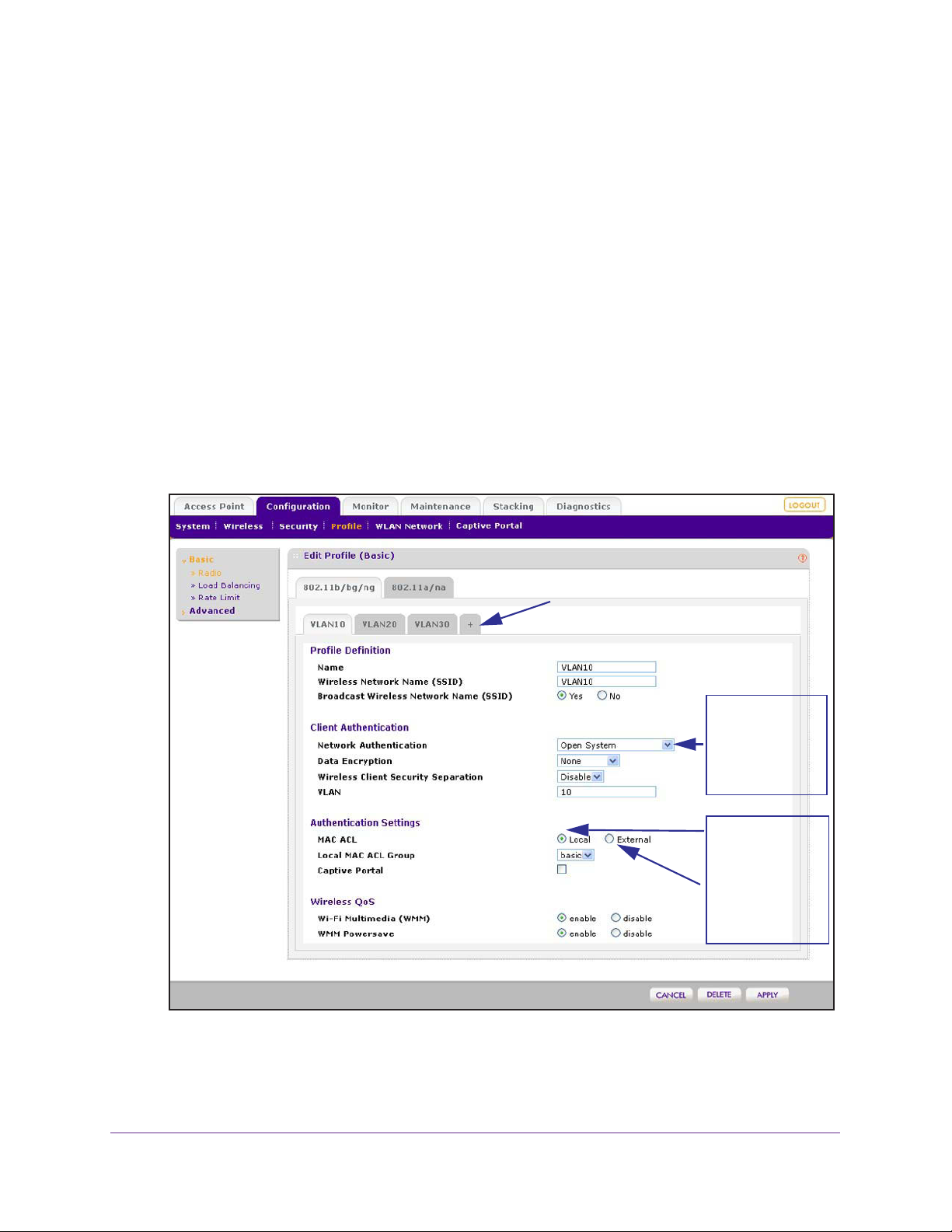
ProSAFE Wireless Controller WC9500
Configure Security Profiles for the Basic Profile Group
The basic profile group works well for small-scale WLAN networks. NETGEAR recommends
that you read the information in the previous section, Wireless Security Profile Concepts,
before you configure any profiles.
Configure Profiles in the Basic Profile Group
The Edit Profile (Basic) screen lets you create and configure up to eight security profiles per
wireless radio (eight profiles for a single-band access point; 16 profiles for a dual-band
access point). Separate profiles are applied to 802.11b/bg/ng-mode and 802.11a/na-mode
radios.
To add a security profile to the basic profile group and configure the security profile:
1. Select Configuration > Profile > Basic > Radio.
The Edit Profile (Basic) screen displays:
Click + to add another profile.
Your selection from
the Network
Authentication menu
determines the
information that is
displayed onscreen.
Select the Local radio
button to display the
Local MAC ACL
Group menu.
Select the External
radio button to
display the External
Radius Server menu.
By default, an NG_11g profile and an NG_11a profile are present in the basic profile
group.
2. Click the tab for the radio for which you want to add a profile.
Manage Security Profiles and Profile Groups
67
Page 68

ProSAFE Wireless Controller WC9500
3. Click the + button to add the profile to the basic profile group.
The Add Profiles pop-up screen displays.
4. (Optional) Clone an existing profile:
a. Select the Clone an existing Profile check box.
The previous figure shows that you can clone an existing profile with the name
VLAN10.
b. Select a profile from the Profiles menu.
5. Click Add.
The newly created profile displays onscreen, and the tab for the new profile is
automatically selected to let you configure the new profile.
Note: The selections that are available from the Network Authentication
menu are affected by the authentication server settings that you
specify on the Authentication Server screen. For more information,
see Manage Authentication Servers and Authentication Server
Groups on page 85. If your selection from the Network
Authentication menu requires authentication, a corresponding
Authentication Server field displays.
6. Configure the settings as described in the following table:
Setting Description
Profile Definition section
Name Enter a unique name to identify the profile.
This value can be up to 32 alphanumeric characters. Use meaningful profile
names instead of the default names.
Profile2, and so on, through Profile8.
The default profile names are Profile1,
Wireless Network Name
(SSID)
Enter a unique name for the wireless network associated with this profile.
Manage Security Profiles and Profile Groups
68
Page 69

ProSAFE Wireless Controller WC9500
Setting Description
Broadcast Wireless
Network Name
Client Authentication section
Note: The options that display onscreen depend on your selection from Network Authentication menu.
Network Authentication From the menu, select the authentication type to be used.
Data Encryption From the menu, select the data encryption type to be used.
Wireless Client Security
Separation
VLAN Enter the VLAN ID to be associated with this security profile.
Authentication Settings section
Note: The options that display onscreen depend on the selection from Network Authentication menu.
Note: MAC ACL displays
only when you select
Open System, Shared
Key, WPA-PSK,
WPA2-PSK, or
WPA-PSK &
from the Network
Authentication menu.
WPA2-PSK
Select the Yes radio button to enable broadcast of the SSID.
This is the default setting.
Select the No radio button to disable broadcast of the SSID, in which case only
devices that have the correct SSID can connect to the access point.
Table 3 on page 78 lists all the authentication type options.
The options available for data encryption as well as other requirements such as
entering a key or passphrase depend on the network authentication settings.
Table 3 on page 78 lists all the data encryption options.
From the menu, select Disable to prevent associated wireless clients from
communicating with each other
Wireless client separation is intended for hotspots and other public access
situations.
This VLAN ID needs to match the VLAN ID that is used by other network
devices.
MAC ACL Select one of the following radio buttons:
• Local
The Local MAC ACL Group menu displays so you can
select a group. For more information, see Manage MAC
Authentication and MAC
page 81.
• External. Use external MAC authentication.
The External Radius Server menu displays so you can
select a server. You can use either the basic-Auth RADIUS
server or a RADIUS server of an advanced authentication
group. You cannot use the external LDAP server.
For information about setting up and enabling internal and
external authentication servers, see Manage Authentication
Servers and Authentication Server Groups on page 85.
Note: The MAC ACL radio buttons do not display onscreen if
the network authentication uses an external RADIUS server.
The reason for this is that you can configure either MAC
authentication with an external RADIUS server or network
authentication with an external RADIUS server, but not both.
That is, if you configure an external RADIUS server with WPA,
WPA2, or WPA & WPA2 (or you use Legacy 802.1X), you
cannot use external MAC authentication, and the MAC ACL
radio buttons do not display on screen. You can still use
internal MAC authentication.
, or select Enable
. Use local MAC authentication.
to allow such communication.
Authentication Groups on
Manage Security Profiles and Profile Groups
69
Page 70

ProSAFE Wireless Controller WC9500
Setting Description
Note: Captive Portal
displays only when you
select Open System,
Shared Key, WPA-PSK,
WPA2-PSK, or
WPA-PSK & WPA2-PSK
from the Network
Authentication menu.
Note: Authentication
Server displays only
when you select WP
with Radius, WP
Radius, or WPA & WPA2
with Radius from the
Network Authentication
menu.
A2 with
Captive Portal Select this check box if you want to enable the captive portal.
Authentication
Server
A
For more information, see Manage Guest Network Access on
page 111.
Note: You cannot configure captive portal authentication if the
network authentication uses a RADIUS server, whether it is a
local server or an external server. That is, if you configure a
RADIUS server with WPA, WPA2, or WPA & WPA2 (or if you
use legacy 802.1X), the Captive Portal check box is not shown
onscreen.
Select one of the following radio buttons:
• Local. Use the local authentication server
• External
Select an external authentication server from the
Authentication Server menu.
Note:
For information about setting up and enabling internal
and external authentication servers, see Manage
Authentication Servers and Authentication Server Groups on
page 85.
. Use an external authentication server.
.
Wireless QoS section
Wi-Fi Multimedia (WMM) To enable Wi-Fi Multimedia (WMM), select the Enable radio button, which is
the default setting.
Select the Disable button to disable the feature. For more information, see
Configure QoS for Advanced Profile Groups on page 144.
WMM Powersave The WMM Powersave feature saves power for battery-powered equipment by
increasing the ef
o enable this feature, select the Enable radio button, which is the default
T
setting.
Select the Disable button to disable the feature.
ficiency and flexibility of data transmission.
7. Click Apply.
Edit and Remove Profiles in the Basic Profile Group
You can easily change or remove a profile from the basic profile group.
To edit an existing profile:
1. Select Configuration > Profile > Basic > Radio.
The Edit Profile (Basic) screen displays.
2. Click the tab for the radio for which you want to edit a profile.
3. Click the tab for the profile that you want to edit.
4. Change the settings.
For information about how to change the settings, see Configure Profiles in the Basic
Profile Group on page 67.
Manage Security Profiles and Profile Groups
70
Page 71

ProSAFE Wireless Controller WC9500
5. Click Apply.
To remove an existing profile:
1. Select Configuration > Profile > Basic > Radio.
The Edit Profile (Basic) screen displays.
2. Click the tab for the radio for which you want to remove a profile.
3. Click the tab for the profile that you want to remove.
4. Click Delete.
5. Confirm that you want to delete the profile.
Configure Security Profiles for Advanced Profile Groups
Advanced profile groups are useful for larger deployments. NETGEAR recommends that you
read the information in the Wireless Security Profile Concepts on page 64 before you
configure any profile groups and profiles.
Advanced Profile Groups
The advanced Profile Group screen lets you create up to eight profile groups. For each
profile group, you can create and configure up to eight security profiles per wireless radio
(eight profiles for a single-band access point; 16 profiles for a dual-band access point).
Separate profiles are applied to 802.11b/bg/ng-mode and 802.1
By default, all access points are assigned to the basic profile group. After you have created
advanced profile groups, you can use the WLAN Network screen to reassign access points to
any of these advanced profile groups (see Assign Access Points to Advanced Profile Groups
on page 104).
To add an advanced profile group:
1. Select Configuration > Profile > Advanced > Radio.
1a/na-mode radios.
Manage Security Profiles and Profile Groups
71
Page 72

ProSAFE Wireless Controller WC9500
The Profile Groups screen displays:
Click + to add another profile group.
2. To add a profile group, click the + button.
The new profile group displays on the Profile Groups screen. By default, an NG_11g-0
profile and an NG_11a-0 profile are present in a profile group.
Note: By default, profile groups are named Group-1, Group-2, Group-3,
and so on. You cannot change these profile group names.
The following table describes the fields that are shown for each profile in a profile group.
Setting Description
Name The unique profile name.
Radio The wireless radio mode in which the profile is operating.
Authentication The authentication setting under which the profile is operating.
To remove an advanced profile group:
1. Select Configuration > Profile > Advanced > Radio.
The Profile Groups screen displays.
2. Click the tab for the profile group that you want to remove.
3. Click Delete.
Note: There is no separate procedure to edit profile groups. You edit profile
groups by adding, removing, or changing profiles in the profile group.
Manage Security Profiles and Profile Groups
72
Page 73

ProSAFE Wireless Controller WC9500
Configure Profiles in an Advanced Profile Group
For each profile group, the Edit Profile (Group-X) screen lets you create and configure up to
eight security profiles per wireless radio (eight profiles for a single-band access point;
16 profiles for a dual-band access point). Separate profiles are applied to
802.11b/bg/ng-mode and 802.11a/na-mode radios.
To add a security profile to an advanced profile group and configure the security
profile:
1. Select Configuration > Profile > Advanced > Radio.
The Profile Groups screen displays.
2. Click Edit.
The Edit Profile (Group-X) screen displays.
3. Click the tab for the radio that for which you want to add a profile.
4. Click the + button to add the profile to the selected advanced profile group.
The Add Profiles pop-up screen displays:
5. (Optional) Clone an existing profile:
a. Select the Clone an existing Profile check box.
b. Select a profile from the Profiles menu.
6. Click Add.
The newly created profile displays onscreen, and the tab for the new profile is
automatically selected to let you configure the new profile.
Note: The selections that are available from the Network Authentication
menu are affected by the authentication server settings that you
specify on the Authentication Server screen. For more information,
see Manage Authentication Servers and Authentication Server
Groups on page 85. If your selection from the Network
Authentication menu requires authentication, a corresponding
Authentication Server field displays.
Manage Security Profiles and Profile Groups
73
Page 74
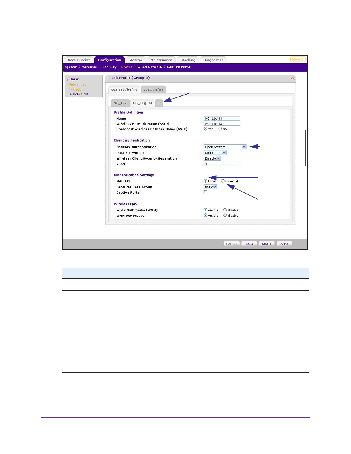
ProSAFE Wireless Controller WC9500
Click + to add another profile.
Your selection from
the Network
Authentication menu
determines the
information that is
displayed onscreen.
Select the Local radio
button to display the
Local MAC ACL
Group menu.
Select the External
radio button to
display the External
Radius Server menu.
7. Configure the settings as described in the following table:
Setting Description
Profile Definition section
Name Enter a unique name to identify the profile.
This value can be up to 32 alphanumeric characters. Use meaningful profile
names instead of the default names.
Profile2, and so on, through Profile8.
Wireless Network Name
(SSID)
Broadcast Wireless
Network Name
Enter a unique name for the wireless network associated with this profile.
Select the Ye
s radio button to enable broadcast of the SSID.
This is the default setting.
Select the No radio button to disable broadcast of the SSID, in which case only
devices that have the correct SSID can connect to the access point.
The default profile names are Profile1,
Manage Security Profiles and Profile Groups
74
Page 75

ProSAFE Wireless Controller WC9500
Setting Description
Client Authentication section
Note: The options that display onscreen depend on your selection from Network Authentication menu.
Network Authentication From the menu, select the authentication type to be used.
Table 3 on page 78 lists all the authentication type options.
Data Encryption From the menu, select the data encryption type to be used.
The options available for data encryption as well as other requirements such as
entering a key or passphrase depend on the network authentication settings.
Table 3 on page 78 lists all the data encryption options.
Wireless Client Security
Separation
VLAN Enter the VLAN ID to be associated with this security profile.
Authentication Settings section
Note: The options that display onscreen depend on the selection from Network Authentication menu.
Note: MAC ACL displays
only when you select
Open System, Shared
Key, WPA-PSK,
WPA2-PSK, or
WPA-PSK &
from the Network
Authentication menu.
WPA2-PSK
From the menu, select Disable to prevent associated wireless clients from
communicating with each other
Wireless client separation is intended for hotspots and other public access
situations.
This VLAN ID needs to match the VLAN ID that is used by other network
devices.
MAC ACL Select one of the following radio buttons:
• Local
The Local MAC ACL Group menu displays so you can
select a group. For more information, see Manage MAC
Authentication and MAC
page 81.
• External. Use external MAC authentication.
The External Radius Server menu displays so you can
select a server. You can use either the basic-Auth RADIUS
server or a RADIUS server of an advanced authentication
group. You cannot use the external LDAP server.
For information about setting up and enabling internal and
external authentication servers, see Manage Authentication
Servers and Authentication Server Groups on page 85.
Note: The MAC ACL radio buttons do not display onscreen if
the network authentication uses an external RADIUS server.
The reason for this is that you can configure either MAC
authentication with an external RADIUS server or network
authentication with an external RADIUS server, but not both.
That is, if you configure an external RADIUS server with WPA,
WPA2, or WPA & WPA2 (or you use Legacy 802.1X), you
cannot use external MAC authentication, and the MAC ACL
radio buttons do not display on screen. You can still use
internal MAC authentication.
, or select Enable
. Use local MAC authentication.
to allow such communication.
Authentication Groups on
Manage Security Profiles and Profile Groups
75
Page 76

ProSAFE Wireless Controller WC9500
Setting Description
Note: Captive Portal
displays only when you
select Open System,
Shared Key, WPA-PSK,
WPA2-PSK, or
WPA-PSK & WPA2-PSK
from the Network
Authentication menu.
Note: Authentication
Server displays only
when you select WP
with Radius, WP
Radius, or WPA & WPA2
with Radius from the
Network Authentication
menu.
A2 with
Captive Portal Select this check box if you want to enable the captive portal.
Authentication
Server
A
For more information, see Manage Guest Network Access on
page 111.
Note: You cannot configure captive portal authentication if the
network authentication uses a RADIUS server, whether it is a
local server or an external server. That is, if you configure a
RADIUS server with WPA, WPA2, or WPA & WPA2 (or if you
use legacy 802.1X), the Captive Portal check box is not shown
onscreen.
Select one of the following radio buttons:
• Local. Use the local authentication server
• External
Select an external authentication server from the
Authentication Server menu.
Note:
For information about setting up and enabling internal
and external authentication servers, see Manage
Authentication Servers and Authentication Server Groups on
page 85.
. Use an external authentication server.
.
Wireless QoS section
Wi-Fi Multimedia (WMM) To enable Wi-Fi Multimedia (WMM), select the Enable radio button, which is
the default setting.
Select the Disable button to disable the feature. For more information, see
Configure QoS for Advanced Profile Groups on page 144.
WMM Powersave The WMM Powersave feature saves power for battery-powered equipment by
increasing the ef
o enable this feature, select the Enable radio button, which is the default
T
setting.
Select the Disable button to disable the feature.
ficiency and flexibility of data transmission.
8. Click Apply.
Edit and Remove Profiles in an Advanced Profile Group
You can easily change or remove a profile from an advanced profile group.
To edit an existing profile to an advanced profile group:
1. Select Configuration > Profile > Advanced > Radio.
The Profile Groups screen displays.
2. Click the tab for the profile group for which you want to edit a profile.
3. Click Edit
.
The Edit Profile screen displays.
4. Click the tab for the radio for which you want to edit a profile.
Manage Security Profiles and Profile Groups
76
Page 77

ProSAFE Wireless Controller WC9500
5. Click the tab for the profile that you want to edit.
6. Change the settings.
For information about how to change the settings, see Configure Profiles in an Advanced
Profile Group on page 73.
7. Click Apply.
To remove an existing profile from an advanced profile group:
1. Select Configuration > Profile > Advanced > Radio.
The Profile Groups screen displays.
2. Click the tab for the profile group for which you want to remove a profile.
3. Click Edit
The Edit Profile (Group-X) screen displays.
4. Click the tab for the radio for which you want to remove a profile.
5. Click the tab for the profile that you want to remove.
6. Click Delete.
7. Confirm that you want to delete the profile.
.
Network Authentication and Data Encryption Options
This section describes the detailed network authentication and data encryption options that
are part of the procedures in Configure Profiles in the Basic Profile Group on page 67 and
Configure Profiles in an Advanced Profile Group on page 73.
Table 3 on page 78 shows the data encryption options based on the network authentication
that you select on the Edit Profile (Basic) or Edit Profile (Group-X) screen, and the required
configuration steps to implement the selected network authentication.
Note: On the Edit Profile (Basic) or Edit Profile (Group-X) screen, for any
selection from the Network Authentication menu that requires a
RADIUS server, authentication is not restricted to a RADIUS server;
you can also use an internal authentication server or an external
LDAP server.
Note: You can configure either MAC authentication with an external
RADIUS server or network authentication with an external RADIUS
server, but not both. That is, if you configure external MAC
authentication, you cannot use an external RADIUS server with
WPA, WPA2, or WPA & WPA2.
Manage Security Profiles and Profile Groups
77
Page 78

Table 3. Network authentication and data encryption settings
ProSAFE Wireless Controller WC9500
Network Authentication
Selection
Open None
Shared Key 64-bit WEP
Data Encryption
Options
WEP
128-bit WEP
152-bit WEP
Configuration Steps
Y ou can use an open system without any encryption or with WEP
encryption:
• No encryption. An
default setting. No further authentication and encryption
configuration is required.
• WEP encryption. T
encryption, see the Shared Key and WEP information further
down in this table.
To configure Shared Key authentication with WEP:
1. From the Data Encryption menu, select a level of WEP
encryption:
- 64-bit WEP. Uses 40/64-bit encryption.
- 128-bit WEP. Uses 104/128-bit encryption.
- 152-bit WEP.
other wireless devices that support this mode.
2.
(Optional) Select the Show Key check box to display the
characters in the key fields.
3. Select a key radio button (Key1, Key2, Key3, or Key4).
4. Enter a key in the corresponding field:
- 64-bit WEP requires a key with 10 characters.
- 128-bit WEP requires a key with 26 characters.
- 152-bit WEP requires a key with 32 characters.
Note: For information about requirements for WEP keys, see
Table 6 on page 207.
open
system without encryption is the
configure an open system with WEP
o
A proprietary mode that works only with
Legacy 802.1x None To configure legacy 802.1x authentication:
1. Set up and enable an internal or external (RADIUS or LDAP)
authentication server.
For information, see
Authentication Server Groups on page 85.
2. Select the Local or External radio button.
3. If you select the External radio button, select the
authentication server that you wish to use from the menu.
Manage Authentication Servers and
Manage Security Profiles and Profile Groups
78
Page 79

ProSAFE Wireless Controller WC9500
Table 3. Network authentication and data encryption settings (continued)
Network Authentication
Selection
WPA with Radius TKIP
WPA2 with Radius AES
Data Encryption
Options
TKIP + AES
TKIP + AES
Configuration Steps
To configure WPA authentication with a RADIUS server:
1. Set up and enable an internal or external (RADIUS or LDAP)
authentication server.
For information, see
Authentication Server Groups on page 85.
2. From the Data Encryption menu, select the type of
encryption:
- TKIP. Supports T
only.
- TKIP +
Select the Local or External radio button.
3.
4. If you select the External radio button, select the
authentication server that you wish to use from the menu.
To configure WPA2 authentication with a RADIUS server:
1. Set up and enable an internal or external (RADIUS or LDAP)
authentication server.
For information, see
Authentication Server Groups on page 85.
2. From the Data Encryption menu, select the type of
encryption:
- AES. Supports AES only
- TKIP + AES. Supports both TKIP and AES.
3.
Select the Local or External radio button.
4. If you select the External radio button, select the
authentication server that you wish to use from the menu.
AES. Supports both TKIP and Advanced
Encryption Standard (AES).
Manage Authentication Servers and
emporal Key Integrity Protocol (TKIP)
Manage Authentication Servers and
.
WPA & WPA2 with Radius
Note: Use this option if
there are both WPA and
WPA2 clients in the
network.
TKIP + AES To configure WPA & WP A2 authentication with a RADIUS server:
1. Set up and enable an internal or external (RADIUS or LDAP)
authentication server
For information, see
Authentication Server Groups on page 85.
2. Select the Local or External radio button.
3. If you select the External radio button, select the
authentication server that you wish to use from the menu.
Note: The Data Encryption menu displays TKIP + AES, which is
the only available option. Both TKIP and AES are supported.
.
Manage Authentication Servers and
Manage Security Profiles and Profile Groups
79
Page 80

ProSAFE Wireless Controller WC9500
Table 3. Network authentication and data encryption settings (continued)
Network Authentication
Selection
WPA-PSK TKIP
WPA2-PSK AES
Data Encryption
Options
TKIP + AES
TKIP + AES
Configuration Steps
To configure WPA-PSK authentication:
1. From the Data Encryption menu, select the type of
encryption:
- TKIP. Supports TKIP only
- TKIP + AES. Supports both TKIP and AES.
2.
(Optional) Select the Show Passphrase check box to display
the characters in the WPA Passphrase (Network Key) field.
Type a passphrase of at least eight characters in the WPA
3.
Passphrase (Network Key) field.
Note: For information about requirements for a WPA
passphrase, see Table 6 on page 207.
To configure WPA2-PSK authentication:
1. From the Data Encryption menu, select the type of
encryption:
- AES. Supports AES only
- TKIP + AES. Supports both TKIP and AES.
2.
(Optional) Select the Show Passphrase check box to display
the characters in the WPA Passphrase (Network Key) field.
Type a passphrase of at least eight characters in the WPA
3.
Passphrase (Network Key) field.
Note: For information about requirements for a WPA
passphrase, see Table 6 on page 207.
.
.
WPA-PSK & WPA2-PSK
Note: Use this option if
there are both WPA-PSK
and WPA2-PSK clients in
the network.
TKIP + AES To configure WPA-PSK & WPA2-PSK authentication:
1. (Optional) Select the Show Passphrase check box to display
the characters in the WPA Passphrase (Network Key) field.
Type a passphrase of at least eight characters in the WPA
2.
Passphrase (Network Key) field.
Note: The Data Encryption menu displays TKIP + AES, which is
the only available option. Both TKIP and AES are supported.
Note: For information about requirements for a WPA
passphrase, see Table 6 on page 207.
Manage Security Profiles and Profile Groups
80
Page 81

ProSAFE Wireless Controller WC9500
Manage MAC Authentication and MAC Authentication Groups
MAC authentication lets you set up an external or a local access control list (ACL) with MAC
addresses of clients to either allow or deny the network access privilege of the specified
clients with the wireless controller–managed access point. The settings are applied only to
managed access points.
Note: The wireless controller can support an aggregate number of
4096 MAC addresses for all its local ACLs.
Guidelines for External MAC Authentication
Note the following external RADIUS server guidelines:
• For each MAC authentication client, you need to configure a policy on the RADIUS
server.
• During MAC authentication, the wireless controller sends the following information to the
RADIUS server:
- MAC address in the format xx:xx:xx:xx:xx:xx
- User name
- Calling station ID
• The wireless controller uses CHAP as the authentication protocol with the RADIUS
server
.
• You can configure either MAC authentication with an external RADIUS server or network
authentication with an external RADIUS server
external RADIUS server with WPA, WPA2, or WPA & WPA2, you cannot use external
MAC authentication but are limited to internal MAC authentication.
To use an external ACL:
1. Configure an ACL on an external RADIUS server
2. On an Edit Profile screen for the basic profile group or an advanced profile group, next to
MAC ACL, select
3. From the External Radius Server menu, select the external authentication server.
For more information, see
page 67 and Configure Security Profiles for Advanced Profile Groups on page 71.
the External radio button.
Configure Security Profiles for the Basic Profile Group on
, but not both. That is, if you configure an
.
The wireless controller consults the MAC ACL at initial client authentication. While a client
roams, the wireless controller uses cached authentication information. After a client has
disassociated from the access point and then attempts to reassociate, the wireless controller
once again consults the MAC
ACL.
Manage Security Profiles and Profile Groups
81
Page 82

ProSAFE Wireless Controller WC9500
Configure Basic Local MAC Authentication Settings
You would typically use the basic MAC authentication group in the profiles of a basic profile
group of a small-scale network. However, you can assign the basic MAC authentication
group to any profile, whether in the basic profile group or in an advanced profile group.
The wireless controller supports a maximum of 256 MAC addresses per SSID.
Note: You cannot add multicast or broadcast MAC addresses to a MAC
access control list (ACL).
To set up basic MAC authentication ACL:
1. Select Configuration > Security > Basic > MAC ACL.
The basic MAC Authentication screen displays:
Note: As an option, you can import a list of MAC addresses from a file. For
more information, see the next section.
2. Next to Trust
ACL as, select one of the following radio buttons:
• Allow. Network access is granted to the clients for which the MAC addresses are
listed in the Selected Wireless Clients list.
• Deny. Network access is denied to the clients for which the MAC addresses are listed
in the Selected Wireless Clients list.
Manage Security Profiles and Profile Groups
82
Page 83

ProSAFE Wireless Controller WC9500
3. Add wireless clients to the Selected Wireless Clients list through one of the following
methods:
A
• The MAC address that you want to add is in
vailable Wireless Clients list, which
contains wireless stations that are present in the vicinity of the access point:
a. Select the MAC address from the A
vailable Wireless Clients list.
b. Click Move.
• The MAC address that you want to add is not in Available Wireless Clients list:
a. Enter the MAC address in the MAC Address field.
b. Click Add
.
4. Click Apply.
To remove a MAC address from the Selected Wireless Clients list:
1. Select the check boxes that correspond to the MAC addresses that you want to remove.
2. Click Delete.
3. Click Apply.
For information about how to add a MAC ACL to a security profile in the basic profile group,
see Configure Profiles in the Basic Profile Group on page 67.
For information about how to add a MAC ACL to a security profile in an advanced profile
group, see Configure Profiles in an Advanced Profile Group on page 73.
Import a MAC List from a File
You can import a precompiled list of MAC addresses from a saved file. This file needs to be a
simple text file with one MAC address per line.
To import a MAC list from a file:
1. Create a text file that includes a list of MAC addresses.
Each MAC address should be on a separate line with hard returns between lines as
shown in the following example:
00:00:11:11:22:29
00:00:11:11:22:28
00:00:11:11:22:27
00:00:11:11:22:26
00:00:11:11:22:25
2. Select Configuration > Security > Basic > MAC ACL.
The basic MAC Authentication screen displays.
3. Click Browse, navigate to the file containing the list of MAC addresses, and select it.
4. Make one of the following selections from the Import MAC List from a file menu:
• Merge. Merges the list of MAC addresses that you intend to import with those that are
already present in the Selected Wireless Clients list.
• Replace. Replaces the MAC addresses that are present in the Selected Wireless
Clients list with those in the file that you intend to import.
Manage Security Profiles and Profile Groups
83
Page 84

ProSAFE Wireless Controller WC9500
5. Click Import.
6. Click Apply.
Configure Local MAC Authentication Groups
For greater security flexibility, you can create up to eight MAC authentication groups (MAC
ACLs) to block or allow network access privilege of different clients. You can assign any MAC
authentication group, including the basic MAC authentication group, to any profile, whether in
the basic profile group or in an advanced profile group.
The wireless controller supports a maximum of 256 MAC addresses per SSID.
Note: You cannot add multicast or broadcast MAC addresses to a MAC
access control list (ACL).
To set up a MAC authentication group:
1. Select Configuration > Security > Advanced > MAC ACL.
The advanced MAC
Authentication screen displays:
Click + to add another ACL group.
2. Click the + button to create an additional ACL group.
3. The new ACL group displays on the advanced MAC Authentication screen, and the tab for
the new
ACL is automatically selected to let you configure the new group.
4. (Optional) In the Group Name field, enter a unique name for the ACL group.
By default, profile groups are named Acl-1,
Manage Security Profiles and Profile Groups
Acl-2, Acl-3, and so on.
84
Page 85

ProSAFE Wireless Controller WC9500
5. Compile the Selected Wireless Clients list.
For information about how to compile a wireless clients list, see Configure Basic Local
MAC Authentication Settings on page 82.
6. Click Apply.
For information about how to add a MAC authentication group to a security profile in the
basic profile group, see Configure Profiles in the Basic Profile Group on page 67.
For information about how to add a MAC authentication group to a security profile in an
advanced profile group, see Configure Profiles in an Advanced Profile Group on page 73.
To delete an ACL group:
1. Select Configuration > Security > Advanced > MAC
The advanced MAC Authentication screen displays:
2. Click the tab for the ACL group that you want to delete.
3. Click Delete
.
Authentication.
Manage Authentication Servers and Authentication Server Groups
You can specify three types of authentication servers: internal, external RADIUS, and
external LDAP:
• Internal authentication server. The wireless controller handles authentication. If you
use this setting, set up WiFi clients on the User Management screen (see Manage Users,
Accounts, and Passwords on page 116.)
• External RADIUS server. Y
typically use in the profiles of a basic profile group of a small-scale network. You need to
specify its configuration on the basic Authentication Server screen (see the next section)
so that you can select this authentication option during the configuration of a profile. As
part of the advanced authentication server settings, you can define multiple external
RADIUS servers that you would typically use in a more complex network with many
profiles. You can then assign different RADIUS servers to different profiles.
ou can define a basic external RADIUS server that you would
By default, the external RADIUS server for the basic authentication group is called
Y
basic-Auth.
authentication servers for the advanced authentication groups are called Auth1 through
Auth8, and you can change these names. You can assign the basic-Auth server to an
advanced profile group, and you can assign a RADIUS server of an advanced
authentication group to the basic profile group.
ou cannot change this name. By default, the external RADIUS
Manage Security Profiles and Profile Groups
85
Page 86

ProSAFE Wireless Controller WC9500
See the following configuration guidelines for external RADIUS servers:
- You need to add only the IP address of the wireless controller as a RADIUS client to
the RADIUS server
. All managed access points are then automatically known to the
RADIUS server.
- For configuration guidelines for external MAC authentication, see Guidelines for
External MAC Authentication on page 81.
- For configuration guidelines for external authentication of captive portal users, see
Manage Guest Network Access on page 111.
• External LDAP server. Y
ou can define one external LDAP server (commonly referred to
as an Active Directory [AD] server). You need to specify its configuration on the basic
Authentication Server screen (see the next section) so that you can select this
authentication option during the configuration of a profile.
By default, the external LDAP server for the basic authentication group is called
basic-LDAP.
You cannot change this name, and you cannot configure any LDAP servers
for the advanced authentication groups. You can assign the basic-LDAP server to both
the basic profile group and to advanced profile groups.
All three servers can be active so that the profiles that you set up can be configured to work
with different authentication servers. For example, you could set up a guest profile with no
authentication, an engineering profile that uses external RADIUS authentication, and a
marketing profile that uses external LDAP authentication.
The settings that you specify on the
are available in the Network Authentication menu and the corresponding
Authentication Server screen affect the selections that
Authentication
Server field on the Edit Profile screens. For information about how to configure security
profiles, see Configure Profiles in the Basic Profile Group on page 67 and Configure Profiles
in an Advanced Profile Group on page 73.
Configure Basic Authentication Server Settings
Use the basic Authentication Server screen to set up the internal authentication server, the
basic external RADIUS server (which is called Auth-basic), and the external LDAP server
(which is called Auth-LDAP). After you have set up these authentication servers, you can
assign any of them to any profile, whether in the basic profile group or in an advanced profile
group.
To configure a basic authentication server:
1. Select Configuration > Security > Basic > Authentication Server.
Manage Security Profiles and Profile Groups
86
Page 87

ProSAFE Wireless Controller WC9500
The basic Authentication Server screen displays. The following figure shows the fields for
an external LDAP server:
2. Select the radio button that corresponds to the authentication server that you want to set up:
• External RADIUS Server
• Internal Authentication Server
• External LDAP Server
3. Configure the settings that correspond to the selected authentication server as described in
the following table:
Setting Description
External
RADIUS
Server
Enable Authentication Select this check box to enable authentication.
Enable Accounting Select this check box to enable accounting.
Primary Server Do the following for each server:
For information about
shared secret
requirements, see
Table 6 on page 207.
Secondary Server
Reauthentication time
(Seconds)
Update Global Key
Every (Seconds)
1. Specify the IP address.
2. Specify the port.
The default port is 1812.
3. Specify the shared secret.
Specify the time (in seconds) after which reauthentication occurs
for all wireless clients.
To enable update of the global key:
1.
Select this check box.
2. Specify the interval (in seconds) after which the global key is
updated for all wireless clients.
Manage Security Profiles and Profile Groups
87
Page 88

Setting Description
ProSAFE Wireless Controller WC9500
Internal
Authentication
Server
External
LDAP Server
Reauthentication Time
(seconds)
Update Global Key
Every (seconds)
Server IP Specify the IP address of the external Active Directory (AD)
Server Port Specify the port of the external
User Base DN Specify the user base distinguished name (DN) on the AD server.
Workgroup Name Specify the workgroup name on the AD server.
Admin Domain Specify the administrative domain on the AD server.
Domain Admin User Specify the user name for the administrative domain.
Domain Admin
Password
Specify the time (in seconds) after
which reauthentication occurs for all
wireless clients.
To enable update of the global key:
1. Select this check box.
2. Specify the interval (in seconds)
after which the global key is
updated for all wireless clients.
authentication server
The default is port 389.
Specify the password for the administrative domain.
Note: For information about password requirements, see
Table 6 on page 207.
.
AD server.
When you use the
internal authentication
server, set up WiFi clients
on the User Management
screen. For information,
see
Manage Users,
Accounts, and
Passwords on page 116.
4. Click Apply.
For information about how to add an authentication server to a security profile in the basic
profile group, see Configure Profiles in the Basic Profile Group on page 67.
For information about how to add an authentication server to a security profile in an advanced
profile group, see Configure Profiles in an Advanced Profile Group on page 73.
Configure RADIUS Authentication Server Groups
For greater security flexibility, you can create up to eight external RADIUS servers to
authenticate different groups of users. After you have set up these authentication servers,
you can assign any of them, including the basic RADIUS server, to any profile, whether in the
basic profile group or in an advanced profile group.
To set up a RADIUS authentication server group:
1. Select Configuration > Security > Advanced >
Authentication Server.
Manage Security Profiles and Profile Groups
88
Page 89
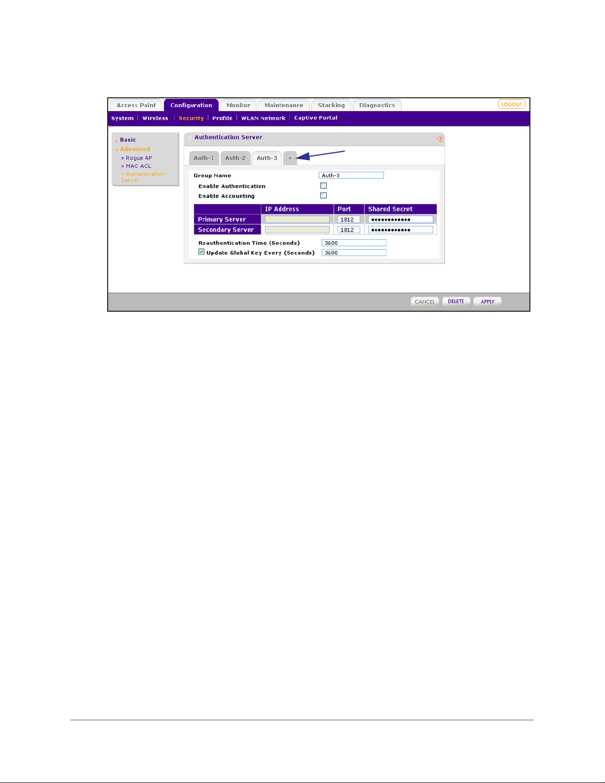
ProSAFE Wireless Controller WC9500
The advanced Authentication Server screen displays:
Click + to add another authentication group.
2. Click the + button to create an additional authentication group.
The new authentication group displays on the advanced Authentication Server screen,
and the tab for the new authentication is automatically selected to let you configure the
new group.
3. (Optional) In the Group Name field, enter a unique name for the authentication group.
By default, authentication groups are named Auth-1, Auth-2, Auth-3, and so on.
4. Configure the external RADIUS server for the group.
For information about setting up an external RADIUS server, see the table in the previous
section, Configure Basic Authentication Server Settings on page 86.
5. Click Apply.
For information about how to add a RADIUS authentication group to a security profile in the
basic profile group, see Configure Profiles in the Basic Profile Group on page 67.
For information about how to add a RADIUS authentication group to a security profile in an
advanced profile group, see Configure Profiles in an Advanced Profile Group on page 73.
To delete a RADIUS authentication group:
1. Configuration > Security > Advanced > Authentication Server.
The advanced
Authentication Server screen displays.
2. Click the tab for the RADIUS authentication group that you want to delete.
3. Click Delete.
Manage Security Profiles and Profile Groups
89
Page 90

6. Discover and Manage Access
Points
This chapter includes the following sections:
• Access Point Discovery Guidelines
• Discover Access Points with the Discovery Wizard
• Manage the Managed AP List
• Assign Access Points to Advanced Profile Groups
IMPORTANT:
Before you use the wireless controller to discover your access
points and push the configurations to the access points:
1. Make sure that you have registered sufficient licenses.
2. Determine which profiles and security you require.
3. If needed, set up authentication servers and MAC authentication.
4. Complete the configuration of the profiles that you intend to use.
These steps are described in Register Your Licenses on page 54
and in Chapter 5, Manage Security Profiles and Profile Groups.
6
90
Page 91

ProSAFE Wireless Controller WC9500
Access Point Discovery Guidelines
You need to run the Discovery Wizard for the wireless controller to discover supported
NETGEAR access points on the LAN or WAN. The wireless controller can discover access
points that are still in their factory default state and access points that are deployed and
running.
After the access points are discovered, you can add them to the Managed AP List. You can
then use the wireless controller to configure, manage, and monitor the managed access
points.
General Discovery Guidelines
An access point needs to run at least its initial firmware release or a newer version. For
firmware requirements, see NETGEAR ProSAFE Access Points on page 15. There are no
other firmware requirements for the access point to function with the wireless controller.
Access points in factory default state that are in the same Layer 2 network can have the
same IP address and still be discovered. Depending on the configuration of the DHCP
server, these access points are discovered in parallel or sequentially
.
Layer 3 Discovery Guidelines
These are the requirements for autodiscovery of local access points across Layer 3
networks:
• All standalone access points need to have SNMP and SSH enabled. (This is the default
setting for access points.)
• UDP port number 7890 needs to be unblocked in the firewall.
• Each access point needs to have a unique IP address. (This requirement does not apply
to Layer 2 discovery
them is discovered at a time.
change its IP address, and run discovery again to discover the next access point with that
IP address.
• DHCP option 43 (vendor-specific information) needs to be enabled on an external DHCP
. Specifying an internal DHCP server on the wireless controller automatically
server
enables DHCP option 43 with the IP address of the wireless controller.
How you need to configure DHCP option 43 depends on the type of external DHCP
server:
- Layer 3 switch as a DHCP server. If you use a Layer 3 switch as a DHCP server,
specify the wireless controller’
points to receive the wireless controller’s IP address and to allow the DHCP server to
assign IP addresses to the access points. The hexadecimal address needs to be
preceded by the vendor-specific octets 02:04:.
.) If more than one access point has the same IP address, only one of
You have to add the access point to the managed list,
s IP address in hexadecimal format to allow the access
Discover and Manage Access Points
91
Page 92

ProSAFE Wireless Controller WC9500
To compose the address, start with 02:04: and then add each of the four address
octets in hexadecimal format, separated by colons. For example:
192.168.33.27 in decimal format equals c0:a8:21:1b in hexadecimal format. After
you have added the vendor-specific octets, the complete address is
02:04:c0:a8:21:1b.
- Linux- or Windows-based DHCP server. If you use a Linux- or Windows-based
DHCP server
as the vendor class identifier.
, configure the IP address in decimal format and NETGEAR_WNC_AP
Discover Access Points with the Discovery Wizard
The Discovery Wizard finds provides two methods to find access points that are not yet on
the managed access point list. These methods are described in the following sections:
• Access Points in Factory Default State and Access Points in a Layer 2 Subnet
• Access Points Installed and Working in Standalone Mode in Different Layer 3 Networks
CAUTION:
If security is not set up, or is set up incorrectly , when the wireless controller
pushes the configurations to the access points, you could accidentally
wipe out all security, leaving your entire network open to access. Be sure
that you set up security correctly (see Chapter 5, Manage Security Profiles
and Profile Groups).
Access Points in Factory Default State and Access Points in a Layer 2 Subnet
Access points in factory default state are access points “out of the box” that have never been
employed. Access points in a Layer 2 subnet are access points that are installed and
functioning in the same IP subnet as the wireless controller and that are connected to the
wireless controller through a back-end Layer 2 switch.
To discover access points in factory default state and access points in a Layer 2
subnet:
1. Select Access Point > Discovery Wizard.
Discover and Manage Access Points
92
Page 93
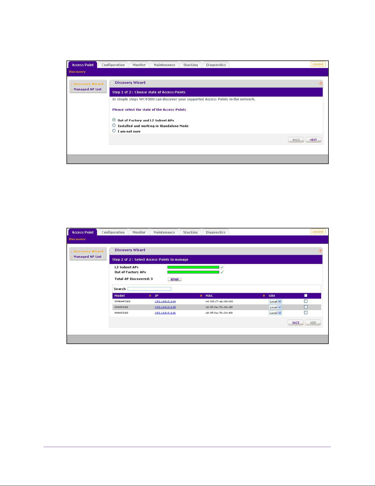
ProSAFE Wireless Controller WC9500
The Discovery Wizard Step 1 of 2 : Choose state of Access Points screen displays:
2. Select the Out of Factory and L2 Subnet APs radio button.
Note: The I am not sure radio button directs you to the product documentation.
3. Click Next.
The Discovery Wizard Step 2 of 2 : Select Access Points to manage screen displays.
The wireless controller searches for NETGEAR products on the LAN based on MAC
address and identifies which products are supported access point models. Progress bars
show the progress of the discovery process.
When the discovery process is finished, the total number of access points is displayed
and the table shows the access points that were discovered. For each access point, the
table includes the model number, IP address, MAC address, and site.
4. (Optional) Enter information in the Search field to find an individual access point.
5. Review the discovery results to make sure that all the access points are listed.
Discover and Manage Access Points
93
Page 94

ProSAFE Wireless Controller WC9500
The effectiveness of the discovery process depends in part on how the access points on
your LAN are set up. If each access point is configured with a unique IP address and is
running current firmware, discovery is usually simple.
If the discovery results are not what you expect, check the following:
• Access points that are already managed by the wireless controller are not in the
discovery list.
To view the Managed AP List, select Access Point > Managed AP List.
• The access points might be in a different IP network.
For information about how to discover access points in a dif
ferent subnet, see Access
Points Installed and Working in Standalone Mode in Different Layer 3 Networks on
page 96.
• Access points that are in factory default mode but across a router are not detected.
For information about how to discover access points across a router, see Access
Points Installed and Working in Standalone Mode in Different Layer 3 Networks on
page 96.
• Make sure that a DHCP server is available in the network or on the wireless
controller.
For information about the wireless controller’s DHCP server, see Manage the DHCP
Server on page 51.
• For more information, see Problems with Access Points on page 202.
6. (Optional) Click Restart.
The discovery process runs again.
7. (Optional) From the Site menu, select Remote for each access point that you want to
designate as a remote access point.
By default, all discovered access points are designated as Local. The Remote and Local
designations are for organization only
.
Note: The wireless controller cannot discover remote access points over a
site-to-site VPN connection or behind a remote NAT router without a VPN
connection. This capability will be added in a future release.
8. Do one of the following:
• Select individual check boxes for discovered access points that you want to add to the
managed list.
• Select the check box in the upper right of the table heading to add all discovered
access points to the managed list.
9. Click Add.
Depending on the type of access points that have been discovered, a screen that lets you
enter or ignore a login name and password might display
Discover and Manage Access Points
94
.
Page 95
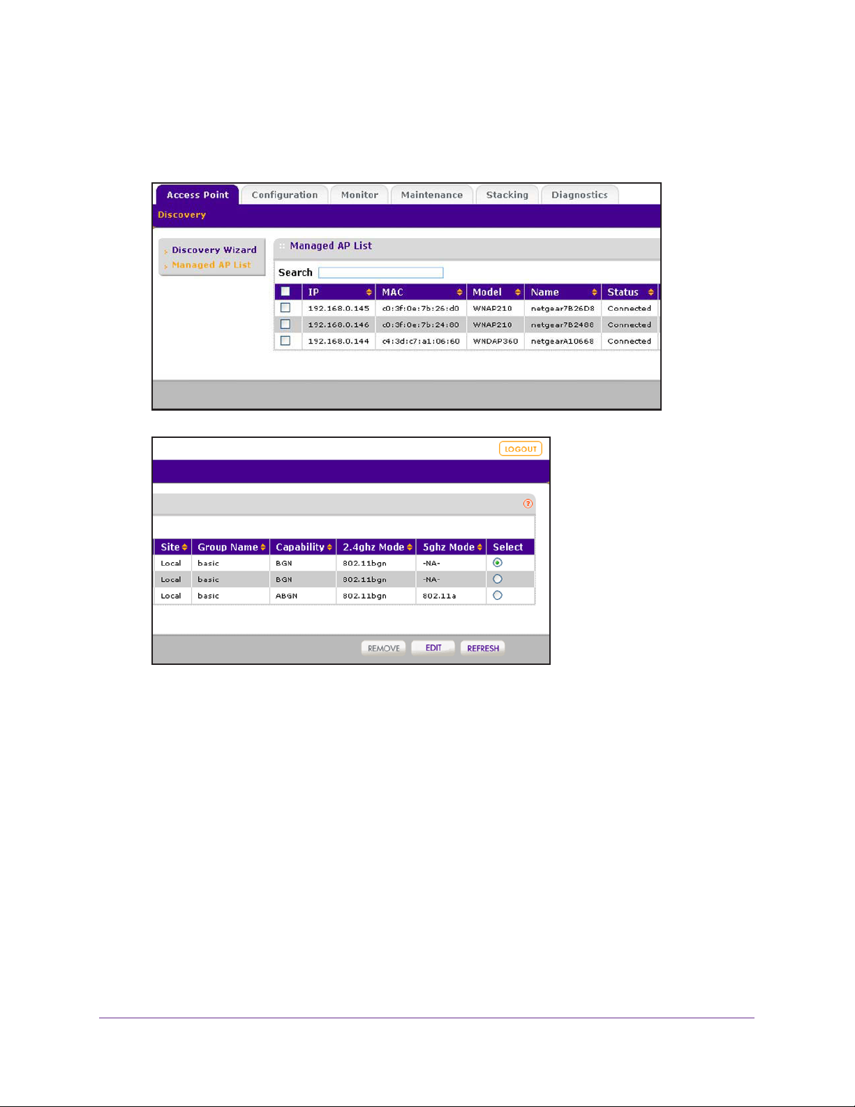
ProSAFE Wireless Controller WC9500
10. If necessary, enter the login name and password.
The Managed AP List screen displays. Because this is a wide screen, it is shown in the
following two figures:
After the access points are added to the Managed AP List, the wireless controller
upgrades the firmware of the access points to the latest firmware that is loaded on the
wireless controller, and the access points become managed access points. Depending
on the number of access points that you add to the Managed AP List, this process might
take several minutes.
By default, the access point upgrade process uses multicast. If you need to configure a
specific multicast IP address range for the upgrade process or disable multicast, see
Configure Multicast Firmware Upgrade for Access Points on page 168.
If one or more access points do not transition to the Connected state (see the Status
column in the Managed
AP List), see Problems with Access Points
on page 202.
For information about how to manage the Managed AP List, see Manage the Managed
AP List on page 100.
Discover and Manage Access Points
95
Page 96

ProSAFE Wireless Controller WC9500
Access Points Installed and Working in Standalone Mode in Different Layer 3 Networks
Access points that are installed and working in standalone mode in different Layer 3 networks
are access points that do not function in the same subnet as the wireless controller but in
different IP ranges and that are connected to the wireless controller through a router.
If you have a very large wireless network, you might have to run the Discovery Wizard
several times.
To discover access points in different Layer 3 networks:
1. Select Access Point > Discovery Wizard.
The Discovery Wizard Step 1 of 3 : Choose state of
2. Select the Installed and working in Standalone Mode radio button.
Note: The I am not sure radio button directs you to the product documentation.
3. Click Next.
The Discovery Wizard Step 2 of 3 : Specify IP Range screen displays:
Access Points screen displays:
Discover and Manage Access Points
96
Page 97

ProSAFE Wireless Controller WC9500
4. In the Range 1 section, fill in the Start IP and End IP fields.
These IP addresses specify the range in which the wireless controller should discover
access points.
5. (Optional) Add additional IP address ranges for the wireless controller to search in:
a. Click Add.
The screen adjusts to display a second set of Start IP and End IP fields.
b. In the Range 2 section, fill in the Start IP and End IP fields.
c. Click Add
.
The screen adjusts to display a third set of Start IP and End IP fields.
d. In the Range 3 section, fill in the Start IP and End IP fields.
6. Click Next.
The Discovery Wizard Step 3 of 3 : Select Access Points to manage screen displays.
The wireless controller searches for NETGEAR products on the LAN based on MAC
address and then identifies which products are supported access point models. A
progress bar show the progress of the discovery process.
When the discovery process is finished, the total number of access points is displayed
and the table shows the access points that were discovered. For each access point, the
table includes the model number, IP address, MAC address, and site.
7. (Optional) Enter information in the Search field to find an individual access point.
8. Review the discovery results to make sure that all the access points are listed.
The effectiveness of the discovery process depends in part on how the access points on
your LAN are set up. If each access point is configured with a unique IP address and is
running current firmware, discovery is usually simple.
Discover and Manage Access Points
97
Page 98

ProSAFE Wireless Controller WC9500
If the discovery results are not what you expect, check the following:
• Access points managed already by the wireless controller are not in the discovery list.
To view the Managed AP List, select Access Point > Managed AP List
.
• Make sure that a DHCP server is available in the network or on the wireless
controller.
For information about the wireless controller’s DHCP server, see Manage the DHCP
Server on page 51.
• If more than one access point has the same IP address, only one of them is
discovered at a time.
You have to add the access point to the managed list, change its IP address, and run
discovery again to discover the next access point with that IP address.
• For more information, see Problems with Access Points on page 202.
9. (Optional) Click Restart.
The discovery process runs again.
10. (Optional) From the Site menu, select Remote for each access point that you want to
designate as a remote access point.
By default, all discovered access points are designated as Local. The Remote and Local
designations are for organization only
.
Note: The wireless controller cannot discover remote access points over a
site-to-site VPN connection or behind a remote NAT router without a VPN
connection. This capability will be added in a future release.
11. Do one of the following:
• Select individual check boxes for discovered access points that you want to add to the
managed list.
• Select the check box in the upper right of the table heading to add all discovered
access points to the managed list.
12. Click Add
.
Depending on the type of access points that have been discovered, a screen that lets you
enter or ignore a login name and password might display
.
13. If necessary, enter the login name and password.
Discover and Manage Access Points
98
Page 99

ProSAFE Wireless Controller WC9500
The Managed AP List screen displays. Because this is a wide screen, it is shown in the
following two figures:
After the access points are added to the Managed AP List, the wireless controller
upgrades the firmware of the access points to the latest firmware that is loaded on the
wireless controller, and the access points become managed access points. Depending
on the number of access points that you add to the Managed AP List, this process might
take several minutes.
By default, the access point upgrade process uses multicast. If you need to configure a
specific multicast IP address range for the upgrade process or disable multicast, see
Configure Multicast Firmware Upgrade for Access Points on page 168.
If one or more access points do not transition to the Connected state (see the Status
column in the Managed
AP List), see Problems with Access Points
on page 202.
For information about how to manage the Managed AP List, see Manage the Managed
AP List on page 100.
Discover and Manage Access Points
99
Page 100
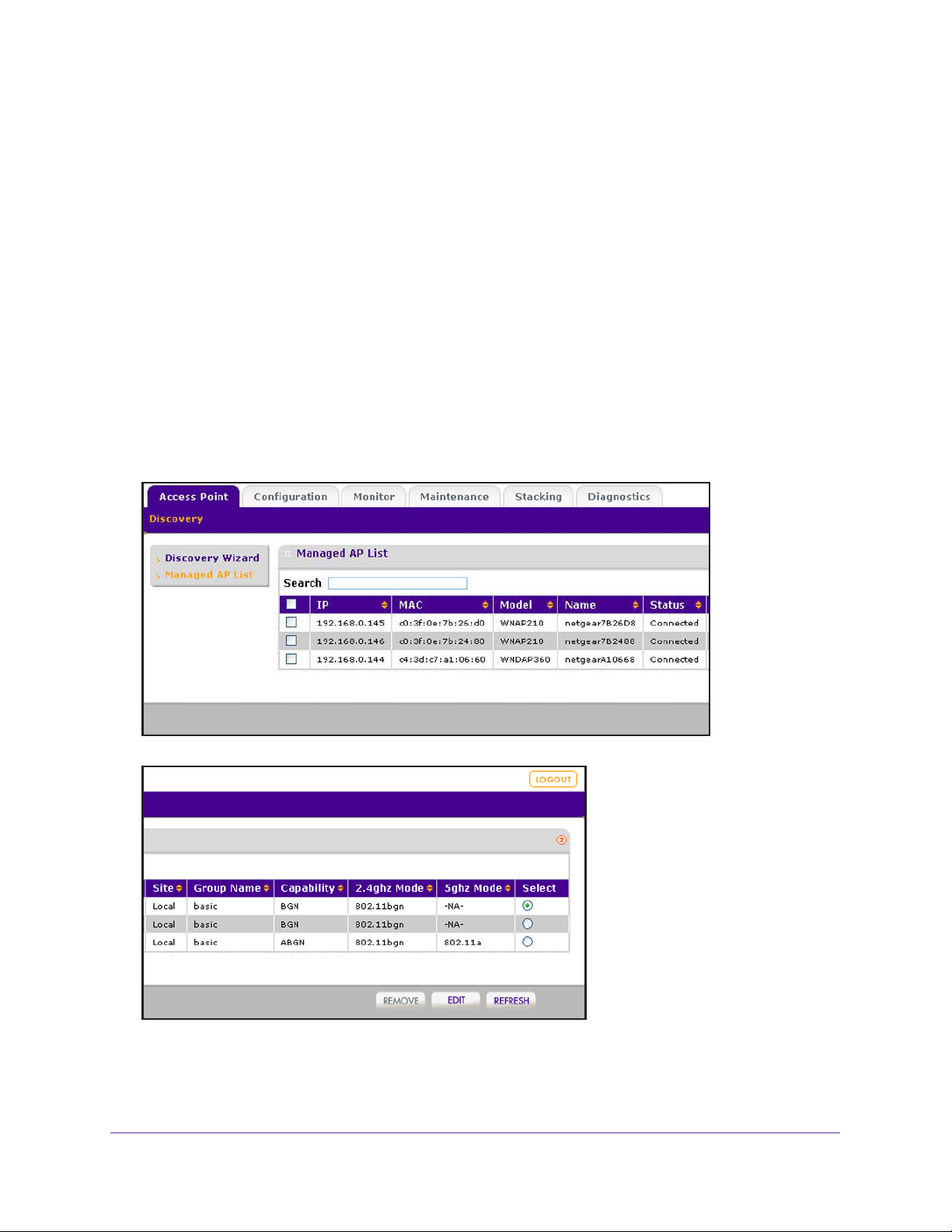
ProSAFE Wireless Controller WC9500
Manage the Managed AP List
After you have added discovered access points to the Managed AP List, you can view the
status of the access points on the list, edit information for selected access point on the list,
and remove access points from the list.
View the Managed AP List
The managed AP List displays the status, IP addresses, MAC addresses, model numbers,
names, and other information for the managed access points.
To view the status and other information for managed access points:
Select Access Point > Managed AP List.
The Managed
following two figures:
AP List screen displays. Because this is a wide screen, it is shown in the
Discover and Manage Access Points
100
 Loading...