

Page 1
ProSafe 20-AP Wireless Controller WC7520
Reference Manual
350 East Plumeria Drive
San Jose, CA 95134
USA
February 20, 2012
202-10686-04
1.1
Page 2

ProSafe 20-AP Wireless Controller WC7520
©2010–2011 NETGEAR, Inc. All rights reserved
No part of this publication may be reproduced, transmitted, transcribed, stored in a retrieval system, or translated
into any language in any form or by any means without the written permission of NETGEAR, Inc.
Technical Su p p o r t
Thank you for choosing NETGEAR. T o register your product, get the latest product updates, get support online, or
for more information about the topics covered in this manual, visit the Support website at
http://support.netgear.com.
Phone (US & Canada only): 1-888-NETGEAR
Phone (Other Countries): Check the list of phone numbers at
http://support.netgear.com/app
/answers/detail/a_id/984.
Trademarks
NETGEAR, the NETGEAR logo, and Connect with Innovation are trademarks and/or registered trademarks of
NETGEAR, Inc. and/or its subsidiaries in the United States and/or other countries. Information is subject to change
without notice. Other brand and product names are registered trademarks or trademarks of their respective
holders. © 2011 NETGEAR, Inc. All rights reserved.
Statement of Conditions
To improve internal design, operational function, and/or reliability, NETGEAR reserves the right to make changes
to the products described in this document without notice. NETGEAR does not assume any liability that may occur
due to the use, or application of, the product(s) or circuit layout(s) described herein.
Revision History
Publication
Part Number
202-10686-04 v1.1 February 2012 Added hexadecimal address information to Guidelines for the
202-10686-04 v1.0 October, 2011 Added the following new information:
Version Publish Date Comments
Autodiscovery Process Across
• New features:
- Discovery and management of remote access points (see
Requirements for Autodiscovery of Remote Access Point
on page 52) and Add Access Points to the Managed List
after Discovery on page 57
- Support for sentry mode (see Edit and
Point Information on page 59)
- Rogue AP mitigation (see Co
Detection Settings on page 114)
- Captive portal accounts (see Manag
and Passwords on page 128)
• Changes and improvements to the monitoring screens
• Additional troubleshooting information
Layer 3 Networks on page 52.
Remove Access
nfigure Basic Rogue
e Users, Accounts,
s
2
Page 3

ProSafe 20-AP Wireless Controller WC7520
202-10686-03 v1.0 July, 2011 Added the following new information:
• Support for the WNDAP360 access point (see NETGEAR
ProSafe Access Points)
• New features:
- N:1 redundancy (see Man
- Monitoring stacking and redundancy (see Vi
Network Summary Screen)
- External RADIUS-based MAC authentication (see
Guidelines for External MAC Authentication)
- External RADIUS-based captive
Configure Captive Portal Settings)
202-10686-02 v1.0 March 201 1 Added the following new information:
• Support for the WNAP320 access point.
• New features:
- Capability to specify use of an access point’s internal or
external
Access Point Information).
- Capability to adjust the Tx power for all managed access
poi
- Capability to adjust the channel and Tx power for
ind
Settings).
- Capability to edit IP settings of individual access points
(s
- Display of radio-mode capabilities on the managed AP list
(s
Revised existing content and
Made changes to some monitoring screens (see Chapter 11,
Monitoring the Wireless Network and Components).
antenna or antennas (see Edit and Remove
nts (see Configure Channels).
ividual access points (see Configure Wireless
ee Manage the Access Point List).
ee Manage the Access Point List).
age Redundancy)
reorganized the manual.
ew th e
portal authentication (see
202-10686-01 v1.4 October 2010 Made a minor revision to indicate the number of supported MAC
esses per SSID.
addr
202-10686-01 v1.3 September 2010 Added an index and made minor revisions to existing content.
202-10686-01 v1.2 September 2010 Added new content and revised existing content in chapters 1,
, 5, 9, and 10.
2, 4
Added chapters 11 and 12 and appendix A.
202-10686-01 v1.1 September 2010 Added new content to chapters 1 through 4.
202-10686-01 v1.0 August 2010 Initial publication.
3
Page 4

Table of Contents
Chapter 1 Introduction and Overview
Key Features and Capabilities. . . . . . . . . . . . . . . . . . . . . . . . . . . . . . . . . . . 9
Package Contents . . . . . . . . . . . . . . . . . . . . . . . . . . . . . . . . . . . . . . . . . . . 11
Hardware Features . . . . . . . . . . . . . . . . . . . . . . . . . . . . . . . . . . . . . . . . . . 12
Front Panel Ports and LEDs . . . . . . . . . . . . . . . . . . . . . . . . . . . . . . . . . 12
Rear Panel Features . . . . . . . . . . . . . . . . . . . . . . . . . . . . . . . . . . . . . . . 13
Bottom Panel with Product Label. . . . . . . . . . . . . . . . . . . . . . . . . . . . . . 14
WC7520 Wireless Controller System Components. . . . . . . . . . . . . . . . . . 14
NETGEAR ProSafe Access Points . . . . . . . . . . . . . . . . . . . . . . . . . . . . 15
What Can You Do with the WC7520 Wireless Controller? . . . . . . . . . . . . 16
Licenses . . . . . . . . . . . . . . . . . . . . . . . . . . . . . . . . . . . . . . . . . . . . . . . . . . 18
Maintenance and Support . . . . . . . . . . . . . . . . . . . . . . . . . . . . . . . . . . . . . 18
Web Management Interface Layout . . . . . . . . . . . . . . . . . . . . . . . . . . . . . 19
Initial Connection and Configuration . . . . . . . . . . . . . . . . . . . . . . . . . . . . . 20
Basic and Advanced Settings . . . . . . . . . . . . . . . . . . . . . . . . . . . . . . . . . . 22
Profile Groups . . . . . . . . . . . . . . . . . . . . . . . . . . . . . . . . . . . . . . . . . . . . 23
Choose a Location for the Wireless Controller . .
Deploy the Wireless Controller . . . . . . . . . . . . . . . . . . . . . . . . . . . . . . . . . 26
. . . . . . . . . . . . . . . . . . . 25
Chapter 2 System Planning and Deployment Scenarios
System Planning . . . . . . . . . . . . . . . . . . . . . . . . . . . . . . . . . . . . . . . . . . . . 27
Preinstallation Planning. . . . . . . . . . . . . . . . . . . . . . . . . . . . . . . . . . . . . 27
Before You Configure a Wireless Controller . .
Single Controller Configuration with Basic
Single Controller Configuration with Advanced Profile Groups. . . . . . . 31
Stacked Controller Configuration. . . . . . . . . . . . . . . . . . . . . . . . . . . . . . 32
Management VLAN and Data VLAN Strategies . . . . . . . . . . . . . . . . . . . . 32
Deployment Scenarios . . . . . . . . . . . . . . . . . . . . . . . . . . . . . . . . . . . . . . . 34
Scenario Example 1: Basic Network with Single VLAN
Scenario Example 2: Advanced Network with VLANs and SSIDs. . . . . 35
Scenario Example 3: Advanced Network with Redundancy . . . . . . . . . 38
. . . . . . . . . . . . . . . . . . . 28
Profile Group . . . . . . . . . . . 30
. . . . . . . . . . . . . 34
Chapter 3 RF Planning
RF Planning Overview. . . . . . . . . . . . . . . . . . . . . . . . . . . . . . . . . . . . . . . . 41
Planning Requirements . . . . . . . . . . . . . . . . . . . . . . . . . . . . . . . . . . . . . 41
Define and Edit Buildings and Floors . . . . . . . . . . . . . . . . . . . . . . . . . . . . 42
Specify Access Point Requirements . . . . . . . . . . . . . . . . . . . . . . . . . . . . . 45
View and Manage Heat Maps for Deployed Plans . . . . . . . . . . . . . . . . . . 48
Table of Contents | 4
Page 5

ProSafe 20-AP Wireless Controller WC7520
Chapter 4 Access Point Discovery and Management
Access Point Discovery and Discovery Guidelines . . . . . . . . . . . . . . . . . .51
Requirements for Autodiscovery of Local Access
Requirements for Autodiscovery of Remote
Run the Discovery Wizard . . . . . . . . . . . . . . . . . . . . . . . . . . . . . . . . . . . . .54
Discovery Results. . . . . . . . . . . . . . . . . . . . . . . . . . . . . . . . . . . . . . . . . . . .56
Manage the Access Point List . . . . . . . . . . . . . . . . . . . . . . . . . . . . . . . . . .57
Add Access Points to the Managed List after
Edit and Remove Access Point Informat
ion . . . . . . . . . . . . . . . . . . . . . .59
Points . . . . . . . . . . . .51
Access Points . . . . . . . . . .52
Discovery . . . . . . . . . . . .57
Chapter 5 Configuring Network Settings
Configure General Settings . . . . . . . . . . . . . . . . . . . . . . . . . . . . . . . . . . . .63
Time Management . . . . . . . . . . . . . . . . . . . . . . . . . . . . . . . . . . . . . . . . . . .64
Configure IP and VLAN Settings . . . . . . . . . . . . . . . . . . . . . . . . . . . . . . . .65
Management VLANs. . . . . . . . . . . . . . . . . . . . . . . . . . . . . . . . . . . . . . . .66
Untagged VLANs . . . . . . . . . . . . . . . . . . . . . . . . . . . . . . . . . . . . . . . . . .67
Manage the DHCP Server . . . . . . . . . . . . . . . . . . . . . . . . . . . . . . . . . . . . .67
Manage Certificates . . . . . . . . . . . . . . . . . . . . . . . . . . . . . . . . . . . . . . . . . .70
Configure Syslog and Alarm Notification Settings . . . . . . . . . . . . . . . . . . .71
Configure Syslog Settings . . . . . . . . . . . . . . . . . . . . . . . . . . . . . . . . . . .71
Configure Alarm Notification Settings. . . . . . . . . . . . . . . . . . . . . . . . . . .72
Configure the Email Notification Server . . . . . . . . . . . . . . . . . . . . . . . . .72
Chapter 6 Managing Security Profiles and Profile Groups
Manage Wireless Security Profiles. . . . . . . . . . . . . . . . . . . . . . . . . . . . . . .74
Small WLAN Networks . . . . . . . . . . . . . . . . . . . . . . . . . . . . . . . . . . . . . .75
Larger WLAN Networks . . . . . . . . . . . . . . . . . . . . . . . . . . . . . . . . . . . . .75
Profile Naming Conventions. . . . . . . . . . . . . . . . . . . . . . . . . . . . . . . . . .76
Considerations Before You Configure Profiles
Configure Security Profiles for the Basic Profile G
Edit and Remove Profiles from the Basic Prof
Network Authentication and Data Encryption O
Configure Security Profiles for Advanced Profile Groups. . . . . . . . . . . . . .84
Edit and Remove Profiles from an Advanced P
Remove an Advanced Profile Group . . . . . . . . . . . . . . . . . . . . . . . . . . .87
Manage Basic and Advanced Profile Groups in the WLAN . . . . . . . . . . . .87
. . . . . . . . . . . . . . . . . . . .76
roup . . . . . . . . . . . . . . .77
ile Group. . . . . . . . . . . . .80
ptions . . . . . . . . . . . . . .81
rofile Group. . . . . . . . . .87
Chapter 7 Configuring Wireless and QoS Settings
About Basic and Advanced Wireless and QoS Configurations . . . . . . . . .90
Configure the Radio . . . . . . . . . . . . . . . . . . . . . . . . . . . . . . . . . . . . . . . . . .91
Basic Radio Configuration . . . . . . . . . . . . . . . . . . . . . . . . . . . . . . . . . . .91
Advanced Radio Configuration for Profile Groups . . . . . . . . . . . . . . . . .92
Configure Wireless Settings. . . . . . . . . . . . . . . . . . . . . . . . . . . . . . . . . . . .93
Basic Wireless Configuration . . . . . . . . . . . . . . . . . . . . . . . . . . . . . . . . .93
Advanced Wireless Configuration for Profile Groups . . . . . . . . . . . . . . .96
5
Page 6

ProSafe 20-AP Wireless Controller WC7520
Configure Channels . . . . . . . . . . . . . . . . . . . . . . . . . . . . . . . . . . . . . . . . . .99
Specify RF Management . . . . . . . . . . . . . . . . . . . . . . . . . . . . . . . . . . . . .101
Basic RF Management. . . . . . . . . . . . . . . . . . . . . . . . . . . . . . . . . . . . .102
Advanced RF Management for Profile Groups. . . . . . . . . . . . . . . . . . .104
Configure QoS for Profile Groups . . . . . . . . . . . . . . . . . . . . . . . . . . . . . .105
Configure Load Balancing . . . . . . . . . . . . . . . . . . . . . . . . . . . . . . . . . . . .107
Configure Rate Limiting . . . . . . . . . . . . . . . . . . . . . . . . . . . . . . . . . . . . . .109
Basic Rate Limiting. . . . . . . . . . . . . . . . . . . . . . . . . . . . . . . . . . . . . . . .109
Advanced Rate Limiting for Profile Groups . . . . . . . . . . . . . . . . . . . . . 110
Chapter 8 Configuring Network Access and Security
About Basic and Advanced Security Configurations . . . . . . . . . . . . . . . .112
Manage Rogue Access Points . . . . . . . . . . . . . . . . . . . . . . . . . . . . . . . . . 113
Configure Basic Rogue Detection Settings . . . . . . . . . . . . . . . . . . . . .114
Configure Advanced Rogue Detection Settings. . . . . . . . . . . . . . . . . . 116
Manage MAC Authentication and MAC Authentication Groups. . . . . . . .117
Guidelines for External MAC Authentication . .
Configure Basic Local MAC Authentication Settings . . . . . . . . . . . . . . 118
Configure Local MAC Authentication Groups. . . . . . . . . . . . . . . . . . . .120
Manage Authentication Servers and Authentication Server Groups . . . .122
Configure Basic Authentication Server Settings. . . . . . . . . . . . . . . . . . 123
Configure RADIUS Authentication Server Groups. . . . . . . . . . . . . . . .125
Manage Guest Network Access. . . . . . . . . . . . . . . . . . . . . . . . . . . . . . . .126
Configure Captive Portal Settings . . . . . . . . . . . . . . . . . . . . . . . . . . . .126
Manage Users, Accounts, and Passwords. . . . . . . . . . . . . . . . . . . . . . . . 128
. . . . . . . . . . . . . . . . . . 118
Chapter 9 Maintaining the Controller
Manage the Configuration File . . . . . . . . . . . . . . . . . . . . . . . . . . . . . . . . . 135
Back Up and Restore the Configuration File . . . . . . . . . . . . . . . . . . . .135
Upgrade the Configuration File. . . . . . . . . . . . . . . . . . . . . . . . . . . . . . .137
Reboot or Reset the Wireless Controller . . . . .
Reboot Access Points . . . . . . . . . . . . . . . . . . . . . . . . . . . . . . . . . . . . . . .141
Manage External Storage. . . . . . . . . . . . . . . . . . . . . . . . . . . . . . . . . . . . . 141
Manage Remote Access . . . . . . . . . . . . . . . . . . . . . . . . . . . . . . . . . . . . .142
Specify Session Time-Outs . . . . . . . . . . . . . . . . . . . . . . . . . . . . . . . . .144
View Alerts and Events and Save the Logs . . . . . . . . . . . . . . . . . . . . . . .144
Save the Logs. . . . . . . . . . . . . . . . . . . . . . . . . . . . . . . . . . . . . . . . . . . .144
View Alerts and Events. . . . . . . . . . . . . . . . . . . . . . . . . . . . . . . . . . . . .145
Manage Licenses. . . . . . . . . . . . . . . . . . . . . . . . . . . . . . . . . . . . . . . . . . .149
View Your Licenses . . . . . . . . . . . . . . . . . . . . . . . . . . . . . . . . . . . . . . .149
Configure the License Server Settings. . . . . . . . . . . . . . . . . . . . . . . . .150
Register Your Licenses . . . . . . . . . . . . . . . . . . . . . . . . . . . . . . . . . . . .151
Retrieve Your Licenses . . . . .
. . . . . . . . . . . . . . . . . . . . . . . . . . . . . . .153
. . . . . . . . . . . . . . . . . . . .139
6
Page 7

ProSafe 20-AP Wireless Controller WC7520
Chapter 10 Managing Stacking and Redundancy
Manage Stacking . . . . . . . . . . . . . . . . . . . . . . . . . . . . . . . . . . . . . . . . . . .154
Configure Stacking . . . . . . . . . . . . . . . . . . . . . . . . . . . . . . . . . . . . . . . .155
Controller Selection List . . . . . . . . . . . . . . . . . . . . . . . . . . . . . . . . . . . .157
Manage Redundancy . . . . . . . . . . . . . . . . . . . . . . . . . . . . . . . . . . . . . . . .158
Single Controller with Redundanc
N:1 Redundancy. . . . . . . . . . . . . . . . . . . . . . . . . . . . . . . . . . . . . . . . . .160
Configure Redundancy. . . . . . . . . . . . . . . . . . . . . . . . . . . . . . . . . . . . .164
y. . . . . . . . . . . . . . . . . . . . . . . . . . . .158
Chapter 11 Monitoring the Wireless Network and Components
Monitor the Network . . . . . . . . . . . . . . . . . . . . . . . . . . . . . . . . . . . . . . . . .167
View the Network Summary Screen. . . . . . . . . . . . . . . . . . . . . . . . . . .168
View Network Usage . . . . . . . . . . . . . . . . . . . . . . . . . . . . . . . . . . . . . .170
View Wireless Controllers in t
View Managed Access Points in the Network . . . . . . . . . . . . . . . . . . .172
View Clients in the Network . . . . . . . . . . . . . . . . . . . . . . . . . . . . . . . . .176
View Security Profiles in the Network. . . . . . . . . . . . . . . . . . . . . . . . . .178
Monitor the Wireless Controller . . . . . . . . . . . . . . . . . . . . . . . . . . . . . . . .179
View the Wireless Controller Summary Screen .
View Wireless Controller Usage. . . . . . . . . . . . . . . . . . . . . . . . . . . . . .182
View Access Points Managed by the Wireless Controller . . . . . . . . . .182
View Clients Managed by the Wireless Controller
View Neighboring Clients Detected by
View Rogue Access Points D
View Security Profiles Managed by the W
View DHCP Leases Provided by the Wireless Controller. . . . . . . . . . .188
View Captive Portal Guests and Users Managed by
the Wireless Controller . . . . . . . . . . . . . . . . . . . . . . . . . . . . . . . . . . . . .188
Monitor the SSIDs . . . . . . . . . . . . . . . . . . . . . . . . . . . . . . . . . . . . . . . . . .190
Monitor the Clients . . . . . . . . . . . . . . . . . . . . . . . . . . . . . . . . . . . . . . . . . .191
View Local Clients . . . . . . . . . . . . . . . . . . . . . . . . . . . . . . . . . . . . . . . .191
View Blacklisted Clients . . . . . . . . . . . . . . . . . . . . . . . . . . . . . . . . . . . .192
he Network. . . . . . . . . . . . . . . . . . . . . . .171
. . . . . . . . . . . . . . . . .180
. . . . . . . . . . . . . . . .184
the Wireless Controller . . . . . .184
etected by the Wireless Controller. . . . .185
ireless Controller. . . . . . . . .187
Chapter 12 Troubleshooting
Troubleshoot Basic Functioning . . . . . . . . . . . . . . . . . . . . . . . . . . . . . . . .194
Power LED Not On. . . . . . . . . . . . . . . . . . . . . . . . . . . . . . . . . . . . . . . .194
Test LED Never Turns Off . . . . . . . . . . . . . . . . . . . . . . . . . . . . . . . . . .195
LAN Port LEDs Not On. . . . . . . . . . . . . . . . . . . . . . . . . . . . . . . . . . . . .195
Troubleshoot the Web Management Interface . . . . . . . . . . . . . . . . . . . . .195
Ethernet Cabling. . . . . . . . . . . . . . . . . . . . . . . . . . . . . . . . . . . . . . . . . .195
IP Address Configuration . . . . . . . . . . . . . . . . . . . . . . . . . . . . . . . . . . .195
Internet Browser . . . . . . . . . . . . . . . . . . . . . . . . . . . . . . . . . . . . . . . . . .196
Troubleshoot a TCP/IP Network Using the Ping Utility. . . . . . . . . . . . . . .197
Test the LAN Path to Your W
Use the Factory Default Button to Restore D
Problems with Date and Time . . . . . . . . . . . . . . . . . . . . . . . . . . . . . . . . .198
ireless Controller . . . . . . . . . . . . . . . . . .197
efault Settings . . . . . . . . . .198
7
Page 8

ProSafe 20-AP Wireless Controller WC7520
Problems with Access Points . . . . . . . . . . . . . . . . . . . . . . . . . . . . . . . . . .198
Discovery Problems . . . . . . . . . . . . . . . . . . . . . . . . . . . . . . . . . . . . . . . 198
Connection Problems. . . . . . . . . . . . . . . . . . . . . . . . . . . . . . . . . . . . . .199
Network Performance and Rogue Access Point
Use the Diagnostic Tools on the Wireless Controller. . . . . . . . . . . . . . . .200
Detection . . . . . . . . .200
Appendix A Factory Default Settings and Technical Specifications
Appendix B Notification of Compliance
Index
8
Page 9

1. Introduction and Overview
This chapter includes the following sections:
• Key Features and Capabilities
• Package Contents
• Hardware Features
• WC7520 Wireless Controller System Components
• What Can You Do with the WC7520 Wireless Controller?
• Licenses
• Maintenance and Support
• Web Management Interface Layout
• Initial Connection and Configuration
• Basic and Advanced Settings
• Choose a Location for the Wireless Controller
1
• Deploy the Wireless Controller
Note: For more information about the topics covered in this manual, visit
the support website at http://support.netgear.com.
Key Features and Capabilities
The ProSafe 20-AP Wireless Controller WC7520 is intended for medium-sized businesses,
schools, and hospitals. In a stacked configuration and with the appropriate licenses, a
wireless controller can support up to 150 access points (APs) with up to 1,500 users or more.
The wireless controller supports the IEEE 802.11a/b/g/n protocols. The wireless controller
allows you to manage your wireless network from a central point, implement security
features centrally, support Layer 2 and Layer 3 fast roaming, configure a guest access
captive portal, and support Voice over Wi-Fi (VoWi-Fi).
9
Page 10

ProSafe 20-AP Wireless Controller WC7520
The wireless controller provides the following key features and capabilities:
• Scalable architecture with stacking and redundancy
- Support for 20 access points on a single wireless controller with no additional license.
- Purch
ased licenses (WC7510L) in increments of 10 access point s allow for supp ort of
up to a maximum number of 50 access points on a single wireless controller.
- A maximum of
three stacked wireless controllers allows fo r up to 150 access point s in
a single network.
- Support
- Support
of N:1 redundancy.
of 802.11a, 802.11b, 802.11g, and 802.11n modes.
• Autodis
- Autodiscovery of a
- Autodiscovery of a
- Autodiscovery of
covery of access points
ccess points in the same Layer 2 domain.
ccess points across a Layer 3 domain.
remote access points over a site-to-site VPN connection or behind a
NAT router.
- Automatic downlo
ad of wireless controller-based firmware to discovered access
points that are added to the managed access point list.
• Centralized m
- Single point of
isualization of live coverage and heat maps for the wireless network.
- V
anagement
management for the entire wireless network.
- Automatic firmware upg
- DHCP server
- Config
• Secu
rity
- Ident
urable management VLAN.
ity-based security authentication with an external RADIUS or LDAP (Active
for IP address provisioning.
Directory) server, or with an internal authentication server.
- Up to 8 profiles per profile gro
points can support up to 16 profiles in one profile group).
- Support
for up to 128 access point profiles1 per wireless controller (8 profiles per
group and 8 groups per radio). Each access point profile supports settings for SSID,
network authe
ntication, data encryption, client separation, VLAN, MAC ACL, and
wireless QoS.
rade to all managed access points.
up and 8 profiles per radio (therefore, dual-band access
- Support
- Rogue a
- Gu
- Sched
1. Number of profiles depends on the access point model used with the wireless controller.
2. Number of profile groups depends on the access point model used with the wireless controller.
for up 8 access point profile groups2 per wireless controller.
ccess point detection, classification, and mitigation.
est access and captive portal access with cost and expiration accounting.
uled wireless on/off times.
Introduction and Overview
10
Page 11

ProSafe 20-AP Wireless Controller WC7520
• Wi-Fi Multimedia Quality of Service and advanced wireless features
i-Fi Multimedia (WMM) support for video, audio, and Voice over Wi-Fi (VoWi-Fi).
- W
- W
MM power save option.
- Aut
- L
- L
• RF planni
- RF p
- Aut
- Aut
- Rat
omatic WLAN healing mechanism ensures seamless coverage for wireless users.
ayer 2 and Layer 3 seamless roaming support (FRS).
ocal Layer 2 traffic switching at access point level for fast processing and roamed
Layer 3 traffic processing at controller level.
ng and management
lanning tool to predict the number and placement of access points based on
signal strength and the number of users per building floor, and to display the
predicted coverage.
omatic control of access point transmit power and channel allocation to reduce
interference.
omatic load balancing of clients across access points.
e limiting per profile.
• Mon
For a list of all features and capabilities of the wireless controller, see the datasheet at
http://support.netgear.com/app/products/model/a_id/13060.
itoring and reporting
- Access po
of the WLAN.
- Monitoring
network usage statistics.
- S
pecific health monitoring of access points.
- L
ogging and emailing of system events, RF events, load-balancing events,
rate-limiting events, and redundancy failover events.
int heat maps by wireless band and signal strength for real-time status view
of the status of the network, wireless controllers, WLANs, and client s, and
Package Contents
The ProSafe 20-AP Wireless Controller WC7520 product package contains the following
items:
• ProSafe 2
• On
• Rubber
• On
• S
e AC power cable
e rack-mount kit
traight-through Category 5 Ethernet cable
0-AP Wireless Controller WC7520 appliance
feet (4) with adhesive backing
• WC7520
• Resou
rce CD
ProSafe Wireless Controller Installation Guide
Introduction and Overview
11
Page 12
ProSafe 20-AP Wireless Controller WC7520
If any of the parts are incorrect, missing, or damaged, contact your NETGEAR dealer. Keep
the carton, including the original packing materials, in case you need to return the product for
repair.
Hardware Features
The front panel ports and LEDs, rear panel components, and bottom label of the wireless
controller are described in this section.
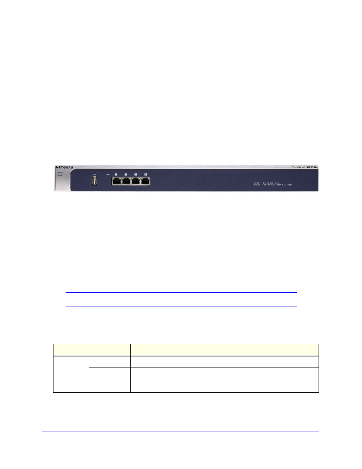
Front Panel Ports and LEDs
The following figure shows the front panel ports and status LEDs of the wireless controller.
Figure 1.
From left to right, the wireless controller’s front panel shows the following ports and LEDs:
• Power LE
• Te
st LED
• USB port f
D
or external storage, for example for more floor heat maps and extended
statistics history
• Fo
ur 10/100/1000 Mbps LAN Ethernet ports with RJ-45 connectors, left LEDs, and right
LEDs. All Ethernet ports provide switched N-way, automatic speed negotiating, auto
MDI/MDIX technology.
Note: The four ports of the wireless controller function as a single switch.
The function of each LED is described in the following table:
Table 1. LED functions
LED Status Description
Power LED On The green Power LED should be lit when the wireless controller is on.
Off If the power LED is not lit when the wireless controller is on, check the
nections and check to see if the power outlet is controlled by a wall switch
con
that is turned off (see Power LED Not On on p
Introduction and Overview
12
age 194).
Page 13
ProSafe 20-AP Wireless Controller WC7520
Table 1. LED functions (continued)
LED Status Description
Te st LED On The wireless controller is initializing. After approximately 2 minutes, when the
wireless controller has completed its initialization, the Test LED turns off. If the
T est LED remains on, the initialization has failed (see T est LED Never Turns Off
on page 195).
its initialization successfully. The Test
Ethernet cable is plugged into the
age 195).
Left LAN
rt LED
po
(one for
each port)
Right LAN
rt LED
po
(one for
each port)
Off The wireless controller has completed
LED should be off during normal operation.
Blinking Firmware is being upgraded.
Off The port has no physical link, that is, no
wireless controller (see also LAN Port LEDs Not On on p
On (green) The port has detected a link with a connected Ethernet device.
Blinking (green) Data is being transmitted or received by the port.
Off The port is operating at 10 Mbps.
On (amber) The port is operating at 100 Mbps.
On (green) The port is operating at 1000 Mbps.
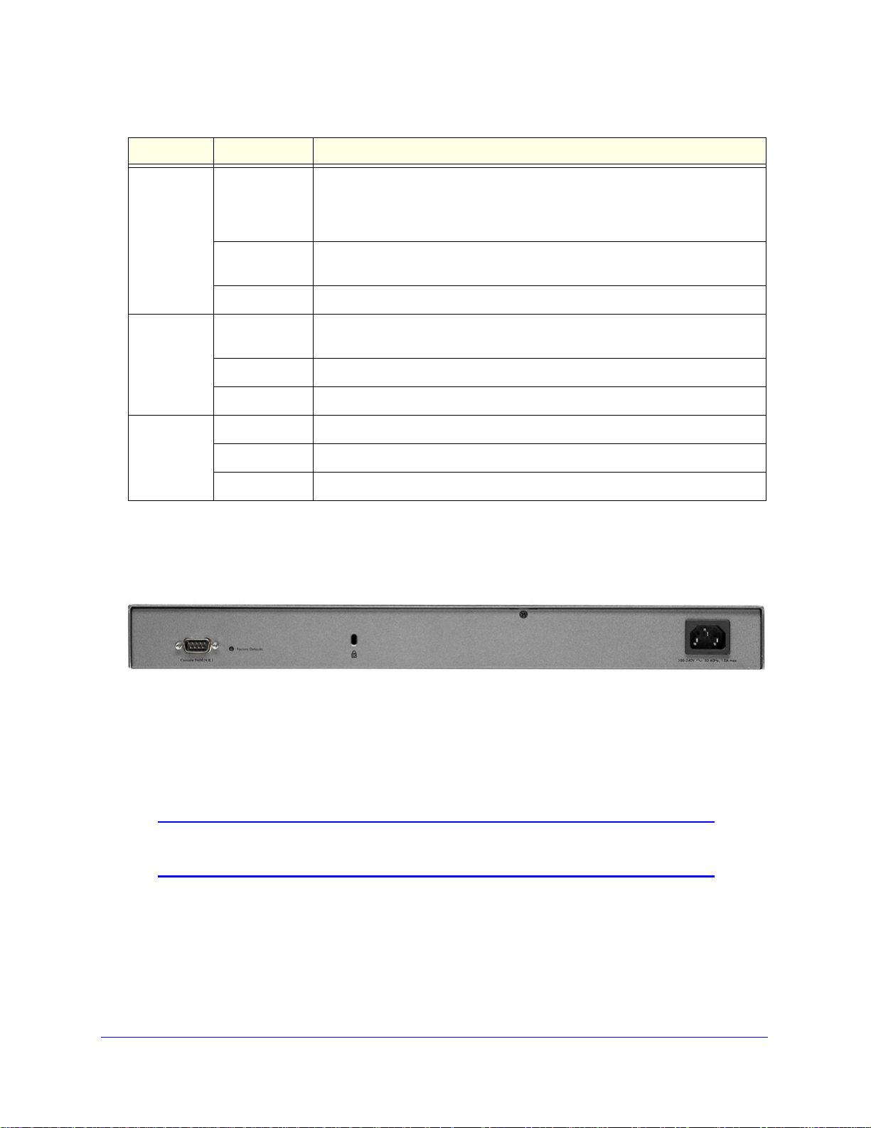
Rear Panel Features
The following figure shows the rear panel components of the wireless controller.
Figure 2.
From left to right, the wireless controller’s rear panel components are:
• Con
sole port. RS232 port for connecting to an optional console terminal. The port has a
DB9 male connector. The default baud rate is 9600 K. The configuration is 8 bits, no
parity, and 1 stop bit.
Note: The console port is for debugging under guidance of NETGEAR
technical support only.
• Factory Defaults button. Using a sharp object, press and hold this button for about
10 seconds until the front panel LED flashes and the wireless controller returns to factory
d
efault settings.
Introduction and Overview
13
Page 14
ProSafe 20-AP Wireless Controller WC7520
Note: If you reset the wireless controller, all configuration settings are lost
and the default password is restored.
• Kensington lock. Attach an optional Kensington lock to prevent unauthorized removal of
the wireless controller.
• AC power socke
power switch.)
t. Attach the power cord to this socket. (There is no separate on/off
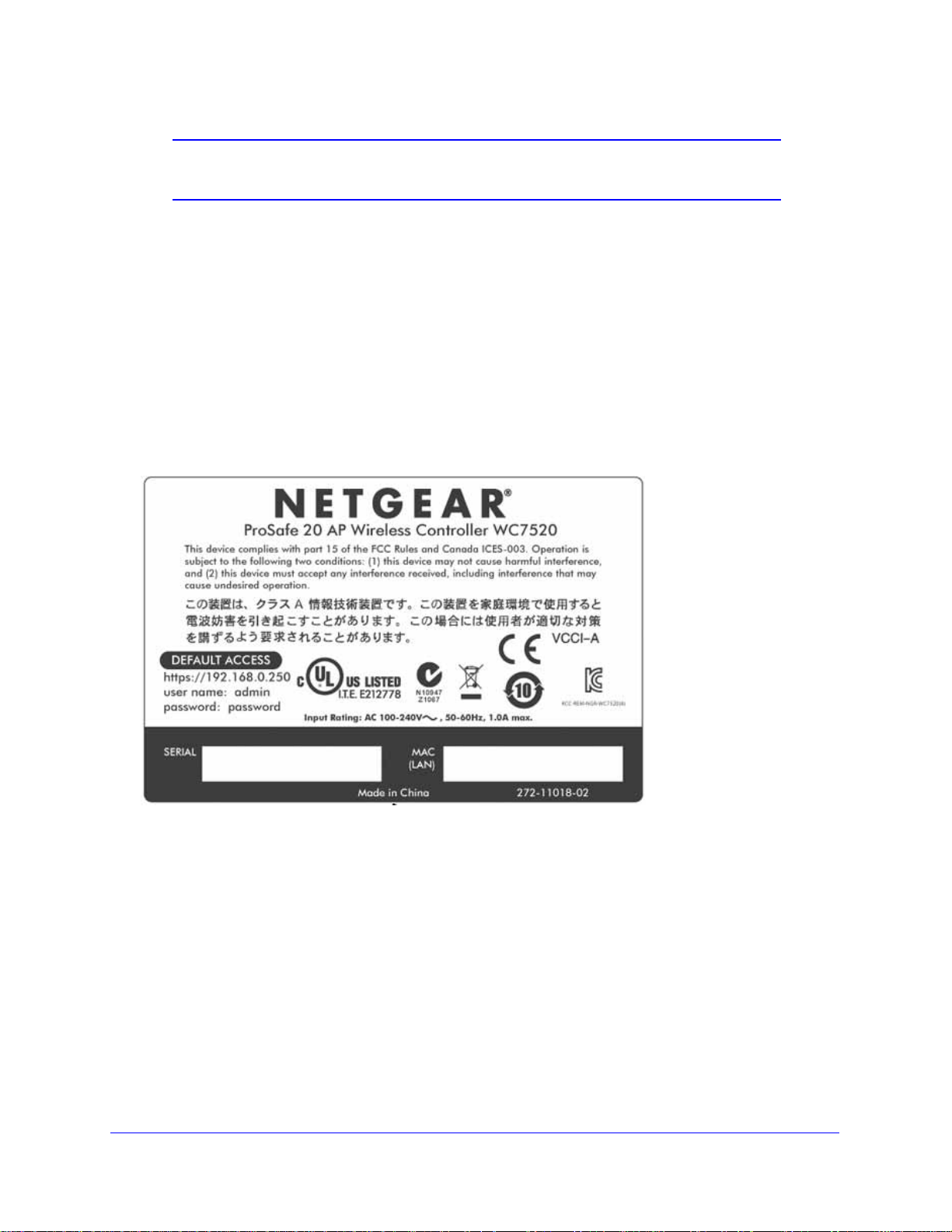
Bottom Panel with Product Label
The product label on the bottom of the wireless controller’s enclosure displays the default IP
address, default user name, and default password, as well as regulatory compliance, input
power, and other information.
Figure 3.
WC7520 Wireless Controller System Components
A WC7520 wireless controller system consists of one or more wireless controllers and a
collection of access points that are organized into groups based on location or network
access.
The wireless controller system can include a single
controller with a backup wireless controller for N:1 redundancy, or a group of up to three
stacked wireless controllers, with or without a redundant wireless controller.
Introduction and Overview
14
wireless controller, a single wireless
Page 15

ProSafe 20-AP Wireless Controller WC7520
The WC7520 wireless controller system supports the following access point models:
• NET
• NET
• NET
• NET
Future releases will support additional access point models.
GEAR WNAP210 ProSafe wireless-N access point
GEAR WNAP320 ProSafe wireless-N access point
GEAR WNDAP350 ProSafe dual-band wireless-N access point
GEAR WNDAP360 ProSafe dual-band wireless-N access point
NETGEAR ProSafe Access Points
You can connect access points to the wireless controller either directly with an Ethernet cable
through a router or switch, or remotely through an IP network. After you have used the
automatic discovery process and added access points to the managed access point list on
the wireless controller, the wireless controller converts the standard access points to
dependent access points by pushing firmware to the access points. From then on, you can
centrally manage and monitor the access points.
A WC7520 wireless controller system can support the following access points:
• WNAP2
- Sup
- Sup
- Req
10 ProSafe Wireless-N Access Point
ports 802.11b, 802.11g, and 802.11n network devices
ports Power over Ethernet (PoE) with a power consumption of up to 5.8W
uires minimum firmware version WNAP210_2.0.8 or a newer version.
For product documentation and firmware, see
http://support.netgear.com/app/products/model/a_id/8101.
• WNAP3
- Sup
- Sup
- Accep
- Req
For product documentation and firmware, see
http://support.netgear.com/app/products/model/a_id/18601.
• WNDAP35
- Sup
- Sup
- Con
- Accep
- Requires minimum firmware version WNDAP350
For product documentation and firmware, see
http://support.netgear.com/app/products/model/a_id/12823.
20 ProSafe Wireless-N Access Point
ports 802.11b, 802.11g, and 802.11n network devices
ports Power over Ethernet (PoE) with a power consumption of up to 5.8W
ts optional antennas
uires minimum firmware version WNAP320_2.0.7 or a newer version.
0 ProSafe Dual Band Wireless-N Access Point
ports 802.11a, 802.11b, 802.11g, and 802.11n network devices
ports PoE with a power consumption of up to 10.75W
current operation in 2.4 GHz and 5 GHz radio band while in 802.11n mode
ts optional antennas
_V2.0 or a newer version.
Introduction and Overview
15
Page 16

ProSafe 20-AP Wireless Controller WC7520
• WNDAP360 ProSafe Dual Band Wireless-N Access Point
- Support
s 802.11a, 802.11b, 802.11g, and 802.11n network devices
- Support
- Concu
- Accept
- Requires minimum firmware version WNDAP3
For product documentation and firmware, see
http://support.netgear.com/app/products/model/a_id/19189.
s PoE with a power consumption of up to 10.51W
rrent operation in 2.4 GHz and 5 GHz radio band while in 802.11n mode
s optional antennas
60_2.0.3 or a newer version.
What Can You Do with the WC7520 Wireless Controller?
These are some of the tasks that you can perform with a WC7520 wireless controller:
Plan a Wireless Network
• Design a WLAN. Design an efficient WLAN with building and floor dimensions for your
specific environment.
• Estim
Estimate how many access points you need for your wireless coverage and determine
their optimum location for best coverage and performance.
For more information, see Chapter 3, RF Planning.
ate the number of required access points and their approximate locations.
Discover Access Points in the Network and Provision IP Addresses and
Firmware
• Discover access points in the network. The access points can be in factory default
state or functioning in standalon e mode, but af ter discovery by the wireless controller and
addition to the managed access point list, the access points become dependent
(managed) access points.
• Provisi
provision IP addresses to all or selected managed access points in the network.
• Upgrade
managed access points in the network.
For more information, see Chapter 4, Access Point Discovery and Management.
on IP addresses to the access points. Use the internal DHCP server to
access point firmware. Update and synchronize new firmware versions to all
Organize the Network
• Create access point profiles. Organize access points in profiles to differentiate between
SSIDs, client authentication, authentication settings, and wireless QoS settings.
• Create a
profile groups to differentiate between buildings, flo ors, businesses or business divisions,
ccess point profile groups. Organize access point profiles in access point
Introduction and Overview
16
Page 17

ProSafe 20-AP Wireless Controller WC7520
and so on. Easily assign access points to profile groups or make changes to
assignments.
For more information, see Chapter 6, Managing Security Profiles and Profile Groups.
Centrally Manage the Wireless Settings for the Network
• Schedule the radios. Schedule the entire network to go offline, or schedule access point
profile groups to go offline.
• Manage wireless
as wireless mode, data rate, channel width, and so on, for the entire network or for
access point profile groups, and manage channel allocation for the entire network.
• Man
• Configure RF ma
For more information, see Chapter 7, Configuring Wireless and QoS Settings.
age QoS settings. Manage QoS queue settings for data, background, video, and
voice traffic for access point profile groups.
hole detection for the entire network or for access point profile groups.
settings and channel allocation. Manage the wireless settings such
nagement settings. Configure WLAN healing and wireless coverage
Centrally Manage Security in the Network
• Manage secure access to the network and secure data transmission . Manage client
authentication, encryption, wireless client security separation, and MAC authentication in
access point profiles.
• Man
• Man
• Ma
• Man
For more information, see Chapter 8, Configuring Network Access and Security.
age authentication servers for the network. Manage all internal and external
authentication servers for the entire network or for access point profile groups.
age MAC authentication. Specify trusted and untrusted MAC addresses for the
entire network.
nage rogue access points . Manage rogue access po ints and their associated client s
in the network.
age guest access. Manage guest access and captive portal access to the network.
Manage Other Wireless Controllers in the Network
• Manage stacking. Specify the primary and secondary wireless controllers in a stack and
synchronize information between the wireless controller.
• Manage redun
redundancy group and enable failover protection.
For more information, see Chapter 10, Managing Stacking and Redundancy.
dancy groups. Specify the primary and secondary wireless controllers in
Introduction and Overview
17
Page 18

ProSafe 20-AP Wireless Controller WC7520
Monitor the Network and Its Components
• View heat map s. V iew the real-time heat map s for a deployed WLAN. See the RF signal
propagation per floor, and identify coverage holes and weak signal spots.
• Monitor the s
access points, clients, access point profiles, and the entire network, and view network
usage statistics.
• Monitor network health.
or compromised.
For more information, see Chapter 11, Monitoring the Wireless Network and Components.
tatus of all wireless devices. View the status the wireless controllers,
See which access points are healthy and which ones are down
Licenses
The wireless controller includes an built-in license to support up to 20 access points in
802.11a/b/g/n mode. You can purchase licenses in 10–access point increments (WC7510L)
for support of up to 50 access points for a single wireless controller. To support 50 access
points, you would need to purchase 3 WC7510L licenses; if you have three wireless
trollers in a stack and want to support the maximum number of 150 access points, you
con
would need to purchase 9 WC7510L licenses.
Adding a redundant wireless controller also r
required number of access points on the redundant wireless controller.
Licenses are tied to the serial number of the wireless controller.
For more information, see the License Configuration section in the datasheet at
http://support.netgear.com/app/products/model/a_id/13060.
equires you to purchase licenses to support the
For information about how to manage your licenses, see Manage Licenses o
n page 149.
Maintenance and Support
NETGEAR offers technical support seven days a week, 24 hours a day. Information about
support is available on the NETGEAR ProSupport website at
http://kb.netgear.com/app/answers/detail/a_id/212.
Introduction and Overview
18
Page 19
ProSafe 20-AP Wireless Controller WC7520
1st level: Main navigation menu tab
2nd level: Configuration menu tab
3rd level: Submenu link
Action buttons
Controller selection list
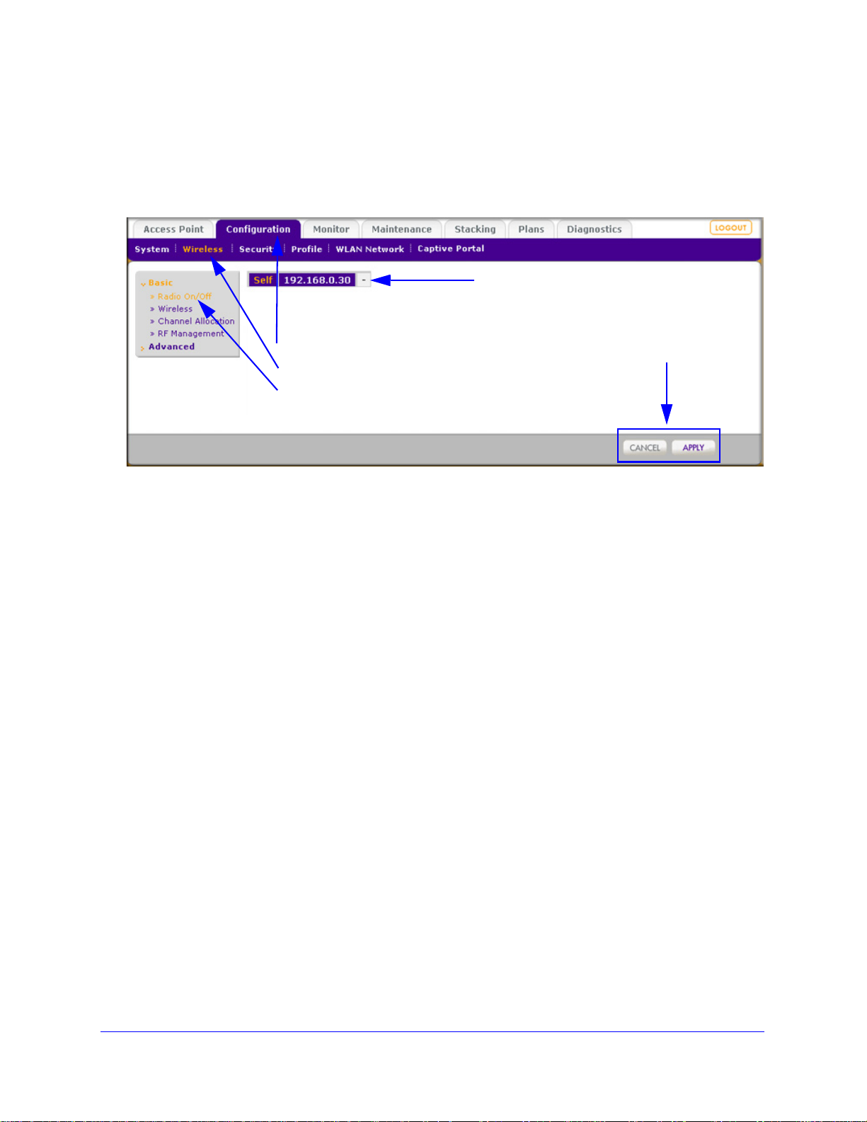
Web Management Interface Layout
The following figure shows the menu at the top and the left of the wireless controller’s web
management interface (the screen’s content has been removed for more clarity).
Figure 4.
A web management interface screen can include the following components:
• 1st le
• 2nd le
• 3rd leve
• Action bu
vel: Main navigation menu tab. The main navigation menu tabs in the light gray
bar across the top of the web management interface provide access to all configuration
menu tabs of the wireless controller and remain constant. When you select a main
navigation menu tab, the letters are displayed in white against a blue background.
vel: Configuration menu tab. The configuration menu tabs in the blue bar
(immediately below the main navigation menu bar) change according to the main
navigation menu tab that you select. When you select a configuration menu tab, the
letters are displayed in orange against a blue background.
l: Submenu link. Each configuration menu tab has one or more submenu links
that are listed on the left side of the screen in a gray box. When you select a submenu
link, the text is displayed in orange against a gray background. On many screens, the
submenus are divided into a basic submenu and an advanced submenu.
ttons. Action buttons change the configuration or allow you to make changes
to the configuration. These are the most common action buttons:
- Appl
- Can
- Add.
- Edit. Allows you
y. Saves all configuration changes made on the current screen. Saved settings
are retained when the wireless controller is powered off or rebooted, while unsaved
configuration changes are lost.
cel. Resets options on the current screen to the last-applied or -saved settings.
Adds a new item to the current screen. Typically, a pop-up window opens that
enables you to enter information in additional fields.
to edit the configuration of the selected item.
- Rem
ove or Delete. Removes the selected item from the table or screen
configuration.
Introduction and Overview
19
Page 20

ProSafe 20-AP Wireless Controller WC7520
- Back. Return to the previous screen.
- Next. Advance to the
next screen.
• Controlle
select the wireless controller to configure.
r selection list. In a stacked configuration, the controller selection list lets you
Initial Connection and Configuration
Follow the steps in this section to set up the wireless controller. For additional information,
see the WC7520 ProSafe Wireless Controller Installation Guide that you can access from
http://kb.netgear.com/app/products/model/a_id/13060.
To set up, configure, and deploy the wireless controller:
1. Connect the wire
a. Config
as the subnet mask.
b. Connect the wire
one of the wireless controller’s ports.
c. Connect the po
d. Check the light
• Power. The
• T
• LAN
ure a computer with a static IP address of 192.168.0.210 and 255.255.255.0
connections and check to see if the power outlet is controlled by a wall switch that
is turned off.
est. The Test LED is on briefly when the controller is first turned on.
1000 Mbps) indicating that a connection has been made. If it is not, make sure
that the Ethernet cable is securely attached at both ends.
less controller to your computer:
less controller to the computer through the network or directly to
wer cord from the wireless controller to an AC power outlet.
s on the front of the wireless controller:
green Power LED should be lit. If the Power LED is not lit, check the
The Ethernet (LAN) LED should be lit (amber for 10/100 Mbps and green for
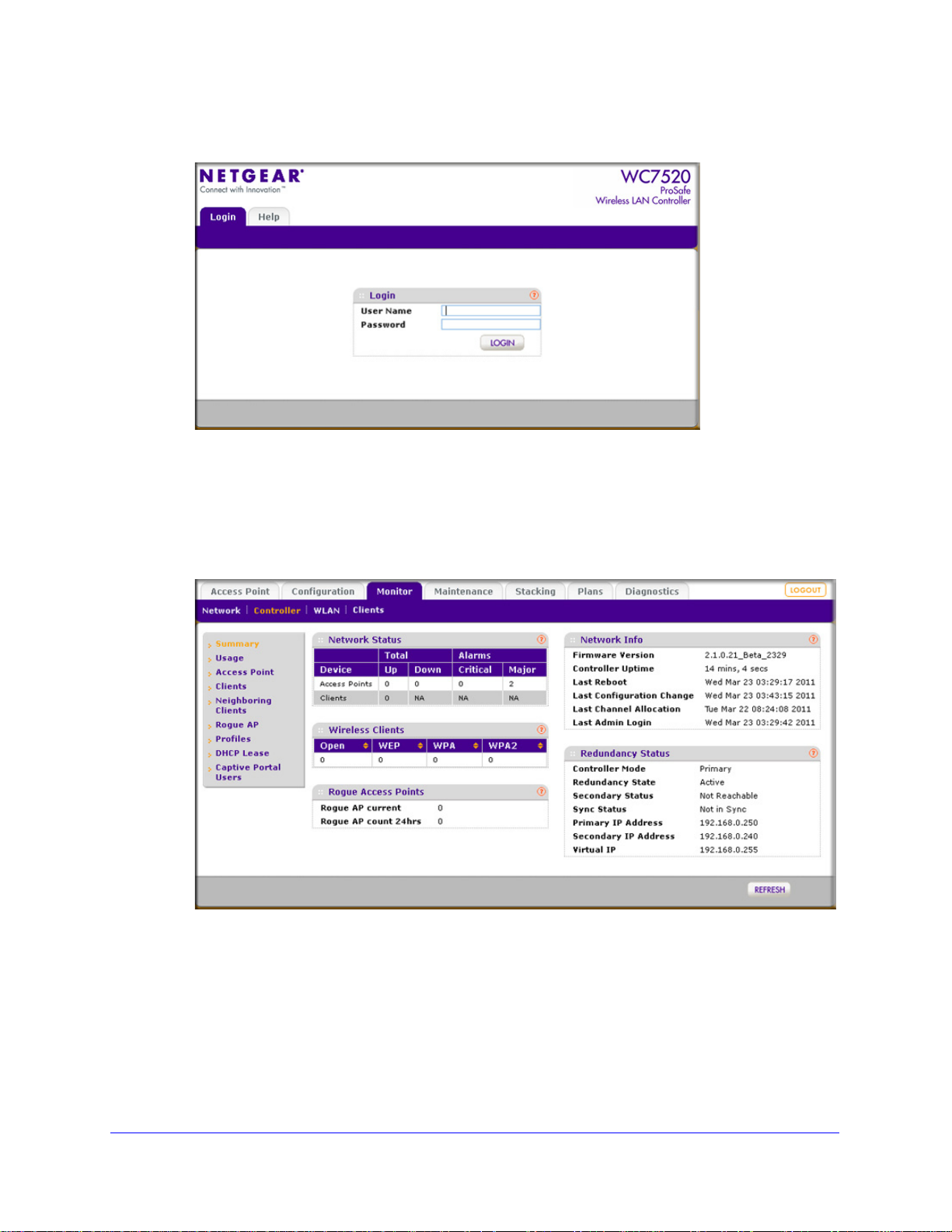
2. Log
in to the wir e l es s c on t r ol l e r:
a. Op
en your browser and type http://192.168.0.250 in the browser’s address field.
Note: You need to use a web browser such as Microsoft Internet Explorer
5.1 or later or Mozilla Firefox l.x or later with JavaScript, cookies,
and SSL enabled.
Introduction and Overview
20
Page 21
ProSafe 20-AP Wireless Controller WC7520
The wireless controller’s login window displays:
Figure 5.
b. When prompted, enter admin for the user name and password for the password,
both in lowercase letters.
c. Click Login. Th
e wireless controller’s web management interface displays, with the
default status screen (the path is Monitor > Controller > Summary), which shows the
network status and related information:
Figure 6.
Note: The Network navigation menu tab displays under the Monitor main
navigation tab only when you have configured stacking.
For information about the layout and general cha
interface, see Web Management Interface Layout on p
Introduction and Overview
21
racteristics of the web management
age 19.
Page 22

ProSafe 20-AP Wireless Controller WC7520
For information about the network status and related information, see View the
Wireless Controller Summary Screen on p
onfigure the wireless controller and your network:
3. C
a. RF planning. Fol
location of the access points.
low instructions in Chapter 3, RF Planning, to plan the number and
age 180.
b. Configure your network. F
configure your network, including the SSIDs, security
QoS, rate limiting, and so on.
c. Set up the wireless controller. Follow the in
page 27 to select the type of deployment for your network.
d. Add the access points. Follow the
Guidelines on p
controller’s managed access point list.
age 51 to discover your access points and add them to wireless
ollow the instructions in Chapter 4 through Chapter 10 to
, MAC ACLs, captive portal,
structions in System Planning on
steps in Access Point Discovery and Discovery
Basic and Advanced Settings
You can deploy the wireless controller in a small wireless network with 10 or 20 access points
or in a large wireless network with up to 150 access points. Small networks require a basic
configuration, but large networks can become very complex and require you to configure the
advanced features of the wireless controller.
Depending on your network configuration, use basic settings or advanced settings to man age
r access points:
you
• Basic
network configurations. For example, all access points on the WLAN are for the same
organization or business and therefore adhere to the same policies and use a small
number of service set identifiers (SSIDs, or network names).
• Adva
network, or if completely separate networks share a single WLAN, use the advanced
settings to set up multiple access point profile groups with multiple security profiles
(SSIDs with associated security settings). For example, a shopping mall might need
several access point profile groups if several businesses share a WLAN but each
business has its own network. Larger networks could require multiple access point profile
groups to allow different policies per building or department. The access points could
have different security profiles per building and department, for example, one for guests,
one for management, one for sales, and so on.
settings for a typical network. The basic settings work with most common
nced settings for access point profile groups. If you have a large wireless
Note: Access point profile groups are also referred to as just profile
groups.
Profiles, security profiles, and SSIDs (that is, SSIDs with associated
security settings) are terms that are interchangeable.
Introduction and Overview
22
Page 23
ProSafe 20-AP Wireless Controller WC7520
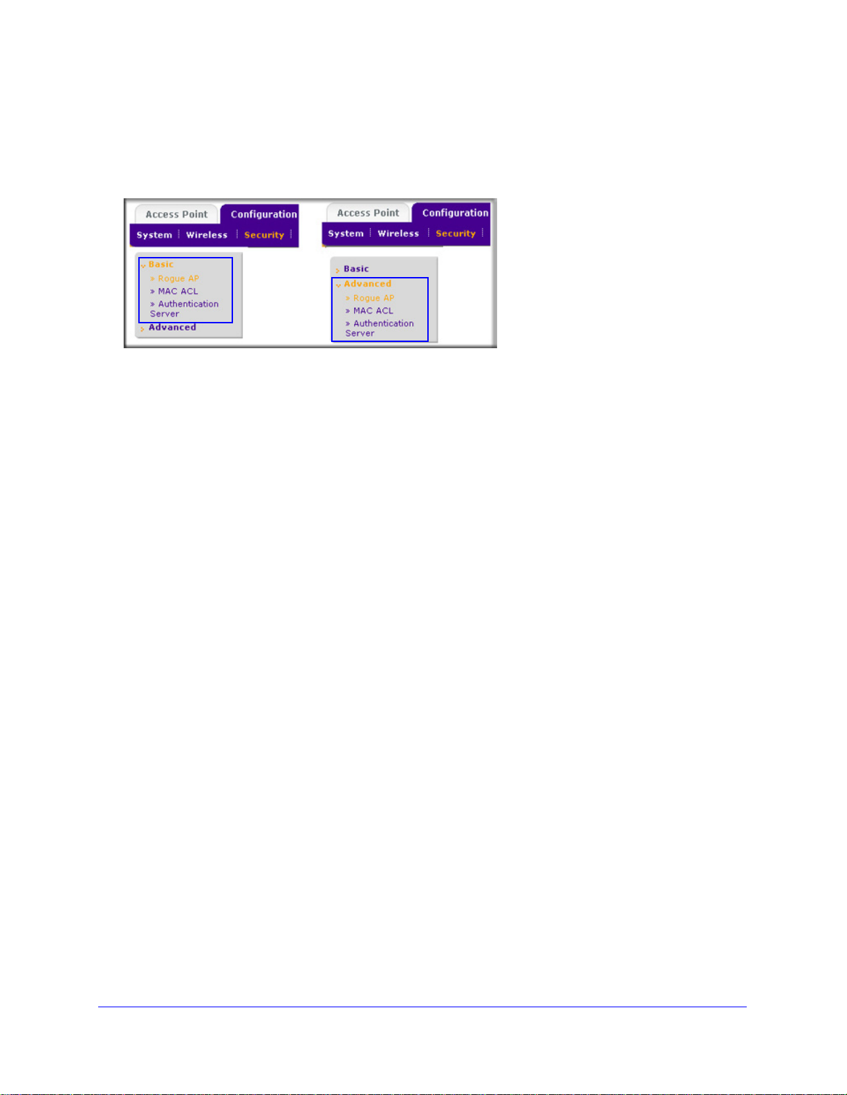
To accommodate all types of networks, almost all configuration menus of the web
management interface are divided into basic and advanced submenus. The following figure
shows an example of the Security > Wireless > Basic submenu on the left and the
Security > Wireless > Advanced submenu on the right:
Figure 7.
Before you start the configuration of your wireless controller, decide whether you can use a
basic configuration (that is, follow the basic submenus) or need to use an advanced
configuration (that is, follow the advanced submenus). Once you have made your choice,
configuring the wireless controller should be fairly easy if you consistently follow either the
basic submenus or the advanced submenus.
Profile Groups
Each access point can support up to 8 security profiles (16 for dual-band access points),
each with its own SSID, security settings, MAC ACL, rate-limiting settings, WMM, and so on.
The wireless controller follows the same architecture. A profile group on the wireless
contro
8 profiles (16 for dual-band access points), each of which has its own SSID, security, MAC
ACL, rate-limiting settings, WMM settings, and so on.
Basic Profile
The basic profile includes all the settings that are required to configure a fully functional
access point with up to 8 security profiles (16 for dual-band access points).
After you have used the automatic discovery process and added access points to the
manag
basic profile group.
If your network requires the wireless controller to manag
different configurations, use the advanced profile.
ller includes all the features that you can configure for an individual access point: up to
ed AP list on the wireless controller, the access points are assigned by default to the
e multiple access points with
Introduction and Overview
23
Page 24
ProSafe 20-AP Wireless Controller WC7520
Group-1
Group-2
Group-3
Group-4
Group-5 Group-6
Group-7
Group-8
2.4-GHz
radio
5-GHz
radio
Security Profiles
Security Profiles
1
2
34
5678
1
23
4
56
78
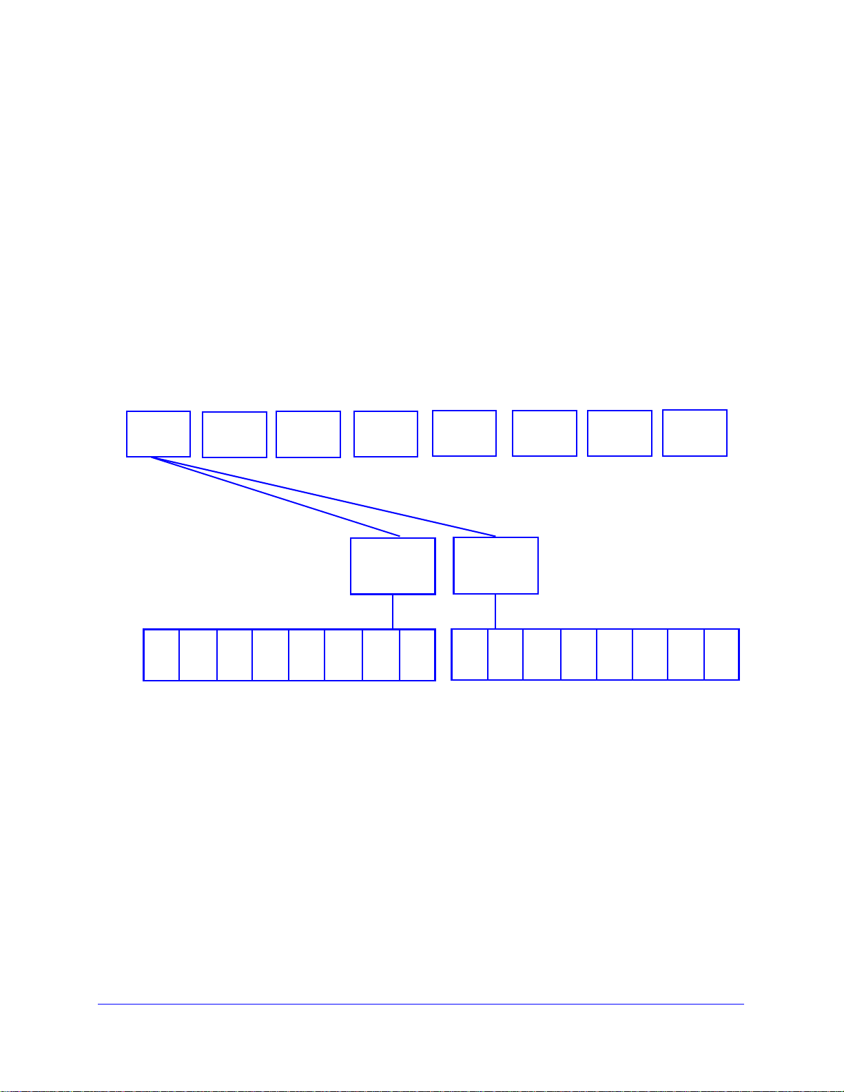
Advanced Profile
The advanced profile lets you configure up to 8 access point profile groups. Each group
includes all the settings that are required to configure a fully functional access point with up to
8 security profiles (16 for dual-band access points).
For example, if there are four buildings, each with a completely different wireless network,
simply create four profile groups. You then assign all access points in one building to one
you
profile group, all access points in another building to a second profile group, and so on.
For each profile group, you can create an individual radio-on/off schedule, RF management
tings, MAC ACL authentication, and an authentication server. For each radio in a profile
set
group (2.4-GHz radio and 5-GHz radio), you can create individual wireless settings, WMM,
and rate-limit settings.
The following figure shows the advanced pro
file group architecture. The structure that is
shown under Group-1 is implemented in all profile groups (that is, Group-2 through Group-8):
Figure 8.
The following figure shows an example of three access point profile groups, in which the first
profile group (Group-1) has three security profiles. For each profile in this profile group, the
profile name, radio mode, and authentication setting are shown. (Group-1 is the default group
in the advanced profile group configuration; you need to create the other profiles groups.)
Introduction and Overview
24
Page 25
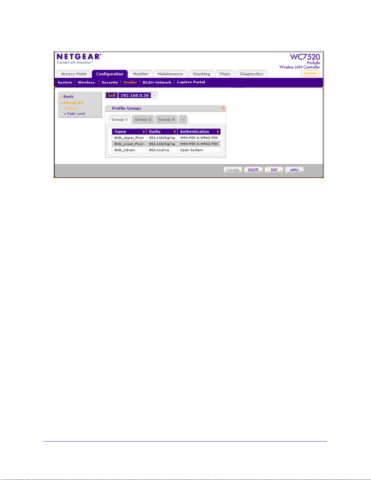
Figure 9.
ProSafe 20-AP Wireless Controller WC7520
Choose a Location for the Wireless Controller
The wireless controller is suitable for use in an office environment where it can be
freestanding on its runner feet or mounted into a standard 19-inch equipment rack.
Alternatively, you can rack-mount the wireless controller in a wiring closet or equipment
room. A mounting kit, containing two mounting brackets and screws, is provided in the
wireless controller package.
Consider the following when deciding where to
• The u
• Cabling is away from sources of electrical noise. Th
• W
• Airflow around
• The a
• T
nit is accessible and cables can be connected easily.
ovens, and air-conditioning units.
ater or moisture cannot enter the case of the unit.
the unit and through the vents in the side of the case is not restricted.
Provide a minimum of 25 mm or 1 inch clearance.
ir is as free of dust as possible.
emperature operating limits are not likely to be exceeded. Install the unit in a clean,
air-conditioned environment. For information about the recommended operating
temperatures for the wireless controller, see Appendix A, Factory Default Settings and
Technical Specifications.
position the wireless controller:
ese include lift shafts, microwave
Introduction and Overview
25
Page 26

ProSafe 20-AP Wireless Controller WC7520
Deploy the Wireless Controller
To deploy the wireless controller:
1. Disconne
it. If necessary, you can now reconfigure the computer that you used in the configuration
process back to its original TCP/IP settings.
2. Connect an Ethern
3. Connect th
outlet. The Power, Test, and Ethernet LEDs should light up. If any of these do not light up,
see Troubleshoot Basic Functioning on p
ct the wireless controller from the computer and place it where you will deploy
et cable from your wireless controller to a LAN port on your network.
e power cord to the wireless controller and plug the power cord into a power
age 194.
Introduction and Overview
26
Page 27

2. System Planning and Deployment
Scenarios
This chapter includes the following sections:
• System Planning
• Management VLAN and Data VLAN Strategies
• Deployment Scenarios
System Planning
This section includes the following subsections:
• Preinstallation Planning
• Before You Configure a Wireless Controller
• Single Controller Configuration with Basic Profile Group
• Single Controller Configuration with Advanced Profile Groups
• Stacked Controller Configuration
2
Preinstallation Planning
Before you install any wireless controllers, determine the following:
• Numb
• Numb
• 802
NETGEAR recommends that you perform a site survey:
• Run
• Run an
• Iden
• Determine
er of access points required to provide seamless coverage
er of wireless controllers required
.11 frequency band and the channels that are optimal for Wi-Fi usage
a spectrum analysis of channels of the site to determine the current RF behavior and
detect both 802.11 and non-802.11 noise.
access point-to-client connectivity test to determine the maximum throughput
achievable on the client.
tify potential RF obstructions and interference sources.
areas where denser coverage might be required because of heavier usage.
27
Page 28

ProSafe 20-AP Wireless Controller WC7520
After the survey is complete, use the collected data to set up an RF plan. For more
information, see RF Planning Overview on p
age 41.
Before You Configure a Wireless Controller
These sections assume that you have deployed at least one wireless controller in your
network and are ready to configure the wireless controller. For information about how to
deploy the wireless controller in your network, see the WC7520 ProSafe Wireless Controller
Installation Guide that you can access from
http://kb.netgear.com/app/products/model/a_id/13060.
For many configurations, you can use the default
DHCP server, client authentication, and data encryption settings are specific to your
environment. Following are short sections that discuss these settings (with the exception of
IP address settings, which are self-explanatory). For information about how to configure
these settings, see the relevant sections.
wireless settings. The IP address, VLAN,
VLANs
The management VLAN is the dedicated VLAN for access to the wireless controller. All traffic
that is directed to the wireless controller, including HTTP, HTTPS, SNMP, and SSH traffic, is
carried over the management VLAN.
If the management VLAN is also configured as a tagged VLAN (the most common
con
figuration), the packets to and from the wireless controller carry the 802.1Q VLAN header
with the assigned VLAN number. If the management VLAN is marked as untagged, the
packets that are sent from the wireless controller do not carry the 802.1Q header, and all
untagged packets that are sent to the wireless controller are treated as management VLAN
traffic.
Note: Use a tagged VLAN or change the tagged VLAN ID only if the hubs
and switches on your LAN support 802.1Q. If they do not, and you
have not specifically configured a tagged VLAN with the same VLAN
ID on the hubs and switches in your network, IP connectivity might
be lost.
The wireless controller needs to have IP connectivity with the access points through the
management VLAN. If the wireless controller and the access points are on different
management VLANs, external VLAN routing needs to allow IP connectivity between the
wireless controller and the access points.
For information about how to configure management VLANs, see Configure IP and VLAN
Settings o
n page 65.
System Planning and Deployment Scenarios
28
Page 29

Client VLANs
ProSafe 20-AP Wireless Controller WC7520
Each authenticated wireless user is placed into a VLAN that determines the user
’s DHCP
server, IP address, and Layer 2 connection. Although you could place all authenticated
wireless users into the single VLAN that is specified in the basic security profile, the wireless
controller allows you to group wireless users into separate VLANs based on the wireless
SSID to differentiate access to network resources. For example, you might place authorized
employee users into one VLAN, and itinerant users, such as contractors or guests, into a
separate VLAN. To use different VLANs, you need to create different security profiles.
For information about how to configure regular VLANs, see Manage Rogue Access Points on
page 113.
DHCP Server
The wireless controller can function as a DHCP server and assign IP addresses to both
wireless and wired devices that are connected to it. You can add up to 64 DHCP server
pools, each assigned to a different VLAN.
Client Authentication and Data Encryption
A user needs to authenticate to the WLAN to be able to access WLAN resources. The
wireless controller supports several types of security methods, including those that require an
external RADIUS or LDAP authentication server.
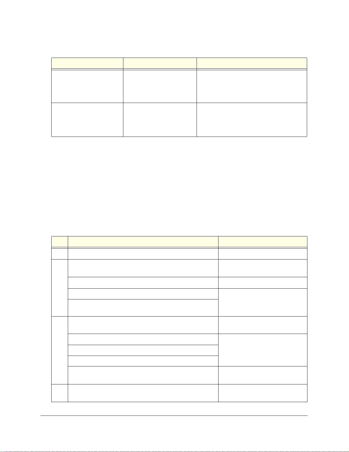
The encryption option that you can select dep
have selected. The following table lists the authentication methods available, with their
corresponding encryption options:
ends upon the authentication method that you
Table 2. Authentication and encryption options
Authentication method Encryption option Authentication server
Open system 64-bit, 128-bit, or 152-bit WEP None
Shared Key 64-bit, 128-bit, or 152-bit WEP None
WPA-PSK TKIP or TKIP+AES None
WPA2-PSK AES or TKIP+AES None
WPA-PSK and WPA2-PSK TKIP+AES None
WPA TKIP or TKIP+AES One of the following authentication servers:
• External RADIUS server
• Internal authentication server
• External LDAP server
System Planning and Deployment Scenarios
29
Page 30
ProSafe 20-AP Wireless Controller WC7520
Table 2. Authentication and encryption options (continued)
Authentication method Encryption option Authentication server
WPA2 AES or TKIP+AES One of the following authentication servers:
• External RADIUS server
• Internal authentication server
• External LDAP server
WPA and WPA2 TKIP+AES One of the following authentication servers:
• External RADIUS server
• Internal authentication server
• External LDAP server
For information about how to configure client authentication and data encryption, see
Manage Rogue Access Points on p
age 113.
For information about how to configure au
Servers and Authentication Server Groups on p
thentication servers, see Manage Authentication
age 122.
Single Controller Configuration with Basic Profile Group
A basic configuration consists of a single wireless controller that controls a collection of
access points that are organized into the basic default group.
To set up a single wireless controller system with a basic profile group:
Step Configuration Web management interface path
1. Optional: Create an RF plan. Plans > Layout
2. If you have not yet done so, configure the system settings of the
wireless controller:
1. Configure the country code of operation.
2. Configure the IP address of wireless controller.
3. Verify that VLAN 1 is set as the management VLAN and is
marked as untagged, which is the default setting.
3. Configure up to 8 profiles, and for each profile, do at least the
following:
Configuration > System > General
Configuration > System > IP/VLAN
1. Configure an SSID for wireless access.
2. Configure the network authentication and data encryption.
3. Assign the VLAN.
If required, configure the authentication server. Configuration > Security > Basic >
4. Run the Discovery Wizard and add the access points to the
managed access point list.
System Planning and Deployment Scenarios
30
Configuration > Profile > Basic
Authentication Server
Access Point > Discovery Wizard
Page 31

ProSafe 20-AP Wireless Controller WC7520
Single Controller Configuration with Advanced Profile Groups
A more complex configuration consists of a single wireless controller that controls a collection
of access points that are organized in access point profile groups and might use several
profiles in each access point profile group.
To set up a single wireless controller system with advanced profile groups:
Step Configuration Web management interface path
1. Optional: Create an RF plan. Plans > Layout
2. If you have not yet done so, configure the system settings of the
wireless controller:
1. Configure the country code of operation.
2. Configure the IP address of wireless controller.
3. Verify that VLAN 1 is set as the management VLAN and is
marked as untagged, which is the default setting.
3. Configure up to 8 access point profile groups, and for each
access point profile in a group, do at least the following:
1. Configure an SSID for wireless access.
2. Configure the network authentication and data encryption.
3. Assign the VLAN.
4. If required, confi gure the authentication server.
5. Run the Discovery Wizard and add the access points to the
managed access point list.
6. Assign the access points to the access point profile groups (also
referred to as WLAN groups).
Configuration > System > General
Configuration > System > IP/VLAN
Configuration > Profile > Advanced
Configuration > Security >
Advanced > Authentication Server
Access Point > Discovery Wizard
Configuration > WLAN Network
System Planning and Deployment Scenarios
31
Page 32

ProSafe 20-AP Wireless Controller WC7520
Stacked Controller Configuration
A stacked controller configuration can consist of up to three wireless controllers and up to
150 access points.
To set up a stacked controller configuration:
Step Configuration Web management interface path
1. On each individual wireless controller that you intend to make a
stack member, follow the configuration steps as explained in one
of the previous sections.
Note: If the stack members will be on different floors or in
different buildings, you can configure a separate access point
profile group for each building or floor.
2. Configure the primary wireless controller and deploy it in the
network.
3. Configure the secondary wireless controllers and deploy them in
the network.
4. Interconnect the wireless controllers that you intend to make
members of the stack. The connection needs to be a wired
connection but does not need to be a direct connection, that is, a
switch or router can be located in between the wireless
controllers that are part of a stack.
5. Configure the stacking group on the wireless controller that you
intend as the primary controller.
6. Synchronize all wireless controllers that are members of the
stack.
See Single Controller Configuration
with Basic Profile Group on page 30
or
Single Controller Configuration with
Advanced Profile Groups on page 31
Stacking > Stacking
Management VLAN and Data VLAN Strategies
If your network includes 10 or more access points, NETGEAR recommends that you set up at
least two VLAN groups: a management VLAN group and a dat a VLAN group. If your ne twork
is large, you should create a number of data VLAN groups. Setting up data VLANs for clients
allows you to:
• Segre
• Creat
gate traffic by user category
e different policies such as access policies that are based on user category
The following illustration shows a simplified
traffic by user category:
System Planning and Deployment Scenarios
view of how you can use VLANs to segregate
32
Page 33

ProSafe 20-AP Wireless Controller WC7520
Figure 10.
The wireless controller uses the management VLAN to continually exchange p ackets with the
access points. For large networks, if all traffic uses a single VLAN, the client traffic could
potentially flood the network. If this happens, and the wireless controller is not able to
exchange packets with the access points, it can cause network performance to slow down,
and the access points can lose their connectivity with the wireless controller.
You should deploy the wireless controller on a trunk port on your switch. The trunk port
should have access t
o all VLANs. Use a high-speed port on your switch as the trunk port to
accommodate the traffic load of the trunk.
System Planning and Deployment Scenarios
33
Page 34

ProSafe 20-AP Wireless Controller WC7520
Deployment Scenarios
This section provides three deployment scenarios to illustrate how the wireless controller can
function in a variety of network configurations:
• Scenario Example 1: Basic Network with Single VLAN
• Scenario Example 2: Advanced Network with VLANs and SSIDs
• Scenario Example 3: Advanced Network with Redundancy
Scenario Example 1: Basic Network with Single VLAN
The following sample scenario consists of a simple network with a wireless controller, PoE
switch, Layer 3 switch or router, and access points:
Figure 11.
System Planning and Deployment Scenarios
34
Page 35

ProSafe 20-AP Wireless Controller WC7520
The access points and wireless controller are connected in the same subnet and use the
same IP address range that is assigned for that subnet. There are no routers between the
access points and the wireless controller. The access points are connected to a PoE switch,
which, in turn, is connected to the wireless controller. The uplink of PoE switch connect s to a
Layer 3 switch or router that provides Internet access.
Provisioning the Wireless Controller
Step Configuration Web management interface path
1. Configure the basic system settings:
1. Configure the country code of operation.
2. Configure the IP address of wireless controller.
3. Verify that VLAN 1 is set as the management VLAN and is
ma
rked as untagged, which is the default setting.
2. Configure the basic wireless settings and security:
1. Configure an SSID for wireless access.
2. Configure the network authentication and data encryption.
3. Configure the encryption.
3. Use any port of the wireless controller to connect the wireless
PoE switch.
4. Deploy the access points and connect them to the same wireless
PoE switch.
5. Run the Discovery Wizard, select the ne
the access points that you want to be managed by the wireless
controller.
Note: By default, all access points are added to the basic group
l settings from the basic group (profile definition, client
and al
authentication, authentication settings, and wireless QoS) are
applied to the access points.
twork layout, and select
Configuration > System > General
Configuration > System > IP/VLAN
Configuration > Profile > Basic
Access Point > Discovery Wizard
Scenario Example 2: Advanced Network with VLANs and SSIDs
The following sample scenario consists of an advanced network with a wireless controller,
PoE switch, Layer 3 switch or router, access points, and several VLANs and SSIDs. These
are the VLANs in the wireless controller system:
• VLAN 1, the
• VLAN 10, a t
• VLAN 20, an
• VLAN 100, a
default untagged VLAN to access the wireless controller
agged client VLAN
other tagged client VLAN
tagged management VLAN
System Planning and Deployment Scenarios
35
Page 36

ProSafe 20-AP Wireless Controller WC7520
Figure 12.
The access points and wireless controller are connected in the same subnet and same VLAN
and use the same IP address range that is assigned for that subnet. There are no routers
between the access points and the wireless controller. The access point s are connected to a
PoE switch, which, in turn, is connected to the wireless controller. The uplink of the PoE
switch connects to a Layer 3 switch or router that provides Internet access.
Prerequisites
This network configuration has the following prerequisites:
• VLANs 1
controller and the PoE switch.
• Th
e wireless controller is connected to the PoE switch through default VLAN 1. You
manage the wireless controller from a computer over VLAN 1 through the PoE switch.
• Th
e DHCP server on the wireless controller is configured in management VLAN 100 to
enable the access points to receive an IP address through VLAN 100.
• Th
e PoE switch port to which the wireless controller is connected is configured as a
tagged port to allow tagged traffic from VLAN 100.
0, 20, and 100 are tagged VLANs and are configured on both the wireless
System Planning and Deployment Scenarios
36
Page 37

ProSafe 20-AP Wireless Controller WC7520
Provisioning the Wireless Controller
Step Configuration Web management interface path
1. For initial discovery and configuration of the access points,
orarily configure management VLAN 100 as an untagged
temp
management VLAN on both the wireless controller and the PoE
switch.
2. Configure the basic system settings:
1. Configure the country code of operation.
2. Configure the IP address of wireless controller.
3. Configure the management VLAN as VLAN 100.
4. Clear the Un
to a tagged VLAN.
3. Add a DHCP server that uses VLAN 100:
1. Configure the IP address range for VLAN 100.
2. Configure the other DHCP server fields, including the
gateway and DNS servers.
4. Configure the following profiles, and configure network
authentication and data encryption for these profiles:
1. A profile with SSID 1 and VLAN 10.
2. A profile with SSID 2 and VLAN 20.
tagged Vlan check box. This changes VLAN 1
Configuration > System > IP/VLAN
Configuration > System > General
Configuration > System > IP/VLAN
Configuration > System > DHCP
Se
rver
Configuration > Profile > Basic
5. Connect the wireless controller to the PoE switch.
6. Before you connect the access points to the PoE switch, verify
tha
t the switch ports to which you intend to connect the access
points are configured as access ports in management VLAN 100.
7. Deploy the access points and connect them to the designated
oE switch ports.
P
8. Wait until the access points are up and running, run the Discovery
Wizard
, specify the network layout by selecting the Same L2
network radio button, and select the access points that you want to
be managed by the wireless controller.
Note: By adding the access points to managed list, you enable
m to receive an IP address from the DHCP server over
the
management VLAN 100.
Access Point > Discovery Wizard
System Planning and Deployment Scenarios
37
Page 38

ProSafe 20-AP Wireless Controller WC7520
Step Configuration Web management interface path
9. For each access point on the managed list, clear the Untagged
Vlan check box and configure VLAN 100 as the management
VLAN. Doing so causes the access points to lose connectivity
with the wireless controller.
10. Restore connectivity between the access points and the wireless
con
troller by changing the PoE switch ports to which the access
points are connected to tagged ports. (During the discovery
process, these switch ports were access ports in management
VLAN 100.)
Scenario Example 3: Advanced Network with Redundancy
The following sample scenario consists of an ad vanced network with on e wire less controller,
one redundant wireless controller, one core switch, two PoE switches in different buildings,
access points, and several VLANs and SSIDs. These are the components in the wireless
controller system:
• One wire
• 50
access points (managed by the wireless controller through management VLAN 1)
• One red
• Four VLANs: VLAN 10,
• Th
ree SSIDs: SSID 1, SSID 2, and SSID 3
less controller
undant wireless controller
VLAN 20, VLAN 30, and VLAN 40
In this scenario, the VLANs and SSIDs are used to accommodate traffic for different user
s in a school that is spread out over two buildings.
group
• Building 1:
- SSID
- SSID
- SSID
1 in VLAN 10 for staff traffic
2 in VLAN 20 for middle school students
3 in VLAN 30 for guests
• Building 2:
- SSID
- SSID
- SSID
1 in VLAN 10 for staff traffic
2 in VLAN 40 for high school students
3 in VLAN 30 for guests
System Planning and Deployment Scenarios
38
Page 39

ProSafe 20-AP Wireless Controller WC7520
Figure 13.
The access points and wireless controllers are connected in the same subnet and same
VLAN and use the same IP address range that is assigned for that subnet. The core switch is
located between the wireless controllers and the PoE switches, to which the access points
are connected. The core switch provides Internet access.
Prerequisites
This network configuration has the following prerequisites:
• VLAN 1 is con
VLAN is untagged.
• VLANs 10,
PoE switch in Building 1. These VLANs are tagged.
• VLANs 1, 1
PoE switches. Except for VLAN 1, these VLANs are tagged.
figured on the wireless controllers, core switch, and PoE switches. This
20, and 30 are configured on the wireless controllers, core switch, and the
0, 20, 30, and 40 are configured on the wireless controllers, core switch, and
System Planning and Deployment Scenarios
39
Page 40

ProSafe 20-AP Wireless Controller WC7520
Provisioning the Wireless Controller
Step Configuration Web management interface path
1. Configure the basic system settings:
1. Configure the country code of operation.
2. Configure the IP address of
3. Verify that VLAN 1 is set as the management VLAN and is
marked
2. Confi g u r e t h e fo l lo w i ng p ro f i l es , and configure network
thentication and data encryption for these profiles:
au
1. A profile with SSID 1 and VLAN 10.
2. A profile with SSID 2 and VLAN 20.
3. A profile with SSID 2 and VLAN 30.
4. A profile with SSID 3 and VLAN 40.
3. Configure the following profile groups:
1. A profile group with the name Buil
following profiles:
2. A profile group with the name Buil
following profiles:
as untagged, which is the default setting.
- The profile with SSID 1 and VLAN 10
- The profile with SSID 2 and VLAN 20
- The profile with SSID 2 and VLAN 30
- The profile with SSID 1 and VLAN 10
- The profile with SSID 2 and VLAN 30
- The profile with SSID 3 and VLAN 40
wireless controller.
ding 1, to which you add the
ding 2, to which you add the
Configuration > System > General
Configuration > System > IP/VLAN
Configuration > Profile > Basic
Configuration > Profile > Advanced
4. Deploy the access points and connect them to PoE switches.
5. Wait until the access points are u
Wizard, specify the network layout by selecting the Same L2
network radio button, and select the access points that you want to
be managed by the wireless controller.
7. Assign the access points to th
referred to as WLAN groups).
p and running, run the Discovery
e access point profile groups (also
System Planning and Deployment Scenarios
40
Access Point > Discovery Wizard
Configuration > WLAN Network
Page 41

3. RF Planning
This chapter includes the following sections:
• RF Planning Overview
• Define and Edit Buildings and Floors
• Specify Access Point Requirements
• View and Manage Heat Maps for Deployed Plans
RF Planning Overview
You can do the following with RF planning:
3
• Defin
• Estimate
• Op
• Monitor WLAN covera
• Iden
RF planning provides a view of each floor , allowing you to spe
be provided. It then provides coverage maps and access point placement locations.
Real-time calibration lets you visualize the indoor propagation of RF signals to identify a reas
with weak signal or dead spots and add additional access points in the right location to
mitigate the weak signal or dead spots.
e WLAN coverage.
the number of access points required based on signal quality and number of
clients per access point.
timize the placement of access points for the best coverage.
ge, rogue access points, and blacklisted clients for a plan that is in
deployment.
tify weak signal spots and dead spots from the coverage hole and add additional
access points to mitigate the situation.
cify how Wi-Fi coverage should
Planning Requirements
Collect the following information before using RF planning to expedite your planning efforts.
• Building
• Numb
dimensions.
er of floors.
• Dist
ance between floors.
41
Page 42

ProSafe 20-AP Wireless Controller WC7520
• Total number of users and number of users per access point.
• Radio type or types.
• Desired d
• Id
entify areas where you do not necessarily want coverage.
• Id
entify areas where you cannot deploy an access point.
Use a worksheet similar to the following to
Table 3. Building planning worksheet
Building dimensions
Height
Width
Number of floors
User information
Number of users
Users per access point
Radio types
Access point desired signal rate
802.11b/bg/ng
ata rates for access points.
collect your information.
802.11a/na
Don’t care/don’t deploy areas
Define and Edit Buildings and Floors
This section explains how you can define your buildings and floors, and make modifications
after you have defined them. You can add a maximum of three local buildings and three
remote buildings, a total of six buildings.
To define a building:
1. Select Plans > Layout. The
and associated screen in view. To define a remote building, click the Remote Building
tab.
Layout Buildings screen displays with the Local Building tab
RF Planning
42
Page 43

ProSafe 20-AP Wireless Controller WC7520
.
Figure 14.
2. The Buildings table shows the names of the previously defined buildings and their number of
floors.
3. T
o add a building, click Add. The Add Building pop-up window displays.
4. Ente
r a name for your building in the Building Name field, and then click Add. The new
building is added to the Buildings table. The name is an a lp h anumeric string up to 64
characters in length.
5. T
o define the floors of the building, select the radio button that corresponds to the building,
and then click Edit. The Layout Floors screen displays:
Figure 15.
RF Planning
43
Page 44

ProSafe 20-AP Wireless Controller WC7520
6. Define the floors as explained in the f o ll ow i ng t ab le :
Table 4. Building name and floors
Setting Description
Building
Building Name You can modify the previously defined buildi
up to 64 characters in length.
Floors
Floor Names The floor name is an alphanumeric stri
Floor Dimensions Enter the floor length in meters in the Length fi
Width field. The default measurements for both are 40 meters.
Existing Floor Map If you have imported a floor map, a very small image of the floor map is shown. Click
Preview to enlarge the map. (If you did not import a floor map, the Preview button is
not displayed.)
New Floor Map If you have an existing floor map, import the map in
Browse and navigating to the location where you have stored the map. Follow the
directions of your browser to import the map.
Note: Background images need to be in JPEG format and cannot exceed
048 x 2048 pixels in size. If you attempt to import a file with a larger pixel footprint,
2
the image will not scale to fit the image area in the floor display area.
Note: Images are scaled (stretched) to fit the display area. The display area aspect
is determined by the floor dimensions.
ratio
Note: The internal flash memory of the wireless controller supports up to three floor
s. If you want to define additional floors, use external USB storage (see Manage
map
External Storage on pag
e 141).
ng name, which is an alphanumeric string
ng up to 64 characters in length.
eld; enter the floor width in meters in
to the RF planning tool by clicking
o add another floor, click the + tab next to the Floor-1 name, or whatever name you have
7. T
given the first floor, and define the floors as explained in Table 4 on p
to six floors in one building but will need external USB storage if you add more than three
or maps.
flo
8. Click Apply to save
9. Click Back t
To edit a building:
1. Select the
o return to the Layout Buildings screen.
radio button in the Edit column that corresponds to the building that you want
to edit.
2. Click Edit.
Note: Because background images for your floors are embedded in the XML file that
defines your building, minimize the file size of the JPEGs that you use for your
backgrounds. You can minimize the file size by selecting maximum compression
(lowest quality) in most graphics programs.
age 44. You can add up
your settings.
RF Planning
44
Page 45

ProSafe 20-AP Wireless Controller WC7520
To delete a building:
1. Select the check box that corresponds to the building that you want to delete, or select
the check box at the top row of the table to delete all buildings.
2. Click Dele
te.
Specify Access Point Requirements
After you have defined the buildings and floors, you need to specify the following RF
requirements for each floor and each supported access point model (WNAP210, WNAP320,
WNDAP350, and WNDAP360):
• Frequenc
• Signal q
y band. The radio frequency to be used (802.11b/bg/ng or 802.11a/na).
uality. The signal strength that you expect for the WLAN. This setting
determines the automatic channel allocation and automatic transmission power of the
access points (see the explanation in the table later in this section).
• Number of c
lient per access point. The total number of clients that you expect to be
supported on each access point.
• T
otal number of clients per floor. The total number of clients that you expect to be
supported on each floor.
Along with the floor dimensions, these settings deter
mine the estimated number of access
points. A screen lets you visually optimize the access point locations for best coverage.
To specify the WLAN requirements for a floor, estimate the number of access points
required, and view their suggested locations:
1. Select Pla
ns > Planning. The Planning Buildings screen displays with the Local
Building tab and associated screen in view. To specify the information for a remote
.
building, click the Remote Building tab.
Figure 16.
RF Planning
45
Page 46

ProSafe 20-AP Wireless Controller WC7520
The Planning Buildings screen shows a tab for each building that you previously defined.
For each building, the screen shows the floors that you previously defined.
2. Select the buildin
3. S
pecify the WLAN requirements for the floor as explained in the f ol lo w in g ta b le :
g and floor that you want to configure by clicking the corresponding tabs.
Table 5. Floor WLAN requirements
Setting Description
Access Point Model Specify the access point model that you will use on the floor by selecting the
WNDAP 350, WNA
Frequency Band Select one of the following radio buttons to specify the frequency band that the access
points will function in:
• 802.11b/bg/ng
• 802.11a/na
Signal Quality Specify the required signal quality by moving the slider or by entering a percentage in
d to the right of the slider. The minimum signal quality is 25 percent; the
the fiel
maximum is 100 percent.
Client Per Radio Specify the expected maximum number of clients per access point by moving the
der or by entering a number in the field to the right of the slider. The maximum
sli
number of clients that you can configure per access point is 64.
Total Clients Specify the expected total number of clients on the floor by moving the slider or by
ntering a number in the field to the right of the slider. The maximum number of total
e
clients that you can configure on the floor is 1024.
P 210, WNAP 320, or WNDAP 360 radio button.
4. Click Estima
te to view the number of access points required for the settings that you
entered. The number of access points displays in a pop-up window. Access points that you
want to deploy in sentry mode are not included in this number. (For information about sentry
mode, see Edit and Remove Access Point Information on
page 59.)
After you have closed the pop-up window, the Estimated Access Points row is added to
the Planning Building
5. Click Vi
ew Ma p to view and optimize the suggest ed approximate access point locations for
s screen.
the settings that you entered:
RF Planning
46
Page 47

ProSafe 20-AP Wireless Controller WC7520
Figure 17.
Note that the planning tool provides only default placement and shows the coverage area
for each access point.
6. Mo
ve the access points to optimize coverage in desired areas and avoid coverage in
unwanted areas based on the floor plan.
Colored circles around the access point symbo
ls indicate the expected approximate
coverage of the individual access point. The color of the circle represents the expected
quality of the signal strength: a darker color indicates signal overlap with nearby access
points.
Note: A red color indicates the strongest coverage area: better than –50 dBm
RSSI; an orang
e color better than -60 dBm; a yellow color better than –70 dBm;
and so on.
Moderate overlap is required for seamless roa
ming. No overlap will lead to
disconnections and dead spots.
You can click an access point icon and drag it to manually reposition it to see how the
n
ew location would affect the coverage. Click Cancel to undo any access point
repositioning changes.
Use the Zoom slider to increase or decrease the size of the map.
7. Click Save to
save the location map, or click Back to return to the Planning Buildings
screen without savings changes to the location map.
Note: For each floor, you can save one location map only. When you
modify and save the location map, the previously saved location
map is overwritten.
RF Planning
47
Page 48

ProSafe 20-AP Wireless Controller WC7520
View and Manage Heat Maps for Deployed Plans
A heat map lets you view in real time, by wireless frequency band, the signal strength and
wireless coverage for a building floor. The heat map shows the actual signal strengths that
each access point is detecting from neighbor access points.
Note: For the heat maps to work correctly, the access point placement on
the floor plan needs to closely match the actual physical location of
the access points.
The heat map shows the following information:
• Signal strength and wireless coverage, including coverage holes
• Known
• Lo
access points that are managed by the wireless controller
cation of rogue access points
• Lo
• Lo
To view the heat map for a building floor and to adjust access points:
1. Select Plans > Deplo
cation of clients associated with the access points
cation of blacklisted clients
yed. The Deployed Buildings screen displays with the Local
Building tab and associated screen in view. To view the information for a remote
.
building, click the Remote Building tab.
Figure 18.
The Deployed Buildings screen shows a tab for each building that you previously defined.
For each building, the screens shows the floors that you previously defined.
RF Planning
48
Page 49

ProSafe 20-AP Wireless Controller WC7520
2. Select the building and floor for which you want to view the heat map by clicking the
corresponding tabs.
3. Click Heat Map. The heat map for
Figure 19.
the selected floor displays:
4. The first time you view the heat map, the access points need to be manually placed on the
heat map to closely match their actual physical locations.
5. Click Apply
to save the locations. Doing so regenerates the complete heat map of the floor.
The spectrum bar at the top of the screen indicates how the colors correspond to the
al strength and wireless coverage.
sign
To view information about an access point or client on the heat map, place your pointer
ver the icon. The following information becomes available:
o
• IP addre
• MAC add
ss
ress
• Name
• Mod
• St
• Power per chann
• Config
el
atus
el
ured and operating channel bandwidth
To select another wireless frequency band, make a selection from the Frequency band
d
rop-down list above the heat map.
Use the Zoom slider to increase or decrease the size of the map.
6. Ma
ke adjustments to the wireless signal strength and coverage in real time by dragging the
access point icons to new locations.
RF Planning
49
Page 50

ProSafe 20-AP Wireless Controller WC7520
The colors disappear from the heat map until you click Apply again. When you apply the
new position, the heat map is refreshed based on the new location and the RF data
collected from the access points.
7. Click Apply
to view how your changes affect the heat map. Depending on the size of your
WLAN, it might take several minutes before the heat map is updated. If you do not want to
apply the changes, click Close to return to the Deployed Buildings screen.
RF Planning
50
Page 51

4. Access Point Discovery and
Management
This chapter includes the following sections:
• Access Point Discovery and Discovery Guidelines
• Run the Discovery Wizard
• Discovery Results
• Manage the Access Point List
Access Point Discovery and Discovery Guidelines
You need to run the Discovery Wizard for the wireless controller to discover supported
NETGEAR access points on the LAN or WAN. The wireless controller can discover access
points that are still in their factory default state and access points that are deployed and
running. After the access points are discovered, you can add them to the Managed AP List.
The wireless controller can configure, manage, and monitor the managed access points.
4
Requirements for Autodiscovery of Local Access Points
If the access points still have their factory default settings, the autodiscovery process should
work fine. If you changed the access point configuration, make sure that the configuration
meets the following general guidelines:
General Guidelines
• All standalone access points need to have SNMP and SSH enabled.
• UDP
• Each
port number 7890 needs to be unblocked in the firewall.
access point needs to have an IP address. All access points that are the same
model ship with the same default IP address. With the exception of access points in
factory default state that are in the same Layer 2 network, if more than one access point
has the same IP address, then only one of them is discovered at a time. You have to add
the access point to the managed list, change its IP ad dress, and then run discovery again
to discover the next access point with that IP address.
51
Page 52

ProSafe 20-AP Wireless Controller WC7520
• An access point needs to run at least it s initial firmware release or a newer version. Th ere
are no other firmware requirements for the access point to function with the wireless
controller.
Guidelines for the Autodiscovery Process Across Layer 3 Networks
In addition to the previous general guidelines, for the autodiscovery process to work across
Layer 3 networks, enable either one of the following options:
• Multicast routing fo
access points.
• DHCP
controller’s IP address in hexadecimal format to allow the access points to receive the
wireless controller’s IP address and to allow the DHCP server to assign IP addresses to
the access points. The hexadecimal address needs to be preceded by the
vendor-specific octets 02:04:.
The DHCP server on the wireless controller automatically enables DHCP option 43 with
it
s own IP address.
option 43 (vendor-specific information) on the DHCP server. Specify the wireless
To compose the address, start with 02:04: and then add each of the four address
ets in hexadecimal format, separated by colons. For example:
oct
192.168.33.27 in decimal format equals c0:a8:21:1b in hexadecimal format. After you
have adde
r IP address 254.0.100.250 between the wireless controller and the
d the vendor-specific octets, the complete address is 02:04:c0:a8:21:1b.
Requirements for Autodiscovery of Remote Access Points
The wireless controller can autodiscover remote access point over a site-to-site VPN
connection or behind a remote NAT router without a VPN connection. Make sure that the
configuration meets the following general guidelines.
Guidelines for the Autodiscovery Process of Remote Access Points
• All standalone access points need to have SNMP and SSH enabled.
• Th
e following ports need to be unblocked in the firewall at the site where the wireless
controller is located in order for the remote access points to communicate with the
wireless controller:
- TCP
- UDP p
- UDP p
- UDP p
- UDP p
port 22. Used by Secure Shell (SSH) and Secure Copy (SCP) for the transfer of
software images and large configuration files and for the transfer over a tunnel.
ort 69. Used by TFTP for software image upgrades of standalone access
points.
ort 123. Used by Network Time Protocol (NTP).
ort 138. Used by NetBIOS to resolve names.
ort 161. Used by the SNMP discovery process.
Access Point Discovery and Management
52
Page 53

ProSafe 20-AP Wireless Controller WC7520
- UDP port 6650. Used by the control channel between the wireless controller and the
remote access point.
- UDP port
7890. Used by the multicast discovery process. This port does not need to
be unblocked in a configuration in which remote access points are located behind a
NAT router.
• Enable DHCP option
43 (vendor-specific information) on the DHCP server. Specify the
wireless controller’s IP address to allow the access points to receive the wireless
controller’s IP address and the DHCP server to assign IP addresses to the access points.
The DHCP server on the wireless controller automatically enables DHCP option 43 with
it
s own IP address.
• Access poin
ts behind a NAT router first need to be converted to managed access points
and then be installed behind the NAT router.
• Each
access point needs to have an IP address. All access points that are the same
model ship with the same default IP address. With the exception of access points in
factory default state that are in the same Layer 2 network at the remote site, if more than
one access point has the same IP address, then only one of them is discovered at a time.
You have to add the access point to the managed list, change its IP address, and then
run discovery again to discover the next access point with that IP address.
• An access
point needs to run at least its initial firmware release or a newer version. There
are no other firmware requirements for the access point to function with the wireless
controller.
Tip: Fo
r management and monitoring purposes, make sure that you give the
remote access points at one site the same location name and that you
create and assign meaningful building and floor names. For information
about creating building and floor names, see Define and Edit Buildings
and Floors on p
age 42; for information about assigning location, building,
and floor names, see Edit and Remove Access Point Information on
page 59.
Limitations after Discovery
The following limitations apply after remote access points have been discovered:
• Seamless Layer 2 r
oaming is supported for the clients of a remote access points, but
seamless Layer 3 roaming is not supported for the clients across remote access points.
When clients move from one IP subnet to another at the remote site, they are
disconnected from their access point and need to reconnect to another access point.
• If a re
mote access point is disconnected from the wireless controller, for example,
because the VPN connection goes down, the following occurs:
- T
he remote access point uses its last known configuration and functions as a
standalone access point while continuously attempting to reconnect to the wireless
controller.
- If the access
point uses WPA-PSK, WPA2-PSK, or WPA-PSK & WPA2-PSK
authentication, it can continue to accept new clients. If the access point uses RADIUS
Access Point Discovery and Management
53
Page 54

ProSafe 20-AP Wireless Controller WC7520
authentication with the local RADIUS server of the wireless controller instead of an
external RADIUS server, the access point can no longer accept new clients.
- If the
access point is rebooted, it loses its configuration.
After the connection with the wireless controller is re
functions once again as a managed access point.
established, the remote access point
Run the Discovery Wizard
The Discovery Wizard finds access points that are not yet on the managed access point list.
To run the Discovery Wizard:
1. Select Access
Point > Discovery Wizard. The Discovery Wizard screen displays:
Figure 20.
2. Select the radio button to specify the state of the access points that you want to discover:
• Fa
• Ins
• I a
3. Click Next. The next
ctory default state. The access points have not been configured.
talled and working in Standalone Mode. The access points have been
configured or deployed, but they are not yet on the Managed AP List.
m not sure. Select this radio button to display documentation.
Discovery Wizard screen displays:
Access Point Discovery and Management
54
Page 55

ProSafe 20-AP Wireless Controller WC7520
Depending on your selections, this screen might
show Step 3 of 3.
Figure 21.
4. Select the radio button that specifies the network layout of the access points, and click Next.
• Same L2
network - directly or via backend L2 switch. Discover all access points
on the LAN that are in the same IP subnet and are connected to the wireless
controller either directly or through a back-end Layer 2 switch.
• Different L3
networks - different VLANs or behind IP subnets. Discover access
points that are in different IP subnet s and that are connected to the wireless controller
through a router .
5. If pro
mpted, fill in the Start IP and End IP fields to specify a range of IP addresses in which
the wireless controller should discover access points:
Figure 22.
6. Optional step: Click Add to add an additional IP address range for the wireless controller to
search in. You can add a maximum of three IP ranges. You can search a maximum of
255 IP addresses at a time. (Do several searches if you have access points in several
networks.)
Access Point Discovery and Management
55
Page 56

ProSafe 20-AP Wireless Controller WC7520
Depending on your selections, this screen might
show Step 4 of 4.
7. Click Next to contin ue. The following occurs:
• Th
e wireless controller searches for NETGEAR products on the LAN based on MAC
address, and then identifies which products are supported access point models.
• Wh
en discovery is finished, the table shows the access points that were located: for
each access point, the table includes the model number, IP address, MAC address,
and name.
The next Discovery Wizard Select Access Points to Manage screen displays. The fo
llowing
figure shows the screen after the access points have been discovered:
Figure 23.
8. Check the discovery results to make sure that all the access points are listed. See the
following section, Discovery Results.
9. Select the
the Managed List after Discovery on p
site designation and add the access points as described in Add Access Points to
age 57.
Discovery Results
The effectiveness of autodiscovery depends in part on how the access points on your LAN
are set up. If each access point is configured with a unique IP address and is running current
firmware, then discovery is usually simple.
If the discovery results are not what you expect, check the following:
• Acce
• Th
• If
• With the
ss points already managed by the wireless controller are not in the discovery list. To
view the Managed AP List, select Access Point > Managed AP List.
e access points might be in a different IP subnet. Verify that you can ping the access
point’s IP address from the wireless controller’s ping utility (see Use the Diagnostic Tools
on the Wireless Controller on
the access points are in factory default mode and across a router, they are not detected.
page 200).
exception of access points in factory default state that are in the same layer
network, if more than one access point has the same IP address, then only one of them is
Access Point Discovery and Management
56
Page 57

ProSafe 20-AP Wireless Controller WC7520
discovered at a time. You have to add the access point to the managed list, change its IP
address, and then run discovery again to discover the next access point with that IP
address.
• Make sure tha
Note: For troubleshooting information, see Problems with Access Points
t a DHCP server is available in the network or on the wireless controller.
on page 198.
Manage the Access Point List
Add Access Points to the Managed List after Discovery
After the wireless controller autodiscovers the access points, as explained in Access Point
Discovery and Discovery Guidelines on p
access points to the managed list so that the wireless controller can manage them.
age 51, select the site designation and then add the
To select the site designation and add discovered access points to the managed list:
n t he la st Discovery Wizard screen (Step 3 of X: Select Access Points to manage; see
1. O
Figure 23 on p
point that you want to designate as a remote access point.
2. From the Sit
which you do not change the site designation to Remote are designated as Local.)
3. Repe
4. Select
5. Click Add.
at step 1 and step 2 for each access point that you want to designate as a remote
access point.
the check boxes for individual access points, or select the check box on the upper left
to select all access points.
lets you enter or ignore a login name and password might display.
The access points are added to the Managed AP List, and the wireless controller
pgrades the firmware of the access points to the latest firmware that is loaded on the
u
wireless controller.
• If you want to
Access Point > Last Discovered to view the most recently discovered access
points. From this screen, you can add the access points to the Managed AP List.
• Af
ter you have added the access points to the Managed AP List, they are removed
from the discovery results and the Last Discovered screen.
age 56) that displays the discovered access points, select an access
e drop-down list, select Remote. The default is Local. (All access points for
Depending on the type of access points that have been discovered, a screen that
wait until later to add the discovered access points, you can select
6. Select Access Point
this is a wide screen, it is shown in the following two figures:
> Managed AP List. The Managed AP List screen displays. Because
Access Point Discovery and Management
57
Page 58

ProSafe 20-AP Wireless Controller WC7520
Figure 24. Left side of the Managed AP List screen
Figure 25. Right side of the Managed AP List screen
The Managed AP List shows the following entries for each access point that you added to
the list:
Table 6. Managed AP list information
Item Description
IP The IP address of the access point.
MAC The MAC address of the access point.
Model The model of the access point.
Name T he name of the access poi nt.
Access Point Discovery and Management
58
Page 59

ProSafe 20-AP Wireless Controller WC7520
Table 6. Managed AP list information (continued)
Item Description
Status Shows one of the following status options:
entication in progress. (This status can last several minutes)
• Auth
• Applying configu rations.
irmware upgrade.
• F
• AP is
• Connecting.
• Conne
• Not Con
rebooting.
cted. This status indicates normal operation.
nected. The wireless controller cannot communicate with the access
point at the configured IP address. The wireless controller tries to log in to
managed access points each minute. If the error is temporary, the status
automatically changes to connected. If the error is prolonged, verify the access
point’s IP address and network connectivity.
Note: Make sure that there is a DHCP server e
managed access points remain in the Connecting state and do not enter the
Connected state.
Site Shows whether the access point is a local or remote one:
cal. The AP is deployed at the local site.
• Lo
• Remote. The AP is deployed at a remote site.
Group Name The default group is basic.
Capability The wireless modes that are supported by the access point.
Note: Capability information lets you determine which access points are 802.11n
capable but function in 802.11g mode.
mode
2.4ghz Mode The access point’s wireless modes that function in the 2.4-GHz band.
5ghz Mode The access point’s wireless modes that function in the 5-GHz band.
Sentry Shows whether or not sentry mode is enabled:
• No. Se
• Ye
ntry mode is disabled.
s. Sentry mode is e nabled.
nabled in the network; otherwise, the
Edit and Remove Access Point Information
To edit an access point in the Managed AP List:
1. Select Acc
on page 58 and Figure 25 on
2. Select
ess Point > Managed AP List to view the Managed AP Li st ( see Figure 24
page 58).
the access point that you want to edit by selecting its radio button in the Edit column
of the Managed AP List.
3. Click Edit. The Edit
Access Point screen displays:
Access Point Discovery and Management
59
Page 60

ProSafe 20-AP Wireless Controller WC7520
Figure 26.
4. Configure the settings as explained in the following table. Some fields are masked out and
cannot be edited; other fields are masked out but can be edited.
Table 7. Access point settings
Setting Description
Access Point Info section
Name Enter a unique value that indicates the access point name. By default, the name is
netgearxxx
access point’s MAC address. You can change the name to one that is meaningful
to you.
Model The model of the access point. This field is populated during the access point
discove
Access Point Discovery and Management
xxx, where xxxxxx represents the last six hexadecimal digits of the
ry process and cannot be edited.
60
Page 61

ProSafe 20-AP Wireless Controller WC7520
Table 7. Access point settings (continued)
Setting Description
Group The group to which the access point is assigned. After the access point discovery
process, the access point is automatically assigned to the basic group. If you have
set up profile groups, you can assign the access point to another profile group by
selecting one from the drop-down list. You can also change the group assignment
at a later time on the WLAN Group Assignment screen. For more information, see
Manage Basic and Advanced Profile Groups in the WLAN on p
IP Settings
These fields show the IP address and other IP settings of th
populated during the access point discovery process. These are the functions of the radio buttons:
• Enable.
client. The IP settings fields are masked out, preventing you from making changes.
• Disab
become available, allowing you to make changes, including chang es to the access point’s IP address.
IP Address The IP address of the access point.
Subnet Mask The subnet mask of the access point.
By default, the Enable radio button is selected, allowing the access point to function as a DHCP
le. Select the Disable radio button to disable the access point’s DHCP client. The IP settings fields
e access point. By default, these fields are
age 87.
Default Gateway The default gateway of the access point.
Primary DNS Server The primary DNS server of the access point.
Secondary DNS Server The secondary DNS server
VLAN Settings section
Untagged VLAN Enter a VLAN ID or leave the default ID. By default, the untagged VLAN is 1 and
agged VLAN check box is selected. When the wireless controller sends
the Unt
frames associated with the untagged VLAN to the LAN (Ethernet) interface, those
frames are untagged. When the wireless controller receives untagged traffic from
the LAN (Ethernet) interface, those frames are assigned to the untagged VLAN.
Managed VLAN Enter a VLAN ID or leave the default ID. By default, the management VLAN is 1.
or more information about management VLANs, see VLANs on p
F
Management VLANs on page 66.
Sentry Mode Settings section
Sentry Mode Select this check box to configure the access poi
sentry mode, the access point monitors the wireless network for faster detection
and mitigation of rogue access points but cannot serve wireless clients.
Note: The WNAP210 access point does not support sentry mode.
Wireless Settings section
of the access point.
age 28 and
nt to function in sentry mode. In
Antenna You can specify which antenna the access point use
the drop-down list:
ternal. The access point uses its internal antenna.
• In
• External. The access point uses its external antenna or antennas. External
antennas are optional antennas that do not come standard with an access point.
Access Point Discovery and Management
61
s by making a selection from
Page 62

ProSafe 20-AP Wireless Controller WC7520
Table 7. Access point settings (continued)
Setting Description
Plan Settings section
Site The site designation that you have selected (see Add Access Points to the
Managed List after Discovery on p
Building After you have configured buildings (see Define and Edit Buildings and Floors on
page 42), select the building in which the access point is located from the
drop-down list.
Floor After you have configured floors (see Define and Edit Buildings and Floors on
page 42), select the floor on which the access po
list.
Location Enter a name that is meaningful to you.
age 57).
int is located from the drop-down
5. Click Apply to save your settings.
6. Click Back to ret
urn to the Managed AP Li s t.
To remove an access point from the Managed AP List:
1. On
the Managed AP List, select the check box to the right of the access point that you
want to remove.
2. Click Remove.
Note: To restore a managed access point to its original firmware and use it
once again as a standalone access point, remove the access point
from the Managed AP List. Log in to the access point’s web
management interface, upgrade the firmware to the standalone AP
firmware version, and then reboot the access point.
Access Point Discovery and Management
62
Page 63

5. Configuring Network Settings
This chapter includes the following sections:
• Configure General Settings
• Time Management
• Configure IP and VLAN Settings
• Manage the DHCP Server
• Manage Certificates
• Configure Syslog and Alarm Notification Settings
Configure General Settings
Note: You need to select the correct country or region of operation. It
might not be legal to operate the access point s in a country or region
not shown here. If your location is not listed, check with your local
government agency or check the NETGEAR website for more
information about which channels to use.
5
The General Settings screen lets you configure the basic settings of your wireless controller.
To configure general settings:
1. Se
lect Configuration > System > General. The General Settings screen displays:
Figure 27.
63
Page 64

ProSafe 20-AP Wireless Controller WC7520
2. Configure the settings as explained in the following table:
Table 8. General settings
Setting Description
Name Enter a unique value as the wireless controller name. NETGEAR recommends
ging the name as soon as possible after setting up. The name needs to contain
chan
only alphabetical characters, numbers, and hyphens, and needs to be 31 characters or
less.
Country/Region From the drop-down list, select the region of ope
the access points managed by the wireless controller. This setting is crucial for optimal
performance of the wireless controller. The wireless controller uses the country code to
determine the best wireless settings for your access points. In the United States, the
country is preset and cannot be changed on the access points. If the country or region
is not set up correctly, the wireless controller might not be able to access the access
points.
Controller
cation Code
Lo
3. Click Apply to save
Optionally, enter a code to identify the physical location of the wireless controller. This
is especially useful if you use more than one wireless controller.
your settings.
ration for the wireless controller and
Time Management
This screen lets you configure the time-related settings of your wireless controller and
managed access points.
To configure time settings:
1. Select Configuration
> System > Time. The Time Settings screen displays:
Figure 28.
Configuring Network Settings
64
Page 65

ProSafe 20-AP Wireless Controller WC7520
2. Configure the settings as explained in the following table:
Table 9. Time settings
Setting Description
Time Zone From the drop-down list, select the local time zone for your country or region.
Current Time This is a nonconfigurable field that displays the current time at your location.
NTP Client Select the Enable
synchronize the clock of the wireless controller and managed access points.
Select the Disable radio button if you do not want to use an NTP server.
Use Custom NTP Server Select this check box if you want to use
NETGEAR NTP server is used.
Hostname/IP Address Enter the host name or IP address of the NT
NTP server.
3. Click App
ly to save your settings.
radio button to use a Network Time Protocol (NTP) server to
an alternate NTP server. By default, the
P server, if you are using a custom
Configure IP and VLAN Settings
The IP Settings screen lets you configure the management IP address settings of the
wireless controller.
To configure IP/VLAN settings:
1. Select Con
figuration > System > IP/VLAN. The IP Settings screen displays:
Figure 29.
Configuring Network Settings
65
Page 66

ProSafe 20-AP Wireless Controller WC7520
2. Configure the settings as explained in the following table:
Table 10. IP and management VLAN settings
Setting Description
IP Settings section
IP Address Enter the IP address of the wireless controller. The default IP address is
2.168.0.250. To change it, enter an available IP address from the address
19
range used on your LAN.
IP Subnet Mask Enter the subnet mask value used on your LAN. The default value is
5.255.255.0.
25
Default Gateway Enter the IP address of the gateway for your LAN.
Primary DNS Server Enter the IP address of the primary Domain Name Server (DNS) that you want to
.
use
Secondary DNS Server Enter the IP address of the secondary DNS that you want to use.
WINS Server Enter the IP address of the Windows Internet Name Service (WINS) that you want
to use.
Management VLAN Settings section
Management VLAN Enter the management VLAN. For information, see Management VLANs
following this table.
Untagged VLAN Select this check box if the configured
Untagged VLANs on this page.
3. Click Apply to save
your settings.
VLAN is untagged. For information, see
Management VLANs
Management VLANs are used for all SNMP and HTTP traffic to and from the wireless
controller and managed access points.
For large deployments, NETGEAR recommends that t
points are in separate VLANs to ensure uninterrupted connectivity between the wireless
controller and the access points.
The wireless controller and access points share heartbe
and share configurations and client key data to facilitate seamless roaming.
he wireless controller and access
at messages to keep synchronized
Configuring Network Settings
66
Page 67

ProSafe 20-AP Wireless Controller WC7520
Untagged VLANs
When the Untagged VLAN check box is selected, one VLAN can be configured as an
untagged VLAN:
• When
• Whe
If the Untagged VLAN check box is cleared, the wireless controller tags all outgoing LAN
(Eth
Changing either of these values will result in a loss of IP connectivity if the hubs and switches
on your network have not yet been configured with the corresponding VLANs.
the wireless controller sends frames associated with the untagged VLAN to the
LAN (Ethernet) interface, those frames do not carry an 802.1Q VLAN header.
n the wireless controller receives untagged traffic from the LAN (Ethernet) interface,
those frames are assigned to the untagged VLAN.
ernet) frames, and accepts only incoming frames that are tagged with known VLAN IDs.
Note: Clear the Untagged VLAN check box only if the hubs and switches
on your LAN support the VLAN (802.1Q) standard. Likewise, change
the untagged VLAN value only if the hubs and switches on your LAN
support the VLAN (802.1Q) standard.
Manage the DHCP Server
Note: Make sure that a DHCP server is available; otherwise, the
Discovery Wizard does not function correctly. If you already have a
DHCP server on your network, do not enable the DHCP server on
the wireless controller.
The wireless controller can function as a DHCP server. Multiple DHCP server pools can be
added for different VLANs. This screen lets you enable and configure the DHCP server. You
can also add DHCP servers.
To add a DHCP server and configure its settings:
1. Select Con
following figure shows part of the DHCP Settings screen:
figuration > System > DHCP. The DHCP Settings screen displays. The
Configuring Network Settings
67
Page 68

ProSafe 20-AP Wireless Controller WC7520
Figure 30.
The DHCP Server List shows the DHCP servers that are already configured on the
wireless controller.
2. Click Add.
The Add DHCP Server pop-up window displays:
Figure 31.
3. Configure the settings as explained in the following table:
Table 11. DHCP settings
Setting Description
Enabled Select this check box to enable the DHCP se
the DHCP server is disabled.
Use VLAN Interface Select this check box to allow the DHCP server to function with multiple VLANs.
VLAN Enter the DHCP server VLAN ID. The range is between 1 and 4094. The DHCP
server will service this VLAN.
IP Network Enter the IP address for the wireless controller in the VLAN that you have
specifie
check box, the IP address of the wireless controller’s management VLAN is
used.
d in the VLAN field. If you have not selected the Use VLAN Interface
Configuring Network Settings
68
rver. When the check box is cleared,
Page 69

ProSafe 20-AP Wireless Controller WC7520
Table 11. DHCP settings (continued)
Setting Description
Subnet Mask Enter the subnet mask that is assigned to the wireless clients by the DHCP
server.
Default Gateway Enter the IP address of the default network ga
network.
Start IP Enter the starting IP address of the range that can be assigned by the DHCP
server.
End IP Enter the ending IP address of the range that can be assigned by the DHCP
.
server
Use Default DNS Server Select this check box to allow the DHCP server to use the wireless controller’s
fault DNS servers. The Primary DNS Server and Secondary DNS Server fields
de
are masked out.
Primary DNS Server Enter the IP address of the primary DNS server for the network.
Secondary DNS Server Enter the IP address of the secondary DNS server for the network.
Use Default WINS
rver
Se
WINS Server Enter the IP address of the WINS Server for the network.
Select this check box to allow the DHCP server to use the wireless controller’s
default WINS server. The WINS Server field is masked out.
teway for all traffic beyond the local
4. Click Add to save your settings and add the new DHCP server to the D HC P S er v er L i st .
To edit a DHCP server:
1. On the
DHCP Server List, select the radio button in the Edit/Remove column that
corresponds to the DHCP server that you want to edit.
2. Click Edit. The Ed
it DHCP Server pop-up window displays. This window is identical to the
Add DHCP Server window (see the previous figure).
3. Ma
ke your changes (see the previous table).
4. Click App
ly to save your changes.
To delete a DHCP server:
1. On the
DHCP Server List, select the radio button in the Edit/Remove column that
corresponds to the DHCP server that you want to remove.
2. Click Remo
ve.
Configuring Network Settings
69
Page 70

ProSafe 20-AP Wireless Controller WC7520
Manage Certificates
The internal authentication server for certificate-based authentication requ ires you to in stall a
certificate on the wireless controller. There is a default self-signed server certificate installed
on the wireless controller. However, NETGEAR strongly recommends that you replace this
default certificate with a custom certificate issued for your site or domain by a trusted
Certificate Authority (CA).
To obtain a security certificate for the wireless controller, generate and submit a certificate
g request (CSR) to the CA of your choice. Upon receiving the CA-signed server
signin
certificate, install the certificate from your PC as described in this section. Certificates need to
be in X.509 PEM format.
To add certificates:
1. Select Configuration
Figure 32.
> System > Certificates. The Add Certificates screen displays:
2. Configure the settings as explained in the following table:
Table 12. Certificates settings
Setting Description
Password The password for wireless controller certificates.
Controller Key Click Brows
Controller Certificate Click Browse, and select the controller certificate.
e, and select the controller key.
CA Certificate Click Brows
3. Click Apply to save
e, and select the CA certificate.
your settings.
Configuring Network Settings
70
Page 71

ProSafe 20-AP Wireless Controller WC7520
Configure Syslog and Alarm Notification Settings
From the Alerts menu you can configure the syslog and the alarms, and specify the email
address from which alerts originate.
Configure Syslog Settings
This screen lets you configure the settings to connect to a syslog server, if you have one
configured in your network.
To configure Syslog settings:
1. Select Con
figuration > System > Alerts > Syslog. The Syslog Settings screen
displays:
Figure 33.
2. Configure the settings as explained in the following table:
Table 13. Syslog settings
Setting Description
Enable Syslog Enable the syslog settings, if you have a syslog server on your network.
Syslog Server IP Address Enter the IP address to which the wireless controller and managed access
s will send all syslogs, if the Syslog check box is selected.
point
Server Port Number Enter the number of the port at which your syslog
requests.
3. Click App
ly to save your settings.
Configuring Network Settings
71
server is configured to listen to
Page 72

ProSafe 20-AP Wireless Controller WC7520
Configure Alarm Notification Settings
You can classify certain events as critical, major, normal, or minor. Some events you can
classify only as critical or major. For example, on the RF Management screen, you can
specify whether a coverage hole should be classified as critical or major (see Basic RF
Management on
To configure alarm actions:
page 102).
1. Select Con
Figure 34.
2. For each alarm severity (Minor, Normal, Major, and Critical), select the desired action from its
corresponding Action drop-down list.
• No Action. When
• Add T
syslog.
• Send Em
3. Fo
4. Click Apply to save
r each alarm severity for which you have selected the Send Email option in the previous
step, enter an email address.
figuration > System > Alerts > Alarms. The Alarm Actions screen displays:
the alarm occurs, no action is taken.
o Syslog. When the alarm occurs, the wireless controller adds an entry to the
ail. When the alarm occurs, the wireless controller sends an email.
your settings.
Configure the Email Notification Server
The email notification server is the location from which the email alerts originate.
To configure email settings:
1. Select Configuration
displays:
> System > Alerts > Email. The Email Configuration screen
Configuring Network Settings
72
Page 73

ProSafe 20-AP Wireless Controller WC7520
Figure 35.
2. Configure the settings as explained in the following table:
Table 14. Email configuration settings
Setting Description
Server Address Enter the IP address of the server from which email notifications are sent.
Port Enter the port number of the server from which ema
default is port number 25.
Sender Email Address Enter the email address from which email notifications are sent.
Authentication Required Select this check box if the email server requ
the User Name and Password fields.
User Name Enter the user name that is associated with the email server.
Password Enter the password that is associated with the email server.
3. Click App
ly to save your settings.
il notifications are sent. The
ires authentication, and complete
Configuring Network Settings
73
Page 74

6. Managing Security Profiles and Profile
Groups
This chapter includes the following sections:
• Manage Wireless Security Profiles
• Configure Security Profiles for the Basic Profile Group
• Configure Security Profiles for Advanced Profile Groups
• Manage Basic and Advanced Profile Groups in the WLAN
Note: In this chapter and in the following chapters, access point profile
groups are referred to as just profile groups.
Profiles, security profiles, and SSIDs (that is, SSIDs with associated
security settings) are terms that are interchangeable.
Manage Wireless Security Profiles
6
Profiles are sets of configurations that you can apply to an access point. The configuration
includes radio parameters, load-balancing parameters, and rate-limit parameters. Each
wireless radio on an access point is capable of supporting 8 profiles. This means that the
dual-band WNDAP350 access point can support a total of 16 profiles. Therefore, in one
profile group on the wireless controller, you can configure up to 8 profiles for each radio, that
is, up to 8 profiles for the 2.4-GHz radio and up to 8 profiles for the 5-GHz radio.
Setting up profiles allows you to configure the WLAN network offline. Then, when the WLAN
network is
can configure profiles and profile groups without taking the state of the access points into
consideration. When the access points connect to the controller, the profile configurations
are pushed onto the access points.
up and running, you can push the configuration onto managed access points. You
74
Page 75

ProSafe 20-AP Wireless Controller WC7520
Note: Note that if an access point is removed from its building (someone
takes it home or it is stolen) the access point does not retain the
configuration that it received from the wireless controller. The
configuration is not stored in memory on the access point.
Depending on your network needs, you can either use the basic profile group (that is, the
basic configuration) or the advanced profile groups (that is, the advanced configuration). The
basic profile group works well for small-scale WLAN networks; advanced profile groups are
useful for larger deployments.
Note: For more information about basic and advanced profile groups, see
Basic and Advanced Settings on page 22.
Small WLAN Networks
For small WLAN networks, you can use the basic configuration with the basic profile group.
All access points belong to the same group and use the same wireless, security, and QoS
configurations.
The basic profile group can contain up to 16 profiles
8 profiles for a single-band access point. Each profile ha
VLAN to allow the profile to establish its own tunnel. Profiles can also share the same VLAN.
For example, in an enterprise network in which all access point
controller serve the same wireless networks and have the same settings, you can use the
basic configuration.
for a dual-band access point, or
s its own SSID and can have it s own
s managed by the wireless
Larger WLAN Networks
For larger network deployments that consist of different sets of WLAN networks, consider
using the advanced configuration to create multiple profile groups. The access points that
belong to the same profile group use the same wireless, security, and QoS configurations.
The wireless controller supports up to 8 profile grou
wireless, security, and QoS configurations. Each profile group can contain up to 16 profiles
for a dual-band access point, or 8 profiles for a single-band access point. Using dual-band
access points, the wireless controller could support a total of 1 28 profiles. Each profile has its
own SSID and can have its own VLAN to allow the profile to establish its own tunnel. Profiles
can also share the same VLAN.
ps. Each profile group can have its own
In larger network deployments also, you would assign guests to a separate VLAN because
uests typically access only the Internet, not the business network, and do not have
g
peer-to-peer access.
Managing Security Profiles and Profile Groups
75
Page 76

ProSafe 20-AP Wireless Controller WC7520
Profile Naming Conventions
You can use profile naming conventions that are based on user groups such as Marketing, or
based on VLANs such as VLAN40, or you can use other naming conventions such as
CompanyName15.
Note: In the advanced configuration, you cannot change the names of
profile groups. However, you can change the group names of MAC
ACLs and external RADIUS servers.
Considerations Before You Configure Profiles
Before you create and configure profiles for the basic profile group or an advanced profile
group, consider the following:
• Authentica
both, first create the authentication server settings:
- Config
Configure Basic Authentication Server Settings on p
- For more complex
Authentication Server screen (see Configure RADIUS Authentication Server Groups
on page 125).
After you have configured authentication se
authentication server to a security profile in a basic profile group or advanced profile
group.
Note: You can configure profiles to function with different authentication
• MAC authentication. If you want to use a MAC access control list (ACL) to control
access of wireless clients, first create one or more MAC ACLs:
tion servers. If you want to use external LDAP or RADIUS authentication, or
ure basic server settings on the basic Authentication Server screen (see
age 123).
networks, configure additional RADIUS servers on the advanced
rver settings, you can then assign any
servers. For example, you could set up a guest profile with no
authentication, an engineering profile that uses external RADIUS
authentication, and a marketing profile that uses external LDAP
authentication. You can also use additional external RADIUS
servers in other profiles.
- Config
Configure Basic Local MAC Authentication Settings o
- For more complex
Authentication screen (see Configure Local MAC Authentication Groups on
page 120).
ure the basic MAC ACL on the basic MAC Authentication screen (see
n page 118).
networks, configure additional MAC ACLs on the advanced MAC
Managing Security Profiles and Profile Group s
76
Page 77

ProSafe 20-AP Wireless Controller WC7520
Click + to add another profile.
Your selection from
the Network
Authentication
drop-down list
determines the
information that is
displayed onscreen.
Select the Local radio
button to display the
Local MAC ACL
Group drop-down list.
Select the External
radio button to
display the External
Radius Server
drop-down list.
After you have configured one or more MAC ACLs, you can then assign any MAC ACL to
a security profile in a basic profile group or advanced profile group.
oning profiles. For faster setup you can clone a profile and rename it. Cloning copies
• Cl
all settings except for the name and SSID.
Configure Security Profiles for the Basic Profile Group
The Edit Profile (Basic) screen lets you create and configure up to 8 security profiles per
wireless radio (8 profiles for a single-band access point; 16 profiles for a dual-band access
p
oint). Separate profiles are applied to 802.11b/bg/ng-mode and 802.11a/na-mode radios.
To add a security profile to the basic profile group:
1. Select Con
displays:
figuration > Profile > Basic > Radio. The Edit Profile (Basic) screen
Figure 36.
By default, an NG_11g profile and an NG_11a profile are present in the basic profile
group.
2. Click a
tab to select a radio.
Managing Security Profiles and Profile Groups
77
Page 78

ProSafe 20-AP Wireless Controller WC7520
3. Click the + button to add a profile to the basic profile group. The Add Profiles pop-up window
displays:
Figure 37.
4. Either click Add, or, if you want to clone an existing profile, select the Clone an existing
Profile check box, select a profile from the Profiles drop-down list, and then click Add. The
newly created profile displays onscreen, and the tab for the new profile is automatically
selected to let you configure the new profile.
Note: The selections that are available in the Network Authentication field
are affected by the authentication server settings that you specify on
the Authentication Server screen. See
Servers and Authentication Server Groups o
Manage Authentication
n page 122. If the
selection in the Network Authentication field requires authentication,
an ad
ditional field, the corresponding Authentication Server field,
displays.
5. Configure the settings as described in the following table:
Table 15. Basic security profile definition settings
Setting Description
Profile Definition section
Name Enter a unique name to identify the profile. This value can be up to
l profile names instead of the
Wireless Network Name
(SSID)
Broadcast Wireless
twork Name
Ne
32 alphanumeric characters. Use meaningfu
default names. The default profile names are Profile1, Profile2, and so on,
through Profile8.
Enter a unique name for the wireless network associated with this profile.
Select the Yes radio button to enable broadcast of the SSID. This is the default
setting. Select the No radio button to disable broadcast of the SSID, in which
case only devices that have the correct SSID can connect to the access point.
Managing Security Profiles and Profile Group s
78
Page 79

ProSafe 20-AP Wireless Controller WC7520
Table 15. Basic security profile definition settings (continued)
Setting Description
Client Authentication section
Note: The options that display onscreen depend on the selecti
list.
Network Authentication F rom the drop-down list, select the authentication type to be used: see
Table 16 on p
Data Encryption From the drop-down list, select the data encryption type to be used. The
options available for data encryption as well as other requirements such as
entering a key or passphrase depend on the network authentication settings:
see Table 16 on
Wireless Client Security
paration
Se
VLAN Enter the VLAN ID to be associated with this secur
Authentication Settings section
Note: The options that display onscreen depend on the selecti
list.
Open System, Shared
ey, WPA-PSK,
K
WPA2-PSK, and
WPA-PSK & WPA2-PSK
From the drop-down list, select Disable to prevent associated wireless clients
from communicating with each other or Enable to allow such communication.
Wireless client separation is intended for hotspots and other public access
situations.
needs to match the VLAN ID that is used by other network devices.
MAC ACL Select one of the following radio buttons:
age 81.
page 81.
cal. Use local MAC authentication. The Local MAC ACL
• Lo
Group drop-down list displays so you can select a group. For
more information, see Manage MAC Authentication and MAC
Authentication Groups o
• External. Use external MAC authentication. The External
Radius Server drop-down list displays so you can select a
server. You can use either the basic-Auth RADIUS server or
a RADIUS server of an advanced authentication group . You
cannot use the external LDAP server. For information about
setting up and enabling internal and external authentication
servers, see Manage Authentication Servers and
Authentication Server Groups on
on from Network Authentication drop-down
ity profile. This VLAN ID
on from Network Authentication drop-down
n page 117.
page 122.
Note: The MAC ACL radio buttons do not display onscreen if
the network authentication uses an external RADIUS server.
The reason for this is that you can configure either MAC
thentication with an external RADIUS server or network
au
authentication with an external RADIUS server, but not both.
That is, if you configure an external RADIUS server with WPA,
WPA2, or WPA & WPA2 (or you use Legacy 802.1X) , you
cannot use external MAC authentication, and the MAC ACL
radio buttons do not display on screen. You still can use
internal MAC authentication.
Managing Security Profiles and Profile Groups
79
Page 80

ProSafe 20-AP Wireless Controller WC7520
Table 15. Basic security profile definition settings (continued)
Setting Description
Open System, Shared
Key, WPA-PSK,
WPA2-PSK, and
WPA-PSK & WPA2-PSK
(continued)
WPA with Radius,
WPA2 with RAdius, and
WPA & WPA2 with Radius
Wireless QoS section
Wi-Fi Multimedia (WMM) To enable Wi-Fi Multimedia (WMM), select the Enable
Captive Portal Select this check box if you want to enable the captive portal.
For more information, see Configure Captive Portal Settings on
page 126.
Note: You cannot configure captive p
network authentication uses an external RADIUS server. That
is, if you configure an external RADIUS server with WPA,
WPA2, or WPA & WPA2 (or if you use legacy 802.1X), the
Captive Portal check box is not shown onscreen.
Authentication
Server
the default setting. Select the Disable button to disable the feature. For more
information, see Configure QoS for Profile Groups on p
Select one of the following radio buttons:
cal. Use the local authentication server.
• Lo
• External. Use an external authentication server. Select an
external authentication server from the Authentication Server
drop-down list.
Note: For information about setting up and enabling internal
external authentication servers, see Manage
and
Authentication Servers and Authentication Server Groups on
page 122.
ortal authentication if the
radio button, which is
age 105.
WMM Powersave The WMM Powersave feature saves power for battery-powered equipment by
increasing the efficiency and flexibility of data transmission. To enable this
feature, select the Enable radio button, which is the default setting. Select the
Disable button to disable the feature.
6. Click Apply to save your settings.
Edit and Remove Profiles from the Basic Profile Group
To edit an existing profile:
1. On
2. Click a t
3. Change th
4. Click Apply to save
To remove an existing profile:
• On the Basic Profile screen, click a tab to select a profile.
• Click a tab to select a radio.
5. Click Delete, and then conf
the Basic Profile screen, click a tab to select a profile.
ab to select a radio.
e settings as explained in the previous table and the following table.
your settings.
irm that you want to delete the profile.
Managing Security Profiles and Profile Group s
80
Page 81

ProSafe 20-AP Wireless Controller WC7520
Network Authentication and Data Encryption Options
The following table shows the data encryption options based on network authentication, and
the required configuration steps to implement a selected network authentication.
Note: On the Edit Profile (Basic) or Edit Profile (Group-X) screen, for any
selection from the Network Authentication drop-down list that
requires a RADIUS server, note that authentication is actually not
restricted to a RADIUS server; you can also use an internal
authentication server or an external LDAP server.
Note: For information about requirements for WEP keys and WPA
passphrases, see Table 54 on page 203.
Note: You can configure either MAC authentication with an external
RADIUS server or network authentication with an external RADIUS
server, but not both. That is, if you configure external MAC
authentication, you cannot use an external RADIUS server with
WPA, WPA2, or WPA & WPA2.
Table 16. Network authentication and data encryption settings
Network authentication
selection
Open None
Data encryption
options
WEP
Configuration steps
Y ou can use an open system without any encr
encryption:
encryption. An open system without encryption is the
• No
default setting. No further authentication and encryption
configuration is required.
• WEP enc
encryption, see the Shared Key and WEP information further
down in this table.
ryption. To configure an open system with WEP
yption or with WEP
Managing Security Profiles and Profile Groups
81
Page 82

ProSafe 20-AP Wireless Controller WC7520
Table 16. Network authentication and data encr yption settings (continued)
Network authentication
selection
Shared Key 64-bit WEP
Legacy 802.1x None To configure legacy 802.1x authentication:
Data encryption
options
128-bit WEP
152-bit WEP
Configuration steps
To configure Shared Key authentication with WEP:
1. From the Data Encryption drop-down list, select a level of
WEP encryption
-bit WEP. Uses 40/64-bit encryption.
- 64
- 128-bit WEP. Uses 104/128-bit encryption.
-bit WEP. A proprietary mode that works only with other
- 152
wireless devices that support this mode.
2. Select a key radio button (Key
3. Enter a key in the corresponding field:
- 64-bit WEP requires a key with 10 characters.
- 128-bit WEP requires a key with 26 characters.
- 152-bit WEP requires a key with 32 characters.
1. Set up and enable an internal or external (RADIUS or LDAP)
tication server. For information, see Manage
authen
Authentication Servers and Authentica
page 122.
2. Select the Lo
3. If you select the External radio button, select the
tication server that you wish to use from the
authen
drop-down list.
:
1, Key2, Key3, or Key4).
cal or External radio button.
tion Server Groups on
WPA with Radius TKIP
TKIP + AES
To configure WPA authentication with a RADIUS server:
1. Set up and enable an internal or external (RADIUS or LDAP)
tication server. For information, see Manage
authen
Authentication Servers and Authentica
page 122.
2. From the Data Encryption drop-d
encryption:
- TKIP. Su
- TKI
Encryption Standard (AES).
3. Select the Lo
4. If you select the External radio button, select the
authen
drop-down list.
pports Temporal Key Integrity Protocol (TKIP) only .
P + AES. Supports both TKIP and Advanced
cal or External radio button.
tication server that you wish to use from the
tion Server Groups on
own list, select the type of
Managing Security Profiles and Profile Group s
82
Page 83

ProSafe 20-AP Wireless Controller WC7520
Table 16. Network authentication and data encryption settings (continued)
Network authentication
selection
WPA2 with Radius AES
WPA & WPA2 with Radius
Note: Use this option if
re are both WPA and
the
WPA2 clients in the
network.
Data encryption
options
TKIP + AES
TKIP + AES To configure WPA & WPA2 authentication with a RADIUS server:
Configuration steps
To configure WPA2 authentication with a RADIUS server:
1. Set up and enable an internal or external (RADIUS or LDAP)
thentication server. For information, see Manage
au
Authentication Servers and Authentication Server Groups on
page 122.
2. From the Data Encryption drop-dow
encryption:
- AES. Support
- TKIP + AES. Supports both TKIP and AES.
3. Select the Lo
4. If you select the External radi
authentication server that you wish to use from the
drop-down list.
1. Set up and enable an internal or external (RADIUS or LDAP)
thentication server. For information, see Manage
au
Authentication Servers and Authentication Server Groups on
page 122.
2. Select the Lo
3. If you select the External radi
authentication server that you wish to use from the
drop-down list.
s AES only.
cal or External radio button.
cal or External radio button.
n list, select the type of
o button, select the
o button, select the
WPA-PSK TKIP
TKIP + AES
WPA2-PSK AES
TKIP + AES
Note: The Data Encryption drop-down list displays
which is the only available option. Both TKIP and AES are
supported.
To configure WPA-PSK authentication:
1. From the Data Encryption drop-dow
encryption:
P. Supp orts TKIP only.
- TKI
P + AES. Supports both TKIP and AES.
- TKI
2. Type a passphrase of at least 8 characters in the WPA
rase (Network Key) field.
Passph
To configure WPA2-PSK authentication:
1. From the Data Encryption drop-dow
encryption:
- AES. Support
P + AES. Supports both TKIP and AES.
- TKI
2. Type a passphrase of at least 8 characters in the WPA
rase (Network Key) field.
Passph
s AES only.
n list, select the type of
n list, select the type of
TKIP + AES,
Managing Security Profiles and Profile Groups
83
Page 84

ProSafe 20-AP Wireless Controller WC7520
Click + to add another profile group.
Table 16. Network authentication and data encr yption settings (continued)
Network authentication
selection
WPA-PSK & WPA2-PSK
Note: Use this option if
are both WPA-PSK
there
and WPA2-PSK clients in
the network.
Data encryption
options
AES
TKIP + AES
Configuration steps
To configure WPA-PSK & WPA2-PSK authentication, type a
assphrase of at least 8 characters in the WPA Passphrase
p
(Network Key) field.
Note: The Data Encryption drop-down list displays TKIP + AES,
which is the only
supported.
available option. Both TKIP and AES are
Configure Security Profiles for Advanced Profile Groups
The advanced Profile Group screen lets you create up to 8 profile groups. For each profile
group you can create and configure up to 8 security profiles per wireless rad io (8 profiles for a
single
-band access point; 16 profiles for a dual-band access point). Separate profiles are
applied to 802.11b/bg/ng-mode and 802.11a/na-mode radios.
By default, all access points are assigned to th
advanced profile groups, you can use the WLAN Network screen to reassign access po ints to
any of these advanced profile groups (see Manage Basic and Advanced Profile Group s in the
WLAN on p
To add a profile group, configure a new profile, and then add another profile:
age 87).
e basic profile group. After you have created
1. Select Configuration
displays:
Figure 38.
> Profile > Advanced > Radio. The Profile Groups screen
Managing Security Profiles and Profile Group s
84
Page 85

ProSafe 20-AP Wireless Controller WC7520
The following table describes the fields that are shown for each profile in a profile group.
Table 17. Profile group setting s
Setting Description
Name The unique profile name.
Radio The wireless radio mode in which the profile is operating.
Authentication The authentication setting under which th
2. Click the +
button to create an additional profile group. The new profile group displays on the
e profile is operating.
advanced Profile Groups screen. By default, an NG_11g-0 profile and an NG_11a-0 profile
are present in a profile group.
Note: By default, profile groups are named Group-1, Group-2, Group-3,
and so on. You cannot change these profile group names.
3. Click Edit. The advanced Edit Profile screen displays.
Note: The selections that are available In the Network Authentication field
are affected by the authentication server settings that you specify on
the Authentication Server screen. See
Servers and Authentication Server Groups on p
Manage Authentication
age 122. If the
selection in the Network Authentication field requires authentication,
n additional field, the corresponding Authentication Server field,
a
displays.
Managing Security Profiles and Profile Groups
85
Page 86

ProSafe 20-AP Wireless Controller WC7520
Click + to add another profile.
Your selection from
the Network
Authentication
drop-down list
determines the
information that is
displayed onscreen.
Select the Local radio
button to display the
Local MAC ACL
Group drop-down list.
Select the External
radio button to
display the External
Radius Server
drop-down list.
Figure 39.
4. Click a tab to select a radio.
pecify the settings as described in Table 15 on page 78 and Table 16 on page 81.
5. S
6. Click Apply to save
7. T
o add another profile to the new profile group:
a. Click a
b. Click the
tab to select a radio.
+ button. The Add Profiles pop-up window displays:
Figure 40.
c. Either click Add, or, if you want to clone an existing profile, select the Clone an
existing Profile check box, select a profile from the Profiles drop-down list, and then
click Add. The newly created profile displays onscreen, and the tab for the new
your settings.
profile is automatically selected to let you configure the new profile.
8. S
pecify the settings as described in Table 15 on page 78 and Table 16 on page 81.
Managing Security Profiles and Profile Group s
86
Page 87

ProSafe 20-AP Wireless Controller WC7520
9. Click Apply to save your settings.
Edit and Remove Profiles from an Advanced Profile Group
To edit an existing profile to an advanced profile group:
1. On the
2. Click Edit. The Ed
3. Click a
4. Click a
5. Chan
6. Click App
To remove an existing profile from an advanced profile group:
1. On the
2. Click Edit. The Ed
3. Click a
4. Click a
5. Click Dele
Profile Groups screen, click a tab to select a profile group.
it Profile screen displays.
tab to select a radio.
tab to select a profile.
ge the settings as explained in the T able 15 on page 78 and Table 16 on page 81.
ly to save your settings.
Profile Groups screen, click a tab to select a profile group.
it Profile screen displays.
tab to select a radio.
tab to select a profile.
te, and then confirm that you want to delete the profile.
Remove an Advanced Profile Group
To remove an advanced profile group:
1. On the
Profile Groups screen, click a tab to select a profile group.
2. Click Dele
Note: You edit profile groups by adding, removing, or changing profiles.
te.
Manage Basic and Advanced Profile Groups in the WLAN
By default, all access points are automatically assigned to the basic profile group. You can
use this screen to assign access points to other profile groups.
To assign access points to a profile group:
1. Select Con
displays:
figuration > WLAN Network. The WLAN Group Assignment screen
Managing Security Profiles and Profile Groups
87
Page 88

ProSafe 20-AP Wireless Controller WC7520
Figure 41.
The displayed settings are explained in the following table:
Table 18. WLAN group assignments
Setting Description
IP The IP address of the access point.
MAC The MAC address of the access point.
Model The model of the access point.
Name The name that you specified for the access point.
Building The building in which the access point is located. For more information, see Define
and Edit Buildings and Floors on p
Information on page 59.
Floor The floor on which the access point is l
Edit Buildings and Floors on page 42 and Edit and Remove Access Point Information
on page 59.
Status The access point connectivity st
• Authentication in progress. (This status can last several minutes)
lying configurations.
• App
• Firmwar
• AP is
• Con
• Con
• Not Co
at the configured IP address. The wireless controller tries to log in to managed
access points each minute. If the error is temporary, the status automatically
changes to connected. If the error is prolonged, verify the access point’s IP
address and network connectivity.
Note: Make sure that there is a DHCP server ena
managed access points remain in the Connecting state and do not enter the
Connected state.
e upgrade.
rebooting.
necting.
nected. This status indicates normal operation.
nnected. The wireless controller cannot communicate with the access point
age 42 and Edit and Remove Access Point
ocated. For more information, see Define and
atus.
bled in the network; otherwise, the
Managing Security Profiles and Profile Group s
88
Page 89

ProSafe 20-AP Wireless Controller WC7520
Table 18. WLAN group assignments (continued)
Setting Description
Remote AP Shows whether the access point is a local or remote one:
cal. The AP is deployed at the local site.
• Lo
• Remote. The AP is deployed a t a remote site.
Sentry Shows whether or not sentry mode is enabled:
Sentry mode is disabled.
• No.
s. Sentry mode is enabled.
• Ye
2. To assign an access point to a profile group, select the profile group name from the Group
Name drop-down list. For information about adding and specifying groups, see the previous
section.
3. Click App
ly to save your settings.
Managing Security Profiles and Profile Groups
89
Page 90

7. Configuring Wireless and QoS Settings
This chapter includes the following sections:
• About Basic and Advanced Wireless and QoS Configurations
• Configure the Radio
• Configure Wireless Settings
• Configure Channels
• Specify RF Management
• Configure QoS for Profile Groups
• Configure Load Balancing
• Configure Rate Limiting
During initial setup, enter your country and region in the General Settings screen (Configure
General Settings on p
controller determines the recommended wireless settings for your access points, and
ablishes these settings the defaults that will be sent to your managed access points.
est
When you are ready to configure your access points, NETGEAR recommends using the
default settings as they are unless you have specific reasons to change them.
age 63). Based on your location and environment, the wireless
7
About Basic and Advanced Wireless and QoS Configurations
It is important to know how to configure your network and decide which configuration model
better fits your needs, basic or advanced. Once you follow one, it is easy to use the same
configuration model for the wireless and Quality of Service (QoS) settings. Before you
configure the wireless settings, read Basic and Advanced Settings on
• Basic wirele
and QoS settings apply to all profiles in the basic profile group:
- Ba
- Ba
- Ba
- Ba
sic radio on/off schedule
sic wireless settings for each radio in the basic profile
sic RF management
sic rate limiting for each radio in the basic profile
ss settings. If you use the basic configuration model, the following wireless
90
page 22.
Page 91

ProSafe 20-AP Wireless Controller WC7520
• Advanced wireless settings. If you use the advanced configuration model, you can
configure the following wireless and QoS settings separately for each profile group that
you have created:
- Advanced rad
- Advanced wire
io on/off schedules for up to 8 profile groups
less settings for each radio in up to 8 profile groups
- Advanced QoS se
- Advanced RF manage
- Advanced rat
• Glo
bal wireless settings. The following wireless and QoS settings apply to all profiles,
whether in the basic profile group or in any of the advanced profile groups:
- Basic cha
- Basic loa
nnel allocation
d balancing for each type of access point model
ttings for each radio in up to 8 profile groups
ment for up to 8 profile groups
e limiting for each radio in up to 8 profile groups
Configure the Radio
Radio On/Off is a green feature that can be used during scheduled vacations or plant
shutdowns, on evenings, or on weekends.
Basic Radio Configuration
To schedule the radio:
1. Select Configurati
displays:
on > Wireless > Basic > Radio On/Off. The basic Schedule screen
Figure 42.
Configuring Wireless and QoS Settings
91
Page 92

ProSafe 20-AP Wireless Controller WC7520
2. Configure the settings as explained in the following table:
Table 19. Schedule radio on/off settings
Setting Description
Current Time This is a nonconfigurable field that disp
controller.
Schedule Radio On/Off You can specify either when the
when it is off by selecting the Off radio button.
Schedule at From the drop-down lists, specify the time (hours and minutes) when you want
to turn the radio either on or off.
Schedule On Select the check boxes for each day of the week that
radio to be either on or off.
Duration From the drop-down lists, specify the duration
radio should be either on or off.
3. Click Apply to save
your settings.
lays the current time for the wireless
radio is on by selecting the On radio button or
you want to schedule the
(in hours and minutes) that the
Advanced Radio Configuration for Profile Groups
You can schedule the radio for specific groups to match their network usage. For example,
during registration, a school could leave the radios on for the main office or administration
building, and turn off radios in buildings that contain only classrooms that are not in use.
To schedule the radio for profile groups:
1. Select Configuration
Schedule screen displays:
> Wireless > Advanced > Radio On/Off. The advanced
Figure 43.
2. Click a tab to select a profile group.
Configuring Wireless and QoS Settings
92
Page 93

ProSafe 20-AP Wireless Controller WC7520
3. Configure the settings as explained in the previous table.
4. Click App
ly to save your settings.
Configure Wireless Settings
Typically, the default wireless settings do not need adjustment. Override the wireless settings
only if there is a specific need, such as a phone vendor that specifies a setting different from
the default. You can configure wireless settings for the basic profile group and for advanced
profile groups (see Advanced Wireless Configuration for Profile Groups o
Basic Wireless Configuration
To configure basic wireless settings:
1. Select Con
screen displays:
figuration > Wireless > Basic > Wireless. The Basic Wireless Settings
n page 96).
Figure 44.
2. Click a tab to select a radio.
3. Select th
e Tu rn Radi o On chec k box to enable configuration of the wireless settings.
Configuring Wireless and QoS Settings
93
Page 94

ProSafe 20-AP Wireless Controller WC7520
Note: If automatic channel allocation is enabled on the Channel Allocation
screen (see
Configure Channels on page 99), you cannot configure
the wireless settings on the Basic Wireless Settings screen. You
to disable automatic channel allocation to be able to configure
need
the wireless settings.
Note: You cannot configure the wireless settings if there are no access
points assigned to a radio in a profile group.
4. Configure the settings as explained in the following table:
Table 20. Wireless settings
Setting Description
Wireless Mode The selections that are available depend on the selected ra dio mode.
From the drop-down list select the wireless mode:
• 802.11b/bg/ng mode:
ng. This is the default setting.
- 11
- 11bg.
b.
- 11
• 802.11a/na mode:
na. This is the default setting.
- 11
a.
- 11
Note: If you select 802.11bg or 802.11
802.11g-compliant devices can connect to the access points. However,
if you select 802.11ng mode, 802.11b-compliant devices cannot
connect.
Data Rate From the drop-down list, select the a
wireless network.
Channel Width
(802.11n only)
Guard Interval
(802.11n only)
From the drop-down list, select the available channel width. A wider
nel improves the performance, but some legacy devices can
chan
operate only in either 20 MHz or 40 MHz.
From the drop-down list, select a value that protects transmissions from
interferen
legacy devices can operate only with a long guard interval.
ce. A shorter guard interval improves performance, but some
b mode, both 802.11n- and
vailable transmit data rates of the
Configuring Wireless and QoS Settings
94
Page 95

ProSafe 20-AP Wireless Controller WC7520
Table 20. Wireless settings (continued)
Setting Description
RTS Threshold (0-2347) Enter the size of the Request to Send (RTS) threshold packet.
The RTS threshold is related to the transmission mechanism
(CSMA/CA
or less than this threshold, the data frame is transmitted immediately; if
the packet size is larger than the specified value, the transmitting
station needs to send an RTS threshold packet to the receiving station,
and then should wait for the receiving station to return a Clear to Send
(CTS) packet before sending the actual packet data.
Fragmentation Length (256-2346) Enter the size that specifies the maximum fragmentation length for data
ackets. Packets larger than the specified fragmentation length are
p
broken up into smaller packets before being transmitted. The
fragmentation length needs to be an even number.
Beacon Interval (100-1000) Enter the time interval for each beacon transmission that allows the
ess point to synchronize the wireless network.
acc
or CSMA/CD) for the packets. If the packet size is equal to
Aggregation Length (1024-65535)
(802.11n only)
AMPDU
(802.11n only)
RIFS Transmission
(802.11n only)
DTIM Interval (1-255) Enter the Delivery Traffic Indication Message (DTIM) or the data
Preamble Type
(802.11b/bg only)
Enter the maximum length of Aggregated MAC Protocol Data Unit
(AMPDU) packets. Larger aggregation lengths can lead to better
network performance. Aggregation is a mechanism used to achieve
higher throughput.
Select the On radi
frames into a single large frame to achieve higher throughput. Enabling
AMPDU can lead to better network performance. Select the Off radio
button to disable this option.
Select the On
(RIFS) option to allow transmission of successive frames at different
transmit powers. Enabling RIFS can lead to better network
performance. Select the Off radio button to disable this option.
eacon rate that you want to use. This sets the message period of the
b
beacon delivery traffic indication in multiples of beacon intervals.
Select one of the following radio button
• Auto. Automatica
transmit preamble provides better performance. Auto is the default
setting.
ng. Enables a long transmit preamble to provide a more reliable
• Lo
connection or a slightly longer range.
o button to allow the aggregation of several MAC
radio button to enable the Reduced Interframe Space
s to specify the preamble type:
lly handles both long and short preambles. A short
5. Optionally, you can override the channel and transmission power for individual access
points.
Configuring Wireless and QoS Settings
95
Page 96

ProSafe 20-AP Wireless Controller WC7520
Note: If automatic Tx power control is enabled on the basic RF
Management screen (see
cannot configure the transmission po
Basic RF Management on page 102), you
wer on the Basic Wireless
Settings screen. You need to disable automatic Tx power control to
enable the Tx Power drop-down list on the Basic Wireless Settings
screen.
The table on the Basic Wireless Settings screen shows the access points that are
managed in the profiles of the basic profile group and to which the channel allocation and
basic RF management settings apply. Use the drop-down lists to change channel or
transmission power settings.
Table 21. Basic profile group: channel and transmission power settings
Setting Description
AP Name The na me of the access point.
Access Point Channel Override these settings only if there is a
select a channel and frequency for the access point to operate in.
Note: Changing a channel might temporarily affect the
point.
Note: By default, the access point’s channel and frequency are set to the ones
t are enabled for the radio and profile group. If the channel and frequency are
tha
not available on the access point, then the channel and frequency are set to the
ones providing the highest performance. For more information, see Configure
Channels on pag
Tx Power From the drop-down list, select the transmission power of the access point.
Note: By default, the access point’s transmission power is set to the
nfiguration that is selected on the basic RF Management screen. For more
co
information, see Basic RF Management on pag
6. Click Apply to save
your settings.
e 99.
specific need. From the drop-down list,
traffic on the access
e 102.
Advanced Wireless Configuration for Profile Groups
NETGEAR recommends using the default wireless settings unless you have specific reasons
to change them. You can configure wireless settings for the basic profile group (see the
previous section) or for advanced profile groups.
To configure wireless settings for profile groups:
1. Select Configuration
> Wireless > Advanced > Wireless. The Advanced Wireless
Settings screen displays:
Configuring Wireless and QoS Settings
96
Page 97

ProSafe 20-AP Wireless Controller WC7520
Figure 45.
2. Click a tab to select a profile group.
3. Click a
4. Select th
tab to select a radio.
e Tu rn Radi o On chec k box to enable configuration of the wireless settings.
Note: If automatic channel allocation is enabled on the Channel Allocation
screen (see
Configure Channels on page 99), you cannot configure
the wireless settings on the Advanced Wireless Settings screen. You
n
eed to disable automatic channel allocation to be able to configure
the wireless settings.
Note: You cannot configure the wireless settings if there are no access
points assigned to a radio in a profile group.
5. Configure the settings as explained in T able 20 on page 94.
Configuring Wireless and QoS Settings
97
Page 98

ProSafe 20-AP Wireless Controller WC7520
6. Optionally, you can override the channel and transmission power for individual access
points.
Note: If automatic Tx power control is enabled on the advanced RF
Management screen (see
Groups on p
age 104), you cannot configure the transmission power
Advanced RF Management for Profile
on the Advanced Wireless Settings screen. You need to disable
automatic Tx power control to en
able the Tx Power drop-down list
on the Advanced Wireless Settings screen.
The table on the Advanced Wireless Settings screen shows the access points that are
managed in the profiles of the selected profile group and to which the channel allocation
and advanced RF management settings apply. Use the drop-down lists to change
channel or transmission power settings.
Table 22. Advanced profile groups: channel and transmission power settings
Setting Description
AP Name The na me of the access point.
Access Point Channel Override these settings only if there is a
select a channel and frequency for the access point to operate in.
Note: Changing a channel might temporarily affect the
point.
Note: By default, the access point’s channel and frequency are set to the ones
t are enabled for the radio and profile group. If the channel and frequency are
tha
not available on the access point, then the channel and frequency are set to the
ones providing the highest performance. For more information, see Configure
Channels on pag
Tx Power From the drop-down list, select the transmission power of the access point.
Note: By default, the access point’s transmission power is set to the
nfiguration that is selected on the basic RF Management screen. For more
co
information, see Advanced RF Management fo
7. Click Apply to save
your settings.
e 99.
specific need. From the drop-down list,
traffic on the access
r Profile Groups on page 104.
Configuring Wireless and QoS Settings
98
Page 99

ProSafe 20-AP Wireless Controller WC7520
CAUTION:
Configure Channels
Do not disable channel allocation unless you are debugging or there is an
extreme situation that affects the channels.
Automatic channel allocation distributes channels across the managed access points to
reduce interference. Each wireless controller allocates channels for its managed access
points, regardless of their configured security profiles. The wireless controller detects
interference, traffic load on the access point, and neighborhood maps to determine the best
channel for an access point. This information, collected over the previous 24 hours, is used
y the controller to determine the best possible channel for the access point.
b
You can configure channel allocation to allow allocation of only the specified channels when
chann
channels allowed according to administration policies.
el allocation is scheduled to run. This ensures that the access points use only the
Note: Click the Run Now button to immediately allocate channels when
circumstances warrant, such as when you add a new access point
or change your network. Running channel allocation might
temporarily affect traffic on the managed access points in the
network.
To adhere to best practices when adjusting channel allocation, NETGEAR recommends the
following:
• Se
• Sch
lect channels that do not overlap. For example, for 2.4 GHz, use channels 1, 6, and 11.
edule channel allocation once a day at times when the fewest clients are expected to
be connected. This allows better management of available bandwidth during the day.
Note: The allocated channels apply to all access points, irrespective of
whether they are managed in profiles of the basic profile group or
profiles of an advanced profile group.
Note: You can override the general channel allocation settings for
individual access points on the Basic Wireless Settings screen and
on the Advanced Wireless Settings screen. For more information,
see Configure Wireless Settings on page 93.
Configuring Wireless and QoS Settings
99
Page 100

ProSafe 20-AP Wireless Controller WC7520
To change the channel allocation:
1. Select Configuration > Wireless > Basic > Channel Allocation. The Channel
Allocation screen displays:
Figure 46.
2. Configure the settings as explained in the following table:
Table 23. Channel allocation settings
Setting Description
Automatic channel allocation Ensure that the Enable radi
operation. Automatic channel allocation distributes channels across
the managed access points to reduce interference. To disable
automatic channel allocation, select the Disable radio button.
Valid corporate channels Specify the wireless band by selecting the 2.4 GHz or 5 GHz check
box. For each wireless band, the following applies:
• You can remove one or more channels from the list of available
annels by clearing its check box. This is a good way to avoid
ch
interference with competing equipment such as in a medical
setting where medical devices use a specifi c channel.
• You cannot add channels. The wireless controller determines
able channels based on the country or region that you
avail
specified on the General Settings screen (see Configure General
Settings on
page 63).
o button is selected during normal
Configuring Wireless and QoS Settings
100
 Loading...