

Page 1
ProSAFE Wireless Controller
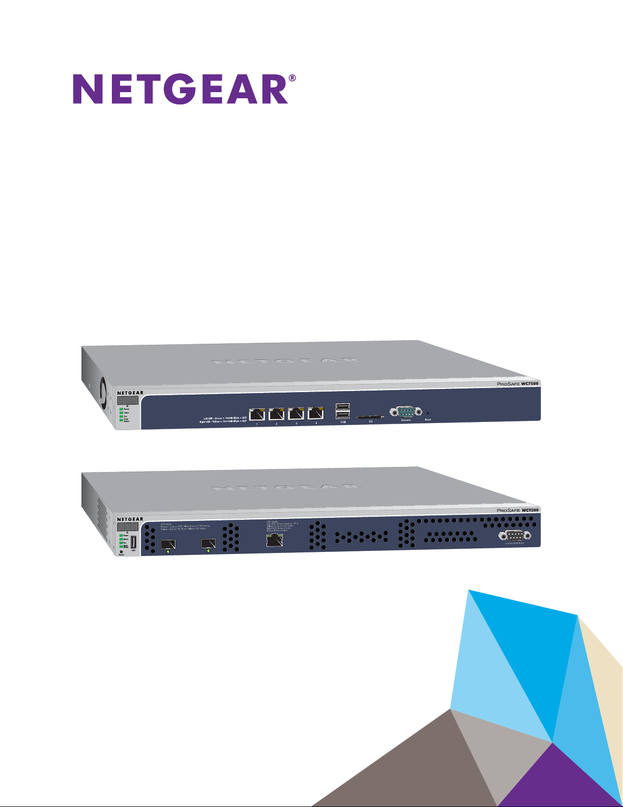
Models WC7500, WC7600,
WC7600v2, and WC9500
User Manual
October 2016
202-11659-02
350 East Plumeria Drive
San Jose, CA 95134
USA
Page 2

ProSAFE Wireless Controller
Support
Thank you for purchasing this NETGEAR product. You can visit www.netgear.com/support to register your product, get help,
access the latest downloads and user manuals, and join our community. We recommend that you use only official NETGEAR
support resources.
Conformity
For the current EU Declaration of Conformity, visit http://kb.netgear.com/app/answers/detail/a_id/11621.
Compliance
For regulatory compliance information, visit http://www.netgear.com/about/regulatory.
See the regulatory compliance document before connecting the power supply.
Trademarks
© NETGEAR, Inc., NETGEAR and the NETGEAR Logo are trademarks of NETGEAR, Inc. Any non-NETGEAR trademarks are
used for reference purposes only.
Revision History
Publication Part
Number
202-11659-02 October 2016 • Added the following new features:
202-11659-01 April 2016 • First publication of the combined manual for all models.
Publish Date Comments
- Support for model WAC740 (see Supported NETGEAR Access Points ).
- Link aggregation for WAC740 access point (see Change Access Point
Information on the Managed AP List and Enable Link Aggregation on a
WAC740 Access Point).
- MU-MIMO for the WAC740 access point (see Configure WiFi Settings
for the Basic Profile Group and Configure WiFi Settings for an
Advanced Profile Group).
- Enhanced syslog support for all wireless controller models (see
Configure the Syslog Settings for an Internal Syslog Location).
- AirQual for the WAC740 access point (see Manage AirQual for a Profile
Group and View AirQual for the Channels in a Profile Group).
- Diagnostic option to send logs for controller-managed access points
over the network (see View the Console Debug Logs of an Access
Point).
- Diagnostic option to capture packets for controller-managed access
points (see Capture WiFi Packets).
• Added Appendix A, Controller-Managed Access Points, which describes
the limited web management interface for controller-managed access
points.
• Introduction of model WC7500 and model WC7600v2.
2
Page 3

Contents
Chapter 1 Introduction
Chapter 2 Hardware Descriptions
Models, Key Features, and Capabilities . . . . . . . . . . . . . . . . . . . . . . . . . . . . . . . . . 12
Model WC7500 . . . . . . . . . . . . . . . . . . . . . . . . . . . . . . . . . . . . . . . . . . . . . . . . . . 12
Model WC7600 . . . . . . . . . . . . . . . . . . . . . . . . . . . . . . . . . . . . . . . . . . . . . . . . . . 12
Model WC7600v2 . . . . . . . . . . . . . . . . . . . . . . . . . . . . . . . . . . . . . . . . . . . . . . . . 13
Model WC9500 . . . . . . . . . . . . . . . . . . . . . . . . . . . . . . . . . . . . . . . . . . . . . . . . . . 13
Model Scalability and Feature Differences . . . . . . . . . . . . . . . . . . . . . . . . . . . . 13
Model Common Features and Capabilities . . . . . . . . . . . . . . . . . . . . . . . . . . . . 14
What Can You Do With a Wireless Controller? . . . . . . . . . . . . . . . . . . . . . . . . . . . 15
Licenses. . . . . . . . . . . . . . . . . . . . . . . . . . . . . . . . . . . . . . . . . . . . . . . . . . . . . . . . . . . . 17
Maintenance and Support . . . . . . . . . . . . . . . . . . . . . . . . . . . . . . . . . . . . . . . . . . . . 17
Package Contents . . . . . . . . . . . . . . . . . . . . . . . . . . . . . . . . . . . . . . . . . . . . . . . . . . . 19
Hardware Models WC7500 and WC7600v2 . . . . . . . . . . . . . . . . . . . . . . . . . . . . 19
WC7500 and WC7600v2 Front Panel Ports and Slots . . . . . . . . . . . . . . . . . 19
WC7500 and WC7600v2 Back Panel Components . . . . . . . . . . . . . . . . . . . . 21
WC7500 and WC7600v2 Product Labels . . . . . . . . . . . . . . . . . . . . . . . . . . . . 21
Hardware Models WC7600 and WC9500 . . . . . . . . . . . . . . . . . . . . . . . . . . . . . . 22
WC7600 and WC9500 Front Panel Ports and Slots . . . . . . . . . . . . . . . . . . . . 22
WC7600 and WC9500 Back Panel Components . . . . . . . . . . . . . . . . . . . . . . 23
WC7600 and WC9500 Product Labels . . . . . . . . . . . . . . . . . . . . . . . . . . . . . . 24
LED Functions (All Models) . . . . . . . . . . . . . . . . . . . . . . . . . . . . . . . . . . . . . . . . . . . 25
Wireless Controller System Components . . . . . . . . . . . . . . . . . . . . . . . . . . . . . . . 26
Supported NETGEAR Access Points . . . . . . . . . . . . . . . . . . . . . . . . . . . . . . . . . . . . 27
Supported NETGEAR Antennas . . . . . . . . . . . . . . . . . . . . . . . . . . . . . . . . . . . . . . . . 30
Chapter 3 System Planning and Deployment Scenarios
Basic and Advanced Setting Concepts . . . . . . . . . . . . . . . . . . . . . . . . . . . . . . . . . . 33
Profile Group Concepts . . . . . . . . . . . . . . . . . . . . . . . . . . . . . . . . . . . . . . . . . . . . . . 34
Basic Profile . . . . . . . . . . . . . . . . . . . . . . . . . . . . . . . . . . . . . . . . . . . . . . . . . . . . . . 34
Advanced Profile . . . . . . . . . . . . . . . . . . . . . . . . . . . . . . . . . . . . . . . . . . . . . . . . . . 34
System Planning Concepts. . . . . . . . . . . . . . . . . . . . . . . . . . . . . . . . . . . . . . . . . . . . 36
Preinstallation Planning . . . . . . . . . . . . . . . . . . . . . . . . . . . . . . . . . . . . . . . . . . . . 36
Before You Configure a Wireless Controller . . . . . . . . . . . . . . . . . . . . . . . . . . . 36
High-Level Configuration Examples. . . . . . . . . . . . . . . . . . . . . . . . . . . . . . . . . . . . 39
Single Controller Configuration With Basic Profile Group . . . . . . . . . . . . . . . 39
Single Controller Configuration With Advanced Profile Groups . . . . . . . . . . 40
Stacked Controller Configuration. . . . . . . . . . . . . . . . . . . . . . . . . . . . . . . . . . . . 41
3
Page 4

ProSAFE Wireless Controller
Management VLAN and Data VLAN Strategies . . . . . . . . . . . . . . . . . . . . . . . . . . 42
High-Level Deployment Scenarios . . . . . . . . . . . . . . . . . . . . . . . . . . . . . . . . . . . . . 44
Scenario Example 1: Network With Single VLAN. . . . . . . . . . . . . . . . . . . . . . . 44
Scenario Example 2: Advanced Network With VLANs and SSIDs . . . . . . . . . 46
Scenario Example 3: Advanced Network With Redundancy . . . . . . . . . . . . . 48
Chapter 4 RF Planning and Deployment
Application, Browser, and Port Requirements for RF Planning. . . . . . . . . . . . . . 53
RF Planning Overview. . . . . . . . . . . . . . . . . . . . . . . . . . . . . . . . . . . . . . . . . . . . . . . . 53
Planning Requirements. . . . . . . . . . . . . . . . . . . . . . . . . . . . . . . . . . . . . . . . . . . . . 54
Recommended RF Planning Procedure for a Building . . . . . . . . . . . . . . . . . . . 56
Manage a Building and Floors for an RF Plan. . . . . . . . . . . . . . . . . . . . . . . . . . . . . 56
Add a Building and Floors. . . . . . . . . . . . . . . . . . . . . . . . . . . . . . . . . . . . . . . . . . . 57
Add a Single Floor to a Building. . . . . . . . . . . . . . . . . . . . . . . . . . . . . . . . . . . . . . 59
Scale a Floor. . . . . . . . . . . . . . . . . . . . . . . . . . . . . . . . . . . . . . . . . . . . . . . . . . . . . . 60
Add a WiFi Coverage or WiFi Noncoverage Zone to a Floor. . . . . . . . . . . . . . 61
Remove a WiFi Coverage or Noncoverage Zone From a Floor. . . . . . . . . . . . 62
Add a WiFi Building Obstacle to a Floor. . . . . . . . . . . . . . . . . . . . . . . . . . . . . . . 62
Remove a Building Obstacle From a Floor . . . . . . . . . . . . . . . . . . . . . . . . . . . . . 64
Add a WiFi Obstruction Area. . . . . . . . . . . . . . . . . . . . . . . . . . . . . . . . . . . . . . . . 65
Remove a WiFi Obstruction Area . . . . . . . . . . . . . . . . . . . . . . . . . . . . . . . . . . . . 66
Change the Name, Map, or Dimensions of a Floor . . . . . . . . . . . . . . . . . . . . . 66
Change the Name of a Building. . . . . . . . . . . . . . . . . . . . . . . . . . . . . . . . . . . . . . 67
Duplicate an Entire Building With All Floors . . . . . . . . . . . . . . . . . . . . . . . . . . . 68
Duplicate a Single Floor . . . . . . . . . . . . . . . . . . . . . . . . . . . . . . . . . . . . . . . . . . . . 68
Remove a Single Floor . . . . . . . . . . . . . . . . . . . . . . . . . . . . . . . . . . . . . . . . . . . . . 69
Remove an Entire Building With All Its Floors. . . . . . . . . . . . . . . . . . . . . . . . . . 70
Use the WiFi Auto Planning Advisor to Generate an RF Plan for a Floor . . . . . . 70
Manually Add and Manage Access Points on a Floor Map for an RF Plan . . . . . 76
Manually Add and Manage Antennas on a Floor Map for an RF Plan. . . . . . . . . 79
Display and Recalculate the WiFi Coverage for a Heat Map . . . . . . . . . . . . . . . . 83
Display or Change the WiFi Inventory for an RF Plan . . . . . . . . . . . . . . . . . . . . . 84
Download a Report for an RF Plan . . . . . . . . . . . . . . . . . . . . . . . . . . . . . . . . . . . . . 87
View the Heat Map for a Deployed Floor Plan . . . . . . . . . . . . . . . . . . . . . . . . . . . 88
Chapter 5 Installation and Configuration Overview
Connect Your Computer to the Wireless Controller. . . . . . . . . . . . . . . . . . . . . . . 92
Log In to the Wireless Controller. . . . . . . . . . . . . . . . . . . . . . . . . . . . . . . . . . . . . . . 92
Roadmap for Initial Configuration. . . . . . . . . . . . . . . . . . . . . . . . . . . . . . . . . . . . . . 94
Roadmap for Configuring Management of Your WiFi Network . . . . . . . . . . . . . 96
Choose a Location for the Wireless Controller . . . . . . . . . . . . . . . . . . . . . . . . . . . 98
Deploy the Wireless Controller . . . . . . . . . . . . . . . . . . . . . . . . . . . . . . . . . . . . . . . . 98
Chapter 6 Configure the System and Network Settings and
Register the Licenses
Configure the General Settings . . . . . . . . . . . . . . . . . . . . . . . . . . . . . . . . . . . . . . . 100
4
Page 5

ProSAFE Wireless Controller
Manage the Time Settings . . . . . . . . . . . . . . . . . . . . . . . . . . . . . . . . . . . . . . . . . . .101
Manage the IP, VLAN, and Link Aggregation Settings. . . . . . . . . . . . . . . . . . . . 102
Management VLAN Concepts . . . . . . . . . . . . . . . . . . . . . . . . . . . . . . . . . . . . . . 102
Untagged VLAN Concepts . . . . . . . . . . . . . . . . . . . . . . . . . . . . . . . . . . . . . . . . .103
Controller Link Aggregation Concepts. . . . . . . . . . . . . . . . . . . . . . . . . . . . . . . 103
Configure the IP, VLAN, and Controller Link Aggregation Settings. . . . . . . 104
Manage the DHCP Server . . . . . . . . . . . . . . . . . . . . . . . . . . . . . . . . . . . . . . . . . . . 106
Add a DHCP Server. . . . . . . . . . . . . . . . . . . . . . . . . . . . . . . . . . . . . . . . . . . . . . . 106
Change the Settings for a DHCP Server . . . . . . . . . . . . . . . . . . . . . . . . . . . . . 108
Remove a DHCP Server . . . . . . . . . . . . . . . . . . . . . . . . . . . . . . . . . . . . . . . . . . . 109
Register Your Licenses . . . . . . . . . . . . . . . . . . . . . . . . . . . . . . . . . . . . . . . . . . . . . . 110
Configure the License Server Settings . . . . . . . . . . . . . . . . . . . . . . . . . . . . . . 110
Register Your Licenses With the License Server. . . . . . . . . . . . . . . . . . . . . . . 111
Manage Certificates . . . . . . . . . . . . . . . . . . . . . . . . . . . . . . . . . . . . . . . . . . . . . . . . 113
Configure Syslog, Alarm Notification, and Email Settings . . . . . . . . . . . . . . . . . 114
Configure the Syslog Settings for an Internal Syslog Location . . . . . . . . . . 114
Configure the Syslog Settings for an External Syslog Location. . . . . . . . . . 116
Configure Alarm Notification Settings. . . . . . . . . . . . . . . . . . . . . . . . . . . . . . . 118
Configure the Email Notification Server . . . . . . . . . . . . . . . . . . . . . . . . . . . . . 119
Chapter 7 Manage Security Profiles and Profile Groups
WiFi Security Profile Concepts . . . . . . . . . . . . . . . . . . . . . . . . . . . . . . . . . . . . . . .121
Small WLAN Networks . . . . . . . . . . . . . . . . . . . . . . . . . . . . . . . . . . . . . . . . . . . . 121
Large WLAN Networks. . . . . . . . . . . . . . . . . . . . . . . . . . . . . . . . . . . . . . . . . . . . 122
Profile Naming Conventions . . . . . . . . . . . . . . . . . . . . . . . . . . . . . . . . . . . . . . . 122
Considerations Before You Configure Profiles . . . . . . . . . . . . . . . . . . . . . . . . 122
Basic and Advanced Security Configuration Concepts . . . . . . . . . . . . . . . . . 123
Manage Security Profiles for the Basic Profile Group . . . . . . . . . . . . . . . . . . . . 124
Configure a Profile in the Basic Profile Group. . . . . . . . . . . . . . . . . . . . . . . . . 124
Change the Settings for a Profile in the Basic Profile Group . . . . . . . . . . . . 128
Remove a Profile From the Basic Profile Group . . . . . . . . . . . . . . . . . . . . . . . 129
Manage Security Profiles for Advanced Profile Groups . . . . . . . . . . . . . . . . . . 129
Add an Advanced Profile Group . . . . . . . . . . . . . . . . . . . . . . . . . . . . . . . . . . . . 129
Remove an Advanced Profile Group. . . . . . . . . . . . . . . . . . . . . . . . . . . . . . . . . 131
Configure a Profile in an Advanced Profile Group . . . . . . . . . . . . . . . . . . . . . 131
Change the Settings for a Profile in an Advanced Profile Group . . . . . . . . . 135
Remove a Profile From an Advanced Profile Group . . . . . . . . . . . . . . . . . . . . 136
Network Authentication and Data Encryption Options . . . . . . . . . . . . . . . . . . . 137
Manage Authentication Servers and Authentication Server Groups. . . . . . . . 140
Authentication Server Concepts. . . . . . . . . . . . . . . . . . . . . . . . . . . . . . . . . . . . 140
Configure Basic Authentication Server Settings . . . . . . . . . . . . . . . . . . . . . . 142
Configure a RADIUS Authentication Server Group . . . . . . . . . . . . . . . . . . . . 144
Remove a RADIUS Authentication Server Group. . . . . . . . . . . . . . . . . . . . . . 145
Manage MAC Authentication and MAC Authentication Groups. . . . . . . . . . . . 146
Guidelines for External MAC Authentication. . . . . . . . . . . . . . . . . . . . . . . . . . . . 146
Configure Basic Local MAC Authentication Settings . . . . . . . . . . . . . . . . . . . 146
Remove a MAC Address From a Wireless Client List . . . . . . . . . . . . . . . . . . . 148
Import a MAC List From a File . . . . . . . . . . . . . . . . . . . . . . . . . . . . . . . . . . . . . . 148
5
Page 6

ProSAFE Wireless Controller
Configure a Local MAC Authentication Group . . . . . . . . . . . . . . . . . . . . . . . . 149
Remove a Local MAC Authentication Group . . . . . . . . . . . . . . . . . . . . . . . . . . . . 151
Select an ACL for a Profile in the Basic Profile Group . . . . . . . . . . . . . . . . . . 151
Select an ACL for a Profile in an Advanced Profile Group. . . . . . . . . . . . . . . 152
Chapter 8 Discover and Manage Access Points
Access Point Discovery Guidelines . . . . . . . . . . . . . . . . . . . . . . . . . . . . . . . . . . . . 155
General Discovery Guidelines . . . . . . . . . . . . . . . . . . . . . . . . . . . . . . . . . . . . . . 155
Layer 3 Discovery Guidelines . . . . . . . . . . . . . . . . . . . . . . . . . . . . . . . . . . . . . . 155
Remote Access Point Discovery Guidelines . . . . . . . . . . . . . . . . . . . . . . . . . . 157
Discover Access Points With the Discovery Wizard. . . . . . . . . . . . . . . . . . . . . . 159
Discover Access Points in Factory Default State and Access
Points in a Layer 2 Subnet. . . . . . . . . . . . . . . . . . . . . . . . . . . . . . . . . . . . . . . . . 159
Discover Access Points Installed and Working in
Standalone Mode in Different Layer 3 Networks . . . . . . . . . . . . . . . . . . . . . 163
Manage the Managed AP List . . . . . . . . . . . . . . . . . . . . . . . . . . . . . . . . . . . . . . . . 167
View the Managed AP List. . . . . . . . . . . . . . . . . . . . . . . . . . . . . . . . . . . . . . . . . 167
Change Access Point Information on the Managed AP List . . . . . . . . . . . . . 170
Remove Access Points From the Managed AP List . . . . . . . . . . . . . . . . . . . . 173
Assign Access Points to Buildings, Floors, and Advanced Profile Groups . . . . 174
Chapter 9 Configure WiFi and QoS Settings
Basic and Advanced WiFi and QoS Configuration Concepts . . . . . . . . . . . . . . . 179
Configure the Radio . . . . . . . . . . . . . . . . . . . . . . . . . . . . . . . . . . . . . . . . . . . . . . . . 179
Configure the Radio for the Basic Profile Group . . . . . . . . . . . . . . . . . . . . . . 179
Configure the Radio for an Advanced Profile Group . . . . . . . . . . . . . . . . . . . 180
Configure WiFi Settings . . . . . . . . . . . . . . . . . . . . . . . . . . . . . . . . . . . . . . . . . . . . . 182
Configure WiFi Settings for the Basic Profile Group . . . . . . . . . . . . . . . . . . . 182
Override Channel and Transmission Power in the Basic Profile Group . . . . 186
Configure WiFi Settings for an Advanced Profile Group . . . . . . . . . . . . . . . . 188
Override Channel and Transmission Power in an Advanced
Profile Group . . . . . . . . . . . . . . . . . . . . . . . . . . . . . . . . . . . . . . . . . . . . . . . . . . . . 193
Configure Channels. . . . . . . . . . . . . . . . . . . . . . . . . . . . . . . . . . . . . . . . . . . . . . . . . 195
Specify Radio Frequency Management . . . . . . . . . . . . . . . . . . . . . . . . . . . . . . . . 198
Radio Frequency Concepts . . . . . . . . . . . . . . . . . . . . . . . . . . . . . . . . . . . . . . . . 198
WLAN Healing Concepts . . . . . . . . . . . . . . . . . . . . . . . . . . . . . . . . . . . . . . . . . . 198
Configure Radio Frequency Management for the Basic Profile Group . . . . 199
Configure Radio Frequency Management for an Advanced
Profile Group . . . . . . . . . . . . . . . . . . . . . . . . . . . . . . . . . . . . . . . . . . . . . . . . . . . . 200
Manage AirQual for a Profile Group . . . . . . . . . . . . . . . . . . . . . . . . . . . . . . . . . . . 203
AirQual Concepts . . . . . . . . . . . . . . . . . . . . . . . . . . . . . . . . . . . . . . . . . . . . . . . . 203
Configure AirQual for the Basic Profile Group . . . . . . . . . . . . . . . . . . . . . . . . 203
Configure AirQual for an Advanced Profile Group . . . . . . . . . . . . . . . . . . . . . 205
Manage Quality of Service for an Advanced Profile Group . . . . . . . . . . . . . . . 207
Quality of Service Concepts . . . . . . . . . . . . . . . . . . . . . . . . . . . . . . . . . . . . . . . 207
Configure Quality of Service for a Profile Group. . . . . . . . . . . . . . . . . . . . . . 208
Manage Load Balancing . . . . . . . . . . . . . . . . . . . . . . . . . . . . . . . . . . . . . . . . . . . . . 210
6
Page 7

ProSAFE Wireless Controller
Load Balancing Concepts. . . . . . . . . . . . . . . . . . . . . . . . . . . . . . . . . . . . . . . . . . 210
Configure Load Balancing . . . . . . . . . . . . . . . . . . . . . . . . . . . . . . . . . . . . . . . . . 211
Manage Rate Limiting . . . . . . . . . . . . . . . . . . . . . . . . . . . . . . . . . . . . . . . . . . . . . . . 212
Rate Limiting Concepts . . . . . . . . . . . . . . . . . . . . . . . . . . . . . . . . . . . . . . . . . . . 212
Configure Rate Limiting for the Basic Profile Group . . . . . . . . . . . . . . . . . . . 213
Configure Rate Limiting for an Advanced Profile Group . . . . . . . . . . . . . . . . 214
Manage the LED Behavior . . . . . . . . . . . . . . . . . . . . . . . . . . . . . . . . . . . . . . . . . . . 215
Manage the LED Behavior for the Basic Profile Group . . . . . . . . . . . . . . . . . 215
Manage the LED Behavior for an Advanced Profile Group. . . . . . . . . . . . . . 216
Chapter 10 Manage Rogue Access Points, Guest Network
Access, and Users
Manage Rogue Access Points . . . . . . . . . . . . . . . . . . . . . . . . . . . . . . . . . . . . . . . . 219
Rogue Access Point Concepts . . . . . . . . . . . . . . . . . . . . . . . . . . . . . . . . . . . . . . 219
Configure Basic Rogue Detection Settings . . . . . . . . . . . . . . . . . . . . . . . . . . . 219
Classify Rogue Access Points . . . . . . . . . . . . . . . . . . . . . . . . . . . . . . . . . . . . . . 220
Import a List of Known Access Points From a File . . . . . . . . . . . . . . . . . . . . . 222
Manage Guest Network Access Through Guest Portals and Captive Portals . 223
Portal Concepts . . . . . . . . . . . . . . . . . . . . . . . . . . . . . . . . . . . . . . . . . . . . . . . . . . 223
Configure a Basic Guest Portal or Captive Portal. . . . . . . . . . . . . . . . . . . . . . 224
Configure an Advanced Guest Portal or Captive Portal . . . . . . . . . . . . . . . . 229
Remove a Portal . . . . . . . . . . . . . . . . . . . . . . . . . . . . . . . . . . . . . . . . . . . . . . . . . 236
Manage Users, Accounts, and Passwords . . . . . . . . . . . . . . . . . . . . . . . . . . . . . . 236
User and Account Concepts . . . . . . . . . . . . . . . . . . . . . . . . . . . . . . . . . . . . . . . 236
Change the Password of the Default admin Account of the
Wireless Controller . . . . . . . . . . . . . . . . . . . . . . . . . . . . . . . . . . . . . . . . . . . . . . . 237
Add a Management User . . . . . . . . . . . . . . . . . . . . . . . . . . . . . . . . . . . . . . . . . . 239
Add a WiFi User . . . . . . . . . . . . . . . . . . . . . . . . . . . . . . . . . . . . . . . . . . . . . . . . . .240
Add a Captive Portal Account . . . . . . . . . . . . . . . . . . . . . . . . . . . . . . . . . . . . . . 241
Add a Logo and Message on Captive Portal User Information. . . . . . . . . . . 243
Add a Captive Portal User . . . . . . . . . . . . . . . . . . . . . . . . . . . . . . . . . . . . . . . . . 245
Add Multiple Captive Portal Users Simultaneously . . . . . . . . . . . . . . . . . . . . 247
Change the Settings for a User or Account. . . . . . . . . . . . . . . . . . . . . . . . . . . 250
Remove Users or Accounts . . . . . . . . . . . . . . . . . . . . . . . . . . . . . . . . . . . . . . . . 250
Export a List of Users or Accounts. . . . . . . . . . . . . . . . . . . . . . . . . . . . . . . . . . 251
Chapter 11 Maintain the Wireless Controller and Access Points
Manage the Configuration File or Upgrade the Firmware. . . . . . . . . . . . . . . . . 254
Back Up the Configuration File . . . . . . . . . . . . . . . . . . . . . . . . . . . . . . . . . . . . . 254
Restore the Configuration File . . . . . . . . . . . . . . . . . . . . . . . . . . . . . . . . . . . . . 255
Upgrade the Firmware . . . . . . . . . . . . . . . . . . . . . . . . . . . . . . . . . . . . . . . . . . . . 256
Reboot the Wireless Controller . . . . . . . . . . . . . . . . . . . . . . . . . . . . . . . . . . . . . . . 259
Reset the Wireless Controller . . . . . . . . . . . . . . . . . . . . . . . . . . . . . . . . . . . . . . . .259
Manage Extended Storage . . . . . . . . . . . . . . . . . . . . . . . . . . . . . . . . . . . . . . . . . . . 260
Manage Remote Access . . . . . . . . . . . . . . . . . . . . . . . . . . . . . . . . . . . . . . . . . . . . . 262
Specify Session Time-Outs . . . . . . . . . . . . . . . . . . . . . . . . . . . . . . . . . . . . . . . . . . 263
Save the Logs. . . . . . . . . . . . . . . . . . . . . . . . . . . . . . . . . . . . . . . . . . . . . . . . . . . . . . 264
7
Page 8

ProSAFE Wireless Controller
Save the System Logs . . . . . . . . . . . . . . . . . . . . . . . . . . . . . . . . . . . . . . . . . . . . 264
Save and Clear the Logs for an Access Point . . . . . . . . . . . . . . . . . . . . . . . . . 265
View Alerts and Events. . . . . . . . . . . . . . . . . . . . . . . . . . . . . . . . . . . . . . . . . . . . . . 267
View System Alerts. . . . . . . . . . . . . . . . . . . . . . . . . . . . . . . . . . . . . . . . . . . . . . . 267
View Radio Frequency Events. . . . . . . . . . . . . . . . . . . . . . . . . . . . . . . . . . . . . . 268
View Load-Balancing Events. . . . . . . . . . . . . . . . . . . . . . . . . . . . . . . . . . . . . . . 269
View Rate-Limit Events . . . . . . . . . . . . . . . . . . . . . . . . . . . . . . . . . . . . . . . . . . . 271
View Redundancy Events. . . . . . . . . . . . . . . . . . . . . . . . . . . . . . . . . . . . . . . . . . 272
View Stacking Events . . . . . . . . . . . . . . . . . . . . . . . . . . . . . . . . . . . . . . . . . . . . . 273
Manage Licenses . . . . . . . . . . . . . . . . . . . . . . . . . . . . . . . . . . . . . . . . . . . . . . . . . . . 274
View Your Licenses . . . . . . . . . . . . . . . . . . . . . . . . . . . . . . . . . . . . . . . . . . . . . . . 274
Retrieve Your Licenses . . . . . . . . . . . . . . . . . . . . . . . . . . . . . . . . . . . . . . . . . . . . 276
Reboot Access Points . . . . . . . . . . . . . . . . . . . . . . . . . . . . . . . . . . . . . . . . . . . . . . . 277
Configure Multicast Firmware Upgrade for Access Points . . . . . . . . . . . . . . . . 278
Change the Multicast Firmware Upgrade Settings . . . . . . . . . . . . . . . . . . . . 278
Disable Multicast Firmware Upgrade . . . . . . . . . . . . . . . . . . . . . . . . . . . . . . . . 279
Chapter 12 Manage Stacking and Redundancy
Stacking Concepts. . . . . . . . . . . . . . . . . . . . . . . . . . . . . . . . . . . . . . . . . . . . . . . . . . 281
Configure a Stack of Wireless Controllers. . . . . . . . . . . . . . . . . . . . . . . . . . . . . . 283
Remove a Wireless Controller From a Stack . . . . . . . . . . . . . . . . . . . . . . . . . . . . 287
Select Which Wireless Controller in a Stack to Configure. . . . . . . . . . . . . . . . . 288
Manage Redundancy for a Single Controller . . . . . . . . . . . . . . . . . . . . . . . . . . . 291
VRRP Redundancy Concepts. . . . . . . . . . . . . . . . . . . . . . . . . . . . . . . . . . . . . . . 291
Configure a Single Controller With Redundancy . . . . . . . . . . . . . . . . . . . . . . 293
Manage a Redundancy Group With N:1 Redundancy . . . . . . . . . . . . . . . . . . . . 297
VRRP N:1 Redundancy Concepts . . . . . . . . . . . . . . . . . . . . . . . . . . . . . . . . . . . 297
Configure a Redundancy Group With N:1 Redundancy . . . . . . . . . . . . . . . . 300
Replace a Redundant Controller . . . . . . . . . . . . . . . . . . . . . . . . . . . . . . . . . . . . . . 305
Remove a Redundancy Group . . . . . . . . . . . . . . . . . . . . . . . . . . . . . . . . . . . . . . . . 306
Chapter 13 Monitor the WiFi Network and Its Components
Monitor the Network . . . . . . . . . . . . . . . . . . . . . . . . . . . . . . . . . . . . . . . . . . . . . . . 309
View the Network Summary Page . . . . . . . . . . . . . . . . . . . . . . . . . . . . . . . . . . 309
View the Wireless Controllers in the Network . . . . . . . . . . . . . . . . . . . . . . . . 311
View the Access Points in the Network . . . . . . . . . . . . . . . . . . . . . . . . . . . . . . 313
View the Clients in the Network. . . . . . . . . . . . . . . . . . . . . . . . . . . . . . . . . . . . 318
View the Profiles in the Network . . . . . . . . . . . . . . . . . . . . . . . . . . . . . . . . . . . 322
Monitor the Wireless Controller . . . . . . . . . . . . . . . . . . . . . . . . . . . . . . . . . . . . . . 324
View the Wireless Controller Summary Page . . . . . . . . . . . . . . . . . . . . . . . . . 324
View Wireless Controller Usage . . . . . . . . . . . . . . . . . . . . . . . . . . . . . . . . . . . . 327
View Access Points That the Wireless Controller Manages . . . . . . . . . . . . . 328
View Clients on Access Points That the Wireless Controller Manages . . . . 333
View Neighboring Clients That the Wireless Controller Detects . . . . . . . . . 337
View Neighboring Access Points That the Wireless Controller
Does Not Manage . . . . . . . . . . . . . . . . . . . . . . . . . . . . . . . . . . . . . . . . . . . . . . . . 339
View Security Profiles That the Wireless Controller Manages. . . . . . . . . . . 340
8
Page 9

ProSAFE Wireless Controller
View DHCP Leases That Are Provided by the Wireless Controller . . . . . . . 342
View Captive Portal Users on Access Points That the
Wireless Controller Manages. . . . . . . . . . . . . . . . . . . . . . . . . . . . . . . . . . . . . . . 343
View the Guest Email Address Database for Access Points That
the Wireless Controller Manages . . . . . . . . . . . . . . . . . . . . . . . . . . . . . . . . . . . 345
View AirQual for the Channels in a Profile Group . . . . . . . . . . . . . . . . . . . . . 346
Monitor the SSIDs on the Wireless Controller. . . . . . . . . . . . . . . . . . . . . . . . . . . 348
Monitor Local Clients in the Network. . . . . . . . . . . . . . . . . . . . . . . . . . . . . . . . . . 353
Monitor Accepted Clients . . . . . . . . . . . . . . . . . . . . . . . . . . . . . . . . . . . . . . . . . 353
Monitor Blacklisted Clients . . . . . . . . . . . . . . . . . . . . . . . . . . . . . . . . . . . . . . . . 357
Chapter 14 Troubleshooting and Diagnostics
Troubleshoot Basic Functioning. . . . . . . . . . . . . . . . . . . . . . . . . . . . . . . . . . . . . . . 361
Power LED Is Not Lit . . . . . . . . . . . . . . . . . . . . . . . . . . . . . . . . . . . . . . . . . . . . . . 361
Status LED Never Turns Off . . . . . . . . . . . . . . . . . . . . . . . . . . . . . . . . . . . . . . . 361
Ethernet Port LEDs Are Not Lit . . . . . . . . . . . . . . . . . . . . . . . . . . . . . . . . . . . . . 361
Troubleshoot the Web Management Interface . . . . . . . . . . . . . . . . . . . . . . . . . . 362
Check the Ethernet Cabling. . . . . . . . . . . . . . . . . . . . . . . . . . . . . . . . . . . . . . . . 362
Check the IP Address Configuration . . . . . . . . . . . . . . . . . . . . . . . . . . . . . . . . 362
Check the Internet Browser . . . . . . . . . . . . . . . . . . . . . . . . . . . . . . . . . . . . . . . 363
Troubleshoot a TCP/IP Network Using the Ping Utility . . . . . . . . . . . . . . . . . . . 363
Use the Reset Button to Restore Default Settings . . . . . . . . . . . . . . . . . . . . . . . 364
Resolve Problems With Date and Time. . . . . . . . . . . . . . . . . . . . . . . . . . . . . . . . . 364
Resolve Network Problems . . . . . . . . . . . . . . . . . . . . . . . . . . . . . . . . . . . . . . . . . .365
Resolve Problems With Access Points . . . . . . . . . . . . . . . . . . . . . . . . . . . . . . . . .365
Resolve Discovery Problems . . . . . . . . . . . . . . . . . . . . . . . . . . . . . . . . . . . . . . . 365
Resolve Connection Problems. . . . . . . . . . . . . . . . . . . . . . . . . . . . . . . . . . . . . . 366
Network Performance and Rogue Access Point Detection. . . . . . . . . . . . . . 366
Use the Diagnostic Tools on the Wireless Controller . . . . . . . . . . . . . . . . . . . . . 366
Ping an Access Point . . . . . . . . . . . . . . . . . . . . . . . . . . . . . . . . . . . . . . . . . . . . . .367
Trace a Route to an Access Point . . . . . . . . . . . . . . . . . . . . . . . . . . . . . . . . . . . 368
View the Console Debug Logs of an Access Point . . . . . . . . . . . . . . . . . . . . . 369
Capture WiFi Packets . . . . . . . . . . . . . . . . . . . . . . . . . . . . . . . . . . . . . . . . . . . . . 371
Appendix A Controller-Managed Access Points
Overview . . . . . . . . . . . . . . . . . . . . . . . . . . . . . . . . . . . . . . . . . . . . . . . . . . . . . . . . . 375
Change IP Address and VLAN Settings on a
Controller-Managed Access Point . . . . . . . . . . . . . . . . . . . . . . . . . . . . . . . . . . . . 376
Reenable the DHCP Client on a Controller-Managed Access Point. . . . . . . . . 377
Upgrade or Change Firmware on a Controller-Managed Access Point . . . . . . 378
Save and View the Logs on a Controller-Managed Access Point. . . . . . . . . . . 381
Enable Link Aggregation on a WAC740 Access Point . . . . . . . . . . . . . . . . . . . . 382
Change the Password on an Access Point . . . . . . . . . . . . . . . . . . . . . . . . . . . . . . 383
Convert an Access Point From Controller-Managed to Standalone . . . . . . . . 385
9
Page 10

ProSAFE Wireless Controller
Appendix B Factory Default Settings, Technical Specifications,
and Passwords Requirements
Factory Default Settings . . . . . . . . . . . . . . . . . . . . . . . . . . . . . . . . . . . . . . . . . . . . 387
Technical Specifications Models WC7500 and WC7600v2. . . . . . . . . . . . . . . 387
Technical Specifications Models WC7600 and WC9500 . . . . . . . . . . . . . . . . . 388
Password Requirements . . . . . . . . . . . . . . . . . . . . . . . . . . . . . . . . . . . . . . . . . . . . . 389
Index
10
Page 11

1. Introduction
This chapter includes the following sections:
• Models, Key Features, and Capabilities
• What Can You Do With a Wireless Controller?
• Licenses
• Maintenance and Support
Note: For more information about the topics covered in this manual, visit the
support website at netgear.com/support.
Note: Firmware updates with new features and bug fixes are made
available from time to time on downloadcenter.netgear.com. Some
products can regularly check the site and download new firmware, or
you can check for and download new firmware manually. If the
features or behavior of your product does not match what is
described in this guide, you might need to update your firmware.
1
Note: In this manual, the terms wireless and WiFi are interchangeable.
11
Page 12

ProSAFE Wireless Controller
Models, Key Features, and Capabilities
The NETGEAR ProSAFE® Wireless Controller is a high-capacity, secured wireless controller
intended for medium to large-sized businesses, higher education institutions, hospitals, and
hotels.
The wireless controller supports the IEEE 802.11a/b/g/n/ac protocols. With the wireless
controller, you can manage your wireless network from a central point, implement security
features centrally, support Layer 2 and Layer 3 fast roaming, configure a guest access
captive portal, and support voice over Wi-Fi (VoWi-Fi).
This user manual supports models WC7500, WC7600, WC7600v2, and WC9500. For a
comparison between the models, see Table 1 on page 13.
Note: For information about the manuals for the legacy model WC7520, visit
downloadcenter.netgear.com/en/product/WC7520.
Model WC7500
One WC7500 wireless controller with the appropriate licenses can support up to 15 access
points (APs) with up to 400 users. Model WC7500 is an entry-level model: You cannot stack
the WC7500, nor is controller redundancy supported.
Model WC7500 provides four RJ-45 Gigabit Ethernet ports. However all four Gigabit Ethernet
ports provide equal performance and are bonded together in Linux active-backup mode. In
this mode, the ports effectively function as one port rather than four separate ports, with one
port active and three ports acting as backup if the active port fails. Therefore, only one port is
available to access the wireless controller for management or for data and control
communications between the wireless controller and the access points. For more
information, visit kb.netgear.com/app/answers/detail/a_id/30974/~/prosafe-wc7500.
Model WC7600
One WC7600 wireless controller with the appropriate licenses can support up to 50 access
points (APs) with up to 2,000 users. In a stacked configuration, a stack of three wireless
controllers can support up to 150 access points with up to 6,000 users.
Model WC7600 provides one RJ-45 Gigabit Ethernet port and two 10 Gigabit Ethernet
(10GbE) slots with standard SFP+ form factor for optional 10GBASE or 1000BASE GBICs.
These ports are available to access the wireless controller for management and for data and
control communications between the wireless controller and the access points.
Introduction
12
Page 13

ProSAFE Wireless Controller
Model WC7600v2
One WC7600v2 wireless controller with the appropriate licenses can support up to 50 access
points (APs) with up to 2,000 users. In a stacked configuration, a stack of three wireless
controllers can support up to 150 access points with up to 6,000 users.
Model WC7600v2 provides four RJ-45 Gigabit Ethernet ports. These ports are available to
access the wireless controller for management and for data and control communications
between the wireless controller and the access points.
Model WC9500
One WC9500 standalone wireless controller with the appropriate licenses can support up to
300 access points with up to 9,000 clients. In a stacked configuration, one wireless controller
with the appropriate licenses can support up to 200 access points with up to 6,000 clients. A
stack can support three wireless controllers with up to 18,000 clients.
Model WC9500 provides one RJ-45 Gigabit Ethernet port and two 10 Gigabit Ethernet
(10GbE) slots with standard SFP+ form factor for optional 10GBASE or 1000BASE GBICs.
These ports are available to access the wireless controller for management and for data and
control communications between the wireless controller and the access points.
Model Scalability and Feature Differences
The following table show the differences in scalability and features between the wireless
controller models.
Table 1. Model differences and scalable architecture
Feature WC7500 WC7600 WC7600v2 WC9500
License in AP increments 5 10, 50 10, 50 10, 50, 100, 200
Single controller
Max. number of APs
Max. number of users
Stack of three controllers
Max. number of APs
Max. number of users
Controller redundancy Not supported Supported Supported Supported
Link aggregation Not supported Supported Not supported Supported
Monitor blacklisted clients Not supported Supported Not supported Supported
1G ports 4
15
400
Stacking is not
supported
1
50
2,000
150
6,000
141
50
2,000
150
6,000
300
9.000
600
18,000
SFP slots None 2 None 2
USB ports 2 1 2 1
Introduction
13
Page 14

ProSAFE Wireless Controller
Table 1. Model differences and scalable architecture (continued)
Feature WC7500 WC7600 WC7600v2 WC9500
SD card slot 1
Optional extra power supply Not supported Supported Not supported Supported
1. All four Gigabit Ethernet ports provide equal performance and are bonded together in Linux active-backup mode.
2. An SD card will be supported in a future release.
2
None 1
1
None
Model Common Features and Capabilities
The wireless controller provides the following common key features and capabilities:
• WiFi modes
- 802.11a
- 802.11b
- 802.11g
- 802.11n
- 802.11ac
• Autodiscovery of access points
- Autodiscovery of access points in the same Layer 2 domain.
- Autodiscovery of access points across a Layer 3 domain.
- Automatic download of wireless controller–based firmware to discovered access
points that are added to the managed access point list.
• Centralized management
- Single point of management for the entire WiFi network.
- Automatic firmware upgrade to all managed access points.
- DHCP server for IP address provisioning.
- Configurable management VLAN.
• Security
- Identity-based security authentication with an external RADIUS or LDAP (Active
Directory) server, or with an internal authentication server.
- Support for nine access point profile groups (one basic and eight advanced) on one
wireless controller.
- Support for up to 8 profiles per access point profile group and 8 profiles per radio
(therefore, dual-band access points can support up to 16 profiles in one access point
profile group).
- Support for up to 144 profiles on one wireless controller (8 profiles per access point
group and eight groups per radio). Each profile supports settings for SSID, network
authentication, data encryption, client separation, VLAN, MAC ACL, and WiFi QoS.
- Rogue access point detection and classification.
Introduction
14
Page 15

ProSAFE Wireless Controller
- Guest access and captive portal access with cost and expiration accounting.
- Scheduled WiFi on/off times.
• Wi-Fi Multimedia Quality of Service and advanced wireless features
- Wi-Fi Multimedia (WMM) support for video, audio, and voice over Wi-Fi (VoWi-Fi).
- WMM power save option.
- Automatic WLAN healing mechanism ensures seamless coverage for WiFi users.
- Layer 2 and Layer 3 seamless roaming support.
- Local Layer 2 traffic switching and Layer 3 traffic processing at access point level for
fast processing.
• Wireless and Radio Frequency (RF) management
- Automatic control of access point transmit power and channel allocation to reduce
interference.
- Automatic load balancing of clients across access points.
- Rate limiting per profile.
- Multicast and broadcast rate limiting
- ARP suppression
• Monitoring and reporting
- Monitoring of the status of the network, wireless controllers, WLANs, and clients, and
network usage statistics.
- Specific health monitoring of access points.
- Logging and emailing of system events, RF events, load-balancing events, and
rate-limiting events.
For a list of all features and capabilities of the wireless controller, see the datasheets:
• For the WC7500, visit netgear.com/support/product/WC7500.
• For the WC7600, visit netgear.com/support/product/WC7600v1.
• For the WC7600v2, visit netgear.com/support/product/WC7600v2.
• For the WC9500, visit netgear.com/support/product/WC9500.
What Can You Do With a Wireless Controller?
You can perform the following tasks with a wireless controller:
• Organize the Network
- Create access point profiles. Organize access points in profiles to differentiate
between SSIDs, client authentication, authentication settings, and WiFi QoS settings.
- Create access point profile groups. Organize access point profiles in access point
profile groups to differentiate between buildings, floors, businesses, business
divisions, and so on. Easily assign access points to profile groups or change
assignments.
For more information, see Chapter 7, Manage Security Profiles and Profile Groups.
Introduction
15
Page 16

ProSAFE Wireless Controller
• Discover Access Points in the Network and Provision IP Addresses and Firmware
- Discover access points in the network. The access points can be in factory default
state or functioning in standalone mode, but after discovery by the wireless controller
and addition to the managed access point list, the access points become dependent
(managed) access points.
- Provision IP addresses to the access points. Use the internal DHCP server to
provision IP addresses to all or selected managed access points in the network.
- Upgrade access point firmware. Update and synchronize new firmware versions to
all managed access points in the network.
For more information, see Chapter 8, Discover and Manage Access Points.
• Centrally Manage Security in the Network
- Manage secure access to the network and secure data transmission. Manage
client authentication, encryption, WiFi client security separation, and MAC
authentication in access point profiles.
- Manage authentication servers for the network. Manage all internal and external
authentication servers for the entire network or for access point profile groups.
- Manage MAC authentication. Specify trusted and untrusted MAC addresses for the
entire network.
- Manage rogue access points. Manage rogue access points and their associated
clients in the network.
- Manage guest access. Manage guest access and captive portal access to the
network.
For more information, see Chapter 10, Manage Rogue Access Points, Guest Network
Access, and Users.
• Centrally Manage the WiFi Settings for the Network
- Schedule the radios. Schedule the entire network to go offline, or schedule access
point profile groups to go offline.
- Manage WiFi settings and channel allocation. Manage the WiFi settings such as
wireless mode, data rate, and channel width for the entire network or for access point
profile groups, and manage channel allocation for the entire network.
- Manage QoS settings. Manage QoS queue settings for data, background, video,
and voice traffic for access point profile groups.
- Configure RF management settings. Configure WLAN healing for access point
profile groups.
For more information, see Chapter 9, Configure WiFi and QoS Settings.
• Manage Other Wireless Controllers in the Network
- Manage stacking. Specify the master and slave wireless controllers in a stack and
synchronize information between the wireless controller.
For more information, see Chapter 12, Manage Stacking and Redundancy.
1. Model WC7500 does not support stacking.
Introduction
16
1
Page 17

ProSAFE Wireless Controller
• Monitor the Network and Its Components
- Monitor the status of all WiFi devices. View the status of the wireless controllers,
access points, clients, access point profiles, and the entire network, and view network
usage statistics.
- Monitor network health. See which access points are healthy and which ones are
down or compromised.
For more information, see Chapter 13, Monitor the WiFi Network and Its Components.
Licenses
By default, the wireless controller comes with a trial license for two access points. You must
purchase and register licenses for the access points in your network. Licenses are tied to the
serial number of the wireless controller.
Depending on the model, you can purchase licenses in 5–, 10–, 50–, 100–, or 200–access
point increments for support of multiple access points on a single wireless controller.
Table 2. Purchasable license increments
License increments WC7500 WC7600 WC7600v2 WC9500
5 APs WC5APL-10000S — —
10 APs — WC10APL-10000S WC10APL-10000S WC10APL-10000S
50 APs — WC50APL-10000S WC50APL-10000S WC50APL-10000S
100 APs — — — WC100APL-10000S
200 APs — — — WC200APL-10000S
For example, if you installed three WC9500 wireless controllers in a stack and want to
support the maximum number of 600 access points in a stacked configuration, you must
purchase three WC200APL licenses (or a combination of other licenses that add up to a total
of 600 access points).
For information about how to register and manage your licenses, see Register Your Licenses
on page 110 and Manage Licenses on page 274.
Maintenance and Support
NETGEAR offers technical support seven days a week, 24 hours a day. Information about
support is available on the NETGEAR ProSupport website at prosupport.netgear.com.
Introduction
17
Page 18

2. Hardware Descriptions
This chapter includes the following sections:
• Package Contents
• Hardware Models WC7500 and WC7600v2
• Hardware Models WC7600 and WC9500
• LED Functions (All Models)
• Wireless Controller System Components
• Supported NETGEAR Access Points
• Supported NETGEAR Antennas
2
18
Page 19
ProSAFE Wireless Controller
Package Contents
The product package contains the following items:
• One ProSAFE wireless controller appliance
• One AC power cable
• Rubber feet (four) with adhesive backing
• One rack-mount kit
• Straight-through Category 5 Ethernet cable
• ProSAFE Wireless Controller Installation Guide
If any of the parts are incorrect, missing, or damaged, contact your NETGEAR dealer. We
recommend that you keep the carton, including the original packing materials, in case you
must return the product for repair.
Hardware Models WC7500 and WC7600v2
The front panel ports, slots, and LEDs, back panel components, and product label of models
WC7500 and WC7600v2 are described in the following sections.
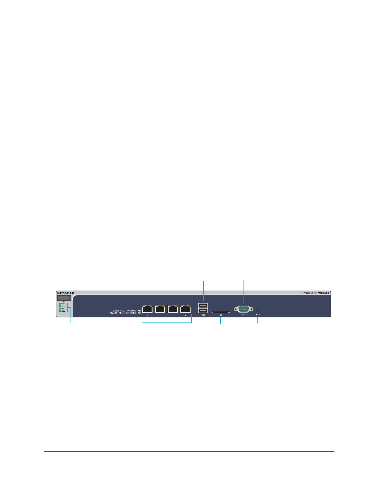
WC7500 and WC7600v2 Front Panel Ports and Slots
The following figure shows the front panel of models WC7500 and WC7600v2. (The label on
the right states PROSAFE WC7500 but the front panel for the WC7600v2 is identical.)
Digital access point counter USB ports Console port
LEDs (top to bottom):
Power, Status,
Fan, Stack Maser
Figure 1. Front panel models WC7500 and WC7600v2
10/100/1000M RJ-45 ports
and LEDs
SD slot
Reset button
Hardware Descriptions
19
Page 20
ProSAFE Wireless Controller
The following figure shows a close-up of the left side of the front panel.
Digital access point counter
USB ports
LEDs (top to bottom):
Power, Status, Fan, Stack Master
10/100/1000M RJ-45 ports
and LEDs
Figure 2. Front panel close-up models WC7500 and WC7600v2
From left to right, the front panel of models WC7500 and WC7600v2 show the components
that are described in the following table.
Table 3. Front panel components models WC7500 and WC7600v2
Component Description
Digital counter Displays the number of connected access points that are in a healthy state.
System LEDs From top to bottom: Power LED, Status LED, Fan LED, and Stack Master LED.
These LEDs are described in Table 5 on page 25.
Ethernet ports and LEDs Four 10/100/1000 Mbps LAN Ethernet port with an RJ-45 connector, left LED, and
right LED. The Ethernet port provides switched N-way, automatic speed negotiating,
auto MDI/MDIX technology.
USB ports Two USB 2.0 ports for external storage of floor heat maps, saving of the syslogs, and
backing up the configuration. The USB ports support FAT32 file systems.
SD card slot An SD card for saving of the system logs will be supported in a future release.
Console port RS232 port for connecting to an optional console terminal. The port provides a DB9
male connector. The default baud rate is 115200 bits/second.
Note: The console port is for debugging under guidance of NETGEAR technical
support only.
Reset button Using a sharp object, press and hold this button for about 10 seconds until the Status
LED blinks and the wireless controller returns to factory default settings.
If you reset the wireless controller, all configuration settings are lost and the default
password is restored.
Hardware Descriptions
20
Page 21
ProSAFE Wireless Controller
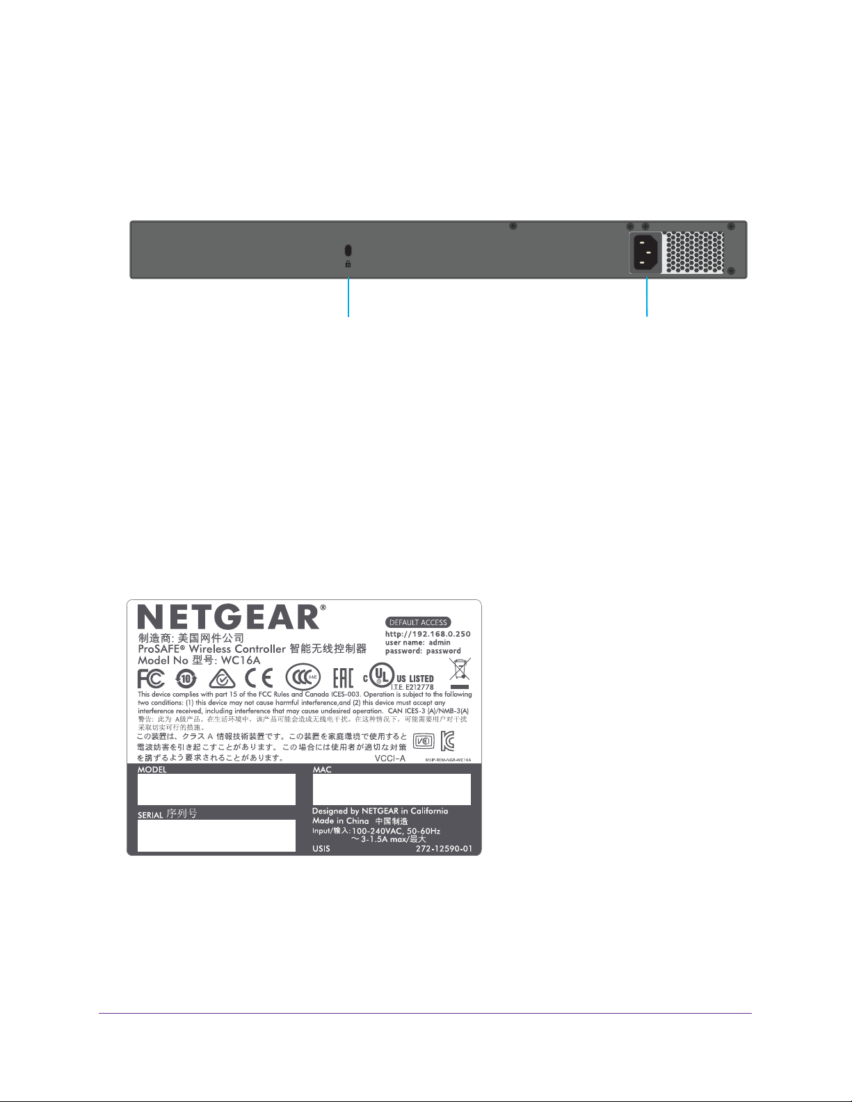
WC7500 and WC7600v2 Back Panel Components
The wireless controller comes with a single internal power supply and internal fans. The back
panel provides a Kensington™ lock slot and the AC power supply connector for the
100–240V, 3A, 50–60 Hz power supply.
Kensington lock slot
Figure 3. Back panel models WC7500 and WC7600v2
Power supply connector
Attach the power cord to the power supply connector. (The wireless controller does not
provide an on/off power switch.)
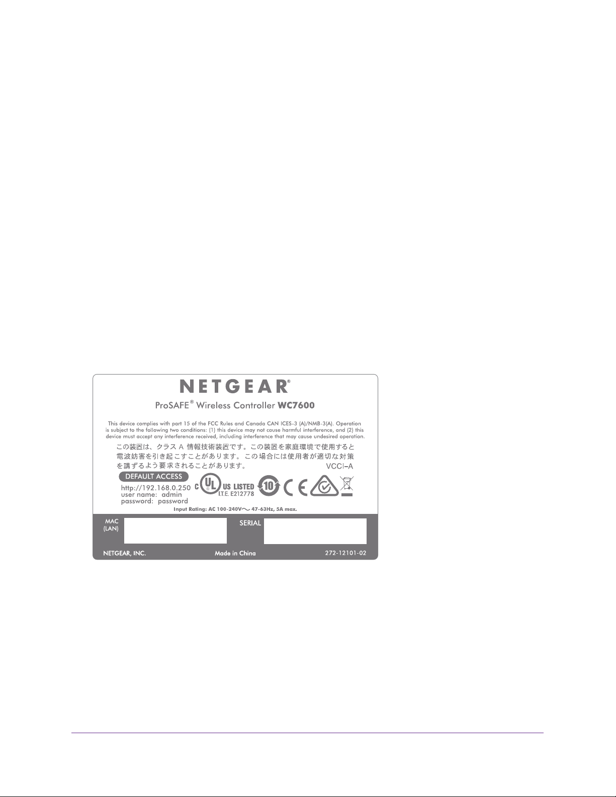
WC7500 and WC7600v2 Product Labels
The product label on the bottom of the wireless controller’s enclosure displays the default IP
address, default user name, and default password, as well as regulatory compliance, input
power, and other information.
Model WC7500 and model WC7600v2 share the same product label. The actual model
number (WC16A for both the WC7500 and the WC7600v2) is stated in the MODEL field.
Figure 4. Product label model WC7500 and model WC7600v2
Hardware Descriptions
21
Page 22
ProSAFE Wireless Controller
Hardware Models WC7600 and WC9500
The front panel ports, slots, and LEDs, back panel components, and product label of models
WC7600 and WC9500 are described in the following sections.
WC7600 and WC9500 Front Panel Ports and Slots
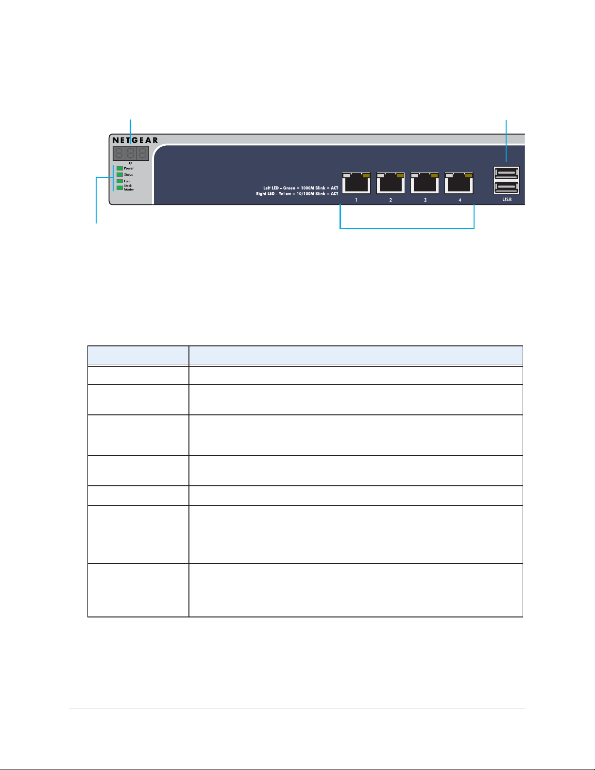
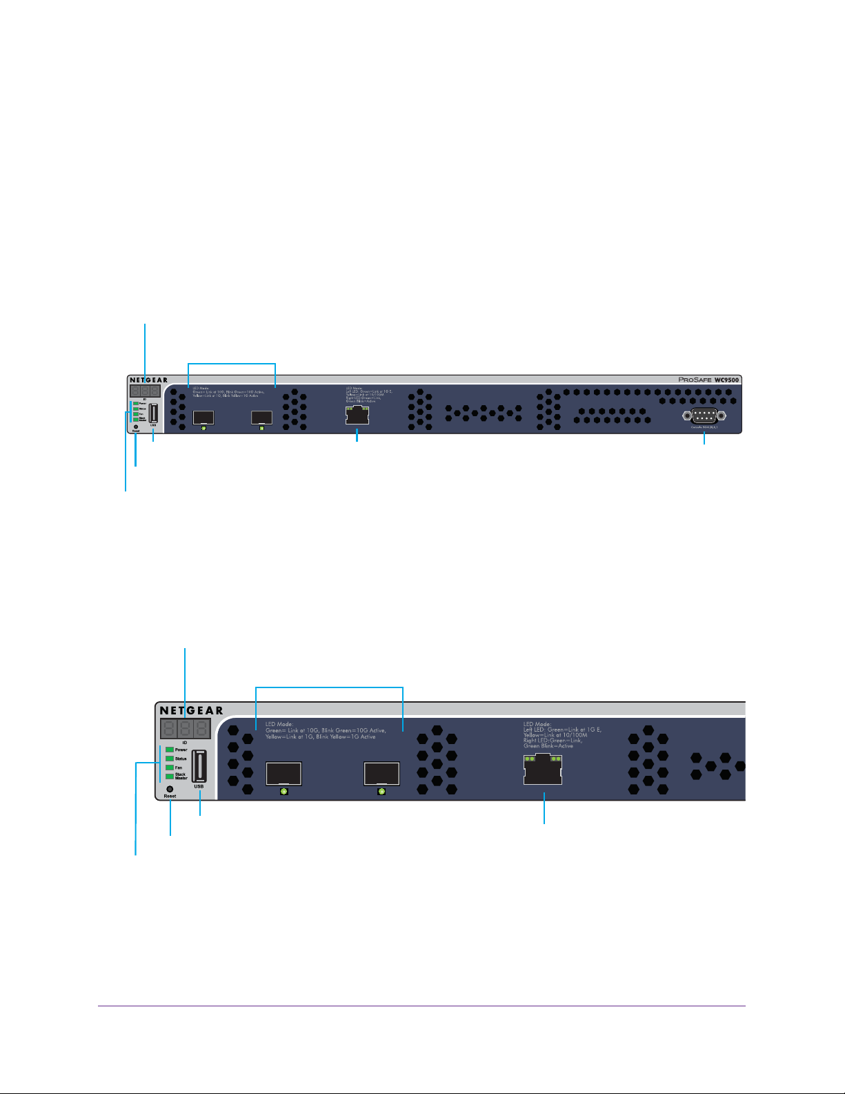
The following figure shows the front panel of models WC7600 and WC9500. (The label on
the right states PROSAFE WC9500 but the front panel for the WC7600 is identical.)
Digital access point counter
SFP+ slots and LEDs
USB port
Reset button
LEDs (top to bottom):
Power, Status,
Fan, Stack Maser
10/100/1000M RJ-45 port
and LEDs
Figure 5. Front panel models WC7600 and WC9500
The following figure shows a close-up of the left side of the front panel.
Digital access point counter
SFP+ slots and LEDs
LEDs (top to bottom):
Power, Status,
Fan, Stack Maser
USB port
Reset button
10/100/1000M RJ-45 port
and LEDs
Console port
Figure 6. Front panel close-up models WC7600 and WC9500
Hardware Descriptions
22
Page 23
ProSAFE Wireless Controller
From left to right, the front panel of models WC7600 and WC9500 show the components that
are described in the following table.
Table 4. Front panel components models WC7600 and WC9500
Component Description
Digital counter Displays the number of connected access points that are in a healthy state.
System LEDs From top to bottom: Power LED, Status LED, Fan LED, and Stack Master LED.
These LEDs are described in Table 5 on page 25.
Reset button Using a sharp object, press and hold this button for about 10 seconds until the Status
LED blinks and the wireless controller returns to factory default settings.
If you reset the wireless controller, all configuration settings are lost and the default
password is restored.
USB port One USB 2.0 port for external storage of floor heat maps, saving of the syslogs, and
backing up the configuration. The USB port supports FAT32 file systems.
SFP+ slots and LEDs Two SFP+ slots for optional 10GE SFP+ or 1G SFP gigabit interface converters
(GBICs), each slot with an LED.
Ethernet port and LEDs One 10/100/1000 Mbps LAN Ethernet port with an RJ-45 connector, left LED, and
right LED. The Ethernet port provides switched N-way, automatic speed negotiating,
auto MDI/MDIX technology.
Console port RS232 port for connecting to an optional console terminal. The port provides a DB9
male connector. The default baud rate is 9600 bits/second.
Note: The console port is for debugging under guidance of NETGEAR technical
support only.
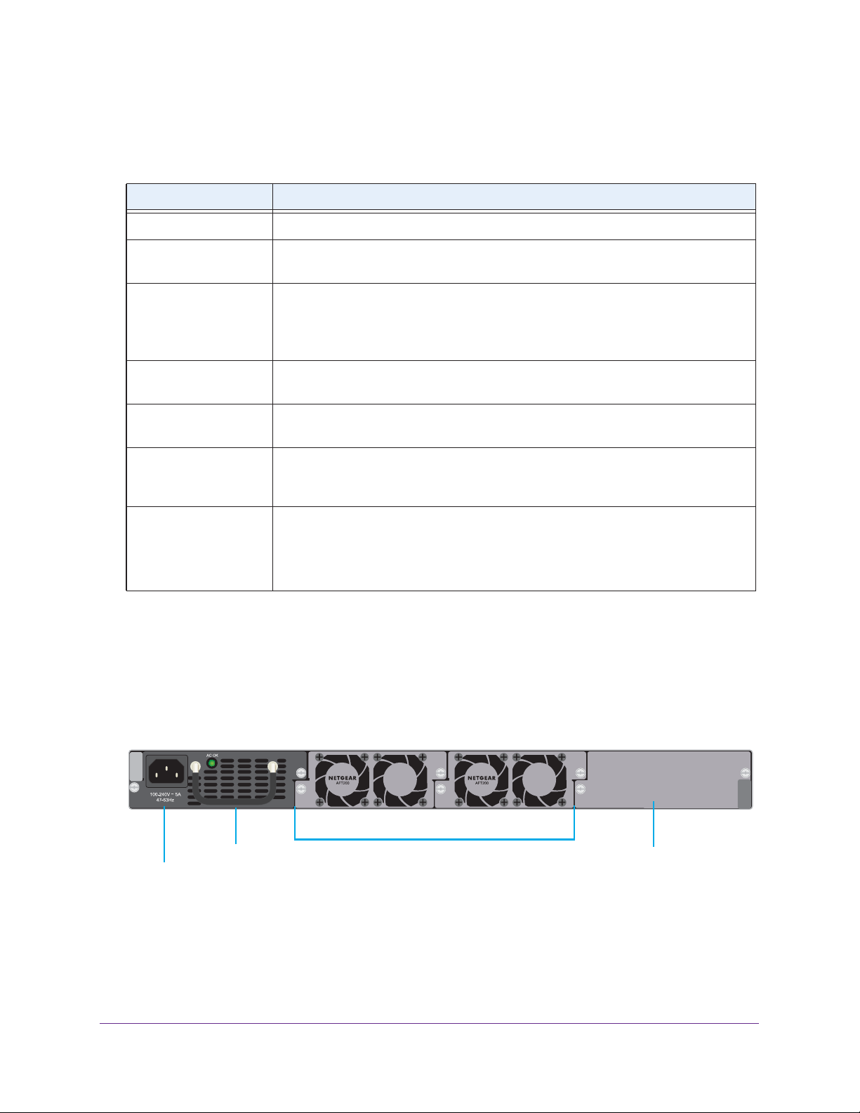
WC7600 and WC9500 Back Panel Components
The wireless controller comes with a single internal power supply but supports an optional
second power supply for power redundancy. The power supplies are hot-swappable.
The following figure shows the back panel of the wireless controller with a single internal
power supply, the power supply connector, and two double fans.
Removable power supply
Power supply connector
Removable fans
Slot for an optional
second power supply
Figure 7. Back panel models WC7600 and WC9500
Hardware Descriptions
23
Page 24
ProSAFE Wireless Controller
From left to right, the back panel of models WC7600 and WC9500 provide the following
components:
• Power supply. 100–240V, 5A, 47–63 Hz power supply, which includes the following
external components:
- AC power socket. Attach the power cord to this socket. (The wireless controller does
not provide an on/off power switch.)
- Power supply with handle. The handle allows for easy removal and insertion of the
power supply.
- LED. The power supply LED is lit green when the power supply functions correctly. If
the LED is off, power is not supplied to the power supply, or a problem occurred.
• Fans. Two double fans, each of which can be easily exchanged.
• Slot for optional second power supply. The cover plate can be removed so you can
insert a second removable power supply for power redundancy.
WC7600 and WC9500 Product Labels
The product label on the bottom of the wireless controller’s enclosure displays the default IP
address, default user name, and default password, as well as regulatory compliance, input
power, and other information.
Figure 8. Product label model WC7600
Hardware Descriptions
24
Page 25

ProSAFE Wireless Controller
Figure 9. Product label WC9500
LED Functions (All Models)
The function of each LED is described in the following table. These LEDS apply to all models
except where noted otherwise.
Table 5. LED functions for all models
LED Status Description
Power LED Solid green The wireless controller is on.
Off The wireless controller is off.
If the power LED is not lit when the wireless controller is on,
check the connections and check to see if the power outlet is
controlled by a wall switch that is turned off (see Power LED Is
Not Lit on page 361).
Status LED Solid yellow The wireless controller is initializing. After approximately two
minutes, when the wireless controller completes its
initialization, the Status LED turns solid green. If the Status
LED remains solid yellow, the initialization failed (see Status
LED Never Turns Off on page 361).
Solid green The wireless controller completed its initialization successfully.
The Status LED is solid green during normal operation.
Off The wireless controller is not receiving power.
Blinking yellow Firmware is being upgraded.
Fan LED Solid green The fans are functioning correctly.
Solid yellow One or more fans are not functioning correctly.
Hardware Descriptions
25
Page 26
ProSAFE Wireless Controller
Table 5. LED functions for all models (continued)
LED Status Description
Stack Master LED
Note: Does not
apply to WC7500
SFP slot LEDs
Note: Does not
apply to WC7500
and WC7600v2
Left Ethernet
port LED
Right Ethernet
port LED
Solid green The wireless controller is functioning as the master controller in
a stack.
Solid yellow The wireless controller is functioning as a slave controller in a
stack.
Solid green The slot is operating at 10G.
Blinking green Data is being transmitted or received at 10G.
Solid yellow The slot is operating at 1G.
Blinking yellow Data is being transmitted or received at 1G.
Off The port is not connected to a powered-on Ethernet device
(see Ethernet Port LEDs Are Not Lit on page 361).
WC7500
and
WC7600v2
WC7600
and
WC9500
Off The port is not connected to a powered-on Ethernet device
WC7500
and
WC7600v2
Solid green The port is operating at 1000 Mbps.
Blinking green Data is being transmitted or received at 1000 Mbps.
Solid green The port is operating at 1000 Mbps.
Solid yellow The port is operating at 100 Mbps or 10 Mbps.
(see Ethernet Port LEDs Are Not Lit on page 361).
Solid yellow The port is operating at 100 Mbps or 10 Mbps.
Blinking yellow Data is being transmitted or received at 100 Mbps or 10 Mbps.
WC7600
and
WC9500
Solid green The port is connected to a powered-on Ethernet device.
Blinking green Data is being transmitted or received.
Wireless Controller System Components
A wireless controller system consists of one or more wireless controllers and a collection of
access points that are organized into groups based on location or network access.
The wireless controller system can include a single wireless controller or a group of up to
three stacked wireless controllers that can function in a redundant configuration
The wireless controller system supports the following NETGEAR ProSAFE access point
models:
• WAC740 ProSAFE 4x4 Dual-Band Wireless AC Access Point
• WAC730 ProSAFE 3x3 Dual-Band Wireless AC Access Point
• WAC720 ProSAFE 2x2 Dual-Band Wireless AC Access Point
1. Model WC7500 does not support stacking and redundancy.
Hardware Descriptions
1
.
26
Page 27

ProSAFE Wireless Controller
• WN370 ProSAFE Wall Mount Wireless N Access Point
• WND930 Outdoor Dual Band Wireless-N
• WNDAP660 ProSAFE Premium 3x3 Dual Band Concurrent Wireless-N Access Point
• WNDAP380R ProSAFE Dual Band Wireless-N Access Point with RFID support
• WNDAP360 ProSAFE Dual Band Wireless-N Access Point
• WNDAP350 ProSAFE Dual Band Wireless-N Access Point
• WNAP320 ProSAFE Wireless-N Access Point
• WNAP210v2 ProSAFE Wireless-N Access Point
Supported NETGEAR Access Points
Y ou can connect access points to the wireless controller either directly with an Ethernet cable
through a router or switch, or remotely through a VPN network. After you use the automatic
discovery process and add access points to the managed access point list on the wireless
controller, the wireless controller converts the standard access points to dependent access
points by pushing firmware to the access points. From then on, you can centrally manage
and monitor the access points.
The following table lists the minimum firmware versions that must run on the standalone
access points before you convert them to managed access points. If your access point runs a
firmware version that is earlier than the minimum firmware version, first upgrade the access
point to the minimum firmware version or a later version.
Table 6. Minimum firmware versions
Access Point Model Minimum Firmware Version on Standalone Access Point
WAC740 Model WAC740 cannot function as a standalone access point. This model can be
used only as a controller-managed access point.
WAC730 All firmware versions are supported.
WAC720 All firmware versions are supported.
WN370 Model WN370 cannot function as a standalone access point. This model can be used
only as a controller-managed access point.
WND930 2.0.4 or a newer version is supported.
WNDAP660 2.0.2 or a newer version is supported.
WNDAP380R All firmware versions are supported.
WNDAP360 2.1.6 or a newer version is supported.
WNDAP350 2.1.7 or a newer version is supported.
WNAP320 2.1.1 or a newer version is supported.
WNAP210v2 All firmware versions are supported.
Hardware Descriptions
27
Page 28

ProSAFE Wireless Controller
A wireless controller system supports the following access points:
• WAC740 ProSAFE 4x4 Dual-Band Wireless AC Access Point
- Supports concurrently 802.11a, 802.11b, 802.11g, 802.11n, and 802.11ac network
devices.
- Operates concurrently in the 2.4 GHz and 5 GHz radio bands.
- Supports 4x4 multi-user multiple input, multiple output (MU-MIMO).
- Supports speeds of up to 1.7 Gbps for 802.11ac network devices.
- Supports Power over Ethernet plus (PoE+) with a power consumption that complies
with the 802.3at standard.
- Accepts optional antennas.
For product documentation and firmware, visit netgear.com/support/product/WAC740.
• WAC730 ProSAFE 3x3 Dual-Band Wireless AC Access Point
- Supports concurrently 802.11a, 802.11b, 802.11g, 802.11n, and 802.11ac network
devices.
- Operates concurrently in the 2.4 GHz and 5 GHz radio bands.
- Supports 3x3 multiple input, multiple output (MIMO).
- Supports speeds of up to 1300 Mbps for 802.11ac network devices.
- Supports Power over Ethernet (PoE) with a power consumption that complies with the
802.3af standard.
- Accepts optional antennas.
For product documentation and firmware, visit netgear.com/support/product/WAC730.
• WAC720 ProSAFE 2x2 Dual-Band Wireless AC Access Point
- Supports concurrently 802.11a, 802.11b, 802.11g, 802.11n, and 802.11ac network
devices.
- Operates concurrently in the 2.4 GHz and 5 GHz radio bands.
- Supports 2x2 multiple input, multiple output (MIMO).
- Supports speeds of up to 867 Mbps for 802.11ac network devices
- Supports Power over Ethernet (PoE) with a power consumption that complies with the
802.3af standard.
- Accepts optional antennas.
For product documentation and firmware, visit netgear.com/support/product/WAC720.
• WN370 ProSAFE Wall Mounted Wireless-N Access Point
- Supports concurrently 802.11b, 802.11g, and 802.11n network devices.
- Operates in the 2.4 GHz radio band.
- Supports speeds of up to 300 Mbps for 802.11n network devices.
- Supports Power over Ethernet (PoE) with a power consumption that complies with the
802.3af standard.
Hardware Descriptions
28
Page 29

ProSAFE Wireless Controller
For product documentation and firmware, visit netgear.com/support/product/WN370.
• WND930 Outdoor Dual Band Wireless-N
- Supports 802.11a, 802.11b, 802.11g, and 802.11n network devices.
- Operates concurrently in the 2.4 GHz and 5 GHz radio bands.
- Supports speeds of up to 300 Mbps for 802.11n network devices.
- Supports Power over Ethernet (PoE) with a power consumption that complies with the
802.3af or 802.3at standards.
For product documentation and firmware, visit netgear.com/support/product/WND930.
• WNDAP660 ProSAFE Premium 3x3 Dual Band Concurrent Wireless-N Access Point
- Supports 802.11a, 802.11b, 802.11g, and 802.11n network devices.
- Operates concurrently in the 2.4 GHz and 5 GHz radio bands.
- Supports 3x3 multiple input, multiple output (MIMO).
- Supports speeds of up to 450 Mbps for 802.11n network devices.
- Supports Power over Ethernet (PoE) with a power consumption that complies with the
802.3at standard.
Note: If your network does not include a PoE device that can provide the
WNDAP660 access point with PoE power according to the 802.3at
standard, you can instead use two ports of a PoE device that complies
with the 802.3af standard. (The WNDAP660 access point provides two
Ethernet ports that accept PoE.)
- Accepts optional antennas.
For product documentation and firmware, visit netgear.com/support/product/WNDAP660.
• WNDAP380R ProSAFE Dual Band Wireless-N Access Point with RFID support
- Supports 802.11a, 802.11b, 802.11g, and 802.11n network devices.
- Operates concurrently in the 2.4 GHz and 5 GHz radio bands.
- Supports Power over Ethernet (PoE) with a power consumption of up to 10.51W.
- Accepts an RFID module for support of RFID devices and tags.
For product documentation and firmware, visit
netgear.com/support/product/WNDAP380R.
• WNDAP360 ProSAFE Dual Band Wireless-N Access Point
- Supports 802.11a, 802.11b, 802.11g, and 802.11n network devices.
- Operates concurrently in the 2.4 GHz and 5 GHz radio bands.
- Supports Power over Ethernet (PoE) with a power consumption of up to 10.51W.
- Accepts optional antennas.
For product documentation and firmware, visit netgear.com/support/product/WNDAP360.
Hardware Descriptions
29
Page 30

ProSAFE Wireless Controller
• WNDAP350 ProSAFE Dual Band Wireless-N Access Point
- Supports 802.11a, 802.11b, 802.11g, and 802.11n network devices.
- Operates concurrently in the 2.4 GHz and 5 GHz radio bands.
- Supports Power over Ethernet (PoE) with a power consumption of up to 10.75W.
- Accepts optional antennas.
For product documentation and firmware, visit netgear.com/support/product/WNDAP350.
• WNAP320 ProSAFE Wireless-N Access Point
- Supports 802.11b, 802.11g, and 802.11n network devices.
- Operates in the 2.4 GHz radio band.
- Supports Power over Ethernet (PoE) with a power consumption of up to 5.8W.
- Accepts optional antennas.
For product documentation and firmware, visit netgear.com/support/product/WNAP320.
• WNAP210v2 ProSAFE Wireless-N Access Point
- Supports 802.11b, 802.11g, and 802.11n network devices.
- Operates in the 2.4 GHz radio band.
- Supports Power over Ethernet (PoE) with a power consumption of up to 5.8W.
- Operates in the 2.4 GHz radio band.
For product documentation and firmware, visit
netgear.com/support/product/WNAP210v2.
Note: Model WNAP210v1 cannot function in a wireless controller system, but
model WNAP210v2 can.
Supported NETGEAR Antennas
A wireless controller system supports the following antennas:
• ANT2409 ProSAFE Indoor/Outdoor 9 dBi Omni-directional Antenna
- 9 dBi omni-directional antenna for indoor or outdoor use
- WiFi signal 802.11g
- Frequency range 2400–2485 MHz
- Maximum range 11.5 km (7.2 miles)
- Polarization vertical
For product documentation and firmware, visit netgear.com/support/product/ANT2409v2.
• ANT224D10 ProSAFE 10 dBi 2x2 Indoor/Outdoor Directional Antenna
- 10 dBi directional antenna for indoor or outdoor use
- WiFi signal 802.11n
Hardware Descriptions
30
Page 31

ProSAFE Wireless Controller
- Frequency range 2400–2500 MHz
- Maximum range 8.5 km (5.28 miles)
- Polarization linear; vertical
For product documentation and firmware, visit netgear.com/support/product/ANT224.
Hardware Descriptions
31
Page 32

3. System Planning and Deployment
Scenarios
This chapter includes the following sections:
• Basic and Advanced Setting Concepts
• Profile Group Concepts
• System Planning Concepts
• High-Level Configuration Examples
• Management VLAN and Data VLAN Strategies
• High-Level Deployment Scenarios
3
32
Page 33

ProSAFE Wireless Controller
Basic and Advanced Setting Concepts
You can deploy the wireless controller in a small WiFi network with 10 or 20 access points or
in a large WiFi network with up to 600 access points. Small networks require a basic
configuration, but large networks can become complex and require you to configure the
advanced features of the wireless controller.
Depending on your network configuration, use basic settings or advanced settings to
manage your access points:
• Basic settings for a typical network. The basic settings work with most common
network configurations. For example, all access points on the WLAN are for the same
organization or business and therefore adhere to the same policies and use a few service
set identifiers (SSIDs, or network names).
• Advanced settings for access point profile groups. In a large WiFi network, or if
separate networks share a single WLAN, use the advanced settings to set up multiple
access point profile groups with multiple security profiles (SSIDs with associated security
settings). For example, a shopping mall might need several access point profile groups if
several businesses share a WLAN but each business maintains its own network. Larger
networks could require multiple access point profile groups to allow different policies per
building or department. The access points could support different security profiles per
building and department, for example, one for guests, one for management, and one for
sales.
Note: Access point profile groups are also referred to as just profile groups.
Profiles, security profiles, and SSIDs (that is, SSIDs with associated
security settings) are terms that are interchangeable.
To accommodate all types of networks, almost all configuration menus of the web
management interface are divided into basic and advanced submenus. The following figure
shows an example of the Configuration > Security > Basic submenu on the left and the
Configuration > Security > Advanced submenu on the right:
Figure 10. Basic and advanced submenus
System Planning and Deployment Scenarios
33
Page 34

ProSAFE Wireless Controller
Before you start the configuration of your wireless controller, decide whether you can use a
basic configuration (that is, follow the Basic submenus) or must use an advanced
configuration (that is, follow the Advanced submenus). Once you make your choice,
configuring the wireless controller can be fairly easy if you consistently follow either the Basic
submenus or the Advanced submenus.
Profile Group Concepts
Each access point can support up to eight security profiles (16 for dual-band access points),
each with its own SSID, security settings, MAC ACL, rate-limiting settings, WMM, and so on.
The wireless controller follows the same architecture. A profile group on the wireless
controller includes all the features that you can configure for an individual access point: up to
8 profiles (16 for dual-band access points), each of which supports its own SSID, security,
MAC ACL, rate-limiting settings, WMM settings, and so on.
Basic Profile
The basic profile includes all the settings that are required to configure a fully functional
access point with up to eight security profiles (16 for dual-band access points).
After you use the automatic discovery process and add access points to the managed AP list
on the wireless controller, the access points are assigned by default to the basic profile
group.
If your network requires the wireless controller to manage multiple access points with
different configurations, use the advanced profile.
Advanced Profile
The advanced profile lets you configure up to eight access point profile groups. Each group
includes all the settings that are required to configure a fully functional access point with up to
eight security profiles (16 for dual-band access points).
For example, if your company site includes four buildings, each with a different WiFi network,
you simply create four profile groups. You then assign all access points in one building to one
profile group, all access points in another building to a second profile group, and so on.
For each profile group, you can create an individual radio on/off schedule, RF management
settings, MAC ACL authentication, and an authentication server. For each radio in a profile
group (2.4 GHz radio and 5 GHz radio), you can create individual WiFi settings, WMM, and
rate-limit settings.
The following figure shows the advanced profile group architecture. The structure that is
shown under Group-1 is implemented in all profile groups (that is, Group-2 through Group-8):
System Planning and Deployment Scenarios
34
Page 35

ProSAFE Wireless Controller
Group-1
Group-2
Group-3
Group-4
2.4 GHz
radio
1
2
34
5678
Security profiles
Figure 11. Advanced profile group architecture
Group-5
5 GHz
radio
1
Group-6
23
Security profiles
Group-7
4
56
Group-8
78
The following figure shows an example of three access point profile groups, in which the first
profile group (Group-1) supports five security profiles. For each profile in this profile group,
the profile name, radio mode, and authentication setting are shown. (Group-1 is the default
group in the advanced profile group configuration; you must create the other profiles groups.)
Figure 12. Example of profile groups with security profiles
System Planning and Deployment Scenarios
35
Page 36

ProSAFE Wireless Controller
System Planning Concepts
This section includes the following subsections:
• Preinstallation Planning
• Before You Configure a Wireless Controller
Preinstallation Planning
Before you install any wireless controllers, determine the following:
• Number of access points required to provide seamless coverage
• Number of licenses required to cover all access points that must be managed
• Number of wireless controllers required
• 802.11 frequency band and the channels that are optimal for WiFi usage
We recommend that you perform a site survey:
• To determine the current RF behavior and detect both 802.11 and non-802.11 noise, run
a spectrum analysis of the channels of the site.
• To determine the maximum throughput that is achievable on the client, run an access
point-to-client connectivity test.
• Identify potential RF obstructions and interference sources.
• Determine areas where denser coverage might be required because of heavier usage.
Before You Configure a Wireless Controller
These sections assume that you deployed at least one wireless controller in your network
and are ready to configure the wireless controller. For information about how to deploy the
wireless controller in your network, see your model’s installation guide, which you can
download by visiting downloads.netgear.com.
For many configurations, you can use the default WiFi settings. The IP address, VLAN,
DHCP server, client authentication, and data encryption settings are specific to your
environment. Following are short sections that describe these settings (except for IP address
settings, which are self-explanatory). For information about how to configure these settings,
see the relevant sections.
Management VLAN
The management VLAN is the dedicated VLAN for access to the wireless controller. All traf fic
that is directed to the wireless controller, including HTTP, HTTPS, SNMP, and SSH traffic, is
carried over the management VLAN.
If the management VLAN is also configured as a tagged VLAN (the most common
configuration), the packets to and from the wireless controller carry the 802.1Q VLAN header
with the assigned VLAN number. If the management VLAN is marked as untagged, the
System Planning and Deployment Scenarios
36
Page 37

ProSAFE Wireless Controller
packets that are sent from the wireless controller do not carry the 802.1Q header, and all
untagged packets that are sent to the wireless controller are treated as management VLAN
traffic.
Note: Use a tagged VLAN or change the tagged VLAN ID only if the hubs
and switches on your LAN support 802.1Q. If they do not, and you did
not configure a tagged VLAN with the same VLAN ID on the hubs and
switches in your network, IP connectivity might be lost.
The management VLAN must provide IP connectivity between the wireless controller and the
access points. If the wireless controller and the access points are on different management
VLANs, external VLAN routing must allow IP connectivity between the wireless controller and
the access points.
For information about how to configure management VLANs, see Manage the IP, VLAN, and
Link Aggregation Settings on page 102.
Client VLANs
Each authenticated WiFi user is placed into a VLAN that determines the user’s DHCP server,
IP address, and Layer 2 connection. Although you could place all authenticated WiFi users
into the single VLAN that is specified in the basic security profile, the wireless controller
allows you to group WiFi users into separate VLANs based on the WiFi SSID to differentiate
access to network resources. For example, you might place authorized employee users into
one VLAN, and itinerant users, such as contractors or guests, into a separate VLAN. To use
different VLANs, you must create different security profiles.
For information about how to configure regular VLANs, see Manage the IP, VLAN, and Link
Aggregation Settings on page 102.
DHCP Server
The wireless controller can function as a DHCP server and assign IP addresses to both WiFi
and wired devices that are connected to it. You can add up to 64 DHCP server pools, each
assigned to a different VLAN.
Specifying an internal DHCP server on the wireless controller automatically enables DHCP
option 43 (vendor-specific information) with the IP address of the wireless controller. Whether
you must enable option 43 on an external DHCP server in a Layer 2 network depends on the
firmware version that the wireless controller is running:
• Firmware version 4.x and earlier versions. Option 43 must be enabled on an external
DHCP server in a Layer 2 network.
• Firmware version 5.x and later versions. Option 43 is not required on an external
DHCP server in a Layer 2 network.
For discovery across Layer 3 networks, you always must enable option 43 on an external
DHCP server.
System Planning and Deployment Scenarios
37
Page 38

ProSAFE Wireless Controller
Client Authentication and Data Encryption
A user must authenticate to the WLAN to be able to access WLAN resources. The wireless
controller supports several types of security methods, including those methods that require
an external RADIUS or LDAP authentication server.
The encryption option that you can select depends upon the authentication method that you
selected. The following table lists the authentication methods available, with their
corresponding encryption options:
Table 7. Authentication and encryption options
Authentication Method Encryption Option Authentication Server
Open System 64-bit, 128-bit, or 152-bit WEP None
Shared Key 64-bit, 128-bit, or 152-bit WEP None
WPA-PSK TKIP or TKIP+AES None
WPA2-PSK AES or TKIP+AES None
WPA-PSK and WPA2-PSK TKIP+AES None
WPA TKIP or TKIP+AES One of the following authentication servers:
• External RADIUS server
• Internal authentication server
• External LDAP server
WPA2 AES or TKIP+AES One of the following authentication servers:
• External RADIUS server
• Internal authentication server
• External LDAP server
WPA and WPA2 TKIP+AES One of the following authentication servers:
• External RADIUS server
• Internal authentication server
• External LDAP server
For information about how to configure client authentication, data encryption, and
authentication servers, see Chapter 7, Manage Security Profiles and Profile Groups.
System Planning and Deployment Scenarios
38
Page 39

ProSAFE Wireless Controller
High-Level Configuration Examples
This section includes the following subsections:
• Single Controller Configuration With Basic Profile Group
• Single Controller Configuration With Advanced Profile Groups
• Stacked Controller Configuration
Single Controller Configuration With Basic Profile Group
A basic configuration consists of a single wireless controller that controls a collection of
access points that are organized into the basic default group.
To set up a single wireless controller system with a basic profile group:
Step Configuration Web Management Interface Path
1. Configure the system and network settings of the wireless
controller:
1. Configure the country code of operation.
2. Configure the time settings.
3. Configure the IP address of the wireless controller.
4. Verify that VLAN 1 is set as the management VLAN and is
marked as untagged.
By default, VLAN 1 an untagged management VLAN.
5. If no network DHCP server is accessible to the access points,
configure the wireless controller’s DHCP server.
2. Configure up to eight profiles, and for each profile, do at least the
following:
1. Configure an SSID for WiFi access.
2. Configure the network authentication and data encryption.
3. Assign the VLAN.
4. If necessary for the selected network authentication option,
configure the authentication server.
Configuration > System > General
Configuration > System > Time
Configuration > System > IP/VLAN
Configuration > System > DHCP
Server
Configuration > Profile > Basic
Configuration > Security > Basic >
Authentication Server
3. Run the Discovery Wizard and add the access points to the
managed access point list.
System Planning and Deployment Scenarios
39
Access Point > Discovery Wizard
Page 40

ProSAFE Wireless Controller
Single Controller Configuration With Advanced Profile Groups
A more complex configuration consists of a single wireless controller that controls a collection
of access points that are organized in access point profile groups and might use several
profiles in each access point profile group.
To set up a single wireless controller system with advanced profile groups:
Step Configuration Web Management Interface Path
1. Configure the system and network settings of the wireless
controller:
1. Configure the country code of operation.
2. Configure the time settings.
3. Configure the IP address of the wireless controller.
4. Verify that VLAN 1 is set as the management VLAN and is
marked as untagged.
By default, VLAN 1 an untagged management VLAN.
5. If no network DHCP server is accessible to the access points,
configure the wireless controller’s DHCP server.
2. Configure up to eight access point profile groups, and for each
access point profile in a group, do at least the following:
1. Configure an SSID for WiFi access.
2. Configure the network authentication and data encryption.
3. Assign the VLAN.
4. If necessary for the selected network authentication option,
configure the authentication server.
Configuration > System > General
Configuration > System > Time
Configuration > System > IP/VLAN
Configuration > System > DHCP
Server
Configuration > Profile > Advanced
Configuration > Security >
Advanced > Authentication Server
3. Run the Discovery Wizard and add the access points to the
managed access point list.
4. Assign the access points to the access point profile groups (also
referred to as WLAN groups).
System Planning and Deployment Scenarios
40
Access Point > Discovery Wizard
Configuration > WLAN Network
Page 41

ProSAFE Wireless Controller
Stacked Controller Configuration
A stacked controller configuration can consist of up to three wireless controllers and up to
600 access points.
Note: If the stack members are on different floors or in different buildings, you
could configure a separate access point profile group for each building or
floor.
To set up a stacked controller configuration:
Step Configuration Web Management Interface Path
1. On each individual wireless controller that you intend to make a
stack member, configure the system and network settings of the
wireless controller:
1. Configure the country code of operation.
2. Configure the time settings.
3. Configure the IP address of the wireless controller.
4. Verify that VLAN 1 is set as the management VLAN and is
marked as untagged.
By default, VLAN 1 an untagged management VLAN.
5. If no network DHCP server is accessible to the access points,
configure the wireless controller’s DHCP server.
2. Configure the master wireless controller and deploy it in the
network.
Configure up to eight access point profile groups, and for each
access point profile in a group, do at least the following:
1. Configure an SSID for WiFi access.
2. Configure the network authentication and data encryption.
3. Assign the VLAN.
Configuration > System > General
Configuration > System > Time
Configuration > System > IP/VLAN
Configuration > System > DHCP
Server
Configuration > Profile > Advanced
4. If necessary for the selected network authentication option,
configure the authentication server.
System Planning and Deployment Scenarios
41
Configuration > Security >
Advanced > Authentication Server
Page 42

ProSAFE Wireless Controller
Step Configuration Web Management Interface Path
3. Configure the slave wireless controllers and deploy them in the
network.
For each slave wireless controller, configure up to eight access
point profile groups, and for each access point profile in a group, do
at least the following:
1. Configure an SSID for WiFi access.
2. Configure the network authentication and data encryption.
3. Assign the VLAN.
4. If necessary for the selected network authentication option,
configure the authentication server.
4. Interconnect the wireless controllers that you intend to make
members of the stack. The connection must be a wired
connection but does not need to be a direct connection, that is, a
switch or router can be located in between the wireless
controllers that are part of a stack.
5. Configure the stacking group on the wireless controller that you
intend as the master controller.
6. Synchronize all wireless controllers that are members of the
stack.
Configuration > Profile > Advanced
Configuration > Security >
Advanced > Authentication Server
Stacking > Stacking
Management VLAN and Data VLAN Strategies
If your network includes 10 or more access points, we recommend that you set up at least
two VLAN groups: a management VLAN group and a data VLAN group. If your network is
large, we recommend that you create a number of data VLAN groups. Setting up data VLANs
for clients allows you to do the following:
• Segregate traffic by user category
• Create different policies such as access policies that are based on user category
System Planning and Deployment Scenarios
42
Page 43

ProSAFE Wireless Controller
The following illustration shows a simplified view of how you can use VLANs to segregate
traffic by user category.
Management VLAN 100 Ethernet traffic
Finance VLAN 10 Ethernet traffic
Employee VLAN 20 Ethernet traffic
Deploy the wireless controller
on a trunk port if you use the
internal DHCP server
Wireless controller
Internet
Network printer
Backend L3 switch
or router
PoE switch
Access point
WNDAP360
Finance
computer
Finance
computer
Employee
computer
Employee
computer
Figure 13. Example: Use VLANs to segregate traffic by user categories
The wireless controller uses the management VLAN to continually exchange packets with
the access points. For large networks, if all traffic uses a single VLAN, the client traffic could
potentially flood the network. If flooding occurs and the wireless controller is not able to
exchange packets with the access points, the network performance can slow down, and the
access points can lose their connectivity with the wireless controller.
If you use the internal DHCP server of the wireless controller, deploy the wireless controller
on a trunk port on your switch. The trunk port must provide access to all VLANs.
To accommodate the traffic load of the trunk, use a high-speed port on your switch as the
trunk port. If you use an external DHCP server, you do not need to deploy the wireless
controller on a trunk port on your switch.
System Planning and Deployment Scenarios
43
Page 44

ProSAFE Wireless Controller
High-Level Deployment Scenarios
This section provides three deployment scenarios to illustrate how the wireless controller can
function in various network configurations:
• Scenario Example 1: Network With Single VLAN
• Scenario Example 2: Advanced Network With VLANs and SSIDs
• Scenario Example 3: Advanced Network With Redundancy
Scenario Example 1: Network With Single VLAN
The following sample scenario consists of a simple network with a wireless controller, PoE
switch, Layer 3 switch or router, and access points.
Management VLAN Ethernet traffic
All client Ethernet traffic
Internet
Deploy the wireless controller
on a trunk port if you use the
internal DHCP server
Wireless controller
Finance
computer
PoE switch
Marketing
computer
Network printer
Employee
computer
Backend L3 switch
or router
Access point
WNDAP360
Employee
computer
Figure 14. Example: Basic network with a single VLAN
System Planning and Deployment Scenarios
44
Page 45

ProSAFE Wireless Controller
The access points and wireless controller are connected in the same subnet and use the
same IP address range that is assigned for that subnet. The configuration does not include
any routers between the access points and the wireless controller. The access points are
connected to a PoE switch, which, in turn, is connected to the wireless controller. The uplink
of the PoE switch connects to a Layer 3 switch or router that provides Internet access.
To provision the wireless controller:
Step Configuration Web Management Interface Path
1. Configure the system and network settings of the wireless
controller:
1. Configure the country code of operation.
2. Configure the time settings.
3. Configure the IP address of the wireless controller.
4. Verify that VLAN 1 is set as the management VLAN and is
marked as untagged.
By default, VLAN 1 an untagged management VLAN.
5. If no network DHCP server is accessible to the access points,
configure the wireless controller’s DHCP server.
2. Configure up to eight profiles, and for each profile, do at least the
following:
1. Configure an SSID for WiFi access.
2. Configure the network authentication and data encryption.
3. Assign the VLAN.
4. If necessary for the selected network authentication option,
configure the authentication server.
Configuration > System > General
Configuration > System > Time
Configuration > System > IP/VLAN
Configuration > System > DHCP
Server
Configuration > Profile > Basic
Configuration > Security > Basic >
Authentication Server
3. Use any port of the wireless controller to connect the WiFi PoE
switch.
4. Deploy the access points and connect them to the same WiFi
PoE switch.
System Planning and Deployment Scenarios
45
Page 46

ProSAFE Wireless Controller
Step Configuration Web Management Interface Path
5. When the access points are operating, open the Discovery
Wizard to do the following:
1. Specify the state of the access points. The state can be either
factory default in a Layer 2 network or already installed and
functioning in standalone mode.
2. Run the Discovery Wizard.
3. Select the access points that you want the wireless controller to
manage and add them to the managed list.
Note: By default, all access points are added to the basic group
and all settings from the basic group (profile definition, client
authentication, authentication settings, and WiFi QoS) are applied
to the access points.
Access Point > Discovery Wizard
Scenario Example 2: Advanced Network With VLANs and SSIDs
The following sample scenario consists of an advanced network with a wireless controller,
PoE switch, Layer 3 switch or router, access points, and several VLANs and SSIDs. The
wireless controller system includes the following VLANs:
• VLAN 1, the default untagged VLAN to access the wireless controller
• VLAN 10, a tagged client VLAN
• VLAN 20, another tagged client VLAN
• VLAN 100, a tagged management VLAN
Management VLAN 100 Ethernet traffic
Client VLAN 10 Ethernet traffic
Client VLAN 20 Ethernet traffic
Wireless controller
Backend L3 switch
or router
Internet
PoE switch
SSID 1
Client VLAN 10
SSID 2
Client VLAN 20
Figure 15. Example: Advanced network with VLANs and SSIDs
WNDAP360
WNDAP360
System Planning and Deployment Scenarios
46
Page 47

ProSAFE Wireless Controller
The access points and wireless controller are connected in the same subnet and same VLAN
and use the same IP address range that is assigned for that subnet. The configuration does
not include any routers between the access points and the wireless controller. The access
points are connected to a PoE switch, which, in turn, is connected to the Layer 3 switch or
router that provides Internet access.
This network configuration requires the following conditions:
• VLANs 10, 20, and 100 are tagged VLANs and are configured on the wireless controller
and the PoE switch.
• The wireless controller is connected to the PoE switch through default VLAN 1. You
manage the wireless controller from a computer over VLAN 1 through the PoE switch.
• The DHCP server on the wireless controller is configured in management VLAN 100 to
enable the access points to receive an IP address through VLAN 100.
• The PoE switch port to which the wireless controller is connected is configured as a
tagged port to allow tagged traffic from VLAN 100.
To provision the wireless controller:
Step Configuration Web Management Interface Path
1. Configure the basic system settings:
1. Configure the country code of operation.
2. Configure the time settings.
3. Configure the IP address of wireless controller.
4. For initial discovery and configuration of the access points,
temporarily configure management VLAN 100 as an
untagged management VLAN on the wireless controller.
5. Change default VLAN 1 to a tagged VLAN.
2. For initial discovery and configuration of the access points,
temporarily configure management VLAN 100 as an untagged
management on the PoE switch.
3. Configure either the network’s DHCP server or the wireless
controller’s DHCP server to use VLAN 100.
If you use the wireless controller’s DHCP server:
1. Configure the IP address range for VLAN 100.
2. Configure the other DHCP server fields, including the
gateway and DNS servers.
Configuration > System > General
Configuration > System > Time
Configuration > System > IP/VLAN
Configuration > System > DHCP
Server
System Planning and Deployment Scenarios
47
Page 48

ProSAFE Wireless Controller
Step Configuration Web Management Interface Path
4. Configure the following profiles, and configure network
authentication and data encryption for these profiles:
1. A profile with SSID 1 and VLAN 10.
2. A profile with SSID 2 and VLAN 20.
3. If necessary for the selected network authentication options,
configure one or more authentication servers.
5. Connect the wireless controller to the PoE switch.
6. Before you connect the access points to the PoE switch, verify
that the switch ports to which you intend to connect the access
points are configured as access ports in management VLAN 100.
7. Deploy the access points and connect them to the designated
PoE switch ports.
8. When the access points are operating, open the Discovery
Wizard to do the following:
1. Specify the state of the access points, which is factory default
in a Layer 2 network.
2. Run the Discovery Wizard.
3. Select the access points that you want the wireless controller to
manage and add them to the managed list.
Configuration > Profile > Basic
Configuration > Security > Basic >
Authentication Server
Access Point > Discovery Wizard
Note: By adding the access points to managed list, you enable
them to receive an IP address from the DHCP server over
management VLAN 100.
9. For each access point on the managed list, disable the untagged
VLAN and configure VLAN 100 as the management VLAN. Doing
so causes the access points to lose connectivity with the wireless
controller.
10. Restore connectivity between the access points and the wireless
controller by changing the PoE switch ports to which the access
points are connected to tagged ports.
During the discovery process, these switch ports were access
ports in management VLAN 100.
Scenario Example 3: Advanced Network With Redundancy
The following sample scenario consists of an advanced network with one wireless controller,
one redundant wireless controller
access points, and several VLANs and SSIDs. These are the components in the wireless
controller system:
• One wireless controller
• Fifty access points (managed by the wireless controller through management VLAN 1)
1. Model WC7500 does not support controller redundancy.
1
, one core switch, two PoE switches in different buildings,
System Planning and Deployment Scenarios
48
Page 49

ProSAFE Wireless Controller
• One redundant wireless controller
• Four VLANs: VLAN 10, VLAN 20, VLAN 30, and VLAN 40
• Three SSIDs: SSID 1, SSID 2, and SSID 3
In this scenario, the VLANs and SSIDs are used to accommodate traffic for different user
groups in a school that is spread out over two buildings.
• Building 1:
- SSID 1 in VLAN 10 for staff traffic
- SSID 2 in VLAN 20 for middle school students
- SSID 3 in VLAN 30 for guests
• Building 2:
- SSID 1 in VLAN 10 for staff traffic
- SSID 2 in VLAN 40 for high school students
- SSID 3 in VLAN 30 for guests
Internet
Backend L3 switch
or router
Wireless controller
Redundant controller
Staff VLAN 10 Ethernet traffic
Middle school VLAN 20 Ethernet traffic
High school VLAN 40 Ethernet traffic
Guest VLAN 30 Ethernet traffic
Core switch
Building 1
SSID 1 Staff VLAN 10
SSID 2 Middle school VLAN 20
SSID 3 Guest VLAN 30
PoE switch
WNDAP660
Building 2
SSID 1 Staff VLAN 10
SSID 2 High school VLAN 40
SSID 3 Guest VLAN 30
PoE switch
WNDAP660
Figure 16. Example: Advanced network with redundancy
The access points and wireless controllers are connected in the same subnet and the same
VLAN and use the same IP address range that is assigned for that subnet. The core switch is
located between the wireless controllers and the PoE switches, to which the access points
are connected. The core switch provides Internet access.
System Planning and Deployment Scenarios
49
Page 50

ProSAFE Wireless Controller
This network configuration requires the following conditions:
• VLAN 1 is configured on the wireless controllers, core switch, and PoE switches. This
VLAN is untagged.
• VLANs 10, 20, and 30 are configured on the wireless controllers, core switch, and the
PoE switch in Building 1. These VLANs are tagged.
• VLANs 1, 10, 20, 30, and 40 are configured on the wireless controllers, core switch, and
PoE switches. Except for VLAN 1, these VLANs are tagged.
To provision the wireless controller:
Step Configuration Web Management Interface Path
1. Configure the basic system settings:
1. Configure the country code of operation.
2. Configure the time settings.
3. Configure the IP address of wireless controller.
4. Verify that VLAN 1 is set as the management VLAN and is
marked as untagged.
By default, VLAN 1 an untagged management VLAN.
5. If no network DHCP server is accessible to the access points,
configure the wireless controller’s DHCP server.
2. Configure the following profiles, and configure network
authentication and data encryption for these profiles:
1. A profile with SSID 1 and VLAN 10.
2. A profile with SSID 2 and VLAN 20.
3. A profile with SSID 2 and VLAN 30.
4. A profile with SSID 3 and VLAN 40.
5. If necessary for the selected network authentication options,
configure one or more authentication servers.
3. Configure the following profile groups:
Configuration > System > General
Configuration > System > Time
Configuration > System > IP/VLAN
Configuration > System > DHCP
Server
Configuration > Profile > Basic
Configuration > Security > Basic >
Authentication Server
1. A profile group with the name Building 1, to which you add the
following profiles:
- The profile with SSID 1 and VLAN 10
- The profile with SSID 2 and VLAN 20
- The profile with SSID 2 and VLAN 30
2. A profile group with the name Building 2, to which you add the
following profiles:
- The profile with SSID 1 and VLAN 10
- The profile with SSID 2 and VLAN 30
- The profile with SSID 3 and VLAN 40
System Planning and Deployment Scenarios
50
Configuration > Profile > Advanced
Page 51

ProSAFE Wireless Controller
Step Configuration Web Management Interface Path
4. Deploy the access points and connect them to PoE switches.
5. When the access points are operating, open the Discovery
Wizard to do the following:
1. Specify the state of the access points, which is the factory
default state in a Layer 2 network.
2. Run the Discovery Wizard.
3. Select and add the access points that you want to be managed
by the wireless controller to the managed list.
Note: By default, all access points are added to the basic group.
6. Assign the access points to the access point profile groups (also
referred to as WLAN groups) Building 1 and Building 2.
Access Point > Discovery Wizard
Configuration > WLAN Network
System Planning and Deployment Scenarios
51
Page 52

4. RF Planning and Deployment
This chapter includes the following sections:
• Application, Browser, and Port Requirements for RF Planning
• RF Planning Overview
• Manage a Building and Floors for an RF Plan
• Use the WiFi Auto Planning Advisor to Generate an RF Plan for a Floor
• Manually Add and Manage Access Points on a Floor Map for an RF Plan
• Manually Add and Manage Antennas on a Floor Map for an RF Plan
• Display and Recalculate the WiFi Coverage for a Heat Map
• Display or Change the WiFi Inventory for an RF Plan
• Download a Report for an RF Plan
• View the Heat Map for a Deployed Floor Plan
4
52
Page 53

ProSAFE Wireless Controller
Application, Browser, and Port Requirements for RF Planning
For you to be able to access the RF planning pages in the web management interface, make
sure that your computer can run Adobe Flash Player and that Java is enabled in your
browser. If you get a Java security warning, add an exception.
To display the RF planning pages, you might need to refresh your browser’s cache. For most
browsers, to refresh the cache, press the F5 key.
For remote access (that is, access over a WAN interface) to the RF planning pages, specific
ports must be open your computer’s firewall:
• For remote HTTPS access, make sure that ports 4430 and 8443 are open.
• For remote HTTP access, make sure that ports 80 and 8080 are open.
RF Planning Overview
You can do the following with RF planning:
• Define WLAN coverage.
• Estimate the number of access points required based on signal quality and number of
clients per access point.
• Optimize the placement of access points for the best coverage.
• Monitor WLAN coverage, rogue access points, and blacklisted clients for a plan that is in
deployment.
• Identify weak signal spots and dead spots from a coverage hole and add additional
access points to mitigate the situation.
RF planning provides a view of each floor in a building, allowing you to specify how WiFi
coverage must be provided. RF planning then provides coverage maps and access point
placement locations.
For deployed RF plans, real-time calibration lets you visualize the indoor propagation of RF
signals to identify areas with a weak signal or dead spots and add additional access points in
the right location to mitigate the weak signal or dead spots.
Note: In a stacking configuration, RF planning is accessible only from the
master controller. The access points that are controlled by the slave
controllers are displayed in the web management interface of the master
controller. These access point are displayed in the default building
(Building-1) on the default floor (Floor-1) of the master controller.
RF Planning and Deployment
53
Page 54

ProSAFE Wireless Controller
Note: In a redundancy group, after a failover occurs to a redundant controller,
RF planning is no longer accessible. Only after a switchback to the
primary controller occurs, RF planning becomes available again.
Planning Requirements
To expedite your planning efforts, collect the information that is listed in Table 8 and Table 9
before you use RF planning.
Use a worksheet similar to the following table to collect your building information.
Table 8. Building planning table
Item Your Information
Building length
Building width
Building height
Number of floors
Distance in height between floors
Use a worksheet similar to the following table to collect your information for each floor in the
building.
Table 9. Floor planning table
Item Your Information
Floor dimensions if different from building dimensions
Length
Width
Height
Define WiFi coverage and noncoverage areas
WiFi coverage areas
WiFi noncoverage areas
WiFi building obstacles
Dry walls
Wood walls
Plastic walls
Glass walls
RF Planning and Deployment
54
Page 55

ProSAFE Wireless Controller
Table 9. Floor planning table (continued)
Item Your Information
Brick walls
Concrete walls
Light doors
Metal doors
Heavy doors
Thin windows
Thick windows
Other obstacles
WiFi building obstruction areas
Cubicle office areas
Closed office areas
Elevator shafts
Warehouses with low-density stock
Warehouses with medium-density stock
Warehouses with high-density stock
WiFi client information
Total number of expected clients on floor
Expected number of clients per access point
WiFi radio band or bands
Access point protocol for each WiFi radio band
2.4 GHz (802.11b/bg/ng)
5 GHz (802.11a/na/ac)
Access point transmission power (from full to minimum) for each WiFi radio band
2.4 GHz
5 GHz
WiFi coverage and signal strength
WiFi coverage percentage
Minimum required signal strength in dBm
RF Planning and Deployment
55
Page 56

ProSAFE Wireless Controller
Recommended RF Planning Procedure for a Building
We recommend that you first set up your building and floors to scale and define the floor
plans. For more information, see Manage a Building and Floors for an RF Plan on page 56.
Then, for each floor, perform the following tasks:
• Use the WiFi Auto Planning Advisor
See Use the WiFi Auto Planning Advisor to Generate an RF Plan for a Floor on page 70.
• (Optional) Manually add and fine-tune access points on each floor.
See Manually Add and Manage Access Points on a Floor Map for an RF Plan on
page 76.
• (Optional) Manually add and fine-tune antennas.
See Manually Add and Manage Antennas on a Floor Map for an RF Plan on page 79.
• (Optional) Display the WiFi coverage.
See Display and Recalculate the WiFi Coverage for a Heat Map on page 83.
• (Optional) Display and fine-tune the WiFi inventory.
See Display or Change the WiFi Inventory for an RF Plan on page 84.
• (Optional) Download the report.
See Download a Report for an RF Plan on page 87.
After you install or move the physical access points and antennas according to the RF plan
for a floor, deploy the floor plan by placing the virtual access points at the virtual locations on
the floor map to match the actual physical locations of the physical access points on the floor
as closely as possible. Doing so enables you to generate a realistic heat map for the
deployed floor plan.
For more information, see View the Heat Map for a Deployed Floor Plan on page 88.
Manage a Building and Floors for an RF Plan
This section describes how you can define a building and floors and make modifications after
you define them.
Defining a floor includes the following main tasks:
• Uploading a custom floor map and setting dimensions (see Add a Building and Floors on
page 57)
• If you do not set dimensions, scaling the floor (see Scale a Floor on page 60)
• Adding WiFi coverage zones and WiFi noncoverage zones (see Add a W iFi Coverage or
WiFi Noncoverage Zone to a Floor on page 61)
• Adding WiFi building obstacles (see Add a WiFi Building Obstacle to a Floor on page 62)
• Adding WiFi obstruction areas (see Add a WiFi Obstruction Area on page 65)
RF Planning and Deployment
56
Page 57

ProSAFE Wireless Controller
Add a Building and Floors
The wireless controller includes a default building and default floor with a default floor map.
You cannot remove the default building or default floor but you can replace the default floor
map with a custom floor map.
You can add up to 30 buildings, each of which can include up to 20 floors. However, the total
number of floors that the wireless controller can support is 128.
To add and define a building and floors:
1. Open a web browser, and in the browser’s address field, type the wireless controller’s IP
address.
By default, the IP address is 192.168.0.250.
The wireless controller’s login window opens.
2. Enter your user name and password.
3. Click the Login button.
The wireless controller’s web management interface opens and displays the Summary
page.
4. Select Plans > Planning.
5. To add a building, in the building tree on the left, click the Add Building icon.
The Add Building pop-up window displays.
6. Enter a name for the building and click the Confirm button.
7. In the building tree, click the + icon of the building that you added.
RF Planning and Deployment
57
Page 58

ProSAFE Wireless Controller
The Floor-1 name displays. This default floor name was added automatically when you
added the building.
8. Click Floor-1.
The default floor map displays. This default floor map was added automatically when you
added the building.
9. To add a custom floor map, click the Add Floor icon.
10. Define the floor:
a. Enter a name for the floor.
b. Upload a custom floor map by clicking the Browse button, following the directions of
your browser to navigate to a floor map, and selecting the floor map.
You can upload a plan in .png, .jpg, or .gif format.
c. To either specify the floor width or the floor length, do the following:
• To specify the floor width, click the Width(X) button, select Meter or Feet from the
menu, and enter the floor width.
• To specify the floor length, click the Length(Y) button, select Meter or Feet from
the menu, and enter the floor length.
Note: If you do not want to enter the length or width or the information is not
available, you can scale the floor later (see Scale a Floor on page 60).
d. Click the Confirm button.
The floor map is uploaded and displays onscreen.
11. Click the Save icon.
Your settings are saved.
12. To add another floor and floor map, repeat Step 9 through Step 11.
RF Planning and Deployment
58
Page 59

ProSAFE Wireless Controller
Add a Single Floor to a Building
You can add a single floor to an existing building.
To add a single floor to a building:
1. Open a web browser, and in the browser’s address field, type the wireless controller’s IP
address.
By default, the IP address is 192.168.0.250.
The wireless controller’s login window opens.
2. Enter your user name and password.
3. Click the Login button.
The wireless controller’s web management interface opens and displays the Summary
page.
4. Select Plans > Planning.
The page displays the Planning icons.
5. In the building tree on the left, click the name of the building to which you are adding a floor.
6. Click the Add Floor icon.
7. Define the floor:
a. Enter a name for the floor.
b. Upload a custom floor map by clicking the Browse button, following the directions of
your browser to navigate to a floor map, and selecting the floor map.
You can upload a plan in .png, .jpg, or .gif format.
c. To either specify the floor width or the floor length, do the following:
• To specify the floor width, click the Width(X) button, select Meter or Feet from the
menu, and enter the floor width.
RF Planning and Deployment
59
Page 60

ProSAFE Wireless Controller
• To specify the floor length, click the Length(Y) button, select Meter or Feet from
the menu, and enter the floor length.
Note: If you do not want to enter the length or width or the information is not
available, you can scale the floor later (see Scale a Floor on page 60).
d. Click the Confirm button.
The floor map is uploaded and displays onscreen.
8. Click the Save icon.
Your settings are saved.
Scale a Floor
If you did not specify the floor width or floor length while adding a new floor (see Add a
Building and Floors on page 57 or Add a Single Floor to a Building on page 59), you can do
so by scaling the floor. You must know the distance in meters or feet between two known
points on the floor.
To scale a floor:
1. Open a web browser, and in the browser’s address field, type the wireless controller’s IP
address.
By default, the IP address is 192.168.0.250.
The wireless controller’s login window opens.
2. Enter your user name and password.
3. Click the Login button.
The wireless controller’s web management interface opens and displays the Summary
page.
4. Select Plans > Planning.
The page displays the Planning icons.
5. In the building tree on the left, click the + icon of the building that contains the floor.
The floor names display.
6. Click the floor name.
The floor map displays.
7. Click the Scale icon.
8. Select a line between two points on the map by anchoring the line at one point and releasing
the line at the other point.
The points do not need to cover the entire length or width of the floor.
The Scale Map pop-up window opens.
RF Planning and Deployment
60
Page 61

ProSAFE Wireless Controller
9. Select Meter or Feet from the menu and enter the distance between the two points.
10. Click the Confirm button.
The floor map is scaled.
11. Click the Save icon.
Your settings are saved.
Add a WiFi Coverage or WiFi Noncoverage Zone to a Floor
A WiFi coverage zone on a floor is an area in which access points must provide WiFi
coverage. A WiFi noncoverage zone on a floor is an area in which access points do not need
to provide WiFi coverage, for example, a storage area.
Note: Before you add a WiFi coverage or WiFi noncoverage zone, first define
the floor dimensions (see Add a Single Floor to a Building on page 59)
or scale the floor (see Scale a Floor on page 60).
To add a WiFi coverage or WiFi noncoverage zone to a floor:
1. Open a web browser, and in the browser’s address field, type the wireless controller’s IP
address.
By default, the IP address is 192.168.0.250.
The wireless controller’s login window opens.
2. Enter your user name and password.
3. Click the Login button.
The wireless controller’s web management interface opens and displays the Summary
page.
4. Select Plans > Planning.
The page displays the Planning icons.
5. In the building tree on the left, click the + icon of the building that contains the floor.
The floor names display.
6. Click the floor name.
The floor map displays.
7. Click the Zone icon.
8. Click either the Coverage Zone icon or the Non-AP Zone icon.
9. Anchor a rectangle at one point on the floor map and define the WiFi coverage zone or the
zone in which you do not need WiFi coverage.
10. To remove the zone, click the Undo link, and repeat Step 7 though Step 9.
11. Click the Save icon.
Your settings are saved.
RF Planning and Deployment
61
Page 62

ProSAFE Wireless Controller
12. To add another zone, repeat Step 7 though Step 11.
Remove a WiFi Coverage or Noncoverage Zone From a Floor
After you add and save a WiFi coverage or noncoverage zone on a floor, you can remove it
from the floor.
To remove a WiFi coverage area or WiFi noncoverage zone from a floor:
1. Open a web browser, and in the browser’s address field, type the wireless controller’s IP
address.
By default, the IP address is 192.168.0.250.
The wireless controller’s login window opens.
2. Enter your user name and password.
3. Click the Login button.
The wireless controller’s web management interface opens and displays the Summary
page.
4. Select Plans > Planning.
The page displays the Planning icons.
5. In the building tree on the left, click the + icon of the building that contains the floor.
The floor names display.
6. Click the floor name.
The floor map displays.
7. Click the Zone icon.
8. Click the zone on the map.
9. Click the Delete link.
10. Click the Save icon.
Your settings are saved.
11. To remove another zone, repeat Step 7 though Step 10.
Add a WiFi Building Obstacle to a Floor
WiFi building obstacles can be any of the following predefined obstacles with their predefined
attenuation factor (WiFi signal loss) in dB or a custom defined building obstacle:
• Dry wall (4 dB)
• Wood wall (4 dB)
• Plastic wall (4 dB)
• Glass wall (8 dB)
• Brick wall (8 dB)
RF Planning and Deployment
62
Page 63

ProSAFE Wireless Controller
• Concrete wall (12 dB)
• Light door (4 dB)
• Metal door (11 dB)
• Heavy door (15 dB)
• Thin window (2 dB)
• Thick window 4 dB)
These obstacles contribute to the WLAN signal degradation based on their construction
materials and interferences.
Note: Before you add a building obstacle, first define the floor dimensions (see
Add a Single Floor to a Building on page 59) or scale the floor (see Scale
a Floor on page 60).
To add a WiFi building obstacle to a floor:
1. Open a web browser, and in the browser’s address field, type the wireless controller’s IP
address.
By default, the IP address is 192.168.0.250.
The wireless controller’s login window opens.
2. Enter your user name and password.
3. Click the Login button.
The wireless controller’s web management interface opens and displays the Summary
page.
4. Select Plans > Planning.
The page displays the Planning icons.
5. In the building tree on the left, click the + icon of the building that contains the floor.
The floor names display.
6. Click the floor name.
The floor map displays.
7. Click the Obstacle icon.
8. Take one of the following actions:
• Select the icon for one of the predefined obstacles.
• Define a custom obstacle:
a. Click the Add Obstacle Type link.
The Add New Obstacle Type pop-up window opens.
b. Enter a name.
c. Enter the attenuation factor in dB.
d. Select a color.
e. Click the Confirm button.
RF Planning and Deployment
63
Page 64

ProSAFE Wireless Controller
f. Click the Obstacle icon.
g. Select the icon for the custom obstacle that you just added.
9. Select a line between two points on the map by anchoring the line at one point and releasing
the line at the other point.
10. To remove the obstacle, click the Undo link, and repeat Step 7 though Step 9.
11. Click the Save icon.
Your settings are saved.
12. To add another obstacle repeat Step 7 though Step 11.
Remove a Building Obstacle From a Floor
After you add and save a WiFi building obstacle on a floor, you can remove it from the floor.
To remove a WiFi building obstacle from a floor:
1. Open a web browser, and in the browser’s address field, type the wireless controller’s IP
address.
By default, the IP address is 192.168.0.250.
The wireless controller’s login window opens.
2. Enter your user name and password.
3. Click the Login button.
The wireless controller’s web management interface opens and displays the Summary
page.
4. Select Plans > Planning.
The page displays the Planning icons.
5. In the building tree on the left, click the + icon of the building that contains the floor.
The floor names display.
6. Click the floor name.
The floor map displays.
7. Click the Obstacle icon.
8. Click the obstacle on the map.
9. Click the Delete link.
10. Click the Save icon.
Your settings are saved.
11. To remove another obstacle, repeat Step 7 though Step 10.
RF Planning and Deployment
64
Page 65

ProSAFE Wireless Controller
Add a WiFi Obstruction Area
WiFi obstructions areas can be any of the following predefined areas:
• Cubicle office area
• Closed office area
• Elevator shaft
• Warehouse stock with low density
• Warehouse stock with medium density
• Warehouse stock with high density
These areas contribute to the WLAN signal degradation based on openness (or lack thereof)
and interferences.
Note: Before you add a WiFi obstruction area, first define the floor dimensions
(see Add a Single Floor to a Building on page 59) or scale the floor (see
Scale a Floor on page 60).
To add a WiFi obstruction area to a floor:
1. Open a web browser, and in the browser’s address field, type the wireless controller’s IP
address.
By default, the IP address is 192.168.0.250.
The wireless controller’s login window opens.
2. Enter your user name and password.
3. Click the Login button.
The wireless controller’s web management interface opens and displays the Summary
page.
4. Select Plans > Planning.
The page displays the Planning icons.
5. In the building tree on the left, click the + icon of the building that contains the floor.
The floor names display.
6. Click the floor name.
The floor map displays.
7. Click the Area icon.
8. Anchor a rectangle at one point on the floor map and define the WiFi obstruction area.
9. To remove the area, click the Undo link, and repeat Step 7 and Step 8.
10. Click the Save icon.
Your settings are saved.
11. To add another area, repeat Step 7 though Step 10.
RF Planning and Deployment
65
Page 66

ProSAFE Wireless Controller
Remove a WiFi Obstruction Area
After you add and save a WiFi obstruction area on a floor, you can remove it from the floor.
To remove a WiFi obstruction area from a floor:
1. Open a web browser, and in the browser’s address field, type the wireless controller’s IP
address.
By default, the IP address is 192.168.0.250.
The wireless controller’s login window opens.
2. Enter your user name and password.
3. Click the Login button.
The wireless controller’s web management interface opens and displays the Summary
page.
4. Select Plans > Planning.
The page displays the Planning icons.
5. In the building tree on the left, click the + icon of the building that contains the floor.
The floor names display.
6. Click the floor name.
The floor map displays.
7. Click the Area icon.
8. Click the area on the map.
9. Click the Delete link.
10. Click the Save icon.
Your settings are saved.
11. To remove another area, repeat Step 7 though Step 10.
Change the Name, Map, or Dimensions of a Floor
You can change the basic properties of a floor, including those for the default floor.
To change the name, map, or dimensions of a floor:
1. Open a web browser, and in the browser’s address field, type the wireless controller’s IP
address.
By default, the IP address is 192.168.0.250.
The wireless controller’s login window opens.
2. Enter your user name and password.
3. Click the Login button.
RF Planning and Deployment
66
Page 67

ProSAFE Wireless Controller
The wireless controller’s web management interface opens and displays the Summary
page.
4. Select Plans > Planning.
The page displays the Planning icons.
5. In the building tree on the left, click the + icon of the building that contains the floor.
The floor names display.
6. Click the floor name.
The floor map displays.
7. Click the Edit icon.
A pop-up window opens and displays information about the floor plan.
8. Change the name or dimensions of the floor, upload another floor map, or perform a
combination of these actions.
For more information about the floor settings, see Add a Single Floor to a Building on
page 59.
9. Click the Confirm button.
Your settings are saved.
Change the Name of a Building
You can change only the name of a building, including the name of the default building. All
other building properties are defined through the floors and the floor plans.
To change the name of a building:
1. Open a web browser, and in the browser’s address field, type the wireless controller’s IP
address.
By default, the IP address is 192.168.0.250.
The wireless controller’s login window opens.
2. Enter your user name and password.
3. Click the Login button.
The wireless controller’s web management interface opens and displays the Summary
page.
4. Select Plans > Planning.
The page displays the Planning icons.
5. In the building tree on the left, click the building name.
6. Click the Edit icon.
A pop-up window opens.
RF Planning and Deployment
67
Page 68

ProSAFE Wireless Controller
7. Change the name.
8. Click the Confirm button.
Your settings are saved.
Duplicate an Entire Building With All Floors
You can duplicate an entire building with all floors and floor plans, including all floor
definitions. For information about duplicating a single floor in a building, see Duplicate a
Single Floor on page 68.
To duplicate an entire building with all floors:
1. Open a web browser, and in the browser’s address field, type the wireless controller’s IP
address.
By default, the IP address is 192.168.0.250.
The wireless controller’s login window opens.
2. Enter your user name and password.
3. Click the Login button.
The wireless controller’s web management interface opens and displays the Summary
page.
4. Select Plans > Layout.
The page displays the Planning icons.
5. In the building tree on the left, click the building name.
6. Click the Duplicate icon.
A pop-up window opens.
7. Enter a name for the new building.
8. Click the Confirm button.
The new building and floor or floors are added in the building tree.
Duplicate a Single Floor
You can duplicate a single floor and floor plan, including the floor definition. For information
about duplicating an entire building with all floors, see Duplicate an Entire Building With All
Floors on page 68.
To duplicate a single floor:
1. Open a web browser, and in the browser’s address field, type the wireless controller’s IP
address.
By default, the IP address is 192.168.0.250.
RF Planning and Deployment
68
Page 69

ProSAFE Wireless Controller
The wireless controller’s login window opens.
2. Enter your user name and password.
3. Click the Login button.
The wireless controller’s web management interface opens and displays the Summary
page.
4. Select Plans > Layout.
The page displays the Planning icons.
5. In the building tree on the left, click the + icon of the building that contains the floor.
The floor names display.
6. Click the floor name.
The floor map displays.
7. Click the Duplicate icon.
A pop-up window opens.
8. Specify a name for the floor and select a building:
a. Enter a name for the new floor.
b. From the Workspace tree, select the building to which you want to add the new floor.
c. Click the Confirm button.
The new floor is added to the building.
Remove a Single Floor
You can remove a single floor from a building. However, you cannot remove the default floor
of the default building.
To remove a single floor:
1. Open a web browser, and in the browser’s address field, type the wireless controller’s IP
address.
By default, the IP address is 192.168.0.250.
The wireless controller’s login window opens.
2. Enter your user name and password.
3. Click the Login button.
The wireless controller’s web management interface opens and displays the Summary
page.
4. Select Plans > Layout.
The page displays the Planning icons.
5. In the building tree on the left, click the + icon of the building that contains the floor.
RF Planning and Deployment
69
Page 70

ProSAFE Wireless Controller
The floor names display.
6. Click the floor name.
The floor map displays.
7. Click the Trashcan icon.
8. Confirm the removal.
The floor is removed.
Remove an Entire Building With All Its Floors
You can remove an entire building with all its floors. However, you cannot remove the default
building.
To remove an entire building:
1. Open a web browser, and in the browser’s address field, type the wireless controller’s IP
address.
By default, the IP address is 192.168.0.250.
The wireless controller’s login window opens.
2. Enter your user name and password.
3. Click the Login button.
The wireless controller’s web management interface opens and displays the Summary
page.
4. Select Plans > Layout.
The page displays the Planning icons.
5. In the building tree on the left, click the building name.
6. Click the Trashcan icon.
7. Confirm the removal.
The building with all its floors is removed.
Use the WiFi Auto Planning Advisor to Generate an RF Plan for a Floor
After you define a building and floors (see Manage a Building and Floors for an RF Plan on
page 56), you can run the WiFi auto planning advisor for a floor. This tool calculates the
number of access points and, optionally, antennas that you might need to provide WiFi
coverage for your environment and suggests the best locations on the floor for these access
points and antennas.
RF Planning and Deployment
70
Page 71

ProSAFE Wireless Controller
The WiFi auto planning advisor bases its calculations on the building and floor definitions and
lets you enter the following parameters to determine the WiFi coverage for your environment:
• NETGEAR access point (see Supported NETGEAR Access Points on page 27)
• NETGEAR antenna (see Supported NETGEAR Antennas on page 30)
• For each WiFi band of a selected access point, the following parameters:
- 802.11 protocol (depending on the access point, 802.11b/g/n, 802.11a/n/ac, or both)
- Transmit power (from minimum power to full power)
Note: The antenna gain and maximum number of supported clients for a
selected access point are set automatically.
• Percentage of expected WiFi coverage (from 10 percent to 100 percent)
• The minimum required signal strength (from –95 dBm to –30 dBm)
The signal strength determines the automatic channel allocation and automatic
transmission power of the access points.
• The WiFi band (2.4 GHz or 5 GHz)
• The maximum number of clients that must be supported on the floor
For you to determine the expected financial investment, the WiFi auto planning advisor also
lets you enter a price for the selected access point and a price for the selected antenna.
Whether or not you enter a price, the WiFi auto planning advisor generates an inventory list.
For more information, see Display or Change the WiFi Inventory for an RF Plan on page 84.
The WiFi auto planning advisor creates a heat map for the 2.4 GHz band, the 5 GHz band, or
for both bands. To optimize the WLAN network coverage and throughput for your RF plan,
you can manually fine-tune the placement of access points and antennas on the floor map.
For more information about adding and managing access points and antennas on a floor
map, see the following sections:
• Manually Add and Manage Access Points on a Floor Map for an RF Plan on page 76
• Manually Add and Manage Antennas on a Floor Map for an RF Plan on page 79
WARNING:
For each floor, you can save one floor map only. When you run the
WiFi auto planning advisor for a floor, the advisor removes all
previously placed access points and antennas from the floor map.
RF Planning and Deployment
71
Page 72

ProSAFE Wireless Controller
To run the WiFi auto planning advisor and generate an RF plan and heat map for a
floor:
1. Open a web browser, and in the browser’s address field, type the wireless controller’s IP
address.
By default, the IP address is 192.168.0.250.
The wireless controller’s login window opens.
2. Enter your user name and password.
3. Click the Login button.
The wireless controller’s web management interface opens and displays the Summary
page.
4. Select Plans > Planning.
The page displays the Planning icons.
5. In the building tree on the left, click the + icon of the building that contains the floor.
The floor names display.
6. Click the floor name.
The floor map displays.
7. Click the Advisor icon.
RF Planning and Deployment
72
Page 73

ProSAFE Wireless Controller
8. Specify the WLAN requirements for the floor as described in the following table.
Setting Description
Select AP and External Antenna for Planning
AP Model Specify the access point that you intend to use for the floor:
1. Click the Browse button.
The access points that the wireless controller supports display in a pop-up window.
2. Click the access point.
All calculations are performed with the selected access point.
3. Click the Confirm button.
Your settings are saved and the pop-up window closes.
Price($) As an option, enter the price of the access point.
2.4G For the 2.4 GHz band, specify the transmission power in dBm for the access point.
From the Transmit Power (dBm) menu, select FULL, HALF(1/2), QUARTER(1/4),
EIGHT(1/8), or MINIMUM(1/16). The default setting is HALF(1/2).
Note: When you select an access point, the AP Protocol, Antenna Gain (dBi), and
Client Support fields are populated automatically.
5G If the selected access point supports the 5 GHz band, specify the transmission power in
dBm for the access point.
From the Transmit Power (dBm) menu, select FULL, HALF(1/2), QUARTER(1/4),
EIGHT(1/8), or MINIMUM(1/16). The default setting is HALF(1/2).
Note: When you select an access point, the AP Protocol, Antenna Gain (dBi), and
Client Support fields are populated automatically.
Antenna Model Specify the antenna that you intend to use for the floor:
1. Click the Browse button.
The antennas that the wireless controller supports for the selected access point
display in a pop-up window.
2. Click the antenna.
All calculations are performed with the selected antenna.
3. Click the Confirm button.
Your settings are saved and the pop-up window closes.
Price($) As an option, enter the price of the antenna.
RF Planning and Deployment
73
Page 74

Setting Description
Criteria of Auto-placement
ProSAFE Wireless Controller
Wi-Fi Coverage
Percentage
Minimum Signal
Strength
Band From the Band menu, select 2.4G or 5G.
Move the slider to the required WiFi coverage. The minimum coverage is 10 percent;
The maximum coverage is 100 percent.
Base the WiFi coverage on the following components:
• The required bandwidth for each connection in the covered area
• The required aggregated throughput for the covered area
• The required aggregated bandwidth for the covered area
A small area allows you better coverage control than a large area. You might need to
set the WiFi coverage percentage for the 2.4 GHz and 5 GHz bands separately.
Note: To prevent packet loss and allow for seamless roaming between covered areas,
configure moderate overlap of the covered areas and make sure that access points in
overlapping areas do not use the same channels.
Move the slider to the minimum required signal strength. The maximum signal quality is
–30 percent; The minimum signal quality is –95 percent.
The required signal strength for good coverage depends on the type of WiFi devices
and applications in the network. The edge of a coverage area for an access point is
based on the signal strength and signal-to-noise ratio (SNR), measured as a WiFi
device moves away from the access point.
Note: For voice applications, We recommend a minimum WiFi signal strength of
-67 dBm and a minimum SNR of 25 dB.
If the selected access point does not support the 5 GHz band, the menu selection is
automatically set to 2.4G.
Maximum Clients
Supported
Enter the total number of clients that must be supported simultaneously on the floor.
9. Click the Start Calculation button.
The WiFi auto planning advisor starts its calculations, displays the progress in a pop-up
window, and generates a heat map.
RF Planning and Deployment
74
Page 75

Signal strength at
this location
ProSAFE Wireless Controller
The WiFi auto planning advisor generates a heat map that suggests the required number
of access points (15 in the figure) and the locations on the floor map to achieve the
optimum WiFi coverage that is based on the WLAN requirements that you specified (see
Step 8).
10. To see the signal strength at a location on the floor map, point to the location (-44dBm at
the location in the figure).
11. To switch the heat map to the 2.4 GHz or 5 GHz band, on the right, click the Band icon.
The Band icon displays 2.4G if the heat map for the 2.4 GHz band is shown. The Band
icon displays 5G if the heat map for the 5 GHz band is shown.
12. To move an access point to another location on the floor map, drag the access point to a
location on the floor map.
Note: Moving an access point turns off the heat map.
13. To move an antenna to another location on the floor map, drag the antenna to a location on
the floor map.
Note: Moving an antenna turns off the heat map.
14. To regenerate the heat map, on the right, click the HeatMap icon.
The heat map is generated and displays. Use the color information on the right as
guidance for WiFi coverage.
15. To show the map with or without grid, on the right side, click the Grid icon.
16. To show the access points by model or without a label, on the right side, click the Label
icon and select your preference.
RF Planning and Deployment
75
Page 76

ProSAFE Wireless Controller
By default, the access point name is shown. Because this section describes an RF plan
that is not yet deployed, the IP address and channel cannot be displayed on the map.
17. To save the floor map with its new configuration, click the Save icon.
The settings are saved.
Manually Add and Manage Access Points on a Floor Map for an RF Plan
You can add individual access points to a floor map for an RF plan. These access points do
not need to be of the same model. After adding access points, you can change their
properties, move them to another location on the floor map, or remove them from the floor
map.
Note: Before you add any access points to a floor plan, first define the floor
dimensions (see Add a Single Floor to a Building on page 59) or scale
the floor (see Scale a Floor on page 60) and define the WiFi coverage
zone (see Add a WiFi Coverage or WiFi Noncoverage Zone to a Floor
on page 61).
To manually add and manage individual access points on a floor map for an RF plan:
1. Open a web browser, and in the browser’s address field, type the wireless controller’s IP
address.
By default, the IP address is 192.168.0.250.
The wireless controller’s login window opens.
2. Enter your user name and password.
3. Click the Login button.
The wireless controller’s web management interface opens and displays the Summary
page.
4. Select Plans > Planning.
The page displays the Planning icons.
5. In the building tree on the left, click the + icon of the building that contains the floor.
The floor names display.
6. Click the floor name.
The floor map displays.
7. Click the AP icon.
RF Planning and Deployment
76
Page 77

ProSAFE Wireless Controller
8. Specify the access point settings as described in the following table.
Setting Description
AP name Enter a name for the access point.
By default, the access points are numbered, for example, AP-16.
AP Model Specify the access point that you intend to use for the floor:
1. Click the Browse button.
The access points that the wireless controller supports display in a pop-up window.
2. Click the access point.
All calculations are performed with the selected access point.
3. Click the Confirm button.
Your settings are saved and the pop-up window closes.
Price($) As an option, enter the price of the access point.
IP Address As an option, enter the IP address of the access point.
Note: If your network uses a DHCP server and a deployed access point receives an IP
address automatically, you can enter any IP address. If you intend to assign a static IP
address to a deployed access point, enter the IP address that you want to set aside for
the access point.
AP Type When you select an access point, this field is populated automatically.
Description As an option, enter a description for the access point.
RF Planning and Deployment
77
Page 78

ProSAFE Wireless Controller
Setting Description
2.4G Specify the settings for the 2.4 GHz band:
• Enable. By default, the On radio button is selected and the 2.4 GHz band is
enabled. To disable the 2.4 GHz band, select the Off radio button.
• Channel. Leave the default selection Auto to enable the access point to select a
channel automatically, or select a specific channel from the menu.
• Protocol. When you select an access point, this field is populated automatically.
• Transmission Power (dBm). From the menu, select FULL, HALF(1/2),
QUARTER(1/4), EIGHT(1/8), or MINIMUM(1/16). The default setting is HALF(1/2).
• Antenna Gain (dBi). When you select an access point, this field is populated
automatically.
5G If the selected access point supports the 5 GHz band, specify the settings for the 5 GHz
band:
• Enable. By default, the On radio button is selected and the 5 GHz band is enabled.
To disable the 5 GHz band, select the Off radio button.
• Channel. Leave the default selection Auto to enable the access point to select a
channel automatically, or select a specific channel from the menu.
• Protocol. When you select an access point, this field is populated automatically.
• Transmission Power (dBm). From the menu, select FULL, HALF(1/2),
QUARTER(1/4), EIGHT(1/8), or MINIMUM(1/16). The default setting is HALF(1/2).
• Antenna Gain (dBi). When you select an access point, this field is populated
automatically.
9. Click the Confirm button.
Your settings are saved and the pop-up window closes.
The new access point is placed at the top of the floor map.
10. Move the access point to the desired location on the floor map by dragging the access point
to a location on the floor map.
11. To change the properties for an access point, do the following:
a. Double-click the access point.
A pop-up menu displays.
b. From the pop-menu, select Edit Properties.
The Edit AP pop-up window opens. This window is identical to the Add AP pop-up
window.
c. Change the properties.
For information about the properties, see the previous table.
d. Click the Confirm button.
Your settings are saved and the pop-up window closes.
12. To remove an existing access point from the floor map, do the following:
a. Click the access point to select it.
b. Click the Delete link.
RF Planning and Deployment
78
Page 79

ProSAFE Wireless Controller
13. To add another access point to the floor map, change the properties for another access
point, move another access point on the floor map, remove another access point from the
floor map, or perform a combination of these tasks, repeat Step 7 through Step 12.
14. To turn the heat map on or off, on the right, click the HeatMap icon.
If you turn on the heat map, the heat map is generated and displays. Use the color
information on the right as guidance for WiFi coverage.
Note: Adding or removing access points changes the heat map.
15. To switch the heat map to the 2.4 GHz or 5 GHz band, on the right, click the Band icon.
The Band icon displays 2.4G if the heat map for the 2.4 GHz band is shown. The Band
icon displays 5G if the heat map for the 5 GHz band is shown.
16. To show the map with or without grid, on the right side, click the Grid icon.
17. To show the access points by model or without a label, on the right side, click the Label
icon and select your preference.
By default, the access point name is shown. Because this section describes an RF plan
that is not yet deployed, the IP address and channel cannot be displayed on the map.
18. To save the floor map with its new configuration, click the Save icon.
The settings are saved.
Manually Add and Manage Antennas on a Floor Map for an RF Plan
You can add individual antennas to a floor map for an RF plan. These antennas do not need
to be of the same model. After adding antennas, you can change their properties, move them
to another location on the floor map, or remove them from the floor map.
Note: Antennas are associated with access points. Therefore, before you
add antennas to a floor plan, first add access points to the floor plan.
For more information about adding access points to a floor plan, see
Use the WiFi Auto Planning Advisor to Generate an RF Plan for a
Floor on page 70 and Manually Add and Manage Access Points on a
Floor Map for an RF Plan on page 76.
RF Planning and Deployment
79
Page 80

ProSAFE Wireless Controller
To manually add and manage individual antennas on a floor map for an RF plan:
1. Open a web browser, and in the browser’s address field, type the wireless controller’s IP
address.
By default, the IP address is 192.168.0.250.
The wireless controller’s login window opens.
2. Enter your user name and password.
3. Click the Login button.
The wireless controller’s web management interface opens and displays the Summary
page.
4. Select Plans > Planning.
The page displays the Planning icons.
5. In the building tree on the left, click the + icon of the building that contains the floor.
The floor names display.
6. Click the floor name.
The floor map displays.
7. Click an access point to select it.
8. Click the Antenna icon.
Note: The Antenna icon is masked if you do not select an access point.
RF Planning and Deployment
80
Page 81

ProSAFE Wireless Controller
9. Specify the antenna settings as described in the following table.
Setting Description
Name Enter a name for the antenna.
By default, the access points are numbered, for example, Antenna-1.
Model Specify the antenna that you intend to use for the floor:
1. Click the Browse button.
The antennas that the wireless controller supports display in a pop-up window.
2. Click the antenna.
All calculations are performed with the selected antenna.
3. Click the Confirm button.
Your settings are saved and the pop-up window closes.
AP Type When you select an antenna, this field is populated automatically.
Angle When you add a directional antenna, by default, the antenna points to the north. You
can set the antenna direction to a desired angle.
Specify the antenna angle:
1. Click the Browse button.
A degree clock displays in a pop-up window.
2. Click the degree at which you want to direct the antenna.
The yellow needle moves to the selected degree.
3. Click the Confirm button.
Your settings are saved and the pop-up window closes.
Price($) As an option, enter the price of the antenna.
Description As an option, enter a description for the access point.
2.4G Specify the settings for the 2.4 GHz band:
• Enable. By default, the On radio button is selected and the 2.4 GHz band is
enabled for the antenna. To disable the 2.4 GHz band for the antenna, select the
Off radio button.
• Antenna Gain (dBi). When you select an antenna, this field is populated
automatically.
• Antenna Pattern. When you select an antenna, this field is populated
automatically.
10. Click the Confirm button.
Your settings are saved and the pop-up window closes.
The new antenna is placed at the edge of the floor map and shows a connection with the
access point.
11. To move an antenna to another location on the floor map, drag the antenna to a location on
the floor map.
Note: Moving an antenna turns off the heat map.
RF Planning and Deployment
81
Page 82

ProSAFE Wireless Controller
12. To change the properties for an antenna, do the following:
a. Double-click the antenna.
A pop-up menu displays.
b. From the pop-menu, select Edit Properties.
The Edit Antenna pop-up window opens. This window is identical to the Add Antenna
pop-up window.
c. Change the properties.
For information about the properties, see the previous table.
d. Click the Confirm button.
Your settings are saved and the pop-up window closes.
13. To remove an existing antenna from the floor map, do the following:
a. Click the antenna to select it.
b. Click the Delete link.
14. To add another antenna to the floor map, change the properties for another antenna, move
another antenna on the floor map, remove another antenna from the floor map, or perform a
combinations of these tasks, repeat Step 7 through Step 13.
15. To turn the heat map on or off, on the right, click the HeatMap icon.
If you turn on the heat map, the heat map is generated and displays. Use the color
information on the right as guidance for WiFi coverage.
Note: Adding or removing antennas changes the heat map.
16. To switch the heat map to the 2.4 GHz or 5 GHz band (for antennas that support dual
bands), on the right, click the Band icon.
The Band icon displays 2.4G if the heat map for the 2.4 GHz band is shown. The Band
icon displays 5G if the heat map for the 5 GHz band is shown.
17. To show the map with or without grid, on the right side, click the Grid icon.
18. To show the antennas by model or without a label, on the right side, click the Label icon
and select your preference.
By default, the antenna name is shown. The IP address and channel do not apply to an
antenna.
19. To save the floor map with its new configuration, click the Save icon.
The settings are saved.
RF Planning and Deployment
82
Page 83

ProSAFE Wireless Controller
Display and Recalculate the WiFi Coverage for a Heat Map
After you set up an RF plan and generate a heat map for a floor, you can display the WiFi
coverage and view how the WiFi coverage changes if you change the minimum signal
strength with the same number of access points and antennas.
The default minimum signal strength is –62 dBm. The WiFi coverage percentage is
calculated based on this value. You can change this value and recalculate the coverage
percentage. However, to change the minimum signal strength for an RF plan, you must run
the WiFi auto planning advisor again (see Use the WiFi Auto Planning Advisor to Generate
an RF Plan for a Floor on page 70).
Note: The WiFi coverage tool is for display and information only. However,
heat maps can function in realtime.
To display and recalculate the WiFi coverage for an existing heat map:
1. Open a web browser, and in the browser’s address field, type the wireless controller’s IP
address.
By default, the IP address is 192.168.0.250.
The wireless controller’s login window opens.
2. Enter your user name and password.
3. Click the Login button.
The wireless controller’s web management interface opens and displays the Summary
page.
4. Select Plans > Planning.
The page displays the Planning icons.
5. In the building tree on the left, click the + icon of the building that contains the floor.
The floor names display.
6. Click the floor name.
The floor map displays.
7. On the right, click the HeatMap icon.
The heat map for the 2.4 GHz band is generated and displays. Use the color information
on the right as guidance for WiFi coverage.
8. To generate the heat map for the 5 GHz band, on the right, click the Band icon.
The heat map for the 5 GHz band is generated and displays. Use the color information on
the right as guidance for WiFi coverage.
9. Click the Coverage icon.
RF Planning and Deployment
83
Page 84

ProSAFE Wireless Controller
Note: The Coverage icon is masked if you did not generate a heat map.
The Total Number of AP and Total Number of Antenna fields are based on the RF plan
and fixed. The Wi-Fi Coverage Percentage (%) field displays the WiFi coverage based
on the position of the Minimum Signal Strength slider at –62dBm.
10. Move the position of the Minimum Signal Strength slider to another dBm value.
11. Click the Re-Calculate button.
The Wi-Fi Coverage Percentage (%) field displays the WiFi coverage based on the new
dBm value.
12. Click the OK button.
The pop-up window closes.
If you want to change the actual minimum signal strength for an RF plan, run the WiFi
auto planning advisor again (see Use the WiFi Auto Planning Advisor to Generate an RF
Plan for a Floor on page 70).
Display or Change the WiFi Inventory for an RF Plan
The inventory for an RF plan of a floor displays all access points and antennas that you
added by running the WiFi auto planning advisor, the access points and antennas that you
added manually, or a combination of both.
To display or change the access point and antenna inventory for an RF plan:
1. Open a web browser, and in the browser’s address field, type the wireless controller’s IP
address.
By default, the IP address is 192.168.0.250.
The wireless controller’s login window opens.
2. Enter your user name and password.
3. Click the Login button.
The wireless controller’s web management interface opens and displays the Summary
page.
4. Select Plans > Planning.
RF Planning and Deployment
84
Page 85

ProSAFE Wireless Controller
The page displays the Planning icons.
5. In the building tree on the left, click the + icon of the building that contains the floor.
The floor names display.
6. Click the floor name.
The floor map displays.
7. Click the Inventory icon.
By default, the AP List tab is selected and the access point inventory displays. The
inventory is based on the access points that you added by running the WiFi auto planning
advisor (see Use the WiFi Auto Planning Advisor to Generate an RF Plan for a Floor on
page 70), the access points that you added manually (see Manually Add and Manage
Access Points on a Floor Map for an RF Plan on page 76), or a combination of both.
8. To change the properties for an access point in the inventory, do the following:
a. Select the access point in the inventory table.
b. Click the Edit Properties button.
The Edit AP pop-up window opens.
c. Change the properties.
For more information about changing the properties, or for information about
removing an access point from the inventory, see Manually Add and Manage Access
Points on a Floor Map for an RF Plan on page 76.
d. Click the Confirm button.
Your settings are saved and the pop-up window closes.
9. On the Inventory pop-up window, click the Antenna List tab.
RF Planning and Deployment
85
Page 86

ProSAFE Wireless Controller
The inventory is based on the antennas that you added by running the WiFi auto planning
advisor (see Use the WiFi Auto Planning Advisor to Generate an RF Plan for a Floor on
page 70), the antennas that you added manually (see Manually Add and Manage
Antennas on a Floor Map for an RF Plan on page 79), or a combination of both.
10. To change the properties for an antenna in the inventory, do the following:
a. Select the antenna in the inventory table.
b. Click the Edit Properties button.
The Edit Antenna pop-up window opens.
c. Change the properties.
For more information about changing the properties, or for information about
removing an access point from the inventory, see Manually Add and Manage
Antennas on a Floor Map for an RF Plan on page 79.
d. Click the Confirm button.
Your settings are saved and the pop-up window closes.
11. On the Inventory pop-up window, click the OK button.
The Inventory pop-up window closes.
12. To save the inventory changes, click the Save icon.
The settings are saved.
RF Planning and Deployment
86
Page 87

ProSAFE Wireless Controller
Download a Report for an RF Plan
The report for an RF plan includes the following components:
• Floor summary
• Inventory summary that could serve as a purchase list
• Detailed list of access points
• Detailed list of antennas (if you added any manually)
• Floor map with suggested locations of the access points and antennas
• Heat map for the 2.4 GHz band
• Heat map for the 5 GHz band
You can download the report as a PDF or a Microsoft Word file.
To generate and download a report for an RF plan:
1. Open a web browser, and in the browser’s address field, type the wireless controller’s IP
address.
By default, the IP address is 192.168.0.250.
The wireless controller’s login window opens.
2. Enter your user name and password.
3. Click the Login button.
The wireless controller’s web management interface opens and displays the Summary
page.
4. Select Plans > Planning.
The page displays the Planning icons.
5. In the building tree on the left, click the + icon of the building that contains the floor.
The floor names display.
6. Click the floor name.
The floor map displays.
7. Click the PDF icon or the Word icon.
The report downloads.
8. Follow the directions of your browser to save the report.
RF Planning and Deployment
87
Page 88

ProSAFE Wireless Controller
View the Heat Map for a Deployed Floor Plan
For an RF plan, you can assign access points and antennas to a building and floor. However,
these access points and antennas are used only for the purpose of planning and are not
actual access points and antennas.
Access points display on the floor map of a deployed floor plan only if you assign them to the
building and floor. For information about assigning access point to a building and floor, see
Assign Access Points to Buildings, Floors, and Advanced Profile Groups on page 174.
A heat map lets you view in real time, by WiFi frequency band, the signal strength and WiFi
coverage for a floor of a building. The heat map shows the actual signal strengths that each
access point is detecting from neighbor access points.
IMPORTANT:
For the heat map to provide realistic information, do the following:
1. Scale the floor plan accurately.
2. Place the different types of obstacles accurately on the floor map.
3. Move each virtual access point to the virtual location on the floor
map that matches the actual physical location of the physical
access point on the floor as closely as possible.
The heat map displays the following information:
• Signal strength and WiFi coverage, including weak coverage areas and coverage holes,
indicated by color
• Access points that are managed by the wireless controller
• For each access point, the following real-time information:
- Status in relation to the wireless controller (for example, Connected)
- IP address
- MAC address
- For each WiFi band, the number of connected clients
- For each WiFi band, the active channel
- For each WiFi band, the transmission (output) power
• Information for each antenna
RF Planning and Deployment
88
Page 89

ProSAFE Wireless Controller
T o move the access points and antennas to the correct locations on the floor map and
generate a realistic heat map for a deployed floor plan:
1. Open a web browser, and in the browser’s address field, type the wireless controller’s IP
address.
By default, the IP address is 192.168.0.250.
The wireless controller’s login window opens.
2. Enter your user name and password.
3. Click the Login button.
The wireless controller’s web management interface opens and displays the Summary
page.
4. Select Plans > Heat Map.
The page displays the Planning icons.
5. In the building tree on the left, click the + icon of the building that contains the floor.
The floor names display.
6. Click the floor name.
Access points
before placement
7. The first time that you view the heat map, move the access points manually on the floor
map to closely match their actual physical locations on the floor by dragging each access
point to the correct location on the floor map.
8. On the right, click the HeatMap icon.
The heat map for the 2.4 GHz band is generated and displays. Use the color information
on the right as guidance for WiFi coverage.
RF Planning and Deployment
89
Page 90

ProSAFE Wireless Controller
9. To generate the heat map for the 5 GHz band, on the right, click the Band icon.
The heat map for the 5 GHz band is generated and displays. Use the color information on
the right as guidance for WiFi coverage.
10. To see the information about an individual access point or antenna, point to the location.
A pop-up field displays the information.
.
11. To make adjustments to the WiFi coverage, drag the access points to new locations on the
floor map.
12. To regenerate the heat map, on the right, click the HeatMap icon.
The heat map is generated and displays. Use the color information on the right of the heat
map as guidance for WiFi coverage.
13. If you made changes to the WiFi coverage on the floor map in Step 11, move each physical
access point to the actual physical location on the floor that matches the virtual location of
the virtual access point on the floor map as closely as possible.
In other words, reverse the process that you accomplished in Step 7 and now make sure
that the actual placement on the floor matches the virtual placement on the floor map.
RF Planning and Deployment
90
Page 91

5. Installation and Configuration
Overview
This chapter includes the following sections:
• Connect Your Computer to the Wireless Controller
• Log In to the Wireless Controller
• Roadmap for Initial Configuration
• Roadmap for Configuring Management of Your WiFi Network
• Choose a Location for the Wireless Controller
• Deploy the Wireless Controller
5
91
Page 92

ProSAFE Wireless Controller
Connect Your Computer to the Wireless Controller
To connect to the wireless controller for initial configuration, follow the steps in this section.
You can also download your model’s installation guide by visiting downloads.netgear.com.
To connect your computer to the wireless controller:
1. Configure the computer with a static IP address of 192.168.0.210 and 255.255.255.0 as
the subnet mask.
2. Connect the wireless controller to the computer through the network or directly to the
wireless controller’s Ethernet port.
3. Connect the power cord from the wireless controller to an AC power outlet.
4. Verify that the following LEDs on the front panel are lit:
LED Description
Power The green Power LED is lit. If the Power LED is not lit, check the connections and check to see
if the power outlet is controlled by a wall switch that is turned off.
Status The Status LED is lit yellow while the wireless controller is initializing. After approximately two
minutes, when the wireless controller completes its initialization, the Status LED turns green.
Fan The green Fan LED is lit, indicating that the fans are functioning correctly.
Ethernet The right Ethernet port LED is lit green for a 1000 Mbps connection or yellow for a 100 Mbps or
10 Mbps connection. If it is not, make sure that the Ethernet cable is securely attached at both
ends.
Log In to the Wireless Controller
Before you log in to the wireless controller, make sure that you follow the steps in Connect
Your Computer to the Wireless Controller on page 92.
To log in to the wireless controller, you must use a web browser such as Microsoft Internet
Explorer, Mozilla Firefox, or Google Chrome with JavaScript, cookies, and SSL enabled.
Installation and Configuration Overview
92
Page 93

ProSAFE Wireless Controller
To log in to the wireless controller:
1. Open your browser and type http://192.168.0.250 in the browser’s address field.
2. When prompted, enter admin for the user name and password for the password, both in
lowercase letters.
3. Click the Login button.
The first time that you log in, the Change Password Notification pop-up window opens.
Changing the password is optional.
4. Click either the NOW button to change the password immediately or the LATER button to
change the password later.
Note: We recommend that you change the administrator password of the
wireless controller to a secure password. (For information about
changing the password later, see Change the Password of the Default
admin Account of the Wireless Controller on page 237). The
administrator password that you configure on the wireless controller is
also pushed to all managed access points.
If you click the LATER button, the following figure, Step 5, and Step 6 do not apply.
Installation and Configuration Overview
93
Page 94

ProSAFE Wireless Controller
In the Old Password field, the old password is automatically entered.
5. In the New Password field, enter your new password and repeat it in the Confirm New
Password field.
Note: You cannot change the default user name (admin), but you can create
a new administrative account with a customized user name. For more
information, see Add a Management User on page 239.
6. Click the OK button.
The wireless controller’s web management interface opens and displays the Summary
page (the path is Monitor > Controller > Summary), which shows the network status
and related information:
For information about the network status and related information, see View the Wireless
Controller Summary Page on page 324.
Roadmap for Initial Configuration
After you connect and log in to the wireless controller, perform the initial configuration. If you
are not sure how you are going to deploy the wireless controller in your network, We
recommend that you read Chapter 3, System Planning and Deployment Scenarios.
This section is a roadmap for basic configuration only: It provides high-level configuration
steps with references to the sections or chapters that provide detailed configuration steps.
Installation and Configuration Overview
94
Page 95

ProSAFE Wireless Controller
To perform the initial configuration of the wireless controller:
1. Open a web browser, and in the browser’s address field, type the wireless controller’s IP
address.
By default, the IP address is 192.168.0.250.
The wireless controller’s login window opens.
2. Enter your user name and password.
3. Click the Login button.
The wireless controller’s web management interface opens and displays the Summary
page.
4. Select Configuration > System > General.
The General Settings page displays.
5. Enter a name for the wireless controller and select the country in which the wireless
controller is used.
6. Click the Apply button.
Your settings are saved.
7. Select Configuration > System > Time.
The Time Setting page displays.
8. Select the time zone in which the wireless controller is used. Optionally, configure the NTP
settings.
For more information, see Manage the Time Settings on page 101.
9. Click the Apply button.
Your settings are saved.
10. Select Configuration > System > IP/VLAN.
The IP Settings page displays.
11. Enter the IP settings for your network and the VLANs that you want to assign to the wireless
controller.
Note: A management VLAN is used for all SNMP and HTTP traffic to and
from the wireless controller and managed access points.
Note: Clear the Untagged VLAN check box only if the hubs and switches in
your network support the VLAN (802.1Q) standard. Likewise, change
the untagged VLAN value only if the hubs and switches in your network
support the VLAN (802.1Q) standard.
For more information, see Manage the IP, VLAN, and Link Aggregation Settings on
page 102.
12. Click the Apply button.
Installation and Configuration Overview
95
Page 96

ProSAFE Wireless Controller
Your settings are saved.
13. If your network does not include a DHCP server, configure the wireless controller’s DHCP
server.
For more information, see Manage the DHCP Server on page 106.
14. Click the Apply button.
Your settings are saved.
The connection to the wireless controller is terminated because you changed its IP
address.
15. Reconfigure your computer with an IP address and subnet mask that is in the same
IP subnet as the new IP address of the wireless controller.
16. Log back in to the wireless controller using its new IP address.
Continue with the following section, Roadmap for Configuring Management of Your WiFi
Network.
Roadmap for Configuring Management of Your WiFi Network
After you perform the initial configuration and change the IP address to an address that is
specific to your network (see Roadmap for Initial Configuration on page 94), you are ready to
configure the wireless controller for management of your WiFi network.
This section is a roadmap only: It provides high-level configuration steps with references to
the sections or chapters that provide detailed configuration steps.
To configure the wireless controller for management of your WiFi network:
1. Open a web browser, and in the browser’s address field, type the wireless controller’s IP
address.
By default, the IP address is 192.168.0.250.
The wireless controller’s login window opens.
2. Enter your user name and password.
3. Click the Login button.
The wireless controller’s web management interface opens and displays the Summary
page.
4. Register the licenses.
For more information, see Register Your Licenses on page 110.
5. (Optional but recommended) Replace the default certificate with a custom certificate for
certificate-based authentication of the
For more information, see Manage Certificates on page 113.
Installation and Configuration Overview
internal authentication server.
96
Page 97

ProSAFE Wireless Controller
6. (Optional but recommended) Configure logs, alerts, and alarms.
For more information, see Configure Syslog, Alarm Notification, and Email Settings on
page 114.
7. Configure security profiles:
a. Configure the security profiles for the basic profile group or for advanced profile
groups.
For detailed configuration steps, see:
• Manage Security Profiles for the Basic Profile Group on page 124.
• Manage Security Profiles for Advanced Profile Groups on page 129.
b. (Optional) Configure authentication servers.
For more information, see Manage Authentication Servers and Authentication Server
Groups on page 140.
c. (Optional) Configure MAC authentication.
For more information, see Manage MAC Authentication and MAC Authentication
Groups on page 146.
d. (Optional) Assign the authentication servers and MAC ACLs to the security profiles.
For more information, see:
• Manage Security Profiles for the Basic Profile Group on page 124.
• Manage Security Profiles for Advanced Profile Groups on page 129.
8. Configure the managed access point list:
a. Run the Discovery Wizard and add access points to the managed list.
For more information, see Discover Access Points With the Discovery Wizard on
page 159.
b. (Optional) Configure access points that are on the managed list.
For more information, see Manage the Managed AP List on page 167.
c. (Optional) Assign access points to advanced profile groups.
For more information, see Assign Access Points to Buildings, Floors, and Advanced
Profile Groups on page 174.
9. (Optional) Configure rogue access point detection.
For more information, see Manage Rogue Access Points on page 219.
10. (Optional) Configure a guest portal or captive portal.
For more information, see Manage Guest Network Access Through Guest Portals and
Captive Portals on page 223.
11. (Optional) Configure user accounts and portal accounts.
For more information, see Manage Users, Accounts, and Passwords on page 236.
12. (Optional) Configure WiFi and QoS settings.
Installation and Configuration Overview
97
Page 98

ProSAFE Wireless Controller
For more information, see Chapter 9, Configure WiFi and QoS Settings.
13. (Optional but recommended) Back up the configuration.
For more information, see Back Up the Configuration File on page 254.
Choose a Location for the Wireless Controller
The wireless controller is suitable for use in an office environment where it can be
freestanding on its runner feet or mounted into a standard 19-inch equipment rack.
Alternatively , you can rack-mount the wireless controller in a wiring closet or equipment room.
A mounting kit, containing two mounting brackets and screws, is provided in the wireless
controller package.
Consider the following when deciding where to position the wireless controller:
• The unit is accessible and cables can be connected easily.
• Cabling is away from sources of electrical noise. These include lift shafts, microwave
ovens, and air-conditioning units.
• Water or moisture cannot enter the case of the unit.
• Airflow around the unit and through the vents in the side of the case is not restricted.
Provide a minimum of 25 mm or 1 inch of clearance.
• The air is as free of dust as possible.
• Temperature operating limits are not likely to be exceeded. Install the unit in a clean,
air-conditioned environment. For information about the recommended operating
temperatures for the wireless controller, see Appendix B, Factory Default Settings,
Technical Specifications, and Passwords Requirements.
Deploy the Wireless Controller
After you follow the steps in Roadmap for Initial Configuration on page 94 and Roadmap for
Configuring Management of Your WiFi Network on page 96, you are ready to deploy the
wireless controller in your network.
To deploy the wireless controller:
1. Disconnect the wireless controller from the computer that you used for configuration.
2. (Optional) Reconfigure the computer back to its original TCP/IP settings.
3. Place the wireless controller where you intend to deploy it.
4. Connect an Ethernet cable from the wireless controller to a switch or router on your wired
network.
5. Connect the power cord to the wireless controller and plug the power cord into a power
outlet.
The Power, Status, and Ethernet LEDs light. If any of these do not light, see Troubleshoot
Basic Functioning on page 361.
Installation and Configuration Overview
98
Page 99

6. Configure the System and Network
Settings and Register the Licenses
This chapter includes the following sections:
• Configure the General Settings
• Manage the Time Settings
• Manage the IP, VLAN, and Link Aggregation Settings
• Manage the DHCP Server
• Register Your Licenses
• Manage Certificates
• Configure Syslog, Alarm Notification, and Email Settings
6
99
Page 100

ProSAFE Wireless Controller
Configure the General Settings
Note: You must select the correct country or region of operation. It might not
be legal to operate the access points in a country or region not shown
here. If your location is not listed, check with your local government
agency or check the NETGEAR website for more information about
which channels to use.
The General Settings page lets you configure the basic settings of your wireless controller.
To configure general settings:
1. Open a web browser, and in the browser’s address field, type the wireless controller’s IP
address.
By default, the IP address is 192.168.0.250.
The wireless controller’s login window opens.
2. Enter your user name and password.
3. Click the Login button.
The wireless controller’s web management interface opens and displays the Summary
page.
4. Select Configuration > System > General.
Configure the System and Network Settings and Register the Licenses
100
 Loading...