

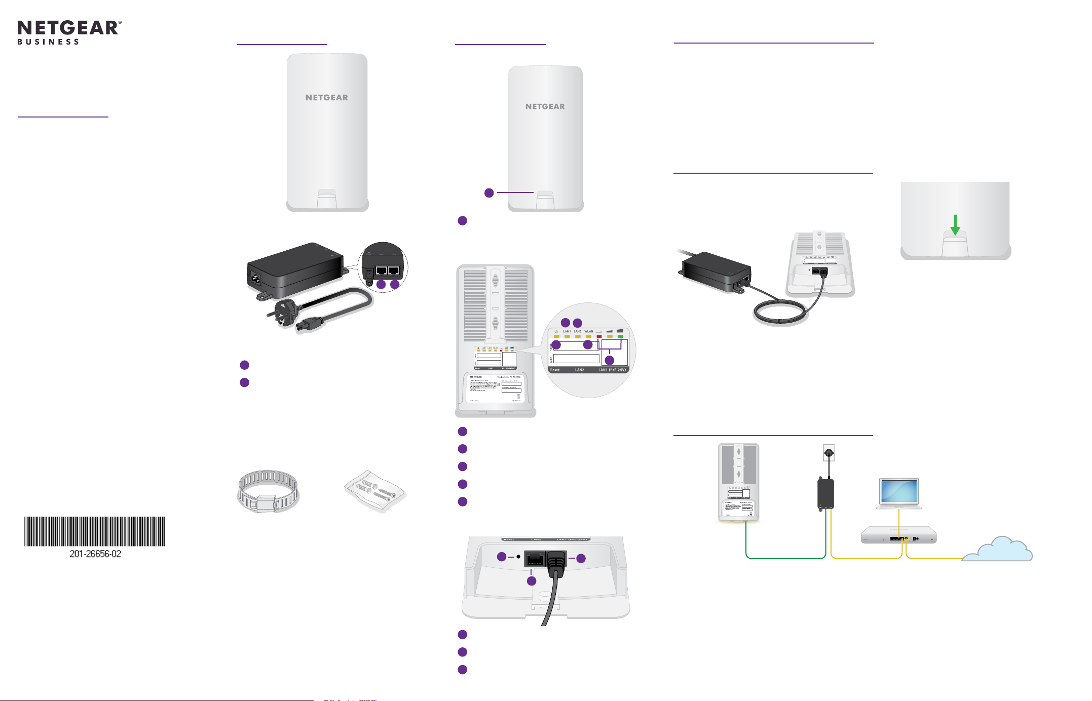
Package contents
AirBridge overview
1. Prepare for installation
Installation Guide
Insight Instant
Wireless AirBridge
Model WBC502B2
Model WBC502B2 is a bundle with one
precongured AirBridge master and
one precongured AirBridge satellite.
A label on the front of the AirBridge
shows whether the AirBridge is
precongured as a master or a satellite.
Insight Instant Wireless AirBridge
(Model WBC502)
1
2
Power adapter and power cord
(varies by region).
1
PoE port: Connect to AirBridge LAN1
2
LAN port: Connect to the network
Note: The power adapter and power
cord are not IP55 rated and must be
placed indoors. Because an Ethernet cable
supports a maximum length of 328 feet
(100 meters), you can place the AirBridge
outdoors but keep the power adapter and
power cord indoors.
Front view
1
1
Latch for bottom panel
Back view
1
Power LED
2
LAN1 LED: Power and network
3
LAN2 LED: Ethernet device
4
WLAN LED: WiFi connectivity
5
Signal strength indicator LEDs
This installation guide describes how to establish a WiFi bridge between two Insight
Instant Wireless AirBridge devices that are precongured for a point-to-point setup.
One AirBridge device is precongured as the master, the other one as the satellite.
You connect the AirBridge master to your wired network at the main site to provide
WiFi connectivity to the AirBridge satellite that you install at the detached site.
This point‑to‑point setup requires a line of sight between the AirBridge master at the
main site and the AirBridge satellite at the detached site.
2. Power on the AirBridge master
1. Pull down on the latch on the front of the
device and remove the bottom panel of
the AirBridge to expose the ports.
2. With the back of the AirBridge facing
you, connect an RJ‑45 Ethernet cable (not
provided) to the AirBridge 24V PoE port on
the right side of the device. Connect the
other end of the cable to the PoE port on
2
3
1
4
5
WARNING: Power on the AirBridge only with an Ethernet cable connected to the
provided power adapter, which must be placed indoors. Do not use any other
power source. The PoE port is not a standard PoE port. Using any other power
the power adapter.
source can damage the device.
3. Insert the plug into a power source.
All the LEDs light and then go off. The power LED stays lit.
3. Connect the AirBridge master to the network
Power
adapter
NETGEAR, Inc.
350 East Plumeria Drive
San Jose, CA 95134, USA
NETGEAR INTERNATIONAL LTD
Floor 1, Building 3,
University Technology Centre
Curraheen Road, Cork,
T12EF21, Ireland
© NETGEAR, Inc., NETGEAR and the NETGEAR
Logo are trademarks of NETGEAR, Inc. Any
non‑NETGEAR trademarks are used for reference
purposes only.
April 2020
Pole mounting strap Wall mount screws
Screw placement guide
Installation guide
Other AirBridge (WBC502) features:
• 2.4 GHz management SSID
• 5 GHz SSID extends your network
• Range of 1.8 miles (3 km) or more
Terms of Use
This device must be professionally installed. It is
the installer’s responsibility to follow local country
regulations including operations within legal frequency
channels, output power and DFS requirements. Vendor
or Reseller or Distributor is not responsible for illegal
wireless operations. Please see Device’s Terms and
Conditions for more details.
and anchors
Bottom view
1
3
1
Reset button
2
LAN1: PoE and network connectivity
3
LAN2: Optional device for satellite only
Master
2
Router Network
We recommend that you connect the AirBridge master to a network with Internet
access during setup. If the network includes a DHCP server, such as a router, the master
is automatically assigned a new IP address. (The default IP address is 192.168.0.100.)
1. Connect the LAN port on the power adapter to a LAN port on a switch or router
on your network. (Do not connect the LAN2 port on the master directly to your
network.)
2. Slide the bottom port cover onto the master until it latches.
3. Install the master to allow for a direct line of site to the detached location, facing
the location where you want to install the AirBridge satellite.
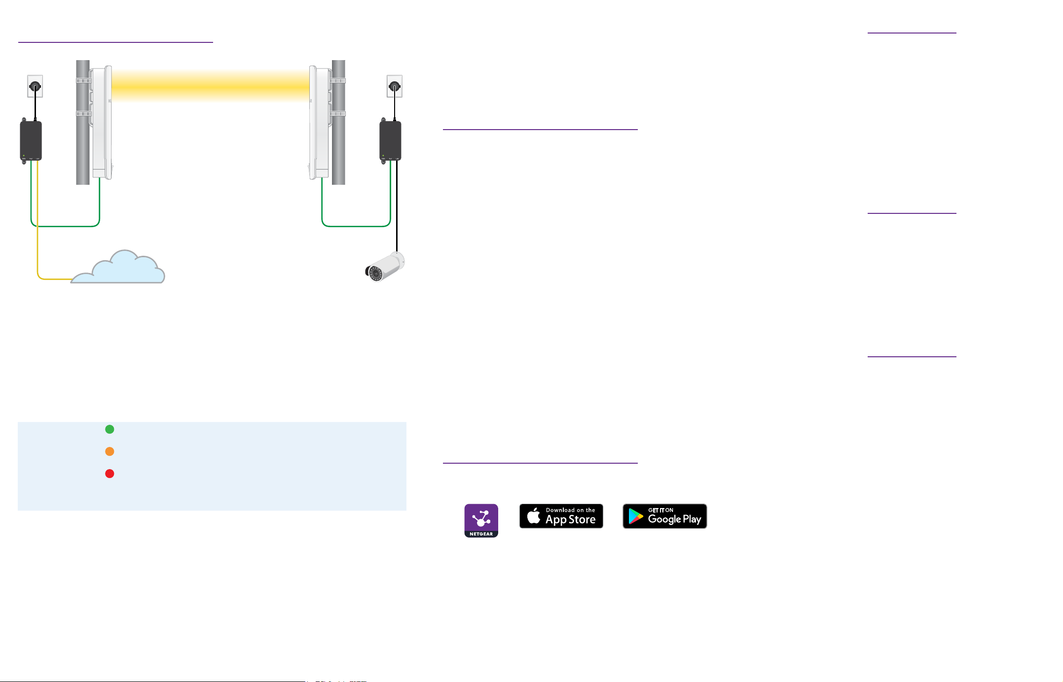
4. Install the AirBridge satellite
Master
Line of sight
Network
1. Install the AirBridge satellite at the detached location in such a way that the
satellite is in a direct line of sight to the master at the main site, and is facing the
master.
You can place the satellite at a distance of 1.8 miles (3 km) or more from the master.
2. Connect power to the satellite the same way you did for the master (see 2. Power
on the AirBridge master.
After the satellite establishes a WiFi connection with the master, the signal
strength indicator (SSI) LEDs light to indicate the strength of the signal for the WiFi
connection.
Green LED Right SSI LED solid green. The signal for the WiFi connection is
Amber LED
Red LED
SSI LEDs off All SSI LEDs off. No WiFi connection is established or the signal
3. Use the SSI LEDs to adjust the position of the satellite for an optimal WiFi signal.
If the signal strength is weak or moderately good, make sure that you place the
satellite according to the following guidelines:
• Place the satellite at a higher location.
• Make sure that the satellite is in a direct, or near line of sight to the master at
the main site.
• Make sure that the front panel of the satellite is facing the front panel of the
master at the main site.
Note: You can use the NETGEAR Insight app to align the satellite. For more
information, see https://kb.netgear.com/000061678.
strong. The left and middle SSI LEDs are off.
Middle SSI LED solid amber. The signal for the WiFi connection
is moderately good. The left and right SSI LEDs are off.
Left SSI LED solid red. The signal for the WiFi connection is
weak. The middle and right SSI LEDs are off.
strength cannot be determined.
Single device or
extended network
Satellite
4. Test the network connectivity by doing one of the following:
• Connect a computer to the LAN2 port on the satellite.
• Connect a WiFi access point to the LAN port on the satellite’s power adapter
and then connect a WiFi client to the access point.
At the detached site, if you can access the network at the main site and the
Internet, the WiFi connection functions.
5. Optional: Log in to the master and satellite
Note: By default, the management mode of the precongured AirBridges is local
browser UI. You can change the management mode so that you can use NETGEAR
Insight to manage the conguration for a point-to-point setup between a master and a
satellite. For more information, visit https://www.netgear.com/support/product/insight.aspx.
We recommend that you log in to the local browser UI of the master rst.
1. Connect your mobile device or computer to the same network where you
connected the AirBridge master or satellite.
2. Enter the IP address of the AirBridge.
If you don’t know the IP address of the AirBridge, use the NETGEAR Insight app or
another discovery method.
Your browser might display a security message. Ignore it or add an exception.
The page adjusts to show the Day Zero Easy Setup settings.
3. In the AP Login New Password eld, specify a new local device password for the
AirBridge, and conrm the password.
4. In the Management WPA2 Passphrase eld, specify a new passphrase for WiFi
management access only.
5. Click the Apply button.
Your settings are saved and the WiFi link might need to be reestablished.
6. Log in with the user name admin and the new local device password that you just
specied, and agree to the Terms of Use.
You can now change or manage the AirBridge settings using the local browser UI.
6. Register your devices in NETGEAR Insight
1. On your mobile device, visit the Apple App Store or Google Play Store, search for
NETGEAR Insight, and download the latest version of the app.
2. Open the NETGEAR Insight app on your mobile device.
3. If you do not own a NETGEAR account, tap Create NETGEAR Account and follow
the onscreen instructions.
4. Enter the email address and password for your account and tap LOG IN.
5. Tap + in the upper right corner.
6. Either use the camera on your phone to scan the bar code, or type in the serial
number.
7. Follow the instructions on screen to register the device.
Other supported modes
Other supported operation modes
for the AirBridge include point‑to‑
multipoint master‑to satellite, access
point, and client bridge. For more
information, see the user manual at
netgear.com/support/product/WBC502.
Insight Premium and Insight Pro
subscribers can use the Insight Cloud
portal to change or manage the point‑
to‑point master‑to‑satellite setup. For
more information, see the NETGEAR
Knowledge Base.
Support and Community
Visit netgear.com/support to get your
questions answered and access the
latest downloads.
You can also check out our NETGEAR
Community for helpful advice at
community.netgear.com.
For more information about Insight
Instant Mesh‑capable products, visit
netgear.com.
Regulatory and Legal
Si ce produit est vendu au Canada,
vous pouvez accéder à ce document
en français canadien à https://www.
netgear.com/support/download/.
(If this product is sold in Canada, you
can access this document in Canadian
French at https://www.netgear.com/
support/download/.)
For regulatory compliance information
including the EU Declaration of
Conformity, visit https://www.netgear.
com/about/regulatory/.
See the regulatory compliance
document before connecting the
power supply.
For NETGEAR’s Privacy Policy, visit
https://www.netgear.com/about/
privacy-policy.
By using this device, you are agreeing
to NETGEAR’s Terms and Conditions
at https://www.netgear.com/about/
terms-and-conditions. If you do not
agree, return the device to your place
of purchase within your return period.
 Loading...