

Page 1
GS700AT Series Smart Switch Software Administration Manual
NETGEAR, Inc.
4500 Great America Parkway
Santa Clara, CA 95054 USA
202-10360-01
March 2008
Page 2

GS700AT Series Smart Switch Software Administration Manual
© 2007, 2008 by NETGEAR, Inc. All Rights reserved.
Trademarks
NETGEAR and the NETGEAR logo are registered trademarks of NETGEAR, Inc. in the United States and/or other
countries. Microsoft, Windows, and Windows NT are registered trademarks and Vista is a trademark of Microsoft
Corporation. Other brand and product names are trademarks or registered trademarks of their respective holders.
Statement of Conditions
In the interest of improving internal design, operational function, and/or reliability, NETGEAR reserves the right to
make changes to the products described in this document without notice.
NETGEAR does not assume any liability that may occur due to the use or application of the product(s) or circuit
layout(s) described herein. Information is subject to change without notice.
Certificate of the Manufacturer/Importer
It is hereby certified that the GS700AT Series Gigabit Smart Switch has been suppressed in accordance with the
conditions set out in the BMPT-AmtsblVfg 243/1991 and Vfg 46/1992. The operation of some equipment (for example,
test transmitters) in accordance with the regulations may, however, be subject to certain restrictions. Please refer to the
notes in the operating instructions.
The Federal Office for Telecommunications Approvals has been notified of the placing of this equipment on the market
and h as been granted the right to test the series for compliance with the regulations.
Voluntary Control Council for Interference (VCCI) Statement
This equipment is in the first category (information equipment to be used in commercial and/or industrial areas) and
conforms to the standards set by the Voluntary Control Council for Interference by Data Processing Equipment and
Electronic Office Machines that are aimed at preventing radio interference in commercial and/or industrial areas.
Consequently, when this equipment is used in a residential area or in an adjacent area thereto, radio interference may be
caused to equipment such as radios and TV receivers.
Federal Communications Commission (FCC) Compliance Notice: Radio Frequency
Notice
This device complies with part 15 of the FCC Rules. Operation is subject to the following two conditions:
• This device may not cause harmful interference.
• This device must accept any interference received, including interference that may cause undesired operation.
NOTE: This equipment has been tested and found to comply with the limits for a Class A digital device, pursuant to
part 15 of the FCC Rules. These limits are designed to provide reasonable protection against harmful
interference in a residential installation. This equipment generates, uses, and can radiate radio frequency
energy and, if not installed and used in accordance with the instructions, may cause harmful interference to
radio communications. However, there is no guarantee that interference will not occur in a particular
installation. If this equipment does cause harmful interference to radio or television reception, which can be
determined by turning the equipment off and on, the user is encouraged to try to correct the int erference by one
or more of the following measures:
ii
v1.0, March 2008
Page 3

GS700AT Series Smart Switch Software Administration Manual
• Reorient or relocate the receiving antenna.
• Increase the separation between the equipment and receiver.
• Connect the equipment into an outlet on a circuit different from that which the receiver is connected.
• Consult the dealer or an experienced radio/TV technician for help.
EU Statement of Compliance
The NETGEAR GS700AT Series Gigabit Smart Switch is compliant with the following EU Council Directives: 89/336/
EEC and LVD 73/23/EEC. Compliance is verified by testing to the following standards: EN55022 Class A, EN55024
and EN60950-1.
Warning: This is a Class A product. In a domestic environment, this product may cause radio interference, in which
case the user may be required to take appropriate measures.
Canadian Department of Communications Radio Interference Regulations
This digital apparatus (NETGEAR GS700AT Series Smart Switch) does not exceed the Class A limits for radio-noise
emissions from digital apparatus as set out in the Radio Interference Regulations of the Canadian Department of
Communications.
Règlement sur le brouillage radioélectrique du ministère des Communications
Cet appareil numérique (NETGEAR GS700AT Series Smart Switch) respecte les limites de bruits radioélectriques
visant les appareils numériques de classe A prescrites dans le Règlement sur le brouillage radioélectrique du ministère
des Communications du Canada.
Customer Support
For assistance with installing and configuring your NETGEAR system or for questions or problems following
installation:
• Check the NETGEAR Web page at http://www.NETGEAR.com/support
• Call Technical Support in No rth America at 1-888-NETGEAR. If you are outside North America, please refer to
the phone numbers listed on the Support Information Card that was included with your switch.
• Email Technical Support at support@NETGEAR.com.
• Defective or damaged merchandise can be returned to your point-of-purchase representative.
Internet/World Wide Web
NETGEAR maintains a World Wide Web home page that you can access at the uniform resource locator (URL) http://
www.NETGEAR.com. A direct connection to the Internet and a Web browser such as Internet Explorer or Netscape are
required.
FCC Requirements for Operation in the United States
FCC Information to User: This product does not contain any user-serviceable components and is to be used with
approved antennas only. Any product changes or modifications will invalidate all applicable regulatory certifications and
approvals
FCC Guidelines for Human Exposure:
uncontrolled environment. This equipment should be installed and operated with a minimum distance of 20 cm between
This equipment complies with FCC radiation exposure limits set forth for an
v1.0, March 2008
iii
Page 4

GS700AT Series Smart Switch Software Administration Manual
the radiator and your body . This transmitter must not be co-located or operating in conjunction with any other anten na or
transmitter.
FCC Declaration Of Conformity: We, NETGEAR, Inc., 4500 Great America Parkway, Santa Clara, CA 95054,
declare under our sole responsibility that the model GS700AT Series Gigabit Smart Switch complies with Part 15 of
FCC Rules. Operation is subject to the following two conditions: a) This device may not cause harmful interference and
b) This device must accept any interference received, including interference that may cause undesired operation.”
Product and Publication Details
Model Number: GS700AT Series
Publication Date: March 2008
Product Family: Smart Switch
Product Name: GS700AT Series Gigabit Smart Switch
Home or Business Product: Business
Language: English
Publication Part Number: 202-10360-01
Publication Version Number: 1.0
iv
v1.0, March 2008
Page 5

Contents
About This Manual
Who Should Use this Book ............................................................................................... ix
How to Use This Book ...................................................................................................... ix
Conventions, Formats, and Scope .................................................................................... x
How to Use This Manual .................................................................................................. xi
How to Print this Manual ...................................................................................................xii
Revision History ..................... ... ... .... ... ... ... ........................................................................xii
Chapter 1
Getting Started with Switch Management
System Requirements ....................................................................................................1-1
Switch Management Interface ................................................................................... ... ..1-2
Network with a DHCP Server .........................................................................................1-3
Network without a DHCP Server ....................................................................................1-5
Web Access ............................................................................... ... ... ... .... ... ... ..................1-8
Additional Utilities .................................................. ... .... ... ... ... .... ... ... ... .... ... ... ..................1-9
Chapter 2
Introduction to the Web Browser Interface
Logging Into the NETGEAR Home Screen ....................................................................2-1
Using the NETGEAR Web Management System Options .............................................2-3
Chapter 3
Managing System Settings
Using the System Settings Utility ....................................................................................3-1
Management ....................................... ................ ................ ................ ................ ............3-1
Device View ....................................................................................................................3-7
SNMP .............................................................................................................................3-7
LLDP ...................................... ................ ................ ................ ................. ................ ......3-27
Chapter 4
Configuring Switching Settings
Configuring Switching Settings .......................................................................................4-1
Contents v
v1.0, December 2007
Page 6

GS700AT Series Smart Switch Software Administration Manual
Ports ...............................................................................................................................4-1
LAG ................................................................................................................................4-4
VLAN ............................................................................................................................4-14
Voice VLAN ........................................... ... .... ... .............................................................4-22
STP ..................................... ............. ............. ............ ............. ............. ............. .............4-28
Multicast .......................................................................................................................4-38
Address Table ...............................................................................................................4-47
Chapter 5
Configuring QoS
Configuring the Basic and Advanced QoS Settings .......................................................5-1
CoS ..................................... ............. ............. ............ ............. ............. ............. ...............5-1
Chapter 6
Managing Security
Setting Security Configuration Options ...........................................................................6-1
Management Security .....................................................................................................6-1
Port Authentication ................................................... .... ... ...............................................6-9
Traffic Control ..................... ... ... ....................................................................................6-15
ACL ..................................... ............. ............. ............ ............. ............. ............. .............6-19
Chapter 7
Monitoring the Switch
Setting Monitoring Options ................................................. ............................................7-1
Logs ....................................... ............................................. ............................................7-1
RMON .................................... ................ ................ ................ ................. ................ ........7-9
Port Mirroring ................................................................................................................7-22
Chapter 8
Maintenance
Using the Maintenance Options ...................... ... ... ... .... ... ... ... .... ... ... ... .... ... ... ... ... ............8-1
Reset ..............................................................................................................................8-1
Upload ............................................................................................................................8-3
Download ..................................... ................. ................ ................ ................ ..................8-4
File Management ............................................................................................................8-5
Troubleshooting ............................................... ............................................................... 8-6
Chapter 9
Online Help
Online Help ...................................................... ... ... ... .... ... ... ............................................9-1
vi Contents
v1.0, December 2007
Page 7

Smart Switch Software Administration Manual
Support ................................................................................................... ........................9-1
User Guide ..................... .... ............................................................. ... .... ... ... ... ... ............9-2
Appendix A
Default Settings
Index
Contents vii
v1.0, December 2007
Page 8

GS700AT Series Smart Switch Software Administration Manual
viii Contents
v1.0, December 2007
Page 9

About This Manual
The NETGEAR® GS700AT Series Smart Switch Software Administration Manual describes how
to install, configure, operate, and troubleshoot the GS700AT Gigabit Smart Switch using its
included software. This book describes the software configuration procedures and explains the
options available within those procedures.
Who Should Use this Book
The information in this manual is intended for readers with intermediate to advanced system
management skills.
This document was created primarily for the system administrator who wishes to install and
configure the GS700AT Series Smart Switch in a network. This user guide assumes that the reader
has a general understanding of switch platforms and a basic knowledge of Ethernet and
networking concepts. To install this switch, it is not necessary to understand and use all of its
capabilities. Once basic configuration is performed, the switch operates using the remaining
factory default parameters. However, a greater level of configuration—anywhere from the basic up
to the maximum possible—will allow your network the full benefit of the switch’s features. The
web interface simplifies this configuration at all levels.
How to Use This Book
This document describes configuration commands for the GS700AT Series Smart Switch
software. The commands can all be accessed from the Web interface.
• Chapter 1, “Getting Started with Switch Management” describes how to use the SmartWizard
Discovery utility to set up your switch so that you can communicate with it.
• Chapter 2, “Introduction to the Web Browser Interface” introduces the Web browser interface.
• Chapter 3, “Managing System Settings” describes how to configure the System functions.
• Chapter 4, “Configuring Switching Settings” describes how to configure the Switching
functions.
• Chapter 5, “Configuring QoS” describes how to configure QoS functions.
v1.0, March 2008
ix
Page 10
GS700AT Series Smart Switch Software Administration Manual
• Chapter 6, “Managing Security” describes how to configure security.
• Chapter 7, “Monitoring the Switch” describes how to configure switch monitoring.
• Chapter 8, “Maintenance” describes the firmware upgrade procedure and reset functions.
• Chapter 9, “Online Help” describes how to obtain online help and support.
• Appendix A, “Default Settings” gives GS700AT Series Smart Switch specifications and lists
default feature values.
Note: Refer to the product release notes for the GS700AT Series Smart Switch Software
application level code. The release notes detail the platform specific functionality
of the Switching, SNMP, Config, and Management packages.
Conventions, Formats, and Scope
The conventions, formats, and scope of this manual are described in the following paragraphs:
• Typographical Conventions. This manual uses the following typographical conventions:
Italics Emphasis, books, CDs, file and server names, extensions
Bold User input, IP addresses, GUI screen text
Fixed Command prompt, CLI text, code
italics URL links
• Formats. This manual uses the following formats to highlight special messages:
Note: This format is used to highlight information of importance or special interest.
Tip: This format is used to highlight a procedure that will save time or resources.
Warning: Ignoring this type of note may result in a malfunction or damage to the
equipment.
x
v1.0, March 2008
Page 11
GS700AT Series Smart Switch Software Administration Manual
Danger: This is a safety warning. Failure to take heed of this notice may result in
personal injury or death.
• Scope. This manual is written for the GS700AT Series Smart Switch according to these
specifications:
Product Version GS700AT Gigabit Smart Switch
Manual Publication Date March 2008
.
Note: Product updates are available on the NETGEAR, Inc. website at
http://www.netgear.com/support.
How to Use This Manual
The HTML version of this manual includes the following:
• Buttons and for browsing forwards or backwards through the manual one page
at a time.
• A button that displays the table of contents and a button. Double-click on a link
in the table of contents or index to navigate directly to where the topic is described in the
manual.
• A button to access the full NETGEAR, Inc. online knowledge base for the product
model.
• Links to PDF versions of the full manual and individual chapters.
xi
v1.0, March 2008
Page 12
GS700AT Series Smart Switch Software Administration Manual
How to Print this Manual
To print this manual, select one of the following options:
• Printing a Page from HTML. Each page in the HTML version of the manual is dedicated to
a major topic. Select File > Print from the browser menu to print the page contents.
• Printing from PDF. Your computer must have the free Adobe Acrobat reader installed in
order to view and print PDF files. The Acrobat reader is available on the Adobe Web site at
http://www.adobe.com.
– Printing a PDF Chapter.
• Click the PDF of This Chapter link at the top left of any page in the chapter you want
to print. The PDF version of the chapter you were viewing opens in a browser
window.
• Click the print icon in the upper left of your browser window.
– Printing a PDF version of the Complete Manual.
• Click the Complete PDF Manual link at the top left of any page in the manual. The
PDF version of the complete manual opens in a browser window.
• Click the print icon in the upper left of your browser window.
Tip: If your printer supports printing two pages on a single sheet of paper, you can
save paper and printer ink by selecting this feature.
Revision History
Part Number
202-10360-01 1.0 March 2008
xii
Version
Number
Date Description
v1.0, March 2008
Page 13

GS700AT Series Smart Switch Software Administration Manual
v1.0, March 2008
xiii
Page 14

Chapter 1
Getting Started with Switch Management
This section provides an overview of switch management, including the methods you can choose
to start managing your NETGEAR GS700AT Gigabit Smart Switch. It also leads you through the
steps necessary to get started, using the SmartWizard Discovery utility. The section includes this
information under the following menu options:
• “System Requirements”
• “Switch Management Interface”
• “Network with a DHCP Server”
• “Network without a DHCP Server”
• “Web Access”
• “Additional Utilities”
System Requirements
The following hardware and software facilities are required to run the applications described in
this manual:
• Network facilities:
– Ethernet network with or without DHCP server as appropriate
– Ethernet cable to connect the switch to a PC
• For running the SmartWizard Discovery utility and local or remote Web Management:
– IBM-type PC with CD drive: RAM size and disk specification are not critical
– OS software: Microsoft Windows Vista, Windows XP, or Windows 2000
– Desktop computer running Microsoft Internet Explorer 5.0 or later or Netscape Navigator
6.0 or later, or equivalent
v1.0, March 2008
1-1
Page 15
GS700AT Series Smart Switch Software Administration Manual
Note: For complete hardware installation instructions, refer to the GS700A T Seri es Smart
Switch Hardware Installation Manual included on your Resource CD, or go to
http://www.netgear.com/support.
Switch Management Interface
Your NETGEAR GS700AT Gigabit Smart Switch contains an embedded web server and
management software for managing and monitoring switch functions. This switch operates as a
simple switch without using the management software. The management software enables you to
configure more advanced features, and consequently improve switch efficiency as well as overall
network performance.
Web-Based Management enables you to monitor, configure, and control your switch remotely
using a common web browser, instead of having to use expensive and complicated SNMP
software products. Simply by using your web br owser, you can monitor the performance of your
switch and optimize network configuration. Using your browser, for example, you can set up
VLANs, traffic priority, and configure port trunking.
In addition, NETGEAR provides the SmartWizard Discovery utility with this product. This
program runs under Microsoft Windows XP or Windows 2000 and provides a “front end” that
discovers the switches on your network segment. When you power up your switch for the first
time, the SmartWizard Discovery utility enables you to configure its basic network parameters
without prior knowledge of IP address or subnet mask. Following such configuration, this program
leads you into the Web Management interface.
Some features of the SmartWizard Discovery utility and Web Management interface are shown in
the table below.
1-2 Getting Started with Switch Management
v1.0, March 2008
Page 16
GS700AT Series Smart Switch Software Administration Manual
Table 1-1. Switch Management Methods
Management Method Features
SmartWizard Discovery utility No IP address or subnet mask setup needed
Discover all switches on the network
User-friendly interface under Microsoft Windows
Firmware upgrade capability
Password change feature
Provides entry to web configuration of switch
Web browser interface Password protection
Ideal for configuring the switch remotely
Compatible with Internet Explorer and Netscape Navigator on any platform
Extensive switch configuration possible
Configuration backup and restore
Can be accessed from any location via the switch’s IP address
Intuitive browser interface
Most visually appealing
For a more detailed discussion of the SmartWizard Discovery utility, continue with this section:
“Network with a DHCP Server” or “Network without a DHCP Server”. For a detailed discussion
of the Web Browser Interface, see Chapter 2, “Introduction to the Web Browser Interface”.
Network with a DHCP Server
To install the switch in a network with a DHCP server, proceed as follows:
1. Connect the GS700AT Series Smart Switch to a DHCP network.
2. Power on the switch by connecting its AC-DC power adapter.
3. Install the SmartWizard Discovery utility, located on the switch installation CD, on your
computer.
4. Start the SmartWizard Discovery utility.
Getting Started with Switch Management 1-3
v1.0, March 2008
Page 17

GS700AT Series Smart Switch Software Administration Manual
5. Click Discover for the SmartWizard Discovery utility to find your GS700AT Gigabit Smart
Switch. You should see a screen similar to that shown below.
Figure 1-1
6. Note the displayed IP address assigned by the DHCP server. You will need this value to access
the switch directly from a web browser (without using the SmartWizard Discovery utility).
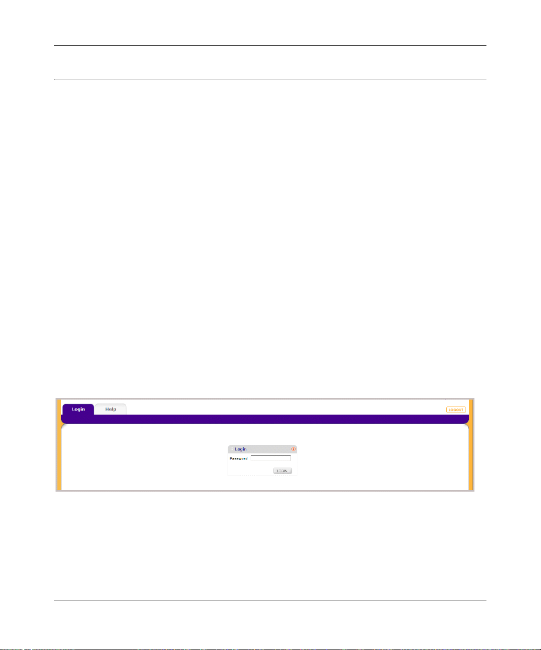
7. Select your switch by highlighting the name of the switch. Then click Web Access. The
discovery utility displays a login window similar to the following:
Figure 1-2
1-4 Getting Started with Switch Management
v1.0, March 2008
Page 18

GS700AT Series Smart Switch Software Administration Manual
8. Use your web browser to manage your switch. The default password is password. Then use
this screen to proceed to management of the switch covered in Chapter 2, “Introduction to the
Web Browser Interface”.
Network without a DHCP Server
This section describes how to set up your switch in a network without a DHCP server, and is
divided into the following tasks:
• Manually assign network parameters for your switch
• Configure the NIC settings on the host PC
• Log in to the web-based switch management utility
Manually Assigning Network Parameters
If your network has no DHCP service, you must assign a static IP address to your switch. You can
also assign the switch a static IP address even if your network has DHCP service. Proceed as
follows:
1. Connect the GS700AT Gigabit Smart Switch to your existing network.
2. Power on the switch by plugging in the AC-DC power adapter. The default IP is
192.168.0.239.
3. Install the SmartWizard Discovery utility on your computer. The SmartWizard Discovery
utility is located on the switch installation CD.
4. Start the SmartWizard Discovery utility.
5. Click Discover for the SmartWizard Discovery utility to find your GS700AT Gigabit Smart
Switch. You should see a screen similar to that shown in Figure 1-1.
Getting Started with Switch Management 1-5
v1.0, March 2008
Page 19
GS700AT Series Smart Switch Software Administration Manual
6. Click Configuration Setting. A screen similar to that shown below appears.
Figure 1-3
7. Select Disable to disable DHCP.
8. The default IP address is 192.168.0.239 and the default subnet mask is 255.255.255.0. If you
want different values, enter the switch IP address, gateway IP address and subnet mask.
9. Type your password and click Set. Please ensure that your PC and the GS700AT Gigabit
Smart Switch are in the same subnet. Note the settings for later use.
1-6 Getting Started with Switch Management
v1.0, March 2008
Page 20
GS700AT Series Smart Switch Software Administration Manual
NIC Setting on the Host that Accesses the GS700AT Gigabit Smart Switch
The settings of your Network Interface Card (NIC) under MS Windows OS are made with entries
into Windows screens similar to the ones shown below. For comparison, the settings screens of the
switch are also shown although they do not appear in the Windows view.
Figure 1-4
You need Windows Administrator privileges to change these settings.
1. On your PC, access the MS Windows operating system TCP/IP Properties.
2. Set IP address and subnet mask appropriately. The subnet mask value is identical to that set in
the switch. The PC IP address must be different from that of the switch but lie in the same
subnet.
3. Click W eb Access in the SmartWizard Discovery utility to enable the management screens as
described in the following section.
Getting Started with Switch Management 1-7
v1.0, March 2008
Page 21
GS700AT Series Smart Switch Software Administration Manual
Web Access
For Web access, you can either:
• Select Web Access using the SmartWizard Discovery utility (see “Network with a DHCP
Server” or “Network without a DHCP Server”).
• Access the switch directly, without using the SmartWizard Discovery utility.
You must work from the same network segment that contains the switch (i.e., the subnet mask
values of switch and PC host must be the same) and you must point your browser using the switch
IP address. If you used the SmartWizard Discovery utility to set up IP address and subnet mask,
either with or without DHCP server, use that IP address in your browser window.
If you are starting with an “out of the box” switch and are not using the SmartWizard Discovery
utility, you must initially configure your host PC to be on a network segment to match the default
parameters of the switch, which are:
• IP address: 192.168.0.239
• Subnet Mask: 255.255.255.0
You can change the network parameters to match those of your network (this procedure is
described in Chapter 3 , “Managing System Settings”). Your host PC network parameters must
then be set to match your network.
Clicking Web Access on the SmartWizard Discovery utility or accessing the switch directly
displays the screen shown below.
.
Figure 1-5
Use this screen to proceed to management of the switch covered in Chapter 2, “Introduction to the
Web Browser Interface”.
1-8 Getting Started with Switch Management
v1.0, March 2008
Page 22
GS700AT Series Smart Switch Software Administration Manual
Additional Utilities
Alternatively, from the main screen shown on Figure 1-1 you can access these additional
functions:
• “Password Change”
• “Firmware Upgrade”
Password Change
You can set a new password of up to 20 ASCII characters.
1. Click Password Change from the Switch Setting section. The Password Change screen
appears. You can set a new password. You must enter the old and new passwords and confirm
the new one.
2. Click Set to enable the new password.
Firmware Upgrade
The GS700AT Series Smart Switch software is upgradeable, and enables your switch to take
advantage of improvements and additional features as they become available. The upgrade
procedure assumes that you have downloaded or otherwise obtained the firmware upgrade and that
you have it available as a binary file on your computer. This procedure uses the TFTP protocol to
implement the transfer from computer to switch.
.
Note: You can also upgrade the firmware using the Download menu of the switch (see
“Download”).
Getting Started with Switch Management 1-9
v1.0, March 2008
Page 23
GS700AT Series Smart Switch Software Administration Manual
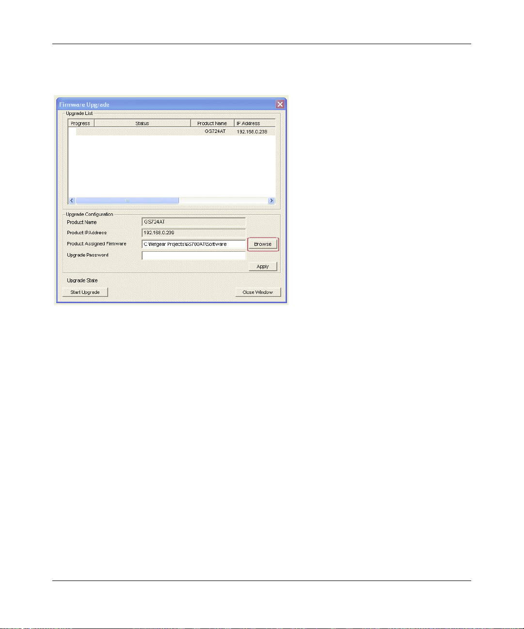
If you click Firmware Upgrade from the main screen (see Figure 1-1), after you have selected the
switch to upgrade, the following screen appears:
Figure 1-6
1. Enter the following values into the appropriate places in the form:
• Product Assigned Firmware: The location of the new firmware. If you do not know the
location, click Browse to locate the file.
• Upgrade Password: Enter your password; the default password is password.
2. Click Apply to apply the settings to the Upgrade Configuration.
3. Click Start Upgrade to begin loading the upgrade. The system software is automatically
loaded. The Upgrade State field shows upgrading in progress.When the process is complete,
the switch automatically reboots.
Exit
Click Exit from the SmartWizard Discovery screen to close the SmartWizard Discovery utility.
1-10 Getting Started with Switch Management
v1.0, March 2008
Page 24
Chapter 2
Introduction to the Web Browser Interface
This section introduces the web browser interface that enables you to configure and manage your
NETGEAR GS700AT Gigabit Smart Switch. Your GS700AT Series Smart Switch provides a
built-in browser interface that enables you to configure and manage it remotely using a standard
Web browser such as Microsoft Internet Explorer or Netscape Navigator. Online Help is also
provided for many of the basic functions and features of the switch.
This section introduces the areas of the browser interface and includes the following topics:
• “Logging Into the NETGEAR Home Screen”
• “Using the NETGEAR Web Management System Options”
Logging Into the NETGEAR Home Screen
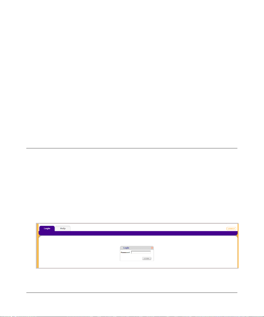
Begin your overview of the GS700AT Series Smart Switch browser interface by logging in:
1. Start the application by one of the following methods, as described in Chapter 1, “Getting
Started with Switch Management”:
a. In the SmartWizard Discovery utility click Web Access.
or
b. In the web browser enter the switch’s IP address and press Enter.
The Login screen appears.
Figure 2-1
v1.0, March 2008
2-1
Page 25
GS700AT Series Smart Switch Software Administration Manual
2. Enter the password (the factory default is password) and click Login. The home screen of the
GS700AT Series Smart Switch browser interface displays.
The Navigation Menu
As shown below, logging in brings you to the view of the web browser interface.
Figure 2-2
The NETGEAR GS700AT Series web browser interface contains the following views:
Main Navigation Area – Located on the top of the NETGEAR GS700AT Series web browser
interface and marked as 1 in Figure 2-2. The Main Navigation Area includes Primary and
Secondary Navigation Bars. The Primary Navigation Bar contains a list of the different features
that can be configured including System, Switching, QoS, Security, Monitoring, Maintena nce and
Help. Each feature expands to a subset of features that can be configured as part of the Secondary
Navigation Bar .
Left Navigation Tree – Located on the left side of the NETGEAR GS700AT Series web browser
interface and marked as 2 in Figure 2-2. For each Secondary Navigation Feat ure the Left
Navigation Tree contains a subset of features that can be expanded to display all the components.
2-2 Introduction to the Web Browser Interface
v1.0, March 2008
Page 26
GS700AT Series Smart Switch Software Administration Manual
Work Area – Located on the right side of the NETGEAR GS700AT Series web browser interface
and marked as 3 in Figure 2-2. The Work Area contains device tables, general device information,
and configurable device parameters.
For further description of the functions, refer to the appropriate section of this manual:
• Chapter 3, “Managing System Settings” describes how to configure the System functions.
• Chapter 4, “Configuring Switching Settings” describes how to configure the Switch functions.
• Chapter 5, “Configuring QoS” describes how to configure QoS functions.
• Chapter 6, “Managing Security” describes how to configure security.
• Chapter 7, “Monitoring the Switch” describes how to configure monitoring functions.
• Chapter 8, “Maintenance” describes maintenance functions, such as firmware upgrade.
• Chapter 9, “Online Help” describes how to obtain online help and support.
Using the NETGEAR Web Management System Options
The GS700AT Series web browser interface provides the following options:
• Device Management Buttons – Provides an explanation of the management buttons in the
NETGEAR GS700AT Series Smart Switch.
• Informational Services – Provides access to informational services including technical
support, online help and device information.
• Using Screen and Table Options – Provides an explanation of specific GUI characteristics
and tables for configuring the device.
Device Management Buttons
The NETGEAR GS700AT Series Smart Switch web browser GUI management buttons allow
network managers to easily configure the device from remote locations. The management buttons
are shown below:
Table 2-1. Device Management Buttons
Button Name Description
ADD Adds information to tables or information windows.
APPLY Applies configured changes to the device.
CANCEL Cancels modifications to tables or information windows.
Introduction to the Web Browser Interface 2-3
v1.0, March 2008
Page 27

GS700AT Series Smart Switch Software Administration Manual
Table 2-1. Device Management Buttons (continued)
Button Name Description
CLEAR ALL Refreshes device information.
CLEAR ALL COUNTERS Resets statistics counters.
CLEAR LOGS Clears logs.
CURRENT MEMBERS Displays current members of a LAG.
DELETE Deletes information from tables or information windows.
GO Selects the specified interface.
REFRESH Refreshes the screen with current data.
T A GGED PORT MEMBERS Displays tagged port members of a VLAN.
TEST Tests copper cables.
UNTAGGED PORT MEMBERS Displays untagged port members of a VLAN.
Informational Services
Informational services provide access to technical support, online help and device information and
are displayed in the following topics:
• “Help Navigation Tab”
• “Accessing Device Information”
Help Navigation Tab
The Help Navigation Tab provides access to informational services including NETGEAR online
support and an online user guide in PDF format. For a detailed description of how to access and
use these functions, see Chapter 9, “Online Help”.
Accessing Device Information
Each screen of the web browser interface contains a help file with configuration information
relating to the selected screen.
2-4 Introduction to the Web Browser Interface
v1.0, March 2008
Page 28
GS700AT Series Smart Switch Software Administration Manual
To access the help file for a screen:
1. Click the encircled red Question Mark icon, shown in the example below.
Figure 2-3
A help window for the screen opens.
Figure 2-4
Using Screen and Table Options
The NETGEAR GS700AT Series web browser interface contains screens and tables for
configuring devices. This section describes the table options:
• “Selecting an Entry”
• “Adding an Entry”
• “Modifying an Entry”
• “Deleting an Entry”
• “Special Table Options”
Introduction to the Web Browser Interface 2-5
v1.0, March 2008
Page 29
GS700AT Series Smart Switch Software Administration Manual
Selecting an Entry
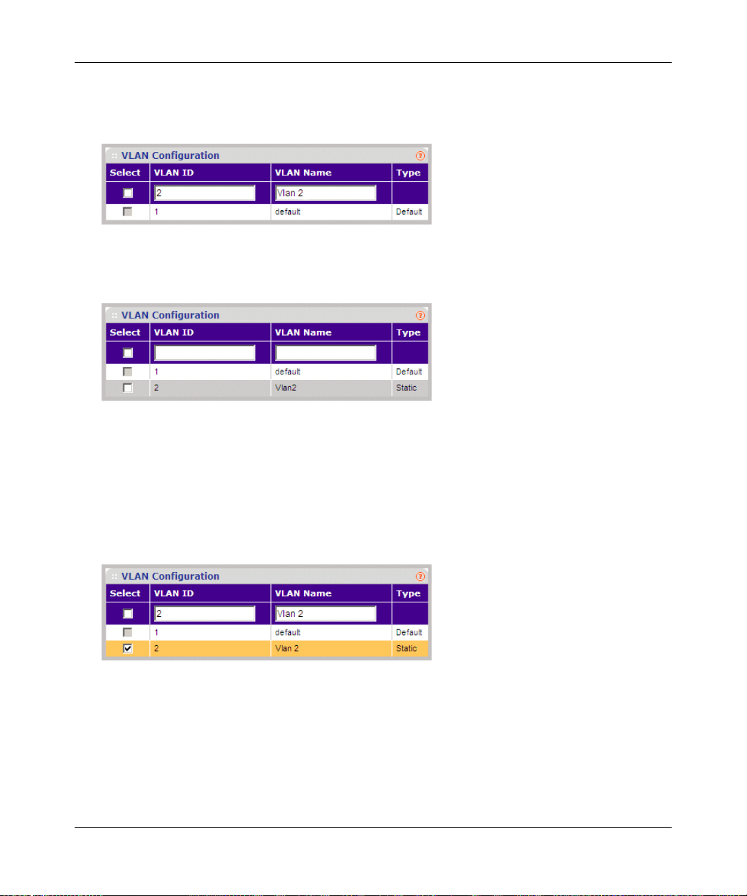
To select an entry:
1. Check the entry’s Select box. The selected entry is highlighted and the information appears in
the first row, which contains the editable fields.
Figure 2-5
To select all entries:
1. Check the Select box in the first row to select all entries in the table. Fields that are unique are
grayed out and displayed as read-only fields.
Figure 2-6
Adding an Entry
An entry may be added to the table by creating a new entry or by duplicating an existing entry.
2-6 Introduction to the Web Browser Interface
v1.0, March 2008
Page 30
GS700AT Series Smart Switch Software Administration Manual
To add an entry by creating a new entry in the table:
1. Enter the fields for the new entry in the provided fields in the first row.
Figure 2-7
2. Click ADD to update the device. The new entry is displayed.
Figure 2-8
Modifying an Entry
An entry may be modified by editing its values in the first row.
To modify an entry:
1. Select the entry to be modified. Its contents are displayed in the first row.
Figure 2-9
2. Modify the fields in the first row.
3. Click APPLY to update the device.
Introduction to the Web Browser Interface 2-7
v1.0, March 2008
Page 31

GS700AT Series Smart Switch Software Administration Manual
Deleting an Entry
To delete entries from a table:
1. Select the entries to be deleted.
2. Click DELETE to update the device.
Special Table Options
The NETGEAR web browser interface tables have a unique GUI design which includes the
following options:
• Gold Buttons
•Quick Boxes
• Interface View and Selection
Gold Buttons. Gold Buttons provide flexibility in viewing and configuring VLANs/LAGs on a
port level. The following example displays gold button basic usage options.
To view the LAG configuration of the ports:
1. Click anywhere on the ports gold button. The ports panel is displayed:
Figure 2-10
2. Select the ports to be added as LAG members within the selected LAG by clicking on their
respective boxes.
3. Click Apply to update the device.
Quick Boxes. Quick Boxes provide users with flexibility in configuring VLANs for all ports or LAGs. Clicking on the quick box toggles between the various options that exist for this field. A quick box appears to the right of the arrow on the left-han d side of the gold button. The following example displays quick box basic usage options.
2-8 Introduction to the Web Browser Interface
v1.0, March 2008
Page 32

GS700AT Series Smart Switch Software Administration Manual
To mark or unmark all ports:
1. Click on the quick box that appears to the left of the Port gold button. A T appears in the
quick box. This sets all ports as Tagged.
Figure 2-11
2. Click on the Port gold button to display the ports, which are now all Tagged.
Figure 2-12
3. Click again on the Port quick box, and a U appears in the quick box and in all the port boxes,
marking the ports as untagged.
Figure 2-13
4. Click again on the quick box, and the quick box and all the port boxes appear blank, marking
the ports as neither tagged nor untagged.
Introduction to the Web Browser Interface 2-9
v1.0, March 2008
Page 33

GS700AT Series Smart Switch Software Administration Manual
5. You may click on individual port boxes to toggle their tagged/untagged status
Interface View and Selection. A port or LAG interface may be selected from a table by using
the interface selection row, located above the row of column headers. Clicking on PORTS or
LAGS displays the ports or the LAGs:
Figure 2-14
To display all ports:
1. Click PORTS in the interface selection row. The screen displa ys a table of all ports.
To display all interfaces:
2. Click All in the interface selection row. A confirmation window opens.
Figure 2-15
2-10 Introduction to the Web Browser Interface
v1.0, March 2008
Page 34

GS700AT Series Smart Switch Software Administration Manual
3. Click OK. The screen displays a table of all interfaces.
To display the LAG table:
1. Click LAGS in the interface selection row. The screen displays a table of all LAGs.
Figure 2-16
To select an interface:
1. Enter the number of the interface in the GO TO INTERFACE box.
2. Click GO to select the interface, as in the following example.
Figure 2-17
Introduction to the Web Browser Interface 2-11
v1.0, March 2008
Page 35

GS700AT Series Smart Switch Software Administration Manual
2-12 Introduction to the Web Browser Interface
v1.0, March 2008
Page 36

Chapter 3
Managing System Settings
Using the System Settings Utility
The navigation pane at the top of the web browser interface contains a System tab that enables you
to manage your GS700AT Series Smart Switch with features under the following main menu
options:
• “Management”
• “Device View”
• “SNMP”
• “LLDP”
The description that follows in this chapter describes configuring and managing system settings in
the GS700AT Series Smart Switch.
Management
The Management menu enables configuration of some system parameters, the switch IP Address
and the system time, and contains the following options:
• “System Information”
• “IP Configuration”
• “Time”
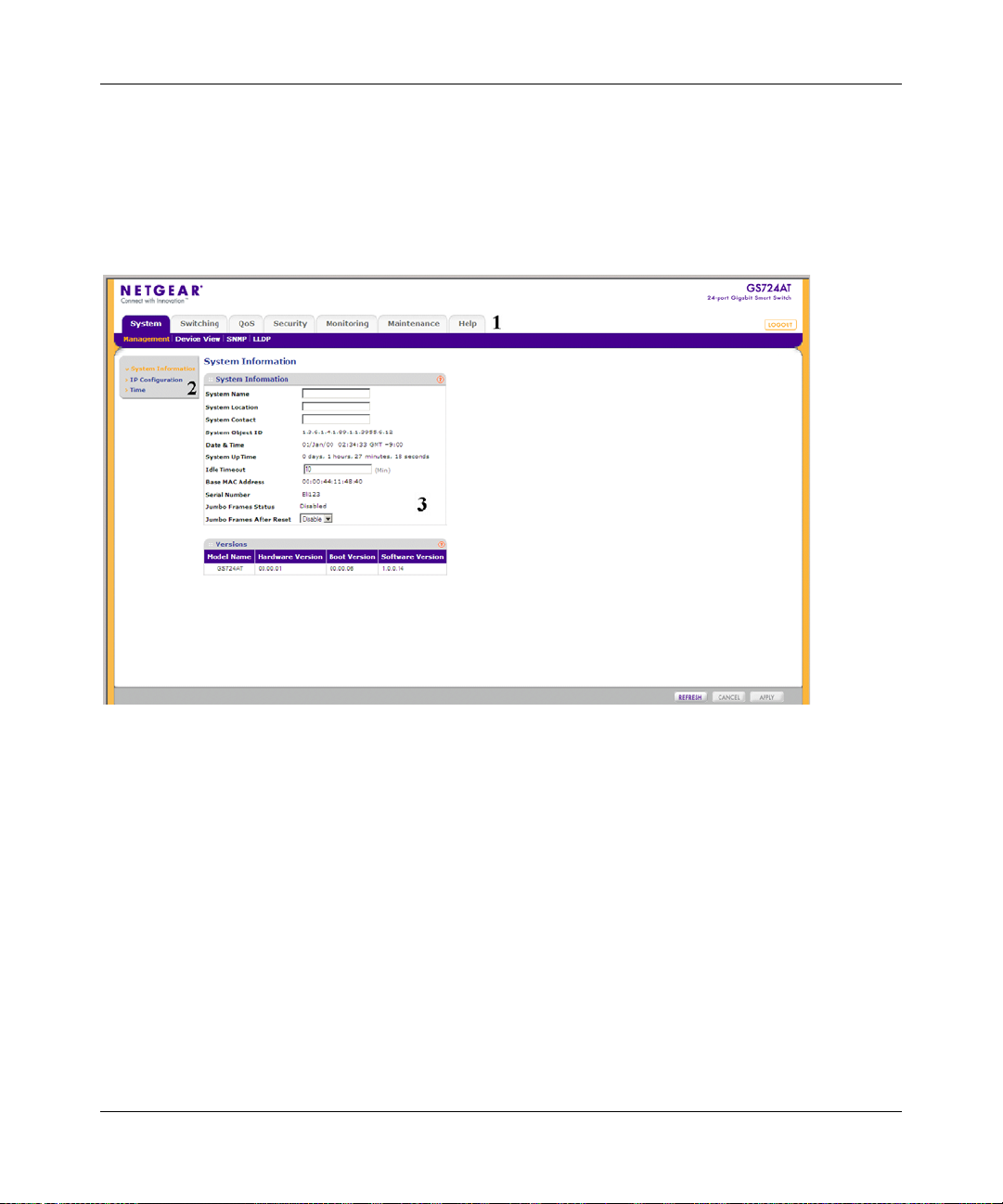
System Information
The System Information screen contains parameters for configuring general device information
including the system name, system location, system contact, idle timeout.
3-1
v1.0, March 2008
Page 37

GS700AT Series Smart Switch Software Administration Manual
To configure system parameters:
1. Click System > Management > System Information. The System Information screen
displays:
Figure 3-1
The System Information screen contains the following fields:
• System Name – Enter the user-defined device name. The field may contain 0-160
characters.
• System Location – Enter the location where the system is currently running. The field
may contain 0-160 characters.
• System Contact – Enter the name of the contact person. The field may contain 0-160
characters.
• System Object ID – Displays the vendor’s authoritative identification.
• Date & Time – Displays the current date and local time.
• System Up Time – Displays the amount of time since the most recent device reset. The
system time is displayed in the following format: days, hours, minutes, seconds. For
example, 41 days, 2 hours, 22 minutes, 15 seconds.
• Idle Timeout – Enter the amount of time (minutes) that elapses before an idle station is
timed out. Idle stations that are timed out must login to the system. The field range is 5 30 minutes. The field default value is 10 minutes.
• Base MAC Address – Displays the MAC address of .
• Serial Number – Displays the device serial number.
3-2 Managing System Settings
v1.0, March 2008
Page 38

GS700AT Series Smart Switch Software Administration Manual
• Jumbo Frames Status – Displays the Jumbo Frame status.
• Jumbo Frames After Reset – Select the Jumbo Frame status. The possible field values
are:
– Enable – Enable Jumbo Frames.
– Disable – Disable Jumbo Frames.
The Versions Table displays the following fields:
• Model Name – Displays the device model name.
• Hardware Version – Displays the installed device hardware version number.
• Boot Version – Displays the current boot version running on the device.
• Software Version – Displays the installed software version number.
2. Enter the System Name, System Location, System Contact and Idle Timeout in the
provided fields.
3. Select whether to enable or disable Jumbo Frames After Reset.
4. Click Apply to update the system settings.
IP Configuration
The IP Configuration screen contains fields for assigning IP addresses. IP addresses are either
defined as static or are retrieved using the Dynamic Host Configuration Protocol (DHCP). The IP
Interface screen also contains information for defining default gateways. DHCP is also configured
from the IP Interface screen. The DHCP assigns dynamic IP addresses to devices on a network.
DHCP ensures that network devices can have a different IP address every time the device connects
to the network.
Note the following when configuring IP Addresses:
• If the device is accessed using SmartWizard Discovery, the IP address retrieved through
DHCP is displayed.
• If the device fails to retrieve an IP address through DHCP, the default IP address is
192.168.0.239.
Managing System Settings 3-3
v1.0, March 2008
Page 39

GS700AT Series Smart Switch Software Administration Manual
To define an IP interface:
1. Click System > Management > IP Configuration. The IP Configuration screen displays:
Figure 3-2
The IP Configuration screen contains the following fields:
• Dynamic IP Address (DHCP) – Enable the IP address to be configured automatically by
the DHCP server. Selecting this field disables the IP Address, Subnet Mask, Gateway
and Delete fields.
• Static IP Address – Enable the user to define a static IP address.
• IP Address – Enter the static IP address used to manage the device.
• Subnet Mask – Enter the IP address mask.
• Gateway – Enter the default gateway IP address. The following option is available:
– Delete – Delete the default gateway IP address.
2. Select the method of assigning the IP address by selecting either Dynamic IP Address or
Static IP Address.
3. If you selected Static IP Address, enter the IP Address, Subnet Mask and Gateway address
in the provided fields.
4. Click Apply to update the system settings.
Time
The Time menu enables local system time or SNTP server configuration, and contains the
following options:
• “Time Configuration”
• “SNTP Server Configuration”
3-4 Managing System Settings
v1.0, March 2008
Page 40

GS700AT Series Smart Switch Software Administration Manual
Time Configuration
The Time Configuration screen contains information for defining both the local hardware clock
and the external SNTP clock. If the system time is managed via an external SNTP clock, and the
external SNTP clock fails, the system time reverts to the local hardware clock.
To configure the local system time:
1. Click System > Management > Time > Time Configuration. The Time Configuration
screen displays:
Figure 3-3
The Time Configuration screen contains the following fields:
• Clock Source – Select the source used to set the system clock. The possible field values
are:
– Local – The system time is set locally via the Date and Time fields.
– SNTP – The system time is set via an SNTP server. Select SNTP to disable the Date
and Time fields.
• Date – Enter the local system date. The field format is DD/MMM/YY (Day/Month/Year).
For example: 04/May/50 (May 4, 2050).
• Time – Enter the local system time. The field format is HH:MM:SS.
For example: 21:15:03.
• Time Zone Offset – Select the difference between Greenwich Mean Time (GMT) and
local time. For example, the Time Zone Offset for Paris is GMT +1, while the Time Zone
Offset for New York is GMT –5.
2. Select the Clock Source by selecting either Local or SNTP.
3. If you selected Local, then enter the local Date and Time in the provided fields.
4. Select the Time Zone Offset from the list.
Managing System Settings 3-5
v1.0, March 2008
Page 41

GS700AT Series Smart Switch Software Administration Manual
5. Click Apply to update the system settings.
Note: If you selected SNTP, you must configure the SNTP servers. Se e “SNTP
Server Configuration” for detailed instructions on configuring the SNTP
servers.
SNTP Server Configuration
The SNTP Server Configuration screen allows network administrators to define primary and
secondary SNTP servers. The system time is first retrieved through the primary SNTP server. If
the device is unable to retrieve the system time through the primary server, the device retrieves the
system time from the secondary server.
To configure SNTP servers:
1. Click System > Management > Time > SNTP Server Configuration. The SNTP Server
Configuration screen displays:
Figure 3-4
The SNTP Server Configuration screen contains the following fields:
• SNTP Server 1 – Enter the primary SNTP server IP address.
The Primary SNTP server is
the first server used to retrieve the system time. The following option is available:
– Delete – Remove the currently configured SNTP Server 1.
• SNTP Server 2 – Enter the secondary SNTP server IP address
server retrieves the system time if the Primary SNTP server times out.
. The Secondary SNTP
The following
option is available:
– Delete – Remove the currently configured SNTP Server 2.
2. Enter the SNTP Server 1 and SNTP Server 2 in the provided fields.
3. Click Apply to update the system settings.
3-6 Managing System Settings
v1.0, March 2008
Page 42

GS700AT Series Smart Switch Software Administration Manual
To remove SNTP servers:
1. Check the Delete box for each SNTP server that is to be removed.
2. Click Apply to update the system settings.
Device View
The Device View menu option displays the Device View screen, which provides a graphic
representation of the device, including the port and LED statuses.
To display the Device View screen:
1. Click System > Device View. The Device View screen displays:
Figure 3-5
SNMP
Simple Network Management Protocol (SNMP) provides a method for managing network
devices. The device supports the following SNMP versions:
• SNMP v1 and v2c
•SNMP version 3
The SNMP agents maintain a list of variables that are used to manage the device. The variables are
defined in the Management Information Base (MIB). The SNMP agent defines the MIB
specification format, as well as the format used to access the information over the network. Access
strings control access rights to the SNMP agents. SNMP v3 applies access control and a new traps
mechanism. In addition, User Security Model (USM) parameters are defined for SNMPv3,
including:
Managing System Settings 3-7
v1.0, March 2008
Page 43

GS700AT Series Smart Switch Software Administration Manual
• Authentication – Provides data integrity and data origin authentication.
• Privacy – Protects against the disclosure of message content. Cipher Block-Chaining (CBC) is
used for encryption. Either authentication is enabled on an SNMP message, or both
authentication and privacy. However, privacy cannot be enabled without authentication.
• Timeliness – Protects against message delay or message redundancy. The SNMP agent
compares the incoming message to the message time information. Enter the amount of time
the device waits before re-sending informs.
• Key Management – Enter key generation, key updates, and key usage.
The device supports SNMP notification filters based on Object IDs (OIDs). OIDs are used by the
system to manage device features. SNMP v3 supports the following features:
• Security
• Feature Access Control
• Traps. The device generates copy traps.
The SNMP menu contains the following options:
• “SNMPv1/v2”
• “SNMPv3”
SNMPv1/v2
The SNMPv1/v2 menu contains the following options:
• “Community Configuration”
• “Trap Configuration”
Community Configuration
Access rights are managed by defining communities in the Community Configuration screen.
When community names are changed, access rights are also modified.
3-8 Managing System Settings
v1.0, March 2008
Page 44

GS700AT Series Smart Switch Software Administration Manual
To configure SNMP communities:
1. Click System > SNMP > SNMPv1/v2 > Community Configuration. The Community
Configuration screen displays:
Figure 3-6
The SNMPv1/v2 Community Configuration screen contains the following fields:
• Management Station – Enter the management station IP address for which the Basic
SNMP community is defined.
• Community String – Enter the SNMP community string used to authenticate the
management station to the device.
• Access Mode – Select the access rights of the community. The possible field values are:
– Read Only – Management access is restricted to read-only. Changes cannot be made
to the device configuration and to the community.
– Read Write – Management access is read-write. Changes can be made to the device
configuration but not to the community.
– SNMP Admin – User has access to all device configuration options, as well as
permissions to modify the community.
2. Select the community entry.
3. Enter the Management Station and Community String in the provided fields in the first row.
4. Select the Access Mode from the list in the provided field in the first row.
5. Click Apply to update the device.
To add a new SNMP community:
1. Click System > SNMP > SNMPv1/v2 > Community Configuration. The Community
Configuration screen displays.
Managing System Settings 3-9
v1.0, March 2008
Page 45

GS700AT Series Smart Switch Software Administration Manual
2. Enter the Management Station and Community String in the provided fields in the first row.
3. Select the Access Mode from the list in the provided field in the first row.
4. Click Add to update the device.
To remove an SNMP community:
1. Click System > SNMP > SNMPv1/v2 > Community Configuration. The Community
Configuration screen displays.
2. Select the entry to be removed.
3. Click Delete to remove the entry.
Trap Con figuration
The SNMPv1/v2 Trap Configuration screen contains information for defining filters that
determine whether traps are sent to specific users, and the trap type sent. SNMP notification filters
provide the following services:
• Identifying Management Trap Targets
• Defining Trap Filtering
• Defining Trap Generation Parameters
• Providing Access Control Checks
To configure SNMPv1/v2 trap station management:
1. Click System > SNMP > SNMPv1/v2 > Trap Configuration. The SNMPv1/v2 Trap
Configuration screen displays:
Figure 3-7
The SNMPv1/v2 Trap Configuration screen contains the following fields:
• Recipients IP – Enter the IP address to which the traps are sent.
3-10 Managing System Settings
v1.0, March 2008
Page 46

GS700AT Series Smart Switch Software Administration Manual
• Notification Type – (Configurable only if the Notification Version is SNMPv2.) Select
the type of notification sent. The possible field values are:
– Traps – Traps are sent.
– Informs – Informs are sent only when SNMPv2 is enabled.
• Community String – Enter the community string of the trap manager.
• Notification Version – Select the trap type. The possible field values are:
– SNMPv1 – SNMP Version 1 traps are sent.
– SNMPv2 – SNMP Version 2c traps are sent.
• UDP Port – Enter the UDP port used to send notifications. The default UDP port is 162.
• Timeout – Enter the amount of time (in seconds) the device waits before re-sending
informs. The default is 15 seconds.
• Retries – Enter the amount of times the device re-sends an inform request. The default is 3
seconds.
2. Select the trap entry.
3. Enter the fields in the first row.
4. Click Apply to update the device.
To add a new SNMP trap:
1. Click System > SNMP > SNMPv1/v2 > Trap Configuration. The SNMPv1/v2 Trap
Configuration screen displays.
2. Enter the fields in the first row.
3. Click Add to update the device.
To remove an SNMP trap:
1. Click System > SNMP > SNMPv1/v2 > Trap Configuration. The SNMPv1/v2 Trap
Configuration screen displays.
2. Select the entry to be removed.
3. Click Delete to remove the entry.
SNMPv3
The SNMPv3 menu contains the following options:
• “Engine ID”
Managing System Settings 3-11
v1.0, March 2008
Page 47
GS700AT Series Smart Switch Software Administration Manual
• “View Name”
• “View Content”
• “Community Configuration”
• “Group Configuration”
• “User Configuration”
• “Global Trap Configuration”
• “Trap Configuration”
• “Trap Filter Name”
• “Trap Filter Content”
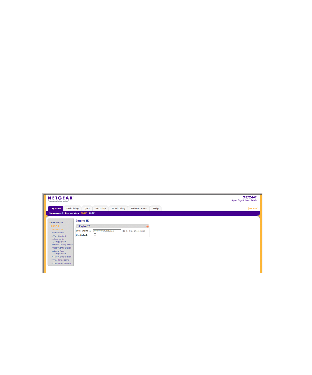
Engine ID
The SNMPv3 Engine ID screen allows network managers to define the SNMP Engine ID and to
assign the default parameters to SNMP.
To define the Local Engine ID:
1. Click System > SNMP > SNMPv3 > Engine ID. The SNMPv3 Engine ID screen displays:
Figure 3-8
The SNMPv3 Engine ID screen contains the following fields:
• Local Engine ID (10-64 Characters) – Enter the local device Engine ID. The field value
is a hexadecimal string. Each byte in hexadecimal character strings is two hexadecimal
digits. Each byte digit can be separated by a period or a colon. The Engine ID must be
defined before SNMPv3 is enabled.
3-12 Managing System Settings
v1.0, March 2008
Page 48

GS700AT Series Smart Switch Software Administration Manual
• Use Default – Check the box to use the device-generated Engine ID. The default Engine
ID is based on the device MAC address and is defined per standard as:
– First 4 octets – First bit = 1, the rest is the IANA Enterprise number.
– Fifth octet – Set to 3 to indicate the MAC address that follows.
– Last 6 octets – MAC address of the device.
2. Specify the Local Engine ID field or check Use Default to use the device-generated Engine
ID (Checking Use Default will override any entry in the Local Engine ID field).
3. Click Apply to update the device.
View Name
The SNMPv3 View Name screen allows the network managers to define SNMPv3 View Names.
SNMPv3 views provide or block access to device features or portions of features.
To define SNMPv3 view names:
1. Click System > SNMP > SNMPv3 > View Name. The SNMPv3 View Name screen displays:
Figure 3-9
The SNMPv3 View Name screen contains the following field:
• View Name – Enter the user-defined view name. The view name can contain a maximum
of 30 alphanumeric characters.
2. Select the entry.
3. Enter the View Name field in the first row.
4. Click Apply to update the device.
Managing System Settings 3-13
v1.0, March 2008
Page 49

GS700AT Series Smart Switch Software Administration Manual
To add a new SNMP View Name:
1. Click System > SNMP > SNMPv3 > View Name. The SNMPv3 View Name screen displays.
2. Enter the View Name field in the first row.
3. Click Add to update the device.
To remove an SNMP View Name:
1. Click System > SNMP > SNMPv3 > View Name. The SNMPv3 View Name screen displays.
2. Select the entry to be removed.
3. Click Delete to remove the entry.
View Content
SNMP views provide or block access to device features or portions of features. For example, a
view can be defined to provide a view that SNMP group A has Read Only (R/O) access to
Multicast groups, while SNMP group B has Read-W rite (R/W) access to Multicast groups. Feature
access is granted via the MIB name or MIB Object ID.
To define the SNMP View Content:
1. Click System > SNMP > SNMPv3 > View Content. The SNMPv3 View Content screen
displays:
Figure 3-10
The SNMPv3 View Content screen contains the following fields:
Views
• View Name – Select the user-defined view name. The view name can contain a maximum
of 30 alphanumeric characters.
3-14 Managing System Settings
v1.0, March 2008
Page 50

GS700AT Series Smart Switch Software Administration Manual
• Object ID Subtree – Enter the device feature OID.
• View Type – Select whether the defined OID branch will be included in or excluded from
the selected SNMP view. The possible field values are:
– Included – The OID is included in the SNMP view.
– Excluded – The OID is excluded from the SNMP view.
2. Select the View Name from the list in the provided field in the Views table.
3. Enter the Object ID Subtree in the provided field in the first row.
4. Select either Included or Excluded from the View Type provided field in the first row.
5. Click Apply to update the device.
To add a new SNMP OID entry:
1. Click System > SNMP > SNMPv3 > View Content. The SNMPv3 View Content screen
displays.
2. Select the View Name from the list in the provided field in the Views table.
3. Enter the Object ID Subtree in the provided field in the first row.
4. Select either Included or Excluded from the View Type provided field in the first row.
5. Click Add to update the device.
To remove an SNMP OID entry:
1. Click System > SNMP > SNMPv3 > View Content. The SNMPv3 View Content screen
displays.
2. Select the View Name from the list in the provided field in the Views table.
3. Select the OID entry to be removed.
4. Click Delete to remove the entry.
Community Configuration
Access rights are managed by defining communities in the Community Configuration screen.
When community names are changed, access rights are also changed.
Managing System Settings 3-15
v1.0, March 2008
Page 51

GS700AT Series Smart Switch Software Administration Manual
To define SNMPv3 communities:
1. Click System > SNMP > SNMPv3 > Community Configuration. The SNMPv3 Community
Configuration screen displays:
Figure 3-11
The SNMPv3 Community Configuration screen contains the following fields:
• Management Station – Enter the management station IP address for which the SNMP
community is defined.
• Community String – Enter the password used to authenticate the management station to
the device.
• Group Name – Select the SNMP group from a list of SNMP groups defined in th e SNMP
Group Configuration screen.
2. Select the SNMP community entry.
3. Enter the Management Station and Community String in the provided fields.
4. Select the Group Name from the list.
5. Click Apply to update the device.
To add a new SNMPv3 community:
1. Click System > SNMP > SNMPv3 > Community Configuration. The SNMPv3 Community
Configuration screen displays.
2. Enter the Management Station and Community String in the provided fields in the first row.
3. Select the Group Name from the list in the provided field in the first row.
4. Click Add to update the device.
3-16 Managing System Settings
v1.0, March 2008
Page 52

GS700AT Series Smart Switch Software Administration Manual
To remove an SNMPv3 community:
1. Click System > SNMP > SNMPv3 > Community Configuration. The SNMPv3 Community
Configuration screen displays.
2. Select the community entry.
3. Click Delete to remove the entry.
Group Configuration
The SNMPv3 Groups screen provides information for creating SNMP groups and assigning
SNMP access control privileges to SNMP groups. Groups allow network managers to assign
access rights to specific device features or feature aspects.
To define an SNMP group:
1. Click System > SNMP > SNMPv3 > Group Configuration. The SNMPv3 Groups screen
displays:
Figure 3-12
The SNMPv3 Groups screen contains the following fields:
• Group Name – Enter the user-defined group to which access control rules are applied.
The field range is up to 30 characters.
• Security Model – Select the SNMP version associated with the group. The possible field
values are:
– SNMPv1 – SNMPv1 is defined for the group.
– SNMPv2 – SNMPv2 c is defined for the group.
– SNMPv3 – SNMPv3 is defined for the group.
Managing System Settings 3-17
v1.0, March 2008
Page 53

GS700AT Series Smart Switch Software Administration Manual
• Security Level – Select the security level attached to the group. Security levels apply to
SNMPv3 only. The possible field values are:
– No Authentication – Neither the Authentication nor the Privacy security levels are
assigned to the group.
– Authentication – Authenticates SNMP messages and ensures that the SNMP
message’s origin is authenticated.
– Privacy – Encrypts SNMP messages.
• Operation – Select the group access rights. The possible field values are:
– Read – Management access is restricted to read-only. Changes are made to the
assigned SNMP view.
– Write – Management access is read-write. Changes are made to the assigned SNMP
view.
– Notify – Sends traps for the assigned SNMP view.
2. Select the SNMP group entry.
3. Select the Security Model and Security Level from the lists in the provided fields in the first
row.
4. Specify the group access rights for the selected SNMP views in the Operation provided fields
in the first row.
5. Click Apply to update the device.
To add a new SNMPv3 group:
1. Click System > SNMP > SNMPv3 > Group Configuration. The SNMPv3 Groups screen
displays.
2. Select the Security Model and Security Level from the lists in the provided fields in the first
row.
3. Specify the group access rights for the selected SNMP views in the Operation provided fields
in the first row.
4. Click Add to update the device.
To remove an SNMPv3 group:
1. Click System > SNMP > SNMPv3 > Group Configuration. The SNMPv3 Groups screen
displays.
2. Select the group entry.
3-18 Managing System Settings
v1.0, March 2008
Page 54

GS700AT Series Smart Switch Software Administration Manual
3. Click Delete to remove the entry.
User Configuration
The SNMPv3 User Configuration screen provides information for creating SNMP groups and
assigning SNMP access control privileges to SNMP groups. Groups allow network managers to
assign access rights to specific device features or feature aspects.
To define SNMP users:
1. Click System > SNMP > SNMPv3 > User Configuration. The SNMPv3 User Configuration
screen displays:
Figure 3-13
The SNMPv3 User Configuration screen contains the following fields:
• User Name – Enter the user name. The field range is up to 30 alphanumeric characters.
• Group Name – Enter the group name from a list of user-defined SNMP groups. SNMP
groups are defined in the Groups screen.
• Engine ID – Select either the local or remote SNMP entity to which the user is connected.
Changing or removing the local SNMP Engine ID deletes the SNMPv3 user database.
• Authentication – Select the method used to authenticate users. The possible field values
are:
– MD5 Key – Users are authenticated using the HMAC-MD5 algorithm.
– SHA Key – Users are authenticated using the HMAC-SHA-9 6 authentication level.
– MD5 Password – The HMAC-MD5-96 password is used for authentication. The user
must enter a password.
Managing System Settings 3-19
v1.0, March 2008
Page 55

GS700AT Series Smart Switch Software Administration Manual
– SHA Password – Users are authenticated using the HMAC-SHA-96 authentication
level. The user must enter a password.
– None – No user authentication is used.
• Password (1-32 Characters) – Enter the password for the group member.
• Authentication Key – Enter the HMAC-MD5-96 or HMAC-SHA-96 authentication
level. The authentication and privacy keys are entered to define the authentication key. If
only authentication is required, 16 bytes are defined. If both privacy and authentication are
required, 32 bytes are defined. Each byte in hexadecimal character strings is two
hexadecimal digits. Each byte can be separated by a period or a colon.
• Privacy Key – Enter the privacy key (LSB). If only authentication is required, 20 bytes
are defined. If both privacy and authentication are required, 36 bytes are defined. Each
byte in hexadecimal character strings is two hexadecimal digits. Each byte can be
separated by a period or colon.
2. Select the user entry.
3. Enter the User Name in the provided field in the first row.
4. Select the Group Name and Engine ID from the lists in the provided fields in the first row.
5. Select the Authentication method from the list in the provided field in the first row.
6. If you selected a password method of Authentication, enter the Password in the provided
field in the first row. If you selected a key method of Authentication, enter the
Authentication Key and Privacy Key in the provided fields in the first row.
7. Click Apply to update the device.
To add a new SNMPv3 user:
1. Click System > SNMP > SNMPv3 > Users Configuration. The SNMPv3 User
Configuration screen displays.
2. Enter the User Name in the provided field in the first row.
3. Select the Group Name and Engine ID from the lists in the provided fields in the first row.
4. Select the Authentication method from the list in the provided field in the first row.
5. If you selected a password method of Authentication, enter the Password in the provided
field in the first row. If you selected a key method of Authentication, enter the
Authentication Key and Privacy Key in the provided fields in the first row.
6. Click Add to update the device.
3-20 Managing System Settings
v1.0, March 2008
Page 56
GS700AT Series Smart Switch Software Administration Manual
To remove an SNMPv3 user:
1. Click System > SNMP > SNMPv3 > Users Configuration. The SNMPv3 User
Configuration screen displays.
2. Select the user entry.
3. Click Delete to remove the entry.
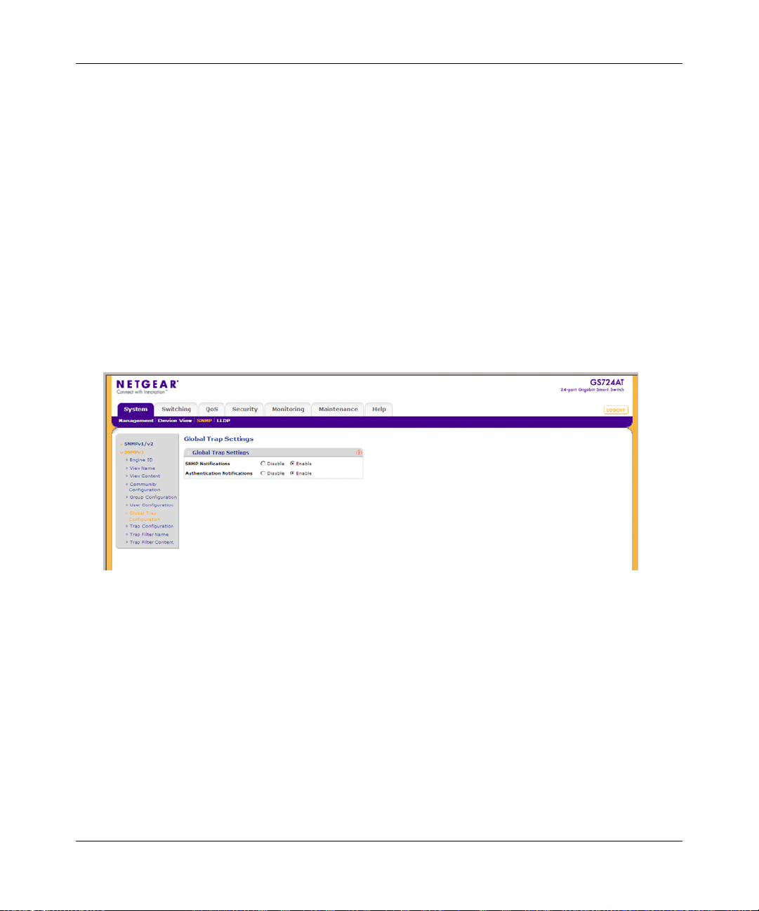
Global Trap Configuration
The SNMPv3 Global Trap Settings screen contains parameters for defining SNMP notification
parameters.
To configure SNMP notification global parameters:
1. Click System > SNMP > SNMPv3 > Global T rap Configuration . The SNMPv3 Global T rap
Settings screen displays:
Figure 3-14
The SNMPv3 Global Trap Settings screen contains the following fields:
• SNMP Notifications – Select whether or not the device can send SNMP notifications.
The possible field values are:
– Enable – Enable SNMP notifications.
– Disable – Disable SNMP notifications.
• Authentication Notifications – Select the SNMP authentication failure notification status
on the device. The possible field values are:
– Enable – Enable the device to send authentication failure notifications.
Managing System Settings 3-21
v1.0, March 2008
Page 57

GS700AT Series Smart Switch Software Administration Manual
– Disable – Disable the device from sending authentication failure notifications.
2. Select either Enable or Disable in the SNMP Notifications provided field.
3. Select either Enable or Disable in the Authentication Notifications provided field.
4. Click Apply to update the device.
Trap Con figuration
The SNMPv3 Trap Configuration screen contains information for defining filters that determine
whether traps are sent to specific users, and the trap type sent. SNMP notification filters provide
the following services:
• Identifying Management Trap Targets
• Defining Trap Filtering
• Selecting Trap Generation Parameters
• Providing Access Control Checks
To define trap station management:
1. Click System > SNMP > SNMPv3 > Trap Configuration. The SNMPv3 T rap Configuration
screen displays:
Figure 3-15
The SNMPv3 Trap Configuration screen contains the following fields:
• Recipients IP – Enter the IP address to which the traps are sent.
• Notification Type – Select the type of notification sent. The possible field values are:
– Traps – Traps are sent.
3-22 Managing System Settings
v1.0, March 2008
Page 58

GS700AT Series Smart Switch Software Administration Manual
– Informs – Informs are sent.
• User Name – Enter the user name. The field range is up to 30 alphanumeric characters.
• Security Level – Select the security level attached to the group. Security levels apply to
SNMPv3 only. The possible field values are:
– No Authentication – Neither the Authentication nor the Privacy security levels are
assigned to the group.
– Authentication – Authenticates SNMP messages and ensures that the SNMP
message’s origin is authenticated.
– Privacy – Encrypts SNMP messages.
• UDP Port – Enter the UDP port used to send notifications. The default is 162.
• Filter Name – Select the SNMP filter name from the list of SNMP Notification filters.
• Timeout – Enter the amount of time (in seconds) the device waits before re-sending
informs. The default is 15 seconds.
• Retries – Enter the amount of times the device re-sends an inform request. The default is 3
seconds.
2. Enter the Recipients IP address in the provided field in the first row.
3. Select either Traps or Informs in the Notification Type provided field in the first row.
4. Enter the User Name in the provided field in the first row.
5. Select the Security Level from the list in the provided field in the first row.
6. Enter the UDP Port in the provided field in the first row.
7. Select the Filter Name from the list in the provided field in the first row.
8. Enter the Timeout and Retries in the provided fields in the first row.
9. Click Apply to update the device.
To add a new trap:
1. Click System > SNMP > SNMPv3 > Trap Configuration. The SNMPv3 T rap Configuration
screen displays.
2. Enter the Recipients IP address in the provided field in the first row.
3. Select either Traps or Informs in the Notification Type provided field in the first row.
4. Enter the User Name in the provided field in the first row.
5. Select the Security Level from the list in the provided field in the first row.
Managing System Settings 3-23
v1.0, March 2008
Page 59

GS700AT Series Smart Switch Software Administration Manual
6. Enter the UDP Port in the provided field in the first row.
7. Select the Filter Name from the list in the provided field in the first row.
8. Enter the Timeout and Retries in the provided fields in the first row.
9. Click Add to update the device.
To remove a trap:
1. Click System > SNMP > SNMPv3 > Trap Configuration. The SNMPv3 T rap Configuration
screen displays.
2. Select the trap entry.
3. Click Delete to remove the entry.
Trap Filter Name
The SNMPv3 Trap Filter Name screen permits filtering traps based on OIDs. Each OID is linked
to a device feature or a portion of a feature. The SNMPv3 Trap Filter Name screen also allows
network managers to filter notifications.
To define the SNMPv3 Trap Filter Name:
1. Click System > SNMP > SNMPv3 > Trap Filter Name. The SNMPv3 T rap Filter Name
screen displays:
Figure 3-16
The SNMPv3 Trap Filter Name screen contains the following field:
• Filter Name – Enter the user-defined notification filter name.
2. Select the trap filter entry.
3-24 Managing System Settings
v1.0, March 2008
Page 60

GS700AT Series Smart Switch Software Administration Manual
3. Enter the trap Filter Name in the provided field in the first row.
4. Click Apply to update the device.
To add a new trap filter name:
1. Click System > SNMP > SNMPv3 > Trap Filter Name. The SNMPv3 T rap Filter Name
screen displays.
2. Enter the trap Filter Name in the provided field in the first row.
3. Click Add to update the device.
To remove a trap filter name:
1. Click System > SNMP > SNMPv3 > Trap Filter Name. The SNMPv3 T rap Filter Name
screen displays.
2. Select the trap filter name entry.
3. Click Delete to remove the entry.
Trap Filter Content
The SNMPv3 Trap Filter Content screen permits filtering traps based on OIDs. Each OID is linked
to a device feature or a portion of a feature. The SNMPv3 Trap Filter Content screen also allows
network managers to filter notifications.
To define SNMPv3 Trap Filter settings:
1. Click System > SNMP > SNMPv3 > Trap Filter Content. The SNMPv3 T rap Filter Content
screen displays:
Figure 3-17
The SNMPv3 Trap Filter Content screen contains the following fields:
Managing System Settings 3-25
v1.0, March 2008
Page 61

GS700AT Series Smart Switch Software Administration Manual
Trap Filter Settings
• Filter Name – Select the user-defined notification filter from the list.
Trap Filter Settings
• Object ID Subtree – Enter the OID for which notifications are sent or blocked. If a filter
is attached to an OID, traps or informs are generated and sent to the trap recipients. OIDs
are selected from either the Select field or the Object ID field.
• Filter Type – Select whether to send traps or informs relating to the selected OID. The
possible field values are:
– Excluded – Do not send traps or informs.
– Included – Send traps or informs.
2. Select the Filter Name from the list in the provided field.
3. Select the trap filter content entry from the OID table.
4. Enter the Object ID Subtree in the provided field in the first row.
5. Select the Filter Type from the list in the provided field in the first row.
6. Click Apply to update the device.
To add a new trap filter content entry:
1. Click System > SNMP > SNMPv3 > Trap Filter Content. The SNMPv3 T rap Filter Content
screen displays.
2. Select the Filter Name from the list in the provided field.
3. Enter the Object ID Subtree in the provided field in the first row.
4. Select the Filter Type from the list in the provided field in the first row.
5. Click Add to update the device.
To remove a trap filter content entry:
1. Click System > SNMP > SNMPv3 > Trap Filter Content. The SNMPv3 T rap Filter Content
screen displays.
2. Select the Filter Name from the list in the provided field.
3. Select the trap filter content entry.
4. Click Delete to remove the entry.
3-26 Managing System Settings
v1.0, March 2008
Page 62

GS700AT Series Smart Switch Software Administration Manual
LLDP
The Link Layer Discovery Protocol (LLDP) allows network managers to troubleshoot and
enhance network management by discovering and maintaining network topologies over multivendor environments. LLDP discovers network neighbors by standardizing methods for network
devices to advertise themselves to other system, and to store discovered information. Device
discovery information includes:
• Device Identification
• Device Capabilities
• Device Configuration
The advertising device transmits multiple advertisement message sets in a single LAN packet. The
multiple advertisement sets are sent in the packet Type Length Value (TLV) field. LLDP devices
must support chassis and port ID advertisement, as well as system name, system ID, system
description, and system capability advertisements.
The LLDP menu enables configuration of LLDP parameters and contains the following options:
• “Basic”
• “Advanced”
Basic
The LLDP Basic menu contains the following option:
• “LLDP Configuration”
LLDP Configuration
The Basic LLDP Configuration screen allows network managers to assign global LLDP and
LLDP-MED (LLDP – Media Endpoint Discovery) parameters.
Managing System Settings 3-27
v1.0, March 2008
Page 63

GS700AT Series Smart Switch Software Administration Manual
To configure LLDP settings:
1. Click System > LLDP > Basic > LLDP Configuration. The Basic LLDP Configuration
screen displays:
Figure 3-18
The Basic LLDP Configuration screen contains the following fields:
LLDP Properties
• LLDP – Select the LLDP global status on the device. The possible field values are:
– Disable – Disable LLDP on the device. This is the default value.
– Enable – Enable LLDP on the device.
• LLDPDU Handling – Select LLDPDU (LLDP Data Unit) packet handling when LLDP is
disabled. The possible field values are:
– Flooding – LLDPDU packets are flooded to all ports in the system.
– Filtering – LLDPDU packets are filtered. This is the default.
• TLV Advertised Interval – Enter the rate in seconds at which LLDP advertisement
updates are sent. The possible field range is 5 - 32768 seconds. The default value is 30
seconds.
• Hold Multiplier – Enter the amount of time that LLDP packets are held before the
packets are discarded, measured in multiples of the TLV Advertised Interval. The possible
field range is 2 - 10. The field default is 4. For example, if the TLV Advertised Interval is
30 seconds and the Hold Multiplier is 4, then the LLDP packets are discarded after 120
seconds.
3-28 Managing System Settings
v1.0, March 2008
Page 64

GS700AT Series Smart Switch Software Administration Manual
• Reinitializing Delay – Enter the amount of time in seconds that passes between disabling
and reinitializing LLDP. The possible field range is 1 - 10 seconds. The field default is 2
seconds.
• Transmit Delay – Enter the amount of time in seconds that passes between successive
LLDP frame transmissions due to changes in the LLDP local systems MIB. The possible
field value is 1 - 8192 seconds. The field default is 2 seconds.
LLDP-MED Properties
• Fast Start Duration – Enter the number of times LLDP packets are sent when the LLDP-
MED Fast Start mechanism is initialized, which occurs when a new Endpoint device links
with the LLDP-MED Network Connectivity Device.
2. Select the LLDP global status on the device by selecting Enable or Disable in the LLDP field.
3. If you selected Disable in the LLDP field, select the type of LLDPDU Handling from the list
in the provided field.
4. If you selected Enable in the LLDP field, enter the TLV Advertised Interval, Hold
Multiplier, Reinitializing Delay, Transmit Delay and Fast Start Duration in the provided
fields.
5. Click Apply to update the device.
Advanced
The LLDP Advanced menu contains the following options:
• “LLDP Configuration”
• “LLDP Port Settings”
• “LLDP-MED Network Policy”
• “LLDP-MED Port Settings”
• “Local Information”
• “Neighbors Information”
LLDP Configuration
The Advanced LLDP Configuration screen allows network managers to assign global LLDP and
LLDP-MED (LLDP – Media Endpoint Discovery) parameters.
Managing System Settings 3-29
v1.0, March 2008
Page 65

GS700AT Series Smart Switch Software Administration Manual
To configure LLDP settings:
1. Click System > LLDP > Advanced > LLDP Configuration. The Advanced LLDP
Configuration screen displays:
Figure 3-19
The Advanced LLDP Configuration screen contains the following fields:
LLDP Properties
• LLDP – Select the LLDP global status on the device. The possible field values are:
– Disable – Disable LLDP on the device. This is the default value.
– Enable – Enable LLDP on the device.
• LLDPDU Handling – Select LLDPDU (LLDP Data Unit) packet handling when LLDP is
disabled. The possible field values are:
– Flooding – LLDPDU packets are flooded to all ports in the system.
– Filtering – LLDPDU packets are filtered. This is the default.
• TLV Advertised Interval – Enter the rate in seconds at which LLDP advertisement
updates are sent. The possible field range is 5 - 32768 seconds. The default value is 30
seconds.
• Hold Multiplier – Enter the amount of time that LLDP packets are held before the
packets are discarded, measured in multiples of the TLV Advertised Interval. The possible
field range is 2 - 10. The field default is 4. For example, if the TLV Advertised Interval is
30 seconds and the Hold Multiplier is 4, then the LLDP packets are discarded after 120
seconds.
3-30 Managing System Settings
v1.0, March 2008
Page 66

GS700AT Series Smart Switch Software Administration Manual
• Reinitializing Delay – Enter the amount of time in seconds that passes between disabling
and reinitializing LLDP. The possible field range is 1 - 10 seconds. The field default is 2
seconds.
• Transmit Delay – Enter the amount of time in seconds that passes between successive
LLDP frame transmissions due to changes in the LLDP local systems MIB. The possible
field value is 1 - 8192 seconds. The field default is 2 seconds.
LLDP-MED Properties
• Fast Start Duration – Enter the number of LLDP packets sent when the LLDP-MED Fast
Start mechanism is initialized, which occurs when a new Endpoint device links with the
LLDP-MED Network Connectivity Device.
2. Select the LLDP global status on the device by selecting Enable or Disable in the LLDP field.
3. If you selected Disable in the LLDP field, select the type of LLDPDU Handling from the list
in the provided field.
4. If you selected Enable in the LLDP field, enter the TLV Advertised Interval, Hold
Multiplier, Reinitializing Delay, Transmit Delay and Fast Start Duration in the provided
fields.
5. Click Apply to update the device.
LLDP Port Settings
The LLDP Port Settings screen allows network administrators to define LLDP port settings,
including the port type, the LLDP port state, and the type of port information advertised.
Managing System Settings 3-31
v1.0, March 2008
Page 67
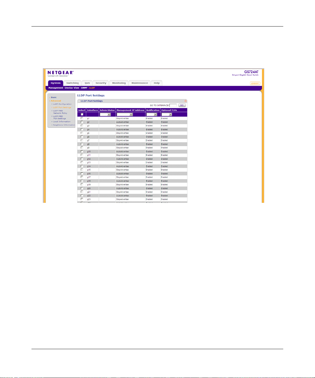
GS700AT Series Smart Switch Software Administration Manual
To define LLDP Port Properties:
1. Click System > LLDP > Advanced > LLDP Port Settings. The LLDP Port Settings screen
displays:
Figure 3-20
The LLDP Port Settings screen contains the following fields:
• Interface – Displays the specific interface for which LLDP parameters are defined.
• Admin Status – Select the LLDP packet transmitting and receiving status of the interface.
The possible field values are:
– Tx Only – Enable transmitting LLDP packets only.
– Rx Only – Enable receiving LLDP packets only.
– Tx & Rx – Enable transmitting and receiving LLDP packets.
– Disable – Disable LLDP on the interface.
• Management IP Address – Select the management IP address that is advertised from the
interface. The possible field values are:
– StopAdvertise – Stop advertising the management IP address from the interface.
3-32 Managing System Settings
v1.0, March 2008
Page 68

GS700AT Series Smart Switch Software Administration Manual
– AutoAdvertise – Advertise the device’s current IP address as the management IP
address.
• Notification – Select the topology change notification status on the interface.
– Enable – Enable topology change notification on the interface. This is the default
value.
– Disable – Disable topology change notification on the interface.
• Optional TLVs – Select whether optional TLVs are adve rtised from the interface.
– Enable – Enable optional TLVs on the interface. This is the default value.
– Disable – Disable optional TLVs on the interface.
2. Select the Interface to configure.
3. Select the Admin Status from the list in the provided field in the first row.
4. Select the Management IP Address from the list in the provided field in the first row.
5. Select the Notification status from the list in the provided field in the first row.
6. Select the Optional TLVs status from the list in the provided field in the first row.
7. Click Apply to update the device.
LLDP-MED Network Policy
LLDP Media Endpoint Discovery (LLDP-MED) increases network flexibility by allowing
different IP systems to coexist on a single network.
LLDP:
• Provides detailed network topology information, including what devices are located on the
network, and where the devices are located. For example, what IP phone is connected to what
port, what software is running on what switch, and what port is connected to what PC.
• Automatically deploys policies over networks for:
–QoS Policies
– Voice VLANs
• Provides Emergency Call Service (E-911) via IP Phone location information.
• Provides troubleshooting information. LLDP-MED sends network managers alerts for:
– Port speed and duplex mode conflicts
– QoS policy misconfigurations
Managing System Settings 3-33
v1.0, March 2008
Page 69

GS700AT Series Smart Switch Software Administration Manual
The LLDP-MED Network Policy screen allows network administrators to define LLDP-MED
network policies, which include the application, VLAN ID, VLAN type, user priority and DSCP
value.
To configure LLDP-MED Network Policy:
1. Click System > LLDP > Advanced > LLDP-MED Network Policy. The LLDP-MED
Network Policy screen displays:
Figure 3-21
The LLDP-MED Network Policy screen contains the following fields:
• Network Policy Number – Select the network policy number. The field range is 1 - 32.
• Application – Select the application for which the network policy is defined. The possible
field values are:
– Voice – The network policy is defined for a Voice application.
– Voice Signaling – The network policy is defined for a Voice Signaling application.
– Guest Voice – The network policy is defined for a Guest Voice application.
– Guest Voice Signaling – The network policy is defined for a Guest Voice Signaling
application.
– Softphone Voice – The network policy is defined for a Softphone Voice application.
– Video Conferencing – The network policy is defined for a Video Conferencing
application.
– Streaming Video – The network policy is defined for a Streaming Video application.
– Video Signaling – The network policy is defined for a Video Signaling application.
• VLAN ID – Enter the VLAN ID for which the network policy is defined.
3-34 Managing System Settings
v1.0, March 2008
Page 70

GS700AT Series Smart Switch Software Administration Manual
• VLAN Type – Select the VLAN type for which the network policy is defined. The
possible field values are:
– Tag ged – The network policy is defined for tagged VLANs.
– Untagged – The network policy is defined for untagged VLANs.
• User Priority – Select the priority assigned to the network application. The field range is
0 - 7.
• DSCP Value – Select the DSCP value assigned to the network policy. The possible field
value is 0 - 63.
2. Select the Network Policy entry to configure.
3. Select the Network Policy Number from the list in the provided field in the first row.
4. Enter the VLAN ID in the provided field in the first row.
5. Select the VLAN Type from the list in the provided field in the first row.
6. Select the User Priority from the list in the provided field in the first row.
7. Select the DSCP Value from the list in the provided field in the first row.
8. Click Apply to update the device.
To add a new network policy entry:
1. Click System > LLDP > Advanced > LLDP-MED Network Policy. The LLDP-MED
Network Policy screen displays.
2. Select the Network Policy Number from the list in the provided field in the first row.
3. Enter the VLAN ID in the provided field in the first row.
4. Select the VLAN Type from the list in the provided field in the first row.
5. Select the User Priority from the list in the provided field in the first row.
6. Select the DSCP Value from the list in the provided field in the first row.
7. Click Add to update the device.
To remove a network policy entry:
1. Click System > LLDP > Advanced > LLDP-MED Network Policy. The LLDP-MED
Network Policy screen displays.
2. Select the Network Policy entry.
3. Click Delete to remove the entry.
Managing System Settings 3-35
v1.0, March 2008
Page 71

GS700AT Series Smart Switch Software Administration Manual
LLDP-MED Port Settings
The LLDP-MED Port Settings screen contains parameters for assigning LLDP-MED network
policies to specific ports.
To configure LLDP-MED port settings:
1. Click System > LLDP > Advanced > LLDP-MED Port Settings. The LLDP-MED Port
Settings screen displays:
Figure 3-22
The LLDP-MED Port Settings screen contains the following fields:
• Port – Select the port to configure.
• LLDP-MED Status – Select the LLDP-MED status for the selected port. The possible
field values are:
– Enable – Enable LLDP-MED on the selected port.
– Disable – Disable LLDP-MED on the selected port.
• Notification – Select the notification status for the selected port. The possible field values
are:
– Enable – Enable notification on the selected port.
– Disable – Disable notification on the selected port.
• Network Policies – Click on the gold button to select the network policy numbers to apply
to the selected port.
2. Select the Port from the list in the provided field.
3. Select the LLDP-MED Status of the selected port from the list in the provided field.
3-36 Managing System Settings
v1.0, March 2008
Page 72

GS700AT Series Smart Switch Software Administration Manual
4. Select the Notification Status of the selected port from the list in the provided field.
5. Click on the Network Policies gold bar and select the network policy numbers to apply to the
port.
6. Click Apply to update the device.
Local Information
The LLDP Local Information screen enables viewing detailed port LLDP-MED information.
To view LLDP-MED port information:
1. Click System > LLDP > Advanced > Local Information. The LLDP-MED Local
Information screen displays:
Figure 3-23
The LLDP-MED Local Information screen contains the following fields:
Device Information
• Chassis ID Subtype – Displays the chassis ID type. For example, MAC address.
• Chassis ID – Displays the chassis identification of the device transmitting the LLDP
frame.
Managing System Settings 3-37
v1.0, March 2008
Page 73

GS700AT Series Smart Switch Software Administration Manual
• System Name – Displays the administratively assigned device name.
• System Description – Describes the device. For example, system hardware type and
version, operating system and network software.
• System Capabilities – Describes the primary device function. For example: Bridge,
Router.
Port Information
• Interface – Displays the port number.
• Port ID Subtype – Displays the port ID type. For example, MAC address.
• Port ID – Displays the port identification of the port transmitting the LLDP frame.
• Port Description – Displays information about the port, including manufacturer, product
name and hardware/software version.
• Advertisement – Displays the advertisement status of the port. The possible field values
are:
– Enabled – Advertisement is enabled on the port.
– Disabled – Advertisement is disabled on the port.
2. Click Refresh to refresh the Local Information screen.
To view LLDP-MED detailed port information:
1. Click System > LLDP > Advanced > Local Information. The LLDP-MED Local
Information screen displays.
3-38 Managing System Settings
v1.0, March 2008
Page 74

GS700AT Series Smart Switch Software Administration Manual
2. Click the Interface to view its detailed information. The Port Information window opens:
Figure 3-24
The Port Information window contains the following fields:
Managed Address
• Address Subtype – Displays the managed address subtype. For example, IPv4.
• Address – Displays the managed address.
• Interface Subtype – Displays the port subtype.
• Interface Number – Displays the port number.
MAC/PHY Details
• Auto-Negotiation Supported – Displays the port speed auto-negotiation support status.
The possible values are:
– True – Auto-negotiation is supported on the port.
– False – Auto-negotiation is not supported on the port.
• Auto-Negotiation Enabled – Displays the port speed auto-negotiation active status. The
possible values are:
Managing System Settings 3-39
v1.0, March 2008
Page 75

GS700AT Series Smart Switch Software Administration Manual
– Enabled – Auto-negotiation is enabled on the port.
– Disabled – Auto-negotiation is not enabled on the port.
• Auto-Negotiation Advertised Capabilities – Displays the port speed auto-negotiation
capabilities. For example, 1000BASE-T half duplex mode, 100BASE-TX full duplex
mode.
• Operational MAU Type – Displays the Medium Attachment Unit (MAU) type. The
MAU performs physical layer functions, including digital data conversion from the
Ethernet interfaces’ collision detection and bit injection into the network. For example,
100BASE-TX full duplex mode.
MED Details
• Capabilities Supported – Displays the MED capabilities enabled on the port.
• Current Capabilities – Capabilities indicates the TLV is advertised by the port.
• Device Class – Network Connectivity indicates the device is a network connectivity
device
Network Policies
• Application Type – Displays the network policy application type. For example, Voice.
• VLAN ID – Displays the network policy VLAN ID.
• VLAN Type – Displays the VLAN type for which the network policy is defined. The
possible field values are:
– Tag ged – The network policy is defined for tagged VLANs.
– Untagged – The network policy is defined for untagged VLANs.
• User Priority – Displays the network policy user priority.
• DSCP – Displays the network policy DSCP.
3. Click the Network Policies gold bar to display the network policies applied to the port.
Neighbors Information
The LLDP Neighbors Information screen contains information received from neighboring device
LLDP advertisements.
3-40 Managing System Settings
v1.0, March 2008
Page 76

GS700AT Series Smart Switch Software Administration Manual
To view LLDP neighbors information:
1. Click System > LLDP > Advanced > Neighbors Information. The LLDP Neighbors
Information screen displays:
Figure 3-25
The LLDP Neighbors Information screen contains the following fields:
• MSAP Entry – Displays the device’s Media Service Access Point (MSAP) entry number.
• Local Port – Displays the port number.
• Chassis ID Subtype – Displays the chassis ID subtype. For example, MAC address.
• Chassis ID – Displays the chassis identification of the device transmitting the LLDP
frame.
• Port ID Subtype – Displays the port ID subtype. For example, MAC address.
• Port ID – Displays the port identification of the port transmitting the LLDP frame.
• System Name – Displays the administratively assigned device name.
2. Click Refresh to refresh the Neighbors Information screen.
To view LLDP Neighbors detailed information:
1. Click System > LLDP > Advanced > Neighbors Information. The LLDP Neighbors
Information screen displays.
Managing System Settings 3-41
v1.0, March 2008
Page 77

GS700AT Series Smart Switch Software Administration Manual
2. Click the MSAP Entry to view its detailed information. The Neighbors Information window
opens:
Figure 3-26
3-42 Managing System Settings
v1.0, March 2008
Page 78

GS700AT Series Smart Switch Software Administration Manual
The Neighbors Information window contains the following fields:
Port Details
• Local Port – Displays the port number.
• MSAP Entry – Displays the device’s Media Service Access Point (MSAP) entry number.
Basic Details
• Chassis ID Subtype – Displays the chassis ID subtype. For example, MAC address.
• Chassis ID – Displays the chassis identification of the device transmitting the LLDP
frame.
• Port ID Subtype – Displays the port ID subtype. For example, IPv4 address.
• Port ID – Displays the port identification of the port transmitting the LLDP frame.
• Port Description – Displays information about the port, including manufacturer, product
name and hardware/software version.
• System Name – Displays the administratively assigned device name.
• System Description – Describes the device. For example, system hardware type and
version, operating system and network software.
• System Capabilities – Describes the primary device function. For example: Bridge,
Router.
Managed Address
• Address Subtype – Displays the managed address subtype. For example, MAC or IPv4.
• Address – Displays the managed address.
• Interface Subtype – Displays the port subtype.
• Interface Number – Displays the port number.
MAC/PHY Details
• Auto-Negotiation Supported – Displays the port speed auto-negotiation support status.
The possible values are:
– True – Auto-negotiation is supported on the port.
– False – Auto-negotiation is not supported on the port.
• Auto-Negotiation Enabled – Displays the port speed auto-negotiation active status. The
possible values are:
– Enabled – Auto-negotiation is enabled on the port.
Managing System Settings 3-43
v1.0, March 2008
Page 79

GS700AT Series Smart Switch Software Administration Manual
– Disabled – Auto-negotiation is not enabled on the port.
• Auto-Negotiation Advertised Capabilities – Displays the port speed auto-negotiation
capabilities. For example, 1000BASE-T half duplex mode, 100BASE-TX full duplex
mode.
• Operational MAU Type – Displays the Medium Attachment Unit (MAU) type. The
MAU performs physical layer functions, including digital data conversion from the
Ethernet interfaces’ collision detection and bit injection into the network. For example,
100BASE-TX full duplex mode.
MED Details
• Capabilities Supported – Displays the MED capabilities enabled on the port.
• Current Capabilities – Displays the MED TLVs advertised by the port.
• Device Class – Displays the LLDP-MED endpoint device class. The possible device
classes are:
– Endpoint Class 1 – Indicates a generic endpoint class, offering basic LLDP services.
– Endpoint Class 2 – Indicates a media endpoint class, offering media streaming
capabilities as well as all Class 1 features.
– Endpoint Class 3 – Indicates a communications device class, offering all Class 1 and
Class 2 features plus location, 911, Layer 2 switch support and device information
management capabilities.
• PoE Device Type – Displays the port PoE type. For example, Powered.
• PoE Power Source – Displays the port’s power source.
• PoE Power Priority – Displays the port’s power priority.
• PoE Power Value – Displays the port’s power value.
• Hardware Revision – Displays the hardware version.
• Firmware Revision – Displays the firmware version.
• Software Revision – Displays the software version.
• Serial Number – Displays the device serial number.
• Model Name – Displays the device model name.
• Asset ID – Displays the asset ID.
3-44 Managing System Settings
v1.0, March 2008
Page 80

GS700AT Series Smart Switch Software Administration Manual
Location Information
• Civic – Displays the device’s civic or street address location. For example, 123 45th St E.
The field value length range is 6 - 160 characters.
• Coordinates – Displays the device’s location map coordinates - latitude, longitude and
altitude.
• ECS ELIN – Displays the device’s Emergency Call Service (ECS) Emergency Location
Identification Number (ELIN). The field range is 10 - 25.
• Unknown – Displays unknown location information.
Network Policies
• Application Type – Displays the network policy application type. For example, Voice.
• VLAN ID – Displays the VLAN ID for which the network policy is defined.
• VLAN Type – Displays the VLAN type for which the network policy is defined. The
possible field values are:
– Tag ged – The network policy is defined for tagged VLANs.
– Untagged – The network policy is defined for untagged VLANs.
• User Priority – Displays the network policy user priority.
• DSCP – Displays the network policy DSCP.
LLDP Unknown TLVs
• Type – Displays the unknown TLV type field.
• Value – Displays the unknown TLV value field.
3. Click the Network Policies gold bar to display the network policies applied to the MSAP
entry.
4. Click the LLDP Unknown TLVs gold bar to display the MSAP entry’s unknown TLVs.
Managing System Settings 3-45
v1.0, March 2008
Page 81

GS700AT Series Smart Switch Software Administration Manual
3-46 Managing System Settings
v1.0, March 2008
Page 82

Chapter 4
Configuring Switching Settings
Configuring Switching Settings
The navigation pane at the top of the web browser interface contains a Switching tab that enables
you to manage your GS700AT Series Smart Switch with features under the following main
headings:
• “Ports”
• “LAG”
• “VLAN”
• “Voice VLAN”
• “STP”
• “Multicast”
• “Address Table”
The description that follows in this chapter describes configuring and managing switching settings
in the GS700AT Series Smart Switch.
Ports
The Ports menu contains the following option:
• “Port Configuration”
Port Configuration
The Port Configuration screen contains fields for defining port parameters enabled on the ports.
4-1
v1.0, March 2008
Page 83
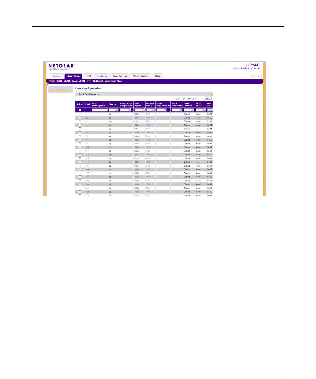
GS700AT Series Smart Switch Software Administration Manual
To configure port parameters:
1. Click Switching > Ports > Port Configuration. The Port Configuration screen displays:
Figure 4-1
The Port Configuration screen contains the following fields:
• Port – Displays the port number.
• Port Description – Enter a user-defined port description.
• Status – Select the port’s operational status. The possible field values are:
– Up – The port is operational.
– Down – The port is not operational.
• Reactivate Suspended – Select the reactivation status for a port disabled through the
locked port security option. The possible field values are:
– Enable – Enable reactivation.
– Disable – Disable reactivation.
4-2 Configuring Switching Settings
v1.0, March 2008
Page 84

GS700AT Series Smart Switch Software Administration Manual
• Port Speed – Select the data transmission rate for the port. The port type determines
which speed setting options are available. Port speeds can only be configured when auto
negotiation is disabled. The possible field values are:
– 10M – The port is currently operating at 10 Mbps.
– 100M – The port is currently operating at 100 Mbps.
– 1000M – The port is currently operating at 1000 Mbps.
• Duplex Mode – Select the port duplex mode. This field is configurable only when auto
negotiation is disabled and the port speed is set to 10M or 100M. The possible field values
are:
– Half – The interface supports transmission between the device and the client in only
one direction at a time.
– Full – The interface supports transmission between the device and its link partner in
both directions simultaneously.
– Auto – The interface supports transmission between the device and the link partner
based on the transmission mode of the link partner.
• Auto Negotiation – Select the port auto negotiation status. Auto negotiation is a protocol
between two link partners that enables a port to advertise its transmission rate, duplex
mode, and flow control abilities to its partner. The possible field values are:
– Enable – Enable auto negotiation.
– Disable – Disable auto negotiation.
• Back Pressure – Select the back pressure mode of the Port. Back Pressure mode is used
with half duplex mode to disable ports from receiving messages. Back Pressure mode is
disabled by default. The possible field values are:
– Enable – Enable back pressure mode.
– Disable – Disable back pressure mode.
• Flow Control – Select the flow control status of the port. Operates when the port is in full
duplex mode. Flow control is disabled by default. The possible field values are:
– Enable – Enable flow control.
– Disable – Disable Flow control.
Configuring Switching Settings 4-3
v1.0, March 2008
Page 85

GS700AT Series Smart Switch Software Administration Manual
• MDI/MDIX – Select the MDI/MDIX status of the port. Hubs and switches are
deliberately wired opposite the way end stations are wired, so that when a hub or switch is
connected to an end station, a straight through Ethernet cable can be used and the pairs
will match up properly . When two hubs or switches are connected to each other or two end
stations are connected to each other, a crossover cable is used to ensure that the correct
pairs are connected. The possible field values are:
– Auto – Provide automatic cable type detection.
– MDI (Media Dependent Interface) – Connect end stations.
– MDIX (Media Dependent Interface with Crossover) – Connect HUBs and switches.
• LAG ID – Select the LAG ID to which the selected port is assigned.
2. Select the interface.
3. Enter or modify the fields in the first row.
4. Click Apply to update the device.
LAG
A Link Aggregated Group (LAG) optimizes port usage by linking a group of ports together to
form a single LAG. Aggregating ports multiplies the bandwidth between the devices, increases
port flexibility, and provides link redundancy. Ports added to a LAG lose their individual port
configuration. When ports are removed from the LAG, the original port configuration is applied to
the ports. Ensure the following, when configuring LAGs:
• All ports within a LAG must be of the same media type.
• A VLAN is not configured on the port.
• The port is not assigned to a different LAG.
• Auto-negotiation mode is not configured on the port.
• The port is in full-duplex mode.
• All ports in the LAG have the same ingress filtering and tagged modes.
• All ports in the LAG have the same back pressure and flow control modes.
• All ports in the LAG have the same priority.
• All ports in the LAG have the same transceiver type.
• The device supports up to eight LAGs with eight ports in each LAG.
4-4 Configuring Switching Settings
v1.0, March 2008
Page 86

GS700AT Series Smart Switch Software Administration Manual
• LACP LAGs support up to 16 ports, with eight ports active at any given time.
The LAG menu contains the following options:
• “Basic”
• “Advanced”
Basic
The LAG Basic menu contains the following options:
• “LAG Configuration”
• “LAG Membership”
LAG Configuration
The Basic LAG Configuration screen contains fields for configuring LAG parameters. The system
supports 8 LAGs, and each LAG can contain up to 8 ports.
To define LAG parameters:
1. Click Switching > LAG > Basic > LAG Configuration. The Basic LAG Configuration
screen displays:
Figure 4-2
The Basic LAG Configuration screen contains the following fields:
• Interface – Displays the LAG number.
• Description – Enter a user-defined LAG description.
• Status – Select the current link operation. The possible field values are:
Configuring Switching Settings 4-5
v1.0, March 2008
Page 87

GS700AT Series Smart Switch Software Administration Manual
– Up – The LAG is currently linked and forwarding traffic.
– Down – The LAG is currently not linked.
• Reactivate Suspended – Select the action to apply to a suspended LAG. The possible
field values are:
– Enable – Reactivate the suspended LAG.
– Disable – Do not reactivate the suspended LAG.
• Type – Displays the LAG type. The possible field values are:
– Static – The LAG is configured manually.
– LACP – The LAG is configured automatically.
• Speed – Select the data transmission rate for the LAG. The LAG type determines what
speed setting options are available. The possible field values are:
– 10M – The LAG is currently operating at 10 Mbps.
– 100M – The LAG is currently operating at 100 Mbps.
– 1000M – The LAG is currently operating at 1000 Mbps.
• Duplex Mode – Displays the duplex mode of the LAG. The possible field value is:
– Full – The interface supports transmission between the device and its link partner in
both directions simultaneously.
• Auto Negotiation – Select the auto negotiation status of the LAG. Auto Negotiation is a
protocol between two link partners that enables a port to advertise its transmission rate,
duplex mode, and flow control abilities to its partner. Auto Negotiation is enabled by
default. The possible field values are:
– Enable – Enable auto negotiation.
– Disable – Disable auto negotiation.
• Flow Control – Select the flow control status of the LAG. Operates when the LAG is in
full duplex mode. Flow Control is disabled by default. The possible field values are:
– Enable – Enable flow control.
– Disable – Disable flow control.
2. Select the interface.
3. Enter or modify the fields in the first row.
4. Click Apply to update the device.
4-6 Configuring Switching Settings
v1.0, March 2008
Page 88

GS700AT Series Smart Switch Software Administration Manual
LAG Membership
The Basic LAG Membership screen allows network managers to assign ports to LAGs.
To assign ports to LAGs:
1. Click Switching > LAG > Basic > LAG Membership. The Basic LAG Membership screen
displays:
Figure 4-3
The Basic LAG Membership screen contains the following fields:
• LAG ID – Select the LAG ID.
• LAG Name – Displays the user-defined LAG name.
• LAG Type – Select the LAG type. The possible field values are:
– Static – The LAG is configured manually.
– LACP – The LAG is configured dynamically.
2. Select the LAG ID and LAG Type.
3. Click on the gold button. The port panel displays.
4. Select the ports to be members of the LAG.
5. Click Apply to update the device.
Configuring Switching Settings 4-7
v1.0, March 2008
Page 89

GS700AT Series Smart Switch Software Administration Manual
6. Click CURRENT MEMBERS. The Current Members window opens and displays the
member ports included in the LAG:
Figure 4-4
Advanced
The LAG Advanced menu contains the following options:
• “LAG Configuration”
• “LAG Membership”
• “LACP Configuration”
• “LACP Port Configuration”
LAG Configuration
The Advanced LAG Configuration screen contains fields for configuring LAG parameters. The
system supports 8 LAGs, and each LAG can contain up to 8 ports.
4-8 Configuring Switching Settings
v1.0, March 2008
Page 90

GS700AT Series Smart Switch Software Administration Manual
To define LAG parameters:
1. Click Switching > LAG > Advanced > LAG Configuration. The Advanced LAG
Configuration screen displays:
Figure 4-5
The Advanced LAG Configuration screen contains the following fields:
• Interface – Displays the LAG number.
• Description – Enter a user-defined LAG description.
• Status – Select the current link operation. The possible field values are:
– Up – The LAG is currently linked and forwarding traffic.
– Down – The LAG is currently not linked.
• Reactivate Suspended – Select the action to apply to a suspended LAG. The possible
field values are:
– Enable – Reactivate the suspended LAG.
– Disable – Do not reactivate the suspended LAG.
• Type – Displays the LAG Type. The possible field values are:
– Static – The LAG is configured manually.
– LACP – The LAG is configured automatically.
• Speed – Select the data transmission rate for the LAG. The LAG type determines what
speed setting options are available. LAG speeds can only be configured when auto
negotiation is disabled. The possible field values are:
Configuring Switching Settings 4-9
v1.0, March 2008
Page 91

GS700AT Series Smart Switch Software Administration Manual
– 10M – The LAG is currently operating at 10 Mbps.
– 100M – The LAG is currently operating at 100 Mbps.
– 1000M – The LAG is currently operating at 1000 Mbps.
• Duplex Mode – Displays the duplex mode of the LAG. The possible field value is:
– Full – The interface supports transmission between the device and its link partner in
both directions simultaneously.
• Auto Negotiation – Select the auto negotiation status of the LAG. Auto Negotiation is a
protocol between two link partners that enables a port to advertise its transmission rate,
duplex mode, and flow control abilities to its partner. Auto Negotiation is enabled by
default. The possible field values are:
– Enable – Enable auto negotiation.
– Disable – Disable auto negotiation.
• Flow Control – Select the flow control status of the LAG. Operates when the port is in full
duplex mode. Flow Control is disabled by default. The possible field values are:
– Enable – Enable flow control.
– Disable – Disable flow control.
2. Select the interface.
3. Enter or modify the fields in the first row.
4. Click Apply to update the device.
4-10 Configuring Switching Settings
v1.0, March 2008
Page 92

GS700AT Series Smart Switch Software Administration Manual
LAG Membership
The Advanced LAG Membership screen allows network managers to assign ports to LAGs.
To assign ports to LAGs:
1. Click Switching > LAG > Advanced > LAG Membership. The Advanced LAG
Membership screen displays:
Figure 4-6
The Advanced LAG Membership screen contains the following fields:
• LAG ID – Select the LAG ID.
• LAG Name – Displays the user-defined LAG name.
• LAG Type – Select the LAG type. The possible field values are:
– Static – The LAG is configured manually.
– LACP – The LAG is configured automatically.
2. Select the LAG ID and LAG Type.
3. Click on the gold button. The port panel displays.
4. Select the ports to be members of the LAG.
5. Click Apply to update the device.
Configuring Switching Settings 4-11
v1.0, March 2008
Page 93

GS700AT Series Smart Switch Software Administration Manual
6. Click CURRENT MEMBERS. The Current Members window opens and displays the
member ports included in the LAG:
Figure 4-7
LACP Configuration
Aggregated links can be set up manually or automatically established by enabling LACP on the
relevant links. Aggregated ports can be linked into link-aggregation port-groups. Each group is
comprised of ports with the same speed. The LACP Configuration screen contains fields for
configuring LACP.
To configure LACP:
1. Click Switching > LAG > Advanced > LACP Configuration. The LACP Configuration
screen displays:
Figure 4-8
4-12 Configuring Switching Settings
v1.0, March 2008
Page 94

GS700AT Series Smart Switch Software Administration Manual
The LACP Configuration screen contains the following field:
• LACP System Priority – Enter the system priority value. The field range is 1-65535. The
field default is 1.
2. Enter the LACP System Priority in the provided field.
3. Click Apply to update the device.
LACP Port Configuration
To configure LACP port priority:
1. Click Switching > LAG > Advanced > LACP Port Configuration. The LACP Port
Configuration screen displays:
Figure 4-9
The LACP Port Configuration screen contains the following fields:
• Interface – Displays the interface number to which timeout and priority values are
assigned.
• LACP Priority – Enter the port priority value. The field range is 1-65535.
• Timeout – Select the administrative LACP timeout. The possible field values are:
– Long – A long timeout value (90 seconds). This is the default.
Configuring Switching Settings 4-13
v1.0, March 2008
Page 95

GS700AT Series Smart Switch Software Administration Manual
– Short – A short timeout value (3 seconds).
2. Select the interface.
3. Enter the LACP Priority and select the Timeout in the provided fields in the first row.
4. Click Apply to update the device.
VLAN
VLANs are logical subgroups with a Local Area Network (LAN) which combine user stations and
network devices into a single unit, regardless of the physical LAN segment to which they are
attached. VLANs allow network traffic to flow more efficiently within subgroups. VLANs use
software to reduce the amount of time it takes for network changes, additions, and moves to be
implemented.
VLANs have no minimum number of ports, and can be created per unit, per device, or through any
other logical connection combination, since they are software-based and not defined by physical
attributes.
VLANs function at Layer 2. Since VLANs isolate traffic within the LAN, a Layer 3 router
working at a protocol level is required to allow traffic flow between VLANs. Layer 3 routers
identify segments and coordinate with VLANs. VLANs are Broadcast and Multicast domains.
Broadcast and Multicast traffic is transmitted only in the VLAN in which the traffic is generated.
VLAN tagging provides a method of transferring VLAN information between VLAN groups.
VLAN tagging attaches a 4-byte tag to packet headers. The VLAN tag indicates to which VLAN
the packets belong. VLAN tags are attached to the VLAN by either the end station or the network
device. VLAN tags also contain VLAN network priority information.
The VLAN menu contains the following options:
• “Basic”
• “Advanced”
Basic
The VLAN Basic menu contains the following options:
• “VLAN Configuration”
4-14 Configuring Switching Settings
v1.0, March 2008
Page 96

GS700AT Series Smart Switch Software Administration Manual
VLAN Configuration
The Basic VLAN Configuration screen provides information and parameters for configuring and
working with VLANs. The maximum number of active VLANs is 12 8.
To define VLAN properties:
1. Click Switching > VLAN > Basic > VLAN Configuration. The Basic VLAN Configuration
screen displays:
Figure 4-10
The Basic VLAN Configuration screen contains the following fields:
• VLAN ID – Enter the VLAN ID. The field range is 2-4093.
• VLAN Name – Enter the user-defined VLAN name.
• Type – Displays the VLAN type. The possible field values are:
– Static – The VLAN is user-defin e d.
– Default – The default VLAN ID is 1. It cannot be modified by the user.
2. Select the VLAN entry.
3. Enter the VLAN ID and VLAN Name in the provided fields in the first row.
4. Click Apply to update the device.
To add a new VLAN:
1. Click Switching > VLAN > Basic > VLAN Configuration. The Basic VLAN Configuration
screen displays.
2. Enter the VLAN ID and VLAN Name in the provided fields in the first row.
3. Click Add to update the device.
Configuring Switching Settings 4-15
v1.0, March 2008
Page 97

GS700AT Series Smart Switch Software Administration Manual
To remove a VLAN:
1. Click Switching > VLAN > Basic > VLAN Configuration. The Basic VLAN Configuration
screen displays.
2. Select the VLAN entry.
3. Click Delete to remove the entry.
Advanced
The VLAN Advanced menu contains the following options:
• “VLAN Configuration”
• “VLAN Membership”
• “Port PVID Configuration”
VLAN Configuration
The Advanced VLAN Configuration screen provides information and parameters for configuring
and working with VLANs. The maximum number of active VLANs is 128.
To define VLAN properties:
1. Click Switching > VLAN > Advanced > VLAN Configuration. The Advanced VLAN
Configuration screen displays:
Figure 4-11
The Advanced VLAN Configuration screen contains the following fields:
• VLAN ID – Enter the VLAN ID. The field range is 2-4093.
• VLAN Name – Enter the user-defined VLAN name.
• Type – Displays the VLAN type. The possible field values are:
4-16 Configuring Switching Settings
v1.0, March 2008
Page 98

GS700AT Series Smart Switch Software Administration Manual
– Static – The VLAN is user-defin e d.
– Default – The VLAN is the default VLAN. The default VLAN is enabled by default.
2. Select the VLAN entry.
3. Enter the VLAN ID and VLAN Name in the provided fields in the first row.
4. Click Apply to update the device.
To add a new VLAN:
1. Click Switching > VLAN > Advanced > VLAN Configuration. The Advanced VLAN
Configuration screen displays.
2. Enter the VLAN ID and VLAN Name in the provided fields in the first row.
3. Click Add to update the device.
To remove a VLAN:
1. Click Switching > VLAN > Advanced > VLAN Configuration. The Advanced VLAN
Configuration screen displays.
2. Select the VLAN entry.
3. Click Delete to remove the entry.
VLAN Membership
The VLAN Membership screen contains a table that maps ports to VLANs. Ports are assigned
VLAN membership by toggling through the Port Control settings.
Configuring Switching Settings 4-17
v1.0, March 2008
Page 99

GS700AT Series Smart Switch Software Administration Manual
To define VLAN group membership:
1. Click Switching > VLAN > Advanced > VLAN Membership. The VLAN Membership
screen displays:
Figure 4-12
The VLAN Membership screen contains the following fields:
• VLAN ID – Select the VLAN ID to be displayed and configured. VLAN ID = 1 cannot be
modified.
• VLAN Name – Displays the name of the VLAN.
• VLAN Type – Displays the VLAN type. The possible field values are:
– Static – The VLAN is user-defin e d.
– Default – The VLAN is the default VLAN. The default VLAN is enabled.
• Group Operation – Select the VLAN membership for all ports and LAGs. The possible
field values are:
– Tag All – Defines all selected interfaces as tagged VLAN members. Packets
belonging to the respective VLAN are tagged. The packets contain VLAN
information.
– Untag All – Defines all selected interfaces as untagged VLAN members. Packets
belonging to the respective VLAN are untagged.
– Remove All – Remove all the interfaces participating in the VLAN.
2. Select the VLAN ID from the list in the provided field.
3. Select the Group Operation from the list in the provided field.
4-18 Configuring Switching Settings
v1.0, March 2008
Page 100
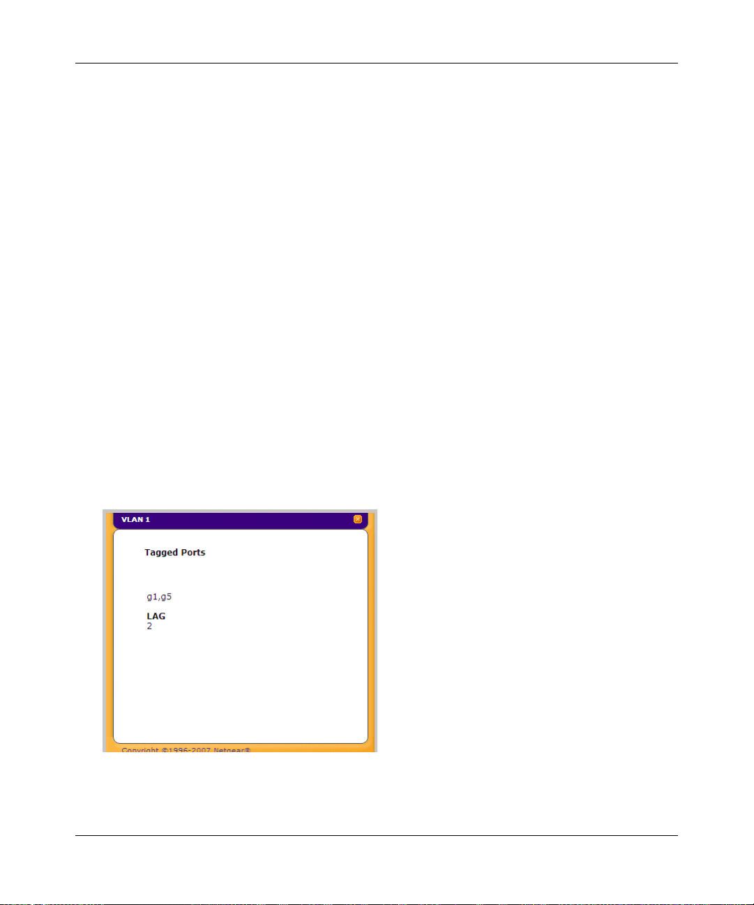
GS700AT Series Smart Switch Software Administration Manual
4. Click Apply to update the device.
To tag or untag selected ports or LAGs:
1. Click Switching > VLAN > Advanced > VLAN Membership. The VLAN Membership
screen displays.
2. Click a gold button to display the ports or LAGs.
3. Click the boxes below the selected ports or LAGs to mark them as tagged (T) or untagged (U).
4. Click Apply to update the device.
To tag or untag all the ports or all the LAGs:
1. Click Switching > VLAN > Advanced > VLAN Membership. The VLAN Membership
screen displays.
2. Click the quick box or the LAG quick box, repeatedly if necessary, until a T or U appears in
the quick box, marking all the ports or LAGs as tagged or untagged, respectively.
3. Click Apply to update the device.
To view VLAN tagged port members:
1. Click Switching > VLAN > Advanced > VLAN Membership. The VLAN Membership
screen displays.
2. Click TAGGED PORT MEMBERS. The VLAN Tagged Ports window opens:
Figure 4-13
Configuring Switching Settings 4-19
v1.0, March 2008
 Loading...