

Page 1

SW510.bk Page i Wednesday, March 12, 1997 10:49 AM
Installation Guide for
the Model SW510
and Model SW518
Ethernet Switches
NETGEAR
A Bay Networks Company
48015 Warm Springs Blvd.
Fremont, CA 94539
USA
M-SW510NA-0
March 1997
, Inc.
Page 2

SW510.bk Page ii Wednesday, March 12, 1997 10:49 AM
© 1997 by NETGEAR, Inc. All rights reserved.
Trademarks
Bay Networks is a registered trademark of Bay Networks, Inc. NETGEAR is a trademark of Bay Networks, Inc.
Other brand and product names are registered trademarks or trademarks of their respective holders.
Statement of Conditions
In the interest of improving internal design, operational function, and/or reliability, NETGEAR reserves the right to
make changes to the products described in this document without notice.
NETGEAR does not assume any liability that may occur due to the use or application of the product(s) or circuit
layout(s) described herein.
Federal Communications Commission (FCC) Declaration of Conformity Statement
Note: This equipment has been tested and found to comply with the limits for a Class A digital device, pursuant to
Part 15 of the FCC rules. These limits are designed to provide reasonable protection against harmful interference when
the equipment is operated in a commercial environment. This equipment generates, uses, and can radiate radio frequenc y
energy. If it is not installed and used in accordance with the instruction manual, it may cause harmful interference to
radio communications. Operation of this equipment in a residential area is likely to cause harmful interference, in which
case users will be required to take whatever measures may be necessary to correct the interference at their own expense.
EN 55 022 Statement
This is to certify that the NETGEAR Model SW510 and Model SW518 Ethernet Switches are shielded against the
generation of radio interference in accordance with the application of Council Directive 89/336/EEC, Article 4a.
Conformity is declared by the application of EN 55 022 Class A (CISPR 22).
Warning:
This is a Class A product. In a domestic environment, this product may
cause radio interference, in which case, the user may be required to take appropriate
measures.
Bestätigung des Herstellers/Importeurs
Es wird hiermit bestätigt, daß das NETGEAR Model SW510 and Model SW518 Ethernet Switches gemäß der im
BMPT -AmtsblVfg 243/1991 und Vfg 46/1992 aufgeführten Bestimmungen entstört ist. Das v orschriftsmäßige Betreiben
einiger Geräte (z.B. Testsender) kann jedoch gewissen Beschränkungen unterliegen. Lesen Sie dazu bitte die
Anmerkungen in der Betriebsanleitung.
Das Bundesamt für Zulassungen in der Telekommunikation wurde davon unterrichtet, daß dieses Gerät auf den Markt
gebracht wurde und es ist berechtigt, die Serie auf die Erfüllung der Vorschriften hin zu überprüfen.
ii
Page 3

SW510.bk Page iii Wednesday, March 12, 1997 10:49 AM
Voluntary Control Council for Interference (VCCI) Statement
This equipment is in the first category (information equipment to be used in commercial and/or industrial areas) and
conforms to the standards set by the Voluntary Control Council for Interference by Data Processing Equipment and
Electronic Office Machines that are aimed at preventing radio interference in commercial and/or industrial areas.
Consequently, when this equipment is used in a residential area or in an adjacent area thereto, radio interference may be
caused to equipment such as radios and TV receivers.
Customer Support
For assistance with installing and configuring your NETGEAR system or with post-installation questions or problems,
contact your point of purchase representative.
To contact customer support or to purchase additional copies of this document and publications for other NETGEAR
products, you can contact NETGEAR at the following numbers:
• Phone:
U.S./Canada: 1-800-211-2069
Japan: 0031-1-26133
Europe: (44) 171-571-5120
• Fax:
U.S./Canada: 510-498-2609
W orld Wide Web
NETGEAR maintains a World Wide Web home page that you can access at the universal resource locator (URL)
http://NETGEAR.baynetworks.com. A direct connection to the Internet and a Web browser such as Internet Explorer or
Netscape are required.
iii
Page 4

SW510.bk Page iv Wednesday, March 12, 1997 10:49 AM
iv
Page 5

SW510.bk Page v Wednesday, March 12, 1997 10:49 AM
Chapter 1
Introduction
Benefits of Using Switching Technology .........................................................................1-1
Overview of the Switches ...............................................................................................1-1
Features .........................................................................................................................1-2
Chapter 2
Physical Description
Front Panel .....................................................................................................................2-1
Ethernet Ports ..........................................................................................................2-2
Normal/Uplink Push Button ......................................................................................2-3
LEDs ........................................................................................................................2-4
Rear Panel ......................................................................................................................2-5
HDX/FDX/AUTO Duplex Toggle Switches ................................................................2-6
Contents
Chapter 3
Applications
Desktop Switching ..........................................................................................................3-1
Network Segmentation ...................................................................................................3-2
Bridging from 10 Mbps to 100 Mbps Networks ...............................................................3-4
Chapter 4
Installation
Site Preparation ..............................................................................................................4-1
Package Contents ..........................................................................................................4-1
Installing a Switch ...........................................................................................................4-2
Installing the Switch on a Flat Surface .....................................................................4-2
Installing the Switch in a Rack .................................................................................4-3
Connecting Devices to the Switch ..................................................................................4-4
Verifying Installation ........................................................................................................4-6
Chapter 5
Contents v
Page 6

SW510.bk Page vi Wednesday, March 12, 1997 10:49 AM
Troubleshooting
LEDs ............................................................................................................................... 5-1
HDX/FDX/AUTO Duplex Toggle Switches ......................................................................5-1
Installation ......................................................................................................................5-2
Cabling ...........................................................................................................................5-2
Network Adapter Cards ..................................................................................................5-2
Configuration ..................................................................................................................5-2
Switch Integrity ...............................................................................................................5-2
Appendix A
Technical Specifications
General Specifications ................................................................................................... A-1
Appendix B
Connector Pin Assignments
RJ-45 Plug and vista RJ-45 Connector ......................................................................... B-1
Appendix C
Ethernet and Cabling Guidelines
Ethernet T echnology ...................................................................................................... C-1
Cable Specifications ......................................................................................................C-2
Twisted Pair Cables ....................................................................................................... C-2
vi Contents
Page 7

SW510.bk Page vii Wednesday, March 12, 1997 10:49 AM
Figure 2-1. Front panel of the Model SW510 switch ..................................................2-1
Figure 2-2. Front panel of the Model SW518 switch ..................................................2-2
Figure 2-3. The vista RJ-45 connector with built-in LEDs ..........................................2-3
Figure 2-4. Rear panel of the Model SW510 switch ...................................................2-5
Figure 2-5. Rear panel of the Model SW518 switch ...................................................2-5
Figures
Figure 3-1. Model SW510 switch used as a desktop switch ......................................3-2
Figure 3-2. Model SW518 switches used for network segmentation and as a
multiport bridge to a high-bandwidth backbone .......................................3-3
Figure 3-3. Bridging from 10 Mbps networks .............................................................3-4
Figure 4-1. Attaching mounting brackets to the Model SW510 and
Model SW518 switches ............................................................................4-3
Figure B-1. RJ-45 plug and vista RJ-45 connector .................................................... B-1
Figure C-1. Straight-through twisted pair cable ......................................................... C-3
Figure C-2. Crossover twisted pair cable ...................................................................C-3
Figures vii
Page 8

SW510.bk Page viii Wednesday, March 12, 1997 10:49 AM
Tables
Table 2-1. LED descriptions ......................................................................................2-4
Table B-1. Pin assignments for the RJ-45 plug and vista RJ-45 connector ............. B-2
Table C-1. Electrical requirements of Category 3, 4, and 5 cables .......................... C-2
viii Tables
Page 9

SW510.bk Page 1 Wednesday, March 12, 1997 10:49 AM
Congratulations on your purchase of the NETGEAR Model SW510 10-port 10/100 Mbps Ethernet
Switch or the NETGEAR Model SW518 18-port 10/100 Mbps Ethernet Switch. These switches
are part of the NETGEAR™ 500-series product family. The switches allow simultaneous
transmission of multiple packets through an internal high-speed data channel, improving the
overall information throughput and productivity of a network environment.
Chapter 1
Introduction
Benefits of Using Switching Technology
Ethernet switches increase network throughput by segmenting network traffic. Instead of 10 PCs
all sharing a single 10 megabit per second (Mbps) network connection with an average of 1 Mbps
per PC, a 10-port switch provides the same 10 PCs with 10 Mbps individually. By using the
10-port switch, performance increases up to tenfold and is done with no change in network wiring,
adapters, or software. As a result, performance upgrade is obtained very quickly and at a low cost.
Overview of the Switches
The Model SW510 and Model SW518 switches can be utilized as either segment switches or
desktop switches. A
each port having significant memory buf fering and supporting hundreds of addresses (one or more
addresses per PC). A segment switch also provides significant performance benefits over a shared
hub. A
generally used where individuals within workgroups need 10 Mbps network throughput but also
require 100 Mbps access.
The design of the Model SW510 and Model SW518 switches enables the use of the devices in the
most demanding segment switching applications, yet pricing makes them very affordable for use
in desktop applications.
desktop switch
segment switch
is designed to support one or a few PCs per port. A desktop switch is
is designed to support an entire workgroup on each port, with
Introduction 1-1
Page 10

SW510.bk Page 2 Wednesday, March 12, 1997 10:49 AM
Installation Guide for the Model SW510 and Model SW518 Ethernet Switches
Increased bandwidth is another advantage of the Model SW510 and Model SW518 switches. In
addition to 10 Mbps ports, each switch has two Fast Ethernet ports that create a high-throughput
connection to a backbone or server with 100 Mbps transmission. In addition to partitioning an
overloaded network, the switches provide a link between traditional 10BASE-T and the faster
100BASE-TX networks. All ports on the switches can operate in either full-duplex or half-duplex
data transfer mode to support the interconnection requirements of other high-speed devices.
Up to nine switching paths (18 paths in full-duplex mode) can be established at the same time,
with each path crossing two ports, performing switching that sends packets to the appropriate port
according to the destination address scanned from the packet header. This technique reduces the
latency of packet transmission to 75 microseconds (µs) or less. Compared to approximately 800 µs
for a bridge or 1800 µs for a router, the Model SW510 and Model SW518 switches deli v er a major
improvement in the performance of your network.
Because the Model SW510 and Model SW518 switches are devices functioning on the media
access control (MAC) layer, they are protocol independent and are compatible with IEEE802.3,
IEEE802.3u, TCP/IP, NetWare, DECnet, and XNS protocols. Each of these switches can be
configured easily in most environments as a standalone device to form a workgroup consisting of
10 to 18 subnetworks or workstations, as a simple twisted-pair LAN, or as a multiport bridge. With
their low port-to-port latency and high forwarding efficiency, the Model SW510 and Model
SW518 switches can also be connected to other switching hubs.
The maximum distance between end nodes is not restricted as it was with the traditional repeaters.
Dividing your network into smaller and more manageable segments, each linked to the larger
network with a switch, creates a maximum distance for communications between end nodes that is
unlimited.
Features
The Model SW510 and Model SW518 switches have the following key features:
• Use in segment or desktop applications
Network productivity is improv ed by segmenting netw ork traf fic or providing pri v ate 10 Mbps
access to the desktop or server, with no changes to the software or network interface.
• Eight 10 Mbps unshielded twisted pair (UTP) Ethernet ports on the Model SW510 switch;
Sixteen 10 Mbps UTP Ethernet ports on the Model SW518 switch
One of the 10 Mbps UTP ports is configurable as Normal (MDI-X) or Uplink (MDI).
1-2 Introduction
Page 11

SW510.bk Page 3 Wednesday, March 12, 1997 10:49 AM
Installation Guide for the Model SW510 and Model SW518 Ethernet Switches
• Two 10/100 Mbps ports on each of the switches
One of the 10/100 Mbps ports is configurable as Normal (MDI-X) or Uplink (MDI).
• Switch-selectable half/full-duplex mode for the 10 Mbps ports
In full-duplex mode, the throughput of point-to-point connections is doubled by enabling
individual ports to transmit and receive concurrently when the other end also supports
full-duplex mode.
• Auto- or full-duplex mode for the 10/100 Mbps ports:
— Auto-negotiable between full-duplex and half-duplex mode when set in auto-duplex mode
The mode will default to half-duplex transmission if the remote end cannot provide a
proper signal to indicate its own capability.
— Can be set to full-duplex mode permanently for interoperability with legacy 100B ASE-TX
devices
• Wire-speed filtering and forwarding to pro vide “traffic cop” function by directing traffic to the
appropriate route without slowing down the traffic
• Plug-and-Play operation with no software to configure
• Low latency store-and-forward transmission mode with leading edge to leading edge of less
than 75 µs
• Ten vista RJ-45 connector ports on the Model SW510 and eighteen vista RJ-45 connector
ports on the Model SW518 switch
Each port has built-in LEDs to monitor individual port status.
• Comprehensive LED indicator panel to monitor overall switching condition
• Auto address learning function to build the routing information database
The routing table contains 8,000 Ethernet address entries per port to store MAC addresses for
attached network nodes.
• 2-megabyte (MB) buffer provided for the 10 Mbps ports on the Model SW518 and 1 MB
buffer pro vided for the 10 Mbps ports on the Model SW510, with an additional 2 MB of buf fer
memory for the two 10/100 Mbps ports
• Conformity to the ISO/IEC 8802-3 and ANSI/IEEE 802.3 10BASE-T standards
• Conformity to the IEEE 802.3u 100BASE-TX standard
• Rack Mount Kit provided for installing the switch in a standard 19-inch rack
Introduction 1-3
Page 12

SW510.bk Page 4 Wednesday, March 12, 1997 10:49 AM
Page 13
SW510.bk Page 1 Wednesday, March 12, 1997 10:49 AM
This chapter explains the hardware features of the NETGEAR Model SW510 and Model SW518
Ethernet switches. It is divided into sections explaining the front and rear panels of the switches.
Use the key at the bottom of each illustration to identify the panel components.
Chapter 2
Physical Description
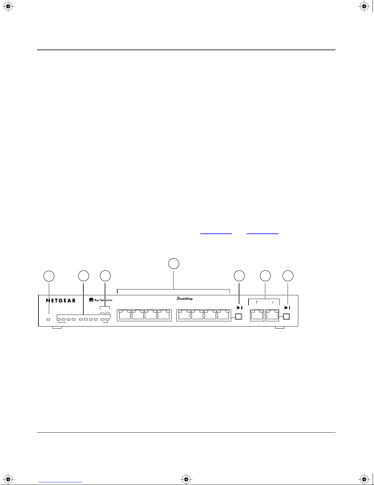
Front Panel
For easier management and control of the switches, familiarize yourself with the ports, LEDs, and
Normal/Uplink push button switches, as illustrated in Figure
panels of the switches.
4
1
10 PORT
10/100Mbps
Power 1 2 3 4 5 6 7 8 9 10
2 6
Ethernet Switch
Green = Rx/Tx Yellow = Collision
Key:
1 = Power LED
2 = Rx/Tx and Collision LEDs for ports 1 through 10
3 = 100 Mbps LEDs for ports 9 and 10
4 = 10 Mbps Ethernet ports1 through 8 with Link and FDX LEDs on each port
5 = Normal/Uplink push button to configure port 8
6 = 10/100 Mbps Ethernet ports 9 and 10 with Link and FDX LEDs on each port
7 = Normal/Uplink push button to configure port 10
3 5 7
10/100 Mbps
1234
Link FDX Link FDX Link
100Mbps
5678
2-1 and Figure 2-2 showing the front
MODEL
FDX
SW510
Normal/UplinkNormal/Uplink
592EA
10/100 Mbps
910
Figure 2-1. Front panel of the Model SW510 switch
Physical Description 2-1
Page 14
SW510.bk Page 2 Wednesday, March 12, 1997 10:49 AM
Installation Guide for the Model SW510 and Model SW518 Ethernet Switches
1
18 PORT
Ethernet Switch
10/100Mbps
1 2 3 4 5 6 7 8
9 10 11 12 13 14 15
Power
Green = Rx/Tx Yellow = Collision
2
3
1
Link FDX
100 Mbps
16
17 18
9
4
5 7
8
16 17 18
6
10/100 Mbps
Link FDX Link FDX
MODEL10/100 Mbps
SW518
Normal/UplinkNormal/Uplink
593EA
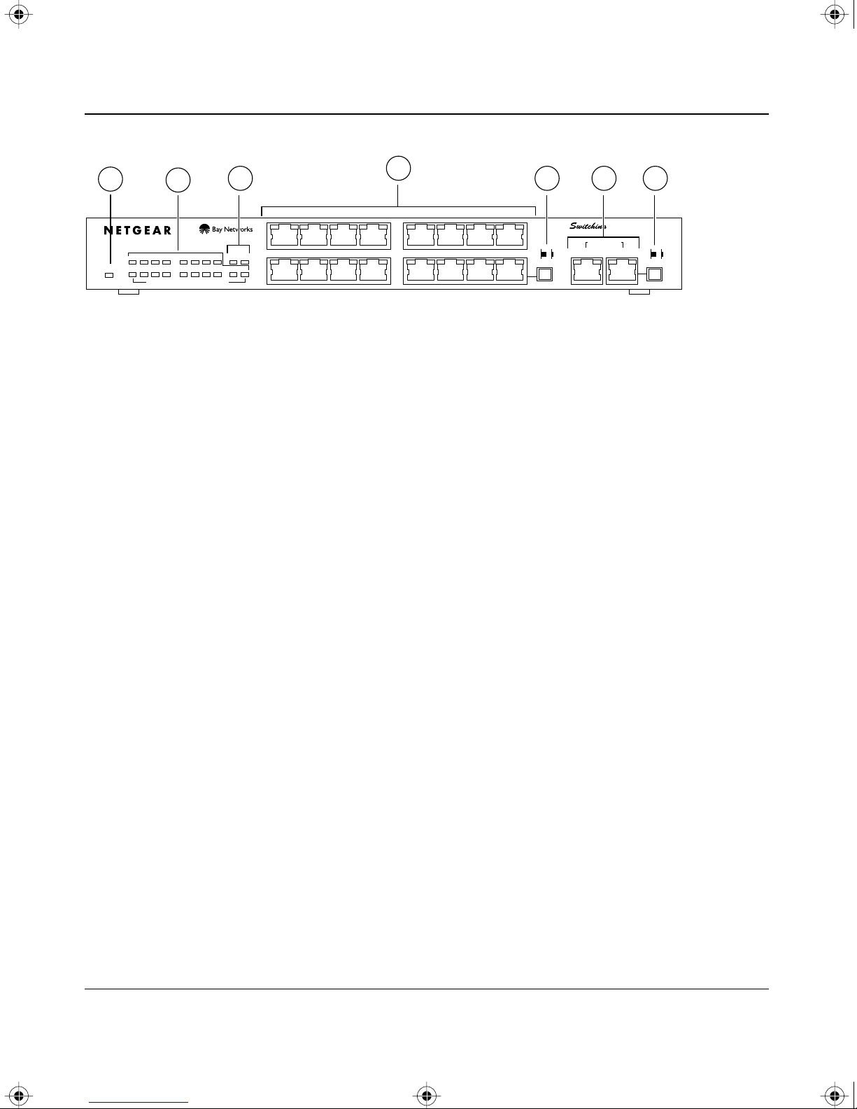
Key:
1 = Power LED
2 = Rx/Tx and Collision LEDs for ports 1 through 18
3 =100 Mbps LEDs for ports 17 and 18
4 =10 Mbps Ethernet ports with Link and FDX LEDs on each port
5 = Normal/Uplink push button to configure port 16
6 =10/100 Mbps Ethernet ports 17 and 18 with Link and FDX LEDs on each port
7 = Normal/Uplink push button to configure port 18
Figure 2-2. Front panel of the Model SW518 switch
Ethernet Ports
The Model SW510 switch is equipped with eight 10 Mbps Ethernet ports and two 10/100 Mbps
Fast Ethernet ports. On the Model SW518 switch, there are sixteen 10 Mbps ports and two 10/100
Mbps ports. A server or PC can be connected to any of the ports.
The 10/100 Mbps ports are Ports 9 and 10 on the Model SW510 switch and Ports 17 and 18 on the
Model SW518 switch. The network access speed for the two 10/100 Mbps ports on both systems is
automatically sensed and displayed on the front panel by the 100 Mbps LEDs.
The 10 Mbps and 10/100 Mbps ports support only one cable connection, which is for unshielded
twisted pair (UTP) cable. An 8-pin RJ-45 plug is used for connection to this port.
2-2 Physical Description
Page 15
SW510.bk Page 3 Wednesday, March 12, 1997 10:49 AM
Installation Guide for the Model SW510 and Model SW518 Ethernet Switches
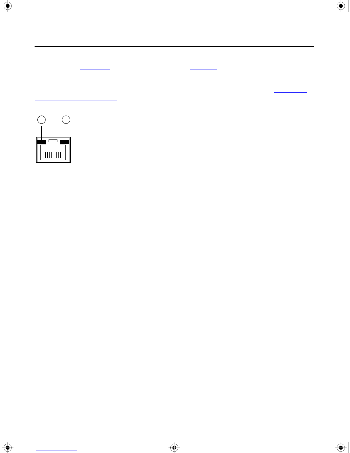
Each of the 10 Mbps and 10/100 Mbps ports uses vista RJ-45 connectors that have built-in LEDs,
as illustrated in Figure
2-3. The LEDs, as described in Table 2-1, indicate that the connection to
the port is valid and that the port is operating in full-duplex mode.
For further information about the vista RJ-45 connector and the RJ-45 plug, refer to Chapter
B,
“Connector Pin Assignments.”
1 2
735EA
Key:
1 = Link LED
2 = FDX LED
Figure 2-3. The vista RJ-45 connector with built-in LEDs
Normal/Uplink Push Button
As illustrated in Figure 2-1 and Figure 2-2, one 10 Mbps port and one of the 10/100 Mbps ports on
each of the switches is equipped with a Normal/Uplink push button that allows you to select
normal (MDI-X) wiring or uplink (MDI) wiring. On the Model SW510 switch, ports 8 and 10 can
be configured for normal or uplink wiring; on the Model SW518 switch, ports 16 and 18 can be
configured for normal or uplink wiring. The ports are configured for normal wiring when the push
button is in the out position. When the push b utton is pressed in, the ports are configured for uplink
wiring. Configuring the ports allows direct connection to a server or PC, or to another switch or a
hub to form a network backbone.
Physical Description 2-3
Page 16

SW510.bk Page 4 Wednesday, March 12, 1997 10:49 AM
Installation Guide for the Model SW510 and Model SW518 Ethernet Switches
LEDs
The LEDs on the Model SW510 and the Model SW518 switches are used to monitor and diagnose
the devices. LEDs on the front panel of the switch and two LEDs on each port allow you to
identify the following information:
• Status of the switch power supply
• Data transmission or receive activity
• Collision occurrence
• Full- or half-duplex transmission
T
able 2-1 describes each LED on the front panels of the switches. See Figure 2-1, Figure 2-2, and
Figure
2-3 for the locations of the LEDs.
Table 2-1. LED descriptions
Label Color Activity Description
Power Green On Power is supplied to the switch.
Off Power is disconnected.
Rx/Tx/Collision Green Blinking Pack et transmission or reception is occurring on the port. The
blinking action corresponds to the amount of packets that are
transmitted or received.
Yellow Blinking Data collision is occurring on the port. The blinking action
corresponds to the amount of collisions.
When a collision occurs, the connected device pauses and
transmits again after waiting a specified time.
Link Green On A valid link is established on the port.
Off A link is not established on the port.
FDX Green On The port is operating in full-duplex mode.
Off The port is operating in half-duplex mode.
100 Mbps Green On The port is operating at 100 Mbps. The 100 Mbps LEDs are
only applicable to ports 9 and 10 on the Model SW510 switch
and ports 17 and 18 on the Model SW518 switch.
2-4 Physical Description
Off The port is operating at 10 Mbps. The 100 Mbps LEDs are
only applicable to ports 9 and 10 on the Model SW510 switch
and ports 17 and 18 on the Model SW518 switch.
Page 17

SW510.bk Page 5 Wednesday, March 12, 1997 10:49 AM
Installation Guide for the Model SW510 and Model SW518 Ethernet Switches
Rear Panel
As illustrated in Figure
2-4 and Figure 2-5, the rear panel has full-duplex (FDX), half-duplex
(HDX), and auto-duplex (AUTO) toggle switches, a standard AC power receptacle, and fans for
cooling.
3
4
WARNING -
Whenever a port changes between FDX and HDX mode, entire unit resets
and traffic in all ports will be stopped temporarily
Enable port to determine duplex mode automatically
AUTO -
Force port to operate at Full Duplex and Half Duplex mode respectively
FDX, HDX -
1
FDX
HDX
Key:
1 = FDX and HDX toggle switches to set 10 Mbps ports 1 through 8 for full- or half-duplex mode
2 = FDX and AUTO toggle switches to set 10/100 Mbps ports 9 and 10 for full- or auto-duplex mode
3 = Fans
4 = AC power outlet
Figure 2-4. Rear panel of the Model SW510 switch
10 Mbps
8
1 2
10/100 Mbps
9
10
FDX
AUTO
595EA
3
4
WARNING -
Whenever a port changes between FDX and HDX mode, entire unit resets
and traffic in all ports will be stopped temporarily
Enable port to determine duplex mode automatically
AUTO -
Force port to operate at Full Duplex and Half Duplex mode respectively
FDX, HDX -
FDX
HDX
10 Mbps
18916
10/100 Mbps
17
18
FDX
AUTO
1 2
596EA
Key:
1 = FDX and HDX toggle switches to set 10 Mbps ports 1 through 16 for full- or half-duplex mode
2 = FDX and AUTO toggle switches to set 10/100 Mbps ports 17 and 18 for full- or auto-duplex mode
3 = Fans
4 = AC power outlet
Figure 2-5. Rear panel of the Model SW518 switch
Physical Description 2-5
Page 18

SW510.bk Page 6 Wednesday, March 12, 1997 10:49 AM
Installation Guide for the Model SW510 and Model SW518 Ethernet Switches
HDX/FDX/AUTO Duplex Toggle Switches
Full-duplex mode is supported for all 10 Mbps or 10/100 Mbps ports and allows the port to
transmit and receive data at the same time. Full-duplex operation applies only to point-to-point
access (for example, when a switch is connected to a PC, a server, or another switch). Because
repeaters and hubs use a common collision domain for all communications and cannot
communicate in a full-duplex mode, the associated 10 Mbps port on the switch should be set to
half-duplex operation when connecting to these types of devices.
Setting the toggle switch to AUTO on the 10/100 Mbps port enables the port to determine duplex
mode automatically. In this mode, the 10/100 Mbps port operates in either full- or half-duplex
mode, depending on the operating mode of the remote port. If the remote port cannot provide the
proper signal to indicate its own capability, the 10/100 Mbps port on the switch operates in
half-duplex mode.
As illustrated in Figure
2-4 and Figure 2-5, one half-duplex (HDX) and full-duplex (FDX) toggle
switch is assigned to each 10 Mbps port on a switch. On the Model SW510 switch, the 10 Mbps
ports are ports 1 through 8; on the Model SW518 switch, the 10 Mbps ports are ports 1 through 16.
The communication mode can be set to either half-duplex or full-duplex mode.
One FDX and AUTO toggle switch is assigned to each 10/100 Mbps port on a switch. On the
Model SW510 switch, the 10/100 Mbps ports are ports 9 and 10; on the Model SW518 switch, the
10/100 Mbps ports are ports 17 and 18.The communication mode can be set to either full-duplex
or auto-duplex mode.
2-6 Physical Description
Page 19

SW510.bk Page 1 Wednesday, March 12, 1997 10:49 AM
This chapter presents an overview of the levels of service provided by incorporating the
technology of the NETGEAR Model SW510 and Model SW518 Ethernet switches into your
network. Examples are given to illustrate the role of the switch in several configurations that
provide those different levels of service to networks and users.
Chapter 3
Applications
The Model SW510 and Model SW518 switches are designed to provide flexibility in configuring
your network connections. The switch can be used as a standalone device or can be connected with
standard repeaters, switching hubs, or other interconnection devices in various configurations. The
configuration examples in this chapter illustrate the integration of the switch in network
environments of all sizes and types. These examples include a network of a few workstations
connected to a printer and a segmented network with multiple users and other networking devices.
Desktop Switching
The Model SW510 and Model SW518 switches are designed to perform the functions of a desktop
switch where a small group of users need to be assured of having 10 Mbps network access. A
power user on the same network can have a 100 Mbps connection to the switch and a 200 Mbps
connection to the server. Figure
Model SW510 Ethernet switch. The power user and the server are connected to the 10/100 Mbps
ports.
3-1 illustrates PCs connected to the 10 Mbps Ethernet ports of a
Applications 3-1
Page 20

SW510.bk Page 2 Wednesday, March 12, 1997 10:49 AM
Installation Guide for the Model SW510 and Model SW518 Ethernet Switches
1
4
32
751EA
Key:
1 = Model SW510 Ethernet switch (Normal/Uplink push button for port 10 set to Normal position)
2 = Server with 200 Mbps connection
(adapter card installed in server that negotiates auto-duplex mode)
(duplex toggle switch for port 9 on Model SW510 switch set in AUTO position to enable auto-duplex mode)
3 = PC with 100 Mbps connection
4 = PCs with 10 Mbps connection
Figure 3-1. Model SW510 switch used as a desktop switch
Network Segmentation
Most networks are interconnected with two-port bridges that insert latency into normal
communications. For data that must pass through several bridges to reach its destination, this
latency can degrade communications. With several 10 Mbps bridging ports and the additional
internally bridged 100 Mbps port, the Model SW518 switch can segment a complex network into a
single efficient bridged node, increasing overall bandwidth and throughput. Segments attached to
the switching hub do not have to cross the backbone. They can now reach each other at near-zero
latency. For high-bandwidth applications that transfer data across the network backbone, the
100 Mbps port provides high-speed access.
The switch increases bandwidth for workgroups and strengthens network throughput when
accessing high-volume file servers. The Model SW518 switch provides parallel communication
between the high-speed 100 Mbps port and each of the 10 Mbps station ports. This method of
communication allows multiple conversations to occur concurrently. This method also expands
overall throughput and allows key servers or other heavily used devices to be available to more
users. Figure
Model EN516 Ethernet hubs, each supporting a network of users. A NETGEAR Model FS508
Fast Ethernet switch serves as the network backbone.
3-2 illustrates the Model SW518 Ethernet switch connected to NETGEAR
3-2 Applications
Page 21

SW510.bk Page 3 Wednesday, March 12, 1997 10:49 AM
Installation Guide for the Model SW510 and Model SW518 Ethernet Switches
2
1
Link Full Link Full
4
4
Link Full Link Full
3
7
4
5
Key:
1 = Model SW518 Ethernet switch (Normal/Uplink push button to configure port 18 set to Uplink position)
2 = Server with 20 Mbps connection (adapter card installed in server; duplex toggle switch for port 7 on
Model SW518 switch set to full-duplex mode)
3 = Model FS508 Fast Ethernet switch serving as network backbone (A Fast Ethernet hub can also be used.)
4 = Model EN516 Ethernet hubs (Normal/Uplink push button set to Uplink position)
5 = Server with 10 Mbps connection
6 = PCs with 10 Mbps connection
7 = PCs with 100 Mbps connection
6
683EA
Figure 3-2. Model SW518 switches used for network segmentation and as a
multiport bridge to a high-bandwidth backbone
Note:
Full-duplex operation applies to point-to-point access only when attaching the
switch to a workstation, a server, or another switch. When connecting to a repeater or a
hub, set the port for half-duplex operation.
Applications 3-3
Page 22

SW510.bk Page 4 Wednesday, March 12, 1997 10:49 AM
Installation Guide for the Model SW510 and Model SW518 Ethernet Switches
Bridging from 10 Mbps to 100 Mbps Networks
The Model SW518 switch functions as a bridge connecting traditional Ethernet networks to
100 Mbps Fast Ethernet networks. Users requiring increased network bandwidth can be grouped
together in the 100 Mbps Fast Ethernet network isolated from the network users who need
occasional network connection to the server. Figure
switch connected to a group of 10 Mbps users. The users who require more power are networked
to the NETGEAR FE516 Fast Ethernet hubs.
3-3 illustrates the Model SW518 Ethernet
2
1
4
Link Full Link Full
5 5 5
Key:
1 = Model SW518 Ethernet switch ((Normal/Uplink push button to configure port 18 set to Uplink position;
Normal/Uplink push button to configure port 16 set to Normal position)
2 = Two FE516 Fast Ethernet hubs cascaded on the backplane
3 = PCs with adapter card installed, enabling 100 Mbps connection
4 = Server with adapter card installed, enabling 100 Mbps connection
5 = Model EN516 Ethernet hubs with 10 Mbps connection (Normal/Uplink push button set to Uplink position)
6 = PCs with 10 Mbps connection
Link Full Link Full
3
6
752EA
Figure 3-3. Bridging from 10 Mbps networks
3-4 Applications
Page 23

SW510.bk Page 1 Wednesday, March 12, 1997 10:49 AM
This chapter describes the installation procedures for the NETGEAR Model SW510 and
Model SW518 Ethernet switches.
Chapter 4
Installation
Site Preparation
Before you begin installing the switch, prepare the installation site. Make sure the operating
environment meets the physical requirements of the switch, as described in Appendix
“Technical Specifications.”
A,
Package Contents
Unpack the contents of the package and verify them against the following list:
• Model SW510 or Model SW518 switch
• Self-adhesive rubber pads for desktop installation
• Rack Mount Kit for rack installation
• AC power cord
• Warranty and Owner Registration Card
• This installation guide
Caution:
and ordinances.
Installation 4-1
Use the appropriate power cord as required by your national electrical codes
Page 24

SW510.bk Page 2 Wednesday, March 12, 1997 10:49 AM
Installation Guide for the Model SW510 and Model SW518 Ethernet Switches
Call your reseller or customer support in your area if there are any wrong, missing, or damaged
parts. Refer to page
iii for the location of customer support in your area.
Keep the carton, including the original packing materials. Use them to repack the switch if you
need to return it for repair.
To qualify for product updates and product warranty registration, fill in the Warranty and Owner
Registration Card within 30 days of purchase and return it to NETGEAR, Inc.
Installing a Switch
To install a switch on a desktop, on another flat surface, or in a rack, follow these steps:
1.
Unpack the switch.
2. Choose a location near the devices to be connected and close to an electrical outlet.
3. Proceed to “Installing the Switch on a Flat Surface” or “Installing the Switch in a Rack.”
Installing the Switch on a Flat Surface
To install the switch on a desktop or any other flat surface, follow these steps:
1. Install the self-adhesive rubber pads on the bottom of the switch.
Peel off the protectiv e backing from the rubber pads and apply one at each mark ed location on
the bottom of the switch.
2. Set the switch on a desktop or any other flat surface.
For proper ventilation, make sure that the switch has at least 2 inches of space on each side and
5 inches of space at the back. It is very important that the fans located in the rear panel are not
blocked. Restricted airflow could cause overheating of the components.
3. Install any additional devices in your stack.
For instructions on connecting to additional switches or other devices, refer to “Connecting to
Other Devices” later in this chapter.
4-2 Installation
Page 25

SW510.bk Page 3 Wednesday, March 12, 1997 10:49 AM
Installation Guide for the Model SW510 and Model SW518 Ethernet Switches
Installing the Switch in a Rack
For mounting the switch in a standard 19-inch rack, you need the following tools and materials:
• Two mounting brackets supplied in the Rack Mount Kit
• Eight screws supplied in the Rack Mount Kit to attach the mounting brackets to the switch
• Four screws and nylon washers supplied in the Rack Mount Kit to attach the mounting
brackets to the rack
• #1 Phillips screwdriver
• #2 Phillips screwdriver
To install the switch in a rack, follow these steps:
1. Attach the mounting brackets to the sides of the switch as illustrated in Figure 4-1.
Hold a mounting bracket against each side of the switch and align the countersunk screw holes
in the bracket with the bracket mounting holes in the switch.
2. Insert the screws provided in the Rack Mount Kit through each bracket and into the
bracket mounting holes in the switch.
3. Using a #1 Phillips screwdriver, tighten the screws to secure each bracket.
4. Hold the switch with the mounting holes in the brackets aligned with the holes in the
rack.
Normal/Uplink
Normal/Uplink
16
Normal/Uplink
Normal/Uplink
16
597EA
Figure 4-1. Attaching mounting brackets to the Model SW510 and
Model SW518 switches
Installation 4-3
Page 26

SW510.bk Page 4 Wednesday, March 12, 1997 10:49 AM
Installation Guide for the Model SW510 and Model SW518 Ethernet Switches
5. Insert two pan-head screws with nylon washers through each bracket and into the rack.
6. Using a #2 Phillips screwdriver, tighten the screws to secure the switch to the rack.
7. Install any additional devices in your stack.
For proper ventilation, make sure that the switch has at least 2 inches of space on each side and
5 inches of space at the back. It is very important that the fans located in the rear panel are not
blocked. Restricted airflow could cause overheating of the components.
For instructions on connecting to additional switches or other devices, refer to “
Connecting
Devices to the Switch.”
Connecting Devices to the Switch
To connect devices to the switch, follow these steps:
1. Connect the device to the selected ports on the switch and set the Normal/Uplink push
button appropriately.
The Normal/Uplink push button eliminates the need to use a crossover cable when connecting
similarly wired devices. Ports 8 and 10 on the Model SW510 switch and ports 16 and 18 on
the Model SW518 switch can be configured for normal (MDI-X) wiring or uplink (MDI)
wiring. Use the following guidelines to configure the ports:
• Set the Normal/Uplink push button to the Normal position and use a straight-through
cable if the remote end of the cable is connected to an MDI wired device such as a PC, a
server, or a router.
• Set the Normal/Uplink push button to the Uplink position and use a straight-through cable
if the remote end of the cable is connected to an MDI-X wired device such as a 10 Mbps
or 100 Mbps hub or repeater, or for backbone connection to another switch.
The ports without the Normal/Uplink push button are normal wired ports. If you are using one
of these ports to connect to another normal port as on a hub or repeater, a crosso ver cable must
be used to connect the two ports.
For further cabling guidelines, refer to Appendix C, “Cabling Specifications.”
4-4 Installation
Page 27

SW510.bk Page 5 Wednesday, March 12, 1997 10:49 AM
Installation Guide for the Model SW510 and Model SW518 Ethernet Switches
2. Set the FDX, HDX, or AUTO toggle switches on the rear panel for the selected duplex
mode.
A hub and repeater use a common collision domain for all communications and cannot
support full-duplex mode. When connecting any of the 10 Mbps ports on the switch to a hub,
set the port to half-duplex mode. When connecting an y of the 10/100 Mbps ports on the switch
to a hub, set the port to AUTO. When connecting to a PC, a server, or another switch, the
duplex setting for the port must be the same as the duplex setting on the PC, server, or other
switch.
• To set the 10 Mbps ports (ports 1 through 8 on the Model SW510 switch and ports 1
through 16 on the Model SW518 switch):
— Move the toggle switch into the up position (to FDX) for full-duplex mode.
— Move the toggle switch into the down position (to HDX) for half-duplex mode.
• To set the 10/100 Mbps ports (ports 9 and 10 on the Model SW510 switch and ports 17
and 18 on the Model SW518 switch):
— Move the toggle switch into the up position (to FDX) for full-duplex mode.The duple x
switch must be set to FDX if you are connecting to legacy full-duplex 100 Mbps
devices that do not generate signals indicating duplex mode. If the duple x switch is set
to AUTO mode when connecting to legacy full-duplex 100 Mbps devices, the 10/100
Mbps ports will default to half-duplex mode because the port does not receive the
proper signal.
— Move the toggle switch into the down position (to AUTO) for auto-duplex mode. The
10/100 Mbps ports will negotiate and automatically determine the duplex mode based
on the mode of the connected port. If the connected port cannot auto-negotiate, the
10/100 Mbps port on the Model SW510 or Model SW518 switch will default to
half-duplex
mode.
Note: Whenever a port changes between FDX and HDX mode, the Model
SW510 and Model SW518 switches reset and traffic in all ports temporarily
stops. When the switches reset, the list of learned addresses is not affected.
3. Connect one end of the power cord to the power outlet on the back panel of the switch,
and connect the other end of the power cord to a wall receptacle.
The switch automatically selects the proper voltage in the range of 100 to 240 volts. The
Power LED lights, and the cooling fans start up after successfully completing the self-tests.
The switch is now operational.
Installation 4-5
Page 28

SW510.bk Page 6 Wednesday, March 12, 1997 10:49 AM
Installation Guide for the Model SW510 and Model SW518 Ethernet Switches
Verifying Installation
Verify network communications by ensuring that all the necessary connections have been made,
that all connected resources can be accessed, and that the LED indicators on the switch are
functioning properly. For additional information, refer to Chapter
5, “Troubleshooting.”
4-6 Installation
Page 29

SW510.bk Page 1 Wednesday, March 12, 1997 10:49 AM
This chapter provides information about troubleshooting the NETGEAR Model SW510 and
Model SW518 Ethernet switches.
Chapter 5
Troubleshooting
LEDs
Verify that all other system components are functioning properly. There may be a defecti ve adapter
card, cable, or port. Check for defects and replace the defective component.
If the Link LED does not light up when a device is connected to its corresponding UTP port, check
that both the switch and the connected device are powered on. When connecting devices to the
switch with twisted pair cable, make sure that the cable length does not exceed 100 meters. Refer
to Chapter
information on twisted pair or straight-through cable use.
4, “Installation,” and Appendix C, “Ethernet and Cabling Guidelines,” for additional
HDX/FDX/AUTO Duplex Toggle Switches
The factory setting for the duplex toggle switches on the 10 Mbps ports is half-duplex (HDX)
mode, and the factory setting for the duplex toggle switches on the 10/100 Mbps ports is
auto-duplex (AUTO) mode.
If performance degradation is a problem or if file transfer is slow, make sure that the half- or
full-duplex setting of the NETGEAR switch and the connected device are the same. When
connecting the switch to a repeater or hub, the 10 Mbps port on the switch must be set to
half-duplex (HDX) mode and the 10/100 Mbps port must be set to auto-duplex (AUTO) mode.
For instructions on setting the duplex toggle switches, refer to “Connecting De
on page
Troubleshooting 5-1
4-4.
vices to the Switch”
Page 30

SW510.bk Page 2 Wednesday, March 12, 1997 10:49 AM
Installation Guide for the Model SW510 and Model SW518 Ethernet Switches
Installation
Verify that all system components have been properly installed. If one or more components are
malfunctioning, test them in an alternate environment where all other components are functioning
properly.
Cabling
To verify that the cabling is correct, refer to Appendix C, “Ethernet and Cabling Guidelines.” Be
sure all cable connectors are securely positioned in the required ports. Straight-through cables
should be used for all standard twisted pair connections.
Make sure all devices are connected to the network. Equipment may have been accidentally
disconnected.
Network Adapter Cards
Make sure the network adapter cards installed in the PCs are in working condition.
Configuration
If problems occur after altering the network configuration, restore the original connections and
determine the problem by implementing the new changes, one procedure at a time. Make sure that
cable distances, repeater limits, and other physical aspects of the installation do not exceed the
Ethernet limitations.
Switch Integrity
If required, verify the integrity of the switch by resetting the switch. Turn the power to the switch
off, and then turn the power to the switch back on. If the problem continues and you have
completed all the preceding diagnoses, contact your NETGEAR distributor.
Caution: Turning the power off and then turning the power on again will clear the
address table.
5-2 Troubleshooting
Page 31

SW510.bk Page 1 Wednesday, March 12, 1997 10:49 AM
This appendix provides technical specifications for the NETGEAR Model SW510 and
Model SW518 Ethernet switches.
Appendix A
Technical Specifications
General Specifications
Network Protocol and Standards Compatibility
ISO/IEC 802-3 (ANSI/IEEE 802.3I) 10BASE-T, 10BASE-2, 10BASE-5
IEEE 802.3u 100BASE-TX
Data Rate
10 Mbps differential Manchester encoded, IEEE 802.3
100 Mbps with 4B/5B encoding and MLT-3 physical interface for 100BASE-TX
Interface
RJ-45 connector
Specifications Model SW510 Switch Model SW518 Switch
Electrical
Power consumption: 35 W 45 W
Input voltage: Autosensing, 100 to 240 VAC,
50 to 60 Hz
Same
Physical
Dimensions: (W) 13 by (H) 1.7 by (D) 8 in. Same
(W) 33 by (H) 4.3 by (D) 20.3 cm Same
Weight: 4.7 lb 5.0 lb
2.1 kg 2.3 kg
Technical Specifications A-1
Page 32

SW510.bk Page 2 Wednesday, March 12, 1997 10:49 AM
Installation Guide for the Model SW510 and Model SW518 Ethernet Switches
Environmental Specifications
Operating temperature: 0° to 40° C
Storage temperature: –32° to 104° C
Operating humidity: 90% maximum relative humidity, noncondensing
Storage humidity: 95% maximum relative humidity, noncondensing
Operating altitude: 10,000 ft (3,000 m) maximum
Storage altitude: 10,000 ft (3,000 m) maximum
Electromagnetic Emissions
Meets requirements of:
CE mark, commercial
FCC Part 15, Subpart B, Class A
EN 55 022 (CISPR 22), Class A
VCCI Class 1
Electromagnetic Susceptibility
CE mark, commercial
Electrostatic discharge (ESD): IEC 801-2, Level 2/3
Radiated electromagnetic field: IEC 801-3, Level 2
Electrical fast transient/burst: IEC 801-4, Level 2
Electrical surge: IEC 801-5, Level 1/2
Safety Agency Approvals
CE mark, commercial
UL listed (UL 1950)
CSA certified (CSA 22.2 #950)
TUV licensed (EN 60 950)
A-2 Technical Specifications
Page 33

SW510.bk Page 3 Wednesday, March 12, 1997 10:49 AM
Installation Guide for the Model SW510 and Model SW518 Ethernet Switches
Performance Specifications
Frame filter rate: 14,800 frames/second, maximum on 10 Mbps port
Frame forward rate: 14,800 frames/second, maximum on 10 Mbps port
Network latency: Less than 75 microseconds for 64-byte frames in
Address database size: 8,000 media access control (MAC) addresses per port
Addressing: 48-bit MAC address
Queue buffer:
148,000 frames/second maximum on 100 Mbps port
148,000 frames/second maximum on 100 Mbps port
store-and-forward mode
10 Mbps ports: 1 MB of buffer space for all 8 ports
100 Mbps ports: 1 MB of buffer space for each port
Technical Specifications A-3
Page 34

SW510.bk Page 4 Wednesday, March 12, 1997 10:49 AM
Page 35

SW510.bk Page 1 Wednesday, March 12, 1997 10:49 AM
This appendix provides information about the RJ-45 plug and the vista RJ-45 connector that are
used for the Model SW510 and Model SW518 Ethernet switches.
Appendix B
Connector Pin Assignments
RJ-45 Plug and vista RJ-45 Connector
The RJ-45 plug accepts 4-pair unshielded (UTP) or shielded 100 Ω twisted pair cable and connects
into the vista RJ-45 connector.
The vista RJ-45 connector (also referred to as a 10 Mbps or 10/100 Mbps port) is used to connect
stations, hubs, and switches through unshielded twisted pair cable and supports 10 Mbps or
100 Mbps data transmission.
The RJ-45 plug and vista RJ-45 connector are both illustrated in Figure
12345678
18
711EA
Key:
1 to 8 = Pin numbers
Figure 5-1. RJ-45 plug and vista RJ-45 connector
6-1.
Connector Pin Assignments B-1
Page 36

SW510.bk Page 2 Wednesday, March 12, 1997 10:49 AM
Installation Guide for the Model SW510 and Model SW518 Ethernet Switches
Table B-1 lists the pin assignments for the RJ-45 plug and the vista RJ-45 connector.
Table 5-1. Pin assignments for the RJ-45 plug and vista RJ-45
connector
Pin Normal assignment Uplink assignment
1 Input Receive Data + Output Transmit Data +
2 Input Receive Data – Output Transmit Data –
3 Output Transmit Data + Input Receive Data +
6 Output Transmit Data – Input Receive Data –
4, 5, 7, 8 Not Used Not Used
B-2 Connector Pin Assignments
Page 37

SW510.bk Page 1 Wednesday, March 12, 1997 10:49 AM
This appendix provides information about Ethernet technology and specifications for cables used
with the Model SW510 and Model SW518 Ethernet switches.
Appendix C
Ethernet and Cabling Guidelines
Ethernet Technology
When 10BASE-T technology was originally introduced, multiple repeaters were frequently used
to build large networks. To increase the number of connections, repeaters were connected together
because individual repeater port densities were often limited to 8 to 24 ports. As structured wiring
systems were implemented, horizontal wiring from the wiring closet to the desktop was designed
for a maximum distance of 100 meters. Stackable repeaters eliminated the need for collision
domains to extend over multiple repeater hubs.
The 100BASE-TX Fast Ethernet technology maintains the same concepts as the 10BASE-T
technology. Both use the same Carrier Sense Multiple Access with Collision Detection
(CSMA/CD) and Media Access Control (MAC) protocols. Both 10BASE-T and 100BASE-TX
Ethernet use the same type of Ethernet frame and error detection mechanisms. They also support
the same star topology using traditional media types and are manageable by the same network
management protocols. The most fundamental difference between the two technologies is that
100BASE-TX operates 10 times faster than traditional 10BASE-T.
The 100BASE-TX technology was developed to support the new paradigm and, by using
switching technology, can provide for the following four distinct levels of service:
• 10BASE-T dedicated bandwidth of 10 Mbps
• 100BASE-TX dedicated bandwidth that equals 100 Mbps
• 100BASE-TX shared bandwidth that equals 100 Mbps
• 10BASE-T shared bandwidth of 10 Mbps
Ethernet and Cabling Guidelines C-1
Page 38

SW510.bk Page 2 Wednesday, March 12, 1997 10:49 AM
Installation Guide for the Model SW510 and Model SW518 Ethernet Switches
Cable Specifications
Category 5 twisted pair cable must be used for 100 Mbps connections. For 10 Mbps connections,
Category 3, 4, or 5 cable can be used; however, NETGEAR highly recommends Category 5.
Category 5 cable will prevent unnecessary expenses or confusion if you upgrade to Fast Ethernet.
able 6-1 lists the electrical requirements of cables.
T
Table 5-1. Electrical requirements of Category 3, 4, and 5 cables
Specification Category 3 Category 4 Category 5
Number of pairs Four Four Four
Impedance 100 Ω ± 15% 100 Ω ± 15% 100 Ω ± 15%
Mutual capacitance at 1 KHz ≤ 6.6 nF
per 100 m
Maximum attenuation
(dB per 100 m, at 20 C) at 4 MHz: 5.6 at 4 MHz: 4.3 at 4 MHz: 8.2
at 10 MHz: 9.8 at 10 MHz: 7.2 at 31 MHz: 11.7
at 16 MHz: 13.1 at 16 MHz: 8.9 at 100 MHz: 22
NEXT loss (dB minimum) at 4 MHz: 32 at 4 MHz: 47 at 16 MHz: 44
at 10 MHz: 26 at 10 MHz: 41 at 31 MHz: 39
at 16 MHz: 23 at 16 MHz: 38 at 100 MHz: 32
≤ 5.6 nF
per 100 m
≤ 5.6 nF
per 100 m
Twisted Pair Cables
For two devices to communicate, the transmitter of each device must be connected to the receiver
of the other device. The crossover function is usually implemented internally as part of the
circuitry in the device. Some repeaters and switch ports are media-dependent interfaces with
crossover ports, referred to as MDI-X or Normal ports. Computer ports and PC adapter card ports
are usually media-dependent interface ports, referred to as MDI or Uplink ports. Refer to the
installation instructions in Chapter
4, “Installation,” for appropriate cable use and connection.
C-2 Ethernet and Cabling Guidelines
Page 39

SW510.bk Page 3 Wednesday, March 12, 1997 10:49 AM
Installation Guide for the Model SW510 and Model SW518 Ethernet Switches
Figure 6-1 illustrates straight-through twisted pair cable.
1
Tx
2
A B
3
Rx
6
Key:
A = Uplink or MDI port (as on a PC)
B = Normal or MDI-X port (as on a hub or switch)
1, 2, 3, 6 = Pin numbers
1
Rx
2
3
Tx
6
Figure 5-1. Straight-through twisted pair cable
Figure 6-2 illustrates crossover twisted pair cable.
1
Rx
2
1
Rx
2
736EA
A B
3
Tx
6
Key:
A and B = Normal or MDI-X port (as on a hub or switch)
1, 2, 3, 6 = Pin numbers
3
Tx
6
737EA
Figure 5-2. Crossover twisted pair cable
Ethernet and Cabling Guidelines C-3
Page 40

SW510.bk Page 4 Wednesday, March 12, 1997 10:49 AM
Page 41

SW510.bk Page 1 Wednesday, March 12, 1997 10:49 AM
Numbers
10 Mbps ports 1-2, 2-1, 3-1, 4-5
100 Mbps LEDs
100BASE-TX
10BASE-T
10/100 Mbps ports
2-1
C-1
C-1
1-3, 2-2, 2-6, 3-1, 4-5
A
applications
bridging from 10 Mbps to 100 Mbps
desktop switching
network segmentation
troubleshooting
AUTO duplex toggle switches
3-1
3-2
5-2
B
bridging from 10 Mbps to 100 Mbps 3-4
C
cable
Category 3, electrical requirements
Category 4, electrical requirements
Category 5, electrical requirements
crossover twisted pair
specifications
straight-through twisted pair
troubleshooting
twisted pair
Collision LED
connections
to other devices
to PCs
to servers
2-2
C-2
5-2
C-2
2-1, 2-4
2-2
C-3
4-4
2-5, 4-5
4-4, C-3
3-4
C-2
C-2
C-2
Index
crossover twisted pair cables
CSMA/CD protocol
customer support
C-1
iii
C-3
D
desktop switching 3-1
E
Ethernet technology, description of C-1
F
FDX
duplex toggle switches
2-4
LEDs
features
front panel
full-duplex mode
1-2
Model SW510 switch
Model SW518 switch
1-3, 2-4
2-5, 4-5, 5-1
2-1
2-2
H
half-duplex mode 1-3, 2-4
HDX duplex toggle switches
2-5, 4-5, 5-1
I
installation
in a rack
on a flat surface
troubleshooting
verifying
4-3
4-2
5-2
4-6
Index 1
Page 42

SW510.bk Page 2 Wednesday, March 12, 1997 10:49 AM
Installation Guide for the Model SW510 and Model SW518 Ethernet Switches
L
LEDs
and troubleshooting
description
Model SW510 switch
Model SW518 switch
Link LED
2-4
2-4
M
MAC protocol C-1
MDI
1-2, C-2, C-3
ports
wiring
MDI-X
ports
wiring
mounting brackets
2-3, 4-4, B-2
1-2, C-2, C-3
2-3, 4-4, B-2
N
4-3
5-1
2-1
2-2
RJ-45 connector. See vista RJ-45 connector
RJ-45 plug
Rx/Tx LED
2-2, B-1
2-4
S
site preparation 4-1
straight-through twisted pair cables
switches, duplex
switching technology, benefits of using
2-5, 4-5, 5-1
4-4, C-3
1-1
T
technical specifications A-1
toggle switches, duplex
troubleshooting
twisted pair cables
5-1
2-5, 4-5, 5-1
C-2
U
uplink ports. See MDI ports
uplink wiring. See MDI wiring
network access speed 2-2
network adapter cards
troubleshooting
network segmentation
normal ports. See MDI-X ports
normal wiring. See MDI-X wiring
Normal/Uplink push button
5-2
3-2
2-1, 3-2, 4-4
P
package contents 4-1
ports
10 Mbps
100 Mbps
10/100 Mbps
Power LED
protocols
1-2, 2-1, 3-1, 4-5
2-4, 3-2
1-3, 2-2, 2-6, 4-5
2-1
C-1
R
rear panel
Model SW510 switch
Model SW518 switch
2-5
2-5
V
vista RJ-45 connector 1-3, 2-3, B-1
W
World Wide Web iii
2 Index
 Loading...