

Page 1

Installation Guide
for the Model SW502
and Model SW507
Ethernet Switches
NETGEAR, Inc.
A Bay Networks Company
48105 Warm Springs Blvd.
Fremont, CA 94539 USA
June 1996
Document Number M-SW500NA-0
Page 2

© 1996 by NETGEAR, Inc. All rights reserved.
Trademarks
NETGEAR and Bay Networks are trademarks of Bay Networks, Inc.
Other brand and product names are registered trademarks or trademarks of their respective holders.
Statement of Conditions
In the interest of improving internal design, operational function, and/or reliability, NETGEAR reserves the right to make
changes to the products described in this document without notice.
NETGEAR does not assume any liability that may occur due to the use or application of the product(s) or circuit layout(s)
described herein.
Federal Communications Commission (FCC) Statement
Note: This equipment has been tested and found to comply with the limits for a Class A digital device, pursuant to Part 15
of the FCC rules. These limits are designed to provide reasonable protection against harmful interference when the
equipment is operated in a commercial environment. This equipment generates, uses, and can radiate radio frequency
energy. If it is not installed and used in accordance with the instruction manual, it may cause harmful interference to radio
communications. Operation of this equipment in a residential area is likely to cause harmful interference, in which case
users will be required to take whatever measures may be necessary to correct the interference at their own expense.
EN 55 022 Declaration of Conformance
This is to certify that the NETGEAR Model SW502 and Model SW507 Ethernet Switches are shielded against the
generation of radio interference in accordance with the application of Council Directive 89/336/EEC, Article 4a.
Conformity is declared by the application of EN 55 022:1987 Class A (CISPR 22:1985/BS 6527:1988).
WARNING: This is a Class A product. In a domestic environment, this product may cause radio
interference, in which case, the user may be required to take appropriate measures.
Bestätigung des Herstellers/Importeurs
Es wird hiermit bestätigt, daß das NETGEAR Model SW502 and Model SW507 Ethernet Switches gemäß der im BMPTAmtsblVfg 243/1991 und Vfg 46/1992 aufgeführten Bestimmungen entstört ist. Das vorschriftsmäßige Betreiben einiger
Geräte (z.B. Testsender) kann jedoch gewissen Beschränkungen unterliegen. Lesen Sie dazu bitte die Anmerkungen in der
Betriebsanleitung.
Das Bundesamt für Zulassungen in der Telekommunikation wurde davon unterrichtet, daß dieses Gerät auf den Markt
gebracht wurde und es ist berechtigt, die Serie auf die Erfüllung der Vorschriften hin zu überprüfen.
Certificate of the Manufacturer/Importer
It is hereby certified that the NETGEAR Model SW502 and Model SW507 Ethernet Switches have been suppressed in
accordance with the conditions set out in the BMPT-AmtsblVfg 243/1991 and Vfg 46/1992. The operation of some
equipment (for example, test transmitters) in accordance with the regulations may, however, be subject to certain
restrictions. Please refer to the notes in the operating instructions.
Federal Office for Telecommunications Approvals has been notified of the placing of this equipment on the market and
has been granted the right to test the series for compliance with the regulations.
ii
Page 3

Voluntary Control Council for Interference (VCCI) Statement
Voluntary Control Council for Interference (VCCI) Statement
This equipment is in the 1st category (information equipment to be used in commercial and/or industrial areas) and
conforms to the standards set by the Voluntary Control Council for Interference by Data Processing Equipment and
Electronic Office Machines that are aimed at preventing radio interference in commercial and/or industrial areas.
Consequently, when this equipment is used in a residential area or in an adjacent area thereto, radio interference may be
caused to equipment such as radios and TV receivers.
Customer Support
For assistance with installing and configuring your NETGEAR system or with post-installation questions or problems,
contact your point of purchase representative.
To contact customer support or to purchase additional copies of this document and publications for other NETGEAR
products, you can contact NETGEAR at the following numbers:
• Phone:
− U.S./Canada: 1-800-211-2069
− Japan: 0031-1-26133
− Germany: 0130-8-23776
• Fax:
− U.S./Canada: 510-498-2609
World Wide Web
NETGEAR maintains a World Wide Web Home Page that you can access at the universal resource locator (URL)
http://NETGEAR.baynetworks.com/home. A direct connection to the Internet and a Web Browser such as Mosaic or
Netscape are required.
iii
Page 4

Contents
Chapter 1 Introduction
Overview of the Switch................................................................ ................................................... 1-1
Features ..........................................................................................................................................1-2
Chapter 2 Physical Description
Front Panel ................................ ................................................................ ..................................... 2-1
Ethernet Ports............................................................................................................................2-2
RJ-45 Ports, Normal/Uplink Push Button and 100M-Port 2/Port 7 LED............................... 2-2
AUI Port.............................................................................................................................. 2-3
BNC Port................................................................................................ ............................. 2-3
Half/Full Duplex Switches......................................................................................................... 2-3
Indicator Panel........................................................................................................................... 2-4
Power LED.......................................................................................................................... 2-4
Port Status LEDs.................................................................................................................. 2-4
Diagnostics Push Button................................................................ ............................................ 2-5
Rear Panel....................................................................................................................................... 2-6
Chapter 3 Installation
Site Preparation............................................................................................................................... 3-1
Package Contents............................................................................................................................ 3-1
Installing a Switch ................................ ................................ .......................................................... 3-2
Installing the Switch on a Flat Surface....................................................................................... 3-2
Installing the Switch in a Rack .................................................................................................. 3-2
Connecting Devices to the Switch................................................................................................... 3-4
Verifying Installation...................................................................................................................... 3-6
Chapter 4 Troubleshooting
Front Panel Indicators..................................................................................................................... 4-1
Half/Full Duplex Switch................................................................................................................. 4-1
System Diagnostics ................................ ................................ ......................................................... 4-2
Installation................................................................................................................................. 4-2
Cabling...................................................................................................................................... 4-2
Network Adapter Cards ............................................................................................................. 4-2
Configuration ............................................................................................................................ 4-2
Switch Integrity......................................................................................................................... 4-2
Contents v
Page 5

Chapter 5 Configuration Examples
Ethernet Technology................................................................ ....................................................... 5-1
Examples........................................................................................................................................ 5-2
Bridging from 10BASE-T Ethernet Networks................................ ............................................ 5-2
Multiport Bridges with High-bandwidth Backbone.................................................................... 5-3
High-bandwidth File Server....................................................................................................... 5-5
High-speed Link between Switches ........................................................................................... 5-6
Appendix A Technical Specifications
General Specifications.................................................................................................................... A-1
Appendix B Connector Pin Assignments
RJ-45 Connector.............................................................................................................................B-1
AUI Connector................................................................................................................................B-2
BNC Connector ................................ ................................................................ ..............................B-3
BNC T-Connector and 50
Appendix C Cabling Specifications
Ω Terminator ................................................................ .........................B-3
Cable Specifications........................................................................................................................ C-1
Twisted-pair Cables ........................................................................................................................C-2
Coaxial 50
Ω Cable......................................................................................................................... C-3
AUI Cable.......................................................................................................................................C-3
Index
vi Contents
Page 6

Chapter 1 Introduction
Congratulations on your purchase of the NETGEAR Model SW502 2-Port 10/100 Mbps Ethernet
switch or the Model SW507 7-Port 10/100 Mbps Ethernet switch. These switches are part of the
NETGEAR 500 Series product family. The switches allow simultaneous transmission of multiple
packets through an internal high-speed data channel and can partition a network more efficiently than
bridges or routers in most environments.
This guide is for individuals who have the following background and experience:
• Working knowledge of basic Ethernet and network management concepts and terminology
• Familiarity with the 10BASE-T and 100BASE-T specifications
• Working knowledge of tools and procedures for installing and operating sensitive electronic
equipment
Overview of the Switch
The Model SW502 and Model SW507 switches both increase bandwidth. To provide 10 Mbps
transmission, the Model SW502 switch provides one RJ-45 station port and the Model SW507 switch
provides up to six RJ-45 ports. Both switches have a 10/100 Mbps port that creates a high-throughput
connection to a backbone or server. In addition to partitioning an overloaded network, these switches
provide a link between traditional 10BASE-T and the faster 100BASE-TX networks. The switches
can be configured to operate in either full-duplex or half-duplex data transfer mode to support the
interconnection requirements of other high-speed devices.
The switches incorporate a non-blocking cross-bar switching matrix that allows simultaneous
transport of multiple packets across the switching hub. Up to seven switching paths can be established
at the same time, with each path crossing two ports. This switching hub performs switching that sends
a packet to the appropriate port according to the destination address scanned from the packet header.
This technique reduces the latency of packet transmission to 20
approximately 800
before it can be forwarded, the Model SW502 and Model SW507 switches deliver a major
improvement in the performance of your network.
As a device functioning on the media access control (MAC) layer, the Model SW502 and Model
SW507 switches are protocol-independent, and are compatible with IEEE802.3, IEEE802.3u, TCP/IP,
NetWare, DECnet, and XNS protocols. They can be easily configured in most environments as a
standalone device to form a workgroup consisting of two to seven subnetworks or workstations, as a
Introduction 1-1
µs for a bridge or 1800 µs for a router, both of which must store the entire packet
µs or less. Compared to
Page 7

Installation Guide for the Model SW502 and Model SW507 Ethernet Switches
simple twisted-pair LAN, or as a multiport bridge. With its low port-to-port latency and highforwarding efficiency, the Ethernet switches can also be connected to other switching hubs.
The maximum distance between end-nodes is not restricted as it was with the traditional repeaters. By
dividing your network into smaller and more manageable segments, each linked to the larger network
with a switch, the maximum distance for communications between end-nodes is unlimited.
Features
The key features of the NETGEAR Model SW502 and Model SW507 switches are:
• Conforms to the ISO/IEC 8802-3 and ANSI/IEEE 802.3 10BASE-T standard.
• Conforms to the IEEE 802.3u 100BASE-TX standard.
• Improves network productivity by segmenting network traffic or providing private 10 Mbps
access to the desktop or server, with no changes to the software or network interface.
− One 10 Mbps Ethernet port on the Model SW502 switch provides Bayonet-Neil Councelman
connector (BNC), attachment unit interface (AUI), or unshielded twisted-pair (UTP)
interfaces.
− Six 10 Mbps UTP Ethernet ports on the Model SW507 switch.
• One additional UTP port running at 10 Mbps or 100 Mbps that can be configured as Normal
(MDI-X) or Uplink (MDI).
• Switch-selectable half/full duplex. Doubles the throughput of point-to-point connections by
enabling individual ports to transmit and receive concurrently when the other end also supports
full-duplex.
• Adaptive forwarding modes. Automatically switches the forwarding mode from cut-through
(minimizes network delay) to fragment-free cut-through, to store-and-forward (minimizes bad
packets) as network gets increasingly busy.
• Minimum latency of packet transmission (leading edge to leading edge) less than 20 µs.
• Address learning function to build the routing information database. Routing table contains 4 K
entries per port to store MAC addresses for attached network nodes.
• Wire-speed filtering and forwarding. Provides “traffic cop” function by directing traffic to the
appropriate route without slowing down the traffic.
• Provides a 64 Kbyte buffer for each 10 Mbps port and a 160 K buffer for the 100 Mbps port.
1-2 Introduction
Page 8

Installation Guide for the Model SW502 and Model SW507 Ethernet Switches
• Non-blocking cross-bar switching matrix allows concurrent operation of up to seven Ethernet
segments on the Model SW507 switch in full-duplex mode.
• Backpressure to alleviate congestion. Reduces network congestion by slowing down incoming
traffic from other segments, when appropriate, by generating collision signals to those segments.
• Microprocessor-based design to monitor network utilization, collisions, and link status.
• A comprehensive LED indicator panel for monitoring overall switching condition and individual
port status.
For further functional descriptions of the switch, refer to Chapter 5, “Configuration Examples.”
Introduction 1-3
Page 9
Chapter 2 Physical Description
This chapter describes the hardware features of the NETGEAR Model SW502 and Model SW507
switches.
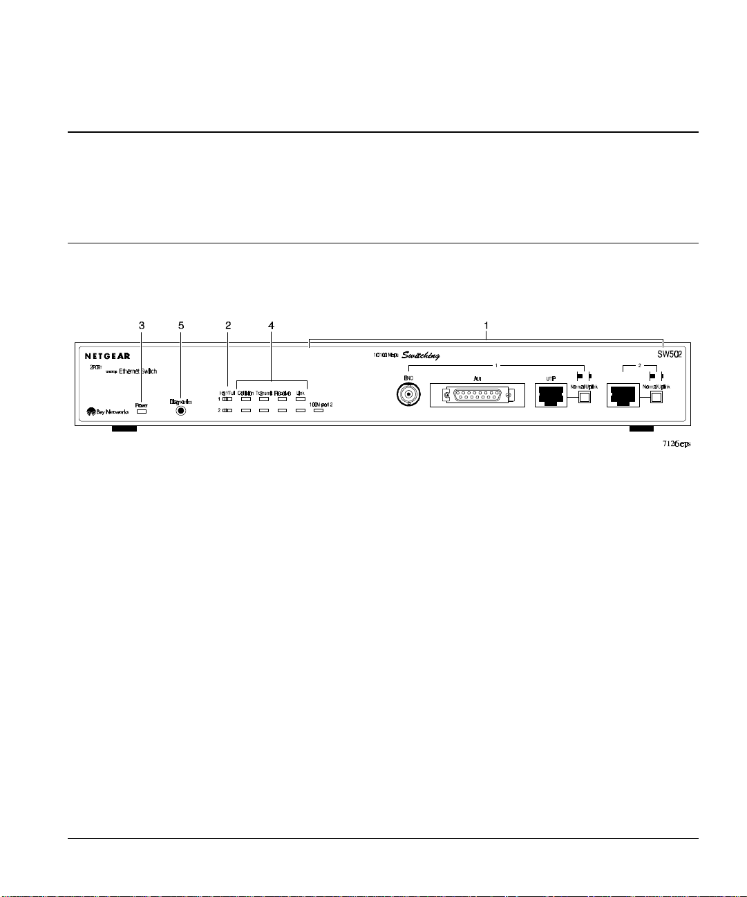
Front Panel
For easier management and control of the switches, familiarize yourself with the ports, display
indicators, diagnostics push button, and panel switches illustrated in Figure 2-1 and Figure 2-2.
1 = BNC, AUI, RJ-45 Ethernet ports, Normal/Uplink push button, and 100M-port 2 LED
2 = Half/Full duplex switch
3 = Power LED
4 = Port status LEDs
5 = Diagnostics push button
Figure 2-1. Front panel of the Model SW502 switch
Physical Description 2-1
Page 10
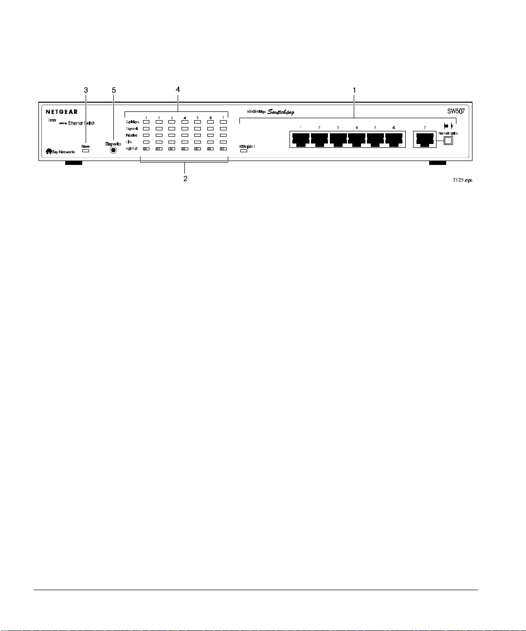
Installation Guide for the Model SW502 and Model SW507 Ethernet Switches
1 = RJ-45 Ethernet ports, Normal/Uplink push button, and 100M-port 7 LED
2 = Half/Full duplex switch
3 = Power LED
4 = Port status LEDs
5 = Diagnostics push button
Figure 2-2. Front panel of the Model SW507 switch
Ethernet Ports
The Model SW502 switch is equipped with one 10 Mbps port and one 10/100 Mbps port for end-node
or daisy-chain connections. The 10 Mbps port supports three communication media, BNC, AUI, and
UTP.
On the Model SW507 switch, six 10 Mbps RJ-45 Ethernet ports and one 10/100 Mbps RJ-45 ports
can be used for either end-node or daisy-chain connection.
RJ-45 Ports, Normal/Uplink Push Button and 100M-Port 2/Port 7 LED
The network access speed for the 10/100 Mbps RJ-45 port on both systems is automatically sensed
and displayed on the front panel by the 100M-port 7 LED. A server or workstation can be connected
to any of the station ports, but only one Fast Ethernet port is provided on the front panel. The 100M
port is Port 2 on the Model SW502 switch and Port 7 on the Model SW507 switch. By connecting
this Fast Ethernet port to a Fast Ethernet switch or hub, you can create a Fast Ethernet backbone of
fast servers.
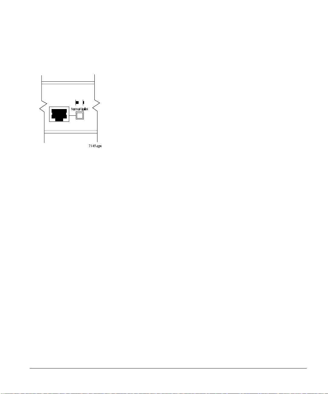
The 10/100 Mbps port and the 10 Mbps port on the Model SW502 switch are equipped with a
Normal/Uplink push button (Figure 2-3) to configure the port for direct server connection or for
connecting with a switch or hub to form an Ethernet backbone. The push button must be set in the
2-2 Physical Description
Page 11
Using the Model SW502 and SW507 Ethernet Switches
Normal position when connecting to a server or computer. For backbone connection to another switch
or hub, the push button must be set in the Uplink position.
Figure 2-3. Fast Ethernet port and Normal/Uplink push button
on the Model SW502 and Model SW507 switches
AUI Port
The AUI port on the Model SW502 switch allows the 10 Mbps port to be connected to an external
transceiver for network extension. Inter-repeater fiber transceivers for 10 BASE-F or FOIRL are
examples of external transceivers. For AUI connector pin assignments, refer to Appendix B,
“Connector Pin Assignments.” For cabling specifications, refer to Appendix C, “Cabling
Specifications.”
BNC Port
The BNC connector, similar to the AUI and RJ-45 ports on the Model SW502 switch, provides
10 Mbps access for end-node or daisy-chain connections. For additional information about the BNC
connector, the BNC T-connector, and the 50
Ω BNC terminator that are used to connect other devices
through this port, refer to Appendix B, “Connector Pin Assignments,” and Chapter 3, “Installation.”
For cabling specifications, refer to Appendix C, “Cabling Specifications.”
Half/Full Duplex Switches
The communication mode can be set to either half-duplex or full-duplex operation. One Half/Full
duplex switch is assigned to each port on the Model SW502 and Model SW507 switches.
Physical Description 2-3
Page 12

Installation Guide for the Model SW502 and Model SW507 Ethernet Switches
Full-duplex mode is supported for all ports. Full-duplex operation only applies to point-to-point
access (such as when a switch is connected to a workstation, a server, or another switch). Repeaters
and hubs use a common collision domain for all communications. When connecting to a repeater or
hub, the associated port should be set to half-duplex operation. When network connection is through
the BNC or AUI interfaces, the Model SW502 switch will operate in half-duplex mode only.
Indicator Panel
The indicator panels on the Model SW502 and Model SW507 switches can be used to monitor and
diagnose the switches. The panel includes a Power LED and port status LEDs.
Power LED
The Power LED indicates if the switch is receiving power (refer to Table 2-1).
Table 2-1. Power LED
Label Color Activity Description
Power Green Steady Light Switch is receiving power and system is running.
No Light Power is disconnected.
Port Status LEDs
The port status LEDs display the status of the port connections and indicate the result of the
diagnostics tests (refer to Table 2-2). These LEDs indicate when packets are being transmitted or
received, when a valid link has been established, or when a collision is occurring. When the LEDs
blink, they correspond to the amount of packets that are transmitted or received and the amount of
collision at the port.
Collisions occur when two or more devices connected to the switch attempt to transmit data at the
same time on the network. When a collision occurs, devices pause and then transmit again after
waiting a specified time. Because these times differ among devices, successive collisions become
increasingly unlikely.
2-4 Physical Description
Page 13

Using the Model SW502 and SW507 Ethernet Switches
Table 2-2. Port status LEDs
Label Color Activity Function
Collision Orange Blinking light Indicates collision during packet transmission on the port.
Transmit Green Blinking light Indicates packet transmission on the port.
Receive Green Blinking light Indicates packets are being received on the port.
Link Green Steady light Indicates a valid link is established on this port.
Light off No valid link is established on this port. For troubleshooting
procedures, refer to Appendix D, “Troubleshooting.”
100M Green Steady light Port is operating at 100 Mbps.
Light off Port is operating at 10 Mbps.
Diagnostics Push Button
The Diagnostics push button initiates the self-diagnostics test to determine the status of the system
components of the switch. The diagnostic test will automatically start when the system is powered on.
To start the diagnostic test after the switch has started operation, press the Diagnostics push button for
two seconds and then release.
After the self-diagnostic test starts, it will continue until all of the components of the ports are tested.
On completion of the diagnostic testing process, the LEDs will continue to blink (refer to Table 2-3).
This blinking indicates the corresponding port components that have failed. The blinking will
continue until the failed port has been repaired.
Table 2-3. Port Diagnostic Test
LED Label Color Activity Diagnostic Display Mode
Collision Orange Blinking light Failed port I.C. test.
Transmit Green Blinking light Failed output queue RAM test.
Receive Green Blinking light Failed input queue RAM test.
Link Green Blinking light Failed routing table RAM test.
For troubleshooting procedures,
refer to Appendix D, “Troubleshooting.”
Physical Description 2-5
Page 14

Installation Guide for the Model SW502 and Model SW507 Ethernet Switches
Rear Panel
The rear panel of both switches contains a standard power receptacle and fans for cooling. The AC
power receptacle provides connection to the AC power outlet. Both of the switches accept between
100 V and 240 V of AC power. Refer to Figure 2-4 for an illustration of the rear panel.
1 = Rear panel fans
2 = AC power outlet
Figure 2-4. Rear panel of the Model SW502 and Model SW507 switches
2-6 Physical Description
Page 15

Chapter 3 Installation
This chapter describes the installation procedures for the NETGEAR Model SW502 and Model
SW507 switches.
Site Preparation
Before you begin installing the switch, prepare the installation site. Make sure the operating
environment meets the physical requirements of the switch. The ambient temperature must be
between 0
Package Contents
Unpack the contents of the package and verify them against the following list:
• Model SW502 switch or Model SW507 switch
• This installation manual
• Owner registration card
• Rack Mount kit
° C and 40° C (32° F and 104° F). The maximum relative humidity must not exceed 90%.
• AC power cord
CAUTION: Use the appropriate power cord as required by your national electrical codes
and ordinances.
The package for the Model SW502 switch contains these additional items:
• BNC T-connector
• 50 Ω BNC terminator
Call your dealer if there are any wrong, missing, or damaged parts. Keep the carton, including the
original packing materials, to repack the switch if there is a need to return it for repair.
To qualify for product updates and product warranty registration, fill in the Owner Registration Card
and return it to NETGEAR, Inc.
Installation 3-1
Page 16

Installation Guide for the Model SW502 and Model SW507 Ethernet Switches
Installing a Switch
To install the switch, follow these steps:
1. Unpack the switch.
2. Choose a location near the devices to be connected and close to an electrical outlet.
3. Follow the instructions for installing the switch on a flat surface or in a rack.
Installing the Switch on a Flat Surface
To install the switch on a tabletop or any other flat surface, follow these steps:
1. Install self-adhesive rubber pads on the bottom of the switch.
Peel off the protective backing from the rubber pads and apply one at each marked location on the
bottom of the switch.
2. Set the switch on a tabletop or any other flat surface. For proper ventilation, make sure that
the switch has at least two inches of space on each side and five inches of space on the back
side.
It is very important that the fans located in the rear panel are not blocked. Restricted airflow could
cause overheating of the components.
3. Install any additional devices in your stack.
Up to four switches can be stacked. For instructions on connecting to additional switches or other
devices, refer to “Connecting to Other Devices” later in this chapter.
Installing the Switch in a Rack
For mounting the switch in a standard 19-inch rack, you need the following tools and materials:
• Two mounting brackets supplied from the Rack Mount Kit
• Eight screws supplied from the Rack Mount Kit to attach the mounting brackets to the switch
• Four screws and nylon washers supplied from the Rack Mount Kit to attach the mounting
brackets to the rack
• #1 Philips screwdriver
• #2 Philips screwdriver
3-2 Installation
Page 17

Installation Guide for the Model SW502 and Model SW507 Ethernet Switches
To install the switch in a rack, follow these steps:
1. Attach the mounting brackets to the sides of the switch as illustrated in Figure 3-1.
Hold a mounting bracket against each side of the switch and align the countersunk screw holes in
the bracket with the bracket mounting holes in the switch.
2. Insert the screws provided with the mounting brackets through each bracket and into the
bracket mounting holes in the switch.
3. Using a #1 Philips screwdriver, tighten the screws to secure each bracket.
4. Hold the switch with the mounting holes in the brackets aligned with the holes in the rack.
Figure 3-1. Attaching mounting brackets to the Model SW502 and Model SW507 switches
5. Insert two pan-head screws with nylon washers through each bracket and into the rack.
6. Using a #2 Philips screwdriver, tighten the screws to secure the switch to the rack.
7. Install any additional devices in your stack.
For proper ventilation, make sure that the switch has at least two inches of space on each side and
five inches of space on the back side. It is very important that the fans located in the rear panel are
not blocked. Restricted airflow could cause overheating of the components.
For instructions on connecting to additional switches or other devices, refer to “Connecting
Devices to the Switch.”
Installation 3-3
Page 18

Installation Guide for the Model SW502 and Model SW507 Ethernet Switches
Connecting Devices to the Switch
To connect devices to the switch, follow these steps:
1. Connect to another device through any of the RJ-45 ports on the switch and set the
Normal/Uplink push button.
The Normal/Uplink push button eliminates the need to use a cross-over cable when connecting
similar devices. Use the following guidelines to configure ports for Normal or Uplink wiring:
− Set the Normal/Uplink push button to the Normal position and use a straight-through cable if
the remote end of the cable is connecting to an MDI-wired device such as a network station or
a router.
− Set the Normal/Uplink push button to the Uplink position and use a straight-through cable if
the remote end of the cable is connecting to an MDI-X device such as a 10 Mbps or 100
Mbps hub or repeater.
− The UTP ports without the Normal/Uplink push button are by default MDI-X ports. An
RJ-45 straight-through cable must be used to connect the two ports, if using one of these UTP
ports to connect to a workstation, a server, or another device with an MDI port.
− An RJ-45 cross-over cable must be used to connect the two ports if using one of the UTP ports
without the Normal/Uplink push button to connect to another MDI-X port.
For further cabling guidelines, refer to Appendix C, “Cabling Specifications.”
2. Connect servers or workstations through either the BNC or AUI port.
On the Model SW502 switch, servers, workstations, or other devices can be connected through the
RJ-45, BNC, or AUI ports. Only one of the three 10 Mbps Ethernet interfaces can be used at a
time.
• The AUI interface can be used to connect an external transceiver. Refer to Appendix C, “Cabling
Specifications,” for further information.
3-4 Installation
Page 19

Installation Guide for the Model SW502 and Model SW507 Ethernet Switches
• When using the BNC interface, refer to Figure 3-2 and follow these steps:
a. Insert the BNC T-connector on the port of the Model SW502 Switch.
b. Connect the coaxial cable that leads from a device on the network to one of the self-locking
ends of the BNC T-connector.
c. Connect the coaxial cable that will go to another device to the remaining end of the self-
locking BNC T-connector. If there are no more devices to be connected, terminate the
connection with the 50
Ω terminator that is provided with the product.
Figure 3-2 illustrates three switches connected through the BNC connector. The separation in
the coaxial cable between the two top switches illustrates the incorporation of other devices.
The figure illustrates that interconnection is not limited to switches.
1=BNC 50 Ω terminator
2=BNC T-connector
Figure 3-2. Connecting devices through the BNC port using the BNC T-connector and 50 terminator
Installation 3-5
Page 20

Installation Guide for the Model SW502 and Model SW507 Ethernet Switches
3. Move the Half/Full duplex switches to the left to set each port on the switch for half-duplex
operation, or move the switches to the right for full-duplex operation.
The Model SW502 switch contains one 10 Mbps Ethernet port with BNC, AUI, or UTP interface,
and one UTP port for either 10 Mbps or 100 Mbps connection that is detected by auto-sensing.
The 10 Mbps ports on the Model SW502 switch support full duplex if the network is connected to
the UTP port. If the network is connected to the AUI or BNC interface, half duplex is supported.
The 10/100 Mbps port supports full-duplex or half-duplex operation.
All of the ports on the Model SW507 switch support half or full-duplex that is controlled through
a push button on the front panel.
A hub or repeater uses a common collision domain for all communications and cannot support full
duplex. When connecting any of the Ethernet or Fast Ethernet ports on the switch to a hub, set the
port to half-duplex operation. When connecting to a workstation, a server, or a switch, the
Half/Full Duplex setting for the port must be the same as the duplex setting on the connecting
device.
4. Connect the appropriate end of the power cable to the power supply receptacle on the back
panel of the switch.
5. Connect the other end of the power cable to a wall receptacle.
The switch automatically selects the proper voltage in the range of 100 to 240 volts. The Power
LED lights and the cooling fans start up after successfully completing the self-tests. The switch is
now operational.
Verifying Installation
Verify network communications by ensuring that all the necessary connections have been made, that
all connected resources can be accessed, and that the LED indicators on the switch are functioning
properly. For additional information, refer to Chapter 4, “Troubleshooting.”
3-6 Installation
Page 21

Chapter 4 Troubleshooting
This chapter provides information about troubleshooting the Model SW502 and Model SW507
switches.
Front Panel Indicators
The front panel indicators can assist you with identifying problems and monitors the Model SW502
and Model SW507 switches.
For UTP connection, if the Link LED does not light up after making a connection, there may be a
defective network adapter, cable, or port. Check for defects and replace the defective component. For
AUI or BNC network connection on the Model SW502 switch, the Link LED will not light until there
is data going through the port.
If the Link LED does not light up when a device is connected to its corresponding UTP port, check
that both the switch and the connected device are powered on. For devices connected to the switch
using twisted-pair cable, check that the cable length does not exceed 100 m. Refer to Chapter 3,
“Installation,” for additional information on twisted-pair or straight-through cable use.
Use the diagnostic procedures described in Chapter 2 , “Physical Description,” to verify that all other
system components are functioning properly. If any component fails the diagnostic test, contact your
NETGEAR distributor for assistance.
Half/Full Duplex Switch
The default setting for the Half/Full duplex switches is half-duplex. If performance degradation is a
problem or if file transfer is slow, make sure that the half- or full-duplex setting of the NETGEAR
switch and the connected device are the same. When connecting any port on the switch to a repeater
or hub, the port on the switch must be set to half-duplex transmission.
Troubleshooting 4-1
Page 22

Installation Guide for the Model SW502 and Model SW507 Ethernet Switches
System Diagnostics
Installation
Verify that all system components have been properly installed. If one or more components are
malfunctioning, test them in an alternate environment where all other components are functioning
properly.
Cabling
Verify that the cabling is correct. Refer to Appendix C, “Cabling Specifications.” Be sure all cable
connectors are securely positioned in the required ports. Straight-through cables should be used for all
standard twisted-pair connections.
Make sure all devices are connected to the network. Equipment may have been accidentally
disconnected.
Network Adapter Cards
Make sure the network adapter cards/network interface cards installed in the workstations are in
working condition. Be sure the AUI media transceiver is functioning properly and that the signal
quality error test has been disabled.
Configuration
If problems occur after altering the network configuration, restore the original connections and
determine the problem by implementing the new changes, one procedure at a time. Ensure that cable
distances, repeater limits, and other physical aspects of the installation do not exceed the
recommendations.
Switch Integrity
If required, verify the integrity of the switch by resetting the switch. Turn off the power to the switch
and then turn the power to the switch back on. If the problem continues and you have completed all
the preceding diagnoses, contact your NETGEAR distributor.
4-2 Troubleshooting
Page 23

Chapter 5 Configuration Examples
This chapter provides an overview of Ethernet technology and the levels of service that are provided
by incorporating the technology of the Model SW502 and Model SW507 switches into your network.
Examples are given to illustrate the role of the switch in several configurations that provide those
different levels of service to networks and users.
Ethernet Technology
When 10BASE-T was originally introduced, multiple repeaters were often used to build large
networks. To increase the number of connections, repeaters were connected together because
individual repeater port densities were often limited to 8 to 24 ports. As structured wiring systems
were implemented, horizontal wiring from the wiring closet to the desktop was designed for a
maximum distance of 100 m. Stackable repeaters eliminated the need for collision domains to extend
over multiple repeater hubs.
100BASE-T Fast Ethernet technology maintains the same concepts of the 10BASE-T technology.
Both use the same Carrier Sense Multiple Access with Collision Detection (CSMA/CD) and Media
Access Control (MAC) protocol. Both 10BASE-T and 100BASE-T Ethernet use the same type of
Ethernet frame and error detection mechanisms. They also support the same star topology using
traditional media types, and are manageable by the same network management protocols. The most
fundamental difference between the two technologies is that 100BASE-T operates 10 times faster than
traditional 10BASE-T.
100BASE-T technology was developed to support the new paradigm and, by using switching
technology, can provide for four distinct levels of service. Combining 10BASE-T, 100BASE-TX, and
switching technology provides:
• 10BASE-T shared bandwidth of 10 megabits per second (Mbps) for the group of active users.
• 10BASE-T dedicated bandwidth of 10 Mbps for each user.
• 100BASE-TX shared bandwidth that equals 100 Mbps for the group of active users.
• 100BASE-TX dedicated bandwidth that equals 100 Mbps for each user.
Configuration Examples 5-1
Page 24

Installation Guide for the Model SW502 and Model SW507 Ethernet Switches
Examples
The NETGEAR Model SW502 and Model SW507 switches are designed to provide flexibility in
configuring your network connections. The switch can be used as a standalone device or can be
connected with standard repeaters, switching hubs, or other interconnection devices in various
configurations. The configuration examples in this chapter illustrate the integration of the switch in
network environments of all sizes and types. These examples include a network of a few workstations
connected to a printer and a segmented network with multiple users and other networking devices.
Bridging from 10BASE-T Ethernet Networks
The Model SW502 switch can function as a two-port bridge connecting traditional Ethernet networks
to 100 Mbps Fast Ethernet networks. Users requiring increased network bandwidth can be grouped
together in the 100 Mbps Fast Ethernet network isolated from the network users who need occasional
network connection to the server. Figure 5-1 illustrates the Model SW502 switch integrated with the
NETGEAR Model EN516 10BASE-T hub and NETGEAR Model FE516 100BASE-T hub.
5-2 Configuration Examples
Page 25

Installation Guide for the Model SW502 and Model SW507 Ethernet Switches
Figure 5-1. Model SW502 switch used as a two-port bridge
Multiport Bridges with High-bandwidth Backbone
Most networks are interconnected with two-port bridges that insert latency into normal
communications. For data that must pass through several bridges to reach its destination, this latency
can degrade communications. With several 10 Mbps bridging ports and the additional internally
bridged 100 Mbps port, the Model SW507 switch can segment a complex network into a single
efficient bridged node, increasing overall bandwidth and throughput. Segments attached to the
switching hub do not have to cross the backbone. They can now reach each other at near-zero latency.
For high-bandwidth applications that transfer data across the network backbone, the 100 Mbps port
provides high-speed fast access. Figure 5-2 illustrates the NETGEAR Model EN516 10BASE-T hubs
and the NETGEAR Model FE516 integrated with the Model SW507 switch.
Configuration Examples 5-3
Page 26

Installation Guide for the Model SW502 and Model SW507 Ethernet Switches
Figure 5-2. Model SW507 switch used as a multiport bridge with high-bandwidth backbone
NOTE: Full-duplex operation only applies to point-to-point access when attaching the
switch to a workstation, server, or another switch. When connecting to a repeater hubs, use
a standard cascaded connection set for half-duplex operation.
5-4 Configuration Examples
Page 27

Installation Guide for the Model SW502 and Model SW507 Ethernet Switches
High-bandwidth File Server
The switch increases bandwidth for workgroups and strengthens network throughput when accessing
high-volume file servers. The Model SW507 switch provides parallel communication between the
high-speed 100 Mbps port and each of the 10 Mbps station ports. This method of communication
allows multiple conversations to occur concurrently. This method also expands overall throughput and
allows key servers or other heavily used devices to be available to more users. Figure 5-3 illustrates
the NETGEAR Model EN516 10BASE-T hubs integrated with the Model SW507 switch.
Figure 5-3. Model SW507 switch used to link high-bandwidth file servers
Configuration Examples 5-5
Page 28

Installation Guide for the Model SW502 and Model SW507 Ethernet Switches
High-speed Link between Switches
The most common LAN implementations use a combination of standard repeater hubs, bridges, and
routers. The bridges and routers become obstacles, reducing overall network throughput. Switching to
higher-speed LANs, such as token ring or FDDI is not a good decision for most users. In addition to
being expensive, you must replace all existing Ethernet cables and adapter cards, restructure your
network, and implement more expensive administration procedures. By using switches to connect
LAN segments, you retain a cohesive LAN structure in which any node can communicate with any
other node in the network. For network applications that require routers, as when interconnecting
different network types, attaching switches directly to a router can improve overall Ethernet
performance. Figure 5-4 illustrates the NETGEAR Model EN516 10BASE-T hubs integrated with
two Model SW507 switches.
Figure 5-4. High-speed link between switches
5-6 Configuration Examples
Page 29

Appendix A Technical Specifications
This appendix provides technical specifications for the NETGEAR Model SW502 and Model SW507
switches.
General Specifications
Network Protocol and Standards Compatibility
ISO/IEC 802-3 (ANSI/IEEE 802.3I) 10BASE-T, 10BASE2, 10BASE5
IEEE 802.3u 100BASE-TX
Data Rate
10 Mbps differential Manchester encoded, IEEE 802.3
100 Mbps with 4B5B encoding and MLT-3 physical interface for 100BASE-TX
Interface Options
AUI connector for transceiver interface
RJ-45 connector for 10BASE-T Ethernet interface
BNC connector for 10BASE2 coax interface
Electrical Specifications
Power consumption: 22 W (Model SW502 switch)
33 W (Model SW507 switch)
Technical Specifications A-1
Page 30

Installation Guide for the Model SW502 and Model SW507 Ethernet Switches
Physical Specifications
Dimensions: (W) 13 by (H) 1.7 by (D) 8 in
(W) 33.0 by (H) 4.3 by (D) 20.3 cm
Weight: 4.84 lb (2.2 kg) Model SW502 switch
5.02 lb (2.3 kg) Model SW507 switch
Environmental Specifications
Operating temperature: 0° to 40° C
Storage temperature: –32° to 104° C
Operating humidity: 90% maximum relative humidity, noncondensing
Storage humidity: 95% maximum relative humidity, noncondensing
Operating altitude: 10,000 ft (3,000 m) maximum
Storage altitude: 10,000 ft (3,000 m) maximum
Electromagnetic Emissions
Meets requirements of:
CE mark, commercial
FCC Part 15, Subpart B, Class A
EN 55 022 (CISPR 22), Class A
VCCI Class 1
Electromagnetic Susceptibility
CE mark, commercial
Electrostatic discharge (ESD): IEC 801-2, Level 2/3
Radiated electromagnetic field: IEC 801-3, Level 2
Electrical fast transient/burst: IEC 801-4, Level 2
Electrical surge: IEC 801-5, Level 1/2
A-2 Technical Specifications
Page 31

Installation Guide for the Model SW502 and Model SW507 Ethernet Switches
Safety Agency Approvals
CE mark, commercial
UL listed (UL 1950)
CSA certified (CSA 22.2 #950)
TUV licensed (EN 60 950)
Performance Specifications
Frame filter rate: 14,800 frames/second, maximum on 10 Mbps port
148,000 frames/second maximum on 100 Mbps port
Frame forward rate: 14,800 frames/second, maximum on 10 Mbps port
148,000 frames/second maximum on 100 Mbps port
Network latency: Less than 20 microseconds in cut-through mode
Less than 70 microseconds for 64-byte frames in
store-and-forward mode
Address database size: 4 K media access control (MAC) addresses per port
Addressing: 48-bit MAC address
Queue buffer: 64 Kbytes/port for 10 Mbps ports
160 Kbytes/port for 10/100 Mbps ports
Frame length: 64-1518 bytes
Technical Specifications A-3
Page 32

Appendix B Connector Pin Assignments
This appendix provides information on the RJ-45 connectors that are used for the Model SW502 and
Model SW507 switches and on the AUI and BNC connectors that are used for the Model SW502
switch.
RJ-45 Connector
The RJ-45 connector is used to connect stations, hubs, and switches through unshielded twisted-pair
cable and supports 10/100 Mbps data transmission. The RJ-45 connector accepts four pair Category 5
UTP or screened 100
Figure B-1. RJ-45 connector
Ω twisted-pair cable.
Table B-1. RJ-45 connector pin assignments
Pin Normal assignment
station ports 1-7
1 Input Receive Data + Output Transmit Data +
2 Input Receive Data – Output Transmit Data –
3 Output Transmit Data + Input Receive Data +
6 Output Transmit Data – Input Receive Data –
4,5,7,8 Not Used Not Used
Connector Pin Assignments B-1
Uplink assignment
cascade Port 7
Page 33

Installation Guide for the Model SW502 and Model SW507 Ethernet Switches
AUI Connector
The AUI connector for the Model SW502 switch supports 10 Mbps data transmission and connects
the switch through an external transceiver to other devices. An inter-repeater fiber link for 10BASE-F
or FOIRL are examples for such applications.
Figure B-2. AUI connector pin assignment
Table B-2. AUI connector pin assignments
Pin Signal
1, 4, 11, 14, 15 Ground
2 CI-A
3 DO-A
5 DI-A
6 +12V DC return
7, 8 Not used
9 CI-B
10 DO-B
12 DI-B
13 +12V DC
B-2 Connector Pin Assignments
Page 34

Installation Guide for the Model SW502 and Model SW507 Ethernet Switches
BNC Connector
The BNC connector for the Model SW502 switch supports 10 Mbps data transmission and connects
the switch to other devices.
1 = center conductor
2 = ground shield
Figure B-3. BNC connector on the Model SW502 switch
BNC T-Connector and 50 ΩΩ Terminator
The BNC port on the Model SW502 switch, together with the BNC T-connector and the 50 Ω
terminator are used for connection to a thin coaxial segment. A thin coaxial Ethernet segment supports
10 Mbps data transmission. For information on connecting through the BNC port, refer to Chapter 3,
“Installation,” and Appendix C, “Cabling Specifications.”
Figure B-4. BNC connector and terminator
Connector Pin Assignments B-3
Page 35

Appendix C Cabling Specifications
This appendix provides specifications for cables used with the Model SW502 and Model 507
switches.
Cable Specifications
Category 5 twisted-pair cable must be used for 100 Mbps connections. For 10 Mbps connections,
Category 3, 4, or 5 cables can be used; however, NETGEAR highly recommends Category 5.
Category 5 cable will avoid unnecessary expenses or confusion if you upgrade to Fast Ethernet.
Table C-1. Electrical requirements of Category 3, 4, and 5 cables
Specification Category 3 Category 4 Category 5
Number of pairs Four Four Four
Impedance 100 Ω ± 15% 100 Ω ± 15% 100 Ω ± 15%
Mutual capacitance
at 1 KHz
Maximum attenuation
(dB per 100 m, at 20
NEXT loss
(dB minimum)
° C)
6.6 nF
per 100 m
at 4 MHz: 5.6
at 10 MHz: 9.8
at 16 MHz: 13.1
at 4 MHz: 32
at 10 MHz: 26
at 16 MHz: 23
5.6 nF
per 100 m
at 4 MHz: 4.3
at 10 MHz: 7.2
at 16 MHz: 8.9
at 4 MHz: 47
at 10 MHz: 41
at 16 MHz: 38
5.6 nF
per 100 m
at 16 MHz: 8.2
at 31 MHz: 11.7
at 100 MHz: 22
at 16 MHz: 44
at 31 MHz: 39
at 100 MHz: 32
Cabling Specifications C-1
Page 36

Installation Guide for the Model SW502 and Model SW507 Ethernet Switches
Twisted-pair Cables
For two devices to communicate, the transmitter of each device must be connected to the receiver of
the other device. The cross-over function is usually implemented internally as part of the circuitry in
the device. Some repeaters and switch ports are media-dependent interfaces with cross-over ports,
referred to as MDI-X or Normal ports. Computers and workstation adapter cards are usually mediadependent interface ports, referred to as MDI or Uplink ports. Refer to the installation instructions in
Chapter 3, “Installation,” for appropriate cable use and connection.
Figure C-1. Straight-through twisted-pair cable
Figure C-2. Cross-over twisted-pair cable
C-2 Cabling Specifications
Page 37

Installation Guide for the Model SW502 and Model SW507 Ethernet Switches
Coaxial 50 ΩΩ Cable
The 50 Ω coaxial cable, together with the BNC T-connector and the 50 Ω terminator, allow a user to
construct a 10BASE-2 network.
Table C-2. Specifications of 10BASE2 (ThinNet) RG 58 A/U or RG 58 C/U coaxial cable
Characteristic
impedance
50 +/- 2 Ω <8.5 db @ 10 MHz
Attenuation
(185m cable)
<6.0 db @ 5 MHz
Transfer
impedance
20 m
Ω @ 1 MHz
Ω @ 10 MHz
100 m
Ω @ 100 MHz
500 m
DC loop
resistance
50 m
Ω /meter
The Ethernet specifications limit segments to 30 stations and specify a minimum of 0.5 m between
any two stations. For optimal configuration control and network management, it is recommended that
segments be limited to five attached stations. Ethernet specifications limit segments to 600 ft (185 m)
in length. For optimal configuration control and network management, it is recommended that
segments be limited to 100 ft (30 m).
AUI Cable
The AUI cable connects the AUI port on the Model SW502 switch to a transceiver. The Ethernet
specifications limit the cable length to 164 ft (50 m).
Cabling Specifications C-3
Page 38

Installation Guide for the Model SW502 and Model SW507 Ethernet Switches
Table C-3. Specifications of AUI cable
Electrical characteristic AUI cable specifications
Nominal dc resistance <1.75 Ω per conductor
Pair-to-pair balanced crosstalk Minimum 40 dB attenuation from 5 MHz to 10 MHz
Differential characteristic impedance 78 +/- 5
<3 Ω difference between pairs
Transfer impedance
Attenuation
Timing jitter
Total signal delay
<10 mΩ @ 500 KHz
<3 mΩ @ 2 MHz
<3 mΩ @ 10 MHz
<30 mΩ @ 100 MHz
<3 dB from 5 MHz to 10 MHz
<1.0 ns introduced by the cable system
<257 ns
Ω at 10 MHz
C-4 Cabling Specifications
Page 39

Index
—A—
AUI
connecting through, 3-4
connector pin assignments, B-2
port, 2-3
—B—
BNC
connecting through, 3-4
connector, B-3
port, 2-3
T-connector and 50-ohm terminator, B-3
T-connector, using in installation, 3-5
—C—
cable specifications, C-1
AUI, C-3
Category 3, C-1
Category 4, C-1
Category 5, C-1
coaxial 50, C-3
twisted-pair, C-2
cabling
troubleshooting, 4-2
configuration
troubleshooting, 4-2
configuration examples
bridging from 10BASE-T Ethernet networks, 5-2
high-bandwidth file server, 5-5
high-speed link between switches, 5-6
multiport bridges with high bandwidth, 5-3
connector
AUI, 3-4
AUI pin assignments, B-2
BNC, B-3
BNC T, using in installation, 3-5
BNC-T connector and 50-ohm terminator, B-3
RJ-45, pin assignment, B-1
contents, package, 3-1
customer support, iii
—D—
diagnostics
100M-port 2 LED, 2-2
100M-port 7 LED, 2-2
Diagnostics push button, 2-5
port diagnostics, table, 2-5
Power LED, 2-4
system, 4-2
—E—
Ethernet technology, 5-1
—F—
features, 1-1
front panel, 2-1
—H—
Half/Full duplex switch, 2-3
setting, 3-6
troubleshooting, 4-1
Index-1
Page 40

Installation Guide for the Model SW502 and Model SW507 Ethernet Switches
—I—
Indicator Panel, 2-4
installation, 3-1
connecting devices to switch, 3-4
in rack, 3-2
on flat surface, 3-2
troubleshooting, 4-2
verifying, 3-6
—L—
LEDs
100M-port 2, 2-2
100M-port 7, 2-2
port diagnostic table, 2-5
port status, 2-4
Power, 2-4
—N—
network adapter cards
troubleshooting, 4-2
Normal/Uplink push button, 2-2
setting, 3-4
—P—
panel
Front, 2-1
Indicator, 2-4
Rear, 2-6
port status LED, 2-4
ports
AUI, 2-3
BNC, 2-3
RJ-45, 2-2
power
AC, 2-6
consumption, A-1
Power LED, 2-4
prerequisite knowledge, 1-1
—R—
rear panel, 2-6
RJ-45
connecting through, 3-4
connector pin assignment, B-1
ports, 2-2
—S—
setting
Half/Full duplex switch, 3-6
Normal/Uplink push button, 3-4
specifications, cable, C-1
AUI, C-3
Category 3, C-1
Category 4, C-1
Category 5, C-1
coaxial 50-ohm, C-3
twisted-pair, C-2
specifications, technical, A-1
Certificate of the Manufacturer/Importer, ii
data rate, A-1
electrical, A-1
electromagnetic emissions, A-2
electromagnetic susceptibility, A-2
EN 55 022 Declaration of Conformance, ii
environmental, A-2
FCC Statement, ii
interface options, A-1
network protocol, A-1
performance specifications, A-3
physical, A-2
safety agency approvals, A-3
standards compatibility, A-1
VCCI Statement, iii
switch integrity
troubleshooting, 4-2
Index-2
Page 41

—T—
troubleshooting, 4-1
cabling, 4-2
configuration, 4-2
front panel indicators, 4-1
Half/Full duplex switch, 4-1
installation, 4-2
network adapter cards, 4-2
Installation Guide for the Model SW502 and Model SW507 Ethernet Switches
switch integrity, 4-2
system diagnostics, 4-2
—U—
UTP. See connector, RJ-45 and RJ-45 connector
—W—
World Wide Web, iii
Index-3
 Loading...