

Page 1

Installation Guide for
the Model SW108
Ethernet Switch
NETGEAR
A Bay Networks Company
48015 Warm Springs Blvd.
Fremont, CA 94539
USA
M-SW108NA-0
June 1997
, Inc.
Page 2

© 1997 by NETGEAR, Inc. All rights reserved.
Trademarks
Bay Networks is a registered trademark of Bay Networks, Inc. NETGEAR is a trademark of Bay Networks, Inc.
Other brand and product names are registered trademarks or trademarks of their respective holders.
Statement of Conditions
In the interest of improving internal design, operational function, and/or reliability, NETGEAR reserves the right to
make changes to the products described in this document without notice.
NETGEAR does not assume any liability that may occur due to the use or application of the product(s) or circuit
layout(s) described herein.
Federal Communications Commission (FCC) Declaration of Conformity Statement
Note: This equipment has been tested and found to comply with the limits for a Class A digital device, pursuant to
Part 15 of the FCC rules. These limits are designed to provide reasonable protection against harmful interference when
the equipment is operated in a commercial environment. This equipment generates, uses, and can radiate radio frequency
energy. If it is not installed and used in accordance with the instruction manual, it may cause harmful interference to
radio communications. Operation of this equipment in a residential area is likely to cause harmful interference, in which
case users will be required to take whatever measures may be necessary to correct the interference at their own expense.
EN 55 022 Statement
This is to certify that the NETGEAR Model SW108 switch is shielded against the generation of radio interference in
accordance with the application of Council Directive 89/336/EEC, Article 4a. Conformity is declared by the application
of EN 55 022 Class A (CISPR 22).
Warning:
which case, the user may be required to take appropriate measures.
This is a Class A product. In a domestic en vironment, this product may cause radio interference, in
Bestätigung des Herstellers/Importeurs
Es wird hiermit bestätigt, daß das NETGEAR Model SW108 switch gemäß der im BMPT-AmtsblVfg 243/1991 und Vfg
46/1992 aufgeführten Bestimmungen entstört ist. Das vorschriftsmäßige Betreiben einiger Geräte (z.B. Testsender) kann
jedoch gewissen Beschränkungen unterliegen. Lesen Sie dazu bitte die Anmerkungen in der Betriebsanleitung.
Das Bundesamt für Zulassungen in der Telekommunikation wurde davon unterrichtet, daß dieses Gerät auf den Markt
gebracht wurde und es ist berechtigt, die Serie auf die Erfüllung der Vorschriften hin zu überprüfen.
ii
Page 3

Voluntary Control Council for Interference (VCCI) Statement
This equipment is in the first category (information equipment to be used in commercial and/or industrial areas) and
conforms to the standards set by the Voluntary Control Council for Interference by Data Processing Equipment and
Electronic Office Machines that are aimed at preventing radio interference in commercial and/or industrial areas.
Consequently, when this equipment is used in a residential area or in an adjacent area thereto, radio interference may be
caused to equipment such as radios and TV receivers.
Customer Support
For assistance with installing and configuring your NETGEAR system or with post-installation questions or problems,
contact your point of purchase representative.
To contact customer support or to purchase additional copies of this document and publications for other NETGEAR
products, you can contact NETGEAR at the following numbers:
• Phone:
U.S./Canada: 1-800-211-2069
Japan: 0031-1-26133
Europe: (44) 171-571-5120
Australia: 1- 800-14-20-46
• Fax:
U.S./Canada: 510-498-2609
World Wide W eb
NETGEAR maintains a World Wide Web Home Page that you can access at the universal resource locator (URL)
http://NETGEAR.baynetworks.com. A direct connection to the Internet and a Web browser such as Internet Explorer
or Netscape are required.
iii
Page 4

iv Contents v
Page 5

Contents
Chapter 1
Introduction
Benefits of Using Switching Technology .........................................................................1-1
Types of Ethernet Switches ............................................................................................1-2
Model SW108 Switch Overview .....................................................................................1-2
Features .........................................................................................................................1-3
Chapter 2
Physical Description
Front Panel .....................................................................................................................2-1
Ethernet Ports ..........................................................................................................2-2
Normal/Uplink Push Button ......................................................................................2-2
LEDs ........................................................................................................................2-3
Rear Panel ......................................................................................................................2-4
FDX and HDX Duplex Toggle Switches ...................................................................2-4
Chapter 3
Applications
Desktop Switching ..........................................................................................................3-2
Segment Switching .........................................................................................................3-3
Chapter 4
Installation
Preparing the Site ...........................................................................................................4-1
Package Contents ..........................................................................................................4-1
Installing the Switch on a Desktop ..................................................................................4-2
Connecting Devices to the Switch ..................................................................................4-2
Verifying Installation ........................................................................................................4-3
Page 6

Chapter 5
Troubleshooting
Troubleshooting the Switch and the Network .................................................................5-1
Appendix A
Technical Specifications
General Specifications ................................................................................................... A-1
Appendix B
Connector Pin Assignments
RJ-45 Plug and vista RJ-45 Connector ......................................................................... B-1
Appendix C
Cabling Guidelines
Ethernet T echnology ......................................................................................................C-1
Cable Specifications ......................................................................................................C-1
Twisted Pair Cables ....................................................................................................... C-2
Index
vi Contents
Page 7

Figures
Figure 2-1. Front panel of the Model SW108 switch ..................................................2-1
Figure 2-2. The vista RJ-45 connector with built-in LEDs ..........................................2-2
Figure 2-3. Rear panel of the Model SW108 switch ...................................................2-4
Figure 3-1. Using the Model SW108 switch for desktop switching .............................3-2
Figure 3-2. Model SW108 switch used as a segment switch .....................................3-3
Figure B-1. RJ-45 plug and vista RJ-45 connector with built-in LEDs ....................... B-1
Figure C-1. Straight-through twisted pair cable .........................................................C-3
Figure C-2. Crossover twisted pair cable ...................................................................C-3
Figures vii
Page 8

Tables
Table 2-1. LED descriptions ......................................................................................2-3
Table 5-1. Troubleshooting ........................................................................................5-1
Table B-1. RJ-45 plug and vista RJ-45 connector pin assignments ......................... B-2
Table C-1. Electrical requirements of Category 3, 4, and 5 cables .......................... C-2
viii Tables
Page 9

Chapter 1
Introduction
Congratulations on your purchase of the NETGEAR™ Model SW108 8-port Ethernet Switch.
The Model SW108 switch segments Ethernet networks to relieve bandwidth congestion instantly,
without having to replace network wiring, interface cards, or software.
This guide describes how to install and use the switch. It includes physical configuration
guidelines for connecting multiple 10 megabit per second (Mbps) hubs and for connecting
10 Mbps Ethernet stations, PCs, and servers.
Benefits of Using Switching Technology
Most of installed networks today are based on shared network technology. With this technology,
a number of users or groups of users share 10 Mbps, 100 Mbps, or other amounts of available
network bandwidth (network capacity). For example, with a total of 10 users, the average
bandwidth available to each user on a 10 Mbps network is calculated as 10/10 Mbps, or 1 Mbps
of bandwidth per user.
Ethernet switches significantly increase network throughput by segmenting network traffic. They
check traffic coming in to each port to learn which network device is located on which segment.
Based on this information, switches forward cross-segment traffic only to the appropriate se gment.
The traffic will not show up in the other segments since it is filtered out. In this way, network
capacity is fully reserved for traffic destined for that segment only, and other segments are not
saturated with unnecessary traffic.
Ethernet switches provide private, dedicated, 10 Mbps capacity to each connected PC/server or
hub/workgroup segment, which is significantly higher than in a shared environment. The higher
bandwidth enables applications such as multimedia, imaging, video, or high- performance
client-server functions among users who are spread out over the network.
Introduction 1-1
Page 10

Installation Guide for the Model SW108 Ethernet Switch
This bandwidth improvement is accomplished very easily, with no change to the desktop (the
network interface cards or software, and network wiring). As a result, the performance upgrade
and the applications it enables are obtained very quickly and at a low cost.
Types of Ethernet Switches
Ethernet switches can be classified in different ways—as desktop switches or segment switches.
A
desktop switch
users need the full 10 Mbps network throughput to support the applications. Often, these switches
support only a single MAC (media access control) address per port, and are relatively inexpensiv e
compared to a segment switch. A
workgroup on each port, with each port having significant memory buffering and supporting
thousands of MAC addresses.
Switches can also be classified by speed. As the name suggests, 10 Mbps switches support only
10 Mbps connections. Similarly, 100 Mbps switches support only 100 Mbps connections. Usually,
10/100 Mbps switches have primarily 10 Mbps ports with one or few 100 Mbps ports. Autosensing
10/100 Mbps switches support 10 Mbps or 100 Mbps connections on each port and are the most
versatile and adaptable switch type.
is designed to support one or a few PCs per port. It is generally used when
segment switch
, in contrast, is designed to support an entire
Model SW108 Switch Overview
The Model SW108 switch is a 10 Mbps switch that can be used as either a segment or a desktop
switch. Its design enables it to function as a segment switching, yet its pricing makes the switch
very affordable for use in desktop applications.
Up to 4 switching paths (8 paths in full-duplex mode) can be established at the same time, with
each path crossing two ports, performing switching that sends packets to the appropriate port
according to the destination address scanned from the packet header. This technique reduces the
latency of packet transmission to 75 microseconds (µs) or less. Compared to approximately 800 µs
for a bridge or 1800 µs for a router, the Model SW108 switch deliv ers a major impro v ement in the
network performance.
Because the Model SW108 switch is a device functioning on the MAC layer , the switch is protocol
independent and is compatible with IEEE802.3, IEEE802.3u, TCP/IP, NetWare, DECnet, and
XNS protocols.
1-2 Introduction
Page 11

Installation Guide for the Model SW108 Ethernet Switch
Features
The Model SW108 switch has the following key features:
• Eight switched, 10 Mbps, Ethernet 10BASE-T ports
• Full-duplex or half-duplex mode of operation
Full-duplex mode doubles throughput of point-to-point connections by letting individual
ports transmit and receive concurrently when the connecting device also supports
full-duplex mode.
• Easy plug-and-play installation with no software to configure, saving time and minimizing
the potential for configuration errors
• Eight vista RJ-45 connector ports
Each port has built-in LEDs to monitor individual port status.
• LEDs provide network traffic status and information about data transmission speed
• Normal/Uplink push button to simplify network extension
The switch can be connected to a hub using a simple, straight-through cable.
• Compact, sturdy metal case design, which enables easy desktop, wall-mount, or under-desk
installation
• Wire-speed filtering and forwarding to provide a “traffic cop” function by directing traffic
to the appropriate port or network segment without slowing down the traffic
• Low latency store-and-forward transmission mode with leading edge to leading edge of
less than 75 µs
• Automatic address learning function to build the packet forwarding information table.
The table contains up to 8,000 MAC addresses (that is, the switch can support networks
with as many as 8,000 devices).
• One megabyte (MB) buffer provided for the 10 Mbps ports
• IEEE 802.3 10BASE-T standard compliance
Introduction 1-3
Page 12

Page 13

Chapter 2
Physical Description
This chapter explains the hardware features of the NETGEAR Model SW108 Ethernet switch. It is
divided into sections explaining the front and rear panels of the switch. Use the key at the bottom
of each illustration to identify the panel components.
Front Panel
For easier management and control of the switch, familiarize yourself with the ports, LEDs, and
Normal/Uplink push button switches on the front panel, as illustrated in Figure 2-1.
3
1
10 BASE-T ETHERNET SWITCH SW108
1 2 3 4
Power
Key:
1 = Power LED
2 = Rx/Tx and Collision LEDs for ports 1 through 8
3 =10 Mbps Ethernet ports1 through 8 with Link and FDX LEDs on each port
4 = Normal/Uplink push button to configure port 8
5 6 7 8
Green = Rx/Tx Yellow = Collision
2
1234
10 Mbps
Link FDX
5678
4
Normal/Uplink
886EA
Figure 2-1. Front panel of the Model SW108 switch
Physical Description 2-1
Page 14
Installation Guide for the Model SW108 Ethernet Switch
Ethernet Ports
The Model SW108 switch is equipped with eight 10 Mbps Ethernet ports that support one cable
connection, unshielded twisted pair (UTP) cable. An eight-pin RJ-45 plug is used for connection
to these ports.
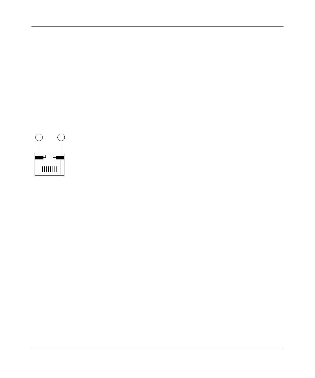
Each port uses vista RJ-45 connectors that have built-in LEDs, as illustrated in Figure 2-2. The
LEDs, as described in Table 2-1, indicate that the connection to the port is valid and that the port
is operating in full-duplex mode.
For further information about the vista RJ-45 connector and the RJ-45 plug, refer to Chapter B,
“Connector Pin Assignments.”
1 2
735EA
Key:
1 = Link LED
2 = FDX LED
Figure 2-2. The vista RJ-45 connector with built-in LEDs
Normal/Uplink Push Button
As illustrated in Figure 2-1, port 8 on the switch is equipped with a Normal/Uplink push button
that allows you to select normal (MDI-X) wiring or uplink (MDI) wiring. The port is configured
for normal wiring when the push button is in the out position for connection to a PC. When the
push button is pressed in, the port is configured for uplink wiring for connection to another switch
or a hub using simple, straight-through wiring.
2-2 Physical Description
Page 15

Installation Guide for the Model SW108 Ethernet Switch
LEDs
You use LEDs on the Model SW108 switch to monitor and diagnose the devices. LEDs on the
front panel of the switch and two LEDs on each port allow you to identify the following
information:
• Status of the switch power supply
• Data transmission or receive activity
• Collision occurrence
• Full- or half-duplex transmission
Table 2-1 describes each LED on the front panel of the switch. See Figure 2-1 for the locations
of the LEDs.
Table 2-1. LED descriptions
Label Color Activity Description
Power Green On Power is supplied to the switch.
Off Power is disconnected.
Rx/Tx/Collision Green On or
blinking
Off There is no packet transmission or reception occurring on
Yellow Blinking Data collision is occurring on the port. The blinking action
Link Green On A valid link is established on the port.
Off A link is not established on the port.
FDX Green On The port is operating in full-duplex mode.
Off The port is operating in half-duplex mode.
Packet transmission or reception is occurring on the port.
the port.
corresponds to the amount of collisions.
When a collision occurs, the connected device pauses
and transmits again after waiting a specified time.
A moderate amount of collision is normal.
Physical Description 2-3
Page 16

Installation Guide for the Model SW108 Ethernet Switch
Rear Panel
As illustrated in Figure 2-3, the rear panel has full-duplex (FDX), and half-duplex (HDX) toggle
switches, a ground clip, and a standard AC power receptacle.
1
2
Force port to operate at Half Duplex mode
HDXFDX -
Force port to operate at Full Duplex and Half Duplex mode only
10 Mbps
1
FDX
HDX
8
3
– +
887EA
Key:
1 = Ground clip
2 = FDX and HDX toggle switches to set the duplex mode of each 10 Mbps port
3 = AC power outlet
Figure 2-3. Rear panel of the Model SW108 switch
FDX and HDX Duplex Toggle Switches
Full-duplex mode is supported for all 10 Mbps ports and allows a port to transmit and receive data
at the same time. Full-duplex operation applies only to point-to-point access where the remote
device also supports full-duplex. In half-duplex mode, the port can either transmit or receive data
at any time, but not transmit or receive data concurrently.
As illustrated in Figure 2-3, one full-duplex (FDX) and half-duplex (HDX) toggle switch is
assigned to each 10 Mbps port on the switch to set the communication mode to either full-duplex
or half-duplex mode.
2-4 Physical Description
Page 17

Chapter 3
Applications
This chapter presents an overview of the levels of service provided by incorporating the
technology of the NETGEAR Model SW108 Ethernet switch into your network.
The Model SW108 Ethernet switch is designed to provide flexibility in configuring your network
connections. Each switch can be used as a standalone device or can be used with 10 Mbps hubs
or other interconnection devices in various configurations. The configuration examples in this
chapter illustrate the integration of the switches in network environments of all sizes and types.
These examples include a network of a few workstations connected to a printer or in a segmented
network with multiple users or workgroups and other networking devices.
Applications 3-1
Page 18

Installation Guide for the Model SW108 Ethernet Switch
Desktop Switching
Figure 3-1 illustrates the Model SW108 switch used as a desktop switch to build a small network
that enables users to have 10 Mbps access to a file server.
1
2
3
7630EA
Key:
1 = Server with 10 Mbps connection
2 = Model SW108 Ethernet switch (Normal/Uplink push button set to Normal position)
3 = PCs with 10 Mbps connection
Figure 3-1. Using the Model SW108 switch for desktop switching
If a full-duplex adapter card is installed in the server or PC, a 20 Mbps connection
Note:
is possible on the port where the server or PC is connected.
3-2 Applications
Page 19
Installation Guide for the Model SW108 Ethernet Switch
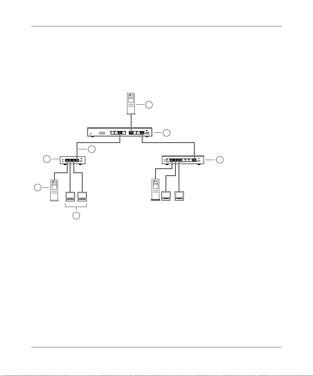
Segment Switching
The Model SW108 switch can segment a network into multiple connected pieces, increasing
overall bandwidth and throughput. Figure 3-2 illustrates the Model SW108 Ethernet switch
segmenting networks that are built with the NETGEAR Model EN104 and Model EN108
Ethernet hubs.
1
2
3
4
Link Rx
1234
1234 5678
Link Rx
1
6
Key:
1 = Server with 10 Mbps connection
2 = Model SW108 Ethernet switch (Normal/Uplink push button set to Normal position)
3 =10 Mbps connection
4 = Model EN104 Ethernet hub (Normal/Uplink push button set to Uplink position)
5 = Model EN108 Ethernet hub (Normal/Uplink push button set to Uplink position)
6 = PCs with 10 Mbps connection
5
7629EA
Figure 3-2. Model SW108 switch used as a segment switch
Applications 3-3
Page 20

Page 21

Chapter 4
Installation
This chapter provides information about installing the Model SW108 Ethernet switch and
information about verifying installation.
Preparing the Site
Before you begin installing the switch, prepare the installation site. Make sure the operating
environment meets the physical requirements of the equipment as described in Appendix A,
“Technical Specifications.”
Package Contents
This package should contain the following items:
• Model SW108 Ethernet switch
• DC power adapter
• Warranty and Owner Registration Card
• This installation guide
Call your reseller or customer support in your area if there are any wrong, missing, or damaged
parts. Refer to page iii for the location of customer support in your area.
Keep the carton, including the original packing materials. Use them to repack the switch if you
need to return it for repair.
To qualify for product updates and product warranty registrations, fill in the Warranty and Owner
Registration Card within 30 days of purchase and return it to NETGEAR, Inc.
Installation 4-1
Page 22

Installation Guide for the Model SW108 Ethernet Switch
Installing the Switch on a Desktop
Choose a location near the devices to be connected and close to an electrical outlet. Set the switch
on a desktop or tabletop, allowing at least two inches (5 cm) of space on all sides to prevent
restriction of airflow.
Connecting Devices to the Switch
Before connecting the switch, refer to Chapter 3, “Applications,” for information to help you
determine the appropriate configuration for your networking needs.
To connect the switch, follow these steps:
Connect the devices to the ports on the switch, using Category 5 UTP cable and an
1.
RJ-45 plug.
2.
Set the Normal/Uplink push button.
The Normal/Uplink push button eliminates the need to use a crossover twisted pair cable
for daisy-chaining or cascading. Use the following guidelines to configure port 1 on the
Model SW108 switch:
• Configure the port for normal wiring if the port is to be connected to an uplink-wired
device, such as a network station or a PC.
• Configure the port for uplink wiring if the port is to be connected to a normal-wired
device, such as a hub or another switch.
The remaining (normal) ports on the Model SW108 switch cannot be configured for uplink
wiring. If you are using one of these ports to connect to another normal port, you must use
a crossover twisted pair cable to connect the two ports. Refer to Appendix C, “Cabling
Guidelines,” for information about crossover twisted pair cable and straight-through twisted
pair cable.
4-2 Installation
Page 23

Installation Guide for the Model SW108 Ethernet Switch
3.
Set the FDX or HDX toggle switches on the rear panel for the selected duplex mode.
A hub and repeater use a common collision domain for all communications and cannot
support full-duplex mode. When connecting any of the 10 Mbps ports on the switch to a
hub, set the port to HDX. When connecting to a PC, a server, or another switch, the duplex
setting for the port must be the same as the duplex setting on the PC, server, or other switch
Whenever a port changes between FDX and HDX mode, the Model SW108
Note:
switch resets and traffic in all ports temporarily stops. When the switch resets, the list
of learned addresses is not affected.
4.
Connect one end of the DC power adapter cable to the power outlet on the rear panel of
the switch and the other end of the power adapter cable to the wall outlet.
Verifying Installation
When the installation is complete and power has been applied to the switch, the following
conditions should exist:
• The Power LED on the front panel is on.
.
• The Link LED on each connected port is on.
• The Rx/Tx/Collision LED on the connected port blinks green when data is being
received by the port and blinks yellow when data collision is occurring on the port.
If you encounter any problems, refer to Chapter 5, “Troubleshooting.”
Installation 4-3
Page 24

Page 25

Chapter 5
Troubleshooting
This chapter provides information about troubleshooting the NETGEAR Model SW108 Ethernet
switch.
Troubleshooting the Switch and the Network
To troubleshoot the switch and the network, refer to Table 5-1.
Table 5-1. Troubleshooting
Symptom Activity Check
No power at switch Pow er LED off Check the power cord connections and make sure the ends are
properly plugged into the switch and the wall outlet.
Rx/Tx Collision LED
blinking
When configured to
operate in full-duplex
mode, the port is
operating in half-duplex
mode
Troubleshooting 5-1
Blinking yellow Data collisions are normal on Ethernet networks and occur
when two or more computers transmit data on the network
simultaneously. Computers that caused the collision retry
transmission at different intervals until the transmission
succeeds. Excessive collisions can result when multiple
switches are connected and when many computers are
connected on the network. Incorrect cab ling, connectors, wiring
techniques, and mismatched duplex operating mode settings
are other causes for excessive collisions.
FDX LED off The connected device may not be able to operate at
half-duplex or may not have the ability to signal the operating
mode. Verify that the connected device is operational.
Page 26

Installation Guide for the Model SW108 Ethernet Switch
Table 5-1. Troubleshooting (continued)
Symptom Activity Check
Port connection
not functioning
Problems with port 8
on the Model SW108
switch
Link LED off or
intermittent
Link LED off Check the Normal/Uplink push button on the front panel.
After the cabling has been installed, if the Link LED is not lit on
an active port, check the attached device and make sure that it
is powered on and there is a proper UTP connection at that
end. Also make sure that the proper cable is installed, and
check for miswired cable pairs or loose connectors.
If the Link LED is on intermittently , check the port termination at
both the switch and device ends . Check the crimp on the RJ-45
connectors.
Check that the length of the UTP cable from the switch to the
device does not exceed 328 f eet (100 meters). Using cable test
equipment, check that the cable meets the specifications as
required by the 10BASE-T standard. Refer to Chapter C,
“Cabling Guidelines,” for information on cable specifications.
Make sure the network adapter card installed in the PC is in
working condition.
Make sure that there is power to both the switch and the
connected PC.
If you are using a straight-through cable connected to a PC or
other MDI-wired device, make sure the Normal/Uplink push
button is set in the Normal position.
If you are using a straight-through cable connected to a router
or another switch, make sure the Normal/Uplink push button is
set in the Uplink position.
Try the alternate position of the Normal/Uplink push button to
turn the Link LED on.
Refer to Chapter C, “Cabling Guidelines,” for cable information.
5-2 Troubleshooting
Page 27

Appendix A
Technical Specifications
This appendix provides technical specifications for the NETGEAR Model SW108 switch.
General Specifications
Network Protocol and Standard
ISO/IEC 802-3 (ANSI/IEEE 802.3i 10BASE-T, Ethernet
Data Rate
10 Mbps Manchester encoded
Interface
RJ-45 connector for 10BASE-T Ethernet interface
Electrical Specifications
Power Consumption: 12.7 W
Input Voltage: 12 V dc
Physical Specifications
Dimensions: (W) 9.3 by (H) 1.1 by (D) 4.1 in.
(W) 23.5 by (H) 2.7 by (D) 10.3 cm
Weight: 1.61 lb.
.73 kg
Technical Specifications A-1
Page 28

Installation Guide for the Model SW108 Ethernet Switch
Environmental Specifications
Operating temperature: 0° to 40° C (32° to 104° F)
Storage temperature: -25° to 70° C (-13° to 158° F)
Operating humidity: 80% maximum relative humidity, noncondensing
Storage humidity: 95% maximum relative humidity, noncondensing
Operating altitude: 10,000 ft (3,000 m) maximum
Storage altitude: 10,000 ft (3,000 m) maximum
Electromagnetic Emissions
Meets requirements of:
CE mark, commercial
FCC Part 15, Class A
EN 55 022 (CISPR 22), Class A
VCCI Class 1 ITE
Electromagnetic Susceptibility
CE mark, commercial
Electrostatic discharge (ESD): IEC 801-2, Level 2/3/4
Radiated electromagnetic field: IEC 801-3, Level 2
Electrical fast transient/burst: IEC 801-4, Level 2
Electrical surge: IEC 801-5, Level 2
A-2 Technical Specifications
Page 29

Installation Guide for the Model SW108 Ethernet Switch
Safety Agency Approvals for Power Adapter
CE mark, commercial
UL listed (UL 1950)
CSA certified (CSA 22.2 #950)
TUV licensed (EN 60 950)
T-Mark
Performance Specifications
Frame filter rate: 14,800 frames/second, maximum
Frame forward rate: 14,800 frames/second, maximum
Network latency: Less than 75 microseconds for 64-byte frames
in store-and-forward mode
Address database size: 8,000 media access control (MAC) addresses per port
Addressing: 48-bit MAC address
Queque buffer: 1 MB of buffer space for all 8 ports
Technical Specifications A-3
Page 30

Page 31
Appendix B
Connector Pin Assignments
This appendix provides information about the RJ-45 connector used for the NETGEAR
Model SW108 Ethernet switch.
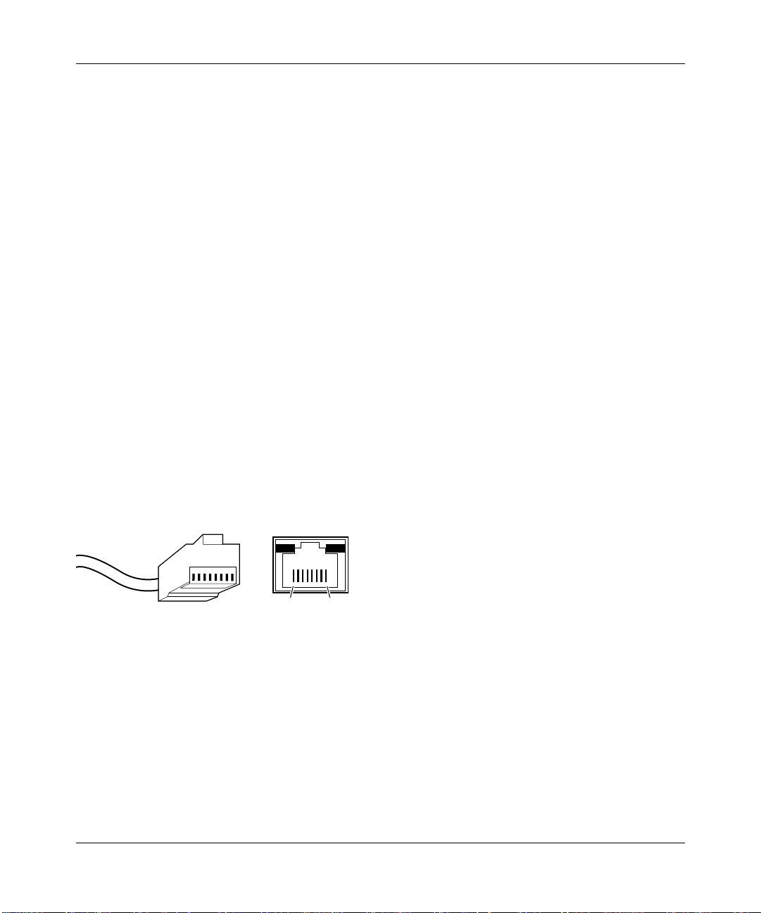
RJ-45 Plug and vista RJ-45 Connector
The RJ-45 plug accepts 4-pair unshielded twisted pair (UTP) or shielded twisted pair (STP)
100 Ω cable and connects into the vista RJ-45 connector.
The vista RJ-45 connector (also referred to as a 10 Mbps port) is used to connect stations, hubs,
and switches through UTP cable and supports 10 Mbps data transmission.
The RJ-45 plug and vista RJ-45 connector are both illustrated in Figure B-1.
12345678
18
711EA
Key:
1 to 8 = Pin numbers
Figure B-1. RJ-45 plug and vista RJ-45 connector with built-in LEDs
Connector Pin Assignments B-1
Page 32

Installation Guide for the Model SW108 Ethernet Switch
Table B-1 lists the pin assignments for the RJ-45 plug and the vista RJ-45 connector.
Table B-1. RJ-45 plug and vista RJ-45 connector
pin assignments
Pin Normal assignment Uplink assignment*
1 Input Receive Data + Output Transmit Data +
2 Input Receive Data – Output Transmit Data –
3 Output Transmit Data + Input Receive Data +
6 Output Transmit Data – Input Receive Data –
4, 5, 7, 8 Internal termination, not used for data transmission
* Applicable to port1 on the Model SW108 switch, when the Normal/Uplink push button is
in the Uplink position.
B-2 Connector Pin Assignments
Page 33

Appendix C
Cabling Guidelines
This appendix provides information on the cable specifications and guidelines for Category 5
UTP cabling used with the NETGEAR Model SW108 Ethernet switch.
Ethernet T echnology
When 10BASE-T technology was originally introduced, multiple repeaters were frequently used
to build large networks. To increase the number of connections, repeaters were connected together
because individual repeater port densities were often limited to 8 to 24 ports. As structured wiring
systems were implemented, horizontal wiring from the wiring closet to the desktop was designed
for a maximum distance of 100 meters. Stackable repeaters eliminated the need for collision
domains to extend over multiple repeater hubs.
Cable Specifications
For 10 Mbps connections, Category 3, 4, or 5 cable can be used; however, NETGEAR highly
recommends Category 5 cable. Category 5 cable will prevent unnecessary expense or confusion
if you upgrade to Fast Ethernet.
Cabling Guidelines C-1
Page 34

Installation Guide for the Model SW108 Ethernet Switch
Table C-1 lists the electrical requirements of the Category 3, 4, and 5 cables.
Table C-1. Electrical requirements of Category 3, 4, and 5 cables
Specification Category 3 Category 4 Category 5
Number of pairs Four Four Two or Four
Impedance 100 Ω ± 15% 100 Ω ± 15% 100 Ω ± 15%
Mutual capacitance at 1 KHz ≤6.6 nF per 100 m ≤5.6 nF per 100 m ≤5.6 nF per 100 m
Maximum attenuation
(dB per 100 m, at 20° C) at 4 MHz: 5.6
at 10 MHz: 9.8
at 16 MHz: 13.1
NEXT loss (dB minimum) at 4 MHz: 32
at 10 MHz: 26
at 16 MHz: 23
at 4 MHz: 4.3
at 10 MHz: 7.2
at 16 MHz: 8.9
at 4 MHz: 47
at 10 MHz: 41
at 16 MHz: 38
at 16 MHz: 8.2
at 31 MHz: 11.7
at 100 MHz: 22
at 16 MHz: 44
at 31 MHz: 39
at 100 MHz: 32
Twisted Pair Cables
For two devices to communicate, the transmitter of each device must be connected to the
receiver of the other device. The crossover function is usually implemented internally as
part of the circuitry in the device. Computers and workstation adapter cards are usually
media-dependent interface ports, called MDI or uplink ports. Most repeaters and switch
ports are configured as media-dependent interfaces with built-in crossover ports, called
MDI-X or normal ports.
C-2 Cabling Guidelines
Page 35

Installation Guide for the Model SW108 Ethernet Switch
Figure C-1 illustrates straight-through twisted pair cable connections.
1
Tx
2
A B
3
Rx
6
Key:
A = Uplink or MDI port (As on a PC)
B = Normal or MDI-X port (As on a hub or switch)
1, 2, 3, 6 = Connector pins
1
Rx
2
3
Tx
6
736EA
Figure C-1. Straight-through twisted pair cable
Figure C-2 illustrates crossover twisted pair cable connections.
1
Rx
2
B B
1
Rx
2
3
Tx
6
Key:
B = Normal or MDI-X port (As on a hub or switch)
1, 2, 3, 6 = Connector pins
3
Tx
6
737EA
Figure C-2. Crossover twisted pair cable
Cabling Guidelines C-3
Page 36

Page 37

Numbers
10 Mbps ports, 2-1, 2-4
A
applications
desktop switching, 3-2
segment switching, 3-3
C
cable
crossover twisted pair, 4-2, C-3
specifications, C-1
straight-through twisted pair, 4-2, 5-2, C-3
troubleshooting, 5-2
Collision LED, 2-1, 2-3, 5-1
crossover twisted pair cable, 4-2, C-3
customer support, iii
Index
H
half-duplex mode, 2-3, 2-4, 4-3, 5-1
HDX duplex toggle switches, 2-4, 4-3
I
installation
on a desktop, 4-2
verifying, 4-3
L
LEDs
and troubleshooting, 5-1
description, 2-3
location, 2-1
Link LED, 2-3, 4-3, 5-2
D
data collisions, 5-1
desktop switching, 1-2, 3-2
devices, connecting to the switch, 4-2
F
FDX duplex toggle switches, 2-4, 4-3, 5-1
FDX LED, 2-3, 5-1
features, 1-3
front panel, 2-1
full-duplex mode, 2-3, 2-4, 4-3, 5-1
Index 1
MDI wiring, 2-2
MDI-X wiring, 2-2
N
normal
ports, 4-2, 5-2, B-2, C-2
wiring, 4-2, 5-2, B-2, C-2
Normal/Uplink push button, 1-3, 2-1, 5-2
O
overview of switch, 1-2
M
Page 38

Installation Guide for the Model SW108 Ethernet Switch
P
package contents, 4-1
ports, 10 Mbps, 2-1, 2-4
Power LED, 2-1, 2-3, 4-3, 5-1
R
rear panel, 2-4
RJ-45 connector. See vista RJ-45 connector
RJ-45 plug
using to connect to 10 Mbps ports, 2-2
using with UTP and STP cable, B-1
Rx/Tx LED, 2-3, 4-3, 5-1
S
segment switching, 1-2, 3-3
site preparation, 4-1
straight-through twisted pair cable, 4-2, 5-2
switches, duplex toggle, 2-4, 4-3
switching technology, 1-2, 3-2
switching, benefits of using, 1-1
V
vista RJ-45 connector
illustration, 2-2
pin assignments, B-1
troubleshooting, 5-2
W
W orld W ide Web, iii
T
technical specifications, A-1
toggle switches, duplex, 2-4, 4-3
troubleshooting, 5-1
U
unshielded twisted pair cable. See UTP cable
uplink
ports, 4-2, B-2, C-2
wiring, 4-2, B-2, C-2
UTP cable, troubleshooting, 5-2
2 Index
Page 39

Page 40

 Loading...