

Page 1

Installation and Reference
for NETGEAR PS111W Print Sever
NETGEAR, Inc.
4500 Great America Parkway
Santa Clara, CA 95054 USA
Phone 888-NETGEAR
M-PS100NA-4
March 2002
Page 2

© 2000, 2002 by NETGEAR, Inc. All rights reserved.
Trademarks
NETGEAR and NETGEAR Print Server are trademarks of NETGEAR, Inc.
Microsoft, Windows, Windows NT, Windows Me, and Windows XP are registered trademarks of
Microsoft Corporation.
Other brand and product names are registered trademarks or trademarks of their respective holders.
Statement of Conditions
In the interest of improving internal design, operational function, and/or reliability, NETGEAR
reserves the right to make changes to the products described in this document without notice.
NETGEAR does not assume any liability that may occur due to the use or application of the product(s)
or circuit layout(s) described herein.
Federal Communications Commission (FCC) Compliance Notice: Radio Frequency Notice
This device complies with part 15 of the FCC Rules. Operation is subject to the following two
conditions:
• This device may not cause harmful interference.
• This device must accept any interference received, including interference that may cause undesired operation.
Note: This equipment has been tested and found to comply with the limits for a Class B digital device,
pursuant to part 15 of the FCC Rules. These limits are designed to provide reasonable protection
against harmful interference in a residential installation. This equipment generates, uses, and can
radiate radio frequency energy and, if not installed and used in accordance with the instructions, may
cause harmful interference to radio communications. However, there is no guarantee that interference
will not occur in a particular installation. If this equipment does cause harmful interference to radio or
television reception, which can be determined by turning the equipment off and on, the user is
encouraged to try to correct the interference by one or more of the following measures:
• Reorient or relocate the receiving antenna.
• Increase the separation between the equipment and receiver.
• Connect the equipment into an outlet on a circuit different from that to which the receiver is connected.
Consult the dealer or an experienced radio/TV technician for help.
EN 55 022 Declaration of Conformance
This is to certify that the NETGEAR Model PS100 series Print Sever is shielded against the generation
of radio interference in accordance with the application of Council Directive 89/336/EEC, Article 4a.
Conformity is declared by the application of EN 55 022
Class B (CISPR 22).
Page 3

Bestätigung des Herstellers/Importeurs
Es wird hiermit bestätigt, daß das Model PS100 series Print Sever gemäß der im BMPT-AmtsblVfg
243/1991 und Vfg 46/1992 aufgeführten Bestimmungen entstört ist. Das vorschriftsmäßige Betreiben
einiger Geräte (z.B. Testsender) kann jedoch gewissen Beschränkungen unterliegen. Lesen Sie dazu
bitte die Anmerkungen in der Betriebsanleitung.
Das Bundesamt für Zulassungen in der Telekommunikation wurde davon unterrichtet, daß dieses Gerät
auf den Markt gebracht wurde und es ist berechtigt, die Serie auf die Erfüllung der Vorschriften hin zu
überprüfen.
Page 4

Certificate of the Manufacturer/Importer
It is hereby certified that the Model PS100 series Print Sever has been suppressed in accordance with
the conditions set out in the BMPT-AmtsblVfg 243/1991 and Vfg 46/1992. The operation of some
equipment (for example, test transmitters) in accordance with the regulations may, however, be subject
to certain restrictions. Please refer to the notes in the operating instructions.
Federal Office for Telecommunications Approvals has been notified of the placing of this equipment
on the market and has been granted the right to test the series for compliance with the regulations.
Compliance with the applicable regulations is dependent upon the use of shielded cables. It is the
responsibility of the user to procure the appropriate cables.
Voluntary Control Council for Interference (VCCI-B) Statement
This is a Class B product based on the standard of the Voluntary Control Council for Interference from
Information Technology Equipment (VCCI). If this is used near a radio or television receiver in a
domestic environment, it may cause radio interference. Install and use the equipment according to the
instruction manual.
Customer Support
For assistance with installing and configuring your NETGEAR system or with post-installation
questions or problems, contact your point-of-purchase representative.
To contact customer support or to purchase additional copies of this document and publications for
other NETGEAR products, you can contact NETGEAR at the following numbers:
• Australia: 1800-142-046 • Korea: 00308-11-0319
• Austria: 00800-06384327
(008000-NETGEAR)
• Canada: 888-NETGEAR • Sweden: 020-790086
• France: 0800-90-2078
• Germany: 00800-06384327
(008000-NETGEAR)
• Japan: 0120-66-5402 • United States: 888-NETGEAR
Internet/World Wide Web
• New Zealand: 0800-444-626
• Switzerland: 00800-06384327
(008000-NETGEAR)
• United Kingdom: 0171-571-5120
NETGEAR maintains a World Wide Web Home Page that you can access at the universal resource
locator (URL) "http://www.NETGEAR.com". A direct connection to the Internet and a Web browser
such as Internet Explorer or Netscape are required.
Page 5

NetGear Print Server Manual
Preface
Congratulations on your purchase of the NETGEAR Model PS100 series Print Sever.
Supporting multiple protocols and operating systems, these print servers provide an effective solution
for networked PCs to connect to the same printer, processing and trafficking printing requests to any
parallel device. These print servers are fast and easy to set up with NETGEAR Print Server with
NETGEAR software configuration program. With Microsoft Internet Explorer or Netscape web
browser, you can configure the print server even easier. Please see Chapter 3 for detail.
Purpose
This guide describes how to set up the Model PS100 series Print Sever. If your network is operating in
a Microsoft environment and you are using Microsoft
Windows NT, Windows
Installation Guide. However, this guide provides you with further reference information.
In this guide, the Model PS100 series Print Sever are referred to collectively as the Model PS100 series
Print Sever or just the print server. Each model is referred to specifically when features or functions are
unique to that particular model.
2000, or Windows XP, refer to the Model PS100 series Print Sever
Windows 95, Windows 98, Windows Me,
Audience
To configure and install the print server, you should have the following background and experience:
Working knowledge of basic network management concepts and terminology
Working knowledge of tools and procedures to install and operate electronic equipment
i
Page 6
NetGear Print Server Manual
Conventions
This section describes the conventions used in this guide.
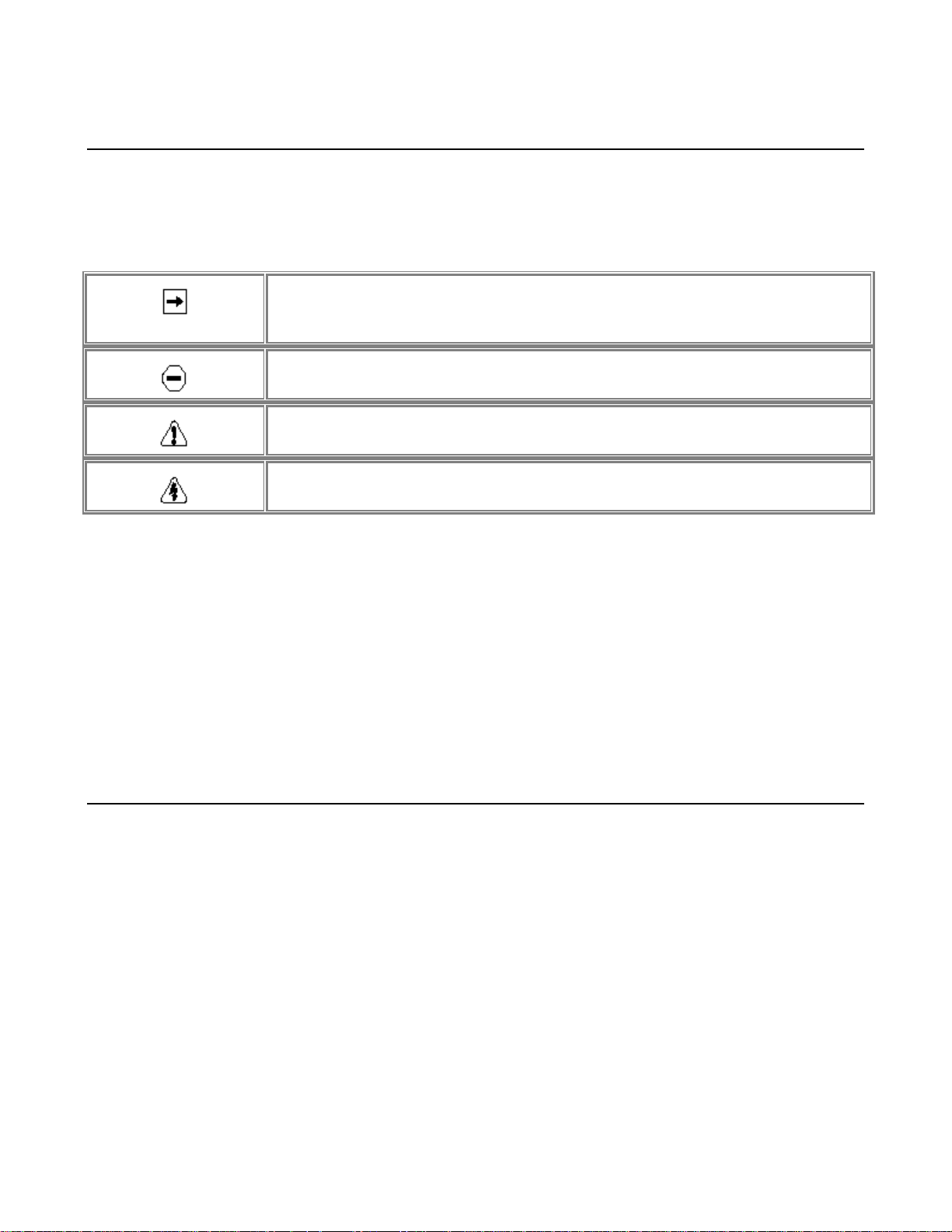
Special Message Formats
This guide uses the following formats to highlight special messages:
• This format is used to highlight information of importance or special interest.
• This format is used to highlight information that will help you prevent
equipment failure or loss of data.
• This format is used to highlight material involving possibility of injury or equipment damage.
• This format is used to alert you that you may incur an electrical shock by
mishandling equipment.
Use of Enter, Type, and Press
This guide uses "enter," "type," and "press" to describe the following actions:
When you read "enter," type the text and press the Enter key.
When you read "type," type the text, but do not press the Enter key.
When you read "press," press only the alphanumeric or named key.
Other Conventions
This guide uses the following additional conventions:
italics Book titles and UNIX file, command, and directory names.
Initial Caps Menu titles and window and button names.
Related Publication
If you are using Microsoft Windows 95, Windows 98, Windows NT, or Windows 2000 and have a
network card installed with the NetBEUI protocol, refer to the Model PS100 series Print Sever
Installation Guide (document part number M1-PS100NA-3). This guide provides instructions for
installing the print servers by using the NETGEAR Print Server Utility, a program developed by
NETGEAR for fast and easy device configuration, and for web configuration, a built-in web server in
the print server so you can use a browser to configure the print server
ii
Page 7

NetGear Print Server Manual
PREFACE................................................................................................................................................ I
PURPOSE ...........................................................................................................................................I
AUDIENCE..........................................................................................................................................I
CONVENTIONS.................................................................................................................................II
Special Message Formats .................................................................................................................ii
Use of Enter, Type, and Press...........................................................................................................ii
Other Conventions ............................................................................................................................ii
RELATED PUBLICATION...............................................................................................................II
CHAPTER 1 INTRODUCTION....................................................................................................... 1
1-1 FEATURES.............................................................................................................................1
1-2 FRONT PANEL ............................................................................................................................2
LEDs............................................................................................................................................... 3
1-3 REAR PANEL ..............................................................................................................................4
CHAPTER 2 INSTALLATION ........................................................................................................5
2-1 PREPARING THE SITE.......................................................................................................5
2-2 VERIFYING PACKAGE CONTENTS ............................................................................... 5
2-3 CONNECTING DEVICES TO THE PRINT SERVER....................................................6
2-4 VERIFYING POWER............................................................................................................ 7
CHAPTER 3 WEB MANAGEMENT FOR PRINT SERVER ......................................................8
3-1 CONFIGURING PRINT SERVER FOR TCP/IP........................................................... 8
3-2 CONNECTING TO THE PRINT SERVER .......................................................................8
3-3 BROWSER MENU SELECTIONS AND CONFIGURATION SCREENS...................9
Server Status..............................................................................................................................9
Configure Server.....................................................................................................................10
TCP/IP..........................................................................................................................................12
AppleTalk....................................................................................................................................13
Wireless.......................................................................................................................................14
Wireless Link Info....................................................................................................................17
Printer Port.................................................................................................................................18
Logical Printer...........................................................................................................................19
Reset............................................................................................................................................21
CHAPTER 4 MICROSOFT WINDOWS SYSTEM PRINTING................................................22
4-1 PRINTING IN WINDOWS ................................................................................................. 22
4-2 NETGEAR PRINT SERVER SOFTWARE INSTALLATION.................................. 23
4-3 SETTING UP YOUR PC TO RECOGNIZE THE PRINT SERVER ........................30
Auto-IP ............................................................................................................................................ 34
Wireless Configuration ...................................................................................................................36
NETGEAR Add Printer Wizard - Write Down the Port Name ......................................................39
iii
Page 8

NetGear Print Server Manual
4-4 ADD A PRINTER TO YOUR SYSTEM TO PRINT ........................................................42
CHAPTER 5 UNIX PRINTING USING TCP/IP.......................................................................... 50
5-1 TEMPORARY IP ADDRESS RESOLUTION................................................................51
Assigning an IP Address to the Print Server Using DHCP...................................51
Assigning an IP Address to the Print Server Using BootP....................................51
Assigning an IP Address to the Print Server Using RARP...................................52
Assigning an IP Address to the Print Server Using ARP.......................................53
5-2 CONFIGURING YOUR PRINT SERVER USING FTP............................................. 55
Configuration Example.........................................................................................................55
List of FTP Files and Commands Supported by the Print Server...................... 56
5-3 SETTING THE PRINT METHOD .................................................................................... 57
LPD Configuration and Printing........................................................................................ 57
Printing Using LPD.................................................................................................................60
Printing Using FTP.................................................................................................................60
Printing Using DSI...................................................................................................................60
CHAPTER 6 APPLETALK PRINTING .......................................................................................61
6-1 SETTING UP PRINT SERVER FOR APPLETALK .....................................................61
6-2 SETTING UP HOST COMPUTER ..................................................................................62
6-3 USING PSTOOL UTILITY ...............................................................................................63
6-4 PSTOOL UTILITY CONFIG FILE FORMAT............................................................64
CHAPTER 7 USING ADVANCED MANAGEMENT TOOLS ..................................................65
7-1 CONFIGURATION USING THE NETGEAR PRINT SERVER
ADMINISTRATION PROGRAM...................................................................................................65
Buttons ............................................................................................................................................66
7-2 ADVANCED PRINT SERVER CONFIGURATION......................................................68
System Tab ......................................................................................................................................68
TCP/IP Tab .....................................................................................................................................70
AppleTalk Tab .................................................................................................................................71
Logical Port Tab .............................................................................................................................72
Physical Port Tab............................................................................................................................73
Wireless Tab....................................................................................................................................74
Link Info Screen ..............................................................................................................................77
7-3 MENU OPTIONS................................................................................................................78
ONFIGURING USING IP SETUP.........................................................................................................80
C
APPENDIX A TECHNICAL SPECIFICATIONS .....................................................................81
GENERAL SPECIFICATIONS......................................................................................................81
APPENDIX B UNDERSTANDING IP ADDRESSES................................................................83
IP ADDRESSES AND THE INTERNET.....................................................................................83
NETMASK.........................................................................................................................................84
iv
Page 9

NetGear Print Server Manual
SUBNET ADDRESSING................................................................................................................85
PRIVATE IP ADDRESSES ..........................................................................................................86
ADDRESS RESOLUTION PROTOCOL..................................................................................... 87
IP CONFIGURATION BY DHCP...............................................................................................87
APPENDIX C CONFIG FILE ......................................................................................................88
CONFIG FILE TCP/IP SETTINGS .......................................................................................88
APPENDIX D USING NETWARE 5 NDPS................................................................................90
OVERVIEW......................................................................................................................................90
Creating an NDPS Manager Object................................................................................90
Creating an NDPS Printer Agent...................................................................................... 91
Workstation Configuration................................................................................................... 92
APPENDIX E IP SETUP ...............................................................................................................94
OVERVIEW......................................................................................................................................94
APPENDIX F ASCII TO HEXADECIMAL CONVERSION TABLE ....................................95
v
Page 10

NetGear Print Server Manual
Chapter 1 Introduction
This chapter describes the features and the components of the Model PS111W Print Sever.
1-1 Features
NETGEAR PS111W print server offers:
• 802.11b standard wireless ready mobile flexibility, and also supports:
• Wired Equivalent Privacy (WEP) 40/64 or 128 bit encryption
• Open System and Shared key authentication
• Infrastructure, ad- hoc, and 802.11 ad- hoc communication modes
• Up to 11 channels or 13 channels*
* Depends on the country areas
• Print support - both wired and wireless simultaneously, when wireless set to ad hoc mode
• Support for multiple protocols (TCP/IP, NetBEUI, and Netbios)
• Support for multiple operating systems (Windows 95, Windows 98, Windows Me, Windows NT,
Windows 2000, Windows XP, Novell NetWare, and UNIX)
• Easy configuration of the device with NETGEAR Print Server software that assures fast and easy
setup for Windows 95, Windows 98, Windows Me, Window NT, Windows 2000, and Windows
XP users.
• Web browser interface provides an easy way to configure the print server in a TCP/IP network
• 10/100BASE-T Ethernet connection on the Model PS111W Print Sever.
• One bidirectional parallel port on the Model PS111W Print Sever.
• Compact size to fit into limited space in a work area.
• Wall- mounting holes for attaching the print server to a vertical surface
• Upgradeable BIOS Flash EPROM
1
Page 11
NetGear Print Server Manual
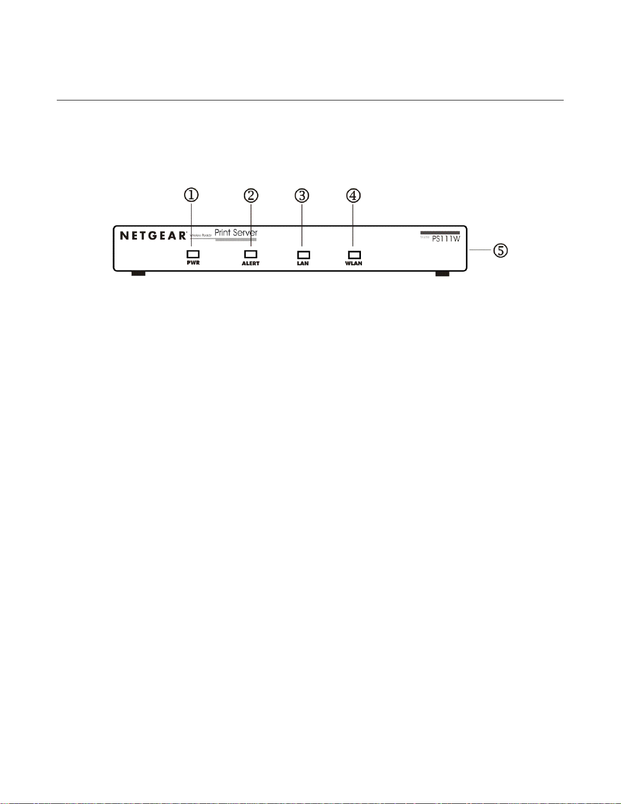
1-2 Front Panel
The LEDs that indicate the status of the server, wired, and wireless LAN are located on the front
panels of the Model PS111W Print Sever, as illustrated bellow:
1-1 Front Panel of the Model PS111W Print Sever
Key:
1 = PWR (power) LED
2 = ALERT LED
3 = LAN LED
4 = WLAN (wireless LAN) LED
5 = Side panel wireless PC card slot
2
Page 12
NetGear Print Server Manual
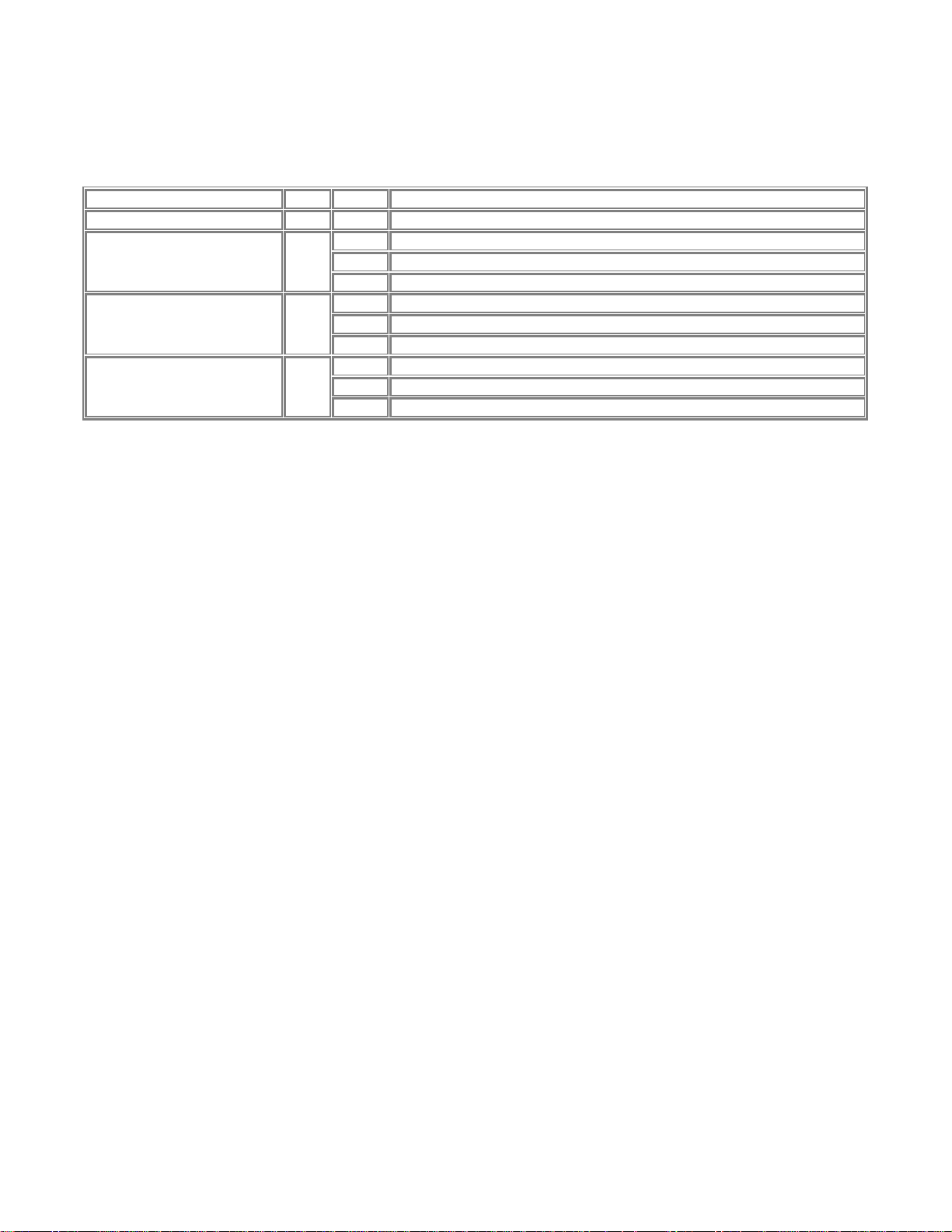
LEDs
There are 4 LEDs on the front panel of the Model PS111W Print Sever. See the table bellow:
LED Descriptions
Label Color Activity Description
PWR (power) Green On Power is supplied to the print server.
Off Operation is normal
Alert Amber
LAN Green
WLAN Green
On Hardware error
Blinking Upgrading BIOS flash ROM
Off No LAN connection
On Operation is normal without data transmitting or receiving from LAN
Blinking Operation is normal with data transmitting or receiving from LAN
Off No wireless PC card
On Operation is normal without data transmitting or receiving from wireless LAN
Blinking Operation is normal with data transmitting or receiving from wireless LAN
3
Page 13
NetGear Print Server Manual
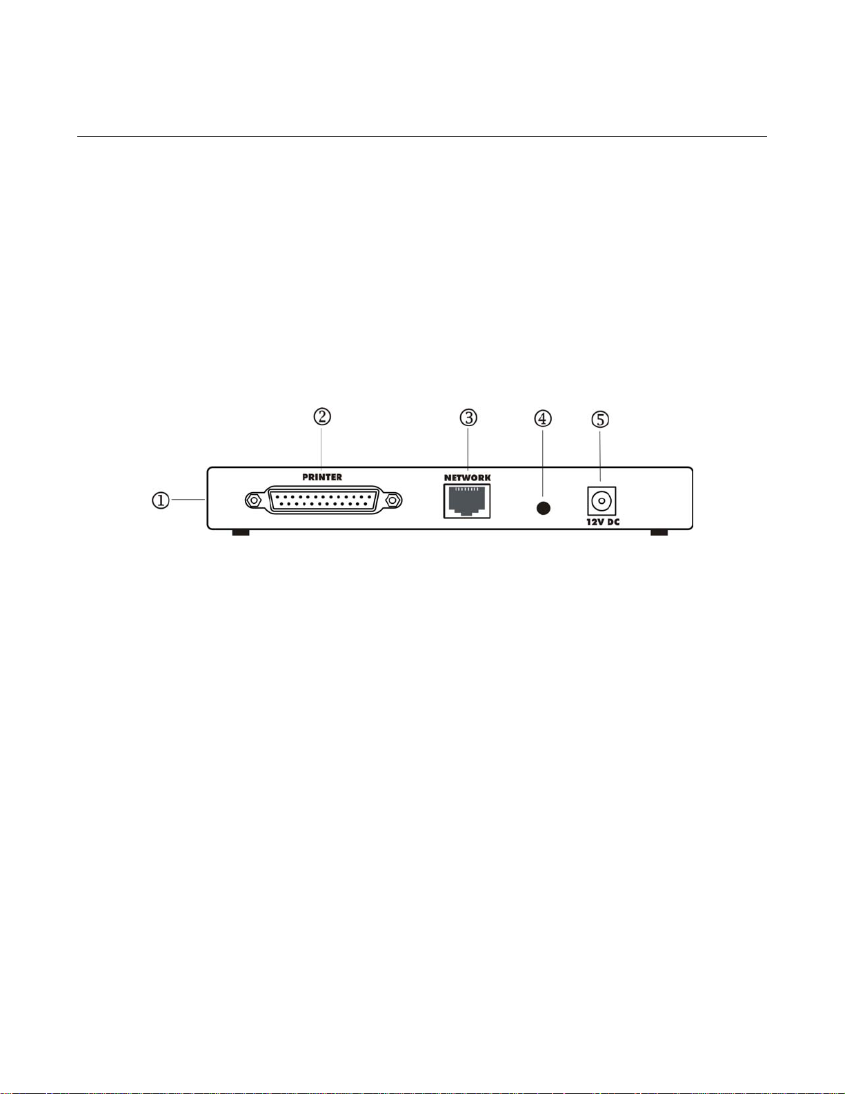
1-3 Rear Panel
The rear panel of the Model PS111W Print Sever has a parallel port for printer. The Model PS111W
Print Sever has one 10/100BASE-T network port. The 10/100BASE-T port is an auto negotiation port
that operates in 100 Mbps and in half-duplex mode when connected to a Fast Ethernet network. The
diagnostic print and reset to factory default button can print the current print server setup including
IP address and wireless information by pressing and holding it two seconds. If press and hold the
button for ten seconds while powering from off to on, the print server will load the factory default
setting back into its flash memory.
The Rear Panel as illustrated below, it has a power adapter receptacle that accepts a 12 V 800mA DC
power adapter.
1-2 Rear Panel of the Model PS111W Print Sever
Key:
1 = Side panel wireless PC card slot
2 = PRINTER (parallel) port
3 = NETWORK port (10/100BASE-T connector)
4 = Diagnostic print and reset to factory default button
5 = Power adapter receptacle
4
Page 14

NetGear Print Server Manual
Chapter 2 Installation
This chapter describes the installation and setup of the NETGEAR Model PS111W Printer Server.
2-1 Preparing the Site
Before you begin installing the print server, prepare the installation site. Make sure the operating
environment meets the physical requirements of the print server, as described below.
2-2 Verifying Package Contents
Your package should contain the following:
• Model PS111W Printer Server
• 12V 800mA DC Power adapter
• PS111W Print Server Resource CD
• PS111W Print Server Installation Guide
• Warranty & Owner Registration Card
• Customer Support Phone Card
Call your reseller or NETGEAR Customer Support in your area if there are any wrong, missing, or
damaged parts. Refer to "Customer Support" section for the location of customer support in your area.
Keep the carton, including the original packing materials. Use them to repack the print server if you
need to return it for repair.
5
Page 15
NetGear Print Server Manual
N
2-3 Connecting Devices to the Print Server
The PS111W Print Server Model has one 10/100BASE-T network port that is auto sensing and will
support either 10 Mbps or 100 Mbps connections, depending on the connected device. The Model
PS101 Print Server has one Ethernet port, which can be operated on a 10/100BASE-T hub/switch in
the half-duplex mode.
The network port on the all Print Server Model is configured for Uplink wiring, which means you can
connect the Print Server direct to an Ethernet switch or hub.
NOTE: Ethernet specifications limit the twisted pair cable (called a twisted pair segment)
extended from a network port to 100 meters in length.
The Model PS111W Print Server has one wireless PC card slot. It can be operated under three types of
environment: LAN, wireless LAN, and both LAN and wireless LAN. Connect network port to an
Ethernet hub/switch makes all LAN connected workstations can print with PS111W Print Server. With
a NETGEAR MA401 802.11b Wireless PC Card in PS111W, all 802.11b wireless connected
workstation can print with PS111W Print Server. If connect network port and with a NETGEAR
MA401 802.11b Wireless PC Card in PS111W, both LAN connected workstation and 802.11b
wireless connected workstation can print with the PS111W Print Server. Please note while the power is
on; do not insert the NETGEAR MA401 802.11b Wireless PC Card in to PS111W Print Server. Doing
so is simply not working and maybe damaging the Print Server and the PC card. Do not remove the
NETGEAR MA401 802.11b Wireless PC Card out from PS111W Print Server, when the power is on.
This may damage the Print Server and the PC card.
WARNING: To avoid damaging to the wireless PC card and PS111W Print Server, do
OT insert and remove the PC card from or to PS111W Print Server while the power of the
Print Server is on.
6
Page 16

NetGear Print Server Manual
2-4 Verifying Power
To complete the installation, connect the power adapter first to the power adapter receptacle on the
print server rear panel and then to the power outlet on the wall. When power has been applied to the
print server:
• The green PWR (power) LED on the front panel is on, if there is one.
• On the PS101 Print Sever Model, the green Link LED on connected network port is on.
• On the PS110 and PS113 Print Sever Model, the green Link/Act LED on the connected PRINTER,
PRINTER 1, PRINTER 2, or PRINTER 3 port is on.
• On the PS111W Print Sever Model, the green LAN LED on connected network port is on, and the green
WLAN LED with the NETGEAR MA401 801.11b Wireless PC Card in PC card slot is on.
Make sure the network interface cards installed in the workstations are in working condition and the
software driver has been installed on the cards.
If required, verify the integrity of the print server by resetting it. Turn power to the print server off and
then back on. If this does not help, you can try to load the factory default setting. The procedure is:
turn power to the print server off, press and hold the diagnostic and reset to factory default button
while turning the power back to the print server. Use the following one of the three options to reconfigure the print server: web management in chapter 3, NETGEAR Print Server Setup Wizard, or
Administrative tool for advanced user in chapter 7.
If the problem continues and you have completed all the preceding diagnoses, contact NETGEAR
Customer Support. For the telephone number of the representative in your area, refer to "Customer
Support" section.
7
Page 17

NetGear Print Server Manual
Chapter 3 Web Management for Print Server
The web browser interface provides an easy way to configure the print server in a TCP/IP network.
You can configure your NETGEAR PS111W Wireless Ready Print Server using any web browser
such as Microsoft Internet Explorer or Netscape Navigator.
This chapter contains information about configuring your NETGEAR PS111W Print Server using the
print server's browser interface. Please refer to the next following chapters for setting up your printing
system.
3-1 Configuring Print Server for TCP/IP
Using a web browser to configure a NETGEAR Print Server requires both the print server and the host
workstation that the web browser runs on to be configured for TCP/IP.
NETGEAR PS111W Print Server is set with the factory setting for DHCP environment, which means
if you have a DHCP server (most recent broad band routers have provided this feature), PS111W will
get its own IP address settings for TCP/IP.
To know the print server’s IP address, press and hold RESET button for two seconds. The printer will
print out the print server status report, where it includes the IP address information.
3-2 Connecting to the Print Server
In order to configure the print server over the browser interface, your PC workstation must have a web
browser program installed such as Microsoft Internet Explorer or Netscape Navigator. Free browser
programs are available for Windows, Macintosh, or Unix/Linux.
1. Start your Web Browser
2. In the Address box, enter HTTP:// followed by the IP Address of the print server. e.g.
http://192.168.0.21
Alternatively, the IP address of the print server can be found under "Device Information" in the "Control"
menu of the NETGEAR Print Server Administration Program.
3. You will then be prompted for the password. If no password has been set, just press ENTER.
4. Use the menu selections listed on the left of the screen to move about.
Note: Remember to save modifications made on any screen by clicking the Save button before
changing to a different screen.
8
Page 18
NetGear Print Server Manual
3-3 Browser Menu selections and Configuration Screens
This section describes the browser menu selections and corresponding configuration screens.
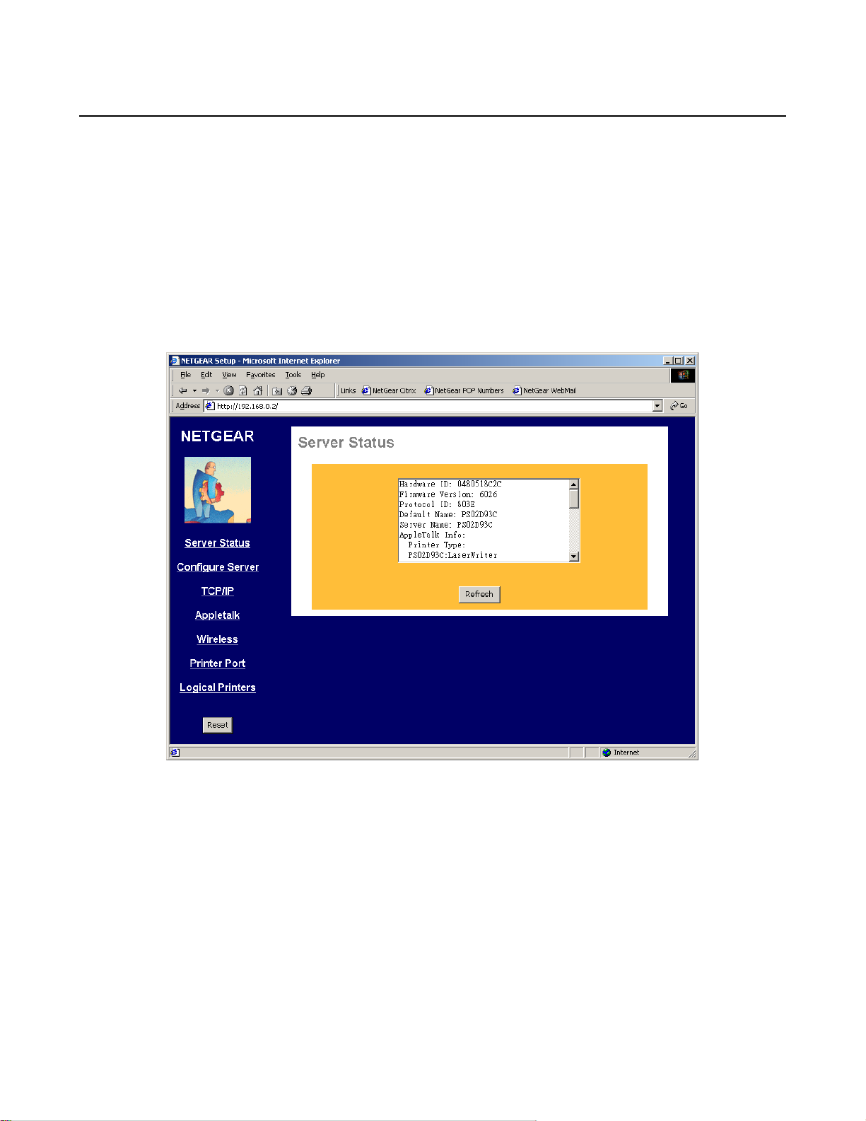
Server Status
The Server Status screen shows print server system data and the current settings for all of the other
screens. It is read-only; no data can be input on this screen. Click the refresh button to refresh
information on this screen. Use the scroll bar to scroll through the display information. Figure 3-1
shows the Server Status Screen.
Figure 3-1 Server Status Screen
9
Page 19
NetGear Print Server Manual
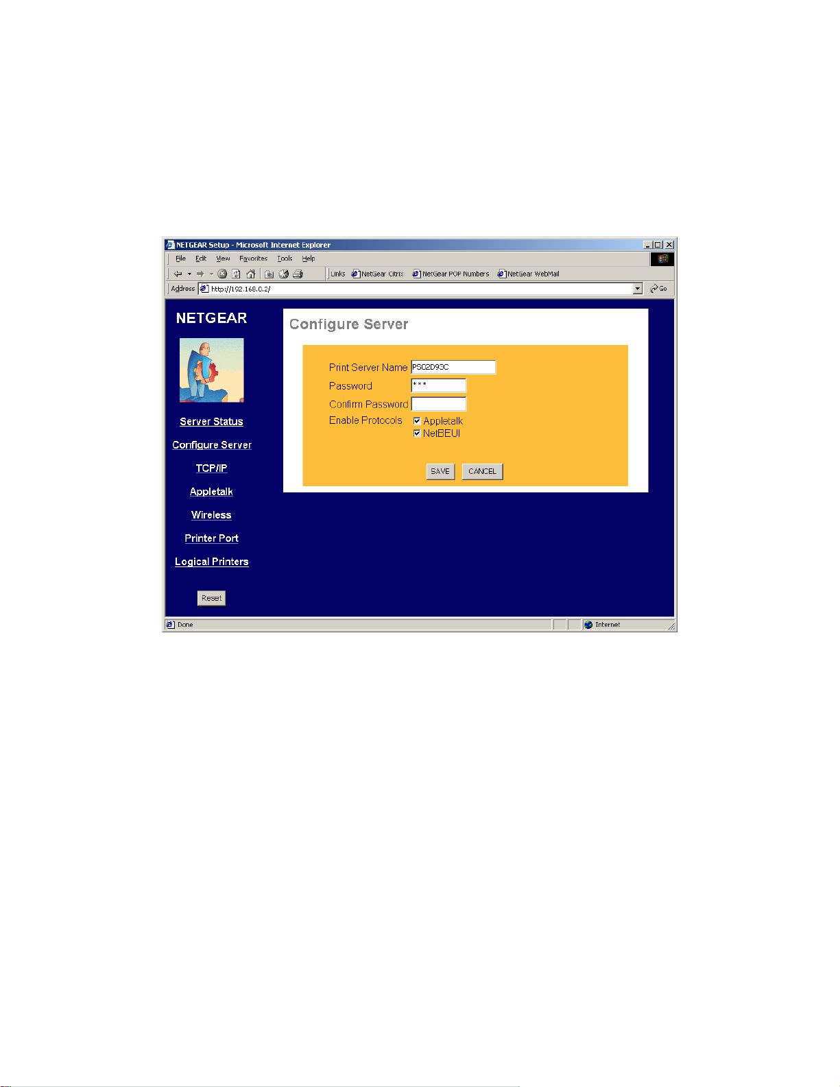
Configure Server
Clicking the Configure Server menu selection brings up the Configure Server screen. The Configure
Server screen contains fields to change the print server name and to enable or disable the various
network protocols supported by the print server. Figure 3-2 and following table show the Configure
Server Screen and describe each of its fields.
Note: Use key Tab on keyboard to move the cursor from field to field besides using the mouse.
Figure 3-2 System Configuration Screen
10
Page 20
NetGear Print Server Manual
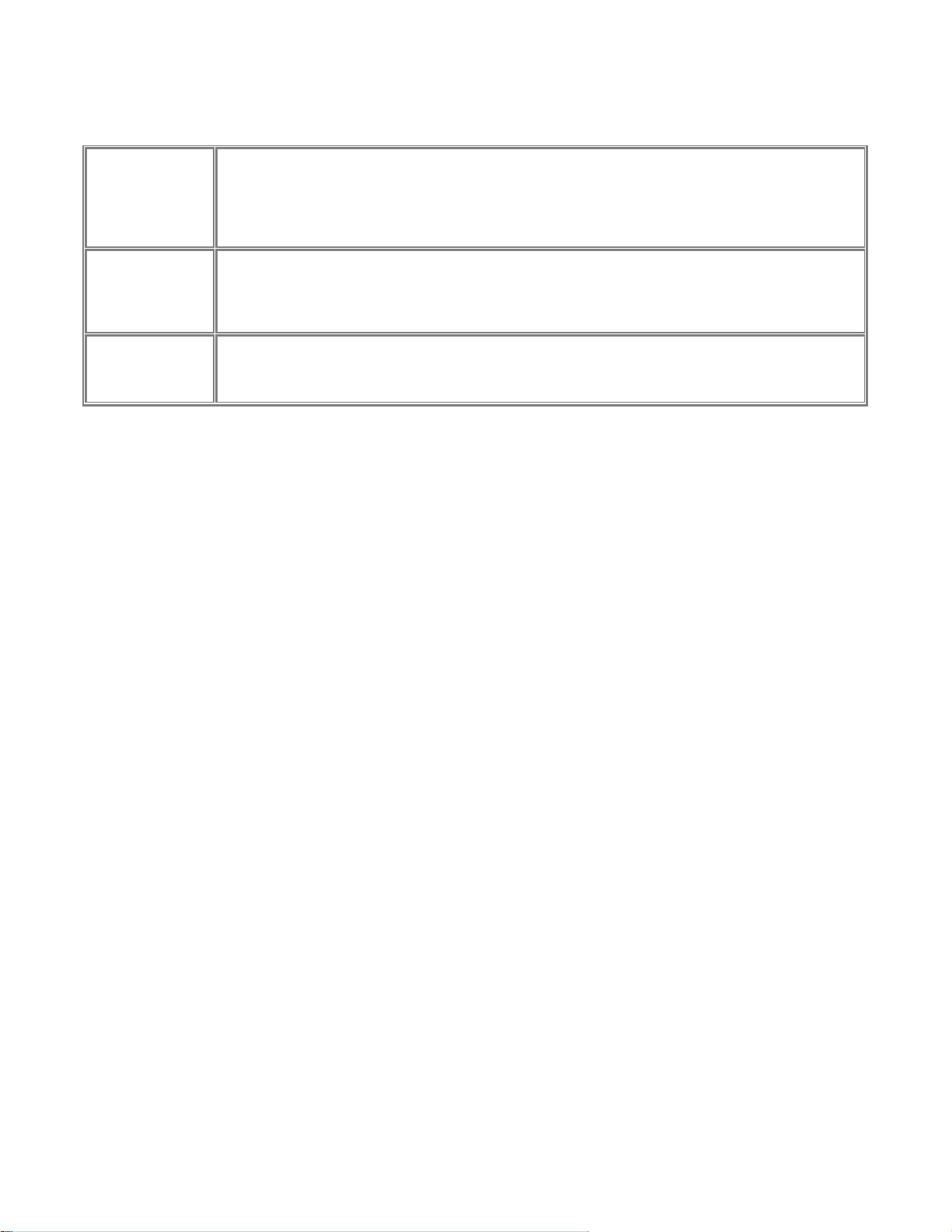
Configure Server Fields
Choose a descriptive name for the print server for identification purposes. This name is used in all
protocols to identify the specific print server. There is a factory default name. For any change,
Print Server Name
Password
Confirm Password
Enable Protocols
NETGEAR recommends that a name be determined before setting the print server in any network. This
name should be no more than 16 characters with at least a non numerical letter. Spaces are not
allowed, but dashes (-) and underscore marks (_) are accepted.
Enter the device password, and again in the Confirm Password field. Once a password is entered, it is
required in order to gain access and change the configuration. If you forget the password to the print
server, the only way to reset it is by resetting the device to factory default through the NETGEAR Print
Server Administration Program.
Check the corresponding protocols to enable them on the print server. AppleTalk is used to support
AppleTalk printing from Apple computers. NetBEUI is primarily used in a small-scale Microsoft
networking environment. A protocol may be disabled if it is not required for your network.
11
Page 21
NetGear Print Server Manual
TCP/IP
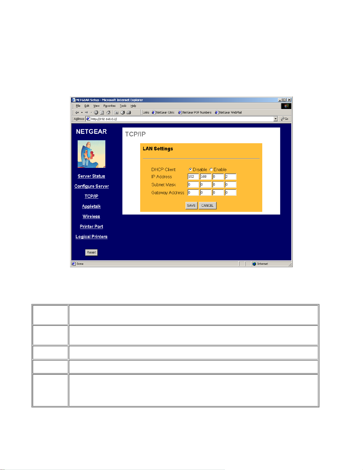
The TCP/IP configuration screen is used to configure the IP address of the print server. Figure 3-3
shows the TCP/IP configuration screen and following table lists its fields, describes the functions, and
explains how to provide information in each field.
TCP/IP Configuration Fields
This field allows you to enable or disable the print server's ability to get its IP address from a DHCP
DHCP Client
IP Address
Subnet Mask
Gateway
Address
Save
Cancel
Buttons
(Dynamic Host Configuration Protocol) server. When disabled, you can provide a fixed IP address in the
following fields. If DHCP client is enabled, the fields that follow are not used.
This IP address is assigned to the print server. If you have a private LAN and do not plan to connect to
the TCP/IP based internet, NETGEAR recommends that you use the address from the IETF-designated
private addresses (for example, 192.168.x.x or 10.x.x.x).
This subnet mask defines the range of addresses that are reachable on your local LAN. For example, in
a network with a NETGEAR router, the default subnet mask is usually 255.255.255.0.
This is the IP address of the router on your network. For example, in a network with a NETGEAR router,
the gateway address is usually 192.168.0.1.
Save:
After the configuration, click on ‘Save’ button to save the value permanently to PS111W.
Cancel:
If changed something that is not good, click on ‘Cancel’ button will load the value back from PS111W. No
modification will be made into PS111W.
Figure 3-3 TCP/IP Configuration Screen
12
Page 22
NetGear Print Server Manual
AppleTalk
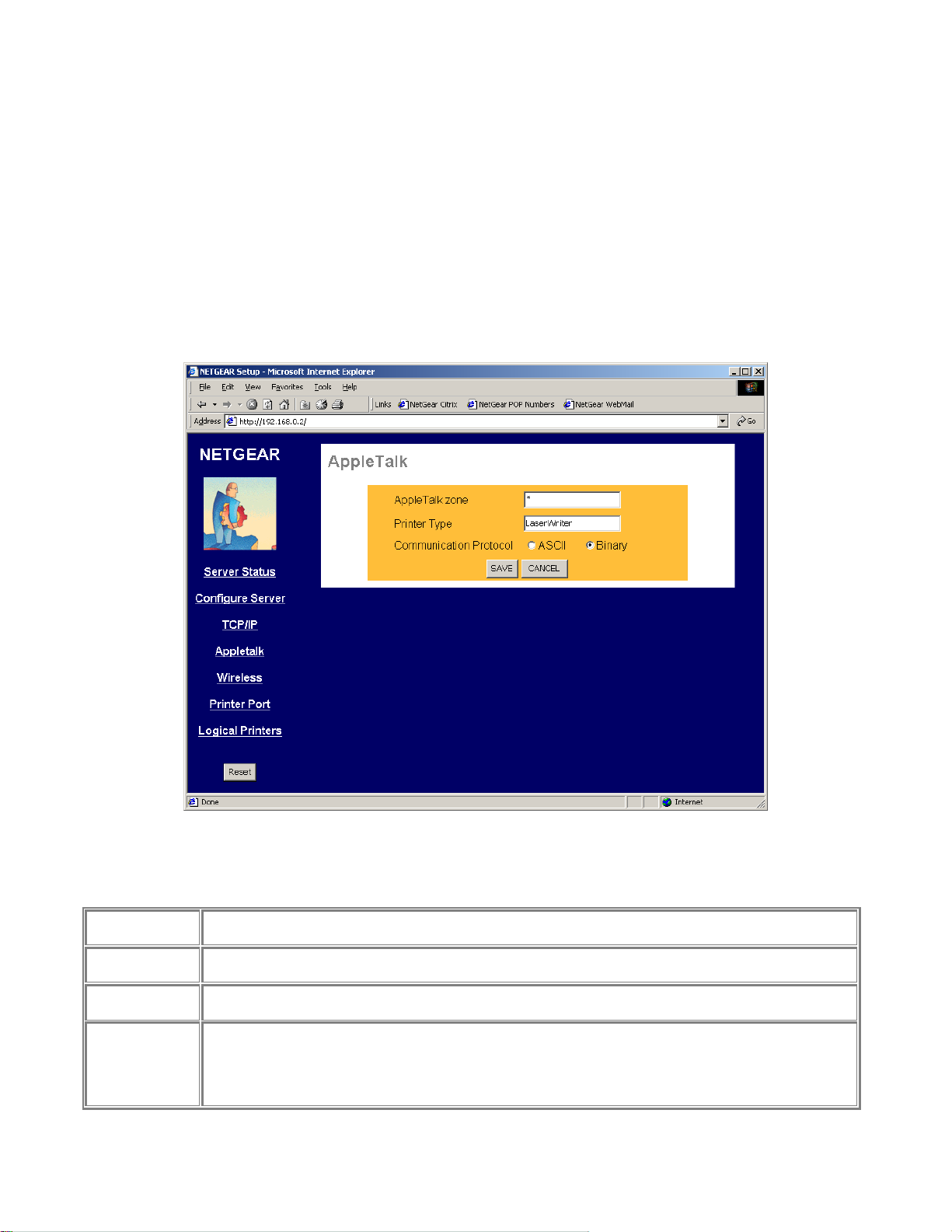
The NETGEAR Print Server supports AppleTalk (EtherTalk), PAP, ATP, NBP, ZIP and DDP
protocols, enabling Apple computers on the network to view and use the Print Server as a regular
AppleTalk printer.
The NETGEAR Print Server is enabled for AppleTalk printing by default. Further AppleTalk
configuration may be configured through a web browser if the print server is configured for IP access.
If the Print Server is not configured for IP access, configuration of the Printer Server for AppleTalk
may be performed through the Print Server Admin program on Windows for Apple machines. Figure
3-4 shows the AppleTalk configuration screen and the following table describes it fields.
Apple Talk Configuration Fields
AppleTalk Zone
Printer Type
Communication
Protocol
Save
Cancel
Buttons
The AppleTalk zone that the print server will appear in. To put the print server in the default AppleTalk
zone of the AppleTalk network the print server is connected to, enter a single asterisk.
These are text fields, used to describe the printer driver used for each port. Currently the only printer
driver supported for AppleTalk is LaserWriter.
Sets whether the port uses ASCII or Binary Communication Protocol. Binary communication is faster than
ASCII. The default is Binary.
Save:
After the configuration, click on ‘Save’ button to save the value permanently to PS111W.
Cancel:
If changed something that is not good, click on ‘Cancel’ button will load the value back from PS111W. No
modification will be made into PS111W.
Figure 3-4 AppleTalk Configuration Screen
13
Page 23
NetGear Print Server Manual
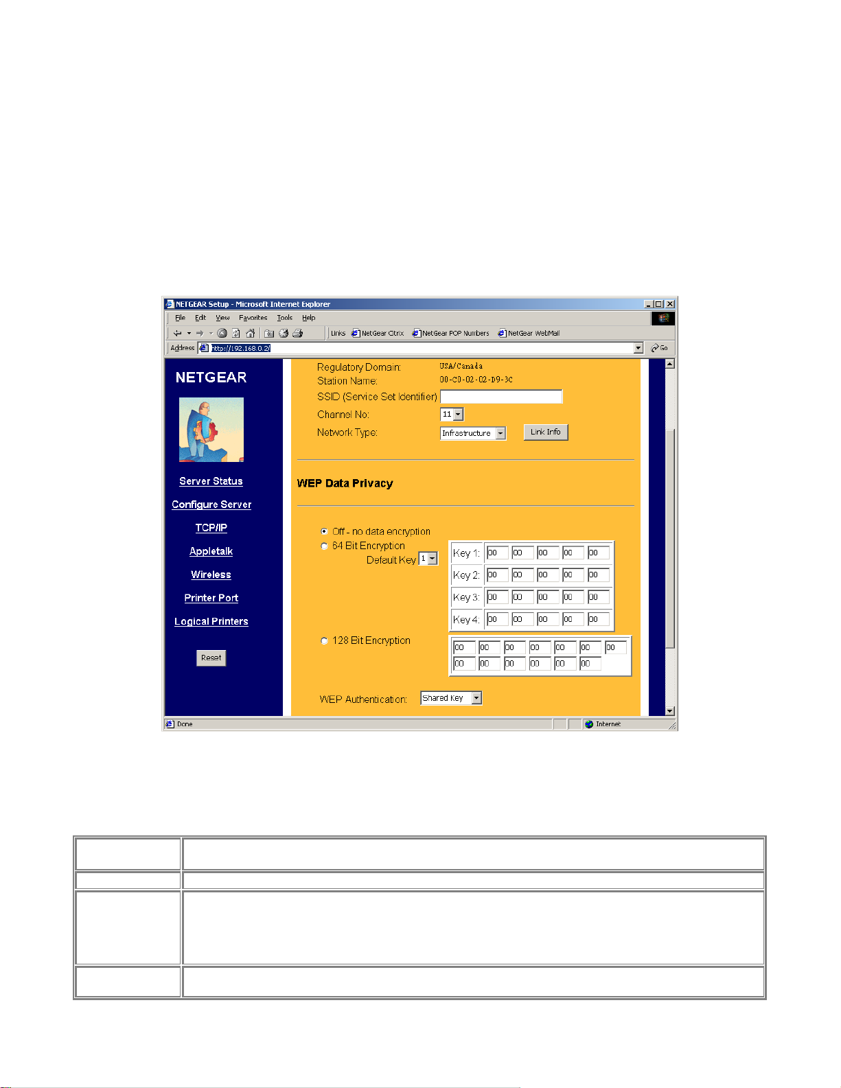
Wireless
The Wireless screen provides selections for many wireless related operations. See Figure 3-5.
For wireless operation, there are two major configurations.
1. Wireless related setups.
2. Wired Equivalent Privacy (WEP) encryption.
See the following Wireless Configuration Screen section for the detail.
Configuration fields and buttons
Regulatory
Domain
Station Name
SSID
Channel No
Not configurable. This information is got automatically when there is a NETGAER MA 401 802.11b
wireless PC card in PS111W. In northern America, usually get ‘USA/Canada’.
Not configurable. It is the Ethernet MAC address for the PS111S.
Stand for Service Set Identifier. It can be empty if the authentication method on Access Point is Open
System (see authentication). To specifically tie to a wireless LAN, you need to get this information from
your network administrator. It MUST be the same in both Access Point and wireless PS111W. If use ad
hoc wireless network, you need to make sure all equipment use the same SSID to communicate to each
other.
The channel is ranged from 1 to 11 for north America, and for other regulatory area it may vary.
Figure 3-5 Wireless Screen
"
-
"
"
"
14
Page 24
NetGear Print Server Manual
number.
• If using "802.11 Ad-hoc" or "Ad-hoc" mode, select the value you wish to use on
your Wireless LAN.
• If using "Infrastructure" mode, the Channel is selected automatically, to match the
Channel used by the Access Point.
• If you experience interference (shown by lost connections and/or slow data
transfers) you may need to experiment with different channels to see which is the
best.
Select the correct value for your Wireless LAN.
• 802.11 Ad-hoc mode is used when there is no Wireless Access Point, and each
Wireless station communicates directly with other Wireless stations. This is the
current standard.
Network Type
• Ad-hoc mode is used when there is no Wireless Access Point, and each Wireless
station communicates directly with other Wireless stations. This is the older
standard.
• Infrastructure mode is used when each Wireless station connects to the Wireless
Access point. This also provides access to the wired LAN.
15
Page 25
NetGear Print Server Manual
WEP Data Privacy Fields
Default setting; data is NOT encrypted before transmitted.
Off – No data
encryption
Choose the data privacy encryption from one of the three
Off – No data encryption,
64 Bit Encryption, or
128 Bit Encryption.
• If selected, data is encrypted, using the default key, before being transmitted. The receiving station
must be set to 64 Bit Encryption, and have the same Key value in the same position in its key table.
Otherwise, it will not be able to decrypt the data.
• Default Key - select the key you wish to be the default. Transmitted data is ALWAYS encrypted
using the Default Key; the other Keys are for decryption only.
Key 1, Key 2, Key 3, and Key 4
64 Bit Encryption
Default Key
128 Bit
Encryption
WEP
Authentication
Save
Cancel
Buttons
This table is used when Encrypting and Decrypting data. All stations, including this Access Point, always
transmit data encrypted using their default key. The key number (1, 2, 3, 4) is also transmitted. The
receiving station will use the key number (1, 2, 3, 4) to determine which key value to use for decryption. If
the key value does not match the transmitting station, decryption will fail.
The easiest way to ensure there are no problems is to have every Station, including the Access Point, use
the same key table (all entries identical). It does not matter which default key is used.
Enter two hexadecimal numbers in each cell. A hexadecimal number is one of 0, 1, 2, 3, 4, 5, 6, 7, 8, 9, a,
b, c, d, e, and f, which represent the number from 0 to 15 respectively.
Choose from 1 to 4. For usage please see ‘64 Bit Encryption’ above.
If selected, data is encrypted using the key before being transmitted. The receiving station must be set to
use 128 Bit Encryption, and have the same Key value. Otherwise, it will not be able to decrypt the data.
Enter two hexadecimal numbers in each cell. A hexadecimal number is one of 0, 1, 2, 3, 4, 5, 6, 7, 8, 9, a,
b, c, d, e, and f, which represent the number from 0 to 15 respectively.
Options are "Open System" or "Shared Key".
Some Wireless cards and Access Points do not support both methods. Check your documentation to
determine the correct value to use.
Save:
After the configuration, click on ‘Save’ button to save the value permanently to PS111W.
Cancel:
If changed something that is not good, click on ‘Cancel’ button will load the value back from PS111W. No
modification will be made into PS111W.
16
Page 26
NetGear Print Server Manual
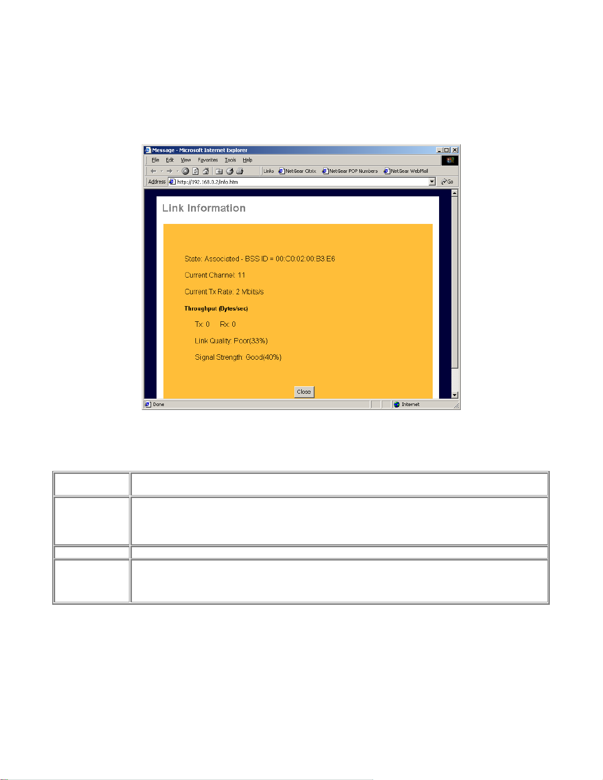
Wireless Link Info
When click on Link Info button in Figure 3-5, the Wireless Link Info screen shows. See Figure
3-6 for the current wireless link information.
Figure 3-6 Wireless Link Information Screen
Wireless Link Info Fields
Stat: Associated
– BSS ID
Current Channel
Current Tx Rate
Throughput
The other wireless party which PS111W wireless communication is associated with
The current used wireless channel.
For Network type as infrastructure mode, the channel is automatically selected the same as with the
Access Point.
The current wireless communication speed
Tx: The current transmitting rate in the unit of byte per second
Rx: The current receiving rate in the unit of byte per second
Link Quality: The quality of the link, which is excellent or poor
Signal Strength: The signal amplification, which is excellent or poor
Note: The information is only meaningful while there is a NETGEAR MA401 802.11b wireless PC
card in the PS111W slot.
17
Page 27
NetGear Print Server Manual
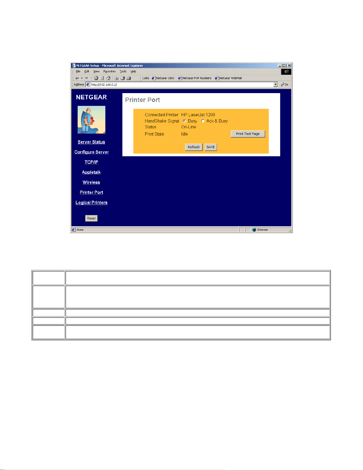
Printer Port
The Printer Port screen provides the status of the printer. See Figure 3-7.
Printer Port
Connected
Printer
HandShake
Signal
Status
Print State
Print Test
Page
Figure 3-7 Printer Port Screen
Shows the descriptive name for the new printer.
This sets one of the communication parameters between this device and the printer.
The default is "Ack & Busy". Only change this to "Busy" if advised to do so by Technical Support.
The current status of the printer (On-line, Off-line, Out of paper)
This will show either Idle or Printing.
Click on this button will print the print server status
18
Page 28
NetGear Print Server Manual
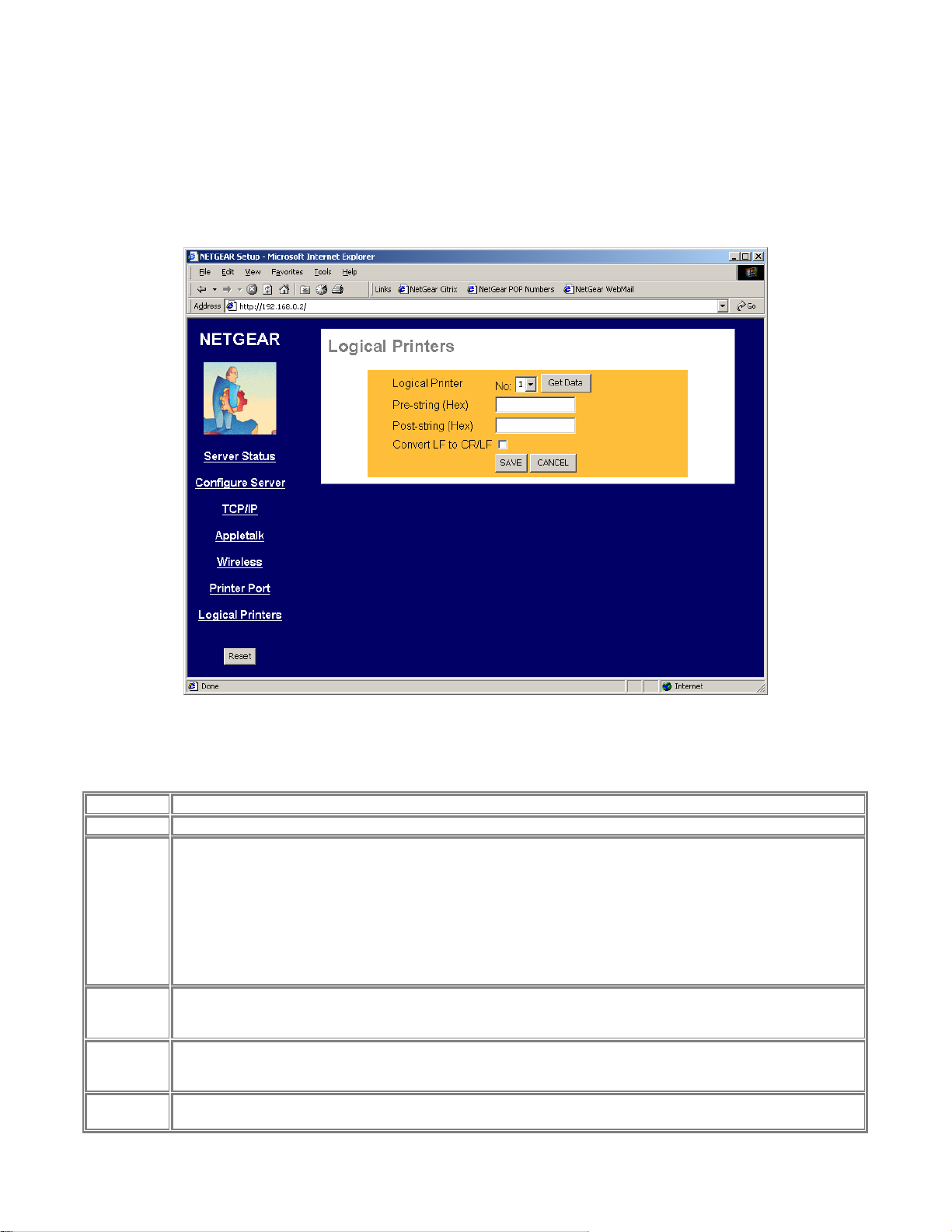
Logical Printer
The logical printer screen is used to map different logical printer ports to printers attached to the Print
Server. A logical printer port is used to specify a set of printer control commands to be sent to a printer
for every print job sent through the logical port. Figure 3-8 shows the logical port screen and the
following table describes its fields.
Logical Port Fields
Logical Port
Get Data
Pre-String
(Hex)
Post-String
(Hex)
Convert LF
to CR/LF
Save
Cancel
Selects the logical port to be configured. Three logical ports are available.
Click this button to display the saved configuration parameter for the selected logical port.
Provides the control character string to send to the printer before the first character of the job is sent to the
printer. One example of such an application would be switching to landscape mode whe n printing to the logical
port. The string is made up of the hexadecimal code of the corresponding ASCII characters, as in these
examples:
ASCII = [Esc]&|0O
Hexadecimal = 1B266C304F
ASCII=[Esc]&|1O
Hexadecimal = 1B266C314F
An ASCII to hexadecimal number conversion table is include in the appendix.
Provides the control character string to send to the printer after the last character of the job is sent to the
printer. The character string must be in hexadecimal format as illustrated in the String Before Job example
above.
If checked, adds a carriage return (CR) every time the line feed (LF) character code is received by the print
server when print data is sent to this logical printer port. Generally this should be unchecked. It may be needed
for compatibility between Unix and Windows.
Save:
After the configuration, click on ‘Save’ button to save the value permanently to PS111W.
Figure 3-8 Logical Port Screen
19
Page 29

NetGear Print Server Manual
Buttons
Cancel:
If changed something that is not good, click on ‘Cancel’ button will load the value back from PS111W. No
modification will be made into PS111W.
20
Page 30

NetGear Print Server Manual
Reset
Clicking the RESET button will reboot the print server. When you change settings for TCP/IP and
Wireless, you will need to reset the print server.
NOTE: If the print server is rebooted, any print job in progress will be disrupted.
NOTE: If DHCP client is enabled, which is the default setting, after system
reboots, the IP address of the unit may be changed. Please use the diagnostic
button prints out to verify the IP address.
21
Page 31

NetGear Print Server Manual
Chapter 4 Microsoft Windows System Printing
This chapter describes how to configure and use the NETGEAR PS111W Print Sever in a Microsoft
Windows networking environment.
To configure your hardware and software for the Microsoft Windows platform, you may:
• Use a web browser, like Microsoft Internet Explorer or Netscape, to configure your NETGEAR
Print Server. For the use of web browser configuration, please refer to Chapter 3.
• Install NETGEAR Print Server software. Run Setup.exe.
• Configure the user PC to print to the NETGEAR Print Server.
• Install the User and Reference guide in the local machine, so that you don’t have to carry the
NETGEAR PS111W Printer Server Resource CD Rom.
4-1 Printing in Windows
For the printing in your Windows system, you will need to do the following steps.
1. Application hardware connection
including the physical network connection to your PC and print server, or the wireless environment
MA401. Also the printer with the cable to the PS111W Print Server. Please refer to Quick
Installation Guide and choose a proper application setting for your environment.
2. NETGEAR Print Server Software Installation
will install the essential software for the configuration of the print server. By using NETGEAR
Print Server Setup Wizard you can set up the print server. If you can use Web Configuration, you
may not need to install the software. Please refer to Chapter 3.
3. Setup your PC to recognize the print server and write down the port name
let your PC add a special printer port by using NETGEAR Add Printer Wizard. Before add driver
for the printer, NETGEAR Add Printer Wizard will add the port automatically. You will need the
port name, so please write down the port name when provided to you.
4. Add a printer to your system to print.
Use NETGEAR Add Printer Driver to install the driver for your printer. Note: If you are using
Windows 9x (including 95, 98, and ME), you MUST install this software.
22
Page 32

NetGear Print Server Manual
4-2 NETGEAR Print Server Software Installation
NETGEAR Print Server software works for PS100 series Print Sever in a Microsoft Windows
networking environment.
To install and set up your network and your print server for the NETGEAR Print Server, you may use
a PC with a Microsoft Windows (95, 98, NT 4.0, ME, 2000, or XP) operating system and with either
the TCP/IP protocol or the NetBEUI protocol enabled.
Turn on the power to your PC.
Note: Before proceeding with these instructions, be sure to assign a name to
your workgroup on your PC. NETGEAR strongly recommends that you exit
Insert the CD ROM into the CDROM drive. The program should start automatically. If not, please
double click on setup.exe under the CDROM root directory. The first screen is shown below. Click on
Next button.
all Windows programs before running the Setup program. It is also necessary
to install the NETGEAR Print Server software on every PC in the network
that will use the printers attached to the PS100 series Print Sever.
Figure 4-1 Print Server Installation
23
Page 33

NetGear Print Server Manual
The second screen provides you an important message as shown below. Click on Next button.
Figure 4-2 Information
24
Page 34

NetGear Print Server Manual
As the next graphics, the third screen shows you a couple options.
Figure 4-3 Components
• NETGEAR Print Server Setup Wizard
An easy to use for the configuration of the print server wizard program
• NETGEAR Add Printer Wizard
A step-by-step guide program to configure the printer to print from your Microsoft Windows
You MUST install the NETGEAR Add Printer Wizard so you can use the print server to print
from Windows.
• Administrative Tools
Advance administrative tools including admin and IPSetup
Use admin to manage the print servers on LAN. Use IPSetup to manually assign IP address for
the print servers. Note that the print server default is a DHCP client. If there is a DHCP server,
you do not need to set up IP address. (Normally a home router comes with a DHCP server).
• User Manual – Adobe Acrobat format (PDF)
A user and reference manual that goes the detail as you see now
25
Page 35

NetGear Print Server Manual
After make the proper selections, click on Next button. You can choose the location of the program.
Figure 4-4 Destination Location
Choose a program folder name. You click on Next button to accept the default name.
Figure 4-5 Program Folder
26
Page 36

NetGear Print Server Manual
The next screen shows you the progress of the installation.
Figure 4-6
27
Page 37

NetGear Print Server Manual
Before you finish the installation, you can choose to run the NETGEAR Print Server Setup Wizard and
read the manual. You can uncheck either one or both of the selections and run it at a later time.
Figure 4-7 Complete Screen
There will be a program group created and shown as below.
Figure 4-8 NETGEAR Print Server
28
Page 38

NetGear Print Server Manual
You can open and access the group from your desktop as well. See Figure 4-9.
29
Page 39

NetGear Print Server Manual
4-3 Setting Up Your PC to Recognize the Print Server
You must set up each PC that will print to the print server. Before proceeding, verify that:
• The print cable is connected to the printer port.
• The AC adapter is plugged into the wall socket.
• The Ethernet cable is plugged into the LAN, or the wireless MA 401 PC card is installed in
PS111W.
Figure 4-9 NETGEAR Print Server software Icon
30
Page 40

NetGear Print Server Manual
To set up each PC:
Double-click on the desktop icon, as showing Figure 4-8, that you named the group in the previous
section, Figure 4-5.
Double-click on NETGAER Print Server Setup Wizard in the NETGEAR Print Server window.
The NETGAER Print Server window opens, as illustrated below.
Figure 4-10 NETGEAR Print Server Setup Wizard Window
In this window, you will see whatever network protocols you have installed on the local machine.
You need TCP/IP to use web management. Most nowadays operating systems including Microsoft
Windows 98, ME, 2000, and XP use TCP/IP as the primary networking protocol.
PS111W does not support NetWare IPX/SPX environment.
Older system, like Microsoft Windows 3.1, may support only Netbios protocol as the Microsoft Network.
You must have either TCP/IP or Netbios protocol, or both to use NETGAER PS111W print server.
31
Page 41

NetGear Print Server Manual
Click on Next.
The Printer Server Setup Wizard window shows the current available NETGEAR Print Server on LAN.
Click on Refresh button to see the new added print server. If you still don’t see the one you’d like to see,
wait a minute and click the Refresh button again.
Figure 4-11 Select Print Server
32
Page 42

NetGear Print Server Manual
Select the PS111W print server and click on Next.
The Printer Server Setup Wizard window shows the current print server Name. The default name is the
Device Name on the base of the unit. Change it to a unique name, or leave it without changing it. See Figure
4-12 Select Name for Print Server.
If your primary network is not Netbios/NetBEUI, you can leave Workgroup Name without a name.
Figure 4-12 Select Name for Print Server
33
Page 43

NetGear Print Server Manual
Click on Next.
The next Printer Server Setup Wizard window, Figure 4-13, shows TCP/IP setting for the print server.
You can choose to use a dynamic IP address, which is the most common setting, for the print server. Then,
select Obtain IP Address automatically. When select this option, there are two ways to get an IP address
dynamically. The first one is to get an IP address from a DHCP server. If you have and use a home
gateway/router, it usually comes with a DHCP server by default. The print server comes out of the factory
as a DHCP client and can get an IP address automatically. The second way is to use a self-assigned IP
address automatically. This is the same as a Microsoft Windows PC system. It is call Auto-IP.
Auto-IP
When NETGEAR PS111W Print Server is without an IP address due to as a DHCP client and there is no
DHCP server to automatically get an IP address, it will self-assign a unique IP address. The address range is
from 169.254.0.1 to 169.254.254.254 with the subnet mask 255.255.0.0 so that the print server can
communicate and work with other IP devices using the same mechanism.
To get the current IP address for the print server, make sure the printer power is ON, the print cable is
connected to the PS111W print server, and the print server power is ON, press the diagnostic button for two
seconds. The printer will print out the status of the print server, as well as the IP address.
How do I use this feature?
Select Obtain IP Address automatically in Figure 4-13 Set up TCP/IP for Print Server to get an IP address.
You do not use a DHCP server (usually if you don’t share a broadband – DSL, Cable, or satellite
connection, you don’t have one). You are networking with Ethernet (including Fast- and Gigabit-Ethernet)
network. Then you can use this feature. Your Microsoft Windows system uses this feature by itself. You can
click on Start – Run, Enter ‘command’, and click OK. When the command prompt window is popped up,
enter
Ipconfig
You may see the IP address for your system with 169.254.m.n, where m = 0-254 and n=1-254. The range is
from 169.254.0.1 to 169.254.254.254 with the subnet mask 255.255.0.0 too. When you know the IP
addresses for your system and the print server, you can test the connection from your PC to the print server.
In the command prompt window, enter
Ping 169.254.x.y
Where 169.254.x.y is the IP address you get from the print out of the print server. (You should replace x and
y with the IP address numbers in the print-out of the print server.)
You may set up a fixed IP address for the PS111W print server.
Select Fixed IP Address. Please enter the IP address, Subnet mask, and Default gateway accordingly. You
should get these values from your network administrator. If you don’t know what values you should use,
you may use Suggest New Values button. This button is available only when you select Fixed IP Address.
After click the Suggest New Value button, a set of values will be filled in the fields.
34
Page 44

NetGear Print Server Manual
Figure 4-13 Set up TCP/IP for Print Server to get an IP address
35
Page 45

NetGear Print Server Manual
Click on Next.
The next Printer Server Setup Wizard window, Figure 4-14, shows wireless settings for the print server.
If there is no NETGEAR 802.11b MA401 Wireless PC card in the slot, and not planning for now, you can
simply skip this step by going directly to the next step.
Wireless Configuration
Station Name is not changeable. It is the MAC address of the Ethernet of the print server.
SSID is Service Set Identifier, which should be the same for the entire wireless LAN. Get it from the
network administrator. If the Encryption is disabled and the Authentication using Open system, this field
can be empty.
Depends on the country area, you can choose one from 11 to 13 channels for the wireless communication.
Please note, when the wireless network type is in infrastructure mode, the channel is selected automatically
same as with the Access Point.
For the Network Type, if you have an Access Point, you MUST use Infrastructure mode to communicate
wirelessly. Please note, if plan to use the PS111W Wireless Ready Print Server in infrastructure mode with
Access Point, you MUST NOT connect it with Ethernet network, or it will disable the wireless
communication.
You can secure your wireless communication by using wired equivalent privacy (WEP) encryption. The
default encryption is disabled as WEP Disabled selected. By selecting WEP Enabled, you can enable the 64bit or 128-bit encryption. If you choose 64-bit WEP Keys, you have the choice of Key 1 to Key 4 for the
Default key. All the key fields are hexadecimal from 00 to FF. You need to enter five hexadecimal values as
a set for 64-bit encryption and 13 for 128-bit.
You also need to choose WEP Authentication method from one of Open System and Shared Key. The WEP
Authentication is associated with the SSID. For the Open System, the wireless device without SSID is
accepted to the Access Point, if no encryption. Some wireless devices can even browse the SSID from
Access Point. If use Shared Key for WEP Authentication, the wireless device must use the same SSID to get
access to the Access Point.
If you plan to use encryption, please make sure all the wireless communicating devices sharing the same
authentication, default key, and encryption keys.
36
Page 46

NetGear Print Server Manual
Figure 4-14 Wireless Configuration
37
Page 47

NetGear Print Server Manual
Click on Next.
Figure 4-15 Configuration Completed shows the completion of the print server configuration.
Figure 4-15 Configuration completed
Click on Finish.
The PS111W Print Server is ready to be used.
If you have installed NETGAER Add Printer Wizard, you’ll be able to install the printer driver and
configure it. Click No, if you don’t need to add a printer to your system now. You can add a printer at a later
time by opening the NETGEAR Print Server group and running NETGEAR Add Printer Wizard.
Figure 4-16 Add a Printer
38
Page 48

NetGear Print Server Manual
NETGEAR Add Printer Wizard - Write Down the Port Name
You can reach this setup procedure by answering Yes to the previous Figure 4-16 Information. Or open
NETGEAR Print Server group and run NEYGEAR Add Printer Wizard.
Make sure that the NETGEAR Print Server and the printer that connects to it are both powered on.
Make sure that the cable connections between them are properly connected.
Figure 4-17 Set up printer
Click on OK.
The Printer Select window, as illustrated in See Figure 4-18 Printer Select Window (Add Port), opens.
Figure 4-18 Printer Select Window (Add Port)
If the cables are not properly connected, your PC screen will appear empty when the Printer Select
window opens. If so, check the cable connections and click on the Refresh button, which will initiate
the PC to browse again for a port.
Click on the printer port you want to use with the print server, and click on Add.
The ADDPORT window for Epson print connection, as illustrated in below.
39
Page 49

NetGear Print Server Manual
ADDPORT Window (Epson Connection)
Click on No if you do not have an Epson Stylus Color printer attached to the port, and continue to step 8.
Or
Click on Yes if you do have an Epson Stylus Color printer (or plan to install one). You must disable the
Epson printer.
To disable:
Click on the Program Files folder on your hard drive.
Start the Epson Spool Manager.
The Queue Setup window opens, as illustrated below. See Figure 4-19 Epson Spool Manager Queue
Setup Window.
Figure 4-19 Epson Spool Manager Queue Setup Window
Select Queue Setup, and click on Use Print Manager for this port.
Click on OK to exit the Queue Setup window.
The ADD PORT window, as illustrated in Figure 4-20 Add Port message, opens. This window informs you
that you have successfully added the port.
40
Page 50

NetGear Print Server Manual
ADD PORT Window
If this is not an Epson printer, skip the above procedure. The Add Port should be added successfully. See
Figure 4-20 Add Port message.
Figure 4-20 Add Port message
Write Down the Port Name
It is very important to remember and write down the port name. You will need this information later when
prompted to select a printer port. See Figure 4-20 Add Port message. The port name, here for example, is
IP_192.168.1.108_P1. You should write it down in the Quick Installation Guide in the line
Now, write down the printer port name: ___________________________________________________
41
Page 51

NetGear Print Server Manual
4-4 Add a printer to your system to print
Select Printer Port for Add Printer Wizard
After selected the printer, you need to select a printer port to print. See Figure 4-21 Select Printer Port for
Add Printer Wizard.
Figure 4-21 Select the Printer Port for Add Printer Wizard
42
Page 52

NetGear Print Server Manual
Use the printer port name written at the last section. Scroll down and find the printer port name. For
example, the printer port name here is ‘IP_192.168.1.108_P1’. See Figure 4-22 Find and select the printer
port. For Windows 95, and 98 users, this window will show up after Add Printer (Figure 4-23 thereafter).
Figure 4-22 Find and select the printer port
Click on Next
Add Printer Wizard, Figure 4-23 Add Printer Wizard window, shows. Choose the manufacturer and the
model name of the printer. If there is a CD provided with the printer, insert the CD and click on ‘Have
Disk…’ button. Follow the instruction on screen to install the correct driver.
43
Page 53

NetGear Print Server Manual
Figure 4-23 Add Printer Wizard
Click on Next
If you have ever installed the printer driver in the system, Figure 4-24 Use Existing Driver window shows.
You can choose to keep the existing driver, or replace it. If you don’t see Figure 4-24, go to the next step.
44
Page 54

NetGear Print Server Manual
Figure 4-24 Use Existing Driver for Add Printer Wizard
Click on Next
Name the printer. See Figure 4-25 Name Your Printer for Add Printer Wizard. If there are more than one
printer drivers installed in the system, you may answer Yes to choose this as your default printer for your
Windows-based programs.
45
Page 55

NetGear Print Server Manual
Figure 4-25 Name Your Printer for Add Printer Wizard
Click on Next
See Figure 4-26 Printer Sharing. When you use print server for the printer, you don’t usually need to share
the printer on the local machine. Keep the default answer as Do not share this printer.
46
Page 56

NetGear Print Server Manual
Figure 4-26 Share Printer for Add Printer Wizard
Click on Next
You can try to print a test page to the printer after your printer installed properly. See Figure 4-27 Print Test
Page. It is OK not to print a test page in answering question Do you want to print a test page to No.
47
Page 57

NetGear Print Server Manual
Figure 4-27 Print Test Page for Add Printer Wizard
Click on Next
If you answer Yes to print a test page, see Figure 4-28.
Figure 4-28 Printer print the test page
Click on OK
Complete the Add Printer Wizard. See Figure 4-29 Completing the Add Printer Wizard.
48
Page 58

NetGear Print Server Manual
Figure 4-29 Completing the Add Printer Wizard
Click on Finish
Now you can print through the PS111W print server. The Figure 4-18 Printer Select Window (Add Port)
window remains on the screen. Click on End to close it.
49
Page 59

NetGear Print Server Manual
Chapter 5 UNIX Printing Using TCP/IP
This chapter explains how to configure and set up the NETGEAR PS111W Print Sever and your UNIX
system if you are operating in a UNIX networking environment. The print server can work with most
UNIX operating systems with the TCP/IP protocol, but the following protocols and printing methods
are supported:
Protocols--DHCP, BOOTP, RARP, FTP, TCP, IP
Printing methods--LPD, FTP, DSI
Setting up your print server and UNIX PC requires a few extra steps and some decisions that must be
made before configuring both your print server and your PC. In all network environments, the print
server must be configured before configuring any PCs on your network. If your network:
Includes both PCs and UNIX systems
NETGEAR highly recommends that you configure the print server from a Windows PC as outlined in the
instructions in Chapter 3 Web Management and Chapter 7 Using Advanced Management Tools." The
administration program software assigns an IP address to the print server by using the NetBEUI or the
IPX/SPX protocol for communication. IPX address resolution is done automatically by the workstation, and
no local manual configuration is necessary. Configure any UNIX system in your network with the
instructions provided in this chapter. See “Setting the Print Method” to choose a printing method.
Includes only UNIX systems or if you have PCs without Windows on your network
You must configure both your print server and all your PC systems with the instructions provided in this
chapter. Before you can configure the print server (which must be done first) you must assign an IP address
to it. (For information about IP addresses, refer to Appendix B “Understanding IP Addresses.”) Use one of
the following two methods:
Assign active IP address resolution
With temporary IP address assignment, the print server sends out broadcast packets actively searching
for a server to provide the print server with an IP address. The print server sends out DHCP packets,
BootP packets, and RARP packets (in this sequence) to resolve its own IP address. This broadcast
mechanism is conducted only upon reset or power cycle.
Assign a temporary IP address to your print server by referring to:
“Assigning an IP Address to the Print Server Using DHCP”
“Assigning an IP Address to the Print Server Using BootP”
“Assigning an IP Address to the Print Server Using RARP”
Assign passive IP address resolution
Assign a static IP address to your print server by referring to “Assigning an IP Address to the Print
Server Using ARP”.
With all four methods of IP address resolution, the print server loses the IP setting after reset or a power
loss. To permanently configure the print server and save the IP address assignment in the flash EEPROM of
the print server, you must use FTP. Using FTP, you can modify the CONFIG file in the print server.
50
Page 60

NetGear Print Server Manual
After you configure the print server as described in “Configuring Your Print Server Using FTP”,
choose a printing method as described in Setting the Print Method” to configure each UNIX PC in
your network.
5-1 Temporary IP Address Resolution
If the IP address is left at 0.0.0.0 (the default value), a temporary IP address is assigned when the print
server is powered on. DHCP, BootP, and RARP are attempted in sequence for finding an address.
The newer PS100 series print servers provide a new Auto-IP feature. If DHCP, BootP, and RARP
cannot get an IP address, an internal IP address will be assigned automatically. The address will be in
the range from 169.254.0.1 to 169.254.254.254 with subnet mask 255.255.0.0. Reset (power cycle) the
print server to get an IP address.
Assigning an IP Address to the Print Server Using DHCP
Using Dynamic Host Configuration Protocol (DHCP) is possible only if you have a DHCP server with
management software that allows you to take advantage of this feature. Otherwise, the IP address of
the print server will be unknown, and connection to the print server is not possible. To use DHCP, turn
on power to the print server; the DHCP server automatically assigns an IP address to it.
If you do not have a DHCP server and you are assigning an IP address to the print server, you can use
BootP, RARP, or ARP.
Assigning an IP Address to the Print Server Using BootP
To assign an IP address using the Bootstrap Protocol (BootP):
Determine the physical address and the device name of the print server.
The factory default name and the physical address are shown on a sticker on the bottom of the unit. The
default name on your device is PSxxxxxx.
Log in to the UNIX host as root.
Add the print server to the /etc/hosts file by adding to the file:
IP_Address NAME # Comment
Use these definitions for entering the information:
IP_Address is the IP address of your print server.
NAME is the name of your print server.
A sample entry is:
192.10.2.54 PS_Rm203 #Default name PS123456
In the example, a print server with an IP address of 192.10.2.54 is called PS_Rm203 and has a default name
of PS123456.
Add to the Boot Table in the /etc/booptab file:
NAME:ht=ether:vm=rfc1024::ha=PA:ip=IP:sm=SM:gw=GW
51
Page 61

NetGear Print Server Manual
Use these definitions for entering the information:
NAME is the name of your print server.
PA is the physical address of your print server.
IP is the IP address of your print server.
SM is the Subnet Mask IP address.
Refer to Appendix B “Understanding IP Addresses,” for additional information about assigning a
Subnet Mask IP address.
GW is the Gateway IP address.
Refer to Appendix B “Understanding IP Addresses,” for additional information about assigning a
Gateway IP address.
Start the BootP daemon (the usual command is BOOTPd) if the command in step 2 did not start the
BootP process, and then reset the print server so that it obtains an IP address using BootP.
Compare the IP address to MAC address association to assure that an IP address has been assigned,
using the ping command:
ping NAME
NAME is the name of the print server. You should receive a response. If you get a timeout message, the
BootP procedure has failed. You can either follow the steps again for using BootP or use one of the other
methods for assigning an IP address.
Proceed to “Configuring Your Print Server Using FTP” to configure the print server, if it has not yet
been configured.
Assigning an IP Address to the Print Server Using RARP
To assign an IP address using the Reverse Address Resolution Protocol (RARP):
Determine the physical address and the device name of the print server.
The factory default name and the physical address are shown on a sticker on the bottom of the unit. The
default name on your device is PSxxxxxx.
Log in to the UNIX host as root.
Add the print server to the /etc/hosts file by adding to the file:
IP_Address NAME # Comment
Use these definitions for entering the information:
IP_Address is the IP address of your print server.
NAME is the name of your print server.
A sample entry is:
192.10.2.54 PS_Rm203 #Default name PS123456
52
Page 62

NetGear Print Server Manual
In the example, a print server with an IP address of 192.10.2.54 is called PS_Rm203 and has a default name
of PS123456.
Add to the Ethernet Address table /etc/ethers:
00:c0:02:xx:yy:zz NAME
Use these definitions for entering the information:
00:c0:02:xx:yy:zz is the location of your print server.
NAME is the name of your print server.
Reset the print server by turning the power off and then on again.
When the print server reboots, it acquires an IP address using RARP.
To assure that an IP address has been assigned, check the IP address to MAC address association using
the ping command:
ping NAME
NAME is the name of the print server. You should receive a response. If you get a timeout message, the
RARP procedure has failed. You can either follow the steps again for using RARP or use one of the other
methods for assigning an IP address.
Proceed to “Configuring Your Print Server Using FTP” to configure the print server, if it has not yet
been configured.
Assigning an IP Address to the Print Server Using ARP
To assign an IP address using the Address Resolution Protocol (ARP):
Determine the physical address and the device name of the print server.
The factory default name and the physical address are shown on a sticker on the bottom of the unit. The
default name on your device is PSxxxxxx.
Log in to the UNIX host as root.
Add the print server to the /etc/hosts file by adding to the file:
IP_Address NAME # Comment
Use these definitions for entering the information:
IP_Address is the IP address of your print server.
NAME is the name of your print server.
A sample entry is:
192.10.2.54 PS_Rm203 #Default name PS123456
In the example, a print server with an IP address of 192.10.2.54 is called PS_Rm203 and has a default name
of PS123456.
Compare the physical address with the IP address of the print server, using the ARP command as
follows:
53
Page 63

NetGear Print Server Manual
arp -s NAME 00:c0:02:xx:yy:zz
Use these definitions for entering the information:
NAME is the name of your print server.
00:c0:02:xx:yy:zz is the physical address of the print server.
A sample entry is:
arp -s PS_Rm203 00:c0:02:12:34:56
To assure that an IP address has been assigned, check the IP address to MAC address association using
the ping command:
ping NAME
NAME is the name of the print server. You should receive a response, but if you get a timeout message, the
ARP procedure has failed. You can either follow the steps again for using ARP or use one of the other
methods for assigning an IP address.
Proceed to “Configuring Your Print Server Using FTP,” which follows.
54
Page 64

NetGear Print Server Manual
5-2 Configuring Your Print Server Using FTP
FTP allows a user to log on to a remote host and to manipulate files on the host. The print server can
act as an FTP host. Using FTP, you can access and modify the CONFIG file in the print server.
Modifying the CONFIG file changes the configuration of the print server.
The limitations of print server support when using FTP are:
• Only one FTP user can connect to the print server at a time.
• Only command line FTP programs can be used. FTP programs that attempt to browse the file
system are not supported.
Configuration Example
This section provides commands to use and responses to each command when you use FTP to connect
to the print server.
Example instructions are:
Connect to the print server by entering the command:
ftp NAME or ftp IP_Address
You can connect using a name instead of an IP address only if your system has been configured to recognize
the name to IP address association.
Enter the default name (on the base of the device) when you are prompted for the user name.
Press [Enter] when prompted for the password.
Copy the configuration file by entering the command:
ftp>get CONFIG
Quit copying the file by entering the command:
ftp>quit
Edit the CONFIG file by typing with a text editor.
NETGEAR recommends that you edit the CONFIG file to provide a permanent IP address to the print
server. The CONFIG file is shown in “CONFIG File.”
Copy the CONFIG file back to the print server and then reset the device by using the commands:
ftp NAME
ftp>put CONFIG
ftp>get RESET
Quit by using the command:
ftp>quit
55
Page 65

NetGear Print Server Manual
List of FTP Files and Commands Supported by the Print Server
Table FTP Files in the Directory lists the file names that appear in the directory.
FTP Files in the Directory
File Name Purpose Mode
CONFIG Configuration file Read/Write
PSINF Device information Read
DEFAULTC Reset device to default configuration Read
RESET Reset device Read
PASSRESET Clear password Read
SETIP Save current IP address Read
Table FTP Commands lists the case-sensitive commands that are implemented. When a command
requires a parameter, the parameter is shown in italics.
FTP Commands
Command Function
dir Lists files as shown in table FTP Files in the Directory.
get FILENAME Retrieves a file. The only files that can be retrieved are CONF IG and PSINF .
get RESET Resets the print server and terminates the current connection.
get
PASSRESET
get SETIP
put CONFIG
put
PASSWORD
put filename Ln Copies the filename file to the printer connected to n port and prints the file.
quit Terminates the current FTP session.
Other FTP commands cannot be used, and they return an Invalid Command error message.
Clears the password.
Sets the current IP address as a static IP address.
To avoid an address conflict, do not use this command if a DHCP server assigned the IP address to the print
server.
Copies the CONFIG file to the print server, overwriting the existing CONFIG file. After using this command to
write a new configuration file, use the get RESET command; all LEDs should turn on and then off while the
print server is resetting.
Copies the password file to the print server and gives it a new password. Passwords can be up to 19 bytes in
length.
56
Page 66

NetGear Print Server Manual
5-3 Setting the Print Method
The following three printing methods can be used in any environment:
Line Printer Daemon (LPD)
LPD is a standard print method for most UNIX systems. The benefit of this method is that it eliminates the
need to install additional software on the host.
File Transfer Protocol (FTP)
FTP is also a standard print method in most UNIX systems, but it is not recommended except as a test and
backup method of printing.
Direct Socket Interface (DSI)
DSI is a UNIX-based method of providing a direct connection between a host computer and a printer. The
host and the print server establish a TCP connection, using a special socket number. All data sent over this
connection is treated as print data and sent transparently to a logical printer defined on the print server.
Of the three choices, LPD and DSI work well with a large number of users because they both employ
print queue processes. FTP does not implement a print queue; if the printer is busy, the print command
may fail.
The three methods are explained more fully in the following sections.
LPD Configuration and Printing
LPD is a built-in printing protocol for most UNIX systems including BSD type UNIX. It is also
supported in Windows NT 3.5 or later. The following sections provide information about configuring
LPD on:
• IBM AIX 4.15
• System V
• BSD
Configuring LPD on IBM AIX 4.15
Before proceeding, make sure that the print server has been assigned an IP address.
To set up your AIX system for LPD printing:
Type the name of your print server, adding it to the /etc/hosts.lpd file.
Start the LPD daemon if it is not running, using the command:
start src -s qdaemon
Start the system administration tool smith and select Print Spooling.
Create the required number of queues (one for each logical printer) by selecting Add a Print Queue,
Remote (Printer attached to Remote Host), and then Standard Processing.
Use these definitions for entering the information:
57
Page 67

NetGear Print Server Manual
Name of queue to add
Use a single-word queue name that indicates the printer attached.
Hostname for remote server
Print server name as used in /etc/hosts.lpd.
Name of queue on remote server
It is the logical printer number (L1 to L3 or L1 to L8) to service this queue.
Type of print spooler on remote server
Use the default value.
Make sure the logical printers are configured in the print server.
Refer to the information provided in table FTP Commands for information about configuring logical
printers.
Print using the command:
lp -d printer_queue file_name
Use these definitions for entering the information:
printer_queue is one of the entries used in Name of queue to add.
file_name is the file you want to print.
Configuring LPD on System V
Before beginning LPD Setup, make sure that an IP address has been assigned to your print server and
that the following statements apply:
The remote host name is the name of the print server.
The remote printer name is the print queue name for the logical printer.
Logical printers are configured on the print server itself.
You identify the service type as BSD if your UNIX system asks for the LPD type.
The LPD protocol that the print server uses meets BSD system standards.
Table Sample Commands for Using LPD on System V shows sample commands when using LPD. The
definitions used in the sample commands are:
printer_name is the name of the print queue serviced by the print server.
Spooler_directory is the name of the directory used to spool the print jobs.
Sample Commands for Using LPD on System V
Action Sample Command
58
Page 68

NetGear Print Server Manual
/
/
/
Stop Print Services
Add a System Printer
Restart the Print Services
Enable printing to the new printer device enable printer_name
Start accepting jobs for the new printer device accept printer_name
Create a spooling directory mkdir /usr/spool/Spooler_directory
Make spooling daemon the owner of this directory chown daemon /usr/spool/Spooler_directory
Create read/write permissions chmod 775 /usr/spool/Spooler_directory
Give permissions to LPD processes chgrp daemon /usr/spool/Spooler_directory
Add remote printer(s). (Repeat this process for
each logical printer/print queue combination that
you want to create.)
Sample command should be entered as one line,
using a tab character where shown.
usr/lib/lpshut
usr/lib/lpadmin -p printer_name -v /dev/null
usr/lib/lpsched
Add to the /etc/printcap file:
printer_name|Remote_Printer_Alias:\
[Tab] :lp=:\
[Tab] :rm=PS_NAME:\
[Tab] :rp=Logical_Printer_name:\
[Tab] :sd=Spooler_directory:\
[Tab] :mx#0
Use these definitions for entering the information:
printer_name is the print queue name used to store jobs for the
corresponding logical printer.
PS_NAME is the print server name defined in /etc/hosts.
Logical_Printer_name is the logical printer name on the print server (L1 to
L3 or L1 to L8, depending on the print server that you are using).
Spooler_directory is the directory you created.
Configuring LPD on BSD
Make sure that an IP address has been assigned to the print server and the following statements apply:
The remote host name is the name of the print server.
The remote printer name is the logical printer (L1 to L3 or L1 to L8).
You identify the service type as BSD if your UNIX system asks for the LPD type.
The LPD protocol that the print server uses meets BSD system standards.
Enter the service type as BSD if asked for the LPD type.
Table Sample Commands for Using LPD on BSD shows sample commands when using LPD. The
definitions used in the sample commands are:
printer_name is the print queue serviced by the logical printer on the print server.
Spooler_dir is the name of the directory used to spool the print jobs.
Sample Commands for Using LPD on BSD
Action Sample Command
Create a spooling directory Mkdir /usr/spool/Spooler_dir
Set spooling daemon as owner of this
directory
Create read/write permissions Chmod 775 /usr/spool/Spooler_dir
Give permissions to LPD processes Chgrp daemon /usr/spool/Spooler_dir
Add remote printer(s)
Chown daemon /usr/spool/Spooler_dir
See adding remote printers in table Sample Commands for Using LPD on
System V
59
Page 69

NetGear Print Server Manual
Start lpc print mechanism lpc start printer_name
Printing Using LPD
For LPD printing instructions, refer to your UNIX manual. An example command that is used for a
BSD UNIX system is:
lpr -P printer_name filename
The definitions used are:
printer_name is the name of the print queue defined on the UNIX host.
filename is the name of the file you want to print.
An example command with parameters is:
lpr -P Marketing /etc/hosts
In the above example, the /etc/hosts file is sent to the Marketing printer queue. It is then sent to the
logical printer associated with this queue.
Printing Using FTP
Using FTP to print lets you send print jobs to the printers directly. Because there is no spooling, if the
printer is not ready, the print job is terminated immediately. The advantage of FTP is that no host
configuration is required.
To print using FTP, use the command lines:
#ftp Name
ftp>put FileName Ln
The definitions used are:
Name is the name of the print server.
FileName is the file you want to print.
Ln is the logical printer you want to print to.
Printing Using DSI
Logical printers must be configured on the print server. Even if you are using the PS100 series Print
Sever that normally supports up to eight logical printers, using DSI to print limits the support to three
logical printers.
Socket numbers are defined as listed in table Socket Number Definitions.
Socket Number Definitions
Logical Printer Number Socket Number
1 4010
2 4020
3 4030
Note: Some of the features described in this chapter may not available to every NETGEAR Print
Server model.
60
Page 70

NetGear Print Server Manual
Chapter 6 AppleTalk Printing
This chapter contains information about configuring and using your NETGEAR PS100 series print
server in an AppleTalk networking environment.
6-1 Setting up Print Server for AppleTalk
There are 3 different ways to configure AppleTalk on a NETGEAR PS100 series print server:
The recommended approach is through the print server's browser interface in an IP networking environment. For
more information, please refer to chapter 3, “Web Management for Print Server”.
6-1 Browser Interface for Configuring AppleTalk
Through the NETGEAR Print Server Administration Program on a PC with Microsoft Windows. For more
information, please refer to chapter 7, “Using Advanced Management Tools”.
Through the NETGEAR PSTool Utility for the Macintosh environment. Described in this chapter.
AppleTalk printing is enabled by default in NETGEAR Print Servers that support AppleTalk printing
and the printers attached to the print servers are advertised in the default zone on the AppleTalk
network.
Configuration will only be necessary if the name of the print server is to be changed from the default,
or if you have an AppleTalk network connected by AppleTalk routers and you wish the printers
61
Page 71

NetGear Print Server Manual
attached to the print server to be advertised in a specific AppleTalk zone, or if you need to change the
communication protocol used between the print server and the printer.
6-2 Setting up Host Computer
The host Apple computer to be setup for AppleTalk printing must be running System 7 Operating
System or later.
Install any printer driver provided by your printer manufacturer for the Mac OS©.
Click the Apple icon and choose Control Panel.
Click Network.
Ensure that EtherTalk is selected under AppleTalk Connection.
Click Chooser. The Chooser panel will open.
Click on either the LaserWriter 8 icon (recommended) or the LaserWriter 7 icon. LaserWriter 8 makes
use of the fonts installed in the printer itself, so the printing response time is quicker. LaserWriter 7
uses the fonts installed in the computer, which increases network traffic and takes more printing time.
Select printers attached to the NETGEAR Print Server from the printer list by clicking on the
appropriate name.
Printers attached to the NETGEAR printer are advertised on AppleTalk networks as xxxxxx_P1,
xxxxxx_P2, xxxxxx_P3, where xxxxxx is the name of the print server. e.g. if the NETGEAR Print Server is
a 3 port model and the printer server name is PS543283, the printers attached to it will be advertised as
PS543283_P1, PS543283_P2, PS543283_3. The default name of the print server's name is recorded on a
label on the bottom of the print server as "Device Name". This name is consisted of 8 digits and/or numbers.
Click on the Close box.
62
Page 72

NetGear Print Server Manual
6-3 Using PSTool Utility
This section describes how to use the NETGEAR PSTool Utility for Apple Computers to configure
AppleTalk on a NETGEAR Print Server. It is not necessary to use the NETGEAR PSTool Utility to
manage AppleTalk printing if your NETGEAR Print Server can be managed via the web browser
interface or if you have Windows workstations running the NETGEAR Print Server Administration
program.
The NETGEAR PSTool Utility is a program that runs under the Mac OS©. You first edit a NETGEAR
Print Server configuration file using a text editor such as SimpleText, then use the NETGEAR PSTool
Utility to send the configuration file to the NETGEAR Print Server. The procedure is as follows:
Copy the following files from the Utility\Apple folder on the Print Server Resource CD-ROM to an
appropriate folder on your Apple computer. Your Apple computer must be running System 7 or later
Mac OS©.
PSTool
CONFIG.2P if configuring a 2 port print server, or CONFIG.3P if configuring a 3 port print server.
Use Chooser to select the desired Print Server.
Double click the CONFIG.2P or CONFIG.3P file that was copied over in step 1, and edit it. Figure 7-1 is
an example of the CONFIG.3P file. DO NOT modify the first line and last line of the file, or change
the number at the beginning of each line.
begin CMD
0001 Device Name: xxxxxxxx
3000 Apple Zone : *
3101 AP_PCOMM1: No
3102 AP_PCOMM2: No
3104 AP_PCOMM3: No
9002
Sample CONFIG.3P Configuration File
Save the file.
Double click the icon for PSTool.
Click the Printer submenu and choose Download Postscript File. A panel will appear with a list of files.
Click the CONFIG file file that you edited in step 3. Then click Download.
63
Page 73

NetGear Print Server Manual
6-4 PSTool Utility CONFIG File Format
The entries of the config file are listed and described in table 7.1. This example is for the 3 port model
of the NETGEAR Print Server.
PSTool Utility Config File Entries
Entry inConfig File Description
begin CMD
0001 Device Name:
xxxxxxxx
3000 Apple Zone: *
3101
AP_PCOMM1: No
3102
AP_PCOMM2: No
3104
AP_PCOMM3:
9002
Note: NETGEAR does not support PS101 Print Server for AppleTalk printing environment.
Do not change this line.
Replace xxxxxxxx with the desired device name. The Device Name will initially be the Default Server
Name. The Default Server Name is shown on a sticker on the base of the device. The Device Name can
be changed, but the new name must not exceed 16 characters in length
The default value "*" allows all AppleTalk zones to access the Print Server's printers. To restrict access
to a particular zone, replace the * with the desired zone name.
These settings determine whether the port uses ASCII or Binary Communication Protocol. Enter No for
ASCII or Yes for Binary. The lines corresponds to port 1, 2 and 3 of the print server.
Binary communication is twice as fast as ASCII
ASCII communication is more reliable
The computer, Print Server and printer MUST all be configured to use the SAME protocol.
Do not change this line.
64
Page 74

NetGear Print Server Manual
Chapter 7 Using Advanced Management Tools
This chapter describes in more detail the two print server management programs bundled with
NETGEAR PS100 series print servers. These programs are included on the Print Server Resource CD.
The two programs described in this chapter are:
• NETGEAR Print Server Administration Program
This software program is a print server administration program based on Windows 95,
Windows 98, Windows NT, or Windows 2000. It runs on any of the four protocols that the
print server supports.
• IPSetup
This program is to the IP address of the Print Server manually from Microsoft Windows.
7-1 Configuration Using the NETGEAR Print Server Administration Program
Before you begin this section, you must first install the NETGEAR Print Server software on your PC,
using the supplied CD-ROM.
To start the NetGear Administration Program:
• Click on Start
• Move along the program folders to highlight the NetGear program folder
• Click on the icon for the Print Server Administration program
As illustrated below, the main screen of the NetGear print server setup utility opens and searches the
network for NETGEAR print servers.
NETGEAR Print Server Administration Program
All active NETGEAR print servers are listed on the screen as shown. If there is any print server
missing from the screen, you may click on the Browse button to scan the network one more time. By
default, the NetGear Administration Program only browses the network with NetBEUI to minimize
unnecessary packets on the network.
If you still do not see all the print servers, the print server that you are trying to configure might have
the default NetBEUI protocol disabled. If the protocol is disabled, click on the Protocol button to
enable browsing with IPX/SPX and TCP/IP. Make sure that the IPX/SPX and TCP/IP protocols are
65
Page 75

NetGear Print Server Manual
also enabled and bound to the network adapter card in your Windows 95, Windows 98, Windows NT,
or Windows 2000 system.
Buttons
Advanced Button
Click on the Advanced button for detailed full configuration of the selected Print Server. See the later
section 7-2 Advanced Print Server Configuration for more information about the
Advanced option.
Quick Button
Click on the Quick button to open the Quick Setup Screen to perform a quick configuration of the print
server in a Microsoft network running the NetBEUI protocol.
Clicking the Quick Setup button will reveal a screen like the following.
Quick Setup Screen
Enter the required Device Name, and click "OK". The Device Name is how users on the network will
see this Print Server on the network.
Protocol Button
This screen allows you to disable protocols which are not used on your network. An example screen is
shown below.
66
Page 76

NetGear Print Server Manual
Protocol Screen
The protocol currently used for communication between your PC and the Print Server is Enabled and
grayed out, so it cannot be disabled.
Browse Button
Use this button to re-scan the network and update icons for any Print Servers located.
Exit Button.
The Exit button ends the NetGear setup utility.
67
Page 77

NetGear Print Server Manual
7-2 Advanced Print Server Configuration
From the main menu, click on the Advanced button to use the advanced configuration procedure. The
Advanced Print Server Configuration screen opens.
The Advanced Print Server Configuration screen contains the fields listed on tabs that can be selected
in any order to customize the configuration of the print server. The following field tabs are provided by
the Advanced Print Server Configuration screen:
• System
• TCP/IP
• NetBEUI
• Logical Port
• Physical Port
• Wireless
Each tab is described in the following sections.
There are two control buttons associated with every tab, and there is a "Return to Main Menu" button
at the bottom of the tab. The function of each button is described in the table bellow.
Control Buttons on All Tabs
Field Description
Restore to
Default
Save to
Device
Return to
Main
Menu
This button appears on many screens. Clicking it replaces the onscreen values with the default settings. The
tab settings are not saved until you click on the Save to Device button. The quickest way to set all device
values to the factory default setting is to click on the Configuration selection on the menu bar and select
Restore Factory Default.
Click this button to write any changed configuration information to the print server.
If you switch to another tab without clicking on the Save to Device button, all new settings are lost.
Click this button to return to the print server administration main menu. If you want to configure another print
server, you must click on this button to return to the main menu and select another print server.
Any configuration change is lost unless you click on the Save to Device button at the bottom of the
field window to send the configuration to the print server. When moving into a new field screen, all
settings in the previous screen are lost. It is essential that you make a decision on the present field
screen whether to abandon or save the new parameters into the print server.
The menu bars and their fields are described in the following sections.
System Tab
The System tab contains the fields to change the print server name and activate or disable the various
networking protocols supported by the print server.
68
Page 78

NetGear Print Server Manual
System Tab Window
System Tab Fields
Field Description
Device
Name
IPX/SPX
Protocol
TCP/IP
Protocol
NetBEUI
Protocol
AppleTalk Choose to enable or disable the AppleTalk Protocol. AppleTalk is used in small networks of Apple
Choose a descriptive name for the router for identification purposes (for example, EngPrsv). This name is
used in all protocols to identify the specific print server. There is a factory default name. For any change,
NETGEAR recommends that a name be determined before setting the print server in any network. This
name should be no more than 16 characters with at least a non numeric letter. Spaces are not allowed, but
dashes (-) and underscore marks (_) are accepted.
Choose to enable or disable the IPX/SPX protocol used in the NetWare environment. This selection is
always shadowed to indicate that the IPX/SPX protocol is always active and cannot be disabled.
Choose to enable or disable the TCP/IP protocol. TCP/IP is used for UNIX networking and Microsoft
networking. The factory default is Enable.
Choose to enable or disable the NetBEUI protocol. NetBEUI is primarily used in a small-scale Microsoft
networking environment.
69
Page 79

NetGear Print Server Manual
Protocol computers. The factory default is enable.
TCP/IP Tab
This tab allows configuration for the TCP/IP network protocol.. For further information about TCP/IP,
refer to Chapter
TCP/IP Tab Window
TCP/IP Tab Fields
Field Description
DHCP This field allows you to enable or disable the print server's ability to get its IP address from a DHCP
IP Address This IP address is assigned to the print server. If you have a private LAN and do not plan to connect to the
(Dynamic Host Configuration Protocol) server. When disabled, you can provide a fixed IP address in the
following fields.
TCP/IP-based internet, NETGEAR recommends that you use the address from the IETP-designated
private addresses (for example, 192.168.x.x or 10.x.x.x).
70
Page 80

NetGear Print Server Manual
Subnet Mask This subnet mask defines the range of addresses that are reachable on your local LAN.
Gateway
Address
This IP address is what the print server uses for stations with IP addresses not reachable on your local
LAN.
AppleTalk Tab
The AppleTalk tab is used to configure the AppleTalk zone that the print server will appear in and the
communication protocol used on the printer port. For further information about AppleTalk printing,
refer to Chapter 7, "AppleTalk Printing".
AppleTalk Tab
AppleTalk Tab Fields
Field Description
AppleTalk Zone The AppleTalk zone that the print server will appear in. To put the print server in the default AppleTalk
zone of the AppleTalk network the print server is connected to, enter a single asterisk.
71
Page 81

NetGear Print Server Manual
Printer Type These are text fields, used to describe the printer driver used for each port. Currently the only printer
driver supported for AppleTalk is LaserWriter.
Communication
Protocol
Sets whether the port uses ASCII or Binary Communication Protocol. Binary communication is faster
than ASCII, but ASCII communication is more reliable. The default is ASCII.
Logical Port Tab
Logical printers (Logical Ports) can be used under Linux or Unix. The Print Server supports 3 Logical
Ports. This screen allows configuration of Logical Ports.
Logical Port Tab Fields
Field Description
Current
Selected
Logical Port
Selects the logical port to be configured. Eight logical ports are available for print servers with two printer
ports; three logical ports are available for one printer port print servers.
Logical Port Tab Window
72
Page 82

NetGear Print Server Manual
Physical Port Selects which physical printer port the logical port is mapped into. Converts LF to LF+ CRAdd a carriage
return (CR) every time the line feed (LF) character code is received by the print server when any print data
is sent to this logical port.
String Before
Job
String After
Job
Provides the control character string to send to the printer before the first character of the job is sent to the
printer. One example of such an application would be switching to landscape mode when printing to the
logical port. The character string must be in hexadecimal format as in these examples:
ASCII = [Esc]&l0O
Hexadecimal = 1B266C304F
ASCII = [Esc]&l1O
Hexadecimal = 1B266C314F
Provides the control character string to send to the printer after the last character of the job is sent to the
printer. The character string must be in hexadecimal format as illustrated in the String Before Job example
above.
Physical Port Tab
This tab allows you to set the "Handshake Signal" used for communication between the Print Server
73
Page 83

NetGear Print Server Manual
Physical Port
Physical Port Tab Fields
Field Description
Current Selected
Physical Port
Physical Port Name If required, you can change the name of the Physical Port.
Handshake Signal The default setting is "Busy". This should only be changed to "Ack and Busy" if advised to do so by
Selects the physical port to be configured.
Technical Support.
Wireless Tab
This tab allows configuration of the Wireless settings for your Print Server. An example screen is
shown below.
74
Page 84

NetGear Print Server Manual
Wireless Tab
Wireless Tab Fields
Field Description
Regulatory Domain It is illegal to use this device in any location outside of the regulatory domain.
Station Name T he name used to identify this Wireless station.
SSID
If using an ESS (Extended Service Set, with multiple access points) this ID is called an ESSID
(Extended Service Set Identifier).
To communicate, all Wireless stations MUST use the same SSID/ESSID. Change this value,
or change the other Wireless stations, to ensure each Wireless station has the same value.
The default value is "null", so the Wireless station can join any Ad-hoc group.
Note! The SSID is case sensitive.
75
Page 85

NetGear Print Server Manual
Channel No
Network Type Select the correct value for your Wireless LAN.
Link Info Button This will display information about the current wireless connection. See below for details.
To communicate in "802.11 Ad-hoc" or "Ad hoc" mode, all Wireless stations MUST
use the
If using "802.11 Ad-hoc" or "Ad-hoc" mode, select the value you wish to use on your Wireless
If using "Infrastructure" mode, the Channel is selected automatically, to match the Channel
If you experience interference (shown by lost connections and/or slow data transfers) you may
802.11 Ad-hoc mode is used when there is no Wireless Access Point, and each Wireless
Ad-hoc mode is used when there is no Wireless Access Point, and each Wireless station
Infrastructure mode is used when each Wireless station connects to the Wireless Access
same Channel number.
LAN.
used by the Access Point.
need to experiment with different channels to see which is the best.
station communicates directly with other Wireless stations. This is the current standard.
communicates directly with other Wireless stations. This is the older standard.
point. This also provides access to the wired LAN.
WEP Disabled/
Enabled
64 Bit
128 Bit If selected, data is encrypted using the key before being transmitted. The receiving station
If Disabled (default), data is NOT encrypted before being transmitted.
If Enabled, you must provide either the 64 Bit key table or the 128 Bit keys, as described
below. The key is used to encrypt the data before transmission.
If selected, data is encrypted, using the default key, before being transmitted. The receiving
station must be set to 64 Bit Encryption, and have the same Key value in the same position
in its key table. Otherwise, it will not be able to decrypt the data.
Default Key - select the key you wish to be the default. Transmitted data is ALWAYS
encrypted using the Default Key; the other Keys are for decryption only.
Key Table:
This table is used when Encrypting and Decrypting data. All stations, including this Access
Point, always transmit data encrypted using their default key. The key number (1, 2, 3, 4) is
also transmitted. The receiving station will use the key number (1, 2, 3, 4) to determine which
key value to use for decryption. If the key value does not match the transmitting station,
decryption will fail.
The easiest way to ensure there are no problems is to have every Station, including the
Access Point, use the same key table (all entries identical). Then, it does not matter which key
is used as the default key.
must be set to use 128 Bit Encryption, and have the same Key value. Otherwise, it will not be
able to decrypt the data.
76
Page 86

NetGear Print Server Manual
WEP Authentication Options are "Open System" or "Shared Key".
Some Wireless cards and Access Points do not support both methods. Check your
documentation to determine the correct value to use.
Link Info Screen
Wireless Link Info
Field Description
State This indicates which access point is currently in use.
Current Channel The current channel which has been used.
Current TX Rate The current transmitting speed.
Throughput (Tx ) This will show how much data has been transmitted per second.
Throughput ( Rx ) This will show how much data has been received per second.
Link Quality This indicates the quality of the Wireless connection
Signal Strength This indicates the strength of the Wireless signal being received.
77
Page 87

NetGear Print Server Manual
7-3 Menu Options
The NetGear Administration program contains a menu bar that provides a number of options including
Control, Printer, and Help, which are outlined in the following section.
Control Menu
Control is the first item on the top menu bar is for print server control. Click on the Control selection,
move the cursor down to select one of the menu selections and click again to carry out the intended
action, as described below.
• Device Information
Select this option to pop up a scrolling window providing a status of the various parameters on
the print server that can be customized. This information includes the various NetBEUI and
TCP/IP parameters.
• Reset Device
Issues a soft reset to reboot the print server. This process allows newly modified print server
parameters to take effect.
• Restore Default Configuration
Changes all print server parameters to their factory default values. If only partial restoration is
intended, use the tab options for the different protocols and choose "Set to Default" from that
particular screen. A confirmation dialog, like the example below, will be shown.
Device Information
78
Page 88

NetGear Print Server Manual
play
Default Configuration
Click "Yes" to confirm setting to factory defaults, or "No" to leave the current configuration
unchanged.
Printer Menu
Individual printer ports are displayed as options under the Printer Menu, and a pop-up window opens
when any of the printer ports are selected, as in the example below.
Printer Status
The printer ports not existing on the print server are shadowed or grayed out.
On the popup window, you can check the connection status of the print server such as on-line, off-line,
paper jam, and out-of-paper. Also on display is the printing information indicating if the print server is
sending data to the printer or if the printer is idling. At the bottom of the screen are four buttons as
described below.
Printer Status
Field Description
Configure Button If the connected printer supports directional communication such as many of the new Hewlett-Packard
LaserJet and DeskJet printers, you can click on this button to customize the various printing parameters
of the printer. The pop-up window consists of a table with the following column headings:
Environment Variable
The configuration variables available on this printer. The list of printer confi guration variables vary
from printer to printer.
Variable Value
Dis
s the current setting. To change the Variable Value (if Read Only is NO) double- click the line
79
Page 89

NetGear Print Server Manual
you wish to change; then enter or select a new value.
Read Only
Indicates whether or not the Environment Variable is modifiable.
Test page Button Informs the print server to send a test page to the printer. The printout includes print server status
information, which is useful when troubleshooting any printing problems.
Refresh Button If you suspect that the printer status is not properly updated on the screen, click this button to generate
packets to collect updated printer information.
Cancel Button Close this pop-up window.
Help Menu
The Help menu has a single item - About - which will display information about the program, as
shown below.
Help - About
Configuring Using IP Setup
IP Setup is a tool to let you configure the IP address for NETGEAR Print Server in Microsoft
Windows environment. Please see Appendix E for IPSetup utility reference.
With IPSetup tool, you can force an IP address to a NETGEAR Print Server. It sets up the subnet mask
and default gateway as well as disables the DHCP. In this way, you can always get a known and fixed
IP address.
80
Page 90

NetGear Print Server Manual
Appendix A Technical Specifications
This appendix provides technical specifications for the NETGEAR Model PS111W Print Server.
General Specifications
Network Protocol and Standards Compatibility
IEEE 802.3u, 100BASE-TX, Fast Ethernet
IEEE 802.3i 10BASE-T CSMA/CD
IEEE 802.11b 11Mbps maximum CSMA/CA
NetBEUI, IPX/SPX, and TCP/IP protocols
Data Rate
100 Mbps with 4B/5B encoding and MLT-3 physical interface
10 Mbps differential Manchester encoded
11Mbps wireless
Interface
PS111W Print Server: One 10BASE-T/100BASE-TX network port (RJ-45)
Power Specifications for the Power Adapter
Input voltage: 100 to 240 V AC, 50 to 60 Hz, according to the power adapter
Localized plug: For North America, Japan, UK, Europe, and Australia
Output voltage: 12 V DC at 800 mA
Power Specifications for the Print Server
Power consumption: 7 W maximum
Input voltage: 12 V DC at 0.8-1.2 Amps, maximum
Physical Specifications
Width: 7.4 in. (18.9 cm)
Height: 1.2 in. (3.0 cm)
Depth: 4.8 in. (12.2 cm)
Weight: 1.61 lb (0.73 kg)
Environmental Specifications
Operating temperature: 0
°
to 40
°
C (32
°
to 104
°
F)
Operating humidity: 90% maximum relative humidity, noncondensing
Electromagnetic Emissions
Meets requirements of: CE mark, commercial
FCC Part 15, Class B
81
Page 91

NetGear Print Server Manual
EN 55 022 (CISPR 22), Class B
VCCI Class B ITE
Safety Agency Approvals, Power Adapter
Meets requirements of: CE mark, commercial
UL listed (UL 1950)
CSA certified (CSA 22.2 #950)
TUV licensed (EN 60 950)
T-Mark
82
Page 92

NetGear Print Server Manual
Appendix B Understanding IP Addresses
This appendix provides information about understanding IP addresses, which you must
assign to the NETGEAR PS100 series Print Sever when operating in
a TCP/IP environment.
IP Addresses and the Internet
Because TCP/IP networks are interconnected widely across the world, every machine on the Internet
must have a unique address to make sure that transmitted data reaches the correct destination. Blocks
of addresses are assigned to organizations by the Internet Assigned Numbers Authority (IANA).
Individual users and small organizations may obtain their addresses either from the IANA or from an
Internet service provider (ISP).
The Internet Protocol (IP) uses a 32-bit address structure. The address is usually written in dot notation
(also called dotted-decimal notation), in which each group of eight bits is written in decimal form,
separated by decimal points. For example, the binary address:
11000011 00100010 00001100 00000111
is normally written as:
195.34.12.7
which is easier to remember and easier to enter into your computer.
In addition, the 32 bits of the address are subdivided into two parts. The first part of the address
identifies the network, and the second part identifies the host node or station on the network.
The dividing point may vary depending on the address range and the application.
There are five standard classes of IP addresses. These address classes have different ways of
determining the network and host sections of the address, allowing for different numbers of hosts on a
network. Each address type begins with a unique bit pattern, which is used by the TCP/IP software to
identify the address class. After the address class has been determined, the software can correctly
identify the host section of the address. The three main address classes are illustrated below, which
shows the network and host sections of the address for each address type.
Three Main Address Classes
Class A addresses can have up to 16,777,214 hosts on a single network. They use an 8-bit network
number and a 24-bit node number. Class A addresses are in this range:
1.x.x.x to 126.x.x.x.
83
Page 93

NetGear Print Server Manual
Class B addresses can have up to 65,354 hosts on a network. Class B addresses use a 16-bit network
number and a 16-bit node number. Class B addresses are in this range:
128.1.x.x to 191.254.x.x.
Class C addresses can have 254 hosts on a network. Class C addresses use 24 bits for the network
address and 8 bits for the node. They are in this range:
192.0.1.x to 223.255.254.x.
Class D addresses are used for multicasts (messages sent to many hosts). Class D addresses are in this
range:
224.0.0.0 to 239.255.255.255.
Class E addresses are for experimental use.
This addressing structure allows IP to uniquely identify each physical network and each node on each
physical network.
For each unique value of the network portion of the address, the base address of the range (host
address of all zeros) is known as the network address and is not usually assigned to a host. Also, the
top address of the range (host address of all ones) is not assigned but is used as the broadcast address
for sending a packet simultaneously to all hosts with the same network address.
Netmask
In each of the above address classes, the size of the two parts (network address and host address) is
implied by the class. This partitioning scheme can also be expressed by a netmask associated with the
IP address. A netmask is a 32-bit quantity that, when logically ANDed with an IP address, yields the
network address. For instance, the netmasks for Class A, B, and C addresses are 255.0.0.0, 255.255.0.0,
and 255.255.255.0, respectively.
For example, the address 192.168.170.237 is a Class C IP address whose network portion is the upper
24 bits. When ANDed with the Class C netmask, as shown here, only the network portion of the
address remains:
11000000 10101000 10101010 11101101 (192.168.170.237)
ANDed with:
11111111 11111111 11111111 00000000 (255.255.255.0)
Equals:
11000000 10101000 10101010 00000000 (192.168.170.0)
As a shorter alternative to dotted-decimal notation, the netmask may also be expressed in terms of the
number of ones from the left. This number is appended to the IP address, following a backward slash
( / ), as "/n." In the example, the address could be written as 192.168.170.237/24, indicating that the
netmask is 24 ones followed by 8 zeros.
84
Page 94

NetGear Print Server Manual
Subnet Addressing
By looking at the addressing structures, you can see that even with a Class C address there are a large
number of hosts per network. Such a structure is an inefficient use of addresses if each end of a routed
link requires a different network number. It is unlikely that the smaller office LANs would have that
many devices. You can resolve this problem by using a technique known as subnet addressing.
Subnet addressing allows us to split one IP network address into smaller multiple physical networks
known as subnetworks. Some of the node numbers are used as a subnet number instead. A Class B
address gives us 16 bits of node numbers translating to 64,000 nodes. Most organizations do not use
64,000 nodes, so there are free bits that can be reassigned. Subnet addressing makes use of those bits
that are free, as illustrated below.
Example of Subnetting a Class B Address
A Class B address can be effectively translated into multiple Class C addresses. For example, the IP
address of 172.16.0.0 is assigned, but node addresses are limited to 255 maximum, allowing 8 extra
bits to use as a subnet address. The IP address of 172.16.97.235 would be interpreted as IP network
address 172.16, subnet number 97, and node number 235. In addition to extending the number of
addresses available, subnet addressing provides other benefits. Subnet addressing allows a network
manager to construct an address scheme for the network by using different subnets for other
geographical locations in the network or for other departments in the organization.
Although the preceding example uses the entire third octet for a subnet address, note that you are not
restricted to octet boundaries in subnetting. To create more network numbers, you need only shift some
bits from the host address to the network address. For instance, to partition a Class C network number
(192.68.135.0) into two, you shift 1 bit from the host address to the network address. The new netmask
(or subnet mask) is 255.255.255.128. The first subnet has network number 192.68.135.0 with hosts
192.68.135.1 to 129.68.135.126, and the second subnet has network number 192.68.135.128 with hosts
192.68.135.129 to 192.68.135.254.
• The number 192.68.135.127 is not assigned because it is the broadcast address of the
first subnet. And 192.68.135.128 is not assigned because it is the network address of
the second subnet.
The table below lists the additional subnet mask bits in dotted-decimal notation. To use the table, write
down the original class netmask and replace the 0 value octets with the dotted-decimal value of the
additional subnet bits. For instance, to partition your Class C network 204.247.203.0 with subnet mask
255.255.255.0 into 16 subnets (4 bits), the new subnet mask becomes 255.255.255.240.
Netmask Notation Translation Table for One Octet
Number of Bits Dotted-Decimal Value
1 128
2 192
3 224
4 240
5 248
85
Page 95

NetGear Print Server Manual
6 252
7 254
8 255
The next table displays several common netmask values in both the dotted-decimal and the masklength
formats.
Netmask Formats
Dotted-Decimal Masklength
255.0.0.0 /8
255.255.0.0 /16
255.255.255.0 /24
255.255.255.128 /25
255.255.255.192 /26
255.255.255.224 /27
255.255.255.240 /28
255.255.255.248 /29
255.255.255.252 /30
255.255.255.254 /31
255.255.255.255 /32
NETGEAR strongly advises that all hosts on a LAN segment use the same netmask for the following
reasons:
So that hosts recognize local IP broadcast packets
When a device broadcasts to its segment neighbors, it uses a destination address of the local network
address with all ones for the host address. In order for this scheme to work, all devices on the segment must
agree on which bits comprise the host address.
So that a local router or bridge will know which addresses are local and which are remote
Private IP Addresses
If your networks are isolated from the Internet (for example, only between your two branch offices),
you can assign any IP addresses to the hosts without problems. However, the IANA has reserved the
following three blocks of IP addresses specifically for private networks:
10.0.0.0 - 10.255.255.255
172.16.0.0 - 172.31.255.255
192.168.0.0 - 192.168.255.255
NETGEAR recommends that you choose your private network number from this list.
Regardless of your particular situation, do not create an arbitrary IP address; always follow the
guidelines explained here. For more information about address assignment, refer to RFC 1918, Address
Allocation for Private Internets, and RFC 2050, Guidelines for Management of IP Address Space .
86
Page 96

NetGear Print Server Manual
Address Resolution Protocol
An IP address alone cannot be used to deliver data from one device to another on a LAN. In order for
data to be sent from one device on the LAN to another, you must convert the IP address of the
destination device to its media access control (MAC) address. Each device on an Ethernet network has
a unique Ethernet MAC address, which is a 48-bit number assigned to each device by the manufacturer.
The technique that associates the IP address with a MAC address is known as address resolution, and
IP uses the Address Resolution Protocol (ARP) to do this.
If a device needs to send data to another station on the network and it does not already have the
destination MAC address recorded, ARP is used. An ARP request is broadcast onto the network, and
all stations receive and read the request. The destination IP address for the chosen station is included as
part of the message so that only the station with this IP address responds to the ARP request and all
other nodes discard it.
The node with the right IP address responds with its own MAC address directly to the sender,
providing the transmitting station with the destination MAC address needed for it to send the data. The
IP address data and MAC address data for each node are held in an ARP table, so that the next time
data needs to be sent, the address can be obtained from the address information in the table.
IP Configuration by DHCP
When an IP-based local area network is installed, each workstation must be configured with an IP
address. If the workstations need to access the Internet, they should also be configured with a gateway
address and one or more DNS server addresses. As an alternative to manual configuration, there is a
method by which each device on the network can obtain this configuration information automatically.
A device on the network may act as a Dynamic Host Configuration Protocol (DHCP) server. The
DHCP server stores a list or pool of IP addresses, along with other information (such as gateway and
DNS addresses) that it may assign to the other devices on the network. The NETGEAR Model
RT328/RH348 router has the capacity to act as a DHCP server.
87
Page 97

NetGear Print Server Manual
Appendix C CONFIG File
This appendix provides information for editing a CONFIG file. CONFIG files are stored in the flash
EEPROM of the NETGEAR PS100 series Print Sever and used for configuring the device using the
FTP method. For more information about using the CONFIG file and to see an example of FTP
commands, refer to the table of FTP Commands"on chapter 5 Unix. Only the parameters related to
TCP/IP operation of the print server are listed.
For modification of the various NetWare IPX/SPX and NetBEUI settings, NETGEAR recommends
that you use the included NETGEAR Print Server Administration Program or the PSCONFIG program.
CONFIG File TCP/IP Settings
When modifying the CONFIG file, use the configuration settings outlined below.
Configuration Settings
Parameter and
Command
Device Name
(0001 BOX_NAME)
TCP/IP Protocol
(0012 TCPIP_P)
IP Address
(4000 IP_ADDR)
Device IP Address
(4001 GATEWAY)
Subnet Mask
(4002 MASK)
TCP Session Retry
Interval
(4010 TCP_INT)
Retry Count
(4011 TCP_CNT)
L1 Logical Printer
Mapping
(0100 L1_PROUT)
String Before Job for L1
Logical Printer
(0101 L1_PREST)
String After Job
(0102 L1_POSTR)
Convert LF to CR+LF
(0103 L1_CHGLF)
Definition
The default name of the print server is PSxxxxxx (PS followed by 6 numbers). You can change
this, but the new name must not exceed 19 characters and must not include any spaces.
Enables or disables reception or transmission of TCP/IP packets.
This is the IP address for your print server. For more information about IP addressing, refer to See
Understanding IP Addresses."
If your network segment has a router, enter the router address here. If there is no router, leave the
address as 0.0.0.0.
If the Gateway Address is 0.0.0.0, leave the Subnet Mask at 0.0.0.0. If you have a router, enter
the Subnet mask for the segment to which the print server is attached.
Sets how long the print server should wait before retrying a TCP/IP connection that is lost.
Allowable values are from 0 to 255 seconds, with 2 as the default.
Sets how many attempts for reconnection will be made. After attempting the set number, the
TCP/IP session is terminated. Allowable values are from 0 to 255, with 254 as the default.
The physical port that this L1 logical printer maps to.
The L1 logical printer control string (in hex) to be sent to the printer before each print job. Note: A
printer control string is limited to 15 characters.
Examples are:
ASCII = [Esc]&l0O
Hexadecimal = 1B266C304F
ASCII = [Esc]&l1O
Hexadecimal = 1B266C314F
The L1 logical printer control string (in hex) to be sent to the printer after each print job. Note: A
printer control string is limited to 15 characters.
Examples are:
ASCII = [Esc]&l0O
Hexadecimal = 1B266C304F
ASCII = [Esc]&l1O
Hexadecimal = 1B266C314F
If On, LF (line feed) characters are changed to CR+LF (carriage return + line feed). If off, no
conversion is done.
88
Page 98

NetGear Print Server Manual
Each Model PS104 and Model PS105 Print Server has one parallel port and supports three logical
printers. PS100 series Print Sever, with two and three parallel ports respectively, supports eight logical
printers. You cannot change the names. Each logical printer has four settings as shown below.
Refer to the next table for the line numbers of the logical printers in the CONFIG file.
CONFIG File Line Numbers
Logical Printer Line Numbers
L1 0100 to 0103
L2 0120 to 0123
L3 0140 to 0143
L4 0160 to 0163
L5 0180 to 0183
L6 0200 to 0203
L7 0220 to 0223
L8 0240 to 0243
89
Page 99

NetGear Print Server Manual
Appendix D Using NetWare 5 NDPS
This appendix provides an overview of using the Print Server with NDPS (Novell Distributed Printing
Services) under Novel NetWare 5.0.
Overview
The NETGEAR Print Server must be configured as a valid device on your TCP/IP network. To use
NDPS (Novell Distributed Printing Services), the Novell server must be running Novell NetWare 5,
and the PCs (clients) must be running IntranetWare Client 2.0 or later.
The following procedure is designed to enable Public Access Printing under NDPS. Public Access
Printing allows anybody on the network to access the printer. The procedure has three parts:
• Create an NDPS Manager Object on the server.
• Create an NDPS Printer Agent on the server.
• Configure each workstation requiring access to the NDPS printers.
Creating an NDPS Manager Object
To create an NDPS manager object:
Log in to NetWare 5.0 Server as Admin and start the NetWare Administrator program Nwadmn32.exe.
Select the container on NetWare Administrator where you want the NDPS Manager object to reside (for
example, TeSupp).
Select Create - Object from the menu bar to view the New Object dialog.
Select NDPS Manager as the object to create. The Create NDPS Manager Object window, as illustrated in
below.
Create NDPS Manager Object
Create NDPS Manager Object Window
Type a name in the NDPS Manager Name.
Browse the Resident Server and select where you want the NDPS Manager object to be assigned.
90
Page 100

NetGear Print Server Manual
Browse the Database Volume and select where you want the NDPS Manager database to be assigned.
Click on Create.
The new NDPS Manager is displayed in the main browser window.
To start the NDPS Manager in future, enter the following command at the console:
LOAD NDPSM
Then select the NDPS Manager object.
To start the NDPS Manager whenever you bring up the server, add a command like the following to
your server's AUTOEXEC.NCF file:
LOAD NDPSM SerMGR.TeSupp
The last item is the name of the NDPS Manager object you want to load.
After creating an NDPS Manager, you can create NDPS printers by using NetWare Administrator,
which is explained in the following section.
Creating an NDPS Printer Agent
To create Public Access Printers using the NDPS Manager Object in NetWare Administrator, follow
these instructions. You will need to repeat the procedure for any other ports on the print server or for
any other logical printers you want to use.
To create an NDPS printer agent:
Start the NDPS Manager object you will be using to control the Printer Agent.
At the Identification page, click on the Printer Agent List.
Click on New to see the Create Printer Agent window, as illustrated below.
Create Printer Agent
Create Printer Agent Window
Enter the name you want for the Printer Agent (PA) Name.
The NDPS Manager will be the NDPS Manager object you are using.
Select Novell Printer Gateway In the Gateway Type.
Click on OK, and then select the available printer.
91
 Loading...