

Page 1
Page 2

Start Here
Instructions in this guide are for users with the fo llowing:
®
• Microsoft
Windows® 95, Windows 98, or Windows NT
• A network card installed with the NetBEUI protocol
All other user s must refer to Installation and Reference for the Model PS104/
PS105/PS110 Printer Server on the PS100 Series Print Server Resource CD for
complete hardware and software installation inst ructions.
®
If you have not yet installed network cards in your PCs, you can use the Model
F A310 netwo rk card, a NETGEAR
™
product. Additiona lly, if y ou w ant t o set up
a network, you can use the Model DB104 10/100 Mbps Fast Ethernet Network
Starter Kit or the Model SB104 10 Mbps Starter Kit, also NETGEAR products.
Features
The Model PS104, Model PS105, or Model PS110 print server has these
features:
• Support for NetBEUI, TCP/IP, and IPX/SPX protocols and Windows 95,
Windows 98, Windows NT, Novell NetWare, and UNIX operating systems
• Autosensing 10/100 megabit per second (Mbps) port for 10BASE-T and
100BASE-T Ethernet connections (Model PS110 only)
• Built-in 4-port and 5-port hub function ality (Model PS104: four 10BASE-T
ports; Model PS105: four 10BASE-T ports and one BNC port)
•FirstGear
configuration of the print server for Windows 95, Windows 98, and
Windows NT users operating on a Microsoft network
• Compact size that allows the print server to be used where space is limited
and to be mounted with Velcro on the side of a printer
• Flash EPROM upgradability
• Extensive LED indicators for at-a-glance status
™
software program de veloped b y NETGEAR, which enables easy
Model PS104/PS105/PS110 Print Server Installation Guide
Page 3
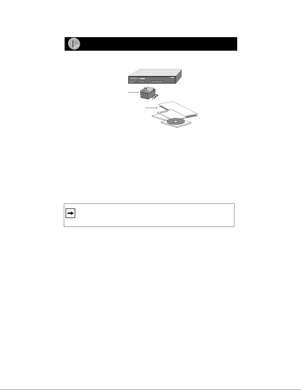
Package Contents
PS100 Series Print Server
(Model PS105 Print Server shown)
NETWORK
34
MODEL
PS104
Col
9002FB
Power
Adapter
PS100 Series
Print Server Resource
Installation Guide,
Warranty & Owner
Registration Card,
Support Information Card
10/100 MbpsPrint Server
PWR
CD,
12
On=Link; Blinking=Rx
Link/Act Alert
PRINTER
Verify that your package contains the following:
• Model PS104, Model PS105, or Model PS110 print server
• Power adapter
• BNC terminator and T-Connector (Model PS105 only)
• PS100 Series Print Server Resource CD
• This installation guide
• Warranty & Owner Registration Card
• Support Information Ca rd
Note: If the supplied power adapter does not meet your country
requirements, make sure you use the appropriate power adapter as
required by your national electrical codes and ordinances.
Customer Support
Call your reseller or NETGEAR Customer Support in your area if there are any
wrong, missing, or damaged parts.
Keep the carton, including the original packing materials. Use them to repack
the print server if you need to return it for repair.
Model PS104/PS105/PS110 Print Server Installation Guide
Page 4
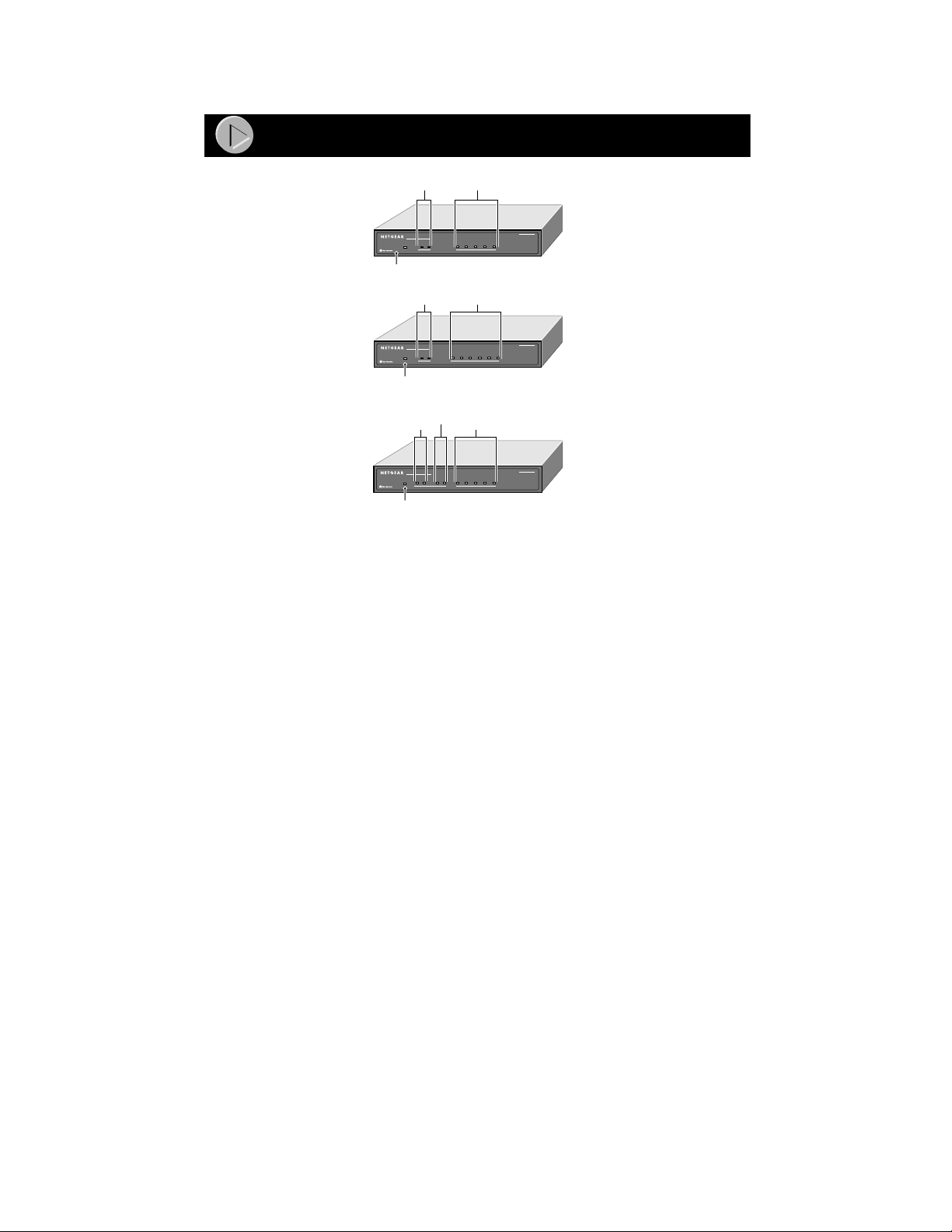
Product Illustration
Start Here
PRINTER LEDs NETWORK LEDs
10/100 MbpsPrint Server
PWR
12
On=Link; Blinking=Rx
Link/Act Alert
PRINTER
NETWORK
34
MODEL
PS104
Col
PWR LED
Front Panel of the Model PS104 Print Server
PRINTER LEDs
10 Mbps Print Server
PWR
Link/Act Alert
PRINTER
NETWORK LEDs
12
345
On=Link; Blinking=Rx
Col
NETWORK
MODEL
PS105
PWR LED
Front Panel of the Model PS105 Print Server
PRINTER 2 LEDs
PRINTER 1 LEDs NETWORK LEDs
10/100 MbpsPrint Server
PWR
Link/Act Alert
Link/Act Alert
Link 100M Rx Tx Col
PRINTER 1
PRINTER 2
NETWORK
MODEL
PS110
PWR LED
Front Panel of the Model PS110 Print Server
9003FA
Model PS104/PS105/PS110 Print Server Installation Guide
Page 5
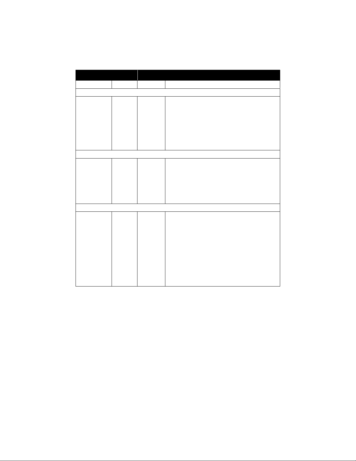
LEDs
The following table describes the activity of the LEDs on the PS100 Series print
servers.
Label Color Activity Description
PWR (power) Green On Power is supplied to the print server.
PRINTER, PRINTER 1, or PRINTER 2
Link/Act Green On A printer is connected to the port.
Off No printer is connected to the port.
Blinking Data transmission is occurring on the port.
Alert Amber On The connected printer is offline, is out of paper,
or has a paper jam.
Off The connection between the printer and print
server is good.
NETWORK (On Model PS104 and Model PS105)
Link/Rx Green Off No link exists between the port and the network.
On The 10 Mbps half-duplex link between the print
server and the network is good.
Blinking Incoming data is on the port.
Col
(collision)
NETWORK (On Model PS110)
Link Green On The link between the port and the network is
100M Green On The link between the port and the network is a
Tx Green Blinking The print server is sending data out of the port.
Rx Green Blinking The print server is receiving data on the port.
Col
(collision)
Amber Blinking Data collision is occurring on the network. Note
that occasional collisions are normal.
good.
100 Mbps half-duplex connection.
Off The link between the port and the network is a
10 Mbps half-duplex connection.
Amber Blinking Data collision is occurring on the network. Note
that occasional collisions are normal.
Model PS104/PS105/PS110 Print Server Installation Guide
Page 6
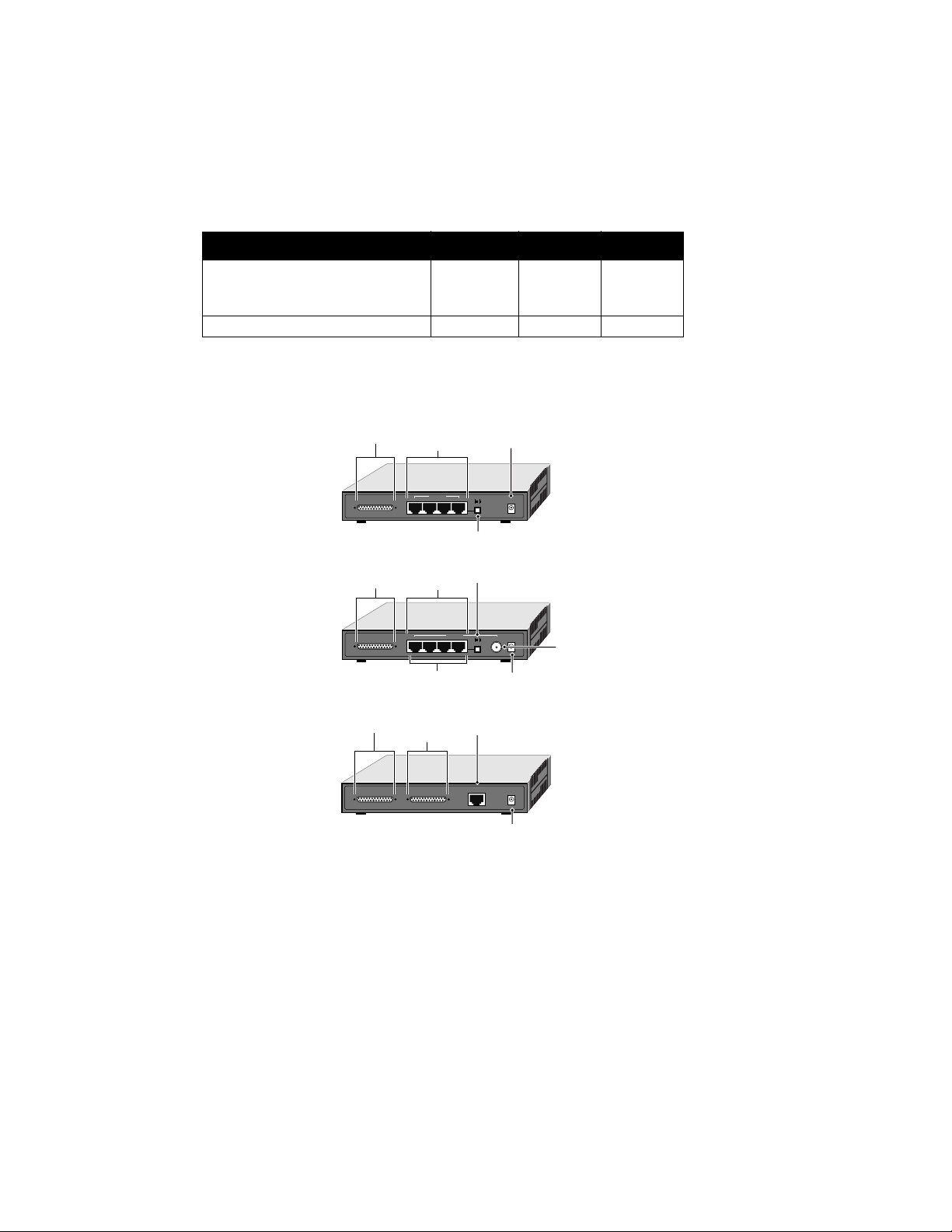
Rear Panel
The rear panel of the Model PS104 Print Server and Model PS105 Print Server
has one parallel PRINTER port, and the rear panel of the Model PS110 Print
Server has t wo pa rallel po rts for print ers (PRI NTE R 1 a nd PRIN TER 2) . Th ese
printer ports accept either printers or other parallel devices such as a plotter.
Number of Ports PS104 PS105 PS110
10BASE-T
BNC
Autosensing 10/100BASE-T
4
n/a
n/a
4
1
n/a
n/a
n/a
1
Parallel Pri nter Port 1 1 2
All models have a power adapter receptacle that accepts a 12 V DC power
adapter.
PRINTER
(parallel) port
Rear Panel of the Model PS104 Print Server
PRINTER
(parallel) port
Rear Panel of the Model PS105 Print Server
PRINTER 2
(parallel) port
Rear Panel of the Model PS110 Print Server
4 10BASE-T
ports
NETWORK
PRINTER
PRINTER
PRINTER 2 PRINTER 1
432
4 10BASE-T
ports
543
10BASE-T connectors
PRINTER 1
(parallel) port
1
Normal/Uplink
Normal/Uplink push button
Normal/Uplink
push button
NETWORK
21
Normal/Uplink
10/100BASE-T
port
NETWORK
Power adapter
receptacle
12VDC 1.2A
12VDC 1.2A
12VDC 1.2A
BNC
port
Power adapter receptacle
Power adapter receptacle
9000FA
Normal/Uplink Push Button (Model PS104 and Model PS105 Only)
The Normal/Uplink push button on the Model PS104 and Model PS105 print
servers allows you to select Normal (MDI-X for connecting to a PC) or Uplink
(MDI for connecting to a hub or switch) wiring for the first 10BASE-T port,
eliminating the need to use a crossover cable. The other10BASE-T ports on the
Model PS104 and Model PS105 print servers are permanently configured for
Normal wiring; the one network port on the Model PS110 Print Server is
permanently configured for Uplink wiring.
Model PS104/PS105/PS110 Print Server Installation Guide
Page 7

Typical Applications
This section illustra te s some examples of how the PS100 Series print servers are
typically installed in a network.
Key
10 Mbps
100 Mbps
Limited to 3 m
in length
Limited to 3 m
in length
Model PS104 Print Server
NETWORK
123
PRINTER
Model PS110 Print Server
PRINTER 1 PRINTER 2
Model PS105 Print Server
NETWORK
543
PRINTER
Limited to 3 m
in length
21
Normal/Uplink
4
12VDC 1.2A
Normal/Uplink
NETWORK
12VDC 1.2A
12VDC 1.2A
BNC terminator
NETGEAR Model
EN108 hub
TP
10 BASE-T HUB
EN108
Pwr
Col
1234 5678
NETGEAR Model
DS108 hub
Auto 10/100 MbpsDUAL SPEED
Coaxial connection
to other network
devices
8575FA
Model PS104 Print Server
NETWORK
123
4
PRINTER
Limited to 3 m
in length
12VDC 1.2A
Normal/Uplink
NETGEAR Model
RT328 router
9001FA
Model PS104/PS105/PS110 Print Server Installation Guide
Page 8

Install the Print Server
You can place the print server on a desktop or any flat surface. To save work
space, you can also mount the print server with Velcro strips on the side of a
printer.
Connect the Printer Cables
Connect a cable (not provided) from the pr inter to the parall el PRINTER port on
the print server. If you are connecting one printer to the Model PS110 Print
Server, you can use either of the ports.
Connect the Network Cables
Using the 10BASE-T Networ k Ports
Use the following table for setting the push button switch and for selecting
either a crossover or straight-through cable when connecting the print server to
other devices.
Connecting Network Port Connecting Device Cable Used
Model PS104 Print Server
Port 1 set to Uplink Hub or switch Straight-through cable
Port 1 set to Normal PC or router Straight-through cable
Ports 2 through 4 PC or router Straight-through cable
Model PS105 Print Server
Port 2 set to Uplink Hub or switch Straight-through cable
Port 2 set to Normal PC or router Straight-through cable
Ports 3 through 5 PC or router Straight-through cable
Model PS110 Print Server
Hub or switch Straight-through cable
PC Crossover cable
Note: Ethernet specifications limit the twisted pair cable (called a
twisted pair segment) extended from a network port to 100 meters in
length.
Model PS104/PS105/PS110 Print Server Installation Guide
Page 9

Using the BNC Network Port (Model PS105)
The BNC-T connector included in the package contents must be used with thin
coaxial cable for a 10BASE2 connection to other network devices that have a
BNC port. To terminate the connection on the last device in the network
segment, you must use the BNC terminator (also included in the package
contents).
Ethernet specifications lim it the segment le ngth of coaxi al cable to 18 5 m, the
maximum distance between nodes to 0.5 m, and the maximum number of nodes
per segment to 30. Make sure the cable meets the specifications as outlined in
Installation and Reference for the Model PS104/PS105/PS110 Print Server on
the PS100 Series Print Server Resource CD.
Verify Power
Connect the power adapter first to the power receptacle on the rear panel of the
print server and then to the power outlet on the wall. When power has been
applied to the print server:
• The green Pwr (power) LED on the front panel is on.
• On the Model PS104 and Model PS105 print servers, the green Link/Rx
LED on each connected network port is on.
• On the Model PS110 Print Server, the Link LED on the connected network
port is on.
• The green Link/Act LED on the connected PRINTER, PRINTER 1, or
PRINTER 2 port is on.
If you find any problems, refer to “Troubleshooting Information.”
Make sure the network interface cards installed in the workstations are in
working condition and the software driver has been installed on the cards.
If required, verify the integrity of the print server by resetting it. Turn power to
the print server off and then back on. If the problem continues and you have
completed all the preceding diagnoses, contact NETGEAR Customer Support.
For the telephone number of the representative in your area, see the Support
Information Card that is included in your package contents.
Model PS104/PS105/PS110 Print Server Installation Guide
Page 10

5
If you are using Windows 95, Windows 98, or Windows NT, this section
provides you with information about how to set up each Windows PC so that it
can recognize the print server.
Before proceeding with these instructions, make sure you have assigned a name
to your workgroup on your PC.
Install the FirstGear for Print Server: Windows User
FirstGear, a software program used with NETGEAR products for quick and
easy installation, is provided on the CD-ROM included in your package
contents.
To install FirstGear on your PC:
1. Turn the power on to your PC.
2. Insert the NETGEAR Resource CD-ROM.
3. The installation process will start with the display of the NETGEAR
window. If it does not, click on Start > Run >
and type in “Install.exe” at t he prompt (f or example, “D: Install.exe”) to
start the installation process.
Install and Set Up
Note: In stall atio n and s etup of the NETGEAR sof tw are is re quire d on
each PC needing access to the printers that will be attached to the print
server .
4. Click on “Next” when the FirstGear window opens.
5. Choose “User PC Installation,” and click on “Next.”
Note: NETGEAR strongly recommends that you exit all Windows
programs before running the Setup program.
6. Click on “Next” when the “NETGEAR Print Server Software
Installation” window opens.
7. Click on “Next” to install the NETGEAR Print Server program in the
Program Files folder.
8. Click on “Next” to title the program folder “FirstGear for Print
Server” (the def aul t name). You may also type in a unique name for the
print server f older.
Verify that the information on the screen is correct.
9. Click on “Finish” when the “Setup Complete” window opens.
The FirstGear Print Se rver Program is now installed on your PC.
Model PS104/PS105/PS110 Print Server Installation Guide
Page 11

Setting Up Your PC to Recognize the Print Server
You must set up each PC that will print to the print server. Before proceeding,
verify that:
• The print cable is connected to the printer port.
• The AC adapter is plugged into the wall socket.
• The Ethernet cable is plugged into the LAN.
To set up each PC:
1. Double-click on the desktop icon you named in step 8 of the previous
section.
2. Click on “Setup.”
3. Click on “OK” after checking that the print server and printer
connected to it are powered on and that the cables are properly
connected.
Note: If the cables are not properly connected, your PC screen will
appear empty when the “Printer Select” window appe ar s. I f this is the
case, check on the cable connections and hit the “Refresh” button,
which will initiate the PC browse again for a port.
4. Click on the printer port y ou want to use with the print se rver, and click
on “Add.”
5. Click on “No” when asked if there is an Epson Stylus COLOR printer
attached to the port, and continue on to step 6.
If you do have an Epson Stylus COLOR printer (or plan to install one),
click on “Yes.” You must now disable the Epson printer. To disable, start
the Epson Spool Manager from the Program Files menu. Select “Queue
Setup,” click on “Use Print Manager For This Port,” and click on “OK” to
exit.
Model PS104/PS105/PS110 Print Server Installation Guide
Page 12

6. Click on “OK” when the “Add Port” screen appears, informing you
that you have successfully added the port.
If you are a Windows 95 or Windows 98 user, take note of this port
number (the number is written as “PSxxxxxx_P1” or “PSxxxxxx_P2”).
You will need this information for step 3 in the next section.
The next sections are written for Windows 95 or Windows 98 users and for
Windows NT users, respectively. Follow the appropriate instructions, and
continue to the final section (“Complete the Setup Process”) to conclude the
setup procedure.
Windows 95 or Windows 98 Users
1. Click on “Next” after clicking on the Manufacturer and Printer Model
you are adding in the “Add Printer Wizard” screen.
If your printer is not li st ed, cl i ck on “Have Disk” and insert the driv e r di sk
that you received from the printer manufacturer. Install the driver,
proceeding as instructed until the “Add Printer Wizard” window opens.
2. If you have already installed the printer driver, select “Keep existing
driver” and click on “Next.” If you have not installed the driver, do so
now as prompted by the screen.
3. Click on the “PSxxxxxxx_P1 (or PSxxxxxx_P2) Netgear Print Server”
that you selected in step 6 when the next “Add Printer Wizard”
appears, and click on “Next.”
4. T ype a na me f or the p rinter (if y ou wa nt to ha v e a unique name), deci de
if you want this printer to be your default printer, and then click on
“Next.”
Windows NT Users
1. Select the port you added in step 6 in the previous section, and click on
“Next.” Do not click on “add port.”
2. Click on “Next” after clicking on the Manufacturer and Printer Model
you are adding in the “Add Printer Wizard” screen.
If your printer is not li st ed, cl i ck on “Have Disk” and insert the driv e r di sk
that you received from the printer manufacturer. Install the driver,
proceeding as instructed until the “Add Printer Wizard” window opens.
3. The “Add Printer W i zar d” screen appears. You can name the pri nte r a
unique name or keep the default name of the printer as it appears on
screen. Click on “Next.”
4. The “Add Printer Wizard” screen appears. With this screen, you can
choose to either share or not share the print server with other users in
the network. If you do want to share the print server, you must click on
all of the operating systems that will be sharing the print server, and
then click on “Next.”
Model PS104/PS105/PS110 Print Server Installation Guide
Page 13

Complete the Setup Process (Windows 95/98 and NT)
Troubleshooting
1. Select “Yes” when asked to print a test page, and click on “Finish.”
2. Click on “End” in the “Add Port” scr e en to complet e the setup proc ess.
You are now ready to use the printer attached to your print server.
Problem Solution
When using the
FirstGear Setup
Program to browse
the network from the
network
administrator’s PC,
the print server
cannot be seen.
The print server is
not listed when you
run the FirstGear For
Print Server Setup
program.
You do not know
what network
protocols are
installed on your PC.
When printing using
some software
applications (for
example,
PowerPoint),
it takes an extremely
long time and the
printout is incorrect.
Because either a hardware or software problem could prevent
you from seeing the print server from the managing station, make
sure that:
• There is a proper link established between the print server and
the hub or workstation. If the LINK LED is on, the link is good.
• You use proper cables. With 10BASE-T connections, you can
use Category 3, 4, or 5 cables. With 100BASE-TX
connections, you can use only Category 5 cables. With
10BASE-2 connections through the BNC port on the Model
PS105, make sure the cable meets the specifications as
outlined in
PS105/PS110 Print Server
Resource CD.
• The NetBEUI protocol is installed in the PC. By default, the
FirstGear Setup Program uses the NetBEUI protocol to search
for print servers connected on the same network as the
network administrator’s PC. Click on the “Protocol” button on
the main screen to make sure that NetBEUI is selected.
• Check the connections to the print server, and ensure that it is
ON.
• If your LAN has TCP/IP ONLY, and does not have a DHCP
server, the print server will
IPSetup program to assign an IP address to the print server.
• The IPSetup program is installed with the ADMIN installation.
To check or change your network protocols
• Navigate to the Network Properties screen by choosing
Start>Settings>Control Panel>Network. The “Configuration”
tab of the Network Properties screen will appear.
• Protocols that are installed are listed.
• To add a protocol, select Add>Protocol>Microsoft and then
select the chosen protocol.
• For TCP/IP, the Properties button allows you to set the IP
address of your PC.
The printer is configured to start printing after the first page is
spooled. To change this setting:
• Double-click on “My Computer,” double-click on “Control
Panel,” double-click on “Printers,” and click on your printer.
With your printer highlighted, click the right mouse button and
click on “Properties.” Click on the “Details” tab and then click
on “Spool Settings.” When the “Details” window opens, choose
“Start printing after last page is spooled” and click on “OK.”
Installation and Reference for the Model PS104/
PS100 Series Print Server
on the
not
be listed. You must use the
:
Model PS104/PS105/PS110 Print Server Installation Guide
Page 14

Technical Specifications
General Specifications
Network Protocol and Standards Compatibility
IEEE 802.3u, 100BASE-TX, F ast Ethernet
IEEE 802.3i 10BASE-T CSMA/CD
Interface
Model PS104 Print Server Four 10BASE-T network ports (RJ-45)
Model PS105 Print Server Four 10BASE-T network ports (RJ-45) and
one BNC port
Model PS110 Print Server One 10/100BASE-T network port
(RJ-45)
Power Specifications
Input voltage 100 to 240 V AC, 50 to 60 Hz,
according t o the power adapter
Output voltage 12 V DC at 0.58 A mps, maximum
Power consumption 7 W maximum
Physical Specifications
Width 7.4 in. (18.9 cm)
Height 1.2 in. (2.1 cm)
Depth 4.8 in. (12.2 cm)
Weight 1.61 lb (0.73 kg)
Environmental Specifications
Operating temperature 0° to 40° C (32° to 104° F)
Operating humidity 90% maximum relative humidity,
noncondensing
Electromagnetic Emis sion s
CE mark, commercial
FCC Part 15, Class B
EN 55 022 (CISPR 22), Class B
VCCI Class B ITE
EN50082-1
Safety Agency Approvals, Power Adapter
CE mark, commercial
UL listed (UL 1950)
CSA certified (CSA 22.2 #950)
TUV licensed (EN 60 950)
T-M ark
Warranty Information
Print server 5 years
Power adapter 1 year
Model PS104/PS105/PS110 Print Server Installation Guide
Page 15

© 1999 by NETGEAR, Inc. All rights reserved.
Declaration of Conformity
NETGEAR Model PS104, Model PS105, and
Model PS110 print servers
Tested to comply
with FCC Standards
Trademarks
Bay Networks is a registered trademark of Bay Networks, I nc.
NETGEAR and FirstGear are trademarks of Bay Net wor ks, Inc.
Microsoft, Windows, and Windows NT are registered trademarks of Microsoft Corporation.
All other trademarks and registered trademarks are the property of their respective owners.
Statement of Conditions
In the interest of improving internal design, operational function, and/or reliability, NETGEAR
reserves the right to make changes to the products described in this document without notice.
NETGEAR does not assume any liability that may occur due to the use or application of the
product(s) or circuit layout(s) de scribed herein.
Certificate of the Manufacturer/Importer
It is hereby certified that the Mode l PS104, M odel PS105 , or Model PS110 prin t server has been
suppressed in accordance with the conditions set out in the BMPT-AmtsblVfg 243/1991 and Vfg
46/1992. The operation of some equipment (for example, test transmitters) in accordance with the
regulations may, however, be subject to certain restrictions. Please refer to the notes in the
operating instructions.
Federal Office for Telecommunications Approvals has been notified of the placing of this
equipment on the market and has been granted the right to test t he series for compl iance with t he
regulations.
Federal Communications Commission (FCC) Compliance Notice:
Radio Frequency Notice
Modifications to this device change it from the original state it was in when
Note:
tested and may alter the device so that it no longer complies with FCC testing
limitations for Class B digital devices. According to FCC regulations, the user could
be prohibited from operating this equipment if it is modified.
This device complies with Part 15 of the FCC Rules. Operation is subject to the following two
conditions:
1. This device may not cause harmful interference.
2. This device must accept any interferen ce received, including
interference that may cause undesi red operation.
Note: This equipment has been te sted an d found to co mply with
the limits for a Class B digital device, pursuant to Part 15 of the
FCC Rules. These limits are designed to provide reasonable
protection against harmful interference in a residential
installation. This equipment generates, uses, and can radiate
radio frequency energy and, if not installed and used in accordance with the instructions, may
cause harmful interference to radio communications. However, there is no guarantee that
interference will not occur in a particular installation. If this equipment does cause harmful
interference to radio or te le vi sion re ceptio n, whic h can be det ermined b y turnin g the e quipmen t of f
and on, the user is encouraged to try to correct th e interference by one or more of t he following
measures:
• Reorient or relocate the receiving antenna.
• Increase the separation between the equipment and receiver.
• Connect the equipment into an outlet on a circuit different from that to which the receiver is
connected.
• Consult the dealer or an experienced radio/TV technician for hel p.
Model PS104/PS105/PS110 Print Server Installation Guide
Page 16

EN 55 022 Statement
This is to certify that the Model PS104, Model PS105, or Model PS110 print server is shielded
against the generation of radio interference in accordance with the application of Council
Directive 89/336 /EEC, Artic le 4a. Conf ormity is de clare d by th e applicatio n of EN 55 022 Class B
(CISPR 22).
Compliance is dependent upon the use of shielded data cables.
Canadian Department of Communications Radio Interference Regulations
This digital apparatus (Model PS104, Model PS105, or Model PS110 print server) does not
exceed the Class B limits for radio-noise emissions fro m digital app aratus as se t out in the Radio
Interference Regulations of the Canadian Department of Communications.
Règlement sur le brouillage radioélectrique du ministère des Communications
Cet appareil numérique (Model PS104, Model PS105, or Model PS110 print server) respecte les
limites de bruits radioélectriques visant les appareils numériques de classe B prescrites dans le
Règlement sur le brouillage radioélectrique du ministère des Communications du Canada.
Model PS104/PS105/PS110 Print Server Installation Guide
Page 17

NETGEAR, Inc.
A Bay Networks Company
4401 Great America Parkway
Santa Clara, CA 95054 USA
Phone: 888-NETGEAR
http://www.NETGEARinc.com
*M1-PS100NA-1*
Model PS104/PS105/PS110 Print Server Installation Guide
 Loading...