

Page 1

Installation and Reference for the Model PS104/PS105/ PS110 Print Server
NETGEAR
A Bay Networks Company
4401 Great America Parkway
Santa Clara, CA 95054 USA
Phone 888-NETGEAR
M-PS100NA-1
May 1999
, Inc.
Page 2
© 1999 by NETGEAR, Inc. All rights reserved.
Declaration of Conformity
NETGEAR Model PS104, Model PS105, and
Model PS110 Print Servers
Tested to comply
with FCC St a n dards
FOR HOME OR OFFICE
Trademarks
Bay Networks is a registered trademark of Bay Networks, Inc.
NETGEAR and FirstGear are trademarks of Bay Networks, Inc.
Microsoft, Windows, and Windows NT are registered trademarks of Mi crosoft Corporation.
Other brand and product names are registered t r ademarks or trademarks of their respective holders.
Statement of Conditions
In the interest of improving internal design, operational function, and/or reliability, NETGEAR reserves the right to
make changes to the product s described in this doc ument without notice.
NETGEAR does not assume any liability that may occur due to the use or application of the product(s) or circuit
layout(s) described herein.
Federal Communications Commission (FCC) Compliance Notice: Radio Frequency Notice
This device complies with part 15 of the FCC Rules. Operation is subject to the following two conditions:
• This device may not cause har m f ul interference.
• This device must accept any interferenc e re ceived, including interference that may
cause undesired operat ion.
Note: This equipment has been tested and found to comply with the limits for a Class B
digital device, pursuant to part 15 of the FCC Rules. These limits are designed to provide
reasonable protection against harmful interference in a residential installation. This
equipment generates, uses, and can radiate radio frequency energy and, if n ot installed
and used in accordance with the inst ructions, may cause harmful interference to radio communications. However, there
is no guarantee that interference will not occur in a particular installation. If this equipment does cause harmful
interference to radio or television reception, which can be determined by turning the equipment off and on, the user is
encouraged to try to correct the interference by one or more of the fol lowing measures:
• Reorient or relocate the receiving antenn a.
• Increase the separati on between the equipment and receiver.
• Connect the equipment into an outlet on a circuit different from that to which the receiver is connected.
Consult the dealer or an experienced radio/TV technician for help.
EN 55 022 Declaration of Conformance
This is to certify that the NETGEAR Model PS104 Print Server, Model PS105 Print Server, and Model PS110 Print
Server are shielded against the generation of radio int erference in accordance with the application of Council Directive
89/336/EEC, Article 4a. Conformity is declared by the application of EN 55 022 Class B (CISPR 22).
ii
Page 3

Bestätigung des Herstellers/Importeurs
Es wird hiermit bestätigt, daß das NETGEAR Model PS104 Print Server, Model PS105 Print Server, and Model PS110
Print Server gemäß der im BMPT-AmtsblVfg 243/1991 und Vfg 46/1992 aufgeführten Bestimmungen entstört ist. Das
vorschriftsmäßige B etreiben einiger Geräte (z.B. Testsender) kann je doch gewissen Beschränkunge n unterliegen. Lesen
Sie dazu bitte die Anmerkungen in der Betriebsanleitung.
Das Bundesamt für Zulassungen in der Telekommunikation wurde davon unterrichtet, daß dieses Gerät auf den Markt
gebracht wurde und es ist berechtigt, die Serie auf die Erfüllung der Vorschriften hin zu überprüfen.
Certificate of the Manufacturer/Importer
It is hereby certified that the Model PS104 Print Server, Model PS105 Print Server, and Model PS110 Print Server have
been suppressed in accordance with the conditions set out in the BMPT-AmtsblVfg 243/1991 and Vfg 46/1992. The
operation of some equipment (for exam ple, te st transmitters) in accord a nce with the re gu latio ns may, however , be
subject to certain restrictions. Please refer to the notes in the operating instructions.
Federal Office for Telecommunications Approvals has been notified of the placing of this equipment on the market and
has been granted the right to test the series for compliance with the regulations.
Compliance with the applicable regu la tio ns is dep enden t upon the use of shield ed cabl es. It is the responsibility of the
user to procure the appropriate cables.
Voluntary Control Council for Interference (VCCI-B) Statement
This is a Class B product based on the standard of the Voluntary Control Council for Interference from Information
T echnology Equipment (VCCI). If this is used near a radio or television receiver in a domestic environment, it may cause
radio interference. Install and use the equipment according to the instruction manual.
Customer Support
For assistance with inst alling and configuring your NETGEAR system or with po st-installation questi ons or problems,
contact your point-of-purch ase representative.
To contact customer support or to purchase additional copies of this do cument and publications f or other NETGEAR
products, you can contact NETGEAR at the fo llowing numbers:
• Australia: 1800-142-046 • Korea: 00308-11-0319
• Austria: 00800-06384327
(008000-NETGEAR)
• Canada: 888-NETGEAR • Sweden: 020-790086
• France: 0800-90-2078 • Switzerland: 00800-06384327
• Germany: 00800-06384327
(008000-NETGEAR)
• Japan: 0120-66-5402 • United States: 888-NETGEAR
• New Zealand: 0800-444-626
(008000-NETGEAR)
• United Kingdom: 0171-571-5120
Internet/World Wide W eb
NETGEAR maintains a World Wide Web Home Page that you can access at the universal resource locator (URL)
http://NETGEAR.baynetworks.com. A direct connection to the Internet and a Web browser such as Internet Explorer
or Netscape are required.
iii
Page 4

iv
Page 5

Contents
Preface
Purpose .......................................................................................................................... xvii
Audience .................................. .......................... .......................... .......................... ......... xvii
Conventions ................................................. ...................................... ............................xviii
Special Message Formats .......................................................................................xviii
Use of Enter, Type, and Press .................................................................................xviii
Other Conventions ....................................................................................................xix
Related Publication ..........................................................................................................xix
Chapter 1
Introduction
Features ..........................................................................................................................1-1
Front Panel ........................................................ ....... ...... ....... ...... ...... ....... ......................1-2
LEDs ........................................................................................................................1-3
Rear Panel ......................................................................................................................1-5
Normal/Uplink Push Button on the Model PS104/PS105 Print Server ....................1-5
Chapter 2
Installation
Preparing the Site ...........................................................................................................2-1
Verifying Package Contents ......................... ...... ....... ...... ....... ...... ...................................2-1
Connecting Devices to the Print Server ..........................................................................2-2
Verifying Power ..... ...... ....... ...... ....... ...... ....... ...... ....... ...... ............................................. ...2-3
Chapter 3
Microsoft Windows 95 and Windows 98 Printing
FirstGear for Print Server ...............................................................................................3-1
Installing and Setting Up FirstGear—User Installation ...................................................3-2
Setting Up Your PC to Recognize the Print Server ..................................................3-8
Installing and Setting Up FirstGear—Admin Installation ...............................................3-17
Contents v
Page 6

Setting Up Your PC to Recognize the Print Server .......................................................3-23
Installing and Setting Up FirstGear—Diskette Option ..................................................3-23
Setting up the Print Server Using NetBEUI and TCP/IP ...............................................3-24
Configuring the Print Server Using NetBEUI .........................................................3-24
Configuring the Print Server Using TCP/IP ............................................................3-24
Chapter 4
Microsoft Windows NT Printing
FirstGear for Print Server ...............................................................................................4-1
Installing and Setting Up FirstGear—User Installation ...................................................4-2
Setting Up Your PC to Recognize the Print Server ..................................................4-8
Installing and Setting Up FirstGear—Admin Installation ...............................................4-18
Setting Up Your PC to Recognize the Print Server ................................................4-24
Installing and Setting Up FirstGear—Diskette Option ..................................................4-24
Setting up the Print Server Using NetBEUI and TCP/IP ...............................................4-25
Configuring the Print Server Using NetBEUI .........................................................4-25
Configuring the Print Server Using TCP/IP ............................................................4-25
Setting Up Spooled LPR Printing with Windows NT 3.51 ......................................4-29
Setting Up Spooled LPR Printing with Windows NT 4.0 ........................................4-31
Chapter 5
Novell NetWare Printing
Configuration Overview ..................................................................................................5-1
Configuring the NetWare File Server .......................................................................5-2
Configuring Your Print Server ...................................................................................5-3
Determining a Device Name for Your Print Server ...................................................5-3
Using Your Print Server in a NetWare 3.x Network ........................................................5-3
Setting PSERVER Mode in NetWare 3.x (Bindery Mode) ........................................5-4
Setting RPRINTER Mode in NetWare 3.x (Bindery Mode) ......................................5-7
Using Your Print Server in a NetWare 4.x Network ......................................................5-11
Setting PSERVER Mode in a NetWare 4.x NDS Mode Network ...........................5-11
Setting PSERVER Mode in a NetWare 4.x Bindery Emulation Network ................5-14
Setting RPRINTER Mode in a NetWare 4.x NDS Mode Network ..........................5-16
Setting PSERVER Mode in NetWare 5.x NDS Mode Network ..............................5-19
vi Contents
Page 7

Using Advanced Functions ...........................................................................................5-20
Servicing Multiple NetWare Bindery File Servers ..................................................5-20
Attaching to More Than One NetWare Print Server ...............................................5-21
Using Logical Ports ................................................................................................5-22
Configuring Logical Printers on the Print Server .............................................5-22
Configuring NetWare File Server to Connect to Logical Printers ....................5-23
Chapter 6
UNIX Printing Using TCP/IP
Temporary IP Address Resolution ..................................................................................6-3
Assigning an IP Address to the Print Server Using DHCP ......................................6-3
Assigning an IP Address to the Print Server Using BootP .......................................6-3
Assigning an IP Address to the Print Server Using RARP .......................................6-4
Assigning an IP Address to the Print Server Using ARP .........................................6-6
Configuring Your Print Server Using FTP .......................................................................6-7
Configuration Example .............................................................................................6-7
List of FTP Files and Commands Supported by the Print Server ............................6-8
Setting the Print Method .................................................................................................6-9
LPD Configuration and Printing ..............................................................................6-10
Configuring LPD on IBM AIX 4.15 ...................................................................6-10
Configuring LPD on System V .........................................................................6-11
Configuring LPD on BSD .................................................................................6-12
Printing Using LPD ................................ ...... ....... ...... ....... ...... ...... ....... ...... ....... ...... .6-13
Printing Using FTP ...... ...... ....... ...... ....... ...... ....... ...... ............................................. .6-14
Printing Using DSI ....................................... ............................................. ....... ...... .6-14
Chapter 7
Using Advanced Management Tools
Configuring Using the FirstGear Print Server Administration Program ..........................7-1
Advanced Print Server Configuration .......................................................................7-4
System Menu Tab ........................................ ...... ....... ...... ...... ....... ......................7-5
NetWare PServer Menu Tab ..............................................................................7-6
NetWare RPrinter Menu Tab ..............................................................................7-9
TCP/IP Menu Tab ............................................................................................7-10
Logical Port Menu Tab .....................................................................................7-12
Contents vii
Page 8

Advanced Print Server Configuration Menu Bar ....................................................7-13
Control Menu Bar Option .................................................................................7-13
Printer Menu Bar Options ................................................................................7-14
Configuring Using PSCONFIG .....................................................................................7-15
PSCONFIG Fields ..................................................................................................7-15
Changing Configuration Menu Options ..................................................................7-16
System Configuration ............................................... ...... ...... ....... ...... ....... ...... .7-16
NetWare Print Server Mode .............................................................................7-17
TCP/IP Configuration .......................................................................................7-18
NetBEUI Configuration ....................................................................................7-19
Logical Printer Configuration ...........................................................................7-20
Configuring Using QUICKSET ......................................................................................7-21
NetWare Print Server (PSERVER) Mode ...............................................................7-21
NetWare Remote Printer (RPRINTER) Mode ........................................................7-23
Appendix A
Technical Specifications
General Specifications ................................................................................................... A-1
Appendix B
Understanding IP Addresses
IP Addresses and the Internet .......................................................................................B-1
Netmask ........................................................................................................................B-3
Subnet Addressing ........................................................................................................ B-4
Private IP Addresses ..................................................................................................... B-6
Address Resolution Protocol ......................................................................................... B-7
IP Configuration by DHCP ............................................................................................. B-7
Appendix C
CONFIG File
CONFIG File TCP/IP Settings .......................................................................................C-1
viii Contents
Page 9

Appendix D
Using NetWare 5 NDPS
Overview ............................ ................... .................... ................... ................... ............... D- 1
Creating an NDPS Manager Object ........................................................................ D-1
Creating an NDPS Printer Agent ............................................................................D-3
Workstation Configuration .......................................................................................D-5
Installing and Configuring the Public Access Printers ...................................... D-5
Appendix E
IP Setup
Overview ............................ ................... .................... ................... ................... ............... E-1
Index
Contents ix
Page 10

x Contents
Page 11

Figures
Figure 1-1. Front Panel of the Model PS104 Print Server ..........................................1-2
Figure 1-2. Front Panel of the Model PS105 Print Server ..........................................1-2
Figure 1-3. Front Panel of the Model PS110 Print Server ..........................................1-3
Figure 1-4. Rear Panel of the Model PS104 Print Server ..........................................1-5
Figure 1-5. Rear Panel of the Model PS105 Print Server ..........................................1-6
Figure 1-6. Rear Panel of the Model PS110 Print Server ..........................................1-6
Figure 3-1. FirstGear Introductory Window ................................................................3-2
Figure 3-2. User Installation Option Window ..............................................................3-3
Figure 3-3. NETGEAR Print Server Software Installation Window ............................3-4
Figure 3-4. Choose Destination Location Window .....................................................3-5
Figure 3-5. Select Program Folder Window ...............................................................3-6
Figure 3-6. Setup Complete Window ............................................ ....... ...... ....... ...... ...3-7
Figure 3-7. Firstgear for Print Server Icon ..................................................................3-8
Figure 3-8. Setup Icon ... ............................................. ....... ...... ...... ....... ...... ....... ......... 3- 9
Figure 3-9. Setup Window .................................... ...... ....... .........................................3-9
Figure 3-10. Printer Select Window (Add Port) ..........................................................3-10
Figure 3-11. ADDPORT Window (Epson Connection) ...............................................3-11
Figure 3-12. Epson Spool Manager Queue Setup Window .......................................3-11
Figure 3-13. ADDPORT Window ................................................................................3-12
Figure 3-14. Add Printer Wizard Window (Manufacturer and Model of Printer) .........3-12
Figure 3-15. Add Printer Wizard Window (Driver Installation) ....................................3-13
Figure 3-16. Add Printer Wizard Window (Printer Name) ..........................................3-14
Figure 3-17. Add Printer Wizard Window (Print Test Page) .......................................3-15
Figure 3-18. Add Port Window (Setup Complete) ......................................................3-16
Figure 3-19. FirstGear Introductory Window ..............................................................3-17
Figure 3-20. “Admin Installation” Option Window .......................................................3-18
Figure 3-21. NETGEAR Print Server Software Installation Window ..........................3-19
Figure 3-22. Choose Destination Location Window ...................................................3-20
Figures xi
Page 12

Figure 3-23. Select Program Folder Window .............................................................3-21
Figure 3-24. Setup Complete Window .......................................................................3-22
Figure 3-25. Install From Disk Window .......................................................................3-23
Figure 3-26. Firstgear for Print Server Icon ................................................................3-24
Figure 3-27. Firstgear for Print Server Window ..........................................................3-25
Figure 3-28. NETGEAR Print Server Administration Program Window .....................3-26
Figure 3-29. TCP/IP Menu .........................................................................................3-27
Figure 4-1. FirstGear Introductory Window ................................................................4-2
Figure 4-2. User PC Installation Option Window ........................................................4-3
Figure 4-3. NETGEAR Print Server Software Installation Window ............................4-4
Figure 4-4. Choose Destination Location Window .....................................................4-5
Figure 4-5. Select Program Folder Window ...............................................................4-6
Figure 4-6. Setup Complete Window ............................................ ....... ...... ....... ...... ...4-7
Figure 4-7. Firstgear for Print Server Icon ..................................................................4-8
Figure 4-8. Firstgear for Print Server Setup Icon .......................................................4-9
Figure 4-9. Setup Window .................................... ...... ....... .........................................4-9
Figure 4-10. Printer Select Window (Add Port) ..........................................................4-10
Figure 4-11. ADDPORT Window (Epson Connection) ...............................................4-10
Figure 4-12. Epson Spool Manager Queue Setup Window .......................................4-11
Figure 4-13. Add Port Window (Added port successfully) ..........................................4-12
Figure 4-14. Add Printer Wizard Window (Add Ports) ................................................4-12
Figure 4-15. Add Printer Wizard Window (Manufacturer and Model of Printer) .........4-13
Figure 4-16. Add Printer Wizard Window (Printer Name) ..........................................4-14
Figure 4-17. Add Printer Wizard Window (Sharing Ports Screen) .............................4-15
Figure 4-18. Add Printer Wizard Window (Print Test Page) .......................................4-16
Figure 4-19. Printer Select Window (End Setup) .......................................................4-17
Figure 4-20. FirstGear Introductory Window ..............................................................4-18
Figure 4-21. Admin Installation Option Window .........................................................4-19
Figure 4-22. NETGEAR Print Server Software Installation Window ..........................4-20
Figure 4-23. Choose Destination Location Window ...................................................4-21
Figure 4-24. Select Program Folder Window .............................................................4-22
Figure 4-25. Setup Complete Window .......................................................................4-23
Figure 4-26. Install From Disk Window .......................................................................4-24
Figure 4-27. Firstgear for Print Server Icon ................................................................4-25
xii Figures
Page 13

Figure 4-28. Firstgear for Print Server Window ..........................................................4-26
Figure 4-29. NETGEAR Print Server Administration Program Window .....................4-27
Figure 4-30. TCP/IP Menu .........................................................................................4-28
Figure 7-1. NETGEAR Print Server Administration Program .....................................7-2
Figure 7-2. FirstGear Setup Utility Quick Setup Screen .............................................7-3
Figure 7-3. System Menu Tab Window ......................................................................7-5
Figure 7-4. NetWare PServer Tab Window ................................................................7-7
Figure 7-5. NetWare RPrinter Tab Window ................................................................7-9
Figure 7-6. TCP/IP Menu Tab Window .....................................................................7-10
Figure 7-7. Logical Port Menu Tab Window .............................................................7-12
Figure B-1. Three Main Address Classes .................................................................. B-2
Figure B-2. Example of Subnetting a Class B Address ............................................. B-4
Figure D-1. Create NDPS Manager Object Window .................................................. D-2
Figure D-2. Create Printer Agent Window .................................................................D-3
Figure D-3. Configure Port Handler Window .............................................................D-4
Figure E-1. NETGEAR Print Server IP Address Configuration .................................. E-2
Figures xiii
Page 14

xiv Figures
Page 15

Tables
Table 1-1. LED Descriptions ....................................................................................1-3
Table 2-1. Cable Selection and Normal/Uplink Push Button Settings ......................2-2
Table 3-1. Fields and Descriptions for TCP/IP Configuration .................................3-28
Table 4-1. Fields and Descriptions for TCP/IP Configuration .................................4-29
Table 4-2. Add a Spooled LPR Printer Fields ........................................................4-30
Table 4-3. Add LPR Compatible Printer Fields .......................................................4-31
Table 5-1. PSERVER Mode Printer Number Mapping ..............................................5-5
Table 5-2. RPRINTER Mode Printer Name Mapping ...............................................5-8
Table 5-3. Logical Printer Configuration Entries .....................................................5-23
Table 6-1. FTP Files in the Directory .......................................................................6-8
Table 6-2. FTP Commands ......................................................................................6-8
Table 6-3. Sample Commands for Using LPD on System V ..................................6-11
Table 6-4. Sample Commands for Using LPD on BSD ...........................................6-13
Table 6-5. Socket Number Definitions ....................................................................6-14
Table 7-1. Control Buttons on All Menu Tabs ............................................................7-4
Table 7-2. System Menu Tab Fields ..........................................................................7-6
Table 7-3. NetWare PSERVER Menu Tab Fields ....................................................7-7
Table 7-4. NetWare RPrinter Menu Tab Fields ........................................................7-9
Table 7-5. TCP/IP Menu Tab Fields ........................................................................7-11
Table 7-6. Logical Port Menu Tab Fields ................................................................7-13
Table 7-7. Advanced Print Server Configuration Menu Bar Selections ..................7-14
Table 7-8. Printer Menu Options ............................................................................7-14
Table 7-9. PSCONFIG Program Options ...............................................................7-15
Tables xv
Page 16

Table 7-10. NetWare Print Server Mode Fields .......................................................7-17
Table 7-11. TCP/IP Configuration Fields .................................................................7-18
Table 7-12. NetBEUI Configuration Fields ................................................................7-19
Table 7-13. Parameters and Definitions for Logical Printer Configuration ...............7-20
Table 7-14. Parameters and Definitions for PSERVER Mode ..................................7-22
Table 7-15. Parameters and Definitions for RPRINTER Mode ................................7-24
Table B-1. Netmask Notation Translation Table for One Octet ................................. B-5
Table B-2. Netmask Formats ........................................................................... ...... .. B-5
Table C-1. Configuration Settings ....................................................... ...... ....... ...... .. C-1
Table C-2. CONFIG File Line Numbers ....................................................................C-3
Table E-1. IP Configuration Settings ........................................................................ E-1
xvi Tables
Page 17

Preface
Congratulations on your purchase of the NETGEAR™ Model PS104 Print Server, Model PS105
Print Server, or Model PS110 Print Server.
Supporting multiple protocols and operating systems, these print servers provide an effective
solution for networked PCs to connect to the same printer, processing and trafficking printing
requests to any parallel device. These print servers are fast and easy to set up with FirstGear
NETGEAR software configuration program.
Purpose
This guide describes how to set up the Model PS104 Print Server, Model PS105 Print Server, and
Model PS110 Print Server. If your network is operating in a Microsoft environment and you are
using Microsoft
PS110 Print Server Quick Installation Guide (NETGEAR part number M1-PS100NA-1).
However, this guide provides you with further reference information.
Windows 95, Windows 98, or Windows NT, refer to the Model PS104/PS105/
™
, a
In this guide, the Model PS104 Print Server, the Model PS 105 Print Server, a nd the Model PS110
Print Server are referred to collectively as the Model PS104/PS105/PS110 Series of print servers
or just the print serv er. Each model is referred to specifica lly when fe atures or fu nctions ar e unique
to that particular model.
Audience
To configure and install the print server, you should have the following background and
experience:
• Working knowledge of basic network management concepts and terminology
• Working knowledge of tools and procedures to install and operate electronic equipment
Preface xvii
Page 18
Installation and Reference for the Model PS104/PS105/PS110 Print Server
Conventions
This section describes the conventions used in this guide.
Special Me ssage Forma t s
This guide uses the following formats to highlight special messages:
Note:
This format is used to highlight information of importance or special interest.
Caution:
equipment failure or loss of data.
Warning:
equipment damage.
Danger:
mishandling equipment.
This format is used to highlight information that will help you prevent
This format is used to highlight material involving possibility of injury or
This format is used to alert you that you may incur an electrical shock by
Use of Enter, Type, and Press
This guide uses “enter,” “type,” and “press” to describe the following actions:
• When you read “enter,” type the text and press the Enter key.
• When you read “type,” type the text, but do not press the Enter key.
• When you read “press,” press only the alphanumeric or named key.
xviii Preface
Page 19

Installation and Reference for the Model PS104/PS105/PS110 Print Server
Other Conventions
This guide uses the following additional conventions:
italics Book titles and UNIX file, command, and directory names.
Initial Caps Menu titles and window and button na mes.
Related Publicat ion
If you are using Microsoft Windows 95, Windows 98, or Windows NT, and have a network card
installed with the NetBEUI protocol, refer to the Model PS104/Model PS105/Model PS110 Print
Server Installation Guide (document part number M1-PS100NA-1). This guide provides
instructions for installing the print servers by using the FirstGear Utility, a program developed by
NETGEAR for fast and easy device configuration.
Preface xix
Page 20

Page 21

Chapter 1
Introduction
This chapter describes the features and the components of the Model PS104/PS105/PS110 print
server.
Features
The Model PS100 series of print servers offers:
• Support for multiple protocols (NetBEUI, TCP/IP, and IPX/SPX)
• Support for multiple operating systems (Windows
NetWare, and UNIX)
• Easy configuration of the device with FirstGear, NETGEAR configuration software that
assures fast and easy setup for Windows 95, Windows 98, and Window NT users
• Support for 10BASE-T Ethernet connection with four 10BASE-T ports on the Model PS104
Print Server, four 10BASE-T ports and a BNC port on the Model PS105 Print Server, or 10/
100BASE-T Ethernet connection on the Model PS110 Print Server
• One IEEE 1284 bidirectional parallel port on the Model PS104 and Model PS105 Print
Servers and two bidirectional parallel ports on the Model PS110 Print Server
• Extensive LED indicators for at-a-glance status information
• Built-in repeater functionality (Model PS104 and Model PS105 Print Servers)
• Compact size to fit into limited space in a work area
• In a TCP/IP environment, configurability to allow others to print to one of your printers from
anywhere on the Internet
Introduction 1-1
95, Windows 98, Windows NT, Novell
Page 22
Installation and Reference for the Model PS104/PS105/PS110 Print Server
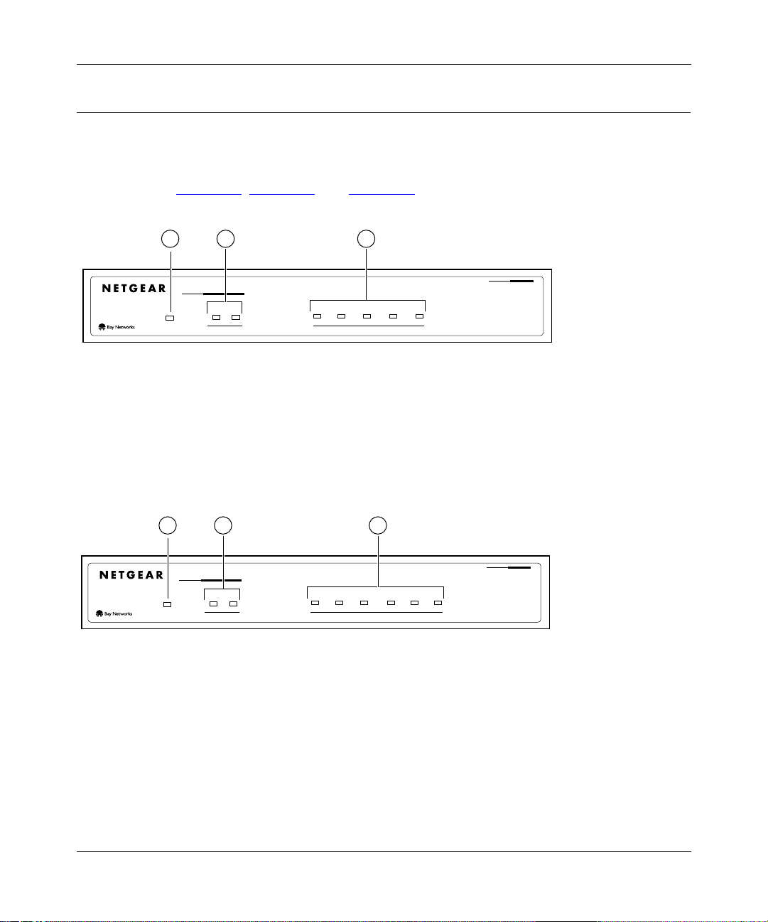
Front Panel
The LEDs that indicate t h e sta tu s of the server, ports, and printer are located o n the front panels of
the Model PS104 Print Server, the Model PS105 Print Server, and the Model PS110 Print Server
as illustrat ed in Figure 1-1
, Figure 1-2, and Figure 1-3, respectively.
2 31
10 Mbps Print Server
PWR
Link/Act Alert
PRINTER
12
34
On=Link; Blinking=Rx
NETWORK
Col
Key:
1 = PWR (power) LED
2 = PRINTER LEDs
3 = NETWORK LEDs
Figure 1-1. Front Panel of the Model PS104 Print Server
2 31
10 Mbps Print Server
PWR
Key:
1 = PWR (power) LED
2 = PRINTER LEDs
3 = NETWORK LEDs
Link/Act Alert
PRINTER
12
345
On=Link; Blinking=Rx
NETWORK
Col
MODEL
MODEL
PS104
8625EA
PS105
Figure 1-2. Front Panel of the Model PS105 Print Server
1-2 Introduction
Page 23
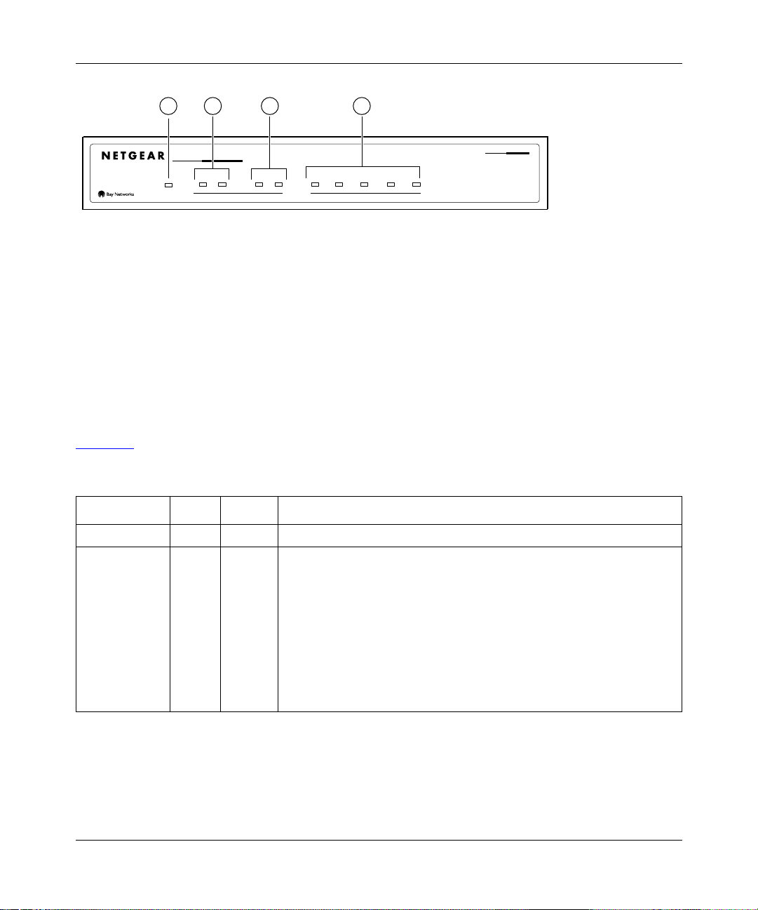
Installation and Reference for the Model PS104/PS105/PS110 Print Server
2 3 41
Key:
1 = PWR (power) LED
2 = PRINTER 1 LEDs
3 = PRINTER 2 LEDs
4 = Network LEDs
10/100 Mbps Print Server
Link/Act Alert
PWR
PRINTER 1
Link/Act Alert
PRINTER 2
Link 100M Rx Tx Col
NETWORK
MODEL
PS110
8626EA
Figure 1-3. Front Panel of the Model PS110 Print Server
LEDs
There are 8 LEDs on t he front panel of the Model PS10 4 Print Se rv er, 9 LEDs on the front pa nel of
the Model PS105 Print Server, and 10 LEDs on the front panel of the Model PS110 Print Server.
Table 1-1
Table 1-1. LED Descriptions
Label Color Activity Description
PWR (power) Green On Power is supplied to the print server.
PRINTER,
PRINTER 1, or
PRINTER 2
• Link/Act Green On A printer is connected to the port.
• Alert Amber On The connected printer is offline, is out of paper, or has a paper jam.
describes the activity of each of the LEDs.
Off No printer is connected to the port.
Blinking Data transmission is occurring on the port.
Off The connection between the printer and print server is good.
Introduction 1-3
Page 24
Installation and Reference for the Model PS104/PS105/PS110 Print Server
Table 1-1. LED Descriptions (continued)
Label Color Activity Description
NETWORK
(Model PS104
and PS105)
• Link/ Rx Green Off No link exists between the port and the network.
On The 10 Mbps half-duplex link betwee n the print se rv er an d the ne twork
is good.
Blinking Incoming data is on the port.
•Col
(collision)
NETWORK
(Model PS110)
• Link Green On The link between the port and the network is good.
• 100M Green On The link between the port and the network is a half-duplex 100 Mbps
• Tx Green Blinking The print server is sending data out of the port.
• Rx Green Blinking The print server is receiving data on the port.
•Col
(collision)
Amber Blinking Data collision is occurring on the network. Note that occasional
collisions are normal.
connection.
Off The link between the port and the network is a half-duplex 10 Mbps
connection.
Amber Blinking Data collision is occurring on the network. Note that occasional
collisions are normal.
1-4 Introduction
Page 25
Installation and Reference for the Model PS104/PS105/PS110 Print Server
Rear Panel
The rear panel of the Model PS104 Print Server and the Model PS105 Pr int Se rv er has one pa ra llel
PRINTER port, and the rear panel of the Model PS110 Print Server has two parallel ports for
printers (PRINTER 1 and PRINTER 2). The ports on the first two print servers accept either a
printer or another paral le l device such as a plotter. Because the Model PS110 Print Server has two
PRINTER ports, two parallel devices can be connected and can operate simultaneously.
The Model PS104 Print Se rver has four 10BASE- T network ports, the Model PS 105 Print Server
has four 10BASE-T network ports and one BNC network port, and the Model PS110 Print Server
has one 10/100BASE-T network port. The 10/100BASE-T port is an autonegotiation port that
operates in 100 Mbps and in half-duplex mode when connected to a Fast Ethernet network.
Normal/Uplink Push Button on the Model PS104/PS105
Print Server
The Normal/Uplink push button on the Model PS104 Print Server and the Model PS105 Print
Server allows you to select Normal (MDI-X) or Uplink (MDI) wiring for NETWORK port 1,
eliminating the need to use a crossover cable. Ports 2 to 4 on the print server are permanently
configured for Normal wiring.
As illustrated in Figure 1-4
, Figure 1-5, and Figure 1-6, all the print serv ers have a Nor mal /Upl ink
push button and a power adapter receptacle that accepts a 12 V DC power adapter.
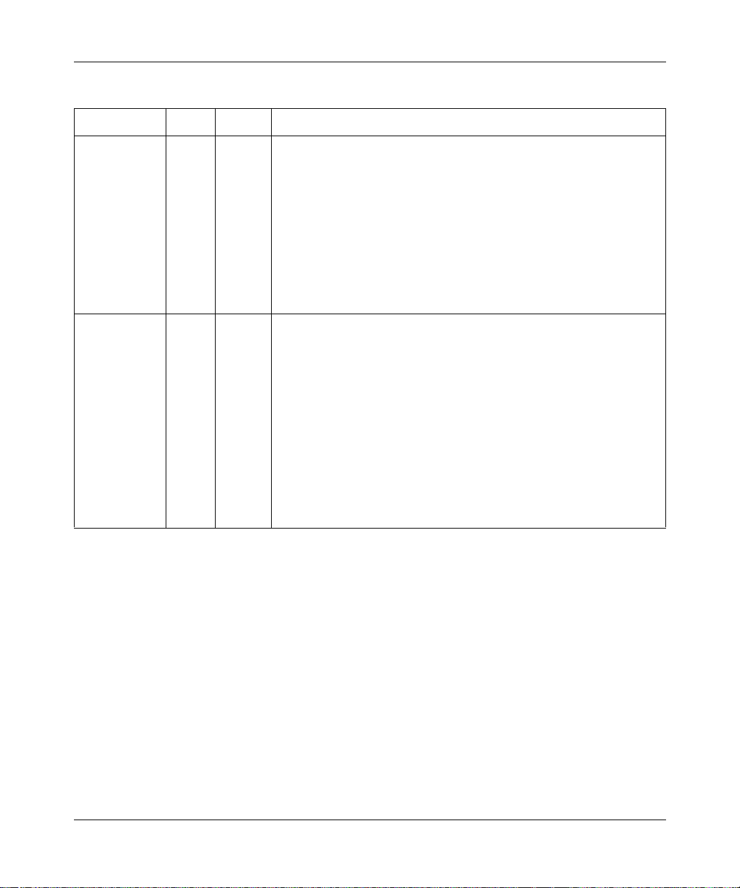
21 3 4
NETWORK
PRINTER
Key:
1 = PRINTER Port
2 = NETWORK port (10BASE-T connectors)
3 = Normal/Uplink push button
4 = Power adapter receptacle
432
Figure 1-4. Rear Panel of the Model PS104 Print Server
Introduction 1-5
1
Normal/Uplink
12VDC 1.2A
8624EA
Page 26
Installation and Reference for the Model PS104/PS105/PS110 Print Server
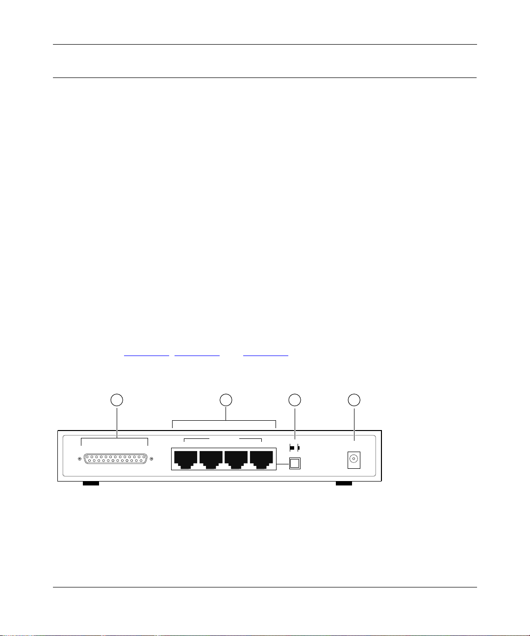
1 2 3 4
PRINTER
432
1
Normal/Uplink
BNC
12VDC 1.2A
9225EA
NETWORK
Key:
1 = PRINTER Port
2 = Network Port (Four 10BASE-T and One BNC Connector)
3 = Normal/Uplink push button
4 = Power adapter receptacle
Figure 1-5. Rear Panel of the Model PS105 Print Server
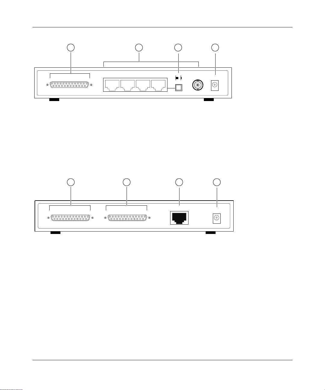
1 2 3 4
PRINTER 2 PRINTER 1
NETWORK
12VDC 1.2A
8627EA
Key:
1 = PRINTER 2 (parallel) port
2 = PRINTER 1 (parallel) port
3 = NETWORK port (10/100BASE-T connector)
4 = Power adapter receptacle
Figure 1-6. Rear Panel of the Model PS110 Print Server
1-6 Introduction
Page 27

Chapter 2
Installation
This chapter describes the installation and setup of the NETGEAR Model PS104/PS105/PS110
print server.
Preparing the Site
Before you begin installing the print server, prepare the installation site. Make sure the operating
environment meets the physical requirements of the print server, as described in Appendix A,
“Technical Specifications.”
Verifying Package Contents
Your package should contain the following:
• Model PS104 Print Server, Model PS105 Print Server, or Model PS110 Print Server
• Power adapter
• BNC terminator and T-connector (Model PS105 only)
• Model PS104/PS105/PS110 Print Server Resource CD
• Model PS104/PS105/PS110 Print Server Installation Guide
• Warranty & Owner Registration Card
• Customer Support Phone Card
Call your resell er or NETGEAR Cust omer S upport i n your area i f t here are a n y wr ong, mis sing, or
damaged parts. Refer to “Customer Support
your area.
Keep the carton, including the original packing materials. Us e them to repack the print server if
you need to return it for repair.
Installation 2-1
” on page iii for the location of customer support in
Page 28
Installation and Reference for the Model PS104/PS105/PS110 Print Server
Connecting Devices to the Print Server
The Model PS104 Print Server has four 10BASE-T network ports. The Model PS105 Print Server
has four 10B ASE- T net work ports and one BNC netw or k por t. The Model P S110 Pr in t Ser ver has
one 10/100B ASE-T netw or k port t hat is autosen sing and will sup port ei th er 10 Mbp s or 100 Mbps
connections, depending on the connected device. The 10/100BASE-T network port operates in
half-duplex mode.
Ports 2 through 4 on the Mode l PS104 Print Server are permane ntly con f igure d for MDI-X wi ring;
port 1 can be set to MDI (Uplink) or MDI-X (Normal) by using the Normal/Uplink push button
switch. The BNC port 1 on the Model PS105 Print Server is for network co nnections with BNC
cabling. The BNC-T connection included in the package contents must be used with the coaxial
cable for a 10B ASE 2 connection to other netwo rk devices that have a BNC port. To terminate the
connection on the last device in the network segment, you must use the BNC terminator, which is
included in the package contents. The one network port on the Model PS110 Print Server is
permanently configured for Uplink wiring.
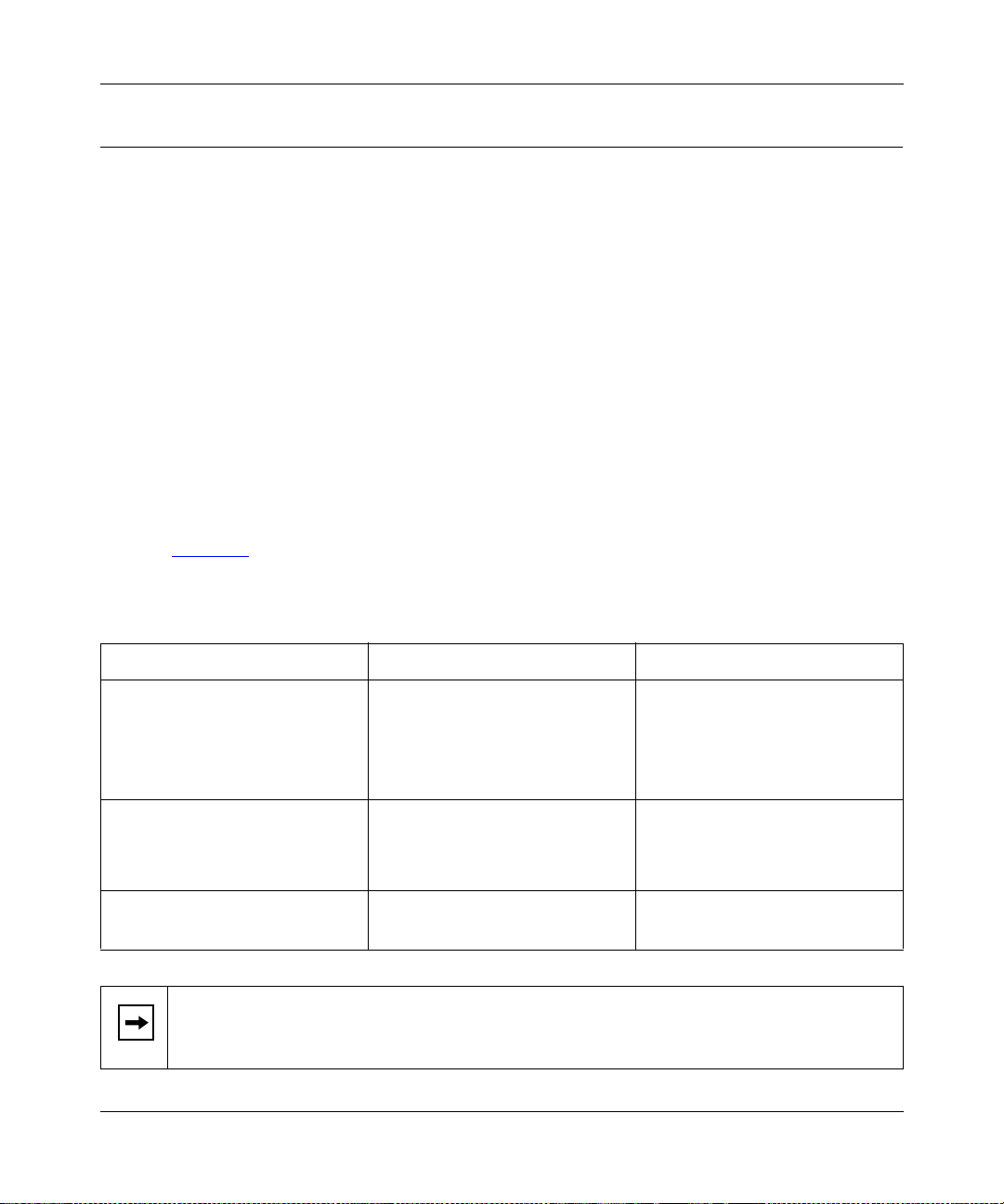
Refer to Table 2-1
for setting the Normal/Uplink push button switch and for selecting either a
crossover or straight-through cable when connecting your print server to other devices.
Table 2-1. Cable Selection and Normal/Uplink Push Button Settings
Connecting Network Port Connecting Device Cable Used
Model PS104 Print Server
Port 1 set to Uplink Hub or switch Straight-through cable
Port 1 set to Normal PC or router Straight-through cable
Ports 2 through 4 PC Straight-through cable
Model PS105 Print Server
Port 1
Port 2 set to Uplink
Ports 3 through 5
Model PS110 Print Server Hub or switch Straight-through cable
Note:
Ethernet specif i cati ons li mit the twi sted p air ca ble (c al led a t wisted pai r se gme nt)
PC
Hub or switch
PC
PC Crossover cable
BNC cable with 50 ohm terminator
Straight-through cable
Straight-through cable
extended from a network port to 100 meters in length.
2-2 Installation
Page 29

Installation and Reference for the Model PS104/PS105/PS110 Print Server
Verifying Power
To complete the installation, connect the po wer ad apter f irst to the po we r adapt er re ceptac le on t he
print server rear panel and then to the power o utlet on the wall. When power has been applied to
the print se r ver:
• The green PWR (power) LED on the front panel is on.
• On the Model PS104 Print Server and the Model PS105 Print Server, the green Link/Rx LED
on each connected network port is on.
• On the Model PS110 Print Server, the green Link LED on each connected printer port is on.
• The green Link/Act LED on the connected PRINTER, PRINTER 1, or PRINTER 2 por t is on.
Make sure the network interface cards installed in the workstations are in working condition and
the software driver has been installed on the ca rds.
If required, verify the integrity of the print server by resetting it. Turn power to the print server off
and then back on. If the problem continues and you have completed all the preceding diagnoses,
contact NETGEAR Customer Support. For the telephone number of the representative in your
area, refer to “Customer Support
” on page iii.
Installation 2-3
Page 30

Page 31

Chapter 3
Microsoft Windows 95 and Windows 98 Printing
This chapter describes how t o configure and use the NETGEAR Mod el PS1 04/ PS105/ PS110 print
server in a Microsoft Windows networking environment.
To correctly configure your hardw are and softw are f or the Mi crosof t Windows platform, you must:
• Install FirstGear for Print Server s oftware.
• Run Setup.
• Configure the user PC to print to the NETGEAR print server.
FirstGear for Print Server
This section describes how to install and set up the print server with the FirstGear for Print Server
Program in Windows 95 or Windows 98. There are several options to choose from:
• User Installation—used through the NetBEUI protocol, this option is geared toward the user
who is already connected to the LAN and needs to set up a PC to the NETGEAR print server.
• Admin Installation—this option is geared toward the user who is connected to the LAN and
also manages the print server.
• User Installation with diskette—this option generates an installation floppy disk for the user
without a CD-ROM drive.
Microsoft Windows 95 and Windows 98 Pr int ing 3-1
Page 32

Installation and Reference for the Model PS104/PS105/PS110 Print Server
To install and set up your network and your print server for the NETGEAR print server, you must
be using a PC with a Wind o ws 95, Windows 98, Windows NT 4.0, or W indows NT 3.51 operating
system and with either the TCP/IP protocol or the NetBEUI protocol enabled.
Note:
Before proceeding with these instructions, be sure to assign a name to your
workgroup on your PC. NETGEAR strongly recommends that you exit all Windows
programs before running the Setup program. It is also necessary to install the FirstGear
software on every PC in the network th at will use the printers attached to the Mo del
PS104/PS105/PS110 print server.
Installing and Setting Up FirstGear—User Installation
To install the NETGEAR print server software for user installation:
1.
Turn on the power to your PC.
2.
Insert the NETGEAR Resource CD-ROM.
The NETGEAR window briefly opens, and the FirstGear introductory window, as illustrated
in Figure 3-1
, opens.
If it does not, click on Start > Run and then type in “Install.exe” at the prompt (for example,
“D:Install.exe”) to start the installation process.
Figure 3-1. FirstGear Introductory Window
3-2 Microsoft Windows 95 and Windows 98 Printing
Page 33

3.
Click on Next.
Installation and Reference for the Model PS104/PS105/PS110 Print Server
Another FirstGear window, as illustrated in Figure 3-2
Figure 3-2. User Installation Option Window
, opens.
Microsoft Windows 95 and Windows 98 Printing 3-3
Page 34

Installation and Reference for the Model PS104/PS105/PS110 Print Server
4.
Choose “User PC Installation” and click on Next.
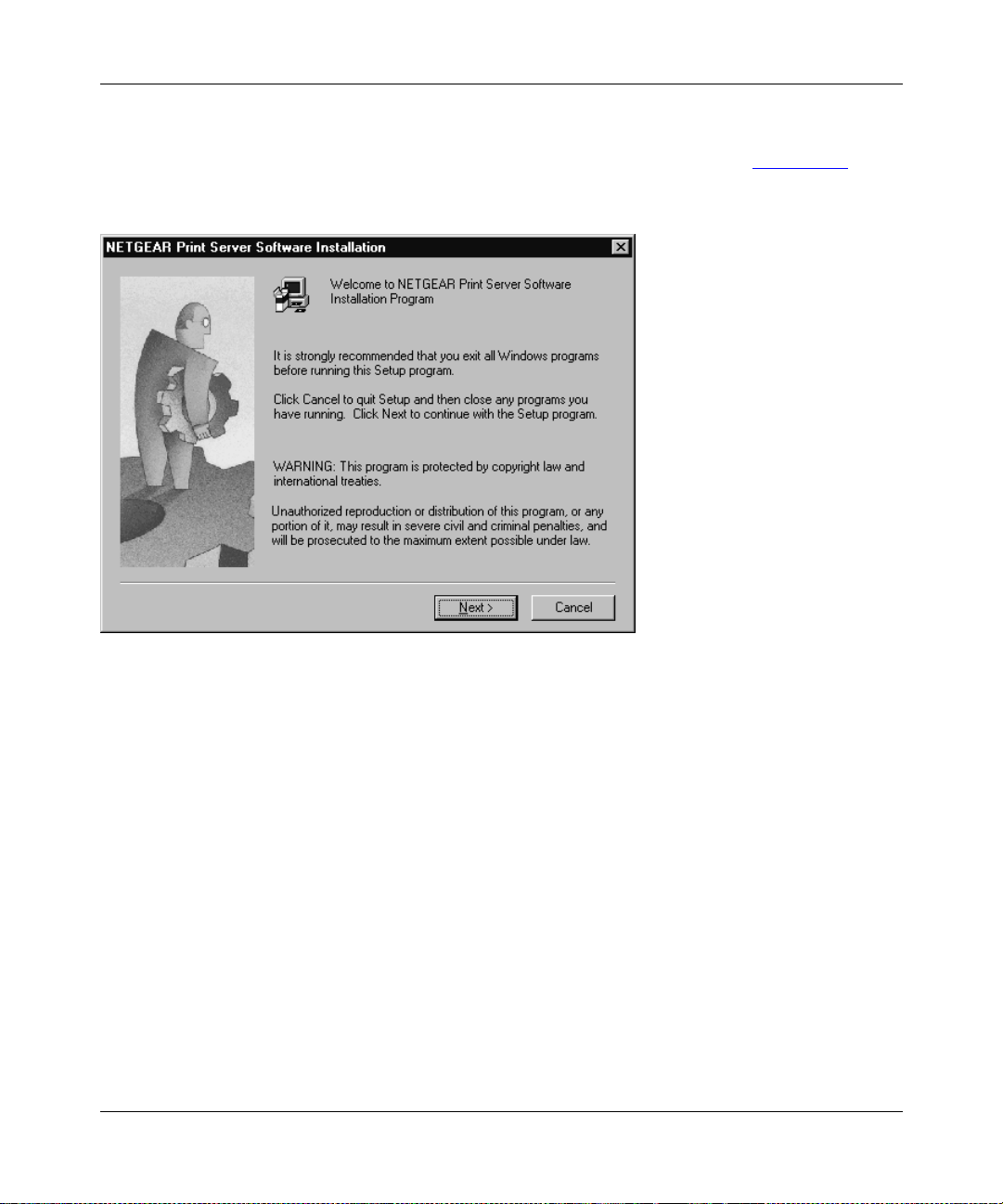
The NETGEAR Print Server Software Installation wi ndow, as illustrate d in Figure 3-3
Figure 3-3. NETGEAR Print Server Software Installation Windo w
, opens.
3-4 Microsoft Windows 95 and Windows 98 Printing
Page 35

5.
Click on Next.
Installation and Reference for the Model PS104/PS105/PS110 Print Server
The Choose Destination Location window, as illustrated in Figure 3-4
Figure 3-4. Choose Destination Location Window
, opens.
Microsoft Windows 95 and Windows 98 Printing 3-5
Page 36
Installation and Reference for the Model PS104/PS105/PS110 Print Server
6.
Click on Next.
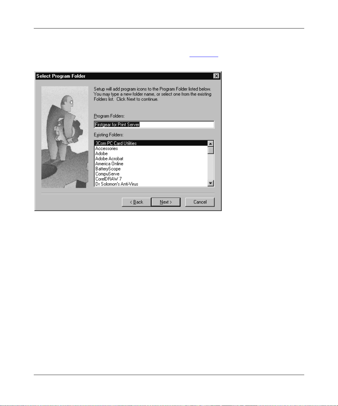
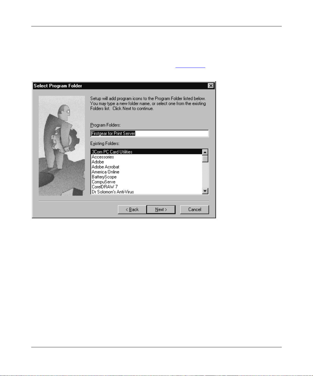
The Select Program Folder window, as illustrated in Figure 3-5
Figure 3-5. Select Program Folder Window
, opens.
3-6 Microsoft Windows 95 and Windows 98 Printing
Page 37
Installation and Reference for the Model PS104/PS105/PS110 Print Server
7.
Type Firstgear for Print Server in the Program Folders entry field (default) or select a
folder from the Existing Folders list .
Or
You can type in a unique name you have chosen for the program folder at the “Program
Folders” prompt or click on a selection in the Existing Folder field to title the folder with
another name. The name will automatically display in the Program Folders entry field.
8.
Click on Next.
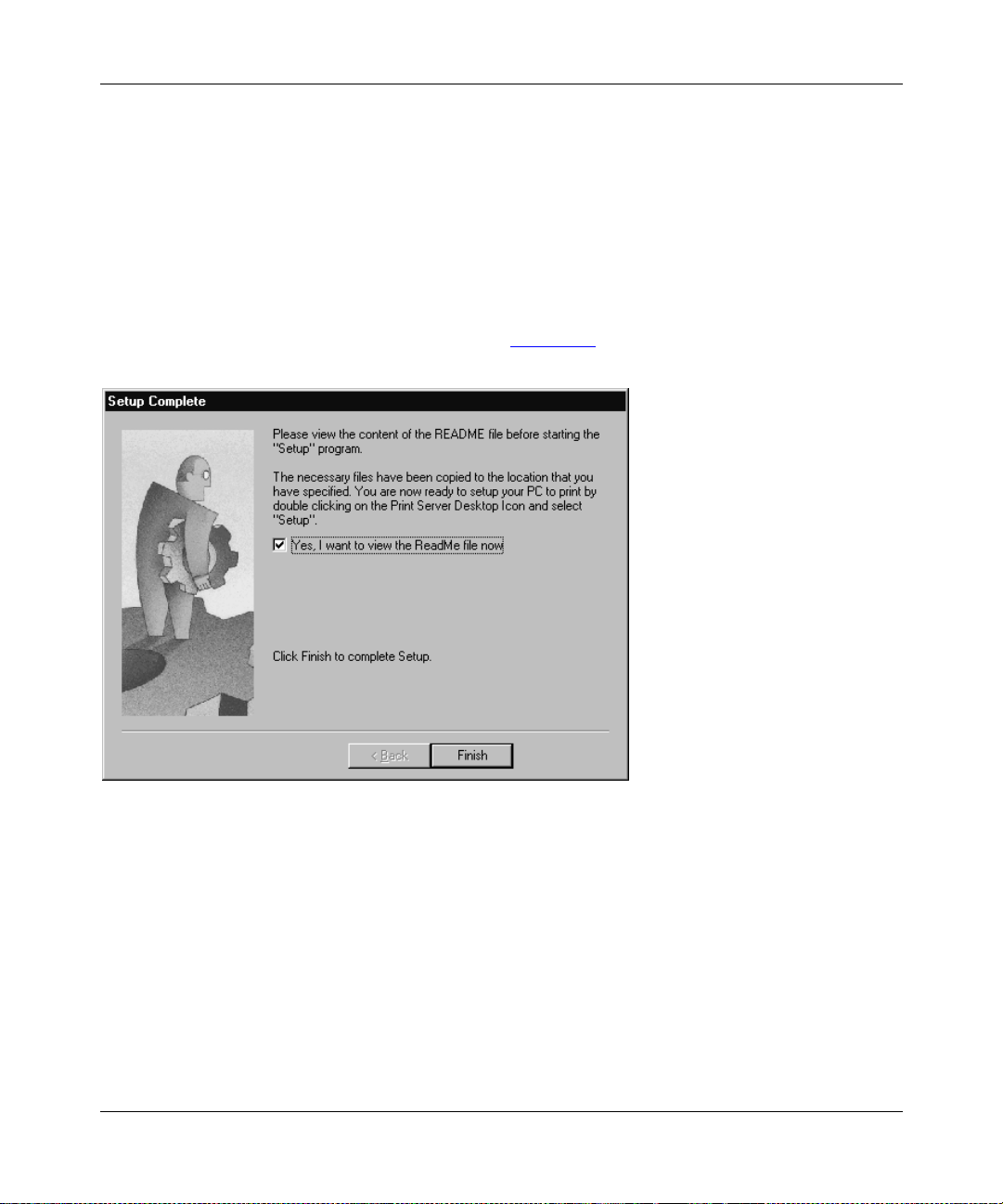
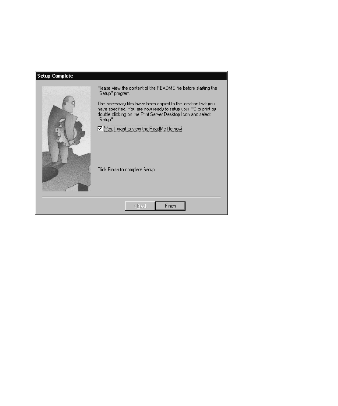
The Setup Complete window, as illustrated in Figure 3-6
Figure 3-6. Setup Complete Window
9.
Click on Finish.
, opens.
The FirstGear Print Server Program is now installed on your PC.
You must now set up your PC to recognize the print server.
Microsoft Windows 95 and Windows 98 Printing 3-7
Page 38
Installation and Reference for the Model PS104/PS105/PS110 Print Server
Setting Up Your PC to Recognize the Print Server
You must set up each PC that will print to the print server. Before proceeding, verify that:
• The print cable is connected to the printer port.
• The AC adapter is plugged into the wall socket.
• The Ethernet cable is plugged into the LAN.
To set up each PC:
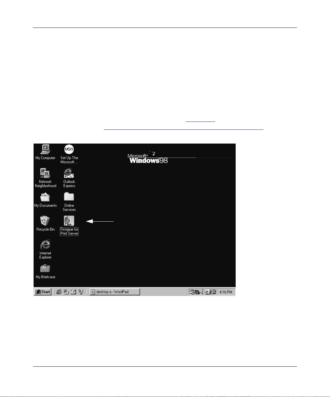
1.
Double-click on the desktop icon, as illustrated in Figure 3-7, that you named in step 7 in
the previous section, “Installing and Setting Up FirstGear—User Installation
.”
Figure 3-7. Firstgear for Print Server Icon
3-8 Microsoft Windows 95 and Windows 98 Printing
Page 39

Installation and Reference for the Model PS104/PS105/PS110 Print Server
The Firstgear for Print Server window, as illustrated in Figure 3-8, opens.
Figure 3-8. Setup Icon
2.
Double-click on Setup in the Firstgear for Print Server window.
The Setup window opens, as illustrated in Figure 3-9
Figure 3-9. Setup Window
3.
Make sure that the NETGEAR print server and the printer that connects to it are both
.
powered on.
4.
Make sure that the cable connections between them are properly connected.
Microsoft Windows 95 and Windows 98 Printing 3-9
Page 40
Installation and Reference for the Model PS104/PS105/PS110 Print Server
5.
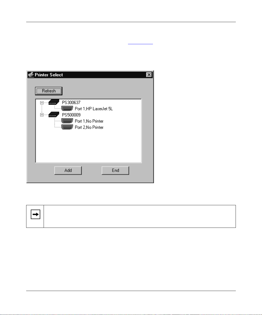
Click on OK.
The Printer S elect window, as illustrated in Figure 3-10
, opens.
The Printer Select window will stay in the background while you work through subsequent
setup windows because you will use this window to complete the setup process.
Figure 3-10. Printer Select Window (Add Port)
Note:
If the cables are not proper ly con nec ted, your PC screen will appear empty when
the Printer Select window opens. If so, check the cable connections and click on the
Refresh button, which will initiate the PC to browse again for a port.
3-10 Microsoft Windows 95 and Windows 98 Printing
Page 41

Installation and Reference for the Model PS104/PS105/PS110 Print Server
6.
Click on the printer port you want to use with the print server, and click on Add.
The ADDPORT window for Epson print connection, as illustrated in Figure 3-11
Figure 3-11. ADDPORT Window (Epson Connection)
7.
Click on No if you do not have an Epson Stylus Color printer attached to the port, and
, opens.
continue to step 8.
Or
Click on Yes if you do have an Epson Stylus Color printer (or plan to install one). You must
disable the Epson printer.
To disable:
a.
Click on the Program Files folder on your hard drive.
b.
Start the Epson Spool Manager.
The Queue Setup window opens, as illustrated in Figure 3-12
Figure 3-12. Epson Spool Manager Queue Se tup Window
Microsoft Windows 95 and Windows 98 Printing 3-11
.
Page 42

Installation and Reference for the Model PS104/PS105/PS110 Print Server
c.
Select Queue Setup, and click on Use Print Manager for this port.
d.
Click on OK to exit the Queue Setup window.
The ADDPORT window, as illustrated in Figure 3-13
you have successfully added the port.
Figure 3-13. ADDPORT Window
8.
Click on OK.
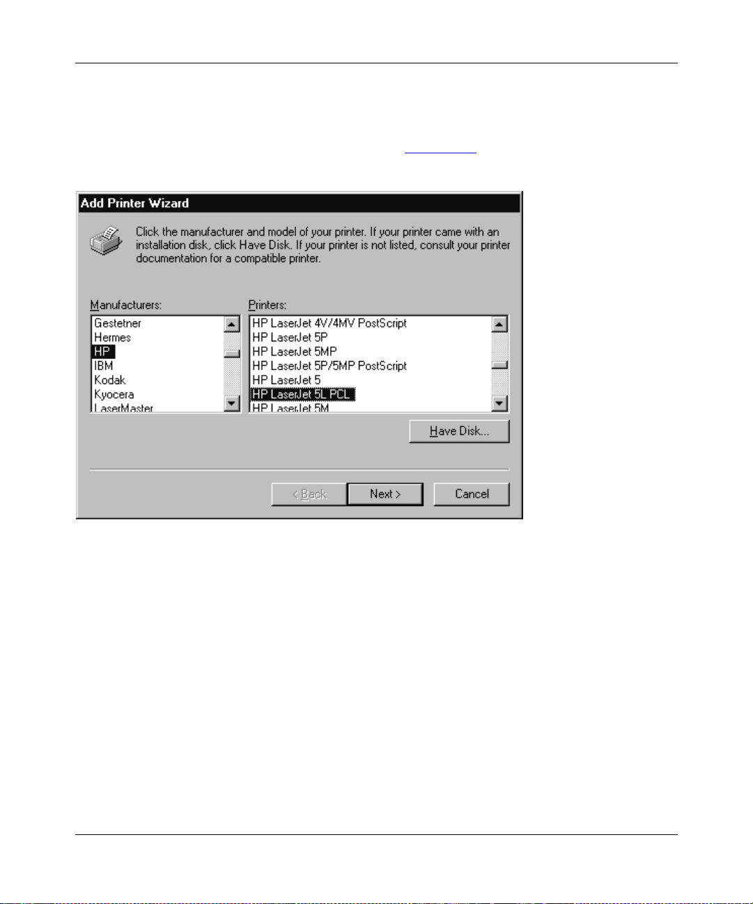
The Add Printer Wizard window, as illustrated in Figure 3-14
, opens. This window informs you that
, opens.
Figure 3-14. Add Printer Wiza rd Window (Manufacturer and Model of Printer)
3-12 Microsoft Windows 95 and Windows 98 Printing
Page 43

Installation and Reference for the Model PS104/PS105/PS110 Print Server
9.
Click on Next after clic king on t he names of t he man ufactur e r and p rinter model y ou ar e
adding.
If your printer is no t list ed, clic k on Ha ve Disk an d insert the dr i ver d isk that you rec ei v ed from
the printer manufacturer. Install the driver, proceeding as instructed until the Add Printer
Wizard window, as illustrated in Figure 3-15
, opens.
Figure 3-15. Add Printer Wiza rd Window (Driver Installation)
Microsoft Windows 95 and Windows 98 Printing 3-13
Page 44

Installation and Reference for the Model PS104/PS105/PS110 Print Server
10.
If you have already installed the printer driver, select Keep existing driver
(recommended), and click on Next. If you have not installed the driver, do so now as
prompted by the screen, as illustrated in Figure 3-15
.
The Add Printer Wizard window for naming your printer, as illustrated in Figure 3-16
Figure 3-16. Add Printer Wizard Window (Printer Name)
, opens.
3-14 Microsoft Windows 95 and Windows 98 Printing
Page 45

Installation and Reference for the Model PS104/PS105/PS110 Print Server
11.
T ype a name f or the printer (if y ou want it to ha ve a unique name) and decide if y ou want
this printer to be your defau lt printer; th en click on Next.
The Add Printer Wizard window for printing a test page, as illustrated in Figure 3-17
Figure 3-17. Add Printer Wizard Window (Print Test Page)
, opens.
Microsoft Windows 95 and Windows 98 Printing 3-15
Page 46

Installation and Reference for the Model PS104/PS105/PS110 Print Server
12.
Select Yes when asked to print a test page, and click on Finish.
The Add Printer window closes and the Printer Select window, as illustrated in Figure 3-18
comes back into view.
,
Figure 3-18. Add Port Window (Setup Complete)
13.
Click on End to complete the setup process.
You are now ready to use the printer attached to your print server.
3-16 Microsoft Windows 95 and Windows 98 Printing
Page 47

Installation and Reference for the Model PS104/PS105/PS110 Print Server
Installing and Setting Up FirstGear—Admin Installation
Choose this option if you are using Wi ndows 95 or Windows 98 to install, print, and manage the
NETGEAR print server.
Note:
It is necessary to instal l the FirstGea r software on every PC in the network that
will use the printers attached to the Model PS104/PS105/PS110 print server.
To install the NETGEAR print server software for admin installation:
1.
Turn on the power to your PC.
2.
Insert the NETGEAR Resource CD-ROM.
The NETGEAR window briefly opens, and the FirstGear Introductory window, as illustrated
in Figure 3-19
If it does not, click on Sta rt > Run > an d the n type in “Install.e xe” at the prompt (for example,
“D:Install.exe”) to start the installation process.
, opens.
Figure 3-19. FirstGear Introductory Window
Microsoft Windows 95 and Windows 98 Printing 3-17
Page 48

Installation and Reference for the Model PS104/PS105/PS110 Print Server
3.
Click on Next.
Another FirstGear window, as illustrated in Figure 3-20
, opens.
Figure 3-20. “Admin Installation” Option Window
3-18 Microsoft Windows 95 and Windows 98 Printing
Page 49
Installation and Reference for the Model PS104/PS105/PS110 Print Server
4.
Choose “Admin PC Installation” and click on Next.
The NETGEAR Print Server Software Installation wi ndow, as illustrate d in Figure 3-21
opens.
Figure 3-21. NETGEAR Print Server Software Installation Window
,
Microsoft Windows 95 and Windows 98 Printing 3-19
Page 50

Installation and Reference for the Model PS104/PS105/PS110 Print Server
5.
Click on Next.
The Choose Destination Location window, as illustrated in Figure 3-22
Figure 3-22. Choose Destination Location Window
, opens.
3-20 Microsoft Windows 95 and Windows 98 Printing
Page 51
Installation and Reference for the Model PS104/PS105/PS110 Print Server
6.
Click on Next to ins tall th e NETGEAR pri nt ser v er pr ogram in the Program Files folder.
If you want to have the program installed elsewher e, c li ck on Browse to f i nd an alternate
location for the software.
The Select Program Folder window, as illustrated in Figure 3-23
Figure 3-23. Select Program Folder Window
, opens.
7.
Type Firstgear for Print Server in the Program Folders entry field (default) or select a
folder from the Existing Folders list .
Or
You can type in a unique name you have chosen for the program folder at the “Program
Folders” prompt or click on a selection in the Existing Folders field to title the folder with
another name. The name automatically displays in the Program Folders entry field.
8.
Click on Next.
The Information window opens. This window displays the f older where the Fi rstGear s oftw are
is saved, the space required for the software, and the space remaining on your hard drive.
Microsoft Windows 95 and Windows 98 Printing 3-21
Page 52

Installation and Reference for the Model PS104/PS105/PS110 Print Server
9.
Click on Next.
The software is copied to the program folder you requested in step 7.
A window opens, asking you if you want to install Adobe Acrobat (a software program that
will allow you to view the manual on line).
10.
Click on Yes if you want Adobe Acrobat to be installed. If you already have Adobe
Acrobat installe d in yo ur PC, clicking on Yes will override the vers ion y ou curr ently ha v e
installed.
Skip to step 12 if you do not want to install Adobe Acrobat.
11.
Click on Next when the Adobe Acrobat Setup window opens.
Follow the screen prompts to install Adobe Acrobat.
The Setup Complete window, as illustrated in Figure 3-24
Figure 3-24. Setup Complete Window
12.
Click on Finish.
, opens.
The FirstGear Print Server program is now installed on your PC.
You must now set up your PC to print to the print server. Proceed to “Setting Up Your PC to
Recognize the Print Server.”
3-22 Microsoft Windows 95 and Windows 98 Printing
Page 53
Installation and Reference for the Model PS104/PS105/PS110 Print Server
Setting Up Your PC to Recognize the Print Serv er
Refer to “Setting Up Your PC to Recognize the Print Server” on page 3-8 for instructions.
Installing and Setting Up FirstGear—Diskette Option
Use this option if your system does not have a CD-ROM drive.
To install the FirstGear software with a diskette:
1.
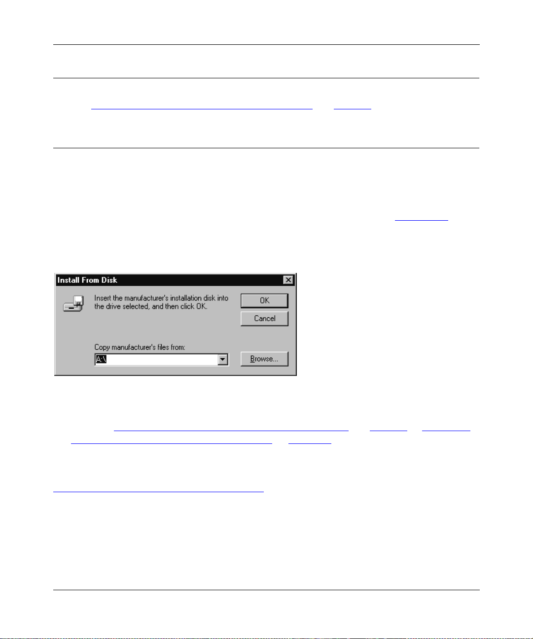
Insert a blank diskette into Drive A, and click on OK, as illustrated in Figure 3-25.
The diskette installation will not work in any other drive but drive A, and you must also use a
high-density disk.
Figure 3-25. Install From Disk Window
Refer to “Installing and Setting Up FirstGear—User Installation” on page 3-2 or “Installing
2.
and Setting Up FirstGear—Admin Installation on page 3-17 to continue with the installation
and setup process.
For more information about the advanced setup features for the NETGEAR print server, refer to
Chapter 7, “Using Advanced Management Tools
Microsoft Windows 95 and Windows 98 Printing 3-23
.”
Page 54
Installation and Reference for the Model PS104/PS105/PS110 Print Server
Setting up the Print Server Using NetBEUI and TCP/IP
Configuring the Print Server Using NetBEUI
No additional print server configuration is necessary after you have followed the steps outlined in
“Setting Up Your PC to Recognize the Print Server
Configuring the Print Server Using TCP/IP
To configure the print server using TCP/IP:
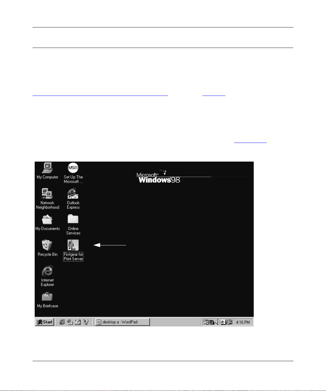
1.
Double-click on the Firstgear for Print Server icon, as illustrated in Figure 3-27, on your
desktop.
” starting on page 3-8.
Figure 3-26. Firstgear for Print Server Icon
3-24 Microsoft Windows 95 and Windows 98 Printing
Page 55

Installation and Reference for the Model PS104/PS105/PS110 Print Server
The Firstgear for Print Server window, as illustrated in Figure 3-27, opens.
Figure 3-27. Firstgear for Print Server Window
Microsoft Windows 95 and Windows 98 Printing 3-25
Page 56

Installation and Reference for the Model PS104/PS105/PS110 Print Server
2.
Double-click on the NETGEAR Print Server Adminis tration icon.
The NETGEA R Print Server A dministration Program window, as illustrated in Figure 3-28
opens.
,
Figure 3-28. NETGEAR Print Server Administration Program Window
3-26 Microsoft Windows 95 and Windows 98 Printing
Page 57
Installation and Reference for the Model PS104/PS105/PS110 Print Server
3.
Click on the Advanced button, as illustrated in Figure 3-28.
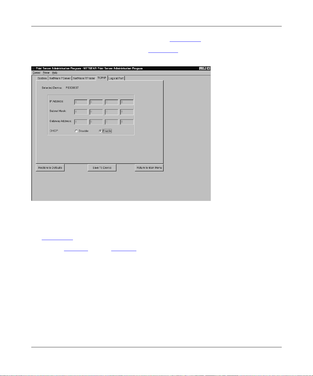
The TCP/IP menu opens, as illustrated in Figure 3-29
Figure 3-29. TCP/IP Menu
.
4.
Click on the TCP/IP menu t ab, which is lo cated a t the top of the wind ow, as illustrated in
Figure 3-29
Refer to Table 3-1
Microsoft Windows 95 and Windows 98 Printing 3-27
.
on page page 3-28 for a description of each field in the TCP/IP menu.
Page 58

Installation and Reference for the Model PS104/PS105/PS110 Print Server
5.
Select Enable or Disable to enable or disable DHCP.
If DHCP is enabled, the print server can be set up to obtain its IP address from a DHCP
(Dynamic Host Configuration Protocol) server or can be manually assigned an IP address at
this menu tab.
If DHCP is disabled, be sure that the IP address assigned to the device is not already in use
when assigning the IP address manually.
For a private TCP/IP network, you can use the IETP-designated private addresses (for
example, 192.168.X.X or 10.X.X.X). For more information about IP addresses, refer to
Appendix B, “Understanding IP Addresses
6.
Type the subnet mask and gateway address (if DHCP is disabled) or proceed to step 7.
7.
Click on the Save To Device button to download the new print server configuration.
8.
Click on Return to Main Menu to exit the Advanced Configuration window.
9.
Click on Exit on the main menu.
Table 3-1. Fields and Descriptions for TCP/IP Configuration
Field Description
.”
DHCP This option allows you to enab le or disable th e print server’s ability to get its IP address from
a DHCP (Dynamic Host Configuration Protocol) server. When disabled, you can provide a
fixed IP address in the IP address, Gateway address, and Subnet Mask fields (listed in this
table).
IP Address This IP address is assigned to the print server. If you have a private LAN and do not plan to
connect to the TCP/IP-based Internet, NETGEAR recommends that you use an address
from the IETP-designated private addresses (for example, 192.168.x.x or 10.x.x.x).
Gateway
Address
Subnet Mask This subnet mask defines the range of addresses that are reachable on your local LAN.
This IP address is what the print s erver uses f or sta tions with IP ad dresses not re achab le on
your local L AN.
Your print server is now set up to use the TCP/IP protocol for networking. If you enable DHCP,
you must prepare the DHCP server to receive a DHCP query from the print server. Then reset the
print server so it can then obtain an IP address from the DHCP server.
If you run into any difficulty with the st at ic I P Se tup , the re is the possibility t hat you inadver ten tl y
disabled the DHCP protocol and/or assigned a wrong subnet IP address. Proceed to Appendix E,
“IP Setup,” for more information to help you force a static IP address to the print server.
3-28 Microsoft Windows 95 and Windows 98 Printing
Page 59

Chapter 4
Microsoft Windows NT Printing
This chapter describes how t o configure and use the NETGEAR Mod el PS1 04/ PS105/ PS110 print
server in a Microsoft Windows NT networking environment.
To correctly configure your hardw are and softw are f or the Mi crosof t Windows platform, you must:
• Install FirstGear for Print Server s oftware.
•Run Setup
• Configure the user PC to print to the NETGEAR print server.
FirstGear for Print Server
This section describes how to install and set up the print server with the FirstGear for Print Server
Program in Windows NT. There are several options to choose from:
• User Installation—used through the NetBEUI protocol, this option is geared toward the user
who is already connected to the LAN and needs to set up a PC to the NETGEAR print server.
• Admin Installation—this option is geared toward the user who is connected to the LAN and
also manages the print server.
• User Installation with diskette—this option generates an installation floppy disk for the user
without a CD-ROM drive.
To install and set up your network and your print server for the NETGEAR print server, you must
be using a PC with a Wind o ws 95, Windows 98, Windows NT 4.0, or W indows NT 3.51 operating
system and with either the TCP/IP protocol or the NetBEUI protocol enabled.
Microsoft Windows NT Printing 4-1
Page 60

Installation and Reference for the Model PS104/PS105/PS110 Print Server
Choose this option, Use r Installation, to be able to print to the print server.
Note:
Before proceeding with these instructions, be sure to assign a name to your
workgroup on your PC. In st allation and setup of t he NETGEAR s oftware is requir ed o n
each PC needing access to the printers that will be attached to the print server.
NETGEAR strongly recommends that you exit all Windows programs before running
the Setup program.
Installing and Setting Up FirstGear—User Installation
To install the NETGEAR print server software for user installation:
1.
Turn on the power to your PC.
2.
Insert the NETGEAR Resource CD-ROM.
The NETGEAR window brie fly opens and the Fir stGear In troductor y windo w, as illustrated in
Figure 4-1
If it does not, click on Start > Run and then type in “Install.exe” at the prompt (for example,
“D:Install.exe”) to start the installation process.
, opens.
Figure 4-1. FirstGear Introductory Window
4-2 Microsoft Windows NT Printing
Page 61

3.
Click on Next.
Installation and Reference for the Model PS104/PS105/PS110 Print Server
Another FirstGear window, as illustrated in Figure 4-2
, opens.
Figure 4-2. User PC Installation Option Window
Microsoft Windows NT Printing 4-3
Page 62

Installation and Reference for the Model PS104/PS105/PS110 Print Server
4.
Choose “User PC Installation” and click on Next.
The NETGEAR Print Server Software Installation wi ndow, as illustrate d in Figure 4-3
Figure 4-3. NETGEAR Print Server Software Installation Windo w
, opens.
4-4 Microsoft Windows NT Printing
Page 63

5.
Click on Next.
Installation and Reference for the Model PS104/PS105/PS110 Print Server
The Choose Destination Location window, as illustrated in Figure 4-4
Figure 4-4. Choose Destination Location Window
, opens.
Microsoft Windows NT Printing 4-5
Page 64

Installation and Reference for the Model PS104/PS105/PS110 Print Server
6.
Click on Next to i nstall the NETGEAR Print Serv er pr ogram in the Progr am Files f older.
If you want to have the program placed elsewhere, click on Browse to find an alternate
location for the software.
The Select Program Folder window, as illustrated in Figure 4-5
Figure 4-5. Select Program Folder Window
, opens.
7.
Type Firstgear for Print Server in the Program Folders entry field (default), or select a
folder from the Existing Folders list .
Or
You c an also type in a unique name for the print server folder. Verify that the information on
the screen is correct.
4-6 Microsoft Windows NT Printing
Page 65
8.
Click on Next.
Installation and Reference for the Model PS104/PS105/PS110 Print Server
The Setup Complete window, as illustrated in Figure 4-6
Figure 4-6. Setup Complete Window
, opens.
9.
Click on Finish.
The FirstGear Print Server Program is now installed on your PC. You must now set up your PC to
recognize the print server.
Microsoft Windows NT Printing 4-7
Page 66

Installation and Reference for the Model PS104/PS105/PS110 Print Server
Setting Up Your PC to Recognize the Print Server
You must set up each PC that will print to the print server. Before proceeding, verify that:
• The print cable is connected to the printer port.
• The AC adapter is plugged into the wall socket.
• The Ethernet cable is plugged into the LAN.
To set up each PC:
1.
Double-click on the desktop icon, as illustrated in Figure 4-7, that you named in step 7 of
the previous section, “Installing and Setting Up FirstGear—User Installation
.”
Figure 4-7. Firstgear for Print Server Icon
4-8 Microsoft Windows NT Printing
Page 67

Installation and Reference for the Model PS104/PS105/PS110 Print Server
The Firstgear for Print Server window, as illustrated in Figure 4-8, opens.
Figure 4-8. Firstgear for Print Server Setup Icon
2.
Click on Setup.
The Setup window, as illustrated in Figure 4-9
Figure 4-9. Setup Window
3.
Make sure the NETGEAR print server and the printer that connects to it are both
, opens.
powered on.
4.
Make sure the cable connections between them are properly connected.
Microsoft Windows NT Printing 4-9
Page 68

Installation and Reference for the Model PS104/PS105/PS110 Print Server
5.
Click on OK.
The Printer S elect window, as illustrated in Figure 4-10
, opens.
The Printer Select window will stay in the background while you work through subsequent
setup windows because you will use this window to complete the setup process.
Figure 4-10. Printer Select Window (Add Port)
Note:
If the cables are not proper ly con nec ted, your PC screen will appear empty when
the Printer Select window opens. If so, check the cable connections and click on the
Refresh button, which will initiate the PC to browse again for a port.
6.
Click on the printer port you want to use with the print server and click on Add.
The ADDPORT window for Epson printer connection, as illustrated in Figure 4-11
Figure 4-11. ADDPORT Window (Epson Connection)
4-10 Microsoft Windows NT Printing
, opens.
Page 69

Installation and Reference for the Model PS104/PS105/PS110 Print Server
7.
Click on No if you do not have an Epson Stylus Color printer attached to the port, and
continue on to Step 8.
Or
If you do have an Epson Stylus Color printer (or plan to install one) you must no w dis abl e the
Epson printer.
To disable:
a.
Click on the Program Files folder on your hard drive.
b.
Start the Epson Spool Manager.
The Queue Setup window, as illustrated in Figure 4-12
Figure 4-12. Epson Spool Manager Queue Se tup Window
c.
Click on Use Print Manager for this port.
, opens.
Microsoft Windows NT Printing 4-11
Page 70

Installation and Reference for the Model PS104/PS105/PS110 Print Server
d.
Click on OK to exit the Queue Setup window.
The ADDPORT window, as illustrated in Figure 4-13
, opens. This window informs you
that you have successfully added the port.
Figure 4-13. Add Port Window (Added port successfully)
8.
Click on OK.
The Add Printer Wizard, as illustrated in Figure 4-14
, opens.
Figure 4-14. Add Printer Wizard Window (Add Ports)
4-12 Microsoft Windows NT Printing
Page 71
Installation and Reference for the Model PS104/PS105/PS110 Print Server
9.
Select the port you added in the previous step. Do
10.
Click on Next.
The Add Printer Wizard window, as illustrated in Figure 4-15
not
click on Add Port.
, opens.
Figure 4-15. Add Printer Wiza rd Window (Manufacturer and Model of Printer)
Microsoft Windows NT Printing 4-13
Page 72

Installation and Reference for the Model PS104/PS105/PS110 Print Server
11.
Click on Next after clic king on t he names of t he man ufactur e r and p rinter model y ou ar e
adding in the Add Printer Wizard window.
If your printer is no t list ed, clic k on Ha ve Disk an d insert the dr i ver d isk that you rec ei v ed from
the printer manufacturer. Install the driver, proceeding as instructed.
The Add Printer Wizard window, as illustrated in Figure 4-16
Figure 4-16. Add Printer Wizard Window (Printer Name)
, opens.
4-14 Microsoft Windows NT Printing
Page 73
Installation and Reference for the Model PS104/PS105/PS110 Print Server
12.
T ype a name f or the printer (if y ou want it to ha ve a unique name) and decide if y ou want
this printer to be your defau lt printer; th en click on Next.
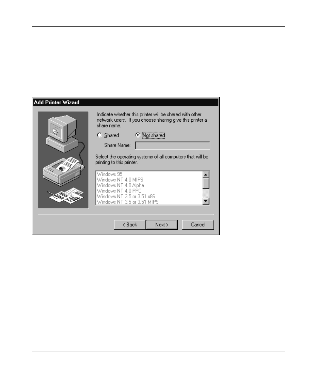
Another Add Printer Wizard screen, as illustrated in Figure 4-17
, opens. With thi s scr ee n, you
can choose to either share or not share the print server with other users in the network. If you
do want to share the print server, you must click on all of the operating systems that will be
sharing the print server.
Figure 4-17. Add Printer Wizard Window (Sharing Ports Screen)
Microsoft Windows NT Printing 4-15
Page 74

Installation and Reference for the Model PS104/PS105/PS110 Print Server
13.
Click on Next.
Another Add Printer Wizard window, as illustrated in Figure 4-18
Figure 4-18. Add Printer Wizard Window (Print Test Page)
, opens.
4-16 Microsoft Windows NT Printing
Page 75

Installation and Reference for the Model PS104/PS105/PS110 Print Server
14.
Click on Finish.
The Add Printer Wizard window closes and the Printer Select window, as illustrated in
Figure 4-19
, comes ba ck into view.
Figure 4-19. Printer Select Window (End Setup)
15.
Click on End.
You are now ready to use the printer attached to your print server.
Microsoft Windows NT Printing 4-17
Page 76

Installation and Reference for the Model PS104/PS105/PS110 Print Server
Installing and Setting Up FirstGear—Admin Installation
Choose this option to install, print, and manage the NETGEAR prin t server.
Note:
It is necessary to instal l the FirstGea r software on every PC in the network that
will use the printers attached to the Model PS104/PS105/PS110 print server.
1.
Turn on the power to your PC.
2.
Insert the NETGEAR Resource CD-ROM.
The NETGEAR window bri efly opens, and the Firstge ar Introduc tory windo w, as illustrated in
Figure 4-20
If it does not, click on Start > Run and then type in “Install.exe” at the prompt (for example,
“D:Install.exe”) to start the installation process.
, opens.
Figure 4-20. FirstGear Introductory Window
4-18 Microsoft Windows NT Printing
Page 77

3.
Click on Next.
Installation and Reference for the Model PS104/PS105/PS110 Print Server
Another FirstGear window, as illustrated in Figure 4-21
, opens.
Figure 4-21. Admin Installation Option Window
Microsoft Windows NT Printing 4-19
Page 78

Installation and Reference for the Model PS104/PS105/PS110 Print Server
4.
Select “Admin PC Installation” and click on Next.
The NETGEAR Print Server Software Installation wi ndow, as illustrate d in Figure 4-22
opens.
,
Figure 4-22. NETGEAR Print Server Software Installation Window
4-20 Microsoft Windows NT Printing
Page 79

5.
Click on Next.
Installation and Reference for the Model PS104/PS105/PS110 Print Server
The Choose Destination Location window, as illustrated in Figure 4-23
, opens.
Figure 4-23. Choose Destination Location Window
Microsoft Windows NT Printing 4-21
Page 80
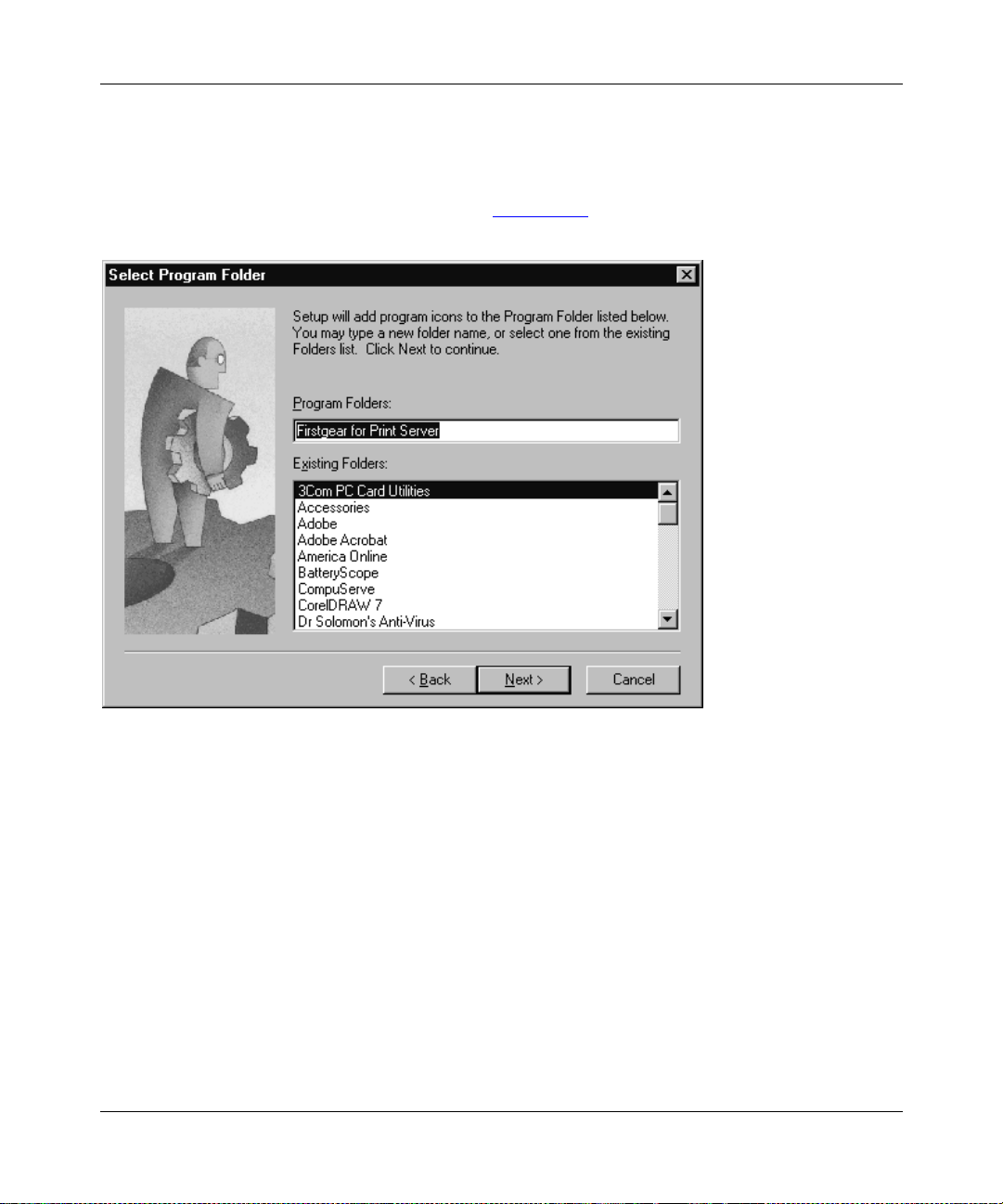
Installation and Reference for the Model PS104/PS105/PS110 Print Server
6.
Click on Next to i nstall the NETGEAR Print Serv er pr ogram in the Progr am Files f older.
If you want to have the program placed elsewhere, click on Browse to find an alternate
location for the software.
The Select Program Folder, as illustrated in Figure 4-24
.
Figure 4-24. Select Program Folder Window
, opens.
7.
Type Firstgear for Print Server in the Program Folders entry field (default) or select a
folder from the Existing Folders list .
Or
You can type in a unique name you have chosen for the program folder at the “Program
Folders” prompt or click on a selection in the Existing Folders field to title the folder with
another name. The name automatically displays in the Program Folders entry field.
8.
Click on Next.
The Information window opens. This window displays the f older where the Fi rstGear s oftw are
is saved, the space required for the software, and the space remaining on your hard drive.
4-22 Microsoft Windows NT Printing
Page 81

Installation and Reference for the Model PS104/PS105/PS110 Print Server
9.
Click on Next.
The software will be copied to the program folder you requested in step 7.
A window opens, asking you if you want to install Adobe Acrobat (a software program that
will allow you to view the manual on line).
10.
Click on Yes if you want Adobe Acrobat to be installed. If you already have Adobe
Acrobat installe d in yo ur PC, clicking on Yes will override the vers ion y ou curr ently ha v e
installed.
Skip to step 12 if you do not want to install Adobe Acrobat.
11.
Click on Next when the Adobe Acrobat Setup window opens.
Follow the screen prompts to install Adobe Acrobat.
The Setup Complete window, as illustrated in Figure 4-25
, opens.
Figure 4-25. Setup Complete Window
Microsoft Windows NT Printing 4-23
Page 82
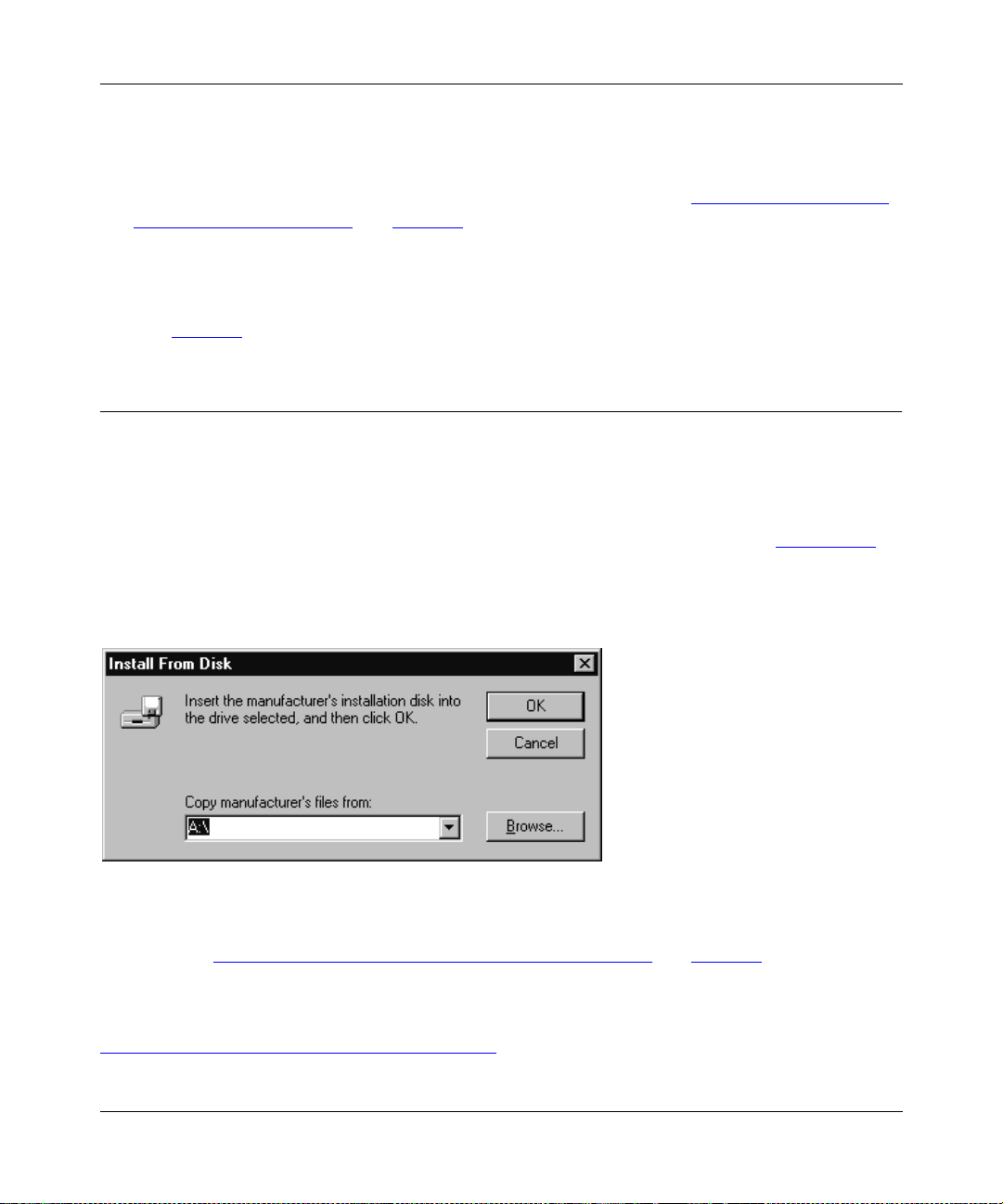
Installation and Reference for the Model PS104/PS105/PS110 Print Server
12.
Click on Finish.
The FirstGear Print Server Program is now installed on your PC.
You must now set up your PC to print to the print server. Proceed to “Setting Up Your PC to
Recognize the Print Server” on page 4-8.
Setting Up Your PC to Recognize the Print Server
Refer to page 4-8 for instructions on setting up your PC to recognize the print server.
Installing and Setting Up FirstGear—Diskette Option
Use this option if your system does not have a CD-ROM drive.
To install the FirstGear software:
1.
Insert a bl ank diskette in to the Drive A, and click on OK, as illustrated in Figure 4-26.
The diskette installation will not work in any other drive but drive A, and you must also use a
high-density disk.
Figure 4-26. Install From Disk Window
Refer to “Installing and Setting Up FirstGear—User Installation” on page 4-2 to continue with
2.
the installation and setup proc ess .
For information about the advanced setup procedures for the NETGEAR print server, refer to
Chapter 7, “Using Advanced Management Tools
4-24 Microsoft Windows NT Printing
.”
Page 83

Installation and Reference for the Model PS104/PS105/PS110 Print Server
Setting up the Print Server Using NetBEUI and TCP/IP
Configuring the Print Server Using NetBEUI
No additional print server configuration is necessary after you have followed the steps outlined in
“Setting Up Your PC to Recognize the Print Server
Configuring the Print Server Using TCP/IP
To configure the print server using TCP/IP:
1.
Double-click on the Firstgear for Print Server icon, as illustrated in Figure 4-27, on your
desktop.
” starting on page 4-8.
Figure 4-27. Firstgear for Print Server Icon
Microsoft Windows NT Printing 4-25
Page 84
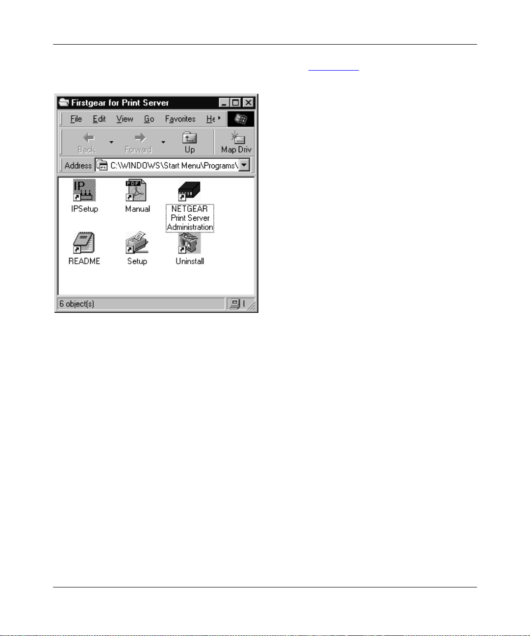
Installation and Reference for the Model PS104/PS105/PS110 Print Server
The Firstgear for Print Server window, as illustrated in Figure 4-28, opens.
Figure 4-28. Firstgear for Print Server Window
4-26 Microsoft Windows NT Printing
Page 85
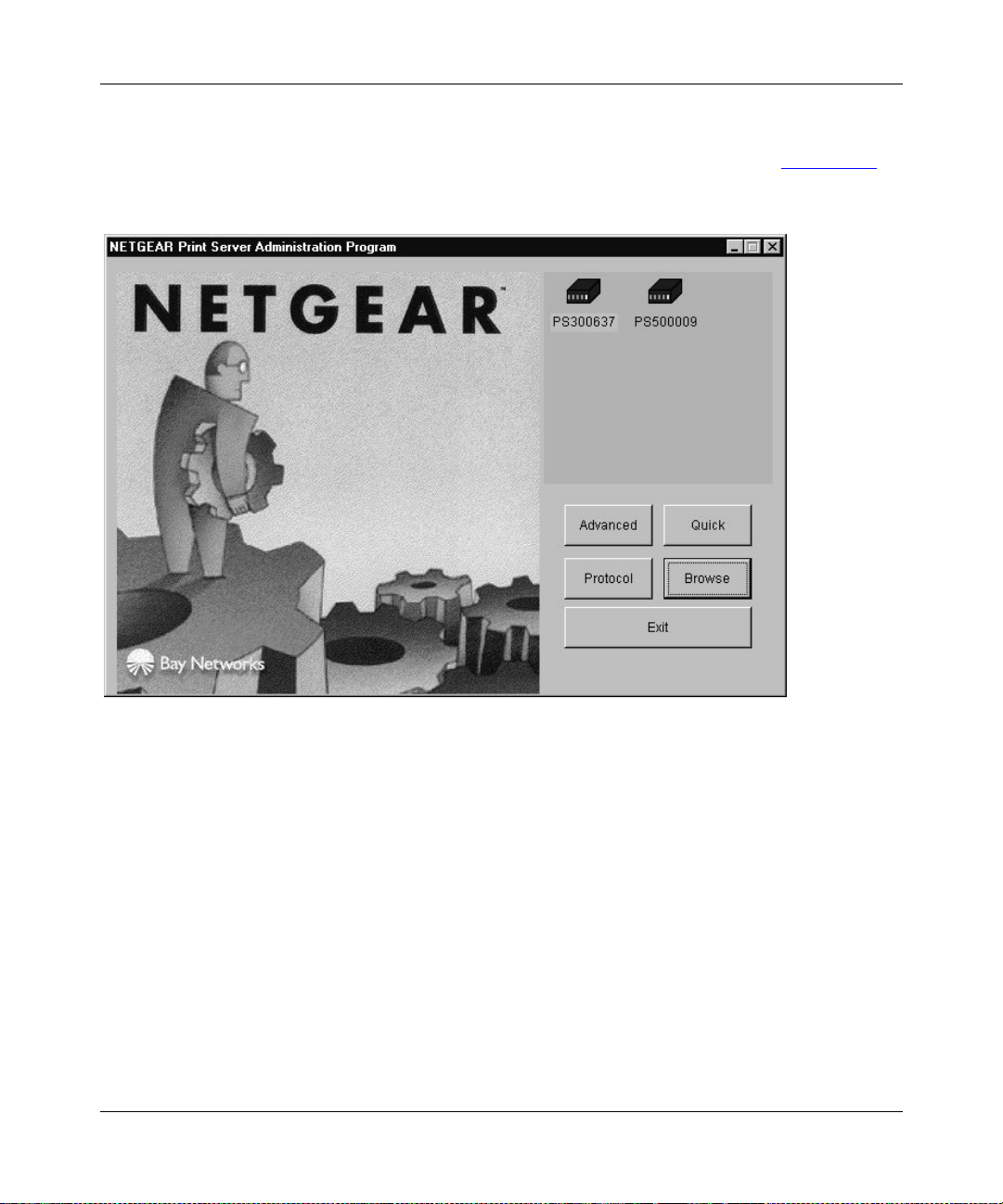
Installation and Reference for the Model PS104/PS105/PS110 Print Server
2.
Double-click on the NETGEAR Print Server Adminis tration icon.
The NETGEA R Print Server A dministration Program window, as illustrated in Figure 4-29
opens.
,
Figure 4-29. NETGEAR Print Server Administration Program Window
Microsoft Windows NT Printing 4-27
Page 86

Installation and Reference for the Model PS104/PS105/PS110 Print Server
3.
Click on the Advanced button, as illustrated in Figure 4-29.
The TCP/IP menu opens, as illustrated in Figure 4-30
.
Figure 4-30. TCP/IP Menu
4.
Click on the TCP/IP menu t ab, which is lo cated a t the top of the wind ow, as illustrated in
Figure 4-30
Refer to Table 4-1
5.
Select Enable or Disable to enable or disable DHCP.
.
on page page 4-29 for a description of each field in the TCP/IP menu.
If DHCP is enabled, the print server can be set up to obtain its IP address from a DHCP
(Dynamic Host Configuration Protocol) server or can be manually assigned an IP address at
this menu tab.
If DHCP is disabled, be sure that the IP address assigned to the device is not already in use
when assigning the IP address manually.
For a private TCP/IP network, you can use the IETP-designated private addresses (for
example, 192.168.X.X or 10.X.X.X). For more information about IP addresses, refer to
Appendix B, “Understanding IP Addresses
4-28 Microsoft Windows NT Printing
.”
Page 87

Installation and Reference for the Model PS104/PS105/PS110 Print Server
6.
Type the subnet mask and gateway address (if DHCP is disabled) or proceed to step 7.
7.
Click on the Save To Device button to download the new print server configuration.
8.
Click on Return to Main Menu to exit the Advanced Configuration window.
9.
Click on Exit on the main menu, and proceed to the next section, “Setting Up Spooled
LPR Printing with Windows NT 3.51.
Table 4-1. Fields and Descriptions for TCP/IP Configuration
Field Description
DHCP This option allows you to enab le or disable th e print server’s ability to get its IP address from
a DHCP (Dynamic Host Configuration Protocol) server. When disabled, you can provide a
fixed IP address in the IP address, Gateway address, and Subnet Mask fields (listed in this
table).
IP Address This IP address is assigned to the print server. If you have a private LAN and do not plan to
connect to the TCP/IP-based Internet, NETGEAR recommends that you use an address
from the IETP-designated private addresses (for example, 192.168.x.x or 10.x.x.x).
Gateway
Address
Subnet Mask This subnet mask defines the range of addresses that are reachable on your local LAN.
This IP address is what the print s erver uses f or sta tions with IP ad dresses not re achab le on
your local L AN.
Your print server is now set up to use the TCP/IP protocol for networking. If you enable DHCP,
you must prepare the DHCP server to receive a DHCP query from the print server. Then reset the
print server so it can then obtain an IP address from the DHCP server.
If you run into any difficulty with the st at ic I P Se tup , the re is the possibility t hat you inadver ten tl y
disabled the DHCP protocol and/or assigned a wrong subnet IP address. Proceed to Appendix E,
“IP Setup,” for more information to help you force a static IP address to the print server.
Setting Up Spooled LPR Printing with Windows NT 3.51
Before starting the PC configuration, you must configure the print server for using TCP/IP as
described in “Configuring the Print Server Using TCP/IP
To prepare for spooled LPR printing:
1.
Click on the Network icon in the Control Panel.
The Network Settings dialog box opens.
Microsoft Windows NT Printing 4-29
” on page 4-25.
Page 88

Installation and Reference for the Model PS104/PS105/PS110 Print Server
2.
Click on the Add Software button.
The Network Software dialog box opens.
3.
Select TCP/IP Protocol And Related Components in the Network Software dialog box,
and then click on Continue.
The Windows NT TCP/IP Installation Options dialog box opens.
4.
Click on the TCP/IP Network Printing Support option.
5.
Click on OK.
Windo ws NT Setup displa ys a message asking fo r the full path to t he Wi ndows NT dist ribut ion
files.
6.
Type the appropriate location, and then click on Continue.
All necessary files are copied to your hard disk.
If you did not check the Enable Automatic DHCP Configuration option in the Windows NT
TCP/IP Installation Options dialog box, you must complete all the required TCP/IP
configuratio n procedures manually. After you finish conf iguri ng TCP/IP, the Network Sett ings
dialog box opens. For more information about IP addresses, refer to Appendix B,
“Understanding IP Addresses.”
7.
Click on Close, and then restart your comp uter so the changes take effect.
To add a spooled LPR printer in the NT station:
1.
Choose Create Printer from the Printer menu in Print Manager to open the dialog box.
2.
Type data in the entry fields of the dialog box, using the definitions in Table 4-2.
Table 4-2. Add a Spooled LPR Printer Fields
Field Description
Printer Name Type a name (up to 32 characters). This name appe ars in the t itle bar of th e
printer window.
Driver Click on the appropriate driver for the attached printer.
Description Type a printer description for other network users to reference.
3.
Click on Other in the Print To entry field.
The Print Destinations dialog box opens.
4-30 Microsoft Windows NT Printing
Page 89

Installation and Reference for the Model PS104/PS105/PS110 Print Server
4.
Click on LP R Port in the Available Pr int Monitor li st, and then c lick on OK.
The Add LPR Compatible Printer window opens.
5.
Type data in the entry fields of the Add LPR C ompatible Pr inter window, using the
definitions in Table 4-3
Table 4-3. Add LPR Compatible Printer Fields
Field Description
.
Name or Address of
Host Providing LPD
Name of Printer On
That Machine
6.
Click on the Share This Printer on the Network option, when the Create Printer dialog
Enter the IP address of your print server.
Enter the appropriate logical printer number (for example, L1). Use only logical
printers when implementing the LPR printer port in the Windows NT system. If
you are using the Model PS104 and Model PS105, L1 and L2 logical ports are
mapped into physical port P1. If you are using the Model PS110 Print Server,
the factory default L1 and L2 logical ports are mapped into physical ports P1
and P2, respectively.
box reopens.
In the Share Name box, Printer Manager creates an MS-DOS compatible resource name,
which you can change. In the Location box, you can enter information about the printer
location. Network users see this information when browsing to find this printer.
7.
Complete a ny other configuration informat ion in the Create Printer dialog box.
Setting Up Spooled LPR Printing with Windows NT 4.0
Before starting the PC configuration, you must configure the print server for using TCP/IP as
described in “Configuring the Print Server Using TCP/IP
To prepare for spooled LPR printing:
” on page 4-25.
1.
Click on Start from the Windows NT desktop, select Settings, and then select Control
Panel.
2.
Double-click on Network.
3.
Click on the Service option and make sure that Simple TCP/IP Service and Microsoft
TCP/IP Printing are enabled.
If they are not enabled, select the Add option and enable them.
Microsoft Windows NT Printing 4-31
Page 90

Installation and Reference for the Model PS104/PS105/PS110 Print Server
4.
Reboot the computer for the changes to take effect, if you added services in step 3.
To add a spooled LPR printer:
1.
Click on Start from the Windows NT desktop, select Settings, and then select Printers.
2.
Double-click on Add Printer to start the Add Printer Wizard.
3.
Click on My Computer, and then click on Next when pr ompted with “This printer wi ll be
managed by.”
4.
Click on Add Port, click on LPR Port, and then click on New Port.
5.
Type the IP address of the print server in the Name of Address of the server providing
the LPR dialog box.
6.
Use the informat ion pr ovided i n Table 4-2 to type the appropriate logical printer numbe r
(L1..L3 or L1..L8, depending on the model) as previously configured on the print server
in the Name of printer or print queue field on the Create Printer dialog box.
Use only the logical printer when implementing the LPR printer port on the Windows NT
system. If you are using the Model PS104 or PS105 Print Server, all three logical ports are
mapped to the same PRINTER port. If you are usi ng the Model PS110 Pri nt Server, the factory
default is L1 = P1 and L2 = P2.
7.
Click on OK.
8.
Click on Close when the Printer Ports window reopens, and then install your printer
driver as usual.
9.
Click on Sharing when prompted to indicate whether or not the printer will be shared.
10.
Type the shared printer name in the Shared dialog box.
This shared name is how other PCs will see this printer on the network.
With this procedure, other windows-based PCs can browse the network to see the print spooler
on the Windows NT PC and print to it. The configuration procedure for each PC is the same as
described in “Setting Up Spooled LPR Printing with Windows NT 3.51
4-32 Microsoft Windows NT Printing
” on page 4-29.
Page 91

Chapter 5
Novell NetWare Printing
This chapter describes ho w to conf ig ure and use the NETGEAR Model PS104 Print Serv er , Model
PS105 Print Server, and Model PS110 Print Server in the Novell NetWare environment.
Configuration Overview
This section describes the requirements and outlines the PSERVER or RPRINTER mode
configuration in either a NetWare Bindery or a NetWare Directory Services (NDS) network
environment.
To configure your print server for the Novell NetWare environment, you must have:
• NetWare Version 3.1x, NetWare Version 4.x, or NetWare Version 5.x
• NetWare PCONSOLE V1.21 or higher installed in your network file server
• NetWare Print Server V1.22 or higher (for remote printer mode only)
• DOS 3.3 or higher installed on all of the workstations in your network
• Network installation completed
Novell NetWare Printing 5-1
Page 92

Installation and Reference for the Model PS104/PS105/PS110 Print Server
The following two operating modes are possible in bindery (NetWare 3.x), NDS network
environment (NetWare 4.x), or NDPS (NetWare 5.x):
• PSERVER mode
PSERVER mode is faster and uses fewer re source s than RPRINTER mode but occupies a user
login slot. The NETGEAR print server emulates a NetWare PSERVER.
When activated, the device:
– Logs in to specified NetWare file server(s)
– Polls the specified print queues
If there are p rint jobs in the print queue, the print server retrieves them from the print
queue.
– Sends the received network packet data to the printer
• RPRINTER mode
RPRINTER mode does not use a login slot. NETGEAR rec ommends tha t PSERVER mode be
used if possible. The print server emulates a NetWare Remote Printer.
When activated, the device:
– Connects to NetWare PSERVER
– Receives the print jobs sent by PSERVER
– Sends the received network packet data to the printer
It is a two-step process to set up the Model PS104/PS105/PS110 print server in the NetWare
environment. The NetWare file server must first be configured, and then you can configure your
print server.
Configuring the NetWare File Server
NetWare server configuration can be e xecuted through the DOS-bas ed PCONSOLE (Net Ware 3.x
and NetW are 4.x), NWADMIN (NetW are 4. x), or NWADMN32 (NetW are 5 .x) based on W indo ws.
All of these programs are provided as part of NetWare. Refer to the following sections for
configuring the file server using PCONSOLE. For information about NWADMIN, refer to the
NetWare user’s manual.
5-2 Novell NetWare Printing
Page 93

Installation and Reference for the Model PS104/PS105/PS110 Print Server
The following sections describe how to determine a device name for your print server and set up
the following three printing components on a Novell NetWare server:
•Print queue
• Print server
•Print
Configuring Your Print Server
There are two methods for configuring the print server in a NetWare environment: the FirstGear
Administration Program based on Windows, or the PSCONFIG program based on MS-DOS. Both
programs are on the Model PS104/PS105/PS110 Print Server Resource CD that come s with your
print server.
Additionally, you can also run the QUICKSET conf igur ation progra m to conf i gure t he pri nt ser ve r
and the current Novell server in a single operation.
This chapter provides step-by-step instructions to set up the file server and the print server using
PCONSOLE and PSCONFIG programs. For detailed descriptions on the various options of
PSCONFIG, the FirstGear Administration Program, and QUICKSET, refer to Chapter 7, “Using
Advanced Management Tools.”
Determining a Device Name for Your Print Server
The Model PS104/PS105/PS110 print server is capable of servicing multiple protocols
simultaneously. However, you must always use the same name for the print server when you are
using more than one protocol. When the print server name is changed, the print operations in all
protocols are affected; therefore, it is important that you decide on a permanent print server name
before setting up the device. Also make sure that you decide on and assign a different name for
each of the print servers on the network.
Using Your Print Server in a NetWare 3.x Network
When configuring using the PSCONFIG utility, copy all files in \Dos directory on the
Model PS104/PS105/PS110 Print Server Resource CD to the hard disk of your workstation. The
PSCONFIG program is in this directory.
Novell NetWare Printing 5-3
Page 94

Installation and Reference for the Model PS104/PS105/PS110 Print Server
Setting PSERVER Mode in NetWare 3.x (Bindery Mode)
To set up the NetWare file server to connect to the Model PS104/PS105/PS110 print server in the
NetW ar e PSERVER mode, first designa te a Ne tWare file serv er that your prin t serv er will l og on to
retrieve print jobs . Log on to the file server as SUPERVISOR or as a use r with SUPERVISOR
privileges. The print server can be configured to service multiple NetWare Bindery file servers as
described in “Using Advanced Funct io ns
has to be designated as t he master f ile se rv er, and this file server is the one that must be conf i gured
and logged on to.
To set up the NetWare file server:
1.
Execute the PCONSOLE program from the system volume of the file server.
2.
Create queues.
To create queues:
a.
Select Print Queue Information in the Available Options window.
b.
Press the [Ins] key to add a new queue.
c.
Type in a queue name and press [Enter].
” on page 5-20. Howe v er, one of the NetWa re f ile serv ers
d.
Repeat steps b and c until you have the number of queues you want.
e.
Press [Esc] to return to th e PCONSOLE Main Menu.
3.
Add the print server.
To inform the NetWare file server that a print server exists:
a.
Select Print Server Information from the PCONSOLE Main Menu.
b.
Press [Ins] to add a new print server.
c.
Type the prin t server name.
The factory default name for the print server is PSxxxxxx (shown on the label on the
bottom of the device).
4.
Assign printers.
To associate a NetWare printer object with each printer port of the print server:
a.
Select the print server you added in step 3.
b.
Select Print Server Configuration.
c.
Select Printer Conf ig urat ion.
5-4 Novell NetWare Printing
Page 95

Installation and Reference for the Model PS104/PS105/PS110 Print Server
d.
Select the printer number on the Configured Printers submenu, using the printer
number mapping as shown in Table 5-1
.
For more information about logical ports, refer to “Using Logical Port s
Table 5-1. PSERVER Mode Printer Number Mapping
Print Server Port File Server Printer Number
Printer port 1 Printer number 0
Printer port 2 Printer number 1
Logical port 1 Printer number 8
Logical port 2 Printer number 9
Logical port 3 Printer number 10
Logical port 4 Printer number 11
Logical port 5 Printer number 12
Logical port 6 Printer number 13
Logical port 7 Printer number 14
Logical port 8 Printer number 15
e.
Enter the print server name in the Name entry field.
Leave the Type entry field with the default value of Defined elsewhere.
f.
Press [Esc].
” on page 5-22.
g.
Select Yes to save the changes.
h.
Repeat steps d, e, and f for each printer port on the print server.
i.
Press [Esc] to return to the Print Server Configuration menu.
5.
Associate printers with print queues.
To associate print queues with the printer(s) attached to your print server:
a.
Select Queues Serviced by Printer from the Print Server Configuration menu.
b.
Select a printer you want to assign a print queue to.
c.
Press [Ins] when the File Server Queue Priority window opens.
d.
Select the print queue that you want the printer to service.
e.
Press [Enter] to accept the default priority level.
Novell NetWare Printing 5-5
Page 96

Installation and Reference for the Model PS104/PS105/PS110 Print Server
f.
Press [Esc] to return to the Defined Printers window.
g.
Repeat steps b through f until all printer and queue associations are configured
completely.
h.
Press [Esc] until you exit out of the PCONSOLE program.
6.
Configure your print server.
To configure your print server:
a.
Execute PSCONFIG wh ile logged on to the file server.
This program was previously copied from the print server resource CD into your hard
disk.
b.
Select the print server that you want to configure.
c.
Select Change Configur ati on.
d.
Select NetWare Configuration.
e.
Verify that PS is the Operation Mode.
PS must be the operation mode for the print server to operate in PSERVER mode. If the
operation mode is RP, the print server operates in RPRI NTER mode. It c an operat e in only
one mode at a time.
f.
Select the Master File Server entry field to open the Select the Master File Server
window.
g.
Select the name of the file server you just configured.
h.
Press [Esc] to return to the Select Configuration Item window.
i.
Select System Configuration if any change to the print server is necessary.
j.
Select Execute Change.
k.
Press [Enter] when asked if you are sure.
l.
Press [Esc] when a window opens indicating the configuration is complete.
m.
Press [Esc] to return to the Active Device List main menu.
Press F2 to make sure that the new print server name is activated if it was changed.
n.
Press [Esc] to exit out of the PSCONFIG program.
Your print server is now set up in the NetWare networking environment. You can access the print
server using NetWare commands printing to the designated queue.
5-6 Novell NetWare Printing
Page 97

Installation and Reference for the Model PS104/PS105/PS110 Print Server
Setting RPRINTER Mode in NetWare 3.x (Bindery Mode)
To set up the NetWare file server to connect to the Model PS104/PS105/PS110 print server in the
NetWare RPRINTER mode, first designate a NetWare file server that your pri nt server will log on
to retrieve print jobs. Log on to the file server as SUPERVISOR or as a user with SUPERVISOR
privileges. The print server can be configured to service multiple NetWare Bindery file servers as
described in “Using Advanced Funct io ns
has to be designated as t he master f ile se rv er, and this file server is the one that must be conf i gured
and logged on to.
To set up the NetWare file server:
1.
Execute the PCONSOLE program from the system volume of the file server.
2.
Create queues.
To create queues:
a.
Select Print Queue Information in the Available Options window.
b.
Press [Ins] to add a new queue.
c.
Type in a queue name and press [Enter].
” on page 5-20. Howe v er, one of the NetWa re f ile serv ers
d.
Repeat steps b and c until you have the number of queues you want.
e.
Press [Esc] to return to th e PCONSOLE Main Menu.
3.
Add the print server.
To inform the NetWare file server that a print server exists:
a.
Select Print Server Information from the PCONSOLE Main Menu.
b.
Press [Ins] to add a new print server.
c.
Type the prin t server name.
This name is not the name of the print server. It is the print server that you will set up
on the NetWare file server. At the end of the installation process, you will load
PSERVER.NLM on the file server using this name.
4.
Assign printers.
This step should be done every time you add a new print server or when you connect a new
printer to the print server.
Novell NetWare Printing 5-7
Page 98

Installation and Reference for the Model PS104/PS105/PS110 Print Server
To associate a NetWare printer object with each printer port of the print server:
a.
Select the print server you added in step 3.
b.
Select Print Server Configuration.
c.
Select Printer Conf ig urat ion.
d.
Select the entry with printer number 0 on the Configured Printers submenu to open
the Printer 0 Configuration window.
e.
Type the predetermined print server name in the Name entry field, using the
convention shown in Table 5-2
.
When referring to the table , ass ume tha t PSx xxxxx is the predetermined name of t he pr in t
server. You can provide a name different from the one presently in the print server, and
then you can change the name of the device when you execute the PSCONFIG program
for the RPRINTER setup.
The factory default name for the print server is PSxxxxxx as shown on the label on the
bottom of the device.
Table 5-2. RPRINTER Mode Printer Name Mapping
Print Server Port Printer Name in File Server
Printer port 1 PSxxxxxx
Printer port 2 PSxxxxxx_P2
Logical port 1 PSxxxxxx_L1
Logical port 2 PSxxxxxx_L2
Logical port 3 PSxxxxxx_L3
Logical port 4 PSxxxxxx_L4
Logical port 5 PSxxxxxx_L5
Logical port 6 PSxxxxxx_L6
Logical port 7 PSxxxxxx_L7
Logical port 8 PSxxxxxx_L8
f.
Select the Type entry field to open the Printer Types window.
g.
Select Remote Parallel, LPT1 in the Printer Types window and press [Enter].
h.
Press [Esc].
i.
Select Yes to save the changes.
5-8 Novell NetWare Printing
Page 99

Installation and Reference for the Model PS104/PS105/PS110 Print Server
j.
Repeat steps d through f for each printer port on the print server.
k.
Press [Esc] to return to the Print Server Configuration menu.
5.
Associate printers with print queues.
To associate print queues with the printer(s) attached to your print server:
a.
Select Queues Serviced by Printer from the Print Server Configuration menu.
b.
Select a printer you want to assign a print queue to.
c.
Press [Ins] when the File Server Queue Priority window opens.
d.
Select the print queue that you want the printer to service.
e.
Press [Enter] to accept the default priority level.
f.
Press [Esc] to return to the Defined Printers window.
g.
Repeat steps b through f until all printer and queue associations are configured
completely.
h.
Press [Esc] until you exit out of the PCONSOLE program.
6.
Configure your print server.
To configure your print server:
a.
Execute PSCONFIG wh ile logged on to the file server.
This program was previously copied from the print server resource CD into your hard
disk.
b.
Select the print server that you want to configure.
c.
Select Change Configur ati on.
d.
Select NetWare Configuration.
e.
Verify that RP is the operation mode.
RP must be the operation mode for the print server to operate in RPRINTER mode. If the
operation mode is PS, the print server operates in PSERVER mode. It can operate only in
one mode at a time.
f.
Select and enter the name of the NetWare print server in the Novell PSERVER (P1)
entry field.
This name is the NetWare print server that you entered in step 3 c.
You c an also modify the Novell PSERVER field of the other printer ports if they exist.
Novell NetWare Printing 5-9
Page 100

Installation and Reference for the Model PS104/PS105/PS110 Print Server
g.
Press [Esc] to return to the Select Configuration Item window.
h.
Select System Configuration if any change to the print server is necessary.
If a change is necessary, select Device Name, change it to the new print server name, and
exit back into the Select Configuration Item window.
i.
Select Execute Change.
j.
Press [Enter] when asked if you are sure.
k.
Press [Esc] when a window opens indicating that the configuration is complete.
l.
Press [Esc] to return to the Active Device List main menu.
Press F2 to make sure that the new print server name is activated if it was changed.
m.
Press [Esc] to exit out of the PSCONFIG program.
7.
Load the PSERVER.NLM on the NetWare file server.
If the NetWare print server to which the NETGEAR print server will be connected has been
previousl y loade d, you must unload and rel oad it ag ain. I f you ar e unloa ding and re loadin g the
PSERVER NetWare Loadable Module (NLM), start with step a. If you are loading the NLM
for the first time, go to step d.
To load the Net Ware PSERVER module:
a.
Go to the file server console where the PSERVER.NLM is running.
b.
Press [Alt] + [Esc] until the print server NLM window opens.
c.
Press [Esc] to stop the print server NLM and answer Yes.
d.
Enter the following command when the NetWare NLM has been unloaded:
load pserver xxxx
is the same NetWare print server entered in steps 3 c and 6 f.
xxxx
Your print server is now set up as a remote printer in the NetWare networking environment. You
can access the print server using NetWare commands printing to the designated queue or printer.
5-10 Novell NetWare Printing
 Loading...