

Page 1

Reference Manual
for NETGEAR PS101 Mini Print Sever
NETGEAR, Inc.
4500 Great America Parkway
Santa Clara, CA 95054 USA
Phone 888-NETGEAR
M-PS101NA-4
March 2002
Page 2

© 2000, 2002 by NETGEAR, Inc. All rights reserved.
Trademarks
NETGEAR and NETGEAR Print Server are trademarks of NETGEAR, Inc.
Microsoft, Windows, Windows NT, Windows Me, and Windows XP are registered trademarks of
Microsoft Corporation.
Other brand and product names are registered trademarks or trademarks of their respective holders.
Statement of Conditions
In the interest of improving internal design, operational function, and/or reliability, NETGEAR
reserves the right to make changes to the products described in this document without notice.
NETGEAR does not assume any liability that may occur due to the use or application of the product(s)
or circuit layout(s) described herein.
Federal Communications Commission (FCC) Compliance Notice: Radio Frequency Notice
This device complies with part 15 of the FCC Rules. Operation is subject to the following two
conditions:
• This device may not cause harmful interference.
• This device must accept any interference received, including interference that may cause undesired operation.
Note: This equipment has been tested and found to comply with the limits for a Class B digital device,
pursuant to part 15 of the FCC Rules. These limits are designed to provide reasonable protection
against harmful interference in a residential installation. This equipment generates, uses, and can
radiate radio frequency energy and, if not installed and used in accordance with the instructions, may
cause harmful interference to radio communications. However, there is no guarantee that interference
will not occur in a particular installation. If this equipment does cause harmful interference to radio or
television reception, which can be determined by turning the equipment off and on, the user is
encouraged to try to correct the interference by one or more of the following measures:
• Reorient or relocate the receiving antenna.
• Increase the separation between the equipment and receiver.
• Connect the equipment into an outlet on a circuit different from that to which the receiver is connected.
Consult the dealer or an experienced radio/TV technician for help.
EN 55 022 Declaration of Conformance
This is to certify that the NETGEAR Model PS100 series Print Sever is shielded against the generation
of radio interference in accordance with the application of Council Directive 89/336/EEC, Article 4a.
Conformity is declared by the application of EN 55 022
Class B (CISPR 22).
Page 3

Bestätigung des Herstellers/Importeurs
Es wird hiermit bestätigt, daß das Model PS100 series Print Sever gemäß der im BMPT-AmtsblVfg
243/1991 und Vfg 46/1992 aufgeführten Bestimmungen entstört ist. Das vorschriftsmäßige Betreiben
einiger Geräte (z.B. Testsender) kann jedoch gewissen Beschränkungen unterliegen. Lesen Sie dazu
bitte die Anmerkungen in der Betriebsanleitung.
Das Bundesamt für Zulassungen in der Telekommunikation wurde davon unterrichtet, daß dieses Gerät
auf den Markt gebracht wurde und es ist berechtigt, die Serie auf die Erfüllung der Vorschriften hin zu
überprüfen.
Page 4

Certificate of the Manufacturer/Importer
It is hereby certified that the Model PS100 series Print Sever has been suppressed in accordance with
the conditions set out in the BMPT-AmtsblVfg 243/1991 and Vfg 46/1992. The operation of some
equipment (for example, test transmitters) in accordance with the regulations may, however, be subject
to certain restrictions. Please refer to the notes in the operating instructions.
Federal Office for Telecommunications Approvals has been notified of the placing of this equipment
on the market and has been granted the right to test the series for compliance with the regulations.
Compliance with the applicable regulations is dependent upon the use of shielded cables. It is the
responsibility of the user to procure the appropriate cables.
Voluntary Control Council for Interference (VCCI-B) Statement
This is a Class B product based on the standard of the Voluntary Control Council for Interference from
Information Technology Equipment (VCCI). If this is used near a radio or television receiver in a
domestic environment, it may cause radio interference. Install and use the equipment according to the
instruction manual.
Customer Support
For assistance with installing and configuring your NETGEAR system or with post-installation
questions or problems, contact your point-of-purchase representative.
To contact customer support or to purchase additional copies of this document and publications for
other NETGEAR products, you can contact NETGEAR at the following numbers:
• Australia: 1800-142-046
• Korea: 00308-11-0319
• Austria: 00800-06384327
(008000-NETGEAR)
• New Zealand: 0800-444-626
• Canada: 888-NETGEAR
• Sweden: 020-790086
• France: 0800-90-2078
• Switzerland: 00800-06384327
(008000-NETGEAR)
• Germany: 00800-06384327
(008000-NETGEAR)
• United Kingdom: 0171-571-5120
• Japan: 0120-66-5402
• United States: 888-NETGEAR
Internet/World Wide Web
NETGEAR maintains a World Wide Web Home Page that you can access at the universal resource
locator (URL) "http://www.NETGEAR.com". A direct connection to the Internet and a Web browser
such as Internet Explorer or Netscape are required.
Page 5

NetGear Print Server Manual
Preface
Congratulations on your purchase of the NETGEAR Model PS100 series Print Sever.
Supporting multiple protocols and operating systems, these print servers provide an effective solution
for networked PCs to connect to the same printer, processing and trafficking printing requests to any
parallel device. These print servers are fast and easy to set up with NETGEAR Print Server with
NETGEAR software configuration program. With Microsoft Internet Explorer or Netscape web
browser, you can configure the print server even easier. Please see Chapter 3 for detail.
Purpose
This guide describes how to set up the Model PS100 series Print Sever. If your network is operating in
a Microsoft environment and you are using Microsoft Windows 95, Windows 98, Windows Me,
Windows NT, Windows 2000, or Windows XP, refer to the Model PS100 series Print Sever
Installation Guide. However, this guide provides you with further reference information.
In this guide, the Model PS100 series Print Sever are referred to collectively as the Model PS100 series
Print Sever or just the print server. Each model is referred to specifically when features or functions are
unique to that particular model.
Audience
To configure and install the print server, you should have the following background and experience:
Working knowledge of basic network management concepts and terminology
Working knowledge of tools and procedures to install and operate electronic equipment
Page 6
NetGear Print Server Manual
Conventions
This section describes the conventions used in this guide.
Special Message Formats
This guide uses the following formats to highlight special messages:
• This format is used to highlight information of importance or special interest.
• This format is used to highlight information that will help you prevent equipment
failure or loss of data.
• This format is used to highlight material involving possibility of injury or
equipment damage.
• This format is used to alert you that you may incur an electrical shock by
mishandling equipment.
Use of Enter, Type, and Press
This guide uses "enter," "type," and "press" to describe the following actions:
When you read "enter," type the text and press the Enter key.
When you read "type," type the text, but do not press the Enter key.
When you read "press," press only the alphanumeric or named key.
Other Conventions
This guide uses the following additional conventions:
italics Book titles and UNIX file, command, chapter-section name, and directory names.
Initial Caps Menu titles and window and button names.
Related Publication
If you are using Microsoft Windows 95, Windows 98, Windows NT, Windows XP, or Windows 2000
and have a network card installed with the NetBEUI protocol, refer to the Model PS100 series Print
Sever Installation Guide. This guide provides instructions for installing the print servers by using the
NETGEAR Print Server Utility, a program developed by NETGEAR for fast and easy device
configuration, and for web configuration, a built-in web server in the print server so you can use a
browser to configure the print server
Page 7

NetGear Print Server Manual
TABLE OF CONTENT
PREFACE ................................................................................................................................................ I
PURPOSE ............................................................................................................................................... I
AUDIENCE .............................................................................................................................................. I
CONVENTIONS ....................................................................................................................................... II
Special Message Formats ................................................................................................................. ii
Use of Enter, Type, and Press .......................................................................................................... ii
Other Conventions ............................................................................................................................ ii
RELATED PUBLICATION ......................................................................................................................... II
CHAPTER 1 INTRODUCTION ...................................................................................................... 1
1-1 FEATURES ................................................................................................................................. 1
1-2 OUTLOOKS FOR PS101 MINI PRINT SERVERS ........................................................................ 2
CHAPTER 2 INSTALLATION ........................................................................................................ 3
2-1 PREPARING THE SITE ................................................................................................................ 3
2-2 VERIFYING PACKAGE CONTENTS ............................................................................................. 3
2-3 CONNECTING DEVICES TO THE PRINT SERVER ........................................................................ 4
2-4 VERIFYING POWER ................................................................................................................... 5
CHAPTER 3 WEB MANAGEMENT FOR PRINT SERVER ...................................................... 6
3-1 CONFIGURING PRINT SERVER FOR TCP/IP ............................................................................. 6
3-2 CONNECTING TO THE PRINT SERVER ....................................................................................... 7
3-3 BROWSER MENU SELECTIONS AND CONFIGURATION SCREENS .............................................. 8
Server Status .................................................................................................................................. 8
Configure Server ............................................................................................................................ 9
TCP/IP ........................................................................................................................................... 10
Printer Port .................................................................................................................................... 11
Reset .............................................................................................................................................. 12
CHAPTER 4 MICROSOFT WINDOWS SYSTEM PRINTING ................................................ 13
4-1 PRINTING IN WINDOWS ........................................................................................................... 13
4-2 NETGEAR PRINT SERVER SOFTWARE INSTALLATION ......................................................... 14
4-3 SETTING UP YOUR PC TO RECOGNIZE THE PRINT SERVER ................................................. 20
Auto-IP ............................................................................................................................................ 24
NETGEAR Add Printer Wizard - Write Down the Port Name ...................................................... 27
4-4 ADD A PRINTER TO YOUR SYSTEM TO PRINT ........................................................................... 30
CHAPTER 5 USING ADVANCED MANAGEMENT TOOLS .................................................. 37
5-1 CONFIGURATION USING THE NETGEAR PRINT SERVER ADMINISTRATION PROGRAM ....... 37
Buttons ............................................................................................................................................ 38
5-2 ADVANCED PRINT SERVER CONFIGURATION ......................................................................... 40
System Tab ...................................................................................................................................... 40
TCP/IP Tab ..................................................................................................................................... 41
Logical Port Tab ............................................................................................................................. 42
Physical Port Tab ........................................................................................................................... 44
5-3 MENU OPTIONS ....................................................................................................................... 44
CONFIGURING USING IP SETUP ......................................................................................................... 48
Page 8

NetGear Print Server Manual
APPENDIX A TECHNICAL SPECIFICATIONS ..................................................................... 49
GENERAL SPECIFICATIONS ................................................................................................................. 49
APPENDIX B UNDERSTANDING IP ADDRESSES ............................................................... 51
IP ADDRESSES AND THE INTERNET .................................................................................................... 51
NETMASK ............................................................................................................................................ 52
SUBNET ADDRESSING ......................................................................................................................... 53
PRIVATE IP ADDRESSES ..................................................................................................................... 54
ADDRESS RESOLUTION PROTOCOL .................................................................................................... 55
IP CONFIGURATION BY DHCP ........................................................................................................... 55
APPENDIX C IP SETUP .............................................................................................................. 56
OVERVIEW ..................................................................................... ERROR! BOOKMARK NOT DEFINED.
APPENDIX D ASCII TO HEXADECIMAL CONVERSION TABLE .................................... 57
Page 9
NetGear Print Server Manual
Chapter 1 Introduction
This chapter describes the features and the components of the Model PS101 Mini Print Sever.
1-1 Features
NETGEAR PS101 mini print server offers:
• Extremely compact size to fit into the back of almost any kind of the printer.
• Need not an extra printer cable.
• Easy configuration of the device with NETGEAR Print Server software that assures fast and easy
setup for Windows 95, Windows 98, Windows Me, Window NT, Windows 2000, and Windows
XP users.
• Web browser interface provides an easy way to configure the print server in a TCP/IP network
• 10BASE-T standard Ethernet capable to connect any 10/100 Mbps hub and switch.
• One bi-directional parallel port on the Model PS101 Print Sever.
• Upgradeable BIOS Flash EPROM
NOTE: Printers with the mini Centronics connecter is not compatible with NETGEAR PS101
Mini Print Server.
How to tell?
If you can plug in PS101 Mini Print Server on the back of the printer, your printer is suitable to use
with NETGEAR PS101 Mini Print Server.
Page 10
NetGear Print Server Manual
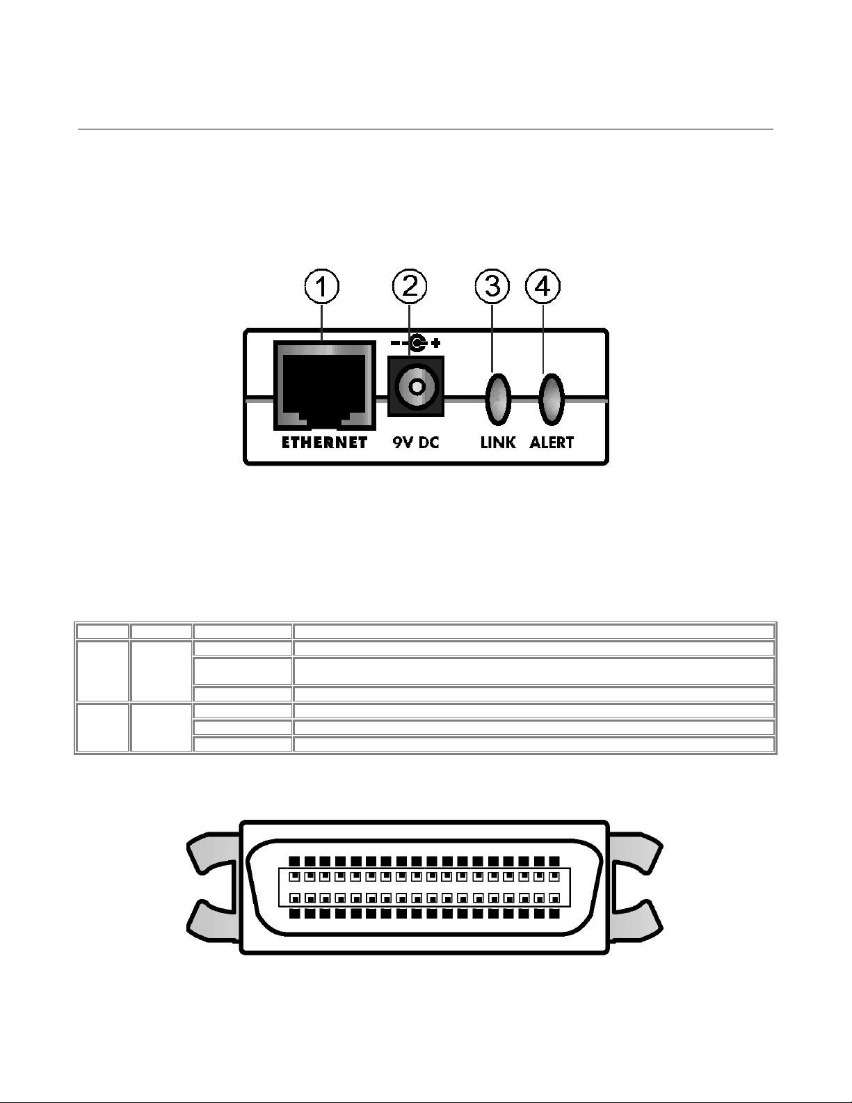
1-2 Outlooks for PS101 Mini Print Servers
The LEDs that indicate the status of the server, and the printing traffic of the Ethernet are located on
the panels of the Model PS101 Mini Print Sever. It has one 10 BASE-T network port. The port
operates in 10 Mbps and in half-duplex mode when connected to a 10/100Mbps Ethernet network. As
illustrated bellow, it has a power adapter receptacle that accepts a 9V 500mA DC power adapter.
1-1 Panel of the Model PS101 Mini Print Sever
Key:
1 = 10 Base-T ETHERNET port
2 = Power adapter receptacle
3 = LINK LED
4 = ALERT LED
There are 2 LEDs on the panel of the Model PS101 Mini Print Sever. See the table bellow:
LED Descriptions
Label
Color
Activity
Description
LINK
Green
Off
No ETHERNET connection
On
Powered ON
Operation is normal without data transmitting or receiving from ETHERNET
Blinking
Operation is normal with data transmitting or receiving from ETHERNET
ALERT
Amber
Off
Operation is normal
On
Hardware error
Blinking
Upgrading BIOS flash ROM
The parallel port of the Model PS101 Mini Print Sever is a standard Centronics 36 type connecter for
printer. The connecter is as illustrated below.
1-2 Centronics 36 connecter of the Model PS101 Mini Print Sever
Page 11

NetGear Print Server Manual
Chapter 2 Installation
This chapter describes the hardware installation and setup of the NETGEAR Model PS101 Mini
Printer Server.
2-1 Preparing the Site
Before you begin installing the print server, prepare the installation site. Make sure the operating
environment meets the physical requirements of the print server, as described below.
2-2 Verifying Package Contents
Your package should contain the following:
• Model PS101 Mini Printer Server
• 9V 500mA DC Power adapter
• PS101 Print Server Resource CD
• PS101 Print Server Installation Guide
• Warranty & Owner Registration Card
• Customer Support Phone Card
Call your reseller or NETGEAR Customer Support in your area if there are any wrong, missing, or
damaged parts. Refer to "Customer Support" section for the location of customer support in your area.
Keep the carton, including the original packing materials. Use them to repack the print server if you
need to return it for repair.
Page 12
NetGear Print Server Manual
2-3 Connecting Devices to the Print Server
The NETGEAR Model PS101 Print Server has a 10 BASE-T Ethernet port, which can be operated on
a 10 and 10/100BASE-T hub or switch in the half-duplex mode.
The network port on the all Print Server Models is configured for Uplink wiring, which means you can
connect the Print Server direct to an Ethernet switch or hub.
Ethernet specifications limit the twisted pair cable (called a twisted pair segment) extended from a
network port to 100 meters in length.
Before applying power on the PS101 Mini Print Server and the printer you would like to use with,
connect the PS101 Mini Print Server to the port of the printer first.
To ensure the functionality working properly, follow the exact order of the procedure below.
1. Connect the PS101 Mini Print Server to the port of the printer
2. Connect the Unshielded Twisted Pair (UTP) cable from your network to print server ETHERNET port.
If you don’t have the network environment, please read the note at the end of the instruction.
3. Connect the power cord to the printer and an AC outlet. Turn on the switch if there is one on the
printer.
4. Connect the 9V DC to the PS101 Mini Print Server and power adapter to an AC outlet.
If you don’t have a network environment, hereunder are the components you may have
to purchase.
1. Network Interface Card (NIC) on all networked workstation PCs. Some of the PCs may have
a built-in NIC. Refer to the PC manual to check out.
2. Ethernet hub or switch. You may use a 10/100 or 10 Mbps only device. They all work.
3. Category 5 (for both 10 and 100Mbps) or 3 (for 10Mbps only) UTP cables for each
connecting device
4. An optional gateway, or router for connecting to Internet.
For the connectivity and setup, please refer to the reference manual for the products, respectively.
Page 13
NetGear Print Server Manual
2-4 Verifying Power
To complete the installation, connect the power adapter first to the power adapter receptacle on the
print server panel and then to the power outlet on the wall. When power has been applied to the print
server:
• On the PS101 Print Sever Model, the green Link LED on connected network port is on.
• On the PS110 and PS113 Print Sever Model, the green Link/Act LED on the connected PRINTER,
PRINTER 1, PRINTER 2, or PRINTER 3 port is on.
• On the PS111W Print Sever Model, the green LAN LED on connected network port is on, and the green
WLAN LED with the NETGEAR MA401 801.11b Wireless PC Card in PC card slot is on.
Make sure the network interface cards installed in the workstations are in working condition and the
software driver has been installed on the cards.
If required, verify the integrity of the print server by resetting it. Turn power to the print server off and
then back on. If this does not help, you can try to load the factory default setting. Please refer to
Chapter 6 under section System Tab for resetting to factory default.
Use the following one of the three options to re-configure the print server: web management in chapter
3, NETGEAR Print Server Setup Wizard in Chapter 4, or Administrative tool for advanced user in
Chapter 6.
If the problem continues and you have completed all the preceding diagnoses, contact NETGEAR
Customer Support. For the telephone number of the representative in your area, refer to Customer
Support section.
To avoid damaging, this device is not certified for used in an enclosure environment.
After using a period of time, it is normal that the PS101 Mini Print Server may get
warm.
Page 14
NetGear Print Server Manual
Chapter 3 Web Management for Print Server
The web browser interface provides an easy way to configure the print server in a TCP/IP network.
You can configure your NETGEAR PS101 Mini Print Server using any web browser such as
Microsoft Internet Explorer or Netscape Navigator.
This chapter contains information about configuring your NETGEAR PS101 Mini Print Server using
the print server's browser interface. Please refer to the next following chapters for setting up your
printing system.
3-1 Configuring Print Server for TCP/IP
Using a web browser to configure
a NETGEAR Print Server requires
both the print server and the host
workstation that the web browser
runs on to be configured for
TCP/IP.
NETGEAR PS101 Print Server is
set with the factory setting for
DHCP environment, which means
if you have a DHCP server (most
recent broad band routers have
provided this feature), PS101 will
get its own IP address settings for
TCP/IP.
To get the IP information for the
print server, you need to install the
Administrative Tools while
installing the print server software.
Please refer to Chapter 4 for
software installation. Run the
NETGEAR Print Server
Administration. See Figure 3-1.
Figure 3-1 Print Server Administration program
Select the PS101 and click on Advance button to open the panel. Refer to Chapter 5, section 5-3 for the
menu Control option and select Device Information. There you will find the IP address for the PS101
Print Server.
You must have Microsoft Windows system to use with PS101 Mini Print Server for the
NEATGEAR Print Server Administrative Tools.
Page 15
NetGear Print Server Manual
3-2 Connecting to the Print Server
In order to configure the print server over the browser interface, your PC workstation must have a web
browser program installed such as Microsoft Internet Explorer or Netscape Navigator. Free browser
programs are available for Windows, Macintosh, or Unix/Linux.
1. Start your Web Browser
2. In the Address box, enter HTTP:// followed by the name or the IP Address of the print server. e.g.
http://192.168.0.21
Alternatively, the IP address of the print server can be found under "Device Information" in the "Control"
menu of the NETGEAR Print Server Administration Program.
If the IP address information is correct, you can usually use the name of the PS101
Mini Print Server for the print server web configuration. The name of the print server
is on the base of the device in the form of PSnnnnnn, where nnnnnn varies on each
PS101.
3. You will then be prompted for the password. If no password has been set, just press ENTER.
4. Use the menu selections listed on the left of the screen to move about.
Note: Remember to save modifications made on any screen by clicking the Save button before
changing to a different screen.
Page 16
NetGear Print Server Manual
3-3 Browser Menu selections and Configuration Screens
This section describes the browser menu selections and corresponding configuration screens.
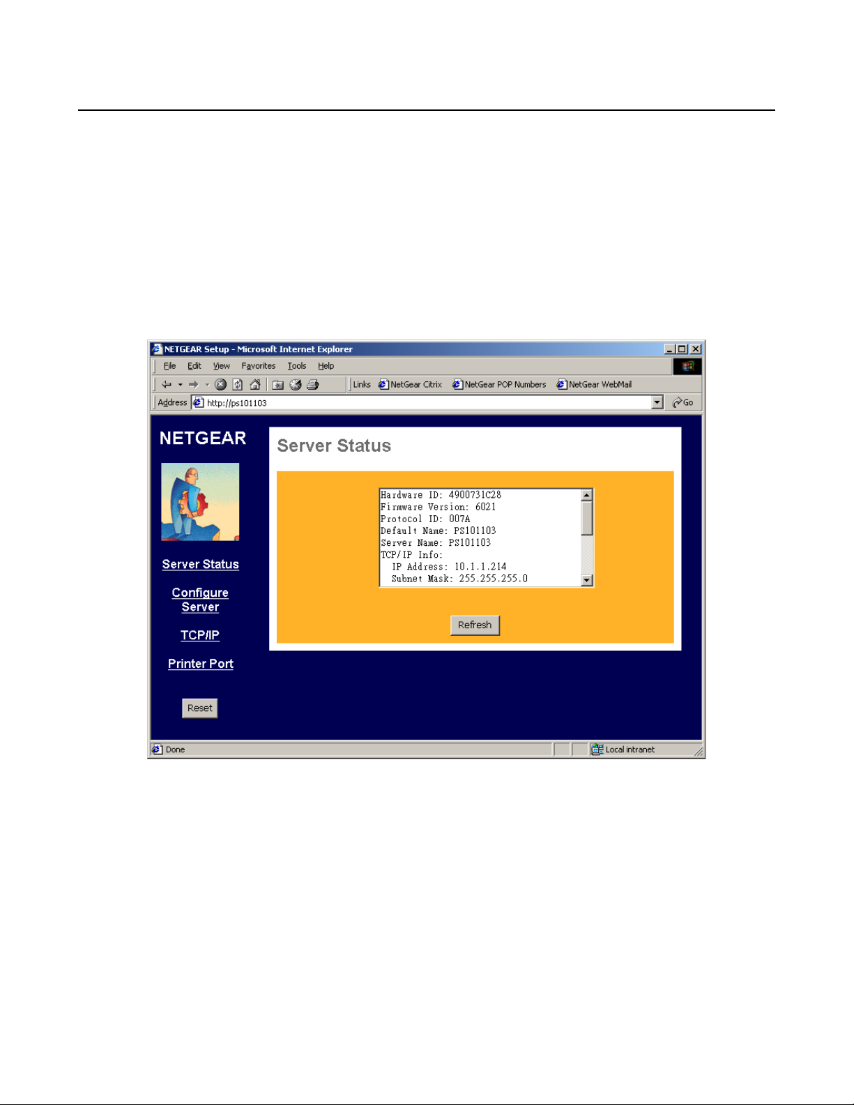
Server Status
The Server Status screen shows print server system data and the current settings for all of the other
screens. It is read-only; no data can be input on this screen. Click the refresh button to refresh
information on this screen. Use the scroll bar to scroll through the display information. Figure 3-2
shows the Server Status Screen.
Figure 3-2 Server Status Screen
Page 17
NetGear Print Server Manual
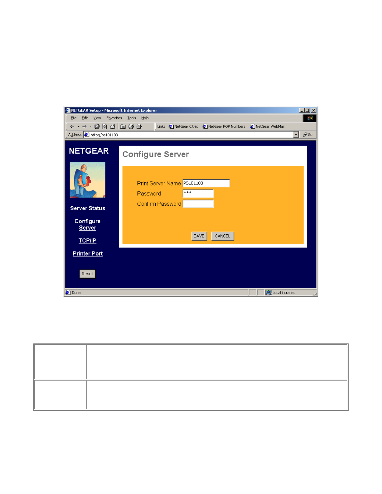
Configure Server
Clicking the Configure Server menu selection brings up the Configure Server screen. The Configure
Server screen contains fields to change the print server name and to enable or disable the various
network protocols supported by the print server. Figure 3-3 and following table show the Configure
Server Screen and describe each of its fields.
Note: Use key Tab on keyboard to move the cursor from field to field besides using the mouse.
Figure 3-3 System Configuration Screen
Configure Server Fields
Print Server Name
Choose a descriptive name for the print server for identification purposes. This name is used in all
protocols to identify the specific print server. There is a factory default name. For any change,
NETGEAR recommends that a name be determined before setting the print server in any network. This
name should be no more than 16 characters with at least a non numerical letter. Spaces are not
allowed, but dashes (-) and underscore marks (_) are accepted.
Password
Confirm Password
Enter the device password, and again in the Confirm Password field. Once a password is entered, it is
required in order to gain access and change the configuration. If you forget the password to the print
server, the only way to reset it is by resetting the device to factory default through the NETGEAR Print
Server Administration Program.
Page 18
NetGear Print Server Manual
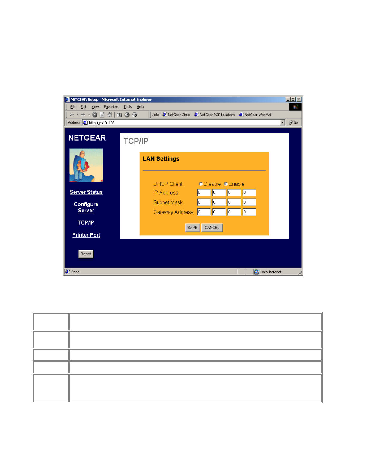
TCP/IP
The TCP/IP configuration screen is used to configure the IP address of the print server. Figure 3-4
shows the TCP/IP configuration screen and following table lists its fields, describes the functions, and
explains how to provide information in each field.
Figure 3-4 TCP/IP Configuration Screen
TCP/IP Configuration Fields
DHCP Client
This field allows you to enable or disable the print server's ability to get its IP address from a DHCP
(Dynamic Host Configuration Protocol) server. When disabled, you can provide a fixed IP address in the
following fields. If DHCP client is enabled, the fields that follow are not used.
IP Address
This IP address is assigned to the print server. If you have a private LAN and do not plan to connect to
the TCP/IP based internet, NETGEAR recommends that you use the address from the IETF-designated
private addresses (for example, 192.168.x.x or 10.x.x.x).
Subnet Mask
This subnet mask defines the range of addresses that are reachable on your local LAN. For example, in
a network with a NETGEAR router, the default subnet mask is usually 255.255.255.0.
Gateway
Address
This is the IP address of the router on your network. For example, in a network with a NETGEAR router,
the gateway address is usually 192.168.0.1.
Save
Cancel
Buttons
Save:
After the configuration, click on ‘Save’ button to save the value permanently to PS101.
Cancel:
If changed something that is not good, click on ‘Cancel’ button will load the value back from PS101. No
modification will be made into PS101.
Page 19
NetGear Print Server Manual
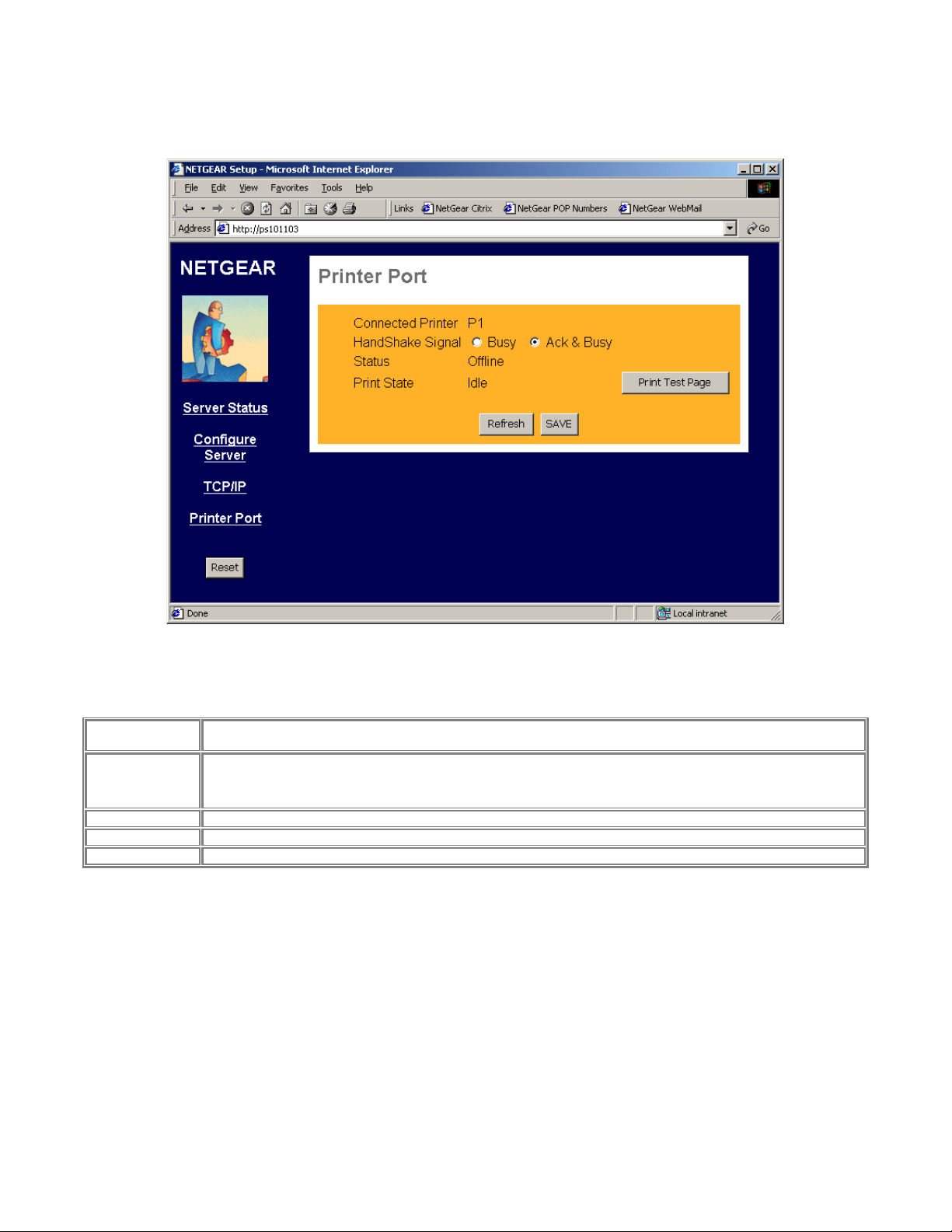
Printer Port
The Printer Port screen provides the status of the printer. See Figure 3-5.
Figure 3-5 Printer Port Screen
Printer Port
Connected
Printer
Shows the descriptive name for the new printer.
HandShake
Signal
This sets one of the communication parameters between this device and the printer.
The default is "Ack & Busy". Only change this to "Busy" if advised to do so by Technical Support.
Status
The current status of the printer (On-line, Off-line, Out of paper)
Print State
This will show either Idle or Printing.
Print Test Page
Click on this button will print the print server status
Page 20
NetGear Print Server Manual
Reset
When you change settings for TCP/IP, you will need to reset the print server.
If the print server is rebooted, any print job in progress will be disrupted.
If DHCP client is enabled, which is the default setting, after system reboots, the IP
address of the unit may be changed. Please use the diagnostic button prints out to
verify the IP address.
Page 21

NetGear Print Server Manual
Chapter 4 Microsoft Windows System Printing
This chapter describes how to configure and use the NETGEAR PS101 Mini Print Sever in a Microsoft
Windows networking environment.
To configure your hardware and software for the Microsoft Windows platform, you may:
• Use a web browser, like Microsoft Internet Explorer or Netscape, to configure your NETGEAR
Print Server. For the use of web browser configuration, please refer to Chapter 3.
• Install NETGEAR Print Server software. Run Setup.exe.
• Configure the user PC to print to the NETGEAR Print Server.
• Install Reference manual in the local machine, so that you don’t have to carry the NETGEAR
PS101 Mini Printer Server Resource CD Rom.
4-1 Printing in Windows
For the printing in your Windows system, you will need to do the following steps.
1. Application hardware connection
including the physical network connection to your PC and print server. Attach the PS101 Mini
Print Server to the printer. DO NOT connect a printer cable to a printer. It is not necessary using a
printer cable with PS101 Mini Print Server. Please refer to Installation Guide for the application
setting in your environment.
2. NETGEAR Print Server Software Installation
will install the essential software for the configuration of the print server. By using NETGEAR
Print Server Setup Wizard you can set up the print server. If you can use Web Configuration, you
may not need to install the software. Please refer to Chapter 3.
3. Setup your PC to recognize the print server and write down the port name
let your PC add a special printer port by using NETGEAR Add Printer Wizard. Before add driver
for the printer, NETGEAR Add Printer Wizard will add the port automatically. You will need the
port name, so please write down the port name when provided to you.
4. Add a printer to your system to print.
Use NETGEAR Add Printer Driver to install the driver for your printer. Note: If you are using
Windows 9x (including 95, 98, and ME), you MUST install this software.
Page 22

NetGear Print Server Manual
4-2 NETGEAR Print Server Software Installation
NETGEAR Print Server software works for PS100 series Print Sever in a Microsoft Windows
networking environment.
To install and set up your network and your print server for the NETGEAR Print Server, you may use
a PC with a Microsoft Windows (95, 98, NT 4.0, ME, 2000, or XP) operating system and with either
the TCP/IP protocol or the NetBEUI protocol enabled.
Turn on the power to your PC.
Before proceeding with these instructions, be sure to assign a name to your
workgroup on your PC. NETGEAR strongly recommends that you exit all Windows
programs before running the Setup program. It is also necessary to install the
NETGEAR Print Server software on every PC in the network that will use the
printers attached to the PS100 series Print Sever.
Insert the CD ROM into the CDROM drive. The program should start automatically. If not, please
double click on setup.exe under the CDROM root directory. The first screen is shown below. Click on
Next button.
Figure 4-1 Print Server Installation
Page 23

NetGear Print Server Manual
The second screen provides you an important message as shown below. Click on Next button.
Figure 4-2 Information
Page 24

NetGear Print Server Manual
As the next graphics, the third screen shows you a couple options.
Figure 4-3 Components
• NETGEAR Print Server Setup Wizard
An easy to use for the configuration of the print server wizard program
• NETGEAR Add Printer Wizard
A step-by-step guide program to configure the printer to print from your Microsoft Windows
You MUST install the NETGEAR Add Printer Wizard so you can use the print server to print
from Windows.
• Administrative Tools
Advance administrative tools including admin and IPSetup
Use admin to manage the print servers on LAN. Use IPSetup to manually assign IP address for
the print servers. Note that the print server default is a DHCP client. If there is a DHCP server,
you do not need to set up IP address. (Normally a home router comes with a DHCP server).
• User Manual – Adobe Acrobat format (PDF)
A user and reference manual that goes the detail as you see now
Page 25
NetGear Print Server Manual
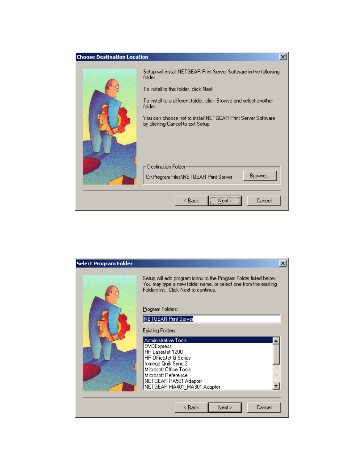
After make the proper selections, click on Next button. You can choose the location of the program.
Figure 4-4 Destination Location
Choose a program folder name. You click on Next button to accept the default name.
Figure 4-5 Program Folder
Page 26

NetGear Print Server Manual
The next screen shows you the progress of the installation.
Figure 4-6
Page 27

NetGear Print Server Manual
Before you finish the installation, you can choose to run the NETGEAR Print Server Setup Wizard and
read the manual. You can uncheck either one or both of the selections and run it at a later time.
Figure 4-7 Complete Screen
There will be a program group created and shown as below.
Figure 4-8 NETGEAR Print Server
You can open and access the group from your desktop as well. See Figure 4-9.
Page 28

NetGear Print Server Manual
4-3 Setting Up Your PC to Recognize the Print Server
You must set up each PC that will print to the print server. Before proceeding, verify that:
• The print server is attached to the printer port on the printer.
• The AC adapter is plugged into the wall socket.
• The Ethernet cable is plugged into the ETHERNET port.
Figure 4-9 NETGEAR Print Server software Icon
Page 29

NetGear Print Server Manual
To set up each PC:
Double-click on the desktop icon, as showing Figure 4-8, that you named the group in the previous
section, Figure 4-5.
Double-click on NETGAER Print Server Setup Wizard in the NETGEAR Print Server window.
The NETGAER Print Server window opens, as illustrated below.
Figure 4-10 NETGEAR Print Server Setup Wizard Window
In this window, you will see whatever network protocols you have installed on the local machine.
You need TCP/IP to use web management. Most nowadays operating systems including Microsoft
Windows 98, ME, 2000, and XP use TCP/IP as the primary networking protocol.
PS101 does not support NetWare IPX/SPX environment.
Older system, like Microsoft Windows 3.1, may support only Netbios protocol as the Microsoft Network.
You must have either TCP/IP or Netbios protocol, or both to use NETGAER PS101 print server.
Page 30
NetGear Print Server Manual
Click on Next.
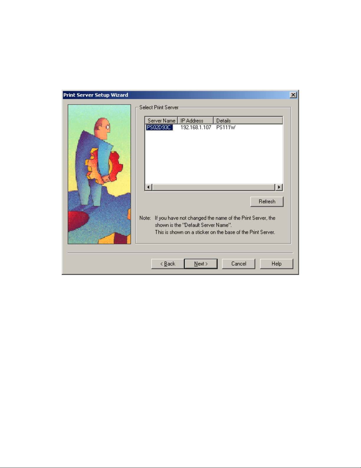
The Printer Server Setup Wizard window shows the current available NETGEAR Print Server on LAN.
Click on Refresh button to see the new added print server. If you still don’t see the one you’d like to see,
wait a minute and click the Refresh button again.
Figure 4-11 Select Print Server
Page 31

NetGear Print Server Manual
Select the PS101 print server and click on Next.
The Printer Server Setup Wizard window shows the current print server Name. The default name is the
Device Name on the base of the unit. Change it to a unique name, or leave it without changing it. See Figure
4-12 Select Name for Print Server.
If your primary network is not Netbios/NetBEUI, you can leave Workgroup Name without a name.
Figure 4-12 Select Name for Print Server
Page 32

NetGear Print Server Manual
Click on Next.
The next Printer Server Setup Wizard window, Figure 4-13, shows TCP/IP setting for the print server.
You can choose to use a dynamic IP address, which is the most common setting, for the print server. Then,
select Obtain IP Address automatically. When select this option, there are two ways to get an IP address
dynamically. The first one is to get an IP address from a DHCP server. If you have and use a home
gateway/router, it usually comes with a DHCP server by default. The print server comes out of the factory
as a DHCP client and can get an IP address automatically. The second way is to use a self-assigned IP
address automatically. This is the same as a Microsoft Windows PC system. It is call Auto-IP.
Auto-IP
When NETGEAR PS101 Print Server is without an IP address due to as a DHCP client and there is no
DHCP server to automatically get an IP address, it will self-assign a unique IP address. The address range is
from 169.254.0.1 to 169.254.254.254 with the subnet mask 255.255.0.0 so that the print server can
communicate and work with other IP devices using the same mechanism.
To get the current IP address for the print server, make sure the printer power is ON, the print cable is
connected to the PS101 print server, and the print server power is ON, press the diagnostic button for two
seconds. The printer will print out the status of the print server, as well as the IP address.
How do I use this feature?
Select Obtain IP Address automatically in Figure 4-13 Set up TCP/IP for Print Server to get an IP address.
You do not use a DHCP server (usually if you don’t share a broadband – DSL, Cable, or satellite
connection, you don’t have one). You are networking with Ethernet (including Fast- and Gigabit-Ethernet)
network. Then you can use this feature. Your Microsoft Windows system uses this feature by itself. You can
click on Start – Run, Enter ‘command’, and click OK. When the command prompt window is popped up,
enter
Ipconfig
You may see the IP address for your system with 169.254.m.n, where m = 0-254 and n=1-254. The range is
from 169.254.0.1 to 169.254.254.254 with the subnet mask 255.255.0.0 too. When you know the IP
addresses for your system and the print server, you can test the connection from your PC to the print server.
In the command prompt window, enter
Ping 169.254.x.y
Where 169.254.x.y is the IP address you get from the print out of the print server. (You should replace x and
y with the IP address numbers in the print-out of the print server.)
You may set up a fixed IP address for the PS101 print server.
Select Fixed IP Address. Please enter the IP address, Subnet mask, and Default gateway accordingly. You
should get these values from your network administrator. If you don’t know what values you should use,
you may use Suggest New Values button. This button is available only when you select Fixed IP Address.
After click the Suggest New Value button, a set of values will be filled in the fields.
Page 33

NetGear Print Server Manual
Figure 4-13 Set up TCP/IP for Print Server to get an IP address
Page 34

NetGear Print Server Manual
Click on Next.
Figure 4-14 Configuration Completed shows the completion of the print server configuration.
Figure 4-14 Configuration completed
Click on Finish.
The PS101 Print Server is ready to be used.
If you have installed NETGAER Add Printer Wizard, you’ll be able to install the printer driver and
configure it. Click No, if you don’t need to add a printer to your system now. You can add a printer at a later
time by opening the NETGEAR Print Server group and running NETGEAR Add Printer Wizard.
Figure 4-15 Add a Printer
Page 35

NetGear Print Server Manual
NETGEAR Add Printer Wizard - Write Down the Port Name
You can reach this setup procedure by answering Yes to the previous Figure 4-15 Information. Or open
NETGEAR Print Server group and run NEYGEAR Add Printer Wizard.
Make sure that the NETGEAR Print Server and the printer that connects to it are both powered on.
Make sure that the cable connections between them are properly connected.
Figure 4-16 Set up printer
Click on OK.
The Printer Select window, as illustrated in See Figure 4-17 Printer Select Window (Add Port), opens.
Figure 4-17 Printer Select Window (Add Port)
If the cables are not properly connected, your PC screen will appear empty when the Printer Select window opens.
If so, check the cable connections and click on the Refresh button, which will initiate the PC to browse again for a
port.
Click on the printer port you want to use with the print server, and click on Add.
The ADDPORT window for Epson print connection, as illustrated in below.
Page 36

NetGear Print Server Manual
ADDPORT Window (Epson Connection)
Click on No if you do not have an Epson Stylus Color printer attached to the port, and continue to step 8.
Or
Click on Yes if you do have an Epson Stylus Color printer (or plan to install one). You must disable the
Epson printer.
To disable:
Click on the Program Files folder on your hard drive.
Start the Epson Spool Manager.
The Queue Setup window opens, as illustrated below. See Figure 4-18 Epson Spool Manager Queue
Setup Window.
Figure 4-18 Epson Spool Manager Queue Setup Window
Select Queue Setup, and click on Use Print Manager for this port.
Click on OK to exit the Queue Setup window.
The ADD PORT window, as illustrated in Figure 4-19 Add Port message, opens. This window informs you
that you have successfully added the port.
Page 37

NetGear Print Server Manual
ADD PORT Window
If this is not an Epson printer, skip the above procedure. The Add Port should be added successfully. See
Figure 4-19 Add Port message.
Figure 4-19 Add Port message
Write Down the Port Name
It is very important to remember and write down the port name. You will need this information later when
prompted to select a printer port. See Figure 4-19 Add Port message. The port name, here for example, is
IP_192.168.1.108_P1. You should write it down in the Quick Installation Guide in the line
Now, write down the printer port name: ___________________________________________________
Page 38

NetGear Print Server Manual
4-4 Add a printer to your system to print
Select Printer Port for Add Printer Wizard
After selected the printer, you need to select a printer port to print. See Figure 4-20 Select Printer Port for
Add Printer Wizard.
Figure 4-20 Select the Printer Port for Add Printer Wizard
Page 39

NetGear Print Server Manual
Use the printer port name written at the last section. Scroll down and find the printer port name. For
example, the printer port name here is ‘IP_192.168.1.108_P1’. See Figure 4-21 Find and select the printer
port. For Windows 95, and 98 users, this window will show up after Add Printer (Figure 4-22 thereafter).
Figure 4-21 Find and select the printer port
Click on Next
Add Printer Wizard, Figure 4-22 Add Printer Wizard window, shows. Choose the manufacturer and the
model name of the printer. If there is a CD provided with the printer, insert the CD and click on ‘Have
Disk…’ button. Follow the instruction on screen to install the correct driver.
Page 40

NetGear Print Server Manual
Figure 4-22 Add Printer Wizard
Click on Next
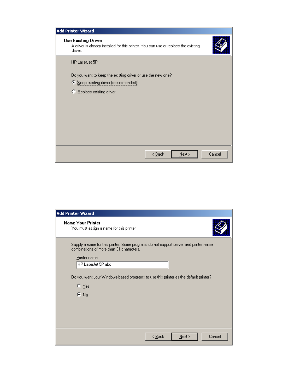
If you have ever installed the printer driver in the system, Figure 4-23 Use Existing Driver window shows.
You can choose to keep the existing driver, or replace it. If you don’t see Figure 4-23, go to the next step.
Page 41
NetGear Print Server Manual
Figure 4-23 Use Existing Driver for Add Printer Wizard
Click on Next
Name the printer. See Figure 4-24 Name Your Printer for Add Printer Wizard. If there are more than one
printer drivers installed in the system, you may answer Yes to choose this as your default printer for your
Windows-based programs.
Page 42

NetGear Print Server Manual
Figure 4-24 Name Your Printer for Add Printer Wizard
Click on Next
See Figure 4-25 Printer Sharing. When you use print server for the printer, you don’t usually need to share
the printer on the local machine. Keep the default answer as Do not share this printer.
Figure 4-25 Share Printer for Add Printer Wizard
Click on Next
You can try to print a test page to the printer after your printer installed properly. See Figure 4-26 Print Test
Page. It is OK not to print a test page in answering question Do you want to print a test page to No.
Page 43

NetGear Print Server Manual
Figure 4-26 Print Test Page for Add Printer Wizard
Click on Next
If you answer Yes to print a test page, see Figure 4-27.
Figure 4-27 Printer print the test page
Click on OK
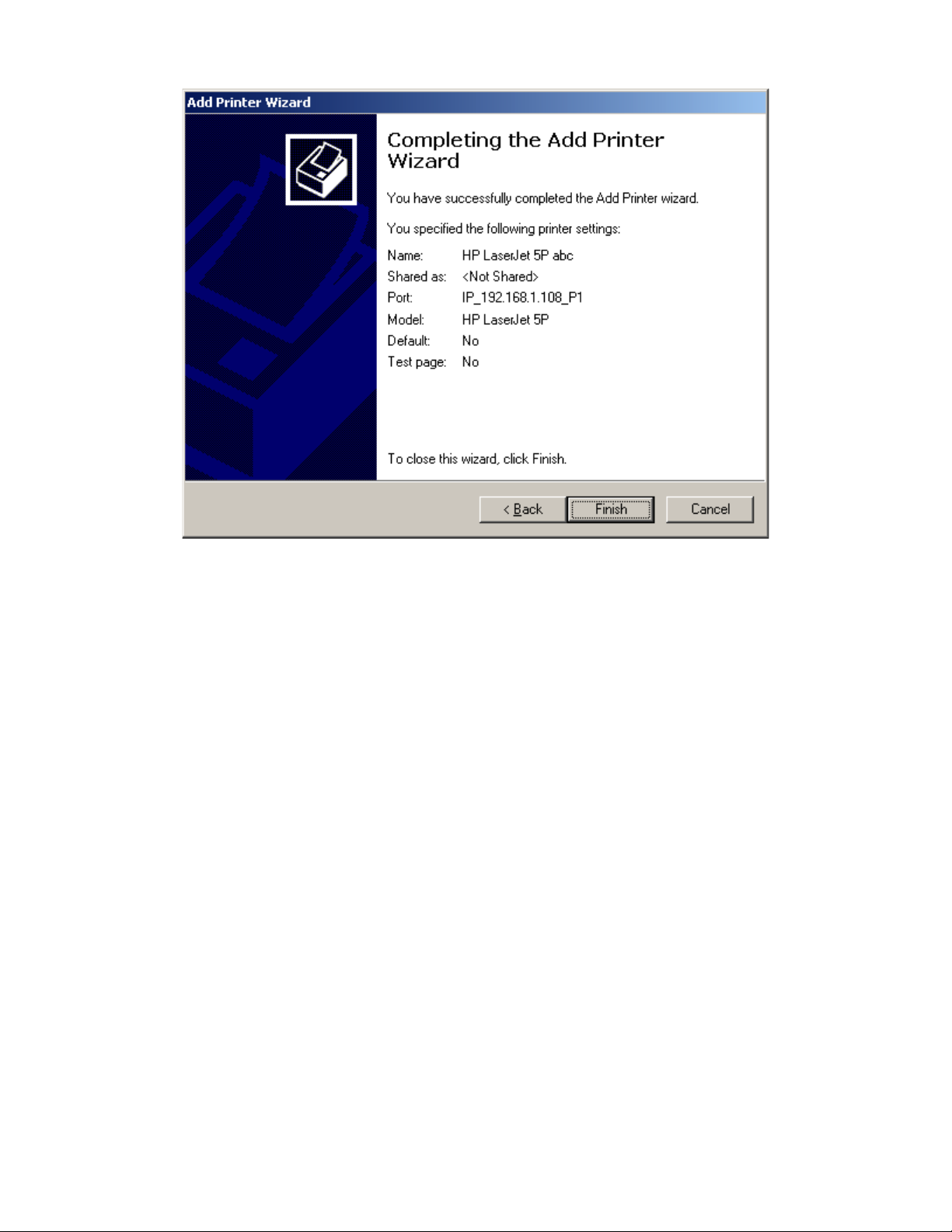
Complete the Add Printer Wizard. See Figure 4-28 Completing the Add Printer Wizard.
Page 44
NetGear Print Server Manual
Figure 4-28 Completing the Add Printer Wizard
Click on Finish
Now you can print through the PS101 print server. The Figure 4-17 Printer Select Window (Add Port)
window remains on the screen. Click on End to close it.
Page 45

NetGear Print Server Manual
Chapter 5 Using Advanced Management Tools
This chapter describes in more detail the two print server management programs bundled with
NETGEAR PS100 series print servers. These programs are included on the Print Server Resource CD.
The two programs are for advanced users and described in this chapter are:
• NETGEAR Print Server Administration Program
This software program is a print server administration program based on Windows 95,
Windows 98, Windows NT, Windows XP, or Windows 2000. It runs on TCP/IP and Netbios
protocols that the print server supports.
• IPSetup
This program is to setup the IP address of the Print Server manually from Microsoft Windows.
Use this handy tool to set up the IP address for the print server when there are troubles to get IP
information from the print server.
5-1 Configuration Using the NETGEAR Print Server Administration
Program
Before you begin this section, you must first install the NETGEAR Print Server software on your PC,
using the supplied CD-ROM.
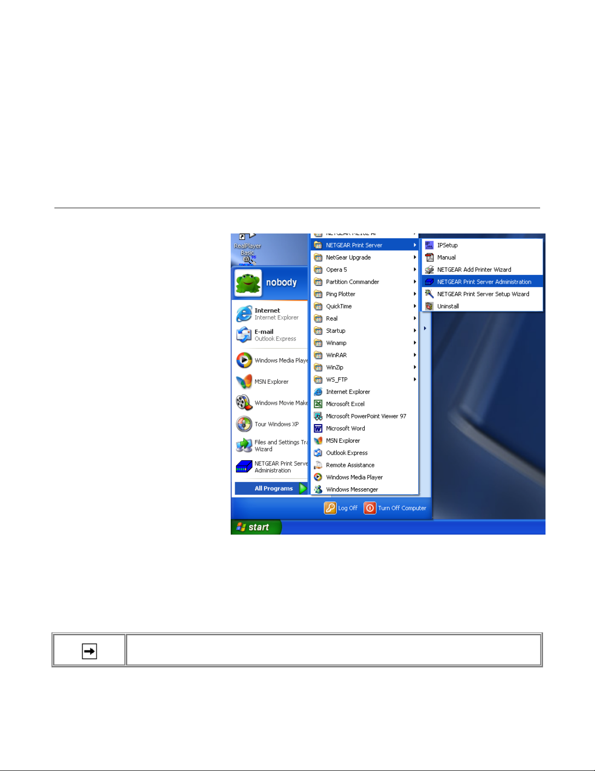
To start the NetGear Administration Program:
• Click on Start
• Move along the program folders to highlight the NetGear program folder
• Click on the icon for the Print Server Administration program
As illustrated below, the main screen of the NetGear print server setup utility opens and searches the
network for NETGEAR print servers.
NETGEAR Print Server Administration Program
All active NETGEAR print servers are listed on the screen as shown. If there is any print server
missing from the screen, you may click on the Browse button to scan the network one more time. By
Page 46

NetGear Print Server Manual
default, the NetGear Administration Program only browses the network with NetBEUI to minimize
unnecessary packets on the network.
If you still do not see all the print servers, the print server that you are trying to configure might have
the default NetBEUI protocol disabled. If the protocol is disabled, click on the Protocol button to
enable browsing with IPX/SPX and TCP/IP. Make sure that the IPX/SPX and TCP/IP protocols are
also enabled and bound to the network adapter card in your Windows 95, Windows 98, Windows NT,
Windows XP, or Windows 2000 system.
Buttons
Advanced Button
Click on the Advanced button for detailed full configuration of the selected Print Server. See the later
section 5-2 Advanced Print Server Configuration for more information about the
Advanced option.
Quick Button
Click on the Quick button to open the Quick Setup Screen to perform a quick configuration of the print
server in a Microsoft network running the NetBEUI protocol.
Clicking the Quick Setup button will reveal a screen like the following.
Quick Setup Screen
Enter the required Device Name, and click "OK". The Device Name is how users on the network will
see this Print Server on the network.
Protocol Button
This screen allows you to disable protocols that are not used on your network. An example screen is
shown below.
Page 47

NetGear Print Server Manual
Protocol Screen
The protocol currently used for communication between your PC and the Print Server is Enabled and
grayed out, so it cannot be disabled.
Browse Button
Use this button to re-scan the network and update icons for any Print Servers located.
Exit Button.
The Exit button ends the NetGear setup utility.
Page 48

NetGear Print Server Manual
5-2 Advanced Print Server Configuration
From the main menu, click on the Advanced button to use the advanced configuration procedure. The
Advanced Print Server Configuration screen opens. The Advanced Print Server Configuration screen
contains the fields listed on tabs that can be selected in any order to customize the configuration of the
print server. The following field tabs are provided by the Advanced Print Server Configuration screen:
• System
• TCP/IP
• Logical Port
• Physical Port
Each tab is described in the following sections.
There are two control buttons associated with every tab, and there is a "Return to Main Menu" button
at the bottom of the tab. The function of each button is described in the table bellow.
Control Buttons on All Tabs
Field
Description
Restore to
Default
This button appears on many screens. Clicking it replaces the onscreen values with the default settings. The
tab settings are not saved until you click on the Save to Device button. The quickest way to set all device
values to the factory default setting is to click on the Configuration selection on the menu bar and select
Restore Factory Default.
Save to
Device
Click this button to write any changed configuration information to the print server.
If you switch to another tab without clicking on the Save to Device button, all new settings are lost.
Return to
Main
Menu
Click this button to return to the print server administration main menu. If you want to configure another print
server, you must click on this button to return to the main menu and select another print server.
Any configuration change is lost unless you click on the Save to Device button at the bottom of the
field window to send the configuration to the print server. When moving into a new field screen, all
settings in the previous screen are lost. It is essential that you make a decision on the present field
screen whether to abandon or save the new parameters into the print server.
The menu bars and their fields are described in the following sections.
System Tab
The System tab contains the fields to change the print server name and activate or disable the various
networking protocols supported by the print server.
Page 49

NetGear Print Server Manual
System Tab Window
System Tab Fields
Field
Description
Device
Name
Choose a descriptive name for the router for identification purposes (for example, EngPrsv). This name is
used in all protocols to identify the specific print server. There is a factory default name. For any change,
NETGEAR recommends that a name be determined before setting the print server in any network. This
name should be no more than 16 characters with at least a non numeric letter. Spaces are not allowed, but
dashes (-) and underscore marks (_) are accepted.
TCP/IP
Protocol
Choose to enable or disable the TCP/IP protocol. TCP/IP is used for UNIX networking and Microsoft
networking. The factory default is Enable.
IPX/SPX
Protocol
Choose to enable or disable the IPX/SPX protocol used in the NetWare environment. This selection is
always shadowed to indicate that the IPX/SPX protocol is always active and cannot be disabled.
NetBEUI
Protocol
Choose to enable or disable the NetBEUI protocol. NetBEUI is primarily used in a small-scale Microsoft
networking environment.
TCP/IP Tab
This tab allows configuration for the TCP/IP network protocol.. For further information about TCP/IP,
refer to Chapter
Page 50

NetGear Print Server Manual
TCP/IP Tab Window
TCP/IP Tab Fields
Field
Description
DHCP
This field allows you to enable or disable the print server's ability to get its IP address from a DHCP
(Dynamic Host Configuration Protocol) server. When disabled, you can provide a fixed IP address in the
following fields.
IP Address
This IP address is assigned to the print server. If you have a private LAN and do not plan to connect to the
TCP/IP-based internet, NETGEAR recommends that you use the address from the IETP-designated
private addresses (for example, 192.168.x.x or 10.x.x.x).
Subnet Mask
This subnet mask defines the range of addresses that are reachable on your local LAN.
Gateway
Address
This IP address is what the print server uses for stations with IP addresses not reachable on your local
LAN.
Logical Port Tab
Logical printers (Logical Ports) can be used under Linux or Unix. The Print Server supports 3 Logical
Ports. This screen allows configuration of Logical Ports.
Page 51

NetGear Print Server Manual
Logical Port Tab Window
Logical Port Tab Fields
Field
Description
Current
Selected
Logical Port
Selects the logical port to be configured. Eight logical ports are available for print servers with two printer
ports; three logical ports are available for one printer port print servers.
Physical Port
Selects which physical printer port the logical port is mapped into. Converts LF to LF+CRAdd a carriage
return (CR) every time the line feed (LF) character code is received by the print server when any print data
is sent to this logical port.
String Before
Job
Provides the control character string to send to the printer before the first character of the job is sent to the
printer. One example of such an application would be switching to landscape mode when printing to the
logical port. The character string must be in hexadecimal format as in these examples:
ASCII = [Esc]&l0O
Hexadecimal = 1B266C304F
ASCII = [Esc]&l1O
Hexadecimal = 1B266C314F
String After
Provides the control character string to send to the printer after the last character of the job is sent to the
printer. The character string must be in hexadecimal format as illustrated in the String Before Job example
Page 52

NetGear Print Server Manual
Job
above.
Physical Port Tab
This tab allows you to set the "Handshake Signal" used for communication between the Print Server
Physical Port
Physical Port Tab Fields
Field
Description
Current Selected
Physical Port
Selects the physical port to be configured.
Physical Port Name
If required, you can change the name of the Physical Port.
Handshake Signal
The default setting is "Busy". This should only be changed to "Ack and Busy" if advised to do so by
Technical Support.
5-3 Menu Options
Page 53

NetGear Print Server Manual
The NetGear Administration program contains a menu bar that provides a number of options including
Control, Printer, and Help, which are outlined in the following section.
Control Menu
Control is the first item on the top menu bar is for print server control. Click on the Control selection,
move the cursor down to select one of the menu selections and click again to carry out the intended
action, as described below.
• Device Information
Select this option to pop up a scrolling window providing a status of the various parameters on
the print server that can be customized. This information includes the various NetBEUI and
TCP/IP parameters.
Page 54

NetGear Print Server Manual
Device Information
• Reset Device
Issues a soft reset to reboot the print server. This process allows newly modified print server
parameters to take effect.
• Restore Default Configuration
Changes all print server parameters to their factory default values. If only partial restoration is
intended, use the tab options for the different protocols and choose "Set to Default" from that
particular screen. A confirmation dialog, like the example below, will be shown.
Default Configuration
Click "Yes" to confirm setting to factory defaults, or "No" to leave the current configuration
unchanged.
Printer Menu
Individual printer ports are displayed as options under the Printer Menu, and a pop-up window opens
when any of the printer ports are selected, as in the example below.
Page 55

NetGear Print Server Manual
Printer Status
The printer ports not existing on the print server are shadowed or grayed out.
On the popup window, you can check the connection status of the print server such as on-line, off-line,
paper jam, and out-of-paper. Also on display is the printing information indicating if the print server is
sending data to the printer or if the printer is idling. At the bottom of the screen are four buttons as
described below.
Printer Status
Field
Description
Configure Button
If the connected printer supports directional communication such as many of the new Hewlett-Packard
LaserJet and DeskJet printers, you can click on this button to customize the various printing parameters
of the printer. The pop-up window consists of a table with the following column headings:
Environment Variable
The configuration variables available on this printer. The list of printer configuration variables vary
from printer to printer.
Variable Value
Displays the current setting. To change the Variable Value (if Read Only is NO) double- click the line
you wish to change; then enter or select a new value.
Read Only
Indicates whether or not the Environment Variable is modifiable.
Test page Button
Informs the print server to send a test page to the printer. The printout includes print server status
information, which is useful when troubleshooting any printing problems.
Refresh Button
If you suspect that the printer status is not properly updated on the screen, click this button to generate
packets to collect updated printer information.
Cancel Button
Close this pop-up window.
Help Menu
The Help menu has a single item - About - which will display information about the program, as
shown below.
Page 56

NetGear Print Server Manual
Help - About
Configuring Using IP Setup
IP Setup is a tool to let you configure the IP address for NETGEAR Print Server in Microsoft
Windows environment. Please see Appendix E for IPSetup utility reference.
With IPSetup tool, you can force an IP address to a NETGEAR Print Server. It sets up the subnet mask
and default gateway as well as disables the DHCP. In this way, you can always get a known and fixed
IP address.
Page 57

NetGear Print Server Manual
Appendix A Technical Specifications
This appendix provides technical specifications for the NETGEAR Model PS101 Print Server.
General Specifications
Network Protocol and Standards Compatibility
IEEE 802.3i 10BASE-T CSMA/CD
NetBEUI and TCP/IP protocols
Data Rate
10 Mbps differential Manchester encoded
Interface
PS101 Print Server: One 10BASE-T network port (RJ-45)
Power Specifications for the Power Adapter
Input voltage: 100 to 240 V AC, 50 to 60 Hz, according to the power adapter
Localized plug: For North America, Japan, UK, Europe, and Australia
Output voltage: 9 V DC at 500 mA
Power Specifications for the Print Server
Power consumption: 4.5 W maximum
Input voltage: 9 V DC at 0.5 Amps, maximum
Physical Specifications
Width 1.3 in. (6.2 cm)
Height 0.8 in. (2.0 cm)
Depth 2.3 in. (6.0 cm)
Weight 0.4 lb. (0.1 kg)
Environmental Specifications
Operating temperature: 0
°
to 40
°
C (32
°
to 104
°
F)
Operating humidity: 90% maximum relative humidity, noncondensing
Electromagnetic Emissions
Meets requirements of: CE mark, commercial
FCC Part 15, Class A
EN 55 022 (CISPR 22), Class B
VCCI Class B ITE
Safety Agency Approvals, Power Adapter
Meets requirements of: CE mark, commercial
Page 58

NetGear Print Server Manual
UL listed (UL 1950)
CSA certified (CSA 22.2 #950)
TUV licensed (EN 60 950)
T-Mark
Page 59

NetGear Print Server Manual
Appendix B Understanding IP Addresses
This appendix provides information about understanding IP addresses, which you must
assign to the NETGEAR PS100 series Print Sever when operating in
a TCP/IP environment.
IP Addresses and the Internet
Because TCP/IP networks are interconnected widely across the world, every machine on the Internet
must have a unique address to make sure that transmitted data reaches the correct destination. Blocks
of addresses are assigned to organizations by the Internet Assigned Numbers Authority (IANA).
Individual users and small organizations may obtain their addresses either from the IANA or from an
Internet service provider (ISP).
The Internet Protocol (IP) uses a 32-bit address structure. The address is usually written in dot notation
(also called dotted-decimal notation), in which each group of eight bits is written in decimal form,
separated by decimal points. For example, the binary address:
11000011 00100010 00001100 00000111
is normally written as:
195.34.12.7
which is easier to remember and easier to enter into your computer.
In addition, the 32 bits of the address are subdivided into two parts. The first part of the address
identifies the network, and the second part identifies the host node or station on the network.
The dividing point may vary depending on the address range and the application.
There are five standard classes of IP addresses. These address classes have different ways of
determining the network and host sections of the address, allowing for different numbers of hosts on a
network. Each address type begins with a unique bit pattern, which is used by the TCP/IP software to
identify the address class. After the address class has been determined, the software can correctly
identify the host section of the address. The three main address classes are illustrated below, which
shows the network and host sections of the address for each address type.
Three Main Address Classes
Class A addresses can have up to 16,777,214 hosts on a single network. They use an 8-bit network
number and a 24-bit node number. Class A addresses are in this range:
1.x.x.x to 126.x.x.x.
Class B addresses can have up to 65,354 hosts on a network. Class B addresses use a 16-bit network
number and a 16-bit node number. Class B addresses are in this range:
Page 60

NetGear Print Server Manual
128.1.x.x to 191.254.x.x.
Class C addresses can have 254 hosts on a network. Class C addresses use 24 bits for the network
address and 8 bits for the node. They are in this range:
192.0.1.x to 223.255.254.x.
Class D addresses are used for multicasts (messages sent to many hosts). Class D addresses are in this
range:
224.0.0.0 to 239.255.255.255.
Class E addresses are for experimental use.
This addressing structure allows IP to uniquely identify each physical network and each node on each
physical network.
For each unique value of the network portion of the address, the base address of the range (host
address of all zeros) is known as the network address and is not usually assigned to a host. Also, the
top address of the range (host address of all ones) is not assigned but is used as the broadcast address
for sending a packet simultaneously to all hosts with the same network address.
Netmask
In each of the above address classes, the size of the two parts (network address and host address) is
implied by the class. This partitioning scheme can also be expressed by a netmask associated with the
IP address. A netmask is a 32-bit quantity that, when logically ANDed with an IP address, yields the
network address. For instance, the netmasks for Class A, B, and C addresses are 255.0.0.0,
255.255.0.0, and 255.255.255.0, respectively.
For example, the address 192.168.170.237 is a Class C IP address whose network portion is the upper
24 bits. When ANDed with the Class C netmask, as shown here, only the network portion of the
address remains:
11000000 10101000 10101010 11101101 (192.168.170.237)
ANDed with:
11111111 11111111 11111111 00000000 (255.255.255.0)
Equals:
11000000 10101000 10101010 00000000 (192.168.170.0)
As a shorter alternative to dotted-decimal notation, the netmask may also be expressed in terms of the
number of ones from the left. This number is appended to the IP address, following a backward slash (
/ ), as "/n." In the example, the address could be written as 192.168.170.237/24, indicating that the
netmask is 24 ones followed by 8 zeros.
Page 61

NetGear Print Server Manual
Subnet Addressing
By looking at the addressing structures, you can see that even with a Class C address there are a large
number of hosts per network. Such a structure is an inefficient use of addresses if each end of a routed
link requires a different network number. It is unlikely that the smaller office LANs would have that
many devices. You can resolve this problem by using a technique known as subnet addressing.
Subnet addressing allows us to split one IP network address into smaller multiple physical networks
known as subnetworks. Some of the node numbers are used as a subnet number instead. A Class B
address gives us 16 bits of node numbers translating to 64,000 nodes. Most organizations do not use
64,000 nodes, so there are free bits that can be reassigned. Subnet addressing makes use of those bits
that are free, as illustrated below.
Example of Subnetting a Class B Address
A Class B address can be effectively translated into multiple Class C addresses. For example, the IP
address of 172.16.0.0 is assigned, but node addresses are limited to 255 maximum, allowing 8 extra
bits to use as a subnet address. The IP address of 172.16.97.235 would be interpreted as IP network
address 172.16, subnet number 97, and node number 235. In addition to extending the number of
addresses available, subnet addressing provides other benefits. Subnet addressing allows a network
manager to construct an address scheme for the network by using different subnets for other
geographical locations in the network or for other departments in the organization.
Although the preceding example uses the entire third octet for a subnet address, note that you are not
restricted to octet boundaries in subnetting. To create more network numbers, you need only shift some
bits from the host address to the network address. For instance, to partition a Class C network number
(192.68.135.0) into two, you shift 1 bit from the host address to the network address. The new netmask
(or subnet mask) is 255.255.255.128. The first subnet has network number 192.68.135.0 with hosts
192.68.135.1 to 129.68.135.126, and the second subnet has network number 192.68.135.128 with hosts
192.68.135.129 to 192.68.135.254.
• The number 192.68.135.127 is not assigned because it is the broadcast address of the first subnet. And
192.68.135.128 is not assigned because it is the network address of the second subnet.
The table below lists the additional subnet mask bits in dotted-decimal notation. To use the table, write
down the original class netmask and replace the 0 value octets with the dotted-decimal value of the
additional subnet bits. For instance, to partition your Class C network 204.247.203.0 with subnet mask
255.255.255.0 into 16 subnets (4 bits), the new subnet mask becomes 255.255.255.240.
Netmask Notation Translation Table for One Octet
Number of Bits
Dotted-Decimal Value
1
128
2
192
3
224
4
240
5
248
6
252
7
254
Page 62

NetGear Print Server Manual
8
255
The next table displays several common netmask values in both the dotted-decimal and the masklength
formats.
Netmask Formats
Dotted-Decimal
Masklength
255.0.0.0
/8
255.255.0.0
/16
255.255.255.0
/24
255.255.255.128
/25
255.255.255.192
/26
255.255.255.224
/27
255.255.255.240
/28
255.255.255.248
/29
255.255.255.252
/30
255.255.255.254
/31
255.255.255.255
/32
NETGEAR strongly advises that all hosts on a LAN segment use the same netmask for the following
reasons:
So that hosts recognize local IP broadcast packets
When a device broadcasts to its segment neighbors, it uses a destination address of the local network
address with all ones for the host address. In order for this scheme to work, all devices on the segment must
agree on which bits comprise the host address.
So that a local router or bridge will know which addresses are local and which are remote
Private IP Addresses
If your networks are isolated from the Internet (for example, only between your two branch offices),
you can assign any IP addresses to the hosts without problems. However, the IANA has reserved the
following three blocks of IP addresses specifically for private networks:
10.0.0.0 - 10.255.255.255
172.16.0.0 - 172.31.255.255
192.168.0.0 - 192.168.255.255
NETGEAR recommends that you choose your private network number from this list.
Regardless of your particular situation, do not create an arbitrary IP address; always follow the
guidelines explained here. For more information about address assignment, refer to RFC 1918, Address
Allocation for Private Internets, and RFC 2050, Guidelines for Management of IP Address Space .
Page 63

NetGear Print Server Manual
Address Resolution Protocol
An IP address alone cannot be used to deliver data from one device to another on a LAN. In order for
data to be sent from one device on the LAN to another, you must convert the IP address of the
destination device to its media access control (MAC) address. Each device on an Ethernet network has
a unique Ethernet MAC address, which is a 48-bit number assigned to each device by the
manufacturer. The technique that associates the IP address with a MAC address is known as address
resolution, and IP uses the Address Resolution Protocol (ARP) to do this.
If a device needs to send data to another station on the network and it does not already have the
destination MAC address recorded, ARP is used. An ARP request is broadcast onto the network, and
all stations receive and read the request. The destination IP address for the chosen station is included as
a part of the message so that only the station with this IP address responds to the ARP request and all
other nodes discard it.
The node with the right IP address responds with its own MAC address directly to the sender,
providing the transmitting station with the destination MAC address needed for it to send the data. The
IP address data and MAC address data for each node are held in an ARP table, so that the next time
data needs to be sent, the address can be obtained from the address information in the table.
IP Configuration by DHCP
When an IP-based local area network is installed, each workstation must be configured with an IP
address. If the workstations need to access the Internet, they should also be configured with a gateway
address and one or more DNS server addresses. As an alternative to manual configuration, there is a
method by which each device on the network can obtain this configuration information automatically.
A device on the network may act as a Dynamic Host Configuration Protocol (DHCP) server. The
DHCP server stores a list or pool of IP addresses, along with other information (such as gateway and
DNS addresses) that it may assign to the other devices on the network. The NETGEAR Model
RT328/RH348 router has the capacity to act as a DHCP server.
Page 64

NetGear Print Server Manual
Appendix C IP Setup
This appendix provides a brief overview of IP addressing.
This appendix is intended only when the user has inadvertently disabled the DHCP protocol and/or
assigned a wrong subnet IP address.
The following table describes each setting.
IP Configuration Settings
Setting
Recommended Value
Device Name
Shown on a sticker on the base of the device in the form "PSxxxxxx."
Device IP Address
192.168.0.1
Gateway IP Address
0.0.0.0
Subnet Mask
0.0.0.0.
Clicking on Reset will set all values back to zero, and clicking on OK sets the data entered.
Ensure that the IP address assigned to the device is not already in use.
Following picture is the NETGEAR Print Server IP Address Configuration window.
NETGEAR Print Server IP Address Configuration
Page 65

NetGear Print Server Manual
Appendix D ASCII to Hexadecimal Conversion Table
Hexadecimal Value
ASCII Character
0
NUL
1
SOH
2
STX 3 ETX 4 EOT
5
ENQ
6
ACK
7
BEL 8 BS 9 HT A LF B VT C FF D CR E SO F SI
10
DLE
11
DC1
12
DC2
13
DC3
14
DC4
15
NAK
16
SYN
17
ETB
18
CAN
19
EM
1A
SUB
1B
ESC
1C
FS
1D
GS
1E
RS
1F
US
20
(SPACE)
21 ! 22 " 23 # 24 $ 25 % 26 & 27 ' 28 ( 29 ) 2A * 2B + 2C , 2D - 2E . 2F / 30 0 31
1
Page 66

NetGear Print Server Manual
32 2 33 3 34 4 35 5 36 6 37 7 38 8 39 9 3A : 3B ; 3C < 3D = 3E > 3F ? 40 @ 41 A 42 B 43 C 44 D 45 E 46 F 47 G 48 H 49 I 4A J 4B K 4C L 4D M 4E N 4F O 50 P 51 Q 52 R 53 S 54 T 55 U 56 V 57 W 58 X 59 Y 5A Z 5B [ 5C \ 5D ] 5E ^ 5F _ 60 ` 61 a 62 b 63 c 64 d 65
e
66
f
67 g 68 h 69
I
Page 67

NetGear Print Server Manual
6A j 6B k 6C l 6D m 6E n 6F o 70 p 71 q 72 r 73 s 74 t 75 u 76 v 77 w 78 x 79 y 7A z 7B { 7C | 7D } 7E ~ 7F
 Loading...