

Page 1
Reference Manual for the
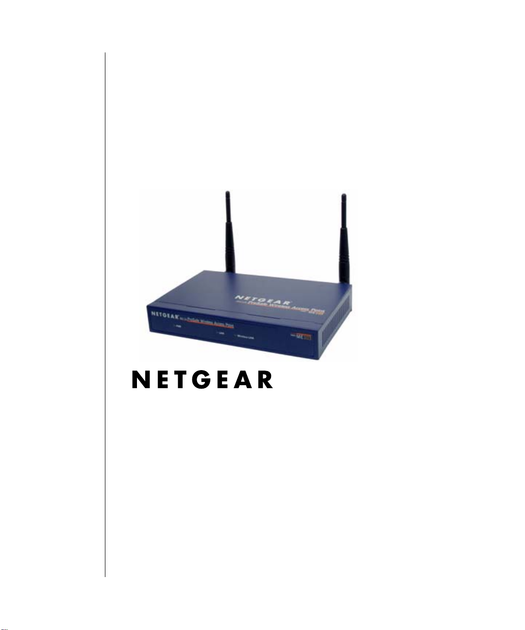
ME103 802.11b ProSafe
Wireless Access Point
NETGEAR, Inc.
4500 Great America Parkway
Santa Clara, CA 95054 USA
Phone 1-888-NETGEAR
August 2003
August 2003
Page 2

NETGEAR, INC.
www.NETGEAR.com
Technical Support
Please register to obtain technical support. Please retain your proof of purchase and warranty
information.
To register your product, get product support or obtain product information and product
documentation, go to http://www.NETGEAR.com
Web, you may register your product by filling out the registration card and mailing it to
NETGEAR customer service.
You will find technical support information at:
http://www.NETGEAR.com/
support by telephone, see the support information card for the correct telephone number for your
country.
© 2003 by NETGEAR, Inc. All rights reserved.
through the customer service area. If you want to contact technical
Trademarks
. If you do not have access to the World Wide
NETGEAR is a registered trademark of NETGEAR, INC. Windows is a registered trademark of Microsoft
Corporation. Other brand and product names are trademarks or registered trademarks of their respective
holders. Information is subject to change without notice. All rights reserved.
Statement of Conditions
In the interest of improving internal design, operational function, and/or reliability, NETGEAR reserves the
right to make changes to the products described in this document without notice. NETGEAR does not
assume any liability that may occur due to the use or application of the product(s) or circuit layout(s)
described herein.
2
August 2003
Page 3
Federal Communications Commission (FCC) Compliance Notice: Radio Frequency Notice
NETGEAR ProSafe Wireless Access Point ME103
Tested to Comply
with FCC Standards
FOR HOME OR OFFICE USE
FCC ID: PY3ME103
Warning!
To co mply with the FCC’s of exposure
requirements you must maintain a
distance of at least 1 cm from the
antenna of this device while it is in use.
This device complies with part 15 of the FCC Rules. Operation is subject to the following two conditions:
1. This device may not cause harmful interference.
2. This device must accept any interference received, including interference that may cause undesired
operation.
Note: This equipment has been tested and found to comply with the limits for a Class B digital device,
pursuant to part 15 of the FCC Rules. These limits are desig ned to provi de reasonable protection
against harmful interference in a residential installation. This equipment generates, uses, and can
radiate radio frequency energy and, if not installed and used in accordance with the instructions,
may cause harmful interference to radio communications. However, there is no guarantee that
interference will not occur in a particular installation. If this equipment does cause harmful
interference to radio or television reception, which can be determined by turning the equipment off
and on, the user is encouraged to try to correct the interference by one or more of the following
measures:
• Reorient or relocate the receiving antenna
• Increase the separation between the equipment and receiver
• Connect the equipment into an outlet on a circuit different from that to which the receiver is
connected
• Consult the dealer or an experienced radio/TV technician for help.
RF Exposure Requirements
WARNING! To ensure compliance with FCC RF exposure requirements, the antenna used for this device
must be installed to provide a separation distance of at least 20 cm (8 in) from all persons and must not be
co-located or operating in conjunction with any other antenna or radio transmitter. Installers and end-users
must follow the installation instructions provided in this user guide.
August 2003
3
Page 4

Radio Frequency Interference Requirements
This device is restricted to indoor use due to its operation in the 2.4 GHz frequency range. FCC requires this
product to be used indoors in 2.4 GHz the frequency range to reduce the potential for harmful interference to
co-channel Mobile Satellite systems.
Regulatory Compliance Information
This device is restricted to indoor use due to reduce the potential for harmful interference to co-channel
Mobile Satellite and Radar Systems.
Canadian Department of Communications Compliance Statement
This Class B Digital apparatus (ME103 802.11b ProSafe Wireless Access Point) meets all the
requirements of the Canadian Interference Causing Equipment Regulations.
Cet appareil numerique del la classe B respect les exigences du Regalement sur le material broilleur du
Canada.
This device comples with Class B limits of Industry of Canada. Operation is subject to the following two
conditions:
1. This device may not cause harmful interference.
2. This device must accept any interference received, including interference that may cause undesired
operation.
The device is certified to the requirements of RSS-139-1 and RSS-210 for 2.4 GHz spread spectrum devices.
The use of this device in a system operating either partially or completely outdoors may require the user to
obtain a license for the system according to the Canadian regulations. For further information, contact your
local Industry Canada office.
EN 55 022 Declaration of Conformance
This is to certify that the ME103 802.11b ProSafe Wireless Access Point is shielded against the generation
of radio interference in accordance with the application of Council Directive 89/336/EEC, Article 4a.
Conformity is declared by the application of EN 55 022 Class B (CISPR 22).
4
August 2003
Page 5
CE Declaration of Conformity
For the following equipment: ME103 802.11b ProSafe Wireless Access Point
0470 !
is herewith confirmed to comply with the requirements set out in the Council Directive on the
Approximation of the Laws of the Member States relating to Electromagnetic Compatibility (89/336/EEC ),
Low-voltage Directive (73/23/EEC) and the Amendment Directive (93/68/EEC), the procedures given in
European Council Directive 99/5/EC and 89/3360EEC. The equipment was passed. The test was performed
according to the following European standards:
• EN 301489-1 V1.2.1 (2000-08)
• EN 301 489-17 V1.1.1 (2000-09)
• EN 55022: 1988 Class B
• EN 61000-3-2: 2000
• EN 6100-3-3: 1995
• EN 55024: 1998 (IEC 61000-4-5:1995, IEC 61000-4-3:1995, IEC 61000-4-4;1995, IEC 61000-4-5:1995, IEC
61000-4-6:1996, IEC 61000-4-8:1993, IEC 61000-4-11:1994)
The test was carried out on February 19, 2003 at Sporton International Inc. Lab.
August 2003
5
Page 6

6
August 2003
Page 7

Contents
Chapter 1
About This Manual
Audience ................................... ................ ................ ................. ................ ................ .....1-v
Scope .............................................................................................................................1-v
Typographical Conventions ...........................................................................................1-vi
Special Message Formats ............................................................................................. 1-vi
How to Use the HTML Version of this Manual .............................................................. 1-vii
How to Print this Manual ...............................................................................................1-viii
Chapter 2
Introduction
About the ME103 802.11b ProSafe Wireless Access Point ...........................................2-1
Key Features ..................................................................................................................2-2
802.11b Standards-based Wireless Networking ......................................................2-3
Autosensing Ethernet Connections with Auto Uplink ...............................................2-4
Compatible and Related NETGEAR Products .........................................................2-4
System Requirements ....................................................................................................2-5
What’s In the Box? .........................................................................................................2-5
Hardware Description .....................................................................................................2-5
ME103 Wireless Access Point Front Panel ..............................................................2-6
ME103 Wireless Access Point Rear Panel ..............................................................2-7
Left Side Primary and Right Side Secondary Detachable Antenna ...................2-7
Restore to Factory Defaults Button ....................................................................2-7
RJ-45 Ethernet Port ...........................................................................................2-7
Power Socket ....................................................................................................2-7
Chapter 3
Basic Installation and Configuration
Observing Placement and Range Guidelines ..................... ................ ................ ............3-1
Cabling Requirements ..............................................................................................3-2
Default Factory Settings ...........................................................................................3-3
Understanding ME103 Wireless Security Options .................................. ........................3-4
Installing the ME103 802.11b ProSafe Wireless Access Point .......................................3-5
Contents iii
August 2003
Page 8

How to Log In to the ME103 Using Its Default NetBIOS Name ......................................3-8
How to Log In to the ME103 Using Its Default IP Address ...........................................3-10
Understanding Basic Wireless Settings .............................. .......................... ................3-11
Understanding Basic Wireless Security Options ..........................................................3-12
Information to Gather Before Changing Basic Wireless Settings ...........................3-14
How to Set Up and Test Basic Wireless Connectivity ............................................3-15
How to Restrict Wireless Access by MAC Address ...............................................3-16
How to Configure WEP ..........................................................................................3-17
Using the Basic IP Settings Options .............................................................................3-18
Chapter 4
Maintenance
Viewing General, Log, Station, and Statistical Information .............................................4-1
Statistics ................................................................. .................................................. 4-3
Activity Log ... ... ... ... ... .... ... ... ... .... ... ....................................... ... ... ... .... ... ... ... ... ............4-5
Viewing a List of Attached Devices .................................................................................4-6
Upgrading the Wireless Access Point Software .............................................................4-7
Configuration File Management ............... .... ..................................................................4-8
Saving and Retrieving the Configuration ..................................................................4-9
Restoring the ME103 to the Factory Default Settings .. ... .... ... ... ... .... ... ... ... ... ............4-9
Using the Reset Button to Restore Factory Default Settings ...................................4-9
Changing the Administrator Password ......................... ....................................... ... 4-10
Chapter 5
Advanced Configuration
Configuring Advanced Security 802.1x Options .............................................................5-1
Basic Requirements for 802.1x ................................................................................5-1
How to Configure the 802.1x Key Exchange Option ................................................5-2
Understanding Advanced Wireless Settings ..................................................................5-8
Configuring Wireless Operating Modes ........................... ............................................. 5-10
How to Configure a ME103 as a Point-to-Point Bridge ..........................................5-10
How to Configure Multi-Point Wireless Bridging ....................................................5-11
Antenna Installation .. ... ... .... ... ... ... .... ... ... ... .......................................... .... ... ... ................5-13
Blank Configuration Worksheet .......................... ... ... .... ... ... ... .... ... ... .............................5-14
Chapter 6
Troubleshooting
No lights are lit on the access point. ...................................... ......................................... 6-1
iv Contents
August 2003
Page 9

The Wireless LAN activity light does not light up. ...........................................................6-2
The LAN light is not lit. ....................................................................................................6-2
I cannot access the Internet or the LAN with a wireless capable computer. .................6-2
I am using EAP-TLS security but get disconnected. ......................................................6-3
I cannot connect to the ME103 to configure it. ............. ... ... ... .... ... ... ... .... ... ... ..................6-3
When I enter a URL or IP address I get a timeout error. ................. ... .... ... ... ... ... .... ... ... ..6-3
Using the Reset Button to Restore Factory Default Settings . .... ... ... ... .... ... ... ... ... .... ... ... ..6-4
Appendix A
Specifications
Specifications for the ME103 ......................................................................................... A-1
Appendix B
Wireless Networking Basics
Wireless Networking Overview .............................. ... .... ... ... ... .... ... ... .............................. B-1
Infrastructure Mode ................................................................................................. B-1
Ad Hoc Mode (Peer-to-Peer Workgroup) ............................... ... ... .... ... ... ... ... .... ... ... . B-2
Network Name: Extended Service Set Identification (ESSID) ................................ B-2
Authentication, WEP, and WPA ..................................................................................... B-2
802.11 Authentication .............................................................................................. B-3
Open System Authentication .............................. .... ... ... ... .... ... ... ... .... ....................... B-3
Shared Key Authentication ...................................................................................... B-4
Overview of WEP Parameters ................................................................................ B-5
Key Size .................................................................................................................. B-6
WEP Configuration Options ................... ... ... ... ... .... .......................................... ... ... . B-7
Wireless Channels ....................... .... ... ... ... ..................................................................... B-7
Understanding 802.1x Port Based Network Access Control ......................................... B-9
Appendix C
Network, Routing, Firewall, and Cabling Basics
Basic Router Concepts .................................................................................................. B-1
What is a Router? ................................................................................................... B-2
IP Addresses and the Internet .. ... .... ... ... ... .... ................................................................. B-2
Netmask .................................... ................................................................ ..............B-4
Subnet Addressing .................................................................................................. B-4
Private IP Addresses ................................. ... ... ... ....................................... ... .... ... ... . B-7
Single IP Address Operation Using NAT ................................................................. B-7
IP Configuration by DHCP ........................ ... ... ... .... ... ... ... .... ... ... ... ........................... B-8
Contents v
August 2003
Page 10

Domain Name Server .............................................................................................. B-9
Routing Protocols .................................................................................................... B-9
RIP ............................... .................... ................... ................... .................... ....... B-9
MAC Addresses and ARP ..... ... ... .... ... ... ......................................................... B-10
Internet Security and Firewalls .................................................................................... B-10
What is a Firewall? .................................................................................................B-11
Stateful Packet Inspection ............................... ... .... ... ... ... .... ... ................................B-11
Denial of Service Attack .........................................................................................B-11
Ethernet Cabling .......................................................................................................... B-12
Uplink Switches, Crossover Cables, and MDI/MDIX Switching ............................ B-12
Cable Quality ......................................................................................................... B-13
Appendix D
Preparing Your PCs for Network Access
Preparing Your Computers for TCP/IP Networking ....................................................... C-1
Configuring Windows 98 and Me for TCP/IP Networking ................... ...........................C-1
Install or V erify Windows Networking Components ................................................. C-1
Enabling DHCP to Automatically Configure TCP/IP Settings ................................. C-3
Selecting Windows’ Internet Access Method .......................................................... C-5
Verifying TCP/IP Properties .................................................................................... C-5
Configuring Windows 2000 or XP for TCP/IP Networking ............................................. C-6
Install or V erify Windows Networking Components ................................................. C-6
DHCP Configuration of TCP/IP in Windows XP ...................................................... C-7
DHCP Configuration of TCP/IP in Windows 2000 .................................................. C-9
Verifying TCP/IP Properties for Windows XP or 2000 ........................................... C-11
Glossary
Index
vi Contents
August 2003
Page 11
Reference Manual for the ME103 802.11b ProSafe Wireless Access Point
Chapter 1
About This Manual
Congratulations on your purchase of the ME103 802.11b ProSafe Wireless Access Point. The
ME103 provides connection for multiple personal computers to the Internet through an external
broadband access device (such as a cable modem or DSL mo dem).
Audience
This reference manual assumes that the reader has basic to intermediate computer and Internet
skills. However, basic computer network, Internet, firewall, and VPN technologies tutorial
information is provided in the Appendices, on the Resource CD for the ME103 ProSafe Wireless
Access Point, and on the Netgear website.
Scope
This manual is written for the ME103 Access Point according to these specifications:
Table 1-1. Manual Specifications
Product Version ME103 802.11b ProSafe Wireless Access Point
Product Final Assembly Number
Firmware Version Number Version 3.0 Release 16
Manual Part Number
Manual Publication Date August 2003
Note: Product updates are available on the NETGEAR web site at
www.netgear.com/support/main.asp. Documentation updates are available on the
NETGEAR, Inc. web site at www.netgear.com/docs.
About This Manual 1-v
August 2003
Page 12
Reference Manual for the ME103 802.11b ProSafe Wireless Access Point
Typographical Conventions
This guide uses the following typographical conventions:
Table 1. Typographical conventions
italics Emphasis.
bold times roman User input.
[Enter] Named keys in text are shown enclosed in square brackets. The notation [Enter]
is used for the Enter key and the Return key.
SMALL CAPS
DOS file and directory names.
Special Message Formats
This guide uses the following formats to highlight special messages:
Note: This format is used to highlight information of importance or special interest.
1-vi About This Manual
August 2003
Page 13
Reference Manual for the ME103 802.11b ProSafe Wireless Access Point
How to Use the HTML Version of this Manual
The HTML version of this manual includes these features.
1
Figure 1-1: HTML version of this manual
1. Left pane. Use the left pane to view the Contents, Index, Search, and Favorites tabs.
To view the HT ML version of the manual, you must have a version 4 or later browser with
Java or JavaScript enabled. To use the Favorites feature, your browser must be set to accept
cookies. You can record a list of favorite pages in the manual for easy later retrieval.
2
3
2. Toolbar buttons. Use the toolbar buttons across the top to navigate, print pages, and more .
–The Show in Contents button locates the currently displayed topic in the Contents tab.
– Previous/Next buttons display the topic that precedes or follows the current topic.
–The PDF button links to a PDF version of the full manual.
–The E-mail button enables you to send feedback by e-mail to Netgear support.
–The Print button prints the currently displayed topic. Using this button when a
step-by-step procedure is displayed will send the entire procedure to your printer--you do
not have to worry about specifying the correct range of pages.
–The Bookmark button bookmarks the currently displayed page in your browser.
3. Right pane. Use the right pane to view the contents of the manual. Also, each page of the
manual includes a “PDF of This Chapter” link at the top right which links to a PDF file
containing just the currently selected chapter of the manual.
About This Manual 1-vii
August 2003
Page 14

Reference Manual for the ME103 802.11b ProSafe Wireless Access Point
How to Print this Manual
To print this manual you man choose one of the following several options, according to your
needs.
• A “How To” Sequence of Steps in the HTML View. Use the Print button on the upper right
of the toolbar to print the currently displayed topic. Using this button when a step-by-step
procedure is displayed will send the entire procedure to your printer--you do not have to worry
about specifying the correct range of pages.
• A Chapter. Use the “PDF of This Chapter” link at the top right of any page.
– Click “PDF of This Chapter” link at the top right of any page in the chapter you want to
print. A new browser window opens showing the PDF version of the chapter you were
viewing.
– Click the print icon in the upper left of the window.
– Tip: If your printer supports printing two pages on a single sheet of paper, you can save
paper an printer ink by selecting this feature.
• The Full Manual. Use the PDF button in the toolbar at the top right of the browser window.
– Click PDF button. A new b rowser wi ndo w op en s sh owing the PDF v ersion o f the chapter
you were viewing.
– Click the print icon in the upper left of the window.
– Tip: If your printer supports printing two pages on a single sheet of paper, you can save
paper an printer ink by selecting this feature.
1-viii About This Manual
August 2003
Page 15

Chapter 2
Introduction
This chapter introduces the NETGEAR ME103 802.11b ProSafe Wireless Access Point. Minimal
prerequisites for installation are presented in “System Requirements” on page 2-5.
About the ME103 802.11b ProSafe Wireless Access Point
The ME103 802.11b ProSafe Wireless Access Point is the basic building block of a wireless LAN
infrastructure. It provides connectivity between Ethernet wired networks and radio-equipped
wireless notebook systems, desktop systems, print servers, and other devices.
The ME103 provides wireless connectivity to multiple wireless network devices within a fixed
range or area of coverage, interacting with a wireless network interface card (NIC) via an antenna.
T ypically, an individual in-building access point provides a maximum connectivity area with about
a 300 foot radius. The ME103 802.11b ProSafe Wireless Access Point can support a small group
of users in a range of several hundred feet. Most access points are rated between 30-70 users
simultaneously.
The ME103 802.11b ProSafe Wireless Access Point acts as a bridge between the wired LAN and
wireless clients. Connecting multiple ME103 Access Points via a wired Ethernet backbone can
further lengthen the wireless network coverage. As a mobile computing device moves out of the
range of one access point, it moves into the range of another. As a result, wireless clients can freely
roam from one Access Point to another and still maintain seamless connection to the network.
The auto-sensing capability of the ME103 802.11b ProSafe Wireless Access Point allows packet
transmission at up to 11Mbps, or at reduced speeds to compensate for distance or electromagnetic
noise interference.
Introduction 2-1
August 2003
Page 16

Reference Manual for the ME103 802.11b ProSafe Wireless Access Point
Key Features
The ME103 Access Point is easy-to-use and provides solid wireless and networking support.
Supported Standards and Conventions
The following standards and conventions are supported:
• Standards Compliant. The Wireless Access Point complies with the IEEE 802.11b (DSSS)
and IEEE 802.1x specifications for Wireless LANs.
• 802.1x Support. Support for 802.1x mode is included, providing for the industrial-strength
wireless security of 802.1x authentication and authorization.
• Radius Client Support. The Wireless Access Point can log in to your existing Radius server
(as a Radius client).
• WEP support. Support for WEP is included. Both 64-bit and 128-bit keys are supported.
• Dynamic WEP key Support. In 802.1x mode, fixed or Dynamic WEP (Wired Equivalent
Privacy) keys can be used. Dynamic key exchange can be used when deploying 802.1x
EAP-TLS.
• DHCP Client Support. DHCP provides a dynamic IP address to PCs and other devices upon
request. The ME103 can act as a client and obtain information from your DHPC server.
• NAT & WINS Support. Support for both NetBIOS broadcast and WINS (Windows Internet
Naming Service) allows the ME103 to easily fit into your existing Windows network.
• SNMP Support. Support for Simple Network Management Protocol (SNMP) Management
Information Base (MIB) management.
Key Features
The NETGEAR ME103 provides solid functionality, including these feat ures:
• Multiple Operating Modes
– Wireless Access Point. Operates as a standard 802.11b or 802.11x Access Point.
– Point-to-Point Bridge. In this mode, the ME103 only communicates with another
bridge-mode wireless station. You must enter the MAC address (physical address) of the
other bridge-mode wireless station in the field provided. WEP should be used to protect
this communication.
– Point-to-Multi-Point Bridge. Select this only if this ME103 is the “Master” for a group
of bridge-mode wireless stations. The other bridge-mode wireless stations must be set to
Point-to-Point Bridge mode, using this ME103's MAC address. They then send all traffic
to this “Master”, rather than communicate directly with each other . WEP should be used to
protect this traffic.
2-2 Introduction
August 2003
Page 17

Reference Manual for the ME103 802.11b ProSafe Wireless Access Point
• Upgradeable Firmware. Firmware is stored in a flash memory and can be upgraded easily,
using only your Web browser, and can be upgraded remotely.
• Access Control. The Access Control MAC address filtering feature can ensure that only
trusted wireless stations can use the ME103 to gain access to your LAN.
• Simple Configuration. If the default settings are unsuitable, they are easy to change.
• Hidden Mode. The SSID is not broadcast, assuring only clients configured with the correct
SSID can connect.
• Configuration Backup. Configuration settings can be backed up to a file and restored.
• Supports Diversity. Dual removable external antennas support diversity.
• Secure and Economical Operation. Adjustable power output allows more secure or
economical operation.
• Automatic Date and Time Updates. Date and time can be automatically updated from
Internet time servers.
• Autosensing Ethernet Connection with
IEEE 802.3 Ethernet networks.
• LED Indicators. Power and wireless activity are easily identified.
Auto Uplink Interface. Connects to 10/100 Mbps
802.11b Standards-based Wireless Networking
The ME103 802.11b ProSafe Wireless Access Point provides a bridge between Ethernet wired
LANs and 802.11b compatible wireless LAN networks. It provides connectivity between Ethernet
wired networks and radio-equipped wireless notebook systems, desktop systems, print servers, and
other devices. Additionally, the ME103 supports the following wireless features:
• Distributed coordinated function (CSMA/CA, Back off procedure, ACK procedure,
retransmission of unacknowledged frames)
• RTS/CTS handshake
• Beacon generation
• Packet fragmentation and reassembly
• Authentication Algorithms (Open System, Shared Key, 802.1x)
• Short or long preamble
• Roaming among access points on the same subnet
Introduction 2-3
August 2003
Page 18

Reference Manual for the ME103 802.11b ProSafe Wireless Access Point
Autosensing Ethernet Connections with Auto Uplink
The ME103 can connect to a standard Ethernet network. The LAN interface is autosensing and
capable of full-duplex or half-duplex operation.
TM
The wireless access point incorporates Auto Uplink
automatically sense whether the Ethernet cable plugged into the port should have a ‘normal’
connection such as to a PC or an ‘uplink’ connection such as to a switch or hub. That port will then
configure itself to the correct configuration. This feature also eliminates any concerns about
crossover cables, as Auto Uplink will accommodate either type of cable to make the right
connection.
technology. The Ethernet port will
Compatible and Related NETGEAR Products
For a list of compatible products from other manufacturers, see the Wireless Ethernet
Compatibility Alliance Web site (WECA, see http://www.wi-fi.net).
The following NETGEAR products work with the ME103 Access Point:
• POE101 Power Over Ethernet Adapter
• WAB501 a/b Dual Band Wireless PC Card Adapter
• MA401 802.11b Wireless PC Card
• WG511 802.11g Wireless CardBus Adapter
• MA111 801.11b Wireless Bridge
• MA101 802.11b Wireless USB Adapter
• ME102 802.11b Wireless Access Point
• MA311 802.11b Wireless PCI Adapter
• MA701 802.11b Wireless Compact Flash Card
System Requirements
Before installing the ME103, make sure your system meets these requirements:
• A 10/100 Mbps Local Area Network device such as a hub or switch
• The Category 5 UTP straight through Ethernet cable with RJ-45 connector included in the
package, or one like it
• A 100-240 V, 50-60 HZ AC power source
• A Web browser for configuration such as Microsoft Internet Explorer 5.0 or above, or
Netscape Navigator 4.78 or above
2-4 Introduction
August 2003
Page 19

Reference Manual for the ME103 802.11b ProSafe Wireless Access Point
• At least one computer with the TCP/IP protocol installed
• 802.11b-compliant devices, such as the NETGEAR MA401 Wireless Adapter
What’s In the Box?
The product package should contain the following items:
• ME103 802.11b ProSafe Wireles s Access Point
• Power adapter and cord (12Vdc, 800mA)
• Straight through Category 5 Ethernet cable
• ME103 802.11b ProSafe Wireles s Acc ess Point Quick Installation Guide
• Resource CD for the ME103 ProSafe Wireless Access Point
Reference Manual for the ME103 802.11b ProSafe Wireless Access Point ( ) -- this manual
• Support Information card
• Warranty and Registration card
Contact your reseller or customer support in your area if there are any wrong, missing, or damaged
parts. You can refer to the Support Information Card for the telephone number of customer support
in your area. You should keep the Support Information card, along with the original pa cking
materials, and use the packing materials to repack the ME103 if you need to return it for repair. To
qualify for product updates and product warranty registrations, we encourage you to register on the
NETGEAR Web site at: http://www.NETGEAR.com.
Hardware Description
The ME103 802.11b ProSafe Wireless Access Point front and rear hardware functions are
described below.
Introduction 2-5
August 2003
Page 20
Reference Manual for the ME103 802.11b ProSafe Wireless Access Point
ME103 Wireless Access Point Front Panel
The ME103 Access Point provides three status LEDs.
802.11b
ProSafe Wireless Access Point
PWR LAN
Wireless LAN
Figure 2-1: ME103 front panel
The following table explains the LED indicators:
MODEL
ME103
LED DESCRIPTION
Power
Power Indicator
No power. If this LED does not come on with the power adapter and cord correctly
Off
installed, see Chapter 4, Troubleshooting.
Power is on.
On
Blink Indicates self test, loading software, or system fault (if continues).
Note: This LED may blink for a minute before going on steady.
LAN Ethernet LAN Link Activity Indicator
Off
Indicates no Ethernet link detected.
Green On
100 Mbps Fast Ethernet link detected, no activity.
Green Blink Indicates data traffic on the 100Mbps Ethernet LAN.
Amber 0n 10 Mbps Ethernet link detected, no activity.
Amber Blink Indicates data traffic on the 10Mbps Ethernet LAN.
Wireless LAN Wireless LAN Link Activity Indicator
Off
Indicates no Ethernet link detected.
Green On
Wireless link enabled, no activity.
Green Blink Wireless link activity.
2-6 Introduction
August 2003
Page 21
Reference Manual for the ME103 802.11b ProSafe Wireless Access Point
ME103 Wireless Access Point Rear Panel
ETHERNET
RESET
5-12V D
C
Figure 2-2: ME103 rear panel
Left Side Primary and Right Side Secondary Detachable Antenna
The ME103 provides two detachable antenna. The one on the left is the primary, and the one on
the right is the secondary. See “Understanding Advanced Wireless Settings” on page 5-8 and
“Antenna Installation” on page 5-13 for important information about configuring and
positioning the antenna to best take advantage of diversity and range capabilities of the ME103.
Restore to Factory Defaults Button
The restore to default button located between the Ethernet RJ-45 connector and the power
socket restores the ME103 to the factory default settings.
RJ-45 Ethernet Port
Use the ME103 Ethernet RJ-45 port to connect to an Ethernet LAN through a device such as a
hub, switch, or router.
Power Socket
This socket connects to the ME103 power adapter.
Introduction 2-7
August 2003
Page 22
Chapter 3
Basic Installation and Configuration
This chapter describes how to set up your ME103 802.11b ProSafe Wi reless Access Point for
wireless connectivity to your LAN. This basic configuration will enable computers with 802.11b
or 802.11g wireless adapters to do such things as connect to the Internet, or access printers and
files on your LAN.
Note: Indoors, computers can connect over 802.11b wireless networks at ranges
of several hundred feet or more. This distance can allow for others outside your area
to access your network. It is important to take appropriate steps to secure your network
from unauthorized access. The ME103 Access Point provides highly effective security
features which are covered in detail in Chapter 3, “Configuring Your Wireless Network.
Deploy the security features appropriate to your needs.
You need to prepare these three things before you can establish a connection through your wireless
access point:
• A location for the ME103 that conforms to the Observing Placement and Range Guidelines
below.
• The wireless access point connected to your LAN through a device such as a hub, switch,
router, or Cable/DSL gateway.
• One or more computers with properly configured 802.11b or 802.11g wireless adapters.
Observing Placement and Range Guidelines
The operating distance or range of your wireless connection can vary significantly bas ed on the
physical placement of the wireless access point. The latency, data throughput performance, and
notebook power consumption of wireless adapters also vary depending on your configuration
choices.
Basic Installation and Configuration 3-1
August 2003
Page 23
Reference Manual for the ME103 802.11b ProSafe Wireless Access Point
Note: Failure to follow these guidelines can result in significant performance
degradation or inability to wirelessly connect to the ME103. For complete performance
specifications, see Appendix A, “Specifications”.
For best results, place your wireless access point:
• Near the center of the area in which your PCs will operate.
• In an elevated location such as a high shelf where the wirelessly connected PCs have
line-of-sight access (even if through walls).
• Away from sources of interference, such as PCs, microwaves, and 2.4 GHz cordless phones.
• Away from large metal surfaces.
• If using multiple access points, it is better if adjacent access points use different
radio frequency
Channels to reduce interference. The recommended Channel spacing between adjacent access
points is 5 Channels (for example, use Channels 1 and 6, or 6 and 11).
The time it takes to establish a wireless connection can vary depending on both your security
settings and placement. WEP connections can take slightly longer to establish. Also, WEP
encryption can consume more battery power on a notebook PC.
Cabling Requirements
The ME103 Access Point connects to your LAN via twisted-pair Category 5 Ethernet cable with
RJ-45 connectors.
Note: The power adapter and cord shipped with the ME103 limits the distance from an
AC outlet. To overcome this, consider using NETGEAR’s POE101 Power Over
Ethernet Adapter with a Cat 5 Ethernet cable like the one included with your ME103.
This adapter sends DC power through an Ethernet cable to enable you to power an
access point in a remote location up to 328 feet away.
Basic Installation and Configuration 3-2
August 2003
Page 24

Reference Manual for the ME103 802.11b ProSafe Wireless Access Point
Default Factory Settings
When you first receive your ME103, the default factory settings will be set as shown below. You
can restore these defaults with the Factory Default Restore switch on the rear panel — see “ME103
Wireless Access Point Rear Panel” on page 2-7.
FEATURE FACTORY DEFAULT SETTINGS
User Name (case sensitive) admin
Password (case sensitive) password
Operating Mode Access Point
Access Point Name NETGEARxxxxxx where xxxxxx are the last six digits of the
wireless access point's MAC address
DHCP DHCP client
IP Configuration
(if DHCP server is unavailable)
Network Name (SSID) NETGEAR
Broadcast Network Name (SSID Enabled
802.11b
Radio Frequency Channel
WEP Disabled
Restricting connectivity based
on MAC Access Control List
WEP Disabled
802.1x Disabled
SNMP Disabled
IP Address: 192.168.0.224
Subnet Mask: 255.255.255.0
Gateway: 0.0.0.0
Primary DNS Server: blank
Secondary DNS Server: blank
11
Disabled
3-3 Basic Installation and Configuration
August 2003
Page 25
Reference Manual for the ME103 802.11b ProSafe Wireless Access Point
Understanding ME103 Wireless Security Options
Unlike wired network data, your wireless data transmissions can be received well beyond your
walls by anyone with a compatible adapter. For this reason, use the security features of your
wireless equipment. The ME103 Access Point provides highly effective security features which
are covered in detail in this chapter. Deploy the security features appropriate to your needs.
Wireless Data
ME103
Security Options
Range: Up to 500 Feet
802.11b
ProSafeWireless AccessPoint
PWR LAN
WirelessLAN
Figure 3-1: ME103 wireless data security options
There are several ways you can enhance the security of your wireless network:
• Restrict Access Based on MAC address. You can restrict access to only trusted PCs so that
unknown PCs cannot wirelessly connect to the ME103. MAC address filtering adds an
obstacle against unwanted access to your network, but the data broadcast over the wireless link
is fully exposed.
• Turn Off the Broadcast of the Wireless Network Name (SSID). If you disable broadcast of
the SSID, only devices that have the correct SSID can connect. This nullifies the wireless
network ‘discovery’ feature of some products such as Windows XP, but the data is still fully
exposed to a determined snoop using specialized test equipment like wireless sniffers.
• Use WEP. Wired Equivalent Privacy (WEP) data encryption provides data security. WEP
Shared Key authentication and WEP data encryption will block all but the most determined
eavesdropper.
• Implement 802.1x. IEEE 802.1x provides very strong security. Although it can use the same
data encryption scheme as WEP, it enables stronger authentication as well as the ability to
dynamically vary the encryption keys.
MODEL
ME103
1) Open System: Easy but no security
2) MAC Access List: No data security
3) WEP: Security but some vulnerabilities
4) 802.1x: Secure
Basic Installation and Configuration 3-4
August 2003
Page 26
Reference Manual for the ME103 802.11b ProSafe Wireless Access Point
Installing the ME103 802.11b ProSafe Wireless Access Point
Before installing the ME103 802.11b ProSafe Wireless Access Point, you should make sure that
your Ethernet network is up and working. You will be connecting the access point to the Ethernet
network so that computers with 802.11b or 802.11g wireless adapters will be able to communicate
with computers on the Ethernet network. In order for this to work correctly, verify that you have
met all of the system requirements, shown on page 2-5.
1SET UP THE ME103 ACCESS POINT
1SET UP THE ME103 ACCESS POINT
Tip: Before mounting the ME103 in a high location, first set up and test the ME103 to verify
wireless network connectivity.
a. Prepare a PC with an Ethernet adapter. If this PC is already part of your network, record its
TCP/IP configuration settings.
b. Configure the PC with a static IP address of 192.168.0.210 and 255.255.255.0 for the
Subnet Mask.
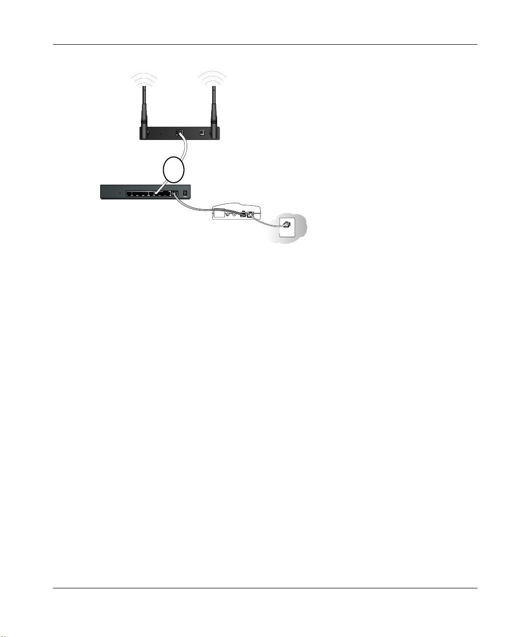
c. Connect an Ethernet cable from the ME103 to the PC (A).
A
ETHERNET
RESET
ME103 802.11b ProSafe
Wireless Access Point
Figure 3-2: Connecting the ME103 to a PC
d.
Turn on your computer, connect the power adapter to the ME103 and verify the following:
– The PWR power light goes on.
– The LAN light of the wireless access point is lit when connected to a powered on PC.
3-5 Basic Installation and Configuration
5-12VDC
August 2003
Page 27

Reference Manual for the ME103 802.11b ProSafe Wireless Access Point
2CONFIGURE LAN AND WIRELESS ACCESS
a. Configure the ME103 Ethernet port for LAN access.
– Connect to the ME103 by opening your browser and entering http://192.168.0.224 in
the address field.
– When prompted, enter admin for the user name and password for the password, both
in lower case letters.
– Click the IP Settings link and configure the IP Settings for your network.
b. Configure the wireless interface for wireless access. See the online help or the
Understanding Basic Wireless Settings topic of the Reference Manual for full instructions.
Note: You must set the Regulatory Domain. It may not be legal to operate the wireless
access point in a region other than one of those identified in this field.
Now that you have finished the setup steps, you are ready to deploy the ME103 in your
network. If needed, you can now reconfigure the PC you used in step 1 back to its original
TCP/IP settings.
3DEPLOY THE ME103 ACCESS POINT
a. Disconnect the ME103 and position it where you will deploy it. The best location is
elevated, such as wall mounted or on the top of a cubicle, at the center of your wireless
coverage area, and within line of sight of all the mobile devices.
Tip: If you plan to locate the ME103 in a location where it is difficult to connect the
electrical power supply , consider using the NETGEAR, Inc. POE101 Power Over Ethernet
Adapter which provides power to the ME103 through the Ethernet cable.
b. Lift the antenna on either side so that they are vertical.
Note: Consult the antenna positioning and wireless mode configuration information in the
Advanced Configuration chapter of the Reference Manual.
Basic Installation and Configuration 3-6
August 2003
Page 28
Reference Manual for the ME103 802.11b ProSafe Wireless Access Point
ME103 802.11b
ProSafe Wireless
Access Point
ETHERNET
RESET
5-12VDC
B
LOCAL
10/100M
876543221INTERNET
Router, Switch, or Hub
Figure 3-3: Connecting the Ethernet cable to a router, hub, or switch
c.
Connect an Ethernet cable from your ME103 Access Point to a LAN port (B) on your
router, switch, or hub.
Note: By default, ME103 is set to be a DHCP client. If your network uses static IP
addresses, you will need to change this setting.
12VDCO.5A
Broadband modem
d. Connect the power adapter to the wireless access point and plug the power adapter in to a
power outlet. The PWR, LAN, and Wireless LAN lights and should light up.
e. Connect the power adapter to the wireless access point and plug the power adapter in to a
power outlet. The PWR, LAN, and Wireless LAN lights and should light up.
4VERIFY WIRELESS CONNECTIVITY
Using a computer with an 802.11b or 802.11g wireless adapter with the correct wireless
settings needed to connect to the ME103 (SSID, WEP, MAC ACL, 802.1x, etc.), verify
connectivity by using a browser such as Netscape or Internet Explorer to browse the Internet,
or check for file and printer access on your network.
Note: If you are unable to connect, see Chapter 6, “Troubleshooting.”
3-7 Basic Installation and Configuration
August 2003
Page 29
Reference Manual for the ME103 802.11b ProSafe Wireless Access Point
How to Log In to the ME103 Using Its Default NetBIOS Name
The ME103 802.11b ProSafe Wireless Access Point can be configured remotely from Microsoft
Internet Explorer browser version 5.0 or above, or Netscape Navigator web browser version 4.78
or above. You can connect to the ME103 by using its default NetBIOS name or its default IP
address. The instructions for connecting using the default NetBIOS name are below. The
instructions for connecting using the default IP address follow this section.
1. Determine the NetBIOS name of your access point.
To find the NetBIOS name, refer to the labels on the bottom of your access point. The access
point NetBIOS name is on the label on the bottom of the unit and looks like
“NETGEAR123456”, where 123456 is the last 6 digits of the access point’s MAC address.
Note: If the computer you are using to connect to the ME103 is on a different subnet, you will
not be able to connect via its NetBIOS name unless there is a WINS server on you LAN.
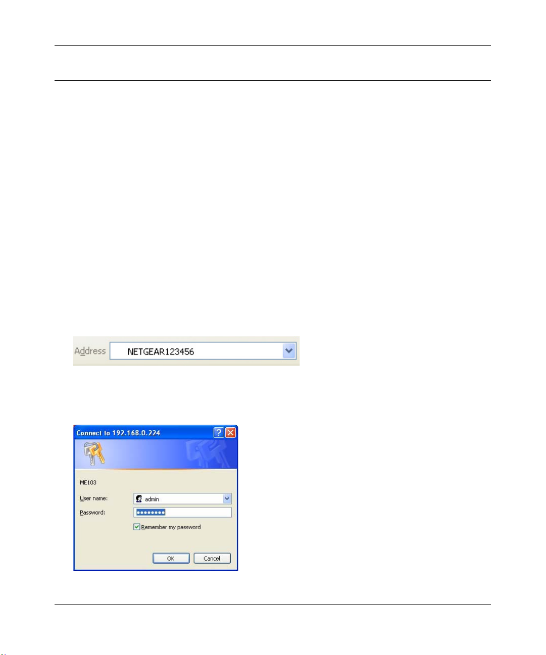
2. Open a Web browser such as Internet Explorer or Netscape Navigator.
3. Log in to the ME103 using the NetBIOS name you found on the bottom of the unit.
In this example, you see NETGEAR123456 in the browser address or location box. There is
no space between “NETGEAR” and the 6 digits of the access point name.You do not need to
include “www” or “http://.”
Figure 3-4: Example ME103 NetBIOS name in browser address bar
4.
A login window like the one shown below opens:
Figure 3-5: Login window
Basic Installation and Configuration 3-8
August 2003
Page 30
Reference Manual for the ME103 802.11b ProSafe Wireless Access Point
Enter the default user name of admin and the default password of password.
Figure 3-6: Login result: ME103 home page
The Web browser will then display the ME103 home page.
3-9 Basic Installation and Configuration
August 2003
Page 31

Reference Manual for the ME103 802.11b ProSafe Wireless Access Point
How to Log In to the ME103 Using Its Default IP Address
1. 192.168.0.224 is the default IP address of your access point. However, the ME103 is also set,
by default, to be a DHCP client. So, if the ME103 has not yet been installed, and there is no
DHCP server on the network, you can log in to the ME103 using its default IP address.
Otherwise, you should use either the NetBIOS login described in “How to Log In to the
ME103 Using Its Default NetBIOS Name” on page 3-8 or the procedure described in “Set up
the ME103 Access Point” on page 3-5” which uses a static IP configuration.
Note: The computer you are using to connect to the ME103 should be configured with an IP
address that starts with 192.168.0.x and a Subnet Mask of 255.25 5.255.0.
2. Open a Web browser such as Internet Explorer or Netscape Navigator.
3. Connect to the ME103 by entering its default address of http://192.168.0.224 into your
browser.
4. A login window like the one shown below opens:
Figure 3-7: Login window
Log in use the default user name of admin and default password of password.
Once you have entered your access point name, your Web browser should automatically find
the ME103 Access Point and display the home page, as shown in “Login result: ME103 home
page” on page 3-9.
Basic Installation and Configuration 3-10
August 2003
Page 32

Reference Manual for the ME103 802.11b ProSafe Wireless Access Point
Understanding Basic Wireless Settings
To configure the wireless settings of your wireless access point, click the Wireless Settings link in
the Basic section of the main menu of the browser interface. The Basic Wireless Settings menu
will appear, as shown below.
Figure 3-8: Basic Wireless Settings menu
The Basic Wireless Settings menu options are discussed below:
• Country Domain. This field identifies the region where the ME103 can be used. It may n ot be
legal to operate the wireless features of the wireless access point in a region other than one of
those identified in this field. There is no default country domain, and the channel is set to 11.
Unless a country domain is selected, the channel cannot be changed.
• Channel. This field identifies which operating frequency will be used. It should not be
necessary to change the wireless channel unless you notice interference problems or setting up
the ME103 near another access point. See “Wireless Channels” on page B-7 for more
information on wireless channels.
– Access points use a fixed channel. You can select the channel used. This allows you to
choose a channel which provides the least interference and best performance. In the USA
and Canada, 11 channels are available.
– If using multiple access points, it is better if adjacent access points use different channels
to reduce interference. The recommended channel spacing between adjacent access points
is 5 channels (for example, use channels 1 and 6, or 6 and 11).
– In "Infrastructure" mode, wireless stations normally scan all channels, looking for an
access point. If more than one access point can be used, the one with the strongest signal is
used. This can only happen when the various access points are using the same SSID.
3-11 Basic Installation and Configuration
August 2003
Page 33

Reference Manual for the ME103 802.11b ProSafe Wireless Access Point
• Wireless Network Name (SSID). The SSID is also known as the wireless network name.
Enter a value of up to 32 alphanumeric characters. In a setting where there is more than one
wireless network, different wireless network names provide a means for separating the traffic.
Any device you want to participate in a particular wireless network will need to use the SSID.
The ME103 default SSID is: NETGEAR.
– A group of W ireless Stations and a single access point, all using the same ID (SSID), form
a Basic Service Set (BSS).
– Using the same SSID is essential. Devices with different SSIDs are unable to
communicate with each other. However, some access points allow connections from
wireless stations which have their SSID set to “any” or whose SSID is blank (null).
– A group of wireless stations and multiple access points, all using the same ID (ESSID),
form an Extended Service Set (ESS).
– Different access points within an ESS can use different channels. To reduce interference, it
is recommended that adjacent access points should use different channels.
– As wireless stations physically move through the area covered by an ESS, they will
automatically change to the access point which has the least interference or best
performance. This capability is called roaming.
Understanding Basic Wireless Security Options
The table below identifies the various basic wireless security options. A full explanation of these
standards is available in Appendix B, “Wireless Networking Basics”.
Figure 3-9: Basic Wireless Security options
Basic Installation and Configuration 3-12
August 2003
Page 34

Reference Manual for the ME103 802.11b ProSafe Wireless Access Point
Table 3-1. Basic Wireless Security Options
Field Description
Network
Authentication
Data Encryption
Network Key If WEP is enabled, you can manually or automatically program the four data
Y ou can select the followin g network authentication options:
• Open: the ME103 does not perform any authentication. Howe ver, if the 802.1x
option is configured, authentication of connections can be performed by a
RADIUS server.
• Shared: this is for shared key authentication. The SSID and data are encrypted.
Y ou can select the followin g data encryption o ptions:
• Disabled
• 64- or 128-bit WEP
With Open Network Authentication and 64- or 128-bit WEP Data Encryption, the
ME103 does perform 64- or 128-bit data encryption but does not perform any
authentication. However, if the 802.1x option is configured, authentication of
connections will be performed by a RADIUS server.
encryption keys. These values must be identical on all PCs and access points in
your network (key 1 must be the same for all, key 2 must be the same for all, etc.)
There are two methods for creating WEP encryption keys:
• Passphrase.
These characters are case sensitive.
Enter a word or group of printable characters in the Passphrase box and click the
Generate button.
Note: Not all wireless adapters support passphrase key generation.
• Manual.
These values are not case sensitive.
64-bit WEP: enter 10 hexadecimal digits (any combination of 0-9, a-f, or A-F).
128-bit WEP: enter 26 hexadecimal digits (any combination of 0-9, a-f, or A-F).
Configure 802.1x WEP security can be compromised by a determined snoop. If you require the kind
of strong security that is extremely difficult to compromise, use 802.1x RADIUS
authentication as explained in “Configuring Advanced Security 802.1x Options” on
page 5-1. For an explanation of 802.1x security, please see “Understanding 802.1x
Port Based Network Access Control” on page B-9.
3-13 Basic Installation and Configuration
August 2003
Page 35

Reference Manual for the ME103 802.11b ProSafe Wireless Access Point
Information to Gather Before Changing Basic Wireless Settings
Before customizing your wireless settings, print this form and record the following information. If
you are working with an existing wireless network, the person who set up or is responsible for the
network will be able to provide this information. Otherwise, you will choose the settings for your
wireless network. Either way, record the settings for your wireless network in the spaces below.
• Wireless Network Name (SSID): ______________________________
The SSID, identifies
the wireless network. You can use up to 32 alphanumeric characters. The SSID is case
sensitive.
Note: The SSID in the wireless adapter card must match the SSID of the wireless access point.
In some configuration utilities (such as in Windows XP), the term “wireless network name” is
used instead of SSID.
• Authentication. Circle one: Open System or Shared Key.
Authentication is unrelated to encryption of data transmissions. Shared Key provides more
network access security.
Note: If you select Shared Key, the other devices in the network will not connect unless they
are set to Shared Key as well and are configured with the correct key.
• WEP Encryption key size. Choose one: 64-bit or 128-bit. 128-bit provides stronger data
security. Again, the encryption key size must be the same for the wireless adapters and the
wireless access point.
• Data Encryption (WEP) Keys.
There are two methods for creating WEP data encryption keys. Whichever method you use,
record the key values in the spaces below.
– Passphrase method. ______ ___ __ __ _________________
These characters are case
sensitive. Enter a word or group of printable characters. When you enter the Passphrase
and click the Generate Key button on the ME103, the keys will be generated.
– Manual method. These values ar e not case sensitive. For 64-bit WEP, enter 10 hex digits
(any combination of 0-9 or a-f). For 128-bit WEP, enter 26 hex digits.
Key 1: ___________________________________
Key 2: ___________________________________
Key 3: ___________________________________
Key 4: ___________________________________
Use the procedures described in the following sections to configure the ME103. Store this
information in a safe place.
Basic Installation and Configuration 3-14
August 2003
Page 36

Reference Manual for the ME103 802.11b ProSafe Wireless Access Point
How to Set Up and Test Basic Wireless Connectivity
Follow the instructions below to set up and test basic wireless connectivity. Once you have
established basic wireless connectivity , you can enable security settings appropriate to your needs.
1. Log in to the ME103 using the MDI/MDIX name printed on the bottom of the unit or at its
default address of http://192.168.0.224 or at whatever IP address the unit is currently
configured. Use the default user name of admin and default password of password, or
whatever password you set up.
2. Click the Wireless Settings link in the main menu of the ME103.
3. Choose a suitable descriptive name for the wireless network name (SSID). In the SSID box,
enter a value of up to 32 alphanumeric characters. The default SSID is NETGEAR.
Note: The SSID of any wireless access adapters must match the SSID you configure in the
ME103 802.11b ProSafe Wireless Access Point. If they do not match, you will not get a
wireless connection to the ME103.
4. Select the Country Domain in which the wireless interface will operate.
5. Set the Channel. It should not be necessary to change the wireless channel unless you notice
interference problems or are near another wireless access point. Select a channel that is not
being used by any other wireless networks within several hundred feet of your wireless access
point. For more information on the wireless channel frequencies see “Wireless Channels” on
page B-7.
6. For initial configuration and testing, leave the Wireless Card Access List set to “Everyone”
and the Encryption Strength set to “Disabled.”
7. Click Apply to save your changes.
Note: If you are configuring the ME103 from a wireless PC and you change the SSID,
channel, or security settings, you will lose your wireless connection when you click
Apply . You must then change the wireless settings of your PC to match the new settings.
8. Configure and test your PCs for wireless connectivity.
Program the wireless adapter of your PCs to have the same SSID and channel that you
configured in the ME103. Check that they have a wireless link and are able to obtain an IP
address by DHCP from the ME103.
Once your PCs have basic wireless connectivity to the ME103, you can configure the advanced
wireless security functions.
3-15 Basic Installation and Configuration
August 2003
Page 37

Reference Manual for the ME103 802.11b ProSafe Wireless Access Point
How to Restrict Wireless Access by MAC Address
To restrict access based on MAC addresses, follow these steps:
1. Log in to the ME103 using the MDI/MDIX name printed on the bottom of the unit or at its
default address of http://192.168.0.224 or at whatever IP address the unit is currently
configured. Use the default user name of admin and default password of password, or
whatever LAN address and password you have set up.
Note: When configuring the ME103 from a wireless PC whose MAC address is not in
the access control list, if you select Turn Access Control On, you will lose your wireless
connection when you click Apply . You must then access the wireless access point from a
wired PC or from a wireless PC which is on the access control list to make any further
changes.
2. From the Wireless Settings menu, click the Setup Access List button to display the Wireless
Access menu shown below.
Figure 3-10: Wireless Card Access List Setup
3.
Click Add to add a wireless device to the wireless access control list. The Wireless Adapter
Access Setup menu displays.
Basic Installation and Configuration 3-16
August 2003
Page 38

Reference Manual for the ME103 802.11b ProSafe Wireless Access Point
Select the Turn Access Control On check box.
4.
5. Then, either select from the list of available wireless cards the ME103 has found in your area,
or enter the MAC address and device name for a device you plan to use. You can usually find
the MAC address printed on the wireless adapter.
Tip: You can copy and paste the MAC addresses from the ME103’s Station List menu into the
MAC Address box. To do this , configure each wireless PC to obtain a wireless link to the
ME103. The PC should then appear in the Station List menu.
Tip: You can import a list of MAC addresses from saved a NETGEAR ME102 access point
access control list. Alternatively , you can produce a list in a text file where each line is a single
MAC address. For example, the MAC address is 00 12 34 aa bb cc can be typed in the
following formats:
• 001234aabbcc
• 00 12 34 aa bb cc
• 00-12-34-aa-bb-cc
• 00:12:34:aa:bb:cc
Only one MAC address per line is allowed. The valid characters are 0 to 9 and a, b, c, d, e, and
f. The valid separators are those shown above. An invalid character will cause the line to be
ignored.
6. Click Add to add the wireless device to the access list. Repeat these steps for each additional
device you want to add to the list.
7. Be sure to click Apply to save your wireless access control list settings.
Now, only devices on this list will be allowed to wirelessly connect to the ME103.
How to Configure WEP
To configure WEP data encryption, follow these steps:
1. Log in to the ME103 using the NetBIOS name printed on the bottom of the unit or at its
default address of http://192.168.0.224 or at whatever IP address the unit is currently
configured Use the default user name of admin and default password of password, or
whatever LAN address and password you have set up.
2. Click the Wireless Settings link in the Basic section of the main menu of the ME103.
3. From the Wireless Settings menu drop-down list, select 64- or 128-bit encryption.
4. You can manually or automatically program the four data encryption keys. These values must
be identical on all PCs and Access Points in your network.
3-17 Basic Installation and Configuration
August 2003
Page 39

Reference Manual for the ME103 802.11b ProSafe Wireless Access Point
• Automatic - enter a word or group of printable characters in the Passphrase box and click
the Generate button. The four key boxes will be automatically populated with key values.
• Manual - enter ten hexadecimal digits (any combination of 0-9, a-f, or A-F)
Select which of the four keys will be active.
See “Overview of WEP Parameters” on page B-5 for a full explanation of each of these
options, as defined by the IEEE 802.11 wireless communication standard.
5. Click Apply to save your settings.
Note: If you use a wireless PC to configure WEP settings, you will be disconnected
when you click Apply. Reconfigure your wireless adapter to match the new settings or
access the wireless access point from a wired PC to make any further changes.
Using the Basic IP Settings Options
The Basic IP Settings menu is under the Basic heading of the main menu. Use this menu to
configure DHCP, static IP, access point NetBIOS name, WINS, and SNMP settings.
Figure 3-11: Basic IP Settings Menu
Basic Installation and Configuration 3-18
August 2003
Page 40

Reference Manual for the ME103 802.11b ProSafe Wireless Access Point
• The IP Address Source
The wireless access point is shipped preconfigured to use a private IP address on the LAN
side, and to act as a DHCP client. If the wireless access point does not find a DHCP server on
the Ethernet LAN, it defaults to this IP configuration:
– IP Address— 192.168.0.224
– IP Subnet Mask— 255.255.255.0
– Gateway — 0.0.0.0
– Primary DNS — blank
– Secondary DNS — blank
If your network has a requirement to use a different IP addressing scheme, you can make those
changes in this menu. These settings are only required if the “Use this IP address” radio button
is chosen. Remember to click Apply to save your changes.
• Access Point Name (NetBIOS)
Enter a new name for the wireless access point and click Apply to save your changes.
• Enable EWINS
This allows your wirelessly connected PCs to browse the remote network using the Windows
Network Neighborhood feature. Select this check box, enter the WINS Server name or IP
address, and click Apply to save your changes.
• SNMP Management
This allows your take advantage of the management features supported in the ME103 MIBs.
3-19 Basic Installation and Configuration
August 2003
Page 41

Chapter 4
Maintenance
This chapter describes how to use the management features of your ME103 802.11b ProSafe
Wireless Access Point. These features can be found by clicking on the Maintenance heading in the
Main Menu of the browser interface.
Viewing General, Log, Station, and Statistical Information
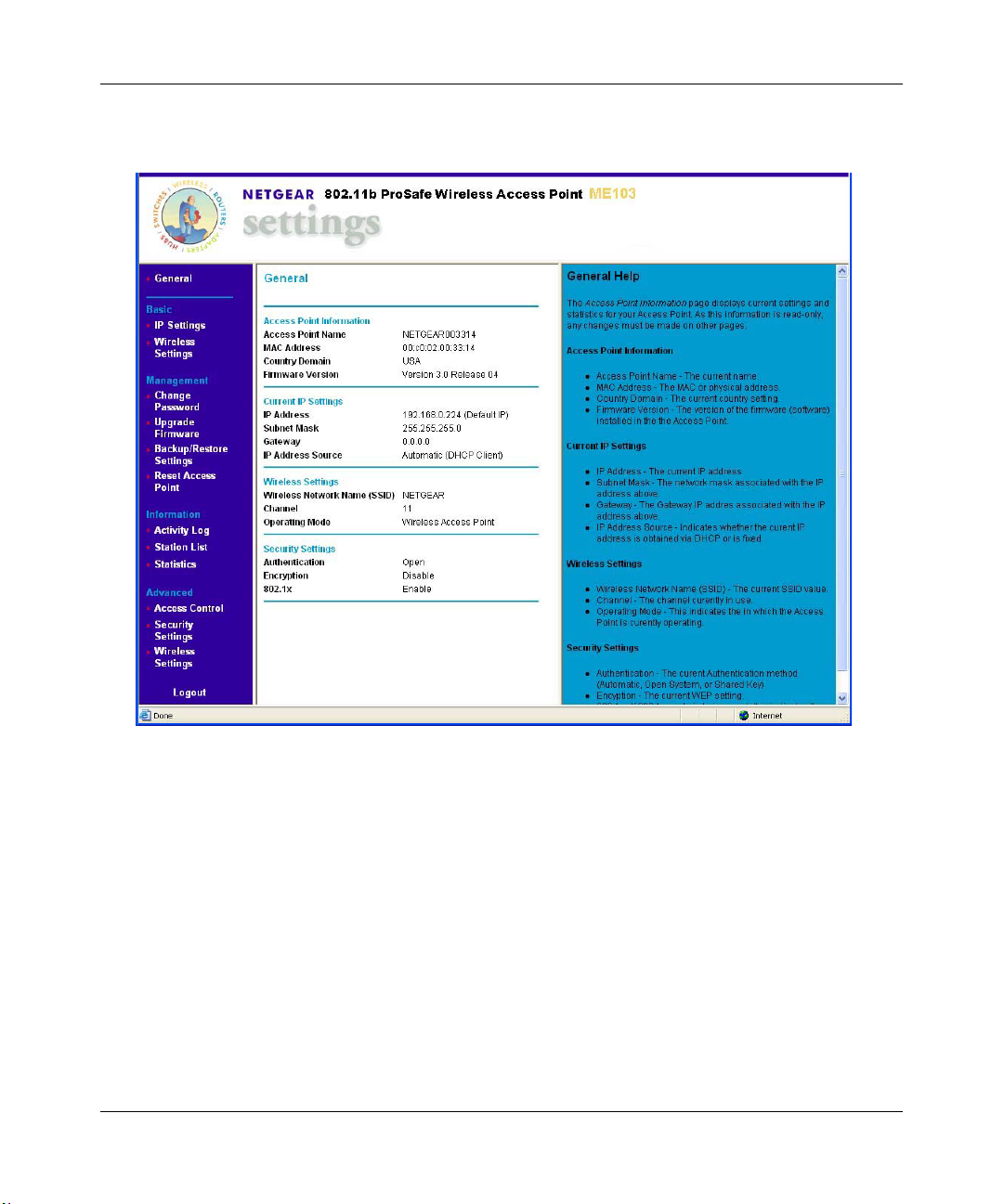
The General information screen provides a summary of the current ME103 configuration settings.
From the main Menu of the browser interface, click General to view the System Status screen,
shown below.
Figure 4-1: Wireless Access Point Status screen
This screen shows the following parameters:
Maintenance 4-1
August 2003
Page 42

Reference Manual for the ME103 802.11b ProSafe Wireless Access Point
Table 4-1. General Information Fields
Field Description
Access Point Information
Access Point Name The default name may be changed if desired.
Note: In 802.1x mode, this name is used as the client Login name for the
RADIUS server.
MAC Address Displays the Media Access Control address (MAC address) of the wireless
access point’s Ethernet port.
Country Domain
Firmware Version The version of the firmware currently installed.
Current IP Settings
IP Address The IP address of the wireless access point.
Subnet Mask
Displays the domain or region for which the wireless access point is
licensed for use. It may not be legal to operate this wireless access point in
a region other than one of those identified in this field.
These parameters apply to the Local ME103 firewall.
The subnet mask for the wireless access point.
Gateway
IP Address Source Automatic (DHCP client) indicates that the current IP address was
Wireless Settings
Wireless Network Name
(SSID)
Channel Identifies the channel the wireless port is using. 11 is the default channel
Operating Mode
Security Settings
Authentication WEP or 802.1x authentication setting.
Encryption
802.1x
The default gateway for the wireless access point communication.
obtained from a DHCP server on your network.
These parameters apply to the target remote ME103 firewall, VPN
gateway, or VPN client.
Displays the wireless network name (SSID) being used by the wireless port
of the wireless access point. The default is NETGEAR.
setting. See “Wireless Channels” on page B-7 for the frequencies used on
each channel.
Identifies the operating mode of the ME103.
The current WEP or 802.1x encryption setting.
The current 802.1x setting.
4-2 Maintenance
August 2003
Page 43

Reference Manual for the ME103 802.11b ProSafe Wireless Access Point
Statistics
The Information - Statistics screen provides various LAN and WLAN statistics.
Figure 4-2: Wireless Access Point Status screen
Maintenance 4-3
August 2003
Page 44

Reference Manual for the ME103 802.11b ProSafe Wireless Access Point
Table 4-1. Statistics Fields
Field Description
System Up Time
Wired Ethernet
Received/Transmitted
Packets The number of packets sent since the ME103 was last restarted.
Bytes
Throughput (B/sec)
CRC Errors The number of CRC errors since th e ME103 was last restarted.
Wireless
Received/Transmitted
Unicast Packets The Unicast packets sent since the ME103 was last restarted.
Broadcast Packets The Broadcast packets sent since the ME103 was last restarted.
Multicast Packets The Multicast packets sent since the ME103 was last restarted.
Total Packets The Wireless packets sent since the ME103 was last restarted.
Total Bytes The Wireless bytes sent since the ME103 was last restarted.
Throughput (B/sec)
Refresh button
The length of time the ME103 802.11b ProSafe Wireless Access Point has
been connected to your network since it was last restarted.
The number of bytes sent since the ME103 was last restarted.
The current bandwidth used on the LAN port.
The current bandwidth used on the wireless port.
Click the Refresh button to update the statistics on this screen.
4-4 Maintenance
August 2003
Page 45

Reference Manual for the ME103 802.11b ProSafe Wireless Access Point
Activity Log
Use the Activity Log to view step-by-step login exchanges or other information about the wireless
communications sessions on the ME103 802.11b ProSafe Wireless Access Point.
Figure 4-3: Activity Log screen
Maintenance 4-5
August 2003
Page 46

Reference Manual for the ME103 802.11b ProSafe Wireless Access Point
Viewing a List of Attached Devices
The Station List menu contains a table of all IP devices associated with the wireless access point in
the wireless network defined by the Wireless Network Name (SSID). From the main menu of the
browser interface, under the Information heading, click the Station List link to view the list, shown
below.
Figure 4-4: Information Station List of associated devices
For each device, the table shows the MAC address and whether the device is allowed to
communicate with the wireless access point or not. Note that if the wireless access point is
rebooted, the table data is lost until the wireless access point rediscovers the devices. To force the
wireless access point to look for associated devices, click the Refresh button.
Note: A wireless network can include multiple wireless access points, all using the same network
name (SSID). This enables extending the reach of the wireless network and allows users to roam
from one access point to another, providing seamless network connectivity. Under these
circumstances, be aware that only the stations associated with this access point will be presented in
the Station List.
4-6 Maintenance
August 2003
Page 47

Reference Manual for the ME103 802.11b ProSafe Wireless Access Point
Upgrading the Wireless Access Point Software
.
Note: When uploading software to the ME103 Access Point, it is important not to
interrupt the W eb browser by closing the wind ow , clicking a link, or loading a new page.
If the browser is interrupted, the upload may fail, corrupt the software, and render the
ME103 completely inoperable.
You cannot perform the firmware upgrade from a workstation connected to the ME103 via a
wireless link. The firmware upgrade must be performed via a workstation connected to the ME103
via the Ethernet LAN interface.
The software of the ME103 Access Point is stored in FLASH memory, and can be upgraded as
new software is released by NETGEAR. Upgrade files can be downloaded from Netgear's Web
site. If the upgrade file is compressed (.ZIP file), you must first extract the image (.IMG) file
before sending it to the wireless access point. The upgrade file can be sent using your browser.
Note: The Web browser used to upload new firmware into the ME103 must support HTTP
uploads, such as Microsoft Internet Explorer 5.0 or above, or Netscape Navigator 4.78 or above.
1. Download the new software file from NETGEAR, save it to your hard disk, and unzip it.
Figure 4-5: ME103 Upgrade menu
2.
From the main menu Management section, click the Upgrade Firmware link to display the
screen above.
3. In the Upgrade Firmware menu, click the Browse button and browse to the location of the
image (.IMG) upgrade file.
Maintenance 4-7
August 2003
Page 48

Reference Manual for the ME103 802.11b ProSafe Wireless Access Point
Click Upload.
4.
When the upload completes, your wireless access point will automatically restart. The upgrade
process typically takes about one minute.
In some cases, you may need to reconfigure the wireless access point after upgrading.
Configuration File Management
The ME103 Access Point settings are stored in the wireless access point in a configuration file.
This file can be saved (backed up) to a user’s PC, retrieved (restored) from the user’s PC, or
cleared to factory default settings.
From the main menu Management heading, click the Backup/Restore Settings link to bring up the
menu shown below.
Figure 4-6: Settings Backup menu
The three options displayed are described in the following sections:
4-8 Maintenance
August 2003
Page 49

Reference Manual for the ME103 802.11b ProSafe Wireless Access Point
Saving and Retrieving the Configuration
The Backup/Restore Settings menu allows you to save or retrieve a file containing your wireless
access point’s configuration settings.
To save your settings, click the Save button. Your browser will extract the configuration file from
the wireless access point and prompts you for a location on your PC to store the file. You can give
the file a meaningful name at this time, such as operations.cfg.
T o restore your settings from a saved configuration file, enter the full path to the fil e on your PC or
click the Browse button to locate the file. When you have located it, click the Retrieve button to
upload the file. After completing the upload, the ME103 will reboot automatically.
Restoring the ME103 to the Factory Default Settings
It is sometimes desirable to restore the wireless access point to the factory default settings. This
can be done by using the Restore function, which restores all factory settings. After a restore, the
wireless access point's password will be password, the ME103's DHCP client is enabled, the
default LAN IP address is 192.168.0.224, and the NetBIOS name is reset to the name printed on
the label on the bottom of the unit.
Using the Reset Button to Restore Factory Default Settings
To restore the factory default configuration settings without knowing the login password or IP
address, you must use the Default Reset button on the rear panel of the wireless access point (see
“ME103 Wireless Access Point Rear Panel” on page 2-7). The reset button has two functions:
• Reboot. When pressed and released, the Wireless Access Point will reboot (restart).
• Reset to Factory Defaults. This button can also be used to clear all data and restore all
settings to the factory default values.
To clear all data and restore the factory default values:
1. Power Off the ME103
2. Hold the Reset Button down while you Power On the ME103.
3. Continue holding the Reset Button until the LEDs blink twice.
4. Release the Reset Button.
The factory default configuration has now been restored, and the ME103 is ready for use.
Maintenance 4-9
August 2003
Page 50

Reference Manual for the ME103 802.11b ProSafe Wireless Access Point
Changing the Administrator Password
The default password is password. Change this password to a more secure password. You cannot
change the administrator login name.
From the main menu of the browser interface, under the Management heading, click Change
Password to bring up the menu shown below.
Figure 4-7: Set Password menu
T o change the password, first enter the old password, and then enter the new password twice. Click
Apply to save your change.
4-10 Maintenance
August 2003
Page 51

Chapter 5
Advanced Configuration
This chapter describes how to configure the advanced features of your ME103 802.11b ProSafe
Wireless Access Point. These features can be found under the Advanced heading in the main
menu.
Configuring Advanced Security 802.1x Options
For an overview of 802.1x, see “Understanding 802.1x Port Based Network Access Control” on
page B-9. The ME103 802.11b ProSafe Wireless Access Point supports these 802.1x options:
• Key Exchange. Key exchange (PEAP, EAP-TLS, EAP-TTLS) provides strong security
through mutual authentication and automatic key exchange between the two endpoints.
Periodic updates are performed using public-key cryptography through a certificate server and
a Remote Authentication Dial-In User Service (RADIUS) server.
The ME103 configuration procedures for these options are presented below.
Basic Requirements for 802.1x
802.1x requires these parts:
1. Authenticator: ME103
2. Authentication Server - a RADIUS server.
Microsoft Internet Authentication Server (IAS) provides RADIUS functionality. Other
vendors also support RADIUS for 802.1x.
3. Supplicant - Windows 2000 with the 802.1x client patch applied (SP4 802.1x client) or
Windows XP.
4. Optionally , the Key Exchange options (PEAP, EAP-TLS, and EAP-TTLS) can take advantage
of a Certificate Authority (CA) such as Windows 2000 server provides. To use
certificate-based authentication, both the RADIUS server and the client need to have a
certificate from a certificate server such as Windows 2000 or a public service such as Verisign.
Advanced Configuration 5-1
August 2003
Page 52

Reference Manual for the ME103 802.11b ProSafe Wireless Access Point
With the above basic requirements, 802.1x securit y can be implemented with the ME103. Refer to
“Understanding 802.1x Port Based Network Access Control” on page B-9 for a description of
basic 802.1x functionality.
How to Configure the 802.1x Key Exchange Option
Follow this procedure to configure the ME103 for 802.1x Key Exchange security. The sample
configuration worksheet below is filled in with the parameters used in this procedure. T o configure
your ME103, print and fill out the blank worksheet found at the end of this section and record your
network configuration. A blank worksheet is provided below.
Key Exchange Configuration Worksheet
802.1x Key Exchange Security Settings
WEP Encryption Key Length: 128/64-bit
Note: Be sure your wireless adapter has the WEP 128/64-bit
encryption feature enabled.
RADIUS Port: 1812
RADIUS Shared Key: r>T(h4&3@#kB
Network LAN IP Network Address Subnet Mask Gateway IP (LAN IP Address)
ME103 192.168.0.2 255.255.255.0 192.168.0.1
1. Configure the RADIUS server to use the 802.1x settings in the worksheet above.
a. Add the ME103 to the RADIUS server using either its IP address or the NetBIOS name.
b. Set the shared key. Both the ME103 and the RADIUS entries should use the same shared
key so that the RADIUS server allows the ME103 to log in to the RADIUS server.
2. Configure the ME103 802.1x Key Exchange parameters.
a. Log in to the ME103 using the NetBIOS name printed on the bottom of the unit, or at its
default address of http://192.168.0.224, or at whatever IP address the unit is currently
configured with. Use the default user name of
admin and password of password. Click
the Security Settings link in the main menu Advanced section to display the Advanced
Security Settings menu.
5-2 Advanced Configuration
August 2003
Page 53

Reference Manual for the ME103 802.11b ProSafe Wireless Access Point
Note: Perform this procedure from a LAN connected computer rather than over a wireless
link. This procedure will change the ME103’s data encryption settings, so all wireless
connections will be disconnected when you apply the settings.
b. Fill in the settings from the worksheet as illustrated above.
Data Encryption (WEP) features are not functional in this mode. Key Exchange mode
automatically supplies the encryption keys and changes the keys regularly at short
intervals.
c. Click Apply.
Note: The idle timeout on the ME103 is 10 minutes. If there is no traf fic for 10 minutes,
the 802.1x supplicant (wireless client) will be automatically disconnected.
3. Configure the PCs on network to use the 802.1x and WEP settings you just applied to the
ME103.
Note: At this time, only W indows XP includes built-in support for 802.1x. Windows 2000 can
support 802.1x with the appropriate SP4 patch. There are also third party client software
packages which will provide 802.1x support for a variety of Windows, Macintosh, Unix, and
Linux clients. The information below is an example of one of many possible scenarios you
may encounter when deploying 802.1x. NETGEAR does not provide support for Windows or
third party software.
a. Using a computer connected via the Ethernet LAN, obtain and install a certificate.
Note: In this example, you must perform this operation from a wired connection to the
Windows 2000 certificate server. A wireless connection through the ME103 will not be
available until after the certificate is already recorded by the client Windows operating
system.
Advanced Configuration 5-3
August 2003
Page 54

Reference Manual for the ME103 802.11b ProSafe Wireless Access Point
Figure 5-1: Request a certificate
Note: The procedure for obtaining certificates differs between a CA like Verisign and a
CA such as a Windows 2000 certificate server. Organizations operate Windows 2000
certificate servers to provide certificates for its members. For example, an administrator of
a Windows 2000 certificate server might provide a certi ficate to you via e-mail rather than
connecting directly as shown in this example.
– Obtain the certificate which includes the public key from a Certificate Authority (CA).
– Install this certificate in the Windows Root Certificate Store.
– After installing the certificate on the Windows client, switch from the wired Ethernet
connection to the wireless adapter.
b. Verify that the “Use Windows to configure my wireless network settings” check box is
selected in the Windows XP Network Connections wireless adapter properties dialog box
Wireless Networks tab page.
Figure 5-2: Windows XP wireless adapter configuration utility
5-4 Advanced Configuration
August 2003
Page 55

Reference Manual for the ME103 802.11b ProSafe Wireless Access Point
Select the wireless network to which you will connect (NETGEAR in the screen above),
c.
and click the Configure button to display the Wireless network properties dialog box
shown below.
Figure 5-3: Configure a Windows XP wireless adapter association
Select only the “Data encryption (WEP enabled)” check box.
d.
e. Click the Authentication tab to display the screen below.
Figure 5-4: Configure a Windows XP wireless adapter for EAP-TLS
f.
Configure the wireless adapter to enable 802.1x authentication by selecting the “Enable
IEEE 802.1x authentication for this network” check box.
g. Click OK to apply the settings to your wireless adapter.
h. The first time you establish the EAP-TLS wireless session from a client workstation,
Windows will prompt you to verify that the certificate it found is the correct one.
Note: During the authentication processes, there is a session timeout. If either the
authenticator or the client does not respond with the proper data to the other side in 30
seconds, the authentication fails. If this happens, you should physically remove the
wireless adapter from your computer, and re-insert it to start the authentication again. In
addition, if the ME103 is rebooted, you should physically remove the wireless adapter
from your computer and re-insert it to start the authentication again.
4. View the ME103 log and check the connection
To check the connection, you can initiate a request from a wireless device to the network.
Use the ME103 Activity Log to monitor the initiation of the 802.1x wireless session.
Advanced Configuration 5-5
August 2003
Page 56

Reference Manual for the ME103 802.11b ProSafe Wireless Access Point
Figure 5-5: Information Activity Log for starting a 802.1x wireless connection
The simplest method is to ping the LAN IP address of another computer on the Ethernet LAN.
a. From a wireless PC, on the Windows taskbar click the Start button, then click Run.
b. Type ping -t 192.168.0.1 , and click OK.
Figure 5-6: Running a Ping test from Windows
c.
This command causes a continuous ping to be sent. Between several seconds to two
minutes, the ping response should change from “timed out” to “reply.”
5-6 Advanced Configuration
August 2003
Page 57

Reference Manual for the ME103 802.11b ProSafe Wireless Access Point
Figure 5-7: Ping test results
At this point the connection is established and your wireless connection is working.
Advanced Configuration 5-7
August 2003
Page 58

Reference Manual for the ME103 802.11b ProSafe Wireless Access Point
Understanding Advanced Wireless Settings
The default advanced wireless settings usually work well. These settings should not be changed
unless you are sure it is necessary.
Figure 5-8: Advanced Wireless Settings screen
5-8 Advanced Configuration
August 2003
Page 59

Reference Manual for the ME103 802.11b ProSafe Wireless Access Point
Table 5-1. Advanced Wireless Settings Fields
Field Description
Operating Mode
Worldwide Mode If you enable 802.11d, you will have access to additional regulatory domains.
Broadcast Wireless
Network Name
(SSID)
Wireless Separation Enable wireless separation avoid channel assignment interference.
Basic Rate This field determines which data communications rate will be used. It should not be
Parameters
RTS Threshold The packet size used to determine whether it should use the CSMA/CD (Carrier
Fragmentation
Length
Beacon Interval Specifies the data beacon rate between 20 and 3000.
Preamble Type A long transmit preamble may provide a more reliable connection or slightly longer
Antenna Selection
Y ou can select the followin g options:
• Wireless Access Point
• Point-to-Point Bridge
• Point-to-Multi-Point Bridge
If you disable broadcast of the SSID, only devices that have the correct SSID can
connect. Disabling SSID broadcast nullifies the wireless network ‘discovery’ feature
of some products such as Windows XP.
necessary to change from the default of Auto-negotiate unless you notice
interference problems. There are times when lowering the data rate will help assure
a more reliable wireless connection.
Use these parameters to set the radio frequency communications settings.
Sense Multiple Access with Collision Detection) or the CSMA/CA (Carrier Sense
Multiple Access with Collision Avoidance) mechanism for packet transmission.
This is the maximum packet size used for fragmentation. Packets larger than the
size programmed in this field will be fragmented. The Fragment Threshold value
must be larger than the RTS Threshold value.
range. A short transmit preamble gives better performance. Long is the default.
Y ou can select the followin g options:
• Primary (R)
• Secondary (L)
• Diversity - note that ME103 diversity is provided in receive mode only, not in
transmit mode. The PRIMARY RF port provides transmit and receive. The
SECONDARY provides receive mode only.
Output Power
Level
Lowering the output power level lets you reduce the chance of interference with
other nearby access points and reduces the coverage range. You can set the power
output level of the transmitter to these options: 18dbm (64mw), 17dbm (50mw),
15dbm (30mw), 13dbm (20mw), 7dbm (5mw), 0dbm (1mw).
Advanced Configuration 5-9
August 2003
Page 60

Reference Manual for the ME103 802.11b ProSafe Wireless Access Point
LAN
Segment 1
192.168.0.1
Router
ME103 in
Point-to-Point
Bridge Mode
ME103 in
Point-to-Point
Bridge Mode
LAN
Segment 2
Hub or Switch
AP1
ETHERNET
RESET
5-12VDC
AP2
ETHERNET
RESET
5-12VDC
Configuring Wireless Operating Modes
The ME103 802.11b ProSafe Wireless Access Point lets you build large bridged wireless
networks. Examples of wireless bridged configurations are:
• Client Access Point to Access Point.
• Point-to-Point Bridge.
• Multi-point bridging.
These features are discussed below.
How to Configure a ME103 as a Point-to-Point Bridge
Figure 5-9: Point-to-Point Bridge
Configure the ME103 (AP1) on LAN Segment 1 in Point-to-Point Bridge mode.
1.
2. Configure the ME103 (AP2) on LAN Segment 2 in Point-to-Point Bridge mode.
AP1 must have AP2’s MAC address in its Remote MAC Address field and AP2 must have
AP1’s MAC address in its Remote MAC Address field.
3. Configure and verify the following parameters for both access points:
• Verify that the LAN network configuration of the ME103 Access Points both are
configured to operate in the same LAN network address range as the LAN devices
• Both use the same ESSID, Channel, authentication mode, if any, and security settings if
security is in use.
5-10 Advanced Configuration
August 2003
Page 61

Reference Manual for the ME103 802.11b ProSafe Wireless Access Point
Verify connectivity across the LAN 1 and LAN 2.
4.
• A PC on either LAN segment should be able to connect to the Internet or share files and
printers of any other PCs or servers connected to LAN Segment 1 or LAN Segment 2.
How to Configure Multi-Point Wireless Bridging
AP3
ETHERNET
RESET
Hub or Switch
LAN
Segment 3
5-12VDC
Router
192.168.0.1
LAN
ME103 in
Point-to-Point
Bridge Mode
AP1
RESET
ETHERNET
5-12VDC
AP2
RESET
"Master" ME103 in
Point-to-Multi-Point
Bridge M ode
Hub or Switch
ME103 in
Point-to-Point
Bridge M ode
ETHERNET
5-12VDC
Segment 1
LAN
Segment 2
Figure 5-10: Multi-Point bridging
Configure the Operating Mode of the ME103 Access Points.
1.
– ME103 (AP1) on LAN Segment 1 in Point-to-Point Bridge mode with the Remote MAC
Address of AP2.
– Because it is in the central location, configure ME103 (AP2) on LAN Segment 2 in
Point-to-Multi-Point Bridge mode. No MAC address is required because it will respond to
Point-to-Point APs which are configured communicating to it.
– Configure the ME103 (AP3) on LAN 3 in Point-to-Point Bridge mode with the Remote
MAC Address of AP2.
2. Verify the following parameters for all access points:
• Verify that the LAN network configuration the ME103 Access Points are configured to
operate in the same LAN network address range as the LAN devices
• Only one AP is configured in Point-to-Multi-Point Bridge mode, and all the others are in
Point-to-Point Bridge mode.
Advanced Configuration 5-11
August 2003
Page 62

Reference Manual for the ME103 802.11b ProSafe Wireless Access Point
• All APs must be on the same LAN. That is, all the APs LAN IP address must be in the
same network.
• If using DHCP, all ME103 Access Points should be set to “Obtain an IP address
automatically (DHCP Client)” in the IP Address Source portion of the Basic IP Settings
menu.
• All ME103 Access Points use the same SSID, Channel, authentication mode, if any, and
encryption in use.
• All Point-to-Point APs must have AP2’s MAC address in its Remote AP MAC address
field.
3. Verify connectivity across the LANs.
• A PC on any LAN segment should be able to connect to the Internet or share files and
printers with any other PCs or servers connected to any of the three LAN segments.
• Wireless stations will not be able to connect to the ME103 Access Points in the illustration
above. If you require warless stations to access any lan segment, you can additional
ME103 Access Points configured in Wireless Access Point mode to any LAN segment.
Note: You can extend this multi-point bridging by adding additional ME103s configured in
Point-to-Point mode for each additional LAN segment. Furthermore, you can extend the range of
the wireless network with NETGEAR wireless antenna accessories.
5-12 Advanced Configuration
August 2003
Page 63

Reference Manual for the ME103 802.11b ProSafe Wireless Access Point
Antenna Installation
The ME103 comes with two removable 2-dBi antenna. Two antennae provide what is called
“space diversity”, which helps to combat the addition of electromagnetic waves in the space where
the unit is installed. This effect is called “multipath fading.” Multipath fading is generated by the
multiple reflections of electromagnetic waves in an office due to walls, ceiling, floors, partitions,
doors, metallic polls, cubicles, etc. and the motion of people and objects. The benefits of two
antennae are evident when there is distance or obstructions in the line of sight between the ME103
and the clients. When only one antenna is used, a degradation of up to 50% of data throughput can
be noticed in several spots of the coverage and also at the fringes of the range.
The two 2dBi antenna are dipole and use vertical polarization. They provide an optimal radiation
pattern in the plane perpendicular to their direction. When oriented vertically, they provide a
optimal range in the horizontal plane (horizontal donut shaped signals). If the office is small and
on multiple floors, it is advised to put the antenna flat so that the maximum coverage is vertical
rather than horizontal. When the office is an odd shape, NETGEAR advises you to do some
orientation trials.
For applications requiring more range, wireless accessories can be used such as external antennae
and bi-directional booster(s). The first optional update is replacing the two 2dBi antennae by two
5-7dBi dipole antennae. Simply turn the ME103 off, unscrew the two antenna, and screw on the
new ones. Be sure to use antenna with a reversed SMA connector.
Another solution is to relocate the antenna(e) with an RF cable to an optimal spot such as a ceiling,
high on a wall, etc. One typical application is to locate the ME103 is in a secure location like a data
center. Two external antenna are placed outside the room, for example on the ceiling, and
connected with RF cables to the ME103. Another application is two external directional antennae,
one pointing to one side of the building, and the other to the other side. Be aware of the loss in the
cable. If the cable is too long and used with a medium gain antenna, the gain from placing the
antenna in good spot may be reduced or eliminated. Only high gain antenna (more than 10dBi)
should be used with a long cable such as 5 or 10m.
To cope with this inherent limitation, NETGEAR also provides bi-directional booster. This
component amplifies the RF signal in transmit mode and in receive mode. It automatically
switches itself to the receive or transmit mode. The booster is placed very close to the antenna and
provides an outstanding output RF power of 500mW or 27dBm. It also includes a low noise
amplifier for the receive path of 10dB gain minimum. The antenna and booster can be connected
with a cable as long as 10 to 15m from the ME103 without any performance reduction.
Advanced Configuration 5-13
August 2003
Page 64

Reference Manual for the ME103 802.11b ProSafe Wireless Access Point
Note that ME103 diversity is provided only in receive mode, not in transmit mode. The Primary
RF port provides transmit and receive. The Secondary RF port provides receive mode only.
Therefore passive components such as external antennae can be connected to either Primary or
Secondary ME103 RF ports. However, an active device such as bi-directional booster has to be
used on the Primary RF port only. If using one booster on each Primary and Secondary RF port,
the one connected to the Secondary will boost only the receive signals.
Blank Configuration Worksheet
EAP-TLS Configuration Worksheet
EAP-TLS 802.1x Security Settings
WEP Encryption Key Length:
RADIUS Port:
RADIUS Shared Key:
Network LAN IP Network Address Subnet Mask Gateway IP (LAN IP Address)
5-14 Advanced Configuration
August 2003
Page 65

Chapter 6
Troubleshooting
This chapter provides information about troubleshooting your ME103 802.11b ProSafe Wireless
Access Point. After each problem description, instructions are given to help you diagnose and
solve the problem. For the common problems listed, go to the section indicated.
• Is the ME103 on?
• Have I connected the wireless access point correctly?
Go to “Installing the ME103 802.11b ProSafe Wireless Access Point” on page 3-5.
• I cannot remember the wireless access point’s configuration password.
Go to “Changing the Administrator Password” on page 4-10.
Note: For up-to-date ME103 installation details and troubleshooting guidance visit
www.NETGEAR.com.
If you have trouble setting up your ME103, check the tips below.
No lights are lit on the access point.
It takes a few seconds for the power indicator to light up. Wait a minute and check the
power light status on the access point.
If the access point has no power.
• Make sure the power cord is connected to the access point.
• Make sure the power adapter is connected to a functioning power outlet. If it is in a power
strip, make sure the power strip is turned on. If it is plugged directly into the wall, verify that it
is not a switched outlet.
• Make sure you are using the correct NETGEAR power adapter supplied with your access
point.
Troubleshooting 6-1
August 2003
Page 66

Reference Manual for the ME103 802.11b ProSafe Wireless Access Point
The Wireless LAN activity light does not light up.
The access point’s antennae are not working.
• If the Wireless LAN activity light stays off, disconnect the adapter from its power source and
then plug it in again.
• Make sure the antennas are tightly connected to the ME103.
• Contact NETGEAR if the Wireless LAN activity light remains off.
The LAN light is not lit.
There is a hardware connection problem.Check these items:
• Make sure the cable connectors are securely plugged in at the access point and the network
device (hub, switch, or router). A switch, hub, or router must be installed between the access
point and the Ethernet LAN or broadband modem.
• Make sure the connected device is turned on.
• Be sure the correct cable is used. Use a standard Category 5 Ethernet patch cable. If the
network device has Auto Uplink™ (MDI/MDIX) ports, you can use either a cross-over cable
or a normal patch cable.
I cannot access the Internet or the LAN with a wireless capable computer.
There is a configuration problem.Check these items:
• You may not have restarted the computer with the wireless adapter to have TCP/IP changes
take effect. Restart the computer.
• The computer with the wireless adapter may not have the correct TCP/IP settings to
communicate with the network. Restart the computer and check that TCP/IP is set up properly
for that network. The usual setting for Windows the Network Properties is set to “Obtain an IP
address automatically.”
• The access point’s default values may not work with your network. Check the access point
default configuration against the configuration of other devices in your network.
6-2 Troubleshooting
August 2003
Page 67

Reference Manual for the ME103 802.11b ProSafe Wireless Access Point
I am using EAP-TLS security but get disconnected.
With 802.1x, occasionally, sporadic wireless communications interference might cause the
encryption key to get dropped. This is not a breach of security. However, if so, your
wireless client can be disconnected from the ME103.
1. Simply disable and then enable the wireless NIC from the Windows Control Panel in
Perform these steps:
the Network connections section, or from the windows system tray on the lower right
of the Windows task bar at the bottom of your screen
2. Upon restarting your wireless adapter, the ME103 will re-authenticate you and establish a
new wireless connection
.
.
I cannot connect to the ME103 to configure it.
Check these items:
• The ME103 is properly installed, LAN connections are OK, and it is powered on. Check that
the LAN port LED is green to verify that the Ethernet connection is OK.
• If you are using the NetBIOS name of the ME103 to connect, ensure that your PC and the
ME103 are on the same network segment or that there is a WINS server on your network.
• If your PC is set to “Obtain an IP Address automatically” (DHCP client), restart it.
• If your PC uses a Fixed (Static) IP address, ensure that it is using an IP Address in the range of
the ME103. The ME103 default IP Address is 192.168.0.224 and the default Subnet Mask is
255.255.255.0. If you are not sure about these settings, follow the instructions for “Installing
the ME103 802.11b ProSafe Wireless Access Point” on page 3-5.
When I enter a URL or IP address I get a timeout error.
A number of things could be causing this. Try the following troubleshooting steps.
• Check whether other PCs work. If they do, ensure that your PCs TCP/IP settings are correct. If
using a Fixed (Static) IP Address, check the Subnet Mask, Default Gateway, DNS, and IP
Addresses.
Troubleshooting 6-3
August 2003
Page 68

Reference Manual for the ME103 802.11b ProSafe Wireless Access Point
• If the PCs are configured correctly, but still not working, ensure that the ME103 is connected
and turned on. Connect to it and check its settings. If you cannot connect to it, check the LAN
and power connections.
• If the ME103 is configured correctly , check your Internet connection (DSL/Cable mo dem etc.)
to make sure that it is working correctly.
Using the Reset Button to Restore Factory Default Settings
The Reset button (see “ME103 Wireless Access Point Rear Panel” on page 2-7) has two functions:
• Reboot. When pressed and released quickly, the ME103 will reboot (restart).
• Reset to Factory Defaults. This button can also be used to clear ALL data and restore ALL
settings to the factory default values.
To clear all data and restore the factory default values:
1. Power off the ME103 and power it back on.
2. Use something with a small point, such as a pen, to press the Reset button in and hold it in for
at least 5 seconds.
3. Release the Reset button.
The factory default configuration has now been restored, and the ME103 is ready for use.
6-4 Troubleshooting
August 2003
Page 69

Reference Manual for the ME103 802.11b ProSafe Wireless Access Point
Appendix A
Specifications
This appendix provides technical specifications for the ME103 802.11b ProSafe Wireless Access
Point.
Specifications for the ME103
Parameter ME103 802.11b ProSafe Wireless Access Point
802.11b Data Rate s 1, 2, 5.5, & 11 Mbps (Auto-rate capable)
802.11b
Operating Frequencies
802.11b
Operating Range
802.11b Encryption 40-bits (also called 64-bits), 128-bits WEP data encryption
Network Management Web-based configuration and status monitoring
Maximum Clients Limited by the amount of wireless network traffic generated by each node;
Status LEDs Power/Ethernet LAN/Wireless LAN
Dimensions W: 7.38 in. (187.3 mm) D: 5.26 in. (131 mm) H: 1 in. (25.4 mm)
Power Adapter 12Vdc, 800mA
Weight 845 g (29.7 oz)
Electromagnetic
Compliance
Environmental
Specifications
Warranty Limited 3-year warranty
2.412 ~ 2.462 GHz (US) 2.457 ~ 2.462 GHz (Spain)
2.412 ~ 2.484 GHz (Japan) 2.457 ~ 2.472 GHz (France)
2.412 ~ 2.472 GHz (Europe ETSI)
Outdoor environment Indoor environment
@ 11 Mbps 500 ft (152 m) 100 ft (30 m)
@ 5.5 Mbps 885 ft (270 m) 165 ft (50 m)
@ 2 Mbps 1300 ft (396 m) 230 ft (70 m)
@ 1 Mbps 1500 ft (457 m) 300 ft (91 m)
typically 15 to 20 nodes.
FCC Part 15 Class B and Class E, C-Tick, CE
Operating temperature: 0 to 50° C
Operating humidity: 5-95%, non-condensing
Specifications A-1
August 2003
Page 70

Reference Manual for the ME103 802.11b ProSafe Wireless Access Point
A-2 Specifications
August 2003
Page 71

Appendix B
Wireless Networking Basics
This chapter provides an overview of wireless networking and security.
Wireless Networking Overview
The ME103 Access Point conforms to the Institute of Electrical and Electronics Engineers (IEEE)
802.11b standard for wireless LANs (WLANs). On an 802.1 1b wireless link, data i s encoded using
direct-sequence spread-spectrum (DSSS) technology and is transmitted in the unlicensed radio
spectrum at 2.5GHz. The maximum data rate for the wireless link is 11 Mbps, but it will
automatically back down from 11 Mbps to 5.5, 2, and 1 Mbps when the radio signal is weak or
when interference is detected.
The 802.11 standard is also called Wireless Ethernet or Wi-Fi by the Wireless Ethernet
Compatibility Alliance (WECA, see http://www.wi-fi.net), an industry standard group promoting
interoperability among 802.11 devices. The 802.11 standard offers two methods for configuring a
wireless network - ad hoc and infrastructure.
Infrastructure Mode
With a wireless Access Point, you can operate the wireless LAN in the infrastructure mode. This
mode provides wireless connectivity to multiple wireless network devices within a fixed range or
area of coverage, interacting with wireless nodes via an antenna.
In the infrastructure mode, the wireless access point converts airwave data into wired Ethernet
data, acting as a bridge between the wired LAN and wireless clients. Connecting multiple Access
Points via a wired Ethernet backbone can further extend the wireless network coverage. As a
mobile computing device moves out of the range of one access point, it moves into the range of
another. As a result, wireless clients can freely roam from one Access Point domain to another and
still maintain seamless network connection.
Wireless Networking Basics B-1
August 2003
Page 72

Reference Manual for the ME103 802.11b ProSafe Wireless Access Point
Ad Hoc Mode (Peer-to-Peer Workgroup)
In an ad hoc network, computers are brought together as needed; thus, there is no structure or fixed
points to the network - each node can generally communicate with any other node. There is no
Access Point involved in this configuration. This mode enables you to quickly set up a small
wireless workgroup and allows workgroup members to exchange data or share printers as
supported by Microsoft networking in the various W indows operating systems. Some vendors also
refer to ad hoc networking as peer-to-peer group networking.
In this configuration, network packets are directly sent and received by the intended transmitting
and receiving stations. As long as the stations are within range of one another, this is the easiest
and least expensive way to set up a wireless network.
Network Name: Extended Service Set Identification (ESSID)
The Extended Service Set Identification (ESSID) is one of two types of Service Set Identification
(SSID). In an ad hoc wireless network with no access points, the Basic Service Set Identification
(BSSID) is used. In an infrastructure wireless network that includes an access point, the ESSID is
used, but may still be referred to as SSID.
An SSID is a thirty-two character (maximum) alphanumeric key identifying the name of the
wireless local area network. Some vendors refer to the SSID as network name. For the wireless
devices in a network to communicate with each other, all devices must be configured with the
same SSID.
Authentication, WEP, and WPA
The absence of a physical connection between nodes makes the wireless links vulnerable to
eavesdropping and information theft. To provide a certain level of security, the IEEE 802.11
standard has defined two types of authentication methods, Open System and Shared Key. With
Open System authentication, a wireless PC can join any network and receive any messages that are
not encrypted. With Shared Key authentication, only those PCs that possess the correct
authentication key can join the network. By default, IEEE 802.11 wireless devices operate in an
Open System network. Recently, Wi-Fi, the Wireless Ethernet Compatibility Alliance
(http://www.wi-fi.net) developed the Wi-Fi Protected Access (WPA), a new strongly enhanced
Wi-Fi security. WPA will soon be incorporated into the IEEE 802.11 standard.
B-2 Wireless Networking Basics
August 2003
Page 73

Reference Manual for the ME103 802.11b ProSafe Wireless Access Point
802.11 Authentication
The 802.11 standard defines several services that govern how two 802.11 devices communicate.
The following events must occur before an 802.11 Station can communicate with an Ethernet
network through an access point such as the one built in to the ME103:
1. Turn on the wireless station.
2. The station listens for messages from any access points that are in range.
3. The station finds a message from an access point that has a matching SSID.
4. The station sends an authentication request to the access point.
5. The access point authenticates the station.
6. The station sends an association request to the access point.
7. The access point associates with the station.
8. The station can now communicate with the Ethernet network through the access point.
An access point must authenticate a station before the station can associate with the access point or
communicate with the network. The IEEE 802.11 standard defines two types of authentication:
Open System and Shared Key.
• Open System Authentication allows any device to join the network, assuming that the device
SSID matches the access point SSID. Alternatively, the device can use the “ANY” SSID
option to associate with any available Access Point within range, regardless of its SSID.
• Shared Key Authentication requires that the station and the access point have the same WEP
Key to authenticate. These two authentication procedures are described below.
Open System Authentication
The following steps occur when two devices use Open System Authentication:
1. The station sends an authentication request to the access point.
2. The access point authenticates the station.
3. The station associates with the access point and joins the network.
This process is illustrated in below.
Wireless Networking Basics B-3
August 2003
Page 74

Reference Manual for the ME103 802.11b ProSafe Wireless Access Point
802.11b Authentication
Open System Steps
1) Authentication request sent to AP
Access Point
Client
2) AP authenticates
3) Client connects to network
INTERNET LOCAL
WLAN
ProSafeWirelessVPNSecurityFirewall
Cable/DSL
LNK
PWR TEST
ACT
Enable
12345678
100
LNK/ACT
MODEL
FVM318
Cable or
DLS modem
attempting
to connect
Figure 6-1: 802.11 open system authentication
Shared Key Authentication
The following steps occur when two devices use Shared Key Authentication:
1. The station sends an authentication request to the access point.
2. The access point sends challenge text to the station.
3. The station uses its configured 64-bit or 128-bit default key to encrypt the challenge text, and
sends the encrypted text to the access point.
4. The access point decrypts the encrypted text using its configured WEP Key that corresponds
to the station’s default key. The access point compares the decrypted text with the original
challenge text. If the decrypted text matches the original challenge text, then the access point
and the station share the same WEP Key and the access point authenticates the station.
5. The station connects to the network.
If the decrypted text does not match the original challenge text (i.e., the access point and station do
not share the same WEP Key), then the access point will refuse to authenticate the station and the
station will be unable to communicate with either the 802.11 network or Ethernet network.
This process is illustrated in below.
B-4 Wireless Networking Basics
August 2003
Page 75

Reference Manual for the ME103 802.11b ProSafe Wireless Access Point
802.11b Authentication
Shared Key Steps
Access Point1) Authentication
request sent to AP
100
LNK/ACT
MODEL
FVM318
Cable or
DLS modem
Client
attempting
to connect
2) AP sends challenge text
3) Client encrypts
challenge text and
sends it back to AP
INTERNET LOCAL
WLAN
ProSafeWirelessVPNSecurityFirewall
Cable/DSL
LNK
PWR TEST
ACT
Enable
12345678
4) AP decrypts, and if correct,
authenticates client
5) Client connects to network
Figure 6-2: 802.11 shared key authentication
Overview of WEP Parameters
Wired Equivalent Privacy (WEP) data encryption is used when the wireless devices are configured
to operate in Shared Key authentication mode. There are two shared key methods implemented in
most commercially available products, 64-bit and 128-bit WEP data encryption.
Before enabling WEP on an 802.11 network, you must first consider what type of encryption you
require and the key size you want to use. Typically, there are three WEP Encryption options
available for 802.11 products:
1. Do Not Use WEP: The 802.11 network does not encrypt data. For authentication purposes, the
network uses Open System Authentication.
2. Use WEP for Encryption: A transmitting 802.11 device encrypts the data portion of every
packet it sends using a configured WEP Key. The receiving 802.1 1b device decry pts the data using
the same WEP Key. For authentication purposes, the 802.11b network uses Open System
Authentication.
3. Use WEP for Authentication and Encryption: A transmitting 802.11 device encrypts the data
portion of every packet it sends using a configured WEP Key. The receiving 802.11 device
decrypts the data using the same WEP Key. For authentication purposes, the 802.11 network uses
Shared Key Authentication.
Wireless Networking Basics B-5
August 2003
Page 76

Reference Manual for the ME103 802.11b ProSafe Wireless Access Point
Note: Some 802.11 access points also support Use WEP for Authentication Only (Shared Key
Authentication without data encryption). However, the ME103 does not offer this option.
Key Size
The IEEE 802.11 standard supports two types of WEP encryption: 40-bit and 128-bit.
The 64-bit WEP data encryption method, allows for a five-character (40-bit) input. Additionally,
24 factory-set bits are added to the forty-bit input to generate a 64-bit encryption key. (The 24
factory-set bits are not user-configurable). This encryption key will be used to encrypt/decrypt all
data transmitted via the wireless interface. Some vendors refer to the 64-bit WEP data encryption
as 40-bit WEP data encryption since the user-configurable portion of the encryption key is 40 bits
wide.
The 128-bit WEP data encryption method consists of 104 user-configurable bits. Similar to the
forty-bit WEP data encryption method, the remaining 24 bits are factory set and not user
configurable. Some vendors allow passphrases to be entered instead of the cryptic hexadecimal
characters to ease encryption key entry.
128-bit encryption is stronger than 40-bit encryption, but 128-bit encryption may not be available
outside of the United States due to U.S. export regulations.
When configured for 40-bit encryption, 802.11 products typically support up to four WEP Keys.
Each 40-bit WEP Key is expressed as 5 sets of two hexadecimal digits (0-9 and A-F). For
example, “12 34 56 78 90” is a 40-bit WEP Key.
When configured for 128-bit encryption, 802.11b products typically support four WEP Keys but
some manufacturers support only one 128-bit key . The 128-bit WEP Key is expressed as 13 sets of
two hexadecimal digits (0-9 and A-F). For example, “12 34 56 78 90 AB CD EF 12 34 56 78 90”
is a 128-bit WEP Key.
Note: Typically, 802.11 access points can store up to four 128-bit WEP Keys but some 802.11
client adapters can only store one. Therefore, make sure that your 802.11 access and client
adapters configurations match.
B-6 Wireless Networking Basics
August 2003
Page 77

Reference Manual for the ME103 802.11b ProSafe Wireless Access Point
WEP Configuration Options
The WEP settings must match on all 802.11 devices that are within the same wireless network as
identified by the SSID. In general, if your mobile clients will roam between access points, then all
of the 802.11 access points and all of the 802.11 client adapters on the network must have the same
WEP settings.
Note: Whatever keys you enter for an AP, you must also enter the same keys for the client adapter
in the same order. In other words, WEP key 1 on the AP must match WEP key 1 on the client
adapter, WEP key 2 on the AP must match WEP key 2 on the client adapter, etc.
Note: The AP and the client adapters can have different default WEP Keys as long as the keys are
in the same order. In other words, the AP can use WEP key 2 as its default key to transmit while a
client adapter can use WEP key 3 as its default key to transmit. The two devices will communicate
as long as the AP’s WEP key 2 is the same as the client’s WEP key 2 and the AP’s WEP key 3 is
the same as the client’s WEP key 3.
Wireless Channels
IEEE 802.11b wireless nodes communicate with each other using radio frequency signals in the
ISM (Industrial, Scientific, and Medical) band between 2.4 GHz and 2.5 GHz. Neighboring
channels are 5 MHz apart. However, due to spread spectrum effect of the signals, a node sending
signals using a particular channel will utilize frequency spectrum 12.5 MHz above and below the
center channel frequency. As a result, two separate wireless networks using neighboring channels
(for example, channel 1 and channel 2) in the same general vicinity will interfere with each other.
Applying two channels that allow the maximum channel separation will decrease the amount of
channel cross-talk, and provide a noticeable performance increase over networks with minimal
channel separation.
Wireless Networking Basics B-7
August 2003
Page 78

Reference Manual for the ME103 802.11b ProSafe Wireless Access Point
The radio frequency channels used are listed in Table B-1:
Table B-1. 802.11b Radio Frequency Channels
Channel Center Frequency Frequency Spread
1 2412 MHz 2399.5 MHz - 2424.5 MHz
2 2417 MHz 2404.5 MHz - 2429.5 MHz
3 2422 MHz 2409.5 MHz - 2434.5 MHz
4 2427 MHz 2414.5 MHz - 2439.5 MHz
5 2432 MHz 2419.5 MHz - 2444.5 MHz
6 2437 MHz 2424.5 MHz - 2449.5 MHz
7 2442 MHz 2429.5 MHz - 2454.5 MHz
8 2447 MHz 2434.5 MHz - 2459.5 MHz
9 2452 MHz 2439.5 MHz - 2464.5 MHz
10 2457 MHz 2444.5 MHz - 2469.5 MHz
11 2462 MHz 2449.5 MHz - 2474.5 MHz
12 2467 MHz 2454.5 MHz - 2479.5 MHz
13 2472 MHz 2459.5 MHz - 2484.5 MHz
Note: The available channels s upporte d by the wireless products in various countries are dif ferent.
The preferred channel separation between the channels in neighboring wireless networks is 25
MHz (5 channels). This means that you can apply up to three different channels within your
wireless network. There are only 11 usable wireless channels in the United States. It is
recommended that you start using channel 1 and grow to use channel 6, and 11 when necessary, as
these three channels do not overlap.
B-8 Wireless Networking Basics
August 2003
Page 79

Reference Manual for the ME103 802.11b ProSafe Wireless Access Point
Understanding 802.1x Port Based Network Access Control
802.1x is well on its way to becoming an industry standard, and provides an effective wireless
LAN security solution. Windows XP implements 802.1x natively, and the ME103 802.11b
ProSafe Wireless Access Point supports 802.1x. The 802.11i committee is specifying the use of
802.1x to eventually become part of the 802.11 standard.
With 802.11b WEP, all access points and client wireless adapters on a particular wireless LAN
must use the same encryption key. Each sending station encrypts data with a WEP key before
transmission, and the receiving station decrypts it using an identical key. This process reduces the
risk of someone passively monitoring the transmission and gaining access to the data transmitted
over the wireless connections.
However, a major problem with the 802.11 standard is that the keys are cumbersome to change. If
you don't update the WEP keys often, an unauthorized person with a sniffi ng tool can monitor your
network for less than a day and decode the encrypted messages. In order to use different keys, you
must manually configure each access point and wireless adapter with new keys.
Products based on the 802.11 standard alone offer system administrators no effective method to
update the keys. This might not be too much of concern with a few users, but the job of renewing
keys on larger networks can be a monumental task. As a result, companies either don't use WEP at
all or maintain the same keys for weeks, months, and even years. Both cases significantly heighten
the wireless LAN's vulnerability to eavesdroppers.
IEEE 802.1x offers an effective framework for authenticating and controlling user traffic to a
protected network, as well as dynamically varying encryption keys. 802.1x ties a protocol called
EAP (Extensible Authentication Protocol) to both the wired and wireless LAN media and supports
multiple authentication methods, such as token cards, Kerberos, one-time passwords, certificates,
and public key authentication. For details on EAP specifically, refer to IETF's RFC 2284.
Wireless Networking Basics B-9
August 2003
Page 80

Reference Manual for the ME103 802.11b ProSafe Wireless Access Point
1
2
3
4
56
7
1.
The client sends an EAP-start message. This begins a series of message exchanges to
authenticate the client.
2. The access point replies with an EAP-request identity message.
3. The client sends an EAP-response packet containing the identity to the authentication server.
4. The authentication server uses a specific authentication algorithm to verify the client's identity .
This could be through the use of digital certificates or other EAP authentication type.
5. The authentication server will either send an accept or reject message to the access point.
6. The access point sends an EAP-success packet (or reject packet) to the client.
7. If the authentication server accepts the client, then the access point will transition the client's
port to an authorized state and forward additional traffic.
B-10 Wireless Networking Basics
August 2003
Page 81

Reference Manual for the ME103 802.11b ProSafe Wireless Access Point
Initial 802.1x communications begin with an unauthenticated supplicant (i.e., client device)
attempting to connect with an authenticator (i.e., 802.11 access point). The access point responds
by enabling a port for passing only EAP packets from the client to an authentication server located
on the wired side of the access point. The access point blocks all other traffic, such as HTTP,
DHCP, and POP3 packets, until the access point can verify the client's identity using an
authentication server (e.g., RADIUS). Once authenticated, the access point opens the client's port
for other types of traffic.
The basic 802.1x protocol provides effective authentication and can offering dynamic key
management using 802.1x as a delivery mechanism. If configured to implement dynamic key
exchange, the 802.1x authentication server can return session keys to the access point along with
the accept message. The access point uses the session keys to build, sign and encrypt an EAP key
message that is sent to the client immediately after sending the success message. The client can
then use contents of the key message to define applicable encryption keys. In typical 802.1x
implementations, the client can automatically change encryption keys as often as necessary to
minimize the possibility of eavesdroppers having enough time to crack the key in current use.
It's important to note that 802.1x doesn't provide the actual authentication mechanisms. When
using 802.1x, you need to choose an EAP type, such as Transport Layer Security (EAP-TLS) or
EAP Tunneled T ransport Layer Security (EAP-TTLS), which defines how the authentication takes
place.
The important part to know at this point is that the software supporting the specific EAP type
resides on the authentication server and within the operating system or application software on the
client devices. The access point acts as a “pass through” for 802.1x messages, which means that
you can specify any EAP type without needing to upgrade an 802.1x-compliant access point. As a
result, you can update the EAP authentication type as newer types become available and your
requirements for security change.
Wireless Networking Basics B-11
August 2003
Page 82

Reference Manual for the ME103 802.11b ProSafe Wireless Access Point
B-12 Wireless Networking Basics
August 2003
Page 83

Appendix C
Network, Routing, Firewall, and Cabling Basics
This chapter provides an overview of IP networks, routing, and wireless networking.
As you read this document, you may be directed to various RFC documents for further
information. An RFC is a Request For Comment (RFC) published by the Internet Engineering
T ask Force (IETF), an open organization that defines the architecture and operation of the Internet.
The RFC documents outline and define the standard protocols and procedures for the Internet. The
documents are listed on the World Wide Web at www.ietf.org and are mirrored and indexed at
many other sites worldwide.
Basic Router Concepts
Large amounts of bandwidth can be provided easily and relatively inexpensively in a local area
network (LAN). However, providing high bandwidth between a local network and the Internet can
be very expensive. Because of this expense, Internet access is usually provided by a slower-speed
wide-area network (W AN) link such as a cable or DSL modem. In order to make the best use of the
slower WAN link, a mechanism must be in place for selecting and transmitting only the data traffic
meant for the Internet. The function of selecting and forwarding this data is performed by a router.
Network, Routing, Firewall, and Cabling Basics C-1
August 2003
Page 84

Reference Manual for the ME103 802.11b ProSafe Wireless Access Point
What is a Router?
A router is a device that forwards traffic between networks based on network layer information in
the data and on routing tables maintained by the router. In these routing tables, a router builds up a
logical picture of the overall network by gathering and exchanging information with other routers
in the network. Using this information, the router chooses the best path for forwarding network
traffic.
Routers vary in performance and scale, number of routing protocols supported, and types of
physical WAN connection they support. The ME103 802.11b ProSafe Wireless Access Point is a
small office router that routes the IP protocol over a single-user broadband connection.
IP Addresses and the Internet
Because TCP/IP networks are interconnected across the world, every machine on the Internet must
have a unique address to make sure that transmitted data reaches the correct destination. Blocks of
addresses are assigned to organizations by the Internet Assigned Numbers Authority (IANA).
Individual users and small organizations may obtain their addresses either from the IANA or from
an Internet service provider (ISP). You can contact IANA at www.iana.org.
The Internet Protocol (IP) uses a 32-bit address structure. The address is usually written in dot
notation (also called dotted-decimal notation), in which each group of eight bits is written in
decimal form, separated by decimal points.
For example, the following binary address: 11000011 00100010 00001100 00000111
is normally written as: 195.34.12.7
The latter version is easier to remember and easier to enter into your computer.
In addition, the 32 bits of the address are subdivided into two parts. The first part of the address
identifies the network, and the second part identifies the host node or station on the network. The
dividing point may vary depending on the address range and the application.
There are five standard classes of IP addresses. These address classes have different ways of
determining the network and host sections of the address, allowing for different numbers of hosts
on a network. Each address type begins with a unique bit pattern, which is used by the TCP/IP
software to identify the address class. After the address class has been determined, the software
can correctly identify the host section of the address. The follow figure shows the three main
address classes, including network and host sections of the address for each address type.
C-2 Network, Routing, Firewall, and Cabling Basics
August 2003
Page 85

Reference Manual for the ME103 802.11b ProSafe Wireless Access Point
C
N
C
C
lass A
etwork Node
lass B
Network Node
lass C
Network Node
Figure 6-3: Three Main Address Classes
The five address classes are:
• Class A
Class A addresses can have up to 16,777,214 hosts on a single network. They use an eight-bit
network number and a 24-bit node number. Class A addresses are in this range:
1.x.x.x to 126.x.x.x.
• Class B
Class B addresses can have up to 65,354 hosts on a network. A Class B address uses a 16-bit
network number and a 16-bit node number. Class B addresses are in this range:
128.1.x.x to 191.254.x.x.
• Class C
Class C addresses can have 254 hosts on a network. Class C addresses use 24 bits for the
network address and eight bits for the node. They are in this range:
192.0.1.x to 223.255.254.x.
• Class D
Class D addresses are used for multicasts (messages sent to many hosts). Class D addresses are
in this range:
224.0.0.0 to 239.255.255.255.
• Class E
Class E addresses are for experimental use.
Network, Routing, Firewall, and Cabling Basics C-3
August 2003
Page 86

Reference Manual for the ME103 802.11b ProSafe Wireless Access Point
This addressing structure allows IP addresses to uniquely identify each physical network and each
node on each physical network.
For each unique value of the network portion of the address, the base address of the range (host
address of all zeros) is known as the network address and is not usually assigned to a host. Also,
the top address of the range (host address of all ones) is not assigned, but is used as the broadcast
address for simultaneously sending a packet to all hosts with the same network address.
Netmask
In each of the address classes previously described, the size of the two parts (network address and
host address) is implied by the class. This partitioning scheme can also be expressed by a netmask
associated with the IP address. A netmask is a 32-bit quantity that, when logically combined (using
an AND operator) with an IP address, yields the network address. For instance, the netmasks for
Class A, B, and C addresses are 255.0.0.0, 255.255.0.0, and 255.255.255.0, respectively.
For example, the address 192.168.170.237 is a Class C IP address whose network portion is the
upper 24 bits. When combined (using an AND operator) with the Class C netmask, as shown here,
only the network portion of the address remains:
11000000 10101000 10101010 11101101 (192.168.170.237)
combined with:
11111111 11111111 11111111 00000000 (255.255.255.0)
Equals:
11000000 10101000 10101010 00000000 (192.168.170.0)
As a shorter alternative to dotted-decimal notation, the netmask may also be expressed in terms of
the number of ones from the left. This number is appended to the IP address, following a backward
slash (/), as “/n.” In the example, the address could be written as 192.168.170.237/24, indicating
that the netmask is 24 ones followed by 8 zeros.
Subnet Addressing
By looking at the addressing structures, you can see that even with a Class C address, there are a
large number of hosts per network. Such a structure is an inefficient use of addresses if each end of
a routed link requires a different network number . It is unlikely that the smaller office LANs would
have that many devices. You can resolve this problem by using a technique known as subnet
addressing.
C-4 Network, Routing, Firewall, and Cabling Basics
August 2003
Page 87

Reference Manual for the ME103 802.11b ProSafe Wireless Access Point
C
Subnet addressing allows us to split one IP network address into smaller multiple physical
networks known as subnetworks. Some of the node numbers are used as a subnet number instead.
A Class B address gives us 16 bits of node numbers translating to 64,000 nodes. Most
organizations do not use 64,000 nodes, so there are free bits that can be reassigned. Subnet
addressing makes use of those bits that are free, as shown below.
lass B
Network Subnet Node
Figure 6-4: Example of Subnetting a Class B Address
A Class B address can be effectively translated into multiple Class C addresses. For example, the
IP address of 172.16.0.0 is assigned, but node addresses are limited to 255 maximum, allowing
eight extra bits to use as a subnet address. The IP address of 172.16.97.235 would be interpreted as
IP network address 172.16, subnet number 97, and node number 235. In addition to extending
the number of addresses available, subnet addressing provides other benefits. Subnet addressing
allows a network manager to construct an address scheme for the network by using different
subnets for other geographical locations in the network or for other departments in the
organization.
Although the preceding example uses the entire third octet for a subnet address, note that you are
not restricted to octet boundaries in subnetting. To create more network numbers, you need only
shift some bits from the host address to the network address. For instance, to partition a Class C
network number (192.68.135.0) into two, you shift one bit from the host address to the network
address. The new netmask (or subnet mask) is 255.255.255.128. The first subnet has network
number 192.68.135.0 with hosts 192.68.135.1 to 129.68 .135.126, and the second subnet has
network number 192.68.135.128 with hosts 192.68.135.129 to 192.68.135.254.
Note: The number 192.68.135.127 is not assigned because it is the broadcast address
of the first subnet. The number 192.68.135.128 is not assigned because it is the network
address of the second subnet.
Network, Routing, Firewall, and Cabling Basics C-5
August 2003
Page 88

Reference Manual for the ME103 802.11b ProSafe Wireless Access Point
The following table lists the additional subnet mask bits in dotted-decimal notation. To use the
table, write down the original class netmask and replace the 0 value octets with the dotted-decimal
value of the additional subnet bits. For example, to partition your Class C network with subnet
mask 255.255.255.0 into 16 subnets (4 bits), the new subnet mask becomes 255.255.255.240.
Table 6-1. Netmask Notation Translation Table for One Octet
Number of Bits Dotted-Decimal Value
1 128
2 192
3 224
4 240
5 248
6 252
7 254
8 255
The following table displays several common netmask values in both the dotted-decimal and the
masklength formats.
Table 6-2. Netmask Formats
Dotted-Decimal Masklength
255.0.0.0 /8
255.255.0.0 /16
255.255.255.0 /24
255.255.255.128 /25
255.255.255.192 /26
255.255.255.224 /27
255.255.255.240 /28
255.255.255.248 /29
255.255.255.252 /30
255.255.255.254 /31
255.255.255.255 /32
Configure all hosts on a LAN segment to use the same netmask for the following reasons:
C-6 Network, Routing, Firewall, and Cabling Basics
August 2003
Page 89

Reference Manual for the ME103 802.11b ProSafe Wireless Access Point
• So that hosts recognize local IP broadcast packets
When a device broadcasts to its segment neighbors, it uses a destination address of the local
network address with all ones for the host address. In order for this scheme to work, all devices
on the segment must agree on which bits comprise the host address.
• So that a local router or bridge recognizes which addresses are local and which are remote
Private IP Addresses
If your local network is isolated from the Internet (for example, when using NAT), you can assign
any IP addresses to the hosts without problems. However, the IANA has reserved the following
three blocks of IP addresses specifically for private networks:
10.0.0.0 - 10.255.255.255
172.16.0.0 - 172.31.255.255
192.168.0.0 - 192.168.255.255
Choose your private network number from this range. The DHCP server of the ME103 Access
Point is preconfigured to automatically assign private addresses.
Regardless of your particular situation, do not create an arbitrary IP address; always follow the
guidelines explained here. For more information about address assignment, refer to RFC 1597,
Address Allocation for Private Internets, and RFC 1466, Guidelines for Management of IP
Address Space. The Internet Engineering Task Force (IETF) publishes RFCs on its Web site at
www.ietf.org.
Single IP Address Operation Using NAT
In the past, if multiple PCs on a LAN needed to access the Internet simultaneously, you had to
obtain a range of IP addresses from the ISP. This type of Internet account is more costly than a
single-address account typically used by a single user with a modem, rather than a router. The
ME103 Access Point employs an address-sharing method called Network Address Translation
(NAT). This method allows several networked PCs to share an Internet account using only a single
IP address, which may be statically or dynamically assigned by your ISP.
The router accomplishes this address sharing by translating the internal LAN IP addresses to a
single address that is globally unique on the Internet. The internal LAN IP addresses can be either
private addresses or registered addresses. For more information about IP address translation, refer
to RFC 1631, The IP Network Address Translator (NAT).
Network, Routing, Firewall, and Cabling Basics C-7
August 2003
Page 90

Reference Manual for the ME103 802.11b ProSafe Wireless Access Point
1
1
1
1
The following figure illustrates a single IP address operation.
92.168.0.2
Private IP addresses
assigned by user
IP addresses
assigned by ISP
92.168.0.3
92.168.0.4
92.168.0.5
192.168.0.1 172.21.15.105
Internet
Figure 6-5: Single IP Address Operation Using NAT
This scheme offers the additional benefit of firewall-like protection because the internal LAN
addresses are not available to the Internet through the translated connection. All incoming
inquiries are filtered out by the router. This filtering can prevent intruders from probing your
system. However, using port forwarding, you can allow one PC (for example, a Web server) on
your local network to be accessible to outside users.
For more information about IP address translation, refer to RFC 1631, The IP Network Address
Translator (NAT).
IP Configuration by DHCP
When an IP-based local area network is installed, each PC must be configured with an IP address.
If the PCs need to access the Internet, they should also be configured with a gateway address and
one or more DNS server addresses. As an alternative to manual configuration, there is a method by
which each PC on the network can automatically obtain this configuration information. A device
on the network may act as a Dynamic Host Configuration Protocol (DHCP) server. The DHCP
server stores a list or pool of IP addresses, along with other information (such as gateway and DNS
addresses) that it may assign to the other devices on the network. The ME103 Access Point has the
capacity to act as a DHCP server.
C-8 Network, Routing, Firewall, and Cabling Basics
August 2003
Page 91

Reference Manual for the ME103 802.11b ProSafe Wireless Access Point
The ME103 Access Point also functions as a DHCP client when connecting to the ISP. The
firewall can automatically obtain an IP address, subnet mask, DNS server addresses, and a
gateway address if the ISP provides this information by DHCP.
Domain Name Server
Many of the resources on the Internet can be addressed by simple descriptive names such as
www.NETGEAR.com. This addressing is very helpful at the application level, but the descriptive
name must be translated to an IP address in order for a user to actually contact the resource. Just as
a telephone directory maps names to phone numbers, or as an ARP table maps IP addresses to
MAC addresses, a domain name system (DNS) server maps descriptive names of network
resources to IP addresses.
When a PC accesses a resource by its descriptive name, it first contacts a DNS server to obtain the
IP address of the resource. The PC sends the desired message using the IP address. Many large
organizations, such as ISPs, maintain their own DNS servers and allow their customers to use the
servers to look up addresses.
Routing Protocols
Two protocols routers use extensively are:
• Routing Information Protocol (RIP)
• Address Resolution Protocol (ARP)
These two protocols are introduced below.
RIP
One of the protocols used by a router to build and maintain a picture of the network is RIP. Using
RIP, routers periodically update one another and check for changes to add to the routing table.
The ME103 Access Point supports both the older RIP-1 and the newer RIP-2 protocols. Among
other improvements, RIP-2 supports subnet and multicast protocols. RIP is not required for most
home applications.
Network, Routing, Firewall, and Cabling Basics C-9
August 2003
Page 92

Reference Manual for the ME103 802.11b ProSafe Wireless Access Point
MAC Addresses and ARP
An IP address alone cannot be used to deliver data from one LAN device to another. To send data
between LAN devices, you must convert the IP address of the destination device to its media
access control address (MAC address). Each device on an Ethernet network has a unique MAC
address, which is a 48-bit number assigned to each device by the manufacturer. The technique that
associates the IP address with a MAC address is known as address resolution. Internet Protocol
uses the ARP to resolve MAC addresses.
If a device sends data to another station on the network and the destination MAC address is not yet
recorded, ARP is used. An ARP request is broadcast onto the network. All stations on the network
receive and read the request. The destination IP address for the chosen station is included as part of
the message so that only the station with this IP address responds to the ARP request. All other
stations discard the request.
The station with the correct IP address responds with its own MAC address directly to the sending
device. The receiving station provides the transmitting station with the required destination MAC
address. The IP address data and MAC address data for each station are held in an ARP table. The
next time data is sent, the address can be obtained from the address information in the table.
For more information about address assignment, refer to the IETF documents RFC 1597, Address
Allocation for Private Internets, and RFC 1466, Guidelines for Management of IP Address Space.
Internet Security and Firewalls
When your LAN connects to the Internet through a router, an opportunity is created for outsiders
to access or disrupt your network. A NAT router provides some protection because by the very
nature of the process, the network behind the router is shielded from access by outsiders on the
Internet. However, there are methods by which a determined hacker can possibly obtain
information about your network or at the least can disrupt your Internet access. A greater degree of
protection is provided by a firewall router.
C-10 Network, Routing, Firewall, and Cabling Basics
August 2003
Page 93

Reference Manual for the ME103 802.11b ProSafe Wireless Access Point
What is a Firewall?
A firewall is a device that protects one network from another, while allowing communication
between the two. A firewall incorporates the functions of the NAT router, while adding features for
dealing with a hacker intrusion or attack. Several known types of intrusion or attack can be
recognized when they occur. When an incident is detected, the firewall can log details of the
attempt, and can optionally send email to an administrator notifying them of the incident. Using
information from the log, the administrator can take action with the ISP of the hacker. In some
types of intrusions, the firewall can fend off the hacker by discarding all further packets from the
hacker’s IP address for a period of time.
Stateful Packet Inspection
Unlike simple Internet sharing routers, a firewall uses a process called stateful packet inspection to
ensure secure firewall filtering to protect your network from attacks and intrusions. Since
user-level applications such as FTP and Web browsers can create complex patterns of network
traffic, it is necessary for the firewall to analyze groups of network connection states. Using
Stateful Packet Inspection, an incoming packet is intercepted at the network layer and then
analyzed for state-related information associated with all network connections. A central cache
within the firewall keeps track of the state information associated with all network connections.
All traffic passing through the firewall is analyzed against the state of these connections in order to
determine whether or not it will be allowed to pass through or rejected.
Denial of Service Attack
A hacker may be able to prevent your network from operating or communicating by launching a
Denial of Service (DoS) attack. The method used for such an attack can be as simple as merely
flooding your site with more requests than it can handle. A more sophisticated attack may attempt
to exploit some weakness in the operating system used by your router or gateway. Some operating
systems can be disrupted by simply sending a packet with incorrect length information.
Network, Routing, Firewall, and Cabling Basics C-11
August 2003
Page 94

Reference Manual for the ME103 802.11b ProSafe Wireless Access Point
Ethernet Cabling
Although Ethernet networks originally used thick or thin coaxial cable, most installations currently
use unshielded twisted pair (UTP) cabling. The UTP cable contains eight conductors, arranged in
four twisted pairs, and terminated with an RJ45 type connector. A normal straight-through UTP
Ethernet cable follows the EIA568B standard wiring and pinout as described in Table 6-1.
Table 6-1. UTP Ethernet cable wiring, straight-through
Pin Wire color Signal
1 Orange/White Transmit (Tx) +
2 Orange Transmit (Tx) 3 Green/White Receive (Rx) +
4Blue
5 Blue/White
6 Green Receive (Rx) 7 Brown/White
8Brown
Uplink Switches, Crossover Cables, and MDI/MDIX Switching
In the wiring table above, the concept of transmit and receive are from the perspective of the PC,
which is wired as Media Dependant Interface (MDI). In this wiring, the PC transmits on pins 1 and
2. At the hub, the perspective is reversed, and the hub receives on pins 1 and 2. This wiring is
referred to as Media Dependant Interface - Crossover (MDI-X).
When connecting a PC to a PC, or a hub port to another hub port, the transmit pair must be
exchanged with the receive pair. This exchange is done by one of two mechanisms. Most hubs
provide an Uplink switch which will exchange the pairs on one port, allowing that port to be
connected to another hub using a normal Ethernet cable. The second method is to use a crossover
cable, which is a special cable in which the transmit and receive pairs are exchanged at one of the
two cable connectors. Crossover cables are often unmarked as such, and must be identified by
comparing the two connectors. Since the cable connectors are clear plastic, it is easy to place them
side by side and view the order of the wire colors on each. On a straight-through cable, the color
order will be the same on both connectors. On a crossover cable, the orange and blue pairs will be
exchanged from one connector to the other.
C-12 Network, Routing, Firewall, and Cabling Basics
August 2003
Page 95

Reference Manual for the ME103 802.11b ProSafe Wireless Access Point
The ME103 Access Point incorporates Auto UplinkTM technology (also called MDI/MDIX). The
Ethernet port will automatically sense whether the Ethernet cable plugged into the port should
have a normal connection (e.g. connecting to a PC) or an uplink connection (e.g. connecting to a
router, switch, or hub). That port will then configure itself to the correct configuration. This feature
also eliminates the need to worry about crossover cables, as Auto Uplink
TM
will accommodate
either type of cable to make the right connection.
Cable Quality
A twisted pair Ethernet network operating at 10 Mbits/second (10BASE-T) will often tolerate low
quality cables, but at 100 Mbits/second (10BASE-Tx) the cable must be rated as Category 5, or
Cat 5 or Cat V, by the Electronic Industry Association (EIA). This rating will be printed on the
cable jacket. A Category 5 cable will meet specified requirements regarding loss and crosstalk. In
addition, there are restrictions on maximum cable length for both 10 and 100 Mbits/second
networks.
Network, Routing, Firewall, and Cabling Basics C-13
August 2003
Page 96

Reference Manual for the ME103 802.11b ProSafe Wireless Access Point
C-14 Network, Routing, Firewall, and Cabling Basics
August 2003
Page 97

Appendix D
Preparing Your PCs for Network Access
This appendix describes how to prepare your PCs to connect to the Internet through the ME103
802.11b ProSafe Wireless Access Point.
For adding file and print sharing to your network, please consult the Windows help information
included with the version of Windows installed on each computer on your network.
Preparing Your Computers for TCP/IP Networking
Computers access the Internet using a protocol called TCP/IP (Transmission Control Protocol/
Internet Protocol). Each computer on your network must have TCP/IP installed and selected as its
networking protocol. If a Network Interface Card (NIC) is already installed in your PC, then TCP/
IP is probably already installed as well.
Most operating systems include the software components you need for networking with TCP/IP.
Windows 95 or later includes the software components for establishing a TCP/IP network.
In your TCP/IP network, each PC and the wireless access point must be assigned a unique IP
addresses. Each PC must also have certain other TCP/IP configuration information such as a
subnet mask (netmask), a domain name server (DNS) address, and a default gateway address. In
most cases, you should install TCP/IP so that the PC obtains its specific network configuration
information automatically from a DHCP server during startup.
Configuring Windows 98 and Me for TCP/IP Networking
As part of the PC preparation process, you may need to install and configure
TCP/IP on your PC. Before starting, locate your Windows CD; you may need to insert it during the
TCP/IP installation process.
Install or Verify Windows Networking Components
To install or verify the necessary components for IP networking:
Preparing Your PCs for Network Access D-1
August 2003
Page 98

Reference Manual for the ME103 802.11b ProSafe Wireless Access Point
On the Windows taskbar , click the S tart button, point to Settings, and then click Control Panel.
1.
2. Double-click the Network icon.
The Network window opens, which displays a list of installed components:
You must have an Ethernet adapter or an ME103, the TCP/IP protocol, and the Client for
Microsoft Networks.
Note: It is not necessary to remove any other network components shown in the
Network window in order to install the adapter, TCP/IP, or Client for Microsoft
Networks.
If you need to add TCP/IP:
a. Click the Add button.
b. Select Protocol, and then click Add.
c. Select Microsoft.
d. Select TCP/IP, and then click OK.
If you need to add the Client for Microsoft Networks:
a. Click the Add button.
b. Select Client, and then click Add.
c. Select Microsoft.
d. Select Client for Microsoft Networks, and then click OK.
If you need to add File and Print Sharing for Microsoft Networks:
D-2 Preparing Your PCs for Network Access
August 2003
Page 99

Reference Manual for the ME103 802.11b ProSafe Wireless Access Point
Click the Add button.
a.
b. Select Client, and then click Add.
c. Select Microsoft.
d. Select File and Print Sharing for Microsoft Networks, and then click OK.
3. Restart your PC for the changes to take effect.
Enabling DHCP to Automatically Configure TCP/IP Settings
After the TCP/IP protocol components are installed, each PC must be assigned specific
information about itself and resources that are available on its network. The simplest way to
configure this information is to allow the PC to obtain the information from a DHCP server in the
network.
You will find there are many similarities in the procedures for different Windows systems
when using DHCP to configure TCP/IP.
The following steps will walk you through the configuration process for each of these
versions of Windows.
In Windows 98 and Me systems, locate your Network Neighborhood icon.
• If the Network Neighborhood icon is on the Windows desktop, position your
mouse pointer over it and right-click your mouse button.
• If the icon is not on the desktop,
• Click Start on the task bar located at the bottom left of the window.
• Choose Settings, and then Control Panel.
• Locate the Network Neighborhood icon and click on it. This will open
the Network panel as shown below.
Preparing Your PCs for Network Access D-3
August 2003
Page 100

Reference Manual for the ME103 802.11b ProSafe Wireless Access Point
Verify the following settings as shown:
• Client for Microsoft Network exists
• Ethernet adapter is present
• TCP/IP is present
• Primary Network Logon is set to
Windows logon
Click on the Properties button. The
following TCP/IP Properties window will
display.
D-4 Preparing Your PCs for Network Access
August 2003
 Loading...