

Page 1

Command Line Interface
Reference for the ProSafe
7300 Series Layer-3
Switches, Software
Version 4.0
NETGEAR, Inc.
4500 Great America Parkway
Santa Clara, CA 95054 USA
Beta Draft 1
December 2005
Page 2

© 2005 by NETGEAR, Inc. All rights reserved. FullManual.
Trademarks
NETGEAR and Auto Uplink are trademarks or registered trademarks of NETGEAR, Inc..
Microsoft, Windows, and Wi ndow s NT are registered trademar ks of Microsoft Corporation.
Other brand and product names are registered trademarks or trademarks of their respective holders. Portions of this
document are copyright Intoto, Inc.
December 2005
Statement of Conditions
In the interest of improving internal design, operational function, and/or reliability, NETGEAR reserves the right to
make changes to the products described in this document without notice.
NETGEAR does not assume any liability that may occur due to the use or application of the product(s) or circuit
layout(s) described herein.
EN 55 022 Declaration of Conformance
This is to certify that the ProSafe 7300 Series Layer-3 Managed Switch is shielded against the generation of radio
interference in accordance with the application of Council Directive 89/336/EEC, Article 4a. Conformity is declared by
the application of EN 55 022 Class B (CISPR 22).
Certificate of the Manufacturer/Importer
It is hereby certified that the ProSafe 7300 Series Layer-3 Managed Switch has been suppressed in accordance with the
conditions set out in the BMPT-AmtsblVfg 243/1991 and Vfg 46/1992. The operation of some equipment (for example,
test transmitters) in accordance with the regulations may, however, be subject to certain restrictions. Please refer to the
notes in the operating instructions.
The Federal Office for Telecommunications Approvals has been notified of the placing of this equipment on the market
and has been granted the right to test the series for compliance with the regulations.
Bestätigung des Herstellers/Importeurs
Es wird hiermit bestätigt, daß dasProSafe 7300 Series Layer-3 Managed Switch gemäß der im BMPT-AmtsblVfg 243/
1991 und Vfg 46/1992 aufgeführten Bestimmungen entstört ist. Das vorschriftsmäßige Betreiben einiger Geräte (z.B.
Testsender) kann jedoch gewissen Beschränkungen unterliegen. Lesen Sie dazu bitte die Anmerkungen in der
Betriebsanleitung.
Das Bundesamt für Zulassungen in der Telekommunikation wurde davon unterrichtet, daß dieses Gerät auf den Markt
gebracht wurde und es ist berechtigt, die Serie auf die Erfüllung der Vorschriften hin zu überprüfen.
Voluntary Control Council for Interference (VCCI) Statement
This equipment is in the Class B category (information equipment to be used in a residential area or an adjacent area
thereto) and conforms to the standards set by the Voluntary Control Council for Interference by Data Processing
Equipment and Electronic Office Machines aimed at preventing radio interference in such residential areas. When used
near a radio or TV receiver, it may become the cause of radio interference. Read instructions for correct handling.
ii
v1.0, December 2005
Page 3
Note: Delete this note and the information below for products that are not wireless.
FCC Information to User
This product does not contain any user serviceable components and is to be used with approved antenn as only. Any
product changes or modifications will invalidate all applicable regulatory certifications and approvals
FCC Guidelines for Human Exposure
This equipment complies with FCC radiation exposure limits set forth for an uncontrolled environment. This equipment
should be installed and operated with minimum distance of 20 cm between the radiator and your body.
This transmitter must not be co-located or operating in conjunction with any other antenna or transmitter."
Declaration Of Conformity
We NETGEAR, Inc., 4500 Great America Parkway, Santa Clara, CA 95054, declare under our sole responsibility that
the model FSM73xx/GSM73xx Cardbus Card Wireless Adapter complies with Part 15 of FCC Rules. Operation is
subject to the following two conditions:
• This device may not cause harmful interference, and
• This device must accept any interference received, including interference that may cause undesired operation.
Regulatory Compliance Information
This section includes user requirements for operating this product in accordance with National laws for usage of radio
spectrum and operation of radio devices. Failure of the end-user to comply with the applicable requirements may result
in unlawful operation and adverse action against the end-user by the applicable National regulatory authority.
NOTE: This product's firmware limits operation to only the channels allowed in a particular Region or Country.
Therefore, all options described in this user's guide may not be available in your version of the product.
FCC Requirements for Operation in the United States
Radio Frequency Interference Warnings & Instructions
This equipment has been tested and found to comply with the limits for a Class B digital device, pursuant to Part 15 of
the FCC Rules. These limits are designed to provide rea sonable protection against harmful interference in a residential
installation. This equipment uses and can radiate radio frequency energy and, if not installed and used in accordance
with the instructions, may cause harmful interference to radio communications. However, there is no guarantee that
interference will not occur in a particular installation. If this equipment does cause harmful interference to radio or
television reception, which can be determined by turning the equipment off and on, the user is encouraged to try to
correct the interference by one or more of the following methods:
• Reorient or relocate the receiving antenna
• Increase the separation between the equipment and the receiver
• Connect the equipment into an electrical outlet on a circuit different from that which the radio receiver is connected
• Consult the dealer or an experienced radio/TV technician for help.
v1.0, December 2005
iii
Page 4
ProSafe 7300 Series Layer-3 Managed Switch
Tested to Comply
with FCC Standards
FOR HOME OR OFFICE USE
Modifications made to the product, unless expressly approved byNETGEAR, Inc., could void the user's right to operate
the equipment.
PY3WG111
Export Restrictions
This product or software contains encryption code which may not be exported or transferred from the US or Canada
without an approved US Department of Commerce export license.
Europe - EU Declaration of Conformity
This device is a 2.4 GHz low power RF device intended for
home and office use in EU and EFTA member states. In
some EU / EFTA member states some restrictions may
apply. Please contact local spectrum management
authorities for further details before putting this device into
This product is certified for Switzerland and all EU countries. Marking by the above symbol indicates compliance with
the Essential Requirements of the R&TTE Directive of the European Union (1999/5/EC). This equipment meets the
following conformance standards: EN300 328, EN301 489-17, EN60950
operation.
Requirements For Operation in the European Community
Countries of Operation and Conditions of Use in the European Community
The user should run the client utility program provided with this product to check the current channel of operation and
confirm that the device is operating in conformance with the spectrum usage rules for European Community countries as
described in this section.
This device is intended to be operated in all countries of the European Community.
Operation Using 2.4 GHz Channels in France
The following radio channel usage limitations apply in France.
The radio spectrum regulator in France, Autorité de regulation des telecommunications (ART), enforces the following
rules with respect to use of 2.4GHz spectrum in various locations in France. Please check ART's web site for latest
requirements for use of the 2.4GHz band in France: http://www.art-telecom.fr/eng/index.htm. When operating in the
following metropolitan regions (départements) in France, this device may be operated under the following conditions:
• Indoors using any channel in the 2.4-2.4835 GHz band (Channels 1-13)
• Outdoors using channels in the 2.4-2.454 GHz band (Channels 1-7)
When operating outside of the following regions (départements) in France (see table below), this product must be
operated under the following conditions:
• Indoors using channels in the 2.4465-2.4835 GHz band (Channels 10-13).
iv
v1.0, December 2005
Page 5
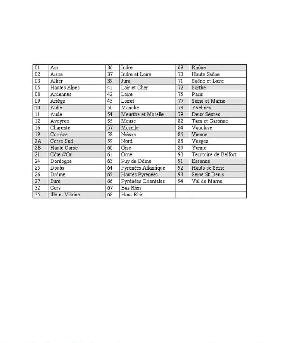
• Outdoor operation not permitted.
Refer to the ART web site for further details.
Metropolitan Regions with Eased Restrictions in 2.4GHz Band
Declaration of Conformity in Languages of the European Community
Finnish: Valmistaja NETGEAR, Inc. vakuuttaa täten että Radio LAN device tyyppinen laite on direktiivin 1999/5/EY
oleellisten vaatimusten ja sitä koskevien direktiivin muid en ehtojen mukainen.
Dutch: Hierbij verklaart NETGEAR, Inc. dat het toestel Radio LAN device in overeenstemming is met de essentiële
eisen en de andere relevante bepalingen van richtlijn 1999/5/EG.
French: Par la présente NETGEAR, Inc. déclare que l'appareil Radio LAN device est conforme aux exigences
essentielles et aux autres dispositions pertinentes de la directive 1999/5/CE.
Swedish: Härmed intygar NETGEAR, Inc. att denna Radio LAN device står I överensstämmelse med de väsentliga
egenskapskrav och övriga relevanta bestämmelser som framgår av direktiv 1999/5/EG.
Danish: Undertegnede NETGEAR, Inc. erklærer herved, at følgende udstyr Radio LAN device overholder de væsentlige
krav og øvrige relevante krav i direktiv 1999/5/EF.
German: Hiermit erklärt NETGEAR, Inc., dass sich dieser/diese/dieses Radio LAN device in Übereinstimmung mit den
grundlegenden Anforderungen und den anderen relevanten Vorschriften der Richtlinie 1999/5/EG befindet.
Italian: Con la presente NETGEAR, Inc. dichiara che questo Radio LAN device è conforme ai requisiti essenziali ed alle
altre disposizioni pertinenti stabilite dalla direttiva 1999/5/CE.
v1.0, December 2005
v
Page 6

Spanish: Por medio de la presente NETGEAR, Inc. declara que el Radio LAN device cumple con los requisitos
esenciales y cualesquiera otras disposiciones aplicables o exigibles de la Directiva 1999/5/CE.
Portugese: NETGEAR, Inc. declara que este Radio LAN device está conforme com os requisitos essenciais e outras
disposições da Directiva 1999/5/CE.
Canadian Department of Communications Radio Interference Regulations
This digital apparatus (ProSafe 7300 Series Layer-3 Managed Switch) does not exceed the Class B limits for radio-noise
emissions from digital apparatus as set out in the Radio Interference Regulations of the Canadian Department of
Communications.
Canada ID: 4054A-WG111
Additional Copyrights
AES Copyright (c) 2001, Dr Brian Gladman <brg@gladman.uk.net>, Worcester, UK.
All rights reserved.
TERMS
Redistribution and use in source and binary forms, with or without modification, are permitted
subject to the following conditions:
1. Redistributions of source code must retain the above copyright notice, this list of
conditions and the following disclaimer.
2. Redistributions in binary form must reproduce the above copyright notice, this list of
conditions and the following disclaimer in the documentation and/or other materials
provided with the distribution.
3. The copyright holder's name must not be used to endorse or promote any products
derived from this software without his specific prior written permission.
This software is provided 'as is' with no express or implied warranties of correctness or fitness
for purpose.
vi
v1.0, December 2005
Page 7

Open SSL Copyright (c) 1998-2000 The OpenSSL Project. All rights reserved.
Redistribution and use in source and binary forms, with or without modification, are permitted
provided that the following conditions * are met:
1. Redistributions of source code must retain the above copyright notice, this list of conditions
and the following disclaimer.
2. Redistributions in binary form must reproduce the above copyright notice, this list of
conditions and the following disclaimer in the documentation and/or other materials
provided with the distribution.
3. All advertising materials mentioning features or use of this software must display the
following acknowledgment: "This product includes software developed by the OpenSSL
Project for use in the OpenSSL Toolkit. (http://www.openssl.org/)"
4. The names "OpenSSL Toolkit" and "OpenSSL Project" must not be used to endorse or
promote products derived from this software without prior written permission. For written
permission, please contact openssl-core@openssl.org.
5. Products derived from this software may not be called "OpenSSL" nor may "OpenSSL"
appear in their names without prior written permission of the OpenSSL Project.
6. Redistributions of any form whatsoever must retain the following acknowledgment: "This
product includes software developed by the OpenSSL Project for use in the OpenSSL
Toolkit (http://www.openssl.org/)"
THIS SOFTWARE IS PROVIDED BY THE OpenSSL PROJECT ``AS IS'' AND ANY
EXPRESSED OR IMPLIED WARRANTIES, INCLUDING, BUT NOT LIMITED TO, THE
IMPLIED WARRANTIES OF MERCHANTABILITY AND FITNESS FOR A PARTICULAR
PURPOSE ARE DISCLAIMED. IN NO EVENT SHALL THE OpenSSL PROJECT OR ITS
CONTRIBUTORS BE LIABLE FOR ANY DIRECT, INDIRECT, INCIDENTAL, SPECIAL,
EXEMPLARY, OR CONSEQUENTIAL DAMAGES (INCLUDING, BUT NOT LIMITED TO,
PROCUREMENT OF SUBSTITUTE GOODS OR SERVICES; LOSS OF USE, DATA, OR
PROFITS; OR BUSINESS INTERRUPTION) HOWEVER CAUSED AND ON ANY THEORY
OF LIABILITY, WHETHER IN CONTRACT, STRICT LIABILITY, OR TORT (INCLUDING
NEGLIGENCE OR OTHERWISE) ARISING IN ANY WAY OUT OF THE USE OF THIS
SOFTWARE, EVEN IF ADVISED OF THE POSSIBILITY OF SUCH DAMAGE.
This product includes cryptographic software written by Eric Young (eay@cryptsoft.com). This
product includes software written by Tim Hudson (tjh@cryptsoft.com).
v1.0, December 2005
vii
Page 8

MD5 Copyright (C) 1990, RSA Data Security, Inc. All rights reserved.
License to copy and use this software is granted provided that it is identified as the "RSA Data
Security, Inc. MD5 Message-Digest Algorithm" in all material mentioning or referencing this
software or this function. License is also granted to make and use derivative works provided
that such works are identified as "derived from the RSA Data Security, Inc. MD5 MessageDigest Algorithm" in all material mentioning or referencing the derived work.
RSA Data Security, Inc. makes no representations concerning either the merchantability of
this software or the suitability of this software for any particular purpose. It is provided "as is"
without express or implied warranty of any kind.
These notices must be retained in any copies of any part of this documentation and/or
software.
PPP Copyright (c) 1989 Carnegie Mellon University. All rights reserved.
Redistribution and use in source and binary forms are permitted provided that the above
copyright notice and this paragraph are duplicated in all such forms and that any
documentation, advertising materials, and other materials related to such distribution and use
acknowledge that the software was developed by Carnegie Mellon University. The name of
the University may not be used to endor s e or promote products derived from th i s software
without specific prior written permission.
THIS SOFTWARE IS PROVIDED ``AS IS'' AND WITHOUT ANY EXPRESS OR IMPLIED
WARRANTIES, INCLUDING, WITHOUT LIMITATION, THE IMPLIED WARRANTIES OF
MERCHANTIBILITY AND FITNESS FOR A PARTICULAR PURPOSE.
Zlib zlib.h -- interface of the 'zlib' general purpose compression library version 1.1.4, March 11th,
2002. Copyright (C) 1995-2002 Jean-loup Gailly and Mark Adler.
viii
This software is provided 'as-is', without any express or implied warranty. In no event will the
authors be held liable for any damages arising from the use of this software. Permission is
granted to anyone to use this software for any purpose, including commercial applications,
and to alter it and redistribute it freely, subject to the following restrictions:
1. The origin of this software must not be misrepresented; you must not claim that you wrote
the original software. If you use this software in a product, an acknowledgment in the
product documentation would be appreciated but is not required.
2. Altered source versions must be plainly marked as such, and must not be misrepresented
as being the original software.
3. This notice may not be removed or altered from any source distribution.
Jean-loup Gailly: jloup@gzip.org; Mark Adler: madler@alu mni.caltech.edu
The data format used by the zlib library is described by RFCs (Request for Comments) 1950
to 1952 in the files ftp://ds.internic.net/rfc/rfc1950.txt
and rfc1952.txt (gzip format)
(zlib format), rfc1951.txt (deflate format)
v1.0, December 2005
Page 9

Product and Publication Details
Model Number: FSM73xx/GSM73xx
Publication Date: December 2005
Product Family: managed switch
Product Name: ProSafe 7300 Series Layer-3 Managed Switch
Home or Business Product: Business
Language: English
Publication Part Number: Beta Draft 1
Publication Version Number 1.0
v1.0, December 2005
ix
Page 10

x
v1.0, December 2005
Page 11

Contents
Command Line Interface Reference for the ProSafe 7300 Series Layer-3
Switches, Software Version 4.0
Chapter 1
About This Manual
1.1....................................................................................................................Audience 1-1
1.2.........................................................................................................................Scope 1-1
1.3....................................................................................... Typographical Conventions 1-2
1.4......................................................................................... Special Message Formats 1-2
1.5............................................................................................How to Use This Manual 1-3
1.6............................................................................................How to Print this Manual 1-3
1.7.........................................................................................................Revision History 1-4
Chapter 2
Overview
2.1.........................................................................................................................Scope 2-1
2.2...........................................................................Using the Command-Line Interface 2-1
2.2.1............................................................................................Command Syntax 2-2
2.2.2................................................................................... Command Conventions 2-2
2.2.3...................................................................Unit-Slot-Port Naming Convention 2-4
2.2.4................................................................Using the “No” Form of a Command 2-5
2.2.5............................................................................................ Command Modes 2-5
2.2.6................................................................................. Entering CLI Commands 2-8
2.2.7...............................................................................................Using CLI Help 2-10
2.2.8.............. ... ... ... ... .... .......................................... ..................Accessing the CLI 2-11
Chapter 3
Administrative Access Commands
3.1................................................................................... Network Interface Commands 3-1
3.1.1..............................................................................................................enable 3-2
3.1.2................................................................................................... serviceport ip 3-2
v1.0, December 2005
xi
Page 12

3.1.3.............. ... ... ... ... .... .......................................... ................. serviceport protocol 3-2
3.1.4.............. ... ... ... ....................................... ... ... .... ... ... ... .... ... .........network parms 3-2
3.1.5..........................................................................................network mgmt_vlan 3-2
3.1.6.............. ... ... ... ....................................... ... ... .... ... ... ... .... ... ...... network protocol 3-3
3.1.7...................................................................................................show network 3-3
3.1.8..............................................................................................show serviceport 3-4
3.2..............................................................................Console Port Access Commands 3-5
3.2.1....................................................................................................configuration 3-5
3.2.2..........................................................................................................lineconfig 3-5
3.2.3.............................................................................................. ...serial baudrate 3-6
3.2.4................................................................................................... serial timeout 3-6
3.2.5.......................................................................................................show serial 3-7
3.3......................................................................................................Telnet Commands 3-8
3.3.1................................................................................................................telnet 3-8
3.3.2........................................................................................transport input telnet 3-8
3.3.3......................................................................................transport output telnet 3-9
3.3.4.....................................................................................................session-limit 3-9
3.3.5.............. ... ... ... ... .... .......................................... ......................session-timeout 3-10
3.3.6.............. ... ... ... ... .... .......................................... .......... telnetcon maxsessions 3-10
3.3.7.............. ... ... ... ....................................... ... ... .... ... ... ... .... ... ....telnetcon timeout 3-11
3.3.8.....................................................................................................show telnet 3-11
3.3.9...............................................................................................show telnetcon 3-12
3.4................................................................................Secure Shell (SSH) Command 3-13
3.4.1............................................................................................................. ip ssh 3-13
3.4.2................................................................................................ip ssh protocol 3-13
3.4.3.............. ... ... ... ....................................... ... ... .... ... ... ... .... .sshcon maxsessions 3-14
3.4.4...............................................................................................sshcon timeout 3-14
3.4.5....................................................................................................show ip ssh 3-15
3.5.....................................................Hypertext Transfer Protocol (HTTP) Commands 3-15
3.5.1..........................................................................................ip http secure-port 3-15
3.5.2................................................................................... ip http secure-protocol 3-16
3.5.3......................................................................................ip http secure-server 3-16
3.5.4.............. ... ... ... ....................................... ... ... .... ... ... ... .... ... ..........ip http server 3-16
3.5.5..........................................................................................network javamode 3-17
3.5.6.............. ... ....................................... ... ... ... ... .... ............................show ip http 3-17
xii
v1.0, December 2005
Page 13

3.6.................... .... ... ... ... ... .... ... ... ... .... ...................................User Account Commands 3-18
3.6.1.............. ... ... ... ....................................... ... ... .... ... ... ... .... ... ............users name 3-18
3.6.2.................................................................................................users passwd 3-19
3.6.3...........................................................................users snmpv3 accessmode 3-19
3.6.4.........................................................................users snmpv3 authentication 3-20
3.6.5...............................................................................users snmpv3 encryption 3-20
3.6.6..........................................................................................show loginsession 3-21
3.6.7.....................................................................................................show users 3-21
3.6.8.............. ... ... ... ....................................... ... ... .... ... ... ... .... ... ..............disconnect 3-22
Chapter 4
Port and System Setup Commands
4.1.................................................................................. Port Configuration Commands 4-1
4.1.1...........................................................................................................interface 4-1
4.1.2.......................................................................................................cablestatus 4-2
4.1.3..................................................................................................auto-negotiate 4-2
4.1.4.............................................................................................auto-negotiate all 4-2
4.1.5...................................................................................................................mtu 4-3
4.1.6......................................................................................................... shutdown 4-3
4.1.7.....................................................................................................shutdown all 4-4
4.1.8...............................................................................................................speed 4-4
4.1.9.......................................................................................................... speed all 4-5
4.1.10..............................................................................................monitor session 4-5
4.1.11............... ... ... ... .... ... ....................................... ... ... ... .... ... ... ... .... ......no monitor 4-6
4.1.12.................................................................................... show monitor session 4-6
4.1.13.......................................................................................................show port 4-7
4.1.14......................................................................................... show port protocol 4-7
4.2....................................................Pre-login Banner and System Prompt Commands 4-8
4.2.1................................................................................................................. copy 4-8
4.2.2.............. ... ... ....................................... ... ... ... .... ... ... ... .......................set prompt 4-8
4.3........................ ... .......................................... ... ... ... .... Keying for Advanced Features 4-9
4.3.1.............. ... ... ... ... .... .......................................... .....................license advanced 4-9
4.3.2.............. ... ... ... ... .... .......................................... ....................show key-features 4-9
4.4.................... .... ... ... ... ... .... ........Simple Network Time Protocol (SNTP) Commands 4-10
4.4.1.................................................................. sntp broadcast client poll-interval 4-10
4.4.2.............. ... ... ... ....................................... ... ... .... ... ... ... .... ... .....sntp client mode 4-10
v1.0, December 2005
xiii
Page 14

4.4.3.............. ... ... ... ....................................... ... ... .... ... ... ... .... ... ........sntp client port 4-11
4.4.4.......................................................................sntp unicast client poll-interval 4-11
4.4.5.......................................................................sntp unicast client poll-timeout 4-11
4.4.6...........................................................................sntp unicast client poll-retry 4-12
4.4.7....................................................................sntp multicast client poll-interval 4-12
4.4.8.............. ... ....................................... ... ... ... ... .... .............................sntp server 4-13
4.4.9.............. ... ....................................... ... ... ... ... .... ...............................s how snt p 4-13
4.4.10............... ... ... ... ....................................... ... .... ... ... ... .... ... ... .. show sntp client 4-13
4.4.11............... ... ... ... .... ... ....................................... ... ... ... .... ... ... .show sntp server 4-14
4.5.......................................................MAC Address and MAC Database Commands 4-15
4.5.1.............. ... ... ... ... .... ... ... ... .... ......................................... network mac-address 4-15
4.5.2.......................................................................................... network mac-type 4-15
4.5.3.............. ... ....................................... ... ... ... ... .... ................................. macfilter 4-16
4.5.4.............. ... ... ... ... .... .......................................... ................... macfilter adddest 4-16
4.5.5.......................................................................................macfilter adddest all 4-17
4.5.6.............. ... ... ... ....................................... ... ... .... ... ... ... .... ... ..... macfilter addsrc 4-17
4.5.7.............. ... ....................................... ... ... ... ... .... .................macfilter addsrc all 4-18
4.5.8...........................................................................................bridge aging-time 4-18
4.5.9...........................................................................show forwardingdb agetime 4-19
4.5.10.............................................................. show mac-address-table multicast 4-20
4.5.11.................................................................... show mac-address-table static 4-20
4.5.12.........................................................show mac-address-table staticfiltering 4-21
4.5.13.....................................................................show mac-address-table stats 4-22
Chapter 5 Spanning Tree Protocol Commands
5.1..................................................................................STP Configuration Commands 5-1
5.1.1...................................................................................................spanning-tree 5-1
5.1.2..................................................................spanning-tree bpdumigrationcheck 5-2
5.1.3...................................................................spanning-tree configuration name 5-2
5.1.4................................................................spanning-tree configuration revision 5-3
5.1.5.............. ... ... ... ... .... ... ... ... .... .........................................spanning-tree edgeport 5-3
5.1.6.............................................................................. spanning-tree forceversion 5-4
5.1.7.............. ... ... ... ... .... ... ... ... .... ... ... ... .... ... ...................spanning-tree forward-time 5-4
5.1.8.................................................................................. spanning-tree hello-time 5-5
5.1.9....................................................................................spanning-tree max-age 5-5
5.1.10................................................................................spanning-tree max-hops 5-6
xiv
v1.0, December 2005
Page 15

5.1.11............... ... ... ... .... ... ....................................... ... ... ... .... ... ... .spanning-tree mst 5-6
5.1.12............................................................................spanning-tree mst instance 5-7
5.1.13.............................................................................. spanning-tree mst priority 5-8
5.1.14.................................................................................. spanning-tree mst vlan 5-9
5.1.15................................................................................spanning-tree port mode 5-9
5.1.16...........................................................................spanning-tree port mode all 5-9
5.2............................................................................................ STP Show Commands 5-10
5.2.1....................................................................................... show spanning-tree 5-10
5.2.2........................................................................show spanning-tree summary 5-12
5.2.3.........................................................................show spanning-tree interface 5-12
5.2.4............................................................show spanning-tree mst port detailed 5-13
5.2.5..........................................................show spanning-tree mst port summary 5-15
5.2.6.................................................................show spanning-tree mst summary 5-16
5.2.7................................................................................show spanning-tree vlan 5-16
Chapter 6
VLAN Commands
6.1................................................................................VLAN Configuration Commands 6-1
6.1.1.................................................................................................. vlan database 6-1
6.1.2..........................................................................................network mgmt_vlan 6-2
6.1.3.................................................................................................................. vlan 6-2
6.1.4............................................................................................. vlan acceptframe 6-2
6.1.5...............................................................................................vlan ingressfilter 6-3
6.1.6................................................................................................vlan makestatic 6-3
6.1.7........................................................................................................vlan name 6-4
6.1.8.............. ... ... ... ... .... .......................................... ......................vlan participation 6-4
6.1.9......................................................................................... vlan participation all 6-5
6.1.10................................................................................ vlan port acceptframe all 6-5
6.1.11.............................................................................................vlan port pvid all 6-6
6.1.12........................................................................................vlan port tagging all 6-6
6.1.13.................................................................................vlan port ingressfilter all 6-7
6.1.14............... ... ... ... .... ... .......................................... ........................Global Config 6-7
6.1.15........................................................................................ vlan protocol group 6-7
6.1.16................................................................... vlan protocol group add protocol 6-7
6.1.17............... ... ... ... .... ... ... ... .... ... ............................... vlan protocol group remove 6-8
6.1.18................................................................................................protocol group 6-8
v1.0, December 2005
xv
Page 16

6.1.19........................................................................................ protocol vlan group 6-9
6.1.20....................................................................................protocol vlan group all 6-9
6.1.21.......................................................................................................vlan pvid 6-10
6.1.22................................................................................................. vlan tagging 6-10
6.2.......................................................................................... VLAN Show Commands 6-11
6.2.1.......................................................................................................show vlan 6-11
6.2.2...............................................................................................show vlan brief 6-12
6.2.3................................................................................................show vlan port 6-13
6.3.................................................................. Provisioning (IEEE 802.1p) Commands 6-14
6.3.1.........................................................................................vlan port priority all 6-14
6.3.2.............. ... ... ... ....................................... ... ... .... ... ... ... .... ... ............ vlan priority 6-14
Chapter 7
DHCP Commands
7.1.............................................. DHCP Server Commands (DHCP Config Pool Mode) 7-2
7.1.1..................................................................................................... ip dhcp pool 7-2
7.1.2..................................................................................................client-identifier 7-2
7.1.3......................................................................................................client-name 7-3
7.1.4................................................................................................... default-router 7-3
7.1.5........................................................................................................dns-server 7-4
7.1.6............................................................................................hardware-address 7-4
7.1.7..................................................................................................................host 7-5
7.1.8................................................................................................................lease 7-5
7.1.9............................................................................................................network 7-6
7.1.10........................................................................................................... bootfile 7-6
7.1.11.................................................................................................domain-name 7-6
7.1.12......................................................................................netbios-name-server 7-7
7.1.13..........................................................................................netbios-node-type 7-7
7.1.14.....................................................................................................next-server 7-8
7.1.15.............................................................................................................option 7-8
7.2...................................................... DHCP Server Commands (Global Config Mode) 7-9
7.2.1................................................................................ip dhcp excluded-address 7-9
7.2.2......................................................................................ip dhcp ping packets 7-10
7.2.3...................................................................................................service dhcp 7-10
7.2.4.............. ... ... ... ... .... .......................................... .........ip dhcp bootp automatic 7-11
7.2.5.............. ... ... ... ... .... ... ... ... .... ... ... ... ...............................ip dhcp conflict logging 7-11
xvi
v1.0, December 2005
Page 17

7.3.............................................................DHCP Server Clear and Show Commands 7-12
7.3.1......................................................................................clear ip dhcp binding 7-12
7.3.2.........................................................................clear ip dhcp server statistics 7-12
7.3.3.............. ... ... ... ... .... .......................................... ..............clear ip dhcp conflict 7-12
7.3.4..................................................................................... show ip dhcp binding 7-13
7.3.5..................................................................show ip dhcp global configuration 7-13
7.3.6.................................................................... show ip dhcp pool configuration 7-14
7.3.7........................................................................show ip dhcp server statistics 7-15
7.3.8.............. ... ... ... ... .... .......................................... ..............show ip dhcp conflict 7-16
7.4.................................................................... DHCP and BOOTP Relay Commands 7-16
7.4.1...........................................................................bootpdhcprelay cidoptmode 7-16
7.4.2.................................................................................. bootpdhcprelay enable 7-17
7.4.3........................................................................bootpdhcprelay maxhopcount 7-17
7.4.4..........................................................................bootpdhcprelay minwaittime 7-18
7.4.5................................................................................ bootpdhcprelay serverip 7-18
7.4.6.............. ... ... ... ... .... .......................................... .............show bootpdhcprelay 7-19
Chapter 8
GARP, GVRP, and GMRP Commands
8.1.....................................................................................................GARP Commands 8-2
8.1.1............................................................................................set garp timer join 8-2
8.1.2......................................................................................... set garp timer leave 8-3
8.1.3......................................................................................set garp timer leaveall 8-4
8.1.4.............. ... ... ... ....................................... ... ... .... ... ... ... .... ... ................show garp 8-4
8.2.....................................................................................................GVRP Commands 8-5
8.2.1........................................................................................ set gvrp adminmode 8-5
8.2.2.................................................................................... set gvrp interfacemode 8-5
8.2.3...................................................................................show gvrp configuration 8-6
8.3.....................................................................................................GMRP Commands 8-7
8.3.1.......................................................................................set gmrp adminmode 8-7
8.3.2.............. ... ... ... ... .... ... ... ... .... ... ... ... .... ... ........................set gmrp interfacemode 8-8
8.3.3..................................................................................show gmrp configuration 8-8
8.3.4...................................................................... show mac-address-table gmrp 8-10
Chapter 9
Port-Based Traffic Control Commands
9.1...........................................................................................Port Security Commands 9-1
v1.0, December 2005
xvii
Page 18

9.1.1.....................................................................................................port-security 9-2
9.1.2...............................................................................port-security max-dynamic 9-2
9.1.3....................................................................................port-security max-static 9-3
9.1.4............................................................................... port-security mac-address 9-3
9.1.5..................................................................... port-security mac-address move 9-3
9.1.6.............. ... ... ... ... .... .......................................... ....................show port-security 9-4
9.1.7.............. ... ... ... ... .... .......................................... ....................show port-security 9-4
9.1.8............................................................................. show port-security dynamic 9-4
9.1.9.................................................................................. show port-security static 9-4
9.1.10........................................................................... show port-security violation 9-5
9.2......................................................................................... Storm Control Commands 9-5
9.2.1.............. ... ... ... ... .... ... ... ... .... ... ... ... ...............................storm-control broadcast 9-5
9.2.2..................................................................................storm-control flowcontrol 9-6
9.2.3.......................................................................................... show storm-control 9-7
Chapter 10
SNMP Commands
10.1...........................................................................SNMP Configuration Commands 10-1
10.1.1............................................................... ... .... ... ... ... .... ... ... ... .... .snmp-server 10-1
10.1.2.............................................................................. snmp-server community 10-2
10.1.3................................................................... snmp-server community ipaddr 10-2
10.1.4..................................................................snmp-server community ipmask 10-3
10.1.5............................................................... ..... snmp-server community mode 10-4
10.1.6..........................................................................snmp-server community ro 10-4
10.1.7..........................................................................snmp-server community rw 10-4
10.1.8..............................................................snmp-server enable traps violation 10-5
10.1.9............................................................................snmp-server enable traps 10-5
10.1.10....................................................... snmp-server enable traps bcaststorm 10-6
10.1.11 ...........................................................snmp-server enable traps linkmode 10-6
10.1.12.........................................................snmp-server enable traps multiusers 10-6
10.1.13........................................................... snmp-server enable traps stpmode 10-7
10.1.14................................................................ .... ... ... ... .... ... ... ... ..........snmptrap 10-7
10.1.15.............................................................................. snmptrap snmpversion 10-8
10.1.16.........................................................................................snmptrap ipaddr 10-8
10.1.17................................................................ .... ... ... ... .... ... ... ...snmptrap mode 10-8
10.1.18................................................................ .... ... ... ... .... .snmp trap link-status 10-9
xviii
v1.0, December 2005
Page 19

10.1.19................................................................ .... ... ... ...snmp trap link-status all 10-9
10.2.....................................................................................SNMP Show Commands 10-10
10.2.1...............................................................................show snmpcommunity 10-10
10.2.2...........................................................................................show snmptrap 10-11
10.2.3............................................................................................show trapflags 10-12
Chapter 11
Port-Based Access and Authentication Commands
11.1.................................................. Port-Based Network Access Control Commands 11-1
11.1.1 ......................................................................................authentication login 11-1
11.1.2 .....................................................................................clear dot1x statistics 11-3
11.1.3 ....................................................................................clear radius statistics 11-3
11.1.4 .........................................................................................dot1x defaultlogin 11-3
11.1.5 .............................................................................................. dot1x initialize 11-3
11.1.6 ....................................................................................................dot1x login 11-3
11.1.7 ..............................................................................................dot1x max-req 11-4
11.1.8 .........................................................................................dot1x port-control 11-4
11.1.9 .................................................................................... dot1x port-control all 11-5
11.1.10 ............................................................. ... .... ... ... ... .... dot1x re-authenticate 11-5
11.1.11............................................................................... dot1x re-authentication 11-6
11.1.12 ..........................................................................dot1x system-auth-control 11-6
11.1.13 ....................................................... ... ... ... .... ... ...................... dot1x timeout 11-6
11.1.14 ....................................................... ... ....................................... . dot1x user 11 -7
11.1.15 .......................................................................................users defaultlogin 11-8
11.1.16 ..................................................................................................users login 11-8
11.1.17 ................................................................................... show authentication 11-8
11.1.18 ......................................................................... show authentication users 11-9
11.1.19 .................................................................................................show dot1x 11-9
11.1.20 .....................................................................................show dot1x users 11-12
11.1.21 ....................................................................... show users authentication 11-13
11.2.................. .... ... ... ... ... .... .......................................... ... ... ... ... RADIUS Commands 11-13
11.2.1 ......................................................... ... ... ..............radius accounting mode 11-13
11.2.2 ...................................................................................... radius server host 11-14
11.2.3 ........................................................................................radius server key 11-15
11.2.4 ............................................................................... radius server msgauth 11-15
11.2.5 ................................................................................. radius server primary 11-16
v1.0, December 2005
xix
Page 20

11.2.6 ............................................................................. radius server retransmit 11-16
11.2.7 ................................................................................. radius server timeout 11-16
11.2.8 ...................................................... ... ... ... ... .... ..........................show radius 11-17
11.2.9 ......................................................... ... ... ... ........... show radius accounting 11-18
11.2.10 ....................................................... ... ... ... .... ... ... ... .. show radius statistics 11-19
Chapter 12
Port-Channel/LAG (802.3ad) Commands
12.1................................................................Port-Channel Configuration Commands 12-1
12.1.1..................... ... .... ... ... ... .......................................... .......................... addport 12-2
12.1.2............................................................... ... .... ..deleteport (Interface Config) 12-2
12.1.3............................................................... ... .... ... ...deleteport (Global Config) 12-2
12.1.4..................... ... .... ... ... ... .... ... ... ... .......................................... .... .port-channel 12-3
12.1.5............................................................... ... .... ... ... ... .... ... ..clear port-channel 12-3
12.1.6........................................................................ port-channel staticcapability 12-3
12.1.7..............................................................................................port lacpmode 12-4
12.1.8......................................................................................... port lacpmode all 12-4
12.1.9.............................................................................port-channel adminmode 12-4
12.1.10................................................................ .... ... ... ... .... ... .port -channel name 12-5
12.1.11 .................................................................................. port-channel linktrap 12-5
12.2............................................................................Port-Channel Show Commands 12-6
12.2.1............................................................................... show port-channel brief 12-6
12.2.2............................................................... ... .... ... ... ... .... ... . show port-channel 12-6
Chapter 13
Quality of Service (QoS) Commands
13.1................................................................... ... .Class of Service (CoS) Commands 13-1
13.1.1.....................................................................classofservice dot1p-mapping 13-2
13.1.2....................................................... classofservice ip-precedence-mapping 13-2
13.1.3...................................................................classofservice ip-dscp-mapping 13-3
13.1.4...................................................................................... classofservice trust 13-3
13.1.5..................... ... .... ... ... ... .... ... ... ... .... ... ... ... ... ..........cos-queue min-bandwidth 13-4
13.1.6..................... ... .... ... ... ... .... ... ... ... .... ... ... ............................... cos-queue strict 13-4
13.1.7..................... ... .... ... ... .......................................... .....................traffic-shape 13-5
13.1.8............................................................show classofservice dot1p-mapping 13-5
13.1.9..............................................show classofservice ip-precedence-mapping 13-6
13.1.10....................................................... show classofservice ip-dscp-mapping 13-6
xx
v1.0, December 2005
Page 21

13.1.11 ...........................................................................show classofservice trust 13-7
13.1.12.................................................................... ... .show interfaces cos-queue 13-7
13.2....................................................... Diffe rentiated Services (DiffServ) Commands 13-8
13.2.1............................................................... ... .... ... ... ............................. diffserv 13-9
13.3...................................................................................DiffServ Class Commands 13-10
13.3.1.................................................................................................. class-map 13-10
13.3.2..................................................................................... class-map rename 13-11
13.3.3..................... ... .... ... ... ... .......................................... ................... match any 13-11
13.3.4........................................................................................match class-map 13-11
13.3.5................................................................................................ match dstip 13-12
13.3.6.......................................................................................... match dstl4port 13-12
13.3.7.............................................................................................match ip dscp 13-13
13.3.8................................................................................. match ip precedence 13-13
13.3.9..................... ... .... ... ... ... .......................................... ................ match ip tos 13-14
13.3.10......................................................................................... match protocol 13-14
13.3.11 .............................................................................................. match srcip 13-15
13.3.12........................................................................................ match srcl4port 13-15
13.4..................................................................................DiffServ Policy Commands 13-15
13.4.1............................................................................................. assign-queue 13-16
13.4.2............................................................................................................drop 13-16
13.4.3.............................................................................................conform-color 13-16
13.4.4...........................................................................................................class 13-17
13.4.5..................... ... .... ... ... ... .......................................... .....................mark cos 13-18
13.4.6.............................................................................................. mark ip-dscp 13-18
13.4.7...................................................................................mark ip-precedence 13-18
13.4.8..............................................................................................police-simple 13-19
13.4.9................................................................................................. policy-map 13-19
13.4.10..................................................................................policy-map rename 13-20
13.5................................................................................DiffServ Service Commands 13-20
13.5.1.............................................................................................service-policy 13-21
13.6...................................................................................DiffServ Show Commands 13-22
13.6.1.........................................................................................show class-map 13-22
13.6.2..............................................................................................show diffserv 13-23
13.6.3..................... ... .... ... ... ... .... ... ... ... .... ... ... ... ... ......................show policy-map 13-24
13.6.4................................................................................. show diffserv service 13-26
v1.0, December 2005
xxi
Page 22

13.6.5............................................................... ... .... ... show diffserv service brief 13-26
13.6.6.........................................................................show policy-map interface 13-27
13.6.7....................................................................................show service-policy 13-27
13.7....................................................... MAC Access Control List (ACL) Commands 13-28
13.7.1.......................................................................... mac access-list extended 13-28
13.7.2............................................................. mac access-list extended rename 13-29
13.7.3..............................................................................................{deny|permit} 13-29
13.7.4..................................................................................... mac access-group 13-31
13.7.5...............................................................................show mac access-lists 13-31
13.8............................................................IP Access Control List (ACL) Commands 13-32
13.8.1..................................................................................................access-list 13-33
13.8.2......................................................................................... ip access-group 13-34
13.8.3...................................................................................show ip access-lists 13-34
13.8.4.......................................................................................show access-lists 13-36
Chapter 14
Routing Commands
14.1................................................... Address Resolution Protocol (ARP) Commands 14-1
14.1.1..................... ... .... ... ....................................... ... ... ... .... ... ... ... .... ................arp 14-2
14.1.2..................................................................................................ip proxy-arp 14-2
14.1.3............................................................... ... .... ... ... ...................arp cachesize 14-3
14.1.4..................... ... .... ... ... ... .... ... ... ... .... ... ... ........................... arp dynamicrenew 14-3
14.1.5..................................................................................................... arp purge 14-3
14.1.6............................................................... ... .... ... ... ... .... ... ... ... .....arp resptime 14-3
14.1.7............................................................... ... .... ... ... ... ......................arp retries 14-5
14.1.8...................................................................................................arp timeout 14-5
14.1.9............................................................................................clear arp-cache 14-6
14.1.10................................................................ .... ... ... ... .... ... ................show arp 14-6
14.1.11 ............................................................................................ show arp brief 14-7
14.2...................... ... ... ... ... .... ... ... ... .... ... ... ... .... ... ... .....................IP Routing Commands 14-8
14.2.1..................... ... .... ... ... ... .......................................... ...........................routing 14-8
14.2.2......................................................................................................ip routing 14-8
14.2.3.................................................................................................... ip address 14-9
14.2.4..................... ... .... ... ....................................... ... ... ... .... ... ... ... .... .........ip route 14-9
14.2.5..................... ... .... ... ... ... .......................................... ............ip route default 14-10
14.2.6.........................................................................................ip route distance 14-11
xxii
v1.0, December 2005
Page 23

14.2.7..................... ... .... ... ... ... .... ... ... ... .......................................... .. ip forwarding 14-11
14.2.8............................................................................................. ip netdirbcast 14-12
14.2.9.........................................................................................................ip mtu 14-12
14.2.10...........................................................................................encapsulation 14-13
14.2.11 .............................................................................................show ip brief 14-13
14.2.12......................................................................................show ip interface 14-14
14.2.13...................... .... ... ... ... .... ... ... ... .... ... ... ... ... .... ..........show ip interface brief 14-15
14.2.14........................................................................................... show ip route 14-16
14.2.15..........................................................................show ip route bestroutes 14-16
14.2.16................................................................ .... ... ... ... .... . show ip route entry 14-17
14.2.17....................................................................... show ip route preferences 14-18
14.2.18...................... .... ... ... ... .... ... ... ... .... ........................................ show ip stats 14-18
14.3................................................................Router Discovery Protocol Commands 14-19
14.3.1.........................................................................................................ip irdp 14-19
14.3.2........................................................................................... ip irdp address 14-19
14.3.3.......................................................................................... ip irdp holdtime 14-20
14.3.4............................................................................ip irdp maxadvertinterval 14-20
14.3.5.............................................................................ip irdp minadvertinterval 14-20
14.3.6.......................................................................................ip irdp preference 14-21
14.3.7................................................................................................show ip irdp 14-21
14.4..........................................................................Virtual LAN Routing Commands 14-22
14.4.1..................... ... .... ... ... ... .... ... ... ... .......................................... .... vlan routing 14-22
14.4.2...............................................................................................show ip vlan 14-22
14.5...................................Virtual Router Redundancy Protocol (VRRP) Commands 14-23
14.5.1.........................................................................................................ip vrrp 14-23
14.5.2.........................................................................................................ip vrrp 14-24
14.5.3...............................................................................................ip vrrp mode 14-24
14.5.4.....................................................................................................ip vrrp ip 14-24
14.5.5................................................................................. ip vrrp authentication 14-25
14.5.6..................... ... .... ... ... ... .... ... ... ... .........................................ip vrrp preempt 14-25
14.5.7.............................................................................................ip vrrp priority 14-26
14.5.8.............................................................................. ip vrrp timers advertise 14-26
14.5.9........................................................................show ip vrrp interface stats 14-26
14.5.10............................................................................................. show ip vrrp 14-28
14.5.11 ...............................................................................show ip vrrp interface 14-29
v1.0, December 2005
xxiii
Page 24

14.5.12...................... .... ... ... ... .... ... ... ... .... ... ... ... ... .... ...show ip vrrp interface brief 14-29
14.6.....................................................Open Shortest Path First (OSPF) Commands 14-30
14.6.1..................................................................................................router ospf 14-30
14.6.2...........................................................................................enable (OSPF) 14-30
14.6.3........................................................................................................ip ospf 14-30
14.6.4.......................................................................................1583compatibility 14-31
14.6.5..................... ... .... ... ... ... .... ... ... ... .... ... ... ............................area default-cost 14-31
14.6.6...................................................................................................area nssa 14-31
14.6.7.................................................................area nssa default-info-originate 14-32
14.6.8..............................................................area nssa no-redistribute (OSPF) 14-32
14.6.9.................................................................area nssa no-summary (OSPF) 14-32
14.6.10.............................................................area nssa translator-role (OSPF) 14-32
14.6.11 ..................................................................area nssa translator-stab-intv 14-33
14.6.12............................................................................................... area range 14-33
14.6.13..................................................................................................area stub 14-33
14.6.14............................................................................. area stub summarylsa 14-34
14.6.15........................................................................................ area virtual-link 14-34
14.6.16................................................................ .area virtual-link authentication 14-35
14.6.17...................................................................area virtual-link dead-interval 14-35
14.6.18...................................................................area virtual-link hello-interval 14-36
14.6.19...........................................................area virtual-link retransmit-interval 14-36
14.6.20.................................................................area virtual-link transmit-delay 14-37
14.6.21.......................................................default-information originate (OSPF) 14-37
14.6.22..............................................................................default-metric (OSPF) 14-38
14.6.23............................................................................................distance ospf 14-38
14.6.24.......................................................................................distribute-list out 14-39
14.6.25................................................................................exit-overflow-interval 14-39
14.6.26.....................................................................................external-lsdb-limit 14-40
14.6.27........................................................................................... ip ospf areaid 14-40
14.6.28...............................................................................ip ospf authentication 14-40
14.6.29...............................................................................................ip ospf cost 14-41
14.6.30................................................................................ ip ospf dead-interval 14-41
14.6.31................................................................ .... ... ... ... ....ip ospf hello-interval 14-42
14.6.32.......................................................................................... ip ospf priority 14-42
14.6.33........................................................................ ip ospf retransmit-interval 14-43
xxiv
v1.0, December 2005
Page 25

14.6.34...............................................................................ip ospf transmit-delay 14-43
14.6.35....................................................................................ip ospf mtu-ignore 14-44
14.6.36................................................................................................... router-id 14-44
14.6.37...............................................................................................redistribute 14-44
14.6.38....................................................................................... maximum-paths 14-45
14.6.39...................................................................................................trapflags 14-45
14.6.40.............................................................................................show ip ospf 14-46
14.6.41................................................................ .... ... ... ... .... ... .show ip ospf area 14-48
14.6.42.............................................................................show ip ospf database 14-49
14.6.43..............................................................................show ip ospf interface 14-50
14.6.44......................................................................show ip ospf interface brief 14-51
14.6.45.................................................................... .. show ip os pf interface stats 14-52
14.6.46..............................................................................show ip ospf neighbor 14-53
14.6.47.................................................................... ..show ip ospf neighbor brief 14-54
14.6.48...................................................................................show ip ospf range 14-55
14.6.49............................................................................ show ip ospf stub table 14-56
14.6.50............................................................................show ip ospf virtual-link 14-56
14.6.51....................................................................show ip ospf virtual-link brief 14-57
14.7.................................................. Routing Information Protocol (RIP) Commands 14-58
14.7.1..................... ... .... ... ... ... .... ... ... ... .......................................... .... ... . router rip 14-58
14.7.2...............................................................................................enable (RIP) 14-58
14.7.3..................... ... .... ... ... ... .......................................... ............................ip rip 14-58
14.7.4............................................................................................auto-summary 14-59
14.7.5.............................................................default-information originate (RIP) 14-59
14.7.6....................................................................................default-metric (RIP) 14-59
14.7.7..................... ... .... ... ... ... .... ... ... ... .......................................... .... distance rip 14-60
14.7.8.........................................................................................distribute-list out 14-60
14.7.9....................................................................................ip rip authentication 14-61
14.7.10................................................................................ip rip receive version 14-61
14.7.11 ....................................................................................ip rip send version 14-62
14.7.12..................................................................................... hostroutesaccept 14-62
14.7.13............................................................................................. split-horizon 14-62
14.7.14...............................................................................................redistribute 14-63
14.7.15................................................................................................show ip rip 14-64
14.7.16.........................................................................show ip rip interface brief 14-65
v1.0, December 2005
xxv
Page 26

14.7.17.......................... ... ... ... .... ... ... ....................................show ip rip interface 14-65
14.8...................................................... Border Gateway Protocol (BGP) Commands 14-66
14.8.1.................................................................................................. router bgp 14-66
14.8.2.....................................................................................aggregate-address 14-67
14.8.3................................................................................bgp addrfamily create 14-67
14.8.4...........................................................................................bgp autorestart 14-68
14.8.5..................................................................................... bgp calcmedmode 14-68
14.8.6............................................................................................. bgp cluster-id 14-68
14.8.7..................... ... .... ... ... ... .... ... ... ... .... .................................... bgp community 14-69
14.8.8............................................................... ... .... . bgp confederation identifier 14-69
14.8.9......................................................................bgp default local-preference 14-70
14.8.10................................................................... bgp flapdamping dampfactor 14-70
14.8.11 ..................................................................bgp flapdamping flapmaxtime 14-70
14.8.12............................................................................bgp flapdamping mode 14-71
14.8.13.....................................................................bgp flapdamping penaltyinc 14-71
14.8.14......................................................................bgp flapdamping reuselimit 14-72
14.8.15...............................................................bgp flapdamping reusemaxsize 14-72
14.8.16................................................................ bgp flapdamping suppresslimit 14-72
14.8.17..............................................................bgp flapdamping timerresolution 14-73
14.8.18...........................................................................bgp interval minasorigin 14-73
14.8.19......................................................................bgp interval minrouteadvint 14-74
14.8.20........................................................................................... bgp localmed 14-74
14.8.21....................................................................................... bgp optionalcap 14-75
14.8.22................................................................ .... ... ... ... .... ... ... ... .... ...bgp origin 14-75
14.8.23.................................................................................................bgp policy 14-75
14.8.24...........................................................................bgp policy action addint 14-76
14.8.25................................................................bgp policy action addint modify 14-77
14.8.26.................................................................... ... ... .. bgp policy action addip 14-77
14.8.27.................................................................bgp policy action addip modify 14-78
14.8.28.................................................................... ... ..bgp policy action remove 14-78
14.8.29.........................................................................bgp policy range address 14-79
14.8.30........................................................................bgp policy range between 14-79
14.8.31.............................................................................bgp policy range equal 14-79
14.8.32................................................................ ...bgp policy range greaterthan 14-79
14.8.33........................................................................bgp policy range lessthan 14-80
xxvi
v1.0, December 2005
Page 27

14.8.34...................................................................................bgp propmedmode 14-80
14.8.35................................................................ .... ... ... ... .... ... ... ... .. bgp router-id 14-80
14.8.36..................................................................................................bgp snpa 14-81
14.8.37..................................................................................bgp suppressmode 14-81
14.8.38..................................................................................................clear bgp 14-82
14.8.39......................................................... default-information originate (BGP) 14-82
14.8.40................................................................................default-metric (BGP) 14-82
14.8.41............................................................................................ distance bgp 14-83
14.8.42.......................................................................................distribute-list out 14-83
14.8.43...........................................................................................enable (BGP) 14-83
14.8.44.................................................................... ... ... ... .... neighbor addrfamily 14-84
14.8.45............................................neighbor <peeripaddr> authentication none 14-84
14.8.46..........................................neighbor <peeripaddr> authentication simple 14-85
14.8.47..........................................................................neighbor confedmember 14-85
14.8.48...................................................................................neighbor connretry 14-85
14.8.49.............................................................................neighbor msgsendlimit 14-86
14.8.50.............................................................................neighbor next-hop-self 14-86
14.8.51............................................................................... neighbor optionalcap 14-87
14.8.52..................................................................................neighbor remote-as 14-87
14.8.53..................................................................neighbor rout e-reflector-client 14-87
14.8.54.................................................................................. neighbor shutdown 14-88
14.8.55........................................................................................neighbor timers 14-88
14.8.56...................................................................................neighbor txdelayint 14-89
14.8.57.................................................................................................... network 14-89
14.8.58...............................................................................................redistribute 14-90
14.8.59.................................................................................... route-aggregation 14-90
14.8.60..............................................................................................route-reflect 14-91
14.8.61...................................................................................................trapflags 14-91
14.8.62..............................................................................................show ip bgp 14-92
14.8.63......................................................................show ip bgp addrfamilyinfo 14-92
14.8.64.............................................................. show ip bgp aggregate-address 14-92
14.8.65................................................................ .... ... ... ... .... ... ..show ip bgp brief 14-93
14.8.66...............................................................................show ip bgp damping 14-95
14.8.67.....................................................................................show ip bgp local 14-96
14.8.68............................................................................show ip bgp mplslabels 14-96
v1.0, December 2005
xxvii
Page 28

14.8.69.............................................................................show ip bgp neighbors 14-97
14.8.70..................................................... show ip bgp neighbors addrfamilyinfo 14-98
14.8.71.................................................................... show ip bgp neighbors stats 14-99
14.8.72................................................................................. show ip bgp nlrilist 14-100
14.8.73.................................................................... ...show ip bgp pathattrtable 14-100
14.8.74.......................... ... ... ... .... ... ... .................................show ip bgp peer-list 14-101
14.8.75......................................................................... show ip bgp policy brief 14-101
14.8.76....................................................................show ip bgp policy detailed 14-102
14.8.77................................................................ .... ... ... ... . show ip bgp snpalist 14-102
14.8.78................................................................ .... ...... ...show ip bgp trapflags 14-103
Chapter 15
IP Multicast Commands
15.1............................................................................................. Multicast Commands 15-2
15.1.1...................................................................................................ip multicast 15-2
15.1.2....................................................................................... ip mcast boundary 15-2
15.1.3................................................................................. ip multicast staticroute 15-3
15.1.4..................... ... .... ... ... ... ..........................................ip multicast ttl-threshold 15-3
15.1.5............................................................ disable ip multicast mdebug mtrace 15-4
15.1.6..................... ... .... ... ....................................... ... ... ... .... ... ... ... .... ...........mrinfo 15-4
15.1.7............................................................................................................mstat 15-5
15.1.8..................... ... .... ... ....................................... ... ... ... .... ... ... ... .... ..........mtrace 15-5
15.1.9...................................................................................... no ip mcast mroute 15-6
15.1.10............................................................................................show ip mcast 15-6
15.1.11 ............................................................................show ip mcast boundary 15-7
15.1.12.............................................................................show ip mcast interface 15-7
15.1.13................................................................................show ip mcast mroute 15-8
15.1.14......................................................................show ip mcast mroute group 15-8
15.1.15....................................................................show ip mcast mroute source 15-9
15.1.16.................................................................... show ip mcast mroute static 15-10
15.1.17............................................................................................. show mrinfo 15-10
15.1.18...............................................................................................show mstat 15-11
15.1.19.............................................................................................show mtrace 15-11
15.2............................................................................................ DVMRP Commands 15-12
15.2.1.....................................................................................................ip dvmrp 15-12
15.2.2.......................................................................................... ip dvmrp metric 15-12
xxviii
v1.0, December 2005
Page 29

15.2.3...................................................................................... ip dvmrp trapflags 15-13
15.2.4.....................................................................................................ip dvmrp 15-13
15.2.5............................................................................................show ip dvmrp 15-13
15.2.6.............................................................................show ip dvmrp interface 15-14
15.2.7..................... ... .... ... ... ... .... ... ... ... .... ... ... ... ... .... ... ... .show ip dvmrp neighbor 15-15
15.2.8..............................................................................show ip dvmrp nexthop 15-15
15.2.9................................................................................. show ip dvmrp prune 15-16
15.2.10................................................................................ show ip dvmrp route 15-16
15.3............................................................................................ PIM-DM Commands 15-17
15.3.1.................................................................................................... ip pimdm 15-17
15.3.2.......................................................................................... ip pimdm mode 15-17
15.3.3............................................................................. ip pimdm query-interval 15-18
15.3.4...........................................................................................show ip pimdm 15-18
15.3.5............................................................................show ip pimdm interface 15-19
15.3.6................................................................... show ip pimdm interface stats 15-19
15.3.7..................... ... .... ... ... ... .... ... ... ... .... ... ... ... ... .... ... ...show ip pimdm neighbor 15-19
15.4............................................................................................ PIM-SM Commands 15-20
15.4.1........................................................................... ip pimsm cbsrpreference 15-20
15.4.2.................................................................. ip pimsm cbsrhashmasklength 15-20
15.4.3.............................................................................ip pimsm crppreference 15-21
15.4.4........................................................................ip pimsm message-interval 15-21
15.4.5.................................................................................................... ip pimsm 15-22
15.4.6.......................................................................................... ip pimsm mode 15-22
15.4.7..............................................................................ip pimsm query-interval 15-23
15.4.8...............................................................................ip pimsm spt-threshold 15-23
15.4.9.......................................................................................... ip pim-trapflags 15-23
15.4.10......................................................................................ip pimsm staticrp 15-24
15.4.11 .............................................................................show ip pimsm rphash 15-24
15.4.12...................... .... ... ... ... .... ... ... ... .... ... ... ... ... .... ... ... .. show ip pimsm staticrp 15-25
15.4.13.........................................................................................show ip pimsm 15-25
15.4.14.....................................................................show ip pimsm candrptable 15-26
15.4.15.............................................................. show ip pimsm componenttable 15-26
15.4.16..........................................................................show ip pimsm interface 15-26
15.4.17..................................................................show ip pimsm interface stats 15-27
15.4.18..........................................................................show ip pimsm neighbor 15-27
v1.0, December 2005
xxix
Page 30

15.4.19.....................................................................................show ip pimsm rp 15-28
15.4.20.............................................................................show ip pimsm rphash 15-28
15.5........................................Internet Group Message Protocol (IGMP) Commands 15-29
15.5.1.......................................................................................................ip igmp 15-29
15.5.2...........................................................................................ip igmp version 15-29
15.5.3..............................................................ip igmp last-member-query-count 15-29
15.5.4........................................................... ip igmp last-member-query-interval 15-30
15.5.5................................................................................ ip igmp query-interval 15-30
15.5.6............................................................. ip igmp query-max-response-time 15-31
15.5.7.....................................................................................ip igmp robustness 15-31
15.5.8.......................................................................ip igmp startup-query-count 15-32
15.5.9....................................................................ip igmp startup-query-interval 15-32
15.5.10............................................................................................show ip igmp 15-32
15.5.11 ................ ... ... .... ... ... ... .... ... ... ... .... ... ... ... ...................show ip igmp groups 15-33
15.5.12.................................................................... ... ... ...show ip igmp interface 15-34
15.5.13........................................................ show ip igmp interface membership 15-35
15.5.14.................................................................... show ip igmp interface stats 15-36
Chapter 16
IGMP Snooping Commands
16.1............................................................IGMP Snooping Configuration Commands 16-1
16.1.1.......................................................................................................set igmp 16-1
16.1.2............................................................... ... .... ... ... ... set igmp interfacemode 16-2
16.1.3.......................................................................................set igmp fast-leave 16-3
16.1.4............................................................ set igmp groupmembership-interval 16-4
16.1.5.................................................................................set igmp maxresponse 16-4
16.1.6...............................................................................set igmp mcrtexpiretime 16-5
16.1.7..........................................................................................set igmp mrouter 16-5
16.1.8...........................................................................set igmp mrouter interface 16-6
16.2........................................................................IGMP Snooping Show Commands 16-6
16.2.1............................................................... ... .... ... ... ... .... ..show igmpsnooping 16-6
16.2.2.........................................................show igmpsnooping mrouter interface 16-8
16.2.3............................................................... .show igmpsnooping mrouter vlan 16-8
16.2.4...................................................... show mac-address-table igmpsnooping 16-9
xxx
v1.0, December 2005
Page 31

Chapter 17
Power Over Ethernet Commands
17.1...............................................................Power Over Ethernet (PO E) Commands 17-2
17.1.1..................... ... .... ... ....................................... ... ... ... .... ... ... ... .... ...............poe 17-3
17.1.2............................................................... ... .... ... ... ... .... ................poe priority 17-3
17.1.3....................................................................................................... poe limit 17-3
17.1.4..................... ... .... ... ... ... .... ... ... ... ................................... poe usagethreshold 17-4
17.1.5....................................................................................... show poe port info 17-4
17.1.6............................................................... ... .... ... ... ......................... show poe 17-5
Chapter 18
System Maintenance Commands
18.1...................................................... System Information and Statistics Commands 18-2
18.1.1............................................................... ... .... ... ... ... .... ........show arp switch 18-2
18.1.2............................................................... ... .... ... ... ... .... ...........show eventlog 18-2
18.1.3............................................................................................ show hardware 18-3
18.1.4..................... ... .... ... ... ... .... ... ... ... .......................................... ..show interface 18-4
18.1.5............................................................................... show interface ethernet 18-6
18.1.6............................................................... ... .... ... ... ... .... ... ... ... ..show logging 18-14
18.1.7................................................................................. show mac-addr-table 18-15
18.1.8...................................................................................show running-config 18-16
18.1.9.............................................................................................. show sysinfo 18-16
18.2....................................................................................System Utility Commands 18-17
18.2.1...................................................................................................traceroute 18-17
18.2.2................................................................................................ clear config 18-17
18.2.3............................................................................................ clear counters 18-17
18.2.4....................................................................................clear igmpsnooping 18-18
18.2.5.................................................................................................. clear pass 18-18
18.2.6...........................................................................................enable passwd 18-18
18.2.7......................................................................................clear port-channel 18-18
18.2.8..................... ... .... ... ... ... .... ... ... ... .... ... ... ...................................clear traplog 18-18
18.2.9................................................................................................... clear vlan 18-18
18.2.10.........................................................................................................copy 18-19
18.2.11 .......................................................................................................logout 18-20
18.2.12..........................................................................................................ping 18-20
18.2.13.......................................................................................................reload 18-21
v1.0, December 2005
xxxi
Page 32

18.3.............................................................................................Logging Commands 18-21
18.3.1.........................................................................................logging buffered 18-21
18.3.2................................................................................ logging buffered wrap 18-21
18.3.3..................... ... .... ... ... ... .... ... ... ... .... ... ... ... ... ........................logging console 18-22
18.3.4............................................................................................... logging host 18-22
18.3.5.................................................................................. logging host remove 18-23
18.3.6..................... ... .... ... ... ... .... ... ... ... .......................................... ....logging port 18-23
18.3.7..................... ... .... ... ... ... .... ... ... ... .... ......................................logging syslog 18-23
18.3.8............................................................... ... .... ... ... ... .... ... ... ... ..show logging 18-24
18.3.9................................................................................show logging buffered 18-25
18.3.10.................................................................................. show logging hosts 18-25
18.3.11 ..............................................................................show logging traplogs 18-25
18.4................................................................... ... CLI Command Logging Command 18-26
18.4.1............................................................... ... .... ... ... ... ...logging cli-command 18-26
18.5.....................................................................Configuration Scripting Commands 18-26
18.5.1..................... ... .... ... ... ... .... ... ... ... .......................................... .... .script apply 18-27
18.5.2............................................................................................... script delete 18-28
18.5.3.....................................................................................................script list 18-28
18.5.4.................................................................................................script show 18-28
18.5.5..................... ... .... ... ... ... .... ... ... ... .... .......................................s cript validate 18-28
xxxii
v1.0, December 2005
Page 33

This chapter introduces the Command Line Interface Reference for the ProSafe 7300
Series Layer-3 Switches, Software Version 4.0. It describes the command-line interface
(CLI) commands used to view and configure the 7300 Series Managed Switch software.
You can access the CLI by using a direct connection to the serial port or by using telnet or
SSH over a remote network connection.
1.1 Audience
This document is for system administrators who configure and operate systems using 7300
Series Managed Switch software. Software engineers who integrate 7300 Series Managed
Switch software into their hardware platform can also benefit from a description of the
configuration options.
This document assumes that the reader has an understanding of the 7300 Series Managed
Switch software base and has read the appropriate specification for the relevant
networking device platform. It also assumes that the reader has a basic knowledge of
Ethernet and networking concepts.
Chapter 1
About This Manual
1.2 Scope
This manual is written for the 7300 Series Managed Switch according to these
specifications:
Table 1-1. Ma nual Specifications
Product ProSafe 7300 Series Layer-3 Managed Switch
Product Final Assembly Number
Firmware Version Number
Manual Part Number Beta Draft 1
Manual Publication Date December 2005
About This Manual 1-1
Publication Version 1.0, December 2005
Page 34

Command Line Interface Reference for the ProSafe 7300 Series Layer-3 Switches, Software Ver-
Note: Product updates are available on the NETGEAR Web site at
http://kbserver.netgear.com/products/.
1.3 Typographical Conventions
This guide uses the following typographical conventions:
Table 1-2. Typographical conventions
italics Emphasis.
bold User input.
Small Caps DOS file and directory names.
1.4 Special Message Formats
This guide uses the following formats to highlight special messages:
Note: This format is used to highlight of importance or special interest.
Tip: A time-saving or resource-saving procedural step.
Warning: Ignoring a warning could result in damage to the equipment or
software malfunction.
Danger: Ignoring this type of warning could result in personal injury or death.
1-2 About This Manual
Publication Version 1.0, December 2005
Page 35

Command Line Interface Reference for the ProSafe 7300 Series Layer-3 Switches, Software Ver-
1.5 How to Use This Manual
The HTML version of this manual includes the following:
•Buttons, and , for browsing forwards or backwards through the manual
one page at a time
•A button that displays the table of contents and possibly an button.
Double-click on a link in the table of contents or index to navigate directly to where
the topic is described in the manual.
•A button to access the full NETGEAR, Inc. online knowledge base for
the product model.
• Links to PDF versions of the full manual and individual chapters.
1.6 How to Print this Manual
To print this manual you can choose one of the following several options, according to
your needs.
• Printing a Page in the HTML View.
Each page in the HTML version of the manual is dedicated to a major topic. Use the
Print button on the browser toolbar to print the page contents.
• Printing a Chapter.
Use the PDF of This Chapter link at the top left of any page.
— Click the PDF of This Chapter link at the t op right of any page in the chapter you
want to print. The PDF version of the chapter you were viewing opens in a
browser window.
Your computer must have the free Adobe Acrobat reader installed in order to view
and print PDF files. The Acrobat reader is available on the Adobe Web site at
http://www.adobe.com.
— Click the print icon in the window toolbar.
Tip: If your printer supports printing of two or more pages on a single sheet
of paper, you can save paper and printer ink by clicking the printer
Properties button and increasing the number of pages per sheet.
About This Manual 1-3
Publication Version 1.0, December 2005
Page 36

Command Line Interface Reference for the ProSafe 7300 Series Layer-3 Switches, Software Ver-
• Printing the Full Manual.
Use the Complete PDF Manual link at the top left of any page.
— Click the Complete PDF Manual link at the top left of any page in the manual.
The PDF version of the complete manual opens in a browser window.
— Click the print icon in the window toolbar.
Tip: If your printer supports printing of two or more pages on a single sheet
of paper, you can save paper and printer ink by clicking the printer
Properties button and increasing the number of pages per sheet.
1.7 Revision History
Table 1-3 lists the revision history of this manual.
Table 1-3. Revision History of This Manual
Revision Change Description
1-4 About This Manual
Publication Version 1.0, December 2005
Page 37

The 7300 Series Managed Switch software has two purposes:
• Assist attached hardware in switching frames, based on Layer 2, 3, or 4 information
contained in the frames.
• Provide a complete device management portfolio to the network administrator.
2.1 Scope
7300 Series Managed Switch software encompasses both hardware and software support.
It software is partitioned to run in the following processors:
• CPU—This code runs the networking device manageme nt portfolio and controls the
overall networking device hardware. It also assists in frame forwarding, as needed and
specified. This code is designed to run on multiple platforms with minimal changes
from platform to platform.
• Networking Device Processor—This code does the majority of the packet switching,
usually at wire speed. This code is platform dependent, and substantial changes might
exist across products.
Chapter 2
Overview
2.2 Using the Command-Line Interface
The command-line interface (CLI) is a text-based way to manage and monitor the system.
You can access the CLI by using a direct serial connection or by using a remote logical
connection with telnet or SSH.
This section describes the CLI syntax, conventions, and modes. It contains the following
topics:
• Section 2.2.1 “Command Syntax” on page 2-2
• Section 2.2.2 “Command Conventions” on page 2-2
• Section 2.2.3 “Unit-Slot-Port Naming Convention” on page 2-4
• Section 2.2.4 “Using the “No” Form of a Command” on page 2-5
Overview 2-1
v1.0, December 2005
Page 38

Command Line Interface Reference for the ProSafe 7300 Series Layer-3 Switches, Software Ver-
• Section 2.2.5 “Command Modes” on page 2-5
• Section 2.2.6 “Entering CLI Commands” on page 2-8
• Section 2.2.7 “Using CLI Help” on page 2-10
• Section 2.2.8 “Accessing the CLI” on page 2-11
2.2.1 Command Syntax
A command is one or more words that might be followed by one or more parameters.
Parameters can be required or optional values.
Some commands, such as
Other commands, such as
show network or clear vlan, do not require parameters.
network parms, require that you supply a value after the
command. You must type the parameter values in a specific order, and optional parameters
follow required parameters. The following example describes the
network parms
command syntax:
Format
network parms <ipaddr> <netmask> [gateway]
• network parms is the command name.
<ipaddr> and <netmask> are parameters and represent requ ired values that you must
•
enter after you type the command keywords.
•
[gateway] is an optional parameter, so you are not required to enter a value in place
of the parameter.
The CLI Command Reference lists each command by the command name and provides a
brief description of the command. Each command reference also contains the following
information:
• Format shows the command keywords and the required and optional parameters.
• Mode identifies the command mode you must be in to access the command.
• Default shows the default value, if any, of a configurable setting on the device.
The
show commands also contain a description of the information that the command
displays.
2.2.2 Command Conventions
In this document, the command name is in bold font. Parameters are in italic font. You
must replace the parameter name with an appropriate value, which might be a name or
number. Parameters are order dependent.
2-2 Overview
v1.0, December 2005
Page 39

Command Line Interface Reference for the ProSafe 7300 Series Layer-3 Switches, Software Ver-
The parameters for a command might include mandatory values, optional values, or
keyword choices. Table 2-1 describes the conventions this document uses to distinguish
between value types.
Table 2-1. Parameter Conventions
Symbol Example Description
<> angle brackets <value> Indicates that you must enter a value in
place of the brackets and text inside them.
[] square brackets [value] Indicates an optional parameter that you
can enter in place of the brackets and text
inside them.
{} curly braces {choice1 | choice2} Indicates that you must select a
parameter from the list of choices.
| Vertical bars choice1 | choice2 Separates the mutually exclusive choices.
[{}] Braces within
square brackets
[{choice1} choice2}] Indicate a choice within an optional
element.
2.2.2.1 Common Parameter Values
Parameter values might be names (strings) or numbers. To use spaces as part of a name
parameter, enclose the name value in double quotes. For example, the expression “System
Name with Spaces” forces the system to accept the spaces. Empty strings (“ ”) are not
valid user-defined strings. Table 2-2 describes common parameter values and value
formatting.
Table 2-2. Parameter Descriptions
Parameter Description
ipaddr This parameter is a valid IP address. You can enter the IP address
in the following formats:
a (32 bits)
a.b (8.24 bits)
a.b.c (8.8.16 bits)
a.b.c.d
In addition to these formats, the CLI accepts decimal, hexidecimal
and octal formats through the following input formats (where n is
any valid hexidecimal, octal or decimal number):
0xn (CLI assumes hexidecimal format)
0n (CLI assumes octal format with leading zeros)
n (CLI assumes decimal format)
macaddr The MAC address format is six hexadecimal numbers separated by
colons, for example 00:06:29:32:81:40.
(8.8.8.8)
Overview 2-3
v1.0, December 2005
Page 40

Command Line Interface Reference for the ProSafe 7300 Series Layer-3 Switches, Software Ver-
Table 2-2. Parameter Descriptions
Parameter Description
areaid Enter area IDs in dotted-decimal notation (for example, 0.0.0.1). An
area ID of 0.0.0.0 is reserved for the backbone. Area IDs have the
same format as IP addresses but are distinct from IP addresses.
You can use the IP network number of the sub-netted network for
the area ID.
routerid Enter the value of <routerid> in dotted-decimal notation, such as
0.0.0.1. A router ID of 0.0.0.0 is invalid.
Interface or slot/port Valid slot and port number separated by forward slashes. For
example, 0/1 represents slot number 0 and port number 1.
Logical Interface Logical slot and port number. This is applicable in the case of a
port-channel (LAG). Y ou can use the logical slot/port to configure
the port-channel.
Character strings Use double quotation marks to identify character strings, for
example, “System Name with Spaces”. An empty string (“”) is not
valid.
2.2.3 Unit-Slot-Port Naming Convention
7300 Series Managed Switch software references physical entities such as cards and ports
by using a Unit-Slot-Port (USP) naming convention. The software also uses this
convention to identify certain logical entities, such as port-channel interfaces.
The slot number has two uses. In the case of physical ports, it identifies the card
containing the ports. In the case of logical and CPU ports it also identifies the type of
interface or port.
Table 2-3. Type of Slots
Slot T y pe Description
Physical slot numbers Physical slot numbers begin with zero, and are allocated up to the
maximum number of physical slots.
Logical slot numbers Logical slots immediately follow physical slots and identify port-
channel (LAG) or router interfaces.
CPU slot numbers The CPU slots immediately follow the logical slots.
2-4 Overview
v1.0, December 2005
Page 41

Command Line Interface Reference for the ProSafe 7300 Series Layer-3 Switches, Software Ver-
The port identifies the specific physical port or logical interface being managed on a given
slot.
Table 2-4. Type of Ports
Port Type Description
Physical Ports The physical ports for each slot are numbered sequentially starting
from zero.
Logical Interfaces Port-channel or Link Aggregation Group (LAG) interfaces are
logical interfaces that are only used for bridging functions.
VLAN routing interfaces are only used for routing functions.
CPU ports CPU ports are handled by the driver as one or more physical
entities located on physical slots.
2.2.4 Using the “No” Form of a Command
The no keyword is a specific form of an existing command and does not represent a new
or distinct command. Almost every configuration command has a
no form to reverse the action of a command or reset a value back to the default. For
the
example, the
Use the command without the keyword
no shutdown configuration command reverses the shutdown of an interface.
no to re-enable a disabled feature or to enable a
feature that is disabled by default.
no form. In general, use
Only the configuration commands are available in the
no form.
2.2.5 Command Modes
The CLI groups commands into modes according to the command function. Each of the
command modes supports specific 7300 Series Managed Switch software commands. The
commands in one mode are not available until you switch to that particular mode, with the
exception of the User EXEC mode commands. You can execute the User EXEC mode
commands in the Privileged EXEC mode.
Overview 2-5
v1.0, December 2005
Page 42

Command Line Interface Reference for the ProSafe 7300 Series Layer-3 Switches, Software Ver-
The command prompt changes in each command mode to help you identify the current
mode. Table 2-5 describes the command modes and the prompts visible in that mode.
Table 2-5. CLI Command Modes
Command Mode Prompt Mode Description
User EXEC
Privileged EXEC
Switch>
Switch#
Contains a limited set of
commands to view basic system
information.
Allows you to issue any EXEC
command, enter the VLAN
mode, or enter the
Global
Configuration mode.
Global Config
VLAN Config
Interface Config
Line Config
Policy Map Config
Policy Class Config
Class Map Config
Router OSPF
Config
Switch (Config)#
Switch (Vlan)#
Switch (Interface <unit/slot/
port>)#
Switch (line)#
Switch (Config policy-map)#
Switch (Config policy-class-map)#
Switch (Config class-map)#
Switch (Config router)#
Groups general setup commands
and permits you to make
modifications to the running
configuration.
Groups all the VLAN commands.
Allows you to enable or modify
the operation of an interface and
provides access to the router
interface configuration
commands.
Use this mode to set up a
physical port for a specific logical
connection operation.
Allows you to configure various
telnet settings and the console
interface.
Allows you to access the QoS
Policy-Map configuration mode
to configure the QoS Policy-Map.
Consists of class creation,
deletion, and matching
commands. The class match
commands specify Layer 2,
Layer 3, and general match
criteria.
Allows you to access the QoS
Class-Map configuration mode to
configure QoS class maps.
Allows you to access the router
OSPF configuration commands.
2-6 Overview
v1.0, December 2005
Page 43

Command Line Interface Reference for the ProSafe 7300 Series Layer-3 Switches, Software Ver-
Table 2-5. CLI Command Modes (continued)
Command Mode Prompt Mode Description
Router RIP Config
Router BGP Config
MAC Access-list
Config
DHCP Pool Config
Stack Global
Config Mode
Switch (Config router)#
Switch (Config router)#
Switch (Config mac-access-list)#
Switch (Config dhcp-pool)#
Switch (Config stack)#
Allows you to access the router
RIP configuration commands.
Allows you to access the router
BGP4 configuration commands.
Allows you to create a MAC
Access-List and to enter the
mode containing Mac AccessList configuration commands.
Allows you to access the DHCP
Pool configuration.
Allows you to access the Stack
Global Config Mode.
Table 2-6 explains how to enter or exit each command mode.
Table 2-6. CLI Mode Access and Exit
Command Mode Access Method Exit or Access Previous Mode
User EXEC This is the first level of access. To exit, enter logout.
Privileged EXEC From the User EXEC mode, enter
enable.
Global Config From the Privileged EXEC mode, enter
configure.
VLAN Config From the Privileged EXEC mode, enter
vlan database.
Interface Config From the Global Config mode , enter
interface <slot/port>.
Line Config From the Global Config mode, enter
lineconfig.
Policy-Map
Config
Policy-Class-Map
Config
From the Global Config mode, enter
policy-map.
From the Policy Map mode enter
class.
To exit to the User EXEC mode, enter
exit or press Ctrl-Z.
To exit to the Privileged EXEC mode,
enter exit, or press Ctrl-Z.
To exit to the Privileged EXEC mode,
enter exit, or press Ctrl-Z.
To exit to the Global Config mode,
enter exit. To return to the Privileged
EXEC mode, enter Ctrl-Z.
To exit to the Global Config mode,
enter exit. To return to the Privileged
EXEC mode, enter Ctrl-Z.
To exit to the Global Config mode,
enter exit. To return to the Privileged
EXEC mode, enter Ctrl-Z.
To exit to the Policy Map mode, enter
exit. To return to the Privileged
mode, enter Ctrl-Z.
EXEC
Overview 2-7
v1.0, December 2005
Page 44

Command Line Interface Reference for the ProSafe 7300 Series Layer-3 Switches, Software Ver-
Table 2-6. CLI Mode Access and Exit
Command Mode Access Method Exit or Access Previous Mode
Class-Map
Config
Router OSPF
Config
Router RIP
Config
Router BGP
Config
MAC Access-list
Config
DHCP Pool
Config
Stack Global
Config Mode
From the Global Config mode, enter
class-map.
From the Global Config mode, enter
router ospf.
From the Global Config mode, enter
router rip.
From the Global Config mode, enter
router bgp <asnumber>.
From the Global Config mode enter
mac access-list extended
<name>.
From the Global Config mode, enter
ip dhcp pool
From the Global Config mode, enter the
stack command.
<name>.
To exit to the Global Config mode,
enter exit. To return to the Privileged
EXEC mode, enter Ctrl-Z.
To exit to the Global Config mode,
enter exit. To return to the Privileged
EXEC mode, enter Ctrl-Z.
To exit to the Global Config mode,
enter exit. To return to the Privileged
EXEC mode, enter Ctrl-Z.
To exit to the Global Config mode,
enter exit. To return to the Privileged
EXEC mode, enter Ctrl-Z.
To exit to the Global Config mode,
enter exit. To return to the Privileged
EXEC mode, enter Ctrl-Z.
To exit to the Global Config mode,
enter exit. To return to the Privileged
EXEC mode, enter Ctrl-Z.
To exit to the Global Config mode,
enter the exit command. To return
to the Privileged EXEC mode, enter
Ctrl-Z.
2.2.6 Entering CLI Commands
The 7300 Series Managed Switch supports several features to help you enter commands.
2.2.6.1 Command Completion and Abbreviation
Command completion finishes spelling the command when you type enough letters of a
command to uniquely identify the command keyword. Once you have entered enough
letters, press the SPACEBAR or TAB key to complete the word.
Command abbreviation allows you to execute a command when you type enough letters of
a command to uniquely identify the command. You must enter all of the required
keywords and parameters before you enter the command.
2-8 Overview
v1.0, December 2005
Page 45

Command Line Interface Reference for the ProSafe 7300 Series Layer-3 Switches, Software Ver-
2.2.6.2 CLI Error Messages
If you enter a command and the system is unable to execute it, an error message appears.
Table 2-7 describes the most common CLI error messages.
Table 2-7. CLI Error Messages
Message Text Description
% Invalid input detected at '^'
marker.
Command not found / Incomplete
command. Use ? to list commands.
Ambiguous command Indicates that you did not enter enough letters to
Indicates that you entered an incorrect or
unavailable command. The carat (^) shows
where the invalid text is detected. This message
also appears if any of the parameters or values
are not recognized.
Indicates that you did not enter the required
keywords or values.
uniquely identify the command.
2.2.6.3 CLI Line-Editing Conventions
Table 2-8 describes the key combinations you can use to edit commands or increase the
speed of command entry. You can access this list from the CLI by entering
help from the
User or Privileged EXEC modes.
Table 2-8. CLI Editing Conventions
Key Sequence Description
DEL or Backspace Delete previous character
Ctrl-A Go to beginning of line
Ctrl-E Go to end of line
Ctrl-F Go forward one character
Ctrl-B Go backward one character
Ctrl-D Delete current character
Ctrl-U, X Delete to beginning of line
Ctrl-K Delete to end of line
Ctrl-W Delete previous word
Ctrl-T Transpose previous character
Ctrl-P Go to previous line in history buffer
Ctrl-R Rewrites or pastes the line
Ctrl-N Go to next line in history buffer
Ctrl-Y Prints last deleted character
Ctrl-Q Enables serial flow
Overview 2-9
v1.0, December 2005
Page 46

Command Line Interface Reference for the ProSafe 7300 Series Layer-3 Switches, Software Ver-
Table 2-8. CLI Editing Conventions
Key Sequence Description
Ctrl-S Disables serial flow
Ctrl-Z Return to root command prompt
Tab, <SPACE> Command-line completion
Exit Go to next lower command prompt
? List available commands, keywords, or parameters
2.2.7 Using CLI Help
Enter a question mark (?) at the command prompt to display the commands available in
the current mode.
(switch) >?
enable Enter into user privilege mode.
help Display help for various special keys.
logout Exit this session. Any unsaved changes are lost.
ping Send ICMP echo packets to a specified IP address.
show Display switch options and settings.
Enter a question mark (?) after each word you enter to display available command
keywords or parameters.
(switch) #network ?
javamode Enable/Disable.
parms Configure Network Parameters of the router.
protocol Select DHCP, BootP, or None as the network config
protocol.
mgmt_vlan Configure the Management VLAN ID of the switch.
If the help output shows a parameter in angle brackets, you must replace the parameter
with a value.
(switch) #network parms ?
<ipaddr> Enter the IP Address.
If there are no additional command keywords or parameters, or if additional parameters
are optional, the following message appears in the output:
<cr> Press Enter to execute the command
2-10 Overview
v1.0, December 2005
Page 47

Command Line Interface Reference for the ProSafe 7300 Series Layer-3 Switches, Software Ver-
You can also enter a question mark (?) after typing one or more characters of a word to list
the available command or parameters that begin with the letters, as shown in the following
example:
(switch) #show m?
mac-addr-table mac-address-table monitor
2.2.8 Accessing the CLI
You can access the CLI by using a direct console connection or by using a telnet or SSH
connection from a remote management host.
For the initial connection, you must use a direct connection to the console port. You
cannot access the system remotely until the system has an IP address and subnet mask.
You can set the network configuration information manually, or you can configure the
system to accept these settings from a BOOTP or DHCP server on your network. For more
information, see Section 3.1 “Network Interface Commands” on page 3-1.
Overview 2-11
v1.0, December 2005
Page 48

Command Line Interface Reference for the ProSafe 7300 Series Layer-3 Switches, Software Ver-
2-12 Overview
v1.0, December 2005
Page 49

Chapter 3
Administrative Access Commands
This section describes the management access and basic port configuration commands
available in the 7300 Series Managed Switch CLI.
This section contains the following topics:
• Section 3.1 “Network Interface Commands” on page 3-1
• Section 3.2 “Console Port Access Commands” on page 3-5
• Section 3.3 “Telnet Commands” on page 3-8
• Section 3.4 “Secure Shell (SSH) Command” on page 3-13
• Section 3.5 “Hypertext Transfer Protocol (HTTP) Commands” on page 3-15
• Section 3.6 “User Account Commands” on page 3-18
The commands in this section are divided into two functional groups:
• Show commands display switch settings, statistics, and other information.
• Configuration commands configure features and options of the switch. For every
configuration command, there is a show command that displays the configuration
setting.
To manage the device by using SNMP, see “SNMP Commands” in Chapter 10.
3.1 Network Interface Commands
This section describes the commands you use to configure a logical interface for
management access.
Note: The service port commands are for out-of-band network management
using the dedicated service port on the platform. The network commands
are used for in-band management using the data ports.
Administrative Access Commands 3-1
v1.0, December 2005
Page 50

Command Line Interface Reference for the ProSafe 7300 Series Layer-3 Switches, Software Ver-
3.1.1 enable
This command gives you access to the Privileged EXEC mode. From the Privileged
EXEC mode, you can configure the network interface.
Format
enable
Mode User EXEC
3.1.2 serviceport ip
This command sets the IP address, the netmask and the gateway of the network
management port.
Format
serviceport ip <ipaddr> <netmask> [gateway]
Mode Privileged EXEC
3.1.3 serviceport protocol
This command specifies the network management port configuration protocol. If you
modify this value, the change is effective immediately. If you use the
the switch periodically sends requests to a BootP server until a response is received. If you
use the
dhcp parameter, the switch periodically sends requests to a DHCP server until a
response is received. If you use the
information for the switch manually.
Format
serviceport protocol {none | bootp | dhcp}
Mode Privileged EXEC
3.1.4 network parms
bootp parameter,
none parameter, you must configure the network
This command sets the IP Address, subnet mask and gateway of the device. The IP
Address and the gateway must be on the same subnet.
Format
network parms <ipaddr> <netmask> [<gateway>]
Mode Privileged EXEC
3.1.5 network mgmt_vlan
This command configures the Management VLAN ID.
Default 1
Format
Mode Privileged EXEC
3-2 Administrative Access Commands
network mgmt_vlan <1-4069>
v1.0, December 2005
Page 51

Command Line Interface Reference for the ProSafe 7300 Series Layer-3 Switches, Software Ver-
3.1.5.1 no network mgmt_vlan
This command sets the Management VLAN ID to the default.
Format
no network mgmt_vlan
Mode Privileged EXEC
3.1.6 network protocol
This command specifies the network configuration protocol to be used. If you modify this
value, change is effective immediately. If you modify this value, the change is effective
immediately. If you use the
BootP server until a response is received. If you use the
bootp parameter, the switch periodically sends requests to a
dhcp parameter, the switch
periodically sends requests to a DHCP server until a response is received. If you use the
none parameter, you must configure the network information for the switch manually.
Default none
Format
network protocol {none | bootp | dhcp}
Mode Privileged EXEC
3.1.7 show network
This command displays configuration settings associated with the switch's network
interface. The network interface is the logical interface used for in-band connectivity with
the switch via any of the switch's front panel ports. The configuration parameters
associated with the switch's network interface do not affect the configuration of the front
panel ports through which traffic is switched or routed.
Format
show network
Modes Privileged EXEC
User EXEC
IP Address The IP address of the interface. The factory default value is
0.0.0.0
Subnet Mask The IP subnet mask for this interface. The factory default
value is 0.0.0.0
Default Gateway The default gateway for this IP interface. The factory default
value is 0.0.0.0
Burned In MAC
Address The burned in MAC address used for in-band connectivity.
Administrative Access Commands 3-3
v1.0, December 2005
Page 52

Command Line Interface Reference for the ProSafe 7300 Series Layer-3 Switches, Software Ver-
Locally
Administered
MAC Address If desired, a locally administered MAC address can be con-
figured for in-band connectivity. To take effect, 'MAC
Address Type' must be set to 'Locally Administered'. Enter
the address as twelve hexadecimal digits (6 bytes) with a
colon between each byte. Bit 1 of byte 0 must be set to a 1
and bit 0 to a 0, i.e. byte 0 should have the following mask
'xxxx xx10'. The MAC address used by this bridge when it
must be referred to in a unique fashion. It is recommended
that this be the numerically smallest MAC address of all ports
that belong to this bridge. However it is only required to be
unique. When concatenated with dot1dStpPriority a unique
BridgeIdentifier is formed which is used in the Spanning Tree
Protocol.
MAC Address
Type Specifies which MAC address should be used for in-band
connectivity. The choices are the burned in or the Locally
Administered address. The factory default is to use the
burned in MAC address.
Network
Configuration
Protocol Current Indicates which network protocol is being used. The options
are bootp | dhcp | none.
Java Mode Specifies if the switch should allow access to the Java applet
in the header frame. Enabled means the applet can be viewed.
The factory default is disabled.
Web Mode Specifies if the switch should allow access to the Web Inter-
face.
3.1.8 show serviceport
This command displays service port configuration information.
Format
Mode Privileged EXEC
IP Address The IP address of the interface. The factory default value is
3-4 Administrative Access Commands
show serviceport
0.0.0.0
v1.0, December 2005
Page 53

Command Line Interface Reference for the ProSafe 7300 Series Layer-3 Switches, Software Ver-
Subnet Mask The IP subnet mask for this interface. The factory default
value is 0.0.0.0
Default Gateway The default gateway for this IP interface. The factory default
value is 0.0.0.0
ServPort
Configuration
Protocol Current Indicates what network protocol was used on the last, or cur-
rent power-up cycle, if any.
Burned in MAC
Address The burned in MAC address used for in-band connectivity.
3.2 Console Port Access Commands
This section describes the commands you use to configure the console port. You can use a
serial cable to connect a management host directly to the console port of the switch.
3.2.1 configuration
This command gives you access to the Global Config mode. From the Global Config
mode, you can configure a variety of system settings, including user accounts. From the
Global Config mode, you can enter other command modes, including Line Config mode.
Format
Mode Privileged EXEC
configuration
3.2.2 lineconfig
This command gives you access to the Line Config mode, which allows you to configure
various telnet settings and the console port.
Format
Mode Global Config
Administrative Access Commands 3-5
lineconfig
v1.0, December 2005
Page 54

Command Line Interface Reference for the ProSafe 7300 Series Layer-3 Switches, Software Ver-
3.2.3 serial baudrate
This command specifies the communication rate of the terminal interface. The supported
rates are 1200, 2400, 4800, 9600, 19200, 38400, 57600, 115200.
Default 9600
Format
serial baudrate {1200 | 2400 | 4800 | 9600 | 19200
| 38400 | 57600 | 115200}
Mode Line Config
3.2.3.1 no serial baudrate
This command sets the communication rate of the terminal interface.
Format
no serial baudrate
Mode Line Config
3.2.4 serial timeout
This command specifies the maximum connect time (in minutes) without console activity .
A value of 0 indicates that a console can be connected indefinitely. The time range is 0 to
160.
Default 5
Format
serial timeout <0-160>
Mode Line Config
3.2.4.1 no serial timeout
This command sets the maximum connect time (in minutes) without console activity.
Format
no serial timeout
Mode Line Config
3-6 Administrative Access Commands
v1.0, December 2005
Page 55

Command Line Interface Reference for the ProSafe 7300 Series Layer-3 Switches, Software Ver-
3.2.5 show serial
This command displays serial communication settings for the switch.
Format
Modes Privileged EXEC
Serial Port Login
Timeout
(minutes) Specifies the time, in minutes, of inactivity on a Serial port
Baud Rate (bps) The default baud rate at which the serial port will try to con-
Character Size
(bits) The number of bits in a character. The number of bits is
Flow Control Whether Hardware Flow-Control is enabled or disabled.
Stop Bits The number of Stop bits per character. The number of Stop
Parity Type The Parity Method used on the Serial Port. The Parity
show serial
User EXEC
connection, after which the Switch will close the connection.
Any numeric value between 0 and 160 is allowed, the factory
default is 5. A value of 0 disables the timeout.
nect. The available values are 1200, 2400, 4800, 9600,
19200, 38400,57600, and 1 15200 b aud. The factory defau lt is
9600 baud.
always 8.
Hardware Flow Control is always disabled.
bits is always 1.
Method is always None.
Administrative Access Commands 3-7
v1.0, December 2005
Page 56

Command Line Interface Reference for the ProSafe 7300 Series Layer-3 Switches, Software Ver-
3.3 Telnet Commands
This section describes the commands you use to configure and view telnet settings. You
can use telnet to manage the device from a remote management host.
3.3.1 telnet
This command establishes a new outbound telnet connection to a remote host. The host
value must be a valid IP address. Valid values for port should be a valid decimal integer in
the range of 0 to 65535, where the default value is 23. If [debug] is used, the current telnet
options enabled is displayed. The optional line parameter sets the outbound telnet
operational mode as ‘linemode’, where by default, the operational mode is ‘character
mode’. The noecho option disables local echo.
Format
Modes Privileged EXEC
3.3.2 transport input telnet
telnet <host> <port> [debug] [line] [noecho]
User EXEC
This command regulates new telnet sessions. If sessions are enabled, new telnet sessions
can be established until there are no more sessions available. If sessions are disabled, no
new telnet sessions are established. An established session remains active until the session
is ended or an abnormal network error ends the session.
Default enabled
Format
Mode Line Config
3.3.2.1 no transport input telnet
This command disables telnet sessions. If sessions are disabled, no new telnet sessions are
established.
Format
Mode Line Config
3-8 Administrative Access Commands
transport input telnet
no transport input telnet
v1.0, December 2005
Page 57

Command Line Interface Reference for the ProSafe 7300 Series Layer-3 Switches, Software Ver-
3.3.3 transport output telnet
This command regulates new outbound telnet connections. If enabled, new outbound
telnet sessions can be established until it reaches the maximum number of simultaneous
outbound telnet sessions allowed. If disabled, no new outbound telnet session can be
established. An established session remains active until the session is ended or an
abnormal network error ends it.
Default enabled
Format
transport output telnet
Mode Line Config
3.3.3.1 no transport output telnet
This command disables new outbound telnet connections. If disabled, no new outbound
telnet connection can be established.
Format
no transport output telnet
Mode Line Config
3.3.4 session-limit
This command specifies the maximum number of simultaneous outbound telnet sessions.
A value of 0 indicates that no outbound telnet session can be established.
Default 5
Format
session-limit <0-5>
Mode Line Config
3.3.4.1 no session-limit
This command sets the maximum number of simultaneous outbound telnet sessions to the
default value.
Format
no session-limit
Mode Line Config
Administrative Access Commands 3-9
v1.0, December 2005
Page 58

Command Line Interface Reference for the ProSafe 7300 Series Layer-3 Switches, Software Ver-
3.3.5 session-timeout
This command sets the telnet session timeout value.The timeout value unit of time is
minutes. A value of 0 indicates that a session remains active indefinitely.
Default 0
Format
session-timeout <0-160>
Mode Line Config
3.3.5.1 no session-timeout
This command sets the telnet session timeout value to the default. The timeout value unit
of time is minutes.
Format
no session-timeout
Mode Line Config
3.3.6 telnetcon maxsessions
This command specifies the maximum number of telnet connection sessions that can be
established. A value of 0 indicates that no telnet connection can be established. The range
is 0 to 5.
Default 5
Format
telnetcon maxsessions <0-5>
Mode Privileged EXEC
3.3.6.1 no telnetcon maxsessions
This command sets the maximum number of telnet connection sessions that can be
established to the default value.
Format
no telnetcon maxsessions
Mode Privileged EXEC
3-10 Administrative Access Commands
v1.0, December 2005
Page 59

Command Line Interface Reference for the ProSafe 7300 Series Layer-3 Switches, Software Ver-
3.3.7 telnetcon timeout
This command sets the telnet connection session timeout value, in minutes. A session is
active as long as the session has not been idle for the value you set, which ranges from 1160 minutes.
Note: Changing the timeout value for active sessions does not become effective
until the session is reaccessed. Also, any keystroke activates the new
timeout duration.
Default 5
Format
Mode Privileged EXEC
3.3.7.1 no telnetcon timeout
This command sets the telnet connection session timeout value to the default.
Note: Changing the timeout value for active sessions does not become effective
until the session is reaccessed. Also, any keystroke activates the new
timeout duration.
Format
Mode Privileged EXEC
3.3.8 show telnet
This command displays the current outbound telnet settings.
Format
Modes Privileged EXEC
Outbound Telnet
Login Timeout Indicates the number of minutes an outbound telnet session is
telnetcon timeout <1-160>
no telnetcon timeout
show telnet
User EXEC
allowed to remain inactive before being logged off.
Maximum Number
of Outbound
Telnet Sessions Indicates the number of simultaneous outbound telnet con-
nections allowed.
Administrative Access Commands 3-11
v1.0, December 2005
Page 60

Command Line Interface Reference for the ProSafe 7300 Series Layer-3 Switches, Software Ver-
Allow New
Outbound Telnet
Sessions Indicates whether outbound telnet sessions are allowed.
3.3.9 show telnetcon
This command displays telnet settings.
Format
Modes Privileged EXEC
Remote
Connection Login
Timeout
(minutes) This object indicates the number of minutes a remote connec-
Maximum Number
of Remote
Connection
Sessions This object indicates the number of simultaneous remote con-
Allow New Telnet
Sessions Indicates that new telnet sessions will not be allowed when
show telnetcon
User EXEC
tion session is allowed to remain inactive before being logged
off. May be specified as a number from 1 to 160. The factory
default is 5.
nection sessions allowed. The factory default is 5.
set to no. The factory default value is yes.
3-12 Administrative Access Commands
v1.0, December 2005
Page 61

Command Line Interface Reference for the ProSafe 7300 Series Layer-3 Switches, Software Ver-
3.4 Secure Shell (SSH) Command
This section describes the commands you use to configure SSH access to the switch. Use
SSH to access the switch from a remote management host.
Note: The system allows a maximum of 5 SSH sessions.
3.4.1 ip ssh
This command is used to enable SSH.
Default disabled
Format
Mode Privileged EXEC
3.4.1.1 no ip ssh
This command is used to disable SSH.
Format
Mode Privileged EXEC
3.4.2 ip ssh protocol
This command is used to set or remove protocol levels (or versions) for SSH. Either SSH1
(1), SSH2 (2), or both SSH 1 and SSH 2 (1 and 2) can be set.
Default 1 and 2
Format
Mode Privileged EXEC
ip ssh
no ip ssh
ip ssh protocol [1] [2]
Administrative Access Commands 3-13
v1.0, December 2005
Page 62

Command Line Interface Reference for the ProSafe 7300 Series Layer-3 Switches, Software Ver-
3.4.3 sshcon maxsessions
This command specifies the maximum number of SSH connection sessions that can be
established. A value of 0 indicates that no ssh connection can be established. The range is
0 to 5.
Default 5
Format
sshcon maxsessions <0-5>
Mode Privileged EXEC
3.4.3.1 no sshcon maxsessions
This command sets the maximum number of allowed SSH connection sessions to the
default value.
Format
no sshcon maxsessions
Mode Privileged EXEC
3.4.4 sshcon timeout
This command sets the SSH connection session timeout value, in minutes. A session is
active as long as the session has been idle for the value set. The time is a decimal value
from 1 to 160.
Changing the timeout value for active sessions does not become effective until the session
is re accessed. Also, any keystroke activates the new timeout duration.
Default 5
Format
sshcon timeout <1-160>
Mode Privileged EXEC
3.4.4.1 no sshcon timeout
This command sets the SSH connection session timeout value, in minutes, to the default.
Changing the timeout value for active sessions does not become effective until the session
is re accessed. Also, any keystroke activates the new timeout duration.
Format
no sshcon timeout
Mode Privileged EXEC
3-14 Administrative Access Commands
v1.0, December 2005
Page 63

Command Line Interface Reference for the ProSafe 7300 Series Layer-3 Switches, Software Ver-
3.4.5 show ip ssh
This command displays the ssh settings.
Format
Mode Privileged EXEC
Administrative
Mode This field indicates whether the administrative mode of SSH
Protocol Level The protocol level may have the values of version 1, version
Connections This field specifies the current SSH connections.
show ip ssh
is enabled or disabled.
2 or both versions 1 and version 2.
3.5 Hypertext Transfer Protocol (HTTP) Commands
This section describes the commands you use to configure HTTP access to the switch.
Access to the switch by using a Web browser is enabled by default. Everything you can
view and configure by using the CLI is also available by using the Web.
3.5.1 ip http secure-port
This command is used to set the SSL port where port can be 1-65535 and the default is
port 443.
Default 443
Format
Mode Privileged EXEC
3.5.1.1 no ip http secure-port
This command is used to reset the SSL port to the default value.
Format
Mode Privileged EXEC
Administrative Access Commands 3-15
ip http secure-port <portid>
no ip http secure-port
v1.0, December 2005
Page 64

Command Line Interface Reference for the ProSafe 7300 Series Layer-3 Switches, Software Ver-
3.5.2 ip http secure-protocol
This command is used to set protocol levels (versions). The protocol level can be set to
TLS1, SSL3 or to both TLS1 and SSL3.
Default SSL3 and TLS1
Format
ip http secure-protocol [SSL3] [TLS1]
Mode Privileged EXEC
3.5.3 ip http secure-server
This command is used to enable the secure socket layer for secure HTTP.
Default disabled
Format
Mode Privileged EXEC
3.5.3.1 no ip http secure-server
This command is used to disable the secure socket layer for secure HTTP.
Format
Mode Privileged EXEC
3.5.4 ip http server
This command enables access to the switch through the Web interface . When access is
enabled, you can login to the switch from the Web interface. When access is disabled, you
cannot login to the switch's Web server. Disabling the Web interface takes effect
immediately and affects all interfaces.
Default enabled
Format
Mode Privileged EXEC
3.5.4.1 no ip http server
This command disables access to the switch through the Web interface. When access is
disabled, you cannot login to the switch's Web server.
Format
Mode Privileged EXEC
ip http secure-server
no ip http secure-server
ip http server
no ip http server
3-16 Administrative Access Commands
v1.0, December 2005
Page 65

Command Line Interface Reference for the ProSafe 7300 Series Layer-3 Switches, Software Ver-
3.5.5 network javamode
This command specifies whether or not the switch should allow access to the Java applet
in the header frame of the Web interface. When access is enabled, the Java applet can be
viewed from the Web interface. When access is disabled, the user cannot view the Java
applet.
Default enabled
Format
network javamode
Mode Privileged EXEC
3.5.5.1 no network javamode
This command disallows access to the Java applet in the header frame of the Web
interface. When access is disabled, the user cannot view the Java applet.
Format
no network javamode
Mode Privileged EXEC
3.5.6 show ip http
This command displays the http settings for the switch.
Format
Mode Privileged EXEC
Secure-Server
Administrative
Mode Indicates whether the administrative mode of secure HTTP is
Secure Protocol
Level Possible values are SSL3, TSL1, or both SSL3 and TSL1.
Secure Port This field specifies the port configured for SSLT.
show ip http
enabled or disabled.
HTTP Mode This field indicates whether the HTTP mode is enabled or
disabled.
Administrative Access Commands 3-17
v1.0, December 2005
Page 66

Command Line Interface Reference for the ProSafe 7300 Series Layer-3 Switches, Software Ver-
3.6 User Account Commands
This section describes the commands you use to add, manage, and delete system users.
The 7300 Series Managed Switch has two default users: admin and guest. The admin user
can view and configure system settings, and the guest user can view settings.
Note: You cannot delete the admin user, and there is only one user allowed with
read/write privileges. You can configure up to five read-only users on the
system.
3.6.1 users name
This command adds a new user account, if space permits. The account <username> can be
up to eight characters in length. You can use alphanumeric characters as well as the dash
(‘-’) and underscore (‘_’). The
You can define up to six user names.
Format
Mode Global Config
<username> is not case-sensitive.
users name <username>
3.6.1.1 no users name
This command removes a user account.
Format
no users name <username>
Mode Global Config
Note: You cannot delete the “admin” user account.
3-18 Administrative Access Commands
v1.0, December 2005
Page 67

Command Line Interface Reference for the ProSafe 7300 Series Layer-3 Switches, Software Ver-
3.6.2 users passwd
Use this command to change a password. Passwords are a maximum of eight
alphanumeric characters. If a user is authorized for authentication or encryption is
enabled, the password length must be at least eight alphanumeric characters. The
username and password are not case-sensitive. When you change a password, a prompt
asks for the old password. If there is no password, press enter.
Default no password
Format
users passwd <username>
Mode Global Config
3.6.2.1 no users passwd
This command sets the password of an existing user to blank. When you change a
password, a prompt asks for the old password. If there is no password, press enter.
Format
no users passwd <username>
Mode Global Config
3.6.3 users snmpv3 accessmode
This command specifies the snmpv3 access privileges for the specified login user. The
valid accessmode values are
name for which the specified access mode applies. The default is
“admin” user and
readonly for all other users
readonly or readwrite. The <username> is the login user
readwrite for the
Default admin - readwrite; other - readonly
Format
users snmpv3 accessmode <username> {readonly |
readwrite}
Mode Global Config
3.6.3.1 no users snmpv3 accessmode
This command sets the snmpv3 access privileges for the specified user as readwrite for
the “admin” user and readonly for all other users. The
<username> value is the user name
for which the specified access mode will apply.
Format
no users snmpv3 accessmode <username>
Mode Global Config
Administrative Access Commands 3-19
v1.0, December 2005
Page 68

Command Line Interface Reference for the ProSafe 7300 Series Layer-3 Switches, Software Ver-
3.6.4 users snmpv3 authentication
This command specifies the authentication protocol to be used for the specified user. The valid authentication
protocols are none, md5 or sha. If you specify md5 or sha, the login password is also used as
the snmpv3 authentication password and therefore must be at least eight characters in
length. The
Default no authentication
Format
Mode Global Config
3.6.4.1 no users snmpv3 authentication
This command sets the authentication protocol to be used for the specified user to none.
The
<username> is the user name for which the specified authentication protocol is used.
<username> is the user name associated with the authentication protocol.
users snmpv3 authentication <username> {none | md5
| sha}
Format
users snmpv3 authentication <username>
Mode Global Config
3.6.5 users snmpv3 encryption
This command specifies the encryption protocol used for the specified user . The valid
encryption protocols are
If you select
key
must be 8 to 64 characters long. If you select the des protocol but do not provide a
des, you can specify the required key on the command line. The encryption
key, the user is prompted for the key. When you use the
is also used as the snmpv3 encryption password, so it must be a minimum of eight
characters. If you select
The
<username> value is the login user name associated with the specified encryption.
Default no encryption
Format
Mode Global Config
des or none.
none, you do not need to provide a key.
users snmpv3 encryption <username> {none |
des[key]}
des protocol, the login password
3-20 Administrative Access Commands
v1.0, December 2005
Page 69

Command Line Interface Reference for the ProSafe 7300 Series Layer-3 Switches, Software Ver-
3.6.5.1 no users snmpv3 encryption
This command sets the encryption protocol to none. The
name for which the specified encryption protocol will be used.
Format
Mode Global Config
3.6.6 show loginsession
This command displays current telnet and serial port connections to the switch.
Format
Mode Privileged EXEC
ID Login Session ID
User Name The name the user will use to login using the serial port or
Connection From IP address of the Te lnet client machine or EIA-232 for the
Idle Time Time this session has been idle.
Session Time Total time this session has been connected.
3.6.7 show users
<username> is the login user
no users snmpv3 encryption <username>
show loginsession
Telnet.
serial port connection.
This command displays the configured user names and their settings. This command is
only available for users with Read/Write privileges.
SNMP is available on the system.
The SNMPv3 fields will only be displayed if
Format show users
Mode Privileged EXEC
User Name The name the user enters to login using the serial port, Telnet
or Web.
Access Mode Shows whether the user is able to change parameters on the
switch (Read/Write) or is only able to view them (Read
Only). As a factory default, the “admin” user has Read/Write
access and the “guest” has Read Only access. There can only
be one Read/Write user and up to five Read Only users.
SNMPv3 Access
Mode This field displays the SNMPv3 Access Mode. If the value is
set to
ReadWrite, the SNMPv3 user is able to set and
Administrative Access Commands 3-21
v1.0, December 2005
Page 70

Command Line Interface Reference for the ProSafe 7300 Series Layer-3 Switches, Software Ver-
retrieve parameters on the system. If the value is set to Rea-
dOnly,
the SNMPv3 user is only able to retrieve parameter
information. The SNMPv3 access mode may be different
than the CLI and Web access mode.
SNMPv3
Authentication This field displays the authentication protocol to be used for
the specified login user.
SNMPv3
Encryption This field displays the encryption protocol to be used for the
specified login user.
3.6.8 disconnect
This command closes a telnet session.
Format
disconnect {<sessionID> | all}
Mode Privileged EXEC
3-22 Administrative Access Commands
v1.0, December 2005
Page 71

Chapter 4
Port and System Setup Commands
This section describes general port and system setup commands available in the 7300
Series Managed Switch CLI.
This section contains the following topics:
• Section 4.1 “Port Configuration Commands” on page 4-1
• Section 4.2 “Pre-login Banner and System Prompt Commands” on page 4-8
• Section 4.3 “Keying for Advanced Features” on page 4-9
• Section 4.4 “Simple Network Time Protocol (SNTP) Commands” on page 4-10
• Section 4.5 “MAC Address and MAC Database Commands” on page 4-15
The commands in this section are in one of three functional groups:
• Show commands display switch settings, statistics, and other information.
• Configuration commands configure features and options of the switch. For every
configuration command, there is a show command that displays the configuration
setting.
• Copy commands transfer or save configuration and informational files to and from the
switch.
4.1 Port Configuration Commands
This section describes the commands you use to view and configure port settings.
4.1.1 interface
This command gives you access to the Interface Config mode, which allows you to enable
or modify the operation of an interface.
Format
Mode Global Config
Port and System Setup Commands 4-1
interface <slot/port>
v1.0, December 2005
Page 72

Command Line Interface Reference for the ProSafe 7300 Series Layer-3 Switches, Software Ver-
4.1.2 cablestatus
This command tests the status of the cable attached to an interface.
Format
cablestatus <slot/port>
Mode Privileged EXEC
4.1.3 auto-negotiate
This command enables automatic negotiation on a port.
Default enabled
Format
Mode Interface Config
4.1.3.1 no auto-negotiate
This command disables automatic negotiation on a port.
Note: Automatic sensing is disabled when automatic negotiation is disabled.
Format
Mode Interface Config
4.1.4 auto-negotiate all
This command enables automatic negotiation on all ports. The default value is enable.
Format
Mode Global Config
4.1.4.1 no auto-negotiate all
auto-negotiate
no auto-negotiate
auto-negotiate all
This command disables automatic negotiation on all ports.
Format
no auto-negotiate all
Mode Global Config
4-2 Port and System Setup Commands
v1.0, December 2005
Page 73

Command Line Interface Reference for the ProSafe 7300 Series Layer-3 Switches, Software Ver-
4.1.5 mtu
This command sets the maximum transmission unit (MTU) size, in bytes, for physical and
port-channel (LAG) interfaces. For the standard implementation, the MTU size is a valid
integer between 1522 - 9216 for tagged packets and a valid integer between 1518 - 9216
for untagged packets.
Note: To receive and process packets, the Ethernet MTU must include any extra
bytes that Layer-2 headers might require. To configure the IP MTU size,
which is the maximum size of the IP packet (IP Header + IP payload), see
Section 14.2.9 “ip mtu” on page 14-12.
Default 1518 (untagged)
Format
Mode Interface Config
4.1.5.1 no mtu
This command sets the default MTU size (in bytes) for the interface.
Format
Mode Interface Config
4.1.6 shutdown
This command disables a port.
Note: You can use the shutdown command on ph ysical and port-channel (LAG)
Default enabled
Format
Mode Interface Config
mtu <1518-9216>
no mtu
interfaces, but not on VLAN routing interfaces.
shutdown
Port and System Setup Commands 4-3
v1.0, December 2005
Page 74

Command Line Interface Reference for the ProSafe 7300 Series Layer-3 Switches, Software Ver-
4.1.6.1 no shutdown
This command enables a port.
Note: You can use the no shutdown command on physical and port-channel
(LAG) interfaces, but not on VLAN routing interfaces.
Format
Mode Interface Config
4.1.7 shutdown all
This command disables all ports.
Note: You can use the shutdown command on physical and port-channel (LAG)
interfaces, but not on VLAN routing interfaces.
Default enabled
Format
Mode Global Config
4.1.7.1 no shutdown all
This command enables all ports.
Note: You can use the shutdown command on ph ysical and port-channel (LAG)
interfaces, but not on VLAN routing interfaces.
no shutdown
shutdown all
Format
no shutdown all
Mode Global Config
4.1.8 speed
This command sets the speed and duplex setting for the interface.
Format
Mode Interface Config
4-4 Port and System Setup Commands
speed {<100 | 10> <half-duplex | full-duplex>}
v1.0, December 2005
Page 75

Command Line Interface Reference for the ProSafe 7300 Series Layer-3 Switches, Software Ver-
Acceptable values are:
100h 100BASE-T half duplex
100f 100BASE-T full duplex
10h 10BASE-T half duplex
10f 10BASE-T full duplex
4.1.9 speed all
This command sets the speed and duplex setting for all interfaces.
Format
Mode Global Config
Acceptable values are:
100h 100BASE-T half-duplex
100f 100BASE-T full duplex
10h 10BASE-T half duplex
10f 10BASE-T full duplex
speed all {<100 | 10> <half-duplex | full-duplex>}
4.1.10 monitor session
This command configures a probe port and a monitored port for monitor session (port
monitoring). To enable port monitoring, you must add a source interface, destination
interface, and enable the mode. If enabled, the probe port monitors all the traffic received
and transmitted on the physical monitored port.
Format
Mode Global Config
Port and System Setup Commands 4-5
monitor session <session-id> {source interface
<slot/port> | destination interface <slot/port> |
mode}
v1.0, December 2005
Page 76

Command Line Interface Reference for the ProSafe 7300 Series Layer-3 Switches, Software Ver-
4.1.10.1 no monitor session
This command removes the monitor session (port monitoring) designation from the source
probe port, the destination monitored port and all VLANs. Once the port is removed from
the VLAN, the user must manually add the port to any desired VLANs.
Note: This command sets the monitor session (port monitoring) mode to disable
and removes the source and destination interfaces.
Format
no monitor session <session-id>
Mode Global Config
4.1.11 no monitor
This command removes all the source ports and a destination port and restores the default
value for mirroring session mode for all the configured sessions.
Note: This is a stand-alone “no” command. This command does not have a
“normal” form.
Default enabled
Format
no monitor
Mode Global config
4.1.12 show monitor session
This command displays the port monitoring information for the system. The <sessionid>
parameter is an integer.
Format
Mode Privileged EXEC
show monitor session <sessionid>
Session ID The session identifying number.
Admin Mode Indicates whether the Port Monitoring feature is enabled or
disabled. The possible values are enable and disable.
Probe Port The interface configured as the probe port.
Mirrored Port
4-6 Port and System Setup Commands
The interface configured as the mirrored port.
v1.0, December 2005
Page 77

Command Line Interface Reference for the ProSafe 7300 Series Layer-3 Switches, Software Ver-
4.1.13 show port
This command displays port information.
Format
Mode Privileged EXEC
Interface Valid slot and port number separated by forward slashes.
Type If not blank, this field indicates that this port is a special type
Probe - this port is a probe port.
Admin Mode Selects the Port control administration state. The port must be
Physical Mode Selects the desired port speed and duplex mode. If auto-nego-
show port {<slot/port> | all}
of port. The possible values are:
Mon - this port is a monitoring port. Look at the Port Moni-
toring screens to find out more information.
Lag - this port is a member of a port-channel (LAG).
enabled in order for it to be allowed into the network. - May
be enabled or disabled. The factory default is enabled.
tiation support is selected, then the duplex mode and speed is
set from the auto-negotiation process. Note that the maximum capability of the port (full duplex -100M) is advertised.
Otherwise, this object determines the port's duplex mode and
transmission rate. The factory default is Auto.
Physical Status Indicates the port speed and duplex mode.
Link Status Indicates whether the Link is up or down.
Link Trap This object determines whether or not to send a trap when
link status changes. The factory default is enabled.
LACP Mode Displays whether LACP is enabled or disabled on this port.
4.1.14 show port protocol
This command displays the Protocol-Based VLAN information for either the entire
system, or for the indicated group.
Format
Mode Privileged EXEC
Group Name This field displays the group name of an entry in the Proto-
Group ID This field displays the group identifier of the protocol group.
Port and System Setup Commands 4-7
show port protocol {<groupid> | all}
col-based VLAN table.
v1.0, December 2005
Page 78

Command Line Interface Reference for the ProSafe 7300 Series Layer-3 Switches, Software Ver-
Protocol(s) This field indicates the type of protocol(s) for this group.
VLAN This field indicates the VLAN associated with this Protocol
Group.
Interface(s) This field lists the slot/port interface(s) that are associated
with this Protocol Group.
4.2 Pre-login Banner and System Prompt Commands
This section describes the commands you use configure the pre-login banner and the
system prompt. The pre-login banner is the text that displays before you login at the
prompt.
4.2.1 copy
The copy command includes the option to upload or down load the CLI Bann er to or from
the switch. You can specify local URLs by using TFTP, Xmodem, Ymodem, or Zmodem.
Default none
User:
Format
copy nvram:clibanner <Code Sample Variable><tftp://
Mode Privileged EXEC
4.2.2 set prompt
This command changes the name of the prompt. The length of name may be up to 64
alphanumeric characters.
Format
Mode Privileged EXEC
copy <Code Sample Variable><tftp://<ipaddr>/<filepath>/
<filename>><Code Sample Variable>
nvram:clibanner
<ipaddr>/<filepath>/<filename>><Code Sample Variable>
set prompt <prompt_string>
4-8 Port and System Setup Commands
v1.0, December 2005
Page 79

Command Line Interface Reference for the ProSafe 7300 Series Layer-3 Switches, Software Ver-
4.3 Keying for Advanced Features
This section describes the commands you use to enter the licence key to access advanced
features. You cannot access the advanced features without a valid license key.
4.3.1 license advanced
This command enables a part icular featu re. This command also enables the corresponding
show commands for a feature.
Note: If the feature is enabled, the feature is visible in the output of the show
running-config command. The <key> parameter specifies the
hexadecimal key for the feature.
Format
Mode Privileged EXEC
4.3.1.1 no license advanced
This command disables a particular feature. This command also disables the
corresponding show commands. The
the feature.
Format
Mode Privileged EXEC
4.3.2 show key-features
This command displays the enabled or disabled status for all keyable features.
Format
Modes Privileged EXEC
Function This is the name of the keyable component or feature.
Status Enabled or disabled.
license advanced <key>
<key> parameter specifies the hexadecimal key for
no license advanced <key>
show key-features
User EXEC
Port and System Setup Commands 4-9
v1.0, December 2005
Page 80

Command Line Interface Reference for the ProSafe 7300 Series Layer-3 Switches, Software Ver-
4.4 Simple Network Time Protocol (SNTP) Commands
This section describes the commands you use to automatically configure the system time
and date by using SNTP.
4.4.1 sntp broadcast client poll-interval
This command sets the poll interval for SNTP broadcast clients in seconds as a power of
two where <poll-interval> can be a value from 6 to 16.
Default 6
Format
sntp broadcast client poll-interval <poll-interval>
Mode Global Config
4.4.1.1 no sntp broadcast client poll-interval
This command resets the poll interval for SNTP broadcast client back to the default value.
Format
no sntp broadcast client poll-interval
Mode Global Config
4.4.2 sntp client mode
This command enables Simple Network Time Protocol (SNTP) client mode and may set
the mode to either broadcast or unicast.
Default disabled
Format
Mode Global Config
4.4.2.1 sntp client mode
This command disables Simple Network Time Protocol (SNTP) client mode.
Format
sntp client mode [broadcast | unicast]
no sntp client mode
Mode Global Config
4-10 Port and System Setup Commands
v1.0, December 2005
Page 81

Command Line Interface Reference for the ProSafe 7300 Series Layer-3 Switches, Software Ver-
4.4.3 sntp client port
This command sets the SNTP client port id to a value from 1-65535.
Default 123
Format
sntp client port <portid>
Mode Global Config
4.4.3.1 no sntp client port
This command resets the SNTP client port back to its default value.
Format
no sntp client port
Mode Global Config
4.4.4 sntp unicast client poll-interval
This command sets the poll interval for SNTP unicast clients in seconds as a power of two
<poll-interval> can be a value from 6 to 16.
where
Default 6
Format
Mode Global Config
4.4.4.1 no sntp unicast client poll-interval
This command resets the poll interval for SNTP unicast clients to its default value.
Format
Mode Global Config
sntp unicast client poll-interval <poll-interval>
no sntp unicast client poll-interval
4.4.5 sntp unicast client poll-timeout
This command sets the poll timeout for SNTP unicast clients in seconds to a value from 1-
30.
Default 5
Format
Mode Global Config
Port and System Setup Commands 4-11
sntp unicast client poll-timeout <poll-timeout>
v1.0, December 2005
Page 82

Command Line Interface Reference for the ProSafe 7300 Series Layer-3 Switches, Software Ver-
4.4.5.1 no sntp unicast client poll-timeout
This command resets the poll timeout for SNTP unicast clients to its default value.
Format
no sntp unicast client poll-timeout
Mode Global Config
4.4.6 sntp unicast client poll-retry
This command will set the poll retry for SNTP unicast clients to a value from 0 to 10.
Default 1
Format
sntp unicast client poll-retry <poll-retry>
Mode Global Config
4.4.6.1 no sntp unicast client poll-retry
This command will reset the poll retry for SNTP unicast clients to its default value.
Format
no sntp unicast client poll-retry
Mode Global Config
4.4.7 sntp multicast client poll-interval
This command will set the poll interval for SNTP multicast clients in seconds as a power
of two where
Default 6
<poll-interval> can be a value from 6 to 16.
Format
sntp multicast client poll-interval <poll-interval>
Mode Global Config
4.4.7.1 no sntp multicast client poll-interval
This command resets the poll interval for SNTP multicast clients to its default value.
Format
no sntp multicast client poll-interval
Mode Global Config
4-12 Port and System Setup Commands
v1.0, December 2005
Page 83

Command Line Interface Reference for the ProSafe 7300 Series Layer-3 Switches, Software Ver-
4.4.8 sntp server
This command configures an SNTP server (a maximum of three). The optional priority
can be a value of 1-3, the version a value of 1-4, and the port id a value of 1-65535.
Format
sntp server <ipaddress> [<priority> [<version>
[<portid>]]]
Mode Global Config
4.4.8.1 no sntp server
This command deletes an server from the configured SNTP servers.
Format
no sntp server remove <ipaddress>
Mode Global Config
4.4.9 show sntp
This command is used to display SNTP settings and status.
Format
Mode Privileged EXEC
Last Update Time Time of last clock upda te.
Last Attempt
Time Time of last transmit query (in unicast mode).
Last Attempt
Status Status of the last SNTP request (in unicast mode) or unsolic-
Broadcast Count Current number of unsolicited broadcast messages that have
show sntp
ited message (in broadcast mode).
been received and processed by the SNTP client since last
reboot.
Multicast Count Current number of unsolicited multicast messages that have
been received and processed by the SNTP client since last
reboot
4.4.10 show sntp client
This command is used to display SNTP client settings.
Format
Mode Privileged EXEC
Port and System Setup Commands 4-13
show sntp client
v1.0, December 2005
Page 84

Command Line Interface Reference for the ProSafe 7300 Series Layer-3 Switches, Software Ver-
Client Supported
Modes Supported SNTP Modes (Broadcast, Unicast, or Multicast).
SNTP Version The highest SNTP version the client supports
Port SNTP Client Port
Client Mode Configured SNTP Client Mode
Poll Interval Poll interval value for SNTP clients in seconds as a power of
two.
Poll Timeout Poll timeout value in seconds for SNTP clients.
Poll Retry Poll retry value for SNTP clients.
4.4.11 show sntp server
This command is used to display SNTP server settings and configured servers.
Format
show sntp server
Mode Privileged EXEC
Server IP
Address IP Address of configured SNTP Server
Server Type Address Type of Server.
Server Stratum Claimed stratum of the server for the last received valid
packet.
Server Reference
ID Reference clock identifier of the server for the last received
valid packet.
Server Mode SNTP Server mode.
Server Max
Entries Total number of SNTP Servers allowed.
Server Current
Entries Total number of SNTP configured.
For each configured server:
IP Address IP Address of configured SNTP Server.
Address Type Address Type of configured SNTP server.
Priority IP priority type of the configured server.
Version SNTP Version number of the server. The protocol version
used to query the server in unicast mode.
4-14 Port and System Setup Commands
v1.0, December 2005
Page 85

Command Line Interface Reference for the ProSafe 7300 Series Layer-3 Switches, Software Ver-
Port Server Port Number
Last Attempt
Time Last server attempt time for the specified server.
Last Attempt
Status Last server attempt status for the server.
Total Unicast
Requests Number of requests to the server.
Failed Unicast
Requests Number of failed requests from server.
4.5 MAC Address and MAC Database Commands
This section describes the commands you use to configure and view information about the
system MAC address and the MAC address table.
4.5.1 network mac-address
This command sets locally administered MAC addresses. The following rules apply:
• Bit 6 of byte 0 (called the U/L bit) indicates whether the address is universally
administered (b'0') or locally administered (b'1').
• Bit 7 of byte 0 (called the I/G bit) indicates whether the destination address is an
individual address (b'0') or a group address (b'1').
• The second character, of the twelve character macaddr, must be 2, 6, A or E.
A locally administered address must have bit 6 On (b'1') and bit 7 Off (b'0').
Format
Mode Privileged EXEC
network mac-address <macaddr>
4.5.2 network mac-type
This command specifies whether the switch uses the burned in MAC address or the
locally-administered MAC address.
Default burnedin
Format
Mode Privileged EXEC
Port and System Setup Commands 4-15
network mac-type {local | burnedin}
v1.0, December 2005
Page 86

Command Line Interface Reference for the ProSafe 7300 Series Layer-3 Switches, Software Ver-
4.5.2.1 no network mac-type
This command resets the value of MAC address to its default.
Format
no network mac-type
Mode Privileged EXE
4.5.3 macfilter
This command adds a static MAC filter entry for the MAC address <macaddr> on the
VLAN <
number in the format of b1:b2:b3:b4:b5:b6.
The restricted MAC Addresses are: 00:00:00:00:00:00, 01:80:C2:00:00:00 to
01:80:C2:00:00:0F, 01:80:C2:00:00:20 to 01:80:C2:00:00:21, and FF:FF:FF:FF:FF:FF.
The <
Up to 100 static MAC filters may be created.
vlanid>. The <macaddr> parameter must be specified as a 6-byte hexadecimal
vlanid> parameter must identify a valid VLAN.
Format
Mode Global Config
4.5.3.1 no macfilter
This command removes all filtering restrictions and the static MAC filter entry for the
MAC address
<macaddr> on the VLAN <vlanid>. The <macaddr> parameter must be
specified as a 6-byte hexadecimal number in the format of b1:b2:b3:b4:b5:b6.
The
<vlanid> parameter must identify a valid VLAN.
Format
Mode Global Config
4.5.4 macfilter adddest
This command adds the interface to the destination filter set for the MAC filter with the
given
<macaddr> and VLAN of <vlanid>. The <macaddr> parameter must be specified as
a 6-byte hexadecimal number in the format of b1:b2:b3:b4:b5:b6.
The
<vlanid> parameter must identify a valid VLAN.
Format
Mode Interface Config
macfilter <macaddr> <vlanid>
no macfilter <macaddr> <vlanid>
macfilter adddest <macaddr> <vlanid>
4-16 Port and System Setup Commands
v1.0, December 2005
Page 87

Command Line Interface Reference for the ProSafe 7300 Series Layer-3 Switches, Software Ver-
4.5.4.1 no macfilter adddest
This command removes a port from the destination filter set for the MAC filter with the
given
<macaddr> and VLAN of <vlanid>. The <macaddr> parameter must be specified as
a 6-byte hexadecimal number in the format of b1:b2:b3:b4:b5:b6.
The
<vlanid> parameter must identify a valid VLAN.
Format
no macfilter adddest <macaddr> <vlanid>
Mode Interface Config
4.5.5 macfilter adddest all
This command adds all interfaces to the destination filter set for the MAC filter with the
<macaddr> and VLAN of <vlanid>. The <macaddr> parameter must be specified
given
as a 6-byte hexadecimal number in the format of b1:b2:b3:b4:b5:b6.
The
<vlanid> parameter must identify a valid VLAN.
Format
Mode Global Config
4.5.5.1 no macfilter adddest all
This command removes all ports from the destination filter set for the MAC filter with the
given
<macaddr> and VLAN of <vlanid>. The <macaddr> parameter must be specified
as a 6-byte hexadecimal number in the format of b1:b2:b3:b4:b5:b6.
The
<vlanid> parameter must identify a valid VLAN.
Format
Mode Global Config
4.5.6 macfilter addsrc
This command adds the interface to the source filter set for the MAC filter with the MAC
address of
specified as a 6-byte hexadecimal number in the format of b1:b2:b3:b4:b5:b6.
The
<macaddr> and VLAN of <vlanid>. The <macaddr> parameter must be
<vlanid> parameter must identify a valid VLAN.
Format
Mode Interface Config
macfilter adddest {all | <macaddr> <vlanid>}
no macfilter adddest {all | <macaddr> <vlanid>}
macfilter addsrc <macaddr> <vlanid>
Port and System Setup Commands 4-17
v1.0, December 2005
Page 88

Command Line Interface Reference for the ProSafe 7300 Series Layer-3 Switches, Software Ver-
4.5.6.1 no macfilter addsrc
This command removes a port from the source filter set for the MAC filter with the MAC
address of
<macaddr> and VLAN of <vlanid>. The <macaddr> parameter must be
specified as a 6-byte hexadecimal number in the format of b1:b2:b3:b4:b5:b6.
The
<vlanid> parameter must identify a valid VLAN.
Format
no macfilter addsrc <macaddr> <vlanid>
Mode Interface Config
4.5.7 macfilter addsrc all
This command adds all interfaces to the source filter set for the MAC filter with the MAC
address of
byte hexadecimal number in the format of b1:b2:b3:b4:b5:b6. The
must identify a valid VLAN.
<macaddr> and <vlanid>. You must specify the <macaddr> parameter as a 6-
<vlanid> parameter
Format
Mode Global Config
4.5.7.1 no macfilter addsrc all
This command removes all interfaces to the source filter set for the MAC filter with the
MAC address of
<macaddr> and VLAN of <vlanid>. You must specify the <macaddr>
parameter as a 6-byte hexadecimal number in the format of b1:b2:b3:b4:b5:b6.
The
<vlanid> parameter must identify a valid VLAN.
Format
Mode Global Config
4.5.8 bridge aging-time
This command configures the forwarding database address aging timeout in seconds. In an
IVL system, the
Default 300
Format
Mode Global Config
Seconds The
[fdbid | all] parameter is required.
macfilter addsrc {all | <macaddr> <vlanid>}
no macfilter addsrc {all | <macaddr> <vlanid>}
bridge aging-time <10-1,000,000> [fdbid | all]
<seconds> parameter must be within the range of 10 to
1,000,000 seconds.
4-18 Port and System Setup Commands
v1.0, December 2005
Page 89

Command Line Interface Reference for the ProSafe 7300 Series Layer-3 Switches, Software Ver-
Forwarding
Database ID The forwarding database ID (
fdbid) indicates which for-
warding database's aging timeout is being configured. Use
the
all option to configure the agetime of all forwarding
databases.
4.5.8.1 no bridge aging-time
This command sets the forwarding database address aging timeout to 300 seconds. In an
IVL system, the
[fdbid | all] parameter is required.
Format
no bridge aging-time [fdbid | all]
Mode Global Config
Forwarding
Database ID Fdbid (Forwarding database ID) indicates which forwarding
database's aging timeout is being configured. All is used to
configure all forwarding database's agetime.
4.5.9 show forwardingdb agetime
This command displays the timeout for address aging. In an IVL system, the [fdbid |
parameter is required.
all]
Default all
Format
Mode Privileged EXEC
Forwarding DB
ID Forwarding database ID indicates the forwarding database
Agetime In an IVL system, this parameter displays the address aging
show forwardingdb agetime [fdbid | all]
whose aging timeout is to be shown. The all option is used to
display the aging timeouts associated with all forwarding
databases.
timeout for the associated forwarding database.
Port and System Setup Commands 4-19
v1.0, December 2005
Page 90

Command Line Interface Reference for the ProSafe 7300 Series Layer-3 Switches, Software Ver-
4.5.10 show mac-address-table multicast
This command displays the Multicast Forwarding Database (MFDB) information. If you
enter the command with no parameter, the entire table is displayed. You can display the
table entry for one MAC Address by specifying the MAC address as an optional
parameter.
Format
Mode Privileged EXEC
MAC Address A multicast MAC address for which the switch has forward-
Type This displays the type of the entry. Static entries are those that
Component The component that is responsible for this entry in the Multi-
Description The text description of this multicast table entry.
show mac-address-table multicast <macaddr>
ing and or filtering information. The format is two-digit hexadecimal numbers separated by colons, for example
01:23:45:67:89:AB. In an IVL system the MAC address will
be displayed as a MAC address and VLAN ID combination
of 8 bytes.
are configured by the end user. Dynamic entries are added to
the table as a result of a learning process or protocol.
cast Forwarding Database. Possible values are IGMP Snooping, GMRP, and Static Filtering.
Interfaces The list of interfaces that are designated for forwarding
(Fwd:) and filtering (Flt:).
Forwarding
Interfaces The resultant forwarding list is derived from combining all
the component’s forwarding interfaces and removing the
interfaces that are listed as the static filtering interfaces.
4.5.11 show mac-address-table static
This command displays the Static MAC Filtering information for all Static MAC Filters. If
you select
value for
Static MAC Filter information only for that MAC address and VLAN.
4-20 Port and System Setup Commands
<all>, all the Static MAC Filters in the system are displayed. If you supply a
<macaddr>, you must also enter a value for <vlanid>, and the system displays
Format
show mac-address-table static {<macaddr> <vlanid>
| all}
Mode Privileged EXEC
v1.0, December 2005
Page 91

Command Line Interface Reference for the ProSafe 7300 Series Layer-3 Switches, Software Ver-
MAC Address Is the MAC Address of the static MAC filter entry.
VLAN ID Is the VLAN ID of the static MAC filter entry.
Source Port(s) Indicates the source port filter set's slot and port(s).
Destination
Port(s) Indicates the destination port filter set's slot and port(s).
4.5.12 show mac-address-table staticfiltering
This command displays the Static Filtering entries in the Multicast Forwarding Database
(MFDB) table.
Format
Mode Privileged EXEC
Mac Address A unicast MAC address for which the switch has forwarding
Type Displays the type of the entry. Static entries are those that are
Description The text description of this multicast table entry.
Interfaces The list of interfaces that are designated for forwarding
show mac-address-table staticfiltering
and or filtering information. The format is 6 or 8 two-digit
hexadecimal numbers that are separated by colons, for example 01:23:45:67:89:AB. In an IVL system the MAC address
will be displayed as 8 bytes.
configured by the end user. Dynamic entries are added to the
table as a result of a learning process or protocol.
(Fwd:) and filtering (Flt:).
Port and System Setup Commands 4-21
v1.0, December 2005
Page 92

Command Line Interface Reference for the ProSafe 7300 Series Layer-3 Switches, Software Ver-
4.5.13 show mac-address-table stats
This command displays the Multicast Forwarding Database (MFDB) statistics.
Format
Mode Privileged EXEC
Total Entries Displays the total number of entries that can possibly be in
Most MFDB
Entries Ever
Used Displays the largest number of entries that have been present
Current Entries Displays the current number of entries in the MFDB.
show mac-address-table stats
the Multicast Forwarding Database table.
in the Multicast Forwarding Database table. This value is also
known as the MFDB high-water mark.
4-22 Port and System Setup Commands
v1.0, December 2005
Page 93

Chapter 5 Spanning Tree Protocol Commands
This section describes the spanning tree protocol (STP) commands available in the 7300
Series Managed Switch CLI. STP helps prevent network loops, duplicate messages, and
network instability.
The STP Commands section includes the following topics:
• Section 5.1 “STP Configuration Commands” on page 5-1
• Section 5.2 “STP Show Commands” on page 5-10
The commands in this section are in one of two functional groups:
• Show commands display switch settings, statistics, and other information.
• Configuration commands configure features and options of the switch. For every
configuration command, there is a show command that displays the configuration
setting.
5.1 STP Configuration Commands
This section describes the commands you use to configure Spanning Tree Protocol (STP).
Note: STP is disabled by default. When you enable STP on the switch, STP is
still disabled on each port.
If STP is disabled, the system does not forward BPDU messages.
5.1.1 spanning-tree
This command sets the spanning-tree operational mode to enabled.
Default disabled
Format
Mode Global Config
Spanning Tree Protocol Commands 5-1
spanning-tree
v1.0, December 2005
Page 94

Command Line Interface Reference for the ProSafe 7300 Series Layer-3 Switches, Software Ver-
5.1.1.1 no spanning-tree
This command sets the spanning-tree operational mode to disabled. While disabled, the
spanning-tree configuration is retained and can be changed, but is not activated.
Format
no spanning-tree
Mode Global Config
5.1.2 spanning-tree bpdumigrationcheck
This command enables BPDU migration check on a given interface. The all option
enables BPDU migration check on all interfaces.
Format
spanning-tree bpdumigrationcheck {<slot/port> |
all}
Mode Global Config
5.1.2.1 no spanning-tree bpdumigrationcheck
This command disables BPDU migration check on a given interface. The all option
disables BPDU migration check on all interfaces.
Format
no spanning-tree bpdumigrationcheck {<slot/port> |
all}
Mode Global Config
5.1.3 spanning-tree configuration name
This command sets the Configuration Identifier Name for use in identifying the
configuration that this switch is currently using. The
characters.
Default base MAC address in hexadecimal notation
Format
Mode Global Config
5.1.3.1 no spanning-tree configuration name
spanning-tree configuration name <name>
<name> is a string of up to 32
This command resets the Configuration Identifier Name to its default.
Format
no spanning-tree configuration name
Mode Global Config
5-2 Spanning Tree Protocol Commands
v1.0, December 2005
Page 95

Command Line Interface Reference for the ProSafe 7300 Series Layer-3 Switches, Software Ver-
5.1.4 spanning-tree configuration revision
This command sets the Configuration Identifier Revision Level for use in identifying the
configuration that this switch is currently using. The Configuration Identifier Revision
Level is a number in the range of 0 to 65535.
Default 0
Format
spanning-tree configuration revision <0-65535>
Mode Global Config
5.1.4.1 no spanning-tree configuration revision
This command sets the Configuration Identifier Revision Level for use in identifying the
configuration that this switch is currently using to the default value, i.e. 0.
Format
no spanning-tree configuration revision
Mode Global Config
5.1.5 spanning-tree edgeport
This command specifies that this port is an Edge Port within the common and internal
spanning tree. This allows this port to transition to Forwarding State without delay.
Format
Mode Interface Config
5.1.5.1 no spanning-tree edgeport
This command specifies that this port is not an Edge Port within the common and internal
spanning tree.
Format
Mode Interface Config
spanning-tree edgeport
no spanning-tree edgeport
Spanning Tree Protocol Commands 5-3
v1.0, December 2005
Page 96

Command Line Interface Reference for the ProSafe 7300 Series Layer-3 Switches, Software Ver-
5.1.6 spanning-tree forceversion
This command sets the Force Protocol Version parameter to a new value. The Force
Protocol Version can be one of the following:
• 802.1d - ST BPDUs are transmitted rather than MST BPDUs (IEEE 802.1d
functionality supported)
• 802.1w - RST BPDUs are transmitted rather than MST BPDUs (IEEE 802.1w
functionality supported)
• 802.1s - MST BPDUs are transmitted (IEEE 802.1s functionality supported)
Default 802.1s
Format
spanning-tree forceversion <802.1d | 802.1w |
802.1s>
Mode Global Config
5.1.6.1 no spanning-tree forceversion
This command sets the Force Protocol Version parameter to the default value, i.e. 802.1s.
Format
no spanning-tree forceversion
Mode Global Config
5.1.7 spanning-tree forward-time
This command sets the Bridge Forward Delay parameter to a new value for the common
and internal spanning tree. The forward-time value is in seconds within a range of 4 to 30,
with the value being greater than or equal to “(Bridge Max Age / 2) + 1”.
Default 15
Format
Mode Global Config
5.1.7.1 no spanning-tree forward-time
This command sets the Bridge Forward Delay parameter for the common and internal
spanning tree to the default value of 15.
spanning-tree forward-time <4-30>
Format
no spanning-tree forward-time
Mode Global Config
5-4 Spanning Tree Protocol Commands
v1.0, December 2005
Page 97

Command Line Interface Reference for the ProSafe 7300 Series Layer-3 Switches, Software Ver-
5.1.8 spanning-tree hello-time
This command sets the Admin Hello Time parameter to a new value for the common and
internal spanning tree. The hello time
10, with the value being less than or equal to (Bridge Max Age / 2) - 1.
Default 2
<value> is in whole seconds within a range of 1 to
Format
spanning-tree hello-time <1-10>
Mode Interface Config
5.1.8.1 no spanning-tree hello-time
This command sets the admin Hello Time parameter for the common and internal
spanning tree to the default value.
Format
no spanning-tree hello-time
Mode Interface Config
5.1.9 spanning-tree max-age
This command sets the Bridge Max Age parameter to a new value for the common and
internal spanning tree. The max-age value is in seconds within a range of 6 to 40, with the
value being less than or equal to 2 x (Bridge Forward Delay - 1).
Default 20
Format
Mode Global Config
5.1.9.1 no spanning-tree max-age
This command sets the Bridge Max Age parameter for the common and internal spanning
tree to the default value of 20.
Format
Mode Global Config
spanning-tree max-age <6-40>
no spanning-tree max-age
Spanning Tree Protocol Commands 5-5
v1.0, December 2005
Page 98

Command Line Interface Reference for the ProSafe 7300 Series Layer-3 Switches, Software Ver-
5.1.10 spanning-tree max-hops
This command sets the MSTP Max Hops parameter to a new value for the common and
internal spanning tree. The max-hops value is a range from 1 to 127.
Default 20
Format
spanning-tree max-hops <1-127>
Mode Global Config
5.1.10.1 no spanning-tree max-hops
This command sets the Bridge Max Hops parameter for the common and internal spanning
tree to the default value.
Format
no spanning-tree max-hops
Mode Global Config
5.1.11 spanning-tree mst
This command sets the Path Cost or Port Priority for this port within the multiple spanning
tree instance or in the common and internal spanning tree. If you specify an
parameter that corresponds to an existing multiple spanning tree instance, the
configurations are done for that multiple spanning tree instance. If you specify 0 (defined
as the default CIST ID) as the
<mstid>, the configurations are done for the common and
internal spanning tree instance.
<mstid>
If you specify the cost option, the command sets the path cost for this port within a
multiple spanning tree instance or the common and internal spanning tree instance,
depending on the
<mstid> parameter. You can set the path cost as a number in the range of
1 to 200000000 or auto. If you select auto the path cost value is set based on Link Speed.
If you specify the external-cost option, this command sets the external-path cost for MST
instance ‘0’ i.e. CIST instance. You can set the external cost as a number in the range of 1
to 200000000 or auto. If you specify auto, the ex ternal path cost v alue is set based on Li nk
Speed.
If you specify the port-priority option, this command sets the priority for this port within
a specific multiple spanning tree instance or the common and internal spanning tree
instance, depending on the
<mstid> parameter. The port-priority value is a number in the
range of 0 to 240 in increments of 16.
5-6 Spanning Tree Protocol Commands
v1.0, December 2005
Page 99

Command Line Interface Reference for the ProSafe 7300 Series Layer-3 Switches, Software Ver-
Default cost: auto; external-cost: auto; port-priority: 128
Format
spanning-tree mst <mstid> {{cost <1-200000000> |
auto} |
{external-cost <1-200000000> | auto}| port-prior-
ity <0-240>}
Mode Interface Config
5.1.11.1 no spanning-tree mst
This command sets the Path Cost or Port Priority for this port within the multiple spanning
tree instance, or in the common and internal spanning tree to the respective default values.
If you specify an
<mstid> parameter that corresponds to an existing multiple spanning tree
instance, you are configuring that multiple spanning tree instance. If you specify 0
(defined as the default CIST ID) as the
<mstid>, you are configuring the common and
internal spanning tree instance.
If the you specify cost, this command sets the path cost for this port within a multiple
spanning tree instance or the common and internal spanning tree instance, depending on
the
<mstid> parameter, to the default value, i.e. a path cost value based on the Link Speed.
If you specify external-cost, this command sets the external path cost for this port for mst
‘0’ instance, to the default value, i.e. a path cost value based on the Link Speed.
If you specify port-priority, this command sets the priority for this port within a specific
multiple spanning tree instance or the common and internal spanning tree instance,
depending on the
Format
<mstid> parameter, to the default value, i.e. 128.
no spanning-tree mst <mstid> <cost | external-cost
| port-priority>
Mode Interface Config
5.1.12 spanning-tree mst instance
This command adds a multiple spanning tree instance to the switch. The parameter
<mstid> is a number within a range of 1 to 4094, that corresponds to the new instance ID
to be added. The maximum number of multiple instances supported by the switch is 4.
Format
Mode Global Config
Spanning Tree Protocol Commands 5-7
spanning-tree mst instance <mstid>
v1.0, December 2005
Page 100

Command Line Interface Reference for the ProSafe 7300 Series Layer-3 Switches, Software Ver-
5.1.12.1 no spanning-tree mst instance
This command removes a multiple spanning tree instance from the switch and reallocates
all VLANs allocated to the deleted instance to the common and internal spanning tree. The
parameter
<mstid> is a number that corresponds to the desired existing multiple spanning
tree instance to be removed.
Format
no spanning-tree mst instance <mstid>
Mode Global Config
5.1.13 spanning-tree mst priority
This command sets the bridge priority for a specific multiple spanning tree instance. The
parameter
tree instance. The priority value is a number within a range of 0 to 61440 in increments of
4096.
<mstid> is a number that corresponds to the desired existing multiple spanning
If you specify 0 (defined as the default CIST ID) as the
Bridge Priority parameter to a new value for the common and internal spanning tree. The
bridge priority value is a number within a range of 0 to 61440. The twelve least significant
bits are masked according to the 802.1s specification. This causes the priority to be
rounded down to the next lower valid priority.
Default 32768
Format
spanning-tree mst priority <mstid> <0-61440>
Mode Global Config
5.1.13.1 no spanning-tree mst priority
This command sets the bridge priority for a specific multiple spanning tree instance to the
default value, i.e. 32768. The parameter
desired existing multiple spanning tree instance.
If 0 (defined as the default CIST ID) is passed as the
Bridge Priority parameter for the common and internal spanning tree to the default value,
i.e. 32768.
Format
spanning-tree mst priority <mstid>
Mode Global Config
<mstid>, this command sets the
<mstid> is a number that corresponds to the
<mstid>, this command sets the
5-8 Spanning Tree Protocol Commands
v1.0, December 2005
 Loading...