

Page 1

ProSafe 7000 Managed Switch Release 8.0.3
Software Administration Manual
350 East Plumeria Drive
San Jose, CA 95134
USA
November 2010
202-10515-04
v1.0
Page 2

ProSafe 7000 Managed Switch Release 8.0.3
©2010 NETGEAR, Inc. All rights reserved.
No part of this publication may be reproduced, transmitted, transcribed, stored in a retrieval system, or translated
into any language in any form or by any means without the written permission of NETGEAR, Inc.
Technical Support
Thank you for choosing NETGEAR. To register your product, get the latest product updates, or get support online,
visit us at http://support.netgear.com.
Phone (US & Canada only): 1-888-NETGEAR
Phone (Other Countries): See Support information card.
Trademarks
NETGEAR, the NETGEAR logo, ReadyNAS, ProSafe, Smart Wizard, Auto Uplink, X-RAID2, and NeoTV are
trademarks or registered trademarks of NETGEAR, Inc. Microsoft, Windows, Windows NT, and Vista are
registered trademarks of Microsoft Corporation. Other brand and product names are registered trademarks or
trademarks of their respective holders.
Statement of Conditions
To improve internal design, operational function, and/or reliability, NETGEAR reserves the right to make changes
to the products described in this document without notice. NETGEAR does not assume any liability that may occur
due to the use, or application of, the product(s) or circuit layout(s) described herein.
Revision History
Publication Part
Number
202-10515-04 v1.0 November 2010 New document template.
202-10515-03 v 1.0 June 2010 Move some content to the Software Setup
202-10515-02 Software release 8.0.2: new firmware with
202-10515-01 Original publication.
Version Publish Date Comments
Guide.
DHCP L3 Relay, color conform policy, DHCP
server in dynamic mode, and configuring a
stacking port as an Ethernet port.
2 |
Page 3

Table of Contents
Chapter 1 Documentation Resources
Chapter 2 VLANs
Create Two VLANs. . . . . . . . . . . . . . . . . . . . . . . . . . . . . . . . . . . . . . . . . . .10
Assign Ports to VLAN2. . . . . . . . . . . . . . . . . . . . . . . . . . . . . . . . . . . . . . . .12
Assign Ports to VLAN3. . . . . . . . . . . . . . . . . . . . . . . . . . . . . . . . . . . . . . . .13
Assign VLAN3 as the Default VLAN for Port 1/0/2. . . . . . . . . . . . . . . . . . .15
Create a MAC-Based VLAN. . . . . . . . . . . . . . . . . . . . . . . . . . . . . . . . . . . .16
Create a Protocol-Based VLAN . . . . . . . . . . . . . . . . . . . . . . . . . . . . . . . . .19
Virtual VLANs: Create an IP Subnet–Based VLAN . . . . . . . . . . . . . . . . . .21
Voice VLANs . . . . . . . . . . . . . . . . . . . . . . . . . . . . . . . . . . . . . . . . . . . . . . .24
Chapter 3 LAGs
Create Two LAGs. . . . . . . . . . . . . . . . . . . . . . . . . . . . . . . . . . . . . . . . . . . .35
Add Ports to LAGs . . . . . . . . . . . . . . . . . . . . . . . . . . . . . . . . . . . . . . . . . . .36
Enable Both LAGs . . . . . . . . . . . . . . . . . . . . . . . . . . . . . . . . . . . . . . . . . . .38
Chapter 4 Port Routing
Port Routing Configuration. . . . . . . . . . . . . . . . . . . . . . . . . . . . . . . . . . . . .40
Enable Routing for the Switch . . . . . . . . . . . . . . . . . . . . . . . . . . . . . . . . . .41
Enable Routing for Ports on the Switch . . . . . . . . . . . . . . . . . . . . . . . . . . .41
Add a Default Route. . . . . . . . . . . . . . . . . . . . . . . . . . . . . . . . . . . . . . . . . .44
Add a Static Route . . . . . . . . . . . . . . . . . . . . . . . . . . . . . . . . . . . . . . . . . . .45
Chapter 5 VLAN Routing
Create Two VLANs. . . . . . . . . . . . . . . . . . . . . . . . . . . . . . . . . . . . . . . . . . .47
Set Up VLAN Routing for the VLANs and the Switch. . . . . . . . . . . . . . . . .52
Chapter 6 RIP
Routing for the Switch . . . . . . . . . . . . . . . . . . . . . . . . . . . . . . . . . . . . . . . .55
Routing for Ports. . . . . . . . . . . . . . . . . . . . . . . . . . . . . . . . . . . . . . . . . . . . .56
RIP for the Switch. . . . . . . . . . . . . . . . . . . . . . . . . . . . . . . . . . . . . . . . . . . .57
RIP for Ports 1/0/2 and 1/0/3 . . . . . . . . . . . . . . . . . . . . . . . . . . . . . . . . . . .58
VLAN Routing with RIP . . . . . . . . . . . . . . . . . . . . . . . . . . . . . . . . . . . . . . .60
Chapter 7 OSPF
Contents | 3
Page 4

ProSafe 7000 Managed Switch Release 8.0.3
Inter-area Router . . . . . . . . . . . . . . . . . . . . . . . . . . . . . . . . . . . . . . . . . . . .65
OSPF on a Border Router . . . . . . . . . . . . . . . . . . . . . . . . . . . . . . . . . . . . .70
Stub Areas . . . . . . . . . . . . . . . . . . . . . . . . . . . . . . . . . . . . . . . . . . . . . . . . .75
nssa Areas . . . . . . . . . . . . . . . . . . . . . . . . . . . . . . . . . . . . . . . . . . . . . . . . .84
VLAN Routing OSPF . . . . . . . . . . . . . . . . . . . . . . . . . . . . . . . . . . . . . . . . .93
OSPFv3 . . . . . . . . . . . . . . . . . . . . . . . . . . . . . . . . . . . . . . . . . . . . . . . . . . .98
Chapter 8 ARP
Proxy ARP Examples. . . . . . . . . . . . . . . . . . . . . . . . . . . . . . . . . . . . . . . .103
Chapter 9 VRRP
VRRP on a Master Router . . . . . . . . . . . . . . . . . . . . . . . . . . . . . . . . . . . .106
VRRP on a Backup Router. . . . . . . . . . . . . . . . . . . . . . . . . . . . . . . . . . . .108
Chapter 10 ACLs
Set Up an IP ACL with Two Rules . . . . . . . . . . . . . . . . . . . . . . . . . . . . . .113
One-Way Access Using a TCP Flag in an ACL . . . . . . . . . . . . . . . . . . . .117
Use ACLs to Configure Isolated VLANs on a Layer 3 Switch . . . . . . . . .132
Set up a MAC ACL with Two Rules . . . . . . . . . . . . . . . . . . . . . . . . . . . . .144
ACL Mirroring. . . . . . . . . . . . . . . . . . . . . . . . . . . . . . . . . . . . . . . . . . . . . .147
ACL Redirect . . . . . . . . . . . . . . . . . . . . . . . . . . . . . . . . . . . . . . . . . . . . . .152
Configure IPv6 ACLs . . . . . . . . . . . . . . . . . . . . . . . . . . . . . . . . . . . . . . . .157
Chapter 11 CoS Queuing
CoS Queue Mapping . . . . . . . . . . . . . . . . . . . . . . . . . . . . . . . . . . . . . . . .165
CoS Queue Configuration . . . . . . . . . . . . . . . . . . . . . . . . . . . . . . . . . . . .166
Show classofservice Trust . . . . . . . . . . . . . . . . . . . . . . . . . . . . . . . . . . . .166
Set classofservice Trust Mode. . . . . . . . . . . . . . . . . . . . . . . . . . . . . . . . .167
Show classofservice IP-Precedence Mapping. . . . . . . . . . . . . . . . . . . . .168
Configure Cos-queue Min-bandwidth and Strict Priority Scheduler Mode169
Set CoS Trust Mode for an Interface . . . . . . . . . . . . . . . . . . . . . . . . . . . .170
Configure Traffic Shaping. . . . . . . . . . . . . . . . . . . . . . . . . . . . . . . . . . . . .171
Chapter 12 DiffServ
DiffServ. . . . . . . . . . . . . . . . . . . . . . . . . . . . . . . . . . . . . . . . . . . . . . . . . . .174
DiffServ for VoIP. . . . . . . . . . . . . . . . . . . . . . . . . . . . . . . . . . . . . . . . . . . .190
Auto VoIP. . . . . . . . . . . . . . . . . . . . . . . . . . . . . . . . . . . . . . . . . . . . . . . . .197
DiffServ for IPv6. . . . . . . . . . . . . . . . . . . . . . . . . . . . . . . . . . . . . . . . . . . .201
Color Conform Policy . . . . . . . . . . . . . . . . . . . . . . . . . . . . . . . . . . . . . . . .208
Chapter 13 IGMP Snooping and Querier
IGMP Snooping . . . . . . . . . . . . . . . . . . . . . . . . . . . . . . . . . . . . . . . . . . . .216
Show igmpsnooping. . . . . . . . . . . . . . . . . . . . . . . . . . . . . . . . . . . . . . . . .217
Show mac-address-table igmpsnooping . . . . . . . . . . . . . . . . . . . . . . . . .218
4 | Contents
Page 5

ProSafe 7000 Managed Switch Release 8.0.3
External Multicast Router . . . . . . . . . . . . . . . . . . . . . . . . . . . . . . . . . . . . .219
Multicast Router Using VLAN. . . . . . . . . . . . . . . . . . . . . . . . . . . . . . . . . .220
IGMP Querier . . . . . . . . . . . . . . . . . . . . . . . . . . . . . . . . . . . . . . . . . . . . . .221
Enable IGMP Querier. . . . . . . . . . . . . . . . . . . . . . . . . . . . . . . . . . . . . . . .222
Show IGMP Querier Status . . . . . . . . . . . . . . . . . . . . . . . . . . . . . . . . . . .225
Chapter 14 Security Management
Port Security. . . . . . . . . . . . . . . . . . . . . . . . . . . . . . . . . . . . . . . . . . . . . . .226
Set the Dynamic and Static Limit on Port 1/0/1 . . . . . . . . . . . . . . . . . . . .227
Convert the Dynamic Address Learned from 1/0/1 to a Static Address. .229
Create a Static Address . . . . . . . . . . . . . . . . . . . . . . . . . . . . . . . . . . . . . .230
Protected Ports. . . . . . . . . . . . . . . . . . . . . . . . . . . . . . . . . . . . . . . . . . . . .230
802.1x Port Security. . . . . . . . . . . . . . . . . . . . . . . . . . . . . . . . . . . . . . . . .237
Create a Guest VLAN. . . . . . . . . . . . . . . . . . . . . . . . . . . . . . . . . . . . . . . .243
Assign VLANs Using RADIUS . . . . . . . . . . . . . . . . . . . . . . . . . . . . . . . . .248
Dynamic ARP Inspection . . . . . . . . . . . . . . . . . . . . . . . . . . . . . . . . . . . . .254
Static Mapping . . . . . . . . . . . . . . . . . . . . . . . . . . . . . . . . . . . . . . . . . . . . .260
DHCP Snooping. . . . . . . . . . . . . . . . . . . . . . . . . . . . . . . . . . . . . . . . . . . .262
Enter Static Binding into the Binding Database . . . . . . . . . . . . . . . . . . . .265
Maximum Rate of DHCP Messages. . . . . . . . . . . . . . . . . . . . . . . . . . . . .266
IP Source Guard. . . . . . . . . . . . . . . . . . . . . . . . . . . . . . . . . . . . . . . . . . . .268
Chapter 15 SNTP
Show SNTP (CLI Only). . . . . . . . . . . . . . . . . . . . . . . . . . . . . . . . . . . . . . .273
Configure SNTP . . . . . . . . . . . . . . . . . . . . . . . . . . . . . . . . . . . . . . . . . . . .275
Set the Time Zone (CLI Only). . . . . . . . . . . . . . . . . . . . . . . . . . . . . . . . . .277
Set the Named SNTP Server . . . . . . . . . . . . . . . . . . . . . . . . . . . . . . . . . .277
Chapter 16 Tools
Traceroute . . . . . . . . . . . . . . . . . . . . . . . . . . . . . . . . . . . . . . . . . . . . . . . .280
Configuration Scripting. . . . . . . . . . . . . . . . . . . . . . . . . . . . . . . . . . . . . . .282
Pre-Login Banner . . . . . . . . . . . . . . . . . . . . . . . . . . . . . . . . . . . . . . . . . . .285
Port Mirroring . . . . . . . . . . . . . . . . . . . . . . . . . . . . . . . . . . . . . . . . . . . . . .286
Dual Image. . . . . . . . . . . . . . . . . . . . . . . . . . . . . . . . . . . . . . . . . . . . . . . .287
Outbound Telnet. . . . . . . . . . . . . . . . . . . . . . . . . . . . . . . . . . . . . . . . . . . .290
Chapter 17 Syslog
Show Logging. . . . . . . . . . . . . . . . . . . . . . . . . . . . . . . . . . . . . . . . . . . . . .295
Show Logging Buffered . . . . . . . . . . . . . . . . . . . . . . . . . . . . . . . . . . . . . .297
Show Logging Traplogs . . . . . . . . . . . . . . . . . . . . . . . . . . . . . . . . . . . . . .298
Show Logging Hosts. . . . . . . . . . . . . . . . . . . . . . . . . . . . . . . . . . . . . . . . .299
Configure Logging for a Port . . . . . . . . . . . . . . . . . . . . . . . . . . . . . . . . . .300
Chapter 18 Switch Stacks
Switch Stack Management and Connectivity . . . . . . . . . . . . . . . . . . . . . .302
Contents | 5
Page 6

ProSafe 7000 Managed Switch Release 8.0.3
The Stack Master and Stack Members . . . . . . . . . . . . . . . . . . . . . . . . . .303
Install and Power-up a Stack . . . . . . . . . . . . . . . . . . . . . . . . . . . . . . . . . .305
Switch Firmware. . . . . . . . . . . . . . . . . . . . . . . . . . . . . . . . . . . . . . . . . . . .306
Configure a Stacking Port as an Ethernet Port . . . . . . . . . . . . . . . . . . . .308
Stack Switches Using 10G Fiber . . . . . . . . . . . . . . . . . . . . . . . . . . . . . . .311
Add, Remove, or Replace a Stack Member. . . . . . . . . . . . . . . . . . . . . . .314
Switch Stack Configuration Files . . . . . . . . . . . . . . . . . . . . . . . . . . . . . . .316
Preconfigure a Switch . . . . . . . . . . . . . . . . . . . . . . . . . . . . . . . . . . . . . . .317
Renumber Stack Members. . . . . . . . . . . . . . . . . . . . . . . . . . . . . . . . . . . .318
Move the Stack Master to a Different Unit . . . . . . . . . . . . . . . . . . . . . . . .320
Chapter 19 SNMP
Add a New Community. . . . . . . . . . . . . . . . . . . . . . . . . . . . . . . . . . . . . . .321
Enable SNMP Trap . . . . . . . . . . . . . . . . . . . . . . . . . . . . . . . . . . . . . . . . .322
SNMP V3 . . . . . . . . . . . . . . . . . . . . . . . . . . . . . . . . . . . . . . . . . . . . . . . . .323
sFlow . . . . . . . . . . . . . . . . . . . . . . . . . . . . . . . . . . . . . . . . . . . . . . . . . . . .325
Time-Based Sampling of Counters with sFlow. . . . . . . . . . . . . . . . . . . . .329
Chapter 20 DNS
Specify Two DNS Servers . . . . . . . . . . . . . . . . . . . . . . . . . . . . . . . . . . . .330
Manually Add a Host Name and an IP Address. . . . . . . . . . . . . . . . . . . .331
Chapter 21 DHCP Server
Configure a DHCP Server in Dynamic Mode. . . . . . . . . . . . . . . . . . . . . .333
Configure a DHCP Reservation . . . . . . . . . . . . . . . . . . . . . . . . . . . . . . . .336
Chapter 22 Double VLANs and Private VLAN Groups
Double VLANs . . . . . . . . . . . . . . . . . . . . . . . . . . . . . . . . . . . . . . . . . . . . .339
Private VLAN Groups. . . . . . . . . . . . . . . . . . . . . . . . . . . . . . . . . . . . . . . .343
Chapter 23 Spanning Tree Protocol
Configure Classic STP (802.1d). . . . . . . . . . . . . . . . . . . . . . . . . . . . . . . .350
Configure Rapid STP (802.1w) . . . . . . . . . . . . . . . . . . . . . . . . . . . . . . . .352
Configure Multiple STP (802.1s) . . . . . . . . . . . . . . . . . . . . . . . . . . . . . . .353
Chapter 24 Tunnel
CLI: Create a Tunnel . . . . . . . . . . . . . . . . . . . . . . . . . . . . . . . . . . . . . . . .357
Web Interface: Create a Tunnel. . . . . . . . . . . . . . . . . . . . . . . . . . . . . . . .359
6 | Contents
Chapter 25 IPv6 Interface Configuration
Create an IPv6 Routing Interface. . . . . . . . . . . . . . . . . . . . . . . . . . . . . . .364
Create an IPv6 Network Interface . . . . . . . . . . . . . . . . . . . . . . . . . . . . . .366
Create an IPv6 Routing VLAN . . . . . . . . . . . . . . . . . . . . . . . . . . . . . . . . .368
Page 7

ProSafe 7000 Managed Switch Release 8.0.3
Chapter 26 PIM
PIM-DM . . . . . . . . . . . . . . . . . . . . . . . . . . . . . . . . . . . . . . . . . . . . . . . . . .373
PIM-SM. . . . . . . . . . . . . . . . . . . . . . . . . . . . . . . . . . . . . . . . . . . . . . . . . . .397
Chapter 27 DHCP L2 Relay and L3 Relay
DHCP L2 Relay . . . . . . . . . . . . . . . . . . . . . . . . . . . . . . . . . . . . . . . . . . . .424
DHCP L3 Relay . . . . . . . . . . . . . . . . . . . . . . . . . . . . . . . . . . . . . . . . . . . .430
Confige a DHCP L3 Relay . . . . . . . . . . . . . . . . . . . . . . . . . . . . . . . . . . . .434
Chapter 28 MLD
Configure MLD . . . . . . . . . . . . . . . . . . . . . . . . . . . . . . . . . . . . . . . . . . . . .439
MLD Snooping . . . . . . . . . . . . . . . . . . . . . . . . . . . . . . . . . . . . . . . . . . . . .452
Chapter 29 DVMRP
CLI: Configure DVMRP . . . . . . . . . . . . . . . . . . . . . . . . . . . . . . . . . . . . . .458
Web Interface: Configure DVMRP . . . . . . . . . . . . . . . . . . . . . . . . . . . . . .464
Chapter 30 Captive Portal
Captive Portal Configuration. . . . . . . . . . . . . . . . . . . . . . . . . . . . . . . . . . .476
Enable Captive Portal. . . . . . . . . . . . . . . . . . . . . . . . . . . . . . . . . . . . . . . .476
Client Access, Authentication, and Control . . . . . . . . . . . . . . . . . . . . . . .478
Block a Captive Portal Instance . . . . . . . . . . . . . . . . . . . . . . . . . . . . . . . .479
Local Authorization, Create Users and Groups . . . . . . . . . . . . . . . . . . . .479
Remote Authorization (RADIUS) User Configuration. . . . . . . . . . . . . . . .481
SSL Certificates . . . . . . . . . . . . . . . . . . . . . . . . . . . . . . . . . . . . . . . . . . . .483
Index
Contents | 7
Page 8

1. Documentation Resources
Before installation, read the Release Notes for this switch product. The Release Notes detail
the platform-specific functionality of the switching, routing, SNMP, configuration,
management, and other packages. In addition, see the following publications:
• The NETGEAR installation guide for your switch
• Hardware Installation Guide
• Software Setup Guide
• NETGEAR CLI Reference for the Prosafe 7X00 Series Managed Switch. Refer to the
Command Line Reference for information about the command structure. There are
different documents in this series; choose the appropriate one for your product.
- The Command Line Reference provides information about the CLI commands used
to configure the switch and the stack. The document provides CLI descriptions,
syntax, and default values.
- The FASTPATH Command Reference provides information about the CLI commands
used to configure the switch. The document provides CLI descriptions, syntax, and
default values.
1
Chapter 1. Documentation Resources | 8
Page 9

2. VLANs
Virtual LANs
This chapter provides the following examples:
• Create Two VLANs on page 10
• Assign Ports to VLAN2 on page 12
• Assign Ports to VLAN3 on page 13
• Assign VLAN3 as the Default VLAN for Port 1/0/2 on page 15
• Create a MAC-Based VLAN on page 16
• Create a Protocol-Based VLAN on page 19
• Virtual VLANs: Create an IP Subnet–Based VLAN on page 21
• Voice VLANs on page 24
Adding virtual LAN (VLAN) support to a Layer 2 switch offers some of the benefits of both
bridging and routing. Like a bridge, a VLAN switch forwards traffic based on the Layer 2 header,
which is fast. Like a router, it partitions the network into logical segments, which provides better
administration, security, and management of multicast traffic.
A VLAN is a set of end stations and the switch ports that connect them. You can have different
reasons for the logical division, such as department or project membership. The only physical
requirement is that the end station and the port to which it is connected both belong to the same
VLAN.
2
Each VLAN in a network has an associated VLAN ID, which appears in the IEEE 802.1Q tag in
the Layer 2 header of packets transmitted on a VLAN. An end station might omit the tag, or the
VLAN portion of the tag, in which case the first switch port to receive the packet can either reject
it or insert a tag using its default VLAN ID. A given port can handle traffic for more than one
VLAN, but it can support only one default VLAN ID.
The Private Edge VLAN feature lets you set protection between ports located on the switch. This
means that a protected port cannot forward traffic to another protected port on the same switch.
The feature does not provide protection between ports located on different switches.
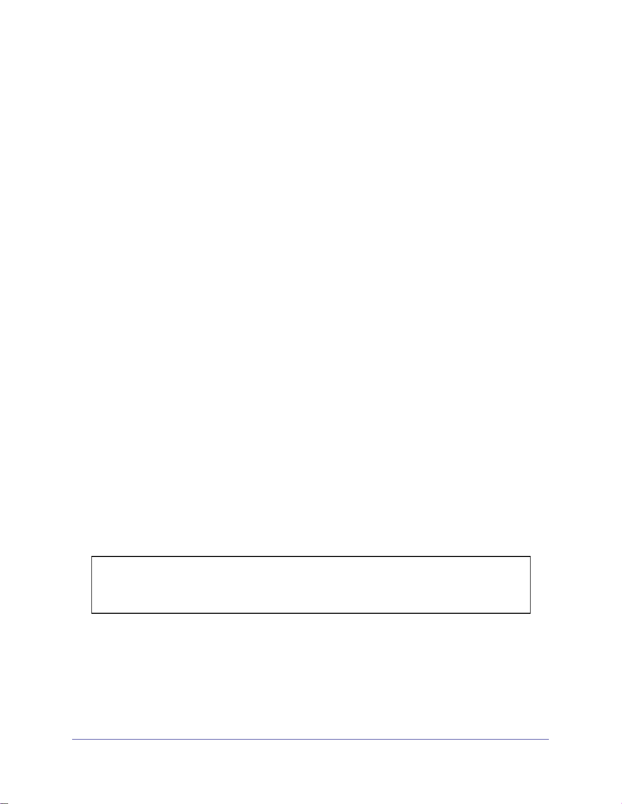
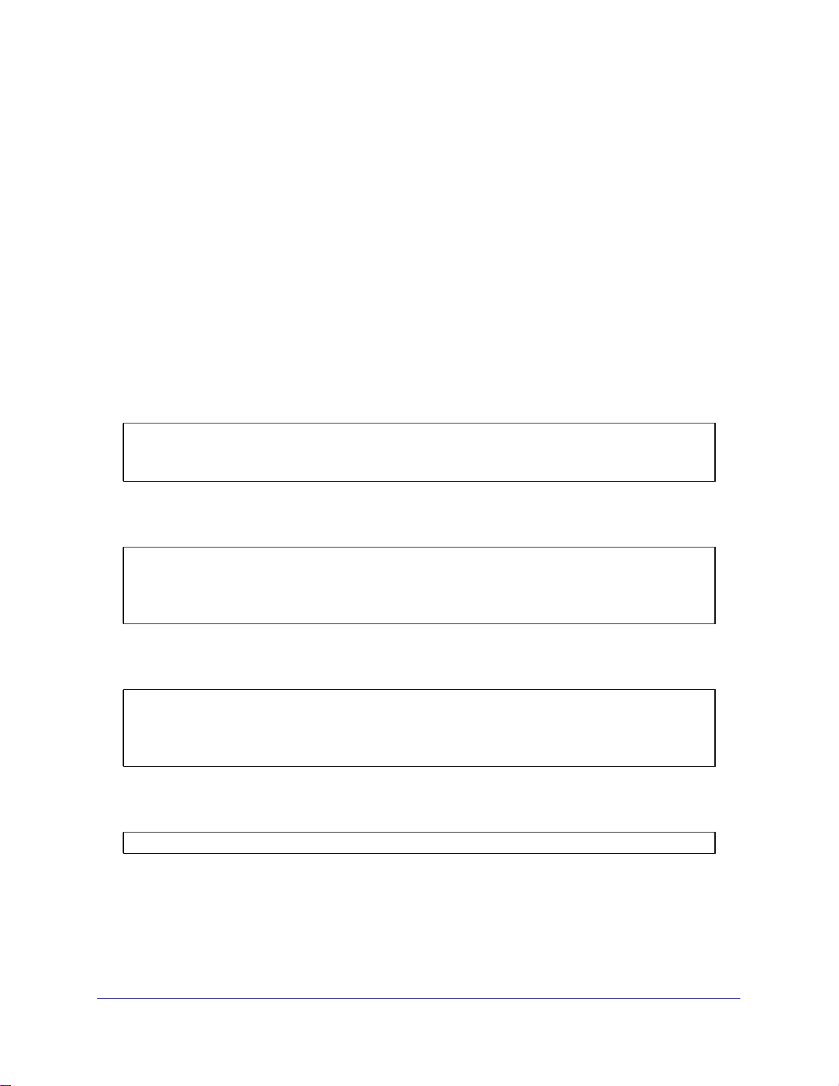
The diagram in this section shows a switch with four ports configured to handle the traffic for two
VLANs. Port 1/0/2 handles traffic for both VLANs, while port 1/0/1 is a member of VLAN 2 only,
Chapter 2. VLANs | 9
Page 10
ProSafe 7000 Managed Switch Release 8.0.3
and ports 1/0/3 and 1/0/4 are members of VLAN 3 only. The script following the diagram shows
the commands you would use to configure the switch as shown in the diagram.
Layer 3 switch
Port 1/0/2 VLAN
Router Port 1/3/1
192.150.3.1
Port 1/0/1
Layer 2
Switch
VLAN 10 VLAN 20
Figure 1. Switch with 4 ports configured for traffic from 2 VLANs
Port 1/0/3 VLAN
Router Port 1/3/2
192.150.4.1
Layer 2
Switch
The following examples show how to create VLANs, assign ports to the VLANs, and assign a
VLAN as the default VLAN to a port.
Create Two VLANs
The example is shown as CLI commands and as a Web interface procedure.
CLI: Create Two VLANS
Use the following commands to create two VLANs and to assign the VLAN IDs while leaving
the names blank.
(Netgear Switch) #vlan database
(Netgear Switch) (Vlan)#vlan 2
(Netgear Switch) (Vlan)#vlan 3
(Netgear Switch) (Vlan)#exit
Web Interface: Create Two VLANS
1. Create VLAN2.
10 | Chapter 2. VLANs
Page 11

ProSafe 7000 Managed Switch Release 8.0.3
a. Select Switching > VLAN > Basic > VLAN Configuration. A screen similar to the
following displays.
b. Enter the following information:
• In the VLAN ID field, enter 2.
• In the VLAN Name field, enter VLAN2.
• In the VLAN Type list, select Static.
c. Click Add.
2. Create VLAN3.
a. Select Switching > VLAN > Basic > VLAN Configuration. A screen similar to the
following displays.
b. Enter the following information:
• In the VLAN ID field, enter 3.
• In the VLAN Name field, enter VLAN3.
• In the VLAN Type list, select Static.
c. Click Add.
Chapter 2. VLANs | 11
Page 12

ProSafe 7000 Managed Switch Release 8.0.3
Assign Ports to VLAN2
This sequence shows how to assign ports to VLAN2, and to specify that frames will always
be transmitted tagged from all member ports and that untagged frames will be rejected on
receipt.
CLI: Assign Ports to VLAN2
(Netgear Switch) #config
(Netgear Switch) (Config)#interface range 1/0/1-1/0/2
(Netgear Switch) (conf-if-range-1/0/1-1/0/2)#vlan participation include 2
(Netgear Switch) (conf-if-range-1/0/1-1/0/2)#vlan acceptframe vlanonly
(Netgear Switch) (conf-if-range-1/0/1-1/0/2)#vlan pvid 2
(Netgear Switch) (conf-if-range-1/0/1-1/0/2)#exit
(Netgear Switch) (Config)#vlan port tagging all 2
(Netgear Switch) (Config)#
Web Interface: Assign Ports to VLAN2
1. Assign ports to VLAN2.
a. Select Switching > VLAN > Advanced > VLAN Membership. A screen similar to the
following displays.
b. In the VLAN ID list, select 2.
c. Click Unit 1. The ports display.
d. Click the gray boxes under ports 1 and 2 until T displays. The T specifies that the
egress packet is tagged for the ports.
e. Click Apply to save the settings.
2. Specify that only tagged frames will be accepted on ports 1/0/1 and 1/0/2.
12 | Chapter 2. VLANs
Page 13

ProSafe 7000 Managed Switch Release 8.0.3
a. Select Switching > VLAN > Advanced > Port PVID Configuration. A screen similar
to the following displays.
b. Under PVID Configuration, scroll down and select the check box for Interface 1/0/1.
Then scroll down and select the Interface 1/0/2 check box.
c. Enter the following information:
• In the Acceptable Frame Type polyhedron list, select VLAN Only.
• In the PVID (1 to 4093) field, enter 2.
d. Click Apply to save the settings.
Assign Ports to VLAN3
This example shows how to assign the ports that will belong to VLAN 3, and to specify that
untagged frames will be accepted on port 1/0/4. Note that port 1/0/2 belongs to both VLANs
and that port 1/0/1 can never belong to VLAN 3.
CLI: Assign Ports to VLAN3
(Netgear Switch) (Config)#interface range 1/0/2-1/0/4
(Netgear Switch) (conf-if-range-1/0/2-1/0/4)#vlan participation include 3
(Netgear Switch) (conf-if-range-1/0/2-1/0/4)#exit
(Netgear Switch) (Config)#interface 1/0/4
(Netgear Switch) (Interface 1/0/4)#vlan acceptframe all
(Netgear Switch) (Interface 1/0/4)#exit
(Netgear Switch) (Config)#exit
Chapter 2. VLANs | 13
Page 14

ProSafe 7000 Managed Switch Release 8.0.3
Web Interface: Assign Ports to VLAN3
1. Assign ports to VLAN3.
a. Select Switching > VLAN > Advanced > VLAN Membership. A screen similar to the
following displays.
b. In the VLAN ID list, select 3.
c. Click Unit 1. The ports display.
d. Click the gray boxes under ports 2, 3 and 4 until T displays. The T specifies that the
egress packet is tagged for the ports.
e. Click Apply to save the settings.
2. Specify that untagged frames will be accepted on port 1/0/4.
a. Select Switching > VLAN > Advanced > Port PVID Configuration. A screen similar
to the following displays.
b. Scroll down and select the Interface 1/0/4 check box. Now 1/0/4 appears in the
Interface field at the top.
c. In the Acceptable Frame Types list, select Admit All.
d. Click Apply to save the settings.
14 | Chapter 2. VLANs
Page 15
ProSafe 7000 Managed Switch Release 8.0.3
Assign VLAN3 as the Default VLAN for Port 1/0/2
This example shows how to assign VLAN 3 as the default VLAN for port 1/0/2.
CLI: Assign VLAN3 as the Default VLAN for Port 1/0/2
(Netgear Switch) #config
(Netgear Switch) (Config)#interface 1/0/2
(Netgear Switch) (Interface 1/0/2)#vlan pvid 3
(Netgear Switch) (Interface 1/0/2)#exit
(Netgear Switch) (Config)#exit
Web Interface: Assign VLAN3 as the Default VLAN for Port 1/0/2
1. Assign VLAN3 as the default VLAN for port 1/0/2.
a. Select Switching > VLAN > Advanced > Port PVID Configuration. A screen similar
to the following displays.
b. Under PVID Configuration, scroll down and select the Interface 1/0/2 check box.
Now 1/0/2 appears in the Interface field at the top.
c. In the PVID (1 to 4093) field, enter 3.
d. Click Apply to save the settings.
Chapter 2. VLANs | 15
Page 16
ProSafe 7000 Managed Switch Release 8.0.3
Create a MAC-Based VLAN
The MAC-based VLAN feature allows incoming untagged packets to be assigned to a VLAN
and thus classify traffic based on the source MAC address of the packet.
You define a MAC to VLAN mapping by configuring an entry in the MAC to VLAN table. An
entry is specified using a source MAC address and the appropriate VLAN ID. The MAC to
VLAN configurations are shared across all ports of the device (i.e., there is a system-wide
table that has MAC address to VLAN ID mappings).
When untagged or priority tagged packets arrive at the switch and entries exist in the MAC to
VLAN table, the source MAC address of the packet is looked up. If an entry is found, the
corresponding VLAN ID is assigned to the packet. If the packet is already priority tagged it will
maintain this value; otherwise, the priority will be set to 0 (zero). The assigned VLAN ID is
verified against the VLAN table. If the VLAN is valid, ingress processing on the packet
continues; otherwise, the packet is dropped. This implies that you can configure a MAC
address mapping to a VLAN that has not been created on the system.
CLI: Create a MAC-Based VLAN
1. Create VLAN3
(Netgear Switch)#vlan database
(Netgear Switch)(Vlan)#vlan 3
(Netgear Switch)(Vlan)#exit
2. Add port 1/0/23 to VLAN3.
(Netgear Switch)#config
(Netgear Switch)(Config)#interface 1/0/23
(Netgear Switch)(Interface 1/0/23)#vlan participation include 3
(Netgear Switch)(Interface 1/0/23)#vlan pvid 3
(Netgear Switch)(Interface 1/0/23)#exit
.
16 | Chapter 2. VLANs
Page 17
ProSafe 7000 Managed Switch Release 8.0.3
3. Map MAC 00:00:0A:00:00:02 to VLAN3.
(Netgear Switch)(Config)#exit
(Netgear Switch)#vlan data
(Netgear Switch)(Vlan)#vlan association mac 00:00:00A:00:00:02 3
(Netgear Switch)(Vlan)#exit
4. Add all the ports to VLAN3.
(Netgear Switch)#config
(Netgear Switch)(Config)#interface range 1/0/1-1/0/28
(Netgear Switch)(conf-if-range-1/0/1-1/0/28)#vlan participation include 3
(Netgear Switch)(conf-if-range-1/0/1-1/0/28)#exit
(Netgear Switch)(Config)#exit
Web Interface: Assign a MAC-Based VLAN
1. Create VLAN3.
a. Select Switching > VLAN > Basic > VLAN Configuration. A screen similar to the
following displays.
b. Enter the following information:
• In the VLAN ID field, enter 3.
• In the VLAN Name field, enter VLAN3.
• In the VLAN Type list, select Static.
c. Click Add.
2. Assign ports to VLAN3.
Chapter 2. VLANs | 17
Page 18

ProSafe 7000 Managed Switch Release 8.0.3
a. Select Switching > VLAN > Advanced > VLAN Membership. A screen similar to the
following displays.
b. In the VLAN ID list, select 3.
c. Click Unit 1. The ports display.
d. Click the gray box before Unit 1 until U displays.
e. Click Apply.
3. Assign VPID3 to port 1/0/23.
a. Select Switching > VLAN > Advanced > Port PVID Configuration. A screen similar
to the following displays.
b. Scroll down and select the 1/0/23 check box.
c. In the PVID (1 to 4093) field, enter 3.
d. Click Apply to save the settings.
4. Map the specific MAC to VLAN3.
a. Select Switching > VLAN > Advanced > MAC based VLAN. A screen similar to the
following displays.
18 | Chapter 2. VLANs
Page 19
ProSafe 7000 Managed Switch Release 8.0.3
b. Enter the following information:
• In the MAC Address field, enter 00:00:0A:00:00:02.
• In the PVID (1 to 4093) field, enter 3.
c. Click Add.
Create a Protocol-Based VLAN
Create two protocol VLAN groups. One is for IPX, and the other is for IP/ARP. The untagged
IPX packets are assigned to VLAN 4, and the untagged IP/ARP packets are assigned to
VLAN 5.
CLI: Create a Protocol-Based VLAN
1. Create a VLAN protocol group vlan_ipx based on IPX protocol.
(Netgear Switch)#config
(Netgear Switch)(Config)#vlan protocol group vlan_ipx
(Netgear Switch)(Config)#vlan protocol group add protocol 1 ipx
2. Create a VLAN protocol group vlan_ipx based on IP/ARP protocol.
(Netgear Switch)(Config)#vlan protocol group vlan_ip
(Netgear Switch)(Config)#vlan protocol group add protocol 2 ip
(Netgear Switch)(Config)#vlan protocol group add protocol 2 arp
(Netgear Switch)(Config)#exit
3. Assign VLAN protocol group 1 to VLAN 4.
(Netgear Switch)#vlan database
(Netgear Switch)(Vlan)#vlan 4
(Netgear Switch)(Vlan)#vlan 5
(Netgear Switch)(Vlan)#protocol group 1 4
4. Assign VLAN protocol group 2 to VLAN 5.
(Netgear Switch)(Vlan)#protocol group 2 5
Chapter 2. VLANs | 19
Page 20
ProSafe 7000 Managed Switch Release 8.0.3
5. Enable protocol VLAN group 1 and 2 on the interface.
(Netgear Switch)(Vlan)#exit
(Netgear Switch)#config
(Netgear Switch)(Config)#interface 1/0/11
(Netgear Switch)(Interface 1/0/11)#protocol vlan group 1
(Netgear Switch)(Interface 1/0/11)#protocol vlan group 2
(Netgear Switch)(Interface 1/0/11)#exit
Web Interface: Create a Protocol-Based VLAN
1. Create the protocol-based VLAN group vlan_ipx.
a. Select Switching > VLAN > Advanced > Protocol Based VLAN Group
Configuration. A screen similar to the following displays.
Enter the following information:
• In the Group Name field, enter vlan_ipx.
• In the Protocol list, select IPX.
• In the VLAN ID field, enter 4.
b. Click Add.
2. Create the protocol-based VLAN group vlan_ip.
a. Select Switching > VLAN >Advanced > Protocol Based VLAN Group
Configuration. A screen similar to the following displays.
b. Enter the following information:
• In the Group Name field, enter vlan_ip.
• In the Protocol list, select IP and ARP while holding down the Ctrl key.
20 | Chapter 2. VLANs
Page 21

ProSafe 7000 Managed Switch Release 8.0.3
• In the VLAN field, enter 5.
c. Click Add.
3. Add port 11 to the group vlan_ipx.
a. Select Switching > VLAN > Advanced > Protocol Based VLAN Group
Membership. A screen similar to the following displays.
b. In the Group ID list, select 1.
c. Click the gray box under port 11. A check mark displays in the box.
d. Click the Apply button.
4. Add port 11 to the group vlan_ip.
a. Select Switching > VLAN > Advanced > Protocol Based VLAN Group
Membership. A screen similar to the following displays
.
b. In the Group ID list, select 2.
c. Click the gray box under port 11. A check mark displays in the box.
d. Click Apply.
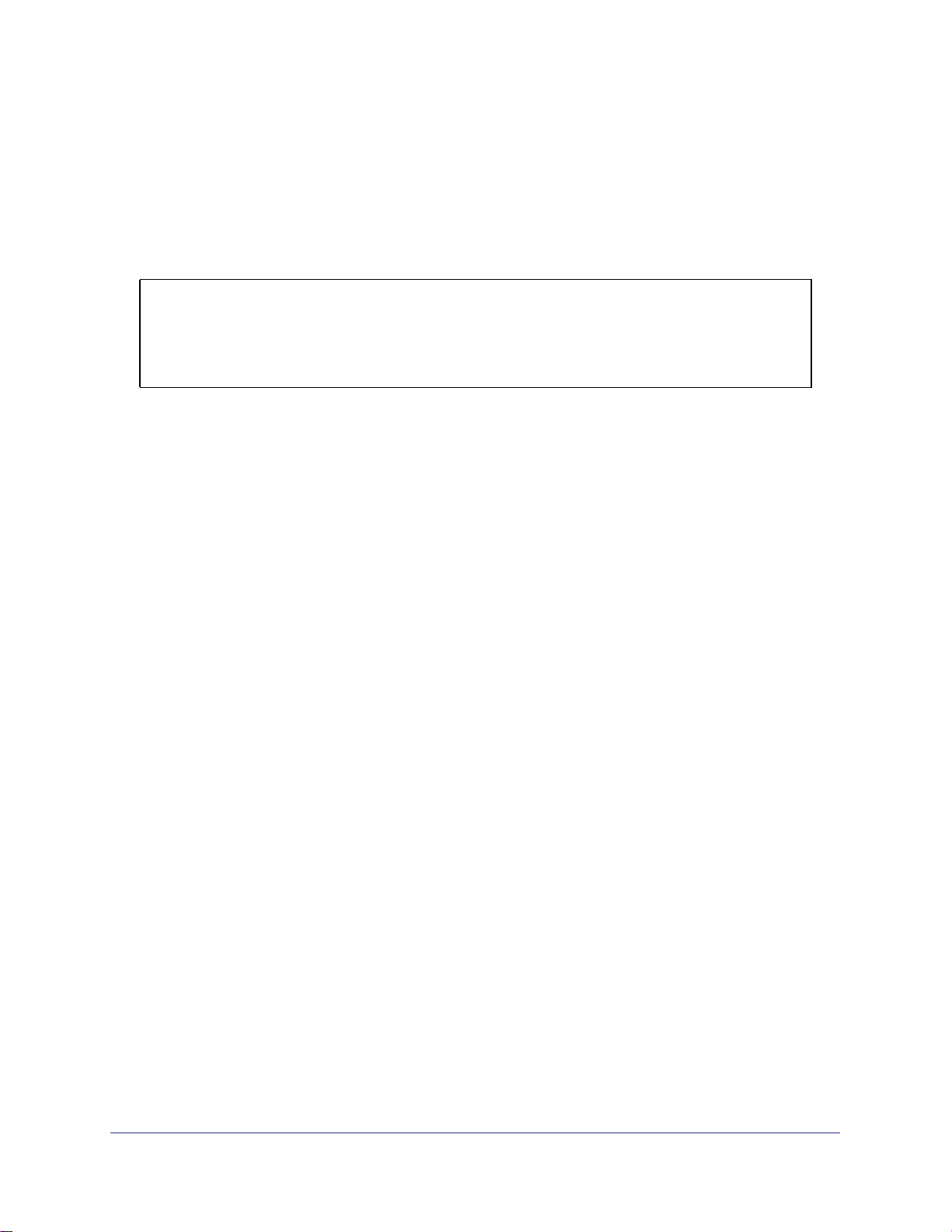
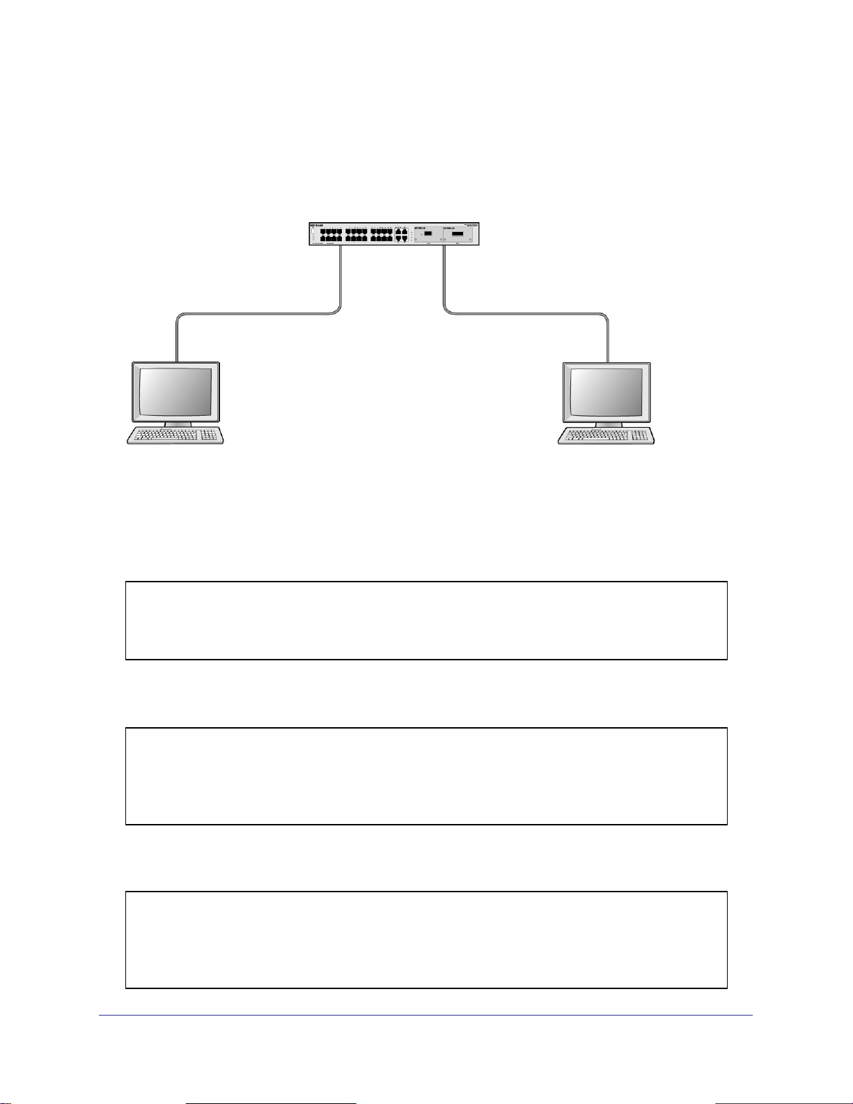
Virtual VLANs: Create an IP Subnet–Based VLAN
In an IP subnet–based VLAN, all the end workstations in an IP subnet are assigned to the
same VLAN. In this VLAN, users can move their workstations without reconfiguring their
network addresses. IP subnet VLANs are based on Layer 3 information from packet headers.
The switch makes use of the network-layer address (for example, the subnet address for
TCP/IP networks) in determining VLAN membership. If a packet is untagged or priority
tagged, the switch associates the packet with any matching IP subnet classification. If no IP
Chapter 2. VLANs | 21
Page 22
ProSafe 7000 Managed Switch Release 8.0.3
subnet classification can be made, the packet is subjected to the normal VLAN classification
rules of the switch. This IP subnet capability does not imply a routing function or that the
VLAN is routed. The IP subnet classification feature affects only the VLAN assignment of a
packet. Appropriate 802.1Q VLAN configuration must exist in order for the packet to be
switched.
1/0/1
PC 1 PC 2
10.100.5.1 10.100.5.30
Switch
1/0/24
Figure 2. IP subnet–based VLAN
CLI: Create an IP Subnet–Based VLAN
(Netgear Switch) #vlan database
(Netgear Switch) (Vlan)#vlan 2000
(Netgear Switch) (Vlan)#vlan association subnet 10.100.0.0 255.255.0.0 2000
(Netgear Switch) (Vlan)#exit
Create an IP subnet–based VLAN 2000.
(Netgear Switch) #config
(Netgear Switch) (Config)#interface range 1/0/1-1/0/24
(Netgear Switch) (conf-if-range-1/0/1-1/0/24)# vlan participation include 2000
(Netgear Switch) (conf-if-range-1/0/1-1/0/24)#exit
(Netgear Switch) (Config)#
Assign all the ports to VLAN 2000.
(Netgear Switch) #show mac-addr-table vlan 2000
MAC Address Interface Status
----------------- --------- -----------00:00:24:58:F5:56 1/0/1 Learned
00:00:24:59:00:62 1/0/24 Learned
22 | Chapter 2. VLANs
Page 23

ProSafe 7000 Managed Switch Release 8.0.3
Web Interface: Create an IP Subnet–Based VLAN
1. Create VLAN 2000.
a. Select Switching > VLAN > Basic > VLAN Configuration. A screen similar to the
following displays.
b. Enter the following information:
• In the VLAN ID field, enter 2000.
• In the VLAN Type list, select Static.
c. Click Add.
2. Assign all the ports to VLAN 2000.
a. Select Switching > VLAN > Advanced > VLAN Membership. A screen similar to
the following displays.
b. In the VLAN ID list, select 2000.
c. Click Unit 1. The ports display.
d. Click the gray box before Unit 1 until U displays.
e. Click Apply.
3. Associate the IP subnet with VLAN 2000.
Chapter 2. VLANs | 23
Page 24

ProSafe 7000 Managed Switch Release 8.0.3
a. Select Switching > VLAN > Advanced > IP Subnet Based VLAN. A screen similar
to the following displays.
b. Enter the following information:
• In the IP Address field, enter 10.100.0.0.
• In the Subnet Mask field, enter 255.255.0.0.
• In the VLAN (1 to 4093) field, enter 2000.
c. Click Add.
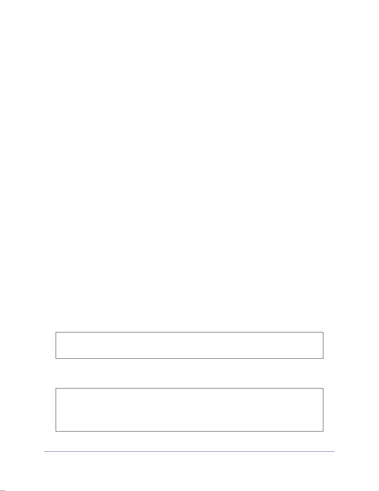
Voice VLANs
The voice VLAN feature enables switch ports to carry voice traffic with defined priority to
enable separation of voice and data traffic coming onto port. Voice VLAN ensures that the
sound quality of an IP phone does not deteriorate when the data traffic on the port is high.
Also, the inherent isolation provided by VLANs ensures that inter-VLAN traffic is under
24 | Chapter 2. VLANs
Page 25

ProSafe 7000 Managed Switch Release 8.0.3
management control and that clients attached to the network cannot initiate a direct attack on
voice components.
PBX
1/0/1
GSM73xxS
1/0/2
VoIP
phone
PC
1/0/3
VoIP
phone
PC
Voice traffic
Data traffic
Figure 3. Voice VLAN
The script in this section shows how to configure Voice VLAN and prioritize the voice traffic.
Here the Voice VLAN mode is in VLAN ID 10.
CLI: Configure Voice VLAN and Prioritize Voice Traffic
1. Create VLAN 10.
(Netgear Switch) #vlan database
(Netgear Switch) (Vlan)#vlan 10
(Netgear Switch) (Vlan)#exit
Chapter 2. VLANs | 25
Page 26

ProSafe 7000 Managed Switch Release 8.0.3
2. Include the ports 1/0/1 and 1/0/2 in VLAN 10.
(Netgear Switch) (Config)#interface range 1/0/1-1/0/2
(Netgear Switch) (conf-if-range-1/0/1-1/0/2)#vlan participation include 10
(Netgear Switch) (conf-if-range-1/0/1-1/0/2)#vlan tagging 10
(Netgear Switch) (conf-if-range-1/0/1-1/0/2)#exit
3. Configure Voice VLAN globally.
(Netgear Switch) (Config)# voice vlan
4. Configure Voice VLAN mode in the interface 1/0/2.
(Netgear Switch) (Config)#interface 1/0/2
(Netgear Switch) (Interface 1/0/2)#voice vlan 10
(Netgear Switch) (Interface 1/0/2)#exit
5. Create the DiffServ class ClassVoiceVLAN.
(Netgear Switch) (Config)#class-map match-all ClassVoiceVLAN
6. Configure VLAN 10 as the matching criteria for the class.
(Netgear Switch) (Config-classmap)#match vlan 10
7. Create the DiffServ policy PolicyVoiceVLAN.
(Netgear Switch) (Config)#policy-map PolicyVoiceVLAN in
8. Map the policy and class and assign them to the higher-priority queue.
(Netgear Switch) (Config-policy-map)#class ClassVoiceVLAN
(Netgear Switch) (Config-policy-classmap)#assign-queue 3
(Netgear Switch) (Config-policy-classmap)#exit
9. Assign it to interfaces 1/0/1 and 1/0/2.
(Netgear Switch) (Config)#interface range 1/0/1-1/0/2
(Netgear Switch) (conf-if-range-1/0/1-1/0/2)# service-policy in PolicyVoiceVLAN
26 | Chapter 2. VLANs
Page 27

ProSafe 7000 Managed Switch Release 8.0.3
Web Interface: Configure Voice VLAN and Prioritize Voice Traffic
1. Create VLAN 10.
a. Select Switching > VLAN > Basic > VLAN Configuration. A screen similar to the
following displays.
b. In the VLAN ID field, enter 10.
c. In the VLAN Name field, enter Voice VLAN.
d. Click Add. A screen similar to the following displays.
2. Include ports 1/0/1 and 1/0/2 in VLAN 10.
a. Select Switching > VLAN > Advanced > VLAN Membership. A screen similar to
the following displays.
b. In the VLAN Membership table, in the VLAN ID list, select 10.
Chapter 2. VLANs | 27
Page 28

ProSafe 7000 Managed Switch Release 8.0.3
c. Select Port 1 and Port 2 as tagged. A screen similar to the following displays.
d. Click Apply.
3. Configure V oice VLAN globally.
a. Select
similar to the following displays.
Switching > VLAN > Advanced > Voice VLAN Configuration. A screen
b. For Admin Mode, select the Enable radio button.
28 | Chapter 2. VLANs
Page 29

ProSafe 7000 Managed Switch Release 8.0.3
c. Click Apply. A screen similar to the following displays.
4. Configure Voice VLAN mode in interface 1/0/2.
a. Select Switching > VLAN > Advanced > Voice VLAN Configuration.
b. Select the 1/0/2 check box.
c. In the Interface Mode list, select VLAN ID.
d. In the Value field, enter 10. A screen similar to the following displays.
e. Click Apply.
5. Create the DiffServ class ClassVoiceVLAN.
a. Select QoS > Advanced > DiffServ > Class Configuration. A screen similar to the
following displays.
b. In the Class Name field, enter ClassVoiceVLAN.
Chapter 2. VLANs | 29
Page 30

ProSafe 7000 Managed Switch Release 8.0.3
c. In the Class Type list, select All. A screen similar to the following displays.
d. Click Add. The Class Name screen displays, as shown in the next step in this
procedure.
6. Configure matching criteria for the class as VLAN 10.
a. Select QoS > DiffServ > Advanced > Class Configuration. A screen similar to the
following displays.
b. Click the class ClassVoiceVLAN. A screen similar to the following displays.
c. In the DiffServ Class Configuration table, select VLAN.
d. In the VLAN ID field, enter 10. A screen similar to the following displays.
30 | Chapter 2. VLANs
Page 31

ProSafe 7000 Managed Switch Release 8.0.3
e. Click Apply. A screen similar to the following displays.
7. Create the DiffServ policy PolicyVoiceVLAN.
a. Select QoS > DiffServ > Advanced > Policy Configuration. A screen similar to the
following displays.
b. In the Policy Name field, enter PolicyVoiceVLAN.
c. In the Policy Type list, select In.
d. In the Member Class list, select ClassVoiceVLAN. A screen similar to the following
displays.
e. Click Add. The Policy Configuration screen displays, as shown in the next step in
this procedure.
8. Map the policy and class and assign them to the higher-priority queue.
Chapter 2. VLANs | 31
Page 32

ProSafe 7000 Managed Switch Release 8.0.3
a. Select QoS > DiffServ > Advanced > Policy Configuration. A screen similar to the
following displays.
b. Click the Policy PolicyVoiceVLAN. A screen similar to the following displays.
c. In the field next to the Assign Queue radio button, select 3. A screen similar to the
following displays.
d. Click Apply.
9. Assign it to interfaces 1/0/1 and 1/0/2.
32 | Chapter 2. VLANs
Page 33

ProSafe 7000 Managed Switch Release 8.0.3
a. Select QoS > DiffServ > Advanced > Service Interface Configuration. A screen
similar to the following displays.
b. Select the check boxes for Interfaces 1/0/1 and 1/0/2.
c. Set the Policy Name field as PolicyVoiceVLAN. A screen similar to the following
displays.
d. Click Apply. A screen similar to the following displays.
Chapter 2. VLANs | 33
Page 34

3. LAGs
Link Aggregation Groups
This chapter provides the following examples:
• Create Two LAGs on page 35
• Add Ports to LAGs on page 36
• Enable Both LAGs on page 38
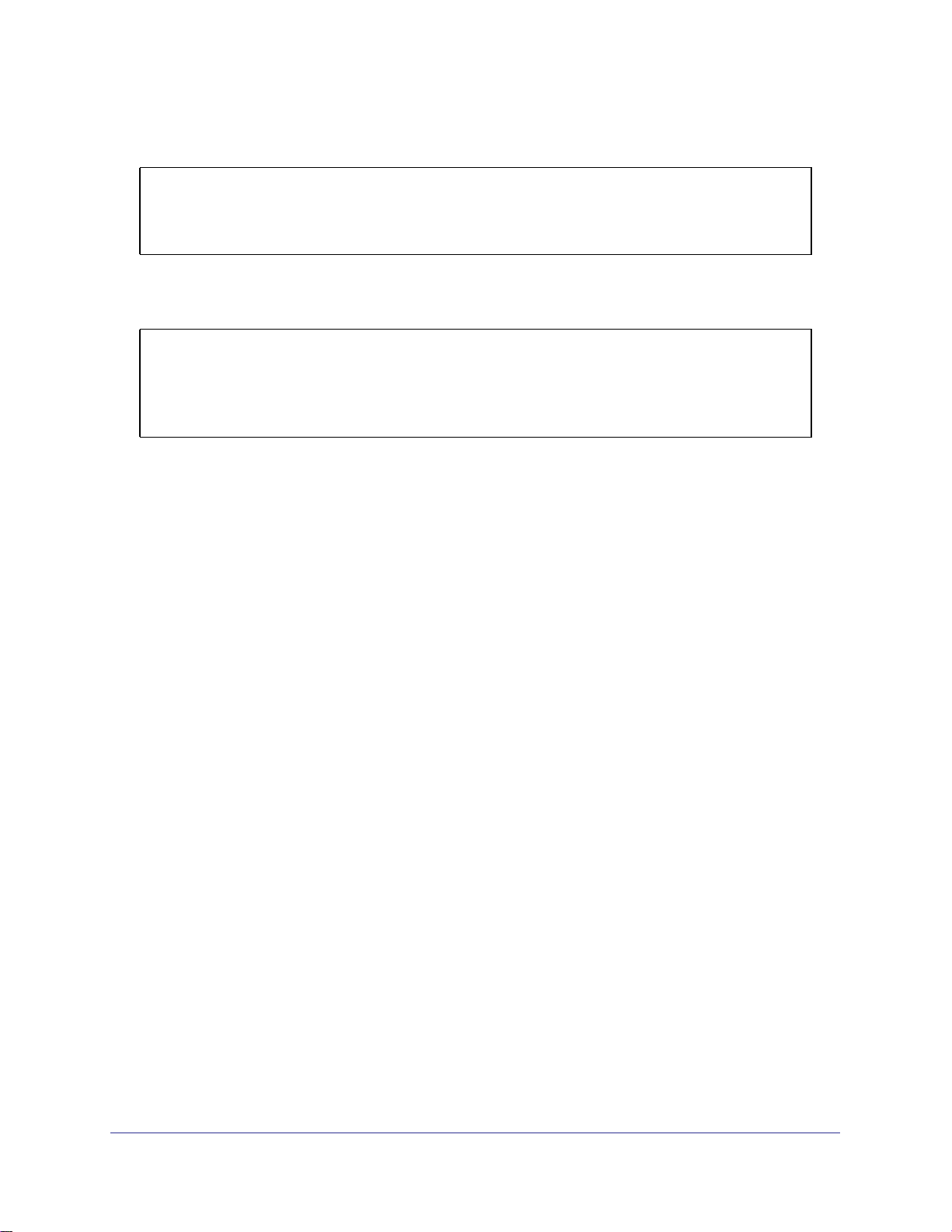
Link aggregation allows the switch to treat multiple physical links between two end-points as a
single logical link. All the physical links in a given LAG must operate in full-duplex mode at the
same speed. LAGs can be used to directly connect two switches when the traffic between them
requires high bandwidth and reliability, or to provide a higher-bandwidth connection to a public
network. Management functions treat a LAG as if it were a single physical port. You can include
a LAG in a VLAN. You can configure more than one LAG for a given switch.
Port 1/0/3
Server
LAG_10
Port 1/0/2
LAG_10
Subnet 3
3
Layer 3 Switch
Port 1/0/8
LAG 20
Layer 2 Switch
Subnet 2 Subnet 3
Figure 4. Example network with two LAGs
LAGs offers the following benefits:
• Increased reliability and availability. If one of the physical links in the LAG goes down,
traffic is dynamically and transparently reassigned to one of the other physical links.
Port 1/0/9
LAG_20
Chapter 3. LAG s | 34
Page 35

ProSafe 7000 Managed Switch Release 8.0.3
• Better use of physical resources. Traffic can be load-balanced across the physical links.
• Increased bandwidth. The aggregated physical links deliver higher bandwidth than each
individual link.
• Incremental increase in bandwidth. A physical upgrade could produce a tenfold increase
in bandwidth; LAG produces a two- or fivefold increase, useful if only a small increase is
needed.
Create Two LAGs
The example is shown as CLI commands and as a Web interface procedure.
CLI: Create Two LAGs
(Netgear Switch) #config
(Netgear Switch) (Config)#port-channel lag_10
(Netgear Switch) (Config)#port-channel lag_20
(Netgear Switch) (Config)#exit
Use the show port-channel all command to show the logical interface IDs you will use to
identify the LAGs in subsequent commands. Assume that lag_10 is assigned ID 1/1, and
lag_20 is assigned ID 1/2.
(Console) #show port-channel all
Port- Link
Log. Channel Adm. Trap STP Mbr Port Port
Intf Name Link Mode Mode Mode Type Ports Speed Active
------ --------------- ------ ---- ---- ------ ------- ------ --------- -----1/1 lag_10 Down En. En. Dis. Dynamic
1/2 lag_20 Down En. En. Dis. Dynamic
Web Interface: Create Two LAGs
1. Create LAG lag_10.
a. Select Switching > LAG > LAG Configuration. A screen similar to the following
displays.
Chapter 3. LAG s | 35
Page 36

ProSafe 7000 Managed Switch Release 8.0.3
b. In the Lag Name field, enter lag_10.
c. Click Add.
2. Create LAG lag_20.
a. Select Switching > LAG > LAG Configuration. A screen similar to the following
displays.
b. In the Lag Name field, enter lag_20.
c. Click Add.
Add Ports to LAGs
The example is shown as CLI commands and as a Web interface procedure.
CLI: Add Ports to the LAGs
(Netgear Switch) #config
(Netgear Switch) (Config)#interface 0/2
(Netgear Switch) (Interface 0/2)#addport 1/1
(Netgear Switch) (Interface 0/2)#exit
(Netgear Switch) (Config)#interface 0/3
(Netgear Switch) (Interface 0/3)#addport 1/1
(Netgear Switch) (Interface 0/3)#exit
(Netgear Switch) (Config)#interface 0/8
(Netgear Switch) (Interface 0/8)#addport 1/2
(Netgear Switch) (Interface 0/8)#exit
(Netgear Switch) (Config)#interface 0/9
(Netgear Switch) (Interface 0/9)#addport 1/2
(Netgear Switch) (Interface 0/9)#exit
(Netgear Switch) (Config)#exit
36 | Chapter 3. LAG s
Page 37

ProSafe 7000 Managed Switch Release 8.0.3
Web Interface: Add Ports to LAGs
1. Add ports to lag_10.
a. Select Switching > LAG > LAG Membership. A screen similar to the following
displays.
b. In the LAG ID list, select LAG 1.
c. Click Unit 1. The ports display.
d. Click the gray boxes under port 2 and 3. Two check marks display in the box.
e. Click Apply to save the settings.
2. Add ports to lag_20.
a. Select Switching > LAG > LAG Membership. A screen similar to the following
displays.
b. Under LAG Membership, in the LAG ID list, select LAG 2.
c. Click Unit 1. The ports display.
d. Click the gray boxes under ports 8 and 9. Two check marks display in the boxes.
e. Click Apply to save the settings.
Chapter 3. LAG s | 37
Page 38

ProSafe 7000 Managed Switch Release 8.0.3
Enable Both LAGs
The example is shown as CLI commands and as a Web interface procedure.
CLI: Enable Both LAGs
By default, the system enables link trap notification.
(Console) #config
(Console) (Config)#port-channel adminmode all
(Console) (Config)#exit
At this point, the LAGs could be added to VLANs.
Web Interface: Enable Both LAGs
a. Select Switching > LAG > LAG Configuration. A screen similar to the following
displays.
b. Select the top check box and the check boxes for lag_10 and lag_20 are selected.
c. In the Admin Mode field, select Enable.
d. Click Apply to save the settings.
38 | Chapter 3. LAG s
Page 39

4. Port Routing
This chapter provides the following sections:
• Port Routing Configuration on page 40
• Enable Routing for the Switch on page 41
• Enable Routing for Ports on the Switch on page 41
• Add a Default Route on page 44
• Add a Static Route on page 45
The first networks were small enough for the end stations to communicate directly. As networks
grew, Layer 2 bridging was used to segregate traffic, a technology that worked well for unicast
traffic, but had problems coping with large quantities of multicast packets. The next major
development was routing, where packets were examined and redirected at Layer 3. End stations
needed to know how to reach their nearest router, and the routers had to interpret the network
topology so that they could forward traffic. Although bridges tended to be faster than routers,
using routers allowed the network to be partitioned into logical subnetworks, which restricted
multicast traffic and also facilitated the development of security mechanisms.
4
An end station specifies the destination station’s Layer 3 address in the packet’s IP header, but
sends the packet to the MAC address of a router. When the Layer 3 router receives the packet, it
will minimally:
• Look up the Layer 3 address in its address table to determine the outbound port.
• Update the Layer 3 header.
• Re-create the Layer 2 header.
The router’s IP address is often statically configured in the end station, although the 7000 Series
Managed Switch supports protocols such as DHCP that allow the address to be assigned
dynamically. Likewise, you can assign some of the entries in the routing tables used by the
router statically, but protocols such as RIP and OSPF allow the tables to be created and updated
dynamically as the network configuration changes.
Chapter 4. Port Routing | 39
Page 40

ProSafe 7000 Managed Switch Release 8.0.3
Port Routing Configuration
The 7000 Series Managed Switch always supports Layer 2 bridging, but Layer 3 routing must
be explicitly enabled, first for the 7000 Series Managed Switch as a whole, and then for each
port that is to be part of the routed network.
The configuration commands used in the example in this section enable IP routing on ports
1/0/2,1/0/3, and 1/0/5. The router ID will be set to the 7000 Series Managed Switch’s
management IP address, or to that of any active router interface if the management address
is not configured.
After the routing configuration commands have been issued, the following functions will be
active:
• IP forwarding, responsible for forwarding received IP packets.
• ARP mapping, responsible for maintaining the ARP Table used to correlate IP and MAC
addresses. The table contains both static entries and entries dynamically updated based
on information in received ARP frames.
• Routing Table Object, responsible for maintaining the common routing table used by all
registered routing protocols.
You can then activate RIP or OSPF, used by routers to exchange route information, on top of
IP Routing. RIP is more often used in smaller networks, while OSPF was designed for larger
and more complex topologies.
The following figure shows a Layer 3 switch configured for port routing. It connects three
different subnets, each connected to a different port.
Layer 3 switch
acting as a router
Port 1/0/2
192.150.2.2
Port 1/0/3
192.130.3.1
Port 1/0/5
192.64.4.1
Subnet 2 Subnet 3 Subnet 5
Figure 5. Layer 3 switch configured for port routing
40 | Chapter 4. Port Routing
Page 41

ProSafe 7000 Managed Switch Release 8.0.3
Enable Routing for the Switch
The example is shown as CLI commands and as a Web interface procedure.
CLI: Enable Routing for the Switch
The following script shows the commands you would use to configure a 7000 Series
Managed Switch to provide the port routing support shown in Figure 5, Layer 3 switch
configured for port routing on page 40.
Use the following command to enable routing for the switch. Execution of the command
enables IP forwarding by default.
(Netgear Switch) #config
(Netgear Switch) (Config)#ip routing
(Netgear Switch) (Config)#exit
Web Interface: Enable Routing for the Switch
1. Select Routing > IP > Basic > IP Configuration. A screen similar to the following
displays.
2. For Routing Mode, select the Enable radio button.
3. Click Apply to save the settings.
Enable Routing for Ports on the Switch
Use the following commands or the Web interface to enable routing for ports on the switch.
The default link-level encapsulation format is Ethernet. Configure the IP addresses and
subnet masks for the ports. Network-directed broadcast frames will be dropped. The
maximum transmission unit (MTU) size is 1500 bytes.
Chapter 4. Port Routing | 41
Page 42

ProSafe 7000 Managed Switch Release 8.0.3
CLI: Enable Routing for Ports on the Switch
(Netgear Switch) #config
(Netgear Switch) (Config)#interface 1/0/2
(Netgear Switch) (Interface 1/0/2)#routing
(Netgear Switch) (Interface 1/0/2)#ip address 192.150.2.1 255.255.255.0
(Netgear Switch) (Interface 1/0/2)#exit
(Netgear Switch) (Config)#interface 1/0/3
(Netgear Switch) (Interface 1/0/3)#routing
(Netgear Switch) (Interface 1/0/3)#ip address 192.150.3.1 255.255.255.0
(Netgear Switch) (Interface 1/0/3)#exit
(Netgear Switch) (Config)#interface 1/0/5
(Netgear Switch) (Interface 1/0/5)#routing
(Netgear Switch) (Interface 1/0/5)#ip address 192.150.5.1 255.255.255.0
(Netgear Switch) (Interface 1/0/5)#exit
(Netgear Switch) (Config)#exit
Web Interface: Enable Routing for Ports on the Switch
1. Assign IP address 192.150.2.1/24 to interface 1/0/2.
a. Select Routing > IP > Advanced > IP Interface Configuration. A screen similar to
the following displays.
b. Scroll down and select the interface 1/0/2 check box. Now 1/0/2 appears in the
Interface field at the top.
c. Under the IP Interface Configuration, enter the following information:
• In the IP Address field, enter 192.150.2.1.
• In the Subnet Mask field, enter 255.255.255.0.
• In the Routing Mode field, select Enable.
d. Click Apply to save the settings.
42 | Chapter 4. Port Routing
Page 43

ProSafe 7000 Managed Switch Release 8.0.3
2. Assign IP address 192.150.3.1/24 to interface 1/0/3.
a. Select Routing > IP> Advanced > IP Interface Configuration. A screen similar to
the following displays.
b. Scroll down and select the interface 1/0/3 check box. Now 1/0/3 appears in the
Interface field at the top.
c. Enter the following information:
• In the IP Address field, enter 192.150.3.1.
• In the Subnet Mask field, enter 255.255.255.0.
• In the Routing Mode field, select Enable.
d. Click Apply to save the settings.
3. Assign IP address 192.150.5.1/24 to interface 1/0/5.
a. Select Routing > IP > Advanced > IP Interface Configuration. A screen similar to
the following displays.
b. Scroll down and select the interface 1/0/5 check box. Now 1/0/5 appears in the
Interface field at the top.
c. Enter the following information:
• In the IP Address field, enter 192.150.5.1.
• In the Subnet Mask field, enter 255.255.255.0.
Chapter 4. Port Routing | 43
Page 44

ProSafe 7000 Managed Switch Release 8.0.3
• In the Routing Mode field, select Enable.
d. Click Apply to save the settings.
Add a Default Route
When IP routing takes place on a switch, a routing table is needed for the switch to forward
the packet based on the destination IP address. The route entry in the routing table can either
be created dynamically through routing protocols like RIP and OSPF, or be manually created
by the network administrator. The route created manually is called the static or default route.
A default route is used for forwarding the packet when the switch can not find a match in the
routing table for an IP packet. The following example shows how to create a default route.
CLI: Add a Default Route
(FSM7338S) (Config) #ip route default?
<nexthopip> Enter the IP Address of the next router.
(FSM7328S) (Config)#ip route default 10.10.10.2
Note that IP subnet 10.10.10.0 should be configured using either port routing (Enable
Routing for Ports on the Switch on page 41) or VLAN routing (see Set Up VLAN Routing for
the VLANs and the Switch on page 52).
Web Interface: Add a Default Route
1. Select Routing > Routing Table > Basic > Route Configuration. The Route
Configuration screen displays.
2. In the Route Type list, select DefaultRoute.
3. In the Next Hop IP Address field, enter one of the routing interface’s IP addresses.
• The Network Address and Subnet Mask fields will not accept input as they are not
needed.
44 | Chapter 4. Port Routing
Page 45

ProSafe 7000 Managed Switch Release 8.0.3
• The Preference field is optional. A value of 1 (highest) will be assigned by default if
not specified.
4. Click the Add button on the bottom of the screen. This creates the default route entry in the
routing table.
Add a Static Route
when the switch performas IP routing, it forwards the packet to the default route for a
destination that is not in the same subnet as the source address. However, you can set a
path (static route) that is different than the default route if you prefer. The following procedure
shows how to add a static route to the switch routing table.
CLI: Add a Static Route
The following commands assume the switch already has a defined a routing interface with a
network address of 10.10.10.0, and is configured so that all packets destined for network
10.10.100.0 take the path of routing port.
(FSM7328S) #show ip route
Total Number of Routes............................1
Network Subnet Next Hop Next Hop
AddressMaskProtocolIntfIP Address
--------------- --------------- --------------- --------------- ---------------
10.10.10.0 255.255.255.0 Local 1/0/3 10.10.10.1
To delete the static route, simply add “no” keyword in the front of the “ip route” command.
Chapter 4. Port Routing | 45
Page 46

ProSafe 7000 Managed Switch Release 8.0.3
Web Interface: Add a Static Route
1. Select Routing > Routing Table > Basic > Route Configuration to display the Route
Configuration screen.
2. In the Route Type list, select Static.
3. Fill in the Network Address field. Note that this field ishould have a network IP address, not
a host IP address. Do not enter something like 10,100.100.1. The last number should
always be 0 (zero).
4. In the Subnet Mask field, enter a value that matches the subnet range that you want to use.
5. The Preference field is optional. A value of 1 is entered by default if you do not enter a
number.
6. Click the Add button on the bottom of the screen. The screen is updated with the static route
shown in the routing table.
7. To remove a route entry, either static or default, select the check box to the left of the entry,
and click the Delete button on the bottom of the screen.
46 | Chapter 4. Port Routing
Page 47

5. VLAN Routing
This chapter provides the following examples:
• Create Two VLANs on page 47
• Set Up VLAN Routing for the VLANs and the Switch on page 52
You can configure the 7000 Series Managed Switch with some ports supporting VLANs and
some supporting routing. You can also configure it to allow traffic on a VLAN to be treated as if
the VLAN were a router port.
When a port is enabled for bridging (the default) rather than routing, all normal bridge processing
is performed for an inbound packet, which is then associated with a VLAN. Its MAC destination
address (DA) and VLAN ID are used to search the MAC address table. If routing is enabled for
the VLAN and the MAC DA of an inbound unicast packet is that of the internal bridge-router
interface, the packet is routed. An inbound multicast packet is forwarded to all ports in the VLAN,
and also to the internal bridge-router interface if it was received on a routed VLAN.
Since a port can be configured to belong to more than one VLAN, VLAN routing might be
enabled for all of the VLANs on the port, or for a subset. VLAN routing can be used to allow more
than one physical port to reside on the same subnet. It could also be used when a VLAN spans
multiple physical networks, or when additional segmentation or security is required.
5
The next section shows you how to configure the 7000 Series Managed Switch to support VLAN
routing and how to use RIP and OSPF. A port can be either a VLAN port or a router port, but not
both. However, a VLAN port can be part of a VLAN that is itself a router port.
Create Two VLANs
This section provides an example of how to configure the 7000 Series Managed Switch to
support VLAN routing. The configuration of the VLAN router port is similar to that of a
physical port. The main difference is that, after the VLAN has been created, you must use the
show ip vlan command to determine the VLAN’s interface ID so that you can use it in the
router configuration commands.
The diagram in this section shows a Layer 3 switch configured for port routing. It connects
two VLANs, with two ports participating in one VLAN, and one port in the other. The script
Chapter 5. VLAN Routing | 47
Page 48

ProSafe 7000 Managed Switch Release 8.0.3
shows the commands you would use to configure a 7000 Series Managed Switch to provide
the VLAN routing support shown in the diagram.
Layer 3 switch
Port 1/0/2 VLAN
Router port 1/3/1
192.150.3.1
Port 1/0/1
Layer 2
Switch
VLAN 10 VLAN 20
Port 1/0/3 VLAN
Router port 1/3/2
192.150.4.1
Layer 2
Switch
Figure 6. Layer 3 switch configured for port routing
CLI: Create Two VLANs
The following code sequence shows an example of creating two VLANs with egress frame
tagging enabled.
(Netgear Switch) #vlan data
(Netgear Switch) (Vlan)#vlan 10
(Netgear Switch) (Vlan)#vlan 20
(Netgear Switch) (Vlan)#exit
(Netgear Switch) #conf
(Netgear Switch) (Config)#interface range 1/0/1-1/0/2
(Netgear Switch) (conf-if-range-1/0/1-1/0/2)#vlan participation include 10
(Netgear Switch) (conf-if-range-1/0/1-1/0/2)#vlan pvid 10
(Netgear Switch) (conf-if-range-1/0/1-1/0/2)#exit
(Netgear Switch) (Config)#interface 1/0/3
(Netgear Switch) (Interface 1/0/3)#vlan participation include 20
(Netgear Switch) (Interface 1/0/3)#vlan pvid 20
(Netgear Switch) (Interface 1/0/3)#exit
(Netgear Switch) (Config)#exit
48 | Chapter 5. VLAN Routing
Page 49

ProSafe 7000 Managed Switch Release 8.0.3
Web Interface: Create Two VLANs
1. Create VLAN 10 and VLAN20.
a. Select Switching > VLAN > Advanced > VLAN Configuration. A screen similar to
the following displays.
b. In the VLAN ID field, enter 10.
c. In the VLAN Name field, enter VLAN10.
d. In the VLAN Type list, select Static.
e. Click Add.
f. Select Switching > VLAN > Advanced > VLAN Configuration. A screen similar to
the following displays.
g. In the VLAN ID field, enter 20.
h. In the VLAN Name field, enter VLAN20.
i. In the VLAN Type list, select Static.
j. Click Add.
2. Add ports to the VLAN10 and VLAN20.
Chapter 5. VLAN Routing | 49
Page 50

ProSafe 7000 Managed Switch Release 8.0.3
a. Select Switching > VLAN > Advanced > VLAN Membership. A screen similar to the
following displays.
b. In the VLAN ID field, select 10.
c. Click the Unit 1. The ports display.
d. Click the gray boxes under ports 1 and 2 until T displays. The T specifies that the
egress packet is tagged for the port.
e. Click Apply.
f. Select Switching > VLAN > Advanced > VLAN Membership. A screen similar to
the following displays.
g. In the VLAN ID list, select 20.
h. Click Unit 1. The ports display.
i. Click the gray box under port 3 until T displays. The T specifies that the egress
packet is tagged for the port.
j. Click Apply.
3. Assign PVID to VLAN10 and VLAN20.
50 | Chapter 5. VLAN Routing
Page 51

ProSafe 7000 Managed Switch Release 8.0.3
a. Select Switching > VLAN > Advanced > Port PVID Configuraton. A screen similar
to the following displays.
b. Scroll down and select 1/0/1 and 1/0/2 check boxes.
c. In the PVID (1 to 4093) field, enter 10.
d. Click Apply to save the settings.
e. Select Switching > VLAN > Advanced > Port PVID Configuraton. A screen
similar to the following displays.
f. Scroll down and select the 1/0/3 check box.
g. In the PVID (1 to 4093) field, enter 20.
h. Click Apply to save the settings.
Chapter 5. VLAN Routing | 51
Page 52

ProSafe 7000 Managed Switch Release 8.0.3
Set Up VLAN Routing for the VLANs and the Switch
The example is shown as CLI commands and as a Web interface procedure.
CLI: Set Up VLAN Routing for the VLANs and the Switch
1. The following code sequence shows how to enable routing for the VLANs:
(Netgear Switch) #vlan data
(Netgear Switch) (Vlan)#vlan routing 10
(Netgear Switch) (Vlan)#vlan routing 20
(Netgear Switch) (Vlan)#exit
This returns the logical interface IDs that will be used instead of the slot/port in
subsequent routing commands. Assume that VLAN 10 is assigned the ID 3/1, and VLAN
20 is assigned the ID 3/2.
2. Enable routing for the switch.
(Netgear Switch) #config
(Netgear Switch) (Config)#ip routing
(Netgear Switch) (Config)#exit
3. The next sequence shows an example of configuring the IP addresses and subnet masks
for the virtual router ports.
(Netgear Switch) (Config)#interface vlan 10
(Netgear Switch) (Interface-vlan 10)#ip address 192.150.3.1 255.255.255.0
(Netgear Switch) (Interface-vlan 10)#exit
(Netgear Switch) (Config)#interface vlan 20
(Netgear Switch) (Interface-vlan 20)#ip address 192.150.4.1 255.255.255.0
(Netgear Switch) (Interface-vlan 20)#exit
(Netgear Switch) (Config)#exit
52 | Chapter 5. VLAN Routing
Page 53

ProSafe 7000 Managed Switch Release 8.0.3
Web Interface: Set Up VLAN Routing for the VLANs and the Switch
1. Select Routing > VLAN> VLAN Routing. A screen similar to the following displays.
2. Enter the following information:
• In the VLAN ID (1 to 4093) list, select 10.
• In the IP Address field, enter 192.150.3.1.
• In the Subnet Mask field, enter 255.255.255.0.
3. Click Add to save the settings.
4. Select Routing > VLAN > VLAN Routing. A screen similar to the following displays.
5. Enter the following information:
• Select 10 in the VLAN ID (1 to 4093) field.
• In the IP Address field, enter 192.150.4.1.
• In the Subnet Mask field, enter 255.255.255.0.
6. Click Add to save the settings.
Chapter 5. VLAN Routing | 53
Page 54

6. RIP
Routing Information Protocol
This chapter provides the following examples:
• Routing for the Switch on page 55
• Routing for Ports on page 56
• RIP for the Switch on page 57
• RIP for Ports 1/0/2 and 1/0/3 on page 58
• VLAN Routing with RIP on page 60
Routing Information Protocol (RIP) is a protocol that routers can use to exchange network
topology information. It is characterized as an interior gateway protocol, and is typically used in
small to medium-sized networks. A router running RIP sends the contents of its routing table to
each of its adjacent routers every 30 seconds. When a route is removed from the routing table, it
is flagged as unusable by the receiving routers after 180 seconds, and removed from their tables
after an additional 120 seconds.
There are two versions of RIP (the managed switch supports both):
• RIPv1 defined in RFC 1058.
- Routes are specified by IP destination network and hop count.
- The routing table is broadcast to all stations on the attached network.
• RIPv2 defined in RFC 1723.
- Route specification also includes subnet mask and gateway
- The routing table is sent to a multicast address, reducing network traffic.
- Authentication is used for security.
.
6
You can configure a given port to do the following:
• Receive packets in either or both formats.
• Send packets formatted for RIPv1 or RIPv2, or send RIPv2 packets to the RIPv1
broadcast address.
• Prevent any RIP packets from being received.
• Prevent any RIP packets from being sent.
Chapter 6. RIP | 54
Page 55

ProSafe 7000 Managed Switch Release 8.0.3
Layer 3 sIwitch
acting as a router
Port 1/0/2
192.150.2.2
Port 1/0/3
192.130.3.1
Subnet 2 Subnet 3 Subnet 5
Figure 7. Network with RIP on ports 1/0/2 and 1/0/3
Port 1/0/5
192.64.4.1
Routing for the Switch
The example is shown as CLI commands and as a Web interface procedure.
CLI: Enable Routing for the Switch
(Netgear Switch) #config
(Netgear Switch) (Config)#ip routing
(Netgear Switch) (Config)#exit
Web Interface: Enable Routing for the Switch
1. Select Routing > IP > Basic > IP Configuration. A screen similar to the following
displays.
2. For Routing Mode, select the Enable radio button.
3. Click Apply to save the settings.
Chapter 6. RIP | 55
Page 56

ProSafe 7000 Managed Switch Release 8.0.3
Routing for Ports
The example is shown as CLI commands and as a Web interface procedure.
CLI: Enable Routing and Assigning IP Addresses for Ports 1/0/2 and 1/0/3
(Netgear Switch) #config
(Netgear Switch) (Config)#interface 1/0/2
(Netgear Switch) (Interface 1/0/2)#routing
(Netgear Switch) (Interface 1/0/2)#ip address 192.150.2.1 255.255.255.0
(Netgear Switch) (Interface 1/0/2)#exit
(Netgear Switch) (Config)#interface 1/0/3
(Netgear Switch) (Interface 1/0/3)#routing
(Netgear Switch) (Interface 1/0/3)#ip address 192.150.3.1 255.255.255.0
(Netgear Switch) (Interface 1/0/3)#exit
(Netgear Switch) (Config)#exit
Web Interface: Enable Routing for the Ports
1. Assign IP address 192.150.2.1/24 to interface 1/0/2.
a. Select Routing > Advanced > IP Interface Configuration. A screen similar to the
following displays.
b. Scroll down and select the Interface 1/0/2 check box. Now 1/0/2 appears in the
Interface field at the top.
c. Enter the following information:
• In the IP Address field, enter 192.150.2.1.
• In the Subnet Mask field, enter 255.255.255.0.
• In the Routing Mode field, select Enable.
d. Click Apply to save the settings.
56 | Chapter 6. RIP
Page 57

ProSafe 7000 Managed Switch Release 8.0.3
2. Assign IP address 192.150.3.1/24 to interface 1/0/3.
a. Select Routing > Advanced >IP Interface Configuration. A screen similar to the
following displays.
b. Scroll down and select the interface 1/0/3 check box. Now 1/0/3 appears in the
Interface field at the top.
c. Enter the following information:
• In the IP Address field, enter 192.150.3.1.
• In the Subnet Mask field, enter 255.255.255.0.
• In the Routing Mode field, select Enable.
d. Click Apply to save the settings.
RIP for the Switch
Note: Unless you have previously disabled RIP, you can skip this step
since RIP is enabled by default.
CLI: Enable RIP on the Switch
This sequence enables RIP for the switch. The route preference defaults to 15.
(Netgear Switch) #config
(Netgear Switch) (Config)#router rip
(Netgear Switch) (Config router)#enable
(Netgear Switch) (Config router)#exit
(Netgear Switch) (Config)#exit
Chapter 6. RIP | 57
Page 58

ProSafe 7000 Managed Switch Release 8.0.3
Web Interface: Enableg RIP on the Switch
1. Select Routing > RIP > Basic > RIP Configuration. A screen similar to the following
displays.
2. For RIP Admin Mode, select Enable radio button.
3. Click Apply to save the setting.
RIP for Ports 1/0/2 and 1/0/3
The example is shown as CLI commands and as a Web interface procedure.
CLI: Enable RIP for Ports 1/0/2 and 1/0/3
This command sequence enables RIP for ports 1/0/2 and 1/0/3. Authentication defaults to
none, and no default route entry is created. The commands specify that both ports receive
both RIPv1 and RIPv2 frames, but send only RIPv2-formatted frames.
(Netgear Switch) #config
(Netgear Switch) (Config)#interface 1/0/2
(Netgear Switch) (Interface 1/0/2)#ip rip
(Netgear Switch) (Interface 1/0/2)#ip rip receive version both
(Netgear Switch) (Interface 1/0/2)#ip rip send version rip2
(Netgear Switch) (Interface 1/0/2)#exit
(Netgear Switch) (Config)#interface 1/0/3
(Netgear Switch) (Interface 1/0/3)#ip rip
(Netgear Switch) (Interface 1/0/3)#ip rip receive version both
(Netgear Switch) (Interface 1/0/3)#ip rip send version rip2
(Netgear Switch) (Interface 1/0/3)#exit
(Netgear Switch) (Config)#exit
58 | Chapter 6. RIP
Page 59

ProSafe 7000 Managed Switch Release 8.0.3
Web Interface: Enable RIP for Ports 1/0/2 and 1/0/3
1. Select Routing > RIP > Advanced > RIP Configuration. A screen similar to the
following displays.
2. Enter the following information:
• In the Interface field, select 1/0/2.
• For RIP Admin Mode, select the Enable radio button.
• In the Send Version field, select RIP-2.
3. Click Apply to save the settings.
4. Select Routing > RIP > Advanced > RIP Configuration. A screen similar to the following
displays.
5. Enter the following information:
• In the Interface field, select 1/0/3.
• For RIP Admin Mode, select the Enable radio button.
• In the Send Version list, select RIP-2.
Chapter 6. RIP | 59
Page 60

ProSafe 7000 Managed Switch Release 8.0.3
6. Click Apply to save the settings.
VLAN Routing with RIP
Routing Information Protocol (RIP) is one of the protocols that routers can use to exchange
network topology information. It is characterized as an interior gateway protocol, and is
typically used in small to medium-sized networks.
Layer 3 switch
Port 1/0/2 VLAN
Router port 1/3/1
192.150.3.1
Layer 2
switch
VLAN 10 VLAN 20
Router port 1/0/5
192.150.4.1
Port 1/0/3 VLAN
Router port 1/3/2
192.150.4.1
Layer 2
switch
Router
Figure 8. VLAN routing RIP configuration example
This example adds support for RIPv2 to the configuration created in the base VLAN routing
example. A second router, using port routing rather than VLAN routing, has been added to
the network.
CLI: Configure VLAN Routing with RIP Support
1. Configure VLAN routing with RIP support on a 7000 Series Managed Switch.
(Netgear Switch) #vlan data
(Netgear Switch) (Vlan)#vlan 10
(Netgear Switch) (Vlan)#vlan 20
(Netgear Switch) (Vlan)#vlan routing 10
(Netgear Switch) (Vlan)#vlan routing 20
(Netgear Switch) (Vlan)#exit
(Netgear Switch) #conf
60 | Chapter 6. RIP
Page 61

ProSafe 7000 Managed Switch Release 8.0.3
(Netgear Switch) (Config)#ip routing
(Netgear Switch) (Config)#vlan port tagging all 10
(Netgear Switch) (Config)#vlan port tagging all 20
(Netgear Switch) (Config)#interface 1/0/2
(Netgear Switch) (Interface 1/0/2)#vlan participation include 10
(Netgear Switch) (Interface 1/0/2)#vlan pvid 10
(Netgear Switch) (Interface 1/0/2)#exit
(Netgear Switch) (Config)#interface 1/0/3
(Netgear Switch) (Interface 1/0/3)#vlan participation include 20
(Netgear Switch) (Interface 1/0/3)#vlan pvid 20
(Netgear Switch) (Interface 1/0/3)#exit
(Netgear Switch) #config
(Netgear Switch) (Config)#interface vlan 10
(Netgear Switch) (Interface vlan 10)#ip address 192.150.3.1 255.255.255.0
(Netgear Switch) (Interface vlan 10)#exit
(Netgear Switch) (Config)#interface vlan 20
(Netgear Switch) (Interface vlan 20)#ip address 192.150.4.1 255.255.255.0
(Netgear Switch) (Interface vlan 20)#exit
2. Enable RIP for the switch. The route preference defaults to 15.
(Netgear Switch) (Config)#router rip
(Netgear Switch) (Config router)#enable
(Netgear Switch) (Config router)#exit
3. Configure the IP address and subnet mask for a non-virtual router port.
(Netgear Switch) (Config)#interface 1/0/5
(Netgear Switch) (Interface 1/0/5)#ip address 192.150.5.1 255.255.255.0
(Netgear Switch) (Interface 1/0/5)#exit
4. Enable RIP for the VLAN router ports. Authentication defaults to none, and no default route
entry is created.
(Netgear Switch) (Config)#interface vlan 10
(Netgear Switch) (Interface vlan 10)#ip rip
(Netgear Switch) (Interface vlan 10)#exit
(Netgear Switch) (Config)#interface vlan 20
(Netgear Switch) (Interface vlan 20)#ip rip
(Netgear Switch) (Interface vlan 20)#exit
(Netgear Switch) (Config)#exit
Chapter 6. RIP | 61
Page 62

ProSafe 7000 Managed Switch Release 8.0.3
Web Interface: Configure VLAN Routing with RIP Support
1. Configure a VLAN and include ports 1/0/2 in the VLAN:
a. Select Routing > VLAN > VLAN Routing Wizard. A screen similar to the following
displays.
b. Enter the following information:
• In the Vlan ID field, enter 10.
• In the IP Address field, enter 192.150.3.1.
• In the Network Mask field, enter 255.255.255.0.
c. Click Unit 1. The ports display:
d. Click the gray box under port 2 until T displays. The T specifies that the egress
packet is tagged for the port.
e. Click Apply to save the VLAN that includes ports 2.
2. Configure a VLAN, and include port 1/0/3 in the VLAN:
a. Select Routing > VLAN > VLAN Routing Wizard. A screen similar to the following
displays.
b. Enter the following information:
• In the Vlan ID field, enter 20.
• In the IP Address field, enter 192.150.4.1.
• In the Network Mask field, enter 255.255.255.0.
c. Click Unit 1. The ports display.
62 | Chapter 6. RIP
Page 63

ProSafe 7000 Managed Switch Release 8.0.3
d. Click the gray box under port 3 until T displays. The T specifies that the egress
packet is tagged for the port.
e. Click Apply to save the VLAN that includes port 3.
3. Enable RIP on the switch (you can skip this step since the RIP is enabled by default).
a. Select Routing > RIP > Basic > RIP Configuration. A screen similar to the following
displays.
b. For RIP Admin Mode, select the Enable radio button.
c. Click Apply to save the setting.
4. Enable RIP on VLANs 10 and 20.
a. Select Routing > RIP > Advanced > RIP Configuration. A screen similar to the
following displays.
b. Enter the following information:
• In the Interface list, select 0/2/1.
• For RIP Admin Mode, select the Enable radio button.
c. Click Apply to save the settings.
Chapter 6. RIP | 63
Page 64

7. OSPF
Open Shortest Path First
This chapter provides the following examples:
• Inter-area Router on page 65
• OSPF on a Border Router on page 70
• Stub Areas on page 75
• nssa Areas on page 84
• VLAN Routing OSPF on page 93
• OSPFv3 on page 98
For larger networks Open Shortest Path First (OSPF) is generally used in preference to RIP.
OSPF offers several benefits to the administrator of a large or complex network:
• Less network traffic:
- Routing table updates are sent only when a change has occurred.
- Only the part of the table which has changed is sent.
- Updates are sent to a multicast, not a broadcast, address.
• Hierarchical management, allowing the network to be subdivided.
7
The top level of the hierarchy of an OSPF network is known as an autonomous system (AS) or
routing domain, and is a collection of networks with a common administration and routing
strategy. The AS is divided into areas: Intra-area routing is used when a source and destination
address are in the same area, and inter-area routing across an OSPF backbone is used when
they are not. An inter-area router communicates with border routers in each of the areas to which
it provides connectivity.
The 7000 Series Managed Switch operating as a router and running OSPF determines the best
route using the assigned cost and the type of the OSPF route. The order for choosing a route if
more than one type of route exists is as follows:
• Intra-area.
• Inter-area.
• External type 1: The route is external to the AS.
• External type 2: The route was learned from other protocols such as RIP.
Chapter 7. OSPF | 64
Page 65

ProSafe 7000 Managed Switch Release 8.0.3
Inter-area Router
The examples in this section show you how to configure a 7000 Series Managed Switch first
as an inter-area router and then as a border router. They show two areas, each with its own
border router connected to one inter-area router.
The following figure shows a network segment with an inter-area router connecting areas
0.0.0.2 and 0.0.0.3. The sample script shows the commands used to configure a 7000 Series
Managed Switch as the inter-area router in the diagram by enabling OSPF on port 1/0/2 in
area 0.0.0.2 and port 1/0/3 in area 0.0.0.3.
Layer 3 switch acting as
an inter-area router
Port 1/0/2
192.150.2.1
Border
Router
Area 2 Area 3
Figure 9. Network segment with an inter-area router connecting areas 0.0.0.2 and 0.0.0.3
Port 1/0/3
192.150.3.1
Border
Router
CLI: Configure an Inter-area Router
1. Enable routing for the switch.
(Netgear Switch) #config
(Netgear Switch) (Config)#ip routing
(Netgear Switch) (Config)#exit
Chapter 7. OSPF | 65
Page 66

ProSafe 7000 Managed Switch Release 8.0.3
2. Assign IP addresses to ports.
(Netgear Switch) #config
(Netgear Switch) (Config)#interface 1/0/2
(Netgear Switch) (Interface 1/0/2)#routing
(Netgear Switch) (Interface 1/0/2)#ip address 192.150.2.1 255.255.255.0
(Netgear Switch) (Interface 1/0/2)#exit
(Netgear Switch) (Config)#interface 1/0/3
(Netgear Switch) (Interface 1/0/3)#routing
(Netgear Switch) (Interface 1/0/3)#ip address 192.150.3.1 255.255.255.0
(Netgear Switch) (Interface 1/0/3)#exit
(Netgear Switch) (Config)#exit
3. Specify the router ID, and enable OSPF for the switch. Set disable1583 compatibility to
prevent a routing loop.
(Netgear Switch) #config
(Netgear Switch) (Config)#router ospf
(Netgear Switch) (Config router)#enable
(Netgear Switch) (Config router)#router-id 192.150.9.9
(Netgear Switch) (Config router)#no 1583compatibility
(Netgear Switch) (Config router)#exit
(Netgear Switch) (Config)#exit
4. Enable OSPF, and set the OSPF priority and cost for the ports.
(Netgear Switch) #config
(Netgear Switch) (Config)#interface 1/0/2
(Netgear Switch) (Interface 1/0/2)#ip ospf
(Netgear Switch) (Interface 1/0/2)#ip ospf areaid 0.0.0.2
(Netgear Switch) (Interface 1/0/2)#ip ospf priority 128
(Netgear Switch) (Interface 1/0/2)#ip ospf cost 32
(Netgear Switch) (Interface 1/0/2)#exit
(Netgear Switch) (Config)#interface 1/0/3
(Netgear Switch) (Interface 1/0/3)#ip ospf
(Netgear Switch) (Interface 1/0/3)#ip ospf areaid 0.0.0.3
(Netgear Switch) (Interface 1/0/3)#ip ospf priority 255
(Netgear Switch) (Interface 1/0/3)#ip ospf cost 64
(Netgear Switch) (Interface 1/0/3)#exit
(Netgear Switch) (Config)#exit
66 | Chapter 7. OSPF
Page 67

ProSafe 7000 Managed Switch Release 8.0.3
Web Interface: Configure an Inter-area Router
1. Enable IP routing on the switch.
a. Select Routing > IP > Basic > IP Configuration. A screen similar to the following
displays.
b. For Routing Mode, select the Enable radio button.
c. Click Apply to save the settings.
2. Assign IP address 192.150.2.1 to port 1/0/2.
a. Select Routing > IP > Advanced > IP Interface Configuration. A screen similar to
the following displays.
b. Scroll down and select the interface 1/0/2 check box. Now 1/0/2 appears in the
Interface field at the top.
c. Enter the following information:
• In the IP Address field, enter 192.150.2.1.
• In the Subnet Mask field, enter 255.255.255.0.
• In the Administrative Mode field, select Enable.
d. Click Apply to save the settings.
3. Assign IP address 192.150.3.1 to port 1/0/3:
Chapter 7. OSPF | 67
Page 68

ProSafe 7000 Managed Switch Release 8.0.3
a. Select Routing > IP > Advanced > IP Interface Configuration. A screen similar to
the following displays.
b. Scroll down and select the interface 1/0/3 check box. Now 1/0/3 appears in the
Interface field at the top.
c. Enter the following information:
• In the IP Address field, enter 192.150.3.1.
• In the Network Mask field, enter 255.255.255.0.
• In the Administrative Mode field, select Enable.
d. Click Apply to save the settings.
4. Specify the router ID, and enable OSPF for the switch.
a. Select Routing > OSPF > Advanced > OSPF Configuration. A screen similar to the
following displays.
b. Under OSPF Configuration, enter the following information:
• In the Router ID field, enter 192.150.9.9.
• In the OSPF Admin Mode field, select Enable.
• In the RFC 1583 Compatibility field, select Disable.
68 | Chapter 7. OSPF
Page 69

ProSafe 7000 Managed Switch Release 8.0.3
c. Click Apply to save the settings.
5. Enable OSPF on port 1/0/2.
a. Select Routing > OSPF > Advanced > Interface Configuration. A screen similar to
the following displays.
b. Scroll downand select the interface 1/0/2 check box. Now 1/0/2 appears in the
Interface field at the top.
• In the OSPF Area ID field, enter 0.0.0.2.
• In the the OSPF Admin Mode field, select Enable.
• In the Priority field, enter 128.
• In the Metric Cost field, enter 32.
c. Click Apply to save the settings.
6. Enable OSPF on port 1/0/3.
a. Select Routing > OSPF > Advanced > Interface Configuration. A screen similar to
the following displays.
b. Scroll down and select the interface 1/0/3 check box. Now 1/0/3 appears in the
Interface field at the top.
• In the OSPF Area ID field, enter 0.0.0.3.
• In the the OSPF Admin Mode field, select Enable.
Chapter 7. OSPF | 69
Page 70

ProSafe 7000 Managed Switch Release 8.0.3
• In the Priority field, enter 255.
• In the Metric Cost field, enter 64.
c. Click Apply to save the settings.
OSPF on a Border Router
The example is shown as CLI commands and as a Web interface procedure. For an OSPF
sample network, see Figure 9 on page 65.
CLI: Configure OSPF on a Border Router
1. Enable routing for the switch.
(Netgear Switch) #config
(Netgear Switch) (Config)#ip routing
2. Enable routing and assign IPs for ports 1/0/2, 1/0/3, and 1/0/4.
(Netgear Switch) (Config)#interface 1/0/2
(Netgear Switch) (Interface 1/0/2)#routing
(Netgear Switch) (Interface 1/0/2)#ip address 192.150.2.2 255.255.255.0
(Netgear Switch) (Interface 1/0/2)#exit
(Netgear Switch) (Config)#interface 1/0/3
(Netgear Switch) (Interface 1/0/3)#routing
(Netgear Switch) (Interface 1/0/3)#ip address 192.130.3.1 255.255.255.0
(Netgear Switch) (Interface 1/0/3)#exit
(Netgear Switch) (Config)#interface 1/0/4
(Netgear Switch) (Interface 1/0/4)#routing
(Netgear Switch) (Interface 1/0/4)#ip address 192.64.4.1 255.255.255.0
(Netgear Switch) (Interface 1/0/4)#exit
3. Specify the router ID, and enable OSPF for the switch. Set disable 1583compatibility to
prevent a routing loop.
(Netgear Switch) (Config)#router ospf
(Netgear Switch) (Config router)#enable
(Netgear Switch) (Config router)#router-id 192.130.1.1
(Netgear Switch) (Config router)#no 1583compatibility
(Netgear Switch) (Config router)#exit
(Netgear Switch) (Config)#exit
70 | Chapter 7. OSPF
Page 71

ProSafe 7000 Managed Switch Release 8.0.3
4. Enable OSPF for the ports, and set the OSPF priority and cost for the ports.
(Netgear Switch) #config
(Netgear Switch) (Config)#interface 1/0/2
(Netgear Switch) (Interface 1/0/2)#ip ospf
(Netgear Switch) (Interface 1/0/2)#ip ospf areaid 0.0.0.2
(Netgear Switch) (Interface 1/0/2)#ip ospf priority 128
(Netgear Switch) (Interface 1/0/2)#ip ospf cost 32
(Netgear Switch) (Interface 1/0/2)#exit
(Netgear Switch) (Config)#interface 1/0/3
(Netgear Switch) (Interface 1/0/3)#ip ospf
(Netgear Switch) (Interface 1/0/3)#ip ospf areaid 0.0.0.2
(Netgear Switch) (Interface 1/0/3)#ip ospf priority 255
(Netgear Switch) (Interface 1/0/3)#ip ospf cost 64
(Netgear Switch) (Interface 1/0/3)#exit
(Netgear Switch) (Config)#interface 1/0/4
(Netgear Switch) (Interface 1/0/4)#ip ospf
(Netgear Switch) (Interface 1/0/4)#ip ospf areaid 0.0.0.2
(Netgear Switch) (Interface 1/0/4)#ip ospf priority 255
(Netgear Switch) (Interface 1/0/4)#ip ospf cost 64
(Netgear Switch) (Interface 1/0/4)#exit
(Netgear Switch) (Config)#exit
Web Interface: Configure OSPF on a Border Router
1. Enable IP routing on the switch.
a. Select Routing > IP > Basic > IP Configuration. A screen similar to the following
displays.
b. For Routing Mode, select the Enable radio button.
c. Click Apply to save the settings.
2. Assign IP address 192.150.2.2 to port 1/0/2.
Chapter 7. OSPF | 71
Page 72

ProSafe 7000 Managed Switch Release 8.0.3
a. Select Routing > IP > Advanced > IP Interface Configuration. A screen similar to
the following displays.
b. Scroll down and select the interface 1/0/2 check box. Now 1/0/2 appears in the
Interface field at the top.
c. Enter the following information:
• In the IP Address field, enter 192.150.2.2.
• In the Network Mask field, enter 255.255.255.0.
• In the Admin Mode field, select Enable.
d. Click Apply to save the settings.
3. Assign IP address 192.130.3.1 to port 1/0/3:
a. Select Routing > IP > Advanced > IP Interface Configuration. A screen similar to
the following displays.
b. Scroll down and select the interface 1/0/3 check box. Now 1/0/3 appears in the
Interface field at the top.
c. Enter the following information:
• In the IP Address field, enter 192.130.3.1.
• In the Network Mask field, enter 255.255.255.0.
• In the Admin Mode field, select Enable.
d. Click Apply to save the settings.
4. Assign IP address 192.64.4.1 to port 1/0/4.
72 | Chapter 7. OSPF
Page 73

ProSafe 7000 Managed Switch Release 8.0.3
a. Select Routing > IP > Advanced > IP Interface Configuration. A screen similar to
the following displays.
b. Scroll down and select the interface 1/0/4 check box. Now 1/0/4 appears in the
Interface field at the top.
c. Enter the following information:
• In the IP Address field, enter 192.64.4.1.
• In the Network Mask field, enter 255.255.255.0.
• In the Admin Mode field, select Enable.
d. Click Apply to save the settings.
5. Specify the router ID, and enable OSPF for the switch.
a. Select Routing > OSPF > Advanced > OSPF Configuration. A screen similar to the
following displays.
b. Under OSPF Configuration, enter the following information:
• In the Router ID field, enter 192.130.1.1.
• In the OSPF Admin Mode field, select Enable .
• In the RFC 1583 Compatibility field, select Disable.
Chapter 7. OSPF | 73
Page 74

ProSafe 7000 Managed Switch Release 8.0.3
c. Click Apply to save the settings.
6. Enable OSPF on the port 1/0/2.
a. Select Routing > OSPF > Advanced > Interface Configuration. A screen similar to
the following displays.
b. Under Interface Configuration, scroll down and select the interface 1/0/2 check box.
Now 1/0/2 appears in the Interface field at the top.
• In the OSPF Area ID field, enter 0.0.0.2.
• In the OSPF Admin Mode field, select Enable.
• In the Router Priority (0 to 255) field, enter 128.
• In the Metric Cost field, enter 32.
c. Click Apply to save the settings.
7. Enable OSPF on port 1/0/3.
a. Select Routing > OSPF > Advanced > Interface Configuration. A screen similar to
the following displays.
b. Under Interface Configuration, scroll down and select the interface 1/0/3 check box.
Now 1/0/3 appears in the Interface field at the top.
• In the OSPF Area ID field, enter 0.0.0.3.
• In the OSPF Admin Mode field, select Enable.
74 | Chapter 7. OSPF
Page 75

ProSafe 7000 Managed Switch Release 8.0.3
• In the Priority field, enter 255.
• In the Metric Cost field, enter 64.
c. Click Apply to save the settings.
8. Enable OSPF on port 1/0/4.
a. Select Routing > OSPF > Advanced > Interface Configuration. A screen similar to
the following displays.
b. Under Interface Configuration, scroll down and select the interface 1/0/4 check box.
Now 1/0/4 appears in the Interface field at the top.
• In the OSPF Area ID field, enter 0.0.0.2.
• In the OSPF Admin Mode field, select the Enable.
• In the Priority field, enter 255.
• In the Metric Cost field, enter 64.
c. Click Apply to save the settings.
Stub Areas
The example is shown as CLI commands and as a Web interface procedure.
Layer 3
Port 2/0/11
Area 0 Area 1
switch
Port 2/0/191
Port 1/0/151
Layer 3
switch
Figure 10. Area 1 is a stub area
Chapter 7. OSPF | 75
Page 76

ProSafe 7000 Managed Switch Release 8.0.3
CLI: Configure Area 1 as a Stub Area on A1
1. Enable routing on the switch.
(Netgear Switch) #config
(Netgear Switch) (Config)#ip routing
2. Set the router IDd to 1.1.1.1.
(Netgear Switch) (Config)#router ospf
(Netgear Switch) (Config-router)#router-id 1.1.1.1
3. Configure area 0.0.0.1 as a stub area
(Netgear Switch) (Config-router)#area 0.0.0.1 stub
.
4. Switch A injects a default route only to area 0.0.0.1.
(Netgear Switch) (Config-router)#no area 0.0.0.1 stub summarylsa
(Netgear Switch) (Config-router)#exit
5. Enable OSPF area 0 on ports 2/0/11.
(Netgear Switch) (Config)#interface 2/0/11
(Netgear Switch) (Interface 2/0/11)#routing
(Netgear Switch) (Interface 2/0/11)#ip address 192.168.10.1 255.255.255.0
(Netgear Switch) (Interface 2/0/11)#ip ospf
(Netgear Switch) (Interface 2/0/11)#exit
6. Enable OSPF area 0.0.0.1 on 2/0/19.
(Netgear Switch) (Config)#interface 2/0/19
(Netgear Switch) (Interface 2/0/19)#routing
(Netgear Switch) (Interface 2/0/19)#ip address 192.168.20.1 255.255.255.0
(Netgear Switch) (Interface 2/0/19)#ip ospf
(Netgear Switch) (Interface 2/0/19)#ip ospf areaid 0.0.0.1
(Netgear Switch) (Interface 2/0/19)#exit
76 | Chapter 7. OSPF
Page 77

ProSafe 7000 Managed Switch Release 8.0.3
(Netgear Switch) (Config)#ex
(Netgear Switch) #show ip ospf neighbor interface all
Router ID IP Address Neighbor Interface State
---------------- ----------- ------------------- ---------
4.4.4.4 192.168.10.2 2/0/11 Full
2.2.2.2 192.168.20.2 2/0/19 Full
(Netgear Switch) #show ip route
Total Number of Routes......................... 4
Network Subnet Next Hop Next Hop
Address Mask Protocol Intf IP Address
--------------- --------------- ------------ --------- ---------------
14.1.1.0 255.255.255.0 OSPF Inter 2/0/11 192.168.10.2
14.1.2.0 255.255.255.0 OSPF Inter 2/0/11 192.168.10.2 192.168.10.0
255.255.255.0 Local 2/0/11 192.168.10.1
192.168.20.0 255.255.255.0 Local 2/0/19 192.168.20.1
Web Interface: Configure Area 1 as a Stub Area on A1
1. Enable IP routing on the switch.
a. Select Routing > IP > Basic > IP Configuration. A screen similar to the following
displays.
b. For Routing Mode, select the Enable radio button.
c. Click Apply to save the settings.
2. Assign IP address 192.168.10.1 to port 2/0/11.
a. Select Routing > IP > Advanced > IP Interface Configuration. A screen similar to
the following displays.
Chapter 7. OSPF | 77
Page 78

ProSafe 7000 Managed Switch Release 8.0.3
b. Scroll down and select the interface 2/0/11 check box. Now 2/0/11 appears in the
Interface field at the top.
c. Enter the following information:
• In the IP Address field, enter 192.168.10.1.
• In the Network Mask field, enter 255.255.255.0.
• In the the Admin Mode field, select Enable.
d. Click Apply to save the settings.
3. Assign IP address 192.168.20.1 to port 2/0/19:
a. Select Routing > IP > Advanced > IP Interface Configuration. A screen similar to
the following displays.
b. Scroll down and select the interface 2/0/19 check box. Now 2/0/19 appears in the
Interface field at the top.
c. Enter the following information:
• In the IP Address field, enter 192.168.20.1.
• In the Network Mask field, enter 255.255.255.0.
• In the the Admin Mode field, select Enable.
d. Click Apply to save the settings.
4. Specify the router ID, and enable OSPF for the switch.
a. Select Routing > OSPF > Basic > OSPF Configuration. A screen similar to the
following displays.
b. Under OSPF Configuration, in the Router ID field, enter 1.1.1.1.
c. Click Apply to save the settings.
5. Enable OSPF on the port 2/0/11.
78 | Chapter 7. OSPF
Page 79

ProSafe 7000 Managed Switch Release 8.0.3
a. Select Routing > OSPF > Advanced > Interface Configuration. A screen similar to
the following displays.
b. Under Interface Configuration, scroll down and select the interface 2/0/11 check box.
Now 2/0/11 appears in the Interface field at the top.
• In the OSPF Area ID field, enter 0.0.0.0.
• In the the Admin Mode field, select Enable.
c. Click Apply to save the settings.
6. Enable OSPF on the port 2/0/19.
a. Select Routing > OSPF > Advanced > Interface Configuration. A screen similar to
the following displays.
b. Under Interface Configuration, scroll down and select the interface 2/0/19 check box.
Now 2/0/19 appears in the Interface field at the top.
• In the OSPF Area ID field, enter 0.0.0.1.
• In the the OSPF Admin Mode field, select Enable.
c. Click Apply to save the settings.
7. Configure area 0.0.0.1 as a stub area.
Chapter 7. OSPF | 79
Page 80

ProSafe 7000 Managed Switch Release 8.0.3
a. Select Routing > OSPF > Advanced > Stub Area Configuration. A screen similar
to the following displays.
b. Enter the following information:
• In the Area ID field, enter 0.0.0.1.
• In the Import Summary LSAs field, select Disable.
c. Click Add to save the settings.
CLI: Configure Area 1 as a Stub Area on A2
1. Enable routing on the switch.
(Netgear Switch) #config
(Netgear Switch) (Config)#ip routing
(Netgear Switch) (Config)#router ospf
2. Set the router ID to 2.2.2.2.
(Netgear Switch) (Config-router)#router-id 2.2.2.2
3. Configure area 0.0.0.1 as a stub area.
(Netgear Switch) (Config-router)#area 0.0.0.1 stub
80 | Chapter 7. OSPF
Page 81

ProSafe 7000 Managed Switch Release 8.0.3
4. Enable OSPF area 0.0.0.1 on the 1/0/15.
(Netgear Switch) (Config-router)#exit
(Netgear Switch) (Config-router)#exit
(Netgear Switch) (Config)#interface 1/0/15
(Netgear Switch) (Interface 1/0/15)#routing
(Netgear Switch) (Interface 1/0/15)#ip address 192.168.20.2 255.255.255.0
(Netgear Switch) (Interface 1/0/15)#ip ospf
(Netgear Switch) (Interface 1/0/15)#ip ospf areaid 0.0.0.1
(Netgear Switch) (Interface 1/0/15)#exit
(Netgear Switch) (Config)#exit
(Netgear Switch) #show ip route
Total Number of Routes......................... 2
Network Subnet Next Hop Next Hop
Address Mask Protocol Intf IP Address
--------------- --------------- ------------ --------- ---------------
0.0.0.0 0.0.0.0 OSPF Inter 1/0/15 192.168.20.1
192.168.20.0 255.255.255.0 Local 1/0/15 192.168.20.2
Web Interface: Configure Area 1 as a Stub Area on A2
1. Enable IP routing on the switch.
a. Select Routing > IP > Basic > IP Configuration. A screen similar to the following
displays.
b. For Routing Mode, select the Enable radio button.
c. Click Apply to save the settings.
2. Assign IP address 192.168.10.1 to port 1/0/15.
Chapter 7. OSPF | 81
Page 82

ProSafe 7000 Managed Switch Release 8.0.3
a. Select Routing > IP > Advanced > IP Interface Configuration. A screen similar to
the following displays.
b. Scroll down and select the interface 1/0/15 check box. Now 1/0/15 appears in the
Interface field at the top.
c. Enter the following information:
• In the IP Address field, enter 192.168.20.2.
• In the Network Mask field, enter 255.255.255.0.
• In the Admin Mode field, select Enable.
d. Click Apply to save the settings.
3. Specify the router ID, and enable OSPF for the switch.
a. Select Routing > OSPF > Basic > OSPF Configuration. A screen similar to the
following displays.
b. In the Router ID field, enter 2.2.2.2.
c. Click Apply to save the settings.
4. Enable OSPF on port 1/0/15.
82 | Chapter 7. OSPF
Page 83

ProSafe 7000 Managed Switch Release 8.0.3
a. Select Routing > OSPF > Advanced > Interface Configuration. A screen similar to
the following displays.
b. Under Interface Configuration, scroll down and select the interface 1/0/15 check box.
Now 1/0/15 appears in the Interface field at the top.
• In the OSPF Area ID field, enter 0.0.0.1.
• In the OSPF Admin Mode field, select Enable.
c. Click Apply to save the settings.
5. Configure area 0.0.0.1 as a stub area.
a. Select Routing > OSPF > Advanced > Stub Area Configuration. A screen similar
to the following displays.
b. In the Area ID field, enter 0.0.0.1.
c. Click Add to save the settings.
Chapter 7. OSPF | 83
Page 84

nssa Areas
ProSafe 7000 Managed Switch Release 8.0.3
Layer 3
Port 2/0/11
Area 0 Area 1
switch
Port 2/0/191
Port 1/0/151
Figure 11. nssa Area
The example is shown as CLI commands and as a Web interface procedure.
CLI: Configure Area 1 as an nssa Area
1. Enable routing on the switch.
(Netgear Switch) #config
(Netgear Switch) (Config)#router ospf
(Netgear Switch) (Config)#ip routing
2. Configure area 0.0.0.1 as an nssa area.
Layer 3
Switch
(Netgear Switch) (Config)#router ospf
(Netgear Switch) (Config-router)#router-id 1.1.1.1
(Netgear Switch) (Config-router)#area 0.0.0.1 nssa
3. Stop importing summary LSAs to area 0.0.0.1.
(Netgear Switch) (Config-router)#area 0.0.0.1 nssa no-summary
84 | Chapter 7. OSPF
Page 85

ProSafe 7000 Managed Switch Release 8.0.3
4. Enable area 0.0.0.1 on port 2/0/19.
(Netgear Switch) (Config-router)#exit
(Netgear Switch) (Config)#interface 2/0/11
(Netgear Switch) (Interface 2/0/11)#routing
(Netgear Switch) (Interface 2/0/11)#ip address 192.168.10.1 255.255.255.0
(Netgear Switch) (Interface 2/0/11)#ip ospf
(Netgear Switch) (Interface 2/0/11)#exit
(Netgear Switch) (Config)#interface 2/0/19
(Netgear Switch) (Interface 2/0/19)#routing
(Netgear Switch) (Interface 2/0/19)#ip address 192.168.20.1 255.255.255.0
(Netgear Switch) (Interface 2/0/19)#ip ospf
(Netgear Switch) (Interface 2/0/19)#ip ospf areaid 0.0.0.1
(Netgear Switch) (Interface 2/0/19)#exit
(Netgear Switch) (Config)#exit
(Netgear Switch) #show ip route
Total Number of Routes......................... 2
Network Subnet Next Hop Next Hop
Address Mask Protocol Intf IP Address
--------------- --------------- ------------ --------- ---------------
14.1.1.0 255.255.255.0 OSPF Inter 2/0/11 192.168.10.2
14.1.2.0 255.255.255.0 OSPF Inter 2/0/11 192.168.10.2
192.168.10.0 255.255.255.0 Local 2/0/11 192.168.10.1
192.168.20.0 255.255.255.0 Local 2/0/19 192.168.20.1
192.168.40.0 255.255.255.0 OSPF NSSA T2 2/0/19 192.168.20.2
192.168.41.0 255.255.255.0 OSPF NSSA T2 2/0/19 192.168.20.2
192.168.42.0 255.255.255.0 OSPF NSSA T2 2/0/19 192.168.20.2
Web Interface: Configure Area 1 as an nssa Area on A1
1. Enable IP routing on the switch.
a. Select Routing > IP > Basic > IP Configuration. A screen similar to the following
displays.
b. For Routing Mode, select the Enable radio button.
c. Click Apply to save the settings.
Chapter 7. OSPF | 85
Page 86

ProSafe 7000 Managed Switch Release 8.0.3
2. Assign IP address 192.168.10.1 to port 2/0/11.
a. Select Routing > IP > Advanced > IP Interface Configuration. A screen similar to
the following displays.
b. Scroll down and select the interface 2/0/11 check box. Now 2/0/11 appears in the
Interface field at the top.
c. Enter the following information:
• In the IP Address field, enter 192.168.10.1.
• In the Network Mask field, enter 255.255.255.0.
• In the Admin Mode field, select Enable.
d. Click Apply to save the settings.
3. Assign IP address 192.168.20.1 to port 2/0/19.
a. Select Routing > IP > Advanced > IP Interface Configuration. A screen similar to
the following displays.
b. Scroll down and select the interface 2/0/19 check box. Now 2/0/19 appears in the
Interface field at the top.
c. Enter the following information:
• In the IP Address field, enter 192.168.20.1.
• In the Subnet Mask field, enter 255.255.255.0.
• In the Admin Mode field, select Enable.
d. Click Apply to save the settings.
86 | Chapter 7. OSPF
Page 87

ProSafe 7000 Managed Switch Release 8.0.3
4. Specify the router ID, and enable OSPF for the switch.
a. Select Routing > OSPF > Basic > OSPF Configuration. A screen similar to the
following displays.
b. Under OSPF Configuration, in the Router ID field, enter 2.2.2.2.
c. Click Apply to save the settings.
5. Enable OSPF on port 2/0/11.
a. Select Routing > OSPF > Advanced > Interface Configuration. A screen similar to
the following displays.
b. Scroll down and select the interface 2/0/11 check box. Now 2/0/11 appears in the
Interface field at the top.
• In the OSPF Area ID field, enter 0.0.0.0.
• In the OSPF Admin Mode field, select Enable.
c. Click Apply to save the settings.
6. Enable OSPF on port 2/0/19.
Chapter 7. OSPF | 87
Page 88

ProSafe 7000 Managed Switch Release 8.0.3
a. Select Routing > OSPF > Advanced > Interface Configuration. A screen similar to
the following displays.
b. Scroll down and select the interface 2/0/19 check box. 2/0/19 now appears in the
Interface field at the top.
c. Enter the following information:
• In the OSPF Area ID field, enter 0.0.0.1.
• In the OSPF Admin Mode field, select Enable.
d. Click Apply to save the settings.
7. Configure area 0.0.0.1 as a nssa area.
a. Select Routing > OSPF > Advanced > NSSA Area Configuration. A screen similar
to the following displays.
b. Enter the following information.
• In the Area ID field, enter 0.0.0.1.
• In the Import Summary LSA’s field, select Disable.
c. Click Add to save the settings.
CLI: Configure Area 1 as an nssa Area on A2
1. Enable routing on the switch.
(Netgear Switch) #config
(Netgear Switch) (Config)#ip routing
(Netgear Switch) (Config)#router ospf
88 | Chapter 7. OSPF
Page 89

ProSafe 7000 Managed Switch Release 8.0.3
2. Set the router ID to 2.2.2.2.
(Netgear Switch) (Config-router)#router-id 2.2.2.2
3. Configure the area 0.0.0.1 as an nssa area.
(Netgear Switch) (Config-router)# area 0.0.0.1 nssa
4. Redistribute the RIP routes into the OSPF.
(Netgear Switch) (Config-router)#redistribute rip
(Netgear Switch) (Config-router)#redistribute rip subnets
5. Enable OSPF area 0.0.0.1 on port 1/0/15.
(Netgear Switch) (Config-router)#exit
(Netgear Switch) (Config)#interface 1/0/11
(Netgear Switch) (Interface 1/0/11)#routing
(Netgear Switch) (Interface 1/0/11)#ip address 192.168.30.1 255.255.255.0
(Netgear Switch) (Interface 1/0/11)#ip rip
(Netgear Switch) (Interface 1/0/11)#exit
(Netgear Switch) (Config)#interface 1/0/15
(Netgear Switch) (Interface 1/0/15)#routing
(Netgear Switch) (Interface 1/0/15)#ip address 192.168.20.2 255.255.255.0
(Netgear Switch) (Interface 1/0/15)#ip ospf
(Netgear Switch) (Interface 1/0/15)#ip ospf areaid 0.0.0.1
(Netgear Switch) (Interface 1/0/15)#exit
(Netgear Switch) (Config)#exit
(Netgear Switch) #show ip route
Total Number of Routes......................... 6
Network Subnet Next Hop Next Hop
Address Mask Protocol Intf IP Address
--------------- --------------- ------------ --------- ---------------
0.0.0.0 0.0.0.0 OSPF Inter 1/0/15 192.168.20.1
192.168.20.0 255.255.255.0 Local 1/0/15 192.168.20.2
192.168.30.0 255.255.255.0 Local 1/0/11 192.168.30.1
192.168.40.0 255.255.255.0 RIP 1/0/11 192.168.30.2
192.168.41.0 255.255.255.0 RIP 1/0/11 192.168.30.2
192.168.42.0 255.255.255.0 RIP 1/0/11 192.168.30.2
Chapter 7. OSPF | 89
Page 90

ProSafe 7000 Managed Switch Release 8.0.3
Web Interface: Configure Area 1 as an nssa Area on A2
1. Enable IP routing on the switch.
a. Select Routing > IP > Basic > IP Configuration. A screen similar to the following
displays.
b. For Routing Mode, select the Enable radio button.
c. Click Apply to save the settings.
2. Assign IP address 192.168.30.1 to port 1/0/11.
a. Select Routing > IP > Advanced > IP Interface Configuration. A screen similar to
the following displays.
b. Scroll down and select the interface 1/0/11 check box. Now 1/0/11 appears in the
Interface field at the top.
c. Enter the following information:
• In the IP Address field, enter 192.168.30.1.
• In the Network Mask field, enter 255.255.255.0.
• In the Routing Mode field, select Enable.
d. Click Apply to save the settings.
3. Assign IP address 192.168.20.2 to port 1/0/15.
90 | Chapter 7. OSPF
Page 91

ProSafe 7000 Managed Switch Release 8.0.3
a. Select Routing > IP > Advanced > IP Interface Configuration. A screen similar to
the following displays.
b. Under Configuration, scroll down and select the interface 1/0/15 check box. Now
1/0/15 appears in the Interface field at the top.
c. Enter the following information:
• In the IP Address field, enter 192.168.20.2.
• In the Network Mask field, enter 255.255.255.0.
• In the Routing Mode field, select Enable.
d. Click Apply to save the settings.
4. Specify the router ID, and enable OSPF for the switch.
a. Select Routing > OSPF > Basic > OSPF Configuration. A screen similar to the
following displays.
b. Under OSPF Configuration, in the Router ID field, enter 2.2.2.2.
c. Click Apply to save the settings.
5. Enable RIP on port 1/0/11.
a. Select Routing > RIP > Advanced > Interface Configuration. A screen similar to
the following displays.
Chapter 7. OSPF | 91
Page 92

ProSafe 7000 Managed Switch Release 8.0.3
b. Enter the following information:
• In the Interface field, select 1/0/11.
• For RIP Admin Mode, select the Enable radio button.
c. Click Apply to save the settings.
6. Enable OSPF on port 1/0/15.
a. Select Routing > OSPF > Advanced > Interface Configuration. A screen similar to
the following displays.
b. Scroll down and select the interface 1/0/15 check box. Now 1/0/15 appears in the
Interface field at the top.
c. Enter the following information:
• In the OSPF Area ID field, enter 0.0.0.1.
• In the OSPF Admin Mode field, select Enable.
d. Click Apply to save the settings.
7. Configure area 0.0.0.1 as an nssa area.
a. Select Routing > OSPF > Advanced > NSSA Area Configuration. A screen similar
to the following displays.
b. In the Area ID field, enter 0.0.0.1.
c. Click Add to save the settings.
8. Redistribute the RIP routes into the OSPF area.
92 | Chapter 7. OSPF
Page 93

ProSafe 7000 Managed Switch Release 8.0.3
a. Select Routing > OSPF > Advanced > Route Redistribution. A screen similar to
the following displays.
b. Under Route Redistribution, in the Available Source list, select RIP.
c. Click Add to add a route redistribution.
VLAN Routing OSPF
For larger networks Open Shortest Path First (OSPF) is generally used in preference to RIP.
OSPF offers the following benefits to the administrator of a large and/or complex network:
• Less network traffic:
- Routing table updates are sent only when a change has occurred
- Only the part of the table that has changed is sent
- Updates are sent to a multicast, not a broadcast, address
• Hierarchical management, allowing the network to be subdivided
The top level of the hierarchy of an OSPF network is known as an autonomous system (AS)
or routing domain, and is a collection of networks with a common administration and routing
strategy. The AS is divided into areas: intra-area routing is used when a source and
destination address are in the same area, and inter-area routing across an OSPF backbone
is used when they are not. An inter-area router communicates with border routers in each of
the areas to which it provides connectivity.
The 7000 Series Managed Switch operating as a router and running OSPF will determine the
best route using the assigned cost and the type of the OSPF route. The order for choosing a
route if more than one type of route exists is as follows:
- Intra-area
- Inter-area
- External type 1: the route is external to the AS
- External Type 2: the route was learned from other protocols such as RIP
Chapter 7. OSPF | 93
Page 94

ProSafe 7000 Managed Switch Release 8.0.3
CLI: Configure VLAN Routing OSPF
This example adds support for OSPF to the configuration created in the base VLAN routing
example in Figure 6, Layer 3 switch configured for port routing on page 48.
1. Configure the 7000 Series Managed Switch as an inter-area router.
(Netgear Switch) #vlan data
(Netgear Switch) (Vlan)#vlan 10
(Netgear Switch) (Vlan)#vlan 20
(Netgear Switch) (Vlan)#vlan routing 10
(Netgear Switch) (Vlan)#vlan routing 20
(Netgear Switch) (Vlan)#exit
(Netgear Switch) #conf
(Netgear Switch) (Config)#ip routing
(Netgear Switch) (Config)#vlan port tagging all 10
(Netgear Switch) (Config)#vlan port tagging all 20
(Netgear Switch) (Config)#interface 1/0/2
(Netgear Switch) (Interface 1/0/2)#vlan participation include 10
(Netgear Switch) (Interface 1/0/2)#vlan pvid 10
(Netgear Switch) (Interface 1/0/2)#exit
(Netgear Switch) (Config)#interface 1/0/3
(Netgear Switch) (Interface 1/0/3)#vlan participation include 20
(Netgear Switch) (Interface 1/0/3)#vlan pvid 20
(Netgear Switch) (Interface 1/0/3)#exit
(Netgear Switch) (Config)#interface vlan 10
(Netgear Switch) (Interface vlan 10)#ip address 192.150.3.1 255.255.255.0
(Netgear Switch) (Interface vlan 10)#exit
(Netgear Switch) (Config)#interface vlan 20
(Netgear Switch) (Interface vlan 20)#ip address 192.150.4.1 255.255.255.0
(Netgear Switch) (Interface vlan 20)#exit
2. Specify the router ID and enable OSPF for the switch.
(Netgear Switch) (Config)#router ospf
(Netgear Switch) (Config router)#router-id 192.150.9.9
(Netgear Switch) (Config router)#enable
(Netgear Switch) (Config router)#exit
94 | Chapter 7. OSPF
Page 95

ProSafe 7000 Managed Switch Release 8.0.3
3. Enable OSPF for the VLAN and physical router ports.
(Netgear Switch) (Config)#interface vlan 10
(Netgear Switch) (Interface vlan 10)#ip ospf areaid 0.0.0.2
(Netgear Switch) (Interface vlan 10)#ip ospf
(Netgear Switch) (Interface vlan 10)#exit
(Netgear Switch) (Config)#interface vlan 20
(Netgear Switch) (Interface vlan 20)#ip ospf areaid 0.0.0.3
(Netgear Switch) (Interface vlan 20)#ip ospf
(Netgear Switch) (Interface vlan 20)#exit
4. Set the OSPF priority and cost for the VLAN and physical router ports.
(Netgear Switch) (Config)#interface vlan 10
(Netgear Switch) (Interface vlan 10)#ip ospf priority 128
(Netgear Switch) (Interface vlan 10)#ip ospf cost 32
(Netgear Switch) (Interface vlan 10)#exit
(Netgear Switch) (Config)#interface vlan 20
(Netgear Switch) (Interface vlan 20)#ip ospf priority 255
(Netgear Switch) (Interface vlan 20)#ip ospf cost 64
(Netgear Switch) (Interface vlan 20)#exit
(Netgear Switch) (Config)#exit
Web Interface: Configure VLAN Routing OSPF
1. Configure a VLAN and include ports 1/0/2 in the VLAN.
a. Select Routing > VLAN > VLAN Routing Wizard. A screen similar to the following
displays.
b. Enter the following information:
• In the Vlan ID field, enter 10.
• In the IP Address field, enter 192.150.3.1.
• In the Network Mask field, enter 255.255.255.0.
c. Click Unit 1. The ports display:
Chapter 7. OSPF | 95
Page 96

ProSafe 7000 Managed Switch Release 8.0.3
Click the gray box under port 2 until T displays. The T specifies that the egress packet
is tagged for the port.
d. Click Apply to save the VLAN that includes ports 2.
2. Configure a VLAN, and include port 1/0/3 in the VLAN.
a. Select Routing > VLAN > VLAN Routing Wizard. A screen similar to the following
displays.
b. Enter the following information:
• In the Vlan ID field, enter 20.
• In the IP Address field, enter 192.150.4.1.
• In the Network Mask field, enter 255.255.255.0.
c. Click Unit 1. The ports display:
Click the gray box under port 3 until T displays. The T specifies that the egress packet
is tagged for the port.
d. Click Apply to save the VLAN that includes port 3.
3. Enable OSPF on the switch.
a. Select Routing > OSPF > Basic > OSPF Configuration. A screen similar to the
following displays.
b. For OSPF Admin Mode, select the Enable radio button.
c. In the Router ID field, enter 192.150.9.9.
d. Click Apply to save the setting.
4. Enable OSPF on VLAN 10.
96 | Chapter 7. OSPF
Page 97

ProSafe 7000 Managed Switch Release 8.0.3
a. Select Routing > OSPF > Advanced > Interface Configuration. A screen similar to
the following displays.
b. Under Interface Configuration, click VLANS to show all the VLAN interfaces.
c. Scroll down and select the interface 0/2/1 check box. Now 0/2/1 appears in the
Interface field at the top.
d. Enter the following information:
• In the OSPF Area ID field, enter 0.0.0.2.
• In the OSPF Admin Mode field, select Enable.
• In the Priority field, enter 128.
• In the Metric Cost field, enter 32.
e. Click Apply to save the settings.
5. Enable OSPF on VLAN 20.
a. Select Routing > OSPF > Advanced > Interface Configuration. A screen similar to
the following displays.
b. Under Interface Configuration, click VLANS to show all the VLAN interfaces.
Chapter 7. OSPF | 97
Page 98

ProSafe 7000 Managed Switch Release 8.0.3
c. Scroll down and select the interface 0/2/2 check box. Now 0/2/2 appears in the
Interface field at the top.
d. Enter the following information:
• In the OSPF Area ID field, enter 0.0.0.3.
• In the OSPF Admin Mode field, select the Enable.
• In the Priority field, enter 255.
• In the Metric Cost field, enter 64.
e. Click Apply to save the settings.
OSPFv3
OSPFv3 is the Open Shortest Path First routing protocol for IPv6. It is similar to OSPFv2 in its
concept of a link state database, intra- and inter-area, and AS external routes and virtual
links. It differs from its IPv4 counterpoint in a number of respects, including the following:
Peering is done through link-local addresses; the protocol is link based rather than network
based; and addressing semantics have been moved to leaf LSAs, which eventually allow its
use for both IPv4 and IPv6. Point-to-point links are also supported in order to enable
operation over tunnels. It is possible to enable OSPF and OSPFv3 at the same time. OSPF
works with IPv4, and OSPFv3 works with IPv6. The following example shows how to
configure OSPFv3 on a IPv6 network.
Area 0
Figure 12. OSPFv3 Protocol for IPv6
CLI: Configure OSPFv3
1. On A1, enable IPv6 unitcast routing on the switch.
(Netgear Switch) (Config)#ipv6 unicast-routing
Switch A2Switch A1
98 | Chapter 7. OSPF
Page 99

ProSafe 7000 Managed Switch Release 8.0.3
2. Enable OSPFv3, and assign 1.1.1.1 to router ID.
(Netgear Switch) (Config)#ipv6 router ospf
(Netgear Switch) (Config-rtr)#enable
(Netgear Switch) (Config-rtr)#router-id 1.1.1.1
(Netgear Switch) (Config-rtr)#exit
3. Enable routing mode on the interface 1/0/1, and assign the IP address 2000::1 to IPv6,.
(Netgear Switch) (Config)#interface 1/0/1
(Netgear Switch) (Interface 1/0/1)#routing
(Netgear Switch) (Interface 1/0/1)#ipv6 address 2000::1/64
(Netgear Switch) (Interface 1/0/1)#ipv6 enable
4. Enable OSPFv3 on the interface 1/0/1, and set the OSPF network mode to broadcast.
(Netgear Switch) (Interface 1/0/1)#ipv6 ospf
(Netgear Switch) (Interface 1/0/1)#ipv6 ospf network broadcast
(Netgear Switch) #show ipv6 ospf neighbor
Router ID Priority Intf ID Interface State DeadTime
---------- -------- ------- --------- -------------- -------
2.2.2.2 1 13 1/0/1 Full/BACKUP-DR 34
5. On A2, enable IPv6 unitcast routing on the switch.
(Netgear Switch) (Config)#ipv6 unicast-routing
6. Enable OSPFv3, and assign 2.2.2.2 as the router ID.
(Netgear Switch) (Config)#ipv6 router ospf
(Netgear Switch) (Config-rtr)#enable
(Netgear Switch) (Config-rtr)#router-id 2.2.2.2
(Netgear Switch) (Config-rtr)#exit
7. Enable routing mode on interface 1/0/13, and assign the IP address 2000::2 to IPv6.
(Netgear Switch) (Config)#interface 1/0/13
(Netgear Switch) (Interface 1/0/13)#routing
(Netgear Switch) (Interface 1/0/13)#ipv6 address 2000::2/64
(Netgear Switch) (Interface 1/0/13)#ipv6 enable
Chapter 7. OSPF | 99
Page 100

ProSafe 7000 Managed Switch Release 8.0.3
8. Enable OSPFv3 on interface 1/0/13, and set the OSPF network mode to broadcast.
(Netgear Switch) (Interface 1/0/13)#ipv6 ospf
(Netgear Switch) (Interface 1/0/13)#ipv6 ospf network broadcast
(Netgear Switch) #show ipv6 ospf neighbor
Router ID Priority IntfID Interface State DeadTime
-------- -------- ------ --------- --------- ----
1.1.1.1 1 1 1/0/13 Full/ DR 34
Web Interface: Configure OSPFv3
1. Enable IPv6 unicast routing on the switch.
a. Select Routing > IPv6 > Basic > IPv6 Global Configuration. A screen similar to the
following displays.
b. For IPv6 Unicast Routing Mode, select the Enable radio button.
c. Click Apply to save the settings.
2. Specify the router ID, and enable OSPFv3 for the switch.
a. Select Routing > OSPFv3 > Basic > OSPFv3 Configuration. A screen similar to the
following displays.
b. Under the OSPF Configuration, enter the following information:
• In the Router ID field, enter 1.1.1.1.
• For Admin Mode, select the Enable radio button.
c. Click Apply to save the settings.
3. Enable IPv6 on port 1/0/1.
100 | Chapter 7. OSPF
 Loading...