

Page 1

GS752TP, GS728TP, and GS728TPP Gigabit Smart Switches
Software Administration Manual
350 East Plumeria Drive
San Jose, CA 95134
USA
March 2013
202-11137-02
v1.0
Page 2

GS752TP, GS728TP, and GS728TPP Gigabit Smart Switches
Support
Thank you for selecting NETGEAR products.
After installing your device, locate the serial number on the label of your product and use it to register your product
at https://my.netgear.com. You must register your product before you can use NETGEAR telephone support.
NETGEAR recommends registering your product through the NETGEAR website. For product updates and web
support, visit http://support.netgear.com.
Phone (US & Canada only): 1-888-NETGEAR.
Phone (Other Countries): Check the list of phone numbers at
http://support.netgear.com/general/contact/default.aspx.
Trademarks
NETGEAR, the NETGEAR logo, and Connect with Innovation are trademarks and/or registered trademarks of
NETGEAR, Inc. and/or its subsidiaries in the United States and/or other countries. Information is subject to change
without notice. © NETGEAR, Inc. All rights reserved.
Revision History
Publication Part Number Version Publish Date Comments
202-11137-02 v1.0 March 2013 Updated document.
202-11137-01 v1.0 February 2013 First publication
2
Page 3

Contents
Chapter 1 Getting Started
Chapter 2 Configuring System Information
Getting Started with the NETGEAR Switch . . . . . . . . . . . . . . . . . . . . . . . . . 9
Switch Management Interface . . . . . . . . . . . . . . . . . . . . . . . . . . . . . . . . . . 10
Connect the Switch to the Network . . . . . . . . . . . . . . . . . . . . . . . . . . . . . . 11
Discover a Switch in a Network with a DHCP Server . . . . . . . . . . . . . . . . 12
Switch Discovery in a Network Without a DHCP Server . . . . . . . . . . . . . . 14
Configure the Network Settings on the Administrative System . . . . . . . . . 15
Access the Management Interface from the Web . . . . . . . . . . . . . . . . . . . 17
Understand the User Interface. . . . . . . . . . . . . . . . . . . . . . . . . . . . . . . . 17
Use SNMP . . . . . . . . . . . . . . . . . . . . . . . . . . . . . . . . . . . . . . . . . . . . . . . 22
Interface Naming Convention . . . . . . . . . . . . . . . . . . . . . . . . . . . . . . . . . . 24
Management . . . . . . . . . . . . . . . . . . . . . . . . . . . . . . . . . . . . . . . . . . . . . . . 26
System Information . . . . . . . . . . . . . . . . . . . . . . . . . . . . . . . . . . . . . . . . 26
IP Configuration . . . . . . . . . . . . . . . . . . . . . . . . . . . . . . . . . . . . . . . . . . . 27
IPv6 Network Configuration . . . . . . . . . . . . . . . . . . . . . . . . . . . . . . . . . . 29
IPv6 Network Neighbors . . . . . . . . . . . . . . . . . . . . . . . . . . . . . . . . . . . . 31
Time. . . . . . . . . . . . . . . . . . . . . . . . . . . . . . . . . . . . . . . . . . . . . . . . . . . . 32
DNS . . . . . . . . . . . . . . . . . . . . . . . . . . . . . . . . . . . . . . . . . . . . . . . . . . . . 36
Green Ethernet Configuration . . . . . . . . . . . . . . . . . . . . . . . . . . . . . . . . 38
PoE . . . . . . . . . . . . . . . . . . . . . . . . . . . . . . . . . . . . . . . . . . . . . . . . . . . . . . 43
PoE Configuration . . . . . . . . . . . . . . . . . . . . . . . . . . . . . . . . . . . . . . . . . 44
PoE Port Configuration . . . . . . . . . . . . . . . . . . . . . . . . . . . . . . . . . . . . . 45
Timer Global Configuration . . . . . . . . . . . . . . . . . . . . . . . . . . . . . . . . . . 46
Timer Schedule . . . . . . . . . . . . . . . . . . . . . . . . . . . . . . . . . . . . . . . . . . . 47
SNMP . . . . . . . . . . . . . . . . . . . . . . . . . . . . . . . . . . . . . . . . . . . . . . . . . . . . 49
SNMP V1/V2 . . . . . . . . . . . . . . . . . . . . . . . . . . . . . . . . . . . . . . . . . . . . . 49
Trap Flags . . . . . . . . . . . . . . . . . . . . . . . . . . . . . . . . . . . . . . . . . . . . . . . 52
SNMP Supported MIBs . . . . . . . . . . . . . . . . . . . . . . . . . . . . . . . . . . . . . 53
SNMP v3 User Configuration. . . . . . . . . . . . . . . . . . . . . . . . . . . . . . . . . 53
LLDP . . . . . . . . . . . . . . . . . . . . . . . . . . . . . . . . . . . . . . . . . . . . . . . . . . . . . 55
LLDP Configuration . . . . . . . . . . . . . . . . . . . . . . . . . . . . . . . . . . . . . . . . 56
LLDP Port Settings . . . . . . . . . . . . . . . . . . . . . . . . . . . . . . . . . . . . . . . . 57
LLDP-MED Network Policy . . . . . . . . . . . . . . . . . . . . . . . . . . . . . . . . . . 58
LLDP-MED Port Settings . . . . . . . . . . . . . . . . . . . . . . . . . . . . . . . . . . . . 59
Local Information . . . . . . . . . . . . . . . . . . . . . . . . . . . . . . . . . . . . . . . . . . 60
Neighbors Information . . . . . . . . . . . . . . . . . . . . . . . . . . . . . . . . . . . . . . 63
Services—DHCP Snooping. . . . . . . . . . . . . . . . . . . . . . . . . . . . . . . . . . . . 67
Table of Contents | 3
Page 4

GS752TP, GS728TP, and GS728TPP Gigabit Smart Switches
DHCP Snooping Global Configuration . . . . . . . . . . . . . . . . . . . . . . . . . .67
DHCP Snooping Interface Configuration . . . . . . . . . . . . . . . . . . . . . . . .68
DHCP Snooping Binding Configuration . . . . . . . . . . . . . . . . . . . . . . . . .70
DHCP Snooping Persistent Configuration . . . . . . . . . . . . . . . . . . . . . . .71
Chapter 3 Configuring Switching Information
Ports . . . . . . . . . . . . . . . . . . . . . . . . . . . . . . . . . . . . . . . . . . . . . . . . . . . . . . 73
Global Configuration. . . . . . . . . . . . . . . . . . . . . . . . . . . . . . . . . . . . . . . .73
Port Configuration. . . . . . . . . . . . . . . . . . . . . . . . . . . . . . . . . . . . . . . . . . 74
Link Aggregation Groups . . . . . . . . . . . . . . . . . . . . . . . . . . . . . . . . . . . . . . 76
LAG Configuration . . . . . . . . . . . . . . . . . . . . . . . . . . . . . . . . . . . . . . . . . 76
LAG Membership . . . . . . . . . . . . . . . . . . . . . . . . . . . . . . . . . . . . . . . . . . 78
LACP Configuration . . . . . . . . . . . . . . . . . . . . . . . . . . . . . . . . . . . . . . . .79
LACP Port Configuration . . . . . . . . . . . . . . . . . . . . . . . . . . . . . . . . . . . . 80
VLANs . . . . . . . . . . . . . . . . . . . . . . . . . . . . . . . . . . . . . . . . . . . . . . . . . . . . 81
VLAN Configuration . . . . . . . . . . . . . . . . . . . . . . . . . . . . . . . . . . . . . . . .81
VLAN Membership Configuration . . . . . . . . . . . . . . . . . . . . . . . . . . . . . . 83
Port VLAN ID Configuration . . . . . . . . . . . . . . . . . . . . . . . . . . . . . . . . . . 84
Voice VLAN . . . . . . . . . . . . . . . . . . . . . . . . . . . . . . . . . . . . . . . . . . . . . . . . 86
Voice VLAN Properties. . . . . . . . . . . . . . . . . . . . . . . . . . . . . . . . . . . . . .86
Voice VLAN Port Setting . . . . . . . . . . . . . . . . . . . . . . . . . . . . . . . . . . . .88
Voice VLAN OUI. . . . . . . . . . . . . . . . . . . . . . . . . . . . . . . . . . . . . . . . . . .88
Auto-VoIP Configuration. . . . . . . . . . . . . . . . . . . . . . . . . . . . . . . . . . . . . . . 90
Spanning Tree Protocol . . . . . . . . . . . . . . . . . . . . . . . . . . . . . . . . . . . . . . . 91
STP Configuration . . . . . . . . . . . . . . . . . . . . . . . . . . . . . . . . . . . . . . . . . 92
CST Configuration . . . . . . . . . . . . . . . . . . . . . . . . . . . . . . . . . . . . . . . . . 94
CST Port Configuration . . . . . . . . . . . . . . . . . . . . . . . . . . . . . . . . . . . . .96
CST Port Status . . . . . . . . . . . . . . . . . . . . . . . . . . . . . . . . . . . . . . . . . . . 97
Rapid STP . . . . . . . . . . . . . . . . . . . . . . . . . . . . . . . . . . . . . . . . . . . . . . . 98
MST Configuration . . . . . . . . . . . . . . . . . . . . . . . . . . . . . . . . . . . . . . . . . 99
MST Port Configuration . . . . . . . . . . . . . . . . . . . . . . . . . . . . . . . . . . . . 102
Multicast . . . . . . . . . . . . . . . . . . . . . . . . . . . . . . . . . . . . . . . . . . . . . . . . . . 104
MFDB . . . . . . . . . . . . . . . . . . . . . . . . . . . . . . . . . . . . . . . . . . . . . . . . . .104
Auto-Video Configuration . . . . . . . . . . . . . . . . . . . . . . . . . . . . . . . . . . .106
IGMP Snooping . . . . . . . . . . . . . . . . . . . . . . . . . . . . . . . . . . . . . . . . . . 107
IGMP Snooping Querier . . . . . . . . . . . . . . . . . . . . . . . . . . . . . . . . . . . . 111
MLD Snooping . . . . . . . . . . . . . . . . . . . . . . . . . . . . . . . . . . . . . . . . . . .115
Static Multicast Address . . . . . . . . . . . . . . . . . . . . . . . . . . . . . . . . . . . . 119
Forwarding Database . . . . . . . . . . . . . . . . . . . . . . . . . . . . . . . . . . . . . . . . 122
Address Table . . . . . . . . . . . . . . . . . . . . . . . . . . . . . . . . . . . . . . . . . . .122
Dynamic Address Configuration . . . . . . . . . . . . . . . . . . . . . . . . . . . . . . 124
Chapter 4 Configuring Routing
Configure IP Settings . . . . . . . . . . . . . . . . . . . . . . . . . . . . . . . . . . . . . . . . 126
Configure VLAN Routing . . . . . . . . . . . . . . . . . . . . . . . . . . . . . . . . . . . . . 127
VLAN Routing Wizard. . . . . . . . . . . . . . . . . . . . . . . . . . . . . . . . . . . . . . 127
Configure VLAN Routing . . . . . . . . . . . . . . . . . . . . . . . . . . . . . . . . . . . 129
4
Page 5

GS752TP, GS728TP, and GS728TPP Gigabit Smart Switches
Configure and View Routes . . . . . . . . . . . . . . . . . . . . . . . . . . . . . . . . . . .130
Configure ARP . . . . . . . . . . . . . . . . . . . . . . . . . . . . . . . . . . . . . . . . . . . . . 132
ARP Cache . . . . . . . . . . . . . . . . . . . . . . . . . . . . . . . . . . . . . . . . . . . . . .133
ARP Entry Configuration. . . . . . . . . . . . . . . . . . . . . . . . . . . . . . . . . . . .134
Global ARP Configuration. . . . . . . . . . . . . . . . . . . . . . . . . . . . . . . . . . .135
ARP Entry Management . . . . . . . . . . . . . . . . . . . . . . . . . . . . . . . . . . . .136
Chapter 5 Configure Quality of Service
Class of Service . . . . . . . . . . . . . . . . . . . . . . . . . . . . . . . . . . . . . . . . . . . . 138
Basic CoS Configuration. . . . . . . . . . . . . . . . . . . . . . . . . . . . . . . . . . . .138
CoS Interface Configuration . . . . . . . . . . . . . . . . . . . . . . . . . . . . . . . . .140
Queue Configuration. . . . . . . . . . . . . . . . . . . . . . . . . . . . . . . . . . . . . . .141
802.1p to Queue Mapping . . . . . . . . . . . . . . . . . . . . . . . . . . . . . . . . . . 142
DSCP to Queue Mapping . . . . . . . . . . . . . . . . . . . . . . . . . . . . . . . . . . . 143
Differentiated Services . . . . . . . . . . . . . . . . . . . . . . . . . . . . . . . . . . . . . . .144
Defining DiffServ. . . . . . . . . . . . . . . . . . . . . . . . . . . . . . . . . . . . . . . . . .144
Diffserv Configuration . . . . . . . . . . . . . . . . . . . . . . . . . . . . . . . . . . . . . . 145
DSCP Violate Action Mapping . . . . . . . . . . . . . . . . . . . . . . . . . . . . . . .145
Class Configuration . . . . . . . . . . . . . . . . . . . . . . . . . . . . . . . . . . . . . . .147
IPv6 Class Configuration . . . . . . . . . . . . . . . . . . . . . . . . . . . . . . . . . . . 149
Policy Configuration . . . . . . . . . . . . . . . . . . . . . . . . . . . . . . . . . . . . . . .152
Service Configuration . . . . . . . . . . . . . . . . . . . . . . . . . . . . . . . . . . . . . .155
Service Statistics . . . . . . . . . . . . . . . . . . . . . . . . . . . . . . . . . . . . . . . . .155
Chapter 6 Managing Device Security
Management Security Settings. . . . . . . . . . . . . . . . . . . . . . . . . . . . . . . . . 158
Change Password . . . . . . . . . . . . . . . . . . . . . . . . . . . . . . . . . . . . . . . .158
Configure RADIUS Settings . . . . . . . . . . . . . . . . . . . . . . . . . . . . . . . . .159
Configure TACACS+ . . . . . . . . . . . . . . . . . . . . . . . . . . . . . . . . . . . . . .163
Authentication List Configuration . . . . . . . . . . . . . . . . . . . . . . . . . . . . .165
Configure Management Access . . . . . . . . . . . . . . . . . . . . . . . . . . . . . . . .169
HTTP Configuration . . . . . . . . . . . . . . . . . . . . . . . . . . . . . . . . . . . . . . .169
Secure HTTP Configuration . . . . . . . . . . . . . . . . . . . . . . . . . . . . . . . . .170
Certificate Management . . . . . . . . . . . . . . . . . . . . . . . . . . . . . . . . . . . .171
Access Control . . . . . . . . . . . . . . . . . . . . . . . . . . . . . . . . . . . . . . . . . . .172
Port Authentication . . . . . . . . . . . . . . . . . . . . . . . . . . . . . . . . . . . . . . . . . .175
802.1x Configuration. . . . . . . . . . . . . . . . . . . . . . . . . . . . . . . . . . . . . . .175
Port Authentication . . . . . . . . . . . . . . . . . . . . . . . . . . . . . . . . . . . . . . . .177
Port Summary. . . . . . . . . . . . . . . . . . . . . . . . . . . . . . . . . . . . . . . . . . . .180
Traffic Control . . . . . . . . . . . . . . . . . . . . . . . . . . . . . . . . . . . . . . . . . . . . . . 182
Storm Control . . . . . . . . . . . . . . . . . . . . . . . . . . . . . . . . . . . . . . . . . . . .182
Port Security Interface Configuration . . . . . . . . . . . . . . . . . . . . . . . . . .184
Security MAC Address . . . . . . . . . . . . . . . . . . . . . . . . . . . . . . . . . . . . .185
Protected Ports . . . . . . . . . . . . . . . . . . . . . . . . . . . . . . . . . . . . . . . . . . .186
Configure Access Control Lists . . . . . . . . . . . . . . . . . . . . . . . . . . . . . . . .187
ACL Wizard. . . . . . . . . . . . . . . . . . . . . . . . . . . . . . . . . . . . . . . . . . . . . .187
MAC ACL . . . . . . . . . . . . . . . . . . . . . . . . . . . . . . . . . . . . . . . . . . . . . . .190
5
Page 6

GS752TP, GS728TP, and GS728TPP Gigabit Smart Switches
MAC Rules . . . . . . . . . . . . . . . . . . . . . . . . . . . . . . . . . . . . . . . . . . . . . .191
MAC Binding Configuration . . . . . . . . . . . . . . . . . . . . . . . . . . . . . . . . . 193
MAC Binding Table. . . . . . . . . . . . . . . . . . . . . . . . . . . . . . . . . . . . . . . . 195
IP ACL . . . . . . . . . . . . . . . . . . . . . . . . . . . . . . . . . . . . . . . . . . . . . . . . . 195
IP Rules . . . . . . . . . . . . . . . . . . . . . . . . . . . . . . . . . . . . . . . . . . . . . . . . 197
IP Extended Rules . . . . . . . . . . . . . . . . . . . . . . . . . . . . . . . . . . . . . . . .198
IPv6 ACL . . . . . . . . . . . . . . . . . . . . . . . . . . . . . . . . . . . . . . . . . . . . . . .201
IPv6 Rules . . . . . . . . . . . . . . . . . . . . . . . . . . . . . . . . . . . . . . . . . . . . . . 202
IP Binding Configuration. . . . . . . . . . . . . . . . . . . . . . . . . . . . . . . . . . . .204
IP Binding Table . . . . . . . . . . . . . . . . . . . . . . . . . . . . . . . . . . . . . . . . . . 206
Chapter 7 Monitoring the System
Ports . . . . . . . . . . . . . . . . . . . . . . . . . . . . . . . . . . . . . . . . . . . . . . . . . . . . . 208
Switch Statistics . . . . . . . . . . . . . . . . . . . . . . . . . . . . . . . . . . . . . . . . . . 208
Port Statistics . . . . . . . . . . . . . . . . . . . . . . . . . . . . . . . . . . . . . . . . . . . . 210
Port Detailed Statistics . . . . . . . . . . . . . . . . . . . . . . . . . . . . . . . . . . . . .211
EAP Statistics . . . . . . . . . . . . . . . . . . . . . . . . . . . . . . . . . . . . . . . . . . . . 215
Cable Test . . . . . . . . . . . . . . . . . . . . . . . . . . . . . . . . . . . . . . . . . . . . . . 216
Logs . . . . . . . . . . . . . . . . . . . . . . . . . . . . . . . . . . . . . . . . . . . . . . . . . . . . . 218
Buffered Logs . . . . . . . . . . . . . . . . . . . . . . . . . . . . . . . . . . . . . . . . . . . . 218
Server Log . . . . . . . . . . . . . . . . . . . . . . . . . . . . . . . . . . . . . . . . . . . . . . 220
Trap Logs . . . . . . . . . . . . . . . . . . . . . . . . . . . . . . . . . . . . . . . . . . . . . . .222
Mirroring . . . . . . . . . . . . . . . . . . . . . . . . . . . . . . . . . . . . . . . . . . . . . . . . . . 223
System Resources Utilization. . . . . . . . . . . . . . . . . . . . . . . . . . . . . . . . . . 225
Chapter 8 Maintenance
Reset . . . . . . . . . . . . . . . . . . . . . . . . . . . . . . . . . . . . . . . . . . . . . . . . . . . . 227
Device Reboot . . . . . . . . . . . . . . . . . . . . . . . . . . . . . . . . . . . . . . . . . . . 227
Factory Default . . . . . . . . . . . . . . . . . . . . . . . . . . . . . . . . . . . . . . . . . . . 228
Upload a File from the Switch . . . . . . . . . . . . . . . . . . . . . . . . . . . . . . . . . 229
TFTP File Upload . . . . . . . . . . . . . . . . . . . . . . . . . . . . . . . . . . . . . . . . .229
HTTP File Upload . . . . . . . . . . . . . . . . . . . . . . . . . . . . . . . . . . . . . . . . . 231
Download a File to the Switch . . . . . . . . . . . . . . . . . . . . . . . . . . . . . . . . . 232
TFTP File Download. . . . . . . . . . . . . . . . . . . . . . . . . . . . . . . . . . . . . . .232
HTTP File Download . . . . . . . . . . . . . . . . . . . . . . . . . . . . . . . . . . . . . .234
File Management . . . . . . . . . . . . . . . . . . . . . . . . . . . . . . . . . . . . . . . . . . . 235
Dual Image Configuration. . . . . . . . . . . . . . . . . . . . . . . . . . . . . . . . . . .235
Dual Image Status . . . . . . . . . . . . . . . . . . . . . . . . . . . . . . . . . . . . . . . . 236
Troubleshooting . . . . . . . . . . . . . . . . . . . . . . . . . . . . . . . . . . . . . . . . . . . . 238
Ping . . . . . . . . . . . . . . . . . . . . . . . . . . . . . . . . . . . . . . . . . . . . . . . . . . .238
Ping IPv6 . . . . . . . . . . . . . . . . . . . . . . . . . . . . . . . . . . . . . . . . . . . . . . . 239
Traceroute . . . . . . . . . . . . . . . . . . . . . . . . . . . . . . . . . . . . . . . . . . . . . . 240
Remote Diagnostics . . . . . . . . . . . . . . . . . . . . . . . . . . . . . . . . . . . . . . .242
Chapter 9 Help
Online Help. . . . . . . . . . . . . . . . . . . . . . . . . . . . . . . . . . . . . . . . . . . . . . . . 244
6
Page 7

GS752TP, GS728TP, and GS728TPP Gigabit Smart Switches
Support . . . . . . . . . . . . . . . . . . . . . . . . . . . . . . . . . . . . . . . . . . . . . . . . . 244
User Guide . . . . . . . . . . . . . . . . . . . . . . . . . . . . . . . . . . . . . . . . . . . . . .245
Registration . . . . . . . . . . . . . . . . . . . . . . . . . . . . . . . . . . . . . . . . . . . . . . .246
Appendix A Hardware Specifications and Default Values
Switch Features and Defaults. . . . . . . . . . . . . . . . . . . . . . . . . . . . . . . . . . 250
Appendix B Configuration Examples
Virtual Local Area Networks (VLANs). . . . . . . . . . . . . . . . . . . . . . . . . . . . 254
Sample VLAN Configuration. . . . . . . . . . . . . . . . . . . . . . . . . . . . . . . . .255
Access Control Lists (ACLs). . . . . . . . . . . . . . . . . . . . . . . . . . . . . . . . . . .256
Sample MAC ACL Configuration . . . . . . . . . . . . . . . . . . . . . . . . . . . . . 256
Sample Standard IP ACL Configuration . . . . . . . . . . . . . . . . . . . . . . . . 257
Differentiated Services (DiffServ) . . . . . . . . . . . . . . . . . . . . . . . . . . . . . . .259
Class. . . . . . . . . . . . . . . . . . . . . . . . . . . . . . . . . . . . . . . . . . . . . . . . . . .259
DiffServ Traffic Classes . . . . . . . . . . . . . . . . . . . . . . . . . . . . . . . . . . . . 260
Create Policies . . . . . . . . . . . . . . . . . . . . . . . . . . . . . . . . . . . . . . . . . . .260
Sample DiffServ Configuration . . . . . . . . . . . . . . . . . . . . . . . . . . . . . . .261
802.1x. . . . . . . . . . . . . . . . . . . . . . . . . . . . . . . . . . . . . . . . . . . . . . . . . . . .263
Sample 802.1x Configuration . . . . . . . . . . . . . . . . . . . . . . . . . . . . . . . .264
MSTP . . . . . . . . . . . . . . . . . . . . . . . . . . . . . . . . . . . . . . . . . . . . . . . . . . . . 266
Sample MSTP Configuration . . . . . . . . . . . . . . . . . . . . . . . . . . . . . . . . 267
Configure VLAN Routing with Static Route . . . . . . . . . . . . . . . . . . . . . . .270
VLAN Routing Overview . . . . . . . . . . . . . . . . . . . . . . . . . . . . . . . . . . . .270
Sample VLAN Routing Configuration . . . . . . . . . . . . . . . . . . . . . . . . . .270
Chapter 10 Notification of Compliance
Index
7
Page 8

1. Getting Started
This manual describes how to configure and operate the GS752TP, GS728TP, and GS728TPP
Gigabit Smart Switches by using the web-based graphical user interface (GUI). This manual
describes the software configuration procedures and explains the options available within those
procedures. These switches are referred to as the NETGEAR switch throughout this document.
1
8
Page 9

GS752TP, GS728TP, and GS728TPP Gigabit Smart Switches
Getting Started with the NETGEAR Switch
This chapter provides an overview of starting your NETGEAR switch and accessing the user
interface. It also describes some actions that can be performed in the Smart Control Center
(SCC) application, which can be downloaded to your computer.
This guide does not document the SCC application. Full documentation for SCC is found at
http://docs.netgear.com/scc/enu/202-10685-01/index.htm.
This chapter contains the following sections:
• Switch Management Interface
• Connect the Switch to the Network
• Discover a Switch in a Network with a DHCP Server
• Switch Discovery in a Network Without a DHCP Server
• Configure the Network Settings on the Administrative System
• Access the Management Interface from the Web
• Interface Naming Convention
9
Page 10

GS752TP, GS728TP, and GS728TPP Gigabit Smart Switches
Switch Management Interface
The NETGEAR switch contains an embedded web server and management software for
managing and monitoring switch functions. The switch functions as a simple switch without
the management software. However, you can use the management software to configure
more advanced features that can improve switch efficiency and overall network performance.
Web-based management lets you monitor, configure, and control your switch remotely using
a standard web browser instead of using expensive and complicated SNMP software
products. From your web browser, you can monitor the performance of your switch and
optimize its configuration for your network. You can configure all switch features, such as
VLANs, QoS, and ACLs, by using the web-based management interface.
NETGEAR provides the Smart Control Center utility with this product. This program runs
under Windows XP, Windows 2003, Windows 2008 or Windows 7 (32
provides a front end that discovers the switches on your network segment (L2 broadcast
domain). When you power up your switch for the first time, use the Smart Control Center to
discover the switch and view the network information that was automatically assigned to the
switch by a DHCP server; or, if no DHCP server is present on the network, use the Smart
Control Center to discover the switch and assign static network information.
bit and 64 bit) and
10
Page 11

GS752TP, GS728TP, and GS728TPP Gigabit Smart Switches
Connect the Switch to the Network
To enable remote management of the switch through a web browser or SNMP, you must
connect the switch to the network and configure it with network information (an IP address,
subnet mask, and default gateway). The switch has a default IP address of 192.168.1.1 and
a default subnet mask of 255.255.255.0.
To change the default network information about the switch, use one of the following three
methods:
• Dynamic assignment through DHCP. DHCP is enabled by default on the switch. If you
connect the switch to a network with a DHCP server, the switch obtains its network
information automatically. You can use the Smart Control Center to discover the
automatically assigned network information. For more information, see
in a Network Without a DHCP Server on page 14.
• Static assignment through the Smart Control Center. If you connect the switch to a
network that does not have a DHCP server, you can use the Smart Control Center to
assign a static IP address, subnet mask, and default gateway. For more information, see
Switch Discovery in a Network Without a DHCP Server on page 14.
• Static assignment by connecting from a local host. If you do not want to use the
Smart Control Center to assign a static address, you can connect to the switch from a
host (administrative system) in the 192.168.0.0/24 network and change the settings by
using the web-based management interface on the switch. For information about how to
set the IP address on the administrative system so it is in the same subnet as the default
IP address of the switch, see
System on page 15.
Configure the Network Settings on the Administrative
Switch Discovery
11
Page 12
GS752TP, GS728TP, and GS728TPP Gigabit Smart Switches
Discover a Switch in a Network with a DHCP Server
This section describes how to set up your switch in a network that has a DHCP server. The
DHCP client on the switch is enabled by default. When you connect it to your network, the
DHCP server automatically assigns an IP address to your switch. To discover the IP address
automatically assigned to the switch, use the Smart Control Center.
To install the switch in a network with a DHCP server, use the following steps:
1. Connect the switch to a network with a DHCP server
.
2. Power on the switch by connecting its power cord.
3. Install the Smart Control Center on your computer
.
4. Start the Smart Control Center.
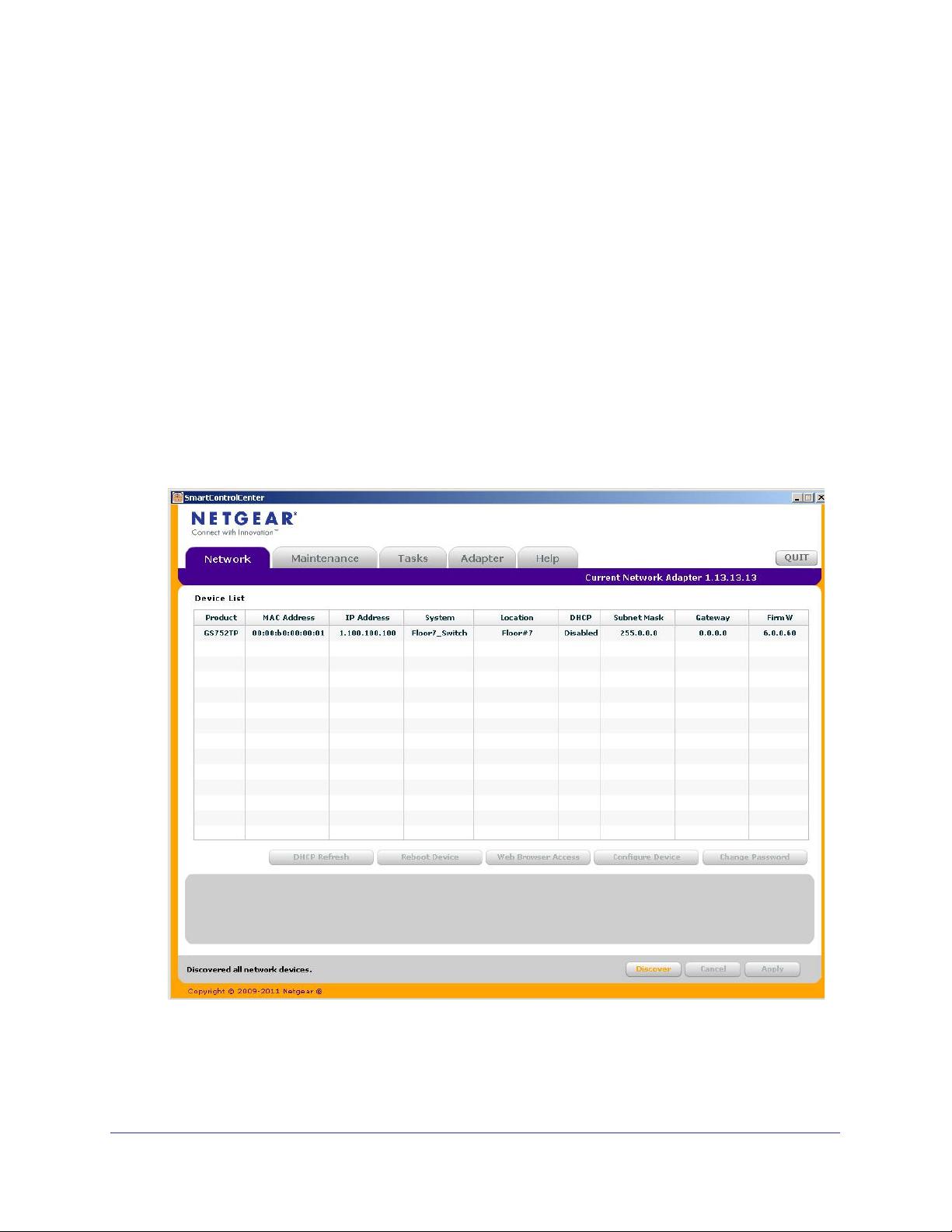
5. Click Discover for the Smart Control Center to find your switch.
A screen similar to the one shown below is displayed.
6. Make a note of the displayed IP address assigned by the DHCP server.
You need this value to access the switch directly from a web browser (without using the
Smart Control Center).
12
Page 13
GS752TP, GS728TP, and GS728TPP Gigabit Smart Switches
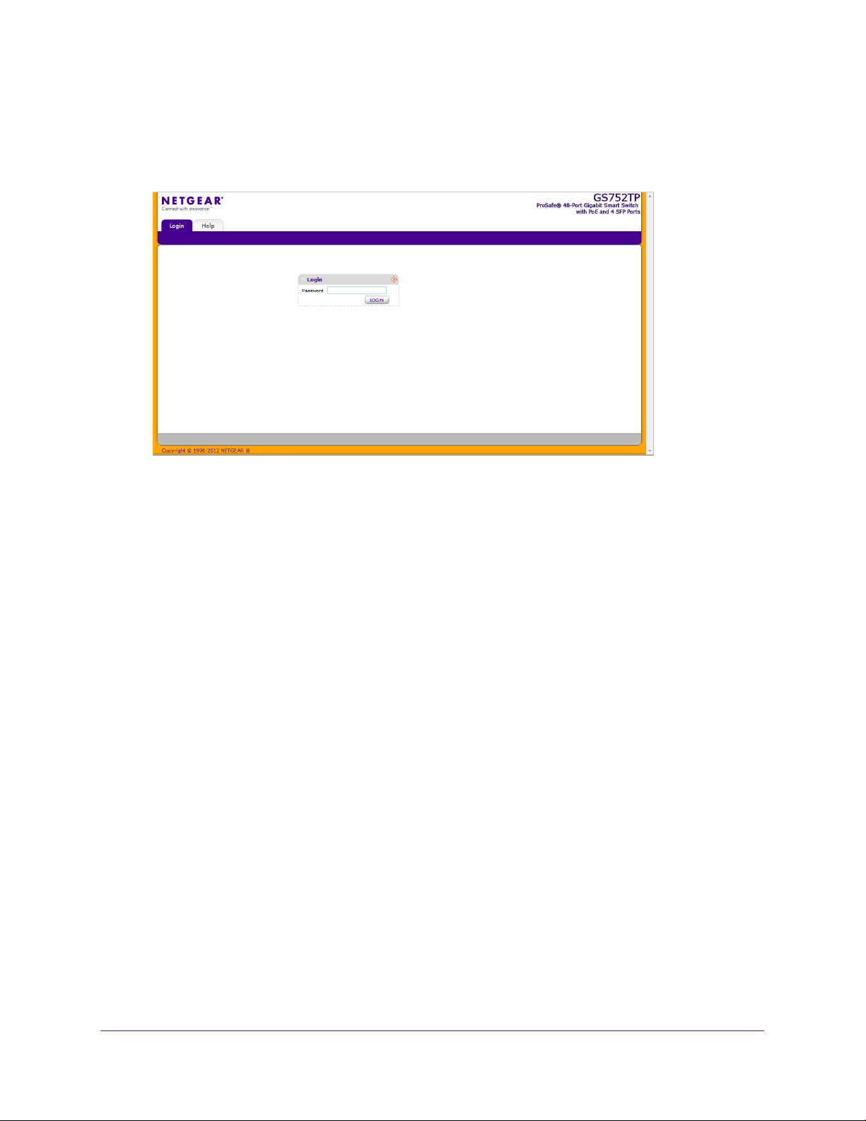
7. Select your switch by clicking the line that displays the switch, then click the
Web Browser Access button.
The Smart Control Center displays a login window.
To manage your switch, use your web browser. The default password is password. Use
this screen to manage your switch. For more information, see Access the Management
Interface from the Web on page 17.
13
Page 14
GS752TP, GS728TP, and GS728TPP Gigabit Smart Switches
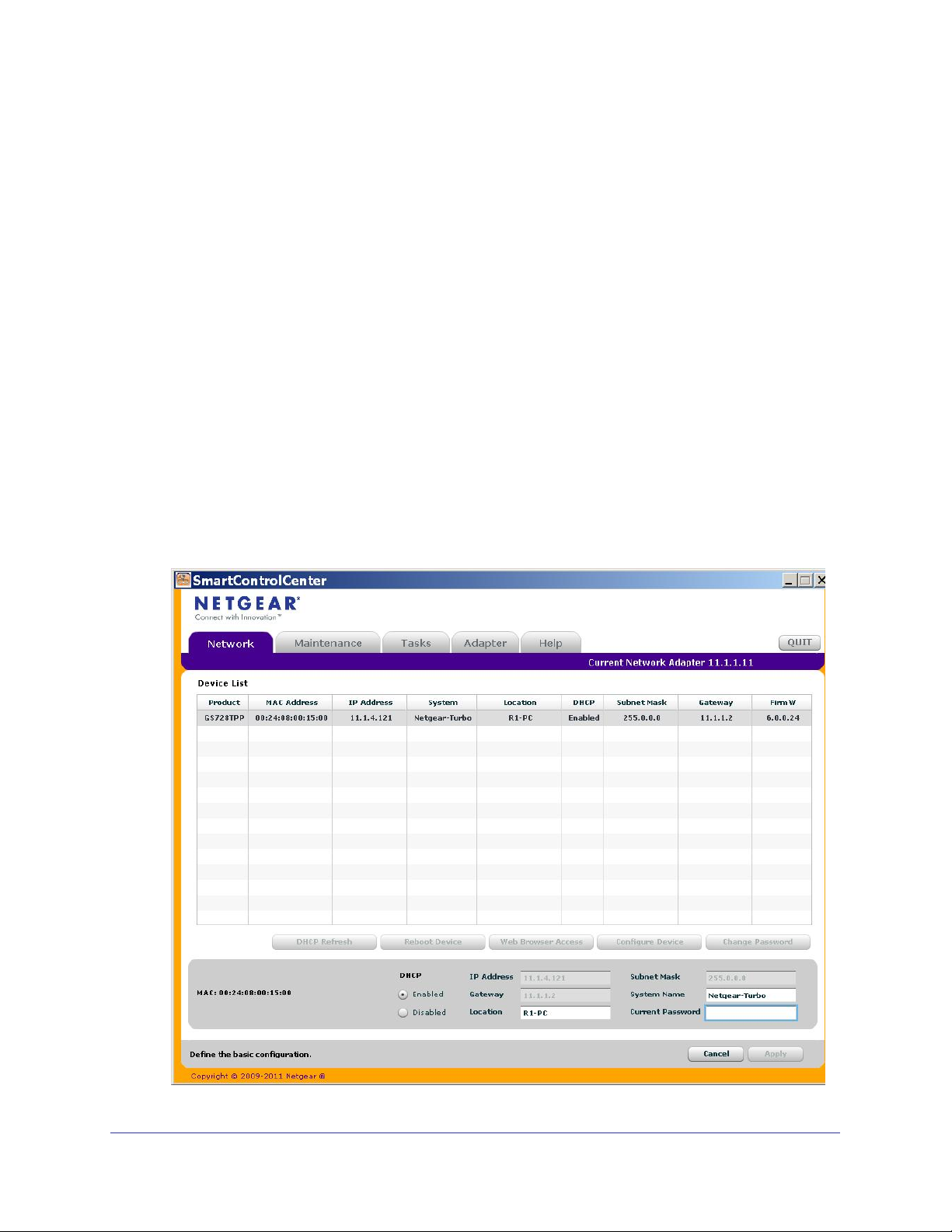
Switch Discovery in a Network Without a DHCP Server
This section describes how to use the Smart Control Center to set up your switch in a
network without a DHCP server. If your network has no DHCP service, you must assign a
static IP address to your switch. You can assign it a static IP address, even if your network
has DHCP service.
To assign a static IP address:
1. Connect the switch to your existing network.
2. Power on the switch by connecting its power cord.
3. Install the Smart Control Center on your computer
4. Start the Smart Control Center.
5. Click Discover for the Smart Control Center to find your NETGEAR switch.
The utility broadcasts Layer 2 discovery packets within the broadcast domain to discover
the switch.
.
6. Select the switch, then click Configure Device.
The screen expands to display more fields at the bottom of the screen.
.
14
Page 15

GS752TP, GS728TP, and GS728TPP Gigabit Smart Switches
7. Select the Disabled radio button to disable DHCP.
8. Enter the static switch IP address, gateway IP address, and subnet mask for the switch and
type your password.
Tip: You must enter the current password every time you use the Smart
Control Center to update the switch setting. The default password is
password.
9. Click APPLY to configure the switch with the network settings.
Ensure that your computer and the switch are in the same subnet. Make a note of these
settings for later use.
Configure the Network Settings on the Administrative System
If you do not use the Smart Control Center to configure the switch network information, you
can connect directly to the switch from the administrative system installed on your computer.
The IP address of the administrative system must be in the same subnet as the default IP
address on the switch. For most networks, this means you must change the IP address of the
administrative system to be on the same subnet as the default IP address of the switch
(192.168.1.1).
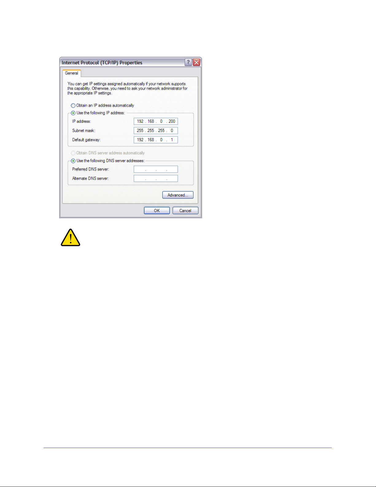
To change the IP address on an administrative system running a Windows operating system,
open the Internet Protocol (TCP/IP) Properties screen that you access from each local area
connection, as shown in the following screen. You need Windows Administrator privileges to
change these settings.
15
Page 16
GS752TP, GS728TP, and GS728TPP Gigabit Smart Switches
WARNING:
When you change the IP address of your administrative system,
connection to the rest of the network is lost. Be sure to write down
your current network address settings before you change them.
To modify the network settings on your administrative system:
1. On your computer
, access the Windows operating system TCP/IP Properties screen.
2. Set the IP address of the administrative system to an address in the 192.168.0.0 network,
such as 192.168.0.200.
The IP address must be different from the switch’s address but within the same subnet.
3. Click OK.
To configure a static address on the switch:
1. Use a straight-through cable to connect the Ethernet port on the administrative system
directly to any port on the NETGEAR switch.
2. Open a web browser on your computer and connect to the management interface.
For more information, see Access the Management Interface from the Web on page 17.
3. Change the network settings on the switch to match the settings on your network.
For more information, see IP Configuration on page 27.
4. Return the network configuration on your administrative system to the original settings.
16
Page 17

GS752TP, GS728TP, and GS728TPP Gigabit Smart Switches
Access the Management Interface from the Web
To access the switch management interface, use one of the following methods:
• From the Smart Control Center, select the switch and click Web Browser Access. For
more information, see the documentation for this application at
http://docs.netgear.com/scc/enu/202-10685-01/index.htm.
• Open a web browser and enter the IP address of the switch in the address field.
You must be able to ping the IP address of the NETGEAR switch management interface from
your administrative system for web access to be available. If you used the Smart Control
Center to set up the IP address and subnet mask, either with or without a DHCP server, use
that IP address in the address field of your web browser. If you did not change the IP address
of the switch from the default value, enter 192.168.0.239 into the address field.
Clicking Web Browser Access on the Smart Control Center or accessing the switch directly
from your web browser displays the Login screen.
Understand the User Interface
To access the switch by using a web browser, the browser must meet the following software
requirements:
• Internet Explorer version 7 or later
• Firefox version 4 or later
To log on to the web interface:
1. Open a web browser and enter the IP address of the switch in the web browser address
field.
2. The factory default password is password. Type the password in the field on the Login
screen and click Login. Passwords are case-sensitive.
17
Page 18

GS752TP, GS728TP, and GS728TPP Gigabit Smart Switches
3. After the system authenticates you, the System Information screen displays.
Navigation tab Configuration menus
Configuration status and options
Help link
Logout button
Help
screen
Screen menu
Figure 1. Configuration Status and Options
Navigation Tabs, Configuration Menus, and Screen Menu
The navigation tabs along the top of the web interface give you quick access to the various
switch functions. The tabs are always available and remain constant, regardless of which
feature you configure.
When you select a tab, the features for that tab appear as menus directly under the tabs. The
menus in the blue bar change according to the navigation tab that is selected.
The configuration screens for each feature are available as submenu links in the screen
menu on the left side of the screen.
18
Page 19

GS752TP, GS728TP, and GS728TPP Gigabit Smart Switches
Some items in the menu expand to reveal multiple submenu links, as shown in the following:
Link
Submenu
Links
When you click a menu item that includes multiple configuration screens, the item becomes
preceded by a down arrow symbol and expands to display the additional submenu links.
Configuration and Status Options
The area directly below the feature links and to the right of the links displays the configuration
information or status for the screen you select. On screens that contain configuration options,
you can enter information into fields or select options from drop-down lists.
Each screen contains access to the HTML-based help that explains the fields and
configuration options for the screen. Each screen also contains command buttons.
The following table shows the command buttons that are used throughout the screens in the
web interface.
Table 1. Command Buttons
Button Function
ADD Places the new item configured in the heading row of a table.
APPLY Sends the updated configuration to the switch. Configuration changes take effect
immediately
CANCEL Resets the data on the screen to the latest value of the switch.
DELETE Removes the selected item.
REFRESH Reloads the screen with the latest information from the device.
LOGOUT Ends the session.
.
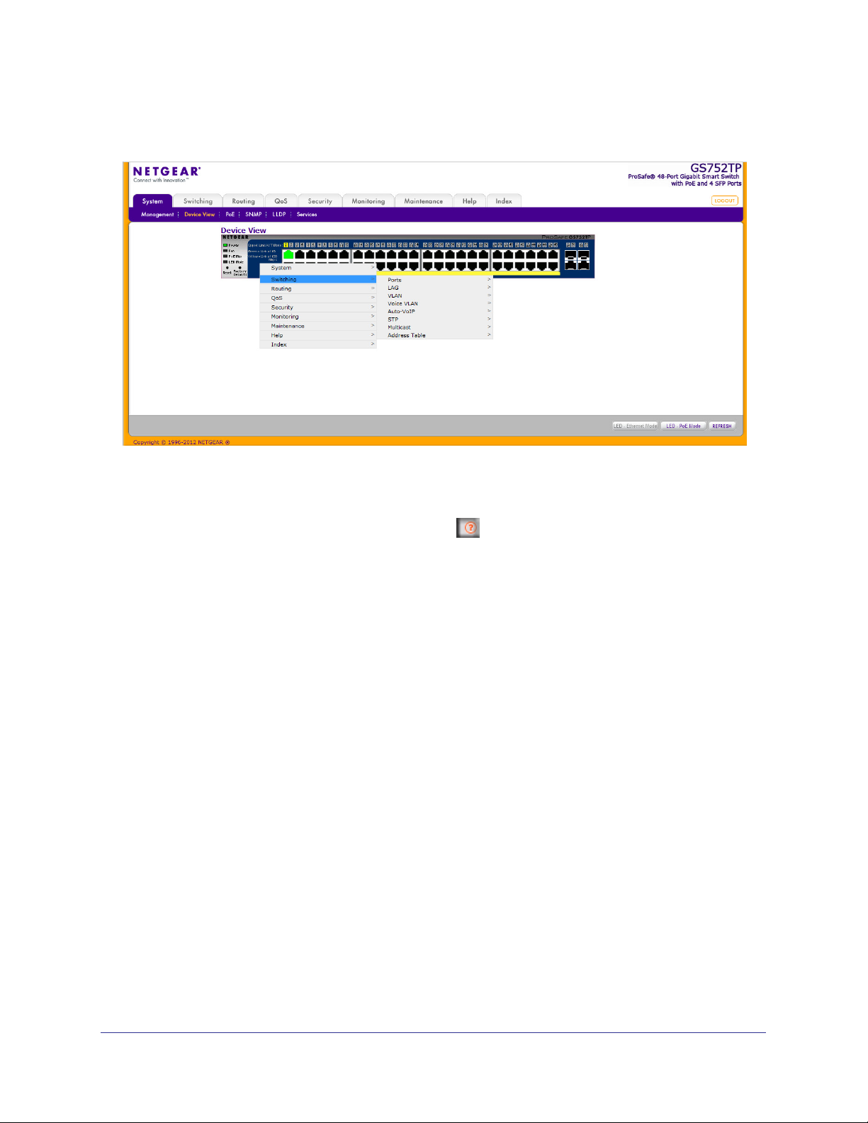
Device View
The Device View is a Java applet that displays the ports on the switch. This graphic provides
an alternate way to navigate to configuration and monitoring options. The graphic also
provides information about device ports, current configuration and status, table information,
and feature components.
19
Page 20

GS752TP, GS728TP, and GS728TPP Gigabit Smart Switches
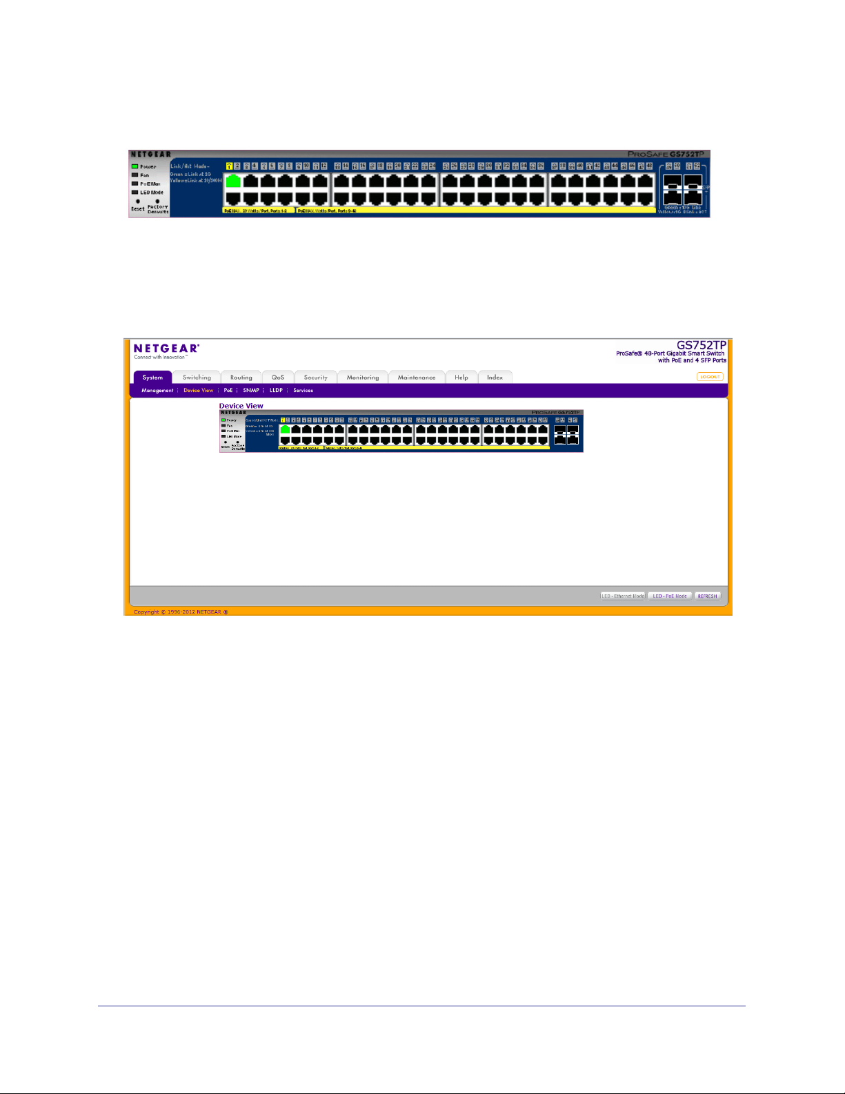
The Device View is available by selecting System Device View.
Depending upon the status of the port, the LED of the port status lights. Green indicates that
the port is enabled. Red indicates that an error occurred on the port and the link is disabled.
The LED of the port speed light in either green or yellow.
• A green LED indicates operational ports at the link speed of 1000 Mbps.
• A yellow LED indicates operational ports at the link speed of 10/100 Mbps.
The system LEDs are on the left side of the front panel.
Power/Status LED
The Power LED is a bicolor LED that serves as an indicator of power and diagnostic status.
The following indications are given by the following LED states:
• A solid green LED indicates that the power is supplied to the switch from the internal
power supply and is operating normally.
• A blinking green LED indicates that the internal power supply has failed, and that the
system is drawing power from a remote power supply or PoE power from an external
power supply.
• A solid yellow LED indicates that system is in the boot-up stage.
• No lit LED indicates that power is disconnected.
FAN Status LED
FAN status is indicated as follows:
• A solid yellow LED indicates that the fan is faulty.
• No lit LED indicates that the fan is operating normally.
Max PoE LED
The Max PoE LED indicates the following:
• A solid yellow LED indicates that less than seven watts of PoE power are available.
• A blinking yellow LED indicates that the PoE Max LED was lit within the previous 2
minutes.
• No lit LED indicates that at least seven watts of PoE power are available.
LED Status LED
The LED Status LED indicates the following:
• A solid green LED indicates that the Port LED is in Ethernet Mode.
• A solid yellow LED indicates that the Port LED is in PoE Mode.
20
Page 21
GS752TP, GS728TP, and GS728TPP Gigabit Smart Switches
The following image shows the device view of the NETGEAR switch.
Figure 2. Ports and LEDs on the Switching Devices
Click the port you want to view or configure to see a menu that displays statistics and
configuration options. Click the menu option to access the screen that contains the
configuration or monitoring options.
Figure 3. Device View
21
Page 22
GS752TP, GS728TP, and GS728TPP Gigabit Smart Switches
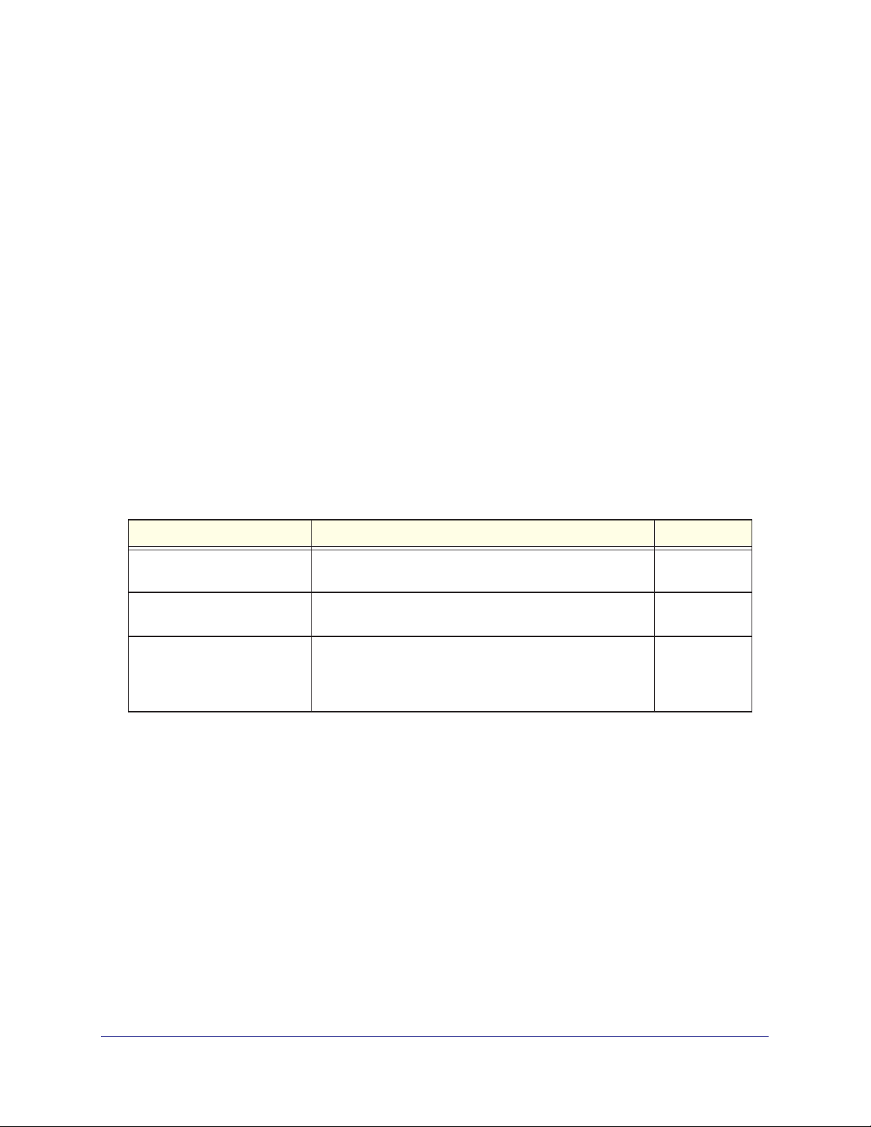
If you right-click the graphic, the main menu displays.
Figure 4. Device View Drop Down Menus
Help Screen Access
Every screen contains a link to the online help , which contains information to help
configure and manage the switch. The online help screens are context-sensitive. For
example, if the IP
Addressing screen is open, the help topic for that screen displays if you
click Help. Figure 1, Configuration Status and Options shows the location of the Help link on
the web interface.
User-Defined Fields
User-defined fields can contain 1 to 159 characters, unless otherwise noted on the
configuration web screen. All characters can be used except for the following (unless
specifically noted in for that feature):
\ <
/ >|
* |
?
Use SNMP
The switch software supports the configuration of SNMP groups and users that can manage
traps that the SNMP agent generates.
The switch uses both standard public MIBs for standard functionality and private MIBs that
support more switch functionality. All private MIBs begin with a hyphen (-) prefix. The main
22
Page 23

GS752TP, GS728TP, and GS728TPP Gigabit Smart Switches
object for interface configuration is in -SWITCHING-MIB, which is a private MIB. Some
interface configurations also involve objects in the public MIB, IF-MIB.
SNMP is enabled by default. The System Information web screen, which displays after a
successful login, displays the information you need to configure an SNMP manager to
access the switch.
Any user can connect to the switch using the SNMPv3 protocol. However, for authentication
and encryption, the switch only supports a single user called admin, which is the only profile
that can be created or modified.
To configure authentication and encryption settings for the SNMPv3 admin profile by
using the web interface:
1. Select the System SNMP SNMPv3 User Configuration screen.
2. To enable authentication, select one of MD5 and SHA authentication protocol options.
3. To enable encryption:
a. Select DES as the encryption protocol.
b. In the Encryption Key field, enter an encryption code of eight or more alphanumeric
characters.
4. Click APPLY.
To access configuration information for SNMPv1 or SNMPv2:
1. Select System SNMP SNMPv1/v2
2. Follow the link to the screen that contains the information to configure.
23
Page 24
GS752TP, GS728TP, and GS728TPP Gigabit Smart Switches
Interface Naming Convention
The switch supports physical and logical interfaces. Interfaces are identified by their type and
the interface number. The switches support the following ports:
• GS752TP. Ports 1–48 are 10/100/1000M AutoSensing Gigabit ports, and ports 49–52 are
100/1000M SFP ports. The first 8 ports are PoE+ providing 30W of DC power, and the
remaining copper ports are PoE (Power over Environment) providing 15.4W of DC power.
• GS728TP. Ports 1–24 are 10/100/1000M
100/1000M SFP ports. The first 8 ports are PoE+ providing 30W of DC power, and the
remaining copper ports are PoE (Power over Environment) providing 15.4W of DC power.
• GS728TPP. Ports 1–24 are 10/100/1000M
are 100/1000M SFP ports. All 24 copper ports are PoE+ providing 30W of DC power. This
model includes an external power supply to support the increased power requirements.
The number of the port is identified on the front panel. You can configure the logical
interfaces by using the software.
The following table describes the naming convention for all
interfaces available on the switch.
AutoSensing Gigabit ports, and ports 25–28 are
AutoSensing Gigabit ports, and ports 25–28
Table 2. Naming Convention
Interface Description Example
Physical The physical ports include Gigabit ports and are numbered
Link aggregation group (LAG) LAG interfaces are logical interfaces that are used only for
CPU Management Interface This is the internal switch interface responsible for the
for Switch Interfaces
sequentially starting from 1.
bridging functions.
switch base MAC address.
configurable and is always listed in the MAC Address
Table.
This interface is not
g1, g2, g3
l1, l2, l3
c1
24
Page 25

2. Configuring System Information
Use the features in the System tab to define the switch’s relationship to its environment. The
System tab contains links to screens described in the following sections:
• Management
• PoE
• SNMP
• LLDP
• Services—DHCP Snooping
2
25
Page 26
GS752TP, GS728TP, and GS728TPP Gigabit Smart Switches
Management
This section describes how to display the switch status and specify some basic switch
information, such as the management interface IP address, system clock settings, and DNS
information. From the Management menu, you can access screens described in the following
sections:
• System Information
• IP Configuration
• IPv6 Network Configuration
• IPv6 Network Neighbors
• Time
• DNS
• Green Ethernet Configuration
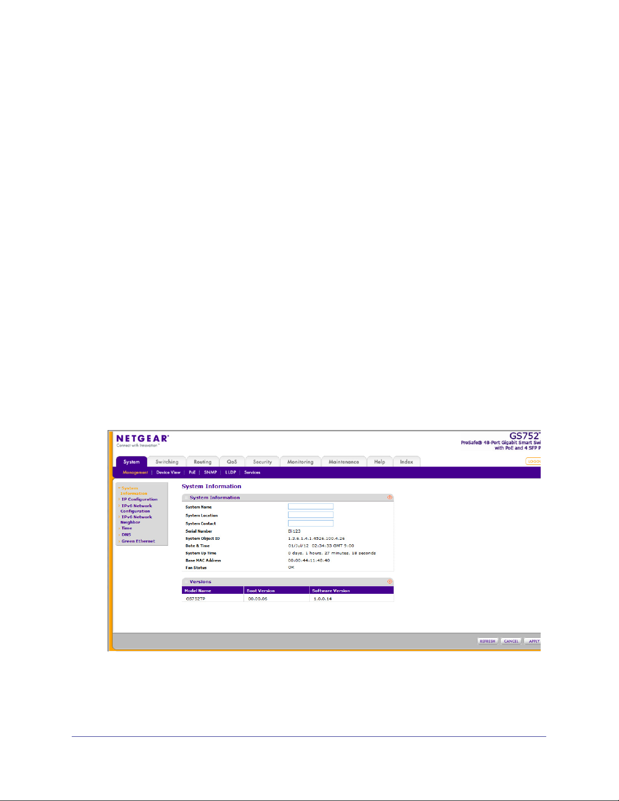
System Information
After a successful login, the System Information screen displays. Use this screen to configure
and view general device information.
To define system information:
1. Select System Management System Information.
The following screen displays:
2. Define the following fields:
• System Name. Enter the name you want to use to identify this switch. You can use
up to 160 alphanumeric characters. The factory default is blank.
26
Page 27

GS752TP, GS728TP, and GS728TPP Gigabit Smart Switches
• System Location. Enter the location of this switch. You can use up to 160
alphanumeric characters. The factory default is blank.
• System Contact. Enter the contact person for this switch.
You can use up to 160
alphanumeric characters. The factory default is blank.
3. Click APPL
Y to apply the changes to the system.
Table 3 describes the status information displayed in the System screen.
Table 3. System status information
Field Description
Serial Number The serial number of the switch.
System Object ID The base object ID for the switch's enterprise MIB.
Date & Time The current date and time.
System Up Time Displays the number of days, hours, and minutes since the last system
restart.
Base MAC Address Universally assigned network address.
Fan Status The status of fan operation.
Model Name The model name of the switch.
Boot Version The boot code version of the switch.
Software Version The software version of the switch.
IP Configuration
Use the IP Configuration screen to configure network information for the management
interface, which is the logical interface used for in-band connectivity with the switch through
any of the switch's front-panel ports. The configuration parameters associated with the
switch's network interface do not affect the configuration of the front panel ports through
which traffic is switched or routed.
27
Page 28
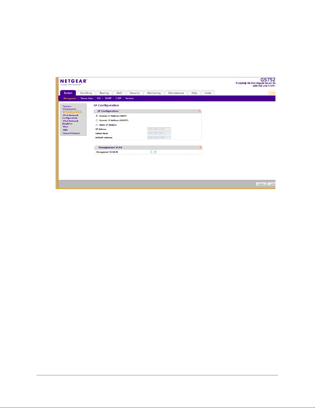
GS752TP, GS728TP, and GS728TPP Gigabit Smart Switches
To configure the network information for the management interface:
1. Select System Management IP Configuration.
The following screen displays:
2. Select the appropriate radio button to determine how to configure the network information for
the switch management interface:
• Dynamic IP
Address (DHCP). Specifies that the switch must obtain the IP address
through a DHCP server.
• Dynamic IP
Address (BOOTP). Specifies that the switch must obtain the IP address
through a BootP server.
• Static IP
Address. Specifies that the IP address, subnet mask, and default gateway
must be manually configured. Enter this information in the fields below this radio
button.
3. If you selected the Static IP Address option, configure the following network information:
• IP Address.
The IP address of the network interface. The factory default value is
192.168.0.239. Each part of the IP address must start with a number other than 0. For
example, IP addresses 001.100.192.6 and 192.001.10.3 are not valid.
• Subnet Mask.
The IP subnet mask for the interface. The factory default value is
255.255.255.0.
• Default Gateway.
The default gateway for the IP interface.
4. Specify the VLAN ID for the management VLAN.
The management VLAN is used to establish an IP connection to the switch from a
workstation that is connected to a port in the same VLAN. If not specified, the active
management VLAN ID is 1 (default), which allows an IP connection to be established
through any port.
28
Page 29

GS752TP, GS728TP, and GS728TPP Gigabit Smart Switches
When the management VLAN is set to a different value, an IP connection can be made
only through a port that is part of the management VLAN. It is also mandatory that the
port VLAN ID (PVID) of the port to be connected in that management VLAN be the same
as the management VLAN ID.
Note: Make sure that the PVID of at least one port that is a port of the
VLAN is the same as the management VLAN ID. For information
about creating VLANs and configuring the PVID for a port, see
VLANs .
The management VLAN has the following requirements:
• Only one management VLAN can be active at a time.
• When a new management VLAN is configured, connectivity through the existing
management VLAN is lost.
• The management station must be reconnected to the port in the new management
VLAN.
5. Click APPLY to apply the changes to the system.
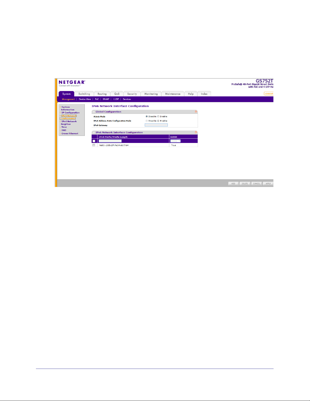
IPv6 Network Configuration
Use the IPv6 Network Configuration screen to configure the IPv6 network interface, which is
the logical interface used for in-band connectivity with the switch through all of the switch's
front-panel ports. The configuration parameters associated with the switch's network
interface do not affect the configuration of the front-panel ports through which traffic is
switched or routed.
To access the switch over a IPv6 network, you must initially configure the switch with IPv6
information (IPv6 prefix, prefix length, and default gateway). IPv6 can be configured using
IPv6 autoconfiguration.
When in-band connectivity is established, IPv6 information can be changed using any of the
following:
• SNMP-based management
• Web-based management
29
Page 30
GS752TP, GS728TP, and GS728TPP Gigabit Smart Switches
To configure the global settings for an IPv6 Interface:
1. Select System Management IPv6 Network Configuration.
The following screen displays:
2. In the Global Configuration Section, configure the following:
• Admin Mode. Enable or disable the IPv6 network interface on the switch.
value is Enable.
• IPv6
Address Auto Configuration Mode. The IPv6 address for the IPv6 network
interface is automatically configured if this option is enabled. The default value is
Disable.
• IPv6 Gateway. Specify the gateway for the IPv6 network interface.
The gateway
address is in IPv6 global or link-local address format.
3. Click APPL
To modify IPv6 addresses on the network interface:
1. Select System
Y to apply the changes to the system.
Management IPv6 Network Configuration.
2. in the IPv6 Network Interface Configuration section, configure the following:
• IPv6 Prefix/Prefix Length. Select an existing IPv6 prefix and prefix length from the
list, or add a new IPv6 prefix and prefix length to the list of IPv6 addresses. The
address is in the global address format.
• EUI64. Specify whether the IPv6 address is in EUI-64 format.
The default value is
False.
3. Click ADD to add a new IPv6 address, or click DELETE to delete a selected IPv6
address from the list of IPv6 addresses.
4. Click APPL
Y to apply the changes to the system.
The default
30
Page 31

GS752TP, GS728TP, and GS728TPP Gigabit Smart Switches
IPv6 Network Neighbors
To view the IPv6 Network Interface Neighbors:
Select System
Management IPv6 Network Neighbors.
The following screen displays:
Properties of each neighbor are displayed, as described below:
• IPv6 Address. Specifies the IPv6 address of the neighbor interface.
• MAC Address. Specifies the MAC address associated with the neighbor interface.
• IsRtr. Indicates whether the neighbor is a router
. If the neighbor is a router, the value is
True. If the neighbor is not a router, the value is False.
• Neighbor State. Specifies the state of the neighbor cache entry
. The following are the
states for dynamic entries in the IPv6 neighbor discovery cache:
• Reach. No more than ReachableT
ime milliseconds have elapsed since confirmation
was received that the forward path to the neighbor was functioning properly. When in
REACH state, the device takes no special action as packets are sent.
• Stale. More than ReachableT
ime milliseconds have elapsed since a confirmation was
last received that the forward path was functioning properly. While in STALE state,
the device takes no action until a packet is sent.
• Delay. More than ReachableT
ime milliseconds have elapsed since a confirmation
was last received that the forward path was functioning properly. A packet was sent
within the last DELAY_FIRST_PROBE_TIME seconds. If no confirmation is received
within DELAY_FIRST_PROBE_TIME seconds of entering the DELAY state, the
device sends a neighbor solicitation message and changes the state to PROBE.
• Probe.
A confirmation is actively sought by repeatedly sending neighbor solicitation
messages every RetransTimer milliseconds until a confirmation is received.
• Last Updated. Elapsed time since the address was last confirmed as reachable.
31
Page 32

GS752TP, GS728TP, and GS728TPP Gigabit Smart Switches
Time
The switch software supports the Simple Network Time Protocol (SNTP). You can also set
the system time manually
SNTP assures accurate network device clock time synchronization up to the millisecond.
Time synchronization is performed by a network SNTP server. The software operates only as
an SNTP client and cannot provide time services to other systems.
Time sources are established by stratums. Stratums define the accuracy of the reference
clock. The higher the stratum (where 0 is the highest), the more accurate the clock. The
switch is a stratum 2 device, and as such accepts stratum 1 or higher time indications.
The following is an example of stratums:
• Stratum 0. A real-time clock is used as the time source, for example, a GPS system.
• Stratum 1. A server that is directly linked to a stratum 0 time source is used. Stratum 1
time servers provide primary network time standards.
• Stratum 2. The time source is distanced from the stratum 1 server over a network path.
For example, a stratum 2 server receives the time over a network link, through NTP, from
a stratum 1 server.
Information received from SNTP servers is evaluated based on the time level and server
type.
SNTP time definitions are assessed and determined by the following time levels:
• T1. Time at which the original request was sent by the client.
• T2. Time at which the original request was received by the server.
• T3. Time at which the server sent a reply.
• T4. Time at which the client received the server's reply.
The device can poll unicast server types for the server time.
Polling for unicast information is used for polling a server for which the IP address is known.
SNTP servers that have been configured on the device are the only ones that are polled for
synchronization information. T1 through T4 are used to determine server time. This is the
preferred method for synchronizing device time because it is the most secure method. If this
method is selected, SNTP information is accepted only from SNTP servers defined on the
device using the SNTP Server Configuration screen.
The device retrieves synchronization information, either by actively requesting information or
at every poll interval.
Time Configuration
Use the Time Configuration screen to view and adjust date and time settings.
32
Page 33

GS752TP, GS728TP, and GS728TPP Gigabit Smart Switches
To configure the time by using the CPU clock cycle as the source:
1. Select System Management Time SNTP Global Configuration.
The following screen displays:
2. Next to the Clock Source, select Local.
3. In the Date field, enter the date in the DD/MM/YYYY format.
4. In the
Time field, enter the time in HH:MM:SS format.
Note: If you do not enter a date and time, the switch calculates the date
and time using the CPU’s clock cycle.
When the clock source is set to Local, the Time Zone Offset field is disabled.
5. Click APPL
Y to send the updated configuration to the switch.
Configuration changes take effect immediately.
To configure the time through SNTP:
1. Next to the Clock Source, select SNTP.
When the clock source is set to SNTP, the Date and Time fields are disabled. The switch
gets the date and time from the network.
2. In the
Time Zone Offset list, select the Coordinated Universal Time (UTC) time zone in
which the switch is located, expressed as the number of hours.
3. Use the SNTP Server Configuration screen to configure the SNTP server settings.
4. Click APPL
Y to send the updated configuration to the switch.
Configuration changes take effect immediately.
33
Page 34

GS752TP, GS728TP, and GS728TPP Gigabit Smart Switches
The SNTP Global Status table on the Time Configuration screen displays information about
the system’s SNTP client. Table 4 describes the SNTP Global Status fields.
Table 4. SNTP Global Status fields.
Field Description
Version Specifies the SNTP version the client supports.
Supported Mode Specifies the SNTP modes the client supports. Multiple modes might be
supported by a client.
Last Update Time Specifies the local date and time (UTC) the SNTP client last updated the
system clock.
Server IP Address Specifies the IP address of the server for the last received valid packet. If no
message has been received from any server
Address Type Specifies the address type of the SNTP server address for the last received
valid packet.
, an empty string is shown.
Server Stratum Specifies the claimed stratum of the server for the last received valid packet.
Server Mode Specifies the mode of the server for the last received valid packet.
Unicast Server Max Entries Specifies the maximum number of unicast server entries that can be
configured on this client.
Unicast Server Current
Entries
Specifies the number of current valid unicast server entries configured for
this client.
SNTP Server Configuration
Use the SNTP server configuration screen to view and modify information for adding and
modifying Simple Network Time Protocol SNTP servers.
34
Page 35

GS752TP, GS728TP, and GS728TPP Gigabit Smart Switches
To configure a new SNTP server:
1. Select System Management Time SNTP Server Configuration.
The following screen displays:
2. Enter the appropriate SNTP server information in the following fields:
• Server Type. Specifies whether the address for the SNTP server is an IP address
(IPv4) or host name (DNS).
• Address. Enter the IP address or the host name of the SNTP server.
• Port. Enter a port number on the SNTP server to which SNTP requests are sent. The
valid range is 1–65535. The default is 123.
3. Click Add.
Repeat the previous steps to add more SNTP servers. You can configure up to three SNTP
servers.
To change the settings for an existing SNTP server:
1. Select the check box next to the configured server.
2. Enter new values in the available fields.
3. Click APPLY.
Configuration changes take effect immediately.
To remove an SNTP server:
1. Select the check box next to the configured server you want to remove.
2. Click DELETE.
The entry is removed, and the device is updated.
The SNTP Server Status table displays status information about the SNTP servers
configured on your switch.
Table 5 describes the SNTP status fields.
35
Page 36

GS752TP, GS728TP, and GS728TPP Gigabit Smart Switches
Table 5. SNTP Server Status Table Fields
Field Description
Address Specifies all the existing server addresses. If no server configuration exists, a
message saying “No SNTP server exists” flashes on the screen.
Last Update Time Specifies the local date and time (UTC) of the server response, according to
which the system clock was updated.
DNS
Use the DNS screens to configure information about DNS servers used by the network and
DNS client settings for the switch.
DNS Configuration
Use this screen to configure global DNS settings and DNS server information.
To configure the global DNS settings:
1. Select System
Management DNS DNS Configuration.
The following screen displays:
2. Specify whether to enable or disable the administrative status of the DNS client.
• Enable.
Allow the switch to send DNS queries to a DNS server to resolve a DNS
domain name. The DNS is enabled by default.
• Disable. Prevent the switch from sending DNS queries.
36
Page 37

GS752TP, GS728TP, and GS728TPP Gigabit Smart Switches
3. In the DNS Default Name field, enter a default DNS name to include in DNS queries. When
the system is performing a lookup on an unqualified host name, this field is provided as the
domain name. For example, if the default domain name is netgear.com and the host name
to resolve is test, test.netgear.com is used in DNS resolution queries.
4. in the DNS Server field, enter an IP address representing the DNS server to which the
switch sends DNS queries, and click ADD. The server appears in the DNS Server list.
• Use standard IPv4 dot notation (from 1 through 158 characters).
• You can specify up to eight DNS servers.
• DNS server precedence is set according to the creation order.
5. Click APPLY to send the updated configuration to the switch.
Configuration changes take effect immediately.
Host Configuration
Use this screen to manually map host names to IP addresses or to view Dynamic DNS
mappings.
To add a static entry to the local DNS table:
1. Select System Management DNS Host Configuration.
The following screen displays:
2. Specify the static host name to add.
• Enter up to 158 characters.
• Each label (separated by periods) can be up to 63 characters.
3. Specify the IP address in standard IPv4 dot notation to associate with the hostname.
4. Click ADD. The entry displays in the list.
37
Page 38

GS752TP, GS728TP, and GS728TPP Gigabit Smart Switches
The Dynamic Host Configuration table shows host name-to-IP address entries that the switch
has learned. Table 6 describes the dynamic host fields.
Table 6. Dynamic Host Configuration table fields
Field Description
Host Lists the host name you assign to the specified IP address.
Type The type of the dynamic entry.
IPv4/IPv6 Address Lists the IP address associated with the host name.
Click CLEAR to delete dynamic host entries. The table repopulates with entries as they are
learned.
Green Ethernet Configuration
The Green Ethernet features allow the switch to reduce power consumption on a per-port
basis. Each switch can support one or more of the following features:
• Auto Power Down Mode. When the Auto Power Down mode is enabled and the port link
is down, the physical layer (PHY) automatically shuts down for a short period and wakes
up to check link pulses. This mode reduces power consumption on the port when no link
partner is present.
• Short Cable Mode. With Short Cable mode enabled, the PHY goes into low-power mode
when the cable length is less than a certain limit.
• Energy Efficient Ethernet (EEE) Mode. EEE enables ports to enter a low-power mode
to reduce power consumption during periods of low link utilization. EEE is defined by
IEEE 802.3az. EEE enables both the send and receive sides of the link to disable some
functionality for power savings when the link is lightly loaded.
38
Page 39

GS752TP, GS728TP, and GS728TPP Gigabit Smart Switches
To configure the Green Ethernet Configuration features:
1. Select System Management Green Ethernet Green Ethernet Configuration.
The following screen displays:
2. Enable or disable the Auto Power Down Mode.
• Enable. When the port link is down, the PHY automatically goes down for a short
period and then wakes up to check link pulses. This allows the port to continue to
perform autonegotiation while consuming less power when no link partner is present.
• Disable. Provide full power to the PHY even if no link partner is present.
3. Enable or disable the Short Cable Mode.
• Enable. When the port link is up at 1-Gbps speed, the cable length test is performed.
If the cable length is less than 10 meters, PHYs are put into the low-power mode so
only enough power is used to support a short cable.
• Disable. Provide full power to the PHY regardless of cable length.
4. Enable or disable the EEE Mode.
• Enable. Enter a low-power mode and disable some functionality for power savings
when the link is lightly loaded.
• Disable. Provide full power to the PHY always.
5. Click APPLY to apply the change to the system.
Configuration changes take effect immediately.
39
Page 40

GS752TP, GS728TP, and GS728TPP Gigabit Smart Switches
Green Ethernet Interface Configuration
Using the Green Ethernet Interface Configuration feature allows for proper port configuration
and the ability to enable or disable the Auto Power Down, Short Cable, and EEE Modes on
specific ports.
To configure the Green Ethernet Interface feature:
1. Select System Management Green Ethernet Green Ethernet Interface
Configuration.
The following screen displays:
2. Select the following interface settings for the physical port:
• Go To Interface. Enter a port identifier (appears in the Port column) and click the Go
button.
The table entry corresponding to the specified port is selected.
• Port. Selects the interface for which data is displayed or configured.
• Auto Power Down Mode. Determines whether Auto Power Down mode is enabled
for the port. The factory default is Disable. When the port link is down, the PHY
automatically goes down for a short period and wakes up to check link pulses. This
mode allows automatic negotiation and reduces power consumption when no link
partner is present.
• Short Cable Mode. Determines whether Short Cable mode is enabled for the port.
The factory default is Disable. When the port link up at 1 Gbps, the cable length test is
performed. If the length of the cable is less than 10 meters, PHYs are put into
low-power mode so enough power is used to support a short cable. Do not enable
both EEE and Short Cable modes for a port.
• EEE Mode. Determines whether Energy Efficient Ethernet (EEE) mode is enabled for
the port. Do not enable both EEE and Short Cable modes for a port.
3. Click APPLY to apply the change to the system.
40
Page 41

GS752TP, GS728TP, and GS728TPP Gigabit Smart Switches
Configuration changes take effect immediately.
Green Ethernet Detail
Use this screen to display or configure Green Ethernet details per interface.
To configure the Green Ethernet Detail feature:
1. Select System Management Green Ethernet Green Ethernet Detail.
The following screen displays:
2. View or configure the Local Device Information:
• Interface. The interface to be displayed or configured.
• Energy Detect Admin Mode. Select Enable or Disable.
• Operational Status. Displays the Energy Detect operational status, either Active or
Inactive.
• Reason. Displays the Admin status, either Admin Down or Admin Up.
• Short Reach Admin Mode. Select Enable or Disable.
• Operational Status. Displays the Short Reach operational status of the port, either
Active or Inactive.
• Reason. Displays the reason why the port is either Active or Inactive.
• EEE Admin Mode. Select Enable or Disable.
• Tw_sys_tx (uSec). Displays the amount of time the Tx_sys_tx has been present on
the port.
• Tw_sys_tx Echo (uSec). Displays the amount of time the Tw_sys_tx Echo has been
present on the port.
• Tw_sys_rx (uSec). Displays the amount of time the Tw_sys_rx has been present on
the port.
41
Page 42

GS752TP, GS728TP, and GS728TPP Gigabit Smart Switches
• Tw_sys_rx Echo (uSec). Displays the amount of time the Tw_sys_rx Echo has been
present on the port.
3. V
iew the Remote Device Information:
• Interface. If local interfaces are enabled to receive LLDP data, this feature allows you
to select the remote device and retrieve port information.
• Remote ID. Displays the remote port identifier
• Remote T
w_sys_tx (uSec). Displays the amount of time the Remote Tw_sys_tx has
.
been present on the port.
• Remote T
w_sys_tx Echo (uSec). Displays the amount of time the Remote
Tw_sys_tx Echo has been present on the port.
• Remote T
w_sys_rx (uSec). Displays the amount of time the Remote Tw_sys_rx has
been present on the port.
• Remote T
w_sys_rx Echo (uSec). Displays the amount of time the Remote
Tw_sys_rx Echo has been present on the port.
Green Ethernet Summary
This screen summarizes the Green Ethernet Summary settings currently in use. To access
the Green Ethernet Summary screen, select System
Management Green Ethernet
Green Ethernet Summary.
In the Green Mode Statistics Summary section, view the following:
• Cumulative Energy Saving (W
atts*Hours). Displays the cumulative energy savings
on the local device.
• Interface. Lists the local interfaces on the device.
• Energy Detect
Admin Mode. Displays the Energy Detect Admin mode for each of
the local interfaces (Enable or Disable).
42
Page 43

GS752TP, GS728TP, and GS728TPP Gigabit Smart Switches
• Energy Detect Operational Status. Displays the operational status of the Energy
Detect mode for each of the local interfaces (Active or Inactive).
• Short Reach Admin Mode. Displays the Short Reach Admin Mode for each of the
local interfaces (Enable or Disable).
• Short Reach Operational Status. Displays the operational status of the Short Reach
Admin mode for each of the local interfaces (Active or Inactive).
• EEE Admin Mode. Displays the EEE Admin mode for each of the local interfaces
(Enable or Disable).
PoE
The switches support both IEEE802.3 at and af, as follows:
• GS728TP. Ports 1–8 support both IEEE802.3 at and af, and ports 9–24 support
IEEE802.3af. The maximum power budget is 192 Watts.
• GS728TPP. Ports 1–24 support both IEEE802.3 at and af. The maximum power budget is
384 Watts for AC mode and 720 Watts for DC mode or AC+DC mode when you are using
external power supply RPS4000.
• GS752TP. Ports 1–8 support both IEEE802.3 at and af, and ports 9–48 support
IEEE802.3af. The maximum power budget is 384 Watts.
The power limit of a port is set to the minimum between the class and the configured max
power limit.
You can configure per-port priority settings, timers, and power limits to manage the power
supplied to the connected powered devices (PDs) and to ensure that the power budget is
used effectively.
From the PoE menu under the System tab, you can view and configure PoE settings for the
switch.
PoE features are described in the following sections:
• PoE Configuration
• PoE Port Configuration
• Timer Global Configuration
• Timer Schedule
43
Page 44

GS752TP, GS728TP, and GS728TPP Gigabit Smart Switches
PoE Configuration
To view global PoE power information and to configure PoE SNMP trap settings, use the PoE
Configuration screen.
To configure PoE trap settings:
1. Select System
The following screen displays:
Note: You can also access the PoE Configuration screen by selecting
PoE Basic PoE Configuration.
System > PoE > Advanced > PoE Configuration.
2. Next to
3. Click APPL
Traps, select the appropriate radio button to enable or disable SNMP traps.
Y to apply the new settings to the system.
Table 7 describes the following information provided in the PoE Configuration screen:
Table 7. PoE Configuration Field Descriptions
Field Description
Power Status Indicates whether the PoE capability is on or off.
Nominal Power Indicates the maximum amount of power the switch can provide to all ports.
44
Page 45

GS752TP, GS728TP, and GS728TPP Gigabit Smart Switches
Field Description
Threshold Power Indicates a power threshold percentage. In order to give power to an
additional port, the consumed power must be below the threshold.
Consumed Power
Displays the amount of power the system can consume before the system
does not provide power to an additional port.
PoE Port Configuration
Use the PoE Port Configuration screen to configure per-port PoE settings.
To assign a timer to the port:
1. Select System
The following screen displays:
PoE Advanced PoE Port Configuration.
2. Select the check box next to one or more interfaces.
3. Configure the settings:
• Admin Mode. Enables or disables the ability of the port to deliver power.
• Priority Level. Determines which ports can deliver power if the total power delivered
by the switch crosses a certain threshold.
The switch might not be able to supply
power to all connected devices. Priority is used to determine which ports can supply
power. When ports have the same priority, the lower numbered port is given a higher
priority.
• High Power Mode. 802.3at for each port.
• Class. Displays the class of the powered device (PD) connected to the port.
classes define the range of maximum power output that the switch generates. The
45
The
Page 46

GS752TP, GS728TP, and GS728TPP Gigabit Smart Switches
power level that the PD can actually use is slightly lower. The classes are defined as
follows:
• 0. 0–15.4W
• 1. 0–4W
• 2. 0–7W
• 3. 0–15.4W
• 4. 0–30W
• Timer Schedule. Select the timer schedule to use for the port. By default, no timer
schedules are configured. To create a timer schedule, use the Timer Global
Configuration screen.
• Output Voltage. Displays the current voltage being delivered to device in volts.
• Output Current. Displays the current being delivered to device in mA.
• Output Power. Displays the current power being delivered to device in watts.
• Power Limit. Displays the type of power limit to use on the port.
• Status. Displays the operational status of the port PD detection.
• Disabled. Indicates that no power is being delivered.
• DeliveringPower. Indicates that power is being drawn by a connected device.
• Fault. Indicates a problem with the port.
• Test. Indicates that the port is in test mode.
• OtherFault. Indicates that the port is idle due to an error condition.
• Searching. Indicates that the port is not in one of the above states.
4. Click APPLY to apply the new settings to the system.
Timer Global Configuration
Use the Timer Global Configuration screen to create or remove timers and to control the
administrative status of the timers. Timers control when power can and cannot be delivered
to a port. To add a timer to a port, use the following general steps:
1. Create a timer.
2. Configure timer settings.
3. Assign a timer to the port.
46
Page 47

GS752TP, GS728TP, and GS728TPP Gigabit Smart Switches
To create a timer:
1. Select System PoE Advanced Timer Global Configuration.
The following screen displays:
2. To add a timer, enter a name in the Timer Schedule Name field, and click ADD.
To remove a timer, select the check box associated with the timer and click DELETE.
To enable or disable the timer feature, select the appropriate radio button and click APPL
Y.
Timer Schedule
Use the Timer Schedule to configure when the power to a port is turned off. For example, you
can specify that the power is turned off every night, during the weekend, or during the same
one-week period every year.
47
Page 48

GS752TP, GS728TP, and GS728TPP Gigabit Smart Switches
To configure timer settings:
1. Select System PoE Advanced Timer Schedule Configuration.
The following screen displays:
2. From the Timer Schedule Name list, select the name of the schedule created on the Timer
Global Configuration screen.
3. Specify the time to turn of
f power.
The time range is from 00:00 to 23:59.
4. Specify the day to turn of
5. If necessary
6. If necessary
, specify the end date by clicking the calendar and selecting the date.
, use the Recurrence Pattern (Daily or Weekly) and Daily Mode fields to
f power by clicking the calendar and selecting the date.
customize the power shutdown schedule.
7. Click APPL
Y to save the settings for the selected timer.
48
Page 49

GS752TP, GS728TP, and GS728TPP Gigabit Smart Switches
SNMP
From SNMP menu under the System tab, you can configure SNMP settings for SNMP V1/V2
and SNMPv3.
SNMP features are described in the following sections:
• SNMP V1/V2
• Trap Flags
• SNMP Supported MIBs
• SNMP v3 User Configuration
SNMP V1/V2
The screens you access from the SNMPV1/V2 link allow you to configure SNMP community
information, traps, and trap flags.
Community Configuration
By default, two SNMP Communities exist:
• Private. Read/Write privileges and status set to Enable.
• Public. Read-only privileges and status set to Enable.
These communities are well-known. To change the defaults or to add other communities, use
the Community Configuration screen. Only the communities that you define using this screen
have access to the switch using the SNMPv1 and SNMPv2c protocols. Only communities
with read/write access can be used to change the configuration using SNMP.
49
Page 50

GS752TP, GS728TP, and GS728TPP Gigabit Smart Switches
To add a new SNMP community:
1. Select System SNMP SNMP V1/V2 Community Configuration.
The following screen displays:
2. To add a new SNMP community, enter community information in the available fields
described below.
• Management Station IP. Specify the IP address of the management station.
ogether, the management station IP and the management station IP mask denote a
T
range of IP addresses from which SNMP clients can use that community to access
this device. If either value (Management Station IP or Management Station IP Mask)
is 0.0.0.0, access is allowed from any IP address. Otherwise, bitwise AND operations
are performed between every client’s address and the mask, and between the
management station IP address and the mask. If the values are equal, access is
allowed. For example, if the management station IP and mask parameters are
192.168.1.0/255.255.255.0, any client whose address is 192.168.1.0 through
192.168.1.255 (inclusive) is allowed access. To allow access from only one station,
use a Mask value of 255.255.255.255, and use that machine’s IP address for as the
client address.
• Management Station IP Mask. Specify the subnet mask to associate with the
management station IP address.
• Community String. Specify a community name.
A valid entry is a case-sensitive
string of up to 16 characters.
• Access Mode. Specify the access level for this community by selecting Read/W
Read Only.
• Status. Specify the status of this community by selecting Enable or Disable from the
pull down menu. If you select Enable, the Community Name must be unique among
rite or
50
Page 51

GS752TP, GS728TP, and GS728TPP Gigabit Smart Switches
all valid Community Names or the set request is rejected. If you select Disable, the
Community Name becomes invalid.
3. Click ADD.
Configuration changes take effect immediately.
Trap Configuration
This screen displays an entry for every active Trap Receiver.
To configure SNMP trap settings:
Select System
SNMP SNMP V1/V2 Trap Configuration.
The following screen displays:
To add a host that receives SNMP traps:
1. Enter trap configuration information in the following fields:
• Recipients IP.
• V
ersion. The trap version used by the receiver.
• SNMP v1. Uses SNMP v1 to send traps to the receiver
• SNMP v2. Uses SNMP v2 to send traps to the receiver
• Community String.
The address in x.x.x.x format to receive SNMP traps from this device.
.
.
The community string for the SNMP trap packet sent to the trap
manager. This community string can be up to 16 characters and is case-sensitive.
2. Click ADD.
Configuration changes take effect immediately.
To modify information about an existing SNMP recipient:
1. Select the check box next to the recipient, and change the desired fields.
51
Page 52

GS752TP, GS728TP, and GS728TPP Gigabit Smart Switches
2. Click APPLY.
Configuration changes take effect immediately.
Trap Flags
Use the Trap Flags screen to enable or disable traps the switch can send to an SNMP
manager. When the condition identified by an active trap encounters the switch, a trap
message is sent to any enabled SNMP trap receivers, and a message is written to the trap
log.
To configure the trap flags:
1. Select System
The following screen displays:
SNMP SNMP V1/V2 Trap Flags.
2. From the All field, globally enable or disable activation of all traps by selecting the
corresponding button.
The factory default is Enable.
3. From the Authentication field, enable or disable activation of authentication failure traps by
selecting the corresponding button.
The factory default is Enable.
4. Click APPL
Y.
Configuration changes take effect immediately.
52
Page 53

GS752TP, GS728TP, and GS728TPP Gigabit Smart Switches
SNMP Supported MIBs
The screen allows you to view a list of the supported MIBs.
To access the Supported MIBS screen, select System SNMP SNMP V1/V2 Supported
MIBS.
SNMP v3 User Configuration
This is the configuration for SNMP v3.
The SNMPv3 Access Mode is a read-only field that shows the access privileges for the user
account.
read-only access.
The admin account always has read/write access, and all other accounts have
53
Page 54

GS752TP, GS728TP, and GS728TPP Gigabit Smart Switches
To configure SNMPv3 settings for the user account:
1. Select System SNMP SNMP V3 User Configuration.
The following screen displays:
2. Next to Authentication Protocol, select the SNMPv3 Authentication Protocol setting for the
selected user account. The valid authentication protocols are None, MD5, or SHA.
• None.
• MD5 or SHA.
The user is unable to access the SNMP data from an SNMP browser.
The user login password is used as SNMPv3 authentication password,
and you must therefore specify a password. The password must be eight characters
in length.
3. Next to Encryption Protocol, select whether to encrypt SNMPv3 packets transmitted by the
switch.
• None. Do not encrypt the contents of SNMPv3 packets transmitted from the switch.
• DES. Encrypt SNMPv3 packets using the DES encryption protocol.
4. If you selected DES for the Encryption Protocol, enter the SNMPv3 encryption key in the
Encryption Key field. Otherwise, this field is ignored. V
5. Click APPL
Y.
alid keys are 0–15 characters long.
Configuration changes take effect immediately.
54
Page 55

GS752TP, GS728TP, and GS728TPP Gigabit Smart Switches
LLDP
The IEEE 802.1AB-defined standard, Link Layer Discovery Protocol (LLDP), allows stations
on an 802 LAN to advertise major capabilities and physical descriptions. A network manager
views this information to identify system topology and detect bad configurations on the LAN.
From the LLDP menu, you can access the features described in the following sections:
• LLDP Configuration
• LLDP Port Settings
• LLDP-MED Network Policy
• LLDP-MED Port Settings
• Local Information
• Neighbors Information
LLDP is a one-way protocol; there are no request-response sequences. Stations advertise
information by implementing the transmit function, and stations implementing the receive
function receive and process information. The transmit and receive functions can be enabled
or disabled separately per port. By default, both the transmit and receive functions are
enabled on all ports. The application is responsible for starting each transmit and receive
state machine appropriately, based on the configured status and operational state of the port.
The Link Layer Discovery Protocol-Media Endpoint Discovery (LLDP-MED) is an
enhancement to LLDP with the following features:
• Autodiscovery of LAN policies (such as VLAN, Layer 2 Priority, and DiffServ settings),
enabling plug, and play networking.
• Device location discovery for creation of location databases.
• Extended and automated power management of Power over Ethernet endpoints.
• Inventory management, enabling network administrators to track their network devices
and determine their characteristics (manufacturer, software and hardware versions, serial
number and asset number).
55
Page 56

GS752TP, GS728TP, and GS728TPP Gigabit Smart Switches
LLDP Configuration
Use the LLDP Configuration screen to specify LLDP and LLDP-MED parameters that are
applied to the switch.
To configure global LLDP settings:
1. Select System > LLDP > Basic > LLDP Configuration.
The following screen displays:
Note: You can also access the LLDP Configuration screen by selecting
System > LLDP > Advanced > LLDP Configuration.
2. Configure the following LLDP settings:
• TL
V Advertised Interval. Specify the interval at which frames are transmitted. The
default is 30 seconds, and the valid range is 5–32768 seconds.
• Hold Multiplier. Specify multiplier on the transmit interval to assign to
(TTL). The default is 4, and the range is 2–10.
• Reinitializing Delay. Specify the delay before a reinitialization.
seconds, and the range is 1–10 seconds.
• T
ransmit Delay. Specify the interval for the transmission of notifications. The default
is 5 seconds, and the range is 5–3600 seconds.
3. T
o change the LLDP-MED properties in the Fast Start Duration field, specify the number of
LLDP packets sent when the LLDP-MED Fast Start mechanism is initialized.
Time-to-Live
The default is 2
56
Page 57

GS752TP, GS728TP, and GS728TPP Gigabit Smart Switches
This occurs when a new endpoint device links with the LLDP-MED network connectivity
device. The default value is 3, and the range is from 1–10.
4. Click APPLY.
Configuration changes take effect immediately.
LLDP Port Settings
Use the LLDP Port Settings screen to specify LLDP parameters that are applied to a specific
interface.
To configure LLDP port settings:
1. Select System
LLDP Advanced LLDP Port Settings.
The following screen displays:
2. Select the check box next to one or more ports.
3. Specify the following LLDP port settings:
• Interface. Specifies the port affected by these parameters.
• Admin Status. Select the status for transmitting and receiving LLDP packets:
• Tx Only. Enable only transmitting LLDP PDUs on the selected ports.
• Rx Only. Enable only receiving LLDP PDUs on the selected ports.
• Tx & Rx. Enable both transmitting and receiving LLDP PDUs on the selected
ports.
This value is the default value.
• Disabled. Do not transmit or receive LLDP PDUs on the selected ports.
• Management IP
Address. Select whether to advertise the management IP address
from the interface. The possible values are:
• Stop Advertise. Do not advertise the management IP address from the interface.
57
Page 58

GS752TP, GS728TP, and GS728TPP Gigabit Smart Switches
• Auto Advertise. Advertise the current IP address of the device as the
management IP address.
• Notification. When notifications are enabled, LLDP interacts with the trap manager to
notify subscribers of remote data change statistics.
• Optional TL
Vs. Enable or disable the transmission of optional type-length value (TLV)
The default is Disabled.
information from the interface. The TLV information includes the system name,
system description, system capabilities, and port description. For information about
how to configure the system name, see Management on page 26. For information
about how to configure the port description, see Ports on page 73.
4. Click APPL
Y to apply the new settings to the system.
LLDP-MED Network Policy
This screen displays information about the LLPD-MED network policy TLV transmitted in the
LLDP frames on the selected local interface.
To view LLPD-MED information:
1. Select System
The following screen displays:
LLDP Advanced LLDP-MED Network Policy.
2. From the Interface menu, select the interface for which you want to view information.
The following LLDP-MED network policy information displays:
• Network Policy Number.
• Application.
The media application type associated with the policy. Only the Voice
The policy number.
application type is supported. The application type that is received on the interface
58
Page 59

GS752TP, GS728TP, and GS728TPP Gigabit Smart Switches
has the VLAN ID, priority, DSCP, tagged bit status, and unknown bit status. This
information is displayed only if a network policy TLV has been transmitted.
• VLAN ID.
• VLAN T
The VLAN ID associated with the policy.
ype. Specifies whether the VLAN associated with the policy is tagged or
untagged.
• User Priority.
• DSCP.
The DSCP associated with a particular policy type.
The priority associated with the policy.
LLDP-MED Port Settings
Use this screen to enable LLDP-MED mode on an interface and configure its properties.
To configure LLDP-MED settings for a port:
1. Select System
The following screen displays:
LLDP Advanced LLDP-MED Port Settings.
2. From the Port list, select the port to configure.
3. From the LLDP-MED Status list, enable or disable the LLDP-MED mode for the selected
interface.
4. From the Notification list, select Enable or Disable to specify whether the port must send
a topology change notification if a device is connected or removed.
5. From
the Transmit Optional TLVs list, select Enable or Disable to specify whether the port
must transmit optional type length values (TLVs) in the LLDP PDU frames.
If enabled, the following LLDP-MED TLVs are transmitted:
• MED Capabilities
59
Page 60

GS752TP, GS728TP, and GS728TPP Gigabit Smart Switches
• Network Policy
• Location Identification
• Extended Power via MDI: PSE
• Extended Power via MDI: PD
• Inventory
6. Click APPL
Y to apply the new settings to the system.
Configuration changes take effect immediately.
Local Information
Use the LLDP Local Information screen to view the data that each port advertises through
LLDP.
To display the LLDP Local Device Information screen:
1. Select System
The following screen displays:
Advanced LLDP Local Information.
The following table describes the LLDP local information that displays for each port.
Field Description
Interface The interface with the information to display.
Port ID Subtype Identifies the type of data displayed in the Port ID field.
Port ID Identifies the physical address of the port.
60
Page 61

GS752TP, GS728TP, and GS728TPP Gigabit Smart Switches
Field Description
Port Description Identifies the user-defined description of the port. For information about how
to configure the port description, see
Advertisement Displays the advertisement status of the port.
Ports on page 73.
2. To view more details about a port, click the name of the port in the Interface column of the
Port Information table.
The following screen displays information for the selected port:
The following table describes the detailed local information that displays for the selected port:
Table 8. Detailed local information.
Field Description
Managed Address
Address SubType Displays the type of address the management interface uses, such as an IPv4
address.
Address Displays the address used to manage the device.
Interface SubType Displays the port subtype.
Interface Number Displays the number that identifies the port.
MAC/PHY Details
61
Page 62

GS752TP, GS728TP, and GS728TPP Gigabit Smart Switches
Field Description
Auto-Negotiation Supported Specifies whether the interface supports port-speed autonegotiation. Possible
values are True and False.
Auto-Negotiation Enabled Displays the port speed autonegotiation support status. The possible values
are True (enabled) and False (disabled).
Auto Negotiation Advertised
Capabilities
Operational MAU Type Displays the Medium Attachment Unit (MAU) type. The MAU performs
MED Details
Capabilities Supported Displays the MED capabilities enabled on the port.
Current Capabilities Displays the TLVs advertised by the port.
Device Class Network Connectivity indicates that the device is a network connectivity
Network Policies
Application Type Specifies the media application type associated with the policy.
VLAN ID Specifies the VLAN ID associated with the policy.
VLAN Type Specifies whether the VLAN associated with the policy is tagged or untagged.
User Priority Specifies the priority associated with the policy.
DSCP Specifies the DSCP associated with a particular policy type.
Displays the port speed autonegotiation capabilities such as 1000BASE-T
half-duplex mode or 100BASE-TX full-duplex mode.
physical layer functions, including digital data conversion from the Ethernet
interface collision detection and bit injection into the network.
device.
62
Page 63

GS752TP, GS728TP, and GS728TPP Gigabit Smart Switches
Neighbors Information
Use the LLDP Neighbors Information screen to view the data that a specified interface has
received from other LLDP-enabled systems.
To display the LLDP Neighbors Information screen:
1. Select System
The following screen displays:
The following table describes the information that displays for all LLDP neighbors that
have been discovered:
LLDP Advanced Neighbors Information.
Table 9. LLDP neighbors information.
Field Description
MSAP Entry Displays the Media Service Access Point (MSAP) entry number for the
remote device.
Local Port Displays the interface on the local system that received LLDP
information from a remote system.
Chassis ID Subtype Identifies the type of data displayed in the Chassis ID field on the remote
system.
Chassis ID Identifies the remote 802 LAN device's chassis.
Port ID Subtype Identifies the type of data displayed in the remote system’s Port ID field.
63
Page 64

GS752TP, GS728TP, and GS728TPP Gigabit Smart Switches
Field Description
Port ID Identifies the physical address of the port on the remote system from
which the data was sent.
System Name Identifies the system name associated with the remote device. If the field
is blank, the name might not be configured on the remote system.
2. To view more information about the remote device, click the link in the MSAP Entry column.
The following screen displays information for the selected port:
The following table describes the information that displays for a selected port:
Table 10. Port Details
Field Description
Port Details
Local Port Displays the interface on the local system that received LLDP information
from a remote system.
MSAP Entry Displays the Media Service Access Point (MSAP) entry number for the
remote device.
Basic Details
Chassis ID Subtype Identifies the type of data displayed in the Chassis ID field on the remote
system.
Chassis ID Identifies the remote 802 LAN device's chassis.
64
Page 65

GS752TP, GS728TP, and GS728TPP Gigabit Smart Switches
Field Description
Port ID Subtype Identifies the type of data displayed in the remote system’s Port ID field.
Port ID Identifies the physical address of the port on the remote system from which
the data was sent.
Port Description Identifies the user-defined description of the port.
System Name Identifies the system name associated with the remote device.
System Description Specifies the description of the selected port associated with the remote
system.
System Capabilities Specifies the system capabilities of the remote system.
Managed Addresses
Address SubType Specifies the type of the management address.
Address Specifies the advertised management address of the remote system.
Interface SubType Specifies the port subtype.
Interface Number Identifies the port on the remote device that sent the information.
MAC/PHY Details
Auto-Negotiation Supported Specifies whether the remote device supports port-speed auto negotiation.
Possible values are True and False.
Auto-Negotiation Enabled Displays the port speed auto negotiation support status. Possible values are
True and False.
Auto Negotiation Advertised
Capabilities
Operational MAU Type Displays the Medium Attachment Unit (MAU) type. The MAU performs
MED Details
Capabilities Supported The supported capabilities that were received in MED TLV from the device.
Current Capabilities The advertised capabilities that were received in MED TLV from the device.
Device Class The LLDP-MED endpoint device class. The possible device classes are:
Displays the port speed auto negotiation capabilities.
physical layer functions, including digital data conversion from the Ethernet
interface collision detection and bit injection into the network.
• Endpoint Class 1. Indicates a generic endpoint class, offering basic LLDP
services.
• Endpoint Class 2. Indicates a media endpoint class, offering media
streaming capabilities as well as all Class 1 features.
• Endpoint Class 3. Indicates a communications device class, offering all
Class 1 and Class 2 features plus location, 911, Layer 2 switch support,
and device information management capabilities.
Hardware Revision The hardware version advertised by the remote device.
Firmware Revision The firmware version advertised by the remote device.
65
Page 66

GS752TP, GS728TP, and GS728TPP Gigabit Smart Switches
Field Description
Software Revision The software version advertised by the remote device.
Serial Number The serial number advertised by the remote device.
Model Name The model name advertised by the remote device.
Asset ID The asset ID advertised by the remote device.
Location Information
Civic The physical location, such as the street address, the remote device has
advertised in the location TLV, for example, 123 45th St. E. The field value
length range is 6–160 characters.
Coordinates The location map coordinates the remote device has advertised in the
location TLV, including latitude, longitude, and altitude.
ECS ELIN The Emergency Call Service (ECS) Emergency Location Identification
Number (ELIN) the remote device has advertised in the location TLV. The
field range is 10–25.
Unknown Specifies unknown location information for the remote device.
Network Policies
Application Type The media application type associated with the policy advertised by the
remote device.
VLAN ID The VLAN ID associated with the policy.
VLAN Type Specifies whether the VLAN associated with the policy is tagged or untagged.
User Priority The priority associated with the policy.
DSCP The DSCP associated with a particular policy type.
LLDP Unknown TLVs
Type The unknown TLV type field.
Value The unknown TLV value field.
66
Page 67

GS752TP, GS728TP, and GS728TPP Gigabit Smart Switches
Services—DHCP Snooping
DHCP snooping is a useful feature that provides security by filtering untrusted DHCP
messages and by building and maintaining a DHCP snooping binding table. An untrusted
message is a message that is received from outside the network or firewall and that can
cause traffic attacks within your network. The DHCP snooping binding table contains the
MAC address, IP address, lease time, binding type, VLAN number, and interface information
that corresponds to each of the local untrusted interfaces of a switch. An untrusted interface
is an interface that is configured to receive messages from outside the network or firewall. A
trusted interface is an interface that is configured to receive messages only from within the
network.
DHCP snooping acts like a firewall between untrusted hosts and DHCP servers. It also
provides way to differentiate between untrusted interfaces connected to the end user and
trusted interfaces connected to the DHCP server or another switch.
From the Services menu, you can access features described in the following sections:
• DHCP Snooping Global Configuration
• DHCP Snooping Interface Configuration
• DHCP Snooping Binding Configuration
• DHCP Snooping Persistent Configuration
DHCP Snooping Global Configuration
To configure DHCP snooping global settings:
1. Select System Services DHCP Snooping Global Configuration.
67
Page 68

GS752TP, GS728TP, and GS728TPP Gigabit Smart Switches
The following screen displays:
2. Next to DHCP Snooping Mode, select Enable or Disable to turn the DHCP snooping feature
on or off. The factory default is disabled.
3. Next to MAC Address Validation, select Enable or Disable to turn on or off the MAC
address validation feature. MAC address validation is enabled by default.
4. Enter the VLAN in the VLAN ID field to enable the DHCP snooping mode.
5. Select Enable or Disable from the DHCP snooping mode list to enable or disable the DHCP
snooping feature for entered VLAN. The factory default is disabled.
6. Click APPLY to apply the change to the system.
Configuration changes take effect immediately.
DHCP Snooping Interface Configuration
Use the DHCP Snooping Interface Configuration screen to view and configure each port as a
trusted or untrusted port. Any DHCP responses received on a trusted port are forwarded. If a
port is configured as untrusted, any DHCP (or BootP) responses received on that port are
discarded.
To configure DHCP snooping interface settings:
1. Select System Services DHCP Snooping Interface Configuration.
68
Page 69

GS752TP, GS728TP, and GS728TPP Gigabit Smart Switches
The following screen displays:
2. In the Go To Interface field, enter the interface name and click the Go button.
The entry corresponding to the specified interface is selected.
3. T
o configure DHCP snooping interface settings, click PORTS, LAGS, or All.
4. Select the check box next to the port or LAG to configure.
You can select multiple ports and LAGs to apply the same setting to the selected
interfaces.
To apply the same settings to all interfaces, select the check box in the
heading row.
5. Select the
Trust Mode for the selected ports or LAGs.
If you select Enable, DHCP snooping application considers the port as trusted. The
factory default is disabled.
6. Click APPL
Y to apply the change to the system.
Configuration changes take effect immediately.
69
Page 70

GS752TP, GS728TP, and GS728TPP Gigabit Smart Switches
DHCP Snooping Binding Configuration
To configure DHCP binding settings:
1. Select System
Services DHCP Snooping Binding Configuration.
The following screen displays:
2. In the Static Binding Configuration section, in the Interface list, select the interface for which
to add a binding to the DHCP snooping database.
3. I
n the MAC Address field, specify the MAC address for the binding to be added.
This MAC address is the key to the binding database.
4. In the VLAN ID list, select the VLAN from the list for the binding rule.
The valid range of the VLAN ID is 1–4093.
5. In the IP
Address field, specify a valid IP address for the binding rule.
6. Click ADD to add the DHCP snooping binding entry to the database.
7. Click APPL
Y to apply the change to the system.
Configuration changes take effect immediately.
Click DELETE to delete selected DHCP snooping binding static entries from the database, or
CLEAR to delete all DHCP snooping binding entries from the database.
The following table describes the information that displays for DHCP Snooping Dynamic
Binding Configuration:
70
Page 71

GS752TP, GS728TP, and GS728TPP Gigabit Smart Switches
Table 11. DHCP Snooping Dynamic Binding Configuration fields.
Field Description
Interface Displays information about the interface to which a binding entry in the
DHCP snooping database.
MAC Address The MAC address for the binding entry in the binding database.
VLAN ID The VLAN for the binding entry in the binding database. The valid range
of the VLAN ID is 1–4093.
IP Address The IP address for the binding entry in the binding database.
Lease Time The remaining lease time for the dynamic binding entries.
DHCP Snooping Persistent Configuration
To configure DHCP snooping persistent settings:
1. Select System
Services DHCP Snooping Persistent Configuration.
The following screen displays:
2. Next to the Local Store, select Enable or Disable to determine if the binding table is stored
locally.
3. In the W
rite Delay field, enter the maximum write time to write to the database locally, in
seconds. The valid range is 600–86400.
4. Click APPL
Y to apply the change to the system.
Configuration changes take effect immediately.
71
Page 72

3. Configuring Switching Information
Use the features you access from the Switching tab to define Layer 2 features. The Switching
tab contains links to features described in the following sections:
• Ports
• Link Aggregation Groups
• VLANs
• Voice VLAN
• Auto-VoIP Configuration
• Spanning Tree Protocol
• Multicast
• Forwarding Database
3
72
Page 73

GS752TP, GS728TP, and GS728TPP Gigabit Smart Switches
Ports
The screens you access from the Ports menu allow you to view and monitor the physical port
information for the ports available on the switch. From the Ports menu, you can access the
features described in the following sections:
• Global Configuration
• Port Configuration
Global Configuration
IEEE 802.3x flow control works by pausing a port when the port becomes oversubscribed
and dropping all traffic for small bursts of time during the congestion condition. This action
can lead to high-priority and network control traffic loss. When IEEE 802.3x flow control is
enabled, lower-speed switches can communicate with higher-speed switches by requesting
that the higher-speed switch refrains from sending packets. Transmissions are temporarily
halted to prevent buffer overflows.
Jumbo frames support packets of up to 9 Kilobytes in size. If jumbo frames are not enabled
(default), the system supports packet size up to 1,518 bytes. For jumbo frames to take ef
the switch must be rebooted after the feature is enabled.
To configure global configuration settings:
1. Select Switching
Ports > Global Configuration.
The following screen displays:
fect,
73
Page 74

GS752TP, GS728TP, and GS728TPP Gigabit Smart Switches
2. Next to Global Flow Control (IEEE 802.3x) Mode, enable or disable IEEE 802.3x flow control
on the system. The factory default is Disable.
• Enable.
• Disable.
3. V
iew the Jumbo Frames Status.
4. In the Jumbo Frames
The switch sends pause packets if the port buffers become full.
The switch does not send pause packets if the port buffers become full.
After Reset list, select Enable or Disable.
Jumbo frames support takes effect only after it is enabled, and after the switch is
rebooted.
The Jumbo Frames Status field displays the status of this feature.
5. Click APPLY to apply the changes to the system.
Port Configuration
Use the Port Configuration screen to configure the physical interfaces on the switch.
To configure port settings:
1. Select Switching
Ports Port Configuration.
The following screen displays:
2. Select the interface for which you want to configure settings.
o configure settings for a physical port, click PORTS.
• T
• T
o configure settings for a link aggregation group (LAG), click LAGS.
• T
o configure settings for both physical ports and LAGs, click All.
3. Select the check box next to the port or LAG to configure.
74
Page 75

GS752TP, GS728TP, and GS728TPP Gigabit Smart Switches
You can select multiple ports and LAGs to apply the same setting to the selected
interfaces. Select the check box in the heading row to apply the same settings to all
interfaces.
4. Configure or view the settings:
• Description. Enter the description string to be attached to a port. The string can be
up to 64 characters in length.
• Port Type. This field is blank for most ports. Otherwise, the possible values are:
• Mirrored. Indicates that the port is a source mirroring port.
• Probe. Indicates that the port is a destination mirroring port.
• LAG. Indicates that the port is a member of a link aggregation trunk. For more
information, see
Link Aggregation Groups .
• Admin Mode. Select the menu the port control administration state, which can be
one of the following:
• Enable. The port can participate in the network (default).
• Disable. The port is administratively down and does not participate in the network.
• Port Speed. Select the port’s speed and duplex mode. If you select Auto, the
autonegotiation process sets the duplex mode and speed. The port’s maximum
capability (full duplex and 1000 Mbps) is advertised. Otherwise, your selection
determines the port’s duplex mode and transmission rate. The factory default is Auto.
• Physical Status. Indicates the physical port’s speed and duplex mode.
• Link Status. Indicates whether the link is up or down.
• MAC Address. Displays the physical address of the specified interface.
• ifIndex. The ifIndex of the interface table entry associated with this port. If the
interface field is set to All, this field is blank.
5. Click APPLY to apply the changes to the system.
75
Page 76

GS752TP, GS728TP, and GS728TPP Gigabit Smart Switches
Link Aggregation Groups
Link aggregation groups (LAGs), which are also known as port channels, allow you to
combine multiple full-duplex Ethernet links into a single logical link. Network devices treat the
aggregation as if it were a single link, which increases fault tolerance and provides load
sharing. You assign the LAG VLAN membership after you create a LAG. The LAG by default
becomes a member of the management VLAN.
A LAG interface can be either static or dynamic, but not both. All members of a LAG must
participate in the same protocols. A static port channel interface does not require a partner
system to be able to aggregate its member ports.
Static LAGs are supported. When a port is added to a LAG as a static member, it does not
transmit or receive LAGPDUs. This switch supports eight LAGs.
From the LAGs menu, you can access features described in the following sections:
• LAG Configuration
• LAG Membership
• LACP Configuration
• LACP Port Configuration
LAG Configuration
Use the LAG Configuration screen to group one or more full-duplex Ethernet links to
aggregate together to form a link aggregation group, which is also known as a port channel.
The switch treats the LAG as if it were a single link.
76
Page 77

GS752TP, GS728TP, and GS728TPP Gigabit Smart Switches
To configure LAG settings:
1. Select Switching LAG Basic LAG Configuration.
The following screen displays:
2. Select the check box next to the LAG to configure.
You can select multiple LAGs to apply the same settings to the selected interfaces.
Select the check box in the heading row to apply the same settings to all interfaces.
3. Configure or view the following settings:
• Description. Specify the description string to be attached to a LAG. It can be up to 64
characters in length.
• LAG ID. Displays the number assigned to the LAG.
This field is read-only.
• Admin Mode. Select Enable or Disable from the list. When the LAG (port channel) is
disabled, no traf
fic flows and LAGPDUs are dropped, but the links that form the LAG
(port channel) are not released. The factory default is Enable.
• STP Mode. Select Enable or Disable from the list to specify the Spanning
Tree
Protocol administrative mode associated with the LAG.
• LAG T
ype. Specifies whether the LAG is configured as a static or LACP port. When
the LAG is static, it does not transmit or process received LAGPDUs. For example the
member ports do not transmit LAGPDUs and all the LAGPDUs it might receive are
dropped. The default is Static.
• Active Ports.
A listing of the ports that are actively participating members of this port
channel. A maximum of 8 ports can be assigned to a static port channel or 16 ports to
a LACP port channel.
• LAG State. Indicates whether the link is up or down.
77
Page 78

GS752TP, GS728TP, and GS728TPP Gigabit Smart Switches
4. Click APPLY to send the updated configuration to the switch.
Configuration changes take effect immediately.
LAG Membership
Use the LAG Membership screen to select two or more full-duplex Ethernet links to
aggregate together to form a link aggregation group (LAG), which is also known as a
port-channel. The switch can treat the port channel as if it were a single link.
To create a LAG:
1. Select Switching
LAG Basic LAG Membership.
The following screen displays:
2. From the LAG ID field, select the LAG to configure.
The LAG Name field, shows the name assigned to the LAG. The values are ch1, ch2,..., and
ch8.
3. Click Port in the orange bar to display the ports.
78
Page 79

GS752TP, GS728TP, and GS728TPP Gigabit Smart Switches
4. Click the box below each port to include the port in the LAG.
The following screen shows an example of how to configure LAG1 with ports g1–g4 as
members.
5. Click APPLY to send the updated configuration to the switch.
Configuration changes take effect immediately.
6. T
o view the ports that are members of the selected LAG, click the CURRENT MEMBERS
button.
LACP Configuration
To configure LACP:
1. Select Switching
The following screen displays:
LAG Advanced LACP Configuration.
2. In the LACP System Priority field, specify the device’s link aggregation priority relative to the
devices at the other ends of the links on which link aggregation is enabled.
A higher value indicates a lower priority. You can change the value of the parameter
globally by specifying a priority from 1 to 65535.
79
The default value is 32768.
Page 80

GS752TP, GS728TP, and GS728TPP Gigabit Smart Switches
3. Click APPLY to send the updated configuration to the switch.
Configuration changes take effect immediately.
LACP Port Configuration
To configure LACP port priority settings:
1. Select Switching
LAG Advanced LACP Port Configuration.
The following screen displays:
2. Select the check box next to the port to configure.
You can select multiple ports to apply the same settings to all selected ports.
Note: You cannot select ports that are not participating in a LAG.
3. Configure the LACP Priority value for the selected port.
The valid range is 0–255. The default value is 128.
4. Configure the administrative LACP
Timeout value.
• Long. Specifies a long time-out value.
• Short. Specifies a short time-out value.
5. Click APPL
Y to send the updated configuration to the switch.
Configuration changes take effect immediately.
80
Page 81

GS752TP, GS728TP, and GS728TPP Gigabit Smart Switches
VLANs
Adding virtual LAN (VLAN) support to a Layer 2 switch offers some of the benefits of both
bridging and routing. Like a bridge, a VLAN switch forwards traffic based on the Layer 2
header, which is fast. Like a router, it partitions the network into logical segments, which
provides better administration, security, and management of multicast traffic.
By default, all ports on the switch are in the same broadcast domain. VLANs electronically
separate ports on the same switch into separate broadcast domains so that broadcast
packets are not sent to all the ports on a single switch. When you use a VLAN, users are
grouped by logical function instead of physical location.
Each VLAN in a network has an associated VLAN ID, which displays in the IEEE 802.1Q tag
in the Layer 2 header of packets transmitted on a VLAN. An end station might omit the tag, or
the VLAN portion of the tag, in which case the first switch port to receive the packet can
either reject it or insert a tag using its default VLAN ID. A given port can handle traffic for
more than one VLAN, but it can support only one default VLAN ID.
From the VLAN menu, you can access the features described in the following sections:
• VLAN Configuration
• VLAN Membership Configuration
• Port VLAN ID Configuration
VLAN Configuration
Use the VLAN Configuration screen to define VLAN groups stored in the VLAN membership
table. The switch supports up to 256 VLANs. VLAN 1 is created by default, and all ports are
untagged members.
81
Page 82

GS752TP, GS728TP, and GS728TPP Gigabit Smart Switches
To configure VLANs:
1. Select Switching VLAN Basic VLAN Configuration.
The following screen displays:
2. To add a VLAN, configure the VLAN ID, name, and type, and click ADD.
You have the following options:
• VLAN ID. Specify the VLAN identifier for the new VLAN.
You can enter data in this
field only when you are creating a VLAN. The range of the VLAN ID is 2–4093.
• VLAN Name. Use this optional field to specify a name for the VLAN. It can be up to
32 alphanumeric characters long, including blanks.
The default is blank. VLAN ID 1 is
always named Default.
• VLAN T
ype. This field identifies the type of the VLAN you are configuring. You cannot
change the type of the default VLAN (VLAN ID = 1) because the type is always
Default. When you create a VLAN on this screen, its type is Static. Voice VLAN (2)
and Auto-Video VLAN (3) are created by default.
o modify settings for a VLAN, select the check box next to the VLAN ID, change the
3. T
desired information, and click APPLY.
Configuration changes take effect immediately.
To reset VLAN settings on the switch to the factory defaults:
1. Select the Reset Configuration check box
2. Click OK in the pop-up message to confirm the operation.
If the Management VLAN is set to a non-default VLAN (VLAN 1), it is automatically set to 1
after you reset the VLAN configuration.
82
Page 83

GS752TP, GS728TP, and GS728TPP Gigabit Smart Switches
VLAN Membership Configuration
Use this screen to configure VLAN port membership for a particular VLAN. You can select
the Group Operation through this screen.
To configure VLAN membership:
1. Select Switching
VLAN Advanced VLAN Membership.
The following screen displays:
2. From the VLAN ID list, select the VLAN to which you want to add ports.
3. Click the orange bar below the VLAN
Type field to display the physical ports on the switch.
4. Click the lower orange bar to display the LAGs on the switch.
5. T
o select the ports or LAGs to add to the VLAN, click the square below each port or LAG.
You can add each interface as a tagged (T) or untagged (U) VLAN member. A blank
square means that the port is not a member of the VLAN.
• T
agged. Frames transmitted from this port are tagged with the port VLAN ID.
• Untagged. Frames transmitted from this port are untagged. Each port can be an
untagged member of only one VLAN. By default, all ports are untagged members of
VLAN 1.
83
Page 84

GS752TP, GS728TP, and GS728TPP Gigabit Smart Switches
In the following screen, ports 6, 7, and 8 are being added as tagged members to VLAN 2.
6. From the Group Operations list, select an identical configuration for all the ports.
The possible values are:
• T
ag All. All frames transmitted for this VLAN are tagged. All the ports are included in
the VLAN.
• Untag All.
included in the VLAN.
• Remove All. Exclude all ports from the selected VLAN.
7. Click APPL
Configuration changes take effect immediately.
All frames transmitted from this VLAN are untagged. All the ports are
Y to send the updated configuration to the switch.
Port VLAN ID Configuration
The Port PVID Configuration screen lets you assign a port VLAN ID (PVID) to an interface. A
PVID has the following requirements:
• All ports must have a defined PVID.
• If no other value is specified, the default VLAN PVID is used.
• If you want to change the port’
the port as a member.
• Use the Port VLAN ID (PVID) Configuration screen to configure a virtual LAN on a port.
s default PVID, you must first create a VLAN that includes
84
Page 85

GS752TP, GS728TP, and GS728TPP Gigabit Smart Switches
To configure PVID information:
1. Select Switching VLAN Advanced Port PVID Configuration.
The following screen displays:
2. Select the check box next to the interfaces to configure.
You can select multiple interfaces to apply the same setting to the selected interfaces.
Select the check box in the heading row to apply the same settings to all interfaces.
• T
o configure PVID settings for a physical port, click PORTS.
• T
o configure PVID settings for a link aggregation group (LAG), click LAGS.
• T
o configure PVID settings for both physical ports and LAGs, click ALL.
3. Configure the PVID to assign to untagged or priority tagged frames received on this port.
4. In the
Acceptable Frame Types list, specify how you want the port to handle untagged and
priority tagged frames.
Whichever you select, VLAN tagged frames are forwarded in accordance with the IEEE
802.1Q VLAN standard.
The factory default is Admit All.
• VLAN Only. The port discards any untagged or priority tagged frames it receives.
• Admit All. Untagged and priority tagged frames received on the port are accepted
and assigned the value of the Port VLAN ID for this port.
5. In the Ingress Filtering list, specify how you want the port to handle tagged frames.
You have the following options:
• Enable.
A tagged frame is discarded if this port is not a member of the VLAN
identified by the VLAN ID in the tag. In an untagged frame, the VLAN is the Port
VLAN ID specified for the port that received this frame.
85
Page 86

GS752TP, GS728TP, and GS728TPP Gigabit Smart Switches
• Disable. All frames are forwarded in accordance with the IEEE 802.1Q VLAN
standard. The factory default is Disable.
6. Specify the default 802.1 p priority assigned to untagged packets arriving at the port.
Possible values are 0–7.
7. Click APPLY to send the updated configuration to the switch.
Configuration changes take effect immediately.
Voice VLAN
Configure the Voice VLAN settings for ports that carry traffic from IP phones. The voice VLAN
feature can help ensure that the sound quality of an IP phone is safeguarded from
deteriorating when the data traffic on the port is high.
The following are two operational modes for IP phones:
• IP phones are configured with VLAN mode enabled, ensuring that the phone uses tagged
packets for all communications.
• IP phones are configured with VLAN mode disabled, ensuring that the phone uses
untagged packets for all communications. The phone uses untagged packets while
retrieving the initial IP address through DHCP. The phone eventually uses the voice
VLAN and commences sending tagged packets.
From the Voice VLAN menu, you can access the features described in the following sections:
• Voice VLAN Properties
• Voice VLAN Port Setting
• Voice VLAN OUI
Voice VLAN Properties
To configure Voice VLAN:
1. Select Switching Voice VLAN Basic Properties.
86
Page 87

GS752TP, GS728TP, and GS728TPP Gigabit Smart Switches
The following screen displays:
2. Next to Voice VLAN Status, enable or disable voice VLAN on the switch.
If the switch does not handle traffic from IP phones, the status must be disabled.
3. From the V
oice VLAN ID list, select the voice VLAN ID to use for voice traffic.
The default value is 2.
4. In the Class of Service list, select the CoS tag value to be reassigned for packets
received on the voice VLAN when Remark CoS is enabled.
5. In the Remark CoS list, specify whether to enable or disable Class of Service remarks
on the selected port.
6. In the V
oice VLAN Aging Time field, specify the amount of time after the last IP phone’s
OUI is aged out for a specific port.
The port ages out after the bridge and voice aging time.
7. Click APPL
Y to send the updated configuration to the switch.
Configuration changes take effect immediately.
87
Page 88

GS752TP, GS728TP, and GS728TPP Gigabit Smart Switches
Voice VLAN Port Setting
To configure Voice VLAN port settings:
1. Select Switching
Voice VLAN Advanced Port Setting.
The following screen displays:
2. Select the check box next to the port to configure.
You can select multiple check boxes to apply the same setting to all selected ports.
3. Go T
o Interface.
Enter the port to be configured and click the GO button.
4. From the V
oice VLAN Mode list, specify whether to enable or disable voice VLAN on the
selected port.
5. Click APPL
Y to send the updated configuration to the switch.
Note: The Membership field displays whether the current operational
status of the voice VLAN on the interface is active or not active.
Voice VLAN OUI
The Organizational Unique Identifier (OUI) identifies the IP phone manufacturer. The switch
comes preconfigured with the following OUIs:
• 00:01:E3. SIEMENS
• 00:03:6B. CISCO1
88
Page 89

GS752TP, GS728TP, and GS728TPP Gigabit Smart Switches
• 00:12:43. CISCO2
• 00:0F:E2. H3C
• 00:60:B9. NITSUKO
• 00:D0:1E. PINTEL
• 00:E0:75. VERILINK
• 00:E0:BB. 3COM
• 00:04:0D.
• 00:1B:4F.
AVAYA1
AVAYA2
You can select an existing OUI or add a new OUI and description to identify the IP phones on
the network.
To configure OUI settings:
1. Select Switching
Voice VLAN Advanced OUI.
The following screen displays:
2. To modify the OUI prefix list, you have the following options:
• Add an OUI prefix to the list. Enter the VOIP OUI prefix in the Telephony OUIs field,
provide a description of the prefix, and click ADD.
format AA:BB:CC.
• Delete an OUI prefix from the list. Select the check box next to the OUI prefix and
click DELETE.
• Modify information for an entry in the OUI list. Select the check box next to the OUI
prefix, update the OUI prefix or description and click APPL
The OUI prefix must be in the
Y.
3. Click REST
ORE DEFAULTS to restore the list to the preconfigured OUIs.
89
Page 90

GS752TP, GS728TP, and GS728TPP Gigabit Smart Switches
Auto-VoIP Configuration
Auto-VoIP automatically makes sure that time-sensitive voice traffic is given priority over data
traffic on ports that have this feature enabled. Auto-VoIP checks for packets carrying the
following VoIP protocols:
• Session Initiation Protocol (SIP)
• H.323 (Prioritize only signaling packets)
• Skinny Call Control Protocol (SCCP)
All three protocols are checked during the signaling, call identification stage. Once the VoIP
call is established, only the SIP and SCCP protocols are checked.
48 bidirectional VoIP calls.
VoIP frames that are received on ports that have the Auto-VoIP feature enabled are assigned
to queue 3.
Auto-VoIP and QoS CoS/DiffServ mode features can co-exist and be activated at the same
time. If both features are active at the same time on the same port, the manual QoS
assignment might override the V
oIP QoS assignment.
This feature supports up to
To configure the Auto-VoIP parameters, use the Auto-VoIP configuration screen. The
Interface column specifies all the configurable
Auto-VoIP interfaces. The Traffic Class
displays the traffic class on which the received VoIP frames are marked.
To enable Auto-VoIP:
1. Select Switching
Auto-VoIP.
The following screen displays:
90
Page 91

GS752TP, GS728TP, and GS728TPP Gigabit Smart Switches
2. To configure Auto-VoIP interface settings for a physical port or a LAG port, click PORT,
LAGS, or ALL.
3. Enter the interface name in the Go To Interface field and click the Go button.
The entry corresponding to the specified port is selected.
4. Select Enable or Disable from the Auto-VoIP Mode drop-down list, as the Auto-VoIP
administrative mode for the interface.
5. Click APPLY to send the updated configuration to the switch.
Spanning Tree Protocol
The Spanning Tree Protocol (STP) provides a tree topology for any arrangement of bridges.
STP also provides one path between end stations on a network, eliminating loops. Spanning
tree versions supported include Common STP, Multiple STP, and Rapid STP.
Classic STP provides a single path between end stations, avoiding and eliminating loops. For
information about configuring Common STP, see
CST Port Configuration .
Multiple Spanning Tree Protocol (MSTP) supports multiple instances of spanning tree to
efficiently channel VLAN traffic over different interfaces. Each instance of the spanning tree
behaves in the manner specified in IEEE 802.1w, Rapid Spanning Tree (RSTP), with slight
modifications in the working but not the end effect (chief among the effects, is the rapid
transitioning of the port to ‘forwarding’). The difference between the RSTP and the traditional
STP (IEEE 802.1D) is the ability to configure and recognize full-duplex connectivity and ports
that are connected to end stations, resulting in rapid transitioning of the port to forwarding
state and the suppression of Topology Change Notification. These features are represented
by the parameters point-to-point and edgeport. MSTP is compatible with both RSTP and
STP, and can be configured to operate entirely as an RSTP bridge or an STP bridge.
Note: For two bridges to be in the same region, the force version should
be 802.1s, and their configuration name, digest key, and revision
level should match. For more information about regions and their
effect on network topology, refer to the IEEE 802.1Q standard.
The STP link contains links to features described in the following sections:
• STP Configuration
• CST Configuration
• CST Port Configuration
• CST Port Status
• Rapid STP
• MST Configuration
• MST Port Configuration
91
Page 92

GS752TP, GS728TP, and GS728TPP Gigabit Smart Switches
STP Configuration
The STP Switch Configuration screen contains fields for enabling STP on the switch.
To configure STP settings on the switch:
1. Select Switching
The following screen displays:
STP Basic STP Configuration.
2. Next to Spanning Tree State, specify whether to enable or disable spanning tree operation
on the switch.
3. Next to STP Operation Mode, specify the Force Protocol V
ersion parameter for the switch.
The following options are:
• STP (Spanning T
• RSTP (Rapid Spanning T
• MSTP (Multiple Spanning T
ree Protocol). IEEE 802.1D
ree Protocol). IEEE 802.1w
ree Protocol). IEEE 802.1s
4. Specify the configuration name and revision level.
• Configuration Name. Name used to identify the configuration currently being used. It
can be up to 32 alphanumeric characters.
• Configuration Revision Level. Number used to identify the configuration currently
being used.
The valid range is 0–65535. The default value is 0.
5. Next to Forward BPDU while STP Disabled, select Enable or Disable.
92
Page 93

GS752TP, GS728TP, and GS728TPP Gigabit Smart Switches
The Forward BPDU while STP Disabled field specifies whether spanning tree BPDUs
should be forwarded or not while spanning-tree is disabled on the switch.
6. Click APPLY to send the updated configuration to the switch.
Configuration changes take place immediately.
The following table describes the STP Status information displayed on the screen.
Table 12. STP Status information.
Field Description
Bridge Identifier The bridge identifier for the CST. It is made up using the bridge priority and
the base MAC address of the bridge.
Time Since Topology Change The time in seconds since the topology of the CST last changed.
Topology Change Count The number of times the topology has changed for the CST.
Topology Change The value of the topology change parameter for the switch indicating if a
topology change is in progress on any port assigned to the CST
either True or False.
Designated Root The bridge identifier of the root bridge. It is made up from the bridge priority
and the base MAC address of the bridge.
Root Path Cost Path cost to the designated root for the CST.
Root Port Port to access the Designated Root for the CST.
Max Age (secs) Specifies the bridge maximum age for CST. The value must be less than or
equal to (2 X bridge forward delay) – 1 and greater than or equal to 2 X
(bridge hello time +1).
Forward Delay (secs) Derived value of the root port bridge forward delay parameter.
. The value is
Hold Time (secs) Minimum time between transmission of configuration BPDUs.
CST Regional Root Priority and base MAC address of the CST regional root.
CST Path Cost Path cost to the CST tree regional root.
93
Page 94

GS752TP, GS728TP, and GS728TPP Gigabit Smart Switches
CST Configuration
To configure Common Spanning Tree (CST) and Internal Spanning Tree on the switch, use
the CST Configuration screen.
To configure CST settings:
1. Select Switching
STP Advanced CST Configuration.
The following screen displays:
2. Specify values for CST in the following fields:
• Bridge Priority. Specify the bridge priority value for the Common and Internal
Spanning
Tree (CST). When switches or bridges are running STP, each is assigned a
priority. After exchanging BPDUs, the switch with the lowest priority value becomes
the root bridge. The bridge priority is a multiple of 4096. If you specify a priority that is
not a multiple of 4096, the priority is automatically set to the next lowest priority that is
a multiple of 4096. For example, if you set the priority to any value from 0 through
4095, it is set to 0. The valid range is 0–61440. The default priority is 32768.
• Bridge Max
Age (Sec). Specify the bridge maximum age time for the Common and
Internal Spanning Tree (CST), which indicates the amount of time in seconds a bridge
waits before implementing a topological change. The value must be less than or equal
to (2 * bridge forward delay) – 1 and greater than or equal to 2 * (bridge hello time +1).
The valid range is 6–40, and the default value is 20.
• Bridge Hello T
ime (Sec). Specifies the switch hello time for the Common and
Internal Spanning Tree (CST), which indicates the amount of time in seconds a root
bridge waits between configuration messages. The value is fixed at 2 seconds.
• Bridge Forward Delay (Sec). Specify the switch forward delay time, which indicates
the amount of time in seconds a bridge remains in a listening and learning state
before forwarding packets.
The value must be greater or equal to (bridge max age / 2)
+ 1. The valid range is 4–30 seconds. The default value is 15.
94
Page 95

GS752TP, GS728TP, and GS728TPP Gigabit Smart Switches
• Spanning Tree Maximum Hops. Specify the maximum number of bridge hops the
information for a particular CST instance can travel before being discarded. The valid
range is 1–40.
3. Click APPL
Y to send the updated configuration to the switch.
Configuration changes take place immediately.
The following table describes the MSTP Status information displayed on the CST
Configuration screen:
Table 13. MSTP Status Information.
Field Description
MST ID Table consisting of the MST instances (including the CST) and the
corresponding VLAN IDs associated with each of them.
VID Table consisting of the VLAN IDs and the corresponding FID associated with
each of them.
FID Table consisting of the FIDs and the corresponding VLAN IDs associated
with each of them.
95
Page 96

GS752TP, GS728TP, and GS728TPP Gigabit Smart Switches
CST Port Configuration
Use the CST Port Configuration screen to configure Common Spanning Tree (CST) and
Internal Spanning Tree on a specific port on the switch.
To configure CST port settings:
1. Select Switching
STP Advanced CST Port Configuration.
The following screen displays:
2. To configure CST settings for an interface, click PORTS, LAGS, or All.
3. Select the check box next to the port or LAG to configure.
You can select multiple ports and LAGs to apply the same settings to the selected
interfaces. Select the check box in the heading row to apply the same settings to all
interfaces.
4. Configure the CST values for the selected ports or LAGs:
• STP Status. Enable or disable the Spanning
Tree Protocol administrative mode
associated with the port or port channel.
• Fast Link. Specifies if the specified port is an edge port with the CST
. Possible values
are Auto, Enable, or Disable. The default is Auto, which specifies that the software
waits for 3 seconds (with no BPDUs received on the interface) before putting the
interface into the PortFast mode.
• BPDU Forwarding. Specifies whether spanning tree BPDUs should be forwarded
while spanning-tree is disabled on the switch. Select Enable or Disable.
• Port State.
The forwarding state of this port. This field is read-only.
96
Page 97

GS752TP, GS728TP, and GS728TPP Gigabit Smart Switches
• Path Cost. Set the Path Cost to a new value for the specified port in the Common
and Internal Spanning Tree. The valid range is 1–200000000.
• Priority.
The priority for a particular port within the CST. The port priority is set in
multiples of 16. If you specify a value that is not a multiple of 16, the priority is
automatically set to the next lowest priority that is a multiple of 16. For example, if you
set a value from 0 through 15, the priority is set to 0. If you specify a number from 16
through 31, the priority is set to 16.
• Port ID.
The port identifier for the specified port within the CST. It is made up from the
port priority and the interface number of the port.
• Hello T
imer. Specifies the switch hello time, which indicates the amount of time in
seconds a port waits between configuration messages. The value is fixed at 2
seconds.
5. Click APPL
Y to send the updated configuration to the switch.
Configuration changes take place immediately.
CST Port Status
To display Common Spanning Tree (CST) and Internal Spanning Tree on a specific port on
the switch, use the CST Port Status screen.
To display the CST Port Status screen, select Switching STP Advanced CST Port
Status. The following screen displays:
To view CST settings for an interface, click PORTS, LAGS, or All.
The following table describes the CST Status information displayed on the screen.
97
Page 98

GS752TP, GS728TP, and GS728TPP Gigabit Smart Switches
Table 14. CST Status Information.
Field Description
Interface Select a physical or port channel interface to configure. The port is
associated with the VLANs associated with the CST
Port Role Each MST Bridge Port that is enabled is assigned a port role for each
spanning tree.
Designated, Alternate, Backup, Master, or Disabled.
Designated Root Root bridge for the CST. It is made up using the bridge priority and the base
MAC address of the bridge.
Designated Cost Displays cost of the port participating in the STP topology. Ports with a lower
cost are less likely to be blocked if STP detects loops.
Designated Bridge Bridge identifier of the bridge with the designated port. It is made up using
the bridge priority and the base MAC address of the bridge.
Designated Port Port identifier on the designated bridge that offers the lowest cost to the
LAN. It is made up from the port priority and the interface number of the port.
The port role can be one of the following values: Root,
.
Edge Port Indicates whether the port is enabled as an edge port. Possible values are
Enabled and Disabled.
Point-to-point MAC Derived value of the point-to-point status.
CST Regional Root Displays the bridge priority and base MAC address of the CST regional root.
CST Path Cost Displays the path cost to the CST tree regional root.
Port Forwarding State Displays the forwarding state of this port.
Rapid STP
Use the Rapid STP screen to view information about Rapid Spanning Tree (RSTP) port
status.
To display the Rapid STP screen, select Switching STP Advanced RSTP.
The following screen displays:
98
Page 99

GS752TP, GS728TP, and GS728TPP Gigabit Smart Switches
The following table describes the Rapid STP Status information displayed on the screen.
Table 15. RSTP Status Information.
Field Description
Interface The physical or port channel interfaces associated with VLANs associated with the CST.
Role Each MST bridge port that is enabled is assigned a port role for each spanning tree. The
port role can be one of the following values: Root, Designated,
Master, or Disabled.
Mode Specifies the spanning tree operation mode. Different modes are STP, RSTP, and MSTP.
Fast Link Indicates whether the port is enabled as an edge port.
Status The forwarding state of this port.
Alternate, Backup,
MST Configuration
Use the MST Configuration screen to configure Multiple Spanning Tree (MST) on the switch.
To configure an MST instance:
1. Select Switching
STP Advanced MST Configuration.
99
Page 100

GS752TP, GS728TP, and GS728TPP Gigabit Smart Switches
The following screen displays:
2. To add an MST instance, configure the MST values and click Add:
• MST ID. Specify the ID of the MST to create.
• Priority. Specify the bridge priority value for the MST
The valid range is 1–15.
. When switches or bridges are
running STP, each is assigned a priority. After exchanging BPDUs, the switch with the
lowest priority value becomes the root bridge. The bridge priority is a multiple of 4096.
If you specify a priority that is not a multiple of 4096, the priority is automatically set to
the next lowest priority that is a multiple of 4096. For example, if you set the priority to
any value from 0 through 4095, the priority is set to 0. The default priority is
32768.The valid range is 0–61440.
• VLAN ID.
The list contains all VLANs configured on the switch. Select a VLAN to
associate with the MST instance.
3. Click APPL
Y to send the updated configuration to the switch.
Configuration changes take place immediately.
To modify an MST instance:
1. Select the check box next to the instance to configure and update the values.
You can select multiple check boxes to apply the same setting to all selected MTS
instances.
2. Click APPL
Y to send the updated configuration to the switch.
Configuration changes take place immediately.
To delete an MST instance, select the check box next to the instance and click DELETE.
100
 Loading...