

Page 1
Installation
48-Port Gigabit Ethernet
Smart Managed Plus Switch
GS750E
Package Contents
• NETGEAR 48-Port Gigabit Ethernet Smart Managed Plus Switch
• Rubber footpads for tabletop installation
• AC power cord (localized to country of sale)
• 19-inch rack-mount kit for rack installation
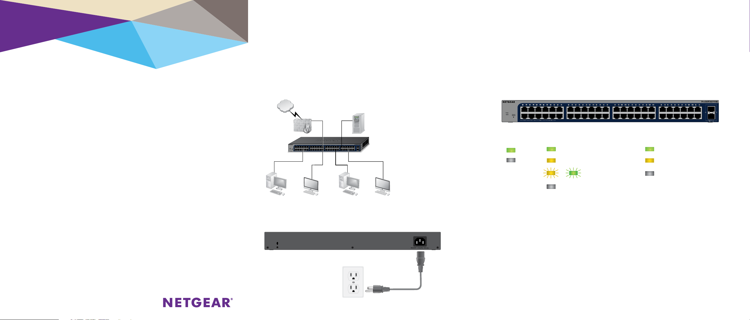
Step 1. Connect the equipment. Step 3. Check the status.
Server
Switch
Workstations
Power LED Port LEDs (Ports 1–48) SPD LED
On 1000 Mbps link 1 Gps link
O 100 or 10 Mbps link 100 Mbps link
Activity (blinking) No link (o)
No link (o)
Step 2. Connect power.
Page 2

Configuring the Switch
Smart Managed Plus switches are plug-and-play, so they can be used
without any configuration. You can also configure and manage additional
advanced features of the switch either by using your computer’s web
browser or by installing the ProSAFE Plus Configuration Utility on your
Windows-based computer.
Web Browser Access
You can configure a switch when it is connected only to your computer
(o-network), or connected to your computer and your network
(on-network).
¾ To use your web browser to configure your switch:
1. If you are configuring the switch o-network, record your computer’s
TCP/IP configuration settings, and then configure the computer with a
static IP address of 192.168.0.210 and with 255.255.255.0 as the
subnet mask.
Note: If you are unsure how to do this, visit netgear.com/support and
search for Static IP address on computer.
2. Plug the switch into a power outlet and connect your computer to the
switch using an Ethernet cable.
3. If you are configuring the switch on-network, connect the switch to
your network with another Ethernet cable.
4. Open a web browser and enter the IP address of the switch.
If the switch is o-network or connected to a network with no DHCP
server, use its default IP address, http://192.168.0.239. If the
switch is connected to a network with a DHCP server, use the IP
address that the DHCP server assigned to the switch. If you are unsure
how to determine the IP address of the switch, you can use the ProSAFE
Plus Configuration Utility.
5. Enter the password.
The default password is password.
6. Click the Login button.
You can now configure additional options for the switch in the web
management interface.
7. When you finish configuring an o-network switch, return your
computer to its original TCP/IP settings and connect the switch to your
network using an Ethernet cable.
ProSAFE Plus Configuration Utility Access
The ProSAFE Plus Configuration Utility runs on Windows-based computers.
Visit netgear.com/support/product/PCU to download the utility.
¾ To configure the switch:
1. Double-click the ProSAFE Plus Utility icon.
The configuration home page displays a list of Smart Managed Plus
switches that it discovers on the local network.
2. Select the switch that you want to configure from the list.
3. When prompted, enter the password.
The default password is password.
4. Use the utility to configure the switch settings.
For a description of Smart Managed Plus features, see the ProSAFE Plus
Switch Utility User Guide. You can access the user guide through links
on the Help tab of the utility.
Specifications
Network Environment
Network interface RJ-45 connector for 10M/100M/1G copper connections; SFP port
for 100M/1G fiber connections.
Network cable Use Category 5e (Cat 5e) or better Ethernet cable.
Operating temperature 32°-122°F (0°-50°C)
Operating humidity 10%-90% relative humidity, noncondensing
Specifications
Ethernet ports 48
SFP ports 2
Power (maximum) 100-240 VAC 50-60 Hz, 1A
Power consumption 30W maximum
Weight 7.17 lb (3.25 kg)
Dimensions
(W x D x H)
17.3 in. x 8.0 in. x 1.7 in. (440 mm x 204 mm x 43 mm)
Support
Thank you for purchasing this NETGEAR product. You can visit
www.netgear.com/support to register your product, get help, access the latest
downloads and user manuals, and join our community. We recommend that you
use only ocial NETGEAR support resources.
For the current EU Declaration of Conformity, visit
http://support.netgear.com/app/answers/detail/a_id/11621/.
For regulatory compliance information, visit netgear.com/about/regulatory/.
See the regulatory compliance document before connecting the power supply.
NETGEAR INTL LTD
Building 3, University Technology Centre
Curraheen Road, Cork, Ireland
NETGEAR, Inc.
350 East Plumeria Drive
San Jose, CA 95134, USA
© NETGEAR, Inc., NETGEAR and the NETGEAR Logo
are trademarks of NETGEAR, Inc. Any non‑NETGEAR
trademarks are used for reference purposes only.
May 2017
 Loading...