

Page 1

GS748T Software User
Manual
NETGEAR, Inc.
4500 Great America Parkway
Santa Clara, CA 95054 USA
202-10233-01
April 2007
Page 2
© 2007 by NETGEAR, Inc. All rights reserved. FullManual.
Trademarks
NETGEAR, the NETGEAR logo, and Auto Uplink are trademarks or registered trademarks of NETGEAR, Inc.
Microsoft, Windows, and Wi ndow s NT are registered trademar ks of Microsoft Corporation.
Other brand and product names are registered trademarks or trademarks of their respective holders. Portions of this
document are copyright Intoto, Inc.
April 2007
Statement of Conditions
In the interest of improving internal design, operational function, and/or reliability, NETGEAR reserves the right to
make changes to the products described in this document without notice.
NETGEAR does not assume any liability that may occur due to the use or application of the product(s) or circuit
layout(s) described herein.
Certificate of the Manufacturer/Importer
It is hereby certified that the GS748T Smart Switch has been suppressed in accordance with the conditions set out in the
BMPT-AmtsblVfg 243/19 91 and Vfg 46/1992. The operation of some equipment (for example, test transmitters) in
accordance with the regulations may, however , be subject to certain restricti ons. Please refer to the notes in the operating
instructions.
The Federal Office for Telecommunications Approvals has been notified of the placing of this equipment on the market
and has been granted the right to test the series for compliance with the regulations.
Bestätigung des Herstellers/Importeurs
Es wird hiermit bestätigt, daß dasGS748T Smart Switch gemäß der im BMPT-AmtsblVfg 243/1991 und Vfg 46/1992
aufgeführten Bestimmungen entstört ist. Das vorschriftsmäßige Betreiben einiger Geräte (z.B. Testsender) kann jedoch
gewissen Beschränkungen unterliegen. Lesen Sie dazu bitte die Anmerkungen in der Betriebsanleitung.
Das Bundesamt für Zulassungen in der Telekommunikation wurde davon unterrichtet, daß dieses Gerät auf den Markt
gebracht wurde und es ist berechtigt, die Serie auf die Erfüllung der Vorschriften hin zu überprüfen.
Voluntary Control Council for Interference (VCCI) Statement
This equipment is in the Class B category (information equipment to be used in a residential area or an adjacent area
thereto) and conforms to the standards set by the Voluntary Control Council for Interference by Data Processing
Equipment and Electronic Office Machines aimed at preventing radio interference in such residential areas. When used
near a radio or TV receiver, it may become the cause of radio interference. Read instructions for correct handling.
Note: Delete this note and the information below for products that are not wireless.
ii
v2.0, April 2007
Page 3

Regulatory Compliance Information
This section includes user requirements for operating this product in accordance with National laws for usage of radio
spectrum and operation of radio devices. Failure of the end-user to comply with the applicable requirements may result
in unlawful operation and adverse action against the end-user by the applicable National regulatory authority.
NOTE: This product's firmware limits operation to only the channels allowed in a particular Region or Country.
Therefore, all options described in this user's guide may not be available in your version of the product.
Europe – EU Declaration of Conformity
Marking by the above symbol indicates compliance with the Essential Requirements of the R&TTE Directive of the
European Union (1999/5/EC). This equipment meets the following conformance standards:
EN300 328, EN301 489-17, EN60950
Europe – Declaration of Conformity in Languages of the European Community
Cesky [Czech] NETGEAR Inc. tímto prohlašuje, že tento Radiolan je ve shode se základními
požadavky a dalšími príslušnými ustanoveními smernice 1999/5/ES..
Dansk
[Danish]
Deutsch
[German]
Eesti
[Estonian]
English Hereby, NETGEAR Inc., declares that this Radiolan is in compliance with the essential
Español
[Spanish]
Undertegnede NETGEAR Inc. erklærer herved, at følgende udstyr Radiolan overholder
de væsentlige krav og øvrige relevante krav i direktiv 1999/5/EF.
Hiermit erklärt NETGEAR Inc., dass sich das Gerät Radiolan in Übereinstimmung mit
den grundlegenden Anforderungen und den übrigen einschlägigen Bestimmungen der
Richtlinie 1999/5/EG befindet.
Käesolevaga kinnitab NETGEAR Inc. seadme Radiolan vastavust direktiivi 1999/5/EÜ
põhinõuetele ja nimetatud direktiivist tulenevatele teistele asjakohastele sätetele.
requirements and other relevant provisions of Directive 1999/5/EC.
Por medio de la presente NETGEAR Inc. declara que el Radiolan cumple con los
requisitos esenciales y cualesquiera otras disposiciones aplicables o exigibles de la
Directiva 1999/5/CE.
Ελληνική
[Greek]
Français
[French]
Italiano [Italian] Con la presente NETGEAR Inc. dichiara che questo Radiolan è conforme ai requisiti
Latviski
[Latvian]
ΜΕ ΤΗΝ ΠΑΡΟΥΣΑ NETGEAR Inc. ΔΗΛΩΝΕΙ ΟΤΙ Radiolan ΣΥΜΜΟΡΦΩΝΕΤΑΙ
ΠΡΟΣ ΤΙΣ ΟΥΣΙΩΔΕΙΣ ΑΠΑΙΤΗΣΕΙΣ ΚΑΙ ΤΙΣ ΛΟΙΠΕΣ ΣΧΕΤΙΚΕΣ ΔΙΑΤΑΞΕΙΣ ΤΗΣ
ΟΔΗΓΙΑΣ 1999/5/ΕΚ.
Par la présente NETGEAR Inc. déclare que l'appareil Radiolan est conforme aux
exigences essentielles et aux autres dispositions pertinentes de la directive 1999/5/CE.
essenziali ed alle altre disposizioni pertinenti stabilite dalla direttiva 1999/5/CE.
Ar šo NETGEAR Inc. deklarç, ka Radiolan atbilst Direktîv as 1999/5/EK bûtiskajâm prasîbâm
un citiem ar to saistîtajiem noteikumiem.
v2.0, April 2007
iii
Page 4

Lietuviø
[Lithuanian]
Šiuo NETGEAR Inc. deklaruoja, kad šis Radiolan atitinka esminius reikalavimus ir kitas
1999/5/EB Direktyvos nuostatas.
Nederlands
[Dutch]
Malti [Maltese] Hawnhekk, NETGEAR Inc., jiddikjara li dan Radiolan jikkonforma mal-htigijiet
Magyar
[Hungarian]
Polski [Polish] Niniejszym NETGEAR Inc. oświadcza, że Radiolan jest zgodny z zasadniczymi
Português
[Portuguese]
Slovensko
[Slovenian]
Slovensky
[Slovak]
Suomi
[Finnish]
Svenska
[Swedish]
Íslenska
[Icelandic]
Hierbij verklaart NETGEAR Inc. dat het toestel Radiolan in overeenstemming is met de
essentiële eisen en de andere relevante bepalingen van richtlijn 1999/5/EG.
essenzjali u ma provvedimenti ohrajn relevanti li hemm fid-Dirrettiva 1999/5/EC.
Alulírott, NETGEAR Inc. nyilatkozom, hogy a Radiolan megfelel a vonatkozó alapvetõ
követelményeknek és az 1999/5/EC irányelv egyéb elõírásainak.
wymogami oraz pozostałymi stosownymi postanowieniami Dyrektywy 1999/5/EC.
NETGEAR Inc. declara que este Radiolan está conforme com os requisitos essenciais
e outras disposições da Directiva 1999/5/CE.
NETGEAR Inc. izjavlja, da je ta Radiolan v skladu z bistvenimi zahtevami in ostalimi
relevantnimi določili direktive 1999/5/ES.
NETGEAR Inc. týmto vyhlasuje, _e Radiolan spĺňa základné po_iadavky a všetky
príslušné ustanovenia Smernice 1999/5/ES.
NETGEAR Inc. vakuuttaa täten että Radiolan tyyppinen laite on direktiivin 1999/5/EY
oleellisten vaatimusten ja sitä koskevien direktiivin muiden ehtojen mukainen.
Härmed intygar NETGEAR Inc. att denna Radiolan står I överensstämmelse med de
väsentliga egenskapskrav och övriga relevanta bestämmelser som framgår av direktiv
1999/5/EG.
Hér með lýsir NETGEAR Inc. yfir því að Radiolan er í samræmi við grunnkröfur og aðrar
kröfur, sem gerðar eru í tilskipun 1999/5/EC.
Norsk
[Norwegian]
NETGEAR Inc. erklærer herved at utstyret Radiolan er i samsvar med de
grunnleggende krav og øvrige relevante krav i direktiv 1999/5/EF.
FCC Requirements for Operation in the United States
FCC Information to User
This product does not contain any user serviceable components and is to be used with approved antenn as only. Any
product changes or modifications will invalidate all applicable regulatory certifications and approvals
FCC Guidelines for Human Exposure
This equipment complies with FCC radiation exposure limits set forth for an uncontrolled environment. This equipment
should be installed and operated with minimum distance of 20 cm between the radiator and your body.
This transmitter must not be co-located or operating in conjunction with any other antenna or transmitter.
iv
v2.0, April 2007
Page 5
FCC Declaration Of Conformity
We NETGEAR, Inc., 4500 Great America Parkway, Santa Clara, CA 95054, declare under our sole responsibility that
the model GS748T GS748T Smart Switch complies with Part 15 of FCC Rules. Operation is subject to the following
two conditions:
• This device may not cause harmful interference, and
• This device must accept any interference received, including interference that may cause undesired operation.
FCC Radio Frequency Interference Warnings & Instructions
This equipment has been tested and found to comply with the limits for a Class B digital device, pursuant to Part 15 of
the FCC Rules. These limits are designed to provide rea sonable protection against harmful interference in a residential
installation. This equipment uses and can radiate radio frequency energy and, if not installed and used in accordance
with the instructions, may cause harmful interference to radio communications. However, there is no guarantee that
interference will not occur in a particular installation. If this equipment does cause harmful interference to radio or
television reception, which can be determined by turning the equipment off and on, the user is encouraged to try to
correct the interference by one or more of the following methods:
• Reorient or relocate the receiving antenna
• Increase the separation between the equipment and the receiver
• Connect the equipment into an electrical outlet on a circuit different from that which the radio receiver is connected
• Consult the dealer or an experienced radio/TV technician for help.
GS748T Smart Switch
Tested to Comply
with FCC Standards
FOR HOME OR OFFICE USE
PY306100037
Modifications made to the product, unless expressly approved by NETGEAR, Inc., could void the user's right to operate
the equipment.
D
Canadian Department of Communications Radio Interference Regulations
This digital apparatus (GS748T Smart Switch) does not exceed the Class B limits for radio-noise emissions from digital
apparatus as set out in the Radio Interference Regulations of the Canadian Department of Communications.
Canada ID: 4054A-WG111
v2.0, April 2007
v
Page 6

Product and Publication Details
Model Number: GS748T
Publication Date: April 2007
Product Family: Smart Switch Series
Product Name: GS748T Smart Switch
Home or Business Product: Business
Language: English
Publication Part Number: 202-10233-01
Publication Version Number: 2.0
vi
v2.0, April 2007
Page 7

Contents
GS748T Software User Manual
About This Manual
Who Should Use this Book ............................................................................................... xi
How to Use This Book ...................................................................................................... xi
Conventions, Formats and Scope ....................................................................................xii
HTML Manual Navigation ................................................................................................xiii
How to Print this Manual ..................................................................................................xiii
Revision History ...............................................................................................................xiv
Chapter 1
Switch Management Overview
Switch Management Interface ........................................................................................1-1
System Requirements ....................................................................................................1-2
Chapter 2
Getting Started—Smart Wizard Discovery
Network with DHCP server .............................................................................................2-1
Network without DHCP Server .......................................................................................2-2
Manually Assigning Network Parameters ................................................................2-3
NIC Setting on the Host that Accesses the GS748T Smart Switch .........................2-4
Web Access ....................................................................................................................2-5
Additional Utilities ...........................................................................................................2-5
Password Change ....................................................................................................2-5
Firmware Upgrade ...................................................................................................2-6
Exit ...........................................................................................................................2-7
Chapter 3
Basic Web Management
Starting Web Management .............................................................................................3-1
The NETGEAR Home Page and Switch Status .............................................................3-2
Description of Switch Status Parameters .......................................................................3-4
v2.0, April 2007
vii
Page 8

System Functions ...........................................................................................................3-6
Firmware Menu ...............................................................................................................3-7
Managing System Files—Backup and Restore ........................................................3-7
Factory Reset ...........................................................................................................3-8
Resetting the System .....................................................................................................3-9
Logout .............................................................................................................................3-9
Chapter 4
Configuring the Switch
Using the Switch Configuration Utility .............................................................................4-1
Port Configuration ....................................................................................................4-2
Viewing Packet Statistics .........................................................................................4-3
Regulating Traffic Rates using Quality of Service Settings ......................................4-5
VLAN Page .............................................................................................................4-7
Creating Port Trunks to Increase Link Bandwidth .................................................. 4-11
Using a Sniffer Port to Monitor Traffic ....................................................................4-13
Jumbo Frame Support ...........................................................................................4-14
Controlling Per-port Packet Throughput .................................................................4-14
Storm Control (Dropping Traffic that is Flooding a Port) ........................................4-15
Using Spanning Tree Protocol to Prevent Path Loops ...........................................4-15
Enabling Switch Management using SNMP ...........................................................4-18
Controlling Switch Access by MAC Address and VLAN ID ....................................4-19
Using IGMP Snooping to Route Packets Based on Content .................................4-20
Filtering Unknown Multicast Packets .....................................................................4-20
Setting Up Static Multicast Groups .........................................................................4-21
Appendix A
Specifications and Default Values
GS748T Smart Switch Specifications ............................................................................ A-1
GS748T Smart Switch Features and Defaults ............................................................... A-2
Appendix B
Virtual Local Area Networks (VLANs)
IEEE 802.1Q VLANs .................................................................................................... B-2
Port-based VLANs ......................................................................................................... B-3
Port-based VLAN Example Configuration ............................................................... B-3
Results of this Configuration ................................................................................... B-4
viii
v2.0, April 2007
Page 9

Appendix C
Network Cabling
Fast Ethernet Cable Guidelines ..................................................................................... C-1
Category 5 Cable ........................................................................................................... C-1
Category 5 Cable Specifications ............................................................................. C-2
Twisted Pair Cables ................................................................................................ C-2
Cabling .................................................................................................................... C-4
Near End Cross Talk (NEXT) .................................................................................. C-5
Patch Cables ........................................................................................................... C-6
RJ-45 Plug and RJ-45 Connectors ......................................................................... C-6
Conclusion .............................................................................................................. C-7
v2.0, April 2007
ix
Page 10

x
v2.0, April 2007
Page 11

About This Manual
The NETGEAR® GS748T Software User Manual describes how to install, configure, operate, and
troubleshoot the GS748T Smart Switch using its included software. This boo k describes the
software configuration procedures and explains the options available within those procedures.
Who Should Use this Book
The information in this manual is intended for readers with intermediate to advanced system
management skills.
This document was created primarily for the system administrator who wishes to install and
configure the GS748T switch in a network. It assumes that the reader has a general understanding
of switch platforms and a basic knowledge of Ethernet and networking concepts. To install this
switch, it is not necessary to understand and use all of its capabilities. Once basic configuration is
performed, it will function in a network using its remaining factory default parameters. However , a
greater level of configuration—anywhere from the basic up to the maximum possible—will give
your network more advantage of its features. The web interface simplifies this configuration at all
levels.
How to Use This Book
This document describes configuration commands for the GS748T switch software. The
commands can all be accessed from the Web interface.
• Chapter 1, “Switch Management Overview” describes what you can expect from Web
management and gives host system requirements.
• Chapter 2, “Getting Started—Smart Wizard Discovery” describes how to use the Smart
Wizard Discovery utility to set up your switch so that you can communicate with it.
• Chapter 4, “Configuring the Switch” describes the features that your switch offers and tells
you how to configure and activate them in your network.
• Appendix A, “Specifications and Default Values” gives GS748T switch specifications and
lists default feature values.
• Appendix B, “Virtual Local Area Networks (VLANs)” describes some concepts of VLANs
v2.0, April 2007
xi
Page 12
GS748T Software User Manual
• Appendix C, “Network Cabling” gives cabling requirements and describes some details of
port cabling connections.
Note: Refer to the product release notes for the GS748T switch Software application
level code. The release notes detail the platform specific functionality of the
Switching, SNMP, Config, and Management packages.
Note: Although this document applies to the NETGEAR® GS748T Smart Switch, some
of the illustrations used may show references to other switch model numbers.
Where such model numbers appear, the illustration concerned should be treated as
an example. The procedures described with these illustrations apply to each of the
family of Smart Switches.
Conventions, Formats and Scope
The conventions, formats, and scope of this manual are described in the following paragraphs:
• Typographical Conventions. This manual uses the following typographical conventions:
Italics Emphasis, books, CDs, URL names
Bold User input
Fixed
width
Screen text, file and server names, extensions, commands, IP addresses
• Formats. This manual uses the following formats to highlight special messages:
Note: This format is used to highlight information of importance or special interest.
Tip: This format is used to highlight a procedure that will save time or resources.
xii
v2.0, April 2007
Page 13
GS748T Software User Manual
Warning: This is a warning of possible malfunction or damage to the equipment.
• Scope. This manual is written for the GS748T switch according to these specifications:
Product Version GS748T Smart Switch
Manual Publication Date April 2007
For more information about network, Internet, firewall, and VPN technologies, use the link to the
NETGEAR shown below.
Note: Product updates are available from the NETGEAR, Inc. website at:
http://www.netgear.com/support/main.asp
HTML Manual Navigation
If an HTML version of this manual is provided, it includes the following:
• Buttons, and , for browsing forwards or backwards through the manual one page
at a time
• A button that displays the table of contents and an button. Double-click on a
link in the table of contents or index to navigate directly to where the topic is described in the
manual.
• A button to access the full NETGEAR, Inc. online knowledge base for the product
model.
• Links to PDF versions of the full manual and individual chapters.
How to Print this Manual
To print this manual, you can choose one of the following options, according to your needs.
• Printing a Page from HTML. Each page in the HTML version of the manual is dedicated to
a major topic. Select File
→ Print from the browser menu to print the page contents.
xiii
v2.0, April 2007
Page 14
GS748T Software User Manual
• Printing from PDF. Your computer must have the free Adobe Acrobat reader installed in
order to view and print PDF files. The Acrobat reader is available on the Adobe Web site at
http://www.adobe.com.
– Printing a PDF Chapter. Use the PDF of This Chapter link at the top left of any page.
• Click the PDF of This Chapter link at the top left of any page in the chapter you want
to print. The PDF version of the chapter you were viewing opens in a browser
window.
• Click the print icon in the upper left of your browser window.
– Printing a PDF version of the Complete Manual. Use the Complete PDF Manual link
at the top left of any page.
• Click the Complete PDF Manual link at the top left of any page in the manual. The
PDF version of the complete manual opens in a browser window.
• Click the print icon in the upper left of your browser window.
Tip: If your printer supports printing two pages on a single sheet of paper, you can
save paper and printer ink by selecting this feature.
Revision History
Document
Part Number
202-10233-01 April 2007 2.0 Rate limiting feature documented.
202-10233-01 February
xiv
Date
2007
Version
Number
1.0 GS748T Smart Switch documentation
Description
v2.0, April 2007
Page 15

Chapter 1
Switch Management Overview
Switch Management Interface
This section gives an overview of switch management, including the methods yo u can use to
manage your NETGEAR GS748T Smart Switch.
Your NETGEAR GS748T Smart Switch contains an embedded web server and management
software for managing and monitoring switch functions. This switch will function as a simple
switch without using the management software but its use enables you to configure more advanced
features and consequently improve switch efficiency and the overall performance of your network.
Web-Based Management enables you to monitor, configure, and control your switch remotely
using a common web browser, instead of having to use expensive and complicated SNMP
software products. Simply by using your web br owser, you can monitor the performance of your
switch, and optimize its configuration for your network. Using your browser , for example, you can
set up VLANs, traffic priority, and configure port trunking.
In addition, NETGEAR provides the Smart Wizard Discovery Utility program with this product.
This program runs under Microsoft Windows XP or Windows 2000 and provides a “front end”
which discovers the switches on your network segment. When you power up your switch for the
first time, Smart Wizard Discovery enables you to configure its basic network parameters without
prior knowledge of IP address or subnet mask. Following such configuration, this program leads
you into the Web Management interface.
Table 1-1 shows some features of Smart Wizard Discovery and Web Management.
v2.0, April 2007
1-1
Page 16

GS748T Software User Manual
Table 1-1. Switch Management Methods
Management Method Features
Smart Wizard Discovery Utility
program
Web browser Password protection
No IP address or subnet mask setup needed
Discover all switches on the network
User-friendly interface under Microsoft Windows
Firmware upgrade capability
Password change feature
Provides entry to web configuration of switch
Ideal for configuring the switch remotely
Compatible with Internet Explorer and Netscape Navigator on any
platform
Extensive switch configuration possible
Configuration backup and restore
For a more detailed discussion of the Smart Wizard Discovery Utility Program, see. For a detailed
discussion of the Web Browser Interface, see Chapter 3, “Basic Web Management”.
System Requirements
The following hardware and software facilities are required to run the applications described in
this manual:
Network facilities:
• Ethernet network with or without DHCP server as appropriate (see Chapter 2, “Getting
Started—Smart Wizard Discovery”)
For running the Smart Wizard Discovery Utility:
• IBM type PC with CD drive; RAM size and disk specification is not critical
• OS software: Microsoft Windows Vista, Windows XP, or Windows 2000
• Switch to PC network cable: crossover? or straight connection via hub
• IBM type PC to run web management GUI; RAM and disk requirement is not critical
For running local or remote Web Management
• Desktop computer running Microsoft Internet Explorer 5.0 or later or Netscape Navigator 6.0
or later, or equivalent.
1-2 Switch Management Overview
v2.0, April 2007
Page 17
Chapter 2
Getting Started—Smart Wizard Discovery
This section leads you through the steps necessary to begin managing your GS748T Smart Switch.
It covers how to install in a network that contains a DHCP server and one without DHCP.
Network with DHCP server
To install the switch in a network with a DHCP server, proceed as follows:
1. Connect the GS748T switch to a DHCP network.
2. Power on the switch by connecting its power cord.
3. Install the Smart Wizard Discovery Utility program on your computer.
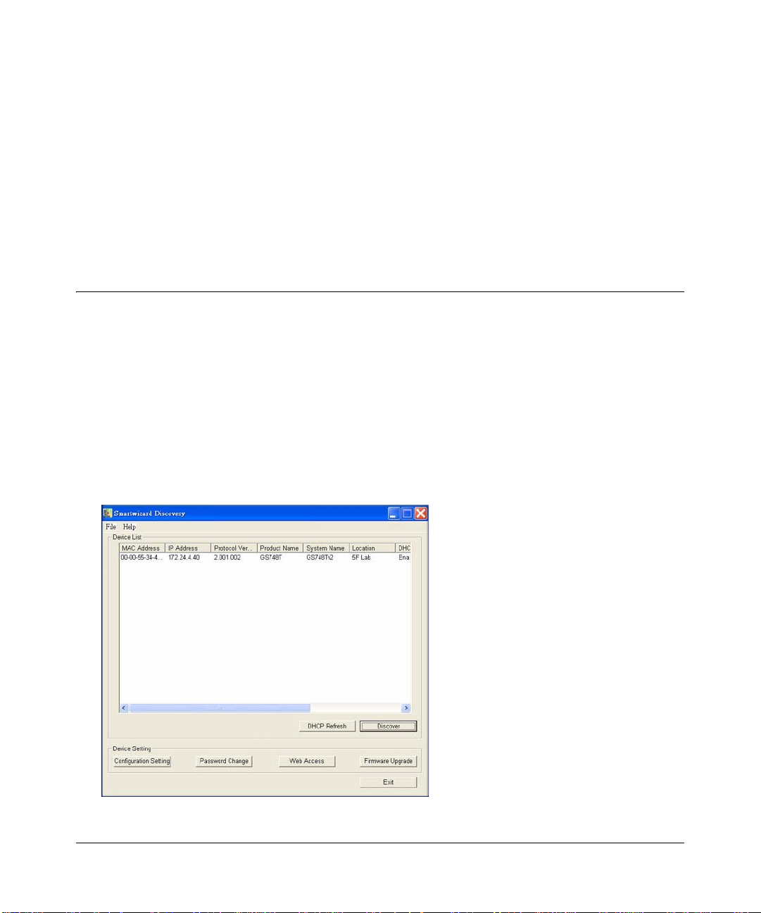
4. Start the Smart Wizard Discovery utility.
5. Click Discover for the Smart Wizard Discovery to find your GS748T Smart Switch. You
should see a screen similar to that shown below.
Figure 2-1
2-1
v2.0, April 2007
Page 18
GS748T Software User Manual
6. Make a note of the displayed IP address assigned by the DHCP server. You will need this
value to access the switch directly from a web browser (without using Smart Wizard
Discovery).
7. Select your switch by clicking on the line that shows it. Then click on the Web Access button.
The discovery utility displays a login window similar to the following:
Figure 2-2
Use your web browser to manage your switch. The default password is ‘password’.
Network without DHCP Server
This section describes how to set up your switch in a network without a DHCP server, and is
divided into the following tasks:
• Manually assign network parameters for your switch
• Configure the NIC settings on the host PC
• Log in to the web-based switch management utility
2-2 Getting Started—Smart Wizard Discovery
v2.0, April 2007
Page 19
GS748T Software User Manual
Manually Assigning Network Parameters
If your network has no DHCP service, you must assign a static IP address to your switch. If yo u
choose, you can assign it a static IP address even if your network has DHCP service. Proceed as
follows:
1. Connect the GS748T Smart Switch to your existing network.
2. Power on the switch by plugging in the power cord (Default IP is 192.168.0.239).
3. Install the Smart Wizard Discovery Utility program on your computer
4. Start the Smart Wizard Discovery utility.
5. Click Discover for the Smart Wizard Discovery Utility to find your GS748T Smart Switch.
You should see a screen similar to that shown in Figure 2-1 on page 2-1.
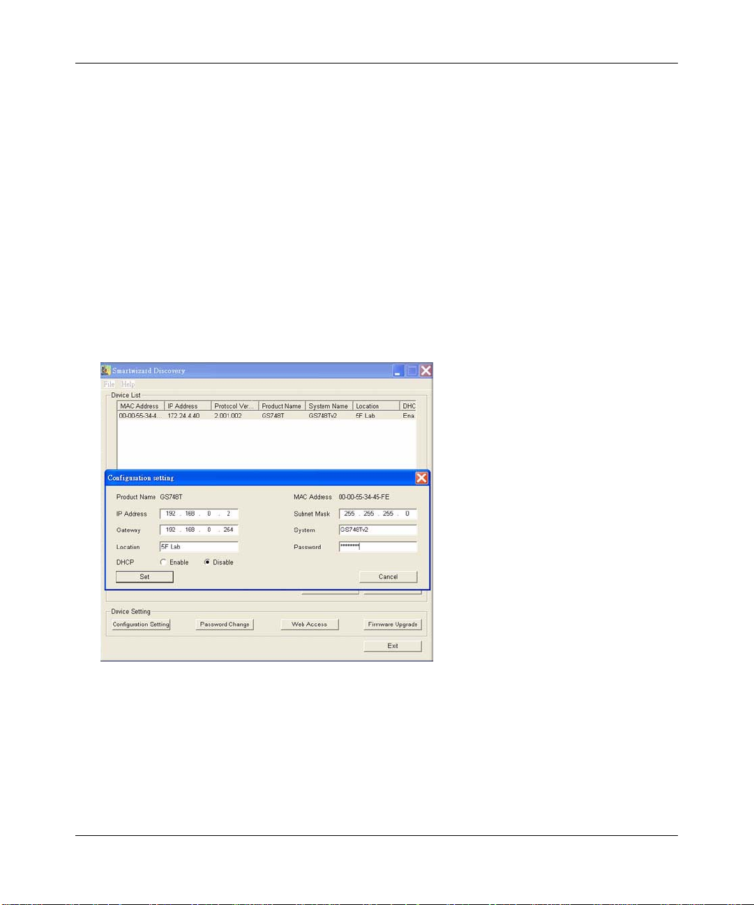
6. Click on Configuration Setting. A screen similar to that shown below appears.
Figure 2-3
7. Choose Disable for DHCP.
8. Enter your chosen switch IP address, gateway IP address and subnet mask, and then type your
password and click “Set”. Please ensure that your PC and the GS748T Smart Switch are in the
same subnet. Make a note of these settings for later use.
Getting Started—Smart Wizard Discovery 2-3
v2.0, April 2007
Page 20
GS748T Software User Manual
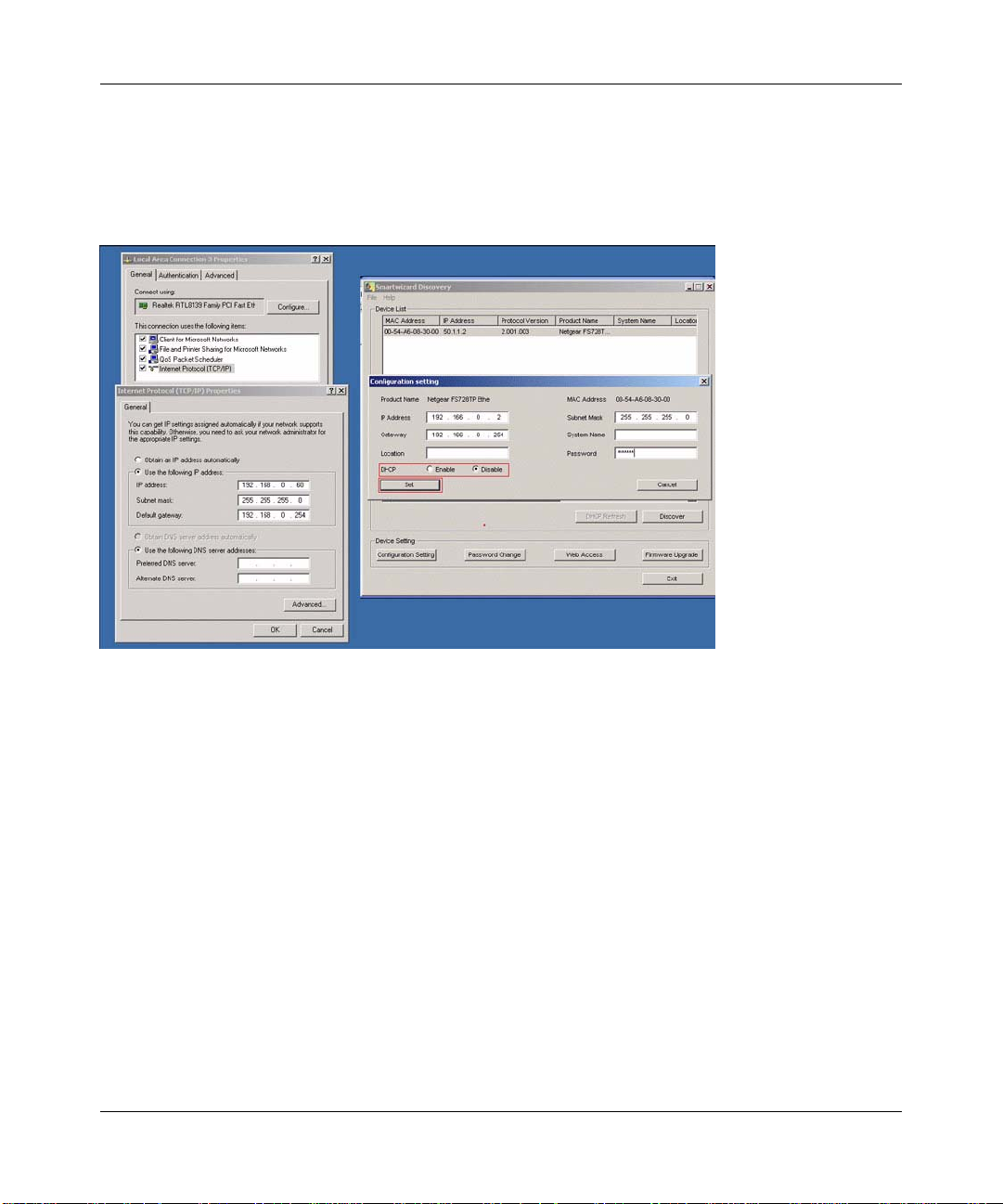
NIC Setting on the Host that Accesses the GS748T Smart Switch
The settings of your network interface card (NIC) under MS Windows OS are made with entries
into the Windows screen pages shown below. For comparison, the settings pages of the switch are
also shown although they do not appear in the Windows view.
Figure 2-4
You need Windows Administrator privilege to change these settings.
1. On your PC, access the MS Windows operating system TCP/IP Properties page as shown. In
MS Windows XP this is found in Control Panel > Network Connections > Local Area
Connection > General: Properties.
2. Select Internet Protocol (TCP/IP) and click on Properties.
3. Set IP address and subnet mask appropriately. The subnet mask value should be identical to
that set in the switch. The PC IP address must be different from that of the switch but lie in the
same subnet.
4. Click on the Web Access button to enable the management screens as described in the
following section
2-4 Getting Started—Smart Wizard Discovery
v2.0, April 2007
Page 21
GS748T Software User Manual
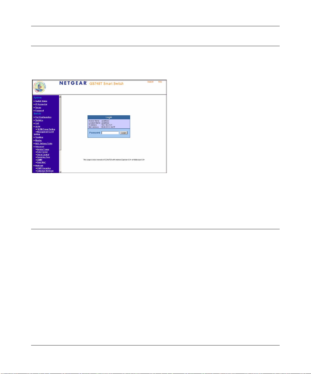
Web Access
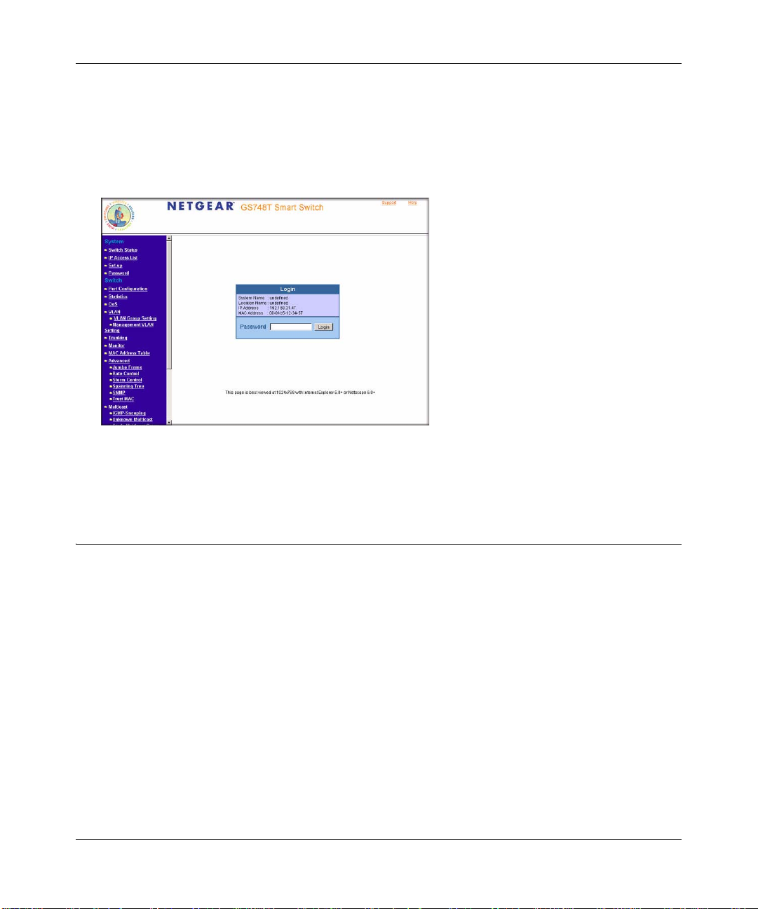
Clicking on the Web Access button of the Smart Wizard Discovery utility reveals the page shown
in below.
Figure 2-5
Use this page to proceed to management of the switch covered in Chapter 3, “Basic Web
Management”.
Additional Utilities
Alternatively, from the main page of Figure 2-1 you can access the additional functions:
• Password Change
• Firmware Upgrade
Password Change
You can set a new password of up to 20 ASCII characters.
1. Click ‘Password Change’ from the Switch Setting section. The Password Change screen.
appears. You can set a new password. In this process, you are required to enter the old
password and to confirm the new one.
2. Click ‘Set’ to enable the new password.
Getting Started—Smart Wizard Discovery 2-5
v2.0, April 2007
Page 22
GS748T Software User Manual
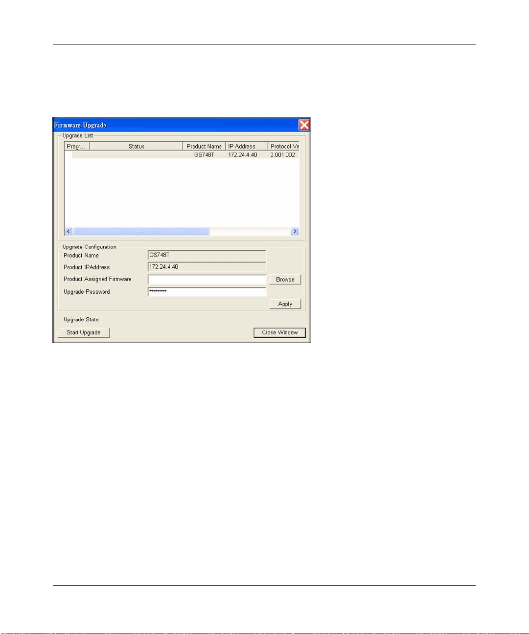
Firmware Upgrade
If you click Firmware Upgrade from the main screen of Figure 2-1, after you have selected the
switch to upgrade, the following screen appears:
Figure 2-6
The application software for the GS748T-series switch is upgradeable, enabling your switch to
take advantage of improvements and additional features as they become available. The upgrade
procedure and the required equipment are described as follows. This procedure assumes that you
have downloaded or otherwise obtained the firmware upgrade and that you have it available as a
binary file on your computer. This procedure uses the TFTP protocol to implement the transfer
from computer to switch.
1. Enter the following values into the appropriate places in the form
• Firmware Path: The location of the new firmware file. You can click Browse to locate
the file.
• Password: Enter your password; the default password is “password”.
• Upgrade State: Shows upgrading in progress.
2. Click Start to begin loading the upgrade. The system software is automatically loaded to all
stacking members. When the process is complete, the switch automatically reboots.
2-6 Getting Started—Smart Wizard Discovery
v2.0, April 2007
Page 23

GS748T Software User Manual
Exit
Click Exit from the Switch Setting section to close the Smart Wizard Discovery Utility program.
Getting Started—Smart Wizard Discovery 2-7
v2.0, April 2007
Page 24

GS748T Software User Manual
2-8 Getting Started—Smart Wizard Discovery
v2.0, April 2007
Page 25

Chapter 3
Basic Web Management
This section contains information for performing basic configuration using your web browser. It
also describes how to backup your configuration and how to reboot or reset yo ur rou t er if
necessary. The section includes this information under the following headings:
• “Starting Web Management”
• “The NETGEAR Home Page and Switch Status”
• “System Functions”
• “Firmware Menu”
• “Factory Reset”
• “Resetting the System”
Your NETGEAR Smart Switch series provides a built-in browser interface that enables you to
configure and manage it remotely using a standard Web browser such as Microsoft Internet
Explorer or Netscape Navigator. This interface also allows for system monitoring of the switch.
The help page covers many of the basic functions and features of the switch and its web interface.
Web Management requires either Microsoft Internet Explorer 5.0 or later or Netscape Nav i gator
6.0 or later
Starting Web Management
This section describes setting browser interface options and using the home page for the GS748T
Smart Switch. This interface is essentially similar to that entered as a result of selecting “Web
Access” from the Smart Wizard Discovery utility (see Chapter 2, “Getting Started—Smart Wizard
Discovery”). However, if you want to access the switch directly, i.e. without using the Smart
Wizard Discovery utility, you must work from the same networ k segment that contains the switch
(i.e. the subnet mask values of switch and PC host must be the same) and you must point your
browser using the switch IP address. If you used the Smart Wizard Discovery utility to set up IP
address and subnet mask, either with or without DHCP server, use that IP address in your browser
window. If you are starting with an “out of the box” switch and are not using the Smart Wizard
Discovery utility, you must initially configure your host PC to be on a network segment to match
the default parameters of the switch, which are:
3-1
v2.0, April 2007
Page 26

GS748T Software User Manual
• IP address: 192.168.0.239
• Subnet Mask: 255.255.255.0
From the home page thus accessed, as described in the next section, you may want to change the
network parameters to match those of your network. This is done using the “Set-up” option
selected from the navigation pane of the web interface. Your host PC network parameters must
then also be set back to match your network.
The NETGEAR Home Page and Switch Status
Having considered the preceding section, the NETGEAR home page for the GS748T Smart
Switch can be accessed from any PC with a web browser.
To start the application:
1. Open a web browser.
2. Enter the device IP address in the address bar.
3. Press Enter. The Login page appears as shown below.
Figure 3-1
3-2 Basic Web Management
v2.0, April 2007
Page 27

GS748T Software User Manual
4. Enter the password (the factory default is “password”) and click Login. The GS748T switc h
home page is displayed as shown below.
Figure 3-2
The home page shows the Navigation Pane on the left side, which provides a menu to access the
various configuration functions of the switch. The Navigation Pane headings can be expanded to
view all the components under a specific feature or retracted to hide these components.
The main pane, entitled Switch Status gives a list that shows the condition of the functions
available in the switch. The material that follows in this manual describes these functions and how
to configure them. None of the switch parameters can be configured directly from the Switch
Status view. Click the Refresh button at the top of the pane to display updated status information.
The header of the page shows the following links:
• Support—brings up the NETGEAR web site
• Help—provides an explanation about each of the menu items shown in the Navigation pane.
Click the help to read the full Help Menu. On some pages, there is a Help button. If you click
that button, you will go to the part of the Help Menu that discusses that page
This header remains displayed with each page accessed from the navigation pane.
Basic Web Management 3-3
v2.0, April 2007
Page 28

GS748T Software User Manual
Within the various browser interface pages, there are several buttons that you can use. Their names
and functions are listed below:
• Browse: Locates a certain path for a desired file.
• Refresh: Pulls that screen’s data from current values on the system
• Apply: Submits change request to system and refreshes screen data
• Add: Add new entries to table information and refreshes screen data
• Delete: Deletes selected entries from table and refreshes screen data
• Factory Reset: Restores the system factory default value.
• Help: Goes to relevant section of Help Menu
Description of Switch Status Parameters
The Switch Status page displays tabular status information under 14 headings. This information is
described briefly as follows in order that the tables appear from the top of the page:
• Switch Status (subheading): Displays parameters:
• Hardware parameters: Product Name; Firmware version; Protocol Version
• DHCP—whether enabled as service from the switch
• Network Parameters: IP Address; Subnet mask; Default gateway MAC address
• System Name and Location Name user values
• Login Timeout; System UpTime
• IP Access List Setting: shows the list of IP addresses allowed to log in to the switch
• PORT Status: shows speed setting, whether flow control is applied, Link Status and priority,
and a user description against port number
• Quality of Service (QoS) IEEE 802.1P QoS Status: can be set up with either 802.1p or
Differentiated Services Code Point (DSCP) determination. The status values displayed are
those of the chosen QoS configuration:
• IEEE 802.1P QoS Status: The 802.1p window shows the traffic priorities assigned to each
of the four queues determined by the tags on incoming packets.
• DSCP Based QoS Status: The DSCP display shows the priority levels assigned to each of
the incoming DSCP classes determined by the 8-bit Diffserv field of the incoming packets.
• IEEE 802.1Q Port VLAN ID (PVID) T able: Th is table shows, for 802.1Q VLANS, the VLAN
membership of each port, denoted by PVID number. Every port must belong to at least one
VLAN—by default all belong to VLAN 1.
3-4 Basic Web Management
v2.0, April 2007
Page 29

GS748T Software User Manual
• VLAN Settings: Two alternatives may show, depending upon the switch configuration. These
options are mutually exclusive.
• IEEE 802.1Q VLAN Settings: shows, by VLAN ID (PVID), which ports belong and
whether their egress packets are tagged or untagged.
• Port-Based VLAN Settings: shows which ports belong to each VLAN ID.
• TRUNK Status: shows the Trunk group, the ports that belong to the group and whether
trunking (Port Aggregation) is enabled for that group.
• Monitor Status: shows ports being monitored and whether this monitoring (sniffing) is of
ingress or egress traffic. Monitoring copies all traffic from the ports in question to the sniffer
port.
• Jumbo Frame: Oversized “Jumbo” (10240 byte) Ethernet frame support may be enabled or
disabled through the switch. If it is disabled, Jumbo frames are dropped.
• IEEE 802.1W Rapid Spanning Tree Protocol (RSTP) Setting: shows the key parameters used
in STP implementation. Bridge Priority determines how likely the switch is to become the root
switch. Max Age determines the time for which configuration information is kept. Hello Time
is the interval between sent configuration messages. Forward Delay is a value for time spent in
a discarding state before passing frames.
The Switch Status page displays the port settings for both 10/100 Mbps and 10/100/1000 Mbps
ports. To configure the ports, go to the Switch → Port Configuration page.
• ID: The port number on the switch
• Speed: Indicates the communication mode set for the port. The default setting for all ports is
Auto-negotiation (Auto). The possible entries are Auto-negotiation (Auto), 10 Mbps half
duplex (10M Half), 10 Mbps full duplex (10M Full), 100 Mbps half du plex (1 00 M Half), 10 0
Mbps full duplex (100M Full), or Disable.
• Flow Control: Indicates whether Flow Control support is set for on (Enabled) or off
(Disabled). The default setting for all ports is enabled.
• Link Status: Indicates the current speed and duplex for the port. DOWN means no link.
The next part of the Switch Status page shows the Virtual Local Area Network (VLAN) status. A
VLAN enables specified ports on the same switch to be partitioned electronically into separate
broadcast domains. By using VLANs, users can group users by logical function (for example
Accounting or Engineering) instead of by physical location based upon the particular switch port
connection.
This page displays the port-based IEEE 802.1Q VLAN settings. The default VLAN setting is to
group all ports to belong to port-based VLAN 1. To configure user-defined VLAN groups, go to
the Switch> VLAN page.
Basic Web Management 3-5
v2.0, April 2007
Page 30

GS748T Software User Manual
Port Trunking is a feature that enables multiple links between switches to work as one virtual link
(aggregate link). Trunks can be defined for similar port types only. For example, a 10/100 port
cannot form a Port Trunk with a gigabit port. Trunks can only be formed within the same bank.
This page displays the Trunk status. The default Trunk setting is all groups disabled. To configure
user-defined Trunk groups, go to the Switch> Trunking page.
If the IEEE802.1Q VLAN is enabled, this page displays the VLAN tag status.
System Functions
Under the System heading in the Navigation Pane, there are four functions; click on any one to
enter the appropriate configuration screen:
• Switch Status: Gives a snapshot of the current state of the switch.Click the
Refresh button to
display the latest status information. As described above, this page appears by default when
you first login.
• IP Access List: This page enables you to limit the IP addresses that can access the
management functions of the switch. The switch only responds to login requests from
computers whose IP addresses appear in its list. The Add button brings up a window into
which you can enter an IP address. When you have done so, click Apply. A typical view after
a few additions is shown below.
Figure 3-3
Click Delete to remove an entry.
3-6 Basic Web Management
v2.0, April 2007
Page 31

GS748T Software User Manual
The switch default state allows access from any IP address. If you enter authorized IP
addresses, be sure to include the IP address of your own management PC.
• Set-up: The following diagram shows a typical Set-up screen. Use it to enter the name and
location of your switch. If you want to use a DHCP server, make the appropriate setting. If you
enable Static IP Address, enter your IP address, Subnet Mask, and Gateway values as shown.
Figure 3-4
• Password: Use this page to set a new password. Be sure to note your setting. If you forget the
password, you must perform a factory reset of the switch to regain management access to it. In
this case you will lose your configuration settings because they are overwritten by factory
default values. However, if you have saved your configuration using Configuration Backup,
you can recover the overwritten values.
Firmware Menu
This menu item is found at the bottom of the menu bar. It contains Configuration Backup and
Factory Reset submenu items. These topics are described at this stage of the description because
their utility may be needed early in the configuration process.
Managing System Files—Backup and Restore
This facility may be used to protect your system configuration and save a possibly long manual
configuration in case of a loss or an accidental manual factory reset.
Basic Web Management 3-7
v2.0, April 2007
Page 32

GS748T Software User Manual
To back up files:
1. Select Configuration Backup => backup. The Configuration Upload Page appears:
Figure 3-5
2. Select Backup to save the settings to a file. Enter the name of the target file and click start.
To restore saved settings:
From the Configuration Backup screen, enter the path to the file and select: “Restore saved setting
from file”. Upon your confirmation the process is started. The browser window subsequently
closes and the switch reboots.
Factory Reset
Factory Reset restores factory defaults when you want or make a major configuration change or
need to regain management access to the switch. Use this feature under the following conditions:
• You have lost your password
• You are installing your switch into a different network environment for which it is simpler to
configure from the factory settings
• You want to make a major configuration change for another reason
Restore Factory Defaults erases any prior user configuration.
To perform Factory Reset, do either of the following:
• From the Navigation pane, navigate to Firmware > Factory Reset and click on the Factory
Reset link, or
3-8 Basic Web Management
v2.0, April 2007
Page 33

GS748T Software User Manual
• Use the restore Factory Defaults button on the right-hand side of the front panel—see the
appropriate installation guide for your switch for more details.
The effect of each of these alternatives is identical.
Resetting the System
Resetting reboots the embedded operating system. To reset the switch for any reason, either
• Power cycle it by disconnecting and reconnecting the power cord, or
• Use the Reset button on the left-hand side of the front panel—see the appropriate installation
guide for your switch for more detail. This operation does not disturb your switch
configuration.
Logout
Click Logout on the Navigation Sidebar Menu to leave the GS748T Smart Switch management
web interface.
Basic Web Management 3-9
v2.0, April 2007
Page 34

GS748T Software User Manual
3-10 Basic Web Management
v2.0, April 2007
Page 35

Chapter 4
Configuring the Switch
Using the Switch Configuration Utility
The Navigation Pane on the left hand side of the home page contains a Switch Menu which
enables you to manage your GS748T Smart Switch with features under the following main
headings:
• Port Configuration
• Statistics
•QoS
•VLAN
•Trunking
• Monitor
• MAC Address Table
• Advanced
• Multicast
The description that follows in this chapter covers these features and tells you how to configure
them in the GS748T switch.
v2.0, April 2007
4-1
Page 36

GS748T Software User Manual
Port Configuration
You can configure port attributes per port by clicking a port ID number at the port setting menu.
1. Click on Port Configuration in the Menu Sidebar; the port configuration page appears.
Figure 4-6
2. Click on a Port ID number in the first column; a port setting window appears.
3. Use the pull-down dialog boxes to configure the attributes.
Figure 4-7
4-2 Configuring the Switch
v2.0, April 2007
Page 37

GS748T Software User Manual
• Speed: Indicates the communication mode set for the port. The default setting for all ports
is Auto-negotiation (Auto). The possible entries are:
• Auto: Auto-negotiation
• 100M Full: 100 Mbps full duplex
• 100M Half: 100 Mbps half duplex
• 10M Full: 10 Mbps full duplex
• 10M Half: 10 Mbps half duplex
• Disable
• Flow Control: may be set
on for Flow Control support or off for no flow control.
• Default Priority: This value indicates the default traffic priority f or the port in the
implementation of Port-based Quality of Service (QoS). The values may be set to 0 - 7.
Note: In order for it to work, you must map the priority to the appropriate 4
queues in the IEEE802.1P of Switch > QoS page.
To activate the new settings, click Apply.
Note: Speed must be set to the same value as for the port’ s link partner. If this is not done,
packet loss or link errors may occur.
Viewing Packet Statistics
This page shows reports of packet traffic and packet errors. The table headings meanings are
explained as follows:
• ID: The port number on the switch
• Tx: Transmitted packets
• Rx: Received packets
• Tx Error: Transmitted packets with error. Packets are counted as contributing to TX Error if
they:
• Had a late collision detected during the transmission (512 bit-times into the transmission)
• Experienced 16 failed transmission attempts due to collision.
• Were dropped due to lack of resources
Configuring the Switch 4-3
v2.0, April 2007
Page 38

GS748T Software User Manual
• Rx Error: Received packet/s with error. Packets are counted as contributing to RX Error if
they:
• Were less than 64 bytes or greater than 1522 bytes in size
• Had a bad FCS
• Were dropped due to lack of resources.
1. Click on Statistics in the main menu; a Statistics page appears.
2. Click on the Refresh button at the top of the page to obtain current statistics data
3. Click Clear Counters to start a new statistics count over time.
4. Click on a port ID entry; the individual statistics table for the port is displayed. This table
breaks down statistics in more detail as shown in the following diagram.
Figure 4-8
4-4 Configuring the Switch
v2.0, April 2007
Page 39

GS748T Software User Manual
Regulating Traffic Rates using Quality of Service Settings
Quality of Service (QoS) is used to manage traffic in a network by treating different types of traffic
with different levels of priority . Higher priority traf fic receives preferential treatment during times
of switch congestion.
Three implementations of QoS are supported:
• Port-based QoS
• IEEE 802.1p-based QoS
• DSCP-based QoS
Port-based QoS
Port-based QoS can be achieved by configuring the Default Priority of a port, as described in
“Port Configuration” on page 4-2.
IEEE 802.1p-based QoS
IEEE 802.1p-based QoS enables the user to map each of the eight priority levels specified in IEEE
802.1p (p0 to p7) to one of four hardware priority queues: High, Normal, Low, and Lowest. The
eight priority levels specified in IEEE 802.1p (p0 to p7) are implemented by a three-bit priority
field in the VLAN tag. The switch empties the four hardware priority queues in order, from High
to Lowest. Packets are transferred to empty the buffers of each higher hardware priority queue in
turn before the next lower hardware priority queue can begin to transfer its received packets
through the switch.
The table in the Quality of Service page below shows an example of IEEE 802.1p-based priority
settings that you can set for a switch.
Figure 4-9
Configuring the Switch 4-5
v2.0, April 2007
Page 40

GS748T Software User Manual
Differentiated Services Code Point (DSCP)-based QoS
The Differentiated Services Code Point (DSCP) 6-bit field in an IP packet header enables levels of
service to be assigned to network traffic according to the field’s binary value. This 6-bit field
comprises three IP Precedence MSBs with a least-significant 3-bit expansion field as defined in
RFC 2474. The IP Precedence bits in the DSCP field are compatible with routers that only support
IP Precedence. DCSPs specifically tailored to be backward compatible with routers that only
support IP precedence lack the 3-bit expansion field and are called Class-selector DSCPs. See the
following diagram for the setting page for DCCP priorities.
Figure 4-10
Match these DHCP values to set “Per Hop Behavior” (PHB) priorities by selecting a QoS serviceclass value of between 0 and 7. Packets within these service classes are treated with equal priority.
RFC 2597 defines the assured forwarding (AF) PHB. It guarantees a certain amount of bandwidth
to an AF class.
The Expedited Forwarding (EF) PHB is defined in RFC 2598 and uses Codepoint 101 1 1 0. The EF
PHB is used to build a low loss, low latency, low jitter, assured bandwidth service. This premium
service can appear to the user be a point to point connection.
4-6 Configuring the Switch
v2.0, April 2007
Page 41

GS748T Software User Manual
VLAN Page
A Virtual Local Area Network (VLAN) is a means of electronically separating ports on the same
switch from a single broadcast domain into separate broadcast domains. By using VLANs, users
can group nodes by logical function instead of physical location. For example, Engineering and
Accounting department traffic can be separated from one another. VLAN memberships are
manipulated by associating switch ports with VLAN IDs (VIDs).
You can choose from two types of VLAN to set up on the switch: IEEE 802.1Q VLAN (Tagged
VLAN), or Port-based VLAN. You cannot mix the types on the same switch. In either case, any
port can be a member of multiple VLANs.
• IEEE 802.1Q VLAN: The VLAN tagging option is a standard set by the IEEE to facilitate the
spanning of VLANs across multiple switches (Reference: Appendix A and IEEE Std 802.1Q1998 Virtual Bridged Local Area Networks). This switch supports the creation of 64 StaticTag VLAN groups.
This implementation separates traffic by adding a VLAN tag into the appropriate egress
frames (packets) from selected switch ports. A receiving switch associates the tagged frame
with the VLAN and forwards it, according to its own VLAN-to-port lookup table, to all ports
on the VLAN except the ingress port. In this way, a VLAN structure may be built across a
“tree” of switches.
You have the option of setting egress frames to be:
• Tagged: this setting adds an 802.1Q tag into the frame leaving the selected port
• Untagged: this option strips the 802.1Q tags from frame leaving the selected port. The port
retains its association with the VLAN. This facility is used when these ports are connected
to downstream equipment that does not recognize (and which consequently may be
confused by) 802.1Q tags.
• Unchanged: this option is the default and signifies that the port is not associated with a
VLAN.
Every port is a member of VLAN ID 1 by default. You can change the default assignment of
any port adjusting the Primary VLAN ID Setting (PVID) table. Use this feature to ensure that
untagged frames reach the VLAN that you require.
• Port-based VLAN: This implementation confines VLAN members to the ports on the
particular switch, that is, the VLANs cannot span multiple switches. VLAN membership of
ports is determined in a lookup table that you set up when you configure the switch. You can
create up to 48 port-based VLANS. Every port belongs to VLAN ID 1 by default.
Configuring the Switch 4-7
v2.0, April 2007
Page 42

GS748T Software User Manual
Adding and Configuring IEEE 802.1Q VLAN Groups
1. From the main Navigation Pane menu, select:
VLAN
→ VLAN Group Setting → IEEE 802.1Q VLAN; a screen appears showing a
VLAN selection window with a table that lists all of the ports with their VLAN membership.
If you have not previously created a VLAN, this window shows VLAN ID 1 (default) with all
ports set Untagged.
Figure 4-11
From the page, you can create a new VLAN, add new ports to an existing VLAN, remove
ports from an existing VLAN or, delete a VLAN.
2. Create a new VLAN Group:
From the VLAN Management pull-down window, select: Add new VLAN.
Enter the VLAN ID value in the VLAN ID dialog window that appears. Yo ur VLAN ID must
lie in the range 2 – 4094.
Click Apply
3. Add VLAN group members as you require:
In the port table, click successively on the window below the port number to obtain your
required symbol:
• ‘T’ (tagged): this option sets egress frames with 802.1Q VLAN tags.
• ‘U’ (untagged): this option determines that frames from these ports exit the switch
untagged.
4-8 Configuring the Switch
v2.0, April 2007
Page 43

GS748T Software User Manual
• Blank space (not a member of a VLAN); use this option to remove a port-VLAN
association.
Click Apply.
4. Configure Primary VLAN ID (PVID):
T o enable untagged p ackets to appear in your required VLAN, be sure to change the PVIDs for
the relevant ports. Access the PVID Settings by using the PVID Setting option in the VLAN
ID pull-down menu. The PVID setting for all ports is VLAN ID 1 by default and is shown
thus in the table. You must have previously created your VID and attached the port to it as
described above.
Click Apply.
Note: Every port has an initial default VID of 1 (PVID = 1). Whether a port has this
VID or has been made a member of another default VID, you cannot remove
any port from its prior default VLAN until you have reassigned its PVID to its
new value. Use the PVID Setting menu option of VLAN Management to
change its PVID before attempting to remove it from its prior default
membership.
Reconfiguring an IEEE 802.1Q VLAN Group
1. From the main Navigation Pane menu, select:
Switch
→ VLAN → VLAN Group Setting → IEEE 802.1Q VLAN; a screen appears
showing a VLAN selection window with a table that lists all of the ports with their VLAN
membership.
2. From the VLAN Management pull-down window, click on the VLAN ID that you want to
reconfigure.
3. Add or remove tag assignments by clicking on the boxes in the table.
4. Click Apply to set your changes.
Deleting an 802.1Q VLAN Group
1. In the VLAN Management pull down menu, select the VLAN you want to remove.
2. Select the Remove VLAN button with your cursor and click on it.
3. Click Apply; all port associations are separated from the VLAN and it is removed.
Configuring the Switch 4-9
v2.0, April 2007
Page 44

GS748T Software User Manual
Adding and Configuring Port-based VLANs
1. From the main Navigation Pane menu, select:
Switch
showing a VLAN selection window with a table that lists all of the ports with their VLAN
membership.
If you have not previously created a VLAN, this window shows VLAN ID 1 (default)
comprising all ports as members.
2. Create a VLAN:
Click on the Add VLAN button; a table for the next higher numbered VID appears.
3. Add a description for your new VLAN, for example, Accounts.
4. In the table, click on the boxes below the port numbers to assign those ports to your new
VLAN. Selected ports are indicated by a check mark in the box. You can click on Set all to
assign all ports to membership of your VLAN.
5. Click Apply.
Reconfiguring a Port-based VLAN
1. From the main Navigation Pane menu, select:
Switch
showing a VLAN selection window with a table that lists all of the ports with their VLAN
membership.
→ VLAN → VLAN Group Setting → Port-based VLAN; a screen appears
→ VLAN → VLAN Group Setting → Port-based VLAN; a screen appears
2. Click a VLAN ID number; a table for that VID appears.
3. Click boxes to select or deselect ports for VLAN membership. You can click on Set all to
assign all ports to your VLAN or Clear all to remove all ports from VLAN membership.
4. Click Apply to activate your new settings.
Deleting a Port-based VLAN
1. From the main Navigation Pane menu, select:
Switch
showing a VLAN selection window with a table that lists all of the ports with their VLAN
membership.
2. Click on the Delete VLAN button; a VLAN Delete window is displayed.
3. Click on the box adjacent to the VLAN ID number.
4. Click Apply to delete this VLAN.
4-10 Configuring the Switch
→ VLAN → VLAN Group Setting → Port-based VLAN; a screen appears
v2.0, April 2007
Page 45

GS748T Software User Manual
Selecting a Management VLAN
1. From the main Navigation Pane menu, select:
Switch
2. In the Management VLAN ID window, select the VID that you want to use for switch
management.
3. Click Apply
→ VLAN → Management VLAN; the Management VLAN window appears.
Creating Port Trunks to Increase Link Bandwidth
Port Trunking (otherwise known as Port Aggregation) enables multiple links between switches to
work as one virtual link (aggregate link) to provide greater bandwidth than would be available by
confining the traffic to a single port. Trunks can be defined for similar port types only. For
example, a 10/100 port cannot form a Port Trunk with a gigabit port. Trunks can only be formed
within the same bank. A bank is a set of ports, such as ports 1 to 8, ports 9 to 16, or 17 to 20, on the
same switch unit. Up to ten trunks can be operating at the same time.
Trunking groups in the Trunk Table are set disabled by default. For each trunk group, trunk
members are pre-set for selection. The following diagram shows a typical port trunking
arrangement.
Configuring the Switch 4-11
v2.0, April 2007
Page 46

GS748T Software User Manual
Figure 4-12
To select Trunk members for a Trunk group, click Apply to activate the new setting
Note: The selected trunk port setting ID numbers must correspond to VLAN group IDs.
Setting up Port Trunks
1. From the main Navigation Pane menu, select: Switch
→ Trunking; The Trunk Setting table
is displayed.
2. Check the boxes against the port numbers in the table.
3. Click Apply to save the settings.
4-12 Configuring the Switch
v2.0, April 2007
Page 47

Removing Port Trunks
GS748T Software User Manual
1. From the main Navigation Pane menu, select: Switch
is displayed.
2. Uncheck the appropriate boxes against the port numbers in the table.
3. Click Apply to save the settings.
→ Trunking; The Trunk Setting table
Using a Sniffer Port to Monitor Traffic
The Monitor feature enables you to configure traffic from any number of ports to be copied
(mirrored) to your selected “sniffer” port, which may be any port that is not a source port. This
traffic may be selected from transmitted (egress) frames, received (ingress) frames or all frames.
Sniffing may be disabled globally.
To configure a sniffer port:
1. From the main Navigation Pane menu, select: Switch
displayed.
→ Monitor; The trunk Setting table is
Figure 4-13
2. From the Sniffer Mode drop-down list box, select Rx, Tx, Both, or Disable. Disable clears
any prior settings.
3. Using the Sniffer Port pull-down menu, select a monitoring port.
4. Click on the boxes in the table to select the ports to be monitored.
Configuring the Switch 4-13
v2.0, April 2007
Page 48

GS748T Software User Manual
5. Click Apply to save the settings.
Jumbo Frame Support
Jumbo Frames are not an approved standard Ethernet frame size, so you must ensure that all of
your networking equipment can support these frames to prevent them from being dropped. The
GS748T switch can carry a maximum frame size of 10240 bytes.
1. From the main Navigation Pane menu, select: Switch
Jumbo Frame Setting page is displayed.
2. Select Enable or Disable on this page and click Apply.
→ Advanced → Jumbo Frame; The
Controlling Per-port Packet Throughput
The Rate Limit Setting enables you to determine the bandwidth of the selected port. There are 11
options of data rate in the range 512K bps to 1000M bps with a disable option that applies no limit
to the data rate. Ingress and egress rates are separately configurable. The Egress Rate settings is
available only with v3h1 firmware.
Figure 4-14
4-14 Configuring the Switch
v2.0, April 2007
Page 49

To enable Rate Limits:
GS748T Software User Manual
1. From the main Navigation Pane menu, select: Switch
Rate Limit Setting page is displayed. with a table of port numbers.
2. Click on a Port number in the table; the Rate Limit window for that port appears.
3. From the pull-down menus on this page, select from the optional rates shown, or select
Disabled.
4. Click Apply to save your setting.
→ Advanced → Rate Limits; The
Storm Control (Dropping Traffic that is Flooding a Port)
The Storm Control feature enables you to prevent your network performance from being disrupted
by excessive traffic arriving at a switch port. The source of this traffic may be selected as Multicast
and Broadcast, Broadcast only, or as a result of Destination Lookup Failure (DLF). A selected
received threshold rate of between 0 and 65535 packets per second may be selected in each case.
Where Multicast and Broadcast is selected as the source of the traffic, the threshold value is the
combined rate of those two types of packet. If packets of the selected type arrive at a rate
exceeding the threshold, they are dropped.
Storm Control is disabled on every port by default.
To enable Storm Control:
1. From the main Navigation Pane menu, select:
Switch
a table of port numbers that can be set as enabled or disabled.
→ Advanced → Storm Control; The Storm Control Setting page is displayed. with
2. In the Ingress Control Mode window , select from: Multicast and Br oadcast, Broadcast only,
or DLF.
3. Click on the window against your selected port to enable Storm Control.
4. Click Apply to save your setting.
Using Spanning Tree Protocol to Prevent Path Loops
Selection of Spanning Tree results in the IEE 802.1W RSTP Setting page being displayed.
To achieve reliability in a network, some path redundancy must be provided. However, multiple
paths between network nodes can cause loops to exist and result in switching confusion and
duplication of traffic. Spanning T ree Protocol (defined by IEE 802.1D) controls the duplicate paths
by accounting for statistical weights in the available paths. It blocks the least efficient alternate
paths and causes traffic only to be carried over the optimal paths between nodes.
Configuring the Switch 4-15
v2.0, April 2007
Page 50

GS748T Software User Manual
The GS748T switch supports Rapid Spanning Tree Protocol (defined by IEEE 802.1w), which is
an improvement (over the 802.1D STP) that shortens connection latency between nodes. The
resultant path between nodes determined by RSTP is the same as that eventually determined by
STP. The following concepts are associated with this protocol.
• Fast Link: When a port running the standard Spanning Tree Protocol (STP) is connected, it
will go through the STP negotiation (listening -
→ learning → forwarding or blocking) before
it is fully available. If a server is trying to access a client through the switch running the STP
negotiation, it is not able to connect to it immediately. This can be a problem for some
networks. Fastlink mode solves this problem by setting the port directly to forwarding mode,
thus allowing any server access request to be forwarded. Fastlink mode can cause temporary
loops in your network, but the STP eliminates them. Fastlink is best used on end node ports,
i.e. ports connected to PCs or servers, to avoid network loops.
• Bridge Priority: Priority setting of this switch in the Spanning Tree.
• Bridge Max Age: Amount of time before a configuration message is discarded by the system.
• Bridge Hello Time: Interval between configuration messages sent by the Spanning Tree
algorithm.
• Bridge Forward Delay: Amount of time system spends in 'learning' and 'listening' states.
• Path Cost: The switch uses this to determine which port is the forwarding port. All other
factors being equal, the path with the lowest cost to the root bridge is the active path.
• Path Priority: STP bases on this to determine the port to use for forwarding. The port with the
lowest number has the highest priority.
The IEE 802.1W RSTP Setting page of the GS748T switch contains a set of default values which
are optimal for most applications. Adjust these values if you must provide for special conditions.
4-16 Configuring the Switch
v2.0, April 2007
Page 51

GS748T Software User Manual
To set up RSTP:
1. From the main Navigation Pane menu, select:
Switch
→ Advanced → Spanning Tree; The IEEE 802.1W RSTP Setting page shown in
The following screen is displayed. with a table of port numbers that can be set as enabled or
disabled.
Figure 4-15
2. Select Enable (RSTP is disabled by default).
3. Modify the page settings if required, or accept the defaults.
4. Click Apply to save your settings.
Configuring the Switch 4-17
v2.0, April 2007
Page 52

GS748T Software User Manual
Enabling Switch Management using SNMP
SNMP (Simple Network Management Protocol) is a transport protocol used for network
management. The protocol is used in communication between a Manager—the management
station—and an agent within the managed device, in this case your switch. The Manager polls the
agent which responds by returning data from the Management Information Bases (MIBs) that it
maintains on the managed device to indicate its status. An agent can return Traps to the Manager,
Traps are messages that alert the manager to conditions that may need attention. Managers and
Agents work within Communities which are defined to confine messaging within named groups.
An agent only responds to requests from Managers within its community.
The SNMP page enables you to limit the IP addresses from which the MIBs of the switch can be
accessed and to which IPs the switch sends SNMP traps. The switch only responds to requests
from management computers whose IP addresses are carried in a list. This list also holds Privilege
information that controls which IPs have read-only or read-write access. You can also select the
traps which the switch sends to the hosts from the following trap events. An “Admin” field must
be set to “Enable” to allow management host communication.
Trap Events are indicated in 3 columns:
• T1: Authentication fail - The switch generates an SNMP trap when a host tries to gain access
to the switch but the host's IP is not in the SNMP host table.
• T2: Device bootup - The switch generates an SNMP trap when it reboots.
• T3: Link Up/Down - The switch generates an SNMP trap when one of its ports changes its link
status.
To enable management from an SNMP Manager:
1. From the main Navigation Pane menu, select:
Switch
screen.
4-18 Configuring the Switch
→ Advanced → SNMP; the switch configuration utility displays the following
v2.0, April 2007
Page 53

GS748T Software User Manual
Figure 4-16
2. In the text boxes along one line, enter the following:
• Your Manager host IP address
• Community name
• Privilege—select ReadOnly or ReadWrite
• Traps—select the those that you want to receive from T1, T2, and T3 (explained above)
• Admin—set to Enable to allow management
3. Click Apply to save your settings.
Controlling Switch Access by MAC Address and VLAN ID
A configuration page enables you to select the source MAC address and VLAN members that are
allowed to access this switch.
If the VLAN mode for the switch is set up as Port-based, you enter a MAC address and port
number that you want to permit access this switch. If the VLAN is set up in 802.1Q mode, you
enter a MAC address and VID to permit access.
To Add a MAC Address
1. From the main Navigation Pane menu, select:
Switch
2. Click on Add; a dialog window is appears.
3. Enter your trusted MAC address:
Configuring the Switch 4-19
→ Advanced → Trust MAC; the Trusted MAC Settings page is displayed.
v2.0, April 2007
Page 54

GS748T Software User Manual
If your switch is set up with Port-based VLANS, in the windows provided, enter the Port and
MAC Address in conventional six hexadecimal pair and colon separator format.
If your switch is set up wit 802.1Q VLANs, enter: Port, VLAN ID, and MAC Address in
conventional six hexadecimal pair and colon separator format.
4. Click Apply to save your settings.
To Remove a MAC Address from the Table
1. From the main Navigation Pane menu, select:
Switch
2. Check the Delete box for the MAC address that you want to remove.
3. Click on the Delete button.
→ Advanced → Trust MAC; the Trusted MAC Settings page is displayed.
Using IGMP Snooping to Route Packets Based on Content
IGMP Snooping enables your switch to examine IGMP packets and forward them in ways based
on their content. IGMP specifies how a host can register a router to receive specific multicast traffic. Configure the switch to use IGMP snooping in subnets that receive IGMP queries from either
IGMP or the IGMP snooping querier. IGMP snooping constrains multicast traffic at Layer 2 by
configuring Layer 2 LAN ports dynamically to forward multicast traffic only to those ports that
want to receive it. The IGMP Snooping Function allows Snooping to be enabled or disabled on a
per-switch basis. It is disabled by default.
To enable or disable IGMP snooping:
1. From the main Navigation Pane menu, select: Switch
IGMP Snooping Setting page is displayed.
2. Select Enable or Disable.
3. Click Apply to save your settings.
→ Multicast→ IGMP Snooping. The
Filtering Unknown Multicast Packets
You can enable or disable the blocking of unknown multicast packets that enter the switch.
To enable or disable blocking of unknown multicast addresses:
1. From the main Navigation Pane menu, select:
Switch
displayed.
4-20 Configuring the Switch
→ Multicast→ Unknown Multicast; the Unknown Multicast Setting page is
v2.0, April 2007
Page 55

GS748T Software User Manual
2. Select Enable or Disable
3. Click Apply to save your settings.
Setting Up Static Multicast Groups
You can specify specific ports and VLANs for receiving Multicast packets with specific MAC
addresses. The MAC addresses are IPv4 Multicast Addresses (RFC1112A) of the form: 01:00:5EXX-XX-XX. A maximum of 64 groups is supported.
To define a multicast group:
1. From the main Navigation Pane menu, select:
Switch
displayed as shown below.
→ Multicast→ S tatic Multicast Group; the S tatic Multicast Groups Setting page is
Figure 4-17
2. In the appropriate windows, enter the VLAN ID and Port to receive the Multicast packets
3. In the MAC Address window, specify the Multicast MAC Address for the packets you want
to receive.
4. Click Apply to save your settings.
To remove a multicast group:
1. In the line of the table that specifies the group, check the Delete box.
2. Click Apply to remove the group.
Configuring the Switch 4-21
v2.0, April 2007
Page 56

GS748T Software User Manual
4-22 Configuring the Switch
v2.0, April 2007
Page 57

Appendix A
Specifications and Default Values
GS748T Smart Switch Specifications
The GS748T Smart Switch conforms to the TCP/IP, UDP, HTTP, ICMP, TFTP, DHCP, 802.1D,
802.1p, and 802.1Q standards.
Table A-1. GS748T Smart Switch Specifications
Feature Value
Interfaces 48G (P01 - P48)
Fiber Option 4 Mini-GBIC Combo (P45 - P48)
PoE N/A
Flash Memory Size 2MB
SRAM Size and Type 16MB DDR
Table A-2. Switch Performance
Feature Value
Switching Capacity 48 x 1Gbps
Forwarding Method Store and Forward
Packet Forwarding Rate 10M:14,880 pps / 100M:148,809 pps / 1G:1,488,095
pps
MAC addresses 8K
Packet RAM buffer capacity 512K-bytes
Specifications and Default Values A-1
v2.0, April 2007
Page 58

GS748T Software User Manual
GS748T Smart Switch Features and Defaults
Table A-3. Port Characteristics
Feature Sets Supported Default
Auto-Negotiation /
Static Speed / Duplex
Auto MDI/MDIX N/A Enabled
802.3x flow control /
Back Pressure
Port Mirroring 1 Disabled
Port Trunking (Aggregation) 10 Disabled
802.1D Spanning Tree 1 Disabled
802.1w RSTP 1 Disabled
IGMP Snooping 1 Disabled
Static 802.1Q Tagging 256 VID = 1
Port Based Private VLAN 48X1 MemberPorts[1] = [1-48]
Learning Process N/A N/A
48 (per-port) Auto-Negotiation
48 (per-port) Enabled
MemberPorts = [1-48]
Table A-4. Quality Of Service
Feature Sets Supported Default
Number of Queues N/A N/A
Port Based 48 (per port) Normal for all ports
802.1p 1 Disabled
DSCP 1 Disabled
Table A-5. Security
Feature Sets Supported Default
ACL 10 All IP addresses allowed
Password Control Access 1 LoginTimeOut = 5 mins.
Password = “password”
A-2 Specifications and Default Values
v2.0, April 2007
Page 59

Table A-5. Security (continued)
Feature Sets Supported Default
Trust MacAddress Filter 256 Disabled
Port -MAC lock down 48 (per port) Disabled
Management VLAN 1 0
Table A-6. Traffic Control
Feature Sets Supported Default
Rate control 48 (per port) Disabled
Storm control 1 (per switch) Disabled
Jumbo frame 48 (per port) Disabled
Table A-7. System Setup
Feature Sets Supported Default
DHCP\Manual IP 1 192.168.0.239
System Name Configuration 1 NULL
Configuration Save/Restore 1 N/A
Firmware Upgrade 1 N/A
Factory Reset 1 N/A
GS748T Software User Manual
Table A-8. Other Features
Feature Sets Supported Default
Static Multicast Entry 64 Disabled
Filter Multicast Control 1 Disabled
Table A-9. Management
Feature Sets Supported Default
SNMPv1/V2c 4 Disabled
MIB Support 1 Disabled
Specifications and Default Values A-3
v2.0, April 2007
Page 60

GS748T Software User Manual
Table A-9. Management
Feature Sets Supported Default
Smart Wizard N/A Enabled
Statistics 48 (per port) N/A
A-4 Specifications and Default Values
v2.0, April 2007
Page 61

Appendix B
Virtual Local Area Networks (VLANs)
A Local Area Network (LAN) can generally be defined as a broadcast domain. Hubs, bridges or
switches in the same physical segment or segments connect all end node devices. End nodes can
communicate with each other without the need for a router. Routers connect LANs together,
routing the traffic to the appropriate port.
A virtual LAN (VLAN) is a local-area network with a definition that maps workstations on some
other basis than geographic location (for example, by department, type of user, or primary
application). To communicate between VLANs, traffic must go through a router, just as if they
were on two separate LANs.
A VLAN is a group of PCs, servers and other network resources that behave as if they were
connected to a single, network segment—even though they may not be. For example, all
marketing personnel may be spread throughout a building. Yet if they are all assigned to a single
VLAN, they can share resources and bandwidth as if they were connected to the same segment.
The resources of other departments can be invisible to the marketing VLAN members, accessible
to all, or accessible only to specified individuals, depending on how the IT manager has set up the
VLANs.
The Advantages of VLANs:
• Easy to do network segmentation: Users that communicate most frequently with each other
can be grouped into common VLANs, regardless of physical location. Each group's traffic is
largely contained within the VLAN, reducing extraneous traffic and improving the efficiency
of the whole network.
• Easy to manage: The addition of nodes, as well as moves and other changes, can be dealt with
quickly and conveniently from a management interface rather than from the wiring closet.
• Increased performance: VLANs free up bandwidth by limiting node-to-node and broadcast
traffic throughout the network.
• Enhanced network security: VLANs create virtual boundaries that can only be crossed through
a router. So standard, router-based security measures can be used to restrict access to each
VLAN
Virtual Local Area Networks (VLANs) B-1
v2.0, April 2007
Page 62

GS748T Software User Manual
IEEE 802.1Q VLANs
Packets received by the switch are treated in the following way:
• When an untagged packet enters a port, it is automatically tagged with the port’s default
VLAN ID tag number. Each port has a default VLAN ID setting that is user-configurable (the
default setting is 1). The default VLAN ID setting for each port can be changed in the PVID
Setting page.
• When a tagged packet enters a port, the tag for that packet is unaffected by the default VLAN
ID Setting. The packet proceeds to the VLAN specified by its VLAN ID (VID) tag number.
• If the port in which the packet entered does not have membership with the VLAN specified by
the VLAN ID tag, the packet is dropped.
• If the port is a member of the VLAN specified by the packet’s VLAN ID, the packet is able to
be sent to other ports with the same VLAN ID.
• Packets leaving the switch are either tagged or untagged, depending on the setting for that
port’s VLAN membership properties. A ‘U’ for a given port means that packets leaving the
switch from that port are Untagged. Inversely, a ‘T’ for a given port means that packets
leaving the switch from that port are tagged with the VLAN ID associated with the port.
The example given in this section comprises numerous steps to illustrate a wide range of
configurations to help provide an understanding of tagged VLANs.
Example
This example demonstrates several scenarios of VLAN use and describes how the switch handles
Tagged and Untagged traffic.
1. Setup the following VLANs: VLAN 10, 20.
2. Configure the VLAN membership. Be sure to set all of them as follows.
• Setting up first VLAN group, VLAN ID = 10:
• Setting up second VLAN group, VLAN ID = 20:
3. Modify PVID Setting to apply previous two VLAN groups: Modify Default VLAN group
(VLAN ID = 1) to apply two new VLAN groups:
The specific ports above have the following Port VLAN ID settings:
• Default VLAN: Port 7 – Port 26 (all U), VID = 1
• VLAN 1: Port 1 (U), Port 2 (U), Port 3 (T), VID = 10
• VLAN 2: Port 4 (U), Port 5 (T), Port 6 (U), VID = 20.
B-2 Virtual Local Area Networks (VLANs)
v2.0, April 2007
Page 63

GS748T Software User Manual
4. The following situations produce results as described:
• If an untagged packet enters Port 1, the switch tags it with a VLAN tag value 10. The
packet has access to Port 2 and Port 3. The outgoing packet is stripped of its tag to leaves
Port 2 as an untagged packet. For Port 3, the outgoing packet leaves as a tagged packet
with a VLAN tag value of 10.
• If a tagged packet with a VLAN tag value 10 enters Port 3, the packet has access to Port 1
and Port 2. If the packet leaves Port 1 and/or Port 2, it is stripped of its tag to leave the
switch as an untagged packet.
• If an untagged packet enters Port 4, the switch tags it with a VLAN tag value 20. The
packet will have access to Port 5 and Port 6. The outgoing packet is stripped of its tag to
become an untagged packet as it leaves Port 6. For Port 5, the outgoing packet leaves as a
tagged packet with a VLAN tag value of 20.
Port-based VLANs
Port-based VLANs help to confine broadcast traffic to the switch ports. This switch allows up to
26 port-based VLAN group, Any one port can belong to different VLAN groups. The defa ult
VLAN group is a port-based VLAN that has all ports belonging to VLAN 1.
Packets received by the switch are treated in the following way:
• When a packet enters a port, it can only proceed to ports with the same VLAN membership as
that ingress port.
• If a port on the switch does not have a common VLAN membership with the source port, the
packet is dropped.
Port-based VLAN Example Configuration
This example basically demonstrates how the port-based VLANs work to meet your needs.
Setup the following VLANs, each with defined descriptions:
• VLAN 1 (IT department)
• VLAN 2 (Sales department)
• VLAN 3 (Marketing department)
• VLAN 4 (Accounting department).
• Configure the VLAN membership. Be sure to set all of them as follows.
• Setting up second VLAN group (Sales), VLAN ID = 02, with membership of ports 1~8, 25.
Virtual Local Area Networks (VLANs) B-3
v2.0, April 2007
Page 64

GS748T Software User Manual
• Setting up third VLAN group (Marketing), VLAN ID = 03, with membership of ports 7~14,
25.
• Setting up fourth VLAN group (Accounting), VLAN ID = 04, with membership of ports
19~20, 25.
• Setting up first VLAN group (IT), VLAN ID = 01, with membership of all ports.
• Since VLAN ID 01 has been setup by default, you will have to remove the ports that belong to
all other VLAN groups except port 25.
• Ports 7 and 8 are kept for connected file server and printer server use. Sales and Marketing
departments can share file archives and printing services.
• Port 25 provides Gigabit speed for e-mail server and Internet connection.
The specific ports above have the following functions:
• VLAN 1: Port 15 – Port 18, Port 21 – Port 24, Port 26, for IT depart ment to monitor and
control activities on all other VLANs
• VLAN 2: Port 1 – Port 8, for Sales department, port 7 and 8 connect to file archives and printer
server.
• VLAN 3: Port 7 – Port 14, for Marketing department, port 7 and 8 connect to file archives and
printer server.
• VLAN 4: Port 19 – Port 20, for Accounting department, its work is kept secret from other
departments except IT.
Results of this Configuration
If a packet comes in on port 2, it can go to ports 1, 3, 4, 5, 6, 7, 8, an d 25, as those are the only ports
in that VLAN. A Sales person on Port 2 can get to the Internet, send and receive e-mail, but cannot
access the marketing department print server or file archives.
If a Marketing user sends out a broadcast message, the Sales and Accounting departments are not
affected by the message, because it does not go out on their ports. Only the Marketing department
and the IT group will receive the broadcast message.
If an IT user sends out a broadcast message, everyone receives it.
B-4 Virtual Local Area Networks (VLANs)
v2.0, April 2007
Page 65

Appendix C
Network Cabling
This appendix provides specifications for cables used with a NETGEAR GS748T Smart Switch.
Fast Ethernet Cable Guidelines
Fast Ethernet uses UTP cable, as specified in the IEEE 802.3u standard for 100BASE-TX.The
specification requires Category 5 UTP cable consisting of either two-pair or four-pair twisted,
insulated copper conductors bound in a single plastic sheath. Category 5 cable is certified up to
100 MHz bandwidth. 100BASE-TX operation uses one pair of wires for transmission and the
other pair for receiving and for collision detection.
When installing Category 5 UTP cabling, use the following guidelines to ensure that your cables
perform to the following specifications:
• Certification: Ensure that your Category 5 UTP cable has completed the Underwriters’
Laboratories (UL) or Electronic Testing Laboratories (ETL) certification process.
• Termination method: To minimize cross-talk noise, maintain the twist ratio of the cable up to
the point of termination; untwist at any RJ-45 plug or patch panel should not exceed 0.5 inch
(1.5 cm).
Category 5 Cable
Category 5 distributed cable that meets ANSI/EIA/TIA-568-A building wiring standards can be a
maximum of 328 feet (ft.) or 100 meters (m) in length, divided as follows:
20 ft. (6 m) between the hub and the patch panel (if used)
295 ft. (90 m) from the wiring closet to the wall outlet
10 ft. (3 m) from the wall outlet to the desktop device
The patch panel and other connecting hardware must meet the requirements for 100 Mbps
operation (Category 5). Only 0.5 inch (1.5 cm) of untwist in the wire pair is allowed at any
termination point.
Network Cabling C-1
v2.0, April 2007
Page 66

GS748T Software User Manual
Category 5 Cable Specifications
Ensure that the fiber cable is crossed over to guarantee link.
Table C-1 lists the electrical requirements of Category 5 UTP cable.
Table C-1. Electrical Requirements of Category 5 Cable
Specifications Category 5 Cable Requirements
Number of pairs Four
Impedance 100 ± 15%
Mutual capacitance at 1 KHz 5.6 nF per 100 m
Maximum attenuation
(dB per 100 m, at 20° C)
NEXT loss (dB minimum) at 16 MHz: 44
at 4 MHz: 8.2
at 31 MHz: 11.7
at 100 MHz: 22.0
at 31 MHz: 39
at 100 MHz: 32
Twisted Pair Cables
For two devices to communicate, the transmitter of each device must be connected to the receiver
of the other device. The crossover function is usually implemented internally as part of the
circuitry in the device. Computers and workstation adapter cards are usually media-dependent
interface ports, called MDI or uplink ports. Most repeaters and switch ports are configured as
media-dependent interfaces with built-in crossover ports, called MDI-X or normal ports. Auto
Uplink technology automatically senses which connection, MDI or MDI-X, is needed and makes
the right connection.
Figure C-1 illustrates straight-through twisted pair cable.
C-2 Network Cabling
v2.0, April 2007
Page 67

Figure C-1Straight-Through Twisted-Pair Cable
Figure C-2 illustrates crossover twisted pair cable.
GS748T Software User Manual
Figure C-2Crossover Twisted-Pair Cable
Patch Panels and Cables
If you are using patch panels, make sure that they meet the 100BASE-TX requirements. Use
Category 5 UTP cable for all patch cables and work area cables to ensure that your UTP patch
cable rating meets or exceeds the distribution cable rating.
To wire patch panels, you need two Category 5 UTP cables with an RJ-45 plug at each end, as
shown in Figure C-3.
Network Cabling C-3
v2.0, April 2007
Page 68

GS748T Software User Manual
Figure C-3
Note: Flat “silver satin” telephone cable may have the same RJ-45 plug. However, using
telephone cable results in excessive collisions, causing the attached port to be
partitioned or disconnected from the network.
Using 1000BASE-T Gigabit Ethernet over Category 5 Cable
When using the new 1000BASE-T standard, the limitations of cable installations and the steps
necessary to ensure optimum performance must be considered. The most important components in
your cabling system are patch panel connections, twists of the pairs at connector transition points,
the jacket around the twisted-pair cable, bundling of multiple pairs on horizontal runs and punch
down blocks. All of these factors affect the performance of 1000BASE-T technology if not
correctly implemented. The following sections are designed to act as a guide to correct cabling for
1000BASE-T.
Cabling
The 1000BASE-T product is designed to operate over Category 5 cabling. To further enhance the
operation, the cabling standards have been amended. The latest standard is Category 5e, which
defines a higher level of link performance than is available with Category 5 cable.
If installing new cable, we recommend using Category 5e cable, since it costs about the same as
Category 5 cable. If using the existing cable, be sure to have the cable plant tested by a
professional who can verify that it meets or exceeds either ANSI/EIA/TIA-568-A:1995 or ISO/
IEC 11801:1995 Category 5 specifications.
C-4 Network Cabling
v2.0, April 2007
Page 69

GS748T Software User Manual
Length
The maximum distance limitation between two pieces of equipment is 100 m, as per the original
Ethernet specification. The end-to-end link is called the “channel.”
TSB-67 defines the “Basic Link” which is the portion of the link that is part of the building
infrastructure. This excludes patch and equipment cords. The maximum basic link length is 295
feet (90 m).
Return Loss
Return loss measures the amount of reflected signal energy resulting from impedance changes in
the cabling link. The nature of 1000BASE-T renders this measurement very important; if too much
energy is reflected back on to the receiver, the device does not perform optimally.
Unlike 10BASE-T and 100BASE-TX, which use only two of the four pairs of wires within the
Category 5, 1000BASE-T uses all four pairs of the twisted pair. Make sure all wires are tested ⎯
this is important.
Factors that affect the return loss are:
The number of transition points, as there is a connection via an RJ-45 to another connector, a patch
panel, or device at each transition point.
Removing the jacket that surrounds the four pairs of twisted cable. It is highly recommended that,
when RJ-45 connections are made, this is minimized to 1-1/4 inch (32 mm).
Untwisting any pair of the twisted-pair cabling. It is important that any untwisting be minimized to
3/8 inch (10 mm) for RJ-45 connections.
Cabling or bundling of multiple Category 5 cables. This is regulated by ANSI/EIA/TIA-568A-3. If
not correctly implemented, this can adversely affect all cabling parameters.
Near End Cross Talk (NEXT)
This is a measure of the signal coupling from one wire to another, within a cable assembly, or
among cables within a bundle. NEXT measures the amount of cross-talk disturbance energy that is
detected at the near end of the link — the end where the transmitter is located. NEXT measures the
amount of energy that is “returned” to the sender end. The factors that affect NEXT and cross talk
are exactly the same as outlined in the Return Loss section. The cross-talk performance is directly
related to the quality of the cable installation.
Network Cabling C-5
v2.0, April 2007
Page 70

GS748T Software User Manual
Patch Cables
When installing your equipment, replace old patch panel cables that do not meet Category 5e
specifications. As pointed out in the NEXT section, this near end piece of cable is critical for
successful operation.
RJ-45 Plug and RJ-45 Connectors
In a Fast Ethernet network, it is important that all 100BASE-T certified Category 5 cabling use RJ45 plugs. The RJ-45 plug accepts 4-pair UTP or shielded twisted-pair (STP) 100-ohm cable and
connects into the RJ-45 connector. The RJ-45 connector is used to connect stations, hubs, and
switches through UTP cable; it supports 10 Mbps, 100 Mbps, or 1000 Mbps data transmission.
Figure C-4 shows an RJ-45 plug and RJ-45 jack.
Figure C-4
Table C-2 lists the pin assignments for the 10/100 Mbps RJ-45 plug and the RJ-45 connector.
Table C-2. 0/100 Mbps RJ-45 Plug and RJ-45 Connector Pin Assignments
Pin Normal Assignment on Ports 1 to 8 Uplink Assignment on Port 8
1 Input Receive Data + Output Transmit Data +
2 Input Receive Data – Output Transmit Data –
3 Output Transmit Data + Input Receive Data +
6 Output Transmit Data – Input Receive Data –
4, 5, 7, 8 Internal termination, not used for data transmission
Table C-2 lists the pin assignments for the 100/1000 Mbps RJ-45 plug and the RJ-45 connector.
C-6 Network Cabling
v2.0, April 2007
Page 71

GS748T Software User Manual
Table C-3. 100/1000 Mbps RJ-45 Plug and RJ-45 Connector Pin Assignments
Pin Channel Description
1
2
3
6
4
5
7
8
A Rx/Tx Data +
Rx/Tx Data
B Rx/Tx Data +
Rx/Tx Data
C Rx/Tx Data +
Rx/Tx Data
D Rx/Tx Data +
Rx/Tx Data
Conclusion
For optimum performance of your 1000BASE-T product, it is important to fully qualify your cable
installation and ensure that it meets or exceeds ANSI/EIA/TIA-568-A:1995 or ISO/IEC
11801:1995 Category 5 specifications. Install Category 5e cable where possible, including patch
panel cables. Minimize transition points, jacket removal, and untwisted lengths. Cable bundles
must be properly installed to meet the requirements in ANSI/EIA/TIA-568A-3.
Network Cabling C-7
v2.0, April 2007
Page 72

GS748T Software User Manual
C-8 Network Cabling
v2.0, April 2007
 Loading...