

Page 1

GS728TS, GS728TPS, GS752TS, and GS752TPS Gigabit Smart Switches
Software Administration Manual
350 East Plumeria Drive
San Jose, CA 95134
USA
February 2012
202-10995-01
v1.0
Page 2

GS728TS, GS728TPS, GS752TS, and GS752TPS Gigabit Smart Switches
©2012 NETGEAR, Inc. All rights reserved
No part of this publication may be reproduced, transmitted, transcribed, stored in a retrieval system, or translated
into any language in any form or by any means without the written permission of NETGEAR, Inc.
Technical Support
Thank you for choosing NETGEAR. To register your product, get the latest product updates, get support online, or
for more information about the topics covered in this manual, visit the Support website at
http://support.netgear.com
Phone (US & Canada only): 1-888-NETGEAR
Phone (Other Countries): Check the list of phone numbers at
http://support.netgear.com/app/answers/detail/a_id/984
Trademarks
NETGEAR, the NETGEAR logo, and Connect with Innovation are trademarks and/or registered trademarks of
NETGEAR, Inc. and/or its subsidiaries in the United States and/or other countries. Information is subject to change
without notice. Other brand and product names are registered trademarks or trademarks of their respective
holders. © 2012 NETGEAR, Inc. All rights reserved.
Statement of Conditions
To improve internal design, operational function, and/or reliability, NETGEAR reserves the right to make changes
to the products described in this document without notice. NETGEAR does not assume any liability that may occur
due to the use, or application of, the product(s) or circuit layout(s) described herein.
Revision History
Publication Part Number Version Publish Date Comments
202-10995-01 v1.0 February 2012 First publication
2
Page 3

Contents
Chapter 1 Getting Started
Getting Started with the Smart Switches . . . . . . . . . . . . . . . . . . . . . . . . . .10
Switch Management Interface . . . . . . . . . . . . . . . . . . . . . . . . . . . . . . . . . .10
Connecting the Switch to the Network . . . . . . . . . . . . . . . . . . . . . . . . . . . .11
Switch Discovery in a Network with a DHCP Server . . . . . . . . . . . . . . . . .12
Switch Discovery in a Network without a DHCP Server. . . . . . . . . . . . . . .14
Configuring the Network Settings on the Administrative System . . . . . . . .15
Web Access . . . . . . . . . . . . . . . . . . . . . . . . . . . . . . . . . . . . . . . . . . . . . . . .16
Smart Control Center Utilities. . . . . . . . . . . . . . . . . . . . . . . . . . . . . . . . . . .17
Network Utilities . . . . . . . . . . . . . . . . . . . . . . . . . . . . . . . . . . . . . . . . . . .17
Configuration Upload and Download . . . . . . . . . . . . . . . . . . . . . . . . . . .19
Firmware Upgrade . . . . . . . . . . . . . . . . . . . . . . . . . . . . . . . . . . . . . . . . .20
Viewing and Managing Tasks. . . . . . . . . . . . . . . . . . . . . . . . . . . . . . . . .22
Understanding the User Interfaces. . . . . . . . . . . . . . . . . . . . . . . . . . . . . . .23
Using the Web Interface. . . . . . . . . . . . . . . . . . . . . . . . . . . . . . . . . . . . .23
Using SNMP. . . . . . . . . . . . . . . . . . . . . . . . . . . . . . . . . . . . . . . . . . . . . .29
Interface Naming Convention. . . . . . . . . . . . . . . . . . . . . . . . . . . . . . . . . . .30
Chapter 2 Configuring System Information
Management. . . . . . . . . . . . . . . . . . . . . . . . . . . . . . . . . . . . . . . . . . . . . . . .31
System Information. . . . . . . . . . . . . . . . . . . . . . . . . . . . . . . . . . . . . . . . .32
Slot Information . . . . . . . . . . . . . . . . . . . . . . . . . . . . . . . . . . . . . . . . . . .33
IP Configuration . . . . . . . . . . . . . . . . . . . . . . . . . . . . . . . . . . . . . . . . . . .35
IPv6 Network Configuration . . . . . . . . . . . . . . . . . . . . . . . . . . . . . . . . . .37
IPv6 Network Neighbor. . . . . . . . . . . . . . . . . . . . . . . . . . . . . . . . . . . . . .38
Time . . . . . . . . . . . . . . . . . . . . . . . . . . . . . . . . . . . . . . . . . . . . . . . . . . . .40
Denial of Service . . . . . . . . . . . . . . . . . . . . . . . . . . . . . . . . . . . . . . . . . .45
DNS . . . . . . . . . . . . . . . . . . . . . . . . . . . . . . . . . . . . . . . . . . . . . . . . . . . .49
Green Ethernet. . . . . . . . . . . . . . . . . . . . . . . . . . . . . . . . . . . . . . . . . . . .51
Stacking . . . . . . . . . . . . . . . . . . . . . . . . . . . . . . . . . . . . . . . . . . . . . . . . . . .61
Stack Features . . . . . . . . . . . . . . . . . . . . . . . . . . . . . . . . . . . . . . . . . . . .61
Firmware Synchronization and Upgrade . . . . . . . . . . . . . . . . . . . . . . . .62
Configuration Maintenance. . . . . . . . . . . . . . . . . . . . . . . . . . . . . . . . . . .62
Stack Master Election. . . . . . . . . . . . . . . . . . . . . . . . . . . . . . . . . . . . . . .62
Factory Defaults Reset Behavior . . . . . . . . . . . . . . . . . . . . . . . . . . . . . .63
Stack Configuration . . . . . . . . . . . . . . . . . . . . . . . . . . . . . . . . . . . . . . . .63
Stack Port Configuration. . . . . . . . . . . . . . . . . . . . . . . . . . . . . . . . . . . . .66
Stack Port Diagnostics . . . . . . . . . . . . . . . . . . . . . . . . . . . . . . . . . . . . . .68
Stack Firmware Synchronization . . . . . . . . . . . . . . . . . . . . . . . . . . . . . .69
3
Page 4

GS728TS, GS728TPS, GS752TS, and GS752TPS Gigabit Smart Switches
PoE/PoE+ (GS728TPS and GS752TPS Only). . . . . . . . . . . . . . . . . . . . . .70
PoE Configuration . . . . . . . . . . . . . . . . . . . . . . . . . . . . . . . . . . . . . . . . .70
PoE Port Configuration. . . . . . . . . . . . . . . . . . . . . . . . . . . . . . . . . . . . . .72
SNMP. . . . . . . . . . . . . . . . . . . . . . . . . . . . . . . . . . . . . . . . . . . . . . . . . . . . .75
SNMPv1/v2. . . . . . . . . . . . . . . . . . . . . . . . . . . . . . . . . . . . . . . . . . . . . . .75
Trap Configuration . . . . . . . . . . . . . . . . . . . . . . . . . . . . . . . . . . . . . . . . .77
Trap Flags . . . . . . . . . . . . . . . . . . . . . . . . . . . . . . . . . . . . . . . . . . . . . . .78
SNMP Supported MIBs . . . . . . . . . . . . . . . . . . . . . . . . . . . . . . . . . . . . .79
SNMP v3 User Configuration . . . . . . . . . . . . . . . . . . . . . . . . . . . . . . . . .79
LLDP . . . . . . . . . . . . . . . . . . . . . . . . . . . . . . . . . . . . . . . . . . . . . . . . . . . . .80
LLDP Configuration . . . . . . . . . . . . . . . . . . . . . . . . . . . . . . . . . . . . . . . .81
LLDP Port Settings. . . . . . . . . . . . . . . . . . . . . . . . . . . . . . . . . . . . . . . . .82
LLDP-MED Network Policy. . . . . . . . . . . . . . . . . . . . . . . . . . . . . . . . . . .83
LLDP-MED Port Settings . . . . . . . . . . . . . . . . . . . . . . . . . . . . . . . . . . . .85
Local Information . . . . . . . . . . . . . . . . . . . . . . . . . . . . . . . . . . . . . . . . . .86
Neighbors Information . . . . . . . . . . . . . . . . . . . . . . . . . . . . . . . . . . . . . .88
Services — DHCP Snooping . . . . . . . . . . . . . . . . . . . . . . . . . . . . . . . . . . .92
DHCP Snooping Global Configuration . . . . . . . . . . . . . . . . . . . . . . . . . .93
Interface Configuration. . . . . . . . . . . . . . . . . . . . . . . . . . . . . . . . . . . . . .94
Binding Configuration. . . . . . . . . . . . . . . . . . . . . . . . . . . . . . . . . . . . . . .95
Persistent Configuration. . . . . . . . . . . . . . . . . . . . . . . . . . . . . . . . . . . . .97
Statistics. . . . . . . . . . . . . . . . . . . . . . . . . . . . . . . . . . . . . . . . . . . . . . . . . 98
Timer Schedule (GS728TPS and GS752TPS Only) . . . . . . . . . . . . . . . . .99
Timer Global Configuration. . . . . . . . . . . . . . . . . . . . . . . . . . . . . . . . . . .99
Timer Schedule Configuration . . . . . . . . . . . . . . . . . . . . . . . . . . . . . . .100
Chapter 3 Configuring Switching Information
Ports. . . . . . . . . . . . . . . . . . . . . . . . . . . . . . . . . . . . . . . . . . . . . . . . . . . . .102
Port Configuration. . . . . . . . . . . . . . . . . . . . . . . . . . . . . . . . . . . . . . . . .102
Flow Control . . . . . . . . . . . . . . . . . . . . . . . . . . . . . . . . . . . . . . . . . . . . .104
Link Aggregation Groups . . . . . . . . . . . . . . . . . . . . . . . . . . . . . . . . . . . . .105
LAG Configuration . . . . . . . . . . . . . . . . . . . . . . . . . . . . . . . . . . . . . . . .105
LAG Membership . . . . . . . . . . . . . . . . . . . . . . . . . . . . . . . . . . . . . . . . .107
LACP Configuration . . . . . . . . . . . . . . . . . . . . . . . . . . . . . . . . . . . . . . .108
LACP Port Configuration . . . . . . . . . . . . . . . . . . . . . . . . . . . . . . . . . . .109
VLANs . . . . . . . . . . . . . . . . . . . . . . . . . . . . . . . . . . . . . . . . . . . . . . . . . . .110
VLAN Configuration . . . . . . . . . . . . . . . . . . . . . . . . . . . . . . . . . . . . . . .110
VLAN Membership Configuration. . . . . . . . . . . . . . . . . . . . . . . . . . . . .112
Port VLAN ID Configuration . . . . . . . . . . . . . . . . . . . . . . . . . . . . . . . . .113
MAC Based VLAN . . . . . . . . . . . . . . . . . . . . . . . . . . . . . . . . . . . . . . . .114
Protocol Based VLAN Group Configuration . . . . . . . . . . . . . . . . . . . . .115
Protocol Based VLAN Group Membership. . . . . . . . . . . . . . . . . . . . . .116
Voice VLAN . . . . . . . . . . . . . . . . . . . . . . . . . . . . . . . . . . . . . . . . . . . . . . .118
Voice VLAN Properties. . . . . . . . . . . . . . . . . . . . . . . . . . . . . . . . . . . . .118
Voice VLAN Port Setting . . . . . . . . . . . . . . . . . . . . . . . . . . . . . . . . . . .119
Voice VLAN OUI. . . . . . . . . . . . . . . . . . . . . . . . . . . . . . . . . . . . . . . . . .120
Auto-VoIP. . . . . . . . . . . . . . . . . . . . . . . . . . . . . . . . . . . . . . . . . . . . . . . . .121
4
Page 5

GS728TS, GS728TPS, GS752TS, and GS752TPS Gigabit Smart Switches
Spanning Tree Protocol . . . . . . . . . . . . . . . . . . . . . . . . . . . . . . . . . . . . . .122
STP Switch Configuration. . . . . . . . . . . . . . . . . . . . . . . . . . . . . . . . . . .123
CST Configuration . . . . . . . . . . . . . . . . . . . . . . . . . . . . . . . . . . . . . . . .125
CST Port Configuration. . . . . . . . . . . . . . . . . . . . . . . . . . . . . . . . . . . . .126
CST Port Status . . . . . . . . . . . . . . . . . . . . . . . . . . . . . . . . . . . . . . . . . .128
Rapid STP . . . . . . . . . . . . . . . . . . . . . . . . . . . . . . . . . . . . . . . . . . . . . .129
MST Configuration . . . . . . . . . . . . . . . . . . . . . . . . . . . . . . . . . . . . . . . .130
MST Port Configuration . . . . . . . . . . . . . . . . . . . . . . . . . . . . . . . . . . . .131
STP Statistics . . . . . . . . . . . . . . . . . . . . . . . . . . . . . . . . . . . . . . . . . . . .134
Multicast . . . . . . . . . . . . . . . . . . . . . . . . . . . . . . . . . . . . . . . . . . . . . . . . . .135
MFDB . . . . . . . . . . . . . . . . . . . . . . . . . . . . . . . . . . . . . . . . . . . . . . . . . .135
Auto-Video Configuration . . . . . . . . . . . . . . . . . . . . . . . . . . . . . . . . . . .137
IGMP Snooping . . . . . . . . . . . . . . . . . . . . . . . . . . . . . . . . . . . . . . . . . .138
IGMP Snooping Querier . . . . . . . . . . . . . . . . . . . . . . . . . . . . . . . . . . . .144
MLD Snooping . . . . . . . . . . . . . . . . . . . . . . . . . . . . . . . . . . . . . . . . . . .147
Forwarding Database. . . . . . . . . . . . . . . . . . . . . . . . . . . . . . . . . . . . . . . .156
MAC Address Table . . . . . . . . . . . . . . . . . . . . . . . . . . . . . . . . . . . . . . .156
Dynamic Address Configuration. . . . . . . . . . . . . . . . . . . . . . . . . . . . . .158
Static MAC Address . . . . . . . . . . . . . . . . . . . . . . . . . . . . . . . . . . . . . . .159
Chapter 4 Configuring Routing
Configuring IP Settings. . . . . . . . . . . . . . . . . . . . . . . . . . . . . . . . . . . . . . .160
IP Configuration . . . . . . . . . . . . . . . . . . . . . . . . . . . . . . . . . . . . . . . . . .161
IP Statistics. . . . . . . . . . . . . . . . . . . . . . . . . . . . . . . . . . . . . . . . . . . . . .162
Configuring VLAN Routing . . . . . . . . . . . . . . . . . . . . . . . . . . . . . . . . . . . .165
VLAN Routing Wizard. . . . . . . . . . . . . . . . . . . . . . . . . . . . . . . . . . . . . .165
VLAN Routing Configuration. . . . . . . . . . . . . . . . . . . . . . . . . . . . . . . . .167
Configuring Router Discovery. . . . . . . . . . . . . . . . . . . . . . . . . . . . . . . . . .168
Router Discovery Configuration . . . . . . . . . . . . . . . . . . . . . . . . . . . . . .168
Configuring and Viewing Routes . . . . . . . . . . . . . . . . . . . . . . . . . . . . . . .169
Configuring ARP. . . . . . . . . . . . . . . . . . . . . . . . . . . . . . . . . . . . . . . . . . . .171
ARP Cache. . . . . . . . . . . . . . . . . . . . . . . . . . . . . . . . . . . . . . . . . . . . . .172
ARP Create. . . . . . . . . . . . . . . . . . . . . . . . . . . . . . . . . . . . . . . . . . . . . .173
Global ARP Configuration. . . . . . . . . . . . . . . . . . . . . . . . . . . . . . . . . . .174
ARP Entry Management. . . . . . . . . . . . . . . . . . . . . . . . . . . . . . . . . . . .175
Chapter 5 Configuring Quality of Service
Class of Service . . . . . . . . . . . . . . . . . . . . . . . . . . . . . . . . . . . . . . . . . . . .177
Basic CoS Configuration. . . . . . . . . . . . . . . . . . . . . . . . . . . . . . . . . . . .178
CoS Interface Configuration . . . . . . . . . . . . . . . . . . . . . . . . . . . . . . . . .179
Interface Queue Configuration . . . . . . . . . . . . . . . . . . . . . . . . . . . . . . .180
802.1p to Queue Mapping . . . . . . . . . . . . . . . . . . . . . . . . . . . . . . . . . .182
DSCP to Queue Mapping. . . . . . . . . . . . . . . . . . . . . . . . . . . . . . . . . . .183
Differentiated Services . . . . . . . . . . . . . . . . . . . . . . . . . . . . . . . . . . . . . . .184
Defining DiffServ. . . . . . . . . . . . . . . . . . . . . . . . . . . . . . . . . . . . . . . . . .184
Diffserv Configuration. . . . . . . . . . . . . . . . . . . . . . . . . . . . . . . . . . . . . .185
Class Configuration . . . . . . . . . . . . . . . . . . . . . . . . . . . . . . . . . . . . . . .186
5
Page 6

GS728TS, GS728TPS, GS752TS, and GS752TPS Gigabit Smart Switches
IPv6 Class Configuration . . . . . . . . . . . . . . . . . . . . . . . . . . . . . . . . . . .189
Policy Configuration . . . . . . . . . . . . . . . . . . . . . . . . . . . . . . . . . . . . . . .191
Service Configuration. . . . . . . . . . . . . . . . . . . . . . . . . . . . . . . . . . . . . .195
Service Statistics . . . . . . . . . . . . . . . . . . . . . . . . . . . . . . . . . . . . . . . . . 196
Chapter 6 Managing Device Security
Management Security Settings . . . . . . . . . . . . . . . . . . . . . . . . . . . . . . . .197
Change Password . . . . . . . . . . . . . . . . . . . . . . . . . . . . . . . . . . . . . . . .198
RADIUS Configuration . . . . . . . . . . . . . . . . . . . . . . . . . . . . . . . . . . . . .199
Configuring TACACS+ . . . . . . . . . . . . . . . . . . . . . . . . . . . . . . . . . . . . .204
Authentication List Configuration . . . . . . . . . . . . . . . . . . . . . . . . . . . . .207
Configuring Management Access . . . . . . . . . . . . . . . . . . . . . . . . . . . . . .210
HTTP Configuration . . . . . . . . . . . . . . . . . . . . . . . . . . . . . . . . . . . . . . .211
Secure HTTP Configuration . . . . . . . . . . . . . . . . . . . . . . . . . . . . . . . . .212
Certificate Management . . . . . . . . . . . . . . . . . . . . . . . . . . . . . . . . . . . .213
Certificate Download . . . . . . . . . . . . . . . . . . . . . . . . . . . . . . . . . . . . . .214
Access Profile Configuration . . . . . . . . . . . . . . . . . . . . . . . . . . . . . . . .215
Access Rule Configuration. . . . . . . . . . . . . . . . . . . . . . . . . . . . . . . . . .217
Port Authentication. . . . . . . . . . . . . . . . . . . . . . . . . . . . . . . . . . . . . . . . . .218
802.1X Configuration . . . . . . . . . . . . . . . . . . . . . . . . . . . . . . . . . . . . . .219
Port Authentication. . . . . . . . . . . . . . . . . . . . . . . . . . . . . . . . . . . . . . . .220
Port Summary. . . . . . . . . . . . . . . . . . . . . . . . . . . . . . . . . . . . . . . . . . . .224
Traffic Control. . . . . . . . . . . . . . . . . . . . . . . . . . . . . . . . . . . . . . . . . . . . . .225
MAC Filter Configuration . . . . . . . . . . . . . . . . . . . . . . . . . . . . . . . . . . .225
MAC Filter Summary . . . . . . . . . . . . . . . . . . . . . . . . . . . . . . . . . . . . . . 227
Storm Control . . . . . . . . . . . . . . . . . . . . . . . . . . . . . . . . . . . . . . . . . . . .228
Port Security Configuration. . . . . . . . . . . . . . . . . . . . . . . . . . . . . . . . . .230
Port Security Interface Configuration . . . . . . . . . . . . . . . . . . . . . . . . . .231
Security MAC Address . . . . . . . . . . . . . . . . . . . . . . . . . . . . . . . . . . . . .232
Protected Ports Membership . . . . . . . . . . . . . . . . . . . . . . . . . . . . . . . .233
Configuring Access Control Lists . . . . . . . . . . . . . . . . . . . . . . . . . . . . . . .234
ACL Wizard . . . . . . . . . . . . . . . . . . . . . . . . . . . . . . . . . . . . . . . . . . . . .235
MAC ACL . . . . . . . . . . . . . . . . . . . . . . . . . . . . . . . . . . . . . . . . . . . . . . .237
MAC Rules . . . . . . . . . . . . . . . . . . . . . . . . . . . . . . . . . . . . . . . . . . . . . .238
MAC Binding Configuration . . . . . . . . . . . . . . . . . . . . . . . . . . . . . . . . .240
MAC Binding Table. . . . . . . . . . . . . . . . . . . . . . . . . . . . . . . . . . . . . . . .241
IP ACL . . . . . . . . . . . . . . . . . . . . . . . . . . . . . . . . . . . . . . . . . . . . . . . . . 242
IP Rules . . . . . . . . . . . . . . . . . . . . . . . . . . . . . . . . . . . . . . . . . . . . . . . .243
IP Extended Rule . . . . . . . . . . . . . . . . . . . . . . . . . . . . . . . . . . . . . . . . .245
IPv6 ACL . . . . . . . . . . . . . . . . . . . . . . . . . . . . . . . . . . . . . . . . . . . . . . .248
IPv6 Rules . . . . . . . . . . . . . . . . . . . . . . . . . . . . . . . . . . . . . . . . . . . . . . 249
IP Binding Configuration. . . . . . . . . . . . . . . . . . . . . . . . . . . . . . . . . . . .252
IP Binding Table. . . . . . . . . . . . . . . . . . . . . . . . . . . . . . . . . . . . . . . . . .254
VLAN Binding Table. . . . . . . . . . . . . . . . . . . . . . . . . . . . . . . . . . . . . . .255
Chapter 7 Monitoring the System
Ports. . . . . . . . . . . . . . . . . . . . . . . . . . . . . . . . . . . . . . . . . . . . . . . . . . . . .256
6
Page 7

GS728TS, GS728TPS, GS752TS, and GS752TPS Gigabit Smart Switches
Switch Statistics . . . . . . . . . . . . . . . . . . . . . . . . . . . . . . . . . . . . . . . . . .256
Port Statistics . . . . . . . . . . . . . . . . . . . . . . . . . . . . . . . . . . . . . . . . . . . .259
Port Detailed Statistics . . . . . . . . . . . . . . . . . . . . . . . . . . . . . . . . . . . . .260
EAP Statistics. . . . . . . . . . . . . . . . . . . . . . . . . . . . . . . . . . . . . . . . . . . .266
Cable Test . . . . . . . . . . . . . . . . . . . . . . . . . . . . . . . . . . . . . . . . . . . . . .268
System Logs. . . . . . . . . . . . . . . . . . . . . . . . . . . . . . . . . . . . . . . . . . . . . . .270
Memory Logs . . . . . . . . . . . . . . . . . . . . . . . . . . . . . . . . . . . . . . . . . . . .270
FLASH Log Configuration. . . . . . . . . . . . . . . . . . . . . . . . . . . . . . . . . . .272
Server Log Configuration . . . . . . . . . . . . . . . . . . . . . . . . . . . . . . . . . . .274
Trap Logs . . . . . . . . . . . . . . . . . . . . . . . . . . . . . . . . . . . . . . . . . . . . . . .276
Event Logs . . . . . . . . . . . . . . . . . . . . . . . . . . . . . . . . . . . . . . . . . . . . . .277
Port Mirroring . . . . . . . . . . . . . . . . . . . . . . . . . . . . . . . . . . . . . . . . . . . . . .278
Multiple Port Mirroring. . . . . . . . . . . . . . . . . . . . . . . . . . . . . . . . . . . . . .278
Chapter 8 Maintaining the System
Reset . . . . . . . . . . . . . . . . . . . . . . . . . . . . . . . . . . . . . . . . . . . . . . . . . . . .280
Device Reboot . . . . . . . . . . . . . . . . . . . . . . . . . . . . . . . . . . . . . . . . . . .280
Factory Default . . . . . . . . . . . . . . . . . . . . . . . . . . . . . . . . . . . . . . . . . . .281
Upload File From Switch . . . . . . . . . . . . . . . . . . . . . . . . . . . . . . . . . . . . .282
TFTP File Upload . . . . . . . . . . . . . . . . . . . . . . . . . . . . . . . . . . . . . . . . .282
HTTP File Upload. . . . . . . . . . . . . . . . . . . . . . . . . . . . . . . . . . . . . . . . .283
Download File To Switch . . . . . . . . . . . . . . . . . . . . . . . . . . . . . . . . . . . . .284
TFTP File Download. . . . . . . . . . . . . . . . . . . . . . . . . . . . . . . . . . . . . . .285
HTTP File Download. . . . . . . . . . . . . . . . . . . . . . . . . . . . . . . . . . . . . . .287
File Management . . . . . . . . . . . . . . . . . . . . . . . . . . . . . . . . . . . . . . . . . . .288
Copy . . . . . . . . . . . . . . . . . . . . . . . . . . . . . . . . . . . . . . . . . . . . . . . . . . .288
Dual Image Configuration. . . . . . . . . . . . . . . . . . . . . . . . . . . . . . . . . . .289
Dual Image Status . . . . . . . . . . . . . . . . . . . . . . . . . . . . . . . . . . . . . . . .291
Troubleshooting . . . . . . . . . . . . . . . . . . . . . . . . . . . . . . . . . . . . . . . . . . . .292
Ping. . . . . . . . . . . . . . . . . . . . . . . . . . . . . . . . . . . . . . . . . . . . . . . . . . . .292
Ping IPv6 . . . . . . . . . . . . . . . . . . . . . . . . . . . . . . . . . . . . . . . . . . . . . . .293
Traceroute . . . . . . . . . . . . . . . . . . . . . . . . . . . . . . . . . . . . . . . . . . . . . .294
Chapter 9 Accessing Help
Online Help. . . . . . . . . . . . . . . . . . . . . . . . . . . . . . . . . . . . . . . . . . . . . . . .296
Support. . . . . . . . . . . . . . . . . . . . . . . . . . . . . . . . . . . . . . . . . . . . . . . . .296
User Guide . . . . . . . . . . . . . . . . . . . . . . . . . . . . . . . . . . . . . . . . . . . . . .297
Registration . . . . . . . . . . . . . . . . . . . . . . . . . . . . . . . . . . . . . . . . . . . . . . .298
Appendix A Hardware Specifications and Default Values
Switch Specifications . . . . . . . . . . . . . . . . . . . . . . . . . . . . . . . . . . . . . . . .300
GS728TS Specifications. . . . . . . . . . . . . . . . . . . . . . . . . . . . . . . . . . . .300
GS728TPS Specifications . . . . . . . . . . . . . . . . . . . . . . . . . . . . . . . . . .300
GS752TS Specifications. . . . . . . . . . . . . . . . . . . . . . . . . . . . . . . . . . . .301
GS752TPS Specifications . . . . . . . . . . . . . . . . . . . . . . . . . . . . . . . . . .301
Switch Performance . . . . . . . . . . . . . . . . . . . . . . . . . . . . . . . . . . . . . . .301
7
Page 8

GS728TS, GS728TPS, GS752TS, and GS752TPS Gigabit Smart Switches
Switch Features and Defaults . . . . . . . . . . . . . . . . . . . . . . . . . . . . . . . . .302
Traffic Control. . . . . . . . . . . . . . . . . . . . . . . . . . . . . . . . . . . . . . . . . . . .302
Quality of Service . . . . . . . . . . . . . . . . . . . . . . . . . . . . . . . . . . . . . . . . .303
Security. . . . . . . . . . . . . . . . . . . . . . . . . . . . . . . . . . . . . . . . . . . . . . . . .303
System Setup and Maintenance. . . . . . . . . . . . . . . . . . . . . . . . . . . . . .304
System Management . . . . . . . . . . . . . . . . . . . . . . . . . . . . . . . . . . . . . .304
Other Features . . . . . . . . . . . . . . . . . . . . . . . . . . . . . . . . . . . . . . . . . . .305
Appendix B Configuration Examples
Virtual Local Area Networks (VLANs) . . . . . . . . . . . . . . . . . . . . . . . . . . .306
VLAN Example Configuration. . . . . . . . . . . . . . . . . . . . . . . . . . . . . . . .307
Access Control Lists (ACLs). . . . . . . . . . . . . . . . . . . . . . . . . . . . . . . . . . .308
MAC ACL Example Configuration . . . . . . . . . . . . . . . . . . . . . . . . . . . .309
Standard IP ACL Example Configuration. . . . . . . . . . . . . . . . . . . . . . .310
Differentiated Services (DiffServ). . . . . . . . . . . . . . . . . . . . . . . . . . . . . . .311
Class. . . . . . . . . . . . . . . . . . . . . . . . . . . . . . . . . . . . . . . . . . . . . . . . . . .312
DiffServ Traffic Classes . . . . . . . . . . . . . . . . . . . . . . . . . . . . . . . . . . . .312
Creating Policies. . . . . . . . . . . . . . . . . . . . . . . . . . . . . . . . . . . . . . . . . .313
DiffServ Example Configuration . . . . . . . . . . . . . . . . . . . . . . . . . . . . . .314
802.1X . . . . . . . . . . . . . . . . . . . . . . . . . . . . . . . . . . . . . . . . . . . . . . . . . . .315
802.1X Example Configuration. . . . . . . . . . . . . . . . . . . . . . . . . . . . . . .317
MSTP . . . . . . . . . . . . . . . . . . . . . . . . . . . . . . . . . . . . . . . . . . . . . . . . . . . .318
MSTP Example Configuration . . . . . . . . . . . . . . . . . . . . . . . . . . . . . . .320
Configuring VLAN Routing. . . . . . . . . . . . . . . . . . . . . . . . . . . . . . . . . . . .322
Creating VLAN Routing Interfaces . . . . . . . . . . . . . . . . . . . . . . . . . . . .322
Appendix C Notification of Compliance
Index
8
Page 9

1. Getting Started
The NETGEAR®GS728TS, GS728TPS, GS752TS, and GS752TPS Smart Switch Software
Administration Manual describes how to configure and operate the GS728TS, GS728TPS,
GS752TS, and GS752TPS Gigabit Smart Switches by using the Web-based graphical user
interface (GUI). This manual describes the software configuration procedures and explains the
options available within those procedures.
Document Organization
The GS728TS, GS728TPS, GS752TS, and GS752TPS Smart Switch Software
Administration Manual contains the following chapters:
• Chapter 1, Getting Started, contains information about performing the initial system
configuration and accessing the user interface.
• Chapter 2, Configuring System Information, describes how to configure administrative
features such as SNMP, DHCP, PoE, and Green Ethernet. It also describes how to
configure stacking on the switches.
1
• Chapter 3, Configuring Switching Information, describes how to manage and monitor the
layer 2 switching features.
• Chapter 4, Configuring Routing, describes how to manage and monitor IP routing.
• Chapter 5, Configuring Quality of Service, describes how to manage the Access Control
Lists (ACLs), and how to configure Differentiated Services and Class of Service features.
• Chapter 6, Managing Device Security, contains information about configuring switch
security information such as port access control and RADIUS server settings.
• Chapter 7, Monitoring the System, describes how to view a variety of information about
the switch and its ports, and to configure how the switch monitors events.
• Chapter 8, Maintaining the System, describes features to help you manage the switch.
• Chapter 9, Accessing Help, describes how to access Online Help resources for the
switch.
• Appendix A, Hardware Specifications and Default Values, contains hardware
specifications and default values on the GS728TS, GS728TPS, GS752TS, and
GS752TPS Smart Switches.
9
Page 10

GS728TS, GS728TPS, GS752TS, and GS752TPS Gigabit Smart Switches
• Appendix B, Configuration Examples, contains examples of how to configure various
features on the GS728TS, GS728TPS, GS752TS, and GS752TPS Smart Switches, such
as VLANs and ACLs.
• Appendix C, Notification of Compliance, contains regulatory information about the
GS728TS, GS728TPS, GS752TS, and GS752TPS Smart Switches.
Note: Refer to the release notes for the GS728TS, GS728TPS, GS752TS,
and GS752TPS Gigabit Smart Switches for information about issues
and workarounds.
Getting Started with the Smart Switches
This chapter provides an overview of starting your GS728TS, GS728TPS, GS752TS, or
GS752TPS Smart Switch and accessing the user interface. It also leads you through the
steps to use the Smart Control Center utility. This chapter contains the following sections:
• Switch Management Interface on page 10
• Connecting the Switch to the Network on page 11
• Switch Discovery in a Network with a DHCP Server on page 12
• Switch Discovery in a Network without a DHCP Server on page 14
• Configuring the Network Settings on the Administrative System on page 15
• Web Access on page 16
• Smart Control Center Utilities on page 17
• Understanding the User Interfaces on page 23
• Interface Naming Convention on page 30
Switch Management Interface
The NETGEAR GS728TS, GS728TPS, GS752TS, and GS752TPS Gigabit Smart Switches
contain an embedded Web server and management software for managing and monitoring
switch functions. Each switch can function as a simple switch without the management
software. However, you can use the management software to configure more advanced
features that can improve switch efficiency and overall network performance.
Web-based management lets you monitor, configure, and control your switch remotely using
a standard Web browser instead of using expensive and complicated SNMP software
products. From your Web browser, you can monitor the performance of your switch and
optimize its configuration for your network. You can configure all switch features, such as
VLANs, QoS, and ACLs by using the Web-based management interface.
NETGEAR provides the Smart Control Center utility with this product. This program runs
under Microsoft
®
Windows® XP, Windows 2000, or Windows Vista® and provides a front end
10
Page 11

GS728TS, GS728TPS, GS752TS, and GS752TPS Gigabit Smart Switches
that discovers the switches on your network segment (L2 broadcast domain). When you
power up your switch for the first time, use the Smart Control Center to discover the switch
and view the network information that has been automatically assigned to the switch by a
DHCP server; or, if no DHCP server is present on the network, use the Smart Control Center
to discover the switch and assign static network information.
In addition to enabling NETGEAR switch discovery, the Smart Control Center provides
several utilities to help you maintain the NETGEAR switches on your network, such as
password management, firmware upgrade, and configuration file backup. For more
information, see
Smart Control Center Utilities on page 17.
Connecting the Switch to the Network
To enable remote management of the switch through a Web browser or SNMP, you must
connect the switch to the network and configure it with network information (an IP address,
subnet mask, and default gateway). The switch has a default IP address of 192.168.0.239
and a default subnet mask of 255.255.255.0.
Use one of the following three methods to change the default network information on the
switch:
• Dynamic assignment through DHCP—DHCP is enabled by default on the switch. If you
connect the switch to a network with a DHCP server, the switch obtains its network
information automatically. You can use the Smart Control Center to discover the
automatically-assigned network information. For more information, see
in a Network with a DHCP Server on page 12
• Static assignment through the Smart Control Center—If you connect the switch to a
network that does not have a DHCP server, you can use the Smart Control Center to
assign a static IP address, subnet mask, and default gateway. For more information, see
Switch Discovery in a Network without a DHCP Server on page 14
• Static assignment by connecting from a local host—If you do not want to use the Smart
Control Center to assign a static address, you can connect to the switch from a host
(administrative system) in the 192.168.0.0/24 network and change the settings by using
the Web-based management interface on the switch. For information about how to set
the IP address on the administrative system so it is in the same subnet as the default IP
address of the switch, see
System on page 15.
Configuring the Network Settings on the Administrative
Switch Discovery
11
Page 12
GS728TS, GS728TPS, GS752TS, and GS752TPS Gigabit Smart Switches
Switch Discovery in a Network with a DHCP Server
This section describes how to set up your switch in a network that has a DHCP server. The
DHCP client on the switch is enabled by default. When you connect it to your network, the
DHCP server will automatically assign an IP address to your switch. Use the Smart Control
Center to discover the IP address automatically assigned to the switch.
To install the switch in a network with a DHCP server, use the following steps:
1. Connect the switch to a network with a DHCP server.
2. Power on the switch by connecting its AC-DC power adapter.
3. Install the Smart Control Center on your computer.
4. Start the Smart Control Center.
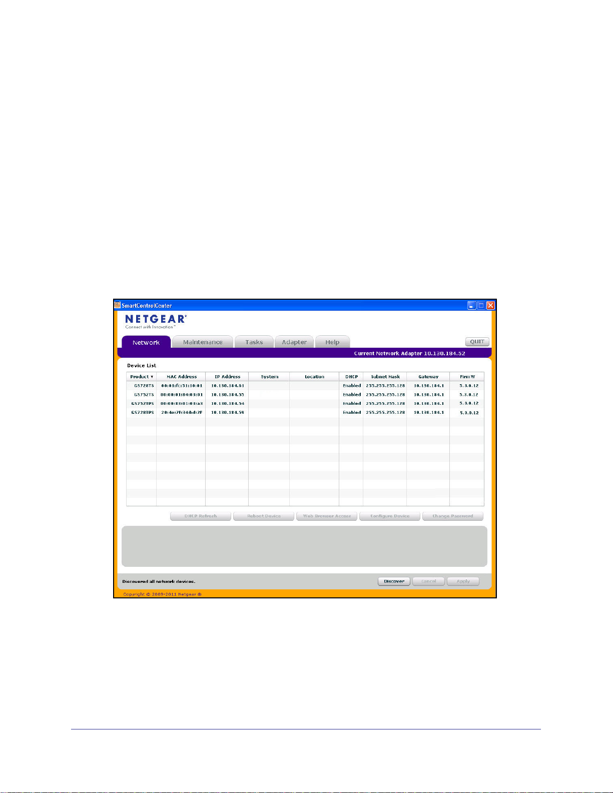
5. Click Discover for the Smart Control Center to find your switch. You should see a screen
similar to the one shown in Figure 1, Smart Switch Discovery.
Figure 1. Smart Switch Discovery
12
Page 13
GS728TS, GS728TPS, GS752TS, and GS752TPS Gigabit Smart Switches
6. Make a note of the displayed IP address assigned by the DHCP server. You will need this
value to access the switch directly from a Web browser (without using the Smart Control
Center).
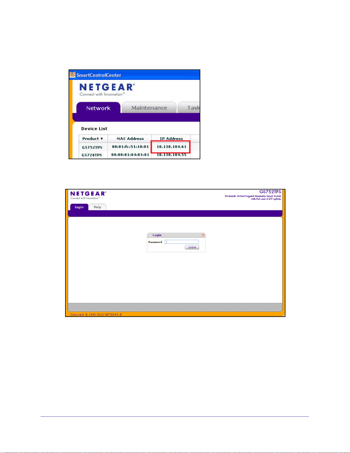
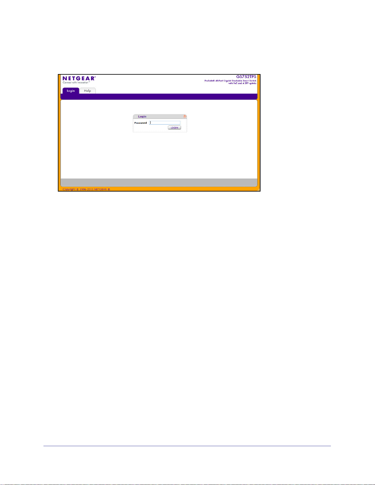
7. Select your switch by clicking the line that displays the switch, then click the
Web Browser Access button. The Smart Control Center displays a login window similar to
the following figure.
Use your Web browser to manage your switch. The default password is password. Then
use this page to proceed to management of the switch covered in Using the Web
Interface on page 23.
13
Page 14
GS728TS, GS728TPS, GS752TS, and GS752TPS Gigabit Smart Switches
Switch Discovery in a Network without a DHCP Server
This section describes how to use the Smart Control Center to set up your switch in a
network without a DHCP server. If your network has no DHCP service, you must assign a
static IP address to your switch. If you choose, you can assign it a static IP address, even if
your network has DHCP service.
To assign a static IP address:
1. Connect the switch to your existing network.
2. Power on the switch by plugging in the AC-DC power adapter.
3. Install the Smart Control Center on your computer.
4. Start the Smart Control Center.
5. Click Discover for the Smart Control Center to find your GS728TS, GS728TPS, GS752TS,
or GS752TPS switch. The utility broadcasts Layer 2 discovery packets within the broadcast
domain to discover the switch.You should see a screen similar to Figure 1 on page 12.
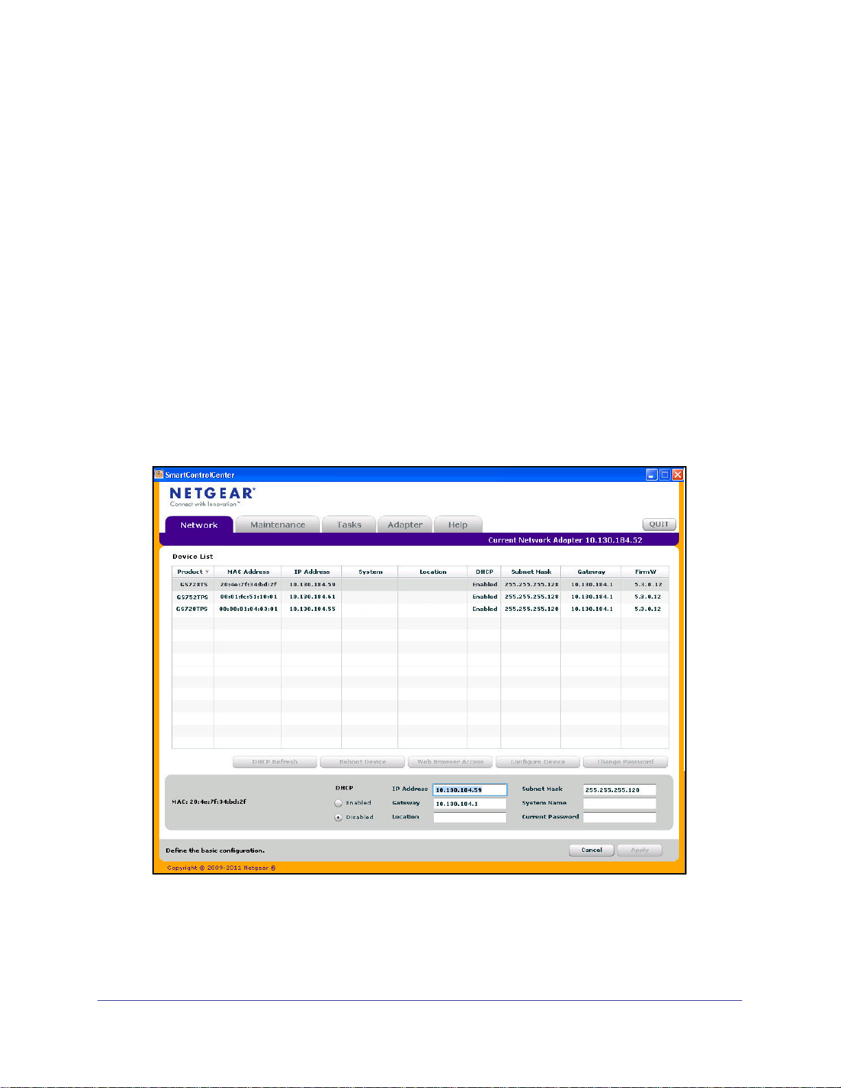
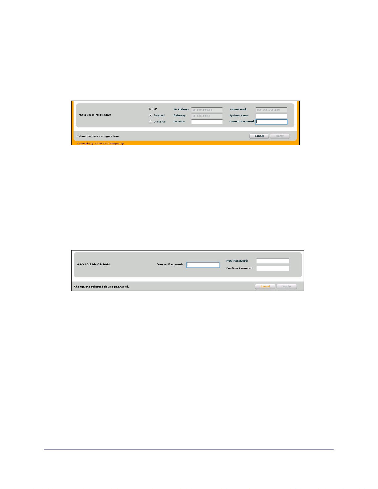
6. Select the switch, then click Configure Device. The page expands to display additional
fields at the bottom of the page, as the following figure shows.
14
Page 15
GS728TS, GS728TPS, GS752TS, and GS752TPS Gigabit Smart Switches
7. Choose the Disabled radio box to disable DHCP.
8. Enter the static switch IP address, gateway IP address and subnet mask, and then type your
password and click Apply.
Tip: You must enter the current password every time you use the Smart
Control Center to update the switch setting. The default password is
password.
Please ensure that your PC and the switch are in the same subnet. Make a note of these
settings for later use.
Configuring the Network Settings on the Administrative System
If you choose not to use the Smart Control Center to configure the network information on the
switch, you can connect directly to the switch from an administrative system, such as a PC or
laptop computer. The IP address of the administrative system must be in the same subnet as
the default IP address on the switch. For most networks, this means you must change the IP
address of the administrative system to be on the same subnet as the default IP address of
the switch (192.168.0.239).
®
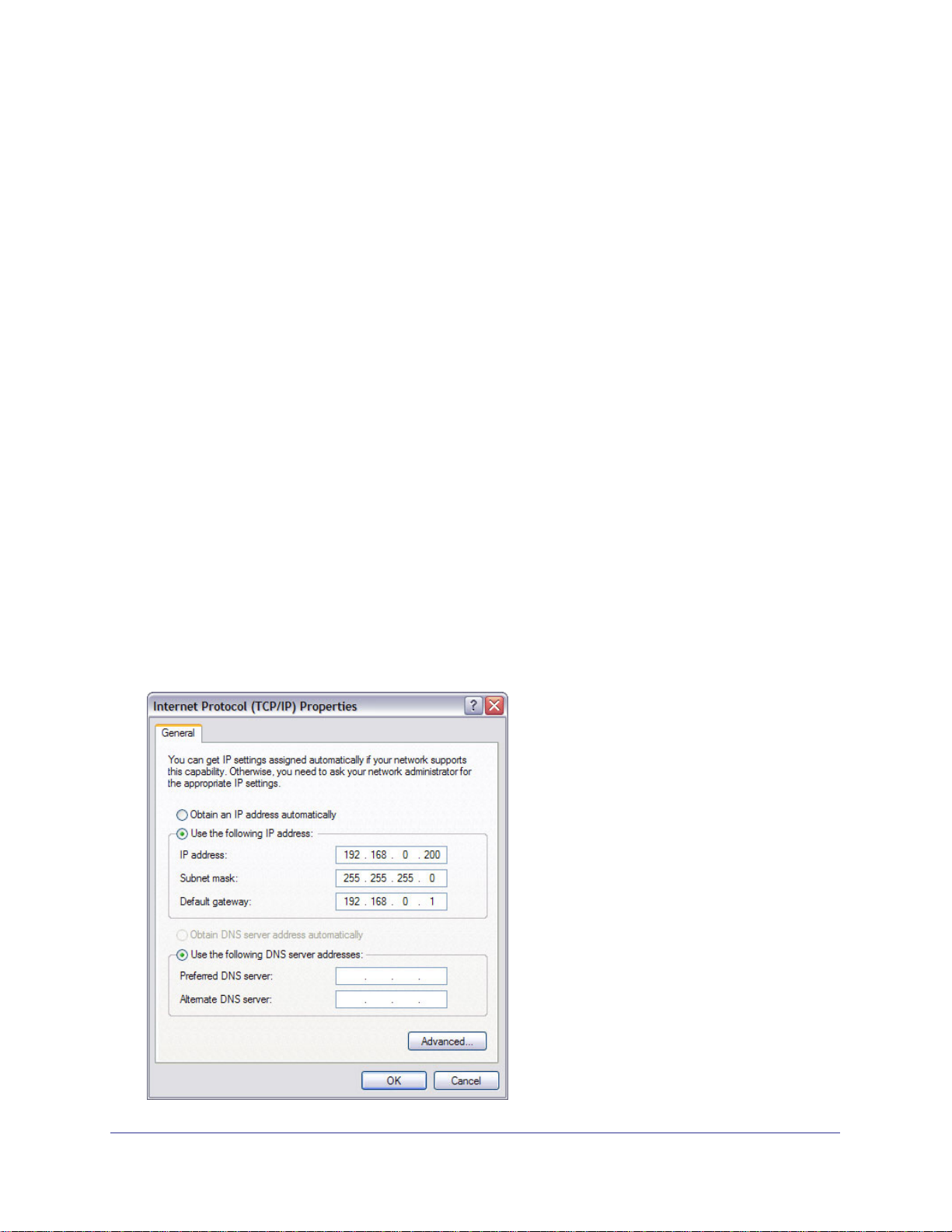
To change the IP address on an administrative system running a Microsoft
operating system, open the Internet Protocol (TCP/IP) properties screen that you access
from the Local Area Connection properties, as shown in the following figure. You need
Windows Administrator privileges to change these settings.
Windows®
15
Page 16

GS728TS, GS728TPS, GS752TS, and GS752TPS Gigabit Smart Switches
WARNING:
When you change the IP address of your administrative system,
you will loose your connection to the rest of the network. Be sure
to write down your current network address settings before you
change them.
To modify the network settings on your administrative system:
1. On your PC, access the MS Windows operating system TCP/IP Properties.
2. Set the IP address of the administrative system to an address in the 192.168.0.0 network,
such as 192.168.0.200. The IP address must be different from that of the switch but within
the same subnet.
3. Click OK.
To configure a static address on the switch:
1. Use a straight-through cable to connect the Ethernet port on the administrative system
directly to any port on the GS728TS, GS728TPS, GS752TS, or GS752TPS.
2. Open a Web browser on your PC and connect to the management interface as described in
Web Access on page 16.
3. Change the network settings on the switch to match those of your network (this procedure is
described in
After you change the network settings on the switch, return the network configuration on your
administrative system to the original settings.
IP Configuration on page 35).
Web Access
To access the GS728TS, GS728TPS, GS752TS, or GS752TPS management interface, use
one of the following methods:
• From the Smart Control Center, select the switch and click Web Browser Access.
• Open a Web browser and enter the IP address of the switch in the address field.
You must be able to ping the IP address of the GS728TS, GS728TPS, GS752TS, or
GS752TPS management interface from your administrative system for Web access to be
available. If you used the Smart Control Center to set up the IP address and subnet mask,
either with or without a DHCP server, use that IP address in the address field of your Web
browser. If you did not change the IP address of the switch from the default value, enter
192.168.0.239 into the address field.
16
Page 17
GS728TS, GS728TPS, GS752TS, and GS752TPS Gigabit Smart Switches
Clicking Web Browser Access on the Smart Control Center or accessing the switch directly
from your Web browser displays the login screen shown in the following figure.
Figure 2. Login Screen
Smart Control Center Utilities
In addition to device discovery and network address assignment, the Smart Control Center
includes several maintenance features. This section describes the following Smart Control
Center utilities:
• Network Utilities on page 17
• Configuration Upload and Download on page 19
• Firmware Upgrade on page 20
• Viewing and Managing Tasks on page 22
Network Utilities
From the Network tab, you can perform the following functions:
• DHCP Refresh—Forces the switch to release the current bindings and request new
address information from the DHCP server.
• Reboot Device—Reboots the selected device.
• Web Browser Access—Launches a Web browser and connects to the management
interface for the selected device.
• Configure Device—Allows you to modify network information for the switch, including
the IP address, DHCP client mode, system name, and location. For more information
about this feature, see Configuring the Device.
• Change Password—Allows you to set a new password for the device. For more
information about this feature, see Changing the Switch Password.
17
Page 18
GS728TS, GS728TPS, GS752TS, and GS752TPS Gigabit Smart Switches
Configuring the Device
To modify switch information:
1. Select the switch.
2. Click Configure Device. Additional fields appear on the screen.
3. To assign or update a static IP address, default gateway, or subnet mask, disable the DHCP
client and enter the new information. You can also specify a system name and location for
the switch.
4. Type the password in the Current Password field. You cannot apply the changes without a
valid switch password. The default password for the switch is password.
5. Click Apply to update the switch with the changes to the network information.
Changing the Switch Password
1. Select the switch.
2. Click Change Password. Additional fields appear on the screen.
3. Type the switch password in the Current Password field. The default password for the
switch is password.
4. Type the new password in the New Password and Confirm Password fields. The
password can contain up to 20 ASCII characters.
5. Click Apply to update the switch with the new password.
18
Page 19
GS728TS, GS728TPS, GS752TS, and GS752TPS Gigabit Smart Switches
Configuration Upload and Download
When you make changes to the switch, the configuration information is stored in a file on the
switch. You can backup the configuration by uploading the configuration file from the switch
to an administrative system. You can download a saved configuration file from the
administrative system to the switch. The configuration file you download to the switch
overwrites the running configuration on the switch.
Configuration upload and download is useful if you want to save a copy of the current switch
configuration (Upload Configuration) before you make changes. If you do not like the
changes, you can use the Download Configuration option to restore the switch to the settings
in the saved configuration file.
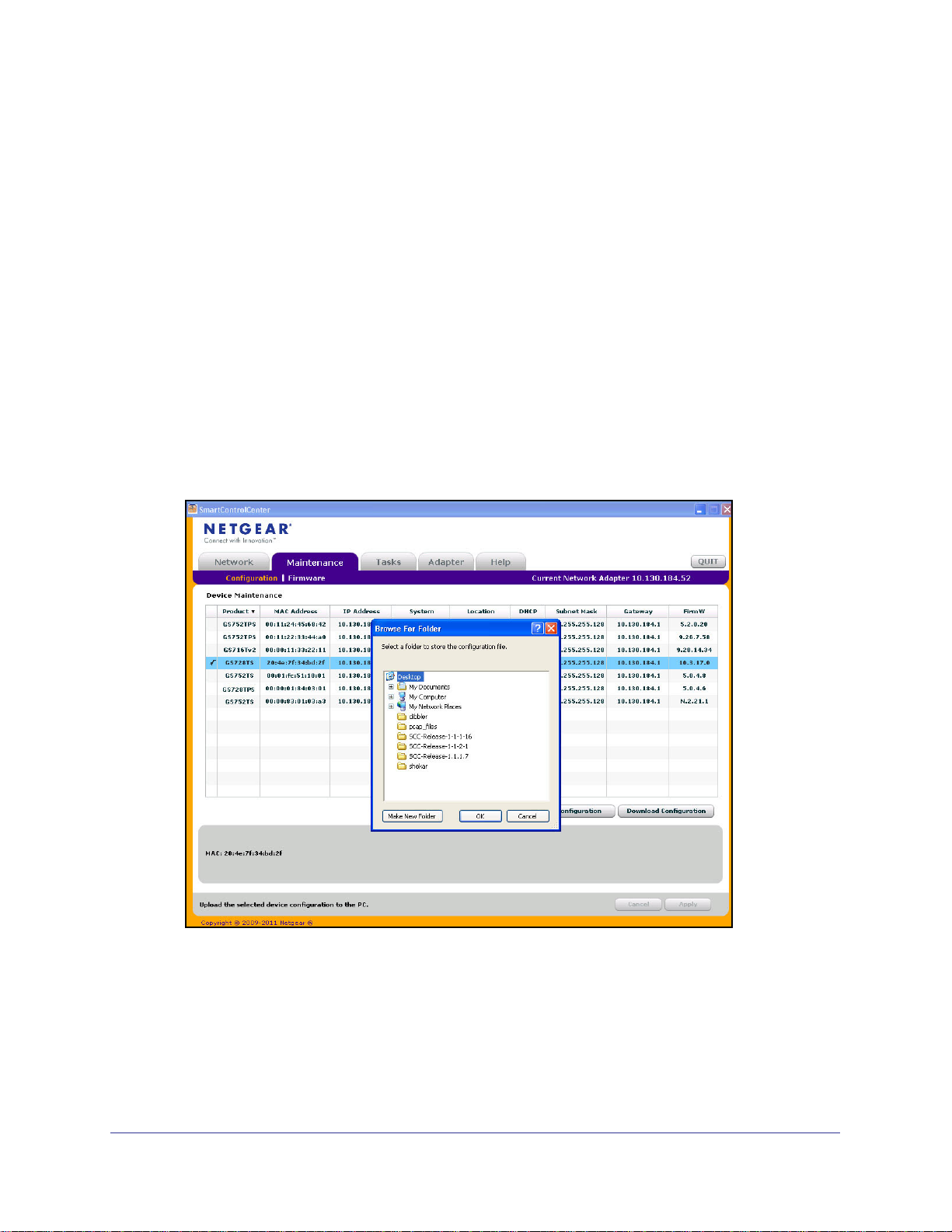
To save a copy of the current switch configuration on your administrative system:
1. Click the Maintenance tab and select the device with the configuration to save.
2. Click Upload Configuration.
3. From the Browse for Folder window that appears, navigate to and select the folder where
you want to store the configuration file.
4. Click OK.
5. Enter the switch password and click Apply.
The file is uploaded to the administrative computer as a *.cfg file. You can open it and
view the contents with a text editor.
19
Page 20

GS728TS, GS728TPS, GS752TS, and GS752TPS Gigabit Smart Switches
To restore the configuration to a previously saved version:
1. Click the Maintenance tab and select the device with the configuration to restore.
2. Click Download Configuration.
3. From the Select a Configuration window that appears, navigate to and select the
configuration file to download to the switch.
4. Click Open.
5. Enter the switch password and click Apply to begin the download process.
Optionally, you can schedule a different date and time to download the configuration file.
To delay the download process, clear the Run Now? check box and enter a date and
time to complete the download.
Note: Click the Tasks tab to view status information about the
configuration download.
Firmware Upgrade
The application software for the GS728TS, GS728TPS, GS752TS, and GS752TPS Smart
Switches is upgradeable, enabling your switch to take advantage of improvements and
additional features as they become available. The upgrade procedure and the required
equipment are described in this section. This procedure assumes that you have downloaded
or otherwise obtained the firmware upgrade and that you have it available as a binary file on
your computer. This procedure uses the TFTP protocol to implement the transfer from
computer to switch.
Note: You can also upgrade the firmware using the TFTP Download and
HTTP Download features mentioned in this book. See
File To Switch on page 284.
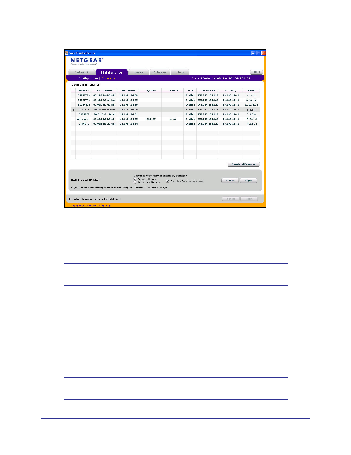
To upgrade your firmware:
1. Click the Maintenance tab, and then click the Firmware link directly below the tabs (see
Figure 1 on page 12).
2. Select the switch to upgrade and click Download Firmware.
3. From the Select new firmware window that appears, navigate to and select the firmware
image to download to the switch.
Download
4. Click Open.
20
Page 21
GS728TS, GS728TPS, GS752TS, and GS752TPS Gigabit Smart Switches
By default, the firmware is downloaded to primary storage and will be become the active
image after the download completes and the switch reboots. To download firmware to use
as a backup image, select the Secondary Storage option. To prevent the switch from
using the downloaded firmware as the active image, make sure the Run this FW after
download option is clear.
Note: NETGEAR recommends that you download the same image as the
primary and secondary image for redundancy.
5. Click Apply.
6. Enter the switch password to continue downloading the firmware.
Optionally, you can schedule a different date and time to download and install the
firmware image. To delay the upgrade process, clear the Run Now? check box and enter
a date and time to complete the upgrade.
7. Click Apply to download the firmware and upgrade the switch with the new image.
8. When the process is complete, the switch automatically reboots.
Note: Click the Tasks tab to view status information about the firmware
upgrade.
21
Page 22
GS728TS, GS728TPS, GS752TS, and GS752TPS Gigabit Smart Switches
WARNING:
It is important that you do not power-off the administrative system
or the switch while the firmware upgrade is in progress.
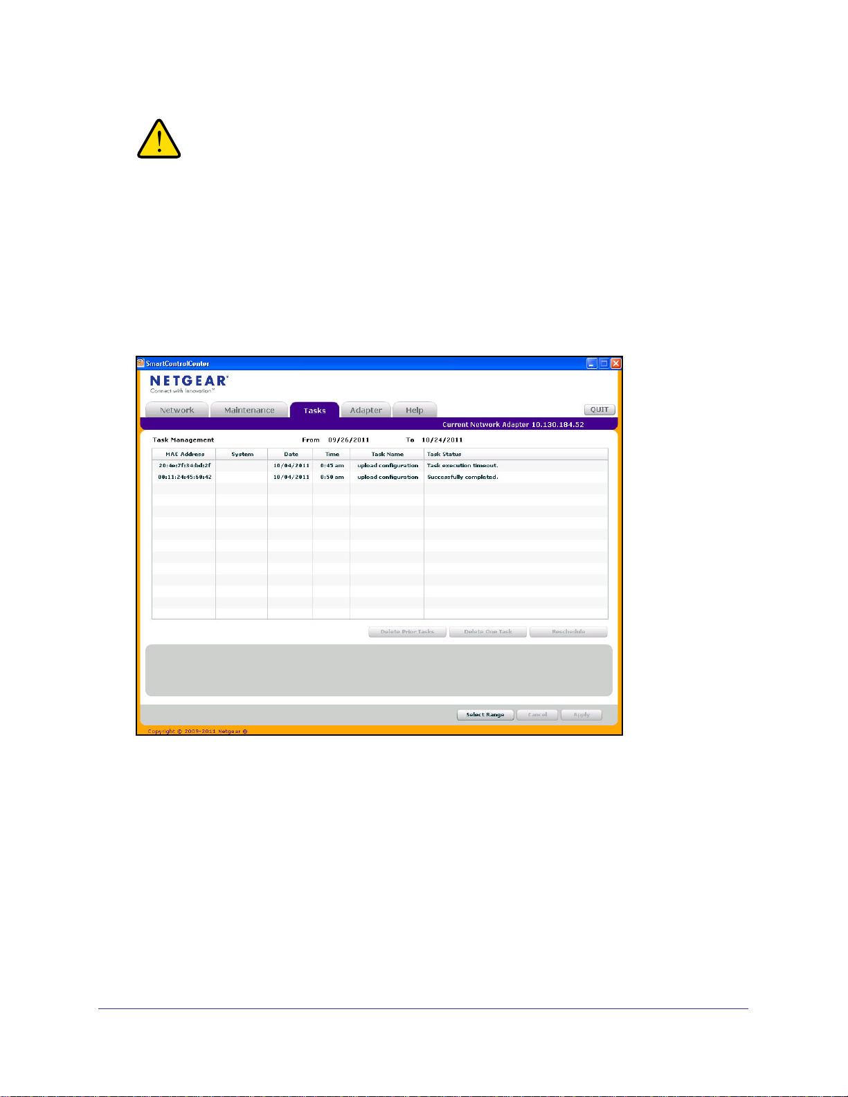
Viewing and Managing Tasks
From the Tasks tab, you can view information about configuration downloads and firmware
upgrades that have already occurred, are in progress, or are scheduled to take place at a
later time. You can also delete or reschedule selected tasks. The following figure shows the
Tasks page.
The following list describes the command buttons that are specific to the Tasks page:
• Delete Task—Remove a completed or schedule task from the list.
• Reschedule—Change the scheduled date and time for a pending firmware upgrade or
configuration download.
• Select Range—Select all tasks that occurred or are scheduled to occur within a certain
period of time.
22
Page 23

GS728TS, GS728TPS, GS752TS, and GS752TPS Gigabit Smart Switches
Understanding the User Interfaces
The GS728TS, GS728TPS, GS752TS, and GS752TPS switches software includes a set of
comprehensive management functions for configuring and monitoring the system by using
one of the following methods:
• Web user interface
• Simple Network Management Protocol (SNMP)
Each of the standards-based management methods allows you to configure and monitor the
components of the GS728TS, GS728TPS, GS752TS, and GS752TPS switches software.
The method you use to manage the system depends on your network size and requirements,
and on your preference.
The GS728TS, GS728TPS, GS752TS, and GS752TPS Smart Switch Software
Administration Manual describes how to use the Web-based interface to manage and
monitor the system.
Using the Web Interface
To access the switch by using a Web browser, the browser must meet the following software
requirements:
• HTML version 4.0, or later
• HTTP version 1.1, or later
• Java Runtime Environment 1.6 or later
Use the following procedures to log on to the Web interface:
1. Open a Web browser and enter the IP address of the switch in the Web browser
address field.
2. The factory default password is password. Type the password into the field on the login
screen, as shown in
sensitive.
3. After the system authenticates you, the System Information page displays.
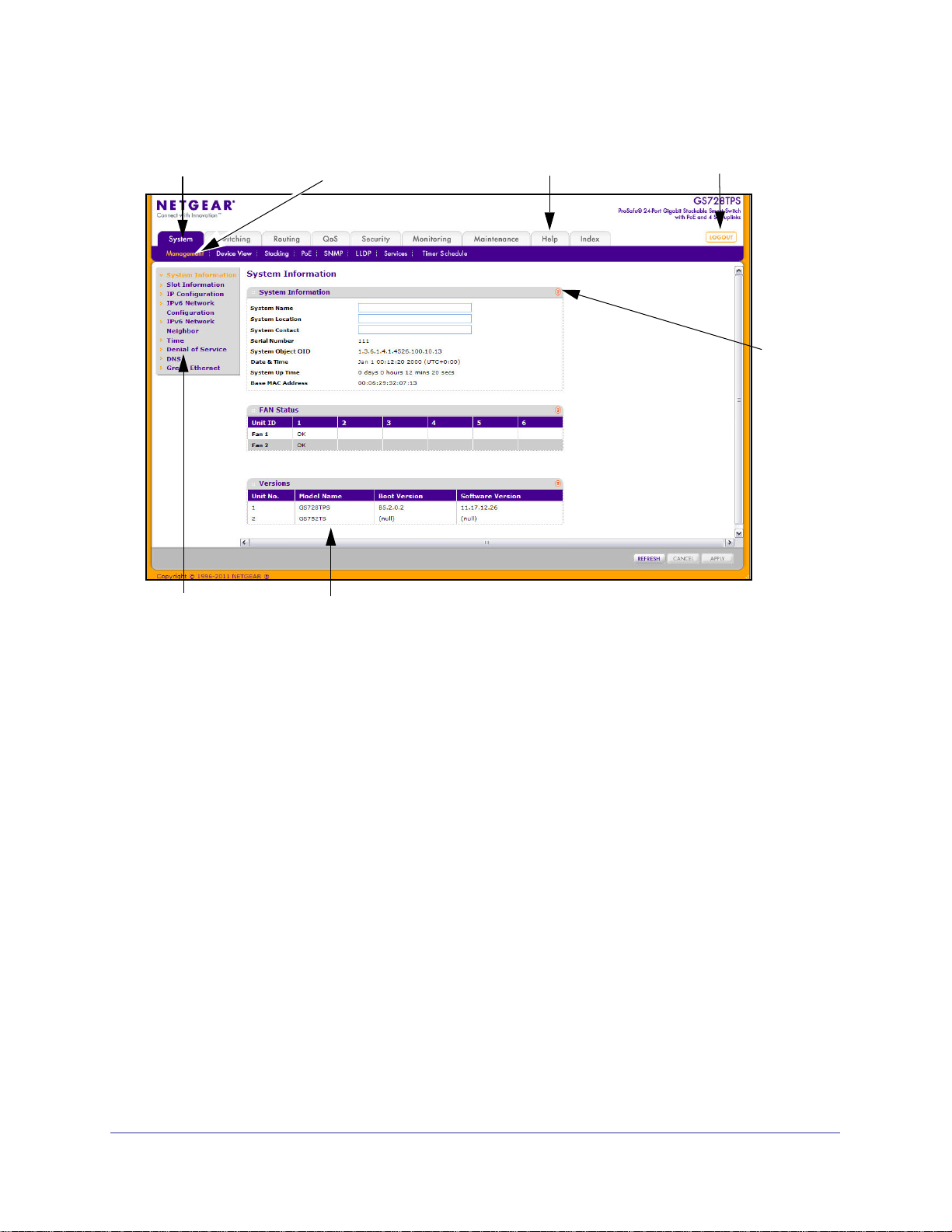
Figure 3 on page 24 shows the layout of the Smart Switch Web interface.
Figure 2 on page 17, and then click Login. Passwords are case
23
Page 24
GS728TS, GS728TPS, GS752TS, and GS752TPS Gigabit Smart Switches
Navigation Tab Feature Link Logout Button
Page Menu
Configuration Status and Options
Help Link
Help
Page
Figure 3. Administrative Page Layout
Navigation Tabs, Feature Links, and Page Menu
The navigation tabs along the top of the Web interface give you quick access to the various
switch functions. The tabs are always available and remain constant, regardless of which
feature you configure.
When you select a tab, the features for that tab appear as links directly under the tabs. The
feature links in the blue bar change according to the navigation tab that is selected.
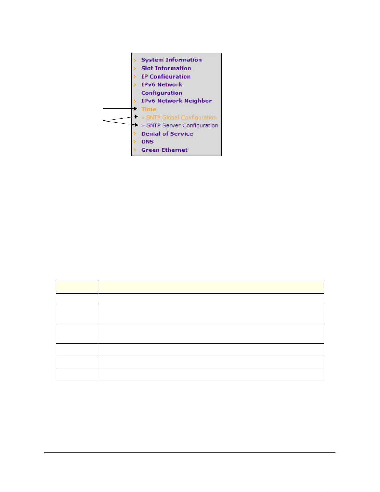
The configuration pages for each feature are available as links in the page menu on the left
side of the page. Some items in the menu expand to reveal multiple configuration pages, as
Figure 4 on page 25. shows. When you click a menu item that includes multiple configuration
pages, the item becomes preceded by a down arrow symbol and expands to display the
additional pages.
24
Page 25
GS728TS, GS728TPS, GS752TS, and GS752TPS Gigabit Smart Switches
Page Link
Configuration
Pages
Figure 4. Menu Hierarchy
Configuration and Monitoring Options
The area directly under the feature links and to the right of the page menu displays the
configuration information or status for the page you select. On pages that contain
configuration options, you can input information into fields or select options from drop-down
menus.
Each page contains access to the HTML-based help that explains the fields and
configuration options for the page. Each page also contains command buttons.
The following table shows the command buttons that are used throughout the pages in the
Web interface:
Table 1. Common Command Buttons
Button Function
Add Clicking Add adds the new item configured in the heading row of a table.
Apply Clicking the Apply button sends the updated configuration to the switch. Configuration
changes take effect immediately.
Cancel Clicking Cancel cancels the configuration on the screen and resets the data on the screen
to the latest value of the switch.
Delete Clicking Delete removes the selected item.
Refresh Clicking the Refresh button refreshes the page with the latest information from the device.
Logout Clicking the Logout button ends the session.
25
Page 26

GS728TS, GS728TPS, GS752TS, and GS752TPS Gigabit Smart Switches
Device View
The Device View is a Java® applet that displays the ports on the switch. This graphic provides
an alternate way to navigate to configuration and monitoring options. The graphic also
provides information about device ports, current configuration and status, table information,
and feature components.
The Device View is available from the System> Device View page.
Depending upon the status of the port, the LED of the port status illuminates in Device View
either red, green, or gray. Green indicates that the port is enabled. Red indicates that an error
has occurred on the port, or red indicates that the link is disabled. Gray is applicable for ports
27 and 28 on the GS728TS/GS728TPS and ports 51 and 52 on the GS752TS/GS752TPS
and indicates that the port is working in stack mode. The LED of the port speed illuminates
either green or yellow.
• A green LED indicates operational ports at 1 Gbps or 2.5 Gbps (if used for stacking) link
speed.
• A yellow LED indicates operational ports at 10/100 Mbps link speed.
The System LEDs are located on the left side of the front panel.
Power/Status LED
The power LED is a bicolor LED that serves as an indicator of power and diagnostic status.
The following indications are given by the following LED states:
• A solid Green LED indicates that the power is supplied to the switch and operating
normally.
• A solid Yellow LED indicates that system is in the boot-up stage.
• No lit LED indicates that power is disconnected.
FAN Status LED
FAN status is indicated as follows:
• A solid yellow LED indicates that the fan is faulty.
• No lit LED indicates that the fan is operating normally.
Stack Master LED
The Stack Master LED is lit if there is an active stack link and the unit is in stack mode.
• A solid Green LED indicates that the switch acts as a master unit in a stack of switches.
• No lit LED indicates that the switch acts as a slave member in a stack of switches.
Seven-Segment LED for the Stacking ID
A solid Green LED displays the stack ID (1–6).
26
Page 27
GS728TS, GS728TPS, GS752TS, and GS752TPS Gigabit Smart Switches
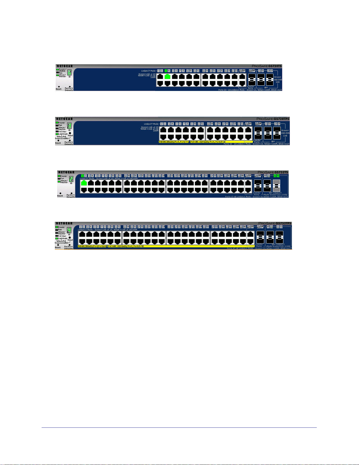
The following figure shows the Device View of the GS728TS.
The following figure shows the Device View of the GS728TPS.
The following figure shows the Device View of the GS752TS.
The following figure shows the Device View of the GS752TPS.
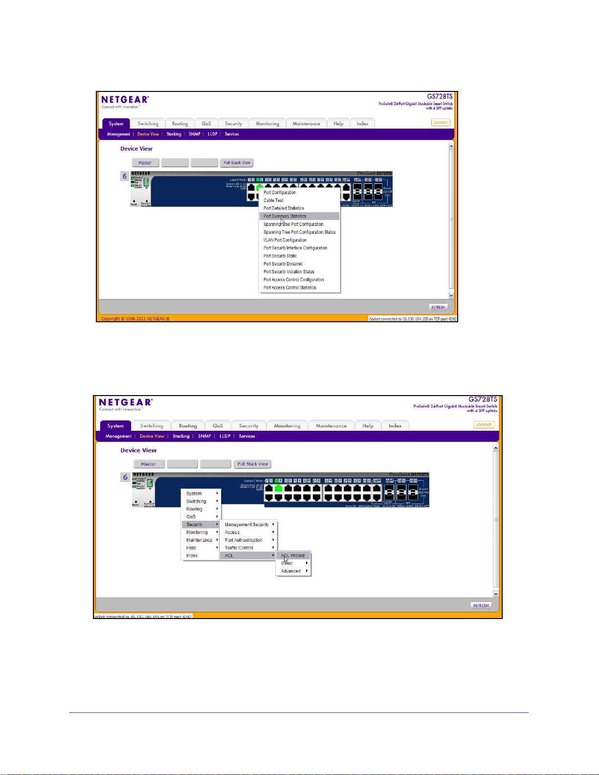
Click the port you want to view or configure to see a menu that displays statistics and
configuration options. Click the menu option to access the page that contains the
configuration or monitoring options.
27
Page 28
GS728TS, GS728TPS, GS752TS, and GS752TPS Gigabit Smart Switches
If you click the graphic, but do not click a specific port, the main menu appears, as the
following figure shows. This menu contains the same option as the navigation tabs at the top
of the page.
28
Page 29

GS728TS, GS728TPS, GS752TS, and GS752TPS Gigabit Smart Switches
Help Page Access
Every page contains a link to the online help , which contains information to assist in
configuring and managing the switch. The online help pages are context sensitive. For
example, if the IP Addressing page is open, the help topic for that page displays if you click
Help. Figure 3 on page 24 shows the location of the link to the Help Page on the Web interface.
User-Defined Fields
User-defined fields can contain 1 to 159 characters, unless otherwise noted on the
configuration Web page. All characters may be used except for the following (unless
specifically noted in for that feature):
\ <
/ >|
* |
?
Using SNMP
The GS728TS, GS728TPS, GS752TS, and GS752TPS switches software supports the
configuration of SNMP groups and users that can manage traps that the SNMP agent
generates. GS728TS, GS728TPS, GS752TS, and GS752TPS switches use both standard
public MIBs for standard functionality and private MIBs that support additional switch
functionality. All private MIBs begin with a “-” prefix. The main object for interface
configuration is in -SWITCHING-MIB, which is a private MIB. Some interface configurations
also involve objects in the public MIB, IF-MIB.
SNMP is enabled by default. The System > Management > System Information Web page,
which is the page that displays after a successful login, displays the information you need to
configure an SNMP manager to access the switch.
Any user can connect to the switch using the SNMPv3 protocol, but for authentication and
encryption, the switch supports only one user which is admin; therefore there is only one
profile that can be created or modified.
To configure authentication and encryption settings for the SNMPv3 admin profile by using
the Web interface:
1. Navigate to the System > SNMP > SNMPv3 > User Configuration page.
2. To enable authentication, select an Authentication Protocol option, which is either MD5 or
SHA.
3. To enable encryption, select the DES option in the Encryption Protocol field. Then, enter
an encryption code of eight or more alphanumeric characters in the Encryption Key field.
4. Click Apply.
To access configuration information for SNMPv1 or SNMPv2, click System > SNMP >
SNMPv1/v2 and click the page that contains the information to configure.
29
Page 30

GS728TS, GS728TPS, GS752TS, and GS752TPS Gigabit Smart Switches
Interface Naming Convention
The GS728TS, GS728TPS, GS752TS, and GS752TPS switches software supports physical
and logical interfaces. Interfaces are identified by their type and the interface number. The
physical ports are gigabit interfaces and are numbered on the front panel. You can configure
the logical interfaces by using the software. The following table describes the naming
convention for all interfaces available on the switch.
Table 2. Interface Naming Conventions
Interface Description Example
Physical The physical ports are gigabit Ethernet
interfaces and are numbered sequentially
starting from one. The number before the slash
indicates the unit number of the stack member.
Link Aggregation Group (LAG) LAG interfaces are logical interfaces that are
only used for bridging functions.
CPU Management Interface This is the internal switch interface responsible
for the switch base MAC address. This interface
is not configurable and is always listed in the
MAC Address Table.
1/g1, 1/g2, 1/g3
3/g21, 3/g22
l1, l2, l3
c1
30
Page 31

2. Configuring System Information
Use the features in the System tab to define the switch’s relationship to its environment. The
System tab contains links to the following features:
• Management on page 31
• Stacking on page 61
• PoE/PoE+ (GS728TPS and GS752TPS Only) on page 70
• SNMP on page 75
• LLDP on page 80
• Services — DHCP Snooping on page 92
• Timer Schedule (GS728TPS and GS752TPS Only) on page 99
Management
2
This section describes how to display the switch status and specify some basic switch
information, such as the management interface IP address, system clock settings, and DNS
information. From the Management link, you can access the following pages:
• System Information on page 32
• Slot Information on page 33
• IP Configuration on page 35
• IPv6 Network Configuration on page 37
• IPv6 Network Neighbor on page 38
• Time on page 40
• Denial of Service on page 45
• DNS on page 49
• Green Ethernet on page 51
31
Page 32

GS728TS, GS728TPS, GS752TS, and GS752TPS Gigabit Smart Switches
System Information
After a successful login, the System Information page displays. Use this page to configure
and view general device information.
To display the System Information page, click System > Management > System Information.
A screen similar to the following is displayed.
To define system information:
1. Open the System Information page.
2. Define the following fields:
• System Name. Enter the name you want to use to identify this switch. You may use
up to 255 alphanumeric characters. The factory default is blank.
• System Location. Enter the location of this switch. You may use up to 255
alphanumeric characters. The factory default is blank.
• System Contact. Enter the contact person for this switch. You may use up to 255
alphanumeric characters. The factory default is blank.
3. Click Apply.
The system parameters are applied, and the device is updated.
The following table describes the status information the System Page displays.
Field Description
Serial Number The serial number of the switch.
System Object OID The base object ID for the switch's enterprise MIB.
32
Page 33

GS728TS, GS728TPS, GS752TS, and GS752TPS Gigabit Smart Switches
Field Description
Date & Time The current date and time.
System Up Time Displays the number of days, hours, and minutes since the last system restart.
Base MAC Address The universally assigned network address.
Fan Status Table
Unit ID Identifies the unit number assigned to the stack member. Up to six units are
supported in a stack, and the table contains separate columns for each possible
unit in the stack, whether the units are present or not.
Fan 1 and Fan 2 These fans remove the heat generated by the power, CPU and other chipsets,
and allow the chipsets to work normally. Fan status has three possible values:
OK, Failure, Not Present.
If the Fan 1 and Fan 2 entries for a Unit ID are blank, then no switch with that unit
number is present in the stack.
Versions Table
Unit No. Identifies the unit number assigned to the stack member.
Model Name The model name of the switch.
Boot Version The boot code version of the switch.
Software Version
The software version of the switch.
Slot Information
Use this page to display details of the different slots in the different units in the stack. The
page also displays information about the card types and switch models supported in the
stack.
To display the Slot Information page, click System
screen similar to the following is displayed.
Management Slot Information. A
33
Page 34

GS728TS, GS728TPS, GS752TS, and GS752TPS Gigabit Smart Switches
Click Refresh to refresh the screen with most recent data.
The following table describes the status information the Slot Information displays.
Field Description
Slot Summary
Slot Identifies the slot using the format unit/slot.
Status Displays whether the slot is empty or full.
Administrative State Displays whether the slot is administratively enabled or disabled.
Power State Displays whether the slot is powered on or not.
Configured Card Model ID Displays the model ID of the card configured for the slot.
Configured Card Description Displays the description of the card configured for the slot.
Inserted Card Model ID Displays the model ID of the card physically present in the slot.
Inserted Card Description Displays the description of the card physically present in the slot.
Card Power Down Displays whether the card in the slot is powered down.
Card Pluggable Displays whether the inserted card is pluggable or not.
Supported Card
Card Model Lists summary information about the card models supported for the
stackable units.
Card Index Displays the index assigned to the selected card type.
Card Type Displays the hardware type of this supported card. This is a 32-bit data
field.
Card Descriptor Displays the additional information about each supported card.
Supported Switch
Switch Model ID Displays the list of models of all supported switches.
Switch Index Displays the index assigned to the selected switch.
Management Preference Identifies whether the unit prefers to be a stack master or stack member.
Code Type Displays the Code Target ID on the supported switch
34
Page 35

GS728TS, GS728TPS, GS752TS, and GS752TPS Gigabit Smart Switches
IP Configuration
Use the IP Configuration page to configure network information for the management
interface, which is the logical interface used for in-band connectivity with the switch through
any of the switch's front panel ports. The configuration parameters associated with the
switch's network interface do not affect the configuration of the front panel ports through
which traffic is switched or routed.
To access the page, click System > Management > IP Configuration. A screen similar to the
following is displayed.
To configure the network information for the management interface:
1. Select the appropriate radio button to determine how to configure the network
information for the switch management interface:
• Dynamic IP Address (DHCP). Specifies that the switch must obtain the IP address
through a DHCP server.
• Dynamic IP Address (BOOTP). Specifies that the switch must obtain the IP address
through a BootP server.
• Static IP Address. Specifies that the IP address, subnet mask, and default gateway
must be manually configured. Enter this information in the fields below this radio
button.
2. If you selected the Static IP Address option, configure the following network information:
• IP Address. The IP address of the network interface. The factory default value is
192.168.0.239. Each part of the IP address must start with a number other than zero.
For example, IP addresses 001.100.192.6 and 192.001.10.3 are not valid.
• Subnet Mask. The IP subnet mask for the interface. The factory default value is
255.255.255.0.
• Default Gateway. The default gateway for the IP interface. The factory default value
is 192.168.0.254.
35
Page 36

GS728TS, GS728TPS, GS752TS, and GS752TPS Gigabit Smart Switches
3. Specify the VLAN ID for the management VLAN.
The management VLAN is used to establish an IP connection to the switch from a
workstation that is connected to a port in the same VLAN. If not specified, the active
management VLAN ID is 1 (default), which allows an IP connection to be established
through any port.
When the management VLAN is set to a different value, an IP connection can be made
only through a port that is part of the management VLAN. It is also mandatory that the
port VLAN ID (PVID) of the port to be connected in that management VLAN be the same
as the management VLAN ID.
The management VLAN has the following requirements:
• Only one management VLAN can be active at a time.
• When a new management VLAN is configured, connectivity through the existing
management VLAN is lost.
• The management station should be reconnected to the port in the new management
VLAN.
Note: Make sure that the VLAN to be configured as the management
VLAN exists. And make sure that the PVID of at least one port that is
a port of the VLAN is the same as the management VLAN ID. For
information about creating VLANs and configuring the PVID for a
port, see VLANs on page 110.
4. If you change any of the network connection parameters, click Apply to apply the changes
to the system.
5. Click Cancel to abandon the changes.
36
Page 37

GS728TS, GS728TPS, GS752TS, and GS752TPS Gigabit Smart Switches
IPv6 Network Configuration
Use the IPv6 Network Configuration page to configure the IPv6 network interface, which is
the logical interface used for in-band connectivity with the switch via all of the switch's
front-panel ports. The configuration parameters associated with the switch's network
interface do not affect the configuration of the front-panel ports through which traffic is
switched or routed.
To access the page, click System
Management IPv6 Network Configuration. A screen
similar to the following is displayed.
To access the switch over a IPv6 network, you must initially configure the switch with IPv6
information (IPv6 prefix, prefix length, and default gateway). IPv6 can be configured using
any of the following options:
• IPv6 Auto Configuration
• DHCPv6
When in-band connectivity is established, IPv6 information can be changed using any of the
following:
• SNMP-based management
• Web-based management
37
Page 38

GS728TS, GS728TPS, GS752TS, and GS752TPS Gigabit Smart Switches
To configure the network information for an IPv6 network:
1. Admin Mode. Enable or disable the IPv6 network interface on the switch. The default
value is Enable.
2. IPv6 Address Auto Configuration Mode. The IPv6 address for the IPv6 network interface
is set in auto configuration mode if this option is enabled. The default value is Disable. Auto
configuration can be enabled only when DHCPv6 is not enabled on any of the management
interfaces.
3. Current Network Configuration Protocol. The IPv6 address for the IPv6 network interface
is configured by DHCPv6 protocol if this option is enabled. The default value is None.
DHCPv6 can be enabled only when IPv6 Auto configuration or DHCPv6 are not enabled on
any of the management interfaces.
4. DHCPv6 Client DUID. Identifier used to identify the client's unique DUID value. This option
only displays when DHCPv6 is enabled.
5. IPv6 Gateway. Specify the gateway for the IPv6 network interface. The gateway address is
in IPv6 global or link-local address format.
6. IPv6 Prefix/Prefix Length. Add the IPv6 prefix and prefix length to the IPv6 network
interface. The address is in the global address format.
7. EUI64. Specify whether format IPv6 address in EUI-64 format. The default value is False.
8. Click Add to add a new IPv6 address in global format.
9. Click Delete to delete a selected IPv6 address.
10. Click Apply to apply the changes to the system.
11. Click Cancel to cancel the configuration on the screen and reset the data on the screen to
the latest value of the switch.
IPv6 Network Neighbor
Use the IPv6 Network Neighbor page to view the IPv6 Network Interface IPv6 Neighbor
Table. If no IPv6 neighbors are detected on the network, the table is empty.
To access the page, click System Management IPv6 Network Neighbor. A screen similar
to the following is displayed.
38
Page 39

GS728TS, GS728TPS, GS752TS, and GS752TPS Gigabit Smart Switches
Click Clear to delete all entries from the table. The table is repopulated as the IPv6 neighbors
are discovered on the network. Click Refresh to refresh the screen with most recent data.
The following table describes the information the IPv6 Network Interface Neighbor Table
displays
Field Description
IPv6 Address Specifies the IPv6 address of neighbor or interface.
MAC Address Specifies MAC address associated with an interface.
IsRtr Indicates whether the neighbor is a router. If the neighbor is a router, the value is
True. If the neighbor is not a router, the value is False.
Neighbor State Specifies the state of the neighbor cache entry. The following are the states for
dynamic entries in the IPv6 neighbor discovery cache:
• Reachable. Positive confirmation was received within the last Reachable Time
milliseconds that the forward path to the neighbor was functioning properly. While
in REACH state, the device takes no special action as packets are sent.
• Stale. More than ReachableTime milliseconds have elapsed since the last positive
confirmation was received that the forward path was functioning properly. While in
STALE state, the device takes no action until a packet is sent.
• Delay. More than ReachableTime milliseconds have elapsed since the last positive
confirmation was received that the forward path was functioning properly. A packet
was sent within the last DELAY_FIRST_PROBE_TIME seconds. If no reachability
confirmation is received within DELAY_FIRST_PROBE_TIME seconds of entering
the DELAY state, send a neighbor solicitation message and change the state to
PROBE.
• Probe. A reachability confirmation is actively sought by resending neighbor
solicitation messages every RetransTimer milliseconds until a reachability
confirmation is received.
• Unknown. The switch cannot determine the state of the cache entry.
Last Updated. Time since the address was confirmed to be reachable.
39
Page 40

GS728TS, GS728TPS, GS752TS, and GS752TPS Gigabit Smart Switches
Time
The GS728TS, GS728TPS, GS752TS, and GS752TPS switch software supports the Simple
Network Time Protocol (SNTP). You can also set the system time manually.
SNTP assures accurate network device clock time synchronization up to the millisecond.
Time synchronization is performed by a network SNTP server. The GS728TS, GS728TPS,
GS752TS, and GS752TPS switches operate only as SNTP clients and cannot provide time
services to other systems.
Time sources are established by Stratums. Stratums define the accuracy of the reference
clock. The higher the stratum (where zero is the highest), the more accurate the clock. The
device receives time from stratum 1 and above since it is itself a stratum 2 device.
The following is an example of stratums:
• Stratum 0: A real-time clock is used as the time source, for example, a GPS system.
• Stratum 1: A server that is directly linked to a Stratum 0 time source is used. Stratum 1
time servers provide primary network time standards.
• Stratum 2: The time source is distanced from the Stratum 1 server over a network path.
For example, a Stratum 2 server receives the time over a network link, via NTP, from a
Stratum 1 server.
Information received from SNTP servers is evaluated based on the time level and server
type.
SNTP time definitions are assessed and determined by the following time levels:
• T1: Time at which the original request was sent by the client.
• T2: Time at which the original request was received by the server.
• T3: Time at which the server sent a reply.
• T4: Time at which the client received the server's reply.
The device can poll Unicast server types for the server time.
Polling for Unicast information is used for polling a server for which the IP address is known.
SNTP servers that have been configured on the device are the only ones that are polled for
synchronization information. T1 through T4 are used to determine server time. This is the
preferred method for synchronizing device time because it is the most secure method. If this
method is selected, SNTP information is accepted only from SNTP servers defined on the
device using the SNTP Server Configuration page.
The device retrieves synchronization information, either by actively requesting information or
at every poll interval.
40
Page 41

GS728TS, GS728TPS, GS752TS, and GS752TPS Gigabit Smart Switches
Time Configuration
Use the Time Configuration page to view and adjust date and time settings.
To display the Time Configuration page, click System > Management > Time > SNTP Global
Configuration.
To configure the time by using the CPU clock cycle as the source:
1. From the Clock Source field, select Local.
2. In the Date field, enter the date in the DD/MM/YYYY format.
3. In the Time field, enter the time in HH:MM:SS format.
Note: If you do not enter a date and time, the switch will calculate the date
and time using the CPU’s clock cycle.
When the Clock Source is set to Local, the Time Zone field is grayed out (disabled).
4. Click Apply to send the updated configuration to the switch. Configuration changes occur
immediately.
41
Page 42

GS728TS, GS728TPS, GS752TS, and GS752TPS Gigabit Smart Switches
To configure the time through SNTP:
1. From the Clock Source field, select SNTP.
When the Clock Source is set to SNTP, the Date and Time fields are grayed out
(disabled). The switch gets the date and time from the network.
2. Use the menu to select the Coordinated Universal Time (UTC) time zone in which the switch
is located, expressed as the number of hours. The options in the Time Zone menu specify
the time difference from UTC time zone.
3. Click Apply to send the updated configuration to the switch. Configuration changes take
effect immediately.
4. Use the SNTP Server Configuration page to configure the SNTP server settings, as
described in
SNTP Server Configuration on page 43.
5. Click Refresh to refresh the page with the most current data from the switch.
6. Click Cancel to cancel the configuration on the screen and reset the data on the screen to
the latest value of the switch.
The SNTP Global Status table on the Time Configuration page displays information about
the system’s SNTP client. The following table describes the SNTP Global Status fields.
Field Description
Version Specifies the SNTP Version the client supports.
Supported Mode Specifies the SNTP modes the client supports. Multiple modes may be
supported by a client.
Last Update Time Specifies the local date and time (UTC) the SNTP client last updated the system
clock.
Last Attempt Time Specifies the local date and time (UTC) of the last SNTP request or receipt of an
unsolicited message.
Last Attempt Status Specifies the status of the last SNTP request or unsolicited message for both
unicast mode. If no message has been received from a server, a status of Other
is displayed. These values are appropriate for all operational modes:
• Other: None of the following enumeration values.
• Success: The SNTP operation was successful and the system time was
updated.
• Request Timed Out: A directed SNTP request timed out without receiving a
response from the SNTP server.
• Bad Date Encoded: The time provided by the SNTP server is not valid.
• Version Not Supported: The SNTP version supported by the server is not
compatible with the version supported by the client.
• Server Unsynchronized: The SNTP server is not synchronized with its
peers. This is indicated via the 'leap indicator' field on the SNTP message.
• Server Kiss Of Death: The SNTP server indicated that no further queries
were to be sent to this server. This is indicated by a stratum field equal to 0 in
a message received from a server.
Server IP Address Specifies the IP address of the server for the last received valid packet. If no
message has been received from any server, an empty string is shown.
42
Page 43

GS728TS, GS728TPS, GS752TS, and GS752TPS Gigabit Smart Switches
Field Description
Address Type Specifies the address type of the SNTP Server address for the last received
valid packet.
Server Stratum Specifies the claimed stratum of the server for the last received valid packet.
Reference Clock Id Specifies the reference clock identifier of the server for the last received valid
packet.
Server Mode Specifies the mode of the server for the last received valid packet.
Unicast Server Max
Entries
Unicast Server Current
Entries
Specifies the maximum number of unicast server entries that can be configured
on this client.
Specifies the number of current valid unicast server entries configured for this
client.
Click Refresh to refresh the page with the most current data from the switch.
SNTP Server Configuration
Use the SNTP Server Configuration page to view and modify information for adding and
modifying Simple Network Time Protocol SNTP servers.
To display the SNTP Server Configuration page, click System > Management > Time > SNTP
Server Configuration.
43
Page 44

GS728TS, GS728TPS, GS752TS, and GS752TPS Gigabit Smart Switches
To configure a new SNTP Server:
1. Enter the appropriate SNTP server information in the available fields:
• Server Type. Specifies whether the address for the SNTP server is an IP address
(IPv4) or hostname (DNS).
• Address. Enter the IP address or the hostname of the SNTP server.
• Port. Enter a port number on the SNTP server to which SNTP requests are sent. The
valid range is 1–65535. The default is 123.
• Priority . Specifies the priority of this server entry in determining the sequence of
servers to which SNTP requests are sent. Enter a priority from 1–3, with 1 being the
default and the highest priority. Servers with lowest numbers have priority.
• Version. Enter the protocol version number that corresponds to the NTP version
running on the SNTP server. The range is 1–4, and the default version is SNTPv4.
2. Click Add.
3. Repeat the previous steps to add additional SNTP servers. You can configure up to three
SNTP servers.
4. To removing an SNTP server, select the check box next to the configured server to remove,
and then click Delete. The entry is removed, and the device is updated.
5. To change the settings for an existing SNTP server, select the check box next to the
configured server and enter new values in the available fields, and then click Apply.
Configuration changes take effect immediately.
6. Click Cancel to cancel the configuration on the screen and reset the data on the screen to
the latest value of the switch.
The SNTP Server Status table displays status information about the SNTP servers
configured on your switch. The following table describes the SNTP Global Status fields.
Field Description
Address Specifies all the existing Server Addresses. If no Server configuration exists,
a message saying “No SNTP server exists” flashes on the screen.
Last Update Time Specifies the local date and time (UTC) that the response from this server
was used to update the system clock.
Last Attempt Time Specifies the local date and time (UTC) that this SNTP server was last
queried.
44
Page 45

GS728TS, GS728TPS, GS752TS, and GS752TPS Gigabit Smart Switches
Field Description
Last Attempt Status Specifies the status of the last SNTP request to this server. If no packet has
been received from this server, a status of Other is displayed:
• Other: None of the following enumeration values.
• Success: The SNTP operation was successful and the system time was
updated.
• Request Timed Out: A directed SNTP request timed out without receiving
a response from the SNTP server.
• Bad Date Encoded: The time provided by the SNTP server is not valid.
• Version Not Supported: The SNTP version supported by the server is not
compatible with the version supported by the client.
• Server Unsynchronized: The SNTP server is not synchronized with its
peers. This is indicated via the 'leap indicator' field on the SNTP message.
• Server Kiss Of Death: The SNTP server indicated that no further queries
were to be sent to this server. This is indicated by a stratum field equal to
0 in a message received from a server.
Requests Specifies the number of SNTP requests made to this server since last agent
reboot.
Failed Requests Specifies the number of failed SNTP requests made to this server since last
reboot.
Click Refresh to refresh the page with the most current data from the switch.
Denial of Service
Use the Denial of Service (DoS) page to configure DoS control. The GS728TS, GS728TPS,
GS752TS, and GS752TPS switches provide support for classifying and blocking specific
types of DoS attacks. The type of DoS attacks the switch can detect and prevent are
described on page
Auto-DoS Configuration
The Auto-DoS Configuration page lets you automatically enable all the DoS features available
on the switch, except for TCP and UDP port attacks. See
information about the types of DoS attacks the switch can monitor and block.
Note: When Auto-DoS is enabled, a port that is under attack is
automatically shut down and does not forward traffic. The port can
be enabled only manually by the admin user. A warning message is
logged to the buffered log and is sent to the Syslog server.
47.
DoS Configuration on page 47 for
45
Page 46

GS728TS, GS728TPS, GS752TS, and GS752TPS Gigabit Smart Switches
To access the Auto-DoS Configuration page, click System > Management > Denial of Service
> Auto-DoS Configuration.
To configure the Auto-DoS feature:
1. Select a radio button to enable or disable Auto-DoS:
• Disable. Auto-DoS is disabled (default).
• Enable. Auto-DoS is enabled.
2. Click Apply to send the updated configuration to the switch. Configuration changes occur
immediately.
3. Click Cancel to cancel the configuration on the screen and reset the data on the screen to
the latest value of the switch.
46
Page 47

GS728TS, GS728TPS, GS752TS, and GS752TPS Gigabit Smart Switches
DoS Configuration
The DoS Configuration page lets you to select which types of DoS attacks for the switch to
monitor and block.
To access the DoS Configuration page, click System > Management > Denial of Service >
Denial of Service Configuration.
To configure individual DoS settings:
1. Select the types of DoS attacks for the switch to monitor and block and configure any
associated values, as the following list describes.
• Denial of Service Min TCP Hdr Size. Specify the minimum TCP header size
allowed. If First Fragment DoS prevention is enabled, the switch will drop packets that
have a TCP header smaller than this configured value. The factory default is 20
bytes.
• Denial of Service ICMPv4. Enable or disable this option by selecting the appropriate
radio button. Enabling ICMPv4 DoS prevention causes the switch to drop ICMPv4
packets that have a type set to ECHO_REQ (ping) and a size greater than the
configured ICMPv4 packet size. The factory default is Disable.
• Denial of Service Max ICMPv4 Size. Specify the maximum allowed ICMPv4 packet
size. If ICMPv4 DoS prevention is enabled, the switch will drop ICMPv4 ping packets
that have a size greater than this configured maximum ICMPv4 packet size. The
range is 0 to 16376, and the default value (when enabled) is 512.
• Denial of Service ICMPv6. Enabling ICMPv6 DoS prevention causes the switch to
drop ICMPv6 packets that have a type set to ECHO_REQ (ping) and a size greater
than the configured ICMPv6 maximum packet size. The factory default is disabled.
47
Page 48

GS728TS, GS728TPS, GS752TS, and GS752TPS Gigabit Smart Switches
• Denial of Service Max ICMPv6 Packet Size. Specify the maximum allowed IPv6
ICMP packet size. If ICMPv6 DoS prevention is enabled, the switch will drop IPv6
ICMP ping packets that have a size greater than this configured maximum ICMPv6
packet size. The range is 0 to 16376, and the default value (when enabled) is 512.
• Denial of Service First Fragment. Enable or disable this option by selecting the
appropriate radio button. Enabling First Fragment DoS prevention causes the switch
to drop packets that have a TCP header smaller than the configured Min TCP Hdr
Size. The factory default is Disable.
• Denial of Service ICMP Fragment. Enable or disable this option by selecting the
appropriate radio button. Enabling ICMP Fragment DoS prevention causes the switch
to drop fragmented ICMP packets. The factory default is disabled.
• Denial of Service SIP=DIP. Enable or disable this option by selecting the appropriate
radio button. Enabling SIP=DIP DoS prevention causes the switch to drop packets
that have a source IP address equal to the destination IP address. The factory default
is Disable.
• Denial of Service SMAC=DMAC. Enable or disable this option by selecting the
appropriate radio button. Enabling SMAC=DMAC DoS prevention causes the switch
to drop packets that have a source MAC address equal to the destination MAC
address. The factory default is disabled.
• Denial of Service TCP FIN&URG&PSH. Enable or disable this option by selecting
the appropriate radio button. Enabling TCP FIN & URG & PSH DoS prevention
causes the switch to drop packets that have TCP Flags FIN, URG, and PSH set and a
TCP Sequence Number equal to 0. The factory default is disabled.
• Denial of Service TCP Flag &Sequence. Enable or disable this option by selecting
the appropriate radio button. Enabling TCP Flag DoS prevention causes the switch to
drop packets that have TCP control flags set to 0 and TCP sequence number set to 0.
The factory default is disabled.
• Denial of Service TCP Fragment. Enable or disable this option by selecting the
appropriate radio button. Enabling TCP Fragment DoS prevention causes the switch
to drop packets that have a TCP payload where the IP payload length minus the IP
header size is less than the minimum allowed TCP header size. The factory default is
Disable.
• Denial of Service TCP Offset. Enable or disable this option by selecting the
appropriate radio button. Enabling TCP Offset DoS prevention causes the switch to
drop packets that have a TCP header Offset=1. The factory default is disabled.
• Denial of Service TCP Port. Enable or disable this option by selecting the
appropriate radio button. Enabling TCP Port DoS prevention causes the switch to
drop packets that have TCP source port equal to TCP destination port. The factory
default is disabled.
• Denial of Service TCP SYN. Enable or disable this option by selecting the
appropriate radio button. Enabling TCP SYN DoS prevention causes the switch to
drop packets that have TCP Flags SYN set and L4 source = 0–1023. The factory
default is disabled.
48
Page 49

GS728TS, GS728TPS, GS752TS, and GS752TPS Gigabit Smart Switches
• Denial of Service TCP SYN&FIN. Enable or disable this option by selecting the
appropriate radio button. Enabling TCP SYN & FIN DoS prevention causes the switch
to drop packets that have TCP Flags SYN and FIN set. The factory default is
disabled.
• Denial of Service UDP Port. Enable or disable this option by selecting the
appropriate radio button. Enabling UDP Port DoS prevention causes the switch to
drop packets that have UDP source port equal to UDP destination port. The factory
default is disabled.
2. If you change any of the DoS settings, click Apply to apply the changes to the switch.
3. Click Cancel to cancel the configuration on the screen and reset the data on the screen to
the latest value of the switch.
DNS
You can use these pages to configure information about DNS servers the network uses and
how the switch operates as a DNS client.
DNS Configuration
Use this page to configure global DNS settings and DNS server information.
To access this page, click System > Management > DNS > DNS Configuration.
To configure the global DNS settings
1. Specify whether to enable or disable the administrative status of the DNS Client.
• Enable. Allow the switch to send DNS queries to a DNS server to resolve a DNS
domain name. DNS is enabled by default.
• Disable. Prevent the switch from sending DNS queries.
49
Page 50

GS728TS, GS728TPS, GS752TS, and GS752TPS Gigabit Smart Switches
2. Enter the DNS default domain name to include in DNS queries. When the system is
performing a lookup on an unqualified hostname, this field is provided as the domain name
(for example, if default domain name is netgear.com and the user enters test, then test is
changed to test.netgear.com to resolve the name). The name can contain 1–255 characters.
3. To specify the DNS server to which the switch sends DNS queries, enter an IP address in
standard IPv4 dot notation in the DNS Server Address and click Add. The server appears
in the list below. You can specify up to eight DNS servers. The preference is set in the order
created.
4. To remove a DNS server from the list, select the check box next to the server you want to
remove and click Delete. If no DNS server is specified, the check box is global and will
delete all the DNS servers listed.
5. Click Cancel to cancel the configuration on the screen and reset the data on the screen to
the latest value of the switch.
6. Click Apply to send the updated configuration to the switch. Configuration changes take
effect immediately.
Host Configuration
Use this page to manually map host names to IP addresses or to view dynamic DNS
mappings.
To access this page, click System > Management > DNS > Host Configuration.
To add a static entry to the local DNS table:
1. Specify the static host name to add. Each substring must be less than 64 characters in
length separated by a dot, and the length of the whole string must not exceed 255
characters.
2. Specify the IPv4 or IPv6 address in standard notation to associate with the hostname.
3. Click Add. The entry appears in the list below.
50
Page 51

GS728TS, GS728TPS, GS752TS, and GS752TPS Gigabit Smart Switches
4. To remove an entry from the static DNS table, select the check box next to the entry and
click Delete.
5. To change the hostname or IP address in an entry, select the check box next to the entry
and enter the new information in the appropriate field, and then click Apply.
6. Click Cancel to cancel the configuration on the screen and reset the data on the screen to
the latest value of the switch.
The Dynamic Host Configuration table shows host name-to-IP address entries that the switch
has learned. The following table describes the dynamic host fields:
Field Description
Host Lists the host name you assign to the specified IP address.
Total Amount of time since the dynamic entry was first added to the table.
Elapsed Amount of time since the dynamic entry was last updated.
Type The type of the dynamic entry.
IPv4/IPv6 Addresses Lists the IPv4 or IPv6 addresses associated with the host name.
Click Clear to delete Dynamic Host Entries. The table will be repopulated with entries as they
are learned.
Green Ethernet
The Green Ethernet features allow the switch to reduce power consumption on a per-port
basis. Each switch can support one or more of the following features:
• Energy-detect Mode - When the Energy Detect mode is enabled and the port link is
down, the PHY automatically goes down for short period of time and then wakes up to
check link pulses. This mode reduces power consumption on the port when no link
partner is present.
• Short Cable Mode: With Short Cable mode enabled, the PHY goes into low power mode
when the cable length is less than a certain limit.
• Energy Efficient Ethernet (EEE): EEE enables ports to enter a low-power mode to reduce
power consumption during periods of low link utilization. EEE is defined by IEEE 802.3az.
EEE enables both the send and receive sides of the link to disable some functionality for
power savings when the link is lightly loaded.
Green Ethernet Configuration
Use this page to configure the administrative mode for the Green Ethernet features available
on the switch. These features must also be enabled on each port to take advantage of the
possible power savings.
To access this page, click System > Management > Green Ethernet Configuration.
51
Page 52

GS728TS, GS728TPS, GS752TS, and GS752TPS Gigabit Smart Switches
To configure the Green Ethernet feature:
1. Enable or disable the Auto Power-Down Mode.
• Enable. When the port link is down, the PHY automatically goes down for a short
period of time and then wakes up to check link pulses. This behavior saves power
consumption when there is no link partner while still allowing the port to perform
auto-negotiation if a link partner does become present.
• Disable. The PHY remains up even if no link partner is present.
2. Enable or disable the Short Cable Mode.
• Enable. The switch performs a cable test on each cable connect to its ports. If the
cable is less than 10m in length, the port is placed in low power mode (nominal
power).
• Disable. Full transmit power is provided to all ports, regardless of cable length.
3. Enable or disable the EEE Mode:
• Enable. The switch allows ports to transition to low-power mode during link idle
conditions.
• Disable. Full transmit power is provided to all ports, regardless of port activity.
4. Click Apply to send the updated configuration to the switch, or click Cancel to abandon the
changes. Applied configuration changes take effect immediately.
52
Page 53

GS728TS, GS728TPS, GS752TS, and GS752TPS Gigabit Smart Switches
Green Ethernet Interface Configuration
Use this page to configure Green Ethernet features on a per-port basis. The Green Ethernet
modes must be administratively enabled on the switch for the mode enabled on the port to
take effect.
To access this page, click System
Interface Configuration.
Management Green Ethernet Green Ethernet
To configure the Green Ethernet Interface feature:
1. Select the check box next to the port to configure. You can select multiple ports to apply
the same setting to all selected ports. To configure all ports, select the check box in the
heading row.
2. Enable or disable the Auto Power-Down Mode.
• Enable. When the port link is down, the PHY automatically goes down for a short
period of time and then wake up to check link pulses. This behavior saves power
consumption when there is no link partner while still allowing the port to perform
auto-negotiation if a link partner does become present.
• Disable. The PHY remains up even if no link partner is present.
3. Enable or disable the Short Cable Mode.
• Enable. The switch performs a cable test on each cable connect to its ports. If the
cable is less than 10m in length, the port is placed in low power mode (nominal
power). Short cable mode and EEE mode cannot be enabled on the same port
simultaneously.
• Disable. Full transmit power is provided to all ports, regardless of cable length.
53
Page 54

GS728TS, GS728TPS, GS752TS, and GS752TPS Gigabit Smart Switches
4. Enable or disable the EEE Mode:
• Enable. The switch allows ports to transition to low-power mode during link idle
conditions. Short cable mode and EEE mode cannot be enabled on the same port
simultaneously.
• Disable. Full transmit power is provided to all ports, regardless of port activity.
5. Click Apply to apply the change to the system. Configuration changes take effect
immediately.
6. Click Cancel to cancel the configuration on the screen and reset the data on the screen to
the latest value of the switch.
Green Ethernet Detail
Use this page to configure Green Ethernet monitor and manage Green Ethernet features on
a specific port.
To access this page, click System Management Green Ethernet Green Ethernet
Detail.
54
Page 55

GS728TS, GS728TPS, GS752TS, and GS752TPS Gigabit Smart Switches
To configure or view details about the Green Ethernet feature on a port:
1. Within the Local Device Information, select the port to view or configure from the
Interface menu.
2. Enable or disable the Energy Detect, Short Reach, or EEE administrative modes on the
interface.
3. If you make any changes to the Green Ethernet modes for the port, click Apply.
4. View the additional Green Ethernet information that displays for the port:
Field Description
Cumulative Energy Saved
on this port due to Green
Mode(s) (Watts * Hours)
Operational Status
(Energy Detect)
Reason Shows the Admin status, either Admin Down or Admin Up.
Operational Status
(Short Reach)
Reason Shows the reason why the port is either Active or Inactive.
Rx Low Power Idle Event
Count
Rx Low Power Idle Duration
(uSec)
Tx Low Power Idle Event
Count
Tx Low Power Idle Duration
(uSec)
Tw_sys_tx (uSec) Integer that indicates the value of Tw_sys that the local system can
Shows the energy savings per port, per hour.
Shows the Green Mode operational status, either Inactive or Active.
Shows the operational status of the port, either Active or Inactive.
This field is incremented each time MAC RX enters LP IDLE state. Shows
the total number of Rx LPI Events since EEE counters are last cleared.
This field indicates duration of Rx LPI state in 10us increments. Shows
the total duration of Rx LPI since the EEE counters are last cleared.
This field is incremented each time MAC TX enters LP IDLE state. Shows
the total number of Tx LPI Events since EEE counters are last cleared.
This field indicates duration of Tx LPI state in 10us increments. Shows
the total duration of Tx LPI since the EEE counters are last cleared.
support.
Tw_sys_tx Echo (uSec) Integer that indicates the remote system's Transmit Tw_sys that was
used by the local system to compute the Tw_sys that it wants to request
from the remote system.
Tw_sys_rx (uSec) Integer that indicates the value of Tw_sys that the local system requests
from the remote system.
Tw_sys_rx Echo (uSec) Integer that indicates the remote systems Receive Tw_sys that was used
by the local system to compute the Tw_sys that it can support.
Fallback Tw_sys (uSec) Integer that indicates the value of fallback Tw_sys that the local system
requests from the remote system.
Tx_dll_enabled Data Link Layer Enabled: Initialization status of the EEE transmit Data
Link Layer management function on the local system.
55
Page 56

GS728TS, GS728TPS, GS752TS, and GS752TPS Gigabit Smart Switches
Field Description
Tx_dll_ready Data Link Layer ready: This variable indicates that the tx system
initialization is complete and is ready to update/receive LLDP PDUs
containing EEE TLV.
Rx_dll_enabled Status of the EEE capability negotiation on the local system.
Rx_dll_ready Data Link Layer ready: This variable indicates that the rx system
initialization is complete and is ready to update/receive LLDP PDUs
containing EEE TLV.
Time Since Counters Last
Cleared
Time Since Counters Last Cleared (since the time of power up, or after
EEE counters are cleared).
5. To view information received from a partner link, select the port connected to the remote
device from the Interface menu in the Remote Device Information area.
The page refreshes and shows the information in the following table if LLDP data has
been received on the interface
Field Description
Remote ID Specifies the remote client identifier assigned to the remote system.
Remote Tw_sys_tx
(uSec)
Remote Tw_sys_tx
Echo (uSec)
Remote Tw_sys_rx
(uSec)
Remote Tw_sys_rx
Echo (uSec)
Remote Fallback
Tw_sys (uSec)
Integer that indicates the value of Tw_sys that the remote system can support.
Integer that indicates the value Transmit Tw_sys echoed back by the remote
system.
Integer that indicates the value of Tw_sys that the remote system requests from
the local system.
Integer that indicates the value of Receive Tw_sys echoed back by the remote
system.
Integer that indicates the value of fallback Tw_sys that the remote system is
advertising.
6. Click Clear to reset the counters on the page to their default values.
7. Click Refresh to update the page with the current information.
56
Page 57

GS728TS, GS728TPS, GS752TS, and GS752TPS Gigabit Smart Switches
Green Ethernet Summary
This page summarizes the Green Ethernet Summary settings currently in use.
To access this page, click System
Summary.
Management Green Ethernet Green Ethernet
The following table describes the information available on the Green Mode Statistics
Summary page.
Field Description
Current Power Consumption
by all ports in Stack
(mWatts)
Estimated Percentage
Power Saving per stack (%)
Cumulative Energy Saving
per Stack (Watts*Hours)
Estimated Power Consumption by all ports in the stack in mWatts.
Estimated Percentage Power saved on all ports in the stack due to Green
mode(s) enabled.
Estimated Cumulative Energy saved per stack in (Watts × Hours) due to all
green modes enabled.
57
Page 58

GS728TS, GS728TPS, GS752TS, and GS752TPS Gigabit Smart Switches
Field Description
Unit Identifies the stack member number.
Green Features supported
on this unit
Interface Identifies the interface associated with the rest of the data in the row.
Energy Detect Admin Mode Shows whether Energy Detect Mode is administratively enabled on the port.
Energy Detect Operational
Status
Short Reach Admin Mode Shows the administrative status of Short Reach Mode on the port. With short
Short Reach Operational
Status
EEE Admin Mode Shows the administrative status of Energy Efficient Ethernet Mode on the
List of Green Features supported on the given unit which could be one or
more of the following:
• Energy-Detect (Energy Detect)
• Short-Reach (Short Reach)
• EEE (Energy Efficient Ethernet)
• LPI-History (EEE Low Power Idle History)
• LLDP-Cap-Exchg (EEE LLDP Capability Exchange)
• Pwr-Usg-Est (Power Usage Estimates).
Shows the current operational status of the Green Mode for the selected
port.
reach mode enabled, PHY goes into low power mode when cable length is
less than a given limit.
Indicates whether the port is in low-power mode due to the cable length.
port. With EEE mode enabled, the port transitions to low power mode during
link idle condition.
Click Refresh to update the page with the most current data from the switch
58
Page 59

GS728TS, GS728TPS, GS752TS, and GS752TPS Gigabit Smart Switches
Green Ethernet LPI History
Use this page to set the sampling interval for EEE LPI data and to specify the number of
samples to keep. From this page, you can also view per-port EEE LPI data.
To access this page, click System Management Green Ethernet Green Ethernet LPI
History.
You do not need to select a port to configure the LPI sampling interval and maximum number
of samples to keep. These settings are global, and the values you specify are applied to all
ports. To configure the LPI settings for the switch:
1. Specify the LPI sampling interval, which determines the interval at which EEE LPI data
needs to be collected. the default value is 3600, and the range is 30 to 36000.
2. Specify the maximum number of LPI samples to store on the switch. The default is 168, and
the range is 1 to 168.
3. Click Apply to send the updated configuration to the switch. Configuration changes take
effect immediately.
4. Click Refresh to refresh the page with the most current data from the switch.
59
Page 60

GS728TS, GS728TPS, GS752TS, and GS752TPS Gigabit Smart Switches
The page also provides the information shown in the following table:
Field Description
Percentage LPI time per
Stack
Sample No Sample index.
Time Since The Sample
Was Recorded
Percentage Time spent in
LPI mode since last sample
Percentage Time spent in
LPI mode since last reset
Time spent in LPI mode since EEE counters are last cleared.
Each time the page is refreshed it shows a different time as it reflects the
difference in current time and time at which the sample was recorded.
Percentage of time spent in LPI mode during the current measurement
interval.
Percentage of time spent in LPI mode since EEE LPI statistics were last
reset.
60
Page 61

GS728TS, GS728TPS, GS752TS, and GS752TPS Gigabit Smart Switches
Stacking
A stackable switch is a switch that is fully functional operating as a stand-alone unit but can
also be set-up to operate together with up to five other switches. This group of switches
shows the characteristics of a single switch while having the port capacity of the sum of the
combined switches.
From the Stacking link under the System tab, you can access the following pages:
• Stack Configuration on page 63
• Stack Port Configuration on page 66
• Stack Port Diagnostics on page 68
• Stack Firmware Synchronization on page 69
One of the switches in the stack controls the operation of the stack. This switch is called the
stack master. The remaining switches in the stack are stack members. The stack members
use stacking technology to behave and work together as a unified system. Layer 2 and
higher protocols present the entire switch stack as a single entity to the network.
The stack master is the single point of stack-wide management. From the stack master, you
configure the following:
• System-level (global) features that apply to all stack members
• Interface-level features for all interfaces on any stack member
A switch stack is identified in the network by its network IP address. The network IP address
is assigned according to the MAC address of the stack master. Every stack member is
uniquely identified by its own stack member number, which is from 1–6. The stack master can
be any number within that range.
Stack Features
Stacking on the GS728TS, GS728TPS, GS752TS, and GS752TPS switches supports the
following:
• Up to six switches per stack, which can be any combination of GS728TS, GS728TPS,
GS752TS, or GS752TPS switches.
• Single IP address management through a web browser or the SCC.
• Master-slave configuration.
• The master retains configuration for entire stack.
• Automatic detection of new members, with synchronization of firmware (upgrade or
downgrade as needed).
• Configuration updates across the stack through a single operation.
• Automatic master fail-over. Fully resilient stack with chain and ring topology.
• Hot swapping (insertion and removal) of stack members.
61
Page 62

GS728TS, GS728TPS, GS752TS, and GS752TPS Gigabit Smart Switches
Firmware Synchronization and Upgrade
All stack members must run the same software version to ensure compatibility within the
stack. By default, if a unit is added to the stack and its software version is not the same as the
stack master, that unit is not allowed to join the stack. You can enable the Stack Firmware
Auto Upgrade feature, which will automatically synchronize the firmware version on the new
unit with the version running on the stack master. The synchronization operation may result in
either upgrade or downgrade of firmware on the mismatched stack member.
Upgrading the firmware on a stack of switches is the same as upgrading the firmware on a
single switch. After you download a new image by using the File Download page or SCC, the
downloaded image is distributed to all the connected units of the stack.
Note: It is recommended to set the active image for all stack members the
same as the active image of the stack master. In other words, if
image1 is the active image on the stack master, all units should have
image1 as the active image. For information about configuring the
active image, see Dual Image Configuration on page 289.
Configuration Maintenance
The stack master stores and maintains the saved and running configuration files for the
switch stack. The configuration files include the system-level settings for the switch stack and
the interface-level settings for all stack members. Each stack member retains a copy of the
saved file for backup purposes. If the master is removed from the stack or becomes
unavailable, another member will be elected master, and will then run from that saved
configuration.
The switch master copies its running configuration to the stack member configured as the
standby unit whenever it changes (subject to some restrictions to reduce overhead). This
enables the standby unit to take over the stack operation with minimal interruption if the stack
master becomes unavailable. The running-config synchronization also occurs when the
running configuration is auto-saved on the stack master or when the standby unit changes.
Stack Master Election
All stack members are eligible stack masters. If the stack master becomes unavailable, the
remaining stack members participate in electing a new stack master from among themselves.
The following factors determine which switch is elected the stack master:
• The switch that is master always has priority to retain the role of master
• Assigned priority
• MAC address
62
Page 63

GS728TS, GS728TPS, GS752TS, and GS752TPS Gigabit Smart Switches
When the stack is powered up and completes the boot process or the original stack master
becomes unavailable, the stack master is determined through an election process.
The rules for stack master Election are as follows:
• If a unit had previously been elected stack master, then it will remain the stack master and
other units will simply be stack members.
• If no units were stack masters, or more than one unit was a stack master, then the unit
with the highest management preference is elected stack master. The management
preference can be assigned by the administrator. However, if all units have the same
management preference, then the unit with the highest MAC address is assigned as the
stack master.
Factory Defaults Reset Behavior
If the stack master is reset to the factory default settings (see Factory Default on page 281),
the stack master applies the default settings to all the stack members and resets the stack,
including all participating stack members. When the stack boots, the stack master election
process begins.
Stack Configuration
From this page, you can preconfigure stack members before adding them to the stack,
change the unit number assigned to a stack member, and to select a new stack master or
give management preference to one or more units.
If you change the unit ID on a stack member, the member reloads. A stack move causes all
routes and layer 2 addresses to be lost. The administrator is prompted to confirm the
management move.
To display the Stack Configuration page, click System Stacking Basic Stack
Configuration. A screen similar to the following is displayed.
63
Page 64

GS728TS, GS728TPS, GS752TS, and GS752TPS Gigabit Smart Switches
To select a new stack master:
1. In the Management Unit Selected menu, select the unit ID of the stack member to
become the stack master.
2. A message indicating that moving stack management will unconfigure entire stack including
all interfaces.
3. Click OK to confirm the selection and reload the stack. The stack will be unavailable until the
boot process completes.
To configure a stack member before adding it to the stack:
1. Select the Unit ID of the stack member to add.
2. Select the switch model number of the new unit from the Switch Type field.
3. Optionally, specify the Switch Priority to select whether you want this unit to become a
management unit in preference to another unit. The default value for this setting is
undefined. If the preference level is set to zero, then the device cannot become a
management unit. A higher value indicates a higher priority, the maximum value is 15.
4. Use the Management Status field to indicate whether the selected switch is the stack
master, a normal stacking member, or the standby unit. A standby unit takes over the stack
master responsibilities if the stack master becomes unavailable.
5. Click Add to add the preconfigured unit to the stack.
64
Page 65

GS728TS, GS728TPS, GS752TS, and GS752TPS Gigabit Smart Switches
To change the settings for an existing stack member:
1. Select the check box next to the stack member to configure.
2. If desired, specify a new unit ID for the stack member in the Change to Switch ID field. The
renumbering process causes the unit to reload.
3. Specify the switch type, priority, or management status from the available fields.
4. Click Apply to save the changes to the stack member.
Note: If you configured a new unit number for an existing stack member, you
are
asked to confirm the change. Click OK to continue or Cancel to retain the
original settings.
5. Click Delete to remove the selected unit from the stack.
6. Click Refresh to update the page with the latest information from the switch.
7. Click Cancel to cancel the configuration on the screen and reset the data on the screen to
the latest value of the switch.
The following table describes the Stack Configuration fields.
Field Description
Hardware Management
Preference
Standby Status Identifies the switch that is configured as the Standby Unit. The possible
Switch Status Displays the status of the selected unit. The possible values are:
The hardware management preference of the switch. The hardware
management preference can be disabled or unassigned.
values are:
• Cfg Standby - Indicates that the unit is configured as the Standby Unit. The
unit configured as the Standby switch becomes the stack manager if the
current manager fails.
• Opr Standby - Indicates that this unit is operating as the Standby Unit and
the configured Standby Unit is not part of the stack.
• None - The switch is not configured as the Standby Unit.
• OK
• Unsupported
• Code Mismatch
• Config Mismatch
• Not Present
65
Page 66

GS728TS, GS728TPS, GS752TS, and GS752TPS Gigabit Smart Switches
The following table describes the Basic Stack Status fields.
Field Description
Unit ID The unit ID of the specific switch.
Switch Description The description for the unit can be configured by the user.
Serial Number The unique box serial number for this switch.
Uptime The displays the relative time since the last reboot of the switch.
Preconfigured Model Identifier This field displays the model type assigned by the device
manufacturer to identify the device.
Plugged-in Model Identifier This field displays the model type assigned by the device
manufacturer to identify the plugged-in device.
Expected Code Type This field indicates the expected code type on this unit.
Detected Code Version This field indicates the detected version of code on this unit.
Detected Code Version in Flash The displays the Release number and version number of the code
stored in flash.
SFS Last Attempt Status This displays the status of last tried stack firmware synchronisation.
“None” is the default value if SFS has not been tried.
Stack Port Configuration
By default, the stack ports on each switch are configured for stacking. However, you can use
these ports as standard Ethernet ports. Use the Stack Port configuration page to configure
the mode of the stack ports and to view information about the ports.
To display the Stack Port Configuration page, click System
Port Configuration. A screen similar to the following is displayed.
Stacking Advanced Stack
66
Page 67

GS728TS, GS728TPS, GS752TS, and GS752TPS Gigabit Smart Switches
To configure the mode of the stack ports:
1. Select the check box associated with the unit and port to configure:
2. From the Configured Stack Mode field, select the operating mode:
• Stack. The port connects to the stack port on another stack member. This is the
default value.
• Ethernet. The port operates as a standard switch port that receives and transmits
network traffic
3. Click Apply to apply the new settings to the system.
4. Click Cancel to cancel the configuration on the screen and reset the data on the screen to
the latest value of the switch.
5. Click Refresh to update the screen with the current information.
The following table describes Stack Port Configuration fields.
Field Description
Unit ID Displays the unit.
Port Displays the stackable interfaces on the given unit.
Running Stack Mode Displays the run-time mode of the stackable interface.
Link Status Displays the link status (UP/DOWN) of the port.
Link Speed (Gbps) Displays the maximum speed of the stacking port.
Transmit Data Rate (Mbps) Displays the approximate transmit rate on the stacking port.
Transmit Error Rate Displays the number of errors in transmit packets per second.
Total Transmit Errors Displays the total number of errors in transmit packets since boot. The
counter may wrap.
Data Rate (Mbps) Displays the approximate receive rate on the stacking port.
Receive Error Rate Displays the number of errors in receive packets per second.
Total Receive Errors Displays the total number of errors in receive packets since boot. The
counter may wrap.
67
Page 68

GS728TS, GS728TPS, GS752TS, and GS752TPS Gigabit Smart Switches
Stack Port Diagnostics
This page displays the diagnostics for all the stackable interfaces in the given stack.
To display the Stack Port Diagnostics page, click System
Stacking Advanced Stack Port
Diagnostics. A screen similar to the following is displayed.
The following table describes the Stack Port Diagnostics fields.
Field Definition
Unit ID Displays the unit.
Port Displays the stackable interface on the given unit.
Port Diagnostics Info Displays three text fields (80 character strings) populated by the
driver containing debug and status information.
68
Page 69

GS728TS, GS728TPS, GS752TS, and GS752TPS Gigabit Smart Switches
Stack Firmware Synchronization
To display the stack firmware synchronization configurations from the Stack Firmware
Synchronization page, click System
Synchronization. A screen similar to the following is displayed.
Stacking Advanced Stack Firmware
To configure the Stack Firmware Synchronization features:
1. Specify whether Stack Firmware Auto Upgrade is enabled or disabled. This feature
determines what to do when a new member attempts to join the stack, and its firmware
does not match the version running on the master.
• Enable. The stack master upgrades the version on the new member to match the
version running on the rest of the stack.
• Disable. The new member is not allowed to join.
2. Use the Traps field
Synchronization Start, Failure, or Finish.
3. Use the Allow Downgrade field to determine whether the stack master should downgrade
the firmware version on a new member that attempts to join the stack if the new member
has a firmware version that is more recent that the stack.
4. Click Refresh to update the page with the latest information from the switch.
5. Click Apply to apply the new settings to the switch. Configuration changes take effect
immediately.
to enable or disable sending of traps during Stack Firmware
69
Page 70

GS728TS, GS728TPS, GS752TS, and GS752TPS Gigabit Smart Switches
PoE/PoE+ (GS728TPS and GS752TPS Only)
Ports g1–g8 on the GS728TPS and GS752TPS are PoE+ (IEEE 802.3at) compliant ports.
Each port is capable of delivering up to 30W of reliable, uninterrupted power to connected
PoE-powered devices (PD). Ports g9–g24 on the GS728TPS and ports g9–g48 on the
GS752TPS are PoE (IEEE 802.3af) ports that are capable of delivering up to 15W of power
to connected PDs.
The GS728TPS can provide a total of 192W of power to all connected devices. The
GS752TPS can provide a total of 384W of power to all connected devices.You can configure
per-port priority settings, timers, and power limits to manage the power supplied to the
connected PDs and to ensure that the power budget for each switch is used effectively.
From the PoE link under the System tab, you can view and configure PoE settings for the
switch and for ports.
From the PoE link, you can access the following pages:
• PoE Configuration on page 70
• PoE Port Configuration on page 72
PoE Configuration
Use the PoE Configuration page to view global PoE power information and to configure PoE
settings.
To display the PoE Configuration page, click System > PoE > Basic > PoE Configuration.
Note: You can also access the PoE Configuration page by clicking System
> PoE > Advanced > PoE Configuration.
70
Page 71

GS728TS, GS728TPS, GS752TS, and GS752TPS Gigabit Smart Switches
To configure PoE trap settings:
1. If you are managing a stack of switches, select the ID of the stack member to configure
from the Unit menu.
2. Specify the percentage of the threshold power that must be consumed before a trap is sent.
3. Select the power management algorithm the switch uses to deliver power to the requesting
PDs.
• Static. The Power allocated for each port depends on the type of power threshold
configured on the port.
• Dynamic. The power consumption of each port is measured and calculated in
real-time.
4. Select the appropriate radio button to enable or disable SNMP traps for PoE.
5. Click Apply to apply the new settings to the system.
6. Click Cancel to cancel the configuration on the screen and reset the data on the screen to
the latest value of the switch.
7. Click Refresh to update the screen with the current information.
The PoE Configuration page also provides the following information:
Field Description
Firmware Version Version of the PoE controller's FW image.
Power Status Indicates whether the PoE capability is on or off.
Nominal Power Indicates the nominal amount of power the switch can provide to all ports.
Threshold Power Shows the amount of power the system can consume before the system will
not provide power to an additional port.
Consumed Power Shows the total amount of power currently being delivered to all ports.
71
Page 72

GS728TS, GS728TPS, GS752TS, and GS752TPS Gigabit Smart Switches
PoE Port Configuration
Use the PoE Port Configuration page to configure per-port PoE settings.
To display the PoE Port Configuration page, click System > PoE > Advanced > PoE Port
Configuration.
To configure PoE Port settings:
1. Select the check box next to the port to configure. Select multiple check boxes to apply
the same settings to each selected port. Select the check box in the heading row to
apply the same settings to all ports.
2. Configure or view the settings:
• Admin Mode. Enable or disable the ability of the port to deliver power.
• High Power. Indicates whether the port supports High Power Mode.
• Max Power. Shows the maximum power, in Watts, the port can provide.
• Port Priority. Determine which ports can deliver power if the total power delivered by
the switch crosses a certain threshold. The switch may not be able to supply power to
all connected devices. Priority is used to determine which ports can supply power.
When ports have the same priority, the lower numbered port is given a higher priority.
The possible priority levels are Critical (highest priority), High, and Low.
72
Page 73

GS728TS, GS728TPS, GS752TS, and GS752TPS Gigabit Smart Switches
• High Power Mode. Select the power-up mode for the port
• Disable: A port is powered in the IEEE 802.3af mode. (Default)
• Legacy: A port is powered using high-inrush current, which is used by legacy
powered devices (PDs) with a power requirement greater than 15W from power
up.
• Pre-802.3at. A port is powered in the IEEE 802.3af mode initially and switched to
the high-power IEEE 802.3at mode before 75 msec. Use this mode if the PD is
not performing Layer 2 classification, or if the switch is performing two-event
Layer 1 classification.
• 802.3at. A port is powered in IEEE 802.3at mode. If the PD class detected by the
switch is not Class 4 (type 2), the port will power up the PD, but only Class 4 PDs
can be powered up in the IEEE 802.3at mode.
• Power Limit Type. Select the type of power limit to use on the port, which is one of
the following:
• Class: Select this option to base the power limit on the detected class value.
When this value is selected, the user-configured value configured in the Power
Limit field is ignored.
• User: Select this option to base the power limit on the value configured in the
Power Limit field.
• None. Select this option to indicate that no power limit type is used on the port.
• Power Limit. Set the maximum amount of power that can be delivered by a port
when the Power Limit Type is User.
• Detection Mode. Select the PD detection mode the PSE port uses to detect an
attached device. The detection mode can be one of the following modes:
• Auto. The port performs four-point resistive detection (802.3af4point) followed by
legacy detection.
• Pre-ieee. The port performs legacy detection.
• ieee. The port performs four-point resistive detection (802.3af4point).
• Class. View the class of the PD connected to the port. The class defines the range of
power a PD is drawing from the system. The class is defined as:
• 0: 0.44–12.95W
• 1: 0.44–3.83W
• 2: 3.84–6.48W
• 3: 6.49–12.95W
• 4: 12.95–25.50W (802.3at Type 2 devices only)
• Timer Schedule. Select the timer schedule to use for the port. By default, no timer
schedules are configured. To create a timer schedule, use the Timer Schedule Global
Configuration page.
• Output Voltage. Shows the current voltage being delivered to device in Volts.
• Output Current. Shows the current being delivered to device in mA.
• Output Power. Shows the current power being delivered to device in Watts.
73
Page 74

GS728TS, GS728TPS, GS752TS, and GS752TPS Gigabit Smart Switches
• Status. View the operational status of the port PD detection.
• Disabled. Indicates no power is being delivered.
• DeliveringPower. Indicates power is being drawn by a connected device.
• Fault. Indicates a problem with the port.
• Test. Indicates the port is in test mode.
• OtherFault. Indicates the port is idle due to an error condition.
• Searching. Indicates the port is not in one of the above states.
• Requesting Power. Indicates that a valid PD has been detected, but the device is
not able to deliver power to the PD due to a power management decision.
• Fault Status. Describes the error description when the PSE port is in fault status,
which can be one of the following:
• No Error. Specifies that the PSE port is not in any error state.
• MPS Absent. Specifies that the PSE port has detected an absence of main power
supply.
• Short. Specifies that the PSE port has detected a short circuit condition.
• Overload. Specifies that the PD connected to the PSE port had tried to provide
more power than it is permissible by the hardware.
• Power Denied. Specifies that the PSE port has been denied power because of
shortage of power or due to administrative action.
3. Click Apply to apply the new settings to the system.
4. Click Cancel to cancel the configuration on the screen and reset the data on the screen to
the latest value of the switch.
5. Click Reset to forcibly reset the selected port(s).
74
Page 75

GS728TS, GS728TPS, GS752TS, and GS752TPS Gigabit Smart Switches
SNMP
From SNMP link under the System tab, you can configure SNMP settings for SNMPv1/v2
and SNMPv3.
From the SNMP link, you can access the following pages:
• SNMPv1/v2 on page 75
• Trap Flags on page 78
• SNMP v3 User Configuration on page 79
SNMPv1/v2
The pages under the SNMPv1/v2 menu allow you to configure SNMP community
information, traps, and trap flags.
Community Configuration
To display this page, click System > SNMP > SNMP V1/V2 > Community Configuration.
By default, two SNMP Communities exist:
• Private, with Read/Write privileges and status set to Enable.
• Public, with Read Only privileges and status set to Enable.
These are well-known communities. Use this page to change the defaults or to add other
communities. Only the communities that you define using this page will have access to the
switch using the SNMPv1 and SNMPv2c protocols. Only those communities with read/write
level access can be used to change the configuration using SNMP.
Use this page when you are using the SNMPv1 and SNMPv2c protocol.
75
Page 76

GS728TS, GS728TPS, GS752TS, and GS752TPS Gigabit Smart Switches
To configure SNMP communities:
1. To add a new SNMP community, enter community information in the available fields
described below, and then click Add.
• Management Station IP. Specify the IP address of the management station.Together,
the Management Station IP and the Management Station IP Mask denote a range of
IP addresses from which SNMP clients may use that community to access this
device. If either (Management Station IP or Management Station IP Mask) value is
0.0.0.0, access is allowed from any IP address. Otherwise, every client’s address is
ANDed with the mask, as is the Management Station IP Address; and, if the values
are equal, access is allowed. For example, if the Management Station IP and
Management Station IP Mask parameters are 192.168.1.0/255.255.255.0, then any
client whose address is 192.168.1.0 through 192.168.1.255 (inclusive) will be allowed
access. To allow access from only one station, use a Management Station IP Mask
value of 255.255.255.255, and use that machine’s IP address for Client Address.
• Management Station IP Mask. Specify the subnet mask to associate with the
management station IP address.
• Community String. Specify a community name. A valid entry is a case-sensitive
string of up to 16 characters.
• Access Mode. Specify the access level for this community by selecting Read/Write or
Read Only from the menu.
• Status. Specify the status of this community by selecting Enable or Disable from the
pull down menu. If you select Enable, the Community Name must be unique among
all valid Community Names or the set request will be rejected. If you select Disable,
the Community Name will become invalid.
2. To modify an existing community, select the check box next to the community, change the
desired fields, and then click Apply. Configuration changes take effect immediately.
3. To delete a community, select the check box next to the community and click Delete.
4. Click Cancel to cancel the configuration on the screen and reset the data on the screen to
the latest value of the switch.
76
Page 77

GS728TS, GS728TPS, GS752TS, and GS752TPS Gigabit Smart Switches
Trap Configuration
This page displays an entry for every active Trap Receiver. To access this page, click System
> SNMP > SNMP V1/V2 > Trap Configuration.
To configure SNMP trap settings:
1. To add a host that will receive SNMP traps, enter trap configuration information in the
available fields described below, and then click Add.
• Recipients IP. The address in x.x.x.x format to receive SNMP traps from this device.
• Version. The trap version to be used by the receiver from the menu.
• SNMP v1: Uses SNMP v1 to send traps to the receiver.
• SNMP v2: Uses SNMP v2 to send traps to the receiver.
• Community String. The community string for the SNMP trap packet to be sent to the
trap manager. This may be up to 16 characters and is case sensitive.
• Status. Select the receiver’s status from the menu:
• Enable: Send traps to the receiver.
• Disable: Do not send traps to the receiver.
2. To modify information about an existing SNMP recipient, select the check box next to the
recipient, change the desired fields, and then click Apply. Configuration changes take effect
immediately.
3. To delete a recipient, select the check box next to the recipient and click Delete.
4. Click Cancel to cancel the configuration on the screen and reset the data on the screen to
the latest value of the switch.
77
Page 78

GS728TS, GS728TPS, GS752TS, and GS752TPS Gigabit Smart Switches
Trap Flags
The pages in the Trap Manager folder allow you to view and configure information about
SNMP traps the system generates.
Use the Trap Flags page to enable or disable traps the switch can send to an SNMP
manager. When the condition identified by an active trap is encountered by the switch, a trap
message is sent to any enabled SNMP Trap Receivers, and a message is written to the trap
log.
To access the Trap Flags page, click System > SNMP > SNMP V1/V2 > Trap Flags.
To configure the trap flags:
1. From the Authentication field, enable or disable activation of authentication failure
traps by selecting the corresponding button. The factory default is Enable.
2. From the Link Up/Down field, enable or disable activation of link status traps by selecting
the corresponding button. The factory default is Enable.
3. From the Spanning Tree field, enable or disable activation of spanning tree traps by
selecting the corresponding button. The factory default is Enable.
4. For the GS728TPS and GS752TPS switches, use the PoE field to enable or disable
activation of PoE traps. The factory default is Enable.
5. If you make any changes to this page, click Apply to send the updated configuration to the
switch. Configuration changes take effect immediately.
6. Click Cancel to cancel the configuration on the screen and reset the data on the screen to
the latest value of the switch.
78
Page 79

GS728TS, GS728TPS, GS752TS, and GS752TPS Gigabit Smart Switches
SNMP Supported MIBs
The SNMP Supported MIBs page lists the MIBs available for management by using a
SNMP-based network management system.
To access the page, click System > SNMP > SNMP V1/V2 > Supported MIBs.
The page displays the name of each supported MIB file and provides a description of the
module.
SNMP v3 User Configuration
This is the configuration for SNMP v3.
To access this page, click System > SNMP > SNMP V3 > User Configuration.
79
Page 80

GS728TS, GS728TPS, GS752TS, and GS752TPS Gigabit Smart Switches
The SNMPv3 Access Mode is a read-only field that shows the access privileges for the user
account. The admin account always has Read/Write access, and all other accounts have
Read Only access.
To configure SNMPv3 settings for the user account:
1. In the Authentication Protocol field, specify the SNMPv3 Authentication Protocol setting
for the selected user account. The valid Authentication Protocols are None, MD5, or
SHA. If you select:
• None: The user will be unable to access the SNMP data from an SNMP browser.
• MD5 or SHA: The user login password will be used as SNMPv3 authentication
password, and you must therefore specify a password. The password must be eight
characters in length.
2. In the Encryption Protocol field, choose whether to encrypt SNMPv3 packets transmitted by
the switch.
• None. Do not encrypt the contents of SNMPv3 packets transmitted from the switch.
• DES. Encrypt SNMPv3 packets using the DES encryption protocol.
3. If you selected DES in the Encryption Protocol field, enter the SNMPv3 Encryption Key here.
Otherwise, this field is ignored. Valid keys are 0 to 15 characters long.
4. Click Apply to send the updated configuration to the switch. Configuration changes take
effect immediately.
5. Click Cancel to cancel the configuration on the screen and reset the data on the screen to
the latest value of the switch.
LLDP
The IEEE 802.1AB-defined standard, Link Layer Discovery Protocol (LLDP), allows stations
on an 802 LAN to advertise major capabilities and physical descriptions. This information is
viewed by a network manager to identify system topology and detect bad configurations on
the LAN.
From the LLDP link, you can access the following pages:
• LLDP Configuration on page 81
• LLDP Port Settings on page 82
• LLDP-MED Network Policy on page 83
• LLDP-MED Port Settings on page 85
• Local Information on page 86
• Neighbors Information on page 88
LLDP is a one-way protocol; there are no request/response sequences. Information is
advertised by stations implementing the transmit function, and is received and processed by
stations implementing the receive function. The transmit and receive functions can be
enabled/disabled separately per port. By default, both transmit and receive are enabled on all
80
Page 81

GS728TS, GS728TPS, GS752TS, and GS752TPS Gigabit Smart Switches
ports. The application is responsible for starting each transmit and receive state machine
appropriately, based on the configured status and operational state of the port.
The Link Layer Discovery Protocol-Media Endpoint Discovery (LLDP-MED) is an
enhancement to LLDP with the following features:
• Auto-discovery of LAN policies (such as VLAN, Layer 2 Priority, and DiffServ settings),
enabling plug and play networking.
• Device location discovery for creation of location databases.
• Extended and automated power management of Power over Ethernet endpoints.
• Inventory management, enabling network administrators to track their network devices
and determine their characteristics (manufacturer, software and hardware versions,
serial/asset number).
LLDP Configuration
Use the LLDP Configuration page to specify LLDP and LLDP-MED parameters that are
applied to the switch.
To display the LLDP Configuration page, click System > LLDP > Basic > LLDP
Configuration.
Note: You can also access the LLDP Configuration page by clicking
System > LLDP > Advanced > LLDP Configuration.
To configure global LLDP settings:
1. Configure the following LLDP properties.
81
Page 82

GS728TS, GS728TPS, GS752TS, and GS752TPS Gigabit Smart Switches
• TLV Advertised Interval. Specify the interval at which frames are transmitted. The
default is 30 seconds, and the valid range is 5–32768 seconds.
• Hold Multiplier. Specify multiplier on the transmit interval to assign to Time-to-Live
(TTL). The default is 4 seconds, and the range is 2–10.
• Reinitializing Delay. Specify the delay before a reinitialization. The default is 2
seconds, and the range is 1–10 seconds.
• Transmit Delay. Specify the interval for the transmission of notifications. The default
is 5 seconds, and the range is 5–3600 seconds.
2. To change the LLDP-MED properties in the Fast Start Duration field, specify the number of
LLDP packets sent when the LLDP-MED Fast Start mechanism is initialized, which occurs
when a new endpoint device links with the LLDP-MED network connectivity device. The
default value is 3 times, and the range is from 1–10.
3. Click Apply to apply the new settings to the system.
4. Click Cancel to cancel the configuration on the screen and reset the data on the screen to
the latest value of the switch.
5. Click Refresh to update the screen with the current information.
LLDP Port Settings
Use the LLDP Port Settings page to specify LLDP parameters that are applied to a specific
interface.
To display the LLDP Port Settings page, click System > LLDP > Advanced > LLDP Port
Settings.
82
Page 83

GS728TS, GS728TPS, GS752TS, and GS752TPS Gigabit Smart Switches
To configure LLDP port settings:
1. Change the LLDP port settings described below:
• Interface. Specifies the port to be affected by these parameters.
• Admin Status. Select the status for transmitting and receiving LLDP packets:
• Tx Only: Enable only transmitting LLDP PDUs on the selected ports.
• Rx Only: Enable only receiving LLDP PDUs on the selected ports.
• Tx and Rx: Enable both transmitting and receiving LLDP PDUs on the selected
ports. This is the default value.
• Disabled: Do not transmit or receive LLDP PDUs on the selected ports.
• Management IP Address. Choose whether to advertise the management IP address
from the interface. The possible field values are:
• Stop Advertise: Do not advertise the management IP address from the interface.
• Auto Advertise: Advertise the current IP address of the device as the
management IP address.
• Notification. When notifications are enabled, LLDP interacts with the Trap Manager to
notify subscribers of remote data change statistics. The default is Disabled.
• Optional TLV(s). Enable or disable the transmission of optional type-length value
(TLV) information from the interface. The TLV information includes the system name,
system description, system capabilities, and port description. The default is Enabled.
To configure the System Name, see
Description, see Ports on page 102.
2. If you make any changes to the page, click Apply to apply the new settings to the system.
3. Click Cancel to cancel the configuration on the screen and reset the data on the screen to
the latest value of the switch.
Management on page 31. To configure the Port
LLDP-MED Network Policy
This page displays information about the LLPD-MED network policy TLV transmitted in the
LLDP frames on the selected local interface.
To display this page, click System > LLDP > Advanced > LLDP-MED Network Policy.
83
Page 84

GS728TS, GS728TPS, GS752TS, and GS752TPS Gigabit Smart Switches
From the Interface menu, select the interface with the information to view. The following table
describes the LLDP-MED network policy information that displays on the screen.
Field Description
Device Information
Chassis ID Subtype Identifies the type of data the local switch displays in the Chassis ID field.
Chassis ID Identifies the local 802 LAN switch.
System Name Identifies the system name associated with the switch.
System Description Provides a description of the switch, which is its model number.
System Capabilities Specifies the system capabilities of the switch.
Port Information
Network Policy Number Specifies the policy number.
Application Specifies the media application type associated with the policy. Only the
Voice application type is supported. The application type that is received on
the interface has the VLAN ID, priority, DSCP, tagged bit status and
unknown bit status. This information is displayed only if a network policy TLV
has been transmitted.
VLAN ID Specifies the VLAN ID associated with the policy.
VLAN Type Specifies whether the VLAN associated with the policy is tagged or
untagged.
User Priority Specifies the priority associated with the policy.
DSCP Specifies the DSCP associated with a particular policy type.
Click Refresh to update the page with the most current data from the switch.
84
Page 85

GS728TS, GS728TPS, GS752TS, and GS752TPS Gigabit Smart Switches
LLDP-MED Port Settings
Use this page to enable LLDP-MED mode on an interface and configure its properties.
To display this page, click System > LLDP > Advanced > LLDP-MED Port Settings.
To configure LLDP-MED settings for a port:
1. From the Port field, select the port to configure.
2. From the LLDP-MED Status field, enable or disable the LLDP-MED mode for the selected
interface.
3. From the Notification field, specify whether the port should send a topology change
notification if a device is connected or removed.
4. From the Transmit Optional TLVs field, specify whether the port should transmit optional
type length values (TLVs) in the LLDP PDU frames. If enabled, the following LLDP-MED
TLVs are transmitted:
• MED Capabilities
• Network Policy
• Location Identification
• Extended Power via MDI: PSE
• Extended Power via MDI: PD
• Inventory
5. Click Apply to send the updated configuration to the switch. These changes occur
immediately and the configuration will be saved.
6. Click Cancel to cancel the configuration on the screen and reset the data on the screen to
the latest value of the switch.
7. Click Refresh to update the screen with the current information.
85
Page 86

GS728TS, GS728TPS, GS752TS, and GS752TPS Gigabit Smart Switches
Local Information
Use the LLDP Local Information page to view the data that each port advertises through
LLDP.
To display the LLDP Local Device Information page, click System > Advanced > LLDP >
Local Information.
The following table describes the LLDP local information that displays for each port.
Field Description
Interface Select the interface with the information to display.
Port ID Subtype Identifies the type of data displayed in the
Port ID Identifies the physical address of the port.
Port Description Identifies the user-defined description of the port. To configure the Port
Description, see Ports on page 102.
Advertisement Displays the advertisement status of the port.
Port ID field.
Click Refresh to refresh the page with the most current data from the switch.
To view additional details about a port, click the name of the port in the Interface column of
the Port Information table.
86
Page 87

GS728TS, GS728TPS, GS752TS, and GS752TPS Gigabit Smart Switches
A popup window displays information for the selected port.
The following table describes the detailed local information that displays for the selected port.
Field Description
Managed Address
Address SubType Displays the type of address the management interface uses, such as an IPv4
address.
Address Displays the address used to manage the device.
Interface SubType Displays the port subtype.
Interface Number Displays the number that identifies the port.
MAC/PHY Details
Auto-Negotiation Supported Specifies whether the interface supports port-speed auto-negotiation. The
possible values are True or False.
Auto-Negotiation Enabled Displays the port speed auto-negotiation support status. The possible values
are True (enabled) or False (disabled).
Auto Negotiation Advertised
Capabilities
Operational MAU Type Displays the Medium Attachment Unit (MAU) type. The MAU performs
Displays the port speed auto-negotiation capabilities such as 1000BASE-T
half-duplex mode or 100BASE-TX full-duplex mode.
physical layer functions, including digital data conversion from the Ethernet
interface collision detection and bit injection into the network.
87
Page 88

GS728TS, GS728TPS, GS752TS, and GS752TPS Gigabit Smart Switches
Field Description
MED Details
Capabilities Supported Displays the MED capabilities enabled on the port.
Current Capabilities Displays the TLVs advertised by the port.
Device Class Network Connectivity indicates the device is a network connectivity device.
Network Policies
Application Type Specifies the media application type associated with the policy.
VLAN ID Specifies the VLAN ID associated with the policy.
VLAN Type Specifies whether the VLAN associated with the policy is tagged or untagged.
User Priority Specifies the priority associated with the policy.
DSCP
Specifies the DSCP associated with a particular policy type.
Neighbors Information
Use the LLDP Neighbors Information page to view the data that a specified interface has
received from other LLDP-enabled systems.
To display the LLDP Neighbors Information page, click System > LLDP > Advanced >
Neighbors Information.
88
Page 89

GS728TS, GS728TPS, GS752TS, and GS752TPS Gigabit Smart Switches
The following table describes the information that displays for all LLDP neighbors that have
been discovered.
Field Description
MSAP Entry Displays the Media Service Access Point (MSAP) entry number for the
remote device.
Local Port Displays the interface on the local system that received LLDP information
from a remote system.
Chassis ID Subtype Identifies the type of data displayed in the Chassis ID field on the remote
system.
Chassis ID Identifies the remote 802 LAN device's chassis.
Port ID Subtype Identifies the type of data displayed in the remote system’s Port ID field.
Port ID Identifies the physical address of the port on the remote system from which
the data was sent.
System Name Identifies the system name associated with the remote device. If the field is
blank, the name might not be configured on the remote system.
Click Refresh to update the information on the screen with the most current data.
To view additional information about the remote device, click the link in the MSAP Entry field.
89
Page 90

GS728TS, GS728TPS, GS752TS, and GS752TPS Gigabit Smart Switches
A popup window displays information for the selected port. The following table describes the
fields in the popup window.
Field Description
Port Details
Local Port Displays the interface on the local system that received LLDP information
from a remote system.
MSAP Entry Displays the Media Service Access Point (MSAP) entry number for the
remote device.
Basic Details
Chassis ID Subtype Identifies the type of data displayed in the Chassis ID field on the remote
system.
Chassis ID Identifies the remote 802 LAN device's chassis.
Port ID Subtype Identifies the type of data displayed in the remote system’s Port ID field.
Port ID Identifies the physical address of the port on the remote system from which
the data was sent.
Port Description Identifies the user-defined description of the port.
System Name Identifies the system name associated with the remote device.
System Description Specifies the description of the selected port associated with the remote
system.
System Capabilities Specifies the system capabilities of the remote system.
Managed Addresses
Address SubType Specifies the type of the management address.
Address Specifies the advertised management address of the remote system.
Interface SubType Specifies the port subtype.
Interface Number Identifies the port on the remote device that sent the information.
MAC/PHY Details
Auto-Negotiation Supported Specifies whether the remote device supports port-speed auto-negotiation.
The possible values are True or False
Auto-Negotiation Enabled Displays the port speed auto-negotiation support status. The possible values
are True or False
Auto Negotiation Advertised
Capabilities
Operational MAU Type Displays the Medium Attachment Unit (MAU) type. The MAU performs
Displays the port speed auto-negotiation capabilities.
physical layer functions, including digital data conversion from the Ethernet
interface collision detection and bit injection into the network.
90
Page 91

GS728TS, GS728TPS, GS752TS, and GS752TPS Gigabit Smart Switches
Field Description
MED Details
Capabilities Supported Specifies the supported capabilities that were received in MED TLV from the
device.
Current Capabilities Specifies the advertised capabilities that were received in MED TLV from the
device.
Device Class Displays the LLDP-MED endpoint device class. The possible device classes
are:
• Endpoint Class 1 Indicates a generic endpoint class, offering basic LLDP
services.
• Endpoint Class 2 Indicates a media endpoint class, offering media
streaming capabilities as well as all Class 1 features.
• Endpoint Class 3 Indicates a communications device class, offering all
Class 1 and Class 2 features plus location, 911, Layer 2 switch support and
device information management capabilities.
PoE Device Type Displays the port PoE type. For example, PSE or PD.
PoE Power Source Displays the port's power source.
PoE Power Priority Displays the port's power priority.
PoE Power Value Displays the port's power value.
Hardware Revision Displays the hardware version advertised by the remote device.
Firmware Revision Displays the firmware version advertised by the remote device.
Software Revision Displays the software version advertised by the remote device.
Serial Number Displays the serial number advertised by the remote device.
Model Name Displays the model name advertised by the remote device.
Asset ID Displays the asset ID advertised by the remote device.
Location Information
Civic Displays the physical location, such as the street address, the remote device
has advertised in the location TLV. For example, 123 45th St. E. The field
value length range is 6–160 characters.
Coordinates Displays the location map coordinates the remote device has advertised in
the location TLV, including latitude, longitude and altitude.
ECS ELIN Displays the Emergency Call Service (ECS) Emergency Location
Identification Number (ELIN) the remote device has advertised in the location
TLV. The field range is 10–25.
Unknown Displays unknown location information for the remote device.
91
Page 92

GS728TS, GS728TPS, GS752TS, and GS752TPS Gigabit Smart Switches
Field Description
Network Policies
Application Type Specifies the media application type associated with the policy advertised by
the remote device.
VLAN ID Specifies the VLAN ID associated with the policy.
VLAN Type Specifies whether the VLAN associated with the policy is tagged or untagged.
User Priority Specifies the priority associated with the policy.
DSCP Specifies the DSCP associated with a particular policy type.
LLDP Unknown TLVs
Type Displays the unknown TLV type field.
Value Displays the unknown TLV value field.
Services — DHCP Snooping
DHCP Snooping is a useful feature that provides security by filtering untrusted DHCP
messages and by building and maintaining a DHCP snooping binding table. An untrusted
message is a message that is received from outside the network or firewall and that can
cause traffic attacks within your network. A known attack is when an unauthorized DHCP
server responds to a client that is requesting an IP address. The server configures the
gateway for the client to be equal to the IP address of the server. At that point, the client
sends all of its IP traffic destined to other networks to the unauthorized machine. This gives
the attacker the possibility of snooping traffic for passwords or employing a
man-in-the-middle attack.
The DHCP snooping binding table contains the MAC address, IP address, lease time,
binding type, VLAN number, and interface information that corresponds to the local untrusted
interfaces of a switch. An untrusted interface is an interface that is configured to receive
messages from outside the network or firewall. A trusted interface is an interface that is
configured to receive only messages from within the network.
DHCP snooping acts like a firewall between untrusted hosts and DHCP servers. It also
provides way to differentiate between untrusted interfaces connected to the end-user and
trusted interfaces connected to the DHCP server or another switch.
From the Services link, you can access the following pages:
• DHCP Snooping Global Configuration on page 93
• Interface Configuration on page 94
• Binding Configuration on page 95
• Persistent Configuration on page 97
• Statistics on page 98
92
Page 93

GS728TS, GS728TPS, GS752TS, and GS752TPS Gigabit Smart Switches
DHCP Snooping Global Configuration
Use the DHCP Snooping Global Configuration page to enable or disable the DHCP Snooping
feature on the switch.
To access the DHCP Snooping Configuration page, click System> Services >
Snooping > Global Configuration.
To configure global DHCP Snooping settings:
1. In the Admin Mode field, select Enable or Disable to turn the DHCP Snooping feature
on or off. DHCP snooping is globally disabled by default.
2. In the MAC Address Validation field, select Enable to allow the switch to validate the sender
MAC address for DHCP snooping. If Disable is selected, the switch will not check the
source MAC address. MAC address validation is enabled by default.
3. Configure the DHCP snooping mode for VLANs. Enter the VLAN ID and specify whether to
enable or disable DHCP snooping:
• Enable. When a DHCP packet is received on a routing VLAN, the DHCP snooping
application applies its filtering rules and updates the bindings database. If a client
message passes filtering rules, the message is placed into the software forwarding
path, where it may be processed by the DHCP relay agent, the local DHCP server, or
forwarded as an IP packet.
DHCP
• Disable. Traffic in the VLAN is not snooped for DHCP massages.
4. Click Apply to apply the change to the system. The changes take effect immediately.
5. Click Cancel to cancel the configuration on the screen and reset the data on the screen to
the latest value of the switch.
93
Page 94

GS728TS, GS728TPS, GS752TS, and GS752TPS Gigabit Smart Switches
Interface Configuration
Use the DHCP Snooping Interface Configuration page to view and configure each port or
LAG as trusted or untrusted. Any DHCP responses received on a trusted port are forwarded.
If a port is configured as untrusted, any DHCP (or BootP) responses received on that port are
discarded.
To access the DHCP Snooping Interface Configuration page, click System> Services >
DHCP Snooping > Interface Configuration.
To configure DHCP snooping settings for an interface:
1. To configure DHCP snooping settings for a physical port, click the unit ID of the stack
member with the ports to configure.
2. To configure DHCP snooping settings for a Link Aggregation Group (LAG), click LAGS.
3. To configure DHCP snooping settings for both physical ports and LAGs, click ALL.
4. Select the check box next to the port or LAG to configure. You can select multiple ports and
LAGs to apply the same setting to the selected interfaces. Select the check box in the
heading row to apply the same settings to all interfaces.
5. Choose the Trust Mode for the selected port(s) or LAG(s).
• Enable: Any DHCP responses received on this port are forwarded. The port
connected downstream from the authorized DHCP server should be configured as a
trusted port. Any DHCP responses received on a trusted port are forwarded. All other
ports should be configured as untrusted. Any DHCP (or BootP) responses received
are discarded.
• Disable: Any DHCP (or BootP) responses received on this port are discarded. Ports
connected to hosts should be configured as untrusted. This is the default value.
6. Use the Logging Invalid Packets menu to choose whether to log invalid packets. When
enabled, the DHCP snooping application sends a log message to the buffered log to record
invalid packets received on this interface. The factory default is disabled.
94
Page 95

GS728TS, GS728TPS, GS752TS, and GS752TPS Gigabit Smart Switches
7. Use the Rate Limit (pps) field to specify the rate limit value for DHCP Snooping purpose. If
the incoming rate of DHCP packets exceeds the value of this object for consecutively burst
interval seconds, the port will be shutdown. If this value is N/A, then burst interval has no
meaning, hence it is disabled. The default value is N/A. The range of Rate Limit is (0 to 300).
8. Use the Burst Interval (secs) field to specify the burst interval value for rate limiting
purpose on this interface. If the rate limit is N/A, then the burst interval has no meaning and
it is not applicable. The default value is N/A. The range of Burst Interval is (1 to 15).
9. Click Apply to apply the change to the system. Configuration changes take effect
immediately.
10. Click Cancel to cancel the configuration on the screen and reset the data on the screen to
the latest value of the switch.
Binding Configuration
The DHCP snooping application uses DHCP messages to build and maintain the binding’s
database. The binding’s database only includes data for clients on untrusted ports. You can
create static binding by manually configuring information in the bindings database. The
DHCP snooping feature dynamically creates a tentative binding from DHCP DISCOVER and
REQUEST messages. Tentative bindings tie a client to a port (the port where the DHCP
client message was received). Tentative bindings are completed when DHCP snooping
learns the client’s IP address from a DHCP ACK message on a trusted port. DHCP snooping
removes bindings in response to DECLINE, RELEASE, and NACK messages. The DHCP
snooping application ignores the ACK messages as a reply to the DHCP Inform messages
received on trusted ports. You can also enter static bindings into the binding database.
When a switch learns of new bindings or when it loses bindings, the switch immediately
updates the entries in the database.
To access the DHCP Snooping Binding Configuration page, click System
Snooping
Binding Configuration.
Services DHCP
95
Page 96

GS728TS, GS728TPS, GS752TS, and GS752TPS Gigabit Smart Switches
To configure static DHCP bindings in the database:
1. Select the interface to add a static binding to into the DHCP snooping database.
2. S
pecify the MAC address for the binding to be added. This is the key to the binding
database.
3. In the VLAN ID field, select the from the VLANs that exist on the switch for the binding rule.
The range of the VLAN ID is (1 to 4093).
4. In the IP Address field, specify a valid IP Address for the binding rule.
5. Click Add to add the DHCP snooping binding entry into the database.
6. Click Delete to delete the selected static entries from the database.
7. Click Clear to delete all DHCP Snooping binding entries.
8. Click Refresh to refresh the data on the screen with the latest DHCP Snooping Dynamic
Binding information.
9. Click Cancel to cancel the configuration on the screen and reset the data on the screen to
the latest value of the switch.
For DHCP Snooping Dynamic Binding Configuration table shows the bindings that have been
learned on the switch through DHCP snooping. The following table describes the available
fields.
Field Description
Interface Displays the interface on which the binding was learned.
MAC Address Displays the MAC address for the binding in the binding database.
VLAN ID Displays the VLAN for the binding entry in the binding database. The range of the
VLAN ID is 1 to 4093.
IP Address Displays the IP Address for the binding entry in the binding database.
Lease Time Displays the remaining Lease time for the Dynamic entries.
96
Page 97

GS728TS, GS728TPS, GS752TS, and GS752TPS Gigabit Smart Switches
Persistent Configuration
Use the DHCP Snooping Persistent Configuration page to configure the persistent location of
the DHCP snooping database. Bindings that are not written to the persistent file are lost
when the system reboots.
To access the DHCP Snooping Persistent Configuration page, click System
DHCP Snooping
Persistent Configuration.
Services
To configure DHCP snooping persistent settings:
1. Specify where to store the persistent binding file:
• Local. The binding table will be stored locally in a file on the switch. Selecting this
option disables the Remote File Name and Remote IP Address fields.
• Remote. The binding table will be stored on the remote TFTP server.
2. If the database is stored in a remote location, specify the IP address of the TFTP server on
which the snooping database will be stored.
3. If the database is stored in a remote location, specify the name of the file on the TFTP
server that will store the bindings database entries. The name can contain up to 32
alphanumeric characters.
4. In the Write Delay field, specify how often to write entries from the local database into the
local or remote file. The default value is 300 seconds, and the range is 15 to 86400
seconds.
5. Click Apply to apply the change to the system. Configuration changes take effect
immediately.
6. Click Cancel to cancel the configuration on the screen and reset the data on the screen to
the latest value of the switch.
97
Page 98

GS728TS, GS728TPS, GS752TS, and GS752TPS Gigabit Smart Switches
Statistics
Use this page to view per-interface DHCP snooping statistics.
To access the DHCP Snooping Statistics page, click System
Services DHCP Snooping
Statistics.
Use the DHCP Snooping Statistics page to view the DHCP Snooping statistics.
1. To view settings for a physical port, click the unit ID of the stack member with the ports
to view.
2. To view settings for a Link Aggregation Group (LAG), click LAGS.
3. To view settings for both physical ports and LAGs, click ALL.
4. View the following DHCP snooping statistics:
• The Interface field shows the untrusted and snooping enabled interface for which
statistics to be displayed.
• The MAC Verify Failures field shows the number of packets that were dropped by
DHCP Snooping as there is no matching DHCP Snooping binding entry found.
• The Client Ifc Mismatch field shows the number of DHCP messages that are
dropped based on source MAC address and client HW address verification.
• The DHCP Server Msgs Received field shows the number of Server messages that
are dropped on an un trusted port.
5. Click Clear to clear all interfaces statistics.
6. Click Refresh to refresh the data on the screen with the latest statistics.
98
Page 99

GS728TS, GS728TPS, GS752TS, and GS752TPS Gigabit Smart Switches
Timer Schedule (GS728TPS and GS752TPS Only)
Timers control when power can and cannot be delivered to the port. Use the following
general steps to add a timer to a port:
1. Create the timer on the Timer Global Configuration page.
2. Configure the timer settings on the Timer Schedule Configuration page.
3. Assign the timer to the port on the PoE Port Configuration page.
Note: The Timer Schedule feature must be enabled for the settings to be
applied to the ports.
From the Timer Schedule link under the System tab, you can view and configure Timer
Schedule settings for the switch and for the PoE ports.
From the Timer Schedule link, you can access the following pages:
• Timer Global Configuration on page 99
• Timer Schedule Configuration on page 100
Timer Global Configuration
Use the Timer Global Configuration page to create or remove timers and to control the
administrative status of the timer feature.
To display the Timer Global Configuration page, click System > Timer Global
Configuration.
To configure global timer settings:
99
Page 100

GS728TS, GS728TPS, GS752TS, and GS752TPS Gigabit Smart Switches
1. To add a timer, enter a name in the Timer Schedule Name field, and click Add.
2. To remove a timer, select the check box associated with the timer and click Delete.
3. To enable or disable the timer feature, select the appropriate radio button and click Apply.
4. Click Cancel to cancel the configuration on the screen and reset the data on the screen to
the latest value of the switch.
Timer Schedule Configuration
Use the Timer Schedule Configuration page to configure when the power to a port is turned
off. For example, you can specify that the power is turned off every night, during the
weekend, or during the same one-week period every year.
To display the Timer Schedule Configuration page, click System > Timer Schedule >
Advanced > Timer Schedule Configuration.
To configure timer schedules:
1. Select the name of the schedule created on the Timer Global Configuration page.
2. Specify the type of timer to configure:
• Absolute. The timer occurs once.
• Periodic. The timer occurs periodically at regular intervals.
The fields available for the timer schedule configuration depend on the selected timer type.
3. In the Timer Schedule Entry menu, select new to configure a new schedule, or select an
existing entry to change its settings.
4. Specify the start and end times for the timer in the appropriate fields. The time range is from
00:00 to 23:59.
5. Specify the start and end dates for the timer by clicking the calendar icon and selecting the
date. If the timer schedule is periodic, you can specify that there is no end date.
100
 Loading...