

Page 1

ProSafe M5300 Switch
Web Management User Guide
350 East Plumeria Drive
San Jose, CA 95134
USA
August 2012
202-10976-01
v1.0
Page 2

ProSafe M5300 Switch
© NETGEAR, Inc. All rights reserved
No part of this publication may be reproduced, transmitted, transcribed, stored in a retrieval system, or translated
into any language in any form or by any means without the written permission of NETGEAR, Inc.
NETGEAR, the NETGEAR logo, and Connect with Innovation are trademarks and/or registered trademarks of
NETGEAR, Inc. and/or its subsidiaries in the United States and/or other countries. Information is subject to change
without notice. Other brand and product names are registered trademarks or trademarks of their respective
holders. © NETGEAR, Inc. All rights reserved.
Technical Support
Thank you for choosing NETGEAR. To register your product, get the latest product updates, get support online, or
for more information about the topics covered in this manual, visit the Support website at
http://support.netgear.com
Phone (US & Canada only): 1-888-NETGEAR
Phone (Other Countries): Check the list of phone numbers at
http://support.netgear.com/app/answers/detail/a_id/984
Statement of Conditions
To improve internal design, operational function, and/or reliability, NETGEAR reserves the right to make changes
to the products described in this document without notice. NETGEAR does not assume any liability that may occur
due to the use, or application of, the product(s) or circuit layout(s) described herein.
Revision History
Publication Part Number Version Publish Date Comments
202-10976-01 v1.0 August 2012 First publication
2
Page 3

Contents
Chapter 1 Getting Started
Chapter 2 Configuring System Information
Switch Management Interface . . . . . . . . . . . . . . . . . . . . . . . . . . . . . . . . . . . 9
Web Access . . . . . . . . . . . . . . . . . . . . . . . . . . . . . . . . . . . . . . . . . . . . . . . . . 9
Understanding the User Interfaces. . . . . . . . . . . . . . . . . . . . . . . . . . . . . . . 10
Using the Web Interface . . . . . . . . . . . . . . . . . . . . . . . . . . . . . . . . . . . . . 10
Interface Naming Convention . . . . . . . . . . . . . . . . . . . . . . . . . . . . . . . . . . . 17
Management. . . . . . . . . . . . . . . . . . . . . . . . . . . . . . . . . . . . . . . . . . . . . . . . 19
System Information. . . . . . . . . . . . . . . . . . . . . . . . . . . . . . . . . . . . . . . . . 20
Switch Statistics . . . . . . . . . . . . . . . . . . . . . . . . . . . . . . . . . . . . . . . . . . . 24
System CPU Status . . . . . . . . . . . . . . . . . . . . . . . . . . . . . . . . . . . . . . . .26
Slot Information . . . . . . . . . . . . . . . . . . . . . . . . . . . . . . . . . . . . . . . . . . .27
Loopback Interface . . . . . . . . . . . . . . . . . . . . . . . . . . . . . . . . . . . . . . . . . 29
Network Interface . . . . . . . . . . . . . . . . . . . . . . . . . . . . . . . . . . . . . . . . . .30
Time . . . . . . . . . . . . . . . . . . . . . . . . . . . . . . . . . . . . . . . . . . . . . . . . . . . . 34
DNS . . . . . . . . . . . . . . . . . . . . . . . . . . . . . . . . . . . . . . . . . . . . . . . . . . . . 40
SDM Template Preference . . . . . . . . . . . . . . . . . . . . . . . . . . . . . . . . . . . 42
License . . . . . . . . . . . . . . . . . . . . . . . . . . . . . . . . . . . . . . . . . . . . . . . . . . . . 43
License Key . . . . . . . . . . . . . . . . . . . . . . . . . . . . . . . . . . . . . . . . . . . . . . 43
License Features . . . . . . . . . . . . . . . . . . . . . . . . . . . . . . . . . . . . . . . . . . 44
Services . . . . . . . . . . . . . . . . . . . . . . . . . . . . . . . . . . . . . . . . . . . . . . . . . . . 45
DHCP Server . . . . . . . . . . . . . . . . . . . . . . . . . . . . . . . . . . . . . . . . . . . . .45
DHCP Relay . . . . . . . . . . . . . . . . . . . . . . . . . . . . . . . . . . . . . . . . . . . . . . 53
DHCP L2 Relay . . . . . . . . . . . . . . . . . . . . . . . . . . . . . . . . . . . . . . . . . . . 54
UDP Relay . . . . . . . . . . . . . . . . . . . . . . . . . . . . . . . . . . . . . . . . . . . . . . .57
DHCPv6 Server . . . . . . . . . . . . . . . . . . . . . . . . . . . . . . . . . . . . . . . . . . . 59
DHCPv6 Relay . . . . . . . . . . . . . . . . . . . . . . . . . . . . . . . . . . . . . . . . . . . .66
Stacking . . . . . . . . . . . . . . . . . . . . . . . . . . . . . . . . . . . . . . . . . . . . . . . . . . . 68
Stack Features . . . . . . . . . . . . . . . . . . . . . . . . . . . . . . . . . . . . . . . . . . . .68
Firmware Synchronization and Upgrade . . . . . . . . . . . . . . . . . . . . . . . . 69
Configuration Maintenance. . . . . . . . . . . . . . . . . . . . . . . . . . . . . . . . . . . 69
Stack Master Election. . . . . . . . . . . . . . . . . . . . . . . . . . . . . . . . . . . . . . .70
Factory Defaults Reset Behavior . . . . . . . . . . . . . . . . . . . . . . . . . . . . . .70
Nonstop Forwarding . . . . . . . . . . . . . . . . . . . . . . . . . . . . . . . . . . . . . . . . 71
Stack Configuration . . . . . . . . . . . . . . . . . . . . . . . . . . . . . . . . . . . . . . . . 72
Stack Port Configuration. . . . . . . . . . . . . . . . . . . . . . . . . . . . . . . . . . . . . 74
Stack Port Diagnostics . . . . . . . . . . . . . . . . . . . . . . . . . . . . . . . . . . . . . .76
Stack Firmware Synchronization . . . . . . . . . . . . . . . . . . . . . . . . . . . . . . 77
3
Page 4

ProSafe M5300 Switch
NSF . . . . . . . . . . . . . . . . . . . . . . . . . . . . . . . . . . . . . . . . . . . . . . . . . . . .78
Checkpoint Statistics . . . . . . . . . . . . . . . . . . . . . . . . . . . . . . . . . . . . . . . 80
Stack Template Summary . . . . . . . . . . . . . . . . . . . . . . . . . . . . . . . . . . . 81
Stack Template Configuration . . . . . . . . . . . . . . . . . . . . . . . . . . . . . . . . 82
PoE (M5300-28G-POE+ and M5300-52G-POE+ Only) . . . . . . . . . . . . . . . 82
Basic PoE Configuration. . . . . . . . . . . . . . . . . . . . . . . . . . . . . . . . . . . . . 83
PoE Port Configuration. . . . . . . . . . . . . . . . . . . . . . . . . . . . . . . . . . . . . .84
SNMP . . . . . . . . . . . . . . . . . . . . . . . . . . . . . . . . . . . . . . . . . . . . . . . . . . . . . 87
SNMPV1/V2 . . . . . . . . . . . . . . . . . . . . . . . . . . . . . . . . . . . . . . . . . . . . . .87
SNMP V3 User Configuration. . . . . . . . . . . . . . . . . . . . . . . . . . . . . . . . .92
LLDP . . . . . . . . . . . . . . . . . . . . . . . . . . . . . . . . . . . . . . . . . . . . . . . . . . . . . 93
LLDP. . . . . . . . . . . . . . . . . . . . . . . . . . . . . . . . . . . . . . . . . . . . . . . . . . . . 93
LLDP-MED . . . . . . . . . . . . . . . . . . . . . . . . . . . . . . . . . . . . . . . . . . . . . .100
ISDP . . . . . . . . . . . . . . . . . . . . . . . . . . . . . . . . . . . . . . . . . . . . . . . . . . . . . 109
ISDP Global Configuration . . . . . . . . . . . . . . . . . . . . . . . . . . . . . . . . . .109
Advanced ISDP Configuration . . . . . . . . . . . . . . . . . . . . . . . . . . . . . . .110
Timer Schedule . . . . . . . . . . . . . . . . . . . . . . . . . . . . . . . . . . . . . . . . . . . . 114
Timer Global Configuration. . . . . . . . . . . . . . . . . . . . . . . . . . . . . . . . . . 114
Timer Schedule Configuration . . . . . . . . . . . . . . . . . . . . . . . . . . . . . . . 115
Chapter 3 Configuring Switching Information
VLANs . . . . . . . . . . . . . . . . . . . . . . . . . . . . . . . . . . . . . . . . . . . . . . . . . . . 119
Basic. . . . . . . . . . . . . . . . . . . . . . . . . . . . . . . . . . . . . . . . . . . . . . . . . . .120
Advanced . . . . . . . . . . . . . . . . . . . . . . . . . . . . . . . . . . . . . . . . . . . . . . . 122
Auto-VoIP Configuration. . . . . . . . . . . . . . . . . . . . . . . . . . . . . . . . . . . . . . 134
Protocol-Based . . . . . . . . . . . . . . . . . . . . . . . . . . . . . . . . . . . . . . . . . . . 134
OUI-Based . . . . . . . . . . . . . . . . . . . . . . . . . . . . . . . . . . . . . . . . . . . . . .136
iSCSI . . . . . . . . . . . . . . . . . . . . . . . . . . . . . . . . . . . . . . . . . . . . . . . . . . . . 139
Basic. . . . . . . . . . . . . . . . . . . . . . . . . . . . . . . . . . . . . . . . . . . . . . . . . . .139
Advanced . . . . . . . . . . . . . . . . . . . . . . . . . . . . . . . . . . . . . . . . . . . . . . . 141
Spanning Tree Protocol . . . . . . . . . . . . . . . . . . . . . . . . . . . . . . . . . . . . . . 143
Basic. . . . . . . . . . . . . . . . . . . . . . . . . . . . . . . . . . . . . . . . . . . . . . . . . . .143
Advanced . . . . . . . . . . . . . . . . . . . . . . . . . . . . . . . . . . . . . . . . . . . . . . . 145
Multicast . . . . . . . . . . . . . . . . . . . . . . . . . . . . . . . . . . . . . . . . . . . . . . . . . . 156
MFDB . . . . . . . . . . . . . . . . . . . . . . . . . . . . . . . . . . . . . . . . . . . . . . . . . .156
IGMP Snooping . . . . . . . . . . . . . . . . . . . . . . . . . . . . . . . . . . . . . . . . . . 158
MLD Snooping . . . . . . . . . . . . . . . . . . . . . . . . . . . . . . . . . . . . . . . . . . .167
MVR Configuration . . . . . . . . . . . . . . . . . . . . . . . . . . . . . . . . . . . . . . . . . . 173
Basic. . . . . . . . . . . . . . . . . . . . . . . . . . . . . . . . . . . . . . . . . . . . . . . . . . .173
Advanced . . . . . . . . . . . . . . . . . . . . . . . . . . . . . . . . . . . . . . . . . . . . . . . 174
Address Table . . . . . . . . . . . . . . . . . . . . . . . . . . . . . . . . . . . . . . . . . . . . . 177
Basic. . . . . . . . . . . . . . . . . . . . . . . . . . . . . . . . . . . . . . . . . . . . . . . . . . .177
Advanced . . . . . . . . . . . . . . . . . . . . . . . . . . . . . . . . . . . . . . . . . . . . . . . 179
Ports . . . . . . . . . . . . . . . . . . . . . . . . . . . . . . . . . . . . . . . . . . . . . . . . . . . . . 181
Port Configuration. . . . . . . . . . . . . . . . . . . . . . . . . . . . . . . . . . . . . . . . . 181
Port Description . . . . . . . . . . . . . . . . . . . . . . . . . . . . . . . . . . . . . . . . . . 182
Link Aggregation Groups . . . . . . . . . . . . . . . . . . . . . . . . . . . . . . . . . . . . . 184
4
Page 5

ProSafe M5300 Switch
LAG Configuration . . . . . . . . . . . . . . . . . . . . . . . . . . . . . . . . . . . . . . . . 184
LAG Membership . . . . . . . . . . . . . . . . . . . . . . . . . . . . . . . . . . . . . . . . .186
Chapter 4 Routing
Routing Table . . . . . . . . . . . . . . . . . . . . . . . . . . . . . . . . . . . . . . . . . . . . . .189
Basic . . . . . . . . . . . . . . . . . . . . . . . . . . . . . . . . . . . . . . . . . . . . . . . . . . .190
Advanced . . . . . . . . . . . . . . . . . . . . . . . . . . . . . . . . . . . . . . . . . . . . . . . 192
IP . . . . . . . . . . . . . . . . . . . . . . . . . . . . . . . . . . . . . . . . . . . . . . . . . . . . . . .193
Basic . . . . . . . . . . . . . . . . . . . . . . . . . . . . . . . . . . . . . . . . . . . . . . . . . . .193
Advanced . . . . . . . . . . . . . . . . . . . . . . . . . . . . . . . . . . . . . . . . . . . . . . . 197
IPv6 . . . . . . . . . . . . . . . . . . . . . . . . . . . . . . . . . . . . . . . . . . . . . . . . . . . . .201
Basic . . . . . . . . . . . . . . . . . . . . . . . . . . . . . . . . . . . . . . . . . . . . . . . . . . .201
Advanced . . . . . . . . . . . . . . . . . . . . . . . . . . . . . . . . . . . . . . . . . . . . . . . 204
VLAN . . . . . . . . . . . . . . . . . . . . . . . . . . . . . . . . . . . . . . . . . . . . . . . . . . . .218
VLAN Routing Wizard. . . . . . . . . . . . . . . . . . . . . . . . . . . . . . . . . . . . . .218
VLAN Routing Configuration. . . . . . . . . . . . . . . . . . . . . . . . . . . . . . . . .219
ARP . . . . . . . . . . . . . . . . . . . . . . . . . . . . . . . . . . . . . . . . . . . . . . . . . . . . .220
Basic . . . . . . . . . . . . . . . . . . . . . . . . . . . . . . . . . . . . . . . . . . . . . . . . . . .221
Advanced . . . . . . . . . . . . . . . . . . . . . . . . . . . . . . . . . . . . . . . . . . . . . . . 221
RIP . . . . . . . . . . . . . . . . . . . . . . . . . . . . . . . . . . . . . . . . . . . . . . . . . . . . . . 225
Basic . . . . . . . . . . . . . . . . . . . . . . . . . . . . . . . . . . . . . . . . . . . . . . . . . . .225
Advanced . . . . . . . . . . . . . . . . . . . . . . . . . . . . . . . . . . . . . . . . . . . . . . . 226
OSPF . . . . . . . . . . . . . . . . . . . . . . . . . . . . . . . . . . . . . . . . . . . . . . . . . . . .232
Basic . . . . . . . . . . . . . . . . . . . . . . . . . . . . . . . . . . . . . . . . . . . . . . . . . . .232
Advanced . . . . . . . . . . . . . . . . . . . . . . . . . . . . . . . . . . . . . . . . . . . . . . . 233
OSPFv3 . . . . . . . . . . . . . . . . . . . . . . . . . . . . . . . . . . . . . . . . . . . . . . . . . . 257
Basic . . . . . . . . . . . . . . . . . . . . . . . . . . . . . . . . . . . . . . . . . . . . . . . . . . .257
Advanced . . . . . . . . . . . . . . . . . . . . . . . . . . . . . . . . . . . . . . . . . . . . . . . 258
Router Discovery . . . . . . . . . . . . . . . . . . . . . . . . . . . . . . . . . . . . . . . . . . . 279
Router Discovery Configuration . . . . . . . . . . . . . . . . . . . . . . . . . . . . . .279
VRRP . . . . . . . . . . . . . . . . . . . . . . . . . . . . . . . . . . . . . . . . . . . . . . . . . . . . 280
Basic . . . . . . . . . . . . . . . . . . . . . . . . . . . . . . . . . . . . . . . . . . . . . . . . . . .280
Advanced . . . . . . . . . . . . . . . . . . . . . . . . . . . . . . . . . . . . . . . . . . . . . . . 282
Multicast . . . . . . . . . . . . . . . . . . . . . . . . . . . . . . . . . . . . . . . . . . . . . . . . . .286
Mroute Table. . . . . . . . . . . . . . . . . . . . . . . . . . . . . . . . . . . . . . . . . . . . .287
Multicast Global Configuration . . . . . . . . . . . . . . . . . . . . . . . . . . . . . . .288
Multicast Interface Configuration . . . . . . . . . . . . . . . . . . . . . . . . . . . . . 289
DVMRP. . . . . . . . . . . . . . . . . . . . . . . . . . . . . . . . . . . . . . . . . . . . . . . . .290
IGMP. . . . . . . . . . . . . . . . . . . . . . . . . . . . . . . . . . . . . . . . . . . . . . . . . . .296
PIM . . . . . . . . . . . . . . . . . . . . . . . . . . . . . . . . . . . . . . . . . . . . . . . . . . . .304
Static Routes Configuration . . . . . . . . . . . . . . . . . . . . . . . . . . . . . . . . .311
Admin Boundary Configuration. . . . . . . . . . . . . . . . . . . . . . . . . . . . . . .312
IPv6 Multicast . . . . . . . . . . . . . . . . . . . . . . . . . . . . . . . . . . . . . . . . . . . . . .313
Mroute Table. . . . . . . . . . . . . . . . . . . . . . . . . . . . . . . . . . . . . . . . . . . . .313
IPv6 PIM . . . . . . . . . . . . . . . . . . . . . . . . . . . . . . . . . . . . . . . . . . . . . . . . 314
MLD . . . . . . . . . . . . . . . . . . . . . . . . . . . . . . . . . . . . . . . . . . . . . . . . . . . 321
Static Routes Configuration . . . . . . . . . . . . . . . . . . . . . . . . . . . . . . . . .329
5
Page 6

ProSafe M5300 Switch
Chapter 5 Configuring Quality of Service
Class of Service . . . . . . . . . . . . . . . . . . . . . . . . . . . . . . . . . . . . . . . . . . . . 331
Basic. . . . . . . . . . . . . . . . . . . . . . . . . . . . . . . . . . . . . . . . . . . . . . . . . . .332
Advanced . . . . . . . . . . . . . . . . . . . . . . . . . . . . . . . . . . . . . . . . . . . . . . . 333
Differentiated Services . . . . . . . . . . . . . . . . . . . . . . . . . . . . . . . . . . . . . . . 339
DiffServ Wizard. . . . . . . . . . . . . . . . . . . . . . . . . . . . . . . . . . . . . . . . . . . 340
Basic. . . . . . . . . . . . . . . . . . . . . . . . . . . . . . . . . . . . . . . . . . . . . . . . . . .341
Advanced . . . . . . . . . . . . . . . . . . . . . . . . . . . . . . . . . . . . . . . . . . . . . . . 343
Chapter 6 Managing Device Security
Management Security Settings . . . . . . . . . . . . . . . . . . . . . . . . . . . . . . . . 355
Local User . . . . . . . . . . . . . . . . . . . . . . . . . . . . . . . . . . . . . . . . . . . . . .356
Enable Password Configuration . . . . . . . . . . . . . . . . . . . . . . . . . . . . . . 358
Line Password Configuration . . . . . . . . . . . . . . . . . . . . . . . . . . . . . . . . 358
RADIUS . . . . . . . . . . . . . . . . . . . . . . . . . . . . . . . . . . . . . . . . . . . . . . . . 359
Configuring TACACS+ . . . . . . . . . . . . . . . . . . . . . . . . . . . . . . . . . . . . . 364
Authentication List Configuration . . . . . . . . . . . . . . . . . . . . . . . . . . . . .366
Login Sessions . . . . . . . . . . . . . . . . . . . . . . . . . . . . . . . . . . . . . . . . . . . 371
Configuring Management Access . . . . . . . . . . . . . . . . . . . . . . . . . . . . . . 372
HTTP . . . . . . . . . . . . . . . . . . . . . . . . . . . . . . . . . . . . . . . . . . . . . . . . . . 372
HTTPS . . . . . . . . . . . . . . . . . . . . . . . . . . . . . . . . . . . . . . . . . . . . . . . . .373
SSH . . . . . . . . . . . . . . . . . . . . . . . . . . . . . . . . . . . . . . . . . . . . . . . . . . . 377
Telnet . . . . . . . . . . . . . . . . . . . . . . . . . . . . . . . . . . . . . . . . . . . . . . . . . . 380
Console Port. . . . . . . . . . . . . . . . . . . . . . . . . . . . . . . . . . . . . . . . . . . . .381
Denial of Service . . . . . . . . . . . . . . . . . . . . . . . . . . . . . . . . . . . . . . . . .382
Access Control . . . . . . . . . . . . . . . . . . . . . . . . . . . . . . . . . . . . . . . . . . .384
Port Authentication . . . . . . . . . . . . . . . . . . . . . . . . . . . . . . . . . . . . . . . . . . 386
Basic. . . . . . . . . . . . . . . . . . . . . . . . . . . . . . . . . . . . . . . . . . . . . . . . . . .387
Advanced . . . . . . . . . . . . . . . . . . . . . . . . . . . . . . . . . . . . . . . . . . . . . . . 389
Traffic Control. . . . . . . . . . . . . . . . . . . . . . . . . . . . . . . . . . . . . . . . . . . . . . 397
MAC Filter. . . . . . . . . . . . . . . . . . . . . . . . . . . . . . . . . . . . . . . . . . . . . . . 397
Port Security . . . . . . . . . . . . . . . . . . . . . . . . . . . . . . . . . . . . . . . . . . . . . 399
Private Group . . . . . . . . . . . . . . . . . . . . . . . . . . . . . . . . . . . . . . . . . . . .404
Protected Ports Configuration . . . . . . . . . . . . . . . . . . . . . . . . . . . . . . .406
Private VLAN . . . . . . . . . . . . . . . . . . . . . . . . . . . . . . . . . . . . . . . . . . . . 407
Storm Control . . . . . . . . . . . . . . . . . . . . . . . . . . . . . . . . . . . . . . . . . . . .412
Control . . . . . . . . . . . . . . . . . . . . . . . . . . . . . . . . . . . . . . . . . . . . . . . . . . . 414
DHCP Snooping . . . . . . . . . . . . . . . . . . . . . . . . . . . . . . . . . . . . . . . . . . 414
IP Source Guard. . . . . . . . . . . . . . . . . . . . . . . . . . . . . . . . . . . . . . . . . .419
Dynamic ARP Inspection . . . . . . . . . . . . . . . . . . . . . . . . . . . . . . . . . . .421
Captive Portal. . . . . . . . . . . . . . . . . . . . . . . . . . . . . . . . . . . . . . . . . . . . . . 426
Configuring Access Control Lists . . . . . . . . . . . . . . . . . . . . . . . . . . . . . . . 435
ACL Wizard . . . . . . . . . . . . . . . . . . . . . . . . . . . . . . . . . . . . . . . . . . . . .435
Basic. . . . . . . . . . . . . . . . . . . . . . . . . . . . . . . . . . . . . . . . . . . . . . . . . . .437
Advanced . . . . . . . . . . . . . . . . . . . . . . . . . . . . . . . . . . . . . . . . . . . . . . . 441
6
Page 7

ProSafe M5300 Switch
Chapter 7 Monitoring the System
Ports . . . . . . . . . . . . . . . . . . . . . . . . . . . . . . . . . . . . . . . . . . . . . . . . . . . . .457
Port Statistics . . . . . . . . . . . . . . . . . . . . . . . . . . . . . . . . . . . . . . . . . . . .458
Port Detailed Statistics . . . . . . . . . . . . . . . . . . . . . . . . . . . . . . . . . . . . .459
EAP Statistics . . . . . . . . . . . . . . . . . . . . . . . . . . . . . . . . . . . . . . . . . . . . 466
Cable Test . . . . . . . . . . . . . . . . . . . . . . . . . . . . . . . . . . . . . . . . . . . . . .467
Logs . . . . . . . . . . . . . . . . . . . . . . . . . . . . . . . . . . . . . . . . . . . . . . . . . . . . .468
Buffered Logs . . . . . . . . . . . . . . . . . . . . . . . . . . . . . . . . . . . . . . . . . . . .469
Command Log Configuration . . . . . . . . . . . . . . . . . . . . . . . . . . . . . . . .470
Console Log Configuration . . . . . . . . . . . . . . . . . . . . . . . . . . . . . . . . . . 471
SysLog Configuration . . . . . . . . . . . . . . . . . . . . . . . . . . . . . . . . . . . . . .471
Trap Logs . . . . . . . . . . . . . . . . . . . . . . . . . . . . . . . . . . . . . . . . . . . . . . .472
Event Logs . . . . . . . . . . . . . . . . . . . . . . . . . . . . . . . . . . . . . . . . . . . . . . 474
Persistent Logs . . . . . . . . . . . . . . . . . . . . . . . . . . . . . . . . . . . . . . . . . . .476
Port Mirroring . . . . . . . . . . . . . . . . . . . . . . . . . . . . . . . . . . . . . . . . . . . . . .477
Multiple Port Mirroring. . . . . . . . . . . . . . . . . . . . . . . . . . . . . . . . . . . . . .477
sFlow . . . . . . . . . . . . . . . . . . . . . . . . . . . . . . . . . . . . . . . . . . . . . . . . . . . .479
Basic . . . . . . . . . . . . . . . . . . . . . . . . . . . . . . . . . . . . . . . . . . . . . . . . . . .479
Advanced . . . . . . . . . . . . . . . . . . . . . . . . . . . . . . . . . . . . . . . . . . . . . . . 480
Chapter 8 Maintenance
Save Configuration . . . . . . . . . . . . . . . . . . . . . . . . . . . . . . . . . . . . . . . . . . 483
Save Configuration . . . . . . . . . . . . . . . . . . . . . . . . . . . . . . . . . . . . . . . . 483
Auto Install Configuration . . . . . . . . . . . . . . . . . . . . . . . . . . . . . . . . . . .484
Reset . . . . . . . . . . . . . . . . . . . . . . . . . . . . . . . . . . . . . . . . . . . . . . . . . . . .485
Device Reboot . . . . . . . . . . . . . . . . . . . . . . . . . . . . . . . . . . . . . . . . . . . 485
Factory Default . . . . . . . . . . . . . . . . . . . . . . . . . . . . . . . . . . . . . . . . . . .486
Password Reset . . . . . . . . . . . . . . . . . . . . . . . . . . . . . . . . . . . . . . . . . .486
Upload File From Switch . . . . . . . . . . . . . . . . . . . . . . . . . . . . . . . . . . . . .487
File Upload . . . . . . . . . . . . . . . . . . . . . . . . . . . . . . . . . . . . . . . . . . . . . .487
HTTP File Upload . . . . . . . . . . . . . . . . . . . . . . . . . . . . . . . . . . . . . . . . . 488
USB File Upload . . . . . . . . . . . . . . . . . . . . . . . . . . . . . . . . . . . . . . . . . . 489
Download File To Switch . . . . . . . . . . . . . . . . . . . . . . . . . . . . . . . . . . . . . 490
File Download . . . . . . . . . . . . . . . . . . . . . . . . . . . . . . . . . . . . . . . . . . . .490
HTTP File Download. . . . . . . . . . . . . . . . . . . . . . . . . . . . . . . . . . . . . . .492
USB File Download. . . . . . . . . . . . . . . . . . . . . . . . . . . . . . . . . . . . . . . .494
File Management . . . . . . . . . . . . . . . . . . . . . . . . . . . . . . . . . . . . . . . . . . .495
Copy . . . . . . . . . . . . . . . . . . . . . . . . . . . . . . . . . . . . . . . . . . . . . . . . . . .495
Dual Image Configuration . . . . . . . . . . . . . . . . . . . . . . . . . . . . . . . . . . .496
Troubleshooting . . . . . . . . . . . . . . . . . . . . . . . . . . . . . . . . . . . . . . . . . . . .497
Ping IPv4 . . . . . . . . . . . . . . . . . . . . . . . . . . . . . . . . . . . . . . . . . . . . . . .497
Ping IPv6 . . . . . . . . . . . . . . . . . . . . . . . . . . . . . . . . . . . . . . . . . . . . . . .498
Traceroute IPv4 . . . . . . . . . . . . . . . . . . . . . . . . . . . . . . . . . . . . . . . . . . 499
Traceroute IPv6 . . . . . . . . . . . . . . . . . . . . . . . . . . . . . . . . . . . . . . . . . . 500
7
Page 8

ProSafe M5300 Switch
Chapter 9 Help
Online Help. . . . . . . . . . . . . . . . . . . . . . . . . . . . . . . . . . . . . . . . . . . . . . . . 501
Support . . . . . . . . . . . . . . . . . . . . . . . . . . . . . . . . . . . . . . . . . . . . . . . . . 501
User Guide . . . . . . . . . . . . . . . . . . . . . . . . . . . . . . . . . . . . . . . . . . . . . .502
Registration . . . . . . . . . . . . . . . . . . . . . . . . . . . . . . . . . . . . . . . . . . . . . . . 503
Appendix A Default Settings
Appendix B Configuration Examples
Virtual Local Area Networks (VLANs) . . . . . . . . . . . . . . . . . . . . . . . . . . . 509
VLAN Example Configuration. . . . . . . . . . . . . . . . . . . . . . . . . . . . . . . .510
Access Control Lists (ACLs). . . . . . . . . . . . . . . . . . . . . . . . . . . . . . . . . . . 511
MAC ACL Example Configuration . . . . . . . . . . . . . . . . . . . . . . . . . . . . 512
Standard IP ACL Example Configuration . . . . . . . . . . . . . . . . . . . . . . . 513
Differentiated Services (DiffServ) . . . . . . . . . . . . . . . . . . . . . . . . . . . . . . . 514
Class. . . . . . . . . . . . . . . . . . . . . . . . . . . . . . . . . . . . . . . . . . . . . . . . . . . 514
DiffServ Traffic Classes . . . . . . . . . . . . . . . . . . . . . . . . . . . . . . . . . . . . 515
Creating Policies. . . . . . . . . . . . . . . . . . . . . . . . . . . . . . . . . . . . . . . . . . 515
DiffServ Example Configuration . . . . . . . . . . . . . . . . . . . . . . . . . . . . . .517
802.1X . . . . . . . . . . . . . . . . . . . . . . . . . . . . . . . . . . . . . . . . . . . . . . . . . . . 518
802.1X Example Configuration. . . . . . . . . . . . . . . . . . . . . . . . . . . . . . .520
MSTP . . . . . . . . . . . . . . . . . . . . . . . . . . . . . . . . . . . . . . . . . . . . . . . . . . . . 521
MSTP Example Configuration . . . . . . . . . . . . . . . . . . . . . . . . . . . . . . . 523
Appendix C Notification of Compliance
Index
8
Page 9

1. Getting Started
This chapter provides an overview of starting your NETGEAR ProSafe M5300 Switch and
accessing the user interface. This chapter contains the following sections:
• Switch Management Interface on page 9
• Web Access on page 9
• Understanding the User Interfaces on page 10
• Interface Naming Convention on page 17
Switch Management Interface
The switches in the NETGEAR ProSafe M5300 family contain an embedded Web server and
management software for managing and monitoring switch functions. M5300 Series devices
function as simple switches without the management software. However, you can use the
management software to configure more advanced features that can improve switch
efficiency and overall network performance.
1
Web-based management lets you monitor, configure, and control your switch remotely using
a standard Web browser instead of using expensive and complicated SNMP software
products. From your Web browser, you can monitor the performance of your switch and
optimize its configuration for your network. You can configure all switch features, such as
VLANs, QoS, and ACLs by using the Web-based management interface.
Web Access
To access the M5300 Series management interface, open a Web browser and enter the IP
address of the switch in the address field.
You must be able to ping the IP address of the M5300 Series management interface from
your administrative system for Web access to be available. If you did not change the IP
address of the switch from the default value, enter 192.168.1.1 into the address field.
9
Page 10
ProSafe M5300 Switch
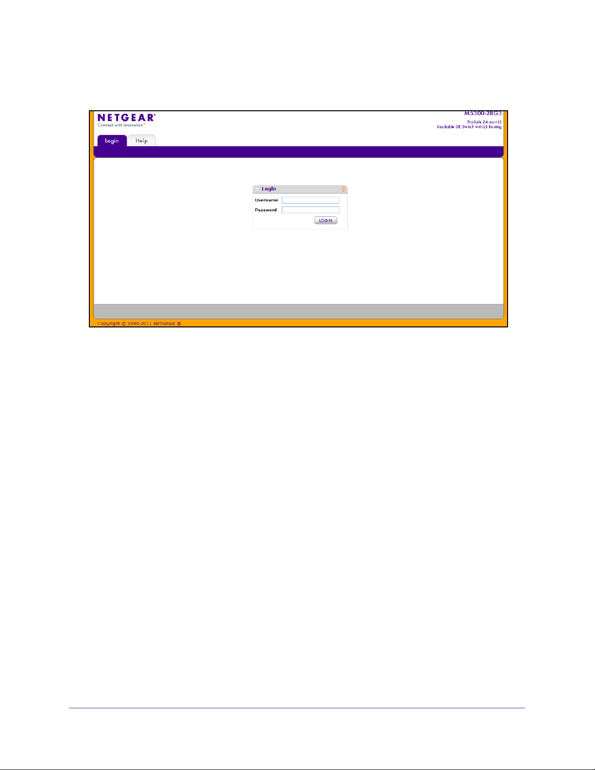
Accessing the switch directly from your Web browser displays the login screen shown below.
Understanding the User Interfaces
ProSafe M5300 software includes a set of comprehensive management functions for
configuring and monitoring the system by using one of the following methods:
• Web user interface
• Simple Network Management Protocol (SNMP)
• Command Line Interface (CLI)
Each of the standards-based management methods allows you to configure and monitor the
components of the ProSafe M5300 software. The method you use to manage the system
depends on your network size and requirements, and on your preference.
The Web Management User Guide Web Management User Guide describes how to use the
Web-based interface to manage and monitor the system.
Using the Web Interface
To access the switch by using a Web browser, the browser must meet the following software
requirements:
• HTML version 4.0, or later
• HTTP version 1.1, or later
• Java Runtime Environment 1.6 or later
Getting Started
10
Page 11
ProSafe M5300 Switch
Use the following procedures to log on to the Web interface:
1. Open a Web browser and enter the IP address of the switch in the Web browser
address field.
2. The default user name is admin, default password is none (no password). Type the user
name into the field on the login screen and then click Login. User names and passwords
are case sensitive.
3. After the system authenticates you, the System Information page displays.
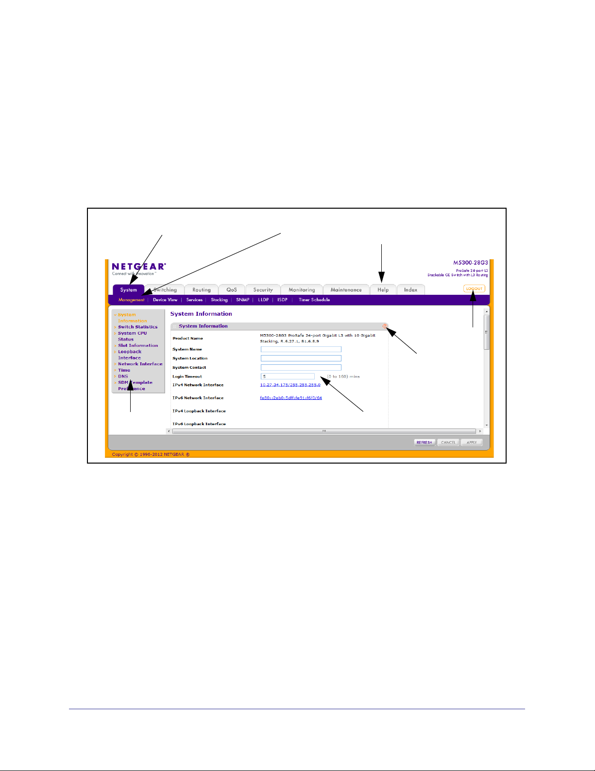
The figure below shows the layout of the Managed Switch Web interface.
Navigation Tab
Page Menu
Feature Link
Help Link
LOGOUT
Button
Help Page
Configuration Status and Options
Navigation Tabs, Feature Links, and Page Menu
The navigation tabs along the top of the Web interface give you quick access to the various
switch functions. The tabs are always available and remain constant, regardless of which
feature you configure.
When you select a tab, the features for that tab appear as links directly under the tabs. The
feature links in the blue bar change according to the navigation tab that is selected.
The configuration pages for each feature are available as links in the page menu on the left
side of the page. Some items in the menu expand to reveal multiple configuration pages, as
the following figure shows. When you click a menu item that includes multiple configuration
pages, the item becomes preceded by a down arrow symbol and expands to display the
additional pages.
Getting Started
11
Page 12
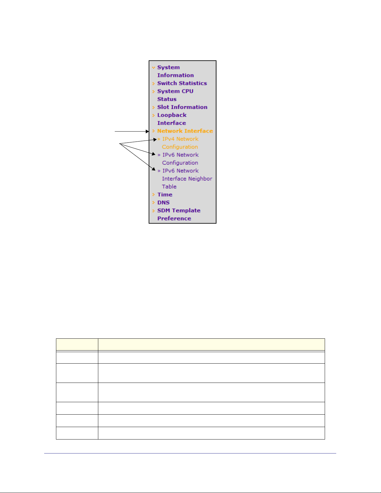
Page Link
Configuration
Pages
ProSafe M5300 Switch
Configuration and Monitoring Options
The area directly under the feature links and to the right of the page menu displays the
configuration information or status for the page you select. On pages that contain
configuration options, you can input information into fields or select options from drop-down
menus.
Each page contains access to the HTML-based help that explains the fields and configuration
options for the page. Each page also contains command buttons.
Table 1 shows the command buttons that are used throughout the pages in the Web
interface:
Table 1. Command Buttons
Button Function
ADD Clicking ADD adds the new item configured in the heading row of a table.
APPLY Clicking APPLY sends the updated configuration to the switch. Configuration changes take
effect immediately.
CANCEL Clicking CANCEL cancels the configuration on the screen and resets the data on the
screen to the latest value of the switch.
DELETE Clicking DELETE removes the selected item.
REFRESH Clicking REFRESH updates the page with the latest information from the device.
LOGOUT Clicking the LOGOUT button ends the session.
Getting Started
12
Page 13
ProSafe M5300 Switch
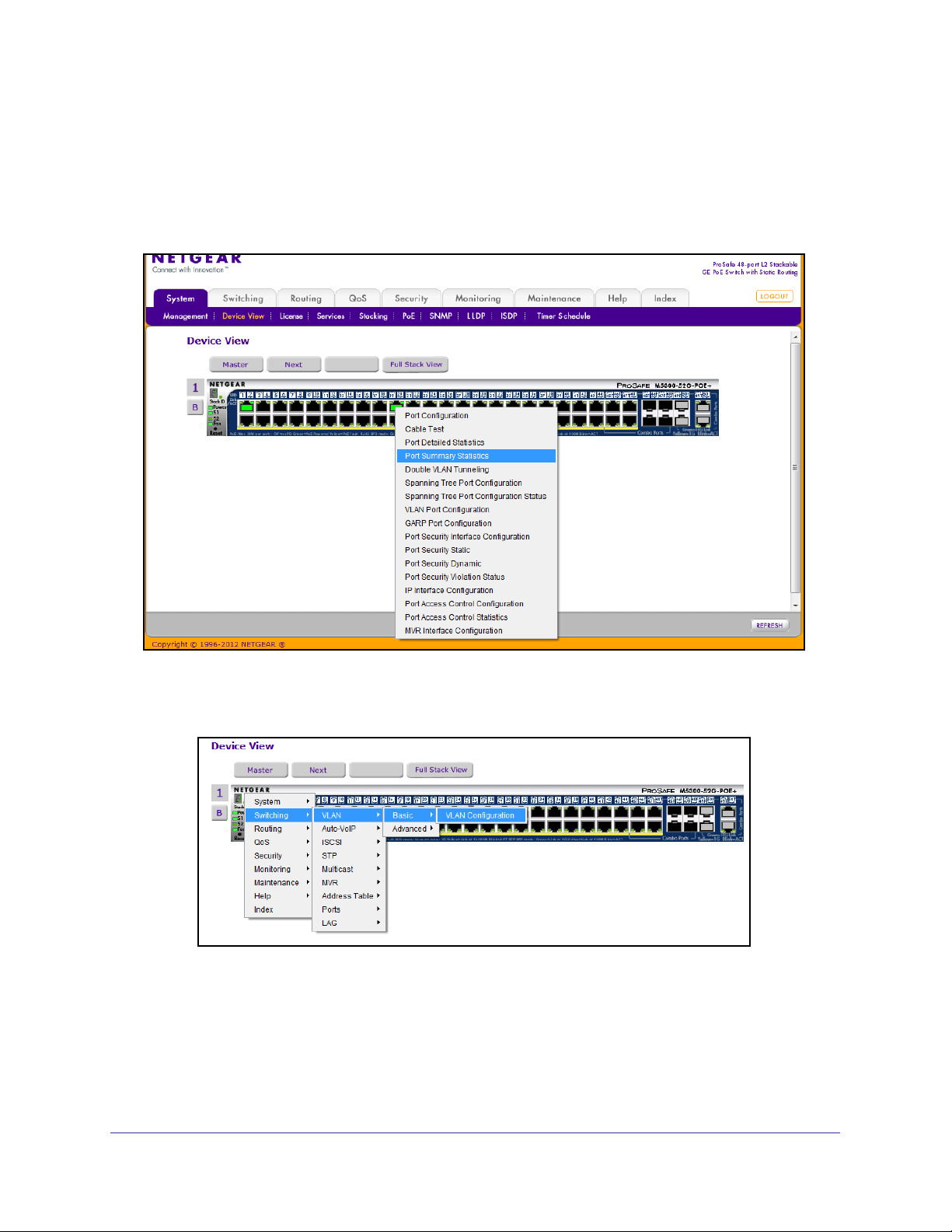
Device View
The Device View is a Java® applet that displays the ports on the switch. This graphic provides
an alternate way to navigate to configuration and monitoring options. The graphic also
provides information about device ports, current configuration and status, table information,
and feature components.
The Device View is available from the System
Device View page.
The port coloring indicates whether a port is currently active. Green indicates that the port is
enabled, red indicates that an error has occurred on the port or that the link is disabled, and
black indicates that the port is not active.
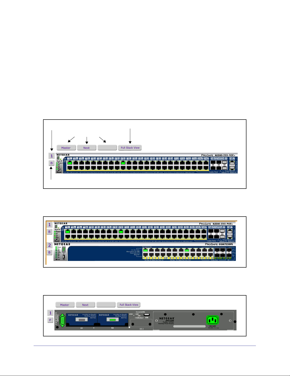
The following figure shows the front-panel Device View of the M5300-52G-POE+ switch.
Stack Unit ID
Stack Navigation
Front/Back View Toggle
Open Full Stack View
Use the stack navigation buttons to view the stack master or the next/previous members in
the stack. Click Full Stack View to see the device view for each stack member on a single
page. The following figure shows the full stack view for a stack with two members.
To view the back panel of the switch, click the front/back toggle button (B or F, depending on
the current view). The following figure shows the back-panel Device View of the
M5300-52G-POE+ switch.
Getting Started
13
Page 14

ProSafe M5300 Switch
Device View System LEDs
In addition to the port LEDs, the device view provides a representation of the system LEDs on
the left side of the front switch panel.
Power/Status LED
The power LED is a bicolor LED that serves as an indicator of power and diagnostic status.
The following indications are given by the following LED states:
• A solid green LED indicates that the power is supplied to the switch and operating
normally.
• A solid yellow LED indicates that system is in the boot-up stage.
• No lit LED indicates that power is disconnected.
FAN Status LED
FAN status is indicated as follows:
• A solid yellow LED indicates that the fan is faulty.
• No lit LED indicates that the fan is operating normally.
Stack Master LED
The Stack Master LED is lit if there is an active stack link and the unit is in stack mode.
• A solid green LED indicates that the switch acts as a master unit in a stack of switches.
• No lit LED indicates that the switch acts as a slave member in a stack of switches.
Module LEDs
Each switch includes two back-panel XAUI ports that support stacking or Ethernet modules.
For the M5300 Series-28G switches, the port numbers are 27 and 28. For M5300 Series-52G
switches, the port numbers are 51 and 52. If a back-panel module is present and active, the
LED is solid green.
Seven-Segment LED for the Stacking ID
A solid green LED displays the stack ID (1–6).
Getting Started
14
Page 15
ProSafe M5300 Switch
Device View Navigation
Click the port you want to view or configure to see a menu that displays statistics and
configuration options. Click the menu option to access the page that contains the
configuration or monitoring options.
If you click the graphic, but do not click a specific port, the main menu appears. This menu
contains the same option as the navigation tabs at the top of the page.
Getting Started
15
Page 16

ProSafe M5300 Switch
Help Page Access
Every page contains a link to the online help , which contains information to assist in
configuring and managing the switch. The online help pages are context sensitive. For
example, if the IP Addressing page is open, the help topic for that page displays if you click
Help.
User-Defined Fields
User-defined fields can contain 1 to 159 characters, unless otherwise noted on the
configuration Web page. All characters may be used except for the following (unless
specifically noted in for that feature):
\ <
/ >|
* |
?
Using SNMP
The ProSafe software supports the configuration of SNMP groups and users that can
manage traps that the SNMP agent generates.
ProSafe use both standard public MIBs for standard functionality and private MIBs that
support additional switch functionality. All private MIBs begin with a “-” prefix. The main object
for interface configuration is in -SWITCHING-MIB, which is a private MIB. Some interface
configurations also involve objects in the public MIB, IF-MIB.
SNMP is enabled by default. The System
Management System Information Web page,
which is the page that displays after a successful login, displays the information you need to
configure an SNMP manager to access the switch.
Any user can connect to the switch using the SNMPv3 protocol, but for authentication and
encryption, the switch supports only one user which is admin; therefore there is only one
profile that can be created or modified.
To configure authentication and encryption settings for the SNMPv3 admin profile by using
the Web interface:
1. Navigate to the System
SNMP SNMPv3 User Configuration page.
2. To enable authentication, select an Authentication Protocol option, which is either MD5 or
SHA.
3. To enable encryption, select the DES option in the Encryption Protocol field. Then, enter
an encryption code of eight or more alphanumeric characters in the Encryption Key field.
4. Click APPLY.
To access configuration information for SNMPv1 or SNMPv2, click System
SNMPv1/v2 and click the page that contains the information to configure.
Getting Started
16
SNMP
Page 17

ProSafe M5300 Switch
Interface Naming Convention
The ProSafe support physical and logical interfaces. Interfaces are identified by their type
and the interface number. The physical ports are gigabit interfaces and are numbered on the
front panel. You configure the logical interfaces by using the software. Table 2 describes the
naming convention for all interfaces available on the switch.
Table 2. Naming Conventions for Interfaces
Interface Description Example
Physical The physical ports are in
unit/slot/port format, where unit is
the stack ID of the switch, slot is the
slot ID (always 0 for physical ports),
and port is the port ID, which starts
at 1 and is identified on the front
panel of the switch.
Link Aggregation Group (LAG) LAG interfaces are logical
interfaces that are only used for
bridging functions.
CPU Management Interface This is the internal switch interface
responsible for the switch base
MAC address. This interface is not
configurable and is always listed in
the MAC Address Table.
Routing VLAN Interfaces This is an interface used for routing
functionality. The format can be
expressed in vlan id format or
unit/slot/interface format, where unit
is 0, slot is 4, and interface is the
logical VLAN interface ID.
1/0/1: Port 1 on stack member 1
2/0/23: Port 23 on stack member 2
ch1, ch2, ch3, and so on
5/1
0/4/1, 0/4/2, 0/4/3, and so on
or
vlan 1, vlan 2, vlan 3, and so on
Getting Started
17
Page 18

ProSafe M5300 Switch
Getting Started
18
Page 19

2. Configuring System Information
Use the features in the System tab to define the switch’s relationship to its environment. The
System tab contains links to the following features:
• Management on page 19
• Device View (See Device View on page 12)
• License on page 43
• Services on page 45
• Stacking on page 68
• PoE (M5300-28G-POE+ and M5300-52G-POE+ Only) on page 82
• SNMP on page 87
• LLDP on page 93
• ISDP on page 109
• Timer Schedule on page 114
2
Management
This section describes how to display the switch status and specify some basic switch
information, such as the management interface IP address, system clock settings, and DNS
information. From the Management link, you can access the following pages:
• System Information on page 20
• Switch Statistics on page 24
• System CPU Status on page 26
• Loopback Interface on page 29
• Network Interface on page 30
• Time on page 34
• DNS on page 40
• SDM Template Preference on page 42
19
Page 20
ProSafe M5300 Switch
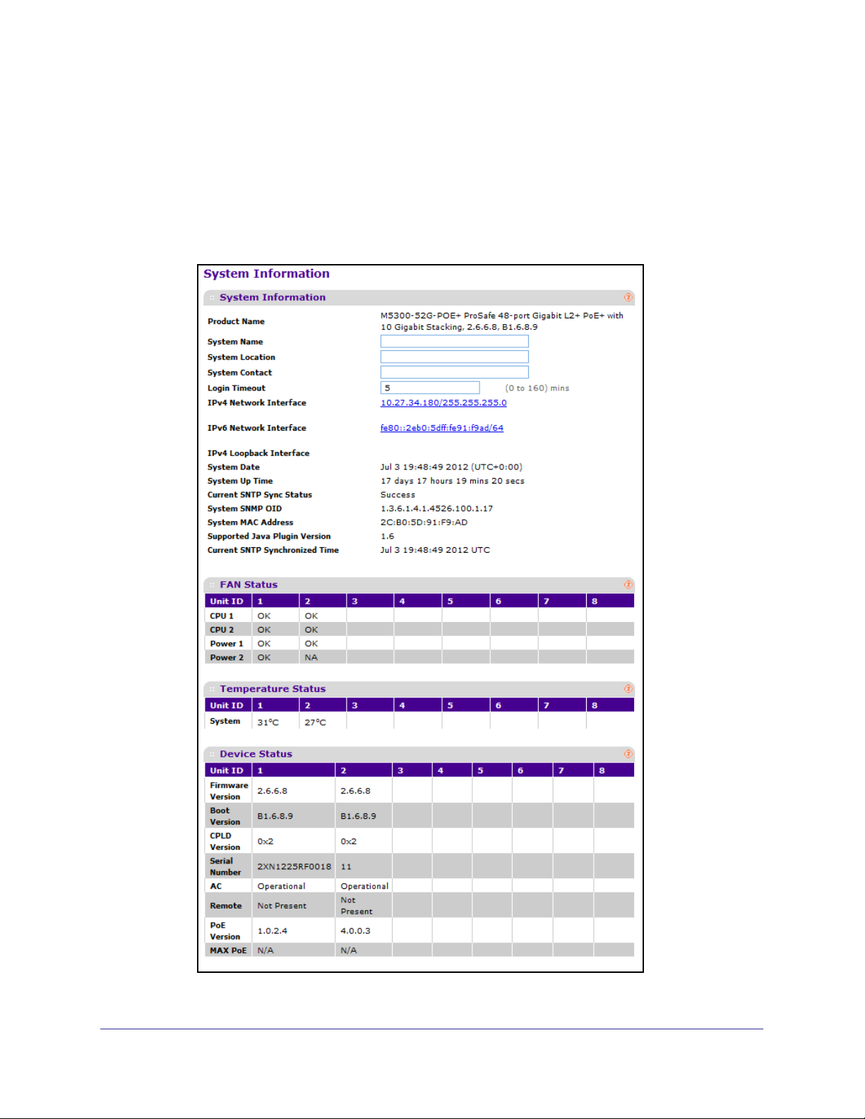
System Information
After a successful login, the System Information page displays. Use this page to configure
and view general device information.
To display the System Information page, click System Management System Information.
A screen similar to the following displays.
Configuring System Information
20
Page 21

ProSafe M5300 Switch
The System Information provides various statuses:
Switch Status
To define system information:
1. In the System Name field, enter the name you want to use to identify this switch. You
may use up to 255 alphanumeric characters. The factory default is blank.
2. In the System Location field, enter the location of this switch. You may use up to 255
alphanumeric characters. The factory default is blank.
3. In the System Contact field, enter the contact person for this switch. You may use up to 25
alphanumeric characters. The factory default is blank.
4. In the Login Timeout field, specify how many minutes of inactivity should occur on a serial
port connection before the switch closes the connection. Enter a number between 0 and
160: the factory default is 5. Entering 0 disables the timeout.
5. Click APPLY to send the updated screen to the switch and cause the changes to take effect
on the switch. These changes will not be retained across a power cycle unless a save is
performed.
The following table describes the status information the System Page displays.
Field Description
Product Name The product name of this switch.
IPv4 Network Interface The IPv4 address and mask assigned to the network interface.
IPv6 Network Interface The IPv6 prefix and prefix length assigned to the network interface.
IPv4 Loopback Interface The IPv4 address and mask assigned to the loopback interface.
IPv6 Loopback Interface The IPv6 prefix and prefix length assigned to the loopback interface.
System Date The current date and time. If the system has not synchronized with
an SNTP server, the system time and date is probably incorrect by
many years.
System Up Time The time in days, hours and minutes since the last switch reboot.
Current SNTP Sync Status Indicates whether the system time has synchronized with an SNTP
server (Success), or has not attempted or failed to synchronize with
an SNTP server (Other).
System SNMP OID The base object ID for the switch's enterprise MIB.
System Mac Address Universally assigned network address.
Supported Java Plugin Version The supported version of Java plugin.
Current SNTP Synchronized Time The current date and time, if the system time has been synchronized
with an SNTP server; otherwise, this field is Not Synchronized.
Configuring System Information
21
Page 22
ProSafe M5300 Switch
FAN Status
The screen shows the status of the fans in all units. These fans remove the heat generated
by the power, CPU, and other chipsets, allowing the chipsets to work normally. Fan status
has three possible values: OK, Failure, Not Applicable (NA).
The following table describes the Fan Status information.
Field Description
Unit ID The stack member unit identifier assigned to the
switch which the fan belongs to.
CPU 1/CPU2 The working status of each CPU fan.
Power 1/Power 2 The working status of the power supply fan(s). If the
status is N/A, the power supply might not be installed
or active, or the switch model might support a single
power supply.
Click REFRESH to refresh the system information of the switch.
Temperature Status
The screen shows the current operating temperature of the switch. The temperature is instant
and can be refreshed when the REFRESH button is pressed. The maximum temperature of
the switch depends on the actual hardware.
The following table describes the Temperature Status information.
Field Description
Unit ID The stack member unit identifier assigned to the
switch which the fan belongs to.
System The current temperature of the switch.
Click REFRESH to refresh the system information of the switch.
Configuring System Information
22
Page 23

ProSafe M5300 Switch
Device Status
The screen shows the various inventory information for each device.
The following table describes the Device Status information.
Field Description
Firmware Version The release.version.maintenance.build number of the code currently running
on the switch. For example, if the release was 8, the version was 0, the
maintenance number was 3, and the build number was 11, the format would
be 8.0.3.11.
Boot Version The version of the boot code which is in the flash memory to load the
firmware into the memory.
CPLD Version The version of the software for the Complex Programmable Logic Device
(CPLD).
Serial Number The serial number of this switch.
AC The status of the internal AC power module.
Remote Indicates the status of the Remote Power Supply (RPS). The status has three
possible values:
• Not Present: RPS bank not connected
• OK: RPS bank connected.
• FAIL: RPS is present, but power is failed.
PoE Version Version of the PoE controller firmware image.
MAX PoE Indicates the status of maximum PoE power available on the switch as
follows:
• ON: Indicates less than 7W of PoE power available for another device.
• OFF: Indicates at least 7W of PoE power available for another device.
• N/A: Indicates that PoE is not supported by the unit.
Click REFRESH to refresh the system information of the switch.
Configuring System Information
23
Page 24
ProSafe M5300 Switch
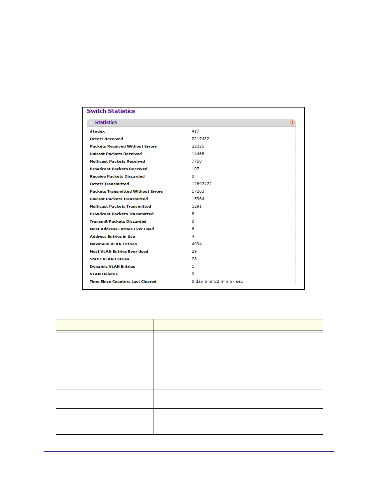
Switch Statistics
Use this page to display the switch statistics.
To display the Switch Statistics page, click System > Management > Switch Statistics. A
screen similar to the following displays.
The following table describes Switch Statistics information.
Field Description
ifIndex This object indicates the ifIndex of the interface table entry
associated with the Processor of this switch.
Octets Received The total number of octets of data received by the processor
(excluding framing bits but including FCS octets).
Packets Received Without Errors The total number of packets (including broadcast packets and
multicast packets) received by the processor.
Unicast Packets Received The number of subnetwork-unicast packets delivered to a
higher-layer protocol.
Multicast Packets Received The total number of packets received that were directed to a
multicast address. Note that this number does not include packets
directed to the broadcast address.
Configuring System Information
24
Page 25

ProSafe M5300 Switch
Field Description
Broadcast Packets Received The total number of packets received that were directed to the
broadcast address. Note that this does not include multicast
packets.
Receive Packets Discarded The number of inbound packets which were chosen to be discarded
even though no errors had been detected to prevent their being
deliverable to a higher-layer protocol. A possible reason for
discarding a packet could be to free up buffer space.
Octets Transmitted The total number of octets transmitted out of the interface, including
framing characters.
Packets Transmitted Without Errors The total number of packets transmitted out of the interface.
Unicast Packets Transmitted The total number of packets that higher-level protocols requested
be transmitted to a subnetwork-unicast address, including those
that were discarded or not sent.
Multicast Packets Transmitted The total number of packets that higher-level protocols requested
be transmitted to a Multicast address, including those that were
discarded or not sent.
Broadcast Packets Transmitted The total number of packets that higher-level protocols requested
be transmitted to the Broadcast address, including those that were
discarded or not sent.
Transmit Packets Discarded The number of outbound packets which were chosen to be
discarded even though no errors had been detected to prevent their
being deliverable to a higher-layer protocol. A possible reason for
discarding a packet could be to free up buffer space.
Most Address Entries Ever Used The highest number of Forwarding Database Address Table entries
that have been learned by this switch since the most recent reboot.
Address Entries in Use The number of Learned and static entries in the Forwarding
Database Address Table for this switch.
Maximum VLAN Entries The maximum number of Virtual LANs (VLANs) allowed on this
switch.
Most VLAN Entries Ever Used The largest number of VLANs that have been active on this switch
since the last reboot.
Static VLAN Entries The number of presently active VLAN entries on this switch that
have been created statically.
Dynamic VLAN Entries The number of presently active VLAN entries on this switch that
have been created by GVRP registration.
VLAN Deletes The number of VLANs on this switch that have been created and
then deleted since the last reboot.
Time Since Counters Last Cleared The elapsed time, in days, hours, minutes, and seconds, since the
statistics for this switch were last cleared.
Click CLEAR to clear all the counters, resetting all switch summary and detailed statistics to
default values. The discarded packets count cannot be cleared.
Configuring System Information
25
Page 26
ProSafe M5300 Switch
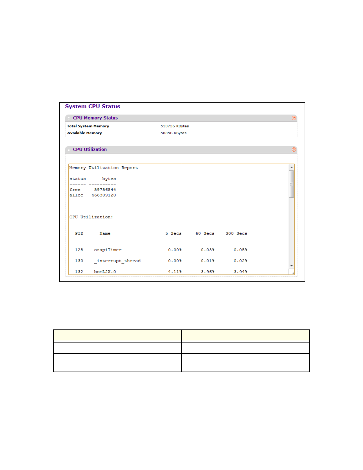
System CPU Status
Use this page to display system CPU status and utilization information.
To display the System Resource page, click System > Management > System CPU Status. A
screen similar to the following displays.
System CPU Status
The following table describes CPU Memory Status information.
Field Description
Total System Memory The total memory of the switch in KBytes.
Available Memory The available memory space for the switch in
KBytes.
CPU Utilization Information
This area displays the CPU Utilization information. It displays the amount of available and
allocated memory and lists each system process (task) that is running, along with its CPU
utilization over the last 5, 60, and 300 seconds.
Configuring System Information
26
Page 27
ProSafe M5300 Switch
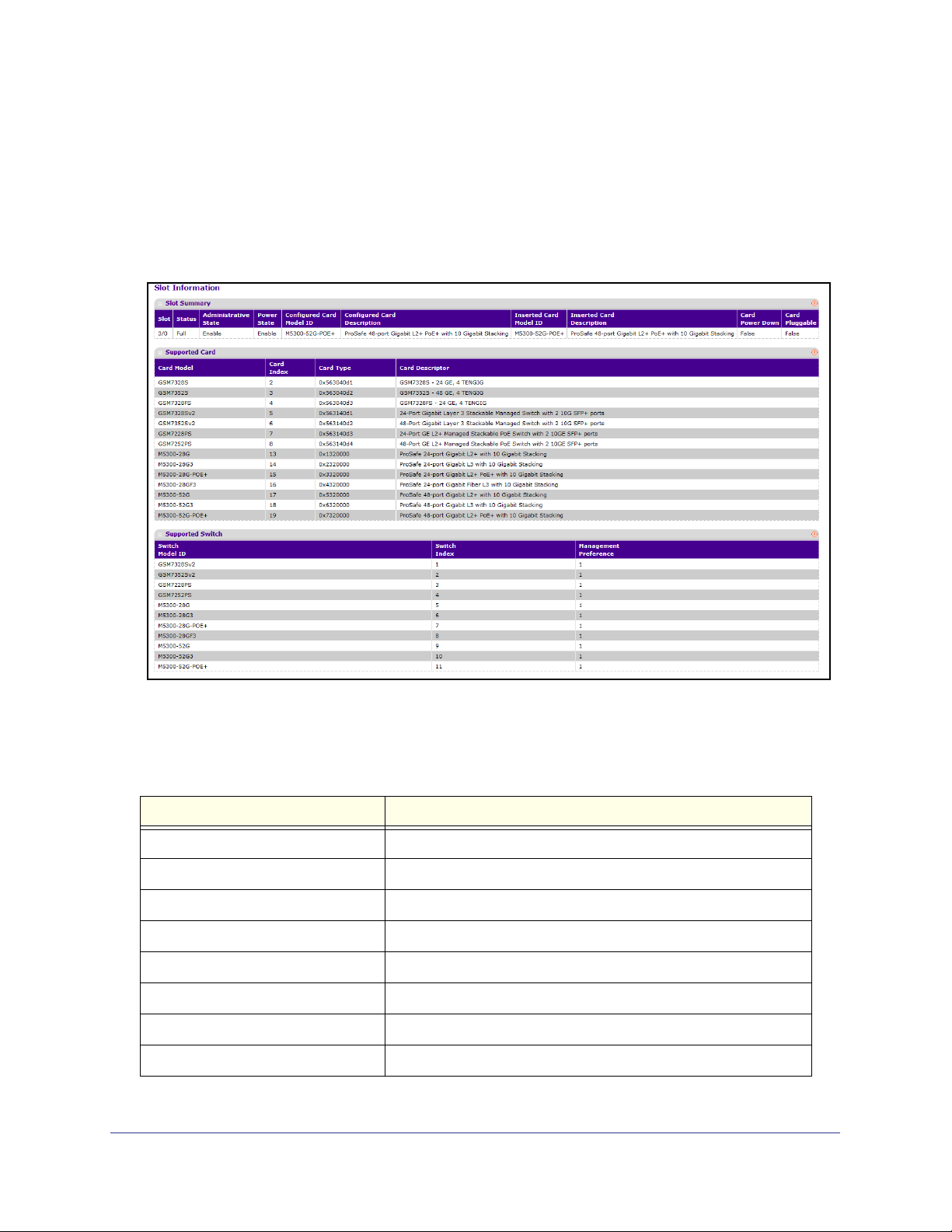
Slot Information
Use this page to view information about the cards installed in the switch’s slots. This page
also provides information about the cards and switches that are compatible with the device.
To display the Switch Statistics page, click System > Management > Slot Information. A
screen similar to the following displays.
Slot Summary
The following table describes information in the Slot Summary table.
Field Description
Slot The slot number.
Status Indicates whether the slot is empty or full.
Administrative State Indicates whether the slot is administratively enabled or disabled.
Power State Indicates whether the device is providing power to the slot.
Configured Card Model ID The model ID of the card configured for the slot.
Configured Card Description The description of the card configured for the slot
Inserted Card Model ID The model ID of the card plugged into the slot.
Inserted Card Description The description of the card plugged into the slot.
Configuring System Information
27
Page 28
ProSafe M5300 Switch
Field Description
Card Power Down If the value is True, the Power State can be administratively enabled
or disabled. If the value is False, the Power State cannot be
configured.
Card Pluggable If the value is True, the card can be administratively enabled or
disabled. If the value is False, the Administrative State cannot be
configured.
Supported Card
The following table describes information in the Supported Card table.
Field Description
Card Model The model ID of the supported card.
Card Index The index assigned to the card type.
Card Type The hardware type of the supported card, which is assigned by the
manufacturer.
Card Descriptor Description of the supported card, which includes the
manufacturer's product number and information about number and
speed of the supported interfaces.
Supported Switch
The following table describes information in the Supported Switch table. When preconfiguring
a new stack member, the Switch Index identifies the type of switch that is being added to the
stack.
Field Description
Switch Model ID The model number of the supported switch.
Switch Index The index assigned to the supported switch.
Configuring System Information
28
Page 29
ProSafe M5300 Switch
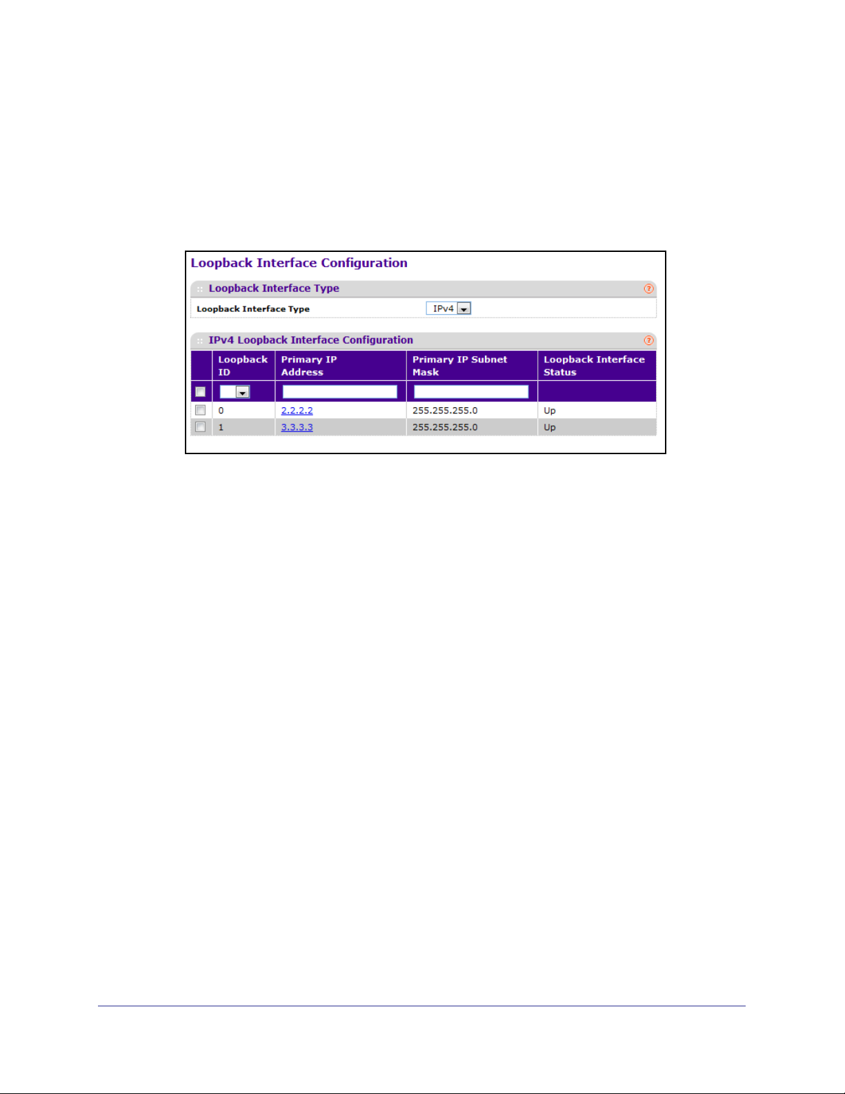
Loopback Interface
Use this page to create, configure, and remove Loopback interfaces. A loopback interface is
a logical interface that is considered to be always up.
To display the Loopback Interface page, click System > Management > Loopback Interface.
A screen similar to the following displays.
To configure a loopback interface:
1. In the Loopback Interface Type field select whether the interface is an IPv4 or IPv6
loopback interface. The configuration fields vary based on the interface type.
2. For an IPv4 loopback interface, configure the following:
a. In the Loopback ID field select the loopback ID number
b. In the Primary Address field, input the primary IPv4 address for this interface in
dotted decimal notation.
c. In the Primary Mask field, input the primary IPv4 subnet mask for this interface in
dotted decimal notation.
d. View the logical status of the interface in the Loopback Interface Status field. A
loopback interface is always up.
3. For an IPv6 loopback interface, configure the following:
a. In the Loopback ID field select the loopback ID number.
b. Use the IPv6 Mode field to enable IPv6 on this interface using the IPv6 address.
This option is only configurable prior to specifying an explicit IPv6 address.
c. Use the IPv6 Address field to enter the IPv6 address in the format prefix/length.
d. Use the EUI64 field to optionally specify the 64-bit extended unique identifier
(EUI-64).
4. Click ADD to add the configured IPv4 or IPv6 loopback interface.
5. To remove the loopback interface configuration, select the box associated with the interface
to remove, and click DELETE.
6. To modify information about a configured interface, select the box associated with the
interface to modify, update the configuration information in the appropriate fields, and click
APPLY.
Configuring System Information
29
Page 30
ProSafe M5300 Switch
Network Interface
From the Network Interface link, you can access the following pages:
• IPv4 Network Configuration on page 30
• IPv6 Network Interface Configuration on page 32
• IPv6 Network Interface Neighbor Table on page 33
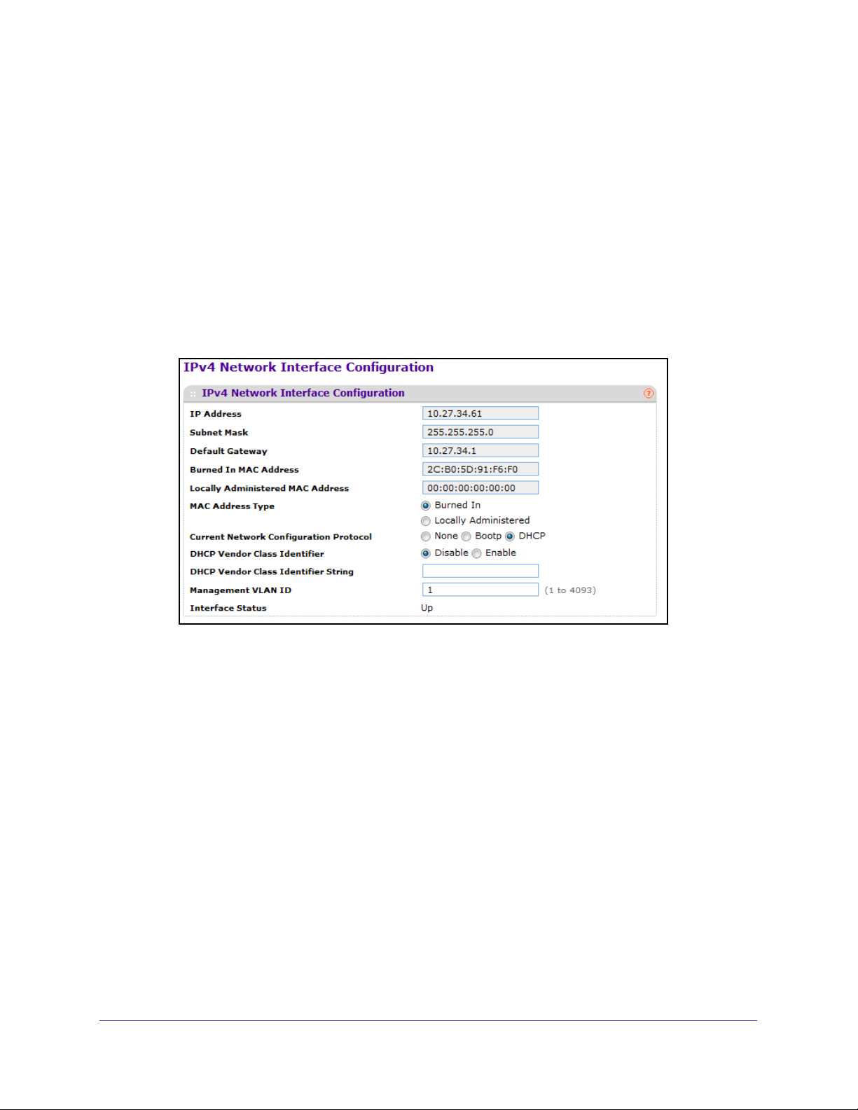
IPv4 Network Configuration
To display the IPv4 Network Configuration page, click System > Management > Network
Interface > IPv4 Network Configuration. A screen similar to the following displays.
The network interface is the logical interface used for in-band connectivity with the switch via
any of the switch's front panel ports. The configuration parameters associated with the
switch's network interface do not affect the configuration of the front panel ports through
which traffic is switched or routed
To access the switch over a network you must first configure it with IP information (IP
address, subnet mask, and default gateway). You can configure the IP information using any
of the following:
• BOOTP
• DHCP
• Terminal interface via the EIA-232 port
Configuring System Information
30
Page 31

ProSafe M5300 Switch
Once you have established in-band connectivity, you can change the IP information using
any of the following:
• Terminal interface via the EIA-232 port
• Terminal interface via telnet
• SNMP-based management
• Web-based management
To configure an IPv4 network interface:
1. Use Current Network Configuration Protocol to specify how the device acquires network
information on the network interface:
• None – The switch does not attempt to acquire network information dynamically.
Select this option to configure a static IP address, subnet mask, and default gateway.
• BOOTP – During the next boot cycle, the BOOTP client on the switch broadcasts a
BOOTP request in an attempt to acquire information from a BOOTP server on the
network.
• DHCP – During the next boot cycle, the DHCP client on the switch broadcasts a
DHCP request in an attempt to acquire information from a DHCP server on the
network. After this option is applied, you can use the Refresh icon at the end of the
row to renew the IPv4 address learned from DHCP server.
2. If the network configuration protocol is None, use the IP Address field to specify the IP
address of the interface. The factory default value is 169.254.100.100. For DHCP or BootP
configuration protocols, this field shows the IP address the network interface has leased
from the DHCP or BootP server.
3. If the network configuration protocol is None, use the Subnet Mask field to enter the IP
subnet mask for the interface. The factory default value is 255.255.0.0. For DHCP or BootP
configuration protocols, this field shows the subnet mask assigned to the network interface
has by the DHCP or BootP server.
4. If the network configuration protocol is None, use Default Gateway to specify the default
gateway for the IP interface. The factory default value is 0.0.0.0. For DHCP or BootP
configuration protocols, this field shows the default gateway assigned to the network
interface has by the DHCP or BootP server.
5. Use MAC Address type to specify whether the burned in or the locally administered MAC
address should be used for in-band connectivity.
If the MAC address type is burned in, the Burned In MAC Address field shows the
hardware address assigned to the device by the manufacturer..
6. If the MAC address type is Locally Administered, use Locally Administered MAC Address
to configure a locally administered MAC address for in-band connectivity instead of using
the burned-in universally administered MAC address. Enter the address as twelve
hexadecimal digits (6 bytes) with a colon between each byte. Bit 1 of byte 0 must be set to
a 1 and bit 0 to a 0, in other words, byte 0 must have a value between x'40' and x'7F'.
7. Use DHCP Vendor Class Identifier to specify whether to set a value for DHCP option 60 in
the DHCP requests that the DHCP client on the switch broadcasts to network DHCP
servers. Option 60, the Vendor Class Identifier (VCI), can help identify the device to the
DHCP server, which allows the server to include additional information in the DHCP
response.
Configuring System Information
31
Page 32

ProSafe M5300 Switch
8. Use DHCP Vendor Class Identifier String to specify the text string to add to DHCP
requests as option 60, the VCI option.
9. Use Management VLAN ID to specify the management VLAN ID of the switch. It may be
configured to any value in the range of 1 - 4093. Some network administrators use a
management VLAN to isolate system management traffic from end-user data traffic.
10. Click APPLY to update the network interface with the specified values.
11. Click CANCEL to abandon the changes.
IPv6 Network Interface Configuration
To display the IPv6 Network Configuration page, click System > Management > Network
Interface > IPv6 Network Interface Configuration. A screen similar to the following displays.
The IPv6 network interface is the logical interface used for in-band connectivity with the
switch via any of the switch's front panel ports. The configuration parameters associated with
the switch's network interface do not affect the configuration of the front panel ports through
which traffic is switched or routed.
To access the switch over an IPv6 network you must first configure it with IPv6 information
(IPv6 prefix, prefix length, and default gateway). You can configure the IP information using
any of the following:
• IPv6 Auto Configuration
• DHCPv6
• Terminal interface via the EIA-232 port
Once you have established in-band connectivity, you can change the IPv6 information using
any of the following:
• Terminal interface via the EIA-232 port
• Terminal interface via telnet
• SNMP-based management
• Web-based management
Configuring System Information
32
Page 33

ProSafe M5300 Switch
To configure an IPv6 network interface:
1. Use Admin Mode to enable or disable the IPv6 network interface on the switch. The
default value is enable.
2. Use IPv6 Address Auto Configuration Mode to set the IPv6 address for the IPv6 network
interface in auto configuration mode if this option is enabled. The default value is disable.
Auto configuration can be enabled only when IPv6 Auto config or DHCPv6 are not enabled
on any of the management interfaces.
3. Use Current Network Configuration Protocol to configure the IPv6 address for the IPv6
network interface by DHCPv6 protocol if this option is enabled. The default value is None.
DHCPv6 can be enabled only when IPv6 Auto config or DHCPv6 are not enabled on any of
the management interfaces.
4. Use DHCPv6 Client DUID to specify an Identifier used to identify the client's unique DUID
value. This option only displays when DHCPv6 is enabled.
5. Use IPv6 Gateway to specify the gateway for the IPv6 network interface. The gateway
address is in IPv6 global or link-local address format.
6. Use IPv6 Prefix/Prefix Length to add the IPv6 prefix and prefix length to the IPv6 network
interface. The address is in global address format.
7. Use EUI64 to specify whether to format the IPv6 address in EUI-64 format. Default value is
false.
8. Click ADD to add a new IPv6 address in global format.
9. Click DELETE to delete a selected IPv6 address.
IPv6 Network Interface Neighbor Table
Use this page to view information about IPv6 neighbors the device has discovered through
the network interface by using the Neighbor Discovery Protocol (NDP).
To display the IPv6 Network Neighbor page, click System > Management > Network
Interface > IPv6 Network Interface Neighbor Table. A screen similar to the following
displays.
The following table displays IPv6 Network Interface Neighbor Table information.
Field Description
IPv6 address The Ipv6 Address of a neighbor switch visible to the
network interface.
MAC address The MAC address of a neighbor switch.
Configuring System Information
33
Page 34

ProSafe M5300 Switch
Field Description
IsRtr True(1) if the neighbor machine is a router, false(2)
otherwise.
Neighbor State The state of the neighboring switch:
• reachable(1) - The neighbor is reachable by this
switch.
• stale(2) - Information about the neighbor is
scheduled for deletion.
• delay(3) - No information has been received from
neighbor during delay period.
• probe(4) - Switch is attempting to probe for this
neighbor.
• unknown(6) - Unknown status.
Last Updated The last sysUpTime that this neighbor has been
updated.
Time
ProSafe software supports the Simple Network Time Protocol (SNTP).
SNTP assures accurate network device clock time synchronization up to the millisecond.
Time synchronization is performed by a network SNTP server. ProSafe software operates
only as an SNTP client and cannot provide time services to other systems.
Time sources are established by Stratums. Stratums define the accuracy of the reference
clock. The higher the stratum (where zero is the highest), the more accurate the clock. The
device receives time from stratum 1 and above since it is itself a stratum 2 device.
The following is an example of stratums:
• Stratum 0: A real-time clock is used as the time source, for example, a GPS system.
• Stratum 1: A server that is directly linked to a Stratum 0 time source is used. Stratum 1
time servers provide primary network time standards.
• Stratum 2: The time source is distanced from the Stratum 1 server over a network path.
For example, a Stratum 2 server receives the time over a network link, via NTP, from a
Stratum 1 server.
Information received from SNTP servers is evaluated based on the time level and server
type.
SNTP time definitions are assessed and determined by the following time levels:
• T1: Time at which the original request was sent by the client.
• T2: Time at which the original request was received by the server.
• T3: Time at which the server sent a reply.
• T4: Time at which the client received the server's reply.
Configuring System Information
34
Page 35

ProSafe M5300 Switch
The device can poll Unicast server types for the server time.
Polling for Unicast information is used for polling a server for which the IP address is known.
SNTP servers that have been configured on the device are the only ones that are polled for
synchronization information. T1 through T4 are used to determine server time. This is the
preferred method for synchronizing device time because it is the most secure method. If this
method is selected, SNTP information is accepted only from SNTP servers defined on the
device using the SNTP Server Configuration page.
The device retrieves synchronization information, either by actively requesting information or
at every poll interval.
SNTP Global Configuration
Use the SNTP Global Configuration page to enable the SNTP client on the device and to
configure the SNTP client settings. Enabling and configuring the SNTP client allows the
device to synchronization the system time with a valid SNTP server on the network.
To display the SNTP Global Configuration page, click System
Global Configuration.
Management > Time SNTP
Configuring System Information
35
Page 36

ProSafe M5300 Switch
SNTP Global Configuration
SNTP stands for Simple Network Time Protocol. As its name suggests, it is a less
complicated version of Network Time Protocol, which is a system for synchronizing the clocks
of networked computer systems, primarily when data transfer is handled via the Internet.
1. Use Client Mode to specify the mode of operation of SNTP Client. An SNTP client may
operate in one of the following modes.
• Disable - SNTP is not operational. No SNTP requests are sent from the client nor are
any received SNTP messages processed.
• Unicast - SNTP operates in a point to point fashion. A unicast client sends a request
to a designated server at its unicast address and expects a reply from which it can
determine the time and, optionally the round-trip delay and local clock offset relative
to the server.
• Broadcast - SNTP operates in the same manner as multicast mode but uses a local
broadcast address instead of a multicast address. The broadcast address has a
single subnet scope while a multicast address has Internet wide scope.
Default value is Disable.
2. Use Port to specify the local UDP port to listen for responses/broadcasts. Allowed range is
1 to 65535. Default value is 123.
3. Use Unicast Poll Interval to specify the number of seconds between unicast poll requests
expressed as a power of two when configured in unicast mode. Allowed range is (6 to 10).
Default value is 6.
4. Use Broadcast Poll Interval to specify the number of seconds between broadcast poll
requests expressed as a power of two when configured in broadcast mode. Broadcasts
received prior to the expiry of this interval are discarded. Allowed range is (6 to 10). Default
value is 6.
5. Use Unicast Poll Timeout to specify the number of seconds to wait for an SNTP response
when configured in unicast mode. Allowed range is (1 to 30). Default value is 5.
6. Use Unicast Poll Retry to specify the number of times to retry a request to an SNTP server
after the first time-out before attempting to use the next configured server when configured in
unicast mode. Allowed range is (0 to 10). Default value is 1.
7. When using SNTP/NTP time servers to update the switch's clock, the time data received
from the server is based on Coordinated Universal Time (UTC) which is the same as
Greenwich Mean Time (GMT). This may not be the time zone in which the switch is located.
Use Time Zone Name to configure a timezone specifying the number of hours and
optionally the number of minutes difference from UTC with Offset Hours and Offset
Minutes. The time zone can affect the display of the current system time. The default
value is UTC.
8. Use Offset Hours to specify the number of hours difference from UTC. See Time Zone
Name (
Step 7 previous) for more information. Allowed range is (-24 to 24).The default value
is 0.
9. Use Offset Minutes to specify the number of Minutes difference from UTC. See Time Zone
Name (
Step 7 previous) for more information. Allowed range is 0 to 59. The default value is
0.
Configuring System Information
36
Page 37

ProSafe M5300 Switch
SNTP Global Status
The following table displays SNTP Global Status information.
Field Description
Version Specifies the SNTP Version the client supports.
Supported Mode Specifies the SNTP modes the client supports. Multiple modes may be
supported by a client.
Last Update Time Specifies the local date and time (UTC) the SNTP client last updated the
system clock.
Last Attempt Time Specifies the local date and time (UTC) of the last SNTP request or receipt
of an unsolicited message.
Last Attempt Status Specifies the status of the last SNTP request or unsolicited message for
both unicast and broadcast modes. If no message has been received from
a server, a status of Other is displayed. These values are appropriate for all
operational modes.
• Other - None of the following enumeration values.
• Success - The SNTP operation was successful and the system time
was updated.
• Request Timed Out - A directed SNTP request timed out without
receiving a response from the SNTP server.
• Bad Date Encoded - The time provided by the SNTP server is not
valid.
• Version Not Supported - The SNTP version supported by the server is
not compatible with the version supported by the client.
• Server Unsynchronized - The SNTP server is not synchronized with its
peers. This is indicated via the 'leap indicator' field on the SNTP
message.
• Server Kiss Of Death - The SNTP server indicated that no further
queries were to be sent to this server. This is indicated by a stratum
field equal to 0 in a message received from a server.
Server IP Address Specifies the IP address of the server for the last received valid packet. If
no message has been received from any server, an empty string is shown.
Address Type Specifies the address type of the SNTP Server address for the last
received valid packet.
Server Stratum Specifies the claimed stratum of the server for the last received valid
packet.
Reference Clock Id Specifies the reference clock identifier of the server for the last received
valid packet.
Server Mode Specifies the mode of the server for the last received valid packet.
Unicast Server Max Entries Specifies the maximum number of unicast server entries that can be
configured on this client.
Configuring System Information
37
Page 38

ProSafe M5300 Switch
Field Description
Unicast Server Current Entries Specifies the number of current valid unicast server entries configured for
this client.
Broadcast Count
Specifies the number of unsolicited broadcast SNTP messages that have
been received and processed by the SNTP client since last reboot.
SNTP Server Configuration
Use the SNTP Server Configuration page to view and modify information for adding and
modifying Simple Network Time Protocol SNTP servers.
To display the SNTP Server Configuration page, click System Management Time SNTP
Server Configuration.
To configure a new SNTP Server:
1. Enter the appropriate SNTP server information in the available fields:
• Server Type - Specifies whether the address for the SNTP server is an IP address
(IPv4) or hostname (DNS).
• Address - Specify the address or host name of an SNTP server the device can use to
synchronize the system time. If this address is a DNS hostname, then that hostname
should be resolved into an IP address each time a SNTP request is sent to it.
• Port - Enter a port number on the SNTP server to which SNTP requests are sent. The
valid range is 1–65535. The default is 123.
• Priority - Specify the priority of this server entry in determining the sequence of
servers to which SNTP requests will be sent. The client continues sending requests to
different servers until a successful response is received or all servers are exhausted.
This object indicates the order in which to query the servers. A server entry with a
precedence of 1 will be queried before a server with a priority of 2, and so forth. If
more than one server has the same priority then the requesting order will follow the
lexicographical ordering of the entries in this table. Allowed range is (1 to 3). Default
value is 1.
• Version - Enter the NTP version running on the server. (Range: 1–4, default: 4).
Configuring System Information
38
Page 39

ProSafe M5300 Switch
2. Click ADD.
3. Repeat the previous steps to add additional SNTP servers. You can configure up to three
SNTP servers.
4. To removing an SNTP server, select the check box next to the configured server to remove,
and then click DELETE. The entry is removed, and the device is updated.
5. To change the settings for an existing SNTP server, select the check box next to the
configured server and enter new values in the available fields, and then click APPLY.
Configuration changes take effect immediately.
6. Click CANCEL to cancel the configuration on the screen and reset the data on the screen to
the latest value of the switch.
7. Click REFRESH to refresh the page with the most current data from the switch.
SNTP Server Status
The SNTP Server Status table displays status information about the SNTP servers
configured on your switch. The following table describes the SNTP Global Status fields.
The following table displays SNTP Server Status information.
Field Description
Address Specifies all the existing Server Addresses. If no Server configuration exists, a
message saying “No SNTP server exists” flashes on the screen.
Last Update Time Specifies the local date and time (UTC) that the response from this server was used
to update the system clock.
Last Attempt Time Specifies the local date and time (UTC) that this SNTP server was last queried.
Last Attempt Status Specifies the status of the last SNTP request to this server. If no packet has been
received from this server, a status of Other is displayed.
• Other - None of the following enumeration values.
• Success - The SNTP operation was successful and the system time was
updated.
• Request Timed Out - A directed SNTP request timed out without receiving a
response from the SNTP server.
• Bad Date Encoded - The time provided by the SNTP server is not valid.
• Version Not Supported - The SNTP version supported by the server is not
compatible with the version supported by the client.
• Server Unsynchronized - The SNTP server is not synchronized with its peers.
This is indicated via the 'leap indicator' field on the SNTP message.
• Server Kiss Of Death - The SNTP server indicated that no further queries were
to be sent to this server. This is indicated by a stratum field equal to 0 in a
message received from a server.
Requests Specifies the number of SNTP requests made to this server since last agent reboot.
Failed Requests Specifies the number of failed SNTP requests made to this server since last reboot.
Configuring System Information
39
Page 40

ProSafe M5300 Switch
DNS
You can use these pages to configure information about DNS servers the network uses and
how the switch operates as a DNS client.
DNS Configuration
Use this page to configure global DNS settings and DNS server information.
To access this page, click System
To configure the global DNS settings:
1. Specify whether to enable or disable the administrative status of the DNS Client.
• Enable - Allow the switch to send DNS queries to a DNS server to resolve a DNS
domain name. Default value is Enable.
• Disable - Prevent the switch from sending DNS queries.
Management DNS DNS Configuration.
2. Enter the DNS default domain name to include in DNS queries. When the system is
performing a lookup on an unqualified hostname, this field is provided as the domain name
(for example, if default domain name is netgear.com and the user enters test, then test is
changed to test.netgear.com to resolve the name). The length of the name should not be
longer than 255 characters.
3. Use Retry Number to specify the number of times to retry sending DNS queries to DNS
server. This number ranges from 0 to 100. The default value is 2.
4. Use Response Timeout (secs) to specify the amount of time, in seconds, to wait for a
response to a DNS query. This timeout ranges from 0 to 3600. The default value is 3.
5. To specify the DNS server to which the switch sends DNS queries, enter an IP address in
standard IPv4 dot notation in the DNS Server field and click ADD. The server appears in
the list below. You can specify up to eight DNS servers. The precedence is set in the order
created.
6. To remove a DNS server from the list, select the check box next to the server you want to
remove and click DELETE. If no DNS server is specified, the check box is global and will
delete all the DNS servers listed.
Configuring System Information
40
Page 41

ProSafe M5300 Switch
7. Click CANCEL to cancel the configuration on the screen and reset the data on the screen to
the latest value of the switch.
8. Click APPLY to send the updated configuration to the switch. Configuration changes take
effect immediately.
DNS Server Configuration
The following table displays DNS Server Configuration information.
Field Description
Serial No The sequence number of the DNS server.
Preference Shows the preference of the DNS Server. The
preference is determined by the order they were
entered.
Host Configuration
Use this page to manually map host names to IP addresses or to view dynamic DNS
mappings.
To access this page, click System Management DNS Host Configuration.
To add a static entry to the local DNS table:
1. Specify the static host name to add. Its length can not exceed 255 characters and it is a
mandatory field for the user.
2. Specify the IP address in standard IPv4 dot notation to associate with the hostname.
3. Click ADD. The entry appears in the list below.
4. To remove an entry from the static DNS table, select the check box next to the entry and
click DELETE.
5. To change the hostname or IP address in an entry, select the check box next to the entry
and enter the new information in the appropriate field, and then click APPLY.
6. Click CANCEL to cancel the configuration on the screen and reset the data on the screen to
the latest value of the switch.
Configuring System Information
41
Page 42

ProSafe M5300 Switch
The Dynamic Host Mapping table shows host name-to-IP address entries that the switch has
learned. The following table describes the dynamic host fields.
Field Description
Host Lists the host name you assign to the specified IP address.
Total Amount of time since the dynamic entry was first added to the table.
Elapsed Amount of time since the dynamic entry was last updated.
Type The type of the dynamic entry.
Addresses Lists the IP address associated with the host name.
SDM Template Preference
You can use this page to configure the Switch Database Management (SDM) template that is
active after the next reboot. An SDM template is a description of the maximum resources the
device can use for various features. Different SDM templates allow different combinations of
scaling factors, enabling different allocations of resources depending on how the device is
used. In other words, SDM templates enable you to reallocate system resources to support a
different mix of features based on your network requirements.
To access this page, click System
Management DNS SDM Template Preference.
To configure the SDM Template Preference settings:
1. Use SDM Current Template ID to view the SDM template the switch is currently using.
2. Use SDM Next Template ID to configure the next active template. It will be active only after
the next reboot. To revert to the default template after the next reboot, use the Default
option. Possible values are:
• Default
• Dual IPv4 and IPv6
• IPv4-routing Default
• IPv4 Data Center
Configuring System Information
42
Page 43

ProSafe M5300 Switch
The following table displays Summary information, which describes the maximum resources
each template supports for various features..
Field Description
SDM Template Identifies the Template. The possible values are:
• Dual IPv4 and IPv6
• IPv4-routing Default
• IPv4 Data Center
ARP Entries The maximum number of entries in the IPv4 Address Resolution Protocol
(ARP) cache for routing interfaces.
IPv4 Unicast Routes The maximum number of IPv4 unicast forwarding table entries.
IPv6 NDP Entries The maximum number of IPv6 Neighbor Discovery Protocol (NDP)
cache entries.
IPv6 Unicast Routes The maximum number of IPv6 unicast forwarding table entries.
ECMP Next Hops The maximum number of next hops that can be installed in the IPv4 and
IPv6 unicast forwarding tables.
IPv4 Multicast Routes The maximum number of IPv4 multicast forwarding table entries.
IPv6 Multicast Routes The maximum number of IPv6 multicast forwarding table entries.
License
From the License link under the System tab, you can view information about the switch
license.
Note: The Licence feature is not available on all switch models.
The License link provides access to the following pages:
• License Key on page 43
• License Features on page 44
License Key
Use the License Key page to view information about the license(s) on the device. Some
features might require a special license in order to be active. If a license is not active, the
feature associated with the license is not available and cannot be configured.
To display the License Key page, click System > License > License Key. A screen similar to
the following displays.
Configuring System Information
43
Page 44

ProSafe M5300 Switch
The following table describes the non-configurable fields on the License Key page.
Field Description
License Date The date the license is purchased.
License Copy The number of licenses that exist on the switch.
License Status Indicates whether the license is active or inactive. If a
license is inactive, a license should be purchased
and downloaded to the switch. The license is not
activated until the switch reboots.
Description A description of the license key status. If the license
is inactive, this field provides information about why it
is inactive.
License Features
Use the License Features page to view information about the features on the device that
require an active license.
To display the License Features page, click System > License > License Features. A screen
similar to the following displays.
Configuring System Information
44
Page 45

ProSafe M5300 Switch
Services
From the Services link, you can access the following pages:
• DHCP Server on page 45
• DHCP Relay on page 53
• DHCP L2 Relay on page 54
• UDP Relay on page 57
• DHCPv6 Server on page 59
• DHCPv6 Relay on page 66
DHCP Server
DHCP is generally used between clients and servers for the purpose of assigning IP
addresses, gateways, and other network settings such as DNS and SNTP server
information.
From the DHCP Server link, you can access the following pages:
• DHCP Server Configuration on page 45
• DHCP Pool Configuration on page 47
• DHCP Pool Options on page 49
• DHCP Server Statistics on page 50
• DHCP Bindings Information on page 51
• DHCP Conflicts Information on page 52
DHCP Server Configuration
To display the DHCP Server Configuration page, click System > Services > DHCP Server>
DHCP Server Configuration. A screen similar to the following displays.
Configuring System Information
45
Page 46

ProSafe M5300 Switch
To enable or disable DHCP service:
1. Use Admin Mode to specify whether the DHCP Service is to be Enabled or Disabled.
Default value is Disable.
2. Use Ping Packet Count to specify the number of packets a server sends to a Pool address
to check for duplication as part of a ping operation. Default value is 2. Valid Range is (0, 2 to
10). Setting the value to 0 will disable the function.
3. Use Conflict Logging Mode to specify whether conflict logging on a DHCP Server is to be
Enabled or Disabled. Default value is Enable.
4. Use Bootp Automatic Mode to specify whether Bootp for dynamic pools is to be Enabled
or Disabled. Default value is Disable.
5. Click CANCEL to cancel the configuration on the screen. Resets the data on the screen to
the latest value of the switch.
6. Click APPLY to send the updated configuration to the switch. Configuration changes take
effect immediately.
Excluded Address Configuration
To configure addresses that cannot be assigned to DHCP clients:
1. Use the IP Range From field to specify the low address if you want to exclude a range
of addresses. Specify the address to be excluded in case you want to exclude a single
address.
2. Use the IP Range To field to specify the high address if you want to exclude a range of
addresses. To exclude a single address, enter the same IP address as specified in IP range
from or leave as 0.0.0.0.
3. Click ADD to add the exclude addresses configured on the screen to the switch.
4. Click DELETE to delete the exclude address from the switch.
Configuring System Information
46
Page 47

ProSafe M5300 Switch
DHCP Pool Configuration
To display the DHCP Pool Configuration page, click System > Services > DHCP Server>
DHCP Pool Configuration. A screen similar to the following displays.
To configure a DHCP pool:
1. Select an existing DHCP pool to update or select Create from the Pool Name field and
configure the DHCP information the following table describes:
Field Description
Pool Name* For a user with read/write permission, this field would show names of all the
existing pools along with an additional option “Create”. When the user selects
“Create” another text box “Pool Name” appears where the user may enter
name for the Pool to be created. For a user with read only permission, this
field would show names of the existing pools only.
Pool Name This field appears when the user with read-write permission has selected
“Create” in the Drop Down list against Pool Name*. Specifies the Name of the
Pool to be created. Pool Name can be up to 31 characters in length.
Configuring System Information
47
Page 48

ProSafe M5300 Switch
Field Description
Type of Binding Specifies the type of binding for the pool.
• Unallocated
• Dynamic
• Manual
Network Address Specifies the subnet address for a DHCP address of a dynamic pool.
Network Mask Specifies the subnet number for a DHCP address of a dynamic pool. Either
Network Mask or Prefix Length can be configured to specify the subnet mask
but not both.
Network Prefix Length Specifies the subnet number for a DHCP address of a dynamic pool. Either
Network Mask or Prefix Length can be configured to specify the subnet mask
but not both. Valid Range is (0 to 32)
Client Name Specifies the Client Name for DHCP manual Pool.
Hardware Address Specifies the MAC address of the hardware platform of the DHCP client.
Hardware Address Type Specifies the protocol of the hardware platform of the DHCP client. Valid types
are ethernet and ieee802. Default value is ethernet.
Client ID Specifies the Client Identifier for DHCP manual Pool.
Host Number Specifies the IP address for a manual binding to a DHCP client. Host can be
set only if at least one among of Client Identifier or Hardware Address is
specified. Deleting Host would delete Client Name, Client ID, Hardware
Address for the Manual Pool and set the Pool Type to Unallocated.
Host Mask Specifies the subnet mask for a manual binding to a DHCP client. Either Host
Mask or Prefix Length can be configured to specify the subnet mask but not
both.
Host Prefix Length Specifies the subnet mask for a manual binding to a DHCP client. Either Host
Mask or Prefix Length can be configured to specify the subnet mask but not
both. Valid Range is (0 to 32)
Lease Time Can be selected as “Infinite” to specify lease time as Infinite or “Specified
Duration” to enter a specific lease period. In case of dynamic binding infinite
implies a lease period of 60 days and In case of manual binding infinite implies
indefinite lease period. Default Value is “Specified Duration”.
Days Specifies the Number of Days of Lease Period. This field appears only if the
user has specified “Specified Duration” as the Lease time. Default Value is 1.
Valid Range is (0 to 59)
Hours Specifies the Number of Hours of Lease Period. This field appears only if the
user has specified “Specified Duration” as the Lease time. Valid Range is (0 to
22)
Minutes Specifies the Number of Minutes of Lease Period. This field appears only if the
user has specified “Specified Duration” as the Lease time. Valid Range is (0 to
86399)
Default Router Addresses Specifies the list of Default Router Addresses for the pool. The user may
specify up to 8 Default Router Addresses in order of preference.
Configuring System Information
48
Page 49

ProSafe M5300 Switch
Field Description
DNS Server Addresses Specifies the list of DNS Server Addresses for the pool. The user may specify
up to 8 DNS Server Addresses in order of preference.
NetBIOS Name Server
Addresses
NetBIOS Node Type Specifies the NetBIOS node type for DHCP clients:
Next Server Address Specifies the Next Server Address for the pool.
Domain Name Specifies the domain name for a DHCP client. Domain Name can be up to 255
Bootfile
Specifies the list of NetBIOS Name Server Addresses for the pool. The user
may specify up to 8 NetBIOS Name Server Addresses in order of preference.
• b-node Broadcast
• p-node Peer-to-Peer
• m-node Mixed
• h-node Hybrid
characters in length.
Specifies the name of the default boot image for a DHCP client. File Name can
be up to 128 characters in length.
2. Use ADD to create the Pool Configuration.
3. Use APPLY to change the Pool Configuration. Sends the updated configuration to the
switch. Configuration changes take effect immediately.
4. Use DELETE to delete the Pool. This field is not visible to a user with read only permission.
DHCP Pool Options
DHCP options are collections of data with type codes that indicate how the options should be
used. Options can specify information that is required for the DHCP protocol, IP stack
configuration parameters for the client, information allowing the client to rendezvous with
DHCP servers, and so on.
To display the DHCP Pool Options page, click System > Services > DHCP Server> DHCP
Pool Options. If at least one DHCP pool has been created, a screen similar to the following
displays.
To configure DHCP options for an existing pool:
1. Use Pool Name to select the Pool Name.
2. Option Code specifies the Option Code configured for the selected Pool.
Configuring System Information
49
Page 50

ProSafe M5300 Switch
3. Use Option Type to specify the Option Type against the Option Code configured for the
selected pool:
• ASCII
• Hex
• IP Address
4. Option Value specifies the Value against the Option Code configured for the selected pool.
5. Click ADD to add a new Option Code for the selected pool.
6. Click DELETE to delete the Option Code for the selected pool.
DHCP Server Statistics
To display the DHCP Server Statistics page, click System > Services > DHCP Server> DHCP
Server Statistics. A screen similar to the following displays.
The following table describes the DHCP Server Statistics fields.
Field Description
Automatic Bindings Specifies the number of Automatic Bindings on the DHCP Server.
Expired Bindings Specifies the number of Expired Bindings on the DHCP Server.
Malformed Messages Specifies the number of the malformed messages.
DHCPDISCOVER Specifies the number of DHCPDISCOVER messages received by the DHCP
Server.
DHCPREQUEST Specifies the number of DHCPREQUEST messages received by the DHCP
Server.
Configuring System Information
50
Page 51

ProSafe M5300 Switch
Field Description
DHCPDECLINE Specifies the number of DHCPDECLINE messages received by the DHCP
Server.
DHCPRELEASE Specifies the number of DHCPRELEASE messages received by the DHCP
Server.
DHCPINFORM Specifies the number of DHCPINFORM messages received by the DHCP
Server.
DHCPOFFER Specifies the number of DHCPOFFER messages sent by the DHCP Server.
DHCPACK Specifies the number of DHCPACK messages sent by the DHCP Server.
DHCPNAK Specifies the number of DHCPNAK messages sent by the DHCP Server.
DHCP Bindings Information
To display the DHCP Bindings Information page, click System > Services > DHCP Server>
DHCP Bindings Information. A screen similar to the following displays.
1. Choose:
• All Dynamic Bindings to specify all dynamic bindings to be deleted.
• Specific Dynamic Binding to specify specific dynamic binding to be deleted.
The following table describes the DHCP Bindings Information fields.
Field Description
IP Address Specifies the Client's IP Address.
Hardware Address Specifies the Client's Hardware Address.
Lease Time Left Specifies the Lease time left in Days, Hours and
Minutes dd:hh:mm format.
Type Specifies the Type of Binding: Dynamic / Manual.
Configuring System Information
51
Page 52

ProSafe M5300 Switch
DHCP Conflicts Information
To display the DHCP Conflicts Information page, click System > Services > DHCP Server>
DHCP Conflicts Information. A screen similar to the following displays.
1. Choose:
• All Address Conflicts to specify all address conflicts to be deleted.
• Specific Address Conflict to specify a specific dynamic binding to be deleted.
The following table describes the DHCP Conflicts Information fields.
Field Description
IP Address Specifies the IP Address of the host as recorded on
the DHCP server.
Detection Method Specifies the manner in which the IP address of the
hosts were found on the DHCP Server.
Detection Time Specifies the time when the conflict was detected in
N days NNh:NNm:NNs format with respect to the
system up time.
Configuring System Information
52
Page 53

ProSafe M5300 Switch
DHCP Relay
If the switch is functioning as a Layer 3 device, the Layer 3 DHCP Relay Agent can relay
DHCP messages between DHCP clients and DHCP servers that are located in different IP
subnets.
To display the DHCP Relay page, click System > Services> DHCP Relay. A screen similar to
the following displays.
DHCP Relay Configuration
To configure the DHCP Relay information:
1. Use Maximum Hop Count to enter the maximum number of hops a client request can
take before being discarded. The range is (1 to 16). The default value is 4.
2. Use Admin Mode to select enable or disable radio button. When you select 'enable' DHCP
requests will be forwarded to the IP address you entered in the 'Server Address' field.
3. Use Minimum Wait Time to enter a Minimum Wait Time in seconds. This value will be
compared to the time stamp in the client's request packets, which should represent the time
since the client was powered up. Packets will only be forwarded when the time stamp
exceeds the minimum wait time. The range is (0 to 100).
4. Use Circuit ID Option Mode to enable or disable Circuit ID Option mode. If you select
'enable' Relay Agent options will be added to requests before they are forwarded to the
server and removed from replies before they are forwarded to clients.
Configuring System Information
53
Page 54

ProSafe M5300 Switch
DHCP Relay Status
The following table describes the DHCP Relay Status fields.
Field Description
Requests Received The total number of DHCP requests received from all clients since the last
time the switch was reset.
Requests Relayed The total number of DHCP requests forwarded to the server since the last
time the switch was reset.
Packets Discarded The total number of DHCP packets discarded by this Relay Agent since the
last time the switch was reset.
DHCP L2 Relay
The DHCP Layer 2 Relay feature permits Layer 3 Relay agent functionality in Layer 2
switched networks.
From the DHCP L2 Relay link, you can access the following pages:
• DHCP L2 Relay Global Configuration on page 54
• DHCP L2 Relay Interface Configuration on page 55
• DHCP L2 Relay Interface Statistics on page 56
DHCP L2 Relay Global Configuration
To display the DHCP L2 Relay Global Configuration page, click System > Services > DHCP
L2 Relay> DHCP L2 Relay Global Configuration. A screen similar to the following displays.
To configure the administrative mode of DHCP L2 Relay on the device, use Admin Mode to
enable or disable the DHCP L2 Relay on the switch. The default is Disable.
Configuring System Information
54
Page 55

ProSafe M5300 Switch
To configure the DHCP L2 Relay VLAN information:
1. VLAN ID shows the VLAN ID configured on the switch.
2. Use Admin Mode to enable or disable the DHCP L2 Relay on the selected VLAN.
3. Use Circuit ID Mode to enable or disable the Circuit ID suboption of DHCP Option-82.
4. Use Remote ID String to specify the Remote ID when Remote ID mode is enabled.
DHCP L2 Relay Interface Configuration
To display the DHCP L2 Relay Interface Configuration page, click System > Services >
DHCP L2 Relay> DHCP L2 Relay Interface Configuration. A screen similar to the following
displays.
To configure one or more interfaces for DHCP L2 relay:
To configure one or more interfaces for DHCP L2 relay:
1. Select the check box associated with each interface to configure, or select the check
box in the heading row to apply the same settings to all interfaces.
2. Use Admin Mode to enable or disable the DHCP L2 Relay on the selected interface.
Default is disable.
3. Use 82 Option Trust Mode to enable or disable an interface to be trusted for DHCP L2
Relay (Option-82) received.
Configuring System Information
55
Page 56

ProSafe M5300 Switch
DHCP L2 Relay Interface Statistics
To display the DHCP L2 Relay Interface Statistics page, click System > Services > DHCP L2
Relay> DHCP L2 Relay Interface Statistics. A screen similar to the following displays.
The following table describes the DHCP L2 Relay Interface Statistics fields.
Field Description
Interface Shows the interface from which the DHCP message
is received.
UntrustedServerMsgsWithOpt82 Shows the number of DHCP message with option82
received from an untrusted server.
UntrustedClientMsgsWithOpt82 Shows the number of DHCP message with option82
received from an untrusted client.
TrustedServerMsgsWithoutOpt82 Shows the number of DHCP message without
option82 received from a trusted server.
TrustedClientMsgsWithoutOpt82 Shows the number of DHCP message without
option82 received from a trusted client.
Configuring System Information
56
Page 57

ProSafe M5300 Switch
UDP Relay
The UDP Relay feature provides the ability for a router to forward configured UDP broadcast
packets to a particular IP address. This allows applications to reach servers on non-local
subnets. This is possible even when the application is designed to assume a server is always
on a local subnet or when the application uses broadcast packets to reach the server (with
the limited broadcast address 255.255.255.255, or a network directed broadcast address).
From the UDP Relay link, you can access the following pages:
• UDP Relay Global Configuration on page 57
• UDP Relay Interface Configuration on page 58
UDP Relay Global Configuration
To display the UDP Relay Global Configuration page, click System > Services > UDP Relay>
UDP Relay Global Configuration. A screen similar to the following displays.
To configure UDP relay:
1. Use Admin Mode to enable or disable the UDP Relay on the switch. The default value
is disable.
2. Use Server Address to specify the UDP Relay Server Address in x.x.x.x format.
3. Use UDP Port to specify the UDP Destination Port. These ports are supported:
• DefaultSet - Relay UDP port 0 packets. This is specified if no UDP port is selected
when creating the Relay server.
• dhcp -Relay DHCP (UDP port 67) packets.
• domain - Relay DNS (UDP port 53) packets.
• isakmp - Relay ISAKMP (UDP port 500) packets.
• mobile-ip - Relay Mobile IP (UDP port 434) packets
• nameserver - Relay IEN-116 Name Service (UDP port 42) packets
• netbios-dgm - Relay NetBIOS Datagram Server (UDP port 138) packets
• netbios-ns - Relay NetBIOS Name Server (UDP port 137) packets
• ntp - Relay network time protocol (UDP port 123) packets.
• pim-auto-rp - Relay PIM auto RP (UDP port 496) packets.
Configuring System Information
57
Page 58

ProSafe M5300 Switch
• rip - Relay RIP (UDP port 520) packets
• tacacs - Relay TACACS (UDP port 49) packet
• tftp - Relay TFTP (UDP port 69) packets
• time - Relay time service (UDP port 37) packets
• Other - If this option is selected, the UDP Port Other Value is enabled. This option
permits a user to enter their own UDP port in UDP Port Other Value.
4. Use UDP Port Other Value to specify a UDP Destination Port that lies between 0 and
65535.
5. Click ADD to create an entry in UDP Relay Table with the specified configuration.
6. Click DELETE to remove all entries or a specified one from UDP Relay Table.
The following table describes the UDP Relay Global Configuration fields.
Field Description
Hit Count Show the number of UDP packets hitting the UDP port
UDP Relay Interface Configuration
To display the UDP Relay Interface Configuration page, click System > Services > UDP
Relay> UDP Relay Interface Configuration. A screen similar to the following displays.
1. Use Interface to select an Interface to be enabled for the UDP Relay.
2. Use Server Address to specify the UDP Relay Server Address in x.x.x.x format.
3. Use UDP Port to specify UDP Destination Port. The following ports are supported:
• DefaultSet - Relay UDP port 0 packets. This is specified if no UDP port is selected
when creating a Relay server.
• dhcp - Relay DHCP (UDP port 67) packets.
• domain - Relay DNS (UDP port 53) packets.
• isakmp - Relay ISAKMP (UDP port 500) packets.
• mobile-ip - Relay Mobile IP (UDP port 434) packets
• nameserver - Relay IEN-116 Name Service (UDP port 42) packets
• netbios-dgm - Relay NetBIOS Datagram Server (UDP port 138) packets
• netbios-ns - Relay NetBIOS Name Server (UDP port 137) packets
Configuring System Information
58
Page 59

ProSafe M5300 Switch
• ntp - Relay network time protocol (UDP port 123) packets.
• pim-auto-rp - Relay PIM auto RP (UDP port 496) packets.
• rip - Relay RIP (UDP port 520) packets
• tacacs - Relay TACACS (UDP port 49) packet
• tftp - Relay TFTP (UDP port 69) packets
• time - Relay time service (UDP port 37) packets
• Other - If this option is selected, the UDP Port Other Value is enabled. This option
permits the user to enter their own UDP port in UDP Port Other Value.
4. Use UDP Port Other Value to specify UDP Destination Port that lies between 0 and 65535.
5. Use Discard to enable/disable dropping of matched packets. Enable can be chosen only
when a user enters 0.0.0.0 IP address. Discard mode can be set to Disable when user adds
a new entry with a non-zero IP address.
6. Click ADD to create an entry in UDP Relay Table with the specified configuration.
7. Click DELETE to remove all entries or a specified one from UDP Relay Interface
Configuration Table.
The following table describes the UDP Relay Interface Configuration fields.
Field Description
Hit Count Show the number of UDP packets hitting the UDP
port.
DHCPv6 Server
IPv6 natively provides IP address autoconfiguration through IPv6 Neighbor Discovery
Protocol (NDP) and through the use of Router Advertisement messages. Thus, the role of
DHCPv6 within the network is different than that of DHCPv4 because DHCPv6 is not the
primary source for IP address assignment.
From the DHCP Server link, you can access the following pages:
• DHCPv6 Server Configuration on page 60
• DHCPv6 Pool Configuration on page 60
• DHCPv6 Prefix Delegation Configuration on page 62
• DHCPv6 Interface Configuration on page 63
• DHCPv6 Bindings Information on page 64
• DHCPv6 Server Statistics on page 65
Configuring System Information
59
Page 60

ProSafe M5300 Switch
DHCPv6 Server Configuration
To display the DHCP Server Configuration page, click System > Services > DHCPv6 Server>
DHCP Server Configuration. A screen similar to the following displays.
To configure global DHCPv6 server settings:
1. Use Admin Mode to specify whether the DHCPv6 Service is to be Enabled or Disabled.
Default value is Disable.
2. In the DHCPv6 Server DUID field, view the client identifier used by the DHCPv6 client (if
enabled) when sending messages to the DHCPv6 server..
3. Click CANCEL to cancel the configuration on the screen. Resets the data on the screen to
the latest value of the switch.
4. Click APPLY to send the updated configuration to the switch. Configuration changes take
effect immediately.
DHCPv6 Pool Configuration
Use the DHCPv6 Pool Configuration page to set up a pool of DHCPv6 parameters for
DHCPv6 clients. The pool is identified with a pool name and contains IPv6 addresses and
domain names of DNS servers.
To display the DHCPv6 Pool Configuration page, click System > Services > DHCPv6
Server> DHCPv6 Pool Configuration. After expanding the DNS Server Addresses and
Domain Name fields, a screen similar to the following displays.
Configuring System Information
60
Page 61

ProSafe M5300 Switch
Configuring System Information
61
Page 62

ProSafe M5300 Switch
To configure a DHCPv6 Pool:
1. From the Pool Name field, select Create and enter name for the Pool to be created. To
modify information for an existing DHCPv6 pool, select the name of the pool to
configure.
2. If you are configuring a new DHCPv6 pool, specify a unique name for the pool in the Pool
Name field.
3. Click the DNS Server Addresses field to expand the field, and enter the IPv6 address for
one or more DNS servers.
4. Click the Domain Name field to expand the field, and specify one or more DNS domain
server names for the pool. Each name may contain up to 255 alphanumeric characters.
5. Use APPLY to send the updated configuration to the switch. Configuration changes take
effect immediately.
6. Use DELETE to delete the pool selected in the Pool Name field.
DHCPv6 Prefix Delegation Configuration
With the larger address space inherent to IPv6, addresses within a network can be allocated
more effectively in a hierarchical fashion. DHCPv6 introduces the notion of prefix delegation
as described in RFC 3633 as a way for routers to centralize and delegate IP address
assignment.
DHCPv6 clients may request multiple IPv6 prefixes. Also, DHCPv6 clients may request
specific IPv6 prefixes. If the configured DHCPv6 pool contains the specific prefix that a
DHCPv6 client requests, then that prefix will be delegated to the client. Otherwise, the first
available IPv6 prefix within the configured pool will be delegated to the client.
Use the Prefix Delegation Configuration page to configure a delegated prefix for a pool. At
least one pool must be created using DHCPv6 Pool Configuration before a delegated prefix
can be configured.
To display the DHCPv6 Prefix Delegation Configuration page, click System > Services >
DHCPv6 Server> DHCPv6 Prefix Delegation Configuration. A screen similar to the
following displays.
To configure the Prefix Delegation information:
1. Use Pool Name to select the Pool Name.
2. Specify the Prefix and Prefix Length of the delegated IPv6 prefix in the appropriate fields.
3. In the DUID field, specify the client's unique DUID value.
4. In the Client Name field, specify the client's name, which is useful for logging or tracing only.
It may be up to 31 alphanumeric characters.
Configuring System Information
62
Page 63

ProSafe M5300 Switch
5. In the Valid Lifetime field, specify the valid lifetime, in seconds, for the delegated prefix. The
values allowed are between 0 to 4294967295.
6. In the Prefer Lifetime field, specify the preferred lifetime, in seconds, for the delegated
prefix. The values allowed are between 0 to 4294967295.
7. Click ADD to add a new delegated prefix for the selected pool.
8. Select the check box associated with a prefix delegation and click DELETE to remove the
delegated prefix.
9. Click CANCEL to cancel the configuration on the screen and reset the data on the screen to
the latest value of the switch.
10. Click APPLY to send the updated configuration to the switch. Configuration changes take
effect immediately.
DHCPv6 Interface Configuration
Use the DHCPv6 Interface Configuration page to configure a DHCPv6 interface.
To display the DHCPv6 Interface Configuration page, click System > Services > DHCPv6
Server> DHCPv6 Interface Configuration. A screen similar to the following displays.
To configure the DHCPv6 Interface Configuration information:
1. Select the check box associated with each interface to configure, or select the check
box in the heading row to apply the same configuration to all interfaces.
2. In the Admin Mode field, specify the DHCPv6 mode to configure server functionality on the
selected interface(s). DHCPv6 server and DHCPv6 relay functions are mutually exclusive.
3. In the Pool Name field, specify the DHCPv6 pool containing stateless and/or prefix
delegation parameters.
4. (Optional) In the Rapid Commit field, select Enable to allow abbreviated exchange between
the client and server.
Configuring System Information
63
Page 64

ProSafe M5300 Switch
5. In the Preferences field, specify the preference value used by clients to determine
preference between multiple DHCPv6 servers. The values allowed are between 0 to
4294967295. The default value is 0.
6. Click APPLY to send the updated configuration to the switch. Configuration changes take
effect immediately.
7. Click CANCEL to cancel the configuration on the screen and reset the data on the screen to
the latest value of the switch.
DHCPv6 Bindings Information
To display the DHCPv6 Bindings Information page, click System > Services > DHCPv6
Server> DHCPv6 Bindings Information. A screen similar to the following displays.
The following table describes the DHCPv6 Bindings Information fields.
Field Description
Client Address The Client's IPv6 address.
Client Interface The interface number where the client binding
occurred.
Client DUID The client's DHCPv6 unique identifier.
Prefix The IPv6 address leased to the client
Prefix Length The IPv6 mask length.
Prefix Type The type of prefix associated with this binding:
Dynamic / Manual.
Expiry Time The number of seconds until the prefix associated
with a binding will expire.
Valid Lifetime The valid lifetime value in seconds of the prefix
associated with a binding.
Prefer Lifetime The preferred lifetime value in seconds of the prefix
associated with a binding
Configuring System Information
64
Page 65

ProSafe M5300 Switch
DHCPv6 Server Statistics
To display the DHCP Server Statistics page, click System > Services > DHCPv6 Server>
DHCPv6 Server Statistics. A screen similar to the following displays.
The following table describes the DHCPv6 Server Statistics fields.
Field Description
Interface Select the interface with the statistics to view.
Messages Received Specifies the aggregate of all interface level statistics for
received messages.
Total DHCPv6 Packets Received Specifies the total number of Packets Received.
DHCPv6 Solicit Packets Received Specifies the number of Solicits.
DHCPv6 Request Packets Received Specifies the number of Requests.
DHCPv6 Confirm Packets Received Specifies the number of Confirms.
DHCPv6 Renew Packets Received Specifies the number of Renews.
DHCPv6 Rebind Packets Received Specifies the number of Rebinds.
Configuring System Information
65
Page 66

ProSafe M5300 Switch
Field Description
DHCPv6 Release Packets Received Specifies the number of Releases.
DHCPv6 Decline Packets Received Specifies the number of Declines.
DHCPv6 Inform Packets Received Specifies the number of Informs.
DHCPv6 Relay-forward Packets Received Specifies the number of Relay forwards.
DHCPv6 Relay-reply Packets Received Specifies the number of Relay Replies.
DHCPv6 Malformed Packets Received Specifies the number of Malformed Packets.
Received DHCPv6 Packets Discarded Specifies the number of Packets Discarded.
Messages Sent The aggregate of all interface level statistics for
messages sent.
Total DHCPv6 Packets Sent Specifies the total number of Packets Transmitted.
DHCPv6 Advertisement Packets Transmitted Specifies the number of Advertisements.
DHCPv6 Reply Packets Transmitted Specifies the number of Replies.
DHCPv6 Reconfig Packets Transmitted Specifies the number of Reconfigurations.
DHCPv6 Relay-forward Packets Transmitted Specifies the number of Relay forwards.
DHCPv6 Relay-reply Packets Transmitted
Specifies the number of Relay Replies.
DHCPv6 Relay
The DHCPv6 Relay Agent allows for various sub-options to be attached to messages that are
being relayed by the local switch to a DHCPv6 server. The DHCPv6 server may in turn use
this information in determining an address to assign to a DHCPv6 client
To display the DHCPv6 Relay Configuration page, click System > Services > DHCPv
A screen similar to the following displays.
6 Relay.
Configuring System Information
66
Page 67

ProSafe M5300 Switch
To configure the DHCPv6 Relay information for one or more interfaces:
1. Select the check box associated with each interface to configure, or select the check
box in the heading row to apply the same configuration to all interfaces.
2. In the Admin Mode field, specify the DHCPv6 mode to configure DHCPv6 Relay
functionality. DHCPv6 server and DHCPv6 relay functions are mutually exclusive.
3. In the Relay Interface field, specify an interface to reach a relay server.
4. In the Destination IP Address field, specify an IPv6 Address to reach a relay server.
5. In the Remote ID field, specify the relay agent information option. The remote ID needs to
be derived from the DHCPv6 server DUID and the relay interface number, or it can be
specified as a user-defined string.
6. Click APPLY to send the updated configuration to the switch. Configuration changes take
effect immediately.
7. Click CANCEL to cancel the configuration on the screen and reset the data on the screen to
the latest value of the switch.
Configuring System Information
67
Page 68

ProSafe M5300 Switch
Stacking
A stackable switch is a switch that is fully functional operating as a stand-alone unit but can
also be set-up to operate together with up to seven other switches. This group of switches
shows the characteristics of a single switch while having the port capacity of the sum of the
combined switches.
From the Stacking link under the System tab, you can access the following pages:
• Stack Configuration on page 72
• Stack Port Configuration on page 74
• Stack Port Diagnostics on page 76
• Stack Firmware Synchronization on page 77
One of the switches in the stack controls the operation of the stack. This switch is called the
stack master. The remaining switches in the stack are stack members. The stack members
use stacking technology to behave and work together as a unified system. Layer 2 and higher
protocols present the entire switch stack as a single entity to the network.
The stack master is the single point of stack-wide management. From the stack master, you
configure the following:
• System-level (global) features that apply to all stack members
• Interface-level features for all interfaces on any stack member
A switch stack is identified in the network by its network IP address. The network IP address
is assigned according to the MAC address of the stack master. Every stack member is
uniquely identified by its own stack member number, which is from 1–6. The stack master can
be any number within that range.
Stack Features
Stacking on the ProSafe M5300 switches supports the following:
• Up to eight switches per stack, which can be any combination of the following switch
models:
• M5300 Series (all models)
• GSM7328S
• GSM7352S
• GSM7328FS
• GSM7328Sv2
• GSM7352Sv2
• GSM7228PS
• GSM7252PS.
Configuring System Information
68
Page 69

ProSafe M5300 Switch
• Single IP address management through a web browser, the CLI, or SNMP.
• Master-slave configuration.
• The master retains configuration for entire stack.
• Automatic detection of new members, with synchronization of firmware (upgrade or
downgrade as needed).
• Configuration updates across the stack through a single operation.
• Automatic master fail-over. Fully resilient stack with chain and ring topology.
• Hot swapping (insertion and removal) of stack members.
Firmware Synchronization and Upgrade
All stack members must run the same software version to ensure compatibility within the
stack. By default, if a unit is added to the stack and its software version is not the same as the
stack master, that unit is not allowed to join the stack. You can enable the Stack Firmware
Auto Upgrade feature, which will automatically synchronize the firmware version on the new
unit with the version running on the stack master. The synchronization operation may result in
either upgrade or downgrade of firmware on the mismatched stack member.
Upgrading the firmware on a stack of switches is the same as upgrading the firmware on a
single switch. After you download a new image by using the File Download page or SCC, the
downloaded image is distributed to all the connected units of the stack.
Note: It is recommended to set the active image for all stack members the
same as the active image of the stack master. In other words, if
image1 is the active image on the stack master, all units should have
image1 as the active image. For information about configuring the
active image, see Dual Image Configuration on page 289.
Configuration Maintenance
The stack master stores and maintains the saved and running configuration files for the
switch stack. The configuration files include the system-level settings for the switch stack and
the interface-level settings for all stack members. Each stack member retains a copy of the
saved file for backup purposes. If the master is removed from the stack or becomes
unavailable, another member will be elected master, and will then run from that saved
configuration.
The switch master copies its running configuration to the stack member configured as the
standby unit whenever it changes (subject to some restrictions to reduce overhead). This
enables the standby unit to take over the stack operation with minimal interruption if the stack
master becomes unavailable. The running-config synchronization also occurs when the
running configuration is auto-saved on the stack master or when the standby unit changes.
Configuring System Information
69
Page 70

ProSafe M5300 Switch
Stack Master Election
All stack members are eligible stack masters. If the stack master becomes unavailable, the
remaining stack members participate in electing a new stack master from among themselves.
The following factors determine which switch is elected the stack master:
• The switch that is master always has priority to retain the role of master
• Assigned priority
• MAC address
When the stack is powered up and completes the boot process or the original stack master
becomes unavailable, the stack master is determined through an election process.
The rules for stack master Election are as follows:
• If a unit had previously been elected stack master, then it will remain the stack master and
other units will simply be stack members.
• If no units were stack masters, or more than one unit was a stack master, then the unit
with the highest management preference is elected stack master. The management
preference can be assigned by the administrator. However, if all units have the same
management preference, then the unit with the highest MAC address is assigned as the
stack master.
Factory Defaults Reset Behavior
If the stack master is reset to the factory default settings (see Factory Default on page 281),
the stack master applies the default settings to all the stack members and resets the stack,
including all participating stack members. When the stack boots, the stack master election
process begins.
A switch can be described in terms of three semi-independent functions called the forwarding
plane, the control plane, and the management plane. The forwarding plane forwards data
packets. The forwarding plane is implemented in hardware. The control plane is the set of
protocols that determine how the forwarding plane should forward packets, deciding which
data packets are allowed to be forwarded and where they should go. Application software on
the management unit acts as the control plane. The management plane is application
software running on the management unit that provides interfaces allowing a network
administrator to configure and monitor the device.
Configuring System Information
70
Page 71

ProSafe M5300 Switch
Nonstop Forwarding
Nonstop forwarding (NSF) allows the forwarding plane of stack units to continue to forward
packets while the control and management planes restart as a result of a power failure,
hardware failure, or software fault on the management unit. A nonstop forwarding failover
can also be manually initiated by clicking the Initiate Failover button on the NSF Summary
page. Traffic flows that enter and exit the stack through physical ports on a unit other than the
management continue with at most sub-second interruption when the management unit fails.
To prepare the backup management unit in case of a failover, applications on the
management unit continuously checkpoint some state information to the backup unit.
Changes to the running configuration are automatically copied to the backup unit. MAC
addresses stay the same across a nonstop forwarding failover so that neighbors do not have
to relearn them.
When a nonstop forwarding failover occurs, the control plane on the backup unit starts from a
partially-initialized state and applies the checkpointed state information. While the control
plane is initializing, the stack cannot react to external changes, such as network topology
changes. Once the control plane is fully operational on the new management unit, the control
plane ensures that the hardware state is updated as necessary. Control plane failover time
depends on the size of the stack, the complexity of the configuration, and the speed of the
CPU.
The management plane restarts when a failover occurs. Management connections must be
reestablished.
For NSF to be effective, adjacent networking devices must not reroute traffic around the
restarting device. The switch uses three techniques to prevent traffic from being rerouted:
1. A protocol may distribute a part of its control plane to stack units so that the protocol can
give the appearance that it is still functional during the restart. Spanning tree and port
channels use this technique.
2. A protocol may enlist the cooperation of its neighbors through a technique known as
graceful restart. OSPF uses graceful restart if it is enabled.
3. A protocol may simply restart after the failover if neighbors react slowly enough that they will
not normally detect the outage. The IP multicast routing protocols are a good example of this
behavior.
To take full advantage of nonstop forwarding, layer 2 connections to neighbors should be via
port channels that span two or more stack units, and layer 3 routes should be ECMP routes
with next hops via physical ports on two or more units. The hardware can quickly move traffic
flows from port channel members or ECMP paths on a failed unit to a surviving unit.
Configuring System Information
71
Page 72

ProSafe M5300 Switch
Stack Configuration
From this page, you can preconfigure stack members before adding them to the stack,
change the unit number assigned to a stack member, and to select a new stack master or
give management preference to one or more units. If you change the unit ID on a stack
member, the member reloads. A stack move causes all routes and layer 2 addresses to be
lost. The administrator is prompted to confirm the management move.
To display the Stack Configuration page, click System Stacking Basic Stack
Configuration. A screen similar to the following is displayed.
To select a new stack master:
1. In the Management Unit Selected menu, select the unit ID of the stack member to
become the stack master.
2. A message indicating that moving stack management will unconfigure entire stack including
all interfaces.
3. Click OK to confirm the selection and reload the stack. The stack will be unavailable until the
boot process completes.
To configure a stack member before adding it to the stack:
1. Select the Unit ID of the stack member to add.
2. Select the switch model number of the new unit from the Switch Type field.
3. Optionally, specify the Switch Priority to select whether you want this unit to become a
management unit in preference to another unit. The default value for this setting is
undefined. If the preference level is set to zero, then the device cannot become a
management unit. A higher value indicates a higher priority, the maximum value is 15.
4. Use the Management Status field to indicate whether the selected switch is the stack
master, a normal stacking member, or the standby unit. A standby unit takes over the stack
master responsibilities if the stack master becomes unavailable.
5. Click Add to add the preconfigured unit to the stack.
Configuring System Information
72
Page 73

ProSafe M5300 Switch
To change the settings for an existing stack member:
1. Select the check box next to the stack member to configure.
2. If desired, specify a new unit ID for the stack member in the Change to Switch ID field. The
renumbering process causes the unit to reload.
3. Specify the switch type, priority, or management status from the available fields.
4. Click Apply to save the changes to the stack member.
Note: If you configured a new unit number for an existing stack member, you
are asked to confirm the change. Click OK to continue or Cancel to retain the
original settings.
5. Click Delete to remove the selected unit from the stack.
6. Click Refresh to update the page with the latest information from the switch.
7. Click Cancel to cancel the configuration on the screen and reset the data on the screen to
the latest value of the switch.
The following table describes the non-configurable Stack Configuration fields.
Field Description
Hardware Management
Preference
Standby Status Identifies the switch that is configured as the Standby Unit. The possible
Switch Status Displays the status of the selected unit. The possible values are:
The hardware management preference of the switch. The hardware
management preference can be disabled or unassigned.
values are:
• Cfg Standby - Indicates that the unit is configured as the Standby Unit. The
unit configured as the Standby switch becomes the stack manager if the
current manager fails.
• Opr Standby - Indicates that this unit is operating as the Standby Unit and
the configured Standby Unit is not part of the stack.
• None - The switch is not configured as the Standby Unit.
• OK
• Unsupported
• Code Mismatch
• Config Mismatch
• Not Present
Configuring System Information
73
Page 74

ProSafe M5300 Switch
The following table describes the Basic Stack Status fields.
Field Description
Unit ID The unit ID of the specific switch.
Switch Description The description for the unit can be configured by the user.
Serial Number The unique box serial number for this switch.
Uptime The displays the relative time since the last reboot of the switch.
Preconfigured Model Identifier This field displays the model type assigned by the device
manufacturer to identify the device.
Plugged-in Model Identifier This field displays the model type assigned by the device
manufacturer to identify the plugged-in device.
Detected Code Version This field indicates the detected version of code on this unit.
Detected Code Version in Flash The displays the Release number and version number of the code
stored in flash.
SFS Last Attempt Status This displays the status of last tried stack firmware synchronisation.
“None” is the default value if SFS has not been tried.
Stack Port Configuration
By default, the stack ports on each switch are configured for stacking. However, you can use
these ports as standard Ethernet ports. Use the Stack Port configuration page to configure
the mode of the stack ports and to view information about the ports.
To display the Stack Port Configuration page, click System
Port Configuration. A screen similar to the following is displayed (the page is shown in two
parts).
Stacking Advanced Stack
Configuring System Information
74
Page 75

ProSafe M5300 Switch
To configure the mode of the stack ports:
1. Select the check box associated with the unit and port to configure:
2. From the Configured Stack Mode field, select the operating mode:
• Stack. The port connects to the stack port on another stack member. This is the
default value.
• Ethernet. The port operates as a standard switch port that receives and transmits
network traffic
3. Click Apply to apply the new settings to the system.
4. Click Cancel to cancel the configuration on the screen and reset the data on the screen to
the latest value of the switch.
5. Click Refresh to update the screen with the current information.
The following table describes Stack Port Configuration fields.
Field Description
Unit ID Displays the unit.
Port Displays the stackable interfaces on the given unit.
Slot ID Displays the slot Id in the format unit/slot.
Type Displays the type of stackable interfaces on the given unit.
XFP/SFP+ Adapter Displays the Name of the XFP/SFP+ Adapter.
Running Stack Mode Displays the run-time mode of the stackable interface.
Configuring System Information
75
Page 76

ProSafe M5300 Switch
Field Description
Link Status Displays the link status (UP/DOWN) of the port.
Link Speed (Gbps) Displays the maximum speed of the stacking port.
Transmit Data Rate (Mbps) Displays the approximate transmit rate on the stacking port.
Transmit Error Rate Displays the number of errors in transmit packets per second.
Total Transmit Errors Displays the total number of errors in transmit packets since boot. The
counter may wrap.
Data Rate (Mbps) Displays the approximate receive rate on the stacking port.
Receive Error Rate Displays the number of errors in receive packets per second.
Total Receive Errors Displays the total number of errors in receive packets since boot. The
counter may wrap.
Stack Port Diagnostics
This page displays the diagnostics for all the stackable interfaces in the given stack.
To display the Stack Port Diagnostics page, click System
Stacking Advanced Stack Port
Diagnostics. A screen similar to the following is displayed.
The following table describes the Stack Port Diagnostics fields.
Field Definition
Unit ID Displays the unit.
Port Displays the stackable interface on the given unit.
Port Diagnostics Info Displays three text fields (80 character strings) populated by the
driver containing debug and status information.
Configuring System Information
76
Page 77

ProSafe M5300 Switch
Stack Firmware Synchronization
To display the stack firmware synchronization configurations from the Stack Firmware
Synchronization page, click System
Synchronization. A screen similar to the following is displayed.
To configure the Stack Firmware Synchronization features:
1. Specify whether Stack Firmware Auto Upgrade is enabled or disabled. This feature
determines what to do when a new member attempts to join the stack, and its firmware
does not match the version running on the master.
• Enable. The stack master upgrades the version on the new member to match the
version running on the rest of the stack.
• Disable. The new member is not allowed to join.
Stacking Advanced Stack Firmware
2. Use the Traps field
to enable or disable sending of traps during Stack Firmware
Synchronization Start, Failure, or Finish.
3. Use the Allow Downgrade field to determine whether the stack master should downgrade
the firmware version on a new member that attempts to join the stack if the new member
has a firmware version that is more recent that the stack.
4. Click Refresh to update the page with the latest information from the switch.
5. Click Apply to apply the new settings to the switch. Configuration changes take effect
immediately.
Configuring System Information
77
Page 78

ProSafe M5300 Switch
NSF
Use the NSF Summary page to enable nonstop forwarding feature on the stack, view
operational status information, and to initiate a warm restart of the management unit.
When nonstop forwarding is enabled, if the management unit of a stack fails, the backup unit
takes over as the master without clearing the hardware tables of any of the surviving units.
Data traffic continues to be forwarded in hardware while the management functions initialize
on the backup unit.
NSF is enabled by default on platforms that support it. The administrator may wish to disable
NSF in order to redirect the CPU resources consumed by data checkpointing.To display the
NSF Summary page, click System
similar to the following is displayed.
Stacking Advanced NSF > NSF Summary. A screen
To configure NSF:
1. To enable or disable NSF on the switch, select the desired option from the Admin Mode
field. When enabled, the stack selects a backup unit to receive checkpointed data from
applications on the management unit.
2. Click INITIATE FAILOVER to start a warm restart. On a warm restart, the backup unit
becomes the management unit without clearing its hardware tables (on a cold restart,
hardware tables are cleared). Applications apply checkpointed data from the former
management unit to the backup unit as the original management unit reboots.
If the system is not ready for a warm restart, for example because no backup unit has
been elected or one or more members of the stack do not support nonstop forwarding,
the command fails with a warning message.
3. Click APPLY if you have updated the NSF Admin Status. If you want the switch to retain the
new setting across a power cycle, you must perform a save.
Configuring System Information
78
Page 79

ProSafe M5300 Switch
4. Click CANCEL to abandon the changes.
5. Click RESET to redisplay the page with the latest status values from the switch.
The NSF Summary page includes the following non-configurable information:
Field Description
Operation Status Indicates whether NSF is operational on the stack, which may differ from the Admin
Status setting. If a unit that does not support NSF is connected to the stack, then
NSF is disabled on all stack members. When a unit that does not support NSF is
disconnected from the stack and all other units support NSF, and NSF is
administratively enabled, then NSF operation resumes.
Last Startup Reason The type of activation that caused the software to start the last time. The possible
values are:
• Power On — The switch rebooted, caused by a power cycle or an administrative
“Reload” command.
• Administrative Move — The administrator issued a command for the stand-by
manager to take over.
• Warm Admin Move — The administrator issued a command for the backup
manager to take over.
• Warm — The primary management card restarted due to a failure, and the
system executed a nonstop forwarding failover to a backup management unit.
• Auto Cold — The system switched from the active manager to the backup
manager and was unable to maintain user data traffic. This is usually caused by
multiple failures occurring close together.
Time Since Last
Restart
Restart In Progress Indicates whether a restart is in progress. A restart is not considered complete until
Warm Restart Ready Indicates whether the initial full checkpoint has finished.
Backup
Configuration Age
Time since the current management card became the active management card. For
the backup management unit, the value is set to 0d 00:00:00.
all hardware tables have been fully reconciled.
Indicates the time since the running configuration was last copied to the backup unit.
Configuring System Information
79
Page 80

ProSafe M5300 Switch
Checkpoint Statistics
Use the Checkpoint Statistics page to display information about the protocol and routing data
that the management unit shares with the backup unit.
To display the Checkpoint Statistics page, click System Stacking Advanced NSF >
Checkpoint Statistics. A screen similar to the following is displayed.
Configuring System Information
80
Page 81

ProSafe M5300 Switch
The following table describes the fields on the Checkpoint Statistics page:
Field Description
Messages Checkpointed The number of messages sent from master unit to backup unit.
Bytes Checkpointed How much data has been sent from master unit to the backup unit.
Time Since Counters Cleared The amount of time since the counters have been reset.
Message Rate Interval The number of seconds between measurements.
Message Rate The number of messages sent in the last measurement interval.
Highest Message Rate The highest number of messages that have been sent in a measurement
interval.
Configuring System Information
81
Page 82

ProSafe M5300 Switch
PoE (M5300-28G-POE+ and M5300-52G-POE+ Only)
Copper Ethernet ports 1–24 on the M5300-28G-POE+ and copper Ethernet ports 1–48 on
the M5300-52G-POE+ are PoE+ (IEEE 802.3at) compliant ports. Each port is capable of
delivering up to 30W of reliable, uninterrupted power to connected PoE-powered devices
(PD).
The GS728TPS can provide a total of 192W of power to all connected devices. The
GS752TPS can provide a total of 384W of power to all connected devices.You can configure
per-port priority settings, timers, and power limits to manage the power supplied to the
connected PDs and to ensure that the power budget for each switch is used effectively.
From the PoE link, you can access the following pages:
• Basic PoE Configuration on page 83
• PoE Port Configuration on page 84
Configuring System Information
82
Page 83

ProSafe M5300 Switch
Basic PoE Configuration
Use the PoE Configuration page to view global PoE power information and to configure PoE
settings.
To display the Basic PoE Configuration page, click System > Services > PoE > Basic > PoE
Configuration. A screen similar to the following displays.
To configure PoE trap settings:
1. If you are managing a stack of switches, select the ID of the stack member to configure
from the Unit menu.
2. Specify the percentage of the threshold power that must be consumed before a trap is sent.
3. Select the power management algorithm the switch uses to deliver power to the requesting
PDs.
• Static. The Power allocated for each port depends on the type of power threshold
configured on the port.
• Dynamic. The power consumption of each port is measured and calculated in
real-time.
4. Select the appropriate radio button to enable or disable SNMP traps for PoE.
5. Click APPLY to apply the new settings to the system.
6. Click CANCEL to cancel the configuration on the screen and reset the data on the screen to
the latest value of the switch.
7. Click REFRESH to update the screen with the current information.
Configuring System Information
83
Page 84

ProSafe M5300 Switch
The PoE Configuration page also provides the following information:
Field Description
Firmware Version Version of the PoE controller's FW image.
Power Status Indicates whether the PoE capability is on or off.
Nominal Power Indicates the nominal amount of power the switch can provide to all ports.
Threshold Power Shows the amount of power the system can consume before the system will
not provide power to an additional port.
Consumed Power Shows the total amount of power currently being delivered to all ports.
PoE Port Configuration
Use the PoE Port Configuration page to configure per-port PoE settings.
To display the Advanced PoE Configuration page, click System > Services > PoE >
Advanced > PoE Configuration. A screen similar to the following displays (the screens have
been edited to show all fields).
Configuring System Information
84
Page 85

ProSafe M5300 Switch
To configure PoE Port settings:
1. Select the check box next to the port to configure. Select multiple check boxes to apply
the same settings to each selected port. Select the check box in the heading row to
apply the same settings to all ports.
2. Configure or view the settings:
• Admin Mode. Enable or disable the ability of the port to deliver power.
• High Power. Indicates whether the port supports High Power Mode.
• Max Power. Shows the maximum power, in Watts, the port can provide.
• Port Priority. Determine which ports can deliver power if the total power delivered by
the switch crosses a certain threshold. The switch may not be able to supply power to
all connected devices. Priority is used to determine which ports can supply power.
When ports have the same priority, the lower numbered port is given a higher priority.
The possible priority levels are Critical (highest priority), High, and Low.
• High Power Mode. Select the power-up mode for the port
• Disable: A port is powered in the IEEE 802.3af mode. (Default)
• Legacy: A port is powered using high-inrush current, which is used by legacy
powered devices (PDs) with a power requirement greater than 15W from power
up.
• Pre-802.3at. A port is powered in the IEEE 802.3af mode initially and switched to
the high-power IEEE 802.3at mode before 75 msec. Use this mode if the PD is
not performing Layer 2 classification, or if the switch is performing two-event
Layer 1 classification.
• 802.3at. A port is powered in IEEE 802.3at mode. If the PD class detected by the
switch is not Class 4 (type 2), the port will power up the PD, but only Class 4 PDs
can be powered up in the IEEE 802.3at mode.
• Power Limit Type. Select the type of power limit to use on the port, which is one of
the following:
• Class: Select this option to base the power limit on the detected class value.
When this value is selected, the user-configured value configured in the Power
Limit field is ignored.
• User: Select this option to base the power limit on the value configured in the
Power Limit field.
• None. Select this option to indicate that no power limit type is used on the port.
• Power Limit. Set the maximum amount of power that can be delivered by a port
when the Power Limit Type is User.
• Detection Type. Select the PD detection mode the PSE port uses to detect an
attached device. The detection mode can be one of the following modes:
• Auto. The port performs four-point resistive detection (802.3af4point) followed by
legacy detection.
• Pre-ieee. The port performs legacy detection.
• ieee. The port performs four-point resistive detection (802.3af4point).
Configuring System Information
85
Page 86

ProSafe M5300 Switch
• Class. View the class of the PD connected to the port. The class defines the range of
power a PD is drawing from the system. The class is defined as:
• 0: 0.44–12.95W
• 1: 0.44–3.83W
• 2: 3.84–6.48W
• 3: 6.49–12.95W
• 4: 12.95–25.50W (802.3at Type 2 devices only)
• Timer Schedule. Select the timer schedule to use for the port. By default, no timer
schedules are configured. To create a timer schedule, use the Timer Schedule Global
Configuration page.
• Output Voltage. Shows the current voltage being delivered to device in Volts.
• Output Current. Shows the current being delivered to device in mA.
• Output Power. Shows the current power being delivered to device in Watts.
• Temperature. The temperature measured at this port of the PoE Controller. It is
measured in degrees celsius.
• Status. View the operational status of the port PD detection.
• Disabled. Indicates no power is being delivered.
• DeliveringPower. Indicates power is being drawn by a connected device.
• Fault. Indicates a problem with the port.
• Test. Indicates the port is in test mode.
• OtherFault. Indicates the port is idle due to an error condition.
• Searching. Indicates the port is not in one of the above states.
• Requesting Power. Indicates that a valid PD has been detected, but the device is
not able to deliver power to the PD due to a power management decision.
• Fault Status. Describes the error description when the PSE port is in fault status,
which can be one of the following:
• No Error. Specifies that the PSE port is not in any error state.
• MPS Absent. Specifies that the PSE port has detected an absence of main power
supply.
• Short. Specifies that the PSE port has detected a short circuit condition.
• Overload. Specifies that the PD connected to the PSE port had tried to provide
more power than it is permissible by the hardware.
• Power Denied. Specifies that the PSE port has been denied power because of
shortage of power or due to administrative action.
3. Click APPLY to apply the new settings to the system.
4. Click CANCEL to cancel the configuration on the screen and reset the data on the screen to
the latest value of the switch.
5. Click RESET to forcibly reset the selected port(s).
Configuring System Information
86
Page 87

ProSafe M5300 Switch
SNMP
From SNMP link under the System tab, you can configure SNMP settings for SNMP V1/V2
and SNMPv3.
From the SNMP link, you can access the following pages:
• SNMPV1/V2 on page 87
• SNMP V3 User Configuration on page 92
SNMPV1/V2
The pages under the SNMPV1/V2 menu allow you to configure SNMP community
information, traps, and trap flags.
From the SNMP V1/V2 link, you can access the following pages:
• Community Configuration on page 87
• Trap Configuration on page 89
• Trap Flags on page 90
• Supported MIBs on page 91
Community Configuration
By default, two SNMP Communities exist:
• Private, with Read/Write privileges and status set to Enable.
• Public, with Read Only privileges and status set to Enable.
These are well-known communities. Use this page to change the defaults or to add other
communities. Only the communities that you define using this page will have access to the
switch using the SNMPv1 and SNMPv2c protocols. Only those communities with read/write
level access can be used to change the configuration using SNMP.
Use this page when you are using the SNMPv1 and SNMPv2c protocol. If you want to use
SNMP v3 you should use the User Accounts menu.
To display this page, click System SNMP SNMP V1/V2 Community Configuration. A
screen similar to the following displays.
Configuring System Information
87
Page 88

ProSafe M5300 Switch
To configure SNMPv1/v2 communities:
1. Use Community Name to reconfigure an existing community, or to create a new one.
Use this pull-down menu to select one of the existing community names, or select
'Create' to add a new one. A valid entry is a case-sensitive string of up to 16 characters.
2. Client Address - Taken together, the Client Address and Client IP Mask denote a range of
IP addresses from which SNMP clients may use that community to access this device. If
either (Client Address or IP Mask) value is 0.0.0.0, access is allowed from any IP address.
Otherwise, every client's address is ANDed with the mask, as is the Client Address, and, if
the values are equal, access is allowed. For example, if the Client Address and Client IP
Mask parameters are 192.168.1.0/255.255.255.0, then any client whose address is
192.168.1.0 through 192.168.1.255 (inclusive) will be allowed access. To allow access from
only one station, use a Client IP Mask value of 255.255.255.255, and use that machine's IP
address for Client Address.
3. Client IP Mask - Taken together, the Client Address and Client IP Mask denote a range of
IP addresses from which SNMP clients may use that community to access this device. If
either (Client Address or IP Mask) value is 0.0.0.0, access is allowed from any IP address.
Otherwise, every client's address is ANDed with the mask, as is the Client Address, and, if
the values are equal, access is allowed. For example, if the Client Address and Client IP
Mask parameters are 192.168.1.0/255.255.255.0, then any client whose IP address is
192.168.1.0 through 192.168.1.255 (inclusive) will be allowed access. To allow access from
only one station, use a Client IP Mask value of 255.255.255.255, and use that machine's IP
address for Client Address.
4. Use Access Mode to specify the access level for this community by selecting Read/Write or
Read Only from the pull-down menu.
5. Use Status to specify the status of this community by selecting Enable or Disable from the
pull-down menu. If you select enable, the Community Name must be unique among all valid
Community Names or the set request will be rejected. If you select disable, the Community
Name will become invalid.
6. Click ADD to add the currently selected community to the switch.
7. Click DELETE to delete the currently selected Community Name.
Configuring System Information
88
Page 89

ProSafe M5300 Switch
Trap Configuration
This page displays an entry for every active Trap Receiver. To access this page, click System
SNMP SNMP V1/V2 Trap Configuration.
To configure SNMPv1/v2 traps:
1. To add a host that will receive SNMP traps, enter trap configuration information in the
available fields described below, and then click ADD.
a. Community Name - Enter the community string for the SNMP trap packet to be sent
to the trap manager. This may be up to 16 characters and is case sensitive.
b. Version - Select the trap version to be used by the receiver from the pull down
menu:
• SNMP v1 - Uses SNMP v1 to send traps to the receiver.
• SNMP v2 - Uses SNMP v2 to send traps to the receiver.
c. Protocol - Select the protocol to be used by the receiver from the pull down menu.
Select the IPv4 if the receiver's address is IPv4 address or IPv6 if the receiver's
address is IPv6.
d. Address - Enter the IPv4 address in x.x.x.x format or IPv6 address in
xxxx:xxxx:xxxx:xxxxx:xxxx:xxxx:xxxx:xxxx or a hostname starting with an alphabet to
receive SNMP traps from this device. Length of address can not exceed 158
characters.
e. Status - Select the receiver's status from the pull-down menu:
• Enable - Send traps to the receiver
• Disable - Do not send traps to the receiver.
2. To modify information about an existing SNMP recipient, select the check box next to the
recipient, change the desired fields, and then click APPLY. Configuration changes take effect
immediately.
3. To delete a recipient, select the check box next to the recipient and click DELETE.
4. Click CANCEL to cancel the configuration on the screen and reset the data on the screen to
the latest value of the switch.
Configuring System Information
89
Page 90

ProSafe M5300 Switch
Trap Flags
Use the Trap Flags page to enable or disable traps. When the condition identified by an
active trap is encountered by the switch, a trap message is sent to any enabled SNMP Trap
Receivers, and a message is written to the trap log.
To access the Trap Flags page, click System
SNMP SNMP V1/V2 Trap Flags. The
following screen shows some, but not all, of the SNMPv1/v2 trap flags.
To configure the trap flags:
1. Use Authentication to enable or disable activation of authentication failure traps by
selecting the corresponding radio button. The factory default is enabled.
2. Use Link Up/Down to enable or disable activation of link status traps by selecting the
corresponding radio button. The factory default is enabled.
3. Use Multiple Users to enable or disable activation of multiple user traps by selecting the
corresponding radio button. The factory default is enabled. This trap is triggered when the
same user ID is logged into the switch more than once at the same time (either via telnet or
the serial port).
4. Use Spanning Tree to enable or disable activation of spanning tree traps by selecting the
corresponding radio button. The factory default is enabled.
Configuring System Information
90
Page 91

ProSafe M5300 Switch
5. Use ACL to enable or disable activation of ACL traps by selecting the corresponding radio
button. The factory default is disabled.
6. Use PoE to enable or disable activation of PoE traps by selecting the corresponding radio
button. The factory default is enabled. Indicates whether PoE traps will be sent.
7. Use DVMRP to enable or disable activation of DVMRP traps by selecting the corresponding
radio button. The factory default is disabled.
8. Use PIM to enable or disable activation of spanning tree traps by selecting the
corresponding radio button. The factory default is disabled.
9. Use the options under the OSPFv2 Traps heading to enable or disable activation of specific
OSPF traps by selecting the corresponding radio button. The factory default is disabled. This
field can be configured only if the OSPF admin mode is enabled.
10. Use the options under the OSPFv3 Traps heading to enable or disable activation of specific
OSPFv3 traps by selecting the corresponding radio button. The factory default is disabled.
This field can be configured only if the OSPFv3 admin mode is enabled.
11. Click CANCEL to cancel the configuration on the screen. Resets the data on the screen to
the latest value of the switch.
12. Click APPLY to send the updated configuration to the switch. Configuration changes take
effect immediately.
Supported MIBs
This page displays all the MIBs supported by the switch. To access this page, click System
SNMP
supported MIBs.
The following table describes the SNMP Supported MIBs Status fields.
Field Description
SNMP V1/V2 Supported MIBs. The following screen shows some, but not all, of the
Name The RFC number if applicable and the name of the MIB.
Description The RFC title or MIB description.
Configuring System Information
91
Page 92

ProSafe M5300 Switch
SNMP V3 User Configuration
To access this page, click System SNMP SNMP V3 User Configuration. A screen similar
to the following displays.
To configure SNMPv3 settings for the user account:
1. Use User Name to specify the user account to be configured.
2. SNMP v3 Access Mode - Indicates the SNMPv3 access privileges for the user account.
The admin account always has 'Read/Write' access, and all other accounts have 'Read Only'
access.
3. Use Authentication Protocol to specify the SNMPv3 Authentication Protocol setting for the
selected user account. The valid Authentication Protocols are None, MD5 or SHA:
• If you select None, the user will be unable to access the SNMP data from an SNMP
browser.
• If you select MD5 or SHA, the user login password will be used as the SNMPv3
authentication password, and you must therefore specify a password, and it must be
eight characters long.
4. Use Encryption Protocol to specify the SNMPv3 Encryption Protocol setting for the
selected user account. The valid Encryption Protocols are None or DES:
• If you select the DES Protocol you must enter a key in the Encryption Key field.
• If None is specified for the Protocol, the Encryption Key is ignored.
5. Encryption Key - If you selected DES in the Encryption Protocol field enter the SNMPv3
Encryption Key here, otherwise, this field is ignored. Valid keys are 0 to 15 characters long.
The APPLY checkbox must be checked in order to change the Encryption Protocol and
Encryption Key.
6. Click CANCEL to cancel the configuration on the screen. Resets the data on the screen to
the latest value of the switch.
7. Click APPLY to send the updated configuration to the switch. Configuration changes take
effect immediately.
Configuring System Information
92
Page 93

ProSafe M5300 Switch
LLDP
The IEEE 802.1AB-defined standard, Link Layer Discovery Protocol (LLDP), allows stations
on an 802 LAN to advertise major capabilities and physical descriptions. This information is
viewed by a network manager to identify system topology and detect bad configurations on
the LAN.
From the LLDP link, you can access the following pages:
• LLDP on page 93
• LLDP-MED on page 100
LLDP is a one-way protocol; there are no request/response sequences. Information is
advertised by stations implementing the transmit function, and is received and processed by
stations implementing the receive function. The transmit and receive functions can be
enabled/disabled separately per port. By default, both transmit and receive are disabled on
all ports. The application is responsible for starting each transmit and receive state machine
appropriately, based on the configured status and operational state of the port.
The Link Layer Discovery Protocol-Media Endpoint Discovery (LLDP-MED) is an
enhancement to LLDP with the following features:
• Auto-discovery of LAN policies (such as VLAN, Layer 2 Priority, and DiffServ settings),
enabling plug and play networking.
• Device location discovery for creation of location databases.
• Extended and automated power management of Power over Ethernet endpoints.
• Inventory management, enabling network administrators to track their network devices
and determine their characteristics (manufacturer, software and hardware versions,
serial/asset number).
LLDP
From the LLDP link, you can access the following pages:
• LLDP Global Configuration on page 94
• LLDP Interface Configuration on page 95
• LLDP Statistics on page 96
• LLDP Local Device Information on page 97
• LLDP Remote Device Information on page 99
• LLDP Remote Device Inventory on page 100
Configuring System Information
93
Page 94

ProSafe M5300 Switch
LLDP Global Configuration
Use the LLDP Global Configuration page to specify LLDP parameters that are applied to the
switch.
To display this page, click System LLDP Global Configuration. A screen similar to the
following displays.
To configure global LLDP settings:
1. Use Transmit Interval to specify the interval in seconds to transmit LLDP frames. The
range is from 5 to 32768 secs. Default value is 30 seconds.
2. Use Transmit Hold Multiplier to specify the multiplier on Transmit Interval to assign TTL.
The range is from 2 to 10 secs. Default value is 4.
3. Use Re-Initialization Delay to specify the delay before re-initialization. The range is from 1
to 10 secs. Default value is 2 seconds.
4. Use Notification Interval to specify the interval in seconds for transmission of notifications.
The range is from 5 to 3600 secs. Default value is 5 seconds.
5. Click CANCEL to cancel the configuration on the screen. Resets the data on the screen to
the latest value of the switch.
6. Click APPLY to send the updated configuration to the switch and cause the changes to take
effect on the switch but these changes will not be retained across a power cycle unless a
save is performed.
Configuring System Information
94
Page 95

ProSafe M5300 Switch
LLDP Interface Configuration
To display this page, click System LLDP Interface Configuration. A screen similar to the
following displays.
1. Use Port to specify the list of ports on which LLDP - 802.1AB can be configured.
2. Link Status indicates whether the Link is up or down.
3. Use Transmit to specify the LLDP - 802.1AB transmit mode for the selected interface.
4. Use Receive to specify the LLDP - 802.1AB receive mode for the selected interface.
5. Use Notify to specify the LLDP - 802.1AB notification mode for the selected interface.
6. Use Transmit Management Information to specify whether management address is
transmitted in LLDP frames for the selected interface.
7. Optional TLV(s):
• Use System Name to include system name TLV in LLDP frames.
• Use System Description to include system description TLV in LLDP frames.
• Use System Capabilities to include system capability TLV in LLDP frames.
• Use Port Description to include port description TLV in LLDP frames.
Configuring System Information
95
Page 96

ProSafe M5300 Switch
LLDP Statistics
To display this page, click System LLDP Statistics. A screen similar to the following
displays.
The following table describes the LLDP Statistics fields.
Field Description
Last Update Specifies the time when an entry was created, modified or deleted in the tables
associated with the remote system.
Total Inserts Specifies the number of times the complete set of information advertised by a
particular MAC Service Access Point (MSAP) has been inserted into tables
associated with the remote systems.
Total Deletes Specifies the number of times the complete set of information advertised by a
particular MAC Service Access Point (MSAP) has been deleted from tables
associated with the remote systems.
Total Drops Specifies the number of times the complete set of information advertised by a
particular MAC Service Access Point (MSAP) could not be entered into tables
associated with the remote systems because of insufficient resources.
Total Age outs Specifies the number of times the complete set of information advertised by a
particular MAC Service Access Point (MSAP) has been deleted from tables
associated with the remote systems because the information timeliness interval
has expired.
Interface Specifies the unit/slot/port for the interfaces.
Transmit Total Specifies the number of LLDP frames transmitted by the LLDP agent on the
corresponding port.
Configuring System Information
96
Page 97

ProSafe M5300 Switch
Field Description
Receive Total Specifies the number of valid LLDP frames received by this LLDP agent on the
corresponding port, while the LLDP agent is enabled.
Discards Specifies the number of LLDP TLVs discarded for any reason by the LLDP agent
on the corresponding port.
Errors Specifies the number of invalid LLDP frames received by the LLDP agent on the
corresponding port, while the LLDP agent is enabled.
Age outs Specifies the number of age-outs that occurred on a given port. An age-out is
the number of times the complete set of information advertised by a particular
MAC Service Access Point (MSAP) has been deleted from tables associated
with the remote entries because information timeliness interval had expired.
TLV Discards Specifies the number of LLDP TLVs discarded for any reason by the LLDP agent
on the corresponding port.
TLV Unknowns Specifies the number of LLDP TLVs received on the local ports which were not
recognized by the LLDP agent on the corresponding port.
TLV MED Specifies the total number of LLDP-MED TLVs received on the local ports.
TLV 802.1 Specifies the total number of LLDP TLVs received on the local ports which are of
type 802.1.
TLV 802.3
Specifies the total number of LLDP TLVs received on the local ports which are of
type 802.3.
LLDP Local Device Information
To display this page, click System LLDP Local Device Information. A screen similar to the
following displays.
Configuring System Information
97
Page 98

ProSafe M5300 Switch
To view LLDP information transmitted by an interface, select the desired interface from the
Interface menu. The following table describes the LLDP Local Device Information fields.
Field Description
Chassis ID Subtype Specifies the string that describes the source of the chassis identifier.
Chassis ID Specifies the string value used to identify the chassis component
associated with the local system.
Port ID Subtype Specifies the string describes the source of the port identifier.
Port ID Specifies the string that describes the source of the port identifier.
System Name Specifies the system name of the local system.
System Description Specifies the description of the selected port associated with the local
system.
Port Description Specifies the description of the selected port associated with the local
system.
System Capabilities Supported Specifies the system capabilities of the local system.
System Capabilities Enabled Specifies the system capabilities of the local system which are
supported and enabled.
Management Address Specifies the advertised management address of the local system.
Management Address Type Specifies the type of the management address.
Configuring System Information
98
Page 99

ProSafe M5300 Switch
LLDP Remote Device Information
This page displays information on remote devices connected to the port.
To display this page, click System
the following displays.
LLDP Remote Device Information. A screen similar to
To view LLDP information received by an interface, select the desired interface from the
Interface menu. The following table describes the LLDP Remote Device Information fields.
Field Description
Chassis ID Subtype Specifies the source of the chassis identifier.
Chassis ID Specifies the chassis component associated with the remote system.
Port ID Subtype Specifies the source of port identifier.
Port ID Specifies the port component associated with the remote system.
System Name Specifies the system name of the remote system.
System Description Specifies the description of the given port associated with the remote
system.
Port Description Specifies the description of the given port associated with the remote
system.
System Capabilities Supported Specifies the system capabilities of the remote system.
System Capabilities Enabled Specifies the system capabilities of the remote system which are
supported and enabled.
Configuring System Information
99
Page 100

ProSafe M5300 Switch
Field Description
Time to Live Specifies the Time To Live value in seconds of the received remote
entry.
Management Address • Management Address - Specifies the advertised management
address of the remote system.
• Type - Specifies the type of the management address.
LLDP Remote Device Inventory
To display this page, click System LLDP LLDP Remote Device Inventory. A screen
similar to the following displays.
The following table describes the LLDP Remote Device Inventory fields.
Field Description
Port Specifies the list of all the ports on which LLDP frame is enabled.
Management Address Specifies the advertised management address of the remote system.
MAC Address Specifies the MAC Address associated with the remote system.
System Name Specifies model name of the remote device.
Remote Port ID Specifies the port component associated with the remote system.
LLDP-MED
From the LLDP-MED link, you can access the following pages:
• LLDP-MED Global Configuration on page 101
• LLDP-MED Interface Configuration on page 102
• LLDP-MED Local Device Information on page 103
• LLDP-MED Remote Device Information on page 105
• LLDP-MED Remote Device Inventory on page 108
Configuring System Information
100
 Loading...