

Page 1
Reference Manual for the ProSafe Wireless 802.11g Firewall/Print Server Model FWG114P v2
NETGEAR, Inc.
4500 Great America Parkway
Santa Clara, CA 95054 USA
201-10301-02
May 2005
201-10301-02, May 2005
Page 2

© 2005 by NETGEAR, Inc. All rights reserved.
Trademarks
NETGEAR is a trademark of Netgear, Inc.
Microsoft, Windows, and Wi ndow s NT are registered trademar ks of Microsoft Corporation.
Other brand and product names are registered trademarks or trademarks of their respective holders.
Statement of Conditions
In the interest of improving internal design, operational function, and/or reliability, NETGEAR reserves the right to
make changes to the products described in this document without notice.
NETGEAR does not assume any liability that may occur due to the use or application of the product(s) or circuit
layout(s) described herein.
Federal Communications Commission (FCC) Compliance Notice: Radio Frequency Notice
This equipment has been tested and found to comply with the limits for a Class B digital device, pursuant to
part 15 of the FCC Rules. These limits are designed to provide reasonable protection against harmful interference in a
residential installation. This equipment generates, uses, and can radiate radio frequency energy and, if not installed and
used in accordance with the instruct ions, may cause harmf ul interference to radio communications. However, there is no
guarantee that interference will not occur in a particular installation. If this equipment does cause harmful interference to
radio or television reception, which can be determined by turning the equipment off and on, the user is encouraged to try
to correct the interference by one or more of the following measures:
• Reorient or relocate the receiving antenna.
• Increase the separation between the equipment and receiver.
• Connect the equipment into an outlet on a circuit different from that to which the receiver is connected.
• Consult the dealer or an experienced radio/TV technician for help.
FCC Caution
1. FCC RF Radiation Exposure Statement: The equipment complies with FCC RF radiation exposure limits set forth
for an uncontrolled environment. This equipment should be installed and operated with a minimum distance of 20
centimeters between the radiator and your body .
2. This transmitter must not be co-located or operating in conjunction with any other antenna or transmitter.
3. Changes or modifications to this unit not expressly approved by the party responsible for compliance could void the
user authority to operate the equipment.
EN 55 022 Declaration of Conformance
This is to certify that the ProSafe Wireless 802.11g Firewall/Print Server Model FWG114P v2 is shielded against the
generation of radio interference in accordance with the application of Council Directive 89/336/EEC, Article 4a.
Conformity is declared by the application of EN 55 022 Class B (CISPR 22).
ii
201-10301-02, May 2005
Page 3

Bestätigung des Herstellers/Importeurs
Es wird hiermit bestätigt, daß das ProSafe Wireless 802.11g Firewall/Print Server Model FWG114P v2 gemäß der im
BMPT-AmtsblVfg 243/1991 und Vfg 46/1992 aufgeführten Bestimmungen entstört ist. Das vorschriftsmäßige Betreiben
einiger Geräte (z.B. Testsender) kann jedoch gewissen Beschränkungen unterliegen. Lesen Sie dazu bitte die
Anmerkungen in der Betriebsanleitung.
Das Bundesamt für Zulassungen in der Telekommunikation wurde davon unterrichtet, daß dieses Gerät auf den Markt
gebracht wurde und es ist berechtigt, die Serie auf die Erfüllung der Vorschriften hin zu überprüfen.
Certificate of the Manufacturer/Importer
It is hereby certified that the ProSafe Wireless 802.1 1g Firewall/Print Server Model FWG114P v2 has been suppressed
in accordance with the conditions set out in the BMPT-AmtsblVfg 243/1991 and Vfg 46/1992. The operation of some
equipment (for example, test transmitters) in accordance with the regulations may, however, be subject to certain
restrictions. Please refer to the notes in the operating instructions.
Federal Office for Telecommunications Approvals has been notified of the placing of this equipment on the market
and has been granted the right to test the series for compliance with the regulations.
Voluntary Contr ol Council for Interference (VCCI) Statement
This equipment is in the second category (information equipment to be used in a residential area or an adjacent area
thereto) and conforms to the standards set by the Voluntary Control Council for Interference by Data Processing
Equipment and Electronic Office Machines aimed at preventing radio interference in such residential areas.
When used near a radio or TV receiver , it may become the cause of radio interference.
Read instructions for correct handling.
Product and Publication Details
Model Number: FWG114P v2
Publication Date: May 2005
Product Family: wireless access point
Product Name: ProSafe Wireless 802.11g Firewall/Print Server Model FWG114P v2
Home or Business Product: Business
Language: English
Publication Part Number: 201-10301-02
201-10301-02, May 2005
iii
Page 4

iv
201-10301-02, May 2005
Page 5

Contents
Chapter 1
About This Manual
Audience, Scope, Conventions, and Formats ................................................................1-1
How to Use This Manual ................................................................................................1-2
How to Print this Manual .................................................................................................1-3
Chapter 2
Introduction
Key Features of the FWG114P v2 ..................................................................................2-1
Full Routing on Both the Broadband and Serial Ports ................................. .... ... ... ..2-2
802.11g and 802.11b Wireless Networking ..............................................................2-2
Virtual Private Networking ........................................................................................2-3
Wireless Multimedia (WMM) Support .......................................................................2-3
A Powerful, True Firewall with Content Filtering ......................................................2-3
Security ....................................................................................................................2-4
Autosensing Ethernet Connections with Auto Uplink ...............................................2-4
Extensive Protocol Support ......................................................................................2-5
Easy Installation and Management ..........................................................................2-6
NETGEAR Related Products ..........................................................................................2-6
Package Contents ..........................................................................................................2-7
The FWG114P v2 Front Panel .................................................................................2-7
The FWG114P v2 Rear Panel ..................................................................................2-8
Chapter 3
Connecting the FWG114P v2 to the Internet
What You Will Need Before You Begin ..................... .... .......................................... ........3-1
Cabling and Computer Hardware Requirements .....................................................3-1
Computer Network Configuration Requirements ............................. ... ... ... ... .... ... .....3-1
Internet Configuration Requirements ....................................................................... 3-2
Where Do I Get the Internet Configuration Parameters? ............................. ............3-2
Record Your Internet Connection Information ..........................................................3-3
Contents v
201-10301-02, May 2005
Page 6

Connecting the FWG114P v2 Wireless Firewall/Print Server .........................................3-4
Verify That Basic Requirements Are Met .................................................................3-4
Basic Setup Troubleshooting Tips ................................................................................3-10
FWG114P v2 Setup Wizard Auto Detection .................................................................3-10
Wizard-Detected Login Account Setup ..................................................................3-11
Wizard-Detected Dynamic IP Account Setup .........................................................3-13
Wizard-Detected Fixed IP Account Setup ..............................................................3-14
How to Configure the Serial Port as the Primary Internet Connection .........................3-15
Testing Your Internet Connection ..................................................................................3-17
Manually Configuring Your Internet Connection ...........................................................3-18
How to Manually Configure the Primary Internet Connection ................................3-19
Chapter 4
Wireless Configuration
Observing Performance, Placement, and Range Guidelines .........................................4-1
Implementing Appropriate Wireless Security ..................................................................4-2
Understanding Wireless Settings ...................................................................................4-3
Default Factory Settings ...........................................................................................4-6
Before You Change the SSID and WEP Settings ....................................................4-7
How to Set Up and Test Basic Wireless Connectivity ..............................................4-8
How to Restrict Wireless Access by MAC Address .................................................4-9
How to Configure WEP ..........................................................................................4-10
How to Configure WPA with Radius .......................................................................4-12
How to Configure WPA2 with Radius .....................................................................4-14
How to Configure WPA and WPA2 with Radius .....................................................4-16
How to Configure WPA-PSK ..................................................................................4-18
How to Configure WPA2-PSK ................................................................................4-20
How to Configure WPA-PSK and WPA2-PSK ........................................................4-21
Chapter 5
Serial Port Configuration
Configuring a Serial Port Modem ...................................................................................5-2
Basic Requirements for Serial Port Modem Configuration .......................................5-2
How to Configure a Serial Port Modem ....................................................................5-2
Configuring Auto-Rollover ..............................................................................................5-3
Basic Requirements for Auto-Rollover .....................................................................5-3
How to Configure Auto-Rollover ...............................................................................5-3
vi Contents
201-10301-02, May 2005
Page 7

Configuring Dial-in on the Serial Port .............................................................................5-4
Basic Requirements for Dial-in .................................................................................5-5
How to Configure Dial-in ..........................................................................................5-5
Configuring LAN-to-LAN Settings ...................................................................................5-6
Basic Requirements for LAN-to-LAN Connections ..................................................5-6
How to Configure LAN-to-LAN Connections ............................................................5-6
Chapter 6
Firewall Protection and
Content Filtering
Firewall Protection and Content Filtering Overview ............ ... .... ... ... ... .... ... ... ... ...............6-1
Using the Block Sites Menu to Screen Content ..............................................................6-1
Services and Rules Regulate Inbound and Outbound Traffic .........................................6-3
Defining a Service ....................................................................................................6-3
Using Inbound/Outbound Rules to Block or Allow Services .....................................6-4
Examples of Using Services and Rules to Regulate Traffic ...........................................6-6
Inbound Rules (Port Forwarding) .............................. ............................................... 6-6
Example: Port Forwarding to a Local Public Web Server ..................................6-7
Example: Port Forwarding for Videoconferencing .............................................6-8
Example: Port Forwarding for VPN Tunnels when NAT is Off ...........................6-8
Outbound Rules (Service Blocking or Port Filtering) ........................... ...... ....... ...... ..6-9
Outbound Rule Example: Blocking Instant Messaging ....................................6-10
Other Rules Considerations ............ ... ... ... ....................................................................6-10
Order of Precedence for Rules ..............................................................................6-11
Rules Menu Options ...............................................................................................6-11
Using a Schedule to Block or Allow Content or Traffic .................................................6-12
Setting the Time Zone ........ ... .... ... ... .......................................... ... .... ... ...................6-13
Getting E-Mail Notifications of Event Logs and Alerts ..................................................6-13
Viewing Logs of Web Access or Attempted Web Access .............................................6-16
What to Include in the Event Log ...........................................................................6-17
Chapter 7
Print Server
Printing Options ..............................................................................................................7-1
For Windows XP and 2000, Use TCP/IP LPR Printing ...................................................7-2
For Windows 95/98/Me, Use the Netgear Printer Port Driver .........................................7-6
Printing from the Macintosh ............................................................................................7-9
Windows Printer Port Management ..............................................................................7-10
Contents vii
201-10301-02, May 2005
Page 8

Troubleshooting the Print Server ..................................................................................7-12
Chapter 8
Virtual Private Networking
Overview of FWG114P v2 Policy-Based VPN Configuration .........................................8-1
Using Policies to Manage VPN Traffic .....................................................................8-2
Using Automatic Key Management ..................................... ................................... .. 8-2
IKE Policies’ Automatic Key and Authentication Management ................................8-3
VPN Policy Configuration for Auto Key Negotiation ..................... ............................ 8-6
VPN Policy Configuration for Manual Key Exchange ...............................................8-9
Using Digital Certificates for IKE Auto-Policy Authentication .......................................8-14
Certificate Revocation List (CRL) ...........................................................................8-14
Walk-Through of Configuration Scenarios on the FWG114P v2 ..................................8-15
How to Use the VPN Wizard to Configure a VPN Tunnel .............................................8-15
VPNC Scenario 1: Gateway to Gateway with Preshared Secrets .........................8-19
Scenario 1: FWG114P v2 to FWG114P v2 with Preshared Secrets ......................8-20
How to Check VPN Connections ...........................................................................8-24
VPNC Scenario 2: Gateway-to-Gateway with Certificates ............................... ...... 8-25
Scenario 2: FWG114P v2 to FWG114P v2 with Certificates ..................................8-26
Netgear VPN Client to FWG114P v2 ............................................................................8-32
Configuration Profile .................................. ... ... ... .... ... ... ... .... ... ................................8-32
Step-By-Step Configuration of FWG114P v2 Gateway .................................................8-33
Step-By-Step Configuration of the Netgear VPN Client ...............................................8-38
Testing the VPN Connection ............................ ... ... ... .... ... ... ... .... ... ... ... .... ... ... ... ... ..........8-45
From the Client PC to the FWG114P v2 ................................................................8-45
From the FWG114P v2 to the Client PC ................................................................8-46
Monitoring the PC VPN Connection ................ ... ... ... .... ... ... ... .... ... ... ... .... ... ... ... ... .... ... ...8-46
Viewing the FWG114P v2 VPN Status and Log Information ........................................8-47
Chapter 9
Maintenance
Viewing Wireless Firewall/Print Server Status Information ............................................. 9-1
Viewing a List of Attached Devices .................................................................................9-6
Upgrading the Router Software ......................................................................................9-7
Configuration File Management .....................................................................................9-7
Restoring and Backing Up the Configuration ...........................................................9-8
Erasing the Configuration .........................................................................................9-9
viii Contents
201-10301-02, May 2005
Page 9

Changing the Administrator Password ...........................................................................9-9
Chapter 10
Advanced Configuration
Using the WAN Setup Options ........ ... ... ... .... ... ... ... ... .... .......................................... ... ...10-1
How to Configure Dynamic DNS ..................................................................................10-3
Using the LAN IP Setup Options ..................................................................................10-5
Configuring LAN TCP/IP Setup Parameters ..........................................................10-5
Using the Router as a DHCP server ......................................................................10-7
Using Address Reservation ....................................................................................10-7
Configuring Static Routes .............................................................................................10-8
Enabling Remote Management Access .....................................................................10-10
Using Universal Plug and Play (UPnP) ......................................................................10-11
Advanced Wireless Settings .......................................................................................10-12
Chapter 11
Troubleshooting
Basic Functioning .........................................................................................................11-1
Power LED Not On .................................................................................................11-1
LEDs Never Turn Off ..............................................................................................11-2
LAN or Internet Port LEDs Not On ......... ... ... ... ... .... ... ... ..........................................11-2
Troubleshooting the Web Configuration Interface ........................................................11-3
Troubleshooting the ISP Connection ............................................................................11-4
Troubleshooting a TCP/IP Network Using a Ping Utility ...............................................1 1-5
Testing the LAN Path to Your Router .....................................................................11-5
Testing the Path from Your Computer to a Remote Device ...... ... .... ... ...................11-6
Restoring the Default Configuration and Password ............ ... .... ... ... ... .... ... ... ... ... .... ... ...11-7
Problems with Date and Time .......................................................................................11-7
Appendix A
Technical Specifications
Appendix B
Networks, Routing, and Firewall Basics
Related Publications ...................................................................................................... B-1
Basic Router Concepts .................................................................................................. B-1
What is a Router? ................................................................................................... B-1
Routing Information Protocol ................................................................................... B-2
IP Addresses and the Internet ......................................... .... ... ... ... .... ... ... ... ... .... ... ... . B-2
Netmask .................................... ................................................................ ..............B-4
Contents ix
201-10301-02, May 2005
Page 10

Subnet Addressing .................................................................................................. B-4
Private IP Addresses ................................. ... ... ... .......................................... ........... B-7
Single IP Address Operation Using NAT ................................................................. B-7
MAC Addresses and Address Resolution Protocol ................................................. B-9
Related Documents ................................................................................................. B-9
Domain Name Server .............................................................................................. B-9
IP Configuration by DHCP .............................. ... .... ... ... ... .... .................................. B-10
Internet Security and Firewalls .................................................................................... B-10
What is a Firewall? .................................................................................................B-11
Stateful Packet Inspection ............................... ... .... ... ... ... .... ... ................................B-11
Denial of Service Attack .........................................................................................B-11
Ethernet Cabling ................................. ... ... .... .......................................... ... ... ... .............B-11
Category 5 Cable Quality ...................................................................................... B-12
Inside Twisted Pair Cables .................................................................................... B-13
Uplink Switches, Crossover Cables, and MDI/MDIX Switching ............................ B-14
Appendix C
Preparing Your Network
Preparing Your Computers for TCP/IP Networking ................................ ... ... ... ... .... ... ... . C-1
Configuring Windows 95, 98, and Me for TCP/IP Networking ....................................... C-2
Install or V erify Windows Networking Components ................................................. C-2
Enabling DHCP to Automatically Configure TCP/IP Settings .................................C-4
Selecting Windows’ Internet Access Method ................ ......................... ........... C-4
Verifying TCP/IP Properties .................................................................................... C-5
Configuring Windows NT, 2000 or XP for IP Networking ................................. .............. C-5
Installing or Verifying Windows Networking Components ......... ... .... ... ...... ... .... ... ... . C-5
Verifying TCP/IP Properties .................................................................................... C-6
Configuring the Macintosh for TCP/IP Networking ........................................................ C-6
MacOS 8.6 or 9.x ...................... ... ... ... .... ... ... ... ... .......................................... ...........C-6
MacOS X ...... ...................................... .... ... ... ... ... .... ... ... ....................................... ... . C-7
Verifying TCP/IP Properties for Macintosh Computers ...........................................C-8
Verifying the Readiness of Your Internet Account ......................................................... C-9
Are Login Protocols Used? ..................................................................................... C-9
What Is Your Configuration Information? ................................................................C-9
Obtaining ISP Configuration Information for Windows Computers .......................C-10
Obtaining ISP Configuration Information for Macintosh Computers ..................... C-11
x Contents
201-10301-02, May 2005
Page 11

Restarting the Network ................................................................................................ C-12
Appendix D
Firewall Log Formats
Action List ...................................................................................................................... D-1
Field List ........................................................................................................................ D-1
Outbound Log ..................................... .......................................... ................................. D-1
Inbound Log ...................................................................................................................D-2
Other IP Traffic ... ... ... ... ... .... ...................................... .... ... ... ... .... .................................... D-2
Router Operation ........................................................................................................... D-3
Other Connections and Traffic to this Router ................................................................ D-4
DoS Attack/Scan ...........................................................................................................D-4
Access Block Site .......................................................................................................... D-6
All Web Sites and News Groups Visited ........................................................................D-6
System Admin Sessions ................................................................................................ D-6
Policy Administration LOG .............................................................................................D-7
Appendix E
Wireless Networking Basics
Wireless Networking Overview .............................. ... .... ... ... ... .... ... ... ... .... ... ... ... ... .... ... .... E-1
Infrastructure Mode ................................................................................................. E-1
Ad Hoc Mode (Peer-to-Peer Workgroup) ................................................................ E-2
Network Name: Extended Service Set Identification (ESSID) ................................ E-2
Authentication and WEP Data Encryption .............................................. ... ... ... ... .... ... ... . E-2
802.11 Authentication .............................................................................................. E-3
Open System Authentication .............................. .... ... ... ... .... ... ... ... .... ....................... E-3
Shared Key Authentication ...................................................................................... E-4
Overview of WEP Parameters ................................................................................ E-5
Key Size .................................................................................................................. E-6
WEP Configuration Options ...................... ... ... ... .... ... ... ... .... ... ... ... .... ... ... ... ... ........... E-7
Wireless Channels ....................... .... ... ... ... ..................................................................... E-7
WPA Wireless Security .................................................................................................. E-8
How Does WPA Compare to WEP? ........................................................................ E-9
How Does WPA Compare to IEEE 802.11i? ........................................................ E-10
What are the Key Features of WPA Security? ...................................................... E-10
WPA Authentication: Enterprise-level User
Authentication via 802.1x/EAP and RADIUS .................................................. E-12
WPA Data Encryption Key Management ........................................................ E-14
Contents xi
201-10301-02, May 2005
Page 12

Is WPA Perfect? ........................................... .......................................... ............... E-16
Product Support for WPA ...................................................................................... E-16
Supporting a Mixture of WPA and WEP Wireless Clients is Discouraged ...... E-16
Changes to Wireless Access Points ............................................................... E-17
Changes to Wireless Network Adapters ......................................................... E-17
Changes to Wireless Client Programs .......................... ......................... ......... E-18
Appendix F
Virtual Private Networking
What is a VPN? ..............................................................................................................F-1
What is IPSec and How Does It Work? ..........................................................................F-2
IPSec Security Features .............................. ... ... .... ... ... ... .... ... ... ... ............................F-2
IPSec Components ...................... ... ... .... ... ... ... ... .... ... ... ... .........................................F-2
Encapsulating Security Payload (ESP) ....................................................................F-3
Authentication Header (AH) ............................... .... ... ... ... .... ... ... ...............................F-4
IKE Security Association ........... .......................................... ... ... ... ............................F-4
Mode ...................................... ...................... ....................... ....................... ........F-5
Key Management .....................................................................................................F-6
Understand the Process Before You Begin ....................................................................F-6
VPN Process Overview ......... ... ... .... ... ... .......................................... ... .... ... .....................F-7
Network Interfaces and Addresses ..........................................................................F-7
Interface Addressing ..........................................................................................F-7
Firewalls ............................................................................................................F-8
Setting Up a VPN Tunnel Between Gateways .........................................................F-8
VPNC IKE Security Parameters ......... ... ... .... ... .............................................................F-10
VPNC IKE Phase I Parameters ..............................................................................F-10
VPNC IKE Phase II Parameters .............................................................................F-11
Testing and Troubleshooting .........................................................................................F-11
Additional Reading ...................... .... ... .......................................... ... ... .... ......................F-11
Appendix G
NETGEAR VPN Configuration
FVS318 or FVM318 to FWG114P v2
Configuration Template ..................................................................................................G-1
Step-By-Step Configuration of FVS318 or FVM318 Gateway A ....................................G-2
Step-By-Step Configuration of FWG114P Gateway B ...................................................G-5
Test the VPN Connection ..............................................................................................G-9
xii Contents
201-10301-02, May 2005
Page 13

Appendix H
NETGEAR VPN Configuration
FVS318 or FVM318 with FQDN to FVS328
Configuration Template .................................................................................................. H-1
Using DDNS and Fully Qualified Domain Names (FQDN) ..................................... H-2
Step-By-Step Configuration of FVS318 or FVM318 Gateway A .................................... H-3
Step-By-Step Configuration of FVS328 Gateway B ...................................... .................H-7
Test the VPN Connection ............................................................................................ H-11
Glossary
Contents xiii
201-10301-02, May 2005
Page 14

xiv Contents
201-10301-02, May 2005
Page 15
Chapter 1
About This Manual
This chapter describes the intended audience, scope, conventions, and formats of this manual.
Audience, Scope, Conventions, and Formats
This reference manual assumes that the reader has basic to intermediate computer and Internet
skills. However, basic computer network, Internet, firewall, and VPN technologies tutorial
information is provided in the Appendices and on the Netgear website.
This guide uses the following typographical conventions:
Table 1-1. Typographical Conventions
italics Emphasis, books, CDs, URL names
bold User input
fixed Screen text, file and server names, extensions, commands, IP addresses
This guide uses the following formats to highlight special messages:
Note: This format is used to highlight information of importance or special interest.
This manual is written for the FWG114P v2 Wireless Firewall/Print Server according to these
specifications:
Table 1-2. Manual Scope
Product Version ProSafe Wireless 802.11g Firewall/Print Server Model FWG114P v2
Manual Publication Date May 2005
Note: Product updates are available on the NETGEAR, Inc. Web site at
http://kbserver.netgear.com/products/FWG114P v2.asp.
About This Manual 1-1
201-10301-02, May 2005
Page 16
Reference Manual for the ProSafe Wireless 802.11g Firewall/Print Server Model FWG114P v2
How to Use This Manual
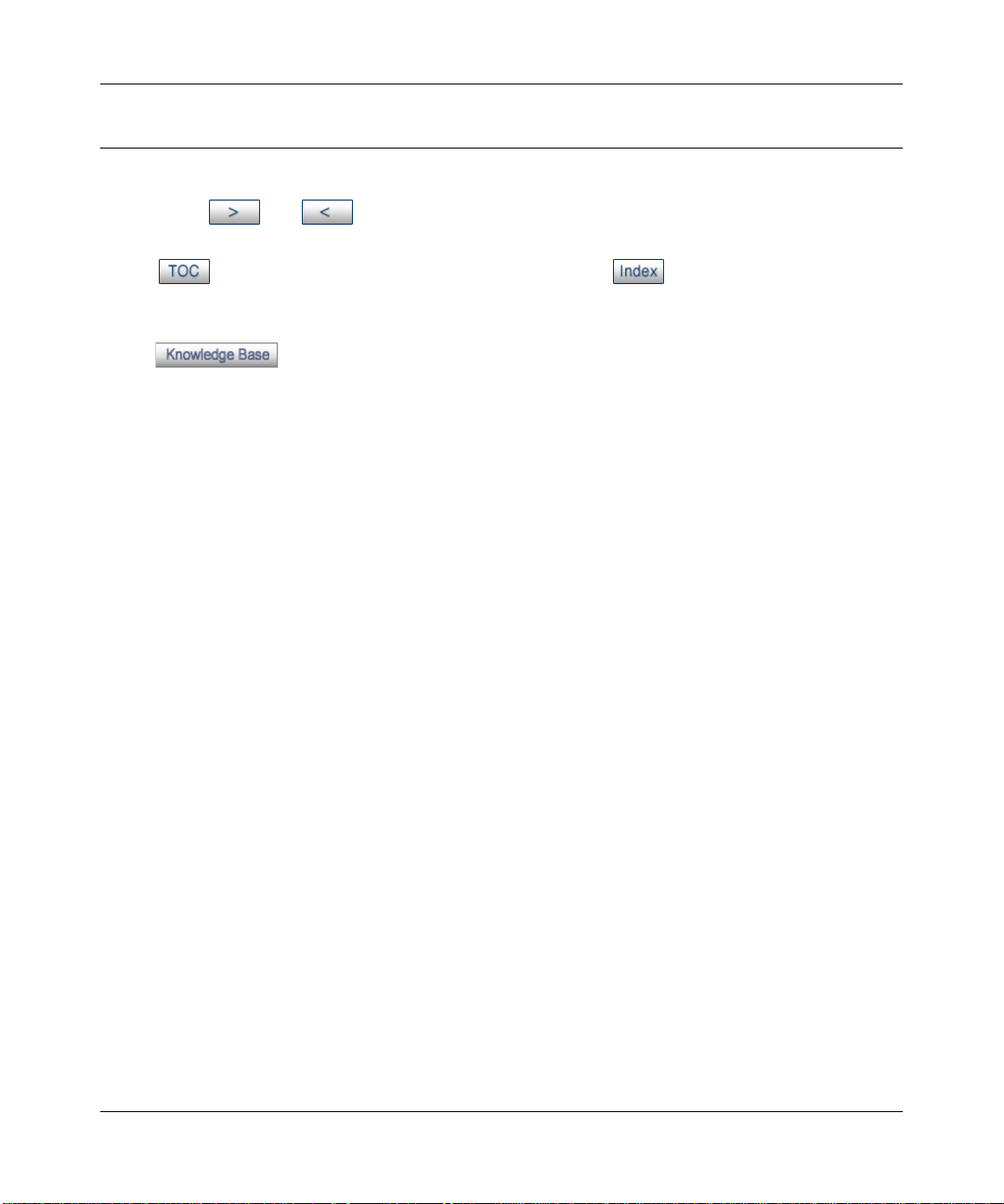
The HTML version of this manual includes the following:
• Buttons, and , for browsing forwards or backwards through the manual one page
at a time
• A button that displays the table of contents and an button. Double-click on a
link in the table of contents or index to navigate directly to where the topic is described in the
manual.
• A button to access the full NETGEAR, Inc. online knowledge base for the
product model.
• Links to PDF versions of the full manual and individual chapters.
1-2 About This Manual
201-10301-02, May 2005
Page 17

Reference Manual for the ProSafe Wireless 802.11g Firewall/Print Server Model FWG114P v2
How to Print this Manual
To print this manual you can choose one of the following several options, according to your needs.
• Printing a Page in the HTML View.
Each page in the HTML version of the manual is dedicated to a major topic. Use the Print
button on the browser toolbar to print the page contents.
• Printing a Chapter.
Use the PDF of This Chapter link at the top left of any page.
– Click the PDF of This Chapter link at the top right of any page in the chapter you want to
print. The PDF version of the chapter you were viewing opens in a browser window.
Note: Your computer must have the free Adobe Acrobat reader installed in order to view
and print PDF files. The Acrobat reader is available on the Adobe Web site at
http://www.adobe.com.
– Click the print icon in the upper left of the window.
Tip: If your printer supports printing two pages on a single sheet of paper, you can save
paper and printer ink by selecting this feature.
• Printing the Full Manual.
Use the Complete PDF Manua l link at the top left of any page.
– Click the Complete PDF Manual link at the top left of any page in the manual. The PDF
version of the complete manual opens in a browser window.
– Click the print icon in the upper left of the window.
Tip: If your printer supports printing two pages on a single sheet of paper, you can save
paper and printer ink by selecting this feature.
About This Manual 1-3
201-10301-02, May 2005
Page 18

Reference Manual for the ProSafe Wireless 802.11g Firewall/Print Server Model FWG114P v2
1-4 About This Manual
201-10301-02, May 2005
Page 19

Chapter 2
Introduction
This chapter describes the features of the NETGEAR ProSafe Wireless 802.11g Firewall/Print
Server Model FWG114P v2.
Key Features of the FWG114P v2
The ProSafe Wireless 802.11g Firewall/Print Server Model FWG114P v2, with a 4-port switch,
connects your LAN to the Internet through a broadband modem. With auto fail-over connectivity
through the serial port, the FWG114P v2 provides highly reliable Internet access.
The FWG114P v2 is a complete security solution that protects your network from attacks and
intrusions and enables secure communications using Virtual Private Networks (VPNs). Unlike
simple Internet sharing routers that rely on Network Address Translation (NAT) for security, the
FWG114P v2 uses Stateful Packet Inspection for Denial of Service attack (DoS) attack protection
and intrusion detection. The FWG114P v2 allows Internet access for up to 253 users. It provides
multiple Web content filtering options, plus browsing activity reporting and instant alerts via
e-mail. Parents or network administrators can establish restricted access policies based on
time-of-day, Web site addresses and address keywords, and share high-speed cable/DSL Internet
access for up to 253 personal computers.
With minimum setup, you can install and use the router within minutes. The FWG114P v2
Wireless Firewall/Print Server provides the following features:
• 802.11g and 802.11b standards-based wireless networking.
• Easy, Web-based setup for installation and management.
• Supports two VPN tunnels, Content Filtering, and Site Blocking Security.
• Wireless Multimedia (WMM) support.
• Built-in 4-port 10/100 Mbps Switch and USB 2.0 Printer Port.
• Ethernet and Serial ports for connection to a WAN device, such as a broadband modem.
• Extensive Protocol Support.
• Login capability.
• Front panel LEDs for easy monitoring of status and activity.
Introduction 2-1
201-10301-02, May 2005
Page 20

Reference Manual for the ProSafe Wireless 802.11g Firewall/Print Server Model FWG114P v2
• Flash memory for firmware upgrade.
• NAT off (classical routing).
Full Routing on Both the Broadband and Serial Ports
You can install, configure, and operate the FWG114P v2 to take full advantage of a variety of
routing options on both the serial and broadband WAN ports, including:
• Internet access via either the serial or broadband port.
• Auto fail-over connectivity through an analog or ISDN modem connected to the serial port.
If the broadband Internet connection fails, after waiting for an amount of time you specify , the
FWG114P v2 can automatically establish a backup ISDN or dial-up Internet connection via
the serial port on the firewall.
• Remote Access Server (RAS) that allows you to log in remotely through the serial port to
access a server on your LAN, other LAN resources, or the Internet, based on a user name and
password you define.
• LAN-to-LAN access between two FWG114P v2 wireless firewall/print servers through the
serial port, with the option of enabling auto-failover Internet access across the serial
LAN-to-LAN connection.
802.11g and 802.11b Wireless Networking
The FWG114P v2 Wireless Firewall/Print Server includes an 802.11g-compliant wireless access
point. The access point provides:
• 802.11b standards-based wireless networking at up to 11 Mbps.
• 802.11g wireless networking at up to 54 Mbps, which conforms to the 802.11g standard.
• WPA and WPA2 enterprise class strong security with RADIUS and certificate authentication
as well as dynamic encryption key generation.
• WPA-PSK and WPA2-PSK pre-s h are d ke y au th entication without the overhead of RADIUS
servers but with all of the strong security of WPA and WPA2.
• 64-bit and 128-bit WEP encryption security.
• WEP keys can be generated manually or by passphrase.
• Wireless access can be restricted by MAC Address.
2-2 Introduction
201-10301-02, May 2005
Page 21

Reference Manual for the ProSafe Wireless 802.11g Firewall/Print Server Model FWG114P v2
• Wireless network name broadcast can be turned off so that only devices that have the network
name (SSID) can connect.
Virtual Private Networking
The FWG114P v2 W ireless Firewall/Print Server p rovides a secure encrypted connectio n between
your local network and remote networks or clients. Its VPN features include:
• Support for up to 2 simultaneous VPN connections.
• Support for industry standard VPN protocols.
The ProSafe Wireless 802.11g Firewall/Print Server Model FWG114P v2 supports standard
keying methods (Manual or IKE), standard authentication methods (MD5 and SHA-1), and
standard encryption methods (DES, 3DES). It is compatible with many other VPN products.
• Support for up to 168 bit encryption (3DES) for maximum security.
• Support for VPN Main Mode, Aggressive mode, or Manual Keying.
• Support for Fully Qualified Domain Name (FQDN) configuration when the Dynamic DNS
feature is enabled with one of the supported service providers.
Wireless Multimedia (WMM) Support
WMM is a subset of the 802.11e standard. WMM allows wireless traffic to have a range of
priorities, depending on the kind of data. Time-dependent information such as video or audio will
have a higher priority than normal traffic. For WMM to function correctly, wireless clients must
also support WMM.
A Powerful, True Firewall with Content Filtering
Unlike simple Internet sharing NAT routers, the FWG114P v2 is a true firewall, using stateful
packet inspection to defend against hacker attacks. Its firewall features include:
• DoS protection.
Automatically detects and thwarts DoS attacks, such as Ping of Death, SYN Flood, LAND
Attack, and IP Spoofing.
• Blocks unwanted traffic from the Internet to your LAN.
• Blocks access from your LAN to Internet locations or services that you specify as off-limits.
Introduction 2-3
201-10301-02, May 2005
Page 22

Reference Manual for the ProSafe Wireless 802.11g Firewall/Print Server Model FWG114P v2
• Logs security incidents.
The FWG114P v2 will log security events, such as blocked incoming traffic, port scans,
attacks, and administrator logins. You can configure the router to e-mail the log to you at
specified intervals. You can also configure the router to send immediate alert messages to your
e-mail address or e-mail pager whenever a significant event occurs.
• With its content filtering feature, the FWG114P v2 prevents objectionable content from
reaching your PCs. The router allows you to control access to Internet content by screening for
keywords within Web addresses. You can configure the router to log and report attempts to
access objectionable Internet sites.
Security
The FWG114P v2 Wireless Firewall/Print Server is equipped with several features designed to
maintain security, as described in this section:
• PCs hidden by NAT.
NAT opens a temporary path to the Internet for requests originating from the local network.
Requests originating from outside the LAN are discarded, preventing users outside the LAN
from finding and directly accessing the PCs on the LAN.
• Port forwarding with NAT.
Although NAT prevents Internet locations from directly accessing the PCs on the LAN, the
router allows you to direct incoming traffic to specific PCs based on the service port number
of the incoming request, or to one designated “DNS” host computer. You can specify
forwarding of single ports or ranges of ports.
Autosensing Ethernet Connections with Auto Uplink
With its internal 8-port 10/100 switch, the FWG11 4P v2 can conn ect to eith er a 10 Mbps standard
Ethernet network or a 100 Mbps Fast Ethernet network. Both the LAN and WAN interfaces are
autosensing and capable of full-duplex or half-duplex operation.
TM
The router incorporates Auto Uplink
whether the Ethernet cable plugged into the port should have a ‘normal’ connection, such as to a
computer, or an ‘uplink’ connection, such as to a switch or hub. That port will then configure itself
to the correct configuration. This feature also eliminates the need to worry about crossover cables,
as Auto Uplink will accommodate either type of cable to make the right connection.
2-4 Introduction
technology. Each Ethernet port will automatically sense
201-10301-02, May 2005
Page 23

Reference Manual for the ProSafe Wireless 802.11g Firewall/Print Server Model FWG114P v2
Extensive Protocol Support
The FWG114P v2 Wireless Firewall/Print Server supports the Transmission Control Protocol/
Internet Protocol (TCP/IP) and Routing Information Protocol (RIP).
• The ability to enable or disable IP address sharing by NAT.
The FWG114P v2 allows several networked PCs to share an Internet account using only a
single IP address, which may be statically or dynamically assigned by your Internet service
provider (ISP). This technique, known as NAT, allows the use of an inexpensive single-user
ISP account. This feature can also be turned off completely for using the FWG114P v2 in
settings where you want to manage the IP address scheme of your organization.
• Automatic configuration of attached PCs by DHCP.
The FWG114P v2 Wireless Firewall/Print Server dynamically assigns network configuration
information, including IP, gateway, and domain name server (DNS) addresses, to attached PCs
on the LAN using the Dynamic Host Configuration Protocol (DHCP). This feature greatly
simplifies configuration of PCs on your local network .
• DNS Proxy.
When DHCP is enabled and no DNS addresses are specified, the router provides its own
address as a DNS server to the attached PCs. The router obtains actual DNS addresses from
the ISP during connection setup and forwards DNS requests from the LAN.
• PPP over Ethernet (PPPoE).
PPPoE is a protocol for connecting remote hosts to the Internet over a DSL connection by
simulating a dial-up connection. This feature eliminates the need to run a login program, such
as Entersys or WinPOET on your computer.
• PPTP login support for European ISPs, BigPond login for Telstra cable in Australia.
• Classical IP (RFC 1577).
Some Internet service providers, in Europe for example, use Classical IP in their ADSL
services. In such cases, the firewall is able to use the Classical IP address from the ISP.
Introduction 2-5
201-10301-02, May 2005
Page 24

Reference Manual for the ProSafe Wireless 802.11g Firewall/Print Server Model FWG114P v2
Easy Installation and Management
You can install, configure, and operate the ProSafe Wireless 802.11g Firewall/Print Server Model
FWG114P v2 within minutes after connecting it to the network. The following features simplify
installation and management tasks:
• Automatic fail-over connectivity through an analog or ISDN modem connected to the serial
port. If the broadband modem Internet connection fails, after waiting for an amount of time
you specify, the FWG114P v2 can automatically establish a backup ISDN or dial-up Internet
connection via the serial port on the firewall.
• Browser-based management.
Browser-based configuration allows you to easily configure your router from almost any type
of personal computer, such as Windows, Macintosh, or Linux. A user-friendly Setup Wizard is
provided and online help documentation is built into the browser-based Web Management
Interface.
• Smart Wizard.
The FWG114P v2 Wireless Firewall/Print Server automatically senses the type of Internet
connection, asking you only for the information required for your type of ISP account.
• Diagnostic functions.
The firewall incorporates built-in diagnostic functions, such as Ping, DNS lookup, and remote
reboot.
• Remote management.
The firewall allows you to log in to the Web Management Interface from a remote location on
the Internet. For security, you can limit remote management access to a specified remote IP
address or range of addresses, and you can choose a nonstandard port number.
• Visual monitoring.
The FWG114P v2 Wireless Firewall/Print Server’s front panel LEDs provide an easy way to
monitor its status and activity .
• Regional support, including ISPs like Telstra DSL and BigPond, or Deutsche Telekom.
• Flash memory for firmware upgrades.
NETGEAR Related Products
The following NETGEAR products are related to the ProSafe Wireless 802.11g Firewall/Print
Server Model FWG114P v2:
• ProSafe™ Dual Band Wireless PC Card Model WAG511
• ProSafe™ Dual Band Wireless PCI Adapter Model WAG311
2-6 Introduction
201-10301-02, May 2005
Page 25
Reference Manual for the ProSafe Wireless 802.11g Firewall/Print Server Model FWG114P v2
• 54 Mbps Wireless PC Card Model WG511
• 54 Mbps Wireless PCI Card Model WG311
• 54 Mbps Wireless USB 2.0 Adapter Model WG121
• ProSafe™ Indoor 5 dBi Omni-directional Antenna Model ANT24O5
• ProSafe™ Indoor/Outdoor 18 dBi Patch Panel Directional Antenna Model ANT24D18
• ProSafe™ Indoor/Outdoor 9 dBi Omni-directional Antenna Model ANT2409
• Low-loss Antenna Cables
Package Contents
The product package should contain the following items:
• ProSafe Wireless 802.11g Firewall/Print Server Model FWG114P v2.
•AC power adapter.
• Category 5 (Cat 5) Ethernet cable.
• FWG114P Installation Guide (201-10301-01).
• Resource CD for the ProSafe Wireless 802.11g Firewall/Print Server Model FWG114P
(SW-10023-03), including:
— This manual.
— Application Notes and other helpful information.
• Registration and Warranty Card.
If any of the parts are incorrect, missing, or damaged, contact your NETGEAR dealer. Keep the
carton, including the original packing materials, in case you need to return the router for repair.
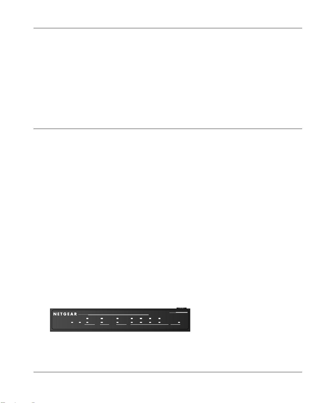
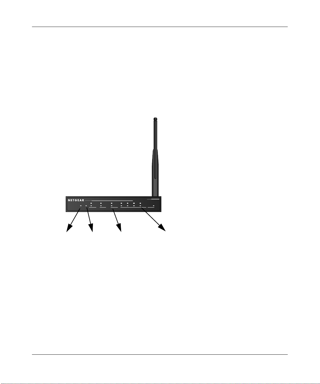
The FWG114P v2 Front Panel
The front panel of the FWG114P v2 contains the status LEDs. Use the LEDs to verify various
operations. Viewed from left to right, Table 2-1 describes the LEDs on the front of the router.
Broadband
ProSafe 802.11g Wireless Firewall/Print Server
ACT
ACT
100
1234
PWR
TEST
ALERT
PRINTER MODEM IN TERNET LOCAL WLAN
LNK/ACT
LINK
Figure 2-1: FWG114P v2 Front Panel
Introduction 2-7
201-10301-02, May 2005
100
LNK/ACT
MODEL
FWG114P
Page 26

Reference Manual for the ProSafe Wireless 802.11g Firewall/Print Server Model FWG114P v2
Table 2-1. LED Descriptions
Label Activity Description
POWER On Power is supplied to the firewall.
TEST On
Off
PRINTER
ACT On
Blinking
ALERT On (Amber) The printer has a problem, such as out of paper, out of ink, or a
MODEM
ACT Blinking Data is being transmitted or received by the Modem port.
LINK On (Amber) The port has detected a link with an attached device.
INTERNET Note: The operation of these LEDs depends on how the WAN port is configured.
100 (100 Mbps) On
Off
LINK/ACT
(Link/Activity)
LOCAL
100 (100 Mbps) On
LINK/ACT
(Link/Activity)
WLAN On
On
Blinking
Off
On
Blinking
Blinking
The system is initializing.
The system is ready and running.
The printer is connected and powered on.
Data is being transmitted or received by the Printer port.
paper jam.
The Internet (WAN) port is operating at 100 Mbps.
The Internet (WAN) port is operating at 10 Mbps.
The Internet port has detected a link with an attached device.
Data is being transmitted or received by the Internet port.
The Local port is operating at 100 Mbps.
The Local port is operating at 10 Mbps.
The Local port has detected a link with an attached device.
The Local port is transmitting or receiving data.
The Wireless (WLAN) port is operating.
The Wireless (WLAN) port is transmitting or receiving data.
The FWG114P v2 Rear Panel
The rear panel of the FWG114P v2 Wireless Firewall/Print Server contains the port connections
listed below.
2-8 Introduction
201-10301-02, May 2005
Page 27
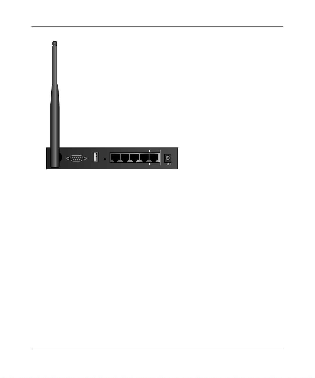
Reference Manual for the ProSafe Wireless 802.11g Firewall/Print Server Model FWG114P v2
LOCA L
MODEM
USB
10/100M
4321
INTERNET
12VDC, 1.0A
Figure 1-2: FWG114P v2 Rear Panel
Viewed from left to right, the rear panel contains the following features:
• Wireless antenna.
• DB-9 serial port for modem connection.
• USB 2.0 Printer Port.
• Factory Default Reset push button.
• Four Ethernet LAN ports.
• Internet Ethernet WAN port for connecting the router to a broadband modem.
• AC power adapter outlet.
Introduction 2-9
201-10301-02, May 2005
Page 28

Reference Manual for the ProSafe Wireless 802.11g Firewall/Print Server Model FWG114P v2
2-10 Introduction
201-10301-02, May 2005
Page 29

Chapter 3
Connecting the FWG114P v2 to the Internet
This chapter describes how to set up the router on your local area network (LAN) and connect to
the Internet. You will find out how to configure your ProSafe Wireless 802.11g Firewall/Print
Server Model FWG114P v2 for Internet access using the Setup Wizard, or how to manually
configure your Internet connection.
What You Will Need Before You Begin
You need to prepare these three things before you begin:
1. An active Internet service, such as those provided by a cable or DSL broadband account.
2. Locate the Internet Service Provider (ISP) configuration information for your broadband
account.
3. Connect the router to a broadband modem and a computer as explained below.
Cabling and Computer Hardware Requirements
To use the FWG114P v2 Wireless Firewall/Print Server on your network, each computer must
have an installed Ethernet Network Interface Card (NIC) and an Ethernet cable. If the computer
will connect to your network at 100 Mbps, you must use a Category 5 (CAT5) cable, such as the
one provided with your router.
Computer Network Configuration Requirements
The FWG114P v2 includes a built-in Web Configuration Manager. To access the configuration
menus on the FWG114P v2, you must use a Java-enabled Web browser program that supports
HTTP uploads, such as Microsoft Internet Explorer or Netscape Navigator. Use Internet Explorer
or Netscape Navigator versions 4.0 or above. Free browser programs are readily available for
Windows, Macintosh, or UNIX/Linux.
Connecting the FWG114P v2 to the Internet 3-1
201-10301-02, May 2005
Page 30

Reference Manual for the ProSafe Wireless 802.11g Firewall/Print Server Model FWG114P v2
For the initial connection to the Internet and configuration of your router, you will need to connect
a computer to the router that is set to automatically get its TCP/IP configuration from the router via
DHCP.
The cable or DSL modem broadband access device must provide a standard 10 Mbps (10BASE-T)
Ethernet interface.
Internet Configuration Requirements
Depending on how your ISP set up your Internet account, you might need one or more of these
configuration parameters to connect your router to the Internet:
• Host and Domain Names.
• ISP login name and password.
• ISP Domain Name Server (DNS) Addresses.
• Fixed IP address which is also known as static IP address.
Where Do I Get the Internet Configuration Parameters?
There are several ways you can gather the required Internet connection information:
• Your ISP provides all the information needed to connect to the Internet. If you cannot locate
this information, you can ask your ISP to provide it or you can try one of the options below.
• If you have a computer already connected using the active Internet access account, you can
gather the configuration information from that computer.
— For Windows 95/98/ME, open the Network control panel, select the TCP/IP entry for the
Ethernet adapter, and click Properties. Record all the settings for each tab page.
— For Windows 2000/XP, open the Local Area Network Connection, select the TCP/IP entry
for the Ethernet adapter, and click Properties. Record all the settings for each tab page.
— For Macintosh computers, open the TCP/IP or Network control panel. Record all the
settings for each section.
• You may also refer to the FWG114P v2 Resource CD for the NETGEAR Router ISP Guide
which provides Internet connection information for many ISPs.
Once you locate your Internet configuration parameters, you may want to record them on the
following form:
3-2 Connecting the FWG114P v2 to the Internet
201-10301-02, May 2005
Page 31

Reference Manual for the ProSafe Wireless 802.11g Firewall/Print Server Model FWG114P v2
Record Yo ur Internet Connection Information
Print this page. Fill in the configuration parameters from your Internet Service Provider (ISP).
ISP Login Name: The login name and password are case sensitive and must be entered exactly as
given by your ISP. For AOL customers, the login name is their primary screen name. Some ISPs
use your full e-mail address as the login name. The Service Name is not required by all ISPs. If
you connect using a login name and password, then fill in the following:
Login Name: ______________________________
Password: __________________________ __
Service Name: _____________________________
Fixed or Static IP Address: If you have a static IP address, record the following information. For
example, 169.254.141.148 could be a valid IP address.
Fixed or Static Internet IP Address: ______
.______.______.______
Gateway IP Address: ______.______.______.______
Subnet Mask: ______.______.______.______
ISP DNS Server Addresses: If you were given DNS server addresses, fill in the following:
Primary DNS Server IP Address: ______
.______.______.______
Secondary DNS Server IP Address: ______.______.______.______
Host and Domain Names: Some ISPs use a specific host or domain name like CCA7324-A or
home. If you have not been given host or domain names, you can use the following examples as a
guide:
• If your main e-mail account with your ISP is
aaa@yyy.com, then use aaa as your host name.
Your ISP might call this your account, user, host, computer, or system name.
• If your ISP’s mail server is
ISP Host Name: _________________________
mail.xxx.yyy.com, then use xxx.yyy.com as the domain name.
ISP Domain Name: _______________________
Serial Port Internet Access: If you use a dial-up account, record the following:
Account/User Name: _________________________
Telephone number: ______________________
Connecting the FWG114P v2 to the Internet 3-3
201-10301-02, May 2005
Password: _________________________
Alternative number: ______________________
Page 32
Reference Manual for the ProSafe Wireless 802.11g Firewall/Print Server Model FWG114P v2
Connecting the FWG114P v2 Wireless Firewall/Print Server
This section provides instructions for connecting the FWG114P v2 W ireless Firewall/Print Server.
Also, the Resource CD for the ProSafe Wireless 802.11g Firewall/Print Server Model FWG114P
(SW-10023-03), includ ed with yo ur ro uter, contains an animated Installation Assistant to help you
through this procedure.
Verify That Basic Requirements Are Met
Assure that the following requirements are met:
• You have your broadband Internet service settings handy.
• The computer is configured to obtain an IP address automatically via DHCP. For instructions
on how to do this, please see the Reference Manual on the Resource CD for the ProSafe
Wireless 802.11g Firewall/Print Server Model FWG114P (SW-10023-03).
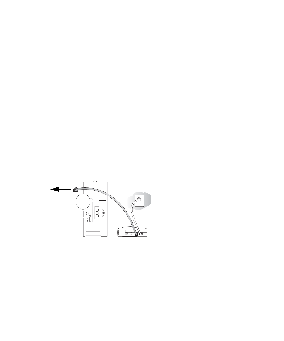
1. CONNECT THE WIRELESS FIREWALL/PRINT SERVER
a. Turn off your computer and cable or DSL modem.
b. Disconnect the Ethernet cable (A) from your computer which connects to the broadband
modem.
Disconnect
from
computer
Figure 3-1: Disconnect the broadband modem
3-4 Connecting the FWG114P v2 to the Internet
A
&DEOHRU'6/PRGHP
201-10301-02, May 2005
Page 33
Reference Manual for the ProSafe Wireless 802.11g Firewall/Print Server Model FWG114P v2
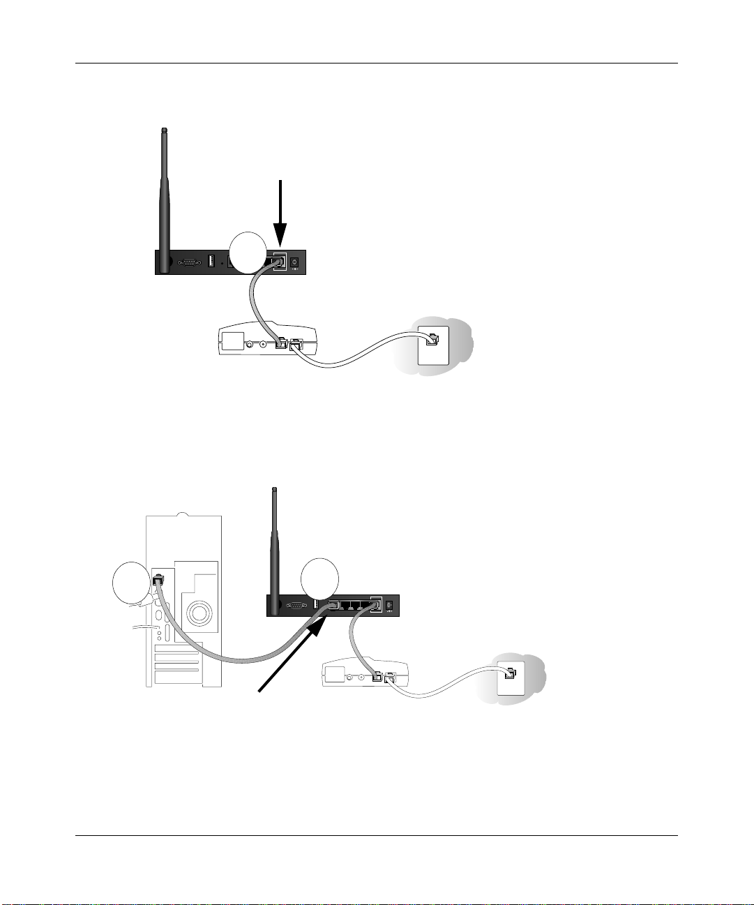
Securely insert the Ethernet cable from your broadband modem into the Internet port (B)
c.
on the FWG114P v2.
Internet Port
LOCAL
10/100M
USB
4321
MODEM
Broadband modem
Figure 3-2: Connect the broadband modem to the router
d.
Securely insert one end of the Ethernet cable that came with your wireless firewall/print
server into a Local port on the router, such as Local port 4 (C), and the other end into the
Ethernet port of your computer (D).
B
INTERNET
12VDC, 1.0A
D
Local Port 4
C
USB
MODEM
Broadband modem
LOCAL
10/100M
4321
INTERNET
12VDC, 1.0A
Figure 3-3: Connect the computers on your network to the router
Note: The FWG114P v2 incorporates Auto UplinkTM technology which eliminates the
need to worry about crossover cables by automatically adjusting to the cable type.
Connecting the FWG114P v2 to the Internet 3-5
201-10301-02, May 2005
Page 34
Reference Manual for the ProSafe Wireless 802.11g Firewall/Print Server Model FWG114P v2
RESTART YOUR NETWORK IN THE CORRECT SEQUENCE
2.
Warning: Failure to restart your network in the correct sequence could prevent you from
connecting to the Internet.
a. First, turn on the broadband modem and wait 2 minutes.
b. Now, turn on your wireless firewall/print server.
c. Last, turn on your computer.
Note: If software usually logs you in to the Internet, do not run that software, or cancel it if
it starts automatically.
Broadband
ProSafe 802.11g Wireless Firewall/Print Server
PWR
TEST
PRINTER MODEM INTERNET LOCAL WLAN
Power Test
ACT
ACT
ALERT
LINK
Internet Port
100
1234
LNK/ACT
MODEL
FWG114P
100
LNK/ACT
Local Port 4
Figure 3-4: Verify the connections to the firewall
d.
Check the status lights and verify the following:
• Power: The power light goes on when your turn the wireless firewall/print server on.
• Test: The test light turns on, then goes off after less than a minute.
• Local: A Local light on the router is lit. If no Local lights are lit, check that the
Ethernet cable connecting the powered on computer to the router is securely attached
at both ends.
• Internet: The Internet light on the wireless firewall/print server is lit. If the Internet
light is not lit, make sure the Ethernet cable is securely attached to the wireless
firewall/print server Internet port and the powered on modem.
3-6 Connecting the FWG114P v2 to the Internet
201-10301-02, May 2005
Page 35
Reference Manual for the ProSafe Wireless 802.11g Firewall/Print Server Model FWG114P v2
LOG IN TO THE WIRELESS FIREWALL/PRINT SERVER
3.
a. From your PC, launch your Internet browser. Because you are not yet connected to the
Internet, your browser will display a page not found message.
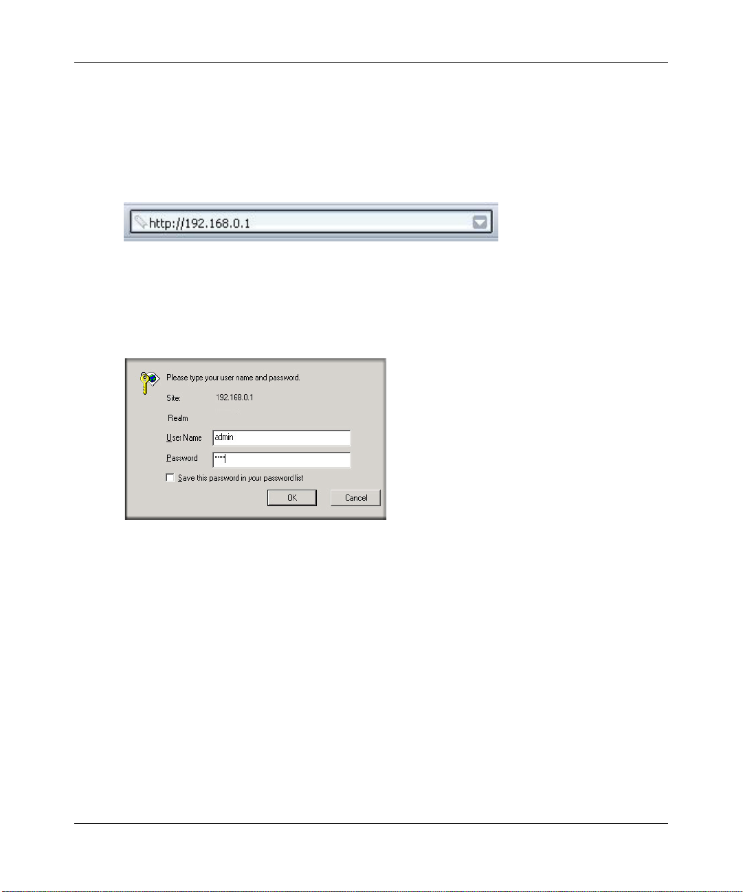
b. Connect to the wireless firewall/print server by typing http://192.168.0.1 in the address
field of Internet Explorer or Netscape
Figure 3-5: Log in to the firewall
c.
Enter admin for the router user name and password for the router password, both in
®
Navigator.
lower case letters.A login window opens as shown here:
Figure 3-6: Login window
Connecting the FWG114P v2 to the Internet 3-7
201-10301-02, May 2005
Page 36
Reference Manual for the ProSafe Wireless 802.11g Firewall/Print Server Model FWG114P v2
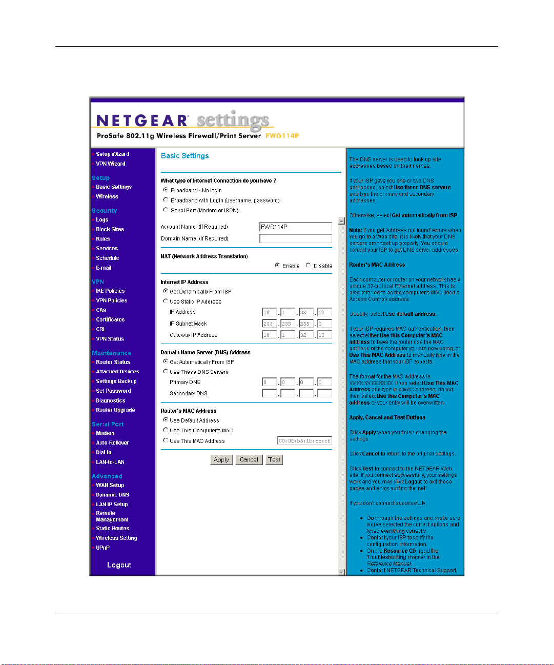
After logging in to the router, you will see the login result page.
d.
Figure 3-7: Login Result page
3-8 Connecting the FWG114P v2 to the Internet
201-10301-02, May 2005
Page 37
Reference Manual for the ProSafe Wireless 802.11g Firewall/Print Server Model FWG114P v2
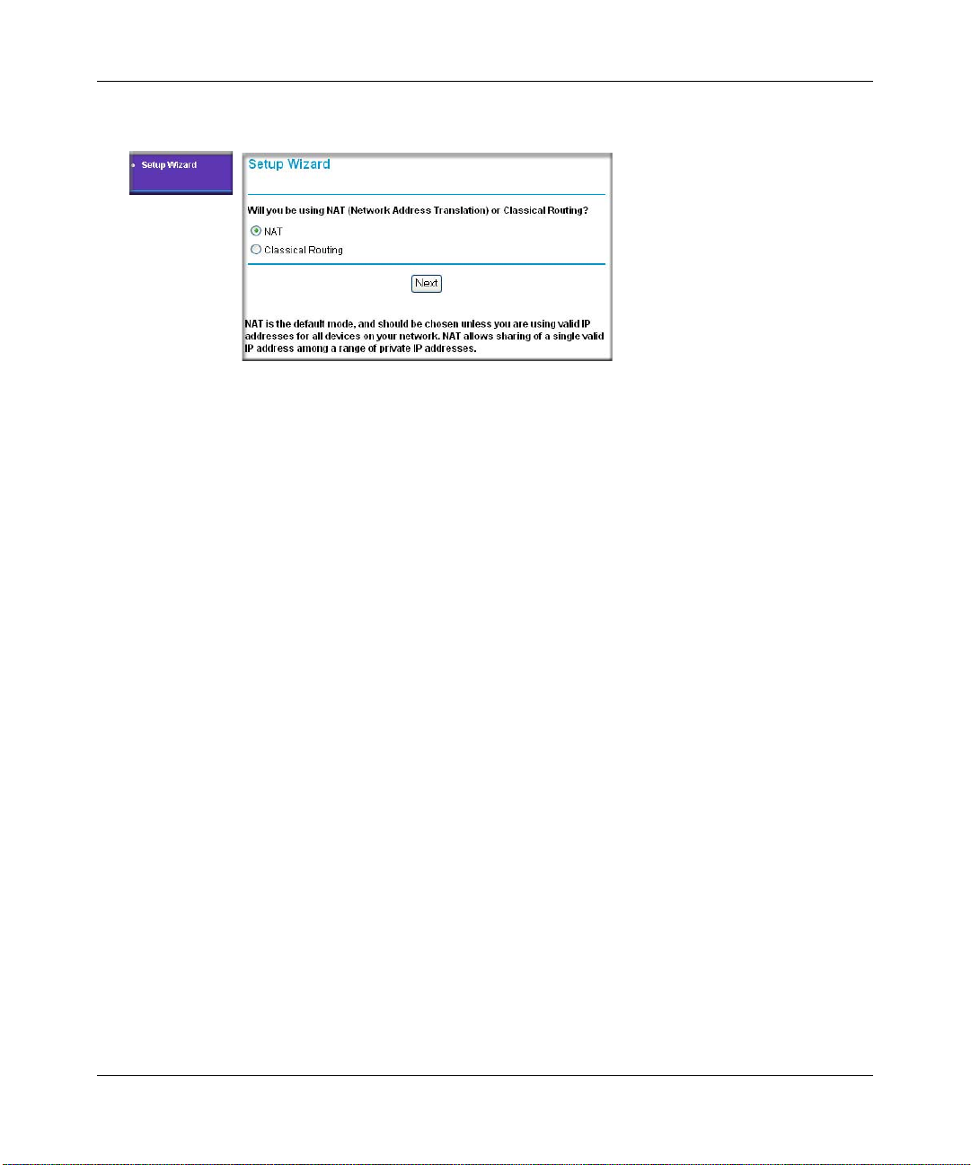
4. RUN THE SETUP WIZARD TO CONNECT TO THE INTERNET
Figure 3-8: Setup Wizard
a.
You are now connected to the router. If you do not see the menu above, click the Setup
Wizard link on the upper left of the main menu.
b. Choose NAT or Classical Routing. Typically, NAT is used. NAT automatically assigns
private IP addresses (192.168.0.x) to LAN connected devices. Classical routing lets you
directly manage the IP addresses the FWG114P v2 uses.
Note: If you choose not to use NAT, each computer on the LAN connected to the
FWG114P v2 must have a valid public IP address in the same subnet as the Wan port of
the FWG114P v2. For more information on NAT , please see “Single IP Address Oper ation
Using NAT” on page B-7. Furthermore, if you turn NAT of f and plan to use VPN, you will
have to open UDP port 500 in the Security settings according to the instructions at
c. Click Next to proceed. Input your ISP settings, as needed.
d. At the end of the Setup Wizard, click the Test button to verify your Internet connection
and register your product. If you have trouble connecting to the Internet, use the
Troubleshooting Tips below to correct basic problems, or refer to the Reference Manual
on the CD.
If you were unable to connect to the firewall, please refer to Basic Functioning “Basic
Functioning” on page 11-1.
You are now connected to the Internet!
Note: For wireless placement and range guidelines, and wireless configuration instructions, please
see Chapter 4, “Wireless Configuration.”
Connecting the FWG114P v2 to the Internet 3-9
201-10301-02, May 2005
Page 38

Reference Manual for the ProSafe Wireless 802.11g Firewall/Print Server Model FWG114P v2
Basic Setup Troubleshooting Tips
Here are some tips for correcting simple problems that prevent with you from connecting to the
Internet or connecting to the wireless firewall/print server.
Be sure to restart your network in the correct sequence.
Follow this sequence. Turn off the modem, wireless firewall/print server, and computer. Turn
on the modem first and wait two minutes. Next, turn on the wireless firewall/print server, and
finally the computer.
Make sure the Ethernet cables are securely plugged in.
• For each powered on computer connected to the wireless firewall/print server with a securely
plugged in Ethernet cable, the corresponding wireless firewall/print server Local port status
light will be lit. The label on the bottom of the wireless firewall/print server identifies the
number of each Local port.
• The Internet port status light on the wireless firewall/print server will be lit if the Ethernet
cable from the wireless firewall/print server to the modem is plugged in securely and the
modem and wireless firewall/print server are turned on.
Make sure the network settings of the computer are correct.
LAN connected computers must be configured to obtain an IP address automatically via
DHCP, unless you have turned NAT off and are managing the IP addresses directly. For
instructions on these configuration settings, please see the Reference Manu al on the Resource
CD for the ProSafe Wire less 802.11g Firewall/Print Server Model FWG114P (SW-10023-03).
FWG114P v2 Setup Wizard Auto Detection
There are two ways you can configure your firewall to connect to the Internet:
• Let the FWG114P v2 auto-detect the type of Internet connection you have and configure it.
• Manually choose which type of Internet connection you have and configure it.
These options are described below. Unless your ISP uses DHCP, you will need the parameters
from your ISP you entered in “Record Your Internet Connection Information” on page 3.
The Setup Wizard will can check for the following connection types:
• Dynamic IP assignment
• A login protocol, such as PPPoE
3-10 Connecting the FWG114P v2 to the Internet
201-10301-02, May 2005
Page 39
Reference Manual for the ProSafe Wireless 802.11g Firewall/Print Server Model FWG114P v2
• Fixed IP address assignment
Next, the Setup Wizard will report which connection type it has discovered, and then display
the appropriate configuration menu. If the Setup Wizard finds no connection, you will be
prompted to check the physical connection between your firewall and the cable or DSL
modem. When the connection is properly made, the firewall’s Internet LED should be on.
The procedures for filling in the configuration menu for each type of connection follow below.
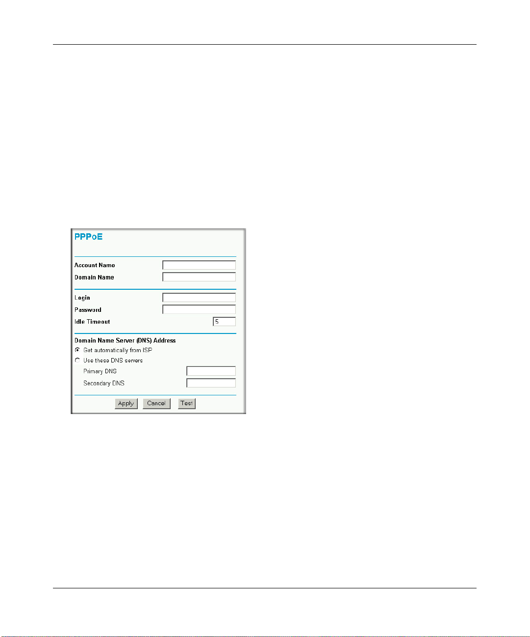
Wizard-Detected Login Account Setup
If the Setup Wizard determines that your Internet service account uses a login protocol, such as
PPP over Ethernet (PPPoE), you will be directed to a menu like the PPPoE menu in Figure 3-9:
Figure 3-9: Setup Wizard menu for PPPoE login accounts
1.
Enter your Account Name (may also be called Host Name) and Domain Name. These
parameters may be necessary to access your ISP’s services, such as mail or news servers. If
you leave the Domain Name field blank, the firewall will attempt to learn the domain
automatically from the ISP. If this is not successful, you may need to enter it manually.
2. Enter the PPPoE login user name and password provided by your ISP. These fields are case
sensitive. If you wish to change the idle timeout, enter a new value in minutes.
Connecting the FWG114P v2 to the Internet 3-11
201-10301-02, May 2005
Page 40

Reference Manual for the ProSafe Wireless 802.11g Firewall/Print Server Model FWG114P v2
Note: You will no longer need to launch the ISP’s login program on your computer in order to
access the Internet. When you start an Internet application, your firewall will automatically log
you in.
3. The Idle Timeout setting determines how long to wait after there is no activity before
disconnecting from the Internet. This is useful in countries where Internet service charges are
based on the amount of time connected to the Internet. Whenever a computer on the network
requests access to the Internet the FWG114P v2 will automatically reconnect.
4. Domain Name Server (DNS) Address: If you know that your ISP does not automatically
transmit DNS addresses to the firewall during login, select “Use these DNS servers” and enter
the IP address of your ISP’s Primary DNS Server. If a Secondary DNS Server address is
available, enter it also.
Note: If you enter an address here, after you finish configuring the firewall, reboot your PCs
so that the settings take effect.
5. Click Apply to save your settings.
6. Click Test to test your Internet connection. If the NETGEAR Web site does not appear within
one minute, refer to Chapter 11, “Troubleshooting”.
3-12 Connecting the FWG114P v2 to the Internet
201-10301-02, May 2005
Page 41
Reference Manual for the ProSafe Wireless 802.11g Firewall/Print Server Model FWG114P v2
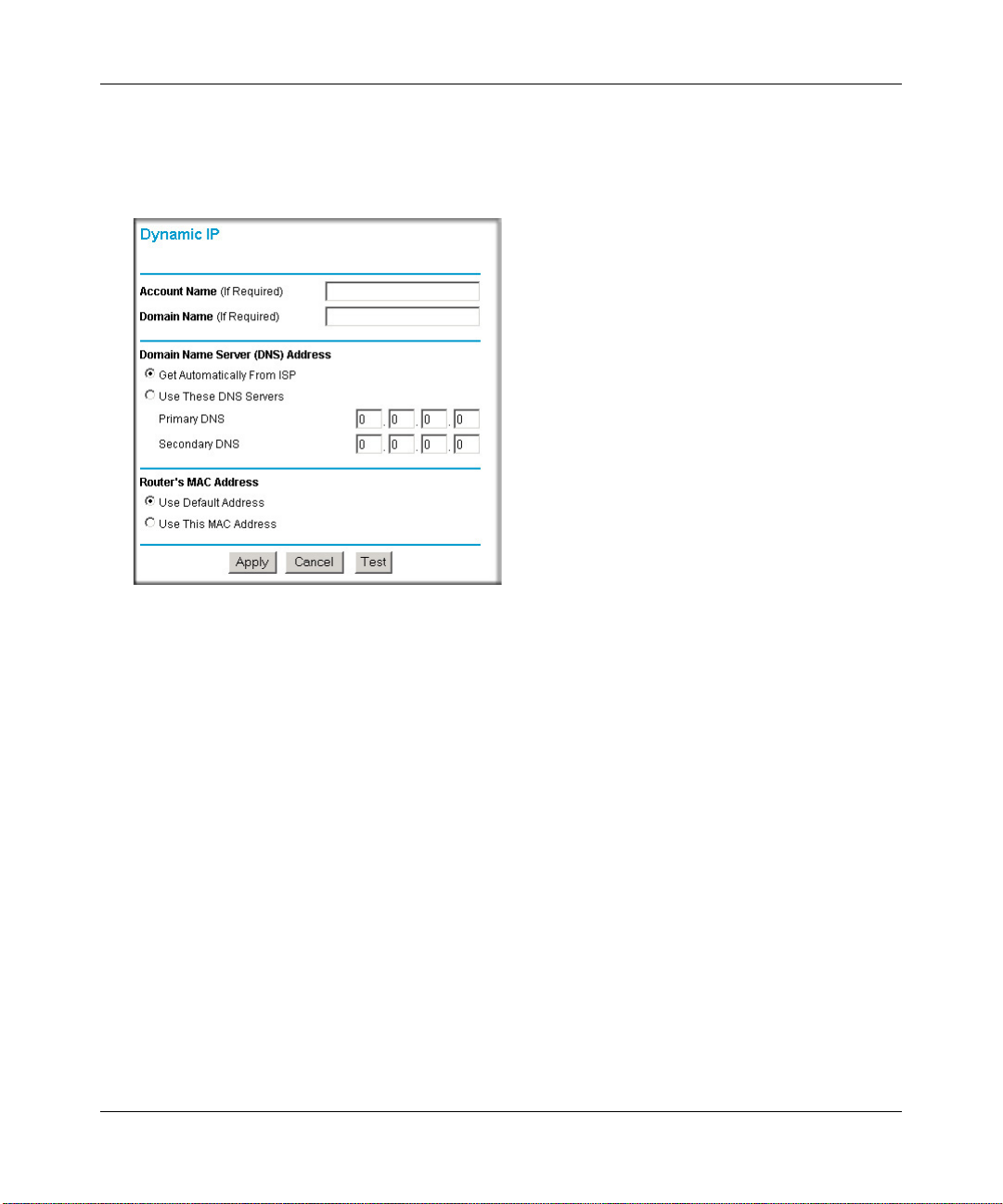
Wizard-Detected Dynamic IP Account Setup
If the Setup Wizard determines that your Internet service account uses Dynamic IP assignment,
you will be directed to the menu shown in Figure 3-10 below:
Figure 3-10: Setup Wizard menu for Dynamic IP address
1.
Enter your Account Name (may also be called Host Name) and Domain Name. These
parameters may be necessary to access your ISP’s services, such as mail or news servers. If
you leave the Domain Name field blank, the firewall will attempt to learn the domain
automatically from the ISP. If this is not successful, you may need to enter it manually.
2. If you know that your ISP does not automatically transmit DNS addresses to the firewall
during login, select “Use these DNS servers” and enter the IP address of your ISP’s Primary
DNS Server. If a Secondary DNS Server address is available, enter it also.
Note: DNS servers are required to perform the function of translating an Internet name, such
as www.netgear.com to a numeric IP address. For a fixed IP address configuration, you must
obtain DNS server addresses from your ISP and enter them manually here. Y ou should reboot
your PCs after configuring the firewall for these settings to take effect.
3. The Router’s MAC Address is the Ethernet MAC address that will be used by the firewall on
the Internet port.
Connecting the FWG114P v2 to the Internet 3-13
201-10301-02, May 2005
Page 42

Reference Manual for the ProSafe Wireless 802.11g Firewall/Print Server Model FWG114P v2
If your ISP allows access from only one specific computer’s Ethernet MAC address, select
“Use this MAC address.” The firewall will then capture and use the MAC address of the
computer that you are now using. You must be using the one computer that is allowed by the
ISP. Otherwise, you can type in a MAC address.
Note: Some ISPs will register the Ethernet MAC address of the network interface card in your
computer when your account is first opened. They will then only accept traffic from the MAC
address of that computer. This feature allows your firewall to masquerade as that computer by
using its MAC address.
4. Click Apply to save your settings.
5. Click Test to test your Internet connection. If the NETGEAR Web site does not appear within
one minute, refer to Chapter 11, “Troubleshooting”.
Wizard-Detected Fixed IP Account Setup
If the Setup Wizard determines that your Internet service account uses Fixed IP assignment, you
will be directed to the menu shown in Figure 3-11 below:
Figure 3-11: Setup Wizard menu for Fixed IP address
3-14 Connecting the FWG114P v2 to the Internet
201-10301-02, May 2005
Page 43

Reference Manual for the ProSafe Wireless 802.11g Firewall/Print Server Model FWG114P v2
Enter your assigned IP Address, Subnet Mask, and the IP Address of your ISP’s gateway
1.
router. This information should have been provided to you by your ISP. You will need the
configuration parameters from your ISP you recorded in “Record Your Internet Connection
Information” on page 3.
2. Enter the IP address of your ISP’s Primary DNS Server. If a Secondary DNS Server address is
available, enter it also.
Note: DNS servers are required to perform the function of translating an Internet name, such
as www.netgear.com to a numeric IP address. For a fixed IP address configuration, you must
obtain DNS server addresses from your ISP and enter them manually here. Y ou should reboot
your PCs after configuring the firewall for these settings to take effect.
3. Click Apply to save the settings.
4. Click Test to test your Internet connection. If the NETGEAR Web site does not appear within
one minute, refer to Chapter 11, “Troubleshooting.
How to Configure the Serial Port as the Primary Internet Connection
Use the procedure below to configure an Internet connection via the serial port of your firewall.
There are three steps to configuring the serial port of your firewall for an Internet connection:
1. Connect the firewall to your ISDN or dial-up analog modem.
2. Configure the firewall.
3. Connect to the Internet.
Follow the steps below to configure a serial port Internet connection on your firewall.
1. Connect the Firewall to your ISDN or dial-up modem
a. Turn off your modem and connect the cable from the serial port of the FWG114P v2 to the
modem.
b. Turn on the modem and wait about 30 seconds for the lights to stop blinking.
2. Configure the Serial Port of the Firewall.
a. Use a browser to log in to the firewall at http://192.168.0.1 with its default User Name of
admin and default Password of password, or using whatever Password you have set up.
b. From the Setup Basic Settings menu, click Serial Port.
Connecting the FWG114P v2 to the Internet 3-15
201-10301-02, May 2005
Page 44

Reference Manual for the ProSafe Wireless 802.11g Firewall/Print Server Model FWG114P v2
Figure 3-12: Serial Internet Connection configuration menu
c.
Fill in the ISDN or analog ISP Internet configuration parameters as appropriate:
• For a Dial-up Account, enter the Account information. Check “Connect as required”
to enable the firewall to automatically dial the number. To enable Idle Time
disconnect, check the box and enter a time in minutes.
• To configure the Internet IP settings, fill in the address parameters your ISP provided.
d. Configure the Modem parameters.
3-16 Connecting the FWG114P v2 to the Internet
201-10301-02, May 2005
Page 45

Reference Manual for the ProSafe Wireless 802.11g Firewall/Print Server Model FWG114P v2
Note: You can validate modem string settings by first connecting the modem directly to a
computer, establishing a connection to your ISP, and then copying the modem string
settings from the computer configuration and pasting them into the FWG114P v2 Modem
Properties Initial String field. For more information on this procedure, please refer to the
support area of the NETGEAR Web site.
• Select the Serial Line Speed. This is the maximum speed the modem will attempt to
use. For ISDN permanent connections, the speeds are typically 64000 or 128000 bps.
For dial-up modems, 56000 bps would be a typical setting.
• Select the Modem Type:
– For ISDN, select “Permanent connection (leased line).”
– For dial-up, select your modem from the list. “Standard Modem” should work in
most cases.
– If your modem is not on the list, select “User Defined” and enter the Modem
Properties.
Note: If you are using the “User Defined” Modem Type, you must first use the Serial Port
menu Modem link to fill in the Modem Properties settings for your modem.
e. Click Apply to save your settings.
3. Connect to the Internet to test your configuration.
a. If you have a broadband connection, disconnect it.
b. From a workstation, open a browser and test your serial port Internet connection.
Note: The response time of your serial port Internet connection will be slower than a
broadband Internet connection.
Testing Your Internet Connection
After completing the Internet connection configuration, your can test your Internet connection.
Log in to the firewall, then, from the Setup Basic Settings link, click the Test button. If the
NETGEAR Web site does not appear within one minute, refer to Chapter 11, “Troubleshooting.”
Note: Popup blocking software may block the test page from opening. Alternately, you can just
open a new browser window and browse the Internet.
To access the Internet from any computer connected to your firewall, launch a browser, such as
Microsoft Internet Explorer or Netscape Navigator. You should see the firewall’s Internet LED
blink, indicating communication to the ISP. The browser should begin to display a Web page.
Connecting the FWG114P v2 to the Internet 3-17
201-10301-02, May 2005
Page 46

Reference Manual for the ProSafe Wireless 802.11g Firewall/Print Server Model FWG114P v2
Manually Configuring Your Internet Connection
You can manually configure your firewall using the menu below, or you can allow the Setup
Wizard to determine your configuration as described in the previous section.
ISP Does Not Require Login
ISP Does Require Login
Figure 3-13: Browser-based configuration Basic Settings menu
3-18 Connecting the FWG114P v2 to the Internet
201-10301-02, May 2005
Page 47

Reference Manual for the ProSafe Wireless 802.11g Firewall/Print Server Model FWG114P v2
How to Manually Configure the Primary Internet Connection
Use these steps to manually configure the primary Internet connection in the Basic Settings menu.
1. Select your Internet connection type (broadband with or without login, or serial).
Note: If you are a Telstra BigPond broadband customer, or if you are in an area, such as
Austria that uses broadband PPTP, login is required. If so, select BigPond or PPTP from the
Internet Service Type drop down box.
2. Enter your Account Name (may also be called Host Name) and Domain Name. These
parameters may be necessary to access your ISP’s services, such as mail or news servers.
3. If needed, enter the PPPoE login user name and password provided by your ISP. These fields
are case sensitive. To change the login timeout, enter a new value in minutes.
Note: You will no longer need to run the ISP’s login program on your computer in order to
access the Internet. When you start an Internet application, your firewall automatically logs
you in.
4. You should only disable NAT if you are sure you do not require it. NAT automatically assigns
private IP addresses (for example, 192.168.0.x) to LAN connected devices. When NAT is
disabled, only standard routing is performed by this router.
Note: Disabling NAT will reboot the router and reset all the FWG114P v2 configuration
settings to the factory default. Disable NAT only if you plan to install the FWG114P v2 in a
setting where you will be manually administering the IP address space on the LAN side of the
router.
5. Internet IP Address: If your ISP assigned you a permanent, fixed IP address for your computer,
select “Use Static IP Address.” Enter the IP address your ISP assigned. Also enter the IP
Subnet Mask and the Gateway IP address. The Gateway is the ISP’s router to which your
firewall will connect.
6. Domain Name Server (DNS) Address: If your ISP does not automatically transmit DNS
addresses to the firewall during login, select “Use These DNS Servers” and enter the IP
address of your ISP’s Primary DNS Server. If a Secondary DNS Server address is availa ble,
enter it.
Note: A DNS server is a host on the Internet that translates Internet names (such as
www .netgear.com) to numeric IP addresses. Typically your ISP transfers the IP address of one
or two DNS servers to your firewall during login. If the ISP does not transfer an address, you
must obtain it from the ISP and enter it manually here. If you enter an address here, you should
reboot your PCs after configuring the firewall.
Connecting the FWG114P v2 to the Internet 3-19
201-10301-02, May 2005
Page 48

Reference Manual for the ProSafe Wireless 802.11g Firewall/Print Server Model FWG114P v2
Router’s MAC Address: This section determines the Ethernet MAC address that will be used
7.
by the firewall on the Internet port. Some ISPs will register the Ethernet MAC address of the
network interface card in your computer when your account is first opened. They will then
only accept traffic from the MAC address of that computer. This feature allows your firewall
to masquerade as that computer by “cloning” its MAC address. To change the MAC address,
select “Use This Computer’s MAC Address.” The firewall will then capture and use the MAC
address of the computer that you are now using. You must be using the one computer that is
allowed by the ISP. Or, select “Use This MAC Address” and enter it.
8. Click Apply to save your settings.
9. Click Test to test your Internet connection. If the NETGEAR Web site does not appear within
one minute, refer to Chapter 11, “Troubleshooting.”
The remaining chapters in this manual describe how to configure the Advanced features of your
firewall, and how to troubleshoot problems that may occur.
3-20 Connecting the FWG114P v2 to the Internet
201-10301-02, May 2005
Page 49
Chapter 4
Wireless Configuration
This chapter describes how to configure the wireless features of your FWG114P v2 Wireless
Firewall/Print Server.
Observing Performance, Placement, and Range Guidelines
In planning your wireless network, you should consider the level of security required. You should
also select the physical placement of your FWG114P v2 in order to maximize the network speed.
For further information on wireless networking, refer to in Appendix E, “Wireless Networking
Basics.”
Note: Failure to follow these guidelines can result in significant performance
degradation or inability to wirelessly connect to the wireless firewall/print server. For
complete range and performance specifications, please see Appendix A, “Technical
Specifications.”
The operating distance or range of your wireless connection can vary significantly bas ed on the
physical placement of the FWG114P v2 Wireless Firewall/Print Server. The latency, data
throughput performance, and notebook power co nsumption also vary depending on your
configuration choices. For best results, place your wireless firewall/print server:
• Near the center of the area in which your PCs will operate.
• In an elevated location, such as a high shelf where the wirelessly connected PCs have
line-of-sight access (even if through walls). The best location is elevated, such as wall
mounted or on the top of a cubicle, and at the center of your wireless coverage area for all the
mobile devices.
• Away from sources of interference, such as PCs, microwaves, and 2.4 GHz cordless phones.
• Away from large metal surfaces.
Be aware that the time it takes to establish a wireless connection can vary depending on both your
security settings and placement. WEP connections can take slightly longer to establish. Also, WEP
encryption can consume more battery power on a notebook computer.
Wireless Configuration 4-1
201-10301-02, May 2005
Page 50
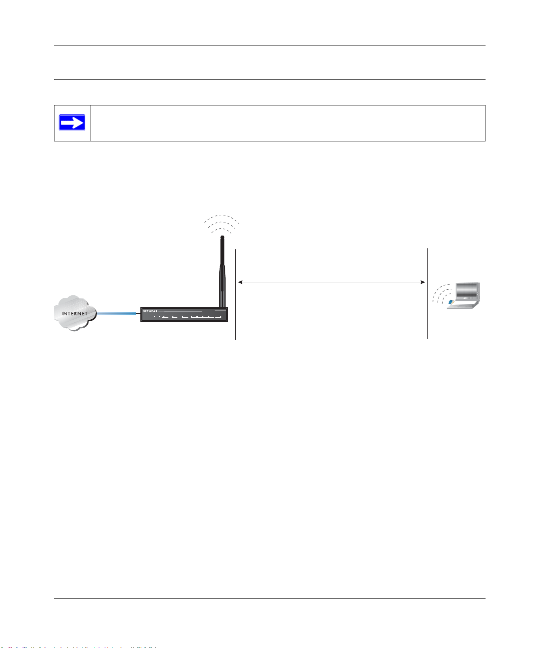
Reference Manual for the ProSafe Wireless 802.11g Firewall/Print Server Model FWG114P v2
Implementing Appropriate Wireless Security
Note: Indoors, computers can connect to wireless networks at ranges of 300 feet or
more. Such distances allow others outside of your area to access your network.
Unlike wired network data, your wireless data transmissions can extend beyond your walls and
can be received by anyone with a compatible adapter. For this reason, use the security features of
your wireless equipment. The FWG114P v2 Wireless Firewall/Print Server provides highly
effective security features which are covered in detail in this chapter.
:LUHOHVV'DWD
6HFXULW\2SWLRQV
5DGLXV8SWR)HHW
.O3ECURITY%ASYBUTNOSECURITY
Á?aM?a
+Á.?wjËoåÔ±¤¤~Ë8ÁjjÄÄËÁjÝ?Ê+ÁÍË.jÁÜjÁ
$&7
$&7
/1.$&7
3:5
7(67
$/(57
$/(57
02).4%2 -/$%- ).4%2.%4 ,/#!, 7,!.
FWG114P
#
8¤¤|+
/1.$&7
-!#!CCESS,IST.ODATASECURITY
7%03ECURITYBUTSOME
PERFORMANCEIMPACT
70!OR70!03+6ERYSTRONGSECURITY
Figure 4-1: FWG1 14P v2 wireless data security options
There are several ways you can enhance the security of your wireless network:
• Restrict Access Based on MAC Address. You can allow only trusted PCs to connect so that
unknown PCs cannot wirelessly connect to the FWG114P v2. Restricting access by MAC
address adds an obstacle against unwanted access to your network, but the data broadcast over
the wireless link is fully exposed.
• Turn Off the Broadcast of the Wireless Network Name SSID. If you disable broadcast of
the SSID, only devices that have the correct SSID can connect. This nullifies wireless network
‘discovery’ feature of some products, such as Windows XP, but the data is still exposed.
• WEP. Wired Equivalent Privacy (WEP) data encryption provides data security. WEP Shared
Key authentication and WEP data encryption will block all but the most determined
eavesdropper.
4-2 Wireless Configuration
201-10301-02, May 2005
Page 51
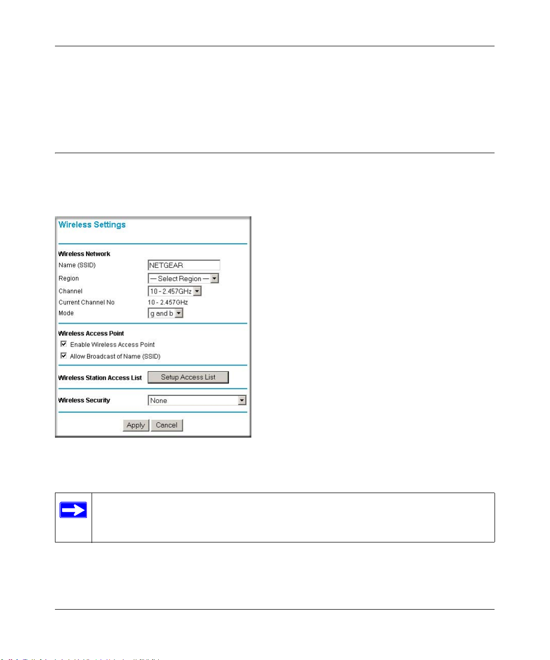
Reference Manual for the ProSafe Wireless 802.11g Firewall/Print Server Model FWG114P v2
• WPA/WPA2 with Radius or WPA/WPA2-PSK. Wi-Fi Protected Access (WPA and WPA2)
data encryption provides data security . The very strong authentication along with dyn amic per
frame rekeying of WPA and WPA2 make it virtually impossible to compromise. Because this
is a new standard, wireless device driver and software availability may be limited.
Understanding Wireless Settings
To configure the wireless settings of your FWG114P v2, click the Wireless link in the Setup
section of the main menu. The wireless settings menu will appear, as shown below.
Figure 4-2: Wireless Settings menu
Note: The 802.11b and 802.1 1g wireless networking protocols are configured in exactly
the same fashion. The FWG114P v2 will automatically adjust to the 802.11g or 802.11b
protocol as the device requires without compromising the speed of the other devices.
Wireless Configuration 4-3
201-10301-02, May 2005
Page 52

Reference Manual for the ProSafe Wireless 802.11g Firewall/Print Server Model FWG114P v2
• Wireless Network. The station name of the FWG114P v2.
— Wireless Network Name (SSID). The SSID is also known as the wireless network name.
Enter a value of up to 32 alphanumeric characters. In a setting where there is more than
one wireless network, different wireless network names provide a means for separating the
traffic. Any device you want to participate in the 802.11b/g wireless network will need to
use this SSID for that network. The FWG114P v2 default SSID is: NETGEAR.
— Region. This field identifies the region where the FWG114P v2 can be used . It may not be
legal to operate the wireless features of the wireless firewall/print server in a region other
than one of those identified in this field. Unless you select a region, you will only be able
to use Channel 11.
— Channel. This field determines which operating frequency will be used. It should not be
necessary to change the wireless channel unless you notice interference problems with
another nearby access point. For more information on the wireless channel frequencies,
please refer to “Wireless Channels” on page E-7.
— Mode. Select the desired wireless mode. The options are:
• g & b - Both 802.11g and 802.11b wireless stations can be used.
• g only - Only 802.11g wireless stations can be used.
• b only - All 802.11b wireless stations can be used. 802.11g wireless stations can still
be used if they can operate in 802.11b mode.
The default is “g & b” which allows both 802.11g and 802.11b wireless stations to access
this device.
• Wireless Access Point
— Enable Wireless Access Point. Enables the wireless radio. When disabled, there are no
wireless communications through the FWG114P v2.
— Allow Broadcast of Name (SSID). The default setting is to enable SSID broadcast. If yo u
disable broadcast of the SSID, only devices that have the correct SSID can connect.
Disabling SSID broadcast somewhat hampers the wireless network ‘discovery’ feature of
some products.
• Wireless Card Access List
Lets you restrict wireless connections according to a list of Trusted PCs MAC addresses.
When the Trusted PCs Only radio button is selected, the FWG114P v2 checks the MAC
address of the wireless station and only allows connections to PCs identified on the trusted
PCs list.
4-4 Wireless Configuration
201-10301-02, May 2005
Page 53

Reference Manual for the ProSafe Wireless 802.11g Firewall/Print Server Model FWG114P v2
T o restrict access based on MAC addresses, click the Set up Access List button and update the
MAC access control list.
• Security Options
– Disable: No data encryption is used.
– WEP (Wired Equivalent Privacy): Use WEP 64 or 128 bit data encryption.
– WPA with Radius: This version of WPA requires the use of a Radius server for
authentication. Each user (Wireless Client) must have a "user" login on the Radius Server
- normally done via a digital certificate. Also, this device must have a "client" login on the
Radius server. Data transmissions are encrypted using a key which is automatically
generated.
– WPA2 with Radius: WPA2 is a later version of WPA. Only select this if all clients
support WP A2. If selected, you must use AES encryption, and configure the Radius Server
Settings. Each user (Wireless Client) must have a "user" login on the Radius Server normally done via a digital certificate. Also, this device must have a "client" login on the
Radius server. Data transmissions are encrypted using a key which is automatically
generated.
– WP A and WPA2 with Radius: This selection allows clients to use either WPA (with AES
encryption) or WPA2 (with TKIP encryption). If selected, encryption must be TKIP +
AES. If selected, you must configure the Radius Server Settings.
– WPA-PSK (Wi-Fi Protected Access Pre-Shared Key): Use WPA-PSK standard
encryption
– WPA2-PSK: WPA2 is a later version of WPA. Only select this if all clients support
WPA2. If selected, you must use AES encryption, and enter the WPA passphrase
(Network key).
– WPA-PSK and WPA2-PSK: This selection allows clients to use either WPA (with AES
encryption) or WPA2 (with TKIP encryption). If selected, encryption must be TKIP +
AES.
Wireless Configuration 4-5
201-10301-02, May 2005
Page 54
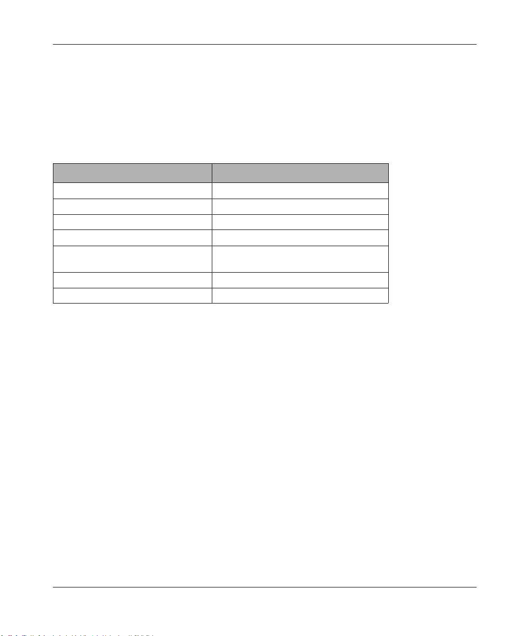
Reference Manual for the ProSafe Wireless 802.11g Firewall/Print Server Model FWG114P v2
Default Factory Settings
The FWG114P v2 default factory settings shown below. You can restore these defaults with the
Factory Default Restore button on the rear panel as seen in the illustration “FWG114P v2 Rear
Panel” on page 2-9. After you install the FWG114P v2 Wireless Firewall/Print Server, use the
procedures below to customize any of the settings to better meet your networking needs.
FEATURE DEFAULT FACTORY SETTINGS
SSID NETGEAR
RF Channel 11 until the region is selected
Access Point Enabled
SSID broadcast Enabled
Wireless Card Access List for
Access Point Connections
WEP Security Disabled
Authentication Type Open System
All wireless stations allowed
4-6 Wireless Configuration
201-10301-02, May 2005
Page 55

Reference Manual for the ProSafe Wireless 802.11g Firewall/Print Server Model FWG114P v2
Before You Change the SSID and WEP Settings
Take the following steps:
For a new wireless network, print or copy this form and fill in the configuration parameters. For an
existing wireless network, the person who set up or is responsible for the network will be able to
provide this information. Be sure to set the Regulatory Domain correctly as the first step.
• SSID: The Service Set Identification (SSID) identifies the wireless local area network.
Wireless is the default FWG114P v2 SSID. However , yo u may customize it by using u p to 32
alphanumeric characters. Write your customized SSID on the line below.
Note: The SSID in the wireless firewall/print server is the SSID you configure in the wireless
adapter card. All wireless nodes in the same network must be configured with the same SSID:
• Authentication
Circle one: Open System or Shared Key. Choose “Shared Key” for more security.
Note: If you select shared key, the other devices in the network will not connect unless they
are set to Shared Key as well and have the same keys in the same positions as those in the
FWG114P v2.
• WEP Encryption Keys
For all four 802.11b keys, choose the Key Size. Circle one: 64 or 128 bits
Key 1: ___________________________________
Key 2: ___________________________________
Key 3: ___________________________________
Key 4: ___________________________________
• WPA-PSK or WPA2-PSK (Pre-Shared Key)
Record the WPA-PSK or WPA2-PSK key:
Key: ___________________________________
• WPA or WPA2 RADIUS Settings
For WPA or WPA2, record the following RADIUS settings:
Server Name/IP Address: Primary _________________
Port: ___________________________________
Shared Key: ___________________________________
Secondary __________________
Use the procedures described in the following sections to configure the FWG114P v2. Store this
information in a safe place.
Wireless Configuration 4-7
201-10301-02, May 2005
Page 56
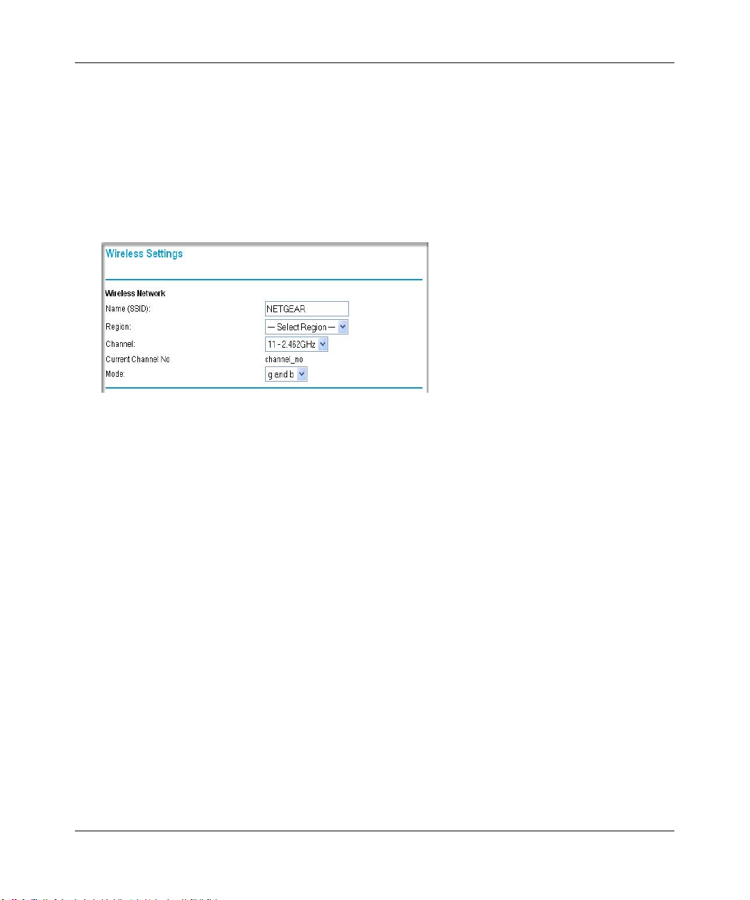
Reference Manual for the ProSafe Wireless 802.11g Firewall/Print Server Model FWG114P v2
How to Set Up and Test Basic Wireless Connectivity
Follow the instructions below to set up and test basic wireless connectivity. Once you have
established basic wireless connectivity , you can enable security settings appropriate to your needs.
1. Log in using the default LAN address of http://192.168.0.1 with the default user name of
admin and default password of password, or using whatever LAN address and password you
have set up.
Figure 4-3: Wireless Settings menu
2.
Set the Regulatory Domain correctly.
3. Choose a suitable descriptive name for the wireless network name (SSID). In the SSID box,
enter a value of up to 32 alphanumeric characters. The default SSID is NETGEAR.
Note: The characters are case sensitive. An access point always functions in infrastructure
mode. The SSID for any wireless device communicating with the access point must match the
SSID configured in the ProSafe W ireless 802.11g Firewall/Print Server Model FWG1 14P v2.
If they do not match, you will not get a wireless connection to the FWG114P v2.
4. Set the Channel.
It should not be necessary to change the wireless channel unless you notice interference
problems with another nearby wireless router or access point. Select a channel that is not being
used by any other wireless networks within several hundred feet of your wireless firewall/print
server. For more information on the wireless channel frequencies please refer to “Wireless
Channels” on page E-7.
5. Depending on the types of wireless adapters you have in your computers, choose from the
Mode drop-down list.
6. For initial configuration and test, leave the Wireless Card Access List set to “All Wireless
Stations” and the Encryption Strength set to “Disable.”
4-8 Wireless Configuration
201-10301-02, May 2005
Page 57

Reference Manual for the ProSafe Wireless 802.11g Firewall/Print Server Model FWG114P v2
Click Apply to save your changes.
7.
Note: If you are configuring the FWG114P v2 from a wireless computer and you
change the wireless firewall/print server’s SSID, channel, or security settings, you will
lose your wireless connection when you click on Apply. You must then change the
wireless settings of your computer to match the FWG114P v2’s new settings.
8. Configure and test your PCs for wireless connectivity.
Program the wireless adapter of your PCs to have the same SSID that you configured in the
FWG114P v2. Check that they have a wireless link and are able to obtain an IP address by
DHCP from the wireless firewall/print server.
Once your PCs have basic wireless connectivity to the wireless firewall/print server, then you can
configure the advanced options and wireless security functions.
How to Restrict Wireless Access by MAC Address
To restrict access based on MAC addresses, follow these steps:
1. Log in at the default LAN address of http://192.168.0.1 with the default user name of admin
and default password of password.
2. Click Wireless in the main menu of the FWG114P v2. From the Wireless Settings menu, click
Setup Access List.
Figure 4-4: Wireless Station Access menu
3.
Click the Turn Access Control On checkbox to enable MAC filtering.
Wireless Configuration 4-9
201-10301-02, May 2005
Page 58

Reference Manual for the ProSafe Wireless 802.11g Firewall/Print Server Model FWG114P v2
Click Add to open the W ireless Card Access Setup menu. You can select a device from the list
4.
of available wireless cards the FWG114P v2 has discovered in your area, or you can manually
enter the MAC address and Device Name (usually the NetBIOS name).
5. Click Add to add this device to your MAC access control list.
Note: When configuring the FWG114P v2 from a wireless computer whose MAC
address is not in the access control list, if you select Turn Access Control On, you will
lose your wireless connection when you click Apply. You must then access the wireless
firewall/print server from a wired computer or from a wireless computer which is on the
access control list to make any further changes.
6. Be sure to click Apply to save your trusted wireless PCs list settings. Now, only devices on
this list will be allowed to wirelessly connect to the FWG114P v2.
To remove a MAC address from the table, click to select it, then click the Delete button.
How to Configure WEP
Note: When changing the wireless settings from a wireless computer , you will lose your
wireless connection when you click Apply. You must then either configure your wireless
adapter to match the new wireless settings or access the wireless firewall/print server
from a wired computer to make any further changes.
To configure WEP data encryption, follow these steps:
1. Log in at the default LAN address of http://192.168.0.1 with the default user name of admin
and default password of password, or using whatever LAN address and password you set up.
4-10 Wireless Configuration
201-10301-02, May 2005
Page 59
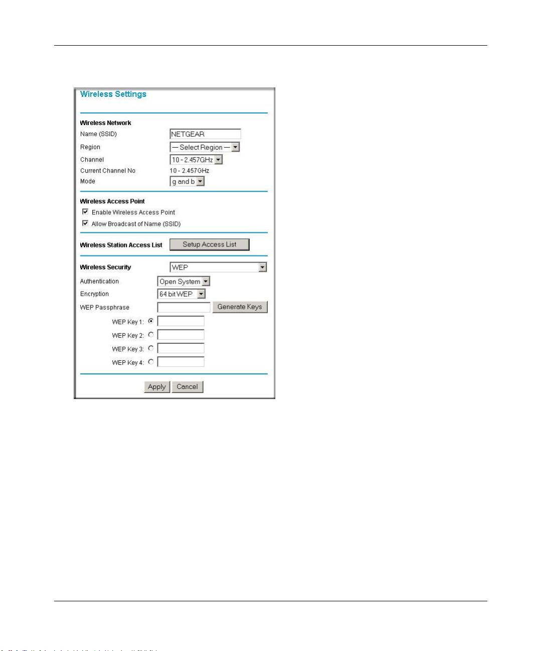
Reference Manual for the ProSafe Wireless 802.11g Firewall/Print Server Model FWG114P v2
Click Wireless Settings in the main menu of the FWG114P v2.
2.
Figure 4-5: Wireless Settings menu (WEP)
3.
Select WEP on the pulldown menu. The WEP options menu will open.
4. Choose the Authentication Type and Encryption Strength options. You can manu ally or
automatically program the four data encryption keys. These values must be identical on all
PCs and Access Points in your network.
– Authentication T ype: Normally this can be left at the default value of "Automatic." If set
to "Open System" or "Shared Key", wireless stations must use the same method.
– Encryption: Select the desired WEP Encryption:
• 64-bit (sometimes called 40-bit) encryption
• 128-bit encryption
Wireless Configuration 4-11
201-10301-02, May 2005
Page 60

Reference Manual for the ProSafe Wireless 802.11g Firewall/Print Server Model FWG114P v2
– WEP Keys: If using WEP, you can manually or automatically program the four data
encryption keys. These values must be identical on all PCs and Access Points in your
network.
• Automatic Key Generation (Passphrase): Enter a word or group of printable
characters (this phrase is case sensitive) in the Passphrase box and click the "Generate
Keys" button to automatically configure the WEP Key(s).
– If encryption is set to 64 bit, then each of the four key boxes will automatically be
populated with key values.
– If encryption is set to 128 bit, then only the selected WEP key box will
automatically be populated with a key value.
• Manual Entry Mode: Enter ten hexadecimal digits (any combination of 0-9, a-f, or
A-F). These hex values are not case sensitive. Select which of the four keys will be
used and enter the matching WEP key information for your network in the selected
key box.
– For 64 bit WEP: Enter ten hexadecimal digits (any combination of 0-9, A-F).
– For 128 bit WEP: Enter twenty-six hexadecimal digits (any combination of 0-9,
A-F).
Please refer to “Overview of WEP Parameters” on page E-5 for a full explanation of each of
these options, as defined by the IEEE 802.11b wireless communication standard.
5. Click Apply to save your settings.
How to Configure WPA with Radius
Note: Not all wireless adapters support WPA. Furthermore, client software is required on the
client. Windows XP and Windows 2000 with Service Pack 3 do include the client software that
supports WPA. Nevertheless, the wireless adapter hardware and driver must also support WPA.
Consult the product document for your wireless adapter and WPA client software for instructions
on configuring WPA settings.
To configure WPA with Radius, follow these steps:
1. Log in at the default LAN address of http://192.168.0.1 with the default user name of admin
and default password of password, or using whatever LAN address and password you have
set up.
4-12 Wireless Configuration
201-10301-02, May 2005
Page 61

Reference Manual for the ProSafe Wireless 802.11g Firewall/Print Server Model FWG114P v2
Click Wireless Settings in the main menu of the FWG114P v2.
2.
Figure 4-6: Wireless Settings menu (WPA with Radius)
3.
Select WPA with Radius on the pulldown menu. The WPA with Radius menu will open.
Encryption: There is no choice for encryption; this is displayed for your information. For
WPA with Radius, TKIP is used.
4. Enter the Radius settings.
• Primary Server Name/IP Address: This field is required. Enter the name or IP address
of the primary Radius Server on your LAN.
• Secondary Radius Server Name/IP Address: This field is optional. If you have a
Secondary Radius Server on your LAN, enter its name or IP address here.
Wireless Configuration 4-13
201-10301-02, May 2005
Page 62

Reference Manual for the ProSafe Wireless 802.11g Firewall/Print Server Model FWG114P v2
• Radius Port: Enter the port number used for connecting to the Radius Server.
• Shared Key: Enter the desired value for the Shared Key. This must match the value used
on the Radius server.
• Radius Accounting: Enable Radius Accounting
Enable this if you want to use the Radius Accounting system. If enabled, the following
fields must be correct:
• Radius Accounting Port: Enter the port number used for Accounting data on the Radius
Server.
• Update Report: Enable this if you wish to have this AP send Accounting update
messages to the Radius accounting server periodically.
If enabled, enter the desired Update Report interval in the field provided.
5. Click Apply to save your settings.
How to Configure WPA2 with Radius
Note: Not all wireless adapters support WPA2. Furthermore, client software is required on the
client. Windows XP and Windows 2000 with Service Pack 3 do include the client software that
supports WPA2. Nevertheless, the wireless adapter hardware and driver must also support WPA2.
Consult the product document for your wireless adapter and WPA2 client software for instructions
on configuring WPA2 settings.
To configure WPA2 with Radius, follow these steps:
1. Log in at the default LAN address of http://192.168.0.1 with the default user name of admin
and default password of password, or using whatever LAN address and password you have
set up.
4-14 Wireless Configuration
201-10301-02, May 2005
Page 63

Reference Manual for the ProSafe Wireless 802.11g Firewall/Print Server Model FWG114P v2
Click Wireless Settings in the main menu of the FWG114P v2.
2.
Figure 4-7: Wireless Settings menu (WPA2 with Radius)
3.
Select WPA2 with Radius on the pulldown menu. The WPA2 with Radius menu will open.
Encryption: There is no choice for encryption; this is displayed for your information. For
WPA2 with Radius, AES is used.
4. Enter the Radius settings.
• Primary Server Name/IP Address: This field is required. Enter the name or IP address
of the primary Radius Server on your LAN.
Wireless Configuration 4-15
201-10301-02, May 2005
Page 64

Reference Manual for the ProSafe Wireless 802.11g Firewall/Print Server Model FWG114P v2
• Secondary Radius Server Name/IP Address: This field is optional. If you have a
Secondary Radius Server on your LAN, enter its name or IP address here.
• Radius Port: Enter the port number used for connecting to the Radius Server.
• Shared Key: Enter the desired value for the Shared Key. This must match the value used
on the Radius server.
• Radius Accounting: Enable Radius Accounting
Enable this if you want to use the Radius Accounting system. If enabled, the following
fields must be correct:
• Radius Accounting Port: Enter the port number used for Accounting data on the Radius
Server.
• Update Report: Enable this if you wish to have this AP send Accounting update
messages to the Radius accounting server periodically.
If enabled, enter the desired Update Report interval in the field provided.
5. Click Apply to save your settings.
How to Configure WPA and WPA2 with Radius
Note: Not all wireless adapters support WPA and WPA2. Furthermore, client software is required
on the client. Windows XP and Windows 2000 with Service Pack 3 do include the client software
that supports WPA and WPA2. Nevertheless, the wireless adapter hardware and driver must also
support WPA and WPA2. Consult the product document for your wireless adapter and WPA and
WPA2 client software for instructions on configuring WPA and WPA2 settings.
To configure WPA and WPA2 with Radius, follow these steps:
1. Log in at the default LAN address of http://192.168.0.1 with the default user name of admin
and default password of password, or using whatever LAN address and password you have
set up.
4-16 Wireless Configuration
201-10301-02, May 2005
Page 65

Reference Manual for the ProSafe Wireless 802.11g Firewall/Print Server Model FWG114P v2
Click Wireless Settings in the main menu of the FWG114P v2.
2.
Figure 4-8: Wireless Settings menu (WPA and WPA2 with Radius)
3.
Select WPA and WPA2 with Radius on the pulldown menu. The WPA and WPA2 with
Radius menu will open.
Encryption: There is no choice for encryption; this is displayed for your information. For
WPA and WPA2 with Radius, WPA clients must use TKIP, and WPA2 clients must use AES.
4. Enter the Radius settings.
• Primary Server Name/IP Address: This field is required. Enter the name or IP address
of the primary Radius Server on your LAN.
Wireless Configuration 4-17
201-10301-02, May 2005
Page 66

Reference Manual for the ProSafe Wireless 802.11g Firewall/Print Server Model FWG114P v2
• Secondary Radius Server Name/IP Address: This field is optional. If you have a
Secondary Radius Server on your LAN, enter its name or IP address here.
• Radius Port: Enter the port number used for connecting to the Radius Server.
• Shared Key: Enter the desired value for the Shared Key. This must match the value used
on the Radius server.
• Radius Accounting: Enable Radius Accounting
Enable this if you want to use the Radius Accounting system. If enabled, the following
fields must be correct:
• Radius Accounting Port: Enter the port number used for Accounting data on the Radius
Server.
• Update Report: Enable this if you wish to have this AP send Accounting update
messages to the Radius accounting server periodically.
If enabled, enter the desired Update Report interval in the field provided.
5. Click Apply to save your settings.
How to Configure WPA-PSK
Note: Not all wireless adapters support WPA. Furthermore, client software is required on the
client. Windows XP and Windows 2000 with Service Pack 3 do include the client software that
supports WPA. Nevertheless, the wireless adapter hardware and driver must also support WPA.
Consult the product document for your wireless adapter and WPA client software for instructions
on configuring WPA settings.
To configure WPA-PSK, follow these steps:
1. Log in at the default LAN address of http://192.168.0.1, with the default user name of admin
and default password of password, or using whatever LAN address and password you have
set up.
4-18 Wireless Configuration
201-10301-02, May 2005
Page 67
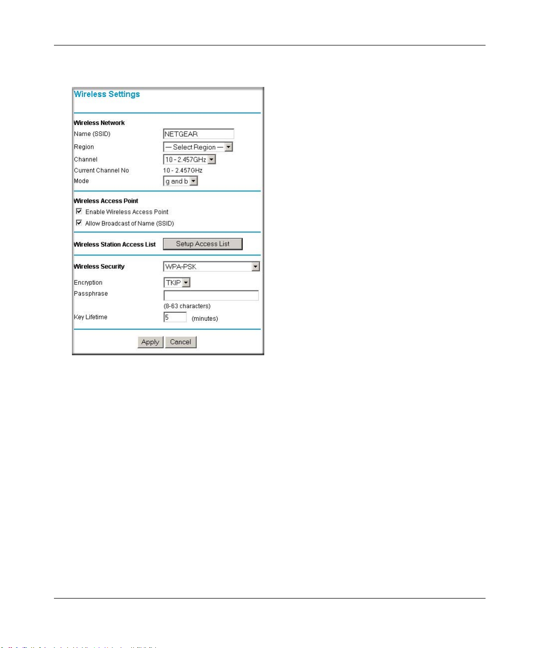
Reference Manual for the ProSafe Wireless 802.11g Firewall/Print Server Model FWG114P v2
Click Wireless Settings in the main menu of the FWG114P v2.
2.
Figure 4-9: Wireless Settings menu (WPA-PSK)
3.
Select WPA-PSK on the pulldown menu. The WPA-PSK menu will open.
4. Select the desired Encryption method. For WPA-PSK, you can choose TKIP or AES.
5. Enter the pre-shared key in the Passphrase field. Enter a word or group of printable characters
in the Passphrase box. The Passphrase must be 8 to 63 characters in length. The 256 Bit key
used for encryption is generated from this passphrase.
6. Enter the Key Lifetime. This setting determines how often the encryption key is changed.
Shorter periods provide greater security, but adversely affect performance. If desired, you can
change the default value.
7. Click Apply to save your settings.
Wireless Configuration 4-19
201-10301-02, May 2005
Page 68
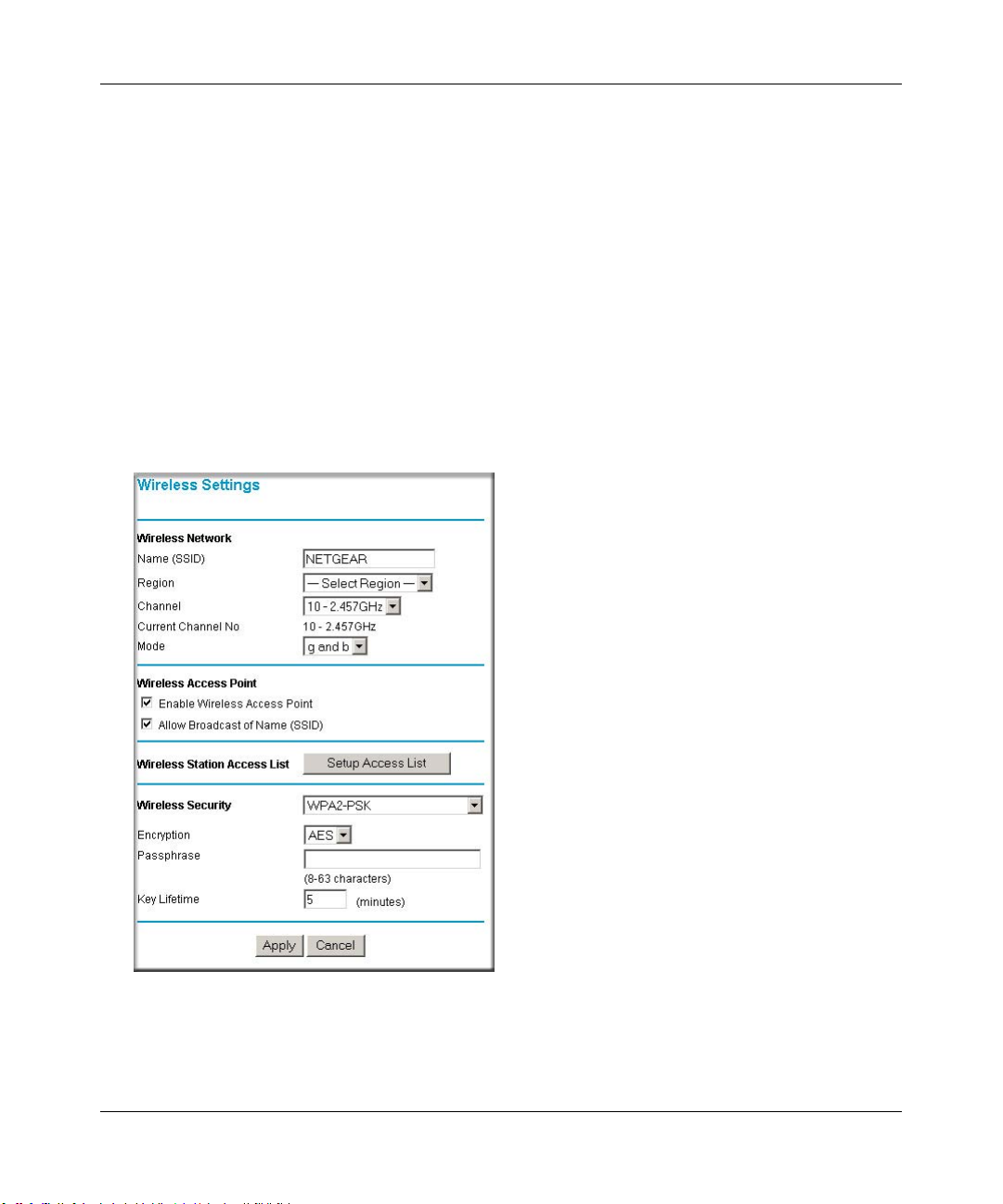
Reference Manual for the ProSafe Wireless 802.11g Firewall/Print Server Model FWG114P v2
How to Configure WPA2-PSK
Note: Not all wireless adapters support WPA2. Furthermore, client software is required on the
client. Windows XP and Windows 2000 with Service Pack 3 do include the client software that
supports WPA2. Nevertheless, the wireless adapter hardware and driver must also support WPA2.
Consult the product document for your wireless adapter and WP2 client software for instructions
on configuring WPA2 settings.
To configure WPA2-PSK, follow these steps:
1. Log in at the default LAN address of http://192.168.0.1, with the default user name of admin
and default password of password, or using whatever LAN address and password you have
set up.
2. Click Wireless Settings in the main menu of the FWG114P v2.
Figure 4-10: Wireless Settings menu (WPA2-PSK)
3.
Select WPA2-PSK on the pulldown menu. The WPA2-PSK menu will open.
4-20 Wireless Configuration
201-10301-02, May 2005
Page 69

Reference Manual for the ProSafe Wireless 802.11g Firewall/Print Server Model FWG114P v2
Select the desired Encryption method. For WPA2-PSK, the only option is AES.
4.
5. Enter the pre-shared key in the Passphrase field. Enter a word or group of printable characters
in the Passphrase box. The Passphrase must be 8 to 63 characters in length. The 256 Bit key
used for encryption is generated from this passphrase.
6. Enter the Key Lifetime. This setting determines how often the encryption key is changed.
Shorter periods provide greater security, but adversely affect performance. If desired, you can
change the default value.
7. Click Apply to save your settings.
How to Configure WPA-PSK and WPA2-PSK
Note: Not all wireless adapters support WPA and WPA2. Furthermore, client software is required
on the client. Windows XP and Windows 2000 with Service Pack 3 do include the client software
that supports WPA and WPA2. Nevertheless, the wireless adapter hardware and driver must also
support WPA and WPA2. Consult the product document for your wireless adapter and WPA and
WPA2 client software for instructions on configuring WPA and WPA2 settings.
To configure WPA-PSK and WPA2-PSK, follow these steps:
1. Log in at the default LAN address of http://192.168.0.1, with the default user name of admin
and default password of password, or using whatever LAN address and password you have
set up.
Wireless Configuration 4-21
201-10301-02, May 2005
Page 70
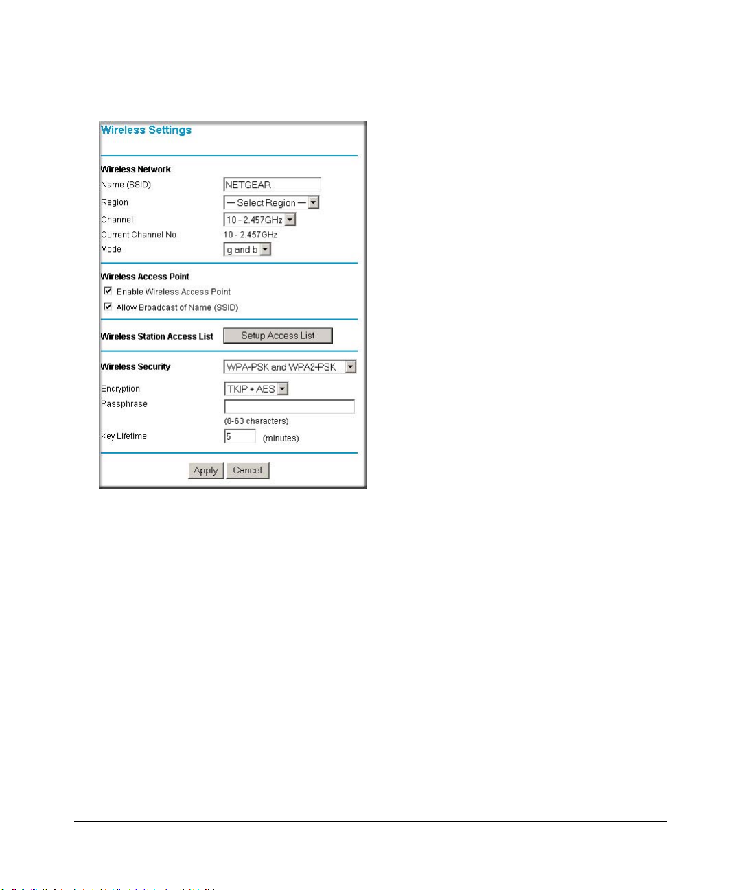
Reference Manual for the ProSafe Wireless 802.11g Firewall/Print Server Model FWG114P v2
Click Wireless Settings in the main menu of the FWG114P v2.
2.
Figure 4-11: Wireless Settings menu (WPA-PSK and WPA2-PSK)
3.
Select WPA-PSK and WPA2-PSK on the pulldown menu. The WPA-PSK and WPA2-PSK
menu will open.
4. Select the desired Encryption method. For WPA-PSK and WPA2-PSK, the only option is
TKIP + AES. WPA clients must use TKIP, and WPA2 clients must use AES.
5. Enter the pre-shared key in the Passphrase field. Enter a word or group of printable characters
in the Passphrase box. The Passphrase must be 8 to 63 characters in length. The 256 Bit key
used for encryption is generated from this passphrase.
6. Enter the Key Lifetime. This setting determines how often the encryption key is changed.
Shorter periods provide greater security, but adversely affect performance. If desired, you can
change the default value.
7. Click Apply to save your settings.
4-22 Wireless Configuration
201-10301-02, May 2005
Page 71

Chapter 5
Serial Port Configuration
This chapter describes how to configure the serial port options of your ProSafe Wireless 802.11g
Firewall/Print Server Model FWG114P v2. The FWG114P v2 serial port lets you share the
broadband connection of another FWG114P v2, share resources between two LANs, and take
advantage of the routing functions on the broadband (WAN), LAN, and serial network interfaces.
Note: If you configure the serial port of the FWG114P v2 as the primary Internet connection, you
will not be able to configure the other serial port options. For instructions on configuring the serial
port as the primary Internet connection, please see “How to Configure the Serial Port as the
Primary Internet Connection“ on page 3-15.
The FWG114P v2 provides these serial port configuration options:
•Modem
Use this option to configure the serial modem settings for any of the features below.
• Auto-Rollover
Use this option to provide a backup connection for your broadband service. If the broadband
service you configured in the Basic Settings menu fails, the FWG114P v2 will automatically
connect to the Internet through the serial port. However, you will then be accessing the
Internet at a slower speed than you would through your broadband service.
• Dial-in
Dial-in lets a single remote computer connect to the FWG114P v2 through the serial port to
gain access to LAN resources or a remote access server.
• LAN-to-LAN
LAN-to-LAN enables direct communications between two FWG114P v2 wireless firewall/
print servers to:
— Share resources on the two LANs.
— Let users on one FWG114P v2 share the Internet connection of the other FWG114P v2.
— Let users on one FWG114P v2 connect to the Internet through the second FWG114P v2 in
case the broadband connection of the first FWG114P v2 fails.
The procedures for these configuration options are presented below.
Serial Port Configuration 5-1
201-10301-02, May 2005M-10207-01, Reference Manual v2
Page 72
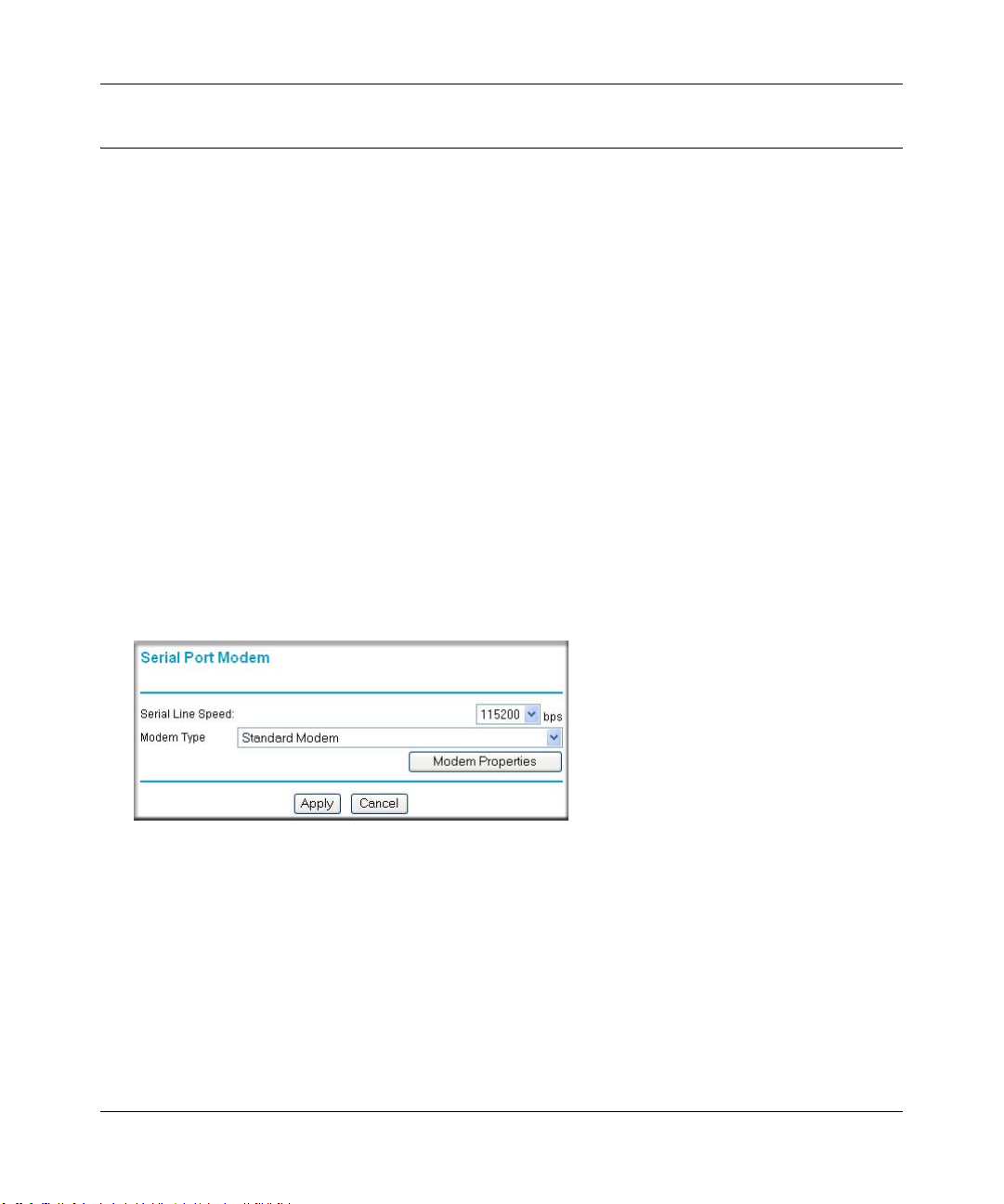
Reference Manual for the ProSafe Wireless 802.11g Firewall/Print Server Model FWG114P v2
Configuring a Serial Port Modem
You can configure a serial port modem for any of the features described above.
Be sure you have prepared the basic requirements listed below, then follow the ‘how to’ procedure.
Basic Requirements for Serial Port Modem Configuration
Configuring a serial port modem requires these elements:
1. A serial analog or ISDN modem.
2. A serial modem cable with a DB9 connector.
3. An active phone or ISDN line.
How to Configure a Serial Port Modem
Follow the steps below to configure a serial port modem.
1. From the main menu, click Modem in the Serial Port section.
Figure 5-1: Serial Port Modem configuration menu
2.
Select the Serial Line Speed.
This is the maximum speed the modem will attempt to use. For ISDN permanent connections,
the speeds are typically 64000 or 128000 bps. For dial-up modems, 56000 bps would be a
typical setting.
3. Select the Modem Type:
— For ISDN, select “Permanent connection (leased line).”
5-2 Serial Port Configuration
201-10301-02, May 2005M-10207-01, Reference Manual v2
Page 73

Reference Manual for the ProSafe Wireless 802.11g Firewall/Print Server Model FWG114P v2
— For dial-up, “Standard Modem” should work in most cases. Otherwise, select your modem
from the list.
— If your modem is not on the list, select “User Defined” and enter the Modem Properties.
If you are using the “User Defined” selection and configuring your own modem stings, fill
in the Modem Properties settings.
Note: Y ou can validate modem string settings by first connecting the modem directly to a
computer, establishing a connection to your ISP, and then copying the modem string
settings from the computer configuration and pasting them into the FWG114P v2 Modem
Properties Initial String field. For more information on this procedure, please refer to the
support area of the NETGEAR Web site.
4. Click Apply to save your settings.
Configuring Auto-Rollover
You can configure the serial port of the FWG114P v2 to provide an auto-rollover backup
connection for your broadband service.
Be sure you have prepared the basic requirements listed below, then follow the ‘how to’ procedure.
Basic Requirements for Auto-Rollover
Auto-Rollover requires these elements:
1. A broadband connection to the FWG114P v2.
2. An ISDN or analog phone line with an active ISDN or dial-up ISP account.
3. A serial modem properly configured and attached to the DB9 connector on the serial port.
4. The Auto-Rollover settings configured and applied to the FWG114P v2.
How to Configure Auto-Rollover
Follow the steps below to configure a serial port auto-rollover connection.
1. Configure a serial port modem according to the instructions above.
2. From the main menu, click Auto-rollover in the Serial Port section.
Serial Port Configuration 5-3
201-10301-02, May 2005M-10207-01, Reference Manual v2
Page 74

Reference Manual for the ProSafe Wireless 802.11g Firewall/Print Server Model FWG114P v2
Figure 5-2: Auto-Rollover configuration menu
Configure the Auto-Rollover settings.
3.
4. Click Apply for the changes to take effect.
Configuring Dial-in on the Serial Port
Dial-in lets a single remote computer connect to the FWG114P v2 through the serial port to gain
access to LAN resources or a remote access server.
Be sure you have prepared the basic requirements listed below, then follow the ‘how to’ procedure.
5-4 Serial Port Configuration
201-10301-02, May 2005M-10207-01, Reference Manual v2
Page 75
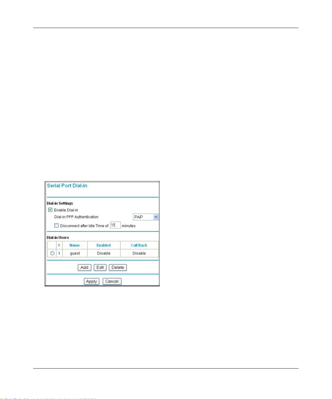
Reference Manual for the ProSafe Wireless 802.11g Firewall/Print Server Model FWG114P v2
Basic Requirements for Dial-in
Dial-in requires these elements:
1. A broadband connection to the FWG114P v2.
2. An analog phone line.
3. A serial modem properly configured and attached to the DB9 connector on the serial port.
4. The Dial-in settings configured and applied to the FWG114P v2.
How to Configure Dial-in
Follow the steps below to configure a serial port dial-in connection.
1. Configure a serial port modem according to the instructions above.
2. From the Serial Port section of the main menu, click Dial-in.
Figure 5-3: Serial Port Dial-in settings screen
3.
Configure the Dial-in settings.
4. Click Apply for the changes to take effect.
Serial Port Configuration 5-5
201-10301-02, May 2005M-10207-01, Reference Manual v2
Page 76

Reference Manual for the ProSafe Wireless 802.11g Firewall/Print Server Model FWG114P v2
Configuring LAN-to-LAN Settings
LAN-to-LAN enables direct communications between two FWG114P v2 wireless firewall/print
servers.
6HULDO&RQQHFWLRQ
)LUHZDOO$
Á?aM?a
+Á.?wjËoåÔ±¤¤~Ë8ÁjjÄÄËÁjÝ?Ê+ÁÍË.jÁÜjÁ
$&7
$&7
$/(57
/1.$&7
3:5
7(67
$/(57
02).4%2 -/$%- ).4%2.%4 ,/#!, 7,!.
#
8¤¤|+
/1.$&7
)LUHZDOO%
Á?aM?a
+Á.?wjËoåÔ±¤¤~Ë8ÁjjÄÄËÁjÝ?Ê+ÁÍË.jÁÜjÁ
$&7
$&7
$/(57
/1.$&7
3:5
7(67
$/(57
02).4%2 -/$%- ).4%2.%4 ,/#!, 7,!.
#
8¤¤|+
/1.$&7
Figure 5-4: LAN-to-LAN network configuration
Basic Requirements for LAN-to-LAN Connections
Serial port LAN-to-LAN configurations require these elements:
1. An ISDN or analog phone line with an active ISDN or dial-up ISP account.
2. A serial modem properly configured and attached to the DB9 connector on the serial port.
3. A broadband connection to one FWG114P v2 for LAN-to-LAN auto-rollover Internet access.
4. The LAN-to-LAN settings configured and applied to the two FWG114P v2 wireless firewall/
print servers.
How to Configure LAN-to-LAN Connections
Follow these steps to configure a serial port LAN-to-LAN connection.
1. Configure a serial port modem.
2. From the main menu, click LAN-to-LAN in the Serial Port section.
5-6 Serial Port Configuration
201-10301-02, May 2005M-10207-01, Reference Manual v2
Page 77

Reference Manual for the ProSafe Wireless 802.11g Firewall/Print Server Model FWG114P v2
Figure 5-5: LAN-to-LAN configuration menu
Configure the LAN-to-LAN settings.
3.
Note: The LAN subnet address of each FWG114P v2 must be different.
4. Click Apply for the changes to take effect.
Serial Port Configuration 5-7
201-10301-02, May 2005M-10207-01, Reference Manual v2
Page 78

Reference Manual for the ProSafe Wireless 802.11g Firewall/Print Server Model FWG114P v2
5-8 Serial Port Configuration
201-10301-02, May 2005M-10207-01, Reference Manual v2
Page 79

Chapter 6
Firewall Protection and
Content Filtering
This chapter describes how to use the content filtering features of the ProSafe Wireless 802.11g
Firewall/Print Server Model FWG114P v2 to protect your network. These features can be found by
clicking on the Content Filtering heading in the Main Menu of the browser interface.
Firewall Protection and Content Filtering Overview
The ProSafe Wireless 802.11g Firewall/Print Server Model FWG114P v2 provides you with Web
content filtering options, plus browsing activity reporting and instant alerts via e-mail. Parents and
network administrators can establish restricted access policies based on time-of-day, Web
addresses, and Web address keywords. You can also block Internet access by applic ations and
services, such as chat or games.
A firewall is a special category of router that protects one network (the “trusted” network, such as
your LAN) from another (the “untrusted” network, such as the Internet), while allowing
communication between the two. A firewall incorporates the functions of a NAT (Network
Address Translation) router, while adding features for dealing with a hacker intrusion or attack,
and for controlling the types of traffic that can flow between the two networks. Unlike simple
Internet sharing NAT routers, a firewall uses a process called stateful packet inspec tion to protect
your network from attacks and intrusions. NAT performs a very limited stateful inspection in that
it considers whether the incoming packet is in response to an outgoing request, but true Stateful
Packet Inspection goes far beyond NAT.
To configure these features of your router, click on the subheadings under the Content Filtering
heading in the Main Menu of the browser interface. The subheadings are described below:
Using the Block Sites Menu to Screen Content
The FWG114P v2 allows you to restrict access based on the following categories:
• Use of a proxy server
• Type of file (Java, ActiveX, Cookie)
Firewall Protection and Content Filtering 6-1
201-10301-02, May 2005
Page 80
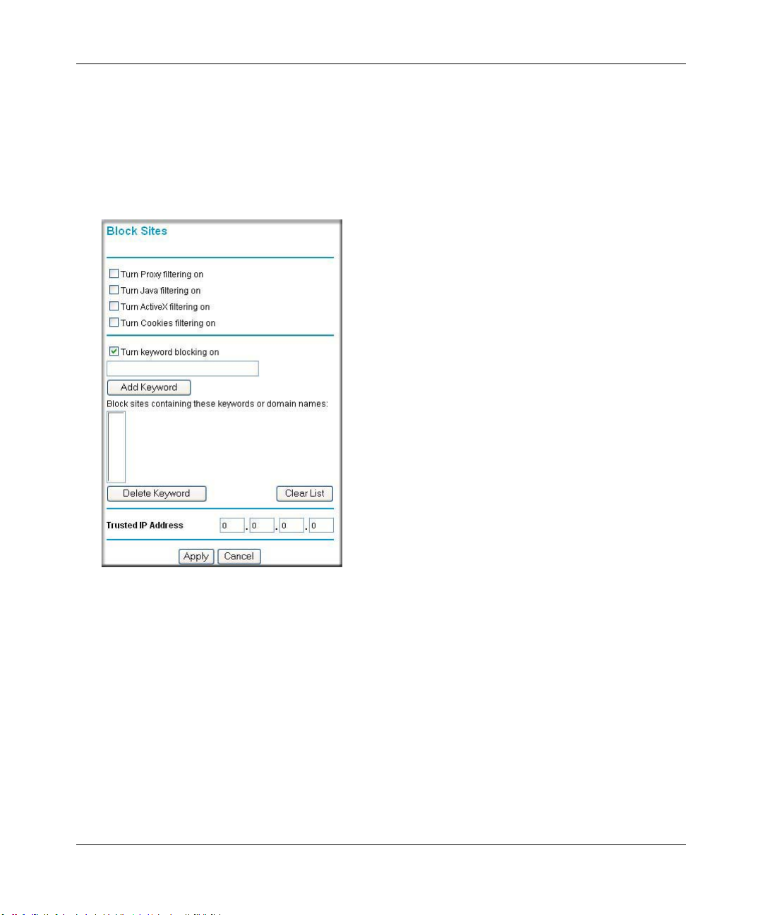
Reference Manual for the ProSafe Wireless 802.11g Firewall/Print Server Model FWG114P v2
• Web addresses
• Web address keywords
These options are discussed below.
The Keyword Blocking menu is shown here.
Figure 6-1: Block Sites menu
T o enable filtering, click the checkbox next to the type of filtering you want to enable. The filtering
choices are:
• Proxy: blocks use of a proxy server
• Java: blocks use of Java applets
• ActiveX: blocks use of ActiveX components (OCX files) used by IE on Windows
• Cookies: blocks all cookies
To enable keyword blocking, check “Turn keyword blocking on”, then click Apply.
To add a keyword or domain, type it in the Keyword box, click Add Keyword, then click Apply.
6-2 Firewall Protection and Content Filtering
201-10301-02, May 2005
Page 81

Reference Manual for the ProSafe Wireless 802.11g Firewall/Print Server Model FWG114P v2
To delete a keyword or domain, select it from the list, click Delete Keyword, then click Apply.
Keyword application examples:
• If the keyword "XXX" is specified, the URL <http://www.badstuff.com/xxx.html> is blocked,
as is the newsgroup alt.pictures.XXX.
• If the keyword “.com” is specified, only Web sites with other domain suffixes (such as .edu or
.gov) can be viewed.
• If you want to block all Internet browsing access, enter the keyword “.”.
Up to 255 entries are supported in the Keyword list.
To specify a Trusted User, enter that computer’s IP address in the Trusted User box and click
Apply . You may specify one Trusted User, which is a computer that will be exempt from blocking
and logging. Since the Trusted User will be identified by an IP address, you should configure that
computer with a fixed or reserved IP address.
Services and Rules Regulate Inbound and Outbound Traffic
The ProSafe Wireless 802.11g Firewall/Print Server Model FWG114P v2 firewall lets you
regulate what ports are available to the various TCP/IP protocols. Follow these two steps to
configure inbound or outbound traffic:
1. Define a Service
2. Set up an Inbound or Outbound Rule that uses the Service
These steps are discussed below.
Defining a Service
Services are functions performed by server computers at the request of client computers. For
example, Web servers serve Web pa ges, time servers serve time and date information, and game
hosts serve data about other players’ moves. When a computer on the Internet sends a request for
service to a server computer, the requested service is identified by a service or port number. This
number appears as the destination port number in the transmitted IP packets. For example, a packet
that is sent with destination port number 80 is an HTTP (Web server) request.
Firewall Protection and Content Filtering 6-3
201-10301-02, May 2005
Page 82

Reference Manual for the ProSafe Wireless 802.11g Firewall/Print Server Model FWG114P v2
The service numbers for many common protocols are defined by the Internet Engineering Task
Force (IETF) and published in RFC1700, “Assigned Numbers.” Service numbers for other
applications are typically chosen from the range 1024 to 65535 by the authors of the application.
Although the FWG114P v2 already holds a list of many service port numbers, you are not limited
to these choices. Use the Services menu to add additional services and applications to the list for
use in defining firewall rules. The Services menu shows a list of services that you have defined.
To define a new service, first you must determine which port number or range of n umbers is used
by the application. This information can usually be determined by contacting the publisher of the
application or from user groups of newsgroups. When you have the port number information, go
the Services menu and click on the Add Custom Service button. The Add Services menu will
appear.
To add a service,
1. Enter a descriptive name for the service so that you will remember what it is.
2. Select whether the service uses TCP or UDP as its transport protocol.
If you can’t determine which is used, select both.
3. Enter the lowest port number used by the service.
4. Enter the highest port number used by the service.
If the service only uses a single port number, enter the same number in both fields.
5. Click Apply.
The new service will now appear in the Services menu, and in the Service name selection box in
the Rules menu.
Using Inbound/Outbound Rules to Block or Allow Services
Firewall rules are used to block or allow specific traffic passing through from one side of the
wireless firewall/print server to the other. Inbound rules (WAN to LAN) restrict access by
outsiders to private resources, selectively allowing only specific outside users to access specific
resources. Outbound rules (LAN to WAN) determine what outside resources local users can have
access to.
A firewall has two default rules, one for inbound traffic and one for outbound. The default rules of
the FWG114P v2 are:
• Inbound: Block all access from outside except responses to requests from the LAN side.
• Outbound: Allow all access from the LAN side to the outside.
6-4 Firewall Protection and Content Filtering
201-10301-02, May 2005
Page 83
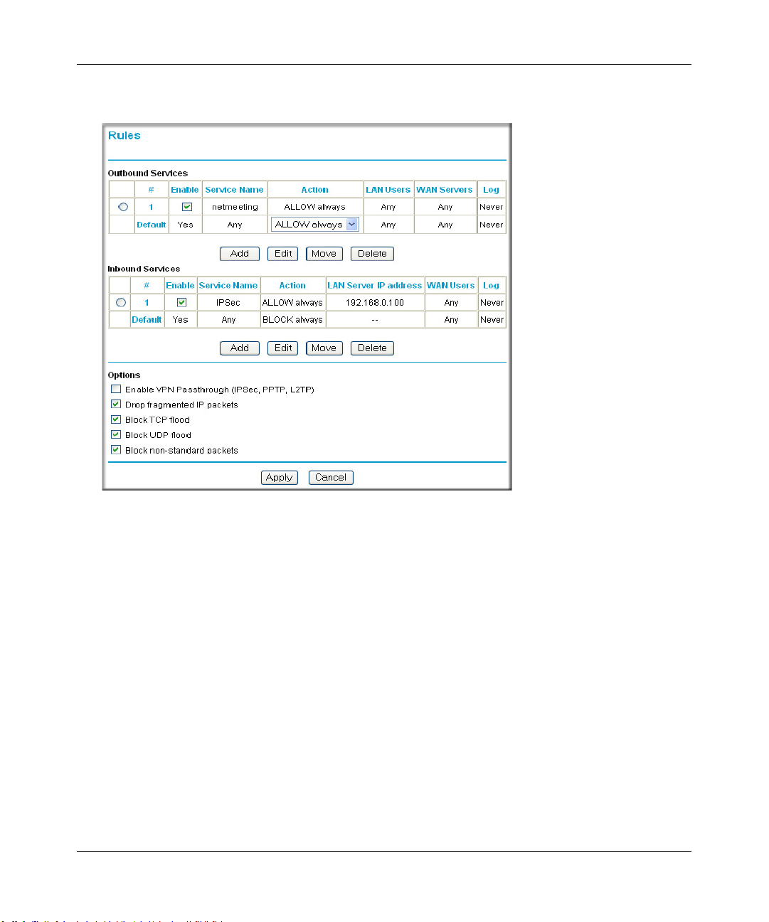
Reference Manual for the ProSafe Wireless 802.11g Firewall/Print Server Model FWG114P v2
These default rules are shown in the Rules table of the Rules menu in Figure 6-2:
Figure 6-2: Rules menu
You can define additional rules that will specify exceptions to the default rules. By adding custom
rules, you can block or allow access based on the service or application, source or destinat ion IP
addresses, and time of day. You can also choose to log traffic that matches or does not match the
rule you have defined.
To create a new rule, click the Add button.
To edit an existing rule, select its button on the left side of the table and click Edit.
To delete an existing rule, select its button on the left side of the table and click Delete.
To move an existing rule to a different position in the table, select its button on the left side of the
table and click Move. At the script prompt, enter the number of the desired new position and click
OK.
An example of the menu for defining or editing a rule is shown in Figure 6-3. The parameters are:
Firewall Protection and Content Filtering 6-5
201-10301-02, May 2005
Page 84

Reference Manual for the ProSafe Wireless 802.11g Firewall/Print Server Model FWG114P v2
• Service. From this list, select the application or service to be allowed or blocked. The list
already displays many common services, but you are not limited to these choices. Use the
Services menu to add any additional services or applications that do not already appear.
• Action. Choose how you would like this type of traffic to be handled. You can block or allow
always, or you can choose to block or allow according to the schedule you have defined in the
Schedule menu.
• Source Address. Specify traffic originating on the LAN (outbound) or the WAN (inbound),
and choose whether you would like the traffic to be restricted by source IP address. You can
select Any, a Single address, or a Range. If you select a range of addresses, enter the range in
the start and finish boxes. If you select a single address, enter it in the start box.
• Destination Address.The Destination Address will be assumed to be from the opposite (LAN
or WAN) of the Source Address. As with the Source Address, you can sele ct Any, a Single
address, or a Range unless NAT is enabled and the destination is the LAN. In that case, you
must enter a Single LAN address in the start box.
• Log. You can select whether the traffic will be logged. The choices are:
– Never - no log entries will be made for this service.
– Match - traffic of this type which matches the parameters and action will be logged.
Examples of Using Services and Rules to Regulate Traffic
Use the examples to see how you combine Services and Rules to regulate how the TCP/IP
protocols are used on your firewall to enable either blocking or allowing specific Internet traffic on
your wireless firewall/print server.
Inbound Rules (Port Forwarding)
Because the FWG114P v2 uses Network Address Translation (NAT), your network presents only
one IP address to the Internet, and outside users cannot directly address any of your local
computers. However, by defining an inbound rule, also known as port forwarding, you can make a
local server (for example, a Web server or game server) visible and available to the Internet. The
rule tells the router to direct inbound traffic for a particular service to one local server based on the
destination port number. This is also known as port forwarding.
6-6 Firewall Protection and Content Filtering
201-10301-02, May 2005
Page 85
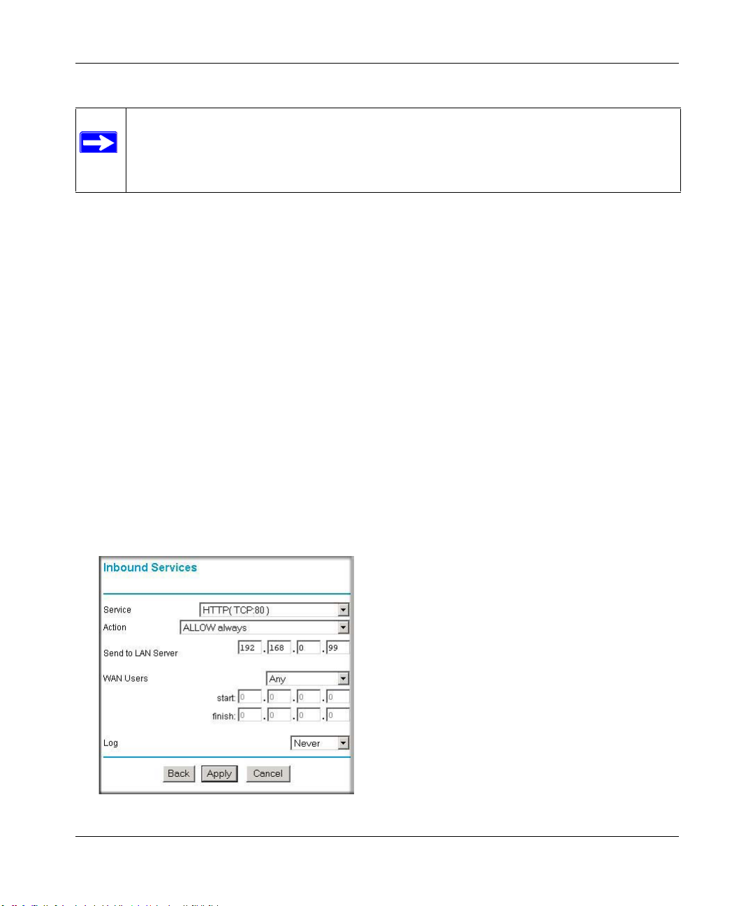
Reference Manual for the ProSafe Wireless 802.11g Firewall/Print Server Model FWG114P v2
Note: Some home broadband accounts do not allow you to run any server processes
(such as a Web or FTP server). Your ISP may check for servers and suspend your
account if it discovers active servers at your location. If you are unsure, refer to the
Acceptable Use Policy of your ISP.
Follow these guidelines when setting up port forwarding inbound rules:
• If your external IP address is assigned dynamically by your ISP, the IP address may change
periodically as the DHCP lease expires. Consider using the Dyamic DNS feature in the
Advanced menus so that external users can always find your network.
• If the IP address of the local server computer is assigned by DHCP, it may change when the
computer is rebooted. To avoid this, use the Reserved IP address feature in the LAN IP menu
to keep the computer’s IP address constant.
• Local computers must access the local server using the local LAN address of the computer.
Attempts by local computers to access the server using the external WAN IP address will fail.
Remember that allowing inbound services opens holes in your FWG114P v2 Wireless Firewall/
Print Server. Only enable those ports that are necessary for your network. Following are two
application examples of inbound rules:
Example: Port Forwarding to a Local Public Web Server
If you host a public W eb ser ver on your local network, you can define a rule to allow inbound Web
(HTTP) requests from any outside IP address to the IP address of your Web server any time of day.
Figure 6-3: Rule example: A Local Public Web Server
Firewall Protection and Content Filtering 6-7
201-10301-02, May 2005
Page 86
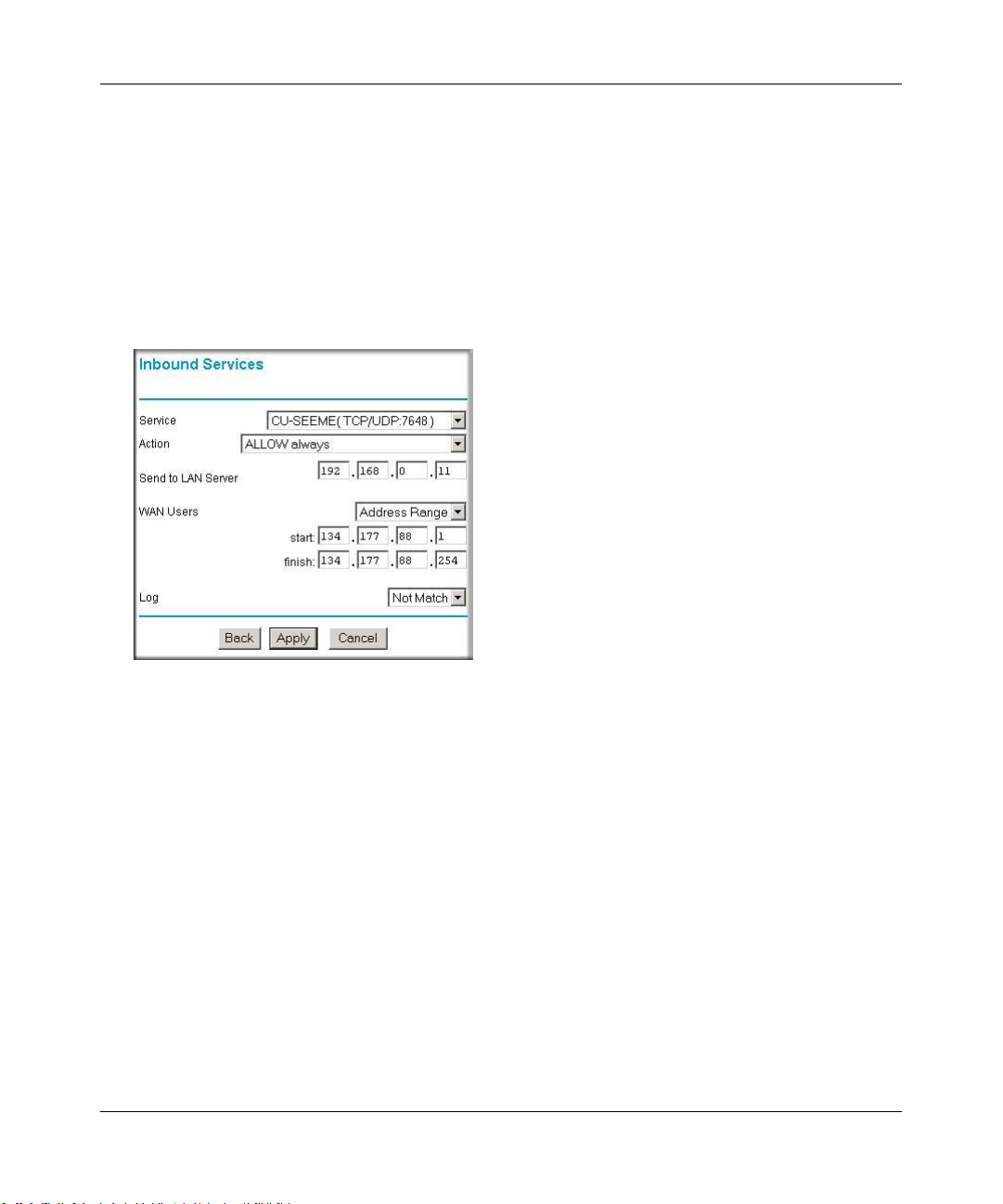
Reference Manual for the ProSafe Wireless 802.11g Firewall/Print Server Model FWG114P v2
This rule is shown in Figure 6-3.
Example: Port Forwarding for Videoconferencing
If you want to allow incoming videoconferencing to be initiated from a restricted range of outside
IP addresses, such as from a branch office, you can create an inbound rule. In the example shown
in Figure 6-4, CU-SeeMe is a predefined service and its connections are allowed only from a
specified range of external IP addresses. In this case, we have also specified logging of any
incoming CU-SeeMe requests that do not match the allowed parameters.
Figure 6-4: Rule example: Videoconference from Restrict ed Addresses
Example: Port Forwarding for VPN Tunnels when NAT is Off
If you want to allow incoming VPN IPSec tunnels to be initiated from outside IP addresses
anywhere on the Internet when NAT is off, first create a service and then an inbound rule.
6-8 Firewall Protection and Content Filtering
201-10301-02, May 2005
Page 87

Reference Manual for the ProSafe Wireless 802.11g Firewall/Print Server Model FWG114P v2
Figure 6-5: Service example: port forwarding for VPN when NAT is Off
In the example shown in Figure 6-5, UDP port 500 connections are defined as the IPSec service.
Figure 6-6: Inbound rule example: VPN IPSec when NAT is off
In the example shown in Figure 6-6, VPN IPSec connections are allowed for any internal LAN IP
address.
Outbound Rules (Service Blocking or Port Filtering)
The FWG114P v2 allows you to block the use of certain Internet services by computers on your
network. This is called service blocking or port filtering. You can define an outbound rule to block
Internet access from a local computer based on:
• IP address of the local computer (source address)
Firewall Protection and Content Filtering 6-9
201-10301-02, May 2005
Page 88
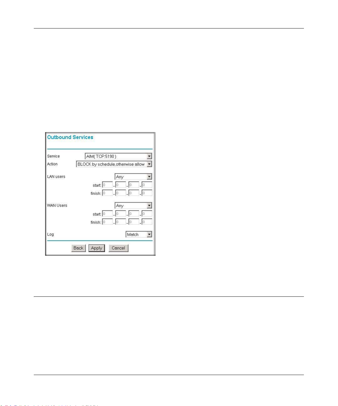
Reference Manual for the ProSafe Wireless 802.11g Firewall/Print Server Model FWG114P v2
• IP address of the Internet site being contacted (destination address)
•Time of day
• Type of service being requested (service port number)
Outbound Rule Example: Blocking Instant Messaging
If you want to block Instant Messenger usage by employees during working hours, you can create
an outbound rule to block that application from any internal IP address to any external address
according to the schedule that you have created in the Schedule menu. Y ou can also have the router
log any attempt to use Instant Messenger during that blocked period.
Figure 6-7: Rule example: Blocking Instant Messenger
Other Rules Considerations
The order of precedence of rules is determined by the position of the rule on a list of many rules.
Also, there are optional Rules settings you can configure. These topics are presented here.
6-10 Firewall Protection and Content Filtering
201-10301-02, May 2005
Page 89
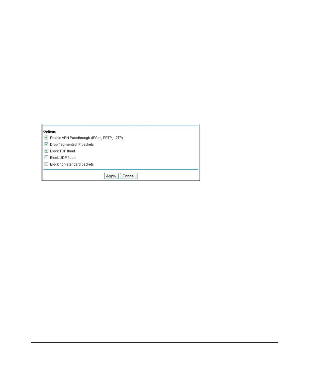
Reference Manual for the ProSafe Wireless 802.11g Firewall/Print Server Model FWG114P v2
Order of Precedence for Rules
As you define new rules, they are added to the tables in the Rules menu. For any traffic attempting
to pass through the firewall, the packet information is subjected to the rules in the order of the
entries in the Rules T able, beginning at the top and proceeding to the default rules at the bottom. In
some cases, the order of precedence of two or more rules may be important in determining the
disposition of a packet. The Move button allows you to relocate a defined rule to a new position in
the table.
Rules Menu Options
Use the Options checkboxes to enable the following:
• Enable VPN Passthrough (IPSec, PPTP, L2TP)
If LAN users need to use VPN (Virtual Private Networking) software on their computer, and
connect to remote sites or servers, enable this checkbox. This will allow the VPN protocols
(IPSec, PPTP, L2TP) to be used. If this checkbox is not checked, these protocols are blocked.
• Drop fragmented IP packets
If checked, all fragmented IP pack ets wil l be dropped (discarded). Normally, this should NOT
be checked.
• Block TCP flood
If checked, when a TCP flood attack is detected, the port used will be closed, and no traffic
will be able to use that port.
• Block UDP flood
If checked, when a UDP flood attack is detected, all traffic from that IP address will be
blocked.
• Block non-standard packets
If checked, only known packet types will be accepted; other packets will be blocked. The
known packet types are TCP, UDP, ICMP, ESP, and GRE. Note that these are packet types, not
protocols.
Firewall Protection and Content Filtering 6-11
201-10301-02, May 2005
Page 90
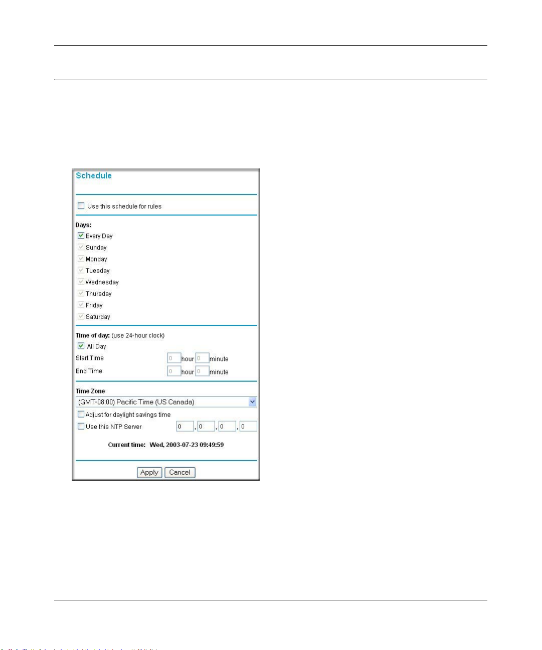
Reference Manual for the ProSafe Wireless 802.11g Firewall/Print Server Model FWG114P v2
Using a Schedule to Block or Allow Content or Traffic
If you enabled content filtering in the Block Sites menu, or if you defined an outbound rule to use
a schedule, you can set up a schedule for when blocking occurs or when access is restricted. The
router allows you to specify when blocking will be enforced by configuring the Schedule tab
shown below.
Figure 6-8: Schedule menu
To block keywords or Internet domains based on a schedule, select Every Day o r select one or
more days. If you want to limit access completely for the selected days, select All Day. Otherwise,
If you want to limit access during certain times for the selected days, type a Start Time and an End
Time.
6-12 Firewall Protection and Content Filtering
201-10301-02, May 2005
Page 91

Reference Manual for the ProSafe Wireless 802.11g Firewall/Print Server Model FWG114P v2
Note: Enter the values in 24-hour time format. For example, 10:30 am would be 10 hours and 30
minutes and 10:30 pm would be 22 hours and 30 minutes.
Be sure to click Apply when you have finished configuring this menu.
Setting the Time Zone
The FWG114P v2 W ireless Firewall/Print Server uses the Network Time Protocol (NTP) to obtain
the current time and date from one of several Network Time Servers on the Internet. In order to
localize the time for your log entries, you must specify your Time Zone:
• Time Zone. Select your local time zone. This setting will be used for the blocking schedule
and for time-stamping log entries.
• Daylight Savings Time. Select this check box for daylight savings time.
Note: If your region uses Daylight Savings Time, you must manually select Adjust for
Daylight Savings Time on the first day of Daylight Savings Time, and unselect it at the end.
Enabling Daylight Savings Time will add one hour to the standard time.
Be sure to click Apply when you have finished configuring this menu.
Getting E-Mail Notifications of Event Logs and Alerts
In order to receive logs and alerts by e-mail, you must provide your e-mail information in the
E-Mail subheading:
Firewall Protection and Content Filtering 6-13
201-10301-02, May 2005
Page 92

Reference Manual for the ProSafe Wireless 802.11g Firewall/Print Server Model FWG114P v2
Figure 6-9: E-mail menu
• Turn e-mail notification on. Select this check box if you want to receive e-mail logs and
alerts from the router.
• Send alerts and logs by e-mail. If you enable e-mail notification, these boxes cannot be
blank. Enter the name or IP address of your ISP’s outgoing (SMTP) mail server (such as
mail.myISP.com). You may be able to find this information in the configuration menu of your
e-mail program. Enter the e-mail address to which logs and alerts will be sent. This e-mail
address will also be used as the From address. If you leave this box blank, log and alert
messages will not be sent via e-mail. Check “My Mail Server requires authentication” if you
need to log in to your SMTP server in order to send e-mail. If this is checked, you must enter
the login name and password for your mail server.
Tip: Y ou used this information when you set up your e-mail program. If you canno t remember
it, check the settings in your e-mail program.
• Send E-mail alerts immediately. You can specify that logs are immediately sent to the
specified e-mail address when any of the following events occur:
6-14 Firewall Protection and Content Filtering
201-10301-02, May 2005
Page 93

Reference Manual for the ProSafe Wireless 802.11g Firewall/Print Server Model FWG114P v2
– If a Denial of Service attack is detected.
– If a Port Scan is detected.
– If a user on your LAN attempts to access a website that you blocked using Keyword
blocking.
• Send logs according to this schedule. You can specify that logs are sent to you according to a
schedule. Select whether you would like to receive the logs Hourly , Daily, Weekly, When Full,
or None for no logs. Depending on your selection, you may also need to specify:
– Day for sending log
Relevant when the log is sent weekly or daily.
– Time for sending log
Relevant when the log is sent daily or weekly.
If the Weekly, Daily or Hourly option is selected and the log fills up before the specified
period, the log is automatically e-mailed to the specified e-mail address. After the log is sent,
the log is cleared from the router’s memory. If the router cannot e-mail the log file, the log
buffer may fill up. In this case, the router overwrites the log and discards its contents.
Be sure to click Apply when you have finished configuring this menu.
Firewall Protection and Content Filtering 6-15
201-10301-02, May 2005
Page 94
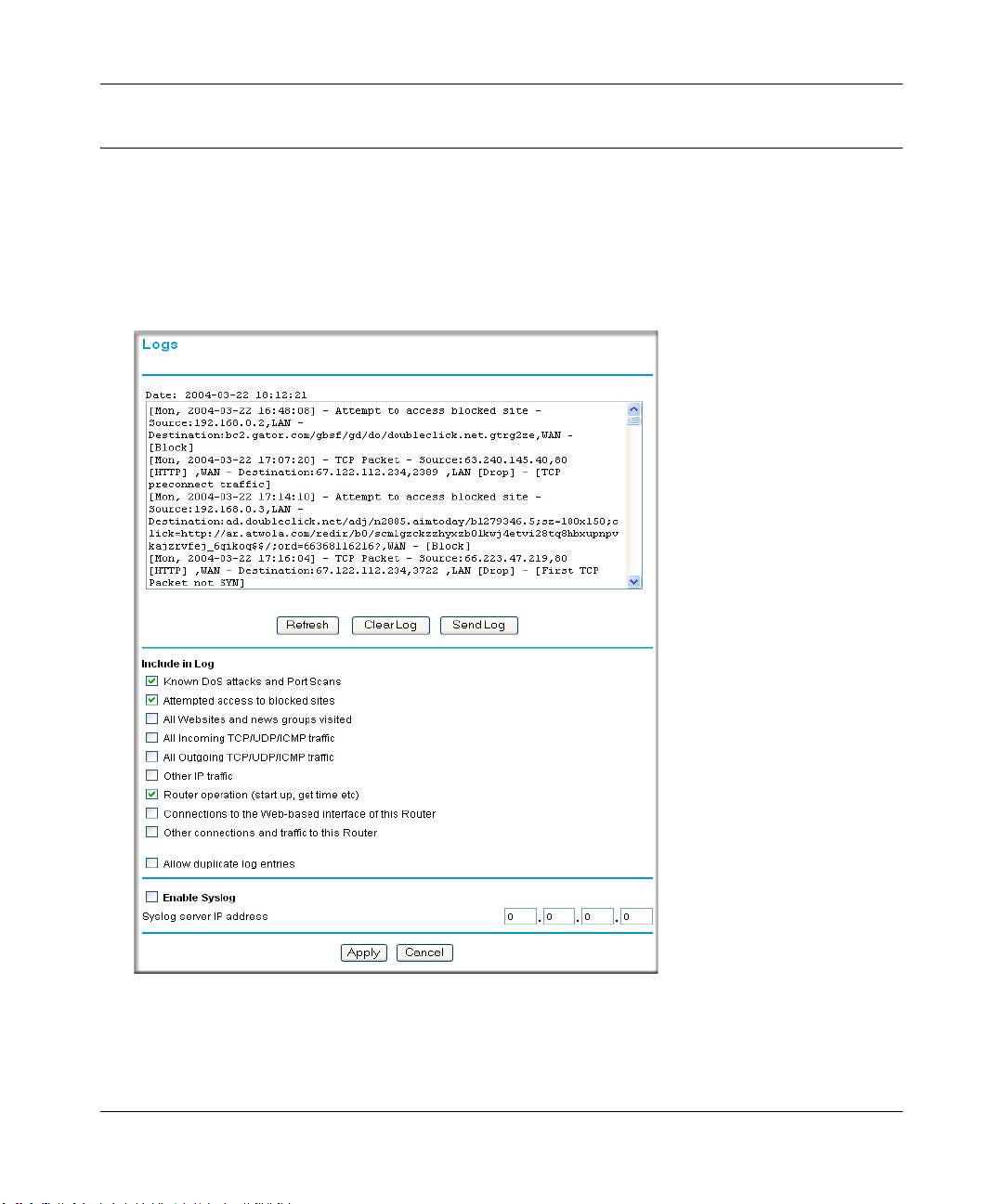
Reference Manual for the ProSafe Wireless 802.11g Firewall/Print Server Model FWG114P v2
Viewing Logs of Web Access or Attempted Web Access
The router will log security-related events, such as denied incoming and outgoing service requests,
hacker probes, and administrator logins. If you enable content filtering in the Block Sites menu,
the Log page will also show you when someone on your network tries to access a blocked site. If
you enabled e-mail notification, you will receive these logs in an e-mail message. If you do not
have e-mail notification enabled, you can view the logs here.
Figure 6-10: Logs menu
See Appendix D, “Firewall Log Formats” for a full explanation of log entry formats.
6-16 Firewall Protection and Content Filtering
201-10301-02, May 2005
Page 95

Reference Manual for the ProSafe Wireless 802.11g Firewall/Print Server Model FWG114P v2
Log action buttons are described in Table 6-1.
Table 6-1. Log action buttons
Field Description
Refresh Refreshes the log screen.
Clear Log Clears the log entries.
Send Log E-mails the log immediately.
What to Include in the Event Log
Use these checkboxes to determ ine whic h even ts ar e included in the log. Checking all options wi ll
increase the size of the log, so it is good practice to disable any events which are not really
required.
• All Websites and news groups visited - If checked, all visited websites and newsgroups are
logged.
• All Incoming TCP/UDP/ICMP traffic - If checked, all incoming TCP/UDP/ICMP connections
and traffic is logged.
• All Outgoing TCP/UDP/ICMP traffic - If checked, all outgoing TCP/UDP/ICMP connections
and traffic is logged.
• Other IP traffic - If checked, all other traffic (IP packets which are not TCP, UDP, or ICMP) is
logged.
• Router operation (start up, get time, etc.) - If checked, Router operations, such as starting up
and getting the time from the Internet Time Server, are logged.
• Connection to the Web-based interface of this Router - If checked, Administrator connections
to the Web-based interface will be logged.
• Other connections and traffic to this Router - If checked, this will log traffic sent to thi s Router
(rather than through this Router to the Internet).
• Allow duplicate log entries - If checked, then events or packets which fall within more than
one (1) category above will have a log entry for each category in which they belong. This will
generate a large number of log entries. If unchecked, then events or packets will only be
logged once. Usually, this should be left unchecked.
Logging programs are available for Windows, Macintosh, and Linux computers.
Firewall Protection and Content Filtering 6-17
201-10301-02, May 2005
Page 96

Reference Manual for the ProSafe Wireless 802.11g Firewall/Print Server Model FWG114P v2
Enable one of these three options, as required:
• Disable - select this if you do not have a Syslog server.
• Broadcast on LAN - the Syslog data is broadcast, rather than sent to a specific Syslog server.
Use this if your Syslog Server does not have a fixed IP address.
• Send to this Syslog server IP address - If your Syslog server has a fixed IP address, select this
option, and enter the IP address of your Syslog server.
6-18 Firewall Protection and Content Filtering
201-10301-02, May 2005
Page 97

Chapter 7
Print Server
This chapter describes how to install and configure the print server in your ProSafe Wireless
802.11g Firewall/Print Server Model FWG114P v2.
Printing Options
The FWG114P v2 supports these methods for printing:
• For Windows XP and 2000 Only: TCP/IP Line Printer Remote (LPR) Printing
— No software needs to be installed
— Windows XP or 2000 users can print directly to the firewall. Print jobs are spooled
(queued) on each computer. The computer sends the print job directly to the LAN IP
address of the FWG114P v2.
• For Windows 95/98/Me, NT4.0, 2000, and XP: Netgear Printer Port Driver
— Install the Netgear Printer Port Driver on Each computer.
— After installing the Print Port Driver from the Resource CD for the ProSafe Wireless
802.1 1g Firewall/Print Server Model FWG114P (SW-10023-03) Windows users can print
directly to the firewall. Print jobs are spooled (queued) on each computer.
• For Macintosh computers: LPR printing
— No software needs to be installed
— LPR printing can be set up on any Macintosh that has Desktop Printing installed or
available. Desktop Printing is supported on MacOS versions beginning from 8.1.
LaserWriter8 version 8.5.1 or higher is also required.
• For Windows NT 4.0 Server or 2000 Server: LPD/LPR Printing
— No software needs to be installed
— If using Windows NT 4.0 Server or W indows 2000 Server , LPD/LP R printing can be used.
No software needs to be installed on either the Windows Server or each client computer.
Print jobs will be spooled (queued) on the Windows Server, and can be managed using the
standard Windows Server tools.
Print Server 7-1
201-10301-02, May 2005
Page 98
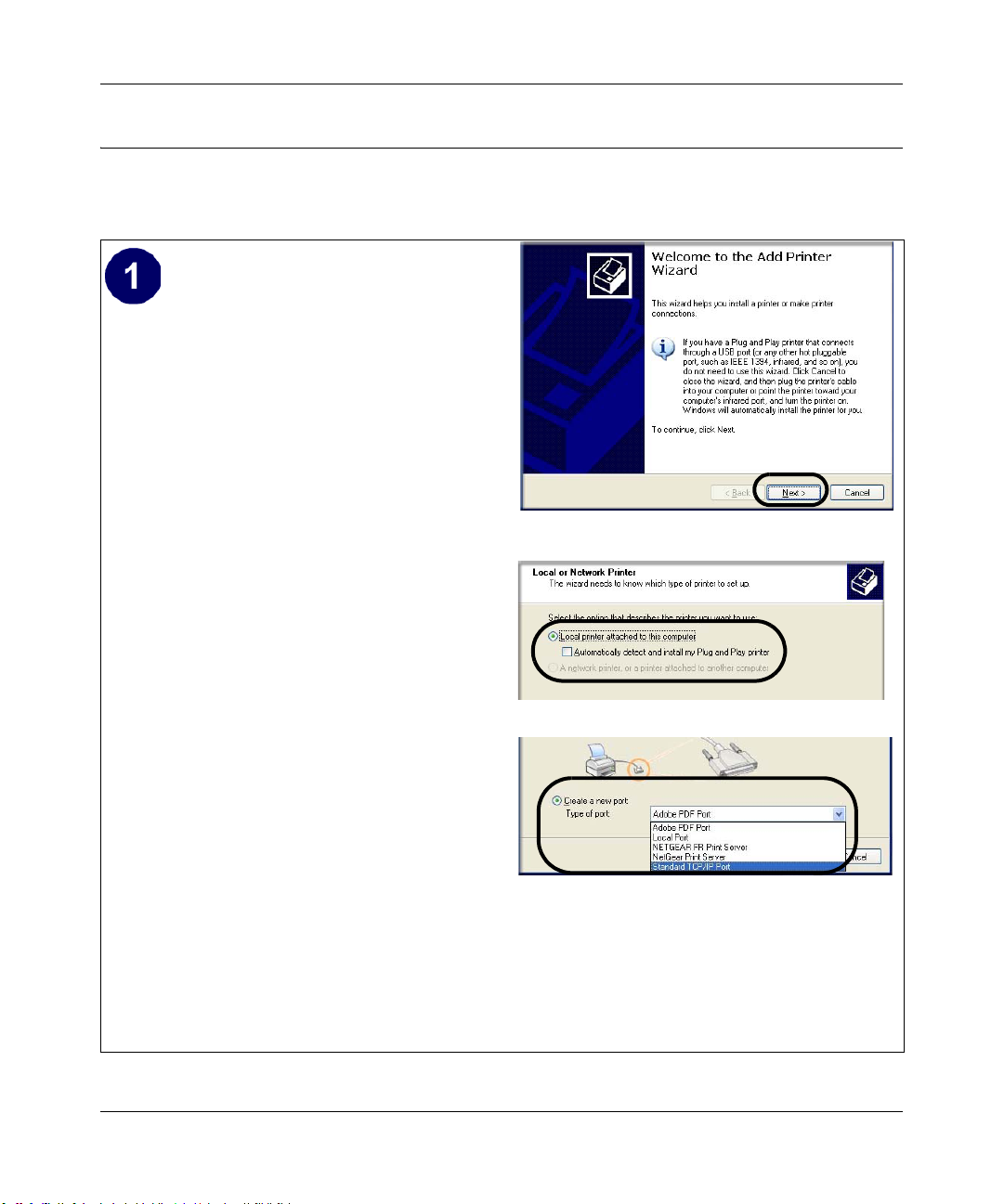
Reference Manual for the ProSafe Wireless 802.11g Firewall/Print Server Model FWG114P v2
For Windows XP and 2000, Use TCP/IP LPR Printing
Follow these instructions to set up TCP/IP printing on your Windows XP and 2000 PCs.
Install the FWG114P v2, connect your
printer to the USB port on the FWG114P v2,
and run the Windows Add Printer Wizard.
a. Follow the instructions in the printed
Installation Guide or this manual to
install your FWG114P v2. Connect your
printer to the USB port on the back of the
FWG114P v2.
b. From the Windows Start menu of a
computer connected to the FWG114P
v2, click Printers and Faxes.
Add Printer Wizard
c. Click Add a printer. Click Next to
proceed.
d. Be sure to choose the Local printer
attached to this computer option.
Local or Network Printer screen
Click Next to proceed.
e. On the Select a Printer Port screen, be
sure to choose the Create a new port:
option.
From the Type of port: drop-down list,
be sure to select Standard TCP/IP
Port.
Select a Printer Port screen
Click Next to proceed.
This will start the Add Standard TCP/IP
Printer Port Wizard.
7-2 Print Server
201-10301-02, May 2005
Page 99
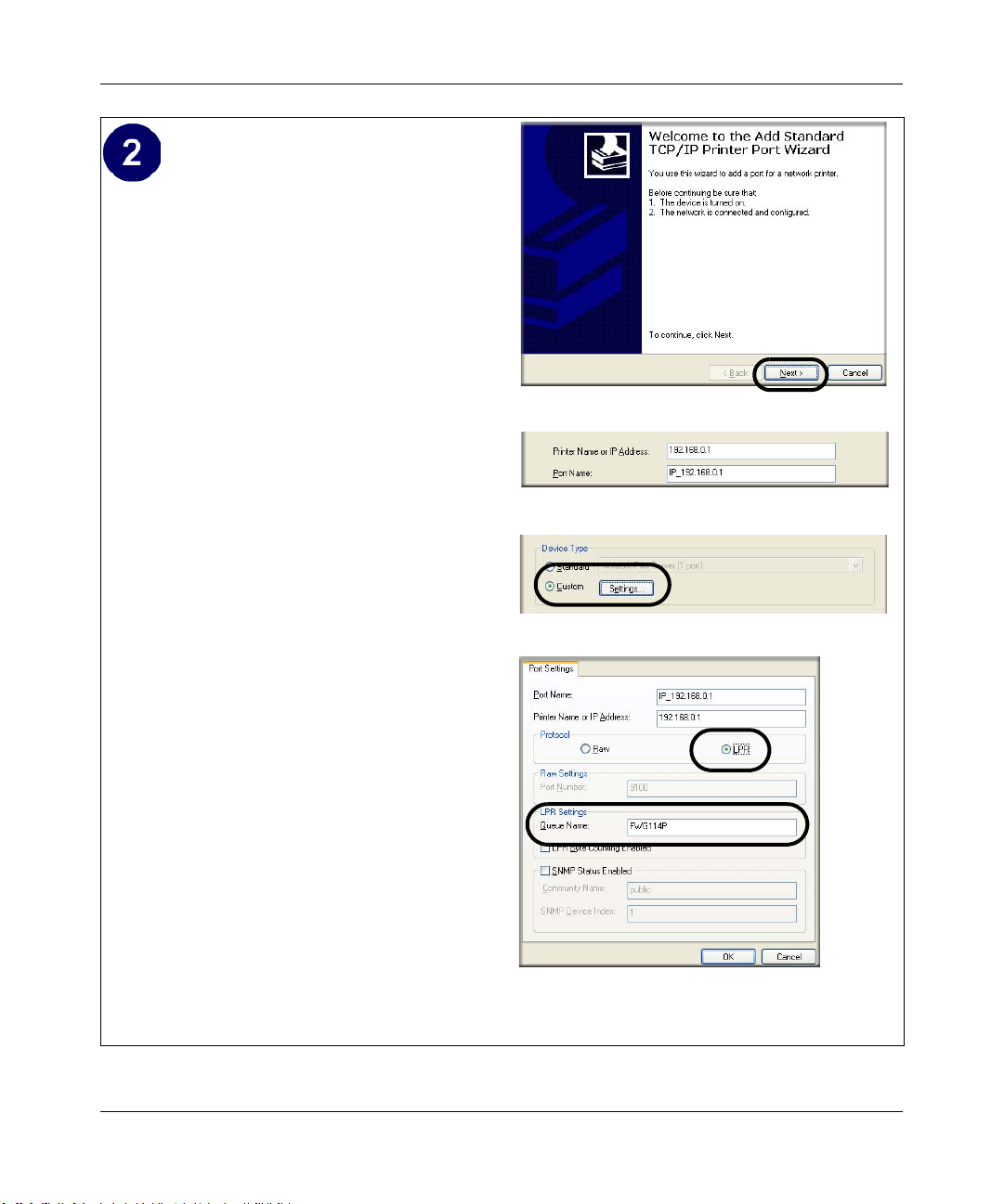
Reference Manual for the ProSafe Wireless 802.11g Firewall/Print Server Model FWG114P v2
Complete the Add Standard TCP/IP Printer
Port Wizard.
a. Click Next to proceed with the Add
Standard TCP/IP Printer Port Wizard.
The Add Port screen will display.
b. From the Add Port screen, enter
192.168.0.1, the FWG114P v2 default
LAN IP address, in the IP Address field.
Add Standard TCP/IP Printer Port Wizard
Note: If you changed the default LAN IP
Address of the FWG114P v2, be sure to
use the address you assigned here. The
Port Name is automatically filled in.
Add Port Screen
Click Next to proceed.
c. In the Device Type section of the
Additional Port Information Required
screen, select Custom.
Additional Port Information Required
d. In the Custom selection, click Settings.
e. The Port Settings tab page opens. In the
Protocol section, select the LPR radio
button, and enter FWG114P as the
Queue Name in the LPR Settings
section. Click OK to close this tab page.
Click Next to proceed.
The Add Printer Wizard will now
prompt you to install the software for the
printer you attached to the FWG114P v2.
Additional Port Information Required
Print Server 7-3
201-10301-02, May 2005
Page 100
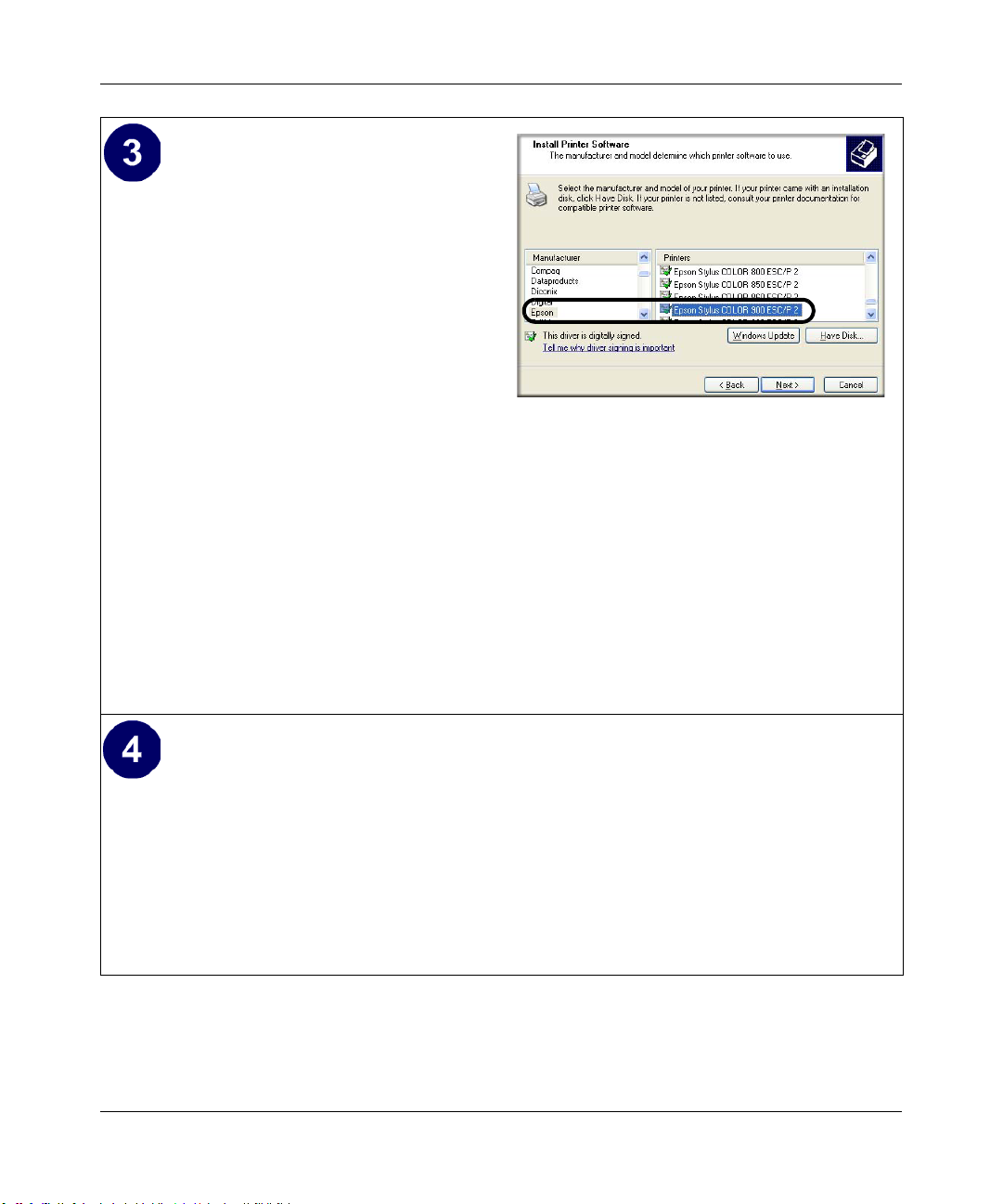
Reference Manual for the ProSafe Wireless 802.11g Firewall/Print Server Model FWG114P v2
Identify the printer connected to FWG114P
v2 USB printer port.
a. From the Install Printer Software screen
selection lists, find the manufacturer and
model of the printer you connected to the
USB port on the FWG114P v2.
Click Next to proceed.
If the printer software is already installed
on this computer, the Add Printer
Wizard will inform you and let you keep
the existing driver.
b. The Name Your Printer screen prompts
for a descriptive name and if you want it
to be the default. Enter your choices.
Click Next to proceed.
c. On the Printer Sharing screen, accept the
Add Printer Wizard Install Printer Software page
If you do not see your make and model
printer in the lists, and you are connected
to the Internet, you can click the
Windows Update button to download
additional printer software from the
Microsoft Web site, or you can click the
Have Disk button to install the printer
software from a disk you have.
“Do not share this printer” option and
click Next to proceed.
Print a test page to verify successful printing on your network.
a. Upon completion of the Add Printer Wizard, you will be prompted to print a test page.
b. Check the printer attached to the FWG114P v2 to see that the test page printed
successfully.
If you are unable to print a test page, see “Troubleshooting the Print Server“ on page -12.
7-4 Print Server
201-10301-02, May 2005
 Loading...