

Page 1
DGFV338 ProSafe Wireless ADSL Modem VPN Firewall Router Reference Manual
NETGEAR, Inc.
4500 Great America Parkway
Santa Clara, CA 95054 USA
April 2007
202-10161-01
v1.0
Page 2
DGFV338 ProSafe Wireless ADSL Modem VPN Firewall Router Reference Manual
Technical Support
Please register to obtain technical support. Please retain your proof of purchase and warranty information.
To register your product, get product support or obtain product information and product documentation, go to
http://www.NETGEAR.com
out the registration card and mailing it to NETGEAR customer service.
You will find technical support information at: http://www.NETGEAR.com/
want to contact technical support by telephone, see the support information card for the correct telephone number for
your country.
© 2007 by NETGEAR, Inc. All rights reserved.
. If you do not have access to the World Wide Web, you may register your product by filling
through the customer service area. If you
Trademarks
NETGEAR and the NETGEAR logo are registered trademarks and ProSafe is a trademark of NETEAR, Inc. Microsoft,
Windows, and Windows NT are registered trademarks of Microsoft Corporation. Other brand and product names are
registered trademarks or trademarks of their respective holders.
Statement of Conditions
In the interest of improving internal design, operational function, and/or reliability, NETGEAR reserves the right to
make changes to the products described in this document without notice.
NETGEAR does not assume any liability that may occur due to the use or application of the product(s) or circuit
layout(s) described herein.
Federal Communications Commission (FCC) Compliance Notice:
Radio Frequency Notice
ProSafe Wireless ADSL Modem VPN Firewall Router
Tested to Comply
with FCC Standards
FOR HOME OR OFFICE USE
FCC ID: PY305300022
This device complies with part 15 of the FCC Rules. Operation is subject to the following two conditions:
• This device may not cause harmful interference.
• This device must accept any interference received, including interference that may cause undesired operation.
Placement and Range Guidelines
Indoors, computers can connect over 802.11 wireless networks at a maximum range of 500 feet (152.4 m) for 802.11b
devices. However, the operating distance or range of your wireless connection can vary significantly, based on the
physical placement of the wireless access point.
For best results, identify a location for your wireless access point according to these guidelines:
ii
v1.0, April 2007
Page 3

DGFV338 ProSafe Wireless ADSL Modem VPN Firewall Router Reference Manual
• Away from potential sources of interference, such as PCs, large metal surfaces, microwaves, and 2.4 GHz cordless
phones.
• In an elevated location such as a high shelf that is near the center of the wireless coverage area for all mobile
devices.
Failure to follow these guidelines can result in significant performance degradation or inability to wirelessly connect to
the wireless access point.
To meet FCC and other national safety guidelines for RF exposure, the antennas for this device must be installed to
ensure a minimum separation distance of 20cm (7.9 in.) from persons. Further, the antennas shall not be collocated with
other transmitting structures.
FCC Statement
DECLARATION OF CONFORMITY
4500 Great America Parkway
Santa Clara, CA 95054, USA
declare under our sole responsibility that the product(s)
DGFV338 (Model Designation)
ProSafe Wireless ADSL Modem VPN Firewall Router (Product Name)
complies with Part 15 of FCC Rules.
Operation is subject to the following two conditions: (1) this device may not cause harmful interference, and (2) this
device must accept any interference received, including interference that may cause undesired operation
To assure continued compliance, any changes or modifications not expressly approved by the party responsible for
compliance could void the user's authority to operate this equipment. (Example - use only shielded interface cables
when connecting to computer or peripheral devices)
We Netgear,
Tel: +1 408 907 8000
FCC Requirements for Operation in the United States
Radio Frequency Interference Warnings & Instructions
This equipment has been tested and found to comply with the limits for a Class B digital device, pursuant to Part 15 of
the FCC Rules. These limits are designed to provide rea sonable protection against harmful interference in a residential
installation. This equipment generates, uses, and can radiate radio frequency energy and, if not installed and used in
accordance with the instructions, may cause harmful interference to radio communications. However, there is no
guarantee that interference will not occur in a particular installation. If this equipment does cause harmful interference to
radio or television reception, which can be determined by turning the equipment off and on, the user is encouraged to try
and correct the interference by one or more of the following measures:
• Reorient or locate the receiving antenna.
• Increase the separation between the equipment and receiver.
• Connect the equipment into an outlet on a circuit different from that to which the receiver is connected.
• Consult the dealer or an experienced radio/TV technician for help.
v1.0, April 2007
iii
Page 4

DGFV338 ProSafe Wireless ADSL Modem VPN Firewall Router Reference Manual
Europe – EU Declaration of Conformity
Marking by the above symbol indicates compliance with the Essential Requirements of the R&TTE Directive of the
European Union (1999/5/EC). This equipment meets the following conformance standards:
EN300 328, EN301 489-17, EN60950Europe – Declaration of Conformit y in Languages of the
European Community
Èesky [Czech] NETGEAR Inc. tímto prohlašuje, _e tento Radiolan je ve shodě se základními po_adavky
a dalšími příslušnými ustanoveními směrnice 1999/5/ES.
Dansk [Danish] Undertegnede NETGEAR Inc. erklærer herved, at følgende udstyr Radiolan overholder
de væsentlige krav og øvrige relevante krav i direktiv 1999/5/EF.
Deutsch
[German]
Eesti [Estonian] Käesolevaga kinnitab NETGEAR Inc. seadme Radiolan vastavust direktiivi 1999/5/EÜ
English Hereby, NETGEAR Inc., declares that this Radiolan is in compliance with the essential
Español
[Spanish]
ЕллзнйкЮ
[Greek]
Français
[French]
Italiano [Italian] Con la presente NETGEAR Inc. dichiara che questo Radiolan è conforme ai requisiti
Latviski [Latvian] Ar šo NETGEAR Inc. deklarē, ka Radiolan atbilst Direktīvas 1999/5/EK bū
Lietuviø
[Lithuanian]
Nederlands
[Dutch]
Malti [Maltese] Hawnhekk, NETGEAR Inc., jiddikjara li dan Radiolan jikkonforma mal-htigijiet essenzjali
Magyar
[Hungarian]
Polski [Polish] Niniejszym NETGEAR Inc. oświadcza, że Radiolan jest zgodny z zasadniczymi
Hiermit erklärt NETGEAR Inc., dass sich das Gerät Radiolan in Übereinstimmung mit
den grundlegenden Anforderungen und den übrigen einschlägigen Bestimmungen der
Richtlinie 1999/5/EG befindet.
põhinõuetele ja nimetatud direktiivist tulenevatele teistele asjakohastele sätetele.
requirements and other relevant provisions of Directive 1999/5/EC.
Por medio de la presente NETGEAR Inc. declara que el Radiolan cumple con los
requisitos esenciales y cualesquiera otras disposiciones aplicables o exigibles de la
Directiva 1999/5/CE.
ΜΕ ΤΗΝ ΠΑΡΟΥΣΑ NETGEAR Inc. ΔΗΛΩΝΕΙ ΟΤΙ Radiolan ΣΥΜΜΟΡΦΩΝΕΤΑΙ ΠΡΟΣ
ΤΙΣ ΟΥΣΙΩΔΕΙΣ ΑΠΑΙΤΗΣΕΙΣ ΚΑΙ ΤΙΣ ΛΟΙΠΕΣ ΣΧΕΤΙΚΕΣ ΔΙΑΤΑΞΕΙΣ ΤΗΣ ΟΔΗΓΙΑΣ
1999/5/ΕΚ.
Par la présente NETGEAR Inc. déclare que l'appareil Radiolan est conforme aux
exigences essentielles et aux autres dispositions pertinentes de la directive 1999/5/CE.
essenziali ed alle altre disposizioni pertinenti stabilite dalla direttiva 1999/5/CE.
tiskajām
prasībām un citiem ar to saistītajiem noteikumiem.
Šiuo NETGEAR Inc. deklaruoja, kad šis Radiolan atitinka esminius reikalavimus ir kitas
1999/5/EB Direktyvos nuostatas.
Hierbij verklaart NETGEAR Inc. dat het toestel Radiolan in overeenstemming is met de
essentiële eisen en de andere relevante bepalingen van richtlijn 1999/5/EG.
u ma provvedimenti ohrajn relevanti li hemm fid-Dirrettiva 1999/5/EC.
Alulírott, NETGEAR Inc. nyilatkozom, hogy a Radiolan megfelel a vonatkozó alapvetõ
követelményeknek és az 1999/5/EC irányelv egyéb elõírásainak.
wymogami oraz pozostałymi stosownymi postanowieniami Dyrektywy 1999/5/EC.
iv
v1.0, April 2007
Page 5

DGFV338 ProSafe Wireless ADSL Modem VPN Firewall Router Reference Manual
Português
[Portuguese]
Slovensko
[Slovenian]
Slovensky
[Slovak]
Suomi [Finnish] NETGEAR Inc. vakuuttaa täten että Radiolan tyyppinen laite on direktiivin 1999/5/EY
Svenska
[Swedish]
Íslenska
[Icelandic]
Norsk
[Norwegian]
NETGEAR Inc. declara que este Radiolan está conforme com os requisitos essenciais e
outras disposições da Directiva 1999/5/CE.
NETGEAR Inc. izjavlja, da je ta Radiolan v skladu z bistvenimi zahtevami in ostalimi
relevantnimi določili direktive 1999/5/ES.
NETGEAR Inc. týmto vyhlasuje, _e Radiolan spĺňa základné po_iadavky a všetky
príslušné ustanovenia Smernice 1999/5/ES.
oleellisten vaatimusten ja sitä koskevien direktiivin muiden ehtojen mukainen.
Härmed intygar NETGEAR Inc. att denna Radiolan står I överensstämmelse med de
väsentliga egenskapskrav och övriga relevanta bestämmelser som framgår av direktiv
1999/5/EG.
Hér með lýsir NETGEAR Inc. yfir því að Radiolan er í samræmi við grunnkröfur og aðrar
kröfur, sem gerðar eru í tilskipun 1999/5/EC.
NETGEAR Inc. erklærer herved at utstyret Radiolan er i samsvar med de grunnleggende
krav og øvrige relevante krav i direktiv 1999/5/EF.
Countries of Operation & Conditions of Use in the European Community
This device is intended to be operated in all countries of the European Community. Requirements for indoor vs. outdoor
operation, license requirements and allowed channels of operation apply in some countries as described below.
Note: The user must use the configuration utility provided with this product to ensure the channels of operation
are in conformance with the spectrum usage rules for European Community countries as described below.
This device requires that the user or installer properly enter the current country of operation in the Radio Settings
menu as described in the Reference Manual, before operating this device.
This device will automatically limit the allowable channels determined by the current country of operation. Incorrectly
entering the country of operation may result in illegal operation and may cause harmful interference to other system. The
user is obligated to ensure the device is operating according to the channel limitations, indoor/outdoor restrictions and
license requirements for each European Community country as described in this document.
This device employs a radar detection feature required for European Community operation in the 5GHz band. This
feature is automatically enabled when the country of operation is correctly configured for any European Community
country. The presence of nearby radar operation may result in temporary interruption of operation of this device. The
radar detection feature will automatically restart operation on a channel free of radar.
The 5GHz Turbo Mode feature is not allowed for operation in any European Community country. The current setting
for this feature is found in the 5GHz Radio Configuration Window as described in the user guide.
This device may be operated indoors or outdoors in all countries of the European Community using the 2.4GHz band:
Channels 1 – 13, except where noted below:
•In Italy the end-user must apply for a license from the national spectrum authority to operate this device outdoors.
•In France outdoor operation is only permitted using the 2.4 – 2.454 GHz band: Channels 1 – 7.
• Belgium requires notifying spectrum agency if deploying >300meter wireless links in outdoor public areas using
2.4GHz band.
v1.0, April 2007
v
Page 6
DGFV338 ProSafe Wireless ADSL Modem VPN Firewall Router Reference Manual
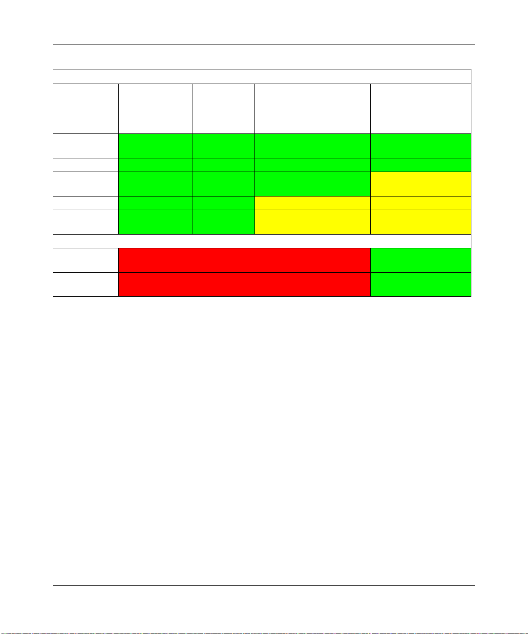
European Spectrum Usage Rules - Effective April 11, 2006
5.15-5.25 (GHz)
Country
Channels:
36,40,44,48
ALL EC
Countries
Belgium Indoor Only Indoor Only Indoor or Outdoor Indoor or Outdoor!
France
Greece Indoor Only Indoor Only Indoor Only Indoor Only
Italy
Indoor Only Indoor Only Indoor or Outdoor Indoor or Outdoor
Indoor Only Indoor Only Indoor or Outdoor Indoor Ch. 1-13
Indoor Only Indoor Only Indoor
5.25-5.35
(GHz)
Channels:
52,56,60,64
5.47-5.725 (GHz)
Channels:
100,104,108,112,116,
120,124,128,132,136,140
(Outdoor w/License)
2.4-2.4835 (GHz)
Channels: 1 to 13
(Except Where Noted)
Outdoor 1-7 Only
Indoor (Outdoor w/
License)
Turbo Mode
AdHoc Mode Not Allowed Same 2.4 GHz rules as
Not Allowed in 5GHz Same 2.4 GHz rules as
above
above
Bestätigung des Herstellers/Importeurs
Es wird hiermit bestätigt, daß das ProSafe Wireless ADSL Modem VPN Firewall Router gemäß der im BMPTAmtsblVfg 243/1991 und Vfg 46/1992 aufgeführten Bestimmungen entstört ist. Das vorschriftsmäßige Betreiben
einiger Geräte (z.B. Testsender) kann jedoch gewissen Beschränkungen unterliegen. Lesen Sie dazu bitte die
Anmerkungen in der Betriebsanleitung.
Das Bundesamt für Zulassungen in der Telekommunikation wurde davon unterrichtet, daß dieses Gerät auf den Markt
gebracht wurde und es ist berechtigt, die Serie auf die Erfüllung der Vorschriften hin zu überprüfen.
Certificate of the Manufacturer/Importer
It is hereby certified that the ProSafe Wireless ADSL Modem VPN Firewall Router has been suppressed in accordance
with the conditions set out in the BMPT-AmtsblVfg 243/1991 and Vfg 46/1992. The operation of some equipment (for
example, test transmitters) in accordance with the regulations may, however, be subject to certain restrictions. Please
refer to the notes in the operating instructions.
Federal Office for Telecommunications Approvals has been notified of the placing of this equipment on the market
and has been granted the right to test the series for compliance with the regulations.
Voluntary Control Council for Interference (VCCI) Statement
This equipment is in the second category (information equipment to be used in a residential area or an adjacent area
thereto) and conforms to the standards set by the Voluntary Control Council for Interference by Data Processing
Equipment and Electronic Office Machines aimed at preventing radio interference in such residential areas.
When used near a radio or TV receiver , it may become the cause of radio interference.
Read instructions for correct handling.
vi
v1.0, April 2007
Page 7

DGFV338 ProSafe Wireless ADSL Modem VPN Firewall Router Reference Manual
Additional Copyrights
AES Copyright (c) 2001, Dr Brian Gladman <brg@gladman.uk.net>, Worcester, UK.
All rights reserved.
TERMS
Redistribution and use in source and binary forms, with or without modification, are permitted
subject to the following conditions:
1. Redistributions of source code must retain the above copyright notice, this list of
conditions and the following disclaimer.
2. Redistributions in binary form must reproduce the above copyright notice, this list of
conditions and the following disclaimer in the documentation and/or other materials
provided with the distribution.
3. The copyright holder's name must not be used to endorse or promote any products
derived from this software without his specific prior written permission.
This software is provided 'as is' with no express or implied warranties of correctness or fitness
for purpose.
v1.0, April 2007
vii
Page 8

DGFV338 ProSafe Wireless ADSL Modem VPN Firewall Router Reference Manual
Open SSL Copyright (c) 1998-2000 The OpenSSL Project. All rights reserved.
Redistribution and use in source and binary forms, with or without modification, are permitted
provided that the following conditions * are met:
1. Redistributions of source code must retain the above copyright notice, this list of conditions
and the following disclaimer.
2. Redistributions in binary form must reproduce the above copyright notice, this list of
conditions and the following disclaimer in the documentation and/or other materials
provided with the distribution.
3. All advertising materials mentioning features or use of this software must display the
following acknowledgment: “This product includes software developed by the OpenSSL
Project for use in the OpenSSL Toolkit. (http://www.openssl.org/)”
4. The names "OpenSSL Toolkit" and "OpenSSL Project" must not be used to endorse or
promote products derived from this software without prior written permission. For written
permission, please contact openssl-core@openssl.org.
5. Products derived from this software may not be called "OpenSSL" nor may "OpenSSL"
appear in their names without prior written permission of the OpenSSL Project.
6. Redistributions of any form whatsoever must retain the following acknowledgment: "This
product includes software developed by the OpenSSL Project for use in the OpenSSL
Toolkit (http://www.openssl.org/)"
THIS SOFTWARE IS PROVIDED BY THE OpenSSL PROJECT ``AS IS'' AND ANY
EXPRESSED OR IMPLIED WARRANTIES, INCLUDING, BUT NOT LIMITED TO, THE
IMPLIED WARRANTIES OF MERCHANTABILITY AND FITNESS FOR A PARTICULAR
PURPOSE ARE DISCLAIMED. IN NO EVENT SHALL THE OpenSSL PROJECT OR ITS
CONTRIBUTORS BE LIABLE FOR ANY DIRECT, INDIRECT, INCIDENTAL, SPECIAL,
EXEMPLARY, OR CONSEQUENTIAL DAMAGES (INCLUDING, BUT NOT LIMITED TO,
PROCUREMENT OF SUBSTITUTE GOODS OR SERVICES; LOSS OF USE, DATA, OR
PROFITS; OR BUSINESS INTERRUPTION) HOWEVER CAUSED AND ON ANY THEORY
OF LIABILITY, WHETHER IN CONTRACT, STRICT LIABILITY, OR TORT (INCLUDING
NEGLIGENCE OR OTHERWISE) ARISING IN ANY WAY OUT OF THE USE OF THIS
SOFTWARE, EVEN IF ADVISED OF THE POSSIBILITY OF SUCH DAMAGE.
viii
This product includes cryptographic software written by Eric Young (eay@cryptsoft.com). This
product includes software written by Tim Hudson (tjh@cryptsoft.com).
v1.0, April 2007
Page 9

DGFV338 ProSafe Wireless ADSL Modem VPN Firewall Router Reference Manual
MD5 Copyright (C) 1990, RSA Data Security, Inc. All rights reserved.
License to copy and use this software is granted provided that it is identified as the "RSA Data
Security, Inc. MD5 Message-Digest Algorithm" in all material mentioning or referencing this
software or this function. License is also granted to make and use derivative works provided
that such works are identified as "derived from the RSA Data Security, Inc. MD5 MessageDigest Algorithm" in all material mentioning or referencing the derived work.
RSA Data Security, Inc. makes no representations concerning either the merchantability of
this software or the suitability of this software for any particular purpose. It is provided "as is"
without express or implied warranty of any kind.
These notices must be retained in any copies of any part of this documentation and/or
software.
PPP Copyright (c) 1989 Carnegie Mellon University. All rights reserved.
Redistribution and use in source and binary forms are permitted provided that the above
copyright notice and this paragraph are duplicated in all such forms and that any
documentation, advertising materials, and other materials related to such distribution and use
acknowledge that the software was developed by Carnegie Mellon University. The name of
the University may not be used to endorse or promote products derived from this software
without specific prior written permission.
THIS SOFTWARE IS PROVIDED ``AS IS'' AND WITHOUT ANY EXPRESS OR IMPLIED
WARRANTIES, INCLUDING, WITHOUT LIMITATION, THE IMPLIED WARRANTIES OF
MERCHANTIBILITY AND FITNESS FOR A PARTICULAR PURPOSE.
Zlib zlib.h -- interface of the 'zlib' general purpose compression library version 1.1.4, March 11th,
2002. Copyright (C) 1995-2002 Jean-loup Gailly and Mark Adler.
This software is provided 'as-is', without any express or implied warranty. In no event will the
authors be held liable for any damages arising from the use of this software. Permission is
granted to anyone to use this software for any purpose, including commercial applications,
and to alter it and redistribute it freely, subject to the following restrictions:
1. The origin of this software must not be misrepresented; you must not claim that you wrote
the original software. If you use this software in a product, an acknowledgment in the
product documentation would be appreciated but is not required.
2. Altered source versions must be plainly marked as such, and must not be misrepresented
as being the original software.
3. This notice may not be removed or altered from any source distribution.
Jean-loup Gailly: jloup@gzip.org; Mark Adler: madler@alumni.caltech.edu
The data format used by the zlib library is described by RFCs (Request for Comments) 1950
to 1952 in the files ftp://ds.internic.net/rfc/rfc1950.txt
and rfc1952.txt (gzip format)
(zlib format), rfc1951.txt (deflate format)
v1.0, April 2007
ix
Page 10

DGFV338 ProSafe Wireless ADSL Modem VPN Firewall Router Reference Manual
Product and Publication Details
Model Number: DGFV338
Publication Date: April 2007
Product Family: Wireless Firewall
Product Name: ProSafe Wireless ADSL Modem VPN Firewall Router
Home or Business Product: Business
Language: English
Publication Part Number: 202-10161-01
Publication Version Number 1.0
x
v1.0, April 2007
Page 11

Contents
About This Manual
Conventions, Format and Scope ....................................................................................xvii
How to Use This Manual ............................................................................................... xviii
How to Print this Manual ................................................................................................xviii
Chapter 1
Introduction
Key Features of the NETGEAR ProSafe DGFV338 .......................................................1-1
Full Routing on Both the ADSL and 10/100 WAN Port ............................................1-2
A Powerful, True Firewall with Content Filtering ......................................................1-2
Security ....................................................................................................................1-3
Virtual Private Networking (VPN) .............................................................................1-3
Autosensing Ethernet Connections with Auto Uplink ...............................................1-3
Extensive Protocol Support ......................................................................................1-4
Easy Installation and Management ..........................................................................1-4
Maintenance and Support ........................................................................................1-5
System Requirements ....................................................................................................1-5
Package Contents ..........................................................................................................1-6
Hardware Description .....................................................................................................1-6
Router Front Panel ...................................................................................................1-6
Router Rear Panel ...................................................................................................1-8
Router Login Factory Defaults ........................................................................................1-9
Placement of your NETGEAR ProSafe DGFV338 .......................................................1-10
Chapter 2
Basic Installation and Configuration
Using ADSL Microfilters (optional) ..................................................................................2-2
Logging in and Configuring your Internet Connection ....................................................2-3
Configuring Your Internet Connection using Auto Detect .........................................2-4
Manually Configuring your ADSL Connection ..........................................................2-6
Manually Configuring your Ethernet Connection ......................................................2-8
v1.0, March 2007
xi
Page 12

DGFV338 ProSafe Wireless ADSL Modem VPN Firewall Router Reference Manual
Selecting Advanced Options for your Ethernet or ADSL Connection ....................2-10
Configuring the WAN Mode ..........................................................................................2-14
Configuring Dynamic DNS (If Needed) ..................................................................2-17
Programming the Traffic Meter ...............................................................................2-20
Chapter 3
Wireless Configuration
Implementing Wireless Security .....................................................................................3-1
Understanding Wireless Settings ...................................................................................3-3
Wireless LANs ..........................................................................................................3-4
Access Control List ..................................................................................................3-6
Wireless Advanced Options .....................................................................................3-7
WEP and WPA/WPA2 Wireless Security Check List Form .............................................3-8
Configuring Your Wireless Settings ................................................................................3-9
Configuring WEP ....................................................................................................3-10
Configuring WPA-PSK ...........................................................................................3-12
Configuring WPA2-PSK .........................................................................................3-13
Configuring WPA-PSK and WPA2-PSK .................................................................3-14
Configuring WPA with RADIUS ..............................................................................3-15
Configuring WPA2 with RADIUS ............................................................................3-16
Configuring WPA and WPA2 with RADIUS ............................................................3-17
Restricting Wireless Access by MAC Address .......................................................3-18
Chapter 4
Security and Firewall Protection
Firewall Protection and Content Filtering Overview ........................................................4-1
Using Rules to Block or Allow Specific Kinds of Traffic ..................................................4-1
About Service Based Rules .....................................................................................4-2
Outbound Rules (Service Blocking) .........................................................................4-3
Inbound Rules (Port Forwarding) .............................................................................4-7
Order of Precedence for Rules ..............................................................................4-17
Customized Services .............................................................................................4-17
Quality of Service (QoS) Priorities .........................................................................4-19
Attack Checks ........................................................................................................4-20
Managing Groups and Hosts ........................................................................................4-21
Blocking Internet Sites ...........................................................................................4-24
Enabling Source MAC Filtering ..............................................................................4-27
xii
v1.0, March 2007
Page 13

DGFV338 ProSafe Wireless ADSL Modem VPN Firewall Router Reference Manual
Setting up Port Triggering ......................................................................................4-28
Setting a Schedule to Block or Allow Specific Traffic .............................................4-31
Event Logs and Alerts ..................................................................................................4-32
Security and Administrator Management .....................................................................4-35
Chapter 5
Virtual Private Networking
Dual WAN Port Systems .................................................................................................5-1
Setting up a VPN Connection using the VPN Wizard .....................................................5-2
VPN Tunnel Policies .......................................................................................................5-5
IKE Policy .................................................................................................................5-5
VPN Policy ...............................................................................................................5-7
VPN Tunnel Connection Status ................................................................................5-8
Creating a VPN Connection: Between FVX538 and DGFV338 .....................................5-9
Configuring the ProSafe DGFV338 ..........................................................................5-9
Configuring the FVX538 .........................................................................................5-14
Testing the Connection ...........................................................................................5-15
Creating a VPN Client Connection: VPN Client to DGFV338 .......................................5-15
Configuring the DGFV338 ......................................................................................5-15
Configuring the VPN Client ....................................................................................5-17
Testing the Connection ...........................................................................................5-21
Certificate Authorities ...................................................................................................5-22
Generating a Self Certificate Request ....................................................................5-23
Uploading a Trusted Certificate ..............................................................................5-25
Managing your Certificate Revocation List (CRL) ..................................................5-25
Extended Authentication (XAUTH) Configuration .........................................................5-26
Configuring XAUTH for VPN Clients ......................................................................5-27
User Database Configuration .................................................................................5-29
RADIUS Client Configuration .................................................................................5-30
Manually Assigning IP Addresses to Remote Users (ModeConfig) .............................5-32
Mode Config Operation ..........................................................................................5-32
Configuring the ProSafe DGFV338 ........................................................................5-33
Configuring the ProSafe VPN Client for ModeConfig .............................................5-36
Chapter 6
Router and Network Management
Performance Management .............................................................................................6-1
v1.0, March 2007
xiii
Page 14

DGFV338 ProSafe Wireless ADSL Modem VPN Firewall Router Reference Manual
Wireless Firewall Features That Reduce Traffic ......................................................6-1
Wireless Firewall Features That Increase Traffic .....................................................6-4
Using QoS to Shift the Traffic Mix ............................................................................6-6
Tools for Traffic Management ...................................................................................6-7
Administrator and Guest Access Authorization ..............................................................6-7
Changing the Passwords and Login Time-out .........................................................6-7
Enabling Remote Management Access ...................................................................6-8
Command Line Interface ........................................................................................6-10
Event Alerts .................................................................................................................. 6-11
Traffic Limits Reached ............................................................................................ 6-11
Monitoring .....................................................................................................................6-12
Router Status .........................................................................................................6-12
WAN Ports ..............................................................................................................6-14
Internet Traffic ........................................................................................................6-15
LAN Ports and Attached Devices ...........................................................................6-17
Firewall Security .....................................................................................................6-19
VPN Tunnels ..........................................................................................................6-21
Using a SNMP Manager ........................................................................................6-22
Diagnostics .............................................................................................................6-24
Configuration File Management ...................................................................................6-26
Settings Backup and Firmware Upgrade ...............................................................6-26
Setting the Time Zone ............................................................................................6-29
Chapter 7
LAN Configuration
Using the Firewall as a DHCP server .............................................................................7-1
Configuring the LAN Setup Options .........................................................................7-2
Using Address Reservation ......................................................................................7-3
Configuring Multi Home LAN IPs .............................................................................7-4
Configuring Static Routes ...............................................................................................7-7
Adding or Editing a Static Route ..............................................................................7-7
Routing Information Protocol (RIP) ..........................................................................7-8
Static Route Example .............................................................................................7-10
Enabling Universal Plug and Play (UPnP) ....................................................................7-10
xiv
v1.0, March 2007
Page 15

DGFV338 ProSafe Wireless ADSL Modem VPN Firewall Router Reference Manual
Chapter 8
Troubleshooting
Basic Functions ..............................................................................................................8-1
Power LED Not On ...................................................................................................8-1
LEDs Never Turn Off ................................................................................................8-2
LAN or Internet Port LEDs Not On ...........................................................................8-2
Troubleshooting the Web Configuration Interface ..........................................................8-2
Troubleshooting the ISP Connection ..............................................................................8-3
Troubleshooting a TCP/IP Network Using a Ping Utility .................................................8-5
Testing the LAN Path to Your Firewall ......................................................................8-5
Testing the Path from Your PC to a Remote Device ................................................8-6
Restoring the Default Configuration and Password ........................................................8-7
Problems with Date and Time .........................................................................................8-7
Appendix A
Default Settings and Technical Specifications
Default Factory Settings ................................................................................................ A-1
Technical Specifications ................................................................................................. A-3
Appendix B
Related Documents
Index
v1.0, March 2007
xv
Page 16

DGFV338 ProSafe Wireless ADSL Modem VPN Firewall Router Reference Manual
xvi
v1.0, March 2007
Page 17
About This Manual
The DGFV338 ProSafe™ Wireless ADSL Modem VPN Firewall Router Reference Manual
describes how to install, configure and troubleshoot the ProSafe Wireless ADSL Modem VPN
Firewall Router. The information is this manual is intended for readers with intermediate computer
and Internet skills.
Conventions, Format and Scope
The conventions, formats, and scope of this manual are described in the following paragraphs:
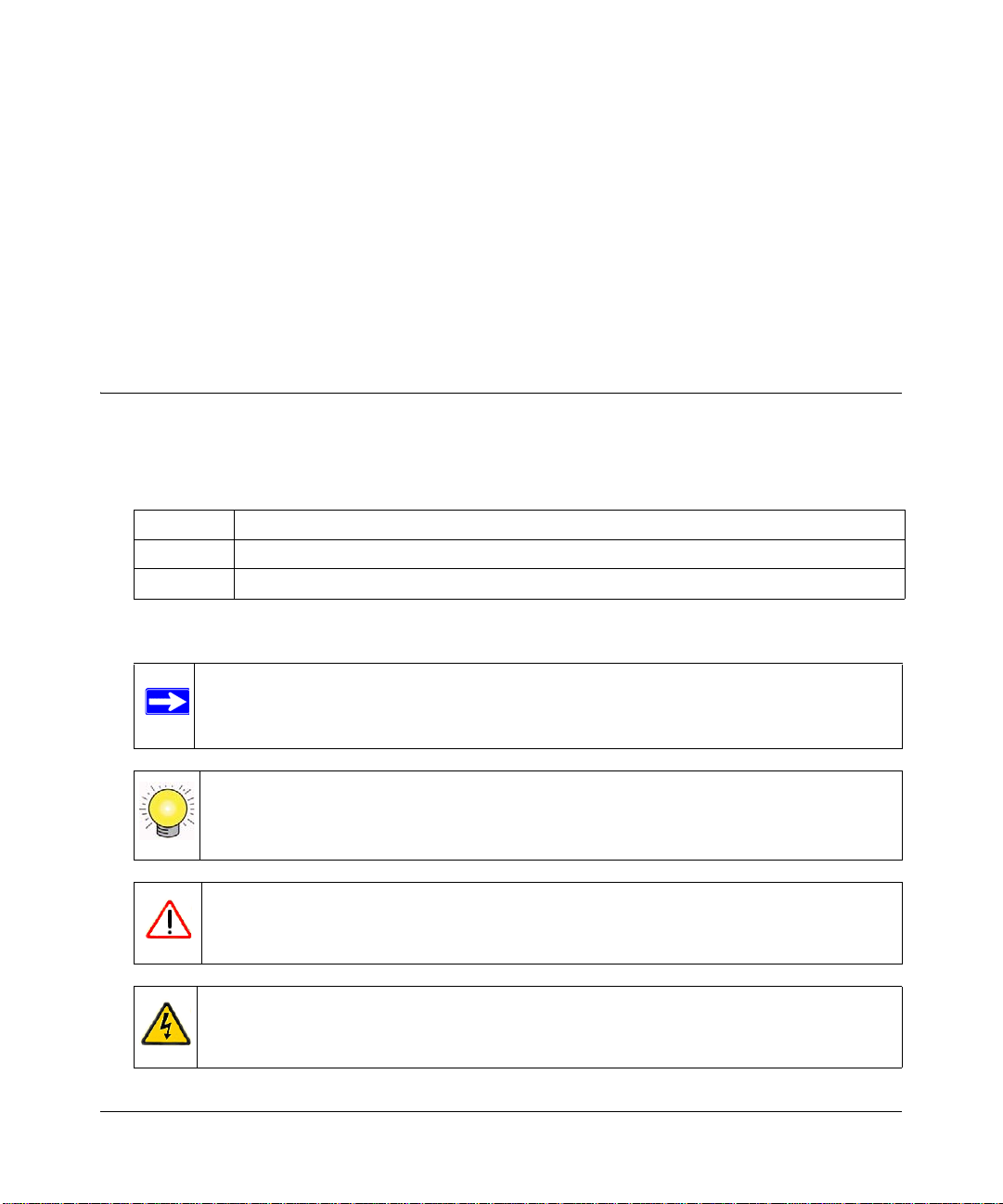
• Typographical Conventions. This guide uses the following typographical conventions:
Italics Emphasis, books, CDs, URL names
Bold User input
Fixed Screen text, file and server names, extensions, commands, IP addresses
• Formats. This guide uses the following formats to highlight special messages:
Note: This format is used to highlight information of importance or special interest.
Tip: This format is used to highlight a procedure that will save time or resources.
Warning: Ignoring this type of note may result in a malfunction or damage to the
equipment.
Danger: This is a safety warning. Failure to take heed of this notice may result in
personal injury or death.
v1.0, April 2007
xvii
Page 18
DGFV338 ProSafe Wireless ADSL Modem VPN Firewall Router Reference Manual
• Scope. This manual is written for the W ireless ADSL Router according t o these specifications:
Product Version ProSafe Wireless ADSL Modem VPN Firewall Router
Manual Publication Date April 2007
For more information about network, Internet, firewall, and VPN technologies, see the links to the
NETGEAR website in Appendix B, “Related Documents”
Note: Product updates are available on the NETGEAR, Inc. Web site at
http://kbserver.netgear.com/products/DGFV338.asp.
How to Use This Manual
The HTML version of this manual includes the following:
• Buttons, and , for browsing forwards or backwards through the manual one page
at a time
• A button that displays the table of contents and an button. Double-click on a
link in the table of contents or index to navigate directly to where the topic is described in the
manual.
• A button to access the full NETGEAR, Inc. online knowledge base for the product
model.
• Links to PDF versions of the full manual and individual chapters.
How to Print this Manual
T o print this manual you can choose one of the following several options, according to your needs.
Your computer must have the free Adobe Acrobat Reader installed in order to view and print PDF
files. The Acrobat Reader is available on the Adobe website at http://www.adobe.com.
• Printing a Page in the HTML View. Each page in the HTML version of the manual is
dedicated to a major topic. Use the Print button on the browser toolbar to print the page
contents.
• Printing a Chapter. Use the PDF of This Chapter link at the top left of any page.
xviii
v1.0, April 2007
Page 19
DGFV338 ProSafe Wireless ADSL Modem VPN Firewall Router Reference Manual
– Click the PDF of This Chapter link at the top right of any page in the chapter you want to
print. The PDF version of the chapter you were viewing opens in a browser window.
– Click the print icon in the upper left of the window.
Tip: If your printer supports printing two pages on a single sheet of paper, you can
save paper and printer ink by selecting this feature.
• Printing the Full Manual. Use the Complete PDF Manual link at the top left of any page.
– Click the Complete PDF Manual link at the top left of any page in the manual. The PDF
version of the complete manual opens in a browser window.
– Click the print icon in the upper left of the window.
Tip: If your printer supports printing two pages on a single sheet of paper, you can
save paper and printer ink by selecting this feature.
v1.0, April 2007
xix
Page 20

DGFV338 ProSafe Wireless ADSL Modem VPN Firewall Router Reference Manual
xx
v1.0, April 2007
Page 21

Chapter 1
Introduction
This chapter describes the features of the ProSafe™ Wireless ADSL Modem VPN Firewall
Router. It also includes the minimum prerequisites for installation (“System Requirements” on
page 1-5.), what’s in the box (“Package Contents” on page 1-6) and a description of the front and
back panels of the DGFV338 (“Hardware Description” on page 1-6). The location of the default
settings to log in to the router is presented in “Router Login Factory Defaults” on page 1-9 and
suggestions on placement of your router to achieve maximum wireless range are in “Placement of
your NETGEAR ProSafe DGFV338” on page 1-10.
Key Features of the NETGEAR ProSafe DGFV338
The NETGEAR ProSafe DGFV338 with eight-port switch connects your local area network
(LAN) to the Internet through an internal ADSL modem or through the Ethernet port via an
external modem. It provides wireless LAN connectivity operating at 2.4GHz (802.11b/g).
The NETGEAR ProSafe DGFV338 has a built-in Stateful Packet Inspection Firewall (SPI)
preventing Denial of Service attacks and provides Internet access for up to 253 users. The
NETGEAR ProSafe DGFV338 provides you with multiple Web content filtering options, plus
browsing activity reporting and instant alerts—both, via e-mail. Network administrators can
establish restricted access policies based on time-of-day, Website addresses and address keywords,
and share high-speed cable/DSL Internet access for a local network.
With minimum setup, you can install and use the firewall within minutes.
The NETGEAR ProSafe DGFV338 provides the following features:
• An internal ADSL modem supporting Annex A or Annex B (depending upon region).
• One 10/100 Mbps Ethernet WAN port.
• 802.11g, 802.11b, 802.11g/b, or Auto 108Mbps.
• Support for up to 50 IPSec VPN tunnels.
• Easy, web-based setup for installation and management.
• URL keyword Content Filtering and Site Blocking Security.
• Quality of Service (QoS) support for traffic prioritization.
• Built in 8-port 10/100 Mbps switch.
Introduction 1-1
v1.0, April 2007
Page 22

DGFV338 ProSafe Wireless ADSL Modem VPN Firewall Router Reference Manual
• Extensive Protocol Support.
• SNMP for manageability.
• Front panel LEDs for easy monitoring of status and activity.
• Flash memory for firmware upgrade.
• Auto Sensing and Auto Uplink™
Full Routing on Both the ADSL and 10/100 WAN Port
You can install, configure, and operate the DGFV338 to take full advantage of a variety of routing
options on both the DSL and broadband WAN ports, including:
• Internet access via either the internal ADSL modem or through the Ethernet port connected to
an external modem.
• Auto Rollover Mode between the internal ADSL modem and the external 10/100 ethernet
WAN port. If the primary connection fails, the DGFV338 can automatically establish a backup
connection via the secondary connection.
A Powerful, True Firewall with Content Filtering
DGFV338 is a true firewall, using stateful packet inspection to defend against attacks. Its firewall
features include:
• DoS protection. Automatically detects and thwarts DoS attacks such as Ping of Death, SYN
Flood, LAND Attack, and IP Spoofing.
• Blocks unwanted traffic from the Internet to your LAN.
• Blocks access from your LAN to Internet locations or services that you specify as off-limits.
• Logs security incidents. The DGFV338 will log security events such as blocked incoming
traffic, attacks, and administrator logins. Y ou can configure the firewall to email the log to you
at specified intervals. You can also configure the firewall to send immediate alert messages to
your email address or email pager whenever a significant event occurs.
• With its URL keyword filtering feature, the DGFV338 prevents objectionable content from
reaching your PCs. The firewall allows you to control access to Internet content by screening
for keywords within Web addresses. You can configure the firewall to log and report attempts
to access objectionable Internet sites.
1-2 Introduction
v1.0, April 2007
Page 23

DGFV338 ProSafe Wireless ADSL Modem VPN Firewall Router Reference Manual
Security
The NETGEAR ProSafe DGFV338 is equipped with several features designed to maintain
security, as described in this section.
• PCs Hidden by NAT. NAT opens a temporary path to the Internet for requests originating
from the local network. Requests originating from outside the LAN are discarded, preventing
users outside the LAN from finding and directly accessing the PCs on the LAN.
• Port Forwarding with NAT. Although NAT prevents Internet locations from directly
accessing the PCs on the LAN, the firewall allows you to direct incoming traffic to specific
PCs based on the service port number of the incoming request. You can specify forwarding of
single ports or ranges of ports.
• Exposed Host (Software DMZ). Incoming traffic from the Internet is normally discarded by
the firewall unless the traffic is a response to one of your local computers or a service for
which you have configured an inbound rule. Instead of discarding this traffic, you can have it
forwarded to one computer on your network.
Virtual Private Networking (VPN)
The NETGEAR ProSafe DGFV338 provides a secure encrypted connection between your local
area network (LAN) and remote networks or clients. It includes the following VPN features:
• Supports 50 IPSec VPN tunnels.
• Supports industry-standard VPN protocols – The DGFV338 supports standard Manual or IKE
keying methods, standard MD5 and SHA-1 authentication methods, and stand ard DES, 3 DES
and AES encryption methods.
• Supports 256-bit AES encryption for maximum security.
• The VPN Wizard configuration is based on the Virtual Private Network Consortium (VPNC)
recommended settings.
Autosensing Ethernet Connections with Auto Uplink
With its internal 8-port 10/100 switch, the DGFV338 can connect to either a 10 Mbps standard
Ethernet network or a 100 Mbps Fast Ethernet network. Both the LAN and WAN interfaces are
autosensing and capable of full-duplex or half-duplex operation.
Introduction 1-3
v1.0, April 2007
Page 24

DGFV338 ProSafe Wireless ADSL Modem VPN Firewall Router Reference Manual
The firewall incorporates Auto Uplink technology. Each Ethernet port will automatically sense
whether the Ethernet cable plugged into the port should have a “normal” connection such as to a
PC or an “uplink” connection such as to a switch or hub. That port will then configure itself to the
correct configuration. This feature also eliminates the need to worry about crossover cables, as
Auto Uplink will accommodate either type of cable to make the right connection.
Extensive Protocol Support
The NETGEAR ProSafe DGFV338 supports the Transmission Control Protocol/Internet Protocol
(TCP/IP) and Routing Information Protocol
• IP Address Sharing by NAT. The DGFV338 allows several networked PCs to share an
Internet account using only a single IP address, which may be statically or dynamically
assigned by your Internet service provider (ISP). This technique, known as NAT, allows the
use of an inexpensive single-user ISP account.
• Automatic Configuration of Attached PCs by DHCP. The DGFV338 dynamically assigns
network configuration information, including IP, gateway, and domain name server (DNS)
addresses, to attached PCs on the LAN using the Dynamic Host Configuration Protocol
(DHCP). This feature greatly simplifies configuration of PCs on your local network.
• DNS Proxy. When DHCP is enabled and no DNS addresses are specified, the firewall
provides its own address as a DNS server to the attached PCs. The firewall obtains actual DNS
addresses from the ISP during connection setup and forwards DNS requests from the LAN.
(RIP).
• PPP over Ethernet (PPPoE). PPPoE is a protocol for connecting remote hosts to the Internet
over a DSL connection by simulating a dial-up connection. This feature eliminates the need to
run a login program such as EnterNet or WinPOET on your PC.
• PPP over ATM (PPPoA). PPPoA is an asynchronous point-to-point protocol for connecting
to the Internet over ADSL.
Easy Installation and Management
You can install, configure, and operate the ProSafe Wireless ADSL Modem VPN Firewall Router
within minutes after connecting it to the network. The following features simplify installation and
management tasks:
• Browser-based management. Browser-based configuration allows you to easily configure
your firewall from almost any type of personal computer, such as Windows, Macintosh, or
Linux. A user-friendly Setup Wizard is provided and online help documentation is built into
the browser-based Web Management Interface.
1-4 Introduction
v1.0, April 2007
Page 25

DGFV338 ProSafe Wireless ADSL Modem VPN Firewall Router Reference Manual
• Smart Wizard. The NETGEAR ProSafe DGFV338 automatically senses the type of Internet
connection, asking you only for the information required for your type of ISP account.
• VPN Wizard. The NETGEAR ProSafe DGFV338 includes the NETGEAR VPN Wizard to
easily configure VPN tunnels according to the recommendations of the Virtual Private
Network Consortium (VPNC) to ensure the VPN tunnels are interoperable with other VPNCcompliant VPN routers and clients.
• SNMP. The NETGEAR ProSafe DGFV338 supports the Simple Network Management
Protocol (SNMP) to let you monitor and manage resources from an SNMP-compliant system
manager. The SNMP system configuration lets you change the system variables for MIB2.
• Diagnostic functions. The firewall incorporates built-in diagnostic functions such as Ping,
Packet Capture, DNS lookup, and remote reboot.
• Remote management. The firewall allows you to securely log in to the Web Management
Interface from a remote location on the Internet. For additional security, you can limit remote
management access to a specified remote IP address or range of addresses, and you can choose
a nonstandard port number.
• Visual monitoring. The front panel LEDs of the NETGEAR ProSafe DGFV338 provide an
easy way to monitor its status and activity.
Maintenance and Support
NETGEAR offers the following features to help you maximize your use of the NETGEAR
ProSafe DGFV338:
• Flash memory for firmware upgrade
• On-line technical support and telephone support for registered products.
System Requirements
Before installing the DGFV338, make sure your system meets these requirements:
• The Category 5 UTP straight through Ethernet cable with RJ-45 connector included in the
package, or one like it
• A 100-240 V, 50-60 HZ AC power source.
• Cable, DSL, Satellite or Wireless Broadband modem (for Ethernet connection).
• Internet service.
• ADSL service (for ADSL connectivity).
Introduction 1-5
v1.0, April 2007
Page 26

DGFV338 ProSafe Wireless ADSL Modem VPN Firewall Router Reference Manual
• A Web browser for configuration such as Mozilla Firefox, Microsoft Internet Explorer 5.0 or
above, or Netscape Navigator 7.2 or above.
• Network card for each connected PC.
• Network Software (for example, Windows).
Package Contents
The product package should contain the following items:
• ProSafe Wireless ADSL Modem VPN Firewall Router.
•AC power adapter.
• Two 2.4 GHz wireless antennas.
• ADSL Microfilter (UK only)
• Category 5 Ethernet cable.
• Telephone cable with RJ -11 connector
• Resource CD, including:
– Application Notes and other helpful information.
– ProSafe VPN Client Software; one user license.
• Warranty and Support Information Card.
If any of the parts are incorrect, missing, or damaged, contact your NETGEAR dealer. Keep the
carton, including the original packing materials, in case you need to return the firewall for repair.
Hardware Description
This section describes the front and rear hardware functions of the wireless ADSL firewall.
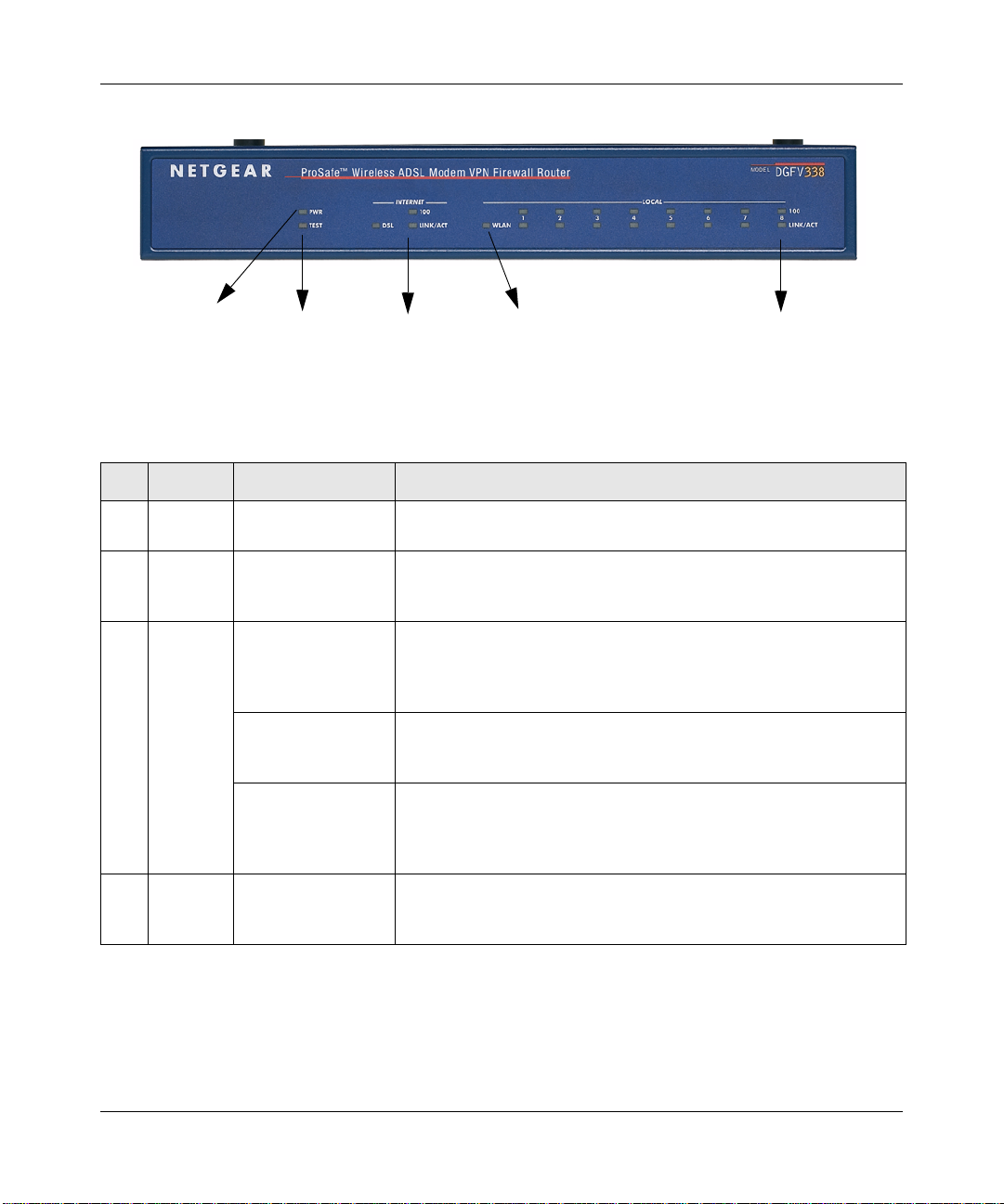
Router Front Panel
The ProSafe Wireless ADSL Modem VPN Firewall Router front panel shown below contains the
power and test LEDs, Internet status LEDs, and the LAN status LEDs.
1-6 Introduction
v1.0, April 2007
Page 27
DGFV338 ProSafe Wireless ADSL Modem VPN Firewall Router Reference Manual
1
2
3
4
Figure 1-1
The table below describes each item on the front panel and its operation.
Table 0-1. Object Descriptions
Nos. LEDs Activity Description
1 Power - 1 On (Green)
Off
2 Test - 2 On (Amber)
Blinking (Amber)
Off
3 Internet
LEDs
4 WLAN On (Green)
Link/Act LED
On (Green)
Blinking (Green)
Off
100 LED
On (Green)
Off
DSL LED
On (Green)
Blinking (Green)
Off
Blinking (Green)
Off
Power is supplied to the gateway
Power is not supplied to the gateway.
Test mode: The system is initializing or the initialization has failed.
Writing to Flash memory (during upgrading or resetting to defaults).
The system has booted successfully.
The WAN port has detected a link with a connected Ethernet device.
Data is being transmitted or received by the WAN port.
The WAN port has no link.
The WAN port is operating at 100 Mbps.
The WAN port is operating at 10 Mbps.
The DSL modem has detected a link with the Internet.
Data is being transmitted or received.
The DSL modem has no connection.
A wireless connection is detected.
Data is being transmitted or received.
No link is detected or the radio is disabled.
5
Introduction 1-7
v1.0, April 2007
Page 28
DGFV338 ProSafe Wireless ADSL Modem VPN Firewall Router Reference Manual
Table 0-1. Object Descriptions (continued)
Nos. LEDs Activity Description
5 Local
LEDs
Link/Act LED
On (Green)
Blinking (Green)
Off
100 LED
On (Green)
Off
The LAN port has detected a link with a connected Ethernet device.
Data is being transmitted or received by the LAN port.
The LAN port has no link.
The LAN port is operating at 100 Mbps.
The LAN port is operating at 10 Mbps.
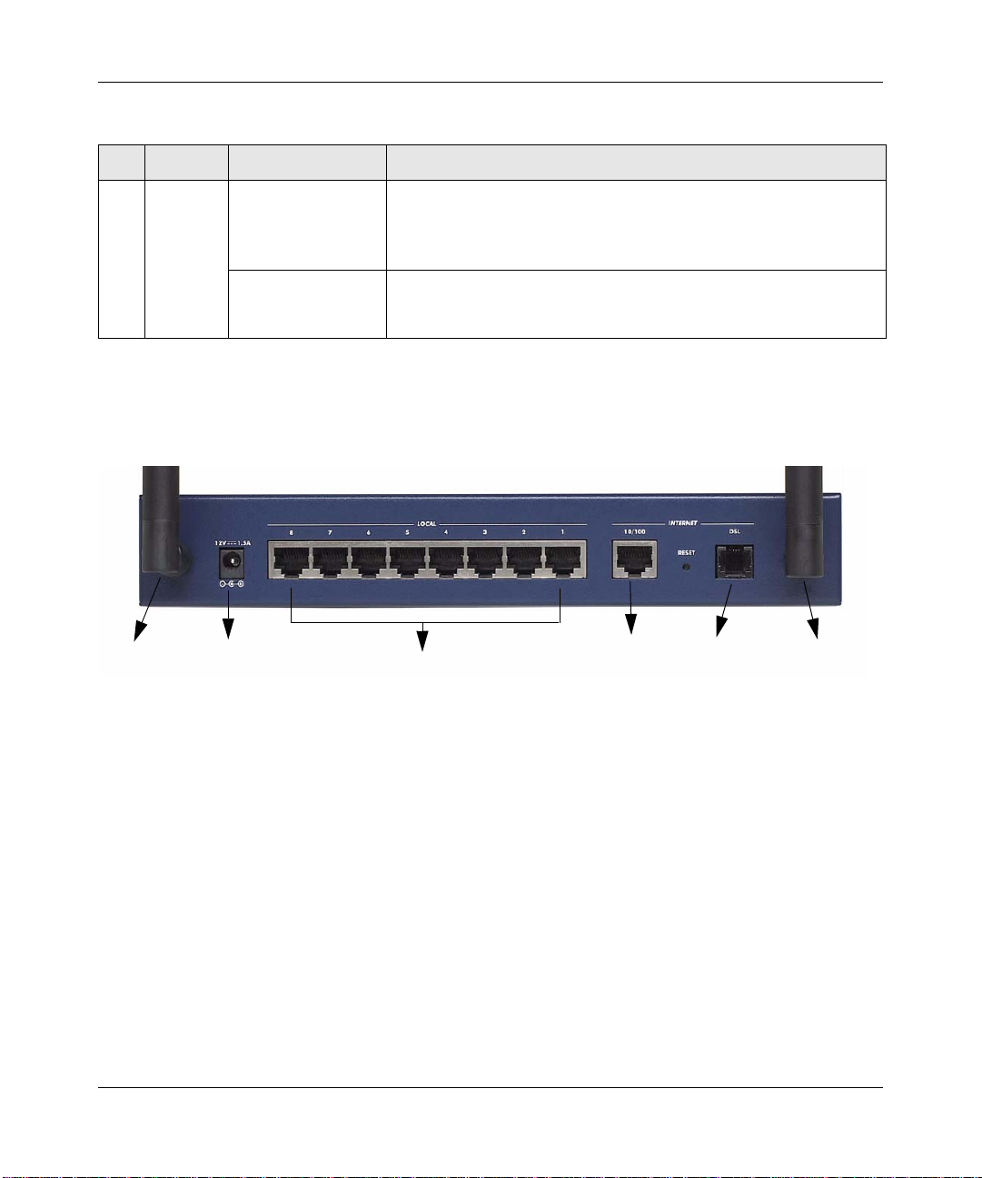
Router Rear Panel
The rear panel of the ProSafe W ireles s ADSL Modem VPN Firewall Rou ter (Figure 1-2) contains
the AC power connection; LAN, Ethernet and DSL port; and the reset button.
1
Figure 1-2
2
3
4
5
1
Viewed from left to right, the rear panel contains the following elements:
1. Wireless antenna. Two 2.4 GHz antennas attach to either end of the NETGEAR ProSafe
DGFV338.
2. DC Power connection (12VDC, 1.5A). Provides power to the gateway when the power
supply is attached.
3. Local LAN ports. An 8-port RJ-45 10/100 Mbps Fast Ethernet Switch, N-way automatic
speed negotiation, auto MDI/MDIX.
4. Ethernet port. serves as the 10/100 WAN port connection to an external modem. One RJ-45
WAN port, N-way automatic speed negotiation, Auto MDI/MDIX.
5. ADSL port. Serves as the direct WAN DSL connection to the Internet from the internal ADSL
modem via a telephone cable.
1-8 Introduction
v1.0, April 2007
Page 29
DGFV338 ProSafe Wireless ADSL Modem VPN Firewall Router Reference Manual
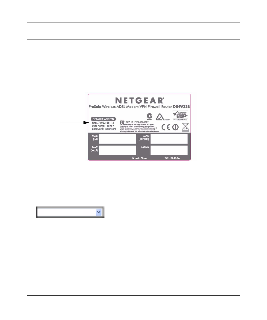
Router Login Factory Defaults
Check the label on the bottom of the DGFV338’s enclosure if you forget the following factory
default information:
• IP Address: http://192.168.1.1 to reach the Web-based GUI from the LAN
•User name: admin
• Password: password
LAN IP Address
User Name
Password
Figure 1-3
To log in to the DGFV338 once it is connected:
1. Open a Web browser.
2. Enter http://192.168.1.1 as the URL.
http://192.168.1.1
Figure 1-4
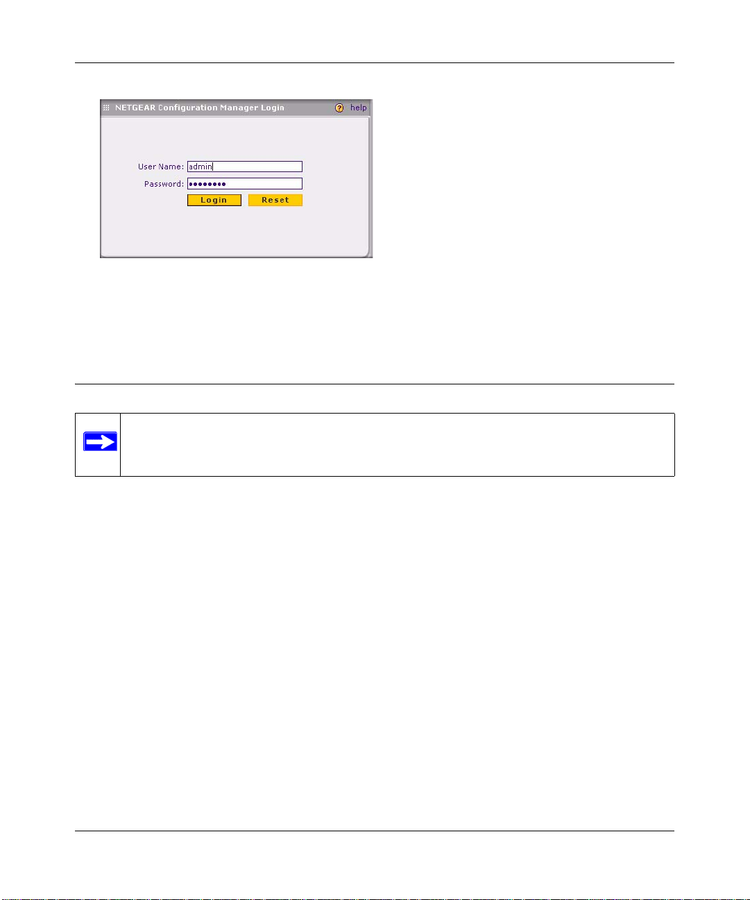
3. Once you get the login screen (Figure 1-5), enter the following information:
• admin for User Name
• password for Password
Introduction 1-9
v1.0, April 2007
Page 30
DGFV338 ProSafe Wireless ADSL Modem VPN Firewall Router Reference Manual
.
Figure 1-5
For a complete list of the factory default settings of your NETGEAR ProSafe DGFV338, see
Appendix A, “Default Settings and Technical Specifications”
Placement of your NETGEAR ProSafe DGFV338
Note: Failure to follow these guidelines can result in significant performance degradation
or inability to wirelessly connect to the wireless ADSL firewall.
The operating distance or range of your wireless connection can vary significantly bas ed on the
physical placement of NETGEAR ProSafe DGFV338. The latency, data throughput performance,
and notebook power consumption also vary depending on your configuration choices. For best
results, place your wireless ADSL firewall:
• Near the center of the area in which your PCs will operate.
• In an elevated location, such as a high shelf where the wireless-connected PCs have line-ofsight access (even if through walls). The best location is elevated, such as wall mounted or on
the top of a cubicle, and at the center of your wireless coverage area for all the mobile devices.
• Away from potential sources of interference, such as PCs, microwaves and cordless phones.
• With the antenna tight and in an upright position.
• Away from large metal surfaces.
1-10 Introduction
v1.0, April 2007
Page 31

Chapter 2
Basic Installation and Configuration
This section provides instructions for connecting the DGFV338. Typically, it takes approximately
seven steps to complete connecting all facets of your gateway:
1. Connect the gateway physically to your network. If connecting through a modem, power
off and disconnect the modem before starting. Connect the cables after turning off your
modem, if you are connecting through your Ethernet port.
If connecting through the built-in ADSL modem, connect the wireless firewall to a microfilter,
and then connect the microfilter to your phone jack (see “Using ADSL Microfilters (optional)”
on page 2-2 for instructions on using microfilters).
For additional instructions on connecting your ProSafe DGFV338, refer to the DGFV338
ProSafe W ireless ADSL Modem VPN Firewall Router Installation Guide on your Resource CD
or to the NETGEAR Website for an online electronic copy.
2. Restart your network in the corr ect sequen ce. It is important to pay attention to the order i n
which you restart your network. Then, check the LEDs and make sure the test lights are
working appropriately.
3. Log into the gateway. After logging in, you are ready to set up and configure your gateway.
You can also change your password and enable remote management at this time.
4. Configure the WAN Setup options for your ISP Internet connection(s). During this phase,
you will connect to your ISP(s). You can also program the WAN traffic meters at this time.
5. Configure the WAN mode for your Internet connection(s). You can also configure the
dynamic DNS on the WAN ports (if needed).
You can configure either the ADSL ISP or the Ethernet ISP or you can enable both ADSL and
Ethernet ISPs, and configure them to operate in Auto-rollover mode. You can also configure
Advanced options such as the factory default MTU size, port speed, and uplink bandwidth.
6. Set up your wireless LANs. Select the appropriate Country/Region and Operating Mode for
your antenna configuration.
Because the wireless interface is disabled by default, the initial wireless configuration must be
made from a wired connection (either via ADSL or Ethernet). During this step, you can also
choose the wireless security method for your LAN gateway; for example, versions of either
WEP or WPA.
Basic Installation and Configuration 2-1
v1.0, April 2007
Page 32

DGFV338 ProSafe Wireless ADSL Modem VPN Firewall Router Reference Manual
7. Set up your VPN connections using Auto Detect. If you do not know your ISP connection,
Auto Detect will attempt to automatically detect your connection type by probing for different
connection methods. If you know your ISP type, you can set up your connections manually.
(Ensure that you have the ISP information relevant to your connection type before you begin.
Using ADSL Microfilters (optional)
ADSL technology uses the same wires as your telephone service. However, ADSL adds signals to
the telephone lines which create noise in the telephone service. You must use ADSL microfilters to
filter out these signals before they reach your telephone. If you are planning on using the ADSL
modem port, and an ADSL Microfilter is not included with your ProSafe DGFV338, you should
acquire one.
There are two types of ADSL Microfilters: a one-line filter and a two-line filter with splitter.
• One-Line Microfilter. A simple microfilter provides an interface filter between your
telephone and the phone jack as shown in Figure 2-1. Each device such as a telephone, fax
machine, answering machine, or caller ID display requires an ADSL microfilter..
Figure 2-1
You can also connect the one-line filter to a phone-jack splitter to allow for connection of the
wireless firewall. However, the phone-jack splitter must be a designated ADSL microfilter/
phone jack splitter.
• ADSL Microfilter with Built-In Splitter. Use an ADSL microfilter with built-in splitter
when there is a single wall outlet which must provide connectivity for both the wireless
firewall and the telephone equipment.
Figure 2-2
2-2 Basic Installation and Configuration
v1.0, April 2007
Page 33

DGFV338 ProSafe Wireless ADSL Modem VPN Firewall Router Reference Manual
.
Warning: Do not connect the wireless firewall to the ADSL line through a
microfilter unless the microfilter is a combination ADSL microfilter/
splitter specifically designed for this purpose. Doing so will block your
connection to the Internet. If you have any doubts about this, connect the
wireless firewall directly to your phone line.
Logging in and Configuring your Internet Connection
Note: To connect to the gateway, your computer needs to be configured to obtain an IP
address automatically via DHCP.
To log in to the wireless firewall:
1. Connect to the gateway by typing http://192.168.1.1 in the address field of Internet Explorer,
Netscape Navigator, or Mozilla Firefox. The login screen will display.
Figure 2-3
2. Enter admin for the gateway user name and password for the gateway password in lower case
letters. Both fields are case-sensitive. (The gateway user name and password are not the same
as any user name or password you may use to log in to your Internet connection.)
Basic Installation and Configuration 2-3
v1.0, April 2007
Page 34

DGFV338 ProSafe Wireless ADSL Modem VPN Firewall Router Reference Manual
3. Click Login. The ProSafe Wireless ADSL Modem VPN Firewall Router user interface will
display.
Note: You might want to enable remote management at this time so that you can log
in remotely in the future to manage the gateway. See “Enabling Remote
Management Access” on page 6-8 for more information. Remote management
enable is cleared with a factory default reset.
Note: When you enable remote management, we strongly advise that you change
your password. See “Changing the Passwords and Login Time-out” on page 6-
7 for the procedure on how to do this.
Configuring Your Internet Connection using Auto Detect
Depending on how you connected your gateway to the Internet, you can configure your ISP
settings by choosing the ADSL ISP settings (for DSL) or the Ethernet ISP settings (for 10/100). If
you connected to both, you can configure both.
Note: To enable Auto-Rollover, you must have both ADSL and Ethernet ports connected
and configured. If you intend to configure both, configure your primary WAN port
first.
To automatically configure your ADSL ISP settings and connect to the Internet:
1. Go to the ADSL ISP Settings screen shown in Figure 2-4 by selecting the primary menu
option Network Configuration and the sub-menu option WAN Settings.
2. Click Auto Detect at the bottom of the screen to automatically detect the type of Internet
connection provided by your ISP. Auto Detect will probe for different connection methods and
suggest one that your ISP will most likely support.
When Auto Detect successfully detects an active Internet service, it reports which connection type
it discovered. The options are described in the Table 2-1., “Internet Service Connections”.
To automatically configure your Ethernet ISP settings and connect to the Internet:
1. Select the Ethernet ISP Settings screen similar to the one shown in Figure 2-5 should display.
2. Click Auto Detect at the bottom of the screen to automatically detect the type of Internet
connection provided by your ISP. Auto Detect will probe for different connection methods and
suggest one that your ISP will most likely support.
2-4 Basic Installation and Configuration
v1.0, April 2007
Page 35

DGFV338 ProSafe Wireless ADSL Modem VPN Firewall Router Reference Manual
When Auto Detect successfully detects an active Internet service, it reports which connection type
it discovered. The options are described in the Table 2-1., “Internet Service Connections”.
Figure 2-4
Basic Installation and Configuration 2-5
v1.0, April 2007
Page 36

DGFV338 ProSafe Wireless ADSL Modem VPN Firewall Router Reference Manual
Figure 2-5
Table 2 -1. Internet Service Connections
Connection Method Data Required
PPPoE Login (Username, Password).
PPPoA Login (Username, Password).
DHCP (Dynamic IP) No data is required.
Static (Fixed) IP Internet IP address, Subnet Mask and Gateway IP Address supplied by
your ISP; and the Router’s DNS Address (also supplied by your ISP).
IPoA Internet IP Address and Subnet Mask; Gateway IP Address
Manually Configuring your ADSL Connection
Unless your ISP assigns your configuration automatically via DHCP, you will need the
configuration parameters from your ISP. For example, if your router detected a PPPoE or PPPoA
service, you must provide a Login sequence in order to obtain an Internet connection from your
2-6 Basic Installation and Configuration
v1.0, April 2007
Page 37

DGFV338 ProSafe Wireless ADSL Modem VPN Firewall Router Reference Manual
ISP. If your ISP requires a Static IP address, then you must provide the fixed addresses for Static
IP. The types of data you will need are highlighted in Table 2-1 by connection method, and
explained in more detail below.
To configure your ADSL ISP connection:
1. Enter your ISP Login information. Select the Does Your Internet Connection require a
Login? option based on the type of account your have with your ISP. If you need to enter login
information every time you connect to the Internet, select Yes. Otherwise, select No.
If your connection is PP TP, PPPoE or BigPond Cable, then you need to login. Choose Yes and
enter:
– Login. This is often the name that you use in your e-mail address (for example, if your
main mail account is jdoe@aol.com, enter jdoe).
Note: Some ISPs (for example, Earthlink) require that you use your full e-mail
address when you log in.
– Password. Enter the password you use to log in to your ISP.
• Enter your ISP Type information:
Select either the PPPoE or PPPoA radio box. (If you have installed log in software such as
WinPoET or Enternet, then your connection type is PPPoE.) Select this option and configure
the following fields:
• Account Name: Valid account name for the PPPoE connection
• Domain Name: Name of your ISPs domain or your domain name if your ISP has assigned
one (optional).
• Idle Timeout: Select Keep Connected, to keep the connection always on. To logout after
the connection is idle for a period of time, select Idle Time and enter the number of
minutes to wait before disconnecting, in the Timeout field.
2. Enter your Internet (IP) Address.
– Select the Get dynamically from ISP radio box if you have not been assigned any static
IP address. The ISP will automatically assign an IP address to the router using DHCP
network protocol.
– If your ISP has assigned a fixed (static) IP address, select Use Static IP Address and fill
in the following fields:
Basic Installation and Configuration 2-7
v1.0, April 2007
Page 38

DGFV338 ProSafe Wireless ADSL Modem VPN Firewall Router Reference Manual
• IP Address: Static IP address assigned to you. This will identify the router to your
ISP.
• IP Subnet Mask: This is usually provided by the ISP or your network administrator.
• Gateway IP Address: IP address of your ISP’s gateway. This is usually provided by
the ISP or your network administrator.
3. Select your Domain Name Servers (DNS). Domain name servers (DNS) convert Internet
names such as www.google.com, www.netgear.com, etc. to Internet addresses called IP
addresses.
– Select the Get Automatically from ISP radio box if you have not been assigned a static
DNS IP address.
– If the Use these DNS Servers radio box is selected, enter valid DNS server IP addresses
in the Primary DNS Server and Secondary DNS Server fields.
4. Click Apply to save your settings. Click Test to verify that the connection is active.
Note: At this point in the configuration process, you should now be connected to the
Internet through the internal ADSL modem and the DSL connection.
Repeat these steps to connect your secondary configuration, if required.
Manually Configuring your Ethernet Connection
Unless your ISP assigns your configuration automatically via DHCP, you will need the
configuration parameters from your ISP. For example, if your router detected a PPPoE or PPPoA
service, you must provide a Login sequence in order to obtain an Internet connection from your
ISP. If your ISP requires a Static IP address, then you must provide the fixed addresses for Static
IP. The types of data you will need are highlighted in Table 2-1 by connection method, and
explained in more detail below.
To configure your Ethernet ISP connection:
1. Enter your ISP Login information. Select the Does Your Internet Connection require a
Login? option based on the type of account your have with your ISP. If you need to enter login
information every time you connect to the Internet, select Yes. Otherwise, select No.
If your connection is PP TP, PPPoE or BigPond Cable, then you need to login. Choose Yes and
enter:
2-8 Basic Installation and Configuration
v1.0, April 2007
Page 39

DGFV338 ProSafe Wireless ADSL Modem VPN Firewall Router Reference Manual
– Login. This is often the name that you use in your e-mail address (for example, if your
main mail account is jdoe@aol.com, enter jdoe).
Note: Some ISPs (for example, Earthlink) require that you use your full e-mail
address when you log in.
– Password. Enter the password you use to log in to your ISP.
• Enter your ISP Type information:
– Austria (PP TP): If your ISP is Austria Telecom or any other ISP that uses PPTP to log in,
fill in the following fields:
• Account Name (also known as Host Name or System Name): Valid account name for
the PPTP connection. This is usually your email “ID” assigned by your ISP, the name
before the “@” symbol in your email address. Some ISPs require that you enter your
full email address here.
• Domain Name: Domain name or workgroup name assigned by your ISP, or your ISPs
domain name (optional).
• Idle Timeout: Select Keep Connected, to Keep the Connection Always On. T o logout
after the connection is idle for a period of time, select Idle Time and enter the number
of minutes to wait before disconnecting in the Timeout field. This is useful if your ISP
charges you based on the amount of time you have logged in.
• My IP Address: IP address assigned by the ISP to make a connection with the ISP
server.
• Server IP Address: IP address of the PPTP server.
– Other (PPPoE): If you have installed log in software such as WinPoET or Enternet, then
your connection type is PPPoE. Select this option and configure the following fields:
• Account Name: Valid account name for the PPPoE connection
• Domain Name: Name of your ISPs domain or your domain name if your ISP has
assigned one (optional).
• Idle Timeout: Select Keep Connected, to keep the connection always on. To logout
after the connection is idle for a period of time, select Idle Time and enter the number
of minutes to wait before disconnecting, in the Timeout field.
Basic Installation and Configuration 2-9
v1.0, April 2007
Page 40

DGFV338 ProSafe Wireless ADSL Modem VPN Firewall Router Reference Manual
– BigPond Cable: If your ISP is Telstra BigPond Cable, select this option and fill in the Log
In Server and Idle Timeout fields. The Log In Server is the IP address of the BigPond Log
In Server local to your area. You can find log in server information at this URL: http://
www.netgear.com.sg/support/bigpond.asp
2. Enter your Internet (IP) Address.
– Select the Get dynamically from ISP radio box if you have not been assigned any static
IP address. The ISP will automatically assign an IP address to the router using DHCP
network protocol.
– If your ISP has assigned a fixed (static) IP address, select Use Static IP Address and fill
in the following fields:
• IP Address: Static IP address assigned to you. This will identify the router to your
ISP.
• IP Subnet Mask: This is usually provided by the ISP or your network administrator.
• Gateway IP Address: IP address of your ISP’s gateway. This is usually provided by
the ISP or your network administrator.
3. Select your Domain Name Servers (DNS). Domain name servers (DNS) convert Internet
names such as www.google.com, www.netgear.com, etc. to Internet addresses called IP
addresses.
– Select the Get Automatically from ISP radio box if you have not been assigned a static
DNS IP address.
– If the Use these DNS Servers radio box is selected, enter valid DNS server IP addresses
in the Primary DNS Server and Secondary DNS Server fields.
4. Click Apply to save your settings. Click Test to verify that the connection is active.
Note: At this point in the configuration process, you should now be connected to the
Internet through the internal ADSL modem and the DSL connection or the
Ethernet or both.
Selecting Advanced Options for your Ethernet or ADSL Connection
Several other Advanced options that can be altered from their default values affect the MTU size,
Ethernet port speed and the MAC (Media Access Control) address of your computer or router.
These Advanced Options are available for both ADSL and Ethernet connections.
2-10 Basic Installation and Configuration
v1.0, April 2007
Page 41

DGFV338 ProSafe Wireless ADSL Modem VPN Firewall Router Reference Manual
• MTU Size. The normal MTU value for most networks is 1500 Bytes, or 1492 for PPPoE
connections. For some ISPs, you may need to reduce the MTU size. However, this is rarely
required and should not be attempted unless you are sure it is necessary for your ISP
connection.
• Port Speed (Ethernet only). Usually, you r router can automatically determine the connection
speed of the 10/100 port. If you cannot establish an Internet connection and the Internet LED
blinks continuously , manually select the port speed.
If you know your Ethernet port on your broadband modem supports 100BaseT, select 100M;
otherwise, select 10M. Use the half-duplex settings unless you are sure you need full duplex.
• Router MAC Address. Each computer or router on your network has a unique 32-bit local
Ethernet address, known as the Media Access Control (MAC) address. In most cases the
default Use Default Address will suffice. If your ISP requires MAC authentication, then select
either:
– Use This Computer’s MAC address, where the router will use the MAC address of the
computer you are now using, or
– Use This MAC Address, where you manually enter the MAC address that your ISP
expects. The format is XX:XX:XX:XX:XX:XX.
If you set up an ADSL connection, in addition to the Advanced ADSL settings, there are some
additional specific ADSL settings that also should be configured. These include: Multiplexing
Method, VPI and VCI.
To configure your ADSL settings:
1. Click he ADSL Settings link at the top of the ADSL ISP Settings screen. The ADSL Settings
screen will display.
Figure 2-6
2. Configure your ADSL Settings. If you don’t know your settings, contact your ISP. These
parameters must be submitted to correctly establish a DSL connection on the WAN interface:
a. Multiplexing Method: Both VC-BASED multiplexing and LLC-BASED multiplexing
methods are supported.
Basic Installation and Configuration 2-11
v1.0, April 2007
Page 42

DGFV338 ProSafe Wireless ADSL Modem VPN Firewall Router Reference Manual
b. VPI (Virtual Path Identifier) value: This is provided by your ISP to identify the ATM
network (in conjunction with the VCI value).
c. VCI (Virtual Channel Identifier) value: This is provided by your ISP (in conjunction with
the VPI value) to identify the ATM network.
3. Click Apply to save your settings.
To co nfigure your Advanced ADSL ISP Settings:
1. Click the Advanced link at the tops of the ADSL ISP Settings screen. The ADSL Advanced
Options screen will display.
Figure 2-7
2. Enter the MTU Size. The MTU (Maximum Transmit Unit) is the size of the largest packet that
can be sent over the network. The standard MTU value for Ethernet networks is usually 1500
Bytes and for PPPoE connections, it is 1492 Bytes. Unless a change is required by your ISP, it
is recommended that the MTU values be left as is.
3. Enter the Router's MAC Address. Similar to other Ethernet devices, the router has its own
48-bit local Ethernet address, also referred to as the MAC (Media Access Control) address.
The default is set to Use default address.
– If your ISP requires MAC authentication and another MAC address has been previously
registered with your ISP, then select either Use this Computer's MAC address to assign the
MAC address of the computer through which you are accessing the router.
– Select Use This MAC Address and manually type in the MAC address expected by your
ISP.
2-12 Basic Installation and Configuration
v1.0, April 2007
Page 43

DGFV338 ProSafe Wireless ADSL Modem VPN Firewall Router Reference Manual
The format for the MAC address is XX:XX:XX:XX:XX:XX where X is a number from 0 to 9
(inclusive) or an alphabetical letter between A and F (inclusive).
4. Click Apply to save the settings. Click Reset to revert to the previous settings.
To configure you Ethernet ISP Advanced options:
1. Select the Advanced link at the top of the Ethernet ISP Settings screen. The4 Ethernet
Advanced Options screen will display.
Figure 2-8
2. Enter the MTU Size. The MTU (Maximum T ransmit Unit) is the size of the largest packet that
can be sent over the network. The standard MTU value for Ethernet networks is usually 1500
Bytes and for PPPoE connections, it is 1492 Bytes. Unless a change is required by your ISP, it
is recommended that the MTU values be left as is.
3. Enter your Port Speed. Most new devices with Ethernet ports run at full-duplex, 100Mbps
modes. The router can automatically negotiate the speed with the other end of the Ethernet
connection. However, if the Internet LED blinks contin uously, you may need to set the port
speed manually. This could occur with some older broadband modems. If the Ethernet port of
the broadband modem supports 100BaseT, select 100BaseT; otherwise, select 10BaseT. Use
the half-duplex settings if full-duplex modes do not function properly.
4. Enter the Router's MAC Address. The router has its own 48-bit local Ethernet address, also
referred to as the MAC (Media Access Control) address. The default is set to Use default
address. If your ISP requires MAC authentication and another MAC address has been
previously registered with your ISP, then select either Use this Computer’s MAC address to
assign the MAC address of the computer through which you are accessing the router, or select
Use This MAC Address and manually type in the MAC address expected by your ISP. The
format for the MAC address is XX:XX:XX:XX:XX:XX where X is a number from 0 to 9
(inclusive) or an alphabetical letter between A and F (inclusive).
Basic Installation and Configuration 2-13
v1.0, April 2007
Page 44

DGFV338 ProSafe Wireless ADSL Modem VPN Firewall Router Reference Manual
5. Click Apply to save your settings.
Note: You can also set up the traffic meter for the Ethernet ISP, if desired, at this time.
See “Programming the Traffic Meter” on page 2-20.
Configuring the WAN Mode
The WAN ports of the ProSafe Wireless ADSL Modem VPN Firewall Router can be configured
for NAT or Classical Routing. You must select one of them—NAT being the most common:
• NAT. NAT is the technology which allows all PCs on your LAN to share a single Internet IP
address. From the Internet, there is only a single device (the Router) and a single IP address.
PCs on your LAN can use any private IP address range, and these IP addresses are not visible
from the Internet.The Router uses NAT to select the correct PC (on your LAN) to receive any
incoming data.
Note: If you only have a single Internet IP address, you MUST use NAT.
• Classical Routing. In this mode, the Router performs Routing, but without NAT. To gain
Internet access, each PC on your LAN must have a valid Internet IP address.
If your ISP has allocated many IP addresses to you, and you have assigned one of these
addresses to each PC, you can choose Classical Routing. Or, you can use Classical Routing for
routing private IP addresses within a campus environment. Otherwise, selecting this method
will not allow Internet access through this Router.
Depending on the WAN port configuration of the ProSafe DGFV338, you can select one of two
options:
• Auto-Rollover using WAN port. If you have configured both the ADSL ISP and Ethernet ISP
WAN ports of the ProSafe Wireless ADSL Modem VPN Firewall Router, you can select autorollover for increased system reliability. In this mode, the selected WAN interface is made
primary and the other is the rollover link. As long as the primary link is up, all traffic is sent
over the primary link. Once the primary WAN interface goes down, the rollover link is brought
up to send the traffic.
2-14 Basic Installation and Configuration
v1.0, April 2007
Page 45

DGFV338 ProSafe Wireless ADSL Modem VPN Firewall Router Reference Manual
• Use Dedicated WAN port.
– Dedicated ADSL. If you have config ured only the ADSL ISP, then select this interface. In
this mode the ADSL interface will always be active and all traffic will be sent over this
link; the other link will always be down. No link failure detection will occur.
– Dedicated Ethernet. If this is your only ISP configuration, then select Dedicated
Ethernet. In this mode the Ethernet interface will always be active and all traffic will be
sent over this link; the other link will always be down. No link failure detection will occur.
WAN failure is detected using DNS queries to a DNS server, or a Ping to an IP address. For each
WAN interface, DNS queries or Ping requests are sent to the specified IP address. If replies are not
received, the corresponding WAN interface is considered down.
• DNS lookup using WAN DNS Servers (ISP DNS Servers). In this case, DNS queries are
sent to the DNS server configured on the ADSL and Ethernet ISP pages (see “Configuring
Your Internet Connection using Auto Detect” on page 2-4).
• DNS lookup using this DNS Server (for example, a public DNS Server), As an option, you
can enter any public DNS server address. DNS queries are sent to this server through the WAN
interface being monitored.
• Ping to this IP address. Enter a public IP address that will not reject the Ping request or will
not consider the traffic abuse. Queries are sent to this server through the WAN interface being
monitored.
• Test Period. DNS query is sent periodically after every test period. The default test period is
30 seconds.
• Failover. The WAN interface is considered down after the configured number of queries have
failed to elicit a reply from the configured DNS server or from the Ping destination. The
minimum number of failed queries is two. The rollover link is brought up after this, if AutoRollover has been selected.
To configure the WAN mode:
1. Select Network Configuration from the main menu and WAN Mode from the submenu. The
WAN Mode screen will display.
2. Select either the NAT or Classical Routing radio button. If you have a single Internet address,
you must use NAT.
Basic Installation and Configuration 2-15
v1.0, April 2007
Page 46

DGFV338 ProSafe Wireless ADSL Modem VPN Firewall Router Reference Manual
Figure 2-9
3. Select your WAN port configuration:
• Select the Auto-Rollover radio button and designate the rollover port from the pull-down
menu. Auto-Rollover is available only if you have connected and configured both an
ADSL ISP and an Ethernet ISP connection.
• Select the Use Dedicated WAN port radio button and select the dedicated port from the
pull-down menu if you have configured and are connected to only one port.
4. Select the WAN Failure Detection Method, if Auto-Rollover is selected:
• Select DNS lookup using this DNS Server and enter the server address (default), or
• Select the Ping to this IP address and enter the ping address.
Once a rollover occurs, when the primary port is restored, the router will automatically switch
back to the designated primary port.
2-16 Basic Installation and Configuration
v1.0, April 2007
Page 47

DGFV338 ProSafe Wireless ADSL Modem VPN Firewall Router Reference Manual
The default time to roll over after the primary WAN interface fails is 2 minutes (e.g., a 30second minimum test period, times a minimum of four tests).
Configuring Dynamic DNS (If Needed)
Note: If your ISP assigns a private WAN IP address such as 192.168.x.x or 10.x.x.x, the
dynamic DNS service will not work because private addresses will not be routed
on the Internet.
If your network has a permanently assigned (static or fixed) IP address, you can register a domain
name and have that name linked with your IP address by public Domain Name Servers (DNS).
However, if your Internet account uses a dynamically assigned IP address, you will not know in
advance what your IP address will be, and the address can change frequently. In this case, you can
use a commercial dynamic DNS service, which allows you to register an extension to its domain,
and resolves DNS requests for the resulting FQDN to your frequently-changing IP address.
For rollover mode, you will need a fully qualified domain name (FQDN) to implement features
such as exposed hosts and virtual private networks regardless of whether you have a fixed or
dynamic IP address.
The gateway contains a client that can connec t to a dynamic DNS service provider. To use this
feature, you must select a service provider and obtain an account with them. After you have
configured your account information in the gateway, whenever your ISP-assigned IP address
changes, your gateway will automatically contact your dynamic DNS service provider, log in to
your account, and register your new IP address.
Basic Installation and Configuration 2-17
v1.0, April 2007
Page 48

DGFV338 ProSafe Wireless ADSL Modem VPN Firewall Router Reference Manual
To configure Dynamic DNS:
1. Select Network Configuration from the main menu and Dynamic DNS from the submenu.
The Dynamic DNS Configuration screen will display with the default None selected.
Figure 2-10
Each DNS service provider requires its own parameters (Figure 2-11).
2-18 Basic Installation and Configuration
v1.0, April 2007
Page 49

DGFV338 ProSafe Wireless ADSL Modem VPN Firewall Router Reference Manual
DynDNS Service Screen
Figure 2-11
2. Access the W eb site of the Dynamic DNS service provider you have chosen and register for an
account (for example, for dyndns.org, go to http://www.dyndns.org).
3. Complete entering the Dynamic DNS screen for the service you have chosen:
a. Select the Use a dynamic DNS service check box of the name of your dynamic DNS
Service Provider.
b. Enter the entire FQDN that your dynamic DNS service provider gave you,
(for example, myName.dyndns.org).
c. Enter the User Name and Password (or key) for logging into your dyna mic DNS account.
d. If your dynamic DNS provider allows the use of wild cards in resolving your URL, you
may select the Use wild cards check box to activate this feature.
For example, the wildcard feature will cause *.yourhost.dyndns.org to be aliased
to the same IP address as yourhost.dyndns.org
4. Click Apply to save your configuration.
Basic Installation and Configuration 2-19
v1.0, April 2007
Page 50

DGFV338 ProSafe Wireless ADSL Modem VPN Firewall Router Reference Manual
Programming the Traffic Meter
The traffic meter is useful when an ISP charges by traffic volume ov er a given period of time or if
you want to look at traffic types over a period of time. The fields are described in Table 2-2 and are
the same for both ADSL and Ethernet but are specific to each WAN interface and must be set
individually. Figure 2-12 displays the traffic meter screen for the ADSL connection.
Traffic Meter ADSL
Figure 2-12
2-20 Basic Installation and Configuration
v1.0, April 2007
Page 51

DGFV338 ProSafe Wireless ADSL Modem VPN Firewall Router Reference Manual
Table 2-2. Traffic Meter Parameters
Parameter Description
Enable Traffic Meter Check this if you wish to record the volume of Internet traffic passing
through the Router's WAN1 or WAN2 port.WAN1 or WAN2 can be selected
through the drop down menu, the entire configuration is specific to each
wan interface.
• No Limit - If this is selected specified restriction will not be applied when
traffic limit is reached.
• Download only - If this is selected the specified restriction will be applied
to the incoming traffic only
• Both Directions - If this is selected the specified restriction will be applied
to both incoming and outgoing traffic only
Enable Monthly Limit Use this if your ISP charges for additional traffic. If enabled, enter the
monthly volume limit and select the desired behavior when the limit is
reached.
Note: Both incoming and outgoing traffic are included in the limit.
Increase this month's limit Use this to temporarily increase the Traffic Limit if you have reached the
monthly limit, but need to continue accessing the Internet. Check the
checkbox and enter the desired increase. (The checkbox will automatically
be cleared when saved so the increase is only applied once.)
This month's limit This displays the limit for the current month.
Restart traffic counter This determines when the traffic counter restarts. Choose the desired time
and day of the month.
Restart Counter Now Click this button to restart the Traffic Counter immediately.
Send E-mail Report before
restarting counter
When limit is reached Select the desired option:
Internet Traffic Statistics This displays statistics on Internet Traffic via the WAN port. If you have not
Traffic by Protocol Click this button if you want to know more details of the Internet Traffic. The
If checked, an E-mail report will be sent immediately before restarting the
counter. You must configure the E-mail screen in order for this function to
work (see “Event Logs and Alerts” on page 4-32).
• Block all traffic - all access to and from the Internet will be blocked.
• Block all traffic except E-mail - Only E-mail traffic will be allowed. All other
traffic will be blocked.
• If using this option, you may also select the Send E-mail alert option. You
must configure the E-mail screen in order for this function to work.
enabled the Traffic Meter, these statistics are not available.
volume of traffic for each protocol will be displayed in a sub-window.Traffic
counters are updated in MBytes scale, counter starts only when traffic
passed is at least 1MB.
Basic Installation and Configuration 2-21
v1.0, April 2007
Page 52

DGFV338 ProSafe Wireless ADSL Modem VPN Firewall Router Reference Manual
To Program the Traffic Meter (if desired):
1. Select Monitoring from the main menu and Traffic Meter from the submenu. The default
ADSL screen shown in Figure 2-12 will display.
2. Fill in the fields from the descriptions in Table 2-2.
3. Click Apply to save your settings.
4. Click Traffic by Protocol to view the traffic details for each interface.
You can also choose to monitor both interfaces since the configuration is specific to each
connected WAN interface.
5. Click Apply to save your settings.
6. Select the WAN Ethernet Traffic Meter tab and repeat the process to program the WAN
Ethernet Traffic Meter (if applicable).
7. Click Apply to save your settings.
2-22 Basic Installation and Configuration
v1.0, April 2007
Page 53

Chapter 3
Wireless Configuration
This chapter describes how to configure the wireless features of your ProSafe DGFV338.
In planning your wireless network, you should consider the level of security required. Yo u should
also select the physical placement of your DGFV338 in order to maximize the network speed (see
Chapter 2, “Basic Installation and Configuration”). For further information on wireless
networking, refer to Appendix B, “Related Documents for a link to resource material on the
NETGEAR website.
Note: Failure to follow these guidelines can result in significant performance degradation
or inability to wirelessly connect to the wireless firewall. For complete range and
performance specifications, please see Appendix A, “Default Settings and
Technical Specifications.”
Implementing Wireless Security
Be aware that the time it takes to establish a wireless connection can vary depending on both your
security settings and placement. WEP connections can take slightly longer to establish. Also, WEP
encryption can consume more battery power on a notebook computer.
Note: Indoors, computers can connect to wireless networks at ranges of 300 feet or more.
Such distances allow others outside of your area to access your network.
Wireless Configuration 3-1
v1.0, April 2007
Page 54

DGFV338 ProSafe Wireless ADSL Modem VPN Firewall Router Reference Manual
Unlike wired network data, your wireless data transmissions can extend beyond your walls and
can be received by anyone with a compatible adapter. For this reason, use the security features of
your wireless equipment. The wireless firewall provides highly effective security features which
are covered in detail in this chapter.
:LUHOHVV'DWD
6HFXULW\2SWLRQV
5DGLXV8SWR)HHW
DGFV338
Á?aM?a
+Á.?wjËoåÔ±¤¤~Ë8ÁjjÄÄËÁjÝ?Ê+ÁÍË.jÁÜjÁ
$&7
$&7
$/(57
/1.$&7
3:5
7(67
$/(57
02).4%2 -/$%- ).4%2.%4 ,/#!, 7,!.
/1.$&7
.O3ECURITY%ASYBUTNOSECURITY
#
8¤¤|+
-!#!CCESS,IST.ODATASECURITY
7%03ECURITYBUTSOMEPERFORMANCE
IMPACT
70!70!OR70!70!03+6ERY
STRONGSECURITY
Figure 3-1
There are several ways you can enhance the security of your wireless network:
• Restrict Access Based on MAC Address. You can allow only trusted PCs to connect so that
unknown PCs cannot wirelessly connect to the DGFV338. Restricting access by MAC address
adds an obstacle against unwanted access to your network, but the data broadcast over the
wireless link is fully exposed.
• Turn Off the Broadcast of the Wireless Network Name SSID. If you disable broadcast of
the SSID, only devices that have the correct SSID can connect. This nullifies wireless network
“discovery” feature of some products, such as Windows XP, but the data is still exposed.
• WEP. Wired Equivalent Privacy (WEP) data encryption provides data security. WEP Shared
Key authentication and WEP data encryption will block all but the most determined
eavesdropper.
• WPA/WPA2 with RADIUS or WPA/WPA2-PSK. Wi-Fi Protected Access (WPA and
WPA2) data encryption provides data security. The very strong authentication along with
dynamic per frame rekeying of WPA and WPA2 make it virtually impossible to compromise.
Because this is a new standard, wireless device driver and software availability may be
limited.
3-2 Wireless Configuration
v1.0, April 2007
Page 55

DGFV338 ProSafe Wireless ADSL Modem VPN Firewall Router Reference Manual
Understanding Wireless Settings
Before configuring your wireless settings, you may want to review the Wi reless Settings choices to
determine what type of security is required for your wireless LAN network and to gather any
security information that may be required. A description of the various types of security available
on the wireless firewall, as well as a description of the other wireless settings you will be prompted
to make follows.
The Wireless Settings menu is divided into two ba sic sections: (1) W ireless Networks and W ireless
Access Point which deals with setting up the proper stations, channels, and regions for your
wireless device; as well as setting up the appropriate broadcast method, and (2) Wireless Security
Type which deals with setting up the security on each of your LANs.
Figure 3-2
Wireless Configuration 3-3
v1.0, April 2007
Page 56

DGFV338 ProSafe Wireless ADSL Modem VPN Firewall Router Reference Manual
Wireless LANs
Configuring the Wireless settings for your LAN consists of the following categories:
• Wireless Network. Wi reless Network Name (SSID). The SSID is also known as the wireless
network name. Enter a value of up to 32 alphanumeric characters. In a setting where there is
more than one wireless network, different wireless network names provide a means for
separating the traffic. Any device you want to participate in the 802.11b/g wireless network
will need to use this SSID for that network. The DGFV338 default SSID is: NETGEAR.
• Country/Region. Lists the various regions where the DGFV338 can be used. It may not be
legal to operate the wireless features of the wireless firewall in a region other than the one
specified for your area.
Note: If your country or region is not listed, please check with your local
government agency or check the NETGEAR website for more
information on which channels to use.
• Operating Mode. The various options are:
– g & b – Both 802.11g and 802.11b wireless stations can be used.
The default is “g & b” which allows both 802.11g and 802.11b wireless stations to access
this device. The 802.11b and 802.11g wireless networking protocols are configured in
exactly the same fashion. The DGFV338 will automatically adjust to the 802.11g or
802.11b protocol the device requires without compromising the speed of the other devices.
– g only – Only 802.11g wireless stations can be used (data rate 54 Mbit/sec).
– b only – All 802.11b wireless stations can be used (11 Mbit/sec). 802.1 1g wireless stations
can still be used if they can operate in 802.11b mode.
• Operating Channel. The default is Auto. This field determines which operating frequency
will be used. It should not be necessary to change the wireless channel unless you notice
interference problems with another nearby access point.
• Wireless Access Point.
– Enable Wireless Access Point. This checkbox should be enabled to turn on the wireless
radio. (The default is disabled.)
– Enable Allow Broadcast of Name. The default setting is to enable SSID broadcast. If you
disable broadcast of the SSID, only devices that have the correct SSID can connect.
Disabling SSID broadcast somewhat hampers the wireless network “discovery” feature of
some products.
3-4 Wireless Configuration
v1.0, April 2007
Page 57

DGFV338 ProSafe Wireless ADSL Modem VPN Firewall Router Reference Manual
• Wireless Security Type. A number of security options are available to use on your Wireless
Network:
– None. No data encryption is used.
– WEP. Enables WEP (Wired Equivalent Privacy) data encryption (64-, or 128-, or 152-bit)
and requires at least one shared key and a WEP passphrase. When selecting WEP , you can
also select:
• Open System. No data encryption is used.
• Shared Key . Enables WEP data encryption (64-, 128-, or 152-bit) and requires at least
one shared key and a WEP passphrase.
– WPA with PSK (Wi-Fi Protected Access Pre-Shared Key). WPA-PSK can use TKIP or
AES standard encryption.
– WPA2 with PSK. WPA2 is a later version of WPA. Only select this if all clients support
WPA2. If selected, you must use AES encryption, and enter the WPA passphrase
(Network key).
– WPA-PSK and WPA2-P SK. This selection allows clients to use either WPA (with AES
encryption) or WPA2 (with TKIP encryption). If selected, encryption must be TKIP +
AES.
– WPA with Radius. This version of WPA requires the use of a Radius server for
authentication. Each user (Wireless Client) must have a “user” login on the Radius
Server— normally done via a digital certificate. Also, this device must have a “client”
login on the Radius server. Data transmissions are encrypted using a key which is
automatically generated.
– WPA2 with RADIUS. WPA2 is a later version of WPA. Only select this if all clients
support WPA2. If selected, you must use AES encryption, and configure the RADIUS
Server Settings. Each user (Wireless Client) must have a “user” login on the Radius
Server—normally done via a digital certificate. Also, this device must have a “client”
login on the RADIUS server. Data transmissions are encrypted using a key which is
automatically generated.
– WPA and WPA2 with RADIUS. This selection allows clients to use either WPA (with
AES encryption) or WPA2 (with TKIP encryption). If selected, encryption must be
TKIP+AES. You must also configure the RADIUS Server Settings.
Wireless Configuration 3-5
v1.0, April 2007
Page 58

DGFV338 ProSafe Wireless ADSL Modem VPN Firewall Router Reference Manual
Note: Not all wireless adapters support WPA and WPA2. Client software is
required on the client. W indows XP and Windows 2000 with Service Pack
3 do include the client software that supports WPA and WPA2. However,
the wireless adapter hardware and driver must also support WPA and
WPA2. Consult the product document for your wireless adapter and WPA
and WPA2 client software for instructions on configuring WP A and WPA2
settings.
Access Control List
The Access Control List enables the restriction of wireless PCs by their MAC addresses. Click the
Setup Access List link at the top of the Wireless Settings screen to configure your trusted wireless
stations.
• Available Wireless Stations. The Available Wireless Stations list displays any available
wireless PCs and their MAC addresses.
If the wireless PC appears in the Available Wireless Cards list, you can click on the radio
button of that PC to capture its MAC address. If your wireless PC is not displayed, make sure
that the PC is configured correctly.
• Trus ted Wireless Stations. Lets you restrict wireless connections according to a list of
Trusted Wireless Stations based on the PC MAC addresses. When the Trusted PCs Only radio
button is selected, the DGFV338 checks the MAC address of the wireless station and only
allows connections to PCs identified on the trusted PCs list.
• To restrict access based on MAC addresses, the Set up Access List radio button must be
selected and the MAC Access Control List must be updated to include a listed of restricted
PCs based on MAC address.
• Add New Stations Manually. If no wireless PCs appears in the Available Wireless Cards list,
you can manually enter the Device Name and MAC address of the authorized wireless PC.
The MAC address is a 12-character key that can usually be found on the bottom of the wireless
device.
3-6 Wireless Configuration
v1.0, April 2007
Page 59

DGFV338 ProSafe Wireless ADSL Modem VPN Firewall Router Reference Manual
Wireless Advanced Options
Warning: The ProSafe DGFV338 is already configured with the optimum settings. Do
not alter these settings unless directed by NETGEAR support. Incorrect
settings may disable the wireless firewall unexpectedly.
Advanced Wireless Router Settings
The Wireless Advanced Options settings are intended for administrator use—and should be used
with caution and only as directed by NETGEAR. The Advanced Settings menu controls the
following:
• RTS Threshold (Default: 2346). The Request to Send Threshold is the packet size that
determines if the CSMA/CD (Carrier Sense Multiple Access with Collision Detection)
mechanism or the CSMA/CA mechanism should be used for packet transmission. With the
CSMA/CD transmission mechanism, the transmitting station sends out the actual packet as
soon as it has waited for the silence period. W ith the CSMA/CA transmission mechanism, the
transmitting station sends out an RTS packet to the receiving station, and waits for the
receiving station to send back a CTS (Clear to Send) packet before sending the actual packet
data.
• Fragmentation Length (Default: 2346). This is the maximum packet size used for
fragmentation. Packets larger than the size programmed in this field will be fragmented. The
Fragment Threshold value must be larger than the RTS Threshold value.
• Beacon Interval (Default: 100). The Beacon Interval specifies the interval time (between
20ms and 1000ms) for each beacon transmission.
• DTIM (Default: 1). The DTIM (Delivery Traffic Indication Message) specifies the data
beacon rate between 1 and 255.
• Preamble Type (Default: Auto). A long transmit preamble may provide a more reliable
connection or a slightly longer range. A short transmit preamble gives better performance.
Auto will automatically handle both long and short preambles.
• SuperG Mode. If enabled, the Wireless Router will enable data compression, packet bursting
and large frame support. This feature is available only for SuperG compatible wireless
devices.
– If you Enable 108Mbps Features, the throughput of the 802.11g connection will be
doubled (typically 54 Mbps) to 108 Mbps and the wireless gateway will be SuperG
enabled. SuperG can be used only on Channel 6.
Wireless Configuration 3-7
v1.0, April 2007
Page 60

DGFV338 ProSafe Wireless ADSL Modem VPN Firewall Router Reference Manual
– If you Enable eXtended Range (XR) Feature, significantly longer range connections
than basic 802.11 are maintained through dense barriers (walls, floors, etc.). Faint
connections will maintain connectivity due to improved error correction and lowered
noise vulnerability.
WEP and WPA/WPA2 Wireless Security Check List Form
For a new wireless network, print or copy this form and fill in the configuration parameters. For an
existing wireless network, the person who set up or is responsible for the network will be able to
provide this information. Be sure to set the Regulatory Domain correctly as the first step.
• SSID. The Service Set Identification (SSID) identifies the wireless local area network.
NETGEAR is the default DGFV338 SSID. However, you may customize it by using up to 32
alphanumeric characters. Write your customized SSID on the line below.
________________________________________________
Note: All wireless nodes in the same network must be configured with the same SSID:
• Authentication. Choose “Shared Key” or above for more security. Circle one:
Open System, Shared Key, Legacy 802.1X, WPA with Radius, WPA2 with Radius, WPA and
WPA2 with Radius, WPA-PSK, WPA2-PSK, or WPA-PSK and WPA2-PSK with Radius.
Note: If you selected any of the secure settings—Shared Key or above—the other devices in
the network will not connect unless they are set to same Authentication type and have the
other required mandatory fields correctly enabled as described previously.
• WEP Encryption Keys. For all four 802.11b keys, choose the Key Size. Circle one: 64, 128,
or 152 bits
Key 1: ___________________________________
Key 2: ___________________________________
Key 3: ___________________________________
Key 4: ___________________________________
• WPA-PSK or WPA2-PSK (Pre-Share d Key)
Record the WPA-PSK or WPA2-PSK key. Key: ___________________________________
• WPA or WPA2 RADIUS Settings. For WPA or WPA2, record the following RADIUS
settings:
Server Name/IP Address: Primary _________________
3-8 Wireless Configuration
v1.0, April 2007
Secondary __________________
Page 61

DGFV338 ProSafe Wireless ADSL Modem VPN Firewall Router Reference Manual
Port: ___________________________________
Shared Key: ___________________________________
Configuring Your Wireless Settings
First configure your wireless network connection, then configure your Wireless Access Point
settings. Lastly, configure your Wireless Security Type that matches your network configuration.
To configure your wirele ss network and enable your wireless access point:
1. Select Network Configuration from the main menu and Wireless Settings from the submenu.
The Wireless Settings screen will display (as shown in Figure 3-3).
2. Enter your Wireless Network Name (SSID). The default SSID is NETGEAR, but NETGEAR
strongly recommends that you change your Network Name to a dif ferent value. It can be up to
32 alphanumeric characters and is case sensitive.
3. Select the correct Country/Region setting to comply with local regulatory requirements
(“Understanding Wireless Settings” on page 3-3 for an explanation of these settings).
4. Select the appropriate Operating Mode for your area and antenna configuration—802.11b/g, b
only, or g only.
5. The Enable Allow Broadcast Name (SSID) radio box is checked (enabled) by default. When
enabled, the SSID will broadcast its name to all Wireless Stations. Stations which have no
SSID (or a “null” value) can then adopt the correct SSID for connections to this Access Point.
6. Check the Enable Wireless Access Point radio button to turn on the wireless radio.
Figure 3-3
To configure the Wireless security settings on your ProSafe DGFV338:
Wireless Configuration 3-9
v1.0, April 2007
Page 62

DGFV338 ProSafe Wireless ADSL Modem VPN Firewall Router Reference Manual
1. Select the Wireless Security Type option you wish to use for your Wireless Network. The
options are described in “Wireless LANs” on page 3-4.
• None: No data encryption is used.
• WEP. This enables WEP and requires at least one shared key (see “Configuring WEP” on
page 3-10).
• WPA-PSK. Uses standard WPA-PSK encryption (see “Configuring WPA-PSK” on
page 3-12).
• WPA2-PSK. WPA2 is a later version that uses only AES encryption (see “Configuring
WPA2-PSK” on page 3-13.)
• WP A-PSK and WPA2-PSK. Allows clients to use either WP A (with TKIP encryption) or
WPA2 (with AES encryption) (see “Configuring WPA-PSK and WPA2-PSK” on
page 3-14.)
• WP A with RADIUS.
This version of WPA requires the use of a RADIUS server for
authentication.(see “Configuring WPA-PSK” on page 3-12.).
• WPA2 with RADIUS. This is later version of WPA and requires the use of a RADIUS
server (see “Configuring WPA2 with RADIUS” on page 3-16.)
• WP A and WPA2 with RADIUS. This version of WP A and WPA2 allows the use of either
AES or TKIP encryption with the RADIUS server (see “Configuring WPA and WPA 2
with RADIUS” on page 3-17.).
2. Click Apply to save your settings.
Configuring WEP
To configure WEP data encryption:
1. Select Network Authentication from the main menu and Wireless Settings from the submenu.
2. In the Wireless Security Type section, select the WEP radio box.
3. From the WEP section, define the WEP security characteristics:
• Select Authentication type from the drop-down menu:
– Automatic (default). Allows either Open System or Shared Key
– Open System
– Shared Key
3-10 Wireless Configuration
v1.0, April 2007
Page 63

DGFV338 ProSafe Wireless ADSL Modem VPN Firewall Router Reference Manual
• Select which encryption strength you want to use from the Encryption drop-down menu
(64 bits, 128 bits, or 152 bits).
Note: 64-bit and 128-bit are the standard encryption strength options. 152-bit key
length is a proprietary mode that will only work with other wireless devices
that support this mode.
• Enter a WEP Passphrase (a word or group of printable characters) in the Passphrase box
and click Generate Keys to automatically configure the WEP Key(s).
You can manually or automatically program the four data encryption keys. These values
must be identical on all PCs and devices in your network. Choose either:
– Automatic – Click Generate. The four key boxes will be automatically populated
with key values.
– Manual – Enter the number of hexadecimal digits appropriate to the encryption
strength: 10 digits for 64-bit and 26 digits for 128-bit (any combination of 0-9, a-f, or
A-F).
Figure 3-4
• Select the key to be used as the default key by checking the radio box. (Data transmissions
are always encrypted using the default key.)
See the document “Wireless Communications” for a full explanation of each of these
options, as defined by the IEEE 802.11 wireless communication standard. A link to this
document on the NETGEAR website is in Appendix B, “Related Documents.”
4. Click Apply to save your settings.
Wireless Configuration 3-11
v1.0, April 2007
Page 64

DGFV338 ProSafe Wireless ADSL Modem VPN Firewall Router Reference Manual
Note: If you use a wireless computer to configure WEP settings, you will be
disconnected when you click Apply. Reconfigure your wireless adapter to
match the new settings or access the wireless firewall from a wired computer
to make any further changes.
Configuring WPA-PSK
Not all wireless adapters support WPA. Furthermore, client software is required on the client.
Windows XP and Windows 2000 with Service Pack 3 or above include the client software that
supports WPA. Nevertheless, the wireless adapter hardware and driver must also support WPA.
Consult the product document for your wireless adapter and WPA client software for instructions
on configuring WPA settings.
To configure WPA-PSK:
1. From the Wireless Security Type section, select WPA. WPA with PSK will be selected by
default.
2. Select the Data Encryption mode: AES or TKIP (TKIP is the default).
3. Enter the Passphrase (Network Key). The 256-bit key used for encryption is generated from
the Passphrase.
4. Enter the Key Lifetime (in minutes). This determines how often the encryption key is changed.
(Shorter periods give better security, but adversely affect performance.)
5. Click Apply to save your settings.
3-12 Wireless Configuration
v1.0, April 2007
Page 65

DGFV338 ProSafe Wireless ADSL Modem VPN Firewall Router Reference Manual
Figure 3-5
Configuring WPA2-PSK
Not all wireless adapters support WPA2. Furthermore, client software is required on the client.
Make sure your client card supports WPA2. Consult the product document for your wireless
adapter and WPA2 client software for instructions on configuring WPA2 settings.
To configure WPA2-PSK:
1. From the Wireless Security Type section, select the WPA2 radio button. By default WPN
with PSK will be selected and Encryption will be set to AES.
2. Enter the preshared Passphrase (Network Key).The 256-bit key used for encryption is
generated from the Passphrase.
3. Enter the Key Lifetime (in minutes). This determines how often the encryption key is changed.
(Shorter periods give better security, but adversely affect performance.)
4. Click Apply to save your settings.
Wireless Configuration 3-13
v1.0, April 2007
Page 66

DGFV338 ProSafe Wireless ADSL Modem VPN Firewall Router Reference Manual
Figure 3-6
Configuring WPA-PSK and WPA2-PSK
Not all wireless adapters support WPA and WPA2. Client software is required on the client:
• Windows XP and Windows 2000 with Service Pack 3 or above do include the client software
that supports WPA. The wireless adapter hardware and driver must also support WPA.
• Service Pack 3 does not include the client software that supports WPA2. Make sure your client
card supports WPA2. The wireless adapter hardware and driver must also support WP A2.
Consult the product documentation for your wireless adapter; WPA client software for instructions
on configuring WPA settings; and WPA2 client software for instructions on configuring WPA2
settings.
To configure WPA-PSK and WPA2-PSK:
1. From the Wireless Security Type section, select WPA and WPA2. By default, WPA with
PSK is selected and Encryption will be set to TKIP+AES.
2. Enter the Passphrase (Network Key).The 256-bit key used for encryp tion is generated from the
Passphrase.
3. Enter the Key Lifetime (in minutes). This determines how often the encryption key is changed.
(Shorter periods give better security, but adversely affect performance.)
3-14 Wireless Configuration
v1.0, April 2007
Page 67

DGFV338 ProSafe Wireless ADSL Modem VPN Firewall Router Reference Manual
Figure 3-7
4. Click Apply to save your settings.
Configuring WPA with RADIUS
Not all wireless adapters support WPA. Furthermore, client software is required on the client.
Windows XP and Windows 2000 with Service Pack 3 or above do include the client software that
supports WPA. Nevertheless, the wireless adapter hardware and driver must also support WPA.
Consult the product document for your wireless adapter and WPA client software for instructions
on configuring WPA settings.
To configure WPA with RADIUS:
1. Choose the WPA radio box.
2. Then select RADIUS from the WPA with pull down menu. Data Encryption will be set to
TKIP by default.
3. Enter the following in the RADIUS Server Settings section:
a. Enter the RADIUS Server Name or IP Address. This is the name or IP address of the
primary RADIUS Server on your LAN (required field).
b. Enter the RADIUS port number for connecting to the RADIUS Server.
c. Enter the Shared Key. The value must match the value used on the RADIUS Server.
Wireless Configuration 3-15
v1.0, April 2007
Page 68

DGFV338 ProSafe Wireless ADSL Modem VPN Firewall Router Reference Manual
Figure 3-8
4. Click Apply to save your settings.
Configuring WPA2 with RADIUS
Not all wireless adapters support WPA2. Furthermore, client software is required on the client.
Make sure your client card supports WPA2. Consult the product document for your wireless
adapter and WPA2 client software for instructions on configuring WPA2 settings.
To configure WPA2 with RADIUS:
1. In the Wireless Security Type section, select the WPA2 radio box.
2. Then select RADIUS from the WPA with pull down menu. By default, Data Encryption will
be set to AES.
3. Enter the following RADIUS Server Settings:
a. Enter the RADIUS Server Name or IP Address. This is the name or IP address of the
primary RADIUS Server on your LAN (required field).
b. Enter the RADIUS port number for connecting to the RADIUS Server.
c. Enter the Shared Key. The value must match the value used on the RADIUS Server.
4. Click Apply to save your settings.
3-16 Wireless Configuration
v1.0, April 2007
Page 69

DGFV338 ProSafe Wireless ADSL Modem VPN Firewall Router Reference Manual
Figure 3-9
Configuring WPA and WPA2 with RADIUS
Not all wireless adapters support WPA and WPA2. Client software is required on the client:
• Windows XP and W indows 20 00 with Service Pack 3, or abov e, do include the client softw are
that supports WPA. The wireless adapter hardware and driver must also support WPA.
• Service Pack 3 does not include the client software that supports WPA2. Make sure your client
card supports WPA2. The wireless adapter hardware and driver must also support WP A2.
Consult the product documentation for your wireless adapter; WPA client software for instructions
on configuring WPA settings; and WPA2 client software for instructions on configuring WPA2
settings.
To configure WPA and WPA2 with RADIUS:
1. In the Wireless Security Type section, select the WPA and WPA2 radio box.
2. Then select RADIUS from the WPA with pull down menu. By default, Data Encryption will
be set to TKIP+AES.
3. Enter the following RADIUS Server Settings:
a. Enter the RADIUS Server Name or IP Address. This is the name or IP address of the
primary RADIUS Server on your LAN (required field).
Wireless Configuration 3-17
v1.0, April 2007
Page 70

DGFV338 ProSafe Wireless ADSL Modem VPN Firewall Router Reference Manual
b. Enter the RADIUS port number for connecting to the RADIUS Server.
c. Enter the Shared Key. The value must match the value used on the RADIUS Server.
4. Click Apply to save your settings.
Figure 3-10
Restricting Wireless Access by MAC Address
The Setup Access List link at the top of the Wireless Settings screen lets you set up an Access
Control List that can block the network access privilege of any specified stations through the
ProSafe DGFV338. When you enable access control, the ProSafe DGFV338 only accepts
connections from wireless PCs on the selected access control list. This provides an additional layer
of security. (The default is disabled.)
3-18 Wireless Configuration
v1.0, April 2007
Page 71

DGFV338 ProSafe Wireless ADSL Modem VPN Firewall Router Reference Manual
Note: If configuring the DGFV338 from a wireless computer whose MAC address is not
in the Trusted Wireless Stations list, if you enable Turn Access Control, you will
lose your wireless connection when you click Apply. You must then access the
wireless firewall from a wired computer or from a wireless computer which is on
the Trusted W ireless Stations list to make any further changes.
To restrict access based on MAC addresses:
1. Log in to the DGFV338 using the default address of http://192.168.1.1, user name admin and
default password password, or whatever LAN address and password you have set up.
2. Select Network Configuration from the main menu and Wireless Settings from the
submenu. Then click the Setup Access List link at the top right of the screen. The Access
Control List screen will display.
Figure 3-11
3. For Do you want to enable Access Control List?, check the Yes radio button and then click
Apply.
4. The Trusted Wireless Stations table displays currently configured MAC addresses of
wireless devices given permission to connect to this access point. If you have not entered any
wireless stations this list will be empty. Delete an existing entry by selecting it and then click
Delete.
5. You can add a New Trusted Station Manually by entering the MAC address of the client.
Click Add and the new address will be entered in the Trusted Wireless Stations list.
Wireless Configuration 3-19
v1.0, April 2007
Page 72

DGFV338 ProSafe Wireless ADSL Modem VPN Firewall Router Reference Manual
6. Select the Available Wireless Stations tab to populate the Available Wireless Stations list
with the MAC addresses of wireless stations found within range of this wireless gateway.
7. Click the Add to T rusted List icon adjacent to the MAC address for each wireless device you
want to add to the Trusted Wireless Stations list. Once added, the wireless device can
establish a connection with this wireless gateway. Now, only devices on this list will be
allowed to wirelessly connect to the DGFV338.
Note: The ACL “Yes” radio button must be enabled to activate the Trusted Wireless
Stations feature.
3-20 Wireless Configuration
v1.0, April 2007
Page 73

Chapter 4
Security and Firewall Protection
This chapter describes how to use the Security features of the ProSafe Wireless ADSL Modem
VPN Firewall Router to protect your network. These features can be found by selecting Security
from the main menu of the browser interface.
Firewall Protection and Content Filtering Overview
The ProSafe Wireless ADSL Modem VPN Firewall Router provides Web Content filtering—by
Domain name (Web sites) and by Keyword Blocking. Browsing activity reporting and instant
alerts via e-mail provide reports on Content Filtering activities. Parents and network
administrators can establish restricted access policies based on time-of-day, specific Web
Components, Web sites and Web address keywords. You can also block Internet access by
applications and services, such as chat or games.
A firewall is a special category of router that protects one network (the “trusted” network, such as
your LAN) from another (the untrusted network, such as the Internet), while allowing
communication between the two.
A firewall incorporates the functions of a NAT (Network Address Translation) router, while
adding features for dealing with a hacker intrusion or attack, and for controlling the types of traffic
that can flow between the two networks. Unlike simple Internet sharing NAT routers, a firewall
uses a process called stateful packet inspection to protect your network from attacks and
intrusions. NAT performs a very limited stateful inspection in that it considers whether the
incoming packet is in response to an outgoing request, but true Stateful Packet Inspection goes far
beyond NAT.
Using Rules to Block or Allow Specific Kinds of Traffic
Firewall rules are used to block or allow specific traffic passing through from one side to the other.
Inbound rules (WAN to LAN) restrict access by outsiders to private resources, selectively allowing
only specific outside users to access specific resources. Outbound rules (LAN to WAN) determine
what outside resources local users can have access to.
Security and Firewall Protection 4-1
v1.0, April 2007
Page 74

DGFV338 ProSafe Wireless ADSL Modem VPN Firewall Router Reference Manual
About Service Based Rules
The rules to block traffic are based on the traffic’s category of service.
• Inbound rules (allow port forwarding). Inbound traffic is normally blocked by the firewall
unless the traffic is in response to a request from the LAN side. The firewall can be configured
to allow this otherwise blocked traffic.
• Outbound rules (service blocking). Outbound traffic is normally allowed unless the firewall
is configured to disallow it.
• Customized services. Additional services can be added to the list of services in the factory
default list. These added services can then have rules defined for them to either allow or block
that traffic.
• Quality of service (QoS) priorities. Each service at its own native priority that impacts its
quality of performance and tolerance for jitter or delays. You can change this QoS priority if
desired to change the traffic mix through the system.
A firewall has two default rules, one for inbound traffic and one for outbound traffic. The default
rules of the DGFV338 are:
• Default Inbound Policy. Block all inbound traffic to the LAN from the Internet (WAN),
except responses to requests from the LAN. To allow computers from the WAN to access
services on the LAN, a firewall rule for each service must be added
.
• Default Outbound Policy.Allow all traffic from the LAN to pass through to the Internet.
Firewall rules can then be applied to block specific types of traffic from going out from the
LAN to the WAN.
The Default Outbound Policy is shown in the LAN-WAN Rules table of the Firewall Rules submenu (under Security on the main menu) in Figure 4-1:
4-2 Security and Firewall Protection
v1.0, April 2007
Page 75

DGFV338 ProSafe Wireless ADSL Modem VPN Firewall Router Reference Manual
Figure 4-1
You may define additional rules that will specify exceptions to the default rules. By adding custom
rules, you can block or allow access based on the service or application, source or destinat ion IP
addresses, and time of day.
You can also tailor these rules to your specific needs (see “Security and Administrator
Management” on page 4-35).
Note: This feature is for Advanced Administrators only! Incorrect configuration will
cause serious problems.
Outbound Rules (Service Blocking)
The DGFV338 allows you to block the use of certain Internet services by PCs on your network. This is called service blocking or port filtering.
The default policy can be changed to block all outbo und traffic and enable only specific services to
pass through the router. The following Outbound Serv ic es lists all the exi sting ru les f or ou tgo i ng
traffic. A rule is defined by the following fields:
• ! (Status): A rule can be disabled if not in use and enabled as needed. A rule is disabled if the
status light is grey and it is enabled if the status light is green. Disabling a rule does not delete
the configuration, but merely de-activates the rule.
• Service Name: This is a unique name assigned to the service. The name usually indicates the
type of traffic the rule covers such as ftp, ssh, telnet, ping, etc. Services not already in the list
can be added on the Add LAN WAN Outbound Services screen.
Security and Firewall Protection 4-3
v1.0, April 2007
Page 76

DGFV338 ProSafe Wireless ADSL Modem VPN Firewall Router Reference Manual
• Filter: Defines an action to be taken on the enabled rule. It can be:
– Block Always: Block selected service at all times.
– Enable Always: Allow selected service to pass through at all times.
– Block by schedule, otherwise allow: W o rks in conjunction with a schedule defined on the
Schedule screen. The selected service will be blocked during the schedule interval
(Schedule 1, Schedule 2 or Schedule 3) and will be allowed to pass through at other times.
– Allow by schedule, otherwise block: Works in conjunction with a schedule defined on
the Schedule screen. The selected service will be allowed to pass through during the
schedule interval (Schedule 1, Schedule 2, or Schedule 3) and will be blocked at other
times.
• LAN Users: Specifies whether one or more LAN IP addresses will be affected by the rule.
This rule will affect packets for the selected service coming from the defined IP address or
range of IP addresses on the LAN side.
– Any: All computers on the LAN are included in the rule.
– Single Address: A single LAN IP address that is affected by the rule.
– Address Range: A range of LAN IP addresses that are affected by the rule.
– Group: Computers that are part of the Group defined in the Network Database will be
affected by the rule. (Groups are defined by selecting Network Configuration from the
main menu, LAN Groups from the sub-menu and then clicking the Edit Group Names
tab.)
• WAN Users: Specifies whether one or more WAN IP address will be affected by the rule. This
rule will affect packets for the selected service to the defined IP address or range of IP
addresses on the WAN side.
– Any: All IP addresses on the WAN will be affected by the rule.
– Single Address: A single WAN IP address will be affected by the rule.
– Address Range: A range of IP addresses on the WAN will be affected by the rule.
• Priority: The priority assigned to IP packets of this service. The priorities are defined by
“T ype of Service (ToS) in the Internet Protocol Suite” standards, RFC 1349. The router marks
the Type Of Service (ToS) field as defined below:
– Normal-Service: No special priority given to the traffic. The IP packets for services with
this priority are marked with a TOS value of 0.
– Minimize-Cost: Used when data must be transferred over a link that has a lower “cost”.
The IP packets for services with this priority are marked with a TOS value of 1.
4-4 Security and Firewall Protection
v1.0, April 2007
Page 77

DGFV338 ProSafe Wireless ADSL Modem VPN Firewall Router Reference Manual
– Maximize-Reliability: Used when data needs to travel to the destination over a reliable
link and with little or no retransmission. The IP packets for services with this priority are
marked with a ToS value of 2.
– Maximize-Throughput: Used when the volume of data transferred during an interval is
important even if the latency over the link is high. The IP packets for services with this
priority are marked with a ToS value of 4.
– Minimize-Delay: Used when the time required (latency) for the packet to reach the
destination must be low. The IP packets for services with this priority are marked with a
ToS value of 8.
• Log: Specifies whether the packets for this rule should be logged or not. If you select Always,
the details for all packets that match this rule will be logged. If you select Never, logging will
be disabled and no details logged.
For example, if an outbound rule for a schedule is selected as Block Always, then for every
packet that tries to make an outbound connection for that service, a message with the packet’s
source address and destination address, along with other information will be recorded in the
log.
Note: Enabling the Log function may generate a significant number of log messages
and is recommended that this be used for debugging purposes only.
• Action: You can move a rule up or down in priority or you can edit the rule by selecting the
appropriate button.
Note: Since Rules are applied in the order listed (from top to bottom), the hierarchy
of the rules may make a difference in how traffic is handled.
Additional actions that can be taken on the rules listed in the Outbound Services table are:
• Edit: Modify the configuration of the selected rule.
• Select All: Selects all the rules in the table.
• Delete: Deletes the selected policy or policies.
• Enable: Enables the selected rule or rules.
• Disable: Disables the selected rule or rules.
• Add: Add a new rule.
Security and Firewall Protection 4-5
v1.0, April 2007
Page 78

DGFV338 ProSafe Wireless ADSL Modem VPN Firewall Router Reference Manual
To add a new Outbound Service:
1. Click the Add icon under the Outbound Services table. The Add LAN-WAN Outbound
Service screen will display.
Figure 4-2
2. Fill out the Outbound Service fields for this policy (based on the field explanations above).
3. Click Apply to create your policy. The new service policy will display in the Outbound
Services table.
Note: See “To block keywords or Internet domains:” on page 4-27 for yet another
way to block outbound traffic from selected PCs that would otherwise be
allowed by the firewall.
4-6 Security and Firewall Protection
v1.0, April 2007
Page 79

DGFV338 ProSafe Wireless ADSL Modem VPN Firewall Router Reference Manual
Figure 4-3
Outbound Rule Example: Blocking Instant Messenger
Outbound rules let you prevent users from using applications such as Instant Messenger. If you
want to block Instant Messenger usage by employees during working hours, you can create an
outbound rule to block that application from any internal IP address to any external address
according to the schedule that you have created in the Schedule menu. You can also have the
firewall log any attempt to use Instant Messenger during that blocked period.
.
Figure 4-4
Inbound Rules (Port Forwarding)
Because the DGFV338 uses Network Address Translation (NAT), your network presents only one
IP address to the Internet and outside users cannot directly address any of your local computers.
Security and Firewall Protection 4-7
v1.0, April 2007
Page 80

DGFV338 ProSafe Wireless ADSL Modem VPN Firewall Router Reference Manual
However, by defining an inbound rule you can make a local server (for example, a Web server or
game server) visible and available to the Internet. The rule tells the firewall to direct inbound
traffic for a particular service to one local server. If you enable Translate to a Port Number, the
traffic will be forwarded to a specific port based on the destination port number. This is also
known as port forwarding.
This following lists all the existing rules for incoming traffic. Remember that allowing inbound
services opens holes in your firewall. Only enable those ports that are necessary for your network.
A rule is defined by the following fields:
• ! (Status): A rule can be disabled if not in use and enabled as needed. A rule is disabled if the
status light is grey and it is enabled if the status light is green. Disabling a rule does not delete
the configuration, but merely de-activates the rule.
• Service Name: This is a unique name assigned to the service. The name usually indicates the
type of traffic the rule covers such as ftp, ssh, telnet, ping, etc. Services not already in the list
can be are added on the Services page.
• Filter: Defines an action to be taken on the enabled rule. It can be:
– Block Always : Block selected service at all times.
– Enable Always: Allow selected service to pass through at all times.
– Block by schedule, otherwise allow: Works in conjunction with a schedule defined in the
Schedule 1/2/3 pages. Selected service will be blocked during the scheduled interval and
will be allowed to pass through at other times.
– Allow by schedule, otherwise block: Works in conjunction with a schedule defined in the
Schedule 1/2/3 pages. Selected service will be allowed to pass through during the
scheduled interval and will be blocked at other times.
• LAN Server IP Address: An IP address and port number of a machine on the LAN which is
hosting the server. It is displayed in the form: <IP address:port number>.
For example, if a machine with an IP address of 192.168.1.100 on the LAN side is running a
telnet server on port 2000, then the table wi ll display 1 92.168.10. 100:2000 . If the teln et server
is running on the default port (port 23), then the table will display only the IP address.
• Destination LAN Users: Specifies whether one or more IP addresses on the LAN will be
affected by the rule. This field is only enabled when in routing mode since the LAN is
accessible only in this mode.
– Any: All computers on the LAN will be affected by the rule.
– Single Address: A single IP address on the LAN will be affected by the rule.
4-8 Security and Firewall Protection
v1.0, April 2007
Page 81

DGFV338 ProSafe Wireless ADSL Modem VPN Firewall Router Reference Manual
– Address Range: A range of IP addresses on the LAN will be affected by the rule.
– Group: Computers that are part of the Group defined in the Network Database will be
affected by the rule (groups are defined under the Network Configuration menu, LAN
Groups page on the Edit Group Names tab).
WAN Users: Specifies whether all Internet addresses or specific IP addresses are included in the
rule.
– Any: All IP addresses on the Internet are included in the rule.
– Single Address: A single Internet IP address that is affected by the rule.
– Address Range: A range of IP addresses that are affected by the rule.
• Destination: The WAN IP address that will map to the incoming server. It can either be the
address of the ADSL or WAN Ethernet port* or another WAN IP add r ess.
Note: This field is only enabled when under NAT mode since the router needs to
map traffic coming from a particular WAN port to a LAN machine.
• Priority: The priority assigned to IP packets of this service. The priorities are defined by
“T ype of Service (TOS) in the Internet Protocol Suite” standards, RFC 1349. The router marks
the Type Of Service (TOS) field as defined below:
– Normal-Service: No special priority given to the traffic. The IP packets for services with
this priority are marked with a TOS value of 0.
– Minimize-Cost: Used when data must be transferred over a link that has a lower “cost”.
The IP packets for services with this priority are marked with a TOS value of 1.
– Maximize-Reliability: Used when data needs to travel to the destination over a reliable
link and with little or no retransmission. The IP packets for services with this priority are
marked with a TOS value of 2.
– Maximize-Throughput: Used when the volume of data transferred during an interval is
important even if the latency over the link is high. The IP packets for services with this
priority are marked with a TOS value of 4.
– Minimize-Delay: Used when the time required (latency) for the packet to reach the
destination must be low. The IP packets for services with this priority are marked with a
TOS value of 8.
• Log: Specifies whether the packets for this rule should be logged or not. To log details for all
packets that match this rule, select Always. Select Never to disable logging.
Security and Firewall Protection 4-9
v1.0, April 2007
Page 82

DGFV338 ProSafe Wireless ADSL Modem VPN Firewall Router Reference Manual
For example, if an inbound rule for a schedule is selected as Block Always, then for every
packet that tries to make an outbound connection for that service, a message with the packet’s
source and destination addresses, along with other information will be recorded in the log.
Enabling logging may generate a significant volume of log messages and is recommended for
debugging purposes only.
Note: See “Setting up Port Triggering” on page 4-28 for yet another way to allow
certain types of inbound traffic that would otherwise be blocked by the
firewall.
Additional actions that can be taken on the rules are:
• Edit: Modify the configuration of the selected rule.
• Select All: Selects all the rules in the table.
• Delete: Deletes the selected policy or policies.
• Enable: Enables the selected rule or rules.
• Disable: Disables the selected rule or rules.
• Add: Add a new rule.
To create a new inbound service rule:
1. Click Add under the Inbound Services table. The Add LAN-WAN Inbound Service will
appear.
Figure 4-5
4-10 Security and Firewall Protection
v1.0, April 2007
Page 83

DGFV338 ProSafe Wireless ADSL Modem VPN Firewall Router Reference Manual
2. Complete the Inbound Service screen and click Apply. The new rule will be listed in the
Inbound Services table.
Figure 4-6
To make changes to an existing inbound service rule:
1. Select the radio button next to an row in the table.
2. Click the button for the desired actions:
• Edit – to make any changes to the rule definition. The Inbound Service screen will be
displayed (see “Inbound Rules (Port Forwarding)” on page 4-7) with the data for the
selected rule.
• Up or Down – to move the selected rule to a new position in the table. .
Note: Since Rules are applied in the order listed (from top to bottom), the
hierarchy of the rules may make a difference in how traffic is handled.
• Delete – to delete the selected rule.
3. Enable or disable a rule by selecting the check box in the Status column of the row adjacent to
the rule you want to modify.
• Click Enable to enable the policy. The status circle will turn green.
• Click Disable to disable the policy. The status circle will turn gray.
Security and Firewall Protection 4-11
v1.0, April 2007
Page 84

DGFV338 ProSafe Wireless ADSL Modem VPN Firewall Router Reference Manual
Inbound Rule Example: A Local Public Web Server
If you host a public W eb ser ver on your local network, you can define a rule to allow inbound Web
(HTTP) requests from any outside IP address to the IP address of your Web server at any time of
day. This rule is shown in Figure 4-7:
Figure 4-7
Inbound Rule Example: Allowing Videoconference from Restricted Addresses
If you want to allow incoming videoconferencing to be initiated from a restricted range of outside
IP addresses, such as from a branch office, you can create an inbound rule. In the example shown
below, CU-SeeMe connections are allowed only from a specified range of external IP addresses.
4-12 Security and Firewall Protection
v1.0, April 2007
Page 85

DGFV338 ProSafe Wireless ADSL Modem VPN Firewall Router Reference Manual
Figure 4-8
Inbound Rule Example: One-to-One NAT Mapping
This application note describes how to configure multi-NAT to support multiple public IP
addresses on one WAN interface of a NETGEAR ProSafe Wireless ADSL Modem VPN Firewall
Router. By creating an inbound rule, we will configure the firewall to host an additional public IP
addresses and associate this address with a Web server on the LAN.
IP Address Requirements – If you arrange with your ISP to have more than one public IP address
for your use, you can use the additional public IP addresses to map to servers on your LAN or
DMZ. One of these public IP addresses will be used as the primary IP address of the router. This
address will be used to provide Internet access to your LAN PCs through NAT. The other
addresses are available to map to your servers.
To configure the DG FV338 for additional IP addresses:
1. Go to the LAN-WAN Rules menu.
2. Click Add under the Inbound Services table to create an Inbound Services rule. The Add
LAN-WAN Inbound Services screen will display.
Security and Firewall Protection 4-13
v1.0, April 2007
Page 86

DGFV338 ProSafe Wireless ADSL Modem VPN Firewall Router Reference Manual
3. From the Device pull-down menu, (see Figure 4-9), select the HTTP service for a Web server.
Figure 4-9
4. From the Action pull-down menu, select ALLOW always.
5. For Send to LAN Server, enter the local IP address of your Web server PC.
6. From the Public Destination IP Address pull-down menu, select Other Public IP Address and
enter one of your public Internet addresses that will be used by clients on the Internet to reach
your Web server.
7. Click Apply.
4-14 Security and Firewall Protection
v1.0, April 2007
Page 87

DGFV338 ProSafe Wireless ADSL Modem VPN Firewall Router Reference Manual
Your rule will now appear in the Inbound Services table of the Rules menu (see Figure 4-10). This
rule is different from a normal inbound port forwarding rule in that the Des tination box contains an
IP Address other than your normal WAN IP Address.
Figure 4-10
T o test the connection from a PC on the Internet, enter http://<IP_address>, where <IP_address>
is the public IP address you have mapped to your Web server. You should see the home page of
your Web server.
Inbound Rule Example: Exposed Host
Specifying an exposed host allows you to set up a computer or server that is available to anyone on
the Internet for services that you haven't defined.
To expose one of the PCs on your LAN as this host (see Figure 4-11):
1. Create an inbound rule that allows all protocols.
2. Place the rule below all other inbound rules by the clicking the Down icon adjacent to the rule.
Note: For security, NETGEAR strongly recommends that you avoid creating an
exposed host. When a computer is designated as the exposed host, it loses
much of the protection of the firewall and is exposed to many exploits from the
Internet. If compromised, the computer can be used to attack your network.
Security and Firewall Protection 4-15
v1.0, April 2007
Page 88

DGFV338 ProSafe Wireless ADSL Modem VPN Firewall Router Reference Manual
1. Select Any protocol and ALLOW Always (or Allow by Schedule)
2. Place rule below all other inbound rules by clicking the down icon
Figure 4-11
Considerations for Inbound Rules
The DHCP setup and how the PCs access the server ’s LAN address impact the Inbound Rules.
• If your external IP address is assigned dynamically by your ISP, the IP address may change
periodically as the DHCP lease expires. Consider using the Dyamic DNS feature in the
Advanced menus so that external users can always find your network.
• If the IP address of the local server PC is assigned by DHCP, it may change when the PC is
rebooted. To avoid this, use the Reserved IP address feature in the LAN IP menu to keep the
PC’s IP address constant.
• Local PCs must access the local server using the PCs’ local LAN address (192.168.0.99 in this
example). Attempts by local PCs to access the server using the external WAN IP address will
fail.
4-16 Security and Firewall Protection
v1.0, April 2007
Page 89

DGFV338 ProSafe Wireless ADSL Modem VPN Firewall Router Reference Manual
Order of Precedence for Rules
As you define new rules, they are added to the tables in the Rules menu, as shown in Figure 4-12:
Figure 4-12
For any traffic attempting to pass through the firewall, the packet information is subjected to the
rules in the order shown in the LAN WAN Rules Table, beginning at the top and proceed ing to the
default rules at the bottom. In some cases, the order of precedence of two or more rules may be
important in determining the disposition of a packet. The Up and Down icons adjacent to each rule
allows you to relocate a defined rule to a new position in the table.
Customized Services
Services are functions performed by server computers at the request of client computers. You can
configure up to 125 custom services.
For example, Web servers serve Web pages, time servers serve time and date information, and
game hosts serve data about other players’ moves. When a computer on the Internet sends a
request for service to a server computer, the requested service is identified by a service or port
number. This number appears as the destination port number in the transmitted IP packets. For
example, a packet that is sent with destination port number 80 is an HTTP (Web server) request.
The service numbers for many common protocols are defined by the Internet Engineering Task
Force (IETF) and published in RFC1700, “Assigned Numbers.” Service numbers for other
applications are typically chosen from the range 1024 to 65535 by the authors of the application.
Security and Firewall Protection 4-17
v1.0, April 2007
Page 90

DGFV338 ProSafe Wireless ADSL Modem VPN Firewall Router Reference Manual
Although the DGFV338 already holds a list of many service port numbers, you are not limited to
these choices. Use the Services menu to add additional services and applications to the list for use
in defining firewall rules. The Services menu shows a list of services that you have defined, as
shown in Figure 4-13:
Figure 4-13
To define a new service, first you must determine which port number or rang e of numbers is used
by the application. This information can usually be determined by contacting the publisher of the
application or from user groups of newsgroups. When you have the port number information, go
the Services menu and click on the Add Custom Service button. The Add Services menu will
appear, as shown in Figure 4-13.
To add a service:
1. Select Security from the main menu and Services from the submenu. The Services screen will
display.
1. Enter a descriptive name for the service so that you will remember what it is.
2. Select whether the service uses TCP or UDP as its transport protocol. If you can’t determine
which is used, select both.
3. Enter the lowest port number used by the service.
4. Enter the highest port number used by the service. If the service only uses a single port
number, enter the same number in both fields.
5. Click Add.
The new service will now appear in the Custom Services T able.
4-18 Security and Firewall Protection
v1.0, April 2007
Page 91

DGFV338 ProSafe Wireless ADSL Modem VPN Firewall Router Reference Manual
Quality of Service (QoS) Priorities
This setting determines the priority of a service, which in turn, determines the quality of that
service for the traffic passing through the firewall. The user can change this priority for Outbound
Services only.
Outbound Rules Add Screen
QoS Priority
Figure 4-14
The QoS priority definition for a service determines the IP packets queue for outbound traffic
passing through the ProSafe DGFV338 for this service. The priorities are defined by “Type of
Service (TOS) in the Internet Protocol Suite” standards, RFC 1349. The router marks the Type Of
Service (TOS) field as defined below:
• Normal-Service: No special priority is given to the traffic. The IP packets for services with
this priority are marked with a ToS value of 0.
• Minimize-Cost: Used when the data must be transferred over a link that has a low
transmission cost. The IP packets for this service priority are marked with a ToS value of 1.
• Maximize-Reliability: Used when data needs to travel to the destination over a reliable link
with little or no retransmission. The IP packets for this service priority are marked with a ToS
value of 2.
• Maximize-Throughput: Used when the volume of data transferred during an interval is
important even though it may have a high link latency. The IP packets for this service priority
are marked with a ToS value of 4.
Security and Firewall Protection 4-19
v1.0, April 2007
Page 92

DGFV338 ProSafe Wireless ADSL Modem VPN Firewall Router Reference Manual
• Minimize-Delay: Used when the time required for the packet to reach the destination must be
fast (low link latency). The IP packets for this service priority are marked with a TOS value of
8.
Attack Checks
This screen allows you to specify if the router should be protected against common attacks from
the LAN and WAN networks. The various types of attack checks are defined below. Select the
appropriate radio boxes to enable the required security measures.
• WAN Security Checks:
– Respond to Ping On Internet Ports: Responds to an ICMP Echo (ping) packet coming from
the Internet or WAN side. (Usually used as a diagnostic tool for connectivity problems. It
is recommended that you disable this option to prevent hackers from easily discovering
the router via a ping.)
Note: Under NAT mode (Network Configuration menu, WAN Mode screen), a
firewall rule that directs ping requests to a particular computer on the LAN
will override this option.
– Enable Stealth Mode: If Stealth Mode is enabled, the router will not respond to port scans
from the WAN or Internet, which makes it less susceptible to discovery and attacks.
– Block TCP Flood: If this option is enabled, the router will drop all invalid TCP packets
and be protected protect from a SYN flood attack.
• LAN Security Checks: Block UDP Flood: If this option is enabled, the router will not accept
more than 20 simultaneous, active, UDP connections from a single computer on the LAN.
• VPN Pass through: IPSec, PPTP or L2TP: Typically, this router is used as a VPN Client or
Gateway that connects to other VPN Gateways. When the router is in NAT mode, all packets
going to the Remote VPN Gateway are first filtered through NAT and then encrypted, per the
VPN policy.
If a VPN Client or Gateway on the LAN side of this router wants to connect to another VPN
endpoint on the WAN, with this router between the two VPN end points, all encrypted packets
will be sent to this router. Since this router filters the encrypted packets through NAT, the
packets become invalid.
IPSec, PPTP, and L2TP represent different types of VPN tunnels that can pass through this
router. To allow the VPN traffic to pass through without filtering, enable those options for the
type of tunnel(s) that will pass through this router.
4-20 Security and Firewall Protection
v1.0, April 2007
Page 93

DGFV338 ProSafe Wireless ADSL Modem VPN Firewall Router Reference Manual
To enable Attack Checks:
1. Select Security from the main menu and Firewall Rules from the submenu. Then click the
Attack Checks tab.
2. Check the radio box for the types of security measures you want to enable. (See the
explanation above the various WAN and LAN Security Checks.)
3. Click Apply to activate the selected security checks.
Figure 4-15
Managing Groups and Hosts
The Network Database is an automatically-maintained list of all known PCs and network devices.
PCs and devices become known by the following methods:
• DHCP Client Requests – By default, the DHCP server in this Router is enabled, and will
accept and respond to DHCP client requests from PCs and other network devices. These
requests also generate an entry in the Network Database. Because of this, leaving the DHCP
Server feature (on the LAN screen) enabled is strongly recommended.
• Scanning the Network – The local network is scanned using standard methods such as ARP.
This will detect active devices which are not DHCP clients. However, sometimes the name of
the PC or device cannot be accurately determined, and will be shown as Unknown.
Some advantages of the Network Database are:
• Generally, you do not need to enter either IP address or MAC addresses. Instead, you can just
select the desired PC or device.
Security and Firewall Protection 4-21
v1.0, April 2007
Page 94

DGFV338 ProSafe Wireless ADSL Modem VPN Firewall Router Reference Manual
• No need to reserve an IP address for a PC in the DHCP Server. All IP address assignments
made by the DHCP Server will be maintained until the PC or device is removed from the
database, either by expiry (inactive for a long time) or by you.
• No need to use a Fixed IP on PCs. Because the address allocated by the DHCP Server will
never change, you don't need to assign a fixed IP to a PC to ensure it always has the same IP
address.
• MAC-level Control over PCs. The Network Database uses the MAC address to identify each
PC or device. So changing a PC's IP address does not affect any restrictions on that PC.
• Group and Individual Control over PCs:
– You can assign PCs to Groups and apply restrictions to each Group using the Firewall
Rules screen (see “Outbound Rules (Service Blocking)” on page 4-3).
– You can also select the Groups to be covered by the Block Sites feature (see “Blocking
Internet Sites” on page 4-24).
– If necessary, you can also create Firewall Rules to apply to a single PC (see “To block
keywords or Internet domains:” on page 4-27). Because the MAC address is used to
identify each PC, users cannot avoid these restrictions by changing their IP address.
4-22 Security and Firewall Protection
v1.0, April 2007
Page 95

DGFV338 ProSafe Wireless ADSL Modem VPN Firewall Router Reference Manual
Figure 4-16
Security and Firewall Protection 4-23
v1.0, April 2007
Page 96

DGFV338 ProSafe Wireless ADSL Modem VPN Firewall Router Reference Manual
Table 4.1 Groups and Hosts
Item Description
Known PCs and
Devices
Operations • Group Assignment – You can select a group for any entry by selecting Edit.
This table lists all current entries in the Network Database. For each PC or
device, the following data is displayed.
• Radio button – Use this to select a PC for editing or deletion.
• Name – The name of the PC or device. Sometimes, this cannot be determined,
and is listed as Unknown. In this case, you can edit the entry to add a
meaningful name.
• IP Address – The current IP address. For DHCP clients, where the IP address
is allocated by the DHCP Server in this device, this IP address will not change.
Where the IP address is set on the PC (as a fixed IP address), you may need
to update this entry manually if the IP address on the PC is changed.
• MAC Address – The MAC address of the PC. The MAC address is a low-level
network identifier which is fixed at manufacture.
• Group – Each PC or device must be in a single group. The Group column
indicates which group each entry is in. By default, all entries are in Group 1.
When the Edit Groups and Hosts screen displays, select the desired group
from the pull-down menu in the Group column. Click Apply.
• Adding a new Entry – If a PC is not connected, using a fixed IP, or a different
LAN segment, it may not be listed. In this case, you can add it by adding it to
the Add Known PCs and Devices and clicking Add.
• Editing an Entry – To edit an entry, click Edit adjacent to the entry.
• Deleting an Entry – If a PC or device has been removed from your network,
you can delete it from the database. Select its radio button, and click Delete.
• Edit Group Names – To edit Group names, click the Edit Group Names link at
the top right of the screen. By default the group names are Group1 through
Group 8, with Group 1 being the default group.
Blocking Internet Sites
If you want to reduce incoming traffic by preventi ng access to certain sites on the Internet, you can
use the wireless firewall Web Components filtering and Key Word Blocking. By default, both are
disabled; all requested traffic from any Web site is allowed. When enabled, if users try to access a
blocked site, they see a “Blocked by NETGEAR” message.
• Web Components filtering – You can filter the following Web Component types: Proxy, Java,
ActiveX, and Cookies. For example, by enabling Java filtering, “Java” files will be blocked.
Certain commonly used web components can be blocked for increased security. Some of these
components are can be used by malicious websites to infect computers that access them.
– Proxy – A proxy server (or simply, proxy) allows computers to route connections to other
computers through the proxy, thus circumventing certain firewall rules. For example, if
4-24 Security and Firewall Protection
v1.0, April 2007
Page 97

DGFV338 ProSafe Wireless ADSL Modem VPN Firewall Router Reference Manual
connections to a specific IP address are blocked by a firewall rule, the requests can be
routed through a proxy that is not blocked by the rule, rendering the restriction ineffective.
Enabling this feature blocks proxy servers.
– Java – Blocks java applets from being downloaded from pages that contain them. Java
applets are small programs embedded in web pages that enable dynamic functionality of
the page. A malicious applet can be used to compromise or infect computers. Enabling this
setting blocks Java applets from being downloaded.
– ActiveX – Similar to Java applets, ActiveX controls install on a Windows computer
running Internet Explorer. A malicious ActiveX control can be used to compromis e or
infect computers. Enabling this setting blocks ActiveX applets from being downloaded.
– Cookies – Cookies are used to store session information by websites that usually require
login. However, several websites use cookies to store tracking information and browsing
habits. Enabling this option filters out cookies from being created by a website.
Note: Many websites require that cookies be accepted in order for the site to be
accessed properly. Blocking cookies may cause many websites to not
function properly.
• Keyword (and domain name) Blocking – You can specify up to 32 words that, should they
appear in the Web site name (URL) or in a newsgroup name, will cause the site or newsgroup
to be blocked by the wireless firewall.
You can apply the keywords to one or more groups in the Apply Keyword Blocking to: fields.
Requests from the PCs in the groups for which keyword blocking has been enabled will be
blocked. Blocking does not occur for the PCs that are in the groups for which keyword
blocking has not been enabled.
If you enter a domain name in the Trusted Domains box, keyword filtering will be bypassed.
For example, if you entered www.netgear.com, keyword filtering will be bypassed for this
domain; however, Web Components filtering still applies.
Keyword application examples:
• If the keyword “XXX” is specified, the URL http://www.badstuff.com/xxx.html is blocked,
as is the newsgroup alt.pictures.XXX.
• If the keyword “.com” is specified, only W eb sites with other domain suffixes (such as .edu or
.gov) can be viewed.
• If you wish to block all Internet browsing access, enter the keyword “.”.
Security and Firewall Protection 4-25
v1.0, April 2007
Page 98

DGFV338 ProSafe Wireless ADSL Modem VPN Firewall Router Reference Manual
The following screen (Figure 4-17) illustrates the use of Keyword Blocking and adding Trusted
Domains.
Figure 4-17
4-26 Security and Firewall Protection
v1.0, April 2007
Page 99

DGFV338 ProSafe Wireless ADSL Modem VPN Firewall Router Reference Manual
To b lock keywords or Internet domains:
1. Check the Yes radio box in the Turn keyword blocking on? section and click Apply. (The
default is No.)
2. Select the Web Components you want to enable and click Apply.
3. Check the boxes next to the group names in the Apply Keyword Blocking to list to specify
for which groups you want to implement Keyword Blocking. Only those PCs that are in one of
the specified groups will undergo the filtering process. Click Enable. Only those groups
names selected with show their status as enabled.
4. Enter a Blocked Keyword in the Add Blocked Keyword table and click Add. The word or
domain name will appear in the Blocked Keywords table. Any number of keywords or
domain names may be added to the list.
5. In the Add Trusted Domain table, enter the name(s) of any domain for which the keyword
filtering will be bypassed and click Add. The domain name must be exact; e.g., entering
www.netgear.com would be allowed as a trusted domain exempt from filtering. The Trusted
Domain will appear in the Trusted Domains table and will be exempt from filtering.
To delete keywords or domain names:
1. Check the box adjacent to the keyword or domain name to be deleted and click Delete.
2. Delete all keywords or domain names by clicking Select All and then Delete.
Enabling Source MAC Filtering
Source MAC Filter will drop the Internet-bound traffic received from PCs with specified MAC
addresses.
• By default, the source MAC address filter is disabled; all the outbound traffic received from
any PCs with a MAC address are allowed.
• When enabled, outbound Internet traffic will be dropped from the PCs that have a configured
MAC address in the Blacked MAC Addresses table.
To enable the Source MAC Address Filtering:
1. Select Security from the main menu and Source MAC Filter from the submenu. The Source
MAC Filter screen will display.
2. In the MAC Filtering Enable section, check the Yes radio box and click Apply.
3. Enter the MAC Address to be blocked in the MAC Address field and click Add. The MAC
address will appear in the Blocked MAC Addresses table. Repeat this process to add
additional MAC addresses.
Security and Firewall Protection 4-27
v1.0, April 2007
Page 100

DGFV338 ProSafe Wireless ADSL Modem VPN Firewall Router Reference Manual
A valid MAC address is 12 fields; 0 to 9 and a to f. For example: 00:e0:4c:69:0a:11.
Figure 4-18
4. Click Apply. The outbound traffic from the specified MAC addresses will be dropped
Note: For additional ways of restricting outbound traffic, see “Order of Precedence
for Rules” on page 4-17.
To delete a MAC Address or all MAC addresses:
• Check the radio box adjacent to the MAC Address to be deleted and click Delete or
• Click select all to select all the MAC Addresses and click Delete.
Setting up Port Triggering
Port triggering is used to allow some applications to function correctly that would otherwise be
partially blocked by the firewall when the router is in NAT mode. Some applications require that
when external devices connect to them, they receive data on a specific port or range of ports. THe
router must send all incoming data for that application only on the required port or range of ports.
Using this feature requires that you know the port numbers used by the application.
Port triggering allows computers on the private network (LAN) to request that one or more ports
be forwarded to them. Unlike basic port forwarding which forwards ports to only one IP address,
port triggering waits for an outbound request from the private network on one of the defined
outgoing ports. It then automatically sets up forwarding to the IP address from where the request
4-28 Security and Firewall Protection
v1.0, April 2007
 Loading...