

Page 1
Wireless Cable Voice Gateway Model CBVG834G Adminstrators User Manual
NETGEAR, Inc.
4500 Great America Parkway
Santa Clara, CA 95054 USA
202-10338-01
v1.0
February 2008
Page 2

Wireless Cable Voice Gateway Model CBVG834G Adminstrators User Manual
© 2008 by NETGEAR, Inc. All rights reserved.
Trademarks
NETGEAR and the NETGEAR logo are trademarks of NETGEAR, Inc. Microsoft, Windows, and Windows NT are
registered trademarks of Microsoft Corporation. Other brand and product names are registered trademarks or trademarks
of their respective holders.
Statement of Conditions
In the interest of improving internal design, operational function, and/or reliability, NETGEAR reserves the right to
make changes to the products described in this document without notice. NETGEAR does not assume any liability that
may occur due to the use or application of the product(s) or circuit layout(s) described herein.
FCC Statement
This equipment has been tested and found to comply with the limits for a Class B digital device, pursuant to Part 15 of
the FCC Rules. These limits are designed to provide reasonable protection against harmful interference in a residential
installation. This equipment generates, uses and can radiate radio frequency energy and, if not installed and used in
accordance with the instructions, may cause harmful interference to radio communications. However, there is no
guarantee that interference will not occur in a particular installation. If this equipment does cause harmful interference to
radio or television reception, which can be determined by turning the equipment off and on, the user is encouraged to try
to correct the interference by one of the following measures:
• Reorient or relocate the receiving antenna.
• Increase the separation between the equipment and receiver.
• Connect the equipment into an outlet on a circuit different from that to which the receiver is connected.
• Consult the dealer or an experienced radio/TV technician for help.
This device complies with Part 15 of the FCC Rules. Operation is subject to the following two conditions:
(1) This device may not cause harmful interference, and
(2) this device must accept any interference received, including interference that may cause undesired operation.
FCC Caution: Any changes or modifications not expressly approved by the party responsible for compliance could void
the user’s authority to operate this equipment.
The radio module has been evaluated under FCC Bulletin OET 65C (01-01) and found to be compliant to the
requirements as set forth in CFR 47 Sections, 2.1093, and 15.247 (b) (4) addressing RF Exposure from radio frequency
devices. This model meets the applicable government requirements for exposure to radio frequency waves.
This equipment should be installed and operated with minimum distance 20cm between the radiator & your body.
For product available in the USA market, only channels 1~11 can be operated.
Selection of other channels is not possible
Europe - EU Declaration of Conformity
Marking by the above symbol indicates compliance with the Essential Requirements of the R&TTE Directive of the
European Union (1999/5/EC). This equipment meets the following conformance standards:
EN300 328, EN301 489-17, EN60950-1
ii
v1.0, February 2008
Page 3

Wireless Cable Voice Gateway Model CBVG834G Adminstrators User Manual
Europe - Declaration of Conformity in Languates of the European Community
Èesky
[Czech]
Dansk
[Danish]
Deutsch
[German]
Eesti
[Estonian]
English Hereby, NETGEAR, Inc., declares that this Radiolan is in compliance with the essential
Español
[Spanish]
ЕллзнйкЮ
[Greek]
Français
[French]
Íslenska
[Icelandic]
Italiano
[Italian]
NETGEAR, Inc. tímto prohlašuje, že tento Radiolan je ve shodì se základními požadavky a
dalšími pøíslušnými ustanoveními smìrnice 1999/5/ES.
Undertegnede NETGEAR, Inc.
væsentlige krav og øvrige relevante krav i direktiv 1999/5/EF.
Hiermit erklärt NETGEAR, Inc., dass sich das Gerät Radiolan in Übereinstimmung mit den
grundlegenden Anforderungen und den übrigen einschlägigen Bestimmungen der
Richtlinie 1999/5/EG befindet.
Käesolevaga kinnitab NETGEAR, Inc. seadme Radiolan vastavust direktiivi 1999/5/EÜ
põhinõuetele ja nimetatud direktiivist tulenevatele teistele asjakohastele sätetele.
requirements and other relevant provisions of Directive 1999/5/EC.
Por medio de la presente NETGEAR, Inc. declara que el Radiolan cumple con los
requisitos esenciales y cualesquiera otras disposiciones aplicables o exigibles de la
Directiva 1999/5/CE.
МЕ ФЗН РБСПХУБ NETGEAR, Inc. ДЗЛЩНЕЙ ПФЙ Radiolan УХММПСЦЩНЕФБЙ РСПУ ФЙУ
ПХУЙЩДЕЙУ БРБЙФЗУЕЙУ КБЙ ФЙУ ЛПЙРЕУ УЧЕФЙКЕУ ДЙБФБОЕЙУ ФЗУ
ПДЗГЙБУ 1999/5/ЕК.
Par la présente NETGEAR, Inc. déclare que l'appareil Radiolan est conforme aux
exigences essentielles et aux autres dispositions pertinentes de la directive 1999/5/CE.
Hér með lýsir NETGEAR, Inc. yfir því að Radiolan er í samræmi við grunnkröfur og aðrar
kröfur, sem gerðar eru í tilskipun 1999/5/EC.
Con la presente NETGEAR, Inc. dichiara che questo Radiolan è conforme ai requisiti
essenziali ed alle altre disposizioni pertinenti stabilite dalla direttiva 1999/5/CE.
erklærer herved, at følgende udstyr Radiolan overholder de
Latviski
[Latvian]
Lietuviø
[Lithuanian]
Nederlands
[Dutch]
Norsk
[Norwegian]
Malti
[Maltese]
Magyar
[Hungarian]
Polski [Polish] Niniejszym NETGEAR, Inc. oœwiadcza, ¿e Radiolan jest zgodny z zasadniczymi
Ar šo NETGEAR, Inc. deklarç, ka Radiolan atbilst Direktîvas 1999/5/EK bûtiskajâm
prasîbâm un citiem ar to saistîtajiem noteikumiem.
Šiuo NETGEAR, Inc. deklaruoja, kad šis Radiola atitinka esminius reikalavimus ir kitas
1999/5/EB Direktyvos nuostatas.
Hierbij verklaart NETGEAR, Inc. dat het toestel Radiolan in overeenstemming is met de
essentiële eisen en de andere relevante bepalingen van richtlijn 1999/5/EG.
NETGEAR, Inc. erklærer herved at utstyret Radiolan er i samsvar med de grunnleggende
krav og øvrige relevante krav i direktiv 1999/5/EF.
Hawnhekk, NETGEAR, Inc., jiddikjara li dan Radiolan jikkonforma mal-tiijiet essenzjali u
ma provvedimenti orajn relevanti li hemm fid-Dirrettiva 1999/5/EC.
Alulírott, NETGEAR, Inc. nyilatkozom, hogy a Radiolan megfelel a vonatkozó alapvetõ
követelményeknek és az 1999/5/EC irányelv egyéb elõírásainak.
wymogami oraz pozosta³ymi stosownymi postanowieniami Dyrektywy 1999/5/EC.
v1.0, February 2008
iii
Page 4
Wireless Cable Voice Gateway Model CBVG834G Adminstrators User Manual
Português
[Portuguese]
Slovensko
[Slovenian]
Slovensky
[Slovak]
Suomi
[Finnish]
Svenska
[Swedish]
NETGEAR, Inc. declara que este Radiolan está conforme com os requisitos essenciais e
outras disposições da Directiva 1999/5/CE.
NETGEAR, Inc. izjavlja, da je ta Radiolan v skladu z bistvenimi zahtevami in ostalimi
relevantnimi doloèili direktive 1999/5/ES.
NETGEAR, Inc. týmto vyhlasuje, že Radiolan spåòa základné požiadavky a všetky
príslušné ustanovenia Smernice 1999/5/ES.
NETGEAR, Inc. vakuuttaa täten että Radiolan
oleellisten vaatimusten ja sitä koskevien direktiivin muiden ehtojen mukainen.
Härmed intygar NETGEAR, Inc. att denna Radiolan står I överensstämmelse med de
väsentliga egenskapskrav och övriga relevanta bestämmelser som framgår av direktiv
1999/5/EG.
tyyppinen laite on direktiivin 1999/5/EY
Bestätigung des Herstellers/Importeurs
Es wird hiermit bestätigt, daß das Wireless Cable Voice Gateway gemäß der im BMPT-AmtsblVfg 243/1991 und Vfg
46/1992 aufgeführten Bestimmungen entstört ist. Das vorschriftsmäßige Betreiben einiger Geräte (z.B. Testsender) kan n
jedoch gewissen Beschränkungen unterliegen. Lesen Sie dazu bitte die Anmerkungen in der Betriebsanleitung.
Das Bundesamt für Zulassungen in der Telekommunikation wurde davon unterrichtet, daß dieses Gerät auf den Markt
gebracht wurde und es ist berechtigt, die Serie auf die Erfüllung der Vorschriften hin zu überprüfen.
Certificate of the Manufacturer/Importer
It is hereby certified that the Wireless Cable Voice Gateway has been suppressed in accordance with the conditions set
out in the BMPT-AmtsblVfg 243/1991 and Vfg 46/1992. The operation of some equipment (for example, test
transmitters) in accordance with the regulations may, however, be subject to certain restrictions. Please refer to the notes
in the operating instructions.
Federal Office for Telecommunications Approvals has been notified of the placing of this equipment on the market
and has been granted the right to test the series for compliance with the regulations.
Voluntary Control Council for Interference (VCCI) Statement
This equipment is in the second category (information equipment to be used in a residential area or an adjacent area
thereto) and conforms to the standards set by the Voluntary Control Council for Interference by Data Processing
Equipment and Electronic Office Machines aimed at preventing radio interference in such residential areas.
When used near a radio or TV receiver , it may become the cause of radio interference.
Read instructions for correct handling.
Technical Support
Please call your Internet Service Provider (ISP) for technical support.
iv
v1.0, February 2008
Page 5

Wireless Cable Voice Gateway Model CBVG834G Adminstrators User Manual
Product and Publication Details
Model Number: CBVG834G
Publication Date: February 2008
Product Family: Gateway
Product Name: Wireless Cable Voice Gateway
Home or Business Product: Home
Language: English
Publication Part Number: 202-10338-01
v1.0, February 2008
v
Page 6

Wireless Cable Voice Gateway Model CBVG834G Adminstrators User Manual
vi
v1.0, February 2008
Page 7

Contents
About This Manual
Conventions, Formats, and Scope ................................................................................... xi
How to Use This Manual ..................................................................................................xii
How to Print this Manual ...................................................................................................xii
Chapter 1
Installing the Gateway
The Gateway Front Panel ...............................................................................................1-1
The Gateway Rear Panel ...............................................................................................1-3
Installing the Voice Gateway ..........................................................................................1-4
Installation Requirements ...............................................................................................1-4
Connect to Your Cable Service ..................................................... ... ... .... ... ... ... ... .... ... ..... 1-4
Connect to a Computer or Router ................ ..................................................................1-5
Check the LEDs ..............................................................................................................1-6
Test the Connection ............ ... ... ... .... ... ... ....................................... ... ... .... ... ... ..................1-6
Logging In to the Wireless Voice Gateway ............... .... ... ... ... ....................................... ..1-7
Connecting to the Internet and VoIP ...............................................................................1-9
Chapter 2
Wireless Configuration
Wireless Placement and Range Guidelines ...................................................................2-2
SSID and Wireless Security Settings Form ....................................................................2-3
Viewing or Changing Wireless Settings ..........................................................................2-4
WEP (Wired Equivalent Privacy) ............................... ... ....... ...... ....... ...... ...... ....... .....2-7
WPA-PSK (WiFi Protected Access Pre-Shared Key) ...............................................2-8
WPA (WiFi Protected Access) ..................................................................................2-9
WPA2-PSK (WiFi Protected Access 2 Pre-Shared Keys) ......................................2-10
WPA2 (WiFi Protected Access 2) ...........................................................................2-11
Configuring Your Wireless Card Access List ................................................................2-12
Adding or Deleting a Wireless Card from the Access List ................ ......... .......... ...2-13
Guest Network .......................... ... .... ... ....................................... ... ... ... .... ... ...................2-14
v1.0, February 2008
vii
Page 8

Wireless Cable Voice Gateway Model CBVG834G Adminstrators User Manual
Wi-Fi Multimedia (WMM) ..............................................................................................2-14
Chapter 3
Protecting Your Network
Changing Passwords ......................................................................................................3-1
Logs ....................................... ............................................. ............................................3-2
Blocking Keywords, Sites and Services ............. ... ... .... ... ... ... .... ... ... ... .... ... ... ... ... .... ... ... ..3-3
Blocking Keywords and Domains .............................................................................3-3
Blocking Access by Time of Day ..............................................................................3-5
Enabling or Disabling Content Filtering Services ...........................................................3-6
Using MAC Filtering to Block Access .............................................................................3-7
Inbound and Outbound Rules .........................................................................................3-8
Port Blocking ......... ....................................... ... ... .... ...................................... .... ... ..... 3-9
Port Forwarding ......................................... .............................................................3-10
Port Triggering ................... ... .... ... ... ... .... ... ....................................... ... ... ... ... .... ... ...3-12
Setting Up a DMZ Host ................................. ................................................................3-14
Chapter 4
Managing Your Network
Gateway Status ..............................................................................................................4-1
Connection Status ........................................................................ ... ... .... ... ... ... ...............4-2
Viewing and Emailing Event Logs ..................................................................................4-4
Restoring Factory Default Configuration Settings . ... .... ... ... ... .... ... ... ... .... ... ... ... ... .... ... ... ..4-5
Running Diagnostic Utilities ............................................................................................4-6
LAN IP Settings ..............................................................................................................4-7
Using the Gateway as a DHCP Server ....................................................................4-8
Remote Management Access ........................................................................................4-9
Universal Plug and Play (UPnP) ...................................................................................4-11
Viewing MTA Status ......................................................................................................4-12
Chapter 5
Troubleshooting
Basic Functions ..............................................................................................................5-1
Connecting to the Wireless Voice Gateway Main Menu .................................................5-2
Troubleshooting the ISP Connection ..............................................................................5-3
Troubleshooting a TCP/IP Network Using a Ping Utility .................................................5-3
Testing the LAN Path to Your Gateway ....................................................................5-4
Testing the Path from Your PC to a Remote Device ................................................5-4
viii
v1.0, February 2008
Page 9

Wireless Cable Voice Gateway Model CBVG834G Adminstrators User Manual
Appendix A
Default Settings and Technical Specifications
Factory Default Settings ................................................................................................ A-1
Technical Specifications ................................................................................................. A-3
Appendix B
Related Documents
Index
v1.0, February 2008
ix
Page 10

Wireless Cable Voice Gateway Model CBVG834G Adminstrators User Manual
x
v1.0, February 2008
Page 11
About This Manual
The NETGEAR® Wireless Cable Voice Gateway Model CVG834G Administrators User Manual
describes how to install, configure and troubleshoot the Wireless Cable Voice Gateway . The
information in this manual is intended for readers with intermediate computer and Internet skills.
Conventions, Formats, and Scope
The conventions, formats, and scope of this manual are described in the following paragraphs:
• Typographical Conventions. This manual uses the following typographical conventions:
Italics Emphasis, books, CDs, URL names
Bold User input
Fixed Screen text, file and server names, extensions, commands, IP addresses
• Formats. This manual uses the following formats to highlight special messages:
Note: This format is used to highlight information of importance or special interest.
Tip: This format is used to highlight a procedure that will save time or resources.
• Scope. This manual is written for the Voice Gateway according to these specifications:
Product Version Wireless Cable Voice Gateway
Manual Publication Date February 2008
For more information about network, Internet, firewall, and VPN technologies, see the links to the
NETGEAR website in Appendix B, “Related Documents”.
v1.0, February 2008
xi
Page 12
Wireless Cable Voice Gateway Model CBVG834G Adminstrators User Manual
How to Use This Manual
The HTML version of this manual includes the following:
• Buttons, and , for browsing forwards or backwards through the manual one page
at a time
• A button that displays the table of contents and an button. Double-click on a
link in the table of contents or index to navigate directly to where the topic is described in the
manual.
• A button to access the full NETGEAR, Inc. online knowledge base for the product
model.
• Links to PDF versions of the full manual and individual chapters.
How to Print this Manual
To print this manual you can choose one of the following several options, according to your needs.
• Printing a Page in the HTML View.
Each page in the HTML version of the manual is dedicated to a major topic. Use the Print
button on the browser toolbar to print the page contents.
• Printing a Chapter.
Use the PDF of This Chapter link at the top left of any page.
– Click the PDF of This Chapter link at the top left of any page in the chapter you want to
print. The PDF version of the chapter you were viewing opens in a browser window.
– Your computer must have the free Adobe Acrobat reader installed in order to view and
print PDF files. The Acrobat reader is available on the Adobe website at
http://www.adobe.com.
– Click the print icon in the upper left of the window.
Tip: If your printer supports printing two pages on a single sheet of paper, you can
save paper and printer ink by selecting this feature.
• Printing the Full Manual.
xii
v1.0, February 2008
Page 13
Wireless Cable Voice Gateway Model CBVG834G Adminstrators User Manual
Use the Complete PDF Manua l link at the top left of any page.
– Click the Complete PDF Manual link at the top left of any page in the manual. The PDF
version of the complete manual opens in a browser window.
– Click the print icon in the upper left of the window.
Tip: If your printer supports printing two pages on a single sheet of paper, you can
save paper and printer ink by selecting this feature.
v1.0, February 2008
xiii
Page 14

Wireless Cable Voice Gateway Model CBVG834G Adminstrators User Manual
xiv
v1.0, February 2008
Page 15
Chapter 1
Installing the Gateway
This chapter describes how to set up the wireless voice gateway on your local area network
(LAN), connect to the Internet, and perform basic configuration.
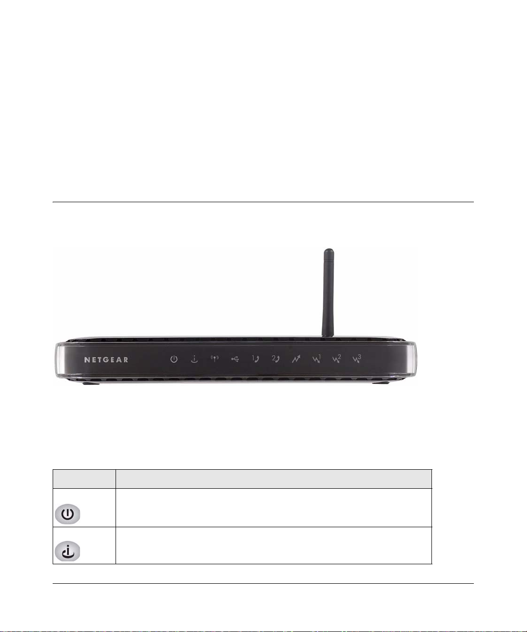
The Gateway Front Panel
The front panel of the Voice Gateway contains status LEDs.
Figure 1-1
You can use the LEDs to verify connections. The following table lists and describes each LED on
the front panel of the Voice Gateway.
Table 1-1. LED Descriptions
LED Description
Power • Green solid: Power is supplied to the gateway.
• Off: Power is not supplied to the gateway.
Online • Amber blink: Synchronization.
• Green solid: Cable link.
• Off: No configuration.
1-1
v1.0, February 2008
Page 16
Wireless Cable Voice Gateway Model CBVG834G Adminstrators User Manual
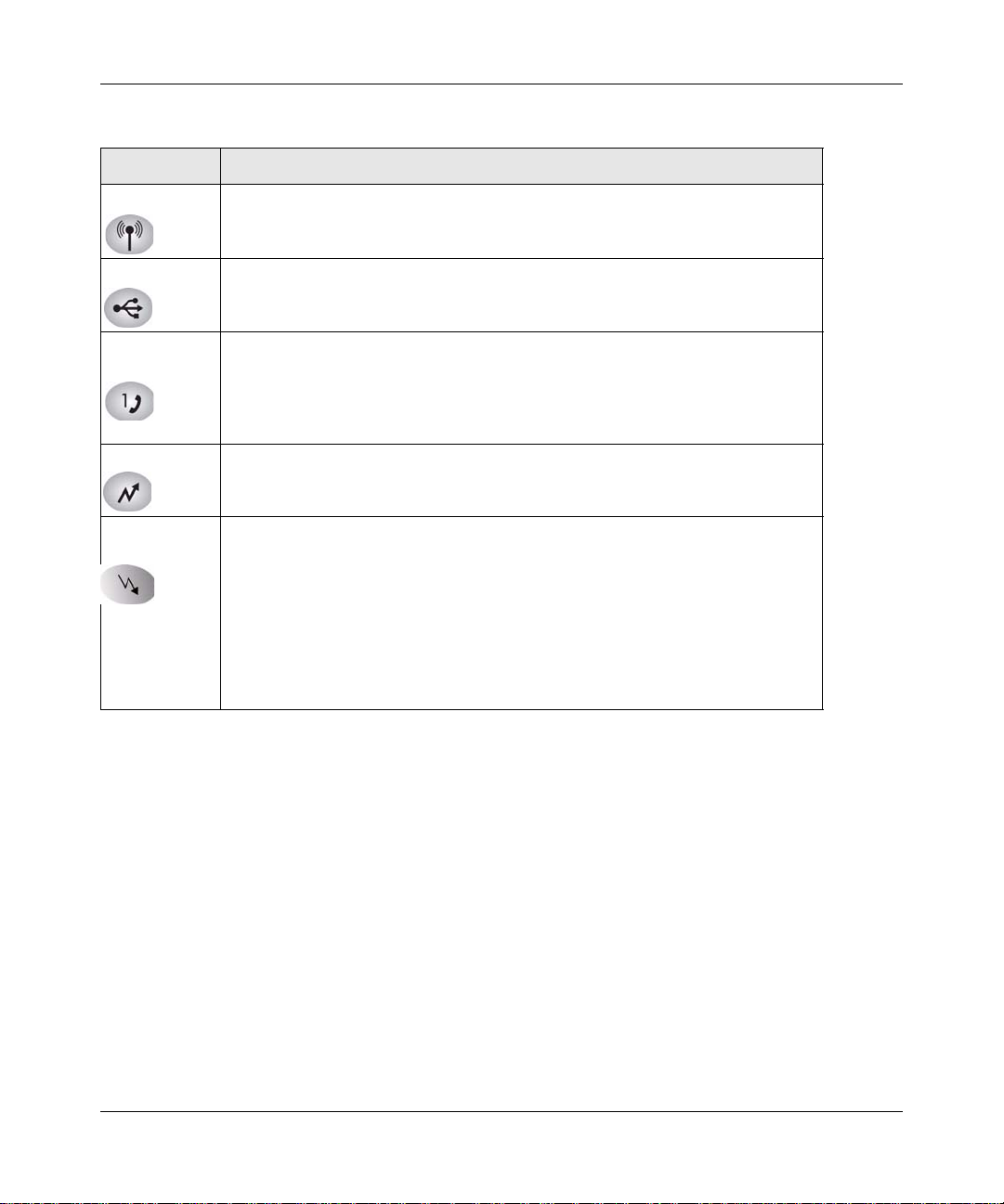
Table 1-1. LED Descriptions (continued)
LED Description
Wireless • Green solid: The wireless connection is operating normally.
• Green blink: Data is being transmitted or received on the wireless interface.
• Off: No wireless link is detected.
USB • Green solid: A USB device is connected to the USB port.
• Off: No USB device is connected.
Voice ports
(1 and 2)
Upstream • Amber blinking: Connecting upstream.
Downstream
1-3
• Green solid: Registered with the Call Agent.
• Green blink: There is an active call.
• Green slow blink: Phone is “on-hook”; registration with Call Agent is in
progress.
• Off: No phones are connected to the voice port.
• Green solid: Upstream found .
Downstream 1
• Amber blinking: Scanning for primary Downstream channel.
• Green solid: Primary downstream found.
Downstream 2
• Green solid: Wideband connection.
• Off: No wideband connection.
Downstream 3
• Green solid: Wideband connection.
• Off. No wideband connection.
1-2 Installing the Gateway
v1.0, February 2008
Page 17
Wireless Cable Voice Gateway Model CBVG834G Adminstrators User Manual
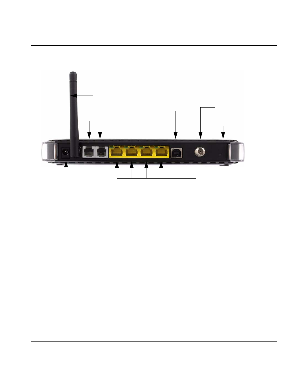
Wireless antenna
AC power adapter input
Four Ethernet LAN ports
Coaxial cable to the cable
service provider
Voice/phone ports to
connect handsets
to connect local computers
USB
Reset
The Gateway Rear Panel
The label on the bottom of the gateway identifies the connections on the rear panel.
Figure 1-2
The rear panel includes the following connections, viewed from left to right.
•Power. AC power adapter input.
• Wireless antenna. The gateway ships with the wireless antenna already attached.
• Two Voice/Phone ports. With VoIP service, connect one or two handsets to these ports.
• Four Ethernet LAN ports. Use these ports to connect local computers. The port connector
LEDs work as follows:
– Green on. The local port has detected link with a 100 Mbps device.
– Green blinking. Data is being transmitted or received at 100 Mbps.
– Amber on: The local port has detected link with a 10 Mbps device.
– Amber blinking. Data is being transmitted or received at 10 Mbps.
– Off. No link is detected on this port.
• USB port. If the USB driver is installed, you can connect a local computer to this port.
• Coaxial cable connector. Attach coaxial cable to the cable service provider’s connection.
• Reset button. Resets the gateway to its factory defaults.
Installing the Gateway 1-3
v1.0, February 2008
Page 18

Wireless Cable Voice Gateway Model CBVG834G Adminstrators User Manual
Installing the Voice Gateway
If your computer has a LAN card with an Ethernet connection, you may have to configure your
TCP/IP settings to work with the Wireless Cable Voice Gateway . If you have questions about
configuring your Ethernet connection, consult your broadband service provider.
Complete the installation in this order:
1. Check the Installation Requirements.
2. Connect to your cable service.
3. Connect the Gateway.
4. Log in to the Gateway.
5. Connect to the Internet.
After installation, set up the wireless connection as explained in Chapter 2, “Wireless
Configuration”.
Installation Requirements
Before you begin, make sure that you have the following:
• A computer with active Ethernet port with DHCP enabled. See the link “Preparing a Computer
for Network Access:” in Appendix B for help with DHCP configuration.
• An active account with your Internet service provider for data and/or voice services.
• Each computer that will connect to the gateway must have either an installed Ethernet
Network Interface Card (NIC), USB Host port, or 802.11b or 802.11g wireless adapter.
Connect to Your Cable Service
Follow these steps:
1. Turn off your computer and router (if you have one).
1-4 Installing the Gateway
v1.0, February 2008
Page 19
Wireless Cable Voice Gateway Model CBVG834G Adminstrators User Manual
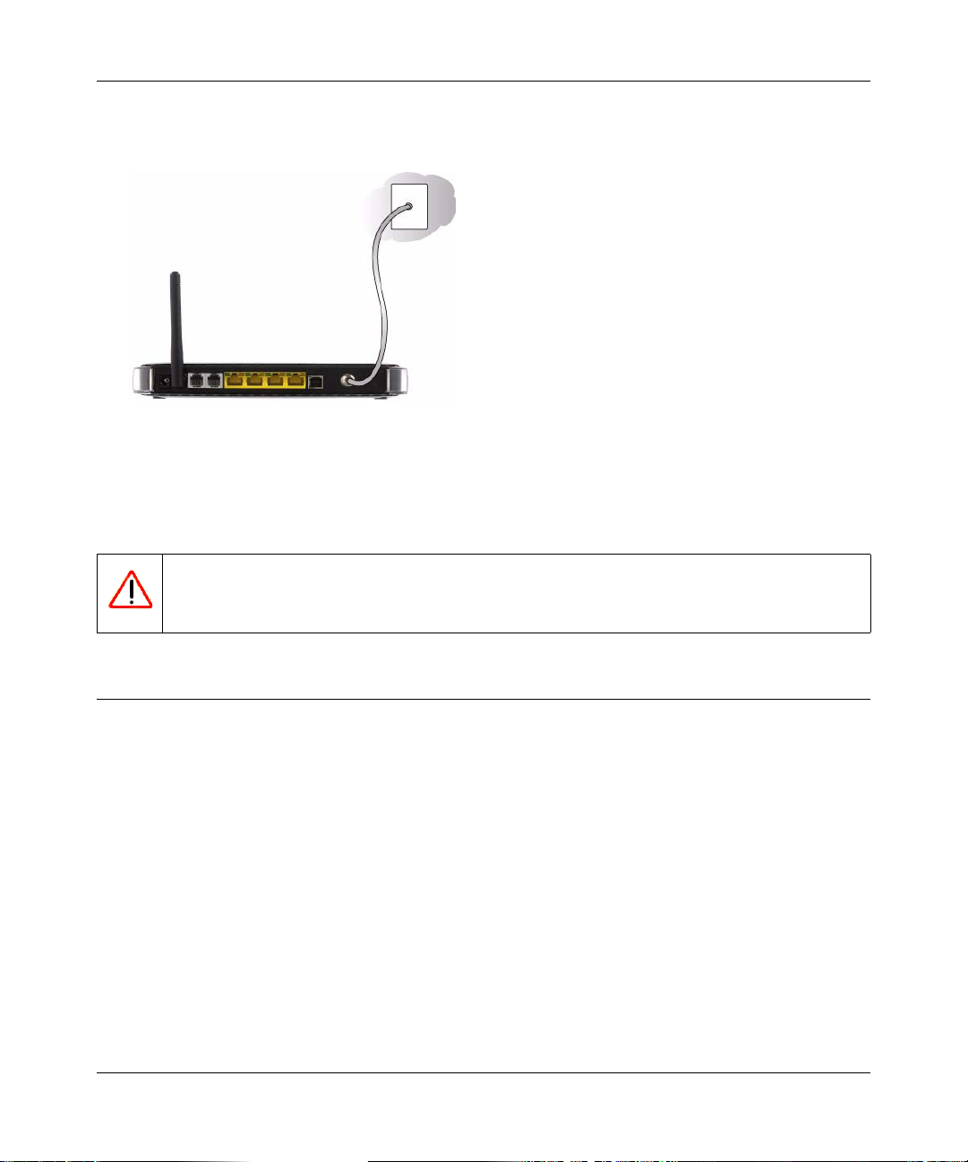
2. Use the coaxial cable provided by your cable company to connect the CBVG834G cable port
to your cable splitter or directly to the cable connector in your wall.
Figure 1-3
3. Connect the Voice Gateway power adapter into the back of the modem and then plug it into a
power source such as a wall socket or power strip.
4. Wait 30 seconds for the Voice Gateway to start up.
Warning: DO NOT disconnect the modem, or it will not be able to register with your
cable Internet service provider.
Connect to a Computer or Router
You can connect the Voice Gateway to an Ethernet port on your computer or router, or to a USB
port on your Windows-based co mp uter. DO NOT connect the Voice Gateway to both the Ethernet
and USB ports.
1. Use the yellow Ethernet cable that shipped with the product to connect the CBVG834G yellow
Ethernet port to an Ethernet port on your computer or the WAN port on your router.
2. If you have VoIP service, connect the phone to Voice Port . If your service includes a second
line, you can connect that phone to Voice Port 2.
3. How you power up depends on whether or not you use a router.
• One computer (no network): Turn on your computer.
• Router and computers: First turn on your router, and then turn on your computers.
Installing the Gateway 1-5
v1.0, February 2008
Page 20
Wireless Cable Voice Gateway Model CBVG834G Adminstrators User Manual
Check the LEDs
Check the LEDs on the front of the Voice Gateway. After the modem registers with your Cable
Internet Service Provider the following LEDs should be lit:
• Power: solid green.
• Online: solid green.
• The other LEDs blink to show activity on the Voice Gateway ports. For more information
about the LEDs, see “The Gateway Front Panel” on page 1-1.
• If the LEDs are not lit, see Chapter 5, “Troubleshooting”.
Test the Connection
Note: It may take up to 5 minutes to establish a connection the first time you power on
your Cable Modem.
To test your setup, view a Web page online.
1. Start your Internet browser on the computer.
2. Go to the NETGEAR website http://www.NETGEAR.com.
If the NETGEAR website does not appear, see Chapter 5, “Troubleshooting”.
3. Quit your Internet browser.
1-6 Installing the Gateway
v1.0, February 2008
Page 21
Wireless Cable Voice Gateway Model CBVG834G Adminstrators User Manual
Logging In to the Wireless Voice Gateway
You can log into the gateway to view or change its configuration settings.
Note: To connect to the gateway, your computer must be configured to use DHCP. For
instructions on how to do this, see the link to “Preparing a Computer for Network
Access:” in Appendix B.
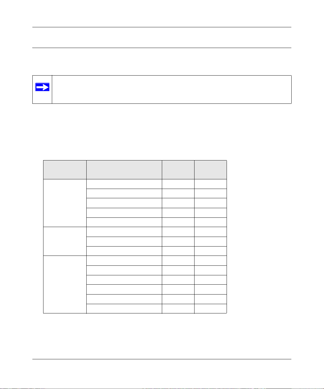
The gateway has two default user names. They are MSO, with the default password of
changeme, and admin, with the default password of password. As shown in the following
table, the MSO user name has access to all menu selections. The admin user name has limited
access.
Table 1-1. Access to Menu Selections Based on User Name
Menu Heading Selection
Setup Basic Settings No Yes
Wireless Settings Yes Yes
WiFi Multimedia No Yes
Guest Network No Yes
MTA Status No Yes
Content Filtering Logs No Yes
Block Sites Yes Yes
Services No Yes
Maintenance Gateway Status Yes Yes
Connection No Yes
Set Password Yes Yes
Backup No Yes
Event Log Yes Yes
Diagnostics No Yes
Admin
Access
MSO
Access
Installing the Gateway 1-7
v1.0, February 2008
Page 22
Wireless Cable Voice Gateway Model CBVG834G Adminstrators User Manual
http://192.168.0.1
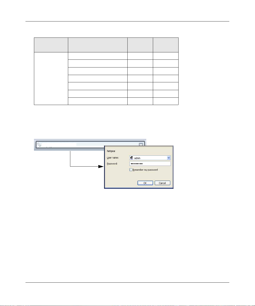
Table 1-1. Access to Menu Selections Based on User Name (continued)
Menu Heading Selection
Advanced MAC Filtering No Yes
Port Blocking Yes Yes
Port Forwarding Yes Yes
Port Triggering Yes Yes
DMZ Host Yes Yes
LAN IP Yes Yes
UPnP Yes Yes
Admin
Access
MSO
Access
To log in to the gateway:
1. Using the computer that you first used to access your cable modem Internet service, connect to
the gateway by typing http://192.168.0.1 in the address field of your Internet browser.
Figure 1-4
2. Enter the user name and password. You are now connected to the gateway.
1-8 Installing the Gateway
v1.0, February 2008
Page 23
Wireless Cable Voice Gateway Model CBVG834G Adminstrators User Manual
Connecting to the Internet and VoIP
To configure the gateway to connect to the Internet you must log in as the user name MSO with
the default password of changeme, or whatever password you have set for MSO.
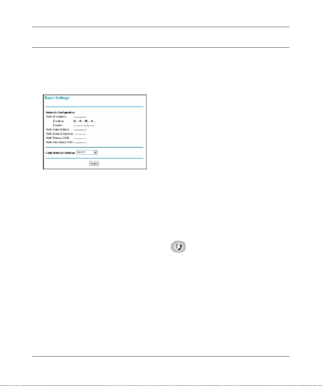
1. From the main menu, select Basic Settings. The Basic Settings screen displays:
Figure 1-5
The settings displayed on this screen depend on the selection in the Cable Network Settings
field. By default, DHCP is selected, as shown in the previous figure.
2. Enter the Network Configuration settings, and adjust the Cable Network Settings field if
needed.
The fields in this screen are described in Table 1-2.
3. Click Apply so that your changes take effect.
4. If you have VoIP service, connect the phone to a Voice Port 1. If your service includes a
second line, you can connect that phone to Voice Port 2. To check the voice status, see
“Viewing and Emailing Event Logs” on page 4-4. To set up a wireless connection, see
Chapter 2, “Wireless Configuration”.
Installing the Gateway 1-9
v1.0, February 2008
Page 24
Wireless Cable Voice Gateway Model CBVG834G Adminstrators User Manual
The following table explains the settings in the Basic Settings screen.
Table 1-2. Basic Settings
Settings Description
Network
Configuration
Cable Network
Settings
WAN IP Address This is the current configuration for the WAN side of your
WAN Subnet Mask
WAN Default Gateway The ISP router to which your gateway will connect.
Primary DNS The DNS server is a host on the Internet that translates
Secondary DNS You can specify a secondary DNS server in this field.
DHCP If your service provider assigns your IP address through
Static If your service provider assigned you a permanent, fixed
L2TP (DHCP) Use this setting for a layer two tunnelling protocol with
L2TP (static) Use this setting for a layer two tunneling protocol with a
gateway.
Internet names (such as
numeric IP addresses. Typically your ISP transfers the IP
address of one or two DNS servers to your gateway during
login. If the ISP does not transfer an address, you must
obtain it from the ISP and enter it manually. If you enter an
address here, you should reboot your PCs after configuring
the gateway.
DHCP, use this default setting.
(static) IP address for your PC, select Static. Fill in the
following fields:
• Static IP Address (also known as the netmask)
• Static IP Mask
• Default Gateway
• Primary DNS
• Secondary DNS
DHCP. Then fill in the following fields:
• PPP User Name
• PPP Password
• L2TP Server
static IP address. Then fill in the following fields:
• Static IP Address (also known as the netmask)
• Static IP Mask
• Default Gateway
• PPP User Name
• PPP Password
• L2TP Server
http://www.netgear.com) to
1-10 Installing the Gateway
v1.0, February 2008
Page 25

Chapter 2
Wireless Configuration
This chapter describes how to set up the wireless features of your wireless voice gateway. In
planning your wireless network, consider the level of security required. Select the location of your
wireless equipment in order to maximize the network speed.
Set up wireless features for the wireless voice gateway in this order:
1. Install the wireless voice gateway as described in Chapter 1, “Installing the Gateway”. The
wireless voice gateway should be working on your LAN before you set up the wireless
features.
2. Plan the location for the wireless voice gateway based on considerations in “Wireless
Placement and Range Guidelines”.
3. Use the form in section “SSID and Wireless Security Settings Form” on page 2-3 to keep track
of your settings.
4. Enter the wireless settings, and verify wireless connectivity as described in “Viewing or
Changing Wireless Settings” and “WEP (Wired Equivalent Privacy)”.
For more information about wireless technology, see the link to the online document “Wireless
Communications:” in Appendix B.
v1.0, February 2008
2-1
Page 26

Wireless Cable Voice Gateway Model CBVG834G Adminstrators User Manual
Wireless Placement and Range Guidelines
The range of your wireless connection can vary significantly based on the physical placement of
the wireless voice gateway. The latency, data throughput performance, and notebook power
consumption of wireless adapters also vary depending on your configuration choices.
For best results, place your wireless voice gateway:
• Near the center of the area in which your PCs will operate.
• In an elevated location such as a high shelf where the wirelessly connected PCs have line-ofsight access (even if through walls).
• Away from sources of interference, such as PCs, microwave ovens, and 2.4 GHz cordless
phones.
• Away from large metal surfaces.
• Put the antenna in a vertical position to provide the best side-to-side coverage. Put the antenna
in a horizontal position to provide the best up-and-down coverage.
• If using multiple access points, it is better if adjacent access points use different radio
frequency channels to reduce interference. The recommended channel spacing between
adjacent access points is 5 channels (for example, use channels 1 and 6, or 6 and 11).
The time it takes to establish a wireless connection can vary depending on both your security
settings and placement. WEP connections can take slightly longer to establish. Also, WEP
encryption can consume more battery power on a notebook computer.
2-2 Wireless Configuration
v1.0, February 2008
Page 27

Wireless Cable Voice Gateway Model CBVG834G Adminstrators User Manual
SSID and Wireless Security Settings Form
For a new wireless network, print or copy this form and fill in the settings. For an existing wireless
network, the person who set up or is responsible for the network can get the settings. Be sure to set
the Regulatory Domain correctly as the first step.
• SSID. The Service Set Identification (SSID) identifies the wireless local area network.
NETGEAR is the default SSID. However, you may customize it by using up to 32
alphanumeric characters. Write your customized SSID on the line below.
____________________________________________________
The SSID in the wireless voice gateway is the SSID you configure in the wireless adapter card.
All wireless nodes in the same network must be configured with the same SSID.
• Authentication.
Circle one: Open System or Shared Key. Choose Shared Key for more security.
To use Shared Key, all devices in the network must be set to Shared Key and have the same
keys in the same positions as those in the CBVG834G.
• WEP Encryption Keys. For all four keys, choose the Key Size. Circle one: 64, or 128 bits.
Key 1: ______________________________________________
Key 2: ______________________________________________
Key 3: ______________________________________________
Key 4: ______________________________________________
• WPA-PSK (Pre-Shared Key) and WPA2-PSK. Record the WPA-PSK or WPA2-PSK key.
Key: _____________________________________________
• WPA and WPA2 RADIUS Settings. For WPA and WPA2, record the following settings for
the primary and secondary RADIUS servers.
Server Name/IP Address: _____________________________________________
Port: _____________________________________________
Shared Key: _____________________________________________
Use the procedures described in the following sections to configure the CBVG834G. Store this
information in a safe place.
Wireless Configuration 2-3
v1.0, February 2008
(8-63 characters)
Page 28

Wireless Cable Voice Gateway Model CBVG834G Adminstrators User Manual
Viewing or Changing Wireless Settings
Note: If you use a wireless computer to change wireless settings such as the SSID, you
will be disconnected when you click Apply. Reconfigure your wireless computer
to match the new settings, or access the wireless voice gateway from a wired
computer to make further changes.
To view or change the wireless settings:
1. Connect a computer to the wireless voice gateway using an Ethernet or USB cable as
described in “Installing the Voice Gateway” on page 1-4.
2. Enter http://192.168.0.1 in the address field of your Internet browser. Log in to the gateway
with either of the default user names, MSO or admin.
3. From the main menu, select Wireless Settings. The Wireless Setting screen displays:
Figure 2-1
2-4 Wireless Configuration
v1.0, February 2008
Page 29

Wireless Cable Voice Gateway Model CBVG834G Adminstrators User Manual
4. For initial configuration and test, leave the settings unchanged.
5. If you make changes, you must click Apply to save the changes.
6. Configure and test your computers for wireless connectivity.
Program the wireless adapter of your computers to have the same SSID and wireless security
settings as your wireless voice gateway. Check that they have a wireless link and are able to
obtain an IP address by DHCP from the wireless voice gateway. If there is interference, adjust
the channel.
The following table explains the Wireless Setting screen.
Table 2-1. Wireless Settings
Settings Description
Wireless
Network
Wireless Access
Point
Name (SSID) The SSID is also known as the wireless network name. The
default SSID is printed on the bottom label of each unit. Any
wireless device that will connect to this wireless voice
gateway must use the same SSID.
If you want to change the SSID, you can enter a
32-character (maximum) name in this field. The characters
are case-sensitive.
Channel The wireless channel used by the gateway. The default is
Channel 6.
Do not change the wireless channel unless you experience
interference (shown by lost connections or slow data
transfers). If this happens, you might need to experiment
with different channels to see which is the best.
Enable Wireless Access
Point
Allow Broadcast Name
(SSID)
On by default, this setting enables the wireless radio, which
allows the wireless voice gateway to work as a wireless
access point.
Turning off the wireless radio can be helpful for
configuration, network tuning, or troubleshooting.
On by default, the wireless voice gateway broadcasts its
SSID, allowing wireless stations that have a null (blank)
SSID to adopt the correct SSID. If you disable broadcast of
the SSID, only devices with the correct SSID can connect.
This nullifies the wireless network discovery feature of some
products such as Windows XP, but the data is still fully
exposed to a determined snoop using specialized test
equipment like wireless sniffers. For this reason NETGEAR
recommends that you also enable wireless security.
Wireless Configuration 2-5
v1.0, February 2008
Page 30

Wireless Cable Voice Gateway Model CBVG834G Adminstrators User Manual
Table 2-1. Wireless Settings (continued)
Settings Description
Wireless Station
Access List
Security Option
WEP (Wired Equivalent Privacy) 128-bit
encryption is the default setting
Other Security Options • Disable. Wireless security is disabled. This setting can be
Turn Access Control On Access control is disabled by default so that any computer
configured with the correct SSID can connect. See
“Configuring Y our Wireless Card Access List”.
WEP security uses encryption keys and data encryption for
data security. See “WEP (Wired Equivalent Privacy)”.
used to establish wireless connectivity before
implementing wireless security. NETGEAR strongly
recommends that you use wireless security.
• WEP (Wired Equivalent Privacy) 64-bit. WEP security
uses encryption keys and data encryption for data
security. You can select 64-bit. See “WEP (Wired
Equivalent Privacy)”.
• WPA options: The wireless voice gateway supports
WPA-PSK, WPA, WPA2-PSK, and WPA2 security. See
“WPA-PSK (WiFi Protected Access Pre-Shared Key)”, or
“WPA2-PSK (WiFi Protected Access 2 Pre-Shared
Keys)”.
2-6 Wireless Configuration
v1.0, February 2008
Page 31

Wireless Cable Voice Gateway Model CBVG834G Adminstrators User Manual
WEP (Wired Equivalent Privacy)
To configure WEP data encryption:
1. From the Wireless Settings screen, select WEP (Wired Equivalent Privacy) 64-bit
encryption or use the default setting WEP (Wired Equivalent Privacy) 128-bit encryption.
Figure 2-2
2. In the Authentication drop-down list, select Open System or Shared Key, or select Shared
Key.
3. If you use encryption keys, enter them. These values must be identical on all computers in
your network. There are two ways to enter the keys:
• Passphrase: Enter a word or group of printable characters in the Passphrase field, and
then click Generate. The Key1 through Key4 fields are populated with key values .
• Manual: Enter 10 hexadecimal digits (any combination of 0-9, a-f, or A-F)
Select which of the four keys will be the default.
See the link to the online document “Wireless Communications:” in Appendix B for a full
explanation of each of these options, as defined by the IEEE 802.11 wireless communication
standard.
4. Click Apply to save your settings.
Wireless Configuration 2-7
v1.0, February 2008
Page 32

Wireless Cable Voice Gateway Model CBVG834G Adminstrators User Manual
WPA-PSK (WiFi Protected Access Pre-Shared Key)
Not all wireless adapters support WP A-PSK. Furthermore, client software is required on the client.
Windows XP and Windows 2000 with Service Pack 3 or above do include the client software that
supports WPA. Nevertheless, the wireless adapter hardware and driver must also support WPA.
Consult the product document for your wireless adapter and WPA client software for instructions
on configuring WPA settings.
To configure WPA-PSK:
1. On the Wireless Settings screen, select the Security Option WPA-PSK.
Figure 2-3
2. In the Passphrase Key field under Security Encryption (WPA-PSK), enter a word or group of
printable characters and enter the Key Lifetime.
The Passphrase must be 8 to 63 characters in length. The 256 Bit key used for encryption is
generated from this passphrase.
3. Click Apply to save your settings.
2-8 Wireless Configuration
v1.0, February 2008
Page 33

Wireless Cable Voice Gateway Model CBVG834G Adminstrators User Manual
WPA (WiFi Protected Access)
Not all wireless adapters support WPA. Furthermore, client software is required on the client.
Windows XP and Windows 2000 with Service Pack 3 or above do include the client software that
supports WPA. Nevertheless, the wireless adapter hardware and driver must also support WPA.
Consult the product document for your wireless adapter and WPA client software for instructions
on configuring WPA setting.
To configure WPA:
1. On the Wireless Settings screen, select Security Option WPA.
Figure 2-4
2. Enter the Security Encryption (WPA) settings.
These settings are required for communication and authentication from a Radius server. A
Secondary Radius Server can be configured which is used if the Primary Radius Server fails.
• Primary Radius Server IP Address. The IP address of the Radius Server. The default is
0.0.0.0
• Radius Port. Port number of the Radius Server. The default is 1812.
• Radius Key. This is shared between the gateway and the Radius Server during
authentication.
3. Click Apply to save your settings.
Wireless Configuration 2-9
v1.0, February 2008
Page 34

Wireless Cable Voice Gateway Model CBVG834G Adminstrators User Manual
WPA2-PSK (WiFi Protected Access 2 Pre-Shared Keys)
Not all wireless adapters support WPA2-PSK. Furthermore, client software is required on the
client. Windows XP and Windows 2000 with Service Pack 3 or above do include the client
software that supports WPA2. Nevertheless, the wireless adapter hardware and driver must also
support WPA2. Consult the product document for your wireless adapter and WPA client software
for instructions on configuring WPA settings.
To configure WPA2-PSK:
1. On the Wireless Settings screen, select WPA2-PSK (Wi-Fi Protected Access 2 Pre-Shared
Key).
Figure 2-5
2. Enter the Security Encryption (WPA2-PSK) settings:
• Pre-Shared Key. Enter a word or group of printable characters. The passphrase must be 8
to 63 characters in length. The 256 Bit key used for encryption is generated from this
passphrase.
• Key Lifetime. Enter the key lifetime in minutes.
3. Click Apply to save your settings.
2-10 Wireless Configuration
v1.0, February 2008
Page 35

Wireless Cable Voice Gateway Model CBVG834G Adminstrators User Manual
WPA2 (WiFi Protected Access 2)
To configure WPA2:
1. On the Wireless Settings page, select the Security Option WPA2.
Figure 2-6
2. Enter the Security Encryption (WPA2) settings.
These settings are required for communication and authentication from a Radius server. A
secondary Radius server can be configured, which is used if the primary Radius server fails.
• Primary Radius Server IP Address. The IP address of the Radius server. The default is
0.0.0.0
• Radius Port. Port number of the Radius Server. The default is 1812.
• Radius Key. This is shared between the gateway and the Radius Server during
authentication.
3. Click Apply to save your settings.
Wireless Configuration 2-11
v1.0, February 2008
Page 36

Wireless Cable Voice Gateway Model CBVG834G Adminstrators User Manual
Configuring Your Wireless Card Access List
By default, any wireless PC that is configured with the SSID and WEP/WPA settings has access to
your wireless network. For increased security, you can restrict access to the wireless network to
only allow specific PCs based on their MAC addresses.
To restrict access based on MAC addresses:
1. Connect to the gateway and log in as described in “Viewing or Changing W ireless Settings” on
page 2-4.
Note: If your computer is connected wirelessly to the wireless voice gateway, be
careful about selecting the Turn Access Control On check box. If your
computer’s MAC address is not in the access control list, then you will lose
your wireless connection when you click Apply. You must then access the
wireless voice gateway from a wired computer, or from a wireless computer
that is on the access control list, to make any further changes.
2. From the main menu, select Wireless Settings. The W ireless Settings screen displays as shown
in Figure 2-1 on page 2-4.
3. Scroll down to the Wireless Card Access List and select the Turn Access Control On check
box.
Figure 2-7
When you turn on access control, the gateway only accepts connections from clients on the
selected access control list. This provides an additional layer of security.
4. Click Apply to confirm this setting.
2-12 Wireless Configuration
v1.0, February 2008
Page 37

Wireless Cable Voice Gateway Model CBVG834G Adminstrators User Manual
Adding or Deleting a Wireless Card from the Access List
To add or delete a wireless card from the Setup Access List:
1. Click Setup Access List. The Wireless Card Access List screen displays.
The Access List displays a list of wireless clients that will have access to the wireless network
when the list is enabled.
Figure 2-8
2. You can add a device to the Access List using either of these methods:
• If the computer is in the Connected Wireless Devices table, click the radio button of that
computer to capture its MAC address.
• Specify the MAC address of the device to be added in the Add Access Filter fields. The
MAC address can usually be found on the bottom of the wireless device.
Note: If no Device Name displays when you enter the MAC address, you can type a
descriptive name for the computer that you are adding.
3. Click Add.
4. Repeat Steps 2 and 3 for each wireless PC that you are adding.
5. Click Apply to save these changes. Now, only devices on this list will be allowed to wirelessly
connect to the gateway.
To delete an entry from the Access List, select the corresponding radio button in the Access List
and then click Delete.
Wireless Configuration 2-13
v1.0, February 2008
Page 38

Wireless Cable Voice Gateway Model CBVG834G Adminstrators User Manual
Guest Network
The guest network feature allows you to set up an additional wireless guest network. From the
main menu, under the Setup heading, select Guest Network. The Wireless Guest Network Setting
screen displays:
Figure 2-9
See the NETGEAR online help for assistance with setting up a wireless guest network.
Wi-Fi Multimedia (WMM)
The Voice Gateway includes Wi-Fi Multimedia (WMM), which is a Quality of Service (QoS)
feature. This feature is enabled, and the Voice Gateway uses it automatically with clients running
applications that support WMM.
WMM QoS provides prioritization of wireless data packets from different applications based on
four categories: voice, video, best effort, and background. For an application to receive the
benefits of WMM QoS, both it and the client running that application must be WMM-enabled.
Legacy applications that do not support WMM, and applications that do not require QoS, are
assigned to the best-effort category, which receives a lower priority than voice and video.
2-14 Wireless Configuration
v1.0, February 2008
Page 39

Wireless Cable Voice Gateway Model CBVG834G Adminstrators User Manual
From the main menu, under the Setup heading, select Wi-Fi Multimedia. The Wi-Fi Multimedia
screen displays:
Figure 2-10
The default setting is Auto. You can change the setting to On or Off. If you make a change, click
Apply to change the settings.
Wireless Configuration 2-15
v1.0, February 2008
Page 40

Wireless Cable Voice Gateway Model CBVG834G Adminstrators User Manual
2-16 Wireless Configuration
v1.0, February 2008
Page 41

Chapter 3
Protecting Your Network
This chapter describes how to control access to your gateway and how to use the firewall features
of the gateway to protect your network.
Changing Passwords
For security reasons, the gateway has its own user names and passwords. The login user name is
admin, with the default password of password. The Numericable user name is MSO with the
default password of changeme. After a period of inactivity for a set length of time, the
administrator login automatically disconnects. You can change the password, and you can change
the amount of time for the administrator login timeout.
Note: The user names and passwords are not the same as any user name or password your
may use to log in to your Internet connection.
NETGEAR recommends that you change these passwords to more secure passwords. The ideal
passwords should contain no dictionary words from any language, and should be a mixture of both
upper and lower case letters, numbers, and symbols. Your passwords can be up to 30 characters.
To change a password:
1. Log in to the gateway by entering the default LAN address of http://192.168.0.1 with a default
user name, or using whatever password and LAN address you have chosen for the gateway.
2. Under the Maintenance heading, select Set Password. The Set Password screen displays:
Figure 3-1
Protecting Your Network 3-1
v1.0, February 2008
Page 42

Wireless Cable Voice Gateway Model CBVG834G Adminstrators User Manual
3. To change the password, first enter the old password, and then enter the new password twice.
4. Click Apply to save your changes.
Note: After changing the password, you will be required to log in again to continue
the configuration. If you have backed up the gateway settings previously, you
should do a new backup so that the saved settings file includes the new
password.
Logs
Note: You must be logged in with the user name MSO to view the Logs screen.
A log is a detailed record of the denial of service (DoS) attacks directed at your network. You can
view the logs here, or you can use e-mail notification to view the logs (see “Viewing and Emailing
Event Logs” on page 4-4).
From the main menu, select Logs. The Logs screen displays:
Figure 3-2
3-2 Protecting Your Network
v1.0, February 2008
Page 43

Wireless Cable Voice Gateway Model CBVG834G Adminstrators User Manual
Blocking Keywords, Sites and Services
The gateway provides a variety of options for blocking Internet content and communications to the
gateway. You can control access to Internet content by screening for keywords within Web
addresses; you also can block access to all sites except those that are explicitly allowed. Blocking
options include:
• Blocking access from your LAN to Internet locations that contain keywords that your specify.
• Blocking access to websites (domains) that you specify as off-limits.
• Allowing access to only websites (domains) that you specify as allowed.
You can block access to the Internet by a specific computer based on the hardware MAC address
of that computer. See “Using MAC Filtering to Block Access” on page 3-7.
Blocking Keywords and Domains
You can restrict access to Internet content based on Web address keywords and domain names. A
domain name is the name of a particular website. For example, for the address www.netgear.com,
the domain name is NETGEAR.com.
Note: To configure Block Sites, you must be logged in as MSO.
To configure Block Sites:
1. Log in to the gateway by entering the default LAN address of http://192.168.0.1, the parent
user name of MSO, and default password of changeme or use whatever password and LAN
address you have chosen for the gateway in parent mode.
Protecting Your Network 3-3
v1.0, February 2008
Page 44

Wireless Cable Voice Gateway Model CBVG834G Adminstrators User Manual
2. Click Block Sites under the Content Filtering heading on the main menu.
Figure 3-3
Keywords
To enable keyword blocking:
1. On the Block Sites screen, select the Enable check box in the Keyword section.
2. Add keywords by entering them into the Add Keyword List. An example of some Keyword
applications are:
• If the keyword “XXX” is specified, the URL “http://www.badstuff.com/xxx.html” is
blocked.
• If the keyword “.com” is specified, only Web sites with other domain suffixes (such as
.edu or .gov) can be viewed.
• If the keyword “.” is specified, all Internet browsing access is blocked.
Up to eight entries are supported in the Keyword List.
3. When you have completed your entries, click Add Keyword.
3-4 Protecting Your Network
v1.0, February 2008
Page 45

Wireless Cable Voice Gateway Model CBVG834G Adminstrators User Manual
Domain Blocking
To enable domain blocking:
1. Select the Enable radio box adjacent to Domain Blocking.
2. Enter the Domain Name of the site name you want to block in the Domain List field.
If the domain “badstuff.com” is specified, the URL “http://www.badstuff.com/xxx.html” will
be blocked, along with all other URLs in the badstuff.com site.
Up to eight entries are supported in the Domain List.
3. When you have completed your entries, click Add Domain.
4. Click Apply to save your settings
To delete a an entry in either the Keyword List or Domain List field:
1. Select it from the list, and click Remove Keyword or click Remove Domain.
2. Click Apply to save your settings.
Blocking Access by Time of Day
The default blocking schedule is to block access all day. However, you can also block access
according to a daily schedule for each PC individually.
To block access for a PC:
1. In the MAC Filtering screen, select the PC for which the schedule will be modified.
2. In the Day(s) to Block section, select the check boxes next to the days when you want access
blocked.
3. In the Time of Day to Block section, select either All Day, or set the hours for Internet
blocking
4. Click Apply to activate the settings.
Protecting Your Network 3-5
v1.0, February 2008
Page 46

Wireless Cable Voice Gateway Model CBVG834G Adminstrators User Manual
Enabling or Disabling Content Filtering Services
Note: To go to the Services screen, you must be logged in as MSO.
You can use the Services screen to disable or enable certain gatewa y featu r es . From the main
menu, select Services. The Services screen displays:
Figure 3-4
Selecting the check box for a service enables it. Clearing the check box disables the corresponding
service. If you make changes, then you must click Apply in order for the changes to take effect.
The services are described as follows:
• Firewall Features. Enabled by default. The gateway will perform stateful packet inspection
(SPI) and protect against Denial of Service (DoS) attacks.
• Ipsec Pass-Through. Enabled by default. IPSec and PPTP traffic will be forwarded. When it
is disabled, this traffic will be blocked.
• PPTP Pass-Through. E nabled by default. PP TP traf fic will be forwarded. W hen it is disabled,
this traffic will be blocked.
• Multicast. Enabled by default. The gateway can pass multicasting streams through the
firewall.
• Web Featu res . Disabled by default. If enabled, certain Web-oriented features such as cookies,
java scripts, or pop-up windows will be blocked by the firewall. For example, if you enable
Filter Cookies, many websites will not allow you to access their site.
3-6 Protecting Your Network
v1.0, February 2008
Page 47

Wireless Cable Voice Gateway Model CBVG834G Adminstrators User Manual
Using MAC Filtering to Block Access
By default, any computer has access to the Internet through your gateway. MAC Filtering allows
you to block access to the Internet to any computer on your LAN based on the hardware MAC
address of its Ethernet or wireless adapter.
Note: To configure MAC Filtering, you must be logged in as MSO.
To configure MAC Filtering:
1. Log in to the gateway at its default LAN address by entering http://192.168.0.1, the parent
user name MSO, and default password of changeme; or use whatever password and LAN
address you have chosen for the gateway.
2. Under the Advanced heading on the main menu, select MAC Filtering. The MAC Filtering
screen displays:
Figure 3-5
The Trusted Devices table is at the top of this screen. It shows devices that are currently connected
to the wireless voice gateway.
Protecting Your Network 3-7
v1.0, February 2008
Page 48

Wireless Cable Voice Gateway Model CBVG834G Adminstrators User Manual
To add a device to the Trusted Devices table:
1. Select a device using one of the following methods:
• If the device is in the Trusted Devices table, click the radio button of that PC to capture is
MAC address.
• If the device is not in the Trusted Devices table, you can manually enter the MAC address
of the PC you want to block. If no Device Name displays when you enter its MAC
address, you can type a descriptive name in the Device Name field.
2. Click Add. The device is listed in the Trusted Devices table.
To delete a device from the Trusted Devices table:
1. Select the MAC address of the PC from the Trusted Devices table.
2. Click Delete to delete the entry.
3. Click Apply to activate the settings.
Inbound and Outbound Rules
You can use firewall rules to block or allow specific traffic passing through from one side to the
other. Inbound rules (WAN to LAN) restrict access by outsiders to private resources, selectively
allowing only specific outside users to access specific resources. Outbound rules (LAN to WAN)
determine what outside resources local users can have access to.
A firewall has two default rules, one for inbound traffic and one for outbound. The default rules of
the gateway are:
• Inbound: Block all access from outside except responses to requests from the LAN side.
Instructions for setting up inbound rules can be found in “Port Forwarding” on page 3-10
• Outbound: Allow all access from the LAN side to the outside. Use Port Blocking to set up
outbound rules (see “Enabling or Disabling Content Filtering Services” on page 3-6).
You may define more rules that specify exceptions to the default rules. By adding custom rules,
you can block or allow access based on the service or application, source or destination IP
addresses, and time of day.
3-8 Protecting Your Network
v1.0, February 2008
Page 49

Wireless Cable Voice Gateway Model CBVG834G Adminstrators User Manual
Port Blocking
You can use Port Blocking to block outbound traffic on specific ports.
To configure port blocking:
1. Under the Advanced heading on the main menu, select Port Blocking. The Port Blocking
screen displays.
Figure 3-6
2. Select the service that you want to block from the Add Predefined Services drop-down list. If
the service that you want to block is not in the predefined list, you can add a custom service.
3. Enter the range of ports that you want to block and select whether the ports are TCP, UDP or
Both.
4. Enter the Local IP Address for the computer to which this rule will apply.
5. Click Add. The selected service is added to the Port Filter List
Blocking a Rule by Day or Time
To specify specific days or times to block a rule:.
1. From the Port Filter List, select a rule, and then select the corresponding Enable check box.
2. Select the check box for the Day(s) to Block when you want to apply the rule.
Protecting Your Network 3-9
v1.0, February 2008
Page 50

Wireless Cable Voice Gateway Model CBVG834G Adminstrators User Manual
3. For the time of day, either select the All Day check box or specify a Start Time and End Time
from the pull-down menus.
4. Click Add. The new Port Blocking rule is in the Outbound Rules table.
To delete an existing rule:
1. Select the rule from the Port Filter List.
2. Click Delete.
Port Forwarding
You can use port forwarding to set up a rule that directs inbound traf fic for a particular service to a
local server (for example, a Web server or game server) based on the destination port. This makes
the server visible and available to the Internet.
Unless you set up port forwarding, the gateway prevents this type of traffic.The gateway uses
Network Address Translation (NAT). NAT presents a single IP address for your network to the
Internet. Outside users cannot directly address your local computers.
Note: Some residential broadband ISP accounts do not allow you to run any server
processes (such as a Web or FTP server) from your location. Your ISP may check
for servers and may suspend your account if it discovers active services at your
location. If you are unsure, refer to the acceptable use policy of your ISP.
Before setting up Port Forwarding, consider the following:
• If the IP address of the local server PC is assigned by DHCP, it may change when the PC is
rebooted. To avoid this, you can assign a static IP address to your server outside the range that
is assigned by DHCP, but in the same subnet as the rest of your LAN. By default, the IP
addresses in the range of 192.168.0.2 through 192.168.0.9 are reserved for this.
• Local computers must access the local server using the local LAN address of the computer
(192.168.0.XXX, by default). Attempts by local computers to access the server using the
external WAN IP address will fail.
Remember that allowing inbound services opens holes in your firewall. Only enable those ports
that are necessary for your network.
3-10 Protecting Your Network
v1.0, February 2008
Page 51

Wireless Cable Voice Gateway Model CBVG834G Adminstrators User Manual
Forwarding Inbound Traffic
To forward inbound traffic:
1. Select the service that you want to forward from the Predefined Services drop-down list.
If the service that you want to forward is not in the predefined list, you can add a custom
service. Enter the range of ports that you want to forward and select whether the ports are TCP,
UDP or Both.
2. If you want to change the suggested port numbers, enter a new St art Port and End Port.
3. From the drop-down Protocol list, select the protocol: TCP, UDP, or Both.
4. Enter the IP address of the computer on your network to which you would like to direct the
inbound traffic in the Local IP Address field.
5. Click Add. The new Port Forwarding rule is added to the Active Forwarding Rules table.
Figure 3-7
Deleting a Rule
To delete an existing rule:
1. Select the radio button for the rule that you want to delete.
2. Click Delete to delete the Port Forwarding rule.
Protecting Your Network 3-11
v1.0, February 2008
Page 52

Wireless Cable Voice Gateway Model CBVG834G Adminstrators User Manual
Port Triggering
Port Triggering is an advanced feature that allows you to dynamical ly open inbound ports based on
outbound traffic on different ports. This feature can be used for gaming and other Internet
applications.
Note: Port Forwarding is similar to port triggering, but it is static and has some
limitations. Ports are open to traffic from the Internet until the port forwarding rule
is removed. Additionally, port forwarding does not work well for some
applications when your WAN IP address is assigned by DHCP, and is changed
frequently. Port Triggering opens an incoming port temporarily and does not
require the server on the internet to track your IP address if it is changed.
Port Triggering monitors outbo und traffic. When the gateway detects traffic on the specified
outbound port, it remembers the IP address of the computer that sent the data and “triggers” the
incoming port. Incoming traffic on the triggered port is then forwarded to the triggering computer.
For example, port triggering can be used for Internet Relay Chat (IRC). When you connect to an
IRC server, the server tries to connect back on the port to do an Ident lookup. Unless you have
configured Port Forwarding to open that port, the traffic will be blocked. In this example, the
initial login to the server in the range of ports is detected. This triggers the gateway to temporarily
forward the port to the PC that initiated the login.
3-12 Protecting Your Network
v1.0, February 2008
Page 53

Wireless Cable Voice Gateway Model CBVG834G Adminstrators User Manual
To configure Port Triggering:
1. On the main menu, select Port Triggering. The Port Triggering screen displays:
Figure 3-8
2. In the Trigger Range field, enter the outbound ports that will be monitored for activity. This
will be the “trigger.”
3. In the Target Range field, enter the inbound ports that should be forwarded when the trigger
occurs.
4. Select the appropriate protocol: TCP, UDP or Both.
5. Select the Enable check box
6. Click Apply.
There are two ways to clear a Port Triggering rule:
• Clear the Enable check box to temporarily disable the rule.
• Select the rule, and then click Delete.
Protecting Your Network 3-13
v1.0, February 2008
Page 54

Wireless Cable Voice Gateway Model CBVG834G Adminstrators User Manual
Setting Up a DMZ Host
The Default DMZ Server feature is helpful when using some online games and video conferencing
applications that are incompatible with NAT. The gateway is programmed to recognize some of
these applications and to work properly with them, but there are other applications that may not
function well. In some cases, one local PC can run the application properly if that PC’s IP address
is entered as the Default DMZ Host.
Note: For security, you should avoid using the Default DMZ Server feature. When a
computer is designated as the default DMZ server, it loses much of the protection
of the firewall, and is exposed to many exploits from the Internet. If compromised,
the computer can be used to attack your network.
Incoming traffic from the Internet is normally discarded by the gateway unless the traffic is a
response to one of your local computers or a service that you have configured in the Port
Forwarding or Port Triggerin g screen. In stead of discarding this traffic, you can have it forwarded
to one computer on your network. This computer is called the default DMZ host.
To assign a computer or server to be a DMZ host:
1. From the main menu, under the Advanced heading, select DMZ Host. The DMZ Host screen
displays:
Figure 3-9
2. In the DMZ Address field, enter the IP address of the computer that you want to assign as a
DMZ host.
3. Click Apply.
To disable the DMZ host, enter 0 (zero), and then click Apply.
If you want the gateway to respond to a ping from the Internet, select the Respond to Ping on
WAN Port check box. This should only be used as a diagnostic tool, since it allows your gateway
to be discovered. Do not select this check box unless you have a specific reason to do so.
3-14 Protecting Your Network
v1.0, February 2008
Page 55

Chapter 4
Managing Your Network
This chapter describes how to perform network management tasks such as viewing the gateway
status, running diagnostics, restoring factory default settings, and backing up your configuration
files. For information about the Guest Network and WMM features, see “Guest Network” on
page 2-14 and “Wi-Fi Multimedia (WMM)” on page 2-14.
Gateway Status
Under the Maintenance heading on the main menu, select Gateway Status to display the following
screen:
Figure 4-1
The Gateway Status fields are described in the following table:
Table 4-1. Gateway Status Screen Settings
Setting Description
Standard Specification
Compliant
Hardware Version The hardware version of the gateway.
Managing Your Network 4-1
DOCSIS 2.0. This is the specification to which the gateway’s cable
interface is compatible.
v1.0, February 2008
Page 56

Wireless Cable Voice Gateway Model CBVG834G Adminstrators User Manual
Table 4-1. Gateway Status Screen Settings (continued)
Setting Description
Software Version The software version of the gateway.
Cable MAC Address The MAC address used by the cable modem port of the gateway. This
MAC address may need to be registered with your cable service
provider.
Device MAC Address The MAC address of the gateway. This is the equivalent of your PC
when connected to a cable modem. You can use the MAC cloning
feature to replace this MAC address with another address when
sending packets to the WAN.
Cable Modem Serial
Number
CM Certificate If the cable modem certificate is Installed, it is possible for the service
System Up Time The time since the gateway has registered with your cable service
Network Access This field will change to Allowed when the registration with your cable
Device IP Address The IP address of the gateway , as seen from the Internet.
The serial number of the gateway hardware.
provider to upgrade your Data Over Cable service securely.
provider.
service provider is complete.
Connection Status
Note: To view the Connection Status screen you must log in as MSO.
4-2 Managing Your Network
v1.0, February 2008
Page 57

Wireless Cable Voice Gateway Model CBVG834G Adminstrators User Manual
On the main menu, select Connection. The Connection screen displays:
Figure 4-2
This screen shows detailed information about the status of your cable service provider connection
that can be used for troubleshooting. The gateway goes through these steps to be provisioned:
1. Acquire and lock Downstream Channel.
2. Acquire upstream parameters and range.
3. Lock Upstream Channel.
4. Acquire IP Address through DHCP.
The date and time is acquired from your cable service provider as part of the registration
procedure.
Managing Your Network 4-3
v1.0, February 2008
Page 58

Wireless Cable Voice Gateway Model CBVG834G Adminstrators User Manual
Viewing and Emailing Event Logs
The gateway logs security-related events such as denied incoming service requests and hacker
probes. You can enable e-mail notification to receive these logs in an e-mail message. Log entries
are described in the following table.
Table 4-1: Security Log entry descriptions
Field Description
Description The type of event and what action was taken if any.
Count This is a reference number for each event.
Last Occurrence The date and time the log entry was recorded.
Target The name or IP address of the destination device of Web site.
Source The IP address of the initiating device for this log entry.
To receive logs and alerts by e-mail, you must provide your e-mail information in the Email
section of the Event Logs screen. From the main menu, select Event Log. The Event Log screen
displays:
Figure 4-3
To enable emailing of logs:
1. In the Contact Email Address field, type the e-mail address to which the logs will be sent.
Use a full e-mail address (for example, ChrisXY@myISP.com).
4-4 Managing Your Network
v1.0, February 2008
Page 59

Wireless Cable Voice Gateway Model CBVG834G Adminstrators User Manual
2. In the SMTP Server Name field, type the outgoing SMTP mail server of your ISP (for
example, mail.myISP.com). You may be able to find this information in the configuration
menu of your e-mail program. If you leave this field blank, no alerts or logs will be sent.
3. Select the E-mail Alerts Enable check box.
4. Click E-mail Log to send the log immediately
5. Click Apply.
.
Restoring Factory Default Configuration Settings
The configuration settings are stored in a configuration file in the gateway. You can use Erase to
restore the factory default configuration settings. The default settings are listed in “Factory Default
Settings” in Appendix A.
To erase the configuration settings and return them to the factory default settings:
1. Under the Maintenance heading on the main menu, select Set Password.
Figure 4-4
2. For Restore Factory Defaults, select Yes.
3. Click Apply. The gateway reboots.
After an erase, the gateway user name is admin and the password is password. The LAN IP
address is 192.168.0.1, and the DHCP client is enabled.
Note: To restore the factory default configuration settings without knowing the login
password or IP address, use the reset button on the rear panel of the gateway.
Use a paper clip to press the button for at least 5 seconds.
Managing Your Network 4-5
v1.0, February 2008
Page 60

Wireless Cable Voice Gateway Model CBVG834G Adminstrators User Manual
Running Diagnostic Utilities
Note: To run diagnostic utilities you must log in as MSO.
You can use diagnostics to t est connectivity to a PC with the ping command. From the main menu,
below the Maintenance heading, select Diagnostics. The Ping screen displays:
Figure 4-5
To perform a ping test:
1. In the Target field, enter the IP address of the PC that you want to ping.
2. If you want to specify additional details, you can set the Ping Size, No. of Pings, and the Ping
Interval.
3. Click Start Tes t to begin the test. Test results are displayed on this screen.
• To stop a test in progress, click Abort Test.
• To delete the results of a ping test from the Results display, click Clear Results.
• To update the results of a ping test, click REFRESH.
4-6 Managing Your Network
v1.0, February 2008
Page 61

Wireless Cable Voice Gateway Model CBVG834G Adminstrators User Manual
LAN IP Settings
The gateway is preconfigured to use private IP addresses on the LAN side, and to act as a DHCP
server. You can use the LAN IP Setup screen to configure LAN IP services such as the IP address
of the gateway and DHCP.
Note: If you change the LAN IP address of the gateway while connected through the
browser, you will be disconnected. You must then open a new connection to the
new IP address and log in again
To configure the LAN IP:
1. Under the Advanced heading on the main menu, select LAN IP. The LAN IP screen displays.
Figure 4-6
2. Enter the following information:
• LAN IP Address. The LAN IP address that you want to assign to your gateway. The
default is 192.168.0.1.
• Subnet Mask. The subnet mask for your network IP address. The default is
255.255.255.0. (Unless you are implementing subnetting, use the default subnet mask.)
Managing Your Network 4-7
v1.0, February 2008
Page 62

Wireless Cable Voice Gateway Model CBVG834G Adminstrators User Manual
These addresses are part of the IETF-designated private address range for use in private
networks, and should be suitable in most applications. If your network has a requirement
to use a different IP addressing scheme, you can make those changes in the LAN IP page.
• DHCP Server. To to assign IP addresses to your computers automatica l ly, select Yes. To
disable the DHCP Server and assign IP addresses to your computers manually, select No.
See “Using the Gateway as a DHCP Server” on page 4-8.
Note: If you select no for the DHCP server setting, then you must assign a static
IP address to your PC in order to reconnect to the gateway and enable the
DHCP server again.
• Starting IP Address. Enter the first of the contiguous addresses in the address pool. The
default start address is 192.168.0.10.
These addresses should be part of the same IP address subnet as the gateway’s LAN IP
address. Using the default addressing scheme, you should define a range between
192.168.0.10 and 192.168.0.253. The range of IP addresses between 192.168.0.2 and
192.168.0.9 can be used for devices with fixed (or static) addresses.
• Ending IP Address. Enter the last of the contiguous addresses in the address pool. The
default end address is 192.168.0.19.
• DHCP Reservation Lease Info. View information about each PC that has been assigned
a DHCP lease by the gateway. The MAC address of the PC, IP address assigned and the
expiration time of the DHCP lease are listed. You can manually revoke the DHCP leases
by clicking Clear DHCP Leases.
3. Click Apply to save your settings.
Using the Gateway as a DHCP Server
By default, the gateway is a DHCP server. It can assign IP, DNS server, and default gateway
addresses to all computers connected to the LAN. The default wireless voice gateway address is its
LAN address. The wireless voice gateway assigns IP addresses to the network computers from a
pool of addresses specified in the Starting Address and Ending Address fields. Each pool address
is tested before it is assigned to avoid duplicate addresses on the LAN.
Note: If another device on your network is the DHCP server, or if you will manually
configure the network settings of all of your computers, select No for the DHCP
Server. For more information about DHCP and IP addresses, see the link to
“Preparing a Computer for Network Access:” in Appendix B.
4-8 Managing Your Network
v1.0, February 2008
Page 63

Wireless Cable Voice Gateway Model CBVG834G Adminstrators User Manual
The gateway delivers the following parameters to any LAN device that requests DHCP:
• An IP Address from the range you have defined.
• Subnet Mask.
• Gateway IP Address is the gateway’s LAN IP address.
• Primary DNS Server, if you entered a Primary DNS address in the Basic Settings page;
otherwise, the gateway’s LAN IP address.
• Secondary DNS Server, if you entered a Secondary DNS address in the Basic Settings page.
Note: The gateway implements a DNS relay function. When it receives a DNS request on
the LAN, it passes it to the DNS server specified on the WAN. It then relays the
response back to the original requesting PC.
Configuring DHCP Server Reservation Parameters
To configure DHCP server reservation parameters for your LAN:
1. Enter the MAC address of the PC for which you want to reserve an IP Address.
2. Enter a free IP Address for the PC.
3. CLick Add.
To remove a reserved IP from the DHCP Reservation Lease Info table:
1. Select the radio button adjacent to the entry that you want to remove from the table.
2. Click Delete.
The DHCP Client Lease details for all computers in the LAN gateway are shown in the DHCP
Client Lease Info table. To clear all DHCP Client leases, click Clear DHCP Leases.
.
Remote Management Access
You can use remote management to configure, upgrade, and check the status of your gateway
through the Internet.
Managing Your Network 4-9
v1.0, February 2008
Page 64

Wireless Cable Voice Gateway Model CBVG834G Adminstrators User Manual
To configure remote management:
1. Under the Advanced heading on the main menu, select Remote Management. The Remote
Management screen displays:
Figure 4-7
2. Select the Allow Remote Management check box.
3. Enter the Remote User Name and Remote Password that will be required to remotely access
your gateway.
4. Enter the Port Number that will be used for accessing the management interface.
Web browser access normally uses the standard HTTP service port 80. For greater security,
you can specify a custom port by entering that number in the box provided. Choose a number
between 1024 and 65535, but do not use the number of any common ser vice p ort. The defau lt
is 8080, which is a common alternate for HTTP.
5. T o make sure that you can use remote management even if the wireless voice gateway is reset,
select the Allow Remote Management after Factory Default Reset check box.
If you do not select this check box, you will not be able to remotely access the gateway if you
use the Erase feature to revert to the Factory Default settings.
6. Click Apply to have your changes take effect.
When accessing your wireless voice gateway from the Internet, type the WAN IP address of your
gateway into your browser, followed by a colon (:) and the port number. For example, if your
WAN IP address is 134.177.0.123 and you use port number 8080, type the following in your
browser:
http://134.177.0.123:8080
4-10 Managing Your Network
v1.0, February 2008
Page 65

Wireless Cable Voice Gateway Model CBVG834G Adminstrators User Manual
Universal Plug and Play (UPnP)
Universal Plug and Play (UPnP) helps devices, such as Internet appliances and computers, access
the network and connect to other devices as needed. UPnP devices can automatically discover the
services from other registered UPnP devices on the network.
UPnP can be enabled or disabled for automatic device configuration. The default setting for UPnP
is disabled. If disabled, the router will not allow any device to automatically control the resources,
such as port forwarding (mapping), of the router.
Other features of UPnP:
• Advertisement Period. The number entered in this field (in minutes) determines how often
the router will advertise (broadcast) its UPnP information. This value can range from 1 to 1440
minutes. The default period is for 30 minutes.
– Shorter durations ensure that control points have current device status at the expense of
additional network traffic.
– Longer durations might compromise the freshness of the device status but can
significantly reduce network traffic.
• Advertisement Time To Live. The time to live for the advertisement is measured in hops
(steps) for each UPnP packet sent. A hop is the number of steps allowed to propagate for each
UPnP advertisement before it disappears. The number of hops can range from 1 to 255. The
default value for the advertisement time to live is 4 hops, which should be fine for most home
networks. If you notice that some devices are not being updated or reached correctly, then you
may need to increase this value a little.
• UPnP Portmap T able. The UPnP Portmap Table displays the IP address of each UPnP device
that is currently accessing the router and which ports (internal and external) that device has
opened. The UPnP Portmap Table also displays what type of port is opened and if that port is
still active for each IP address.
Managing Your Network 4-11
v1.0, February 2008
Page 66

Wireless Cable Voice Gateway Model CBVG834G Adminstrators User Manual
To activate UPnP:
1. From the main menu, select UPnP. The UPnP screen displays:
Figure 4-8
2. Select the Turn UPnP On check box, and then click Apply.
To save, cancel or refresh the table:
• To save the new settings to the gateway router, click Apply.
• To disregard any unsaved changes, click Cancel.
• To update the UPnP Portmap table and to show the active ports that are currently opened by
UPnP devices, click Refresh.
Viewing MTA Status
Note: To view MTA Status you must log in as MSO.
The MTA Status screen shows the status of the voice ports on the gateway. From the main menu,
under the Setup heading, select MTA Status. The MTA Status screen displays:
Figure 4-9
4-12 Managing Your Network
v1.0, February 2008
Page 67

Chapter 5
Troubleshooting
This chapter gives information about troubleshooting your gateway. For the common problems
listed, go to the section indicated.
• Is the gateway on?
• Have I connected the gateway correctly?
Go to “Basic Functions” on page 5-1.
• I cannot access the gateway’s configuration with my browser.
Go to “Connecting to the Wireless Voice Gateway Main Menu” on page 5-2.
• I have configured the gateway but I cannot access the Internet.
Go to “Troubleshooting the ISP Connection” on page 5-3.
• I cannot remember the gateway’s password.
• I want to clear the configuration and start over again.
Go to “Restoring Factory Default Configuration Settings” on page 4-5.
Basic Functions
After you turn on power to the gateway, the following sequence of events should occur:
1. When power is first applied, verify that the Power LED is on.
2. After approximately 30 seconds, verify that:
a. The LAN LEDs are lit for any local ports that are connected.
b. The Downstream 1 LED is lit.
v1.0, February 2008
5-1
Page 68

Wireless Cable Voice Gateway Model CBVG834G Adminstrators User Manual
If any of these conditions does not occur, see the following table.
Table 5-1. Basic Troubleshooting with LEDs
Problem Action
Power LED is off. If the Power and other LEDs are off when your gateway is turned on:
• Make sure that the power cord is properly connected to your gateway
and that the power supply adapter is properly connected to a
functioning power outlet.
• Check that you are using the 12VDC power adapter supplied by
NETGEAR for this product.
If the error persists, you have a hardware problem and should contact
technical support.
LAN LEDs are off, but ports
are connected.
Check the following:
• Make sure that the Ethernet cable connections are secure at the
gateway and at the hub or PC.
• Make sure that power is turned on to the connected computer.
• Be sure you are using the correct cable:
When connecting the gateway use the cable that was supplied.
Connecting to the Wireless Voice Gateway Main Menu
If you are unable to access the gateway’s main menu from a PC on your local network, check the
following:
• Check the Ethernet connection between the PC and the gateway as described in the previous
section.
• Make sure that your PC’s IP address is on the same subnet as the gateway. If you are using the
recommended addressing scheme, your PC’s address should be in the range of 192.168.0.10 to
192.168.0.254. Refer to “Preparing a Computer for Network Access:” in Appendix B for more
information about IP address configuration.
Note: If your PC’s IP address is shown as 169.254.x.x:
Recent versions of Windows and Mac OS generate and assign an IP address if
the computer cannot reach a DHCP server. These auto-generated addresses are
in the range of 169.254.x.x. If your IP address is in this range, check the
connection from the PC to the gateway and reboot your PC.
5-2 Troubleshooting
v1.0, February 2008
Page 69

Wireless Cable Voice Gateway Model CBVG834G Adminstrators User Manual
• If your gateway’s IP address has been changed and you don’t know the current IP address,
clear the gateway’s configuration to factory defaults. This will set the gateway’s IP address to
192.168.0.1. This procedure is explained in “Restoring Factory Default Configuration
Settings” on page 4-5.
• Make sure that your browser has Java, JavaScript, or ActiveX enabled. If you are using
Internet Explorer, click Refresh to be sure that the Java applet is loaded.
• Try quitting the browser and launching it again.
• Make sure that you are using the correct login information. The factory default login name is
admin and the password is password. Make sure that Caps Lock is off when entering this
information.
If the gateway does not save changes you have made, check the following:
• When entering configuration settings, be sure to click Apply before moving to another menu
or page, or your changes are lost.
• Click the Refresh or Reload button in the Web browser. The changes may have occurred, but
the Web browser may be caching the old configuration.
Troubleshooting the ISP Connection
If your gateway is unable to access the Internet and your Online LED is on, you might need to
register the Cable MAC Address and Device MAC Address of you gateway with your cable
service provider.
Additionally, your PC may not have the gateway configured as its TCP/IP gateway. If your PC
obtains its information from the gateway by DHCP, reboot the PC and verify the gateway address
as described in “Preparing a Computer for Network Access:” in Appendix B.
Troubleshooting a TCP/IP Network Using a Ping Utility
Most TCP/IP terminal devices and routers contain a ping utility that sends an echo request packet
to the designated device. The device then responds with an echo reply. Troubleshooting a TCP/IP
network is made easier by using the ping utility in your PC or workstation.
Troubleshooting 5-3
v1.0, February 2008
Page 70

Wireless Cable Voice Gateway Model CBVG834G Adminstrators User Manual
Testing the LAN Path to Your Gateway
You can ping the gateway from your PC to verify that the LAN path to your gateway is set up
correctly.
To ping the gateway from a PC running Windows 95 or later:
1. From the Windows toolbar, click Start, and then select Run.
2. In the field provided, type ping followed by the IP address of the gateway, as in this example:
ping 192.168.0.1
3. Click OK.
• You should see a message like this one:
Pinging <IP address> with 32 bytes of data
• If the path is working, you see this message:
Reply from <IP address>: bytes=32 time=NN ms TTL=xxx
• If the path is not working, you see this message:
Request timed out
If the path is not functioning correctly, you could have one of the following problems:
• Wrong physical connections
– Make sure that the LAN port LED is on. If the LED is off, follow the instructions in
“LAN LEDs are off, but ports are connected.” on page 5-2”.
– Check that the corresponding Link LEDs are on for your network interface card and
for the hub ports (if any) that are connected to your workstation and gateway.
• Wrong network configuration
– Verify that the Ethernet card driver software and TCP/IP software are both installed
and configured on your PC or workstation.
– Verify that the IP address for your gateway and your workstation are correct and that
the addresses are on the same subnet.
Testing the Path from Your PC to a Remote Device
After verifying that the LAN path works correctly, test the path from your PC to a remote device.
From the Windows run menu, type:
PING -n 10 <IP address>
5-4 Troubleshooting
v1.0, February 2008
Page 71

Wireless Cable Voice Gateway Model CBVG834G Adminstrators User Manual
where <IP address> is the IP address of a remote device such as your ISP’s DNS server.
If the path is working correctly, replies as in the previous section are displayed. If you do not
receive replies:
• Check that your PC has the IP address of your gateway listed as the default gateway. If the IP
configuration of your PC is assigned by DHCP, this information will not be visible in your
PC’s Network Control Panel. Verify that the IP address of the gateway is listed as the default
gateway as described in “Preparing a Computer for Network Access:” in Appendix B.
• Check to see that the network address of your PC (the portion of the IP address specified by
the netmask) is different from the network address of the remote device.
• Check that your Cable Link LED is on.
• If your ISP assigned a host name to your PC, enter that host name as the Account Name in the
Basic Settings page.
• Your ISP could be rejecting the device MAC address of your gateway because it does not
match the MAC address of the PC that you previously used to connect to a cable modem. In
this case you will need to clone your PC’s MAC address.
Troubleshooting 5-5
v1.0, February 2008
Page 72

Wireless Cable Voice Gateway Model CBVG834G Adminstrators User Manual
5-6 Troubleshooting
v1.0, February 2008
Page 73

Appendix A
Default Settings and Technical Specifications
Factory Default Settings
You can use the reset button located on the front of your device to reset all settings to their factory
defaults. This is called a hard reset.
• To perform a hard reset, push and hold the reset button for approximately 5 seconds (until the
Test LED blinks rapidly). Your device will return to the factory configuration settings shown
in the table below.
• Pressing the reset button for a shorter period of time will simply cause your device to reboot.
Feature Description
Smart Wizard Enabled
Gateway Login
Gateway login URL
Parental user name MSO
Parental password changeme
Administrator user name admin
Administrator password password
Internet Connection
WAN MAC address Use default hardware address
MTU Size 1500
Local Network
LAN IP Address (aka Gateway IP address) 192.168.0.1
Gateway subnet mask 255.255.255.0
DHCP server Enabled
LAN IP starting IP address 192.168.0.10
v1.0, February 2008
http://192.168.0.1
A-1
Page 74

Wireless Cable Voice Gateway Model CBVG834G Adminstrators User Manual
Feature Description
LAN IP ending IP address 192.168.0.19
Static IP address pool 192.168.0.2 to 192.168.0.9 inclusive
Wireless
Wireless communication Enabled
Wireless network name (SSID)
Security WEP (Wired Equivalent Privacy) 128-bit encryption
WEP Keys Unique for each wireless voice gateway.
SSID Broadcast Enabled
Turn Radio On Enabled
Default Channel 6
Operating Mode 802.11g and 801.11b
Country/Region Default is United States in US; selectable in ROW
Wireless Card Access List Off
Unique for each wireless voice gateway.
It is printed on the product label.
It is printed on the product label.
Security Disabled
Firewall (disabled by default)
Inbound (communications coming in from
the Internet)
Outbound (communications going out to the
Internet)
DMZ Host Disabled
UPnP Disabled
VPN Pass-Through Enabled
Multicast Enabled
Remote Management
Disabled (bars all unsolicited requests except for traffic
on port 80, the http port)
Enabled (all)
Disabled
A-2 Default Settings and Technical Specifications
v1.0, February 2008
Page 75

Wireless Cable Voice Gateway Model CBVG834G Adminstrators User Manual
Technical S pecifications
The table below describes the technical specifications for the Wireless Cable Voice Gateway .
Feature Description
Network Protocol and Standards Compatibility
Data and Routing Protocols TCP/IP
DHCP server and client
DNS relay
NAT (many-to-one)
TFTP client
VPN pass through (IPSec, PPTP)
Power Adapter
North America (input) North America (input) 120V, 60 Hz, input
All regions (output) 15 V DC @ 1.2A output, 15W maximum
Physical specifications
Dimensions 6.9 by 4.5 by 1.2 in. (175 by 114 by 30 mm)
Weight 0.68 lb (0.31 kg)
Environmental Specifications
Operating temperature 32° το 140° F (0° to 40° C)
Operating humidity 90% maximum relative humidity, noncondensing
Electromagnetic emissions Meets requirements of: FCC Part 15 Class B
Interface Specifications
Local 10BASE-T or 100BASE-Tx, RJ-45
USB 1.1 Function
802.1 1g and 802.11b wireless access point
Internet DOCSIS 2.0. Downward compatible with DOCSIS 1.0 and
DOCSIS 1.1.
Default Settings and Technical Specifications A-3
v1.0, February 2008
Page 76

Wireless Cable Voice Gateway Model CBVG834G Adminstrators User Manual
A-4 Default Settings and Technical Specifications
v1.0, February 2008
Page 77

Appendix B
Related Documents
This appendix provides links to reference documents you can use to gain a more complete
understanding of the technologies used in your NETGEAR product.
Document Link
Internet Networking and TCP/IP
Addressing:
Wireless Communications:
Preparing a Computer for
Network Access:
Virtual Private Networking
(VPN):
Glossary:
http://documentation.netgear.com/reference/enu/tcpip/index.htm
http://documentation.netgear.com/reference/enu/wireless/index.htm
http://documentation.netgear.com/reference/enu/wsdhcp/index.htm
http://documentation.netgear.com/reference/enu/vpn/index.htm
http://documentation.netgear.com/reference/enu/glossary/index.htm
v1.0, February 2008
B-1
Page 78

Wireless Cable Voice Gateway Model CBVG834G Adminstrators User Manual
B-2 Related Documents
v1.0, February 2008
Page 79

Index
Numerics
192.168.0.1, default login 1-8, 2-4, 3-1, 3-3, 3-7
B
Basic Settings 1-9
blocking
outbound traffic 3-9
Web sites 3-3
C
Coaxial cable
connection location 1-3
connected wireless devices
adding to 2-13
list of 2-13
Content Filtering 3-4, 3-6
D
default gateway login 1-8
default settings
restoring 4-5
Denial of Service attacksDoS. See Denial of Service
attacks.
DHCP Client
reservations leases 4-9
DHCP server 4-8
configuring reservation parameters 4-9
default use 4-8
reservation parameters 4-9
DMZ Host 3-14
DMZ Server
as Host 3-14
DNS Relay 4-9
DNS server 1-9, 1-10
E
Ethernet Network Interface Card 1-4
F
factory default settings
list of A-1
reset button, using 4-5
restoring 4-5
Firewall Features 3-6
firewall rules
inbound traffiic 3-8
LAN to WAN 3-8
outbound traffic 3-8
WAN to LAN 3-8
Fixed IP address pool. See Static IP address pool
forwarding inbound traffic 3-10
front panel 1-1
front panel diagram 1-1
G
gaming
port triggering 3-12
setting up DMZ Host 3-14
gateway
default login 1-8
placement of 2-2, 2-4
I
Inbound Rules 3-10
inbound traffic 3-8
forwarding of 3-10
v1.0, February 2008
Index-1
Page 80

Wireless Cable Voice Gateway Model CBVG834G Adminstrators User Manual
open ports 3-12
Internet Relay Chat
port triggering, used with 3-12
IP addresses
auto-generated 5-2
IPSec 3-6
IRC. See Internet Relay Chat
K
keyword blocking 3-3
adding keywords 3-4
L
LAN IP
address pool 4-8
configuring 4-7
LEDs
description 1-1
M
MAC address 5-5
location of 2-13
restricting access 2-12
MAC filtering 3-7
Multicast 3-6
N
Network Access
about B-1
network configuration
Dynamic IP Address 1-9
Static IP Address 1-9
NIC. See Ethernet Network Interface Card
O
Outbound Rules 3-8
outbound traffic
blocking of 3-9
rules 3-8
P
parental controls 3-3
blocking key words 3-3
blocking Web sites 3-3
content filtering services 3-6
MAC filtering 3-7
Passphrase
WEP, use with 2-7
WPA-PSK, use with 2-8
password, default password 3-7
ping command 4-6
port blocking 3-8, 3-9
port forwarding 3-10
port triggering 3-12
gaming setup 3-12
PPTP 3-6
Q
Quality of Service (QoS) 2-14
R
rear panel diagram 1-3
remote management 4-9
Reset button 1-3
restricting access 2-12
MAC address 2-12
wireless card access list 2-12
Rules
inbound 3-10
outbound 3-8
S
security, adding WEP. See Wireless Settings
security, adding WPA-PSK. See Wireless Settings
Services
Firewall features 3-6
Web features 3-6
SPI. See Stateful Packet Inspect ion 3-6
Stateful Packet Inspection 3-6
Index-2
v1.0, February 2008
Page 81

Wireless Cable Voice Gateway Model CBVG834G Adminstrators User Manual
Static IP address pool 4-8
superuser, default parent login 3-7
T
TCP/IP
connections, troubleshooting 5-3
technical specifications A-3
test connectivity
ping command, using 4-6
troubleshooting 5-1
gateway connection 5-2
Internet connection 5-3
LAN to gateway 5-4
PC to remote device 5-4
ping command 5-3
power LEDs 5-1
U
Universal Plug and Play. See UPnP
UPnP 4-11
USB
host port 1-4
port location 1-3
interference 2-2
range 2-2
settings form 2-3
wireless adapter
802.11b 1-4
80211g 1-4
wireless communications, about B-1
Wireless Settings
configuring 2-4
WEP, configuring 2-7
WPA2-PSK, configuring 2-10
WPA-PSK, configuring 2-8
WPA2-PSK, configuring 2-10
WPA-PSK, configuring 2-8
V
video conferencing
setting up DMZ Host 3-14
VPN Pass-Through 3-6
W
Web Features 3-6
Web site blocking 3-3
Web sites
blocking of 3-3
WEP, configuring 2-7
Wi-Fi Multimedia (WMM) 2-14
wireless
antenna location 2-2
channel setup 2-2
connection latency 2-2
Index-3
v1.0, February 2008
Page 82

Wireless Cable Voice Gateway Model CBVG834G Adminstrators User Manual
Index-4
v1.0, February 2008
 Loading...