

Page 1
Installation Guide
5 dBi Omni-directional Antenna
ANT24O5
Page 2
Introduction
This section introduces the package contents of the NETGEAR 5 dBi Omni-directional
Antenna ANT24O5 and related components.
NOTE: To obtain optimal results in extending wireless range with antenna installations, it is
recommended that a qualified professional installer service is consulted for site survey and
proper installation.
To comply with FCC r ules the ANT24O5 antenna should only be used with devices that
have been FCC approved for use with the ANT24O5. Please check the NETGEAR web site
at http://www.NETGEAR.com/go/antennas_fcc for an updated list of FCC approved devices.
For EU, use of any antenna requires careful planning and extra consideration to comply with
EU emissions and health standards and regulations. Antenna installation must comply with the
maximum level authorized by each country, see page 9.
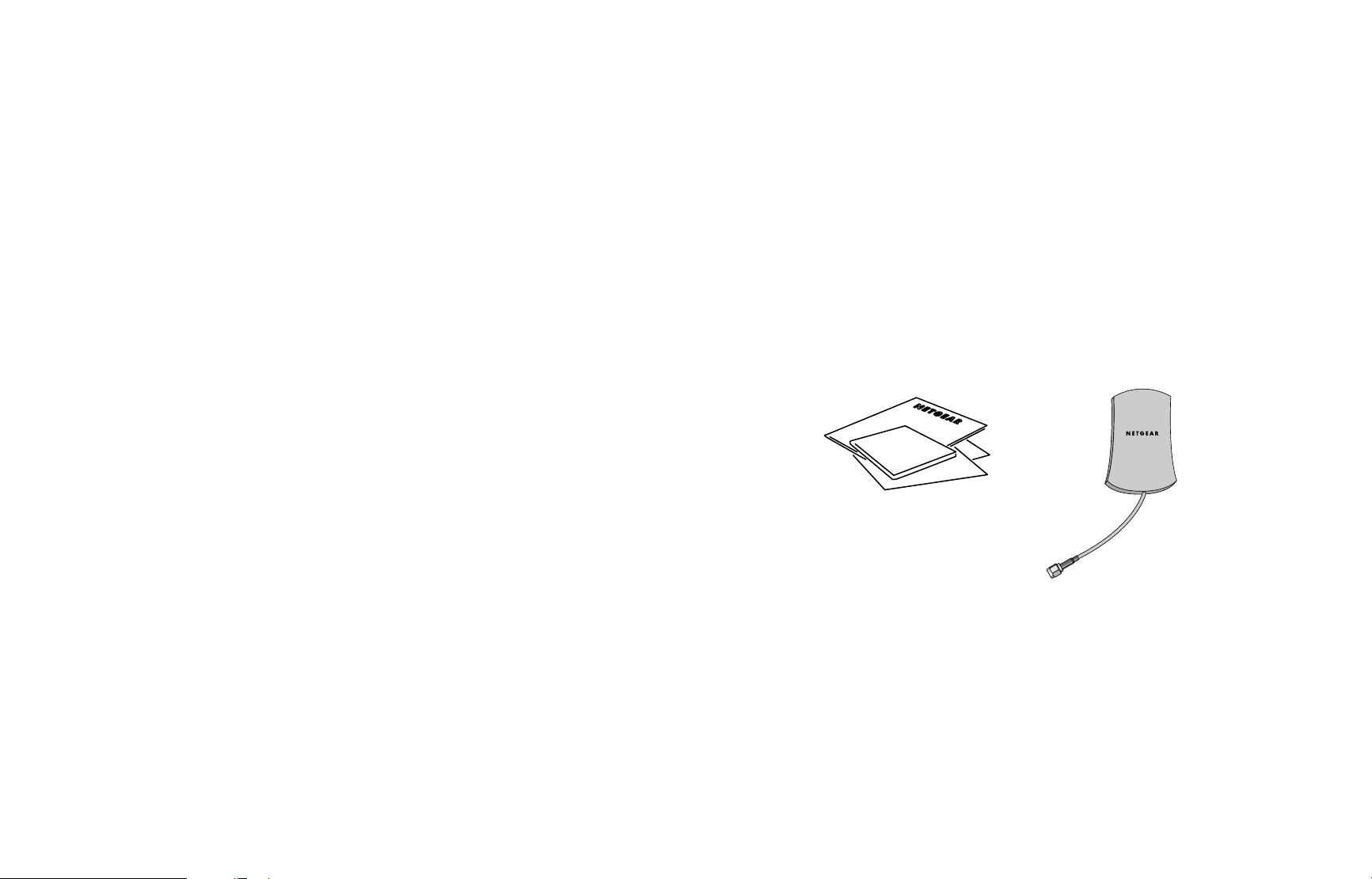
Package Contents
The package should contain:
• NETGEAR 5 dBi Omni-directional Antenna ANT24O5 including a 10 cm RG316 cable with
a reverse SMA connector for IEEE 802.11b or 802.11g wireless devices
• Ceiling/Wall mount bracket hardware
• Warranty card
• Support information card
1
Installation Guide, Warranty card and
Support information card
5 dBi Antenna
ANT24O5
Page 3
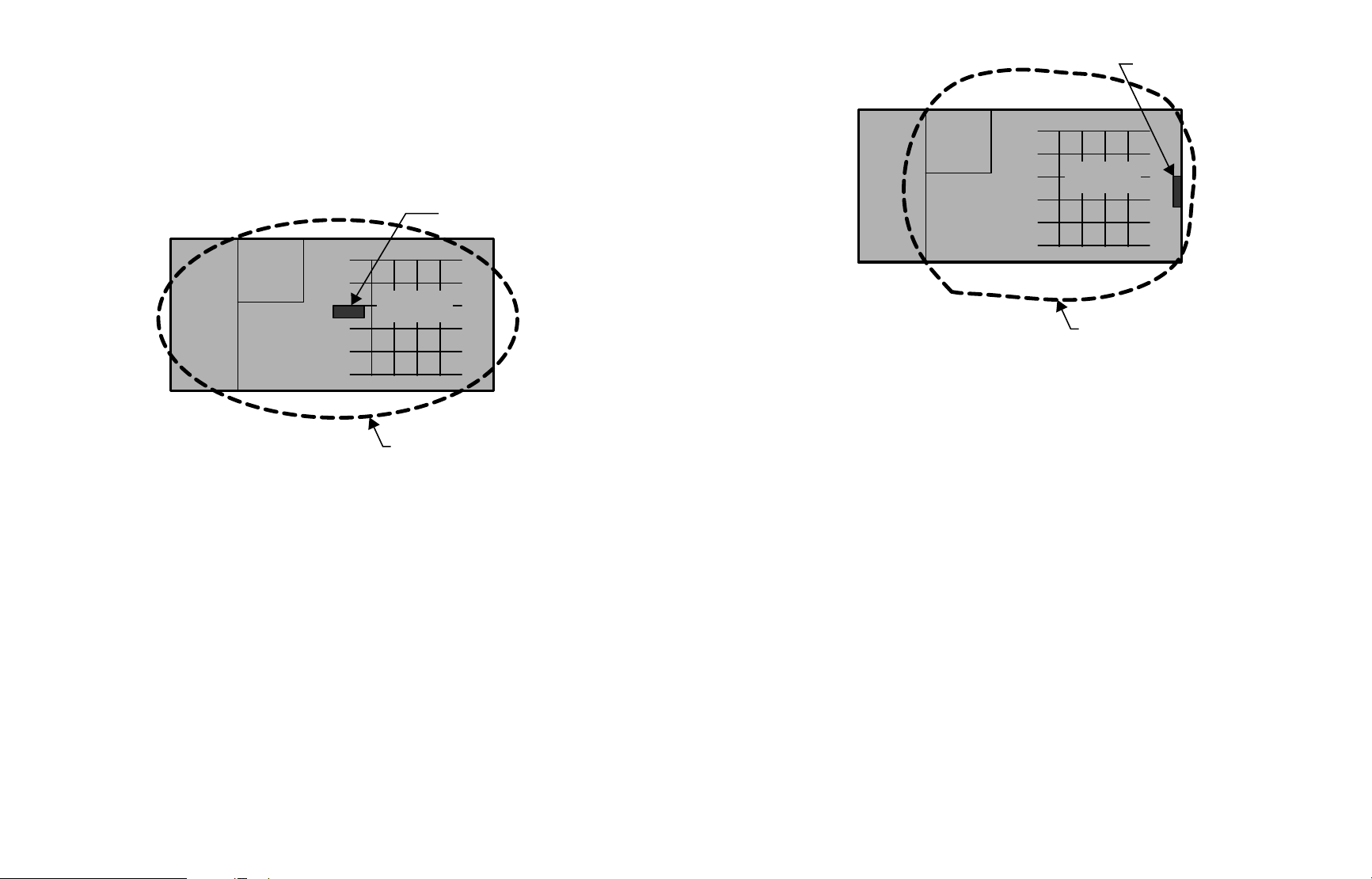
Figures 1 and 2 show where one could place the ANT24O5 for best coverage in an office. In
Figure 1, the ANT24O5 is placed on the ceiling in the middle of the area to cover. In Figure 2,
the ANT24O5 is placed in an elevated location on an interior wall, above and facing the
indoor coverage. Notice that the area close to the antenna, behind or beside it, will still be
covered because the dynamic range of the WLAN transmitter/receiver and antenna is
approximately 100dB. So, even with 20dB to 40dB of attenuation, the signal strength is still
strong and communication is maintained.
Placement and Other Important Considerations
In order to maximize coverage, antennas must be placed in a good spot. A lot of improvement
can be achieved by optimizing the line of sight between antennas. Try to minimize the
partitions and partial obstructions if possible. For instance, place the antenna on a wall above
the cubicles (cubicles generally include a metal foil). Ideal placement is against a wall, 2m high,
or on the ceiling facing the area to cover.
The longer the antenna cable, the higher the attenuation, or signal loss. This will decrease the
range and performance. The best performance is achieved with a short cable between the
antenna and the wireless device. The shortest FCC approved antenna cable is the NETGEAR
1.5 M (ACC-10314-01) cable. For optimal performance, use a low-loss NETGEAR antenna
cable up to 10 meters long.
If the wireless access point, router or gateway is in a IT room, place the antenna outside of the
room close to the ceiling against a wall. Use a NETGEAR antenna cable of up to 10 meters in
length to connect the antenna to the wireless access point.
3
2
Figure 2: Optimal antenna placement on an interior wall
Figure 1: Optimal antenna placement on the ceiling
ANT24O5
Cubicles
1.5m high
Approximate
coverage area
ANT24O5
Cubicles
1.5m high
Approximate
coverage area
Page 4

Wireless device with two antennas, but replacing only the
primary antenna
Wireless device with two antennas, but replacing both the
primary and secondary antennas
Installing the Antenna
The instructions below cover these scenarios:
• Wireless device with a single antenna
• Wireless device with two antennas, but replacing only the primary antenna
• Wireless device with two antennas, but replacing both the primary and secondary antennas
Turn off your wireless unit, locate the scenario below that fits your equipment, and connect
your wireless accessories according to the illustration. After attaching your new antenna,
reconnect your wireless device to the network and turn it on.
Wireless device with a single antenna
5
4
5 dBi Antenna
ANT24O5
Antenna executes
both transmit and
receive function.
Antenna executes
both transmit and
receive function.
ETHERNET
RESET
Wireless Access Point
5-12V DC
5 dBi Antenna
ANT24O5
NETGEAR antenna cable
Antenna
Connection
NETGEAR antenna cable
Antenna
Connection
Wireless Access Point
ETHERNET
RESET
Primary Secondary
5-12V DC
5 dBi Antenna
ANT24O5
Antenna executes
both transmit and
receive function.
Primary Secondary
Wireless Access Point
ETHERNET
RESET
5 dBi Antenna
ANT24O5
Antenna executes
receives function
only.
5-12V DC
NETGEAR antenna cable
Antenna
Connection
Page 5

The ANT24O5 built-in cable specifications are listed here.
Horizontal Plane Radiation Pattern (X-Y, Azimuth)
Specifications
7
6
Description
138 dB/100 m = 42 dB/100 ft @ 2.4 GHz
Type
Length
External Diameter
Impedance
SWR
13 mm = 0.5 in
Loss
RG318
10 cm = 3.9 in
2.5 mm
50 ± 5 Ohms
1.5 maximum
10cm RG318
Minimum bend radius
Description
2.0 maximum
Frequency Range
Type
Impedance
Maximum Input Power
SWR
-10 dB
Return Loss
2450 ± 50MHz
Patch
50 ± 5 Ohms
20W (without N/SMA adapter)
ANT24O5, 5 dBi Omni-directional
Antenna with a 10cm RG318 cable and
reverse female jack SMA connector
5 dBi
Gain
Directional
Radiation
Vertical
Polarization
HORZ 120 ° VERT 110 °
Beam Degree
SMA Female reverse
Connector Type
PC+ABS
Material
WHITE
Color
STEEL
Mounting Base
-20 to 65° C (-4 to 149° F)
Operation Temperature
-30 to 80° C (-22 to 176° F)
Storage Temperature
99.2 x 53.9 x 27.5 mm/3.91 x 21.2 x 1.08 in
Device Size (l x w x h)
55 g/.12 lb.
Weight
2 years
Warranty
120
150
180 0
210
90
60
30
-30
Top View
330
240
270
300
Page 6

Statement of Conditions
In the interest of improving internal design, operational function, and/or reliability, NETGEAR reserves the right to
make changes to the products described in this document without notice. NETGEAR does not assume any liability
that may occur due to the use or application of the product(s) or circuit layout(s) described herein.
Federal Communications Commission (FCC) Compliance Notice:Radio Frequency Notice
This device complies with part 15 of the FCC Rules. Operation is subject to the following two conditions:
1. This device may not cause harmful interference.
2. This device must accept any interference received, including interference that may cause undesired operation.
Note: This equipment has been tested and found to comply with the limits for a Class B digital device, pursuant to
part 15 of the FCC Rules. These limits are designed to provide reasonable protection against harmful interference in a
residential installation. This equipment generates, uses, and can radiate radio frequency energy and, if not installed and
used in accordance with the instructions, may cause harmful interference to radio communications. However, there is
no guarantee that interference will not occur in a particular installation. If this equipment does cause harmful
interference to radio or television reception, which can be determined by turning the equipment off and on, the user is
encouraged to try to correct the interference by one or more of the following measures: (1) Reorient or relocate the
receiving antenna, (2) Increase the separation between the equipment and receiver, (3) Connect the equipment into an
outlet on a circuit different from that to which the receiver is connected, (4) Consult the dealer or an experienced
radio/TV technician for help. Devices approved for the ANT2405 are listed at www.NETGEAR.com/go/antennas_fcc.
Federal Communications Commission (FCC) Radiation Exposure Statement
This equipment complies with FCC radiation exposure limits set forth for an uncontrolled environment. In order to
avoid the possibility of exceeding the FCC radio frequency exposure limits, human proximity to the antenna shall not
be less than 20 cm (8 inches) during normal operation. This device should not be co-located with other transmitters.
For EU, use of any antenna requires careful planning and extra consideration to comply with EU emissions and health
standards and regulations. It is recommended that a qualified professional installer service is consulted for site
survey and proper installation. Antenna installation must comply with the maximum level authorized by each country.
Devices that comply with EU regulations to work with the ANT2405 are listed at www.NETGEAR.com/go/antennas_eu.
Vertical Plane Radiation Pattern (X-Z, Elevation)
Radiation Pattern (Y-Z, Elevation)
8
120
150
180 0
210
240
90
270
-30
60
30
Front
Side View
330
300
120
90
60
150
180 0
210
240
-30
270
30
Front
Bottom View
330
300
Page 7

Technical Support
PLEASE REFER TO THE SUPPORT INFORMATION CARD THAT SHIPPED WITH
YOUR PRODUCT.
By registering your product at www.NETGEAR.com/register, we can provide you with faster
expert technical support and timely notices of product and software upgrades.
NETGEAR, INC.
Support Information
Phone: 1-888-NETGEAR (For US & Canada only) - 24x7 phone support
See Support Information card for other countries.
E-mail: support@NETGEAR.com (24x7 online support)
www.NETGEAR.com
©2003 NETGEAR, Inc. NETGEAR, the Netgear logo, The Gear Guy, Auto Uplink and
Everybody's Connecting are trademarks or registered trademarks of Netgear, Inc. in the United
States and/or other countries. Microsoft and Windows are registered trademarks of Microsoft
Corporation in the United States and/or other countries. Other brand and product names are
trademarks or registered trademarks of their respective holders. Information is subject to change
without notice. All rights reserved.
July 2003
*M-10081-02*
M-10081-02
 Loading...