

Page 1
Model WT-5800 Patient Warming System
Service Manual
Page 2

© 2011 Nellcor Puritan Bennett LLC. All rights reserved.
To obtain warranty information contact your local Nellcor representative.
Page 3

Table of Contents
Safety Information.................................................................................................... 9
Overview ................................................................................................................ 9
Warnings ................................................................................................................ 9
Cautions................................................................................................................ 11
Introduction............................................................................................................. 13
Overview .............................................................................................................. 13
Intended Use ........................................................................................................ 13
Manual Availability.............................................................................................. 13
Background Information..................................................................................... 13
Safety Features..................................................................................................... 14
Customized Warming Therapy ..................................................................... 14
Automatic Temperature Stepdown.............................................................. 14
Automatic Over Temperature Shutdown .................................................... 14
Alarms ............................................................................................................ 15
HEPA Filter ..................................................................................................... 16
Wheel Locks ................................................................................................... 16
Symbols................................................................................................................. 17
Description of the Warming System................................................................... 17
Routine Maintenance ............................................................................................. 21
Overview .............................................................................................................. 21
HEPA Filter Replacement..................................................................................... 21
Power Cord Replacement.................................................................................... 24
Nozzle Replacement ............................................................................................ 25
Cleaning the Warming Unit ................................................................................ 26
Performance Verification........................................................................................ 27
Overview .............................................................................................................. 27
Power Fail / Start Alarm Check............................................................................ 27
Thermostat Protection Check.............................................................................. 28
Output Temperature Check ................................................................................ 31
Safety Tests........................................................................................................... 33
Repair....................................................................................................................... 35
Overview .............................................................................................................. 35
Filter Cover Assembly Replacement ................................................................... 36
Separating the Front and Rear Covers................................................................ 38
Rejoining the Front and Rear Covers.................................................................. 40
Front Cover Assembly Replacement ................................................................... 41
Control PCBA Replacement................................................................................. 49
Heater Assembly Replacement............................................................................ 53
Hose Replacement ............................................................................................... 64
Duct Adapter Assembly Replacement ................................................................ 66
Rear Cover Assembly Replacement..................................................................... 71
Service Manual iii
Page 4

Spare Parts & Accessories....................................................................................... 87
Overview .............................................................................................................. 87
Ordering Information.......................................................................................... 87
Replacement Parts and Accessories .................................................................... 90
Manual Availability.............................................................................................. 90
Packing for Shipment ............................................................................................. 91
Overview .............................................................................................................. 91
Returning the Warming Unit .............................................................................. 91
Repacking in Original Carton.............................................................................. 91
Repacking in a Different Carton......................................................................... 93
Specifications .......................................................................................................... 95
Overview .............................................................................................................. 95
Warming System Specifications .......................................................................... 95
Transport and Shipping in Shipping Container ................................................. 96
Compliance........................................................................................................... 96
Manufacturer’s Declaration ................................................................................ 96
Electromagnetic Compatibility (EMC)................................................................. 97
Electromagnetic Emissions ............................................................................ 97
Electromagnetic Immunity............................................................................ 97
Ground Integrity Test .......................................................................................... 99
Earth Leakage Current Test............................................................................... 100
Enclosure Leakage Current Test........................................................................ 100
Principles of Operation......................................................................................... 101
Overview ............................................................................................................ 101
Control Panel ..................................................................................................... 101
Main Circuit Board............................................................................................. 102
DC Power Supply Circuit.............................................................................. 102
Control Logic Circuit.................................................................................... 103
Automatic Temperature Stepdown............................................................ 103
Alarm Drive Circuits..................................................................................... 103
Temperature Control Circuit....................................................................... 104
LCD Hour Meter........................................................................................... 105
AC Power Section ........................................................................................ 105
Blower .......................................................................................................... 106
Heater........................................................................................................... 106
Thermostat Protection ................................................................................ 106
Over-Temperature Test Port ....................................................................... 106
iv Service Manual
Page 5

List of Figures
Figure 1: Cart Wheel Lock........................................................................................... 16
Figure 2: Front View.................................................................................................... 18
Figure 3: Back View.................................................................................................... 19
Figure 4: Operating Hours Meter............................................................................... 22
Figure 5: Filter Cover Screws....................................................................................... 22
Figure 6: HEPA Filter and Power Cord Strain Relief.................................................. 23
Figure 7: Power Cord Routing .................................................................................... 24
Figure 8: Over-Temperature Test Port ....................................................................... 29
Figure 9: WT-5800 High Temperature Setting .......................................................... 29
Figure 10: Warning Light............................................................................................ 30
Figure 11: Output Temperature Test Setup............................................................... 32
Figure 12: Temperature Selection .............................................................................. 32
Figure 13: Ground Stud............................................................................................... 33
Figure 14: Power Cord ................................................................................................ 37
Figure 15: Filter Cover Screws..................................................................................... 37
Figure 16: Power Cord ................................................................................................ 38
Figure 17: Cover Screw Locations............................................................................... 39
Figure 18: Separated Covers ....................................................................................... 39
Figure 19: Cover Screw Locations............................................................................... 40
Figure 20: Cable Harness Bundle Ties ........................................................................ 42
Figure 21: Front Cover Assembly................................................................................ 42
Figure 22: Power Switch Clips and Wires................................................................... 43
Figure 23: Cable Disconnect ....................................................................................... 43
Figure 24: Control PCB Screws.................................................................................... 44
Figure 25: Control PCB Lights ..................................................................................... 45
Figure 26: Control PCB Screws.................................................................................... 45
Figure 27: Cable Connections ..................................................................................... 46
Figure 28: Power Switch Clips and Wires................................................................... 46
Figure 29: Front Cover Assembly Component Locations .......................................... 47
Figure 30: Equipotential Ground Stud Wiring .......................................................... 47
Figure 31: Cable Harness Bundle Ties ........................................................................ 48
Figure 32: Control PCB Connections .......................................................................... 49
Figure 33: Control PCB Screws.................................................................................... 50
Figure 34: Control PCB Lights ..................................................................................... 50
Figure 35: Control PCB Screws.................................................................................... 51
Figure 36: Cable Connections ..................................................................................... 51
Figure 37: Cable Harness Bundle Ties ........................................................................ 52
Figure 38: Filter Removal ............................................................................................ 53
Figure 39: Blower Assembly Screws ........................................................................... 54
Figure 40: Cable Harness Bundle Ties ........................................................................ 54
Figure 41: Front Cover Assembly................................................................................ 55
Figure 42: Duct Adapter Placement ........................................................................... 56
Figure 43: Blower Motor Removal ............................................................................. 57
Figure 44: Blower Assembly Clips............................................................................... 57
Figure 45: Rubber Gasket ........................................................................................... 58
Service Manual v
Page 6

Figure 46: Heater Assembly ........................................................................................ 58
Figure 47: Heater Assembly Installation .................................................................... 59
Figure 48: Rubber Gasket ........................................................................................... 60
Figure 49: Blower Assembly Clips............................................................................... 60
Figure 50: Duct Adapter Placement ........................................................................... 61
Figure 51: Blower Assembly Screws ........................................................................... 62
Figure 52: Cable Harness Bundle Ties ........................................................................ 62
Figure 53: Filter Installation........................................................................................ 63
Figure 54: Filter Cover Installation ............................................................................. 63
Figure 55: Hose Attachment....................................................................................... 65
Figure 56: Thermistor Silicone .................................................................................... 67
Figure 57: Thermistor Removal .................................................................................. 67
Figure 58: Duct Adapter Removal .............................................................................. 68
Figure 59: Duct Adapter Placement ........................................................................... 69
Figure 60: Thermistor Position Within Duct Adapter ............................................... 69
Figure 61: Filter Cover Screws..................................................................................... 72
Figure 62: Filter Removal ............................................................................................ 72
Figure 63: Separated Covers ....................................................................................... 73
Figure 64: Front Cover Assembly................................................................................ 74
Figure 65: Cable Disconnect ....................................................................................... 75
Figure 66: Thermistor Cable Removal ........................................................................ 75
Figure 67: Blower Assembly Screws ........................................................................... 76
Figure 68: Blower Capacitor ....................................................................................... 76
Figure 69: Blower Motor Removal ............................................................................. 77
Figure 70: Blower Assembly Clips............................................................................... 77
Figure 71: Rubber Gasket ........................................................................................... 78
Figure 72: Heater Assembly ........................................................................................ 78
Figure 73: Heater Assembly Installation .................................................................... 79
Figure 74: Rubber Gasket ........................................................................................... 80
Figure 75: Blower Installation .................................................................................... 80
Figure 76: Blower Screws ............................................................................................ 81
Figure 77: Thermistor Cable Installation.................................................................... 81
Figure 78: Capacitor Installation ................................................................................ 82
Figure 79: Cable Connections ..................................................................................... 82
Figure 80: Front Cover Assembly................................................................................ 83
Figure 81: Equipotential Ground Stud Wiring .......................................................... 84
Figure 82: Cable Harness Bundle Ties ........................................................................ 84
Figure 83: Filter Installation........................................................................................ 85
Figure 84: Filter Cover Installation ............................................................................. 85
Figure 85: Spare Parts (Sheet 1).................................................................................. 89
Figure 86: Spare Parts (Sheet 2).................................................................................. 90
Figure 87: Packing the Warming Unit in Original Carton ........................................ 92
Figure 88: Control Panel ........................................................................................... 101
Figure 89: Hour Meter .............................................................................................. 105
Figure 90: Warming Unit Schematic (Sheet 1)......................................................... 107
Figure 91: Warming Unit Schematic (Sheet 2)......................................................... 108
vi Service Manual
Page 7

List of Tables
Table 1: Symbols on the Warming System................................................................. 17
Table 2: Equipment Required for HEPA Filter Replacement .................................... 21
Table 3: Equipment Required for Thermostat Protection Check ............................. 28
Table 4: Equipment Required for Output Temperature Check................................ 31
Table 5: Filter Cover Assembly Components ............................................................. 36
Table 6: Tools Required for Replacing FIlter Cover Assembly .................................. 36
Table 7: Tools Required for Separating Front and Rear Covers ............................... 38
Table 8: Filter Cover Assembly Components ............................................................. 41
Table 9: Tools Required for Replacing Front Cover Assembly.................................. 41
Table 10: Tools Required for Replacing Control PCB ................................................ 49
Table 11: Heater Assembly Components ................................................................... 53
Table 12: Tools Required for Replacing Heater Assembly ........................................ 53
Table 13: Hose Assembly Components ...................................................................... 64
Table 14: Tools Required for Replacing Hose Assembly ........................................... 64
Table 15: Duct Adapter Assembly Components ........................................................ 66
Table 16: Tools Required for Replacing Duct Adapter Assembly............................. 66
Table 17: Rear Cover Assembly Components ............................................................ 71
Table 18: Tools Required for Replacing Rear Cover Assembly ................................. 71
Table 19: Spare Parts and Accessories........................................................................ 88
Table 20: System Specifications .................................................................................. 95
Table 21: Shipping Container Specifications ............................................................. 96
Table 22: Compliance Standards ................................................................................ 96
Table 23: Electromagnetic Emissions Guidelines....................................................... 97
Table 24: Electromagnetic Immunity Guidelines....................................................... 97
Table 25: Recommended Separation Distances......................................................... 99
Table 26: Earth Leakage Current Test...................................................................... 100
Table 27: Enclosure Leakage Current Test............................................................... 100
Service Manual vii
Page 8

Page Left Intentionally Blank
viii Service Manual
Page 9

1 Safety Information
Overview
This chapter contains safety information requiring users to exercise
appropriate caution when servicing the WarmTouch™ Model WT-5800
patient warming system.
The WARNING symbol identifies warnings.
Overview
Warnings alert the user to potential serious outcomes, such as death, injury,
or adverse events to the patient or user.
The CAUTION symbol identifies cautions.
Cautions alert the user to exercise care necessary for the safe and effective
use of the warming system.
The NOTE symbol identifies notes.
Notes contain important information that may otherwise be overlooked or
missed.
Warnings
WARNING
Possible explosion hazard. Do not use the device in the presence of
flammable anesthetics.
Service Manual 9
Page 10

Safety Information
WARNING
Possible electrical shock hazard. To reduce the risk of electrical shock do not
remove the back case. Servicing is only to be done by qualified personnel.
WARNING
Possible electric shock hazard. Grounding reliability can be achieved only
when the warming system is connected to a suitable mains outlet.
WARNING
Possible fire hazard. Prevent the blanket material from coming into contact
with a laser or an electrosurgical active electrode; rapid combustion could
result.
WARNING
Possible burn hazard. Do not apply heat directly to open wounds. All
patient’s wounds should be covered while using the warming system.
WARNING
Possible patient burns. Use caution and consider discontinuing use on
patients during vascular surgery when an artery to an extremity is clamped.
Do not apply the warming system to ischemic limbs.
WARNING
Possible patient burns. Use caution and monitor closely if used on patients
with severe peripheral vascular disease.
WARNING
If a malfunction occurs in the warming system, discontinue use. Notify your
sales/service center of the malfunction. The unit must be serviced by an
authorized service technician.
WARNING
TM
No free-hosing. Keep hose nozzle connected to a WarmTouch
blanket at
all times or thermal injury may occur.
WARNING
TM
WarmTouch CareDrape
and CareQuiltTM blankets are for single patient use
only.
10 Service Manual
Page 11

WARNING
The warming system should not be operated in the presence of
electromagnetic fields that are greater than 3 volts/meter. This could cause
shutdown of the warming system by the fail-safe function within the
equipment.
WARNING
The warming system is not suitable for use during magnetic resonance
imaging (MRI) scanning. The warming system may affect the MRI image.
WARNING
Continuously monitor the patient's temperature. Reduce the air temperature
or discontinue therapy when normothermia is reached.
WARNING
The patient must be closely monitored for rewarming. Vasodilation and
potential hypotension can occur. Use good judgment when selecting a
temperature. If unsure of proper setting, consult with the attending
physician.
Cautions
WARNING
The use of accessories and power cables other than those specified may
result in increased emission and/or decreased immunity of the warming
system.
WARNING
Thermal injury may result if the warming system hose comes into contact
with the patient.
WARNING
Using the warming system on transdermal medication patches may increase
the rate of drug delivery, potentially causing harm to the patient.
WARNING
Before attempting to open or disassemble the warming system, disconnect
the power cord from the AC power source.
Cautions
Caution
Federal (U.S.A.) law restricts the use of the warming system to sale by or on the order
of a physician.
Service Manual 11
Page 12

Safety Information
Caution
The warming system is fitted with an air filter; however, airborne contamination
should be considered when using the warming system.
Caution
If the warming system is mounted on the intravenous (IV) pole, it should be installed
with the top of the unit’s handle less than 76 cm (30 inches) above the floor to
prevent the IV pole from tipping over.
Caution
The institution should follow local governing ordinances and recycling instructions
regarding disposal or recycling of filter and device components or end of life of the
product.
Caution
The HEPA filter must be changed every 2,000 hours of operation. Refer to the
Routine Maintenance section for replacement procedures requiring a qualified
technician.
Caution
Do not spray, pour, or spill any liquid on the warming unit, its accessories,
connectors, switches or openings in the case.
Caution
Observe ESD (electrostatic discharge) precautions when working within the warming
system.
Caution
Repairs to the warming system should only be accomplished by trained service
technicians.
Caution
Ensure that the patient is dry or the warming system may be ineffective.
12 Service Manual
Page 13

1 Introduction
Overview
This chapter provides an introduction to the WarmTouch™ Model WT-5800
patient warming system.
Intended Use
The WarmTouch™ Model WT-5800 patient warming system (warming unit
and blanket) is intended for prevention and treatment of hypothermia, for
example, with the surgical patient, the patient in the pre-operative holding
area, the pregnant woman who shivers during epidural anesthesia due to
hypothermia, or any patient who is uncomfortable anywhere in the cold
critical care environment.
Overview
Manual Availability
The most recent revision of this manual is available on the Internet at:
http://www.nellcor.com/serv/manuals.aspx
Background Information
There are numerous ways of warming your patient, from cotton blankets to
water mattresses. Research has shown that low temperatures surrounding the
patient are a major factor contributing to hypothermia.
system covers the patient with warm air and actively transfers heat across the
skin. The result is to achieve normothermia.
1
Morris RH, Wilkey BR. “The Effects of the Ambient Temperature on Patient Temperature
During Surgery Not Involving Body Cavities.” Anesthesiology 32:102
2
Morris RH. “Influence of Ambient Temperature on Patient Temperature During
Intra
-abdominal Surgery.” Annals of Surgery 173:230-233, 1971.
1,2
The warming
-107, 1970.
Service Manual 13
Page 14

Introduction
In creating this warm customized pocket of air around the hypothermic
patient, it is important to note that stagnant air, even if it is warm, does not
work as an effective heat transfer medium. Stagnant air acts as an insulator,
preventing the boundary layer of molecules next to the skin surface from
transferring heat.
Forced air warming causes warmed air molecules to flow over cooler skin
surface. It is this active flow of warmed molecules that acts as a heat transfer
medium. With the warming system, air is warmed and delivered into a
lightweight blanket (CareQuilt or CareDrape blanket) that rests over or under
the patient. The CareQuilt and CareDrape blankets have many small
perforations on the underside that allow air to exit the blanket and surround
the patient.
Safety Features
The warming system is designed to give healthcare professionals more control
over the patient’s core body temperature. There are several safety features of
the warming system which make it safe and appropriate for such use.
Customized Warming Therapy
Clinicians select temperature range setting at the onset of warming therapy
to help ensure the appropriate setting is selected for every patient.
Automatic Temperature Stepdown
The warming system provides a 45-minute temperature stepdown feature.
When in High temperature mode, blower temperature will automatically drop
to the Medium temperature setting after each 45 minutes of use. The
temperature may be reset to High at any time by selecting the High
temperature setting on the control panel to start another 45-minute cycle.
Automatic Over Temperature Shutdown
The automatic temperature controller and two back-up systems help to
ensure temperature will not reach excessive levels. If necessary, the control
system automatically turns off the heater element when the blower outlet
temperature rises to between 47º C and 50º C, illuminates the warning light,
14 Service Manual
Page 15

and sounds an audible alarm. The warming system heater will start producing
heat when the warming system temperature drops to between approximately
34º C and 37º C. A yellow warning light illuminates whenever the control
system identifies an over-temperature condition.
Alarms
The WarmTouch control circuit manages and monitors operation of the
patient warming system. Should the control circuit encounter a failure
condition, it reports failures using both visual and audible alarms. The visual
alarm is a yellow warning indicator on the control panel that lights at power
on, upon power restoration following power failure, and whenever the
control system identifies an alarm condition. The audible alarm sounds
intermittently or continuously, depending on the alarm condition. Investigate
immediately.
Safety Features
The WarmTouch control circuit recognizes two failure conditions.
1. Power On/Power Fail Alarm — This condition causes an intermittent
audible alarm and continuous visual alarm. It appears at power on and
after power failure, indicating the operator must select the desired
temperature. Upon selection of a temperature key, the system cancels the
alarm and the blower operates at the desired temperature.
2. Over-temperature Alarm — This condition causes a continuous audible
alarm and a flashing visual alarm. It appears when reaching the
temperature safety limit, and the control system turns off the heater. Once
the system air temperature returns to a safe operating temperature of
between 34ºC and 37ºC, the heater will turn back on.
If the control system determines the heater again exceeds the safety limit,
the warming system alarms once more. Take the warming system out of
service for repair by a qualified service technician.
If a power failure occurs while the warming system is in the overtemperature fault condition, and the warming system is still in the overtemperature fault condition when power is restored, both continuous
audible and visual alarms will activate. In this instance, the overtemperature fault cannot be cleared. Take the warming system out of
service for repair by a qualified service technician.
Note:
The Power Fail/Start Alarm is only found on WT-5800 warming units containing a
Control PCBA with part number GR100305.
Service Manual 15
Page 16
Introduction
HEPA Filter
Caution
The HEPA filter must be changed every 2,000 hours of operation. Refer to the
Routine Maintenance section for replacement procedures requiring a qualified
technician.
The system's High Efficiency Particulate Air Filter is 99.97% efficient at
0.3-micron particle size.
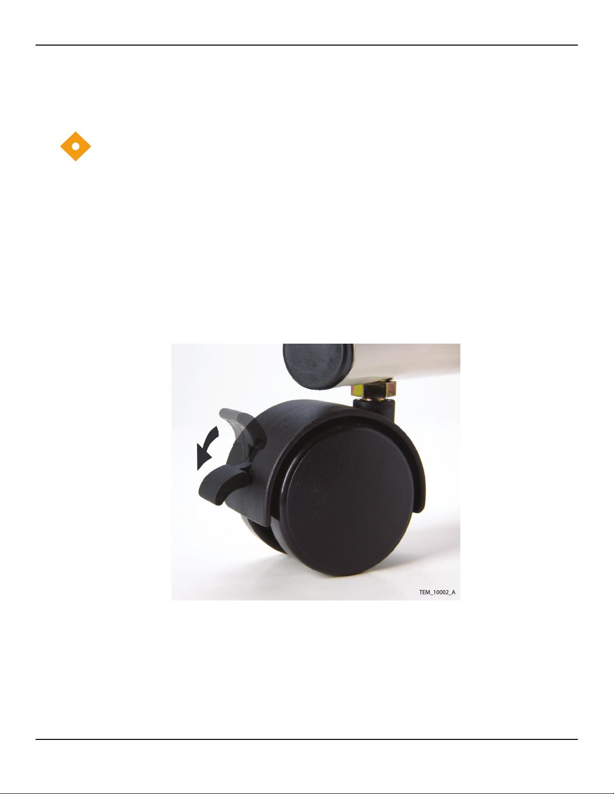
Wheel Locks
The cart is equipped with two wheel locks. The wheel locks prevent the cart
from moving while in use. The wheel locks must be released when moving
the cart. Press the wheel lock arm down to lock the wheel. Lift the wheel lock
arm to release the wheel lock. See Figure 1.
Figure 1. Cart Wheel Lock
16 Service Manual
Page 17

Symbols
The symbols identified in Table 1 are the symbols used on the warming unit.
Table 1. Symbols on the Warming System
Symbols
Attention symbol, consult accompanying documentation
Do not direct air from the hose to the patient (free-hosing); use hose only
with warming blankets.
Dangerous voltage
Protection Class I
Protection Type BF
Date of manufacture
Visual and audible alert
.
Description of the Warming System
The warming unit (Figure 2 and Figure 3) and CareQuiltTMand CareDrape
blankets are intended for prevention and treatment of hypothermia. For
example, use the warming system with the surgical patient, the patient in the
preoperative holding area, the pregnant woman who shivers during epidural
anesthesia due to hypothermia, or any patient who is uncomfortable
anywhere in the cold critical care environment.
Service Manual 17
TM
Page 18
Introduction
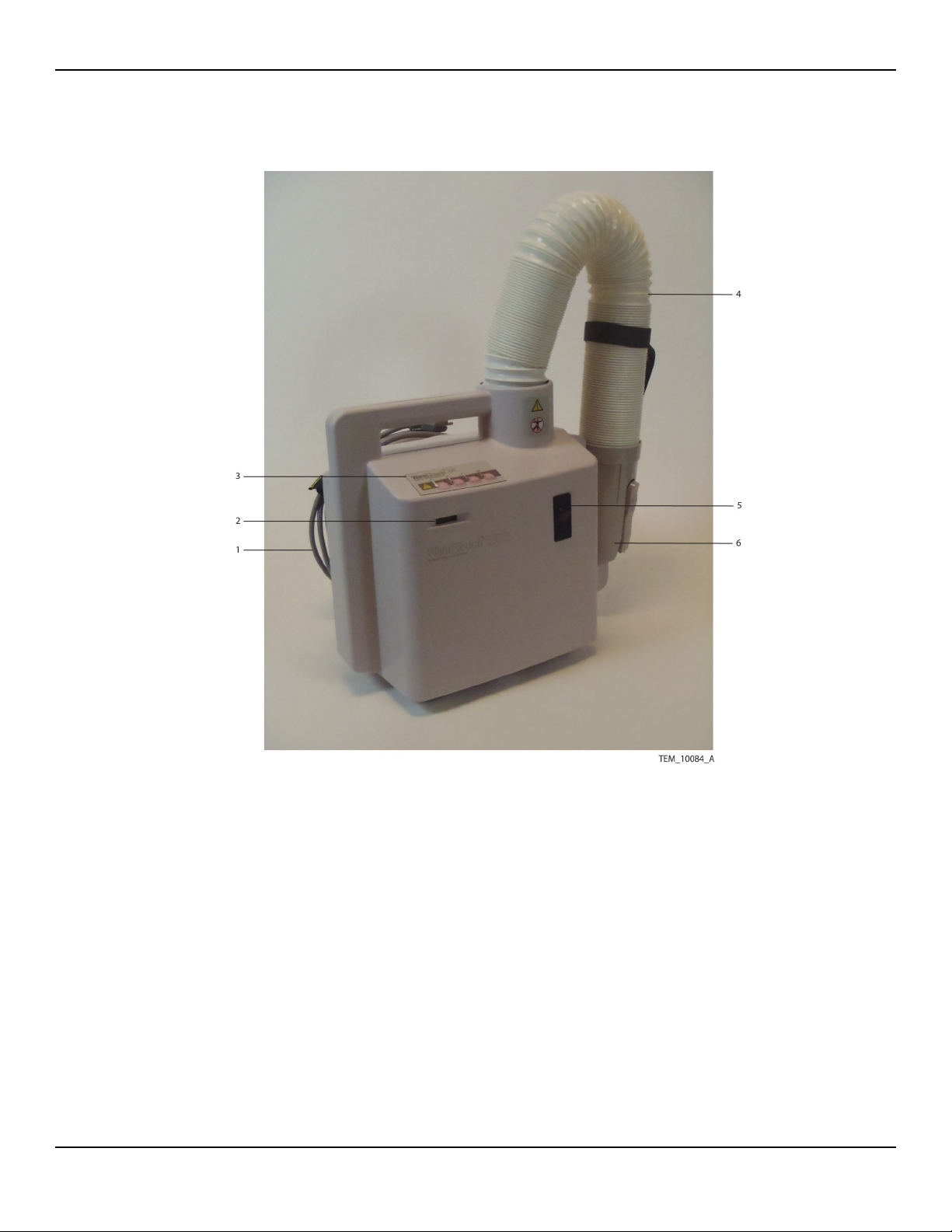
1 Power Cord 4 Hose
2 Hours Meter 5 Power Switch
3 Control Panel 6 Nozzle
Figure 2. Front View
18 Service Manual
Page 19
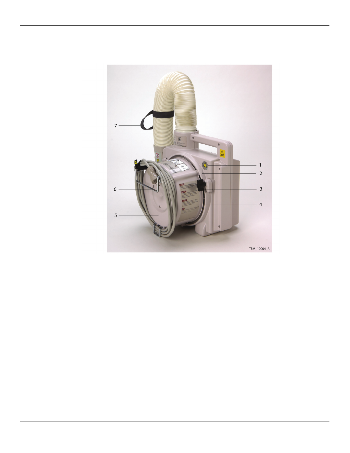
Description of the Warming System
1 Over-Temperature Test Port 5 Filter Cover
2 Instruction Label 6 Bed Hook Bracket
3 Blower Cart Clamp 7 Nozzle Strap with Clip
4 Warning Label
Figure 3. Back View
Service Manual 19
Page 20

Introduction
Page Left Intentionally Blank
20 Service Manual
Page 21
1 Routine Maintenance
Overview
This chapter provides routine maintenance procedures for the WarmTouch™
Model WT-5800 patient warming system.
Caution
The institution should follow local governing ordinances and recycling instructions
regarding disposal or recycling of filter and device components or end of life of the
product.
Overview
HEPA Filter Replacement
The warming system filter must be replaced after every 2,000 hours of use.
Contact Nellcor’s Customer Service Department (1.800.635.5267, press 3 in
the U.S.A.) or your local Nellcor representative to purchase new filters. The
correct filter will be sent to your hospital for installation.
Caution
Only qualified hospital personnel should replace the air filter.
Table 2. Equipment Required for HEPA Filter Replacement
Equipment Description / Use
Phillips screwdriver #2 / Removing screws
Replacement filter P/N 505-2200
Flat blade screwdriver Detaching power cord from filter cover
WARNING
Do not operate the warming system with the back cover removed.
Note:
To read the operating hours meter, the warming system must be running.
Service Manual 21
Page 22
Routine Maintenance
To replace the HEPA filter:
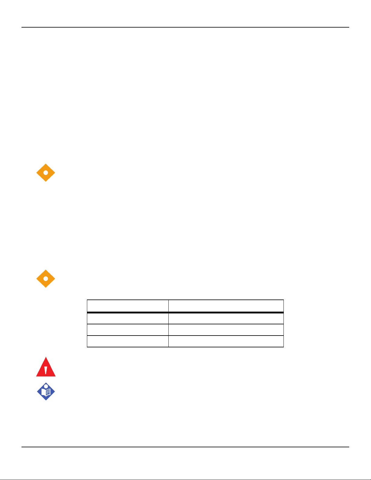
1. Write the date and total hours of operation of the warming system on the
new filter label and warming system label. The operating hours meter is on
the front of the warming system (see Figure 4).
Figure 4. Operating Hours Meter
2. Unplug the warming system.
3. Lay the warming unit on its front side so that the bottom of the warming
unit is visible.
4. Unwrap the power cord from the filter cover.
5. Remove the filter cover screws. See Figure 5.
Figure 5. Filter Cover Screws
22 Service Manual
Page 23
HEPA Filter Replacement
6. Unseat the power cord from the power cord routing bracket on the filter
cover. If necessary, use the head of the flat blade screwdriver to separate
the halves of the bracket sufficiently to allow unseating of the cord.
7. Remove the filter cover.
8. Remove the filter. See Figure 6.
1 HEPA Filter 2 Power Cord Strain Relief
Figure 6. HEPA Filter and Power Cord Strain Relief
9. Place the new filter into the warming unit.
10. Ensure that the power cord’s female connector is still fully inserted into the
socket in the warming unit housing.
11. Place the filter cover on the case and reseat the power cable into the
power cable routing bracket on the bottom of the cover.
12. Align the filter cover with the three screw holes in the filter and install the
three screws holding the filter cover to the warming unit.
13. Attach the completed replacement filter label to the rear surface of the
filter cover. If a replacement filter label is already present, cover it with the
new label.
Service Manual 23
Page 24
Routine Maintenance
Power Cord Replacement
The warming system is equipped with a detachable power cord. If the power
cord is damaged, contact your local Nellcor representative.
Caution
Only qualified hospital personnel should replace the power cord.
The only equipment required for this procedure is a flat blade screwdriver.
To replace the power cord:
1. Unplug the warming system power cord from the AC outlet.
2. Lay the warming unit on its rear side so that the bottom of the warming
unit is visible.
3. Unwind the power cord from the filter cover.
4.
Unseat the power cord from the power cord routing bracket (Figure 7, item 4)
on the filter cover. If necessary, use the head of the flat blade screwdriver to
separate the halves of the bracket sufficiently to allow unseating of the cord
5. Disconnect the power cord connector (Figure 7, item 2) from its socket in
the blower housing.
1 Equipotential Ground 3 Strain Relief
2 Power Cord Female Connector 4 Power Cord Routing Bracket
.
Figure 7. Power Cord Routing
24 Service Manual
Page 25

Nozzle Replacement
6. Connect the replacement power cord connector to the warming unit,
making sure the connector is fully inserted into the socket in the warming
unit housing.
7. Reseat the power cord into the power cord routing bracket. If necessary,
use the head of the flat blade screwdriver to separate the halves of the
bracket sufficiently to allow reseating of the cord.
Nozzle Replacement
If the nozzle is damaged, contact your Nellcor representative.
The only equipment required for this procedure is a flat blade screwdriver. The
nozzle is held in place at its base by four clips on the hose assembly; make
sure the screwdriver is long enough to reach inside the nozzle to the clips.
To replace the nozzle:
1. Insert the screwdriver blade into the nozzle, positioning it between one of
the clips and the inner surface of the nozzle.
2. Use the screwdriver blade to push the clip in toward the center of the
nozzle, while simultaneously pulling the nozzle away from the hose until
the clip is disengaged from the base of the nozzle.
3. Repeat steps 1 and 2 to disengage the other three clips.
4. Remove the nozzle from the hose.
5.
Put the replacement nozzle over the end of the hose
6. Push the replacement nozzle down onto the hose until all four clips
engage with the nozzle.
.
Service Manual 25
Page 26

Routine Maintenance
Cleaning the Warming Unit
Caution
Do not spray, pour, or spill any liquid on the warming unit, its accessories,
connectors, switches, or openings in the case.
For surface-cleaning and disinfecting, follow your institution's procedures or
the recommended actions below.
Surface cleaning — Use a soft cloth dampened with either a commercial,
•
nonabrasive cleaner or a solution of 70% alcohol in water, lightly wiping
the surfaces of the warming unit.
• Disinfection — Use a soft cloth saturated with a solution of 10% chlorine
bleach in tap water, lightly wiping the surfaces of the warming unit.
26 Service Manual
Page 27

1 Performance Verification
Overview
This chapter provides performance verification procedures to be used when
servicing the WarmTouch™ Model WT-5800 patient warming system.
Power Fail / Start Alarm Check
This procedure ensures the Power Fail / Start Alarm functions correctly and
can be canceled properly. Perform this procedure before returning the
warming system into service.
Overview
Note:
The Power Fail/Start Alarm is only found on WT-5800 warming units containing a
PCBA with part number GR100305. WT-5800 warming units with earlier versions of
the Control PCBA (referred to as the Universal PCBA in earlier versions of this
manual) do not have this alarm, and do not need this test.
At power up, both audible and visual alarms activate, regardless of the reason for
power loss. Selecting any blower temperature cancels both types of alarms.
No equipment is required for this check.
To check the Power Fail / Start Alarm:
1. Plug in the warming system.
2. Turn on the warming system using the power switch. The audible alarm should
sound intermittently, and the warning light should be on steady. The Low
temperature indicator light on the control panel should also be on steady.
3. Select any temperature setting. The audible alarm should stop, and the
warning light should turn off. The indicator light for the selected
temperature should be on steady.
4. Turn off the warming system and unplug it.
Service Manual 27
Page 28

Performance Verification
Thermostat Protection Check
This procedure checks to ensure that the thermostat protection controls are
working properly. This procedure should be performed before returning the
warming system into service.
Calibration of the thermostat protection is neither required nor possible. If the
test time or temperatures are outside the allowable range, factory service is
required. Contact your local Nellcor representative.
Table3.Equipment Required for Thermostat Protection Check
Equipment Description / Use
Temperature probe Mon-a-Therm subcutaneous temperature probe, or
equivalent, and monitor with an accuracy of ±0.2ºC.
Tape To hold the temperature probe in place.
Stopwatch Manual or electronic
Jumper wire with alligator clips 3 to 12 in (8 to 30 cm) long, alligator clip at each
end, 12 gauge minimum.
Phillips screwdriver #2 / Loosening and tightening test port screw.
WarmTouch CareDrape Lower
Body blanket
To complete patient warming system.
To check thermostat protection:
1. Lay the temperature probe beside the warming unit nozzle at the end of
the hose and bend approximately 1.5 inches (4 cm) of the temperature
probe into the nozzle opening.
2. Position the tip of the temperature probe approximately 1 to 2 in (2.5 to 5
cm)) inside the nozzle, centered in the nozzle opening.
3. Tape the probe in place.
4. Connect the probe to the temperature monitor.
5. Connect the nozzle to the blanket.
6. Unplug the warming system.
7. Loosen the over-temperature test port screw. See Figure 8.
8. Slide the over-temperature test port cover to the side.
28 Service Manual
Page 29
Thermostat Protection Check
Figure 8. Over-Temperature Test Port
WARNING
Possible patient injury. Connecting the jumper wire disables (shorts out) the
thermistor that is part of the temperature control system.
9. Connect the jumper wire across the two terminals in the over-temperature
test port.
10. Plug in the warming system and turn it on.
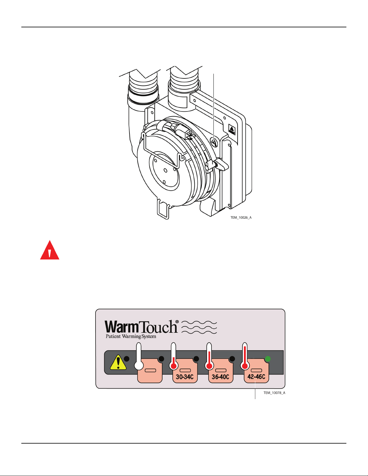
11. Select the High (42-46C) temperature setting. See Figure 9.
Figure 9. WT-5800 High Temperature Setting
Service Manual 29
Page 30
Performance Verification
12. When the monitored temperature exceeds 46ºC, start the stopwatch.
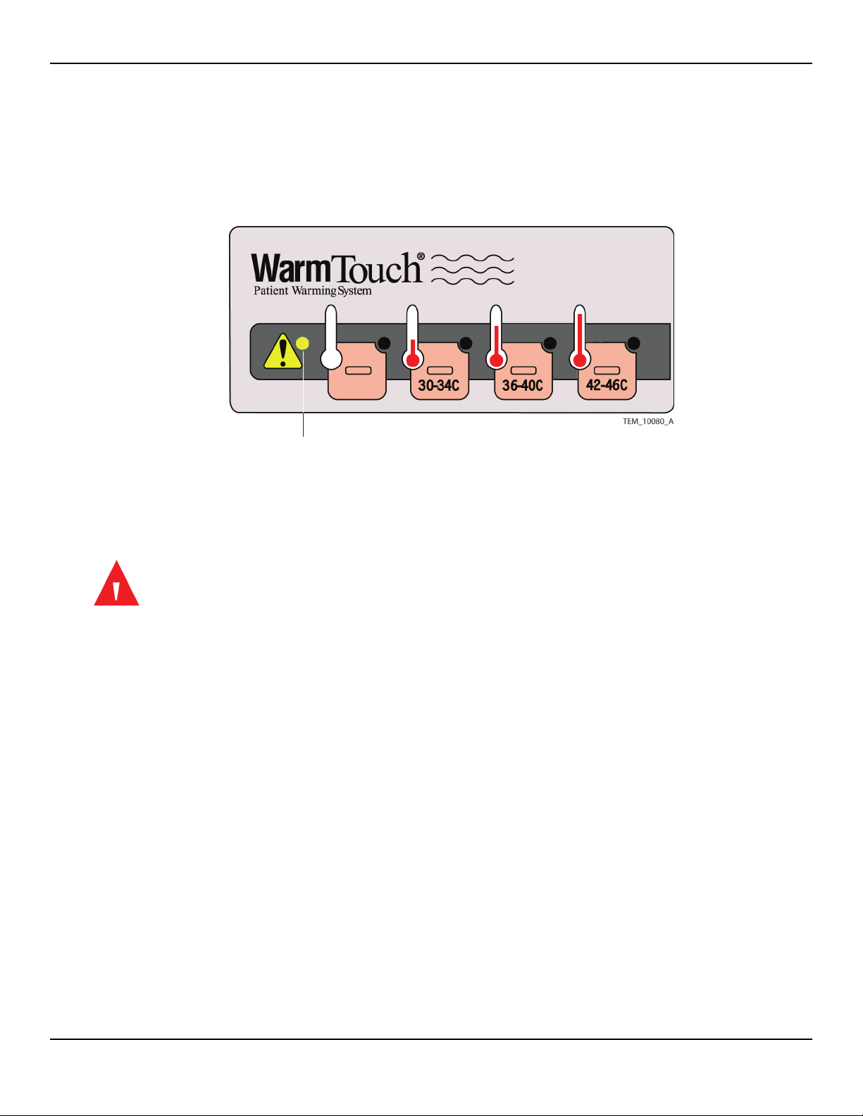
13. When the alarm starts to sound and the warning light indicator lights, stop
the stopwatch. See Figure 10.
Figure 10. Warning Light
14. Time elapsed on the stopwatch should be 5 minutes or less, and the
temperature monitor should not exceed 58ºC.
15. Turn off the warming system and unplug it.
WARNING
Possible patient injury. Connection of the jumper wire disables (shorts out)
the thermistor that is part of the temperature control system. The jumper
wire must be removed.
16. Remove the jumper wire from the over-temperature test port. See Figure 8.
17. Close the over-temperature test port and tighten the screw.
18. Disconnect the warming unit from the blanket.
19. Allow the warming unit to cool for 30 minutes before using it on a patient.
30 Service Manual
Page 31

Output Temperature Check
Output Temperature Check
This procedure measures the warming system output air temperature at the
input to the blanket. This procedure should be performed before returning
the warming system into service.
Calibration of the temperature control circuit is neither required nor possible.
If the test temperatures are outside the allowable range, factory service is
required. Contact your local Nellcor representative.
Table4.Equipment Required for Output Temperature Check
Equipment Description/Use
Temperature Probe Mon-a-Therm subcutaneous temperature probe, or
equivalent, and monitor with an accuracy of ±0.2ºC.
Tape To hold the temperature probe in place.
WarmTouch CareDrape™
Lower Body blanket
To complete patient warming system.
To check output temperature:
1. Lay the temperature probe alongside the warming unit nozzle at the end
of the hose and bend approximately 1.5 in (4 cm) of the temperature
probe into the nozzle opening.
2. Position the tip of the temperature probe so that it is approximately 1 to 2
in (2.5 to 5cm) inside the nozzle, centered in the nozzle opening.
3. Tape the probe in place.
4. Connect the probe to the temperature monitor.
5. Connect the nozzle to the blanket.
6. Extend the hose to match the configuration shown in Figure 11.
Service Manual 31
Page 32

Performance Verification
1 14 to 16 in (35.6 to 40.6 cm) 2 28 to 30 in (71.1 to 76.2 cm)
Figure 11. Output Temperature Test Setup
7. Turn on the warming system.
8. Select the Ambient temperature setting (Figure 12, item 1).
1 Ambient Temperature Select 3 Medium Temperature Select
2 Low Temperature Select 4 High Temperature Select
Figure 12. Temperature Selection
9. Allow the warming system to run for a few minutes at the Ambient
setting. The temperature monitor should indicate little to no change from
the ambient room air temperature.
10. Select the Low (30-34C) temperature setting (Figure 12, item 2).
11. Allow 8 to 10 minutes for the temperature to stabilize at the Low setting.
The temperature monitor should indicate 30ºC to 34ºC.
32 Service Manual
Page 33

12. Select the Medium (36-40C) temperature setting (Figure 12, item 3).
13. Allow 8 to 10 minutes for the temperature to stabilize at the Medium
setting. The temperature monitor should indicate 36ºC to 40ºC.
14. Select the High (42-46C) temperature setting (Figure 12, item 4).
15. Allow 8 to 10 minutes for the temperature to stabilize at the High setting.
The temperature monitor should indicate 42ºC to 46ºC.
16. Turn off the warming system and unplug it.
17. Disconnect the warming unit from the blanket.
18. Remove the temperature probe from the nozzle.
19. Allow the warming system to cool for 30 minutes before using it on a
patient.
Safety Tests
Safety Tests
The warming system is provided with a ground stud to allow safety testing
without opening the case. See Figure 13.
Figure 13. Ground Stud
Note:
Use applicable standards for institution and country. Test equipment and its
application must comply with the applicable standard.
To perform safety tests:
• Test ground integrity. See page 99 for test values.
• Test earth leakage current. See page 100 for test values.
• Test enclosure leakage current. See page 100 for test values.
Service Manual 33
Page 34

Performance Verification
Page Left Intentionally Blank
34 Service Manual
Page 35

1 Repair
Overview
This chapter provides procedures for servicing the WarmTouch™ Model WT5800 patient warming system.
WARNING
Before attempting to open or disassemble the warming system, disconnect
the power cord from the AC power source.
Caution
Observe ESD (electrostatic discharge) precautions when working within the warming
system.
Caution
Repairs to the warming system should only be accomplished by trained service
technicians.
Follow local government ordinances and recycling instructions regarding the disposal
of the warming system and/or parts.
Overview
Service Manual 35
Page 36

Repair
Filter Cover Assembly Replacement
Table5.Filter Cover Assembly Components
Qty Component
1 Filter cover
1 Bed hook
1 Foot, filter cover, short
4 Truss HD screws (8-32)
1 Gasket, WarmTouch
1 Operating instructions label
1 Grounding reliability label
Table6.Tools Required for Replacing FIlter Cover Assembly
Tool Parameter / Use
Phillips screwdriver #2 / Removing screws.
Torque driver 8 to 12 in/lbs (20 to 30 cm/kg)
Flat blade screwdriver Detaching filter cover from power cord.
To replace the filter cover assembly:
1. Unplug the warming system power cord from the AC outlet.
2. Lay the warming unit on its front side, so that the bottom of the unit is
visible.
36 Service Manual
Page 37

Filter Cover Assembly Replacement
3. Unwind the power cord from the filter cover. See Figure 14.
Figure 14. Power Cord
4. Unseat the power cord from the power cord routing bracket on the filter
cover. If necessary, use the head of the flat blade screwdriver to separate
the halves of the bracket sufficiently to allow unseating of the cord.
5. Disconnect the power cord connector from the warming unit.
6. Remove the filter cover screws. See Figure 15.
Figure 15. Filter Cover Screws
7. Remove the filter cover assembly from the warming unit.
Service Manual 37
Page 38

Repair
8. Place the replacement filter cover assembly on the warming unit and install
the screws. Tighten the screws to 8 to 12 in/lbs (20 to 30 cm/kg). See
Figure 15.
9. Reconnect the power cord to the warming unit. Ensure the connector is
fully inserted into the socket on the blower housing.
10. Reseat the power cord into the power cord routing bracket. If necessary,
use the head of the flat blade screwdriver to separate the halves of the
bracket sufficiently to allow reseating of the cord.
Separating the Front and Rear Covers
Table7.Tools Required for Separating Front and Rear Covers
Tool Parameter / Use
Phillips screwdriver #2 / Removing screws.
Flat blade screwdriver Detaching power cord from filter cover.
To separate the warming unit covers:
1. Unplug the warming system power cord from the AC outlet.
2. Lay the warming unit on its front side, so that the bottom of the unit is
visible.
3. Unwind the power cord from the filter cover. See Figure 16.
4. Unseat the power cord from the power cord routing bracket on the filter
cover. If necessary, use the head of the flat blade screwdriver to separate
the halves of the bracket sufficiently to allow unseating of the cord.
Figure 16. Power Cord
38 Service Manual
Page 39

Separating the Front and Rear Covers
5. Disconnect the power cord connector from the warming unit.
6. Remove the screws holding the front and rear covers together. See
Figure 17.
Figure 17. Cover Screw Locations
Caution
Separate the front and rear covers very carefully. Do not apply too much pressure
to the wires connecting the covers. They are short and easily damaged.
7. Carefully separate the front and rear covers. See Figure 18.
Figure 18. Separated Covers
Service Manual 39
Page 40

Repair
Rejoining the Front and Rear Covers
Caution
Ensure that the cable harness between the two covers is not pinched by the covers
when joining them back together.
To rejoin the warming unit covers:
1. Carefully align the covers and put them back together, placing the rear
cover atop the front cover so that the covers nest.
2. Install the screws through the holes in the rear cover to attach it to the
front cover. Tighten screws to 7 to 10 in/lbs (18 to 25 cm/kg). See
Figure 19.
Figure 19. Cover Screw Locations
3. Connect the power cord connector to the warming unit, making sure the
connector is fully inserted into the socket in the warming unit housing.
4. Reseat the power cord into the power cord routing bracket. If necessary,
use the head of the flat blade screwdriver to separate the halves of the
bracket sufficiently to allow reseating of the cord.
40 Service Manual
Page 41

Front Cover Assembly Replacement
Table8.Filter Cover Assembly Components
Qty Component
1 Front enclosure
1 Key pad
1 Lens
1 Ground symbol label
1 Cable tie mount
1 Cable clamp
1 Ground equipotential label
1 0.25 in (6.5 mm) hole for equipotential ground pin
Front Cover Assembly Replacement
Table9.Tools Required for Replacing Front Cover Assembly
Tool Parameters / Uses
Phillips screwdriver #2
Torque driver/wrench 4 to 12 in/lbs (10 to 30 cm/kg)
36 to 40 in/lbs (91 to 112 cm/kg)
Wire cutter Cutting cable ties.
Socket wrench 10 mm
Flat blade screwdriver Detaching power cord from filter cover.
Contact removal tool Souriau RX2025GE1 or equivalent
To replace the front cover assembly:
1. Separate the front and rear covers. See page 38, Separating the Front and
Rear Covers.
Service Manual 41
Page 42

Repair
2. Cut the cable harness bundle ties. See Figure 20.
Figure 20. Cable Harness Bundle Ties
3. Disconnect the 9-pin connector from the Control PCB (Figure 21, item 1).
1 9-Pin Connector 4 Cable Clamp
2 Equipotential Ground Terminal 5 Power Switch
3 AC Power Connector
Figure 21. Front Cover Assembly
42 Service Manual
Page 43

Front Cover Assembly Replacement
4. Disconnect the equipotential ground stud and remove it from the front
cover assembly (Figure 21, item 2).
5. Remove the AC power connector from the front cover assembly (Figure 21,
item 3).
6. Remove the cable clamp from the front cover assembly (Figure 21, item 4).
Caution
Write down the color code of each wire connected to the power switch. This will
ensure that the wires will be reconnected properly.
7. Disconnect the four wires from the power switch. See Figure 22.
8. Depress the four clips on the power switch and push the power switch
through its hole in the front cover assembly. See Figure 22.
Figure 22. Power Switch Clips and Wires
9. Cut the cable tie securing the thermistor cable to the front cover assembly
(Figure 23, item 1).
Figure 23. Cable Disconnect
Service Manual 43
Page 44

Repair
10. Remove the ground screw (Figure 23, item 2).
11. Cut the cable tie securing the thermistor cable connector (Figure 23, item
3) to the Control PCBA.
12. Disconnect the thermistor cable (Figure 23, item 3).
13. Disconnect the ribbon cable (Figure 23, item 4).
14. Remove the screws holding the Control PCB onto the front cover assembly.
Figure 24. Control PCB Screws
15. Carefully lift the Control PCB out of the front cover assembly.
16. Discard the old front cover assembly.
44 Service Manual
Page 45

Front Cover Assembly Replacement
Caution
Carefully align the lights on the Control PCB with the control panel key pad push
buttons. Failure to do so could damage the key pad or the Control PCB lights. See
Figure 25, items 1-5.
Figure 25. Control PCB Lights
17. Carefully place the Control PCB into the replacement front cover assembly
and install the mounting screws. Tighten the screws to 4 to 6 in/lbs (10 to
15 cm/kg). See Figure 26.
Figure 26. Control PCB Screws
Service Manual 45
Page 46

Repair
18. Connect the ribbon cable (Figure 27, item 4) to the Control PCBA.
Figure 27. Cable Connections
19. Connect the thermistor cable (Figure 27, item 3).
20. Install a cable tie around the thermistor cable connector (Figure 27, item 3)
and Control PCB connector to secure the thermistor cable to the PCBA.
21. Connect the keypad grounding strap and blower ground wire. See
Figure 27, item 2. Tighten the screw to 4 to 6 in/lbs (10 to 15 cm/kg).
22. Install a cable tie around the thermistor cable and the cable tie mount
(Figure 27, item 1) to secure the thermistor cable to the front cover.
23. Slide the power switch through its hole in the front of the front cover
assembly until the four clips on the power switch click into place. Ensure
that the “0”, marked on the front of the power switch, is towards the
bottom of the front cover assembly. See Figure 28.
Figure 28. Power Switch Clips and Wires
46 Service Manual
Page 47

Front Cover Assembly Replacement
24. Connect the four wires to the power switch. Make sure to reconnect the
wires in the same way they were connected before; refer to the list of wire
colors and where they were connected to the switch, as recorded in Step
7. See Figure 29, item 5.
Figure 29. Front Cover Assembly Component Locations
25. Install the cable clamp around the power switch cables. Tighten the screw
to 4 to 6 in/lbs (10 to 15 cm/kg. See Figure 29, item 4.
26. Install the AC power connector into the front cover assembly. Tighten
screws to 4 to 6 in/lbs (10 to 15 cm/kg). See Figure 29, item 3.
27. Install the equipotential ground (Figure 29, item 2) and attach ground wires
as shown in Figure 30. Tighten nuts to 36 to 44 in/lbs (91 to 112 cm/kg).
1 Blower Housing Ground 3 AC Power Connector Ground
2 Blower Motor Ground
Figure 30. Equipotential Ground Stud Wiring
Service Manual 47
Page 48

Repair
28. Connect the 9-pin connector to the Control PCB. See Figure 29, item 1.
29. Install the cable harness bundle ties. See Figure 31.
Figure 31. Cable Harness Bundle Ties
30. Rejoin the front and rear covers. See page 40, Rejoining the Front and Rear
Covers.
31. Perform the following checks/tests to verify proper operation of the
warming unit prior to returning it into service:
a. Power Fail / Start Alarm Check on page 27
b. Thermostat Protection Check on page 28
c. Output Temperature Check on page 31
d. Safety Tests on page 33
48 Service Manual
Page 49

Control PCBA Replacement
The replacement Control PCB (P/N GR100305) comes fully assembled.
Table10.Tools Required for Replacing Control PCB
Tool Parameter / Use
Phillips screwdriver #2 / Removing screws.
Torque driver 4 to 20 in/lbs (10 to 51 cm/kg)
Wire cutter Cutting cable ties and jumpers.
Flat blade screwdriver Detaching power cord from filter cover.
To replace the Control PCB assembly:
1. Separate the front and rear covers. See page 38, Separating the Front and
Rear Covers.
Control PCBA Replacement
2. Disconnect the 9-pin connector from the Control PCB (Figure 32, item 1).
1 9-pin Connector 3 Keypad Ribbon Cable Connector
2 Keypad and Blower Ground 4 Thermistor Cable Connector
Figure 32. Control PCB Connections
3. Cut the cable tie securing the thermistor cable connector (Figure 32, item
4) to the Control PCBA.
Service Manual 49
Page 50

Repair
4. Disconnect the thermistor cable.
5. Disconnect the ribbon cable (Figure 32, item 3).
6. Remove the screws holding the Control PCB onto the front cover assembly.
Figure 33. Control PCB Screws
7. Carefully lift the Control PCB out of the front cover assembly.
Caution
Carefully align the lights on the Control PCB with the control panel key pad push
buttons. Failure to do so could damage the key pad or the Control PCB lights. See
Figure 34, items 1-5.
Figure 34. Control PCB Lights
50 Service Manual
Page 51

Control PCBA Replacement
8. Carefully place the replacement Control PCB into the front cover assembly
and install the mounting screws. Tighten the screws to 4 to 6 in/lbs (10 to
15 cm/kg. See Figure 35.
Figure 35. Control PCB Screws
9. Connect the ribbon cable (Figure 36, item 3).
Figure 36. Cable Connections
10. Connect the thermistor cable.
Service Manual 51
Page 52

Repair
11. Install a cable tie around the thermistor cable connector (Figure 36, item 4)
and Control PCB connector to secure the thermistor cable to the PCBA.
12. Connect the 9-pin connector to the Control PCB (Figure 36, item 1).
13. Install the cable harness bundle ties. See Figure 37, item 1.
Figure 37. Cable Harness Bundle Ties
14. Rejoin the front and rear covers. See page 40, Rejoining the Front and Rear
Covers.
15. Perform the following checks/tests to verify proper operation of the
warming unit prior to returning it into service:
a. Power Fail / Start Alarm Check on page 27
b. Thermostat Protection Check on page 28
c. Output Temperature Check on page 31
d. Safety Tests on page 33
52 Service Manual
Page 53

Heater Assembly Replacement
Table11.Heater Assembly Components
Qty Component
1 Heater, 230V
2 Pins, 16-18 GA, 13 A
Table12.Tools Required for Replacing Heater Assembly
Tool Parameter / Use
Phillips screwdriver #2 / Removing screws
Wire cutter Cutting cable ties
Socket 10 mm
Contact removal tool Souriau RX2025GE1 or equivalent
Heater Assembly Replacement
Torque driver/wrench 4 to 12 in/lbs (10 to 30 cm/kg)
36 to 44 in/lbs (91 to 112 cm/kg)
Flat blade screwdriver Detaching power cord from filter cover
To replace the heater assembly:
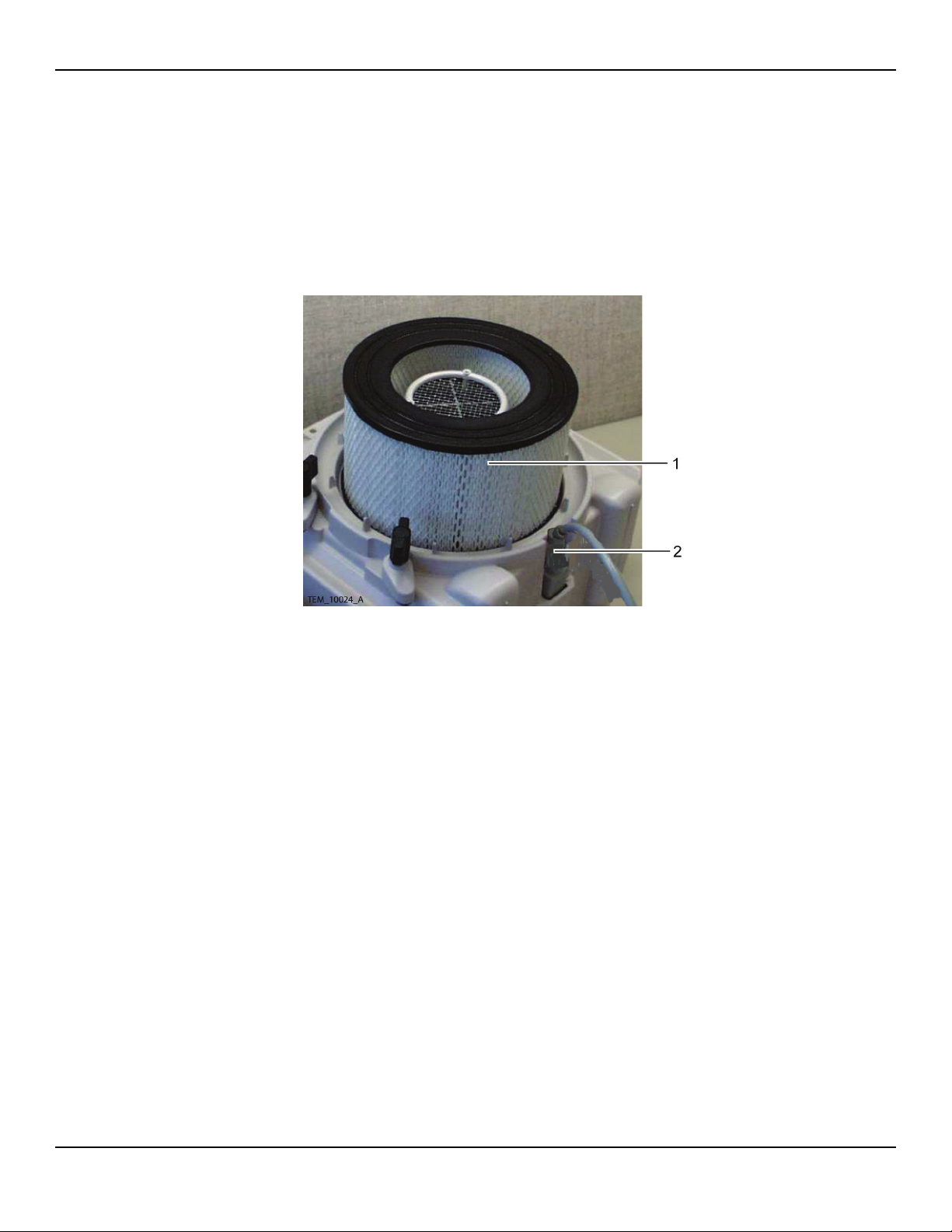
1. Remove the filter cover assembly from the rear cover assembly. See page
36, Filter Cover Assembly Replacement.
2. Remove the filter from the rear cover assembly. See Figure 38, item 1.
Figure 38. Filter Removal
Service Manual 53
Page 54

Repair
Note:
The blower assembly is attached to the rear cover assembly by four screws and four
clips. It is easier for two people to release the clips and lift the blower assembly from
the rear cover assembly.
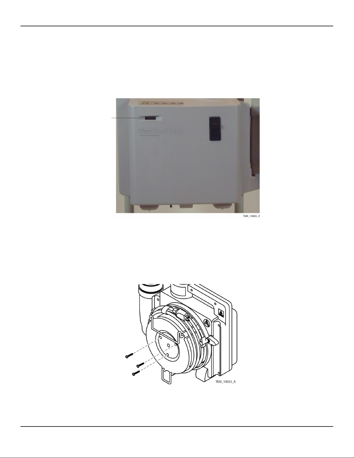
3. Remove the screws holding the blower assembly to the rear cover
assembly. See Figure 39.
Figure 39. Blower Assembly Screws
4. Separate the front and rear covers. See page 38, Separating the Front and
Rear Covers.
5. Cut the cable harness bundle ties. See Figure 40, items 1 and 2.
Figure 40. Cable Harness Bundle Ties
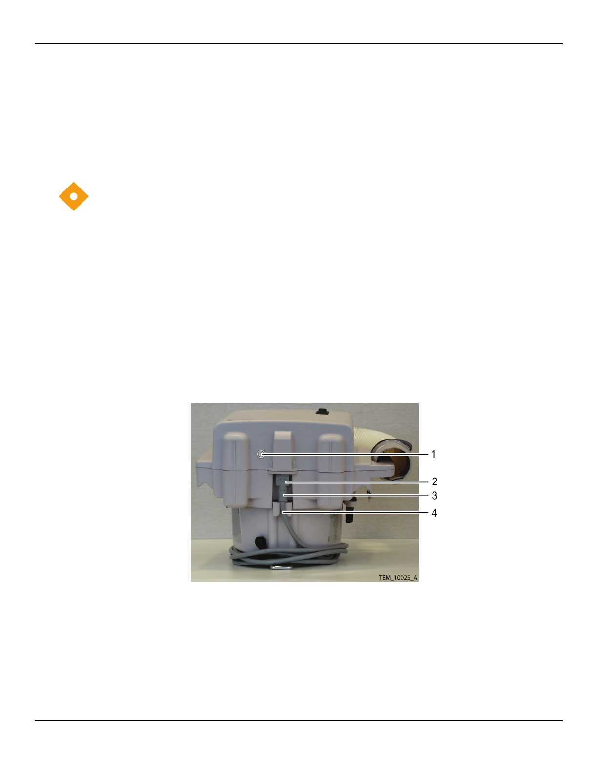
6. Disconnect the 9-pin connector from the Control PCB. See Figure 41, item 1.
54 Service Manual
Page 55

Heater Assembly Replacement
Note:
During the remainder of this procedure, make sure not to apply excessive pressure to
the wires still connected between the separated halves of the warming unit.
1 9-Pin Connector 4 Cable Clamp
2 Equipotential Ground Terminal 5 Power Switch
3 AC Power Connector
Figure 41. Front Cover Assembly
Caution
Care must be taken when moving the duct adapter. The thermistor connection to the
duct adaptor is fragile and will become disconnected if too much pressure is applied
to it.
Service Manual 55
Page 56

Repair
7. Carefully lift the duct adapter and lay the duct adapter on the rear cover
handle. See Figure 42.
1 Duct Adapter 2 Thermistor Connection
Figure 42. Duct Adapter Placement
56 Service Manual
Page 57

Heater Assembly Replacement
8. Rotate the blower motor assembly clockwise to disengage two of the four
clips. See Figure 43 and Figure 44.
Figure 43. Blower Motor Removal
Figure 44. Blower Assembly Clips
9. Slide the blower motor assembly away from the engaged clips to
disengage them.
Service Manual 57
Page 58

Repair
10. Lay the blower motor assembly beside the rear cover assembly. Do not
overstress the connecting wires.
11. Remove the rubber gasket from the rear cover assembly.
Figure 45. Rubber Gasket
Caution
Do not touch the heater coil. Body oil can damage the heater coil when it is in use.
12. Lift the heater assembly (Figure 46, item 1) out of the rear cover assembly.
Figure 46. Heater Assembly
58 Service Manual
Page 59

Heater Assembly Replacement
Note:
For the next four steps, use a Souriau RX2025GE1 contact removal tool or equivalent.
13. Remove the black wire and pin (Figure 46, item 3) from pin 2 of the 9-pin
connector (Figure 46, item 5).
14. Remove the red wire (may be white in some assemblies) and pin (Figure 46,
item 2) from pin 8 of the 9-pin connector (Figure 46, item 4).
15. Install the red (or white) wire and pin from the new heater into pin 8 of the
9-pin connector.
16. Install the black wire and pin from the new heater into pin 2 of the 9-pin
connector.
Note:
Ensure that the heater thermostat (Figure 47, item 3) is oriented upward when
reinstalling the heater in the rear cover assembly.
17. Slide the new heater into the rear cover assembly. See Figure 47.
1 Heater Assembly (removed) 3 Heater Assembly (in place)
2 Rear Panel Assembly 4 Heater Wire Cutouts
Figure 47. Heater Assembly Installation
18. Orient the heater so that the heater thermostat (Figure 47, item 3) is
nearest the rear cover assembly handle (Figure 47, item 2).
19. Route the wires from the heater through the cut-outs in the rear cover
assembly (Figure 47, item 4).
Service Manual 59
Page 60

Repair
20. Place the rubber gasket into the rear cover assembly, with the wire
indentations over the heater wires. See Figure 48, item 1.
Figure 48. Rubber Gasket
21. Place the blower assembly into the rear cover assembly and ensure that the
blower assembly clips (shown in Figure 49) attach over the edges of the
blower assembly.
Figure 49. Blower Assembly Clips
60 Service Manual
Page 61

Heater Assembly Replacement
Caution
Exercise caution when moving the duct adapter. Do not apply excessive pressure, as
the thermistor connection to the duct adaptor is fragile and can easily become
disconnected.
22. Carefully reinsert the duct adapter into the blower assembly. See Figure 50.
1 Duct Adapter 2 Thermistor Connection
Figure 50. Duct Adapter Placement
Note:
If the rivet holding the thermistor in place in the duct is loose or pulled out entirely,
follow the instructions in the Duct Adapter Assembly Replacement section (page 66)
to reseat the thermistor.
Service Manual 61
Page 62

Repair
23. Install the blower assembly mounting screws into the rear cover assembly.
Tighten the screws to 4 to 6 in/lbs (10 to 15 cm/kg).
Figure 51. Blower Assembly Screws
24. Connect the 9-pin connector to the Control PCB. See Figure 41, item 1.
25. Install the cable harness bundle ties. See Figure 52, items 1 and 2.
Figure 52. Cable Harness Bundle Ties
26. Rejoin the front and rear covers. See page 40, Rejoining the Front and Rear
Covers, steps 1 and 2.
62 Service Manual
Page 63

27. Place the filter into the rear cover assembly.
Figure 53. Filter Installation
Heater Assembly Replacement
28. Install the filter cover assembly on the rear cover assembly. Tighten the
screws to 8 to 12 in/lbs (20 to 30 cm/kg). See Figure 54.
Figure 54. Filter Cover Installation
29. Install the power cord on the warming system, inserting the female
connector into its socket on the warming system housing, and seating the
cord in the routing bracket on the filter cover. If necessary, use the head of
a flat blade screwdriver to separate the halves of the routing bracket
sufficiently to allow seating of the cord.
Service Manual 63
Page 64

Repair
30. Perform the following checks/tests to verify proper operation of the
warming unit prior to returning it into service:
a. Power Fail / Start Alarm Check on page 27
b.
Thermostat Protection Check on page 28
c. Output Temperature Check on page 31
Safety Tests on page 33
d.
Hose Replacement
Table13.Hose Assembly Components
Qty Component
1 Hose
1 Nozzle Strap with Clip
Table14.Tools Required for Replacing Hose Assembly
Tool Parameter / Use
Wire cutter Cutting reinforcing wire
Pliers Bending reinforcing wire
Note:
If the warming system hose is damaged, contact your local Nellcor representative to
obtain a replacement hose. The hose for the warming system is made of plastic
reinforced with wire.
Caution
Only qualified service technicians should replace the hose.
To replace the hose:
1. Separate the front and rear covers. See page 38, Separating the Front and
Rear Covers.
2. Locate the end of the hose on the duct adapter.
64 Service Manual
Page 65

3. Find the end of the hose’s reinforcing wire that is inserted into the locking
hole in the duct adapter (Figure 55, item 1). Straighten the end of the wire
and pull it out of the locking hole.
Hose Replacement
Figure 55. Hose Attachment
4. Turn the hose counterclockwise to unscrew it from the duct adapter.
5. On the replacement hose, trim the end of the reinforcing wire that is free
of the hose material so that approximately 5/8” remains.
6. At a point 1/2” from its free end, bend the wire 90 degrees, so it is
perpendicular to the edge of the hose.
7. Put the end of the replacement hose onto the duct adapter.
8. Turn the hose clockwise to screw it onto the duct adapter, until the bent
end of the reinforcing wire is aligned with and can easily be placed into the
locking hole.
9. Hook the end of the wire through the locking hole, then bend it to secure
the hose in place. (See Figure 55.)
10. Remove the nozzle from the end of the old hose and install it onto the free
end of the replacement hose. Refer to page 25, Nozzle Replacement.
11. Remove the blanket clip from the old hose and slide it over the nozzle onto
the replacement hose.
12. Rejoin the front and rear covers. See page 40, Rejoining the Front and Rear
Covers.
Service Manual 65
Page 66

Repair
13. Perform the following checks/tests to verify proper operation of the
warming unit prior to returning it into service:
• Power Fail / Start Alarm Check on page 27
• Thermostat Protection Check on page 28
• Output Temperature Check on page 31
• Safety Tests on page 33
Duct Adapter Assembly Replacement
Table15.Duct Adapter Assembly Components
Qty Component
1 Duct Adapter
2 Screen
Table16.Tools Required for Replacing Duct Adapter Assembly
Tool Parameter / Use
Phillips screwdriver #2 / Removing screws
Wire cutter Cutting cable ties
Knife Removal of silicone RTV
Silicone RTV Thermistor connection
Torque driver/wrench 7 to 12 in/lbs (18 to 30 cm/kg)
Flat blade screwdriver Detaching power cord from filter cover
Removing thermostat rivets
Needlenose pliers Removing thermostat rivets
To replace the duct adapter assembly:
1. Separate the front and rear covers. See page 38, Separating the Front and
Rear Covers.
Caution
The thermistor is very delicate and easily damaged. Use extreme care when handling,
removing, or replacing the thermistor.
66 Service Manual
Page 67

Duct Adapter Assembly Replacement
2. Remove the silicone RTV from the thermistor connection on the duct
adapter assembly. See Figure 56.
Figure 56. Thermistor Silicone
3. Carefully detach the thermistor rivet (Figure 57, item 3) and slide the
thermistor (Figure 57, item 2) out of the duct adapter assembly.
Figure 57. Thermistor Removal
4. Detach the wires from the two thermostats on the side of the duct
transition. Leave the jumper wire connecting the two thermostats
(Figure 57, item 1) in place.
Service Manual 67
Page 68

Repair
5. Lift the duct adapter assembly out of the rear cover assembly. See
Figure 58, item 1.
Figure 58. Duct Adapter Removal
6. Using the flat blade screwdriver, reach inside the duct and push the locking
pin on each of the plastic rivets holding the thermostats in place
downward, so that the pins are flush with the surface of the rivet.
7. Outside the duct, use the needlenose pliers to pull each locking pin
upward (out from the duct) until the rivet is loose and pulls free from the
duct. Save the rivets and their locking pins.
8. Line up the holes in the thermostat mounting flanges with the holes in the
replacement duct.
9. Reinstall the plastic rivets, pushing them through the holes in the
thermostat mounting flanges into the holes in the replacement duct.
Outside the duct, use the flat blade screwdriver to push the locking pins on
the rivets inward so that they are flush with the tops of the rivets.
10. Connect the two wires previously attached to the old duct adapter onto
the replacement duct adapter, connecting them to the same connection
points.
68 Service Manual
Page 69

Duct Adapter Assembly Replacement
11. Slide the new duct adapter assembly into the blower housing.
Figure 59. Duct Adapter Placement
Caution
The thermistor is very delicate and easily damaged. Use extreme care when handling,
removing or replacing the thermistor.
12. Carefully reinsert the thermistor into the duct adapter assembly. See
Figure 57, item 1.
Note:
Position the thermistor as shown.
Figure 60. Thermistor Position Within Duct Adapter
Service Manual 69
Page 70

Repair
13. Apply a small amount of silicone RTV to the thermistor rivet cap and the
adapter housing. See Figure 56.
14. Rejoin the front and rear covers. See page 40, Rejoining the Front and Rear
Covers.
15. Perform the following checks/tests to verify proper operation of the
warming unit prior to returning it into service:
a. Power Fail / Start Alarm Check on page 27
b. Thermostat Protection Check on page 28
Output Temperature Check on page 31
c.
d.
Safety Tests on page 33
70 Service Manual
Page 71

Rear Cover Assembly Replacement
Table17.Rear Cover Assembly Components
Qty Component
1 Rear Enclosure
1 Cable Clamp
1 Cable Tie
3 Lag Bolts, 3¼
1 Test Cover
1 Screw
1 Heater Cone Insert
1 Heater Screen
Rear Cover Assembly Replacement
1 Attention Label
3 Knob, IV Pole Clamp
3 IV Pole Clamp Assembly
Table18.Tools Required for Replacing Rear Cover Assembly
Tool Parameter / Use
Phillips screwdriver #2 / Removing screws
Wire cutter Cutting cable ties
Socket 10 mm
Torque driver/wrench 4 to 12 in/lbs (10 to 30 cm/kg)
36 to 44 in/lbs (91 to 112 cm/kg)
Flat blade screwdriver Detaching power cord from filter cover
To replace the rear cover assembly:
1. Unplug the warming system power cord from the AC outlet.
2. Lay the warming unit on its front side, so that the bottom of the unit is
visible.
Service Manual 71
Page 72

Repair
3. Remove the filter cover screws from the warming unit. See Figure 61.
Figure 61. Filter Cover Screws
4. Unseat the power cord from the power cord routing bracket on the filter
cover. If necessary, use the head of the flat blade screwdriver to separate
the halves of the bracket sufficiently to allow unseating of the cord.
5. Disconnect the power cord connector from the warming unit.
6. Remove the filter cover assembly from the warming unit.
7. Remove the filter from the rear cover assembly. See Figure 62.
Figure 62. Filter Removal
8. Separate the front and rear covers. See page 38, Separating the Front and
Rear Covers.
72 Service Manual
Page 73

Rear Cover Assembly Replacement
Note:
Perform steps 9 through 18 if complete separation of the front and rear halves of the
unit is desired or necessary. Otherwise, skip to step 19.
9. Cut the two cable bundle ties. See Figure 63, items 1 and 2.
Figure 63. Separated Covers
10. Disconnect the 9-pin connector from the Control PCB (Figure 64, item 1).
1 9-Pin Connector 4 Cable Clamp
2 Equipotential Ground Terminal 5 Power Switch
3 AC Power Connector
Figure 64. Front Cover Assembly
11. Disconnect the wires from the equipotential ground stud (Figure 64, item 2).
Service Manual 73
Page 74

Repair
12. Remove the AC power connector from the front cover assembly (Figure 64,
item 3).
13. Remove the cable clamp from the front cover assembly (Figure 64, item 4).
Caution
Write down the color code of each wire connected to the power switch. This will
ensure that the wires will be reconnected properly.
14. Disconnect the four wires from the power switch (Figure 64, item 5).
15. Cut the cable tie securing the thermistor cable to the front cover assembly
(Figure 65, item 1).
Figure 65. Cable Disconnect
16. Remove the ground screw. See Figure 65, item 2.
17. Disconnect the thermistor cable connector. See Figure 65, item 3.
18. Place the front cover assembly in a safe place.
Caution
The thermistor is very delicate and easily damaged. Use extreme care when handling,
removing or replacing the thermistor.
74 Service Manual
Page 75

Rear Cover Assembly Replacement
19. Remove the thermistor cable terminal board (Figure 66, item 2).
Figure 66. Thermistor Cable Removal
20. Cut the cable tie securing the thermistor cable to the rear cover assembly
(Figure 66, item 1).
Note:
The blower assembly is held onto the rear cover assembly by four screws and four
clips. It is easier for two people to release the clips and lift the blower assembly from
the rear cover assembly.
21. Remove the screws holding the blower assembly to the rear cover
assembly. See Figure 67.
Figure 67. Blower Assembly Screws
Service Manual 75
Page 76

Repair
22. Loosen the nut holding the capacitor to the rear cover assembly. See
Figure 68.
Figure 68. Blower Capacitor
23. Cut the cable tie and lift the capacitor free of the rear cover assembly.
Note:
The thermistor cable is fragile. When handling the adapter duct, apply as little
tension as possible to the thermistor cable to avoid damaging wires or its mechanical
connection to the duct.
24. Carefully pull the adapter duct up to remove it from the blower outlet.
Take care not to pull the thermistor cable out of the adapter duct when
removing the duct from the outlet.
25. Rotate the blower motor assembly clockwise to disengage two of the four
clips. See Figure 69 and Figure 70.
Figure 69. Blower Motor Removal
76 Service Manual
Page 77

Figure 70. Blower Assembly Clips
Rear Cover Assembly Replacement
26. Slide the blower motor assembly away from the engaged clips to
disengage them.
27. Remove the rubber gasket from the rear cover assembly.
Figure 71. Rubber Gasket
Caution
Do not touch the heater coil. Body oil can cause damage to the heater coil when it is
in use.
Service Manual 77
Page 78

Repair
28. Lift the heater assembly (Figure 72, item 1) out of the rear cover assembly.
Figure 72. Heater Assembly
29. Discard the old rear cover assembly, including the heater cone insert,
heater screen, and mounting clamps.
Note:
Ensure that the heater temperature sensor (Figure 73, item 1) is oriented upward
when installing the heater in the replacement rear cover assembly.
30. Slide the heater into the replacement rear cover assembly (see Figure 73).
Figure 73. Heater Assembly Installation
78 Service Manual
Page 79

Rear Cover Assembly Replacement
31. Route the wires from the heater through the cut-outs in the rear cover
assembly. See Figure 73, item 4.
32. Place the rubber gasket into the rear cover assembly
, with the wire
indentations over the heater wires. See Figure 74, item 1.
Figure 74. Rubber Gasket
33. Place the blower assembly into the rear cover assembly and ensure that the
blower assembly clips (shown in Figure 75) attach over the edges of the
blower assembly.
Figure 75. Blower Installation
Service Manual 79
Page 80

Repair
Note:
The thermistor cable is fragile. When handling the adapter duct, apply as little
tension as possible to the thermistor cable to avoid damaging wires or its mechanical
connection to the duct.
34. Carefully place the square end of the adapter duct into the blower outlet and
snap the duct into place, taking care not to damage the thermistor cable.
35. Install the blower assembly mounting screws into the rear cover assembly.
Tighten the screws to 4 to 6 in/lbs (10 to 15 cm/kg). See Figure 76.
Figure 76. Blower Screws
36. Install the thermistor cable terminal board (Figure 77, item 2). Tighten the
screw to 4 to 6 in/lbs (10 to 15 cm/kg).
Figure 77. Thermistor Cable Installation
37. Install a cable tie around the thermistor cable and the cable tie mount on
the rear cover assembly (Figure 77, item 1).
80 Service Manual
Page 81

Rear Cover Assembly Replacement
Caution
Do not overtighten the capacitor nut. Overtightening the capacitor nut will cause the
plastic rib to crack.
38. Install the capacitor in the rear cover assembly and tighten the nut to 7 to
10 in/lbs (18 to 25 cm/kg). See Figure 78.
Figure 78. Capacitor Installation
39. Install the cable tie around the capacitor. See Figure 78.
Note:
Perform steps 40 through 49 only if steps 9 through 18 were performed earlier, and
the front and rear halves of the warming system have been completely detached
from each other. If steps 9 through 18 were not performed, skip to step 50.
40. Connect the thermistor cable to the Control PCB.
Figure 79. Cable Connections
Service Manual 81
Page 82

Repair
41. Install a cable tie around the thermistor cable connector (Figure 79, item 3)
and Control PCB connector to secure the thermistor cable to the PCBA.
42. Connect the key pad ground strap and the blower ground wire (Figure 79,
item 2). Tighten the screw to 4 to 6 in/lbs (10 to 15 cm/kg).
43. Install a cable tie around the thermistor cable and the cable tie mount
(Figure 79, item 1) to secure the thermistor cable to the front cover.
44. Connect the four wires to the power switch. Make sure to reconnect the
wires in the same way they were connected before; refer to the list of wire
colors and where they were connected to the switch, as recorded in Step
14. See Figure 80, item 5.
Figure 80. Front Cover Assembly
45. Install the cable clamp around the power switch wires (Figure 80, item 4).
46. Install the AC power connector into the front cover assembly. Tighten the
screws to 4 to 6 in/lbs (10 to 15 cm/kg). See Figure 80, item 3.
47. Connect the 9-pin connector to the Control PCB (Figure 80, item 1).
82 Service Manual
Page 83

Rear Cover Assembly Replacement
48. Connect the ground wires to the equipotential ground stud (Figure 80,
item 2) in the order shown in Figure 81. Tighten the nuts to 36 to 44 in/lbs
(91 to 112 cm/kg).
1 Blower Housing Ground 3 AC Power Connector Ground
2 Blower Motor Ground
Figure 81. Equipotential Ground Stud Wiring
49. Install the cable harness bundle ties. See Figure 82, items 1 and 2.
Figure 82. Cable Harness Bundle Ties
50. Rejoin the front and rear covers. See page 40, Rejoining the Front and Rear
Covers.
Service Manual 83
Page 84

Repair
51. Place the filter into the rear cover assembly.
Figure 83. Filter Installation
52. Install the filter cover assembly on the rear cover assembly. Tighten the
screws to 8 to 12 in/lbs (20 to 30 cm/kg). See Figure 84.
Figure 84. Filter Cover Installation
53. Install the power cord on the warming system, inserting the female
connector into its socket on the warming system housing, and seating the
cord in the routing bracket on the filter cover. If necessary, use the head of
a flat blade screwdriver to separate the halves of the routing bracket
sufficiently to allow seating of the cord.
84 Service Manual
Page 85

Rear Cover Assembly Replacement
54. Perform the following checks/tests to verify proper operation of the
warming system prior to returning it into service:
• Power Fail / Start Alarm Check on page 27
• Thermostat Protection Check on page 28
• Output Temperature Check on page 31
• Safety Tests on page 33
Service Manual 85
Page 86

Repair
Page Left Intentionally Blank
86 Service Manual
Page 87

1 Spare Parts & Accessories
Overview
This chapter provides information on spare parts and accessories for the
WarmTouch™ Model WT-5800 patient warming system, as well as how to
order them.
Ordering Information
The warming system and blankets may be ordered from Nellcor Technical
Services (1.800.635.5267) or your local representative.
Overview
Service Manual 87
Page 88

Spare Parts & Accessories
Table19.Spare Parts and Accessories
Item
Description
AC Inlet / EMI Filter 20 SP10001335
AC Power Switch / Breaker 23 SP169-1801
Blower Assembly, 230V 18 SP10034565
Cart 3 5022900
Connector Assembly 15 168-1202SP
Control Panel 13 SP169-1202
Duct Adapter Assembly 17 168-0205SP
Filter Cover Assembly 8 168-0202SP23
Front Cover Assembly 2 2 168-0201SP2
Fuse, 0.32 amps 21 169-5800
Heater Assembly 19 168-5803SP
HEPA Filter 9 502-2200
Hose 1 502-2000
I.V. Clamp and Foot 4 168-0203SP
Number
Figure 85
Item
Number
Figure 86 Part Number
I.V. Clamp Knob 5 168-2005SP
Nozzle 11 502-2100
Nozzle Strap with Clip 12 SP312-0070
PCB, 5800 WT 22 GR100305
Power Cord (EU) 7 502-2500
Power Cord (UK) 7 901518CI
Rear Cover Assembly 6 6 168-0200SP23
Strap, Hook and Loop 10 168-2023
Thermostat, Disc 50° 2EA 16 SP168-0220
Thermistor Assembly 14 SP169-0211
88 Service Manual
Page 89

Ordering Information
Figure 85. Spare Parts (Sheet 1)
Service Manual 89
Page 90

Spare Parts & Accessories
Figure 86. Spare Parts (Sheet 2)
Replacement Parts and Accessories
Warming system replacement parts and accessories are listed on the Internet at:
http://www.nellcor.com/serv/GenParts.aspx
Manual Availability
The most recent revision of this manual is available on the Internet at:
http://www.nellcor.com/serv/manuals.aspx
90 Service Manual
Page 91

1 Packing for Shipment
Overview
To ship the WarmTouch™ Model WT-5800 patient warming system for any
reason, follow the instructions in this chapter.
Returning the Warming Unit
Prior to shipping the warming unit, contact Nellcor Technical Services or your
local Nellcor representative for shipping instructions, including a Returned
Goods Authorization (RGA) number. Mark the shipping carton and any
shipping documents with the RGA number.
Overview
Return the warming unit by any shipping method that provides proof of
delivery.
If possible, ship the warming unit in its original shipping carton. If the original
carton is not available, use a suitable carton with appropriate packing material
to protect the warming unit during shipping. North American customers may
also contact the Nellcor Technical Services Department to obtain a
replacement shipping carton.
Pack the warming unit carefully. Failure to follow the packing instructions in
this section may result in loss or damage not covered by any applicable Nellcor
warranty.
Repacking in Original Carton
If available, use the original carton and packing materials. See Figure 87.
Note:
Use tape or staples on the packing inserts to ensure they retain their form.
Service Manual 91
Page 92

Packing for Shipment
Figure 87. Packing the Warming Unit in Original Carton
92 Service Manual
Page 93

Repacking in a Different Carton
To pack the warming unit (refer to Figure 87):
1. Place the full length insert (item 3) into the box (item 4), with the wide side
gap on the right.
2. Slide the base support insert (item 6) into the bottom of the box, with the
ribs facing up.
3. Make sure the warming unit (item 2) is mounted onto the cart (item 5).
Refer to the WT-5800 Patient Warming System Operator’s Manual for
details.
4. Slide the warming unit and cart into the box, with the handle to the rear
and the bottom of the cart frame resting on the base support insert.
5. Place the hose insert (item 1) over the warming unit, with the wide flange
on the right side and the shallow cutout resting against the hose outlet.
6. Route the collapsed hose from the blower and set the nozzle end (item 7)
into the two deep cutouts in the hose insert. The nozzle should be in the
lower of the two cutouts, above the cart base.
7. Seal carton with packing tape.
8. Label carton with shipping address, return address, and RGA number.
Repacking in a Different Carton
If the original carton is not available, use the following procedure to pack the
warming unit:
1. Locate a corrugated cardboard shipping carton with a bursting strength of
at least 200 pounds per square inch (psi).
2. Fill the bottom of the carton with at least 2 inches of packing material.
3. Place the warming unit on the layer of packing material and fill the box
completely with packing material.
4. Seal carton with packing tape.
5. Label carton with the shipping address, return address, and RGA number.
Service Manual 93
Page 94

Packing for Shipment
Page Left Intentionally Blank
94 Service Manual
Page 95

1 Specifications
Overview
This chapter contains physical and operating specifications for the
WarmTouch™ Model WT-5800 patient warming system.
Warming System Specifications
No special transport or storage methods are required for the WarmTouch™
Model WT-5800 patient warming system.
Overview
Table20.System Specifications
Warming Blanket Specifications
Maximum blanket surface temperature 44
Blower Specifications
Dimensions 38 cm x 41 cm x 28 cm
Weight 6.8 kgs (15 lbs.)
Power Requirements 220 - 230 VAC, 50 - 60 Hz, 6 A
Automatic Temperature Stepdown (Boost to
High Temperature)
Power Supply Cord 4.26 m (14 feet)
Thermal Protection Thermostat (internal): 47
Ambient Blower Operating Temperature Range 18
Over Temperature Alarm Level 65 dB at 3 meters
Protection Against Ingress of Fluids Ordinary
Cart Specifications
Weight 3.1 kg (6.8 pounds)
°C
(15 inches x 16 inches x 11 inches)
After 45 minutes of continuous use blower will
step down from High to Medium setting.
°C - 50°C
(117
°F - 122°F)
°C - 28°C (64.4°F - 82.4°F)
Height 67.1 cm (26.4 inches)
Width 32.3 cm (12.7 inches)
Depth 38.6 cm (15.2 inches)
Service Manual 95
Page 96

Specifications
Transport and Shipping in Shipping Container
Table21.Shipping Container Specifications
Temperature -40ºC to 70ºC (-40ºF to 158ºF)
Altitude -390 m to 6,096 m (-1,280 ft. to 20,000 ft.)
Barometric Pressure 500 hPa to 1,060 hPa (375 mmHg to 795 mmHg)
Relative Humidity 15% to 95% (non-condensing)
Compliance
Table22.Compliance Standards
Item Compliant With
Equipment classification IEC/EN 60601-1 2nd edition
CSA C22.2 No. 601.1 M90
UL 60601-1 1st edition
IEC 60601-2-35: 1996
EN 60601-2-35: 1997
Type of protection Class I (on AC power)
Degree of protection Type BF - Applied part
Mode of operation Continuous
Electromagnetic Compatibility IEC/EN 60601-1-2 3rd edition
Manufacturer’s Declaration
WARNING
The use of accessories and cables other than those specified may result in
increased emission and/or decreased immunity of the warming system.
The warming system is suitable for use in the specified electromagnetic
environment. The customer and/or user of the warming system should ensure
it is used in the prescribed electromagnetic environment.
96 Service Manual
Page 97

Electromagnetic Compatibility (EMC)
Electromagnetic Compatibility (EMC)
Electromagnetic Emissions
Table23.Electromagnetic Emissions Guidelines
Emissions Test Compliance Electromagnetic Environment Guidance
RF emission
CISPR 11
Harmonic emissions
IEC/EN 61000-3-2
Voltage fluctuation/
flicker emissions
IEC/EN 61000-3-3
Group 1,
Class A
N/A The warming system is suitable for use in all
N/A
This is a class A product per IEC CISPR 11 and is
not intended to be used in a residential
environment. If used in a domestic
environment, this equipment may not offer
adequate protection to radio-frequency
communication services. The user may be
required to take mitigation measures, such as
relocating or re-orienting the equipment.
establishments other than domestic and those
directly connected to the public low-voltage
power supply network that supplies buildings
used for domestic purposes.
Electromagnetic Immunity
These guidelines may not apply in all situations. Electromagnetic propagation
is affected by absorption and reflection from structures, objects, and people.
Table24.Electromagnetic Immunity Guidelines
Immunity Test
EN 60601-1-2
Test Level Compliance Level
Electromagnetic Environment
Guidance
Electrostatic
discharge (ESD)
IEC/EN 61000-4-2
Electric fast
transient/burst
IEC/EN 61000-4-4
Service Manual 97
±6 kV contact
±8 kV air
±2 kV for power
supply lines
±1 kV for input/
output lines
±6 kV contact
±8 kV air
±2 kV for power
supply lines
±1 kV for input/
output lines
Floor should be wood, concrete, or
ceramic tile. If floors are covered
with synthetic material, the relative
humidity should be at least 30%.
Mains power quality should be
that of a typical commercial and/or
hospital environment.
Page 98

Specifications
Table24.Electromagnetic Immunity Guidelines (Continued)
Immunity Test
Surge
IEC/EN 61000-4-5
Voltage dips, short
interruptions and
voltage variations
on power supply
IEC/EN 61000-4-11
Power frequency
(50/60 Hz) magnetic
field
IEC/EN 61000-4-8
EN 60601-1-2
Test Level Compliance Level
±1 kV
differential
mode
±2 kV common
±1 kV differential
mode
±2 kV common
mode
Electromagnetic Environment
Guidance
Mains power quality should be
that of a typical commercial and/or
hospital environment.
mode
<5% U
T
(>95% dip in
U
) for 0.5 cycle
T
<5% U
T
(>95% dip in UT)
for 0.5 cycle
Mains power quality should be
that of a typical commercial and/or
hospital environment.
If the user of the warming system
40% U
T
(60% dip in UT)
for 5 cycles
40% U
T
(60% dip in UT) for
5 cycles
requires continued operation
during power mains interruption,
it is recommended that the
warming system be powered from
70% U
T
(30% dip in UT)
for 25 cycles
<5% U
T
(95% dip in UT)
for 5 sec.
70% U
T
(30% dip in UT) for
25 cycles
<5% U
T
(95% dip in UT) for
5 sec.
an uninterruptible power supply or
battery.
Note: U
is the AC mains voltage
T
prior to application of the test
level.
3 A/m 3 A/m It may be necessary to position the
warming system further from the
sources of power frequency
magnetic fields or to install
magnetic shielding. The power
frequency magnetic field should
be measured in the intended
installation location to assure that
it is sufficiently low.
For transmitters rated at a maximum output power not listed, estimate the
separation distance using the equation in the corresponding column, where P
is the maximum output (power rating of the transmitter in watts [W])
according to the transmitter manufacturer.
98 Service Manual
Page 99

Ground Integrity Test
Note:
Portable and mobile RF communications equipment should be used no closer to any
part of the warming system, including cables, than the recommended separation
distance calculated from the equation appropriate for the frequency of the
transmitter.
Table25.Recommended Separation Distances
Frequency of
Transmitter
Radiated RF
EN 61000-4-3
Conducted RF
EN 61000-4-6
Rated
Maximum
Output Power
of Transmitter
in Watts
0.010 0.120 0.035 0.070
0.100 0.380 0.110 0.220
1.000 1.200 0.350 0.700
10.000 3.800 1.120 2.210
3 V/m
80 MHz
800 MHz
3 V/m
800 MHz
2.5 GHz
3 Vrms
150 kHz
80 MHz
150 kHz to 80 MHz 80 MHz to 800 MHz 800 MHz to 2.5 GHz
3 V/m Distance =
3 V/m Distance =
3 Vrms Distance =
Separation Distance in Meters
According to Transmitter Frequency
Equation for Separation
80 MHz to 800 MHz
800 MHz to 2.5 GHz
150 kHz to 80 MHz
Distance
0.35
0.7
1.2
P
P
P
100.000 12.000 3.500 7.000
Ground Integrity Test
Without power cord: ื 100 m വ
With power cord: ื 200 m വ
Service Manual 99
Page 100

Specifications
Earth Leakage Current Test
Table26.Earth Leakage Current Test
AC Polarity Line Cord Neutral Cord Leakage Current
Normal Closed Closed 500 µA
Reversed Closed Closed 500 µA
Normal Open Closed 1000 µA
Normal Closed Open 1000 µA
Enclosure Leakage Current Test
Table27.Enclosure Leakage Current Test
AC Line Cord Neutral Line Cord Power Line Ground Cable AAMI / ANSI Standard ES1
Normal Closed Closed 100 µA
Normal Closed Open 500 µA
Normal Open Closed 500 µA
Reversed Closed Closed 100 µA
Reversed Open Closed 500 µA
Reversed Closed Open 500 µA
100 Service Manual
 Loading...