

Page 1
Service Manual
WarmTouch™
Convective Warming Unit
Page 2

COVIDIEN, COVIDIEN with logo, and Covidien logo are U.S. and internationally registered
trademarks of Covidien AG. Other brands are trademarks of a Covidien company.
©2013 Covidien.
Page 3

Table of Contents
1 Introduction . . . . . . . . . . . . . . . . . . . . . . . . . . . . . . . . . . . . . . . . . . .1-1
1.1 Overview . . . . . . . . . . . . . . . . . . . . . . . . . . . . . . . . . . . . . . . . . . .1-1
1.2 Safety Information . . . . . . . . . . . . . . . . . . . . . . . . . . . . . . . . . . . .1-2
1.2.1 Safety Symbol Definitions . . . . . . . . . . . . . . . . . . . . . . . . . . .1-2
1.2.2 Warnings (Service) . . . . . . . . . . . . . . . . . . . . . . . . . . . . . . . . .1-2
1.2.3 Cautions (Service) . . . . . . . . . . . . . . . . . . . . . . . . . . . . . . . . .1-3
1.2.4 Warnings (Patient Treatment) . . . . . . . . . . . . . . . . . . . . . . . .1-4
1.2.5 Cautions (Patient Treatment) . . . . . . . . . . . . . . . . . . . . . . . . .1-6
1.3 ESD (Electrostatic Discharge) Precautions . . . . . . . . . . . . . . . . . . .1-7
1.4 Tools Required for Service . . . . . . . . . . . . . . . . . . . . . . . . . . . . . .1-7
1.5 Serial Number, Software Version, and Error Codes . . . . . . . . . . . .1-9
1.6 Component Disposal - WEEE Directive . . . . . . . . . . . . . . . . . . . .1-11
1.7 Labeling Symbols . . . . . . . . . . . . . . . . . . . . . . . . . . . . . . . . . . . .1-12
1.8 Obtaining Technical Assistance . . . . . . . . . . . . . . . . . . . . . . . . . .1-14
1.9 Related Documents . . . . . . . . . . . . . . . . . . . . . . . . . . . . . . . . . .1-17
1.10 Warranty Information . . . . . . . . . . . . . . . . . . . . . . . . . . . . . . . .1-17
2 Product Overview . . . . . . . . . . . . . . . . . . . . . . . . . . . . . . . . . . . . . .2-1
2.1 Overview . . . . . . . . . . . . . . . . . . . . . . . . . . . . . . . . . . . . . . . . . . .2-1
2.2 Product Description . . . . . . . . . . . . . . . . . . . . . . . . . . . . . . . . . . .2-1
2.2.1 Features . . . . . . . . . . . . . . . . . . . . . . . . . . . . . . . . . . . . . . . .2-1
2.2.2 Indications for Use . . . . . . . . . . . . . . . . . . . . . . . . . . . . . . . .2-2
2.2.3 Contraindications . . . . . . . . . . . . . . . . . . . . . . . . . . . . . . . . .2-2
2.2.4 Covidien WarmTouch™ Warming Blankets . . . . . . . . . . . . . .2-2
2.3 Product Views . . . . . . . . . . . . . . . . . . . . . . . . . . . . . . . . . . . . . . .2-3
2.3.1 Front View . . . . . . . . . . . . . . . . . . . . . . . . . . . . . . . . . . . . . .2-3
2.3.2 Back View . . . . . . . . . . . . . . . . . . . . . . . . . . . . . . . . . . . . . . .2-4
2.4 Operator’s Panel . . . . . . . . . . . . . . . . . . . . . . . . . . . . . . . . . . . . . .2-5
3 Installation . . . . . . . . . . . . . . . . . . . . . . . . . . . . . . . . . . . . . . . . . . . .3-1
3.1 Overview . . . . . . . . . . . . . . . . . . . . . . . . . . . . . . . . . . . . . . . . . . .3-1
3.2 Safety Reminders . . . . . . . . . . . . . . . . . . . . . . . . . . . . . . . . . . . . .3-1
3.3 Attaching the Power Cord . . . . . . . . . . . . . . . . . . . . . . . . . . . . . .3-2
3.4 Installing the Warming Unit . . . . . . . . . . . . . . . . . . . . . . . . . . . . .3-5
3.4.1 IV Pole Installation . . . . . . . . . . . . . . . . . . . . . . . . . . . . . . . . .3-5
3.4.2 Bed Installation . . . . . . . . . . . . . . . . . . . . . . . . . . . . . . . . . . .3-8
3.4.3 Cart Installation . . . . . . . . . . . . . . . . . . . . . . . . . . . . . . . . . . .3-9
Service Manual i
Page 4

4 Operation . . . . . . . . . . . . . . . . . . . . . . . . . . . . . . . . . . . . . . . . . . . . .4-1
4.1 Overview . . . . . . . . . . . . . . . . . . . . . . . . . . . . . . . . . . . . . . . . . . .4-1
4.2 Safety Reminder . . . . . . . . . . . . . . . . . . . . . . . . . . . . . . . . . . . . . .4-1
4.3 Applying Power . . . . . . . . . . . . . . . . . . . . . . . . . . . . . . . . . . . . . .4-2
4.4 Overview of Warming Unit Operating Modes . . . . . . . . . . . . . . . .4-3
4.5 Beginning Operation . . . . . . . . . . . . . . . . . . . . . . . . . . . . . . . . . .4-4
4.6 Controlling the Temperature . . . . . . . . . . . . . . . . . . . . . . . . . . . .4-5
4.6.1 Using Boost Mode . . . . . . . . . . . . . . . . . . . . . . . . . . . . . . . . .4-6
4.6.2 Using the Heat Off Setting . . . . . . . . . . . . . . . . . . . . . . . . . .4-7
4.6.3 Returning to Ready Mode . . . . . . . . . . . . . . . . . . . . . . . . . . .4-7
4.6.4 Returning to Standby Mode . . . . . . . . . . . . . . . . . . . . . . . . .4-8
4.6.5 If Power is Interrupted... . . . . . . . . . . . . . . . . . . . . . . . . . . . .4-8
4.7 Powering Off the Warming Unit . . . . . . . . . . . . . . . . . . . . . . . . . .4-8
5 Maintenance . . . . . . . . . . . . . . . . . . . . . . . . . . . . . . . . . . . . . . . . . .5-1
5.1 Overview . . . . . . . . . . . . . . . . . . . . . . . . . . . . . . . . . . . . . . . . . . .5-1
5.2 Safety Reminders . . . . . . . . . . . . . . . . . . . . . . . . . . . . . . . . . . . . .5-1
5.3 Cleaning the Warming Unit . . . . . . . . . . . . . . . . . . . . . . . . . . . . .5-2
5.4 Safety Checks . . . . . . . . . . . . . . . . . . . . . . . . . . . . . . . . . . . . . . . .5-3
5.4.1 Physical Inspection . . . . . . . . . . . . . . . . . . . . . . . . . . . . . . . .5-3
5.4.2 Temperature and Alarm Verification . . . . . . . . . . . . . . . . . . .5-3
5.4.3 Electrical Safety Tests . . . . . . . . . . . . . . . . . . . . . . . . . . . . . .5-3
5.5 Filter Replacement . . . . . . . . . . . . . . . . . . . . . . . . . . . . . . . . . . . .5-4
5.6 Monitoring the Filter Status . . . . . . . . . . . . . . . . . . . . . . . . . . . .5-10
6 Troubleshooting . . . . . . . . . . . . . . . . . . . . . . . . . . . . . . . . . . . . . . .6-1
6.1 Overview . . . . . . . . . . . . . . . . . . . . . . . . . . . . . . . . . . . . . . . . . . .6-1
6.2 Safety Reminders . . . . . . . . . . . . . . . . . . . . . . . . . . . . . . . . . . . . .6-1
6.3 Principles of Operation . . . . . . . . . . . . . . . . . . . . . . . . . . . . . . . . .6-2
6.3.1 Overview . . . . . . . . . . . . . . . . . . . . . . . . . . . . . . . . . . . . . . . .6-2
6.3.2 Block Diagram . . . . . . . . . . . . . . . . . . . . . . . . . . . . . . . . . . . .6-3
6.3.3 Component Descriptions . . . . . . . . . . . . . . . . . . . . . . . . . . . .6-4
6.3.4 Component Cable Connections . . . . . . . . . . . . . . . . . . . . . .6-8
6.4 Basic Troubleshooting . . . . . . . . . . . . . . . . . . . . . . . . . . . . . . . . .6-9
6.5 Alarms . . . . . . . . . . . . . . . . . . . . . . . . . . . . . . . . . . . . . . . . . . . .6-12
7 Performance Verification . . . . . . . . . . . . . . . . . . . . . . . . . . . . . . . .7-1
7.1 Overview . . . . . . . . . . . . . . . . . . . . . . . . . . . . . . . . . . . . . . . . . . .7-1
7.2 Safety Reminders . . . . . . . . . . . . . . . . . . . . . . . . . . . . . . . . . . . . .7-1
7.3 Required Test Equipment . . . . . . . . . . . . . . . . . . . . . . . . . . . . . . .7-2
7.4 Service Screen Access . . . . . . . . . . . . . . . . . . . . . . . . . . . . . . . . . .7-2
ii Service Manual
Page 5

7.5 Performance Tests . . . . . . . . . . . . . . . . . . . . . . . . . . . . . . . . . . . .7-3
7.5.1 Power-On Test . . . . . . . . . . . . . . . . . . . . . . . . . . . . . . . . . . .7-3
7.5.2 Keypad Test . . . . . . . . . . . . . . . . . . . . . . . . . . . . . . . . . . . . .7-5
7.5.3 Display Test . . . . . . . . . . . . . . . . . . . . . . . . . . . . . . . . . . . . . .7-7
7.5.4 Temperature Accuracy Test . . . . . . . . . . . . . . . . . . . . . . . . . .7-8
7.5.5 Flow Test . . . . . . . . . . . . . . . . . . . . . . . . . . . . . . . . . . . . . .7-10
7.5.6 Thermostat Test . . . . . . . . . . . . . . . . . . . . . . . . . . . . . . . . .7-11
7.6 Electrical Safety Tests . . . . . . . . . . . . . . . . . . . . . . . . . . . . . . . . .7-14
7.6.1 Ground Bond Test . . . . . . . . . . . . . . . . . . . . . . . . . . . . . . . .7-14
7.6.2 Earth Leakage Current Test (Line Leakage) . . . . . . . . . . . . .7-14
7.6.3 Enclosure Leakage Current Test (Line Leakage) . . . . . . . . . .7-14
8 External Component Replacement . . . . . . . . . . . . . . . . . . . . . . . . .8-1
8.1 Overview . . . . . . . . . . . . . . . . . . . . . . . . . . . . . . . . . . . . . . . . . . .8-1
8.2 Safety Reminders . . . . . . . . . . . . . . . . . . . . . . . . . . . . . . . . . . . . .8-1
8.3 Pole Clamp Replacement . . . . . . . . . . . . . . . . . . . . . . . . . . . . . . .8-2
8.4 USB Port Cover Replacement . . . . . . . . . . . . . . . . . . . . . . . . . . . .8-4
8.5 Power Cord Replacement . . . . . . . . . . . . . . . . . . . . . . . . . . . . . . .8-5
8.6 Nozzle Replacement . . . . . . . . . . . . . . . . . . . . . . . . . . . . . . . . . . .8-8
8.7 Nozzle Strap with Clip Replacement . . . . . . . . . . . . . . . . . . . . . .8-10
8.8 No Free-Hosing Label Replacement . . . . . . . . . . . . . . . . . . . . . . .8-11
9 Accessing the Inside of the Warming Unit . . . . . . . . . . . . . . . . . .9-1
9.1 Overview . . . . . . . . . . . . . . . . . . . . . . . . . . . . . . . . . . . . . . . . . . .9-1
9.2 Safety Reminders . . . . . . . . . . . . . . . . . . . . . . . . . . . . . . . . . . . . .9-1
9.3 Separating the Front and Rear Enclosures . . . . . . . . . . . . . . . . . . .9-2
9.4 Rejoining the Front and Rear Enclosures . . . . . . . . . . . . . . . . . . . .9-5
10 Internal Component Replacement (Inside Front Enclosure) . . .10-1
10.1 Overview . . . . . . . . . . . . . . . . . . . . . . . . . . . . . . . . . . . . . . . . .10-1
10.2 Safety Reminders . . . . . . . . . . . . . . . . . . . . . . . . . . . . . . . . . . .10-2
10.3 Keypad Replacement . . . . . . . . . . . . . . . . . . . . . . . . . . . . . . . .10-3
10.4 Display (LCD) Replacement . . . . . . . . . . . . . . . . . . . . . . . . . . . .10-8
10.5 User Interface (UI) PCBA Replacement . . . . . . . . . . . . . . . . . .10-12
10.6 Ribbon Cable Replacement . . . . . . . . . . . . . . . . . . . . . . . . . . .10-19
10.7 USB Cable Replacement . . . . . . . . . . . . . . . . . . . . . . . . . . . . .10-22
10.8 Clock Battery Replacement . . . . . . . . . . . . . . . . . . . . . . . . . . .10-29
10.9 Power PCBA Replacement . . . . . . . . . . . . . . . . . . . . . . . . . . .10-31
10.10 Fuse Replacement . . . . . . . . . . . . . . . . . . . . . . . . . . . . . . . .10-35
10.11 Speaker Replacement . . . . . . . . . . . . . . . . . . . . . . . . . . . . . .10-37
10.12 Speaker Cable Replacement . . . . . . . . . . . . . . . . . . . . . . . . .10-40
Service Manual iii
Page 6

10.13 Power Supply Replacement . . . . . . . . . . . . . . . . . . . . . . . . .10-43
10.14 Power Supply Output Cable Replacement . . . . . . . . . . . . . . .10-46
10.15 Ground Cable Replacement . . . . . . . . . . . . . . . . . . . . . . . . .10-48
10.16 AC Power Inlet Replacement . . . . . . . . . . . . . . . . . . . . . . . .10-51
10.17 Equipotential Stud Replacement . . . . . . . . . . . . . . . . . . . . . .10-55
11 Internal Component Replacement (Inside Rear Enclosure) . . .11-1
11.1 Overview . . . . . . . . . . . . . . . . . . . . . . . . . . . . . . . . . . . . . . . . .11-1
11.2 Safety Reminders . . . . . . . . . . . . . . . . . . . . . . . . . . . . . . . . . . .11-2
11.3 Thermistor Sensor Assembly Replacement . . . . . . . . . . . . . . . .11-3
11.4 Thermostat Replacement . . . . . . . . . . . . . . . . . . . . . . . . . . . . .11-9
11.5 Thermostat Cable Replacement . . . . . . . . . . . . . . . . . . . . . . .11-14
11.6 Pole Clamp and Mounting Bolt Replacement . . . . . . . . . . . . .11-18
11.7 Hose Replacement . . . . . . . . . . . . . . . . . . . . . . . . . . . . . . . . .11-21
11.8 Hose Duct Adapter Replacement . . . . . . . . . . . . . . . . . . . . . .11-25
11.9 Fan Assembly Replacement . . . . . . . . . . . . . . . . . . . . . . . . . . .11-33
11.10 Heater Assembly Replacement . . . . . . . . . . . . . . . . . . . . . . .11-43
12 Enclosure Replacement . . . . . . . . . . . . . . . . . . . . . . . . . . . . . . . .12-1
12.1 Overview . . . . . . . . . . . . . . . . . . . . . . . . . . . . . . . . . . . . . . . . .12-1
12.2 Safety Reminders . . . . . . . . . . . . . . . . . . . . . . . . . . . . . . . . . . .12-1
12.3 Front Enclosure Replacement . . . . . . . . . . . . . . . . . . . . . . . . . .12-2
12.4 Filter Enclosure Replacement . . . . . . . . . . . . . . . . . . . . . . . . .12-12
12.5 Rear Enclosure Replacement . . . . . . . . . . . . . . . . . . . . . . . . . .12-15
13 Product Specifications . . . . . . . . . . . . . . . . . . . . . . . . . . . . . . . . .13-1
13.1 Overview . . . . . . . . . . . . . . . . . . . . . . . . . . . . . . . . . . . . . . . . .13-1
13.2 Physical Characteristics . . . . . . . . . . . . . . . . . . . . . . . . . . . . . . .13-1
13.2.1 Warming Unit . . . . . . . . . . . . . . . . . . . . . . . . . . . . . . . . . .13-1
13.2.2 Transport Cart (Optional) . . . . . . . . . . . . . . . . . . . . . . . . .13-1
13.3 Electrical Requirements . . . . . . . . . . . . . . . . . . . . . . . . . . . . . . .13-2
13.4 Environmental Specifications . . . . . . . . . . . . . . . . . . . . . . . . . .13-2
13.4.1 Operating . . . . . . . . . . . . . . . . . . . . . . . . . . . . . . . . . . . . .13-2
13.4.2 Shipping and Storage . . . . . . . . . . . . . . . . . . . . . . . . . . . .13-2
13.5 Performance Specifications . . . . . . . . . . . . . . . . . . . . . . . . . . . .13-3
13.6 Product Compliance . . . . . . . . . . . . . . . . . . . . . . . . . . . . . . . . .13-3
13.7 Electromagnetic Compatibility (EMC) . . . . . . . . . . . . . . . . . . . .13-4
13.7.1 Manufacturer’s Declaration . . . . . . . . . . . . . . . . . . . . . . . .13-4
13.7.2 Electromagnetic Emissions . . . . . . . . . . . . . . . . . . . . . . . . .13-4
13.7.3 Electromagnetic Immunity . . . . . . . . . . . . . . . . . . . . . . . . .13-5
iv Service Manual
Page 7

14 Packing for Shipment . . . . . . . . . . . . . . . . . . . . . . . . . . . . . . . . .14-1
14.1 Overview . . . . . . . . . . . . . . . . . . . . . . . . . . . . . . . . . . . . . . . . .14-1
14.2 Returning the Warming Unit to Covidien . . . . . . . . . . . . . . . . .14-1
14.3 Packing in the Original Carton . . . . . . . . . . . . . . . . . . . . . . . . .14-2
14.4 Packing in a Different Carton . . . . . . . . . . . . . . . . . . . . . . . . . .14-4
A Parts and Accessories . . . . . . . . . . . . . . . . . . . . . . . . . . . . . . . . . . A-1
A.1 Overview . . . . . . . . . . . . . . . . . . . . . . . . . . . . . . . . . . . . . . . . . . A-1
A.2 External Components . . . . . . . . . . . . . . . . . . . . . . . . . . . . . . . . . A-2
A.3 Internal Components (Inside Front Enclosure) . . . . . . . . . . . . . . . A-3
A.4 Internal Components (Inside Rear Enclosure) . . . . . . . . . . . . . . . A-5
A.5 Enclosures . . . . . . . . . . . . . . . . . . . . . . . . . . . . . . . . . . . . . . . . . A-6
A.6 Miscellaneous Components . . . . . . . . . . . . . . . . . . . . . . . . . . . . A-7
A.7 Parts Locator . . . . . . . . . . . . . . . . . . . . . . . . . . . . . . . . . . . . . . . A-8
B Error Codes . . . . . . . . . . . . . . . . . . . . . . . . . . . . . . . . . . . . . . . . . . . B-1
B.1 Overview . . . . . . . . . . . . . . . . . . . . . . . . . . . . . . . . . . . . . . . . . . .B-1
B.2 Error Codes and Suggested Resolutions . . . . . . . . . . . . . . . . . . . .B-2
C Service Test Data Sheet . . . . . . . . . . . . . . . . . . . . . . . . . . . . . . . . . C-1
C.1 Overview . . . . . . . . . . . . . . . . . . . . . . . . . . . . . . . . . . . . . . . . . . C-1
Index . . . . . . . . . . . . . . . . . . . . . . . . . . . . . . . . . . . . . . . . . . . . . . . . Index-1
Service Manual v
Page 8

Page Left Intentionally Blank
vi Service Manual
Page 9

Figures
1 Introduction
Figure 1-1 Serial Number Label on Back of Warming Unit . . . . . . . . . . . .1-9
Figure 1-2 Menu Screen . . . . . . . . . . . . . . . . . . . . . . . . . . . . . . . . . . . .1-10
Figure 1-3 System Information Screen . . . . . . . . . . . . . . . . . . . . . . . . . .1-10
2 Product Overview
Figure 2-1 Front View . . . . . . . . . . . . . . . . . . . . . . . . . . . . . . . . . . . . . . .2-3
Figure 2-2 Back View . . . . . . . . . . . . . . . . . . . . . . . . . . . . . . . . . . . . . . . .2-4
Figure 2-3 Operator’s Panel . . . . . . . . . . . . . . . . . . . . . . . . . . . . . . . . . . .2-5
3 Installation
Figure 3-1 Positioning the Unit for Power Cord Installation . . . . . . . . . . .3-2
Figure 3-2 Power Cord Connection . . . . . . . . . . . . . . . . . . . . . . . . . . . . .3-3
Figure 3-3 Power Cord Wrapped and Secured . . . . . . . . . . . . . . . . . . . .3-4
Figure 3-4 Back View . . . . . . . . . . . . . . . . . . . . . . . . . . . . . . . . . . . . . . . .3-6
Figure 3-5 Warming Unit Mounted on IV Pole . . . . . . . . . . . . . . . . . . . . .3-7
Figure 3-6 Bed Installation . . . . . . . . . . . . . . . . . . . . . . . . . . . . . . . . . . . .3-8
Figure 3-7 Back View . . . . . . . . . . . . . . . . . . . . . . . . . . . . . . . . . . . . . . . .3-9
Figure 3-8 Cart Mounting Peg and Warming Unit Mounting Hole . . . . .3-10
Figure 3-9 Warming Unit Mounted on Cart . . . . . . . . . . . . . . . . . . . . . .3-11
4 Operation
Figure 4-1 Main Screen at Power-On . . . . . . . . . . . . . . . . . . . . . . . . . . . .4-4
Figure 4-2 Replace Filter Screen at Power-On . . . . . . . . . . . . . . . . . . . . . .4-4
Figure 4-3 Warming System Set to 40°C (Medium) . . . . . . . . . . . . . . . . .4-6
Figure 4-4 Warming System Set to Boost Mode . . . . . . . . . . . . . . . . . . . .4-6
Figure 4-5 Warming System Set to Heat Off . . . . . . . . . . . . . . . . . . . . . .4-7
Figure 4-6 Warming System Set to Ready Mode . . . . . . . . . . . . . . . . . . .4-7
5 Maintenance
Figure 5-1 Replace Filter Screen . . . . . . . . . . . . . . . . . . . . . . . . . . . . . . . .5-4
Figure 5-2 Filter Enclosure and Power Cord Connection . . . . . . . . . . . . . .5-5
Figure 5-3 HEPA Filter . . . . . . . . . . . . . . . . . . . . . . . . . . . . . . . . . . . . . . .5-6
Figure 5-4 Gasket inside Filter Enclosure . . . . . . . . . . . . . . . . . . . . . . . . .5-7
Figure 5-5 Replace Filter Screen . . . . . . . . . . . . . . . . . . . . . . . . . . . . . . . .5-8
Figure 5-6 Filter Information Screen - Filter Expired . . . . . . . . . . . . . . . . .5-8
Figure 5-7 Main Screen at Power-On . . . . . . . . . . . . . . . . . . . . . . . . . . . .5-9
Figure 5-8 Power Cord Wrapped and Secured . . . . . . . . . . . . . . . . . . . .5-9
Service Manual vii
Page 10

Figure 5-9 Menu Screen . . . . . . . . . . . . . . . . . . . . . . . . . . . . . . . . . . . .5-10
Figure 5-10 Filter Information Screen . . . . . . . . . . . . . . . . . . . . . . . . . . .5-11
6 Troubleshooting
Figure 6-1 Warming Unit Block Diagram . . . . . . . . . . . . . . . . . . . . . . . . .6-3
Figure 6-2 Cable Connections Between Major Components . . . . . . . . . .6-8
Figure 6-3 Low-Priority Alarm (Left) and Medium-Priority Alarm (Right) .6-12
7 Performance Verification
Figure 7-1 Key Code Screen . . . . . . . . . . . . . . . . . . . . . . . . . . . . . . . . . .7-2
Figure 7-2 Main Screen at Power-On . . . . . . . . . . . . . . . . . . . . . . . . . . . .7-4
Figure 7-3 Replace Filter Screen at Power-On . . . . . . . . . . . . . . . . . . . . . .7-4
Figure 7-4 Position of Hose for Temperature Accuracy Test . . . . . . . . . . .7-8
Figure 7-5 Position of Hose for Flow Test . . . . . . . . . . . . . . . . . . . . . . . .7-10
Figure 7-6 Menu Screen . . . . . . . . . . . . . . . . . . . . . . . . . . . . . . . . . . . .7-11
Figure 7-7 Key Code Screen . . . . . . . . . . . . . . . . . . . . . . . . . . . . . . . . .7-11
Figure 7-8 Select Test Screen . . . . . . . . . . . . . . . . . . . . . . . . . . . . . . . . .7-12
Figure 7-9 Thermostat Test Screen . . . . . . . . . . . . . . . . . . . . . . . . . . . . .7-12
8 External Component Replacement
Figure 8-1 Pole Clamps . . . . . . . . . . . . . . . . . . . . . . . . . . . . . . . . . . . . . .8-2
Figure 8-2 Pole Clamp Foot and Knob . . . . . . . . . . . . . . . . . . . . . . . . . . .8-3
Figure 8-3 USB Port Cover . . . . . . . . . . . . . . . . . . . . . . . . . . . . . . . . . . . .8-4
Figure 8-4 Power Cord Connection . . . . . . . . . . . . . . . . . . . . . . . . . . . . .8-5
Figure 8-5 Power Cord Wrapped and Secured . . . . . . . . . . . . . . . . . . . . .8-7
Figure 8-6 Nozzle . . . . . . . . . . . . . . . . . . . . . . . . . . . . . . . . . . . . . . . . . .8-8
Figure 8-7 Nozzle Clips . . . . . . . . . . . . . . . . . . . . . . . . . . . . . . . . . . . . . .8-9
Figure 8-8 Nozzle Strap with Clip . . . . . . . . . . . . . . . . . . . . . . . . . . . . .8-10
Figure 8-9 No Free-Hosing Labels on Front Enclosure (L) and Nozzle (R) .8-11
9 Accessing the Inside of the Warming Unit
Figure 9-1 Separated Enclosures . . . . . . . . . . . . . . . . . . . . . . . . . . . . . . .9-2
Figure 9-2 Power Cord Connection . . . . . . . . . . . . . . . . . . . . . . . . . . . . .9-3
Figure 9-3 Enclosure Screws . . . . . . . . . . . . . . . . . . . . . . . . . . . . . . . . . .9-4
Figure 9-4 Rejoining the Enclosures . . . . . . . . . . . . . . . . . . . . . . . . . . . . .9-5
Figure 9-5 Power Cord Connection . . . . . . . . . . . . . . . . . . . . . . . . . . . . .9-6
Figure 9-6 Power Cord Wrapped and Secured . . . . . . . . . . . . . . . . . . . . .9-7
10 Internal Component Replacement (Inside Front Enclosure)
Figure 10-1 Keypad . . . . . . . . . . . . . . . . . . . . . . . . . . . . . . . . . . . . . . . .10-3
Figure 10-2 Keypad Cable Connection on UI PCBA . . . . . . . . . . . . . . . .10-4
viii Service Manual
Page 11

Figure 10-3 Removing the Keypad . . . . . . . . . . . . . . . . . . . . . . . . . . . . .10-5
Figure 10-4 Feeding the Keypad Cable Through the Access Slot . . . . . .10-6
Figure 10-5 Aligning the Keypad . . . . . . . . . . . . . . . . . . . . . . . . . . . . . .10-6
Figure 10-6 Keypad Cable Secured by Locking Bar . . . . . . . . . . . . . . . . .10-7
Figure 10-7 Display behind UI PCBA . . . . . . . . . . . . . . . . . . . . . . . . . . .10-8
Figure 10-8 Display Cable Connection on UI PCBA . . . . . . . . . . . . . . . .10-9
Figure 10-9 Positioning the Display . . . . . . . . . . . . . . . . . . . . . . . . . . .10-10
Figure 10-10 UI PCBA . . . . . . . . . . . . . . . . . . . . . . . . . . . . . . . . . . . . .10-12
Figure 10-11 UI PCBA Connections . . . . . . . . . . . . . . . . . . . . . . . . . . .10-14
Figure 10-12 USB Connection on UI PCBA . . . . . . . . . . . . . . . . . . . . . .10-15
Figure 10-13 Attaching Backing Plate and Cable Tie to UI PCBA . . . . .10-16
Figure 10-14 Keypad Cable Secured by Locking Bar . . . . . . . . . . . . . . .10-18
Figure 10-15 Ribbon Cable . . . . . . . . . . . . . . . . . . . . . . . . . . . . . . . . .10-19
Figure 10-16 Ribbon Cable Connections . . . . . . . . . . . . . . . . . . . . . . .10-20
Figure 10-17 USB Cable . . . . . . . . . . . . . . . . . . . . . . . . . . . . . . . . . . .10-22
Figure 10-18 USB Port . . . . . . . . . . . . . . . . . . . . . . . . . . . . . . . . . . . . .10-23
Figure 10-19 UI PCBA Connections . . . . . . . . . . . . . . . . . . . . . . . . . . .10-24
Figure 10-20 USB Connection on UI PCBA . . . . . . . . . . . . . . . . . . . . . .10-25
Figure 10-21 Attaching Backing Plate and Cable Tie to UI PCBA . . . . .10-26
Figure 10-22 Keypad Cable Secured by Locking Bar . . . . . . . . . . . . . . .10-28
Figure 10-23 Clock Battery on UI PCBA . . . . . . . . . . . . . . . . . . . . . . . .10-29
Figure 10-24 Power PCBA . . . . . . . . . . . . . . . . . . . . . . . . . . . . . . . . . .10-31
Figure 10-25 Power PCBA Connections . . . . . . . . . . . . . . . . . . . . . . . .10-33
Figure 10-26 Fuses on Power PCBA . . . . . . . . . . . . . . . . . . . . . . . . . . .10-35
Figure 10-27 Speaker . . . . . . . . . . . . . . . . . . . . . . . . . . . . . . . . . . . . .10-37
Figure 10-28 Speaker Cable Connections . . . . . . . . . . . . . . . . . . . . . .10-38
Figure 10-29 Speaker Cable . . . . . . . . . . . . . . . . . . . . . . . . . . . . . . . .10-40
Figure 10-30 Speaker Cable Connections . . . . . . . . . . . . . . . . . . . . . .10-41
Figure 10-31 Power Supply . . . . . . . . . . . . . . . . . . . . . . . . . . . . . . . . .10-43
Figure 10-32 Power Supply Connections . . . . . . . . . . . . . . . . . . . . . . .10-44
Figure 10-33 Power Supply Output Cable . . . . . . . . . . . . . . . . . . . . . .10-46
Figure 10-34 Power Supply Output Cable Connections . . . . . . . . . . . .10-47
Figure 10-35 Ground Cable . . . . . . . . . . . . . . . . . . . . . . . . . . . . . . . . .10-48
Figure 10-36 Ground Cable Terminal on Equipotential Stud . . . . . . . .10-49
Figure 10-37 AC Power Inlet . . . . . . . . . . . . . . . . . . . . . . . . . . . . . . . .10-51
Figure 10-38 AC Power Inlet Connections . . . . . . . . . . . . . . . . . . . . . .10-52
Figure 10-39 Equipotential Stud Connections . . . . . . . . . . . . . . . . . . .10-53
Figure 10-40 Equipotential Stud . . . . . . . . . . . . . . . . . . . . . . . . . . . . .10-55
Figure 10-41 Equipotential Stud Connections . . . . . . . . . . . . . . . . . . .10-56
Figure 10-42 Equipotential Stud and Washer . . . . . . . . . . . . . . . . . . . .10-57
Service Manual ix
Page 12

11 Internal Component Replacement (Inside Rear Enclosure)
Figure 11-1 Thermistor Sensor Assembly . . . . . . . . . . . . . . . . . . . . . . . .11-3
Figure 11-2 Thermistor Wire and Rivet . . . . . . . . . . . . . . . . . . . . . . . . . .11-4
Figure 11-3 Thermistor Cable Connections . . . . . . . . . . . . . . . . . . . . . .11-5
Figure 11-4 Attaching Rivet to Thermistor Wire . . . . . . . . . . . . . . . . . . .11-6
Figure 11-5 Inserting Thermistor Wire and Rivet . . . . . . . . . . . . . . . . . .11-6
Figure 11-6 Thermistor Position Inside Hose Duct Adapter . . . . . . . . . . .11-7
Figure 11-7 Inserting the Hose Duct Adapter . . . . . . . . . . . . . . . . . . . . .11-7
Figure 11-8 Thermostat . . . . . . . . . . . . . . . . . . . . . . . . . . . . . . . . . . . . .11-9
Figure 11-9 Thermostat Cable Connection to Thermostat . . . . . . . . . .11-10
Figure 11-10 Thermostat Rivets (Outside of Hose Duct Adapter) . . . . .11-11
Figure 11-11 Thermostat Rivets (Inside of Hose Duct Adapter) . . . . . . .11-12
Figure 11-12 Inserting the Hose Duct Adapter . . . . . . . . . . . . . . . . . . .11-12
Figure 11-13 Thermostat Cable . . . . . . . . . . . . . . . . . . . . . . . . . . . . . .11-14
Figure 11-14 Thermostat Cable Connection to Power PCBA . . . . . . . .11-15
Figure 11-15 Thermostat Cable Connection to Thermostat . . . . . . . . .11-16
Figure 11-16 Pole Clamps . . . . . . . . . . . . . . . . . . . . . . . . . . . . . . . . . .11-18
Figure 11-17 Pole Clamp Foot and Knob . . . . . . . . . . . . . . . . . . . . . . .11-19
Figure 11-18 Pole Clamp Mounting Bolt . . . . . . . . . . . . . . . . . . . . . . .11-20
Figure 11-19 Hose . . . . . . . . . . . . . . . . . . . . . . . . . . . . . . . . . . . . . . . .11-21
Figure 11-20 Wire Attaching Hose to Hose Duct Adapter . . . . . . . . . .11-22
Figure 11-21 Inserting Hose Duct Adapter . . . . . . . . . . . . . . . . . . . . . .11-23
Figure 11-22 Hose Duct Adapter . . . . . . . . . . . . . . . . . . . . . . . . . . . . .11-25
Figure 11-23 Thermistor Wire and Rivet . . . . . . . . . . . . . . . . . . . . . . . .11-26
Figure 11-24 Thermostat Cable Connection to Thermostat . . . . . . . . .11-27
Figure 11-25 Wire Attaching Hose to Hose Duct Adapter . . . . . . . . . .11-28
Figure 11-26 Thermostat Rivets (Outside of Hose Duct Adapter) . . . . .11-29
Figure 11-27 Thermostat Rivets (Inside of Hose Duct Adapter) . . . . . . .11-30
Figure 11-28 Inserting the Hose Duct Adapter . . . . . . . . . . . . . . . . . . .11-31
Figure 11-29 Inserting Thermistor Wire and Rivet . . . . . . . . . . . . . . . .11-32
Figure 11-30 Fan Assembly . . . . . . . . . . . . . . . . . . . . . . . . . . . . . . . . .11-33
Figure 11-31 USB Port . . . . . . . . . . . . . . . . . . . . . . . . . . . . . . . . . . . . .11-34
Figure 11-32 Filter Enclosure and Screws . . . . . . . . . . . . . . . . . . . . . . .11-35
Figure 11-33 Power PCBA Connections . . . . . . . . . . . . . . . . . . . . . . . .11-36
Figure 11-34 Fan Assembly Screws . . . . . . . . . . . . . . . . . . . . . . . . . . .11-37
Figure 11-35 Cable Tie Securing Fan Cable to Thermistor Cable . . . . .11-38
Figure 11-36 Position of Fan Assembly . . . . . . . . . . . . . . . . . . . . . . . .11-39
Figure 11-37 Inserting the Hose Duct Adapter . . . . . . . . . . . . . . . . . . .11-40
Figure 11-38 Securing the Hose Duct Adapter . . . . . . . . . . . . . . . . . . .11-40
Figure 11-39 USB Connector in Rear Enclosure . . . . . . . . . . . . . . . . . .11-41
Figure 11-40 Heater Assembly (below Fan Assembly) . . . . . . . . . . . . . .11-43
x Service Manual
Page 13

Figure 11-41 USB Port . . . . . . . . . . . . . . . . . . . . . . . . . . . . . . . . . . . . .11-44
Figure 11-42 Filter Enclosure and Screws . . . . . . . . . . . . . . . . . . . . . . .11-45
Figure 11-43 Power PCBA Connections . . . . . . . . . . . . . . . . . . . . . . . .11-46
Figure 11-44 Fan Assembly Screws . . . . . . . . . . . . . . . . . . . . . . . . . . .11-47
Figure 11-45 Fan Assembly and Hose Duct Adapter . . . . . . . . . . . . . . .11-48
Figure 11-46 Fan Assembly Pulled for Heater Replacement . . . . . . . . .11-49
Figure 11-47 Heater Assembly and Gasket . . . . . . . . . . . . . . . . . . . . .11-50
Figure 11-48 Routing of Heater Wires . . . . . . . . . . . . . . . . . . . . . . . . .11-51
Figure 11-49 Inserting the Hose Duct Adapter . . . . . . . . . . . . . . . . . . .11-52
Figure 11-50 Securing the Hose Duct Adapter . . . . . . . . . . . . . . . . . . .11-52
Figure 11-51 USB Connector in Rear Enclosure . . . . . . . . . . . . . . . . . .11-53
Figure 11-52 Routing of Cables around Fan Assembly . . . . . . . . . . . . .11-54
12 Enclosure Replacement
Figure 12-1 Front Enclosure – Components to be Removed/Reinstalled .12-2
Figure 12-2 Equipotential Stud Connections . . . . . . . . . . . . . . . . . . . . .12-3
Figure 12-3 AC Power Inlet Connections . . . . . . . . . . . . . . . . . . . . . . . .12-4
Figure 12-4 Power Supply Connections . . . . . . . . . . . . . . . . . . . . . . . . .12-5
Figure 12-5 Speaker Connections . . . . . . . . . . . . . . . . . . . . . . . . . . . . .12-6
Figure 12-6 Power PCBA Connections . . . . . . . . . . . . . . . . . . . . . . . . . .12-7
Figure 12-7 UI PCBA Connections . . . . . . . . . . . . . . . . . . . . . . . . . . . . .12-8
Figure 12-8 Keypad Cable Secured by Locking Bar . . . . . . . . . . . . . . . . .12-9
Figure 12-9 Filter Enclosure . . . . . . . . . . . . . . . . . . . . . . . . . . . . . . . . .12-12
Figure 12-10 Power Cord Wrapped and Secured . . . . . . . . . . . . . . . . .12-14
Figure 12-11 Rear Enclosure (Outside) – Components to be
Removed/Reinstalled . . . . . . . . . . . . . . . . . . . . . . . . . . .12-15
Figure 12-12 Rear Enclosure (Inside) – Components to be
Removed/Reinstalled . . . . . . . . . . . . . . . . . . . . . . . . . . .12-16
Figure 12-13 USB Connector and Screws . . . . . . . . . . . . . . . . . . . . . . .12-18
Figure 12-14 Filter Enclosure and Power Cord Connection . . . . . . . . . .12-19
Figure 12-15 Power PCBA Connections . . . . . . . . . . . . . . . . . . . . . . . .12-20
Figure 12-16 Cable Ties to be Removed from Rear Enclosure . . . . . . . .12-21
Figure 12-17 Fan Assembly Screws . . . . . . . . . . . . . . . . . . . . . . . . . . .12-22
Figure 12-18 Heater Assembly and Gasket . . . . . . . . . . . . . . . . . . . . .12-23
Figure 12-19 Pole Clamps and Mounting Bolts . . . . . . . . . . . . . . . . . .12-24
Figure 12-20 Serial Number Label . . . . . . . . . . . . . . . . . . . . . . . . . . . .12-25
Figure 12-21 Cable Tie Mount for Thermistor Cable . . . . . . . . . . . . . .12-25
Figure 12-22 Position of Heater Cone and Screen . . . . . . . . . . . . . . . .12-26
Figure 12-23 Routing of Heater Wires . . . . . . . . . . . . . . . . . . . . . . . . .12-27
Figure 12-24 Position of Hose Duct Adapter . . . . . . . . . . . . . . . . . . . .12-28
Figure 12-25 Inserting the Hose Duct Adapter . . . . . . . . . . . . . . . . . . .12-29
Service Manual xi
Page 14

Figure 12-26 Securing the Hose Duct Adapter . . . . . . . . . . . . . . . . . . .12-29
Figure 12-27 USB Connector in Rear Enclosure . . . . . . . . . . . . . . . . . .12-30
Figure 12-28 Thermistor Cable Secured . . . . . . . . . . . . . . . . . . . . . . . .12-31
Figure 12-29 Cable Ties and Routing of Cables . . . . . . . . . . . . . . . . . .12-32
Figure 12-30 Serial Number Label . . . . . . . . . . . . . . . . . . . . . . . . . . . .12-33
14 Packing for Shipment
Figure 14-1 Packing in the Original Carton . . . . . . . . . . . . . . . . . . . . . .14-3
A Parts and Accessories
Figure A-1 External Components (Front) . . . . . . . . . . . . . . . . . . . . . . . . A-8
Figure A-2 External Components (Back) . . . . . . . . . . . . . . . . . . . . . . . . . A-9
Figure A-3 External Components (Bottom) . . . . . . . . . . . . . . . . . . . . . . A-10
Figure A-4 HEPA Filter (Filter Enclosure Removed) . . . . . . . . . . . . . . . . A-10
Figure A-5 Internal Components (Inside Front Enclosure) . . . . . . . . . . . A-11
Figure A-6 Internal Components (Inside Rear Enclosure) . . . . . . . . . . . A-12
xii Service Manual
Page 15

1 Introduction
1.1 Overview
This manual, for use by qualified personnel only, contains instructions for
servicing, testing, and maintaining the Covidien WarmTouch™ Convective
Warming Unit. The manual includes all information necessary for
troubleshooting problems with the warming unit and replacing affected
components, including parts lists, replacement procedures, and system
diagrams.
Safety Information Page 1-2
ESD (Electrostatic Discharge) Precautions Page 1-7
Tools Required for Service Page 1-7
Serial Number, Software Version, and Error Codes Page 1-9
Component Disposal - WEEE Directive Page 1-11
Labeling Symbols Page 1-12
Obtaining Technical Assistance Page 1-14
Related Documents Page 1-17
Warranty Information Page 1-17
1-1
Page 16
Introduction
1.2 Safety Information
This section lists safety information associated with the warming unit. Where
appropriate in the manual, individual Warnings and Cautions are repeated as
reminders. Please familiarize yourself with this safety information before servicing the warming unit.
For reference, additional Warnings and Cautions that apply to operating the
warming system in the clinical environment are provided in Warnings (Patient
Treatment) on page 1-4 and Cautions (Patient Treatment) on page 1-6.
1.2.1 Safety Symbol Definitions
Table1-1.Safety Symbol Definitions
Symbol Definition
WARNING
Warnings alert users to potential serious outcomes (death, injury, or adverse
events) to the patient, user, or environment.
Caution
Cautions alert users to exercise appropriate care for safe and effective use of the
product.
Note
Notes provide additional guidelines or information.
1.2.2 Warnings (Service)
WARNING:
Possible electric shock hazard. Grounding reliability can be achieved only
when the warming unit is connected to a suitable mains outlet with
protective earth grounding.
WARNING:
The use of accessories or cables with the warming system other than those
indicated in this manual may result in non-compliance with the specifications
listed in Electromagnetic Compatibility (EMC) on page 13-4.
1-2 Service Manual
Page 17

WARNING:
No modification of this equipment is allowed. Modification can result in
death, injury, or property damage.
WARNING:
Before attempting to open or disassemble the warming unit, disconnect the
power cord from the AC power source.
WARNING:
Do not operate the warming unit with the filter enclosure removed.
1.2.3 Cautions (Service)
Safety Information
Caution:
Do not spray, pour, or spill any liquid on the warming unit, its accessories,
connectors, switches, or openings in the case.
Caution:
The HEPA filter must
whichever comes first.
Caution:
Operation of the warming system may affect or be affected by other devices
in the vicinity due to electromagnetic interference (EMI). If interference
occurs, try increasing the distance between devices, repositioning the cabling,
or plugging the devices into separate outlet circuit branches. Reference
Electromagnetic Compatibility (EMC) on page 13-4 for additional guidance.
Caution:
The institution should follow local governing ordinances and recycling
instructions regarding disposal or recycling of filter and device components or
end of life of the product.
be replaced every 2,000 hours of operation or 365 days,
Caution:
Observe ESD (electrostatic discharge) precautions when servicing the
warming unit.
Service Manual 1-3
Page 18

Introduction
WARNING:
WARNING:
WARNING:
1.2.4 Warnings (Patient Treatment)
The following additional Warnings apply to operating the warming system in
a clinical environment for patient treatment:
Possible explosion hazard. Do not use the device in the presence of flammable
anesthetics or in an oxygen-rich environment.
No free-hosing. Keep hose nozzle connected to a WarmTouch™ blanket at all
times or thermal injury may occur.
Possible burn or infection hazard. Do not allow warming blanket to come in
contact with open wounds. All patients’ wounds should be covered while
using the warming system.
WARNING:
Possible patient burns. Use caution and consider discontinuing use on
patients during vascular surgery when an artery to an extremity is clamped.
Do not apply the warming system to ischemic limbs.
WARNING:
Thermal injury may occur if the warming unit hose comes into contact with
the patient.
WARNING:
Possible fire hazard. Prevent the blanket material from coming into contact
with a laser or an electrosurgical active electrode.
WARNING:
Continuously monitor the patient's temperature during treatment with the
warming system. Use good clinical judgment in selecting and adjusting
temperature settings based on the patient's warming needs and response to
treatment.
1-4 Service Manual
Page 19

WARNING:
Using the warming system on patients with transdermal medication patches
may increase the rate of drug delivery, potentially causing harm to the
patient.
WARNING:
Thermally conductive materials, such as water, gel, and similar substances,
can decrease the patient's body temperature when the warming unit is
switched off.
WARNING:
Do not use the warming system during magnetic resonance imaging (MRI)
scanning.
Safety Information
WARNING:
Do not operate the warming system in a stacked configuration with other
equipment.
WARNING:
Do not operate the warming system adjacent to other equipment. If such a
configuration cannot be avoided, first test the warming system in the
intended configuration to verify normal operation.
WARNING:
Use WarmTouch™ blankets only as directed. Carefully follow the Instructions
for Use provided with the blankets regarding proper handling and
positioning.
WARNING:
WarmTouch™ blankets are for single patient use only.
WARNING:
Clean the warming unit after each use, as described in this manual.
WARNING:
If a fault or sudden change in performance occurs in the warming system,
discontinue use. Notify your sales/service center. The unit must be serviced by
qualified personnel using procedures provided in the Service Manual.
Service Manual 1-5
Page 20

Introduction
WARNING:
Caution:
Possible electrical shock hazard. To reduce the risk of electrical shock, do not
remove the back case. Servicing is only to be done by qualified personnel.
1.2.5 Cautions (Patient Treatment)
The following additional Cautions apply to operating the warming system in a
clinical environment for patient treatment:
Federal (U.S.A.) law restricts the use of the warming system to sale by or on
the order of a physician.
Caution:
Only use WarmTouch™ blankets with the WarmTouch warming unit. Do not
attempt to use other types of blankets with the warming unit. Similarly, do
not attempt to use WarmTouch blankets with other types of warming units.
Caution:
The USB port on the warming unit is for service use by qualified personnel
only. During patient treatment, a USB cable must not
warming unit.
be connected to the
1-6 Service Manual
Page 21

ESD (Electrostatic Discharge) Precautions
1.3 ESD (Electrostatic Discharge) Precautions
Caution:
Observe ESD (electrostatic discharge) precautions when servicing the
warming unit.
To avoid damaging ESD-sensitive components while service the warming unit,
follow all appropriate ESD guidelines. These guidelines include:
• Using an ESD wrist strap, properly connected to a reliable ground.
• Using an anti-static mat.
• Handling ESD-sensitive components properly. (Do not touch connection points,
connector pins, leads, or terminals.)
• Keeping non-conducting materials (plastic containers, foam cups, synthetic cloth-
ing, cellophane tape, etc.) away from the work area.
1.4 Tools Required for Service
• Electrical leakage tester
• Ground bond tester
• Ohmmeter or digital multi-meter with resistance function
• Temperature probe (see page 7-2 for requirements)
• Torque driver with:
#1 Phillips bit
#2 Phillips bit
11/32” hex socket
10mm hex socket
(See Table 1-2 on page 1-8 for torque requirements.)
• 10 mm open-end or box wrench
• 70% isopropyl alcohol solution and soft cloth for cleaning
• Small flat-blade screwdriver
• Pliers
Service Manual 1-7
Page 22

Introduction
• Medium flat-blade screwdriver with long handle
• Knife, box cutter, or similar tool with a thin, stiff blade
• Wire cutters
• Small knife or scissors
• Cable ties
• Strap or cable tie to wrap around handle of unit and hose duct adapter
• Non-metallic stylus or similar tool
• Ruler
• Small rubber mallet or similar tool
• Handheld blow-dryer
Table1-2.Torque Requirements
Item Bit Torque (Metric) Torque (English)
USB port cover screw Phillips #2 1.1 to 1.5 N-m 9.7 to 13.3 lb-in
USB cable connector screws Phillips #1 0.18 to 0.27 N-m 1.6 to 2.4 lb-in
Filter enclosure screws Phillips #2 1.2 to 1.6 N-m 10.6 to 14.2 lb-in
Front/rear enclosure screws Phillips #2 1.1 to 1.5 N-m 9.7 to 13.3 lb-in
UI PCBA screws 11/32" socket 0.4 to 0.6 N-m 3.5 to 5.3 lb-in
Power PCBA screws Phillips #2 1.1 to 1.5 N-m 9.7 to 13.3 lb-in
Speaker screws Phillips #2 1.1 to 1.5 N-m 9.7 to 13.3 lb-in
Power supply screws Phillips #1 0.4 to 0.6 N-m 3.5 to 5.3 lb-in
Equipotential stud screws 10mm socket 3.2 to 3.8 N-m 28.3 to 33.6 lb-in
AC power inlet screws Phillips #1 0.4 to 0.6 N-m 3.5 to 5.3 lb-in
Fan assembly screws Phillips #2 1.1 to 1.5 N-m 9.7 to 13.3 lb-in
1-8 Service Manual
Page 23
Serial Number, Software Version, and Error Codes
1.5 Serial Number, Software Version, and Error
Codes
Prior to servicing the warming unit, note the unit’s serial number, software
version, and any error codes.
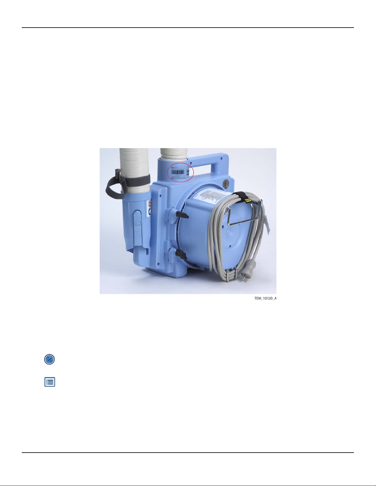
The serial number is located on the back of the warming unit (Figure 1-1).
Figure1-1.Serial Number Label on Back of Warming Unit
The software version number and error codes can be obtained from the
warming unit’s System Information screen as described below.
To access the System Information screen:
1. Plug the warming unit’s power cord into the outlet, and press the On/Standby
key.
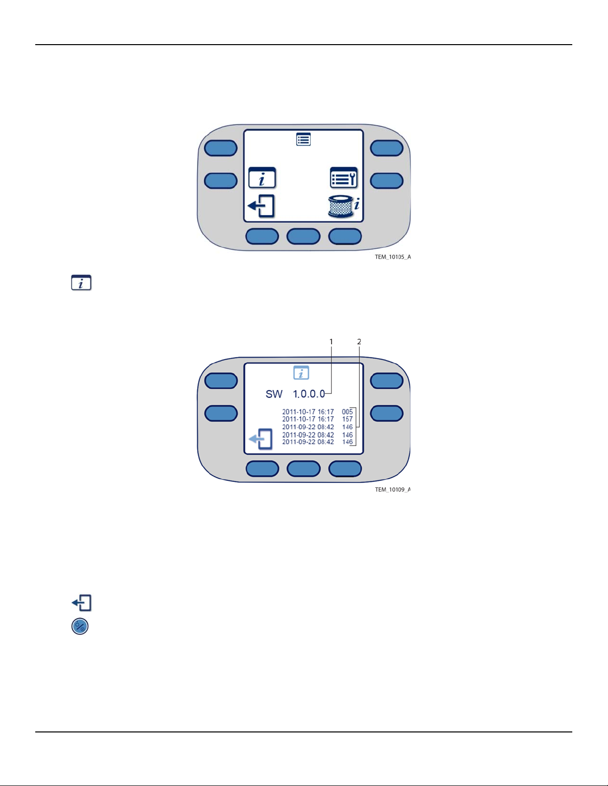
2. Press the Menu key. The Menu screen appears (Figure 1-2).
Service Manual 1-9
Page 24
Introduction
Figure1-2.Menu Screen
3. Press the System Information key. The System Information screen shows the
software version and the most recent error messages, if any (Figure 1-3).
Figure1-3.System Information Screen
1 Software Version 2 Error Messages (Up to Six)
Note:
Time stamps associated with error messages do not necessarily reflect local time.
The warming unit is set to UTC (Coordinated Universal Time) at manufacture.
4. To return to the Main screen, press the Exit key twice.
5. Press the On/Standby key to power off the unit.
1-10 Service Manual
Page 25

Component Disposal - WEEE Directive
1.6 Component Disposal - WEEE Directive
The warming unit contains components that must be disposed of
in accordance with WEEE Directive. Do not dispose of the
warming unit as a whole or the following individual components
as unsorted municipal waste:
• Power cord – page 8-5
• Display (LCD) – page 10-8
• User Interface (UI) PCBA – page 10-12
• Clock battery – page 10-29
• Power PCBA – page 10-31
• Power supply – page 10-43
Service Manual 1-11
Page 26
Introduction
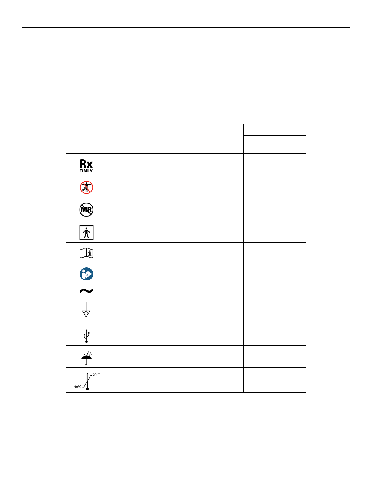
1.7 Labeling Symbols
Table 1-3 defines the symbols that appear on the warming unit or its shipping
label.
Table1-3.Symbols on the Warming Unit and Shipping Label
Symbol Description Appears On...
Warming
Unit
By prescription only X X
No Free Hosing: Hose nozzle must be connected to a
WarmTouch™ blanket or thermal injury may occur.
Do not use during magnetic resonance imaging (MRI). X X
Degree of protection from electric shock:
Protection Class I, Type BF applied part
Recommendation to consult accompanying documents X X
Requirement to consult accompanying documents X X
Nature of power supply: Alternating Current (AC) X
Potential equalization conductor terminal
Used to access the warming unit’s electrical ground for
electrical safety testing
X
X
X
Shipping
Label
Universal Serial Bus (USB) port
(For service use by qualified personnel only)
Keep dry X X
Temperature limitations (shipping/storage): -40°C to
+70°C
1-12 Service Manual
X
X
Page 27
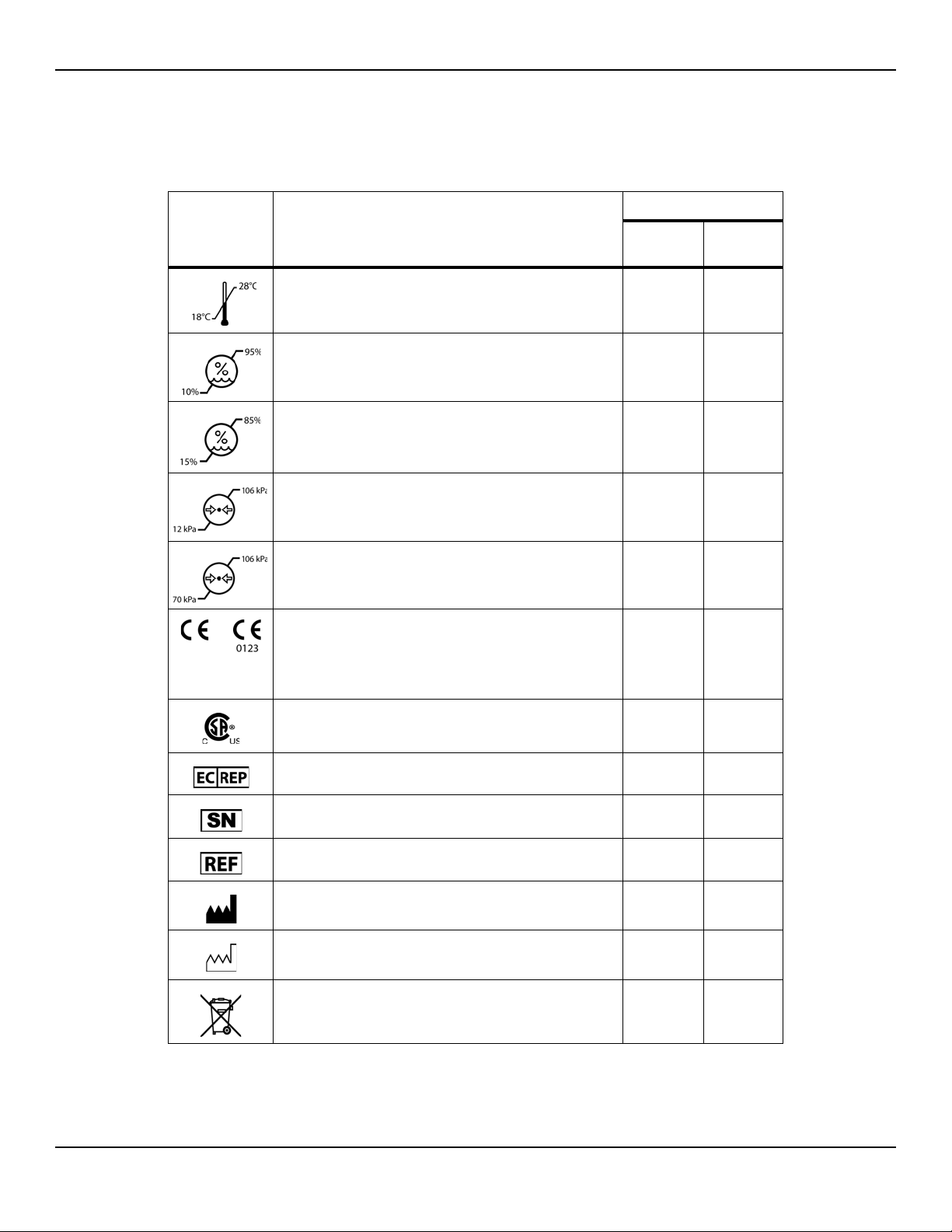
Table1-3.Symbols on the Warming Unit and Shipping Label (Continued)
Symbol Description Appears On...
Labeling Symbols
Warming
Unit
Temperature limitations (operating): +18°C to +28°C X
Relative humidity limitations (shipping/storage): 10% to
95% (non-condensing)
Relative humidity limitations (operating): 15% to 85%
(non-condensing)
Atmospheric pressure limitations (shipping/storage):
12 kPa to 106 kPa
Atmospheric pressure limitations (operating): 70 kPa to
106 kPa
CE – Conformité Européene authorization mark
0123 – TÜV SÜD Product Service GmbH (notified body)
Signifies compliance with Medical Device Directive
93/42/EEC
Shipping
Label
X
X
X
X
XX
CSA – Canadian Standards Association certification
mark
European Community (EC) authorized representative X X
Serial number X X
Catalog number X X
Manufacturer X X
Date of manufacture X X
Proper waste disposal for electrical and electronic equipment (WEEE)
X
X
Service Manual 1-13
Page 28

Introduction
1.8 Obtaining Technical Assistance
For technical assistance or to order parts and additional manuals, contact Covidien Technical Services or a local Covidien representative.
When contacting Covidien for troubleshooting or service issues, please provide
the information described in Serial Number, Software Version, and Error Codes
on page 1-9.
Covidien Technical Services
Covidien Argentina
Aguero 351
Capital Federal - 1171 ABC
Argentina
Tel: (5411) 4863-5300
Fax: (5411) 4863-4142
Covidien Austria GmbH
Campus21
Europaring F09402
Brunn am Gebrige
A-2345 Österreich
Tel: (+43) 2236 - 3788 39
Fax: (+43) 2236 - 3788 3940
Covidien Canada
19600 Clark Graham
Baie d'Urfe, QC, H9X 3R8
Canada
Tel:1-514-695-1220, Ext.4004
Fax: 1-514-695-4965
Covidien Colombia
Edificio Prados de la Morea
Carretera Central Del Norte
(Cra 7a) Kilometro 18,
Chia-Cundinamarca
Bogota, Colombia
Tel: (571) 619-5469
Fax: (571) 619-5425
Covidien Asia
Singapore Regional Service
Centre
15 Pioneer Hub, #06-04
Singapore 627753
Tel (65) 6578 5288
Fax (65) 6515 5260
Covidien Belgie S.A.-N.V.
Generaal De Wittelaan 9/5
Mechelen
2800
België
Tel +32 152 981 37
Fax +32 152 167 83
Covidien Chile
Camino lo Boza (Ex 8395)
Pudehuel
Santiago
Chile
Tel: (562) 739 - 3000
Fax: (562) 783 - 3149
Covidien Costa Rica
Global Park, Parkway 50
La Auroa de Heredia
Costa Rica
Tel: (506) 2239 - 5386
Fax: (506) 2239 - 5319
Covidien Australia
52A Huntingwood Drive
Huntingwood, NSW 2148
Australia
Tel: (+61) 1800 - 350702
Fax: (+61) 2967 - 18118
Covidien Brazil
Av. Das Nações Undias 12995
Andar 23 - Brooklin
São Paulo, SP
Brasil 04578-000
Tel: (5511) 2187-6200
Fax: (5511) 2187-6380
Covidien China
2F, Tyco Plaza
99 Tian Zhou Rd
Shang Hai 200233
P.R. China
Tel: (+86) 4008 1886 86
Fax: (+86) 2154 4511 18
Covidien ECE
Prosecká 851/64
190 00 Praha 9
Česká republika
Tel: +420 239 000 711
Fax: +420 239 000 437
1-14 Service Manual
Page 29

Covidien Technical Services (Continued)
Obtaining Technical Assistance
Covidien Danmark A/S
Langebrogade 6E, 4. sal
1411 København K
Danmark
Tel +45 702 753 50
Fax:+45 702 756 50
Covidien Finland Oy
Läkkisepäntie 23
00620 Helsinki
Finland
Te. +35 896 226 84 10
Fax +35 896 226 84 11
Covidien India
10th Floor Building No 9B
DLF Cyber City Phase III
Gurgaon
Haryana - 122002
India
Tel + 91 1244 709800
Fax + 91 1244 206850
Covidien Deutschland
GmbH
Technisches Service Center
Raffineriestr. 18
93333 Neustadt / Donau
Germany
Tel + 49 944 595 93 80
Fax + 49 944 595 93 65
Covidien France SA
Parc d'affaires Technopolis
Bat. Sigma, 3 Avenue du
Canada
LP 851 Les Ulis
91975 Courtaboeuf Cedex
France
Tel +33 169 821 416
Fax +33 169 821 532
Covidien Hungary
1095 Budapest
Mariassy u. 7
Magyarorszag
Hungary
Tel + 36 1880 7975
Fax + 36 1777 4932
Covidien ECE
Galvaniho 7/a
821 04 Bratislava
Slovakia
Tel.: +421 248 214 573
Fax: +421 248 214 501
Covidien Hong Kong
Unit 12 - 16, 18/F
BEA Tower
Millennium City 5
4187 Kwun Tong Road
Kwum Tong,
Kowloon, Hong Kong
Tel + 852 3157 7299
Fax + 852 2838 0749
Covidien Ireland
Block G, Ground Floor,
Cherrywood Technology Park,
Loughlinstown
County Dublin, Ireland
Tel +353 1 4381613
Fax 353 1 439 3039
Covidien Israel
5 Shacham St.
North Industrial Park
Caesarea
38900 Israel
Tel +97 246 277 388
Fax+97 266 277 688
Covidien Korea
5F, Hibrand Living Gwan,
#215,
Yangjae-Dong,
Seocho-Gu
Seoul, Korea
Tel: +822 570 5459
Fax: +822 570 5499
Covidien Italia S.p.A.
Via Rivoltana 2/D
20090 Segrate
Italy
Tel +39 027 030 81 31
Fax +39 027 031 72 84
Covidien Mexico
Insurgentes Sur # 863, Piso 16
Col. Nápoles
Del. Benito Juarez
Mexico, D.F. 03810 Mexico
Tel: (5255) 5804-1524
Fax: (5255) 5536-1326
Covidien Japan Inc.
Technical Support Center
83-1, Takashimadaira 1Chome
Itabashi-ku, Tokyo 175-0082
Japan
Tel: +81 (0) 3 6859 0120
Fax: +81 (0) 3 6859 0142
Covidien Nederland BV
Hogeweg 105
5301 LL Zaltbommel
Nederland
Tel +31 41 857 66 00
Service Manual 1-15
Page 30

Introduction
Covidien Technical Services (Continued)
Covidien Norge AS
Postboks 343
1372 Asker.
Norway
Tel +47 668 522 22
Fax +47 668 522 23
Covidien Portugal Lda.
Estrada do Outeiro de Polima,
Lote 10-1° Abóboda
2785-521 S.Domingos de Rana
Portugal
Tel +35 121 448 10 36 /30
Fax +35 121 445 1082
Covidien Saglik A.S.
Maslak Mahallesi Bilim Sokak
No: 5, Sun Plaza Kat: 2-3
Sisli, Istanbul 34398
Turkey
Tel +90 212 366 20 00
Fax +90 212 276 35 25
Covidien Sverige AB
Box 54
171 74 Solna
Sweden
Tel +46 858 56 05 00
Fax + 46 858 56 05 29
Covidien Panama
Parque Industrial Costa del Esta
Calle Primera, Edifio # 109
Panama City, Panama
Tel: (507) 264-7337
Fax: (507) 236-7408
Covidien Puerto Rico
Palmas Industrial Park
Road 869 Km 2.0 Bdlg. #1
Cataño, PR 00962
Tel. 787-993-7250
Ext. 7222 & 7221
Fax 787-993-7234
Covidien South Africa
Corporate Park North
379 Roan Crescent
Randjespark
Midrand, South Africa
Tel +27 115 429 500
Fax +27 115 429 624
Covidien Switzerland
Roosstrasse 53
8832 Wollerau
Schweiz
Tel +41 44786 5050
Fax +41 44786 5010
Covidien Polska
Al. Jerozolimskie 162
Warszawa. 02-342
Polska
Tel +48 223 122 130
Fax +48 223 122 020
Covidien Russia
53 bld. 5 Dubininskaya Street
Moscow
RUSSIA. 119054
Tel +70 495 933 64 69
Fax +70 495 933 64 68
Covidien Spain S.L.
Business Park World Trade
Center Almeda Park Edificio
7 - 3ª planta Plaça de la Pau s/n
Cornellà de Llobregat
Covidien Thailand
99 Soi Rubia,
Sukhumvit 42 Road
13 - 14 Fl., Berli Jucker Building
Prakanong, Klongtoey
Bangkok 10110, Thailand
Tel +662 2073 - 100
Fax +662 657 - 6325
Covidien UK
Unit 2, Talisman Business Park
London Road, Bicester
OX26 6HR, United Kingdom
Tel +44(0)1869 328092
Fax +44(0)1869 327585
1-16 Service Manual
Covidien US
15 Hampshire Street
Mansfield, MA 02048 USA
Tel 1.800.635.5267
Tel 1.925.463.4635 (toll)
Page 31

1.9 Related Documents
• Operator’s Manual - Covidien WarmTouch™ Convective Warming System — This
document provides instructions for operating the WarmTouch warming system in
a clinical environment.
• Instructions for Use - Covidien WarmTouch™ Warming Blanket — This document,
provided with WarmTouch warming blankets, contains important information
regarding intended use, handling, connection, and positioning of the blanket.
1.10 Warranty Information
To obtain warranty information, contact Covidien Technical Services or a local
Covidien representative. Reference Obtaining Technical Assistance on
page 1-14.
Related Documents
Service Manual 1-17
Page 32

Introduction
Page Left Intentionally Blank
1-18 Service Manual
Page 33

2 Product Overview
2.1 Overview
This chapter provides an introduction to the Covidien WarmTouch™ Convective Warming System, including information about its features and controls.
2.2 Product Description
The warming system provides a means for treating or preventing hypothermia
in adult and pediatric patients in clinical settings. The warming system consists
of an electronic blower (warming unit) that delivers heated air through a flexible hose to a lightweight blanket placed on the patient. The blanket distributes the heated air through numerous small perforations that allow the air to
reach the targeted areas of the patient’s body.
2.2.1 Features
• Multiple Temperature Settings — A range of temperature settings allows the
clinician to customize and adjust treatment based on the patient’s needs.
• Boost Mode — For rapid warming, air is generated at 47°C for 45 minutes, after
which the temperature automatically drops to the 45°C (High) temperature setting.
• HEPA Filter — A High Efficiency Particulate Air (HEPA) filter removes at least
99.97% of particles 0.3 micrometers or larger from the air delivered to the
warming blanket. The warming unit monitors the amount of time the filter is in
use and indicates when the filter needs to be replaced.
• Automatic Over- and Under-Temperature Protection — At any of the
heated air settings, if the temperature of the generated air is out of range for a
specific amount of time, the heater and fan automatically shut off and an alarm
is issued.
• Optional Cart with Wheel Locks — An optional transport cart, equipped with
wheel locks, is available for the warming unit. The wheel locks reduce cart movement while the system is in use.
2-1
Page 34

Product Overview
2.2.2 Indications for Use
2.2.3 Contraindications
2.2.4 Covidien WarmTouch™ Warming Blankets
The WarmTouch Convective Warming System (warming unit and blanket) is
intended for prevention and treatment of hypothermia, and for the management of appropriate normothermia.
None known.
The Covidien WarmTouch™ Convective Warming Unit is designed for use with
WarmTouch™ blankets only. WarmTouch blankets are designed to attach
securely to the warming unit’s hose nozzle. The nozzle features guides and a
clip to ensure correct orientation.
Do not attempt to use other types of blankets with the warming unit; the performance of the warming system has not been evaluated with other blankets
and cannot be predicted.
The warming unit is compatible with all WarmTouch blankets.
2-2 Service Manual
Page 35

2.3 Product Views
2.3.1 Front View
Product Views
Figure2-1.Front View
1 Operator’s Panel 4 Hose
2 Handle 5 Nozzle Strap with Clip
3 No Free-Hosing Label 6 Nozzle
Service Manual 2-3
Page 36

Product Overview
2.3.2 Back View
Figure2-2.Back View
1 No Free-Hosing Label 5 Mounting Channel (x2)
2 Serial Number Label 6 Pole Clamp (x3)
3 Symbols Label 7 Bed Hook
4 USB Port (Under Cover) 8 Power Cord
2-4 Service Manual
Page 37

2.4 Operator’s Panel
The operator’s panel includes an On/Standby key, a multi-functional keypad,
and a display that provides temperature and status information. The display
indicates the function of each adjacent key. Key functions change based on
operating context, as described in subsequent chapters.
Figure2-3.Operator’s Panel
Operator’s Panel
1
2
3
4 Temperature/Information Area – Displays the current air temperature being generated
(rounded to the closest 1°C). The following symbols can also appear in this area:
On/Standby Key – Press to place the warming unit in Ready mode or to return to
Standby mode. Reference Beginning Operation on page 4-4 and Returning to
Standby Mode on page 4-8.
Status LED – Indicates the warming unit’s operational status. Reference Overview
of Warming Unit Operating Modes on page 4-3.
Fan Off Key – During operation, press to turn off the fan. The heater, if running,
shuts off automatically. Reference Returning to Ready Mode on page 4-7.
Dashes instead of a temperature reading indicate that the warming
unit is in Ready mode (both heater and fan are off).
Animated symbol indicates that the fan is on.
Animated symbol indicates that the heater is on.
Service Manual 2-5
Page 38

Product Overview
Animated arrow indicates that the temperature is adjusting upward or
downward to a new setting. The symbol disappears when the temperature is within 1.5°C of the new setting.
5
6
7
8
9
10
Note:
When you press any of the temperature setting keys, the Heat Off key, or the Fan
Off key, the setting is highlighted on the display to indicate the current selection. For
example, in the previous figure, 34° is the current selection.
Menu Key – Press to access screens for viewing filter status and system information. Reference Monitoring the Filter Status on page 5-10 and Serial Number, Soft-
ware Version, and Error Codes on page 1-9.
Note: Symbol is shown for reference only. This menu is accessible only when the
heater and fan are off (Ready mode).
47°C (Boost Mode) Key – Press to generate air at 47°C (116.6°F) for 45 minutes.
Reference Using Boost Mode on page 4-6.
45°C (High) Key – Press to generate air at 45°C (113°F). Reference Controlling the
Temperature on page 4-5.
40°C (Medium) Key – Press to generate air at 40°C (104°F). Reference Controlling
the Temperature on page 4-5.
34°C (Low) Key – Press to generate air at 34°C (93.2°F). Reference Controlling the
Temperature on page 4-5.
Heat Off Key – Press to deliver air at room temperature (unheated). Reference
Controlling the Temperature on page 4-5.
Note:
A soft click tone indicates a successful key press.
2-6 Service Manual
Page 39

3 Installation
3.1 Overview
This chapter contains information for installing the Covidien WarmTouch™
Convective Warming Unit.
3.2 Safety Reminders
WARNING:
The use of accessories or cables with the warming system other than those
indicated in this manual may result in non-compliance with the specifications
listed in Electromagnetic Compatibility (EMC) on page 13-4.
WARNING:
No modification of this equipment is allowed. Modification can result in
death, injury, or property damage.
3-1
Page 40

Installation
3.3 Attaching the Power Cord
The warming unit is shipped with a power cord appropriate to the country
of use.
To attach the power cord:
1. Position the warming unit on its front so the bottom of the unit is accessible
(Figure 3-2).
Figure3-1.Positioning the Unit for Power Cord Installation
1 Power Cord Routing Bracket 2 Power Cord Socket
2. Insert the power cord into the socket on the warming unit, making sure that it is
fully seated.
Note: Do not route the power cord through the metal hook on the filter enclosure.
3. Press the power cord into the routing bracket until it is completely seated
(Figure 3-2). If necessary, use a screwdriver to carefully spread the sides of the
bracket while inserting the cord.
3-2 Service Manual
Page 41

Figure3-2.Power Cord Connection
Attaching the Power Cord
4. Set the warming unit upright. Wrap the power cord around the back of the unit,
and secure it with the attached strap (Figure 3-3).
Service Manual 3-3
Page 42

Installation
Figure3-3.Power Cord Wrapped and Secured
3-4 Service Manual
Page 43

3.4 Installing the Warming Unit
The warming unit can be used as a standalone device, or it can be mounted
on an IV pole, bed, or optional transport cart. The following sections provide
mounting instructions.
3.4.1 IV Pole Installation
The warming unit can be mounted on an IV pole with a maximum diameter of
3.2 cm (1.25 inches) and a minimum diameter of 1.9 cm (0.75 inches).
To avoid tipping, the warming unit must be mounted on the pole with the
handle no higher than 76 cm (30 inches) above the floor.
Requirements:
• Measuring tape
Installing the Warming Unit
To install the warming unit on an IV pole:
1. On the IV pole, mark the maximum mounting height. The warming unit’s handle
must be no higher than 76 cm (30 inches) above the floor.
2. Ensure that the power cord is secured at the back of the warming unit. Reference
Figure 3-4 on page 3-6.
3. Locate the mounting channel with two clamps at the back of the warming unit.
Do not use the mounting channel with one clamp. Reference Figure 3-4 on
page 3-6.
4. Loosen the knobs on the two clamps and rotate the clamp feet away from the
mounting channel.
Service Manual 3-5
Page 44

Installation
Figure3-4.Back View
1 Mounting Channel 3 Clamp Knob (x2)
2 Clamp Foot (x2)
5. Bracing the IV pole, position the warming unit against the pole so that the pole is
fully seated in the mounting channel. Verify that the handle is not
above the
maximum height.Reference Figure 3-5 on page 3-7.
6. Rotate the two clamp feet across the IV pole, and tighten the clamp knobs to
secure the warming unit. Do not overtighten.
3-6 Service Manual
Page 45

Figure3-5.Warming Unit Mounted on IV Pole
Installing the Warming Unit
Service Manual 3-7
Page 46

Installation
3.4.2 Bed Installation
The warming unit can be attached to a bed that has a mounting surface up to
3.6 cm (1.4 inches) wide. Typically, the unit is attached to the bed’s head board
or foot board.
To attach the warming unit to a bed:
1. Locate the bed hook on the back of the warming unit. Reference Figure 2-2 on
page 2-4. The hook slides in and out to accommodate different mounting surface
widths.
2. Hang the bed hook over the mounting surface to attach the warming unit to the
bed.
Figure3-6.Bed Installation
3-8 Service Manual
Page 47

3.4.3 Cart Installation
An optional transport cart is available for the warming unit. Contact Covidien
Technical Services or a local Covidien representative to purchase the transport
cart. Reference Obtaining Technical Assistance on page 1-14.
To install the warming unit on the cart:
1. Ensure that the power cord is secured at the back of the warming unit. Reference
Figure 3-7.
2. Loosen the knobs on the three clamps at the back of the warming unit, and rotate
the clamp feet away from the mounting channels.
Figure3-7.Back View
Installing the Warming Unit
1 Mounting Channel (x2) 3 Clamp Foot (x3)
2 Clamp Knob (x3)
Service Manual 3-9
Page 48

Installation
3. Locate the mounting pegs on the cart’s vertical poles, and locate the holes at the
bottom of the warming unit’s mounting channels.
Figure3-8.Cart Mounting Peg and Warming Unit Mounting Hole
1 Mounting Channel (x2) 3 Mounting Peg (x2)
2 Mounting Hole (x2)
4. Holding the warming unit by the handle and bracing the cart, position the
warming unit against the cart so that the mounting holes engage the mounting
pegs. The cart poles must be fully seated in the mounting channels.
5. Rotate each of the three clamp feet across the cart poles, and tighten the clamp
knobs to secure the warming unit. Do not overtighten.
3-10 Service Manual
Page 49

Figure3-9.Warming Unit Mounted on Cart
Installing the Warming Unit
Service Manual 3-11
Page 50

Installation
Page Left Intentionally Blank
3-12 Service Manual
Page 51

4 Operation
4.1 Overview
This chapter provides basic operating instructions for the Covidien WarmTouch™ Convective Warming Unit. Full instructions for operating the unit in a
clinical setting are provided in the Covidien WarmTouch™ Convective
Warming System Operator’s Manual. Clinicians intending to use the warming
system for treatment of patients must consult the Operator’s Manual.
Applying Power Page 4-2
Overview of Warming Unit Operating Modes Page 4-3
Beginning Operation Page 4-4
Controlling the Temperature Page 4-5
Powering Off the Warming Unit Page 4-8
4.2 Safety Reminder
WARNING:
The use of accessories or cables with the warming system other than those
indicated in this manual may result in non-compliance with the specifications
listed in Electromagnetic Compatibility (EMC) on page 13-4.
4-1
Page 52

Operation
4.3 Applying Power
WARNING:
Possible electric shock hazard. Grounding reliability can be achieved only
when the warming unit is connected to a suitable mains outlet with
protective earth grounding.
To apply power to the warming unit:
1. Locate a hospital-grade or suitable mains outlet with protective earth grounding.
Ensure that the power outlet is easily accessible; disconnection from the outlet is
the only way to completely remove power from the warming unit.
2. Plug the warming unit’s power cord into the outlet. The status LED illuminates
amber to indicate that the warming unit is in Standby mode. The fan and heater
are off, and the display is blank.
4-2 Service Manual
Page 53

Overview of Warming Unit Operating Modes
4.4 Overview of Warming Unit Operating Modes
Standby Mode
• Status LED: AMBER
• Heater: OFF
• Fan: OFF
• Display: OFF
Ready Mode
• Status LED: GREEN
• Heater: OFF
• Fan: OFF
• Display: ON
Treatment Mode
• Status LED: GREEN
• Heater: ON or OFF
• Fan: ON
• Display: ON
See Operator’s Panel on
page 2-5 for descriptions of
the display symbols.
1 On/Standby Key — Press to place the unit in Ready mode and prepare for
operation, or press to return to Standby mode when treatment is complete.
See Beginning Operation on page 4-4 and Returning to Standby Mode on
page 4-8.
2 Temperature Keys — Press to place the unit in Treatment mode, delivering
air to the blanket. See Controlling the Temperature on page 4-5.
3 Fan Off Key — Press to return to Ready mode, pausing air delivery. See
Returning to Ready Mode on page 4-7.
Service Manual 4-3
Page 54

Operation
4.5 Beginning Operation
To begin operation:
1. Press the On/Standby key. The unit enters Ready mode:
• The status LED turns green, and the display turns on.
• A short tone indicates a successful power-on self-test (POST). If POST is unsuc-
cessful, an alarm screen appears. See Alarms on page 6-12.
• The Main screen appears (Figure 4-1). Note that if the filter needs to be
replaced, the Replace Filter screen appears instead of the Main screen
(Figure 4-2).
Figure4-1.Main Screen at Power-On
Figure4-2.Replace Filter Screen at Power-On
2. If you see the Replace Filter screen, follow the procedure Filter Replacement on
page 5-4. It is possible to continue operation; however, failure to replace the filter
4-4 Service Manual
Page 55

as recommended can adversely affect device performance. If you choose to continue operation, press the OK key. The Main screen appears (Figure 4-1). Until the
filter is replaced, the Replace Filter screen reappears at each subsequent poweron.
4.6 Controlling the Temperature
Note:
During patient treatment, a WarmTouch™ warming blanket must be attached to the
warming unit at all times.
Select a setting by pressing one of the temperature keys. Change the setting
as desired.
Note that the temperature settings and readings on the display correspond to
internal measurements of the air entering the hose. The air temperature entering the blanket is lower and can vary depending on environmental conditions.
Use Table 4-1 as a guideline for selecting temperature settings.
Controlling the Temperature
Setting Avg. Temperature
Entering Hose
Room temperature Room temperature To aid in cooling the patient, if
(Heat Off)
34°C (93°F) 32°C (90°F) To help prevent or treat hypo-
(Low)
40°C (104°F) 38°C (100°F)
(Medium)
45°C (113°F) 42°C (108°F)
(High)
47°C (117°F) for 45
(Boost)
minutes
Table4-1.Temperature Settings
Avg. Temperature
Entering Blanket
44°C (111°F) To rapidly warm patients.
Typical Use
necessary.
thermia, or to maintain appropriate normothermia.
Service Manual 4-5
Page 56

Operation
Figure4-3.Warming System Set to 40°C (Medium)
Note that when you change the temperature setting, an amber arrow appears
next to the current temperature while it adjusts. When the temperature is
within approximately 1.5°C of the new setting, the arrow disappears.
4.6.1 Using Boost Mode
Boost mode allows rapid warming of patients. Air is generated at 47°C
(116.6°F) for 45 minutes. After 45 minutes, the setting automatically changes
to 45°C (High).
To use Boost mode, press the 47°C (Boost Mode) key. A countdown timer
shows the time remaining before the temperature switches to the 45°C (High)
setting. Boost mode sessions can be repeated as necessary.
Figure4-4.Warming System Set to Boost Mode
4-6 Service Manual
Page 57

4.6.2 Using the Heat Off Setting
The heat off setting provides a means to cool a patient. To use the heat off
setting, press the Heat Off key. Air is delivered to the warming blanket at
room temperature (heater off).
Figure4-5.Warming System Set to Heat Off
Controlling the Temperature
4.6.3 Returning to Ready Mode
During operation, you can switch back to Ready mode (fan and heat off) any
time you do not need to apply air to the warming blanket. The display stays
on, and the unit remains ready to operate.
To return to Ready mode, press the Fan Off key. Note that in Ready mode, the
temperature reading shows dashes.
Figure4-6.Warming System Set to Ready Mode
Service Manual 4-7
Page 58

Operation
4.6.4 Returning to Standby Mode
Use Standby mode when you are finished using the warming system but do
not wish to unplug it.
To return to Standby mode during operation, press the On/Standby key. The
heater and fan shut off, the display goes blank, and the status LED turns
amber.
4.6.5 If Power is Interrupted...
If power is interrupted during operation, the warming unit responds as follows, based on the duration of the power loss:
• Power restored within approximately 15 seconds — The warming unit
powers up, performs a power-on self-test (POST), and resumes operation in the
same mode as before the power loss.
• Power restored after approximately 15 seconds — The warming unit
powers up in Standby mode.
If the warming unit powers back up in Standby mode, press the On/Standby
key to enter Ready mode, then select a temperature setting to resume operation.
4.7 Powering Off the Warming Unit
To power off the warming unit:
1. Press the On/Standby key. The fan and heater (if running at the time) turn off.
The display goes blank, and the status LED turns amber.
2. To completely remove power from the warming unit, unplug the unit’s power
cord from the outlet.
4-8 Service Manual
Page 59

5 Maintenance
5.1 Overview
This chapter describes the cleaning and maintenance requirements for the
Covidien WarmTouch™ Convective Warming Unit.
Cleaning the Warming Unit Page 5-2
Safety Checks Page 5-3
Filter Replacement Page 5-4
Monitoring the Filter Status Page 5-10
5.2 Safety Reminders
WARNING:
Before attempting to open or disassemble the warming unit, disconnect the
power cord from the AC power source.
Caution:
Observe ESD (electrostatic discharge) precautions when servicing the
warming unit.
5-1
Page 60

Maintenance
WARNING:
WARNING:
Caution:
5.3 Cleaning the Warming Unit
Clean the warming unit after each use, as described in this manual.
Disconnect the warming unit's power cord from the AC power source before
performing this procedure.
Do not spray, pour, or spill any liquid on the warming unit, its accessories,
connectors, switches, or openings in the case.
For surface cleaning and disinfection of the warming unit, follow your institution's procedures or the recommended actions below:
• Surface cleaning — Use a soft cloth dampened with either a commercial, non-
abrasive cleaner or a solution of 70% alcohol in water, lightly wiping the surfaces
of the warming unit.
• Disinfection — Use a soft cloth saturated with a solution of 10% chlorine bleach
in tap water, lightly wiping the surfaces of the warming unit.
5-2 Service Manual
Page 61

5.4 Safety Checks
5.4.1 Physical Inspection
Covidien recommends that the customer perform a visual check of the following items before each use of the warming unit:
• Equipment — Inspect the warming unit and power cord for mechanical damage
or deterioration.
• Labels — Inspect the safety labels for legibility.
After performing any service on the warming unit, be sure to check these items
before returning the unit to operation.
Covidien also recommends checking the time remaining time before the filter
must be replaced before returning the unit to operation. See Monitoring the
Filter Status on page 5-10 for instructions.
Safety Checks
5.4.2 Temperature and Alarm Verification
Once a year, the following tests must be performed:
• Temperature Accuracy Test — Use this test to verify heater output tempera-
tures. See page 7-8 for instructions.
• Thermostat Test — Use this test to verify the alarm system. See page 7-11 for
instructions.
These tests are also required after certain service procedures. Refer to the
instructions in each component replacement section for testing requirements.
5.4.3 Electrical Safety Tests
The following electrical safety tests must be performed after certain service
procedures:
• Ground Bond Test — See page 7-14 for values.
• Earth Leakage Current Test (Line Leakage) — See page 7-14 for values.
• Enclosure Leakage Current Test (Line Leakage) — See page 7-14 for values.
Refer to the instructions in each component replacement section for testing
requirements.
Service Manual 5-3
Page 62

Maintenance
WARNING:
WARNING:
Caution:
5.5 Filter Replacement
Do not operate the warming unit with the filter enclosure removed.
Disconnect the warming unit's power cord from the AC power source before
performing this procedure.
The HEPA filter must
whichever comes first.
be replaced every 2,000 hours of operation or 365 days,
Caution:
The institution should follow local governing ordinances and recycling
instructions regarding disposal or recycling of filter and device components
or end of life of the product.
The warming unit contains a HEPA filter that must be replaced at regular intervals. When the filter needs to be replaced, the screen shown in Figure 5-1
appears at each power-on. Failure to replace the filter as recommended
can adversely affect device performance.
Figure5-1.Replace Filter Screen
5-4 Service Manual
Page 63

Requirements:
• WT HEPA Filter Kit (page A-7)
• Torque driver with #2 Phillips bit
• 70% isopropyl alcohol solution and soft cloth (if replacing gasket in filter enclo-
sure)
To replace the filter:
1. If the power cord is secured around the back of the unit, unwind it completely.
2. Position the warming unit on its front so the bottom of the unit is accessible
(Figure 5-2).
Figure5-2.Filter Enclosure and Power Cord Connection
Filter Replacement
1 Filter Enclosure 3 Power Cord Routing Bracket
2 Filter Enclosure Screws (x3) 4 Power Cord Connector
Service Manual 5-5
Page 64

Maintenance
Caution:
3. Remove the three screws from the filter enclosure. Lift the enclosure away from
the unit, disengaging the power cord from its socket. Set the enclosure and
attached power cord aside.
The institution should follow local governing ordinances and recycling
instructions regarding disposal or recycling of filter and device
components or end of life of the product.
4. Remove the filter (Figure 5-3). Dispose of the filter as required by local governing
ordinances.
Figure5-3.HEPA Filter
5. Place the new filter on the unit.
5-6 Service Manual
Page 65

6. Before placing the filter enclosure back on the unit, check the circular gasket
inside the enclosure (Figure 5-4). If the gasket is worn or damaged, replace it as
follows:
a. Peel the gasket off the enclosure.
b. Use a soft cloth dampened with a solution of 70% isopropyl alcohol to
remove any adhesive remnants from the surface. Make sure that the surface
is completely dry before proceeding.
c. Remove the backing from the new gasket to expose the adhesive.
d. Center the gasket around the raised area in the enclosure, and press around
the entire gasket to adhere.
Figure5-4.Gasket inside Filter Enclosure
Filter Replacement
7. Place the filter enclosure back on the unit, aligning the power cord with its socket.
Make sure that the enclosure is fully seated on the unit.
8. Press the power cord connector into the socket so that it is fully connected
(Figure 5-2 on page 5-5).
9. Reinstall the three screws in the filter enclosure. Tighten the screws to 1.2 to 1.6
N-m (10.6 to 14.2 lb-in).
Service Manual 5-7
Page 66

Maintenance
10. Set the unit upright, and plug the power cord into the power outlet.
11. Reset the filter counters as follows:
a. Press the On/Standby key. The Replace Filter screen appears (Figure 5-5).
Figure5-5.Replace Filter Screen
b. Press the Replace Filter key. The Filter Information screen appears (Figure 5-
6).
Figure5-6.Filter Information Screen - Filter Expired
c. Press the Filter Reset key.
d. Press the key code as described in Service Screen Access on page 7-2. The filter
counters are reset to 365 days and 2000 hours.
e. Press the On/Standby key to return to Standby mode. Press the On/Standby
key again and verify that the Main screen appears (Figure 5-7) rather than the
Replace Filter screen.
5-8 Service Manual
Page 67

Figure5-7.Main Screen at Power-On
12. Power off the warming unit by pressing the On/Standby key. Disconnect the
power cord from the outlet.
13. Wrap the power cord around the back of the unit, and secure it with the attached
strap (Figure 5-8).
Filter Replacement
Figure5-8.Power Cord Wrapped and Secured
Service Manual 5-9
Page 68

Maintenance
Note:
5.6 Monitoring the Filter Status
The warming unit monitors filter usage and provides counters that indicate the
number of operating hours and days until the filter needs to be replaced. You
can anticipate filter replacement by checking the counters on the Filter Information screen.
The Filter Information screen is only accessible when the warming unit is in Ready
mode. It is not accessible while the warming unit is operating.
To view the Filter Information screen:
1. If the warming unit is not already powered on, follow the steps in Applying Power
on page 4-2.
2. Press the On/Standby key to enter Ready mode.
3. Press the Menu key on the Main screen. The Menu screen appears (Figure 5-9).
Figure5-9.Menu Screen
4. Press the Filter Information key. The Filter Information screen indicates the days
and operating hours remaining before the filter needs to be replaced (Figure 5-
10).
5-10 Service Manual
Page 69

Figure5-10.Filter Information Screen
1 Filter Days Remaining 2 Filter Hours Remaining
Monitoring the Filter Status
5. To return to the Main screen, press the Exit key twice.
Service Manual 5-11
Page 70

Maintenance
Page Left Intentionally Blank
5-12 Service Manual
Page 71

6 Troubleshooting
6.1 Overview
This chapter provides information for troubleshooting problems that may
occur with the Covidien WarmTouch™ Convective Warming Unit.
Principles of Operation Page 6-2
Basic Troubleshooting Page 6-9
Alarms Page 6-12
6.2 Safety Reminders
WARNING:
No modification of this equipment is allowed. Modification can result in
death, injury, or property damage.
Caution:
Operation of the warming system may affect or be affected by other devices
in the vicinity due to electromagnetic interference (EMI). If interference
occurs, try increasing the distance between devices, repositioning the cabling,
or plugging the devices into separate outlet circuit branches. Reference
Electromagnetic Compatibility (EMC) on page 13-4 for additional guidance.
6-1
Page 72

Troubleshooting
6.3 Principles of Operation
6.3.1 Overview
The Covidien WarmTouch™ Convective Warming System provides clinicians
with a means to supply warmed or room temperature air to the skin surface of
patients to achieve and maintain normothermia. The system consists of the
Covidien WarmTouch™ Convective Warming Unit and specially designed
blankets to distribute the air.
The warming unit is powered from wall outlet AC power through an internal
power supply that maintains a consistent output across a range of input voltages and frequencies. Users interact with the unit via a set of hardware keys
arranged around a software-controlled Graphical User Interface (GUI).
The warming unit produces air output by drawing room air through a High
Efficiency Particulate Air (HEPA) filter, across a heating element, and into an
electrically-operated fan. The fan outputs the air across a control thermistor at
the base of the hose. The temperature of the air is monitored by a hardware
circuit under software control that provides power to the heating element to
regulate the temperature for the heated air settings. The heated air is delivered to the output hose where the nozzle connects distally to the blanket,
resulting in air delivery to the patient.
The delivered air temperature is constantly monitored by the warming unit’s
microprocessors. If the temperature does not stay within specification, the unit
shuts down the heating element and the fan. A safety thermostat provides
additional protection by shutting down the heating element and fan if the
heated air temperature exceeds its operating limit.
6-2 Service Manual
Page 73

6.3.2 Block Diagram
Figure 6-1 shows the relationship between the major components in the
warming unit. Descriptions of the components and their interactions follow. A
detailed diagram of the cable connections between the components is provided on page 6-8.
Figure6-1.Warming Unit Block Diagram
Principles of Operation
Service Manual 6-3
Page 74

Troubleshooting
6.3.3 Component Descriptions
Display
The unit uses a 2.5”, QVGA (320 x 240) TFT liquid crystal display (LCD) to relay
status and provide interactive information to the user. The display is located
inside the unit’s front enclosure behind the UI PCBA (see Figure 10-7 on
page 10-8). The display is controlled by the UI microprocessor on the UI PCBA
and connects to the PCBA via a cable that is fixed to the display.
Keypad
The keypad on the front of the unit consists of an On/Standby key and seven
multifunction control keys. The On/Standby key switches the unit between
Standby mode and Ready mode (see Overview of Warming Unit Operating
Modes on page 4-3). The control keys perform a variety of functions depend-
ing on operating context.
The keypad is built into the die-cut panel that attaches to the unit’s front enclo-
sure. The panel includes an LED that indicates warming unit status:
• Green for operating modes
• Amber for standby mode
• Off when disconnected from power
The keypad connects to the UI PCBA via a fixed cable that is routed into the
unit through a slot below the panel (see Figure 10-4 on page 10-6).
USB Port
To facilitate software updates, error log downloads, and other service tasks
performed at Covidien Service Centers, the warming unit can communicate
with a computer via its USB interface. The USB port is located under a protective cover at the back of the unit (see Figure 10-18 on page 10-23). An internal
USB cable connects the port to the UI PCBA (see Figure 10-17 on page 10-22).
6-4 Service Manual
Page 75

Principles of Operation
Speaker
The unit’s speaker is located inside the front enclosure (see Figure 10-27 on
page 10-37). The speaker generates alert tones (such as when POST passes),
alarm tones, and key clicks. It is connected to and driven by the power PCBA.
There is no external speaker opening.
UI PCBA
The UI PCBA is located inside the front enclosure below the operator’s panel
(see Figure 10-10 on page 10-12). It contains the UI microprocessor which is
responsible for all user interface functions. The UI microprocessor displays
information and menus on the LCD and receives user input from the keypad.
It sends commands based on the input to the A/D microprocessor on the
power PCBA which controls the unit’s power, fan, and heating functions.
The UI PCBA also contains a real-time clock (RTC) that allows filter use to be
tracked and log/code entries to be time-stamped. The replaceable battery for
the RTC is located on the UI PCBA.
The USB connector on the UI PCBA supports software updates, error log
downloads, and other service functions performed at Covidien Service
Centers.
Power PCBA
The power PCBA is located inside the front enclosure (see Figure 10-24 on
page 10-31). It contains the A/D microprocessor and control circuitry for the
fan, heater, and thermostat.
The power PCBA has power input connections from the AC power inlet and
power supply, and output connections to the heater, fan, thermostat, and
speaker. The power PCBA converts the 48VDC output from the power supply
to various voltages required to power components throughout the system. The
power circuits are protected by redundant fuses located on the PCBA.
The A/D microprocessor maintains a communication channel with the UI
microprocessor and controls power to the UI PCBA and display. It also receives
input from the thermistor and relays that input to the UI microprocessor which
displays the temperature readings on the LCD.
Service Manual 6-5
Page 76

Troubleshooting
Power Supply
The power supply is located inside the front enclosure (Figure 10-31 on
page 10-43). It is an internally-fused AC/DC converter delivering 48VDC, 65W
output from an input range of 90-264VAC. It has an input connection from
the AC power inlet, an output connection to the power PCBA, and a ground
connection to the equipotential stud. The 48V output from the power supply
is converted to 12V, 5V, 3.3V, and 2.5V on the power PCBA to drive various
system components.
HEPA Filter
The HEPA filter is located inside the filter enclosure at the back of the unit (see
Figure 5-3 on page 5-6). The fan draws air into the filter through the opening
at the base of the filter enclosure prior to delivering the air across the heating
element.
The filter must be replaced every 2,000 hours of operation or 365 days, whichever comes first. Software counters track the number of power-on hours and
calendar days since the previous filter change. These counters rely on the realtime clock (RTC) located on the UI PCBA.
When the filter needs to be replaced based on either of the counters, the user
is notified at power-on. The counters can be reset using a key code at the
keypad when the filter is replaced.
Heater
The heater is located below the fan assembly inside the rear enclosure (see
Figure 11-40 on page 11-43). The heater consists of a wire-wound element
that generates heat when current (90-264VAC) is passed through it. The
heater connects to the power PCBA and is controlled by the A/D microprocessor based on user input and thermistor feedback.
Fan
The fan is located inside the rear enclosure (see Figure 11-30 on page 11-33).
It is powered by 48VDC from the power PCBA. Fan speed is monitored by the
A/D microprocessor and is voltage-controlled via circuitry on the PCBA. If the
speed is too low or too high, the software shuts down the fan and heater and
generates an alarm.
6-6 Service Manual
Page 77

Principles of Operation
Thermostat
The thermostat is located in the hose duct adapter near the base of the hose
(see Figure 11-9 on page 11-10). It is connected to the power PCBA. The thermostat provides thermal cut-out protection by opening at 49°C to 55°C (120°F
to 131°F), resulting in heater and fan shutdown.
Thermistor
The thermistor is located in the hose duct adapter just below the screen at the
base of the hose (see Figure 11-2 on page 11-4 and Figure 11-6 on
page 11-7). It is connected to the power PCBA.
During operation, the temperature measured by the thermistor is monitored
by the A/D processor and relayed to the UI microprocessor for display on the
LCD. If the temperature does not remain within specification, the software
shuts down the heater and fan and generates an alarm.
Service Manual 6-7
Page 78

Troubleshooting
6.3.4 Component Cable Connections
Figure6-2.Cable Connections Between Major Components
6-8 Service Manual
Page 79

6.4 Basic Troubleshooting
Table6-1.Warming Unit Problems and Resolutions
Problem Resolution
Basic Troubleshooting
Low-priority alarm
Medium-priority alarm
(flashing)
Failure to power on
(LED not turning on)
See Alarms on page 6-12.
• Check the power cord’s connection to the warming unit. The
connector must be fully seated (page 3-2).
• Try a different power cord (page 8-5).
• Check the cable connections between the AC power inlet and
the power supply, power PCBA, and equipotential stud
(page 10-51).
• Check the fuses on the power PCBA (page 10-35).
• Check the ribbon cable connection between the power PCBA
and the UI PCBA (page 10-19).
• Check the keypad cable connection to the UI PCBA (page 10-3).
• Try replacing components in the following order:
1. Ribbon cable (page 10-19).
2. Power supply output cable (page 10-46).
3. AC power inlet (page 10-51).
4. Power supply (page 10-43).
5. Power PCBA (page 10-31).
6. UI PCBA (page 10-12).
7. Keypad (page 10-3).
Power-on self-test (POST)
failure
Check the error codes on the System Information screen (page 1-9),
and perform recommended corrective actions (page B-1).
Service Manual 6-9
Page 80

Troubleshooting
Table6-1.Warming Unit Problems and Resolutions (Continued)
Problem Resolution
Display not working • Make sure that the On/Standby key has been pressed and the
status LED is green. (If the status LED is amber, the display is
blank.)
• Check the display cable connection to the UI PCBA (page 10-8).
• Try replacing components in the following order:
1. Display (page 10-8).
2. UI PCBA (page 10-12).
Display test failure
(bad pixels or incorrect colors)
Key(s) not working on keypad
or
Keypad test failure
Speaker not working
Fan not operating
• Check the display cable connection to the UI PCBA (page 10-8).
• Try replacing components in the following order:
1. Display (page 10-8).
2. UI PCBA (page 10-12).
• Check the keypad cable connection to the UI PCBA (page 10-3).
• Try replacing components in the following order:
1. UI PCBA (page 10-12).
2. Keypad (page 10-3).
• Check the speaker cable connection to the power PCBA and to
the two terminals on the speaker. Make sure the wires are on
the correct terminals (red to positive; black to negative)
(page 10-40).
• Try replacing components in the following order:
1. Speaker cable (page 10-40).
2. Speaker (page 10-37).
3. Power PCBA (page 10-31).
• Check the error codes on the System Information screen
(page 1-9), and perform recommended corrective actions
(page B-1).
• Check the fan cable connection to the power PCBA
(page 10-31).
• Try replacing components in the following order:
1. Fan (page 11-33).
2. Power PCBA (page 10-31).
Flow test failure
(fan speed out of range)
• Check the fan cable connection to the power PCBA
(page 10-31).
• Try replacing components in the following order:
1. Power PCBA (page 10-31).
2. Fan (page 11-33).
6-10 Service Manual
Page 81

Table6-1.Warming Unit Problems and Resolutions (Continued)
Problem Resolution
Heater not operating • Check the error codes on the System Information screen
(page 1-9), and perform recommended corrective actions
(page B-1).
• Check the heater cable connection to the power PCBA
(page 10-31).
• Try replacing components in the following order:
1. Heater (page 11-43).
2. Power PCBA (page 10-31).
Basic Troubleshooting
Thermostat test failure
(thermostat fails to open)
Temperature accuracy test
failure
(output air temperature not
within specification)
• Check the error codes on the System Information screen
(page 1-9), and perform recommended corrective actions
(page B-1).
• Check the thermostat cable connection to the power PCBA and
to the thermostat terminals (page 11-14).
• Try replacing components in the following order:
1. Thermostat (page 11-9).
2. Power PCBA (page 10-31).
3. Thermostat cable (page 11-14).
• Check the error codes on the System Information screen
(page 1-9), and perform recommended corrective actions
(page B-1).
• Check the thermistor cable connection to the power PCBA
(page 11-3).
• Make sure that the thermistor wire and rivet are correctly
attached to the hose duct adapter (page 11-4).
• Check the heater cable connection to the power PCBA
(page 10-31).
• Try replacing components in the following order:
1. Thermistor sensor assembly (page 11-3).
2. Power PCBA (page 10-31).
Electromagnetic interference
between the warming unit
and other devices
• Check the error codes on the System Information screen
(page 1-9), and perform recommended corrective actions
(page B-1).
• Advise the customer to try increasing the distance between
devices, repositioning the cabling, or plugging the devices into
separate outlet circuit branches. See Electromagnetic Compati-
bility (EMC) on page 13-4 for additional guidance.
Service Manual 6-11
Page 82

Troubleshooting
6.5 Alarms
If an alarm condition or error occurs during operation, the warming unit
sounds alarm tones and displays an alarm screen. There are two types of
alarms: low-priority and medium-priority.
Figure6-3.Low-Priority Alarm (Left) and Medium-Priority Alarm (Right)
Note:
If multiple alarms occur at the same time, the unit reports the highest priority alarm.
Table6-2.Alarm Indicators
Symbol Tones Type of Alarm
Two successive tones
repeating
Three successive tones
repeating at decreasing
intervals
(flashing)
Low-priority alarm: A condition that
requires operator awareness.
Medium-priority alarm: A condition that
requires prompt operator response.
6-12 Service Manual
Page 83

To troubleshoot an alarm:
1. If the alarm is currently indicated on the unit’s display, try clearing the alarm as
follows:
a. Power off the warming unit by pressing the key indicated on the alarm screen.
b. Press the On/Standby key to power the warming unit back on.
Note: While a low-priority alarm may be cleared this way, a medium-priority alarm
typically will not be cleared.
2. If possible, check the error codes on the System Information screen (see Serial
Number, Software Version, and Error Codes on page 1-9). Perform the repair(s)
listed for the error code(s) (see Error Codes and Suggested Resolutions on
page B-2).
Alarms
Service Manual 6-13
Page 84

Troubleshooting
Page Left Intentionally Blank
6-14 Service Manual
Page 85

7 Performance Verification
7.1 Overview
This chapter provides instructions for testing the Covidien WarmTouch™ Convective Warming Unit after repair. Testing is required after most service procedures. Refer to the instructions in each component replacement section for
minimum testing requirements.
Required Test Equipment Page 7-2
Service Screen Access Page 7-2
Performance Tests Page 7-3
Electrical Safety Tests Page 7-14
7.2 Safety Reminders
WARNING:
Possible electric shock hazard. Grounding reliability can be achieved only
when the warming unit is connected to a suitable mains outlet with
protective earth grounding.
Caution:
Observe ESD (electrostatic discharge) precautions when servicing the
warming unit.
7-1
Page 86

Performance Verification
7.3 Required Test Equipment
• Temperature probe (either handheld meter or USB-based):
– Accuracy of probe must be ±0.25°C or better over the range 10°C to 60°C.
– Probe cable must be long enough to reach from computer to hose duct
• Electrical leakage tester
• Ground bond tester
7.4 Service Screen Access
adapter screen inside compressed hose.
The warming unit provides screens for performing functions restricted to
service personnel. These screens are protected by a key code.
When you see the message “Enter Key Code” press the keys indicated in
Figure 7-1 simultaneously to access these screens.
Figure7-1.Key Code Screen
7-2 Service Manual
Page 87

7.5 Performance Tests
Power-On Test Page 7-3
Keypad Test Page 7-5
Display Test Page 7-7
Temperature Accuracy Test Page 7-8
Flow Test Page 7-10
Thermostat Test Page 7-11
Note:
A test data sheet that can be used to record test results is provided on page C-2.
Performance Tests
7.5.1 Power-On Test
Use the power-on test to confirm basic functionality of the unit.
To perform the power-on test:
1. Plug the warming unit’s power cord into the outlet, and press the On/Standby
key.
2. Verify that the unit passes its power-on self-test (POST) and enters Ready mode:
• The status LED turns green, and the display turns on.
• A short tone sounds, indicating a successful POST. If POST is unsuccessful, an
alarm screen appears (see Alarms on page 6-12).
• The Main screen appears (Figure 7-2). Note that if the filter needs to be
replaced, the Replace Filter screen appears instead of the Main screen
(Figure 7-3). If you see the Replace Filter screen, press the OK key to proceed
to the Main screen. (The filter must be replaced before placing the unit back
in operation. Refer to Filter Replacement on page 5-4.)
Service Manual 7-3
Page 88

Performance Verification
Figure7-2.Main Screen at Power-On
Figure7-3.Replace Filter Screen at Power-On
3. Press one of the temperature keys. Verify that the temperature reading on the
screen rises and stabilizes.
4. When finished with all testing:
a. Press the On/Standby key to power off the unit.
b. Unplug the unit from the outlet.
Power-On Test Failure
If the test fails, see Basic Troubleshooting on page 6-9.
7-4 Service Manual
Page 89

7.5.2 Keypad Test
Use the keypad test to confirm that each key is functioning and that the unit
responds as expected.
To perform the keypad test:
1. Perform steps 1 and 2 of the power-on test (page 7-3).
2. Press and verify each key:
Key Expected Behavior of Unit
Temperature reading on Main screen rises and stabilizes.
Reading corresponds to key pressed.
Performance Tests
(Heat Off)
(Fan Off)
(Menu)
Unit delivers air at room temperature:
- Heater: OFF
- Fan: ON
- Status LED: GREEN
Unit returns to Ready mode:
- Heater: OFF
- Fan: OFF
- Status LED: GREEN
Menu screen appears:
Service Manual 7-5
Page 90

Performance Verification
Key Expected Behavior of Unit
Main screen appears:
(Exit)
Unit powers off:
- Display: OFF
(On/Standby)
- Status LED: AMBER
3. When finished with all testing, unplug the unit from the outlet.
Keypad Test Failure
If the test fails, see Basic Troubleshooting on page 6-9.
7-6 Service Manual
Page 91

7.5.3 Display Test
Use the display test to confirm that there are no bad pixels.
To perform the display test:
1. Plug the warming unit’s power cord into the outlet, and press the On/Standby
key.
2. Verify that the initial display screen is lighted white and has no vertical or
horizontal black or colored rows.
3. When finished with all testing:
a. Press the On/Standby key to power off the unit.
b. Unplug the unit from the outlet.
Performance Tests
Display Test Failure
If the test fails, see Basic Troubleshooting on page 6-9.
Service Manual 7-7
Page 92

Performance Verification
7.5.4 Temperature Accuracy Test
Use the temperature accuracy test to verify that the unit’s output air temperature is within specification.
Requirements:
• Temperature probe (see page 7-2).
To perform the temperature accuracy test:
1. Perform steps 1 and 2 of the power-on test (page 7-3).
2. Fully compress the warming unit’s hose and position it vertically, nozzle facing up
(Figure 7-4).
Figure7-4.Position of Hose for Temperature Accuracy Test
7-8 Service Manual
Page 93

3. Lower the temperature probe into the hose until it contacts the metal screen at
the base of the hose duct adapter. The probe should be approximately centered
on the screen.
4. Test the 34°C setting:
a. Press the 34°C key. Allow the temperature to stabilize for at least 3 minutes.
b. Confirm that the temperature measured by the probe is within 1°C of the
temperature setting.
5. Test the 47°C setting:
a. Press the 47°C key. Allow the temperature to stabilize for at least 3 minutes.
b. Confirm that the temperature measured by the probe is within 1°C of the
temperature setting.
6. Remove the temperature probe from the unit.
Performance Tests
7. When finished with all testing:
a. Press the On/Standby key to power off the unit.
b. Unplug the unit from the outlet.
Temperature Accuracy Test Failure
If the test fails, see Basic Troubleshooting on page 6-9.
Service Manual 7-9
Page 94

Performance Verification
7.5.5 Flow Test
Use the flow test to confirm fan functionality.
To perform the flow test:
1. Position the hose on the nozzle hook with the hose compressed as much as pos-
sible (Figure 7-5).
Figure7-5.Position of Hose for Flow Test
2. Perform steps 1 and 2 of the power-on test (page 7-3).
3. Press the 34°C key. The fan should ramp up to operating speed and air should
flow from the nozzle. Confirm that no alarms occur.
4. When finished with all testing:
a. Press the On/Standby key to power off the unit.
b. Unplug the unit from the outlet.
Flow Test Failure
If the test fails, see Basic Troubleshooting on page 6-9.
7-10 Service Manual
Page 95

7.5.6 Thermostat Test
Use the thermostat test to verify that the thermostat opens when an over-temperature condition occurs and that an audible and visual alarm is generated.
To perform the thermostat test:
1. Perform steps 1 and 2 of the power-on test (page 7-3).
2. Press the Menu key on the Main screen. The Menu screen appears (Figure 7-6).
Figure7-6.Menu Screen
Performance Tests
3. Press the System Test key. The Key Code screen appears (Figure 7-7).
Figure7-7.Key Code Screen
Service Manual 7-11
Page 96

Performance Verification
4. Press the key code as described in Service Screen Access on page 7-2. The Select
Test screen appears (Figure 7-8).
Figure7-8.Select Test Screen
5. Press the Test Thermostat key to begin the thermostat test. The Thermostat Test
screen appears (Figure 7-9).
Figure7-9.Thermostat Test Screen
6. Verify that within 1-2 minutes, the heater and fan shut down and an alarm is gen-
erated. (It is not necessary to time the process, however, if the thermostat fails to
open, see Thermostat Test Failure on page 7-13.)
7. Press the On/Standby key to power off the unit. Allow the unit to cool 5 -10 min-
utes, then power it back on.
8. Press the Menu key. The Menu screen appears.
7-12 Service Manual
Page 97

9. Press the System Information key. The System Information screen shows the
most recent error messages. Look for error code 006, indicating that the thermal
cut-out switch opened.
10. When finished with all testing:
a. Press the On/Standby key to power off the unit.
b. Unplug the unit from the outlet.
Thermostat Test Failure
If the thermostat fails to open within 20 minutes after the thermostat test
begins, the heater and fan automatically shut down. The following message
appears on the display:
Thermostat Test Failed. Consult Service Manual
If the test fails, see Basic Troubleshooting on page 6-9.
Performance Tests
Service Manual 7-13
Page 98

Performance Verification
7.6 Electrical Safety Tests
This section provides values for electrical safety tests required by the warming
unit. Technicians must be familiar with the standards applicable to their respective institution and country. Test equipment and its application must comply
with the applicable standards.
7.6.1 Ground Bond Test
Without power cord: ≤ 100 m Ω
With power cord: ≤ 200 m Ω
7.6.2 Earth Leakage Current Test (Line Leakage)
Table7-1.Earth Leakage Current Test
AC Polarity Line Cord Neutral Cord Leakage Current
Normal Closed Closed 300 μA
Reversed Closed Closed 300 μA
Normal Open Closed 1000 μA
Normal Closed Open 1000 μA
7.6.3 Enclosure Leakage Current Test (Line Leakage)
Table7-2.Enclosure Leakage Current Test
AC Line Cord Neutral Line Cord Power Line
Ground Cable
Normal Closed Closed 100 μA
Normal Closed Open 500 μA
Normal Open Closed 500 μA
AAMI / ANSI
Standard ES1
Reversed Closed Closed 100 μA
Reversed Open Closed 500 μA
Reversed Closed Open 500 μA
7-14 Service Manual
Page 99

8 External Component Replacement
8.1 Overview
This chapter provides instructions for replacing external components of the
Covidien WarmTouch™ Convective Warming Unit.
Pole Clamp Replacement Page 8-2
USB Port Cover Replacement Page 8-4
Power Cord Replacement Page 8-5
Nozzle Replacement Page 8-8
Nozzle Strap with Clip Replacement Page 8-10
No Free-Hosing Label Replacement Page 8-11
8.2 Safety Reminders
WARNING:
No modification of this equipment is allowed. Modification can result in
death, injury, or property damage.
WARNING:
Before attempting to open or disassemble the warming unit, disconnect the
power cord from the AC power source.
Caution:
Observe ESD (electrostatic discharge) precautions when servicing the
warming unit.
8-1
Page 100

External Component Replacement
8.3 Pole Clamp Replacement
This procedure describes replacing pole clamps only, not the mounting bolts
for the clamps. If you are replacing the mounting bolts, refer to Pole Clamp and
Mounting Bolt Replacement on page 11-18.
Figure8-1.Pole Clamps
Requirements:
• WT-CWU Pole Clamp Kit (page A-2)
Note: Each kit contains three clamps, knobs, and mounting bolts.
WARNING:
Disconnect the warming unit's power cord from the AC power source before
performing this procedure.
8-2 Service Manual
 Loading...