

Page 1
+
Jomesh
TECHNOLOGIES
PTY
LTD
INSTRUCTION
Postal
Telephone
Facsimile:
Address:
PATIENT
MODEL
P.O.
Box
National
National
WARMING
PWS
AND
879,
(03)
5228 0200 | International:
(03)
5229
SERVICE
Belmont,
3551 | International:
SYSTEM
2000
Victoria
3216,
MANUAL
Australia
+613 5229
+613 5229
0200
3551
|
|
Prepared:
Revised:
Revision:
Applies
to:
10
May,
2000
6
February,
c
Board
Copyright © 2000
2001
Revision
c
Jomesh
Technologies
Pty
Ltd
Page 2
Jomesh
Technologies
CONTENTS
PWS
2000 Patient
Warming
System
SPECIFICATIONS..
INTRODUCTION
OPERATION.
WARNINGS
SERVICE
SCHEMATIC
μοι
8.1,
6.2.
63.
6.4,
7.
TA.
73.
7.4.
Microcontroller
Digital
Reset
System
PREVENTATIVE
Electrical
2.
|
Over-Temperature
Filter
Performance
DIAGRAM
Temperature
Circuit
Block
Replacement
DESCRIPTION
Sensor
Diagram...
MAINTENANCE
Safety
Inspection
In
Cutout
...........
ça
Testing
e
seno
.
eri
sa
3
4
4
5
6
*
8
8
9
9
9
0
11
11
CONTROL
8.
SCHEMATIC
8.
9.1.
9.2.
10
10.1.
10.2.
44,
Control
System
PARTS
General
Control
CERTIFICATIONS
BOARD
DIAGRAMS
Board
Block
LIST
Assembly.
Board...
COMPONENT
Schematic
Diagram
AND
COMPLIANCES
LEGEND.
Diagram
ore
ο
πο
.....
ο
μμ
rr
o
τος
13
14
15
16
16
sost
Page 3
—
Jomesh
Technologies
PWS
2000
Patient
Warming
System
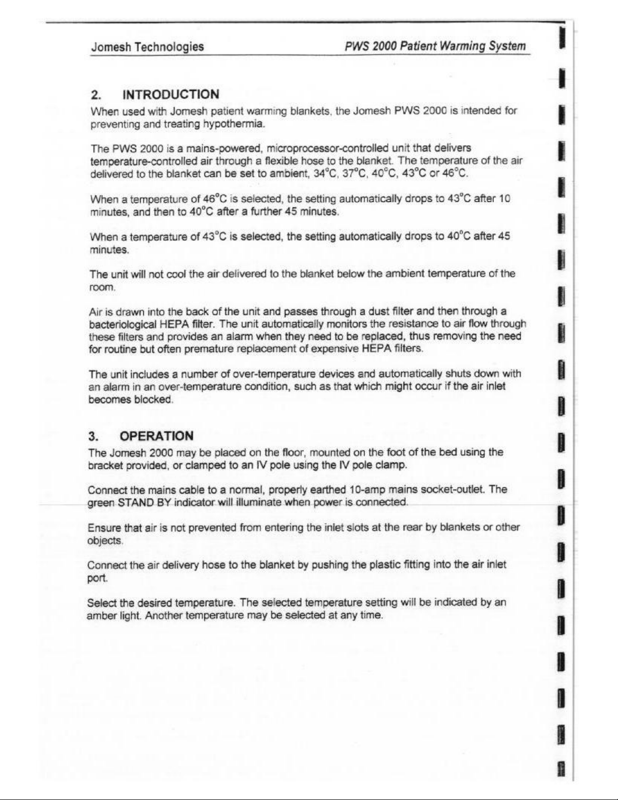
1.
(GENERAL
[Model
(Supply
Supply
Supply
External
¡Type
[Degree
(Applied
¡Degree
Method
mmm
mmm
mmm
[Degree
[ammable
lairioxygen/nitrous
Mode
Environmental
transport.
PERFORMANCE
‘Temperature
[Temperature
[except
Environmental
ithe
‘Time
¡temperature
following
DIMENSIONS
[Width
Depth
[Height
WEIGHT
SPECIFICATIONS
Number
Voltage
Frequency
Power
Fuses
of
protection
of
protection
Part
of
protection
of
disinfection
of
safety
in
anaesthetic
of
operation [Continuous
conditions
storage
settings
accuracy
for
the
ambient temperature
conditions
specified
required
temperature
to
accuracy
a
change
——
_
against
the
oxide
and
attain
in
electric
against
against
presence of
for
of
temperature
electric
ingress
mixtures
required
operation
delivered
of
delivered
required
accuracy
the
specified
delivered
shock
shock
of
water
with
for
air
air.
setting
to
achieve
air
setting
PWS
2000
[240
Vac + 6%
50
Hz
1300
Watts
2 x 8 Amp
[Class
1
[Type
ВЕ
[Warming
[Not
specified
[Surface
‘moistened
[Not
specified
10°C
to
humidity,
Ambient,
は
2°C
with
[Not
specified
|20°C
to
Inon-condensing
(5
minutes
360
milimetres
210
millimetres
370
milimetres
10
kilograms
Maximum
DA205
Blanket & Delivery
disinfection
with a mild
40°C,
non-condensing
34°C,
delivery
22°C,
5x20mm
is
possible
disinfectant
Less
than
37°C,
40°C,
hose
without
30%
delivery
to
70%
Hose
90%
relative
43°C
cover
hose
relative
m
=
using a cloth
]
|
solution.
or
46°C
cover
humidity,
=
e
Itis a pre-requisite
understand
e
mmm
for
all
the
operating
staff
skilled
procedures
in
using
contained
convective
herein.
patient
warming
devices
to
Page 4
Jomesh
2.
When
preventing
The
temperature-controlled
delivered
When a temperature
minutes,
When a temperature
minutes.
The
room.
Airis
bacteriological
these
for
Technologies
INTRODUCTION
used
with
and
treating
PWS
2000
is a mains-powered,
to
the
blanket
and
then
unit
will
not
cool
drawn
routine
into
the
HEPA
filters
and
provides
but
often
Jomesh
to
patient
hypothermia.
air
through a flexible
can
of
46°C
40°C
after a further
of
43°C
the
air
delivered
back
of
filter.
The
an
premature
be
set
is
is
the
alarm
replacement
PWS
2000
warming
to
selected,
selected,
unit
unit
when
blankets,
microprocessor-controlled
hose
ambient,
the
45
minutes.
the
to
the
blanket
and
passes
automatically
they
of
the
Jomesh
to
the
blanket.
34°C,
37°C,
setting
setting
need
automatically
automatically
below
through a dust
monitors
to
be
replaced,
expensive
HEPA
40°C,
the
ambient
the
resistance
Patient
PWS
unit
The
43°C
drops
drops
filter
thus
filters,
Warming
2000
is
that
delivers
temperature
or
46°C.
to
43°C
to
40°C
temperature
and
then
to air
removing
System
intended
after
after
through
flow
for
of
the
air
10
45
of
the
a
through
the
need
The
unit
includes a number
an
alarm
in
an
becomes
3.
The
bracket
Connect
green
Ensure
blocked
OPERATION
Jomesh
provided,
the
STAND
that
air
objects
Connect
the
port.
Select
amber
the
desired
light.
Another
of
over-temperature
over-temperature
2000
may
be
or
clamped
mains
air
cable
to a
BY
indicator
is
not
prevented
delivery
hose
temperature.
temperature
condition,
placed
will
on
to
an
normal,
illuminate
from
to
the
The
may
such
the
floor,
mounted
IV
pole
using
properly
entering
blanket
selected
be
earthed
when
power
the
by
pushing
temperature
selected
devices
as
and
that
which
on the foot
the
IV
pole
10-amp
is
connected.
inlet
slots
the
plastic
setting
at
any
time.
automatically
might occur
of
shuts
if
the
bed
the
using
clamp.
mains
at
the
socket-outlet.
rear
by
blankets
fitting
into
the
will
be
indicated
down
air
inlet
the
The
or
other
air
inlet
by
an
with
Page 5
Jomesh
The
to
43°C
selecting
THE
CIRCULATION.
The
to
40°C
selecting
Technologies
internal
46°C
intemal
10
minute
after
10
46°C.
SETTING
45
minute
after
45
43°C.
timer
that
minutes
minutes
can
IS
NOT
timer
that
can
automatically
be reset
RECOMMENDED
be
by
automatically
reset
by
decreases
momentarily
ON
decreases
momentarily
PWS
2000
Patient
the
temperature
selecting
PATIENTS
selecting
another
WITH
the
temperature
another
Warming
setting
setting
IMPAIRED
setting
setting
from
and
then
from
and
then
System
46°C.
re-
43°C
re-
‘Switch
unit
The
indicator
+
supply
*
Inthe
4.
+
Use
+
Monitor
+
Do
+
+
the
unit
is
off,
unit
will
will
In
the
event
restricted
blocked
the
electricity
Do
Consider
filter.
problem
and
event
WARNINGS
only
in
patient
not
use
not
apply
discontinuing
off
by
pressing
automatically
illuminate
of a FILTER
by
an
persists,
have
of a FAULT
supply
accordance
on
patients
warm
together
object
Remove
disconnect
the
fiter(s)
and
have
temperature
air
OFF.
switch
such
any
alarm,
with
with
directly
use
off
with
alarm,
as a blanket,
such
replaced
the
these
during
impaired
to
during
The
green
STAND
in an
alarm
condition
the red
check
restriction
the
disconnect
unit
serviced
instructions.
use
an
vascular
FILTER
that
air
as
and
PWS
2000
by a trained
the
with
circulation
open
wound
surgery
indicator
flow
this
will
select
from
technician.
PWS
by a trained
unconscious
BY
indicator
and
the
or the
into
the
be
automatically
the
desired
the
patient
2000
from
technician.
patients.
when
an
will
green
red
back
of
the
temperature
and
from
the
patient
artery
is
illuminate
STAND
FAULT
unit
detected
clamped
when
BY
indicator.
is
not
being
as
a
setting.
the
electricity
and
from
the
the
If
+
Do
not
apply
warm
+
Discontinue
+
Unit
must
+
Ensure
specified
only
the
unit
in
this
use
be
air
directly
in
alarm
condition.
opened
is
subjected
manual
or
serviced
to
to
the
patient
by a trained
the
electrical
safety
from
the
hose.
technician.
and
performance
inspections
as
Page 6
Jomesh
Technologies
PWS
2000
Patient
Warming
System
5.
This
Patient
paramedical,
purposes
Confidence
available
Jomesh
SERVICE
Manual
presents
Warming
of
to
System.
engineering
maintenance
material
any
to
other
Technologies
information,
This
Manual
+
Descriptions
+
Discussion
+
Descriptions
+
All
printed
While
every
responsibilty
product
change
If
you,
as a user
PWS
2000
contact
presents
of
the
of
Electrical
of
the
circuit
board
attempt
is
taken
improvement
without
details
notice.
of
this
or
this
Manual,
are
located
all
the
relevant
This
and
technical
and
repair
the
Jomesh
organisation
Ply.
Ltd.
the
following:
schematic
Safety
necessary
component
has
been
made
for
any
errors
and product
manual,
have
your
on
the
technical
information
personnel.
of
the
Distributor
or
person
Refer
to
the
diagrams.
inspection
preventative
legend,
to
ensure
or
omissions.
specifications
any
relevant
communication
first
page
information
is
provided
This
PWS
2000.
or
PWS
without
previous
for
as a service
information
It
is
2000
the
specific
sections
procedures.
maintenance.
schematic
this
Jomesh
and
comments
with
of
this
Manual.
diagram,
Manual
is
has a policy
component
Jomesh
the
Jomesh
to
medical,
is
intended
provided
Owner
of
accurate
or
would
es
Commercial-in-
and
shall
written
this
permission
Manual
and
parts
and
of
continuous
types
are
questions
be
about
welcomed.
PWS
2000
nursing,
for
the
fair
not
be
made
of
for
operator
list
information.
complete,
subject
no
to
the
Our
The
PWS
2000
has
been
product.
provide a user-friendly
approximately
unit
HEPA
through
‘The
switches
functions.
grouped
(FILTER / FAULT)
after
minutes.
Air
controlled
temperature
The
PWS
2000
operator
0.85
m°/min
through a two-stage
filter.
The
filtered
the
PVC
delivery
PWS
2000
operator
grouped
The
into
10
minutes. A set
temperature
by
into
OFF
PWS
2000
OFF (STAND
functions.
temperature of
is
measured
the
microcontroller.
cutout
switches
filter
replaced.
designed
utilises
(30
air
passes
hose.
controls
(STAND
operator
BY),
A
as
to
provide a sophisticated
microcontroller
interface.
f/m)
system
consist
ON
set
it
exits
The
Airfiow through the
by a mains-powered fan
comprising a replaceable
over a 1250
of
BY)
and
indicators
(34°C / 37°C / 40°C / 43°C / 46°C)
temperature
43°C
the
PWS
and a pressure
Patient
technology
Watt
seven
automatically
unit
2000
switch
front
ON
(34°C / 37°C / 40°C / 43°C / 46°C)
consist
of
46°C
by a digital
includes
that
to
control
PWS
blower.
dust
heating
of
automatically
element
panel
push-button
nine
front
decreases
temperature
two
independent
detects
when
Warming
all
functions
2000
is
maintained
Room
air
filter
and a replaceable
and
exits the
membrane
panel
visual
and
ALARM
decreases
to
44°C
after
sensor
over-
the
filter(s)
System
and
at
enters
the
unit
indicators
to
43°C
45
and
need
to
be
Page 7

Jomesh
Technologies
PWS
2000
Patient
Warming
System
6.
This
the
‘Schematic
The
+
+
«
‘The
SCHEMATIC
section
Printed
describes
Circuit
Board (PCB)
Diagrams
following
The
Schematic
Electrical
a
schematic
Net
labels
logic
PWS
should
Diagrams
connectivity
sheet
(signal
*0”
(eg:
SIGNAL).
2000
Board
assist
or
names)
Microcontroller.
Digital
Reset
Push-button
Fan
LED
Buzzer
Power
Power
temperature
circuit.
and
pressure
and
heater
displays
and
relays.
and
their
its
driver.
supplies.
supply
decoupling
Connectors.
DIAGRAM
the
PWS
DESCRIPTION
2000 schematic
Component
contained
is
net
implements
sensor.
drivers.
in
Section
with
the
interpretation
are
organised
shown
labels
by
on
are
prefixed
the
continuous
partial
following
switches.
capacitors.
diagrams.
Legend
contained
9.
of
the
Schematic
in a fiat
wires
with a forward
structure.
wires
and
between
slash
functions:
Reference
in
net
labels
schematic
when
should
Section 8 and
Diagrams:
on
partial
sheets.
they
are
be
made
to
the
wires
within
asserted
with
a
The more
The Atmel
*
CPU
+
Program
+
RAM
+
Interrupt
External
Counter/Timers
‘Watchdog
Digital
‘The
+
Monitors
*
Monitors
*
Controls
Controls
important
6.1.
Microcontroller
of
AT8958252
ROM
controller
interrupts
timer
Input/Output
microcontroller
the
the
the
the fan
performs
air
temperature
push-button
display
and
these
functions
microcontroller
are
elaborated
(U1)
integrates
ports
the
through
and
pressure
and
buzzer
heater
relays.
following
drivers.
functions:
the
digital
switches.
below.
a
number
temperature
of
functions:
sensor.
Page 8

Jomesh
The
software
of a microcontroller
The
8
technique
controlled
When
+
Digital
+
Signal
The
+
Signal
The
‘Thus
off
with
Technol
microcontroller
program
6.2.
Dallas
6.3.
the
Digital
DS1820
that
by
and
Reset
microcontroller
Input/Output
/FAN_RELAY
fan
blower
/HEAT_RELAY
heater
the
reset
the
heater
ROM
contained
fault,
Jomesh
Temperature
direct-to-digital
utilises
communicates
low
Circuit
is
ports
goes
is
switched
goes
is
switched
process
being
off.
implements a safety
tumed
is
0 - 3 go
factory
in
programmed
the
microcontrolier
must
temperature
and
high
temperature
with
the
reset
either
high.
low
switching
on.
high
switching
on.
PWS
with
ROM
ft a replacement
Sensor
sensor
coefficient
microcontroller
by
power-on
on the
fan
off
the
strategy
2000
the
application
is
subject
part
(U4)
measures
oscillators.
(U1)
over a single
or
by
the
watchdog
relay.
heater
to
relay.
prevent
Patient
to
Warming
software
copyright.
temperature
The
sensor
“wire”.
timer
the fan
blower
System
program.
In
the
event
through
is
being
turned
7
The
Power-On
Following
connected
asserted
Watchdog
The
hardware.
To
prevent
overflows
software
watchdog
microcontroller
from
Reset
power-on
to
ground.
high.
Reset
microcontroller
When a watchdog
such a system
by
the
application
malfunction,
timer.
This
from
occurring.
capacitor
watchdog
running
(C3)
This
causes
timer
timer
reset
the
software
the
application
failure
will
produce a system
out
of
charges
the
is
overflow
microcontroller
software
control.
from
zero
Reset
input
incremented
occurs
program.
If
the
program
This
prevents a potentially
to
of
the
regularly
the
microcontroller
watchdog
microcontroller
will
reset
on
+5V
(VCC)
microcontroller
by the
timer
fail
overflow
through
microcontroller
is
is
reloaded
suffers a hardware
to
load
the
thus
hazardous
resistor
to
be
momentarily
reset.
microcontroller
preventing
before
situation
(R1)
it
or
the
Page 9

Jomesh
Technologies
PWS
2000
Patient
Warming
System
6.4.
The
System
PWS
2000
+
Mains
Over-temperature
Mains
Heater.
Fan
biower.
Control
Solid-state
Before
removing
subassemblies,
connections
The
System
does
warrant
7.
PREVENTATIVE
7.4.
It
is
recommended
PWS
2000.
published
System
Block
electrical
Diagram
and
fuses.
cutout
power
filter
Board.
relay
any
of
make a careful
could
compromise
Block
Diagram
extensive
Electrical
that a program
Information
technical
standards.
Block
Diagram
shows
electronic
the
general
subassemblies:
switches.
the
connections
note
so
that
patient
is
presented
discussion.
MAINTENANCE
Safety
on
the
type
safety
as
Inspection
of
regular
and
frequency
electrical
between
the electrical
these
may
and/or
an
aid
electrical
damage
to
of
testing
connectivity
and
be
correctly
the
understanding
safety
inspections
may
between
electronic
reinstated.
PWS
2000.
the
PWS
be
be
obtained
the
various
Incorrect
2000
and
instituted
from
for
the
locally
In
Australia,
+
AS3511
This
programs
management
safety,
・
AS2500
This
equipment
patient
installations
A
Hospital
by
Jomesh
electrical
Programmed
patient
the
relevant
Technical
standard
for
medical
and
essential
Guide
standard
provides
used
and
operator
to
Biomedical
or
the
Jomesh
safety
inspections
electrical
safety.
Mandatory,
apply.
technical
management
specifies
safety
to
in
be
procedures
devices.
routine
health
used
testing
and
performance
the
safe
use
a
comprehensive
care
facilities.
safety,
including
for
particular
Some
Engineering
distributor
and
providing
safety
inspections
statutory
standards
programs
required
of
medical
of
these
are:
for
medical
to
develop
include
devices.
testing.
of
electricity
details
medical
Department
would
suitable
are
requirements
in
patient care.
guide
to
the
Measures
of
are
the
classes
procedures.
or
third
party
be
capable
of
test
documentation
essential
for
electrical
devices.
equipment
procedures
This
standard
safe
use
detailed
of
service
performing
to
confirm
safety
management
for
specifies
of
electrically
to
provide
equipment
organisation
the
continued
inspections
acceptance,
fault
electrical
operated
and
maintain
and
electrical
nominated
necessary
operator
and
may
also
Page 10

Jomesh
Technologies
PWS
2000
Patient
Warming
System
7.2.
The
PWS
adequately
Required:
+
PWS
+
Digital
‧
Light-weight
STEP
1
if
Place
(Do
‘Connect
|Familiarise
|with
[The
+
|*
+
+
|*
・
[The
'*
。
|
Performance
2000
verify
2000
Instruction
Thermometer.
you
have
the
not
connect
reference
temperature
Ensure
Ensure
humidity,
Place
Check
following
Check
to
within
Note
that
delivered
hose.
the
degree
filter
Select
Progressively
light-weight
With
new
before
Inspection
does
not
require
the
PWS
2000
&
Service
plastic
the
the
The
occlusion
the
the
bag.
not
already
PWS
2000
the
PWS
yourself
to
the
delivery
that
the
non-condensing,
digital
that
the
a
change
that
the
42°C
some
air
is
magnitude
to
which
Ambient
occlude
plastic
filters,
“Filter”
done
on a firm, level
PVC
delivery
2000
to
with
the
the
PWS
2000
control system
hose
environmental
thermometer
temperature
in
set
temperature
variation
possible
of
the
the
monitoring
temperature
the air
bag
until
it
should
alarm
occurs.
adjustment
functions.
Manual.
so,
the
240V
operation of
is verified
cover
of
temperature.
of
between
because
heat
hose
system
the
be
possible
or
calibration.
PROCEDURE
read the
hose
Instruction
is
conditions
sensor
delivered
delivered
of
is
longitudinally
setting.
inlet
“Filter”
PWS
surface.
to a warming
supply
loss
louvres
mains.
the
PWS
and
as
follows:
undamaged
are
in
the
centre
air
stabilises
air
corresponds
the
set
temperature
the
heat
will
depend
is
verified as
on
alarm
to
occlude
A
performance
2000
the
Instruction
blanket.
2000
by
operating
Service
and
20°C
loss
compressed
ocours.
almost
Manual.
that
it
covers
to
22°C,
30%
of
the
PVC
within
that
on
the
follows:
rear
of
five
with the
and
temperature
occurs
ambient
or
the
PWS
all
of
the
inspection
and
Service
the
the
entire
to
70%
delivery
(5)
minutes
set
temperature
in
the
PVC
temperature
extended.
2000
air
inlet
will
Manual.
PWS 2000
hose.
relative
hose
outlet.
of
delivery
using
louvres
|
and
Ee
a
Page 11

Jomesh
Technologies
PWS
2000
Patient
Warming
System
7.3.
‘The
PWS
performance
of
those
Items
+
+
‘Shorting
Required:
PWS
Digital
STEP)
1
_|if
2
|e
+
‘+
3
|»
・
+
>
'»_
5
[Replace
|At
8
[Place
7
[Important
the
(components
8
[Check
jattains
9
|*
+
+
|e
10
|Replace
11
[Confirm
inspection
Over-Temperature
2000
inspection.
responsible
2000
Disconnect
Remove
Ensure
Instruction
Thermometer.
link
comprising
you
have
Place
the
Do
not
Disconnect
Locate
Locate
Securely
Repeat
the
Remove
front
panel.
Remove
the
the
this
stage,
the
Ambient
tnat the
70+10°С.
that
the
thet
Cutout
over-temperature
This
for
the
8:
Service
two
not
already
PWS
2000
connect
the
the
connect
digital
Connect
may
step 3 above.
the
front
as
the
the
PWS
front
panel
eight
solid-state
front
fit
temperature
PWS
the PWS
shorting
all
the
detailed
(8)
front
panel.
the
panel
screws
thermometer
the
be
demaged
2000
internal
panel
PWS
cutout
test
is
technical
4mm
done
on a firm,
PVC
delivery
2000
with
Philips
relay
shorting
by
reversing
sufficient
PWS
setting.
ceases
2000
from
link
from
wiring
by
reversing
2000
functions
in
Section
function
entirely
management
Manual.
ring
terminais
PROCEDURE
so,
read
level
hose
from
the
the
warning
head
which
is
link
only
sensor
2000
to
The
by
excessive
operation
the
the
solid-state
is
correctly
7.2
Testing
does
not
require
optional
the
240V
screws
mounted
across the
step 3 above,
to
in
the
fan
240V
step 3 above.
correctly
and
may
of
the
PWS
joined
PWS
surface.
to a warming
label.
located
hold
the
centre
240V
must
heat.
when
supply
reinstated.
by
2000
Instruction
supply mains.
around
on
the
solid-state
the
front
of
the
supply
operate
the
temperature
mains.
relay
output
by
undertaking
adjustment,
be
performed
2000.
10cm
of
10Amp
and
blanket.
the
perimeter
_
inside
panel
of
the
left
relay
output
in
place.
PVC
delivery
mains
and
immediately
during
this
test
of
terminais.
a
performance
calibration
at
the
discretion
rated
wire.
Service
of
the
panel.
terminais.
hose
outlet.
otherwise
delivered
or
Manual.
select
air
=
|
7.4.
‘The
PWS
replaceable
replacement
Filter
2000
has a two-stage
HEPA
filter.
when a “Filter”
Replacement
filter
The
dust
filter
alarm
occurs.
system
comprising a replaceable
or
both
the
dust
filter
and
HEPA
dust
filter
filter
may require
and
a
Page 12

SY
Jomesh
Items
+
Replaceable
Replaceable
STEP,
1
2
10
n
12
13
14
Technologies
Required:
PWS
2000
Instruction
Philips
ola
Number 1 Screwdriver.
dust
HEPA
İf
you
have
not
¡+
Place
the
PWS
|»
Do
not
connect
le
Connect
[Determine the
la.
Select
le
Confirm
[Disconnect
le
Locate
|
Remove
panel.
|+
Remove
le
Remove
»
Replace
Replace
At
this
Again,
«
Select
‘=
Confirm
・
Ifthe
next
+
Ifthe
replaced.
Ifyou
Repeat
Remove
Remove
securing
+
Remove
je
Remove
le.
Replace
Ensure
Replace
Replace
[Confirm
inspection
the
occluded
the
Ambient
that
the
the
rear
the
the
the
the
the
rear
stage,
fit
determine
the
Ambient
that
“Filter”
step.
“Filter
Proceed
wish
to
step 5 above.
the
the
the
the
frame.
the
the
the
HEPA
the
frame
the
rear
that
the
as
detailed
filter.
filter.
already
PWS
the
PWS
eight
rear
dust
dust
screws
the
alarm
alarm
replace
dust
four
HEPA
HEPA
HEPA
PWS
&
Service
2000
the
PVC
2000
temperature
“Filter”
2000
panel
(8)
panel.
filter
filter
panei
by
the
occluded
temperature
‘Filter’
occurs,
does
to
filter.
(4)
Philips
fitter.
filter
filter
filter gasket
securing
panel
2000
in
Manual.
done
so,
on a firm,
delivery
to
the
state
of
the
alarm
from the
with
the
Philips
with a new item.
sufficient
step
the
by
head
and
discard.
reversing
state
alarm
then
not occur,
13.
HEPA
head
and
discard
with a new
the
HEPA
reversing
functions
Section
PROCEDURE
read
the
PWS
level
240V
occurs.
air
only
does
filter
is
surface.
hose
to @ warming
supply
filter(s)
setting.
240V
inlet
screws
step 5 above.
to
of
the
setting
or
the
HEPA
then
screws
item.
located on the
filter
step 5 above.
correctly
mains.
as
follows:
supply
louvres.
located
hold
the
filter(s)
does
filter
the
anyway,
located
by
reversing
7.2.
PWS
2000
Patient
2000
Instruction
blanket.
mains.
around
rear
as
not occur.
must
HEPA
filter
proceed
near
air-off
by
undertaking
the
panel
follows:
in
be
replaced.
does
to
the
the
comers
face
of
step
Warming
and
Service
perimeter
place.
not have
next
the
filter.
10
above.
a
performance
of
Proceed
tobe
step.
of
the
frame
System
Manual.
the
rear
|
|
|
to
the
|
Page 13

Jomesh
Technologies
PWS
2000
Patient
Warming
System
CONTROL
BOARD
COMPONENT
LEGEND
Page 14

Jomesh
Technologies
PWS
2000
Patient
Warming
System
Page 15

Jomesh
Technologies
PWS
2000
Patient
Warming
System
9.2.
System
Block
Diagram
|
|
em
Mom
1omrNoo
Page 16

Jomesh
Technologies
PWS
2000
Patient
Warming
System
10.
PARTS
10.1.
PART
LIST
General
KUNDER
ddddda
1
TEE
Por
IO7.3
19 5 SU-12
04300.
有朋
μπας
РСТ
еда
106
sz
Ро
Temos
|
ES
TES
Assembly
DESCRIPTION
(Board
‘Cone
Raney,
ne
Karam,
[Саба
давать,
Ea
Asem
fes
Asse.
[cade
Asse,
[Cable
Assembly,
Cale
Assembly,
(Cab
Asma
Ea
Assenti
ae
Kam
[Се
Зо
Eco
IV
Poke
EA
06 で で 3 Per
[bel
HEPA
(Fer,
Pret
(Fano.
Hose.
[Foot
Rubber.
ie,
Am,
1000.
10004,
[Label
Swen
Wang
Tao,
Assembly,
Seka
[Erich
Mio,
İSA
Thermal NE
Comat
read Chas
Gru
Power,
Por
oie
Power,
Power,
Power,
For
Power,
Gay
Вы
Camp
ae
Бо
12122,
os,
Slant
Bower
Grey,
Dolny
Some,
1400.
sing
Test Pack
Sate,
OC
NO
Fer
Grass
Fei
Fe
lia
Hester
Maine
Pug
Treml
TRE
Can
Тот
Gant
em
End,
Sack
End,
Black
SeAdhesive
Panel
19000
CH,
Zero Y Sah
SOR
Opening
lr
Sue
Fier
Term
Sr
Fier
Gara
Fier,
8
Ray,
Far
Sold
Ste
Corin à Chamas
Sela
mul
Sh
Thema
Bar
Gn
Cable
TOR
on
AN
ON
Face
Mou
Br
Taba
DNS
amparo
Ral
ard
Fan
Chasis
Relay
F:
Siti
Sae
Fay
BA
Load
EEE
Page 17

Jomesh
Technologies
PWS
2000
Patient
Warming
System
(ERC
=
Em
oz
En
区
ERİ
Em
DIZ
1081
回
a
12
Pes
a
回
[Rê
a
RT
ru
回
Gu
回
στ
τος
στ
品
E
10.2.
DESIGNATION
而
而
Control
[MANUF.
A
TE
Ser
Piles
Raye
Tico
д
R
Laine
Tanem
а
Tae
Woes
74800.
Wacomp
cies
A
A
Rat
at [5
Word
Waa
e
Te
ar
ai
me
Board
[PARTAUMBER
A
İz
ПОЗ
22000
бт
A
A
La
—[OWE218082
İTE
ОГ
ei
TIZI
ETO
ok
|
RESEN
O
A
[314001
140.023
PFT
БИ
rss
[ет
E
İsme
[DESCRIPTION
Cover
em
Sd
re
Erp,
aşar
[Capra
(Diode,
(Diode,
m)
AAA
eser
A
[Resistor,
iia
Teror
ie
(or 1 ANRT,
Corni
Capac,
Sec,
Crane
ci,
Smal
Signal
Bridge,
[Fuse
ender.
NES,
Rand
Sar
Ba PR
0.250
Ne
i
Prose
Mane
none
Dari
OI
ee
equi
Crt
Bow
Rin
EVE
507
ka
504,
29V
75V
400V
TA
Pr
PCB
Pr,
Fen
POE
1%
Va
Cd,
TOR
NO,
DIRO
Sap
OK
Sör
TO
ear
Doe
nm
POE
Tör
OF
PR
Низы
ОЕ
0203
0
Ph
Ra
07
PM
150mA_
(4
Pin
Plasto
DIP)
TEN
Sama
Wr. 4 Way,
ek
Moe © Way,
Va
Rear
cda
Deer
AVAYA
Fan
ZA
Precio
Pra
AS
ACTA)
Sed
OF
FCB
Wat 7 War
OT
BA
Canes
Common
OPA
Pin
Pini
DE
PRIS
EVO
Coni
PTH
Pa
PR
Pack
PER
PH
Gee
ES
PSE
ZE)
af
TO) | 1.
OT
Tİ
T
τ
PRA,
Ta
a
2
|
τ
7
T
|
τ
Ξ
i
т
E
7
7
т
7
т
Page 18

Report
No:
M000546
Page
2of
16
Test
Sample:
Model
Number:
‘Serial
Number:
Manufacturer:
Tested
For:
Address:
rest
Standards
Certificate
EMC
Technologies
Issue
Patent
Warming
Jomesh
2078
PWS
Biomedical
Biomedica!
РО
Box
Elhem,
+613
Vl
9458
of
Date:
2600
Engineering
Engineering
856,
3095
1963
+813 9456 2088
Peter
Ampi
IEC
601-4-2:
‘Medical
safety
Requirements
EN85011:
IEC
801-2:
IEG
801-3:
1EC
801-4:
IEC
801-5:
1999 / ASINZS
electrical
2.
Collateral
and
1998 / ASINZS2064:
1991
1992
(Draft)
1988
(Draft)
Compliance
Report
4%
No:
M000546
July,
2000
System
Company
Company
of
of
Australia
Australia
2200.1.2:
equipment
Standard:
tests
immunity
Immunity
immunity
Part
1:
Electromagnetic
1907
to
Electrostatic
Immunity
to
to
Electrical
to
High
Voltage
Australia
Ply
Lic
Ply
Ltd
1995
General
Radiated
requirements
compatibility
Emission
Discharges
Fields
fast
Transients
Surges
for
-
Result
of
Test:
‘Tost
Dates:
Test
Officers:
‘Authorised
5292
Signature:
Issued
by
EMC
Phone:
Tie
Australia.
of
accreditation.
Laboralory
The
test
sample
Refer
to
Report
23“
May
to 2 June
Philips
Technologies
Technologies
+61
Tho
loss
Pty.
Ltd.,
393353333
Ts
accredied
reported
by
herein
complied
M000546
2000
Pty
57
Assembly
Fax:
+61
39338
the
National
have
been
with
the
above
standards.
for
full
details
Lid
Dve.,
Tullamarine,
9260 | www.emctech.com.au
Assocation
performed
of
in
accordance
Vic.,
3043,
Testing
Author
with
its
terms
Australia.
 Loading...