

Page 1

SERVICE MANUAL
NELLCOR SYMPHONY
®
N-3100 Blood Pressure Monitor
To contact Nellcor Puritan Bennett’s representative: In the United States, call 1-800-NELLCOR or 510 463-4000; outside the
United States, call your local Nellcor Puritan Bennett representative.
Caution: Federal law (U.S.) restricts this device to sale by or on the order of a physician.
© 1998Nellcor Incorporated. All rights reserved. 034134B-0298
Page 2

Corporate Headquarters
Regional/Local Offices
Nellcor Puritan Bennett Inc.
4280 Hacienda Drive
Pleasanton, California 94588 U.S.A.
Tel. 510 463-4000 or
1-800-NELLCOR
Fax 510 463-4420
U.S. Service Repair Center
Nellcor Puritan Bennett Inc.
2200 Faraday Avenue
Carlsbad, California 92008
U.S.A.
Tel. 619 603-5300
European Office
Nellcor Puritan Bennett Europe BV
Hambakenwetering 1
5231 DD ’s-Hertogenbosch
The Netherlands
Tel. +31.73.6485200
Asia/Pacific Office
Nellcor Puritan Bennett HK Ltd.
Room 1602 Evergo House
38 Gloucester Road
Wanchai
Hong Kong
Tel. +852.2529.0363
Nellcor Puritan Bennett UK Ltd.
10, Talisman Business Centre
London Road
Bicester
Oxfordshire OX6 0JX
United Kingdom
Tel. +44.1869.322700
Nellcor Puritan Bennett Belgium
NV/SA
Interleuvenlaan 62/8, Zone 2
B-3001 Heverlee
Belgium
Tel. +32.16.400467
Nellcor Puritan Bennett France
3 Avenue du Canada, Bâtiment
Sigma
LP851
91975 Courtaboeuf Cedex
France
Tel. +33.01.69.82.14.00
Nellcor Puritan Bennett Germany
GmbH
Black-&-Decker-Strasse 28
65510 Idstein
Germany
Tel. +49.6126.5930
Nellcor Puritan Bennett Italia
Via Edison, 6
20090 Assago (MI)
Italy
Tel. +39.2.4577161
Nellcor Puritan Bennett Finland Oy
Kappelitie 8
02200 Espoo
Finland
Tel. +358.90.270.92.900
To obtain information about a warranty, if any, for this product, contact Nellcor
Puritan Bennett’s Technical Services Department or your local Nellcor Puritan
Bennett representative.
NELLCOR SYMPHONY and the Nellcor knob configuration are trademarks of Nellcor
Puritan Bennett Inc.
Page 3

TABLE OF CONTENTS
List of Figures
List of Tables
Section 1: Introduction
1.1 Manual Overview.......................................................................... 1-1
1.2 Warnings, Cautions, and Notes.................................................... 1-1
1.2.1 Warning........................................................................... 1-1
1.2.2 Caution............................................................................ 1-1
1.2.3 Note................................................................................. 1-1
1.3 N-3100 Blood Pressure Monitor Description ................................ 1-1
1.4 Related Documents...................................................................... 1-2
Section 2: Routine Maintenance
2.1 Cleaning ....................................................................................... 2-1
2.2 Periodic Safety and Functional Checks........................................ 2-1
2.3 Batteries ....................................................................................... 2-1
Section 3: Performance Verification
3.1 Introduction................................................................................... 3-1
3.2 Equipment Needed....................................................................... 3-1
3.3 Performance Tests....................................................................... 3-1
3.3.1 Power-up......................................................................... 3-1
3.3.1.1 Power-On Self-Test ........................................................ 3-1
3.3.1.2 Power-On Defaults for Adult-Pediatric Alarm Limits
3.3.1.3 Power-On Defaults for Neonatal Alarm Limits
3.3.2 Verification of Pneumatic System ................................... 3-10
3.3.2.1 Pressure Transducer Accuracy....................................... 3-11
3.3.2.2 Pneumatic Leakage —Adult............................................ 3-12
3.3.2.3 Pneumatic Leakage—Neonate....................................... 3-12
3.3.2.4 Cuff Inflation Rate ........................................................... 3-13
3.3.2.5 Cuff Deflation Rate.......................................................... 3-13
3.3.2.6 High-Pressure—Adult ..................................................... 3-14
3.3.2.7 High-Pressure—Neonate................................................ 3-14
3.3.3 Pulse Rate Accuracy Tests............................................. 3-15
3.3.3.1 Pulse Rate Accuracy Test —Adult.................................. 3-15
3.3.3.2 Pulse Rate Accuracy Test —Neonate ............................ 3-16
3.4 Safety Tests ................................................................................. 3-16
3.4.1 Ground Integrity .............................................................. 3-16
3.4.2 Electrical Leakage........................................................... 3-17
3.4.2.1 Earth Leakage Current.................................................... 3-17
3.4.2.2 Patient Leakage Current ................................................. 3-18
3.4.2.3 Patient Leakage Current (MOAP)................................... 3-18
............................................................................... 1-1
................................................................ 2-1
.......................................................... 3-1
and Ranges................................................................. 3-3
and Ranges.................................................................. 3-7
iii
Page 4

Table of Contents
Section 4: Configuration and Service Modes
........................................... 4-1
4.1 Introduction................................................................................... 4-1
4.2 Configuration Mode...................................................................... 4-1
4.2.1 Adult-Pediatric/Neonatal Mode Default........................... 4-3
4.2.2 Systolic Upper Alarm Limit.............................................. 4-3
4.2.3 Systolic Lower Alarm Limit.............................................. 4-3
4.2.4 Diastolic Upper Alarm Limit............................................. 4-3
4.2.5 Diastolic Lower Alarm Limit............................................. 4-3
4.2.6 Mean Upper Alarm Limit ................................................. 4-4
4.2.7 Mean Lower Alarm Limit ................................................. 4-4
4.2.8 Pulse Rate Upper Alarm Limit......................................... 4-4
4.2.9 Pulse Rate Lower Alarm Limit......................................... 4-4
4.2.10 Alarm Volume ................................................................. 4-5
4.2.11 Alarm Silence Duration ................................................... 4-5
4.2.12 Auto Measurement Cycle Interval................................... 4-5
4.2.13 Configuration Menu......................................................... 4-6
4.3 Service Mode................................................................................ 4-7
4.3.1 Menu Item 1: Software Version Report........................... 4-10
4.3.2 Menu Item 2: Lamp Test Mode....................................... 4-10
4.3.3 Menu Item 3: Button Test Mode...................................... 4-10
4.3.4 Menu Item 4: Speaker Test Mode................................... 4-11
4.3.5 Menu Item 5: Internal Configuration
Code (ICC) Report..................................................... 4-12
4.3.6 Menu Item 6: Total Operating Hours Report................... 4-12
4.3.7 Menu Items 7-16: Error Log Record Report.................... 4-12
4.3.8 Menu Item 17: Instrument Identification (IID) Report ...... 4-13
4.3.9 Menu Item 18: Power and Battery Status Report ........... 4-13
4.3.10 Menu Item 19: Persistent Time Sense Report................ 4-14
4.3.11 Menu Item 20: Reset to Factory Defaults........................ 4-14
4.3.12 Menu Item 21: Initial Cluster Instrument Number
(CIN) Selection.......................................................... 4-14
4.3.13 Menu Item 23: Enable/Disable Alarm
Silence Reminder....................................................... 4-15
4.3.14 Menu Item 24: Pressure Calculation
Algorithm Selection.................................................... 4-15
4.3.15 Menu Item 29: Instrument Compatibility Report.............. 4-16
4.3.16 Menu Item 30: Pressure Transducer
Accuracy Test Mode .................................................. 4-16
4.3.17 Menu Item 31: Inflation Time Test Mode ........................ 4-17
4.3.18 Menu Item 32: Deflation Rate Test Mode ....................... 4-17
4.3.19 Menu Item 33: Adult Leak Test Mode ............................. 4-18
4.3.20 Menu Item 34: Neonate Leak Test Mode........................ 4-18
4.3.21 Menu Item 35: Adult Maximum Pump
Pressure Test Mode................................................... 4-19
4.3.22 Menu Item 36: Neonate Maximum Pump
Pressure Test Mode................................................... 4-19
4.3.23 Menu Item 37: Blood Pressure Module
Self-Check Report...................................................... 4-20
iv
Page 5

Table of Contents
Section 5: Troubleshooting
5.1 Introduction................................................................................... 5-1
5.2 How to Use this Section ............................................................... 5-1
5.3 Who Should Perform Repairs....................................................... 5-1
5.4 Replacement Level Supported..................................................... 5-1
5.5 Obtaining Replacement Parts ...................................................... 5-1
5.6 Troubleshooting Guide................................................................. 5-2
5.6.1 AC Power........................................................................ 5-3
5.6.2 Error Codes..................................................................... 5-4
5.6.2.1 User-Correctable Error Codes ........................................ 5-4
5.6.2.2 Failure Error Codes......................................................... 5-5
5.6.3 Buttons ............................................................................ 5-7
5.6.4 Display/Alarms ................................................................ 5-7
5.6.5 Operational Performance................................................ 5-8
5.6.6 Stacked Configuration..................................................... 5-8
Section 6: Disassembly Guide
6.1 Introduction................................................................................... 6-1
6.2 Fuse Replacement ....................................................................... 6-1
6.3 Monitor Disassembly .................................................................... 6-2
6.3.1 Replacing the Piezo Speaker.......................................... 6-3
6.3.2 Replacing the Monitor Speaker....................................... 6-4
6.3.3 Replacing the Hose Fitting.............................................. 6-5
6.3.4 Removing the UIF Board................................................. 6-5
6.3.5 Removing the Pump Module........................................... 6-7
6.4 Lithium Battery Replacement ....................................................... 6-8
6.5 Reassembly.................................................................................. 6-8
Section 7: Spare Parts
7.1 Introduction................................................................................... 7-1
Section 8: Packing for Shipment
8.1 General Instructions ..................................................................... 8-1
8.2 Repacking in Original Carton ....................................................... 8-2
8.3 Repacking in a Different Carton ................................................... 8-3
Section 9: Specifications
9.1 General......................................................................................... 9-1
9.2 Electrical....................................................................................... 9-1
9.3 Physical Characteristics ............................................................... 9-1
9.4 Environmental .............................................................................. 9-1
9.5 Alarms .......................................................................................... 9-2
9.6 Factory Defaults ........................................................................... 9-2
9.7 Performance................................................................................. 9-3
Appendix
...................................................................................................... A-1
A1 Integrity Test................................................................................. A-1
A2 Error Types................................................................................... A-2
A3 User-Correctable Error Codes...................................................... A-3
A4 Failure Error Codes...................................................................... A-4
A5 Internally Corrected Error Codes.................................................. A-4
........................................................................ 5-1
................................................................... 6-1
................................................................................ 7-1
............................................................... 8-1
............................................................................ 9-1
v
Page 6

Table of Contents
LIST OF FIGURES
Technical Supplement
................................................................................ S-1
S1 Introduction................................................................................... S-1
S2 Overview ...................................................................................... S-1
S3 Stackbus Interconnect.................................................................. S-2
S4 Circuit Analysis............................................................................. S-3
S4.1 Functional Overview ....................................................... S-3
S4.2 Detailed Circuit Analysis ................................................. S-5
S4.2.1 UIF/Power Supply Module .............................................. S-5
S4.2.2 Blood Pressure Module................................................... S-9
S4.2.3 Display Board.................................................................. S-10
S5 Schematic Diagrams .................................................................... S-11
1-1 N-3100 Front Panel (North American) .............................................. 1-2
1-2 N-3100 Front Panel (International) ................................................... 1-2
3-1 Self-Test Display .............................................................................. 3-2
6-1 Fuse Replacement............................................................................ 6-2
6-2 N-3100 Corner Screws ..................................................................... 6-2
6-3 Separating the Monitor and Disconnecting the Cables .................... 6-3
6-4 Removing the Monitor Speaker Assembly........................................ 6-4
6-5 Removing UIF and Display PCBs..................................................... 6-6
6-6 Removing Pump Module................................................................... 6-7
6-7 Installing the Handle ......................................................................... 6-9
7-1 N-3100 Expanded View .................................................................... 7-2
8-1 Repacking the N-3100 ..................................................................... 8-2
S2-1 Oscillatory Blood Pressure Measurement ........................................ S-2
S4-1 N-3100 Functional Block Diagram................................................... S-4
S4-2 Internal/External Bus Connections ................................................... S-5
S4-3 Speaker Driver and Volume Control Block Diagram ........................ S-8
S4-4 Display Board Block Diagram........................................................... S-10
LIST OF TABLES
3-1 Earth Leakage Current Limits........................................................... 3-17
3-2 Patient Leakage Current Limits ........................................................ 3-18
3-3 Patient Leakage Current Test Configurations................................... 3-19
4-1 Configuration Mode Menu ................................................................ 4-2
4-2 Service Mode Menu.......................................................................... 4-9
5-1 Problem Categories.......................................................................... 5-2
5-2 Power Problems................................................................................ 5-3
5-3 N-3100 User-Correctable Error Codes ............................................ 5-4
5-4 N-3100 Failure Error Codes.............................................................. 5-5
5-5 Button Problems ............................................................................... 5-7
5-6 Display/Alarms Problems ................................................................. 5-7
5-7 Operational Performance Problems ................................................. 5-8
5-8 Stack Problems................................................................................. 5-8
A-1 Error Types....................................................................................... A-2
A-2 N-3100 Failure Error Codes.............................................................. A-4
A-3 N-3100 Internally Corrected Error Codes ........................................ A-5
S4-1 J1 Connector..................................................................................... S-8
S4-2 J5 Upper Inter-Stack Connector ....................................................... S-9
S4-3 J2 Speaker Connector...................................................................... S-9
vi
Page 7

SECTION 1: INTRODUCTION
1.1 Manual Overview
1.2 Warnings, Cautions, and Notes
1.3 N-3100 Blood Pressure Monitor Description
1.4 Related Documents
1.1 MANUAL OVERVIEW
This manual contains information for servicing the NELLCOR SYMPHONY
N-3100 blood pressure monitor. Only qualified service personnel should
service this product. Before servicing the N-3100, read the operator’s manual
carefully for a thorough understanding of operation.
1.2 WARNINGS, CAUTIONS, AND NOTES
This manual uses three terms that are important for proper operation of the
monitor: Warning, Caution, and Note.
1.2.1 Warning
A warning precedes an action that may result in injury or death to the
patient or user. Warnings are boxed and highlighted in boldface type.
1.2.2 Caution
A caution precedes an action that may result in damage to, or malfunction of,
the monitor. Cautions are highlighted in boldface type.
1.2.3 Note
A note gives information that requires special attention.
1.3 N-3100 BLOOD PRESSURE MONITOR DESCRIPTION
The N-3100 is a noninvasive blood pressure monitor that measures systolic,
diastolic, and mean arterial blood pressure. It also derives the patient’s pulse
rate at the time of blood pressure measurement. The N-3100 is intended for
hospital use to monitor adult, pediatric, or neonatal patients. The N-3100 can
be used in mobile environments when stacked with the N-3000, the N-3200,
or both. When used in mobile environments, the N-3100 must be protected
from excessive moisture such as direct rainfall.
The N-3100 can operate as a standalone monitor or it can be connected to
(stacked with) other NELLCOR SYMPHONY instruments, such as the
N-3000 pulse oximeter, the N-3200 display/printer, or both.
The physical and operational characteristics of the monitor are described in
the operator’s manual and Section 9, Specifications, of this manual.
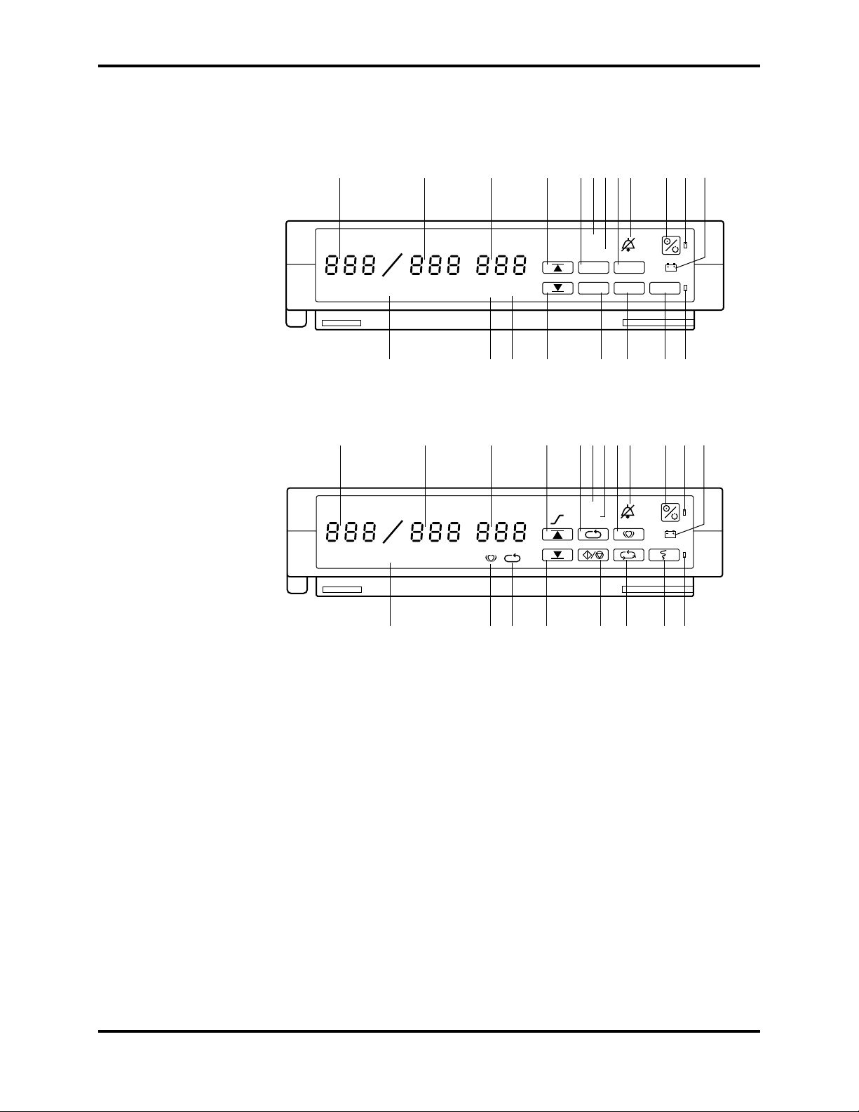
Figures 1-1 and 1-2 depict the North American and International front panels
of the N-3100 and the names of its displays and controls.
1-1
Page 8
Section 1: Introduction
Note: All graphics presented in this manual relevant to the monitor are
depicted in the International symbol format. Refer to your operator’s
manual and Figures 1-1 and 1-2 of this manual for applicable
translations.
1 2
SYSTOLIC
mmHg
NEONATAL
20
DIASTOLIC
mmHg
3
PULSE
RATE
19
MEAN
mmHg
CYCLE
18
17
4
567
AUTO
MANUAL
LIMITS
START
STOP
16
9
8
PULSECYCLE
STAT
15
Figure 1-1: N-3100 Front Panel (North American)
MAN
9
8
1 2
SYS
mmHg
NEO
DIA
mmHg
3
MAP
mmHg
567
4
AUTO
10
PRINT
14
10
11
13
11
12
12
1 SYSTOLIC display 11 POWER ON indicator
2 DIASTOLIC display 12 BATTERY IN USE/BATTERY LOW indicator
3 MEAN/PULSE RATE display 13 PRINTER IN USE/STACKED indicator
4 UPPER ALARM LIMIT button 14 PRINT button
5 CYCLE button 15 STAT MODE button
6 AUTOMATIC MODE indicator 16 START/STOP MEASUREMENT button
7 MANUAL MODE indicator 17 LOWER ALARM LIMIT button
8 PULSE button 18 CYCLE indicator
9 AUDIBLE ALARM OFF indicator 19 PULSE RATE indicator
10 ON/STANDBY button 20 NEONATAL MODE indicator
1.4 RELATED DOCUMENTS
To perform test and troubleshooting procedures and to understand the
principles of operation and circuit analysis sections of this manual, you must
know how to operate the monitor. Refer to the N-3100 operator’s manual. To
understand the various Nellcor Puritan Bennett cuffs and hose that work
with the monitor, refer to the individual cuff and hose directions for use.
20
19
18
Figure 1-2: N-3100 Front Panel (International)
1314151617
1-2
Page 9

SECTION 2: ROUTINE MAINTENANCE
2.1 Cleaning
2.2 Periodic Safety and Functional Checks
2.3 Batteries
2.1 CLEANING
Caution: Do not immerse the N-3100 or its accessories in liquid or use
caustic or abrasive cleaners. Do not spray or pour any liquid on the
monitor or its accessories.
To clean the N-3100, dampen a cloth with a commercial, nonabrasive cleaner
and wipe the instrument exterior surfaces lightly. Do not allow any liquids to
come in contact with the power connector, fuse holder, or switches. Do not
allow any liquids to penetrate connectors or openings in the instrument cover.
For cuffs and hoses, follow individual directions for use.
2.2 PERIODIC SAFETY AND FUNCTIONAL CHECKS
The following safety checks should be performed by a qualified service
technician after any repair or opening of the case, upon return of the
instrument from any use outside your institution’s control, or at least every 2
years.
1. Inspect the exterior of the N-3100 and verify that there is no evidence of
damage. Refer to Section 5, Troubleshooting for repair. If the N-3100
cannot be repaired, contact Nellcor Puritan Bennett’s Technical Services
Department or your local Nellcor Puritan Bennett representative.
2. 3 BATTERIES
2. Inspect safety labels for legibility. If labels are not legible, contact
Nellcor Puritan Bennett’s Technical Services Department or your local
Nellcor Puritan Bennett representative.
3. Verify that the monitor performs properly as described in paragraph 3.3.
4. Perform the electrical safety tests detailed in paragraph 3.4. If the unit
fails these electrical safety tests, do not attempt to repair, contact Nellcor
Puritan Bennett’s Technical Services Department or your local Nellcor
Puritan Bennett representative.
5. Inspect fuse(s) for proper rating (AC inlet fuse: 0.8 Amp, 250 Volt). If
necessary, replace as described in paragraph 6.2.
Nellcor Puritan Bennett recommends replacing all instrument batteries at
least every 2 years. To replace the batteries, refer to Section 6, Disassembly
Guide.
If the N-3100 has been stored for more than 30 days and has not been
connected to an SPS power supply, charge the battery before use. A fully
discharged battery requires a 14-hour charge for a full charge. A 6-hour
charge is required for 1 hour of operating time. Connect the N-3100 to an SPS
external power supply during storage to ensure that the battery remains fully
charged and the N-3100 is ready for immediate use.
2-1
Page 10

Page 11

SECTION 3: PERFORMANCE VERIFICATION
3.1 Introduction
3.2 Equipment Needed
3.3 Performance Tests
3.4 Safety Tests
3.1 INTRODUCTION
This section discusses the tests used to verify performance of the monitor. All
tests are accomplished through the control panel.
3.2 EQUIPMENT NEEDED
Equipment Description
AC Power Adapter SPS-I or SPS-I1 (International) or
SPS-N or SPS-N1 (North American)
Electrical Safety Analyzer Must meet current AAMI
specifications
Blood Pressure Simulator Bio-tek “BP Pump” Noninvasive
Blood Pressure Analyzer or
equivalent
3.3 PERFORMANCE TESTS
The following tests are used to verify performance of the N-3100 and should
be performed following troubleshooting and repairs. If the N-3100 fails any
test, refer to Section 5, Troubleshooting.
3.3.1 Power-up
The power-up tests (paragraphs 3.3.1.1 through 3.3.1.3) verify the following
monitor functions:
• Power-On Self-Test
• Power-On Defaults for Adult-Pediatric Alarm Limits and Ranges
• Power-On Defaults for Neonatal Alarm Limits and Ranges
3.3.1.1 Power-On Self-Test
1. Connect the monitor to model SPS-I (or SPS-I1) or model SPS-N (or
SPS-N1) external power supply or, if stacked with the N-3200, connect
AC power to the N-3200.
2. Do not connect any hoses or cuffs to the monitor.
3-1
Page 12
Section 3: Performance Verification
3. Observe the monitor front panel. With the N-3100 in STANDBY (turned
off), press the ON/STANDBY button. In order to successfully complete
the self-test, the monitor must perform the following sequence.
a. The monitor emits three consecutively higher-pitched beeps.
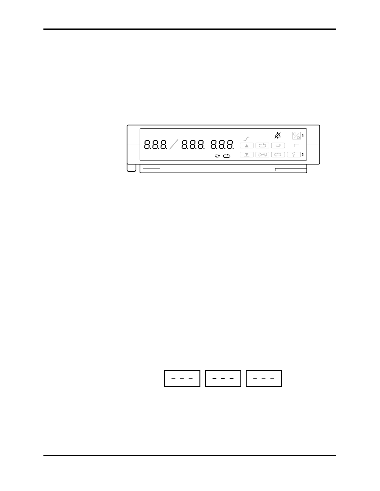
b. All indicators light momentarily as illustrated in Figure 3-1. Verify
that “8.8.8.” is shown in the SYSTOLIC, DIASTOLIC, and
MEAN/PULSE RATE displays.
Note: Slight differences in the brightness of display segments and
indicators are normal and acceptable.
SYS
mmHg
NEO
DIA
mmHg
MAP
mmHg
AUTO
MAN
Figure 3-1: Self-Test Display
c. All displays (except the POWER ON indicator) turn off briefly.
d. Each segment in the digital displays lights individually in sequence
in a scanning, or firefly, test pattern and all indicators light
momentarily.
e. The sequence of steps b and c will be repeated until all internal tests
are complete.
Note: The number of times the sequence of steps b and c is
repeated is dependent on the amount of information stored
in trend memory. Typically, you will see two cycles of the
sequence.
f. A single, 1-second beep is produced and all displays again illuminate
momentarily, indicating the automatic Power-On Self-Test is
complete.
3-2
g. The POWER ON indicator and the MANUAL MODE indicator are
illuminated. A “–” is displayed in each window of the SYSTOLIC,
DIASTOLIC and MEAN/PULSE RATE displays. This is referred to
as the normal mode steady state.
SYS
mmHg
DIA
mmHg
MAP
mmHg
Page 13

Section 3: Performance Verification
Caution: Pressing and holding the NEW PATIENT/NEONATAL
button (3 seconds or more) until three beeps sound clears all
previously stored patient data.
h. Press and hold the NEW PATIENT/NEONATAL button (located on
the rear panel) for approximately 3 seconds until you hear three
beeps to indicate that stored patient data is cleared.
3.3.1.2 Power-On Defaults for Adult-Pediatric Alarm Limits and Ranges
Note: The following procedure is written using Nellcor Puritan Bennett
factory-set power-on default settings. If your institution has other
custom power-on default settings, those values will be displayed and
should be substituted in the following procedure. The N-3100 can be
reset to factory power-on defaults using the service mode procedure
described in Paragraph 4.3.11, Menu Item 20, or configuration mode,
as described in Paragraph 4.2.13, Configuration Menu (item 3).
In the following procedures, each time the UPPER ALARM LIMIT
button or the LOWER ALARM LIMIT button is pressed, the N-3100
will emit a beep.
When observing or changing default limits, a 3-second timeout is in
effect, that is, if no action is taken within 3 seconds, the monitor
automatically returns to the normal operating mode steady state.
The following procedures use the N-3100 UP and DOWN ARROW
buttons located on the top of the monitor. When the N-3100 is
stacked with the N-3000, the N-3200, or both, the Nellcor knob on
either of these units can be used to perform the function of the
N-3100 UP and DOWN ARROW buttons. Turning the Nellcor knob in
a clockwise direction is equivalent to pressing the N-3100 UP
ARROW button. Turning the knob in a counterclockwise direction is
equivalent to pressing the N-3100 DOWN ARROW button. There will
be no sounds or beeps associated with turning a Nellcor knob. When
the N-3100 is stacked with the N-3000, the UP and DOWN ARROW
buttons are not accessible and the Nellcor knob must be used.
1. Press the ON/STANDBY button to turn the unit on. Verify that the
N-3100 is in adult-pediatric mode, which is indicated by the NEONATAL
MODE indicator being off. If the indicator is lit, quickly press and
release the NEW PATIENT/NEONATAL button twice to place the
N-3100 in the adult-pediatric mode. When the unit is in the normal mode
steady state, press and release the UPPER ALARM LIMIT button.
Verify that the monitor emits a single beep when you press the button.
Verify that the SYSTOLIC display indicates the default alarm limit
value of “240” for a few seconds and verify that the other displays show
dashes while the “240” is displayed as shown below. Do not press any
buttons for at least 3 seconds and all displays will change to show a dash
in the center of each character (normal mode steady state).
SYS
mmHg
DIA
mmHg
MAP
mmHg
3-3
Page 14

Section 3: Performance Verification
2. From the normal mode steady state, press and release the UPPER
ALARM LIMIT button. Press and hold the DOWN ARROW button until
a value of “70.” is shown in the SYSTOLIC display.
Note: A period (“.”) following a displayed alarm limit value is an
3. From the normal mode steady state, press and release the LOWER
ALARM LIMIT button. Verify that the monitor emits a single beep when
you press the button. Within 3 seconds, verify the SYSTOLIC display
indicates an alarm limit value of “70” and verify that the other displays
show a dash at the bottom while the “70” is displayed as shown below.
indication that the alarm limit value has been changed from the
power-on default value previously set in the N-3100.
SYS
mmHg
DIA
mmHg
MAP
mmHg
4. From the normal mode steady state, press and release the LOWER
ALARM LIMIT button. Within 3 seconds, press and hold the DOWN
ARROW button until “60.” is displayed in the SYSTOLIC display. Verify
“60.” is the lowest value to which the lower alarm limit can be adjusted.
5. From the normal mode steady state, press and release the LOWER
ALARM LIMIT button. Within 3 seconds, press and hold the UP
ARROW button and verify that the upper alarm limit setting of “70.” is
the highest value to which the lower systolic alarm limit can be adjusted.
6. From the normal mode steady state, press and release the UPPER
ALARM LIMIT button twice. Verify that the monitor emits a single beep
each time you press the button. Verify that the DIASTOLIC display
indicates default alarm limit value of “210” for a few seconds and verify
that the other displays show dashes at the top while the “210” is
displayed.
7. From the normal mode steady state, press and release the UPPER
ALARM LIMIT button twice. Press and hold the DOWN ARROW button
until “50.” is shown in the DIASTOLIC display
8. From the normal mode steady state, press and release the LOWER
ALARM LIMIT button twice. Verify that the monitor emits a single beep
each time you press the button. Within 3 seconds, verify that the
DIASTOLIC display indicates an alarm limit value of “50” and verify
that the other displays show dashes at the bottom while the “50” is
displayed.
3-4
9. From the normal mode steady state, press and release the LOWER
ALARM LIMIT button twice. Within 3 seconds, press and hold the
DOWN ARROW button until “40.” is displayed in the DIASTOLIC
display. Verify that “40.” is the lowest value to which the lower alarm
limit can be adjusted.
10. From the normal mode steady state, press and release the LOWER
ALARM LIMIT button twice. Within 3 seconds, press and hold the UP
ARROW button and verify that “50.” is the highest value to which the
lower alarm limit can be adjusted.
Page 15

Section 3: Performance Verification
11. From the normal mode steady state, press and release the UPPER
ALARM LIMIT button three times. Verify that the monitor emits a
single beep each time you press the button. Verify that the
MEAN/PULSE RATE display indicates an alarm limit value of “225” for
a few seconds and verify that the other displays show dashes at the top
while the “225” is displayed.
12. From the normal mode steady state, press and release the UPPER
ALARM LIMIT button three times. Press and hold the DOWN ARROW
button until “55.” is displayed in the MEAN/PULSE RATE display.
13. From the normal mode steady state, press and release the LOWER
ALARM LIMIT button three times. Verify that the monitor emits a
single beep each time you press the button. Within 3 seconds, verify that
the MEAN/PULSE RATE display indicates the default alarm limit value
of “55” and verify that the other displays show dashes at the bottom
while the “55” is displayed.
14. From the normal mode steady state, press and release the LOWER
ALARM LIMIT button three times. Within 3 seconds, press and hold the
DOWN ARROW button until “55.” is shown in the MEAN/PULSE RATE
display. Verify that “55.” is the lowest value to which the lower alarm
limit can be adjusted.
15. From the normal mode steady state, press and release the LOWER
ALARM LIMIT button three times. Within 3 seconds, press and hold the
UP ARROW button and verify that “55.” is the highest value to which
the lower alarm limit can be adjusted.
16. From the normal mode steady state, press and release the UPPER
ALARM LIMIT button four times. Verify that the monitor emits a single
beep each time you press the button. Verify that the PULSE RATE
indicator is lit and the MEAN/PULSE RATE display indicates the
default alarm limit value of “170” for a few seconds and verify that the
other displays show a dash at the top of each display character while the
“170” is displayed.
17. From the normal mode steady state, press and release the UPPER
ALARM LIMIT button four times. Press and hold the DOWN ARROW
button until “40.” is shown in the MEAN/PULSE RATE display.
18. From the normal mode steady state, press and release the LOWER
ALARM LIMIT button four times. Verify that the monitor emits a single
beep each time you press the button. Within 3 seconds, verify that the
PULSE RATE indicator is lit and the MEAN/PULSE RATE display
indicates the default alarm limit value of “40” and verify that the other
displays show dashes at the bottom while the “40” is displayed.
19. From the normal mode steady state, press and release the LOWER
ALARM LIMIT button four times. Within 3 seconds, press and hold the
DOWN ARROW button until “30.” is displayed in the MEAN/PULSE
RATE display. Verify that “30.” is the lowest value to which the lower
alarm limit can be adjusted.
20. From the normal mode steady state, press and release the LOWER
ALARM LIMIT button four times. Within 3 seconds, press and hold the
UP ARROW button and verify that “40.” is the highest value to which
the lower alarm limit can be adjusted.
3-5
Page 16

Section 3: Performance Verification
21. Press the ON/STANDBY button to turn the monitor off. Verify that the
monitor emits three consecutively lower-pitched beeps.
22. Press the ON/STANDBY button to turn the monitor on. The monitor
performs the Power-On Self-Test described in 3.3.1.1, steps 3a.
through 3g.
23. From the normal mode steady state, press and release the UPPER
ALARM LIMIT button. Verify that the monitor emits a single beep and
the SYSTOLIC display indicates an alarm limit of “240” for a few
seconds.
24. From the normal mode steady state, press and release the LOWER
ALARM LIMIT button. Verify that the monitor emits a single beep and
that the SYSTOLIC display indicates an alarm limit of “70” for a few
seconds.
25. From the normal mode steady state, press the UPPER ALARM LIMIT
button two times rapidly. Verify that the monitor emits two beeps and
that the DIASTOLIC display indicates an alarm limit of “210” for a few
seconds.
26. From the normal mode steady state, press the LOWER ALARM LIMIT
button two times rapidly. Verify that the monitor emits two beeps and
that the DIASTOLIC display indicates an alarm limit of “50” for a few
seconds.
27. From the normal mode steady state, press the UPPER ALARM LIMIT
button three times rapidly. Verify that the monitor emits three beeps
and that the MEAN/PULSE RATE display indicates an alarm limit of
“225” for a few seconds.
28. From the normal mode steady state, press the LOWER ALARM LIMIT
button three times rapidly. Verify that the monitor emits three beeps
and the MEAN/PULSE RATE display indicates an alarm limit of “55” for
a few seconds.
29. From the normal mode steady state, press the UPPER ALARM LIMIT
button four times rapidly. Verify that the monitor emits four beeps, the
PULSE RATE indicator lights and that the MEAN/PULSE RATE display
indicates an alarm limit of “170” for a few seconds.
30. From the normal mode steady state, press the LOWER ALARM LIMIT
button four times rapidly. Verify that the monitor emits four beeps, the
PULSE RATE indicator lights, and the MEAN/PULSE RATE display
indicates an alarm limit of “40” for a few seconds.
31. Press the ON/STANDBY button to place the N-3100 in the standby
mode. Verify that the monitor emits three consecutively higher-pitched
beeps.
3-6
Page 17

3.3.1.3 Power-On Defaults for Neonatal Alarm Limits and Ranges
Note: The following procedure is written using Nellcor Puritan Bennett
factory-set power-on default settings. If your institution has other
custom power-on default settings, those values will be displayed and
should be substituted in the following procedure. The N-3100 can be
reset to factory power-on defaults using the service mode procedure
described in Paragraph 4.3.11, Menu Item 20, or configuration mode,
as described in Paragraph 4.2.13, Configuration Menu (item 3).
In the following procedures, each time the UPPER ALARM LIMIT
button or the LOWER ALARM LIMIT button is pressed, the N-3100
will emit a beep.
When observing or changing default limits, a 3-second timeout is in
effect, i.e., if no action is taken within 3 seconds, the monitor
automatically returns to the normal operating mode steady state.
The following procedures use the N-3100 UP and DOWN ARROW
buttons located on the top of the monitor. When the N-3100 is
stacked with the N-3000, the Nellcor knob on this unit can be used to
perform the function of the N-3100 UP and DOWN ARROW buttons.
Turning the Nellcor knob in a clockwise direction is equivalent to
pressing the N-3100 UP ARROW button. Turning the knob in a
counterclockwise direction is equivalent to pressing the N-3100
DOWN ARROW button. There will be no sounds or beeps associated
with turning the knob. When the N-3100 is stacked with the N-3000,
the UP and DOWN ARROW buttons are not accessible and the
Nellcor knob must be used.
Section 3: Performance Verification
1. Press the ON/STANDBY button to turn the unit on. Verify that the
N-3100 is in the neonatal mode, which is indicated by the NEONATAL
MODE indicator being lit. If the indicator is not lit, quickly press and
release the NEW PATIENT/NEONATAL button twice to place the
N-3100 in the neonatal mode. When the unit is in the normal mode
steady state, press and release the UPPER ALARM LIMIT button.
Verify that the monitor emits a single beep when you press the UPPER
ALARM LIMIT button. Verify that the SYSTOLIC display indicates an
alarm limit value of “120” for a few seconds and verify that the other
displays show dashes at the top while the “120” is displayed. Do not
press any buttons for at least 3 seconds and all displays will change to
show a dash in the center of each character (normal mode steady state).
2. From the normal mode steady state, press and release the UPPER
ALARM LIMIT button. Press and hold the DOWN ARROW button until
“50.” is displayed the SYSTOLIC display.
Note: A period (“.”) following a displayed alarm limit value is an
indication that the alarm limit value has been changed from the
power-on default value previously set in the N-3100.
3. From the normal mode steady state, press and release the LOWER
ALARM LIMIT button. Verify that the monitor emits a single beep when
you press the button. Within 3 seconds, verify that the SYSTOLIC
display indicates an alarm limit value of “50” (the default systolic lower
alarm limit) and verify that the other displays show dashes at the bottom
while the “50” is displayed.
3-7
Page 18

Section 3: Performance Verification
4. From the normal mode steady state, press and release the LOWER
ALARM LIMIT button. Within 3 seconds, press and hold the DOWN
ARROW button until “40.” is displayed in the SYSTOLIC display. Verify
that “40.” is the lowest value to which the lower alarm limit can be
adjusted.
5. From the normal mode steady state, press and release the LOWER
ALARM LIMIT button. Within 3 seconds, press and hold the UP
ARROW button and verify that “50.” is the highest value to which the
lower alarm limit can be adjusted.
6. From the normal mode steady state, press the UPPER ALARM LIMIT
button twice. Verify that the monitor emits a single beep each time you
press the button. Verify that the DIASTOLIC display indicates a default
alarm limit value of “80” for a few seconds and verify that the other
displays show dashes at the top while the “80” is displayed.
7. From the normal mode steady state, press the UPPER ALARM LIMIT
button twice. Press and hold the DOWN ARROW button until “30.” is
shown in the DIASTOLIC display.
8. From the normal mode steady state, press the LOWER ALARM LIMIT
button twice. Verify that the monitor emits a single beep each time you
press the button. Within 3 seconds, verify that the DIASTOLIC display
indicates a default alarm limit value of “30” (the default diastolic lower
alarm limit) and verify that the other displays show dashes at the bottom
while the “30” is displayed.
9. From the normal mode steady state, press the LOWER ALARM LIMIT
button twice. Within 3 seconds, press and hold the DOWN ARROW
button until “20.” is displayed in the DIASTOLIC display. Verify that
“20.” is the lowest value to which the lower alarm limit can be adjusted.
10. From the normal mode steady state, press and release the LOWER
ALARM LIMIT button twice. Within 3 seconds, press and hold the UP
ARROW button and verify that “30.” is the highest value to which the
lower alarm limit can be adjusted.
11. From the normal mode steady state, press the UPPER ALARM LIMIT
button three times. Verify that the monitor emits a single beep each time
you press the button. Verify that the MEAN/PULSE RATE display
indicates an alarm limit value of “95” (the default mean upper alarm
limit) for a few seconds, and verify that the other displays show dashes
at the top while the “95” is displayed.
12. From the normal mode steady state, press and release the UPPER
ALARM LIMIT button three times. Press and hold the DOWN ARROW
button until “45.” is shown in the MEAN/PULSE RATE display.
13. From the normal mode steady state, press the LOWER ALARM LIMIT
button three times. Verify that the monitor emits a single beep each time
you press the button. Within 3 seconds, verify that the MEAN/PULSE
RATE display indicates an alarm limit value of “45” and verify that the
other displays show a dash at the bottom of each display character while
the “45” is displayed.
3-8
Page 19

Section 3: Performance Verification
14. From the normal mode steady state, press the LOWER ALARM LIMIT
button three times. Within 3 seconds, press and hold the DOWN
ARROW button until “35.” is displayed in the MEAN/PULSE RATE
display. Verify that “35.” is the lowest value to which the lower alarm
limit can be adjusted.
15. From the normal mode steady state, press the LOWER ALARM LIMIT
button three times. Within 3 seconds, press and hold the UP ARROW
button and verify that “45.” is the highest value to which the lower alarm
limit can be adjusted.
16. From the normal mode steady state, press the UPPER ALARM LIMIT
button four times. Verify that the monitor emits a single beep each time
you press the button. Verify that the PULSE RATE indicator is lit and
the MEAN/PULSE RATE display indicates an alarm limit value of “230”
(the default pulse rate upper alarm limit) for a few seconds and verify
that the other displays show dashes at the top while the “230” is
displayed.
17. From the normal mode steady state, press the UPPER ALARM LIMIT
button four times. Press and hold the DOWN ARROW button until “40.”
is shown in the MEAN/PULSE RATE display.
18. From the normal mode steady state, press the LOWER ALARM LIMIT
button four times. Verify that the monitor emits a single beep each time
you press the button. Within 3 seconds, verify that the PULSE RATE
indicator is lit and the MEAN/PULSE RATE display indicates an alarm
limit value of “40” and verify that the other displays show dashes at the
bottom while the “40” is displayed.
19. From the normal mode steady state, press the LOWER ALARM LIMIT
button four times. Within 3 seconds, press and hold the DOWN ARROW
button until “30.” is displayed in the MEAN/PULSE RATE display.
Verify that “45.” is the lowest value to which the lower alarm limit can be
adjusted.
20. From the normal mode steady state, press and release the LOWER
ALARM LIMIT button four times. Within 3 seconds, press and hold the
UP ARROW button and verify “40.” is the highest value to which the
lower alarm limit can be adjusted.
21. Press the ON/STANDBY button to turn the monitor off. Verify that the
monitor emits three consecutively lower-pitched beeps.
22. Press the N-3100 ON/STANDBY button to turn the monitor on. The
monitor performs the Power-On Self-Test described in 3.3.1.1, steps 3a.
through 3g.
23. From the normal mode steady state, press and release the UPPER
ALARM LIMIT button. Verify that the monitor emits a single beep and
that the SYSTOLIC display indicates an alarm limit of “120” for a few
seconds.
24. From the normal mode steady state, press and release the LOWER
ALARM LIMIT button. Verify that the monitor emits a single beep and
that the SYSTOLIC display indicates an alarm limit of “50” for a few
seconds.
3-9
Page 20

Section 3: Performance Verification
25. From the normal mode steady state, rapidly press the UPPER ALARM
LIMIT button twice. Verify that the monitor emits two beeps and that
the DIASTOLIC display indicates an alarm limit of “80” for a few
seconds.
26. From the normal mode steady state, rapidly press the LOWER ALARM
LIMIT button twice. Verify that the monitor emits two beeps and that
the DIASTOLIC display indicates an alarm limit of “30” for a few
seconds.
27. From the normal mode steady state, rapidly press the UPPER ALARM
LIMIT button three times. Verify that the monitor emits three beeps and
that the MEAN/PULSE RATE display indicates an alarm limit of “95”
for a few seconds.
28. From the normal mode steady state, rapidly press the LOWER ALARM
LIMIT button three times. Verify that the monitor emits three beeps and
that the MEAN/PULSE RATE display indicates an alarm limit of “45”
for a few seconds.
29. From the normal mode steady state, rapidly press the UPPER ALARM
LIMIT button four times. Verify that the monitor emits four beeps, the
PULSE RATE indicator lights and that the MEAN/PULSE RATE display
indicates an alarm limit of “230” for a few seconds.
30. From the normal mode steady state, rapidly press the LOWER ALARM
LIMIT button four times. Verify that the monitor emits four beeps, the
PULSE RATE indicator lights, and the MEAN/PULSE RATE display
indicates an alarm limit of “40” for a few seconds.
31. Press the ON/STANDBY button to place the N-3100 in the standby
mode. Verify that the monitor emits three consecutively higher-pitched
beeps.
3.3.2 Verification of Pneumatic System
Tests in paragraphs 3.3.2.1 through 3.3.2.7 verify the functionality of the
N-3100 pneumatic system. These tests were designed to use the Bio-Tek “BP
Pump” noninvasive blood pressure (NIBP) simulator. The internal test
volume of the Bio-Tek simulator is 250 cm3, which is used to calculate the
inflation/deflation rate periods. The Bio-Tek simulator or an equivalent NIBP
simulator is required to perform these tests.
The N-3100 should be placed in the service mode for each of these tests. For a
detailed explanation of the service mode, refer to Section 4, Configuration
and Service Modes.
Note: The N-3100 cannot be placed in the service mode while it is stacked
with the N-3000. Disconnect the N-3000 from the N-3100 before
performing the verification tests.
Perform all of the following tests to verify the pneumatic system functionality:
3-10
• Paragraph 3.3.2.1 Pressure Transducer Accuracy
• Paragraph 3.3.2.2 Pneumatic Leakage - Adult
• Paragraph 3.3.2.3 Pneumatic Leakage - Neonate
• Paragraph 3.3.2.4 Cuff Inflation Rate
• Paragraph 3.3.2.5 Cuff Deflation Rate
• Paragraph 3.3.2.6 High Pressure - Adult
• Paragraph 3.3.2.7 High Pressure - Neonate
Page 21

Section 3: Performance Verification
These tests can be performed individually (in any order) or sequentially.
However, all of the tests must be performed to verify the pneumatic system
functionality. Prior to performing any of these tests, perform the following
setup procedure. If these tests are performed in sequence, this procedure
needs to be performed once prior to the first test.
1. Turn on the Bio-Tek simulator and press the MODE button three times
to place the simulator in the tests mode. The simulator screen will
indicate “Internal Cuff” and “Pressure Gauge.”
2. Connect the simulator hose to the hose connector on the right side panel
of the N-3100.
3. With the N-3100 in the standby mode (off) and connected to AC power,
while simultaneously pressing and holding the UPPER ALARM LIMIT
button, the LOWER ALARM LIMIT button, and the PRINT button,
press and release the ON/STANDBY button. Continue to hold down the
UPPER ALARM LIMIT, LOWER ALARM LIMIT and PRINT buttons
until the Power-On Self-Test is complete. “SEr” will flash in the
MEAN/PULSE RATE display.
4. Within 15 seconds, press and release the PRINT button to place the
N-3100 in the service mode steady state. “SEr” is continuously displayed
in the MEAN/PULSE RATE display.
Note: To exit any test and return to the service mode steady state,
press the LOWER ALARM LIMIT button.
To exit the service mode steady state at any time, press the
ON/STANDBY button to turn the N-3100 off.
If there is no button activity for 5 minutes, the N-3100 will shut
itself off and exit the service mode.
3.3.2.1 Pressure Transducer Accuracy
Perform the following test to verify the pressure accuracy of the N-3100
pressure transducer. Prior to performing this procedure, the setup procedure
in paragraph 3.3.2, “Verification of Pneumatic System” must be completed.
1. Press the UP/DOWN ARROW buttons until menu item 30 is displayed in
the SYSTOLIC display.
2. Press the UPPER ALARM LIMIT button.
3. Press the START/STOP button. The simulator begins to pressurize. The
current pressure in mmHg is displayed in the DIASTOLIC display.
4. Allow 30 seconds for the pressure to stabilize.
5. The numbers displayed by the simulator and in the DIASTOLIC display
should be within 4 mmHg of each other to successfully complete the test.
6. Manually stop the test with the START/STOP button.
Note: If the test is not stopped manually within 10 minutes, the
N-3100 will automatically stop the test.
7. Return to the service mode steady state by pressing the LOWER ALARM
LIMIT button.
3-11
Page 22

Section 3: Performance Verification
3.3.2.2 Pneumatic Leakage—Adult
The pneumatic leakage test verifies the integrity of the pneumatic system in
the adult mode. Prior to performing this procedure, the setup procedure in
paragraph 3.3.2 must be completed.
1. Press the UP/DOWN ARROW buttons until menu item 33 is displayed in
the SYSTOLIC display.
2. Press the UPPER ALARM LIMIT button.
3. Press the START/STOP button. The simulator begins to pressurize. The
current pressure reading will be displayed in the DIASTOLIC display
until the test is completed.
4. Approximately 4 to 5 minutes later, the simulator will depressurize. The
SYSTOLIC display indicates menu item “33.0.” The DIASTOLIC display
indicates the change in pressure in mmHg from the reference pressure
reading until the end of the 4 to 5 minute period.
5. A reading of 6 mmHg or less indicates successful completion of the test.
6. Return to the service mode steady state by pressing the LOWER ALARM
LIMIT button.
3.3.2.3 Pneumatic Leakage—Neonate
The pneumatic leakage test verifies the integrity of the pneumatic system in
the neonate mode. Prior to performing this procedure, the setup procedure in
paragraph 3.3.2 must be completed.
1. Press the UP/DOWN ARROW buttons until menu item 34 is displayed in
the SYSTOLIC display.
2. Press the UPPER ALARM LIMIT button.
3. Press the START/STOP button. The simulator begins to pressurize. The
current pressure reading will be displayed until the test is completed.
4. Approximately 4 to 5 minutes later, the simulator will depressurize. The
SYSTOLIC display indicates menu item “34.0.” The DIASTOLIC display
indicates the change in pressure in mmHg from the reference pressure
reading until the end of the 4 to 5 minute period.
5. A reading of 6 mmHg or less indicates successful completion of the test.
6. Return to the service mode steady state by pressing the LOWER ALARM
LIMIT button.
3-12
Page 23

3.3.2.4 Cuff Inflation Rate
The cuff inflation rate test verifies the inflation rate of the N-3100. Prior to
performing this procedure, the setup procedure in paragraph 3.3.2 must be
completed.
1. Press the UP/DOWN ARROW buttons until menu item “31” is displayed
2. Press and release the UPPER ALARM LIMIT button.
3. Press and release the START/STOP button. The simulator begins to
4. At the end of the test cycle, the simulator depressurizes and the
5. Press the UP ARROW button to display menu item “31.1” in the
Section 3: Performance Verification
in the SYSTOLIC display.
pressurize. The current pressure in mmHg is displayed in the
DIASTOLIC display.
SYSTOLIC display indicates submenu item number “31.0.” The
DIASTOLIC display indicates the time in seconds, to the nearest tenth,
required to pressurize to 250 mmHg. A reading of 3.0–9.0 seconds
indicates successful completion of the test.
SYSTOLIC display. The DIASTOLIC display indicates the time in
seconds, to the nearest tenth, required to pressurize to 300 mmHg. A
reading of 4.0–9.0 seconds indicates successful completion of the test.
6. Return to the service mode steady state by pressing the LOWER ALARM
3.3.2.5 Cuff Deflation Rate
The cuff deflation rate test verifies the deflation rate. Prior to performing this
procedure, the setup procedure in paragraph 3.3.2 must be completed.
1. Press the UP/DOWN ARROW buttons until menu item “32” is displayed
2. Press the UPPER ALARM LIMIT button.
3. Press the START/STOP button. The simulator begins to pressurize. The
4. At the end of the test cycle, the simulator depressurizes and the
5. Press the UP ARROW button to display menu item 32.1 in the
LIMIT button.
in the SYSTOLIC display.
current pressure in mmHg is displayed in the DIASTOLIC display.
SYSTOLIC display indicates submenu item number “32.0.” The
DIASTOLIC display indicates the rate in mmHg per second, to the
nearest tenth, required to depressurize from 260 to 180 mmHg. A
reading of 4.6–6.2 seconds indicates successful completion of the test.
SYSTOLIC display. The DIASTOLIC display indicates the rate in mmHg
per second, to the nearest tenth, required to depressurize from 180 to
100 mmHg. A reading of 4.6–6.2 seconds indicates successful completion
of the test.
6. Press the UP ARROW button to display menu item 32.2 in the
SYSTOLIC display. The DIASTOLIC display indicates the rate in mmHg
per second, to the nearest tenth, required to depressurize from 100 to
60 mmHg. A reading of 3.3–5.2 seconds indicates successful completion
of the test.
3-13
Page 24

Section 3: Performance Verification
7. Press the UP ARROW button to display menu item 32.3 in the
SYSTOLIC display. The DIASTOLIC display indicates the rate in mmHg
per second, to the nearest tenth, required to depressurize from 60 to
30 mmHg. A reading of 2.6–4.4 seconds indicates successful completion
of the test.
8. Return to the service mode steady state by pressing the LOWER ALARM
LIMIT button.
3.3.2.6 High Pressure—Adult
The high-pressure test verifies the functionality of the high-pressure relief
valve in the adult mode. Prior to performing this procedure, the setup
procedure in paragraph 3.3.2 must be completed.
1. Press the SELECT button on the Bio-Tek simulator until Over Pressure
Test is displayed.
2. From the N-3100 service mode steady state, press the UP/DOWN
ARROW button until menu item 35 is displayed in the SYSTOLIC
display.
3. Press and release the UPPER ALARM LIMIT button.
4. Press and release the START/STOP button. As soon as the N-3100 pump
begins to operate, press the START TEST button on the simulator. The
current pressure in mmHg is displayed in the DIASTOLIC display. The
simulator begins to pressurize until the high-pressure relief valve opens.
If the pressure relief valve does not open by the time 331 mmHg is
reached, the test is unsuccessful.
5. The SYSTOLIC display indicates menu item 35. The DIASTOLIC
display indicates the maximum pressure achieved. If the high-pressure
relief valve does not open, the DIASTOLIC display flashes. A reading of
330 mmHg or less indicates successful completion of the test.
6. Return to the service mode steady state by pressing the LOWER ALARM
LIMIT button.
3.3.2.7 High-Pressure—Neonate
The high-pressure test verifies the functionality of the high-pressure relief
valve in the neonate mode. Prior to performing this procedure, the setup
procedure in paragraph 3.3.2 must be completed.
1. Press the SELECT button on the Bio-Tek simulator until Over Pressure
Test is displayed.
2. From the service mode steady state, press the UP/DOWN ARROW
buttons until menu item 36 is displayed in the SYSTOLIC display.
3. Press and release the UPPER ALARM LIMIT button.
4. Press and release the START/STOP button. As soon as the N-3100 pump
begins to operate, press the START TEST button on the simulator. The
current pressure in mmHg is displayed in the DIASTOLIC display. The
simulator begins to pressurize until the high-pressure relief valve opens.
If the pressure relief valve does not open by the time 166 mmHg is
reached, the test is unsuccessful.
3-14
Page 25

5. The test is complete when the pressure has increased, deflated, and the
MANUAL indicator turns off.
6. The SYSTOLIC display indicates menu item 36. A nonflashing
DIASTOLIC display indicates the maximum pressure achieved. If the
high-pressure relief valve does not open, the DIASTOLIC display flashes.
A reading of 165 mmHg or less indicates successful completion of the
test.
7. Return to the service mode steady state by pressing the LOWER ALARM
LIMIT button.
3.3.3 Pulse Rate Accuracy Tests
The following tests verify the functionality of pulse rate detection. A Bio-Tek
“BP Pump” Noninvasive Blood Pressure Simulator or equivalent is required.
The N-3100 will be used in the manual mode.
3.3.3.1 Pulse Rate Accuracy Test—Adult
This test verifies the accuracy of the blood pressure and pulse rate detection
in the adult mode.
1. Turn on the Bio-Tek simulator and press the MODE button three times
to place it in the Tests mode. The simulator screen will indicate “Internal
Cuff” and “Pressure Gauge.”
Section 3: Performance Verification
2. Connect the simulator hose to the hose connector on the right side panel
of the N-3100.
3. Place the simulator in the Adult Internal Cuff mode and return to Tests
mode.
4. Press the MODE button on the simulator until Simulation mode is
displayed.
5. Using the SELECT and ARROW buttons on the simulator, set the
systolic/diastolic values to 180/120, with a heart rate value of 100.
6. Turn the N-3100 on and ensure it is in the manual mode (the MANUAL
indicator is lit).
7. Set the N-3100 to the adult-pediatric mode (the NEONATAL MODE
indicator is not lit).
8. Press and release the START/STOP button on the N-3100.
9. After completion of the blood pressure test cycle, press the PULSE
button on the N-3100. The measured pulse rate appears in the
MEAN/PULSE RATE display.
10. A reading between 95–105 bpm indicates successful completion of the
test.
3-15
Page 26

Section 3: Performance Verification
3.3.3.2 Pulse Rate Accuracy Test—Neonate
This test verifies the functionality of the pulse rate detection in the neonate
mode.
1. Turn on the Bio-Tek simulator and press the MODE button three times
to place it in the Tests mode. The simulator screen will indicate “Internal
Cuff” and “Pressure Gauge.”
2. Connect the simulator hose to the hose connector on the right side panel
of the N-3100.
3. Place the simulator in the Neonate Internal Cuff mode and return to
Tests mode.
4. Press the MODE button on the simulator until Simulation mode is
displayed.
5. Using the SELECT and ARROW buttons on the simulator, set the
systolic/diastolic values to 70/40, with a heart rate value of 140 and a
pulse volume of 35%.
6. Turn the N-3100 on and ensure that it is in the manual mode (the
MANUAL indicator is lit).
3.4 SAFETY TESTS
3.4.1 Ground Integrity
7. Set the N-3100 to the neonatal mode (the NEONATAL MODE indicator
is lit).
8. Press and release the START/STOP button on the N-3100.
9. After completion of the blood pressure test cycle, press the PULSE
button on the N-3100. The measured pulse rate appears in the
MEAN/PULSE RATE display.
10. A reading between 135–145 bpm indicates successful completion of the
test.
WARNING: To ensure the safety of the operator and patient when
the N-3100 is stacked with and powered by an N-3200, also perform
the safety tests in the N-3200 service manual. Failure to comply could
result in serious injury or death.
N-3100 safety tests consist of:
• Ground Integrity
• Electrical Leakage
This test verifies the integrity of the power cord ground wire from the AC
plug and the connection with the SPS external power supply chassis ground.
3-16
1. Set up the electrical safety analyzer as follows:
Function: Ground Resistance Test
Range: mΩ (milliohms)
Page 27

2. Connect the monitor’s AC plug to the analyzer as recommended in the
analyzer operating instructions.
3. Connect the analyzer resistance input lead to the equipotential terminal
(grounding stud) on the external power supply. Verify that the analyzer
indicates 150 milliohms or less.
3.4.2 Electrical Leakage
The following tests verify the electrical leakage of the monitor:
• Earth Leakage Current
• Patient Leakage Current
• Patient Source Current (Mains on Applied Part)
3.4.2.1 Earth Leakage Current
This test is in compliance with IEC 601-1 and AAMI Standard ES1,
paragraph 3.3.1, Chassis Source Current, between the power ground and
(Part B) exposed conductive hardware.
1. Configure the electrical safety analyzer as follows:
Section 3: Performance Verification
Function: Leakage
Range: µA
2. Connect the monitor AC plug to the electrical safety analyzer as
recommended by the analyzer operating instructions.
3. Connect the electrical safety analyzer "leakage" input lead to the
monitor's equipotential terminal.
4. The equipotential terminal is not connected to ground.
5. All functional earth terminals are not connected to ground.
Table 3-1: Earth Leakage Current Limits
AC LINE
POLARITY
NEUTRAL
LINE
POWER LINE
EARTH
LEAKAGE
CURRENT
Normal Closed Closed 100 µA
Normal Closed Open 300 µA
3-17
Page 28

Section 3: Performance Verification
3.4.2.2 Patient Leakage Current
This test is in compliance with AAMI Standard ES1, paragraph 3.3.2 and
IEC 601-1. Patient Leakage Current is measured between any individual
patient connection and power (earth) ground.
1. Configure the electrical safety analyzer as follows:
Function: Patient Leakage
Range: µA
2. Connect the monitor AC plug to the electrical safety analyzer as
recommended by the analyzer operating instructions for Patient Leakage
Current.
3. Connect the electrical safety analyzer patient leakage input lead to the
monitor's patient connector.
4. The equipotential terminal is not connected to ground.
5. All functional earth terminals are not connected to ground.
6. The leakage current must not exceed the values shown in the table
below:
Table 3-2: Patient Leakage Current Limits
AC LINE
POLARITY
NEUTRAL
LINE
POWER LINE
GROUND
CABLE
Normal Closed Closed 10 µA
Normal Open Closed 10 µA
Normal Closed Open 10 µA
Reverse Closed Closed 10 µA
Reverse Open Closed 10 µA
Reverse Closed Open 10 µA
3.4.2.3 Patient Leakage Current (Mains Voltage on the Applied Part)
This test is in compliance with AAMI Standard ES1, paragraph 4.4 and IEC
601-1. Patient Leakage Current is the measured value in a patient
connection if a source of 240 Volts, 50 Hz with respect to power (earth)
ground, is connected to that patient connection.
Warning: AC mains voltage will be present on the patient applied
part terminals during this test. Exercise caution to avoid electrical
shock hazard.
LEAKAGE
CURRENT
3-18
1. Configure the electrical safety analyzer as follows:
Function: Patient Leakage (MOAP)
Range: µA
Page 29

Section 3: Performance Verification
2. Connect the monitor AC plug to the electrical safety analyzer as
recommended by the operating instructions for patient sink (leakage)
current.
3. Connect the electrical safety analyzer patient leakage input lead to the
patient connector on the monitor's sensor input.
4. The equipotential terminal is not connected to ground.
5. All functional earth terminals are not connected to ground.
6. The analyzer leakage current must not exceed 10 µA for any of the
conditions shown below.
Table 3-3: Patient Leakage Current Test Configurations —
Mains Voltage on the Applied Part
AC LINE
POLARITY
NEUTRAL LINE POWER LINE
GROUND CABLE
Normal Closed Closed
Reverse Closed Closed
3-19
Page 30

Page 31

SECTION 4: CONFIGURATION AND SERVICE MODES
4.1 Introduction
4.2 Configuration Mode
4.3 Service Mode
4.1 INTRODUCTION
This section discusses use of the configuration mode to configure power-on
default values and the service mode to identify and correct monitor
difficulties.
4.2 CONFIGURATION MODE
The following paragraphs describe how to enter the N-3100 configuration
mode and change factory power-on default settings.
Note: The N-3100 can be powered by an SPS external power supply or by
an N-3200 when the N-3100 and N-3200 are stacked.
The following procedures use the N-3100 UP and DOWN ARROW
buttons located on the top of the N-3100. When the N-3100 is stacked
with the N-3000, the N-3200, or both, the Nellcor knob on either of
these units can be used to perform the function of the N-3100 UP and
DOWN ARROW buttons. Turning the Nellcor knob in a clockwise
direction is equivalent to pressing the N-3100 UP ARROW button.
Turning the Nellcor knob in a counterclockwise direction is
equivalent to pressing the N-3100 DOWN ARROW button. There are
no sounds or beeps associated with turning a Nellcor knob. When the
N-3100 is stacked with the N-3000, the UP and DOWN ARROW
buttons are not accessible and the Nellcor knob must be used.
To enter configuration mode:
1. If the monitor is on, turn it off.
2. While simultaneously pressing both UPPER and LOWER ALARM
LIMIT buttons, turn the monitor on. Continue to hold down both the
UPPER and LOWER ALARM LIMIT buttons until “CFG” begins
flashing in the MEAN/PULSE RATE display.
3. Release the UPPER and LOWER ALARM LIMIT buttons.
4. Press the PRINT button. “CFG” stops flashing and remains displayed in
the MEAN/PULSE RATE display. (If you do not press the PRINT button
within 15 seconds, the monitor turns off automatically.)
You are now in configuration mode steady state. The N-3100 automatically
shuts off if there is no button action for approximately 2 minutes.
When an alarm limit is changed from the previous default value, a decimal
point appears next to the value in the display window.
To exit the configuration mode, turn the monitor off by pressing the
ON/STANDBY button or allow the monitor to turn off automatically after a
2-minute timeout. The monitor retains the configuration settings existing at
the moment the N-3100 is turned off as the power-on default settings.
4-1
Page 32

Section 4: Configuration and Service Modes
Note: While changing limits, there must be some user interaction with the
monitor within a 3-second period or the monitor returns to
configuration mode steady state operation.
Table 4-1 lists the default settings that can be configured and the respective
buttons to press to access the settings. Methods used to change the default
settings are detailed in paragraphs 4.2.1 through 4.2.13.
Default Setting
Systolic Upper Alarm Limit Press UPPER ALARM LIMIT button once
Systolic Lower Alarm Limit Press LOWER ALARM LIMIT button once
Diastolic Upper Alarm Limit Press UPPER ALARM LIMIT button twice
Diastolic Lower Alarm Limit Press LOWER ALARM LIMIT button twice
Mean Upper Alarm Limit Press UPPER ALARM LIMIT button three
Mean Lower Alarm Limit Press LOWER ALARM LIMIT button three
Table 4-1: Configuration Mode Menu
Buttons to Press While in
Configuration Mode Steady State
times
times
Pulse Rate Upper Alarm
Limit
Pulse Rate Lower Alarm
Limit
Press UPPER ALARM LIMIT button four
times
Press LOWER ALARM LIMIT button four
times
Alarm Volume Press and hold ALARM SILENCE button
Alarm Silence Duration Press ALARM SILENCE button and within 3
seconds press UP or DOWN ARROW button
Auto Measurement Cycle
Press CYCLE button
Interval
Configuration Menu Press UPPER and LOWER ALARM LIMIT
buttons simultaneously
Adult-Pediatric/Neonatal
Power-up Mode
Press NEW PATIENT/NEONATAL button
twice within 2 seconds
Note: To change neonate default alarm limits, first enter the neonatal
mode from configuration mode steady state by pressing the NEW
PATIENT/NEONATAL button twice within 2 seconds. Then change
the desired limit using the same method as for adult default limits.
4-2
Page 33

4.2.1 Adult-Pediatric/Neonatal Mode Default
The operating mode that the monitor is in when you exit the configuration
mode (adult-pediatric or neonatal), becomes the power-on default operating
mode.
4.2.2 Systolic Upper Alarm Limit
1. From configuration mode steady state, press the UPPER ALARM LIMIT
button once. The current default value is displayed in the SYSTOLIC
display.
2. To change the upper alarm limit value, press and hold the UP or DOWN
ARROW button on top of the monitor. You cannot decrease the value
lower than the set lower alarm limit.
3. To place the monitor back into configuration mode steady state, allow the
display to time out (3 seconds).
4.2.3 Systolic Lower Alarm Limit
1. From configuration mode steady state, press the LOWER ALARM LIMIT
button once. The current default value is displayed in the SYSTOLIC
display.
Section 4: Configuration and Service Modes
2. To change the lower alarm limit value, press and hold the UP or DOWN
ARROW button on top of the monitor. You cannot increase the value
higher than the set upper alarm limit.
3. To place the monitor back into configuration mode steady state, allow the
display to time out (3 seconds).
4.2.4 Diastolic Upper Alarm Limit
1. From configuration mode steady state, press the UPPER ALARM LIMIT
button twice. The current default value is displayed in the DIASTOLIC
display.
2. To change the upper alarm limit value, press and hold the UP or DOWN
ARROW button on top of the monitor. You cannot decrease the value
lower than the set lower alarm limit.
3. To place the monitor back into configuration mode steady state, allow the
display to time out (3 seconds).
4.2.5 Diastolic Lower Alarm Limit
1. From configuration mode steady state, press the LOWER ALARM LIMIT
button twice. The current default value is displayed in the DIASTOLIC
display.
2. To change the lower alarm limit value, press and hold the UP or DOWN
ARROW button on top of the monitor. You cannot increase the value
higher than the set upper alarm limit.
3. To place the monitor back into configuration mode steady state, allow the
display to time out (3 seconds).
4-3
Page 34

Section 4: Configuration and Service Modes
4.2.6 Mean Upper Alarm Limit
1. From configuration mode steady state, press the UPPER ALARM LIMIT
button three times. The current default value is displayed in the
MEAN/PULSE RATE display.
2. To change the upper alarm limit value, press and hold the UP or DOWN
ARROW button on top of the monitor. You cannot decrease the value
lower than the set lower alarm limit.
3. To place the monitor back into configuration mode steady state, allow the
display to time out (3 seconds).
4.2.7 Mean Lower Alarm Limit
1. From configuration mode steady state, press the LOWER ALARM LIMIT
button three times. The current default value is displayed in the
MEAN/PULSE RATE display.
2. To change the lower alarm limit value, press and hold the UP or DOWN
ARROW button on top of the monitor. You cannot increase the value
higher than the set upper alarm limit.
3. To place the monitor back into configuration mode steady state, allow the
display to time out (3 seconds).
4.2.8 Pulse Rate Upper Alarm Limit
1. From configuration mode steady state, press the UPPER ALARM LIMIT
button four times. The PULSE RATE indicator will light and the current
default value will be displayed in the MEAN/PULSE RATE display.
2. To change the upper alarm limit value, press and hold the UP or DOWN
ARROW button on top of the monitor. You cannot decrease the value
lower than the set lower alarm limit.
3. To place the monitor back into configuration mode steady state, allow the
display to time out (3 seconds).
4.2.9 Pulse Rate Lower Alarm Limit
1. From configuration mode steady state, press the LOWER ALARM LIMIT
button three times. The PULSE RATE indicator will light and the
current default value will be displayed in the MEAN/PULSE RATE
display.
2. To change the lower alarm limit value, press and hold the UP or DOWN
ARROW button on top of the monitor. You cannot increase the value
higher than the set upper alarm limit.
3. To place the monitor back into configuration mode steady state, allow the
display to time out (3 seconds).
4-4
Page 35

4.2.10 Alarm Volume
Use the following procedure to adjust the alarm volume default:
1. From the configuration mode steady state, press and hold the ALARM
SILENCE button for approximately 3 seconds. A continuous tone at the
current volume setting is emitted.
2. “VOL” is displayed in the DIASTOLIC display. A value from 1 to 10
(1 = lowest, 10 = highest) corresponding to the current volume setting is
displayed in the MEAN/PULSE RATE display.
3. Continue to hold the ALARM SILENCE button and press the UP or
DOWN ARROW button to increase or decrease the volume.
4. To exit this procedure and set the alarm volume default, release the
ALARM SILENCE button.
4.2.11 Alarm Silence Duration
Use the following procedure to adjust the alarm silence duration default:
1. From the configuration mode steady state, press and hold the ALARM
SILENCE button. The current default setting, in seconds, for the silence
duration appears in the DIASTOLIC display. The SYSTOLIC display
indicates “CFG,” while the MEAN/PULSE RATE display indicates “SEC”
(seconds).
Section 4: Configuration and Service Modes
2. Within 3 seconds and while holding the ALARM SILENCE button, press
the UP or DOWN ARROW button to adjust the silence duration. Silence
duration choices are 30 SEC, 60 SEC, 90 SEC, and 120 SEC.
3. To exit this procedure and set the alarm silence duration default, release
the ALARM SILENCE button and return to the configuration mode
steady state.
4.2.12 Auto Measurement Cycle Interval
Use the following procedure to adjust the auto measurement cycle interval
default:
1. From the configuration mode steady state, press and release the CYCLE
button. The current default setting, in minutes, for the auto
measurement cycle interval appears in the MEAN/PULSE RATE
display. The SYSTOLIC display indicates “CFG.” The CYCLE indicator
lights.
2. Use the UP or DOWN arrows to adjust the cycle interval default. Cycle
interval choices are 1, 3, 5, 10, 15, 30, 60, 90 minutes and OFF.
3. To exit this procedure and set the monitor to power-up in the manual
mode, select OFF as the cycle interval and allow the unit to time out and
return to the configuration mode steady state.
To exit this procedure and set the monitor to power-up in the automatic
mode, select a cycle interval other than OFF and allow the unit to time
out and return to the configuration mode steady state. The cycle interval
selected will be the default cycle interval.
4-5
Page 36

Section 4: Configuration and Service Modes
4.2.13 Configuration Menu
Entering the configuration menu steady state from the configuration mode
steady state, allows you to view the UIF software version, enable/disable the
measurement complete tone, or reset to factory power-on defaults. To return
to the configuration mode steady state from the configuration menu steady
state, while in the configuration mode steady state, press the LOWER
ALARM LIMIT button.
1. From configuration mode steady state, press the UPPER and LOWER
ALARM LIMIT buttons simultaneously to access the configuration menu
steady state. The currently selected menu item number (1 to 3) is
displayed in the SYSTOLIC display.
2. To view the software version of the UIF module, press the UP or DOWN
ARROW buttons until “1” is displayed in the SYSTOLIC display. Press
the UPPER ALARM LIMIT button. The PULSE RATE indicator will
light.
The digit in the left-hand display character of the SYSTOLIC display
represents the software version. The next two characters in the
SYSTOLIC display represent the major software revision. The three
characters in the DIASTOLIC display represent the minor software
revision. To return to the configuration menu steady state, press the
LOWER ALARM LIMIT button or allow the unit to time out (10
seconds).
3. To enable or disable the measurement complete tone, press the UP or
DOWN ARROW buttons until “2” is displayed in the SYSTOLIC display.
Press the UPPER ALARM LIMIT button. The PULSE RATE indicator
will light. The current state is displayed in the DIASTOLIC display
(0 = disabled, 1 = enabled).
To change the current state, press the UP/DOWN ARROW buttons until
the desired state is displayed. To return to the configuration menu
steady state, press the LOWER ALARM LIMIT key or allow the unit to
time out (10 seconds).
4. To reset institutional default parameters to factory default values, press
the UP ARROW button until “3” is displayed in the SYSTOLIC display.
Press the UPPER ALARM LIMIT button to reset the parameters. The
monitor automatically returns to the configuration menu steady state
when the values are reset.
4-6
Page 37

4.3 SERVICE MODE
Section 4: Configuration and Service Modes
The service mode allows a service technician to select menu items that set up
the N-3100 to perform tests that determine monitor functionality. The service
mode also allows access to the error log report.
Caution: Menu items 70 and above are for factory purposes only.
Adjustment of menu items 70 and above by personnel other than
qualified factory personnel may cause the N-3100 to malfunction.
Note: In order to change default settings, you must be able to access the UP
and DOWN ARROW buttons located on the top of N-3100. If the
N-3100 is stacked with the N-3000, disconnect the N-3000 from the
stack before entering the service mode. The N-3100 can be powered
by an SPS external power supply or by an N-3200 when the N-3100 is
stacked with the N-3200.
Use the following procedure to place the monitor in the service mode:
1. If the monitor is on, turn it off.
2. While simultaneously holding down the UPPER and LOWER ALARM
LIMIT buttons and the PRINT button, press and release the
ON/STANDBY button. Continue to hold down the UPPER and LOWER
ALARM LIMIT and PRINT buttons while the monitor performs the
power-on self-test (POST).
3. When “SEr” begins flashing in the MEAN/PULSE RATE display, release
the UPPER and LOWER ALARM LIMIT and PRINT buttons.
4. Within 15 seconds, press the PRINT button to set the N-3100 to the
service mode steady state. You must press the PRINT button within
15 seconds or the monitor will turn itself off automatically. In the service
mode steady state, “SEr” stops flashing and is continuously displayed.
The number of the service mode main menu item is shown in the
SYSTOLIC display.
Note: Failure error codes (refer to Section 5, Troubleshooting for an
explanation of error codes) may be reported upon entering the
service mode. The N-3100 should automatically access the menu
item used to correct the situation.
If a user-correctable error code (a code beginning with “0”) is
displayed while in the service mode, press the LOWER ALARM
LIMIT button to clear the error.
5. Use the UP or DOWN ARROW buttons to move from one main menu
item to the next.
Note: While in the service mode steady state, the UPPER and LOWER
ALARM LIMIT buttons are used as enter and exit buttons,
respectively. You must press the UPPER ALARM LIMIT button
to select an item and move to the submenu level. To return to
the service mode steady state, you press the LOWER ALARM
LIMIT button.
4-7
Page 38

Section 4: Configuration and Service Modes
6. When you have scrolled to the desired menu item, press the UPPER
ALARM LIMIT button. The PULSE RATE indicator lights.
This indicates that you are now in a submenu level of the selected menu
item. Use the UP and DOWN ARROW buttons to move from one
submenu item to another.
Note: Some menu items do not have submenu item selections.
7. To return to the service mode steady state from a menu item, press the
LOWER ALARM LIMIT button.
8. To exit the service mode, turn off the monitor by pressing the
ON/STANDBY button. The N-3100 automatically turns off if no action is
taken for approximately 5 minutes.
Main menu items available from the service mode (shown in Table 4-2) are
discussed in numerical order in the following paragraphs.
4-8
Page 39

Section 4: Configuration and Service Modes
Table 4-2: Service Mode Menu
Menu
No. Type of Report/Test
1 Software Version Report
2 Lamp Test Mode
3 Button Test Mode
4 Speaker Test Mode
5 Internal Configuration Code Report
6 Total Operating Hours Report
7 Error Log Record 1
8 Error Log Record 2
9 Error Log Record 3
10 Error Log Record 4
11 Error Log Record 5
12 Error Log Record 6
13 Error Log Record 7
14 Error Log Record 8
15 Error Log Record 9
16 Error Log Record 10
17 Instrument Identification Report
18 Power Management and Battery Status
19 Persistent Time Sense Report
20 Reset to Factory Defaults
21 Cluster Instrument Number (CIN) Adjustment
23 Enable/Disable Alarm Silence Reminder
24 Pressure Calculation Algorithm Selection
29 Compatibility Report
30 Pressure Transducer Accuracy Test Mode
31 Inflation Time Test Mode
32 Deflation Rate Test Mode
33 Adult Leak Test Mode
34 Neonate Leak Test Mode
35 Adult Maximum Pump Pressure Test Mode
36 Neonate Maximum Pump Pressure Test Mode
37 Blood Pressure Module Self-Check Report
4-9
Page 40

Section 4: Configuration and Service Modes
4.3.1 Menu Item 1: Software Version Report
This report identifies the software versions of the UIF PCB and blood
pressure module.
1. From the service mode steady state, select menu item 1 by pressing the
UP or DOWN ARROW buttons until “1” appears in the SYSTOLIC
display. Press the UPPER ALARM LIMIT button. The UIF software
version number is displayed in the left-hand character of the DIASTOLIC
display. The UIF module major revision number is displayed in the next
two characters of the DIASTOLIC display. The UIF module minor
revision number is displayed in the MEAN/PULSE RATE display.
2. Press the UP ARROW button to view the blood pressure module version
in the SYSTOLIC display.
3. Press the LOWER ALARM LIMIT button to return to the service mode
steady state.
4.3.2 Menu Item 2: Lamp Test Mode
This test verifies that indicators and front-panel lamps are functional.
1. From the service mode steady state, select menu item 2 by pressing the
UP or DOWN ARROW buttons until “2” appears in the SYSTOLIC
display. Press the UPPER ALARM LIMIT button.
2. Initially, all indicators will light. Press and hold the UP ARROW button
to light each display segment, decimal, and indicator, in a sequential
scanning pattern to verify that each lamp works. After each lamp has lit,
all lamps will turn off.
Note: The POWER-ON indicator is not tested with this procedure. It
can be verified by turning the monitor on and off.
3. Press and hold the DOWN ARROW button to reverse the firefly pattern.
4. Press the LOWER ALARM LIMIT button to return to the service mode
steady state.
4.3.3 Menu Item 3: Button Test Mode
This test verifies proper operation of individual buttons and button
combinations.
1. From the service mode, select menu item 3 by pressing the UP or DOWN
ARROW buttons until “3” appears in the SYSTOLIC display. Press the
UPPER ALARM LIMIT button.
4-10
Page 41

Section 4: Configuration and Service Modes
2. Press each of the buttons and button combinations listed below. The
corresponding number should appear in the DIASTOLIC display to
indicate that these keys and key combinations are functioning correctly.
Press the following button and/or
button combinations:
Displayed
number:
No buttons pressed 0
LOWER ALARM LIMIT 1
UPPER ALARM LIMIT 2
CYCLE 3
PULSE 4
CYCLE and PULSE, simultaneously 5
ALARM SILENCE 6
LOWER ALARM LIMIT and ALARM SILENCE,
7
simultaneously
UPPER ALARM LIMIT and ALARM SILENCE,
8
simultaneously
STAT 9
START/STOP 10
PRINT 11
NEW PATIENT/NEONATAL (rear panel) 12
Any combination not listed 13
UPPER and LOWER ALARM LIMIT,
simultaneously
UPPER and LOWER ALARM LIMIT and PRINT ,
simultaneously
3. Press the UP or DOWN ARROW button to return to the service mode
steady state.
4.3.4 Menu Item 4: Speaker Test Mode
This menu item verifies that the volume control is functional and determines
whether or not there are any discontinuities or saturation conditions in the
audible output.
1. From the service mode steady state, select menu item 4 by pressing the
UP or DOWN ARROW buttons until “4” appears in the SYSTOLIC
display. Press the UPPER ALARM LIMIT button. A “1” should appear in
the DIASTOLIC display.
14
15
4-11
Page 42

Section 4: Configuration and Service Modes
2. Press the UP ARROW button. As the number in the DIASTOLIC display
increases to a maximum of 254, the volume should correspondingly
increase.
3. Press the DOWN ARROW button to decrease the volume.
4. Press the LOWER ALARM LIMIT button to return to the service mode
steady state.
4.3.5 Menu Item 5: Internal Configuration Code (ICC) Report
This menu item confirms whether or not the current monitor configuration is
the desired configuration. The ICC is the hexadecimal representation of the
instrument hardware configuration derived by the processor through direct
internal examination of the hardware and software present in the N-3100.
1. From the service mode, select menu item 5 by pressing the UP/DOWN
ARROW buttons until “5” appears in the SYSTOLIC display. Press the
UPPER ALARM LIMIT button. The ICC value (should be “0”) appears in
the DIASTOLIC display, followed by the letter “H.” If the displayed ICC
differs from the value stored in the EEPROM, then the displayed value
will flash.
2. If the displayed value is flashing, press the UPPER ALARM LIMIT
button to save the value as the default.
3. Press the LOWER ALARM LIMIT button to return to the service mode
steady state.
4.3.6 Menu Item 6: Total Operating Hours Report
This report displays the total number of operating hours logged by the UIF
PCB since it was produced. From the service mode, select menu item 6 by
pressing the UP or DOWN ARROW buttons until “6” appears in the
SYSTOLIC display. Press the UPPER ALARM LIMIT button. The total
number of operating hours is displayed in the SYSTOLIC and DIASTOLIC
displays. Possible values are from 0 to 999,999 hours. Press the LOWER
ALARM LIMIT button to return to the service mode steady state.
4.3.7 Menu Items 7-16: Error Log Record Report
This report provides information regarding the last ten error codes recorded
by the monitor before it was turned off, the number of occurrences of that
particular error, and the number of operating hours since the most recent
occurrence of the error. The error log has ten entries (menu items 7-16), as
indicated below. Note: Refer to Section 5, Troubleshooting, and the Appendix
for an explanation of error codes.
The procedure below is for Error Log Record 1 (menu item 7). Use the same
procedure to access Error Log Records 2 through 10 (menu items 8 through
16).
4-12
Page 43

1. In the service mode, select menu item 7 by pressing the UP or DOWN
ARROW buttons until “7” appears in the SYSTOLIC display. Press the
UPPER ALARM LIMIT button. The number “7.0” appears in the
SYSTOLIC display.
2. Read the error code in the DIASTOLIC display. A value of “0” indicates
that the error log entry is not in use.
3. Press the UP ARROW button to display “7.1” in the SYSTOLIC display.
4. Read the number of occurrences of this particular error code in the
DIASTOLIC display. A value of 256 indicates there have been 256 or
more occurrences.
5. Press the UP ARROW button again. The time (in operating hours) of the
last occurrence of the error is displayed in the SYSTOLIC and
DIASTOLIC display fields.
6. Press the LOWER ALARM LIMIT button to return to the service mode
steady state.
4.3.8 Menu Item 17: Instrument Identification (IID) Report
This report displays a hexadecimal number corresponding to the instrument
identifier. This number should agree with the address label on the outside of
the instrument. However, the label and the internal value may disagree if the
monitor UIF module was replaced and the external label was not changed.
Section 4: Configuration and Service Modes
1. From the service mode, select menu item 17 by pressing the UP or
DOWN ARROW buttons. Press the UPPER ALARM LIMIT button. A
hexadecimal number should appear across the entire monitor display
field, with an H in the last (far right) position.
2. Verify that this number agrees with the number on the monitor’s
external label. If the numbers do not agree, contact Nellcor Puritan
Bennett’s Technical Services Department or your local Nellcor Puritan
Bennett representative.
3. Press the LOWER ALARM LIMIT button to return to the service mode
steady state.
4.3.9 Menu Item 18: Power and Battery Status Report
This menu item allows you to determine battery conditions.
1. From the service mode steady state, select menu item 18 by pressing the
UP or DOWN ARROW buttons. Press the UPPER ALARM LIMIT
button. The number “18.0” should appear in the SYSTOLIC display and
the current battery voltage in volts appears in the DIASTOLIC display.
2. Press the UP ARROW button to display “18.1” in the SYSTOLIC display.
The number shown in the DIASTOLIC display field represents the
current charge bus voltage in volts.
3. Press the UP ARROW button to display “18.2” in the SYSTOLIC display.
The number shown in the DIASTOLIC display represents the lower
lithium cell voltage in volts.
4. Press the LOWER ALARM LIMIT button to return to the service mode
steady state.
4-13
Page 44

Section 4: Configuration and Service Modes
4.3.10 Menu Item 19: Persistent Time Sense Report
This report allows you to determine if the internal persistent time circuit is
keeping time correctly.
1. From the service mode steady state, select menu item 19 by pressing the
UP or DOWN ARROW buttons.
2. Press the UPPER ALARM LIMIT button. The persistent time in seconds
is displayed in the SYSTOLIC and DIASTOLIC displays. Using a watch
or other timepiece, note the time to the nearest second.
3. Wait 3 minutes from the time you originally noted.
4. Subtract the first figure you noted from the figure now displayed. The
difference should equal approximately 3 minutes (180 seconds).
5. Press the LOWER ALARM LIMIT button to return to the service mode
steady state.
4.3.11 Menu Item 20: Reset to Factory Defaults
This function allows the service technician to reset the monitor to the Nellcor
factory default settings (see the Specifications section of this manual).
1. From the service mode steady state, select menu item 20 by pressing the
UP or DOWN ARROW buttons. Press the UPPER ALARM LIMIT
button.
2. Verify that the N-3100 emits three short beeps to indicate that the
default settings have been successfully reset to the factory default
values. Any alarm limit that was set to a value other than the factory
default is now lost. The N-3100 automatically exits the menu item and
returns to the service mode. If the reset is successful, the monitor will
beep. If the reset was not successful, an error code will be displayed.
4.3.12 Menu Item 21: Initial Cluster Instrument Number (CIN) Selection
This function allows the service technician to select the initial cluster
instrument number (CIN) address for an N-3100 that is being used in a
stacked configuration.
1. From the service mode steady state, select menu item 21 by pressing the
UP or DOWN ARROW buttons. Press the UPPER ALARM LIMIT
button. The number 21 is shown in the SYSTOLIC display and the
current hexadecimal CIN is shown in the DIASTOLIC display. If the
displayed CIN is different from the number stored in the N-3100
memory, the CIN will flash.
2. To select a new CIN, press the UP and DOWN ARROW buttons. New
CIN values must be in the range of 1 to 15.
4-14
3. Once you have selected a new CIN, press the UPPER ALARM LIMIT
button to save the new CIN in the N-3100 memory.
4. Press the LOWER ALARM LIMIT button to return to the service mode
steady state.
Page 45

Section 4: Configuration and Service Modes
4.3.13 Menu Item 23: Enable/Disable Alarm Silence Reminder
This function allows the service technician to disable or enable the Alarm
Silence Reminder feature.
1. From the service mode steady state, select menu item 23 by pressing the
UP or DOWN ARROW buttons. Press the UPPER ALARM LIMIT
button.
2. Observe the current Alarm Silence Reminder setting of “0” (disabled) or
“1” (enabled) in the DIASTOLIC display. If the displayed value is
different from the stored power-on default value, the displayed value will
flash.
3. To change the Alarm Silence Reminder setting, press the UP or DOWN
ARROW button until the desired setting is displayed.
4. Press the UPPER ALARM LIMIT button to store the displayed value as
the power-on default.
5. Press the LOWER ALARM LIMIT button to return to the service mode
steady state.
4.3.14 Menu Item 24: Pressure Calculation Algorithm Selection
This function allows the service technician to select the algorithm used for
computing blood pressure values to be displayed.
1. From the service mode, select menu item 24 by pressing the UP or
DOWN ARROW buttons. Press the UPPER ALARM LIMIT button.
2. Observe the current pressure calculation algorithm setting (1 = raw;
2 = adjusted) in the DIASTOLIC display. If the displayed value is
different from the power-on value, the displayed value will flash.
3. To change the pressure calculation algorithm setting, press the UP or
DOWN ARROW button until the desired setting is displayed.
4. Press the UPPER ALARM LIMIT button to store the displayed value as
the power-on default.
5. Press the LOWER ALARM LIMIT button to return to the service mode
steady state.
Note: When pressure calculation algorithm 2 (adjusted) is selected and
the N-3100 is operating in the adult-pediatric mode, the
displayed systolic blood pressure value will be adjusted by
-2 mmHg from the value measured by the NIBP module. In
addition, the displayed diastolic blood pressure value will be
adjusted by +5 mmHg from the value measured by the NIBP
module. When pressure algorithm 1 (raw) is selected and the
N-3100 is operating in the adult-pediatric mode, the displayed
systolic and diastolic blood pressure values will be the same as
the values measured by the NIBP module. When the N-3100 is
operating in the neonatal mode, the displayed systolic and
diastolic blood pressure values will be the same as the values
measured by the NIBP module with no adjustments, regardless
of the pressure calculation algorithm that is selected. Typically,
pressure calculation algorithm 1 (raw) is selected for N-3100
applications in Japan. For N-3100 applications in the Americas,
4-15
Page 46

Section 4: Configuration and Service Modes
Europe, the South Pacific and other parts of Asia, pressure
calculation algorithm 2 (adjusted) is selected. The pressure
calculation algorithm should be selected to be consistent with
practices used in the country or institution where the N-3100 is
to be used.
4.3.15 Menu Item 29: Instrument Compatibility Report
This function is used by the service technician to display the sensorbus
protocol version and the multicast version. To function properly in a stack,
the N-3100 must have the same protocol version and multicast version as
other instruments in the stack.
1. From the service mode, select menu item 29 by pressing the UP or
DOWN ARROW buttons. Press the UPPER ALARM LIMIT button. The
SYSTOLIC display will show 29.0 and the DIASTOLIC display will show
a number representing the version and revision of the sensorbus protocol
software in the N-3100. The two digits preceding the decimal point are
the version, and the number following the decimal point is the revision.
2. Press the UP ARROW button. The SYSTOLIC display will show 29.1 and
the DIASTOLIC display will show a number representing the version
and revision of the multicast software in the N-3100. The two digits
preceding the decimal point are the version, and the number following
the decimal point is the revision.
3. Press the LOWER ALARM LIMIT button to return to the service mode
steady state.
4.3.16 Menu Item 30: Pressure Transducer Accuracy Test Mode
Note: Menu items 30 through 36 are discussed in the Performance
Verification section, paragraph 3.3.2, “Verification of Pneumatic
System.” Refer to those procedures for verification standards. The
use of test chambers and the manual inflation pump mentioned in
this section is an optional method of using these service mode menu
items.
The pressure transducer accuracy test verifies the pressure accuracy of the
sensor and requires a 220 cm3 test chamber, a manometer, and a manual
inflation pump.
1. Connect the 220 cm3 test chamber to the N-3100 hose connector.
2. Using an adapter, connect the manometer and pump in parallel with the
test chamber.
3. From the service mode steady state, press the UP or DOWN ARROW
buttons until menu item 30 is displayed in the SYSTOLIC display.
4. Press and release the UPPER ALARM LIMIT button.
5. Press and release the START/STOP button. The chamber begins to
pressurize to approximately 180 mmHg. The current chamber pressure
in mmHg is displayed in the DIASTOLIC display.
4-16
6. Using the hand pump, manually pressurize the system to approximately
300 mmHg, comparing the manometer readings to the value displayed in
the N-3100 DIASTOLIC display.
Page 47

7. Using the air bleed on the hand pump, manually depressurize the
system, comparing the manometer readings to the N-3100 displayed
values.
8. Manually stop the test with the START/STOP button.
Note: If the test is not manually stopped within 10 minutes, the
N-3100 will automatically stop the test.
9. Return to the service mode steady state by pressing the LOWER ALARM
LIMIT button.
4.3.17 Menu Item 31: Inflation Time Test Mode
This function allows the service technician to test the time to inflate a cuff
from 0 to 250 mmHg and from 0 to 300 mmHg. A 700 cm3 test chamber is
required.
1. Connect the 700 cm3 test chamber to the N-3100 hose connector.
2. From the service mode steady state, press the UP or DOWN ARROW
buttons until menu item 31 is displayed in the SYSTOLIC display.
3. Press and release the UPPER ALARM LIMIT button.
Section 4: Configuration and Service Modes
4. Press and release the START/STOP button. The chamber begins to
pressurize to approximately 300 mmHg. The current chamber pressure
in mmHg is displayed in the DIASTOLIC display.
5. At the end of the test cycle, the chamber depressurizes and the
SYSTOLIC display indicates submenu item number 31.0. The
DIASTOLIC display indicates the time in seconds, to the nearest tenth,
required to pressurize to 250 mmHg.
6. Press the UP ARROW button. The number “31.1” is displayed in the
SYSTOLIC display. The DIASTOLIC display indicates the time in
seconds, to the nearest tenth, required to pressurize to 300 mmHg.
7. Return to the service mode steady state by pressing the LOWER ALARM
LIMIT button.
4.3.18 Menu Item 32: Deflation Rate Test Mode
This function allows the service technician to test the time required to deflate
the cuff. A 220 cm3 test chamber is required.
1. Connect the 220 cm3 test chamber to the N-3100 hose connector.
2. From the service mode steady state, press the UP or DOWN ARROW
buttons until menu item 32 is displayed in the SYSTOLIC display.
3. Press and release the UPPER ALARM LIMIT button.
4. Press and release the START/STOP button. The chamber begins to
pressurize to approximately 300 mmHg. The current chamber pressure
in mmHg is displayed in the DIASTOLIC display.
4-17
Page 48

Section 4: Configuration and Service Modes
5. At the end of the test cycle, the chamber depressurizes and the
SYSTOLIC display indicates submenu item number 32.0. The
DIASTOLIC display indicates the rate in mmHg per second, to the
nearest tenth, required to depressurize from 260 to 180 mmHg.
6. Using the UP ARROW button, go to menu item 32.1 in the SYSTOLIC
display. The DIASTOLIC display indicates the rate in mmHg per second,
to the nearest tenth, required to depressurize from 180 to 100 mmHg.
7. Using the UP ARROW button, go to menu item 32.2 in the SYSTOLIC
display. The DIASTOLIC display indicates the rate in mmHg per second,
to the nearest tenth, required to depressurize from 100 to 60 mmHg.
8. Using the UP ARROW button, go to menu item 32.3 in the SYSTOLIC
display. The DIASTOLIC display indicates the rate in mmHg per second,
to the nearest tenth, required to depressurize from 60 to 30 mmHg.
9. Return to the service mode steady state by pressing the LOWER ALARM
LIMIT button.
4.3.19 Menu Item 33: Adult Leak Test Mode
The adult leak test verifies the integrity of the pneumatic system in the adult
mode. A 220 cm3 test chamber is required.
1. Connect the 220 cm3 test chamber to the hose connector on the right side
panel of the N-3100.
2. From the service mode steady state press, the UP or DOWN ARROW
buttons until menu item 33 is displayed in the SYSTOLIC display.
3. Press and release the UPPER ALARM LIMIT button.
4. Press and release the START/STOP button. The chamber begins to
pressurize to approximately 300 mmHg.
5. The current pressure reading will be displayed in the DIASTOLIC
display until the test is completed.
6. Approximately 4 minutes later, the chamber will depressurize. The
SYSTOLIC display indicates menu item “33.0.” The DIASTOLIC display
indicates the change in pressure from the reference pressure reading
until the end of the 4-minute period, in mmHg.
7. Return to the service mode steady state by pressing the LOWER ALARM
LIMIT button.
4.3.20 Menu Item 34: Neonate Leak Test Mode
The neonate leak test verifies the integrity of the pneumatic system in the
neonate mode. A 220 cm3 test chamber is required.
4-18
1. Connect the 220 cm3 test chamber to the N-3100 hose connector.
2. From the service mode steady state, press the UP or DOWN ARROW
buttons until menu item 34 is displayed in the SYSTOLIC display.
3. Press and release the UPPER ALARM LIMIT button.
Page 49

Section 4: Configuration and Service Modes
4. Press and release the START/STOP button. The chamber begins to
pressurize to approximately 150 mmHg.
5. The current pressure reading will be displayed until the test is
completed.
6. Approximately four minutes later, the chamber will depressurize. The
SYSTOLIC display indicates menu item “34.0.” The DIASTOLIC display
indicates the change in pressure from the reference pressure reading
until the end of the 4-minute period, in mmHg.
7. Return to the service mode steady state by pressing the LOWER ALARM
LIMIT button.
4.3.21 Menu Item 35: Adult Maximum Pump Pressure Test Mode
The adult maximum pump pressure test verifies the functionality of the high
pressure relief valve in the adult mode, and requires a 220 cm3 test chamber,
a manometer, a manual inflation pump, and an adapter.
1. Connect the 220 cm3 test chamber to the N-3100 hose connector.
2. Using an adapter, connect the manometer and pump in parallel with the
test chamber.
3. From the service mode steady state, press the UP or DOWN ARROW
buttons until menu item 35 is displayed in the SYSTOLIC display.
4. Press and release the UPPER ALARM LIMIT button.
5. Press and release the START/STOP button. The chamber begins to
pressurize to approximately 300 mmHg. The current chamber pressure
in mmHg is displayed in the DIASTOLIC display.
6. Manually increase the pressure until the pressure relief valve opens.
This normally should happen before the pressure reaches 331 mmHg.
7. The SYSTOLIC display indicates menu item 35. The DIASTOLIC
display indicates the maximum chamber pressure achieved. If the
pressure relief valve does not open, the DIASTOLIC display flashes.
8. Return to the service mode steady state by pressing the LOWER ALARM
LIMIT button.
4.3.22 Menu Item 36: Neonate Maximum Pump Pressure Test Mode
The neonate maximum pump pressure test verifies the functionality of the
high-pressure relief valve in the neonate mode, and requires a 220 cm3 test
chamber, a manometer, a manual inflation pump, and an adapter.
1. Connect the 220 cm3 test chamber to the N-3100 hose connector.
2. Using an adapter, connect the manometer and pump in parallel to the
test chamber.
3. From the service mode steady state, press the UP or DOWN ARROW
buttons until menu item 36 is displayed in the SYSTOLIC display.
4. Press and release the UPPER ALARM LIMIT button.
4-19
Page 50

Section 4: Configuration and Service Modes
5. Press and release the START/STOP button. The chamber begins to
pressurize to approximately 150 mmHg. The current chamber pressure
in mmHg is displayed in the DIASTOLIC display.
6. Manually increase the pressure until the pressure relief valve opens.
This normally should happen before the pressure reaches 171 mmHg.
7. The SYSTOLIC display indicates menu item 36. A nonflashing
DIASTOLIC display indicates the maximum chamber pressure achieved.
If the pressure relief valve does not open, the DIASTOLIC display
flashes.
8. Return to the service mode steady state by pressing the LOWER ALARM
LIMIT button.
4.3.23 Menu Item 37: Blood Pressure Module Self-Check Report
This function allows the service technician to display the results of the blood
pressure module internal self-check.
1. From the service mode steady state, select menu item 37 by pressing the
UP or DOWN ARROW buttons. Press the UPPER ALARM LIMIT button
to begin the test.
2. While the test is in progress, “37” will be displayed in the SYSTOLIC
display and the DIASTOLIC display will contain a sequentially scanning
pattern.
3. After completion of the self-test, “37.0” will be displayed in the
SYSTOLIC display and the resulting error from the self-test will be
displayed in the DIASTOLIC field (0 = no error; 1 = RAM error; 2 = ROM
error).
4. Press the UP ARROW button to display “37.1” in the SYSTOLIC display.
5. The left and middle characters of the DIASTOLIC display will be the
year and the right character with the left character of the MEAN/PULSE
RATE display will be the month of the program date. The middle and
right characters of the MEAN/PULSE RATE display will be the day of
the month of the program date.
6. Press the UP ARROW button to display “37.2” in the SYSTOLIC display.
7. The first two digits of the DIASTOLIC display will be the first byte of the
version in hexadecimal format. The third digit will be “H,” indicating this
is a hexadecimal representation. The first two digits of the
MEAN/PULSE RATE display will be the second byte of the version in
hexadecimal format. Again, the third digit will be “H,” indicating this is a
hexadecimal representation.
8. Press the UP ARROW button to display “37.3” in the SYSTOLIC display.
9. The first two digits of the DIASTOLIC display will be the third byte of
the version in hexadecimal format. The third digit will be “H.” The first
two digits of the MEAN/PULSE RATE display will be the fourth byte of
the version in hexadecimal format. The third digit will be “H.”
4-20
10. Press the UP ARROW button to display “37.4” in the SYSTOLIC display.
Page 51

Section 4: Configuration and Service Modes
11. The first two digits of the DIASTOLIC display will be the fifth byte of the
version in hexadecimal format. The third digit will be “H.” The first two
digits of the MEAN/PULSE RATE display will be the sixth byte of the
version in hexadecimal format. The third digit will be “H.”
12. Press the UP ARROW button to display “37.5” in the SYSTOLIC display.
13. The first two digits of the DIASTOLIC display will be the seventh byte of
the version in hexadecimal format. The third digit will be “H.”
14. Press the LOWER ALARM LIMIT button to return to the service mode
steady state.
Caution: Menu items 70 and above are for factory purposes only.
Adjustment of menu items 70 and above by other than qualified
factory personnel may cause the N-3100 to malfunction.
4-21
Page 52

Page 53

SECTION 5: TROUBLESHOOTING
5.1 Introduction
5.2 How to Use this Section
5.3 Who Should Perform Repairs
5.4 Replacement Level Supported
5.5 Obtaining Replacement Parts
5.6 Troubleshooting Guide
5.1 INTRODUCTION
This section explains how to troubleshoot the N-3100 if problems arise.
Tables are included that list possible monitor difficulties, along with probable
causes, and recommended actions to correct the difficulties.
5.2 HOW TO USE THIS SECTION
Use this section in conjunction with Section 3, Performance Verification, and
Section 7, Spare Parts. To remove and replace a defective part, follow the
instructions in Section 6, Disassembly Guide. The circuit analysis section in
the Technical Supplement also offers information on how the monitor
functions that you may find useful in troubleshooting.
5.3 WHO SHOULD PERFORM REPAIRS
Only qualified service personnel should open the monitor housing, remove
and replace components, or make adjustments. If your medical facility does
not have qualified service personnel, contact Nellcor Puritan Bennett’s
Technical Services Department or your local Nellcor Puritan Bennett
representative.
5.4 REPLACEMENT LEVEL SUPPORTED
The replacement level supported for this product is limited to the printed
circuit board (PCB) and major subassembly level. Once you isolate a suspect
PCB, follow the procedures in Section 6, Disassembly Guide, to replace the
PCB with a known good PCB. Check to see if the trouble symptom disappears
and the monitor passes all performance tests. If the trouble symptom
persists, continue troubleshooting to isolate another suspect PCB.
5.5 OBTAINING REPLACEMENT PARTS
Nellcor Puritan Bennett Technical Services provides technical assistance
information and replacement parts. To obtain replacement parts, contact
Nellcor Puritan Bennett. Refer to parts by the part names and part numbers
listed in Section 7, Spare Parts.
5-1
Page 54

Section 5: Troubleshooting
5.6 TROUBLESHOOTING GUIDE
Problems with the N-3100 are separated into the categories indicated in
Table 5-1. Refer to the paragraph indicated for further troubleshooting
instructions.
Note: Taking the recommended actions discussed in this section will correct
the majority of problems you will encounter. However, problems not
covered here can be resolved by contacting Nellcor Puritan Bennett’s
Technical Services Department or your local Nellcor Puritan Bennett
representative
Problem Area Refer to Paragraph
Table 5-1: Problem Categories
1. AC Power
5.6.1
• No power-up
• Fails power-on self-test
2. Error Codes 5.6.2
3. Buttons
5.6.3
• Monitor does not respond properly to
buttons when pressed
4. Display/Alarms
5.6.4
• Displays do not respond properly
• Alarms or other tones do not sound
properly or are generated without
apparent cause
5. Operational
5.6.5
• Displays appear to be operational,
but monitor shows no readings
• Suspect readings
6. Stacked Configuration
5.6.6
5-2
• N-3100 operates properly when used
alone but not when stacked
Page 55

5.6.1 AC Power
Section 5: Troubleshooting
Most AC power problems result in one of two symptoms. Either there is no
response when the ON/STANDBY button is pressed, or the microprocessor
failure alarm sounds. If the microprocessor failure alarm sounds and an error
code is displayed, refer to paragraph 5.6.2. Otherwise, refer to Table 5-2.
Table 5-2: Power Problems
Condition Recommended Action
1. The N-3100 fails to
turn on when the
ON/STANDBY
button is pressed.
1. If the N-3100 is powered by an SPS external
power supply, ensure that the power supply is
plugged into an operational AC outlet. If it is,
and the green POWER AVAILABLE indicator is
not lit, replace the power supply.
2. If the N-3100 is powered by an SPS external
power supply and the green power supply
POWER AVAILABLE indicator is lit, ensure that
the power supply is properly plugged into the
N-3100.
3. If the N-3100 is stacked with the N-3200, ensure
that the N-3200 is plugged into an operational
AC outlet. If it is, and the N-3200 POWER ON
indicator is not lit, troubleshoot the N-3200.
4. If the N-3100 is stacked with the N-3200 and the
N-3200 POWER ON indicator is lit, ensure that
the N-3200 is properly stacked with the N-3100.
5. Check the N-3100 fuse. The fuse is located on the
Lower Docking Connector PCB as indicated in
paragraph 6.2 of the Disassembly Guide section.
Replace if necessary.
6. Check the ribbon connector from the bottom
enclosure to the UIF PCB. If the connection is
good, replace the UIF PCB.
2. The microprocessor
failure alarm
sounds and no
error code is
displayed.
Replace the UIF PCB.
5-3
Page 56

Section 5: Troubleshooting
5.6.2 Error Codes
When there is a problem within the N-3100 monitor, an error code may be
displayed on the front panel, as illustrated:
These codes correspond to messages that indicate what part of the monitor is
at fault. Actions to take for specific error codes are listed below. For a more
thorough understanding of the error codes, refer to Appendix A.
5.6.2.1 User-Correctable Error Codes
Table 5-3 lists the error codes that can be corrected by the operator. Refer to
the number of the error code that is displayed on the N-3100, then perform
the recommended action for the listed error code. Turn the N-3100 off and
back on and verify that the error code no longer appears.
Error
Code Description Recommended Action
055 Alarm limits and other
settings have been returned
to power-on defaults.
SYS
mmHg
DIA
mmHg
Table 5-3: N-3100 User-Correctable Error Codes
Press UPPER or LOWER ALARM
LIMIT button as needed and if
necessary, set alarm limits, alarm
volume, audible alarm silence
duration, and operating mode to the
desired value.
058 Alarm silence duration and
alarm volume have been
returned to power-on
defaults.
085 A measurement could not
be completed due to faulty
cuff/hose, improper cuff
application, or patient
motion or physiology.
086 Measured values not in
proper relationship (for
example, systolic should be
greater than mean, etc.) or
pulse rate out of range of
N-3100.
Press the ALARM SILENCE button.
If necessary, check and adjust alarm
silence duration and alarm volume.
Check patient. Check cuff
connections. Check cuff application
and orientation. If necessary, replace
cuff.
Check patient. Check cuff application
and orientation. If necessary, replace
cuff. Check for interference sources
near monitor. If necessary, move
monitor away from interference
sources.
5-4
Page 57

Section 5: Troubleshooting
Table 5-3: N-3100 User-Correctable Error Codes (Cont.)
088 The N-3100 has received
093 Blood pressure test failed.
094 Blood pressure valve
097 Communication with pump
5.6.2.2 Failure Error Codes
Failure error codes are displayed by the monitor with a leading digit of “1.”
These codes may be cleared only by turning the monitor off and then on
again.
more button pushes than it
can retain while it processes
the current operation.
This code only displayed in
service mode.
opened. This code only
displayed in service mode.
assembly lost.
Let the current operation proceed.
Check cuff connections. Check cuff
application and orientation. If
necessary, replace cuff. Press UPPER
ALARM LIMIT button and perform
test again.
Check cuff connections. Check cuff
application and orientation. If
necessary, replace cuff. Press UPPER
ALARM LIMIT button and perform
test again.
Take a blood pressure measurement.
Error will clear when a successful
measurement is taken.
Table 5-4 lists the possible failure error codes and the recommended action to
take. Refer to Appendix A2 for a more detailed explanation of the codes.
Table 5-4: N-3100 Failure Error Codes
Error Code Recommended Action
103 1. Turn the monitor off, then on again.
2. If the error code still appears, turn off the monitor and
replace the blood pressure module.
106, 113, 114,
125, 152, 175,
176, 179, 189
1. Turn the monitor off, then on again.
2. If the error code still appears, turn off the monitor and
replace the UIF PCB.
110 1. Turn the monitor off, then on again.
2. If the error code still appears, turn off the monitor and
replace both lithium backup batteries.
3. If the error code still appears, turn the monitor off and
replace the UIF PCB.
5-5
Page 58

Section 5: Troubleshooting
112 1. Turn the monitor off, then on again and enter service
159 1. Use the service mode to reset the institutional default
177 1. Turn the monitor off, then on again.
178, 191 1. Turn the monitor off, then on again.
Table 5-4: N-3100 Failure Error Codes (Cont.)
mode.
2. Menu item 5 will be displayed. Save the ICC value as
described in Section 4, Configuration and Service Modes
(paragraph 4.3.5, menu item 5).
values to factory default values as discussed in Section 4,
Configuration and Service Modes (paragraph 4.3.11, menu
item 20).
2. If the error code still appears, turn off the monitor and
replace the UIF PCB.
2. If stacked and STACKED indicator is not lit, turn all
units in the stack off and then on again.
2. If the error code still appears, use the service mode to
reset the institutional default values to factory default
values as discussed in Section 4, Configuration and
Service Modes (Paragraph 4.3.11, menu item 20).
3. If the error code still appears, turn off the monitor and
replace the UIF PCB.
183 1. Turn the monitor off, then on again.
192, 195, 196 1. Turn the monitor off, then on again.
2. Verify compatibility of software as discussed in Section 4,
Configuration and Service Modes (paragraph 4.3.15, menu
item 29).
3. If the error code still appears, verify compatibility of the
ROMs by calling Nellcor Puritan Bennett’s Technical
Services Department or your local Nellcor Puritan
Bennett representative.
5-6
Page 59

5.6.3 Buttons
Section 5: Troubleshooting
Table 5-5 lists symptoms of problems relating to nonresponsive buttons and
provides recommended actions. If the action requires replacement of a PCB,
refer to Section 6, Disassembly Guide.
Table 5-5: Button Problems
Condition Recommended Action
5.6.4 Display/Alarms
1. The N-3100 turns on
but does not respond
to one of the buttons
(other buttons are
1. Check connection between the UIF PCB and
the Display PCB.
2. Replace the Display PCB.
operational).
2. The N-3100 turns on
but does not respond
to any of the buttons.
1. Press the NEW PATIENT/NEONATAL button
twice rapidly. If the NEONATAL MODE
indicator lights, replace the Display PCB.
2. If the NEONATAL MODE indicator does not
light, replace the UIF PCB.
Table 5-6 lists symptoms of problems relating to nonfunctioning displays,
audible tones or alarms, and recommended actions. If the action requires
replacement of a PCB or module, refer to Section 6, Disassembly Guide.
Table 5-6: Display/Alarms Problems
Condition Recommended Action
1. Display values are
1. Replace the Display PCB.
missing or erratic.
2. If the condition still persists, replace the UIF
PCB.
2. Display segments do
not light.
3. Alarm sounds for no
apparent reason.
4. N-3100 responds to
button press but tone
fails to sound.
1. Check the connection between the UIF PCB
and the Display PCB.
2. If the condition does not change, replace the
Display PCB.
3. If the condition still persists, replace the UIF
PCB.
1. Moisture or spilled liquids can cause an alarm
to sound. Allow the monitor to dry thoroughly
before using.
2. Replace UIF PCB.
1. Check the connection between the UIF PCB
and the speaker.
2. If the condition does not change, replace the
speaker.
3. If the condition still persists, replace the UIF
PCB.
5-7
Page 60

Section 5: Troubleshooting
5.6.5 Operational Performance
Table 5-7 lists symptoms of problems relating to operational performance (no
error codes displayed) and recommended actions. If the action requires
replacement of a PCB or module, refer to Section 6, Disassembly Guide.
Condition Recommended Action
Table 5-7: Operational Performance Problems
1. The display appears to
be operational but the
readings are suspect or
nonexistent.
5.6.6 Stacked Configuration
Table 5-8 lists symptoms and recommended actions for problems encountered
while in the stacked configuration. Refer to the N-3000 or the N-3200 service
manual for more troubleshooting information.
Condition Recommended Action
1. While stacked with
N-3000 only, BATTERY
IN USE/BATTERY LOW
indicators on the N-3000
and N-3100 light steadily
while they are connected
to AC. Both units are
operational.
1. Check the hose and cuff for leaks and that a
good connection is made. Replace cuff or
hose if necessary.
2. Perform verification of pneumatic system
as described in Section 3, Performance
Verification (Paragraph 3.3.2).
3. If the condition still persists, replace the
UIF PCB.
4. If the condition still persists, replace the
pump assembly.
Table 5-8: Stack Problems
1. If stacked with N-3000 only, ensure that
the SPS power supply is plugged into an
operational AC outlet. If it is, and the green
indicator light is not lit, replace the power
supply.
2. If the green SPS indicator is lit, ensure that
the power supply is properly plugged into
the N-3100.
5-8
2. While stacked with
N-3200, BATTERY IN
USE/BATTERY LOW
indicators on the N-3200
and N-3100 light steadily
while they are connected
to AC. Both units are
operational.
1. Ensure that the power cord is properly
connected to the N-3200 rear panel and an
AC power outlet.
2. Ensure that the N-3200 main power switch
is turned on.
Page 61

Section 5: Troubleshooting
Table 5-8: Stack Problems (Cont.)
3. BATTERY IN USE/
BATTERY LOW
indicators on the N-3000
light steadily but do not
on the N-3100 and
N-3200 while they are
connected to AC via the
external power supply.
All units are operational.
4. BATTERY IN USE/
BATTERY LOW
indicators on the N-3100
light steadily but do not
on the N-3000 while they
are connected to AC via
the external power
supply. Both units are
operational.
5. The N-3000 and/or
N-3200 and N-3100 do
not operate when
disconnected from the
external power supply.
1. Ensure that a good docking connection
exists between the N-3000 and N-3100.
2. Check the N-3000 fuse. Replace if
necessary as indicated in the Disassembly
Guide section of the N-3000 service
manual.
3. Refer to the Troubleshooting section of the
N-3000 service manual.
Check the N-3100 fuse. Replace if necessary
as indicated in the Disassembly Guide
section of this service manual.
1. The N-3000 or N-3200 battery may be
discharged. To recharge the battery, keep
the N-3000 connected to its external power
supply, or connect the N-3200 to AC power.
Confirm that the BATTERY CHARGING
indicator lights. The battery will be fully
charged when, after powering the unit off
and then on again, the BATTERY
CHARGING indicator does not light. The
monitors may be used with a less than fully
charged battery, but with a corresponding
decrease in operating time from that
charge.
2. If the battery fails to hold a charge, replace
it as indicated in the Disassembly Guide
section of the N-3000 or N-3200 service
manual.
6. BATTERY IN
USE/BATTERY LOW
indicator flashes during
DC operation.
There is 25% or less usable charge left on
the N-3000 and/or N-3200 battery. At this
point, if possible, discontinue use of the
N-3000/ N-3200 on battery power, connect it
to its external power source and allow it to
recharge (approximately 12 hours).
5-9
Page 62

Section 5: Troubleshooting
Table 5-8: Stack Problems (Cont.)
7. While operating on
battery power, N-3000
operates with BATTERY
IN USE/BATTERY LOW
indicator lighting
steadily but N-3100 does
not operate.
8. Serial data or the alarm
active function from the
N-3100 is not available
at the serial data output
of the N-3000 or cannot
be displayed on the
N-3200.
9. The AUDIBLE ALARM
SILENCE button and
knob on an N-3000
stacked with the N-3100
have no effect on the
N-3100.
Ensure that a good docking connection
exists between the N-3000 and N-3100.
1. Ensure that a good docking connection
exists between the N-3100 and the N-3000,
the N-3200, or both.
2. Check that an SPS power supply connected
to the N-3100 is functioning properly or
that AC power connected to the N-3200 is
correct.
Earlier N-3000 versions do not have the
ability to communicate properly with the
N-3100. After ensuring that a good docking
connection exists, contact Nellcor Puritan
Bennett’s Technical Services Department or
your local Nellcor Puritant Bennett
representative for information on
retrofitting the N-3000.
5-10
Page 63

SECTION 6: DISASSEMBLY GUIDE
6.1 Introduction
6.2 Fuse Replacement
6.3 Monitor Disassembly
6.4 Lithium Battery Replacement
6.5 Reassembly
6.1 INTRODUCTION
The N-3100 can be disassembled down to all major component parts,
including:
• PCBs
• lithium batteries
• cables
• function keys
• chassis enclosures
Tools required for disassembly:
• small, Phillips-head screwdriver
• medium, Phillips-head screwdriver
• needle-nose pliers
WARNING: Before attempting to open or disassemble the N-3100,
disconnect the AC power cord from the N-3100.
Caution: Observe ESD (electrostatic discharge) precautions when
working within the unit.
If the bottom cover is removed while disassembling the monitor, do
not connect the SPS Power Supply to the monitor while the power
supply is plugged into AC power. Instead, first connect the power
supply to the monitor, then connect the power supply to AC power.
Failure to do so may result in damage to the monitor.
Note: Some spare parts have a business reply card attached. When you
6.2 FUSE REPLACEMENT
See Figure 6-1. To replace the fuse on the lower docking connector board:
1. Disconnect the N-3100 from the SPS power supply. If you are operating
2. Set the N-3100 upside down, facing you.
3. Loosen the two screws on the left end of the bottom cover.
4. Squeeze the middle of the cover and lift the cover up and off the chassis.
receive these spare parts, please fill out and return the card.
in the stacked configuration, remove the N-3000 from the stack.
6-1
Page 64

Section 6: Disassembly Guide
5. Replace the fuse, as illustrated above, with one of same value and rating
Fuse F1, 0.8 amp
PCB
Figure 6-1: Fuse Replacement
(0.8 amp, 250 volt).
6. Replace the bottom cover.
6.3 MONITOR DISASSEMBLY
1. Place the N-3100 in the standby mode by pressing the ON/STANDBY
button.
2. Disconnect the unit from the SPS power supply. If operating in the
stacked configuration, remove the monitor from the stack.
3. Set the N-3100 upside down, facing you.
4. Remove the four corner screws that hold the unit together (Figure 6-2).
Screws Screws
6-2
Figure 6-2: N-3100 Corner Screws
Page 65

Section 6: Disassembly Guide
5. Separate the bottom enclosure from the top half of the monitor, keeping
the right side panel attached to the bottom enclosure and the left side
panel attached to the top.
6. Disconnect the blood pressure module ribbon connector from the UIF
board as illustrated in Figure 6-3.
Handle
Left panel
Piezo
assembly
UIF board
Right panel
Lower docking
connector ribbon
Figure 6-3: Separating the Monitor and Disconnecting the Cables
6.3.1 Replacing the Piezo Speaker
To replace the Piezo speaker:
1. Disconnect the Piezo assembly wires from the UIF board.
2. Unsnap the speaker from the form-fitted side cover by gently prying it
with a small screwdriver.
3. Install a new speaker.
ON/STBY button
Pump hose
Blood Pressure module
ribbon connector
Bottom enclosure
6-3
Page 66

Section 6: Disassembly Guide
6.3.2 Replacing the Monitor Speaker
To replace the monitor speaker:
1. Disconnect the lower docking connector ribbon from the UIF board by
depressing the bar at the top of the connector on the UIF board and
carefully pulling on the ribbon cable.
2. Disconnect the speaker connector from the UIF board.
3. Loosen the two screws securing the monitor speaker assembly to the
right side panel as illustrated in Figure 6-4.
Pump assembly
Hose fitting
Speaker assembly
Loctite
6-4
Figure 6-4: Removing the Monitor Speaker Assembly
4. Remove the speaker from the molded housing.
5. Install a new speaker.
6. Tighten the two screws.
Page 67

6.3.3 Replacing the Hose Fitting
To replace the hose fitting:
1. Perform step 1 in paragraph 6.3.2.
2. Disconnect the pump hose from the fitting on the side panel.
3. Loosen and remove the retaining nut.
4. Pull fitting out of the side-panel molded housing.
5. Install the new fitting, applying LocTite (removable thread locker 242) or
equivalent on the hose fitting and retaining nut, as illustrated in Figure
6-4.
6. Ensure that the hose is located as indicated in Figure 6-4 to avoid
crimping when the monitor is reassembled. Connect the hose to the
fitting.
6.3.4 Removing the UIF Board
When replacing the UIF PCB, ensure that the Instrument Identification on
the bottom of the unit (see Figure 6-2) is replaced with the one provided with
the replacement PCB. To remove the UIF board:
Section 6: Disassembly Guide
1. Disassemble the monitor as indicated in paragraph 6.3 and 6.3.2, steps 1
through 3.
2. Remove the five screws securing the board to the chassis, as shown in
Figure 6-5.
3. Lift up, carefully prying up on the left side where J3 is connected to the
top docking connector, which is mounted to the chassis.
4. Disconnect the Display board from the UIF board.
6-5
Page 68

Section 6: Disassembly Guide
To remove the display panel front lens, loosen the five screws securing the
UIF board first, then lift the cover up and away from the chassis.
J3
Rear panel
Lithium batteries
UIF board
Display board
connector
Top enclosure
Button setTop docking
Figure 6-5: Removing UIF and Display PCBs
Front lens
6-6
Page 69

6.3.5 Removing the Pump Module
To remove the pump module:
1. Remove the four screws securing the module to the bottom enclosure, as
shown in Figure 6-6.
Section 6: Disassembly Guide
Pump bracket
Figure 6-6: Removing Pump Module
Pump assembly
Blood pressure PCB
Lower docking
connector
Bottom enclosure
6-7
Page 70

Section 6: Disassembly Guide
2. Remove the three screws securing the pump bracket to the pump
module.
3. Lift the module up and out of the chassis housing. Use caution when
removing to ensure that the pump module does not damage the lower
docking connector. Note: The pump and Blood Pressure PCB are not
field- repairable.
6.4 LITHIUM BATTERY REPLACEMENT
1. Place the N-3100 in the standby mode by pressing the ON/STANDBY
button.
2. Disconnect the unit from the SPS power supply. If operating in the
stacked configuration, remove the N-3100 from the stack.
3. Set the N-3100 upside down, facing you.
4. Remove the four corner screws that hold the unit together, and separate
the two halves of the monitor.
5. Locate the two 3-volt lithium batteries on the UIF board (Figure 6-5).
6. Slide the batteries from underneath the spring clips. Do not dispose of
lithium batteries by placing them in the regular trash. Dispose of
properly or return them to Nellcor Puritan Bennet’s Technical Services
Department for disposal.
6.5 REASSEMBLY
7. Replace batteries, observing correct polarity (positive terminal up).
8. Reassemble chassis.
Reassemble the monitor by performing the disassembly steps in reverse
order.
1. Ensure that all plastic isolation shields are reinstalled correctly.
2. Ensure that the small, copper wiper fingers that make contact with the
side-panel metalized coating throughout the top chassis fit properly.
3. Ensure that all buttons are seated properly and operate smoothly.
4. All of the side panels have channel guides molded into the top and
bottom chassis to assist in proper location and seating.
5. To install the handle, locate the small spring attached to one side. After
all PCBs and side panels have been properly seated in the top chassis,
install the handle into the cradle in a vertical position, as illustrated in
Figure 6-7. Guide the spring into the molded channel located at the rear
of the top chassis while leaning the handle to the inside of the unit.
When properly seated, the handle will rotate out with a small amount of
spring tension and naturally return to the vertical resting position.
6-8
Page 71

Section 6: Disassembly Guide
Figure 6-7: Installing the Handle
6. Depending upon the level of repairs, you may have to reconfigure the
monitor’s Internal Configuration Code (ICC) in order to get the monitor
to operate properly. Reconfiguration is performed using menu item 20 of
the service mode. Refer to Section 4, Configuration and Service Mode.
6-9
Page 72

Page 73

SECTION 7: SPARE PARTS
7.1 Introduction
7.1 INTRODUCTION
Spare parts, along with corresponding part numbers, are shown below.
Numbers in parentheses correspond to the callouts in Figure 7-1.
Item
Number
(1) Blood pressure module ribbon cable
(2) Lower docking connector PCB
(3) Fuse
(4) Bottom enclosure
(5) Handle assembly
(6) Left panel
(7) Display PCB
(8) UIF PCB
(9) Control buttons, International
(9) Control buttons, North American
(10) Front lens, International
(10) Front lens, North American
(11) Connector cover
(12) Top enclosure
(13) Upper docking connector PCB
(14) Hose fitting
(15) Right panel
(16) Speaker assembly
(17) Lithium batteries
(18) Piezo speaker
(19) Rear panel
(20) Torsion spring
(21) Battery cover
(22) Proximity switch
(23) Blood pressure module
(24) Pump bracket
Power supply, International, SPS-I1
Power supply, North American, SPS-N1
NPC-I Hospital-grade power cord, International
NPC-I Hospital-grade power cord, North American
Part
Number
030375
031773
691122
031646
030783
030083
030158
031769
030748
030530
031776
031775
030167
030401
031771
030361
030079
031779
640112
031780
030110
030472
031764
030800
031777
031509
033867
033877
901862
901861
Figure 7-1 shows the N-3100 expanded view with numbered callouts relating
to item numbers listed on the spare parts list.
7-1
Page 74

Section 7: Spare Parts
Pump bracket (24)
Blood Pressure module (23)
Proximity switch (22)
Blood Pressure module
ribbon cable (1)
Lower docking
connector PCB (2)
Fuse (3)
Speaker
assembly (16)
Right
panel (15)
Battery cover (21)
Torsion spring (20)
Rear panel (19)
speaker (18)
Lithium
batteries (17)
Bottom enclosure (4)
Handle assembly (5)
Peizo
Left panel (6)
Display PCB (7)
UIF PCB (8)
7-2
Hose fitting (14)
Upper docking
connector PCB (13)
Top enclosure (12)
Control
buttons (9)
Front lens (10)
Connector
cover (11)
Figure 7-1: N-3100 Expanded View
Page 75

SECTION 8: PACKING FOR SHIPMENT
8.1 General Instructions
8.2 Repacking in Original Carton
8.3 Repacking in a Different Carton
To ship the monitor for any reason, follow the instructions in this section.
8.1 GENERAL INSTRUCTIONS
Pack the monitor carefully. Failure to follow the instructions in this section
may result in loss or damage not covered by the Nellcor Puritan Bennett
warranty. If the original shipping carton is not available, use another
suitable carton. North American customers may call Nellcor Puritan
Bennett’s Technical Services Department to obtain a shipping carton.
Prior to shipping the monitor, contact your supplier or the local Nellcor
Puriatn Bennett office (Technical Service Department) for a returned goods
authorization (RGA) number.
Mark the shipping carton and any shipping forms with the RGA number.
Return the monitor by any shipping method that provides proof of delivery.
8-1
Page 76

Section 8: Packing for Shipment
8.2 REPACKING IN ORIGINAL CARTON
If available, use the original carton and packing materials as illustrated in
Figure 8-1.
8-2
Figure 8-1: Repacking the N-3100
1. Place the monitor and, if necessary, accessory items in the original
packaging.
Note: Additional packing materials will be needed around loose
accessory items.
2. Place in the shipping carton and seal the carton with packaging tape.
3. Label the carton with the shipping address, return address, and RGA
number, if applicable.
Page 77

8.3 REPACKING IN A DIFFERENT CARTON
If the original carton is not available:
1. Place the monitor in a plastic bag.
2. Use a corrugated cardboard shipping carton with at least 200 pounds per
square inch (psi) bursting strength.
3. Fill the bottom of the carton with at least 2 inches of packing material.
4. Place the bagged unit on the layer of packing material and fill the box
completely with packing material.
5. Seal the carton with packing tape.
6. Label the carton with the shipping address, return address, and RGA
number, if applicable.
Section 8: Packing for Shipment
8-3
Page 78

Page 79

SECTION 9: SPECIFICATIONS
9. 1 General
9.2 Electrical
9.3 Physical Characteristics
9. 4 Environmental
9.5 Alarms
9.6 Performance
9.1 GENERAL
Designed to meet safety requirements of:
UL 544, CSA-C22.2 No. 601.1-M90, IEC 601-1, IEC 601-1 (type CF),
ISO 9919, RFE per VFG 243, EMC per IEC 801 series and per CISPR 11,
Class A and VDE 0871, Class B (Vfg. 243/1991).
The NELLCOR SYMPHONY N-3100 blood pressure monitor adheres to
ANSI/AAMI Standard SP10-1992, Standards for Electronic Automated
Sphygmomanometers when tested in the supine position.
9.2 ELECTRICAL
Protection Class
Class I when connected to N-3000: per I.E.C. 601-1, clause 2.2.4
Degree of Protection
Type CF: per I.E.C. 601-1, clause 2.2.26
Input Voltage 15 (DC)
Fuse 0.8A, 250V
External Power Supply
Model SPS-I or SPS-I1 AC input: 100–240V~, 500 mA (maximum),
Model SPS-N or SPS-N1 AC input: 100–120 VAC, 500 mA (maximum),
9.3 PHYSICAL CHARACTERISTICS
Dimensions 6.35 cm x 23.88 cm x 14.73 cm
Weight 1.06 kg (2.34 lb.)
9.4 ENVIRONMENTAL
Operating Temperature +5° to +40°C (+41°F to +104°F)
Storage Temperature (unboxed) -20° to +60°C (-4°F to +140°F)
50/60 Hz
50/60 Hz
(2.5 in. x 9.4 in. x 5.8 in.)
Storage Temperature (boxed) -40° to +70°C (-40°F to +158°F)
9-1
Page 80

Section 9: Specifications
Operating Altitude -390m to +3,048m (-1,280 ft. to
Operating Relative Humidity 15 to 95%, noncondensing
9.5 ALARMS
Adult Alarm Limit Range
Systolic Blood Pressure 60–250 mmHg
Diastolic Blood Pressure 40–220 mmHg
Mean Blood Pressure 45–235 mmHg
Pulse Rate 30–180 bpm
Neonatal Alarm Limit Range
Systolic Blood Pressure 40–130 mmHg
Diastolic Blood Pressure 20–90 mmHg
Mean Blood Pressure 35–105 mmHg
Pulse Rate 30–240 bpm
9.6 FACTORY DEFAULTS
Factory Default Alarm Limit Settings
Systolic Blood Pressure Upper Limit: 240 mmHg 120 mmHg
Systolic Blood Pressure Lower Limit: 70 mmHg 50 mmHg
Diastolic Blood Pressure Upper Limit: 210 mmHg 80 mmHg
Diastolic Blood Pressure Lower Limit: 50 mmHg 30 mmHg
Mean Blood Pressure Upper Limit: 225 mmHg 95 mmHg
Mean Blood Pressure Lower Limit: 55 mmHg 45 mmHg
Pulse Rate Upper Limit: 170 bpm 230 bpm
Pulse Rate Lower Limit: 40 bpm 40 bpm
+10,000 ft.)
Adult Neonatal
Other Factory Default Settings
Operating Mode Adult-Pediatric
Audible Alarm Volume Level 5
Audible Alarm Silence Period 60 seconds
Alarm Silence Reminder On
Measurement Interval Off (Manual)
Measurement Completion Tone On
Pressure Calibration Algorithm 2 (Adjusted)
Initial Inflation Pressure (Adult-Pediatric) 180 mmHg
Initial Inflation Pressure (Neonatal) 120 mmHg
9-2
Page 81

9.7 PERFORMANCE
Section 9: Specifications
Range
Adult-Pediatric Measurement Range:
Systolic Blood Pressure 60–250 mmHg
Diastolic Blood Pressure 40–220 mmHg
Mean Arterial Blood Pressure 45–235 mmHg
Pulse Rate 40–200 bpm
Neonatal Measurement Range:
Systolic Blood Pressure 40–130 mmHg
Diastolic Blood Pressure 20–90 mmHg
Mean Arterial Blood Pressure 35–105 mmHg
Pulse Rate 40–240 bpm
Measurement Accuracy
Adult-Pediatric:
Pulse Rate Accuracy: Displayed pulse rates in the range of 40–200 bpm are
accurate to within ± 2 bpm or 2%, whichever is greater.
Pressure scale range in the adult-pediatric mode is 10–300 mmHg. Values in
the pressure scale range will be displayed while the N-3100 is inflating and
deflating the cuff. When the cuff pressure is within this range, the pressure
indicated by the N-3100 is within ± 3 mmHg or ± 2%, whichever is greater, of
the actual cuff pressure.
Note: Accuracy is not specified for displayed values outside of the stated
ranges.
Neonatal:
Pulse Rate Accuracy: Displayed pulse rate in the range of 40–240 bpm are
accurate to within ± 2 bpm or 2%, whichever is greater.
Pressure scale range in the neonatal mode is 5–150 mmHg. Values in the
pressure scale range will be displayed while the N-3100 is inflating and
deflating the cuff. When the cuff pressure is within this range, the pressure
indicated by the N-3100 is within ± 3 mmHg or ± 2%, whichever is greater, of
the actual cuff pressure.
Note: Accuracy is not specified for displayed values outside of the stated
ranges.
9-3
Page 82

Page 83

APPENDIX
A1 Integrity Tests
A2 Error Types
A3 User-Correctable Error Codes
A4 Failure Error Codes
A5 Internally Corrected Error Codes
A1 INTEGRITY TESTS
The N-3100 routinely performs internal system integrity tests to verify and
monitor proper operation. As a result, error codes are recorded in the internal
Error Log and codes may be displayed on the monitor front-panel display.
These error codes help establish a starting point for troubleshooting the
N-3100.
Failure error codes are produced by the N-3100 when one of the following
automatic integrity tests detects an error:
• POST (Power-On Self-Test) and Watchdog: The POST tests and verifies
• Background Test: Background tests periodically run during normal
microprocessor memory, display, speaker, communications, time sense
device, control logic, and blood pressure module hardware. The watchdog
circuit monitors the operational status of the microprocessor.
operation and check the memory integrity and microprocessor operation.
Internal communication variables and parameters are checked for the
appropriate values and timeliness.
• Failure Error Detection: A failure error may occur at any time. The
failure error detection process attempts to make an entry into the Error
Log, displays an error code, sounds an alarm, and places the instrument
into a state (including ceasing monitoring) that minimizes the chance of
additional risk to patient or caregiver.
A-1
Page 84

Appendix
A2 ERROR TYPES
There are six classes of errors in the N-3100 as indicated in Table A-1.
Table A-1: Error Types
Error Type Description
1. Generic POST/
microprocessor
failure.
In this case, nothing may happen, or a shrill
continuous alarm may sound and the display may
go blank. This represents a severe hardware
failure. For example, the UIF microprocessor could
not activate the display or speaker facilities.
2. Initialization failure. An EEExxx code representing the failure is
displayed and a low-priority alarm sound is
produced, but no entry is made in the Error Log.
POST has proceeded to the point that the UIF
microprocessor has control of the display and
speaker facilities. The error cannot be logged
because the Error Log portion of the EEPROM has
failed, or internal communications to the Error
Log cannot be established.
3. Failure error at the
end of initialization
or during steady
state operation.
4. Internally corrected
error.
An EEExxx code representing the failure is
displayed, a low-priority alarm sound is produced,
and a failure type error entry is made in the Error
Log.
These errors do not appear on the display and they
do not cause an alarm. However, they are entered
in the Error Log. These errors represent events
that have occurred in the instrument that are
undesirable, but for which the instrument has
effective means of recovery. Examples of these
types of errors include such things as watchdog
resets, data stream restarts due to data underrun
or stoppage, and resource exhaustion, for example,
not enough memory buffers or not enough CPU
cycles.
A-2
Page 85

Appendix
Table A-1: Error Types (Cont.)
Error Type Description
5. User-correctable error. An EEE0xx code representing the failure is
displayed and a low-priority alarm sound is
produced, but no entry is made in the Error
Log. These types of errors represent
hardware failure conditions that can be
corrected by the user, such as replacing a
faulty cuff or unkinking the hose. These
errors are not logged because they are
caused by conditions external to the N-3100.
They are readily identified by the 0 leading
digit in the error number displayed along
with EEE (failure errors have a leading digit
other than 0).
6. Unexpected loss of power. This condition results in a power-failure
alarm. Nothing is logged in the Error Log
and the display is blank because the primary
power in the instrument has failed. This
alarm is powered by the secondary backup
lithium batteries located on the UIF board.
In all cases, an attempt to store an error in the Error Log may fail due to
failure or corruption of the Error Log in EEPROM. This condition alone does
not constitute a failure error and operation of the instrument proceeds as if
the error has been successfully logged.
A3 USER-CORRECTABLE ERROR CODES
The following error codes are user-correctable.
Error Code Explanation
055 Alarm limits and other settings have been returned to power-
on defaults
058 Alarm silence duration and alarm volume have been returned
to power-on defaults
085 A measurement could not be completed, probably due to
patient motion or physiology
No cuff was present, or adult cuff used in Neonatal mode
Neonatal cuff used while in Adult mode
Measured values not in proper relationship (for example,
systolic should be greater than mean) or pulse rate out of
range of N-3100
083 Invalid measurement data
088 The N-3100 has received more button pushes than it can
retain while it processes the current operation
A-3
Page 86

Appendix
User-correctable error codes (cont.)
093 Blood pressure test failed, displayed only in service mode
094 Blood pressure test failed, displayed only in service mode
097 Communication failure with the pump assembly, displayed
A4 FAILURE ERROR CODES
Table A-2 lists the possible failure error codes in numerical order.
Error Code Explanation
103 Blood pressure module failed startup tests
106 POST failure
110 Lithium battery voltage below acceptable threshold
112 Hardware configuration does not match
113 Internal component failure on UIF PCB
only in service mode
Table A-2: N-3100 Failure Error Codes
114 System is unstable; the number of resets in the last minute is
excessive
159 Operation not completed
175 A persistent communication failure has been detected
176 A persistent communication failure has been detected
177 Communication between stacked instruments has failed
178 An EEPROM memory corruption has been detected
179 Internal tests indicate an invalid program configuration
183 Module reset occurred while in configuration or service mode
189 Internal component failure on UIF PCB
191 An EEPROM memory corruption has been detected
192 Unstable communication bus network
195 Two instruments in the stack are of incompatible versions
196 The modes of the stacked instruments are incompatible
A5 INTERNALLY CORRECTED ERROR CODES
A-4
Internally corrected error codes are not normally displayed. These errors are
logged on the internal Error Log and the N-3100 watchdog circuitry resets
the monitor. They can be accessed only by using the service mode (menu
items 7 through 16) as indicated in Paragraph 4.3, service mode.
Page 87

Appendix
Table A-3 lists the internally corrected error codes. Note: It is not normally
necessary for service personnel to access the Error Log. However, if you find
it necessary to contact Nellcor Puritan Bennett’s Technical Services
Department or your local Nellcor Puritan Bennett representative, they may
request information from the Error Log.
Table A-3: N-3100 Internally Corrected Error Codes
Error Code Explanation
101 General failure of POST
111 A blood pressure module POST error has occurred
125 Software cannot allocate a resource (ran out of a dynamic
resource, memory corruption during initialization, or a logic
error resulting from a low-probability combination of events)
126 Temporary program memory has been exceeded (stack)
150 A program task has been found to be over-or under-dispatched
151 An illogical state or result has occurred that is likely to have
been caused by working memory corruption or other device
malfunction
152 A program memory corruption has been detected
153 An unknown microprocessor interrupt has occurred
154 Operating system failure
156 An unexpected result has occurred in communication bus-
related utility software
157 An unexpected event or condition has occurred in an
application program
183 Operating mode has changed unexpectedly
184 Internal memory structures have been corrupted or an
expected parcel has been misdirected or corrupted
A-5
Page 88

Page 89

TECHNICAL SUPPLEMENT
S1 Introduction
S2 Overview
S3 Stackbus Interconnect
S4 Circuit Analysis
S5 Schematic Diagrams
S1 INTRODUCTION
This Technical Supplement provides the reader with a summary of the
N-3100 operating principles and an in-depth discussion of N-3100 circuits. A
functional overview and detailed circuit analysis are supported by block and
schematic diagrams. The schematic diagrams are located at the end of this
supplement.
S2 OVERVIEW
The N-3100 uses an oscillometric technique to provide noninvasive blood
pressure measurements at selected intervals. The N-3100 uses the inflatable
sphygmomanometer cuff similar to that used by clinicians in routine
auscultatory blood pressure measurements. The clinician normally inflates
the cuff manually, then deflates the cuff slowly, listening for Korotkoff’s
sounds associated with systole and diastole. The oscillometric technique uses
a pressure transducer and electronic data processing to determine systolic,
mean, and diastolic pressures.
A motorized pump inflates the cuff to approximately 180 mmHg (120 mmHg
for neonatal patients) initially. The N-3100 then deflates cuff pressure
gradually. A pressure transducer detects air pressure and sends a signal to
the measurement circuits. As pressure in the cuff is reduced, blood flows in
the previously occluded artery and the pressure read by the transducer
changes. The point at which oscillation increases sharply is defined as the
systolic pressure. As the cuff deflates further, oscillation amplitude increases
to a maximum, then decreases. The point of peak oscillation amplitude is
defined as the mean arterial pressure. The point at which the system detects
a rapid decrease in oscillation is defined as the diastolic pressure. Figure S2-1
shows the inflation and deflation process and the oscillation of the pressure
as seen by the transducer.
The N-3100 is factory-set to self-calibrate before every measurement.
S-1
Page 90

Technical Supplement
200
150
100
Cuff Pressure (mmHg)
50
0
Inflation
Period
S3 STACKBUS INTERCONNECT
Stackbus is the general term for the communication interconnect between the
N-3000 and the N-3100 instruments.
Systolic Pressure
Mean Pressure
Diastolic
Pressure
Linear Bleed PeriodCuff
Pressure
Release
Pressure
Stabilization
Figure S2-1: Oscillatory Blood Pressure Measurement
Time
The internal communication bus is used for communications between the
UIF/Power Supply PCB and the Blood Pressure module. Information is
transmitted over a single PCB trace using the Arcnet (discussed in S4,
Circuit Analysis) local area network standard as the message protocol.
The external Stackbus is used for communications between the N-3000 and
the N-3100. Information is exchanged over two pins on the N-3000 docking
connector and two sockets on the N-3100 upper docking connector. As with
the internal communication bus, the Arcnet local area network standard is
used as the protocol. RS-485 drivers and receivers are used for signaling. A
proximity sensor on the N-3100 UIF PCB detects when the N-3000 is docked,
which enables the internal communication bus signals.
Access to the Stackbus is accomplished through token passing. A token
designates which station (module or instrument) has control of the Stackbus.
The token passes in a circular manner from station to station. The station
holding the token has the exclusive right to transmit onto the Stackbus, but
the right to transmit may be temporarily donated to another station to
acknowledge a transmission by the token holder. The token holder must
relinquish control of the Stackbus by passing the token to the next station on
the loop within a specified period of time. During normal operation, the right
to access the Stackbus passes from station to station in a continuous,
consistent manner.
S-2
Page 91

All stations participate in the loop when stacked and turned on. Maintenance
of token passing, loop initialization, lost token recovery, and the addition of
new stations is implemented in the N-3000’s UIF/Gateway and SpO2 modules
and in the N-3100 by the Arcnet.
S4 CIRCUIT ANALYSIS
This section provides a descriptive overview of the N-3100 modular design, as
well as a detailed circuit analysis.
S4.1 FUNCTIONAL OVERVIEW
The monitor functional block diagram is shown in Figure S4-1.
Technical Supplement
S-3
Page 92

Technical Supplement
Cuff
Dump
Valve
Bleed
Valve
Pressure
Sensor
Pressure
Sensor
N3100
NIBP Measurement Module
(Colin BPM1500)
Pump
Power
Conditioning
+5 +6
10.5
Serial Communications Link
Sense
Watchdog
CPU
Stet
Measurement
CPU
Batt Bus
Charge Bus
Docking Connector(s)
Sensorbus
Speaker
Management
COM20020
BUTTONS
Audible Alarm Off
Start/Stop
Pulse
Cycle
Up Arrow
Down Arrow
Upper Limit
Lower Limit
Power
Circuitry
ARCNET
Controller
Parallel
EEPROM
8Kx8
ROM
512Kx16
RAM
128Kx8
D/A
Print
INT
Key Matrix
to SPI
Controller
16C54
On/Stby
Charge Bus
Switched Power
Alarm Silence
Bat in Use
POWER
(Hardwired)
to Power Supply
Addr/Data
A/D
INDICATORS
NEO
AUTO
MAN
PRINT
Tx Data
Rx Data
{
SCI
CPU
SPI
Colin Reset
CTS
RTS
Power
Cutoff
UIF Board
External
Watchdog
MAXIM 691
Reset
SPI
Persistent
Power Fail
Display Board
LED shift registers and drivers
Time
Clock
Alarm
Serial
EEPROM
128K byte
7219 MAXIM7219 MAXIM
MAPDIASYS
Lithium
Battery
x2
New
Patient
Button
Piezo
S-4
Figure S4-1: N-3100 Functional Block Diagram
Page 93

S4.2 DETAILED CIRCUIT ANALYSIS
The following paragraphs discuss the operation of each of the printed circuit
boards within the N-3100 blood pressure monitor. (Refer to the appropriate
schematic diagram at the end of this appendix, as necessary.)
S4.2.1 UIF/Power Supply Module
The UIF module, located on the UIF/Power Supply PCB, provides power to
the other modules within the N-3100 and controls communication between
each module.
Technical Supplement
S4.2.1.1 Microprocessor
The primary microprocessor for this board is U3, a Motorola MC68HC16Z1
IC, also referred to as the HC16. This microprocessor uses a 16-bit CPU and
contains several submodules, including A/D converters, pulse width
modulators, internal RAM, and a queued serial module. The microprocessor
also contains a non-multiplexed data/address bus and input/output timer
pins. A synthesized clock signal is produced using the signal from Y2, a
32.768 kHz crystal. Software determines the operating clock frequency.
HC16
CPU
COM
20020
UIF/Power Supply Board
Serial Communications
External Stackbus
Figure S4-2 Internal/External Bus Connections
Blood Pressure
Blood Pressure
Module
Module
Serial Communications
Docking
Connector
Display
Module
N-3000
Queued Serial Module
The queued serial module (QSM) provides the microcontroller unit with two
serial communication interfaces divided into two submodules, the queued
serial peripheral interface and the serial communications interface (SCI). The
queued serial peripheral interface submodule is used to communicate to the
following four different devices:
• a real-time clock on the UIF board
• a serial EEPROM on the UIF board
• a PIC microprocessor on the Display board
• the display drivers on the Display board
S-5
Page 94

Technical Supplement
The QSM allows the real-time clock to communicate to the QSM by
connecting the MISO and MOSI lines. The signals from the QSM are tied to
the 5-volt power supply through resistors.
The SCI submodule communicates with the blood pressure module in an
EIA-232 format at the 5-volt level.
Analog to Digital Converter Module
The A/D Converter module has eight analog inputs that can be converted to
digital representations. A voltage divider is used to reduce the input voltages
to a value that is within the 0-5 volt range of the A/D converter.
System Integration Module
The system integration module provides configuration control, system clock
control, internal bus transfer control, and interrupt handling control. Port E
uses the HC16 bus signals for bit positions 2 through 7 and discrete input
signals for bit positions 0 and 1. Port F can be configured to be either discrete
signals or interrupt requests.
S4.2.1.2. Peripheral and Support ICs
The peripheral and support ICs for the U3 microprocessor include program
memory chip U10, data and variable memory U13, trend memory U4, serial
EEPROM U7, real-time clock U12, Arcnet controller U8, digital-to-analog
converter U5, power on reset/watchdog timer U21, and the display buttons.
Program memory — U10 contains the program code in a 512K x 16
EPROM. The UIF uses chip select CSBOOT to select the EPROM.
Data and variable memory — U13 uses a scratchpad memory to retain
variables and data during operation. The UIF uses chip select CS0 to select
the 128K x 16 SRAM.
Trend memory — Trend data is retained in parallel EEPROM U4. The 8K x
8 chip will retain data when the N-3100 is turned off. It is selected by CS3
(device select) and CS4 (write enable).
Serial EEPROM — U7 contains instrument configuration, limit data, and
the Error Log. It is accessed by the QSPI serial data line and enabled by
PSC1 chip select.
Real-Time Clock — U12 provides a time sense for the UIF/Power Supply. It
is powered while the unit is off by the lithium batteries. It is accessed by the
WSQI serial data line and is enabled by PSC2 chip select.
Arcnet controller — U8 is used to implement the communication bus
protocol. It is a memory-mapped device that controls all the Stackbus
communications.
DAC — U5 is used to control speaker volume. It is an 8-bit, memory-mapped
device and is enabled by chip select CS5.
S-6
Page 95

S4.2.1.3 Power Supply
Technical Supplement
Watchdog Timer — U21 ensures that the U3 microprocessor does not
operate when the +5 volt supply falls below 4.5 volts minimum. This chip
holds U3 in reset until the power supply is back within an acceptable range of
voltage levels. Whenever the power supply falls out of regulation, this chip
resets the microprocessor.
The watchdog timer also resets the microprocessor if the CLRWD signal is
not toggled within the timeout period. When the watchdog times out, a
WDOL signal is transmitted, causing the alarm oscillator to emit a tone to
the Piezo speaker and blank the display. This signal remains active until the
AUDIBLE ALARM OFF button is pressed.
Display drivers — The QSM serial port is used to communicate with the
two display drivers on the Display board through the serial line. The driver
data lines are daisy-chained together so that only PCS0 is needed to
communicate to both drivers.
The UIF/Power Supply PCB contains three DC-DC converters that convert
voltages from the SPS power supply or the N-3000 battery to the +5 voltage
needed in the N-3100. There are additional DC-DC power converters that
supply +6 volts to the pump valves and the ±10.5 volts that power the analog
circuits and dump valves in the Blood Pressure module.
Power on/off — A latch composed of two gates of CMOS U20 controls the
power-on FET. The input voltage is filtered and reduced by CR15 to
approximately 9.5 volts when the unit is on and approximately 9.8 volts when
the unit is off.
Switch U19 controls the destination of the front-panel ON/STANDBY button.
If the +5 volt supply is off, the button press sets the latch, allowing the power
to the DC-DC converters. When the supply is on, a button press generates an
level 6 interrupt to the HC16 and the latch is turned off by the software.
Battery backup — The real-time clock, the power-on reset and watchdog
timer, and the power loss/CPU failure logic are the only elements on the
board that have the battery backup capability. The 691 chip is used to select
the power source for the real-time clock and Piezo alarm circuitry from either
the +5 volt power supply or the lithium battery supply.
+5 volt DC-DC converter — The +5 volt supply converts the input voltage
from inductor T4 into 5 volts for the digital electronics. The switching
converter circuit is made using switching regulators. The circuit contains a
current-limiting resistor designed to stop the converter if a short circuit
exists. Capacitors are provided at the output for better load regulation.
S-7
Page 96

Technical Supplement
S4.2.1.4 Speaker Driver and Volume Control
As illustrated in Figure S4-3, speaker tones originate from the U3 GPT
output compare-pin (OC2). The GPT pin outputs a square wave whose
frequency is under software control. This signal is buffered by U6, then input
into DAC U5. The DAC may be programmed to attenuate the signal to one of
256 levels, effectively acting as a volume control. This signal is then sent to
speaker driver U22 that drives an 8–32Ω speaker.
S4.2.1.5 Connectors
HC16
GPT
Square wave
of known
frequency
Buffer
Audio driver enable signal
DAC
Volume
Control
Attenuated
square
wave
Driver
Speaker
Figure S4-3: Speaker Driver and Volume Control Block Diagram
This section describes UIF connectors and provides tables that detail
connector pin-outs.
J1 — is a 20-pin connector that interfaces the UIF/Power Supply PCB to the
Blood Pressure module. A ribbon cable is attached from J1 to the Blood
Pressure module.
Table S4-1: J1 Connector
Input/Output/
Pin No. Pin Description
1 Transmit data to Blood Pressure module (TXD) Output
2 Receive data from Blood Pressure module (RXD) Input
3 Request to send (XRTS) Output
4 Status from Blood Pressure module (OK = LOW) Power
5 Logic ground Input
6 VDD Power
7 Blood Pressure module power (positive) Power
8 Blood Pressure module power (positive) Power
9 Module power ground Power
10 Module power ground Power
11 Blood Pressure module power (negative) Power
12 Pump power Power
13 Pump power Power
14 Pump power Power
15 Pump power ground Power
16 Pump power ground Power
17 Pump power ground Power
18 Reserved
19 Spare
20 Reset signal to Blood Pressure module Output
Power
S-8
Page 97

Technical Supplement
J5 — contains power and signal lines used in the stack configuration to
communicate with the N-3000. These signal lines include the battery bus,
charge bus, digital and case ground, and the external Stackbus.
Table S4-2: J5 Upper Inter-Stack Connector
Input/Output/
Pin No. Pin Description
1 Chassis (case) ground Power
2 Stackbus differential (positive) Input/Output
3 Stackbus differential (negative) Input/Output
4 Digital ground Power
5 External charge bus Power
6 Battery bus voltage Power
7 N/C n/a
8 Not used n/a
9 Not used n/a
10 Not used n/a
Power
J2 — connects to the monitor speaker.
Pin No. Pin Description
1 Differential speaker signal + Input/Output
2 Differential speaker signal – Input/Output
S4.2.2 Blood Pressure Module
The Blood Pressure module uses the Colin, model 1500 blood pressure
module. It consists of main CPU U2 for measuring blood pressure and sub
CPU U14 for monitoring the pressure and measuring time.
The pressure signal detected by HIC pressure sensor PM1 is calibrated to
approximately 10mv/mmHg by gain amplifier U12. The signal output is
converted by A/D converter U7 and read as pressure by U2 and U14.
The pulse wave is detected from the pressure signal and is filtered, amplified,
converted into a DC signal, and read by U2. The adult signal is amplified by
U18 and the neonate signal is amplified by U19.
The mechanical parts are a pump and bleed/dump valve.
S4.2.2.1 System Flow
When power is applied to the Blood Pressure module, initialization and zero
calibration of the pressure is performed. The module is then in a ready
condition which permits interruption from the UIF CPU.
Table S4-3: J2 Speaker Connector
Input/Output/
Power
S-9
Page 98

Technical Supplement
S4.2.3 Display Board
When the start command from the UIF is received, the Blood Pressure
module closes the bleed/dump valve and drives the pump to increase the cuff
pressure to the preset value. The cuff is deflated by the opening of the bleed
valve to measure the blood pressure. When the measurement is complete, the
Blood Pressure module sends the blood pressure value to the UIF board and
returns to the ready condition.
Sub CPU U14 monitors the main CPU with regard to the pressure, inflation
rate, deflation rate, watchdog, and analog voltage. If U14 detects a problem,
it disables the drive circuit of the pump and bleed/dump valve and resets U2,
which sends an error message to the UIF board.
The N-3100 display board contains the front-panel display for the monitor.
The display board is connected to, and controlled by, the UIF. The Display
board block diagram is shown in Figure S4-4.
Digital Displays:
Systolic
UIF
Synchronous
Serial Interface
Five Volt Supply
Interrupt
On/Off Circuitry
Figure S4-4 Display Board Block Diagram
Display
Driver
Indicators:
Buttons:
On/Standby
PIC
On/Standby
Diastolic
Mean
Audible Alarm Off
Cycle
Pulse Rate
Manual
Auto
Printer Available
Neonatal
Battery In Use
Printer In Use/Stacked
Upper Alarm Limit
Lower Alarm Limit
Print
Start/Stop Measurement
Stat
Pulse
Cycle
Up Arrow
Down Arrow
Audible Alarm Off
Display Board
S-10
The display driver ICs consist of U1 and U2, which use a 3-wire serial
interface connect to the CPU U3 on the UIF/Power Supply module. The two
drivers used on this module are cascaded together and require that the host
microprocessor write 32 bits (16 x 2) to the board per each display update.
The front-panel POWER LED (DS23) is lit whenever the monitor power
supply is on.
Page 99

Technical Supplement
There are 11 buttons on the display panel: the ON/STANDBY button (SW1)
and the AUDIBLE ALARM OFF button (SW2) are connected directly to the
UIF/Power Supply module. All the buttons except the ON/STANDBY button
are connected to an input matrix of PIC microprocessor U3. The PIC is
responsible for communicating with the UIF.
U3 is used to indicate a button change of state. The buttons are input
through a matrix form to the PIC. The PIC will recognize when a button is
pressed or released and request an HC16 interrupt on the UIF/Power Supply.
When the HC16 responds by initiating a serial communication, the PIC
inputs this information to the HC16. Although the PIC requests a serial
communication link, it has no other control over the communications.
The J1 connector pin-outs are as follows:
1 +5V power for display drivers
2 +5V power for display drivers
3 Enable for PIC microprocessor
4 Serial clock to display drivers
5 Load data to display drivers
6 Serial data to display drivers
7 N/C
8 Audible alarm off
9 ON/Standby button signal
10 N/C
11 PIC Interrupt
12 +5 volts for green LED
13 Ground
14 Ground
S.5 SCHEMATIC DIAGRAMS
The following schematics and part locator diagrams are included in this
section:
Figure Description
Figure S5-1 Display PCB Part Locator Diagram
Figure S5-2 UIF PCB Part Locator Diagram
Figure S5-3 Display PCB Schematic Diagram
Figure S5-4 UIF PCB Schematic Diagram
Figure S5-5 Upper Docking Connector PCB Schematic Diagram
Figure S5-6 Lower Docking Connector Board Schematic Diagram
Figure S5-7 Blood Pressure PCB Schematic Diagram
S-11
 Loading...