

Page 1

SERVICE MANUAL
Nellcor Symphony
®
N-3000 Patient Monitor
SpO2, ECG, and Respiration Capabilities
To contact Nellcor Puritan Bennett’s representative: In the United States, call 1-800-NELLCOR or 510 463-4000;
outside the United States, call your local Nellcor Puritan Bennett representative.
Caution: Federal law (U.S.) restricts this device to sale by or on the order of a physician.
© 1996 Nellcor Puritan Bennett Incorporated. All rights reserved. 035071A-1096
Page 2

Corporate Headquarters
Regional/Local Offices
Nellcor Puritan Bennett Inc.
4280 Hacienda Drive
Pleasanton, California 94588 U.S.A.
Tel. 510 463-4000 or
1-800-NELLCOR
Fax 510 463-4420
U.S. Service Repair Center
Nellcor Puritan Bennett Inc.
2391 Fenton Street
Chula Vista, California 91914
U.S.A.
Tel. 619 482-5000
European Office
Nellcor Puritan Bennett Europe BV
Hambakenwetering 1
5231 DD ’s-Hertogenbosch
The Netherlands
Tel. +31.73.6485200
Asia/Pacific Office
Nellcor Puritan Bennett HK Ltd.
Room 1602 Evergo House
38 Gloucester Road
Wanchai
Hong Kong
Tel. +852.2529.0363
Nellcor Puritan Bennett UK Ltd.
10, Talisman Business Centre
London Road
Bicester
Oxfordshire OX6 0JX
United Kingdom
Tel. +44.1869.322700
Nellcor Puritan Bennett Belgium NV/SA
Interleuvenlaan 62/8, Zone 2
B-3001 Heverlee
Belgium
Tel. +32.16.400467
Nellcor Puritan Bennett France
21 rue Albert Calmette
78353 Jouy-en-Josas Cedex
France
Tel. +33.1.34.63.06.00
Nellcor Puritan Bennett Germany GmbH
Black-&-Decker-Strasse 28
65510 Idstein
Germany
Tel. +49.6126.5930
Nellcor Puritan Bennett Italia Srl
Via dei Tulipani, 3
20090 Pieve Emanuele (MI)
Italy
Tel. +39.2.90786404
To obtain information about a warranty, if any, for this product, contact Nellcor Puritan Bennett
Technical Services or your local Nellcor Puritan Bennett representative.
Purchase of this instrument confers no express or implied license under any Nellcor Puritan
Bennett patent to use the instrument with any sensor that is not manufactured or licensed by
Nellcor Puritan Bennett.
Nellcor Puritan Bennett, Durasensor, Nellcor Symphony, Oxisensor II, and the Nellcor Puritan
Bennett knob configuration are trademarks of Nellcor Puritan Bennett Incorporated.
Covered by one or more of the following U.S. Patents and foreign equivalents: 4,621,643;
4,653,498; 4,700,708; 4,770,179; 4,869,254; 5,078,136; 5,351,685; and 5,368,026.
Page 3

TABLE OF CONTENTS
List of Figures
List of Tables
Section 1: Introduction........................................................................... 1-1
1.1 Manual Overview ..................................................................... 1-1
1.2 N-3000 Patient Monitor Description .......................................... 1-1
1.3 Related Documents.................................................................. 1-2
Section 2: Routine Maintenance............................................................ 2-1
2.1 Cleaning................................................................................... 2-1
2.2 Periodic Safety and Functional Checks..................................... 2-1
2.3 Batteries................................................................................... 2-1
Section 3: Performance Verification...................................................... 3-1
3.1 Introduction .............................................................................. 3-1
3.2 Equipment Needed................................................................... 3-1
3.3 Performance Tests................................................................... 3-2
3.4 Safety Tests............................................................................. 3-19
Section 4: Configuration Mode, Service Mode, and Alarm
Active Function....................................................................................... 4-1
4.1 Introduction .............................................................................. 4-1
4.2 Configuration Mode.................................................................. 4-1
3.3.1 Battery Charge........................................................... 3-2
3.3.2 Battery Performance Test .......................................... 3-2
3.3.3 Power-up Performance............................................... 3-3
3.3.3.1 Power-On Self-Test.................................................... 3-3
3.3.3.2 Adult Power-On Defaults and Alarm Limit Ranges...... 3-4
3.3.3.3 Neonate Power-On Defaults and Alarm Limit Ranges 3-6
3.3.4 Hardware and Software Tests..................................... 3-7
3.3.4.1 Operation with a Pulse Oximeter Tester..................... 3-7
3.3.4.2 Operation with an ECG Simulator............................... 3-11
3.3.4.3 Operation with a Respiration Simulator ...................... 3-13
3.3.4.4 General Operation...................................................... 3-13
3.3.4.5 ECG Cable Test......................................................... 3-19
3.4.1 Ground Integrity ......................................................... 3-19
3.4.2 Electrical Leakage...................................................... 3-19
3.4.2.1 Chassis Source Current.............................................. 3-20
3.4.2.2 Patient Source Current............................................... 3-21
3.4.2.3 Patient Sink Current................................................... 3-22
4.2.1 Adult/Neonatal Mode Default...................................... 4-2
4.2.2 Default SpO2 Upper Alarm Limit ................................ 4-2
4.2.3 Default SpO2 Lower Alarm Limit................................. 4-3
4.2.4 Default Heart/Pulse Rate Upper Alarm Limit .............. 4-3
4.2.5 Default Heart/Pulse Rate Lower Alarm Limit............... 4-3
4.2.6 Default Respiration Rate Upper Alarm Limit............... 4-4
4.2.7 Default Respiration Rate Lower Alarm Limit............... 4-4
4.2.8 Default Alarm Volume................................................ 4-4
4.2.9 Default Alarm Silence Duration .................................. 4-4
4.2.10 Configuration Menu.................................................... 4-5
4.2.10.1 Pulse Tone Volume................................................... 4-6
4.2.10.2 UIF Software Version Report..................................... 4-6
4.2.10.3 SpO2 Software Version Report .................................. 4-6
4.2.10.4 Serial Port Baud Rate................................................ 4-6
4.2.10.5 Trend Type................................................................ 4-7
iii
Page 4

Table of Contents
4.2.10.6 Reset to Factory Defaults .......................................... 4-7
4.2.10.7 Primary Heart/Pulse Rate Source.............................. 4-7
4.2.10.8 Primary Pulse Tone Source....................................... 4-8
4.2.10.9 ECG Lead Selection.................................................. 4-8
4.2.10.10 ECG Pacer Filter Status .......................................... 4-8
4.2.10.11 ECG Low Frequency Filter Status............................ 4-9
4.2.10.12 ECG Software Version Report ................................. 4-9
4.2.10.13 Respiration Noise Timeout....................................... 4-9
4.2.10.14 Respiration Sensitivity Selection.............................. 4-10
4.3 Service Mode........................................................................... 4-10
4.3.1 Menu Item 1: Software Version Report....................... 4-13
4.3.2 Menu Item 2: Knob and Lamp Test............................. 4-14
4.3.3 Menu Item 3: Button Test........................................... 4-14
4.3.4 Menu Item 4: Speaker Test........................................ 4-15
4.3.5 Menu Item 5: Internal Configuration Code (ICC)
Report........................................................................ 4-15
4.3.6 Menu Item 6: Total Operating Hours Report............... 4-16
4.3.7 Menu Items 7-16: Error Log Record Report................ 4-16
4.3.8 Menu Item 17: Instrument Identification (IID) Report .. 4-16
4.3.9 Menu Item 18: Power Status ...................................... 4-17
4.3.10 Menu Item 19: Persistent Time Sense Report ............ 4-17
4.3.11 Menu Item 20: Reset to Factory Defaults.................... 4-18
4.3.12 Menu Item 21: Initial Cluster Instrument Number
Report........................................................................ 4-18
4.3.13 Menu Item 22: Latching Alarms.................................. 4-18
4.3.14 Menu Item 23: Enable/Disable Alarm Silence
Reminder................................................................... 4-19
4.3.15 Menu Item 25: Dump EEPROM Data ......................... 4-19
4.3.16 Menu Item 28: Enable/Disable Battery Charge
Circuit ........................................................................ 4-20
4.3.17 Menu Item 29: Instrument Compatibility Report.......... 4-20
4.3.18 Menu Item 30: SpO2 RCAL Report............................. 4-20
4.3.19 Menu Item 31: SpO2 IR and Red Offset Report.......... 4-21
4.3.20 Menu Item 32: SpO2 Corrected IR and Red Signals
Report........................................................................ 4-21
4.3.21 Menu Item 33: SpO2 IR LED Drive Test ..................... 4-21
4.3.22 Menu Item 34: SpO2 Red LED Drive Test .................. 4-22
4.3.23 Menu Item 35: SpO2 DM-Gain Test............................ 4-23
4.3.24 Menu Item 36: SpO2 P-Gain Test............................... 4-23
4.3.25 Menu Item 37: Set SpO2 Analog Test Mode............... 4-24
4.3.26 Menu Item 38: SpO2 A/D-Cal Line Test...................... 4-24
4.3.27 Menu Item 39: SpO2 Enable Automatic Operation...... 4-25
4.3.28 Menu Item 40: Set ECG Lead .................................... 4-25
4.3.29 Menu Item 41: Set ECG Pacer Filter .......................... 4-25
4.3.30 Menu Item 42: Set ECG Low Frequency Filter............ 4-26
4.3.31 Menu Item 43: Set ECG Baseline Reset..................... 4-26
4.3.32 Menu Item 44: ECG POST Test Signal ...................... 4-26
4.3.33 Menu Item 45: Check ECG Cable Off Detection......... 4-27
4.3.34 Menu Item 46: Check ECG Lead Off Detection .......... 4-27
4.3.35 Menu Item 47: Display ECG Output Value.................. 4-28
4.3.36 Menu Item 49: ECG Enable Automatic Operation....... 4-28
4.3.37 Menu Item 51: Set Respiration Baseline Reset........... 4-29
4.3.38 Menu Item 53: Display Respiration Output Value........ 4-29
4.3.39 Menu Item 54: Enable/Disable Respiration
Monitoring.................................................................. 4-30
iv
Page 5

Table of Contents
4.3.40 Menu Item 55: Enable/Disable Breath Pulses............. 4-30
4.3.41 Menu Item 56: Respiration Enable Automatic
Operation................................................................... 4-31
4.3.42 Menu Item 60: Set Serial Port Baud Rate................... 4-31
4.3.43 Menu Item 61: Serial Port Loop Back Test ................. 4-31
4.3.44 Menu Item 62: Serial Port Transmit Test .................... 4-32
4.4 Alarm Active Function.............................................................. 4-32
Section 5: Troubleshooting ................................................................... 5-1
5.1 Introduction .............................................................................. 5-1
5.2 How to Use this Section............................................................ 5-1
5.3 Who Should Perform Repairs................................................... 5-1
5.4 Replacement Level Supported.................................................. 5-1
5.5 Obtaining Replacement Parts................................................... 5-1
5.6 Troubleshooting guide.............................................................. 5-2
5.6.1 Power......................................................................... 5-3
5.6.2 Error Codes................................................................ 5-4
5.6.2.1 User-Correctable Error Codes .................................... 5-4
5.6.2.2 Failure Error Codes.................................................... 5-4
5.6.3 Buttons/Knob.............................................................. 5-7
5.6.4 Display/Alarms........................................................... 5-8
5.6.5 Operational Performance........................................... 5-9
5.6.6 Stacked Operation ..................................................... 5-10
5.6.7 Serial Port.................................................................. 5-12
Section 6: Disassembly Guide............................................................... 6-1
6.1 Introduction .............................................................................. 6-1
6.2 Removing the Battery............................................................... 6-2
6.3 Battery Replacement................................................................ 6-3
6.4 Fuse Replacement ................................................................... 6-4
6.5 Monitor Disassembly ................................................................ 6-4
6.5.1 Communications Board Switch Settings..................... 6-5
6.6 Removing the Alarm Speaker................................................... 6-6
6.7 Removing the SpO2 PCB and SpO2 Controller PCB................. 6-6
6.8 Removing the Communications PCB........................................ 6-7
6.9 Removing the ECG PCB and ECG Controller PCB .................. 6-8
6.10 Removing the UIF PCB and Display PCB................................. 6-8
6.10.1 Installing a Replacement UIF PCB ............................. 6-9
6.11 Control Knob Assembly Replacement....................................... 6-10
6.12 Lithium Battery Replacement.................................................... 6-11
6.13 Reassembly.............................................................................. 6-11
Section 7: Spare Parts............................................................................ 7-1
7.1 Introduction .............................................................................. 7-1
Section 8: Packing for Shipment........................................................... 8-1
8.1 General Instructions ................................................................. 8-1
8.2 Repacking in Original Carton.................................................... 8-1
8.3 Repacking in a Different Carton................................................ 8-2
Section 9: Specifications........................................................................ 9-1
9.1 General.................................................................................... 9-1
9.2 Electrical .................................................................................. 9-1
9.3 Physical Characteristics............................................................ 9-2
9.4 Environmental.......................................................................... 9-2
9.5 Alarms...................................................................................... 9-2
9.6 Factory Default Settings........................................................... 9-2
9.7 Performance............................................................................. 9-3
v
Page 6

Table of Contents
Appendix................................................................................................. A-1
A1 Error Types .............................................................................. A-1
A2 User-Correctable Error Codes................................................... A-2
A3 Failure Error Codes .................................................................. A-2
A4 Internally Corrected Error Codes .............................................. A-3
Technical Supplement............................................................................ S-1
S1 Introduction .............................................................................. S-1
S2 Oximetry Overview................................................................... S-1
S2.1 Automatic Calibration................................................. S-1
S2.2 Functional Versus Fractional Saturation..................... S-2
S2.3 Measured Versus Calculated Saturation..................... S-2
S3 Stackbus Interconnect .............................................................. S-2
S4 Circuit Analysis......................................................................... S-3
S4.1 Functional Overview .................................................. S-3
S4.2 Circuit Description...................................................... S-4
S4.2.1 SpO2 Module ............................................................. S-4
S4.2.2 ECG/Respiration Module............................................ S-6
S4.2.3 UIF Module ................................................................ S-9
S4.2.4 SpO2 Controller.......................................................... S-16
S4.2.5 ECG Controller........................................................... S-18
S4.2.6 Communications Submodule...................................... S-19
S4.2.7 Display Board............................................................. S-21
S.5 Schematic Diagrams ................................................................ S-22
vi
Page 7

LIST OF FIGURES
LIST OF TABLES
Table of Contents
1-1 N-3000 Front Panel ...................................................................... 1-2
3-1 Self-Test Display .......................................................................... 3-3
3-2 Serial Port Interface...................................................................... 3-15
3-3 Serial Port Connector - External Pin Locations ............................. 3-16
3-4 Battery Cover Removal ................................................................ 3-17
3-5 Speaker Test................................................................................ 3-18
3-6 ECG Cable Pin Locations............................................................. 3-19
4-1 Serial Port Pin Locations .............................................................. 4-33
6-1 Battery Replacement.................................................................... 6-2
6-2 Removing the Battery................................................................... 6-3
6-3 N-3000 Fuses............................................................................... 6-4
6-4 N-3000 Corner Screws.................................................................. 6-4
6-5 Opening the N-3000 Monitor......................................................... 6-5
6-6 Handle, Left Side Panel, and Speaker Disassembly...................... 6-6
6-7 Rear Panel and SpO2 Module Disassembly.................................. 6-7
6-8 Communications PCB Removal.................................................... 6-8
6-9 Display PCB and UIF PCB Disassembly....................................... 6-9
6-10 Knob Encoder Disassembly .......................................................... 6-10
6-11 Knob Disassembly........................................................................ 6-10
7-1 N-3000 Expanded View ................................................................ 7-2
8-1 Repacking the N-3000.................................................................. 8-1
S2-1 Oxyhemoglobin Dissociation Curve.............................................. S-2
S4-1 N-3000 Functional Block Diagram ................................................ S-4
S4-2 Timing Diagram............................................................................ S-5
S4-3 Internal/External Stackbus Connections........................................ S-13
S4-4 Communications Sub module Block Diagram............................... S-20
S4-5 Display Board Block Diagram ....................................................... S-21
3-1 Dynamic Operating Ranges........................................................... 3-9
3-2 Serial Port Voltages....................................................................... 3-16
3-3 ECG Cable Resistances................................................................ 3-20
4-1 Configuration Mode Menu ............................................................. 4-2
4-2 Configuration Menu....................................................................... 4-5
4-3 Service Mode Steady State - Main Menu....................................... 4-12
5-1 Problem Categories....................................................................... 5-2
5-2 Power Problems............................................................................ 5-3
5-3 N-3000 Failure Error Codes........................................................... 5-5
5-4 Buttons/Knob Problems................................................................. 5-7
5-5 Display/Alarms Problems .............................................................. 5-8
5-6 Operational Performance Problems............................................... 5-9
5-7 Stack Problems............................................................................. 5-10
5-8 Serial Port Problems ..................................................................... 5-12
A-1 Error Types ................................................................................... A-1
A-2 N-3000 User-Correctable Error Codes........................................... A-2
A-3 N-3000 Failure Error Codes........................................................... A-2
A-4 N-3000 Internally Corrected Error Codes....................................... A-3
S4-1 J13 Inter Stack Connector ............................................................. S-9
S4-2 J8 Connector................................................................................. S-14
S4-3 J12, J22 Inter Module Connector................................................... S-15
S4-4 J5 Display Connector .................................................................... S-16
S4-5 J2 Speaker Connector................................................................... S-16
S4-6 J3 Knob Connector........................................................................ S-16
vii
Page 8

Page 9

SECTION 1: INTRODUCTION
1.1 Manual Overview
1.2 N-3000 Patient Monitor Description
1.3 Related Documents
1.1 MANUAL OVERVIEW
This manual contains information for servicing the Nellcor Symphony
model N-3000 patient monitor. Only qualified service personnel should service
this product. Before servicing the N-3000, read the operator’s manual carefully
for a thorough understanding of operation.
1.2 N-3000 PATIENT MONITOR DESCRIPTION
The purpose and function of the Nellcor Symphony N-3000 patient monitor is to
noninvasively and continuously monitor functional arterial oxygen saturation,
ECG, pulse rate, heart rate, and respiration rate for adult, pediatric, and neonatal
patients in all hospital areas and hospital-type facilities. It may be used for
hospital transport when powered by its internal battery.
The N-3000 can operate as a standalone monitor or it can be connected to
(stacked with) other Nellcor Symphony instruments, such as the N-3100 blood
pressure monitor and N-3200 display/printer. When used with the N-3200
display/printer, the instruments can display and print out ECG, respiration, and
plethysmographic waveforms and SpO2, pulse rate, heart rate, and respiration
rate tabular data.
The physical and operational characteristics of the monitor are described in the
operator’s manual and Section 9, Specifications, of this manual.
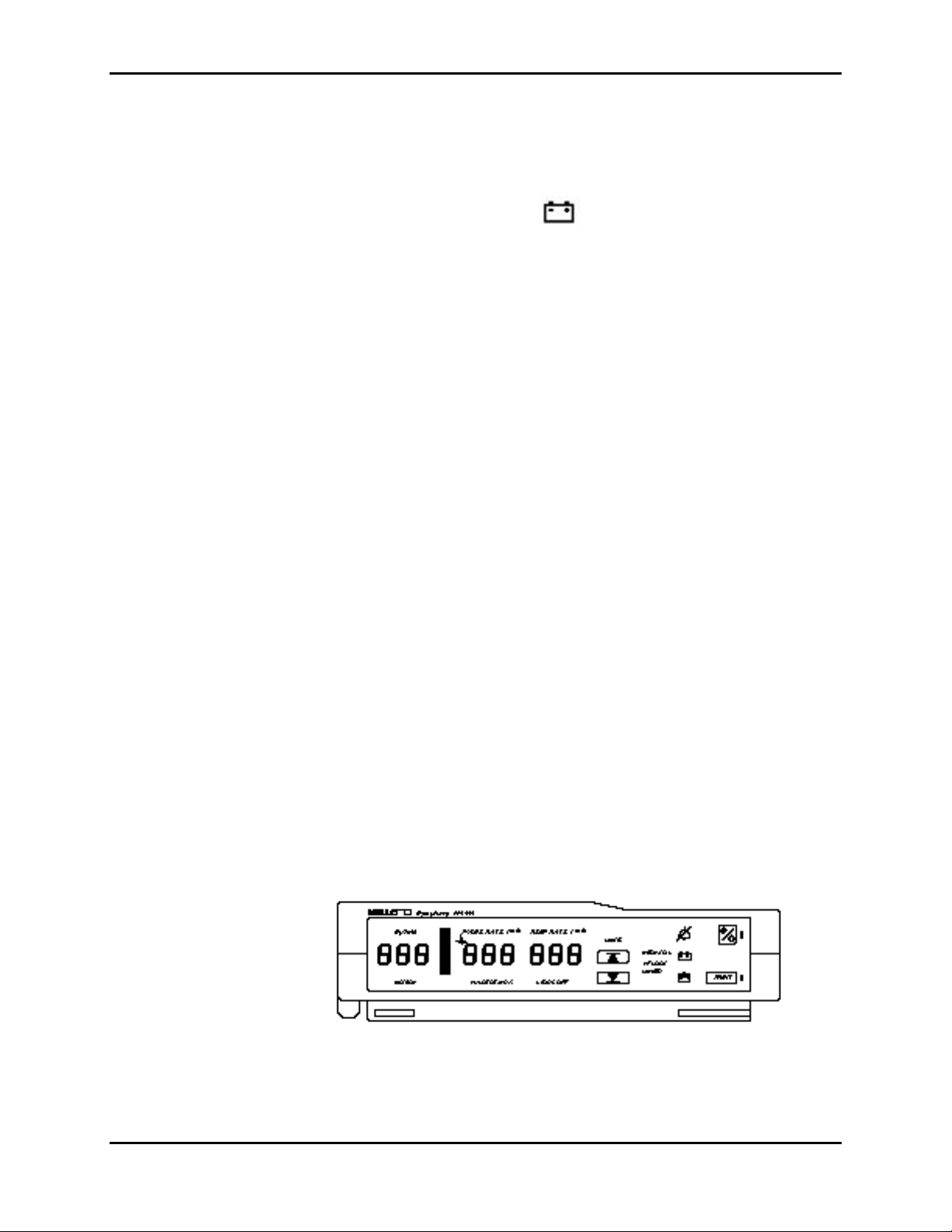
Figure 1-1 depicts the front panel of the N-3000 and the names of its displays
and controls.
1-1
Page 10

Section 1: Introduction
Figure 1-1: N-3000 Front Panel
1. SpO2% display 11. PRINT button
2. PULSE AMPLITUDE indicator 12. BATTERY IN USE/BATTERY LOW
indicator
3. ECG HEART RATE indicator 13. BATTERY CHARGING indicator
4. HEART/PULSE RATE display 14. LINKED indicator*
5. RESPIRATION RATE display 15. RF LOCKED indicator*
6. NEONATAL MODE indicator 16. LOWER ALARM LIMIT button
7. AUDIBLE ALARM OFF indicator 17. UPPER ALARM LIMIT button
8. ON/STANDBY button 18. LEADS OFF indicator
9. POWER ON indicator 19. PULSE SEARCH indicator
10. STACKED indicator 20. PATIENT MOTION indicator
* Not used on this model
1.3 RELATED DOCUMENTS
To perform test and troubleshooting procedures and to understand the principles
of operation and circuit analysis sections of this manual, you must know how to
operate the monitor. Refer to the N-3000 operator’s manual. To understand the
various Nellcor Puritan Bennett sensors and ECG leads that work with the
monitor, refer to the individual sensor or leads directions for use.
1-2
Page 11

SECTION 2: ROUTINE MAINTENANCE
2.1 Cleaning
2.2 Periodic Safety and Functional Checks
2.3 Batteries
2.1 CLEANING
Caution: Do not immerse the N-3000 or its accessories in liquid or clean
with caustic or abrasive cleaners. Do not spray or pour any liquid on the
monitor or its accessories.
To clean the N-3000, dampen a cloth with a commercial, nonabrasive cleaner
and wipe the exterior surfaces lightly. Do not allow any liquids to come in contact
with the power connector, fuse holder, or switches. Do not allow any liquids to
penetrate connectors or openings in the instrument cover. Wipe sensor and ECG
lead extension cables with a damp cloth. For sensors and ECG leads, follow the
individual directions for use.
2.2 PERIODIC SAFETY AND FUNCTIONAL CHECKS
The following checks should be performed at least every 2 years by a qualified
service technician.
1. Inspect the exterior of the N-3000 for damage.
2.3 BATTERIES
2. Inspect safety labels for legibility. If the labels are not legible, contact
Nellcor Puritan Bennett’s Technical Services Department or your local
Nellcor Puritan Bennett representative.
3. Verify that the unit performs properly as described in paragraph 3.3.
4. Perform the electrical safety tests detailed in paragraph 3.4. If the unit fails
these electrical safety tests, do not attempt to repair. Contact Nellcor
Puritan Bennett’s Technical Services Department or your local Nellcor
Puritan Bennett representative.
5. Inspect the fuses for proper value and rating (F1: 1.0 Amp, 250 Volt, Slo-
Blow and F2: 2.5 Amp, 250 Volt, Slo-Blow) as discussed in paragraph 6.4.
Nellcor Puritan Bennett recommends replacing instrument batteries at least
every 2 years. To replace the batteries, refer to Section 6, Disassembly Guide.
If the N-3000 has been stored for more than 30 days, charge the battery as
described in paragraph 3.3.1. A fully discharged battery requires 14 hours of
charging time for a full charge. A 6-hour charge is required for 1 hour of
operating time.
2-1
Page 12

Page 13

SECTION 3: PERFORMANCE VERIFICATION
3.1 Introduction
3.2 Equipment Needed
3.3 Performance Tests
3.4 Safety Tests
3.1 INTRODUCTION
This section discusses the tests used to verify performance following repairs or
during routine maintenance. All tests can be performed without removing the N3000 cover. All tests except the battery charge and battery performance tests
must be performed as the last operation before the monitor is returned to the
user.
If the N-3000 fails to perform as specified in any test, repairs must correct the
problem before the monitor is returned to the user.
3.2 EQUIPMENT NEEDED
Equipment Description
AC power adapter Use an appropriate Nellcor Symphony
SPS-N1 or PSS-1 power supply.
Connector adapter 6-pin, “D”
Digital multimeter (DMM) Fluke Model 87 or equivalent
Durasensor
®
oxygen transducer DS-100A
ECG cable SCE-10
ECG electrodes standard
ECG leads SLE series
ECG simulator Dynatech Nevada, medSim 300 or
equivalent
Oxisensor® II oxygen transducer D-25
Pulse oximeter tester SRC-2
Respiration simulator Dynatech Nevada, medSim 300 or
equivalent
Safety analyzer Must meet current AAMI
specifications
Sensor cable SCP-10
Serial interface cable EIA-232 cable (optional)
Stopwatch Manual or electronic
3.3 PERFORMANCE TESTS
The battery charge procedure should be performed before monitor repairs
whenever possible. It should also be performed before and after performing the
battery performance test (paragraph 3.3.2).
3-1
Page 14

Section 3: Performance Verification
This section is written using Nellcor Puritan Bennett factory-set defaults. If your
institution has preconfigured custom defaults, those values will be displayed.
Factory defaults can be reset using the configuration mode procedure described
in paragraph 4.2.10.6.
3.3.1 Battery Charge
Perform the following procedure to fully charge the battery.
1. Connect the monitor to an AC power source using an external power supply.
2. Verify that the monitor is off and that the BATTERY CHARGING indicator is
lit.
3. Charge the battery for at least 14 hours.
Note: The BATTERY CHARGING indicator is programmed to go out
when the N-3000 has been connected to AC power for
approximately 14 hours with no power interruptions. If there are
any power interruptions, the 14-hour charging period begins again
when power is restored.
4. The only way to check for a full charge is to perform the procedure in
paragraph 3.3.2 “Battery Performance Test.”
3.3.2 Battery Performance Test
The monitor is specified to operate on battery power a minimum of 4 hours.
(This time may decrease if the N-3000 is operating in the stacked configuration
with an N-3100 or N-3200.) Before performing this test, ensure that the battery is
fully charged (paragraph 3.3.1).
1. Connect the Nellcor Puritan Bennett SRC-2 pulse oximeter tester to the
monitor via the SCP-10 sensor cable.
2. Set the SRC-2 switches as follows:
SWITCH POSITION
RATE 38
LIGHT LOW
MODULATION LOW
RCAL/MODE RCAL 63/LOC
An illuminated BATTERY CHARGING indicator is not necessarily
an indication that the battery contains less than a full charge. It is
merely used as a timer to indicate that the battery has been
continuously charging for less than 14 hours.
3-2
3. Ensure that the monitor is not connected to AC power.
Page 15
4. With the N-3000 turned off, press the ON/STANDBY button and verify that
the BATTERY IN USE/BATTERY LOW indicator lights after the power-on
self-test is completed. Verify that the monitor is responding to the simulator
signal and the audible alarm is sounding. Do not silence the alarm during
this test.
5. The monitor must operate for at least 4 hours.
6. Verify that the BATTERY IN USE/BATTERY LOW indicator will start to
flash after about 3.5 to 3.75 hours (15-30 minutes before the battery fully
discharges).
7. Allow the monitor to operate until it automatically powers down due to the
low battery.
8. If the monitor passes this test, immediately recharge the battery (paragraph
3.3.1, steps 1 - 3).
3.3.3 Power-up Performance
The power-up performance tests (3.3.3.1 through 3.3.3.3) verify the following
monitor functions:
Section 3: Performance Verification
• 3.3.3.1 Power-On Self-Test
• 3.3.3.2 Adult Defaults and Alarm Limit Ranges
• 3.3.3.3 Neonate Defaults and Alarm Limit Ranges
3.3.3.1 Power-On Self-Test
1. Connect the monitor to an AC power source and verify that the BATTERY
2. Do not connect any input cables to the monitor.
3. Observe the monitor front panel. With the monitor off, press the
CHARGING indicator is lit.
ON/STANDBY button. The monitor must perform the following sequence.
a. The monitor emits three consecutively higher pitched beeps.
b. All indicators light for a few seconds as illustrated in Figure 3-1. Verify
that the SpO2% (left-most display), HEART/PULSE RATE (middle),
and RESPIRATION RATE (right) displays all indicate “8.8.8.”.
Figure 3-1: Self-Test Display
c. All displays turn off momentarily.
3-3
Page 16

Section 3: Performance Verification
d. Digital displays individually light in a scanning test pattern.
e. A 1-second beep sounds and all displays again illuminate momentarily.
f. All displays turn off except the POWER ON and BATTERY
CHARGING indicators. The SpO2% and HEART/PULSE RATE
displays are blank. The RESPIRATION RATE display indicates “0” for
about 15 seconds, then is blank. The monitor is in the “normal mode
steady state.”
g. Press and hold the NEW PATIENT/NEONATAL button (located on the
rear panel) for 3 seconds until you hear three beeps, indicating that
stored patient data is cleared.
3.3.3.2 Adult Power-On Defaults and Alarm Limit Ranges
Note: When observing or changing default limits, a 3-second timeout is in
effect, that is, if no action is taken within 3 seconds, the monitor
automatically returns to the normal mode steady state.
1. Ensure that the monitor is on. Press and release the UPPER ALARM LIMIT
button. Verify that the monitor emits a single beep and the SpO2% display
indicates an alarm limit of “100” for about 3 seconds. Verify that the other
displays indicate a single bar at the top of each window while the “100” is
displayed.
At the end of the 3 seconds, the displays are blank (normal mode steady
state).
2. Press and release the UPPER ALARM LIMIT button. Begin rotating the
control knob counterclockwise (CCW) within 3 seconds. Verify that the
SpO2% display reduces to a minimum of “85.”.
Note: A decimal point in the display indicates that the alarm limits have
changed.
3. Press and release the LOWER ALARM LIMIT button. Verify that the
monitor emits a single beep and the SpO2% display indicates an alarm limit
of “85” for 3 seconds. Verify that the other displays indicate a single bar at
the bottom of each window.
4. Press and hold the LOWER ALARM LIMIT button. Rotate the control knob
CCW and verify that the SpO2% display reduces to a minimum of “20”.
Rotate the control knob clockwise (CW) and verify that the SpO2% display
cannot be raised past the upper alarm limit setting of “85”.
5. Press the UPPER ALARM LIMIT button two times rapidly (twice within 3
seconds). Verify that the monitor emits two beeps and the HEART/PULSE
RATE display indicates an alarm limit of “170” for about 3 seconds.
3-4
Page 17

Section 3: Performance Verification
6. From the normal mode steady state, press the UPPER ALARM LIMIT
button two times rapidly. Begin rotating the control knob CCW within
3 seconds. Verify that the HEART/PULSE RATE display reduces to a
minimum of “40”.
7. Press the LOWER ALARM LIMIT button two times rapidly. Verify that the
HEART/PULSE RATE display indicates an alarm limit of “40” for 3 seconds.
8. From the normal mode steady state, press the LOWER ALARM LIMIT
button two times rapidly. Rotate the control knob CCW. Verify that the
HEART/PULSE RATE display reduces to a minimum of “30”.
9. Press the LOWER ALARM LIMIT button three times rapidly. Verify that the
RESPIRATION RATE display indicates an alarm limit of “4” for 3 seconds.
10. From the normal mode steady state, press the LOWER ALARM LIMIT
button three times rapidly. Begin rotating the control knob CW within
3 seconds. Verify the RESPIRATION RATE display increases to a
maximum of “40”.
11. Press the UPPER ALARM LIMIT button three times rapidly. Verify the
RESPIRATION RATE display indicates an alarm limit of “40” for 3 seconds.
12. Press the UPPER ALARM LIMIT button three times rapidly. Begin rotating
the control knob CW within 3 seconds. Verify that the RESPIRATION RATE
display increases to a maximum of “150”.
13. Press the ON/STANDBY button to turn the monitor off. Verify that the
monitor emits three decreasing pitch beeps.
14. Press the ON/STANDBY button to turn the N-3000 back on.
15. Press and release the UPPER ALARM LIMIT button. Verify that the SpO2%
display indicates an alarm limit of “100”.
16. Press and release the LOWER ALARM LIMIT button. Verify that the
SpO2% display indicates an alarm limit of “85”.
17. Press the UPPER ALARM LIMIT button two times rapidly. Verify that the
HEART/PULSE RATE display indicates an alarm limit of “170”.
18. Press the LOWER ALARM LIMIT button two times rapidly. Verify that the
HEART/PULSE RATE display indicates an alarm limit of “40”.
19. Press the UPPER ALARM LIMIT button three times rapidly. Verify that the
RESPIRATION RATE display indicates an alarm limit of “40”.
20. Press the LOWER ALARM LIMIT button three times rapidly. Verify that the
RESPIRATION RATE display indicates an alarm limit of “4”.
21. Press the ON/STANDBY button to turn the monitor off.
3-5
Page 18

Section 3: Performance Verification
3.3.3.3 Neonate Power-On Defaults and Alarm Limit Ranges
Note: When observing or changing default limits, a 3-second timeout is in
effect, that is, if no action is taken within 3 seconds, the monitor
automatically returns to the normal mode steady state.
1. Turn the monitor on.
2. Press the NEW PATIENT/NEONATAL button on the rear panel twice within
2 seconds. Verify that there is an audible beep each time the button is
pressed.
3. Verify that the NEONATAL MODE indicator on the front panel is lit.
4. Press and release the UPPER ALARM LIMIT button. Verify that the SpO2%
display indicates an alarm limit of “95” for 3 seconds. Verify that the other
displays indicate a single bar at the top of each window while the “95” is
displayed.
5. Press and release the UPPER ALARM LIMIT button. Begin rotating the
control knob CCW within 3 seconds. Verify that the SpO2% display reduces
to a minimum of “80”.
6. Press and release the LOWER ALARM LIMIT button. Verify that the SpO2%
display indicates an alarm limit of “80”. Verify that the other displays
indicate a single bar at the bottom of each window.
7. From the normal mode steady state, press and release the LOWER ALARM
LIMIT button. Rotate the control knob CCW. Verify that the SpO2% display
reduces to a minimum of “20”.
8. Press the UPPER ALARM LIMIT button two times rapidly (twice within 3
seconds). Verify that the HEART/PULSE RATE display indicates an alarm
limit of “190”.
9. Press the LOWER ALARM LIMIT button twice rapidly. Verify that the
HEART/PULSE RATE display indicates an alarm limit of “90”.
10. Press the UPPER ALARM LIMIT button three times rapidly. Verify that the
RESPIRATION RATE display indicates an alarm limit of “80”.
11. Press the LOWER ALARM LIMIT button three times rapidly. Verify that the
RESPIRATION RATE display indicates an alarm limit of “20”.
12. Press the ON/STANDBY button to turn the monitor off.
13. Press the ON/STANDBY button to turn the monitor on. The monitor
performs the sequence described in 3.3.3.1. Verify that the “NEO” indicator
is not lit.
14. Press and release the UPPER ALARM LIMIT button. Verify that the SpO2%
display indicates an alarm limit of “100”.
3-6
15. Press and release the LOWER ALARM LIMIT button. Verify that the SpO2%
display indicates an alarm limit of “85”.
16. Press the ON/STANDBY button to turn the monitor off.
Page 19

This completes the power-up performance tests.
3.3.4 Hardware and Software Tests
Hardware and software testing include the following tests.
• 3.3.4.1 Operation with a Pulse Oximeter Tester
• 3.3.4.2 Operation with an ECG Simulator
• 3.3.4.3 Operation with a Respiration Simulator
• 3.3.4.4 General Operation
3.3.4.1 Operation with a Pulse Oximeter Tester
Operation with an SRC-2 pulse oximeter tester includes the following tests.
• 3.3.4.1.1 Alarms and Alarm Silence
• 3.3.4.1.2 Alarm Volume Control
• 3.3.4.1.3 Pulse Tone Volume Control
• 3.3.4.1.4 Dynamic Operating Range
• 3.3.4.1.5 RCAL Determination
• 3.3.4.1.6 LED Drive Test
3.3.4.1.1 Alarms and Alarm Silence
Section 3: Performance Verification
1. Connect the SRC-2 pulse oximeter tester to the sensor input cable and
connect the cable to the monitor. Set the SRC-2 as follows:
SWITCH POSITION
RATE 38
LIGHT LOW
MODULATION OFF
RCAL/MODE RCAL 63/LOCAL
2. Press the ON/STANDBY button to turn the monitor on. After the normal
power-up sequence, verify that the SpO2%, HEART/PULSE RATE and
RESPIRATION RATE displays initially indicate zeroes.
Note: The pulse bar may occasionally indicate a step change as the
monitor is in the pulse search mode.
3. Move the modulation switch on the SRC-2 to LOW.
4. Verify that the following monitor reaction:
a. The pulse bar begins to track the artificial pulse signal from the SRC-2.
b. The pulse tone is heard.
c. Zeroes are displayed in the SpO2%, HEART/PULSE RATE, and
RESPIRATION RATE displays.
d. After about 10 to 20 seconds, the monitor displays a saturation and
pulse rate as specified by the tester. Verify that the values are within
the following tolerances:
Oxygen Saturation Range 79% to 83%
Pulse Rate Range 37 to 39 bpm
3-7
Page 20

Section 3: Performance Verification
e. The audible alarm sounds and both the SpO2% and HEART/PULSE
5. Press and momentarily hold the AUDIBLE ALARM OFF button on the top of
the monitor. Verify that the HEART/PULSE RATE display indicates “60” and
the RESPIRATION RATE display indicates “SEC” while the AUDIBLE
ALARM OFF button is pressed. The alarm is silenced.
6. Release the AUDIBLE ALARM OFF button. Verify the following:
a. The alarm remains silenced.
b. The AUDIBLE ALARM OFF indicator lights.
c. The SpO2% and HEART/PULSE RATE displays resume flashing.
d. The pulse tone is still audible.
e. The audible alarm returns in approximately 60 seconds.
7. Press and hold the AUDIBLE ALARM OFF button. Rotate the control knob
CCW until the HEART/PULSE RATE display indicates “30”. Rotate the
control knob CW and verify that the displays indicate 60 SEC, 90 SEC, 120
SEC, and OFF. Release the button when the display indicates “OFF”. Verify
that the AUDIBLE ALARM OFF indicator flashes.
RATE displays will flash, indicating both parameters have violated the
default alarm limits.
8. Wait approximately 3 minutes. Verify that the alarm does not return. After 3
minutes, the alarm silence reminder beeps three times, and will continue to
do so at 3-minute intervals.
3.3.4.1.2 Alarm Volume Control
After completing the procedure in paragraph 3.3.4.1.1:
1. Press and hold the AUDIBLE ALARM OFF button on the top of the monitor.
Verify the following:
a. “OFF” is displayed for approximately 3 seconds.
b. After 3 seconds, a steady tone is heard at the default alarm volume
setting, the HEART/PULSE RATE display indicates “VOL”, and the
RESPIRATION RATE display indicates the default setting of 5.
2. While continuing to hold the AUDIBLE ALARM OFF button, rotate the
control knob CCW to decrease the alarm volume setting to a minimum
value of 1. The alarm tone should decrease but still be audible.
3. Rotate the control knob CW to increase the alarm volume setting to a
maximum value of 10. Verify the volume increases. Rotate the knob CCW
until a comfortable audio level is attained.
4. Release the AUDIBLE ALARM OFF button. The tone will stop.
3-8
3.3.4.1.3 Pulse Tone Volume Control
1. Rotate the control knob CW and verify that the beeping pulse tone sound
level increases.
Page 21

Section 3: Performance Verification
2. Rotate the control knob CCW and verify that the beeping pulse tone
decreases until it is no longer audible. Rotate the knob CW to return the
beep volume to a comfortable level.
3.3.4.1.4 Dynamic Operating Range
The following test sequence verifies proper monitor operation over a range of
input signals.
1. Connect the SRC-2 to the N-3000 and turn the N-3000 on.
2. Place the SRC-2 in the RCAL 63/LOCAL mode.
3. Set the SRC-2 as indicated in Table 3-1. Verify that the N-3000 readings
are within the indicated tolerances. Allow the monitor several seconds to
stabilize the readings.
Note: A “*” indicates values that produce an alarm. Press the AUDIBLE
ALARM OFF button to silence the alarm.
Table 3-1: Dynamic Operating Range
SRC-2 Settings N-3000 Indications
RATE LIGHT MODULATION SpO2 Pulse Rate
38 HIGH2 LOW 79 - 83* 37 - 39*
112 HIGH1 HIGH 79 - 83* 110 - 114
201 LOW LOW 79 - 83* 195 - 207*
201 LOW HIGH 79 - 83* 195 - 207*
4. Turn the monitor off.
3.3.4.1.5 RCAL Determination
1. Ensure that the N-3000 is turned off and connected to AC power via an
external power supply.
2. Connect the SRC-2 pulse oximeter tester to the sensor input cable and
connect the cable to the monitor. Set the SRC-2 as follows:
SWITCH POSITION
RATE 38
LIGHT LOW
MODULATION OFF
RCAL/MODE RCAL 63/LOCAL
3. Enter the service mode as follows:
a. While simultaneously holding down the UPPER and LOWER ALARM
LIMIT buttons and the PRINT button, press and release the
ON/STANDBY button. Continue to press and hold the UPPER and
LOWER ALARM LIMIT and PRINT buttons while the monitor performs
the power-on test.
b. When “SEr” begins flashing in the AUXILIARY display, release the
UPPER and LOWER ALARM LIMIT and PRINT buttons.
3-9
Page 22

Section 3: Performance Verification
c. Press the PRINT button within 15 seconds or the monitor will turn off
4. Select menu item 30 by rotating the knob until “30” appears in the SpO2%
display.
5. Press the UPPER ALARM LIMIT button.
6. Verify the RCAL index number “63” is displayed in the HEART/PULSE
RATE display.
7. Set the SRC-2 RCAL/Mode switch to 64/LOCAL and verify that “64” is
displayed in the HEART/PULSE RATE display.
8. Press the ON/STANDBY button to turn the monitor off.
3.3.4.1.6 LED Drive Test
1. Ensure that the N-3000 is turned off and connected to AC power via an
external power supply.
2. Connect the SRC-2 pulse oximeter tester to the sensor input cable and
connect the cable to the monitor. Set the SRC-2 as follows:
automatically. The number “1” appears in the SpO2% display. You are
now in the service mode steady state.
SWITCH POSITION
RATE 38
LIGHT LOW
MODULATION OFF
RCAL/MODE RCAL 63/LOCAL
3. Enter the service mode as follows:
a. While simultaneously holding down the UPPER and LOWER ALARM
LIMIT buttons and the PRINT button, press and release the
ON/STANDBY button. Continue to press and hold the UPPER and
LOWER ALARM LIMIT and PRINT buttons while the monitor performs
the power-on test.
b. When “SEr” begins flashing in the AUXILIARY display, release the
UPPER and LOWER ALARM LIMIT and PRINT buttons.
c. Press the PRINT button within 15 seconds or the monitor will turn off
automatically. The number “1” appears in the SpO2% display. You are
now in the service mode.
4. Select menu item 33 by rotating the knob until “33” appears in the SpO2%
display.
5. Press the UPPER ALARM LIMIT button.
3-10
6. Verify that the SpO2 IR LED drive value “170” is displayed in the
HEART/PULSE RATE display and the IR indicator on the SRC-2 is
illuminated.
7. Rotate the control knob to adjust the IR LED drive level indicated in the
HEART/PULSE RATE display to “255”.
Page 23

Section 3: Performance Verification
8. While watching the IR indicator on the SRC-2, press the UPPER ALARM
LIMIT button and verify that the LED intensity increases.
9. Rotate the knob to adjust the IR LED drive level to “0”.
10. Press the UPPER ALARM LIMIT button. Verify that the IR LED turns off.
11. Rotate the knob to adjust the IR LED drive level to “170”.
12. Press the UPPER ALARM LIMIT button and verify that the LED intensity
increases.
13. Press the LOWER ALARM LIMIT button to return to the service mode
steady state.
14. Select menu item 34 by rotating the knob until “34” appears in the SpO2%
display.
15. Press the UPPER ALARM LIMIT button.
16. Verify that the SpO2 red LED drive value “170” is displayed in the
HEART/PULSE RATE display and that the IR indicator on the SRC-2 is
illuminated.
17. Rotate the control knob to adjust the red LED drive level to “255”.
18. Press the UPPER ALARM LIMIT button and verify that the LED intensity
increases.
19. Rotate the knob to adjust the red LED drive level to “0”.
20. Press the UPPER ALARM LIMIT button and verify that the RED indicator turns
off.
21. Rotate the knob to adjust the red LED drive level back to “170”.
22. Press the UPPER ALARM LIMIT button and verify that the RED indicator
intensity increases.
23. Press the LOWER ALARM LIMIT button to return to the service mode
steady state.
24. Press the ON/STANDBY button to turn the N-3000 off.
3.3.4.2 Operation with an ECG Simulator
1. With the monitor off, connect the ECG leads RA, LA, and LL to the
appropriate jacks on the ECG tester.
Nellcor Puritan Bennett ECG leads are color-coded as follows:
Right arm (RA) - white
Left arm (LA) - Black
Left leg (LL) - Red
3-11
Page 24

Section 3: Performance Verification
2. Connect the leads to the SCE-10 ECG cable. Connect the SCE-10 to the
ECG input port on the N-3000. Set the ECG tester as follows:
PARAMETER SETTING
HEART RATE 30 bpm
AMPLITUDE 1 millivolt
LEAD SELECT I
SINUS RHYTHM Normal
RCAL/MODE Adult
Note: The accuracy of N-3000 ECG measurements is + 5 bpm. In the
3. Ensure that the monitor is connected to an AC power source. Press the
ON/STANDBY button to turn the monitor on. After the normal power-up
sequence, verify the following monitor reactions:
a. The heart rate “beep” will be heard.
b. After at least five heartbeats, the monitor displays a heart rate of 30 ± 5
c. The audible alarm will sound and the HEART/PULSE RATE display will
procedure below, add the tolerance of the simulator to the acceptable
range of readings.
bpm.
flash, indicating the heart rate is below the default lower alarm limit.
The heart rate “beep” can still be heard.
4. Press the AUDIBLE ALARM OFF BUTTON. Verify that the alarm is
silenced.
5. Increase the heart rate setting on the ECG simulator to 240 bpm. Verify that
the rate of beeps increases and the HEART/PULSE RATE display value
increases.
6. After at least five heartbeats, verify that the monitor displays a heart rate of
240 ± 5 bpm.
7. Verify that the audible alarm sounds and the HEART/PULSE RATE display
flashes, indicating that the heart rate is above the default upper alarm limit.
8. Press AUDIBLE ALARM OFF button to silence the alarm.
9. Decrease the heart rate setting on the ECG simulator to 120 bpm.
10. After at least five heartbeats, verify that the monitor displays a heart rate of
120 ± 5 bpm.
11. Disconnect the LL lead from the ECG simulator. Verify that the LEADS OFF
indicator lights, three dashes are displayed in the HEART/PULSE RATE
display, and a low priority audible alarm sounds.
3-12
Page 25

12. Reconnect the LL lead to the ECG simulator. Verify that the LEADS OFF
indicator is no longer lit and that the alarm is silenced.
Note: Depending on the lead used and pleth configuration, the
HEART/PULSE RATE display may revert to a pulse rate as leads
are removed in step 11. If a medium priority alarm results and is
silenced, the low priority alarm from leads off will not break
through.
13. Repeat steps 11 and 12 for the LA and RA leads.
14. Turn the monitor off.
3.3.4.3 Operation with a Respiration Simulator
1. With the monitor off, connect the Nellcor Puritan Bennett ECG leads to the
appropriate jacks on the respiration simulator.
2. Connect the leads to the SCE-10 ECG cable. Connect the SCE-10 to the
ECG input port on the N-3000.
Note: The accuracy of N-3000 ECG measurements is + 3 breaths per
minute. In the procedure below, add the tolerance of the simulator
to the acceptable range of readings.
Section 3: Performance Verification
3. Set the simulator for a respiration rate of 100 breaths per minute.
4. Ensure that the monitor is connected to an AC power source. Press the
5. Press the AUDIBLE ALARM OFF BUTTON. Verify that the alarm is
6. Decrease the respiration rate setting on the respiration simulator to 20
7. After at least 5 breaths, verify that the monitor displays a respiration rate of
8. Power down the monitor and disconnect it from the simulator.
3.3.4.4 General Operation
ON/STANDBY button to turn the monitor on. After the normal power-up
sequence, verify the following monitor reactions:
a. After about 20-25 seconds, the monitor displays a respiration rate of
100 ± 3 breaths per minute.
b. The audible alarm will sound and the RESPIRATION RATE display will
flash, indicating the respiration rate is above the default upper alarm
limit.
silenced.
breaths per minute.
20 ± 3 breaths per minute.
The following tests are an overall performance check of the system:
• 3.3.4.4.1 LED Excitation Test
• 3.3.4.4.2 Operation with a Live Subject
• 3.3.4.4.3 Serial Interface Test
• 3.3.4.4.4 Piezo Speaker Test
• 3.3.4.4.5 Persistent Time Clock Test
3-13
Page 26

Section 3: Performance Verification
• 3.3.4.4.6 ECG Cable Test
3.3.4.4.1 LED Excitation Test
This procedure uses normal system components to test circuit operation. A
Nellcor Puritan Bennett™ Oxisensor II® oxygen transducer, model D-25, is used
to examine LED intensity control. The red LED is used to verify intensity
modulation caused by the LED intensity control circuit.
1. Connect the monitor to an AC power source through the SPS-N1 or PSS-1
power supply.
2. Connect an SCP-10 sensor input cable to the monitor.
3. Connect a D-25 sensor to the sensor input cable.
4. Press the ON/STANDBY button to turn the monitor on.
5. Leave the sensor open with the LEDs and photodetector visible.
6. After the monitor completes its normal power-up sequence, verify that the
sensor LED is brightly lit.
7. Slowly move the sensor LED in proximity to the photodetector element of
the sensor. Verify, as the LED approaches the optical sensor, that the LED
intensity decreases.
8. Open the sensor and notice that the LED intensity increases.
9. Repeat step 7 and the intensity will again decrease. This variation is an
indication that the microprocessor is in proper control of LED intensity.
10. Turn the N-3000 off.
3.3.4.4.2 Operation with a Live Subject
Patient monitoring involves connecting the monitor to a live subject for a
qualitative test.
1. Ensure that the monitor is connected to an AC power source through the
SPS-N1 or PSS-1 power supply.
2. Connect an SCP-10 sensor input cable to the monitor.
3. Connect a Nellcor Puritan Bennett™ Durasensor® oxygen transducer,
model DS-100A, to the sensor input cable.
4. Clip the DS-100A to the subject as recommended in the sensor directions
for use.
5. Connect ECG electrodes to the patient.
6. Connect an SCE-10 ECG cable to the N-3000. Connect ECG leads to the
cable.
3-14
7. Connect the ECG leads to the electrodes on the patient according to the
leads directions for use.
Page 27
Section 3: Performance Verification
8. Press the ON/STANDBY button to turn the monitor on and verify that the
monitor is operating.
9. The monitor should stabilize on the subject’s physiological signal in about
15 to 30 seconds. Verify that the saturation and heart and respiration rates
are reasonable for the subject.
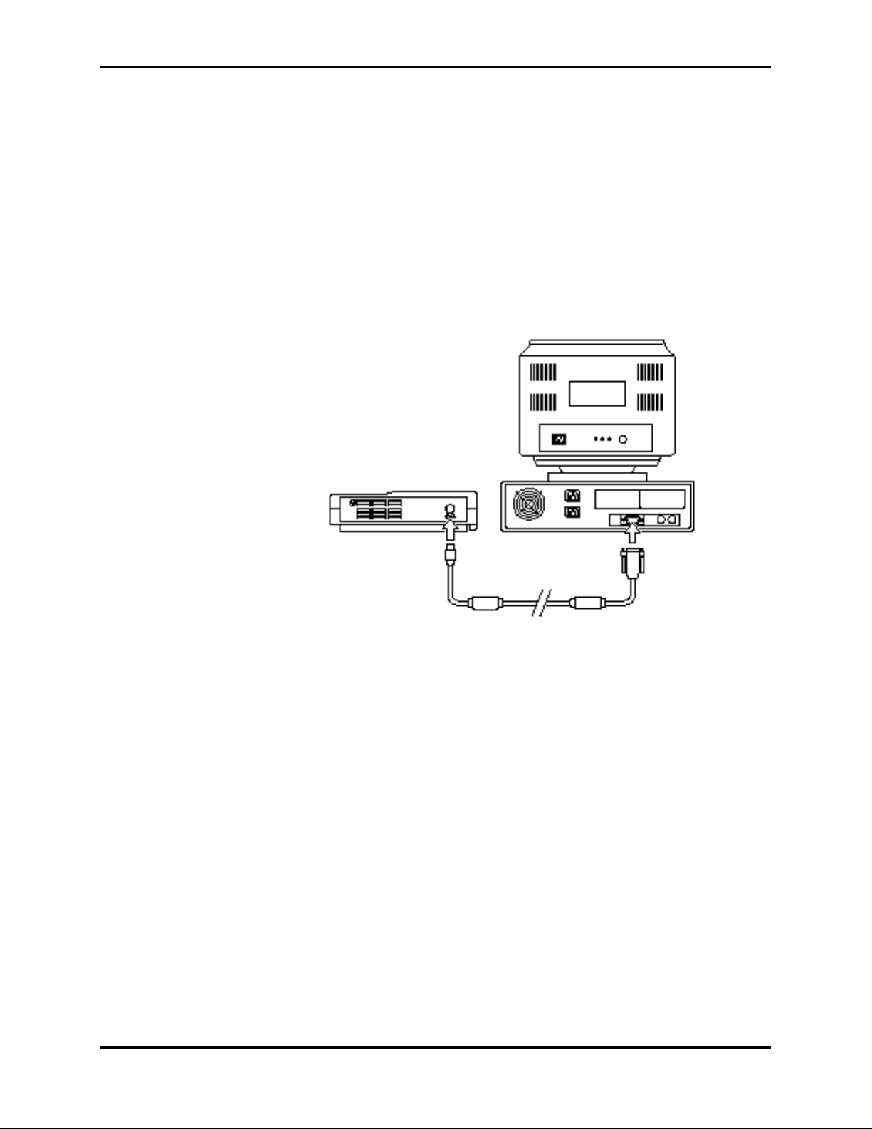
3.3.4.4.3 Serial Interface Test
The communications submodule of the N-3000, using an asynchronous EIA-232
communications format, allows communications between the N-3000 and a PC
via the 6-pin connector on the rear panel of the N-3000, as illustrated in Figure
3-2. An SAK-232 cable and detailed directions for use are available by
contacting your local Nellcor Puritan Bennett representative.
Figure 3-2: Serial Port Interface
The two configurable options of serial data interface are RS-232 and EIA-422.
The N-3000 is shipped with the RS-232 setting. To change the settings, refer to
paragraph 6.5.1.
Perform the following procedure to test the serial port voltages. The test is
qualitative and will only verify that the serial interface port is powered correctly.
1. Connect the monitor to an AC power source through the SPS-N1 or PSS-1
power supply and turn the monitor on.
2. Connect a 6-pin miniature connector adapter to the serial interface port.
3. Set up the DMM with the function set to “VDC” at a range of 10 volts.
4. Connect the DMM negative lead to connector pin 4 (GND).
3-15
Page 28

Section 3: Performance Verification
5. Connect the DMM positive lead to the following pins and verify the voltage
values listed in Table 3-2. If the voltages are not as indicated, follow the
procedures in paragraph 5.6.7.
Figure 3-3: Serial Port Connector - External Pin Locations
Table 3-2: Serial Port Voltages
Pin Line Voltage
1 DTR 7.5 ± 2.5
2 DSR 0.0 ± 0.4
3 TXD -7.5 ± 2.5
4 GND 0.0 ± 0.4
5 RXD 0.0 ± 0.4
6 Alarm Active 0.0 ± 0.4 or
3.3 ± 0.4
3.3.4.4.4 Piezo Speaker Test
The following test verifies that the Piezo power-loss alarm speaker sounds when
the N-3000 loses power.
WARNING: Before attempting to open or disassemble the N-3000,
disconnect the power cord from the N-3000.
Caution: Observe ESD (electrostatic discharge) precautions when working
within the monitor.
3-16
Page 29
Section 3: Performance Verification
1. Ensure that the N-3000 is turned off.
2. Disconnect the monitor from the external power supply.
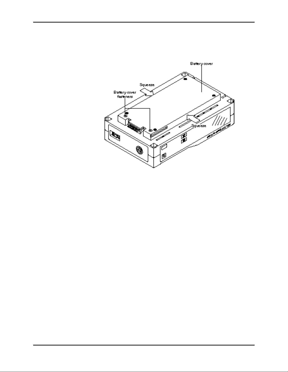
3. Set the N-3000 upside down facing you, as shown in Figure 3-4.
Figure 3-4: Battery Cover Removal
4. Using a small, Phillips-head screwdriver, loosen the two battery cover
retaining fasteners securing the battery compartment cover.
5. Gently squeeze the battery cover sides in the middle as you swing the
cover open (it is hinged on the right with three tabs that extend into slots on
the chassis).
3-17
Page 30
Section 3: Performance Verification
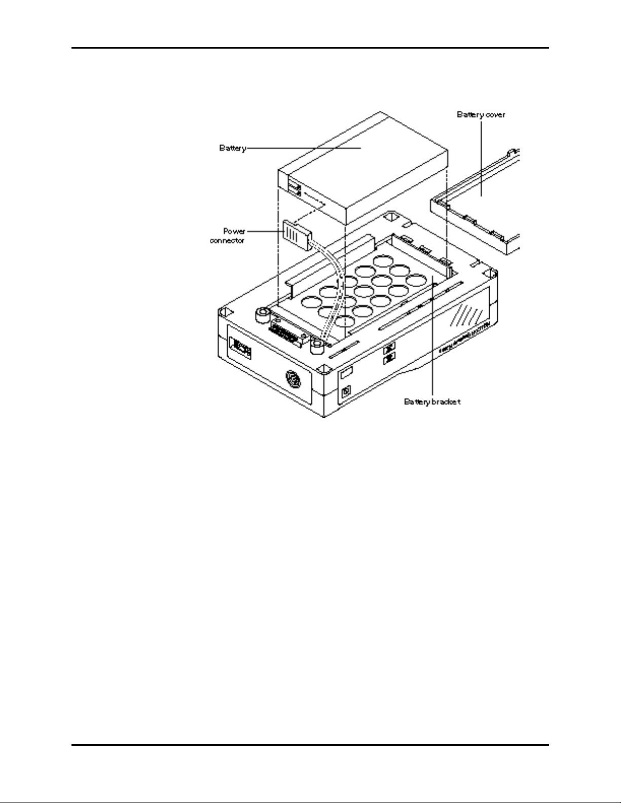
6. Lift the battery out of the compartment, as shown in Figure 3-5. It may be
necessary to use the edge of a flat tip screwdriver to gently pry the battery
loose.
Figure 3-5: Speaker Test
7. Turn the monitor on by pressing the ON/STANDBY button.
8. When the power-on self-test is complete, disconnect the power connector
from the battery. Verify that a shrill, beeping alarm is emitted from the
speaker.
9. Reconnect the power connector to the battery. Verify that the alarm is
silenced and the monitor powers back on.
10. Disconnect the power connector from the battery a second time. Verify that
the Piezo alarm sounds.
11. Press the AUDIBLE ALARM OFF button and verify that the alarm is
silenced.
12. Reconnect the power connector to the battery. Verify that the alarm remains
silent and the monitor powers back on.
13. Turn the monitor off by pressing the ON/STANDBY button.
14. Replace the battery in the battery bracket and reconnect the battery cover.
3-18
Page 31

Section 3: Performance Verification
3.3.4.4.5 Persistent Time Clock Test
This procedure allows you to check the operation of the persistent time clock.
1. Enter the service mode as follows:
a. While holding down the UPPER and LOWER ALARM LIMIT buttons
and the PRINT button, press and release the ON/STANDBY button.
Continue to hold the UPPER and LOWER ALARM LIMIT and PRINT
buttons while the monitor performs the power-on test.
b. When “SEr” begins flashing in the AUXILIARY display, release the
UPPER and LOWER ALARM LIMIT and PRINT buttons.
c. Press the PRINT button within 15 seconds or the monitor will turn off
automatically. The number “1” appears in the SpO2% display. You are
now in the service mode steady state.
2. Select menu item 19 by rotating the control knob.
3. Press the UPPER ALARM LIMIT button. The persistent time in seconds is
displayed in the SpO2% and HEART/PULSE RATE displays. For example,
“001 688” indicates that the monitor has been powered on for 1,688
seconds = 28 minutes, 8 seconds. Verify that the right-most digit is counting
seconds.
3.3.4.5 ECG Cable Test
If the display reads “999 999”, this indicates that persistent time is greater
than or equal to 999,999 seconds. If dashes are displayed, the contents of
the memory of the persistent time circuit are lost. This can occur when the
backup lithium battery has been replaced.
4. Using a timepiece, track the clock to verify proper operation.
5. Press the LOWER ALARM LIMIT button to return to the service mode
steady state.
6. Turn the monitor off by pressing the ON/STANDBY button.
The following test should be completed after defibrillation has been performed
on a patient attached to ECG leads and a Nellcor Puritan Bennett SCE-10 ECG
cable. It does not need to be performed as a component of an N-3000
performance verification test.
Perform the following procedure to test the ECG cable.
1. Disconnect the SCE-10 ECG cable from the N-3000 and the ECG leads.
Pin locations for both ends of the ECG cable are identified in Figure 3-6.
3-19
Page 32

Section 3: Performance Verification
2. Measure the resistances between the pins as indicated in Table 3-3.
3. If the resistances are not as indicated, replace the cable.
Figure 3-6: ECG Cable Pin Locations
Table 3-3: ECG Cable Resistances
Pin To Pin Resistance
2 A 900 - 1100 ohms
3 B 900 - 1100 ohms
8 C 900 - 1100 ohms
5 D, E, F 0 - 5 ohms
8 5 open
2 5 open
3 5 open
A D open
B E open
C F open
3.4 SAFETY TESTS
N-3000 safety tests consist of:
• Ground Integrity
• Electrical Leakage
3.4.1 Ground Integrity
This test verifies the integrity of the power cord ground wire from the AC plug
and connection with the external power supply chassis ground.
1. Configure the electrical safety analyzer as follows:
2. Connect the monitor’s AC plug to the analyzer as recommended by the
3. Connect the analyzer “resistance” input lead to the grounding lug on the
3.4.2 Electrical Leakage
Function: Ground resistance test
Range: Milliohms
analyzer operating instructions.
rear panel of the external power supply. Verify that the analyzer indicates
150 milliohms or less.
The following tests verify the electrical leakage of the monitor.
• Chassis Source Current
• Patient Source Current
• Patient Sink Current
3.4.2.1 Chassis Source Current
3-20
Page 33

Section 3: Performance Verification
This test is in compliance with IEC 601.1 and AAMI Standard ES1, paragraph
3.3.1, Chassis Source Current, between the power ground and (part b), exposed
conductive hardware.
1. Configure the electrical safety analyzer as follows:
Function: Leakage
Range: Microamps
2. Connect the monitor AC plug to the electrical safety analyzer as
recommended by the analyzer operating instructions.
3. Connect the electrical safety analyzer “leakage” input lead to the monitor’s
external power supply grounding lug.
The analyzer leakage indication must not exceed 100 microamps at
100–120 VAC or 500 microamps at 220–240 VAC for the following AC
power configurations while the monitor is turned on and while turned off.
3.4.2.2 Patient Source Current
This test is in compliance with AAMI Standard ES1, paragraph 3.3.2. Patient
Source Current is measured between any individual patient connection and
power (earth) ground.
1. Configure the electrical safety analyzer as follows:
Function: Leakage
Range: Microamps
2. Connect the monitor AC plug to the electrical safety analyzer as
recommended by the analyzer operating instructions for patient source
current.
3. Connect the electrical safety analyzer leakage input lead to the monitor’s
sensor input connector.
AC LINE
POLARITY
POWER LINE
GROUND CABLE
Normal Normal
Reverse Normal
Reverse Open
Normal Open
The analyzer leakage indication must not exceed 10 microamps for all of
the following AC power configurations with the monitor on.
AC LINE
POLARITY
POWER LINE
GROUND CABLE
Normal Normal
Reverse Normal
Reverse Open
3-21
Page 34

Section 3: Performance Verification
3.4.2.3 Patient Sink Current
This test is in compliance with AAMI Standard ES1, paragraph 4.4. Patient sink
current is measured in a patient connection if a source of 240 volts, 50 Hz (or
120 volts, 60 Hz) with respect to power (earth) ground, is connected to that
patient connection.
1. Configure the electrical safety analyzer as follows:
Function: Leakage
Range: µA
2. Connect the monitor AC plug to the electrical safety analyzer as
recommended by the operating instructions for patient sink current.
3. Connect the electrical safety analyzer leakage input lead to the monitor’s
sensor input.
The analyzer leakage indication must not exceed 50 microamps for
240 volts (10 microamps for 120 volts) for the following AC power
configurations with the monitor on.
Normal Open
AC LINE
POLARITY
POWER LINE
GROUND CABLE
Normal Normal
Normal Open
3-22
Page 35

SECTION 4: CONFIGURATION MODE, SERVICE MODE, AND ALARM
ACTIVE FUNCTION
4.1 Introduction
4.2 Configuration Mode
4.3 Service Mode
4.4 Alarm Active Function
4.1 INTRODUCTION
This section discusses use of the configuration mode to reconfigure power-on
default values, the service mode to identify and correct monitor difficulties, and
the alarm active function.
4.2 CONFIGURATION MODE
The following paragraphs describe how to enter the N-3000 configuration mode
and change factory power-on default settings.
The N-3000 cannot enter the configuration mode while it is stacked unless the
other instruments are in the configuration mode or are turned off. If the other
instruments are in the configuration mode, the N-3000 knob may be used to
scroll to the desired menu item and adjust the settings of the other instruments.
Likewise, if the N-3000 is stacked with an N-3200, and both are in the
configuration mode, the N-3200 knob may be used to scroll to the desired menu
item and adjust the settings of the N-3000.
Use the following procedure to enter configuration mode:
1. If the monitor is on, turn it off.
2. While simultaneously pressing both UPPER and LOWER ALARM LIMIT
buttons, turn the monitor on. Continue to press both buttons until “CFG”
begins flashing in the RESPIRATION RATE display.
3. Release the UPPER and LOWER ALARM LIMIT buttons.
4. Press the PRINT button. “CFG” stops flashing and remains displayed in the
RESPIRATION RATE display. (If the PRINT button is not pressed within
15 seconds after “CFG” begins flashing, the monitor will turn off
automatically.)
You are now in configuration mode steady state. The N-3000 automatically
powers down if no action is taken for approximately 2 minutes.
After changing or viewing a default setting, you can return to the configuration
mode steady state by allowing the display to timeout (3 seconds).
To exit the configuration mode, turn the monitor off by pressing the
ON/STANDBY button. Default settings take place when the monitor is turned off.
Default settings also take place if the N-3000 powers down due to the 2-minute
timeout.
Note: While changing default limits, there must be some user interaction with
the monitor within a 3-second period or the monitor will return to
configuration mode steady state operation.
4-1
Page 36

Section 4: Configuration Mode, Service Mode, and Alarm Active Function
Table 4-1 lists the default settings that can be configured and the respective
entry procedures to access the settings. Methods used to change the default
settings are detailed in paragraphs 4.2.1 through 4.2.10.
Table 4-1: Configuration Mode Menu
Power on Default
Setting
Button Press Procedure from
Configuration Mode Steady State
Paragrap
h
Described
Adult/Neonatal Mode NEW PATIENT/NEONATAL button
4.2.1
twice
SpO2 Upper Alarm Limit UPPER ALARM LIMIT button 4.2.2
SpO2 Lower Alarm Limit LOWER ALARM LIMIT button 4.2.3
Heart/Pulse Rate Upper
UPPER ALARM LIMIT button twice 4.2.4
Alarm Limit
Heart/Pulse Rate Lower
LOWER ALARM LIMIT button twice 4.2.5
Alarm Limit
Respiration Rate Upper
Alarm Limit
Respiration Rate Lower
Alarm Limit
Alarm Volume ALARM SILENCE button (press and
UPPER ALARM LIMIT button three
times
LOWER ALARM LIMIT button three
times
4.2.6
4.2.7
4.2.8
hold for 3 seconds before turning
knob)
Alarm Silence Duration ALARM SILENCE button (press and
4.2.9
hold; turn knob within 3 seconds)
Configuration Menu UPPER/LOWER ALARM LIMIT
Note: To change neonate default limits, enter the neonatal mode from
configuration mode steady state by pressing the NEW
PATIENT/NEONATAL button twice within 2 seconds. Change the
desired limit using the same method as adult default limits.
When an SpO2 or heart/pulse rate default limit has been changed, a decimal
point will appear after the displayed limit until the configuration mode is exited.
4.2.1 Adult/Neonatal Mode Default
The mode (adult or neonatal) that the monitor is in when exiting the
configuration mode, becomes the power-on default.
To change from a power-on default of adult mode to a power-on default of
neonatal mode, enter the configuration mode steady state. Press the NEW
PATIENT/NEONATAL button twice within 2 seconds and then power-down by
pressing the ON/STANDBY button.
4.2.2 Default SpO2 Upper Alarm Limit
4.2.10
buttons simultaneously
4-2
Page 37

Section 4: Configuration Mode, Service Mode, and Alarm Active Function
1. From the configuration mode steady state, press and release the UPPER
ALARM LIMIT button. The current default value is displayed in the SpO2%
display. Dashes appear in the HEART/PULSE RATE display (the upper
horizontal segments of the display), indicating that the monitor is in the “set
SpO2 upper alarm limit” mode.
2. To change the upper alarm limit default value, rotate the knob on top of the
monitor (or, if stacked with an N-3200 in the configuration mode, the knob
on the N-3200). You cannot decrease the value lower than the current SpO2
lower alarm limit default setting. The SpO2 upper alarm limit cannot be set
higher than 100.
3. Return to configuration mode steady state.
Note: If you press the LOWER ALARM LIMIT button before the 3-second
timeout, you can then change the SpO2 lower alarm limit default. If
you press the UPPER ALARM LIMIT button, you can then change
the pulse rate upper alarm limit default. This method can also be
used while setting the other default alarm limits.
4.2.3 Default SpO2 Lower Alarm Limit
1. From the configuration mode steady state, press and release the LOWER
ALARM LIMIT button. The current default value is displayed in the SpO2%
display.
2. To change the lower alarm limit default value, rotate the knob on top of the
monitor. You cannot increase the value higher than the current SpO2 upper
alarm limit setting. The SpO2 default lower alarm limit cannot be set lower
than 80.
3. Return to the configuration mode steady state.
4.2.4 Default Heart/Pulse Rate Upper Alarm Limit
1. From the configuration mode steady state, press the UPPER ALARM LIMIT
button twice within 3 seconds. The current default value is displayed in the
HEART/PULSE RATE display. Dashes appear in the SpO2% display (the
upper horizontal segments of the display), indicating that the monitor is in
the “set pulse rate upper alarm limit” mode.
2. To change the upper alarm limit default value, rotate the control knob on
top of the monitor. You cannot decrease the value lower than the current
pulse rate lower alarm limit default setting. The pulse rate default upper
alarm limit cannot be set higher than 250.
3. Return to configuration mode steady state.
4.2.5 Default Heart/Pulse Rate Lower Alarm Limit
1. From the configuration mode steady state, press the LOWER ALARM
LIMIT button twice within 3 seconds. The current default value is displayed
in the HEART/PULSE RATE display.
2. To change the default lower alarm limit value, rotate the knob CW to
increase, or CCW to decrease. You cannot increase the value higher than
the current pulse rate upper limit setting. The pulse rate lower alarm limit
cannot be set lower than 30.
4-3
Page 38

Section 4: Configuration Mode, Service Mode, and Alarm Active Function
3. Return to the configuration mode steady state.
4-4
Page 39

Section 4: Configuration Mode, Service Mode, and Alarm Active Function
4.2.6 Default Respiration Rate Upper Alarm Limit
1. From the configuration mode steady state, press the UPPER ALARM LIMIT
button three times within 3 seconds. The current default value is displayed
in the RESPIRATION RATE display.
2. To change the default upper alarm limit value, rotate the control knob on
top of the monitor CW to increase or CCW to decrease. You cannot
decrease the value lower than the current respiration rate lower limit setting.
The respiration rate upper alarm limit cannot be set higher than 150.
3. Return to the configuration mode steady state.
4.2.7 Default Respiration Rate Lower Alarm Limit
1. From the configuration mode steady state, press the LOWER ALARM
LIMIT button three times within three seconds. The current default value is
displayed in the RESPIRATION RATE display.
2. To change the default lower alarm limit value, rotate the knob CW to
increase, or CCW to decrease. You cannot increase the value higher than
the current respiration rate upper limit setting. The respiration rate lower
alarm limit cannot be set lower than 3.
To set the default respiration setting to OFF, rotate the knob CCW past 3.
OFF is displayed in the RESPIRATION RATE display and respiration
monitoring is disabled in the current mode (adult or neonatal).
3. Return to the configuration mode steady state.
4.2.8 Default Alarm Volume
Perform the following steps to adjust the default alarm volume:
1. From the configuration mode steady state, press and hold the AUDIBLE
ALARM OFF button. After 3 seconds, a continuous tone at the current
volume setting is emitted. “VOL” is displayed in the HEART/PULSE RATE
display, and the current default alarm setting (a number from 1 to 10) is
displayed in the SpO2% display.
2. While continuing to hold the AUDIBLE ALARM OFF button, turn the control
knob on the top of the monitor CW to increase the default volume, CCW to
decrease the default volume.
3. Release the AUDIBLE ALARM OFF button and the monitor returns to the
configuration mode steady state.
4.2.9 Default Alarm Silence Duration
The default alarm silence duration may also be adjusted while in the
configuration mode. To do so:
1. From the configuration mode steady state, press and hold the AUDIBLE
ALARM OFF button for 3 seconds or less. The current default setting for the
alarm silence duration appears in the HEART/PULSE RATE display. The
SpO2% display indicates “CFG”, while the RESPIRATION RATE display
indicates “SEC” (seconds).
4-5
Page 40

Section 4: Configuration Mode, Service Mode, and Alarm Active Function
Note: Pressing the AUDIBLE ALARM OFF button for more than
3 seconds without turning the knob, causes the N-3000 to enter the
“Default Alarm Volume” mode as described in paragraph 4.2.8.
2. Use the control knob on the top of the N-3000 to adjust the default alarm
silence duration. Alarm silence duration choices are 30 SEC, 60 SEC,
90 SEC, and 120 SEC.
4.2.10 Configuration Menu
The configuration menu allows you to configure the functions listed in Table 4-2.
After accessing a menu item by pressing the UPPER ALARM LIMIT button, if
the knob is not turned and no button is pressed for a period of time equal to the
“timeout” as listed in the table, you will automatically return to the configuration
menu steady state. The last setting displayed for the menu item will become the
default setting.
Table 4-2: Configuration Menu
Menu
Number Configurable Setting
Paragraph
Described Timeout
0 Pulse tone volume 4.2.10.1 3 seconds
1 UIF software version report 4.2.10.2 10
seconds
2 SpO2 software version report 4.2.10.3 10
seconds
3 Serial port baud rate 4.2.10.4 3 seconds
4 Trend type 4.2.10.5 3 seconds
5 Reset to factory defaults 4.2.10.6 N/A
6 Primary heart/pulse rate source 4.2.10.7 3 seconds
7 Primary pulse tone source 4.2.10.8 3 seconds
8 ECG lead selection 4.2.10.9 3 seconds
9 ECG pacer filter status 4.2.10.10 3 seconds
10 ECG low frequency filter status 4.2.10.11 3 seconds
11 ECG software version report 4.2.10.12 10
seconds
12 Respiration noise timeout 4.2.10.13 3 seconds
4-6
13 Respiration sensitivity selection 4.2.10.14 3 seconds
To access the configuration menu from the configuration mode steady state,
press the UPPER and LOWER ALARM LIMIT buttons simultaneously. The
SpO2% display indicates the menu number (0 through 13) and the PATIENT
MOTION indicator is illuminated to indicate the monitor is in the configuration
menu steady state.
Rotate the knob on top of the N-3000 to access the desired menu number. Press
the UPPER ALARM LIMIT button to configure the displayed item, using the
procedures listed in paragraphs 4.2.10.1 through 4.2.10.14.
Page 41

Section 4: Configuration Mode, Service Mode, and Alarm Active Function
To exit the configuration menu steady state and return to the configuration mode
steady state, press the LOWER ALARM LIMIT button or, if there is no knob or
button activity for 15 seconds, you will automatically return to the configuration
mode steady state. You may also exit by turning the monitor off.
4.2.10.1 Pulse Tone Volume
Menu item number “0” allows you to set the default volume (1 through 10) for the
pulse tone.
1. From the configuration menu steady state, rotate the knob until “0” is
displayed in the SpO2% display. Press the UPPER ALARM LIMIT button.
2. The current default pulse tone volume setting is displayed in the
HEART/PULSE RATE display. An audio tone sounds at the current volume
setting Rotate the knob CW or CCW to set the desired power-on default
volume level (1 through 10).
3. Press the LOWER ALARM LIMIT BUTTON to return to the configuration
menu steady state.
4.2.10.2 UIF Software Version Report
1. From the configuration menu steady state, rotate the knob until “1” is
displayed in the SpO2% display. Press the UPPER ALARM LIMIT button.
2. The UIF software version number is the six digit number in the SpO2% and
HEART/PULSE RATE displays.
3. Press the LOWER ALARM LIMIT BUTTON to return to the configuration
menu steady state.
4.2.10.3 SpO2 Software Version Report
1. From the configuration menu steady state, rotate the knob until “2” is
displayed in the SpO2% display. Press the UPPER ALARM LIMIT button.
2. The SpO2 software version number is the six digit number in the SpO2%
and HEART/PULSE RATE displays.
3. Press the LOWER ALARM LIMIT BUTTON to return to the configuration
menu steady state.
4.2.10.4 Serial Port Baud Rate
1. From the configuration menu steady state, rotate the knob until “3” is
displayed in the SpO2% display. Press the UPPER ALARM LIMIT button.
2. The current baud rate, in thousands, is displayed in the HEART/PULSE
RATE display. To change the default baud rate setting, rotate the knob until
the desired setting is displayed. Baud rates available are 1.2k, 2.4k, 9.6k,
19.2k, and 38.4k.
Note: Baud rates should not exceed 19,200 in RS-232 mode (use
EIA-422 mode). Refer to paragraph 6.5.1 to change the
communication mode settings.
4-7
Page 42

Section 4: Configuration Mode, Service Mode, and Alarm Active Function
3. Press the LOWER ALARM LIMIT button to return to the configuration menu
steady state.
4.2.10.5 Trend Type
Patient trend information can be accessed by attaching the N-3000 to an
N-3200. It is also available for a PC via the serial port.
Menu item number 4 allows you to select “5”, “10” or “20” (displayed in the
SpO2% display) as the default trend format. Selecting “20” causes patient trend
data to be recorded every 20 seconds. Each patient parameter value will be both
the maximum and minimum data for each parameter during the sample period.
Data is stored for the most recent 32 hours of patient monitoring during the last
five days. This selection is described as “Format 2” in the N-3000 operator’s
manual.
Selecting “10” causes patient trend data to be recorded every 10 seconds. Each
patient parameter value will be the average of all data samples for each
parameter during the sample period. Data is stored for the most recent 24 hours
of patient monitoring during the last five days. This selection is described as
“Format 1” in the N-3000 operator’s manual.
Selecting “5” causes patient trend data to be recorded every 5 seconds. Each
patient parameter value will be the most recent data sample for each parameter
during the sample period. Data is stored for the most recent 12 hours of patient
monitoring during the last five days. This selection is described as “Format 3” in
the N-3000 operator’s manual.
1. From the configuration menu steady state, rotate the knob until “4” is
displayed in the SpO2% display. Press the UPPER ALARM LIMIT button.
2. “5”, “10” or “20” is displayed in the HEART/PULSE RATE display. Rotate
the knob to display the desired default trend type.
3. Press the LOWER ALARM LIMIT BUTTON to return to the configuration
menu steady state.
4.2.10.6 Reset to Factory Defaults
Menu item number 5 allows you to reset all default settings to the original factory
settings as listed in paragraph 9.6, “Factory Default Settings,” of the
Specifications section.
1. From the configuration menu steady state, rotate the knob until “5” is
displayed in the SpO2% display.
2. Press the UPPER ALARM LIMIT button to reset to factory defaults. Three
beeps indicate that all configurable power-on default parameters, except
latching alarms and alarm silence reminder enable, are set to their factory
default values. You are automatically returned to the configuration menu
steady state.
4.2.10.7 Primary Heart/Pulse Rate Source
4-8
Menu item number “6” allows you to select the default primary heart/pulse rate
source. Selecting “SPO” causes the pulse rate measured by an SpO2 sensor to
be used as the primary source displayed in the HEART/PULSE RATE display.
Page 43

Section 4: Configuration Mode, Service Mode, and Alarm Active Function
Selecting “ECG” causes the heart rate measured by ECG leads to be used as
the primary source displayed in the HEART/PULSE RATE display.
1. From the configuration menu steady state, rotate the knob until “6” is
displayed in the SpO2% display. Press the UPPER ALARM LIMIT button.
2. The current primary heart/pulse rate source is displayed in the
HEART/PULSE RATE. “ECG” indicates that the primary source is the heart
rate as measured with the ECG leads. “SPO” indicates that the primary
source is the pulse rate as measured by the SpO2 sensor. To change the
default setting, rotate the knob until the desired setting is displayed.
3. Press the LOWER ALARM LIMIT button to return to the configuration menu
steady state.
4.2.10.8 Primary Pulse Tone Source
Menu item number “7” allows you to select the default heart/pulse tone source.
Selecting “SPO” causes the pulse rate measured by an SpO2 sensor to provide
the pulse tone. Selecting “ECG” causes the heart rate measured by ECG leads
to provide the pulse tone.
1. From the configuration menu steady state, rotate the knob until “7” is
displayed in the SpO2% display. Press the UPPER ALARM LIMIT button.
2. The current pulse tone source is displayed in the HEART/PULSE RATE
display. “ECG” indicates that the source is the heart beat as measured with
the ECG leads. “SPO” indicates that the source is the pulse beat as
measured by the SpO2 sensor. To change the default setting, rotate the
knob until the desired setting is displayed.
3. Press the LOWER ALARM LIMIT button to return to the configuration menu
steady state.
4.2.10.9 ECG Lead Selection
Menu item number “8” allows you to select the default ECG leads option. The
leads option allows detection of the electrical signal generated by the heart along
different axes through the heart. Selections are “1” (lead I, LA-RA), “2” (lead II,
LL-RA) or “3” (lead III, LL-LA).
1. From the configuration menu steady state, rotate the knob until “8” is
displayed in the SpO2% display. Press the UPPER ALARM LIMIT button.
2. “1”, “2”, or “3” is displayed in the HEART/PULSE RATE display. To change
the default setting, rotate the knob until the desired setting is displayed.
3. Press the LOWER ALARM LIMIT button to return to the configuration menu
steady state.
4.2.10.10 ECG Pacer Filter Status
Menu item number “9” allows you to select either “ON” or “OFF” as the pacer
filter default. Pacer filter “ON” causes the N-3000 to detect and filter pacemaker
generated noise signals so that they will not be measured in determining a
patient’s heart rate. When the filter is “ON”, pacemaker signals of .1 to 2.0
milliseconds in duration with 2.0 to 700.0 millivolt amplitude are filtered out.
4-9
Page 44

Section 4: Configuration Mode, Service Mode, and Alarm Active Function
1. From the configuration menu steady state, rotate the knob until “9” is
displayed in the SpO2% display. Press the UPPER ALARM LIMIT button.
2. “ON” or “OFF” is displayed in the HEART/PULSE RATE display. To change
the default setting, rotate the knob until the desired setting is displayed.
3. Press the LOWER ALARM LIMIT button to return to the configuration menu
steady state.
4.2.10.11 ECG Low Frequency Filter Status
Menu item number “10” allows you to select “ON” or “OFF” as the low frequency
filter default. Selecting “ON” enables a .05 Hz, ECG channel, high-pass filter,
providing better ST segment resolution. When “OFF” is selected, a 0.5 Hz filter
is used.
1. From the configuration menu steady state, rotate the knob until “10” is
displayed in the SpO2% display. Press the UPPER ALARM LIMIT button.
2. “ON” or “OFF” is displayed in the HEART/PULSE RATE display. To change
the default setting, rotate the knob until the desired setting is displayed.
3. Press the LOWER ALARM LIMIT button to return to the configuration menu
steady state.
4.2.10.12 ECG Software Version Report
1. From the configuration menu steady state, rotate the knob until “11” is
displayed in the SpO2% display. Press the UPPER ALARM LIMIT button.
2. The ECG software version number is the six digit number in the SpO2%
and HEART/PULSE RATE displays.
3. Press the LOWER ALARM LIMIT BUTTON to return to the configuration
menu steady state.
4.2.10.13 Respiration Noise Timeout
Menu item number “12” allows you to select “5”, “10”, “15”, “20”, “25” or “30”
seconds as the default adult mode setting for the amount of time before a low
priority alarm is sounded when respiration noise is detected. The 25-second and
30-second selections are not available in the neonate mode.
1. From the configuration menu steady state, rotate the knob until “12” is
displayed in the SpO2% display. Press the UPPER ALARM LIMIT button.
2. “5”, “10”, “15”, “20”, “25” or “30” is displayed in the SpO2% display. (“25” and
“30” are not displayed in the neonatal mode.) Rotate the knob to display the
desired default respiration noise timeout.
3. Press the LOWER ALARM LIMIT BUTTON to select the displayed setting
and return to the configuration menu steady state.
4.2.10.14 Respiration Sensitivity Selection
Menu item number “13” allows you to adjust the sensitivity setting of the
respiration detection circuitry. Selectable settings are 1, 2, 3, or 4, with 1 being
the least sensitive and 4 the most sensitive. Decreasing the sensitivity setting
4-10
Page 45

4.3 SERVICE MODE
Section 4: Configuration Mode, Service Mode, and Alarm Active Function
decreases the possibility that movement might be interpreted by the N-3000 as
respiration, but also decreases the capability of the N-3000 to pick up light
breathing. The default setting is “4”.
1. From the configuration menu steady state, rotate the knob until “13” is
displayed in the SpO2% display. Press the UPPER ALARM LIMIT button.
2. “1”, “2”, “3”, or “4” is displayed in the SpO2% display. Rotate the knob to
display the desired respiration sensitivity.
3. Press the LOWER ALARM LIMIT BUTTON to select the displayed setting
and return to the configuration menu steady state.
The service mode allows the technician to go through a series of tests to
determine monitor functionality and to access the error log report.
The service modes cannot be accessed by the N-3000 while it is stacked with an
active N-3100 or N-3200. If operating in the stacked configuration, disconnect
the N-3000 from other instruments or turn the other instruments off before
entering the service mode.
Use the following procedures to place the monitor into the service mode:
1. If the monitor is on, turn it off.
2. While simultaneously holding down the UPPER and LOWER ALARM LIMIT
buttons and the PRINT button, press and release the ON/STANDBY button.
Continue to press and hold the UPPER and LOWER ALARM LIMIT and
PRINT buttons while the monitor performs the power-on self-test.
3. When “SEr” begins flashing in the AUXILIARY display, release the UPPER
and LOWER ALARM LIMIT and PRINT buttons.
4. Press the PRINT button. You must press this button within 15 seconds or
the monitor will turn off automatically. You are now in service mode steady
state.
Note: Failure errors (refer to Troubleshooting section for an explanation of
failure errors and error codes) may be encountered by the N-3000
upon entering the service mode. The N-3000 will automatically
access the menu item used to correct this situation.
If a user-correctable error code (a code beginning with “0”) is
displayed while in the service mode, press the LOWER ALARM
LIMIT button to clear the error.
• “SEr” stops flashing and is continuously displayed.
• The number “1” is indicated in the SpO2% display.
• The PATIENT MOTION indicator is lit, indicating that you are in the
service mode steady state, with access to the main menu as indicated
in Table 4-3.
4-11
Page 46

Section 4: Configuration Mode, Service Mode, and Alarm Active Function
5. Use the knob to move from one main menu item to the next.
While in service mode, the UPPER and LOWER ALARM LIMIT buttons are
used as enter and exit buttons, respectively. You must press the UPPER
ALARM LIMIT button to select a main menu item and move to the submenu
level.
6. When you have scrolled to the desired menu item, press the UPPER
ALARM LIMIT button. The PATIENT MOTION indicator goes out and the
PULSE SEARCH indicator illuminates.
This indicates that you are now in a submenu of the selected main menu
item. Use the knob to move from one submenu item to the next. Not all
menu items have submenu selections.
7. To return to the service mode steady state from a menu item, press the
LOWER ALARM LIMIT button. (Menu item 3, Button Test, is an exception;
it is exited by rotating the knob.)
8. To exit the service mode, power-down the monitor by pressing the
ON/STANDBY button. The N-3000 is automatically powered down if no
action is taken for approximately 5 minutes.
Main menu items available from the service mode steady state are discussed in
numerical order as indicated in Table 4-3.
4-12
Page 47

Section 4: Configuration Mode, Service Mode, and Alarm Active Function
Table 4-3: Service Mode Steady State - Main Menu
Menu
No. Type of Report/Test
Paragraph
Described
1 Software Version Report 4.3.1
2 Knob and Lamp Test 4.3.2
3 Button Test 4.3.3
4 Speaker Test 4.3.4
5 Internal Configuration Code (ICC) Report 4.3.5
6 Total Operating Hours Report 4.3.6
7 Error Log Record 1 4.3.7
8 Error Log Record 2 4.3.7
9 Error Log Record 3 4.3.7
10 Error Log Record 4 4.3.7
11 Error Log Record 5 4.3.7
12 Error Log Record 6 4.3.7
13 Error Log Record 7 4.3.7
14 Error Log Record 8 4.3.7
15 Error Log Record 9 4.3.7
16 Error Log Record 10 4.3.7
17 Instrument Identification (IID) Report 4.3.8
18 Power Status 4.3.9
19 Persistent Time Sense Report 4.3.10
20 Reset to Factory Defaults 4.3.11
21 Initial Cluster Instrument Number Report 4.3.12
22 Latching Alarms 4.3.13
23 Enable/Disable Alarm Silence Reminder 4.3.14
25 Dump EEPROM Data 4.3.15
28 Enable/Disable Battery Charge Circuit 4.3.16
29 Instrument Compatibility Report 4.3.17
30 SpO2 RCAL Report 4.3.18
31 SpO2 IR and Red Offset Report 4.3.19
32 SpO2 Corrected IR and Red Signals Report 4.3.20
33 SpO2 IR LED Drive Test 4.3.21
34 SpO2 Red LED Drive Test 4.3.22
35 SpO2 DM-Gain Test 4.3.23
36 SpO2 P-Gain Test 4.3.24
37 Set SpO2 Analog Test Mode 4.3.25
38 SpO2 A/D-Cal Line Test 4.3.26
39 SpO2 Enable Automatic Operation 4.3.27
4-13
Page 48

Section 4: Configuration Mode, Service Mode, and Alarm Active Function
DO NOT USE
Table 4-3: Service Mode Steady State - Main Menu - (Continued)
Menu
No. Type of Report/Test
Paragraph
Described
40 Set ECG Lead 4.3.28
41 Set ECG Pacer Filter 4.3.29
42 Set ECG Low Frequency Filter 4.3.30
43 Set ECG Baseline Reset 4.3.31
44 Set ECG POST Test Signal 4.3.32
45 Check ECG Cable Off Detection 4.3.33
46 Check ECG Lead Off Detection 4.3.34
47 Display ECG Output Value 4.3.35
49 ECG Enable Automatic Operation 4.3.36
51 Set Respiration Baseline Reset 4.3.37
53 Display Respiration Output Value 4.3.38
54 Enable/Disable Respiration Monitoring 4.3.39
55 Enable/Disable Breath Pulses 4.3.40
56 Respiration Enable Automatic Operation 4.3.41
60 Set Serial Port Baud Rate 4.3.42
61 Serial Port Loop Back Test 4.3.43
62 Serial Port Transmit Test 4.3.44
70 Nellcor Puritan Bennett Internal Test -
4.3.1 Menu Item 1: Software Version Report
This report identifies the software versions of the UIF and SpO2 modules.
1. From the service mode steady state, select menu item 1 by rotating the
Nellcor Puritan Bennett knob until “1” appears in the SpO2% display. Press
the UPPER ALARM LIMIT button. A “1.0” appears in the SpO2% display.
The UIF software version number is the six-digit number in the
HEART/PULSE RATE and RESPIRATION RATE displays.
2. Rotate the knob to change the number in the SpO2% display to “1.1”. The
SpO2 software version number is the six-digit number in the
HEART/PULSE RATE and RESPIRATION RATE displays.
3. Rotate the knob to change the number in the SpO2% display to “1.2”. The
ECG software version number is the six-digit number in the
HEART/PULSE RATE and RESPIRATION RATE displays.
Note: Respiration software is a component of the ECG software.
4. Press the LOWER ALARM LIMIT button to return to the service mode
steady state.
4-14
Page 49

Section 4: Configuration Mode, Service Mode, and Alarm Active Function
4.3.2 Menu Item 2: Knob and Lamp Test
This test verifies that indicators, front-panel lamps, and the control knob are
functional.
1. From the service mode steady state, select menu item 2 by rotating the
knob until “2” appears in the SpO2% display. Press the UPPER ALARM
LIMIT button. All indicators light.
2. Rotate the knob CW to light each display segment, decimal, indicator, and
blip bar in a scanning pattern to verify that each lamp works.
Note: The POWER-ON indicator is not tested with this procedure. It can
be verified by turning the monitor on and off. The BATTERY
CHARGING indicator is also not tested.
3. Rotate the knob CCW to reverse the firefly pattern. Knob functionality is
verified by the even movement through the firefly pattern as the knob is
turned.
4. Press the LOWER ALARM LIMIT button to return to the service mode
steady state.
4.3.3 Menu Item 3: Button Test
This test verifies proper operation of individual buttons and button combinations.
1. From the service mode steady state, select menu item 3 by rotating the
knob until “3” appears in the SpO2% display. Press the UPPER ALARM
LIMIT button. A “0” appears in the HEART/PULSE RATE display.
2. Press each of the buttons and button combinations listed below. The
corresponding number appears in the HEART/PULSE RATE display to
indicate that these buttons and button combinations are functioning
correctly.
Displayed
Press the following button and/or button combinations:
number:
None pressed 0
Audible alarm off 1
New patient/neonatal (rear panel) 2
Upper alarm limit 3
Lower alarm limit 4
Print 5
Upper and lower alarm limits, simultaneously 6
Upper/lower limits and print, simultaneously 7
Upper limit and audible alarm off, simultaneously 8
Lower limit and audible alarm off, simultaneously 9
Any combination not listed above 10
4-15
Page 50

Section 4: Configuration Mode, Service Mode, and Alarm Active Function
3. Rotate the knob CW or CCW to return to the service mode steady state.
4.3.4 Menu Item 4: Speaker Test
This test verifies that the volume control is functional and determines whether or
not there are any discontinuities or saturation conditions in the audible output.
1. From the service mode steady state, select menu item 4 by rotating the
knob until “4” appears in the SpO2% display. Press the UPPER ALARM
LIMIT button. A “1” appears in the HEART/PULSE RATE display and a lowlevel audible tone heard.
2. Rotate the control knob CW. As the number in the HEART/PULSE RATE
display increases from 0 to 254, the volume will correspondingly increase.
3. Rotate the control knob CCW to decrease the volume.
4. Press the LOWER ALARM LIMIT button to return to the service mode
steady state.
4.3.5 Menu Item 5: Internal Configuration Code (ICC) Report
This menu item verifies whether the current monitor configuration is the desired
configuration. The ICC is the hexadecimal representation of the instrument
hardware configuration derived by the UIF processor through internal
examination of the modules and software present in the N-3000.
1. From the service mode steady state, select menu item 5 by rotating the
knob until “5” appears in the SpO2% display. Press the UPPER ALARM
LIMIT button. The ICC value appears as the two left-most digits in the
HEART/PULSE RATE display. The right-most digit displays “H” (for
hexadecimal). The monitor’s configuration is represented by one of the
following values:
ICC
Value Monitor Configuration
3 SpO2 only, with serial port
7 SpO2 and ECG only, with serial port
F SpO2, ECG and respiration, with serial port
12 SpO2 only, with wired network interface
16 SpO2 and ECG only, with wired network interface
1E SpO2, ECG and respiration, with wired network interface
FF Invalid configuration
If the displayed ICC value differs from the value stored in the EEPROM,
then the displayed value will flash.
2. If the displayed value is flashing, press the UPPER ALARM LIMIT button to
save the value as the default.
4-16
3. Press the LOWER ALARM LIMIT button to return to the service mode
steady state.
Page 51

Section 4: Configuration Mode, Service Mode, and Alarm Active Function
4.3.6 Menu Item 6: Total Operating Hours Report
This report displays the total number of operating hours logged by the unit since
it was produced.
1. From the service mode steady state, select menu item 6 by rotating the
knob until “6” appears in the SpO2% display. Press the UPPER ALARM
LIMIT button. The total number of operating hours is displayed in the
SpO2% and HEART/PULSE RATE displays. Possible values are from 0 to
999,999 hours.
2. Press the LOWER ALARM LIMIT button to return to the service mode
steady state.
4.3.7 Menu Items 7-16: Error Log Record Report
This report provides information regarding the last ten error codes recorded by
the monitor, the number of occurrences of that particular error, and the number
of operating hours at the last time the error occurred. The error log has ten
entries (menu items 7-16), as indicated below. Refer to Section 5,
Troubleshooting, and the Appendix for an explanation of error codes.
The following procedure is for Error Log Record 1 (menu item 7). Use the same
procedure to access Error Log Records 2 through 10 (menu items 8 through 16).
1. From the service mode steady state, select menu item 7 by rotating the
knob until “7” appears in the SpO2% display. Press the UPPER ALARM
LIMIT button. The number “7.0” appears in the SpO2% display.
2. Read the error code in the HEART/PULSE RATE display. A value of “000”
indicates that the menu item contains no error code. If dashes are
displayed, the error log contents cannot be determined.
3. Rotate the control knob CW to display “7.1” in the SpO2% display.
4. Read the number of occurrences of this particular error code in the
HEART/PULSE RATE display. If “256” is displayed, there have been 256 or
more occurrences.
5. Continue to rotate the control knob CW. The total number of operating
hours when the last instance of the error occurred is displayed in the
SpO2% and HEART/PULSE RATE displays.
6. Press the LOWER ALARM LIMIT button to return to the service mode
steady state.
4.3.8 Menu Item 17: Instrument Identification (IID) Report
This report displays a hexadecimal number corresponding to the instrument
identifier. This number should agree with the address label on the outside of the
instrument. However, the label and the internal value may disagree if the
monitor UIF module was replaced and the external label was not changed.
1. From the service mode steady state, select menu item 17 by rotating the
knob until “17” appears in the SpO2% display. Press the UPPER ALARM
LIMIT button. A hexadecimal number appears across the entire monitor
display, with an “H” in the last (far right) position.
4-17
Page 52

Section 4: Configuration Mode, Service Mode, and Alarm Active Function
2. Verify that this number agrees with the number on the monitor external
label. If the number does not agree, the number on the external label should
be changed to agree with the displayed number.
3. Press the LOWER ALARM LIMIT button to return to the service mode
steady state.
4.3.9 Menu Item 18: Power Status
This test allows you to determine battery conditions.
1. From the service mode steady state, select menu item 18 by rotating the
knob until “18” appears in the SpO2% display. Press the UPPER ALARM
LIMIT button. The number “18.0” appears in the SpO2% display. The
number shown in the HEART/PULSE RATE display is the lead-acid battery
voltage to the nearest tenth of a volt.
2. Rotate the control knob CW until “18.1” appears in the SpO2% display. The
number shown in the HEART/PULSE RATE display is the charge bus
voltage to the nearest tenth of a volt.
3. Rotate the control knob CW until “18.2” appears in the SpO2% display. The
number shown in the HEART/PULSE RATE display is the backup lithium
battery voltage to the nearest tenth of a volt.
Note: The control knob can be rotated until “18.3” appears in the SpO2%
display. However, the number shown in the HEART/ PULSE RATE
display has no meaning and can be disregarded.
4. Press the LOWER ALARM LIMIT button to return to the service mode
steady state.
4.3.10 Menu Item 19: Persistent Time Sense Report
This report allows you to determine if the internal persistent time circuit is
keeping time correctly.
1. From the service mode steady state, select menu item 19 by rotating the
knob until “19” appears in the SpO2% display.
2. Press the UPPER ALARM LIMIT button. The persistent time in seconds is
displayed in the SpO2% and HEART/PULSE RATE displays. For example,
“001 688” indicates that the monitor has been powered on for 1,688
seconds = 28 minutes, 8 seconds. Make a note of the displayed time.
If the display reads “999 999” this indicates that persistent time is greater
than or equal to 999,999 seconds. If dashes are displayed, the contents of
the memory of the persistent time circuit are lost. This can occur when the
backup lithium battery has been replaced.
3. Using a watch or other timepiece, wait 3 minutes. Subtract the first figure
you noted from the figure now displayed on the N-3000. The difference
should equal approximately 3 minutes (180 seconds).
4-18
4. Press the LOWER ALARM LIMIT button to return to the service mode
steady state.
Page 53

Section 4: Configuration Mode, Service Mode, and Alarm Active Function
4.3.11 Menu Item 20: Reset to Factory Defaults
This function allows you to reset the monitor to the factory default settings (see
the Specifications section of this manual).
From the service mode steady state, select menu item 20. As soon as you press
the UPPER ALARM LIMIT button, the default settings are reset. Any preset
configurable alarms are now lost. When the default settings are reset, the
monitor will beep three times and automatically return to the service mode
steady state. If the reset was not successful, an error code will be displayed.
4.3.12 Menu Item 21: Initial Cluster Instrument Number Report
This report displays a hexadecimal number corresponding to the initial internal
stack address when the instrument is being used in a stack configuration with an
address conflict. Such a conflict may occur when identical instrument types (for
example, two N-3100s) are in the same stack.
1. From the service mode steady state, select menu item 21 by rotating the
knob until “21” appears in the SpO2% display. Press the UPPER ALARM
LIMIT button. The two left-most digits in the HEART/PULSE RATE display
are the hexadecimal representation of the cluster instrument number. “H”
(for hexadecimal) is displayed as the right-most digit of the HEART/PULSE
RATE display.
2. If the displayed value is different than the EEPROM value, the display will
flash. Rotate the knob to adjust the cluster instrument number to the desired
value.
3. Press the UPPER ALARM LIMIT button to accept the displayed value as
the default value. The display stops flashing.
4. Press the LOWER ALARM LIMIT button to return to the service mode
steady state.
4.3.13 Menu Item 22: Latching Alarms
This function allows you to disable or enable the latching alarm feature. The
factory default setting is latching alarm disabled.
1. From the service mode steady state, select menu item 22 by rotating the
knob until “22” appears in the SpO2% display. Press the UPPER ALARM
LIMIT button.
2. Observe the enable/disable latching alarm setting of “OFF” or “ON” in the
HEART/PULSE RATE display.
OFF = latching alarm disabled
ON = latching alarm enabled
3. To change the enable/disable latching alarm setting, rotate the knob until
the desired setting is displayed (flashing).
4. Press the UPPER ALARM LIMIT button to store the default setting.
5. Press the LOWER ALARM LIMIT button to return to the service mode
steady state.
4-19
Page 54

Section 4: Configuration Mode, Service Mode, and Alarm Active Function
4.3.14 Menu Item 23: Enable/Disable Alarm Silence Reminder
This function allows you to disable or enable the alarm silence reminder feature.
The factory default setting is alarm silence reminder enabled.
1. From the service mode steady state, select menu item 23 by rotating the
knob until “23” appears in the SpO2% display. Press the UPPER ALARM
LIMIT button.
2. Observe the alarm silence reminder setting of “OFF” or “ON” in the
HEART/PULSE RATE display.
OFF = alarm silence reminder disabled
ON = alarm silence reminder enabled
3. To change the alarm silence reminder setting, rotate the knob until the
desired setting is displayed (flashing).
4. Press the UPPER ALARM LIMIT button to store the default setting.
5. Press the LOWER ALARM LIMIT button to return to the service mode
steady state.
4.3.15 Menu Item 25: Dump EEPROM Data
This function allows you to dump the entire contents of the EEPROM to a serial
data capture device. This data may then be transmitted to Nellcor Puritan
Bennett to assist in diagnosing the condition of the instrument.
Note: The N-3000 must be operating from AC power to perform this menu
item.
1. Turn the N-3000 off.
2. Connect the N-3000 to a PC through the serial port.
3. Execute your communication software application. Port settings should be
set as indicated below:
Baud Rate 19,200 (or equivalent to N-3000 setting as
determined by using menu item 60)
Parity N
Data Bits 8
Stop Bits 1
4. Power-on the N-3000 and place it in the service mode steady state.
5. Select menu item 25 by rotating the knob until “25” appears in the SpO2%
display. Press the UPPER ALARM LIMIT button. “EE” will be displayed in
the HEART/PULSE RATE display.
4-20
6. Press the PRINT button to transmit the contents of the EEPROM memory
out of the serial port.
7. Press the LOWER ALARM LIMIT button to return to the service mode
steady state.
Page 55

Section 4: Configuration Mode, Service Mode, and Alarm Active Function
4.3.16 Menu Item 28: Enable/Disable Battery Charge Circuit
This test allows you to turn the battery charging circuit on or off.
1. From the service mode steady state, select menu item 28 by rotating the
knob until “28” appears in the SpO2% display. Press the UPPER ALARM
LIMIT button.
2. Observe the battery charging circuit setting of “OFF” or “ON” in the
HEART/PULSE RATE display.
OFF = battery charging circuit disabled
ON = battery charging circuit enabled
3. To enable or disable the battery charge circuit, rotate the knob until the
desired setting is displayed (flashing). Press the UPPER ALARM LIMIT
button.
4. Press the LOWER ALARM LIMIT button to return to the service mode
steady state.
4.3.17 Menu Item 29: Instrument Compatibility Report
This function allows you to determine the cause of an “instruments not
compatible” error message.
1. From the service mode steady state, select menu item 29 by rotating the
knob until “29” appears in the SpO2% display. Press the UPPER ALARM
LIMIT button. The number “29.0” appears in the SpO2% display. The
number in the HEART/PULSE RATE display is the sensorbus protocol
version and revision number of the N-3000.
2. Rotate the knob until “29.1” appears in the SpO2% display. Press the
UPPER ALARM LIMIT button. The number in the HEART/PULSE RATE
display is the multicast version and revision number of the N-3000.
3. Press the LOWER ALARM LIMIT button to return to the service mode
steady state.
4.3.18 Menu Item 30: SpO2 RCAL Report
This function allows you to check the sensor RCAL value readings.
1. Connect the SRC-2 tester or a compatible sensor to the N-3000.
2. Select menu item 30 by rotating the knob until “30” appears in the SpO2%
display. Press the UPPER ALARM LIMIT button.
3. Read the RCAL standard representation of the nominal sensor resistance in
the HEART/PULSE RATE display.
4. If connected to an SRC-2 tester, set the SRC-2 RCAL/Mode switch to 63.
The RCAL value “63” is displayed in the HEART/PULSE RATE display. Set
the SRC-2 RCAL/Mode switch to 64. The RCAL value “64” is displayed in
the HEART/PULSE RATE display.
5. Press the LOWER ALARM LIMIT button to return to the service mode
steady state.
4-21
Page 56

Section 4: Configuration Mode, Service Mode, and Alarm Active Function
4.3.19 Menu Item 31: SpO2 IR and Red Offset Report
This function allows you to validate the operation of the SpO2 module. The
values represent the DC voltage offset for the current amplifier gain when the
amplifier inputs are zeroed. It is not necessary to use this feature unless
instructed to do so by Nellcor Puritan Bennett service personnel.
1. Connect the sensor cable and SRC-2 to the N-3000.
2. Set the SRC-2 as follows:
SWITCH POSITION
RATE 38
LIGHT LOW
MODULATION OFF
RCAL/MODE RCAL 63/LOCAL
3. From the service mode steady state, select menu item 31 by rotating the
knob until “31” appears in the SpO2% display. Press the UPPER ALARM
LIMIT button. The SpO2 IR offset appears in the SpO2% display, and the
SpO2 red offset appears in the HEART/PULSE RATE display. The values
are displayed in millivolts.
4. Press the LOWER ALARM LIMIT button to return to the service mode
steady state.
4.3.20 Menu Item 32: SpO2 Corrected IR and Red Signals Report
This function allows you to validate the operation of the SpO2 module. The
values represent the outputs of the IR and red sensor channels after the
amplifier offset values have been applied.
1. Connect the sensor to the N-3000.
2. Verify that the SpO2 module is set for automatic operation using menu item
39 (paragraph 4.3.27).
3. Press the LOWER ALARM LIMIT button to return to the service mode
steady state.
4. From the service mode steady state, select menu item 32 by rotating the
knob until “32” appears in the SpO2% display. Press the UPPER ALARM
LIMIT button. The SpO2 corrected IR output signal is displayed in the
SpO2% display in hundredths of volts. The SpO2 corrected red output signal
is displayed in the HEART/PULSE RATE display in hundredths of volts.
5. Press the LOWER ALARM LIMIT button to return to the service mode
steady state.
4.3.21 Menu Item 33: SpO2 IR LED Drive Test
This function allows you to validate sensors and/or the operation of the SpO2
module. It is not necessary to use this feature unless instructed to do so by
Nellcor Puritan Bennett service personnel.
1. Connect the sensor to the N-3000.
4-22
Page 57

Section 4: Configuration Mode, Service Mode, and Alarm Active Function
2. Verify that the SpO2 module is set for automatic operation using menu item
39 (paragraph 4.3.27).
3. Press the LOWER ALARM LIMIT button to return to the service mode
steady state.
4. From the service mode steady state, select menu item 33 by rotating the
knob until “33” appears in the SpO2% display. Press the UPPER ALARM
LIMIT button.
5. The SpO2 IR drive value (between 0-255) is displayed in the
HEART/PULSE RATE display.
6. To adjust the drive value, rotate the knob. The HEART/PULSE RATE
display will flash. Pressing the UPPER ALARM LIMIT button will set the
displayed value in the SpO2 module, which will cease its automatic
operation. The HEART/PULSE RATE display will stop flashing.
7. Press and hold the PRINT button to display the SpO2 corrected IR and red
output signals as described in menu item 32. Release the PRINT button.
8. Press the LOWER ALARM LIMIT button to return to the service mode
steady state.
4.3.22 Menu Item 34: SpO2 Red LED Drive Test
This function allows you to validate sensors and/or the operation of the SpO2
module. It is not necessary to use this feature unless instructed to do so by
Nellcor Puritan Bennett service personnel.
1. Connect the sensor to the N-3000.
2. Verify that the SpO2 module is set for automatic operation using menu item
39 (paragraph 4.3.27).
3. Press the LOWER ALARM LIMIT button to return to the service mode
steady state.
4. From the service mode steady state, select menu item 34 by rotating the
knob until “34” appears in the SpO2% display. Press the UPPER ALARM
LIMIT button.
5. The SpO2 red LED drive value (between 0-255) is displayed in the
HEART/PULSE RATE display.
6. To adjust the drive value, rotate the knob. The HEART/PULSE RATE
display will flash. Pressing the UPPER ALARM LIMIT button will set the
displayed value in the SpO2 module, which will cease its automatic
operation. The HEART/PULSE RATE display will stop flashing.
7. Press and hold the PRINT button to display the SpO2 corrected IR and red
output signals as described in menu item 32. Release the PRINT button.
8. Press the LOWER ALARM LIMIT button to return to the service mode
steady state.
4-23
Page 58

Section 4: Configuration Mode, Service Mode, and Alarm Active Function
4.3.23 Menu Item 35: SpO2 DM-Gain Test
This function allows you to validate sensors and/or the operation of the SpO2
module.
1. Connect the sensor to the N-3000.
2. Verify that the SpO2 module is set for automatic operation using menu item
39 (paragraph 4.3.27).
3. Press the LOWER ALARM LIMIT button to return to the service mode
steady state.
4. From the service mode steady state, select menu item 35 by rotating the
knob until “35” appears in the SpO2% display. Press the UPPER ALARM
LIMIT button.
5. The SpO2 demodulator gain value (from 0 to 6) is displayed in the
HEART/PULSE RATE display.
6. To adjust the gain, rotate the knob. The HEART/PULSE RATE display will
flash. Pressing the UPPER ALARM LIMIT button will set the displayed
value in the SpO2 module, which will cease its automatic operation. The
HEART/PULSE RATE display will stop flashing.
7. Press and hold the PRINT button to display the SpO2 corrected IR and red
output signals as described in menu item 32. Release the PRINT button.
8. Press the LOWER ALARM LIMIT button to return to the service mode
steady state.
4.3.24 Menu Item 36: SpO2 P-Gain Test
This function allows you to validate sensors and/or the operation of the SpO2
module.
1. Connect the sensor to the N-3000.
2. Verify that the SpO2 module is set for automatic operation using menu item
39 (paragraph 4.3.27).
3. Press the LOWER ALARM LIMIT button to return to the service mode
steady state.
4. From the service mode steady state, select menu item 36 by rotating the
knob until “36” appears in the SpO2% display. Press the UPPER ALARM
LIMIT button.
5. The SpO2 preamp gain (from 0 to 3) is displayed in the HEART/PULSE
RATE display.
4-24
6. To adjust the gain value, rotate the knob. The HEART/PULSE RATE
display will flash. Pressing the UPPER ALARM LIMIT button will set the
displayed value in the SpO2 module, which will cease its automatic
operation. The HEART/PULSE RATE display will stop flashing.
7. Press and hold the PRINT button to display the SpO2 corrected IR and red
output signals as described in menu item 32. Release the PRINT button.
Page 59

Section 4: Configuration Mode, Service Mode, and Alarm Active Function
8. Press the LOWER ALARM LIMIT button to return to the service mode
steady state.
4.3.25 Menu Item 37: Set SpO2 Analog Test Mode
This function allows you to validate sensors and/or the operation of the SpO2
module.
1. Connect the sensor to the N-3000.
2. From the service mode steady state, select menu item 37 by rotating the
knob until “37” appears in the SpO2% display. Press the UPPER ALARM
LIMIT button.
3. The test mode setting of “0” (normal operation) is displayed in the
HEART/PULSE RATE display. “SEr” is displayed in the AUXILIARY display
and “37” is displayed in the SpO2% digital display.
4. Rotate the knob to select other settings.
1 = “zero” setting
2 = “system test” setting
If the displayed value is different from the current SpO2 value, the display
will flash.
Pressing the UPPER ALARM LIMIT button will set the displayed value in
the SpO2 module, which will cease its automatic operation.
5. Press the LOWER ALARM LIMIT button to return to the service mode
steady state.
4.3.26 Menu Item 38: SpO2 A/D-Cal Line Test
This function allows you to verify calibration of the SpO2 A/D converter.
1. From the service mode steady state, select menu item 38 by rotating the
knob until “38” appears in the SpO2% display. Press the UPPER ALARM
LIMIT button.
2. Observe the PULSE RATE display. The possible values 0, 1, 2, or 3
indicate the following status
“0” Indicates that both A/D converters are undergoing self-calibration,
which will take approximately 3 seconds. A value of “0” after the
3-second period indicates that both converters have failed selfcalibration.
“1” Indicates that the IR A/D converter has completed self-calibration and
the red A/D is still undergoing self-calibration or has failed selfcalibration.
“2” Indicates that the red A/D converter has completed self-calibration
and the IR A/D is still undergoing self-calibration or has failed selfcalibration.
“3” Indicates that both converters have completed self-calibration.
4-25
Page 60

Section 4: Configuration Mode, Service Mode, and Alarm Active Function
3. Press the LOWER ALARM LIMIT button to return to the service mode
steady state.
4.3.27 Menu Item 39: SpO2 Enable Automatic Operation
This function allows you to enable or disable the SpO2 module automatic
operation mode.
1. Connect the sensor to the N-3000.
2. From the service mode steady state, select menu item 39 by rotating the
knob until “39” appears in the SpO2% display. Press the UPPER ALARM
LIMIT button.
3. Observe the SpO2 automatic operation setting of “OFF” or “ON” in the
HEART/PULSE RATE display.
OFF = SpO2 module is not in automatic operation
ON = SpO2 module is in automatic operation
4. Rotate the knob to change the display and turn automatic operation ON or
OFF. Press the UPPER ALARM LIMIT button to change the setting.
5. Press the LOWER ALARM LIMIT button to return to the service mode
steady state.
4.3.28 Menu Item 40: Set ECG Lead
This function allows you to change the ECG lead setting. The power-on default
setting is not changed.
1. From the service mode steady state, select menu item 40 by rotating the
knob until “40” appears in the SpO2% display. Press the UPPER ALARM
LIMIT button.
2. The currently selected ECG lead is displayed in the HEART/PULSE RATE
display.
0 = OFF
1 = lead I (LA-RA)
2 = lead II (LL-RA)
3 = lead III (LL-LA)
3. Rotate the knob to the desired ECG lead setting.
4. Press the LOWER ALARM LIMIT button to return to the service mode
steady state.
4.3.29 Menu Item 41: Set ECG Pacer Filter
This function allows you to turn the pacer filter ON or OFF. Pacer filter “ON”
causes the N-3000 to filter pacemaker generated signals so that they will not be
measured in determining a patient’s heart rate. When the filter is “ON”,
pacemaker signals of .1 to 2.0 milliseconds in duration with 2.0 to 700.0 millivolt
amplitude are filtered out.
4-26
The power-on default setting is not changed.
Page 61

Section 4: Configuration Mode, Service Mode, and Alarm Active Function
1. From the service mode steady state, select menu item 40 by rotating the
knob until “40” appears in the SpO2% display. Press the UPPER ALARM
LIMIT button.
2. “ON” or “OFF” is displayed in the HEART/PULSE RATE display. To change
the current setting, rotate the knob until the desired setting is displayed.
Press the UPPER ALARM LIMIT button to change the setting.
3. Press the LOWER ALARM LIMIT button to return to the service mode
steady state.
4.3.30 Menu Item 42: Set ECG Low Frequency Filter
This function allows you to change the ECG low frequency filter for service
mode testing. Selecting “ON” enables a .05 Hz, ECG channel, high-pass filter,
providing better ST segment resolution. When “OFF” is selected, a 0.5 Hz filter
is used.
The power-on default setting is not changed.
1. From the service mode steady state, select menu item 42 by rotating the
knob until “42” appears in the SpO2% display. Press the UPPER ALARM
LIMIT button.
2. The currently selected ECG low frequency filter status is displayed in the
HEART/PULSE RATE display.
OFF = Filter is disabled (0.5 - 40 Hz bandwidth)
ON = Filter is enabled (0.05 - 40 Hz bandwidth)
3. Rotate the knob to the desired low frequency filter setting. Press the
UPPER ALARM LIMIT button to change the setting.
4. Press the LOWER ALARM LIMIT button to select the setting and return to
the service mode steady state.
4.3.31 Menu Item 43: Set ECG Baseline Reset
This function allows you to control the ECG reset switch for service mode
testing. The power-on default setting is not changed. It is not necessary to use
this feature unless instructed to do so by Nellcor Puritan Bennett service
personnel.
1. From the service mode steady state, select menu item 43 by rotating the
knob until “43” appears in the SpO2% display. Press the UPPER ALARM
LIMIT button.
2. The currently selected reset position, “OFF” or “ON” is displayed in the
HEART/PULSE RATE display.
3. Rotate the knob to the desired ECG reset. Press the UPPER ALARM LIMIT
button to change the setting.
4. Press the LOWER ALARM LIMIT button to select the setting and return to
the service mode steady state.
4.3.32 Menu Item 44: ECG POST Test Signal
4-27
Page 62

Section 4: Configuration Mode, Service Mode, and Alarm Active Function
This function allows you to send an internal test signal either singly or
repetitively from the ECG module for service mode testing.
1. From the service mode steady state, select menu item 44 by rotating the
knob until “44” appears in the SpO2% display. Press the UPPER ALARM
LIMIT button.
2. “44” is displayed in the SpO2% display. “0” is displayed in the
HEART/PULSE RATE display. Rotate the knob to display the following
functions:
0 = ECG POST-TEST line high
1 = ECG POST-TEST line low
2 = Lead selection is set to OFF and a 100 ms pulse is transmitted out
the ECG POST-TEST line each time the UPPER ALARM LIMIT
button is pressed
3 = Lead selection is set to OFF and a 100 ms pulse is transmitted out
the ECG POST-TEST line once a second
3. Press the UPPER ALARM LIMIT button to select the desired setting.
4. Press the LOWER ALARM LIMIT button to return to the service mode
steady state.
4.3.33 Menu Item 45: Check ECG Cable Off Detection
This function allows you to test the ECG cable off circuitry.
1. From the service mode steady state, select menu item 45 by rotating the
knob until “45” appears in the SpO2% display. Press the UPPER ALARM
LIMIT button.
2. The current ECG cable status is displayed in the HEART/PULSE RATE
display.
OFF = cable off is detected
ON = no cable off is detected
3. Press the LOWER ALARM LIMIT button to select the setting and return to
the service mode steady state.
4.3.34 Menu Item 46: Check ECG Lead Off Detection
This function allows you to test the ECG lead off circuitry.
1. From the service mode steady state, select menu item 46 by rotating the
knob until “46” appears in the SpO2% display. Press the UPPER ALARM
LIMIT button.
4-28
2. The current ECG lead status is displayed in the HEART/PULSE RATE
display.
OFF = lead off is detected
ON = no lead off is detected
Page 63

Section 4: Configuration Mode, Service Mode, and Alarm Active Function
3. Press the LOWER ALARM LIMIT button to select the setting and return to
the service mode steady state.
4-29
Page 64

Section 4: Configuration Mode, Service Mode, and Alarm Active Function
4.3.35 Menu Item 47: Display ECG Output Value
This function allows you to test the ECG A/D channel.
1. From the service mode steady state, select menu item 47 by rotating the
knob until “47” appears in the SpO2% display. Press the UPPER ALARM
LIMIT button. The PULSE SEARCH indicator is illuminated. The number
“47.0” appears in the SpO2% display and the HEART/PULSE RATE display
flashes “ON” while the maximum, minimum, and average values for the
ECG display and ECG analysis channels are captured.
2. When “ON” stops flashing, the maximum value in volts for the ECG display
channel during the 1-second capture period is indicated in the
HEART/PULSE RATE display.
3. Rotate the control knob CW until “47.1” appears in the SpO2% display. The
number shown in the HEART/PULSE RATE display is the average value in
volts for the ECG display channel during the 1-second capture period.
4. Rotate the control knob CW until “47.2” appears in the SpO2% display. The
number shown in the HEART/PULSE RATE display is the minimum value
in volts for the ECG display channel during the capture period.
5. Rotate the control knob CW until “47.3” appears in the SpO2% display. The
number shown in the HEART/PULSE RATE display is the maximum value
in volts for the ECG analysis channel during the capture period.
6. Rotate the control knob CW until “47.4” appears in the SpO2% display. The
number shown in the HEART/PULSE RATE display is the average value in
volts for the ECG analysis channel during the capture period.
7. Rotate the control knob CW until “47.5” appears in the SpO2% display. The
number shown in the HEART/PULSE RATE display is the minimum value
in volts for the ECG analysis channel during the 1-second period.
8. Press the LOWER ALARM LIMIT button to return to the service mode
steady state.
4.3.36 Menu Item 49: ECG Enable Automatic Operation
This function allows you to enable or disable the ECG module automatic
operation mode. It is not necessary to use this feature unless instructed to do so
by Nellcor Puritan Bennett service personnel.
1. From the service mode steady state, select menu item 49 by rotating the
knob until “49” appears in the SpO2% display. Press the UPPER ALARM
LIMIT button.
2. The HEART/PULSE RATE display indicates whether or not the ECG
module is in automatic operation.
OFF = not in automatic operation
ON = in automatic operation
4-30
3. Rotate the knob to change the setting. Press the UPPER ALARM LIMIT
button to change the setting.
Page 65

Section 4: Configuration Mode, Service Mode, and Alarm Active Function
4. Press the LOWER ALARM LIMIT button to return to the service mode
steady state.
4.3.37 Menu Item 51: Set Respiration Baseline Reset
This function allows you to control the respiration reset switch for service mode
testing. The power-on default setting is not changed. It is not necessary to use
this feature unless instructed to do so by Nellcor Puritan Bennett service
personnel.
1. From the service mode steady state, select menu item 51 by rotating the
knob until “51” appears in the SpO2% display. Press the UPPER ALARM
LIMIT button.
2. The currently selected reset position, “OFF” or “ON”, is displayed in the
HEART/PULSE RATE display. The normal position is “OFF”.
3. Rotate the knob to the desired respiration reset. The displayed reset
position will flash if it is different than a previously set value or if the ECG
module is currently in automatic operation (menu item 49). Press the
UPPER ALARM LIMIT button to change the setting.
4. Press the LOWER ALARM LIMIT button to select the setting and return to
the service mode steady state.
4.3.38 Menu Item 53: Display Respiration Output Value
This function allows you to test the respiration A/D circuitry. It is not necessary to
use this feature unless instructed to do so by Nellcor Puritan Bennett service
personnel.
1. From the service mode steady state, select menu item 53 by rotating the
knob until “53” appears in the SpO2% display. Press the UPPER ALARM
LIMIT button. The PULSE SEARCH indicator is illuminated. The number
“53.0” appears in the SpO2% display and the HEART/PULSE RATE display
flashes “ON” while the maximum, minimum, and average values for the
respiration channel and maximum and minimum values for the respiration
impedance channel are captured.
2. When “ON” stops flashing, the maximum value in volts for the respiration
signal during the capture period is indicated in the HEART/PULSE RATE
display.
3. Rotate the control knob CW until “53.1” appears in the SpO2% display. The
number shown in the HEART/PULSE RATE display is the average value in
volts for the respiration signal during the capture period.
4. Rotate the control knob CW until “53.2” appears in the SpO2% display. The
number shown in the HEART/PULSE RATE display is the minimum value
in volts for the respiration signal during the capture period.
5. Rotate the control knob CW until “53.3” appears in the SpO2% display. The
number shown in the HEART/PULSE RATE display is the maximum value
in volts for the respiration impedance signal during the capture period.
4-31
Page 66

Section 4: Configuration Mode, Service Mode, and Alarm Active Function
6. Rotate the control knob CW until “53.4” appears in the SpO2% display. The
number shown in the HEART/PULSE RATE display is the minimum value
in volts for the respiration impedance signal during the capture period.
7. Press the LOWER ALARM LIMIT button to return to the service mode
steady state.
4.3.39 Menu Item 54: Enable/Disable Respiration Monitoring
This function allows you to disable the respiration system for service mode
testing. The setting does not affect normal mode operation. The power-on
default setting is not changed. It is not necessary to use this feature unless
instructed to do so by Nellcor Puritan Bennett service personnel.
1. From the service mode steady state, select menu item 54 by rotating the
knob until “54” appears in the SpO2% display. Press the UPPER ALARM
LIMIT button.
2. The currently selected setting is displayed in the HEART/PULSE RATE
display.
OFF = disabled
ON = enabled
3. Rotate the knob to the desired setting. If the displayed value is different
from the current setting, it will flash.
4. Press the UPPER ALARM LIMIT button to change the setting.
5. Press the LOWER ALARM LIMIT button to return to the service mode
steady state.
4.3.40 Menu Item 55: Enable/Disable Breath Pulses
This function allows you to enable or disable breath pulses from the serial port.
When a setting is changed using this function, the power-on default setting is
also changed.
When breath pulses are enabled, a pulse for each detected breath is sent out via
the serial port DTR output.
1. From the service mode steady state, select menu item 55 by rotating the
knob until “55” appears in the SpO2% display. Press the UPPER ALARM
LIMIT button.
2. The currently selected setting is displayed in the HEART/PULSE RATE
display.
OFF = disabled
ON = enabled
4-32
3. Rotate the knob to the desired setting. If the displayed value is different
from the current setting, it will flash.
4. Press the UPPER ALARM LIMIT button to change the setting and store it as
the default setting.
Page 67

Section 4: Configuration Mode, Service Mode, and Alarm Active Function
5. Press the LOWER ALARM LIMIT button to return to the service mode
steady state.
4.3.41 Menu Item 56: Respiration Enable Automatic Operation
This function allows you to enable or disable the respiration automatic operation
mode. It is not necessary to use this feature unless instructed to do so by Nellcor
Puritan Bennett service personnel.
1. From the service mode steady state, select menu item 56 by rotating the
knob until “56” appears in the SpO2% display. Press the UPPER ALARM
LIMIT button.
2. The HEART/PULSE RATE display indicates whether or not the respiration
circuit is in automatic operation.
OFF = not in automatic operation
ON = in automatic operation
3. Rotate the knob to view the settings. If the displayed value is different than
the current setting, the display will flash.
4. Press the UPPER ALARM LIMIT button to accept the displayed value.
5. Press the LOWER ALARM LIMIT button to return to the service mode
steady state.
4.3.42 Menu Item 60: Set Serial Port Baud Rate
This function allows you to set the default serial port baud rate.
1. From the service mode steady state, select menu item 60 by rotating the
knob until “60” appears in the SpO2% display. Press the UPPER ALARM
LIMIT button.
2. The current baud rate, in hundreds, is displayed in the HEART/PULSE
RATE display. Rotate the knob to view the settings. If the displayed value is
different than the current setting, the display will flash.
Note: When the N-3000 is connected to a PC in the RS-232 format, a
baud rate above 19,200 should not be used.
3. Press the UPPER ALARM LIMIT button to store the displayed value as the
default setting.
4. Press the LOWER ALARM LIMIT button to return to the service mode
steady state.
4.3.43 Menu Item 61: Serial Port Loop Back Test
This test verifies that, when the N-3000 is connected to a PC through the N-3000
serial port, the serial port receive hardware is functional.
Note: The N-3000 must be operating from AC power to perform this menu
item.
1. Turn the N-3000 off.
4-33
Page 68

Section 4: Configuration Mode, Service Mode, and Alarm Active Function
2. Connect the N-3000 to a PC through the serial port.
4-34
Page 69

Section 4: Configuration Mode, Service Mode, and Alarm Active Function
3. Execute your communication software application. Port settings should be
set as indicated below:
Baud Rate 19200 (or as set using menu item 60)
Parity N
Data Bits 8
Stop Bits 1
4. Turn on the N-3000 and place it in the service mode.
5. Select menu item 61 by rotating the knob until “61” appears in the SpO2%
display. “SLT” appears in the HEART/PULSE RATE display. Press the
UPPER ALARM LIMIT button.
6. Type any characters on your PC keyboard and verify that the characters are
echoed on the PC screen. This confirms that data received on the serial
port receive line is transmitted on the transmit data line.
7. Press the LOWER ALARM LIMIT button to return to the service mode
steady state.
4.3.44 Menu Item 62: Serial Port Transmit Test
This test verifies that, when the N-3000 is connected to a PC through the N-3000
serial port, the serial port transmit hardware is functional.
Note: The N-3000 must be operating from AC power to perform this menu
item.
1. Perform steps 1 through 4 as indicated in paragraph 4.3.43, menu item 61.
2. Select menu item 62 by rotating the knob until “62” appears in the SpO2%
display. “STT” appears in the HEART/PULSE RATE display. Press the
UPPER ALARM LIMIT button.
3. Verify that a fixed pattern of bytes (0 through 255) are repeatedly
transmitted on the data line when menu item 62 is selected.
4. Press the LOWER ALARM LIMIT button to return to the service mode
steady state.
Caution: Menu items 70 and above are for factory purposes only.
Adjustment of menu items 70 and above by other than qualified factory
personnel may cause the N-3000 to malfunction.
4.4 ALARM ACTIVE FUNCTION
The N-3000 alarm active function allows low, medium, or high priority alarms to
be monitored from a remote location via the N-3000 serial port. This function
allows use of a “nurse call” light. Alarm monitoring also applies to an attached,
active N-3100 or N-3200. The monitoring remains active whether the monitor is
operating on AC or DC power.
4-35
Page 70

Section 4: Configuration Mode, Service Mode, and Alarm Active Function
Pin 6 on the serial port is open when no alarms are active. Alarm activity results
in pin 6 shorting to ground. The pin will remain shorted to ground as long as the
alarm is sounding.
Figure 4-1: Serial Port Pin Locations
If voltage levels of ±7 volts on pin 1 are desired for remote alarm monitoring
(while in RS-232 mode), short together the DSR (pin 2) and TXD (pin 3) lines of
the communication cable. Once the alarm active function has been enabled
during power-on, an alarm will toggle the DTR line pin 1 from a logic LOW of -7
volts to a HIGH of +7 volts. As long as the alarm is sounding, this line will
remain HIGH. When the alarm is silenced, or becomes inactive, the line will
return to its LOW logic level.
If a continuous 3.3 volt signal on pin 6 is desired (as when using the Nellcor
Puritan Bennett SOC-3 adapter), change the dip switch settings on the
Communications PCB as instructed in paragraph 6.5.1.
4-36
Page 71

SECTION 5: TROUBLESHOOTING
5.1 Introduction
5.2 How to Use this Section
5.3 Who Should Perform Repairs
5.4 Replacement Level Supported
5.5 Obtaining Replacement Parts
5.6 Troubleshooting Guide
5.1 INTRODUCTION
This section explains how to troubleshoot the N-3000 if problems arise. Tables
are supplied that list possible monitor difficulties, along with probable causes,
and recommended actions to correct the difficulty.
5.2 HOW TO USE THIS SECTION
Use this section in conjunction with Section 3, Performance Verification, and
Section 7, Spare Parts. To remove and replace a part you suspect is defective,
follow the instructions in Section 6, Disassembly Guide. The circuit analysis
section in the Technical Supplement offers information on how the monitor
functions.
5.3 WHO SHOULD PERFORM REPAIRS
Only qualified service personnel should open the monitor housing, remove and
replace components, or make adjustments. If your medical facility does not have
qualified service personnel, contact Nellcor Puritan Bennett Technical Services
or your local Nellcor Puritan Bennett representative.
5.4 REPLACEMENT LEVEL SUPPORTED
The replacement level supported for this product is to the printed circuit board
(PCB) and major subassembly level. Once you isolate a suspected PCB, follow
the procedures in Section 6, Disassembly Guide, to replace the PCB with a
known good PCB. Check to see if the trouble symptom disappears and that the
monitor passes all performance tests. If the trouble symptom persists, swap back
the replacement PCB with the suspected malfunctioning PCB (the original PCB
that was installed when you started troubleshooting) and continue
troubleshooting as directed in this section.
5.5 OBTAINING REPLACEMENT PARTS
Nellcor Puritan Bennett Technical Services provides technical assistance
information and replacement parts. To obtain replacement parts, contact Nellcor
Puritan Bennett or your local Nellcor Puritan Bennett representative. Refer to
parts by the part names and part numbers listed in Section 7, Spare Parts.
5-1
Page 72

Section 5: Troubleshooting
5.6 TROUBLESHOOTING GUIDE
Problems with the N-3000 are separated into the categories indicated in Table 5-
1. Refer to the paragraph indicated for further troubleshooting instructions.
Note: Taking the recommended actions discussed in this section will correct
the majority of problems you will encounter. However, problems not
covered here can be resolved by calling Nellcor Puritan Bennett
Technical Services or your local representative.
Problem Area Refer to Paragraph
Table 5-1: Problem Categories
1. Power
5.6.1
• No power-up on AC and/or DC
• Fails power-on self-test
• Powers down without apparent cause
2. Error Messages 5.6.2
3. Buttons/Knob
5.6.3
• Monitor does not respond properly to
buttons and/or knob
4. Display/Alarms
5.6.4
• Displays do not respond properly
• Alarms or other tones do not sound
properly or are generated without
apparent cause
5. Operational Performance
5.6.5
• Displays appear to be operational, but
monitor shows no readings
• Suspect readings
6. Stacked Configuration
5.6.6
5-2
• N-3000 operates properly when used
alone but not when stacked
7. Serial Port
5.6.7
• N-3000 and PC not communicating
properly
All of the categories in Table 5-1 are discussed in the following paragraphs.
Page 73

5.6.1 Power
Section 5: Troubleshooting
Power problems are related to AC and/or DC. Table 5-2 lists recommended
actions to power problems.
Table 5-2: Power Problems
Condition Recommended Action
1. BATTERY-INUSE/BATTERY
LOW indicator
lights steadily
while N-3000 is
connected to AC
via the external
power supply.
2. The N-3000 does
not operate when
disconnected
from its external
power supply or
the power failure
alarm sounds
when AC power is
disconnected.
1. Ensure that the SPS or PSS power supply is plugged
into an operational AC outlet. If using the SPS power
supply and the power supply indicator light is not lit,
replace the power supply. If using the PSS power
supply, refer to the PSS-1 technical manual.
2. Ensure that the power supply is properly plugged into
the N-3000.
3. Check the fuse. The fuse is located on the lower
docking connector as indicated in paragraph 6.3 and
Figure 6-3 of the Disassembly Guide section.
Replace if necessary.
4. Check the ribbon connection from the bottom
enclosure to the UIF PCB, as instructed in paragraph
6.5 of the Disassembly Guide section. If the
connection is good, replace the UIF PCB.
1. The battery may be discharged. To recharge the
battery, refer to paragraph 3.3.1, Battery Charge. The
monitor may be used with a less than fully charged
battery but with a corresponding decrease in
operating time from that charge.
2. If the battery fails to hold a charge, replace the
battery as indicated in Section 6, Disassembly Guide.
3. BATTERY-INUSE/BATTERY
LOW indicator
flashes during DC
operation.
4. The microprocessor failure alarm
sounds and no
error code is
displayed.
There are 15 minutes or less of usable charge left on
the N-3000 battery. At this point, if possible, cease
use of the N-3000 on battery power, connect it to its
external power source and allow it to recharge
(approximately 14 hours). The N-3000 may continue
to be used while it is recharging.
Replace the UIF PCB.
5-3
Page 74

Section 5: Troubleshooting
5.6.2 Error Codes
When there is a problem within the N-3000 monitor, an error code may be
displayed on the front panel, as illustrated:
These codes correspond to messages that indicate what part of the monitor is at
fault. Actions to take when encountering error codes are listed below. For a more
thorough understanding of the error codes, refer to Appendix A.
5.6.2.1 User-Correctable Error Codes
The following error codes can be corrected by the operator:
Error
Code
5.6.2.2 Failure Error Codes
Explanation
055 Current user input values (limits, volumes, times) have been lost
during an internal reset and the unit has returned to power-on
defaults. Reset the values if different from power-on defaults.
058 Alarm and beep volume, audible alarm silence duration and
operating mode have returned to power-on defaults due to an
internal instrument reset.
062
or
063
Alarm limits have been reset to their power-on default due to
software corruption in the ECG module. Press the UPPER or
LOWER ALARM LIMIT button twice to display the heart rate
alarm limit. This resets all limits to their power-on defaults.
Turning the unit off and back on again produces the same
results.
081 Cannot calibrate sensor (possible shorted/open LED or cable).
Check sensor and cable connections. Check sensor and cable;
replace if necessary. If replacing sensor and/or cable does not fix
the problem, remove the N-3000 monitor from service. Use the
SpO2 diagnostic tests (service mode menu item numbers 31
through 39) to further evaluate the problem.
5-4
Failure error codes are those that are displayed by the monitor with a leading
digit other than “0”. In some cases, these codes can be cleared by simply turning
the monitor off and then on again.
Table 5-3 lists the possible failure error codes and the recommended action to
take. If the action requires replacement of a PCB, refer to Section 6,
Disassembly Guide. If the recommended action fails to solve the problem, notify
Nellcor Puritan Bennett Technical Services or your local representative. Refer to
the Appendix for a further explanation of the codes.
Page 75

Table 5-3: N-3000 Failure Error Codes
Error Code Recommended Action
106 1. Turn the monitor off, then on again.
2. If the error code still appears, power-down the monitor and
verify that the UIF PCB ROM (U3) is securely seated in its
socket. Turn the monitor on again.
3. If the error code still appears, power down the monitor and
replace the UIF PCB.
Section 5: Troubleshooting
108, 109,
111, 178
1. Turn the monitor off, then on again.
2. If the error code still appears, power-down the monitor and
replace the UIF PCB.
110 1. Turn the monitor off, then on again.
2. Use service mode menu item number 18 to evaluate the
status of the lithium backup battery.
3. If necessary, power-down the monitor and replace the lithium
backup battery.
4. If the error code still appears, power down the monitor and
replace the UIF PCB.
114, 183,
Turn the monitor off, then on again.
283
151, 175,
176
1. Turn the monitor off, then on again.
2. If the error code still appears, turn off the monitor. Verify that
the SpO2 Module ROM is securely seated in the socket.
3. Verify that the SpO2 Controller PCB is securely seated.
4. Turn the monitor on. If the error code still appears, replace the
SpO2 Controller PCB.
5. If the error code still appears, power-down the monitor and
replace the UIF PCB.
159 1. Use the service mode menu item 20 to reset the default
values to factory default values as discussed in Section 4,
Configuration and Service Modes.
2. If the error code still appears, power-down the monitor and
replace the UIF PCB.
3. If the error code still appears, power down the monitor and
replace the SpO2 Controller PCB.
177 1. Turn the monitor off, then on again.
2. If the error code still appears and the N-3000 is stacked with
another instrument, turn all stacked instruments off and then
on again.
5-5
Page 76

Section 5: Troubleshooting
Table 5-3: N-3000 Failure Error Codes - (Continued)
Error Code Recommended Action
178, 191 1. Turn the monitor off, then on again.
2. If the error code still appears, use the service mode, menu
item 20, to reset the default values to factory default values
as discussed in Section 4, Configuration and Service Modes.
3. If the error code still appears, replace the UIF PCB.
179 1. Turn the monitor off, then on again.
2. If the error code is occurring while powering on after the
replacement of the UIF PCB, perform the procedure in
paragraph 6.10.1. If the error code still appears, verify
compatibility of UIF Module SW ROM and SpO2 Module SW
ROM part numbers by using service mode menu item 17. If
the error code still appears, contact Nellcor Puritan Bennett
Technical Services or your local representative.
3. If the error code still appears, verify compatibility of UIF
Module SW ROM and SpO2 Module SW ROM part numbers
by using service mode menu item 17. If the error code still
appears, contact Nellcor Puritan Bennett Technical Services
or your local representative to ensure the numbers are
compatible.
4. If the numbers are compatible, power-down and verify that
the SpO2 Module ROM is securely seated.
5. Verify that the SpO2 Controller PCB and SpO2 module are
securely seated.
6. Turn the monitor on. If the error code still appears, replace
the SpO2 Controller PCB.
7. If the error code still appears, replace the UIF PCB.
189, 376 1. Turn the monitor off, then on again.
2. If the error code still appears, replace the UIF PCB.
192, 195,
196
1. Turn the monitor off, then on again.
2. Use the service mode, menu item 29, to verify the
compatibility of your software.
3. If the error code still appears, verify compatibility of the
ROMs by calling Nellcor Puritan Bennett Technical Services
or your local representative.
203, 206,
211
1. Turn the monitor off, then on again.
2. If the error code still appears, power-down the monitor and
replace the SpO2 Controller PCB.
204, 205 1. Turn the monitor off, then on again.
2. If the error code still appears, power-down the monitor and
replace the SpO2 PCB.
3. If the error code still appears, power down the monitor and
replace the SpO2 Controller PCB.
5-6
Page 77

5.6.3 Buttons/Knob
Section 5: Troubleshooting
Table 5-3: N-3000 Failure Error Codes - (Continued)
Error Code Recommended Action
275, 276 1. Turn the monitor off, then on again.
2. If the error code still appears, power-down and verify that the
SpO2 Controller PCB is securely seated.
3. If the error code still appears, replace the SpO2 Controller
PCB.
4. If the error code still appears, power down the monitor and
replace the UIF PCB.
308, 309,
310
1. Turn the monitor off, then on again.
2. If the error code still appears, power-down the monitor and
replace the ECG PCB.
Table 5-4 lists symptoms of problems relating to nonresponsive buttons or the
Nellcor Puritan Bennett knob and recommended actions. If the action requires
replacement of a PCB, refer to Section 6, Disassembly Guide.
Table 5-4: Buttons/Knob Problems
Condition Recommended Action
1. The N-3000 turns on
but does not respond
to the knob (buttons
are operational).
1. If possible, verify the problem with the service
mode, menu item 2, knob and lamp test.
2. Verify proper connection between knob and UIF
PCB.
3. If the condition still persists, replace the UIF
PCB.
2. The N-3000 responds
to some, but not all
buttons.
1. Verify the problem and identify faulty buttons
with the service mode, menu item 3, button test.
2. If faulty buttons are AUDIBLE ALARM SILENCE
button or NEW PATIENT/ NEONATAL button,
replace UIF PCB.
3. If faulty buttons are on front panel, replace
Display PCB. If the buttons still do not work,
replace the UIF PCB.
3. The N-3000 turns on
but does not respond
to either the knob or
any of the buttons.
1. Press the NEW PATIENT/NEONATAL button
twice rapidly. If the NEONATAL MODE indicator
lights, replace the Display PCB.
2. If the NEONATAL MODE indicator does not
light, replace the UIF PCB.
5-7
Page 78

Section 5: Troubleshooting
5.6.4 Display/Alarms
Table 5-5 lists symptoms of problems relating to nonfunctioning displays, audible
tones or alarms, and recommended actions. If the action requires replacement
of a PCB or module, refer to Section 6, Disassembly Guide.
Table 5-5: Display/Alarms Problems
Condition Recommended Action
1. Display values are
missing or erratic.
2. Display segments do
not light.
3. When the ECG cable
is connected, there is
no HEART/PULSE
RATE display, but the
SpO2% display is
functional.
1. If the sensor is connected, replace the sensor
connector assembly.
2. If the condition persists, replace the sensor
extension cable.
3. If the condition does not change, replace the
SpO2 PCB.
4. If the condition still persists, replace the ECG
PCB.
5. If the condition still persists, replace the UIF
PCB.
1. Verify the problem with the service mode menu
item 2, knob and lamp test.
2. Check the connection between the UIF PCB and
the Display PCB.
3. If the condition does not change, replace the
Display PCB.
4. If the condition still persists, replace the UIF
PCB.
1. Replace the cable with a known serviceable
cable.
2. Ensure there is a good connection between the
ECG PCB and UIF PCB.
3. If the condition still persists, replace the ECG
PCB.
5-8
4. Alarm sounds for no
apparent reason.
1. Moisture or spilled liquids can cause an alarm to
sound. Allow the monitor to dry thoroughly
before using.
2. If the condition persists, replace the UIF PCB.
5. Alarm does not sound. 1. Verify the problem with the service mode menu
item 4, speaker test.
2. Replace the speaker as described in Section 6,
Disassembly Guide.
3. If the condition persists, replace the UIF PCB.
Page 79

5.6.5 Operational Performance
Table 5-6 lists symptoms of problems relating to operational performance (no
error codes displayed) and recommended actions. If the action requires
replacement of a PCB or module, refer to Section 6, Disassembly Guide.
Condition Recommended Action
Section 5: Troubleshooting
Table 5-6: Operational Performance Problems
1. The PULSE AMPLITUDE
indicator seems to
indicate a pulse, but the
digital displays show
zeroes.
2. SpO2 or heart/pulse rate
values change rapidly;
PULSE AMPLITUDE
indicator is erratic.
3. When the ECG cable is
disconnected from the
leads during operation,
there is no cable off
alarm.
1. The sensor may be damaged; replace it.
2. If the condition still persists, replace the UIF
PCB.
1. The sensor may be damp or may have been
reused too many times. Replace it.
2. An electrosurgical unit (ESU) may be
interfering with performance:
– Move the N-3000 and its cables and
sensors as far from the ESU as possible.
– Plug the N-3000 power supply and the
ESU into different AC circuits.
– Move the ESU ground pad as close to the
surgical site as possible and as far away
from the sensor as possible.
3. Verify the performance with the procedures
detailed in Section 3.
4. If the condition still persists, replace the UIF
PCB.
1. Replace the cable with a known serviceable
cable.
2. If the condition still persists, replace the ECG
PCB.
4. When the ECG leads are
disconnected from the
patient during operation,
there is no leads off
alarm.
5. Monitor is functional for
some of the ECG lead
settings (I, II, or III), but
not all.
1. Replace the cable and leads with known
serviceable cable and leads.
2. If the condition still persists, replace the ECG
PCB.
1. Replace the cable and leads with known
serviceable cable and leads.
2. If the condition still persists, replace the ECG
PCB.
5-9
Page 80

Section 5: Troubleshooting
5.6.6 Stacked Operation
Table 5-7 lists symptoms of problems encountered while in the stacked
configuration with the N-3100 and recommended actions. Refer to the N-3100
service manual for more troubleshooting information. For problems encountered
while stacked with the N-3200, refer to the N-3200 service manual.
Condition Recommended Action
Table 5-7: Stack Problems
1. BATTERY IN
USE/BATTERY LOW
indicators on the N-3000
and N-3100 light steadily
while they are connected
to AC via the external
power supply. Both units
are operational.
2. BATTERY IN
USE/BATTERY LOW
indicators on the N-3000
and N-3200 light steadily
while they are connected
to AC. Both units are
operational.
3. BATTERY IN
USE/BATTERY LOW
indicators on the N-3000
light steadily but N-3100
and/or N-3200 does not
while they are connected
to AC. The units are
operational.
1. Ensure that the SPS or PSS power supply is
plugged into an operational AC outlet. If
using the SPS power supply and the power
supply indicator light is not lit, replace the
power supply. If using the PSS power supply,
refer to the PSS-1 technical manual.
2. Ensure that the power supply is properly
plugged into the N-3100.
3. Check the N-3000 fuse and replace if
necessary.
1. Ensure that the N-3200 power cord is
plugged into an operational AC outlet and the
N-3200 AC receptacle.
2. Ensure that the AC power switch on the rear
panel of the N-3200 is ON.
3. Check the N-3200 fuse and replace if
necessary.
4. If the condition persists, replace the N-3200
power supply as instructed in the N-3200
service manual.
1. Ensure that a good docking connection exists
between the N-3000 and N-3100/N-3200.
2. Check the N-3000 fuse and replace it if
necessary, as indicated in the Disassembly
Guide section.
5-10
4. BATTERY IN
USE/BATTERY LOW
indicators on the N-3100
or N-3200 light steadily
but N-3000 does not while
they are connected to AC
via the external power
supply. Both units are
operational.
1. Check the N-3100 and N-3200 fuses and
replace if necessary, as indicated in the
Disassembly Guide section of the N-3100 or
N-3200 service manual.
Page 81

Table 5-7: Stack Problems - (Continued)
Condition Recommended Action
Section 5: Troubleshooting
5. The N-3000 and N-3100
do not operate when
disconnected from the
external power supply.
6. The N-3000 and N-3200
do not operate when
disconnected from AC
power.
7. While operating on
battery power, the N-3000
operates with BATTERY
IN USE/BATTERY LOW
indicator lighting steadily
but N-3100 does not
operate.
1. The N-3000 battery may be discharged. To
recharge the battery, keep the N-3000
connected to its external power supply.
Confirm that the BATTERY CHARGING
indicator lights. The monitors may be used
with a less than fully charged battery but with
a corresponding decrease in operating time
from that charge.
2. If the battery fails to hold a charge, replace
as indicated in the Disassembly Guide
section.
1. The N-3000 battery and N-3200 batteries
may be discharged. To recharge the
batteries, keep the N-3200 connected to AC
power. Confirm that the BATTERY
CHARGING indicator lights. The monitors
may be used with a less than fully charged
battery but with a corresponding decrease in
operating time from that charge.
2. If the battery fails to hold a charge, replace
as indicated in the Disassembly Guide
section.
1. Ensure that a good docking connection exists
between the N-3000 and N-3100.
2. If the condition persists, recharge the battery.
The battery may have enough power left to
operate the N-3000 but not the N-3100.
5-11
Page 82

Section 5: Troubleshooting
5.6.7 Serial Port
Table 5-8 lists symptoms of problems relating to the serial port and
recommended actions. If the action requires replacement of a PCB or module,
refer to Section 6, Disassembly Guide.
Table 5-8: Serial Port Problems
Condition Recommended Action
1. The measured voltages
at the serial port
(paragraph 3.3.4.4.3) are
incorrect.
2. The measured voltages
at the serial port
(paragraph 3.3.5.3) are
correct but messages are
not being transmitted or
received.
1. Ensure the Communications PCB switch
settings are as described in paragraph 6.5.1.
2. If the condition persists, replace the
Communications PCB.
3. If the condition still persists, replace the UIF
PCB.
1. Perform the serial port loop back (menu item
61) and serial port transmit (menu item 62)
tests in the service mode (paragraphs 4.3.43
and 4.3.44). If the tests are successful,
recheck the message formats you are
sending to the monitor, ensure that a good
cable connection exists between PC and
N-3000, and verify the baud rate using the
service mode, menu item 60. (When
connected to a PC in the RS-232 format, a
baud rate above 19,200 should not be used.)
2. If the test fails, ensure the Communications
PCB switch settings are as described in
paragraph 6.8.
3. If the condition persists, replace the
Communication PCB.
4. If the condition still persists, replace the UIF
PCB.
5-12
Page 83

SECTION 6: DISASSEMBLY GUIDE
6.1 Introduction
6.2 Removing the Battery
6.3 Battery Replacement
6.4 Fuse Replacement
6.5 Monitor Disassembly
6.6 Removing the Alarm Speaker
6.7 Removing the SpO2 PCB and SpO2 Controller PCB
6.8 Removing the Communications PCB
6.9 Removing the ECG PCB and ECG Controller PCB
6.10 Removing the UIF PCB and Display PCB
6.11 Control Knob Assembly Replacement
6.12 Lithium Battery Replacement
6.13 Reassembly
6.1 INTRODUCTION
The N-3000 can be disassembled down to all major component parts, including:
• PCBs
• batteries
• cables
• function buttons
• chassis enclosures
The following tools are required:
• small, Phillips-head screwdriver
• medium, Phillips-head screwdriver
• needle-nose pliers or 1/4-inch socket
• 7/16-inch socket
• 7/16-inch torque wrench, 10 inch-pounds (1.13 newton-meters); required
only when replacing knob
WARNING: Before attempting to open or disassemble the N-3000,
disconnect the power cord from the N-3000.
Caution: Observe ESD (electrostatic discharge) precautions when working
within the unit.
Caution: Remove the battery before disassembling the unit.
Note: Some spare parts have a business reply card attached. When you
receive these spare parts, please fill out and return the card.
6-1
Page 84

Section 6: Disassembly Guide
6.2 REMOVING THE BATTERY
Caution: If it is necessary to apply AC power while the battery cover is
removed, do not connect the SPS or PSS power supply to the monitor
while the power supply is plugged into AC power. Instead, first connect
the power supply to the monitor, then connect the power supply to AC
power. Misalignment of the power supply cord connector with the lower
docking connector may result in damage to the monitor. (This caution
does not apply when the battery cover is attached to the N-3000.)
Perform the following steps to replace the battery.
1. Turn the N-3000 OFF by pressing the ON/STANDBY button.
2. Disconnect the monitor from the SPS or PSS power supply.
3. Set the N-3000 upside down facing you, as shown in Figure 6-1.
6-2
Figure 6-1: Battery Replacement
4. Loosen the two battery cover retaining fasteners securing the battery
compartment cover.
5. Gently squeeze the battery cover sides in the middle as you swing the
cover open (it is hinged on the right with three tabs that extend into slots on
the chassis).
Page 85

Section 6: Disassembly Guide
6. Lift the battery out of the battery bracket, as shown in Figure 6-2. It may be
necessary to use the edge of a flat tip screwdriver to gently pry the battery
loose.
7. Disconnect the power connector from the battery.
6.3 BATTERY REPLACEMENT
1. Complete the procedure in paragraph 6.2.
2. The lead-acid battery is recyclable. Do not dispose of battery by placing it in
the regular trash. Dispose of properly or return to Nellcor Puritan Bennett
Technical Services for disposal.
3. Connect the power connector to the new battery.
4. Position the battery into the battery bracket.
5. Replace the battery cover and tighten the retaining fasteners.
6. Turn the monitor on and verify proper operation.
Note: If the replacement battery is low on charge, the BATTERY CHARGING
indicator may not light if the monitor is off and connected to AC power.
If that is the case, turn the N-3000 on to begin charging.
Figure 6-2: Removing the Battery
6-3
Page 86

Section 6: Disassembly Guide
6.4 FUSE REPLACEMENT
1. Complete the procedure in paragraph 6.2.
2. Replace the fuses as shown in Figure 6-3 with equivalent replacements.
3. Reinstall the battery and battery cover.
Caution: The battery fuse (F2) on the Docking Connector PCB must be
removed before disconnecting the docking connector cable from
connector J13 as indicated in paragraph 6.5. Failure to remove the fuse
may result in damage to the Lower Docking Connector PCB or UIF PCB.
6.5 MONITOR DISASSEMBLY
1. Complete the procedure in paragraph 6.2.
2. Remove the four corner screws that hold the monitor together (Figure 6-4).
Figure 6-3: N-3000 Fuses
6-4
Figure 6-4: N-3000 Corner Screws
Page 87

Section 6: Disassembly Guide
3. Pull the carrying handle down to the right.
4. Pull the unit apart, swinging the bottom half to your left, as illustrated in
Figure 6-5.
Figure 6-5: Opening the N-3000 Monitor
Caution: The battery fuse (F2) on the Docking Connector PCB must be
removed as indicated in paragraph 6.4 before disconnecting the docking
connector cable from connector J13. Failure to remove the fuse may result
in damage to the Lower Docking Connector PCB or UIF PCB.
5. The docking connector cable is plugged into connector J13 on the UIF PCB.
Disconnect the docking connector cable from connector J13 by gently
pushing the top of the connector down, while pulling straight up on the
cable.
6.5.1 Communications Board Switch Settings
1. To change the switch settings on the Communications PCB, complete steps
1 through 4 in paragraph 6.5.
2. The switch settings on the Communications PCB are shipped for RS-232
communications and should be as follows (refer to Figure 6-5):
SW1 - Positions 1, 3, 5, and 7 = ON; Positions 2, 4, and 6 = OFF
SW2 - Positions 2, 4, and 6 = ON; Positions 1, 3, 5, and 7 = OFF
SW3 - Position 1 = ON; Position 2, 3, and 4 = OFF
Jumper J6 in “IGND” position.
6-5
Page 88

Section 6: Disassembly Guide
If a continuous 3.3 volt signal at pin 6 of the serial port (Figure 3.3) is
required (as when using the SOC-3 adapter), change the SW3 settings as
follows:
SW3 - Position 1 = OFF; Position 2, 3, and 4 = ON
If RS-422 settings are required, change SW1 and SW2 as follows:
SW1 - Positions 1, 3, 5, and 7 = OFF; Positions 2, 4, and 6 = ON
SW2 - Positions 2, 4, and 6 = OFF; Positions 1, 3, 5, and 7 = ON
SW3 - Position 1 = ON; Position 2, 3, and 4 = OFF
6.6 REMOVING THE ALARM SPEAKER
1. Complete the procedure in paragraph 6.5.
2. Remove the handle and spring assembly on the right side of the unit, as
illustrated in Figure 6-6, lifting it up out of the molded chassis cradle.
Figure 6-6: Handle, Left Side Panel, and Speaker Disassembly
3. Remove the left side panel (this is on your right, as illustrated above) by
pulling straight up; be careful not to damage speakers.
4. Remove the alarm speaker cable by lifting up from connector J2 on the UIF
PCB.
6.7 REMOVING THE SPO2 PCB AND SPO2 CONTROLLER PCB
1. Complete the procedure in paragraph 6.5.
6-6
Page 89

Section 6: Disassembly Guide
6-7
Page 90

Section 6: Disassembly Guide
2. Remove the rear panel, rear-panel insulator, and NEW
PATIENT/NEONATAL button by lifting up and rotating out of the chassis
channel guides as illustrated in Figure 6-7.
Figure 6-7: Rear Panel and SpO2 Module Disassembly
3. Remove the SpO2 PCB and the SpO2 Controller PCB by disconnecting
them from the Pemm studs on the UIF PCB. Pull up on the top board from
the right side to disconnect from the Pemm studs.
4. To remove the SpO2 PCB from the SpO2 Controller PCB, unsnap the SpO2
PCB from the Pemm studs on the SpO2 Controller PCB.
6.8 REMOVING THE COMMUNICATIONS PCB
1. Complete the procedures in paragraph 6.6 and step 2 of paragraph 6.7.
6-8
Page 91

Section 6: Disassembly Guide
2. Using a 1/4 inch socket or needle-nose pliers, remove the Communications
PCB by removing the four 1/4-inch nuts that secure it to the UIF PCB
(Figure 6-8). After removing the nuts, lift straight up.
Figure 6-8: Communications PCB Removal
6.9 REMOVING THE ECG PCB AND ECG CONTROLLER PCB
Note: The ECG PCB also contains the respiration circuitry.
1. Complete the procedure in paragraph 6.5.
2. Remove the rear panel, rear-panel insulator, and NEW
PATIENT/NEONATAL button by lifting up and rotating out of the chassis
channel guides as illustrated in Figure 6-7.
3. Remove the ECG PCB and the ECG Controller PCB by disconnecting them
from the Pemm studs on the UIF PCB. Pull up on the top board from the
right side to disconnect from the Pemm studs.
4. To remove the ECG PCB from the ECG Controller PCB, unsnap the ECG
PCB from the Pemm studs on the ECG Controller PCB.
6.10 REMOVING THE UIF PCB AND DISPLAY PCB
1. Complete the procedures in paragraphs 6.7, 6.8, and 6.9.
2. Remove the right-side panel by lifting it straight up.
3. Remove the front-panel bezel by gently lifting it up and rotating it away from
the Display PCB as illustrated in Figure 6-9.
6-9
Page 92

Section 6: Disassembly Guide
The display PCB is secured to the UIF PCB via the J5 connector. To
remove the Display PCB, the UIF PCB must first be loosened to allow the
Display PCB to be lifted out of the molded chassis housing slots.
Figure 6-9: Display PCB and UIF PCB Disassembly
4. Using a Phillips-head screwdriver, remove the six screws securing the UIF
PCB to the chassis.
5. Remove the Display PCB by lifting up on the mother board, then pulling the
Display PCB away from the UIF PCB and disconnecting from J5.
6. Disconnect the control knob ribbon cable from J3 on the UIF PCB. Push the
top of the connector down, then pull the cable straight up and out of the
connector.
7. Lift the UIF PCB out of the chassis housing.
6.10.1 Installing a Replacement UIF PCB
Complete the following procedure after replacing a UIF PCB.
1. Power-up in the service mode as described in paragraph 4.3. The number
“5” in the SpO2% display indicates that menu item 5 (paragraph 4.3.5) has
been accessed. The number “07” flashes in the HEART/PULSE RATE
display.
6-10
Page 93

2. Press the UPPER ALARM LIMIT button to accept the ICC value of “07,”
indicating that the unit is an SpO2 unit with ECG capabilities.
3. Turn the unit off. The N-3000 is ready for normal operation.
4. Replace the Instrument Identification label by attaching it to the enclosure
on the bottom of the unit. Confirm the IID number using the service mode
menu item 17.
6.11 CONTROL KNOB ASSEMBLY REPLACEMENT
1. Complete the procedure in paragraph 6.10. The top cover appears as
illustrated in Figure 6-10.
Section 6: Disassembly Guide
Figure 6-10: Knob Encoder Disassembly
2. Turn the cover right-side-up and use a small, flat blade to gently pry the
knob off the shaft (Figure 6-11). Use caution to avoid nicking or denting the
surrounding top cover.
6-11
Page 94

Section 6: Disassembly Guide
3. Using a 7/16-inch socket, remove the nut securing the shaft and knob
Figure 6-11: Knob Disassembly
assembly to the chassis.
4. Replace the control knob assembly with the elastomeric washer closest to
the plastic chassis. Torque nut to 10 inch-pounds. Replace the heat shield
and white plastic insulator as illustrated in Figure 6-10.
6.12 LITHIUM BATTERY REPLACEMENT
1. Disconnect AC line voltage from the monitor.
2. With the monitor upside down and facing you, open up the chassis as
shown in Figure 6-5.
3. Locate the lithium batteries on the UIF PCB (Figure 6-9). The backup
lithium battery (the larger of the two lithium batteries) is used to supply
backup power to the UIF processor if the lead-acid battery fails during DC
use. It also supplies power to the piezo power loss alarm speaker during a
microprocessor or power failure alarm. The other (smaller) battery provides
additional voltage to power the piezo speaker.
4. Slide battery (or batteries) from underneath the spring clips. Do not dispose
of lithium batteries by placing them in the regular trash. Dispose of properly
or return to Nellcor Puritan Bennett Technical Services for disposal.
5. Replace batteries, observing correct polarity (positive terminal up). Ensure
that they are secure.
6. Reassemble the chassis.
6.13 REASSEMBLY
6-12
Reassemble the monitor by performing the disassembly steps in reverse order.
1. Ensure that all plastic isolation shields are reinstalled correctly.
Page 95

Section 6: Disassembly Guide
2. Ensure that the small wiper fingers that make contact with the side- panel
metalized coating throughout the top chassis fit properly.
3. Ensure that all buttons are seated properly and operate smoothly.
4. All of the side panels have channel guides molded into the top and bottom
chassis to assist in proper location and seating.
5. To install the handle, locate the small spring attached to one side. After all
PCBs and side panels have been properly seated in the top chassis, install
the handle into the cradle in a vertical position. Guide the spring into the
molded channel located at the rear of the top chassis while leaning the
handle to the inside of the unit. When properly seated, the handle will rotate
out with a small amount of spring tension and naturally return to the vertical
resting position.
6. Depending upon the level of repairs, you may have to reconfigure the
monitor’s Internal Configuration Code (ICC) in order to get the monitor to
operate properly. Refer to the service mode section, menu item 21, of this
manual.
6-13
Page 96

Page 97

SECTION 7: SPARE PARTS
7.1 Introduction
7.1 INTRODUCTION
Spare parts, along with part numbers, are shown below. Item numbers in
parentheses correspond to the callout numbers in Figure 7-1.
Item No. Description Part No.
1 Cover, battery 031763
2 Battery, lead-acid, 12V-2Ah 640115
3 Bracket, battery 030487
4 Cover, bottom, monitor 031646
5 Handle, carrying 030783
6 Panel, left, speaker mount 030067
7 Gasket, speaker 032994
8 Speaker, with lead, connector and insulator 033115
9 PCB, communications, EPP SP033961
11 Battery, lithium, small (3V, 12mm) 640112
12 Battery, lithium, large (3V, 23mm) 642002
13 PCB, ECG SP033777
14 PCB, ECG controller SP031802
15 Cover, top, without metal shield 024897
16 PCB, display SP045985
18 Panel, front, lens, NA, with ECG/Resp 033309
20 Buttons, set of 2, on/standby, print, NA 030524
21 Buttons, set of 2, alarm limit 030711
22 Knob, control 024138
23 Encoder, with flexible type cable, optical 291169
25 Panel, right, with ECG, NA 033121
26 PCB, UIF SP034971
27 PCB, SpO2 controller SP033274
28 Panel, rear 030065
29 PCB, SpO2 SP030063
34 Clip, grounding 031517
35 Button, audible alarm off 031853
36 Cable, 012 CKT, docking connector 030581
37 Gasket, rubber, SpO2 030974
38 Button, new patient/neonatal 023301
39 Insulator, ECG PCB/ECG Controller PCB, white 032974
40 PCB, docking connector SP030221
not pictured SPS-N1 power supply, North American 033877
not pictured NPC-NA power cord, North American 071505
not pictured OXISENSOR II assortment pack ASP3
not pictured Cable, EIA-232, serial interface 030604
not pictured Cable, input, sensor SCP10
not pictured Fuse, 1.0A, type-T, 250V, 5x20 mm 691208
not pictured Fuse, 2.5A, type-T, 250V, 5x20 mm 691311
Section 7: Spare Parts
7-1
Page 98

Section 7: Spare Parts
Figure 7-1 shows the N-3000 expanded view with numbered callouts relating to
the spare parts list.
7-2
Figure 7-1: N-3000 Expanded View
Page 99

SECTION 8: PACKING FOR SHIPMENT
8.1 General Instructions
8.2 Repacking in Original Carton
8.3 Repacking in a Different Carton
To ship the monitor for any reason, follow the instructions in this section.
8.1 GENERAL INSTRUCTIONS
Pack the monitor carefully. Failure to follow the instructions in this section may
result in loss or damage not covered by the Nellcor Puritan Bennett warranty. If
the original shipping carton is not available, use another suitable carton; North
American customers may call Nellcor Puritan Bennett Technical Services to
obtain a shipping carton.
Prior to shipping the monitor, contact your supplier or the local Nellcor Puritan
Bennett office (Technical Services Department) for a returned goods
authorization number. Mark the shipping carton and any shipping documents
with the returned goods authorization number.
8.2 REPACKING IN ORIGINAL CARTON
If available, use the original carton and packing materials. Pack the monitor as
follows:
1. Place the monitor and, if necessary, accessory items in original packaging.
Figure 8-1: Repacking the N-3000
2. Place in shipping carton and seal carton with packaging tape.
8-1
Page 100

Section 8: Packing for Shipment
3. Label carton with shipping address, return address and RGA number, if
applicable.
8.3 REPACKING IN A DIFFERENT CARTON
If the original carton is not available, use the following procedure to pack the
N-3000:
1. Place the monitor in a plastic bag.
2. Locate a corrugated cardboard shipping carton with at least 200 pounds per
square inch (psi) bursting strength.
3. Fill the bottom of the carton with at least 2 inches of packing material.
4. Place the bagged unit on the layer of packing material and fill the box
completely with packing material.
5. Seal the carton with packing tape.
6. Label the carton with the shipping address, return address, and RGA
number, if applicable.
8-2
 Loading...